
The Project Gutenberg EBook of Scientific American Supplement, No. 324,
March 18, 1882, by Various

This eBook is for the use of anyone anywhere at no cost and with
almost no restrictions whatsoever.  You may copy it, give it away or
re-use it under the terms of the Project Gutenberg License included
with this eBook or online at www.gutenberg.org


Title: Scientific American Supplement, No. 324, March 18, 1882

Author: Various

Posting Date: October 10, 2012 [EBook #8483]
Release Date: July, 2005
First Posted: July 24, 2003

Language: English

Character set encoding: ISO-8859-1

*** START OF THIS PROJECT GUTENBERG EBOOK SCIENTIFICA AMEICAN SUPPL., NO. 324 ***


Produced by Olaf Voss, Don Kretz, Juliet Sutherland, Charles
Franks and the Distributed Proofreaders Team
We give this week an engraving of a radial drilling machine designed especially for the use of boiler-makers, this machine, together with the plate bending rolls, forming portion of a plant constructed for Messrs. Beesley and Sons, boiler makers, of Barrow-in-Furness.
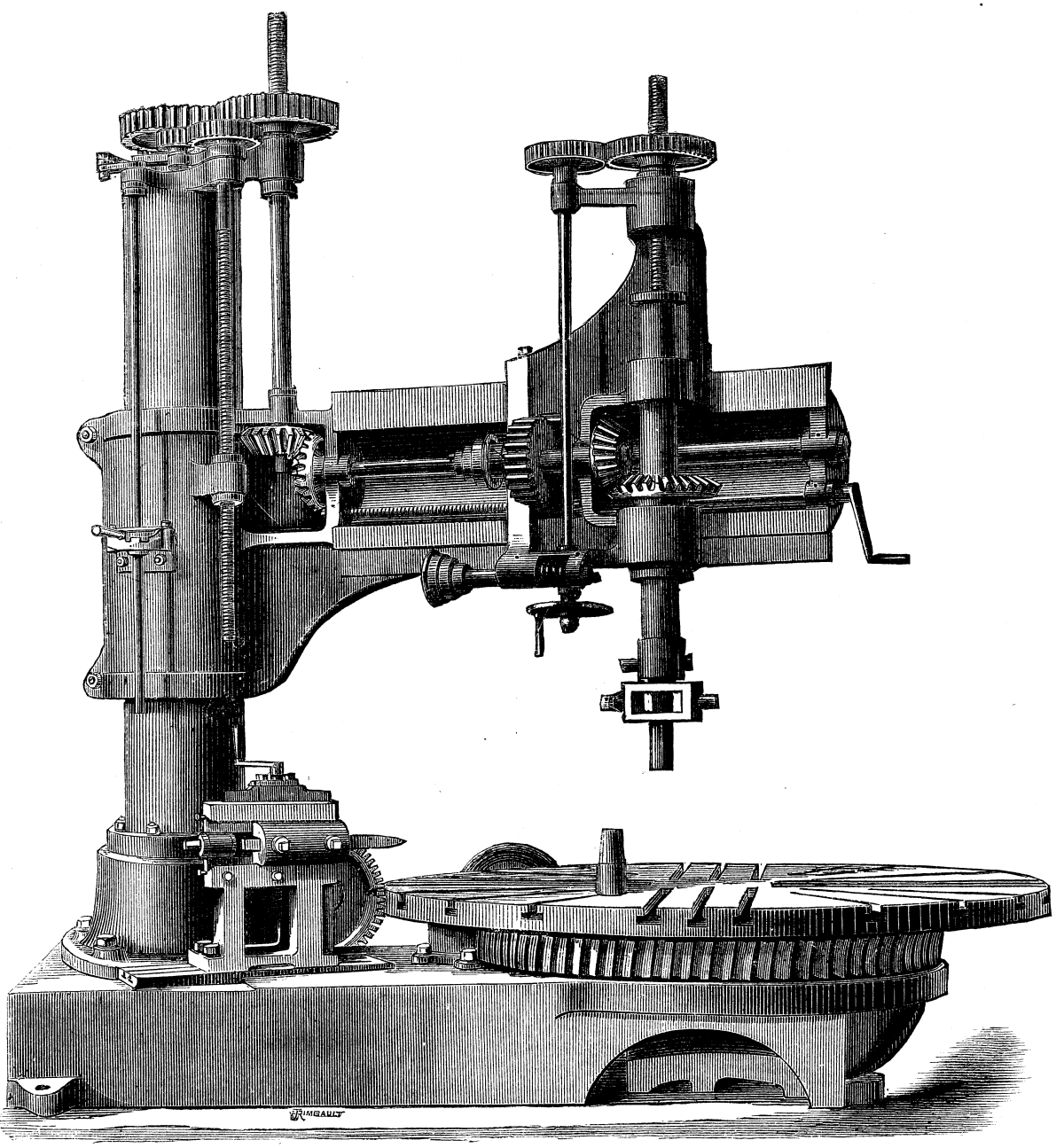
IMPROVED BOILER PLATERADIAL DRILL.
This radial drill, which is a tool of substantial proportions, is adapted not only for ordinary drilling work, but also for turning the ends of boiler shells, for cutting out of flue holes tube boring, etc. As will be seen from our engraving, the pillar which supports the radial arm is mounted on a massive baseplate, which also carries a circular table 6 ft. in diameter, this table having a worm-wheel cast on it as shown. This table is driven by a worm gearing into the wheel just mentioned. On this table boiler ends up to 8 ft. in diameter can be turned up, the turning tool being carried by a slide rest, which is mounted on the main baseplate, as shown, and which is adjustable vertically and radially.
For cutting out flue holes a steel boring head is employed, this head having a round end which fits into the center of the table. When this work is being done the radial arm is brought into the lowest position. Flue holes 40 in. in diameter can thus be cut out.
The machine has a 4 in. steel spindle with self-acting variable feed motion through a range of 10 in., and the radial arm is raised or lowered by power through a range of 2 ft. 8 in. When the arm is in its highest position there is room for a piece of work 4 ft. high between the circular table and the lower end of the spindle. The circular table serves as a compound table for ordinary work, and the machine is altogether a very useful one for boiler-makers.
The plate-bending rolls, which are illustrated on first page, are 10 ft. long, and are made of wrought iron, the top roll being 12 in. and the two bottom rolls 10 in. in diameter. Each of the bottom rolls carries at its end a large spur-wheel, these spur-wheels, which are on opposite sides of the machine, each gearing into a pinion on a shaft which runs from end to end below the rolls, and which is itself geared to the shaft carrying the belt pulleys, as shown. This is a very simple and direct mode of driving, and avoids the necessity for small wheels on the rolls. There is no swing frame, but the top roll is arranged to draw through between the arms of the spur-wheels, a very substantially framed machine being thus obtained.
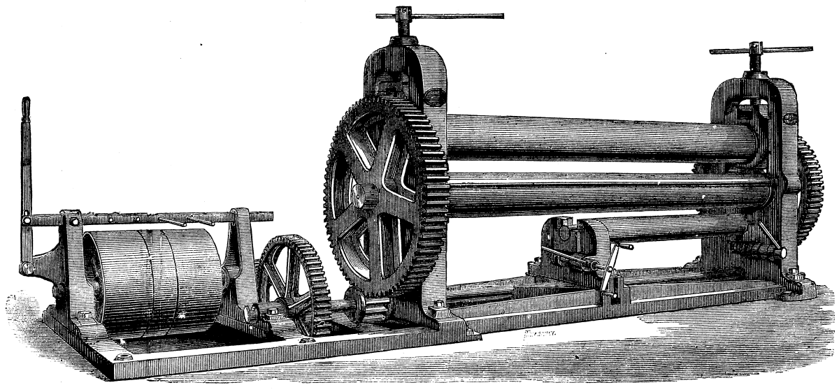
IMPROVED BOILER PLATE BENDING ROLLER.
The chief novelty in the machine is the additional roll provided under the ordinary bottom rolls. This extra roll, which is used for straightening old plates and for bending small tubes, pipes, etc., is made of steel, and is 7 in. in diameter by 5 ft. long. It is provided with a swing frame at one end to allow of taking-off pipes when bent, etc., and it is altogether a very useful addition.
The machine we illustrate weighs 11 tons, and is all self-contained, the standards being mounted on a strong bedplate, which also carries the bearings for the shaft with fast and loose pulleys, belt gear, etc. Thus no foundation is required.--Engineering.
[Footnote: A paper read Feb. 8, 1882, before the Society of Arts, London.]
A great change has lately been taking place throughout Europe in the matter of armaments. Artillery knowledge has been advancing "by leaps and bounds;" and all the chief nations are vying with each other in the perfection of their matériel of war. As a readiness to fight is the best insurance for peace, it behooves us to see from time to time how we stand, and the present moment is a peculiarly suitable one for taking stock of our powers and capabilities. I propose, therefore, to give you, this evening, a brief sketch of the principles of manufacture of modern guns, at home and abroad, concluding with a few words on their employment and power.
The introduction of rifled cannon into practical use, about twenty years ago, caused a complete revolution in the art of gun-making. Cast iron and bronze were found no longer suitable for the purpose. Cast iron was too brittle to sustain the pressure of the powder gas, when its duration was increased by the use of elongated projectiles; while the softness of bronze was ill adapted to retain the nicety of form required by accurate rifling.
From among a cloud of proposals, experiments, and inventions, two great systems at length disentangled themselves. They were the English construction of built-up wrought iron coils, and the Prussian construction of solid steel castings.
Wrought-iron, as you are all aware, is nearly pure iron, containing but a trace of carbon. Steel, as used for guns, contains from 0.3 to 0.5 per cent of carbon; the larger the quantity of carbon, the harder the steel. Since the early days of which I am now speaking, great improvement has taken place in the qualities of both materials, but more especially in that of steel. Still the same general characteristics were to be noted, and it may be broadly stated, that England chose confessedly the weaker material, as being more under control, cheaper, and safer to intrust with the lives of men; while Prussia selected the stronger but less manageable substance, in the hope of improving its uniformity, and rendering it thoroughly trustworthy. The difference in strength, when both are sound, is great. Roughly, gun steel is about twice as strong as wrought iron.
I must now say a few words on the nature of the strains to which a piece of ordnance is subjected when fired. Gunpowder is commonly termed an explosive, but this hardly represents its qualities accurately. With a true explosive, such as gun-cotton, nitro glycerine and its compounds, detonation and conversion of the whole into gas are practically instantaneous, whatever the size of the mass; while, with gunpowder, only the exterior of the grain or lump burns and gives off gas, so that the larger the grain the slower the combustion. The products consist of liquids and gases. The gas, when cooled down to ordinary temperature, occupies about 280 times the volume of the powder. At the moment of combustion, it is enormously expanded by heat, and its volume is probably somewhat about 6,000 times that of the powder. I have here a few specimens of the powders used for different sizes of guns, rising from the fine grain of the mountain gun to the large prisms and cylinders fired in our heavy ordnance. You will readily perceive that, with the fine-grained powders, the rapid combustion turned the whole charge into gas before the projectile could move far away from its seat, setting up a high pressure which acted violently on both gun and shot, so that a short, sharp strain, approximating to a blow, had to be guarded against.
With the large slow-bursting powders now used, long heavy shells move quietly off under the impulse of a gradual evolution of gas, the presence of which continues to increase till the projectile has moved a foot or more; then ensues a contest between the increasing volume of the gas, tending to raise the pressure, and the growing space behind the advancing shot, tending to relieve it. As artillery science progresses, so does the duration of this contest extend further along the bore of the gun toward the great desideratum, a low maximum pressure long sustained.
When quick burning powder was used for ordnance, the pressures were short and sharp; the metal in immediate proximity to the charge was called upon to undergo severe strains, which had scarcely time to reach the more distant portions of the gun at all; the exterior was not nearly so much strained as the interior. In order to obviate this defect, and to bring the exterior of the gun into play, the system of building up guns of successive tubes was introduced. These tubes were put one over the other in a state of tension produced by "shrinkage." This term is applied to the process of expanding a tube by the application of heat, and in that condition fitting it over a tube larger than the inner diameter of the outer tube when cold. When the outer tube cools it contracts on the inner tube and clutches it fast. The wrought-iron guns of England have all been put together in this manner.
Prussia at first relied on the superior strength of solid castings of steel to withstand the explosive strain, but at length found the necessity for re-enforcing them with hoops of the same material, shrunk on the body of the piece.
The grand principle of shrinkage enables the gunmaker to bring into play the strength of the exterior of the gun, even with quick powders, and to a still greater extent as the duration of the strain increases with the progress of powder manufacture. Thus, taking our largest muzzle-loaders designed a few years ago, the thin steel lining tube, which forms an excellent surface, is compressed considerably by the wrought-iron breech coil holding it, which, in its turn, is compressed by the massive exterior coil. When the gun is fired, the strain is transmitted at once, or nearly at once, to the breech coil, and thence more slowly to the outer one. Now, as the duration of the pressure increases, owing to the use of larger charges of slower burning powder, it is evident that the more complete and effective will be the transmission of the strain to the exterior, and, consequently, the further into the body of the gun, starting from the bore, and traveling outward, does it become advantageous to employ the stronger material. Hence, in England, we had reason to congratulate ourselves on the certainty and cheapness of manufacture of wrought iron coils, as long as moderate charges of comparatively quick burning powder were employed, and as long as adherence to a muzzle-loading system permitted the projectiles to move away at an early period of the combustion of the charge. Then the pressures, though sharp, were of short duration, and were not thoroughly transmitted through the body of the gun, so that the solidity, mass, and compression of the surrounding coils proved usually sufficient to support the interior lining. Now that breech-loading and slow powders have been introduced, these conditions have been changed. The strains, though less severe, and less tending to explosive rupture, last longer, and are more fully transmitted through the body of the gun. Sheer strength of material now tells more, and signs have not been wanting that coils of wrought iron afford insufficient support to the lining. It becomes, therefore, advantageous to thicken the inner tube, and to support it with a steel breech piece. Carrying this principle further, we shall be led to substitute the stronger for the weaker metal throughout the piece. This has been done by the Germans in the first instance, and recently by the French also. It is probable that we shall follow the same course. When I say "probable," I intentionally guard myself against uttering a prediction. It is never safe to prophesy, unless you know, as the American humorist puts it. And in this case we do not know, for a very dangerous rival, once defeated, but now full of renewed vigor, has entered the lists against forged steel as a material for ordnance. This rival's name is wire. Tempered steel wires can be made of extraordinary strength. A piece of round section, only one thirty-fifth of an inch in diameter, will just sustain a heavy man.
If, now, a steel tube, suitable for the lining of a gun, be prepared by having wire wound round it very tightly, layer over layer, it will be compressed as the winding proceeds, and the tension of the wire will act as shrinkage. You will readily understand that a gun can be thus formed, having enormous strength to resist bursting. Unfortunately, the wires have no cohesion with one another, and the great difficulty with construction of this kind is to obtain what gun-makers call end strength. It is of but little use to make your walls strong enough, if the first round blows the breech out. In the early days of wire this was what happened, and Mr. Longridge, who invented the system, was compelled to abandon it.
Lately, methods have been devised in France, by M. Schultz; at Elswick, by Sir W.G. Armstrong & Co.; and at Woolwich, by ourselves, for getting end strength with wire guns. They are all in the experimental stage; they may prove successful; but I prefer not to prophesy at present.
The diagrams on the wall show the general construction of the modern German, French, and English heavy breech-loading guns. The Germans have a tube, a jacket, and hoops. The French, a thick tube or body, and hoops. The English, a tube, a jacket, and an overcoat, as it may be called. In each system of construction, the whole of the wall of the gun comes into play to resist the transverse bursting strain of the charge.
The longitudinal or end strength varies: thus, in the German guns, the tube and hoops do nothing--the jacket is considered sufficient. The French construction relies entirely on the thick body, while the English method aims at utilizing the whole section of the gun, both ways. Of course, if the others are strong enough, there is no particular advantage in this; and it is by no means improbable that eventually we shall find it cheaper, and equally good, to substitute hoops for the "overcoat."
I fear I have detained you a long time over construction, but it is both instructive and interesting to note that certain well defined points of contact now exist between all the great systems. Thus, a surface of steel inside the bore is common to all, and the general use of steel is spreading fast. Shrinkage, again, is now everywhere employed, and such differences as still exist are matters rather of detail than of principle, as far as systems of construction are concerned.
We now come to a part of the question which has long been hotly debated in this country, and about which an immense quantity of matter has been both spoken and written on opposite sides--I mean muzzle loading and breech-loading. The controversy has been a remarkable one, and, perhaps, the most remarkable part of it has been the circumstance that while there is now little doubt that the advocates of breech-loading were on the right side, their reasons were for the most part fallacious. Thus, they commonly stated that a gun loaded at the breech could be more rapidly fired than one loaded at the muzzle. Now, this was certainly not the case, at any rate, with the comparatively short guns which were made on both systems a few years ago. The public were acquainted with breech-loaders only in the form of sporting guns and rifles, and argued from them. The muzzle-loading thirty eight ton guns were fired in a casemate at Shoeburyness repeatedly in less than twenty minutes for ten rounds, with careful aiming. No breech-loader of corresponding size has, I think, ever beaten that rate. With field-guns in the open, the No. 1 of the detachment can aim his muzzle loader while it is being loaded, while he must wait to do so till loading at the breech is completed. Again, it was freely stated that, with breech-loaders greater protection was afforded to the gunners than with the muzzle-loaders. This entirely depends on how the guns are mounted. If in siege works or en barbette, it is much easier to load a muzzle loader under cover than a breech-loader. But I need not traverse the old ground all over again. It is sufficient for me to say here, that the real cause which has rendered breech-loading an absolute necessity is the improvement which has been made in the powder. You witnessed a few minutes ago the change which took place in the action of fired gunpowder when the grains were enlarged. You will readily understand that nearly the whole of a quick burning charge was converted into gas before the shot had time to start; suppose for the moment that the combustion was really instantaneous. Then we have a bore, say sixteen diameters long, with the cartridge occupying a length of, say, two diameters.
The pressure of the gas causes the shot to move. The greater the pressure, the greater the impulse given. As the shot advances, the pressure lessens; and it lessens in proportion to the distance the shot proceeds. Thus, when the shot has proceeded a distance equal to the length of the cartridge, the space occupied by the gas is doubled, and its original pressure is halved. As the shot travels another cartridge length, the space occupied by the gas is trebled, and its pressure will be but one-third of the original amount. When the shot arrives at the muzzle--that is, at eight times the length of the cartridge from the breech--the pressure will be but one ninth of that originally set up. Remember, this is on the supposition that the powder has been entirely converted into gas before the shot begins to move.
Now, suppose the powder to be of a slow-burning kind, and assume that only one-third of it has been converted into gas before the shot starts, then the remaining two-thirds will be giving off additional gas as the shot travels through the bore. Instead, therefore, of the pressure falling rapidly, as the shot approaches the muzzle, the increasing quantity of gas tends to make up for the increasing space holding it. You will at once perceive that the slower the combustion of the powder the less difference there will be in the pressure exerted by the gas at the breech and at the muzzle, and the greater will be the advantage, in point of velocity, of lengthening the bore, and so keeping the shot under the influence of the pressure. Hence, all recent improvement has tended toward larger charges of slower burning powder, and increased length of bore. And it is evident that the longer the bore of the gun, the greater is the convenience of putting the charge in behind, instead of having to ram it home from the front. I may here remark, that the increased length of gun necessary to produce the best effect is causing even those who have possessed breech-loaders for many years to rearm, just as completely as we are now beginning to do. All the old short breech loading guns are becoming obsolete. Another great advantage of breech-loading is the facility afforded for enlarging the powder chamber of the gun, so that a comparatively short, thick cartridge may be I employed, without any definite restriction due to the size of the bore.
There is yet one more point in which breech-loading has recently been found, in the Royal Gun Factory, to possess a great advantage over muzzle-loading as regards ballistic effect. With a shot loaded from the front, it is clear that it must be smaller all over than the bore, or it would not pass down to its seat. A shot thrust in from behind, on the contrary, may be furnished with a band or sheath of comparatively soft metal larger than the bore; the gas then acting on the base of the projectile, forces the band through the grooves, sealing the escape, entering the projectile, and, to a great extent, mitigating the erosion of surface. This is, of course, universally known. It is also pretty generally known among artillerists that the effect of the resistance offered by the band or sheathing on the powder is to cause more complete combustion of the charge before the shot moves, and therefore to raise the velocity and the pressure. But I believe it escaped notice, till observed in May, 1880, in the Royal Gun Factory, that this circumstance affords a most steady and convenient mode of regulating the consumption of the charge, so as to obtain the best results with the powder employed.
Supposing the projectile to start, as in a muzzle loader, without offering any resistance beyond that due to inertia, it is necessary to employ a powder which shall burn quickly enough to give off most of its gas before the shot has proceeded far down the bore; otherwise the velocity at the muzzle will be low. To control this comparatively quick burning powder, a large air space is given to the cartridge, which, therefore, is placed in a chamber considerably too big for it. Supposing, on the other hand, the projectile to be furnished with a stout band, giving a high resistance to initial motion, a much slower powder can be used, since the combustion proceeds as if in a closed vessel, until sufficient pressure is developed to overcome the resistance of the band. This enables us to put a larger quantity of slower burning powder into the chamber, and in fact to use, instead of a space filled with air, a space filled with powder giving off gas, which comes into play as the projectile travels down the bore. Thus, while not exceeding the intended pressure at the breech, the pressure toward the muzzle is kept up, and the velocity very materially increased. Following this principle to this conclusion, it will be found that the perfect charge for a gun will be one which exactly fills the chamber, and which is composed of a powder rather too slow to give the pressure for which the gun is designed, supposing the shot to move off freely. The powder should be so much too slow as to require for its full development the holding power of a band which is just strong enough to give rotation to the shot.
Having settled that the gun of the future is to be a breech-loader, we have next to consider what system of closing the breech is to be adopted.
The German guns are provided with a round backed wedge, which is pushed in from the side of the breech, and forced firmly home by a screw provided with handles; the face of the wedge is fitted with an easily removable flat plate, which abuts against a Broad well ring, let into a recess in the end of the bore. On firing, the gas presses the ring firmly against the flat plate, and renders escape impossible as long as the surfaces remain uninjured. When they become worn, the ring and plate can be exchanged in a few minutes. Mr. Vavasseur, of Southwark, constructs his guns on a very similar plan. In the French guns, and our modern ones, the bore is continued to the rear extremity of the piece, the breech end forming an intermittent screw, that is, a screw having the threads intermittently left and slotted away. The breech block has a similarly cut screw on it, so that when the slots in the block correspond with the untouched threads in the gun, the block can be pushed straight in, and the threads made to engage by part of a revolution. In the French Marine the escape of gas is stopped very much as in Krupp's system; a Broadwell ring is let into a recess in the end of the bore, and a plate on the face of the breech-block abuts against it.
In the French land service the escape is sealed in quite a different manner. A stalk passes through the breech-block, its foot being secured on the exterior. The stalk has a mushroom-shaped head projecting into the bore. Round the neck of the stalk, just under the mushroom, is a collar of asbestos, secured in a canvas cover; when the gun is fired, the gas presses the mushroom against the asbestos collar, and squeezes it against the walls of the bore. It is found that this cuts off all escape.
We are at present using the Elswick method, which consists of a flat-backed cup, abutting against the slightly rounded face of the breech plug. The lips of the cup rest against a copper ring let in the walls of the bore. On firing, the gas presses back the cup against the rounded end of the breech-block, and thus forces the lips hard against the copper ring.
It is difficult to compare the excellence of these various systems, so much depends on the care of the gunners, and the nicety of manufacture. The German and French marine methods permit the parts to be quickly exchanged when worn, but it is necessary to cut deeply into the walls of the gun, and to make the wedge, or breech-screw, considerably larger than the opening into the chamber.
The Elswick plan is decidedly better in this last respect, but it requires several hours to extract and renew the copper ring where worn.
The French land service (De Bange) arrangement requires no cutting into the gun, and no enlargement of the breech screw beyond the size of the chamber, while it is renewable in a few minutes, merely requiring a fresh asbestos pad when worn. As regards durability, there is probably no great difference. I have been informed that with a light gun as many as 3,000 rounds have been fired with one asbestos pad. But usually it may be considered that a renewal will be required of the wearing surfaces of any breech-loader after a number of rounds, varying from six or seven hundred, with a field gun, to a hundred or a hundred and fifty with a very heavy gun. Full information is wanting on this point.
Having now decided on the material of which the gun is to be composed, and the manner in which it is to be constructed, and having, moreover, settled the knotty point of how it is to be loaded, we come to the general principles on which a gun is designed. It must not be overlooked that a gun is a machine which has to perform a certain quantity of work of a certain definite kind, and, like all other machines, must be formed specially for its purpose. The motive power is gunpowder, and the article to be produced is perhaps a hole in an armor-plate, perhaps a breach in a concealed escarp, or perhaps destructive effect on troops. These articles are quite distinct, and though all guns are capable of producing them all to some extent, no gun is capable of producing more than one in the highest state of excellence.
Thus, for armor piercing, a long pointed bolt, nearly solid, is required. It must strike with great velocity, and must therefore be propelled by a very large charge of powder. Hence an armor-piercing gun should have a large chamber and a comparatively small bore of great length.
For breaching fortifications, on the other hand, curved fire is necessary; the escarps of modern fortresses are usually covered from view by screens of earth or masonry in front, so that the projectiles must pass over the crest of the screen, and drop sufficiently to strike the wall about half-way down, that is to say, at an angle of 15° to 20°. To destroy the wall, shell containing large bursting charges of powder are found to be particularly well adapted. Now it is clear that, for a shell to drop at an angle of 15° or 20° at the end of a moderate range, the velocity at starting must be low. Hence, for pieces intended for breaching no enlarged powder chamber is wanted; the effect on the wall is due to the shell, which must be made of a shape to hold the most powder for a given weight; and, therefore, rather short and thick. This gives us a large bore, which need not be long, as little velocity is required.
For producing destructive effect among troops, a third kind of projectile is employed. It is called shrapnel, and it consists of a thin shell, holding a little powder and a large quantity of bullets. The powder is ignited by a fuse, which is set to act during flight, or on graze, when the shell is nearing the object. The explosion bursts the shell open, and liberates the bullets, which fly forward, actuated by the velocity of the shell at the moment of bursting. Hence, to render the bullets effective, a considerable remaining velocity is requisite. The gun must therefore take a large powder charge, while, as the shell has to hold as many bullets as possible, the bore must be large enough to take a short projectile of the given weight. Thus, the proportions of the shrapnel gun will be intermediate between those of the armor-piercing gun and the shell gun.
There are certain axioms known from experience, which should be mentioned here. First, the length of the powder chamber should not be more than three and a half or four times its diameter, if it can possibly be avoided, because, with longer charges, the inflamed powder gas is apt to acquire rapid motion, and to set up violent local pressures. Next, the strength of a heavy gun, as reckoned on the principle of all the metal being sound and well in bearing, should not be less than about four times the strain expected.
Again, though there are several opinions as to the best weight of shot for armor piercing, in proportion to diameter, yet among the most advanced gun-makers, there is a growing tendency toward increased weight. The value of w/d³, that is, the weight in pounds divided by the cube of the diameter in inches, as this question is termed, is in the hands of the Ordnance Committee, and it is to be confidently hoped that efforts will shortly be made to arrive at a solution. In the meantime, from about 0.45 to 0.5 appears to be a fairly satisfactory value, and is adopted for the present.
Lastly, it may be broadly stated, that with suitable powders, a charge of one-third the weight of the shot demands for most profitable use a length of bore equal to about twenty-six calibers; a charge equal to half the weight of the shot should be accommodated with a bore of about thirty calibers; while a charge of two-thirds the weight of the shot will be best suited by a bore thirty-five calibers long. Of course, in each case, greater length of bore will give increased velocity, but it will be gained at the expense of additional weight, which can be better utilized elsewhere in the gun.
The amount of work performed by gunpowder, when exploded in a gun, is a subject which has engaged a vast quantity of attention, and some highly ingenious methods of calculating it have been put forward. Owing, however, to the impossibility of ascertaining how fast the combustion of large grains and prisms proceeds, a very considerable amount of experience is required to enable the gunmaker to apply the necessary corrections to these calculations; but, on the whole, it may be said that, with a given charge and weight of shot, the muzzle velocity may now be predicted with some accuracy.
You now have the chief data on which the designer bases his proposals, and lays down the dimensions of the gun to suit such conditions as it may be required to fulfill. In actual practice, the conditions are almost always complicated, either by necessities of mounting in particular places, such as turrets and casemates; or by the advantages attending the interchangeability of stores, or other circumstances; and it requires great watchfulness to keep abreast of the ever-growing improvements of the day.
I will now conclude with a few words on the power of heavy guns, when employed in various ways. The first consideration is accuracy of fire. No matter how deadly the projectile may be, it is useless if it does but waste itself on air. Accuracy is of two kinds--true direction and precision of range. All modern guns are capable of being made to shoot straight; but their precision of range depends partly on the successful designing of the gun and ammunition, so as to give uniform velocities, and partly on the flatness of the trajectory. The greater the velocity, the lower the trajectory, and the greater the chance of striking the target. Supposing a heavy gun to be mounted as in the fortresses round our coasts, and aimed with due care, the distance of the object being approximately known, we may fairly expect to strike a target of the size of an ordinary door about every other shot, at a range of a mile and a half. Here we have carriages mounted on accurately leveled platforms; we have men working electric position finders, and the gunners live on the spot, and know the look of the sea and land round about.
Now, consider the case of guns mounted in ships. You at once perceive the difficulties of the shooter. Even supposing the ship to be one of our magnificent ironclads, solid, steady, yielding little to the motion of the water, yet she is under steam, the aim of her guns is altered every moment, some oscillation is unavoidable, and she can only estimate the range of her adversary. Great skill is required, and not only required, I am glad to say, but ready to hand, on the part of the seamen gunners; and low trajectory guns must be provided to aid their skill.
If we go to unarmored ships of great tonnage and speed, we shall find these difficulties intensified; and if we pass on to the little gunboats, advocated in some quarters for attacking ironclads in a swarm, we shall find that unsteadiness of platform in a sea-way renders them a helpless and harmless mark for the comparatively accurate practice of their solitary but stately foe.
The destructive power of guns is little known to the general public, and many wild statements are sometimes put forward. Guns and plates have fought their battle with varying success for many years. One day the plate resists, another day the gun drives its bolt through. But it is frequently overlooked that the victory of a plate is a complete victory. If the shot does not get through, it does practically nothing. On the other hand, the victory of the gun is but a partial triumph; it is confined to a small arc. I mean that, when the plate is struck at an angle exceeding 30° or so, the shot glances harmlessly off; while, even when perforation is obtained, it is at the expense of the more deadly qualities of the projectile, which must be a nearly solid bolt, unable to carry in with it heavy bursting charges of powder or destructive masses of balls.
About six years ago, an experiment carried out at Shoeburyness taught a lesson which seems to be in danger of being forgotten. We hear sometimes that unarmored vessels are a match for ironclads and forts; and I will conclude this paper with a short extract from the official account of the results of firing shrapnel shell at an unprotected ship's side. I shall say nothing of boilers and magazines, but shall state simply the damage to guns and gunners.
A target was built representing the side of a certain class of unarmored ships of war; behind this target, as on a deck, were placed some unserviceable guns, mounted on old carriages, and surrounded by wooden dummies, to represent the men working the guns. The attacking gun was a twelve-ton nine-inch muzzle-loader, of the old despised type, and the projectiles were shrapnel shell. The charges were reduced to represent the striking force at a range of 500 yards. Two rounds did the following damage inside, besides tearing and ripping the ship's side in all directions.
1st Gun.--Seven men of detachment killed.
2d Gun.--Carriage destroyed. Six men blown to pieces, all the remainder of the detachment severely hit.
3d Gun.--No damage to gun or carriage. Five men killed, one blown to bits, and one wounded in leg.
4th Gun.--Gun dismounted. The whole of the gun detachment blown to pieces.
That is the amount of destruction achieved in an unarmored ship by two rounds of shrapnel shell.
This locomotive is the design of Mr. Henry F. Shaw, of Boston.
This engine has oscillating cylinders placed between the driving-wheels. Fig. 2 represents a section of one of these cylinders, from which it will be seen that each has two pistons and piston-rods, which are connected directly to the crank-pins. His invention is described as follows in his specification:
"Midway between each set of wheels, e and f, is located the oscillating steam-cylinder, g, having its journals, g' and g", supported in the stationary arm, h, which is secured in a suitable manner to the frame, c. To each cylinder, g, is secured or cast in one piece therewith a balanced vibratory beam or truss, i, as shown. Within the cylinder, g, are two movable pistons, k and k', Fig. 2, provided with piston-rods, l and l', and cross-heads, m and m', as shown.
"n n are slides for the cross-head, m, on the insides of one end of the truss or beam, i, and n' n', are similar slides in the other end of said truss or beam, for the cross-head, m'. To the driving-wheel, e, is attached a crank-pin, passing through the cross-head, m, and to the driver-wheel, f, is attached a similar crank-pin, F, that passes through the cross-head, m'. o is the slide-valve within the steam-chest, G, which slide-valve is operated forward and back by means of the valve-rod, o¹, the outer end of which is hinged to the upper end of the slotted lever, o², Fig. 1, that is hung at o³, on the end of the balanced and vibratory beam of truss, i, as shown. On the crank, F, is secured an eccentric, that works within the slot of the slotted lever, o², during the revolution of the crank, F, and in this manner imparts the requisite motion to the slide valve, o, to admit the steam into the cylinder, g, alternately between the pistons, k and k', and at the ends of said cylinder, g, so as to alternately force the pistons, k and k', from and toward each other, and thus, in combination with the vibratory motion of the truss, i, impart a rotary motion to the driving-wheels, e and f.
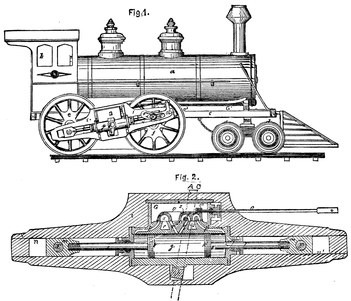
SHAWS OSCILLATING CYLINDER LOCOMOTIVE.
"The steam is admitted to and from the cylinder, g, as follows: When the pistons, k and k', are at the outer ends of their stroke the steam enters through the channel, p, back of the piston, k, and at the same time through the channel, p', back of the piston, k', and thus causes both pistons to move toward each other, the steam between them being at the same time exhausted through the channels, q and q', the former communicating with the exhaust, r, by means of the space, s, in the valve, o, and the latter communicating with the exhaust, r', through the channel, s', in the said valve, o. The steam that passes to the back of the piston, k, comes direct from the steam-chest, G, through the open end of the channel, p, the valve, o, being at this time moved to one side to leave the port, p, open. The steam is admitted to the back end of the piston, k', from the steam-chest, G, through the channel, s", in the valve, o, and from thence to the channel, p'. When the pistons, k and k', have reached their inner positions the live steam is admitted through the channels, q and q', direct from the steam-chest, G, to the former, and through the recess, s³, and channel, s', in the valve, o, to the latter, the exhaust steam back of the piston, K, passing out through the channel, p, to the recess, s, in the valve, o, and thence to the exhaust, r, the exhaust steam back of the piston, k, passing out through channel, p', and through channel, s", in the valve, o, and thence to the exhaust, r'.
"The valve-rod, o', is to be connected to a link and reversing lever as usual, such being, however, omitted in the drawings."
The advantages claimed for it are that "it is composed of very few parts, and it is very powerful on account of its having a separate steam actuating piston for each of its driving-wheels. It has great strength and resistance, owing to the fact that no pressure is exerted on the journals on which the steam cylinders oscillate, and all the pressure from the steam pistons is directly transferred to the crank-pins on the driving-wheels. The engine is perfectly balanced in any position during the stroke, and it may therefore be run at a much higher speed than the common engines now in use."
The cylinder of the engine--assuming that it has only a single-acting one, placed with its axis vertical--consists of two parts; the upper hot part being lined with plumbago, fire-clay, or other refractory material, and the lower part kept cool by a water casing. The cylinder has a trunk piston working in the lower part, and on its upper side a shield that almost fills the hot part of the cylinder when the piston is at the extreme of its upstroke. The trunk-rod of the piston passes through a stuffing-box in the cylinder bottom, and is connected to a crank on the engine-shaft; and this (unless multiple cylinders are employed) carries a heavy fly-wheel. From the lower end of the cylinder there is a passage which, by means of a rotating or reciprocating slide, is alternately put in communication with inlets for gas and air (regulated by suitable cocks or valves) and with a strong receptacle. As the piston, makes its upstroke, air and gas are drawn into the annular space surrounding its trunk, and the mixed air and gas are compressed by the downstroke of the piston, and delivered into the receptacle, in which considerable pressure is maintained. The receptacle is made of cylindrical form, with a domed cover of thin sheet metal; so that in case of excessive internal pressure it can operate as a safety-valve to save the body of the receptacle from damage. From the upper end of the cylinder there is a passage that, by means of a rotating or reciprocating slide, is alternately put in communication with the receptacle and with a discharge outlet. In this passage are fixed a number of wire gauze screens or pieces of metal with interstices. These constitute a regenerator of heat, and also prevent a communication of flame from the cylinder to the receptacle. In the upper end of the cylinder or of the piston shield are provided electrodes which give an electric spark, or a platinum wire which is rendered incandescent by a current from an inductor or other source of electricity to ignite the combustible charge of the cylinder. After the engine has been for some time at work, the heat at the upper part of the cylinder may suffice for effecting ignition without provision of other means for this purpose.
In combining such an engine with means for generating the combustible gas, a gas producer is employed. In this producer a current of heated air is introduced into the heart of a body of kindled fuel, and the gases produced--partly by distillation and partly by imperfect combustion of the fuel--are conveyed to the gas inlet of the cylinder or pump of the engine. As the gas in leaving the producer is hot, it is caused to pass through regenerating apparatus, to which it delivers a large portion of its heat before it reaches the engine, and the air which supplies the producer is made to pass through this regenerating apparatus so as to take up the heat abstracted from the gas.
In the accompanying engravings, Fig. 1 shows a front elevation (partly in section) of a pair of engines constructed according to this invention. The lower part, A, of each cylinder is cooled by water circulating through its casing. The upper part, B, is lined with refractory material, such as fire-clay. The trunk piston, C, is made hollow, and formed with a shield covered by refractory material to protect the packing of the piston and the surface of the lower part of the cylinder from heat. The pistons of the two cylinders are connected by rods, D, to opposite cranks on the shaft, E. This shaft, by means of bevel gear, F, works a revolving cylindrical valve, G, situated in a casing between the two cylinders. The lowest part of this casing is supplied with combustible gas and with air, in proportions capable of being regulated by stopcocks or valves. The highest part of the casing communicates with a discharge-pipe; and the middle part of it with a reservoir which can be cut off from communication by a stopcock, so that the charge in the reservoir may be retained when the engine is stopped. The middle space of the hollow valve, G, communicates, by a number of holes, with the middle space of the slide casing. It also, by means of a port at its lower part, communicates alternately with the annular spaces of the two cylinders; this communication in each case being made when the piston is performing the latter part of its downstroke. The interior of the slide also, by means of a second port at its upper part, communicates alternately with the tops of the two cylinders; this communication being in each case made while the piston is performing the first portion of its downstroke. During the upstroke of each piston the slide, by means of another port, makes communication alternately to each cylinder from the bottom of the slide casing, and by means of a fourth port make communication alternately from each cylinder to the top of the slide casing. In the passage connecting the top of the slide casing to each cylinder is placed a regenerator, consisting of a number of perforated metal plates or sheets of wire gauze.
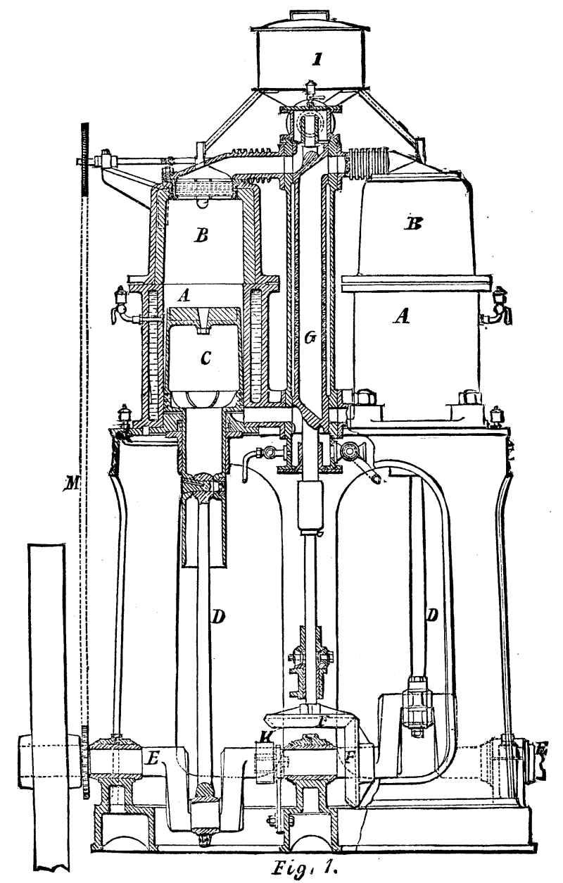
SIEMENS' GAS PRODUCER AND GAS MOTOR. Fig 1.
In order that gas of poor quality or gas diluted with a large proportion of air may be utilized, an igniting arrangement is employed which operates as follows: I is a vessel containing a supply of hydrocarbon oil, preferably of volatile character. From this vessel pipes lead to two cocks, one for each cylinder; these corks being caused to revolve in time with the engine-shaft by a chain, M, communicating motion from a wheel on the engine shaft to a chain-wheel of equal size on the spindle of the two cocks. The plug of each cock has on its side a small hollow, which during one part of its revolution presents itself under the oil-pipe, and receives a charge of oil. During another part of its revolution, which is timed to correspond with the flow of gaseous mixture to the cylinder, the hollow of the plug presents itself to the bend of a pipe leading from the top of the cylinder to a port opening into the cylinder below the regenerator, in which port are situated two wires of platinum. These wires are connected with the brushes of a commutator, K, on the engine-shaft, which commutator is in electrical connection with the poles of a battery, dynamo-electric machine, or other source of electricity. Instead of two wires to produce a spark, a single wire may be arranged to become incandescent at the proper time for ignition.
The operation of the engine is as follows: Each piston as it ascends draws into the annular space under it a supply of gas and air in proportion regulated by the cocks or valves, and as it descends it forces this charge into the interior of the revolving valve and its casing, and into the reservoir which communicates therewith. When either piston is at the top of its stroke, the revolving valve admits to the upper part of the cylinder a supply of the gaseous mixture from the reservoir and valve casing, and this passes through the generator. At the same time a portion of the charge passes by the pipe, and becomes enriched by admixture of the hydrocarbon oil delivered to it by the cock. The enriched mixture, in passing the platinum wires, which at that time give an electrical spark, is ignited, and ignites the charge that is passing through the regenerator into the cylinder. The mixture thus ignited expands, and acting on the full area of the piston propels it downward, the under side of the piston being at that time subject to pressure only on its annular area. When the piston has completed its down-stroke the passage is opened to the discharge-pipe, and the expanded products of combustion then pass from the cylinder through the regenerator, and are discharged. In their passage they give out to the regenerator a large portion of their heat, which the charge entering the cylinder for the next stroke receives in passing through the regenerator.
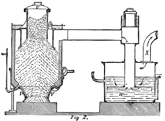
SIEMENS' GAS PRODUCER AND GAS MOTOR. Fig 2.
Fig. 2 is a vertical section of a gas producer and scrubber, which, as stated above, may be employed in combination with engines such as have been described for supplying them with combustible gas. The producer is a vessel lined with refractory material. At the top it has a supply opening covered by a cap, U, having a flange dipping into a sand joint. At the bottom it has an opening surrounded by inclined bars, V, which rest upon a water-pipe perforated with small holes, by which water issues to cool the bars and generate vapor. This vapor rises along with a limited supply of air through the incandescent fuel above, and combustible gas is produced, which collects in the annular space, and is led thence by a pipe to the scrubber. The scrubber is a vessel containing in its lower part water, W, supplied by a pipe, and having an overflow. By means of a perforated deflecting plate the gas is caused to bubble through the water, whereby it is cleansed and cooled, and it passes by a pipe, X, to supply the engine. The upper end of the vertical pipe of the scrubber is made open and covered by a cap sealed in water while the producer is at work. In starting the producer this cap is removed and a chimney pipe put in its place, so as to give a draught for kindling the fuel in the producer. When the fuel is kindled the chimney is removed and the cap substituted, whereupon the suction of the engine continues the draught as required.
This paper, lately read before the Institution of Mechanical Engineers, London, is a description of the construction and working of a dredger on M. Bazin's system, as used by the author for the past three years in dredging sand and other material in Lowestoft Harbor. The dredger is represented in its general features on next page, Fig. 1. The total length of the hull is 60 ft., with 20 ft. beam. In the after part of the hold is placed a horizontal boiler, A, which supplies steam to a pair of inverted vertical engines, B. These engines drive, through belts and overhead pulleys, a centrifugal pump, C, which discharges into the open trough, H. The suction pipe, D, of this pump passes through the side of the dredger, and then forms an elbow bent downward at an angle of 45 deg. To this elbow is attached a flexible pipe, E, 12 in. in diameter and 25 ft. long, made of India-rubber, with a coil of iron inside to help it to keep its shape. At the lower end of this pipe is an elbow-shaped copper nozzle which rests on the bottom, and is fitted with a grating to prevent stones getting into the pump and stopping the work. The flexible tube is supported by chains that pass over the head of a derrick, F, mounted at the stern of the dredger, and then round the barrel of a steam winch. By this means the depth of the nozzle is altered, as required to suit the depth of water.
A man stands at the winch, and lifts or lowers the pipe as is required, judging by the character of the discharge from the pump. If the liquid discharged is very dark and thick the nozzle is too deep in the sand or gravel; if of a light color the pipe must be lowered. The best proportion of water to sand is 5 to 1. When loose sand is the only material to be dealt with, it can be easily sucked up, even if the nozzle is deeply buried; but at other times stones interfere with the work, and the man in charge of the flexible tube has to be very careful as to the depth to which the nozzle may be buried in the sand. The pump is shown in Figs. 2 and 3. The fan is 2 ft. diameter, and has only two blades, a larger number being less efficient. The faces of the blades, where they come in contact with the sand, are covered with flaps of India-rubber. Small doors are provided at the side of the pump for cleaning it out, extracting stones, etc. The fan makes 350 revolutions per minute, and at that speed is capable of raising 400 tons of sand, gravel, and stones per hour, but the average in actual work may be taken at 200 tons per hour. This is with a 10-horse power engine, and working in a depth of water varying from 7 ft. to 25 ft. The great advantage of this dredger is its capability of working in disturbed water, where the frames of a bucket dredger would be injured by the rise and fall of the vessel.
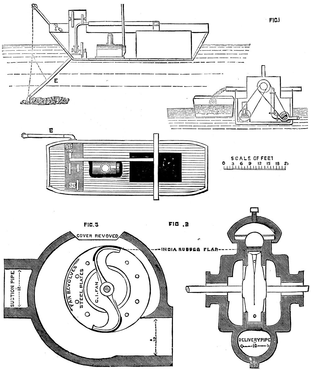
THE BRAZIN SYSTEMEM OF DREDGING.
Thus at Lowestoft bucket dredgers are used inside the harbor, and the Bazin dredger at the entrance, where there are sand and gravel, and where the water is more disturbed. The dredger does not succeed very well in soft silt, because, owing to its slow precipitation, it runs over the sides of the hopper barges without settling. Nor does it do for dredging solid clay. It gives, however, excellent results with sand and gravel, and for this work is much superior to the bucket dredger. The experience in working was then described, showing that a great many very discouraging failures preceded successful working, about a year being expended in getting good results.
The vessel or barge for carrying the machinery and pumps cost £600, and the contract price of the machinery and pumps was £1,200. But before the dredger was taken over by the company the alterations before enumerated had cost about £300, bringing the total for barge and dredger up to £2,100. In building a second dredger this might of course be greatly reduced. The cost of repairs for one month's working has been only £5. The contractor receives for labor alone 1-1/8d. per ton, being at the rate of about 1¾d. for the dredging and 3/8d. for taking to sea--a lead of two miles--all materials being supplied to him. The consumption of coal is at the rate of about 1 ton for 1,000 tons of sand dredged. At Lowestoft Harbor the total amount of dredging has been about 200,000 tons yearly, but this is now much reduced in consequence of the pier extension recently constructed by the author, which now prevents the sand and shingle from the sea blocking the mouth of the harbor. The total cost of working has been 2.572d. per ton. which with 10 per cent interest on capital, 0.240d., makes the total cost per ton 2.812d. The repairs to steam tug, hopper, barges, and dredger have averaged about 2d. per ton.
Before the discussion on the paper commenced, Mr. Langley remarked that attempts had been made to connect the engine direct to the pump of a Bazin dredger, but this arrangement failed, and the belt acted as a safety arrangement and prevented breakage by slipping when the pump was choked in any way. A new lock was constructed near Lowestoft a short time ago, and the dredger pump was used to empty it; when half empty the men placed a net in front of the delivery pipe and caught a cartload of fish, many of which where uninjured. In the discussion Mr. Wallick, who had superintended the use of the dredger at Lowenstoft, gave some of his experience there, and repeated the information and opinions given by Mr. Langley in the paper.
Mr. Ball, London agent for M. Bazin, said that as devised by M. Bazin the pump was placed below water level, so that the head of water outside should be utilized; but he--Mr. Ball--now placed the pump considerably above water level, as no specially formed craft was thus necessary. He also described some of the steps by which he had arrived at the present arrangements of the whole plant, and gave some particulars of its working. Mr. Crampton asked some questions, in reply to which Mr. Ball said the longest distance they had carried the material was 1,200 yards in two relays--namely, a second pump on a floating barge with special engine. The distance to which they could carry the material depended upon its character. Fine sand would travel well; mud would not, bowlders would not, though gravel would. To give the water a rotary motion he had inserted a helical piece of angle iron, and so prevented deposition.
Although the accident in the tunnel in process of construction at Union Hill by the New York, Ontario, and Western Railroad Company, which took place on Tuesday afternoon, was happily attended with no loss of life or serious injuries to the men employed in the shaft, it reads a new lesson as to the firing of charges of powder by electricity, and one that should be carefully noted by railway and civil engineers, and even by the torpedo service of the United States. The exact cause of the explosion has scarcely been fully and accurately set forth by the various reports of the affair.
It appears that the wires usually employed lo supply the electric lamps in the excavation were used for the purpose of firing the charges, being disconnected from the electric light system for the moment and connected with the explosives. As a rule, six charges were fired together, those of the afternoon relay of men being exploded at very regular hours--the last usually at 5:45 P.M. There were only sixteen men in the shaft, and the work of connecting the wires had commenced, when the flash of lightning that occurred at 5:42 P.M., suddenly charged the conductors and produced the explosion.
There were two flashes of lightning between the hours of 5 and 6 o'clock Tuesday afternoon, the first taking place at 5:23, and the second nineteen minutes later. The former, according to testimony elicited by our reporter, simply caused a slight perturbation of the lights in the tunnel, but did not extinguish them. Five minutes later the work of disconnection and reconnection began, but only two of the six charges were ready for the pressure of the button when the last flash interrupted the proceedings. The fact that the time of the explosion corresponded to the second with that of the aerial electrical discharge furnishes indubitable evidence that the accident was not caused by any carelessness on the part the electrician in charge, and exonerates all parties from blame. At the same time it should be remembered by engineers in of such work that atmospheric electricity cannot be altogether disregarded in such cases, and that as a source of accident it may at any time prove dangerous. The concurrence of circumstances on Tuesday was particularly fortunate. In the first instance only two of the six charges had been connected with the firing battery, and in the second the rock in which the charges were inserted was so peculiarly soft and porous as to deaden the force of the eight pounds of giant powder thus prematurely set off. Had the cartridges been set in the harder and more solid rock of the east heading, instead of the west, and the explosion taken place there, probably not a man in the shaft would have escaped destruction. The lesson to engineers is one of no less importance than if the whole number of men had been killed, and should lead to the exercise of great care and precaution at times when the air is charged with electrical energy.--New York Times.
Whatever may be the misgivings entertained by many engineers respecting the future use of cast iron for structures of certain kinds, it is clear that for architectural purposes this material is likely to be employed to an extent hardly contemplated by many who have looked upon it with disfavor. At the present moment many buildings may be seen in London, in which cast iron has been introduced instead of stone for architectural features, and the substitution of cast iron for façades in many warehouses and commercial buildings seems to show that, notwithstanding the prejudices of the English architect against the importation of the iron architecture of our transatlantic brethren, there is a prospect of its being largely employed for frontages in which ample lighting and strength are needed. The extensive window space necessary in narrow city thoroughfares, and the difficulty of employing brick in large masses, such as pilasters and lintels, have chiefly led to the adoption of material having less of the uncertain durability and strength of either stone or terra-cotta in its favor. Architects would gladly resort to the last-named material if it could be procured in sufficient size and mass without the difficulties attendant upon shrinkage in the burning, and the winding and unevenness of the lines thereby caused. They have also an even more tractable material in concrete ready to their hand, if they would seriously bring themselves to the task of stamping an expressive art upon it, instead of going on designing concrete houses as if they were stone ones. Cast iron has the advantage of being a tried material; it is well adapted for structures not liable to sudden weights or to vibration, and so it has come to be used for features of an architectural kind, by a sort of tacit acknowledgment in its favor. Those who are desirous of seeing examples of its employment in fronts of warehouses will find instances in Queen Victoria Street, Southwark Street, and Bridge Road, and Theobalds Road, where the whole or portions of fronts have been constructed of cast iron. At some corner premises in Southwark, the piers as well as the windows are formed of cast iron, the former being made to assume the appearance of projecting pilasters. There is nothing to which the most captious critic could object in the treatment adopted here; the pilasters and other features have plain moulded members, and there is no principle of design in cast work which has been violated--the only question being the purely aesthetic one--is it justifiable to copy features in cast iron which have generally been constructed in stone or marble? The answer is obvious: Certainly not, when those features suggest the mass and proportions or treatment proper only for stone or marble; but when they do not so represent the material, it is quite optional for the architect to build up his front with castings, if by so doing he can obtain greater rigidity of bearing, strength, and durability. He ought, of course, to vary the proportions of his pilasters and horizontal lintels, and make them more in accord with the material. It is the wholesale reproduction of the more costly and ornamental features, such as we see in many buildings of New York and Philadelphia, where whole fronts are manufactured of cast iron and sheet-metal, which has shocked the minds of architects of culture and sensitive feeling. Such imitations and cheap displays outrage the artist by the attempt to produce in cast or rolled metal what properly belongs to a stone front.
Bearing this distinction in mind, we are not presuming too much to assert that architects have in cast iron, when properly employed under certain restrictions, a material which might be turned to account in narrow fronts where the use of brick or stone piers would encroach too much upon the space for light. For warehouse fronts, we have evidence for thinking that the employment of iron might be attended with advantage, especially in combination with brickwork for the main vertical piers. Plain classic mouldings, capitals and bases of the Doric or Tuscan order, are well suited for cast-iron supports to lintels or girders. In one attempt to make use of the structural features of the latter, the fronts of the girders between the piers are divided into panels, the flanges and stiffening pieces to the webs forming an effective framework for cast or applied ornament to be introduced. The iron framework thus constructed lends itself to the minor divisions of the window openings, which can be of wood. In the new Leaden Hall and Metropolitan Fruit and Vegetable Markets, cast-iron fronts have been largely employed, consisting of stanchions cast in the form of pilasters, with horizontal connections and other architectural members.
Regarding the more constructive aspects of cast iron, the employment of it in fronts having numerous points of support and small bearings is clearly within the capabilities of the material. So long as it is used in positions in which its resistance to compression is the chief office it has to fulfill, cast iron is in its right place. In the fronts of buildings, therefore, where it is made to carry the floors and rolled joists, and the lintels of openings, either as piers, pilasters, or simply as mullions of windows, it is strictly within its legitimate functions. So with regard to lintels and heads of openings where short spans exist, cast iron is free from the objection that can be urged against it for long girders. In fact, no position is better fitted for a brittle, granular material than that of a vertical framework to receive windows and ornamentation, and for such purposes cast iron is, to our minds, admirably suited.
For bridge-building the value of this metal has lately been much disputed, though we have several notable examples of its use in the earlier days for such structures. In fact, the use of cast iron for structural purposes is not older than the time of Smeaton, who in 1755 employed it for mill construction, and about the same time the great Coalbrookdale Viaduct was erected across the Severn near Broseley, which gave an impetus to the use of cast iron for bridge construction. The viaduct had a span of 100 feet, and was composed of ribs cast in two pieces; it was erected from castings designed by Mr. Pritchard, of Shrewsbury, an architect, and this circumstance is worthy of note as showing that an architect really was the first to employ this material for important structural work, and that the same profession was the first to reject it upon traditional grounds. It is quite certain, however, the bridge-builder lost no time in trying his hand upon so tractable a material; for not long after Telford erected a bridge at Buildwas of even a greater span, and the famous cast-iron bridge over the river Wear at Sunderland was erected from the designs of Thomas Paine, the author of the "Age of Reason." Iron bridges quickly followed upon these early experiments, for we hear of several being built on the arched system, and large cotton-mills being erected upon fireproof principles at the commencement of the present century, the iron girders and columns of one mill being designed by Boulton and Watt. A little later, Eaton Hodgkinson proved by experiments the uncertainty of cast iron with regard to tensile strength, which he showed to be much less than had been stated by Tredgold. Cast iron was afterwards largely adopted by engineers. The experiments of Hodgkinson supplied a safe foundation of facts to work upon, and cast iron has ever since retained its hold. Thomas Paine's celebrated bridge at Sunderland had a span of 236 feet and a rise of 34 feet, and was constructed of six ribs, and is remarkable from the fact that the arched girder principle used in the Coalbrookdale and Buildwas bridges was rejected, that the ribs were composed of segments or voussoirs, each made up of 125 parts, thus treating the material in the manner of stone. Each voussoir was a cast-iron framed piece two feet long and five feet in depth, and these were bolted together. The Southwark bridge over the Thames, by Sir John Rennie, followed, in which a similar principle of construction is adopted. There is much to be said in favor of a system which puts each rib under compression in the manner of a stone arch, and which builds up a rib from a number of small pieces. At least, it is a system based on the legitimate use of cast iron for constructive purposes. The large segmental castings used in the Pimlico bridge, and the new bridge over the Trent at Nottingham, from Mr. M. O. Tarbotton's design, are excellent examples of the arched girder system. The Nottingham bridge has each rib made up of three I-shaped segments bolted together and united transversely; the span is 100 feet in each of the three openings, and the ribs are three feet deep at the springing, diminishing about six inches at the crown. We have yet to learn why engineers have abandoned the arched bridge for the wrought iron girder system, except that the latter is considered more economical, and better fitted for bearing tensile stress. Cast-iron bridges constructed as rigid arches, subject to compression and composed of small parts, have all the mechanical advantages of stone without some of its drawbacks, while artistically they can be made satisfactory erections.--Building News.
We announce with regret the death of Major Sir William Palliser, which took place suddenly on February 4, 1882. Sir William had been suffering from disease of the heart for a considerable period, but we believe that no one anticipated that the end was so near. For some twenty years Sir William had devoted himself to the improvement of guns, projectiles, and armor. To him is attributed the invention of the chilled-headed projectiles which are known by his name. There seems to be no doubt that chilled projectiles were suggested at Woolwich Arsenal, and even made, before Sir William took the matter up, but there is excellent reason to believe that Sir William knew nothing of this, and that the invention was original with him; at all events, he, aided by the efforts of the foundry and the laboratory at Woolwich, brought these projectiles to perfection, and unless steel-faced armor defeat them they cannot be said to have as yet met their match. A most valuable invention of the deceased officer was the cut-down screw bolt for securing armor plates to ships and ports. It was at one time feared that no fastening could be got for armor plates, as on the impact of a shot the heads or the nuts always flew off the bolts. The fracture usually took place just at the point where the screw-thread terminated. Sir William adopted the bold course of actually weakening the bolt in the middle of its length by turning it down, so that the screw stands raised up instead of being cut into the bolt, and by this simple device he changed the whole face of affairs, and the expedient applied in other ways, such as by drilling holes longitudinally down bolts, has since been extensively adopted where great immunity from fracture is required.
It is, however, for the well-known converted gun that Sir William Palliser's name will be best remembered. When our smooth-bore cast iron guns became obsolete they were converted into the rifled compound guns by a process which led to their being known as Palliser guns. The plan was to bore out a cast iron gun and then to insert a wrought iron rifled barrel consisting of two tubes of coiled iron one inside the other. By the firing of a proof charge the wrought iron barrel was tightened inside the cast iron casing. By this means we obtained a converted gun at one-third of the cost of a new gun, and saved £140 on a 64-pounder and £210 on an 80-pounder. The process of conversion involved no change in the external shape of the gun, and it could, therefore, be replaced upon the carriage and platform to which it formerly belonged. The converted guns were placed upon wooden frigates and corvettes and upon the land fronts of fortifications, and were adopted for the defense of harbors. The many services Sir William Palliser had rendered to the science of artillery secured him the Companionship of the Bath in 1868, and knighthood in 1873. In 1874 he received a formal acknowledgment from the Lords of the Admiralty of the efficiency of his armor bolts for ironclad ships. His guns have been largely made in America and elsewhere abroad; and in 1875 he received from the King of Italy the Cross of Commander of the Crown of Italy. The youngest son of Lieutenant Colonel Wray Palliser--Waterford Militia--he was born in Dublin in 1830, and was therefore only fifty-two years of age. He was educated successively at Rugby, at Trinity College, Dublin, and at Trinity Hall, Cambridge, and, finally passing through the Staff College at Sandhurst, he entered the Rifle Brigade in 1855, and was transferred to the Eighteenth Hussars in 1858. He remained in the service to the end of 1871, when he retired by the sale of his commission. At the general election of 1880, Sir William Palliser was returned as a Conservative at the head of the poll for Taunton. In the House of Commons Sir William gave his chief attention to the scientific matters on which his authority was so generally recognized. Under the many disappointments and "unkind cuts," which fall to the lot of the most successful inventors, Sir William Palliser displayed qualities that won hearty admiration. The confidence with which he left his last well-known experiment to be carried out in his own absence almost under the directions of those whose professional opinions were adverse to his own, may be called chivalrous. His liberality and kindness of Colonel of the second Middlesex Artillery Volunteers had gained him the affection of the entire corps; in short, where it might naturally be expected that he should win respect, he won the love of those who were thrown with him.--The Engineer.
THE CEDARS OF LEBANON.--Regulations were lately issued by Rustem Pasha for the guidance of travelers and others visiting the Cedars of Lebanon. These venerable trees have now been fenced in, but, with certain restrictions, they will continue to be accessible to all who wish to inspect them. In future no encampments will be permitted within the enclosure, except in the part marked out for that purpose by the keeper, nor may any cooking or camp fires be lighted near the trees.
The object of these articles is to lay down in the simplest and most intelligible way the principles which are concerned in the mechanical production of electric currents. Every one knows now that electric lights are produced from powerful currents of electricity generated in a machine containing magnets and coils of wire, and driven by a steam engine, or gas engine, or water-wheel. But of the thousands who have heard that a steam engine can thus provide us with electric currents, how many are there who comprehend the action of the generator or dynamo-electric machine? How many, of engineers even, can explain where the electricity comes from, or how the mechanical power is converted into electrical energy, or what the magnetism of the iron magnets has to do with it all? Take any one of the dynamo-electric machines of the present date--the Siemens, the Gramme, the Brush, or the Edison machine--of each of these there exist descriptions excellent in their way, and sufficient for men already versed in the technicalities of electric science. But to those who have not served an apprenticeship to the technicalities--to all but professed electricians--the action of these machines is almost an unknown mystery. As, however, an understanding of the how and the why of the dynamo-electric machine or generator is the very A B C of electrical engineering, an exposition of the fundamental principles of the mechanical production of electric currents demands an important place in the current science of the day. It will be our endeavor to expound these principles in the plainest terms, while at the same time sacrificing nothing in point of scientific accuracy or of essential detail.
The modern dynamo-electric machine or generator may be regarded as a combination of iron bars and copper wires, certain parts of the machinery being fixed, while other parts are driven round by the application of mechanical forces. How the movement of copper wires and iron bars in this peculiar arrangement can generate electric currents is the point which we are proposing to make clear. Friction has nothing to do with the matter. The old-fashioned spark-producing "electrical machine" of our youthful days, in which a glass cylinder or disk was rotated by a handle while a rubber of silk pressed against it, has nothing in common with the dynamo-electric generator, except that in both something turns upon an axis as a grindstone or the barrel of a barrel-organ may do. In the modern "dynamo" we cannot help having friction at the bearings and contact pieces, it is true, but there should be no other friction. The moving coils of wire or "armatures" should rotate freely without touching the iron pole-pieces of the fixed portion of the machine. In fact friction would be fatal to the action of the "dynamo." How then does it act? We will proceed to explain without further delay. There are, however, three fundamental principles to be borne in mind if we would follow the explanation clearly from step to step, and these three principles must be laid down at the very outset.
1. The first principle is that the existence of the energy of electric currents, and also the energy of magnetic attractions, must be sought for not so much in the wire that carries the current, or in the bar of steel or iron that we call a magnet, as in the space that surrounds the wire or the bar.
2. The second fundamental principle is that the electric current is, in one sense, quite as much a magnetic fact as an electrical fact; and that the wire which carries a current through it has magnetic properties (so long as the current flows) and can attract bits of iron to itself as a steel magnet does.
3. The third principle to be borne in mind is that to do work of any kind, whether mechanical or electrical, requires the expenditure of energy to a certain amount. The steam engine cannot work without its coal, nor the laborer without his food; nor will a flame go on burning without its fuel of some kind or other. Neither can an electric current go on flowing, nor an electric light keep on shedding forth its beams, without a constant supply of energy from some source or other.
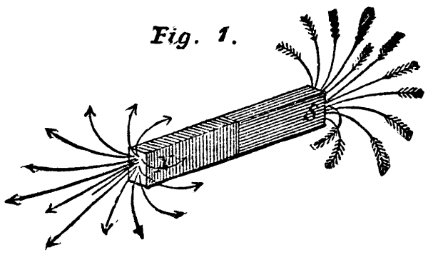
Fig. 1.
The last of these three principles, involving the relation of electric currents to the work they can do and to the energy expended in their production, will be treated of separately and later. Meantime we resume the task of showing how such currents can be produced mechanically, and how magnetism comes in in the process.
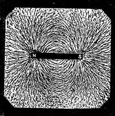
Fig. 2
Surrounding every magnet there is a "field" or region in which the magnetic forces act. Any small magnet, such for example as a compass needle, when brought into this field of force, exhibits a tendency to set itself in a certain direction. It turns so as to point with its north pole toward the south pole of the magnet, and with its south pole toward the north pole of the magnet; or if it cannot do both these things at once, it takes up an intermediate position under the joint action of the separate forces and sets in along a certain line. Such lines of force run through the magnetic "field" from one pole of the magnet to the other in curves. If we define a line of force as being the line along which a free north-seeking magnetic pole would be urged, then these lines will run from the north pole of the magnet round to the south pole, and pass through the substance of the magnet itself. In Fig. 1 a rough sketch is given of the lines of magnetic force as they emerge from the poles of a bar magnet in tufts. The arrow heads show the direction in which a free north pole would move. These lines of forces are no fiction of the imagination, like the lines of latitude and longitude on the globe; they exist and can be rendered visible by the simplest of expedients. When iron filings are sprinkled upon a card or a sheet of glass below which a magnet is placed, the filings set themselves--especially if aided by a gentle tap--along the lines of force. Fig. 2 is a reproduction from nature of this very experiment, and surpasses any attempt to draw the lines of force artificially. It is impossible to magnetize a magnet without also in this fashion magnetizing the space surrounding the magnet; and the space thus filled with the lines of force possesses properties which ordinary unmagnetic space does not possess. These lines give us definite information about the magnetic condition of the space where they are. Their direction shows us the direction of the magnetic forces, and their density shows us the strength of the magnetic forces; for where the force is strongest there we have the lines of force most numerous and most strongly delineated in the scattered filings. To complete this first consideration of the magnetic field surrounding a magnet, we will take a look at Fig. 3, which reproduces the lines of filings as they settle in the field of force opposite the end of a bar magnet. The repulsion of the north pole of the magnet upon the north poles of other magnets would be, of course, in lines diverging radially from the magnet pole.
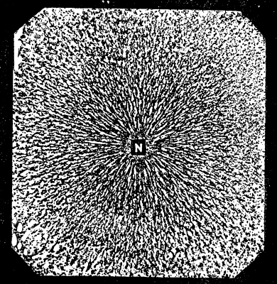
Fig. 3
We will next consider the space surrounding a wire through which a current of electricity is flowing. This wire has magnetic properties so long as the current continues, and will, like a magnet, act on a compass needle. But the needle never tries to point toward the wire; its tendency is always to set itself broadside to the current and at right angles to it. The "field" of a current flowing up a straight wire is, in fact, not unlike the sketch shown in Fig. 4, where instead of tufted groups we have a sort of magnetic whirl to represent the lines of force. The lines of force of the galvanic field are, indeed, circles or curves which inclose the conducting wire, and their number is proportional to the strength of the current. In the figure, where the current is supposed to be flowing up the wire (shown by the dark arrows), the little arrows show the direction in which a free north pole would be urged round the wire;[1] a south pole would, of course, be urged round the wire in the contrary direction. Now, though when we look at the telegraph wires, or at any wire carrying a current of electricity, we cannot see these whirls of magnetic force in the surrounding space, there is no doubt that they exist there, and that a great part of the energy spent in starting an electric current is spent in producing these magnetic whirls in the surrounding space. There is, however, one way of showing the existence of these lines of force; similar, indeed, to that adopted for showing the lines of force in the field surrounding a magnet. Pass the conducting wire up through a hole in a card or a plate of glass, as shown in Fig. 5, and sprinkle filings over the surface. They will, when the glass is gently tapped, arrange themselves in concentric circles, the smallest and innermost being the best defined because the magnetic force is strongest there. Fig 6 is an actual reproduction of the circular lines produced in this fashion by iron filings in the field of force surrounding an electric current.
[Footnote 1: It will not be out of place here to recall Ampere's ingenious rule for remembering the direction in which a current urges the pole of a magnetic needle. "Suppose a man swimming in the wire with the current, and that he turns so as to face the needle, then the north pole of the needle will be deflected toward his left hand."]
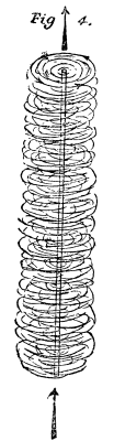
Fig. 4
This experimental evidence must suffice to establish two of the three fundamental points stated at the outset, for they prove conclusively that the electric current may be treated as a magnetic phenomenon, and that both in the case of the pole of a magnet, and in that of the wire which carries a current, a portion, at any rate, of the energy of the magnetic forces exists outside the magnet or the current, and must be sought in the surrounding space.

Fig. 5
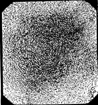
Fig. 6
Having grasped these two points, the next step in our argument is to establish the relation between the current and the magnet, and to show how one may produce the other.
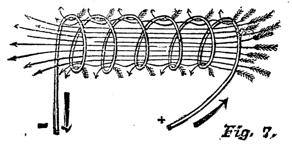
Fig. 7
If we wind a piece of copper wire into a helix or spiral, as in Fig. 7, and pass a current of electricity through it, the magnetic whirls in the surrounding space are modified, and the lines of force are no longer small circles wrapping round the conducting wire. For now the lines of force of adjacent strands of the coil merge into one another, and run continuously through the helix from one end to the other. Compare this figure with Fig. 1, and the similarity in the arrangement of the lines of force is obvious. The front end of the helix acts, in fact, like the north pole of a magnet, and the further end like the south pole. If a small bar of iron be now pushed into the interior of this helix, the lines of force will run through it and magnetize it, converting it into an electro-magnet. The magnetic "field" of such an electro-magnet is shown in Fig. 8, which is reproduced from the actual figure made by iron filings. To magnetize the iron bar of the electro-magnet as strongly as possible the wire should be coiled many times round, and the current should be as strong as possible. This mode of making an iron rod or bar into a powerful magnet is adopted in every dynamo-electric machine. For, as will be presently explained, very powerful magnets are required, and these magnets are most effectively made by sending the electric currents through spiral coils of wire wound (as in Fig. 8) round the bars that are to be made into magnets.

Fig. 8
The reader will at this point probably be ready to jump to the conclusion that magnets and currents are alike surrounded by a sort of magnetic atmosphere, and such a view may help those to whom the subject is fresh to realize how such actions as we have been describing can be communicated from one magnet to another, or from a current to a magnet. Nevertheless such a conclusion would be both premature and inaccurate. Even in the most perfect vacuum these actions still go on, and the lines of force can still be traced. It is probably more correct to conclude that these magnetic actions are propagated through space not by special magnetic atmospheres, but by there being movements and pressures and tensions in the ether which is believed to pervade all space as a very thin medium more attenuated than the lightest gas, and which when subjected to electro-magnetic forces assumes a peculiar state, and gives rise to the actions which have been detailed in the preceding paragraphs.
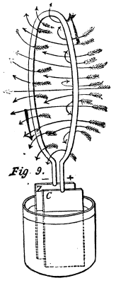
Fig. 9.
The next point to be studied is the magnetic property of a single loop of the wire through which an electric current flows. Fig. 9 represents a single voltaic cell containing the usual plates of zinc and copper dipping into acid to generate a current in the old-fashioned way. This current flows from the zinc plate through the liquid to the copper plate, and from thence it flows round the wire ring or circuit back to the zinc plate. Here the lines of magnetic force in the surrounding space are no longer only whirls like those drawn in Fig. 4 and 6, for they react on one another and become nearly parallel where they pass through the middle of the ring. The thick arrows show the direction of the electric current, the fine arrows are the lines of magnetic force, and show the paths along which a free north pole would be urged. All the front face, where the arrow-heads are, will be like the north pole of a magnet. All the other face of the ring will be like the south pole of a magnet. Our ring resembles a flat magnet, one face all north pole the other face all south pole. Such a magnet is sometimes called a "magnetic shell."[1]
[Footnote 1: The rule for telling which face of the magnetic shell (or of the loop circuit) is north and which south in its magnetic properties is the following: If as you look at the circuit the current is flowing in the same apparent direction as the hands of a clock move, then the face you are looking at is a south pole. If the current flows the opposite way round to the hands of a clock, then it is the north pole face that you are looking at.]
Since the circuit through which the current is flowing has these magnetic properties, it can attract other magnets or repel them according to circumstances.
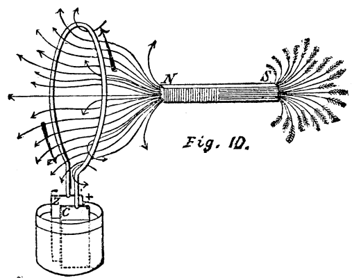
Fig. 10.
If a magnet be placed near the circuit, so that its north pole, N, is opposite that side of the circuit which acts as a south pole, the magnet and the circuit will attract one another. The lines of force that radiate from the end of the magnet, curve round and coalesce with some of those of the circuit. It was shown by the late Professor Clerk-Maxwell, that every portion of a circuit is acted upon by a force urging it in such a direction as to make it inclose within its embrace the greatest possible number of lines of force. This proposition, which has been termed "Maxwell's Rule," is very important, because it can be so readily applied to so many cases, and will enable one so easily to think out the actual reaction in any particular case. The rule is illustrated by the sketch shown in Fig. 10, where a bar magnet has been placed with its north pole opposite the south face of the circuit of the cell. The lines of force of the magnet are drawn into the ring and coalesce with those due to the current. According to Faraday's mode of regarding the actions in the magnetic field there is a tendency for the lines of force to shorten themselves. This would occur if either the magnet were pulled into the circuit, or the circuit were moved up toward the magnet. Each attracts the other, and whichever of them is free to move will move in obedience to the attraction. And the motion will in either case be such as to increase the total number of lines of force that pass through the circuit. Lest it should be thought that Fig. 10 is fanciful or overdrawn, we reproduce an actual magnetic "field" made in the manner described in the preceding article. Fig. 11 is a kind of sectional view of Fig. 10, the circuit being represented merely by two circular spots or holes above and below the middle line, the current flowing toward the spectator through the lower spot, and passing in front of the figure to the upper hole, where it flows down. Into this circuit the pole, N, is attracted, the tendency being to draw as many lines of force as possible into the embrace of the circuit.
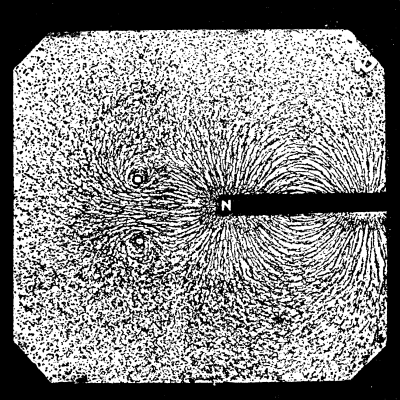
Fig. 11.
So far as the reasoning about these mutual actions of magnets and currents is concerned, it would therefore appear that the lines of force are the really important feature to be understood and studied. All our reasons about the attractions of magnets could be equally well thought out if there were no corporeal magnets there at all, only collections of lines of force. Bars of iron and steel may be regarded as convenient conductors of the lines of force; and the poles of magnets are simply the places where the lines of force run out of the metal into the air or vice versa. Electric currents also may be reasoned about, and their magnetic actions foretold quite irrespective of the copper wire that acts as a conductor; for here there are not even any poles; the lines of force or magnetic whirls are wholly outside the metal. There is an important difference, however, to be observed between the case of the lines of force of the current, and that of the lines of force of the magnet. The lines of force of the magnet are the magnet so far as magnetic forces are concerned; for a piece of soft iron laid along the lines of force thereby becomes a magnet and remains a magnet as long as the lines of force pass through it. But the lines of force crossing through a circuit are not the same thing as the current of electricity that flows round the circuit. You may take a I loop of wire and put the poles of magnets on each side of it so that the lines of force pass through in great numbers from one face to the other, but if you have them there even for months and years the mere presence of these lines of force will not create an electric current even of the feeblest kind. There must be motion to induce a current of electricity to flow in a wire circuit.
Faraday's great discovery was, in fact, that when the pole of a magnet is moved into, or moved out of, a coil of wire, the motion produces, while it lasts, currents of electricity in the coil. Such currents are known as "induced currents;" and the action is called magneto-electric "induction." The momentary current produced by plunging the magnet pole into the wire coil or circuit is found to be in the opposite direction to that in which a current must be sent if it were desired to attract the magnet pole into the coil. If the reader will look back to Fig. 10 he will see that a north magnet pole is being attracted in from behind into a circuit round which, as he views it, the current flows in an opposite sense to that in which the hands of a clock move round. Now, compare this figure with Fig. 12, which represents the generation of a momentary induced current by the act of moving the north pole, N, toward a wire ring, which is in this case connected with a little detecter galvanometer, G. The momentary current flows round the circuit (as seen by the spectator from the front) in the same sense as the movement of the hands of a clock. The induced current which results from the motion is found, then, to be in a direction exactly opposed to that of the current that would itself produce the same movement of the magnet pole. If the north pole, instead of being moved toward or into the circuit, were moved away from the circuit, this motion will also induce a transient current to flow round the wire, but this time the current will be in the same sense as that in Fig. 10, in the opposite sense to that in Fig. 12. Pulling the magnet pole away sets up a current in the reverse direction to that set up by pushing the pole nearer. In both cases the currents only last while the motion lasts.
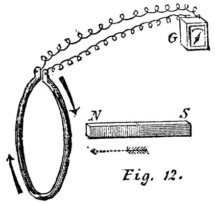
Fig. 12.
Now in the first article it was pointed out that the lines of force of the magnet indicate not only the direction, but the strength of the magnetic forces. The stronger the pole of the magnet is, the greater will be the number of lines of force that radiate from its poles. The strength of the current that flows round a circuit is also proportional to the number of lines of force which are thereby caused to pass (as in Fig. 9) through the circuit. The stronger the current, the more numerous the lines of force that thread themselves through the circuit. When a magnet is moved near a circuit near it, it is found that any alteration in the number of lines of force that cross the circuit is accompanied by the production of a current. Referring once more to Fig. 10, we will call the direction of the current round the circuit in that figure the positive direction; and to define this direction we may remark that if we were to view the circuit from such a point as to look along the lines of force in their own direction, the direction of the current round the circuit will appear to be the same as that of the hands of a clock moving round a dial. If the magnet, N S, be now drawn away from the circuit so that fewer of its lines of force passed through the circuit, experiment shows the result that the current flowing in circuit will be for the moment increased in strength, the increase in strength being proportional to the rate of decrease in the number of lines of force. So, on the other hand, if the magnet were pushed up toward the circuit, the current in the circuit would be momentarily reduced in strength, the decrease in strength in the current being proportional to the rate of increase in the number of lines of force.
Similar considerations apply to the case of the simple circuit and the magnet shown in Fig. 12. In this circuit there is no current flowing so long as the magnet is at rest; but if the magnet be moved up toward the circuit so as to increase the number of lines of force that pass through the circuit, there will be a momentary "inverse" current induced in the circuit and it will flow in the negative direction. While if the magnet were moved away the decrease in the number of lines of force would result in a transient "direct" current, or one flowing in the positive direction.
It would be possible to deduce these results from an abstract consideration of the matter from the point of view of the principle of conservation of energy. But we prefer to reserve this point until a general notion of the action of dynamo-electric machines has been given.
The following principles or generalized statements follow as a matter of the very simplest consequence from the foregoing considerations:
(a) To induce a current in a coil of wire by means of a magnet there must be relative motion between coil and magnet.
(b) Approach of a magnet to a coil or of a coil to a magnet induces currents in the opposite direction to that induced by recession.
(c) The stronger the magnet the stronger will be the induced currents in the coils.
(d) The more rapid the motion the stronger will be the momentary current induced in the coils (but the time it lasts will, of course, be shorter).
(e) The greater the number of turns in the coil the stronger will be the total current induced in it by the movement of the magnet.
These points are of vital importance in the action of dynamo electric generators. It remains, however, yet to be shown how these transient and momentary induction currents can be so directed and manipulated as to be made to combine into a steady and continuous supply. To bring a magnet pole up toward a coil of wire is a process which can only last a very limited time; and its recession from the coil also cannot furnish a continuous current since it is a process of limited duration. In the earliest machines in which the principle of magneto-electric induction was applied, the currents produced were of this momentary kind, alternating in direction. Coils of wire fixed to a rotating axis were moved past the pole of a magnet. While the coil was approaching the lines of force were increasing, and a momentary inverse current was set up, which was immediately succeeded by a momentary direct current as the coil receded from the pole. Such machines on a small scale are still to be found in opticians' shops for the purpose of giving people shocks. On a large scale alternate current machines are still employed for certain purposes in electric lighting, as, for example, for use with the Jablochkoff candle. Large alternate-current machines have been devised by Wilde, Gramme, Siemens, De Meritens, and others.--Engineering.
Dr. Odling delivered a lecture on the above before the Chemical Society, London, February 2, 1882.
The lecturer said that it had been found useful to occasionally bring forward various points of chemical doctrine, on which there were differences of opinion, to be discussed by the society. On this occasion he wished not so much to demonstrate certain conclusions, or to make a declaration of his opinions, as to invite discussion and a thoughtful consideration of questions of importance to chemists. Originally three questions were proposed: First, Is there any satisfactory evidence deducible of the existence of two distinct forms of chemical combination (atomic and molecular)? Second, Is the determination of the vapor density of a body alone sufficient to determine the weight of the chemical molecule? Third, In the case of an element forming two or more distinct series of compounds, e.g., ferrous and ferric salts, is the transition from one series to another necessarily connected with the addition or subtraction of an even number of hydrogenoid atoms? He would, however, limit himself to the first of these questions; at the same time the three questions were so closely associated with one another that in discussing the first it was difficult to know where to begin. The answer to this question (Is there any satisfactory evidence deducible of the existence of two distinct forms of chemical combination?) depends materially on the view we take of the property called in text-books valency or atomicity; and before discussing the question it is important to have a clear idea of what these words valency and atomicity really mean. It is necessary, too, to start with some propositions which must be taken for granted. These propositions are: First, that in all chemical changes, those kinds of matter which we commonly call elementary, do not suffer decomposition. Second, That the atomic weights of the elements as received are correct, i.e., that they do really express with great exactitude the relative weights of the atoms of the individual elements. If we accept these two propositions, it follows that hydrogen can be replaced atom for atom by other elements not only by the hydrogens but by alkali metals, etc. Hydrogen is, it may here be remarked, an element of unique character; not only can it be replaced by the elements of the widely different classes represented by chlorine and sodium, but it is the terminal of the series of paraffins, CnH2n; C3H6, C2H4, H2. The third proposition which must be taken for granted is, that the groups of elements, C2H5, CH3, behave as elements, and that these radicals, ethyl, methyl, etc., do not suffer decomposition in many chemical reactions.
Now as to valency or atomicity, accepting the received atomic weights of the elements, it is certain that there are at least four distinct types of hydrogen compounds represented by ClH, OH2, NH3, CH4. The recognition of these types, and their relations to each other as types, was one of the most important and best assured advances made in theoretical chemistry. When we compare the formula of water with that of hydrochloric acid, we find that there is twice as much hydrogen combined with one atom of oxygen as there is combined with one atom of chlorine; and in a great many other instances, we find that we can replace two atoms of chlorine by one atom of oxygen, so that we get an idea of the exchangeable value of these elements, and we say that one atom of oxygen is worth two of chlorine, or is bivalent; similarly, nitrogen is said to be trivalent. The meaning attached to the word "valency," is simply one of interchangeability, just as we say a penny is worth two halfpennies or four farthings. The question next arises, is the valency of an element fixed or variable? If the word be defined as above, it is absolutely certain that the valency varies. Thus, tin may be trivalent, SnCl2, or tetravalent, SnCl4. Accordingly elements have been classed as monads, dyads, triads, etc. The lecturer objected most strongly to the word "atomicity;" he could not conceive of one atom being more atomic than another; he could understand the atomicity of a molecule or the equivalency of an atom, but not the atomicity of an atom; the expression seemed to him complete nonsense. He next considered the possibility of assigning a fixed limit to this valency or adicity of an atom, and concluded that the adicity was not absolutely fixed, but was fixed in relation to certain elements, e.g., C never combines with more than four atoms of H; O never more than two atoms of H, etc. The adicity of an element when combined with two or more elements is usually higher than when combined with only one, e.g., NH3, NH4Cl. The term "capacity of saturation," may be used as a synonym for adicity, if care be taken to distinguish it from other kinds of saturation, such as an acid with an alkali, etc. Adicity is, however, quite distinct from combining force; the latter is indicated by the amount of heat evolved in the combination.
The lecturer then proceeded to criticise a statement commonly found in text books, that chemical combination suppresses altogether the properties of the combining bodies. The reverse of this statement is probably true. To take the case commonly given of the combination of copper and sulphur when heated; this is good as far as it goes, but there are numerous instances, as ClI, SSe, etc., where the original properties and characters of the combining elements do not completely disappear. The real statement is that the original properties of the elements disappear more or less, and least when the combination is weak and attended with the evolution of a slight amount of heat, and in every case some properties are left which can be recognized. So with reference to the question of atomic and molecular combination, as atomic combination does not necessarily produce change, it does not differ in this respect from what is usually called molecular combination.
The lecturer then referred to an important difference in the adicity of chlorine and oxygen. Chlorine can combine with methyl or ethyl singly. Oxygen can combine with both and hold them together in one molecule. The recognition of this fundamental difference between chlorine and oxygen, this formation of double oxides as opposed to single chlorides, marks an epoch in scientific chemistry.
The lecturer then considered the subject of chemical formulæ; it is the bounden duty of every formula to express clearly the number of atoms of each kind of elementary matter which enters into the constitution of the molecule of the substance. A formula may do much more than this. If we attempt to express too much by a complex formula we may veil the number of atoms contained in it. This difficulty may be avoided by using two formulæ, a synoptic formula giving the number of atoms present, and a complex formula perhaps covering half a page, giving the constitution of the molecule. But between the purely synoptic formula and the very elaborate formula there are others--contracted formulæ--which labor under the disadvantage, as a rule, of being one-sided, and so create a false impression as to the nature of the substance. Thus, for instance, to take the formula of sulphuric acid, H2SO4. This suggests that all the oxygen is united to the S; (HO)2SO2 suggests that two atoms of hydroxyl exist in the molecule; then, again, we might write the formula HSO2OH, or H2OSO3. All of these are justifiable, and each might be useful to explain certain reactions of sulphuric acid, but to use one only creates a false impression. The only plan is to use them variously and capriciously, according to the reaction to be explained. Again, ethyl acetate may be written--
          H_{3}C\
          H_{2}C/
                \
                 O
                /
              OC\
          H_{3}C/
Or condensed--
          H_{5}C_{2} \
                      }O
          H_{3}C_{2}O/
Or H5C2O.C2H3O, or H5C2.C2H3O2. Now each of these two latter formulæ is a partial formula, each represents a one-sided view; it is justifiable if you use both, but unfair if you use only one.
We now come to the question as to the existence or non-existence of two distinct classes of compounds, one in which the atoms are combined directly or indirectly with each other, and the other in which a group of atoms is combined as an integer with some other group of atoms, without any atomic connection by so-called molecular combination. These two modes of combination are essentially distinct. The question is not one of degree. Are there any facts to support this theory that one set of compounds is formed in one way, another in a different way? Take the case of the sulphates: Starting with SO3, we can replace one atom of O by HO2, and obtain SO2(HO)2 or H2SO4; replacing a second atom, we get SO(HO)4 or H4SO5, glacial sulphuric acid, a perfectly definite body corresponding to a definite class of sulphates, e.g., H2MgSO5, Zn2SO5, etc. By replacing the third atom of O we get S(HO)6 or H6SOH6; this corresponds to a class of salts, gypsum, H4CaSO6, etc. These are admitted without dispute to be atomic compounds. Are we to stop here? We may write the above compounds thus: H2SO4, H2SO4H2O, H2SO42H2O. If we measure the heat evolved in the formation of the two latter compounds, it is, for H2SO4+H2O, 6.272; H2SO4+2H2O, 3.092. But if we now take the compound H2SO4+3H2O we have heat evolved 1.744; so we can have H2SO44H2O, etc. Where are we to draw the line between atomic and molecular combination, and why? It comes to this: All compounds which you can explain on your views of atomicity are atomic, and all that you cannot thus explain are molecular. Similarly with phosphates, arsenates, etc. In all these compounds it is impossible to lay one's finger on any distinction as regards chemical behavior between the compounds called atomic and those usually called molecular.
Two points remain to be mentioned: The first is the relationship between alteration of adicity and two series (ous and ic) of compounds. Tin is usually said to be dyad in stannous compounds and a tetrad in stannic compounds, but in a compound like SnCl2AmCl, is not tin really a tetrad?
                 {Cl
                 {Cl
              Sn {Cl
                 {NH_{4}
and yet it is a stannous compound, and gives a black precipitate with H2S; so that valency does not necessarily go with the series. The second point is that an objection may be urged, as, for example, in ammonium chloride (the lecturer stated above that here N was a pentad, the addition of the chlorine having caused the N to assume the pentadic character), it may be said, why should you not suppose that it is the chlorine "which has altered its valency, and that the compound should be written:
                 {H
                 {H
               N { \
                 {H--Cl
                 {H/
There is something to be said for this view, but on the whole the balance of the evidence is in favor of nitrogen being a pentad.
In conclusion the lecturer stated that his principal object was to direct the attention of chemists, and especially of young chemists, to the question: Is there or is there not any evidence derived from the properties, the decompositions, or the relative stabilities of substances to warrant us in believing that two classes of compounds exist: one class in which there is interatomic connection alone, and another in which the connection is molecular?
Mr. Martenson, of St. Petersburg, who, it will be remembered, was one of the Russian delegates to the International Pharmaceutical Congress, has been analyzing a number of French preparations for the toilet, most of which are familiar to our readers, at any rate by name and repute.
1. Eau de Fleurs de Lys--(Planchon and Riet, Paris.)--An infallible banisher of freckles, etc., etc. The bottle contains 100 grammes of a milky fluid, made up of 97 per cent. of water, 2.5 per cent. of precipitated calomel, and a small quantity of common salt and corrosive sublimate, and scented with orange flower water.
2. Eau de Blanc de Perles.--The bottle contains 120 grammes of a weak alkaline solution, with a thick deposit of 15 per cent. of carbonate of lead, and scented with otto of roses and geranium.
3. Nouveau Blanc de Perle, Extra Fin.--(Lubin, Paris.)--The bottles contains 35 grammes of a liquid consisting of water, holding in suspension about equal parts of zinc oxide, magnesic carbonate, and powdered talc, perfumed with otto of roses.
4. Lait de Perles.--A close imitation of No. 3, the bottle holding nearly three times the quantity for the same price. The amount of the precipitate in this case is 20 per cent.
5. Lait de Perles.--(Legrand, Paris).--The bottles contain 65 grammes of a thick white fluid, the precipitate from which consists of zinc oxide and bismuth oxychloride, and is scented with rose water.
6. Lait Antiphélique.--(Candès and Co., Paris.)--Each bottle contains 140 grammes of a milky fluid, smelling strongly of camphor, and having an acid reaction. It contains alcohol, camphor, ammonic chloride, half per cent. of corrosive sublimate, albumen, and a little free hydrochloric acid.
7. Lait de Concombres.--The bottle contains 160 grammes of a very inelegantly made emulsion, smelling of very common rose-water, with an unpleasant twang about it, and giving a strongly alkaline reaction. It consists of soap, glycerin, and cotton seed oil, made into a semi-emulsion.
8. Crême de Fleurs des Lys; Blanc de Ville Onctueux.--About 30 grammes of a kind of weak ointment contained in a small pomatum pot prettily ornamented. It is simply a salve made of wax oil, and possibly lard, mixed with a large proportion of zinc oxide, and smelling of inferior otto of roses.
9. Páte de Velonas.-This paste consists of almond, and possibly other meal mixed with soap powder, and has a strong alkaline reaction. It is scented with orris-root.
10. Rouge Végétal.--The box contains 8½ grammes of raspberry colored powder, consisting chiefly of China clay and talc, tinted to the proper depth with extract of cochineal.
11. Rouge Extra Fin Foncé.--A small square bottle containing 11 grammes of a deep red solution, smelling of otto of roses and ammonia. It consists of a solution of carmine in ammonia, with an addition of a certain amount of alcohol.
12. Rouge de Dorin.--Extract des Fleurs des Indes.--A round pot containing a porcelain disk, covered with about 6 grammes of a bright red paste, which is a mixture of carthamin or safflower with talc. This rouge, which differs from all the others, is harmless and effectual, but must bear a high profit seeing that the ingredients cost only a few half-pence, while it sells in St. Petersburg at about 4s. 9d. a pot.
13. Etui Mystérieux ou Boite de Maintenon.--A prettily got-up box containing red and white paint, and two sticks of black and blue cosmetic for the eyebrows and veins, with camel's hair pencils for applying the latter. Sells in St. Petersburg at 6s. 4d.
14. Philidore.--Remède Specifique pour oter les Pellicules de la tête, etc.--The bottle contains 100 grammes of a strong alkaline solution smelling strongly of ammonia, and containing potash, ammonia, alcohol, glycerin, and eau de cologne.
15. Colorigène Rigaud.--A blue bottle containing 160 grammes of a clear fluid with a slight black deposit, consisting of a mixture of equal parts of a 14 per cent. solution of sodic hyposulphate, and a 4 per cent. solution of lead acetate. Of course the longer this solution is kept the more lead sulphate it deposits. It sells in St. Petersburg at 8s. per bottle. It is also stated to be much more powerful if used in conjunction with the Pommade Miranda Rigaud. This beats Mrs. Allen completely out of the field.--Pharmaceutische Zeitschrift für Russland.
We translate the following important article, says the Chemists' Journal, from the Moniteur Scientifique of last month. It may be explained for the sake of our student readers that the word mydriatic is derived from the Greek mudriasis, which means paralysis of the pupil.
The synthetical researches which I have undertaken with a view to explain the constitution of atropine have shown me the necessity of studying the connection of atropine with the other alkaloids, which have an analogous physiological action. According to the early researches we could not discover any of these relationships which only become evident when we come to study the new discoveries which have been made in connection with the tropines, to which class belong both duboisine and hyoscyamine, which, although differing from atropine, are equally mydriatic in their action.
Discovered by Mein in 1831 in the roots of belladonna. More thoroughly studied some time after by Geiger and Hesse, who confirmed Mein's results. Liebig next published an analysis of the alkaloid, which was afterward shown to be incorrect. He consequently modified his formula, and gave the following as the composition of atropine; C17H23NO3. Liebig's amended analysis was afterward confirmed by Planta, who further showed that the alkaloid itself melted at 194° F., and its double gold salt at 275° F. It is worthy of remark that the first figure was considered correct until my researches proved the contrary. The physiological action of atropine, especially in relation to the eye, has been most carefully studied by several celebrated ophthalmologists, such as Graef, Donders, Bezold, and Bloebaum. Its chemical properties have also been the object of very extensive researches by Pfeiffer, Kraut, and Lassen. Pfeiffer first discovered that benzoic acid was one of the products of decomposition of atropine, and Kraut split atropine by means of baryta water into atropic acid, C9H6O2, and tropine, C8O15NO. Lassen, who used hydrochloric acid, discovered the true products of the splitting up of atropine, viz., tropic acid, C9H8O3, and tropine, C8H15N, and proved at the same time that atropic acid is easily formed by the action of boiling baryta water on tropic acid, while hydrochloric acid at all temperatures forms isatropic acid, an isomer of atropic acid. Kraut confirmed these results, and showed that atropic acid as well as cinnamic acid gives benzoic acid by oxidation, and hydratropic acid (the isomer of phenylpropionic acid) by reduction with sodium amalgam. These results are sufficient to show that tropic acid may have one of the following two formulae.
          I                       II


         CH_{2}OH                    CH_{3}
        /                         /
C_{4}H_{5}CH           or    C_{8}H_{5}--C--OH
        \                         \
         OOHO                      COOH
Fittig and Wurster, who discovered atrolactic acid, C2H10O3, an isomer of tropic acid, gives tropic acid the second formula, while Burgheimar and myself have shown that it is the true formula of atrolactic acid. Lately we have succeeded in performing the complete synthesis of atropic acid, and the artificial preparation of atropine has been greatly facilitated since I have shown that we can easily reconstruct atropine by starting from its products of decomposition, tropic acid, and tropine.
Before my researches nothing was known of the constitution of tropine. New unpublished researches into this problem have shown that it closely resembles neurine,[1] a body which I hope will speedily lead us to the complete synthesis of atropine.
[Footnote 1: As we shall probably hear a great deal about this alkaloid, it may be as well to state that, although found in the brain and liver, it may be prepared synthetically by the action of ethylene oxide, (CH2)2O, water, H2O, and trimethyiamine, N(CH3)3. Its constitution is that of trimethyl-ethylene-hydrate-ammonic-hydrate, and has the following constitutional formula:
   { (CH_{2})_{2}OH
   { CH_{3}
N  { CH_{3}
   { CH_{3}
   { OH
or in other words, it is the hydrate of trimethyl-hydrethylene-ammonium.]
The fusing point of atropine is not 194° F., as stated by Planta, but 237° F. Crystallized from not too dilute alcohol it forms crystals which are aggregations of prisms. Toluene, alcohol, and chloroform all dissolve atropine readily. Its double gold salt is very characteristic. It is generally precipitated in the form of an oil which solidifies rapidly and may be crystallized from hot water after the addition of a little hydrochloric acid. This clouds in cooling, and after a certain time it separates in small crystals of indeterminate form which unite in warty concretions. After drying the salt forms a dull powder, melting between 275° F. and 280° F. It also melts in boiling water, and its aqueous solution exposed to the light is partially reduced, 100 grammes of water acidulated with 10 cubic centimeters of 1.190° solution of hydrochloric acid dissolves 0.137 gramme of the gold salt at 136° F. to 140° F.
I should fancy that the above particulars are sufficent to completely differentiate atropine from all the other mydriatic alkaloids.
Planta has already tried to show that atropine is identical with the daturine obtained by Geiger and Hesse, founding his opinion on facts which we nowadays look upon as doubtful. This identity was generally admitted by all chemists. The pharmacologists, headed by Soubeiran, Erhardt, Schroff, and Poehl, were much more reserved in their judgment. I thought it as well, therefore, to recommence the study of daturine, the more so as I had already determined the incorrectness of the long accepted point of fusion of atropine, and that my researches on hyoscyamine convinced me that this base is an isomer of atropine, although very analogous to it. I have also shown that Merck's daturine differs from atropine, and is merely pure hyoscyamine. A short time afterward there appeared a paper by Schmidt which again asserted the identity of daturine and atropine. I therefore requested Mr. Merck, of Darmstadt, to send me all the bases which he obtained from datura. This eminent manufacturer was good enough to comply with my request, and sent me two products, one of which was marked "light daturine," the other "heavy daturine," the separation of which was effected in the following manner: The solution of crude daturine in concentrated alcohol was mixed with a little hot water; this treatment caused the deposition of the "heavy daturine," while the "light daturine" remained in the mother liquor. The "heavy daturine," of which only a small quantity is obtainable, is far from being a body of definite composition, that is to say, it is a mixture of atropine and hyoscyamine. If we convert the base into a double gold salt we obtain by a single crystallization a dull looking salt, melting at from 275° F. to 280° F., the appearance of which is very different to that of atropine. I have succeeded in splitting up "heavy daturine" by two different methods. By recrystallizing the gold salt six times from boiling water, the salt of hyoscyamine, which melts at from 316° F. to 323° F., crystallizes our first, and by the successive evaporation of the mother liquor at last obtain the pure gold salt of atropine, which melts at 275° F. to 280° F. If we only want to isolate the atropine, it is better to crystallize the free base two or three times from alcohol at 50 per cent., always taking the earliest formed crystals.
These facts prove the presence of atropine in datura; but while Planta and Schmidt assert that only this alkaloid is found in the plant, I have proved that the proportion of atropine in it is but small, while its richness in hyoscyamine is great. I think, therefore, that both Planta and Schmidt must have worked with a mixture of atropine and hyoscyamine. It is true that Schmidt had received pure atropine under the name of daturine, for I have proved most conclusively that the so-called daturine supplied by Trommsdorff, of Erfurt, is pure atropine and nothing else. It has no action whatever on polarized light.
Discovered by Geiger and Hesse in 1833. It was first obtained in the form of needles, which were much more soluble than atropine. In the pure state it forms a viscous mass with a repulsive odor. These researches were repeated by Thibout, Kletinski, Ludwig, Lading, Bucheim, Wagymar, and Renard.
Hoehn and Reichardt have recently studied hyoscyamine in a very complete manner. They have obtained the body in the form of warty concretions as soft as wax, and melting at 194° F., having a formula according to them of C15H23NO3. They have also studied the splitting up of the alkaloid by means of baryta water, and have obtained an acid which they have named hyoscinic acid, and which melts at about 219° F., and a basic body, hyoscine, C6H13N. They represent the reaction as follows:
C15H23NO3 = C9H10O3 + C6H13N.
According to this view hyoscyamine ought to be the hyoscinate of hyoscine, or at any rate an isomer of this body. It is to be remarked that they compare hyoscinic acid not with tropic acid, of which it possesses the composition, but with atropic acid, C9H8O2. I have worked with the hyoscyamine of both Merck and Trommsdorff, as well as with a product which I obtained from hyoscyamus seeds myself. The best way of purifying the alkaloid is by recrystallizing its gold salt several times, so as to obtain it in brilliant yellow plates, melting at 320° F. By passing a stream of hydrosulphuric acid gas through the liquor the gold is precipitated in the form of sulphide. The liquid is filtered and evaporated, precipitated by an excess of a strong solution of potassium carbonate, and the alkaloid extracted by chloroform. The solution is dried over carbonate of potassium, and part of the chloroform is distilled off. By leaving the solution to evaporate spontaneously the alkaloid is obtained in silky crystals. The crystals are then dissolved in alcohol, which, on being poured into water, parts with them in the same form.
Hyoscyamine crystallizes in the acicular form, with greater difficulty even than atropine, it also forms less compact crystals. Its fusing point is 149.6° F. I have not yet succeeded in crystallizing any of its more simple salts. The double platinum salt melts at 392° F., with decomposition. The double gold salt, which has been described above, does not melt in boiling water, and its aqueous solution is reduced neither by boiling nor by long exposure to light. By leaving the hot saturated solution to cool it does not cloud, but the double salt separates pretty rapidly in the form of plates.
One liter of water containing 10 cubic centimeters of hydrochloric acid at 1.19° dissolves 65 centigrammes of the salt at 146° F.
These characteristics allow us to differentiate atropine and hyoscyamine, the reactions of which are almost identical, as will be seen from the following table, which shows the action of weak solutions of the acids named on the hydrochlorates of the bases:
_Reagents_.         _Hyoscyamine_.        _Atropine_.


Picric acid.        An oil solidifying    Crystalline precipitate.
                    immediately into
                    tabular crystals.


Mercuropotassic     White cheesy          Same.
iodide.             precipitate.


Iodized potassic    An immediate          A brown oil crystallizing
iodide.             precipitate of        after a time.
                    periodate.


Mercuric chloride.  Same as picric acid.  Same.


Tannic acid.        Slight cloud.         Cloud hardly visible.


Platinum chloride.  O.                    O.
(To be continued.)
The solution of morphia, free from foreign bodies, is evaporated to dryness, and the residue is heated on the water bath with a few drops of sulphuric acid. A minute crystal of ferrous sulphate is then added, bruised with a glass rod, stirred up in the liquid, heated for a minute longer, and poured into a white porcelain capsule, containing 2 to 3 c.c. strong ammonia. The morphia solution sinks to the bottom, and where the liquids touch there is formed a red color, passing into violet at the margin, while the ammoniacal stratum takes a pure blue. The reaction is very distinct to 0.0006 grm. Codeine does not give this reaction. If sulphuric acid at 190° to 200° is allowed to act upon morphia, there is ultimately formed an opaque black green mass. If this is poured dropwise into much water, the mixture turns bluish, and if it is then shaken up with ether or chloroform, the form takes a purple and the latter a very permanent blue. Codeine gives the same reaction, but no other of the alkaloids. This reaction can be obtained very distinctly with 0.0004 grm. of morphia.
[Footnote: From Jernkontorets Annaler, vol. xxxvi.--Iron.]
If we dissolve black oxide of manganese, permanganate of potash, or any other compound of manganese of a higher degree of oxidation than the protoxide in hydrochloric acid, we obtain, as is well known, a dark colored solution of perchloride of manganese, which, when heated to boiling loses color pretty rapidly, chlorine being given off, until finally only protochloride remains. This decomposition also proceeds at the common temperature, though much more slowly, and we may therefore say that manganese when dissolved in hydrochloric acid always tends to descend to its lowest, and, considered as a base, strongest degree of oxidation, which is not raised to a higher degree even by chameleon solution. In slightly acid, neutral, or alkaline solutions on the other hand, protoxide of manganese absorbs oxygen with great avidity and forms with it different compounds, according to the means of oxidation employed. Thus, for example, manganese is slowly deposited from an ammoniacal solution, when it is permitted to take up oxygen from the air, as hydrated sesquioxide, and from neutral or alkaline solutions, as hydrated peroxide on the addition of chlorine, bromine, or chameleon solution. For if to an acid solution of protochloride of manganese we add a solution of bicarbonate of soda, as long as carbonic acid escapes or till the free acid is saturated and the protochloride of manganese converted into carbonate of protoxide of manganese, which forms with bicarbonate of soda a soluble double salt, resembling the carbonate of lime and magnesia, we obtain a solution which is, indeed, acid from free carbonic acid, but has a slight alkaline reaction with litmus paper, and with the greatest ease deprives chameleon solution of its color, the permanganic acid being reduced and the protoxide of manganese being oxidized to peroxide, which is precipitated as hydrate. This reaction proceeds according to the formula,
3MnCO3 + 2KMnO4 + H2O = 2KHCO3 + 5MnO2 + CO2
and it may be employed for estimating the content of manganese by titration. As follows from the formula two equivalents of permanganate of potash are required for the titration of three equivalents of protoxide of manganese, which has also been established by direct experiments, as well as that the escape of carbonic acid indicated by the formula actually takes place. The precipitate of manganese is dissolved either in water to which 0.5 per cent. of hydrochloric acid has been added, or in boiling nitric acid. When manganese occurs along with iron, which in general is the case, we must take care that the iron in the solution is in the state of peroxide, which is precipitated on the addition of the bicarbonate of soda, and is allowed to remain as a precipitate, because it does not affect the titration injuriously. The removal of this precipitate by filtering would be more loss than gain, partly because there would be a risk of losing manganese in this way, partly because the precipitate of manganese, which occurs immediately on the addition of the chameleon solution, proceeds both more rapidly and with greater completeness in the presence of the iron precipitate than otherwise. This appears to be caused by the iron precipitate as it were inclosing, and mechanically drawing down the light manganese precipitate, provided a weak chemical union between the two precipitates does not even take place, depending on the tendency of peroxide of manganese to behave toward bases, as, for instance, hydrate of lime as an acid. Hence it thus follows that it ought to be arranged that a sufficient quantity of iron[1] (at least the same quantity as of manganese) be present in the liquid at titration, also that time be given for the precipitate to fall, so that the color of the solution may be observed between every addition of chameleon solution.
[Footnote 1: For this in case of need a solution of perchloride of iron free of manganese may be employed.]
When the content of manganese is large, it is sometimes rather long before the solution is ready for titration. The reason of this appears to be that a part of the manganese is first precipitated as hydrated sesquioxide, which is afterward oxidized to hydrated peroxide, for the upper portion of the liquid may sometimes be colored by chameleon, while the lower portion, which is in closer contact with the precipitate, is less colored or absolutely colorless. From this we also see how advisable it is to stir the liquid frequently during titration. Toward the close of it, it is also advantageous, when the contents of manganese are large, to warm the solution to about 50° C., because the removal of color is thereby hastened. When the fluid, which is well stirred after each addition of chameleon, has obtained from it a perceptible color, which does not disappear after several stirrings, the whole of the manganese is precipitated and the color of the solution remains almost unchanged after the lapse of at least twelve hours.
When the content of manganese is large the solution may be divided into two equal portions, one of which is first to be roughly titrated to ascertain its content approximately, after which the whole is to be mixed together and the titration completed, which can thus be performed with greater speed and certainty. If too much chameleon has been added, one may titrate back with an accurately estimated solution of manganese, which is prepared most easily by evaporating fifteen cubic centimeters chameleon solution down to two or three cubic centimeters, boiling with two to three cubic centimeters hydrochloric acid so long as the smell of chlorine is observed, and then diluting the solution to ten cubic centimeters, when one cubic centimeter of it corresponds to the same measure of chameleon.
With respect to the delay which must take place during the titration in order to give the precipitate time to fall, it is advantageous, in order to save time, to work with several samples; but it is, in such a case, desirable to have a separate burette for each sample, in order to avoid noting every addition of the chameleon solution and afterward adding them up. If burettes are wanting, and one must be used for several samples, a Mohr's burette with glass cock is the most convenient to use. For the titration of iron with chameleon solution, the latter is commonly used of such a strength that 0.01 gramme of iron corresponds to about one cubic centimeter of chameleon solution, which is obtained by dissolving 5.75 grammes permanganate of potash in 1,000 cubic centimeters water. The titration is determined by means of iron, a salt of iron or oxalic acid. A drop of such a solution, corresponding to about one-twentieth cubic centimeter, or 0.0001 gramme Mn, is sufficient to give a perceptible reddish color to 200 cubic centimeters of water.
As what takes place in the titration of iron with chameleon is indicated by the following formula,
10FeO + 2KMnO4 = 5Fe2O3 + K2O + 2MnO2,
it appears, on making a comparison with the formula given above, that ten equivalents of iron correspond to three equivalents of manganese, and that there is thus required for three equivalents manganese as much chameleon solution as for ten equivalents iron. When we know the titration of the chameleon solution for iron, that for manganese is obtained by multiplying the former by (3 x 55)/(10 x 56) =0.295. If, for instance, one cubic centimeter chameleon solution corresponds to 0.01 gramme iron, the figure for manganese is 0.01 x 0.295 = 0.00295 gramme per cubic centimeter.
We can of course also determine the titration for manganese in a chameleon solution with the greatest certainty by titrating a compound of manganese with an accurately estimated content of it, for instance, a spiegeleisen or ferromanganese; the test is carried out in the following way: The substance, which is to be examined for manganese, is dissolved by means of hydrochloric acid. If the manganese, as in slags, be combined with silica, it is frequently necessary first to fuse the specimen with soda. Iron ores and refinery cinders may indeed, if they are reduced to a very fine state of division, be commonly decomposed by boiling with hydrochloric acid with or without the addition of sulphuric acid, but the undissolved silica is generally rendered impure by manganese, which can only be removed by fusion with soda.
The dissolving of the fused mass in hydrochloric acid does not need to be carried to dryness for the separation of the soluble silica, but the boiling, after the addition of a little nitric acid, is only kept up until the iron passes into perchloride and the manganese into protochloride. The quantity, which ought to be taken for the test, depends on the accuracy with which it is desired to have the manganese estimated.
Of ferromanganese and other very manganiferous substances, in which the manganese need not be determined with greater exactness than to 0.1 per cent., only 0.01 gram. is taken for a test; but of common pig, wrought iron, steel, iron ore, slags, etc., there is taken 0.5 to 1 gramme according to the supposed content of manganese and the desired exactness of the estimation. For instance one gramme iron, which has passed through a metal sieve with holes half a millimeter in diameter, is placed in a beaker 125 mm. in height and 60 mm. in diameter, and has added to it twenty cubic centimeters of hydrochloric acid of 1.12 specific gravity, which, with a well-fitting glass cover, is boiled for half an hour, in order that the combined carbon may be driven off in the shape of gas. After at least the half of the hydrochloric acid has been boiled away, there are added at least five cubic centimeters nitric acid of 1.2 specific gravity, partly to bring the iron to peroxide, partly to destroy the organic matters formed from the carbon, which might possibly be remaining and might tend to remove the color of the chameleon solution. The boiling is now continued till near dryness, when five cubic centimeters hydrochloric acid are added, after which the solution is boiled as long as any reddish-yellow vapors of nitrous acid are observed. When these have disappeared a drop of the liquid taken up on a small glass rod is tested with an newly prepared solution of red prussiate of potash (2 grammes in 100 cubic centimeters water), to ascertain whether there is any protoxide of iron remaining. First, when no indication of blue or green is visible, the test shows a pure yellow, it is certain that there are no reducing substances in the solution.
If a trace of protoxide of iron remains in the solution another cubic centimeter of nitric acid ought to be added and the boiling continued so long as any reddish-yellow vapors are visible, more hydrochloric acid also being added to keep the solution from being dried up. The process is continued in this way until two tests have given no reaction of protoxide of iron, when the solution is diluted with water; but no dilution should take place until the oxidation is complete, because in the course of it the solution ought to be kept as concentrated as possible. Silica, and graphite when it is present, need not be removed by filtration, if it is not intended to estimate them, or there be no fear that the graphite is accompanied by any humous substance, or that any oily, viscous compound has been deposited on the sides of the beaker. In the last mentioned case the solution should be transferred into another beaker, and filtered, if graphite be present. When the solution is evaporated to dryness, the remainder has five cubic centimeters hydrochloric acid added to it, and the liquid is then brought to boiling in order that the perchloride of manganese possibly formed during the evaporation to dryness may be reduced to protochloride, after which the solution is diluted with water till it measures about 100 cubic centimeters. To this is now added in small portions and with constant stirring as much of a saturated solution of bicarbonate of soda (thirteen parts water dissolve one part salt), that all the iron is precipitated, after which, when the escape of carbonic acid has ceased, the solution is diluted with water till it measures 200 cubic centimeters and is then ready for titration.
A large excess of bicarbonate ought to be avoided, because in a solution of pure protochloride of manganese it renders the liquid milky and turbid; the addition of more water, however, makes it clear. The solution of bicarbonate must be free from organic substances which may tend to remove the color of the chameleon solution. To ascertain this, the latter is added to the former drop by drop so long as the color is removed.
If it be desired to estimate the silica in the same test, the iron, as when it is analyzed for silica, may be also dissolved in sulphuric acid, and afterward oxidized with nitric acid, after which the solution is boiled to near dryness, so that the organic substances are completely destroyed. In order afterward, to drive off the nitric acid and get the manganese with certainty reduced to protoxide, the solution is boiled with a little hydrochloric acid. In this way the solution goes on rapidly and conveniently, but the titration takes longer time than when the iron is dissolved in hydrochloric acid, because the iron precipitate is more voluminous, and, in consequence, longer in being deposited. To diminish this inconvenience the solution ought to be made larger. In such a case the rule for dissolving is, one gramme iron (more if the content of silica is small) is dissolved in a mixture of two cubic centimeters sulphuric acid of 1.83 specific gravity and twelve cubic centimeters of water in the way described above, and boiled until salt of iron begins to be deposited on the bottom of the beaker. Five cubic centimeters hydrochloric acid are now added, and the solution tested with red prussiate of potash for protoxide of iron, and the boiling continued till near dryness, when all the nitric acid is commonly driven off. Should nitrous acid still show itself, some more hydrochloric acid is added and the boiling continued.
As in dissolving in hydrochloric acid and oxidizing with nitric acid the solution ought to be twice tested for protoxide of iron, even although at the first test none can be discovered. The silica is taken upon a filter, dried, ignited, and weighed. The filtrate is treated with bicarbonate of soda, and titrated with chameleon solution in the way described above. If the content of manganese is small (under 0.5 per cent.) it is not necessary to warm the liquid before titration; but in proportion as the content of manganese is larger there is so much greater reason to hasten the removal of color by warming and constant stirring toward the close of the titration.
[Footnote: Read before the American Chemical Society, Dec. 16, 1881]
The element manganese having many peculiarities in its reactions with the other elements, is now extensively used in the arts, its combinations entering into and are used in many of the important processes; it is consequently often brought before the chemist in his analysis, and has to be determined in most cases with considerable accuracy. Many methods have been proposed for this, all of them of more or less value; those yielding the best results, however, requiring a considerable length of time for their execution, and involving so large an amount of manipulatory skill as to render them fairly impracticable to a chemist at all pressed for time, and receiving but a mere trifle for the results.
As I have had to make numerous estimations of manganese in various compounds, as a public analyst, I have been induced to investigate the volumetric methods at present in use to find their comparative values, and if possible to work out a new one, setting aside one or more of the difficulties met with in the use of the older ones. This paper is a part summary of the results. First, I will detail my process of estimation, then on the separation.
From all compounds of manganese, excepting those containing cobalt and nickel, the manganese is precipitated as binoxide; those containing these two elements are treated with phosphoric acid, or as noted under Separation.
A.--The Estimation. The binoxide of commerce, as taken from the mine, is well sampled, powdered, and dried at 100°C. 0.5 gramme of this is taken and placed in a 250 c.c. flask; in analysis the binoxide on the filter, from the treatments noted under separation is thoroughly washed with warm water; it is then washed down in a flask, as above, after breaking the filter paper; sufficient water is added to one-third fill the flask, and about twice the approximate weight of the binoxide in the flask of oxalate of potassa; these are agitated together. A twice perforated stopper is fitted to this flask, carrying through one opening a 25 c c. pipette nearly filled with sulphuric acid, sp. gr. 1.4, the lower point of which just dips below the mixture in the flask, and the upper end, carrying a rubber tube and pinch cock to control the flow of acid. Through the other opening passes a glass tube bent at an acute angle and connected by a short rubber tube to an adjoining flask, two-thirds filled with decinormal baryta solutions. These connections are all made air tight. Sulphuric acid is allowed in small portions at a time to flow into the mixture. Carbonic acid is evolved, and, passing into the adjoining flask, is absorbed by the baryta, precipitating it as carbonate. To prevent the precipitate forming around or choking up the entrance tube, the flask must be agitated at short intervals to break it off. The reaction so familiar to us in other determinations is expressed thus:
MnO2+KO,C2O3+2SO3 = MnO,SO3+KO.SO3+2CO2,
When no more carbonic acid is evolved, another tube from this last flask is connected with the aspirator, the pinch-cock of the pipette open, and air drawn through the apparatus for about half a minute, and thus all the carbonic acid evolved absorbed, or the flasks may be slightly heated. If danger of more carbonic acid being absorbed from the air is feared, and always in very accurate analysis, a potassa tube may be connected to the pipette before drawing the air through. The precipitate formed is allowed to settle, 50 c.c. of the supernatant solution is removed with a pipette and transferred to a beaker; 50 c.c. of decinormal nitric acid and some water is added with sufficient cochineal tincture. It is then titrated back with decinormal soda; from this is now readily deducted the amount of carbonic acid, and from that the MnO2, holding in view that 44 parts of carbonic acid is equivalent to 43.5 of MnO2 or 98.87 per cent, and that 1 c.c. of the N/10 baryta solution is equivalent to 0.0022 grm. of CO2.
If a carbonate, chloride, or nitrate, be present in the native binoxide, it must be removed with some sulphuric acid. This is afterward neutralized with a little caustic soda. This method yields the following results for its value in amount of manganese to 100: 99.91-99.902-99.895, and can be executed in about twenty minutes. Fifteen determinations can be carried on at once without loss of time, this, however, depending on the operator's skill. I have made many assays, and assays by this method with similarly excellent results.
Of the other methods, Bunsen's is acknowledged to be the most accurate, but is, of course, too troublesome to be used in technical work, although it is used in scientific analysis. Ordinary samples are not sufficiently accurate to allow the use of this method.
The methods of reducing with iron and titrating this with chromate of potassa, etc., have given a constant average of from 98.60-99.01. These results are fair, but hard to obtain expeditiously.
Of the methods of precipitating the compounds of the protoxide and estimating the acid, that of the phosphate is by far the most accurate, titrating with uranium solution; 99.82 is a nearly constant average with me, much depending on the operator's familiarity with the uranium process.
The methods of Lenssen, or ferricyanide of potassium method, yields very widely differing results. I have found the figures of Fresenius about the same as my own in this case; that is from 98.00-100.10.
B.--On the Separation. First, from its soluble simple combinations with the acids or bases containing no iron or cobalt; if they are present, it is treated as is noted later. If sulphuric acid is present it must be separated by treating the solution of the compound with barium chloride and filtering. A nearly neutral solution is prepared in water or hydrochloric acid and placed in a flask. Here it is treated with chlorine by passing a current of that gas through it as long as it causes a precipitate and for some time afterward. It is then discontinued, the mixture allowed to deposit for a few moments, and about two-thirds of the supernatant solution decanted; it is mixed with some more water, and these decantations repeated until they pass away without reaction, or by filtering it and washing on the filter; it is then dissolved in hot hydrochloric acid, this nearly neutralized, a solution of sesquichloride of iron is added, and again treated with an excess of chlorine. After washing it is transferred to the flasks of the apparatus mentioned in the first part of this paper, and estimated. Myself and several others have found this always to be a true MnO2, and not a varying mixture of protosesquioxide and binoxide, and will thus yield accurate results. This reprecipitation may sometimes be dispensed with by adding the iron salt before the first precipitation, but it of course depends upon the other elements present.
From Compounds containing Cobalt, Cobalt and Nickel, Iron and group III., together or with other elements.--Group III. and sesqui. iron are separated by agitation with baryta carbonate, some chloride of ammonia being added to prevent nickel and cobalt precipitation traces, and filtering. If cobalt is present we treat this filtrate with nitrite of potassa, etc., to separate it (that is, if it and nickel are to be separated and estimated in the same sample; but if they are to be estimated as one, or not separated, the treatment with nitrite, etc., is not used). The filtrate from this last is directly treated with chlorine. If nickel and cobalt are not to be estimated in this sample, the solution, as chlorides, is mixed with some chloride of ammonium and ammonia, then with a fair excess of phosphoric acid, a sufficient quantity more of ammonia to render the mixture alkaline. The precipitate formed is transferred to the filter and well washed with water containing NH3Cl and NH4O, then dissolved in hydrochloric acid and reprecipitated with ammonia, filtering and washing as before. It is again dissolved in HCl and titrated with uranium solution, or decomposed by tin, as noted below, and the manganese precipitated as binoxide with chlorine, and determined. The latter method is hardly practicable, and I never have time to use it, as the titration and all together yields a value of 99.80 in most cases, if accurately executed.
From the bases of groups V. and VI. these are separated by hydrogen sulphide, from iron in alloys, ores, etc., and in general the iron is separated as basic acetate, and the manganese afterward precipitated with chlorine. Bromine is generally used in place of chlorine, the use of which chemists claim as troublesome; but in a number of examinations I have found it to yield more satisfactory results than bromine, which is much more expensive.
From the acids in insoluble and a few other compounds, chromic, arsenic, and arsenious acids, by fusion with carbonate of soda in presence of carbonic acid gas; borate of manganese is readily decomposed when the boracic acid is to be determined by boiling with solution of potassa, dissolving the residue in hydrochloric acid and precipitating the manganese as binoxide. This boiling, however, is seldom needed, as the borate is soluble in HCl.
From phosphoric acid I always use Girard's method of treatment with tin, using it rasped, and it yields much more accurate results with but little manipulation. When the other acids mentioned above are present in the compound, we treat it as directed there.
From silicic acid, by evaporation with hydrochloric acid.
From sulphur or iodine, by decomposing with sulphuric acid and separating this with baryta chloride.
[Footnote: Abstract of a paper "On the Nature and Functions of the 'Yellow Cells' of Radiolarians and Coelenterates," read to the Royal Society of Edinburgh, on January 14, 1882, and published by permission of the Council.--Nature.]
It is now nearly forty years since the presence of chlorophyl in certain species of planarian worms was recognized by Schultze. Later observers concluded that the green color of certain infusorians, of the common fresh water hydra and of the fresh water sponge, was due to the same pigment, but little more attention was paid to the subject until 1870, when Ray Lankester applied the spectroscope to its investigation. He thus considerably extended the list of chlorophyl containing animals, and his results are summarized in Sachs' Botany (Eng. ed.). His list includes, besides the animals already mentioned, two species of Radiolarians, the common green sea anemone (Anthea cereus, var. Smaragdina), the remarkable Gephyrean, Bonellia viridis, a Polychæte worm, Chætoperus, and even a Crustacean, Idotea viridis.
The main interest of the question of course lies in its bearing on the long-disputed relations between plants and animals; for, since neither locomotion nor irritability is peculiar to animals; since many insectivorous plants habitually digest solid food; since cellulose, that most characteristic of vegetable products, is practically identical with the tunicin of Ascidians, it becomes of the greatest interest to know whether the chlorophyl of animals preserves its ordinary vegetable function of effecting or aiding the decomposition of carbonic anhydride and the synthetic production of starch. For although it had long been known that Euglena evolved oxygen in sunlight, the animal nature of such an organism was merely thereby rendered more doubtful than ever. In 1878 I had the good fortune to find at Roscoff the material for the solution of the problem in the grass-green planarian, Convoluta schultzii, of which multitudes are to be found in certain localities on the coast, lying on the sand, covered only by an inch or two of water, and apparently basking in the sun. It was only necessary to expose a quantity of these animals to direct sunlight to observe the rapid evolution of bubbles of gas, which, when collected and analyzed, yielded from 45 to 55 per cent. of oxygen. Both chemical and histological observations showed the abundant presence of starch in the green cells, and thus these planarians, and presumably also Hydra spongilla, etc., were proved to be truly "vegetating animals."
Being at Naples early in the spring of 1879, I exposed to sunlight some of the reputedly chlorophyl containing animals to be obtained there, namely, Bonellia viridis and Idotea viridis, while Krukenberg had meanwhile been making the same experiment with Bonellia and Anthea at Trieste. Our results were totally negative, but so far as Bonellia was concerned this was not to be wondered at since the later spectroscopic investigations of Sorby and Schenk had fully confirmed the opinion of Lacaze-Duthiers as to the complete distinctness of its pigment from chlorophyl. Krukenberg, too, who follows these investigators in terming it bonellein, has recently figured the spectra of Anthea-green, and this also seems to differ considerably from chlorophyl, while I am strongly of the opinion that the pigment of the green crustaceans is, if possible, even more distinct, having not improbably a merely protective resemblance.
It is now necessary to pass to the discussion of a widely distinct subject--the long outstanding enigma of the nature and functions of the "yellow cells" of Radiolarians. These bodies were first so called by Huxley in his description of Thallassicolla, and are small bodies of distinctly cellular nature, with a cell wall, well defined nucleus, and protoplasmic contents saturated by a yellow pigment. They multiply rapidly by transverse division, and are present in almost all Radiolarians, but in very variable number. Johnnes Muller at first supposed them to be concerned with reproduction, but afterward gave up this view. In his famous monograph of the Radiolarians, Haeckel suggests that they are probably secreting cells or digestive glands in the simplest form, and compares them to the liver-cells of Amphioxus, and the "liver-cells" described by Vogt in Velella and Porpita. Later he made the remarkable discovery that starch was present in notable quantity in these yellow cells, and considered this as confirming his view that these cells were in some way related to the function of nutrition. In 1871 a very remarkable contribution to our knowledge of the Radiolarians was published by Cienkowski, who strongly expressed the opinion that these yellow cells were parasitic algæ, pointing out that our only evidence of their Radiolarian nature was furnished by their constant occurrence in most members of the group. He showed that they were capable not only of surviving the death of the Radiolarian, but even of multipying, and of passing through an encysted and an amoeboid state, and urged their mode of development and the great variability of their numbers within the same species as further evidence of his view.
The next important work was that of Richard Hertwig, who inclined to think that these cells sometimes developed from the protoplasm of the Radiolarian, and failing to verify the observations of Cienkowski, maintained the opinion of Haeckel that the yellow cells "fur den Stoffwechsel der Radiolarien von Bedeutung sind." In a later publication (1879) he, however, hesitates to decide as to the nature of the yellow cells, but suggests two considerations as favoring the view of their parasitic nature--first, that yellow cells are to be found in Radiolarians which possess only a single nucleus, and secondly, that they are absent in a good many species altogether.
A later investigator, Dr. Brandt, of Berlin, although failing to confirm Haeckel's observations as to the presence of starch, has completely corroborated the main discovery of Cienkowski, since he finds the yellow cells to survive for no less than two months after the death of the Radiolarian, and even to continue to live in the gelatinous investment from which the protoplasm had long departed in the form of swarm-spores. He sum up the evidence strongly in favor of their parasitic nature.
Meanwhile similar bodies were being described by the investigators of other groups. Haeckel had already compared the yellow cells of Radiolarians to the so-called liver-cells of Velella; but the brothers Hertwig first recalled attention to the subject in 1879 by expressing their opinion that the well-known "pigment bodies" which occur in the endoderm cells of the tentacles of many sea-anemones were also parasitic algæ. This opinion was founded on their occasional occurrence outside the body of the anemone, on their irregular distribution in various species, and on their resemblance to the yellow cells of Radiolarians. But they did not succeed in demonstrating the presence of starch, cellulose, or chlorophyl. The last of this long series of researches is that of Hamann (1881), who investigates the similar structures which occur in the oral region of the Rhizostome jelly-fishes. While agreeing with Cienkowski as to the parasitic nature of the yellow cells of Radiolarians, he holds strongly that those of anemones and jelly-fishes are unicellular glands.
In the hope of clearing up these contradictions, I returned to Naples in October last, and first convinced myself of the accuracy of the observation of Cienkowski and Brandt as to the survival of the yellow cells in the bodies of dead Radiolarians, and their assumption of the encysted and the amoeboid states. Their mode of division, too, is thoroughly algoid. One finds, not unfrequently, groups of three and four closely resembling Protococcus. Starch is invariably present; the wall is true plant-cellulose, yielding a magnificent blue with iodine and sulphuric acid, and the yellow coloring matter is identical with that of diatoms, and yields the same greenish residue after treatment with alcohol. So, too, in Velella, in sea-anemones, and in medusæ; in all cases the protoplasm and nucleus, the cellulose, starch, and chlorophyl, can be made out in the most perfectly distinct way. The failure of former observers with these reactions, in which I at first also shared, has been simply due to neglect of the ordinary botanical precautions. Such reactions will not succeed until the animal tissue has been treated with alcohol and macerated for some hours in a weak solution of caustic potash. Then, after neutralizing the alkali by means of dilute acetic acid, and adding a weak solution of iodine, followed by strong sulphuric acid, the presence of starch and cellulose can be successively demonstrated. Thus, then, the chemical composition, as well as the structure and mode of division of these yellow cells, are those of unicellular algæ, and I accordingly propose the generic name of Philozoon, and distinguish four species, differing slightly in size, color, mode of division, behavior with reagents, etc., for which the name of P. radiolarum, P. siphonophorum, P. actiniarum, and P. medusarum, according to their habitat, may be conveniently adopted. It now remains to inquire what is their mode of life, and what their function.
I next exposed a quantity of Radiolarians (chiefly Collozoum) to sunshine, and was delighted to find them soon studded with tiny gas-bubbles. Though it was not possible to obtain enough for a quantitative analysis, I was able to satisfy myself that the gas was not absorbed by caustic potash, but was partly taken up by pyrogallic acid, that is to say, that little or no carbonic acid was present, but that a fair amount of oxygen was present, diluted of course by nitrogen. The exposure of a shoal of the beautiful blue pelagic Siphonophore, Velella, for a few hours, enabled me to collect a large quantity of gas, which yielded from 24 to 25 per cent. of oxygen, that subsequently squeezed out from the interior of the chambered cartilaginous float, giving only 5 per cent. But the most startling result was obtained by the exposure of the common Anthea cereus, which yielded great quantities of gas containing on an average from 32 to 38 per cent. of oxygen.
At first sight it might seem impossible to reconcile this copious evolution of oxygen with the completely negative results obtained from the same animal by so careful an experimenter as Krukenberg, yet the difficulty is more apparent than real. After considerable difficulty I was able to obtain a large and beautiful specimen of Anthea cereus, var. smaragdina, which is a far more beautiful green than that with which I had been before operating--the dingy brownish-olive variety, plumosa. The former owes its color to a green pigment diffused chiefly through the ectoderm, but has comparatively few algæ in its endoderm; while in the latter the pigment is present in much smaller quantity; but the endoderm cells are crowded by algæ. An ordinary specimen of plumosa was also taken, and the two were placed in similar vessels side by side, and exposed to full sunshine; by afternoon the specimen of plumosa had yielded gas enough for an analysis, while the larger and finer smaragdina had scarcely produced a bubble. Two varieties of Ceriactis aurantiaca, one with, the other without, yellow cells, were next exposed, with a precisely similar result. The complete dependence of the evolution of oxygen upon the presence of algæ, and its complete independence of the pigment proper to the animal, were still further demonstrated by exposing as many as possible of those anemones known to contain yellow cells (Aiptasia chamæleon, Helianthus troglodytes, etc.) side by side with a large number of forms from which these are absent (Actinia mesembryanthemum, Sagastia parasitica, Cerianthus, etc.). The former never failed to yield abundant gas rich in oxygen, while in the latter series not a single bubble ever appeared.
Thus, then, the coloring matter described as chlorophyl by Lankester has really been mainly derived from that of the endodermal algæ of the variety plumosa, which predominates at Naples; while the anthea-green of Krukenberg must mainly consist of the green pigment of the ectoderm, since the Trieste variety evidently does not contain algæ in any great quantity. But since the Naples variety contains a certain amount of ordinary green pigment, and since the Trieste variety is tolerably sure to contain some algæ, both spectroscopists have been operating on a mixture of two wholly distinct pigments--diatom-yellow and anthea-green.
But what is the physiological relationship of the plants and animal thus so curiously and intimately associated? Every one knows that all the colorless cells of a plant share the starch formed by the green cells; and it seems impossible to doubt that the endoderm cell or the Radiolarian, which actually incloses the vegetable cell, must similarly profit by its labors. In other words, when the vegetable cell dissolves its own starch, some must needs pass out by osmose into the surrounding animal cell; nor must it be forgotten that the latter possesses abundance of amylolytic ferment. Then, too, the Philozoon is subservient in another way to the nutritive function of the animal, for after its short life it dies and is digested; the yellow bodies supposed by various observers to be developing cells being nothing but dead algæ in progress of solution and disappearance.
Again, the animal cell is constantly producing carbonic acid and nitrogenous waste, but these are the first necessities of life to our alga, which removes them, so performing an intracellular renal function, and of course reaping an abundant reward, as its rapid rate of multiplication shows.
Nor do the services of the Philozoon end here; for during sunlight it is constantly evolving nascent oxygen directly into the surrounding animal protoplasm, and thus we have actually foreign chlorophyl performing the respiratory function of native hæmoglobin! And the resemblance becomes closer when we bear in mind that hæmoglobin sometimes lies as a stationary deposit in certain tissues, like the tongue muscles of certain mollusks, or the nerve cord of Aphrodite and Nemerteans.
The importance of this respiratory function is best seen by comparing as specimens the common red and white Gorgonia, which are usually considered as being mere varieties of the same species, G. verrucosa. The red variety is absolutely free from Philozoon, which could not exist in such deeply colored light, while the white variety, which I am inclined to think is usually the larger and better grown of the two, is perfectly crammed. Just as with the anemones above referred to, the red variety evolves no oxygen in sunlight, while the white yields an abundance, and we have thus two widely contrasted physiological varieties, as I may call them, without the least morphological difference. The white specimen, placed in spirit, yields a strong solution of chlorophyl; the red, again, yields a red solution, which was at once recognized as being tetronerythrin by my friend M. Merejkowsky, who was at the same time investigating the distribution and properties of that remarkable pigment, so widely distributed in the animal kingdom. This substance, which was first discovered in the red spots which decorate the heads of certain birds, has recently been shown by Krukenberg to be one of the most important of the coloring matter of sponges, while Merejkowsky now finds it in fishes and in almost all classes of invertebrate animals. It has been strongly suspected to be an oxygen-carrying pigment, an idea to which the present observation seems to me to yield considerable support. It is moreover readily bleached by light, another analogy to chlorophyl, as we know from Pringsheim's researches.
When one exposes an aquarium full of Anthea to sunlight, the creatures, hitherto almost motionless, begin to wave their arms, as if pleasantly stimulated by the oxygen which is being developed in their tissues. Specimens which I kept exposed to direct sunshine for days together in a shallow vessel placed on a white slab, soon acquired a dark, unhealthy hue, as if being oxygenated too rapidly, although I protected them from any undue rise of temperature by keeping up a flow of cold water. So, too, I found that Radiolarians were killed by a day's exposure to sunshine, even in cool water, and it is to the need for escaping this too rapid oxidation that I ascribe their remarkable habit of leaving the surface and sinking into deep water early in the day.
It is easy, too, to obtain direct proof of this absorption of a great part of the evolved oxygen by the animal tissues through which it has to pass. The gas evolved by a green alga (Ulva) in sunlight may contain as much as 70 per cent. of oxygen, that evolved by brown algae (Haliseris) 45 per cent., that from diatoms about 42 per cent.; that, however, obtained from the animals containing Philozoon yielded a very much lower percentage of oxygen, e.g. Velella 24 per cent., white Gorgonia 24 per cent., Ceriactis 21 per cent., while Anthea, which contains most algæ, gave from 32 to 38 per cent. This difference is naturally to be accounted for by the avidity for oxygen of the animal cells.
Thus, then, for a vegetable cell no more ideal existence can be imagined than that within the body of an animal cell of sufficient active vitality to manure it with carbonic acid and nitrogen waste, yet of sufficient transparency to allow the free entrance of the necessary light. And conversely, for an animal cell there can be no more ideal existence than to contain a vegetable cell, constantly removing its waste products, supplying it with oxygen and starch, and being digestible after death. For our present knowledge of the power of intracellular digestion possessed by the endoderm cells of the lower invertebrates removes all difficulties both as to the mode of entrance of the algæ, and its fate when dead. In short, we have here the relation of the animal and the vegetable world reduced to the simplest and closest conceivable form.
It must be by this time sufficiently obvious that this remarkable association of plant and animal is by no means to be termed a case of parasitism. If so, the animals so infested would be weakened, whereas their exceptional success in the struggle for existence is evident. Anthea cereus, which contains most algæ, probably far outnumbers all the other species of sea-anemones put together, and the Radiolarians which contain yellow cells are far more abundant than those which are destitute of them. So, too, the young gonophores of Velella, which bud off from the parent colony and start in life with a provision of Philozoon (far better than a yolk-sac) survive a fortnight or more in a small bottle--far longer than the other small pelagic animals. Such instances, which might easily be multiplied, show that the association is beneficial to the animals concerned.
The nearest analogue to this remarkable partnership is to be found in the vegetable kingdom, where, as the researches of Schwendener, Bornet, and Stahl have shown, we have certain algæ and fungi associating themselves into the colonies we are accustomed to call lichens, so that we may not unfairly call our agricultural Radiolarians and anemones animal lichens. And if there be any parasitism in the matter, it is by no means of the alga upon the animal, but of the animal, like the fungus, upon the alga. Such an association is far more complex than that of the fungus and alga in the lichen, and indeed stands unique in physiology as the highest development, not of parasitism, but of the reciprocity between the animal and vegetable kingdoms. Thus, then, the list of supposed chlorophyl containing animals with which we started, breaks up into three categories; first those which do not contain chlorophyl at all, but green pigments of unknown function (Bonelia<, Idotea, etc.); secondly, those vegetating by their own intrinsic chlorophyl (Convoluta, Hydra, Spongilia); thirdly, those vegetating by proxy, if one may so speak, rearing copious algae in their own tissues, and profiting in every way by the vital activities of these.
PATRICK GEDDES.
We give in the accompanying figures the arrangement of the different apparatus necessary for the manufacture and compression of illuminating gas on the system of Mr. Pintsch, as well as the arrangements adopted by the inventor for the lighting of railway cars and buoys. This system has been adopted to some extent in both Germany and England, and is also being introduced into France.
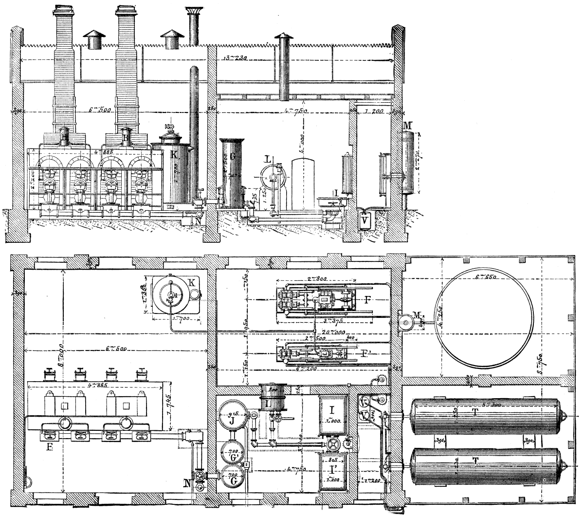
WORKS FOR THE MANUFACTURE OF OIL GAS.--ELEVATION AND PLAN.
The Pintsch gas is prepared by the distillation of heavy oils in a furnace composed of two superposed retorts. The oil to be volatilized is contained in a vertical reservoir B, which carries a bent pipe that enters the upper retort, A. The flow of the oil is regulated in this conduit by means of a micrometer screw which permits of varying the supply according to the temperature of the retorts. In order to facilitate the vaporization, the flow of oil starts from a cast-iron trough, C, and from thence spreads in a thin and uniform layer in the retort. The residua of distillation remain almost entirely in the reservoir, O, from whence they are easily removed. The vapor from the oil which is disengaged in the vessel, A, goes to the lower retort, D, in which the transformation of the matter is thoroughly completed. On leaving the latter, the gas enters the drum, E, at the lower part of the furnace. To prevent the choking up of the pipe, R, the latter is provided with a joint permitting of dilatation. The gas on leaving E goes to the condenser, G G, where it is freed from its tar. The latter flows out, and the gas proceeds to the washer, J, and the purifiers, I and I, to be purified. The amount of production is registered by the meter, L.
When the gas is to be utilized for lighting railway cars or buoys, it is compressed in the accumulators, T, which are large cylindrical reservoirs of riveted or welded iron plate.
Compression is effected by means of a pump, F or F', which sucks the gas into a desiccating cylinder, M, connected with the gasometer of the works The pump, F, which is used when the production is larger than usual, has two compressing cylinders of different diameters, one measuring 170 millimeters and the other 100. The piston has a stroke of 320 millimeters. The two compressing cylinders are double acting, and communicate with each other by valves so arranged as to prevent injurious spaces. The gas drawn from the gasometer is first compressed in the larger cylinder to a pressure of about 4 atmospheres; then it passes into the second cylinder, whence it is forced into the accumulators under a pressure varying from 10 to 12 atmospheres.
For a not very large production, the small pump suffices. This has a single compressing cylinder connected directly with the piston rod, upon which acts the steam coming from the boiler, K. This pump compresses the gas to a pressure of 10 atmospheres, and is capable of storing seven cubic meters of it per hour.
The carburets of hydrogen which separate in a liquid state through the effect of the compression of the gas are retained in a cylindrical receptacle, V, which is located between the pump and the accumulators, T.
Besides the necessary safety apparatus, there is disposed in front of the condensers a special valve, N, which allows the gas to escape into the air if the retorts or the purifying apparatus get choked up.
When the oil gas is not compressed it possesses an illuminating power four times greater than that obtained from coal gas; and, while the latter loses the greater part of its luminous power by compression, the former loses only an eighth. It is this property that renders the oil gas eminently fitted for lighting cars, and it is for this reason that several large European railway companies have adopted it.
We show in the accompanying engravings the mode of installation that the inventor has finally adopted for railway purposes. Each car is furnished, perpendicularly to its length, with a reservoir, a, containing the supply of gas under a pressure of 6 or 7 atmospheres. The gas is introduced into this reservoir by means of a valve, which is put in communication with the mouths of supply pipes placed along a platform. The pipes are provided with a stopcock and their mouths are closed by a cap. To fill the car reservoir it is only necessary to connect the mouths of the supply pipes with the valves of the cars by means of rubber tubing--an operation which takes about one minute for each car.
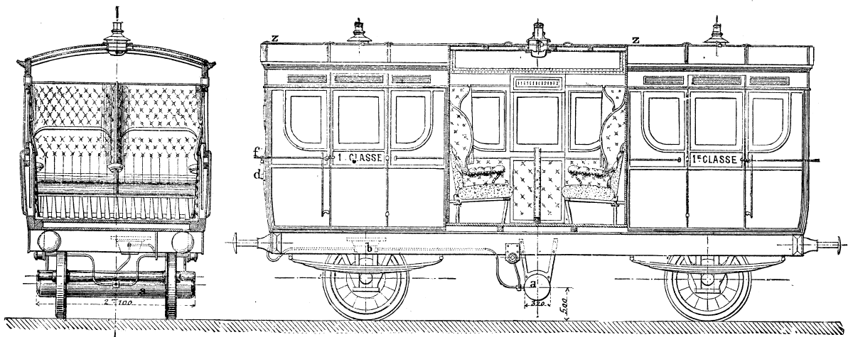
LIGHTING OF RAIWAY CARS
When it is necessary to supply cars at certain points where there are no gas works, there is attached to the train a special car on which are placed two or three accumulators, which thus transport a supply of the compressed gas to distances that are often very far removed from the source of supply.
The reservoir of each car, containing a certain supply of gas, communicates with a regulator, b, the importance of which we scarcely need point out. This apparatus consists: (1) of a cast-iron cup, A, closed at the top by a membrane, B, which is impervious to gas; (2) of a rod, C, connected at one end with the membrane, and at the other with a lever, D; (3) of a regulating valve resting on the lever, and of a spring, E, which renders the internal mechanism independent of the motions of the car. The lever, acting for the opening and closing of the valve, serves to admit gas into the regulator through the aperture, F. This latter is so calculated as to allow the passage of a quantity of gas corresponding to a pressure of 16 millimeters. As soon as such a pressure is reached in the regulator, the membrane rises and acts on the lever, and the latter closes the valve. When the pressure diminishes, as a consequence of the consumption of gas, the spring, E, carries the lever to its initial position and another admission of gas takes place. Communication between the regulator and the lamps is effected by means of a pipe, z, of 7 millimeters diameter (provided with a cock, d, which permits of extinguishing all the lamps at once, and by special branches for each lamp. The lamps used differ little in external form from those at present employed. The body is of cast-iron; the cover, funnel, and chimney are of tin; and the burner is of steatite. The products of combustion are led outside through a flattened chimney, t, resting at o on the center of the reflector. The air enters through the cover of the lamp and reaches the interior through a series of apertures in the circumference of the cast-iron bell which supports the reflector. There is no communication whatever between the interior of the lamp and the interior of the car, and thus there is no danger of passengers being annoyed by the odor of gas. By means of a peculiar apparatus, f, the flame may be reduced to a minimum without being extinguished. This arrangement is at the disposition of the conductor or within reach of the passengers. For facilitating cleaning, the lamps are arranged so as to turn on a hinge-joint, m; so that, on removing the reflector, o, it is only necessary to raise the arm that carries the burner, r in order to clean the base, s, without any difficulty.
On several railways both the palace and postals cars are also heated by compressed oil gas; and lately an application has been made of the gas for supplying the headlights of locomotives (see figure), and for the signals placed at the rear of trains. But one of the most interesting applications of oil is that of
in which case it is compressed into large reservoirs placed on a boat. The buoys employed are generally of from 90 to 285 cubic feet capacity, affording a lighting for from 35 to 100 days.
To the upper part of the buoy there is affixed a firmly supported tube carrying at its extremity the lantern, c. The gas compressed to 6 or 7 atmospheres in the body of the buoy passes, before reaching the burner, into a regulator analogous to the one installed on railway cars, but modified in such a way as to operate with regularity whatever be the inclination of the buoy. In the section showing the details of the lantern on a large scale the direction taken by the air is indicated by arrows, as is also the direction taken by the products of combustion. These latter escape at m, through apertures in the cap of the apparatus.
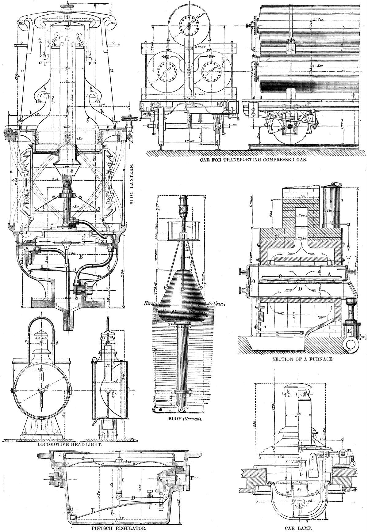
COMPRESSED OIL GAS FOR LIGHTING CARS STEAMBOTS, AND BUOYS.
The regulator, B, in the interior of the lantern, brings to a uniform pressure the inclosed gas, whose pressure continues diminishing as a consequence of the consumption. The lantern is protected against wind and waves by very thick convex glasses set into metallic cross-bars, c. The flame is located in the focus of a Fresnel lens, b, consisting of superposed prismatic rings, and adjusted at its lower part with a circle, d, while a conical ring, e makes a joint at its other extremity. This ring is held by the top piece of the lantern through the intermedium of six spiral springs, c' c''. Under the focus of the flame there is placed a conical reflector of German silver, t.
The buoy is filled through an aperture, k, in the side of the upper tube. This aperture is provided with a valve which allows of the buoy being charged by connecting it with the accumulators located on a boat built especially for this service. As soon as the gas reaches 6 or 7 atmospheres the cocks of the buoy and reservoir are closed, and the connecting tube is removed. The consumption of gas in the lantern is. 1,230 cubic inches per hour. This being known it is very easy to calculate from the capacity of the buoy how often it is necessary to charge it.
A large number of buoys on the Pintsch system are already in use.
The oil gas is likewise applicable to the illumination of lighthouses, and among those that are now being lighted in that way we may cite the one in the port of Pillau, near Königsberg. Several large steamers are likewise being lighted on this plan. In such an application of oil gas the management of the apparatus is very easy, and the permanence of the illuminating power of the gas gives every facility for the lighting of the boat, whatever be the duration of the trip.
Although Mr. Pintsch's process of manufacture has been but recently introduced into France, it has received a number of applications that permits us to foresee the future that is in store for it. The Railway Company of the West has contracted for the lighting of 250 first-class cars that run within the precincts of the city; the State Railways have 56 cars lighted in this way running between Nantes and Bordeaux and between Saintes and Limoges; and the Line of the East has just applied the system to 80 of its cars.
T. W. Engelmann proposes, in the Botanische Zeitung, a new test, of an extremely delicate nature, for determining the presence of very minute quantities of oxygen, namely: its power of exciting the motility of bacteria. If any of the smaller species, especially Bacterium termo, are brought to rest, and then introduced into a fluid in which there is the minutest trace of free oxygen, they will immediately begin to move about freely; and if the oxygen is gradually introduced, their motion will be set up only in those parts of the drop which the oxygen reaches. In this way Engelmann was able to determine the evolution of oxygen by Euglena and by chlorophyl granules.
Ten grms. of sulphur, pulverized as finely as possible, are covered with hot water and a few drops of nitric acid digested for some time, filtered, and washed till the washings have no longer an acid reaction. Thus calcium chloride and sulphate are removed, and calcium sulphide, if present, is destroyed. The sulphur thus prepared is covered with water at 70° to 80°, a few drops of ammonia are added, and the mixture is digested for a quarter of an hour. All the arsenic present as sulphide is dissolved, and the ammoniacal liquid is variously treated according to the degree of accuracy required. For perfectly accurate determinations the ammoniacal solution is mixed with silver nitrate, and all the sulphur present in the state of arsenic sulphide is thrown down as silver sulphide, acidified with nitric acid, filtered, and washed. The precipitate of silver sulphide is dissolved in hot nitric acid and determined as silver chloride. From the weight of the latter the arsenic sulphide is calculated. As a less accurate but more rapid method, the ammoniacal solution of arsenic sulphide is cautiously neutralized with pure dilute nitric acid and considerably diluted. It is then titrated with decinormal silver nitrate till a drop of the solution is turned brown with neutral chromate. The arsenic is easily calculated from the quantity of silver nitrate consumed. For very rough determinations it is sufficient to treat ten grms. of finely-ground sulphur with nitric acid, to extract with ammonia, and to add silver nitrate. From the intensity of the color, or the quantity of the precipitate of silver sulphide, it may be judged if the sulphur is approximately free from arsenic or strongly contaminated. The author states that, contrary to the general belief, reddish yellow sulphur is more free from arsenic than such as is of a full yellow color.
A great deal has been written and said about tree planting. Some advise one way, some another. I will give you my method, with which I have been very successful, and, as it differs somewhat from the usual mode, may be interesting to some of your readers. I go into the woods, select a place where it is thick with strong, young, healthy, rapid growing trees. I commence by making a trench across so as I will get as many as I want. I may have to destroy some until I get a right start. I then undermine, taking out the trees as I advance; this gives me a chance not to destroy the roots. I care nothing about the top, because I cut them into what is called poles eight or ten feet long. Sometimes I draw them out by hitching a team when I can get them so far excavated that I can turn them down enough to hitch above where I intend to cut them off; by this method I often get almost the entire root. I have three particular points in this; good root, a stem without any blemish, and a rapid growing tree. This is seldom to be got where most people recommend trees to be taken from--isolated ones on the outside of the woods; they are generally scraggy and stunted; and to get their roots you would have to follow along way to get at the fibers on their points, without which they will have a hard struggle to live. Another point recommended is to plant so that the tree will stand in the direction it was before being moved; that I never think about, but always study to have the longest and most roots on the side where the wind will be strongest, which is generally the west, on an open exposure.
For years I was much against this system of cutting trees into poles, and fought hard against one of the most successful tree planters in Canada about this pole business. I have trees planted under the system described that have many strong shoots six and eight feet long--hard maple, elm, etc., under the most unfavorable circumstances. In planting, be particular to have the hole into which you plant much larger than your roots; and be sure you draw out all your roots to their length before you put on your soil; clean away all the black, leafy soil about them, for if that is left, and gets once dry, you will not easily wet it again. Break down the edges of your holes as you progress, not to leave them as if they were confined in a flower pot; and when finished, put around them a good heavy mulch, I do not care what of--sawdust, manure, or straw. This last you can keep by throwing a few spadefuls of soil over; let it pass out over the edges of your holes at least one foot.
I have no doubt that the best time to plant is the fall, as, if left till spring, the trees are too far advanced before the frost is put of the ground; and by fall planting the soil gets settled about the roots, and they go on with the season.
Trees cut like poles have another great advantage. For the first season they require no stakes to guard against the wind shaking them, which is a necessity with a top; for depend upon it, if your tree is allowed to sway with the wind, your roots will take very little hold that season, and may die, often the second year, from this very cause.
All who try this system will find out that they will get a much prettier headed tree, and much sooner see a tree of beauty than by any other, as, when your roots have plenty of fibrous roots, and are in vigorous health, three years will give you nice trees.--The Canadian Horticulturist.
In a paper (Russian) recently read before the Botanical Section of the St. Petersburg Natural History Society, Mr. K. Friderich describes in detail the anatomical structures to be met with in the aerial roots of Acanthorhiza aculeata, these roots presenting a remarkable example of roots being metamorphosed into spines. Supplementing this, E. Regel made the following remarks:
Palm trees, grown from seed, thicken their stems for a succession of years, like bulbs, only at the base. Many palms continue this primary growth (i.e., the growth they first started with) for fifty to sixty years before they form their trunk. During this time new roots are always being developed at the base of the stem, in whorls, and these always above the old roots. This even takes place in old specimens, especially in those planted in the open ground which have already formed a trunk, In such cases the cortex layer, where the roots break through, is sprung off. In conservatories, under the influence of the damp air, this root formation, on which indeed the further normal growth of the palm depends, takes place without any special assistance. When the palm is grown in a sitting room, one must surround the base of the trunk with moss, which is to be kept damp, in order to favor the development of the roots. When the base of the palm trunk has almost reached its normal thickness, then begins the upward development of the trunk, which takes place more slowly in those species whose leaves grow close together than in those whose leaves are further apart. In specimens of many species of Cocos and Syagrus, whose leaves are particularly far apart, the stems grow so quickly when planted in the open ground that they increase by five to six feet in height per annum. The stem of those palms which develop a terminal inflorescence have ended their apical growth by doing so, and wither gradually, In addition to this (withering) in the case, e.g. of Arenga saccharifera, new inflorescences are developed from the original axils (Blattachseln) from above downward, so that one sees at last the already leafless trunk still developing inflorescences in the direction toward the base of the trunk. Almost all palms with this latter kind of growth develop offshoots in their youth at the base of their trunks, which shoot up again into trunks after the death of the primary trunk, if they are not taken off before. As to the structure of the palm trunks out of unconnected wood bundles, the assertion has been made that the palm stem does not grow thicker in the course of time, and that this is the explanation of the columnar almost evenly thick trunk. But careful measurements that were made for years have led Regel to the conclusion that a thickening of the trunk actually takes place, which probably amounts to an increase of about a third over the original circumference of the trunk.
In my dispatch, No. 140, dated September 1, 1880, I referred to the fact that new machinery for reeling silk had been invented, which, in my opinion, was destined to be of great importance, and to make this industry extremely valuable and profitable in our country. I beg now to submit some additional observations upon this subject, and for the purpose of being definite, to entitle them
Silk reeling is at present accomplished by the use of appliances which differ only in detail from those in use many centuries ago, and which can scarcely be called machines, being rather of the nature of apparatus depending entirely upon the skill and knowledge of the operative for the results produced. In fact, even the most perfect of French and Italian reels bear about the same relation to automatic machinery that an old-fashioned spinning wheel does to our modern spinning machines.
Since the date of my previous dispatch upon this subject, the new reeling machine of Mr. E. W. Serrell, jr., of New York (who still continues in Lyons), has been undergoing improvement and development, and it is with the hope of facilitating the introduction and culture of silk, and of enabling our people to adopt the best means to that end, and to avoid errors which have been disastrous in the past and are likely to be extremely expensive in the near future, that I now communicate with the department, which is equally interested in securing new sources of industry and wealth for our people at home as for the promotion and extension of their commerce abroad.
It will be recollected that from about 1834 to 1839 there raged a great speculation in mulberry trees of a certain species (Morus multicaulis) destined for feeding silk worms. This speculation led to a total loss of all the time and money devoted to it, partly because of its wild and utterly unsound character, and partly because the little silk which was actually produced could not be reeled to advantage. As a result, silk culture fell into utter disrepute and for nearly a generation was scarcely thought of as a practical thing in the United States. Time, however, showed clearly where the great obstacle lay, and although many may have imagined that other difficulties led to its abandonment in 1839-40, those who have studied the matter are unanimously of the opinion that the want of reeling machinery has alone prevented the success of sericulture in those parts of the Union which are suitable for it. Believing this obstacle to be removed, it remains to set forth in a brief manner some of the points upon which, it appears to me, the successful introduction of silk raising will depend.
For the success of silk culture in our country two things are now requisite--the acquisition on the part of those about to engage in it of sound knowledge of its processes and requirements, and proper organization.
The details of the work of silk culture are of such a nature that they may be readily understood, and I apprehend that there will be little difficulty found by those who engage in it in mastering them, after some little experience. The point at which it seems to me that there is the most danger is at the very beginning.
In order to avoid delays and losses, the person who begins silk culture should have a pretty clear idea of the scale of operations which are likely to be most profitable; of the trees, or rather shrubs, which must be obtained; of the apparatus and fixtures necessary, and of the results which may be reasonably expected from the labor and expense required. All of these items will be found to vary in different parts of the country, and I fear that general rules, broad deductions, and such information as would apply under all circumstances and in all places would be extremely difficult to formulate, and too vague for practical use at any given point.
In fact, as far as information which may be considered perfectly general is concerned, I have, for the time being, only one point to put forward in addition to what has already been published in the United States, which is to repeat and show as emphatically as possible that the use of the reels at present employed for the filature of silk is entirely impracticable in our country, and that the raiser must sell his cocoons.
This has been so often said and so clearly shown that I should consider it unnecessary to repeat it had not my attention been called to the fact that the success of several people and associations in the United States in raising cocoons has again made it a temptation to endeavor to reel silk, and during the past year I have received applications from people in different States for information as to the kind of silk reel employed here which would be most suitable for use by them.
I am aware, also, that estimates have been made and published by some eminent authorities tending to show that this work could be done on a paying basis in some places in America. So far as I have seen them, however, these estimates are fatally defective in that they do not allow for differences in quality of silk reeled by competent or incompetent people, and under circumstances favorable or otherwise, but seem to assume that any silk reeled in our country would be a first rate article, and paid for accordingly.
While this might be true in isolated cases, it could not be true in general, as with present appliances the art of reeling good silk is only to be acquired and retained by years of apprenticeship and constant practice joined to a natural talent for the work. So true is this, that even in districts where the work has been largely carried on for many generations, quite a large proportion of women who try for years find it impossible to become good reelers.
Now, there is a considerable difference in price between well reeled and poorly reeled silk--a difference so great that silk not well reeled in every way is not worth as much as the cocoons from which it is derived. It is, therefore, quite a hopeless task to reel silk unless the reeler is skilled. Even if it could be done to advantage--which I do not think it could--there exists in America no means of training reelers. In Europe they are taught by degrees in the filatures, working first at the easier stages of the operations, and afterward being helped forward under the eyes and guidance of experienced operatives.
Another grave defect in the estimates alluded to is that all the profit is assumed to be paid to the reeler. This can evidently only be the case when each reeler runs her own reel, owns and cares for her own cocoons, sells her own silk, and furnishes her own capital. Now, even supposing that persons so fortunately placed as to be able to fulfill all these conditions should wish to engage in silk reeling, which is in the highest degree improbable, there exists an almost insuperable obstacle to the production of good silk except by an establishment large enough to use the cocoons of many producers.
Nearly every silk crop as raised by the individual growers contains three or four grades of cocoons, and to produce good and uniform silk, these must be separated and each sort reeled by itself, producing several grades of silk.
Without going into detail, it is enough to say that this is not practical for those who attempt to reel their own cocoons, and that for this reason, and many others, hand reels and single basins have been nearly abandoned even in Italy; the women finding so much difficulty that they prefer to sell their cocoons and work in large establishments where the work is done to more advantage.
It is evident, therefore, that, from the estimates made, there should be a considerable deduction for poor workmanship, and another for use of capital, organization, selling expenses, superintendence, insurance, repairs, deterioration, etc. In fact, I do not see in what way the reeling of silk in the United States, by the ordinary method, could be made to bear a much higher charge for labor than that borne by European filatures, which barely pay with labor at one franc per diem of thirteen hours.
To be able, then, to reel silk by the ordinary reels, it would first be necessary to find a sufficiency of highly skilled operatives willing to labor in a factory thirteen hours per day for twenty cents each. I sincerely believe and hope that this can never be done. I have enlarged somewhat upon this difficulty for the purpose of showing that the growers, or at any rate individual growers of cocoons, should not attempt to do the reeling, but by no means with an idea of discouraging the raising of silk worms, which is and should be an entirely separate matter. To use a rough comparison, I should esteem it as wasteful, even if possible, for each grower to attempt to reel his own cocoons as for each farmer to grind his own wheat upon his farm and endeavor to sell the flour.
It is, therefore, clear that the object of the sericulturist should be to raise and market as good a crop of cocoons as possible to the best advantage, and with the least possible expense and risk.
After what has been said, it may be very properly asked, if, seeing that the hopes which have been entertained of reeling by the usual method have proved fallacious, and as no radically new system of raising silk worms is under consideration, it is not very possible that all hopes of profit from rearing the worm may prove fallacious also.
In fact, not only has the question been asked, but an argument of great apparent strength and much plausibility has been formulated and extensively circulated, tending to show that the difficulty of cheap labor, which it has been shown stood in the way of reeling without improved machinery, will make the raising of cocoons also a hopelessly unprofitable task.
Briefly summarized, this argument may be stated as follows:
First. To raise silk worms to advantage much time and attention are required.
Second. Time and attention are more costly in the United States than in other countries.
Third. Consequently, cocoons can be more cheaply raised in other countries than in the United States.
Fourth. The United States possess no special advantages as a market for cocoons, and therefore they must be sold as cheaply as elsewhere, and the labor costing more, there is less profit.
Fifth. The profits made by raisers in Europe are not very great, and as they would be less in the United States, it is not worth while to try to raise cocoons in that country.
It must be acknowledged that upon the surface this all appears to be very sound and almost unanswerable, but I hope to be able to show that there is in reality not the slightest real foundation for the conclusion to which this argument points.
Taking the points cited in order, I would say, as regards the first and second, that although labor and time are required to raise cocoons, I am convinced that the labor and time of the kind necessary will not be found more expensive in our country than in Europe, for the following reasons:
The work is a home industry. It can be carried on without severe manual labor except for a few days, at the end of the season, when large crops are raised.
Now, nothing is better known than that there exists in many of our States an enormous number of wives and daughters of country people of a class entirely different from any to be found elsewhere, except, perhaps, to a limited extent, in England. I refer to the "well-to-do" but not wealthy agricultural and manufacturing classes in small villages.
One or two generations ago the farmers' and mechanics' wives and daughters found plenty of work in spinning, weaving, dyeing, cutting, and making the linen and clothes of the family. This has entirely ceased as a domestic industry with the exception of the "sewing" of the women's clothes and men's underwear. As a consequence, the women of the family are condemned to idleness, or to the drudgery of the whole household work.
Upon a proper occasion I think that much might be said of the evils and dangers which are likely within a short time to arise from the fact that perhaps a large majority of American women find themselves, because of the present organization of society and industry, almost unable to contribute to the family income except by going away from home, or in doing the most menial and severe labor as household workers from one end of the year to the other. I shall at present, however, only point out that in hundreds of thousands of homes in the country an opportunity of gaining a very moderate sum in addition to the present income by the expenditure of some weeks of care and light work would be hailed as a Godsend, and that, too, in families where the feeling of self-respect and the desire to keep the family together are far too strong to permit the women to go away from home in any way to earn money.
Let any one who doubts this consider the dairy work and similar industries, and try to calculate how much per diem the women thus occupied at home gain in money. It may be said with entire accuracy that, as a rule, anything in which the women can engage at home, by which something may be earned, will in general be regarded as net profit through out many sections of the land. In the silk districts of Europe, agricultural machinery is very much less employed than with us, and in general every woman who can possibly be spared from other work is a field laborer and valuable as such. So that time taken for raising silk must be deducted from her other productive work and charged to the cost of the silk crop. I think that there can be no doubt that this one fact is quite sufficient to make the question of the cost of caring for the worms really as much in favor of the United States as at first glance it appears to be the other way; it being the case that in our country many who would be glad to do the work have spare time to give to it, whereas in Europe every hour that is given to silk worms would otherwise be spent in the field.
In the South there are very large masses of inhabitants who are unable to work in the fields, both men and women, and who would also find in a yearly crop of silk worms a very comfortable addition to their yearly gains, and one which could be derived from time not otherwise convertible into money. Land is very much dearer, and taxes are higher in the European silk districts than with us, and every little crop of cocoons has to pay its share, which adds a considerable percentage to its cost.
The buildings possessed by peasants and used for the raising of silk worms are, in general, small, close, and miserable. Throughout America the roomy barns which are empty at the cocoon season, will, with little preparation, be much preferable, and enable the raisers to work to very much better advantage.
In Europe diseases of several kinds have become more or less prevalent, and in some cases have diminished the production of whole districts.
Notwithstanding the fact that many experiments have been made in America, and in Georgia particularly, and silk has been raised continuously for over a century, these diseases (maladies des vers a soile) have never made their appearance.
The people of our country are, as a rule, much better educated than those in Southern France and Italy, and will undoubtedly use their intelligence in such a way as to derive a benefit from it, and economize their labor by proper appliances, etc.
Taking all these facts into consideration, I am convinced that that there will be no difficulty in raising cocoons for the same cost in labor in the United States as in Europe, and I am inclined to think that the work can be much more cheaply done.
It is true that the United States is not an especially good market for cocoons; in fact up to this time there has been scarcely any market at all for them; but with the organization of the industry and the introduction of reeling machinery, the market will be at least as good there as elsewhere. As to whether it will be "worth while" for our people to raise silk worms, I would say that though the amount of money to be paid by any one family is certainly not very large, it is nearly all clear profit, and under the circumstances which I have above pointed out, and which exist so generally, I am sure that the sum to be realized will be regarded as very important by a vast number of people. As in other points, it is extremely difficult to make any exact estimates on such a subject which would be generally applicable to a country so large and so various in climate, soil, and social habit as ours. I am inclined to think, however, that were the members of an average family, under average circumstances, to raise a crop of cocoons, the amount which could be advantageously reared should produce, according to circumstances, from seventy-five to two hundred dollars. Scarcely any "paying" result can be hoped for, however, without more or less organization of the work, as sericulture is an industry which is very sensitive to the evils of a want of proper co-operation among those who carry on its various processes. After some reflection, I am of the opinion that individual growers will have great difficulty in selling cocoons if they are isolated from others, and I therefore doubt the wisdom of encouraging sporadic and ill-directed efforts, which, however well meant and earnestly pursued, are much more apt to end in disappointment, discouragement, and discredit to the newly developing industry than in anything else. It seems to me to be neither wise nor fair to furnish estimates of returns, which presuppose an organization of the industry, without mentioning the difficulties which must be encountered where the organization is lacking. The great difficulty is in selling the cocoons after they are raised, and this can only be practically overcome by such a development of the culture as will result in the production, within the limits of a given neighborhood, of sufficient quantities of cocoons to make it practicable to prepare and forward them to market. It is as well known as any other fact in trade, that small transactions are much more costly in proportion than large ones, and this general rule is especially applicable to the cocoon market. The product of two or three isolated families in the interior of our country could not be marketed to advantage. Whereas, were several hundreds engaged on the work in the same vicinity the charge of marketing their joint crop would be only a small percentage of its value.
Silk raising is the work of an organized people, and before it can become successful in our country must possess proper channels for its trade, just as much as wool, or cotton, or wheat. The machinery of this organization, however, need not be either complicated or expensive. What is required is a system of nuclei in towns or large villages, which may serve as centers of information and as gathering receptacles for the crops of surrounding producers.
The details of organization must be left, and I think may safely be left to the good sense of the people of different sections, who will work out the problem in different ways, according to their different circumstances. Even were the need of organization not made evident to those undertaking sericulture in the beginning, it would soon become so, as it has, in fact, in several parts of the country. I have therefore deemed it proper to call attention to this matter, on the principle that a "stitch in time saves nine." I am informed that there exist already in the United States several associations devoted to acquiring and disseminating knowledge of the art of sericulture. This is a very great step in the right direction, and cannot be too heartily commended. If conducted with prudence and wisdom these societies will be of great service, and I would respectfully suggest that any encouragement which the government may think proper to afford would in all probability be extremely useful and profitable to the country in the future. Provided, always, that such societies are really devoted to the dissemination of information and the careful organization of the industry, and are not merely visionary and impractical cultivators of misapplied enthusiasm.
It would, I think, be of importance so far as possible, to direct the attention of county and State agricultural societies, "village improvement clubs," and in general the intelligent and careful portion of our rural population to this matter. It is beyond doubt that the time when sericulture can be begun and carried on profitably in our country has arrived. Its successful introduction would result in a very important yearly revenue and increase in the public wealth, for I think that within a comparatively few years it could be made to be worth at least fifty or sixty millions of dollars per annum, and perhaps much more. This, however, is a less advantage than the fact that by supplying a new home industry it would do much toward conserving home ties and interests, and thereby help to strengthen and perpetuate good morals and home living among our people.
"Don't black bears sleep through the winter?" questioned the writer of an attendant who was dealing out mid-day rations of bread and milk at the park.
"That's the general impression," was the rejoinder, "but we have never noticed any attempts at hibernation here. Bears are unusually lively during the cold months, and demand their food as regularly as do the lions and other feline animals. I don't know that any observations of value on this question have ever been made on animals in confinement. I have had some experience with outside animals, and a great many go through what is called a winter's sleep; and in warm countries there is what might be called a summer sleep. Bears begin in the fall to look out for a soft nest; and if it's possible for them to eat more at one time than another they do it then, and when the cold weather sets in they are fat and in prime condition. According to some authorities, the fat produces the carbon that in some way tends to induce somnolency. The stomach of a bear at this time becomes empty, and naturally shrivels or draws into a very small space, and is rendered totally useless by a substance called 'tappen' that clogs it and the intestines; this is formed of pine leaves and other material that the animal takes from ants' nest and the trunks of trees in its search after honey. They lie asleep in this condition for about six months, generally snowed in; but you can tell the place, as the heat of the bear, what there is left, keeps an air hole up through the snow. The bear seems to live on its fat, the tappen preventing its too rapid consumption; and if you run across them during this time--even along in March just before they wake up--they are about as fat as when they went in. I have taken a slice of fat from a black bear six inches thick--regular blubber. I remember," continued the man, "one winter I was 'log hauling' in the western part of this State. We had our eyes on a big tree, and one morning when it was about ten degrees below zero I tackled it to warm up. I hammered away for about five hours at it and finally started her, and over she came--slowly at first, and then as if she was going right through. The snow was nearly three feet deep, and as the tree struck it flew up for about twenty feet and half blinded me, and when I came to there was the biggest black bear I ever saw standing along side of me, looking about as mixed as I did. I had lost my ax, and the first move I made she started, and on taking a look I found that she had a nest in the trunk and had probably turned in for the winter. It was about twenty feet from the ground, and was built with moss, leaves, and all kinds of truck, and as warm and as snug as you please--a good place to spend a winter in."
The brown and polar bears have the same habit of lying up for the winter. An Esquimau informed Captain Lyon that in the first of the winter the pregnant bears are always fat and solitary. When a heavy fall of snow sets in the animal seeks some hollow place in which she can lie down, and remains quiet while the snow covers her. Sometimes she will wait until a quantity of snow has fallen and then digs herself a cave; at all events it seems necessary that she should be covered up by the snow. She now goes to sleep and does not wake until the spring sun is pretty high, when she brings forth two cubs. The cave by this time has become much larger by the effect of the animal's warmth and breath, so that the cubs have room enough to move, and they acquire considerable strength by continually sucking. The dam at length becomes so thin and weak that it is with great difficulty she extricates herself, which she does when the sun is powerful enough to throw a strong glare through the snow which roofs the den. Then the family comes out, and will take anything that comes along in the way of food. During the long sleep the temperature of the bear's blood is reduced to almost that of the surrounding air. The power of will over the muscles seems to be suspended, respiration is hardly noticeable, and most of the vital functions are at a complete standstill--the entire body sleeping, as it were. The male grizzly bear never hibernates. The young and the females, however, build nests, one of which measured ten feet high, five feet long, and six feet wide.
Bats are great winter sleepers, and in most of the known caves they can be found during the cold months clinging to the walls and to each other. During hibernation their respiration ceases almost entirely, and only the most careful use of a stethoscope can reveal it. The air that has surrounded numbers of them has been carefully examined and not the slightest evidence found of its having been breathed; and, stranger yet, they can exist in this condition in gas, that, were they awake, would prove instantly fatal. A machine has been invented to examine these and other animals while in this condition. A delicate index records the slightest pulsation, while a thermometer shows the rise and fall of the temperature at every moment during the period; and by an arrangement of the wing, the circulation of the blood is recorded. A more delicate experiment can hardly be imagined, as a strong breath, a sneeze, or a footfall will cause the subject of the experiment to recover enough to respire several times; and the effect of this on the machine can be imagined when it is known that though, while in this condition, they produce no effect upon the oxygen of the air about them, they consume when respiring more than four cubic inches of oxygen an hour.
The common marmot is a great underground sleeper. They build large storehouses, sometimes eight feet in diameter, and from the latter part of September to April they lie in them, and, like the bears, give birth to their young during this period.
The dormouse is a remarkable sleeper. Even in their ordinary sleep they can be taken from the nest and handled without waking them. Toward winter they acquire a great deal of fat, and stow away a vast amount of provision around about their nest, and then go to sleep within; but they rarely awake to use this food unless a very warm period comes around before the regular breaking up of cold weather.
The hedgehog is a sound winter sleeper, and has been the subject of an infinite number of experiments while in this condition. One experimentalist, believing that cold was the cause of their curious condition, surrounded one with a freezing mixture, and froze it to death. By increasing the cold about another that was already hibernating, it was made to wake up; and walked off.
If an animal is suddenly decapitated while in this hibernating condition, the action of the heart is not affected for some time, a second life seeming to outlive the one taken. An experiment has been made in which the brain of the sleeper was removed, then the entire spinal cord, but for two hours hardly any change was noticeable upon the action of the heart; and a day after that organ contracted when touched by the operator.
The writer has the winter nest of a family of ants. A piece of fence rail was found beneath an old pile of boards and brought into a warm room for the sake of a rich fungus growing upon it, and several hours after the table and chairs were found to be covered with ants. Where they came from was a mystery, until the old rail was accidentally jarred and a number fell from it. A section was cut down through it, and the winter home of the tribe destroyed--probably the work of weeks, perhaps months. The interior of the wood was completely riddled by tunnels and passages, some being large and holding several hundred ants, while others contained only a few. In some of the interior passages the ants had not been affected by the heat, and were packed in great masses and evidently fast asleep; they soon recovered, however, and walked off slowly in different directions, as if wondering if an earthquake or spring had come.
A great number of insects go through a period of hibernation, especially spiders. The young of the latter are often covered by the parent; first, by coarse strings of silk, as if to hold them in place, and then by a white, silvery web worked over them, which forms probably a sure protection from wind and weather.
The writer has a cherry-stone in which is coiled up an insect, best known as the sowbug. A squirrel had probably eaten out the meat and opened the way, and in this snug retreat we found the little hibernater snugly rolled up, as is also its habit when alarmed. The mouth of the hole was stopped by black soil, but whether from accident or by the animal itself we could not tell.
Some fishes and reptiles are hibernaters. Frogs and toads sleep out the winter at the bottom of ponds or in holes in the ground. Tree toads, if kept in a cage in the winter and provided with soil, will endeavor to cover themselves with it, showing how strong the instinct or habit is. Some fishes are so insensible to heat or cold that when in this condition they can be frozen and carried for a number of days and then be brought back to an active condition. The pond snail passes into a winter sleep as soon as the temperature of the water is below 14° Cent., that is, they will not digest food or grow until the temperature of the water is at least up to 15° Cent. Those who have watched the Harlem River from McComb's Dam Bridge cannot have failed to notice the curious appearance of the muddy shores of the river and creeks at low tide. If the sun shines brightly, the dismal beach seems to quiver and scintillate in a most beautiful manner, reflecting the light like so many diamonds. If we draw nearer, this shore is seen to be entirely covered in places with little snails, that, left by the tide, are forging through the mud to regain the water, and the sunlight striking on them is reflected by the glass-like secretion with which they are covered, producing the curious effect noticed. This could be seen in the warm months, but now, not a snail of the countless millions can be seen. They have gone down in search of "hard-pan," there to hibernate until next April. The land snail (Helix pomatia) sleeps four months during the year, and does not throw off the calcareous lid that protects it during this time until the day temperature has reached 12° Cent. Prairie dogs feel the effect of temperature as low as this.
In Cuba reptiles hibernate between 7° and 24° Cent., according to the species. In warmer countries, snakes, lizards, frogs, etc., fall into a state called chill coma that precisely resembles winter sleep, but their temperature is far above that at which hibernating animals of the north are still active. The state of hibernation is not the direct result of an extreme of heat or cold, but rather is caused by a departure from the optimum. In the snail its normal temperature is about the same as the water, and being a poor heat producer it is not surprising that when the water grows colder the animal is forced to succumb; but it is a remarkable fact that warm-blooded animals like many of the above-mentioned, whose bodies are maintained by internal processes at a high temperature of 26° to 38°, are incapable of resisting the lowering influence of cold. The fall in temperature in some is wonderful; as an example, the high body temperature of warm-blooded animals may be said to oscillate between 36° and 43° Cent. (this includes man). Experiments made with the zizel show that during hibernation this animal's temperature is only 2° Cent., the lowest known; and a thermometer introduced into the animal indicated the same, showing that warm-blooded animals in hibernating become truly cold blooded animals. If a rabbit's temperature reaches 15° Cent., it will die. The germs of bryozoa or of the fresh water sponges resist any amount of cold, but the full grown forms die at the first cold turn. Insects are destroyed, but their eggs live, though of the greatest possible delicacy. Salmon eggs have been carried from this State to Australia, and there hatched. In fact, some animals live in the ice, as the glacier flea and several others.
As it is not the direct result of extremes of heat or cold that produces sleep, neither is the awakening from hibernation directly caused by a rise of temperature. In experiments made upon weasels, which are sometimes caught asleep, one came to life in about three hours, during which the temperature of the room remained the same as it had been during the entire hibernation, viz., 10° Cent. In another weasel, during the awakening, the body temperature rose very rapidly--and more so in the second part of the period than in the first. In the first hour and fifty-five minutes of the awakening the body temperature rose 6.6° Cent, and in the following fifty minutes it rose 17° Cent. This remarkable increase took place without any vigorous movements on the part of the weasel. Even its breathing showed no increase in proportion to the rise. These cases show that though, at certain seasons, animals relax as it were and lie dormant, and recover, seemingly at the will of the weather, yet, in point of fact, the rise and fall of temperature has no direct effect upon them. The cause is an internal one, awaiting discovery.--C. F. HOLDER, in Forest and Stream.
What is described as the largest steel sailing ship afloat was lately launched at Belfast, Ireland. It registers 2,220 tons, and has been named the Garfield. It will be employed in the Australian and California trade.
London Nature, in a recent issue, says: From a scientific point of view, the work done by the tides is of unspeakable importance. Whence is this energy derived with which the tides do their work? If the tides are caused by the moon, the energy they possess must also be derived from the moon. This looks plain enough, but unfortunately it is not true. Would it be true to assert that the finger of the rifleman which pulls the trigger supplies the energy with which the rifle bullet is animated? Of course it would not. The energy is derived from the explosion of gunpowder, and the pulling of the trigger is merely the means by which that energy is liberated.
In somewhat similar manner the tidal wave produced by the moon is the means whereby a part of the energy stored in the earth is compelled to expend itself in work. Let me illustrate this by a comparison between the earth rotating on its axis and the fly-wheel of an engine: The fly wheel is a sort of reservoir, into which the engine pours its power at each stroke of the piston. The various machines in the mill merely draw off the power from the store accumulated in the fly-wheel. The earth is like a gigantic fly-wheel detached from the engine, though still connected with the machines in the mill. In that mighty fly-wheel a stupendous quantity of energy is stored up, and a stupendous quantity of energy would be given out before that fly-wheel would come to rest. The earth's rotation is a reservoir from whence the tides draw the energy they require for doing work. Hence it is that though the tides are caused by the moon, yet whenever they require energy they draw on the supply ready to hand in the rotation of the earth. The earth differs from the fly-wheel of an engine in a very important point. As the energy is withdrawn from the fly-wheel by the machines in the mill, so it is restored thereto by the power of the steam engine, and the fly runs uniformly. But the earth is merely the fly-wheel without the engine. When the work by the tides withdraws energy from the earth, that energy is never restored. It, therefore, follows that the earth's rotation must be decreasing. This leads to a consequence of the most wonderful importance. It tells us that the speed with which the earth rotates on its axis is diminishing. We can state the result in a manner which has the merits of simplicity and brevity. The tides are increasing the length of the day. At present, no doubt, the effect of the tides in changing the length of the day is very small. A day now is not appreciably longer than a day a hundred years ago. Even in a thousand years the change in the length of the day is only a fraction of a second. But the importance arises from the fact that the change, slow though it is, lies always in one direction. The day is continually increasing. In millions of years the accumulated effect becomes not only appreciable, but even of startling magnitude.
The change in the length of the day must involve a corresponding change in the motion of the moon. If the moon acts on the earth and retards the rotation of the earth, so, conversely, does the earth react upon the moon. The earth is tormented by the moon, so it strives to drive away its persecutor. At present the moon revolves around the earth at a distance of about 240,000 miles. The reaction of the earth tends to increase this distance, and to force the moon to revolve in an orbit which is continually growing larger and larger. As thousands of years roll on, the length of the day increases second by second, and the distance of the moon increases mile by mile. A million years ago the day, probably, contained some minutes less than our present day of twenty-four hours. Our retrospect does not halt here; we at once project our view back to an incredibly remote epoch which was a crisis in the history of our system. It must have been at least 50,000,000 years ago. It may have been very much earlier. This crisis was the interesting occasion when the moon was born. The length of the day was only a very few hours. If we call it three hours we shall not be far from the truth. Purhaps you may think that if we looked back to a still earlier epoch, the day would become still less, and finally disappear altogether. This is, however, not the case. The day can never have been much less than three hours in the present order of things. Everybody knows that the earth is not a sphere, but there is a protuberance at the equator, so that, as our school books tell us, the earth is shaped like an orange. It is well known that this protuberance is due to the rotation of the earth on its axis, by which the equatorial parts bulge out by centrifugal force. The quicker the earth rotates the greater is the protuberance. If, however, the rate of rotation exceeds a certain limit, the equatorial portion of the earth could no longer cling together. The attraction which unites them would be overcome by centrifugal force, and a general break up would occur. It can be shown that the rotation of the earth, when on the point of rupture, corresponds to a length of the day somewhere about the critical value of three hours, which we have already adopted. It is, therefore, impossible for us to suppose a day much shorter than three hours.
Let us leave the earth for a few minutes and examine the past history of the moon. We have seen the moon revolve around the earth in an ever-widening orbit, and consequently the moon must, in ancient times, have been nearer the earth than it is now. No doubt the change is slow. There is not much difference between the orbit of the moon a thousand years ago and the orbit in which the moon is now moving. But when we rise to millions of years, the difference becomes very appreciable. Thirty or forty millions of years ago the moon was much closer to the earth than it is at present; very possibly the moon was then only half its present distance. We must, however, look still earlier, to a certain epoch not less than fifty million of years ago. At that epoch the moon must have been so close to the earth that the two bodies were almost touching. Everybody knows that the moon revolves now around the earth in a period of twenty-seven days. The period depends upon the distance between the earth and the moon. In earlier times the month must have been shorter than our present month. Some millions of years ago the moon completed its journey in a week instead of taking twenty-eight days as at present. Looking back earlier still, we find the month has dwindled down to a day, then down to a few hours, until at that wondrous epoch when the moon was almost touching the earth, the moon spun around the earth once every three hours.
In those ancient times I see our earth to be a noble globe, as it is as present. Yet it is not partly covered with oceans and partly clothed with verdure. The primeval earth seems rather a fiery and half-molten mass, where no organic life can dwell. Instead of the atmosphere which we now have, I see a dense mass of vapors in which perhaps, all the oceans of the earth are suspended as clouds. I see that the sun still rises and sets to give the succession of day and of night, but the day and the night together only amounted to three hours, instead of twenty-four. Almost touching the chaotic mass of the earth is another much smaller and equally chaotic body. Around the earth I see this small body rapidly rotating, the two revolving together, as if they were bound by invisible bands. The smaller body is the moon.
The Revue Industrielle gives the following method of drilling holes in glass: First, prepare a saturated solution of gum camphor in oil of turpentine. Then take a lance-shaped drill, heat it to a white heat, and dip it into a bath of mercury, which will render it extremely hard. When sharpened and dipped into the above-named camphor solution, the tool will enter the glass as if the latter were as soft as wood. If care be taken to keep the spot being drilled constantly wet with the solution, the operation will proceed rapidly, and there will rarely be any need of sharpening the tool.
A catalogue, containing brief notices of many important scientific papers heretofore published in the SUPPLEMENT, may be had gratis at this office.
Terms of Subscription, $5 a Year.
Sent by mail, postage prepaid, to subscribers in any part of the United States or Canada. Six dollars a year, sent, prepaid, to any foreign country.
All the back numbers of THE SUPPLEMENT, from the commencement, January 1, 1876, can be had. Price, 10 cents each.
All the back volumes of THE SUPPLEMENT can likewise be supplied. Two volumes are issued yearly. Price of each volume, $2.50, stitched in paper, or $3.50, bound in stiff covers.
COMBINED RATES--One copy of SCIENTIFIC AMERICAN and one copy of SCIENTIFIC AMERICAN SUPPLEMENT, one year, postpaid, $7.00.
A liberal discount to booksellers, news agents, and canvassers.
MUNN & CO., Publishers,
261 Broadway, New York, N. Y.
In connection with the Scientific American, Messrs. MUNN & Co. are Solicitors of American and Foreign Patents, have had 35 years' experience, and now have the largest establishment in the world. Patents are obtained on the best terms.
A special notice is made in the Scientific American of all Inventions patented through this Agency, with the name and residence of the Patentee. By the immense circulation thus given, public attention is directed to the merits of the new patent, and sales or introduction often easily effected.
Any person who has made a new discovery or invention can ascertain, free of charge, whether a patent can probably be obtained, by writing to MUNN & Co.
We also send free our Hand Book about the Patent Laws, Patents, Caveats. Trade Marks, their costs, and how procured, with hints for procuring advances on inventions. Address
MUNN & CO., 261 Broadway, New York.
Branch Office, cor. F and 7th Sts., Washington, D. C.
End of the Project Gutenberg EBook of Scientific American Supplement, No.
324, March 18, 1882, by Various

*** END OF THIS PROJECT GUTENBERG EBOOK SCIENTIFICA AMEICAN SUPPL., NO. 324 ***

***** This file should be named 8483-h.htm or 8483-h.zip *****
This and all associated files of various formats will be found in:
        http://www.gutenberg.org/8/4/8/8483/

Produced by Olaf Voss, Don Kretz, Juliet Sutherland, Charles
Franks and the Distributed Proofreaders Team


Updated editions will replace the previous one--the old editions
will be renamed.

Creating the works from public domain print editions means that no
one owns a United States copyright in these works, so the Foundation
(and you!) can copy and distribute it in the United States without
permission and without paying copyright royalties.  Special rules,
set forth in the General Terms of Use part of this license, apply to
copying and distributing Project Gutenberg-tm electronic works to
protect the PROJECT GUTENBERG-tm concept and trademark.  Project
Gutenberg is a registered trademark, and may not be used if you
charge for the eBooks, unless you receive specific permission.  If you
do not charge anything for copies of this eBook, complying with the
rules is very easy.  You may use this eBook for nearly any purpose
such as creation of derivative works, reports, performances and
research.  They may be modified and printed and given away--you may do
practically ANYTHING with public domain eBooks.  Redistribution is
subject to the trademark license, especially commercial
redistribution.


*** START: FULL LICENSE ***

THE FULL PROJECT GUTENBERG LICENSE
PLEASE READ THIS BEFORE YOU DISTRIBUTE OR USE THIS WORK

To protect the Project Gutenberg-tm mission of promoting the free
distribution of electronic works, by using or distributing this work
(or any other work associated in any way with the phrase "Project
Gutenberg"), you agree to comply with all the terms of the Full Project
Gutenberg-tm License available with this file or online at
  www.gutenberg.org/license.


Section 1.  General Terms of Use and Redistributing Project Gutenberg-tm
electronic works

1.A.  By reading or using any part of this Project Gutenberg-tm
electronic work, you indicate that you have read, understand, agree to
and accept all the terms of this license and intellectual property
(trademark/copyright) agreement.  If you do not agree to abide by all
the terms of this agreement, you must cease using and return or destroy
all copies of Project Gutenberg-tm electronic works in your possession.
If you paid a fee for obtaining a copy of or access to a Project
Gutenberg-tm electronic work and you do not agree to be bound by the
terms of this agreement, you may obtain a refund from the person or
entity to whom you paid the fee as set forth in paragraph 1.E.8.

1.B.  "Project Gutenberg" is a registered trademark.  It may only be
used on or associated in any way with an electronic work by people who
agree to be bound by the terms of this agreement.  There are a few
things that you can do with most Project Gutenberg-tm electronic works
even without complying with the full terms of this agreement.  See
paragraph 1.C below.  There are a lot of things you can do with Project
Gutenberg-tm electronic works if you follow the terms of this agreement
and help preserve free future access to Project Gutenberg-tm electronic
works.  See paragraph 1.E below.

1.C.  The Project Gutenberg Literary Archive Foundation ("the Foundation"
or PGLAF), owns a compilation copyright in the collection of Project
Gutenberg-tm electronic works.  Nearly all the individual works in the
collection are in the public domain in the United States.  If an
individual work is in the public domain in the United States and you are
located in the United States, we do not claim a right to prevent you from
copying, distributing, performing, displaying or creating derivative
works based on the work as long as all references to Project Gutenberg
are removed.  Of course, we hope that you will support the Project
Gutenberg-tm mission of promoting free access to electronic works by
freely sharing Project Gutenberg-tm works in compliance with the terms of
this agreement for keeping the Project Gutenberg-tm name associated with
the work.  You can easily comply with the terms of this agreement by
keeping this work in the same format with its attached full Project
Gutenberg-tm License when you share it without charge with others.

1.D.  The copyright laws of the place where you are located also govern
what you can do with this work.  Copyright laws in most countries are in
a constant state of change.  If you are outside the United States, check
the laws of your country in addition to the terms of this agreement
before downloading, copying, displaying, performing, distributing or
creating derivative works based on this work or any other Project
Gutenberg-tm work.  The Foundation makes no representations concerning
the copyright status of any work in any country outside the United
States.

1.E.  Unless you have removed all references to Project Gutenberg:

1.E.1.  The following sentence, with active links to, or other immediate
access to, the full Project Gutenberg-tm License must appear prominently
whenever any copy of a Project Gutenberg-tm work (any work on which the
phrase "Project Gutenberg" appears, or with which the phrase "Project
Gutenberg" is associated) is accessed, displayed, performed, viewed,
copied or distributed:

This eBook is for the use of anyone anywhere at no cost and with
almost no restrictions whatsoever.  You may copy it, give it away or
re-use it under the terms of the Project Gutenberg License included
with this eBook or online at www.gutenberg.org

1.E.2.  If an individual Project Gutenberg-tm electronic work is derived
from the public domain (does not contain a notice indicating that it is
posted with permission of the copyright holder), the work can be copied
and distributed to anyone in the United States without paying any fees
or charges.  If you are redistributing or providing access to a work
with the phrase "Project Gutenberg" associated with or appearing on the
work, you must comply either with the requirements of paragraphs 1.E.1
through 1.E.7 or obtain permission for the use of the work and the
Project Gutenberg-tm trademark as set forth in paragraphs 1.E.8 or
1.E.9.

1.E.3.  If an individual Project Gutenberg-tm electronic work is posted
with the permission of the copyright holder, your use and distribution
must comply with both paragraphs 1.E.1 through 1.E.7 and any additional
terms imposed by the copyright holder.  Additional terms will be linked
to the Project Gutenberg-tm License for all works posted with the
permission of the copyright holder found at the beginning of this work.

1.E.4.  Do not unlink or detach or remove the full Project Gutenberg-tm
License terms from this work, or any files containing a part of this
work or any other work associated with Project Gutenberg-tm.

1.E.5.  Do not copy, display, perform, distribute or redistribute this
electronic work, or any part of this electronic work, without
prominently displaying the sentence set forth in paragraph 1.E.1 with
active links or immediate access to the full terms of the Project
Gutenberg-tm License.

1.E.6.  You may convert to and distribute this work in any binary,
compressed, marked up, nonproprietary or proprietary form, including any
word processing or hypertext form.  However, if you provide access to or
distribute copies of a Project Gutenberg-tm work in a format other than
"Plain Vanilla ASCII" or other format used in the official version
posted on the official Project Gutenberg-tm web site (www.gutenberg.org),
you must, at no additional cost, fee or expense to the user, provide a
copy, a means of exporting a copy, or a means of obtaining a copy upon
request, of the work in its original "Plain Vanilla ASCII" or other
form.  Any alternate format must include the full Project Gutenberg-tm
License as specified in paragraph 1.E.1.

1.E.7.  Do not charge a fee for access to, viewing, displaying,
performing, copying or distributing any Project Gutenberg-tm works
unless you comply with paragraph 1.E.8 or 1.E.9.

1.E.8.  You may charge a reasonable fee for copies of or providing
access to or distributing Project Gutenberg-tm electronic works provided
that

- You pay a royalty fee of 20% of the gross profits you derive from
     the use of Project Gutenberg-tm works calculated using the method
     you already use to calculate your applicable taxes.  The fee is
     owed to the owner of the Project Gutenberg-tm trademark, but he
     has agreed to donate royalties under this paragraph to the
     Project Gutenberg Literary Archive Foundation.  Royalty payments
     must be paid within 60 days following each date on which you
     prepare (or are legally required to prepare) your periodic tax
     returns.  Royalty payments should be clearly marked as such and
     sent to the Project Gutenberg Literary Archive Foundation at the
     address specified in Section 4, "Information about donations to
     the Project Gutenberg Literary Archive Foundation."

- You provide a full refund of any money paid by a user who notifies
     you in writing (or by e-mail) within 30 days of receipt that s/he
     does not agree to the terms of the full Project Gutenberg-tm
     License.  You must require such a user to return or
     destroy all copies of the works possessed in a physical medium
     and discontinue all use of and all access to other copies of
     Project Gutenberg-tm works.

- You provide, in accordance with paragraph 1.F.3, a full refund of any
     money paid for a work or a replacement copy, if a defect in the
     electronic work is discovered and reported to you within 90 days
     of receipt of the work.

- You comply with all other terms of this agreement for free
     distribution of Project Gutenberg-tm works.

1.E.9.  If you wish to charge a fee or distribute a Project Gutenberg-tm
electronic work or group of works on different terms than are set
forth in this agreement, you must obtain permission in writing from
both the Project Gutenberg Literary Archive Foundation and Michael
Hart, the owner of the Project Gutenberg-tm trademark.  Contact the
Foundation as set forth in Section 3 below.

1.F.

1.F.1.  Project Gutenberg volunteers and employees expend considerable
effort to identify, do copyright research on, transcribe and proofread
public domain works in creating the Project Gutenberg-tm
collection.  Despite these efforts, Project Gutenberg-tm electronic
works, and the medium on which they may be stored, may contain
"Defects," such as, but not limited to, incomplete, inaccurate or
corrupt data, transcription errors, a copyright or other intellectual
property infringement, a defective or damaged disk or other medium, a
computer virus, or computer codes that damage or cannot be read by
your equipment.

1.F.2.  LIMITED WARRANTY, DISCLAIMER OF DAMAGES - Except for the "Right
of Replacement or Refund" described in paragraph 1.F.3, the Project
Gutenberg Literary Archive Foundation, the owner of the Project
Gutenberg-tm trademark, and any other party distributing a Project
Gutenberg-tm electronic work under this agreement, disclaim all
liability to you for damages, costs and expenses, including legal
fees.  YOU AGREE THAT YOU HAVE NO REMEDIES FOR NEGLIGENCE, STRICT
LIABILITY, BREACH OF WARRANTY OR BREACH OF CONTRACT EXCEPT THOSE
PROVIDED IN PARAGRAPH 1.F.3.  YOU AGREE THAT THE FOUNDATION, THE
TRADEMARK OWNER, AND ANY DISTRIBUTOR UNDER THIS AGREEMENT WILL NOT BE
LIABLE TO YOU FOR ACTUAL, DIRECT, INDIRECT, CONSEQUENTIAL, PUNITIVE OR
INCIDENTAL DAMAGES EVEN IF YOU GIVE NOTICE OF THE POSSIBILITY OF SUCH
DAMAGE.

1.F.3.  LIMITED RIGHT OF REPLACEMENT OR REFUND - If you discover a
defect in this electronic work within 90 days of receiving it, you can
receive a refund of the money (if any) you paid for it by sending a
written explanation to the person you received the work from.  If you
received the work on a physical medium, you must return the medium with
your written explanation.  The person or entity that provided you with
the defective work may elect to provide a replacement copy in lieu of a
refund.  If you received the work electronically, the person or entity
providing it to you may choose to give you a second opportunity to
receive the work electronically in lieu of a refund.  If the second copy
is also defective, you may demand a refund in writing without further
opportunities to fix the problem.

1.F.4.  Except for the limited right of replacement or refund set forth
in paragraph 1.F.3, this work is provided to you 'AS-IS', WITH NO OTHER
WARRANTIES OF ANY KIND, EXPRESS OR IMPLIED, INCLUDING BUT NOT LIMITED TO
WARRANTIES OF MERCHANTABILITY OR FITNESS FOR ANY PURPOSE.

1.F.5.  Some states do not allow disclaimers of certain implied
warranties or the exclusion or limitation of certain types of damages.
If any disclaimer or limitation set forth in this agreement violates the
law of the state applicable to this agreement, the agreement shall be
interpreted to make the maximum disclaimer or limitation permitted by
the applicable state law.  The invalidity or unenforceability of any
provision of this agreement shall not void the remaining provisions.

1.F.6.  INDEMNITY - You agree to indemnify and hold the Foundation, the
trademark owner, any agent or employee of the Foundation, anyone
providing copies of Project Gutenberg-tm electronic works in accordance
with this agreement, and any volunteers associated with the production,
promotion and distribution of Project Gutenberg-tm electronic works,
harmless from all liability, costs and expenses, including legal fees,
that arise directly or indirectly from any of the following which you do
or cause to occur: (a) distribution of this or any Project Gutenberg-tm
work, (b) alteration, modification, or additions or deletions to any
Project Gutenberg-tm work, and (c) any Defect you cause.


Section  2.  Information about the Mission of Project Gutenberg-tm

Project Gutenberg-tm is synonymous with the free distribution of
electronic works in formats readable by the widest variety of computers
including obsolete, old, middle-aged and new computers.  It exists
because of the efforts of hundreds of volunteers and donations from
people in all walks of life.

Volunteers and financial support to provide volunteers with the
assistance they need are critical to reaching Project Gutenberg-tm's
goals and ensuring that the Project Gutenberg-tm collection will
remain freely available for generations to come.  In 2001, the Project
Gutenberg Literary Archive Foundation was created to provide a secure
and permanent future for Project Gutenberg-tm and future generations.
To learn more about the Project Gutenberg Literary Archive Foundation
and how your efforts and donations can help, see Sections 3 and 4
and the Foundation information page at www.gutenberg.org


Section 3.  Information about the Project Gutenberg Literary Archive
Foundation

The Project Gutenberg Literary Archive Foundation is a non profit
501(c)(3) educational corporation organized under the laws of the
state of Mississippi and granted tax exempt status by the Internal
Revenue Service.  The Foundation's EIN or federal tax identification
number is 64-6221541.  Contributions to the Project Gutenberg
Literary Archive Foundation are tax deductible to the full extent
permitted by U.S. federal laws and your state's laws.

The Foundation's principal office is located at 4557 Melan Dr. S.
Fairbanks, AK, 99712., but its volunteers and employees are scattered
throughout numerous locations.  Its business office is located at 809
North 1500 West, Salt Lake City, UT 84116, (801) 596-1887.  Email
contact links and up to date contact information can be found at the
Foundation's web site and official page at www.gutenberg.org/contact

For additional contact information:
     Dr. Gregory B. Newby
     Chief Executive and Director
     gbnewby@pglaf.org

Section 4.  Information about Donations to the Project Gutenberg
Literary Archive Foundation

Project Gutenberg-tm depends upon and cannot survive without wide
spread public support and donations to carry out its mission of
increasing the number of public domain and licensed works that can be
freely distributed in machine readable form accessible by the widest
array of equipment including outdated equipment.  Many small donations
($1 to $5,000) are particularly important to maintaining tax exempt
status with the IRS.

The Foundation is committed to complying with the laws regulating
charities and charitable donations in all 50 states of the United
States.  Compliance requirements are not uniform and it takes a
considerable effort, much paperwork and many fees to meet and keep up
with these requirements.  We do not solicit donations in locations
where we have not received written confirmation of compliance.  To
SEND DONATIONS or determine the status of compliance for any
particular state visit www.gutenberg.org/donate

While we cannot and do not solicit contributions from states where we
have not met the solicitation requirements, we know of no prohibition
against accepting unsolicited donations from donors in such states who
approach us with offers to donate.

International donations are gratefully accepted, but we cannot make
any statements concerning tax treatment of donations received from
outside the United States.  U.S. laws alone swamp our small staff.

Please check the Project Gutenberg Web pages for current donation
methods and addresses.  Donations are accepted in a number of other
ways including checks, online payments and credit card donations.
To donate, please visit:  www.gutenberg.org/donate


Section 5.  General Information About Project Gutenberg-tm electronic
works.

Professor Michael S. Hart was the originator of the Project Gutenberg-tm
concept of a library of electronic works that could be freely shared
with anyone.  For forty years, he produced and distributed Project
Gutenberg-tm eBooks with only a loose network of volunteer support.

Project Gutenberg-tm eBooks are often created from several printed
editions, all of which are confirmed as Public Domain in the U.S.
unless a copyright notice is included.  Thus, we do not necessarily
keep eBooks in compliance with any particular paper edition.

Most people start at our Web site which has the main PG search facility:

     www.gutenberg.org

This Web site includes information about Project Gutenberg-tm,
including how to make donations to the Project Gutenberg Literary
Archive Foundation, how to help produce our new eBooks, and how to
subscribe to our email newsletter to hear about new eBooks.