*** START OF THE PROJECT GUTENBERG EBOOK 66078 ***
Transcriber’s notes:
The text of this e-book has mostly been preserved in its original
form including some inconsistency of hyphenation and use of diacritics
(aeriform/aëriform). Three spelling typos have been corrected
(arrangment → arrangement, pully → pulley, dye → die) as have typos
in equations on pages 40 and 43. And some missing punctuation has been
corrected silently (periods, commas, incorrect quotes). To assist
the reader, hyperlinks have been added to the table of contents,
index and footnotes, as well as to the numerous cross-references
within the text. Page numbers are shown in
the right margin and footnotes are located at the end. Footnotes are located at the end.
The cover image of the book was created by the
transcriber and is placed in the public domain.
A
TREATISE ON MECHANICS,
BY
CAPTAIN HENRY KATER, V. PRES: R.S.
─── and ───
DIONYSIUS LARDNER, D.C.L. F.R.S. &c. &c.
A NEW EDITION REVISED & CORRECTED.
1852.

H. Corbould del.E. Finder fc.
London:
PRINTED FOR LONGMAN, BROWN, GREEN & LONGMANS. PATERNOSTER ROW:
ADVERTISEMENT.
This Treatise on Mechanics, which was originally
published in 1830, is the work of Dr. Lardner, with
the exception of the twenty-first chapter, which was
written by the late Captain Kater. The present edition
has been revised and corrected by Dr. Lardner.
London, January, 1852.
CHAP. I. |
PROPERTIES OF MATTER. |
| Organs of Sense.—Sensations.—Properties
or Qualities.—Observation. —Comparison and
Generalisation.—Particular and general Qualities.—Magnitude.
—Size.—Volume.—Lines.—Surfaces.—Edges.—Area.—Length.
—Impenetrability.—Apparent Penetration.—Figure.—Different
from Volume. —Atoms.—Molecules.—Matter
separable.—Particles.—Force.—Cohesion of Atoms.—Hypothetical Phrases
unnecessary.—Attraction. | |
CHAP. II. |
PROPERTIES OF MATTER, CONTINUED. |
| Divisibility.—Unlimited Divisibility.—Wollaston’s
micrometric Wire. —Method of making it.—Thickness of a Soap
Bubble.—Wings of Insects.—Gilding of Wire for Embroidery.—Globules
of the Blood.—Animalcules.—Their minute Organisation.—Ultimate
Atoms.—Crystals.—Porosity.—Volume.—Density. —Quicksilver
passing through Pores of Wood.—Filtration.—Porosity of Hydrophane.
—Compressibility.—Elasticity.—Dilatability.—Heat.—Contraction
of Metal used to restore the Perpendicular to Walls of a Building.—Impenetrability
of Air. —Compressibility of it.—Elasticity of it.—Liquids not absolutely
incompressible. —Experiments.—Elasticity of Fluids.—Aeriform
Fluids.—Domestic Fire Box.— Evolution of Heat by compressed Air. | |
CHAP. III. |
INERTIA. |
| Inertia.—Matter Incapable of spontaneous
Change.—Impediments to Motion.—Motion of the Solar System.—Law of
Nature.—Language used to express Inertia sometimes faulty.—Familiar Examples of
Inertia. | |
CHAP. IV. |
ACTION AND REACTION. |
| Inertia in a single Body.—Consequences of Inertia in two or
more Bodies.— Examples.—Effects of Impact.—Motion not estimated by Speed or
Velocity alone.—Examples.—Rule for estimating the Quantity of Motion.—Action
and Reaction.—Examples of.—Velocity of two Bodies after Impact.—Rule for
finding the common Velocity after Impact.—Magnet and Iron.—Feather and Cannon Ball
impinging.—Newton’s Laws of Motion.—Inutility of.—Familiar Effects
resulting from Consequences of Inertia. | vi |
CHAP. V. |
COMPOSITION AND RESOLUTION OF FORCE. |
| Motion and
Pressure.—Force.—Attraction.—Parallelogram of
Forces.—Resultant.—Components.—Composition of Force.—Resolution of
Force.—Illustrative Experiments.—Composition of Pressures.—Theorems
regulating Pressures also regulate Motion.—Examples.—Resolution
of Motion.—Forces in Equilibrium.—Composition of Motion and
Pressure.—Illustrations.—Boat in a Current.—Motions of Fishes.—Flight
of Birds.—Sails of a Vessel.—Tacking.—Equestrian Feats.—Absolute and
relative Motion. | |
CHAP. VI. |
ATTRACTION. |
| Impulse.—Mechanical State of Bodies.—Absolute
Rest.—Uniform and rectilinear Motion.—Attractions.—Molecular
or atomic.—Interstitial Spaces in Bodies.—Repulsion and
Attraction.—Cohesion.—In Solids and Fluids.—Manufacture of
Shot.—Capillary Attractions.—Shortening of Rope by Moisture.—Suspension
of Liquids in capillary Tubes.—Capillary Siphon.—Affinity between Quicksilver
and Gold.—Examples of Affinity.—Sulphuric Acid and Water.—Oxygen and
Hydrogen. —Oxygen and Quicksilver.—Magnetism.—Electricity and
Electro-Magnetism.—Gravitation.—Its Law.—Examples of.—Depends
on the Mass.—Attraction between the Earth and detached Bodies on its
Surface.—Weight.—Gravitation of the Earth.—Illustrated by Projectiles.
—Plumb-Line.—Cavendish’s Experiments. | |
CHAP. VII. |
TERRESTRIAL GRAVITY. |
| Phenomena of falling Bodies.—Gravity greater at the Poles
than Equator.—Heavy and light Bodies fall with equal Speed to the Earth.—
Experiment.—Increased Velocity of falling Bodies.—Principles of uniformly
accelerated Motion.—Relations between the Height, Time, and Velocity.—Attwood’s
Machine.—Retarded Motion. | |
CHAP. VIII. |
OF THE MOTION OF BODIES ON INCLINED PLANES AND CURVES. |
| Force perpendicular to a Plane.—Oblique
Force.—Inclined Plane.—Weight produces Pressure and Motion.—Motion
uniformly accelerated.—Space moved through in a given Time.—Increased
Elevation produces increased Force.—Perpendicular and horizontal
Plane.—Final Velocity.—Motion down a Curve.—Depends upon Velocity
and Curvature.—Centrifugal Force.—Circle of Curvature.—Radius of
Curvature.—Whirling Table.—Experiments.—Solar System.—Examples of
centrifugal Force. | |
CHAP. IX. |
THE CENTRE OF GRAVITY. |
| Terrestrial Attraction the combined Action of parallel
Forces.—Single equivalent Force.—Examples.—Method of finding
the Centre ofvii Gravity.—Line of
Direction.—Globe.—Oblate Spheroid.—Prolate Spheroid.—Cube.
—Straight Wand.—Flat Plate.—Triangular Plate.—Centre of Gravity
not always within the Body.—A Ring.—Experiments.—Stable, instable, and
neutral Equilibrium. —Motion and Position of the Arms and Feet.—Effect of
the Knee-Joint.—Positions of a Dancer.—Porter under a Load.—Motion of a
Quadruped.—Rope Dancing.—Centre of Gravity of two Bodies separated from each
other.—Mathematical and experimental Examples. —The Conservation of the Motion
of the Centre of Gravity.—Solar System.—Centre of Gravity sometimes called Centre of
Inertia. | |
CHAP. X. |
THE MECHANICAL PROPERTIES OF AN AXIS. |
| An Axis.—Planets and common spinning Top.—Oscillation
or Vibration.—Instantaneous and continued Forces.—Percussion.—Continued
Force.—Rotation.—Impressed Forces.—Properties of a fixed
Axis.—Movement of the Force round the Axis.—Leverage of the Force.—Impulse
perpendicular to, but not crossing, the Axis.—Radius of Gyration.—Centre of
Gyration.—Moment of Inertia.—Principal Axes.—Centre of Percussion. | |
CHAP. XI. |
OF THE PENDULUM. |
| Isochronism.—Experiments.—Simple Pendulum.—Examples
illustrative of.—Length of.—Experiments of Kater, Biot, Sabine, and
others.—Huygens’ Cycloidal Pendulum. | |
CHAP. XII. |
OF SIMPLE MACHINES. |
| Statics.—Dynamics.—Force.—Power.—Weight.—Lever.—Cord.—Inclined
Plane. | |
CHAP. XIII. |
OF THE LEVER. |
| Arms.—Fulcrum.—Three Kinds of Levers.—Crow
Bar.—Handspike. —Oar.—Nutcrackers.—Turning
Lathe.—Steelyard.—Rectangular Lever.—Hammer.—Load between two
Bearers.—Combination of Levers.—Equivalent Lever. |
|
CHAP. XIV. |
OF WHEEL-WORK. |
| Wheel and Axle.—Thickness of the Rope.—Ways of applying
the Power.—Projecting Pins.—Windlass.—Winch.—Axle.—Horizontal
Wheel.—Tread-Mill.—Cranes.—Water-Wheels.
—Paddle-Wheel.—Rachet-Wheel.—Rack.—Spring
of a Watch.—Fusee.—Straps or Cords.—Examples
of.—Turning Lathe.—Revolving Shafts.—Spinning
Machinery.—Saw-Mill.—Pinion.—Leaves.
—Crane.—Spur-Wheels.—Crown-Wheels.—Bevelled
Wheels.—Hunting-Cog.—Chronometers. —Hair-Spring.—Balance-Wheel. | viii |
CHAP. XV. |
OF THE PULLEY. |
| Cord.—Sheave.—Fixed Pulley.—Fire Escapes.—Single
moveable Pulley.—Systems of Pulleys.—Smeaton’s Tackle.—White’s
Pulley.—Advantage of.—Runner.—Spanish Bartons. |
|
CHAP. XVI. |
ON THE INCLINED PLANE, WEDGE, AND SCREW. |
| Inclined Plane.—Effect of a Weight on.—Power
of.—Roads.—Power Oblique to the Plane.—Plane sometimes moves under the
Weight.—Wedge.—Sometimes formed of two inclined Planes.—More powerful as
its Angle is acute.—Where used.—Limits to the Angle.—Screw.—Hunter’s
Screw.—Examples.—Micrometer Screw. | |
CHAP. XVII. |
ON THE REGULATION AND ACCUMULATION OF FORCE. |
| Uniformity of Operation.—Irregularity of prime
Mover.—Water-Mill.—Wind-Mill.—Steam Pressure.—Animal
Power.—Spring.—Regulators.—Steam-Engine.—Governor.—Self-acting
Damper.—Tachometer.—Accumulation of
Power.—Examples.—Hammer.—Flail.—Bow-string.—Fire
Arms.—Air-Gun.—Steam-Gun.—Inert Matter a Magazine for
Force.—Fly-Wheel.—Condensed Air.—Rolling Metal.—Coining-Press. | |
CHAP. XVIII. |
MECHANICAL CONTRIVANCES FOR MODIFYING MOTION. |
| Division of Motion into rectilinear and
rotatory.—Continued and reciprocating.—Examples.—Flowing
Water.—Wind.—Animal Motion.—Falling of a
Body.—Syringe-Pump.—Hammer.—Steam-Engine.—Fulling
Mill.—Rose-Engine.—Apparatus of Zureda.—Leupold’s Application
of it.—Hooke’s universal Joint.—Circular and alternate
Motion.—Examples.—Watt’s Methods of connecting the Motion of the Piston with that of
the Beam.—Parallel Motion. | |
CHAP. XIX. |
OF FRICTION AND THE RIGIDITY OF CORDAGE. |
| Friction and Rigidity.—Laws of Friction.—Rigidity of
Cordage.—Strength of Materials.—Resistance from Friction.—Independent
of the Magnitude of Surfaces.—Examples.—Vince’s Experiments.—Effect
of Velocity.—Means for diminishing Friction.—Friction Wheels.—Angle
of Repose.—Best Angle of Draught.—Rail-Roads.—Stiffness of Ropes. | |
CHAP. XX. |
ON THE STRENGTH OF MATERIALS. |
| Difficulty of determining the Laws which govern the Strength
of Materials.—Forces tending to separate the Parts of a Solid.—Laws by
whichix Solids resist Compression.—Euler’s
theory.—Transverse Strength of Solids.—Strength diminished by the Increase of
Height.—Lateral or Transverse Strain.—Limits of Magnitude.—Relative
Strength of small Animals greater than large ones. | |
CHAP. XXI. |
ON BALANCES AND PENDULUMS. |
| Weight.—Time.—The Balance.—Fulcrum.—Centre
of Gravity of.—Sensibility of.—Positions of the Fulcrum.—Beam
variously constructed.—Troughton’s Balance.—Robinson’s
Balance.—Kater’s Balance.—Method of adjusting a Balance.—Use of
it.—Precautions necessary.—Of Weights.—Adjustment of.—Dr.
Black’s Balance.—Steelyard.—Roman Statera or Steelyard.—Convenience
of.—C. Paul’s Steelyard.—Chinese Steel-yard.—Danish Balance.—Bent Lever
Balance.—Brady’s Balance.—Weighing Machine for Turnpike Roads.—Instruments
for Weighing by means of a Spring.—Spring Steelyard.—Salter’s Spring
Balance.—Marriott’s Dial Weighing Machine.—Dynamometer.—Compensation
Pendulums.—Barton’s Gridiron Pendulum.—Table of linear Expansion.—Second
Table.—Harrison’s Pendulum.—Troughton’s Pendulum.—Benzenberg’s
Pendulum.—Ward’s Compensation Pendulum.—Compensation Tube of Julien
le Roy.—Deparcieux’s Compensation.—Kater’s Pendulum.—Reed’s
Pendulum.—Ellicott’s Pendulum.—Mercurial Pendulum.—Graham’s
Pendulum.—Compensation Pendulum of Wood and Lead.—Smeaton’s
Pendulum.—Brown’s Mode of Adjustment. | |
1
THE
ELEMENTS OF MECHANICS.
CHAP. I.
PROPERTIES OF MATTER—MAGNITUDE—IMPENETRABILITY—FIGURE—FORCE.
(1.) Placed in the material world, Man is continually
exposed to the action of an infinite variety of objects by
which he is surrounded. The body, to which the thinking
and living principles have been united, is an apparatus
exquisitely contrived to receive and to transmit
impressions. Its various parts are organised with obvious
reference to the several external agents by which
it is to be effected. Each organ is designed to convey
to the mind immediate notice of some peculiar action,
and is accordingly endued with a corresponding susceptibility.
This adaptation of such organs to the particular
influences of material agents, is rendered still more conspicuous
when we consider that, however delicate its
structure, each organ is wholly insensible to every influence
except that to which it appears to be specially
appropriated. The eye, so intensely susceptible of
impressions from light, is not at all affected by those
of sound; while the fine mechanism of the ear, so sensitively
alive to every effect of the latter class, is altogether
insensible to the former. The splendour of excessive
light may occasion blindness, and deafness may
result from the roar of a cannonade; but neither the
sight nor the hearing can be injured by the most ex2treme
action of that principle which is designed to affect
the other.
Thus the organs of sense are instruments by which
the mind is enabled to determine the existence and the
qualities of external things. The effects which these
objects produce upon the mind through the organs, are
called sensations, and these sensations are the immediate
elements of all human knowledge. Matter is the
general name which has been given to that substance,
which, under forms infinitely various, affects the senses.
Metaphysicians have differed in defining this principle.
Some have even doubted of its existence. But these
discussions are beyond the sphere of mechanical philosophy,
the conclusions of which are in nowise affected
by them. Our investigations here relate, not to matter
as an abstract existence, but to those qualities which we
discover in it by the senses, and of the existence of
which we are sure, however the question as to matter
itself may be decided. When we speak of “bodies,”
we mean those things, whatever they be, which excite
in our minds certain sensations; and the powers to
excite those sensations are called “properties,” or
“qualities.”
(2.) To ascertain by observation the properties of
bodies, is the first step towards obtaining a knowledge
of nature. Hence man becomes a natural philosopher
the moment he begins to feel and to perceive. The
first stage of life is a state of constant and curious excitement.
Observation and attention, ever awake, are
engaged upon a succession of objects new and wonderful.
The large repository of the memory is opened, and
every hour pours into it unbounded stores of natural
facts and appearances, the rich materials of future knowledge.
The keen appetite for discovery implanted in
the mind for the highest ends, continually stimulated
by the presence of what is novel, renders torpid every
other faculty, and the powers of reflection and comparison
are lost in the incessant activity and unexhausted
vigour of observation. After a season, however, the3
more ordinary classes of phenomena cease to excite by
their novelty. Attention is drawn from the discovery
of what is new, to the examination of what is familiar.
From the external world the mind turns in upon itself,
and the feverish astonishment of childhood gives place
to the more calm contemplation of incipient maturity.
The vast and heterogeneous mass of phenomena collected
by past experience is brought under review. The great
work of comparison begins. Memory produces her
stores, and reason arranges them. Then succeed those
first attempts at generalisation which mark the dawn
of science in the mind.
To compare, to classify, to generalise, seem to be
instinctive propensities peculiar to man. They separate
him from inferior animals by a wide chasm. It is
to these powers that all the higher mental attributes
may be traced, and it is from their right application
that all progress in science must arise. Without these
powers, the phenomena of nature would continue a
confused heap of crude facts, with which the memory
might be loaded, but from which the intellect would
derive no advantage. Comparison and generalisation
are the great digestive organs of the mind, by which
only nutrition can be extracted from this mass of intellectual
food, and without which, observation the most
extensive, and attention the most unremitting, can be
productive of no real or useful advancement in knowledge.
(3.) Upon reviewing those properties of bodies which
the senses most frequently present to us, we observe
that very few of them are essential to, and inseparable
from, matter. The greater number may be called particular
or peculiar qualities, being found in some bodies
but not in others. Thus the property of attracting
iron is peculiar to the loadstone, and not observable in
other substances. One body excites the sensation of
green, another of red, and a third is deprived of all
colour. A few characteristic and essential qualities are,
however, inseparable from matter in whatever state, or4
under whatever form it exist. Such properties alone
can be considered as tests of materiality. Where their
presence is neither manifest to sense, nor demonstrable
by reason, there matter is not. The principal of these
qualities are magnitude and impenetrability.
(4.) Magnitude.—Every body occupies space, that is,
it has magnitude. This is a property observable by the
senses in all bodies which are not so minute as to elude
them, and which the understanding can trace to the
smallest particle of matter. It is impossible, by any
stretch of imagination, even to conceive a portion of
matter so minute as to have no magnitude.
The quantity of space which a body occupies is sometimes
called its magnitude. In colloquial phraseology,
the word size is used to express this notion; but the
most correct term, and that which we shall generally
adopt is volume. Thus we say, the volume of the earth
is so many cubic miles, the volume of this room is so
many cubic feet.
The external limits of the magnitude of a body are
lines and surfaces, lines being the limits which separate
the several surfaces of the same body. The linear
limits of a body are also called edges. Thus the line
which separates the top of a chest from one of its sides
is called an edge.
The quantity of a surface is called its area, and the
quantity of a line is called its length. Thus we say, the
area of a field is so many acres, the length of a rope is so
many yards. The word “magnitude” is, however, often
used indifferently for volume, area, and length. If the
objects of investigation were of a more complex and subtle
character, as in metaphysics, this unsteady application
of terms might be productive of confusion, and even
of error; but in this science the meaning of the term
is evident, from the way in which it is applied, and no
inconvenience is found to arise.
(5.) Impenetrability.—This property will be most
clearly explained by defining the positive quality from
which it takes its name, and of which it merely signifies5
the absence. A substance would be penetrable if it were
such as to allow another to pass through the space which
it occupies, without disturbing its component parts. Thus,
if a comet striking the earth could enter it at one side,
and, passing through it, emerge from the other without
separating or deranging any bodies on or within the
earth, then the earth would be penetrable by the comet.
When bodies are said to be impenetrable, it is therefore
meant that one cannot pass through another without
displacing some or all of the component parts of that
other. There are many instances of apparent penetration;
but in all these, the parts of the body which
seem to be penetrated are displaced. Thus, if the
point of a needle be plunged in a vessel of water, all the
water which previously filled the space into which the
needle enters will be displaced, and the level of the
water will rise in the vessel to the same height as it
would by pouring in so much more water as would fill
the space occupied by the needle.
(6.) Figure.—If the hand be placed upon a solid body,
we become sensible of its impenetrability, by the obstruction
which it opposes to the entrance of the hand within
its dimensions. We are also sensible that this obstruction
commences at certain places; that it has certain determinate
limits; that these limitations are placed in certain
directions relatively to each other. The mutual relation
which is found to subsist between these boundaries of a
body, gives us the notion of its figure. The figure and
volume of a body should be carefully distinguished.
Each is entirely independent of the other. Bodies having
very different volumes may have the same figure;
and in like manner bodies differing in figure may have
the same volume. The figure of a body is what in popular
language is called its shape or form. The volume
of a body is that which is commonly called its size. It
will hence be easily understood, that one body (a globe,
for example) may have ten times the volume of another
(globe), and yet have the same figure; and that two
bodies (as a die and a globe) may have figures altogether6
different, and yet have equal volumes. What we have
here observed of volumes will also be applicable to lengths
and areas. The arc of a circle and a straight line may
have the same length, although they have different
figures; and, on the other hand, two arcs of different
circles may have the same figure, but very unequal
lengths. The surface of a ball is curved, that of the
table plane; and yet the area of the surface of the ball
may be equal to that of the table.
(7.) Atoms—Molecules.—Impenetrability must not
be confounded with inseparability. Every body which
has been brought under human observation is separable
into parts; and these parts, however small, are separable
into others, still more minute. To this process of
division no practical limit has ever been found. Nevertheless,
many of the phenomena which the researches of
those who have successfully examined the laws of nature
have developed, render it highly probable that all bodies
are composed of elementary parts which are indivisible
and unalterable. The component parts, which may be
called atoms, are so minute, as altogether to elude the
senses, even when aided by the most powerful scientific
instruments. The word molecule is often used to signify
component parts of a body so small as to escape sensible
observation, but not ultimate atoms, each molecule
being supposed to be formed of several atoms, arranged
according to some determinate figure. Particle is used
also to express small component parts, but more generally
is applied to those which are not too minute to be
discoverable by observation.
(8.) Force.—If the particles of matter were endued
with no property in relation to one another, except their
mutual impenetrability, the universe would be like a
mass of sand, without variety of state or form. Atoms,
when placed in juxtaposition, would neither cohere,
as in solid bodies, nor repel each other, as in aeriform
substances. On the contrary, we find that in some
cases the atoms which compose bodies are not simply
placed together, but a certain effect is manifested in their7
strong coherence. If they were merely placed in juxtaposition,
their separation would be effected as easily as
any one of them could be removed from one place to another.
Take a piece of iron, and attempt to separate its
parts: the effort will be strongly resisted, and it will
be a matter of much greater facility to move the whole
mass. It appears, therefore, that in such cases the parts
which are in juxtaposition cohere and resist their mutual
separation. This effect is denominated force; and
the constituent atoms are said to cohere with a greater
or less degree of force, according as they oppose a greater
or less resistance to their mutual separation.
The coherence of particles in juxtaposition is an
effect of the same class as the mutual approach of particles
placed at a distance from each other. It is not
difficult to perceive that the same influence which causes
the bodies A and B to approach each other, when placed
at some distance asunder, will, when they unite, retain
them together, and oppose a resistance to their separation.
Hence this effect of the mutual approximation of bodies
towards each other is also called force.
Force is generally defined to be “whatever produces
or opposes the production of motion in matter.” In this
sense, it is a name for the unknown cause of a known effect.
It would, however, be more philosophical to give the
name, not to the cause, of which we are ignorant, but
to the effect, of which we have sensible evidence. To
observe and to classify is the whole business of the natural
philosopher. When causes are referred to, it is
implied, that effects of the same class arise from the
agency of the same cause. However probable this assumption
may be, it is altogether unnecessary. All the
objects of science, the enlargement of mind, the extension
and improvement of knowledge, the facility of
its acquisition, are obtained by generalisation alone, and
no good can arise from tainting our conclusions with the
possible errors of hypotheses.
It may be here, once for all, observed, that the
phraseology of causation and hypotheses has become so8
interwoven with the language of science, that it is impossible
to avoid the frequent use of it. Thus, we say,
“the magnet attracts iron;” the expression attract
intimating the cause of the observed effect. In such
cases, however, we must be understood to mean the
effect itself, finding it less inconvenient to continue the
use of the received phrases, modifying their signification,
than to introduce new ones.
Force, when manifested by the mutual approach or
cohesion of bodies, is also called attraction, and it is
variously denominated, according to the circumstances
under which it is observed to act. Thus, the force
which holds together the atoms of solid bodies is called
cohesive attraction. The force which draws bodies to
the surface of the earth, when placed above it, is called
the attraction of gravitation. The force which is exhibited
by the mutual approach, or adhesion, of the loadstone
and iron, is called magnetic attraction, and so on.
When force is manifested by the motion of bodies from
each other, it is called repulsion. Thus, if a piece of glass,
having been briskly rubbed with a silk handkerchief, touch
successively two feathers, these feathers, if brought near
each other, will move asunder. This effect is called repulsion,
and the feathers are said to repel each other.
(9.) The influence which forces have upon the form,
state, arrangement, and motions of material substances
is the principal object of physical science. In its strict
sense, Mechanics is a term of very extensive signification.
According to the more popular usage, however,
it has been generally applied to that part of physical
science which includes the investigation of the phenomena
of motion and rest, pressure and other effects developed
by the mutual action of solid masses. The
consideration of similar phenomena, exhibited in bodies
of the liquid form, is consigned to Hydrostatics, and
that of aeriform fluids to Pneumatics.
9
CHAP. II.
DIVISIBILITY—POROSITY—DENSITY—COMPRESSIBILITY—ELASTICITY—DILATABILITY.
(10.) Besides the qualities of magnitude and impenetrability,
there are several other general properties of
bodies contemplated in mechanical philosophy, and to
which we shall have frequent occasion to refer. Those
which we shall notice in the present chapter are,
1. Divisibility.
2. Porosity—Density.
3. Compressibility—Elasticity.
4. Dilatability.
(11.) Divisibility.—Observation and experience prove
that all bodies of sensible magnitude, even the most
solid, consist of parts which are separable. To the
practical subdivision of matter there seems to be no
assignable limit. Numerous examples of the division
of matter, to a degree almost exceeding belief, may be
found in experimental enquiries instituted in physical
science; the useful arts furnish many instances not less
striking; but, perhaps, the most conspicuous proofs
which can be produced, of the extreme minuteness of
which the parts of matter are susceptible, arise from the
consideration of certain parts of the organised world.
(12.) The relative places of stars in the heavens, as
seen in the field of view of a telescope, are marked by
fine lines of wire placed before the eye-glass, and which
cross each other at right angles. The stars appearing
in the telescope as mere lucid points without sensible
magnitude, it is necessary that the wires which mark
their places should have a corresponding tenuity. But
these wires being magnified by the eye-glass would have
an apparent thickness, which would render them inapplicable
to this purpose, unless their real dimensions
were of a most uncommon degree of minuteness. To
obtain wire for this purpose, Dr. Wollaston invented the10
following process:—A piece of fine platinum wire, a b,
is extended along the axis of a cylindrical mould, A B,
fig. 1. Into this mould, at A, molten silver is poured.
Since the heat necessary for the fusion of platinum is much
greater than that which retains silver in the liquid form,
the wire a b remains solid, while the mould A B is filled
with the silver. When the metal has become solid by
being cooled, and has been removed from the mould, a
cylindrical bar of silver is obtained, having a platinum
wire in its axis. This bar is then wire-drawn, by forcing
it successively through holes C, D, E, F, G, H, diminishing
in magnitude, the first hole being a little less
than the wire at the beginning of the process. By these
means the platinum a b is wire-drawn at the same time
and in the same proportion with the silver, so that whatever
be the original proportion of the thickness of the
wire a b to that of the mould A B, the same will be the
proportion of the platinum wire to the whole at the
several thicknesses C, D, &c. If we suppose the mould
A B to be ten times the thickness of the wire a b, then
the silver wire, throughout the whole process, will be
ten times the thickness of the platinum wire which it
includes within it. The silver wire may be drawn to a
thickness not exceeding the 300th of an inch. The
platinum will thus not exceed the 3000th of an inch.
The wire is then dipped in nitric acid, which dissolves
the silver, but leaves the platinum solid. By this
method Dr. Wollaston succeeded in obtaining wire, the
diameter of which did not exceed the 18000th of an
inch. A quantity of this wire, equal in bulk to a common
die used in games of chance, would extend from
Paris to Rome.
(13.) Newton succeeded in determining the thickness
of very thin laminæ of transparent substances by observing
the colours which they reflect. A soap bubble
is a thin shell of water, and is observed to reflect different
colours from different parts of its surface. Immediately
before the bubble bursts, a black spot may be
observed near the top. At this part the thickness has11
been proved not to exceed the 2,500,000th of an
inch.
The transparent wings of certain insects are so attenuated
in their structure that 50,000 of them placed
over each other would not form a pile a quarter of an
inch in height.
(14.) In the manufacture of embroidery it is necessary
to obtain very fine gilt silver threads. To accomplish
this, a cylindrical bar of silver, weighing 360
ounces, is covered with about two ounces of gold. This
gilt bar is then wire-drawn, as in the first example,
until it is reduced to a thread so fine that 3400 feet of
it weigh less than an ounce. The wire is then flattened
by passing it between rollers under a severe pressure, a
process which increases its length, so that about 4000
feet shall weigh one ounce. Hence, one foot will weigh
the 4000th part of an ounce. The proportion of the gold
to the silver in the original bar was that of 2 to 360, or
1 to 180. Since the same proportion is preserved after
the bar has been wire-drawn, it follows that the quantity
of gold which covers one foot of the fine wire is the
180th part of the 4000th of an ounce; that is the
720,000th part of an ounce.
The quantity of gold which covers one inch of this
wire will be twelve times less than that which covers
one foot. Hence, this quantity will be the 8,640,000th
part of an ounce. If this inch be again divided into
100 equal parts, every part will be distinctly visible
without the aid of microscopes. The gold which covers
this small but visible portion is the 864,000,000th
part of an ounce. But we may proceed even further;
this portion of the wire may be viewed by a microscope
which magnifies 500 times, so that the 500th part of
it will thus become visible. In this manner, therefore,
an ounce of gold may be divided into 432,000,000,000
visible parts, each of which will possess all the characters
and qualities found in the largest masses of the
metal. It will retain its solidity, texture, and colour;
it will resist the same agents, and enter into combination
with the same substances. If the gilt wire be dipped12
in nitric acid, the silver within the coating will be dissolved,
but the hollow tube of gold which surrounded it
will still cohere and remain suspended.
(15.) The organised world offers still more remarkable
examples of the inconceivable subtilty of matter.
The blood which flows in the veins of animals is not,
as it seems, an uniformly red liquid. It consists of
flat discs of a red colour, floating in a transparent fluid
called serum. In different species these discs differ both
in figure and in magnitude. In man and all animals
which suckle their young, they are perfectly circular or
nearly so. In birds, reptiles, and fishes, they are of oval
form. In the human species, the diameter of these
discs is about the 3500th of an inch. Hence it follows,
that in a drop of blood which would remain suspended
from the point of a fine needle, there must be about
3,000,000 of such discs.
Small as these discs are, the animal kingdom presents
beings whose whole bodies are still more minute.
Animalcules have been discovered, whose magnitude is
such, that a million of them do not exceed the bulk
of a grain of sand; and yet each of these creatures is
composed of members as curiously organised as those of
the largest species; they have life and spontaneous motion,
and are endued with sense and instinct. In the
liquids in which they live, they are observed to move
with astonishing speed and activity; nor are their motions
blind and fortuitous, but evidently governed by
choice, and directed to an end. They use food and
drink, from which they derive nutrition, and are therefore
furnished with a digestive apparatus. They have
great muscular power, and are furnished with limbs and
muscles of strength and flexibility. They are susceptible
of the same appetites, and obnoxious to the same
passions, the gratification of which is attended with
the same results as in our own species. Spallanzani observes,
that certain animalcules devour others so voraciously,
that they fatten and become indolent and sluggish
by over-feeding. After a meal of this kind, if they be13
confined in distilled water, so as to be deprived of all
food, their condition becomes reduced; they regain
their spirit and activity, and amuse themselves in the
pursuit of the more minute animals, which are supplied
to them; they swallow these without depriving them of
life, for, by the aid of the microscope, the one has been
observed moving within the body of the other. These
singular appearances are not matters of idle and curious
observation. They lead us to enquire what parts are
necessary to produce such results. Must we not conclude
that these creatures have heart, arteries, veins,
muscles, sinews, tendons, nerves, circulating fluids, and
all the concomitant apparatus of a living organised body?
And if so, how inconceivably minute must those parts
be! If a globule of their blood bears the same proportion
to their whole bulk as a globule of our blood bears
to our magnitude, what powers of calculation can give
an adequate notion of its minuteness?
(16.) These and many other phenomena observed in the
immediate productions of nature, or developed by mechanical
and chemical processes, prove that the materials
of which bodies are formed are susceptible of minuteness
which infinitely exceeds the powers of sensible observation,
even when those powers have been extended by all
the aids of science. Shall we then conclude that matter
is infinitely divisible, and that there are no original constituent
atoms of determinate magnitude and figure at
which all subdivision must cease? Such an inference
would be unwarranted, even had we no other means of
judging the question, except those of direct observation;
for it would be imposing that limit on the works of
nature which she has placed upon our powers of observing
them. Aided by reason, however, and a due consideration
of certain phenomena which come within our
immediate powers of observation, we are frequently able
to determine other phenomena which are beyond those
powers. The diurnal motion of the earth is not perceived
by us, because all things around us participate in
it, preserve their relative position, and appear to be at14
rest. But reason tells us that such a motion must produce
the alternations of day and night, and the rising
and setting of all the heavenly bodies; appearances which
are plainly observable, and which betray the cause from
which they arise. Again, we cannot place ourselves at a
distance from the earth, and behold the axis on which it
revolves, and observe its peculiar obliquity to the orbit
in which the earth moves; but we see and feel the
vicissitudes of the seasons, an effect which is the immediate
consequence of that inclination, and by which we
are able to detect it.
(17.) So it is in the present case. Although we are unable
by direct observation to prove the existence of constituent
material atoms of determinate figure, yet there are
many observable phenomena which render their existence
in the highest degree probable, if not morally certain.
The most remarkable of this class of effects is observed in
the crystallisation of salts. When salt is dissolved in a
sufficient quantity of pure water, it mixes with the water
in such a manner as wholly to disappear to the sight and
touch, the mixture being one uniform transparent liquid
like the water itself, before its union with the salt. The
presence of the salt in the water may, however, be ascertained
by weighing the mixture, which will be found to
exceed the original weight of the water by the exact
amount of the weight of the salt. It is a well-known
fact, that a certain degree of heat will convert water
into vapour, and that the same degree of heat does not
produce the same effect upon salt. The mixture of
salt and water being exposed to this temperature, the
water will gradually evaporate, disengaging itself from
the salt with which it has been combined. When so
much of the water has evaporated, that what remains is
insufficient to keep in solution the whole of the salt, a
part of the latter thus disengaged from the water will
return to the solid state. The saline constituent will
not in this case collect in irregular solid molecules; but
will exhibit itself in particles of regular figure, terminated
by plane surfaces, the figure being always the same
for the same species of salt, but different for different15
species. These particles are called crystals. There are
several circumstances in the formation of these crystals
which merit attention.
If one of them be detached from the others, and the
progress of its formation observed, it will be found gradually
to increase, always preserving its original figure.
Since its increase must be caused by the continued accession
of saline molecules, disengaged by the evaporation
of the water, it follows that these molecules must be so
formed, that by attaching themselves successively to the
crystal, they maintain the regularity of its bounding
planes, and preserve their mutual inclinations unvaried.
Suppose a crystal to be taken from the liquid during
the process of crystallisation, and a piece broken from it
so as to destroy the regularity of its form: if the crystal
thus broken be restored to the liquid, it will be observed
gradually to resume its regular form, the atoms of salt
successively dismissed by the vaporising water filling up
the irregular cavities produced by the fracture. Hence
it follows, that the saline particles which compose the
surface of the crystal, and those which form the interior
of its mass, are similar, and exert similar attractions on
the atoms disengaged by the water.
All these details of the process of crystallisation are
very evident indications of a determinate figure in the
ultimate atoms of the substances which are crystallised.
But besides the substances which are thus reduced by art
to the form of crystals, there are larger classes which
naturally exist in that state. There are certain planes,
called planes of cleavage, in the directions of which natural
crystals are easily divided. These planes, in substances
of the same kind, always have the same relative
position, but differ in different substances. The surfaces
of the planes of cleavage are quite invisible before the
crystal is divided; but when the parts are separated,
these surfaces exhibit a most intense polish, which no
effort of art can equal.
We may conceive crystallised substances to be regular
mechanical structures formed of atoms of a certain16
figure, on which the figure of the whole structure must
depend. The planes of cleavage are parallel to the
sides of the constituent atoms; and their directions,
therefore, form so many conditions for the determination
of their figure. The shape of the atoms being thus determined,
it is not difficult to assign all the various ways
in which they may be arranged, so as to produce figures
which are accordingly found to correspond with the
various forms of crystals of the same substance.
(18.) When these phenomena are duly considered
and compared, little doubt can remain that all substances
susceptible of crystallisation, consist of atoms of determinate
figure. This is the case with all solid bodies
whatever, which have come under scientific observation,
for they have been severally found in or reduced to a
crystallised form. Liquids crystallise in freezing, and
if aëriform fluids could by any means be reduced to the
solid form, they would probably also manifest the same
effect. Hence it appears reasonable to presume, that
all bodies are composed of atoms; that the different
qualities with which we find different substances endued,
depend on the magnitude and figure of these atoms;
that these atoms are indestructible and immutable by
any natural process, for we find the qualities which
depend on them unchangeably the same under all the
influences to which they have been submitted since their
creation; that these atoms are so minute in their magnitude,
that they cannot be observed by any means
which human art has yet contrived; but still that magnitudes
can be assigned which they do not exceed.
It is proper, however, to observe here, that the various
theorems of mechanical science do not rest upon
any hypothesis concerning these atoms as a basis. These
theorems are not inferred from this or any other supposition,
and therefore their truth would not be in anywise
disturbed, even though it should be established that
matter is physically divisible in infinitum. The basis
of mechanical science is observed facts, and, since the
reasoning is demonstrative, the conclusions have the17
same degree of certainty as the facts from which they
are deduced.
(19.) Porosity.—The volume of a body is the quantity
of space included within its external surfaces. The
mass of a body, is the collection of atoms or material
particles of which it consists. Two atoms or particles
are said to be in contact, when they have approached
each other until arrested by their mutual impenetrability.
If the component particles of a body were in
contact, the volume would be completely occupied by
the mass. But this is not the case. We shall presently
prove, that the component particles of no known
substance are in absolute contact. Hence it follows that
the volume consists partly of material particles, and
partly of interstitial spaces, which spaces are either absolutely
void and empty, or filled by some substance of
a different kind from the body in question. These
interstitial spaces are called pores.
In bodies which are constituted uniformly throughout
their entire dimensions, the component particles and the
pores are uniformly distributed through the volume;
that is, a given space in one part of the volume will
contain the same quantity of matter and the same
quantity of pores as an equal space in another part.
(20.) The proportion of the quantity of matter to
the magnitude is called the density. Thus if of two
substances, one contain in a given space twice as much
matter as the other, it is said to be “twice as dense.”
The density of bodies is, therefore, proportionate to
the closeness or proximity of their particles; and it is
evident, that the greater the density, the less will be the
porosity.
The pores of a body are frequently filled with another
body of a more subtle nature. If the pores of a body
on the surface of the earth, and exposed to the atmosphere,
be greater than the atoms of air, then the air may
pervade the pores. This is found to be the case with
many sorts of wood which have an open grain. If a piece
of such wood, or of chalk, or of sugar, be pressed to the18
bottom of a vessel of water, the air which fills the pores
will be observed to escape in bubbles and to rise to the
surface, the water entering the pores, and taking its
place.
If a tall vessel or tube, having a wooden bottom, be
filled with quicksilver, the liquid metal will be forced
by its own weight through the pores of the wood, and
will be seen escaping in a silver shower from the bottom.
(21.) The process of filtration, in the arts, depends
on the presence of pores of such a magnitude as to
allow a passage to the liquid, but to refuse it to those
impurities from which it is to be disengaged. Various
substances are used as filtres; but, whatever be used, this
circumstance should always be remembered, that no
substance can be separated from a liquid by filtration,
except one whose particles are larger than those of the
liquid. In general, filtres are used to separate solid impurities
from a liquid. The most ordinary filtres are
soft stone, paper, and charcoal.
(22.) All organised substances in the animal and
vegetable kingdoms are, from their very natures, porous
in a high degree. Minerals are porous in various degrees.
Among the silicious stones is one called hydrophane,
which manifests its porosity in a very remarkable
manner. The stone, in its ordinary state, is semi-transparent.
If, however, it be plunged in water, when it
is withdrawn it is as translucent as glass. The pores,
in this case, previously filled with air, are pervaded by
the water, between which and the stone there subsists a
physical relation, by which the one renders the other
perfectly transparent.
Larger mineral masses exhibit degrees of porosity not
less striking. Water percolates through the sides and
roofs of caverns and grottoes, and being impregnated
with calcareous and other earths, forms stalactites, or pendant
protuberances, which present a curious appearance.
(23.) Compressibility.—That quality, in virtue of
which a body allows its volume to be diminished without
diminishing its mass, is called compressibility. This19
effect is produced by bringing the constituent particles
more close together, and thereby increasing the density
and diminishing the pores. This effect may be produced
in several ways; but the name “compressibility”
is only applied to it when it is caused by the agency of
mechanical force, as by pressure or percussion.
All known bodies, whatever be their nature, are capable
of having their dimensions reduced without diminishing
their mass; and this is one of the most conclusive
proofs that all bodies are porous, or that the constituent
atoms are not in contact; for the space by which the
volume may be diminished must, before the diminution,
consist of pores.
(24.) Elasticity.—Some bodies, when compressed by
mechanical agency, will resume their former dimensions
with a certain energy when relieved from the operation of
the force which has compressed them. This property is
called elasticity; and it follows, from this definition,
that all elastic bodies must be compressible, although the
converse is not true, compressibility not necessarily implying
elasticity.
(25.) Dilatability.—This quality is the opposite of
compressibility. It is the capability observed in bodies
to have their volume enlarged without increasing their
mass. This effect may be produced in several ways.
In ordinary circumstances, a body may exist under the
constant action of a pressure by which its volume and
density are determined. It may happen, that on the occasional
removal of that pressure, the body will dilate
by a quality inherent in its constitution. This is the
case with common air. Dilatation may also be the effect
of heat, as will presently appear.
The several qualities of bodies which we have noticed
in this chapter, when viewed in relation to each other,
present many circumstances worthy of attention.
(26.) It is a physical law, of high generality, that an
increase in the temperature, or degree of heat by which
a body is affected, is accompanied by an increase of
volume; and that a diminution of temperature is ac20companied
by a diminution of volume. The exceptions
to this law will be noticed and explained in our treatise
on Heat. Hence it appears that the reduction of
temperature is an effect which, considered mechanically,
is equivalent to compression or condensation, since it
diminishes the volume without altering the mass; and
since this is an effect of which all bodies whatever
are susceptible, it follows that all bodies whatever have
pores. (23.)
The fact, that the elevation of temperature produces
an increase of volume, is manifested by numerous experiments.
(27.) If a flaccid bladder be tied at the mouth, so as
to stop the escape of air, and be then held before a fire,
it will gradually swell, and assume the appearance of
being fully inflated. The small quantity of air contained
in the bladder is, in this case, so much dilated by the heat,
that it occupies a considerably increased space, and fills
the bladder, of which it before only occupied a small
part. When the bladder is removed from the fire, and
allowed to resume its former temperature, the air returns
to its former dimensions, and the bladder becomes again
flaccid.
(28.) Let A B, fig. 2. be a glass tube, with a bulb at
the end A; and let the bulb A, and a part of the tube, be
filled with any liquid, coloured so as to be visible. Let
C be the level of the liquid in the tube. If the bulb be
now exposed to heat, by being plunged in hot water, the
level of the liquid C will rapidly rise towards B. This
effect is produced by the dilatation of the liquid in the
bulb, which filling a greater space, a part of it is forced
into the tube. This experiment may easily be made with
a common glass tube and a little port wine.
Thermometers are constructed on this principle, the
rise of the liquid in the tube being used as an indication
of the degree of heat which causes it. A particular account
of these useful instruments will be found in our
treatise on Heat.
(29.) The change of dimension of solids produced by21
changes of temperature being much less than that of
bodies in the liquid or aeriform state, is not so easily
observable. A remarkable instance occurs in the process
of shoeing the wheels of carriages. The rim of iron with
which the wheel is to be bound, is made in the first instance
of a diameter somewhat less than that of the
wheel; but being raised by the application of fire to a
very high temperature, its volume receives such an increase,
that it will be sufficient to embrace and surround
the wheel. When placed upon the wheel it is cooled,
and suddenly contracting its dimensions, binds the parts
of the wheel firmly together, and becomes securely seated
in its place upon the fellies.
(30.) It frequently happens that the stopper of a glass
bottle or decanter becomes fixed in its place so firmly, that
the exertion of force sufficient to withdraw it would endanger
the vessel. In this case, if a cloth wetted with
hot-water be applied to the neck of the bottle, the glass
will expand, and the neck will be enlarged, so as to allow
the stopper to be easily withdrawn.
(31.) The contraction of metal consequent upon
change of temperature was applied some time ago in
Paris to restore the walls of a tottering building to their
proper position. In the Conservatoire des Arts et Métiers,
the walls of a part of the building were forced out
of the perpendicular by the weight of the roof, so that
each wall was leaning outwards. M. Molard conceived
the notion of applying the irresistible force with which
metals contract in cooling, to draw the walls together.
Bars of iron were placed in parallel directions across the
building, and at right-angles to the direction of the walls.
Being passed through the walls, nuts were screwed on
their ends, outside the building. Every alternate bar
was then heated by lamps, and the nuts screwed close to
the walls. The bars were then cooled, and the lengths
being diminished by contraction, the nuts on their extremities
were drawn together, and with them the walls
were drawn through an equal space. The same process
was repeated with the intermediate bars, and so on alter22nately
until the walls were brought into a perpendicular
position.
(32.) Since there is a continual change of temperature
in all bodies on the surface of the globe, it follows,
that there is also a continual change of magnitude.
The substances which surround us are constantly
swelling and contracting, under the vicissitudes of heat
and cold. They grow smaller in winter, and dilate in
summer. They swell their bulk on a warm day, and
contract it on a cold one. These curious phenomena
are not noticed, only because our ordinary means of observation
are not sufficiently accurate to appreciate them.
Nevertheless, in some familiar instances the effect is
very obvious. In warm weather the flesh swells, the
vessels appear filled, the hand is plump, and the skin
distended. In cold weather, when the body has been
exposed to the open air, the flesh appears to contract,
the vessels shrink, and the skin shrivels.
(33.) The phenomena attending change of temperature
are conclusive proofs of the universal porosity
of material substances, but they are not the only proofs.
Many substances admit of compression by the mere
agency of mechanical force.
Let a small piece of cork be placed floating on the
surface of water in a basin or other vessel, and an empty
glass goblet be inverted over the cork, so that its edge
just meets the water. A portion of air will then be
confined in the goblet, and detached from the remainder
of the atmosphere. If the goblet be now pressed downwards,
so as to be entirely immersed, it will be observed,
that the water will not fill it, being excluded by the
impenetrability of the air inclosed in it. This experiment,
therefore, is decisive of the fact, that air, one of
the most subtle and attenuated substances we know of,
possesses the quality of impenetrability. It absolutely
excludes any other body from the space which it occupies
at any given moment.
But although the water does not fill the goblet, yet if
the position of the cork which floats upon its surface be23
noticed, it will be found that the level of the water
within has risen above its edge or rim. In fact, the
water has partially filled the goblet, and the air has been
forced to contract its dimensions. This effect is produced
by the pressure of the incumbent water forcing
the surface in the goblet against the air, which yields
until it is so far compressed that it acquires a force able
to withstand this pressure. Thus it appears that air is
capable of being reduced in its dimensions by mechanical
pressure, independently of the agency of heat. It is
compressible.
That this effect is the consequence of the pressure of
the liquid will be easily made manifest by showing
that, as the pressure is increased, the air is proportionally
contracted in its dimensions; and as it is diminished,
the dimensions are on the other hand enlarged. If the
depth of the goblet in the water be increased, the cork
will be seen to rise in it, showing that the increased
pressure, at the greater depth, causes the air in the goblet
to be more condensed. If, on the other hand, the
goblet be raised toward the surface, the cork will be
observed to descend toward the edge, showing that as
it is relieved from the pressure of the liquid, the air
gradually approaches to its primitive dimensions.
(34.) These phenomena also prove, that air has the
property of elasticity. If it were simply compressible,
and not elastic, it would retain the dimensions to which
it was reduced by the pressure of the liquid; but this is
not found to be the result. As the compressing force is
diminished, so in the same proportion does the air, by
its elastic virtue, exert a force by which it resumes its
former dimensions.
That it is the air alone which excludes the water from
the goblet, in the preceding experiments, can easily be
proved. When the goblet is sunk deep in the vessel of
water, let it be inclined a little to one side until its mouth
is presented towards the side of the vessel; let this inclination
be so regulated, that the surface of the water
in the goblet shall just reach its edge. Upon a slight24
increase of inclination, air will be observed to escape
from the goblet, and to rise in bubbles to the surface of
the water. If the goblet be then restored to its position,
it will be found that the cork will rise higher in it than
before the escape of the air. The water in this case
rises and fills the space which the air allowed to escape
has deserted. The same process may be repeated until
all the air has escaped, and then the goblet will be completely
filled by the water.
(35.) Liquids are compressible by mechanical force
in so slight a degree, that they are considered in all
hydrostatical treatises as incompressible fluids. They
are, however, not absolutely incompressible, but yield
slightly to very intense pressure. The question of the
compressibility of liquids was raised at a remote period
in the history of science. Nearly two centuries ago, an
experiment was instituted at the Academy del Cimento
in Florence, to ascertain whether water be compressible.
With this view, a hollow ball of gold was filled with the
liquid, and the aperture exactly and firmly closed. The
globe was then submitted to a very severe pressure, by
which its figure was slightly changed. Now it is proved
in geometry, that a globe has this peculiar property,
that any change whatever in its figure must necessarily
diminish its volume or contents. Hence it was inferred,
that if the water did not issue through the pores of the
gold, or burst the globe, its compressibility would be
established. The result of the experiment was, that the
water did ooze through the pores, and covered the surface
of the globe, presenting the appearance of dew, or
of steam cooled by the metal. But this experiment was
inconclusive. It is quite true, that if the water had not
escaped upon the change of figure of the globe, the compressibility
of the liquid would have been established.
The escape of the water does not, however, prove its
incompressibility. To accomplish this, it would be necessary
first to measure accurately the volume of water
which transuded by compression, and next to measure
the diminution of volume which the vessel suffered by25
its change of figure. If this diminution were greater
than the volume of water which escaped, it would follow
that the water remaining in the globe had been compressed,
notwithstanding the escape of the remainder.
But this could never be accomplished with the delicacy
and exactitude necessary in such an experiment; and,
consequently, as far as the question of the compressibility
of water was concerned, nothing was proved. It forms,
however, a very striking illustration of the porosity of
so dense a substance as gold, and proves that its pores
are larger than the elementary particles of water, since
these are capable of passing through them.
(36.) It has since been proved, that water, and
other liquids, are compressible. In the year 1761,
Canton communicated to the Royal Society the results
of some experiments which proved this fact. He provided
a glass tube with a bulb, such as that described
in (28), and filled the bulb and a part of the tube with
water well purified from air. He then placed this
in an apparatus called a condenser, by which he was
enabled to submit the surface of the liquid in the tube
to very intense pressure of condensed air. He found
that the level of the liquid in the tube fell in a perceptible
degree upon the application of the pressure.
The same experiment established the fact, that liquids
are elastic; for upon removing the pressure, the liquid
rose to its original level, and therefore resumed its former
dimensions.
(37.) Elasticity does not always accompany compressibility.
If lead or iron be submitted to the hammer,
it may be hardened and diminished in its volume; but
it will not resume its former volume after each stroke
of the hammer.
(38.) There are some bodies which maintain the state
of density in which they are commonly found by the continual
agency of mechanical pressure; and such bodies
are endued with a quality, in virtue of which they would
enlarge their dimensions without limit, if the pressure
which confines them were removed. Such bodies are26
called elastic fluids or gases, and always exist in the form
of common air, in whose mechanical properties they participate.
They are hence often called aeriform fluids.
Those who are provided with an air-pump can easily
establish this property experimentally. Take a flaccid
bladder, such as that already described in (27.), and
place it under the glass receiver of an air-pump: by
this instrument we shall be able to remove the air which
surrounds the bladder under the receiver, so as to relieve
the small quantity of air which is inclosed in the bladder
from the pressure of the external air: when this is
accomplished, the bladder will be observed to swell, as if
it were inflated, and will be perfectly distended. The
air contained in it, therefore, has a tendency to dilate,
which takes effect when it ceases to be resisted by the
pressure of surrounding air.
(39.) It has been stated that the increase or diminution
of temperature is accompanied by an increase or
diminution of volume. Related to this, there is another
phenomenon too remarkable to pass unnoticed, although
this is not the proper place to dwell upon it: it is the
converse of the former; viz. that an increase or diminution
of bulk is accompanied by a diminution or increase
of temperature. As the application of heat from some
foreign source produces an increase of dimensions, so if
the dimensions be increased from any other cause, a corresponding
portion of the heat which the body had before
the enlargement, will be absorbed in the process, and the
temperature will be thereby diminished. In the same
way, since the abstraction of heat causes a diminution of
volume, so if that diminution be caused by any other
means, the body will give out the heat which in the other
case was abstracted, and will rise in its temperature.
Numerous and well-known facts illustrate these observations.
A smith by hammering a piece of bar iron,
and thereby compressing it, will render it red hot.
When air is violently compressed, it becomes so hot as
to ignite cotton and other substances. An ingenious
instrument for producing a light for domestic uses has27
been constructed, consisting of a small cylinder, in which
a solid piston moves air-tight: a little tinder, or dry
sponge, is attached to the bottom of the piston, which is
then violently forced into the cylinder: the air between
the bottom of the cylinder and the piston becomes intensely
compressed, and evolves so much heat as to light
the tinder.
In all the cases where friction or percussion produces
heat or fire, it is because they are means of compression.
The effects of flints, of pieces of wood rubbed together,
the warmth produced by friction on the flesh, are all to
be attributed to the same cause.
CHAP. III.
INERTIA.
(40.) The quality of matter which is of all others the
most important in mechanical investigations, is that which
has been called Inertia.
Matter is incapable of spontaneous change. This is
one of the earliest and most universal results of human
observation: it is equivalent to stating that mere matter
is deprived of life; for spontaneous action is the only
test of the presence of the living principle. If we see a
mass of matter undergo any change, we never seek for
the cause of that change in the body itself; we look for
some external cause producing it. This inability for
voluntary change of state or qualities is a more general
principle than inertia. At any given moment of time a
body must be in one or other of two states, rest or motion.
Inertia, or inactivity, signifies the total absence of power
to change this state. A body endued with inertia cannot
of itself, and independent of all external influence, commence
to move from a state of rest; neither can it when
moving arrest its progress and become quiescent.
(41.) The same property by which a body is unable
by any power of its own to pass from a state of rest to28
one of motion, or vice versâ, also renders it incapable of
increasing or diminishing any motion which it may have
received from an external cause. If a body be moving
in a certain direction at the rate of ten miles per hour, it
cannot by any energy of its own change its rate of motion
to eleven or nine miles an hour. This is a direct
consequence of that manifestation of inertia which has
just been explained. For the same power which would
cause a body moving at ten miles an hour to increase its
rate to eleven miles, would also cause the same body at
rest to commence moving at the rate of one mile an hour;
and the same power which would cause a body moving
at the rate of ten miles an hour to move at the rate of
nine miles in the hour, would cause the same body moving
at the rate of one mile an hour to become quiescent.
It therefore appears, that to increase or diminish the
motion of a body is an effect of the same kind as to
change the state of rest into that of motion, or vice versâ.
(42.) The effects and phenomena which hourly fall
under our observation afford unnumbered examples of
the inability of lifeless matter to put itself into motion,
or to increase any motion which may have been communicated
to it. But it does not happen that we have
the same direct and frequent evidence of its inability to
destroy or diminish any motion which it may have received.
And hence it arises, that while no one will
deny to matter the former effect of inertia, few will at
first acknowledge the latter. Indeed, even so late as the
time of Kepler, philosophers themselves held it as a
maxim, that “matter is more inclined to rest than to
motion;” we ought not, therefore, to be surprised if in
the present day those who have not been conversant
with physical science are slow to believe that a body
once put in motion would continue for ever to move
with the same velocity, if it were not stopped by some
external cause.
Reason, assisted by observation, will, however, soon
dispel this illusion. Experience shows us in various
ways, that the same causes which destroy motion in one29
direction are capable of producing as much motion in
the opposite direction. Thus, if a wheel, spinning on
its axis with a certain velocity, be stopped by a hand
seizing one of the spokes, the effort which accomplishes
this is exactly the same as, had the wheel been previously
at rest, would have put it in motion in the opposite direction
with the same velocity. If a carriage drawn
by horses be in motion, the same exertion of power in
the horses is necessary to stop it, as would be necessary
to back it, if it were at rest. Now, if this be admitted
as a general principle, it must be evident that a body
which can destroy or diminish its own motion must also
be capable of putting itself into motion from a state of
rest, or of increasing any motion which it has received.
But this latter is contrary to all experience, and therefore
we are compelled to admit that a body cannot diminish
or destroy any motion which it has received.
Let us enquire why we are more disposed to admit
the inability of matter to produce than to destroy motion
in itself. We see most of those motions which take
place around us on the surface of the earth subject to
gradual decay, and if not renewed from time to time,
at length cease. A stone rolled along the ground, a
wheel revolving on its axis, the heaving of the deep
after a storm, and all other motions produced in bodies
by external causes, decay, when the exciting cause is
suspended; and if that cause do not renew its action,
they ultimately cease.
But is there no exciting cause, on the other hand,
which thus gradually deprives those bodies of their
motion?—and if that cause were removed, or its intensity
diminished, would not the motion continue, or be more
slowly retarded? When a stone is rolled along the
ground, the inequalities of its shape as well as those of
the ground are impediments, which retard and soon
destroy its motion. Render the stone round, and the
ground level, and the motion will be considerably prolonged.
But still small asperities will remain on the
stone, and on the surface over which it rolls: substitute30
for the stone a ball of highly-polished steel, moving on
a highly-polished steel plane, truly level, and the motion
will continue without sensible diminution for a very
long period; but even here, and in every instance of
motions produced by art, minute asperities must exist
on the surfaces which move in contact with each other,
which must resist, gradually diminish, and ultimately
destroy the motion.
Independently of the obstructions to the continuation
of motion arising from friction, there is another impediment
to which all motions on the surface of the earth
are liable—the resistance of the air. How much this
may affect the continuation of motion appears by many
familiar effects. On a calm day carry an open umbrella
with its concave side presented in the direction in which
you are moving, and a powerful resistance will be opposed
to your progress, which will increase with every
increase of the speed with which you move.
(43.) We are not, however, without direct experience
to prove, that motions when unresisted will for ever continue.
In the heavens we find an apparatus, which
furnishes a sublime verification of this principle. There,
removed from all casual obstructions and resistances,
the vast bodies of the universe roll on in their appointed
paths with unerring regularity, preserving
without diminution all that motion which they received
at their creation from the hand which launched them
into space. This alone, unsupported by other reasons,
would be sufficient to establish the quality of inertia;
but viewed in connection with the other circumstances
previously mentioned, no doubt can remain that this is
an universal law of nature.
(44.) It has been proved, that inability to change the
quantity of motion is a consequence of inertia. The
inability to change the direction of motion is another
consequence of this quality. The same cause which increases
or diminishes motion, would also give motion to
a body at rest; and therefore we infer that the same31
inability which prevents a body from moving itself, will
also prevent it from increasing or diminishing any motion
which it has received. In the same manner we can
show, that any cause which changes the direction of
motion would also give motion to a body at rest; and
therefore if a body change the direction of its own motion,
the same body might move itself from a state of
rest; and therefore the power of changing the direction
of any motion which it may have received is inconsistent
with the quality of inertia.
(45.) If a body, moving from A, fig. 3. to B, receive
at B a blow in the direction C B E, it will immediately
change its direction to that of another line B D. The
cause which produces this change of direction would have
put the body in motion in the direction B E, had it been
quiescent at B when it sustained the blow.
(46.) Again, suppose G H to be a hard plane surface;
and let the body be supposed to be perfectly inelastic.
When it strikes the surface at B, it will commence to
move along it in the direction B H. This change of
direction is produced by the resistance of the surface. If
the body, instead of meeting the surface in the direction
A B, had moved in the direction E B, perpendicular to
it, all motion would have been destroyed, and the body
reduced to a state of rest.
(47.) By the former example it appears that the deflecting
cause would have put a quiescent body in motion,
and by the latter it would have reduced a moving body
to a state of rest. Hence the phenomenon of a change of
direction is to be referred to the same class as the change
from rest to motion, or from motion to rest. The
quality of inertia is, therefore, inconsistent with any
change in the direction of motion which does not arise
from an external cause.
(48.) From all that has been here stated, we may
infer generally, that an inanimate parcel of matter is
incapable of changing its state of rest or motion; that,
in whatever state it be, in that state it must for ever32
continue, unless disturbed by some external cause; that
if it be in motion, that motion must always be uniform,
or must proceed at the same rate, equal spaces being
moved over in the same time: any increase of its rate
must betray some impelling cause; any diminution must
proceed from an impeding cause, and neither of these
causes can exist in the body itself; that such motion
must not only be constantly at the same uniform rate,
but also must be always in the same direction, any deflection
from one uniform direction necessarily arising
from some external influence.
The language sometimes used to explain the property
of inertia in popular works, is eminently calculated to
mislead the student. The terms resistance and stubbornness
to move are faulty in this respect. Inertia implies
absolute passiveness, a perfect indifference to rest or
motion. It implies as strongly the absence of all resistance
to the reception of motion, as it does the absence
of all power to move itself. The term vis inertiæ or
force of inactivity, so frequently used even by authors
pretending to scientific accuracy, is still more reprehensible.
It is a contradiction in terms; the term inactivity
implying the absence of all force.
(49.) Before we close this chapter, it may be advantageous
to point out some practical and familiar examples
of the general law of inertia. The student must, however,
recollect, that the great object of science is generalisation,
and that his mind is to be elevated to the
contemplation of the laws of nature, and to receive a
habit the very reverse of that which disposes us to enjoy
the descent from generals to particulars. Instances,
taken from the occurrences of ordinary life, may, however,
be useful in verifying the general law, and in impressing
it upon the memory; and for this reason, we
shall occasionally in the present treatise refer to such
examples; always, however, keeping them in subser33vience
to the general principles of which they are manifestations,
and on which the attention of the student
should never cease to be fixed.
(50.) If a carriage, a horse, or a boat, moving with
speed, be suddenly retarded or stopped, by any cause
which does not at the same time affect passengers, riders,
or any loose bodies which are carried, they will be precipitated
in the direction of the motion; because by
reason of their inertia, they persevere in the motion
which they shared in common with that which transported
them, and are not deprived of that motion by the
same cause.
(51.) If a passenger leap from a carriage in rapid
motion, he will fall in the direction in which the carriage
is moving at the moment his feet meet the ground; because
his body, on quitting the vehicle, retains, by its
inertia, the motion which it had in common with it.
When he reaches the ground, this motion is destroyed
by the resistance of the ground to the feet, but is retained
in the upper and heavier part of the body; so
that the same effect is produced as if the feet had been
tripped.
(52.) When a carriage is once put in motion with a
determinate speed on a level road, the only force necessary
to sustain the motion is that which is sufficient to
overcome the friction of the road; but at starting a
greater expenditure of force is necessary, inasmuch as
not only the friction is to be overcome, but the force with
which the vehicle is intended to move must be communicated
to it. Hence we see that horses make a much
greater exertion at starting than subsequently, when the
carriage is in motion; and we may also infer the inexpediency
of attempting to start at full speed, especially
with heavy carriages.
(53.) Coursing owes all its interest to the instinctive
consciousness of the nature of inertia which seems to
govern the measures of the hare. The greyhound is a
comparatively heavy body moving at the same or greater34
speed in pursuit. The hare doubles, that is, suddenly
changes the direction of her course, and turns back at an
oblique angle with the direction in which she had been
running. The greyhound, unable to resist the tendency
of its body to persevere in the rapid motion it had acquired,
is urged forward many yards before it is able to
check its speed and return to the pursuit. Meanwhile
the hare is gaining ground in the other direction, so that
the animals are at a very considerable distance asunder
when the pursuit is recommenced. In this way a hare,
though much less fleet than a greyhound, will often
escape it.
In racing, the horses shoot far beyond the winning-post
before their course can be arrested.
CHAP. IV.
ACTION AND REACTION.
(54.) The effects of inertia or inactivity, considered
in the last chapter, are such as may be manifested by a
single insulated body, without reference to, or connection
with, any other body whatever. They might all be recognised
if there were but one body existing in the universe.
There are, however, other important results of this law,
to the development of which two bodies at least are
necessary.
(55.) If a mass A, fig. 4., moving towards C, impinge
upon an equal mass, which is quiescent at B, the
two masses will move together towards C after the impact.
But it will be observed, that their speed after the
impact will be only half that of A before it. Thus,
after the impact, A loses half its velocity; and B, which
was before quiescent, receives exactly this amount of motion.
It appears, therefore, in this case, that B receives
exactly as much motion as A loses: so that the real35
quantity of motion from B to C is the same as the quantity
of motion from A to B.
Now, suppose that B consisted of two masses, each
equal to A, it would be found that in this case the velocity
of the triple mass after impact would be one-third
of the velocity from A to B. Thus, after impact, A
loses two-thirds of its velocity and, B consisting of two
masses each equal to A, each of these two receives one-third
of A’s motion; so that the whole motion received
by B is two-thirds of the motion of A before impact.
By the impact, therefore, exactly as much motion is
received by B as is lost by A.
A similar result will be obtained, whatever proportion
may subsist between the masses A and B. Suppose B
to be ten times A; then the whole motion of A must,
after the impact, be distributed among the parts of the
united masses of A and B: but these united masses are,
in this case, eleven times the mass of A. Now, as they
all move with a common motion, it follows that A’s
former motion must be equally distributed among them;
so that each part shall have an eleventh part of it.
Therefore the velocity after impact will be the eleventh
part of the velocity of A before it. Thus A loses by the
impact ten-eleventh parts of its motion, which are precisely
what B receives.
Again, if the masses of A and B be 5 and 7, then the
united mass after impact will be 12. The motion of A
before impact will be equally distributed between these
twelve parts, so that each part will have a twelfth of it;
but five of these parts belong to the mass A, and seven
to B. Hence B will receive seven-twelfths, while A
retains five-twelfths.
(56.) In general, therefore, when a mass A in motion
impinges on a mass B at rest, to find the motion of
the united mass after impact, “divide the whole motion
of A into as many equal parts as there are equal component
masses in A and B together, and then B will receive
by the impact as many parts of this motion as it
has equal component masses.”
36
This is an immediate consequence of the property of
inertia, explained in the last chapter. If we were to
suppose that by their mutual impact A were to give to B
either more or less motion than that which it (A) loses, it
would necessarily follow, that either A or B must have
a power of producing or of resisting motion, which
would be inconsistent with the quality of inertia already
defined. For if A give to B more motion than it loses,
all the overplus or excess must be excited in B by the
action of A; and, therefore, A is not inactive, but is
capable of exciting motion which it does not possess. On
the other hand, B cannot receive from A less motion than
A loses, because then B must be admitted to have the
power by its resistance of destroying all the deficiency;
a power essentially active, and inconsistent with the quality
of inertia.
(57.) If we contemplate the effects of impact, which
we have now described, as facts ascertained by experiment
(which they may be), we may take them as further
verification of the universality of the quality of inertia.
But, on the other hand, we may view them as phenomena
which may certainly be predicted from the previous
knowledge of that quality; and this is one of many
instances of the advantage which science possesses over
knowledge merely practical. Having obtained by observation
or experience a certain number of simple facts, and
thence deduced the general qualities of bodies, we are
enabled, by demonstrative reasoning, to discover other
facts which have never fallen under our observation, or,
if so, may have never excited attention. In this way
philosophers have discovered certain small motions and
slight changes which have taken place among the heavenly
bodies, and have directed the attention of astronomical
observers to them, instructing them with the greatest
precision as to the exact moment of time and the point
of the firmament to which they should direct the telescope,
in order to witness the predicted event.
(58.) Since by the quality of inertia a body can37
neither generate nor destroy motion, it follows that when
two bodies act upon each other in any way whatever, the
total quantity of motion in a given direction, after the
action takes place, must be the same as before it, for
otherwise some motion would be produced by the action
of the bodies, which would contradict the principle that
they are inert. The word “action” is here applied, perhaps
improperly, but according to the usage of mechanical
writers, to express a certain phenomenon or effect. It is,
therefore, not to be understood as implying any active
principle in the bodies to which it is attributed.
(59.) In the cases of collision of which we have
spoken, one of the masses B was supposed to be quiescent
before the impact. We shall now suppose it to be moving
in the same direction as A, that is, towards C, but
with a less velocity, so that A shall overtake it, and
impinge upon it. After the impact, the two masses will
move towards C with a common velocity, the amount of
which we now propose to determine.
If the masses A and B be equal, then their motions
or velocities added together must be the motion of the
united mass after impact, since no motion can either be
created or destroyed by that event. But as A and B
move with a common motion, this sum must be equally
distributed between them, and therefore each will move
with a velocity equal to half the sum of their velocities
before the impact. Thus, if A have the velocity 7, and
B have 5, the velocity of the united mass after impact
is 6, being the half of 12, the sum of 7 and 5.
If A and B be not equal, suppose them divided into
equal component parts, and let A consist of 8, and B of
6, equal masses: let the velocity of A be 17, so that the
motion of each of the 8 parts being 17, the motion of
the whole will be 136. In the same manner, let the
velocity of B be 10, the motion of each part being 10,
the whole motion of the 6 parts will be 60. The sum
of the two motions, therefore, towards C is 196; and
since none of this can be lost by the impact, nor any38
motion added to it, this must also be the whole motion
of the united masses after impact. Being equally distributed
among the 14 component parts of which these
united masses consist, each part will have a fourteenth
of the whole motion. Hence, 196 being divided by 14,
we obtain the quotient 14, which is the velocity with
which the whole moves.
(60.) In general, therefore, when two masses moving
in the same direction impinge one upon the other, and
after impact move together, their common velocity may
be determined by the following rule: “Express the
masses and velocities by numbers in the usual way, and
multiply the numbers expressing the masses by the numbers
which express the velocities; the two products thus
obtained being added together, and their sum divided by
the sum of the numbers expressing the masses, the quotient
will be the number expressing the required velocity.”
(61.) From the preceding details, it appears that
motion is not adequately estimated by speed or velocity.
For example, a certain mass A, moving at a determinate
rate, has a certain quantity of motion. If another equal
mass B be added to A, and a similar velocity be given
to it, as much more motion will evidently be called into
existence. In other words, the two equal masses A and
B united have twice as much motion as the single mass
A had when moving alone, and with the same speed.
The same reasoning will show that three equal masses
will with the same speed have three times the motion of
any one of them. In general, therefore, the velocity
being the same, the quantity of motion will always be
increased or diminished in the same proportion as the
mass moved is increased or diminished.
(62.) On the other hand, the quantity of motion does
not depend on the mass only, but also on the speed. If a
certain determinate mass move with a certain determinate
speed, another equal mass which moves with twice the
speed, that is, which moves over twice the space in the
same time, will have twice the quantity of motion. In39
this manner, the mass being the same, the quantity of
motion will increase or diminish in the same proportion
as the velocity.
(63.) The true estimate, then, of the quantity of
motion is found by multiplying together the numbers
which express the mass and the velocity. Thus, in the
example which has been last given of the impact of
masses, the quantities of motion before and after impact
appear to be as follow:
* The sign × placed between two numbers meant that they are to be
multiplied together.
By this calculation it appears that in the impact A has
lost a quantity of motion expressed by 24, and that B
has received exactly that amount. The effect, therefore,
of the impact is a transfer of motion from A to B; but
no new motion is produced in the direction A C which
did not exist before. This is obviously consistent with
the property of inertia, and indeed an inevitable result
of it.
These results may be generalised and more clearly
and concisely expressed by the aid of the symbols of
arithmetic.
Let a express the velocity of A.
Let b express the velocity of B.
Let x express the velocity of the united masses of A
and B after impact, each of these velocities being expressed
in feet per second, and the masses of A and B
being expressed by the weight in pounds.
40
We shall then have the momenta or moving forces of
A and B before impact, expressed by A × a and B × b,
and the moving force of the united mass after impact
will be expressed by (A + B) × x.
The moving force of A after impact is A × x, and
therefore the force it loses by the collision will be
(A × a - A × x). The force of B after impact will be
B × x, and therefore the force it gains will be B × x
- B × b. But since the force lost by A must be equal to
the force gained by B, we shall have
A × a - A × x = B × x - B × b
from which it is easy to infer
(A + B) × x = A × a + B × b
and if it be required to express the velocity of the
united masses after impact, we have
x = A × a + B × b/A + B
When it is said that A × a and B × b express the
moving forces of A and B, it must be understood that
the unit of momentum or moving force is in the case
here supposed, the force with which a mass of matter
weighing 1 lb. would move if its velocity were 1 foot per
second, and accordingly the forces with which A and B
move before impact are as many times this as there are
units respectively in the numbers signified by the general
symbols A × a and B × b.
In like manner, the force of the united masses after
impact is as many times greater than that of 1 lb. moving
through 1 foot per second as there are units in the numbers
expressed by (A + B) × x.
(64.) These phenomena present an example of a
law deduced from the property of inertia, and generally
expressed thus—“action and reaction are equal, and
in contrary directions.” The student must, however, be
cautious not to receive these terms in their ordinary41
acceptation. After the full explanation of inertia given
in the last chapter, it is, perhaps, scarcely necessary
here to repeat, that in the phenomena manifested by the
motion of two bodies, there can be neither “action” nor
“reaction,” properly so called. The bodies are absolutely
incapable either of action or resistance. The sense
in which these words must be received, as used in the
law, is merely an expression of the transfer of a certain
quantity of motion from one body to another, which is
called an action in the body which loses the motion, and
a reaction in the body which receives it. The accession
of motion to the latter is said to proceed from the action
of the former; and the loss of the same motion in the
former is ascribed to the reaction of the latter. The
whole phraseology is, however, most objectionable and
unphilosophical, and is calculated to create wrong notions.
(65.) The bodies impinging were, in the last case,
supposed to move in the same direction. We shall now
consider the case in which they move in opposite directions.
First, let the masses A and B be supposed to be
equal, and moving in opposite directions, with the same
velocity. Let C, fig. 5., be the point at which they meet.
The equal motions in opposite directions will, in this
case, destroy each other, and both masses will be reduced
to a state of rest. Thus, the mass A loses all
its motion in the direction A C, which it may be supposed
to transfer to B at the moment of impact. But B having
previously had an equal quantity of motion in the direction
B C, will now have two equal motions impressed
upon it, in directions immediately opposite; and these
motions neutralising each other, the mass becomes quiescent.
In this case, therefore, as in all the former
examples, each body transfers to the other all the motion
which it loses, consistently with the principle of “action
and reaction.”
The masses A and B being still supposed equal, let
them move towards C with different velocities. Let A
move with the velocity 10, and B with the velocity 6.42
Of the 10 parts of motion with which A is endued, 6
being transferred to B, will destroy the equal velocity 6,
which B has in the direction B C. The bodies will then
move together in the direction C B, the four remaining
parts of A’s motion being equally distributed between
them. Each body will, therefore, have two parts of A’s
original motion, and 2 therefore will be their common
velocity after impact. In this case, A loses 8 of the 10
parts of its motion in the direction A C. On the other
hand, B loses the entire of its 6 parts of motion in the
direction B C, and receives 2 parts in the direction A C.
This is equivalent to receiving 8 parts of A’s motion in
the direction A C. Thus, according to the law of
“action and reaction,” B receives exactly what A loses.
Finally, suppose that both the masses and velocities of
A and B are unequal. Let the mass of A be 8, and its
velocity 9: and let the mass of B be 6, and its velocity
5. The quantity of motion of A will be 72, and that of
B, in the opposite direction, will be 30. Of the 72
parts of motion, which A has in the direction A C, 30
being transferred to B, will destroy all its 30 parts of
motion in the direction B C, and the two masses will
move in the direction C B, with the remaining 42 parts
of motion, which will be equally distributed among their
14 component masses. Each component part will, therefore,
receive 3 parts of motion; and accordingly 3
will be the common velocity of the united mass after
impact.
(66.) When two masses moving in opposite directions
impinge and move together, their common velocity
after impact may be found by the following
rule:—“Multiply the numbers expressing the masses
by those which express the velocities respectively, and
subtract the lesser product from the greater; divide the
remainder by the sum of the numbers expressing the
masses, and the quotient will be the common velocity;
the direction will be that of the mass which has the
greater quantity of motion.”
It may be shown without difficulty, that the example43
which we have just given obeys the law of “action and
reaction.”
Hence it appears that the quantity of motion in the direction
A C of which A has been deprived by the impact
is 48, the difference between 72 and 24. On the
other hand, B loses by the impact the quantity 30 in the
direction B C, which is equivalent to receiving 30 in the
direction A C. But it also acquires a quantity 18 in the
direction A C, which, added to the former 30, gives a
total of 48 received by B in the direction A C. Thus
the same quantity of motion which A loses in the direction
A C, is received by B in the same direction. The
law of “action and reaction” is, therefore, fulfilled.
This result may in like manner be generalised.
Retaining the former symbols, the moving forces of A
and B before impact will be A × a and B × b and
their forces after impact will be A × x and B × x.
The force lost by A will therefore be A × a - A × x.
The mass B will have lost all the force B × b which
it had in its former direction, and will have received the
force B × x in the opposite direction. Therefore
the actual force imparted to B by the collision will be
B × b + B × x. But since the force lost by A must
be equal to that imparted to B, we shall have
A × a - A × x = B × b + B × x
and therefore
(A + B) × x = A × a - B × b
and if the common velocity after impact be required,
we have
44
x = A × a - B × b/A + B
As a general rule, therefore, to find the common velocity
after impact. Multiply the weights by the previous
velocities and take their sum if the bodies move in
the same direction, and their difference if they move in
opposite directions, and divide the one or the other by
the sum of their weights. The greatest will be the velocity
after impact.
(67.) The examples of the equality of action and reaction
in the collision of bodies may be exhibited experimentally
by a very simple apparatus. Let A, fig. 6., and
B be two balls of soft clay, or any other substance which
is inelastic, or nearly so, and let these be suspended from
C by equal strings, so that they may be in contact; and
let a graduated arc, of which the centre is C, be placed
so that the balls may oscillate over it. One of the balls
being moved from its place of rest along the arc, and
allowed to descend upon the other through a certain number
of degrees, will strike the other with a velocity corresponding
to that number of degrees, and both balls will
then move together with a velocity which may be estimated
by the number of degrees of the arc through
which they rise.
(68.) In all these cases in which we have explained
the law of “action and reaction,” the transfer of motion
from one body to the other has been made by impact or
collision. The phenomenon has been selected only because
it is the most ordinary way in which bodies are seen
to affect each other. The law is, however, universal, and
will be fulfilled in whatever manner the bodies may affect
each other. Thus A may be connected with B by a
flexible string, which, at the commencement of A’s motion,
is slack. Until the string becomes stretched, that is,
until A’s distance from B becomes equal to the length of
the string, A will continue to have all the motion first
impressed upon it. But when the string is stretched, a
part of that motion is transferred to B, which is then45
drawn after A; and whatever motion B in this way
receives, A must lose. All that has been observed of
the effect of motion transferred by impact will be equally
applicable in this case.
Again, if B, fig. 4., be a magnet moving in the direction
B C with a certain quantity of motion, and while it
is so moving a mass of iron be placed at rest at A, the
attraction of the magnet will draw the iron after it towards
C, and will thus communicate to the iron a certain
quantity of motion in the direction of C. All the motion
thus communicated to the iron A must be lost by the
magnet B.
If the magnet and the iron were both placed quiescent
at B and A, the attraction of the magnet would cause the
iron to move from A towards B; but the magnet in this
case not having any motion, cannot be literally said to
transfer a motion to the iron. At the moment, however,
when the iron begins to move from A towards B,
the magnet will be observed to begin also to move from
B towards A; and if the velocities of the two bodies be
expressed by numbers, and respectively multiplied by the
numbers expressing their masses, the quantities of motion
thus obtained will be found to be exactly equal. We
have already explained why a quantity of motion received
in the direction B A, is equivalent to the same
quantity lost in the direction A B. Hence it appears,
that the magnet in receiving as much motion in the
direction B A, as it gives in the direction A B, suffers
an effect which is equivalent to losing as much motion
directed towards C as it has communicated to the iron
in the same direction.
In the same manner, if the body B had any property
in virtue of which it might repel A, it would itself be
repelled with the same quantity of motion. In a word,
whatever be the manner in which the bodies may affect
each other, whether by collision, traction, attraction, or
repulsion, or by whatever other name the phenomenon
may be designated, still it is an inevitable consequence,
that any motion, in a given direction, which one of the
bodies may receive, must be accompanied by a loss of46
motion in the same direction, and to the same amount,
by the other body, or the acquisition of as much motion
in the contrary direction; or, finally, by a loss in the
same direction, and an acquisition of motion in the contrary
direction, the combined amount of which is equal
to the motion received by the former.
(69.) From the principle, that the force of a body in
motion depends on the mass and the velocity, it follows,
that any body, however small, may be made to move with
the same force as any other body, however great, by giving
to the smaller body a velocity which bears to that of the
greater the same proportion as the mass of the greater
bears to the mass of the smaller. Thus a feather, ten
thousand of which would have the same weight as a
cannon-ball, would move with the same force if it had ten
thousand times the velocity; and in such a case, these
two bodies encountering in opposite directions, would
mutually destroy each other’s motion.
(70.) The consequences of the property of inertia,
which have been explained in the present and preceding
chapters, have been given by Newton, in his Principia,
and, after him, in most English treatises on mechanics,
under the form of three propositions, which are called
the “laws of motion.” They are as follow:—
I.
“Every body must persevere in its state of rest, or of
uniform motion in a straight line, unless it be compelled
to change that state by forces impressed upon it.”
II.
“Every change of motion must be proportional to the
impressed force, and must be in the direction of that
straight line in which the force is impressed.”
III.
“Action must always be equal and contrary to reaction;
or the actions of two bodies upon each other must
be equal, and directed towards contrary sides.”
47
When inertia and force are defined, the first law becomes
an identical proposition. The second law cannot
be rendered perfectly intelligible until the student has
read the chapter on the composition and resolution of
forces, for, in fact, it is intended as an expression of the
whole body of results in that chapter. The third law
has been explained in the present chapter, as far as it can
be rendered intelligible in the present stage of our progress.
We have noticed these formularies more from a respect
for the authorities by which they have been proposed and
adopted, than from any persuasion of their utility.
Their full import cannot be comprehended until nearly
the whole of elementary mechanics has been acquired,
and then all such summaries become useless.
(71.) The consequences deduced from the consideration
of the quality of inertia in this chapter, will account
for many effects which fall under our notice daily,
and with which we have become so familiar, that they
have almost ceased to excite curiosity. One of the facts
of which we have most frequent practical illustration is,
that the quantity of motion or moving force, as it is sometimes
called, is estimated by the velocity of the motion,
and the weight or mass of the thing moved conjointly.
If the same force impel two balls, one of one pound
weight, and the other of two pounds, it follows, since the
balls can neither give force to themselves, nor resist that
which is impressed upon them, that they will move with
the same force. But the lighter ball will move with
twice the speed of the heavier. The impressed force
which is manifested by giving velocity to a double mass
in the one, is engaged in giving a double velocity to the
other.
If a cannon-ball were forty times the weight of a
musket-ball, but the musket-ball moved with forty times
the velocity of the cannon-ball, both would strike any
obstacle with the same force, and would overcome the48
same resistance; for the one would acquire from its
velocity as much force as the other derives from its
weight.
A very small velocity may be accompanied by enormous
force, if the mass which is moved with that velocity
be proportionally great. A large ship, floating near
the pier wall, may approach it with so small a velocity as
to be scarcely perceptible, and yet the force will be so
great as to crush a small boat.
A grain of shot flung from the hand, and striking the
person, will occasion no pain, and indeed will scarcely be
felt, while a block of stone having the same velocity
would occasion death.
If a body in motion strike a body at rest, the striking
body must sustain as great a shock from the collision as
if it had been at rest, and struck by the other body with
the same force. For the loss of force which it sustains
in the one direction, is an effect of the same kind as if,
being at rest, it had received as much force in the opposite
direction. If a man, walking rapidly or running,
encounters another standing still, he suffers as much from
the collision as the man against whom he strikes.
If a leaden bullet be discharged against a plank of
hard wood, it will be found that the round shape of the
ball is destroyed, and that it has itself suffered a force by
the impact, which is equivalent to the effect which it
produces upon the plank.
When two bodies moving in opposite directions meet,
each body sustains as great a shock as if, being at rest, it
had been struck by the other body with the united forces
of the two. Thus, if two equal balls, moving at the rate
of ten feet in a second, meet, each will be struck with the
same force as if, being at rest, the other had moved
against it at the rate of twenty feet in a second. In this
case one part of the shock sustained arises from the loss
of force in one direction, and another from the reception
of force in the opposite direction.
For this reason, two persons walking in opposite
directions receive from their encounter a more violent49
shock than might be expected. If they be of nearly
equal weight, and one be walking at the rate of three
and the other four miles an hour, each sustains the same
shock as if he had been at rest, and struck by the other
running at the rate of seven miles an hour.
This principle accounts for the destructive effects
arising from ships running foul of each other at sea. If
two ships of 500 tons burden encounter each other, sailing
at ten knots an hour, each sustains the shock which,
being at rest, it would receive from a vessel of 1000 tons
burden sailing ten knots an hour.
It is a mistake to suppose, that when a large and small
body encounter, the small body suffers a greater shock
than the large one. The shock which they sustain must
be the same; but the large body may be better able to
bear it.
When the fist of a pugilist strikes the body of his
antagonist, it sustains as great a shock as it gives; but
the fist being more fitted to endure the blow, the injury
and pain are inflicted on his opponent. This is not the
case, however, when fist meets fist. Then the parts in
collision are equally sensitive and vulnerable, and the
effect is aggravated by both having approached each other
with great force. The effect of the blow is the same as
if one fist, being held at rest, were struck by the other with
the combined force of both.
CHAP. V.
THE COMPOSITION AND RESOLUTION OF FORCE.
(72.) Motion and pressure are terms too familiar to
need explanation. It may be observed, generally, that
definitions in the first rudiments of a science are seldom,
if ever, comprehended. The force of words is learned by
their application; and it is not until a definition becomes
useless, that we are taught the meaning of the terms in50
which it is expressed. Moreover, we are perhaps justified
in saying, that in the mathematical sciences the
fundamental notions are of so uncompounded a character,
that definitions, when developed and enlarged
upon, often draw us into metaphysical subtleties and
distinctions, which, whatever be their merit or importance,
would be here altogether misplaced. We shall,
therefore, at once take it for granted, that the words
motion and pressure express phenomena or effects which
are the subjects of constant experience and hourly observation;
and if the scientific use of these words be
more precise than their general and popular application,
that precision will soon be learned by their frequent use
in the present treatise.
(73.) Force is the name given in mechanics to whatever
produces motion or pressure. This word is also
often used to express the motion or pressure itself; and
when the cause of the motion or pressure is not known,
this is the only correct use of the word. Thus, when a
piece of iron moves toward a magnet, it is usual to say
that the cause of the motion is “the attraction of the
magnet;” but in effect we are ignorant of the cause of
this phenomenon; and the name attraction would be
better applied to the effect of which we have experience.
In like manner the attraction and repulsion of electrified
bodies should be understood, not as names for unknown
causes, but as words expressing observed appearances or
effects.
When a certain phraseology has, however, gotten into
general use, it is neither easy nor convenient to supersede
it. We shall, therefore, be compelled, in speaking of
motion and pressure, to use the language of causation;
but must advise the student that it is effects and not
causes which will be expressed.
(74.) If two forces act upon the same point of a body
in different directions, a single force may be assigned,
which, acting on that point, will produce the same result
as the united effects of the other two.
Let P, fig. 7., be the point on which the two forces51
act, and let their directions be P A and P B. From the
point P, upon the line P A, take a length P a, consisting
of as many inches as there are ounces in the force P A;
and, in like manner, take P b, in the direction P B, consisting
of as many inches as there are ounces in the force
P B. Through a draw a line parallel to P B, and through
b draw a line parallel to P A, and suppose that these lines
meet at c. Then draw P C. A single force, acting in the
direction P C, and consisting of as many ounces as the
line P c consists of inches, will produce upon the point P
the same effect as the two forces P A and P B produce
acting together.
(75.) The figure P a c b is called in GEOMETRY a
parallelogram; the lines P a, P b, are called its sides, and
the line P c is called its diagonal. Thus the method of
finding an equivalent for two forces, which we have just
explained, is generally called “the parallelogram of
forces,” and is usually expressed thus: “If two forces
be represented in quantity and direction by the sides of a
parallelogram, an equivalent force will be represented in
quantity and direction by its diagonal.”
(76.) A single force, which is thus mechanically
equivalent to two or more other forces, is called their
resultant, and relatively to it they are called its components.
In any mechanical investigation, when the
resultant is used for the components, which it always
may be, the process is called “the composition of force.”
It is, however, frequently expedient to substitute for a
single force two or more forces, to which it is mechanically
equivalent, or of which it is the resultant. This
process is called “the resolution of force.”
(77.) To verify experimentally the theorem of the
parallelogram of forces is not difficult. Let two small
wheels, M N, fig. 8., with grooves in their edges to receive
a thread, be attached to an upright board, or to a wall.
Let a thread be passed over them, having weights A and
B, hooked upon loops at its extremities. From any part
P of the thread between the wheels let a weight C be
suspended: it will draw the thread downwards, so as to52
form an angle M P N, and the apparatus will settle itself
at rest in some determinate position. In this state it is
evident that since the weight C, acting in the direction
P C, balances the weights A and B, acting in the directions
P M and P N, these two forces must be mechanically
equivalent to a force equal to the weight C,
and acting directly upwards from P. The weight C is
therefore the quantity of the resultant of the forces P M
and P N; and the direction of the resultant is that of a
line drawn directly upwards from P.
To ascertain how far this is consistent with the
theorem of “the parallelogram of forces,” let a line P O
be drawn upon the upright board to which the wheels
are attached, from the point P upward, in the direction of
the thread C P. Also, let lines be drawn upon the board
immediately under the threads P M and P N. From the
point P, on the line P O, take as many inches as there are
ounces in the weight C. Let the part of P O thus measured
be P c, and from c draw c a parallel to P N, and c b
parallel to P M. If the sides P a and P b of the parallelogram
thus formed be measured, it will be found that
P a will consist of as many inches as there are ounces
in the weight A, and P b of as many inches as there are
ounces in the weight B.
In this illustration, ounces and inches have been used
as the subdivisions of weight and length. It is scarcely
necessary to state, that any other measures of these
quantities would serve as well, only observing that the
same denominations must be preserved in all parts of the
same investigation.
(78.) Among the philosophical apparatus of the
University of London, is a very simple and convenient
instrument which I constructed for the experimental
illustration of this important theorem. The wheels
M N are attached to the tops of two tall stands, the
heights of which may be varied at pleasure by an adjusting
screw. A jointed parallelogram, A B C D, fig. 9.,
is formed, whose sides are divided into inches, and the
joints at A and B are moveable, so as to vary the lengths53
of the sides at pleasure. The joint C is fixed at the
extremity of a ruler, also divided into inches, while the
opposite joint A is attached to a brass loop, which surrounds
the diagonal ruler loosely, so as to slide freely
along it. An adjusting screw is provided in this loop so
as to clamp it in any required position.
In making the experiment, the sides A B and A D, C B
and C D are adjusted by the joints B and A to the same
number of inches respectively as there are ounces in the
weights A and B, fig. 8. Then the diagonal A C is adjusted
by the loop and screw at A, to as many inches as
there are ounces in the weight C. This done, the point
A is placed behind P, fig. 8., and the parallelogram is held
upright, so that the diagonal A C shall be in the direction
of the vertical thread P C. The sides A B and A D will
then be found to take the direction of the threads P M
and P N. By changing the weights and the lengths of
the diagonal and sides of the parallelogram, the experiment
may be easily varied at pleasure.
(79.) In the examples of the composition of forces
which we have here given, the effects of the forces are
the production of pressures, or, to speak more correctly,
the theorem which we have illustrated, is “the composition
of pressures.” For the point P is supposed to be
at rest, and to be drawn or pressed in the directions
P M and P N. In the definition which has been given
of the word force, it is declared to include motions as
well as pressures. In fact, if motion be resisted, the
effect is converted into pressure. The same cause acting
upon a body, will either produce motion or pressure,
according as the body is free or restrained. If the body
be free, motion ensues; if restrained, pressure, or both
these effects together. It is therefore consistent with
analogy to expect that the same theorems which regulate
pressures, will also be applicable to motions; and we find
accordingly a most exact correspondence.
(80.) If a body have a motion in the direction A B,
and at the point P it receive another motion, such as
would carry it in the direction P C, fig. 10., were it pre54viously
quiescent at P, it is required to determine the
direction which the body will take, and the speed with
which it will move, under these circumstances.
Let the velocity with which the body is moving from
A to B be such, that it would move through a certain
space, suppose P N, in one second of time, and let the
velocity of the motion impressed upon it at P be such,
that if it had no previous motion it would move from P
to M in one second. From the point M draw a line
parallel to P B, and from N draw a line parallel to P C,
and suppose these lines to meet at some point, as O.
Then draw the line P O. In consequence of the two
motions, which are at the same time impressed upon the
body at P, it will move in the straight line from P to O.
Thus the two motions, which are expressed in quantity
and direction by the sides of a parallelogram, will,
when given to the same body, produce a single motion,
expressed in quantity and direction by its diagonal; a
theorem which is to motions exactly what the former
was to pressures.
There are various methods of illustrating experimentally
the composition of motion. An ivory ball, being
placed upon a perfectly level square table, at one of the
corners, and receiving two equal impulses, in the directions
of the sides of the table, will move along the diagonal.
Apparatus for this experiment differ from each
other only in the way of communicating the impulses to
the ball.
(81.) As two motions simultaneously communicated
to a body are equivalent to a single motion in an intermediate
direction, so also a single motion may be mechanically
replaced, by two motions in directions expressed
by the sides of any parallelogram, whose diagonal
represents the single motion. This process is
“the resolution of motion,” and gives considerable clearness
and facility to many mechanical investigations.
(82.) It is frequently necessary to express the portion
of a given force, which acts in some given direction different
from the immediate direction of the force itself.55
Thus, if a force act from A, fig. 11., in the direction A C,
we may require to estimate what part of that force acts
in the direction A B. If the force be a pressure, take
as many inches A P from A, on the line A C, as there
are ounces in the force, and from P draw P M perpendicular
to A B; then the part of the force which acts
along A B will be as many ounces as there are inches in
A M. The force A B is mechanically equivalent to two
forces, expressed by the sides A M and A N of the parallelogram;
but A N, being perpendicular to A B, can
have no effect on a body at A, in the direction of A B,
and therefore the effective part of the force A P in the
direction A B is expressed by A M.
(83.) Any number of forces acting on the same point
of a body may be replaced by a single force, which is
mechanically equivalent to them, and which is, therefore,
their resultant. This composition may be effected
by the successive application of the parallelogram of
forces. Let the several forces be called A, B, C, D, E,
&c. Draw the parallelogram whose sides express the
forces A and B, and let its diagonal be A′. The force
expressed by A′ will be equivalent to A and B. Then
draw the parallelogram whose sides express the forces
A′ and C, and let its diagonal be B′. This diagonal
will express a force mechanically equivalent to A′ and C.
But A′ is mechanically equivalent to A and B, and
therefore B′ is mechanically equivalent to A, B, and C.
Next construct a parallelogram, whose sides express the
forces B′ and D, and let its diagonal be C′. The force
expressed by C′ will be mechanically equivalent to the
forces B′ and D; but the force B′ is equivalent to A, B,
C, and therefore C′ is equivalent to A, B, C, and D.
By continuing this process it is evident, that a single
force may be found, which will be equivalent to, and
may be always substituted for, any number of forces
which act upon the same point.
If the forces which act upon the point neutralise
each other, so that no motion can ensue, they are said
to be in equilibrium.
56
(84.) Examples of the composition of motion and
pressure are continually presenting themselves. They
occur in almost every instance of motion or force which
falls under our observation. The difficulty is to find
an example which, strictly speaking, is a simple motion.
When a boat is rowed across a river, in which there
is a current, it will not move in the direction in which
it is impelled by the oars. Neither will it take the direction
of the stream, but will proceed exactly in that
intermediate direction which is determined by the composition
of force.
Let A, fig. 12., be the place of the boat at starting;
and suppose that the oars are so worked as to impel the
boat towards B with a force which would carry it to B
in one hour, if there were no current in the river. But,
on the other hand, suppose the rapidity of the current
is such, that without any exertion of the rowers the boat
would float down the stream in one hour to C. From
C draw C D parallel to A B, and draw the straight line
A D diagonally. The combined effect of the oars and
the current will be, that the boat will be carried along
A D, and will arrive at the opposite bank in one hour, at
the point D.
If the object be, therefore, to reach the point B,
starting from A, the rowers must calculate, as nearly as
possible, the velocity of the current. They must imagine
a certain point E at such a distance above B that the
boat would be floated by the stream from E to B in the
time taken in crossing the river in the direction A E,
if there were no current. If they row towards the
point E, the boat will arrive at the point B, moving in
the line A B.
In this case the boat is impelled by two forces, that
of the oars in the direction A E, and that of the current
in the direction A C. The result will be, according
to the parallelogram of forces, a motion in the diagonal
A B.
57
The wind and tide acting upon a vessel is a case of a
similar kind. Suppose that the wind is made to impel
the vessel in the direction of the keel; while the tide
may be acting in any direction oblique to that of the
keel. The course of the vessel is determined exactly in
the same manner as that of the boat in the last example.
The action of the oars themselves, in impelling the
boat, is an example of the composition of force. Let
A, fig. 13., be the head, and B the stern of the boat.
The boatman presents his face towards B, and places
the oars so that their blades press against the water in
the directions C E, D F. The resistance of the water
produces forces on the side of the boat, in the directions
G L and H L, which, by the composition of force, are
equivalent to die diagonal force K L, in the direction of
the keel.
Similar observations will apply to almost every body
impelled by instruments projecting from its sides, and
acting against a fluid. The motions of fishes, the act of
swimming, the flight of birds, are all instances of the
same kind.
(85.) The action of wind upon the sails of a vessel,
and the force thereby transmitted to the keel, modified
by the rudder, is a problem which is solved by the principles
of the composition and resolution of force; but it
is of too complicated and difficult a nature to be introduced
with all its necessary conditions and limitations in this
place. The question may, however, be simplified, if we
consider the canvass of the sails to be stretched so completely
as to form a plane surface. Let A B, fig. 14., be
the position of the sail, and let the wind blow in the
direction C D. If the line C D be taken to express the
force of the wind, let D E C F be a parallelogram, of
which it is the diagonal. The force C D is equivalent
to two forces, one in the direction F D of the plane of
the canvass, and the other E D perpendicular to the sail.
The effect, therefore, is the same as if there were two
winds, one blowing in the direction of F D or B A, that
is against the edge of the sail, and the other, E D, blow58ing
full against its face. It is evident that the former
will produce no effect whatever upon the sail, and that
the latter will urge the vessel in the direction D G.
Let us now consider this force D G as acting in the
diagonal of the parallelogram D H G I. It will be equivalent
to two forces, D H and D I, acting along the sides.
One of these forces, D H, is in the direction of the keel,
and the other, D I, at right angles to the length of the
vessel, so as to urge it sideways. The form of the vessel
is evidently such as to offer a great resistance to the
latter force, and very little to the former. It consequently
proceeds with considerable velocity in the direction
D H of its keel, and makes way very slowly in
the sideward direction D I. The latter effect is called
lee-way.
From this explanation it will be easily understood,
how a wind which is nearly opposed to the course of
a vessel may, nevertheless, be made to impel it by the
effect of sails. The angle B D V, formed by the sail
and the direction of the keel, may be very oblique, as
may also be the angle C D B formed by the direction of
the wind and that of the sail. Therefore the angle
C D V, made up of these two, and which is that formed
by the direction of the wind and that of the keel, may
be very oblique. In fig. 15. the wind is nearly contrary
to the direction of the keel, and yet there is an impelling
force expressed by the line D H, the line C D expressing,
as before, the whole force of the wind.
In this example there are two successive decompositions
of force. First, the original force of the wind C D
is resolved into two, E D and F D; and next the element
E D, or its equal D G, is resolved into D I and D H; so
that the original force is resolved into three, viz. F D,
D I, D H, which, taken together, are mechanically equivalent
to it. The part F D is entirely ineffectual; it
glides off on the surface of the canvass without producing
any effect upon the vessel. The part D I produces
lee-way, and the part D H impels.
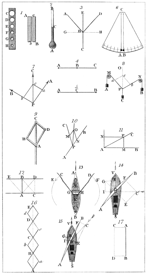
H. Adlard, sc.
London, Pubd. by Longman & Co.
(86.) If the wind, however, be directly contrary to59
the course which it is required that the vessel should
take, there is no position which can be given to the sails
which will impel the vessel. In this case the required
course itself is resolved into two, in which the vessel
sails alternately, a process which is called tacking. Thus,
suppose the vessel is required to move from A to E, fig. 16.,
the wind setting from E to A. The motion A B being
resolved into two, by being assumed as the diagonal of
a parallelogram, the sides A a, a B of the parallelogram
are successively sailed over, and the vessel by this
means arrives at B, instead of moving along the diagonal
A B. In the same manner she moves along B b, b C,
C c, c D, D d, d E, and arrives at E. She thus sails
continually at a sufficient angle with the wind to obtain
an impelling force, yet at a sufficiently small angle to
make way in her proposed course.
The consideration of the effect of the rudder, which
we have omitted in the preceding illustration, affords
another instance of the resolution of force. We shall
not, however, pursue this example further.
(87.) A body falling from the top of the mast when
the vessel is in full sail, is an example of the composition
of motion. It might be expected, that during the
descent of the body, the vessel having sailed forward,
would leave it behind, and that, therefore, it would fall
in the water behind the stern, or at least on the deck,
considerably behind the mast. On the other hand, it is
found to fall at the foot of the mast, exactly as it would
if the vessel were not in motion. To account for this,
let A B, fig. 17., be the position of the mast when the
body at the top is disengaged. The mast is moving
onwards with the vessel in the direction A C, so that in
the time which the body would take to fall to the deck,
the top of the mast would move from A to C. But the
body being on the mast at the moment it is disengaged,
has this motion A C in common with the mast; and
therefore in its descent it is affected by two motions,
viz. that of the vessel expressed by A C, and its descending
motion expressed by A B. Hence, by the com60position
of motion, it will be found at the opposite angle
D of the parallelogram, at the end of the fall. During
the fall, however, the mast has moved with the vessel,
and has advanced to C D, so that the body falls at the
foot of the mast.
(88.) An instance of the composition of motion, which
is worthy of some attention, as it affords a proof of the
diurnal motion of the earth, is derived from observing
the descent of a body from a very high tower. To render
the explanation of this more simple, we shall suppose
the tower to be on the equator of the earth. Let
E P Q, fig. 18., be a section of the earth through the equator,
and let P T be the tower. Let us suppose that the
earth moves on its axis in the direction E P Q. The
foot P of the tower will, therefore, in one day move
over the circle E P Q, while the top T moves over the
greater circle T T′ R. Hence it is evident, that the top
of the tower moves with greater speed than the foot,
and therefore in the same time moves through a greater
space. Now suppose a body placed at the top; it participates
in the motion which the top of the tower has
in common with the earth. If it be disengaged, it also
receives the descending motion T P. Let us suppose
that the body would take five seconds to fall from T to
P, and that in the same time the top T is moved by the
rotation of the earth from T to T′, the foot being moved
from P to P′. The falling body is therefore endued
with two motions, one expressed by T T′, and the other
by T P. The combined effect of these will be found in
the usual way by the parallelogram. Take T p equal to
T T′; the body will move from T to p in the time
of the fall, and will meet the ground at p. But since
T T′ is greater than P P′, it follows that the point p must
be at a distance from P′ equal to the excess of T T′
above P P′. Hence the body will not fall exactly at the
foot of the tower, but at a certain distance from it, in
the direction of the earth’s motion, that is, eastward.
This is found, by experiment, to be actually the case;
and the distance from the foot of the tower, at which61
the body is observed to fall, agrees with that which is
computed from the motion of the earth, to as great a
degree of exactness as could be expected from the nature
of the experiment.
(89.) The properties of compounded motions cause
some of the equestrian feats exhibited at public spectacles
to be performed by a kind of exertion very different
from that which the spectators generally attribute
to the performer. For example, the horseman standing
on the saddle leaps over a garter extended over the
horse at right angles to his motion; the horse passing
under the garter, the rider lights upon the saddle at
the opposite side. The exertion of the performer, in
this case, is not that which he would use were he to
leap from the ground over a garter at the same height.
In the latter case, he would make an exertion to rise,
and, at the same time, to project his body forward. In
the case, however, of the horseman, he merely makes
that exertion which is necessary to rise directly upwards
to a sufficient height to clear the garter. The
motion which he has in common with the horse, compounded
with the elevation acquired by his muscular
power, accomplishes the leap.
To explain this more fully, let A B C, fig. 19., be the
direction in which the horse moves, A being the point
at which the rider quits the saddle, and C the point at
which he returns to it. Let D be the highest point
which is to be cleared in the leap. At A the rider makes
a leap towards the point E, and this must be done at
such a distance from B, that he would rise from B to E
in the time in which the horse moves from A to B. On
departing from A, the rider has, therefore, two motions,
represented by the lines A E and A B, by which he will
move from the point A to the opposite angle D of the
parallelogram. At D, the exertion of the leap being
overcome by the weight of his body, he begins to return
downward, and would fall from D to B in the time in
which the horse moves from B to C. But at D he still
retains the motion which he had in common with the
horse; and therefore, in leaving the point D, he has62
two motions, expressed by the lines D F and D B. The
compounded effects of these motions carry him from D
to C. Strictly speaking, his motion from A to D, and
from D to C, is not in straight lines, but in a curve. It
is not necessary here, however, to attend to this circumstance.
(90.) If a billiard-ball strike the cushion of the table
obliquely, it will be reflected from it in a certain direction,
forming an angle with the direction in which it struck it.
This affords an example of the resolution and composition
of motion. We shall first consider the effect which
would ensue if the ball struck the cushion perpendicularly.
Let A B, fig. 20., be the cushion, and C D the direction
in which the ball moves towards it. If the ball and
the cushion were perfectly inelastic, the resistance of the
cushion would destroy the motion of the ball, and it
would be reduced to a state of rest at D. If, on the
other hand, the ball were perfectly elastic, it would be
reflected from the cushion, and would receive as much
motion from D to C after the impact, as it had from
C to D before it. Perfect elasticity, however, is a
quality which is never found in these bodies. They
are always elastic, but imperfectly so. Consequently the
ball after the impact will be reflected from D towards C,
but with a less motion than that with which it approached
from C to D.
Now let us suppose that the ball, instead of moving
from C to D, moves from E to D. The force with which
it strikes D being expressed by D E′, equal to E D, may
be resolved into two, D F and D C′. The resistance of
the cushion destroys D C′, and the elasticity produces a
contrary force in the direction D C, but less than D C or
D C′, because that elasticity is imperfect. The line D C
expressing the force in the direction C D, let D G (less
than D C) express the reflective force in the direction
D C. The other element D F, into which the force D E′
is resolved by the impact, is not destroyed or modified by
the cushion, and therefore, on leaving the cushion at D,63
the ball is influenced by two forces, D F (which is equal
to C E) and D G. Consequently it will move in the diagonal
D H.
(91.) The angle E D C is in this case called the “angle
of incidence,” and C D H is called “the angle of reflection.”
It is evident, from what has been just inferred,
that the ball, being imperfectly elastic, the angle of incidence
must always be less than the angle of reflection,
and with the same obliquity of incidence, the more imperfect
the elasticity is, the less will be the angle of reflection.
In the impact of a perfectly elastic body, the angle of
reflection would be equal to the angle of incidence. For
then the line D G, expressing the reflective force, would
be taken equal to C D, and the angle C D H would be
equal to C D E. This is found by experiment to be the
case when light is reflected from a polished surface of
glass or metal.
Motion is sometimes distinguished into absolute and
relative. What “relative motion” means is easily explained.
If a man walk upon the deck of a ship from
stem to stern, he has a relative motion which is measured
by the space upon the deck over which he walks in a given
time. But while he is thus walking from stem to stern,
the ship and its contents, including himself, are impelled
through the deep in the opposite direction. If it so
happen that the motion of the man, from stem to stern,
be exactly equal to the motion of the ship in the contrary
way, the man will be, relatively to the surface of the sea
and that of the earth, at rest. Thus, relatively to the
ship, he is in motion, while, relatively to the surface
of the earth, he is at rest. But still this is not absolute
rest. The surface itself is moving by the diurnal
rotation of the earth upon its axis, as well as by the
annual motion in its orbit round the sun. These motions,
and others to which the earth is subject, must be all
compounded by the theorem of the parallelogram of
forces before we can obtain the absolute state of the body
with respect to motion or rest.
(92.) Whatever produces, or tends to produce, a
change in the state of a particle or mass of matter with
respect to motion or rest, is a force. Rest, or uniform
rectilinear motion, are therefore the only states in which
any body can exist which is not subject to the present
action of some force. We are not, however, entitled to
conclude, that because a body is observed in one or other
of these states, it is therefore uninfluenced by any forces.
It may be under the immediate action of forces which
neutralise each other: thus two forces may be acting
upon it which are equal, and in opposite directions. In
such a case, its state of rest, or of uniform rectilinear
motion, will be undisturbed. The state of uniform rectilinear
motion declares more with respect to the body
than the state of rest; for the former betrays the action
of a force upon the body at some antecedent period; this
action having been suspended, while its effect continues
to be observed in the motion which it has produced.
(93.) When the state of a body is changed from rest
to uniform rectilinear motion, the action of the force
is only momentary, in which case it is called an impulse.
If a body in uniform rectilinear motion receive an impulse
in the direction in which it is moving, the effect
will be, that it will continue to move uniformly in the
same direction, but its velocity will be increased by the
amount of speed which the impulse would have given it
had it been previously quiescent. Thus, if the previous
motion be at the rate of ten feet in a second, and the impulse
be such as would move it from a state of rest at five
feet in a second, the velocity, after the impulse, will be
fifteen feet in a second.
But if the impulse be received in a direction immediately
opposed to the previous motion, then it will diminish
the speed by that amount of velocity which it would65
give to the body had it been previously at rest. In the
example already given, if the impulse were opposed to
the previous motion, the velocity of the body after the
impulse would be five feet in a second. If the impulse
received in the direction opposed to the motion be such
as would give to the body at rest a velocity equal to that
with which it is moving, then the effect will be, that
after the impulse no motion will exist; and if the impulse
would give it a still greater velocity, the body will
be moved in the opposite direction with an uniform velocity
equal to the excess of that due to the impulse over
that which the body previously had.
When a body in a state of uniform motion receives
an impulse in a direction not coinciding with that of its
motion, it will move uniformly after the impulse in an
intermediate direction, which may be determined by the
principles established for the composition of motion in
the last chapter.
Thus it appears, that whenever the state of a body is
changed either from rest to uniform rectilinear motion
or vice versa, or from one state of uniform rectilinear
motion to another, differing from that either in velocity
or direction, or in both, the phenomenon is produced by
that peculiar modification of force whose action continues
but for a single instant, and which has been called an
impulse.
(94.) In most cases, however, the mechanical state of
a body is observed to be subject to a continual change or
tendency to change. We are surrounded by innumerable
examples of this. A body is placed on the table.
A continual pressure is excited on the surface of the
table. This pressure is only the consequence of the
continual tendency of the body to move downwards. If
the body were excited by a force of the nature of an
impulse, the effect upon the table would be instantaneous,
and would immediately cease. It would, in fact, be a
blow. But the continuation of the pressure proves the
continuation of the action of the force.
If the table be removed from beneath the body, the66
force which excites it being no longer resisted, will produce
motion; it is manifested, not as before, by a tendency
to produce motion, but by the actual exhibition of
that phenomenon. Now if the exciting force were an
impulse, the body would descend to the ground with an
uniform velocity. On the other hand, as will hereafter
appear, every moment of its fall increases its speed, and
that speed is greatest at the instant it meets the ground.
A piece of iron placed at a distance from a magnet
approaches it, but not with an uniform velocity. The
force of the magnet continues to act during the approach
of the iron, and each moment gives it increased motion.
(95.) The forces which are thus in constant operation,
proceed from secret agencies which the human
mind has never been able to detect. All the analogies of
nature prove that they are not the immediate results of
the divine will, but are secondary causes, that is, effects
of some more remote principles. To ascend to these
secondary causes, and thus as it were approach one step
nearer to the Creator, is the great business of philosophy;
and the most certain means for accomplishing
this, is diligently to observe, to compare, and to classify
the phenomena, and to avoid assuming the existence of
any thing which has not either been directly observed,
or which cannot be inferred demonstratively from natural
phenomena. Philosophy should follow nature, and
not lead her.
While the law of inertia, established by observation
and reason, declares the inability of matter, from any
principle resident in it, to change its state, all the phenomena
of the universe prove that state to be in constant
but regular fluctuation. There is not in existence a
single instance of the phenomenon of absolute rest, or of
motion which is absolutely uniform and rectilinear. In
bodies, or the parts of bodies, there is no known instance
of simple passive juxtaposition unaccompanied by pressure
or tension, or some other “tendency to motion.”
Innumerable secret powers are ever at work, compensating,
as it were, for inertia, and supplying the material67
world with a substitute for the principles of action and
will, which give such immeasurable superiority to the
character of life.
(96.) The forces which are thus in continual operation,
whose existence is demonstrated by their observed
effects, but whose nature, seat, and mode of operation
are unknown to us, are called by the general name attractions.
These forces are classified according to the
analogies which prevail among their effects, in the same
manner, and according to the same principles, as organised
beings are grouped in natural history. In that
department of natural science, when individuals are distributed
in classes, the object is merely to generalise,
and thereby promote the enlargement of knowledge; but
nothing is or ought to be thus assumed respecting
the essence, or real internal constitution of the individuals.
According to their external and observable characters
and qualities they are classed; and this classification
should never be adduced as an evidence of any
thing except that similitude of qualities to which it owed
its origin.
Phenomena are to the natural philosopher what organised
beings are to the naturalist. He groups and
classifies them on the same principles, and with a like
object. And as the naturalist gives to each species a
name applicable to the individual beings which exhibit
corresponding qualities, so the philosopher gives to each
force or attraction a name corresponding to the phenomena
of which it is the cause. The naturalist is ignorant
of the real essence or internal constitution of the
thing which he nominates, and of the manner in which
it comes to possess or exhibit those qualities which form
the basis of his classification; and the natural philosopher
is equally ignorant of the nature, seat, and mode of operation
of the force which he assigns as the cause of an
observed class of effects.
These observations respecting the true import of the
term “attraction” seem the more necessary to be premised,
because the general phraseology of physical science,68
taken as language is commonly received, will seem to
convey something more. The names of the several attractions
which we shall have to notice, frequently refer
the seat of the cause to specific objects, and seem to
imply something respecting its mode of operation. Thus,
when we say “the magnet attracts a piece of iron,” the
true philosophical import of the words is, “that a piece
of iron placed in the vicinity of the magnet, will move
towards it, or placed in contact, will adhere to it, so that
some force is necessary to separate them.” In the ordinary
sense, however, something more than this simple
fact is implied. It is insinuated that the magnet is the
seat of the force which gives motion to the iron; that
in the production of the phenomenon, the magnet is an
agent exerting a certain influence, of which the iron is
the subject. Of all this, however, there is no proof;
on the contrary, since the magnet must move towards
the iron with just as much force as the iron moves towards
the magnet, there is as much reason to place the
seat of the force in the iron, and consider it as an agent
affecting the magnet. But, in fact, the influence which
produces this phenomenon may not be resident in either
the one body or the other. It may be imagined to be a
property of a medium in which both are placed, or to
arise from some third body, the presence of which is
not immediately observed. However attractive these
and like speculations may be, they cannot be allowed a
place in physical investigations, nor should consequences
drawn from such hypotheses be allowed to taint our
conclusions with their uncertainty.
The student ought, therefore, to be aware, that whatever
may seem to be implied by the language used in
this science in relation to attractions, nothing is permitted
to form the basis of reasoning respecting them
except their effects; and whatever be the common signification
of the terms used, it is to these effects, and to
these alone, they should be referred.
(97.) Attractions may be primarily distributed into
two classes; one consisting of those which exist between69
the molecules or constituent parts of bodies, and the
other between bodies themselves. The former are sometimes
called, for distinction, molecular or atomic attractions.
Without the agency of molecular forces, the whole
face of nature would be deprived of variety and beauty;
the universe would be a confused heap of material atoms
dispersed through space, without form, shape, coherence,
or motion. Bodies would neither have the forms of
solid, liquid, or air; heat and light would no longer
produce their wonted effects; organised beings could
not exist; life itself, as connected with body, would be
extinct. Atoms of matter, whether distant or in juxtaposition,
would have no tendency to change their places,
and all would be eternal stillness and rest. If, then,
we are asked for a proof of the existence of molecular
forces, we may point to the earth and to the heavens;
we may name every object which can be seen or felt.
The whole material world is one great result of the
influence of these powerful agents.
(98.) It has been proved (11. et seq.) that the constituent
particles of bodies are of inconceivable minuteness,
and that they are not in immediate contact (23),
but separated from each other by interstitial spaces,
which, like the atoms themselves, although too small to
be directly observed, yet are incontestably proved to
exist, by observable phenomena, from which their existence
demonstratively follows. The resistance which
every body opposes to compression, proves that a repulsive
influence prevails between the particles, and that
this repulsion is the cause which keeps the atoms separate,
and maintains the interstitial spaces just mentioned.
Although this repulsion is found to exist between the
molecules of all substances whatever, yet it has different
degrees of energy in different bodies. This is proved
by the fact, that some substances admit of easy compression,
while in others, the exertion of considerable
force is necessary to produce the smallest diminution in
bulk.
70
The space around each atom of a body, through which
this repulsive influence extends, is generally limited, and
immediately beyond it, a force of the opposite kind is
manifested, viz. attraction. Thus, in solid bodies, the
particles resist separation as well as compression, and the
application of force is as necessary to break the body, or
divide it into separate parts, as to force its particles into
closer aggregation. It is by virtue of this attraction that
solid bodies maintain their figure, and that their parts
are not separated and scattered like those of fluids, merely
by their own weight. This force is called the attraction
of cohesion.
The cohesive force acts in different substances with
different degrees of energy: in some its intensity is very
great; but the sphere of its influence apparently very
limited. This is the case with all bodies which are hard,
strong, and brittle, which no force can extend or stretch
in any perceptible degree, and which require a great
force to break or tear them asunder. Such, for example,
is cast iron, certain stones, and various other substances.
In some bodies the cohesive force is weak, but the sphere
of its action considerable. Bodies which are easily
extended, without being broken or torn asunder, furnish
examples of this. Such are Indian-rubber, or caoutchouc,
several animal and vegetable products, and, in general, all
solids of a soft and viscid kind.
Between these extremes, the cohesive force may be
observed in various degrees. In lead and other soft
metals, its sphere of action is greater, and its energy
less, than in the former examples; but its sphere less,
and energy greater, than in the latter ones. It is from
the influence of this force, and that of the repulsion,
whose sphere of action is still closer to the component
atoms, that all the varieties of texture which we denominate
hard, soft, tough, brittle, ductile, pliant, &c. arise.
After having been broken, or otherwise separated, the
parts of a solid may be again united by their cohesion,
provided any considerable number of points be brought
into sufficiently close contact. When this is done by me71chanical
means, however, the cohesion is not so strong as
before their separation, and a comparatively small force
will be sufficient again to disunite them. Two pieces of
lead freshly cut, with smooth surfaces, will adhere when
pressed together, and will require a considerable force to
separate them. In the same manner if a piece of Indian-rubber
be torn, the parts separated will again cohere, by
being brought together with a slight pressure. The
union of the parts in such instances is easy, because the
sphere through which the influence of cohesion extends
is considerable; but even in bodies in which this influence
extends through a more limited space, the cohesion
of separate pieces will be manifested, provided their surfaces
be highly polished, so as to insure the near approach
of a great number of their particles. Thus, two polished
surfaces of glass, metal, or stone, will adhere when
brought into contact.
In all these cases, if the bodies be disunited by mechanical
force, they will separate at exactly the parts at
which they had been united, so that after their separation
no part of the one will adhere to the other; proving
that the force of cohesion of the surfaces brought into
contact is less than that which naturally held the particles
of each together.
(99.) When a body is in the liquid form, the weight
of its particles greatly predominates over their mutual
cohesion, and consequently if such a body be unconfined
it will be scattered by its own weight; if it be placed in
any vessel, it will settle itself, by the force of its weight,
into the lowest parts, so that no space in the vessel below
the upper surface of the liquid will be unoccupied. The
particles of a solid body placed in the vessel have exactly
the same tendency, by reason of their weight; but this
tendency is resisted and prevented from taking effect by
their strong cohesion.
Although this cohesion in solids is much greater than
in liquids, and productive of more obvious effects, yet the
principle is not altogether unobserved in liquids. Water
converted into vapour by heat, is divided into incon72ceivably
minute particles, which ascend in the atmosphere.
When it is there deprived of a part of that heat
which gave it the vaporous form, the particles, in virtue
of their cohesive force, collect into round drops, in which
form they descend to the earth.
In the same manner, if a liquid be allowed to fall
gradually from the lip of a vessel, it will not be dismissed
in particles indefinitely small, as if its mass were incoherent,
like sand or powder, but will fall in drops of
considerable magnitude. In proportion as the cohesive
force is greater, these drops affect a greater size. Thus,
oil and viscid liquids fall in large drops; ether, alcohol,
and others in small ones.
Two drops of rain trickling down a window pane will
coalesce when they approach each other; and the same
phenomenon is still more remarkable, if a few drops of
quicksilver be scattered on an horizontal plate of glass.
It is the cohesive principle which gives rotundity to
grains of shot: the liquid metal is allowed to fall like
rain from a great elevation. In its descent the drops
become truly globular, and before they reach the end of
their fall they are hardened by cooling, so that they
retain their shape.
It is also, probably, to the cohesive attraction that we
should assign the globular forms of all the great bodies
of the universe; the sun, planets, satellites, &c., which
originally may have been in the liquid state.
(100.) Molecular attraction is also exhibited between
the particles of liquids and solids. A drop of water will
not descend freely when it is in contact with a perpendicular
glass plane: it will adhere to the glass; its descent
will be retarded; and if its weight be insufficient to overcome
the adhesive force, it will remain suspended.
If a plate of glass be placed upon the surface of water
without being permitted to sink, it will require more
force to raise it from the water than is sufficient merely
to balance the weight of the glass. This shows the
adhesion of the water and glass, and also the cohesive force
with which the particles of the water resist separation.
73
If a needle be dipped in certain liquids, a drop will
remain suspended at its point when withdrawn from
them: and, in general, when a solid body has been
immersed in a liquid and withdrawn, it is wet; that is,
some of the liquid has adhered to its surfaces. If no
attraction existed between the solid and liquid, the
solid would be in the same state after immersion as
before. This is proved by liquids and solids between
which no attraction exists. If a piece of glass be immersed
in mercury, it will be in the same state when
withdrawn as before it was immersed. No mercury
will adhere to it; it will not be wet.
When it rains, the person and vesture are affected
only because this attraction exists between them and
water. If it rained mercury, none would adhere to them.
(101.) When molecular attraction is exhibited by
liquids pervading the interstices of porous bodies, ascending
in crevices or in the bores of small tubes, it is called
capillary attraction. Instances of this are innumerable.
Liquids are thus drawn into the pores of sponge, sugar,
lamp-wick, &c. The animal and vegetable kingdom
furnish numerous examples of this class of effects.
A weight being suspended by a dry rope, will be
drawn upwards through a considerable height, if the rope
be moistened with a wet sponge. The attraction of the
particles composing the rope for the water is in this
case so powerful, that the tension produced by several
hundred weight cannot expel them.
A glass tube, of small bore, being dipped in water
tinged by mixture with a little ink, will retain a quantity
of the liquid suspended when withdrawn. The
height of the liquid in the tube will be seen by looking
through it. It is found that the less the bore of the tube
is, the greater will be the height of the column sustained.
A series of such tubes fixed in the same frame,
with their lower orifices at the same level, and with bores
gradually decreasing, being dipped in the liquid, will
exhibit columns gradually increasing.
A capillary syphon is formed of a hank of cotton74
threads, one end of which is immersed in the vessel containing
the liquid, and the other is carried into the vessel
into which the liquid is to be transferred. The liquid
may be thus drawn from the one vessel into the other.
The same effect may be produced by a glass syphon with
a small bore.
(102.) It frequently happens that a molecular repulsion
is exhibited between a solid and a liquid. If a piece
of wood be immersed in quicksilver, the liquid will be
depressed at that part of the surface which is near the
wood; and in like manner, if it be contained in a glass
vessel, it will be depressed at the edges. In a barometer
tube, the surface of the mercury is convex, owing partly
to the repulsion between the glass and mercury.
All solids, however, do not repel mercury. If any
golden trinket be dipped in that liquid, or even be exposed
for a moment to contact with it, the gold will be
instantly intermingled with particles of quicksilver, the
metal changes its colour, and becomes white like silver,
and the mercury can only be extricated by a difficult
process. Chains, seals, rings, &c. should always be laid
aside by those engaged in experiments or other processes
in which mercury is used.
(103.) Of all the forms under which molecular force
is exhibited, that in which it takes the name of affinity
is attended with the most conspicuous effects. Affinity
is in chemistry what inertia is in mechanics, the basis
of the science. The present treatise is not the proper
place for any detailed account of this important class of
natural phenomena. Those who seek such knowledge
are referred to our treatise on Chemistry. Since, however,
affinity sometimes influences the mechanical state
of bodies, and affects their mechanical properties, it will
be necessary here to state so much respecting it as to
render intelligible those references which we may have
occasion to make to such effects.
When the particles of different bodies are brought
into close contact, and more especially when, being in a
fluid state, they are mixed together, their union is fre75quently
observed to produce a compound body, differing
in its qualities from either of the component bodies.
Thus the bulk of the compound is often greater or less
than the united volumes of the component bodies. The
component bodies may be of the ordinary temperature of
the atmosphere, and yet the compound may be of a much
higher or lower temperature. The components may be
liquid, and the compound solid. The colour of the
compound may bear no resemblance whatever to that of
the components. The species of molecular action between
the components, which produce these and similar,
effects, is called affinity.
(104.) We shall limit ourselves here to the statement
of a few examples of these phenomena.
If a pint of water and a pint of sulphuric acid be
mixed, the compound will be considerably less than a
quart. The density of the mixture is, therefore, greater
than that which would result from the mere diffusion
of the particles of the one fluid through those of the
other. The particles have assumed a greater proximity,
and therefore exhibit a mutual attraction.
In this experiment, although the liquids before being
mixed be of the temperature of the surrounding air,
the mixture will be so intensely hot, that the vessel
which contains it cannot be touched without pain.
If the two aeriform fluids, called oxygen and hydrogen,
be mixed together in a certain proportion, the compound
will be water. In this case, the components are
different from the compound, not merely in the one being
air and the other liquid, but in other respects not
less striking. The compound water extinguishes fire,
and yet of the components, hydrogen is one of the most
inflammable substances in nature, and the presence of
oxygen is indispensably necessary to sustain the phenomenon
of combustion.
Oxygen gas, united with quicksilver, produces a compound
of a black colour, the quicksilver being white and
the gas colourless. When these substances are combined
in another proportion, they give a red compound.
76
(105.) Having noticed the principal molecular forces,
we shall now proceed to the consideration of those attractions
which are exhibited between bodies existing in
masses. The influence of molecular attractions is limited
to insensible distances. On the contrary, the forces
which are now to be noticed act at considerable distances,
and to the influence of some there is no limit, the effect,
however, decreasing as the distance increases.
The effect of the loadstone on iron is well known,
and is one of this class of forces. For a detailed account
of this force, and the various phenomena of which
it is the cause, the reader is referred to our treatise on
Magnetism.
When glass, wax, amber, and other substances are
submitted to friction with silken or woollen cloth, they
are observed to attract feathers, and other light bodies
placed near them. A like effect is produced in several
other ways, and is attended with other phenomena, the
discussion of which forms a principal part of physical
science. The force thus exhibited is called electricity.
For details respecting it, and for its connection with
magnetism, the reader is referred to our treatises on
Electricity and Electro-magnetism.
(106.) These attractions exist either between bodies
of particular kinds, or are developed by reducing the
bodies which manifest them to a certain state by friction,
or some other means. There is, however, an attraction,
which is manifested between bodies of all
species, and under all circumstances whatever; an attraction,
the intensity of which is wholly independent
of the nature of the bodies, and only depends on their
masses and mutual distances. Thus, if a mass of metal
and a mass of clay be placed in the vast abyss of space,
at a mile asunder, they will instantly commence to approach
each other with certain velocities. Again, if a
mass of stone and of wood respectively equal to the
former, be placed at a like distance, they will also commence
to approach each other with the same velocities
as the former. This universal attraction, which only77
depends on the quantity of the masses and their mutual
distances, is called the “attraction of gravitation.” We
shall first explain the “law” of this attraction, and
shall then point out some of the principal phenomena
by which its existence and its laws are known.
(107.) The “law of gravitation” sometimes from
its universality called the “law of nature,” may be
explained as follows:
Let us suppose two masses, A and B, placed beyond
the influence or attraction of any other bodies,
in a state of rest, and at any proposed distance from
each other. By their mutual attraction they will approach
each other, but not with the same velocity. The
velocity of A will be greater than that of B, in the same
proportion as its mass is less than that of B. Thus, if
the mass of B be twice that of A, while A approaches
B through a space of two feet, B will approach A
through a space of one foot. Hence it follows, that
the force with which A moves towards B is equal to
the force with which B moves towards A (68). This
is only a consequence of the property of inertia, and is
an example of the equality of action and reaction, as
explained in Chapter IV. The velocity with which A
and B approach each other is estimated by the diminution
of their distance, A B, by their mutual approach
in a given time. Thus, if in one second A move
towards B through a space of two feet, and in the same
time B moves towards A through the space of one foot,
they will approach each other through a space of three
feet in a second, which will be their relative velocity
(91).
If the mass of B be doubled, it will attract A with
double the former force, or, what is the same, will cause
A to approach B with double the former velocity. If
the mass of B be trebled, it will attract A with treble
the first force, and, in general, while the distance A B
remains the same, the attractive force of B upon A will
increase or diminish in exactly the same proportion as
the mass of B is increased or diminished.
78
In the same manner, if the mass A be doubled, it will
be attracted by B with a double force, because B exerts
the same degree of attraction on every part of the mass
A, and any addition which it may receive will not diminish
or otherwise affect the influence of B on its
former mass.
To express this in general arithmetical symbols let
a and b express the space through which A and B respectively
would be moved towards each other by their
mutual attraction. We would then have
A × a = B × b.
Thus, it is a general law of gravitation, that so long
as the distance between two bodies remains the same,
each will attract and be attracted by the other, in proportion
to its mass; and any increase or decrease of the
mass will cause a corresponding increase or decrease in
the amount of the attraction.
(108.) We shall now explain the law, according to
which the attraction is changed, by changing the distance
between the bodies. At the distance of one mile
the body B attracts A with a certain force. At the
distance of two miles, the masses not being changed, the
attraction of B upon A will be one-fourth of its amount
at the distance of one mile. At the distance of three
miles, it will be one-ninth of its original amount; at
four miles, it is reduced to a sixteenth, and so on. The
following table exhibits the diminution of the attraction
corresponding to the successive increase of distance:
| Distance |
1 |
2 |
3 |
4 |
5 |
6 |
7 |
8 |
&c. |
| Attraction |
1 |
1/4 |
1/9 |
1/16 |
1/25 |
1/36 |
1/49 |
1/64 |
&c. |
In ARITHMETIC, that number which is found by multiplying
any proposed number by itself, is called its
square. Thus 4, that is, 2 multiplied by 2, is the
square of 2; 9 that is, 3 times 3, is the square of 3,
and so on. On inspecting the above table, it will be
apparent, therefore, that the attraction of gravitation
decreases in the same proportion as the square of the
distance from the attracting body increases, the mass of79
both bodies in this case being supposed to remain the
same; but if the mass of either be increased or diminished,
the attraction will be increased or diminished in
the same proportion.
(109.) Hence the law of gravitation may be thus expressed:
“The mutual attraction of two bodies increases
in the same proportion as their masses are increased, and
as the square of their distance is decreased; and it decreases
in proportion as their masses are decreased, and
as the square of their distance is increased.”
This law may be more clearly expressed by means of
general symbols. Let f express the force with which a
mass weighing 1 lb. will attract another mass weighing
1 lb., at the distance of 1 foot. The force with which
they will mutually attract, when removed to the distance
expressed in feet by D, will be
f/D2
that is, the force f divided by the square of the number
D.
If one of the bodies, instead of weighing 1 lb., weigh
the number of pounds expressed by A, their mutual
attraction will be increased A times, and will therefore
be expressed by
A × f/D2
In fine, if the other be also the number of pounds
expressed by B, their mutual attraction will be
A × B × f/D2
(110.) Having explained the law of gravitation, we
shall now proceed to show how the existence of this
force is proved, and its law discovered.
The earth is known to be a globular mass of matter,
incomparably greater than any of the detached bodies
which are found upon its surface. If one of these bodies
suspended at any proposed height above the surface of
the earth be disengaged, it will be observed to descend80
perpendicularly to the earth, that is, in the direction of
the earth’s centre. The force with which it descends
will also be found to be in proportion to the mass, without
any regard to the species of the body. These circumstances
are consistent with the account which we
have given of gravitation. But by that account we
should expect, that as the falling body is attracted with
a certain force towards the earth, the earth itself should
be attracted towards it by the same force; and instead
of the falling body moving towards the earth, which is
the phenomenon observed, the earth and it should move
towards each other, and meet at some intermediate point.
This, in fact, is the case, although it is impossible to
render the motion of the earth observable, for reasons
which will easily be understood.
Since all the bodies around us participate in this motion,
it would not be directly observable, even though its
quantity were sufficiently great to be perceived under
other circumstances. But setting aside this consideration,
the space through which the earth moves in such a case
is too minute to be the subject of sensible observation.
It has been stated (107), that when two bodies attract
each other, the space through which the greater approaches
the lesser, bears to that through which the lesser
approaches the greater, the same proportion as the mass
of the lesser bears to the mass of the greater. Now the
mass of the earth is more than 1000,000,000,000,000
times the mass of any body which is observed to
fall on its surface; and therefore if even the largest
body which can come under observation were to fall
through an height of 500 feet, the corresponding motion
of the earth would be through a space less than the
1000,000,000,000,000th part of 500 feet, which is
less than the 100,000,000,000th part of an inch.
The attraction between the earth and detached bodies
on its surface is not only exhibited by the descent of
these bodies when unsupported, but by their pressure
when supported. This pressure is what is called weight.
The phenomena of weight, and the descent of heavy
bodies, will be fully investigated in the next chapter.
81
(111.) It is not alone by the direct fall of bodies
that the gravitation of the earth is manifested. The
curvilinear motion of bodies projected in directions different
from the perpendicular, is a combination of the
effects of the uniform velocity which has been given to the
projectile by the impulse which it has received, and the
accelerated velocity which it receives from the earth’s attraction.
Suppose a body placed at any point P, fig. 21.,
above the surface of the earth, and let P C be the direction
of the earth’s centre. If the body were allowed to move
without receiving any impulse, it would descend to the
earth in the direction P A, with an accelerated motion.
But suppose that at the moment of its departure from
P, it receives an impulse in the direction P B, which
would carry it to B in the time the body would fall from
P to A, then, by the composition of motion, the body
must at the end of that time be found in the line B D,
parallel to P A. If the motion in the direction of P A
were uniform, the body P would in this case move in
the straight line from P to D. But this is not the case.
The velocity of the body in the direction P A is at first
so small as to produce very little deflection of its motion
from the line P B. As the velocity, however, increases,
this deflection increases, so that it moves from P to D
in a curve, which is convex, towards P B.
The greater the velocity of the projectile in the direction
P A, the greater sweep the curve will take. Thus
it will successively take the forms P D, P E, P F, &c.,
and that velocity can be computed, which (setting aside
the resistance of the air) would cause the projectile to
go completely round the earth, and return to the point
P from which it departed. In this case, the body P
would continue to revolve round the earth like the moon.
Hence it is obvious, that the phenomenon of the revolution
of the moon round the earth, is nothing more than
the combined effects of the earth’s attraction, and the
impulse which it received when launched into space by
the hand of its Creator.
(112.) This is a great step in the analysis of the82
phenomenon of gravitation. We have thus reduced to
the same class two effects apparently very dissimilar, the
rectilinear descent of a heavy body, and the nearly circular
revolution of the moon round the earth. Hence
we are conducted to a generalisation still more extensive.
As the moon’s revolution round the earth, in an orbit
nearly circular, is caused by the combination of the
earth’s attraction, and an original projectile impulse, so
also the singular phenomena of the planets’ revolution
round the sun in orbits nearly circular, must be considered
an effect of the same class, as well as the revolution
of the satellites of those planets which are attended by
such bodies. Although the orbits in which the comets
move deviate very much from circles, yet this does not
hinder the application of the same principle to them,
their deviation from circles not depending on the sun’s
attraction, but only on the direction and force of the
original impulse which put them in motion.
(113.) We therefore conclude that gravitation is the
principle which, as it were, animates the universe. All
the great changes and revolutions of the bodies which
compose our system, can be traced to or derived from
this principle. It still remains to show how that remarkable
law, by which this force is declared to increase
or decrease in the same proportion as the square
of the distance from the attracting body is decreased or
increased, may be verified and established.
It has been shown, that the curvilinear path of a projectile
depends on, and can be derived, by mathematical
reasoning, from the consideration of the intensity of the
earth’s attraction, and the force of the original impulse,
or the velocity of projection. In the same manner, by
a reverse process, when we know the curve in which a
projectile moves, we can infer the amount of the attracting
force which gives the curvature to its path. In this
way, from our knowledge of the curvature of the moon’s
orbit, and the velocity with which she moves, the intensity
of the attraction which the earth exerts upon her
can be exactly ascertained. Upon comparing this with
the force of gravitation at the earth’s surface, it is found83
that the latter is as many times greater than the former,
as the square of the moon’s distance is greater than the
square of the distance of a body on the surface of the
earth from its centre.
(114.) If this were the only fact which could be
brought to establish the law of gravitation, it might be
thought to be an accidental relation, not necessarily characterising
the attraction of gravitation. Upon examining
the orbits and velocities of the several planets, the
same result is, however, obtained. It is found that the
forces with which they are severally attracted by the
sun are great, in exactly the same proportion as the
squares of the several numbers expressing their distances
are small. The mutual gravitation of bodies on the
surface of the earth towards each other is lost in the
predominating force exerted by the earth upon all of
them. Nevertheless, in some cases, this effect has not
only been observed, but actually measured.
A plumb-line, under ordinary circumstances, hangs in
a direction truly vertical; but if it be near a large mass
of matter, as a mountain, it has been observed to be
deflected from the true vertical, towards the mountain.
This effect was observed by Dr. Maskeline near the
mountain called Skehallien, in Scotland, and by French
astronomers near Chimboraco. For particulars of these
observations, see our treatise on Geodæsy.
Cavendish succeeded in exhibiting the effects of the
mutual gravitation of metallic spheres. Two globes of
lead A, B, each about a foot in diameter, were placed at
a certain distance asunder. A light rod, to the ends of
which were attached small metallic balls C, D, was suspended
at its centre E from a fine wire, and the rod
was placed as in fig. 22., so that the attractions of
each of the leaden globes had a tendency to turn the
rod round the centre E in the same direction. A manifest
effect was produced upon the balls C, D, by the
gravitation of the spheres. In this experiment, care
must be taken that no magnetic substance is intermixed
with the materials of the balls.
84
Having so far stated the principles on which the law
of gravitation is established, we shall dismiss this subject
without further details, since it more properly belongs
to the subject of Physical Astronomy; to which we
refer the reader for a complete demonstration of the law,
and for the detailed development of its various and important
consequences.
CHAP. VII.
TERRESTRIAL GRAVITY.
(115.) Gravitation is the general name given to
this attraction, by whatever masses of matter it may be
manifested. As exhibited in the effects produced by the
earth upon surrounding bodies, it is called “terrestrial
gravity.”
As the attraction of the earth is directed towards its
centre, it might be expected that two plumb-lines should
appear not to be parallel, but so inclined to each other
as to converge to a point under the surface of the earth.
Thus, if A B and C D, fig. 23., be two plumb-lines, each
will be directed to the centre O, where, if their directions
were continued, they would meet. In like manner, if
two bodies were allowed to fall from A and C, they would
descend in the directions A B and C D, which converge
to O. Observation, on the contrary, shows, that plumb-lines
suspended in places not far distant from each other
are truly parallel; and that bodies allowed to fall descend
in parallel lines. This apparent parallelism of the direction
of terrestrial gravity is accounted for by the
enormous proportion which the magnitude of the earth
bears to the distance between the two plumb-lines or the
two falling bodies which are compared. If the distance
between the places B, D, were 1200 feet, the inclination
of the lines A B and C D would not amount to a quarter
of a minute, or the 240th part of a degree. But the distance,
in cases where the parallelism is assumed, is never
greater than, and seldom so great as, a few yards; and
hence the inclination of the directions A B and C D is85
too small to be appreciated by any practical measure.
In the investigation of the phenomena of falling bodies,
we shall, therefore, assume, that all the particles of the
same body are attracted in parallel directions, perpendicular
to an horizontal plane.
(116.) Since the intensity of terrestrial gravity increases
as the square of the distance decreases, it might
be expected that, as a falling body approaches the earth,
the force which accelerates it should be continually increasing,
and, strictly speaking, it is so. But any height
through which we observe falling bodies to descend
bears so very small a proportion to the whole distance
from the centre, that the change of intensity of the
force of gravity is quite beyond any practical means of
estimating it. The radius, or the distance from the
surface of the earth to its centre, is 4000 miles. Now,
suppose a body descended through the height of half a
mile, a distance very much beyond those used in experimental
enquiries, the distances from the centre, at
the beginning and end of the fall, are then in the proportion
of 8000 to 8001, and therefore the proportion
of the force of attraction at the commencement to the
force at the end, being that of the squares of these
numbers, is 64,000,000 to 64,016,001, which, in the
whole descent, is an increase of about one part in 4000;
a quantity practically insignificant. We shall, therefore,
in explaining the laws of falling bodies, assume
that, in the entire descent, the body is urged by a force
of uniform intensity.
Although the force which attracts all parts of the
same body during its descent in a given place is the
same, yet the force of gravity, at different parts of the
earth’s surface, has different intensities. The intensity
diminishes with the latitude, so that it is greater
towards the poles, and lesser towards the equator. The
causes of this variation, its law, and the experimental
proofs of it, will be explained, when we shall treat of
centrifugal force, and the motion of pendulums. It is
sufficient merely to advert to it in this place.
86
(117.) Since the earth’s attraction acts separately
and equally on every particle of matter, without regard
to the nature or species of the body, it follows that all
bodies, of whatever kind, or whatever be their masses,
must be moved with the same velocity. If two equal
particles of matter be placed at a certain distance above
the surface of the earth, they will fall in parallel lines,
and with exactly the same speed, because the earth attracts
them equally. In the same manner, a thousand
particles would fall with equal velocities. Now, these
circumstances will in no wise be changed if those 1000
particles, instead of existing separately, be aggregated
into two solid masses, one consisting of 990 particles,
and the other of 10. We shall thus have a heavy body
and a light one, and, according to our reasoning, they
must fall to the earth with the same speed.
Common experience, however, is not always consistent
with this doctrine. What are called light substances,
as feathers, gold-leaf, paper, &c., are observed
to fall slowly and irregularly, while heavier masses, as
solid pieces of metal, stones, &c., fall rapidly. Nay,
there are not a few instances in which the earth, instead
of attracting bodies, seems to repel them, as in the case
of smoke, vapours, balloons, and other substances which
actually ascend. We are to consider that the mass of
the earth is not the only agent engaged in these phenomena.
The earth is surrounded by an atmosphere
composed of an elastic or aeriform fluid. This atmosphere
has certain properties, which will be explained in
our treatise on Pneumatics, and which are the causes
of the anomalous circumstances alluded to. Light
bodies rise in the atmosphere, for the same reason that
a piece of cork rises from the bottom of a vessel of water;
and other light bodies fall more slowly than heavy ones,
for the same reason that an egg in water falls to the
bottom more slowly than a leaden bullet. This treatise
is not the place to give a direct explanation of these
phenomena. It will be sufficient for our present purpose
to show, that if there were no atmosphere, all bodies,
heavy and light, would fall at the same rate. This may87
easily be accomplished by the aid of an air-pump.
Having by that instrument abstracted the air from a
tall glass vessel, we are enabled, by means of a wire
passing air-tight through a hole in the top, to let fall
several bodies from the top of the vessel to the bottom.
These, whether they be feathers, paper, gold-leaf, pieces
of money, &c. all descend with the same speed, and strike
the bottom at the same moment.
(118.) Every one who has seen a heavy body fall
from a height, has witnessed the fact, that its velocity
increases as it approaches the ground. But if this were
not observable by the eye, it would be betrayed by the
effects. It is well known, that the force with which a
body strikes the ground increases with the height from
whence it has fallen. This force, however, is proportional
to the velocity which it has at the moment it meets
the ground, and therefore this velocity increases with the
height.
When the observations on attraction in the last
chapter are well understood, it will be evident that
the velocity which a body has acquired in falling
from any height, is the accumulated effects of the
attraction of terrestrial gravity during the whole time of
the fall. Each instant of the fall a new impulse is given
to the body, from which it receives additional velocity;
and its final velocity is composed of the aggregation of
all the small increments of velocity which are thus communicated.
As we are at present to suppose the intensity
of the attraction invariable, it will follow that the
velocity communicated to the body in each instant of
time will be the same, and therefore that the whole quantity
of velocity produced or accumulated at the end of
any time is proportional to the length of that time.
Thus, if a certain velocity be produced in a body having
fallen for one second, twice that velocity will be produced
when it has fallen for two seconds, thrice that
velocity in three seconds, and so on. Such is the
fundamental principle or characteristic of uniformly
accelerated motion.
88
(119.) In examining the circumstances of the descent
of a body, the time of the fall and the velocity at each
instant of that time are not the only things to be attended
to. The spaces through which it falls in given intervals
of time, counted either from the commencement of its
fall, or from any proposed epoch of the descent, are
equally important objects of enquiry. To estimate the
space in reference to the time and the final velocity, we
must consider that this space has been moved through
with varying speed. From a state of rest at the beginning
of the fall, the speed gradually increases with the
time, and the final velocity is greater still than that which
the body had at any preceding instant during its descent.
We cannot, therefore, directly appreciate the space moved
through in this case by the time and final velocity. But
as the velocity increases uniformly with the time, we
shall obtain the average speed, by finding that which the
body had in the middle of the interval which elapsed
between the beginning and end of the fall, and thus
the space through which the body has actually fallen is
that through which it would move in the same time with
this average velocity uniformly continued.
But since the velocity which the body receives in any
time, counted from the beginning of its descent, is in the
proportion of that time, it follows that the velocity of the
body after half the whole time of descent is half the final
velocity. From whence it appears, that the height from
which a body falls in any proposed time is equal to the
space through which a body would move in the same time
with half the final velocity, and it is therefore equal to
half the space which would be moved through in the
same time with the final velocity.
(120.) It follows from this reasoning, that between
the three quantities, the height, the time, and the final
velocity, which enter into the investigation of the phenomena
of falling bodies, there are two fixed relations:
First, the time, counted from the beginning of the fall
and the final velocity, are proportional the one to the
other; so that as one increases, the other increases in the
same proportion. Secondly, the height being equal to89
half the space which would be moved through in the time
of the fall, with the final velocity, must have a fixed
proportion to these two quantities, viz. the time and the
final velocity, or must be proportional to the product of
the two numbers which express them.
But since the time is always proportional to the final
velocity, they may be expressed by equal numbers, and
the product of equal numbers is the square of either of
them. Hence, the product of the numbers expressing
the time and final velocity is equivalent to the square of
the number expressing the time, or to the square of the
number expressing the final velocity. Hence we infer,
that the height is always proportional to the square of
the time of the fall, or to the square of the final
velocity.
(121.) The use of a few mathematical characters will
render these results more distinct, even to students not
conversant with mathematical science.
Let S = the height from which the body falls, expressed
in feet.
V = the velocity at the end of the fall in feet per
second.
T = the number of seconds in the time of the
fall.
g = the number of feet through which a body
would fall in one second.
It will therefore follow that the velocity acquired in
one second will be 2g, and the velocity acquired in T
seconds will therefore be 2g × T; so that
V = 2g × T [1]
Since the space which a body falls through in T seconds
is found by multiplying the space it falls through
in one second by T2, we shall have
S = g × T2 [2]
from which, combined with [1] we deduce
90
S = V2/4g [3]
S = 1/2V × T [4]
By these formularies, if the height through which a
body falls freely in one second be known, the height
through which it will fall in any proposed time may be
computed. For since the height is proportional to the
square of the time, the height through which it will fall
in two seconds will be four times that which it falls
through in one second. In three seconds it will fall
through nine times that space; in four seconds, sixteen
times; in five seconds, twenty-five times, and so on. The
following, therefore, is a general rule to find the height
through which a body will fall in any given time:
“Reduce the given time to seconds, take the square
of the number of seconds in it, and multiply the height
through which a body falls in one second by that number;
the result will be the height sought.”
The following table exhibits the heights and corresponding
times as far as 10 seconds:
| Time |
1 |
2 |
3 |
4 |
5 |
6 |
7 |
8 |
9 |
10 |
| Height |
1 |
4 |
9 |
16 |
25 |
36 |
49 |
64 |
81 |
100 |
Each unit in the numbers of the first row expresses a
second of time, and each unit in those of the second row
expresses the height through which a body falls freely
in a second.
(122.) If a body fall continually for several successive
seconds, the spaces which it falls through in each succeeding
second have a remarkable relation among each
other, which may be easily deduced from the preceding
table. Taking the space moved through in the first
second still as our unit, four times that space will be
moved through in the first two seconds. Subtract from
this 1, the space moved through in the first second, and
the remainder 3 is the space through which the body falls
in the second second. In like manner if 4, the height
fallen through in the first two seconds, be subtracted91
from 9, the height fallen through in the first three seconds,
the remainder 5 will be the space fallen through in
the third second. To find the space fallen through in the
fourth second, subtract 9, the space fallen through in the
first three seconds, from 16, the space fallen through in
the first four seconds, and the result is 7, and so on. It
thus appears that if the space fallen through in the first
second be called 1, the spaces described in the second,
third, fourth, fifth, &c. seconds, will be expressed by
the odd numbers respectively, 3, 5, 7, 9, &c. This
places in a striking point of view the accelerated motion
of a falling body, the spaces moved through in each
succeeding second being continually increased.
(123.) If velocity be estimated by the space through
which the body would move uniformly in one second,
then the final velocity of a body falling for one second
will be 2; for with that final velocity the body would in
one second move through twice the height through which
it has fallen.
(124.) Since the final velocity increases in the same
proportion as the time, it follows that after two seconds
it is twice its amount after one, and after three seconds
thrice that, and so on. Thus, the following table exhibits
the final velocities corresponding to the times of
descent:
| Time |
1 |
2 |
3 |
4 |
5 |
6 |
7 |
8 |
9 |
10 |
| Final velocity |
2 |
4 |
6 |
8 |
10 |
12 |
14 |
16 |
18 |
20 |
The numbers in the second row express the spaces
through which a body with the final velocity would move
in one second, the unit being, as usual, the space through
which a body falls freely in one second.
(125.) Having thus developed theoretically the laws
which characterise the descent of bodies, falling freely
by the force of gravity, or by any other uniform force
of the same kind, it is necessary that we should show
how these laws can be exhibited by actual experiment.
There are some circumstances attending the fall of heavy
bodies which would render it difficult, if not impossible,
to illustrate, by the direct observation of this pheno92menon,
the properties which have been explained in
this chapter. A body falling freely by the force of
gravity, as we shall hereafter prove, descends in one
second of time through a height of about 16 feet1; in
two seconds, it would, therefore, fall through four times
that space, or 64 feet; in three seconds, through 9 times
the height, or 144 feet; and in four seconds, through 256
feet. In order, therefore, to be enabled to observe the
phenomena for only four seconds, we should command
an height of at least 256 feet. But further; the velocity
at the end of the first second would be at the rate of 32
feet per second; at the end of the second second, it
would be 64 feet per second; and towards the end of the
fall it would be about 120 feet per second. It is evident
that this great degree of rapidity would be a serious impediment
to accurate observation, even though we should
be able to command the requisite height. It appears
therefore that the number expressed by g in the preceding
formulæ is 16·083.
It occurred to Mr. George Attwood, a mathematician
and natural philosopher of the last century, that all the
phenomena of falling bodies might be experimentally
exhibited and accurately observed, if a force of the same
kind as gravity, viz. an uniformly accelerating force, be
used, but of a much less intensity; so that while the
motion continues to be governed by the same laws, its
quantity may be so much diminished, that the final velocity,
even after a descent of many seconds, shall be
so moderated as to admit of most deliberate and exact
observation. This being once accomplished, nothing
more would remain but to find the height through which
a body would fall in one second, or, what is the same, the
proportion of the force of gravity to the mitigated but
uniform accelerating force thus substituted for it.
(126.) To realise this notion, Attwood constructed a
wheel turning on its axle with very little friction, and
having a groove on its edge to receive a string. Over
this wheel, and in the groove, he placed a fine silken cord,
to the ends of which were attached equal cylindrical93
weights. Thus placed, the weights perfectly balance each
other, and no motion ensues. To one of the weights he
then added a small quantity, so as to give it a slight
preponderance. The loaded weight now began to descend,
drawing up on the other side the unloaded weight. The
descent of the loaded weight, under these circumstances,
is a motion exactly of the same kind as the descent of a
heavy body falling freely by the force of gravity; that is,
it increases according to the same laws, though at a very
diminished rate. To explain this, suppose that the
loaded weight descends from a state of rest through one
inch in a second, it will descend through 4 inches in two
seconds, through 9 in three, through 16 in four, and so
on. Thus in 20 seconds, it would descend through 400
inches, or 33 feet 4 inches, a height which, if it were
necessary, could easily be commanded.
It might, perhaps, be thought, that since the weights
suspended at the ends of the thread are in equilibrium,
and therefore have no tendency either to move or to
resist motion, the additional weight placed upon one of
them ought to descend as rapidly as it would if it were
allowed to fall freely and unconnected with them. It
is very true that this weight will receive from the attraction
of the earth the same force when placed upon
one of the suspended weights, as it would if it were
disengaged from them; but in the consequences which
ensue, there is this difference. If it were unconnected
with the suspended weights, the whole force impressed
upon it would be expended in accelerating its descent;
but being connected with the equal weights which sustain
each other in equilibrium, by the silken cord passing
over the wheel, the force which is impressed upon the
added weight is expended, not as before, in giving velocity
to the added weight alone, but to it together with
the two equal weights appended to the string, one of
which descends with the added weight, and the other
rises on the opposite side of the wheel. Hence, setting
aside any effect which the wheel itself produces, the
velocity of the descent must be lessened just in proportion
as the mass among which the impressed force is to be94
distributed is increased; and therefore the rate of the
fall bears to that of a body falling freely the same proportion
as the added weight bears to the sum of the
masses of the equal suspended weights and the added
weight. Thus the smaller the added weight is, and the
greater the equal suspended weights are, the slower will
the rate of descent be.
To render the circumstances of the fall conveniently
observable, a vertical shaft (see fig. 24.) is usually provided,
which is placed behind the descending weight.
This pillar is divided to inches and halves, and of course
may be still more minutely graduated, if necessary. A
stage to receive the falling weight is moveable on this
pillar, and capable of being fixed in any proposed position
by an adjusting screw. A pendulum vibrating
seconds, the beat of which ought to be very audible, is
placed near the observer. The loaded weight being thus
allowed to descend for any proposed time, or from any
required height, all the circumstances of the descent may
be accurately observed, and the several laws already explained
in this chapter may be experimentally verified.
(127.) The laws which govern the descent of bodies
by gravity, being reversed, will be applicable to the
ascent of bodies projected upwards. If a body be
projected directly upwards with any given velocity, it
will rise to the height from which it should have fallen
to acquire that velocity. The earth’s attraction will, in
this case, gradually deprive the body of the velocity
which is communicated to it at the moment at which it
is projected. Consequently, the phenomenon will be
that of retarded motion. At each part of its ascent it
will have the same velocity which it would have if it
descended to the same place from the highest point to
which it rises. Hence it is clear, that all the particulars
relative to the ascent of bodies may be immediately
inferred from those of their descent, and therefore this
subject demands no further notice.
To complete the investigation of the phenomena of
falling bodies, it would now only remain to explain the95
method of ascertaining the exact height through which
a body would descend in one second, if unresisted by
the atmosphere, or any other disturbing cause. As the
solution of this problem, however, requires the aid of
principles not yet explained, it must for the present be
postponed.
CHAP. VIII.
OF THE MOTION OF BODIES ON INCLINED PLANES AND CURVES.
(128.) In the last chapter, we investigated the phenomena
of bodies descending freely in the vertical direction,
and determined the laws which govern, not their
motion alone, but that of bodies urged by any uniformly
accelerating force whatever. We shall now consider
some of the most ordinary cases in which the free descent
of bodies is impeded, and the effects of their gravitation
modified.
(129.) If a body, urged by any forces whatever, be
placed upon a hard unyielding surface, it will evidently
remain at rest, if the resultant (76) of all the forces
which are applied to it be directed perpendicularly against
the surface. In this case, the effect produced is pressure,
but no motion ensues. If only one force act upon
the body, it will remain at rest, provided the direction
of that force be perpendicular to the surface.
But the effect will be different, if the resultant of the
forces which are applied to the body be oblique to the
surface. In that case this resultant, which, for simplicity,
may be taken as a single force, may be considered
as mechanically equivalent to two forces (76), one in
the direction of the surface, and the other perpendicular
to it. The latter element will be resisted, and will produce
a pressure; the former will cause the body to
move. This will perhaps be more clearly apprehended
by the aid of a diagram.
Let A B, fig. 25., be the surface, and let P be a particle96
of matter placed upon it, and urged by a force in the direction
P D, perpendicular to A B. It is manifest, that
this force can only press the particle P against A B, but
cannot give it any motion.
But let us suppose, that the force which urges P is
in a direction P F, oblique to A B. Taking P F as the
diagonal of a parallelogram, whose sides are P D and
P C (74), the force P F is mechanically equivalent to
two forces, expressed by the lines P D and P C. But
P D, being perpendicular to A B, produces pressure without
motion, and P C, being in the direction of A B, produces
motion without pressure. Thus the effect of the
force P F is distributed between motion and pressure in
a certain proportion, which depends on the obliquity of
its direction to that of the surface. The two extreme
cases are, 1. When it is in the direction of the surface;
it then produces motion without pressure: and, 2. When
it is perpendicular to the surface; it then produces pressure
without motion. In all intermediate directions,
however, it will produce both these effects.
(130.) It will be very apparent, that the more oblique
the direction of the force P F is to A B, the greater
will be that part of it which produces motion, and
the less will be that which produces pressure. This
will be evident by inspecting fig. 26. In this figure the
line P F, which represents the force, is equal to P F in
fig. 25. But P D, which expresses the pressure, is less
in fig. 26. than in fig. 25., while P C, which expresses the
motion, is greater. So long, then, as the obliquity of the
directions of the surface and the force remain unchanged,
so long will the distribution of the force between motion
and pressure remain the same; and therefore, if the force
itself remain the same, the parts of it which produce
motion and pressure will be respectively equal.
(131.) These general principles being understood,
no difficulty can arise in applying them to the motion of
bodies urged on inclined planes or curves by the force
of gravity. If a body be placed on an unyielding horizontal
plane, it will remain at rest, producing a pressure
on the plane equal to the total amount of its weight.
For in this case the force which urges the body, being
that of terrestrial gravity, its direction is vertical, and
therefore perpendicular to the horizontal plane.
But if the body P, fig. 25., be placed upon a plane
A B, oblique to the direction of the force of gravity,
then, according to what has been proved (129), the
weight of the body will be distributed into two parts,
P C and P D; one, P D, producing a pressure on the
plane A B, and the other, P C, producing motion down
the plane. Since the obliquity of the perpendicular direction
P F of the weight to that of the plane A B
must be the same on whatever part of the plane the
weight may be placed, it follows (130), that the proportion
P C of the weight which urges the body down
the plane must be the same throughout its whole descent.
(132.) Hence it may easily be inferred, that the force
down the plane is uniform; for since the weight of the
body P is always the same, and since its proportion to
that part which urges it down the plane is the same, it
follows that the quantity of this part cannot vary. The
motion of a heavy body down an inclined plane is
therefore an uniformly-accelerated motion, and is characterised
by all the properties of uniformly-accelerated
motion, explained in the last chapter.
Since P F represents the force of gravity, that is, the
force with which the body would descend freely in the vertical
direction, and P C the force with which it moves
down the plane, it follows that a body would fall freely
in the vertical direction from P to F in the same time as
on the plane it would move from P to C. In this manner,
therefore, when the height through which a body would
fall vertically is known, the space through which it would
descend in the same time down any given inclined plane
may be immediately determined. For let A B, fig. 25., be
the given inclined plane, and let P F be the space through
which the body would fall in one second. From F draw
F C perpendicular to the plane, and the space P C is that
through which the body P will fall in one second on
the plane.
(133.) As the angle B A H, which measures the elevation
of the plane, is increased, the obliquity of the
vertical direction P F with the plane is also increased.
Consequently, according to what has been proved (130),
it follows, that as the elevation of the plane is increased,
the force which urges the body down the plane is also
increased, and as the elevation is diminished, the force
suffers a corresponding diminution. The two extreme
cases are, 1. When the plane is raised until it becomes
perpendicular, in which case the weight is permitted to
fall freely, without exerting any pressure upon the plane;
and, 2. When the plane is depressed until it becomes
horizontal, in which case the whole weight is supported,
and there is no motion.
From these circumstances it follows, that by means of
an inclined plane we can obtain an uniformly-accelerating
force of any magnitude less than that of gravity.
We have here omitted, and shall for the present in
every instance omit, the effects of friction, by which the
motion down the plane is retarded. Having first investigated
the mechanical properties of bodies supposed to be
free from friction, we shall consider friction separately,
and show how the present results are modified by it.
(134.) The accelerating forces on different inclined
planes may be compared by the principle explained in
(131). Let figs. 25. and 26. be two inclined planes, and
take the lines P F in each figure equal, both expressing
the force of gravity, then P C will be the force which in
each case urges the body down the plane.
As the force down an inclined plane is less than that
which urges a body falling freely in the vertical direction,
the space through which the body must fall to
attain a certain final velocity must be just so much
greater as the accelerating force is less. On this principle
we shall be able to determine the final velocity in
descending through any space on a plane, compared with
the final velocity attained in falling freely in the vertical
direction. Suppose the body P, fig. 27., placed at the top
of the plane, and from H draw the perpendicular H C. If
B H represent the force of gravity, B C will represent the
force down the plane (131). In order that the body97
moving down the plane shall have a final velocity equal
to that of one which has fallen freely from B to H, it
will be necessary that it should move from B down the
plane, through a space which bears the same proportion
to B H as B H does to B C. But since the triangle
A B H is in all respects similar to H B C, only made
upon a larger scale, the line A B bears the same proportion
to B H as B H bears to B C. Hence, in falling on
the inclined plane from B to A, the final velocity is the
same as in falling freely from B to H.
It is evident that the same will be true at whatever
level an horizontal line be drawn. Thus, if I K be horizontal,
the final velocity in falling on the plane from B
to I will be the same as the final velocity in falling
freely from B to K.
(135.) The motion of a heavy body down a curve
differs in an important respect from the motion down
an inclined plane. Every part of the plane being
equally inclined to the vertical direction, the effect of
gravity in the direction of the plane is uniform; and,
consequently, the phenomena obey all the established
laws of uniformly-accelerated motion. If, however, we
suppose the line B A, on which the body P descends, to
be curved as in fig. 28., the obliquity of its direction
at different parts, to the direction P F of gravity, will
evidently vary. In the present instance, this obliquity
is greater towards B and less towards A, and hence the
part of the force of gravity which gives motion to the
body is greater towards B than towards A (130). The
force, therefore, which urges the body, instead of being
uniform as in the inclined plane, is here gradually diminished.
The rate of this diminution depends entirely
on the nature of the curve, and can be deduced
from the properties of the curve by mathematical reasoning.
The details of such an investigation are not,
however, of a sufficiently elementary character to allow
of being introduced with advantage into this treatise.
We must therefore limit ourselves to explain such of the
results as may be necessary for the development of the
other parts of the science.
98
(136.) When a heavy body is moved down an inclined
plane by the force of gravity, the plane has been proved
to sustain a pressure, arising from a certain part of the
weight P D, fig. 25., which acts perpendicularly to the
plane. This is also the case in moving down a curve such
as B A, fig. 28. In this case, also, the whole weight is
distributed between that part which is directed down
the curve, and that which, being perpendicular to the
curve, produces a pressure upon it. There is, however,
another cause which produces pressure upon the curve, and
which has no operation in the case of the inclined plane.
By the property of inertia, when a body is put in motion
in any direction, it must persevere in that direction,
unless it be deflected from it by an efficient force. In
the motion down an inclined plane the direction is never
changed, and therefore by its inertia the falling body
retains all the motion impressed upon it continually in
the same direction; but when it descends upon a curve,
its direction is constantly varying, and the resistance of
the curve being the deflecting cause, the curve must
sustain a pressure equal to that force, which would thus
be capable of continually deflecting the body from
the rectilinear path in which it would move in virtue
of its inertia. This pressure entirely depends on the
curvature of the path in which the body is constrained
to move, and on its inertia, and is therefore altogether
independent of the weight, and would, in fact, exist if
the weight were without effect.
(137.) This pressure has been denominated centrifugal
force, because it evinces a tendency of the moving
body to fly from the centre of the curve in which it
is moved. Its quantity depends conjointly on the velocity
of the motion and the curvature of the path
through which the body is moved. As circles may be
described with every degree of curvature, according to
the length of the radius, or the distance from their circumference
to their centre, it follows that, whatever be
the curve in which the body moves, a circle can always
be assigned which has the same curvature as is found at99
any proposed point of the given curve. Such a circle
is called “the circle of curvature” at that point of the
curve; and as all curves, except the circle, vary their
degrees of curvature at different points, it follows that
different parts of the same curve will have different
circles of curvature. It is evident that the greater the
radius of a circle is, the less is its curvature: thus the
circle with the radius A B, fig. 29., is more curved than
that whose radius is C D, and that in the exact proportion
of the radius C D to the radius A B. The radius
of the circle of curvature for any part of a curve is
called “the radius of curvature” of that part.
(138.) The centrifugal pressure increases as the radius
of curvature increases; but it also has a dependence
on the velocity with which the moving body swings
round the centre of the circle of curvature. This velocity
is estimated either by the actual space through which
the body moves, or by the angular velocity of a line
drawn from the centre of the circle to the moving body.
That body carries one end of this line with it, while
the other remains fixed at the centre. As this angular
swing round the centre increases, the centrifugal pressure
increases. To estimate the rate at which this pressure
in general varies, it is necessary to multiply the square
of the number expressing the angular velocity by that
which expresses the radius of curvature, and the force
increases in the same proportion as the product thus
obtained.
(139.) We have observed that the same causes which
produce pressure on a body restrained, will produce motion
if the body be free. Accordingly, if a body be
moved by any efficient cause in a curve, it will, by reason
of the centrifugal force, fly off, and the moving force
with which it will thus retreat from the centre round
which it is whirled will be a measure of the centrifugal
force. Upon this principle an apparatus called a whirling
table has been constructed, for the purpose of
exhibiting experimental illustrations of the laws of centrifugal
force. By this machine we are enabled to place
any proposed weights at any given distances from cen100tres
round which they are whirled, either with the same
angular velocity, or with velocities having a certain proportion.
Threads attached to the whirling weights are
carried to the centres round which they respectively
revolve, and there, passing over pulleys, are connected
with weights which may be varied at pleasure. When
the whirling weights fly from their respective centres,
by reason of the centrifugal force, they draw up the
weights attached to the other ends of the threads, and
the amount of the centrifugal force is estimated by the
weight which it is capable of raising.
With this instrument the following experiments may
be exhibited:—
Exp. 1. Equal weights whirled with the same velocity
at equal distances from the centre raise the same
weight, and therefore have the same centrifugal force.
Exp. 2. Equal weights whirled with the same angular
velocity at distances from the centre in the proportion
of one to two, will raise weights in the same
proportion. Therefore the centrifugal forces are in that
proportion.
Exp. 3. Equal weights whirled at equal distances
with angular velocities which are as one to two, will
raise weights as one to four, that is, as the squares of
the angular velocities. Therefore the centrifugal forces
are in that proportion.
Exp. 4. Equal weights whirled at distances which are
as two to three, with angular velocities which are as one
to two, will raise weights which are as two to twelve;
that is, as the products of the distances two and three,
and the squares one and four, of the angular velocities.
Hence, the centrifugal forces are in this proportion.
The centrifugal force must also increase as the mass
of the body moved increases; for, like attraction, each
particle of the moving body is separately and equally
affected by it. Hence a double mass, moving at the same
distance, and with the same velocity, will have a double
force. The following experiment verifies this:—
Exp. 5. If weights, which are as one to two, be
whirled at equal distances with the same velocity, they
will raise weights which are as one to two.
101
The law which governs centrifugal force may then be
expressed in general symbols briefly thus:—
Let c = the centrifugal force with which a weight of
one lb. revolving in a circle in one second, the radius of
which is one foot, would act on a string connecting it
with the centre. The force with which it would act on
a string, the length of which is R feet, would be c × R;
and if instead of revolving in one second it revolved in
T seconds, the force would be
c × R/T2;
and if the revolving mass were W lbs. the force would be
C = c × W × R/T2.
This formula includes the entire theory of centrifugal
force.
But it can be shown that the number expressed by c
is 1·226, and consequently
C = 1·226 × W × R/T2.
It is often more convenient to use the number of revolutions
made in a given time than the time of one
revolution. Let N then express the number of revolutions,
or fraction of a revolution, made in one second,
and we shall have
T = 1/N.
Therefore
C = 1·226 × W × R × N2.
(140.) The consideration of centrifugal force proves,
that if a body be observed to move in a curvilinear path,
some efficient cause must exist which prevents it from
flying off, and which compels it to revolve round the
centre. If the body be connected with the centre by a
thread, cord, or rod, then the effect of the centrifugal
force is to give tension to the thread, cord, or rod. If
an unyielding curved surface be placed on the convex side
of the path, then the force will produce pressure on this102
surface. But if a body is observed to move in a curve
without any visible material connection with its centre,
and without any obstruction on the convex side of its path
to resist its retreat, as is the case with the motions of
the planets round the sun, and the satellites round the
planets, it is usual to assign the cause to the attraction
of the body which occupies the centre: in the present
instance the sun is that body, and it is customary to say
that the attraction of the sun, neutralising the effects
of the centrifugal force of the planets, retains them in
their orbits. We have elsewhere animadverted on the
inaccurate and unphilosophical style of this phraseology,
in which terms are admitted which intimate not
only an unknown cause, but assign its seat, and intimate
something of its nature. All that we are entitled to declare
in this case is, that a motion is continually impressed
upon the planet; that this motion is directed towards
the sun; that it counteracts the centrifugal force; but
from whence this motion proceeds, whether it be a virtue
resident in the sun, or a property of the medium or space
in which both sun and planets are placed, or whatever
other influence may be its proximate cause, we are altogether
ignorant.
(141.) Numerous examples of the effects of centrifugal
force may be produced.
If a stone or other weight be placed in a sling, which
is whirled round by the hand in a direction perpendicular
to the ground, the stone will not fall out of the sling, even
when it is at the top of its circuit, and, consequently,
has no support beneath it. The centrifugal force, in this
case, acting from the hand, which is the centre of rotation,
is greater than the weight of the body, and therefore
prevents its fall.
In like manner, a glass of water may be whirled so
rapidly that even when the mouth of the glass is presented
downwards, the water will still be retained in it
by the centrifugal force.
If a bucket of water be suspended by a number of
threads, and these threads be twisted by turning round103
the bucket many times in the same direction, on allowing
the cords to untwist, the bucket will be whirled rapidly
round, and the water will be observed to rise on its sides
and sink at its centre, owing to the centrifugal force with
which it is driven from the centre. This effect might
be carried so far, that all the water would flow over and
leave the bucket nearly empty.
(142.) A carriage, or horseman, or pedestrian, passing
a corner moves in a curve, and suffers a centrifugal force,
which increases with the velocity, and which impresses
on the body a force directed from the corner. An animal
causes its weight to resist this force, by voluntarily
inclining its body towards the corner. In this case, let
A B, fig. 30., be the body; C D is the direction of the
weight perpendicular to the ground, and C F is the direction
of the centrifugal force parallel to the ground and
from the corner. The body A B is inclined to the corner,
so that the diagonal force (74), which is mechanically
equivalent to the weight and centrifugal force, shall be in
the direction C A, and shall therefore produce the pressure
of the feet upon the ground.
As the velocity is increased, the centrifugal force is
also increased, and therefore a greater inclination of the
body is necessary to resist it. We accordingly find that
the more rapidly a corner is turned, the more the animal
inclines his body towards it.
A carriage, however, not having voluntary motion,
cannot make this compensation for the disturbing force
which is called into existence by the gradual change of
direction of the motion; consequently it will, under
certain circumstances, be overturned, falling of course
outwards, or from the corner. If A B be the carriage,
and C, fig. 31., the place at which the weight is principally
collected, this point C will be under the influence of
two forces: the weight, which may be represented by the
perpendicular C D, and the centrifugal force, which will
be represented by a line C F, which shall have the same
proportion to C D as the centrifugal force has to the
weight. Now the combined effect of these two forces will
be the same as the effect of a single force, represented by104
C G. Thus, the pressure of the carriage on the road is
brought nearer to the outer wheel B. If the centrifugal
force bear the same proportion to the weight as C F (or
D B), fig. 32., bears to C D, the whole pressure is thrown
upon the wheel B.
If the centrifugal force bear to the weight a greater
proportion than D B has to C D, then the line C F, which
represents it, fig. 33., will be greater than D B. The
diagonal C G, which represents the combined effects of
the weight and centrifugal force, will in this case pass
outside the wheel B, and therefore this resultant will be
unresisted. To perceive how far it will tend to overturn
the carriage, let the force C G be resolved into two, one
in the direction of C B, and the other C K, perpendicular
to C B. The former C B will be resisted by the road,
but the latter C K will tend to lift the carriage over the
external wheel. If the velocity and the curvature of the
course be continued for a sufficient time to enable this
force C K to elevate the weight, so that the line of direction
shall fall on B, the carriage will be overthrown.
It is evident from what has been now stated, that the
chances of overthrow under these circumstances depend
on the proportion of B D to C D, or what is to the
same purpose, of the distance between the wheels to
the height of the principal seat of the load. It will be
shown in the next chapter, that there is a certain point,
called the centre of gravity, at which the entire weight
of the vehicle and its load may be conceived to be concentrated.
This is the point which in the present investigation
we have marked C. The security of the carriage,
therefore, depends on the greatness of the distance
between the wheels and the smallness of the elevation of
the centre of gravity above the road; for either or both
of these circumstances will increase the proportion of
B D to C D.
(143.) In the equestrian feat exhibited in the ring
at the amphitheatre, when the horse moves round with
the performer standing on the saddle, both the horse and
rider incline continually towards the centre of the ring,
and the inclination increases with the velocity of the105
motion: by this inclination their weights counteract the
effect of the centrifugal force, exactly as in the case
already mentioned (142.)
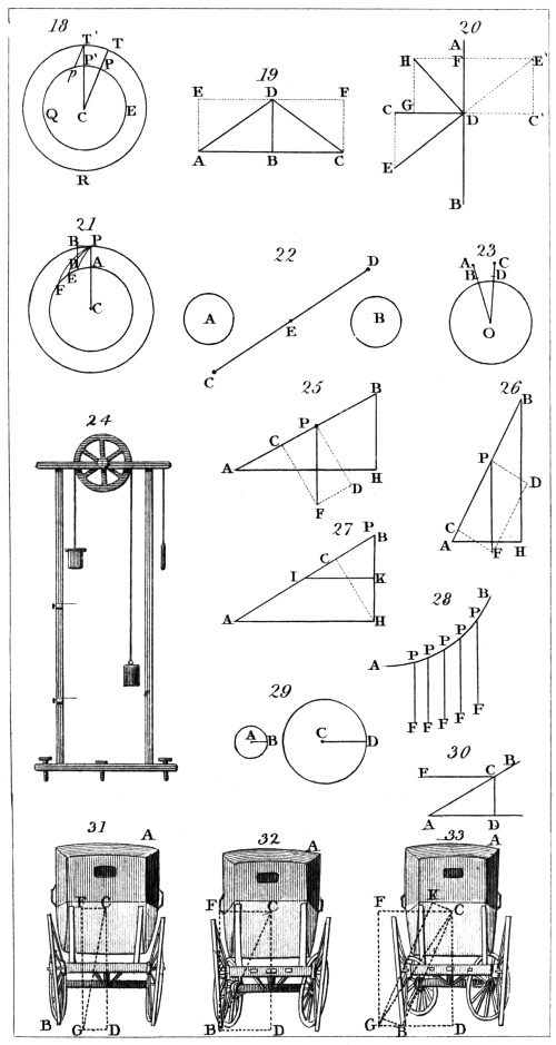
H. Adlard, sc.
London, Pubd. by Longman & Co.
(144.) If a body be allowed to fall by its weight down
a convex surface, such as A B, fig. 34., it would continue
upon the surface until it arrive at B but for the effect of
the centrifugal force: this, giving it a motion from the
centre of the curve, will cause it to quit the curve at
a certain point C, which can be easily found by mathematical
computation.
(145.) The most remarkable and important manifestation
of centrifugal force is observed in the effects
produced by the rotation of the earth upon its axis.
Let the circle in fig. 35. represent a section of the
earth, A B being the axis on which it revolves. This
rotation causes the matter which composes the mass of
the earth to revolve in circles round the different points
of the axis as centres at the various distances at which
the component parts of this mass are placed. As they
all revolve with the same angular velocity, they will be
affected by centrifugal forces, which will be greater or
less in proportion as their distances from the centre are
greater or less. Consequently the parts of the earth which
are situated about the equator, D, will be more strongly
affected by centrifugal force than those about the poles,
A B. The effect of this difference has been that the
component matter about the equator has actually been
driven farther from the centre than that about the poles,
so that the figure of the earth has swelled out at the sides,
and appears proportionally depressed at the top and bottom,
resembling the shape of an orange. An exaggerated
representation of this figure is given in fig. 36.; the
real difference between the distances of the poles and
equator from the centre being too small to be perceptible
in a diagram. The exact proportion of C A to C D has
never yet been certainly ascertained. Some observations
make C D exceed C A by 1/277, and others by only 1/333.
The latter, however, seems the more probable. It may
be considered to be included between these limits.
106
The same cause operates more powerfully in other
planets which revolve more rapidly on their axes. Jupiter
and Saturn have forms which are considerably more
elliptical.
(146.) The centrifugal force of the earth’s rotation
also affects detached bodies on its surface. If such
bodies were not held upon the surface by the earth’s
attraction, they would be immediately flung off by the
whirling motion in which they participate. The centrifugal
force, however, really diminishes the effects of the
earth’s attraction on those bodies, or, what is the same,
diminishes their weights. If the earth did not revolve
on its axis, the weight of bodies in all places equally
distant from the centre would be the same; but this is
not so when the bodies, as they do, move round with the
earth. They acquire from the centrifugal force a tendency
to fly from the axis, which increases with their
distance from that axis, and is therefore greater the
nearer they are to the equator, and less as they approach
the pole. But there is another reason why the centrifugal
force is more efficient, in the opposition which it
gives to gravity near the equator than near the poles.
This force does not act from the centre of the earth, but
is directed from the earth’s axis. It is, therefore, not
directly opposed to gravity, except on the equator itself.
On leaving the equator, and proceeding towards the poles,
it is less and less opposed to gravity, as will be plain on
inspecting fig. 35., where the lines P C all represent the
direction of gravity, and the lines P F represent the direction
of the centrifugal force.
Since, then, as we proceed from the equator towards
the poles, not only the amount of the centrifugal force
is continually diminished, but also it acts less and less in
opposition to gravity, it follows that the weights of bodies
are most diminished by it at the equator, and less so
towards the poles.
Since bodies are commonly weighed by balancing
them against other bodies of known weight, it may be
asked, how the phenomena we have been just describing
can be ascertained as a matter of fact? for whatever be107
the body against which it may be balanced, that body
must suffer just as much diminution of weight as every
other, and consequently, all being diminished in the same
proportion, the balance will be preserved though the
weights be changed.
To render this effect observable, it will be necessary
to compare the effects of gravity with some phenomenon
which is not affected by the centrifugal force of the
earth’s rotation, and which will be the same at every
part of the earth. The means of accomplishing this will
be explained in a subsequent chapter.
CHAP. IX.
THE CENTRE OF GRAVITY.
(147.) By the earth’s attraction, all the particles
which compose the mass of a body are solicited by equal
forces in parallel directions downwards. If these component
particles were placed in mere juxtaposition,
without any mechanical connection, the force impressed
on any one of them could in nowise affect the others,
and the mass would, in such a case, be contemplated as
an aggregation of small particles of matter, each urged
by an independent force. But the bodies which are the
subjects of investigation in mechanical science are not
found in this state. Solid bodies are coherent masses,
the particles of which are firmly bound together, so that
any force which affects one, being modified according
to circumstances, will be transmitted through the whole
body. Liquids accommodate themselves to the shape of
the surfaces on which they rest, and forces affecting any
one part are transmitted to others, in a manner depending
on the peculiar properties of this class of bodies.
As all bodies, which are subjects of mechanical enquiry,
on the surface of the earth, must be continually108
influenced by terrestrial gravity, it is desirable to obtain
some easy and summary method of estimating the effect
of this force. To consider it, as is unavoidable in the
first instance, the combined action of an infinite number
of equal and parallel forces soliciting the elementary
molecules downwards, would be attended with manifest
inconvenience. An infinite number of forces, and an
infinite subdivision of the mass, would form parts of
every mechanical problem.
To overcome this difficulty, and to obtain all the ease
and simplicity which can be desired in elementary investigations,
it is only necessary to determine some force,
whose single effect shall be equivalent to the combined
effects of the gravitation of all the molecules of the
body. If this can be accomplished, that single force
might be introduced into all problems to represent the
whole effect of the earth’s attraction, and no regard need
be had to any particles of the body, except that on which
this force acts.
(148.) To discover such a force, if it exist, we shall
first enquire what properties must necessarily characterise
it. Let A B, fig. 37., be a solid body placed near
the surface of the earth. Its particles are all solicited
downwards, in the directions represented by the arrows.
Now, if there be any single force equivalent to these
combined effects, two properties may be at once assigned
to it: 1. It must be presented downwards, in the common
direction of those forces to which it is mechanically
equivalent; and, 2. it must be equal in intensity
to their sum, or, what is the same, to the force with
which the whole mass would descend. We shall then
suppose it to have this intensity, and to have the direction
of the arrow D E. Now, if the single force, in the
direction D E, be equivalent to all the separate attractions
which affect the particles, we may suppose all these
attractions removed, and the body A B influenced only
by a single attraction, acting in the direction D E. This
being admitted, it follows that if the body be placed
upon a prop, immediately under the direction of the line109
D E, or be suspended from a fixed point immediately
above its direction, it will remain motionless. For the
whole attracting force in the direction D E will, in the
one case, press the body on the prop, and, in the other
case, will give tension to the cord, rod, or whatever
other means of suspension be used.
(149.) But suppose the body were suspended from
some point P, not in the direction of the line D E. Let
P C be the direction of the thread by which the body is
suspended. Its whole weight, according to the supposition
which we have adopted, must then act in the
direction C E. Taking C F to represent the weight; it
may be considered as mechanically equivalent to two
forces (74), C I and C H. Of these C H, acting directly
from the point P, merely produces pressure upon
it, and gives tension to the cord P C; but C I, acting at
right angles to C P, produces motion round P as a centre,
and in the direction C I, towards a vertical line P G,
drawn through the point P. If the body A B had been
on the other side of the line P G, it would have moved
in like manner towards it, and therefore in the direction
contrary to its present motion.
Hence we must infer, that when the body is suspended
from a fixed point, it cannot remain at rest, if
that fixed point be not placed in the direction of the line
D E; and, on the other hand, that if the fixed point be
in the direction of that line, it cannot move. A practical
test is thus suggested, by which the line D E may be at
once discovered. Let a thread be attached to any point
of the body, and let it be suspended by this thread from
a hook or other fixed point. The direction of the
thread, when the body becomes quiescent, will be that
of a single force equivalent to the gravitation of all the
component parts of the mass.
(150.) An enquiry is here suggested: does the direction
of the equivalent force thus determined depend
on the position of the body with respect to the surface
of the earth, and how is the direction of the equivalent
force affected by a change in that position? This ques110tion
may be at once solved if the body be suspended by
different points, and the directions which the suspending
thread takes in each case relatively to the figure and dimensions
of the body examined.
The body being suspended in this manner from any
point, let a small hole be bored through it, in the exact
direction of the thread, so that if the thread were continued
below the point where it is attached to the body,
it would pass through this hole. The body being successively
suspended by several different points on its
surface, let as many small holes be bored through it in the
same manner. If the body be then cut through, so as to
discover the directions which the several holes have taken,
they will be all found to cross each other at one point
within the body; or the same fact may be discovered
thus: a thin wire, which nearly fills the holes being
passed through any one of them, it will be found
to intercept the passage of a similar wire through any
other.
This singular fact teaches us, what indeed can be
proved by mathematical reasoning without experiment,
that there is one point in every body through which the
single force, which is equivalent to the gravitation of all
its particles, must pass, in whatever position the body be
placed. This point is called the centre of gravity.
(151.) In whatever situation a body may be placed,
the centre of gravity will have a tendency to descend in
the direction of a line perpendicular to the horizon, and
which is called the line of direction of the weight. If
the body be altogether free and unrestricted by any resistance
or impediment, the centre of gravity will actually
descend in this direction, and all the other points
of the body will move with the same velocity in parallel
directions, so that during its fall the position of the
parts of the body, with respect to the ground, will be
unaltered. But if the body, as is most usual, be subject
to some resistance or restraint, it will either remain
unmoved, its weight being expended in exciting pressure
on the restraining points or surfaces, or it will move in111
a direction and with a velocity depending on the circumstances
which restrain it.
In order to determine these effects, to predict the
pressure produced by the weight if the body be quiescent,
or the mixed effects of motion and pressure, if it
be not so, it is necessary in all cases to be able to assign
the place of the centre of gravity. When the magnitude
and figure of the body, and the density of the
matter which occupies its dimensions, are known, the
place of the centre of gravity can be determined with
the greatest precision by mathematical calculation. The
process by which this is accomplished, however, is not
of a sufficiently elementary nature to be properly introduced
into this treatise. To render it intelligible would
require the aid of some of the most advanced analytical
principles; and even to express the position of the point
in question, except in very particular instances, would
be impossible, without the aid of peculiar symbols.
(152.) There are certain particular forms of body in
which, when they are uniformly dense, the place of the
centre of gravity can be easily assigned, and proved by
reasoning, which is generally intelligible; but in all
cases whatever, this point may be easily determined by
experiment.
(153.) If a body uniformly dense have such a shape
that a point may be found on either side of which in
all directions around it the materials of the body are
similarly distributed, that point will obviously be the
centre of gravity. For if it be supported, the gravitation
of the particles on one side drawing them downwards,
is resisted by an effect of exactly the same kind
and of equal amount on the opposite side, and so the
body remains balanced on the point.
The most remarkable body of this kind is a globe,
the centre of which is evidently its centre of gravity.
A figure, such as fig. 38., called an oblate spheroid, has
its centre of gravity at its centre, C. Such is the figure
of the earth. The same may be observed of the elliptical
solid, fig. 39., which is called a prolate spheroid.
112
A cube, and some other regular solids, bounded by
plane surfaces, have a point within them, such as above
described, and which is, therefore, their centre of gravity.
Such are fig. 40.
A straight wand of uniform thickness has its centre
of gravity at the centre of its length; and a cylindrical
body has its centre of gravity in its centre, at the middle
of its length or axis. Such is the point C, fig. 41.
A flat plate of any uniform substance, and which has
in every part an equal thickness, has its centre of gravity
at the middle of its thickness, and under a point of its
surface, which is to be determined by its shape. If it
be circular or elliptical, this point is its centre. If it
have any regular form, bounded by straight edges, it is
that point which is equally distant from its several angles,
as C in fig. 42.
(154.) There are some cases in which, although the
place of the centre of gravity is not so obvious as in the
examples just given, still it may be discovered without
any mathematical process, which is not easily understood.
Suppose A B C, fig. 43., to be a flat triangular plate of
uniform thickness and density. Let it be imagined to be
divided into narrow bars, by lines parallel to the side
A C, as represented in the figure. Draw B D from the
angle B to the middle point D of the side A C. It is not
difficult to perceive, that B D will divide equally all the
bars into which the triangle is conceived to be divided.
Now if the flat triangular plate A B C be placed in
a horizontal position on a straight edge coinciding with
the line B D, it will be balanced: for the bars parallel
to A C will be severally balanced by the edge immediately
under their middle point; since that middle
point is the centre of gravity of each bar. Since, then,
the triangle is balanced on the edge, the centre of gravity
must be somewhere immediately over it, and must,
therefore, be within the plate at some point under the
line B D.
The same reasoning will prove that the centre of
gravity of the plate is under the line A E, drawn from113
the angle A to the middle point E of the side B C. To
perceive this, it is only necessary to consider the triangle
divided into bars parallel to B C, and thence to show
that it will be balanced on an edge placed under A E.
Since then the centre of gravity of the plate is under
the line B D, and also under A E, it must be under the
point G, at which these lines cross each other; and it is
accordingly at a depth beneath G, equal to half the
thickness of the plate.
This may be experimentally verified by taking a piece
of tin or card, and cutting it into a triangular form.
The point G being found by drawing B D and A E,
which divide two sides equally, it will be balanced if placed
upon the point of a pin at G.
The centre of gravity of a triangle being thus determined,
we shall be able to find the position of the centre
of gravity of any plate of uniform thickness and density
which is bounded by straight edges, as will be shown
hereafter. (173.)
(155.) The centre of gravity is not always included
within the volume of the body, that is, it is not enclosed
by its surfaces. Numerous examples of this can be produced.
If a piece of wire be bent into any form, the
centre of gravity will rarely be in the wire. Suppose
it be brought to the form of a ring. In that case,
the centre of gravity of the wire will be the centre of
the circle, a point not forming any part of the wire itself:
nevertheless this point may be proved to have the
characteristic property of the centre of gravity; for if
the ring be suspended by any point, the centre of the ring
must always settle itself under the point of suspension.
If this centre could be supposed to be connected with
the ring by very fine threads, whose weight would be
insignificant, and which might be united by a knot or
otherwise at the centre, the ring would be balanced upon
a point placed under the knot.
In like manner, if the wire be formed into an ellipse,
or any other curve similarly arranged round a centre
point, that point will be its centre of gravity.
114
(156.) To find the centre of gravity experimentally,
the method described in (149, 150) may be used. In
this case two points of suspension will be sufficient to determine
it; for the directions of the suspending cord being
continued through the body, will cross each other at the
centre of gravity. These directions may also be found
by placing the body on a sharp point, and adjusting it
so as to be balanced upon it. In this case a line drawn
through the body directly upwards from the point will
pass through the centre of gravity, and therefore two
such lines must cross at that point.
(157.) If the body have two flat parallel surfaces
like sheet metal, stiff paper, card, board, &c., the centre
of gravity may be found by balancing the body in
two positions on an horizontal straight edge. The
point where the lines marked by the edge cross each
other will be immediately under the centre of gravity.
This may be verified by showing that the body will be
balanced on a point thus placed, or that if it be suspended,
the point thus determined will always come
under the point of suspension.
The position of the centre of gravity of such bodies
may also be found by placing the body on an horizontal
table having a straight edge. The body being moved
beyond the edge until it is in that position in which the
slightest disturbance will cause it to fall, the centre of
gravity will then be immediately over the edge. This
being done in two positions, the centre of gravity will
be determined as before.
(158.) It has been already stated, that when the
body is perfectly free, the centre of gravity must necessarily
move downwards, in a direction perpendicular
to an horizontal plane. When the body is not free, the
circumstances which restrain it generally permit the
centre of gravity to move in certain directions, but obstruct
its motion in others. Thus if a body be suspended
from a fixed point by a flexible cord, the centre
of gravity is free to move in every direction except those
which would carry it farther from the point of suspen115sion
than the length of the cord. Hence if we conceive
a globe or sphere to surround the point of suspension
on every side to a distance equal to that of the centre of
gravity from the point of suspension, when the cord is
fully stretched, the centre of gravity will be at liberty
to move in every direction within this sphere.
There are an infinite variety of circumstances under
which the motion of a body may be restrained, and in
which a most important and useful class of mechanical
problems originate. Before we notice others, we shall,
however, examine that which has just been described
more particularly.
Let P, fig. 44., be the point of suspension, and C the
centre of gravity, and suppose the body so placed that C
shall be within the sphere already described. The cord
will therefore be slackened, and in this state the body will
be free. The centre of gravity will therefore descend
in the perpendicular direction until the cord becomes
fully extended; the tension will then prevent its further
motion in the perpendicular direction. The downward
force must now be considered as the diagonal of a parallelogram,
and equivalent to two forces C D and C E, in
the directions of the sides, as already explained in (149).
The force C D will bring the centre of gravity into the
direction P F, perpendicularly under the point of suspension.
Since the force of gravity acts continually on
C in its approach to P F, it will move towards that line
with accelerated speed, and when it has arrived there it
will have acquired a force to which no obstruction is
immediately opposed, and consequently by its inertia it
retains this force, and moves beyond P F on the other
side. But when the point C gets into the line P F, it
is in the lowest possible position; for it is at the lowest
point of the sphere which limits its motion. When it
passes to the other side of P F, it must therefore begin
to ascend, and the force of gravity, which, in the former
case, accelerated its descent, will now for the same reason,
and with equal energy, oppose its ascent. This
will be easily understood. Let C′ be any point which it116
may have attained in ascending; C′ G′, the force of
gravity, is now equivalent to C′ D′ and C′ E′. The
latter as before produces tension; but the former C′ D′
is in a direction immediately opposed to the motion, and
therefore retards it. This retardation will continue
until all the motion acquired by the body in its descent
from the first position has been destroyed, and then it
will begin to return to P F, and so it will continue to
vibrate from the one side to the other until the friction
on the point P, and the resistance of the air, gradually
deprive it of its motion, and bring it to a state of rest
in the direction P F.
But for the effects of friction and atmospheric resistance,
the body would continue for ever to oscillate equally
from side to side of the line P F.
(159.) The phenomenon just developed is only an
example of an extensive class. Whenever the circumstances
which restrain the body are of such a nature
that the centre of gravity is prevented from descending
below a certain level, but not, on the other hand, restrained
from rising above it, the body will remain at
rest if the centre of gravity be placed at the lowest limit
of its level; any disturbance will cause it to oscillate
around this state, and it cannot return to a state of rest
until friction or some other cause have deprived it of
the motion communicated by the disturbing force.
(160.) Under the circumstances which we have just
described, the body could not maintain itself in a state
of rest in any position except that in which the centre
of gravity is, at the lowest point of the space in which
it is free to move. This, however, is not always the
case. Suppose it were suspended by an inflexible rod
instead of a flexible string; the centre of gravity would
then not only be prevented from receding from the point
of suspension, but also from approaching it; in fact, it
would be always kept at the same distance from it.
Thus, instead of being capable of moving anywhere
within the sphere, it is now capable of moving on its
surface only. The reasoning used in the last case may117
also be applied here, to prove that when the centre of
gravity is on either side of the perpendicular P F, it will
fall towards P F and oscillate, and that if it be placed in
the line P F, it will remain in equilibrium. But in this
case there is another position, in which the centre of
gravity may be placed so as to produce equilibrium. If
it be placed at the highest point of the sphere in which
it moves, the whole force acting on it will then be directed
on the point of suspension, perpendicularly downwards,
and will be entirely expended in producing
pressure on that point; consequently, the body will
in this case be in equilibrium. But this state of equilibrium
is of a character very different from that in
which the centre of gravity was at the lowest part of
the sphere. In the present case any displacement, however
slight, of the centre of gravity, will carry it to a
lower level, and the force of gravity will then prevent
its return to its former state, and will impel it downwards
until it attain the lowest point of the sphere, and
round that point it will oscillate.
(161.) The two states of equilibrium which have
been just noticed, are called stable and instable equilibrium.
The character of the former is, that any disturbance
of the state produces oscillation about it; but
any disturbance of the latter state produces a total overthrow,
and finally causes oscillation around the state of
stable equilibrium.
Let A B, fig. 45., be an elliptical board resting on its
edge on an horizontal plane. In the position here represented,
the extremity P of the lesser axis being the
point of support, the board is in stable equilibrium;
for any motion on either side must cause the centre of
gravity C to ascend in the directions C O, and oscillation
will ensue. If, however, it rest upon the smaller end, as
in fig. 46., the position would still be a state of equilibrium,
because the centre of gravity is directly above
the point of support; but it would be instable equilibrium,
because the slightest displacement of the centre of gravity
would cause it to descend.
118
Thus an egg or a lemon may be balanced on the end,
but the least disturbance will overthrow it. On the
contrary, it will easily rest on the side, and any disturbance
will produce oscillation.
(162.) When the circumstances under which the
body is placed allow the centre of gravity to move only
in an horizontal line, the body is in a state which may
be called neutral equilibrium. The slightest force will
move the centre of gravity, but will neither produce
oscillation nor overthrow the body, as in the last two
cases.
An example of this state is furnished by a cylinder
placed upon an horizontal plane. As the cylinder is
rolled upon the plane, the centre of gravity C, fig. 47.,
moves in a line parallel to the plane A B, and distant
from it by the radius of the cylinder. The body will
thus rest indifferently in any position, because the line
of direction always falls upon a point P at which the
body rests upon the plane.
If the plane were inclined, as in fig. 48., a body might
be so shaped, that while it would roll the centre of gravity
would move horizontally. In this case the body
would rest indifferently on any part of the plane, as if
it were horizontal, provided the friction be sufficient to
prevent the body from sliding down the plane.
If the centre of gravity of a cylinder happen not to
coincide with its centre by reason of the want of uniformity
in the materials of which it is composed, it will
not be in a state of neutral equilibrium on an horizontal
plane, as in fig. 47. In this case let G, fig. 49., be the
centre of gravity. In the position here represented,
where the centre of gravity is immediately below the
centre C, the state will be stable equilibrium, because a
motion on either side would cause the centre of gravity
to ascend; but in fig. 50., where G is immediately above
C, the state is instable equilibrium, because a motion on
either side would cause G to descend, and the body
would turn into the position fig. 49.
(163.) A cylinder of this kind will, under certain119
circumstances, roll up an inclined plane. Let A B,
fig. 51., be the inclined plane, and let the cylinder be so
placed that the line of direction from G shall be above
the point P at which the cylinder rests upon the plane.
The whole weight of the body acting in the direction
G D will obviously cause the cylinder to roll towards A,
provided the friction be sufficient to prevent sliding;
but although the cylinder in this case ascends, the centre
of gravity G really descends.
When G is so placed that the line of direction G D
shall fall on the point P, the cylinder will be in equilibrium,
because its weight acts upon the point on which
it rests. There are two cases represented in fig. 52.
and fig. 53., in which G takes this position. Fig. 52.
represents the state of stable, and fig. 53. of instable
equilibrium.
(164.) When a body is placed upon a base, its stability
depends upon the position of the line of direction
and the height of the centre of gravity above the base.
If the line of direction fall within the base, the body
will stand firm; if it fall on the edge of the base, it will
be in a state in which the slightest force will overthrow
it on that side at which the line of direction falls; and
if the line of direction fall without the base, the body
must turn over that edge which is nearest to the line of
direction.
In fig. 54. and fig. 55., the line of direction G P falls
within the base, and it is obvious that the body will
stand firm; for any attempt to turn it over either edge
would cause the centre of gravity to ascend. But in
fig. 56. the line of direction falls upon the edge, and if
the body be turned over, the centre of gravity immediately
commences to descend. Until it be turned
over, however, the centre of gravity is supported by the
edge.
In fig. 57. the line of direction falls outside the base,
the centre of gravity has a tendency to descend from G
towards A, and the body will accordingly fall in that direction.
120
(165.) When the line of direction falls within the
base, bodies will always stand firm, but not with the
same degree of stability. In general, the stability depends
on the height through which the centre of gravity
must be elevated before the body can be overthrown.
The greater this height is, the greater in the same proportion
will be the stability.
Let B A C, fig. 58., be a pyramid, the centre of gravity
being at G. To turn this over the edge B, the
centre of gravity; must be carried over the arch G E, and
must therefore be raised through the height H E. If,
however, the pyramid were taller relatively to its base, as
in fig. 59., the height H E would be proportionally less;
and if the base were very small in reference to the height,
as in fig. 60., the height H E would be very small, and a
slight force would throw it over the edge B.
It is obvious that the same observations may be applied
to all figures whatever, the conclusions just deduced
depending only on the distance of the line of direction
from the edge of the base, and the height of the centre of
gravity above it.
(166.) Hence we may perceive the principle on which
the stability of loaded carriages depends. When the
load is placed at a considerable elevation above the wheels,
the centre of gravity is elevated, and the carriage becomes
proportionally insecure. In coaches for the conveyance
of passengers, the luggage is therefore sometimes placed
below the body of the coach; light parcels of large bulk
may be placed on the top with impunity.
When the centre of gravity of a carriage is much
elevated, there is considerable danger of overthrow, if
a corner be turned sharply and with a rapid pace; for the
centrifugal force then acting on the centre of gravity will
easily raise it through the small height which is necessary
to turn the carriage over the external wheels (142).
(167.) The same waggon will have greater stability
when loaded with a heavy substance which occupies a
small space, such as metal, than when it carries the
same weight of a lighter substance, such as hay; because121
the centre of gravity in the latter case will be much more
elevated.
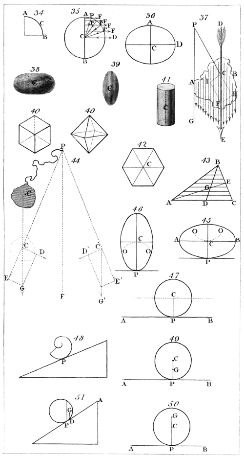
H. Adlard, sc.
London, Pubd. by Longman & Co.
If a large table be placed upon a single leg in its centre,
it will be impracticable to make it stand firm; but if the
pillar on which it rests terminate in a tripod, it will have
the same stability as if it had three legs attached to the
points directly over the places where the feet of the tripod
rest.
(168.) When a solid body is supported by more points
than one, it is not necessary for its stability that the line
of direction should fall on one of those points. If there
be only two points of support, the line of direction must
fall between them. The body is in this case supported
as effectually as if it rested on an edge coinciding with a
straight line drawn from one point of support to the
other. If there be three points of support, which are
not ranged in the same straight line, the body will be
supported in the same manner as it would be by a base
coinciding with the triangle formed by straight lines joining
the three points of support. In the same manner,
whatever be the number of points on which the body
may rest, its virtual base will be found by supposing
straight lines drawn, joining the several points successively.
When the line of direction falls within this base,
the body will always stand firm, and otherwise not.
The degree of stability is determined in the same manner
as if the base were a continued surface.
(169.) Necessity and experience teach an animal to
adapt its postures and motions to the position of the
centre of gravity of his body. When a man stands, the
line of direction of his weight must fall within the base
formed by his feet. If A B, C D, fig. 61., be the feet, this
base is the space A B D C. It is evident, that the more
his toes are turned outwards, the more contracted the
base will be in the direction E F, and the more liable he
will be to fall backwards or forwards. Also, the closer
his feet are together, the more contracted the base will be
in the direction G H, and the more liable he will be to
fall towards either side.
122
When a man walks, the legs are alternately lifted
from the ground, and the centre of gravity is either unsupported
or thrown from the one side to the other.
The body is also thrown a little forward, in order that
the tendency of the centre of gravity to fall in the direction
of the toes may assist the muscular action in propelling
the body. This forward inclination of the body
increases with the speed of the motion.
But for the flexibility of the knee-joint the labour of
walking would be much greater than it is; for the centre
of gravity would be more elevated by each step. The
line of motion of the centre of gravity in walking is represented
by fig. 62., and deviates but little from a regular
horizontal line, so that the elevation of the centre of
gravity is subject to very slight variation. But if there
were no knee-joint, as when a man has wooden legs, the
centre of gravity would move as in fig. 63., so that at each
step the weight of the body would be lifted through a
considerable height, and therefore the labour of walking
would be much increased.
If a man stand on one leg, the line of direction of his
weight must fall within the space on which his foot
treads. The smallness of this space, compared with the
height of the centre of gravity, accounts for the difficulty
of this feat.
The position of the centre of gravity of the body
changes with the posture and position of the limbs. If
the arm be extended from one side, the centre of gravity
is brought nearer to that side than it was when the arm
hung perpendicularly. When dancers, standing on one
leg, extend the other at right angles to it, they must
incline the body in the direction opposite to that in
which the leg is extended, in order to bring the centre
of gravity over the foot which supports them.
When a porter carries a load, his position must be
regulated by the centre of gravity of his body and the
load taken together. If he bore the load on his back,
the line of direction would pass beyond his heels, and he123
would fall backwards. To bring the centre of gravity
over his feet he accordingly leans forward, fig. 64.
If a nurse carry a child in her arms, she leans back
for a like reason.
When a load is carried on the head, the bearer stands
upright, that the centre of gravity may be over his feet.
In ascending a hill, we appear to incline forward; and
in descending, to lean backward, but in truth, we are
standing upright with respect to a level plane. This is
necessary to keep the line of direction between the feet,
as is evident from fig. 65.
A person sitting on a chair which has no back cannot
rise from it without either stooping forward to bring the
centre of gravity over the feet, or drawing back the feet
to bring them under the centre of gravity.
A quadruped never raises both feet on the same side
simultaneously, for the centre of gravity would then be
unsupported. Let A B C D, fig. 66., be the feet. The
base on which it stands is A B C D, and the centre of
gravity is nearly over the point O, where the diagonals
cross each other. The legs A and C being raised together,
the centre of gravity is supported by the legs B and
D, since it falls between them; and when B and D are
raised it is, in like manner, supported by the feet A and
C. The centre of gravity, however, is often unsupported
for a moment; for the leg B is raised from the
ground before A comes to it, as is plain from observing
the track of a horse’s feet, the mark of A being upon or
before that of B. In the more rapid paces of all animals
the centre of gravity is at intervals unsupported.
The feats of rope-dancers are experiments on the
management of the centre of gravity. The evolutions
of the performer are found to be facilitated by holding
in his hand a heavy pole. His security in this case depends,
not on the centre of gravity of his body, but on
that of his body and the pole taken together. This
point is near the centre of the pole, so that, in fact, he
may be said to hold in his hands the point on the position
of which the facility of his feats depends. Without124
the aid of the pole the centre of gravity would be within
the trunk of the body, and its position could not be
adapted to circumstances with the same ease and rapidity.
(170.) The centre of gravity of a mass of fluid is
that point which would have the properties which have
been proved to belong to the centre of gravity of a solid,
if the fluid were solidified without changing in any respect
the quantity or arrangement of its parts. This
point also possesses other properties, in reference to
fluids, which will be investigated in Hydrostatics and
Pneumatics.
(171.) The centre of gravity of two bodies separated
from one another, is that point which would possess
the properties ascribed to the centre of gravity, if the
two bodies were united by an inflexible line, the weight
of which might be neglected. To find this point mathematically
is a very simple problem. Let A and B,
fig. 67., be the two bodies, and a and b their centres of
gravity. Draw the right line a b, and divide it at C, in
such a manner that a C shall have the same proportion
to b C as the mass of the body B has to the mass of the
body A.
This may easily be verified experimentally. Let A
and B be two bodies, whose weight is considerable, in
comparison with that of the rod a b, which joins them.
Let a fine silken string, with its ends attached to them, be
hung upon a pin; and on the same pin let a plumb-line
be suspended. In whatever position the bodies may be
hung, it will be observed that the plumb-line will cross
the rod a b at the same point, and that point will divide
the line a b into parts a C and b C, which are in the proportion
of the mass of B to the mass of A.
(172.) The centre of gravity of three separate bodies
is defined in the same manner as that of two, and
may be found by first determining the centre of gravity
of two; and then supposing their masses concentrated
at that point, so as to form one body, and finding the
centre of gravity of that and the third.
125
In the same manner the centre of gravity of any
number of bodies may be determined.
(173.) If a plate of uniform thickness be bounded by
straight edges, its centre of gravity may be found by
dividing it into triangles by diagonal lines, as in fig. 68.,
and having determined by (154) the centres of gravity of
the several triangles, the centre of gravity of the whole
plate will be their common centre of gravity, found as
above.
(174.) Although the centre of gravity takes its name
from the familiar properties which it has in reference
to detached bodies of inconsiderable magnitude,
placed on or near the surface of the earth, yet it possesses
properties of a much more general and not less important
nature. One of the most remarkable of these is, that
the centre of gravity of any number of separate bodies is
never affected by the mutual attraction, impact, or other
influence which the bodies may transmit from one to
another. This is a necessary consequence of the equality
of action and reaction explained in Chapter IV. For if
A and B, fig. 67., attract each other, and change their
places to A′ and B′, the space a a′ will have to b b′ the
same proportion as B has to A, and therefore by what
has just been proved (171) the same proportion as a C
has to b C. It follows, that the remainders a′ C and b′ C
will be in the proportion of B to A, and that C will
continue to be the centre of gravity of the bodies after
they have approached by their mutual attraction.
Suppose, for example, that A and B were 12lbs. and
8lbs. respectively, and that a b were 40 feet. The point
C must (171) divide a b into two parts, in the proportion
of 8 to 12, or of 2 to 3. Hence it is obvious that a C
will be 16 feet, and b C 24 feet. Now, suppose that A
and B attract each other, and that A approaches B
through two feet. Then B must approach A through
three feet. Their distances from C will now be 14
feet and 21 feet, which, being in the proportion of B
to A, the point C will still be their centre of gravity.
Hence it follows, that if a system of bodies, placed at126
rest, be permitted to obey their mutual attractions, although
the bodies will thereby be severally moved, yet
their common centre of gravity must remain quiescent.
(175.) When one of two bodies is moving in a straight
line, the other being at rest, their common centre of
gravity must move in a parallel straight line. Let A
and B, fig. 69., be the centres of gravity of the bodies,
and let A move from A to a, B remaining at rest.
Draw the lines A B and a B. In every position which
the body B assumes during its motion, the centre of
gravity C divides the line joining them into parts A C,
B C, which are in the proportion of the mass B to the
mass A. Now, suppose any number of lines drawn from
B to the line A a; a parallel C c to A a through C divides
all these lines in the same proportion; and therefore,
while the body A moves from A to a, the common
centre of gravity moves from C to c.
If both the bodies A and B moved uniformly in
straight lines, the centre of gravity would have a motion
compounded (74) of the two motions with which it
would be affected, if each moved while the other remained
at rest. In the same manner, if there were three
bodies, each moving uniformly in a straight line, their
common centre of gravity would have a motion compounded
of that motion which it would have if one remained
at rest while the other two moved, and that
which the motion of the first would give it if the last
two remained at rest; and in the same manner it may
be proved, that when any number of bodies move each
in a straight line, their common centre of gravity will
have a motion compounded of the motions which it receives
from the bodies severally.
It may happen that the several motions which the
centre of gravity receives from the bodies of the system
will neutralise each other; and this does, in fact, take
place for such motions as are the consequences of the
mutual action of the bodies upon one another.
(176.) If a system of bodies be not under the immediate
influence of any forces, and their mutual attrac127tion
be conceived to be suspended, they must severally
be either at rest or in uniform rectilinear motion in
virtue of their inertia. Hence, their common centre of
gravity must also be either at rest or in uniform rectilinear
motion. Now, if we suppose their mutual attractions
to take effect, the state of their common centre of
gravity will not be changed, but the bodies will severally
receive motions compounded of their previous
uniform rectilinear motions and those which result from
their mutual attractions. The combined effects will
cause each body to revolve in an orbit round the common
centre of gravity, or will precipitate it towards
that point. But still that point will maintain its former
state undisturbed.
This constitutes one of the general laws of mechanical
science, and is of great importance in physical
astronomy. It is known by the title “the conservation
of the motion of the centre of gravity.”
(177.) The solar system is an instance of the class
of phenomena to which we have just referred. All the
motions of the bodies which compose it can be traced
to certain uniform rectilinear motions, received from
some former impulse, or from a force whose action has
been suspended, and those motions which necessarily
result from the principle of gravitation. But we shall
not here insist further on this subject, which more properly
belongs to another department of the science.
(178.) If a solid body suffer an impact in the direction
of a line passing through its centre of gravity, all
the particles of the body will be driven forward with
the same velocity in lines parallel to the direction of
the impact, and the whole force of the motion will be
equal to that of the impact. The common velocity of
the parts of the body will in this case be determined by
the principles explained in Chapter IV. The impelling
force being equally distributed among all the parts, the
velocity will be found by dividing the numerical value
of that force by the number expressing the mass.
If any number of impacts be given simultaneously to128
different points of a body, a certain complex motion will
generally ensue. The mass will have a relative motion
round the centre of gravity as if it were fixed, while that
point will move forward uniformly in a straight line,
carrying the body with it. The relative motion of the
mass round the centre of gravity may be found by considering
the centre of gravity as a fixed point, round
which the mass is free to move, and then determining the
motion which the applied forces would produce. This
motion being supposed to continue uninterrupted, let all
the forces be imagined to be applied in their proper
directions and quantities to the centre of gravity. By
the principles for the composition of force they will be
mechanically equivalent to a single force through that
point. In the direction of this single force the centre of
gravity will move and have the same velocity as if the
whole mass were there concentrated and received the
impelling forces.
(179.) These general properties, which are entirely
independent of gravity, render the “centre of gravity”
an inadequate title for this important point. Some physical
writers have, consequently, called it the “centre of
inertia.” The “centre of gravity,” however, is the
name by which it is still generally designated.
CHAP. X.
THE MECHANICAL PROPERTIES OF AN AXIS.
(180.) When a body has a motion of rotation, the line
round which it revolves is called an axis. Every point
of the body must in this case move in a circle, whose
centre lies in the axis, and whose radius is the distance
of the point from the axis. Sometimes while the body
revolves, the axis itself is moveable, and not unfrequently
in a state of actual motion. The motions of the129
earth and planets, or that of a common spinning-top, are
examples of this. The cases, however, which will be
considered in the present chapter, are chiefly those in
which the axis is immovable, or at least where its motion
has no relation to the phenomena under investigation.
Instances of this are so frequent and obvious, that it
seems scarcely necessary to particularise them. Wheel-work
of every description, the moving parts of watches
and clocks, turning lathes, mill-work, doors and lids on
hinges, are all obvious examples. In tools or other instruments
which work on joints or pivots, such as scissors,
shears, pincers, although the joint or pivot be not absolutely
fixed, it is to be considered so in reference to the
mechanical effect.
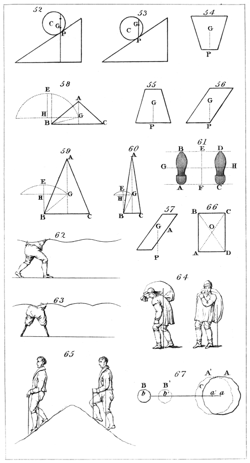
H. Adlard, sc.
London, Pubd. by Longman & Co.
In some cases, as in most of the wheels of watches and
clocks, fly-wheels and chucks of the turning lathe, and
the arms of wind-mills, the body turns continually in the
same direction, and each of its points traverses a complete
circle during every revolution of the body round its axis.
In other instances the motion is alternate or reciprocating,
its direction being at intervals reversed. Such is
the case in pendulums of clocks, balance-wheels of chronometers,
the treddle of the lathe, doors and lids on
hinges, scissors, shears, pincers, &c. When the alternation
is constant and regular, it is called oscillation or
vibration, as in pendulums and balance-wheels.
(181.) To explain the properties of an axis of rotation
it will be necessary to consider the different kinds of
forces to the action of which a body moveable on such an
axis may be submitted, to show how this action depends
on their several quantities and directions, to distinguish
the cases in which the forces neutralise each other and
mutually equilibrate from those in which motion ensues,
to determine the effect which the axis suffers, and, in the
cases where motion is produced, to estimate the effects of
those centrifugal forces (137.) which are created by the
mass of the body whirling round the axis.
Forces in general have been distinguished by the duration
of their action into instantaneous and continued130
forces. The effect of an instantaneous force is produced
in an infinitely short time. If the body which sustains
such an action be previously quiescent and free, it will
move with a uniform velocity in the direction of the impressed
force. (93.) If, on the other hand, the body be
not free, but so restrained that the impulse cannot put it in
motion, then the fixed points or lines which resist the
motion sustain a corresponding shock at the moment of
the impulse. This effect, which is called percussion, is,
like the force which causes it, instantaneous.
A continued force produces a continued effect. If
the body be free and previously quiescent, this effect is a
continual increase of velocity. If the body be so restrained
that the applied force cannot put it in motion,
the effect is a continued pressure on the points or lines
which sustain it. (94.)
It may happen, however, that although the body be
not absolutely free to move in obedience to the force applied
to it, yet still it may not be altogether so restrained
as to resist the effect of that force and remain at rest. If
the point at which a force is applied be free to move in
a certain direction not coinciding with that of the applied
force, that force will be resolved into two elements; one
of which is in the direction in which the point is free to
move, and the other at right angles to that direction.
The point will move in obedience to the former element,
and the latter will produce percussion or pressure on the
points or lines which restrain the body. In fact, in such
cases the resistance offered by the circumstances which confine
the motion of the body modifies the motion which it
receives, and as every change of motion must be the consequence
of a force applied (44.), the fixed points or lines
which offer the resistance must suffer a corresponding
effect.
It may happen that the forces impressed on the body,
whether they be continued or instantaneous, are such as,
were it free, would communicate to it a motion which
the circumstances which restrain it do not forbid it to
receive. In such a case the fixed points or lines which131
restrain the body sustain no force, and the phenomena
will be the same in all respects as if these points or lines
were not fixed.
It will be easy to apply these general reflections to the
case in which a solid body is moveable on a fixed axis.
Such a body is susceptible of no motion except one of
rotation on that axis. If it be submitted to the action
of instantaneous forces, one or other of the following
effects must ensue. 1. The axis may resist the forces,
and prevent any motion. 2. The axis may modify the
effect of the forces sustaining a corresponding percussion,
and the body receiving a motion of rotation. 3. The
forces applied may be such as would cause the body to
spin round the axis even were it not fixed, in which case
the body will receive a motion of rotation, but the axis
will suffer no percussion.
What has been just observed of the effect of instantaneous
forces is likewise applicable to continued ones. 1.
The axis may entirely resist the effect of such forces, in
which case it will suffer a pressure which may be estimated
by the rules for the composition of force. 2. It
may modify the effect of the applied forces, in which case
it must also sustain a pressure, and the body must receive
a motion of rotation which is subject to constant variation,
owing to the incessant action of the forces. 3. The
forces may be such as would communicate to the body
the same rotatory motion if the axis were not fixed.
In this case the forces will produce no pressure on the
axis.
The impressed forces are not the only causes which
affect the axis of a body during the phenomenon of rotation.
This species of motion calls into action other forces
depending on the inertia of the mass, which produce effects
upon the axis, and which play a prominent part in the theory
of rotation. While the body revolves on its axis, the
component particles of its mass move in circles, the centres
of which are placed in the axis. The radius of the circle
in which each particle moves is the line drawn from that
particle perpendicular to the axis. It has been already132
proved that a particle of matter, moving round a centre, is
attended with a centrifugal force proportionate to the radius
of the circle in which it moves and to the square of its
angular velocity. When a solid body revolves on its axis,
all its parts are whirled round together, each performing
a complete revolution in the same time. The angular velocity
is consequently the same for all, and the difference
of the centrifugal forces of different particles must entirely
depend upon their distances from the axis. The tendency
of each particle to fly from the axis, arising from the centrifugal
force, is resisted by the cohesion of the parts of
the mass, and in general this tendency is expended in exciting
a pressure or strain upon the axis. It ought to be
recollected, however, that this pressure or strain is altogether
different from that already mentioned, and produced
by the forces which give motion to the body. The latter
depends entirely upon the quantity and directions of the
applied forces in relation to the axis: the former depends
on the figure and density of the body, and the velocity
of its motion.
These very complex effects render a simple and elementary
exposition of the mechanical properties of a fixed
axis a matter of considerable difficulty. Indeed, the
complete mathematical development of this theory long
eluded the skill of the most acute geometers, and it was
only at a comparatively late period that it yielded to the
searching analysis of modern science.
(182.) To commence with the most simple case, we
shall consider the body as submitted to the action of a
single force. The effect of this force will vary according
to the relation of its direction to that of the axis. There
are two ways in which a body may be conceived to be
moveable around an axis. 1. By having pivots at two
points which rest in sockets, so that when the body is
moved it must revolve round the right line joining the
pivots as an axis. 2. A thin cylindrical rod may pass
through the body, on which it may turn in the same
manner as a wheel upon its axle.
If the force be applied to the body in the direction of133
the axis, it is evident that no motion can ensue, and the
effect produced will be a pressure on that pivot towards
which the force is directed. If in this case the body
revolved on a cylindrical rod, the tendency of the force
would be to make it slide along the rod without revolving
round it.
Let us next suppose the force to be applied not in the
direction of the axis itself, but parallel to it. Let A B,
fig. 70., be the axis, and let C D be the direction of the
force applied. The pivots being supposed to be at A and
B, draw A G and B F perpendicular to A B. The force
C D will be equivalent to three forces, one acting from B
towards A, equal in quantity to the force C D. This
force will evidently produce a corresponding pressure on
the pivot A. The other two forces will act in the directions
A G and B F, and will have respectively to the
force C D the same proportion as A E has to A B. Such
will be the mechanical effect of a force C D parallel to the
axis. And as these effects are all directed on the pivots,
no motion can ensue.
If the body revolve on a cylindrical rod, the forces A G
and B F would produce a strain upon the axis, while the
third force in the direction B A would have a tendency
to make the body slide along it.
(183.) If the force applied to the body be directed
upon the axis, and at right angles to it, no motion can be
produced. In this case, if the body be supported by pivots
at A and B, the force K L, perpendicular to the line
A B, will be distributed between the pivots, producing
a pressure on each proportional to its distance from the
other. The pressure on A having to the pressure on B
the same proportion as L B has to L A.
If the force K H be directed obliquely to the axis,
it will be equivalent to two forces (76.), one K L perpendicular
to the axis, and the other K M parallel to it.
The effect of each of these may be investigated as in the
preceding cases.
In all these observations the body has been supposed
to be submitted to the action of one force only. If134
several forces act upon it, the direction of each of them
crossing the axis either perpendicularly or obliquely, or
taking the direction of the axis or any parallel direction,
their effects may be similarly investigated. In the same
manner we may determine the effects of any number of
forces whose combined results are mechanically equivalent
to forces which either intersect the axis or are parallel
to it.
(184.) If any force be applied whose direction lies in a
plane oblique to the axis, it can always be resolved into
two elements (76.), one of which is parallel to the axis,
and the other in a plane perpendicular to it. The effect
of the former has been already determined, and therefore
we shall at present confine our attention to the latter.
Suppose the axis to be perpendicular to the paper, and
to pass through the point G, fig. 71. and let A B C be
a section of the body. It will be convenient to consider
the section vertical and the axis horizontal, omitting,
however, any notice of the effect of the weight of the
body.
Let a weight W be suspended by a cord Q W from
any point Q. This weight will evidently have a tendency
to turn the body round in the direction A B C.
Let another cord be attached to any other point P, and,
being carried over a wheel R, let a dish S be attached to
it, and let fine sand be poured into this dish until the
tendency of S to turn the body round the axis in the
direction of C B A balances the opposite tendency of W.
Let the weights of W and S be then exactly ascertained,
and also let the distances G I and G H of the cords
from the axis be exactly measured. It will be found
that, if the number of ounces in the weight S be multiplied
by the number of inches in G H, and also the
number of ounces in W by the number of inches in G I,
equal products will be obtained. This experiment may
be varied by varying the position of the wheel R, and
thereby changing the direction of the string P R, in
which cases it will be always found necessary to vary
the weight of S in such a manner, that when the num135ber
of ounces in it is multiplied by the number of inches
in the distance of the string from the axis, the product
obtained shall be equal to that of the weight W by the
distance G I. We have here used ounces and inches as
the measures of weight and distance; but it is obvious
that any other measures would be equally applicable.
From what has been just stated it follows, that the
energy of the weight of S to move the body on its axis,
does not depend alone upon the actual amount of that
weight, but also upon the distance of the string from
the axis. If, while the position of the string remains
unaltered, the weight of S be increased or diminished,
the resisting weight W must be increased or diminished
in the same proportion. But if, while the weight of S
remains unaltered, the distance of the string P R from
the axis G be increased or diminished, it will be found
necessary to increase or diminish the resisting weight W
in exactly the same proportion. It therefore appears
that the increase or diminution of the distance of the
direction of a force from the axis has the same effect
upon its power to give rotation as a similar increase or
diminution of the force itself. The power of a force to
produce rotation is, therefore, accurately estimated, not
by the force alone, but by the product found by multiplying
the force by the distance of its direction from the
axis. It is frequently necessary in mechanical science
to refer to this power of a force, and, accordingly, the
product just mentioned has received a particular denomination.
It is called the moment of the force round the
axis.
(185.) The distance of the direction of a force from
the axis is sometimes called the leverage of the force.
The moment of a force is therefore found by multiplying
the force by its leverage, and the energy of a given
force to turn a body round an axis is proportional to the
leverage of that force.
From all that has been observed it may easily be inferred
that, if several forces affect a body moveable on
an axis, having tendencies to turn it in different direc136tions,
they will mutually neutralise each other and produce
equilibrium, if the sum of the moments of those
forces which tend to turn the body in one direction be
equal to the sum of the moments of those which tend to
turn it in the opposite direction. Thus, if the forces
A, B, C, . . . tend to turn the body from right to left, and
the distances of their directions from the axis be a, b, c, . . .
and the forces A′, B′, C′, . . . tend to move it from left to
right, and the distances of their directions from the axis
be a′, b′, c′, . . .; then these forces will produce equilibrium,
if the products found by multiplying the ounces
in A, B, C, . . . respectively by the inches in a, b, c, . . . when
added together be equal to the products found by multiplying
the ounces in A′, B′, C′, . . . by the inches in
a′, b′, c′, . . . respectively when added together. But if
either of these sets of products when added together exceed
the other, the corresponding set of forces will prevail,
and the body will revolve on its axis.
(186.) When a body receives an impulse in a direction
perpendicular to the axis, but not crossing it, a uniform
rotatory motion is produced. The velocity of this motion
depends on the force of the impulse, the distance of the
direction of the impulse from the axis, and the manner
in which the mass of the body is distributed round the
axis. It is to be considered that the whole force of the
impulse is shared amongst the various parts of the
mass, and is transmitted to them from the point where
the impulse is applied by reason of the cohesion and
tenacity of the parts, and the impossibility of one part
yielding to a force without carrying all the other parts
with it. The force applied acts upon those particles
nearer to the axis than its own direction under advantageous
circumstances; for, according to what has been
already explained, their power to resist the effect of the
applied force is small in the same proportion with their
distance. On the other hand, the applied force acts
upon particles of the mass, at a greater distance than its
own direction, under circumstances proportionably disadvantageous;
for their resistance to the applied force
is great in proportion to their distances from the axis.
137
Let C D, fig. 72., be a section of the body made by a
plane passing through the axis A B. Suppose the impulse
to be applied at P, perpendicular to this plane, and
at the distance P O from the axis. The effect of the impulse
being distributed through the mass will cause the
body to revolve on A B, with a uniform velocity. There is
a certain point G, at which, if the whole mass were concentrated,
it would receive from the impulse the same
velocity round the axis. The distance O G is called the
radius of gyration of the axis A B, and the point G is
called the centre of gyration relatively to that axis. The
effect of the impulse upon the mass concentrated at G is
great in exactly the same proportion as O G is small.
This easily follows from the property of moments which
has been already explained; from whence it may be
inferred, that the greater the radius of gyration is, the
less will be the velocity which the body will receive from
a given impulse.
(187.) Since the radius of gyration depends on the
manner in which the mass is arranged round the axis, it
follows that for different axes in the same body there
will be different radii of gyration. Of all axes taken in
the same body parallel to each other, that which passes
through the centre of gravity has the least radius of
gyration. If the radius of gyration of any axis passing
through the centre of gravity be given, that of any
parallel axis can be found; for the square of the
radius of gyration of any axis is equal to the square of
the distance of that axis from the centre of gravity added
to the square of the radius of gyration of the parallel
axis through the centre of gravity.
(188.) The product of the numerical expressions for
the mass of the body and the square of the radius of
gyration is a quantity much used in mechanical science,
and has been called the moment of inertia. The moments
of inertia, therefore, for different axes in the same body
are proportional to the squares of the corresponding radii
of gyration; and consequently increase as the distances
of the axes from the centre of gravity increase. (187.)
138
(189.) From what has been explained in (187.), it
follows, that the moment of inertia of any axis may be
computed by common arithmetic, if the moment of inertia
of a parallel axis through the centre of gravity be
previously known. To determine this last, however,
would require analytical processes altogether unsuitable
to the nature and objects of the present treatise.
The velocity of rotation which a body receives from
a given impulse is great in exactly the same proportion
as the moment of inertia is small. Thus the moment
of inertia may be considered in rotatory motion analogous
to the mass of the body in rectilinear motion.
From what has been explained in (187.) it follows
that a given impulse at a given distance from the axis
will communicate the greatest angular velocity when
the axis passes through the centre of gravity, and that
the velocity which it will communicate round other
axes will be diminished in the same proportion as the
squares of their distances from the centre of gravity
added to the square of the radius of gyration for a
parallel axis through the centre of gravity are augmented.
(190.) If any point whatever be assumed in a body,
and right lines be conceived to diverge in all directions
from that point, there are generally two of these lines,
which being taken as axes of rotation, one has a greater
and the other a less moment of inertia than any of the
others. It is a remarkable circumstance, that, whatever
be the nature of the body, whatever be its shape, and
whatever be the position of the point assumed, these
two axes of greatest and least moment will always be
at right angles to each other.
These axes and a third through the same point, and
at right angles to both of them, are called the principal
axes of that point from which they diverge. To form
a distinct notion of their relative position, let the axis
of greatest moment be imagined to lie horizontally from
north to south, and the axis of least moment from east
to west; then the third principal axis will be presented139
perpendicularly upwards and downwards. The first
two being called the principal axes of greatest and least
moment, the third may be called the intermediate principal
axis.
(191.) Although the moments of the three principal
axes be in general unequal, yet bodies may be found
having certain axes for which these moments may be
equal. In some cases the moment of the intermediate
axis is equal to that of the principal axis of greatest
moment: in others it is equal to that of the principal
axis of least moment, and in others the moments of all
the three principal axes are equal to each other.
If the moments of any two of three principal axes be
equal, the moments of all axes through the same point
and in their plane will also be equal; and if the moments
of the three principal axes through a point be
equal, the moments of all axes whatever, through the
same point, will be equal.
(192.) If the moments of the principal axes through
the centre of gravity be known, the moments for all
other axes through that point may be easily computed.
To effect this it is only necessary to multiply the moments
of the principal axes by the squares of the co-sines
of the angles formed by them respectively with the
axis whose moment is sought. The products being
added together will give the required moment.
(193.) By combining this result with that of (189.),
it will be evident that the moment of all axes whatever
may be determined, if those of the principal axes
through the centre of gravity be known.
(194.) It is obvious that the principal axis of least
moment through the centre of gravity has a less moment
of inertia than any other axis whatever. For it
has, by its definition (190.) a less moment of inertia
than any other axis through the centre of gravity, and
every other axis through the centre of gravity has a less
moment of inertia than a parallel axis through any
other point (187.) and (189.)
(195.) If two of the principal axes through the
centre of gravity have equal moments of inertia, all axes140
in any plane parallel to the plane of these axes, and
passing through the point where a perpendicular from
the centre of gravity meets that plane, must have equal
moments of inertia. For by (191.) all axes in the
plane of those two have equal moments, and by (189.)
the axes in the parallel plane have moments which
exceed these by the same quantity, being equally distant
from them. (187.)
Hence it is obvious that if the three principal axes
through the centre of gravity have equal moments, all
axes situated in any given plane, and passing through
the point where the perpendicular from the centre of
gravity meets that plane, will have equal moments,
being equally distant from parallel axes through the
centre of gravity.
(196.) If the three principal axes through the
centre of gravity have unequal moments, there is no
point whatever for which all axes will have equal
moments; but if the principal axis of least moment
and the intermediate principal axis through the centre
of gravity have equal moments, then there will be two
points on the principal axis of greatest moment, equally
distant at opposite sides of the centre of gravity, at
which all axes will have equal moments. If the three
principal axes through the centre of gravity have equal
moments, no other point of the body can have principal
axes of equal moment.
(197.) When a body revolves on a fixed axis, the
parts of its mass are whirled in circles round the
axis; and since they move with a common angular
velocity, they will have centrifugal forces proportional to
their distances from the axis. If the component parts
of the mass were not united together by cohesive forces
of energies greater than these centrifugal forces, they
would be separated, and would fly off from the axis;
but their cohesion prevents this, and causes the effects
of the different centrifugal forces, which affect the
different parts of the mass, to be transmitted so as to
modify each other, and finally to produce one or more
forces mechanically equivalent to the whole, and which141
are exerted upon the axis and resisted by it. We
propose now to explain these effects, as far as it is
possible to render them intelligible without the aid of
mathematical language.
It is obvious that any number of equal parts of the
mass, which are uniformly arranged in a circle round
the axis, have equal centrifugal forces acting from the
centre of the circle in every direction. These mutually
neutralise each other, and therefore exert no force on
the axis. The same may be said of all parts of the
mass which are regularly and equally distributed on
every side of the axis.
Also if equal masses be placed at equal distances on
opposite sides of the axis, their centrifugal forces will
destroy each other. Hence it appears that the pressure
which the axis of rotation sustains from the centrifugal
forces of the revolving mass, arises from the unequal
distribution of the matter around it.
From this reasoning it will be easily perceived that
in the following examples the axis of rotation will
sustain no pressure.
A globe revolving on any of its diameters, the density
being the same at equal distances from the centre.
A spheroid or a cylinder revolving on its axis, the
density being equal at equal distances from the axis.
A cube revolving on an axis which passes through
the centre of two opposite bases, being of uniform
density.
A circular plate of uniform thickness and density
revolving on one of its diameters as an axis.
(198.) In all these examples it will be observed that
the axis of rotation passes through the centre of gravity.
The general theorem, of which they are only particular
instances, is, “if a body revolve on a principal axis, passing
through the centre of gravity, the axis will sustain
no pressure from the centrifugal force of the revolving
mass.” This is a property in which the principal axes
through the centre of gravity are unique. There is no
other axis on which a body could revolve without
pressure.
142
If two of the principal axes through the centre of
gravity have equal moments, every axis in their plane
has the same moment, and is to be considered equally
as a principal axis. In this case the body would revolve
on any of these axes without pressure.
A homogeneous spheroid furnishes an example of
this. If any of the diameters of the earth’s equator
were a fixed axis, the earth would revolve on it without
producing pressure.
If the three principal axes through the centre of
gravity have equal moments, all axes through the
centre of gravity are to be considered as principal
axes. In this case the body would revolve without
pressure on any axis through the centre of gravity.
A globe, in which the density of the mass at equal
distances from the centre is the same, is an example
of this. Such a body would revolve without pressure
on any axis through its centre.
(199.) Since no pressure is excited on the axis in
these cases, the state of the body will not be changed,
if during its rotation the axis cease to be fixed. The
body will notwithstanding continue to revolve round
the axis, and the axis will maintain its position.
Thus a spinning-top of homogeneous material and
symmetrical form will revolve steadily in the same
position, until the friction of its point with the surface
on which it rests deprives it of motion. This is a
phenomenon which can only be exhibited when the
axis of rotation is a principal axis through the centre
of gravity.
(200.) If the body revolve round any axis through
the centre of gravity, which is not a principal axis,
the centrifugal pressure is represented by two forces,
which are equal and parallel, but which act in opposite
directions on different points of the axis. The effect of
these forces is to produce a strain upon the axis, and
give the body a tendency to move round another axis
at right angles to the former.
(201.) If the fixed axis on which a body revolves143
be a principal axis through any point different from
the centre of gravity, then a pressure will be produced
by the centrifugal force of the revolving mass, and this
pressure will act at right angles to the axis on the point
to which it is a principal axis, and in the plane through
that axis and the centre of gravity. The amount of
the pressure will be proportional to the mass of the
body, the distance of the centre of gravity from the
axis, and the square of the velocity of rotation.
(202.) Since the whole pressure is in this case excited
on a single point, the stability of the axis will not
be disturbed, provided that point alone be fixed. So
that even though the axis should be free to turn on that
point, no motion will ensue as long as no external
forces act upon the body.
(203.) If the axis of rotation be not a principal axis,
the centrifugal forces will produce an effect which
cannot be represented by a single force. The effect
may be understood by conceiving two forces to act on
different points of the axis at right angles to it and to
each other. The quantities of these pressures and
their directions depend on the figure and density of
the mass and the position of the axis, in a manner
which cannot be explained without the aid of mathematical
language and principles.
(204.) The effects upon the axis which have been
now explained are those which arise from the motion
of rotation, from whatever cause that motion may have
arisen. The forces which produce that motion, however,
are attended with effects on the axis which still
remain to be noticed. When these forces, whether
they be of the nature of instantaneous actions or continued
forces, are entirely resisted by the axis, their
directions must severally be in a plane passing through
the axis, or they must, by the principles of the composition
of force [(74.) et seq.], be mechanically equivalent
to forces in that plane. In every other case the
impressed forces must produce motion, and, except in
certain cases, must also produce effects upon the axis.
144
By the rules for the composition of force it is possible
in all cases to resolve the impressed forces into
others which are either in planes through the axis, or
in planes perpendicular to it, or, finally, some in planes
through it, and others in planes perpendicular to it.
The effect of those which are in planes through the
axis has been already explained; and we shall now
confine our attention to those impelling forces which
act at right angles to the axis, and which produce
motion.
It will be sufficient to consider the effect of a single
force at right angles to the axis; for whatever be the
number of forces which act either simultaneously or
successively, the effect of the whole will be decided by
combining their separate effects. The effect which a
single force produces depends on two circumstances,
1. The position of the axis with respect to the figure
and mass of the body, and 2. The quantity and direction
of the force itself.
In general the shock which the axis sustains from
the impact may be represented by two impacts applied
to it at different points, one parallel to the impressed
force, and the other perpendicular to it, but both perpendicular
to the axis. There are certain circumstances,
however, under which this effect will be
modified.
If the impulse which the body receives be in a
direction perpendicular to a plane through the axis and
the centre of gravity, and at a distance from the axis
which bears to the radius of gyration (186.) the same
proportion as that line bears to the distance of the
centre of gravity from the axis, there are certain cases
in which the impulse will produce no percussion. To
characterise these cases generally would require analytical
formulæ which cannot conveniently be translated
into ordinary language. That point of the plane, however,
where the direction of the impressed force meets
it, when no percussion on the axis is produced, is
called the centre of percussion.
145
If the axis of rotation be a principal axis, the centre
of percussion must be in the right line drawn through
the centre of gravity, intersecting the axis at right angles,
and at the distance from the axis already explained.
If the axis of rotation be parallel to a principal axis
through the centre of gravity, the centre of percussion
will be determined in the same manner.
(205.) There are many positions which the axis may
have in which there will be no centre of percussion; that
is, there will be no direction in which an impulse could
be applied without producing a shock upon the axis. One
of these positions is when it is a principal axis through
the centre of gravity. This is the only case of rotation
round an axis in which no effect arises from the centrifugal
force; and therefore it follows that the only case
in which the axis sustains no effect from the motion
produced, is one in which it must necessarily suffer an
effect from that which produces the motion.
If the body be acted upon by continued forces, their
effect is at each instant determined by the general principles
for the composition of force.
CHAP. XI.
ON THE PENDULUM.
(206.) When a body is placed on a horizontal axis
which does not pass through its centre of gravity, it will
remain in permanent equilibrium only when the centre
of gravity is immediately below the axis. If this point
be placed in any other situation, the body will oscillate
from side to side, until the atmospherical resistance and
the friction of the axis destroy its motion. (159, 160.)
Such a body is called a pendulum. The swinging motion
which it receives is called oscillation or vibration.
(207.) The use of the pendulum, not only for philosophical
purposes, but in the ordinary economy of life,146
renders it a subject of considerable importance. It furnishes
the most exact means of measuring time, and of
determining with precision various natural phenomena.
By its means the variation of the force of gravity in
different latitudes is discovered, and the law of that
variation experimentally exhibited. In the present
chapter, we propose to explain the general principles
which regulate the oscillation of pendulums. Minute
details concerning their construction will be given in the
twenty-first chapter of this volume.
(208.) A simple pendulum is composed of a heavy
molecule attached to the end of a flexible thread, and
suspended by a fixed point O, fig. 73. When the pendulum
is placed in the position O C, the molecule being
vertically below the point of suspension, it will remain
in equilibrium; but if it be drawn into the position O A
and there liberated, it will descend towards C, moving
through the arc A C with accelerated motion. Having
arrived at C and acquired a certain velocity, it will, by
reason of its inertia, continue to move in the same
direction. It will therefore commence to ascend the arc
C A′ with the velocity so acquired. During its ascent,
the weight of the molecule retards its motion in exactly
the same manner as it had accelerated it in descending
from A to C; and when the molecule has ascended
through the arc C A′ equal to C A, its entire velocity
will be destroyed, and it will cease to move in that direction.
It will thus be placed at A′ in the same manner
as in the first instance it had been placed at A, and consequently
it will descend from A′ to C with accelerated
motion, in the same manner as it first moved from A to
C. It will then ascend from C to A, and so on, continually.
In this case the thread, by which the molecule
is suspended, is supposed to be perfectly flexible, inextensible,
and of inconsiderable weight. The point of
suspension is supposed to be without friction, and the
atmosphere to offer no resistance to the motion.
It is evident from what has been stated, that the
times of moving from A to A′ and from A′ to A are147
equal, and will continue to be equal so long as the pendulum
continues to vibrate. If the number of vibrations
performed by the pendulum were registered, and the
time of each vibration known, this instrument would
become a chronometer.
The rate at which the motion of the pendulum is
accelerated in its descent towards its lowest position is
not uniform, because the force which impels it is
continually decreasing, and altogether disappears at the
point C. The impelling force arises from the effect of
gravity on the suspended molecule, and this effect is always
produced in the vertical direction A V. The greater the
angle O A V is, the less efficient the force of gravity will
be in accelerating the molecule: this angle evidently
increases as the molecule approaches C, which will
appear by inspecting fig. 73. At C, the force of gravity
acting in the direction C B is totally expended in giving
tension to the thread, and is inefficient in moving the
molecule. It follows, therefore, that the impelling force
is greatest at A, and continually diminishes from A to C,
where it altogether vanishes. The same observations
will be applicable to the retarding force from C to A′, and
to the accelerating force from A′ to C, and so on.
When the length of the thread and the intensity of
the force of gravity are given, the time of vibration
depends on the length of the arc A C, or on the magnitude
of the angle A O C. If, however, this angle do not
exceed a certain limit of magnitude, the time of vibration
will be subject to no sensible variation, however
that angle may vary. Thus the time of oscillation will
be the same, whether the angle A O C be 2°, or 1° 30′, or
1°, or any lesser magnitude. This property of a pendulum
is expressed by the word isochronism. The
strict demonstration of this property depends on mathematical
principles, the details of which would not be
suitable to the present treatise. It is not difficult,
however, to explain generally how it happens that the
same pendulum will swing through greater and smaller
arcs of vibration in the same time. If it swing from A,148
the force of gravity at the commencement of its motion
impels it with an effect depending on the obliquity of
the lines O A and A V. If it commence its motion
from a, the impelling effect from the force of gravity
will be considerably less than at A; consequently, the
pendulum begins to move at a slower rate, when it
swings from a than when it moves from A: the greater
magnitude of the swing is therefore compensated by the
increased velocity, so that the greater and the smaller arcs
of vibration are moved through in the same time.
(209.) To establish this property experimentally, it is
only necessary to suspend a small ball of metal, or other
heavy substance, by a flexible thread, and to put it in a
state of vibration, the entire arc of vibration not exceeding
4° or 5°, the friction on the point of suspension and
other causes will gradually diminish the arc of vibration,
so that after the lapse of some hours it will be so small,
that the motion will scarcely be discerned without
microscopic aid. If the vibration of this pendulum be
observed in reference to a correct timekeeper, at the
commencement, at the middle, and towards the end
of its motion, the rate will be found to suffer no sensible
change.
This remarkable law of isochronism was one of the
earliest discoveries of Galileo. It is said, that when very
young, he observed a chandelier suspended from the roof
of a church in Pisa swinging with a pendulous motion,
and was struck with the uniformity of the rate even when
the extent of the swing was subject to evident variation.
(210.) It has been stated in (117.) that the attraction
of gravity affects all bodies equally, and moves them with
the same velocity, whatever be the nature or quantity of
the materials of which they are composed. Since it is
the force of gravity which moves the pendulum, we should
therefore expect that the circumstances of that motion
should not be affected either by the quantity or quality
of the pendulous body. And we find this, in fact, to be
the case; for if small pieces of different heavy substances
such as lead, brass, ivory, &c., be suspended by fine149
threads of equal length, they will vibrate in the same
time, provided their weights bear a considerable proportion
to the atmospherical resistance, or that they be suspended
in vacuo.
(211.) Since the time of vibration of a pendulum,
which oscillates in small arcs, depends neither on the magnitude
of the arc of vibration nor on the quality or
weight of the pendulous body, it will be necessary to explain
the circumstances on which the variation of this
time depends.
The first and most striking of these circumstances is
the length of the suspending thread. The rudest experiments
will demonstrate the fact, that every increase
in the length of this thread will produce a corresponding
increase in the time of vibration; but according to what
law does this increase proceed? If the length of the thread
be doubled or trebled, will the time of vibration also be increased
in a double or treble proportion? This problem
is capable of exact mathematical solution, and the result
shows that the time of vibration increases not in the
proportion of the increased length of the thread, but as
the square root of that length; that is to say, if the
length of the thread be increased in a four-fold proportion,
the time of vibration will be augmented in a two-fold
proportion. If the thread be increased to nine times its
length, the time of vibration will be trebled, and so on.
This relation is exactly the same as that which was proved
to subsist between the spaces through which a body falls
freely, and the times of fall. In the table, page 89, if the
figures representing the height be understood to express
the length of different pendulums, the figures immediately
above them will express the corresponding times of vibration.
This law of the proportion of the lengths of pendulums
to the squares of the time of vibration may be experimentally
established in the following manner:—
Let A, B, C, fig. 74., be three small pieces of metal
each attached by threads to two points of suspension, and
let them be placed in the same vertical line under the150
point O; suppose them so adjusted that the distances
O A, O B, and O C shall be in the proportion of the
numbers 1, 4, and 9. Let them be removed from the
vertical in a direction at right angles to the plane of the
paper, so that the threads shall be in the same plane, and
therefore the three pendulums will have the same angle
of vibration. Being now liberated, the pendulum A will
immediately gain upon B, and B upon C, so that A will
have completed one vibration before B or C. At the end
of the second vibration of A, the pendulum B will have
arrived at the end of its first vibration, so that the suspending
threads of A and B will then be separated by
the whole angle of vibration; at the end of the fourth vibration
of A the suspending threads of A and B will return
to their first position, B having completed two vibrations;
thus the proportion of the times of vibration of B and A
will be 2 to 1, the proportion of their lengths being
4 to 1. At the end of the third vibration of A, C will
have completed one vibration, and the suspending strings
will coincide in the position distant by the whole angle
of vibration from their first position. So that three vibrations
of A are performed in the same time as one of
C: the proportion of the time of vibration of C and A
are, therefore, 3 to 1, the proportion of their lengths being
9 to 1, conformably to the law already explained.
(212.) In all the preceding observations we have assumed
that the material of the pendulous body is of inconsiderable
magnitude, its whole weight being conceived
to be collected in a physical point. This is generally
called a simple pendulum; but since the conditions of a
suspending thread without weight, and a heavy molecule
without magnitude, cannot have practical existence, the
simple pendulum must be considered as imaginary, and
merely used to establish hypothetical theorems, which,
though inapplicable in practice, are nevertheless the means
of investigating the laws which govern the real phenomena
of pendulous bodies.
A pendulous body being of determinate magnitude, its
several parts will be situated at different distances from151
the axis of suspension. If each component part of such
a body were separately connected with the axis of suspension
by a fine thread, it would, being unconnected with
the other particles, be an independent simple pendulum,
and would oscillate according to the laws already explained.
It therefore follows that those particles of the
body which are nearest to the axis of suspension would,
if liberated from their connection with the others, vibrate
more rapidly than those which are more remote. The
connection, however, which the particles of the body
have, by reason of their solidity, compels them all to
vibrate in the same time. Consequently, those particles
which are nearer the axis are retarded by the slower
motion of those which are more remote; while the more
remote particles, on the other hand, are urged forward by
the greater tendency of the nearer particles to rapid vibration.
This will be more readily comprehended, if we
conceive two particles of matter A and B, fig. 75., to be
connected with the same axis O by an inflexible wire O C,
the weight of which may be neglected. If B were removed,
A would vibrate in a certain time depending upon
the distance O A. If A were removed, and B placed upon
the wire at a distance B O equal to four times A O, B
would vibrate in twice the former time. Now if both be
placed on the wire at the distances just mentioned, the tendency
of A to vibrate more rapidly will be transmitted to
B by means of the wire, and will urge B forward more
quickly than if A were not present: on the other hand,
the tendency of B to vibrate more slowly will be transmitted
by the wire to A, and will cause it to move more
slowly than if B were not present. The inflexible quality
of the connecting wire will in this case compel A and B to
vibrate simultaneously, the time of vibration being greater
than that of A, and less than that of B, if each vibrated
unconnected with the other.
If, instead of supposing two particles of matter placed
on the wire, a greater number were supposed to be
placed at various distances from O, it is evident the
same reasoning would be applicable. They would mu152tually
affect each other’s motion; those placed nearest to
point O accelerating the motion of those more remote,
and being themselves retarded by the latter. Among
these particles one would be found in which all these
effects would be mutually neutralised, all the particles
nearer O being retarded in reference to that motion
which they would have if unconnected with the rest,
and those more remote being in the same respect accelerated.
The point at which such a particle is placed is
called the centre of oscillation.
What has been here observed of the effects of
particles of matter placed upon rigid wire will be
equally applicable to the particles of a solid body.
Those which are nearer to the axis are urged forward
by those which are more remote, and are in their turn
retarded by them; and as with the particles placed upon
the wire, there is a certain particle of the body at which
the effects are mutually neutralised, and which vibrates
in the same time as it would if it were unconnected
with the other parts of the body, and simply connected
by a fine thread to the axis. By this centre of oscillation
the calculations respecting the vibration of a solid
body are rendered as simple as those of a molecule of
inconsiderable magnitude. All the properties which have
been explained as belonging to a simple pendulum may
thus be transferred to a vibrating body of any magnitude
and figure, by considering it as equivalent to a single
particle of matter vibrating at its centre of oscillation.
(213.) It follows from this reasoning, that the virtual
length of a pendulum is to be estimated by the distance
of its centre of oscillation from the axis of suspension,
and therefore that the times of vibration of
different pendulums are in the same proportion as the
square roots of the distances of their centres of oscillation
from their axes.
The investigation of the position of the centre of
oscillation is, in most cases, a subject of intricate mathematical
calculation. It depends on the magnitude and
figure of the pendulous body, the manner in which the153
mass is distributed through its volume, or the density
of its several parts, and the position of the axis on which
it swings.
The place of the centre of oscillation may be determined
when the position of the centre of gravity and
the centre of gyration are known; for the distance of
the centre of oscillation from the axis will always be
obtained by dividing the square of the radius of gyration
(186.) by the distance of the centre of gravity from the
axis. Thus if 6 be the radius of gyration, and 9 the
distance of gravity from the axis, 36 divided by 9,
which is 4, will be the distance of the centre of oscillation
from the axis. Hence it may be inferred generally,
that the greater the proportion which the radius of gyration
bears to the distance of the centre of gravity from
the axis, the greater will be the distance of the centre of
oscillation.
It follows from this reasoning, that the length of a
pendulum is not limited by the dimensions of its volume.
If the axis be so placed that the centre of gravity is
near it, and the centre of gyration comparatively removed
from it, the centre of oscillation may be placed
far beyond the limits of the pendulous body. Suppose
the centre of gravity is at a distance of one inch from
the axis, and the centre of gyration 12 inches, the centre
of oscillation will then be at the distance of 144 inches,
or 12 feet. Such a pendulum may not in its greatest
dimensions exceed one foot, and yet its time of vibration
would be equal to that of a simple pendulum whose
length is 12 feet.
By these means pendulums of small dimensions may
be made to vibrate as slowly as may be desired. The
instruments called metronomes, used for marking the
time of musical performances, are constructed on this
principle.
(214.) The centre of oscillation is distinguished by
a very remarkable property in relation to the axis of
suspension. If A, fig. 76., be the point of suspension,
and O the corresponding centre of oscillation, the time154
of vibration of the pendulum will not be changed if
it be raised from its support, inverted, and suspended
from the point O. It follows, therefore, that if O be
taken as the point of suspension, A will be the corresponding
centre of oscillation. These two points are, therefore,
convertible. This property may be verified experimentally
in the following manner. A pendulum being put into
a state of vibration, let a small heavy body be suspended
by a fine thread, the length of which is so adjusted that
it vibrates simultaneously with the pendulum. Let the
distance from the point of suspension to the centre of
the vibrating body be measured, and take this distance
on the pendulum from the axis of suspension downwards;
the place of the centre of oscillation will thus
be obtained, since the distance so measured from the
axis is the length of the equivalent simple pendulum.
If the pendulum be now raised from its support, inverted,
and suspended from the centre of oscillation thus obtained,
it will be found to vibrate simultaneously with
the body suspended by the thread.
(215.) This property of the interchangeable nature
of the centres of oscillation and suspension has been,
at a late period, adopted by Captain Kater, as an accurate
means of determining the length of a pendulum.
Having ascertained with great accuracy two points of
suspension at which the same body will vibrate in the
same time, the distance between these points being
accurately measured, is the length of the equivalent
simple pendulum. See Chapter XXI.
(216.) The manner in which the time of vibration of
a pendulum depends on its length being explained, we
are next to consider how this time is affected by the
attraction of gravity. It is obvious that, since the pendulum
is moved by this attraction, the rapidity of its
motion will be increased, if the impelling force receive
any augmentation; but it still is to be decided, in what
exact proportion the time of oscillation will be diminished
by any proposed increase in the intensity of the
earth’s attraction. It can be demonstrated mathema155tically,
that the time of one vibration of a pendulum has
the same proportion to the time of falling freely in the
perpendicular direction, through a height equal to half
the length of the pendulum, as the circumference of a
circle has to its diameter. Since, therefore, the times
of vibration of pendulums are in a fixed proportion to
the times of falling freely through spaces equal to the
halves of their lengths, it follows that these times have
the same relation to the force of attraction as the times
of falling freely through their lengths have to that force.
If the intensity of the force of gravity were increased in
a four-fold proportion, the time of falling through a
given height would be diminished in a two-fold proportion;
if the intensity were increased to a nine-fold proportion,
the time of falling through a given space would
be diminished in a three-fold proportion, and so on; the
rate of diminution of the time being always as the
square root of the increased force. By what has been
just stated this law will also be applicable to the
vibration of pendulums. Any increase in the intensity
of the force of gravity would cause a given pendulum
to vibrate more rapidly, and the increased rapidity of
the vibration would be in the same proportion as the
square root of the increased intensity of the force of
gravity.
(217.) The laws which regulate the times of vibration
of pendulums in relation to one another being well
understood, the whole theory of these instruments will
be completed, when the method of ascertaining the actual
time of vibration of any pendulum, in reference to its
length, has been explained. In such an investigation, the
two elements to be determined are, 1. the exact time of a
single vibration, and, 2. the exact distance of the centre
of oscillation from the point of suspension.
The former is ascertained by putting a pendulum in
motion in the presence of a good chronometer, and
observing precisely the number of oscillations which are
made in any proposed number of hours. The entire
time during which the pendulum swings, being divided156
by the number of oscillations made during that time, the
exact time of one oscillation will be obtained.
The distance of the centre of oscillation from the point
of suspension may be rendered a matter of easy calculation,
by giving a certain uniform figure and material to
the pendulous body.
(218.) The time of vibration of one pendulum of
known length being thus obtained, we shall be enabled
immediately to solve either of the following problems.
“To find the length of a pendulum which shall
vibrate in a given time.”
“To find the time of vibration of a pendulum of a
given length.”
The former is solved as follows: the time of vibration
of the known pendulum is to the time of vibration
of the required pendulum, as the square root of the
length of the known pendulum is to the square root of
the length of the required pendulum. This length is
therefore found by the ordinary rules of arithmetic.
The latter may be solved as follows: the length of the
known pendulum is to the length of the proposed pendulum,
as the square of the time of vibration of the
known pendulum is to the square of the time of vibration
of the proposed pendulum. The latter time may therefore
be found by arithmetic.
(219.) Since the rate of a pendulum has a known
relation to the intensity of the earth’s attraction, we are
enabled, by this instrument, not only to detect certain
variations in that attraction in various parts of the earth,
but also to discover the actual amount of the attraction
at any given place.
The actual amount of the earth’s attraction at any given
place is estimated by the height through which a body
would fall freely at that place in any given time, as
in one second. To determine this, let the length of a
pendulum which would vibrate in one second at that
place be found. As the circumference of a circle is to
its diameter2 (a known proportion), so will one second
be to the time of falling through a height equal to157
half the length of this pendulum. This time is therefore
a matter of arithmetical calculation. It has been
proved in (120.), that the heights, through which a body
falls freely, are in the same proportion as the squares of
the times; from whence it follows, that the square of
the time of falling through a height equal to half the
length of the pendulum is to one second as half the
length of that pendulum is to the height through which
a body would fall in one second. This height, therefore,
may be immediately computed, and thus the actual
amount of the force of gravity at any given place may
be ascertained.
(220.) To compare the force of gravity in different
parts of the earth, it is only necessary to swing the same
pendulum in the places under consideration, and to
observe the rapidity of its vibrations. The proportion
of the force of gravity in the several places will be that
of the squares of the velocity of the vibration. Observations
to this effect have been made at several places,
by Biot, Kater, Sabine, and others.
The earth being a mass of matter of a form nearly
spherical, revolving with considerable velocity on an
axis, its component parts are affected by a centrifugal
force; in virtue of which, they have a tendency to fly off
in a direction perpendicular to the axis. This tendency
increases in the same proportion as the distance of any
part from the axis increases, and consequently those parts
of the earth which are near the equator, are more strongly
affected by this influence than those near the pole. It
has been already explained (145.) that the figure of
the earth is affected by this cause, and that it has
acquired a spheroidal form. The centrifugal force,
acting in opposition to the earth’s attraction, diminishes
its effects; and consequently, where this force is more
efficient, a pendulum will vibrate more slowly. By
these means the rate of vibration of a pendulum becomes
an indication of the amount of the centrifugal force.
But this latter varies in proportion to the distance of the
place from the earth’s axis; and thus the rate of a158
pendulum indicates the relation of the distances of
different parts of the earth’s surface from its axis. The
figure of the earth may be thus ascertained, and that
which theory assigns to it, it may be practically proved to
have.
This, however, is not the only method by which the
figure of the earth may be determined. The meridians
being sections of the earth through its axis, if their
figure were exactly determined, that of the earth would
be known. Measurements of arcs of meridians on a
large scale have been executed, and are still being made
in various parts of the earth, with a view to determine
the curvature of a meridian at different latitudes. This
method is independent of every hypothesis concerning
the density and internal structure of the earth, and is
considered by some to be susceptible of more accuracy than
that which depends on the observations of pendulums.
(221.) It has been stated that, when the arc of
vibration of a pendulum is not very small, a variation in
its length will produce a sensible effect on the time of
vibration. To construct a pendulum such that the time
of vibration may be independent of the extent of the
swing, was a favourite speculation of geometers. This
problem was solved by Huygens, who showed that the
curve called a cycloid, previously discovered and described
by Galileo, possessed the isochronal property; that is,
that a body moving in it by the force of gravity, would
vibrate in the same time, whatever be the length of the
arc described.
Let O A, fig. 77., be a horizontal line, and let O B be
a circle placed below this line, and in contact with it.
If this circle be rolled upon the line from O towards A,
a point upon its circumference, which at the beginning of
the motion is placed at O, will during the motion trace
the curve O C A. This curve is called a cycloid. If
the circle be supposed to roll in the opposite direction
towards A′, the same point will trace another cycloid
O C′ A′. The points C and C′ being the lowest points
of the curves, if the perpendiculars C D and C′ D′ be159
drawn, they will respectively be equal to the diameter of
the circle. By a known property of this curve, the arcs
O C and O C′ are equal to twice the diameter of the
circle. From the point O suppose a flexible thread to
be suspended, whose length is twice the diameter of the
circle, and which sustains a pendulous body P at its
extremity. If the curves O C and O C′, from the plane
of the paper, be raised so as to form surfaces to which
the thread may be applied, the extremity P will extend
to the points C and C′, when the entire thread has been
applied to either of the curves. As the thread is deflected
on either side of its vertical position, it is applied to a
greater or lesser portion of either curve, according to the
quantity of its deflection from the vertical. If it be
deflected on each side until the point P reaches the
points C and C′, the extremity would trace a cycloid
C P C′ precisely equal and similar to those already mentioned.
Availing himself of this property of the curve,
Huygens constructed his cycloidal pendulum. The time
of vibration was subject to no variation, however the arc
of vibration might change, provided only that the length
of the string O P continued the same. If small arcs
of the cycloid be taken on either side of the point P, they
will not sensibly differ from arcs of a circle described
with the centre O and the radius O P; for, in slight
deflections from the vertical position, the effect of the
curves O C and O C′ on the thread O P is altogether
inconsiderable. It is for this reason that when the arcs
of vibration of a circular pendulum are small, they partake
of the property of isochronism peculiar to those of
a cycloid. But when the deflection of P from the
vertical is great, the effect of the curves O C and O C′
on the thread produces a considerable deviation of the
point P from the arc of the circle whose centre is O and
whose radius is O P, and consequently the property of
isochronism will no longer be observed in the circular
pendulum.
160
CHAP. XII.
OF SIMPLE MACHINES.
(222.) A MACHINE is an instrument by which force or
motion may be transmitted and modified as to its quantity
and direction. There are two ways in which a machine
may be applied, and which give rise to a division of mechanical
science into parts denominated STATICS and DYNAMICS;
the one including the theory of equilibrium, and
the other the theory of motion. When a machine is considered
statically, it is viewed as an instrument by which
forces of determinate quantities and direction are made to
balance other forces of other quantities and other directions.
If it be viewed dynamically, it is considered
as a means by which certain motions of determinate
quantity and direction may be made to produce other motions
in other directions and quantities. It will not be
convenient, however, in the present treatise, to follow this
division of the subject. We shall, on the other hand, as
hitherto, consider the phenomena of equilibrium and motion
together.
The effects of machinery are too frequently described
in such a manner as to invest them with the appearance of
paradox, and to excite astonishment at what appears to
contradict the results of the most common experience.
It will be our object here to take a different course, and to
attempt to show that those effects which have been held
up as matters of astonishment are the necessary, natural,
and obvious results of causes adapted to produce them
in a manner analogous to the objects of most familiar
experience.
(223.) In the application of a machine there are three
things to be considered. 1. The force or resistance which
is required to be sustained, opposed, or overcome. 2.
The force which is used to sustain, support, or overcome
that resistance. 3. The machine itself by which the161
effect of this latter force is transmitted to the former. Of
whatever nature be the force or the resistance which is to
be sustained or overcome, it is technically called the weight,
since, whatever it be, a weight of equivalent effect may
always be found. The force which is employed to sustain
or overcome it is technically called the power.
(224.) In expressing the effect of machinery it is
usual to say that the power sustains the weight; but this,
in fact, is not the case, and hence arises that appearance of
paradox which has already been alluded to. If, for example,
it is said that a power of one ounce sustains the
weight of one ton, astonishment is not unnaturally excited,
because the fact, as thus stated, if the terms be literally
interpreted, is physically impossible. No power less
than a ton can, in the ordinary acceptation of the word, support
the weight of a ton. It will, however, be asked how it
happens that a machine appears to do this? how it happens
that by holding a silken thread, which an ounce weight
would snap, many hundred weight may be sustained?
To explain this it will only be necessary to consider the
effect of a machine, when the power and weight are in
equilibrium.
(225.) In every machine there are some fixed points or
props; and the arrangement of the parts is always such,
that the pressure, excited by the power or weight, or both,
is distributed among these props. If the weight amount
to twenty hundred, it is possible so to distribute it, that
any proportion, however great, of it may be thrown on the
fixed points or props of the machine; the remaining part
only can properly be said to be supported by the power,
and this part can never be greater than the power. Considering
the effect in this way, it appears that the power
supports just so much of the weight and no more as is
equal to its own force, and that all the remaining part of
the weight is sustained by the machine. The force of
these observations will be more apparent when the nature
and properties of the mechanic powers and other machines
have been explained.
(226.) When a machine is considered dynamically,162
its effects are explained on different principles. It is true
that, in this case, a very small power may elevate a very
great weight; but nevertheless, in so doing, whatever be
the machine used, the total expenditure of power, in raising
the weight through any height, is never less than that
which would be expended if the power were immediately
applied to the weight without the intervention of any
machine. This circumstance arises from an universal
property of machines by which the velocity of the weight
is always less than that of the power, in exactly the same
proportion as the power itself is less than the weight; so
that when a certain power is applied to elevate a weight, the
rate at which the elevation is effected is always slow in the
same proportion as the weight is great. From a due
consideration of this remarkable law, it will easily be understood,
that a machine can never diminish the total expenditure
of power necessary to raise any weight or to
overcome any resistance. In such cases, all that a machine
ever does or ever can do, is to enable the power to be expended
at a slow rate, and in a more advantageous direction
than if it were immediately applied to the weight or the
resistance.
Let us suppose that P is a power amounting to an ounce,
and that W is a weight amounting to 50 ounces, and that
P elevates W by means of a machine. In virtue of the
property already stated, it follows, that while P moves
through 50 feet, W will be moved through 1 foot; but
in moving P through 50 feet, 50 distinct efforts are
made, by each of which 1 ounce is moved through 1 foot,
and by which collectively 50 distinct ounces might be
successively raised through 1 foot. But the weight W
is 50 ounces, and has been raised through 1 foot; from
whence it appears, that the expenditure of power is equal
to that which would be necessary to raise the weight without
the intervention of any machine.
This important principle may be presented under another
aspect, which will perhaps render it more apparent.
Suppose the weight W were actually divided into
50 equal parts, or suppose it were a vessel of liquid163
weighing 50 ounces, and containing 50 equal measures;
if these 50 measures were successively lifted through a
height of 1 foot; the efforts necessary to accomplish this
would be the same as those used to move the power P
through 50 feet, and it is obvious, that the total expenditure
of force would be the same as that which would
be necessary to lift the entire contents of the vessel through
1 foot.
When the nature and properties of the mechanic powers
and other machines have been explained, the force of these
observations will be more distinctly perceived. The effects
of props and fixed points in sustaining a part of the
weight, and sometimes the whole, both of the weight
and power, will then be manifest, and every machine will
furnish a verification of the remarkable proportion between
the velocities of the weight and power, which has enabled
us to explain what might otherwise be paradoxical
and difficult of comprehension.
(227.) The most simple species of machines are those
which are commonly denominated the MECHANIC POWERS.
These have been differently enumerated by different writers.
If, however, the object be to arrange in distinct
classes, and in the smallest possible number of them, those
machines which are alike in principle, the mechanic
powers may be reduced to three.
1. The lever.
2. The cord.
3. The inclined plane.
To one or other of these classes all simple machines
whatever may be reduced, and all complex machines
may be resolved into simple elements which come under
them.
(228.) The first class includes every machine which is
composed of a solid body revolving on a fixed axis, although
the name lever has been commonly confined to
cases where the machine affects certain particular forms.
This is by far the most useful class of machines, and will
require in subsequent chapters very detailed development.164
The general principle, upon which equilibrium is established
between the power and weight in machines of
this class has been already explained in (183.) The
power and weight are always supposed to be applied in
directions at right angles to the axis. If lines be drawn
from the axis perpendicular to the directions of power
and weight, equilibrium will subsist, provided the power
multiplied by the perpendicular distance of its direction
from the axis, be equal to the weight multiplied by the
perpendicular distance of its direction from the axis.
This is a principle to which we shall have occasion to
refer in explaining the various machines of this class.
(229.) If the moment of the power (184.) be greater
than that of the weight, the effect of the power will prevail
over that of the weight, and elevate it; but if, on the
other hand, the moment of the power be less than that of
the weight, the power will be insufficient to support the
weight, and will allow it to fall.
(230.) The second class of simple machines includes
all those cases in which force is transmitted by means of
flexible threads, ropes, or chains. The principle, by which
the effects of these machines are estimated, is, that the
tension throughout the whole length of the same cord,
provided it be perfectly flexible, and free from the effects
of friction, must be the same. Thus, if a force acting at
one end be balanced by a force acting at the other
end, however the cord may be bent, or whatever
course it may be compelled to take, by any causes which
may affect it between its ends, these forces must be equal,
provided the cord be free to move over any obstacles which
may deflect it.
Within this class of machines are included all the various
forms of pulleys.
(231.) The third class of simple machines includes
all those cases in which the weight or resistance is supported
or moved on a hard surface inclined to the vertical
direction.
The effects of such machines are estimated by resolving
the whole weight of the body into two elements by the
parallelogram of forces. One of these elements is perpen165dicular
to the surface, and supported by its resistance;
the other is parallel to the surface, and supported by the
power. The proportion, therefore, of the power to the
weight will always depend on the obliquity of the surface
to the direction of the weight. This will be easily understood
by referring to what has been already explained
in Chapter VIII.
Under this class of machines come the inclined plane,
commonly so called, the wedge, the screw, and various
others.
(232.) In order to simplify the development of the
elementary theory of machines, it is expedient to omit
the consideration of many circumstances, of which, however,
a strict account must be taken before any practically
useful application of that theory can be attempted. A
machine, as we must for the present contemplate it, is a
thing which can have no real or practical existence. Its
various parts are considered to be free from friction: all
surfaces which move in contact are supposed to be infinitely
smooth and polished. The solid parts are conceived
to be absolutely inflexible. The weight and inertia
of the machine itself are wholly neglected, and we
reason upon it as if it were divested of these qualities. Cords
and ropes are supposed to have no stiffness, to be infinitely
flexible. The machine, when it moves, is supposed
to suffer no resistance from the atmosphere, and to be in
all respects circumstanced as if it were in vacuo.
It is scarcely necessary to state, that, all these suppositions
being false, none of the consequences deduced
from them can be true. Nevertheless, as it is the
business of art to bring machines as near to this state of
ideal perfection as possible, the conclusions which are
thus obtained, though false in a strict sense, yet deviate
from the truth in but a small degree. Like the first
outline of a picture, they resemble in their general
features that truth to which, after many subsequent
corrections, they must finally approximate.
After a first approximation has been made on the
several false suppositions which have been mentioned,166
various effects, which have been previously neglected,
are successively taken into account. Roughness, rigidity,
imperfect flexibility, the resistance of air and other
fluids, the effects of the weight and inertia of the
machine, are severally examined, and their laws and
properties detected. The modifications and corrections,
thus suggested as necessary to be introduced into our
former conclusions, are applied, and a second approximation,
but still only an approximation, to truth is made.
For, in investigating the laws which regulate the several
effects just mentioned, we are compelled to proceed upon
a new group of false suppositions. To determine the
laws which regulate the friction of surfaces, it is necessary
to assume that every part of the surfaces of contact
are uniformly rough; that the solid parts which are
imperfectly rigid, and the cords which are imperfectly
flexible, are constituted throughout their entire dimensions
of a uniform material; so that the imperfection
does not prevail more in one part than another. Thus,
all irregularity is left out of account, and a general
average of the effects taken. It is obvious, therefore,
that by these means we have still failed in obtaining a
result exactly conformable to the real state of things; but
it is equally obvious, that we have obtained one much
more conformable to that state than had been previously
accomplished, and sufficiently near it for most practical
purposes.
This apparent imperfection in our instruments and
powers of investigation is not peculiar to mechanics:
it pervades all departments of natural science. In
astronomy, the motions of the celestial bodies, and their
various changes and appearances as developed by theory,
assisted by observation and experience, are only approximations
to the real motions and appearances which
take place in nature. It is true that these approximations
are susceptible of almost unlimited accuracy; but still they
are, and ever will continue to be, only approximations.
Optics and all other branches of natural science are liable
to the same observations.
167
CHAP. XIII.
OF THE LEVER.
(233.) An inflexible, straight bar, turning on an axis,
is commonly called a lever. The arms of the lever are
those parts of the bar which extend on each side of the
axis.
The axis is called the fulcrum or prop.
(234.) Levers are commonly divided into three kinds,
according to the relative positions of the power, the
weight, and the fulcrum.
In a lever of the first kind, as in fig. 78., the fulcrum
is between the power and weight.
In a lever of the second kind, as in fig. 79., the weight
is between the fulcrum and power.
In a lever of the third kind, as in fig. 80., the power
is between the fulcrum and weight.
(235.) In all these cases, the power will sustain the
weight in equilibrium, provided its moment be equal to
that of the weight. (184.) But the moment of the
power is, in this case, equal to the product obtained by
multiplying the power by its distance from the fulcrum;
and the moment of the weight by multiplying the weight
by its distance from the fulcrum. Thus, if the number
of ounces in P, being multiplied by the number of inches
in P F, be equal to the number of ounces in W, multiplied
by the number of inches in W F, equilibrium will
be established. It is evident from this, that as the
distance of the power from the fulcrum increases in
comparison to the distance of the weight from the
fulcrum, in the same degree exactly will the proportion
of the power to the weight diminish. In other words,
the proportion of the power to the weight will be always
the same as that of their distances from the fulcrum
taken in a reverse order.
In cases where a small power is required to sustain or168
elevate a great weight, it will therefore be necessary
either to remove the power to a great distance from the
fulcrum, or to bring the weight very near it.
(236.) Numerous examples of levers of the first
kind may be given. A crow-bar, applied to elevate a
stone or other weight, is an instance. The fulcrum is
another stone placed near that which is to be raised, and
the power is the hand placed at the other end of the
bar.
A handspike is a similar example.
A poker applied to raise fuel is a lever of the first
kind, the fulcrum being the bar of the grate.
Scissors, shears, nippers, pincers, and other similar
instruments are composed of two levers of the first
kind; the fulcrum being the joint or pivot, and the
weight the resistance of the substance to be cut or
seized; the power being the fingers applied at the other
end of the levers.
The brake of a pump is a lever of the first kind;
the pump-rods and piston being the weight to be
raised.
(237.) Examples of levers of the second kind,
though not so frequent as those just mentioned, are
not uncommon.
An oar is a lever of the second kind. The reaction
of the water against the blade is the fulcrum. The
boat is the weight, and the hand of the boatman the
power.
The rudder of a ship or boat is an example of this
kind of lever, and explained in a similar way.
The chipping knife is a lever of the second kind.
The end attached to the bench is the fulcrum, and the
weight the resistance of the substance to be cut, placed
beneath it.
A door moved upon its hinges is another example.
Nut-crackers are two levers of the second kind; the
hinge which unites them being the fulcrum, the resistance
of the shell placed between them being the weight,
and the hand applied to the extremity being the power.
169
A wheelbarrow is a lever of the second kind; the
fulcrum being the point at which the wheel presses on
the ground, and the weight being that of the barrow
and its load, collected at their centre of gravity.
The same observation may be applied to all two-wheeled
carriages, which are partly sustained by the
animal which draws them.
(238.) In a lever of the third kind, the weight, being
more distant from the fulcrum than the power, must be
proportionably less than it. In this instrument, therefore,
the power acts upon the weight to a mechanical
disadvantage, inasmuch as a greater power is necessary
to support or move the weight than would be required
if the power were immediately applied to the weight,
without the intervention of a machine. We shall,
however, hereafter show that the advantage which is
lost in force is gained in despatch, and that in proportion
as the weight is less than the power which moves
it, so will the speed of its motion be greater than that
of the power.
Hence a lever of the third kind is only used in cases
where the exertion of great power is a consideration
subordinate to those of rapidity and despatch.
The most striking example of levers of the third
kind is found in the animal economy. The limbs of
animals are generally levers of this description. The
socket of the bone is the fulcrum; a strong muscle attached
to the bone near the socket is the power; and
the weight of the limb, together with whatever resistance
is opposed to its motion, is the weight. A slight
contraction of the muscle in this case gives a considerable
motion to the limb: this effect is particularly conspicuous
in the motion of the arms and legs in the
human body; a very inconsiderable contraction of the
muscles at the shoulders and hips giving the sweep to
the limbs from which the body derives so much activity.
The treddle of the turning lathe is a lever of the
third kind. The hinge which attaches it to the floor is170
the fulcrum, the foot applied to it near the hinge is the
power, and the crank upon the axis of the fly-wheel,
with which its extremity is connected, is the weight.
Tongs are levers of this kind, as also the shears
used in shearing sheep. In these cases the power is the
hand placed immediately below the fulcrum or point
where the two levers are connected.
(239.) When the power is said to support the
weight by means of a lever or any other machine, it
is only meant that the power keeps the machine in
equilibrium, and thereby enables it to sustain the weight.
It is necessary to attend to this distinction, to remove
the difficulty which may arise from the paradox of a
small power sustaining a great weight.
In a lever of the first kind, the fulcrum F, fig. 78.,
or axis, sustains the united forces of the power and
weight.
In a lever of the second kind, if the power be supposed
to act over a wheel R, fig. 79., the fulcrum F
sustains a pressure equal to the difference between the
power and weight, and the axis of the wheel R sustains
a pressure equal to twice the power; so that the total
pressures on F and R are equivalent to the united forces
of the power and weight.
In a lever of the third kind similar observations are
applicable. The wheel R, fig. 80., sustains a pressure
equal to twice the power, and the fulcrum F sustains a
pressure equal to the difference between the power and
weight.
These facts may be experimentally established by
attaching a string to the lever immediately over the fulcrum,
and suspending the lever by that string from the
arm of a balance. The counterpoising weight, when
the fulcrum is removed, will, in the first case, be equal
to the sum of the weight and power, and in the last
two cases equal to their difference.
(240.) We have hitherto omitted the consideration
of the effect of the weight of the lever itself. If the
centre of gravity of the lever be in the vertical line171
through the axis, the weight of the instrument will have
no other effect than to increase the pressure on the axis
by its own amount. But if the centre of gravity be on
the same side of the axis with the weight, as at G, it
will oppose the effect of the power, a certain part of
which must therefore be allowed to support it. To
ascertain what part of the power is thus expended, it is
to be considered that the moment of the weight of the
lever collected at G, is found by multiplying that weight
by the distance G F. The moment of that part of the
power which supports this must be equal to it; therefore,
it is only necessary to find how much of the power
multiplied by P F will be equal to the weight of the
lever multiplied by G F. This is a question in common
arithmetic.
If the centre of gravity of the lever be at a different
side of the axis from the weight, as at G′, the weight of
the instrument will co-operate with the power in sustaining
the weight W. To determine what portion of
the weight W is thus sustained by the weight of the
lever, it is only necessary to find how much of W, multiplied
by the distance W F, is equal to the weight of the
lever multiplied by G′ F.
In these cases the pressure on the fulcrum, as already
estimated, will always be increased by the weight of the
lever.
(241.) The sense in which a small power is said to
sustain a great weight, and the manner of accomplishing
this, being explained, we shall now consider how the
power is applied in moving the weight. Let P W,
fig. 81., be the places of the power and weight, and F
that of the fulcrum, and let the power be depressed to
P′ while the weight is raised to W′. The space P P′
evidently bears the same proportion to W W′, as the
arm P F to W F. Thus if P F be ten times W F, P P′
will be ten times W W′. A power of one pound at P
being moved from P to P′, will carry a weight of ten
pounds from W to W′. But in this case it ought not
to be said, that a lesser weight moves a greater, for it is172
not difficult to show, that the total expenditure of force
in the motion of one pound from P to P′ is exactly the
same as in the motion of ten pounds from W to W′. If
the space P P′ be ten inches, the space W W′ will be
one inch. A weight of one pound is therefore moved
through ten successive inches, and in each inch the
force expended is that which would be sufficient to move
one pound through one inch. The total expenditure of
force from P to P′ is ten times the force necessary to
move one pound through one inch, or what is the same,
it is that which would be necessary to move ten pounds
through one inch. But this is exactly what is accomplished
by the opposite end W of the lever; for the
weight W is ten pounds, and the space W W′ is one
inch.
If the weight W of ten pounds could be conveniently
divided into ten equal parts of one pound each, each
part might be separately raised through one inch, without
the intervention of the lever or any other machine.
In this case, the same quantity of power would be expended,
and expended in the same manner as in the case
just mentioned.
It is evident, therefore, that when a machine is applied
to raise a weight or to overcome resistance, as much force
must be really used as if the power were immediately
applied to the weight or resistance. All that is accomplished
by the machine is to enable the power to do
that by a succession of distinct efforts which should be
otherwise performed by a single effort. These observations
will be found to be applicable to all machines
whatever.
(242.) Weighing machines of almost every kind,
whether used for commercial or philosophical purposes,
are varieties of the lever. The common balance, which,
of all weighing machines, is the most perfect and best
adapted for ordinary use, whether in commerce or experimental
philosophy, is a lever with equal arms. In the
steel-yard one weight serves as a counterpoise and measure
of others of different amount, by receiving a leverage173
variable according to the varying amount of the weight
against which it acts. A detailed account of such instruments
will be found in Chapter XXI.
(243.) We have hitherto considered the power and
weight as acting on the lever, in directions perpendicular
to its length and parallel to each other. This does not
always happen. Let A B, fig. 83., be a lever whose fulcrum
is F, and let A R be the direction of the power, and B S
the direction of the weight. If the lines R A and S B be
continued, and perpendiculars F C and F D drawn from
the fulcrum to those lines, the moment of the power will
be found by multiplying the power by the line F C, and
the moment of the weight by multiplying the weight
by F D. If these moments be equal, the power will
sustain the weight in equilibrium. (185).
It is evident, that the same reasoning will be applicable
when the arms of the lever are not in the same
direction. These arms may be of any figure or shape,
and may be placed relatively to each other in any
position.
(244.) In the rectangular lever the arms are perpendicular
to each other, and the fulcrum F, fig. 84., is at
the right angle. The moment of the power, in this case,
is P multiplied by A F, and that of the weight W
multiplied by B F. When the instrument is in equilibrium
these moments must be equal.
When the hammer is used for drawing a nail, it is a
lever of this kind: the claw of the hammer is the shorter
arm; the resistance of the nail is the weight; and the
hand applied to the handle the power.
(245.) When a beam rests on two props A B, fig. 85.,
and supports, at some intermediate place C, a weight W,
this weight is distributed between the props in a manner
which may be determined by the principles already
explained. If the pressure on the prop B be considered
as a power sustaining the weight W, by means of the
lever of the second kind B A, then this power multiplied
by B A must be equal to the weight multiplied by C A.
Hence the pressure on B will be the same fraction of the174
weight as the part A C is of A B. In the same manner
it may be proved, that the pressure on A is the same
fraction of the weight as B C is of B A. Thus, if A C
be one third, and therefore B C two thirds of B A, the
pressure on B will be one third of the weight, and the
pressure on A two thirds of the weight.
It follows from this reasoning, that if the weight be
in the middle, equally distant from B and A, each prop
will sustain half the weight. The effect of the weight
of the beam itself may be determined by considering it
to be collected at its centre of gravity. If this point,
therefore, be equally distant from the props, the weight
of the beam will be equally distributed between them.
According to these principles, the manner in which a
load borne on poles between two bearers is distributed
between them may be ascertained. As the efforts of the
bearers and the direction of the weight are always
parallel; the position of the poles relatively to the
horizon makes no difference in the distribution of the
weights between the bearers. Whether they ascend or
descend, or move on a level plane, the weight will be
similarly shared between them.
If the beam extend beyond the prop, as in fig. 86.,
and the weight be suspended at a point not placed between
them, the props must be applied at different sides
of the beam. The pressures which they sustain may be
calculated in the same manner as in the former case.
The pressure of the prop B may be considered as a
power sustaining the weight W by means of the lever
B C. Hence, the pressure of B, multiplied by B A,
must be equal to the weight W multiplied by A C.
Therefore, the pressure on B bears the same proportion
to the weight as A C does to A B. In the same manner,
considering B as a fulcrum, and the pressure of the
prop A as the power, it may be proved that the pressure
of A bears the same proportion to the weight as the line
B C does to A B. It therefore appears, that the pressure
on the prop A is greater than the weight.
(246.) When great power is required, and it is inconve175nient
to construct a long lever, a combination of levers
may be used. In fig. 87. such a system of levers is
represented, consisting of three levers of the first kind.
The manner in which the effect of the power is transmitted
to the weight may be investigated by considering
the effect of each lever successively. The power at P
produces an upward force at P′, which bears to P the
same proportion as P′ F to P F. Therefore, the effect
at P′ is as many times the power as the line P F is of
P′ F. Thus, if P F be ten times P′ F, the upward force
at P′ is ten times the power. The arm P′ F′ of the
second lever is pressed upwards by a force equal to ten
times the power at P. In the same manner this may be
shown to produce an effect at P″ as many times greater
than P′ as P′ F′ is greater than P″ F′. Thus, if P′ F′ be
twelve times P″ F′, the effect at P″ will be twelve times
that of P′. But this last was ten times the power, and
therefore the P″ will be one hundred and twenty times
the power. In the same manner it may be shown that
the weight is as many times greater than the effect at P″
as P″ F″ is greater than W F″. If P″ F″ be five times
W F″, the weight will be five times the effect at P″. But
this effect is one hundred and twenty times the power,
and therefore the weight would be six hundred times
the power.
In the same manner the effect of any compound
system of levers may be ascertained by taking the proportion
of the weight to the power in each lever separately,
and multiplying these numbers together. In the example
given, these proportions are 10, 12, and 5, which
multiplied together give 600. In fig. 87. the levers
composing the system are of the first kind; but the
principles of the calculation will not be altered if they
be of the second or third kind, or some of one kind and
some of another.
(247.) That number which expresses the proportion
of the weight to the equilibrating power in any machine,
we shall call the power of the machine. Thus, if, in a
lever, a power of one pound support a weight of ten176
pounds, the power of the machine is ten. If a power
of 2lbs. support a weight of 11lbs., the power of the
machine is 51/2, 2 being contained in 11 51/2 times.
(248.) As the distances of the power and weight
from the fulcrum of a lever may be varied at pleasure,
and any assigned proportion given to them, a lever may
always be conceived having a power equal to that of any
given machine. Such a lever may be called, in relation
to that machine, the equivalent lever.
As every complex machine consists of a number of
simple machines acting one upon another, and as each
simple machine may be represented by an equivalent
lever, the complex machine will be represented by a
compound system of equivalent levers. From what has
been proved in (246.), it therefore follows that the power
of a complex machine may be calculated by multiplying
together the powers of the several simple machines of
which it is composed.
CHAP. XIV.
OF WHEEL-WORK.
(249.) When a lever is applied to raise a weight, or
overcome a resistance, the space through which it acts at
any one time is small, and the work must be accomplished
by a succession of short and intermitting efforts.
In fig. 81., after the weight has been raised from W to
W′, the lever must again return to its first position, to
repeat the action. During this return the motion of the
weight is suspended, and it will fall downwards unless
some provision be made to sustain it. The common lever is,
therefore, only used in cases where weights are required
to be raised through small spaces, and under these
circumstances its great simplicity strongly recommends
it. But where a continuous motion is to be produced, as
in raising ore from the mine, or in weighing the anchor of
a vessel, some contrivance must be adopted to remove177
the intermitting action of the lever, and render it continual.
The various forms given to the lever, with a
view to accomplish this, are generally denominated the
wheel and axle.
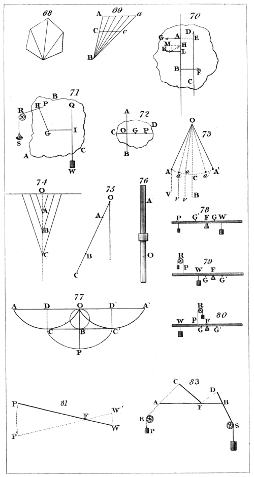
H. Adlard, sc.
London, Pubd. by Longman & Co.
In fig. 88., A B is a horizontal axle, which rests in
pivots at its extremities, or is supported in gudgeons, and
capable of revolving. Round this axis a rope is coiled,
which sustains the weight W. On the same axis a
wheel C is fixed, round which a rope is coiled in a contrary
direction, to which is appended the power P. The
moment of the power is found by multiplying it by the
radius of a wheel, and the moment of the weight, by multiplying
it by the radius of its axle. If these moments
be equal (185.), the machine will be in equilibrium.
Whence it appears that the power of the machine (247.)
is expressed by the proportion which the radius of the
wheel bears to the radius of the axle; or, what is the same,
of the diameter of the wheel to the diameter of the axle.
This principle is applicable to the wheel and axle in
every variety of form under which it can be presented.
(250.) It is evident that as the power descends continually,
and the rope is uncoiled from the wheel, the
weight will be raised continually, the rope by which it is
suspended being at the same time coiled upon the axle.
When the machine is in equilibrium, the forces of
both the weight and power are sustained by the axle, and
distributed between its props, in the manner explained
in (245.)
When the machine is applied to raise a weight, the
velocity with which the power moves is as many times
greater than that with which the weight rises, as the
weight itself is greater than the power. This is a principle
which has already been noticed, and which is common
to all machines whatsoever. It may hence be
proved, that in the elevation of the weight a quantity of
power is expended equal to that which would be necessary
to elevate the weight if the power were immediately
applied to it, without the intervention of any machine.
This has been explained in the case of the lever in (241.),178
and may be explained in the present instance in nearly
the same words.
In one revolution of the machine the length of rope
uncoiled from the wheel is equal to the circumference of
the wheel, and through this space the power must therefore
move. At the same time the length of rope coiled
upon the axle is equal to the circumference of the axle,
and through this space the weight must be raised. The
spaces, therefore, through which the power and weight
move in the same time, are in the proportion of the circumferences
of the wheel and axle; but these circumferences
are in the same proportion as their diameters. Therefore
the velocity of the power will bear to the velocity of
the weight the same proportion as the diameter of the
wheel bears to the diameter of the axle, or, what is the
same, as the weight bears to the power (249).
(251.) We have here omitted the consideration of
the thickness of the rope. When this is considered,
the force must be conceived as acting in the direction of
the centre of the rope, and therefore the thickness of the
rope which supports the power ought to be added to the
diameter of the wheel, and the thickness of the rope
which supports the weight to the diameter of the axle.
It is the more necessary to attend to this circumstance,
as the strength of the rope necessary to support the
weight causes its thickness to bear a considerable proportion
to the diameter of the axle; while the rope which
sustains the power not requiring the same strength, and
being applied to a larger circle, bears a very inconsiderable
proportion to its diameter.
(252.) In numerous forms of the wheel and axle,
the weight or resistance is applied by a rope coiled
upon the axle; but the manner in which the power is
applied is very various, and not often by means of a
rope. The circumference of a wheel sometimes carries
projecting pins, as represented in fig. 88., to which the
hand is applied to turn the machine. An instance of
this occurs in the wheel used in the steerage of a vessel.
In the common windlass, the power is applied by179
means of a winch, which is a rectangular lever, as represented
in fig. 89. The arm B C of the winch represents
the radius of the wheel, and the power is applied to C D
at right angles to B C.
In some cases no wheel is attached to the axle; but
it is pierced with holes directed towards its centre, in
which long levers are incessantly inserted, and a continuous
action produced by several men working at the
same time; so that while some are transferring the levers
from hole to hole, others are working the windlass.
The axle is sometimes placed in a vertical position,
the wheel or levers being moved horizontally. The capstan
is an example of this: a vertical axis is fixed in the
deck of the ship; the circumference is pierced with holes
presented towards its centre. These holes receive long
levers, as represented in fig. 90. The men who work
the capstan walk continually round the axle, pressing
forward the levers near their extremities.
In some cases the wheel is turned by the weight of
animals placed at its circumference, who move forward
as fast as the wheel descends, so as to maintain
their position continually at the extremity of the horizontal
diameter. The treadmill, fig. 91., and certain
cranes, such as fig. 92., are examples of this.
In water-wheels, the power is the weight of water
contained in buckets at the circumference, as in fig. 93.,
which is called an over-shot wheel: and sometimes by
the impulse of water against float-boards at the circumference,
as in the under-shot wheel, fig. 94. Both these
principles act in the breast-wheel, fig. 95.
In the paddle-wheel of a steam-boat, the power is the
resistance which the water offers to the motion of the
paddle-boards.
In windmills, the power is the force of the wind acting
on various parts of the arms, and may be considered
as different powers simultaneously acting on different
wheels having the same axle.
(253.) In most cases in which the wheel and axle is
used, the action of the power is liable to occasional sus180pension
or intermission, in which case some contrivance
is necessary to prevent the recoil of the weight. A
ratchet wheel R, fig. 88., is provided for this purpose,
which is a contrivance which permits the wheel to turn
in one direction; but a catch which falls between the
teeth of a fixed wheel prevents its motion in the other
direction. The effect of the power or weight is sometimes
transmitted to the wheel or axle by means of a
straight bar, on the edge of which teeth are raised, which
engage themselves in corresponding teeth on the wheel
or axle. Such a bar is called a rack; and an instance of
its use may be observed in the manner of working the
pistons of an air-pump.
(254.) The power of the wheel and axle being expressed
by the number of times the diameter of the axle
is contained in that of the wheel, there are obviously only
two ways by which this power may be increased; viz.
either by increasing the diameter of the wheel, or diminishing
that of the axle. In cases where great power
is required, each of these methods is attended with practical
inconvenience and difficulty. If the diameter of
the wheel be considerably enlarged, the machine will
become unwieldy, and the power will work through an
unmanageable space. If, on the other hand, the power
of the machine be increased by reducing the thickness of
the axle, the strength of the axle will become insufficient
for the support of that weight, the magnitude of which
had rendered the increase of the power of the machine
necessary. To combine the requisite strength with moderate
dimensions and great mechanical power is, therefore,
impracticable in the ordinary form of the wheel and
axle. This has, however, been accomplished by giving
different thicknesses to different parts of the axle, and
carrying a rope, which is coiled on the thinner part,
through a wheel attached to the weight, and coiling it
in the opposite direction on the thicker part, as in fig. 96.
To investigate the proportion of the power to the weight
in this case, let fig. 97. represent a section of the apparatus
at right angles to the axis. The weight is equally181
suspended by the two parts of the rope, S and S′, and
therefore each part is stretched by a force equal to half
the weight. The moment of the force, which stretches
the rope S, is half the weight multiplied by the radius
of the thinner part of the axle. This force being at the
same side of the centre with the power, co-operates with
it in supporting the force which stretches S′, and which
acts at the other side of the centre. By the principle
established in (185.), the moments of P and S must be
equal to that of S′; and therefore if P be multiplied by
the radius of the wheel, and added to half the weight
multiplied by the radius of the thinner part of the axle,
we must obtain a sum equal to half the weight multiplied
by the radius of the thicker part of the axle.
Hence it is easy to perceive, that the power multiplied
by the radius of the wheel is equal to half the
weight multiplied by the difference of the radii of the
thicker and thinner parts of the axle; or, what is the
same, the power multiplied by the diameter of the wheel,
is equal to the weight multiplied by half the difference of
the diameters of the thinner and thicker parts of the axle.
A wheel and axle constructed in this manner is equivalent
to an ordinary one, in which the wheel has
the same diameter, and whose axle has a diameter
equal to half the difference of the diameters of the
thicker and thinner parts. The power of the machine
is expressed by the proportion which the diameter of the
wheel bears to half the difference of these diameters;
and therefore this power, when the diameter of the wheel
is given, does not, as in the ordinary wheel and axle,
depend on the smallness of the axle, but on the smallness
of the difference of the thinner and thicker parts of it.
The axle may, therefore, be constructed of such a thickness
as to give it all the requisite strength, and yet the
difference of the diameters of its different parts may be
so small as to give it all the requisite power.
(255.) It often happens that a varying weight is to
be raised, or resistance overcome by a uniform power.
If, in such a case, the weight be raised by a rope coiled182
upon a uniform axle, the action of the power would not
be uniform, but would vary with the weight. It is,
however, in most cases desirable or necessary that the
weight or resistance, even though it vary, shall be moved
uniformly. This will be accomplished if by any means
the leverage of the weight is made to increase in the
same proportion as the weight diminishes, and to diminish
in the same proportion as the weight increases: for in
that case the moment of the weight will never vary,
whatever it gains by the increase of weight being lost
by the diminished leverage, and whatever it loses by the
diminished weight being gained by the increased leverage.
An axle, the surface of which is curved in such a
manner, that the thickness on which the rope is coiled
continually increased or diminishes in the same proportion
as the weight or resistance diminishes or increases,
will produce this effect.
It is obvious that all that has been said respecting a variable
weight or resistance, is also applicable to a variable
power, which, therefore, may, by the same means, be made
to produce a uniform effect. An instance of this occurs
in a watch, which is moved by a spiral spring. When
the watch has been wound up, this spring acts with its
greatest intensity, and as the watch goes down, the elastic
force of the spring gradually loses its energy. This
spring is connected by a chain with an axle of varying
thickness, called a fusee. When the spring is at its
greatest intensity, the chain acts upon the thinnest part
of the fusee, and as it is uncoiled it acts upon a part of
the fusee which is continually increasing in thickness,
the spring at the same time losing its elastic power in
exactly the same proportion. A representation of the
fusee, and the cylindrical box which contains the spring,
is given in fig. 98., and of the spring itself in fig. 99.
(256.) When great power is required, wheels and
axles may be combined in a manner analogous to a compound
system of levers, explained in (246.) In this
case the power acts on the circumference of the first
wheel, and its effect is transmitted to the circumference183
of the first axle. That circumference is placed in connection
with the circumference of the second wheel, and
the effect is thereby transmitted to the circumference of
the second axle, and so on. It is obvious from what was
proved in (248.), that the power of such a combination
of wheels and axles will be found by multiplying together
the powers of the several wheels of which it is composed.
It is sometimes convenient to compute this power by
numbers expressing the proportions of the circumferences
or diameters of the several wheels, to the circumferences
or diameters of the several axles respectively. This
computation is made by first multiplying the numbers
together which express the circumferences or diameters
of the wheels, and then multiplying together the numbers
which express the circumferences or diameters of
the several axles. The proportion of the two products
will express the power of the machine. Thus,
if the circumferences or diameters be as the numbers
10, 14, and 15, their product will be 2100; and if the
circumferences or diameters of the axles be expressed by
the numbers 3, 4, and 5, their product will be 60, and
the power of the machine will be expressed by the proportion
of 2100 and 60, or 35 to 1.
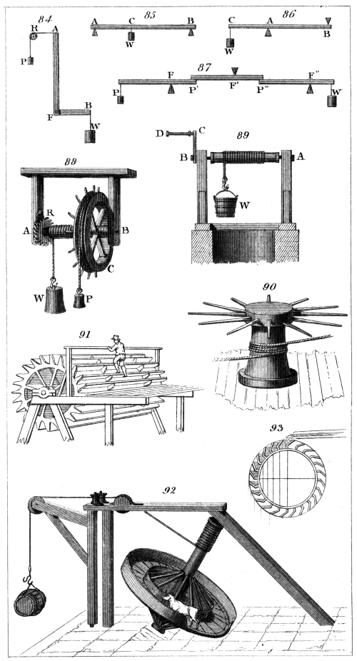
H. Adlard, sc.
London, Pubd. by Longman & Co.
(257.) The manner in which the circumferences of
the axles act upon the circumferences of the wheels in
compound wheel-work is various. Sometimes a strap
or cord is applied to a groove in the circumference of the
axle, and carried round a similar groove in the circumference
of the succeeding wheel. The friction of this
cord or strap with the groove is sufficient to prevent its
sliding and to communicate the force from the axle to
the wheel, or vice versa. This method of connecting
wheel-work is represented in fig. 100.
Numerous examples of wheels and axles driven by
straps or cords occur in machinery applied to almost
every department of the arts and manufactures. In the
turning lathe, the wheel worked by the treddle is connected
with the mandrel by a catgut cord passing through
grooves in the wheel and axle. In all great factories,184
revolving shafts are carried along the apartments, on which,
at certain intervals, straps are attached passing round
their circumferences and carried round the wheels which
give motion to the several machines. If the wheels, connected
by straps or cords, are required to revolve in the
same direction, these cords are arranged as in fig. 100.;
but if they are required to revolve in contrary directions,
they are applied as in fig. 101.
One of the chief advantages of the method of transmitting
motion between wheels and axles by straps or cords,
is that the wheel and axle may be placed at any distance
from each other which may be found convenient, and
may be made to turn either in the same or contrary
directions.
(258.) When the circumference of the wheel acts
immediately on the circumference of the succeeding axle,
some means must necessarily be adopted to prevent the
wheel from moving in contact with the axle without compelling
the latter to turn. If the surfaces of both were
perfectly smooth, so that all friction were removed, it is
obvious that either would slide over the surface of the
other, without communicating motion to it. But, on
the other hand, if there were any asperities, however
small, upon these surfaces, they would become mutually
inserted among each other, and neither the wheel nor
axle could move without causing the asperities with
which its edge is studded to encounter those asperities
which project from the surface of the other; and thus,
until these projections should be broken off, both wheel
and axle must be moved at the same time. It is on this
account that if the surfaces of the wheels and axles are
by any means rendered rough, and pressed together with
sufficient force, the motion of either will turn the other,
provided the load or resistance be not greater than the
force necessary to break off these small projections which
produce the friction.
In cases where great power is not required, motion
is communicated in this way through a train of wheel-work,
by rendering the surface of the wheel and axle185
rough, either by facing them with buff leather, or with
wood cut across the grain. This method is sometimes
used in spinning machinery, where one large buffed
wheel, placed in a horizontal position, revolves in contact
with several small buffed rollers, each roller communicating
motion to a spindle. The position of the
wheel W, and the rollers R R, &c., are represented in
fig. 102. Each roller can be thrown out of contact with
the wheel, and restored to it at pleasure.
The communication of motion between wheels and
axles by friction has the advantage of great smoothness
and evenness, and of proceeding with little noise; but this
method can only be used in cases where the resistance
is not very considerable, and therefore is seldom adopted
in works on a large scale. Dr. Gregory mentions an instance
of a saw mill at Southampton, where the wheels
act upon each other by the contact of the end grain of
wood. The machinery makes very little noise, and
wears very well, having been used not less than 20
years.
(259.) The most usual method of transmitting motion
through a train of wheel-work is by the formation
of teeth upon their circumferences, so that these indentures
of each wheel fall between the corresponding
ones of that in which it works, and ensure the action
so long as the strain is not so great as to fracture the
tooth.
In the formation of teeth very minute attention must
be given to their figure, in order that the motion may
be communicated from wheel to wheel with smoothness
and uniformity. This can only be accomplished by
shaping the teeth according to curves of a peculiar kind,
which mathematicians have invented, and assigned rules
for drawing. The ill consequences of neglecting this
will be very apparent, by considering the nature of the
action which would be produced if the teeth were formed
of square projecting pins, as in fig. 103. When the
tooth A comes into contact with B, it acts obliquely
upon it, and, as it moves, the corner of B slides upon the186
plane surface of A in such a manner as to produce much
friction, and to grind away the side of A and the end of
B. As they approach the position C D, they sustain a
jolt the moment their surfaces come into full contact;
and after passing the position of C D, the same scraping
and grinding effect is produced in the opposite direction,
until by the revolution of the wheels the teeth become
disengaged. These effects are avoided by giving to the
teeth the curved forms represented in fig. 104. By such
means the surfaces of the teeth roll upon each other with
very inconsiderable friction, and the direction in which
the pressure is excited is always that of a line M N,
touching the two wheels, and at right angles to the
radii. Thus the pressure being always the same, and
acting with the same leverage, produces a uniform
effect.
(260.) When wheels work together, their teeth must
necessarily be of the same size, and therefore the proportion
of their circumferences may always be estimated by
the number of teeth which they carry. Hence it follows,
that in computing the power of compound wheel-work,
the number of teeth may always be used to express the
circumferences respectively, or the diameters which are
proportional to these circumferences. When teeth are
raised upon an axle, it is generally called a pinion, and
in that case the teeth are called leaves. The rule for
computing the train of wheel-work given in (256.) will
be expressed as follows: when the wheel and axle carry
teeth, multiply together the number of teeth in each of
the wheels, and next the number of leaves in each of
the pinions; the proportion of the two products will
express the power of the machine. If some of the
wheels and axles carry teeth, and others not, this computation
may be made by using for those circumferences
which do not bear teeth the number of teeth which
would fill them. Fig. 105. represents a train of three
wheels and pinions. The wheel F which bears the
power, and the axle which bears the weight, have no
teeth; but it is easy to find the number of teeth which
they would carry.
187
(261.) It is evident that each pinion revolves much
more frequently in a given time than the wheel which
it drives. Thus, if the pinion C be furnished with
ten teeth, and the wheel E, which it drives, have sixty
teeth, the pinion C must turn six times, in order to turn
the wheel E once round. The velocities of revolution
of every wheel and pinion which work in one another
will therefore have the same proportion as their number
of teeth taken in a reverse order, and by this means the
relative velocity of wheels and pinions may be determined
according to any proposed rate.
Wheel-work, like all other machinery, is used to transmit
and modify force in every department of the arts
and manufactures; but it is also used in cases where motion
alone, and not force, is the object to be attained.
The most remarkable example of this occurs in watch
and clock-work, where the object is merely to produce
uniform motions of rotation, having certain proportions,
and without any regard to the elevation of weights, or
the overcoming of resistances.
(262.) A crane is an example of combination of
wheel-work used for the purpose of raising or lowering
great weights. Fig. 106. represents a machine of this
kind. A B is a strong vertical beam, resting on a pivot,
and secured in its position by beams in the floor. It
is capable, however, of turning on its axis, being confined
between rollers attached to the beams and fixed
in the floor. C D is a projecting arm called a gib,
formed of beams which are mortised into A B. The
wheel-work is mounted in two cast-iron crosses, bolted
on each side of the beams, one of which appears at
E F G H. The winch at which the power is applied is
at I. This carries a pinion immediately behind H.
This pinion works in a wheel K, which carries another
pinion upon its axle. This last pinion works in a larger
wheel L, which carries upon its axis a barrel M, on
which a chain or rope is coiled. The chain passes over
a pulley D at the top of the gib. At the end of the
chain a hook O is attached, to support the weight W.
During the elevation of the weight it is convenient that188
its recoil should be hindered in case of any occasional
suspension of the power. This is accomplished by a
ratchet wheel attached to the barrel M, as explained in
(253.); but when the weight W is to be lowered, the
catch must be removed from this ratchet wheel. In this
case the too rapid descent of the weight is in some cases
checked by pressure excited on some part of the wheel-work,
so as to produce sufficient friction to retard the
descent in any required degree, or even to suspend it, if
necessary. The vertical beam at B resting on a pivot,
and being fixed between rollers, allows the gib to be
turned round in any direction; so that a weight raised
from one side of the crane may be carried round, and
deposited on another side, at any distance within the
range of the gib. Thus, if a crane be placed upon a
wharf near a vessel, weights may be raised, and when
elevated, the gib may be turned round so as to let them
descend into the hold.
The power of this machine may be computed upon
the principles already explained. The magnitude of the
circle, in which the power at I moves, may be determined
by the radius of the winch, and therefore the
number of teeth which a wheel of that size would carry
may be found. In like manner we may determine the
number of leaves in a pinion whose magnitude would be
equal to the barrel M. Let the first number be multiplied
by the number of teeth in the wheel K, and that
product by the number of teeth in the wheel L. Next let
the number of leaves in the pinion H be multiplied by
the number of leaves in the pinion attached to the axle
of the wheel K, and let that product be multiplied by
the number of leaves in a pinion, whose diameter is
equal to that of the barrel M. These two products will
express the power of the machine.
(263.) Toothed wheels are of three kinds, distinguished
by the position which the teeth bear with respect
to the axis of the wheel. When they are raised upon
the edge of the wheel as in fig. 105., they are called spur
wheels, or spur gear. When they are raised parallel to the
axis, as in fig. 107., it is called a crown wheel. When189
the teeth are raised on a surface inclined to the plane of
the wheel, as in fig. 108., they are called bevelled wheels.
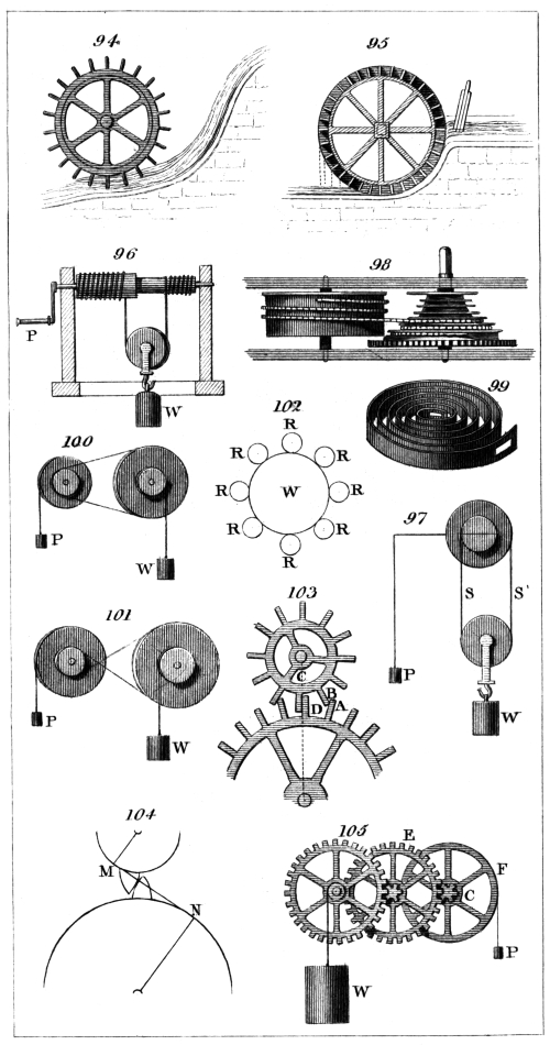
H. Adlard, sc.
London, Pubd. by Longman & Co.
If a motion round one axis is to be communicated to
another axis parallel to it, spur gear is generally used.
Thus, in fig. 105., the three axes are parallel to each
other. If a motion round one axis is to be communicated
to another at right angles to it, a crown wheel,
working in a spur pinion, as in fig. 107., will serve. Or
the same object may be obtained by two bevelled wheels,
as in fig. 108.
If a motion round one axis is required to be communicated
to another inclined to it at any proposed angle,
two bevelled wheels can always be used. In fig. 109. let
A B and A C be the two axles; two bevelled wheels,
such as D E and E F, on these axles will transmit the
motion or rotation from one to the other, and the relative
velocity may, as usual, be regulated by the proportional
magnitude of the wheels.
(264.) In order to equalise the wear of the teeth of
a wheel and pinion, which work in one another, it is
necessary that every leaf of the pinion should work in
succession through every tooth of the wheel, and not
continually act upon the same set of teeth. If the teeth
could be accurately shaped according to mathematical
principles, and the materials of which they are formed
be perfectly uniform, this precaution would be less necessary;
but as slight inequalities, both of material and
form, must necessarily exist, the effects of these should
be as far as possible equalised, by distributing them
through every part of the wheel. For this purpose it is
usual, especially in mill-work, where considerable force
is used, so to regulate the proportion of the number of
teeth in the wheel and pinion, that the same leaf of the
pinion shall not be engaged twice with any one tooth of
the wheel, until after the action of a number of teeth,
expressed by the product of the number of teeth in the
wheel and pinion. Let us suppose that the pinion contains
ten leaves, which we shall denominate by the numbers
1, 2, 3, &c., and that the wheel contains 60 teeth190
similarly denominated. At the commencement of the
motion suppose the leaf 1 of the pinion engages the
tooth 1 of the wheel; then after one revolution the leaf
1 of the pinion will engage the tooth 11 of the wheel,
and after two revolutions the leaf 1 of the pinion will
engage the tooth 21 of the wheel; and in like manner,
after 3, 4, and 5 revolutions of the pinion, the leaf 1
will engage successively the teeth 31, 41, and 51 of the
wheel. After the sixth revolution, the leaf 1 of the
pinion will again engage the tooth 1 of the wheel. Thus
it is evident, that in the case here supposed the leaf 1 of
the pinion will continually be engaged with the teeth 1,
11, 21, 31, 41, and 51 of the wheel, and no others.
The like may be said of every leaf of the pinion. Thus
the leaf 2 of the pinion will be successively engaged
with the teeth 2, 12, 22, 32, 42, and 52 of the wheel,
and no others. Any accidental inequalities of these
teeth will therefore continually act upon each other,
until the circumference of the wheel be divided into
parts of ten teeth each, unequally worn. This effect
would be avoided by giving either the wheel or pinion
one tooth more or one tooth less. Thus, suppose the
wheel, instead of having sixty teeth, had sixty-one, then
after six revolutions of the pinion the leaf 1 of the pinion
would be engaged with the tooth 61 of the wheel; and
after one revolution of the wheel, the leaf 2 of the pinion
would be engaged with the tooth 1 of the wheel. Thus,
during the first revolution of the wheel the leaf 1 of the
pinion would be successively engaged with the teeth 1,
11, 21, 31, 41, 51, and 61 of the wheel: at the commencement
of the second revolution of the wheel the
leaf 2 of the pinion would be engaged with the tooth 1
of the wheel; and during the second revolution of the
wheel the leaf 1 of the pinion would be successively
engaged with the teeth 10, 20, 30, 40, 50, and 60 of
the wheel. In the same manner it may be shown, that
in the third revolution of the wheel the leaf 1 of the
pinion would be successively engaged with the teeth 9,
19, 29, 39, 49, and 59 of the wheel: during the fourth191
revolution of the wheel the leaf 1 of the pinion would
be successively engaged with the teeth 8, 18, 28, 38,
48, and 58 of the wheel. By continuing this reasoning
it will appear, that during the tenth revolution of the
wheel the leaf 1 of the pinion will be engaged successively
with the teeth 2, 12, 22, 32, 42, and 52 of the
wheel. At the commencement of the eleventh revolution
of the wheel the leaf 1 of the pinion will be engaged
with the tooth 1 of the wheel, as at the beginning
of the motion. It is evident, therefore, that during the
first ten revolutions of the wheel each leaf of the pinion
has been successively engaged with every tooth of the
wheel, and that during these ten revolutions the pinion
has revolved sixty-one times. Thus the leaves of the
pinion have acted six hundred and ten times upon the
teeth of the wheel, before two teeth can have acted twice
upon each other.
The odd tooth which produces this effect is called by
millwrights the hunting cog.
(265.) The most familiar case in which wheel-work
is used to produce and regulate motion merely, without
any reference to weights to be raised or resistances to be
overcome, is that of chronometers. In watch and clock
work the object is to cause a wheel to revolve with a
uniform velocity, and at a certain rate. The motion of
this wheel is indicated by an index or hand placed upon
its axis, and carried round with it. In proportion to the
length of the hand the circle over which its extremity
plays is enlarged, and its motion becomes more perceptible.
This circle is divided, so that very small fractions
of a revolution of the hand may be accurately observed.
In most chronometers it is required to give motion to
two hands, and sometimes to three. These motions
proceed at different rates, according to the subdivisions
of time generally adopted. One wheel revolves in a
minute, bearing a hand which plays round a circle divided
into sixty equal parts; the motion of the hand
over each part indicating one second, and a complete
revolution of the hand being performed in one minute.192
Another wheel revolves once, while the former revolves
sixty times; consequently the hand carried by this wheel
revolves once in sixty minutes, or one hour. The circle
on which it plays is, like the former, divided into sixty
equal parts, and the motion of the hand over each division
is performed in one minute. This is generally
called the minute hand, and the former the second
hand.
A third wheel revolves once, while that which carries
the minute hand revolves twelve times; consequently
this last wheel, which carries the hour hand, revolves at
a rate twelve times less than that of the minute hand,
and therefore seven hundred and twenty times less than
the second hand. We shall now endeavour to explain
the manner in which these motions are produced and
regulated. Let A, B, C, D, E, fig. 110., represent a
train of wheels, and a, b, c, d represent their pinions, e
being a cylinder on the axis of the wheel E, round which
a rope is coiled, sustaining a weight W. Let the effect
of this weight transmitted through the train of wheels be
opposed by a power P acting upon the wheel A, and let
this power be supposed to be of such a nature as to cause
the weight W to descend with a uniform velocity, and
at any proposed rate. The wheel E carries on its circumference
eighty-four teeth. The wheel D carries
eighty teeth; the wheel C is also furnished with eighty
teeth, and the wheel B with seventy-five. The pinions
d and c are each furnished with twelve leaves, and the
pinions b and a with ten.
If the power at P be so regulated as to allow the
wheel A to revolve once in a minute, with a uniform velocity,
a hand attached to the axis of this wheel will
serve as the second hand. The pinion a carrying ten
teeth must revolve seven times and a half to produce one
revolution of B, consequently fifteen revolutions of the
wheel A will produce two revolutions of the wheel B;
the wheel B, therefore, revolves twice in fifteen minutes.
The pinion b must revolve eight times to produce one
revolution of the wheel C, and therefore the wheel C193
must revolve once in four quarters of an hour, or in one
hour. If a hand be attached to the axis of this wheel,
it will have the motion necessary for the minute hand.
The pinion c must revolve six times and two thirds to
produce one revolution of the wheel D, and therefore
this wheel must revolve once in six hours and two
thirds. The pinion d revolves seven times for one revolution
of the wheel E, and therefore the wheel E will
revolve once in forty-six hours and two thirds.
On the axis of the wheel C a second pinion may be
placed, furnished with seven leaves, which may lead a
wheel of eighty-four teeth, so that this wheel shall turn
once during twelve turns of the wheel C. If a hand be
fixed upon the axis, this hand will revolve once for
twelve revolutions of the minute hand fixed upon the
axis of the wheel C; that is, it will revolve once in
twelve hours. If it play upon a dial divided into twelve
equal parts, it will move over each part in an hour, and will
serve the purpose of the hour hand of the chronometer.
We have here supposed that the second hand, the
minute hand, and the hour hand move on separate dials.
This, however, is not necessary. The axis of the hour
hand is commonly a tube, inclosing within it that of the
minute hand, so that the same dial serves for both. The
second hand, however, is generally furnished with a separate
dial.
(266.) We shall now explain the manner in which a
power is applied to the wheel A, so as to regulate and
equalise the effect of the weight W. Suppose the wheel
A furnished with thirty teeth, as in fig. 111.; if nothing
check the motion, the weight W would descend with an
accelerated velocity, and would communicate an accelerated
motion to the wheel A. This effect, however, is
interrupted by the following contrivance:—L M is a pendulum
vibrating on the centre L, and so regulated that
the time of its oscillation is one second. The pallets
I and K are connected with the pendulum, so as to oscillate
with it. In the position of the pendulum represented
in the figure, the pallet I stops the motion of the194
wheel A, and entirely suspends the action of the weight
W, fig. 110., so that for a moment the entire machine is
motionless. The weight M, however, falls by its gravity
towards the lowest position, and disengages the pallet
I from the tooth of the wheel. The weight W begins
then to take effect, and the wheel A turns from A
towards B. Meanwhile the pendulum M oscillates
to the other side, and the pallet K falls under a tooth
of the wheel A, and checks for a moment its further
motion. On the returning vibration the pallet K becomes
again disengaged, and allows the tooth of the
wheel to escape, and by the influence of the weight W
another tooth passes before the motion of the wheel A is
again checked by the interposition of the pallet I.
From this explanation it will appear that, in two vibrations
of the pendulum, one tooth of the wheel A
passes the pallet I, and therefore, if the wheel A be
furnished with 30 teeth, it will be allowed to make one
revolution during 60 vibrations of the pendulum. If,
therefore, the pendulum be regulated so as to vibrate
seconds, this wheel will revolve once in a minute. From
the action of the pallets in checking the motion of the
wheel A, and allowing its teeth alternately to escape,
this has been called the escapement wheel; and the wheel
and pallets together are generally called the escapement,
or ’scapement.
We have already explained, that by reason of the
friction on the points of support, and other causes, the
swing of the pendulum would gradually diminish, and
its vibration at length cease. This, however, is prevented
by the action of the teeth of the scapement wheel
upon the pallets, which is just sufficient to communicate
that quantity of force to the pendulum which is necessary
to counteract the retarding effects, and to maintain
its motion. It thus appears, that although the effect of
the gravity of the weight W in giving motion to the machine
is at intervals suspended, yet this part of the force
is not lost, being, during these intervals, employed in
giving to the pendulum all that motion which it would
lose by the resistances to which it is inevitably exposed.
195
In stationary clocks, and in other cases in which the
bulk of the machine is not an objection, a descending
weight is used as the moving power. But in watches
and portable chronometers, this would be attended with
evident inconvenience. In such cases, a spiral spring,
called the mainspring, is the moving power. The manner
in which this spring communicates rotation to an
axis, and the ingenious method of equalising the effect
of its variable elasticity by giving to it a leverage, which
increases as the elastic force diminishes, have been already
explained. (255.)
A similar objection lies against the use of a pendulum
in portable chronometers. A spiral spring of a similar
kind, but infinitely more delicate, called a hair spring,
is substituted in its place. This spring is connected
with a nicely-balanced wheel, called the balance wheel,
which plays in pivots. When this wheel is turned to
a certain extent in one direction, the hair spring is coiled
up, and its elasticity causes the wheel to recoil, and
return to a position in which the energy of the spring
acts in the opposite direction. The balance wheel then
returns, and continually vibrates in the same manner.
The axis of this wheel is furnished with pallets similar
to those of the pendulum, which are alternately engaged
with the teeth of a crown wheel, which takes the place
of the scapement wheel already described.
A general view of the work of a common watch is
represented in fig. 111. bis. A is the balance wheel bearing
pallets p p upon its axis; C is the crown wheel, whose
teeth are suffered to escape alternately by those pallets in
the manner already described in the scapement of a
clock. On the axis of the crown wheel is placed a
pinion d, which drives another crown wheel K. On the
axis of this is placed the pinion c, which plays in the
teeth of the third wheel L. The pinion b on the axis
of L is engaged with the wheel M, called the centre
wheel. The axle of this wheel is carried up through
the centre of the dial. A pinion a is placed upon it,
which works in the great wheel N. On this wheel the196
mainspring immediately acts. O P is the mainspring
stripped of its barrel. The axis of the wheel M passing
through the centre of the dial is squared at the end to
receive the minute hand. A second pinion Q is placed
upon this axle which drives a wheel T. On the axle of
this wheel a pinion g is placed, which drives the hour
wheel V. This wheel is placed upon a tubular axis,
which incloses within it the axis of the wheel M. This
tubular axis passing through the centre of the dial, carries
the hour hand. The wheels A, B, C, D, E, fig.
110., correspond to the wheels C, K, L, M, N, fig. 112.;
and the pinions a, b, c, d, e, fig. 109., correspond to the
pinions d, c, b, a, fig. 111. From what has already been
explained of these wheels, it will be obvious that the
wheel M, fig. 111., revolves once in an hour, causing the
minute hand to move round the dial once in that time.
This wheel at the same time turns the pinion Q which
leads the wheel T. This wheel again turns the pinion
g which leads the hour wheel V. The leaves and teeth
of these pinions and wheels are proportioned, as already
explained, so that the wheel V revolves once during
twelve revolutions of the wheel M. The hour hand,
therefore, which is carried by the tubular axle of the
wheel V, moves once round the dial in twelve hours.
Our object here has not been to give a detailed account
of watch and clock work, a subject for which we
must refer the reader to the proper department of this
work. Such a general account has only been attempted
as may explain how tooth and pinion work may be applied
to regulate motion.
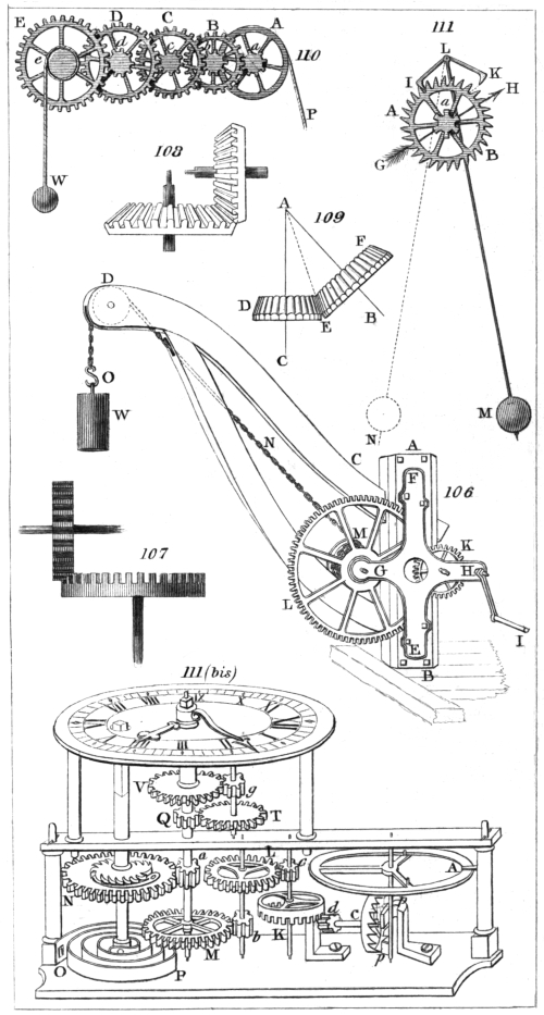
H. Adlard, sc.
London, Pubd. by Longman & Co.
197
CHAP. XV.
OF THE PULLEY.
(267.) The next class of simple machines, which present
themselves to our attention, is that which we have
called the cord. If a rope were perfectly flexible, and
were capable of being bent over a sharp edge, and of
moving upon it without friction, we should be enabled
by its means to make a force in any one direction overcome
resistance, or communicate motion in any other
direction. Thus if P, fig. 112., be such an edge, a perfectly
flexible rope passing over it would be capable of
transmitting a force S F to a resistance Q R, so as to
support or overcome R, or by a motion in the direction
of S F to produce another motion in the direction R Q.
But as no materials of which ropes can be constructed
can give them perfect flexibility, and as in proportion
to the strength by which they are enabled to transmit
force their rigidity increases, it is necessary, in practice,
to adopt means to remove or mitigate those effects
which attend imperfect flexibility, and which would
otherwise render cords practically inapplicable as machines.
When a cord is used to transmit a force from one
direction to another, its stiffness renders some force necessary
in bending it over the angle P, which the two
directions form; and if the angle be sharp, the exertion
of such a force may be attended with the rupture of the
cord. If, instead of bending the rope at one point over
a single angle, the change of direction were produced by
successively deflecting it over several angles, each of
which would be less sharp than a single one could be,
the force requisite for the deflection, as well as the
liability of rupturing the cord, would be considerably
diminished. But this end will be still more perfectly
attained if the deflection of the cord be produced by
bending it over the surface of a curve.
198
If a rope were applied only to sustain, and not to
move a weight, this would be sufficient to remove the
inconveniences arising from its rigidity. But when motion
is to be produced, the rope, in passing over the
curved surface, would be subject to excessive friction,
and consequently to rapid wear. This inconvenience
is removed by causing the surface on which the rope
runs to move with it, so that no more friction is produced
than would arise from the curved surface rolling
upon the rope.
(268.) All these ends are attained by the common
pulley, which consists of a wheel called a sheave, fixed
in a block and turning on a pivot. A groove is formed
in the edge of the wheel in which the rope runs, the
wheel revolving with it. Such an apparatus is represented
in fig. 113.
We shall, for the present, omit the consideration of
that part of the effects of the stiffness and friction of
the machine which is not removed by the contrivance
just explained, and shall consider the rope as perfectly
flexible and moving without friction.
From the definition of a flexible cord, it follows, that
its tension, or the force by which it is stretched throughout
its entire length, must be uniform. From this principle,
and this alone, all the mechanical properties of
pulleys may be derived.
Although, as already explained, the whole mechanical
efficacy of this machine depends on the qualities of the
cord, and not on those of the block and sheave, which
are only introduced to remove the accidental effects of
stiffness and friction; yet it has been usual to give the
name pulley to the block and sheave, and a combination
of blocks, sheaves, and ropes is called a tackle.
(269.) When the rope passes over a single wheel,
which is fixed in its position, as in fig. 113., the machine
is called a fixed pulley. Since the tension of the cord is
uniform throughout its length, it follows, that in this
machine the power and weight are equal. For the
weight stretches that part of the cord which is between199
the weight and pulley, and the power stretches that part
between the power and the pulley. And since the tension
throughout the whole length is the same, the weight
must be equal to the power.
Hence it appears that no mechanical advantage is
gained by this machine. Nevertheless, there is scarcely
any engine, simple or complex, attended with more convenience.
In the application of power, whether of men
or animals, or arising from natural forces, there are always
some directions in which it may be exerted to
much greater convenience and advantage than others,
and in many cases the exertion of these powers is limited
to a single direction. A machine, therefore, which enables
us to give the most advantageous direction to the
moving power, whatever be the direction of the resistance
opposed to it, contributes as much practical convenience
as one which enables a small power to balance
or overcome a great weight. In directing the power
against the resistance, it is often necessary to use two
fixed pulleys. Thus, in elevating a weight A, fig. 114.,
to the summit of a building, by the strength of a horse
moving below, two fixed pulleys B and C may be used.
The rope is carried from A over the pulley B; and,
passing downwards, is brought under C, and finally
drawn by the animal on the horizontal plane. In
the same manner sails are spread, and flags hoisted on
the yards and masts of a ship, by sailors pulling a rope
on the deck.
By means of the fixed pulley a man may raise himself
to a considerable height, or descend to any proposed
depth. If he be placed in a chair or bucket attached to
one end of a rope which is carried over a fixed pulley,
by laying hold of this rope on the other side, as represented
in fig. 115., he may, at will, descend to a depth
equal to half of the entire length of the rope, by continually
yielding rope on the one side, and depressing
the bucket or chair by his weight on the other. Fire-escapes
have been constructed on this principle, the
fixed pulley being attached to some part of the building.
200
(270.) A single moveable pulley is represented in
fig. 116. A cord is carried from a fixed point F, and
passing through a block B, attached to a weight W,
passes over a fixed pulley C, the power being applied at
P. We shall first suppose the parts of the cord on each
side the wheel B to be parallel; in this case, the whole
weight W being sustained by the parts of the cords B C
and B F, and these parts being equally stretched (268.),
each must sustain half the weight, which is therefore the
tension of the cord. This tension is resisted by the
power at P, which must, therefore, be equal to half the
weight. In this machine, therefore, the weight is twice
the power.
(271.) If the parts of the cord B C and B F be not
parallel, as in fig. 117., a greater power than half the
weight is therefore necessary to sustain it. To determine
the power necessary to support a given weight,
in this case take the line B A in the vertical direction,
consisting of as many inches as the weight consists of
ounces; from A draw A D parallel to B C, and A E
parallel to B F; the force of the weight represented by
A B will be equivalent to two forces represented by B D
and B E. (74.) The number of inches in these lines
respectively will represent the number of ounces which
are equivalent to the tensions of the parts B F and B C
of the cord. But as these tensions are equal, B D and
B E must be equal, and each will express the amount of
the power P, which stretches the cord at P C.
It is evident that the four lines, A E, E B, B D, and
D A, are equal. And as each of them represents the
power, the weight which is represented by A B must
be less than twice the power which is represented by
A E and E B taken together. It follows, therefore, that
as parts of the ropes which support the weight depart
from parallelism the machine becomes less and less
efficacious; and there are certain obliquities at which
the equilibrating power would be much greater than the
weight.
(272.) The mechanical power of pulleys admits of201
being almost indefinitely increased by combination. Systems
of pulleys may be divided into two classes; those
in which a single rope is used, and those which consist
of several distinct ropes. Fig. 118. and 119. represent
two systems of pulleys, each having a single rope.
The weight is in each case attached to a moveable block,
B, in which are fixed two or more wheels; A is a fixed
block, and the rope is successively passed over the wheels
above and below, and, after passing over the last wheel
above, is attached to the power. The tension of that
part of the cord to which the power is attached is produced
by the power, and therefore equivalent to it, and
the same tension must extend throughout its whole
length. The weight is sustained by all those parts of
the cord which pass from the lower block, and as the
force which stretches them all is the same, viz. that of
the power, the effect of the weight must be equally distributed
among them, their directions being supposed to
be parallel. It will be evident, from this reasoning, that
the weight will be as many times greater than the power
as the number of cords which support the lower block.
Thus, if there be six cords, each cord will support a
sixth part of the weight, that is, the weight will be six
times the tension of the cord, or six times the power.
In fig. 118. the cord is represented as being finally attached
to a hook on the upper block. But it may be carried
over an additional wheel fixed in that block, and finally
attached to a hook in the lower block, as in fig. 119., by
which one will be added to the power of the machine, the
number of cords at the lower block being increased by
one. In the system represented in fig. 118. the wheels are
placed in the blocks one above the other; in fig. 119. they
are placed side by side. In all systems of pulleys of this
class, the weight of the lower block is to be considered
as a part of the weight to be raised, and in estimating
the power of the machine, this should always be attended
to.
(273.) When the power of the machine, and therefore
the number of wheels, is considerable, some diffi202culty
arises in the arrangement of the wheels and cords.
The celebrated Smeaton contrived a tackle, which takes
its name from him, in which there are ten wheels in
each block: five large wheels placed side by side, and
five smaller ones similarly placed above them in the
lower block, and below them in the upper. Fig. 120.
represents Smeaton’s blocks without the rope. The
wheels are marked with the numbers 1, 2, 3, &c., in the
order in which the rope is to be passed over them. As
in this pulley 20 distinct parts of the rope support the
lower block, the weight, including the lower block, will
be 20 times the equilibrating power.
(274.) In all these systems of pulleys, every wheel
has a separate axle, and there is a distinct wheel for
every turn of the rope at each block. Each wheel is
attended with friction on its axle, and also with friction
between the sheave and block. The machine is by this
means robbed of a great part of its efficacy, since, to
overcome the friction alone, a considerable power is in
most cases necessary.
An ingenious contrivance has been suggested, by
which all the advantage of a large number of wheels
may be obtained without the multiplied friction of
distinct sheaves and axles. To comprehend the excellence
of this contrivance, it will be necessary to consider
the rate at which the rope passes over the several
wheels of such a system, as fig. 118. If one foot of the
rope G F pass over the pulley F, two feet must pass over
the pulley E, because the distance between F and E
being shortened one foot, the total length of the rope
G F E must be shortened two feet. These two feet of
rope must pass in the direction E D, and the wheel D,
rising one foot, three feet of rope must consequently pass
over it. These three feet of rope passing in the direction
D C, and the rope D C being also shortened one foot
by the ascent of the lower block, four feet of rope must
pass over the wheel C. In the same way it may be
shown that five feet must pass over B, and six feet over
A. Thus, whatever be the number of wheels in the203
upper and lower blocks, the parts of the rope which pass
in the same time over the wheels in the lower block are
in the proportion of the odd numbers 1, 3, 5, &c.; and
those which pass over the wheels in the upper block in
the same time, are as the even numbers 2, 4, 6, &c. If
the wheels were all of equal size, as in fig. 119., they
would revolve with velocities proportional to the rate at
which the rope passes over them. So that, while the
first wheel below revolves once, the first wheel above
will revolve twice; the second wheel below three times;
the second wheel above, four times, and so on. If,
however, the wheels differed in size in proportion to the
quantity of rope which must pass over them, they would
evidently revolve in the same time. Thus, if the first
wheel above were twice the size of the first wheel below,
one revolution would throw off twice the quantity of
rope. Again, if the second wheel below were thrice
the size of the first wheel below, it would throw off in
one revolution thrice the quantity of rope, and so on.
Wheels thus proportioned, revolving in exactly the
same time, might be all placed on one axle, and would
partake of one common motion, or, what is to the same
effect, several grooves might be cut upon the face of one
solid wheel, with diameters in the proportion of the odd
numbers 1, 3, and 5, &c., for the lower pulley, and corresponding
grooves on the face of another solid wheel
represented by the even numbers 2, 4, 6, &c., for the
upper pulley. The rope being passed successively over
the grooves of such wheels, would be thrown off exactly
in the same manner as if every groove were upon a separate
wheel, and every wheel revolved independently of
the others. Such is White’s pulley, represented in
fig. 121.
The advantage of this machine, when accurately constructed,
is very considerable. The friction, even when
great resistances are to be opposed, is very trifling; but,
on the other hand, it has corresponding disadvantages
which greatly circumscribe its practical utility. In the
workmanship of the grooves great difficulty is found in204
giving them the exact proportions. In doing which, the
thickness of the rope must be accurately allowed for; and
consequently it follows, that the same pulley can never act
except with a rope of a particular diameter. A very
slight deviation from the true proportion of the grooves
will cause the rope to be unequally stretched, and will
throw on some parts of it an undue proportion of the
weight, while other parts become nearly, and sometimes
altogether slack. Besides these defects, the rope is so
liable to derangement by being thrown out of the grooves,
that the pulley can scarcely be considered portable.
For these and other reasons, this machine, ingenious
as it unquestionably is, has never been extensively used.
(275.) In the several systems of pulleys just explained,
the hook to which the fixed block is attached supports
the entire of both the power and weight. When the
machine is in equilibrium, the power only supports so
much of the weight as is equal to the tension of the
cord, all the remainder of the weight being thrown on
the fixed point, according to what was observed in (225.)
If the power be moved so as to raise the weight,
it will move with a velocity as many times greater
than that of the weight as the weight itself is greater
than the power. Thus in fig. 118. if the weight
attached to the lower block ascend one foot, six feet of
line will pass over the pulley A, according to what has been
already proved. Thus, the power will descend through six
feet, while the weight rises one foot. But, in this case,
the weight is six times the power. All the observations
in (226.) will therefore be applicable to the cases of great
weights raised by small powers by means of the system
of pulleys just described.
(276.) When two or more ropes are used, pulleys may
be combined in various ways so as to produce any degree
of mechanical effect. If to any of the systems already
described a single moveable pulley be added, the power
of the machine would be doubled. In this case, the
second rope is attached to the hook of the lower block,
as in fig. 122., and being carried through a moveable205
pulley attached to the weight, it is finally brought up to
a fixed point. The tension of the second cord is equal
to half the weight (270.); and therefore the power P, by
means of the first cord, will have only half the tension
which it would have if the weight were attached to the
lower block. A moveable pulley thus applied is called a
runner.
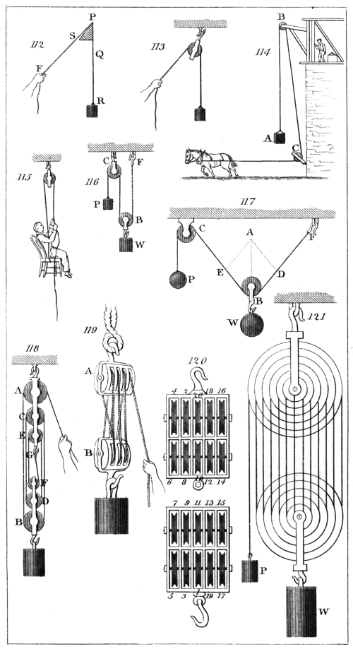
C. Varley, del.
H. Adlard, sc.
London, Pubd. by Longman & Co.
(277.) Two systems of pulleys, called Spanish bartons,
having each two ropes, are represented in fig. 123. The
tension of the rope P A B C in the first system is equal
to the power; and therefore the parts B A and B C
support a portion of the weight equal to twice the power.
The rope E A supports the tensions of A P and A B;
and therefore the tension of A E D is twice the power.
Thus, the united tensions of the ropes which support
the pulley B is four times the power, which is therefore
the amount of the weight. In the second system, the
rope P A D is stretched by the power. The rope A E B C
acts against the united tensions A P and A D; and
therefore the tension of A E or E B is twice the power.
Thus, the weight acts against three tensions; two of
which are equal to twice the power, and the remaining
one is equal to the power. The weight is therefore
equal to five times the power.
A single rope may be so arranged with one moveable
pulley as to support a weight equal to three times the
power. In fig. 124. this arrangement is represented,
where the numbers sufficiently indicate the tension of
the rope, and the proportion of the weight and power.
In fig. 125. another method of producing the same effect
with two ropes is represented.
(278.) If several single moveable pulleys be made
successively to act upon each other, the effect is doubled
by every additional pulley: such a system as this is
represented in fig. 126. The tension of the first rope is
equal to the power; the second rope acts against twice
the tension of the first, and therefore it is stretched
with a force equal to twice the power: the third rope
acts against twice this tension, and therefore it is stretched206
with a force equal to four times the power, and so on.
In the system represented in fig. 126. there are three
ropes, and the weight is eight times the power. Another
rope would render it sixteen times the power, and so on.
In this system, it is obvious that the ropes will require
to have different degrees of strength, since the tension to
which they are subject increases in a double proportion
from the power to the weight.
(279.) If each of the ropes, instead of being attached
to fixed points at the top, are carried over fixed pulleys,
and attached to the several moveable pulleys respectively,
as in fig. 127., the power of the machine will be greatly
increased; for in that case the forces which stretch the
successive ropes increase in a treble instead of a double
proportion, as will be evident by attending to the numbers
which express the tensions in the figure. One rope
would render the weight three times the power, two
ropes nine times, three ropes twenty-seven times, and
so on. An arrangement of pulleys is represented in fig.
128., by which each rope, instead of being finally
attached to a fixed point, as in fig. 126., is attached to the
weight. The weight is in this case supported by three
ropes; one stretched with a force equal to the power;
another with a force equal to twice the power; and a
third with a force equal to four times the power. The
weight is therefore, in this case, seven times the power.
(280.) If the ropes, instead of being attached to the
weight, pass through wheels, as in fig. 129., and are
finally attached to the pulleys above, the power of the
machine will be considerably increased. In the system
here represented the weight is twenty-six times the
power.
(281.) In considering these several combinations of
pulleys, we have omitted to estimate the effects produced
by the weights of the sheaves and blocks. Without
entering into the details of this computation, it may be
observed generally, that in the systems represented in
figs. 126., 127. the weight of the wheel and blocks acts
against the power; but that in figs. 128. and 129. they207
assist the powers in supporting the weight. In the
systems represented in fig. 123. the weight of the pulleys,
to a certain extent, neutralise each other.
(282.) It will in all cases be found, that that quantity
by which the weight exceeds the power is supported by
fixed points; and therefore, although it be commonly
stated that a small power supports a great weight, yet
in the pulley, as in all other machines, the power supports
no more of the weight than is exactly equal to its
own amount. It will not be necessary to establish this
in each of the examples which have been given: having
explained it in one instance, the student will find no
difficulty in applying the same reasoning to others. In
fig. 126., the fixed pulley sustains a force equal to twice
the power, and by it the power giving tension to the first
rope sustains a part of the weight equal to itself. The
first hook sustains a portion of the weight equal to the
tension of the first string, or to the power. The second
hook sustains a force equal to twice the power; and the
third hook sustains a force equal to four times the
power. The three hooks therefore sustain a portion of
the weight equal to seven times the power; and the
weight itself being eight times the power, it is evident
that the part of the weight which remains to be supported
by the power is equal to the power itself.
(283.) When a weight is raised by any of the systems
of pulleys which have been last described, the proportion
between the velocity of the weight and the velocity of
the power, so frequently noticed in other machines, will
always be observed. In the system of pulleys represented
in fig. 126. the weight being eight times the power,
the velocity of the power will be eight times that of the
weight. If the power be moved through eight feet, that
part of the rope between the fixed pulley and the first moveable
pulley will be shortened by eight feet. And since the
two parts which lie above the first moveable pulley must be
equally shortened, each will be diminished by four feet;
therefore the first pulley will rise through four feet while
the power moves through eight feet. In the same way208
it may be shown, that while the first pulley moves
through four feet, the second moves through two; and
while the second moves through two, the third, to which
the weight is attached, is raised through one foot. While
the power, therefore, is carried through eight feet, the
weight is moved through one foot.
By reasoning similar to this, it may be shown that
the space through which the power is moved in every
case is as many times greater than the height through
which the weight is raised, as the weight is greater than
the power.
(284.) From its portable form, cheapness of construction,
and the facility with which it may be applied
in almost every situation, the pulley is one of the most
useful of the simple machines. The mechanical advantage,
however, which it appears in theory to possess is
considerably diminished in practice, owing to the stiffness
of the cordage, and the friction of the wheels and
blocks. By this means it is computed that in most cases
so great a proportion as two thirds of the power is lost.
The pulley is much used in building, where weights are
to be elevated to great heights. But its most extensive
application is found in the rigging of ships, where almost
every motion is accomplished by its means.
(285.) In all the examples of pulleys, we have supposed
the parts of the rope sustaining the weight and
each of the moveable pulleys to be parallel to each other.
If they be subject to considerable obliquity, the relative
tensions of the different ropes must be estimated according
to the principle applied in (271.)
209
CHAP. XVI.
ON THE INCLINED PLANE, WEDGE, AND SCREW.
(286.) The inclined plane is the most simple of all
machines. It is a hard plane surface forming some
angle with a horizontal plane, that angle not being a
right angle. When a weight is placed on such a plane,
a two-fold effect is produced. A part of the effect of
the weight is resisted by the plane, and produces a pressure
upon it; and the remainder urges the weight down
the plane, and would produce a pressure against any
surface resisting its motion placed in a direction perpendicular
to the plane (131.)
Let A B, fig. 130., be such a plane, B C its horizontal
base, A C its height, and A B C its angle of elevation.
Let W be a weight placed upon it. This weight acts
in the vertical direction W D, and is equivalent to two
forces, W F perpendicular to the plane, and W E directed
down the plane (74.) If a plane be placed at right
angles to the inclined plane below W, it will resist the
descent of the weight, and sustain a pressure expressed
by W E. Thus, the weight W resting in the corner,
instead of producing one pressure in the direction
W D, will produce two pressures, one expressed by W F
upon the inclined plane, and the other expressed by
W E upon the resisting plane. These pressures respectively
have the same proportion to the entire weight
as W F and W E have to W D, or as D E and W E
have to W D, because D E is equal to W F. Now the
triangle W E D is in all respects similar to the triangle
A B C, the one differing from the other only in the scale
on which it is constructed. Therefore, the three lines
A C, C B, and B A, are in the same proportion to each
other as the lines W E, E D, and W D. Hence, A B
has to A C the same proportion as the whole weight
has to the pressure directed toward B, and A B has to210
B C the same proportion as the whole weight has to the
pressure on the inclined plane.
We have here supposed the weight to be sustained
upon the inclined plane by a hard plane fixed at right
angles to it. But the power necessary to sustain the
weight will be the same in whatever way it is applied,
provided it act in the direction of the plane. Thus, a
cord may be attached to the weight, and stretched towards
A, or the hands of men may be applied to the
weight below it, so as to resist its descent towards B.
But in whatever way it be applied, the amount of
the power will be determined in the same manner. Suppose
the weight to consist of as many pounds as there
are inches in A B, then the power requisite to sustain
it upon the plane will consist of as many pounds
as there are inches in A C, and the pressure on the plane
will amount to as many pounds as there are inches in B C.
From what has been stated it may easily be inferred
that the less the elevation of the plane is, the less will
be the power requisite to sustain a given weight upon it,
and the greater will be the pressure upon it. Suppose
the inclined plane A B to turn upon a hinge at B, and to
be depressed so that its angle of elevation shall be diminished,
it is evident that as this angle decreases the
height of the plane decreases, and its base increases.
Thus, when it takes the position B A′, the height A′ C′
is less than the former height A C, while the base B C′
is greater than the former base B C. The power requisite
to support the weight upon the plane in the position
B A′ is represented by A′ C′, and is as much less than the
power requisite to sustain it upon the plane A B, as the
height A′ C′ is less than the height A C. On the other
hand, the pressure upon the plane in the position B A′
is as much greater than the pressure upon the plane
B A, as the base B C′ is greater than the base B C.
(287.) The power of an inclined plane, considered as
a machine, is therefore estimated by the proportion
which its length bears to its height. This power is
always increased by diminishing the elevation of the plane.
211
Roads which are not level may be regarded as inclined
planes, and loads drawn upon them in carriages, considered
in reference to the powers which impel them, are
subject to all the conditions which have been established
for inclined planes. The inclination of the road is estimated
by the height corresponding to some proposed
length. Thus it is said to rise one foot in fifteen, one
foot in twenty, &c., meaning that if fifteen or twenty
feet of the road be taken as the length of an inclined
plane, such as A B, the corresponding height will be one
foot. Or the same may be expressed thus: that if
fifteen or twenty feet be measured upon the road, the
difference of the levels of the two extremities of the distance
measured is one foot. According to this method
of estimating the inclination of roads, the power requisite
to sustain a load upon them (setting aside the effect
of friction), is always proportional to that elevation.
Thus, if a road rise one foot in twenty, a power of one
ton will be sufficient to sustain twenty tons, and so on.
On a horizontal plane the only resistance which the
power has to overcome is the friction of the load with
the plane, and the consideration of this being for the
present omitted, a weight once put in motion would continue
moving for ever, without any further action of the
power. But if the plane be inclined, the power will be
expended in raising the weight through the perpendicular
height of the plane. Thus, in a road which rises
one foot in ten, the power is expended in raising the
weight through one perpendicular foot for every ten feet
of the road over which it is moved. As the expenditure
of power depends upon the rate at which the weight is
raised perpendicularly, it is evident that the greater
the inclination of the road is, the slower the motion
must be with the same force. If the energy of
the power be such as to raise the weight at the rate of
one foot per minute, the weight may be moved in each
minute through that length of the road which corresponds
to a rise of one foot. Thus, if two roads rise
one at the rate of a foot in fifteen feet, and the other at212
the rate of one foot in twenty feet, the same expenditure
of power will move the weight through fifteen feet of
the one, and twenty feet of the other at the same rate.
From such considerations as these, it will readily
appear that it may often be more expedient to carry a
road through a circuitous route than to continue it in
the most direct course; for though the measured length
of road may be considerably greater than in the former
case, yet more may be gained in speed with the same
expenditure of power than is lost by the increase of
distance. By attending to these circumstances, modern
road-makers have greatly facilitated and expedited the
intercourse between distant places.
(288.) If the power act obliquely to the plane, it will
have a twofold effect; a part being expended in supporting
or drawing the weight, and a part in diminishing
or increasing the pressure upon the plane. Let
W P, fig. 130., be the power. This will be equivalent
to two forces, W F′, perpendicular to the plane, and
W E′ in the direction of the plane. (74.) In order
that the power should sustain the weight, it is necessary
that that part W E′ of the power which acts in the
direction of the plane should be equal to that part W E,
fig. 130., of the weight which acts down the plane. The
other part W F′ of the power acting perpendicular to the
plane is immediately opposed to that part W F of the
weight which produces pressure. The pressure upon
the plane will therefore be diminished by the amount
of W F′. The amount of the power which will equilibrate
with the weight may, in this case, be found as
follows. Take W E′ equal to W E, and draw E′ P
perpendicular to the plane, and meeting the direction of
the power. The proportion of the power to the
weight will be that of W P to W D. And the proportion
of the pressure to the weight will be that of the
difference between W F and W F′ to W D. If the
amount of the power have a less proportion to the weight
than W P has to W D, it will not support the body on
the plane, but will allow it to descend. And if it213
have a greater proportion, it will draw the weight up
the plane towards A.
(289.) It sometimes happens that a weight upon one
inclined plane is raised or supported by another weight
upon another inclined plane. Thus, if A B and A B′,
fig. 131., be two inclined planes forming an angle at A,
and W W′ be two weights placed upon these planes,
and connected by a cord passing over a pulley at A, the
one weight will either sustain the other, or one will
descend, drawing the other up. To determine the circumstances
under which these effects will ensue, draw
the lines W D and W′ D′ in the vertical direction, and
take upon them as many inches as there are ounces in
the weights respectively. W D and W′ D′ being the
lengths thus taken, and therefore representing the weights,
the lines W E and W′ E′ will represent the effects of
these weights respectively down the planes. If W E
and W′ E′ be equal, the weights will sustain each other
without motion. But if W E be greater than W′ E′,
the weight W will descend, drawing the weight W′ up.
And if W′ E′ be greater than W E, the weight W′ will
descend, drawing the weight W up. In every case the
lines W F and W′ F′ will represent the pressures upon
the planes respectively.
It is not necessary, for the effect just described, that
the inclined planes should, as represented in the figure,
form an angle with each other. They may be parallel,
or in any other position, the rope being carried over a
sufficient number of wheels placed so as to give it the
necessary deflection. This method of moving loads is
frequently applied in great public works where rail-roads
are used. Loaded waggons descend one inclined plane,
while other waggons, either empty or so loaded as to
permit the descent of those with which they are connected,
are drawn up the other.
(290.) In the application of the inclined plane which
we have hitherto noticed, the machine itself is supposed
to be fixed in its position, while the weight or load is
moved upon it. But it frequently happens that resist214ances
are to be overcome which do not admit of being
thus moved. In such cases, instead of moving the load
upon the planes, the plane is to be moved under or
against the load. Let D E, fig. 132., be a heavy beam
secured in a vertical position between guides F G and
H I, so that it is free to move upwards and downwards,
but not laterally. Let A B C be an inclined plane, the
extremity of which is placed beneath the end of the
beam. A force applied to the back of this plane A C, in
the direction C B, will urge the plane under the beam so
as to raise the beam to the position represented in fig. 133.
Thus, while the inclined plane is moved through the
distance C B, the beam is raised through the height C A.
(291.) When the inclined plane is applied in this
manner, it is called a wedge. And if the power applied
to the back were a continued pressure, its proportion to
the weight would be that of A C to C B. It follows,
therefore, that the more acute the angle B is, the more
powerful will be the wedge.
In some cases, the wedge is formed of two inclined
planes, placed base to base, as represented in fig. 134.
The theoretical estimation of the power of this machine
is not applicable in practice with any degree of accuracy.
This is in part owing to the enormous proportion
which the friction in most cases bears to the theoretical
value of the power, but still more to the nature of the
power generally used. The force of a blow is of a
nature so wholly different from continued forces, such
as the pressure of weights, or the resistance offered by
the cohesion of bodies, that it admits of no numerical
comparison with them. Hence we cannot properly
state the proportion which the force of a blow bears to
the amount of a weight or resistance. The wedge is
almost invariably urged by percussion; while the resistances
which it has to overcome are as constantly
forces of the other kind. Although, however, no exact
numerical comparison can be made, yet it may be stated
in a general way that the wedge is more and more
powerful as its angle is more acute.
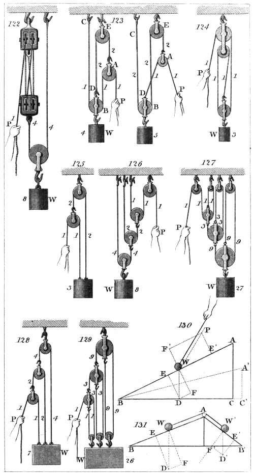
C. Varley, del.
H. Adlard, sc.
London, Pubd. by Longman & Co.
215
In the arts and manufactures, wedges are used where
enormous force is to be exerted through a very small
space. Thus it is resorted to for splitting masses of
timber or stone. Ships are raised in docks by wedges
driven under their keels. The wedge is the principal
agent in the oil-mill. The seeds from which the oil
is to be extracted are introduced into hair bags, and
placed between planes of hard wood. Wedges inserted
between the bags are driven by allowing heavy beams to
fall on them. The pressure thus excited is so intense,
that the seeds in the bags are formed into a mass nearly
as solid as wood. Instances have occurred in which
the wedge has been used to restore a tottering edifice to
its perpendicular position.
All cutting and piercing instruments, such as knives,
razors, scissors, chisels, &c., nails, pins, needles, awls,
&c. are wedges. The angle of the wedge, in these
cases, is more or less acute, according to the purpose to
which it is to be applied. In determining this, two things
are to be considered—the mechanical power, which is
increased by diminishing the angle of the wedge; and
the strength of the tool, which is always diminished by
the same cause. There is, therefore, a practical limit
to the increase of the power, and that degree of sharpness
only is to be given to the tool which is consistent
with the strength requisite for the purpose to which it is
to be applied. In tools intended for cutting wood, the
angle is generally about 30°. For iron it is from 50°
to 60°; and for brass, from 80° to 90°. Tools which
act by pressure may be made more acute than those
which are driven by a blow; and in general the softer
and more yielding the substance to be divided is, and
the less the power required to act upon it, the more
acute the wedge may be constructed.
In many cases the utility of the wedge depends on
that which is entirely omitted in its theory, viz. the
friction which arises between its surface and the substance
which it divides. This is the case when pins,
bolts, or nails are used for binding the parts of struc216tures
together; in which case, were it not for the friction,
they would recoil from their places, and fail to
produce the desired effect. Even when the wedge is
used as a mechanical engine, the presence of friction is
absolutely indispensable to its practical utility. The
power, as has already been stated, generally acts by successive
blows, and is therefore subject to constant intermission,
and but for the friction the wedge would recoil
between the intervals of the blows with as much force
as it had been driven forward. Thus the object of
the labour would be continually frustrated. The friction
in this case is of the same use as a ratchet wheel,
but is much more necessary, as the power applied to the
wedge is more liable to intermission than in the cases
where ratchet wheels are generally used.
(292.) When a road directly ascends the side of a
hill, it is to be considered as an inclined plane; but it
will not lose its mechanical character, if, instead of
directly ascending towards the top of the hill, it winds
successively round it, and gradually ascends so as after
several revolutions to reach the top. In the same manner
a path may be conceived to surround a pillar by
which the ascent may be facilitated upon the principle
of the inclined plane. Winding stairs constructed in the
interior of great columns partake of this character; for
although the ascent be produced by successive steps, yet
if a floor could be made sufficiently rough to prevent the
feet from slipping, the ascent would be accomplished
with equal facility. In such a case the winding path
would be equivalent to an inclined plane, bent into such
a form as to accommodate it to the peculiar circumstances
in which it would be required to be used. It will not be
difficult to trace the resemblance between such an adaptation
of the inclined plane and the appearances presented
by the thread of a screw: and it may hence be easily
understood that a screw is nothing more than an inclined
plane constructed upon the surface of a cylinder.
This will, perhaps, be more apparent by the following
contrivance: Let A B, fig. 135., be a common round217
ruler, and let C D E be a piece of white paper cut in
the form of an inclined plane, whose height C D is equal
to the length of the ruler A B, and let the edge C E
of the paper be marked with a broad black line: let the
edge C D be applied to the ruler A B, and being attached
thereto, let the paper be rolled round the ruler; the
ruler will then present the appearance of a screw, fig. 136.
the thread of the screw being marked by the black line
C E, winding continually round the ruler. Let D F,
fig. 135., be equal to the circumference of the ruler, and
draw F G parallel to D C, and G H parallel to D E, the
part C G F D of the paper will exactly surround the
ruler once: the part C G will form one convolution of the
thread, and may be considered as the length of one inclined
plane surrounding the cylinder, C H being the
corresponding height, and G H the base. The power of
the screw does not, as in the ordinary cases of the inclined
plane, act parallel to the plane or thread, but at right
angles to the length of the cylinder A B, or, what is to
the same effect, parallel to the base H G; therefore the
proportion of the power to the weight will be, according
to principles already explained, the same as that of C H
to the space through which the power moves parallel to
H G in one revolution of the screw. H C is evidently
the distance between the successive positions of the thread
as it winds round the cylinder; and it appears from what
has been just stated, that the less this distance is, or, in
other words, the finer the thread is, the more powerful
the machine will be.
(293.) In the application of the screw the weight or
resistance is not, as in the inclined plane and wedge,
placed upon the surface of the plane or thread. The
power is usually transmitted by causing the screw to
move in a concave cylinder, on the interior surface of
which a spiral cavity is cut, corresponding exactly to
the thread of the screw, and in which the thread will
move by turning round the screw continually in the
same direction. This hollow cylinder is usually called
the nut or concave screw. The screw surrounded by its218
spiral thread is represented in fig. 137.; and a section of
the same playing in the nut is represented in fig. 138.
There are several ways in which the effect of the
power may be conveyed to the resistance by this apparatus.
First, let us suppose that the nut A B is fixed. If the
screw be continually turned on its axis, by a lever E F
inserted in one end of it, it will be moved in the direction
C D, advancing every revolution through a space
equal to the distance between two contiguous threads.
By turning the lever in an opposite direction, the screw
will be moved in the direction D C.
If the screw be fixed, so as to be incapable either of
moving longitudinally or revolving on its axis, the nut
A B may be turned upon the screw by a lever, and will
move on the screw towards C or towards D, according to
the direction in which the lever is turned.
In the former case we have supposed the nut to be
absolutely immoveable, and in the latter case the screw
to be absolutely immoveable. It may happen, however,
that the nut, though capable of revolving, is incapable
of moving longitudinally; and that the screw, though
incapable of revolving, is capable of moving longitudinally.
In that case, by turning the nut A B upon the
screw by the lever, the screw will be urged in the direction C D
or D C, according to the way in which the nut
is turned.
The apparatus may, on the contrary, be so arranged,
that the nut, though incapable of revolving, is capable of
moving longitudinally; and the screw, though capable
of revolving, is incapable of moving longitudinally. In
this case, by turning the screw in the one direction or in
the other, the nut A B will be urged in the direction C D
or D C.
All these various arrangements may be observed in
different applications to the machine.
(294.) A screw may be cut upon a cylinder by
placing the cylinder in a turning lathe, and giving it
a rotatory motion upon its axis. The cutting point is219
then presented to the cylinder, and moved in the direction
of its length, at such a rate as to be carried
through the distance between the intended thread, while
the cylinder revolves once. The relative motions of the
cutting point and the cylinder being preserved with
perfect uniformity, the thread will be cut from one end
to the other. The shape of the threads may be either
square, as in fig. 137., or triangular, as in fig. 139.
(295.) The screw is generally used in cases where
severe pressure is to be excited through small spaces; it
is therefore the agent in most presses. In fig. 140., the
nut is fixed, and by turning the lever, which passes
through the head of the screw, a pressure is excited
upon any substance placed upon the plate immediately
under the end of the screw. In fig. 141., the screw is
incapable of revolving, but is capable of advancing in the
direction of its length. On the other hand, the nut is
capable of revolving, but does not advance in the direction
of the screw. When the nut is turned by means
of the screw inserted in it, the screw advances in the
direction of its length, and urges the board which is
attached to it upwards, so as to press any substance
placed between it and the fixed board above.
In cases where liquids or juices are to be expressed
from solid bodies, the screw is the agent generally employed.
It is also used in coining, where the impression
of a die is to be made upon a piece of metal, and in the
same way in producing the impression of a seal upon
wax or other substance adapted to receive it. When
soft and light materials, such as cotton, are to be reduced
to a convenient bulk for transportation, the screw
is used to compress them, and they are thus reduced into
hard dense masses. In printing, the paper is urged by a
severe and sudden pressure upon the types, by means of
a screw.
(296.) As the mechanical power of the screw depends
upon the relative magnitude of the circumference
through which the power revolves, and the distance between
the threads, it is evident, that, to increase the220
efficacy of the machine, we must either increase the
length of the lever by which the power acts, or diminish
the magnitude of the thread. Although there is no
limit in theory to the increase of the mechanical efficacy
by these means, yet practical inconvenience arises which
effectually prevents that increase being carried beyond a
certain extent. If the lever by which the power acts be
increased, the same difficulty arises as was already explained
in the wheel and axle (254.); the space
through which the power should act would be so unwieldy,
that its application would become impracticable.
If, on the other hand, the power of the machine be increased
by diminishing the size of the thread, the
strength of the thread will be so diminished, that a
slight resistance will tear it from the cylinder. The
cases in which it is necessary to increase the power of
the machine, being those in which the greatest resistances
are to be overcome, the object will evidently be defeated,
if the means chosen to increase that power deprive the
machine of the strength which is necessary to sustain
the force to which it is to be submitted.
(297.) These inconveniences are removed by a contrivance
of Mr. Hunter, which, while it gives to the
machine all the requisite strength and compactness,
allows it to have an almost unlimited degree of mechanical
efficacy.
This contrivance consists in the use of two screws,
the threads of which may have any strength and magnitude,
but which have a very small difference of
breadth. While the working point is urged forward by
that which has the greater thread, it is drawn back by
that which has the less; so that during each revolution
of the screw, instead of being advanced through a space
equal to the magnitude of either of the threads, it moves
through a space equal to their difference. The mechanical
power of such a machine will be the same as that of
a single screw having a thread, whose magnitude is
equal to the difference of the magnitudes of the two
threads just mentioned.
221
Thus, without inconveniently increasing the sweep of
the power, on the one hand, or, on the other, diminishing
the thread until the necessary strength is lost, the
machine will acquire an efficacy limited by nothing
but the smallness of the difference between the two
threads.
This principle was first applied in the manner represented
in fig. 142. A is the greater thread, playing in
the fixed nut; B is the lesser thread, cut upon a
smaller cylinder, and playing in a concave screw, cut
within the greater cylinder. During every revolution
of the screw, the cylinder A descends through a space
equal to the distance between its threads. At the same
time the smaller cylinder B ascends through a space
equal to the distance between the threads cut upon it:
the effect is, that the board D descends through a space
equal to the difference between the threads upon A and
the threads upon B, and the machine has a power proportionate
to the smallness of this difference.
Thus, suppose the screw A has twenty threads in an
inch, while the screw B has twenty-one; during one
revolution, the screw A will descend through a space
equal to the 20th part of an inch. If, during this motion,
the screw B did not turn within A, the board D
would be advanced through the 20th of an inch; but
because the hollow screw within A turns upon B, the screw
B will, relatively to A, be raised in one revolution through
a space equal to the 21st part of an inch. Thus,
while the board D is depressed through the 20th of an
inch by the screw A, it is raised through the 21st of an
inch by the screw B. It is, therefore, on the whole,
depressed through a space equal to the excess of the
20th of an inch above the 21st of an inch, that is,
through the 420th of an inch.
The power of this machine will, therefore, be expressed
by the number of times the 420th of an inch
is contained in the circumference through which the
power moves.
(298.) In the practical application of this principle222
at present the arrangement is somewhat different. The
two threads are usually cut on different parts of the same
cylinder. If nuts be supposed to be placed upon these,
which are capable of moving in the direction of the length,
but not of revolving, it is evident that by turning the
screw once round, each nut will be advanced through a
space equal to the breadth of the respective threads. By
this means the two nuts will either approach each other, or
mutually recede, according to the direction in which the
screw is turned, through a space equal to the difference
of the breadth of the threads, and they will exert a force
either in compressing or extending any substance placed
between them, proportionate to the smallness of that
difference.
(299.) A toothed wheel is sometimes used instead of
a nut, so that the same quality by which the revolution
of the screw urges the nut forward is applied to make
the wheel revolve. The screw is in this case called an
endless screw, because its action upon the wheel may be
continued without limit. This application of the screw
is represented in fig. 143. P is the winch to which the
power is applied; and its effect at the circumference of
the wheel is estimated in the same manner as the effect
of the screw upon the nut. This effect is to be considered
as a power acting upon the circumference of the wheel;
and its proportion to the weight or resistance is to be
calculated in the same manner as the proportion of the
power to the weight in the wheel and axle.
(300.) We have hitherto considered the screw as
an engine used to overcome great resistances. It is
also eminently useful in several departments of experimental
science, for the measurement of very minute motions
and spaces, the magnitude of which could scarcely
be ascertained by any other means. The very slow
motion which may be imparted to the end of a screw,
by a very considerable motion in the power, renders it
peculiarly well adapted for this purpose. To explain
the manner in which it is applied—suppose a screw to
be so cut as to have fifty threads in an inch, each revo223lution
of the screw will advance its point through the
fiftieth part of an inch. Now, suppose the head of the
screw to be a circle, whose diameter is an inch, the circumference
of the head will be something more than three
inches: this may be easily divided into a hundred equal
parts distinctly visible. If a fixed index be presented
to this graduated circumference, the hundredth part of a
revolution of the screw may be observed, by noting the
passage of one division of the head under the index.
Since one entire revolution of the head moves the point
through the fiftieth of an inch, one division will correspond
to the five thousandth of an inch. In order to
observe the motion of the point of the screw in this case,
a fine wire is attached to it, which is carried across the
field of view of a powerful microscope, by which the
motion is so magnified as to be distinctly perceptible.
A screw used for such purposes is called a micrometer
screw. Such an apparatus is usually attached to the
limbs of graduated instruments, for the purposes of
astronomical and other observation. Without the aid
of this apparatus, no observation could be taken with
greater accuracy than the amount of the smallest division
upon the limb. Thus, if an instrument for measuring
angles were divided into small arcs of one minute, and
an angle were observed which brought the index of the
instrument to some point between two divisions, we could
only conclude that the observed angle must consist of
a certain number of degrees and minutes, together with
an additional number of seconds, which would be unknown,
inasmuch as there would be no means of ascertaining
the fraction of a minute between the index and
the adjacent division of the instrument. But if a screw
be provided, the point of which moves through a space
equal to one division of the instrument, with sixty revolutions
of the head, and that the head itself be divided
into one hundred equal parts, each complete revolution
of the screw will correspond to the sixtieth part of a
minute, or to one second, and each division on the head
of the screw will correspond to the hundredth part of a224
second. The index being attached to this screw, let the
head be turned until the index be moved from its observed
position to the adjacent division of the limb. The number
of complete revolutions of the screw necessary to accomplish
this will be the number of seconds; and the number
of parts of a revolution over the complete number of revolutions
will be the hundredth parts of a second necessary
to be added to the degrees and minutes primarily
observed.
It is not, however, only to such instruments that the
micrometer screw is applicable; any spaces whatever
may be measured by it. An instance of its mechanical
application may be mentioned in a steel-yard, an instrument
for ascertaining the amount of weights by a given
weight, sliding on a long graduated arm of a lever. The
distance from the fulcrum, at which this weight counterpoises
the weight to be ascertained, serves as a measure
to the amount of that weight. When the sliding weight
happens to be placed between two divisions of the arm,
a micrometer screw is used to ascertain the fraction of
the division.
Hunter’s screw, already described, seems to be well
adapted to micrometrical purposes; since the motion of
the point may be rendered indefinitely slow, without requiring
an exquisitely fine thread, such as in the single
screw would be necessary.
CHAP. XVII.
ON THE REGULATION AND ACCUMULATION OF FORCE.
(301.) It is frequently indispensable, and always desirable,
that the operation of a machine should be regular
and uniform. Sudden changes in its velocity,
and desultory variations in the effective energy of its
power, are often injurious or destructive to the apparatus
itself, and when applied to manufactures never fail225
to produce unevenness in the work. To invent methods
for insuring the regular motion of machinery, by removing
those causes of inequality which may be avoided,
and by compensating others, has therefore been a problem
to which much attention and ingenuity have been
directed. This is chiefly accomplished by controlling,
and, as it were, measuring out the power according to
the exigencies of the machine, and causing its effective
energy to be always commensurate with the resistance
which it has to overcome.
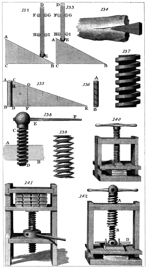
C. Varley, del.
H. Adlard, sc.
London, Pubd. by Longman & Co.
Irregularity in the motion of machinery may proceed
from one or more of the following causes:—1. irregularity
in the prime mover; 2. occasional variation in the
amount of the load or resistance; and, 3. because, in the
various positions which the parts of the machine assume
during its motion, the power may not be transmitted
with equal effect to the working point.
The energy of the prime mover is seldom if ever
regular. The force of water varies with the copiousness
of the stream. The power which impels the windmill
is proverbially capricious. The pressure of steam varies
with the intensity of the furnace. Animal power, the
result of will, temper, and health is difficult of control.
Human labour is most of all unmanageable; hence no
machine works so irregularly as one which is manipulated.
In some cases the moving force is subject, by the very
conditions of its existence, to constant variation, as in
the example of a spring, which gradually loses its energy
as it recoils. (255.) In many instances the prime
mover is liable to regular intermission, and is actually
suspended for certain intervals of time. This is the case
in the single acting steam-engine, where the pressure of
the steam urges the descent of the piston, but is suspended
during its ascent.
The load or resistance to which the machine is applied
is not less fluctuating. In mills there are a multiplicity
of parts which are severally liable to be
occasionally disengaged, and to have their operation
suspended. In large factories for spinning, weaving,226
printing, &c. a great number of separate spinning machines,
looms, presses, or other engines, are usually
worked by one common mover, such as a water-wheel
or steam-engine. In these cases the number of machines
employed from time to time necessarily varies
with the fluctuating demand for the articles produced,
and from other causes. Under such circumstances the
velocity with which every part of the machinery is
moved would suffer corresponding changes, increasing
its rapidity with every augmentation of the moving
power or diminution of the resistance, or being retarded
in its speed by the contrary circumstances.
But even when the prime mover and the resistance
are both regular, or rendered so by proper contrivances,
still it will rarely happen that the machine by which the
energy of the one is transmitted to the other conveys
this with unimpaired effect in all the phases of its operation.
To give a general notion of this cause of inequality
to those who have not been familiar with machinery
would not be easy, without having recourse to
an example. For the present we shall merely state,
that the several moving parts of every machine assume
in succession a variety of positions; that at regular periods
they return to their first position, and again undergo
the same succession of changes. In the different
positions through which they are carried in every period
of motion, the efficacy of the machine to transmit the
power to the resistance is different, and thus the effective
energy of the machine in acting upon the resistance
would be subject to continual fluctuation. This will be
more clearly understood when we come to explain the
methods of counteracting the defect or equalising the
action of the power upon the resistance.
Such are the chief causes of the inequalities incidental
to the motion of machinery, and we now propose to describe
a few of the many ingenious contrivances which
the skill of engineers has produced to remove the consequent
inconveniences.
(302.) Setting aside, for the present, the last cause227
of inequality, and considering the machinery, whatever
it be, to transmit the power to the resistance without
irregular interruption, it is evident that every contrivance,
having for its object to render the velocity uniform,
can only accomplish this by causing the variations
of the power and resistance to be proportionate to each
other. This may be done either by increasing or diminishing
the power as the resistance increases or
diminishes; or by increasing or diminishing the resistance
as the power increases or diminishes.
According to the facilities or convenience presented
by the peculiar circumstances of the case either of these
methods is adopted.
The contrivances for effecting this are called regulators.
Most regulators act upon that part of the machine
which commands the supply of the power by means of
levers, or some other mechanical contrivance, so as to
check the quantity of the moving principle conveyed to
the machine when the velocity has a tendency to increase;
and, on the other hand, to increase that supply
upon any undue abatement of its speed. In a water-mill
this is done by acting upon the shuttle; in a wind-mill,
by an adjustment of the sail-cloth; and in a steam-engine,
by opening or closing, in a greater or less degree,
the valve by which the cylinder is supplied with steam.
(303.) Of all the contrivances for regulating machinery,
that which is best known and most commonly
used is the governor. This regulator, which had been
long in use in mill-work and other machinery, has of
late years attracted more general notice by its beautiful
adaptation in the steam-engines of Watt. It consists
of heavy balls B B, fig. 144., attached to the extremities
of rods B F. These rods play upon a joint at E,
passing through a mortise in the vertical stem D D′. At
F they are united by joints to the short rods F H, which
are again connected by joints at H to a ring which slides
upon the vertical shaft D D′. From this description it
will be apparent that when the balls B are drawn from
the axis, their upper arms E F are caused to increase228
their divergence in the same manner as the blades of a
scissors are opened by separating the handles. These,
acting upon the ring by means of the short links F H,
draw it down the vertical axis from D towards E. A
contrary effect is produced when the balls B are brought
closer to the axis, and the divergence of the rods B E
diminished. A horizontal wheel W is attached to the
vertical axis D D′, having a groove to receive a rope or
strap upon its rim. This strap passes round the wheel
or axis by which motion is transmitted to the machinery
to be regulated, so that the spindle or shaft D D′ will
always be made to revolve with a speed proportionate to
that of the machinery.
As the shaft D D′ revolves, the balls B are carried
round it with a circular motion, and consequently acquire
a centrifugal force which causes them to recede
from the axle, and therefore to depress the ring H.
On the edge or rim of this ring is formed a groove,
which is embraced by the prongs of a fork I, at the extremity
of one arm of a lever whose fulcrum is at G.
The extremity K of the other arm is connected by some
means with the part of the machine which supplies the
power. In the present instance we shall suppose it a
steam-engine, in which case the rod K I communicates
with a flat circular valve V, placed in the principal
steam-pipe, and so arranged that, when K is elevated as
far as by their divergence the balls B have power over it,
the passage of the pipe will be closed by the valve V,
and the passage of steam entirely stopped; and, on the
other hand, when the balls subside to their lowest position,
the valve will be presented with its edge in the
direction of the tube, so as to intercept no part of the
steam.
The property which renders this instrument so admirably
adapted to the purpose to which it is applied is,
that when the divergence of the balls is not very considerable,
they must always revolve with the same velocity,
whether they move at a greater or lesser distance
from the vertical axis. If any circumstance increases229
that velocity, the balls instantly recede from the axis,
and closing the valve V, check the supply of steam, and
thereby diminishing the speed of the motion, restore the
machine to its former rate. If, on the contrary, that
fixed velocity be diminished, the centrifugal force being
no longer sufficient to support the balls, they descend
towards the axle, open the valve V, and, increasing the
supply of steam, restore the proper velocity of the
machine.
When the governor is applied to a water-wheel it is
made to act upon the shuttle through which the water
flows, and controls its quantity as effectually, and upon
the same principle, as has just been explained in reference
to the steam-engine. When applied to a windmill
it regulates the sail-cloth so as to diminish the efficacy
of the power upon the arms as the force of the wind increases,
or vice versâ.
In cases where the resistance admits of easy and convenient
change, the governor may act so as to accommodate
it to the varying energy of the power. This is
often done in corn-mills, where it acts upon the shuttle
which metes out the corn to the millstones. When the
power which drives the mill increases, a proportionally
increased feed of corn is given to the stones, so that the
resistance being varied in the ratio of the power, the same
velocity will be maintained.
(304.) In some cases the centrifugal force of the
revolving balls is not sufficiently great to control the
power or the resistance, and regulators of a different
kind must be resorted to. The following contrivance is
called the water-regulator:—
A common pump is worked by the machine, whose
motion is to be regulated, and water is thus raised and
discharged into a cistern. It is allowed to flow from
this cistern through a pipe of a given magnitude. When
the water is pumped up with the same velocity as it is
discharged by this pipe, it is evident that the level of the
water in the cistern will be stationary, since it receives
from the pump the exact quantity which it discharges230
from the pipe. But if the pump throw in more water
in a given time than is discharged by the pipe, the cistern
will begin to be filled, and the level of the water
will rise. If, on the other hand, the supply from the
pump be less than the discharge from the pipe, the level
of the water in the cistern will subside. Since the rate at
which water is supplied from the pump will always be
proportional to the velocity of the machine, it follows that
every fluctuation in this velocity will be indicated by the
rising or subsiding of the level of the water in the cistern,
and that level never can remain stationary, except
at that exact velocity which supplies the quantity of
water discharged by the pipe. This pipe may be constructed
so as by an adjustment to discharge the water at
any required rate; and thus the cistern may be adapted
to indicate a constant velocity of any proposed amount.
If the cistern were constantly watched by an attendant,
the velocity of the machine might be abated by
regulating the power when the level of the water is
observed to rise, or increased when it falls; but this
is much more effectually and regularly performed by
causing the surface of the water itself to perform the
duty. A float or large hollow metal ball is placed upon
the surface of the water in the cistern. This ball is
connected with a lever acting upon some part of the machinery,
which controls the power or regulates the amount
of resistance, as already explained in the case of the
governor. When the level of the water rises, the buoyancy
of the ball causes it to rise also with a force
equal to the difference between its own weight and the
weight of as much water as it displaces. By enlarging
the floating ball, a force may be obtained sufficiently
great to move those parts of the machinery
which act upon the power or resistance, and thus either
to diminish the supply of the moving principle or to
increase the amount of the resistance, and thereby retard
the motion and reduce the velocity to its proper limit.
When the level of the water in the cistern falls, the
floating ball being no longer supported on the liquid231
surface, descends with the force of its own weight, and
producing an effect upon the power or resistance contrary
to the former, increases the effective energy of the one, or
diminishes that of the other, until the velocity proper to
the machine be restored.
The sensibility of these regulators is increased by
making the surface of water in the cistern as small as
possible; for then a small change in the rate at which the
water is supplied by the pump will produce a considerable
change in the level of the water in the cistern.
Instead of using a float, the cistern itself may be suspended
from the lever which controls the supply of the
power, and in this case a sliding weight may be placed
on the other arm, so that it will balance the cistern
when it contains that quantity of water which corresponds
to the fixed level already explained. If the
quantity of water in the cistern be increased by an undue
velocity of the machine, the weight of the cistern
will preponderate, draw down the arm of the lever, and
check the supply of the power. If, on the other hand,
the supply of water be too small, the cistern will no
longer balance the counterpoise, the arm by which it is
suspended will be raised, and the energy of the power
will be increased.
(305.) In the steam-engine the self-regulating principle
is carried to an astonishing pitch of perfection.
The machine itself raises in due quantity the cold water
necessary to condense the steam. It pumps off the hot
water produced by the steam, which has been cooled, and
lodges it in a reservoir for the supply of the boiler. It
carries from this reservoir exactly that quantity of water
which is necessary to supply the wants of the boiler, and
lodges it therein according as it is required. It breathes
the boiler of redundant steam, and preserves that which
remains fit, both in quantity and quality, for the use of
the engine. It blows its own fire, maintaining its intensity,
and increasing or diminishing it according to the
quantity of steam which it is necessary to raise; so that
when much work is expected from the engine, the fire232
is proportionally brisk and vivid. It breaks and prepares
its own fuel, and scatters it upon the bars at proper
times and in due quantity. It opens and closes its several
valves at the proper moments, works its own pumps,
turns its own wheels, and is only not alive. Among so
many beautiful examples of the self-regulating principle,
it is difficult to select. We shall, however, mention one
or two, and for others refer the reader to our treatise on
this subject.3
It is necessary in this machine that the water in the
boiler be maintained constantly at the same level, and,
therefore, that as much be supplied, from time to time,
as is consumed by evaporation. A pump which is
wrought by the engine itself supplies a cistern C, fig. 145.,
with hot water. At the bottom of this cistern is a
valve V opening into a tube which descends into the
boiler. This valve is connected by a wire with the arm
of a lever on the fulcrum D, the other arm E of which
is also connected by a wire with a stone float F, which
is partially immersed in the water of the boiler, and is
balanced by a sliding weight A. The weight A only
counterpoises the stone float F by the aid of its buoyance
in the water; for if the water be removed, the
stone F will preponderate, and raise the weight A.
When the water in the boiler is at its proper level, the
length of the wire connecting the valve V with the lever
is so adjusted that this valve shall be closed, the wire at
the same time being fully extended. When, by evaporation,
the water in the boiler begins to be diminished,
the level falls, and the stone weight F, being no longer
supported, overcomes the counterpoise A, raises the arm
of the lever, and, pulling the wire, opens the valve V.
The water in the cistern C then flows through the tube
into the boiler, and continues to flow until the level be
so raised that the stone weight F is again elevated, the
valve V closed, and the further supply of water from
the cistern C suspended.
In order to render the operation of this apparatus233
easily intelligible, we have here supposed an imperfection
which does not exist. According to what has just been
stated, the level of the water in the boiler descends from
its proper height, and subsequently returns to it. But,
in fact, this does not happen. The float F and valve V
adjust themselves, so that a constant supply of water
passes through the valve, which proceeds exactly at the
same rate as that at which the water in the boiler is
consumed.
(306.) In the same machine there occurs a singularly
happy example of self-adjustment, in the method by which
the strength of the fire is regulated. The governor regulates
the supply of steam to the engine, and proportions
it to the work to be done. With this work, therefore,
the demands upon the boiler increase or diminish, and
with these demands the production of steam in the
boiler ought to vary. In fact, the rate at which steam
is generated in the boiler, ought to be equal to that at
which it is consumed in the engine, otherwise one of
two effects must ensue: either the boiler will fail to
supply the engine with steam, or steam will accumulate
in the boiler, being produced in undue quantity, and,
escaping at the safety valve, will thus be wasted. It is,
therefore, necessary to control the agent which generates
the steam, namely, the fire, and to vary its intensity
from time to time, proportioning it to the demands of
the engine. To accomplish this, the following contrivance
has been adopted:—Let T, fig. 146., be a tube inserted
in the top of the boiler, and descending nearly to
the bottom. The pressure of the steam confined in the
boiler, acting upon the surface of the water, forces it to
a certain height in the tube T. A weight F, half immersed
in the water in the tube, is suspended by a chain,
which passes over the wheels P P′, and is balanced by a
metal plate D, in the same manner as the stone float,
fig. 145., is balanced by the weight A. The plate D passes
through the mouth of the flue E as it issues finally from the
boiler; so that when the plate D falls it stops the flue,
suspending thereby the draught of air through the furnace,234
mitigating the intensity of the fire, and checking the production
of steam. If, on the contrary, the plate D be
drawn up, the draught is increased, the fire is rendered
more active, and the production of steam in the boiler
is stimulated. Now, suppose that the boiler produces
steam faster than the engine consumes it, either because
the load on the engine has been diminished, and, therefore,
its consumption of steam reduced, or because the
fire has become too intense; the consequence is, that the
steam, beginning to accumulate in the boiler, will press
upon the surface of the water with increased force, and
the water will be raised in the tube T. The weight F
will, therefore, be lifted, and the plate D will descend,
diminish, or stop the draught, mitigate the fire, and retard
the production of steam, and will continue to do so
until the rate at which steam is produced shall be commensurate
to the wants of the engine. If, on the
other hand, the production of steam be inadequate to
the exigency of the machine, either because of an increased
load, or of the insufficient force of the fire, the
steam in the boiler will lose its elasticity, and the surface
of the water not sustaining its wonted pressure, the
water in the tube T will fall; consequently the weight
F will descend, and the plate D will be raised. The
flue being thus opened, the draught will be increased,
and the fire rendered more intense. Thus the production
of steam becomes more rapid, and is rendered
sufficiently abundant for the purposes of the engine.
This apparatus is called the self-acting damper.
(307.) When a perfectly uniform rate of motion
has not been attained, it is often necessary to indicate
small variations of velocity. The following contrivance,
called a tachometer4, has been invented to accomplish this.
A cup, fig. 147., is filled to the level C D with quicksilver,
and is attached to a spindle, which is whirled by the
machine in the same manner as the governor already
described. It is well known that the centrifugal force
produced by this whirling motion will cause the mer235cury
to recede from the centre and rise upon the sides
of the cup, so that its surface will assume the concave
appearance represented in fig. 148. In this case the
centre of the surface will obviously have fallen below
its original level, fig. 147., and the edges will have risen
above that level. As this effect is produced by the velocity
of the machine, so it is proportionate to that
velocity, and subject to corresponding variations. Any
method of rendering visible small changes in the central
level of the surface of the quicksilver will indicate minute
variations in the velocity of the machine.
A glass tube A, open at both ends, and expanding at
one extremity into a bell B, is immersed with its wider
end in the mercury, the surface of which will stand at
the same level in the bell B, and in the cup C D. The
tube is so suspended as to be unconnected with the cup.
This tube is then filled to a certain height A, with spirits
tinged with some colouring matter, to render it easily
observable. When the cup is whirled by the machine
to which it is attached, the level of the quicksilver
in the bell falls, leaving more space for the spirits,
which, therefore, descends in the tube. As the motion
is continued, every change of velocity causes a corresponding
change in the level of the mercury, and, therefore,
also in the level A of the spirits. It will be
observed, that, in consequence of the capacity of the bell
B being much greater than that of the tube A, a very
small change in the level of the quicksilver in the bell
will produce a considerable change in the height of the
spirits in the tube. Thus this ingenious instrument
becomes a very delicate indicator of variations in the
motion of machinery.
(308.) The governor, and other methods of regulating
the motion of machinery which have been just described,
are adapted principally to cases in which the
proportion of the resistance to the load is subject to certain
fluctuations or gradual changes, or at least to cases
in which the resistance is not at any time entirely withdrawn,
nor the energy of the power actually suspended.236
Circumstances, however, frequently occur in which, while
the power remains in full activity, the resistance is at
intervals suddenly removed and as suddenly again returns.
On the other hand, cases also present themselves,
in which, while the resistance is continued, the impelling
power is subject to intermission at regular periods.
In the former case, the machine would be driven with a
ruinous rapidity during those periods at which it is
relieved from its load, and on the return of the load every
part would suffer a violent strain, from its endeavour to
retain the velocity which it had acquired, and the speedy
destruction of the engine could not fail to ensue. In the
latter case, the motion would be greatly retarded or
entirely suspended during those periods at which the
moving power is deprived of its activity, and, consequently,
the motion which it would communicate would
be so irregular as to be useless for the purposes of manufactures.
It is also frequently desirable, by means of a weak
but continued power, to produce a severe but instantaneous
effect. Thus a blow may be required to be given
by the muscular action of a man’s arm with a force to
which, unaided by mechanical contrivance, its strength
would be entirely inadequate.
In all these cases, it is evident that the object to be
attained is, an effectual method of accumulating the energy
of the power so as to make it available after the action
by which it has been produced has ceased. Thus, in the
case in which the load is at periodical intervals withdrawn
from the machine, if the force of the power could be
imparted to something by which it would be preserved,
so as to be brought against the load when it again
returned, the inconvenience would be removed. In like
manner, in the case where the power itself is subject to
intermission, if a part of the force which it exerts in its
intervals of action could be accumulated and preserved,
it might be brought to bear upon the machine during its
periods of suspension. By the same means of accumulating
force, the strength of an infant, by repeated efforts,237
might produce effects which would be vainly attempted
by the single and momentary action of the strongest
man.
(309.) The property of inertia, explained and illustrated
in the third and fourth chapters of this volume
furnishes an easy and effectual method of accomplishing
this. A mass of matter retains, by virtue of its inertia,
the whole of any force which may have been given
to it, except that part of which friction and the atmospheric
resistance deprives it. By contrivances which are
well known and present no difficulty, the part of the
moving force thus lost may be rendered comparatively
small, and the moving mass may be regarded as retaining
nearly the whole of the force impressed upon it. To
render this method of accumulating force fully intelligible,
let us first imagine a polished level plane on which a
heavy globe of metal, also polished, is placed. It is
evident that the globe will remain at rest on any part of
the plane without a tendency to move in any direction.
As the friction is nearly removed by the polish of the
surfaces, the globe will be easily moved by the least
force applied to it. Suppose a slight impulse given to
it, which will cause it to move at the rate of one foot in
a second. Setting aside the effects of friction, it will
continue to move at this rate for any length of time.
The same impulse repeated will increase its speed to two
feet per second. A third impulse to three feet, and so
on. Thus 10,000 repetitions of the impulse will cause
it to move at the rate of 10,000 feet per second. If the
body to which these impulses were communicated were
a cannon ball, it might, by a constant repetition of the
impelling force, be at length made to move with as much
force as if it were projected from the most powerful
piece of ordnance. The force with which the ball in
such a case would strike a building might be sufficient
to reduce it to ruins, and yet such force would be
nothing more than the accumulation of a number of
weak efforts not beyond the power of a child to exert,
which are stored up, and preserved, as it were, by the238
moving mass, and thereby brought to bear, at the same
moment, upon the point to which the force is directed.
It is the sum of a number of actions exerted successively,
and, during a long interval, brought into operation at
one and the same moment.
But the case which is here supposed cannot actually
occur; because we have not usually any practical
means of moving a body for any considerable time in
the same direction without much friction, and without
encountering numerous obstacles which would impede
its progress. It is not, however, essential to the effect
which is to be produced, that the motion should be in a
straight line. If a leaden weight be attached to the end
of a light rod or cord, and be whirled by the force of
the arm in a circle, it will gradually acquire increased
speed and force, and at length may receive an impetus
which would cause it to penetrate a piece of board as
effectually as if it were discharged from a musket.
The force of a hammer or sledge depends partly on
its weight, but much more on the principle just explained.
Were it allowed merely to fall by the force of its weight
upon the head of a nail, or upon a bar of heated iron
which is to be flattened, an inconsiderable effect would
be produced. But when it is wielded by the arm of a
man, it receives at every moment of its motion increased
force, which is finally expended in a single instant on
the head of the nail, or on the bar of iron.
The effects of flails in threshing, of clubs, whips, canes,
and instruments for striking, axes, hatchets, cleavers,
and all instruments which cut by a blow, depend on the
same principle, and are similarly explained.
The bow-string which impels the arrow does not
produce its effect at once. It continues to act upon
the shaft until it resumes its straight position, and then
the arrow takes flight with the force accumulated during
the continuance of the action of the string, from the
moment it was disengaged from the finger of the bow-man.
Fire-arms themselves act upon a similar principle,239
as also the air-gun and steam-gun. In these instruments
the ball is placed in a tube, and suddenly exposed
to the pressure of a highly elastic fluid, either produced
by explosion as in fire-arms, by previous condensation
as in the air-gun, or by the evaporation of highly heated
liquids as in the steam-gun. But in every case this
pressure continues to act upon it until it leaves the mouth
of the tube, and then it departs with the whole force
communicated to it during its passage along the tube.
(310.) From all these considerations it will easily be
perceived that a mass of inert matter may be regarded
as a magazine in which force may be deposited and accumulated,
to be used in any way which may be necessary.
For many reasons, which will be sufficiently
obvious, the form commonly given to the mass of matter
used for this purpose in machinery is that of a wheel,
in the rim of which it is principally collected. Conceive
a massive ring of metal, fig. 149., connected with
a central box or nave by light spokes, and turning on
an axis with little friction. Such an apparatus is called
a fly-wheel. If any force be applied to it, with that
force (making some slight deduction for friction) it will
move, and will continue to move until some obstacle be
opposed to its motion, which will receive from it a part
of the force it has acquired. The uses of this apparatus
will be easily understood by examples of its application.
Suppose that a heavy stamper or hammer is to be
raised to a certain height, and thence to be allowed to
fall, and that the power used for this purpose is a water-wheel.
While the stamper ascends, the power of the
wheel is nearly balanced by its weight, and the motion
of the machine is slow. But the moment the stamper
is disengaged and allowed to fall, the power of the wheel,
having no resistance, nor any object on which to expend
itself, suddenly accelerates the machine, which moves
with a speed proportioned to the amount of the power,
until it again engages the stamper, when its velocity is
as suddenly checked. Every part suffers a strain, and
the machine moves again slowly until it discharges its240
load, when it is again accelerated, and so on. In this
case, besides the certainty of injury and wear, and the
probability of fracture from the sudden and frequent
changes of velocity, nearly the whole force exerted by
the power in the intervals between the commencement
of each descent of the stamper and the next ascent is
lost. These defects are removed by a fly-wheel. When
the stamper is discharged, the energy of the power is
expended in moving the wheel, which, by reason of its
great mass, will not receive an undue velocity. In the
interval between the descent and ascent of the stamper,
the force of the power is lodged in the heavy rim of the
fly-wheel. When the stamper is again taken up by the
machine, this force is brought to bear upon it, combined
with the immediate power of the water-wheel, and the
stamper is elevated with nearly the same velocity as that
with which the machine moved in the interval of its
descent.
(311.) In many cases, when the moving power is not
subject to variation, the efficacy of the machine to transmit
it to the working point is subject to continual change.
The several parts of every machine have certain periods
of motion, in which they pass through a variety of positions,
to which they continually return after stated
intervals. In these different positions the effect of the
power transmitted to the working point is different; and
cases even occur in which this effect is altogether annihilated,
and the machine is brought into a predicament
in which the power loses all influence over the weight.
In such cases the aid of a fly-wheel is effectual and indispensable.
In those phases of the machine, which are
most favourable to the transmission of force, the fly-wheel
shares the effect of the power with the load, and
retaining the force thus received directs it upon the
load at the moments when the transmission of power by
the machine is either feeble or altogether suspended.
These general observations will, perhaps, be more clearly
apprehended by an example of an application of the fly-wheel,
in a case such as those now alluded to.
241
Let A B C D E F, fig. 150., be a crank, which is a
double winch (252.) and fig. 89.), by which an axle,
A B E F, is to be turned. Attached to the middle of
C D by a joint is a rod, which is connected with a beam,
worked with an alternate motion on a centre, like the
brake of a pump, and driven by any constant power,
such as a steam-engine. The bar C D is to be carried
with a circular motion round the axis A E. Let the
machine, viewed in the direction A B E F of the axis,
be conceived to be represented in fig. 151., where A represents
the centre round which the motion is to be produced,
and G the point where the connecting rod G H is
attached to the arm of the crank. The circle through
which G is to be urged by the rod is represented by the
dotted line. In the position represented in fig. 151., the
rod acting in the direction H G has its full power to
turn the crank G A round the centre A. As the crank
comes into the position represented in fig. 152., this
power is diminished, and when the point G comes immediately
below A, as in fig. 153., the force in the direction
H G has no effect in turning the crank round A, but, on
the contrary, is entirely expended in pulling the crank
in the direction A G, and, therefore, only acts upon the
pivots or gudgeons which support the axle. At this
crisis of the motion, therefore, the whole effective energy
of the power is annihilated.
After the crank has passed to the position represented
in fig. 154., the direction of the force which acts
upon the connecting rod is changed, and now the crank
is drawn upward in the direction G H. In this position
the moving force has some efficacy to produce rotation
round A, which efficacy continually increases until the
crank attains the position shown in fig. 155., when its
power is greatest. Passing from this position its efficacy
is continually diminished, until the point G comes immediately
above the axis A, fig. 156. Here again the
power loses all its efficacy to turn the axle. The force
in the direction G H or H G can obviously produce no
other effect than a strain upon the pivots or gudgeons.
242
In the critical situations represented in fig. 153., and
fig. 156., the machine would be incapable of moving,
were the immediate force of the power the only impelling
principle. But having been previously in motion
by virtue of the inertia of its various parts, it has a
tendency to continue in motion; and if the resistance
of the load and the effects of friction be not too great,
this disposition to preserve its state of motion will extricate
the machine from the dilemma in which it is
involved in the cases just mentioned, by the peculiar
arrangement of its parts. In many cases, however, the
force thus acquired during the phases of the machine, in
which the power is active, is insufficient to carry it
through the dead points (fig. 153. and fig. 156.); and
in all cases the motion would be very unequal, being
continually retarded as it approached these points, and
continually accelerated after it passed them. A fly-wheel
attached to the axis A, or to some other part of the machinery,
will effectually remove this defect. When the
crank assumes the positions in fig. 151. and fig. 155., the
power is in full play upon it, and a share of the effect is
imparted to the massive rim of the fly-wheel. When
the crank gets into the predicament exhibited in fig. 153.
and fig. 156., the momentum which the fly-wheel received
when the crank acted with most advantage, immediately
extricates the machine, and, carrying the crank
beyond the dead point, brings the power again to bear
upon it.
The astonishing effects of a fly-wheel, as an accumulator
of force, have led some into the error of supposing
that such an apparatus increases the actual power of a
machine. It is hoped, however, that after what has been
explained respecting the inertia of matter and the true
effects of machines, the reader will not be liable to a
similar mistake. On the contrary, as a fly cannot act
without friction, and as the amount of the friction, like
that of inertia, is in proportion to the weight, a portion of
the actual moving force must unavoidably be lost by the
use of a fly. In cases, however, where a fly is properly243
applied this loss of power is inconsiderable, compared
with the advantageous distribution of what remains.
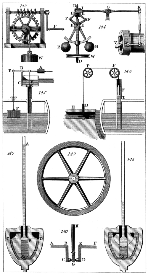
C. Varley, del.
H. Adlard, sc.
London, Pubd. by Longman & Co.
As an accumulator of force, a fly can never have more
force than has been applied to put it in motion. In this
respect it is analogous to an elastic spring, or the force
of condensed air, or any other power which derives its
existence from causes purely mechanical. In bending
a spring a gradual expenditure of power is necessary.
On the recoil this power is exerted in a much shorter
time than that consumed in its production, but its total
amount is not altered. Air is condensed by a succession
of manual efforts, one of which alone would be incapable
of projecting a leaden ball with any considerable force,
and all of which could not be immediately applied to the
ball at the same instant. But the reservoir of condensed
air is a magazine in which a great number of such efforts
are stored up, so as to be brought at once into action. If
a ball be exposed to their effect, it may be projected with
a destructive force.
In mills for rolling metal the fly-wheel is used in this
way. The water-wheel or other moving power is allowed
for some time to act upon the fly-wheel alone, no
load being placed upon the machine. A force is thus
gained which is sufficient to roll a large piece of metal,
to which without such means the mill would be quite
inadequate. In the same manner a force may be gained
by the arm of a man acting on a fly for a few seconds,
sufficient to impress an image on a piece of metal by an
instantaneous stroke. The fly is, therefore, the principal
agent in coining presses.
(312.) The power of a fly is often transmitted to the
working point by means of a screw. At the extremities
of the cross arm A B, fig. 157., which works the screw,
two heavy balls of metal are placed. When the arm A B
is whirled round, those masses of metal acquire a momentum,
by which the screw, being driven downward, urges
the die with an immense force against the substance destined
to receive the impression.
Some engines used in coining have flies with arms244
four feet long, bearing one hundred weight at each of
their extremities. By turning such an arm at the rate
of one entire circumference in a second, the die will
be driven against the metal with the same force as that
with which 7500 pounds weight would fall from the
height of 16 feet; an enormous power, if the simplicity
and compactness of the machine be considered.
The place to be assigned to a fly-wheel relatively to
the other parts of the machinery is determined by the
purpose for which it is used. If it be intended to equalise
the action, it should be near the working point. Thus,
in a steam-engine, it is placed on the crank which turns
the axle by which the power of the engine is transmitted
to the object it is finally designed to affect. On the
contrary, in handmills, such as those commonly used for
grinding coffee, &c., it is placed upon the axis of the
winch by which the machine is worked.
The open work of fenders, fire-grates, and similar
ornamental articles constructed in metal, is produced by
the action of a fly, in the manner already described.
The cutting tool, shaped according to the pattern to be
executed, is attached to the end of the screw; and the
metal being held in a proper position beneath it, the fly
is made to urge the tool downwards with such force as
to stamp out pieces of the required figure. When the
pattern is complicated, and it is necessary to preserve
with exactness the relative situation of its different parts,
a number of punches are impelled together, so as to strike
the entire piece of metal at the same instant, and in this
manner the most elaborate open work is executed by a
single stroke.
245
CHAP. XVIII.
MECHANICAL CONTRIVANCES FOR MODIFYING MOTION.
(313.) The classes of simple machines denominated
mechanic powers, have relation chiefly to the peculiar
principle which determines the action of the power on
the weight or resistance. In explaining this arrangement
various other reflections have been incidentally
mixed up with our investigations; yet still much
remains to be unfolded before the student can form a
just notion of those means by which the complex machinery
used in the arts and manufactures so effectually
attains the ends, to the accomplishment of which it is
directed.
By a power of a given energy to oppose a resistance
of a different energy, or by a moving principle having a
given velocity to generate another velocity of a different
amount, is only one of the many objects to be effected
by a machine. In the arts and manufactures the kind
of motion produced is generally of greater importance
than its rate. The latter may affect the quantity of work
done in a given time, but the former is essential to the
performance of the work in any quantity whatever. In
the practical application of machines, the object to be
attained is generally to communicate to the working
point some peculiar sort of motion suitable to the uses
for which the machine is intended; but it rarely happens
that the moving power has this sort of motion. Hence,
the machine must be so contrived that, while that part
on which this power acts is capable of moving in obedience
to it, its connection with the other parts shall be
such that the working point may receive that motion
which is necessary for the purposes to which the machine
is applied.
To give a perfect solution of this problem it would be
necessary to explain, first, all the varieties of moving246
powers which are at our disposal; secondly, all the variety
of motions which it may be necessary to produce;
and, thirdly, to show all the methods by which each
variety of prime mover may be made to produce the
several species of motion in the working point. It is
obvious that such an enumeration would be impracticable,
and even an approximation to it would be unsuitable
to the present treatise. Nevertheless, so much
ingenuity has been displayed in many of the contrivances
for modifying motion, and an acquaintance
with some of them is so essential to a clear comprehension
of the nature and operation of complex machines,
that it would be improper to omit some account of those
at least which most frequently occur in machinery, or
which are most conspicuous for elegance and simplicity.
The varieties of motion which most commonly present
themselves in the practical application of mechanics may
be divided into rectilinear and rotatory. In rectilinear
motion the several parts of the moving body proceed in
parallel straight lines with the same speed. In rotatory
motion the several points revolve round an axis, each
performing a complete circle, or similar parts of a circle,
in the same time.
Each of these may again be resolved into continued
and reciprocating. In a continued motion, whether rectilinear
or rotatory, the parts move constantly in the same
direction, whether that be in parallel straight lines, or in
rotation on an axis. In reciprocating motion the several
parts move alternately in opposite directions, tracing the
same spaces from end to end continually. Thus, there
are four principal species of motion which more frequently
than any others act upon, or are required to be
transmitted by, machines:—
1. Continued rectilinear motion.
2. Reciprocating rectilinear motion.
3. Continued circular motion.
4. Reciprocating circular motion.
These will be more clearly understood by examples of
each kind.
247
Continued rectilinear motion is observed in the flowing
of a river, in a fall of water, in the blowing of the
wind, in the motion of an animal upon a straight road,
in the perpendicular fall of a heavy body, in the motion
of a body down an inclined plane.
Reciprocating rectilinear motion is seen in the piston
of a common syringe, in the rod of a common pump, in
the hammer of a pavier, the piston of a steam-engine,
the stampers of a fulling mill.
Continued circular motion is exhibited in all kinds of
wheel-work, and is so common, that to particularise it
is needless.
Reciprocating circular motion is seen in the pendulum
of a clock, and in the balance-wheel of a watch.
We shall now explain some of the contrivances by
which a power having one of these motions may be made
to communicate either the same species of motion
changed in its velocity or direction, or any of the other
three kinds of motion.
(314.) By a continued rectilinear motion another continued
rectilinear motion in a different direction may be
produced, by one or more fixed pulleys. A cord passed
over these, one end of it being moved by the power, will
transmit the same motion unchanged to the other end.
If the directions of the two motions cross each other, one
fixed pulley will be sufficient; see fig. 113., where the
hand takes the direction of the one motion, and the
weight that of the other. In this case the pulley must
be placed in the angle at which the directions of the two
motions cross each other. If this angle be distant from
the places at which the objects in motion are situate, an
inconvenient length of rope may be necessary. In this
case the same may be effected by the use of two pulleys,
as in fig. 158.
If the directions of the two motions be parallel, two
pulleys must be used as in fig. 158., where P′ A′ is one
motion, and B W the other. In these cases the axles of
the two wheels are parallel.
It may so happen that the directions of the two mo248tions
neither cross each other nor are parallel. This
would happen, for example, if the direction of one were
upon the paper in the line P A, while the other were
perpendicular to the paper from the point O. In this
case two pulleys should be used, the axle of one O′ being
perpendicular to the paper, while the axle of the other O
should be on the paper. This will be evident by a little
reflection.
In general, the axle of each pulley must be perpendicular
to the two directions in which the rope passes
from its groove; and by due attention to this condition
it will be perceived, that a continued rectilinear motion
may be transferred from any one direction to any other
direction, by means of a cord and two pulleys, without
changing its velocity.
If it be necessary to change the velocity, any of the
systems of pulleys described in chap. XV. may be used
in addition to the fixed pulleys.
By the wheel and axle any one continued rectilinear
motion may be made to produce another in any other
direction, and with any other velocity. It has been
already explained (250.) that the proportion of the velocity
of the power to that of the weight is as the diameter
of the wheel to the diameter of the axle. The thickness
of the axle being therefore regulated in relation to the
size of the wheel, so that their diameters shall have that
proportion which subsists between the proposed velocities,
one condition of the problem will be fulfilled. The
rope coiled upon the axle may be carried, by means of
one or more fixed pulleys, into the direction of one of the
proposed motions, while that which surrounds the wheel
is carried into the direction of the other by similar
means.
(315.) By the wheel and axle a continued rectilinear
motion may be made to produce a continued rotatory
motion, or vice versâ. If the power be applied by a
rope coiled upon the wheel, the continued motion of the
power in a straight line will cause the machine to have
a rotatory motion. Again, if the weight be applied by249
a rope coiled upon the axle, a power having a rotatory
motion applied to the wheel will cause the continued ascent
of the weight in a straight line.
Continued rectilinear and rotatory motions may be
made to produce each other, by causing a toothed wheel
to work in a straight bar, called a rack, carrying teeth
upon its edge. Such an apparatus is represented in
fig. 159.
In some cases the teeth of the wheel work in the
links of a chain. The wheel is then called a rag-wheel,
fig. 160.
Straps, bands, or ropes, may communicate rotation
to a wheel, by their friction in a groove upon its edge.
A continued rectilinear motion is produced by a continued
circular motion in the case of a screw. The
lever which turns the screw has a continued circular motion,
while the screw itself advances with a continued
rectilinear motion.
The continued rectilinear motion of a stream of water
acting upon a wheel produces continued circular motion
in the wheel, fig. 93, 94, 95. In like manner the continued
rectilinear motion of the wind produces a continued
circular motion in the arms of a windmill.
Cranes for raising and lowering heavy weights convert
a circular motion of the power into a continued rectilinear
motion of the weight.
(316.) Continued circular motion may produce reciprocating
rectilinear motion, by a great variety of ingenious
contrivances.
Reciprocating rectilinear motion is used when heavy
stampers are to be raised to a certain height, and allowed
to fall upon some object placed beneath them. This
may be accomplished by a wheel bearing on its edge
curved teeth, called wipers. The stamper is furnished
with a projecting arm or peg, beneath which the
wipers are successively brought by the revolution of
the wheel. As the wheel revolves the wiper raises the
stamper, until its extremity passes the extremity of the
projecting arm of the stamper, when the latter imme250diately
falls by its own weight. It is then taken up by
the next wiper, and so the process is continued.
A similar effect is produced if the wheel be partially
furnished with teeth, and the stamper carry a rack in
which these teeth work. Such an apparatus is represented
in fig. 161.
It is sometimes necessary that the reciprocating rectilinear
motion shall be performed at a certain varying
rate in both directions. This may be accomplished by
the machine represented in fig. 162. A wheel upon the
axle C turns uniformly in the direction A B D E.
A rod mn moves in guides, which only permit it to ascend
and descend perpendicularly. Its extremity m
rests upon a path or groove raised from the face of the
wheel, and shaped into such a curve that as the wheel
revolves the rod mn shall be moved alternately in opposite
directions through the guides, with the required
velocity. The manner in which the velocity varies
will depend on the form given to the groove or channel
raised upon the face of the wheel, and this may be
shaped so as to give any variation to the motion of the
rod mn which may be required for the purpose to which
it is to be applied.
The rose-engine in the turning-lathe is constructed on
this principle. It is also used in spinning machinery.
It is often necessary that the rod to which reciprocating
motion is communicated shall be urged by the
same force in both directions. A wheel partially furnished
with teeth, acting on two racks placed on different
sides of it, and both connected with the bar or
rod to which the reciprocating motion is to be communicated,
will accomplish this. Such an apparatus is
represented in fig. 163., and needs no further explanation.
Another contrivance for the same purpose is shown in
fig. 164., where A is a wheel turned by a winch H, and
connected with a rod or beam moving in guides by the
joint ab. As the wheel A is turned by the winch H
the beam is moved between the guides alternately in251
opposite directions, the extent of its range being governed
by the length of the diameter of the wheel. Such
an apparatus is used for grinding and polishing plane
surfaces, and also occurs in silk machinery.
An apparatus applied by M. Zureda in a machine for
pricking holes in leather is represented in fig. 165. The
wheel A B has its circumference formed into teeth, the
shape of which may be varied according to the circumstances
under which it is to be applied. One extremity
of the rod ab rests upon the teeth of the wheel upon
which it is pressed by a spring at the other extremity.
When the wheel revolves, it communicates to this rod a
reciprocating rectilinear motion.
Leupold has applied this mechanism to move the pistons
of pumps.5 Upon the vertical axis of a horizontal
hydraulic wheel is fixed another horizontal wheel,
which is furnished with seven teeth in the manner of a
crown wheel (263.). These teeth are shaped like inclined
planes, the intervals between them being equal to
the length of the planes. Projecting arms attached to
the piston rods rest upon the crown of this wheel; and,
as it revolves, the inclined surfaces of the teeth, being
forced under the arm, raise the rod upon the principle
of the wedge. To diminish the obstruction arising from
friction, the projecting arms of the piston rods are provided
with rollers, which run upon the teeth of the
wheel. In one revolution of the wheel each piston
makes as many ascents and descents as there are teeth.
(317.) Wheel-work furnishes numerous examples of
continued circular motion round one axis, producing
continued circular motion round another. If the axles
be in parallel directions, and not too distant, rotation
may be transmitted from one to the other by two spur-wheels
(263.); and the relative velocities may be determined
by giving a corresponding proportion to the
diameter of the wheels.
If a rotary motion is to be communicated from one
axis to another parallel to it, and at any considerable252
distance, it cannot in practice be accomplished by wheels
alone, for their diameters would be too large. In this
case a strap or chain is carried round the circumferences
of both wheels. If they are intended to turn in the
same direction, the strap is arranged as in fig. 100.; but
if in contrary directions it is crossed, as in fig. 101. In
this case, as with toothed wheels, the relative velocities
are determined by the proportion of the diameters of the
wheels.
If the axles be distant and not parallel, the cord, by
which the motion is transmitted, must be passed over
grooved wheels, or fixed pulleys, properly placed between
the two axles.
It may happen that the strain upon the wheel, to
which the motion is to be transmitted, is too great to
allow of a strap or cord being used. In this case, a
shaft extending from the one axis to another, and carrying
two bevelled wheels (263.), will accomplish the object.
One of these bevelled wheels is placed upon the shaft
near to, and in connection with, the wheel from which
the motion is to be taken, and the other at a part of it
near to, and in connection with, that wheel to which
the motion is to be conveyed, fig. 166.
The methods of transmitting rotation from one axis
to another perpendicular to it, by crown and by bevelled
wheels, have been explained in (263.).
The endless screw (299.) is a machine by which a
rotatory motion round one axis may communicate a
rotatory motion round another perpendicular to it. The
power revolves round an axis coinciding with the length
of the screw, and the axis of the wheel driven by the
screw is at right angles to this.
The axis to which rotation is to be given, or from
which it is to be taken, is sometimes variable in its position.
In such cases, an ingenious contrivance, called
a universal joint, invented by the celebrated Dr. Hooke,
may be used. The two shafts or axles A B, fig. 167.,
between which the motion is to be communicated, terminate
in semicircles, the diameters of which, C D and253
E F, are fixed in the form of a cross, their extremities
moving freely in bushes placed in the extremities of the
semicircles. Thus, while the central cross remains unmoved,
the shaft A and its semicircular end may revolve
round C D as an axis; and the shaft B and its semicircular
end may revolve round E F as an axis. If the
shaft A be made to revolve without changing its direction,
the points C D will move in a circle whose centre
is at the middle of the cross. The motion thus given
to the cross will cause the points E F to move in another
circle round the same centre, and hence the shaft B will
be made to revolve.
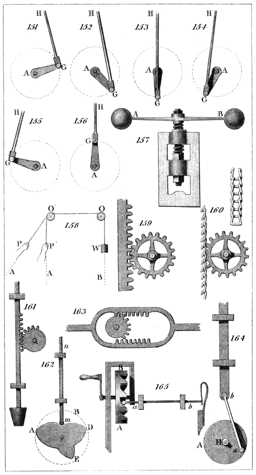
C. Varley, del.
H. Adlard, sc.
London, Pubd. by Longman & Co.
This instrument will not transmit the motion if the
angle under the directions of the shafts be less than 140°.
In this case a double joint, as represented in fig. 168.,
will answer the purpose. This consists of four semicircles
united by two crosses, and its principle and
operation is the same as in the last case.
Universal joints are of great use in adjusting the position
of large telescopes, where, while the observer
continues to look through the tube, it is necessary to turn
endless screws or wheels whose axes are not in an accessible
position.
The cross is not indispensably necessary in the universal
joint. A hoop, with four pins projecting from it
at four points equally distant from each other, or dividing
the circle of the hoop into four equal arcs, will
answer the purpose. These pins play in the bushes of
the semicircles in the same manner as those of the cross.
The universal joint is much used in cotton-mills,
where shafts are carried to a considerable distance from
the prime mover, and great advantage is gained by dividing
them into convenient lengths, connected by a
joint of this kind.
(318.) In the practical application of machinery, it is
often necessary to connect a part having a continued circular
motion with another which has a reciprocating or
alternate motion, so that either may move the other.254
There are many contrivances by which this may be
effected.
One of the most remarkable examples of it is presented
in the scapements of watches and clocks. In this
case, however, it can scarcely be said with strict propriety
that it is the rotation of the scapement-wheel
(266.) which communicates the vibration to the balance-wheel
or pendulum. That vibration is produced in the
one case by the peculiar nature of the spiral spring fixed
upon the axis of the balance-wheel, and in the other
case by the gravity of the pendulum. The force of the
scapement-wheel only maintains the vibration, and prevents
its decay by friction and atmospheric resistance.
Nevertheless, between the two parts thus moving there
exists a mechanical connection, which is generally
brought within the class of contrivances now under consideration.
A beam vibrating on an axis, and driven by the piston
of a steam-engine, or any other power, may communicate
rotary motion to an axis by a connector and a crank.
This apparatus has been already described in (311.).
Every steam-engine which works by a beam affords an
example of this. The working beam is generally placed
over the engine, the piston rod being attached to one
end of it, while the connecting rod unites the other end
with the crank. In boat-engines, however, this position
would be inconvenient, requiring more room than could
easily be spared. The piston rod, in these cases, is,
therefore, connected with the end of the beam by long
rods, and the beam is placed beside and below the engine.
The use of a fly-wheel here would also be objectionable.
The effect of the dead points explained in (311.) is
avoided without the aid of a fly, by placing two cranks
upon the revolving axle, and working them by two pistons.
The cranks are so placed that when either is at its
dead point, the other is in its most favourable position.
A wheel A, fig. 169., armed with wipers, acting
upon a sledge-hammer B, fixed upon a centre or axle C,
will, by a continued rotatory motion, give the hammer255
the reciprocating motion necessary for the purposes to
which it is applied. The manner in which this acts
must be evident on inspecting the figure.
The treddle of the lathe furnishes an obvious example
of a vibrating circular motion producing a continued
circular one. The treddle acts upon a crank, which
gives motion to the principal wheel, in the same manner
as already described in reference to the working beam
and crank in the steam-engine.
By the following ingenious mechanism an alternate
or vibrating force may be made to communicate a circular
motion continually in the same direction. Let
A B, fig. 170., be an axis receiving an alternate motion
from some force applied to it, such as a swinging weight.
Two ratchet wheels (253.) m and n are fixed on this
axle, their teeth being inclined in opposite directions.
Two toothed wheels C and D are likewise placed upon
it, but so arranged that they turn upon the axle with a
little friction. These wheels carry two catches p, q,
which fall into the teeth of the ratchet wheels m, n, but
fall on opposite sides conformably to the inclination of
the teeth already mentioned. The effect of these catches
is, that if the axis be made to revolve in one direction,
one of the two toothed wheels is always compelled (by
the catch against which the motion is directed) to revolve
with it, while the other is permitted to remain
stationary in obedience to any force sufficiently great to
overcome its friction with the axle on which it is placed.
The wheels C and D are both engaged by bevelled teeth
(263.) with the wheel E.
According to this arrangement, in whichever direction
the axis A B is made to revolve, the wheel E will continually
turn in the same direction, and, therefore, if the
axle A B be made to turn alternately in the one direction
and the other, the wheel E will not change the direction
of its motion. Let us suppose that the axle A B is turned
against the catch p. The wheel C will then be made to turn
with the axle. This will drive the wheel E in the same
direction. The teeth on the opposite side of the wheel E256
being engaged with those of the wheel D, the latter will
be turned upon the axle, the friction, which alone resists
its motion in that direction, being overcome. Let the
motion of the axle A B be now reversed. Since the
teeth of the ratchet wheel n are moved against the
catch q, the wheel D will be compelled to revolve with
the axle. The wheel E will be driven in the same direction
as before, and the wheel C will be moved on the
axle A B, and in a contrary direction to the motion of
the axle, the friction being overcome by the force of the
wheel E. Thus, while the axle A B is turned alternately
in the one direction and the other, the wheel E is constantly
moved in the same direction.
It is evident that the direction in which the wheel E
moves may be reversed by changing the position of the
ratchet wheels and catches.
(319.) It is often necessary to communicate an alternate
circular motion, like that of a pendulum, by means of
an alternate motion in a straight line. A remarkable instance
of this occurs in the steam engine. The moving
force in this machine is the pressure of steam, which impels
a piston from end to end alternately in a cylinder.
The force of this piston is communicated to the working
beam by a strong rod, which passes through a collar in
one end of the piston. Since it is necessary that the steam
included in the cylinder should not escape between the
piston rod and the collar through which it moves, and yet,
that it should move as freely and be subject to as little resistance
as possible, the rod is turned so as to be truly
cylindrical, and is well polished. It is evident that,
under these circumstances, it must not be subject to any
lateral or cross strain, which would bend it towards one
side or the other of the cylinder. But the end of the beam
to which it communicates motion, if connected immediately
with the rod by a joint, would draw it alternately
to the one side and the other, since it moves in the arc
of a circle, the centre of which is at the centre of the
beam. It is necessary, therefore, to contrive some method
of connecting the rod and the end of the beam, so257
that while the one shall ascend and descend in a straight
line, the other may move in the circular arc.
The method which first suggests itself to accomplish
this is, to construct an arch-head upon the end of the
beam, as in fig. 171. Let C be the centre on which the
beam works, and let B D be an arch attached to the end
of the beam, being a part of a circle having C for its
centre. To the highest point B of the arch a chain is
attached, which is carried upon the face of the arch B A,
and the other end of which is attached to the piston rod.
Under these circumstances it is evident, that when the
force of the steam impels the piston downwards, the
chain P A B will draw the end of the beam down, and
will, therefore, elevate the other end.
When the steam-engine is used for certain purposes,
such as pumping, this arrangement is sufficient. The
piston in that case is not forced upwards by the pressure
of steam. During its ascent it is not subject to
the action of any force of steam, and the other end of
the beam falls by the weight of the pump-rods drawing
the piston, at the opposite end A, to the top of the cylinder.
Thus the machine is in fact passive during the
ascent of the piston, and exerts its power only during
the descent.
If the machine, however, be applied to purposes
in which a constant action of the moving force is necessary,
as is always the case in manufactures, the force of
the piston must drive the beam in its ascent as well as
in its descent. The arrangement just described cannot
effect this; for although a chain is capable of transmitting
any force, by which its extremities are drawn in opposite
directions, yet it is, from its flexibility, incapable
of communicating a force which drives one extremity of
it towards the other. In the one case the piston first pulls
down the beam, and then the beam pulls up the piston.
The chain, because it is inextensible, is perfectly capable
of both these actions; and being flexible, it applies itself
to the arch-head of the beam, so as to maintain the direction
of its force upon the piston continually in the258
same straight line. But when the piston acts upon the
beam in both ways, in pulling it down and pushing it
up, the chain becomes inefficient, being from its flexibility
incapable of the latter action.
The problem might be solved by extending the length
of the piston rod, so that its extremity shall be above
the beam, and using two chains; one connecting the
highest point of the rod with the lowest point of the
arch-head, and the other connecting the highest point of
the arch-head with a point on the rod below the point
which meets the arch-head when the piston is at the top
of the cylinder, fig. 172.
The connection required may also be made by arming
the arch-head with teeth, fig. 173., and causing the piston
rod to terminate in a rack. In cases where, as in
the steam-engine, smoothness of motion is essential, this
method is objectionable; and under any circumstances
such an apparatus is liable to rapid wear.
The method contrived by Watt, for connecting the
motion of the piston with that of the beam, is one of the
most ingenious and elegant solutions ever proposed for a
mechanical problem. He conceived the motion of two
straight rods A B, C D, fig. 174., moving on centres or
pivots A and C, so that the extremities B and D would
move in the arcs of circles having their centres at A
and C. The extremities B and D of these rods he
conceived to be connected with a third rod B D united
with them by pivots on which it could turn freely.
To the system of rods thus connected let an alternate
motion on the centres A and C be communicated: the
points B and D will move upwards and downwards in
the arcs expressed by the dotted lines, but the middle
point P of the connecting rod B D will move upwards and
downwards without any sensible deviation from a straight
line.
To prove this demonstratively would require some
abstruse mathematical investigation. It may, however,
be rendered in some degree apparent by reasoning of a
looser and more popular nature. As the point B is raised259
to E, it is also drawn aside towards the right. At the
same time the other extremity D of the rod B D is
raised to E′, and is drawn aside towards the left. The
ends of the rod B D being thus at the same time drawn
equally towards opposite sides, its middle point P will
suffer no lateral derangement, and will move directly
upwards. On the other hand, if B be moved downwards
to F, it will be drawn laterally to the right, while
D being moved to F′ will be drawn to the left. Hence,
as before, the middle point P sustains no lateral derangement,
but merely descends. Thus, as the extremities B
and D move upwards and downwards in circles, the
middle point P moves upwards and downwards in a
straight line.6
The application of this geometrical principle in the
steam-engine evinces much ingenuity. The same arm
of the beam usually works two pistons, that of the cylinder
and that of the air-pump. The apparatus is represented
on the arm of the beam in fig. 175. The
beam moves alternately upwards and downwards on its
axis A. Every point of it, therefore, describes a part of
a circle of which A is the centre. Let B be the point
which divides the arm A G into two equal parts A B
and B G; and let C D be a straight rod, equal in length
to G B, and fixed on a centre or pivot C on which it is
at liberty to play. The end D of this rod is connected by
a straight bar with the point B, by pivots on which the
rod B D turns freely. If the beam be now supposed
to rise and fall alternately, the points B and D will move
upwards and downwards in circular arcs, and, as already
explained with respect to the points B D, fig. 174., the
middle point P of the connecting rod B D will move
upwards and downwards without lateral deflection. To
this point one of the piston rods which are to be worked
is attached.
260
To comprehend the method of working the other piston,
conceive a rod G P′, equal in length to B D, to be
attached to the end G of the beam by a pivot on which
it moves freely; and let its extremity P′ be connected
with D by another rod P′ D, equal in length to G B,
and playing on points at P′ and D. The piston rod of
the cylinder is attached to the point P′, and this point
has a motion precisely similar to that of P, without any
lateral derangement, but with a range in the perpendicular
direction twice as great. This will be apparent
by conceiving a straight line drawn from the centre A
of the beam to P′, which will also pass through P.
Since G P′ is always parallel to B P, it is evident that
the triangle P′ G A is always similar to P B A, and
has its sides and angles similarly placed, but those sides
are each twice the magnitude of the corresponding sides
of the other triangle. Hence the point P′ must be subject
to the same changes of position as the point P, with
this difference only, that in the same time it moves over
a space of twice the magnitude. In fact, the line traced
by P′ is the same as that traced by P, but on a scale
twice as large. This contrivance is usually called the
parallel motion, but the same name is generally applied
to all contrivances by which a circular motion is made
to produce a rectilinear one.
CHAP. XIX.
OF FRICTION AND THE RIGIDITY OF CORDAGE.
(320.) With a view to the simplification of the elementary
theory of machines, the consideration of several
mechanical effects of great practical importance has been
postponed, and the attention of the student has been
directed exclusively to the way in which the moving
power is modified in being transmitted to the resistance
independently of such effects. A machine has been re261garded
as an instrument by which a moving principle,
inapplicable in its existing state to the purpose for which
it is required, may be changed either in its velocity or
direction, or in some other character, so as to be adapted
to that purpose. But in accomplishing this, the several
parts of the machine have been considered as possessing
in a perfect degree qualities which they enjoy only in an
imperfect degree; and accordingly the conclusions to
which by such reasoning we are conducted are infected
with errors, the amount of which will depend on the
degree in which the machinery falls short of perfection
in those qualities which theoretically are imputed to it.
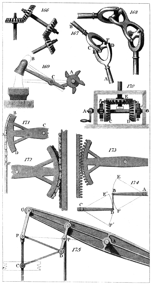
C. Varley, del.
H. Adlard, sc.
London, Pubd. by Longman & Co.
Of the several parts of a machine, some are designed
to move, while others are fixed; and of those which
move, some have motions differing in quantity and direction
from those of others. The several parts, whether
fixed or movable, are subject to various strains and pressures,
which they are intended to resist. These forces
not only vary according to the load which the machine
has to overcome, but also according to the peculiar form
and structure of the machine itself. During the operation
the surfaces of the movable parts move in immediate
contact with the surfaces either of fixed parts or of parts
having other motions. If these surfaces were endued
with perfect smoothness or polish, and the several parts
subject to strains possessed perfect inflexibility and infinite
strength, then the effects of machinery might be
practically investigated by the principles already explained.
But the materials of which every machine is
formed are endued with limited strength, and therefore
the load which is placed upon it must be restricted accordingly,
else it will be liable to be distorted by the
flexure, or even to be destroyed by the fracture of those
parts which are submitted to an undue strain. The surfaces
of the movable parts, and those surfaces with which
they move in contact, cannot in practice be rendered so
smooth but that such roughness and inequality will remain
as sensibly to impede the motion. To overcome
such an impediment requires no inconsiderable part of262
the moving power. This part is, therefore, intercepted
before its arrival at the working point, and the resistance
to be finally overcome is deprived of it. The property
thus depending on the imperfect smoothness of surfaces,
and impeding the motion of bodies whose surfaces are in
immediate contact, is called friction. Before we can
form a just estimate of the effects of machinery, it is
necessary to determine the force lost by this impediment,
and the laws which under different circumstances
regulate that loss.
When cordage is engaged in the formation of any part
of a machine, it has hitherto been considered as possessing
perfect flexibility. This is not the case in practice;
and the want of perfect flexibility, which is called rigidity,
renders a certain quantity of force necessary to bend a
cord or rope over the surface of an axle or the groove of
a wheel. During the motion of the rope a different part
of it must thus be continually bent, and the force which
is expended in producing the necessary flexure must
be derived from the moving power, and is thus intercepted
on its way to the working point. In calculating
the effects of cordage, due regard must be had to this
waste of power; and therefore it is necessary to enquire
into the laws which govern the flexure of imperfectly
flexible ropes, and the way in which these affect the machines
in which ropes are commonly used.
To complete, therefore, the elementary theory of machinery,
we propose in the present and following chapter
to explain the principal laws which determine the effects
of friction, the rigidity of cordage, and the strength of
materials.
(321.) If a horizontal plane surface were perfectly
smooth, and free from the smallest inequalities, and a
body having a flat surface also perfectly smooth were
placed upon it, any force applied to the latter would
put it in motion, and that motion would continue undiminished
as long as the body would remain upon the
smooth horizontal surface. But if this surface, instead
of being every where perfectly even, had in particular263
places small projecting eminences, a certain quantity of
force would be necessary to carry the moving body over
these, and a proportional diminution in its rate of motion
would ensue. Thus, if such eminences were of
frequent occurrence, each would deprive the body of a
part of its speed, so that between that and the next it
would move with a less velocity than it had between the
same and the preceding one. This decrease being continued
by a sufficient number of such eminences encountering
the body in succession, the velocity would at
last be so much diminished that the body would not
have sufficient force to carry it over the next eminence,
and its motion would thus altogether cease.
Now, instead of the eminences being at a considerable
distance asunder, suppose them to be contiguous, and to
be spread in every direction over the horizontal plane,
and also suppose corresponding eminences to be upon the
surface of the moving body; these projections incessantly
encountering one another will continually obstruct
the motion of the body, and will gradually diminish its
velocity, until it be reduced to a state of rest.
Such is the cause of friction. The amount of this
resisting force increases with the magnitude of these
asperities, or with the roughness of the surfaces; but it
does not solely depend on this. The surfaces remaining
the same, a little reflection on the method of illustration
just adopted, will show that the amount of
friction ought also to depend upon the force with which
the surfaces moving one upon the other are pressed together.
It is evident, that as the weight of the body
supposed to move upon the horizontal plane is increased,
a proportionally greater force will be necessary to carry
it over the obstacles which it encounters, and therefore
it will the more speedily be deprived of its velocity
and reduced to a state of rest.
(322.) Thus we might predict with probability, that
which accurate experimental enquiry proves to be true,
that the resistance from friction depends conjointly on
the roughness of the surfaces and the force of the264
pressure. When the surfaces are the same, a double
pressure will produce a double amount of friction, a
treble pressure a treble amount of friction, and so on.
Experiment also, however, gives a result which, at
least at first view, might not have been anticipated from
the mode of illustration we have adopted. It is found
that the resistance arising from friction does not at all
depend on the magnitude of the surface of contact; but
provided the nature of the surfaces and the amount of
pressure remain the same, this resistance will be equal,
whether the surfaces which move one upon the other be
great or small. Thus, if the moving body be a flat
block of wood, the face of which is equal to a square
foot in magnitude, and the edge of which does not exceed
a square inch, it will be subject to the same amount of
friction, whether it move upon its broad face or upon its
narrow edge. If we consider the effect of the pressure in
each case, we shall be able to perceive why this must be
the case. Let us suppose the weight of the block to be
144 ounces. When it rests upon its face, a pressure to
this amount acts upon a surface of 144 square inches, so
that a pressure of one ounce acts upon each square inch.
The total resistance arising from friction will, therefore,
be 144 times that resistance which would be produced
by a surface of one square inch under a pressure of one
ounce. Now, suppose the block placed upon its edge,
there is then a pressure of 144 ounces upon a surface
equal to one square inch. But it has been already
shown, that when the surface is the same, the friction
must increase in proportion to the pressure. Hence we
infer that the friction produced in the present case is
144 times the friction which would be produced by a
pressure of one ounce acting on one square inch of
surface, which is the same resistance as that which the
body was proved to be subject to when resting on its
face.
These two laws, that friction is independent of the
magnitude of the surface, and is proportional to the
pressure when the quality of the surfaces is the same,265
are useful in practice, and generally true. In very extreme
cases they are, however, in error. When the
pressure is very intense, in proportion to the surface,
the friction is somewhat less than it would be by these
laws; and when it is very small in proportion to the
surface, it is somewhat greater.
(323.) There are two methods of establishing by
experiment the laws of friction, which have been just
explained.
First. The surfaces between which the friction is to
be determined being rendered perfectly flat, let one be
fixed in the horizontal position on a table T T′, fig. 176.;
and let the other be attached to the bottom of a box B C,
adapted to receive weights, so as to vary the pressure.
Let a silken cord S P, attached to the box, be carried
parallel to the table over a wheel at P, and let a dish D
be suspended from it. If no friction existed between
the surfaces, the smallest weight appended to the cord
would draw the box towards P with a continually increasing
speed. But the friction which always exists
interrupts this effect, and a small weight may act upon
the string without moving the box at all. Let weights
be put in the dish D, until a sufficient force is obtained
to overcome the friction without giving the box an accelerated
motion. Such a weight is equivalent to the
amount of the friction.
The amount of the weight of the box being previously
ascertained, let this weight be now doubled by
placing additional weights in the box. The pressure
will thus be doubled, and it will be found that the
weight of the dish D and its load, which before was
able to overcome the friction, is now altogether inadequate
to it. Let additional weights be placed in the
dish until the friction be counteracted as before, and it
will be observed, that the whole weight necessary to
produce this effect is exactly twice the weight which
produced it in the former case. Thus it appears that
a double amount of pressure produces a double amount
of friction; and in a similar way it may be proved,266
that any proposed increase or decrease of the pressure
will be attended with a proportionate variation in the
amount of the friction.
Second. Let one of the surfaces be attached to a flat
plane A B, fig. 177., which can be placed at any inclination
with an horizontal plane B C, the other surface
being, as before, attached to the box adapted to receive
weights. The box being placed upon the plane, let the
latter be slightly elevated. The tendency of the box to
descend upon A B, will bear the same proportion to its
entire weight as the perpendicular A E bears to the
length of the plane A B (286.). Thus if the length
A B be 36 inches, and the height A E be three inches,
that is a twelfth part of the length, then the tendency
of the weight to move down the plane is equal to a
twelfth part of its whole amount. If the weight were
twelve ounces, and the surfaces perfectly smooth, a force
of one ounce acting up the plane would be necessary to
prevent the descent of the weight.
In this case also the pressure on the plane will be represented
by the length of the base B E (286.), that is,
it will bear the same proportion to the whole weight
as B E bears to B A. The relative amounts of the
weight, the tendency to descend, and the pressure, will
always be exhibited by the relative lengths of A B, A E,
and B E.
This being premised, let the elevation of the plane
A B be gradually increased until the tendency of the
weight to descend just overcomes the friction, but not
so much as to allow the box to descend with accelerated
speed. The proportion of the whole weight, which
then acts down the plane, will be found by measuring
the height A E, and the pressure will be determined by
measuring the base B E. Now let the weight in the
box be increased, and it will be found that the same
elevation is necessary to overcome the friction; nor will
this elevation suffer any change, however the pressure
or the magnitude of the surfaces which move in contact
may be varied.
267
Since, therefore, in all these cases, the height A E
and the base B E remain the same, it follows that the
proportion between the friction and pressure is undisturbed.
(324.) The law that friction is proportional to the
pressure, has been questioned by the late professor Vince
of Cambridge, who deduced from a series of experiments,
that although the friction increases with the pressure,
yet that it increases in a somewhat less ratio; and from
this it would follow, that the variation of the surface of
contact must produce some effect upon the amount of
friction. The law, as we have explained it, however, is
sufficiently near the truth for most practical purposes.
(325.) There are several circumstances regarding the
quality of the surfaces which produce important effects
on the quantity of friction, and which ought to be
noticed here.
This resistance is different in the surfaces of different
substances. When the surfaces are those of wood newly
planed, it amounts to about half the pressure, but is different
in different kinds of wood. The friction of metallic
surfaces is about one fourth of the pressure.
In general the friction between the surfaces of bodies
of different kinds is less than between those of the same
kind. Thus, between wood and metal the friction is
about one fifth of the pressure.
It is evident that the smoother the surfaces are the
less will be the friction. On this account, the friction
of surfaces, when first brought into contact, is often
greater than after their attrition has been continued for
a certain time, because that process has a tendency to
remove and rub off those minute asperities and projections
on which the friction depends. But this has a
limit, and after a certain quantity of attrition the friction
ceases to decrease. Newly planed surfaces of wood
have at first a degree of friction which is equal to half
the entire pressure, but after they are worn by attrition
it is reduced to a third.
If the surfaces in contact be placed with their grains268
in the same direction, the friction will be greater than
if the grains cross each other.
Smearing the surfaces with unctuous matter diminishes
the friction, probably by filling the cavities between the
minute projections which produce the friction.
When the surfaces are first placed in contact, the
friction is less than when they are suffered to rest so for
some time; this is proved by observing the force which
in each case is necessary to move the one upon the
other, that force being less if applied at the first moment
of contact than when the contact has continued.
This, however, has a limit. There is a certain time,
different in different substances, within which this resistance
attains its greatest amount. In surfaces of
wood this takes place in about two minutes; in metals
the time is imperceptibly short; and when a surface of
wood is placed upon a surface of metal, it continues to
increase for several days. The limit is larger when the
surfaces are great, and belong to substances of different
kinds.
The velocity with which the surfaces move upon one
another produces but little effect upon the friction.
(326.) There are several ways in which bodies may
move one upon the other, in which friction will produce
different effects. The principal of these are, first, the
case where one body slides over another; the second,
where a body having a round form rolls upon another;
and, thirdly, where an axis revolves within a hollow
cylinder, or the hollow cylinder revolves upon the axis.
With the same amount of pressure and a like quality
of surface, the quantity of friction is greatest in the first
case and least in the second. The friction in the second
case also depends on the diameter of the body which
rolls, and is small in proportion as that diameter is great.
Thus a carriage with large wheels is less impeded by
the friction of the road than one with small wheels.
In the third case, the leverage of the wheel aids the
power in overcoming the friction. Let fig. 178. represent
a section of the wheel and axle; let C be the centre269
of the axle, and let B E be the hollow cylinder in the
nave of the wheel in which the axle is inserted. If B
be the part on which the axle presses, and the wheel
turn in the direction N D M, the friction will act at B in
the direction B F, and with the leverage B C. The
power acts against this at D in the direction D A, and
with the leverage D C. It is therefore evident, that as
D C is greater than B C, in the same proportion does
the power act with mechanical advantage on the friction.
(327.) Contrivances for diminishing the effects of
friction depend on the properties just explained, the
motion of rolling being as much as possible substituted
for that of sliding; and where the motion of rolling
cannot be applied, that of a wheel upon its axle is used.
In some cases both these motions are combined.
If a heavy load be drawn upon a plane in the manner
of a sledge, the motion will be that of sliding, the
species which is attended with the greatest quantity of
friction; but if the load be placed upon cylindrical
rollers, the nature of the motion is changed, and becomes
that in which there is the least quantity of friction.
Thus large blocks of stone, or heavy beams of
timber, which would require an enormous power to move
them on a level road, are easily advanced when rollers
are put under them.
When very heavy weights are to be moved through
small spaces, this method is used with advantage; but
when loads ore to be transported to considerable distances,
the process is inconvenient and slow, owing to
the necessity of continually replacing the rollers in front
of the load as they are left behind by its progressive
advancement.
The wheels of carriages may be regarded as rollers
which are continually carried forward with the load.
In addition to the friction of the rolling motion on the
road, they have, it is true, the friction of the axle in
the nave; but, on the other hand, they are free from the
friction of the rollers with the under surface of the load,
or the carriage in which the load is transported. The270
advantages of wheel carriages in diminishing the effects
of friction is sometimes attributed to the slowness with
which that axle moves within the box, compared with
the rate at which the wheel moves over the road; but
this is erroneous. The quantity of friction does not in
any case vary considerably with the velocity of the motion,
but least of all does it in that particular kind of
motion here considered.
In certain cases, where it is of great importance to
remove the effects of friction, a contrivance called friction-wheels,
or friction-rollers, is used. The axle of a
friction-wheel, instead of revolving within a hollow
cylinder, which is fixed, rests upon the edges of wheels
which revolve with it; the species of motion thus becomes
that in which the friction is of least amount.
Let A B and D C, fig. 179., be two wheels revolving
on pivots P Q with as little friction as possible, and so
placed that the axle O of a third wheel E F may rest
between their edges. As the wheel E F revolves, the
axle O, instead of grinding its surface on the surface on
which it presses, carries that surface with it, causing the
wheels A B, C D, to revolve.
In wheel carriages, the roughness of the road is more
easily overcome by large wheels than by small ones.
The cause of this arises partly from the large wheels
not being so liable to sink into holes as small ones, but
more because, in surmounting obstacles, the load is
elevated less abruptly. This will be easily understood
by observing the curves in fig. 180., which represent
the elevation of the axle in each case.
(328.) If a carriage were capable of moving on a
road without friction, the most advantageous direction
in which a force could be applied to draw it would be
parallel to the road. When the motion is impeded by
friction, it is better, however, that the line of draught
should be inclined to the road, so that the drawing force
may be expended partly in lessening the pressure on the
road, and partly in advancing the load.
Let W, fig. 181., be a load which is to be moved271
upon the plane surface A B. If the drawing force be
applied in the direction C D, parallel to the plane A B,
it will have to overcome the friction produced by the
pressure of the whole weight of the load upon the plane;
but if it be inclined upwards in the direction C E, it
will be equivalent to two forces expressed (74.) by C G
and C F. The part C G has the effect of lightening the
pressure of the carriage upon the road, and therefore
of diminishing the friction in the same proportion. The
part C F draws the load along the plane. Since C F is
less than C E or C D the whole moving force, it is evident
that a part of the force of draught is lost by this
obliquity; but, on the other hand, a part of the opposing
resistance is also removed. If the latter exceed the
former, an advantage will be gained by the obliquity;
but if the former exceed the latter, force will be lost.
By mathematical reasoning, founded on these considerations,
it is proved that the best angle of draught is
exactly that obliquity which should be given to the road
in order to enable the carriage to move of itself. This
obliquity is sometimes called the angle of repose, and is
that angle which determines the proportion of the friction
to the pressure in the second method, explained in
(323.). The more rough the road is, the greater will
this angle be; and therefore it follows, that on bad roads
the obliquity of the traces to the road should be greater
than on good ones. On a smooth Macadamised way, a
very slight declivity would cause a carriage to roll by
its own weight: hence, in this case, the traces should be
nearly parallel to the road.
In rail roads, for like reasons, the line of draught
should be parallel to the road, or nearly so.
(329.) When ropes or cords form a part of machinery,
the effects of their imperfect flexibility are in a
certain degree counteracted by bending them over the
grooves of wheels. But although this so far diminishes
these effects as to render ropes practically useful, yet
still, in calculating the powers of machinery, it is necessary
to take into account some consequences of the272
rigidity of cordage which even by these means are not
removed.
To explain the way in which the stiffness of a rope
modifies the operation of a machine, we shall suppose it
bent over a wheel and stretched by weights A B, fig. 182.,
at its extremities. The weights A and B being equal,
and acting at C and D in opposite ways, balance the
wheel. If the weight A receive an addition, it will
overcome the resistance of B, and turn the wheel in the
direction D E C. Now, for the present, let us suppose
that the rope is perfectly inflexible; the wheel and
weights will be turned into the position represented in
fig. 183. The leverage by which A acts will be diminished,
and will become O F, having been before O C;
and the leverage by which B acts will be increased to
O G, having been before O D.
But the rope not being inflexible will yield partially
to the effects of the weights A and B, and the parts A C
and B D will be bent into the forms represented in
fig. 184. The form of the curvature which the rope on
each side of the wheel receives is still such that the
descending weight A works with a diminished leverage
F O, while the ascending weight resists it with an increased
leverage G O. Thus so much of the moving
power is lost, by the stiffness of the rope, as is necessary
to compensate this disadvantageous change in the power
of the machine.
CHAP. XX.
ON THE STRENGTH OF MATERIALS.
(330.) Experimental enquiries into the laws which
regulate the strength of solid bodies, or their power to
resist forces variously applied to tear or break them, are
obstructed by practical difficulties, the nature and extent
of which are so discouraging that few have ventured
to encounter them at all, and still fewer have had the273
steadiness to persevere until any result showing a general
law has been obtained. These difficulties arise, partly
from the great forces which must be applied, but more
from the peculiar nature of the objects of those experiments.
The end to which such an enquiry must be
directed is the development of a general law; that is,
such a rule as would be rigidly observed if the materials,
the strength of which is the object of enquiry, were perfectly
uniform in their texture, and subject to no casual
inequalities. In proportion as these inequalities are frequent,
experiments must be multiplied, that a long average
may embrace cases varying in both extremes, so as
to eliminate each other’s effects in the final result.
The materials of which structures and works of art
are composed are liable to so many and so considerable
inequalities of texture, that any rule which can be deduced,
even by the most extensive series of experiments,
must be regarded as a mean result, from which individual
examples will be found to vary in so great a degree,
that more than usual caution must be observed in its
practical application. The details of this subject belong
to engineering, more properly than to the elements of
mechanics. Nevertheless, a general view of the most
important principles which have been established respecting
the strength of materials will not be misplaced
in this treatise.
A piece of solid matter may be submitted to the action
of a force tending to separate its parts in several ways;
the principal of which are,—
1. To a direct pull,—as when a rope or wire is
stretched by a weight. When a tie-beam resists the
separation of the sides of a structure, &c.
2. To a direct pressure or thrust,—as when a weight
rests upon a pillar.
3. To a transverse strain,—as when weights on the
ends of a lever press it on the fulcrum.
(331.) If a solid be submitted to a force which draws
it in the direction of its length, having a tendency to pull
its ends in opposite directions, its strength or power to274
resist such a force is proportional to the magnitude of its
transverse section. Thus, suppose a square rod of metal
A B, fig. 185., of the breadth and thickness of one inch,
be pulled by a force in the direction A B, and that a
certain force is found sufficient to tear it; a rod of the
same metal of twice the breadth and the same thickness
will require double the force to break it; one of treble
the breadth and the same thickness will require treble
the force to break it, and so on.
The reason of this is evident. A rod of double or
treble the thickness, in this case, is equivalent to two or
three equal and similar rods which equally and separately
resist the drawing force, and therefore possess a degree
of strength proportionate to their number.
It will easily be perceived, that whatever be the section,
the same reasoning will be applicable, and the power
of resistance will, in general, be proportional to its magnitude
or area.
If the material were perfectly uniform throughout its
dimensions, the resistance to a direct pull would not be
affected by the length of the rod. In practice, however,
the increase of length is found to lessen the strength.
This is to be attributed to the increased chance of inequality.
(332.) No satisfactory results have been obtained
either by theory or experiment respecting the laws by
which solids resist compression. The power of a perpendicular
pillar to support a weight placed upon it
evidently depends on its thickness, or the magnitude of its
base, and on its height. It is certain that when the height
is the same, the strength increases with every increase of
the base, but it seems doubtful whether the strength be
exactly proportional to the base. That is, if two columns
of the same material have equal heights, and the base of
one be double the base of the other, the strength of one
will be greater, but it is not certain whether it will exactly
double that of the other. According to the theory
of Euler, which is in a certain degree verified by the
experiments of Musschenbrock, the strength will be in275creased
in a greater proportion than the base, so that, if
the base be doubled, the strength will be more than
doubled.
When the base is the same, the strength is diminished
by increasing the height, and this decrease of strength is
proportionally greater than the increase of height. According
to Euler’s theory, the decrease of strength is proportional
to the square of the height; that is, when the
height is increased in a two-fold proportion, the strength
is diminished in a four-fold proportion.
(333.) The strain to which solids forming the parts
of structures of every kind are most commonly exposed
is the lateral or transverse strain, or that which acts at
right angles to their lengths. If any strain act obliquely
to the direction of their length it may be resolved into
two forces (76.), one in the direction of the length, and
the other at right angles to the length. That part which
acts in the direction of the length will produce either
compression or a direct pull, and its effect must be investigated
accordingly.
Although the results of theory, as well as those of
experimental investigations, present great discordances
respecting the transverse strength of solids, yet there are
some particulars, in which they, for the most part, agree;
to this it is our object here to confine our observations,
declining all details relating to disputed points.
Let A B C D, fig. 186., be a beam, supported at its
ends A and B. Its strength to support a weight at E
pressing downwards at right angles to its length is evidently
proportional to its breadth, the other things being
the same. For a beam of double or treble breadth, and
of the same thickness, is equivalent to two or three
equal and similar beams placed side by side. Since
each of these would possess the same strength, the whole
taken together would possess double or treble the strength
of any one of them.
When the breadth and length are the same the
strength obviously increases with the depth, but not in
the same proportion. The increase of strength is found276
to be much greater in proportion than the increase of
depth. By the theory of Galileo, a double or treble
thickness ought to increase the strength in a four-fold
or nine-fold proportion, and experiments in most cases
do not materially vary from this rule.
If while the breadth and depth remain the same, the
length of the beam, or rather, the distance between the
points of support, vary, the strength will vary accordingly,
decreasing in the same proportion as the
length increases.
From these observations it appears, that the transverse
strength of a beam depends more on its thickness
than its breadth. Hence we find that a broad
thin board is much stronger when its edge is presented
upwards. On this principle the joists or rafters of
floors and roofs are constructed.
If two beams be in all respects similar, their strengths
will be in the proportion of the squares of their lengths.
Let the length, breadth, and depth of the one be respectively
double the length, breadth, and depth of the
other. By the double breadth the beam doubles its
strength, but by doubling the length half this strength
is lost. Thus the increase of length and breadth counteract
each other’s effects, and as far as they are concerned
the strength of the beam is not changed. But by
doubling the thickness the strength is increased in a
four-fold proportion, that is, as the square of the length.
In the same manner it may be shown, that when all the
dimensions are trebled, the strength is increased in a
nine-fold proportion, and so on.
(334.) In all structures the materials have to support
their own weight, and therefore their available
strength is to be estimated by the excess of their absolute
strength above that degree of strength which is just
sufficient to support their own weight. This consideration
leads to some conclusions, of which numerous and
striking illustrations are presented in the works of nature
and art.
We have seen that the absolute strength with which277
a lateral strain is resisted is in the proportion of the
square of the linear dimensions of similar parts of a
structure, and therefore the amount of this strength increases
rapidly with every increase of the dimensions of
a body. But at the same time the weight of the body
increases in a still more rapid proportion. Thus, if the
several dimensions be doubled, the strength will be increased
in a four-fold but the weight in an eight-fold
proportion. If the dimensions be trebled, the strength
will be multiplied nine times, but the weight twenty-seven
times. Again, if the dimensions be multiplied
four times, the strength will be multiplied sixteen times,
and the weight sixty-four times, and so on.
Hence it is obvious, that although the strength of a
body of small dimensions may greatly exceed its weight,
and, therefore, it may be able to support a load many
times its own weight; yet by a great increase in the dimensions
the weight increasing in a much greater degree
the available strength may be much diminished, and
such a magnitude may be assigned, that the weight of
the body must exceed its strength, and it not only
would be unable to support any load, but would actually
fall to pieces by its own weight.
The strength of a structure of any kind is not, therefore,
to be determined by that of its model, which will
always be much stronger in proportion to its size. All
works natural and artificial have limits of magnitude
which, while their materials remain the same, they cannot
surpass.
In conformity with what has just been explained, it
has been observed, that small animals are stronger in
proportion than large ones; that the young plant has more
available strength in proportion than the large forest
tree; that children are less liable to injury from accident
than men, &c. But although to a certain extent these
observations are just, yet it ought not to be forgotten,
that the mechanical conclusions which they are brought
to illustrate are founded on the supposition, that the
smaller and greater bodies which are compared are com278posed
of precisely similar materials. This is not the
case in any of the examples here adduced.
CHAP. XXI.
ON BALANCES AND PENDULUMS.
(335.) The preceding chapters have been confined almost
wholly to the consideration of the laws of mechanics,
without entering into a particular description of the machinery
and instruments dependant upon those laws.
Such descriptions would have interfered too much with
the regular progress of the subject, and it therefore appeared
preferable to devote a chapter exclusively to this
portion of the work.
Perhaps there are no ideas which man receives through
the medium of sense which may not be referred ultimately
to matter and motion. In proportion, therefore,
as he becomes acquainted with the properties of the one
and the laws of the other, his knowledge is extended,
his comforts are multiplied; he is enabled to bend the
powers of nature to his will, and to construct machinery
which effects with ease that which the united labour of
thousands would in vain be exerted to accomplish.
Of the properties of matter, one of the most important
is its weight, and the element which mingles inseparably
with the laws of motion is time.
In the present chapter it is our intention to describe
such instruments as are usually employed for determining
the weight of bodies. To attempt a description of
the various machines which are used for the measurement
of time, would lead us into too wide a field for the
present occasion, and we shall, therefore, confine ourselves
to an account of the methods which have been practised
to perfect, to perfect that instrument which affords the most
correct means of measuring time, the pendulum.
The instrument by which we are enabled to determine,
with greater accuracy than by any other means,279
the relative weight of a body, compared with the weight
of another body assumed as a standard, is the balance.
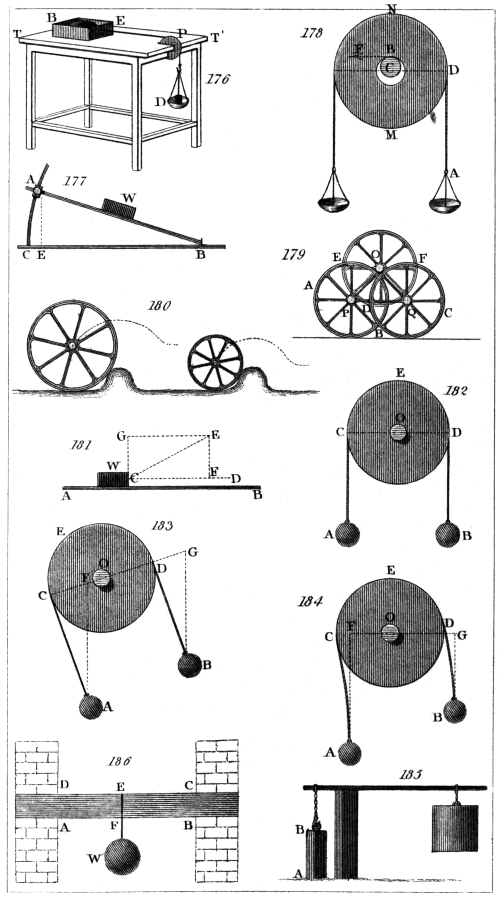
H. Adlard, sc.
London, Pubd. by Longman & Co.
Of the Balance.
The balance may be described as consisting of an inflexible
rod or lever, called the beam, furnished with
three axes; one, the fulcrum or centre of motion situated
in the middle, upon which the beam turns, and the other
two near the extremities, and at equal distances from the
middle. These last are called the points of support, and
serve to sustain the pans or scales.
The points of support and the fulcrum are in the
same right line, and the centre of gravity of the whole
should be a little below the fulcrum when the position
of the beam is horizontal.
The arms of the lever being equal, it follows that if
equal weights be put into the scales no effect will be
produced on the position of the balance, and the beam
will remain horizontal.
If a small addition be made to the weight in one of
the scales, the horizontality of the beam will be disturbed;
and after oscillating for some time, it will, on
attaining a state of rest, form an angle with the horizon,
the extent of which is a measure of the delicacy or sensibility
of the balance.
As the sensibility of a balance is of the utmost importance
in nice scientific enquiries, we shall enter somewhat
at large into a consideration of the circumstances
by which this property is influenced.
In fig. 187. let A B represent the beam drawn from
the horizontal position by a very small weight placed in
the scale suspended from the point of support B; then
the force tending to draw the beam from the horizontal
position may be expressed by P B, multiplied by such
very small weight acting upon the point B.
Let the centre of gravity of the whole be at G; then
the force acting against the former will be G P multiplied
into the weight of the beam and scales, and when
these forces are equal, the beam will rest in an inclined280
position. Hence we may perceive that as the centre of
gravity is nearer to or further from the fulcrum S, (every
thing else remaining the same) the sensibility of the
balance will be increased or diminished.
For, suppose the centre of gravity were removed to g,
then to produce an opposing force equal to that acting
upon the extremity of the beam, the distance g p from
the perpendicular line must be increased until it becomes
nearly equal to G P; but for this purpose the
end of the beam B must descend, which will increase the
angle H S B.
As all weights placed in the scales are referred to the
line joining the points of support, and as this line is
above the centre of gravity of the beam when not
loaded, such weights will raise the centre of gravity; but
it will be seen that the sensibility of the balance, as far
as it depends upon this cause, will remain unaltered.
For, calling the distance S G unity, the distance of
the centre of gravity from the point S (to which the
weight which has been added is referred) will be expressed
by the reciprocal of the weight of the beam so
increased; that is, if the weight of the beam be doubled
by weights placed in the scales, S g will be one half of
S G; and if the weight of the beam be in like manner
trebled, S g will be one third of S G, and so on. And
as G P varies as S G, g p will be inversely proportionate
to the increased weight of the beam, and consequently,
the product obtained by multiplying g p by the
weight of the beam and its load will be a constant
quantity, and the sensibility of the balance, as before
stated, will suffer no alteration.
We will now suppose that the fulcrum S, fig. 188.,
is situated below the line joining the points of support,
and that the centre of gravity of the beam when not
loaded is at G. Also that when a very small weight is
placed in the scale suspended from the point B, the
beam is drawn from its horizontal position, the deviation
being a measure of the sensibility of the balance. Then,
as before stated, G P multiplied by the weight of the281
beam will be equal to P′ B multiplied by the very small
additional weight acting on the point B.
Now if we place equal weights in both scales, such
additional weights will be referred to the point W, and
the resulting distance of the centre of gravity from the
point W, calling W G unity, will be expressed as before
by the reciprocal of the increased weight of the loaded
beam. But G P will decrease in a greater proportion
than W G: thus, supposing the weight of the beam to
be doubled, W g would be one half of W G; but g p, as
will be evident on an inspection of the figure, will be
less than half of G P; and the same small weight which
was before applied to the point B, if now added, would
depress the point B, until the distance g p became such
as that, when multiplied by the weight of the whole, the
product would be as before equal to P′ B, multiplied by
the before mentioned very small added weight. The
sensibility of the balance, therefore, in this case would be
increased.
If the beam be sufficiently loaded, the centre of gravity
will at length be raised to the fulcrum S, and the
beam will rest indifferently in any position. If more
weight be then added, the centre of gravity will be
raised above the fulcrum, and the beam will turn over.
Lastly, if the fulcrum S, fig. 189., is above the
line joining the two points of support, as any additional
weights placed in the scales will be referred to the
point W, in the line joining A and B, if the weight
of the beam be doubled by such added weights, and the
centre of gravity be consequently raised to g, W g
will become equal to half of W G. But g p, being
greater than one half of G P, the end of the beam B
will rise until g p becomes such as to be equal, when
multiplied by the whole increased weight of the beam,
to P B, multiplied by the small weight, which we suppose
to have been placed as in the preceding examples,
in the scale.
From what has been said it will be seen that there
are three positions of the fulcrum which influence the282
sensibility of the balance: first, when the fulcrum and
the points of support are in a right line, when the sensibility
of the balance will remain the same, though the
weight with which the beam is loaded should be varied:
secondly, when the fulcrum is below the line joining
the two points of support, in which case the sensibility
of the balance will be increased by additional weights,
until at length the centre of gravity is raised above the
fulcrum, when the beam will turn over; and, thirdly,
when the fulcrum is above the line joining the two
points of support, in which case the sensibility of the
balance will be diminished as the weight with which
the beam is loaded is increased.
The sensibility of a balance, as here defined, is the
angular deviation of the beam occasioned by placing an
additional constant small weight in one of the scales;
but it is frequently expressed by the proportion which
such small additional weight bears to the weight of the
beam and its load, and sometimes to the weight the
value of which is to be determined.
This proportion, however, will evidently vary with
different weights, except in the case where the centre of
gravity of the beam is in the line joining the points
supporting the scales, the fulcrum being above this line,
and it is therefore necessary, in every other case, when
speaking of the sensibility of the balance, to designate
the weight with which it is loaded: thus, if a balance
has a troy pound in each scale, and the horizontality of
the beam varies a certain small quantity, just perceptible
on the addition of one hundredth of a grain, we
say that the balance is sensible to 1/1152000 part of its
load with a pound in each scale, or that it will determine
the weight of a troy pound within 1/576000 part of
the whole.
The nearer the centre of gravity of a balance is to its
fulcrum the slower will be the oscillations of the beam.
The number of oscillations, therefore, made by the beam
in a given time (a minute for example), affords the
most accurate method of judging of the sensibility of the283
balance, which will be the greater as the oscillations are
fewer.
Balances of the most perfect kind, and of such only
it is our present object to treat, are usually furnished
with adjustments, by means of which the length of the
arms, or the distances of the fulcrum from the points of
support, may be equalised, and the fulcrum and the two
points of support be placed in a right line; but these
adjustments, as will hereafter be seen, are not absolutely
necessary.
The beam is variously constructed, according to the
purposes to which the balance is to be applied. Sometimes
it is made of a rod of solid steel; sometimes of
two hollow cones joined at their bases; and, in some
balances, the beam is a frame in the form of a rhombus:
the principal object in all, however, is to combine
strength and inflexibility with lightness.
A balance of the best kind, made by Troughton, is so
contrived as to be contained, when not in use, in a
drawer below the case; and when in use, it is protected
from any disturbance from currents of air, by being enclosed
in the case above the drawer, the back and front
of which are of plate glass. There are doors in the
sides, through which the scale-pans are loaded, and there
is a door at the top through which the beam may be
taken out.
A strong brass pillar, in the centre of the box, supports
a square piece, on the front and back of which
rise two arches, nearly semicircular, on which are fixed
two horizontal planes of agate, intended to support
the fulcrum. Within the pillar is a cylindrical tube,
which slides up and down by means of a handle on the
outside of the case. To the top of this interior tube is
fixed an arch, the terminations of which pass beneath
and outside of the two arches before described. These
terminations are formed into Y s, destined to receive
the ends of the fulcrum, which are made cylindrical for
this purpose, when the interior tube is elevated in order
to relieve the axis when the balance is not in use. On284
depressing the interior tube, the Y s quit the axis, and
leave it in its proper position on the agate planes. The
beam is about eighteen inches long, and is formed of
two hollow cones of brass, joined at their bases. The
thickness of the brass does not exceed 0·02 of an inch,
but by means of circular rings driven into the cones at
intervals they are rendered almost inflexible. Across
the middle of the beam passes a cylinder of steel, the
lower side of which is formed into an edge, having an
angle of about thirty degrees, which, being hardened and
well polished, constitutes the fulcrum, and rests upon the
agate planes for the length of about 0·05 of an inch.
Each point of suspension is formed of an axis having
two sharp concave edges, upon which rest at right angles
two other sharp concave edges formed in the spur-shaped
piece to which the strings carrying the scale-pan are
attached. The two points are adjustable, the one horizontally,
for the purpose of equalising the arms of the
beam, and the other vertically, for bringing the points
of suspension and the fulcrum into a right line.
Such is the form of Troughton’s balance: we shall
now give the description of a balance as constructed by
Mr. Robinson of Devonshire Street, Portland Place:—
The beam of this balance is only ten inches long. It
is a frame of bell-metal in the form of a rhombus. The
fulcrum is an equilateral triangular prism of steel one
inch in length; but the edge on which the beam vibrates
is formed to an angle of 120°, in order to prevent any
injury from the weight with which it may be loaded. The
chief peculiarity in this balance consists in the knife-edge
which forms the fulcrum bearing upon an agate plane
throughout its whole length, whereas we have seen in
the balance before described that the whole weight is
supported by portions only of the knife-edge, amounting
together to one tenth of an inch. The supports for the
scales are knife-edges each six tenths of an inch long.
These are each furnished with two pressing screws, by
means of which they may be made parallel to the central
knife-edge.
285
Each end of the beam is sprung obliquely upwards
and towards the middle, so as to form a spring through
which a pushing screw passes, which serves to vary the
distance of the point of support from the fulcrum, and,
at the same time, by its oblique action to raise or depress
it, so as to furnish a means of bringing the points of
support and the fulcrum into a right line.
A piece of wire, four inches long, on which a screw
is cut, proceeds from the middle of the beam downwards.
This is pointed to serve as an index, and a
small brass ball moves on the screw, by changing the
situation of which the place of the centre of gravity may
be varied at pleasure.
The fulcrum, as before remarked, rests upon an agate
plane throughout its whole length, and the scale-pans are
attached to planes of agate which rest upon the knife-edges
forming the points of support. This method of
supporting the scale-pans, we have reason to believe, is
due to Mr. Cavendish. Upon the lower half of the pillar
to which the agate plane is fixed, a tube slides up and
down by means of a lever which passes to the outside of
the case. From the top of this tube arms proceed
obliquely towards the ends of the balance, serving to
support a horizontal piece, carrying at each extremity
two sets of Y s, one a little above the other. The upper
Y s are destined to receive the agate planes to which the
scale-pans are attached, and thus to relieve the knife-edges
from their pressure; the lower to receive the
knife-edges which, form the points of support, consequently
these latter Y s, when in action, sustain the
whole beam.
When the lever is freed from a notch in which it is
lodged, a spring is allowed to act upon the tube we have
mentioned, and to elevate it. The upper Y s first meet
the agate planes carrying the scale-pans and free them
from the knife-edges. The lower Y s then come into
action and raise the whole beam, elevating the central
knife-edge above the agate plane. This is the usual state
of the balance when not in use: when it is to be brought286
into action, the reverse of what we have described takes
place. On pressing down the lever, the central knife-edge
first meets the agate plane, and afterwards the two
agate planes carrying the scale-pans are deposited upon
their supporting knife-edges.
A balance of this construction was employed by the
writer of this article in adjusting the national standard
pound. With a pound troy in each scale, the addition
of one hundredth of a grain caused the index to vary
one division, equal to one tenth of an inch, and Mr. Robinson
adjusts these balances so that with one thousand
grains in each scale, the index varies perceptibly on the
addition of one thousandth of a grain, or of one-millionth
part of the weight to be determined.
It may not be uninteresting to subjoin, from the Philosophical
Transactions for 1826, the description of a
balance perhaps the most sensible that has yet been
made, constructed for verifying the national standard
bushel. The author says,—
“The weight of the bushel measure, together with
the 80 lbs. of water it should contain, was about 250 lbs.;
and as I could find no balance capable of determining so
large a weight with sufficient accuracy, I was under the
necessity of constructing one for this express purpose.
“I first tried cast iron; but though the beam was
made as light as was consistent with the requisite degree
of strength, the inertia of such a mass appeared to be so
considerable, that much time must have been lost before
the balance would have answered to the small differences
I wished to ascertain. Lightness was a property essentially
necessary, and bulk was very desirable, in order
to preclude such errors as might arise from the beam
being partially affected by sudden alterations of temperature.
I therefore determined to employ wood, a material
in which the requisites I sought were combined.
The beam was made of a plank of mahogany, about 7O
inches long, 22 inches wide, and 21/4 thick, tapering from
the middle to the extremities. An opening was cut in
the centre, and strong blocks screwed to each side of the287
plank, to form a bearing for the back of a knife-edge
which passed through the centre. Blocks were also
screwed to each side at the extremities of the beam on
which rested the backs of the knife-edges for supporting
the pans. The opening in the centre was made sufficiently
large to admit the support hereafter to be described,
upon which the knife-edge rested.
“In all beams which I have seen, with the exception
of those made by Mr. Robinson, the whole weight is
sustained by short portions at the extremities of the
knife-edge; and the weight being thus thrown upon a
few points, the knife-edge becomes more liable to change
its figure and to suffer injury.
“To remedy this defect, the central knife-edge of the
beam I am describing was made 6 inches, and the two
others 5 inches long. They were triangular prisms
with equal sides of three fourths of an inch, very carefully
finished, and the edges ultimately formed to an
angle of 120°.
“Each knife-edge was screwed to a thick plate of
brass, the surfaces in contact having been previously
ground together; and these plates were screwed to the
beam, the knife-edges being placed in the same plane,
and as nearly equidistant and parallel to each other as
could be done by construction.
“The support upon which the central knife-edge
rested throughout its whole length was formed of a plate
of polished hard steel, screwed to a block of cast iron.
This block was passed through the opening before mentioned
in the centre of the beam, and properly attached
to a frame of cast iron.
“The stirrups to which the scales were hooked rested
upon plates of polished steel to which they were attached,
and the under surfaces of which were formed by
careful grinding into cylindrical segments. These were
in contact with the knife-edges their whole length, and
were known to be in their proper position by the correspondence
of their extremities with those of the knife-edges.
A well imagined contrivance was applied by288
Mr. Bate for raising the beam when loaded, in order to
prevent unnecessary wear of the knife-edge, and for the
purpose of adjusting the place of the centre of gravity,
when the beam was loaded with the weight required to
be determined, a screw carrying a movable ball projected
vertically from the middle of die beam.
“The performance of this balance fully equalled my
expectations. With two hundred and fifty pounds in
each scale, the addition of a single grain occasioned an
immediate variation in the index of one twentieth of an
inch, the radius being fifty inches.”
From the preceding account it appears that this balance
is sensible to 1/1750000 part of the weight which
was to be determined.
We shall now describe the method to be pursued in
adjusting a balance.
1. To bring the points of suspension and the fulcrum
into a right line.
Make the vibrations of the balance very slow by moving
the weight which influences the centre of gravity,
and bring the beam into a horizontal position, by means
of small bits of paper thrown into the scales. Then
load the scales with nearly the greatest weight the
beam is fitted to carry. If the vibrations are performed
in the same time as before, no further adjustment
is necessary; but if the beam vibrates quicker, or if it
oversets, cause it to vibrate in the same time as at first,
by moving the adjusting weight, and note the distance
through which the weight has passed. Move the weight
then in the contrary direction through double this distance,
and then produce the former slow motion by
means of the screw acting vertically on the point of support.
Repeat this operation until the adjustment is
perfect.
2. To make the arms of the beam of an equal
length.
Put weights in the scales as before; bring the beam
as nearly as possible to a horizontal position, and note
the division at which the index stands; unhook the289
scales, and transfer them with their weights to the other
ends of the beam, when, if the index points to the same
division, the arms are of an equal length; but if not,
bring the index to the division which had been noted,
by placing small weights in one or the other scale. Take
away half these weights, and bring the index again to
the observed division by the adjusting screw, which acts
horizontally on the point of support. If the scale-pans
are known to be of the same weight, it will not be necessary
to change the scales, but merely to transfer the
weights from one scale-pan to the other.
Of the Use of the Balance.
Though we have described the method of adjusting
the balance, these adjustments, as we have before
remarked, may be dispensed with. Indeed, in all delicate
scientific operations, it is advisable never to rely
upon adjustments, which, after every care has been employed
in effecting them, can only be considered as
approximations to the truth. We shall, therefore, now
describe the best method of ascertaining the weight of a
body, and which does not depend on the accuracy of
these adjustments.
Having levelled the case which contains the balance,
and thrown the beam out of action, place a weight in
each scale-pan nearly equal to the weight which is to be
determined. Lower the beam very gently till it is in
action, and by means of the adjustment for raising or
lowering the centre of gravity, cause the beam to vibrate
very slowly. Remove these weights, and place the substance,
the weight of which is to be determined in one
of the scale-pans; carefully counterpoise it by means of
any convenient substances put into the other scale-pan,
and observe the division at which the index stands;
remove the body, the weight of which is to be ascertained,
and substitute standard weights for it so as to
bring the index to the same division as before. These
weights will be equal to the weight of the body.
If it be required to compare two weights together290
which are intended to be equal, and to ascertain their
difference, if any, the method of proceeding will be
nearly the same. The standard weight is to be carefully
counterpoised, and the division at which the index
stands, noted. And now it will be convenient to add in
either of the scales some small weight, such as one or
two hundredths of a grain, and mark the number of divisions
passed over in consequence by the index, by which
the value of one division of the scale will be known.
This should be repeated a few times, and the mean taken
for greater certainty.
Having noted the division at which the index rests,
the standard weight is to be removed, and the weight
which is to be compared with it substituted for it. The
index is then again to be noted, and the difference between
this and the former indication will give the difference
between the weights in parts of a grain.
If the balance is adjusted so as to be very sensible, it
will be long before it comes to a state of rest. It may,
therefore, sometimes be advisable to take the mean of
the extent of the vibrations of the index as the point
where it would rest, and this may be repeated several
times for greater accuracy. It must, however, be remembered,
that it is not safe to do this when the extent
of the vibrations is beyond one or two divisions of the
scale; but with this limitation it is, perhaps, as good
a method as can be pursued.
Many precautions are necessary to ensure a satisfactory
result. The weights should never be touched by
the hand; for not only would this oxydate the weight,
but by raising its temperature it would appear lighter,
when placed in the scale-pan, than it should do, in consequence
of the ascent of the heated air. For the larger
weights a wooden fork or tongs, according to the form
of the weight, should be employed; and for the smaller,
a pair of forceps made of copper will be found the most
convenient. This metal possessing sufficient elasticity to
open the forceps on their being released from pressure, and
yet not opposing a resistance sufficient to interfere with291
that delicacy of touch which is desirable in such operations.
Of Weights.
It must be obvious, that the excellence of the balance
would be of little use, unless the weights employed were
equally to be depended upon. The weights may either be
accurately adjusted, or the difference between each weight
and the standard may be determined, and, consequently,
its true value ascertained. It has been already shown
how the latter may be effected, in the instructions which
have been given for comparing two weights together;
and we shall now show the readiest mode of adjusting
weights to an exact equality with a given standard.
The material of the weight may be either brass or
platina, and its form may be cylindrical: the diameter
being nearly twice the height. A small spherical knob
is screwed into the centre, a space being left under the
screw to receive the portions of fine wire used in the
adjustment. It will be convenient to form a cavity in
the bottom of each weight to receive the knob of the
weight upon which it may be placed.
Each weight is now to be compared with the standard,
and should it be too heavy, it is to be reduced till it
becomes in a very small degree too light, when the
amount of the deficiency is to be carefully determined.
Some very fine silver wire is now to be taken, and
the weight of three or four feet of it ascertained. From
this it will be known what length of the wire is equal
to the error of the weight to be adjusted; and this
length being cut off is to be enclosed under the screw.
To guard against any possible error, it will be advisable
before the screw is firmly fixed in its place, again to
compare the weight with the standard.
The most approved method of making weights expressing
the decimal parts of a grain, is to determine, as
before, with great care, the weight of a certain length of
fine wire, and then to cut off such portions as are equal
to the weights required.
292
Before we conclude this article we shall give a description,
from the Annals of Philosophy for 1825, of
“a very sensible balance,” used by the late Dr. Black:—
“A thin piece of fir wood, not thicker than a shilling, and
a foot long, three tenths of an inch broad in the middle, and
one tenth and a half at each end, is divided by transverse
lines into twenty parts; that is, ten parts on each side of
the middle. These are the principal divisions, and each of
them is subdivided into halves and quarters. Across the
middle is fixed one of the smallest needles I could procure,
to serve as an axis, and it is fixed in its place by
means of a little sealing wax. The numeration of the
divisions is from the middle to each end of the beam.
The fulcrum is a bit of plate brass, the middle of which
lies flat on my table when I use the balance, and the
two ends are bent up to a right angle so as to stand
upright. These two ends are ground at the same time
on a flat hone, that the extreme surfaces of them may
be in the same plane; and their distance is such that
the needle, when laid across them, rests on them at a
small distance from the sides of the beam. They rise
above the surface of the table only one tenth and a half
or two tenths of an inch, so that the beam is very limited
in its play. See fig. 190.
“The weights I use are one globule of gold, which
weighs one grain, and two or three others which weigh
one tenth of a grain each; and also a number of small
rings of fine brass wire, made in the manner first mentioned
by Mr. Lewis, by appending a weight to the
wire, and coiling it with the tension of that weight
round a thicker brass wire in a close spiral, after which,
the extremity of the spiral being tied hard with waxed
thread, I put the covered wire into a vice, and applying
a sharp knife, which is struck with a hammer, I cut
through a great number of the coils at one stroke, and
find them as exactly equal to one another as can be
desired. Those I use happen to be the 1/30 part of a
grain each, or 300 of them weigh ten grains; but
I have others much lighter.
293
“You will perceive that by means of these weights
placed on different parts of the beam, I can learn the
weight of any little mass from one grain, or a little
more, to the 1/1200 of a grain. For if the thing to be
weighed weighs one grain, it will, when placed on one
extremity of the beam, counterpoise the large gold
weight at the other extremity. If it weighs half a
grain it will counterpoise the heavy gold weight placed
at 5. If it weigh 6/10 of a grain, you must place the
heavy gold weight at 5, and one of the lighter ones at
the extremity to counterpoise it, and if it weighs only
one or two, or three or four hundredths of a grain,
it will be counterpoised by one of the small gold weights
placed at the first or second, or third or fourth division.
If, on the contrary, it weighs one grain and a fraction, it
will be counterpoised by the heavy gold weight at the
extremity, and one or more of the lighter ones placed
in some other part of the beam.
“This beam has served me hitherto for every purpose;
but had I occasion for a more delicate one, I
could make it easily by taking a much thinner and
lighter slip of wood, and grinding the needle to give it an
edge. It would also be easy to make it carry small
scales of paper for particular purposes.”
The writer of this article has used a balance of this
kind, and finds that it is sensible to 1/1000 of a grain
when loaded with ten grains. It is necessary, however,
where accuracy is required, to employ a scale-pan.
This may be made of thin card paper, shaped as in
fig. 191.
A thread is to be passed through the two ends, by
tightening which they may be brought near each other.
The most convenient weights for this beam appear to
be two of one grain each, and one of one tenth of a
grain. They should be made of straight wire; and if
the beam be notched at the divisions, they may be
lodged in these notches very conveniently. Ten divisions
on each side of the middle will be sufficient. The
weight of the scale-pan must first be carefully ascertained,294
in order that it may be deducted from the weight, afterwards
determined, of the scale-pan and the substance it
may contain.
If the scale-pan be placed at the tenth division of the
beam, it is evident that by means of the two grain
weights, a greater weight cannot be determined than
one grain and nine tenths; but if the scale-pan be placed
at any other division of the beam, the resulting apparent
weight must be increased by multiplying it by ten, and
dividing by the number of the division at which the
scale-pan is placed; and in this manner it is evident that
if the scale-pan be placed at the division numbered 1,
a weight amounting to nineteen grains may be determined.
We have been tempted to describe this little apparatus,
because it is extremely simple in its construction,
may be easily made, and may be very usefully employed
on many occasions where extreme accuracy is not necessary.
Description of the Steelyard.
The steelyard is a lever, having unequal arms; and
in its most simple form it is so arranged, that one weight
alone serves to determine a great variety of others, by
sliding it along the longer arm of the lever, and thus
varying its distance from the fulcrum.
It has been demonstrated, chapter xiii., that in the
lever the proportion of the power to the weight will be
always the same as that of their distances from the fulcrum,
taken in a reverse order; consequently, when a
constant weight is used, and an equilibrium established
by sliding this weight on the longer arm of the lever,
the relative weight of the substance weighed, to the
constant weight, will be in the same proportion as the
distance of the constant weight from the fulcrum is to
the length of the shorter arm.
Thus, suppose the length of the shorter arm, or the
distance of the fulcrum from the point from which the
weight to be determined is suspended, to be one inch;295
let the longer arm of the lever be divided into parts of
one inch each, beginning at the fulcrum. Now let the
constant weight be equal to one pound, and let the
steelyard be so constructed that the shorter arm shall be
sufficiently heavy to counterpoise the longer when the
bar is unloaded. Then suppose a substance, the weight
of which is five pounds, to be suspended from the
shorter arm. It will be found that when the constant
weight is placed at the distance of five inches from the
fulcrum, the weights will be in equilibrium, and the
bar consequently horizontal. In this steelyard, therefore,
the distance of each inch from the fulcrum indicates a
weight of one pound. An instrument of this form was
used by the Romans, and it is usually described as the
Roman statera or steelyard. A representation of it is
given at fig. 192.
The steelyard is in very general use for the coarser
purposes of commerce, but constructed differently from
that which we have described. The beam with the
scales or hooks is seldom in equilibrium upon the point
F, when the weight P is removed; but the longer arm
usually preponderates, and the commencement of the
graduations, therefore, is not at F, but at some point
between B and F. The common steelyard, which we
have represented at fig. 193., is usually furnished with
two points, from either of which the substance, the
weight of which is to be determined, may be suspended.
The value of the divisions is in this case
increased in proportion as the length of the shorter
arm is decreased. Thus, in the steelyard which we
have described, if there be a second point of suspension
at the distance of half an inch from the fulcrum, each
division of the longer arm will indicate two pounds
instead of one, and these divisions are usually marked
upon the opposite edge of the steelyard, which is made
to turn over.
This instrument is very convenient, because it requires
but one weight; and the pressure on the fulcrum is less
than in the balance, when the substance to be weighed296
is heavier than the constant weight. But, on the contrary,
when the constant weight exceeds the substance
to be weighed, the pressure on the fulcrum is greater in
the steelyard than in the balance, and the balance is,
therefore, preferable in determining small weights.
There is also an advantage in the balance, because the
subdivision of weights can be effected with a greater
degree of precision than the subdivision of the arm of
the steelyard.
C. Paul’s Steelyard.
A steelyard has been constructed by Mr. C. Paul,
inspector of weights and measures at Geneva, which
is much to be preferred to that in common use. Mr. C.
Paul states, that steelyards have two advantages over
balances: 1. That their axis of suspension is not loaded
with any other weight than that of the merchandise,
the constant weight of the apparatus itself excepted;
while the axis of the balance, besides the weight of the instrument,
sustains a weight double to that of the merchandise.
2. The use of the balance requires a considerable
assortment of weights, which causes a proportional
increase in the price of the apparatus, independently of
the chances of error which it multiplies, and of the time
employed in producing an equilibrium.
1. In C. Paul’s steelyard the centres of the movement
of suspension, or the two constant centres, are placed on
the exact line of the divisions of the beam; an elevation
almost imperceptible in the axis of the beam, destined
to compensate for the very slight flexion of the bar,
alone excepted.
2. The apparatus, by the construction of the beam,
is balanced below its centre of motion, so that when no
weight is suspended the beam naturally remains horizontal,
and resumes that position when removed from it, as
also when the steelyard is loaded, and the weight is at
the division which ought to show how much the merchandise
weighs. The horizontal situation in this steelyard,
as well as in the others, is known by means of the297
tongue which rises vertically above the axis of suspension.
3. It may be discovered, that the steelyard is deranged
if, when not loaded, the beam does not remain
horizontal.
4. The advantage of a great and a small side (which in
the other augments the extent of their power of weighing)
is supplied by a very simple process, which accomplishes
the same end with some additional advantages.
This process is to employ on the same division different
weights. The numbers of the divisions on the bar, point
out the degree of heaviness expressed by the corresponding
weights. For example, when the large weight of the large
steelyard weighs 16 lbs., each division it passes over on
the bar is equivalent to a pound; the small weight,
weighing sixteen times less than the large one, will represent
on each of these divisions the sixteenth part of
a pound, or one ounce; and the opposite face of the bar
is marked by pounds at each sixteenth division. In
this construction, therefore, we have the advantage of being
able, by employing both weights at once, to ascertain,
for example, almost within an ounce, the weight of
500 pounds of merchandise. It will be sufficient to
add what is indicated by the small weight in ounces, to
that of the large one in pounds, after an equilibrium has
been obtained by the position of the two weights, viz.
the large one placed at the next pound below its real
weight, and the small one at the division which determines
the number of ounces to be added.
5. As the beam is graduated only on one edge, it
may have the form of a thin bar, which renders it much
less susceptible of being bent by the action of the weight,
and affords room for making the figures more visible on
both the faces.
6. In these steelyards the disposition of the axes is not
only such that the beam represents a mathematical lever
without weight, but in the principle of its division, the
interval between every two divisions is a determined and
aliquot part of the distance between the two fixed points298
of suspension; and each of the two weights employed
has for its absolute weight the unity of the weight it represents,
multiplied by the number of the divisions contained
in the interval between the two centres of
motion.
Thus, supposing the arms of the steelyard divided in
such a manner that ten divisions are exactly contained
in the distance between the two constant centres of motion,
a weight to express the pounds on each division of
the beam must really weigh ten pounds; that to point
out the ounces on the same divisions must weigh ten
ounces, &c. So that the same steelyard may be adapted
to any system of measures whatever, and in particular
to the decimal system, by varying the absolute heaviness
of the weights, and their relation with each other.
But to trace out, in a few words, the advantages of
the steelyards constructed by C. Paul for commercial
purposes, we shall only observe,—
1. That the buyer and seller are certain of the correctness
of the instrument, if the beam remains horizontal
when it is unloaded and in its usual position. 2. That
these steelyards have one suspension less than the old
ones, and are so much more simple. 3. That by these
means we obtain, with the greatest facility, by employing
two weights, the exact weight of merchandise, with
all the approximation that can be desired, and even with
a greater precision than that given by common balances.
There are few of these which, when loaded with 500
pounds at each end, give decided indication of an ounce
variation; and the steelyards of C. Paul possess that
advantage, and cost one half less than balances of equal
dominion. 4. In the last place, we may verify at pleasure
the justness of the weights, by the transposition
which their ratio to each other will permit; for example,
by observing whether, when the weight of one
pound is brought back one division, and the weight of
one ounce carried forward sixteen divisions, the equilibrium
still remains.
It is on this simple and advantageous principle that299
C. Paul has constructed his universal steelyard. It
serves for weighing in the usual manner, and according
to any system of weights, all ponderable bodies to the
precision of half a grain in the weight of a hundred
ounces; that is to say, of a ten-thousandth part. It is
employed, besides, for ascertaining the specific gravity
of solids, of liquids, and of air, by processes extremely
simple, and which do not require many subdivisions in
the weights.
We think the description above given will be sufficiently
intelligible without a representation of this instrument.
An account of its application to the determination
of specific gravities will be found in vol. iii.
of the Philosophical Magazine.
The Chinese Steelyard.
This instrument is used in China and the East Indies
for weighing gems, precious metals, &c. The
beam is a small rod of ivory, about a foot in length.
Upon this are three lines of divisions, marked by fine
silver studs, all beginning from the end of the beam,
whence the first is extended 8 inches, the second 61/2, and
the third 81/2. The first is European weight, and the
other two Chinese. At the other end of the beam
hangs a round scale, and at three several distances from
this end are holes, through which pass so many fine
strings, serving as different points of suspension. The
first distance makes 13/5 inches, the second 31/5, or double
the former, and the third 44/5, or triple the same. The
instrument, when used, is held by one of the strings,
and a sealed weight of about 11/4 oz. troy, is slid upon
the beam until an equilibrium is produced; the weight
of the body is then indicated by the graduated scale
above mentioned.
The Danish Balance.
The Danish balance is a straight bar or lever, having
a heavy weight fixed to one end, and a hook or scale-pan
to receive the substance, the weight of which is to300
be determined, suspended from the other end. The fulcrum
is moveable, and is made to slide upon the bar,
till the beam rests in a horizontal position, when the
place of the fulcrum indicates the weight required. In
order to construct a balance of this kind, let the distance
of the centre of gravity from that point to which the
substance to be weighed is suspended be found by experiment,
when the beam is unloaded. Multiply this
distance by the weight of the whole apparatus, and divide
the product by the weight of the apparatus increased
by the weight of the body. This will give the distance
from the point of suspension, at which the fulcrum
being placed, the whole will be in equilibrio: for example,
supposing the distance of the centre of gravity
from the point of suspension to be 10 inches, and the
weight of the whole apparatus to be ten pounds; suppose,
also, it were required to mark the divisions which
should indicate weights of one, two, or three pounds, &c.
First, for the place of the division indicating one pound
we have 10 × 10/10 + 1 = 100/10 + 1 = 91/11 inches, the place of
the division marking one pound. For two pounds we
have 100/10 + 2 = 81/3 inches, the place of the division indicating
two pounds; and for three pounds 100/10 + 3 = 79/13
inches for the place of the division indicating three
pounds, and so on.
This balance is subject to the inconvenience of the
divisions becoming much shorter as the weight increases.
The distance between the divisions indicating one and
two pounds being, in the example we have given, about
seven tenths of an inch, whilst that between 20 and 21
pounds is only one tenth of an inch; consequently a
very small error in the place of the divisions indicating
the larger weights would occasion very inaccurate results.
The Danish balance is represented at fig. 194.
301
The Bent Lever Balance.
This instrument is represented at fig. 195. The
weight at C, is fixed at the end of the bent lever
A B C, which is supported by its axis B on the pillar
I H. A scale-pan E, is suspended from the other end of
the lever at A. Through the centre of motion B draw
the horizontal line K B G, upon which, from A and C
let fall the perpendiculars A K and C D. Then if B K
and B D are reciprocally proportional to the weights at
A and C, they will be in equilibrio, but if not, the weight
C will move upwards or downwards along the arc F G
till that ratio is obtained. If the lever be so bent that
when A coincides with the line G K, C coincides with
the vertical B H, then as C moves from F to G, its
momentum will increase while that of the weight in the
scale-pan E will decrease. Hence the weight in E, corresponding
to different positions of the balance, may be
expressed on the graduated arc F G.
Brady’s Balance, or Weighing Apparatus.
This partakes of the properties both of the bent
lever balance and of the steelyard. It is represented,
at fig. 196. A B C is a frame of cast iron having a
great part of its weight towards A. F is a fulcrum, and
E a moveable suspender, having a scale and hook at its
lower extremity. E K G are three distinct places, to
which the suspender E may be applied, and to which
belong respectively the three graduated scales of division
expressing weights, f C, c d, and a b. When the scale
and suspender are applied at G, the apparatus is in equilibrio,
with the edge A B horizontal, and the suspender
cuts the zero on the scale a b. Now, any substance, the
weight of which is to be ascertained, being put into the
scale, the whole apparatus turns about F, and the part
towards B descends till the equilibrium is again established,
when the weight of the body is read off from the
scale a b, which registers to ounces and extends to two
pounds. If the weight of the body exceed two pounds,302
and be less than eleven pounds, the suspender is placed
at K; and when the scale is empty, the number 2 is
found to the right of the index of the suspender. If now
weights exceeding two pounds be placed in the scale, the
whole again turns about F, and the weight of the body
is shown on the graduated arc c d, which extends to
eleven pounds, and registers to every two ounces.
If the weight of the body exceed eleven pounds, the
suspender is hung on at E, and the weights are ascertained
in the same manner on the scale f C to thirty
pounds, the subdivisions being on this scale quarters of
pounds. The same principles would obviously apply to
weights greater or less than the above. To prevent
mistake, the three points of support G, K, E, are numbered
1, 2, 3; and the corresponding arcs are respectively
numbered in the same manner. When the hook
is used instead of the scale, the latter is turned upwards,
there being a joint at m for that purpose.
The Weighing Machine for Turnpike Roads.
This machine is for the purpose of ascertaining the
weight of heavy bodies, such as wheel carriages. It consists
of a wooden platform placed over a pit made in the
line of the road, and which contains the machinery. The
pit is walled withinside, and the platform is fitted to the
walls of the pit, but without touching them, and it is
therefore at liberty to move freely up and down. The
platform is supported by levers placed beneath it, and is
exactly level with the surface of the road, so that a carriage
is easily drawn on it, the wheels being upon the
platform whilst the horses are upon the solid ground
beyond it. The construction of this machine will be
readily understood by reference to fig. 197., in which
the platform is supposed to be transparent so as to allow
of the levers being seen below it.
A, B, C, D, represent four levers tending towards the
centre of the platform, and each moveable on its fulcrum
at A, B, C, D; the fulcrum of each rests upon a piece
securely fixed in the corner of the pit. The platform is303
supported upon the cross pins a, b, c, d, by means of
pieces of iron which project from it near its corners, and
which are represented in the plate by the short dark
lines crossing the pins a, b, c, d. The four levers are
connected under the centre of the platform, but not so
as to prevent their free motion, and are supported by a
long lever at the point F, the fulcrum of which rests
upon a piece of masonry at E: the end of this last lever
passes below the surface of the road into the turnpike
house, and is there attached to one arm of a balance, or,
as in Salmon’s patent weighing machine, to a strap
passing round a cylinder which winds up a small weight
round a spiral, and indicates, by means of an index, the
weight placed upon the platform.
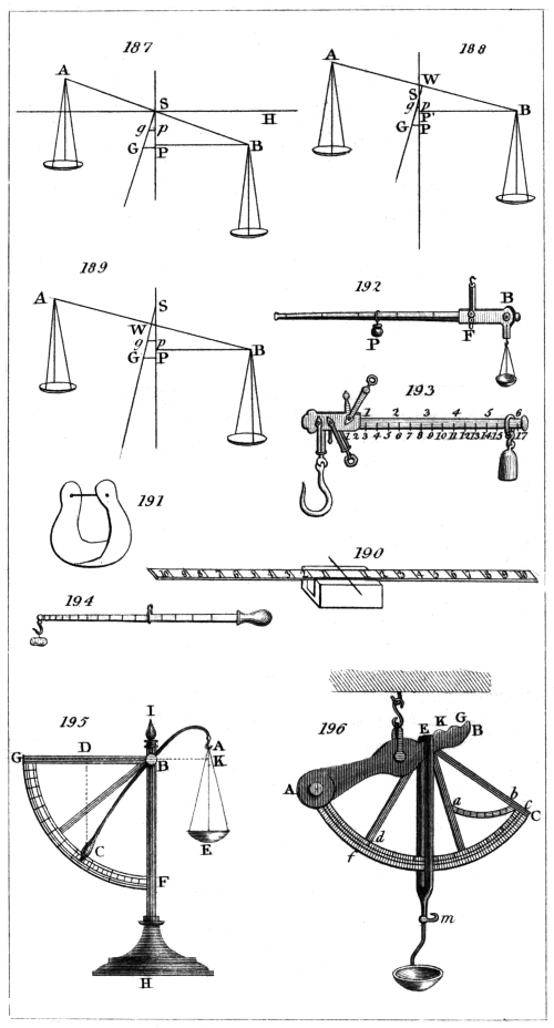
Captn. Kater, del.
H. Adlard, sc.
London, Pubd. by Longman & Co.
Suppose the distance from A to F to be ten times as
great as that from A to a, then a force of one pound
applied beneath F would balance ten pounds applied at
a, or upon the platform. Again: let the distance from
E to G be also ten times greater than the distance from
the fulcrum E to F; then a force of one pound applied
to raise up the end of the lever G would counterpoise a
weight of ten pounds placed upon F. Now, as we gain
ten times the power by the first levers, and ten times
more by the lever E G, it follows, that a force of one
pound tending to elevate G, would balance 100 lbs.
placed on the platform; so that if the end of the lever
G be attached to one arm of a balance, a weight of 10 lbs.
placed in a scale suspended from the other arm, will
express the value of 1000 lbs. placed upon the platform.
The levers are counterpoised, when the platform is not
loaded, by a weight H applied to the end of the last
lever, continued beyond the fulcrum for that purpose.
Of Instruments for weighing by means of a Spring.
The spring is well adapted to the construction of a
weighing machine, from the property it possesses of
yielding in proportion to the force impressed, and consequently
giving a scale of equal parts for equal additions
of weight. It is liable, however, to suffer injury, unless304
the steel of which it is composed be very well tempered,
from a want of perfect elasticity, and, consequently, from
not returning to its original place after it has been forcibly
compressed. This, however, must be considered to
arise, in a great measure, from imperfection of workmanship,
or of the material employed, or from its having
been subjected to too great a force.
The Spring Steelyard.
The little instrument known by this name is in very
general use, and is particularly convenient where great
accuracy is not necessary, as a spring which will ascertain
weights from one pound to fifty, is contained in a
cylinder only 4 inches long and 3/4 inch diameter.
This instrument is represented at fig. 198. It consists
of a tube of iron, of the dimensions just stated,
closed at the bottom, to which is attached an iron hook
for supporting the substance to be weighed; a rod of
iron a b, four tenths of an inch wide and one tenth
thick, is firmly fixed in the circular plate c d, which
slides smoothly in the iron tube.
A strong steel spring is also fastened to this plate, and
passed round the rod a b without touching it, and
without coming in contact with the interior of the cylindrical
tube. The tube is closed at the top by a circular
piece of iron through which the piece a b passes.
Upon the face of a b the weight is expressed by
divisions, each of which indicates one pound, and five of
such divisions in the instrument now before us occupy
two tenths of an inch. The divisions, notwithstanding,
are of sufficient size to enable them to be subdivided by
the eye.
To use this instrument, the substance to be weighed
is suspended by the hook, the instrument being held by
a ring passing through the rod at the other end. The
spring then suffers a compression proportionate to the
weight, and the number of pounds is indicated by the
division on the rod which is cut by the top of the cylindrical
tube.
305
Salter’s improved Spring Balance.
A very neat form of the instrument last described has
been recently brought before the public by Mr. Salter,
under the name of the Improved Spring Balance. It
is represented at fig. 199. The spring is contained in
the upper half of a cylinder behind the brass plate
forming the face of the instrument; and the rod is fixed
to the lower extremity of the spring, which is consequently
extended, instead of being compressed, by the
application of the weight. The divisions, each indicating
half a pound, are engraved upon the face of the brass plate,
and are pointed out by an index attached to the rod.
Marriott’s Patent Dial Weighing Machine.
The exterior of this instrument is represented at
fig. 200., and the interior at fig. 201. A B C is a shallow
brass box, having a solid piece as represented at A, to
which the spring D E F is firmly fixed by a nut at
D. The other end of the spring at F is pinned to
the brass piece G H, to the part of which at G is also
fixed the iron racked plate I. A screw L serves as a
stop to keep this rack in its place. The teeth of the
rack fit into those of the pinion M, the axis of which
passes through the centre of the dial-plate, and carries
an index which points out the weight. The brass piece
G H is merely a plate where it passes over the spring,
and the tail piece H, to which the weight is suspended,
passes through an opening in the side of the box.
Of the Dynamometer.
This is an important instrument in mechanics, calculated
to measure the muscular strength exerted by
men and animals. It consists essentially of a spring
steelyard, such as that we first described. This is sometimes
employed alone, and sometimes in combination
with various levers, which allow of the spring being
made more delicate, and consequently increase the extent
of the divisions indicating the weight.
306
The first instrument of this kind appears to have been
invented by Mr. Graham, but it was too bulky and inconvenient
for use. M. le Roy made one of a more
simple construction. It consisted of a metal tube, about
a foot long, placed vertically upon a stand, and containing
in the inside a spiral spring, having above it a graduated
rod terminating in a globe. This rod entered
the tube more or less in proportion to the force applied
to the globe, and the divisions indicated the quantity of
this force. Therefore, when a man pressed upon the globe
with all his strength, the divisions upon the rod showed
the number of pounds weight to which it was equal.
An instrument of this kind for determining the force
of a blow struck by a man with his fist was lately exhibited
at the National Repository. It was fixed to a
wall, from which it projected horizontally. In place of
the globe there was a cushion to receive the blow, and
as the suddenness with which the spring returned rendered
it impossible to read the division upon the rod,
another rod similarly divided was forced in by the plate
forming the basis of the cushion, and remained stationary
when the spring returned. The common spring
steelyard, however, which we first described, is in principle
the same as M. le Roy’s dynamometer, and is
much more conveniently constructed for the purpose we
are considering. The ring at one end may be fixed to
an immovable object, and the hook at the other attached
to a man, or to an animal, and the extent to which the
graduated rod is drawn out of the cylinder shows at
once the force which is applied. Though this is perhaps
the best, and certainly the most simple dynamometer,
others have been contrived, which are, however, but
modifications of the spring steelyard. One of these is
represented at fig. 202. The spiral spring acts in the
manner before described, but its divisions are increased
in size, and therefore rendered more perceptible by
means of a rack fixed to the plate, acting against the
spiral spring, the teeth of which move a pinion upon
which the arm I is fixed, pointing to the graduated arc K.
307
Another dynamometer has been invented by Mr. Salmon;
it is represented at fig. 203. and is a combination
of levers with the spring. By means of these
levers a much more delicate spring, and which is therefore
more sensible, may be employed than in the dynamometer
last described.
The manner in which these levers and spring act will
be readily understood by an inspection of the figure.
Like the weighing machine for carriages, the fulcrum of
each lever is at one end, and the force is diminished in
passing to the spring, in the ratio of the length of its
arms. The spring moves a pinion by means of a rack,
upon which pinion a hand is placed, indicating by divisions
upon a circular dial-plate, the amount of the
force employed.
The spring used in this machine is calculated to weigh
only about 50 lbs. instead of about 5 cwt., as in the
last described; but by means of the levers which intervene
between it and the force applied, it will serve to
estimate a force equal to 6 cwt., and might obviously be
made to go to a much greater extent, by varying the
ratio of the length of the arms of the levers.
ON COMPENSATION PENDULUMS.
(336.) It is said of Galileo that, when very young, he
observed a lamp suspended from the roof of a church at
Pisa, swinging backwards and forwards with a pendulous
motion. This, if it had been remarked at all by an
uneducated mind, would, most probably, have been passed
by as a common occurrence, unworthy of the slightest
notice; but to the mind imbued with science no incident
is insignificant; and a circumstance apparently the
most trivial, when subjected to the giant force of expanded
intellect, may become of immense importance to
the improvement and to the well-being of man. The
fall of an apple, it is said, suggested to Newton the
theory of gravitation, and his powerful mind speedily
extended to all creation that great law which brings an308
apple to the ground. The swinging of a lamp in a
church at Pisa, viewed by the piercing intellect of Galileo,
gave rise to an instrument which affords the most perfect
measure of time, which serves to determine the figure
of the earth, and which is inseparably connected with all
the refinements of modern astronomy.
The properties of the pendulum, and the manner in
which it serves to measure time, have been fully explained
in chapter xi.; and if a substance could be
found not susceptible of any change in its dimensions
from a change of temperature, nothing more would be
necessary, as the centre of oscillation would always remain
at the same distance from the point of suspension. As
every known substance, however, expands with heat,
and contracts with cold, the length of the pendulum will
vary with every alteration of temperature, and thus the
time of its vibration will suffer a corresponding change.
The effect of a difference of temperature of 25°, or
that which usually occurs between winter and summer,
would occasion a clock furnished with a pendulum having
an iron rod to gain or lose six seconds in twenty-four
hours.
It became, then, highly important to discover some
means of counteracting this variation to which the length
of the pendulum was liable, or, in other words, to devise
a method by which the centre of oscillation should, under
every change of temperature, remain at the same distance
from the point of suspension: happily, the difference in
the rate of expansion of different metals presented a ready
means of effecting this.
Graham, in the year 1715, made several experiments
to ascertain the relative expansions of various metals,
with a view of availing himself of the difference of the
expansions of two or more of them when opposed to
each other, to construct a compensating pendulum. But
the difference he found was so small, that he gave up all
hope of being able to accomplish his object in that way.
Knowing, however, that mercury was much more affected
by a given change of temperature than any other sub309stance,
he saw that if the mercury could be made to
ascend while the rod of the pendulum became longer,
and vice versâ, the centre of oscillation might always be
kept at the same distance from the point of suspension.
This idea happily gave birth to the mercurial pendulum,
which is now in very general use.
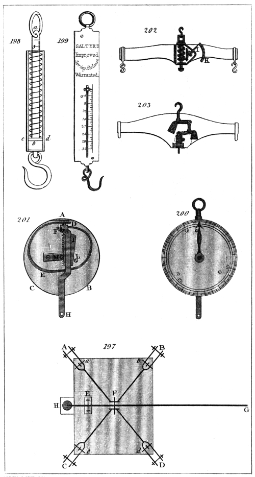
Captn. Kater, del.
H. Adlard, sc.
London, Pubd. by Longman & Co.
In the mean time, Graham’s suggestion excited the
ingenuity of Harrison, originally a carpenter at Barton
in Lincolnshire, who, in 1726, produced a pendulum
formed of parallel brass and steel rods, known by the
name of the gridiron pendulum.
In the mercurial pendulum, the bob or weight is the
material affording the compensation; but in the gridiron
pendulum the object is attained by the greater expansion
of the brass rods, which raise the bob upwards towards
the point of suspension as much as the steel rods elongate
downwards.
In the present article, we shall describe such compensation
pendulums as appear to us likely to answer best
in practice; and we trust we shall be able to simplify
the subject so as to render a knowledge of mathematics
in the construction of this important instrument unnecessary.
The following table contains the linear expansion of
various substances in parts of their length, occasioned by
a change of temperature amounting to one degree. We
have taken the liberty of extracting it from a very valuable
paper by F. Bailey, Esq., on the mercurial compensation
pendulum, published in the Memoirs of the
Astronomical Society of London for 1824.
310
TABLE I.
Linear Expansion of various Substances for One Degree
of Fahrenheit’s Thermometer.
Substances. |
Expansions. |
Authors. |
| White Deal, |
 |
·0000022685 |
|
Captain Kater. |
| ·0000028444 |
|
Dr. Struve. |
| English Flint Glass, |
|
·0000047887 |
|
Dulong and Petit. |
| Iron (cast), |
|
·0000061700 |
|
General Roy. |
| ·0000065668 |
|
Dulong and Petit. |
| Iron (wire), |
|
·0000068613 |
|
Lavoisier and L. |
| Iron (bar), |
|
·0000069844 |
|
Hasslar. |
| Steel (rod), |
|
·0000063596 |
|
General Roy. |
| Brass, |
|
·0000104400 |
 |
Commissioners of
Weights and Measures
—mean of several
experiments. |
| Lead, |
|
·0000159259 |
|
Smeaton. |
| Zinc, |
|
·0000163426 |
|
Ditto. |
| Zinc (hammered), |
|
·0000172685 |
|
Ditto. |
| Mercury in bulk, |
·00010010 |
|
Dulong and Petit. |
From this table it is easy to determine the length of
a rod of any substance the expansion of which shall be
equal to that of a rod of given length of any other substance.
The lengths of such rods will be inversely proportionate
to their expansions. If, therefore, we divide the lesser
expansion by the greater (supposing the rod the length
of which is given to be made of the lesser expansible
material), and multiply the given length by this quotient,
we shall have the required length of a rod, the expansion
of which will be equal to that of the rod given. For
example:—The expansion of a rod of steel being,
from the above table, ·0000063596, and that of brass,311
·0000104400; if it were required to determine the
length of a rod of brass which should expand as much as
a rod of steel of 39 inches in length, we have ·0000063596/·0000104400
= ·6091, which, multiplied by 39, gives 23·75 inches
for the length of brass required.
We shall here, in order to facilitate calculation, give
the ratio of the lengths of such substances as may be employed
in the construction of compensation pendulums.
TABLE II.
| Steel rod and brass compensation, as 1: |
·6091 |
| Iron wire rod and lead compensation, |
·4308 |
| Steel rod and lead compensation, |
·3993 |
| Iron wire rod and zinc compensation, |
·3973 |
| Steel rod and zinc compensation, |
·3682 |
| Glass rod and lead compensation, |
·3007 |
| Glass rod and zinc compensation, |
·2773 |
| Deal rod and lead compensation, |
·1427 |
| Deal rod and zinc compensation, |
·1313 |
| Steel rod and mercury in a steel cylinder, |
·0728 |
| Steel rod and mercury in a glass cylinder, |
·0703 |
| Glass rod and mercury in a glass cylinder, |
·0529 |
It is evident that in this table the decimals express
the length of a rod of the compensating material, the
expansion of which is equal to that of a pendulum rod
whose length is unity.
As we are not aware of the existence of any work
which contains instructions that might enable an artist
or an amateur to make a compensation pendulum, we
shall endeavour to give such detailed information as may
free the subject from every difficulty.
The pendulum of a clock is generally suspended by a
spring, fixed to its upper extremity, and passing through
a slit made in a piece which is called the cock of the
pendulum. The point of suspension is, therefore, that
part of the spring which meets the lower surface of the
cock. Now the distance of the centre of oscillation of
the pendulum from this point may be varied in two
ways; the one by drawing up the spring through this312
slit, and the other by raising the bob of the pendulum.
Either of these methods may be practised in the compensation
pendulum, but the former is subject to objections
from which the latter is exempt.
Suppose it were required to compensate a pendulum
of 39 inches in length, of steel, by means of the expansion
of a brass rod. Here, referring to fig. 204.,
we have S C 39 inches (which is to remain constant)
of steel; the pendulum spring, passing through the cock
at S, is attached to another rod of steel, which is fixed
to the cross piece R A at A. The other end of the cross
piece at R is fastened to a brass rod, the lower extremity
of which is fixed to the cock of the pendulum at B.
Now the brass rod B R must expand upwards, as much
as the steel rod A C expands downwards; and the length
of the brass must be such as to effect this, leaving 39
inches of the steel rod below the cock of the pendulum.
Let us first try 80 inches of steel. Multiplying
this by ·6091, we have 48·73 inches for the length
of brass, which compensates 80 inches of steel. But as
48·73 inches of the steel, equal in length to the brass,
would in this case be above the cock of the pendulum,
it would leave only 31·27 inches below it, instead of
39 inches.
Let us now try 100 inches of steel. This, multiplied
as before by ·6091, gives 60·91 inches, according to the
expansions which we have used, for the length of the brass
rod, and leaves 39·09 inches below the cock of the
pendulum, which is sufficiently near for our present
purpose.
From what has been said we may perceive that the
total length of the material of which the pendulum rod
is composed must be always equal to the length of the
pendulum added to the length of the compensation.
In this instance we have effected our object, by drawing
the pendulum-spring through the slit; but we will
now show how the same thing may be done by moving
the bob of the pendulum. At fig. 205., let S C, as before,
be equal to 39 inches. Let the steel rod S D turn off313
at right angles at D, and let a rod of brass B R, of 61
inches in length, ascend perpendicularly from this cross
piece to R. To the upper part of the brass rod fix another
cross piece R A, and from the extremity A let a
steel rod descend to E, bending it as in the figure till it
reaches C. Now the total length of the pieces of steel
expanding downwards is equal to S D, D F, and F C
(amounting together to 39 inches), to which must be
added a length of steel equal to that of the brass rod B R,
(61 inches), making together 100 inches of steel as before,
the expansion of which downwards is compensated
by that of the brass rod, of 61 inches in length,
expanding upwards.
This form, however, is evidently inconvenient, from
the great length of brass and steel which is carried above
the cock of the pendulum; but it is the same thing whether
the brass and steel be each in one piece, or divided
into several, provided the pieces of steel be all so arranged
as to expand downwards, and those of brass upwards.
Thus, at fig. 206., the portions of steel expanding
downwards are together equal, as before, to 100 inches,
and the two brass pieces expanding upwards are together
equal to 61 inches. So that, in fact, the two last forms
of compensation which we have described differ in no
respect from each other in principle, but only in the
arrangement of the materials. The last is the half of
the gridiron pendulum, the remaining bars being merely
duplicates of those we have described, and serving no
other purpose but to form a secure frame-work.
Harrison’s Gridiron Pendulum.
After what has been said, little more is necessary than
to give a representation of this pendulum. This is done
at fig. 207., in which the darker lines represent the steel
rods, and the lighter those of brass. The central rod is
fixed at its lower extremity to the middle of the third
cross piece from the bottom, and passes freely through
holes in the cross pieces which are above, whilst the
other rods are secured near their extremities to the cross314
pieces by pins passing through them. In order to render
the whole more secure, the bars pass freely through
holes made in two other cross pieces, the extremities of
which are fixed to the exterior steel wires. As different
kinds of the same metal vary in their rate of
expansion, the pendulum when finished may be found
upon trial to be not duly compensated. In this case one
or more of the cross pieces is shifted higher or lower
upon the bars, and secured by pins passed through fresh
holes.
Troughton’s Tubular Pendulum.
This is an admirable modification of Harrison’s gridiron
pendulum. It is represented at fig. 208., where it
may be seen that it has the appearance of a simple pendulum,
as the whole compensation is concealed within
a tube six tenths of an inch in diameter.
A steel wire, about one tenth of an inch in diameter,
is fixed in the usual manner to the spring by which the
pendulum is suspended. This wire passes to the bottom
of an interior brass tube, in the centre of which it is
firmly screwed. The top of this tube is closed, the steel
rod passing freely through a hole in the centre. Into
the top of this interior tube two steel wires, of one tenth
of an inch in diameter, are screwed into holes made in
that diameter, which is at right angles to the motion of
the pendulum. These wires pass down the tube without
touching either it or the central rod, through holes made
in the piece which closes the bottom of the interior tube.
The lower extremities of these wires, which project a
little beyond the inner tube, are securely fixed in a piece
which closes the bottom of an exterior brass tube, which
is of such a diameter as just to allow the interior tube
to pass freely through it, and of a sufficient length to
extend a little above it. The top of the exterior tube is
closed like that of the interior, having also a hole in its
centre, to allow the first steel rod to pass freely through
it. Into the top of the exterior tube, in that diameter
which coincides with the motion of the pendulum, a315
second pair of steel wires of the same diameter as the
former are screwed, their distance from the central rod
being equal to the distance of each from the first pair.
They consequently pass down within the interior tube,
and through holes made in the pieces closing the lower
ends of both the interior and exterior tubes. The lower
ends of these wires are fastened to a short cylindrical
piece of brass of the same diameter as the exterior tube,
to which the bob is suspended by its centre.
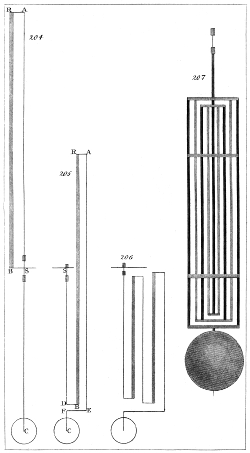
Captn. Kater, del.
H. Adlard, sc.
London, Pubd. by Longman & Co.
Fig. 209. is a full sized section of the rod; the three
concentric circles represent the two tubes, and the rectangular
position of the two pair of wires round the
middle one is shown by the five small circles.
Fig. 210. is the part which closes the upper end of the
interior tube. The two small circles are the two wires
which proceed from it, and the three large circles show
the holes through which the middle wire and the other
pair of wires pass.
Fig. 211. is the bottom of the interior tube. The small
circle in the centre is where the central rod is fastened
to it, the others the holes for the other four wires to pass
through.
Fig. 212. is the part which closes the top of the external
tube. In the large circle in the centre a small brass tube
is fixed, which serves as a covering for the upper part of
the middle wire, and the two small circles are to receive
the wires of the last expansion.
Fig. 213. represents the bottom of the exterior tube, in
which the small circles show the places where the wires
of the second expansion are fastened, and the larger ones
the holes for the other pair of wires to pass through.
Fig. 214. is a cylindrical piece of brass, showing the
manner in which the lower ends of the wires of the last
expansion are fastened to it, and the hole in the middle
is that by which it is pinned to the centre of the bob.
The upper ends of the two pair of wires are, as we have
observed, fastened by screwing them into the pieces
which stop up the ends of the tubes, but at the lower ends
they are all fixed as represented in fig. 214. The pieces316
represented by figs. 213. and 214. have each a jointed
motion, by means of which the fellow wires of each pair
would be equally stretched, although they were not exactly
of the same length.
The action of this pendulum is evidently the same as
that of the gridiron pendulum, as we have three lengths
of steel expanding downwards, and two of brass expanding
upwards. The weight of the pendulum has a tendency
to straighten the steel rods, and the tubular form
of the brass compensation effectually precludes the fear
of its bending; an advantage not possessed by the gridiron
pendulum, in which brass rods are employed.
Mr. Troughton, to the account he has given of this
pendulum in Nicholson’s Journal, for December, 1804,
has added the lengths of the different parts of which it
was composed, and the expansions of brass and steel
from which these lengths were computed. The length
of the interior tube was 31·9 inches, and that of the exterior
one 32·8 inches, to which must be added 0·4, the
quantity by which in this pendulum the centre of oscillation
is higher than the centre of the bob. These are
all of brass. The parts which are of steel are,—the middle
wire, which, including 0·6, the length of the suspension
spring, is 39·3 inches. The first pair of wires 32·5
inches; and the second pair, 33·2 inches. The expansions
used were, for brass ·00001666, and for steel
·00000661, in parts of their length for one degree of
temperature.
Benzenberg’s Pendulum.
This pendulum is mentioned in Nicholson’s Journal
for April, 1804, and is taken from Voigt’s Magazin für
den Neuesten Zustande der Naturkunde, vol. iv. p. 787.
The compensation appears to have been effected by a
single rod of lead in the centre, of about half an inch
thick; the descending rods were made of the best thick
iron wire.
As this pendulum deserves attention from the ease
with which it may be made, and as others which have317
since been produced resemble it in principle, we have
given a representation of it at fig. 215., where A B C D
are two rods of iron wire riveted into the cross
pieces A C B D. E F is a rod of lead pinned to the
middle of the piece B D, and also at its upper extremity
to the cross piece G H, into which the second pair of
iron wires are fixed, which pass downwards freely
through holes made in the cross piece B D. The lower
extremities of these last iron wires are fastened into the
piece K L, which carries the bob of the pendulum.
To determine the length of lead necessary for the
compensation, we must recollect, as before, that the
distance from the point of suspension to the centre of
the bob (speaking always of a pendulum intended to
vibrate seconds) must be 39 inches. Let us suppose
the total length of the iron wire to be 60 inches;
then, from the table which we have given, we have
·4308 for the length of a rod of lead, the expansion of
which is equivalent to that of an iron rod whose length
is unity. Multiplying 60 inches by ·4308, we have
25·84 inches of lead, which would compensate 60
inches of iron; but this, taken from 60 inches, leaves
only 34·16 instead of 39 inches. Trying again, in
like manner, 68·5 inches of iron, we find 29·5 inches
of lead for the length, affording an equivalent compensation,
and which, taken from 68·5 inches, leaves 39
inches.
The length of the rod of lead then required as a
compensation in this pendulum is about 291/2 inches.
The writer of this article would suggest another form
for this pendulum, which has the advantage of greater
simplicity of construction.
S A, fig. 216., is a rod of iron wire, to which the
pendulum spring is attached. Upon this passes a cylindrical
tube of lead, 291/2 inches long, which is either
pinned at its lower extremity to the end of the iron rod
S A, or rests upon a nut firmly screwed upon the extremity
of this rod.
A tube of sheet iron passes over the tube of lead, and318
is furnished at top with a flanche, by which it is supported
upon the leaden tube; or it may be fastened to
the top of this tube in any manner that may be thought
convenient.
The bob of the pendulum may be either passed upon
the iron tube (continued to a sufficient length) and
secured by a pin passing through the centre of the bob,
or the iron tube may be terminated by an iron wire
serving the same purpose.
Here we have evidently the same expansions upwards
and downwards as in the gridiron form, given to this
pendulum by Mr. Benzenberg, joined to the compactness
of Troughton’s tubular pendulum.
Ward’s Compensation Pendulum.
In the year 1806, Mr. Henry Ward, of Blandford in
Dorsetshire, received the silver medal of the Society of
Arts for the compensation pendulum which we are about
to describe.
Fig. 217. is a side view of the pendulum rod when
together. H H and I I are two flat rods of iron about
an eighth of an inch thick. K K is a bar of zinc
placed between them, and is nearly a quarter of an inch
thick. The corners of the iron bars are bevelled off,
which gives them a much lighter appearance. These bars
are kept together by means of three screws, O O O, which
pass through oblong holes in the bars H H and K K, and
screw into the rod I I. The bar H H is fastened to the
bar of zinc K K, by the screw m, which is called the
adjusting screw. This screw is tapped into H H, and
passes just through K K; but that part of the screw
which passes K K has its threads turned off. The iron
bar I I has a shoulder at its upper end, and rests on the
top of the zinc bar K K and is wholly supported by
it. There are several holes for the screw m, in order to
adjust the compensation.
The action of this pendulum is similar to that last
described, the zinc expanding upwards as much as
the iron rods expand downwards, and consequently the319
instance from the point of suspension to the centre of
oscillation remains the same.
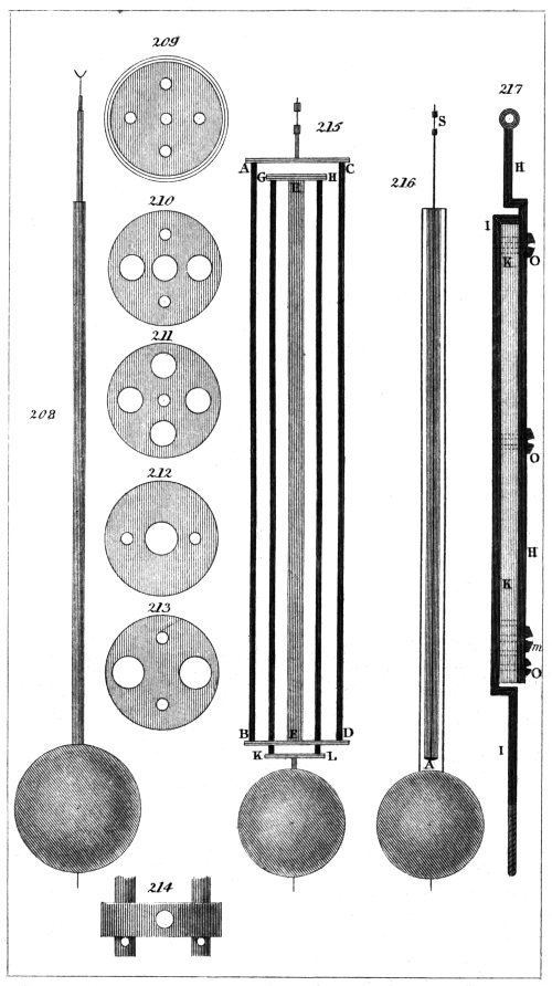
Captn. Kater, del.
H. Adlard, sc.
London, Pubd. by Longman & Co.
Mr. Ward states that the expansion of the zinc he
used (hammered zinc) was greater than that given in
the tables. He found that the true length of the zinc
bar should be about 23 inches; our computation would
make it nearly 26.
The Compensation Tube of Julien le Roy.
We mention this merely to state that it is similar in
principal to the apparatus represented at fig. 204.,
with merely this difference, that, instead of the steel
rod being fixed to a cross piece proceeding from the
brass bar B R, it is attached to a cap fixed upon a
brass tube (through which it passes) of the same length
as that of the brass rod B R. Cassini spoke well of
this pendulum, and it was used in the observatory of
Cluny about the year 1748.
Deparcieux’s Compensation.
This was contrived in the same year as that invented
by Julien le Roy. It is represented at fig. 218., where
A B D F is a steel bar, the ends of which are to be
fixed to the lower sides of pieces forming a part of
the cock of the pendulum. G E I H is of brass, and stands
with its extremities resting on the horizontal part B D
of the steel frame. The upper part E I of the brass
frame passes above the cock of the pendulum, and
admits the tapped wire K, to which the pendulum spring
is fixed through a squared hole in the middle. A nut
upon this tapped wire gives the adjustment for time.
The spring passes through the slit in the cock in the
usual manner.
It may be easily perceived that this pendulum is in
principle the same as that of Le Roy; the expansion
of the total length of steel A B S C downwards being
compensated by the equivalent expansion of the brass bar
G E upwards. It is, however, preferable to Le Roy’s, because
the compensation is contained in the clock case.
320
Deparcieux had previously published, in the year 1739,
an improvement of an imperfectly compensating pendulum,
proposed in the year 1733 by Regnauld, a
clockmaker of Chalons. In this pendulum Deparcieux
employed a lever with unequal arms to increase the
effect of the expansion of the brass rod, which was too
short.
We may here remark, that all fixed compensations
are liable to the same objection, namely, that of not
moving with the pendulum, and therefore not taking
precisely the same temperature.
Captain Kater’s Compensation Pendulum.
In Nicholson’s Journal, for July, 1808, is the description
of a compensation pendulum by the writer of this
article. In this pendulum the rod is of white deal,
three quarters of an inch wide, and a quarter of an inch
thick. It was placed in an oven, and suffered to remain
there for a long time until it became a little charred.
The ends were then soaked in melted sealing-wax; and
the rod, being cleaned, was coated several times with copal
varnish. To the lower extremity of the rod a cap of
brass was firmly fixed, from which a strong steel screw
proceeded for the purpose of regulating the pendulum
for time in the usual manner.
A square tube of zinc was cast, seven inches long and
three quarters of an inch square; the internal dimensions
being four tenths of an inch. The lower part of
the pendulum rod was cut away on the two sides, so as
to slide with perfect freedom within the tube of zinc.
To the bottom of this zinc tube a piece of brass a quarter
of an inch thick was soldered, in which a circular hole
was made nearly four tenths of an inch in diameter,
having a screw on the inside. A cylinder of zinc, furnished
with a corresponding screw on its surface, fitted
into this aperture, and a thin plate of brass screwed upon
the cylinder, served as a clamp to prevent any shake
after the length of zinc necessary for compensation
should have been determined. A hole was made through321
the axis of the cylinder, through which passed the steel
screw terminating the pendulum rod.
An opening was made through the bob of the pendulum,
extending to its centre, to admit the square tube
of zinc which was fixed at its upper extremity to the
centre of the bob. The pendulum rod passed through
the bob in the usual manner, and the whole was supported
by a nut on the steel screw at the extremity.
In this form the compensation acts immediately upon
the centre of the bob, elevating it along the rod as
much as the rod elongates downwards: the method of
calculating the length of the required compensation is
precisely the same as that we have before given.
Assuming the length of the deal rod to be 43 inches,
and multiplying this by ·1313 from Table II., we have
5·64 inches for the length of the zinc necessary to counteract
the expansion of the deal. The length of the
steel screw between the termination of the pendulum
rod and the nut was two inches, and that of the suspension
spring one inch. Now, 3 inches of steel multiplied
by ·3682 would give 1·10 inches for the length
of zinc which would compensate the steel, and, adding
this to 5·64 inches, we have 6·74 inches for the whole
length of zinc required.
In this pendulum, the length of the compensating
part may be varied by means of the zinc cylinder furnished
with a screw for that purpose. The bob of this
pendulum and its compensation are represented at
fig. 219.
It has been objected to the use of wooden pendulum
rods, that it is difficult, if not impossible, to secure them
from the action of moisture, which would at once be
fatal to their correct performance. The pendulum now
before us has, however, been going with but little intermission
since it was first constructed: it is attached
to a sidereal clock, not of a superior description, and
exposed to very considerable variations of moisture and
dryness; yet the change in its rate has been so very
trifling as to authorize the belief that moisture has little322
or no effect upon a wooden rod prepared in the manner
we have described. Its rate, under different temperatures,
shows that it is over-compensated; the length of the
zinc remaining, as stated in Nicholson’s Journal 7·42
inches, instead of which it appears, by our present compensation,
that it should be 6·78 inches.
Reid’s Compensation Pendulum.
Mr. Adam Reid of Woolwich presented to the Society
of Arts, in 1809, a compensation pendulum, for which
he was rewarded with fifteen guineas. This pendulum
is the same in principle with that last described; the
rod, however, is of steel instead of wood, and the compensation
possesses no means of adjustment. This pendulum
is represented at fig. 220., where S B is the steel
rod, a little thicker where it enters the bob C, and of
a lozenge shape to prevent the bob turning, but above
and below it is cylindrical.
A tube of zinc D passes to the centre of the bob from
below, and the bob is supported upon it by a piece which
crosses its centre, and which meets the upper end of the
tube.
The rod being passed through the bob and zinc tube,
a nut is applied upon a screw at the lower extremity of
the rod in the usual manner. If the compensation
should be too much, the zinc tube is to be shortened
until it is correct.
The length of the zinc tube will be the same in this
pendulum as in that of Mr. Ward—about 23 inches,
if his experiments are to be relied upon.
The objection to this pendulum appears to be its
great length, which amounts to 62 inches. We conceive
it would be preferable to place the zinc above the bob,
as in the modification which we have suggested of Benzenberg’s
pendulum.
Ellicott’s Pendulum.
It appears that the idea of combining the expansions
of different metals with a lever, so as to form a com323pensation
pendulum, originated with Mr. Graham; for
Mr. Short, in the Philosophical Transactions for 1752,
states that he was informed by Mr. Shelton, that Mr.
Graham, in the year 1737, made a pendulum, consisting
of three bars, one of steel between two of brass; and
that the steel bar acted upon a lever so as to raise the
pendulum when lengthened by heat, and to let it down
when shortened by cold.
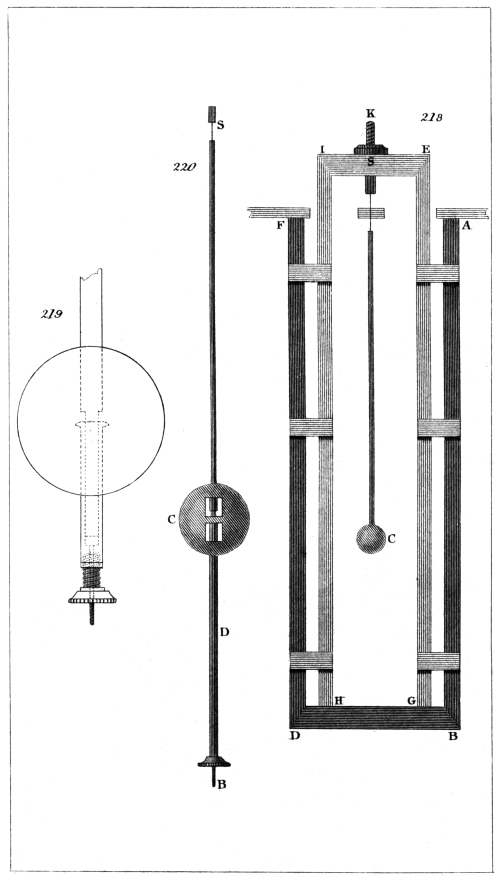
Captn. Kater, del.
H. Adlard, sc.
London, Pubd. by Longman & Co.
This pendulum, however, was found upon trial to
move by jerks, and was therefore laid aside by the inventor
to make way for the mercurial pendulum.
Mr. Short also says that Mr. Fotheringham, a quaker
of Lincolnshire, caused a pendulum to be made, in the
year 1738 or 1739, consisting of two bars, one of brass
and the other of steel, fastened together by screws with
levers to raise or let down the bob, and that these levers
were placed above the bob.
Mr. John Ellicott of London had made very, accurate
experiments on the relative expansions of seven
different metals, which, however, will be found to differ
more or less from the results of the experiments of
others. It is not, however, from this to be concluded
that Ellicott’s determinations were erroneous; for the
expansion of a metal will suffer considerable change even
by the processes to which it is necessarily subjected in
the construction of a pendulum. It is therefore desirable,
whenever a compensation pendulum is to be
made, that the expansions of the materials employed
should be determined after the processes of drilling,
filing, and hammering have been gone through.
It had been objected to Harrison’s gridiron pendulum,
that the adjustments of the rods was inconvenient, and
that the expansion of the bob supported at its lower
edge would, unless taken into the account, vitiate the
compensation. These considerations, it is supposed,
gave rise to Ellicott’s pendulum, which is nearly similar
to those we have just mentioned.
Ellicott’s pendulum is thus constructed:—A bar of
brass and a bar of iron are firmly fixed together at their324
upper ends, the bar of brass lying upon the bar of iron,
which is the rod of the pendulum. These bars are held
near each other by screws passing through oblong holes
in the brass, and tapped into the iron, and thus the
brass is allowed to expand or contract freely upon the
iron with any change of temperature. The brass bar
passes to the centre of the bob of the pendulum, a little
above and below which the iron is left broader for the
purpose of attaching the levers to it, and the iron is
made of a sufficient length to pass quite through the
bob of the pendulum.
The pivots of two strong steel levers turn in two holes
drilled in the broad part of the iron bar. The short
arms of these levers are in contact with the lower extremity
of the brass bar, and their longer arms support
the bob of the pendulum by meeting the heads of two
screws which pass horizontally from each side of the
bob towards its centre. By advancing these screws towards
the centre of the bob, the longer arms of the
lever are shortened, and thus the compensation may be
readily adjusted. At the lower end of the iron rod,
under the bob, a strong double spring is fixed, to support
the greater part of the weight of the bob by its
pressure upwards against two points at equal distances
from the pendulum rod. Mr. Ellicott gave a description
of this pendulum to the Royal Society in 1752, but he
says the thought was executed in 1738. As this pendulum
is very seldom met with, we think it unnecessary
to give a representation of it.
Compensation by means of a Compound Bar of Steel
and Brass.
Several compensations for pendulums have been proposed,
by means of a compound bar formed of steel and
brass soldered together. In a bar of this description, the
brass expanding more than the steel, the bar becomes
curved by a change of temperature, the brass side becoming
convex and the steel concave with heat. Now,
if a bar of this description have its ends resting on325
supports on each side the cock of the pendulum, the
bar passing above the cock with the brass uppermost, if
the pendulum spring be attached to the middle of the
bar, and it pass in the usual manner through the slit of
the cock, it is evident that, by an increase of temperature,
the bar will become curved upwards, and the pendulum
spring be drawn upwards through the slit, and thus the
elongation of the pendulum downwards will be compensated.
The compensation may be adjusted by varying
the distance of the points of support from the
middle of the bar.
Such was one of the modes of compensation proposed
by Nicholson. Others of the same description (that is,
with compound bars) have been brought before the
public by Mr. Thomas Doughty and Mr. David Ritchie;
but as they are supposed to be liable to many practical
objections, we do not think it requisite to describe them
more particularly.
There is, however, a mode of compensation by means
of a compound bar, described by M. Biot in the first
volume of his Traité de Physique, which appears to
possess considerable merit, of which he mentions having
first witnessed the successful employment by the
inventor, a clockmaker named Martin. At fig. 221.,
S C, is the rod of the pendulum, made, in the usual
manner, of iron or steel; this rod passes through the
middle of a compound bar of brass and steel (the brass
being undermost), which should be furnished with a
short tube and screws, by means of which, or by passing
a pin through the tube and rod, it may be securely fixed
at any part of the pendulum rod.
Two small equal weights W W slide along the compound
bar, and, when their proper position has been
determined, may be securely clamped.
The manner in which this compensation acts is thus:—Suppose
the temperature to increase, the brass expanding
more than the steel, the bar becomes curved,
and its extremities carrying the weights W and W are
elevated, and thus the place of the centre of oscillation326
is made to approach the point of suspension as much,
when the compensation is properly adjusted, as it had
receded from it by the elongation of the pendulum rod.
There are three methods of adjusting this compensation:
the first, by increasing or diminishing the weights
W and W; the second, by varying the distance of the
weights W and W from the middle of the bar; and the
third, by varying the distance of the bar from the bob
of the pendulum, taking care not to pass the middle of
the rod. The effect of the compensation is greater as
the weights W and W are greater or more distant from
the centre of the bar, and also as the bar is nearer to
the bob of the pendulum.
M. Biot says that he and M. Matthieu employed a
pendulum of this kind for a long time in making astronomical
observations in which they were desirous of
attaining an extreme degree of precision, and that they
found its rate to be always perfectly regular.
In all the pendulums which we have described, the
bob is supposed to be fixed to the rod by a pin passing
through its centre, and the adjustment for time is to be
made by means of a small weight sliding upon the rod.
Of the Mercurial Pendulum.
We have been guided, in our arrangement of the
pendulums which we have described, by the similarity
in the mode of compensation employed; and we have
now to treat of that method of compensation which is
effected by the expansion of the material of which the
bob itself of the pendulum is composed.
On this subject, as we have before observed, an
admirable paper, from the pen of Mr. Francis Baily,
may be found in the Memoirs of the Astronomical
Society of London, which leaves nothing to be desired
by the mathematical reader. But as our object is to simplify,
and to render our subjects as popular as may be,
we must endeavour to substitute for the perfect accuracy
which Mr. Baily’s paper presents, such rules as may be
found not only readily intelligible, but practically appli327cable,
within the limits of those inevitable errors which
arise from a want of knowledge of the exact expansion
of the materials employed.
At fig. 222., let S B represent the rod of a pendulum,
and F C B a metallic tube or cylinder, supported
by a nut at the extremity of the pendulum rod, in
the usual manner, and having a greater expansibility
than that of the rod. Now C, the centre of gravity,
supposing the rod to be without weight, will be in the
middle of the cylinder; and if C B, or half the cylinder,
be of such a length as to expand upwards as much as
the pendulum rod S B expands downwards, it is evident
that the centre of gravity C will remain, under any
change of temperature, at the same distance from the
point of suspension S. M. Biot imagined that, in
effecting this, a compensation sufficiently accurate would
be obtained; but Mr. Baily has shown that this is by
no means the fact.
Let us suppose the place of the centre of oscillation
to be at O, about three or four tenths of an inch, in a
pendulum of the usual construction, below the centre of
gravity. Now, the object of the compensation is to
preserve the distance from S to O invariable, and not
the distance from S to C.
The distance of the centre of oscillation varies with
the length of the cylinder F B, and hence suffers an
alteration in its distance from the point of suspension
by the elongation of the cylinder, although the distance
of the centre of gravity C from the point of suspension
remains unaltered.
We shall endeavour to render this perfectly familiar.
Suppose a metallic cylinder, 6 inches long, to be suspended
by a thread 36 inches long, thus forming a pendulum
in which the distance of the centre of gravity
from the point of suspension is 39 inches: the centre of
oscillation in such a pendulum will be nearly one tenth
of an inch below the centre of gravity. Now let us
imagine cylindrical portions of equal lengths to be added
to each end of the cylinder, until it reaches the point of328
suspension; we shall then have a cylinder of 78 inches
in length, the centre of gravity of which will still be at
the distance of 39 inches from the point of suspension.
But it is well known that the centre of oscillation of
such a cylinder is at the distance of about two thirds of
its length from the point of suspension. The centre of
oscillation, therefore, has been removed, by the elongation
of the cylinder, about 13 inches below the centre
of gravity, whilst the centre of gravity has remained
stationary.
Now the same thing as that which we have just
described takes place, though in a very minor degree,
with our former cylinder, employed as a compensating
bob to a pendulum. The rod expands downwards, the
centre of gravity remains at the same distance from the
point of suspension, and the cylinder elongates both
above and below this point; the consequence of which
is, that though the centre of gravity has remained stationary,
the distance of the centre of oscillation from the
point of suspension has increased. It is, therefore, evident
that the length of the compensation must be such
as to carry the centre of gravity a little nearer to the
point of suspension than it was before the expansion
took place; by which means the centre of oscillation
will be restored to its former distance from the point of
suspension.
Let us suppose the expansions to have taken place,
and that the centre of gravity, remaining at the same
distance from the point of suspension, the centre of
oscillation is removed to a greater distance, as we have
before explained. It is well known that the product
obtained by multiplying the distance from the point of
suspension to the centre of gravity, by the distance from
the centre of gravity to the centre of oscillation, is a
constant quantity; if, therefore, the distance from the
centre of gravity to the point of suspension be lessened,
the distance from the centre of gravity to the centre of
oscillation will be proportionally, though not equally, increased,
and the centre of oscillation will, therefore, be329
elevated. We see, then, if we elevate the centre of
gravity precisely the requisite quantity, by employing a
sufficient length of the compensating material, that
although the distance from the centre of gravity to the
point of suspension is lessened, yet the distance from
the point of suspension to the centre of oscillation will
suffer no change.
The following rule for finding the length of the compensating
material in a pendulum of the kind we have
been considering will be found sufficiently accurate for
all practical purposes:—
Find in the manner before directed the length of the
compensating material, the expansion of which will be
equal to that of the rod of the pendulum. Double this
length, and increase the product by its one-tenth part,
which will give the total length required. We shall give
examples of this as we proceed.
Graham’s Mercurial Pendulum.
It was in the year 1721 that Graham first put up a
pendulum of this description, and subjected it to the test
of experiment; but it appears to have been afterwards
set aside to make way for Harrison’s gridiron pendulum,
or for others of a similar description. For some years
past, however, its merits have been more generally
known, and it is not surprising that it should be considered
as preferable to others, both from the simplicity
of its construction, and the perfect ease with which the
compensation may be adjusted.
We have already alluded to Mr. Baily’s very able
paper on this pendulum, and we shall take the liberty of
extracting from it the following description:—
At fig. 223. is a drawing of the mercurial pendulum,
as constructed in the manner proposed by Mr. Baily.
“The rod S F is made of steel, and perfectly straight;
its form may be either cylindrical, of about a quarter of an
inch in diameter, or a flat bar, three eighths of an inch
wide, and one eighth of an inch thick: its length from S to
F, that is, from the bottom of the spring to the bottom of330
the rod at F, should be 34 inches. The lower part of this
rod, which passes through the top of the stirrup, and
about half an inch above and below the same, must be
formed into a coarse and deep screw, about two tenths of
an inch in diameter, and having about thirty turns in an
inch. A steel nut with a milled head must be placed at
the end of the rod, in order to support the stirrup; and a
similar nut must also be placed on the rod above the head
of the stirrup, in order to screw firmly down on the same,
and thus secure it in its position, after it has been adjusted
nearly to the required rate. These nuts are represented
at B and C. A small slit is cut in the rod, where it passes
through the head of the stirrup, through which a steel
pin E is screwed, in order to keep the stirrup from turning
round on the rod. The stirrup itself is also made of
steel, and the side pieces should be of the same form as
the rod, in order that they may readily acquire the same
temperature. The top of the stirrup consists of a flat
piece of steel, shaped as in the drawing, somewhat more
than three eighths of an inch thick. Through the middle
of the top (which at this part is about one inch deep)
a hole must be drilled sufficiently large to enable the
screw of the rod to pass freely, but without shaking.
The inside height of the stirrup from A to D may be
81/2 inches, and the inside width between the bars about
three inches. The bottom piece should be about three
eighths of an inch thick, and hollowed out nearly a quarter
of an inch deep, so as to admit the glass cylinder
freely. This glass cylinder should have a brass or iron
cover G, which should fit the mouth of it freely, with a
shoulder projecting on each side, by means of which it
should be screwed to the side bars of the stirrup, and thus
be secured always in the same position. This cap should
not press on the glass cylinder, so as to prevent its expansion.
The measures above given may require a slight
modification, according to the weight of the mercury
employed, and the magnitude of the cylinder: the final
adjustment, however, may be safely left to the artist.
Some persons have recommended that a circular piece of331
thick plate glass should float on the mercury, in order to
preserve its surface uniformly level.7 The part at the
bottom marked H is a piece of brass fastened with
screws to the front of the bottom of the stirrup, through
a small hole, in which a steel wire or common needle is
passed, in order to indicate (on a scale affixed to the
case of the clock) the arc of vibration. This wire should
merely rest in the hole, whereby it may be easily removed
when it is required to detach the pendulum from
the clock, in order that the stirrup might then stand
securely on its base. One of the screw holes should be
rather larger than the body of the screw, in order to admit
of a small adjustment, in case the steel wire should
not stand exactly perpendicular to the axis of motion.
The scale should be divided into degrees, and not inches,
observing that with a radius of 44 inches (the estimated
distance from the bend of the spring to the end of the
steel wire) the length of each degree on the scale must
be 0·768 inch.”
In order to determine the length of the mercurial
column necessary to form the compensation for this pendulum,
we must proceed in the following manner:—
Let us suppose the length of the steel rod and stirrup
together to be 42 inches. The absolute expansion of
the mercury is ·00010010; but it is not the absolute
expansion, but the vertical expansion in a glass cylinder,
which is required, and this will evidently be influenced
by the expansion of the base of this cylinder. It is
easily demonstrable that, if we multiply the linear expansion
of any substance (always supposed to be a very
small part of its length) by 3, we may in all cases take
the result for the cubical or absolute expansion of such332
substance. In like manner, if we multiply the linear expansion
by 2, we shall have the superficial expansion.
If we want the apparent expansion of mercury, the
absolute or cubical expansion of the glass vessel must
be deducted from the absolute expansion of the mercury,
which will leave its excess or apparent expansion.
In like manner, deducting the superficial expansion of
glass from the absolute expansion of mercury, we shall
have its relative vertical expansion. Now, taking the
rate of expansion of glass to be ·00000479, and multiplying
it by 2, the relative vertical expansion of the
mercury in the glass cylinder will be ·00010010 -
·00000958 = ·00009052.
The expansion of a steel rod, according to our table,
is ·0000063596; which, divided by ·00009052, gives
·0703 for the length of a column of mercury, the expansion
of which is equal to that of a steel rod whose
length is unity.
We have now to multiply 42 inches by ·0703, which
gives 2·95 inches; and this, deducted from 42, leaves
39·1 inches; so that the length of rod we have chosen
is sufficiently near the truth. Now, double 2·95 inches,
and add one tenth of its product, and we shall have 6·49
inches for the length of the mercurial column forming
the requisite compensation. Mr. Baily’s more accurate
calculation gives 6·31 inches.
A mercurial compensation pendulum may be formed,
having a cylinder of steel or iron, with its top constructed
in the same manner as the top of the stirrup,
so as to receive the screw of the rod. To find the
length of the mercurial column necessary in a pendulum
of this description (that is, with a cylinder made of
steel), we must double the linear expansion of steel, and
take it from the absolute expansion of mercury to obtain
the relative vertical expansion of the mercury. This
will be ·00010010 - ·00001272 = ·00008738; and,
proceeding as before, we have ·0000063596/·00008738 = ·07279.
Let the length of the steel rod be, as before, 42 inches.333
Multiplying this by ·07279, we have 3·057, which
being doubled, and one tenth of the product added, we
obtain 6·72 inches for the length of the compensating
mercurial column; which Mr. Baily states to be 6·59.
A mercurial compensation pendulum having a rod of
glass has been employed by the writer of this article,
who has had reason to think well of its performance.
Its cheapness and simplicity much recommend it. It is
merely a cylinder of glass of about 7 inches in depth,
and 21/2 inches diameter, terminated by a long neck,
which forms the rod of the pendulum, the whole blown
in one piece. A cap of brass is clamped by means of
screws to the top of the rod, and to this the pendulum
spring is pinned.
We have unquestionable authority for saying, that
the mercurial pendulum of the usual construction, that
is, with a steel rod and glass cylinder, is not affected by
a change of temperature simultaneously in all its parts.
Now, the pendulum of which we are treating being
formed throughout of the same material in a single
piece, and in every part of the same thickness, it is presumed
it cannot expand in a linear direction, until the
temperature has penetrated to the whole interior surface
of the glass, when it is rapidly diffused through the
mass of mercury. M. Biot mentions that a pendulum
of this kind was formerly used in France, and expresses
his surprise that it was no longer employed, as he had
heard it very highly spoken of. The writer of this
article has also used a pendulum with a glass rod, which
differs from that we have just mentioned, in having the
lower end of the rod firmly fixed in a socket attached to
the centre of a circular iron plate, on the circumference
of which a screw is cut, which fits into a collar of iron,
supporting the cylinder (to which it is cemented) by
means of a circular lip.
This arrangement, though perhaps less perfect than
that we have just described, the pendulum not being in
one piece, has the advantage of allowing a circular plate of
glass to be placed upon the surface of the mercury, as334
practised by Mr. Browne. To determine the length of
a column of mercury for a glass pendulum, let us suppose
the glass, including the cylinder, to be 41 inches
in length. Multiplying this by ·0529, the number
taken from Table II. for a glass rod and mercury in a
glass cylinder, we have 2·17 inches for the uncorrected
length of mercury, which compensates 41 inches of
glass. Suppose the steel spring to be one inch and a
half long: multiplying this by ·0703, the appropriate
decimal taken from Table II., we have 0·1, the length of
mercury due to the steel, making with the former 2·27
inches, which, being doubled, and the product increased
by its one-tenth part, we obtain five inches for the
length of the required column of mercury.
Compensation Pendulum of Wood and Lead, on the
Principle of the Mercurial Pendulum.
If by any contrivance wood could be rendered impervious
to moisture, it would afford one of the most convenient
substances known for a compensation pendulum.
It does not appear that sufficient experiments have been
made upon this subject to decide the question. Mr.
Browne of Portland Place, who has devoted much of
his time and attention to the most delicate enquiries of
this kind, has, we believe, found that if a teak rod is
well gilded, it will not afterwards be affected by
moisture. At all events, it makes a far superior pendulum,
when thus prepared, to what it does when such
preparation is omitted.
Mr. Baily, in the paper we have before alluded to,
proposes an economical pendulum to be constructed by
means of a leaden cylinder and a deal rod. He prefers
lead to zinc, on account of its inferior price, and the ease
with which it may be formed into the required shape;
and as there is no considerable difference in their rates
of expansion, it is equally applicable to the purpose.
Let the length of the deal rod be taken at 46 inches.
Then, to find the length of the cylinder of lead to compensate
this, we have, in Table II., ·1427 for such a335
pendulum; which, being multiplied by 46, the product
doubled, and one tenth of the result added to it, gives
14·44 inches for the length of the leaden cylinder.
Mr. Baily’s compensation gives 14·3 inches.
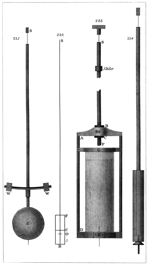
Captn. Kater, del.
H. Adlard, sc.
London, Pubd. by Longman & Co.
The rod is recommended to be made of about three
eighths of an inch in diameter: the leaden cylinder is
to be cast with a hole through its centre, which will admit
with perfect freedom the cylindrical end of the rod.
The cylinder is supported upon a nut, which screws on
the end of the rod in the usual manner. This pendulum
is represented at fig. 224.
Mr. Baily proposes that the pendulum should be
adjusted nearly to the given rate by means of the screw
at the bottom, and that the final adjustment be made
by means of a slider moving along the rod. Indeed,
this is a means of adjustment which we would recommend
to be employed in every pendulum.
Smeaton’s Pendulum.
We shall conclude our account of compensation pendulums
with a description of that invented by Mr.
Smeaton. The compensation for temperature in this
pendulum is effected by combining the two modes, which
have been so fully described in the preceding part of
this article.
The pendulum rod is of solid glass, and is furnished
with a steel screw and nut at the bottom in the usual
manner. Upon the glass rod a hollow cylinder of zinc,
about the eighth of an inch thick, and about 12 inches
long, passes freely, and rests upon the nut at the bottom
of the pendulum rod.
Over the zinc cylinder passes a tube made of sheet-iron.
The edge of this tube at the top is turned inwards,
and is notched so as to allow of this being
effected. A flanche is thus formed, by which the iron
tube is supported, upon the zinc cylinder. The lower
edge of the iron tube is turned outwards, so as to form
a base destined to support a leaden cylinder, which we
are about to describe.
336
A cylinder of lead, rather more than 12 inches long,
is cast with a hole through its axis, of such a diameter
as to allow of its sliding freely, but without shake, upon
the iron tube over which it passes, and by the lower
extremity of which it is supported.
Now the zinc, resting upon the nut and expanding
upwards, will raise the whole of the remaining part of
the compensation. This expansion upwards will be
slightly counteracted by the lesser expansion downwards
of the iron tube, which carries with it the leaden
cylinder. The cylinder of lead now acts upon the
principle of the mercurial pendulum, and, expanding
upwards, contributes that which was wanting to restore
the centre of oscillation to its proper distance from the
point of suspension.
This pendulum, we have been informed, does well in
practice, and we are not aware that any description of
it has been before published.
The method of calculating the length of the tubes
required to form the compensation is very simple;
nothing more is necessary than to find the length of
zinc, the expansion of which is equal to that of the
pendulum rod.
Let the pendulum rod be composed of 43 inches of
glass, the spring being an inch and a half long, and the
screw between the end of the glass rod and the nut half
an inch, making in the whole two inches of steel and
43 inches of glass.
Now to find the length of zinc that will compensate
the glass, we have, from Table II., for glass and zinc
·2773, which, multiplied by 43, gives 11·92 inches.
In like manner we obtain as a compensation for two
inches of steel 0·74 of zinc, which, added to 11·92, gives
12·66 inches for the total length of the zinc cylinder.
Now if the iron tube and the lead cylinder be each
made of the same length as the zinc, and arranged as
we have described, the compensation will be perfect.
To prove this, find, by means of the expansions given
in Table I., the actual expansion of each of the sub337stances
employed in the pendulum, and we shall have
the following results:—
| The expansion of 12·66 inches of zinc
expanding upwards is |
·0002186 |
| Deduct that of 12·66 inches of iron
expanding downwards |
·0000869 |
|
────── |
| Remaining effect of expansion upwards,
referred to the lower extremity of the iron tube |
·0001317 |
| Now, for the lead.—On the principle
of the mercurial compensation, subtract one
tenth part of the length of the cylinder,
and take half the remainder, and we shall
have six inches of lead, the expansion of
which upwards is |
·0000955 |
|
────── |
| Total expansion of the compensation upwards |
·0002272 |
|
────── |
| To find the expansion of the rod, we have
the expansion of 43 inches of glass |
·0002059 |
| Of two inches of steel | ·0000127 |
| ────── |
| Total expansion of the pendulum rod |
·0002186 |
Agreeing near enough with that of the compensation
before found.
As we conceive we have been sufficiently explicit in
our description of this pendulum, in the construction of
which no difficulty presents itself, we think an engraved
representation of it would be superfluous.
We have hitherto treated only of compensations for
temperature; but there is another kind of error, which
has been sometimes insisted upon, arising from a variation
in the density of the atmosphere. If the density
of the atmosphere be increased, the pendulum will experience
a greater resistance, the arc of vibration will in
consequence be diminished, and the pendulum will338
vibrate faster. This, however, is in some measure
counteracted by the increased buoyancy of the atmosphere,
which, acting in opposition to gravity, occasions
the pendulum to vibrate slower. If the one effect
exactly equalled the other, it is evident no error would
arise; and in a paper by Mr. Davies Gilbert, President
of the Royal Society of London, published in the Quarterly
Journal for 1826, he has proved that, by a
happy chance, the arc in which pendulums of clocks are
usually made to vibrate is the arc at which this compensation
of error takes place. This arc, for a pendulum
having a brass bob, is 1° 56′ 30″ on each side of the
perpendicular; and for a mercurial pendulum, 1° 31′ 44″,
or about one degree and a half.
It is well known that, if a pendulum vibrates in a
circular arc, the times of vibration will vary nearly as
the squares of the arcs; but if the pendulum could be
made to vibrate in a cycloid, the time of its vibration in
arcs of different extent would then remain the same.
Huygens and others, therefore, endeavoured to effect
this by placing the spring of the pendulum between
cheeks of a cycloidal form.
When escapements are employed which do not insure
an unvarying impulse to the pendulum, the force may
be unequally transmitted through the train of the clock
in consequence of unavoidable imperfections of workmanship,
and the arc of vibration may suffer some increase
or diminution from this cause. To discover a
remedy for this is certainly desirable.
The writer of this article some years ago imagined a
mode, which he believes has also been suggested by
others, by which he conceived a pendulum might be
made to describe an arc approaching in form to that of
a cycloid. The pendulum spring was of a triangular
form, and the point or vertex was pinned into the top
of the pendulum rod, the base of the triangle forming
the axis of suspension. Now it is evident that when
the pendulum is in motion, the spring will resist bending339
at the axis of suspension, with a force in some sort
proportionate to the base of the triangle.
Suppose the pendulum to have arrived at the extent
of its vibrations; the spring will present a curved appearance;
and if the distance from the point of suspension
to the centre of oscillation be then measured, it
will evidently, in consequence of the curvature of the
spring, be shorter than the distance from the point of
suspension to the centre of oscillation, measured when
the pendulum is in a perpendicular position, and consequently
when the spring is perfectly straight.
The base of the triangle may be diminished, or the
spring be made thinner; either of which will lessen its
effect. We cannot say how this plan might answer
upon further trial, as sufficient experiments were not
made at the time to authorize a decisive conclusion.
We have thus completed our account of compensation
pendulums; but before we conclude, it may not be unacceptable
if we offer a few remarks on some points which
may be found of practical utility.
The cock of the pendulum should be firmly fixed
either to the wall or to the case of the clock, and not to
the clock itself, as is sometimes done, and which has
occasioned much irregularity in its rate, from the motion
communicated to the point of suspension. We prefer a
bracket or shelf of cast iron or brass, upon which the
clock may be fixed, and the cock carrying the pendulum
attached to its perpendicular back. This bracket may
either be screwed to the back of the clock-case, or, which
is the better mode, securely fixed to the wall; and if the
latter be adopted, the whole may be defended from the
atmosphere, or from dust, by the clock-case, which thus
has no connection either with the clock or with the pendulum.
The point of suspension should be distinctly defined
and immovable. This may be readily effected, after the
pendulum shall have taken the direction of gravity, by
means of a strong screw entering the cock (which should340
be very stout) on one side, and pressing a flat piece of
brass into firm contact with the spring.
The impulse should be given in that plane of the rod
which coincides with the plane of vibration passing
through the axis of the rod. If the impulse be given at
any point either before or behind this plane, the probable
result will be a tremulous unsteady motion of the pendulum.
A few rough trials, and moving the weight, will bring
the pendulum near its intended time of vibration, which
should be left a little too slow; when the bob should be
firmly fixed to the rod, if the form of the pendulum
will admit of it, by a pin or screw passing through its
centre.
The more delicate adjustment may be completed by
shifting the place of the slider with which the pendulum
is supposed to be furnished on the rod.
Mr. Browne (of whom we have before spoken) practises
the following very delicate mode of adjustment for
rate, which will be found extremely convenient, as it is
not necessary to stop the pendulum in order to make the
required alteration. Having ascertained, by experiment,
the effect produced on the rate of the clock, by placing
a weight upon the bob equal to a given number of grains,
he prepares certain smaller weights of sheet-lead, which
are turned up at the corners, that they may be conveniently
laid hold of by a pair of forceps, and the effect
of these small weights on the rate of the clock will be, of
course, known by proportion. The rate being supposed
to be in defect, the weights necessary to correct this may
be deposited, without difficulty, upon the bob of the
pendulum, or upon some convenient plane surface, placed
in order to receive them: and should it be necessary to
remove any one of the weights, this may readily be done
by employing a delicate pair of forceps, without producing
the slightest disturbance in the motion of the
pendulum.
A.
Action and reaction, 34.
Aeriform fluids, 26.
Animalcules, 12.
Atmosphere, impenetrability of, 22.
Compressibility and elasticity of, 23.
Atoms, 6.
Coherence of, 7.
Attraction, magnetic, of gravitation, 8, 50, 64.
Molecular or atomic, 69.
Cohesion, 70.
Attwood, machine of, 92.
Axes, principal, 138.
Axis, mechanical properties of, 128.
B.
Balance, 279.
Of Bates, 288.
Use of, 289.
Danish, 299.
Bent-lever of Brady, 301.
Bodies, 2.
Lines, surfaces, edges, area, length of, 4.
Figure, volume, shape of, 5.
Porosity of, 17.
Compressibility of, 18.
Elasticity, dilatibility of, 19.
Inertia of, 27.
Rule for determining velocity of; motion of two bodies after impact, 38.
C.
Capillary attraction, 73.
Capstan, 179.
Cause and effect, 7.
Circle of curvature, 99.
Cog, hunting, 191.
Components, 51.
Cord, 163.
Cordage, friction and rigidity of, 260.
Crank, 241.
Crystallisation, 14.
Cycloid, 158.
D.
Damper, self-acting, 234.
Deparcieux’s compensation pendulum, 319.
Diagonal, 51.
Dynamics, 160.
Dynamometer, 305.
E.
Electricity, 76.
Electro-magnetism, 76.
Equilibrium, neutral, instable, and stable, 118.
F.
Figure, 5.
Fly-wheel, 239.
Force, 6.
Composition and resolution of, 49.
Centrifugal, 98.
Moment of; leverage of, 135.
Regulation and accumulation of, 224.
Friction, effects of, 96.
Laws of, 264.
G.
Governor, 227.
Gravitation, attraction of, 77.
Terrestrial, 84.
Gravity, centre of, 107.
Gyration, radius of, centre of, 137.
H.
Hooke’s universal joint, 252.
Hydrophane, porosity of, 18.
I.
Impact, 39.
Impulse, 65.
Inclined plane, 163–209.
Inclined roads, 211.
Inertia, 27.
Laws of, 32.
Moment of, 137.
J.
Julien le Roy, compensation tube of, 319.
L.
Lever, 163.
Fulcrum of; three kinds of, 167.
Equivalent, 176.
Line of direction, 110.
Liquids, compressibility of, 24.
Loadstone, 68.
M.
Machines, simple, 160.
Power of, 175.
Regulation of, 225.
Magnet, 68.
Magnetic attraction, 8.
Magnetism, 76.
Magnitude, 4.
Marriott’s patent weighing machine, 305.
Materials, strength of, 272.
Matter, properties of, 2.
Impenetrability of, 4.
Atoms of; molecules of, 6.
Divisibility of, 9.
Examples of the subtilty of, 12.342
Limit to the divisibility of, 13.
Porosity of; density of, 17.
Compressibility of, 18.
Elasticity and dilatability of, 19.
Impenetrability of, 22.
Inertia of, 27.
Mechanical science, foundation of, 16.
Metronomes, principles of, 153.
Molecules, 6.
Motion, laws of, 46.
Uniformly accelerated, 87.
Table illustrative of, 90.
Retarded; of bodies on inclined planes and curves, 94.
Rotary and progressive, 127.
Mechanical contrivances for the modification of, 245.
Continued rectilinear; reciprocatory rectilinear; continued circular; reciprocating circular, 246.
N.
Newton, method of, for determining the thickness of transparent substances, 10.
Laws of motion of, 46.
O.
Oscillation, 129.
Of the pendulum, 145.
Centre of, 152.
P.
Parallelogram, 51.
Particle, 6.
Pendulum, oscillation or vibration of, 145.
Isochronism of, 147.
Centre of oscillation of, 152.
Of Troughton, 284.
Compensation, 307.
Of Harrison, 313.
Tubular, of Troughton, 314.
Of Benzenberg, 316.
Ward’s compensation, 318.
Captain Kater’s compensation, 320.
Reid’s; Ellicott’s compensation, 322.
Steel and brass compensation, 324.
Mercurial, 326.
Graham’s mercurial, 329.
Wood and lead, 334.
Smeaton’s, 335.
Percussion, 130.
Centre of, 144.
Planes of cleavage, 15.
Porosity, 17.
Power, 161.
Properties, 2.
Projectiles, curvilinear path of, 82.
Pulley, 164.
Tackle; fixed, 198.
Single moveable, 200.
Called a runner; Spanish bartons, 205.
R.
Rail-roads, 213.
Regulating damper, 233.
Regulators, 227.
Repulsion, 8.
Molecular, 74.
Resultant, 51.
Rose-engine, 250.
S.
Salters, spring balance of, 305.
Screw, 209.
Concave, 217.
Micrometer, 223.
Shape, 5.
Siphon, capillary, 73.
Spring, 304.
Statics, 160.
Steelyard, 294.
C. Paul’s, 296.
Chinese, 299.
T.
Table, whirling, 99.
Tachometer, 234.
Tread-mill, 179.
V.
Velocity, angular, 99.
Vibration, 129.
Of the pendulum, 145.
Centre of, 152.
Volume, 5–17.
W.
Watch, mainspring of; balance wheel of, 195.
Water regulator, 229.
Wedge, 209.
Use of, 215.
Weight, 161–291.
Weighing machines, 278.
For turnpike roads, 302.
By means of a spring, 303.
Wheels, spur, crown, bevelled, 189.
Escapement, 194.
Wheel and axle, 177.
Wheel-work, 176.
Winch, 179.
Windlass, 178.
Wollaston’s wire, 10.
Z.
Zureda, apparatus of; Leupold’s application of, 251.
END OF MECHANICS.
London:
Spottiswoodes and Shaw
New-street-Square.
*** END OF THE PROJECT GUTENBERG EBOOK 66078 ***