Wireless Telegraph Construction For Amateurs
This ebook is for the use of anyone anywhere in the United States and most other parts of the world at no cost and with almost no restrictions whatsoever. You may copy it, give it away or re-use it under the terms of the Project Gutenberg License included with this ebook or online at https://www.gutenberg.org/license. If you are not located in the United States, you'll have to check the laws of the country where you are located before using this ebook.
Title: Wireless Telegraph Construction For Amateurs
Author: Alfred Powell Morgan
Release Date: December 30, 2020 [EBook #64174]
Language: English
Character set encoding: UTF-8
*** START OF THIS PROJECT GUTENBERG EBOOK WIRELESS TELEGRAPH CONSTRUCTION FOR AMATEURS ***
Produced by James Simmons.
This file was produced from page images at the Internet Archive.
Transcriber's Note
This book was transcribed from scans of the original found at the Internet Archive. Tables are represented as images. The index of the original book has been removed, but the catalog of books from the publisher has been included. There was no book cover image in the scans so I created one.

WIRELESS TELEGRAPH
CONSTRUCTION FOR
AMATEURS
BY
ALFRED POWELL MORGAN
EDITOR MECHANICAL AND ELECTRICAL DEPARTMENT OF THE "BOYS' MAGAZINE"
AUTHOR OF "WIRELESS TELEGRAPHY AND TELEPHONY"
WITH 167 ILLUSTRATIONS
Third Edition, Revised and Enlarged
WITH A COMPLETE DESCRIPTION OF THE
NEW WIRELESS LAW
NEW YORK:
D. VAN NOSTRAND COMPANY
25 PARK PLACE
1914
Copyright, 1910, 1913, by
D. VAN NOSTRAND COMPANY
Stanhope Press
F. H. GILSON COMPANY
BOSTON. U.S.A.
PREFACE.
In this work, the author has endeavored to present a book embracing practical information for those who may wish to build for private or experimental use a set of wireless instruments which are more than toys but yet not so expensive as the commercial apparatus.
Many books have been published on the subject of wireless telegraphy, but in them the interests of the novice have been rather neglected and in order to build an outfit he has been forced to rely upon a series of disconnected articles published in the amateur periodicals.
It is the object of this book to show the construction of simple, efficient instruments by means of clear drawings, and to give enough elementary theory and practical hints to enable the experimenter to build a size and type in keeping with his needs and resources.
The tiresome "how to make" style has been avoided as far as possible. History and all unimportant details are omitted to give in their place a concise explanation of the parts played by the different instruments and the influence of developing their various factors.
A small lathe and a set of taps and dies are necessary to produce apparatus having a good appearance, but a little ingenuity displayed in adapting screws and parts of old electrical instruments oftentimes at hand will make these tools unnecessary.
Ordinary precaution and plenty of time should be used in the work. It is obvious that if a large coil is to be made, it is well to insure its successful completion by painstaking care and the use of proper materials. Neither is it wise to strain an instrument through becoming impatient and using it before it is properly completed and adjusted.
Wherever possible instructions have been given regarding the adjustment of the apparatus, but it is only by actual practice that the operator will acquaint himself with the most efficient manipulation.
Extracts from articles contributed by the Author to Popular Electricity have been used in the chapters on Spark Gaps, Oscillation Detectors and Telephone Receivers, through the courtesy of the editor, Mr. H. W. Young.
In conclusion, the writer wishes to express his thanks to the United Wireless Telegraph Company for views of their apparatus and to the other firms who have loaned electrotypes and supplied information. To those who have assisted in the preparation of the book, more especially to Mr. Safford Adams, for numerous suggestions and criticisms, the Author desires to express his full acknowledgments.
ALFRED POWELL MORGAN.
UPPER MONTCLAIR, N.J.
June, 1910.
PREFACE TO THE THIRD EDITION.
The success of the previous editions of this book has made a new and third one necessary.
There have not been any startling changes or new discoveries made in the field of wireless telegraphy since the first edition was published, but the art has undergone a number of small changes and improvements which have increased the efficiency and selectivity of the apparatus.
Since then a federal law restricting and controlling wireless telegraphy has been passed. Its effect has been to place wireless telegraphy upon a more certain basis, and to give a recognized standing to the amateur experimenter.
This new law has been included in this edition in the form of an appendix. The amateur will do well to read it carefully. Compliance with its regulations will prove beneficial rather than a hindrance.
A fully illustrated chapter explaining exactly how to comply with the law and how to build the apparatus required has been added. Complete descriptions of several new types of detectors are also included.
All old matter has been thoroughly revised and several illustrations replaced by ones more up-to-date and of direct interest.
ALFRED P. MORGAN.
UPPER MONTCLAIR, N.J.
May, 1913.
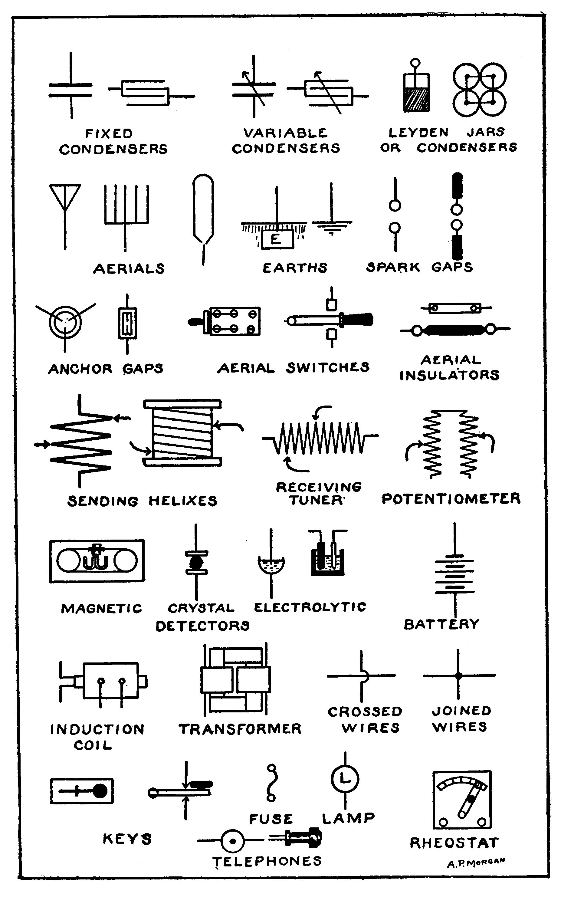
- Frontispiece. Plate I. Electrical Conventions.
- Fig 1. Hertz Oscillator and Resonator.
- Fig. 2. Hydraulic Oscillator.
- Fig. 3. "Hydraulic" Transmitter and Receptor.
- Fig. 4. Simple Wireless Telegraph Transmitter and Receptor.
- Fig. 5. Electric Waves and Lines of Strain.
- Fig. 6. Resonance Tube.
- Fig. 7. Lag and Lead.
- Fig. 8. Tuned Hydraulic Transmitter and Receptor.
- Fig. 9. Tuned Wireless Telegraph Transmitter and Receptor
- Fig. 10. Long-distance Receiving Set.
- Fig. 11. Murdock Receiving Set.
- Fig. 12. Clapp-Eastham Receiving Set.
- Fig. 13. Prague Receiving Set.
- Fig. 14. Receiving Set.
- Fig. 15. Receiving Set.
- Fig. 16. Murdock Transmitting and Receiving Set.
- Fig. 17. United Wireless Portable Outfit.
- Plate II. Aerial Systems.
- Fig. 18. Electrose Insulators.
- Fig. 19. Guy Insulator.
- Fig. 20. Insulating Tube.
- Fig. 21. High-tension Cable and Insulator.
- Fig. 22. Flat-top T Aerial.
- Fig. 23. Ground Clamp.
- Fig. 24. Switch for Lightning Protection.
- Fig. 25. Diagram of an Induction Coil.
- Fig. 26. Induction Coil Core.
- Fig. 27. Theoretical and practical form of secondary.
- Fig. 28. Layer Winding for Small Coils.
- Fig. 29. Section Winder.
- Fig. 30. Impregnator for Silk Covered Wire.
- Fig. 31. Methods of Connecting the Secondary Sections.
- Fig. 32. Coil Case.
- Fig. 33. Simple Interrupter.
- Fig. 34. Independent Interrupter.
- Fig. 35. Details of Magnets.
- Fig. 36. Details of Moving Parts.
- Fig. 37. Details of Standard and Screws.
- Fig. 38. Diagram of Connections for an Independent Interrupter.
- Fig. 39. Construction of a Paper Condenser.
- Fig. 40. Wenhelt and Simon Electrolytic Interrupters.
- Fig. 41. Construction of Electrolytic Interrupters.
- Fig. 42. Details of Electrolytic Interrupters.
- Fig. 43. Electrolytic Interrupter.
- Fig. 44. Assembly and Dimensions of Core.
- Fig. 45. Fiber Head and Separator.
- Fig. 46. Section Form.
- Fig. 47. Methods of Connecting Sections.
- Fig. 48. Assembly of Leg.
- Fig. 49. Transformer with One Secondary removed.
- Fig. 50. Wiring Diagram.
- Fig. 51. Clapp-Eastham 1/4-K.W. Transformer.
- Fig. 52. United Wireless Motor-Generator set for supplying Alternating Current to the Transformer.
- Fig. 53. Simple Condenser.
- Fig. 54. Leyden Jar.
- Fig. 55. "Aerial Switch."
- Fig. 56. Amco Oscillation Condenser.
- Fig. 57. Clapp-Eastham Oscillation Condenser.
- Fig. 58. Methods of Varying Capacity.
- Fig. 59. Spark Gaps.
- Fig. 60. Spark Gap.
- Fig. 61. Closely Coupled Helix.
- Plate III. Transmitting Circuits.
- Fig. 62. Prague Transmitting Helix.
- Fig. 63. Closely Coupled Tuning Circuit.
- Fig. 64. Loosely Coupled Transmitting Helix and Contact Clip.
- Fig. 65. Loosely Coupled Transmitting Circuit.
- Fig. 66. United Wireless Helix, Spark Gap and Condenser.
- Fig. 67. Morse Key fitted with Extension Lever.
- Fig. 68. Wireless Key.
- Fig. 69. "United Wireless Type Key."
- Fig. 70. Connections for Aerial Switch.
- Fig. 71. Aerial Switches.
- Fig. 72. Detail of Contacts.
- Fig. 73. Details of Switch Parts.
- Fig. 74. Method of Fastening Knife.
- Fig. 75. "T" Aerial Switch.
- Fig. 76. "United" Wireless Lightning Switch.
- Fig. 77. Shoemaker Tuning Coil and Aerial Switch.
- Fig. 78. "United" Wireless Anchor Gaps.
- Fig. 79. Anchor Gap.
- Fig. 80. Simple Hot Wire Meter.
- Fig. 81. Meter with Case Removed.
- Fig. 82. Glass Compensating Strip.
- Fig. 83. Details of "Hot Wire" Supports.
- Fig. 84. Details of Movement.
- Fig. 85. Complete Movement.
- Fig. 86. Side View of Hot Wire and Movement.
- Fig. 87. United Wireless Hot Wire Ammeter.
- Fig. 88. Universal Detector.
- Fig. 89. Details of Universal Detector.
- Fig. 90. Parts of Universal Detector.
- Fig. 91. Bare Point Electrolytic Detector.
- Fig. 92. Effect of Exposing too much Wire.
- Fig. 93. Electrolytic Detector Circuits.
- Fig. 94. Electrolytic Detector.
- Fig. 95. Forming "Glass" Point.
- Fig. 96. Shoemaker Detector.
- Fig. 97. Shoemaker Detector Circuits.
- Fig. 98. Lamp Detector.
- Fig. 99. Simple Electrolytic Detector.
- Fig. 100. Electrolytic Detector.
- Fig. 101. Details of Electrolytic Detector.
- Fig. 102. Increasing the Sensitiveness of an Electrolytic Detector.
- Fig. 103. Tantalum Detector.
- Fig. 104. United Wireless Carborundum Detector (horizontal type).
- Fig. 105. United Wireless Carborundum Detector (vertical type).
- Fig. 106. Clapp-Eastham Ferron Detector.
- Fig. 107. Silicon Crystal in Cup.
- Fig. 108. Silicon Detector Circuits.
- Fig. 109. Perikon Detector Elements.
- Fig. 110. Perikon Detector.
- Fig. 111. Peroxide of Lead Detector.
- Fig. 112. Marconi Magnetic Detector.
- Fig. 113. Details of Transformer.
- Fig. 114. Method of Joining Ends of Band.
- Fig. 115. Pulley.
- Fig. 116. Pulley Bearings.
- Fig. 117. Circuit of Magnetic Detector.
- Fig. 118. Fleming Oscillation Valve.
- Fig. 119. Flame Audion.
- Fig. 120. Circuit of Flame Audion.
- Fig. 121. Double-slide Tuning Coil.
- Fig. 122. Sliders.
- Fig. 123. Double-slide Tuning Coil Circuits.
- Plate IV. Receiving Circuits. (Straightaway Aerial.)
- Fig. 124. Murdock Double-slide Tuning Coil.
- Fig. 125. United Wireless Receiving Set.
- Fig. 126. United Wireless Portable Receiving Set.
- Fig. 127. Oscillation Transformer.
- Fig. 128. United Wireless Receiving Transformer.
- Fig. 129. Details of Receiving Transformer.
- Fig. 130. Slider for Loose Coupler.
- Fig. 131. Loosely Coupled Tuning Circuits.
- Fig. 132. Combination Loosely and Closely Coupled Tuner.
- Fig. 133. Clapp-Eastham Loose Coupler.
- Fig. 134. A Highly Efficient Form of Loose Coupler.
- Fig. 135. Potentiometer.
- Fig. 136. Amco Potentiometer.
- Plate V. Receiving Circuits.
- Fig. 137. Tuning Circuit with and without an Adjustable Condenser.
- Fig. 138. Tubular Condenser.
- Fig. 139. Variable Condenser.
- Fig. 140. Details of Variable Condenser.
- Fig. 141. Sliding Plate Variable Condenser.
- Fig. 142. Types of Permanent Magnets.
- Fig. 143. Grinding Tool.
- Fig. 144. Parts of a Holtzer Cabot Receiver.
- Fig. 145. Holtzer Cabot Head Set.
- Fig. 146. Adjustable Head Band.
- Fig. 147. Marconi Station at Siasconset, Mass.
- Plate VI. DeForest and Marconi Systems.
- Fig. 148. Experimental Amateur Station of W. Haddon, Brooklyn, N. Y.
- Fig. 149. Complete Receiving Outfit Consisting of Receiving Transformer, Detector, Fixed Condenser, Loading Coil, Two Variable Condensers, Potentiometer, Battery, Switches, etc.
- Fig. 150. Receiving Outfit Consisting of Receiving Transformer, Fixed Condenser and Detector.
- Fig. 151. Amco Oscillation Helix.
- Fig. 152. Details of Oscillation Helix Construction.
- Fig. 153. Quenched Gap.
- Fig. 154. Quenched Gap.
- Fig. 155. Details of Disk and Ring.
- Fig. 156. Explanatory Drawing of Quenched Gap.
- Fig. 157. Amco Rotary Gap.
- Fig. 158. Details of Revolving Parts of Rotary Gap.
- Fig. 159. Details of Rotary Gap.
- Fig. 160. Methods of Preventing "Kick Back."
- Fig. 161. Variometer.
- Fig. 162. Silicon Detector.
- Fig. 163. Pyron Detector.
- Fig. 164. Galena Detector.
- Fig. 165. Audion.
- Fig. 166. Audion Circuit.
- Fig. 167. Rotary Variable Condenser.
CHAPTER I. INTRODUCTORY.
Being desirous of keeping this book as far as possible within the limits prescribed by the title, it is not possible to go deeply into the theory of the propagation of electric waves, but at the same time it is not deemed advisable to plunge suddenly into the construction of wireless apparatus without giving some explanation of the underlying principles.
If the reader desires information upon this subject he is referred to Fleming's "Electric Wave Telegraphy" or the same author's "Elementary Manual of Radio-telegraphy and Radio-telephony."
The explanations given in this chapter do not involve any actual theory of the transmission and reception of electric waves. They are merely intended to show the train of actions which take place and may be observed in a physical sense. With this purpose in view, several references have been made to simple hydraulic apparatus and an analogy drawn to render the explanation clearer.
The Transmission and Reception of Electric Waves.
Wireless telegraphy by means of electromagnetic waves may be divided into four distinct operations, namely:
The generation of electrical oscillations.
The transformation of electrical oscillations into electrical waves.
The transformation of electrical waves into electrical oscillations.
The detection of the electrical oscillations.
The first two operations comprise those taking place at the transmitter, while the last two, which are the converse of the first, are in evidence only when receiving.
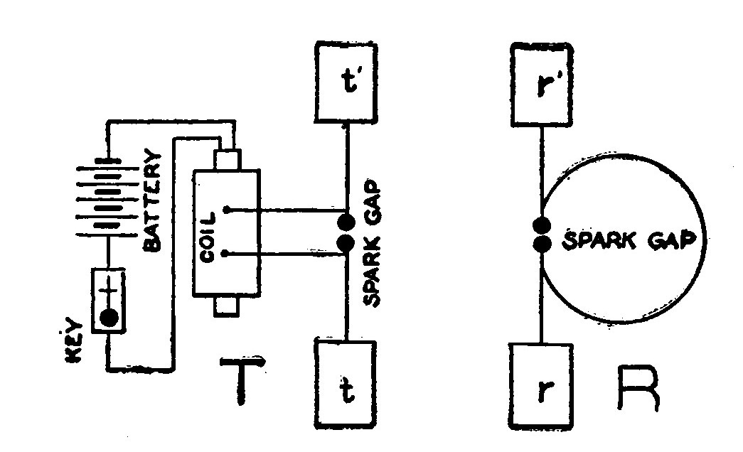
Fig. 1 illustrates the original Hertz oscillator and resonator, which is the simplest form a wireless installation may take. T represents the transmitting apparatus and R the receptor. At the transmitting station a telegraph key is placed in series with a battery and an induction coil. Two large metal plates, t and t', are connected to the opposite sides of the spark gap, which in turn is connected to the secondary of the induction coil. When the key is pressed the electrical circuit is completed and the voltage of the battery is raised sufficiently by the induction coil to charge the metal plates t and t'.
The key serves to break the current into periods corresponding to the dots and dashes of the telegraph code. When the high voltage of the induction coil is impressed upon the plates they become charged, and being of opposite polarity, when at a maximum the energy rushes across the gap and produces a disruptive spark. Each discharge, although appearing like a single spark passing in one direction, is in reality made up of a large number of rapid oscillations or surgings. The first passage of current serves to more than discharge the plates and they become charged in the opposite direction. A reverse discharge then occurs which also oversteps itself, and thus the oscillations go on, but gradually become weaker and weaker until they die completely or are damped out. The heated air of the spark gap becomes a conductor during the passage of the spark, and the oscillations are enabled to surge back and forth at the rate of 15,000 to 1,000,000 per second, although the actual discharge may take only a fraction of a second.
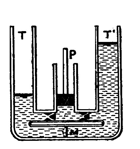
The generation of electrical oscillations may perhaps be made more clear by reference to the hydraulic apparatus illustrated in Fig. 2. T and T' are communicating tubes divided by an elastic membrane M. The tubes may be likened to the metal plates t and t' or the arms of the oscillator. The membrane may be likened to the layer of air between the knobs which separates the opposite arms of the oscillator. P is a pump connected to the two tubes T and T', and the broken lines in the apparatus represent water. The pump corresponds to the induction coil in Fig. 1, and the water to the secondary currents of the induction coil. When the pump is set in operation, the water is drawn from the tube T and injected into T'. The pump valves prevent it from flowing back. When the level becomes very high in T', the great pressure distends the membrane in the direction shown by the dotted line until finally it bursts and the water is allowed to flow with a rush into the tube T. But the inertia of the water causes it to rise higher in the tube than its final position of equilibrium, while in returning and endeavoring to seek its level its inertia carries it below this position. Thus the water oscillates back and forth until finally it comes to rest.
Similarly the difference of potential of the oscillator arms is not immediately equalized upon the breaking down of the air gap, and the apparatus becomes the seat of extremely rapid electrical oscillations, as explained above.
All space is supposed to be filled with a highly attenuated, invisible and weightless medium called ether. When the electrical oscillations surge back and forth through the arms of the oscillator, portions of the energy are thrown off from the apparatus and travel in enlarging circles like the ripples on a pond. These consist of lines of dielectric stress or electrostatic flux which pass through the ether and constitute electromagnetic waves.
The receptor or resonator R, Fig. 1, consists of a circle of wire having in it a small spark gap capable of minute adjustment. Two metal plates r and r' are sometimes attached to the opposite sides of the spark gap. When the key is pressed at the transmitting station and waves are sent out through the ether, they strike the resonator and set up therein electrical oscillations which pass across the gap in the shape of sparks.
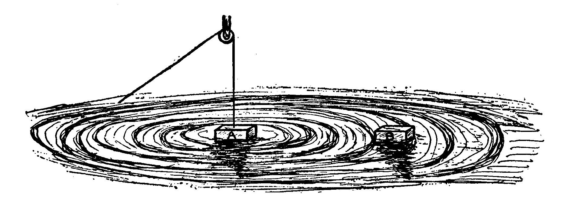
To make the explanation clearer, let us consider Fig. 3 in which two floats or blocks of wood are represented as resting on the surface of a tank or pool of water. One float, A, is connected by a rope and pulley so that by jerking the rope the float may be made to oscillate and cause little ripples or waves to pass outwards in a gradually enlarging circle. When the waves reach the float, B, they cause it to rise and fall with each wave or to oscillate and reproduce the movements of the float, A. Likewise the oscillations set up by a wireless transmitter are sent out into space to be caught and duplicated at the receiving station. Of course this analogy to the propagation and reception of electric waves is not the same as the true electrical actions, but is merely a graphical, representation.
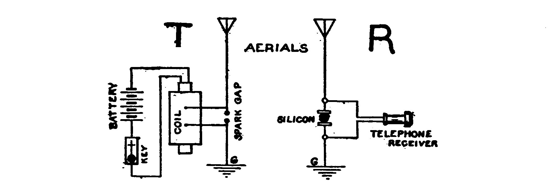
The wireless telegraph outfit illustrated in Fig. 1 would not serve for more than short distances of a few feet, and so a somewhat similar but more efficient apparatus is employed in practice. Fig. 4 shows such a system in its simplest form. In this case the secondary or high potential leads of the induction coil are connected, one to an earth and the other to an aerial or antenna composed of a number of bare copper wires insulated and suspended from a mast.
All electrically charged bodies are surrounded by an electrostatic field of force, the nature of which in theory is a state of strain.
The action of an induction coil connected as in Fig. 4 is to charge the upper part of the aerial above the spark gap, say with negative electricity and establish a field of force in its vicinity varying in area from a few feet to several miles. When the charge reaches a certain potential it is sufficient to puncture the layer of air in the gap and a spark takes place, setting up electrical oscillations.
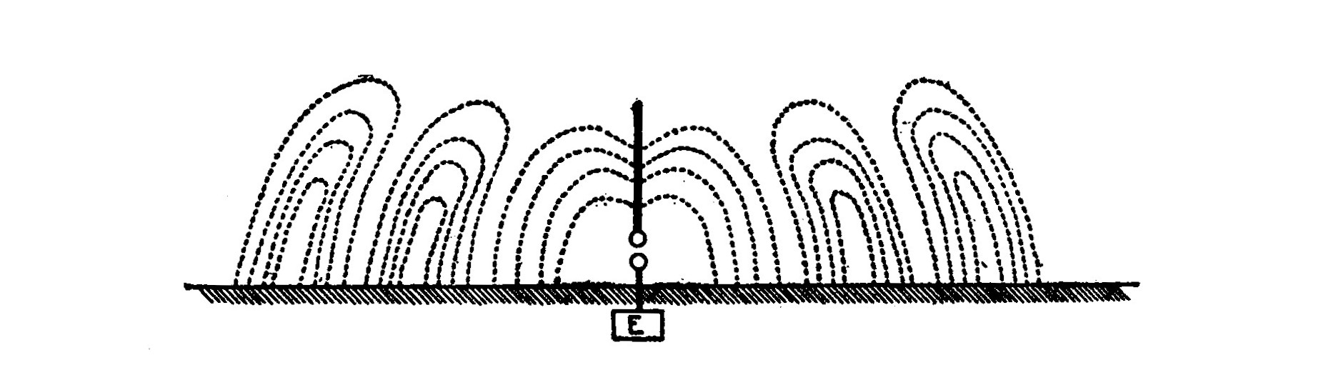
Previous to the rupture of the spark gap, lines of electric strain or force stretch from the aerial to the earth on all sides as in the center of Fig. 5. A line of force may be defined as a curve drawn in the electric field so that the direction of the curve is the same as that of the electric intensity at that point.
The aerial and the earth act like the two metal plates in Fig. 1 or like the opposite plates of a condenser. As soon as the air gap is punctured it becomes conductive and the aerial charge rushes down into the earth. With the discharge, the strain in the electrostatic field is released and the aerial charge rushes down into the earth, but in so relaxing produces a new current and builds up a strain around the antenna opposite in direction to the first. This process repeats itself very rapidly and electrical oscillations are thus set up in the antenna. Every oscillation changes the direction of the magnetic flux or dielectric strain and causes the imaginary lines which originally stretched from the aerial to the earth to be displaced and the ends terminating at the aerial to run down it and form semi-loops or inverted "U's" standing with their ends on the earth in a circular ripple around the aerial and moving away from it with the speed of light. In Fig. 5 three oscillations are supposed to have taken place. The shortest distance between two adjacent points at which the electric strain is at a maximum in the same direction and period of time is the wave length emitted by the aerial. The separate standing groups of dielectric strain moving away from the antenna are electromagnetic waves. In the figure, the adjacent groups are separated by half a wave length. These waves are emitted at right angles to the transmitting aerial, whence they pass through the ether to the other station. When they reach the receiving aerial they set up electrical oscillations therein which are too weak to be perceptible in the shape of sparks as in the original Hertz oscillator and resonator because of the great distance separating the stations, so they are made to flow through a detector, which in Fig. 4 is represented as being a crystal of a mineral called silicon. When the high frequency currents strike the silicon, they set up a weak pulsating direct current. This action is due to a peculiar rectifying property of the mineral. The direct current flows through the telephone receiver and produces an audible sound. If the aerial and ground were connected directly to the terminals of the telephone receiver, without the silicon, the oscillations would not pass because of the impeding or choking action of the electro-magnets in the telephone receivers.
Tuning.—It is sometimes desirable that messages should be made selective or secretive. It is obvious that if there were several large stations in the same neighborhood they could not all operate at the same time unless some means of preventing the stations from receiving more than one message at a time were possible. This is the object in view of the so-called "tuning" of wireless telegraphy. It also accomplishes a second purpose which is perhaps considered more important than the first. The length of the aerial may be too great or too short for the amount of energy and the length of the waves which it emits or receives. When this is the case, the oscillations are quickly damped out and do not generate very powerful waves or produce strong signals at the receiving station and thus by properly adjusting the circuit all undesirable messages may be cut out as well as the signaling range greatly increased. Every electrical circuit has a definite period or electrical length, determined by its inductance and capacity. A circuit emits waves of only one length for given values of inductance and capacity, and must also be of a certain length before it will respond to waves sent out by another transmitter. The careful adjustment of a circuit to emit or receive a given wave constitutes tuning.
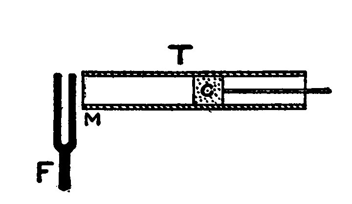
This may be made more clear by the comparison of an electrical circuit with a column of air. Fig. 6 represents a cross section of a glass tube, T, lying in a horizontal position and containing a cork, C, which can be slid to various positions. By adjusting the cork we are able to obtain various depths of air in the tube from its open end, M, to the cork, C.
When a vibrating tuning fork, F, is held opposite the open mouth and the cork slid back and forth it is found that the sound of the tuning fork is greatly increased in volume at a certain position of the cork. If the cork is then removed from this position the sound decreases in intensity. When the cork is in such a position that the sound of the fork is reenforced, we have secured resonance. When in this condition and the prong of the vibrating fork is moving toward the open mouth of the tube a "condensed" pulse of air travels down the tube and back again, having been reflected at the cork and reaching M just as the prong of the fork begins its excursion away from the open mouth of the tube. When the prong of the fork is moving away from M a "rarefied" pulse of air moves from M to C and back again by the time the prong is ready to begin its next vibration. When the tube is not in resonance, the successive condensations and rarefactions passing up and down the air column interfere with one another and decrease instead of increase the sound of the tuning fork.
If we substitute the sound waves emitted by the tuning fork for high frequency oscillations and the air column for the electrical circuit we may readily see that by adjusting its length, resonance can be produced. If the length of the air column is measured it will be found that the reenforcing of the sound of the fork reaches a maximum when the depth of the air column is one-fourth of the sound wave length given by the fork. Likewise resonance is produced in wireless telegraphy when the length of the circuit is approximately one-fourth the length of the waves. Vice versa, the wave emitted from an ordinary closed circuit transmitter is approximately four times the length of the aerial wire. For example, an aerial 25 meters long will emit waves having a length in the neighborhood of 100 meters.
As stated above, tuning is accomplished and resonance or syntony established by varying the inductance and capacity of the circuit. The capacity of a circuit may be defined as its relative ability to retain an electrical charge, while inductance is the property of an electric circuit by virtue of which lines of force are developed around it.
Capacity and inductance are opposite or reactive in their effects upon a circuit. If the value of one is decreased the influence of the other in increased. Fig. 7 and the following explanation will serve to illustrate this.

Alternating currents do not always keep step with the voltage impulses of a circuit. If there is inductance in the circuit, the current will lag behind the voltage, and if there is capacity, the impulses of the current will lead. Fig. 7 A illustrates the lag produced by inductance and B the lead produced by capacity. In A the impulses of the current, represented by the full line, occur a little later than those of the volts as represented by the dotted line. In B the effect is just the opposite and the current leads. These reactive effects of inductance and capacity are very pronounced with the high frequency currents of wireless telegraphy, and, as stated before, are the factors which determine the period of the circuit.
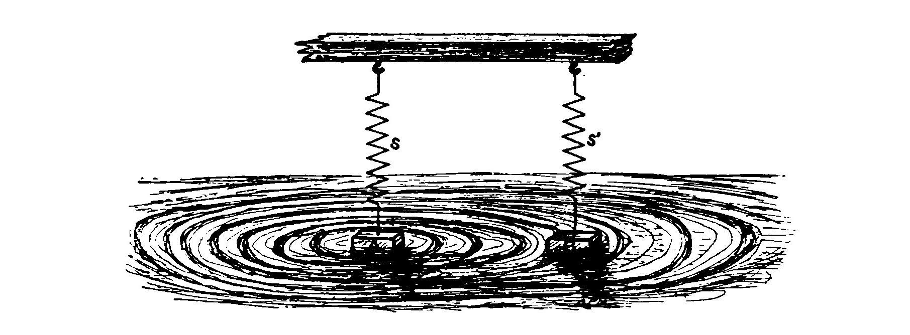
Tuning is represented graphically in Fig. 8. The two floats A and B are not only resting on the surface of a pool of water as in Fig. 3 but are also suspended from the springs S and S'. The springs will have, like a pendulum, a definite time of rising and falling, or period of oscillation, depending upon their length. If we strike the float A the spring will cause the float to rise and fall at a definite rate and send out a little wave or ripple with every oscillation. If the springs S and S' are of the same length, the float B will be caused to oscillate with every wave sent out by A, for, the periods of the springs being equal, B will be permitted to rise with a wave and fall again just in time to be raised by the next oncoming ripple. On the other hand, if the springs are of different lengths, B may only rise slightly and in falling meet an oncoming wave which will cause it to rise before it has reached its lowest point and so dampen or weaken its oscillations that they either do not become very strong or are entirely obliterated. Thus several floats having different periods of oscillation might be sending out ripples in the same pool, and the float B could be made to respond to any of them by adjusting the length of the spring.
We may also see in this illustration the part that tuning plays in causing the apparatus to emit or receive more powerful impulses. When the rope in the untuned apparatus illustrated in Fig. 3 is jerked, the block A oscillates only once or twice before a new jerk is required to keep it in motion. In Fig. 8 it is quite the contrary, for when an impulse has been given to the float A it will oscillate much longer than the untuned float before it requires to be set in motion again. Likewise the float B in Fig. 8 will oscillate longer and more powerfully than the float B in Fig. 3, when once it has been set in motion.
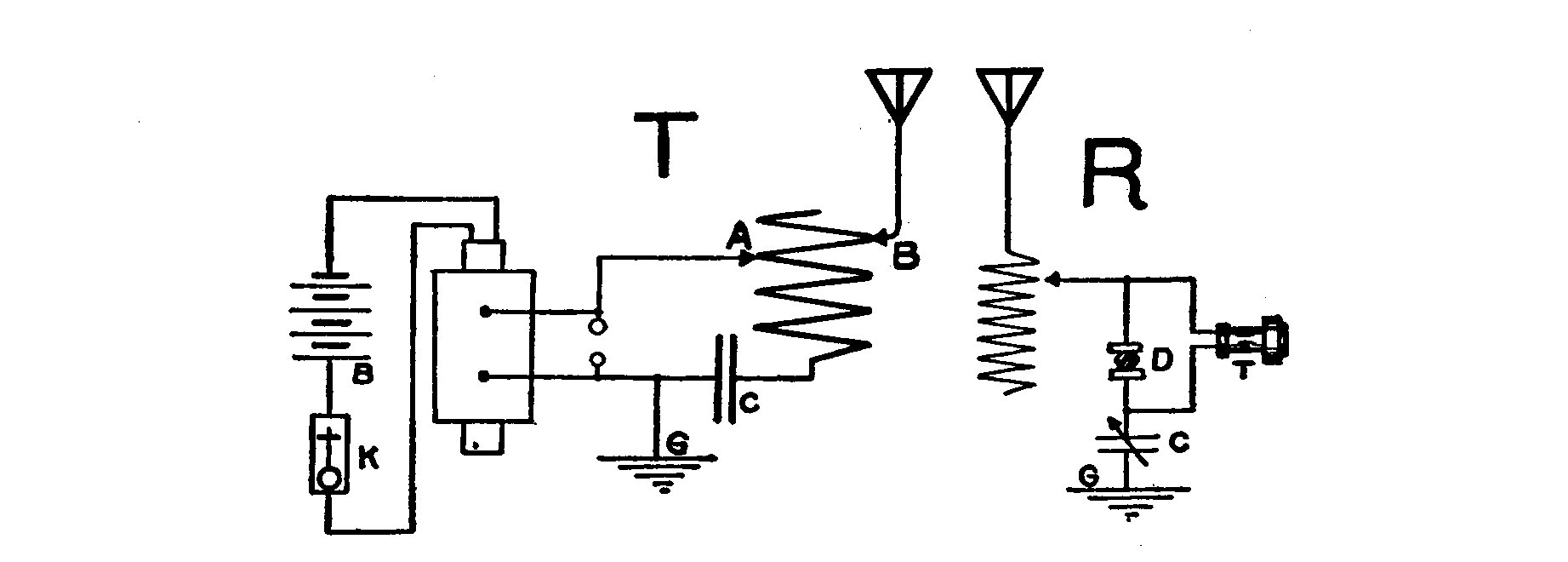
Fig. 9 shows a diagram of a simple wireless telegraph system employing an inductance and capacity for tuning the circuits. When the induction coil is in operation it charges a condenser. The condenser discharges through the sending helix and across the spark gap. The sending helix is merely a spiral coil of wire of large diameter, and constitutes the greater part of the inductance in the circuit. Two movable contacts, A and B, make connections with the helix. The spark gap, condenser and lower portion of the helix up to the movable contact A are known as the closed circuit. By shifting A, more or less inductance may be included in the closed circuit until resonance is secured. The aerial, the inductance from the contact B down, the condenser and the ground compose the open circuit. By varying the contact B more or less inductance may be included in the open circuit and its period altered until the oscillatory currents of both circuits flow in the same period of time. The closed and open portions of the transmitting helix form an auto transformer, and the voltages of the open circuit are raised above those of the closed circuit.
The tuned receptor shown in Fig. 9 is the simplest form possible and is known as the single slide system. The tuning coil or helix is much longer in proportion to its diameter than the sending helix, and is made of finer wire, since it does not carry such heavy currents. When the contact is slid up or down on the tuning coil, the inductance of the circuit is varied. Since the oscillating currents in the receiving aerial have the same frequency as those in the radiating aerial, the receptor must have the same relative values of inductance and capacity. This condition is obtained by varying the slider until the signals in the telephone receivers are the loudest.
In practice more than one sliding contact is used, and these together with adjustable condensers make the circuit more complicated. These devices are necessary because oscillations may be forced on a receptor by a near-by transmitter unless other precautions than the "single slider" are taken. Such circuits are illustrated in Plates IV and V. With them it is possible to obtain a considerable degree of selectivity and "tune out" an undesirable message.
CHAPTER II. THE APPARATUS.
It is generally the receiving apparatus which first attracts the attention of the amateur operator, and so it will be considered first here. An efficient receiving set consists of some form of Detector, Tuning Coil, Telephone Receivers, and Condenser.
Other accessories such as adjustable condensers, potentiometer, battery and testing buzzer improve the outfit and make it more complete.
The choice of the type of instruments must be left entirely to the person who is constructing them. His resources will determine whether he is to use 1,000 ohm telephone receivers built especially for wireless work or ordinary ones having a resistance of only 75 ohms. It is therefore best to read carefully the chapters devoted to the different pieces of receiving apparatus and select the type of detector, tuning coil, etc., which it is desirable to use before commencing the construction of any.
For beginners, I would recommend an outfit consisting of a silicon detector, a double slide tuning coil, a condenser of fixed capacity and 75-ohm telephone receivers. Such an outfit with a 50-foot aerial will receive messages about 150 miles. If 1,000 ohm telephone receivers are used, messages may be read up to 400 miles. Much depends upon the location of the station and the ability of the operator.
A more elaborate and efficient set consists of an electrolytic or "Perikon" detector, a transforming tuner, two adjustable condensers, a potentiometer and a pair of 1,000 ohm telephone receivers. This outfit and a 75-foot aerial could be made to receive 500 to 1,000 miles by a careful operator.
Several cuts of wireless apparatus built for private installation are shown both in this chapter and further through the book, to give an idea of how the better instruments of this type are constructed and finished.
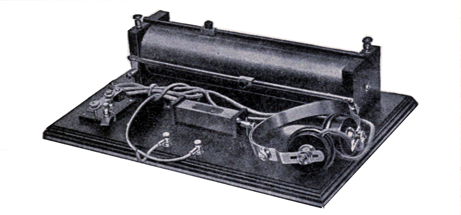
Fig. 10 illustrates a selective receiving set built by the Long Distance Wireless Company. The set is mounted on a mahogany base and the instruments are finished in polished hard rubber and lacquered brass. They comprise a detector stand so arranged that any of the sensitive minerals used in wireless work may be used. The tuning coil is of the double slide type. The condenser is sealed up in a square lacquered brass tube fitted with hard rubber ends and binding posts. The arrangement and construction of the outfit may be readily understood from the cut.
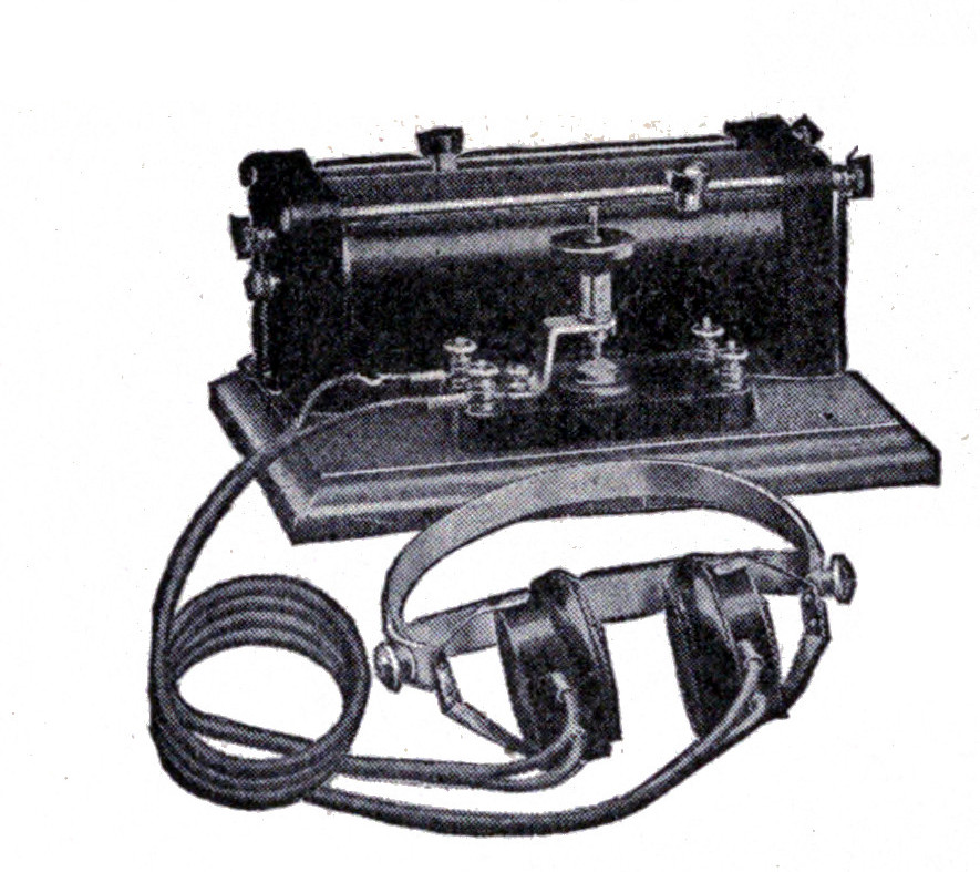
Fig. 11 illustrates a receiving set manufactured by the Wm. J. Murdock Company. The tuning coil is fitted with hard rubber composition ends and is wound on a special core which is not affected by temperature changes. The detector is of the crystal type and is of rather unique construction, since the small fixed condenser is mounted in the base of the detector itself.
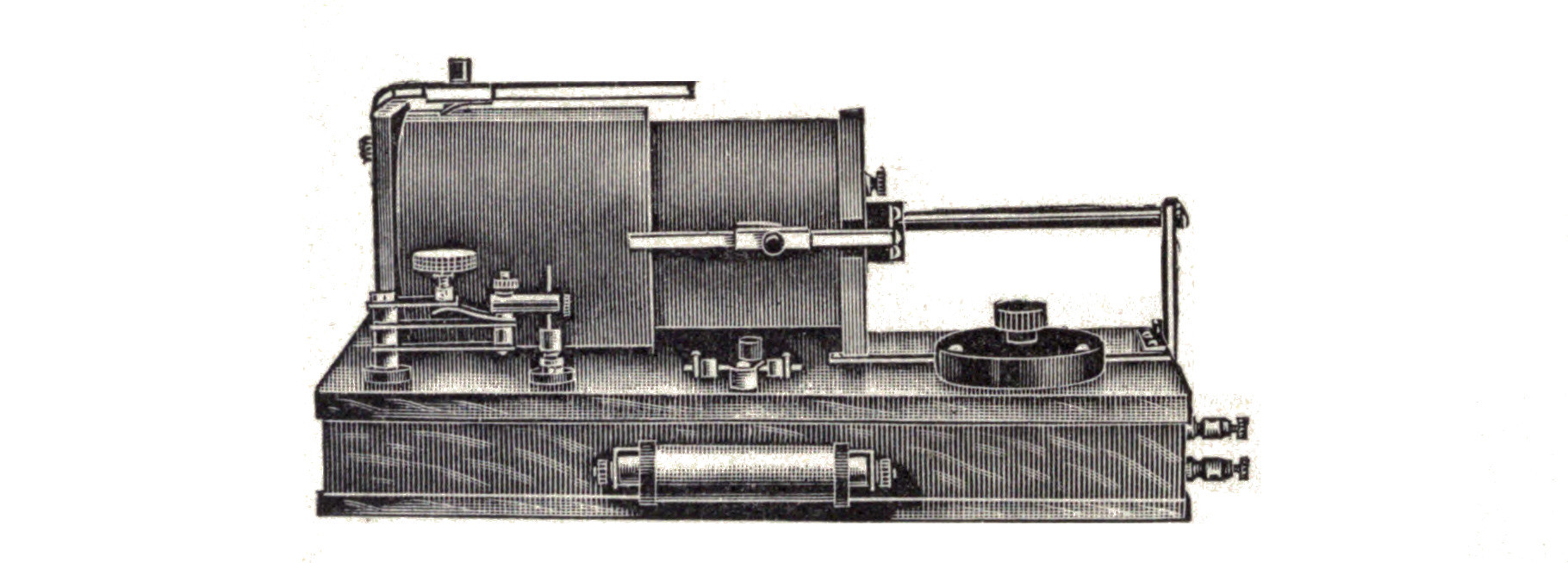
The Clapp-Eastham set in Fig. 12 employs a receiving transformer which makes great selectivity possible. The detector is mounted at the left-hand side of the outfit. A very sensitive mineral called "Ferron" is used in the detector. The fixed condenser is enclosed in a brass tube fitted with hard rubber ends and is located on the front of the base, directly in the center. A variable condenser of the rotary type is placed at the right-hand corner.
The Prague Electric Company manufacture the apparatus shown in Fig. 13. The cabinet is mahogany and is fitted with a hard rubber cover. A fixed condenser and a double slide tuning coil are mounted within the cabinet. The sliders of the tuning coil project through two long slots in the cabinet. A universal detector mounted on top of the cabinet is so designed that any material may be experimented with or tested.
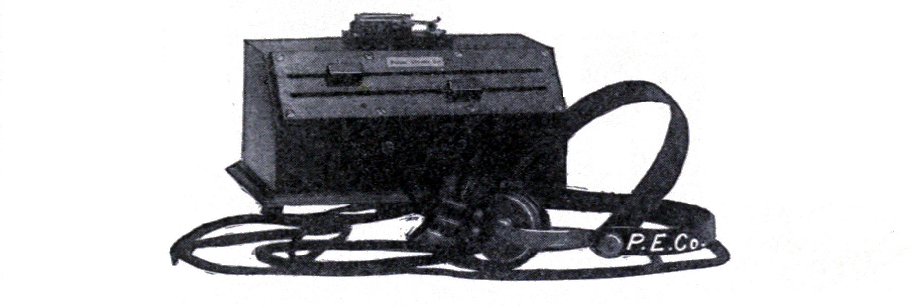
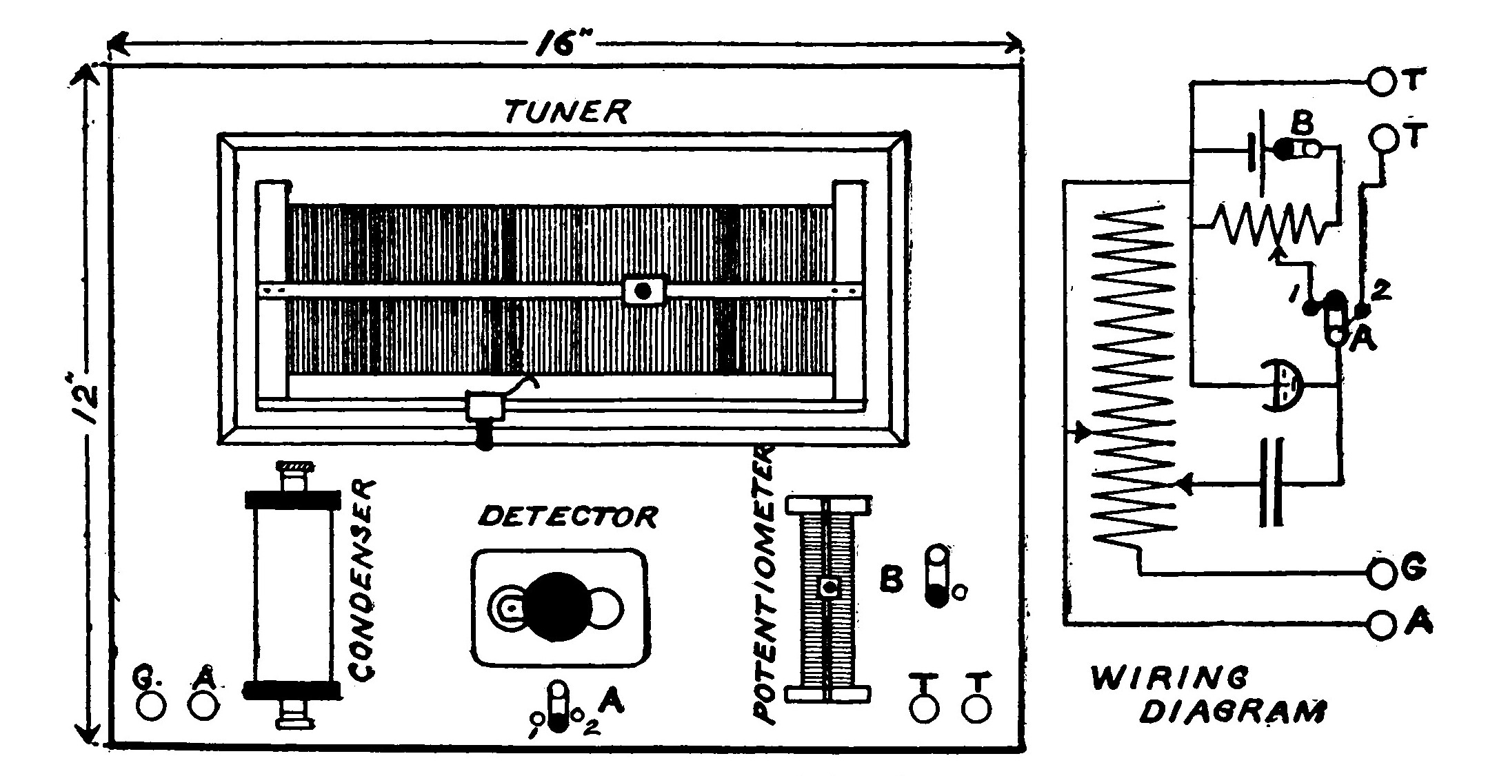
Fig. 14 shows a receiving set built up from apparatus described in this book. The cabinet is 12 x 16 inches and 4 inches deep. The wood should be 1/2 inch thick, and in order to present a good appearance is preferably of mahogany. As mahogany is sometimes very hard to procure and expensive, some may find red birch an excellent substitute. When stained with a mahogany stain it presents a fine appearance.
Varnishing and polishing are wasted time when applied to the average amateur's instruments in view of the rough handling and scratching which they receive. The best plan is to stain the wood with an oil stain and give it a wax finish. An oil stain contains no varnish but is merely coloring matter and oil. A good coat should be applied with a wide brush and the surplus stain immediately wiped off by rubbing the whole surface with a piece of cheesecloth. As soon as the stain is thoroughly dry the wood is waxed.
Cut up some beeswax into fine shreds and place it in a jar. Pour some turpentine over the beeswax and let the mixture stand for five or six hours, giving it an occasional stir. Allow it to stand further if necessary until the wax melts and then add enough turpentine to give the mixture a consistency similar to that of thick cream. Apply the preparation to the wood with a rag, and then rub with a piece of clean cheesecloth until the finish is hard and dry. Waxing produces a gloss which is not so bright as a French polish but yet is more durable and not so easily scratched or marred.
A double slide tuning coil made as described in Chapter XIV is mounted on top of the cabinet in the rear. A "universal" detector is mounted in the center, directly in front of the tuning coil. A tubular condenser of fixed capacity is placed on the left-hand side of the detector, and a potentiometer on the opposite side. A double point switch placed directly in front of the detector enables the potentiometer to be brought into play when a battery is used. Four binding posts are mounted on the front of the cabinet. The ground and aerial are connected to the left-hand pair and the telephone receivers to those on the right hand. The wiring diagram is shown also in Fig. 14. By placing the switch A on contact 1, the potentiometer is brought into use. When on contact 2, the potentiometer is cut out. The switch B must be opened when the detector is not in use so as not to run down the battery.
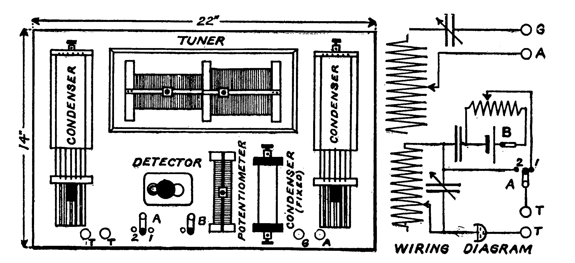
Fig. 15 shows a receiving set somewhat similar to that shown in Fig. 14 but more elaborate and efficient. The cabinet in this case measures 14 x 22 inches and is 6 inches deep. A loosely coupled or transforming tuning coil is used in place of the closely coupled double slide type. Two variable condensers are mounted on either side of the tuning coil. The detector and potentiometer occupy the space directly in front of the tuning coil, while a fixed condenser is placed at their right. The two switches for breaking the battery circuit and disconnecting the potentiometer are in front of the detector. The aerial, ground and telephone receiver leads are connected to binding posts mounted on the front of the cabinet.
The batteries, in both cases, are placed inside the cabinet. The details and construction of all the separate instruments will be found in the respective chapters as denoted by the titles.
Transmitting Range.—A simple transmitting outfit capable of sending about two miles consists of the necessary batteries, a one-inch spark induction coil, a small zinc spark gap and a key. The connections of such a transmitting outfit are shown in Fig. 4.
If the same coil is used with a transmitting helix and a condenser, the range may be increased from 3 to 5 miles.
A 1 1/2-inch spark induction coil using a condenser and a transmitting helix will send about 10 miles, and a 3-inch coil under the same conditions about 20 miles. A 4 and a 6 inch coil will transmit about 30 and 40 miles respectively.
The one quarter kilowatt transformer with a helix and four two-quart leyden jars or an equivalent condenser will transmit at least 50 miles with a suitable aerial. Used as a one half kilowatt transformer with a helix and eight two-quart leyden jars, it will send about 100 miles.
Of course, as in the case of the receiving outfits, these distances are approximate and depend upon the location of the station, the nature of the ground over which the messages are transmitted, the kind of receptor used at the receiving station and the efficiency of the operator himself.
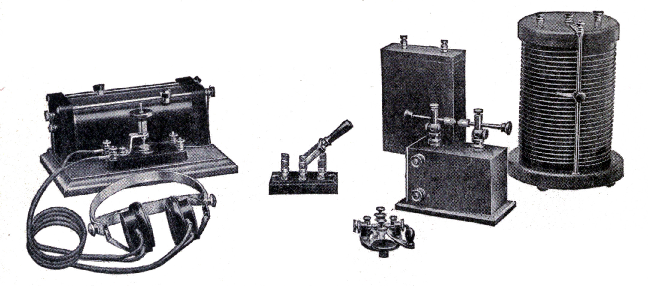
Fig. 16 illustrates a complete Murdock transmitting and receiving set. The transmitting outfit consists of a 15-watt induction coil giving about a one-inch spark, a sending helix, oscillation condenser, a key and a double pole double throw switch for changing the antenna and ground from the transmitting to the receiving instruments or vice versa. The spark gap is mounted on top of the coil. The receiving outfit is the same as that illustrated in Fig. 11.
A complete wireless station—outside of the aerial consists primarily of a source of electrical energy, a transformer or induction coil for charging the oscillation condenser, an oscillation condenser, a transmitting helix, a key for breaking the primary current, a spark gap, an aerial switch, a hot wire ammeter for tuning the transmitting circuits, a detector, a receiving tuner, auxiliary tuning apparatus such as fixed and variable condensers, a potentiometer and battery, and a pair of telephone receivers with a headband.
Other apparatus such as switches, insulators, anchor gaps, testing buzzers, reactance coils, grounding switches, etc., have been described in various places throughout the book and their use suggested whenever it is of any advantage.
The choice of transmitting instruments, as with the receiving apparatus, is left entirely with the experimenter so that he may suit his ideas and means. Wherever possible the range and power of the instruments have been given and suggestions made as to the other apparatus which should be used in connection with them so that the completed outfit will bear some sense of proportion.
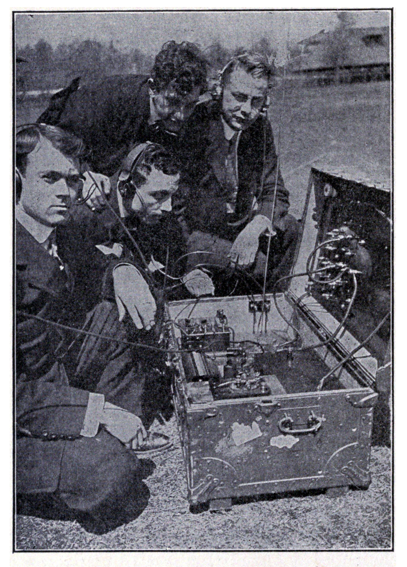
Fig. 17 illustrates the portable wireless telegraph set manufactured by the United Wireless Telegraph Company for army service and exploring expeditions or isolated camps. The aerial and the mast can be unloaded, erected, and all parts be ready for operation in fifteen minutes. The mast is made of interchangeable wooden sections. The current for the transmitter is furnished by a portable storage battery. The whole outfit is capable of furnishing efficient service for distances of 25 to 30 miles.
CHAPTER III. AERIALS AND EARTH CONNECTIONS.
The aerial or antenna ordinarily consists of a number of wires elevated in the air to emit or intercept the Hertzian waves. In fitting up a wireless station the location and erection of an aerial are of prime importance, and the successful reception and transmission of wireless messages will depend largely upon its condition.
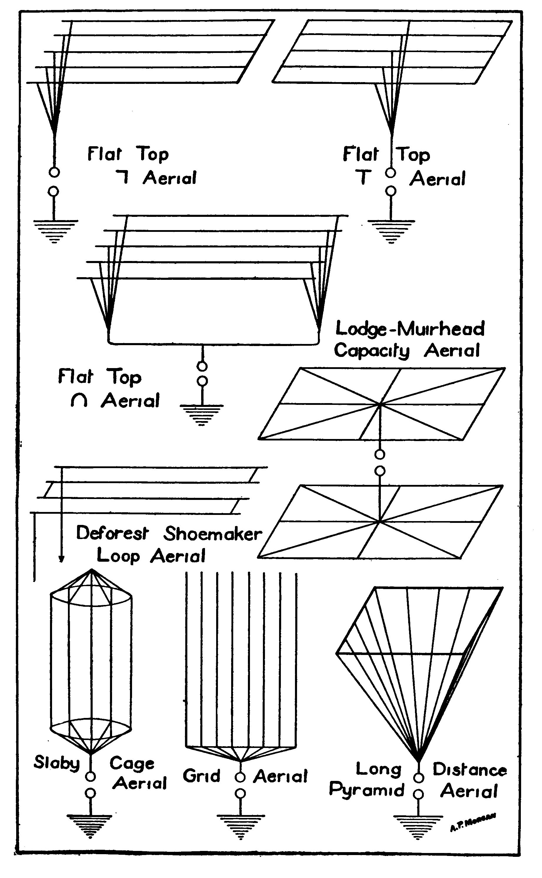
A few years ago the wireless antenna consisted of a metal plate high in the air and having a wire suspended from it, but to-day usually exists in one of the forms illustrated in Plate II.
The higher an aerial is placed above the surface of the earth, the wider will be its electrostatic field, and consequently more powerful electrical waves will be developed. But after a height of 180-200 feet is attained, the engineering difficulties and the expenses increase so rapidly that few stations exceed it. Other things being equal, the increased range in transmitting varies as the square of the height of the radiating wires. For example, a 25-foot aerial capable of transmitting one mile theoretically will send waves 16 miles if made 100 feet high. The actual ratio is often greater, but much is dependent upon the many meteorological conditions.
After the limit in a vertical direction has been reached, the only remaining possibilities are to increase the surface and spread out horizontally.
The flat top aerials are used on shipboard or wherever it is an advantage to suspend the wires between two masts.
They are especially recommended for amateur use, since they need not be so high as the other aerials, to be efficient. The flat top aerials are directive, that is, they receive or radiate waves better in certain directions. The bent or inverted L type is one of these and exhibits a preference for waves coming from a direction opposite to that in which its free end points. This directive action of an inverted L antenna may be somewhat lessened if the leads are taken off at the center and it is made a T aerial. This is the most common form of flat top aerial in use on ships.
The inverted U type is not used extensively because the two opposite leads or rat-tails make a centrally located operating room necessary. The loop aerial is used by the United Wireless Company, in both their ship and land stations. This type of aerial is well adapted to long waves and close tuning.
The Lodge-Muirhead capacity aerial does not make use of a ground and is rarely seen in this country. Lately the United States Signal Corps have applied it to their balloons where an earth connection would be impossible. The upper part of the balloon is covered with a network of wires which serves as the upper aerial, and a second system of wires is suspended below the balloon to take the place of the ground. By this means they have had little difficulty in establishing successful communication between the balloons and the earth.
The pyramid aerial is the type used by Marconi in long-distance ultra-powerful stations, but is debarred from extensive installation on account of the large cost of erection.
The cage and grid aerials are of the vertical type and are excellent where a high support to elevate them can be secured. They are at present used principally by the Massie and Stone Companies.
The desirable feature of an aerial is a quantity known as its electrostatic capacity and is measured by the charge required to raise its potential one unit. An increase in capacity enables more energy to be accumulated in the antenna, and consequently greater radiation results. The capacity of an aerial may be increased by adding wires, but must not be carried too far or the transmitting apparatus will not be able to raise its potential sufficiently. Owing to an effect caused by mutual induction between the wires, the lines of strain are not distributed symmetrically, and the capacity will not vary directly but rather approximately as the square root of the number of wires. In order to decrease this action and use the surface most efficiently, the wires should not be placed nearer than one-fiftieth of their length and preferably farther apart.
The materials used for the insulation and suspension of an aerial must be reliable, so that in event of bad weather the station will not lose energy or be put out of working order because the aerial blew down.
Porcelain cleats or a string of porcelain insulating knobs make inexpensive insulators. The standard insulator for wireless telegraph work is the "Electrose" insulator. These are made of a molded composition, and have iron rings set firmly in the ends so that they can withstand a very heavy strain. Hard rubber is undesirable for an aerial insulator because it becomes carbonized and covered with a conducting layer.
High frequency currents permeate copper wire only about one three-hundredth of an inch, and so, in order to increase the surface and decrease the resistance, it is best to make the aerial of stranded wire. A phosphor bronze wire for this purpose which is very flexible but still does not sag or stretch, is composed of 7 strands of No. 20 B. S. gauge. Such a wire 150 feet long suspended vertically and insulated from the earth will have a capacity of from 0.0003 to 0.0004 of a microfarad.
The aerial must receive very particular attention if the station is one kilowatt or over in power. In that case stranded wire is necessary. The insulation of the aerial must be as thorough as possible, and proximity to large conductors such as smokestacks, telephone lines, etc., avoided. Rope stays and guys are advisable in order to prevent dissipation of energy. If wire stays must be used they should be divided up at frequent intervals by insulators.
Fig. 19 illustrates a guy insulator used by the United Wireless Telegraph Company. It is made of two strips of well paraffined wood separated by two porcelain knob insulators.
Copper wire is the most desirable for an aerial. Iron wire must never be used unless it is very heavily galvanized, and even then it is not to be recommended. Aluminum wire is undesirable except for kite sustained aerials. When used on an aerial and exposed to smoke and other fumes it becomes quickly coated with a layer of oxide. All connections made in aluminum wire must be soldered. This necessity may be better understood when it is explained that electro-magnets on dynamos, etc., are sometimes wound with bare aluminum wire and that the natural coating of oxide on the wire is sufficient insulation to separate the turns.
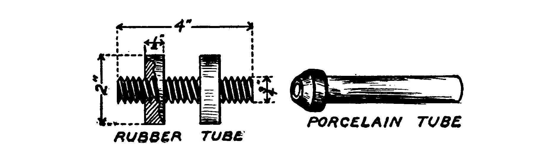
Where the aerial enters the building in which the instruments are located it must be very carefully insulated. The simplest method is to bore a hole through the wall and push a porcelain tube through it. The rat-tail or leading-in wire is then passed through and the interstices between it and the tube poured full of melted paraffin.
The best method is to bore a hole in the window pane and pass the wire through a hard rubber insulating tube. Fig. 20 shows such a tube. It is three-quarters of an inch in outside diameter and has an internal bore of three-eighths of an inch. The tube is threaded throughout its entire length. Two hard rubber flanges inch thick and 2 inches in diameter are threaded to screw on the tube. The tube is inserted in the hole in the window pane and the flanges screwed on either side. If a soft rubber washer is placed between the hard rubber flanges and the pane there will be less likelihood of cracking the glass. The leading-in wire is then passed through the tube. The hole in the window pane may be bored by using a copper tube having an external diameter equal to that of the required hole. The tube is set in a brace and used like an ordinary bit, but must be kept well smeared with emery and oil or else it will not cut.
This method of leading in the rat-tail is the only one to be recommended if the transmitter is one-quarter kilowatt or over in power.

The lead-in should be anchored just outside of the window so as to relieve the glass pane and the tube from all strain. Pirelli cable or the high-tension cable which is used for the secondary wiring of an automobile is the best conductor to use for the aerial in the interior of a building. The way to lead it over the ceiling is to support it on a porcelain cleat similar to that shown in Fig. 21.
Many are under the erroneous impression that four times the length of the aerial is the wave length which the station will emit. This is only at the best a very rough approximation, for many undeterminable factors such as the nature and location of surrounding objects, trees, etc., so affect the capacity and inductance of the aerial that the wave length must be determined empirically after the aerial is in operation.
The standard wave length of the United States Navy for ship installations is 425 meters. An inverted L aerial, calculated before erection to have a wave length as near as possible to this, has the following dimensions: Four horizontal stranded phosphor bronze wires (7 strands No. 20 B. S.) each 160 feet long and spaced 5 feet apart, four vertical wires 85 feet long and a 35-foot rat-tail.
It is always desirable that the wave length should be as long as possible, for the waves will then travel farther and are not absorbed to such an extent by trees, etc. The absorption due to trees is said to vary as the fourth power of the frequency.
It is sometimes very convenient to calculate the strain on insulators or masts caused by a horizontal antenna. This is easily found by the following equation:
P equals L² x W/8S
where P is the required strain in lbs., W the weight in lbs. per foot of aerial, L the length of the aerial and S the sag of the wire in feet.
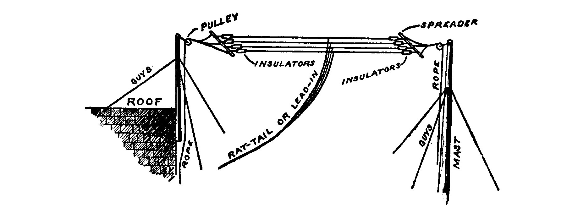
When erecting an aerial, it is best to fasten a pulley at the top of the supporting mast and hoist the aerial up after the pole is in position. Then in case the wires become twisted or broken they may be lowered and repaired without any difficulty.
Erection of an Aerial.—The average amateur aerial is generally from 40 to 60 feet high and supported at one end by a short pole placed on the house and at the other end by a mast set in the ground or lashed to a tree. Fig. 22 illustrates such an arrangement whereby a flat-top T aerial is supported at one end by a short pole fastened to the house and at the other end by a pole set in the ground.
The flat-top loop aerial is preferred by some amateurs and it is to be recommended for receiving but is an inefficient radiator. When this type of aerial is used the two leading-in wires should be connected to a switch so that when the switch is closed they are connected. The aerial may then be used as a straight-away aerial for transmitting, and by opening the switch, as a loop aerial for receiving. This precaution is advised when a loop aerial is to be used with a low-powered induction coil as a transmitter, for otherwise there will be a loss of energy at the anchor gap.
A large aerial is of no advantage when used with a small transformer or induction coil because it cannot become properly charged.
To erect a flat-top T aerial, first select its location. If possible take advantage of two trees and lash a short pole in the top of each, so that the aerial may be raised up clear of the leaves. Another good plan is to erect a pole at each end of the house. In any case, the distance separating the poles must not be greater than three times the height above ground or the directive action of the aerial will be very pronounced. An aerial 50 to 60 feet high should have a length of from 80 to 100 feet. Stranded wire is no advantage for receiving, but must be used if the transmitter is other than a small induction coil.
Secure two spruce sticks about 2 inches in diameter and 10 feet long. Fasten an insulator 6 inches from each end of the spars and two more each 3 J feet from the ends. This arrangement will separate each of the four wires which compose the aerial by three feet.
The two spars are then laid on the ground at a distance apart equal to the desired length of the aerial. Four wires, either stranded or No. 12 B. S. gauge copper, are cut to equal lengths and fastened to the corresponding insulators. The middle of each wire is found and a long copper wire soldered to it. These four wires constitute the rat-tail or lead-in. They should be of the same length, and are not connected together until they are about to enter the building. A short rope tied to each end of the spars and fastened to the rope which passes over the pulley on the top of the pole, serves as a bridle to prevent the aerial from twisting. The aerial is then hoisted up but allowed to hang slightly slack.
There is considerable difference of opinion among experts as to whether or not the ends of the horizontal wires should be connected, and it is impossible to say with good reason which method is better. However, when erecting a flat top aerial, exercise every care to make all the wires of exactly the same length.
An aerial of the size and type just described will send and receive the following distances.

These distances are only approximate and will vary with the efficiency of the operator and the location of the station.
When any of the transformers described later are used, the aerial should be 80 to 100 feet high. In this case the last named receiving outfit will have a range of from 500 to 1,000 miles.
Ground Connections.—The importance of a good earth or ground connection can hardly be overestimated. Whenever possible commercial stations are located on moist ground or near a body of water so that a good ground may be secured by imbedding zinc or copper plates in the earth or water. A ground on shipboard is easily secured by fastening a conductor to one of the ship's plates.
If the ground connection is poor, the natural period of the oscillation circuit is made irregular and short, so that the currents are choked in passing in and out of the earth. The result is an undesirable rise of potential at the lower end of the aerial and often harmful sparking at the ground connection. The transmitting and receiving ranges of a station are very considerably reduced through a poor earth.
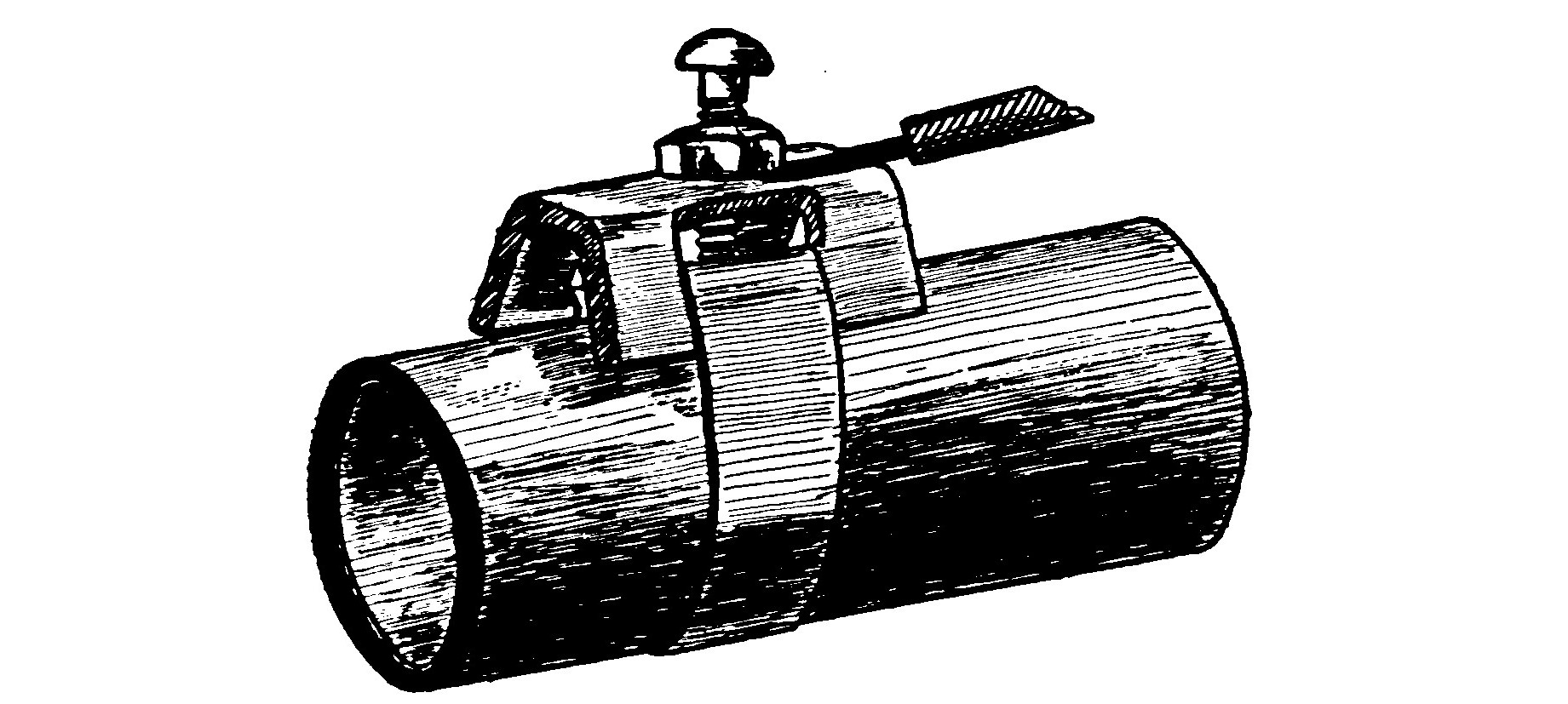
Ground connection can often be obtained in the country by immersing metal plates in a well or a cistern. Where connection is made to a water supply pipe some sort of a ground clamp should be used to insure a good contact.
An efficient earth for portable outfits may be quickly formed by spreading a large area of wire netting over the ground.
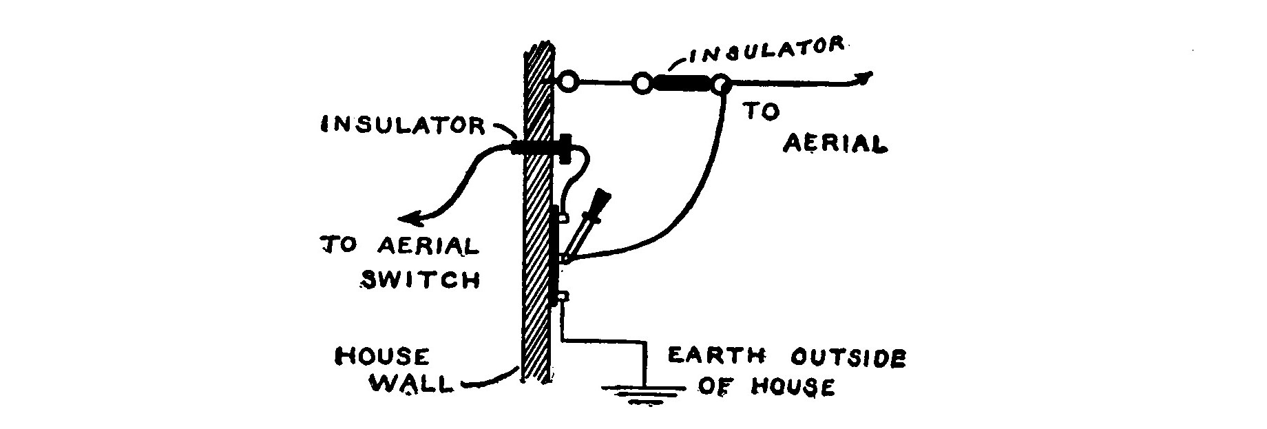
Proper precautions for protection against lightning by grounding the aerial outside of the building should be taken.
The wisest plan is to install a heavy single pole double throw switch outside of the building where the rat-tail enters. The knife of the switch should be connected to the aerial, one contact to the house lead and the other to a heavy wire grounded on the outside of the building as in Fig. 24. When the apparatus is not in use the aerial should be grounded by throwing the switch on the grounded contact.
The rulings of the National Board of Fire Underwriters governing this class of work are appended below.
"1. Aerial conductors to be permanently and effectively grounded at all times when the station is not in operation by a conductor not smaller than No. 4 B. S. gauge copper wire, run in a direct line as possible to water pipe on street side of said water pipe within the premises or to some other equally satisfactory earth connection.
"2. Aerial conductors when grounded as above specified must be effectually cut off from all apparatus within the building.
"3. Or the aerial to be permanently connected at all times to earth in the manner specified above, through a short gap lightning arrester; said arrester to have a gap of not over .015 of an inch between brass or copper plates not less than 2 1/2 inches in length, parallel to the gap, and 1 1/2 inches the other way, with a thickness of not less than one-eighth of an inch, mounted on non-combustible, non-absorptive insulating material of such dimensions as to give ample strength. Other approved arresters of equally low resistance and equally substantial construction may be used.
"4. In cases where the aerial is grounded as specified in paragraph 1, the switch employed to join the aerial to the ground connection shall not be smaller than a standard 100-ampere jack-knife switch.
"Notice of wiring done for these installations should be sent to the Board, the same as for all other work."
CHAPTER IV. INDUCTION COILS.
Some means of charging the condenser which produces the oscillatory discharge is necessary. An induction coil is the most practical for the amateur.
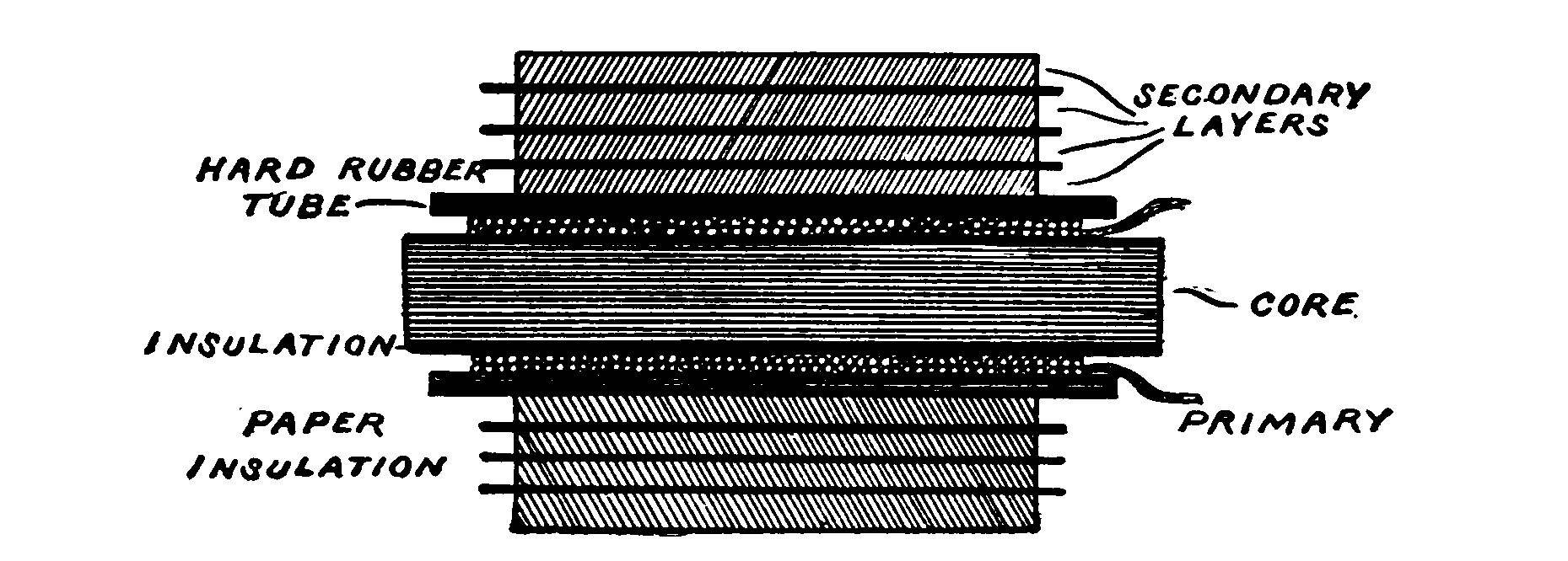
The induction coil consists of a primary coil of wire wound around a central iron core and surrounded by a secondary coil consisting of many thousand turns of carefully insulated wire. The primary coil is connected to a source of direct current which also includes an interrupter to "make" and "break" the current in rapid succession. Every "make" of the circuit and consequent magnetization of the core induces a momentary inverse current in the secondary, and every "break" and corresponding demagnetization a momentary direct current. Normally, the induced currents would be equal, but by means of a condenser shunted across the interrupter the circuit when "made" requires considerable time for the current and magnetization of the core to reach a maximum value, while when broken the demagnetization and current drop are nearly instantaneous. The value of the induced electromotive force in a circuit varies as the speed at which the magnetic lines of force cut the circuit, and so the induced e.m.f. at "break" is thus rendered high enough to leap across a gap in the shape of sparks.
The formulas connected with induction coils depend upon conditions which are never met in actual practice and cannot be relied upon. To construct a coil of a given size, it is necessary to use dimensions obtained empirically. Therefore it is well for the amateur to stick closely to lines and hints which are given here or which appear in some up to date book on induction coil building.
For a long time the induction coil was an expensive, inefficient instrument, until wireless telegraphy demanded of it more rigid and efficient design and construction. It was the aim of manufacturers to produce the longest possible spark length with a minimum amount of secondary wire. As a result of this demand, wireless coils are now made with a core of large diameter and give heavier and thicker sparks. The secondary in this case is short and uses wire of large cross section in order to reduce the resistance and minimize the heating.
No one part of an induction coil may be developed to its maximum efficiency without seriously influencing and lowering the efficiency of the other parts. The following suggestions regarding the construction are given that they may prove a useful guide to the amateur coil builder. The parts will be considered in their natural order of construction.
Core.—Some experimenters not quite familiar with the principles of magnetism reason that if an induction coil were provided with a closed core as the transformer, the efficiency of the coil would be materially increased. But this is not so, for the magnetization and demagnetization of the iron cannot take place rapidly enough in a closed core when an interrupted direct current is employed in place of an alternating current.
The core of an induction coil is therefore always straight. For the same reason, it is never solid but is made up of a bundle of soft iron wires in order that rapid changes in magnetism may take place. The wires are always of as high a permeability1 as possible so as to create a strong magnetic field. Swedish or Russian iron of a good quality is the best, as its hysteresis2 losses are small. The smaller the diameter of the wire the less will be the eddy current losses and heating, but the permeability is also rendered less and the core will not be so effective, as the amount of iron is thereby decreased and the oxidized surface increased. No. 22 B. S. gauge wire is the best size for the average core.
Wires of a good quality may be purchased already cut to various lengths. To buy them in this form will save a great deal of the labor required in building a core. If the wires are not quite straight they may be straightened by rolling them, one at a time, between two boards. It is best to reanneal the wires in the following manner. Place them in an iron pipe and plug the ends of the pipe with clay. Then lay it in a coal fire until the whole mass attains a red heat. The fire is then allowed to die out gradually with the pipe and wires remaining in the ashes until cool. When cool remove them from the pipe and rub each one with emery paper until bright. After this cleaning, the wires are dipped in hot water and dried. They are then dipped in a good quality of varnish and allowed to dry again.
The varnish serves to interpose resistance to the eddy currents generated in the core and renders the losses due to this cause much less. A strong paper tube having an internal diameter equal to the diameter of the finished core is made by rolling the paper on a form and cementing with shellac. When perfectly dry. the tube is removed and the wires tightly packed in it. The following table gives the core dimensions for practical coils of different sizes.
Primary Winding.—The ratio of the number of primary turns of an induction coil to the number of secondary turns bears no relation to the ratio of the primary and the secondary currents. It has been found in practice that two layers of wire wound tightly on the core constitute the best primary. The primary should always be thoroughly shellacked or covered with insulating varnish. Since there is almost no ventilation in the primary the wire must be large enough to avoid all heating. A table containing the various sizes of primary wires is given below.
In large coils, the inductance of the primary causes a "kick back" and sparks are liable to pass between the adjacent turns. For this reason, it is always well to use double cotton covered wire and to further thoroughly insulate it by soaking the primary and core in a pan of melted paraffin and allowing them to harden therein. Afterwards the pan is slightly warmed to loosen the cake of paraffin and the excess of wax removed by scraping with a blunt instrument so as not to injure the wires. Paraffin contracts upon hardening, and the proper method to impregnate a porous substance is to allow it to soak and become set in it upon cooling.
A good method of reducing the "kick back" and also the size of the condenser shunted across the interrupter is to form the primary of a number of turns of smaller wire in parallel, the effect being to give a conductivity equal to a single wire of large diameter and at the same time to make a more compact winding of the primary on the core. This method of winding is very desirable in large coils, as it reduces the cross section of the primary and allows the secondary to be placed nearer the core, where the magnetic field is the strongest.
The primary winding ought to occupy nearly the whole length of the core, since there is no gain in carrying the end of the core very far beyond the end of the primary, for most of the magnetic lines of force bend at the end of the primary and return without passing through the extreme ends of the core.
Insulating Tube.—The successful operation of an induction coil without breaking down when under strain depends largely upon the insulating tube which separates the primary and secondary. Hard rubber tubes are perhaps the best. A tube may be easily built up of several layers of 1/2-inch sheet hard rubber by steaming it so as to soften it and then wrapping it around a form. The tube should fit the primary tightly and be about one inch shorter than the core. After the tube is in place it is poured full of beeswax and rosin in order to fill all interstices and prevent sparks due to the condenser effect of the windings from jumping from the inside of the tube to the primary.
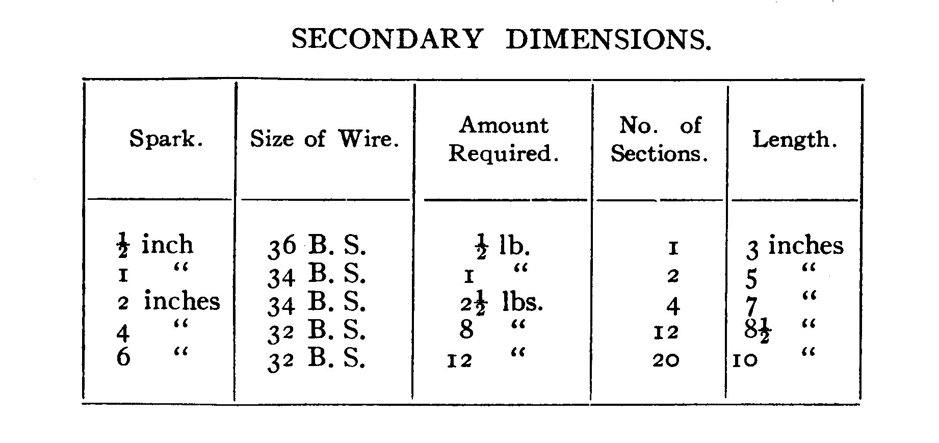
Secondary.—A coil used as a wireless telegraph transmitter must have wire of large cross section in its secondary so as to obtain a heavy disruptive discharge. Numbers 34 and 32 B. S. are generally used for small coils and numbers 30 and 28 B. S. for large coils. Silk covered wire is the usual practice, but enameled wire is coming into use. Cotton covered wire takes up too much space and has poorer insulating qualities.
Enameled wire is insulated by a coating of cellulose acetate, which has a dielectric strength of about twice that of cotton and takes up much less room than silk. There is, then, with enameled wire a great saving in space, and a greater number of turns may be placed on the secondary without increasing its mean distance from the core. The following table shows the comparative diameters of silk and enamel covered wires suitable in size for use on the secondaries of induction coils.
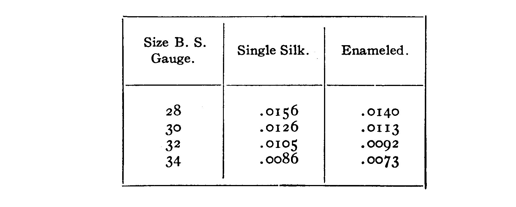
In winding enameled wire it must be taken into consideration that the insulation of enameled wire is rigid and has no give. Consequently, to allow for expansion, enameled wire must be more loosely wound than fiber or silk covered wire. The occasional insertion of a layer of paper in winding will give room for expansion and at the same time not add greatly to the diameter.
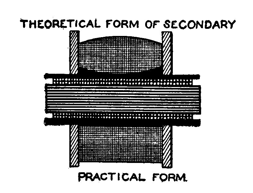
The length of the secondary is generally not much more than one-half the length of the core. Coils giving sparks up to 2 inches in length may be wound in two sections or in layer windings, but the layer winding is not recommended for coils giving sparks over one inch. It is best in a coil of this kind to insert an occasional layer of paper. The paper should be well shellacked or paraffined and be of a good grade of linen. It should project about one-quarter of an inch from the ends of the secondary as shown by the sectional drawing in Fig. 28.
This insertion of paper increases the insulation and renders the liability of sparks jumping from layer to layer much less, as is the case when the layers are very long.
The secondaries of large coils are made up of "pies" or "pancakes" from one-eighth to three-eighths of an inch in thickness. The "pies" are separated from each other by a triple thickness of blotting paper which has been thoroughly dried and then soaked in melted paraffin. In cutting the blotting paper, much labor may be saved if a metal template of the required size is first cut from sheet brass and then laid on the blotting paper, which is cut by scoring around the edge of the template with a sharp knife.

The "pies" are wound in a bobbin or form such as is shown in Fig. 29.
The disks or flanges are made of sheet brass and mounted on an arbor so that the form may be placed in a lathe or some other contrivance for revolving it. The core is beveled in order to facilitate the removal of a completed "pie" from the winder. The flanges of the winder are clamped against the core by two nuts placed on either side. The "pie" is removed by unscrewing one of the nuts and removing one of the flanges.
In winding silk covered wire it is first passed through a mixture of beeswax and rosin or a bath of melted paraffin. The excess of wax is removed by passing the wire through a slit made in a pad of paper or by rubbing against a piece of felt. Fig. 30 shows such a contrivance.
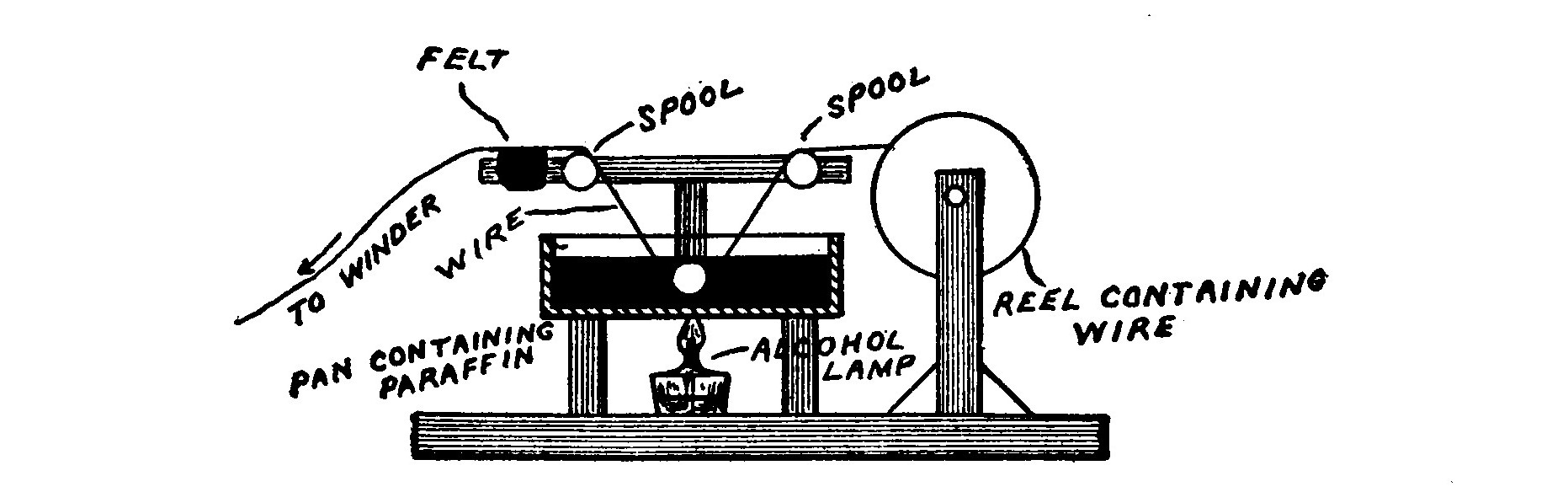
The wire passes from the reel over an ordinary spool down into the pan of paraffin, out of the paraffin, over another spool, and rubs against a piece of felt to remove the surplus paraffin. The spools are mounted with a screw and a washer so that they will turn without friction.
The wire is guided, when winding, by the fingers. If it is wrapped with a piece of felt and held between the thumb and forefinger it will run without friction and not cut the fingers. It is necessary that the wire should be closely watched for kinks, etc. which would cause the wire to break. Oftentimes the wire is broken but is held together by the insulation. Therefore each "pie" should be tested for continuity when completed. This is best accomplished by means of a galvanometer and battery. All imperfect "pies" should be rejected, as one of them would cause serious trouble if embodied in the coil. In soldering the secondary wires, acid must not be used as it soon corrodes the fine wires. Rosin is the best flux for this purpose. When building a small coil with a "layer" winding it is absolutely necessary that the wire should be wound on in smooth even layers. In a built-up secondary having "pies" not greater than 1/4 inch in thickness such great care is not necessary.
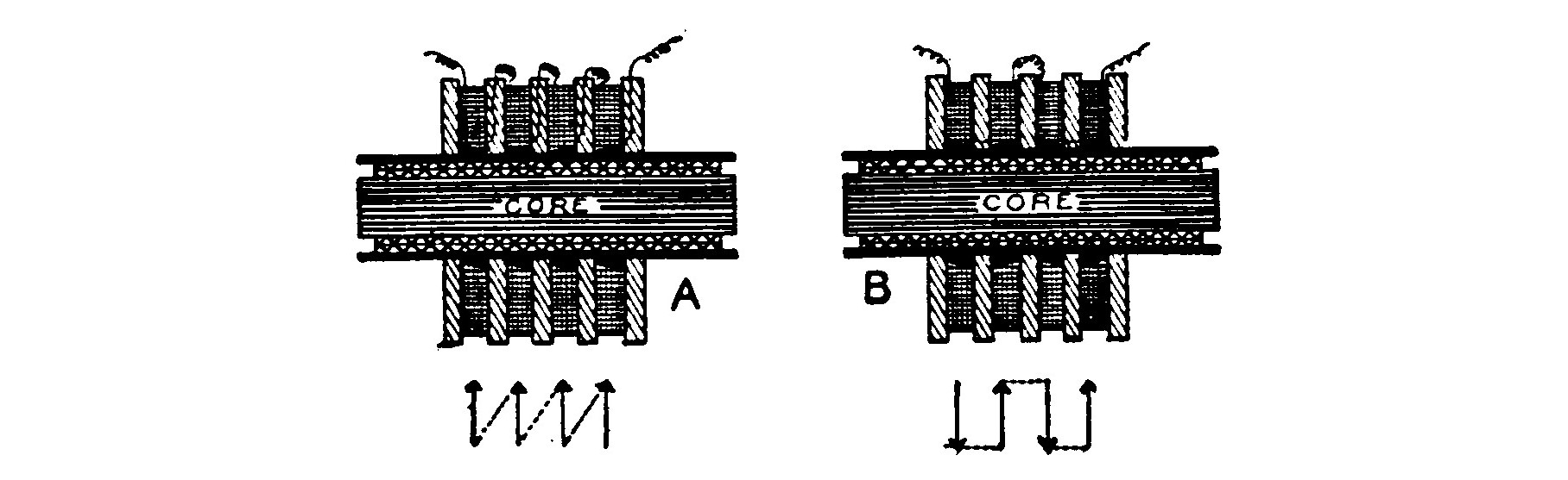
Fig. 31 shows the methods of connecting up the pies or pancakes. In A, the inside of one section is connected to the outside of the next, and so on. The maximum voltage which can exist between the adjacent sections in this case is equal to the e.m.f. generated by one "pie" and is equal throughout. In B, the coils are connected alternately inside and out. The voltage ranges from zero at the points where they are connected, to a value equal to twice the e.m.f. developed by one section. It would seem that there would be a saving in insulation space of one-half in the first case, but it is not so since the connecting wire passes between the "pies" and therefore the insulation must be twice as thick or exactly equal to that in the second case. The latter method (Fig. 31 B) is the best and most convenient. When the "pies" are connected in this manner the current must flow through alternate sections in opposite directions. To accomplish this it is not necessary to wind every alternate coil in an opposite direction, but merely to turn them around and connect them with the direction of their windings reversed as shown by the arrows and the bevels in Fig. 31. The connections between the sections must be very carefully soldered.
After the secondary is assembled the coil should be placed in a tight receptacle or tank containing melted paraffin. The tank is then connected to an air pump or aspirator and the air exhausted. The diminution of pressure causes any air bubbles in the windings to expand and be pumped out. After standing a while, the pressure of the atmosphere is readmitted and the place of the bubbles will be occupied by paraffin which has been forced in under pressure.
Mounting.—A coil for wireless work is best mounted as shown in Fig. 32 and used with an independent interrupter. The coil may then be placed under the operating table or on the wall, out of harm's way, and the interrupter on the table, where it is handy to the adjustment of the operator.

The case is simply a rectangular hardwood box large enough to contain the completed coil. Two binding posts mounted on the side of the box connect with the primary winding and two on the top of the box lead to the secondary terminals. The box is filled with boiled oil or melted paraffin and sealed up by screwing on the lid. If desirable, the secondary binding posts may be mounted on the top of a short piece of hard rubber rod as illustrated in the drawing.
| [1] | Magnetic permeability is the conducting power for lines of magnetic force. |
| [2] | See hysteresis under Magnetic Detector. |
CHAPTER V. INTERRUPTERS.
We now come to what is the greatest source of trouble and annoyance in an induction coil, namely the interrupter. Too much importance cannot be attached to this instrument, for upon it depends largely the satisfactory working of the coil. The operation of an induction coil and the part played by the interrupter were fully explained in the chapter on induction coils.
An adjustable interrupter is necessary for large coils, that is, one not only whose speed may be governed, but also the time and duration of the break.
The rapidity of oscillation of a mechanical interrupter is a very different thing from the speed of break. The ideal speed of break is instantaneous. In wireless telegraphy, very faint signals are heard more distinctly in telephone receivers if the rate of interruption at the station sending them is high. The human ear is somewhat more sensitive to sounds higher than those ordinarily produced in the telephone receivers of a wireless receptor. This seems to argue the use of a high-speed interrupter to make and break the current. But the effect on the coil must also be considered.
In the first place, where a condenser is shunted across the terminals of the secondary as is the case with a wireless transmitter, a high-speed interrupter would be very likely to set up harmful oscillations in the secondary of the coil itself.
Second, if too fast, the rise and fall of the secondary currents will be caused to run into each other, since the break will occur before the primary current has reached a maximum and the reverse secondary current has died away.
Third, the diameter of the core of a wireless coil is generally much larger than that of the ordinary coil, and if a very rapid interrupter is employed there is not time enough to properly magnetize the core before the current is broken.
Fourth, the strength of the losses in the core caused by the eddy currents and hysteresis are proportional to the interruptions in the primary circuit and therefore a low speed will be the most efficient. A rapid interrupter requires a higher voltage and amperage than the same interrupter run at a lower speed.
These are some of the reasons why it is very desirable to use an atomic interrupter or one so adjustable that the rate of the time and duration of the "make" and "break" may be closely regulated. An ideal interrupter is designed to give the longest time possible after contact is established and before the "break" occurs.
It does not pay to construct an interrupter for an induction coil giving sparks up to 2 inches in length. The type of interrupter in use on automobile coils is perfectly well adapted to small coils, and may be purchased complete with the platinum points for as low a price as $1.50.
The mechanical break described below is designed so that various adjustments are possible and it may be adapted to almost any coil. Since it is independent, it need not be mounted directly on the coil, but may be placed in the position most convenient to the operator for adjustment. The interrupter will not operate coils well on an electromotive force above 30 volts, for the excessive voltage causes a spark at the contacts when the circuit is broken and prolongs the decadence of the primary current.
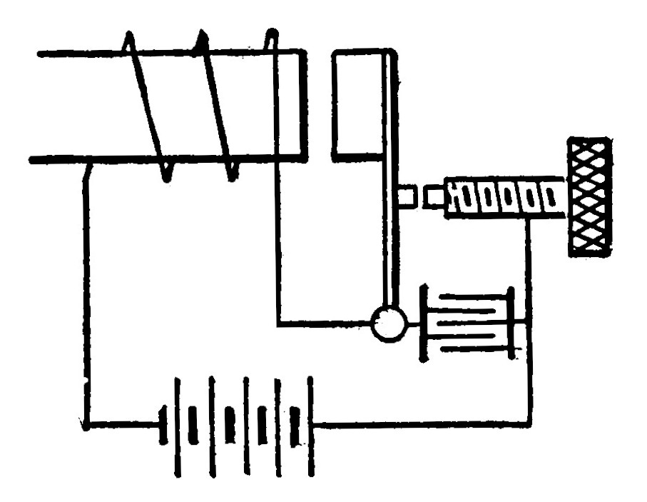
Independent Atomic Interrupter.—Fig. 34 illustrates two views of the interrupter. Current is furnished to the electromagnets by a six volt battery independent of the source supplying the coil. The interrupter is set in operation by closing the circuit breaker on the aerial switch. When the primary circuit of the transmitter is then completed by pressing the key, the coil will respond immediately because the interrupter is already in vibration.
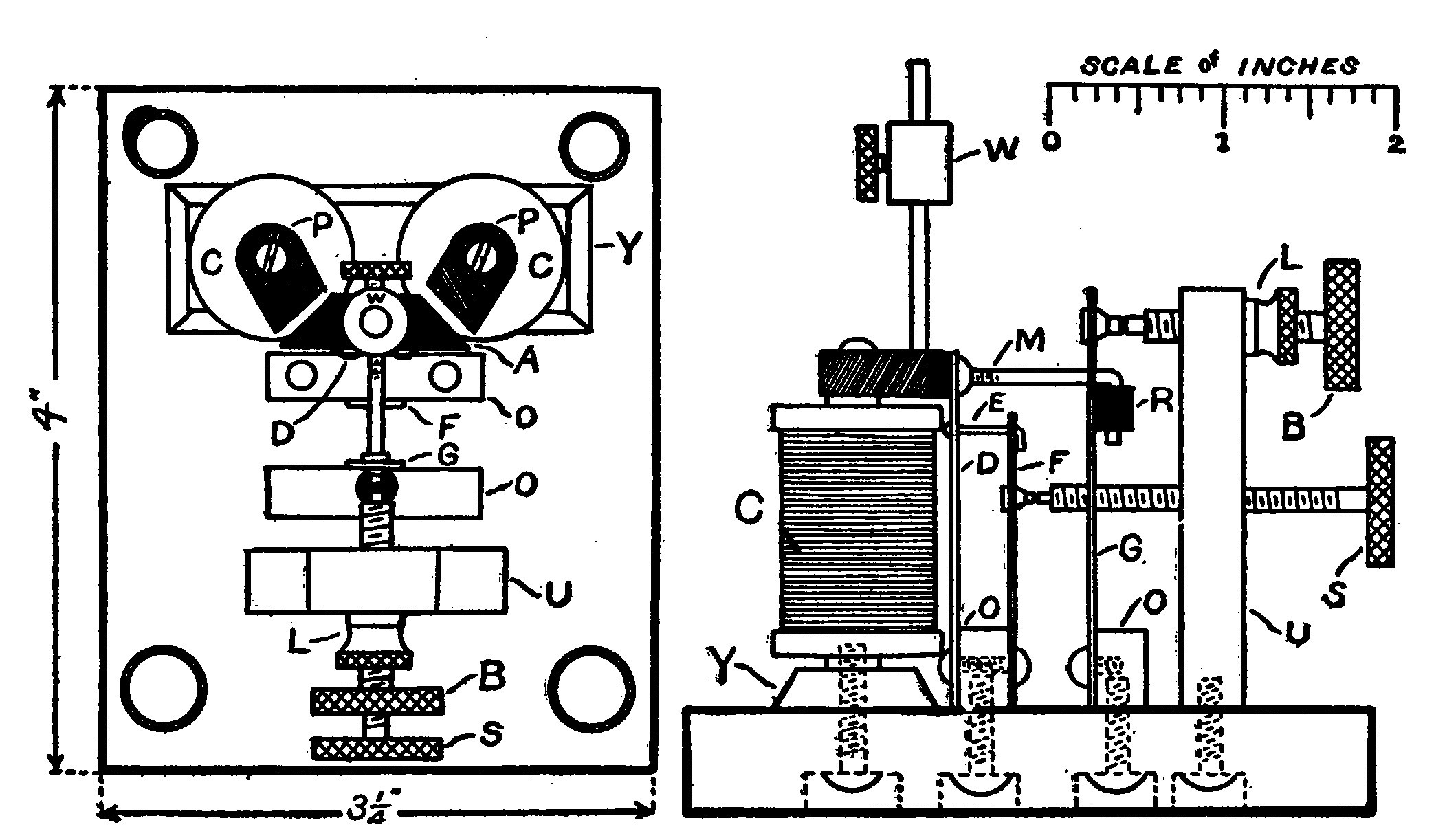
The electromagnets (Fig. 35) are a pair of four ohm telegraph sounder magnets. A hole is bored in the center of the top of each magnet core and threaded with an 8-32 tap so that the pole pieces may be fastened thereto, The shape and dimensions of these projections, which must be made of soft iron, are illustrated in Fig. 35.

A soft iron yoke Y, 2 1/2 x 7/8 x 1/4 inches, connects the bottom of the magnets and supports them in an upright position. An 8-32 machine screw passing upward through the base and yoke holds them firmly. The base is preferably of hard rubber 4 x 3 1/4 x 3/4 inches.
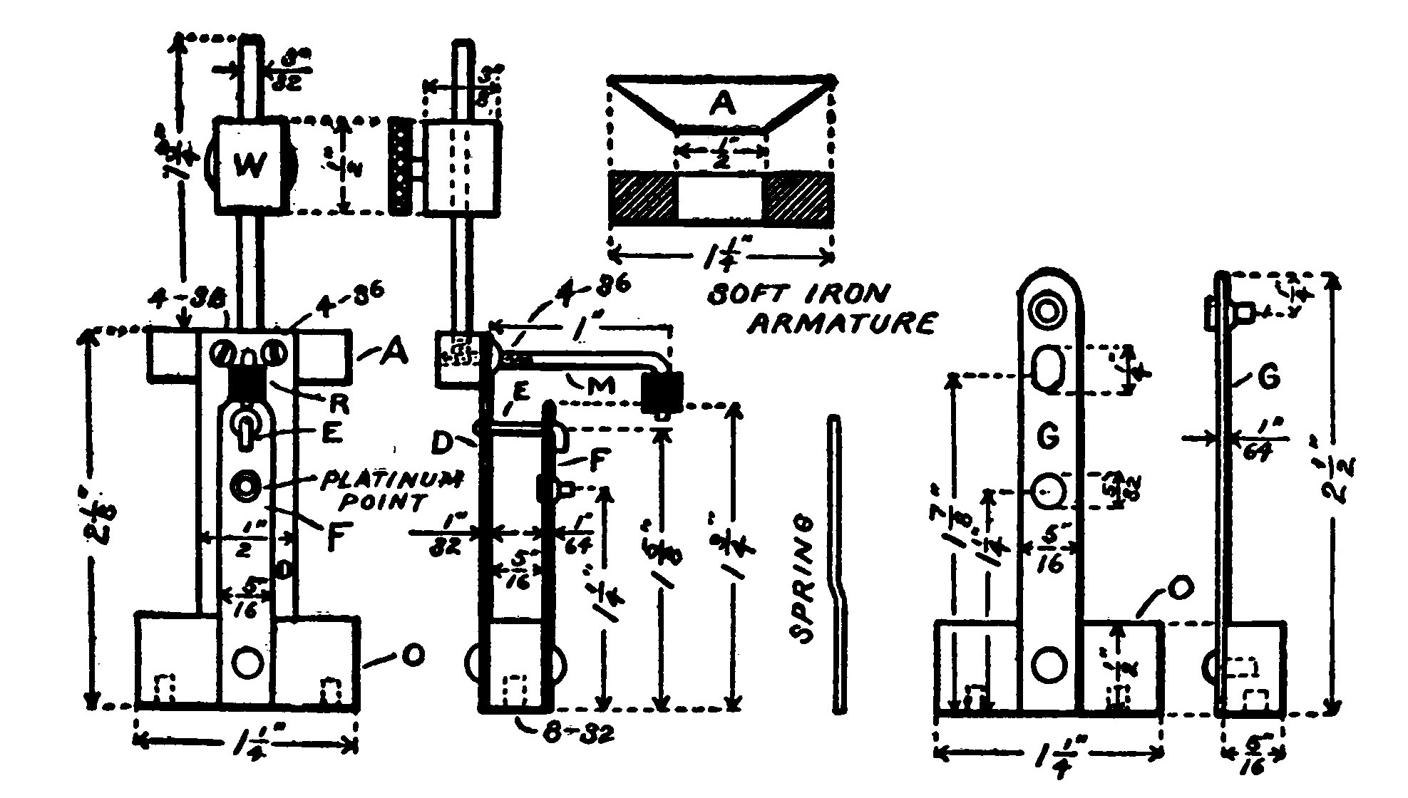
The moving parts are illustrated in Fig. 36. The main spring, D, is a strip of spring steel, 2 1/8 inches long, 1/2 inch wide, and 1/32 inch thick. The soft iron armature, A, is fastened to the spring by means of two small 4-36 machine screws. M is a piece of brass rod, 1 1/2 inches long, bent in the form of a hook and threaded with a 4-36 die to screw in a similarly threaded hole in the back of the armature A. The hooked portion of M is fitted with a small piece of hard rubber rod, R, to insulate it where it comes into contact with the spring, G. The spring, D, carries a second hook, E, riveted to the center of the spring 1 5/8 inches from the lower end. The hook, which is about 3/8 inch long, passes through a hole in the top of the spring, F, and engages it so that it is set in operation by the vibratory motion of the spring, D. The spring, F, is 1 3/4 inches long, 5/16 inch wide, and ir 1/64 inch thick. It carries a platinum rivet 3/4 inch from its lower end. The spring, G, is 2 1/2 inches long, 5/16 inch wide and 1/64 inch thick. A heavy platinum rivet is fastened 2 1/4 inches from the lower end. An elongated hole, 1/4 inch long and 3/16 inch wide, permits the hook, M, to pass through the opening. A 5/32 inch hole, 1 1/4 inches from the bottom, allows the adjusting screw to pass through and make contact with the platinum rivet on the spring, F.
Two rectangular pieces of brass, O, 1 1/4 x 1/2 x 5/16 inches are fastened to the base to support the springs.
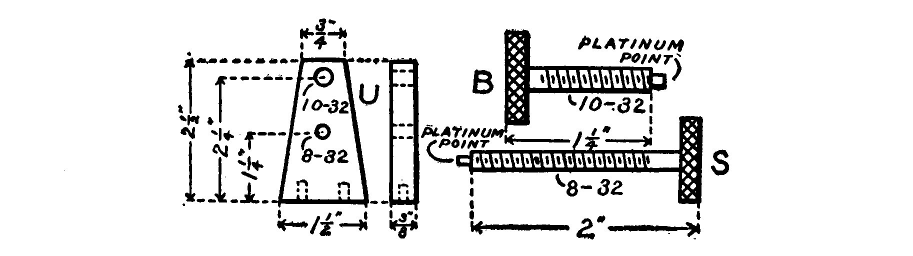
The standard, U, supporting the adjusting thumbscrews is a piece of 3/8-inch brass, 2 1/2 inches high. It tapers from 1 1/2 inches at the bottom to 3/4 inch at the top. A hole 2 1/4 inches from the bottom is threaded with a 10-32 tap to receive the thumbscrew, B. A second hole 1 1/4 inches from the base is threaded with an 8-32 tap to fit the adjusting screw, S.
Both of the adjusting thumbscrews carry heavy platinum points. The standard is held upright to the base by means of two machine screws passing through the base.
A 3/32 inch brass rod 1 3/4 inches long is threaded to fit a hole in the top of the armature. A sliding weight, W, may be clamped in any position on the rod by means of a thumb-screw. Raising or lowering the position of the weight decreases or increases the natural period of vibration of the interrupter. Screwing the hook, M, in or out so as to shorten or lengthen it, decreases or increases the ratio of the make to the break.
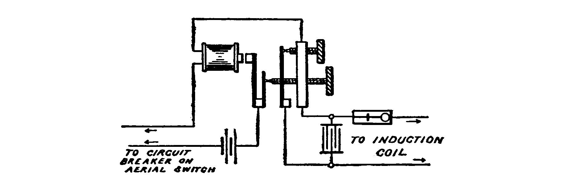
Fig. 38 shows a diagram of the connections of the interrupter. The standard, the thumbscrew, B, and the spring, G, form part of the primary circuit of the induction coil. The standard, the thumbscrew, S, the spring, F, and the electromagnets are placed in series with a six-volt battery and connected to the circuit breaker on the aerial switch, so that when the switch is thrown in position for transmitting, the interrupter will be set in operation.
A condenser must be shunted across the larger contacts of the interrupter in order to hasten the demagnetization of the core of the induction coil and create a higher e.m.f. in the secondary. The condenser must be suited in size to the induction coil with which the interrupter is to be used and so the following table is appended to serve as a guide.
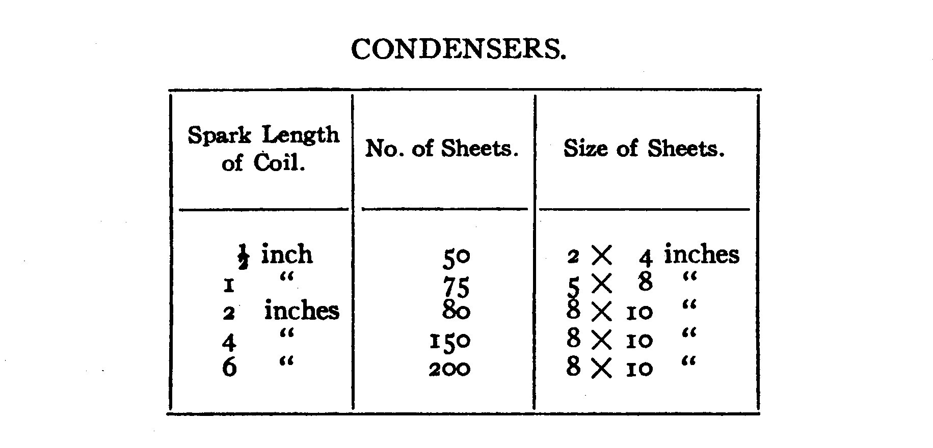
The condensers are built up of alternate sheets of tin foil and paraffined paper. Connections are made to the sheets by means of tin foil strips which project out alternately from opposite sides as in the illustration.
The paper should be about two inches larger each way so as to leave a one inch margin on all sides of the tin foil.

When the alternate sheets of tin foil and paper have all been assembled, the condenser is warmed so as to soften the paraffin. It is then placed between two flat boards and subjected to great pressure in a letter press or a vice. The capacity of a pressed condenser is often several times that of a condenser of the same dimensions but not pressed.
Mercury Interrupters.—The mercury turbine interrupter is one of the most convenient and successful breaks in use. The construction is such that a stream of mercury is made to play against a number of saw shaped metal teeth. A spiral worm terminating in a nozzle at the top is rapidly revolved by an electric motor. The lower end of the tubular worm dips in a mercury reservoir, so that when the spiral is revolved the mercury is caused by centrifugal action to rise in the tube and be thrown out in the form of a jet at the upper end. When the revolving jet strikes one of the metal teeth, the circuit is closed and the current flows from the mercury jet into the teeth. When the mercury jet passes between the openings between the teeth, the circuit is interrupted. By raising and lowering the saw teeth so that the mercury strikes either the lower or upper part of them, the ratio between the make and break may be made smaller or larger. By regulating the speed of the motor driving the jet, the number of interruptions may be varied from 10 to 10,000 per second. The bottom and sides of the mercury reservoir are ribbed to prevent the mercury from attaining a rotary motion.
A somewhat simpler and more easily constructed type of mercury interrupter consists of a hard rubber disk having a brass rod running through from the periphery to the center, where it connects with the shaft. The lower edge of the disk dips at an angle in a mercury bath and is rapidly revolved by an electric motor. When the rod is under the surface of the mercury, the circuit is made through the mercury to the rod. The circuit is broken when the rod is above the surface. The mercury is covered with a layer of alcohol, which prevents excessive sparking and makes a quicker break. An interrupter of this kind when run by a motor of the magnetic attraction type is exceedingly simple.
The break of any of the mercury type interrupters when properly adjusted is much quicker than the hammer spring break and gives thicker sparks.
After the mercury has been in use awhile it becomes churned up into small globules of a black color, but may be easily cleaned and restored for use by shaking up with some strong sulphuric acid. Care must be taken that the mercury is perfectly dry and free from acid before replacing in the interrupter.
Electrolytic Interrupters.—Fig. 40 shows a diagram of a Wehnelt interrupter. The cathode or negative electrode is a lead plate immersed in dilute sulphuric acid. The anode is a piece of platinum wire placed in a porcelain tube and projecting through a small hole in the bottom, so that only a very small surface of the wire is exposed to the liquid. When a strong electrical current is passed through the acid electrolyte, the current is very rapidly interrupted by the formation of gases on the small platinum electrode. The speed of the interrupter is variable through great ranges by moving the platinum electrode up or down and changing the amount of surface exposed to the liquid. The only disadvantage of this interrupter is that the electrolyte soon becomes heated, and unless the interrupter is provided with a water jacket or some device for cooling, the bubbles of gas do not form freely. A potential of at least 40 volts is required to operate a Wehnelt or other electrolytic break.
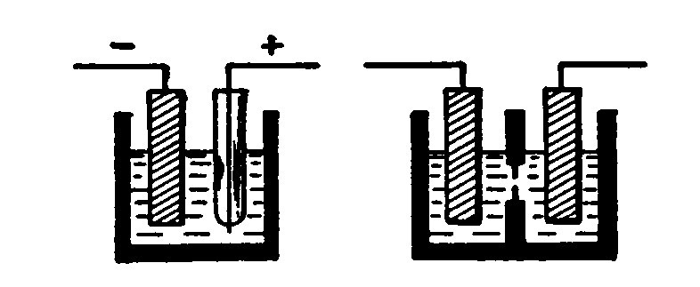
A Wehnelt interrupter may easily be made by sealing a platinum wire in a glass tube. It is well to make several such tubes with the platinum projecting from one-sixteenth to one-quarter of an inch. The different tubes will each have a different speed of interruption, and one should be picked out which seems to be most suitable for the coil upon testing. Connection to the platinum wire is established by filling the tube with mercury and dipping a wire in it.
Fig. 40 also shows a diagram of a Simon electrolytic interrupter. It consists of a vessel containing dilute sulphuric acid and divided into two parts by a thin porcelain diaphragm having a small hole in the center. A lead electrode dips into each of the divisions. The interruption is caused by exceeding a certain current density in the small hole at the diaphragm. Upon the passage of the current the liquid is so heated that it becomes vaporized. The vapor is a poor conductor to low voltages and so the current is broken. Immediately upon the cessation of the current, the vapor condenses and the circuit is established again. This cycle repeats itself with a speed depending upon the size of the aperture and the amount of current flowing.
A crude form of this type of interrupter may be made by heating the end of a test tube in a pin flame, and then blowing on the open end of the tube so as to burst the soft glass and form a small hole. Several such test tubes should be prepared having holes varying from 1/32 to 1/8 of an inch in diameter. The one which gives the best results upon trial is selected for use. A number of holes in a single tube, if not too many or too large in diameter, increases the efficiency and the speed of interruption. The tube should be immersed in a glass jar containing dilute sulphuric acid. One lead electrode is placed inside of the test tube and the other outside. It makes no difference which way the current flows through this interrupter.
The Caldwell interrupter is a modification of the Simon type in which the size of the aperture is made adjustable by means of a pointed glass rod which may be raised or lowered in the hole and the speed of interruption varied. An interrupter of the test tube type as described above may be modified to this form by locating the hole directly in the center of the bottom of the tube and inserting in it a hard glass rod which has been drawn out to a point.
Electrolytic interrupters do not require any condenser connected across the break.
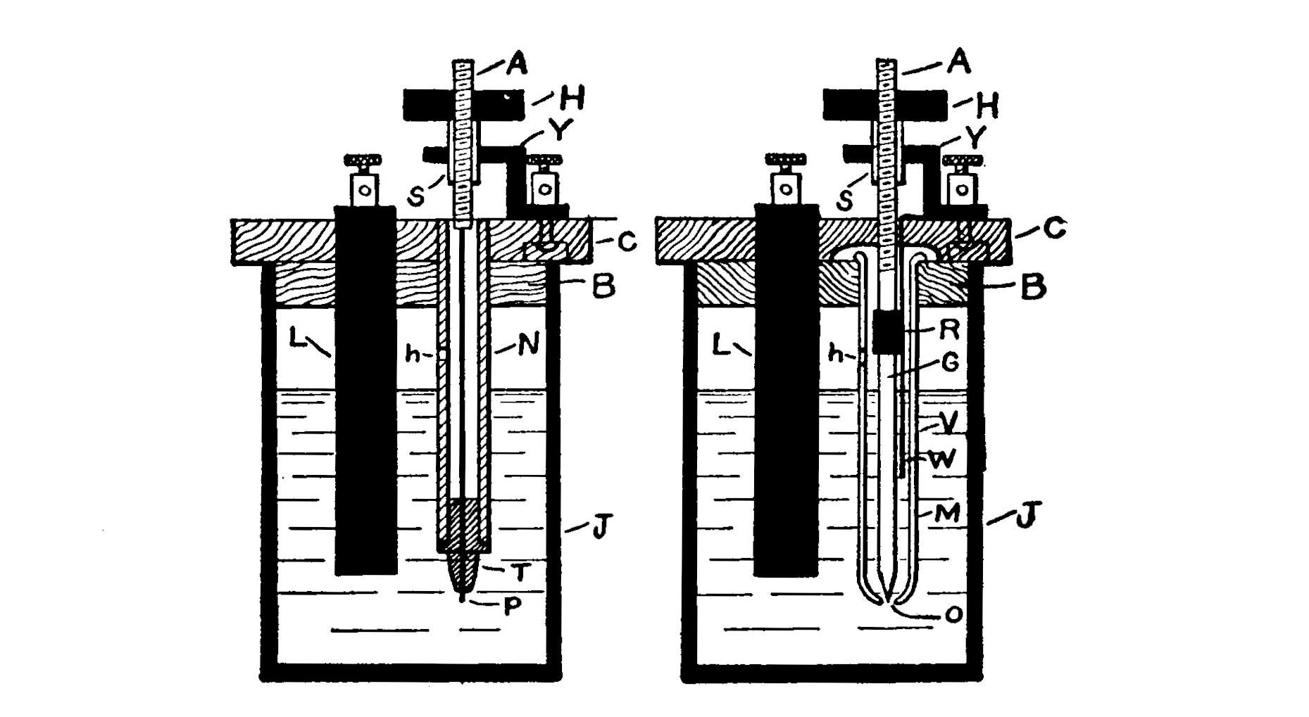
Fig. 41 shows in section more substantial forms of both the Wehnelt and Simon-Caldwell interrupters. The containers are ordinary 5 x 7 inch battery jars. They are fitted with covers made of two thicknesses, C and B, of 3/4-inch wood. The upper piece, C, is 6 inches in diameter, while the under one should fit snugly into the interior of the jar. The wood must be boiled in paraffin to protect it from the action of the acid. A slit is made in the left-hand side of both covers for the passage of a lead electrode, L, 1 inch wide and 1/4 inch thick. The upper end of the electrode is bent over and fitted with a binding post.
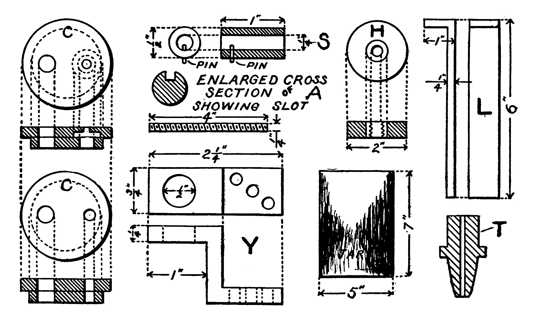
The mechanism for adjusting the interrupters is the same in both cases. The dimensions are indicated in Fig. 42. A brass yoke, Y, is mounted on the cover in the position shown. A 1/2-inch hole is bored through the upper part of the yoke and a piece of brass tubing, S, 1 inch long soldered in a vertical position in the hole. A 1/4-inch threaded brass rod passes through the tube, 5. A groove is milled in A along its entire length and engages a pin in the wall of S. The rod is thus enabled to slide up and down in the tube but is prevented from revolving. A fiber head, H, is fitted with a brass sleeve or bushing in its center. The bushing should fit tightly into the fiber head and is threaded to fit the rod, A. The electrode may then be carefully raised or lowered by revolving the head. The tube, V, for the Simon-Caldwell interrupter is a hard glass test tube. A 1/8-inch hole is blown in the bottom of the tube. A hard glass rod, G, is drawn out to a point and fastened to the lower end of the rod, A, by means of a short length of flexible rubber tubing, R.
The tube, N, for the Wehnelt break is made from a piece of hard rubber tubing 6 inches long, having a bore of J inch.
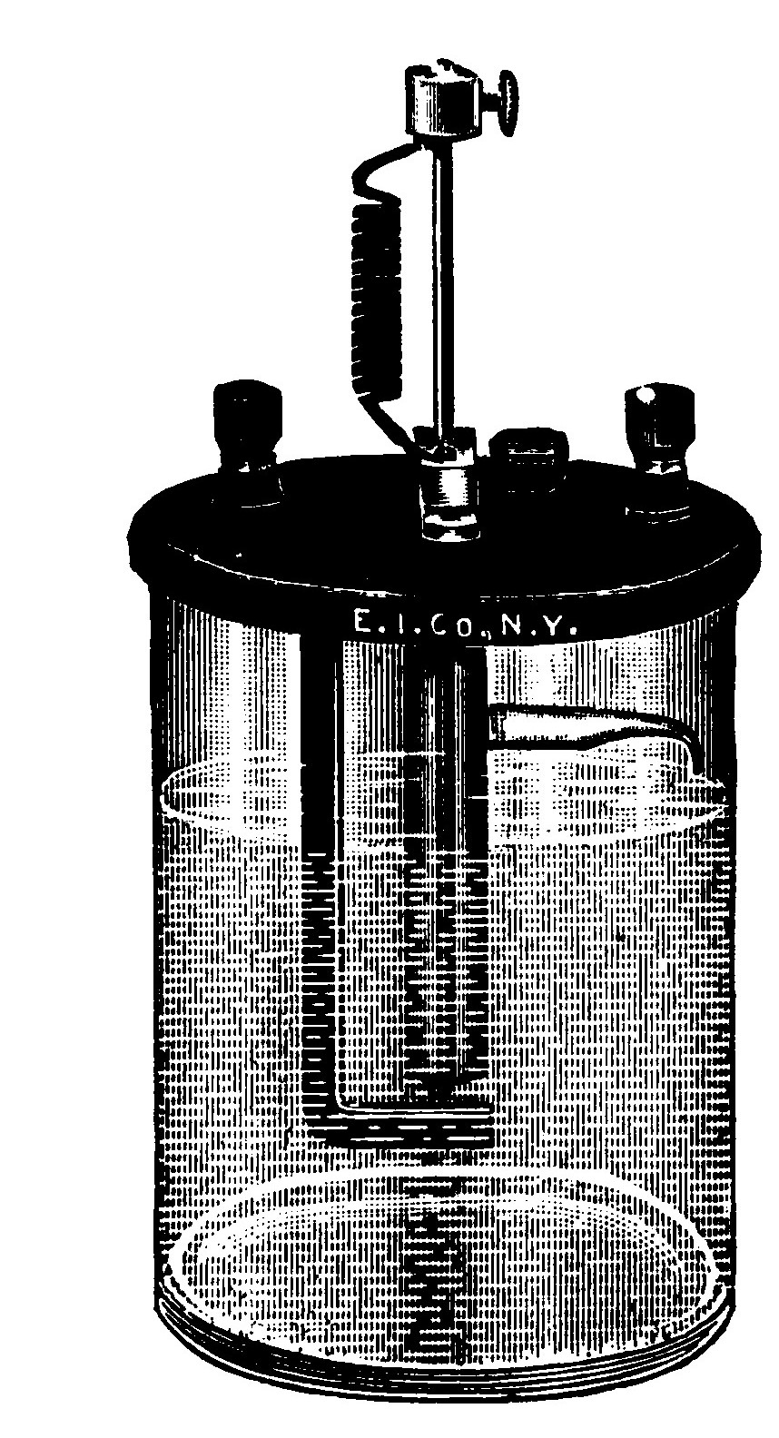
The lower end is fitted with a spark plug porcelain. The porcelain must fit the tube tightly and not leak. The electrode, P, is a piece of brass wire which will just pass through the hole in the porcelain. The upper end of the electrode, P, is soldered or fastened otherwise to the lower end of the rod, A.
A small hole, h, should be made in the tubes, N and V, above the level of the electrolyte in the jar. When the interrupter is in operation the electrolyte gradually rises in the tubes, and would corrode the lower end of A if it were not able to pass out through the vents.
In the Simon-Caldwell interrupter, a strip of lead passes from the binding post mounted on the foot of the yoke down inside of the test tube. The size of the hole in the tube is regulated by revolving the fiber head so that the glass pointed rod will be inserted in or withdrawn from the hole.
The frequency of the interruption will also depend somewhat on the concentration of the acid solution. It is therefore best to start with a weak solution and add acid slowly until it is of the proper strength.
CHAPTER VI. TRANSFORMERS.
Where alternating current is available in commercial wireless telegraph stations, the induction coil has been gradually superseded by the more modern transformer for charging the oscillation condenser. Since the transformer is less expensive to construct than an induction coil capable of transmitting the same distance, it is favored by many amateur experimenters. A one quarter kilowatt transformer has a sending range of over 50 miles when used with a properly constructed aerial about 80 feet high. This is probably the size best suited to the average private installation.
The secondary of a wireless transformer seldom develops potentials exceeding 15,000 to 20,000 volts, while those of an induction coil range from 1 5,000 to 300,000 volts. However, the strength of the secondary current of a transformer is so much greater than that of an induction coil, that more powerful and penetrating waves are developed. For these reasons a transformer is always rated by its output in watts or kilowatts rather than by the spark length produced at the secondary terminals. The spark of a one quarter kilowatt transformer is only 0.25 to 0.50 of an inch, while the spark of a one half kilowatt transformer may be the same length but still represent more energy.
There are two distinct types of transformers in use, known as the "open" and "closed," accordingly whether the core is straight like the core of an induction coil or in the form of a hollow rectangle. The open core type is used in the government stations and by the United Wireless Telegraph Co. It is the simpler and more easily constructed of the two, but is also less efficient and requires that more material be expended to bring it up to a definite rating. In principle it is simply an induction coil operated on alternating current minus the interrupter and condenser. In view of the greater currents employed, the windings must be larger and heavier than those of the induction coil to prevent heating.
Before commencing the construction of a transformer one should read the chapter on induction coils and use the same care emphasized there in regard to building coils.
Open Core Transformer.—The transformer described below will transmit from 20 to 75 miles and consume about 300 watts on the no volt 60 cycle alternating current.
The core is 16 inches long and 2 inches in diameter. It is built up of soft iron wires in the same manner as if it were the core of an induction coil.
The primary is composed of two layers of No. 14 double cotton covered B. S. gauge magnet wire. The primary is 14 inches long and is wrapped with a layer of micanite cloth 3/8 inch thick to separate it from the secondary winding.
It is never advisable to use shellacked cotton cloth as insulation. When cotton is dried and shellacked, it is at first a good insulator, but soon becomes capable of absorbing moisture. Shellac carbonizes at a low temperature, and if a transformer or coil having any of this sort of insulation entering into its construction is overheated, the insulation is liable to become a conductor. Micanite cloth is the best insulation for transformers. The dielectric strengths of the different forms of micanite are shown by the following table.
The secondary is wound in ten sections over the micanite insulation. Each section is 6 inches in diameter and 1 1/4 inches thick and is wound with No. 30 B. S. single silk covered wire. The sections are separated by disks of blotting paper 1/8 inch thick and 7 inches in diameter, treated as described in Chapter IV. The completed transformer should be placed in a box and covered with oil.
A One Quarter Kilowatt Closed Core Transformer. The simplest form of a closed core transformer consists of two independent coils of insulated wire wound upon an iron ring. When an alternating current is passed through one of the coils, known as the primary, it generates a magnetic flux in the iron core. The lines of force passing through the core induce in the secondary coil an electromotive force the magnitude of which is in nearly the same ratio to the primary inducing electromotive force as the number of turns of wire in the secondary is to the number of turns in the primary. For example, if it is desired to raise the potential of the no volt alternating current to 22,000 volts, the number of turns in the secondary of the transformer must be at least 200 times the number in the primary.
A circular ring of iron wire presents several theoretical advantages as a transformer core but it would be difficult to form and afterwards place the windings in position. The core is therefore usually in the form of a hollow rectangle, built up of very thin sheets or laminations of soft iron carefully insulated from one another by a coat of varnish. If the core were solid or the separate laminations not insulated from one another, heavy currents, known as eddy currents, would be set up in the iron and cause heating. A considerable loss in the efficiency of the transformer would also result.
One half of both the secondary and the primary windings of a properly designed transformer are placed on opposite sides or "legs" of the core in order to reduce the magnetic leakage and increase the efficiency. The only difficulty involved in such construction is the proper insulation of the primary from the secondary, but if careful attention is given to this point no difficulty will be experienced.
Core.—The dimensions and method of assembling the core laminations are indicated by Fig. 44. Long strips are cut from soft Russian or Swedish stovepipe iron. The strips, which are 1 3/4 inches wide are then cut up into short lengths, one half of which are 7 3/4 inches long and the other half 4 3/4 inches. Enough are cut to form two piles of each size 1 3/4 inches high when compressed. The completed core will then form a hollow rectangle 9 1/2 x 6 1/2 x 1 3/4 inches.
The strips must be dipped in some good insulating varnish such as P. & B. compound and thoroughly dried before they are assembled. Both "legs" (the longest sides) are laid on a table with the alternate ends overlapping as shown by A and B in Fig. 44. After the short pieces C and D have been slipped between the overlapping ends the whole core is squared up. The strips D are then carefully removed and one end of the core thus left open until all the windings are in place. Three or four layers of well varnished linen cloth are wound tightly over the "legs" preparatory to winding on the primary.
Primary.—Four fiber heads, H, 4 3/4 inches square, 1/2 inch thick and having a square hole 1 7/8 x 1 7/8 inches cut in the center are required. One of the fiber heads is placed on each end of the assembled "leg" as shown in Fig. 48.

The primary winding is wound in six layers, 4 1/2 inches long, three layers on each "leg." About three pounds of No. 16 B. S. gauge double cotton covered magnet wire are required for the winding. The terminals of the two halves of the primary are led through the fiber heads at the same end of the transformer. The windings are not to be carried close up to the fiber heads but begin and end about 1/4 inch from them, so that the remaining space may be filled by winding in a strip of micanite cloth 1/4 inch wide. The primary and secondary windings are separated by a strip of micanite cloth 5 inches wide, wound over both of the primary windings close up to the heads until a layer 1/2 inch thick is formed.
Secondary.—The form on which the secondary sections are wound is illustrated in Fig. 46. All the parts are cut out of wood except the shaft and are made of the dimensions indicated. If the center of the form is slightly tapered it will greatly facilitate the removal of the completed sections. Sixteen sections are required. When removed from the winder they will be in the form of hollow squares 4 1/2 x 4 1/2 x 7/16 inches.
About ten pounds of No. 34 B. S. gauge silk covered wire are required to wind the sections. Cotton covered wire must not be used to avoid expense, because with it a sufficient number of secondary turns cannot be secured to bring the secondary current up to the proper voltage. By observing explicitly the instructions and precautions given below no trouble will be experienced in handling enameled wire and forming the sections. The form should be placed in a lathe chuck or some other machine which is convenient and whereby the form may be rapidly revolved under the control of the operator.
Saw slots are cut in the wooden flanges and the center of the form as shown in the illustration so that silk threads may be passed under and around the completed section and tied so that a possible "cave in" of the wire is prevented. After tying up the section should be removed from the form by unscrewing the nut and taking off the flange.
When winding the wire it must be very carefully watched for loops or kinks and only be laid on in even layers. It must also be borne in mind that enameled wire cannot be as tightly wound as fiber covered wire for reasons heretofore explained. In case the wire becomes broken, it must be smoothly spliced and soldered. Do not under any consideration use acid as a flux or heat the wire with a flame. Acid will corrode the fine wire, and the flame will badly oxidize or melt it. Use a short piece of No. 8 B. S. gauge tinned copper wire set in a small file handle as a soldering iron, and rosin as a flux. Paraffin some silk binding tape such as dressmakers use and wrap the joint with a small piece. The sections as they are removed from the winder must be taped and then carefully marked with an arrow which points in the direction of the winding.
Fig. 47 illustrates the two methods of connecting up the sections. It will be noticed in the second method that the arrow denoting the direction of winding points down on every alternate section. This does not indicate necessarily that every alternate section is wound in an opposite direction from the other, but that they have merely been turned around so that the arrows come on a reverse side of the core and point in an opposite direction. This precaution must be taken in order that the current will flow through all the sections, and is made necessary because the inside terminal of one section is connected to the inside terminal of the adjacent section and the outside terminal of that section is connected to the outside terminal of the next adjacent section. The first method, A, illustrated in Fig. 44, is less complicated and does not require this reversal, but for various reasons is not to be recommended in place of B.
Eight of the completed and taped sections are placed on each "leg" of the transformer, with one of the fiber separators between each pair as in Figs. 48 and 49. When each "leg" has been completely assembled, solder all the secondary terminals together so as to connect as in Fig. 47.

Then place the remaining fiber head, S, on each of the "legs" and finish assembling the core by slipping in the end strips D.
Square the core up perfectly true and fasten by four fiber strips M, Fig. 49, 9 3/4 inches long, 1 3/4 inches wide and 1/2-inch thick. The strips are placed in the position shown in Fig. 46 and a hole P bored in the end of each. Four 1/4-inch bolts, two of which are 3 inches long and two 3 1/2 inches, pass through the holes in the strips, so that when the nuts are screwed on the core is clamped firmly. The two longer bolts are placed at the same end of the transformer.
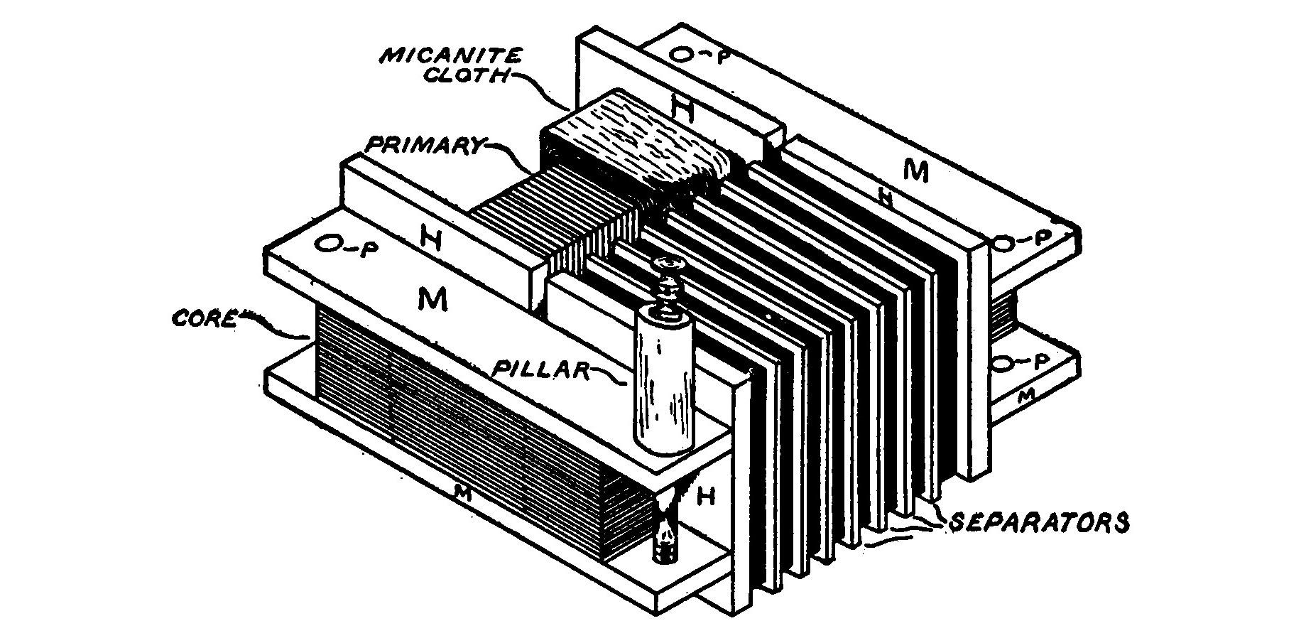
The terminals of the primary lead out to four binding posts mounted on the fiber strips. The pillars which support the secondary binding posts are fiber rods, 1 inch in diameter and 2 inches long. The lower end of each is bored and tapped to fit the upper ends of the longer bolts which clamp the fiber strips together. An insulating shield must be placed between the two secondary windings to prevent sparks from jumping across. A piece of fiber 5 x 5 x 1/8 inches will serve nicely for this purpose. If the primary windings are placed in series the transformer will consume about 300 watts. When the transformer is placed in a box and the box filled with some boiled amber petroleum, the windings may be connected in parallel and the transformer will consume about 500 watts. It will then transmit over 100 miles providing the aerial is at least 100 feet high.
The wiring connections are diagramed in Fig. 50. A variable inductance or reactance coil is connected in series with the primary circuit to steady the current, as explained in the paragraph under reactance. A reactance suitable for this transformer may be constructed by winding two layers of No. 12 B. S. gauge cotton covered wire, six inches long, around a hollow wooden tube made of cigar box wood. The core is built up of soft sheet iron to form a rectangle 8 x 1 3/4 x 1 3/4 inches which will just slide in and out of the tube. The windings should be about six inches long.
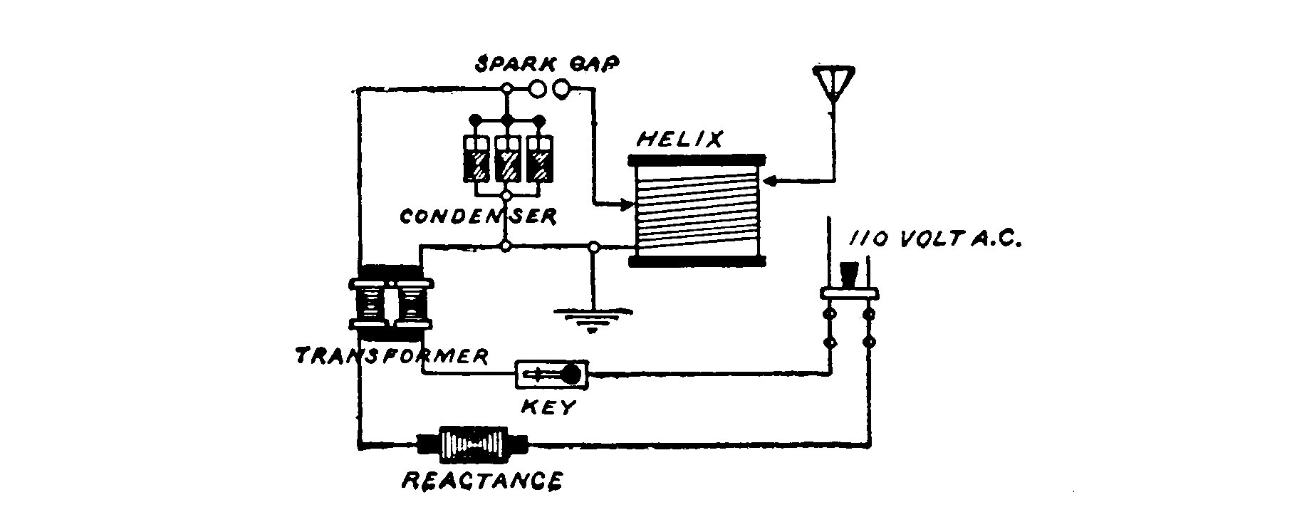
Five half-gallon Leyden jars form about the right capacity for the secondary of the transformer when the windings are in series. Twice that number must be used when the windings are in parallel.
The secondary sections must always be kept in series, as otherwise the voltage would not be high enough to properly charge the condenser.
Construction of a 2-K.W. Transformer.
Core.—Strips 2 1/2 inches wide are cut from soft sheet iron. One half of them should be 11 1/2 inches long and the other half 6 1/2 inches. Enough are cut to make two piles of each size 2 1/2 inches high. Both sides (the longest strips) of the core are built up with the ends overlapping as in Fig. 41.
The ends (the short pieces) are then slipped between the overlapping ends of the long strips and the whole core squared up. The completed core should have a cross section of 2 1/2 inches square and form a hollow rectangle 8 x 14 inches. The strips of iron must be dipped in P. & B. insulating varnish and dried before they are assembled.
Primary.—Four fiber heads 6 inches square, 1/2 inch thick and having a hole 2 1/2 inches square are made. One of these is placed on the core legs as shown by Fig. 48. Two or three layers of well varnished linen are wound over the core preparatory to winding the primary. Room must be left for the other head to be placed on the opposite end after the windings are all in place. The primary consists of 100 double turns of No. 12 B. S. gauge double cotton covered magnet wire. Fifty of the double turns are wound on each leg. The four terminals of the primary are led out through the fiber heads. Care should be taken to distinguish them from each other so that they may be identified when the transformer is completed. The primary is then wound with a strip of micanite or empire cloth 8 inches wide until it measures 4 inches square over all.
Secondary.—The secondary coils, which are eight in number, are wound on a form 4 inches square and 1 1/2 inches between the flanges. The construction of the form is similar to that shown in Fig. 46 but is larger. The slots are also necessary here so that the completed section may be tied up.
About ten pounds of No. 30 B. S. gauge single silk covered wire are required to wind the secondary. The sections are wound in smooth even layers until they are six inches in outside diameter. They are then tied up and removed from the winder. The sections are separated by sheets of fiber 6 1/2 inches square on the outside, 1/2 inch thick, having a hole 4 inches square cut in the center. The sections are all connected in series and the terminals soldered to strips of copper.
After the secondary coils are all in place and connected, the fiber head is slipped on the end of the leg. Then the short lengths of the core, which had been pulled out again after squaring the core up, are slipped into place. The core is squared up again and fastened together by boring a 3/8-inch hole completely through the core at each corner. Two strips of fiber 12 x 2 1/2 x 1/2 inches are bored with corresponding holes in their ends. These strips are placed at the end of the transformer, on top of the core, and 1/4-inch bolts passed through the holes in the fiber and the core. The bolts are wrapped with micanite cloth where they pass through the core, and an insulating washer is placed under the nuts, so that the iron core laminations are not electrically connected. The nuts are tightened until the core is held firmly together.
The fiber strips also serve as insulated supports for the binding posts. The copper terminals of the secondary lead to two binding posts mounted on two fiber or hard rubber pillars 1 inch diameter and 4 inches high. The rods are arranged as explained in the section under the heading of a 1/4-K.W. transformer.
The transformer is designed for use on a 60-cycle 110-volt current. It may be used on 220 volts if the two primary coils are connected in series. When the primaries are in series, and the transformer is used on the 110-volt current, it will deliver a voltage of about 12,000 at the secondary. With either primary alone the voltage will be about 12,000, and with both in parallel about 25,000. It will then deliver a very heavy current at the secondary and draw from the line about 20 amperes in the primary. If used with a proper tuning helix, condenser and aerial, the transformer is capable of sending about 300 miles under favorable conditions.
If the transformer is to be used for long periods at a time, it is best to place it in a tight wooden box 18 inches square and 12 inches deep. The box is then filled with boiled linseed oil or amber petroleum.
A rheostat or impedance and reactance coil should be placed in series with the transformer to regulate the current and also to prevent arcing across the spark gap.
Reactance.—In Chapter I, the lag and lead of a circuit were explained in connection with tuning. This is a property of every alternating circuit and is brought to our notice again in the transformer which charges the condenser. The current developed by a transformer is a leading current, since the instantaneous values of the current do not correspond to the proportionate values of the voltage supplying the current. In order to force the current values of the charging current to correspond with the voltage it is necessary to produce a "lag." This is accomplished by means of an adjustable reactance in series with the primary of the transformer.
A reactance or inductance suitable for the 2-K.W. transformer may be made by building up a coil in the same manner as described under the heading of the J-K.W. transformer. The reactance will have to be somewhat larger on account of the heavier currents. The core is built up of sheet iron to measure 2 1/2 x 2 1/2 x 10 inches when completed. The coil is wound around a wooden form and is composed of about 100 turns of No. 8 B. S. gauge double cotton covered magnet wire. By varying the amount of core inserted in the hollow coil the energy may be adjusted as desired.
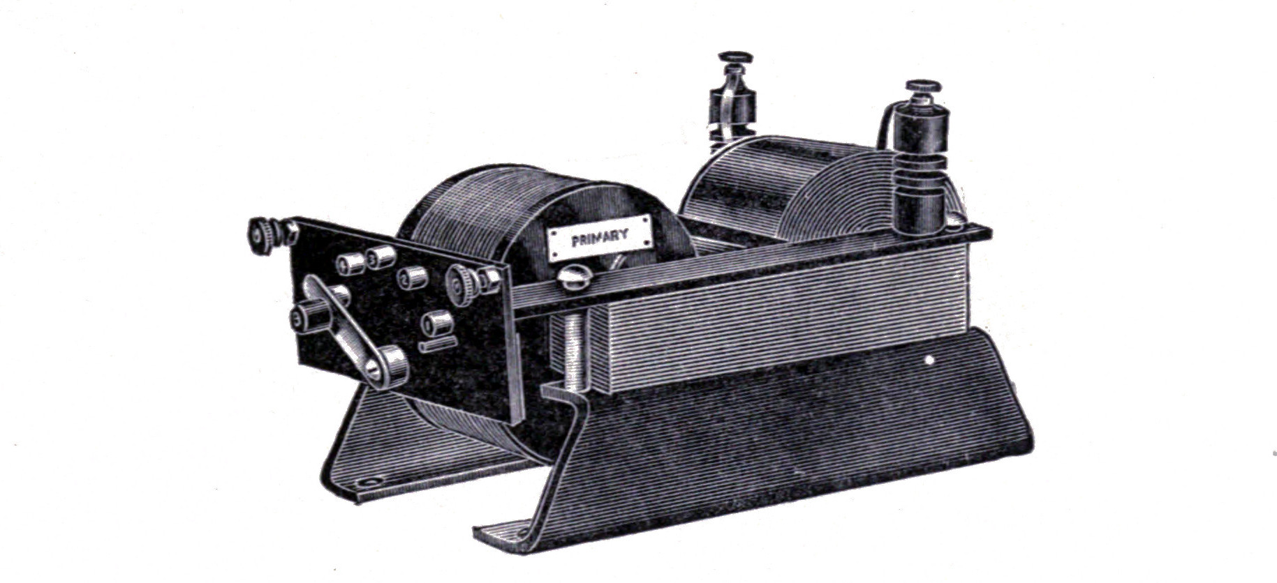
Fig. 51 illustrates the 1/4-K.W. transformer manufactured by the Clapp-Eastham Company. The core is so constructed that a small metal tongue of soft iron projects from one side of the core towards the opposite side between the windings, but is separated from the opposite side by a small air gap. Several objects are accomplished by this tongue, which gives rise to magnetic leakage; the inductance of the primary is increased thereby to such an extent that the transformer is self-controlling, so that it may be connected directly to the source of alternating current supply of ordinary commercial frequencies and potential, and the current flowing in this circuit be regulated by varying the number of turns in the primary coil. As this magnetic leakage gives rise to a loose coupling effect, the primary and secondary circuits may be brought into resonance by placing a suitable capacity across the secondary terminals. This condition of resonance brings the power factor to a materially higher percentage. While the power factor of the open or closed core transformer is seldom above 50%, this type of transformer has a power factor of 80 to 90% when used with a suitable condenser.
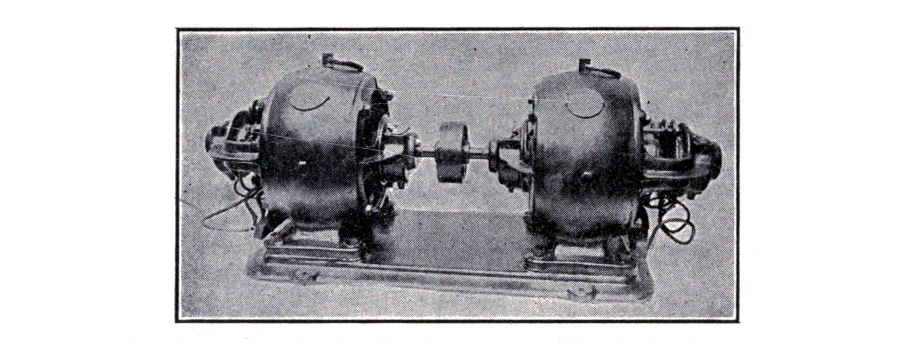
Another point of considerable advantage is the almost entire freedom from arcing at the spark gap when this type of transformer is used. The spark gap is connected directly across the secondary terminals of the transformer and the condenser. The primary turns of the helix and the spark gap are connected in series. When the transformer is in operation, this condenser being across the secondary, the transformer is in resonance and the condenser is charged to such a point that it will jump the spark gap. At the instant that the spark passes, the secondary of the transformer is practically short circuited through the spark gap. As this circuit is now closed and the condenser out of circuit, the secondary circuit of the transformer is no longer in resonance and the energy immediately drops off, destroying at once the tendency for an arc to form. As soon as the spark has passed, the condenser of course comes in to play and the condition of resonance being reestablished the same process is repeated. The Clapp-Eastham Company have made application for a patent on any transformer employing this or any similar construction for use in charging a condenser.
CHAPTER VII. OSCILLATION CONDENSERS AND LEYDEN JARS.
A condenser consists of two conducting surfaces separated by an insulator or dielectric. Fig. 53 shows a diagram of a simple condenser in which A and B are two tinfoil sheets separated by a sheet of glass, C.

If A is connected by means of a wire to a static machine a positive charge will collect on the glass at A and induce a negative charge at B, so that if A and B are connected to a small spark gap the charge will leap the gap in the form of a spark.
When a condenser discharges through a coil of wire, the discharge consists of a large number of exceedingly rapid oscillations or surgings. The first passage of current more than empties the condenser and it becomes charged in the opposite direction, that is, the conducting coatings change their polarity. A reverse discharge then occurs which also oversteps itself and the oscillations thus go on but become rapidly weaker until they die completely. The time consumed in the discharge may have been only a fraction of a second, but during that short period the current perhaps oscillated several thousand times.
If a condenser is discharged through a conductor of high resistance the discharge passes out slowly, and dies away gradually in one direction without oscillating. One of the fundamental equations of wireless telegraphy is therefore that there will be oscillations in a circuit if the resistance in ohms is not greater than the square root of four times the inductance in henries divided by the capacity of the condenser in microfarads.
The capacity or the ability of a condenser to store electricity depends upon the area and form of the conducting surfaces, the thickness of the dielectric between them, and a factor known as the specific inductive capacity of the dielectric. The unit of capacity is called the farad and is defined as the condenser which would be raised to a potential of one volt by a charge of one ampere flowing for one second. A condenser of such a capacity is, because of its enormous size, impractical to construct, and the unit ordinarily used is therefore the microfarad, or one millionth of a farad.
Capacity may be calculated from the following formula:
Capacity equals K(A/D),
where K equals a constant depending upon the specific inductive capacity of the dielectric, A the total area of tinfoil and D the thickness of the dielectric.
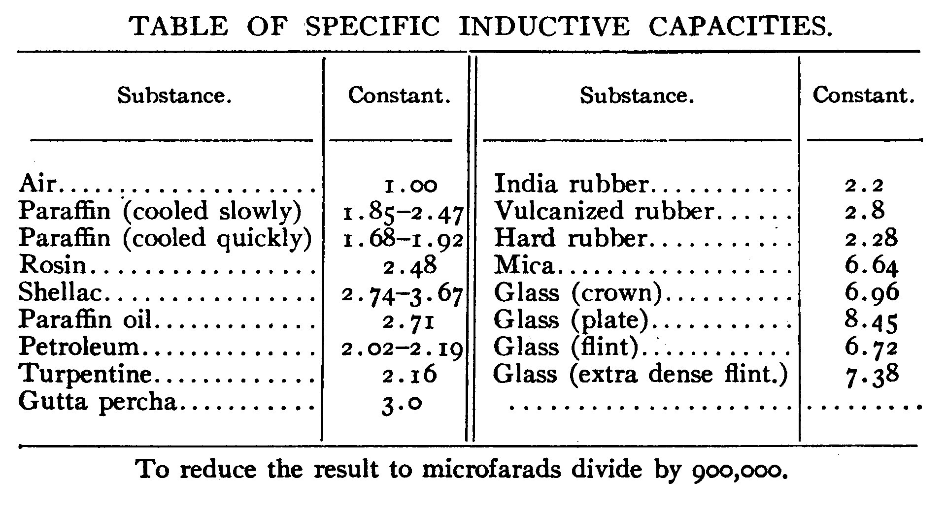
Leyden Jars.—Transmitting condensers in a wireless telegraph station usually take the convenient form of a jar, coated inside and out with tinfoil and known as a Leyden jar.
The jars should be of good Bohemian or Jena hard glass and coated with tinfoil only for about three-quarters of their height, as otherwise the discharge is liable to pass over the top. The tinfoil must be thick to avoid blistering, and is stuck to the glass with shellac varnish. The blistering of Leyden jars is a serious fault, for when this condition exists, the capacity is thereby altered to such an extent that the period of the closed circuit may be sufficiently altered to throw the system out of tune and decrease the radiation of energy.
Considerable expense may be saved if the glass jars are purchased and coated by the amateur. The best jars are those imported from Germany, which have wide mouths so that they may be easily coated inside with tinfoil.
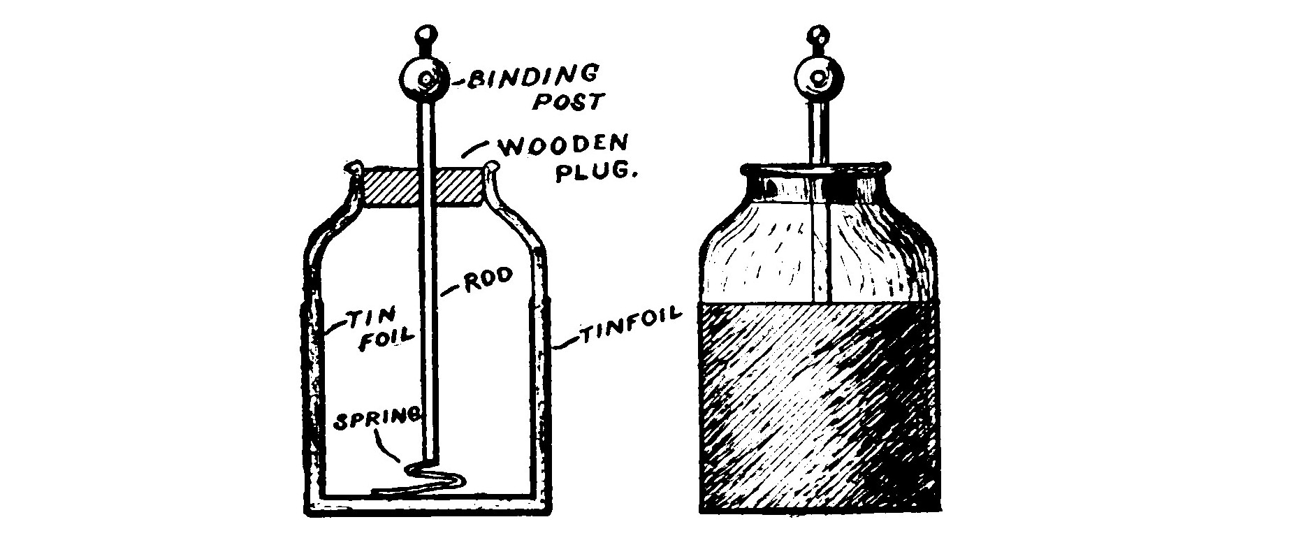
The jars must be thoroughly cleaned and dried before they are coated. Give the inside a thorough brushing over with shellac varnish, and before it is dry, carefully insert the tinfoil and press it smoothly against the glass. The outside of the jar is treated and coated in the same manner. The inside and outside of the bottom are also coated by cutting the tinfoil in circular pieces and shellacking them on.
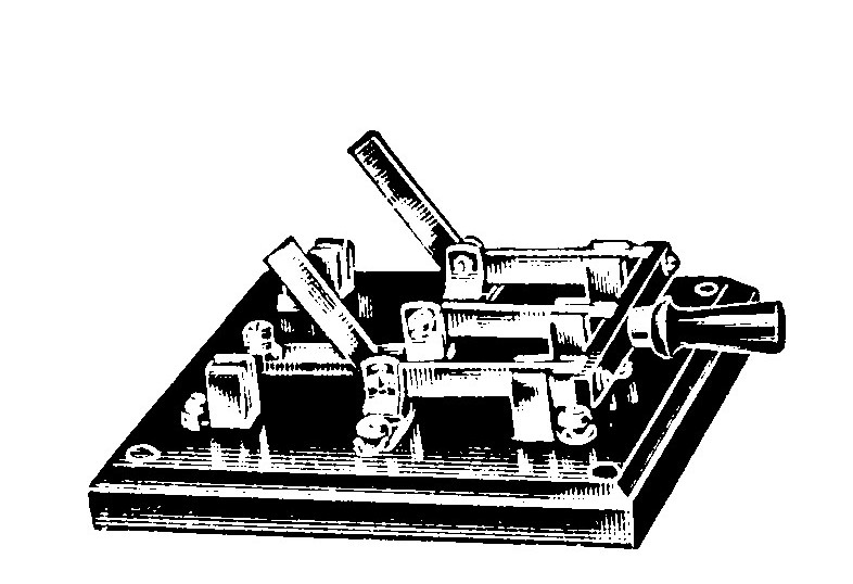
The whole upper part of the jar is given one or two coats of shellac in order to prevent the collection of moisture and brush discharging. A wooden plug fitted in the top of the jar supports a brass rod, terminating at the lower end in a chain or spiral spring which connects with the inner coating. When trouble is experienced because of an imperfect contact between the coating and the chain or rod, a layer of brass filings an inch or two deep placed in the bottom of the jar will remedy the difficulty. The upper end of the rod usually terminates in a small brass ball or a binding post.
The wooden plug or cover is dried in an oven to expel all moisture and then boiled in paraffin.
Small Leyden jars may be very conveniently made from six-inch test tubes and mounted in a rack so that the capacity of the condenser will be adjustable by removing one or more of the tubes. An ordinary test tube rack such as is used in chemical laboratories serves very well for this purpose. The tubes should be connected in parallel, that is, all the outside coatings together and all the inside coatings together.
Figs. 55 and 56 illustrate condensers of this type which are on the market. The tubes are all separately removable so that the capacity may be adjusted.
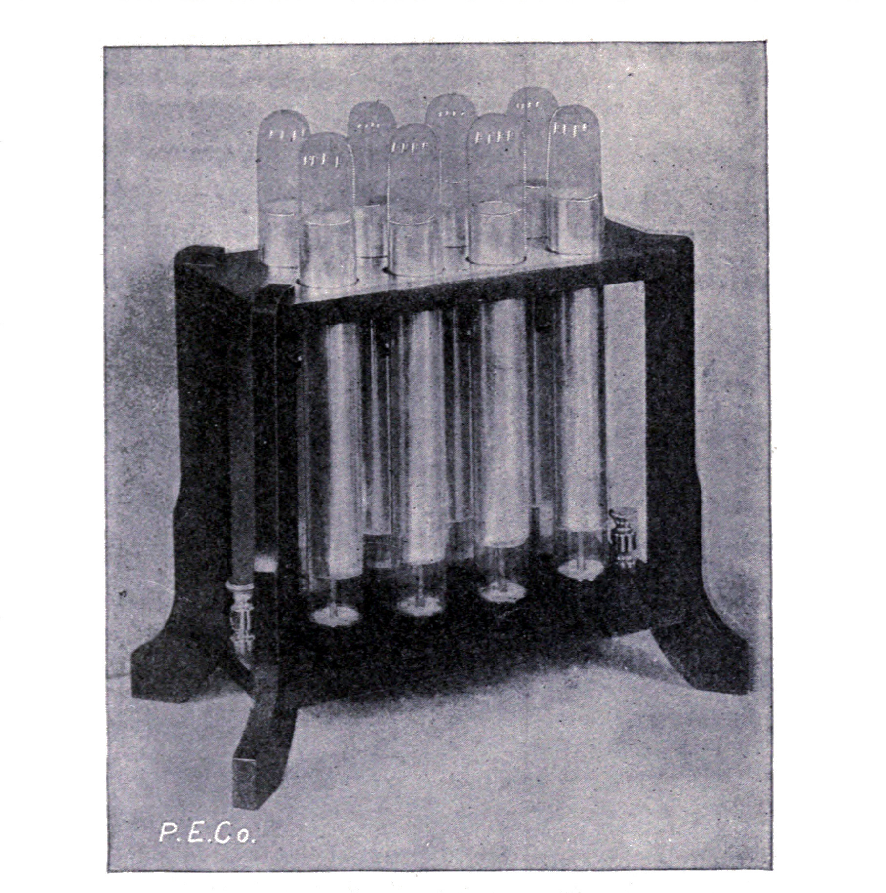
Glass Plate Condensers.—Glass plate condensers offer several advantages over Leyden jars and are coming into wide use. They are not so bulky or expensive and, above all, do not blister.
Plate condensers are often placed in a rack and made adjustable by means of movable contacts. Much the better plan is to place the plates in oil, as this eliminates all corona or brush discharges and much sharper tuning is rendered possible. The container is usually a tight wooden box filled with oil or paraffin after the plates are in place.
It is impossible to state the size of condenser suitable for induction coils of a given power or spark length, because many factors such as inductance, length of aerial, etc., which differ in various stations, influence the capacity. A condenser of convenient size suitable for coils or small transformers consuming from 250 to 300 watts is that described below. It is about the proper size for the small open core and 1/4-K.W. closed core transformers, described in the last chapter.
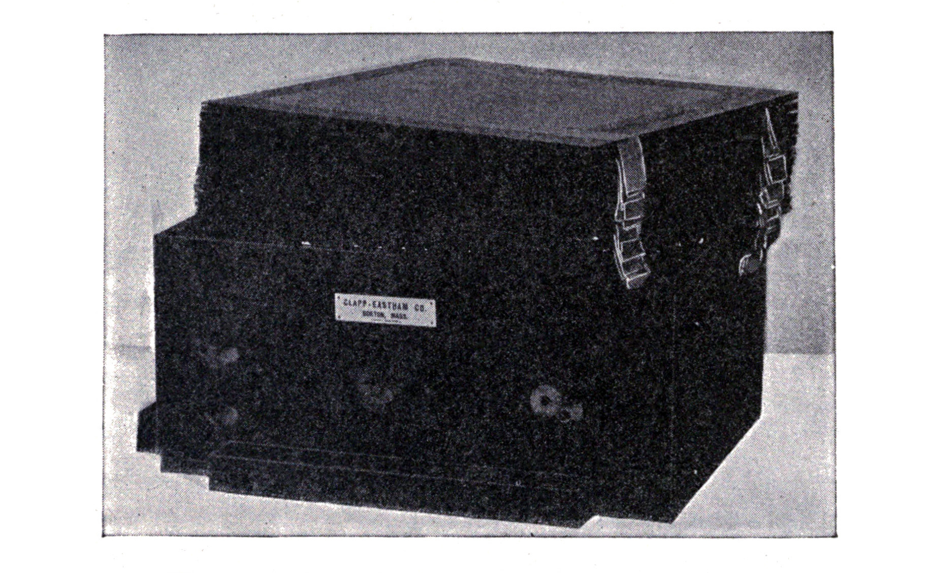
The glass plates may be secured by removing the emulsion from old 8 x 10 inch photograph plates. Hot water will soften the gelatin on the plates so that it may be very easily scraped off. Twenty-four plates of this size are required. The tinfoil is cut 8 x 8 inches, so that an inch margin is left on all sides. The alternate sheets are connected together by heavy tinfoil or thin copper foil strips. The condenser should be placed in a convenient sized wooden box and poured full of paraffin.
The plate condenser shown in Fig. 57 is of .02 microfarad capacity. The condenser is mounted in a plain wooden box with several binding posts brought out, so that the capacity may be varied by connecting in various sections. The condenser is manufactured and designed by the Clapp-Eastham Company for use with the transformer illustrated in Fig. 51.
It is very necessary to have the transmitting condenser adjustable so that its capacity may be varied, for the proper value depends upon the wave length, spark frequency, power and persistency of the wave train.
When the condenser capacity is too small the spark will be somewhat flaming like an arc, and the potential to which the aerial is charged will be low. If too much capacity is used the spark will be very irregular and intermittent.
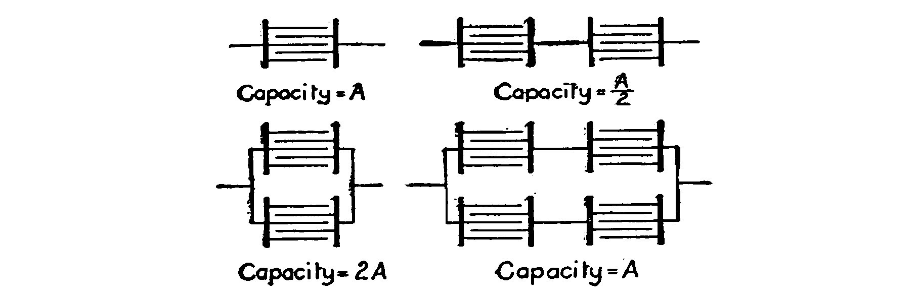
Fig. 58 shows condensers connected in series and in parallel and a combination of the two. Two condensers of equal capacity connected in parallel have twice the capacity of one, while in series they will have only one-half the capacity of either. This may be otherwise stated as the capacity in series is equal to the reciprocal of the sum of the reciprocals of their capacities separately. By this means of connecting either in series or in parallel almost any desired adjustment of capacity may be brought about.
Oftentimes a high voltage may be divided between two condensers by placing them in series and thus using them safely on a voltage which would rupture either one alone. For example, two condensers built for 20,000 volts and to be used on 30,000 volts could be made to perform this duty safely and only undergo a potential of 15,000 volts, which is a large margin of safety.
It is obvious that if the capacity of the circuit were to remain constant, four condensers connected up in series-parallel would be necessary.
In case of several Ley den jars or condensers connected up in a transmitting circuit, the leads or conducting wires connecting the various units should all be of as nearly the same length as it is possible to have them.
The resistance of metallic conductors to high frequency currents is several times their normal resistance to constant currents. The larger the diameter of the wire the greater is this ratio. This increase of resistance is due to the fact that the high frequency currents permeate wires only a very short distance. In the case of copper, the depth is only about one three-hundredth of an inch and with other metals much less. Therefore it is advisable to use as leads and conductors of large condensers, stranded wires or flat ribbons of sheet copper in order to present more surface and offer less resistance than solid conductors of an equal cross sectional area.
Iron must never be used, as its resistance to these currents is over fifty times that of copper.
After connections are once established between the jars or the condenser units, they cannot be altered nor the capacity changed without re tuning the circuits afterwards.
CHAPTER VIII. SPARK GAPS OR OSCILLATORS.
The oscillator or spark gap is one of the most important yet often the most poorly adjusted part of a wireless station.
To obtain a good oscillatory discharge with little damping it is necessary that the resistance of the circuit should be kept low, and since the greatest part of the resistance is in the spark gap it would appear as if this must be very short. While there are reasons for keeping it short there are on the other hand very good reasons why it should not be made too short, and the proper length should be a sort of compromise to be determined by experiment.
If the gap is too short, the discharge will form an arc and the only oscillations taking place will be those corresponding to the frequency of the charging current. Power consumption is also in favor of a long gap, since it causes the induction coil or transformer to draw less current from the line. Another argument in favor of a long gap is the fact that the condenser is charged to a higher voltage and more energy stored up, which makes a greater distance of transmission possible. But as stated above (and there always is a tendency for the amateur operator to open out his gap as long as the sparks will continue to jump steadily) the discharge will not oscillate but will merely set up a unidirectional current.
There exists a proper gap length for a given circuit which will cause that circuit to emit a maximum amount of energy and which may be determined accurately only by means of a hot-wire ammeter placed in the aerial circuit. The proper gap length is then indicated by the maximum deflection of the meter.
The correct adjustment of the gap may be approximated by the experienced operator. If too short, the spark will be hissing and flaming and is in extreme cases red or yellow colored. It should be lengthened out until it is thick and white and a slight increase in sound is noted. The spark should not be, as commonly thought, stringy and crackling.
Arcing is often caused by insufficient condenser capacity in the circuit. But if the capacity is increased to remedy the arcing, the gap length should also be increased or otherwise the potential of the condenser may not be sufficiently raised to permit a disruptive discharge to take place.
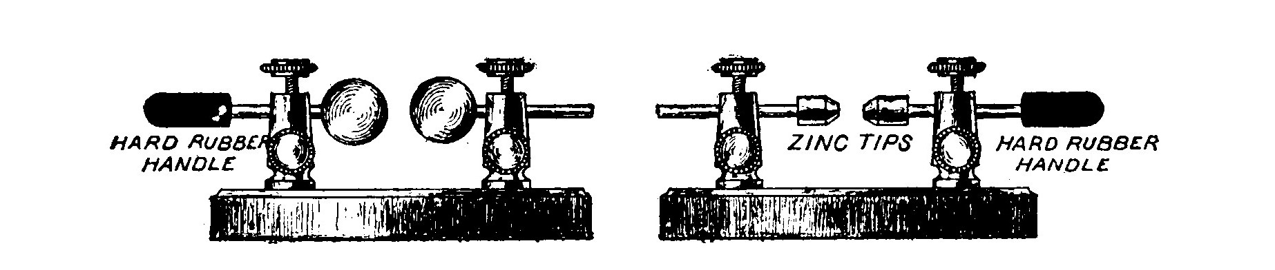
The best spark gap for use with a small untuned transmitter, making use of neither tuning helix nor condenser, is shown at the left in Fig. 59. It consists of two brass balls supported on suitable double binding posts. The balls tend to thicken the spark and make it more disruptive than if it passed between rods or points. The balls also increase the potential required to leap the gap without increasing its length and permit the aerial to become more highly charged before a discharge takes place. For this reason the balls or knobs must always be kept free from small rough spots or points by frequent polishing.
Silver has some peculiar property which makes it the most efficient material for a spark gap, but its cost prohibits its use and so brass or zinc, which are next in order, is generally used.
The type of gap illustrated at the right in Fig. 59 is very convenient and efficient for small tuned transmitters employing coils of low power.
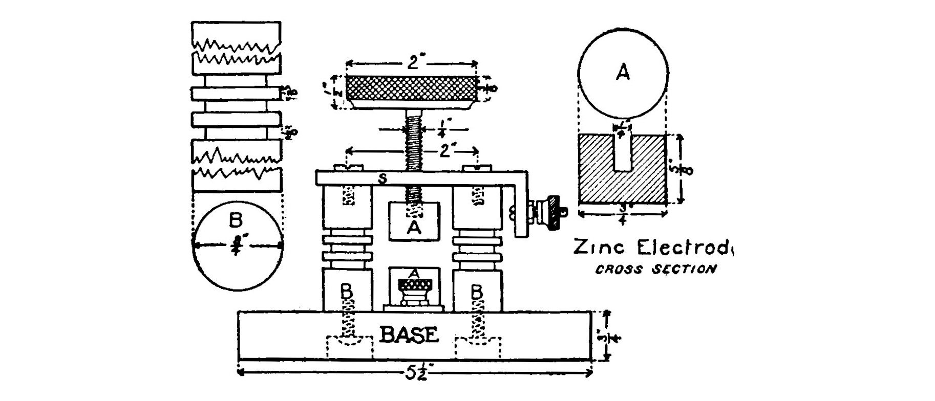
The zinc tips are pieces of 3/8-inch zinc battery rod 3/4 inch long. They are bored and threaded to fit a pair of brass rods 1/8 inch diameter and 2 1/2 inches long. The rods are supported by two double binding posts and are fitted with two pieces of hard rubber rod 1/2 inch diameter and 1 inch long to serve as handles. If desirable one of the rods and binding posts may be threaded so that the adjustment of the gap can be accomplished by revolving the handle and screwing the gap in or out.
A gap of the size and type just described would not be suitable in connection with a large transformer or an induction coil. The heavy discharge of such powerful instruments would very rapidly heat the small brass parts and corrode or even melt the zinc. The spark gap such as is shown in Fig. 59 may be used with a very large coil or the two kilowatt transformer if the same proportions are kept and it is made one-half again as large. Using the dimensions shown in the figure, the spark gap is suited to either the open core or the 1/4 and 1/2 kilowatt transformers.
Two pieces of hard rubber rod, 3/4 inch diameter and 2 inches long serve as the standards. Three grooves 1/8 inch wide, 1/8 inch deep and 1/8 inch apart better the appearance and reduce the liability of leakage but are not necessary. Two holes 2 inches apart are bored in S, a strip of brass 3 x 3/4 x 1/4 inches. Two screws pass through these holes into the rubber standards BB and hold S firmly in position. The end of S is bent down at right angles and bored to receive a binding post. A hole is bored in S halfway between the standards and tapped to receive a threaded brass rod 2 inches long and 1/4 inch diameter. The lower ends of the hard rubber standards are each bored and tapped to receive a screw which fastens them to the base. The electrodes are zinc or brass cylinders 3/4 inch diameter and 5/8 inch long. The upper electrode is adjustable by means of a knurled hard rubber head 2 inches diameter and 1/2 inch thick. The lower one is fastened to a brass plate 2 inches long, 1 inch wide and 1/8 inch thick. One end of the plate is fitted with a binding post. The base is a piece of hard rubber 5 1/2 x 3 inches x 3/4 inch.
CHAPTER IX. TRANSMITTING HELIXES.
The transmitting helix or tuning coil supplies the greater part of the inductance which is so necessary for the production of electrical oscillations in the transmitting circuit. It consists merely of a few turns of heavy copper or brass wire wound in a helix around a form. Two or more movable contacts permit various amounts of the inductance to be inserted in the open or closed circuits.
The tuning helixes described in this chapter are offered principally to serve as guides. They have been designed as carefully as possible to suit the transmitters for which they are recommended.
There are factors, such as the aerial, etc., which vary greatly in stations of the same rated power and make it best to determine the length of the helix by actual experiment.
A certain amount of inductance is necessary in the closed circuit for the production of electrical oscillations and to transfer energy to the open circuit. Inductance beyond that necessary to receive energy from the closed circuit lessens the radiation and makes it necessary to increase the period of the open circuit by adding wires to the aerial.
The open and closed circuits of a tuning helix constitute an oscillation transformer, and the two circuits if they are very close together or intertwined are said to be closely coupled. When separated or far apart they are loosely coupled.
Closely Coupled Helix.—Fig. 61 illustrates a closely coupled tuning helix, suitable for ordinary induction coils giving sparks up to 3 or 4 inches in length.
The heads of the helix are circular pieces of hard wood 1 inch thick and 12 inches in diameter. Six rectangular notches are made at equal distances along the edges of the heads. Six uprights 3/4 x 1/2 inch and 8 3/4 inches long are fastened in the notches with small round headed brass screws so that the heads are separated a distance of 6 3/4 inches. Grooves are cut in the outside face of each of the uprights at a distance of 7/8 inch apart. The wire forming the helix is 1/4 inch brass. Brass wire is springy and retains its shape better than copper. About twenty-two feet will be required. The wire is wound in the grooves in the uprights and held in place by a few double pointed tacks placed judiciously. The adjacent turns of wire will then have a separation of about 5/8 inch.
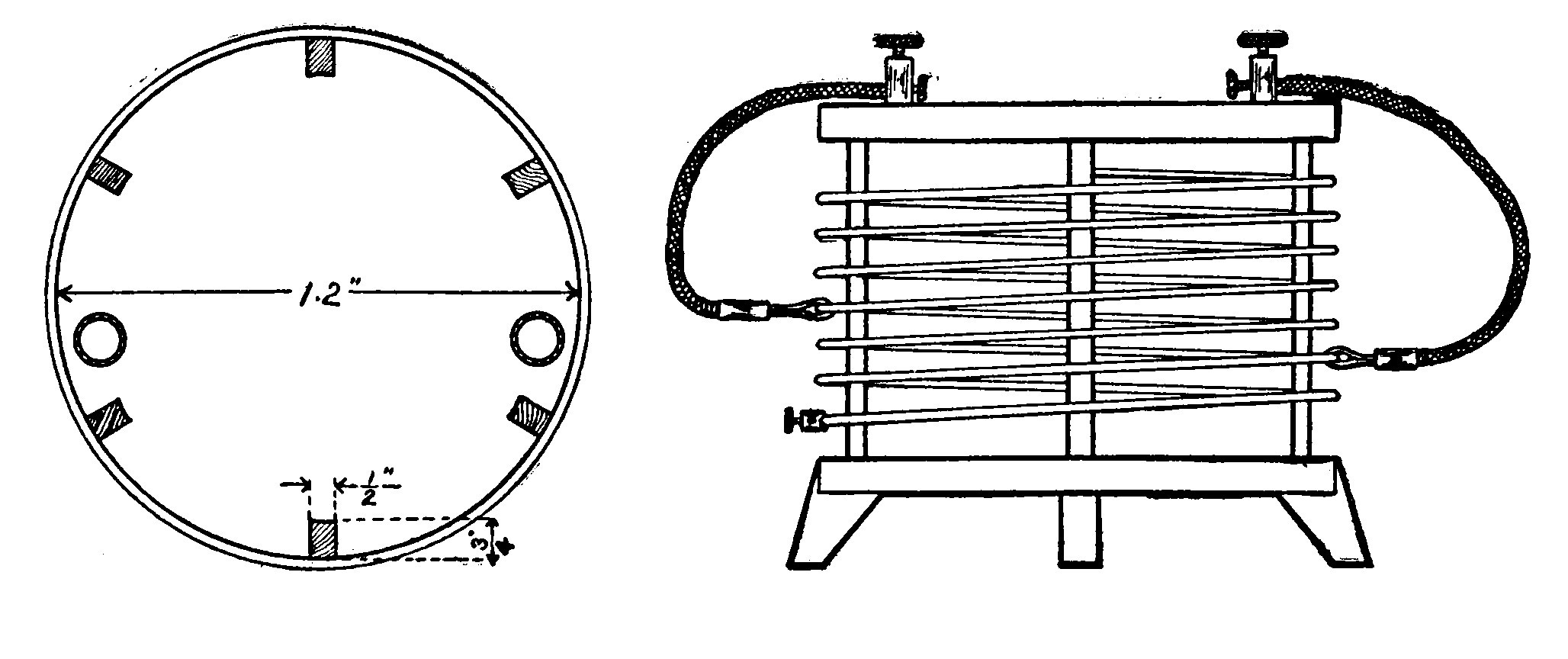
The helix is raised above the level of the operating bench or table by three small feet fastened to the under head, 120 degrees apart.
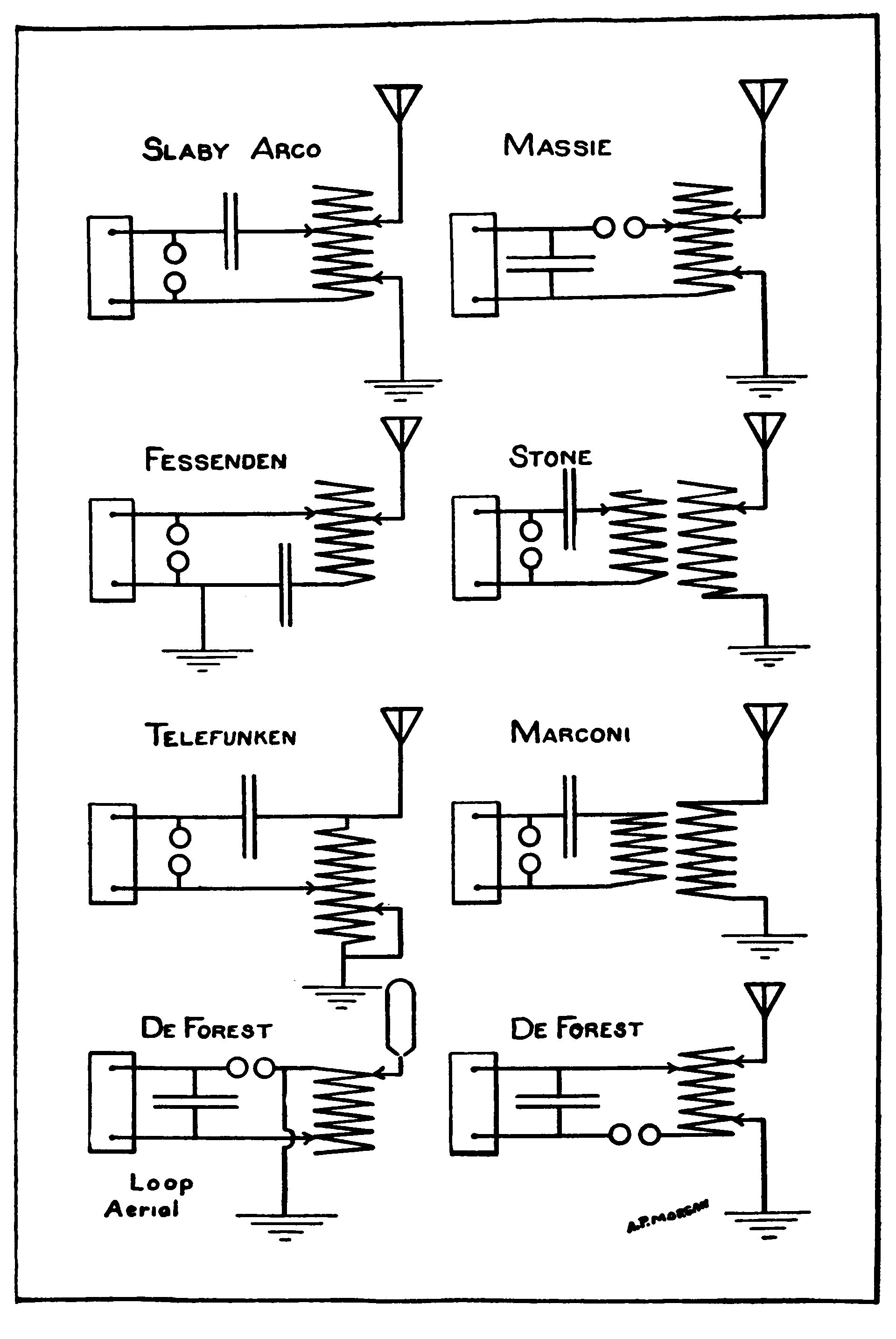
If it is desired to use this helix with the one quarter K.W. transformer, the diameter of the wire should be increased to 5/16 inch. The two K.W. transformer will require seven turns of 1/2-inch hard drawn brass wire two feet in diameter.
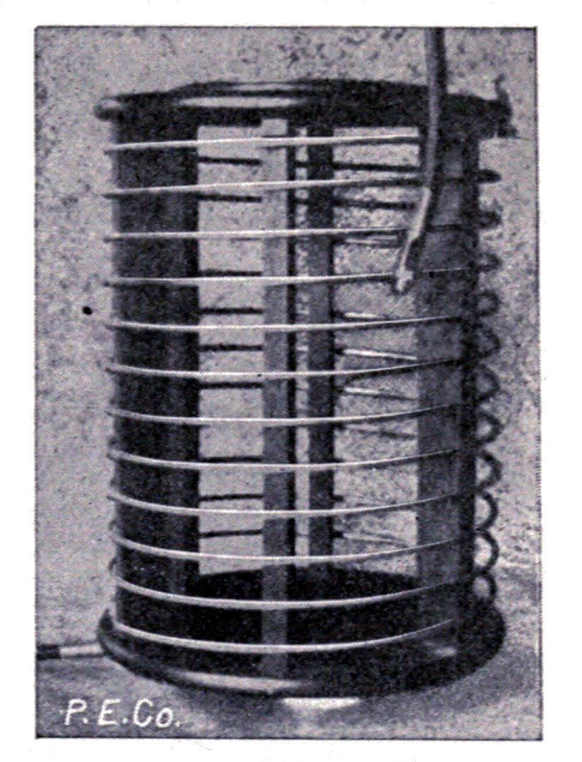
When setting up a transmitting station, it is a good plan to coil up a long piece of the wire to be used on the helix around a rough form. The adjacent turns should be the same distance apart as they are to be on the finished instrument. Tune up the station with this improvised helix and ascertain the amount of inductance required. It is then easy to design a helix containing the proper amount of wire. Four or five feet extra should be included to allow plenty of range in case it is ever necessary to make any changes in the aerial or condenser.
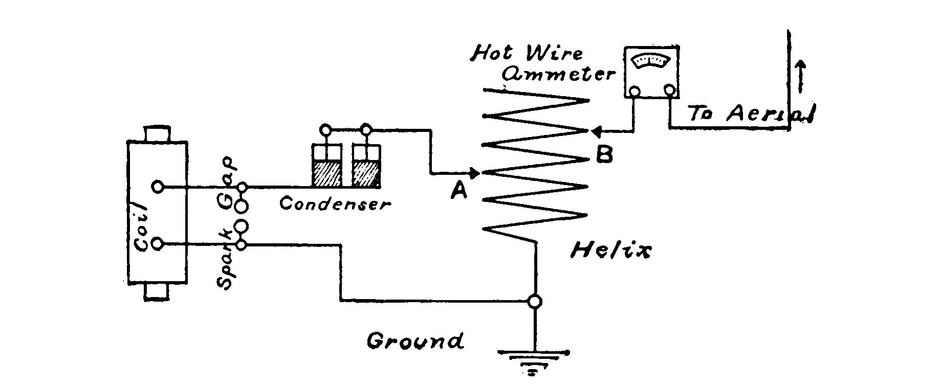
Plate III illustrates the transmitting circuits of the various commercial systems. The circuit used will determine the number of binding posts and movable clips necessary. Fig. 63 gives the diagram of a very good circuit.
Loosely Coupled Helix. The heads of the primary coil of the loosely coupled helix illustrated in Fig. 64 are circular pieces of hard wood 1 inch thick and 18 inches in diameter. Six uprights 3/4 x 1/2 inch and 11 inches long are set into notches in the upper head and fastened to the base so that the space between the heads for winding the wire is 10 inches.
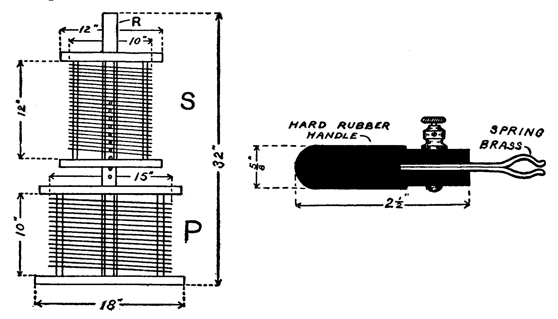
A square wooden pillar 1 1/2 x 1 1/2 inches and 32 inches long passes through a square hole 1 1/2 x 1 1/2 inches in the center of the heads and projects 20 inches above the upper one. The heads of the secondary coil are each 12 inches in diameter. The distance between them is also 12 inches. A square hole 1 1/2 inches x 1 1/2 inches in the center of each of the heads permits the whole secondary coil to slide up and down on the pillar. Several 1/4 inch holes bored 1 inch apart in the pillar admit a small peg of the same diameter. The coupling between the two coils is varied by changing the height of S above P and inserting the peg to hold the upper coil in position.
The primary winding of the transformer should consist of about 20 turns 15 inches in diameter, and may range in size of wire from No. 2 to No. 8 B. S. gauge.
The secondary is 10 inches in diameter and will require about 40 turns of No. 10 to No. 16 B. S. gauge.
The largest sizes of wire are for the one-quarter and one-half K.W. transformers while the smaller sizes are best suited to small induction coils.
Fig. 64 also illustrates a clip for making connections to the turns of the helix. The handle is a piece of hard rubber rod 2 1/2 inches long and 5/8 inch in diameter. A saw slot 1 inch deep is cut down the center of one end. Two strips of spring brass 2 inches long, 5/8 inch wide and 3/64 inch thick are bent as shown in the illustration. The straight ends are slipped in the slot in the handle and clamped together by boring a hole and passing a machine screw through. The upper end may be fitted with a nut or a binding post to facilitate connection. Flexible copper ribbons or stranded wire should be the only conductor used for the tuning leads.
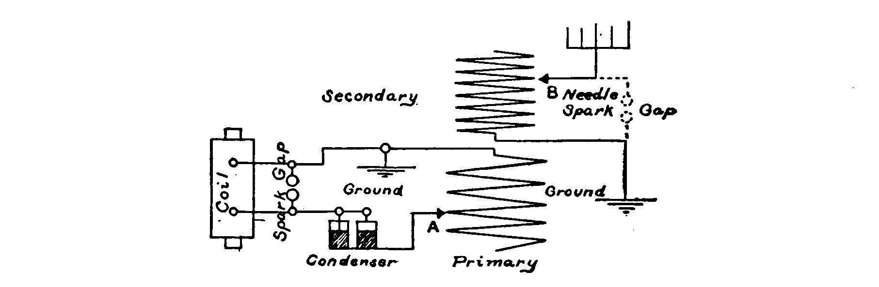
Tuning a Transmitter.—Fig. 62 shows a complete wiring diagram of a transmitter with a hot wire ammeter inserted in the aerial circuit.
To tune such a transmitter place both contacts A and B together on a turn of wire near the center of the helix. Set the transmitter in operation by pressing the key and move both contacts together along the various turns of wire until the meter shows a maximum reading. Then vary B alone until the reading is still higher. Shifting A varies the inductance in the closed circuit and B that of the open circuit.
Fig. 65 illustrates the circuit of a loosely coupled transmitter. To tune such a circuit it is necessary to connect a small needle spark gap between the aerial and the ground.
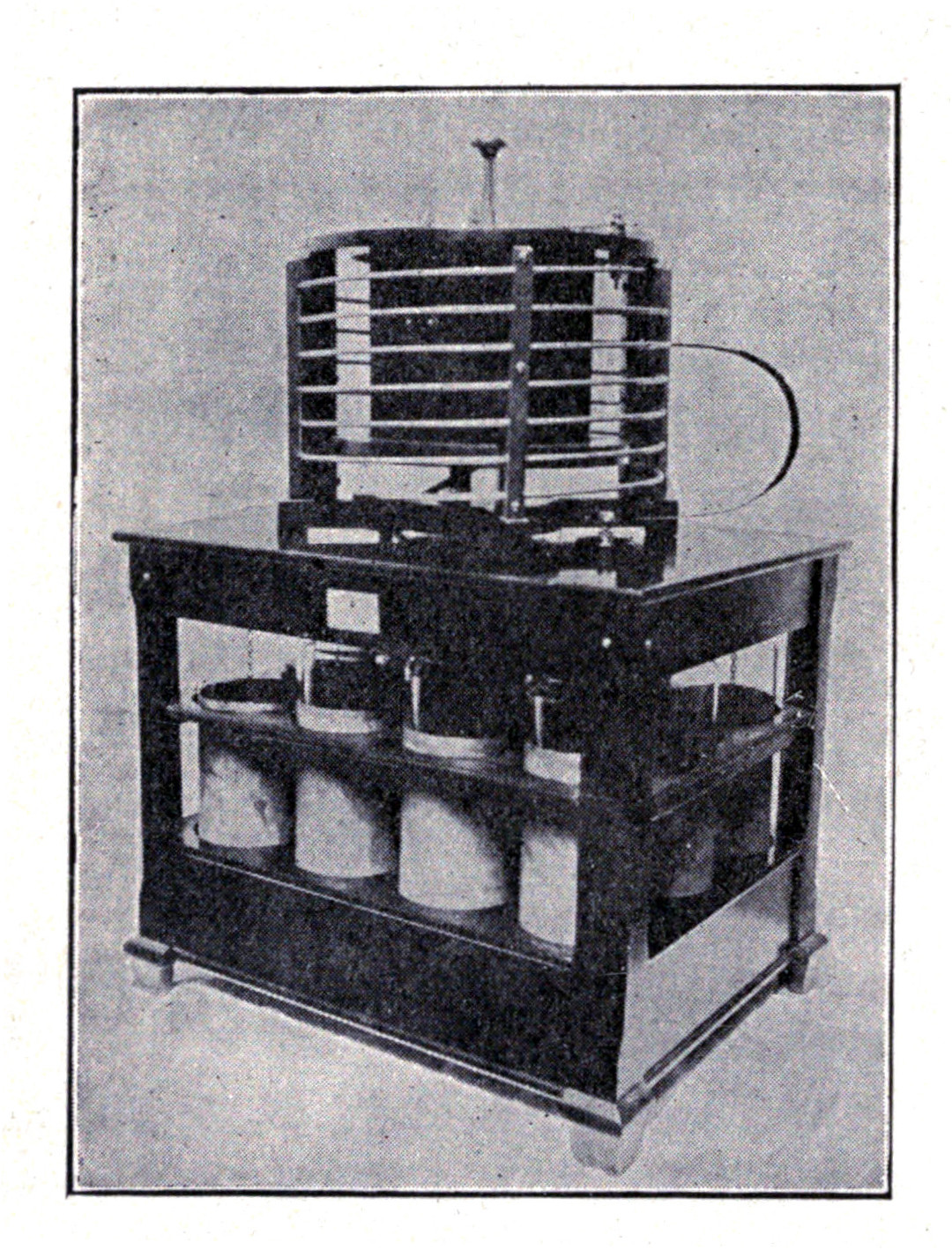
A suitable spark gap for this purpose may be made of two darning needles mounted in double binding posts.
Set the clips, A and B, at the center turns of their respective coils. Press the key to operate the transmitter and adjust the clip, A, until the best spark is obtained in the small needle gap. Then adjust B until the spark is still better.
If several wires seem to give the same results, move the secondary a little further away from the primary and try again. After securing the best spark it is possible to obtain, remove the needle gap, which is only used in testing. The hot wire ammeter should then be placed in series with the aerial. By slowly and carefully adjusting the clips and varying the coupling, the hot wire ammeter will indicate the proper "tune."
The secondary of the loosely coupled tuning coil produces a "kick back" effect on the primary, due to induction, and unless the two coils are somewhat separated, the wave emitted from the transmitter will have more than one "hump" and a person receiving the wave will be able to tune it in on two places on his tuning coil.
A loosely coupled tuning coil does not radiate so much energy as a closely coupled helix, but will, when properly tuned, emit a wave which is not so highly damped. Therefore as far as distance is concerned the loosely coupled type is perhaps the most efficient.
CHAPTER X. KEYS.
THE keys used in wireless work differ from those used in commercial wire telegraphy in being much heavier and stronger, so as to conduct and break the heavier currents without heating. Where very powerful currents must be broken the contacts of the key usually operate under oil or in the magnetic field of a pair of electromagnets. In other cases a small key is used to operate a heavy relay. In the former type a metal arm projects downward from the lever of an ordinary Morse telegraph key into a compartment filled with oil. The arm is provided with a platinum point which makes contact with another similar point on the bottom of the compartment, so that the break is made under oil and the key remains cool and does not arc. In the second form the same result is accomplished by a magnetic "blowout." The "blowout" is merely an electromagnet connected in series with the key and its poles at right angles to the contacts of the key. When the circuit is broken the magnetic field extinguishes the arc which tends to form between the contacts of the key.
An ordinary Morse key may be used with coils operated on batteries if they do not give more than a four-inch spark. Larger coils or transformers, especially if they are operated on the 110-volt current, require a heavier key. Where an ordinary Morse key is used with a 3-inch or 4-inch coil it is a very good plan to provide an auxiliary conductor, one end of which is fastened to the metal base and the other end to the adjusting screw on the back of the lever. A piece of flexible lamp cord is suitable for this purpose. This precaution saves the pivots of the key from heating and possible burning by heavy currents.
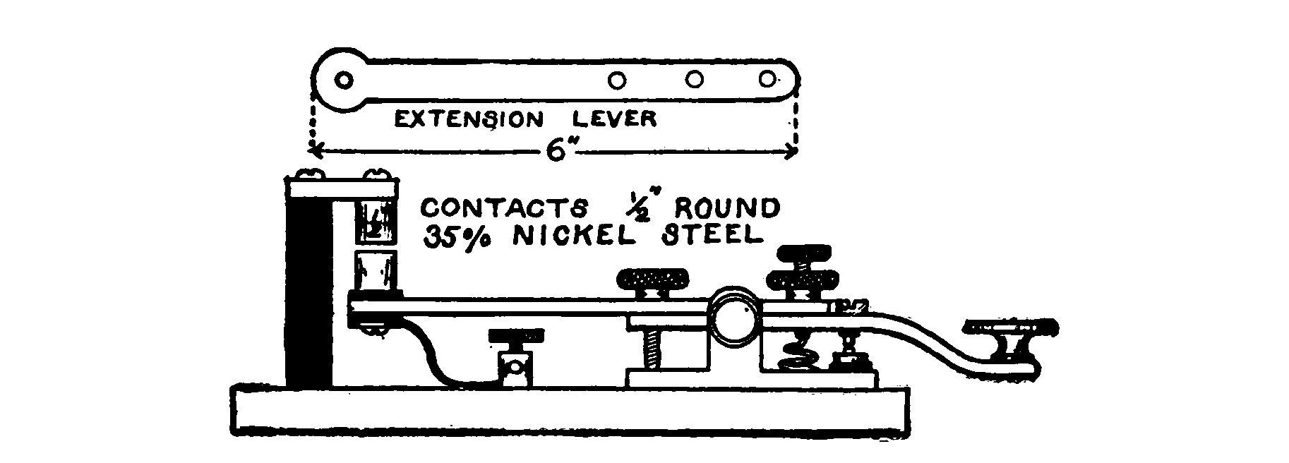
The most convenient method is to fit up an old Morse key in the manner shown in Fig. 67. The lever is extended by a piece of aluminum or brass 6 inches long and 5/16 inch thick. The exact shape and the dimensions are indicated in the illustration.
The extension lever is provided with a 1/2-inch round brass or nickel steel contact 7/8 inch long. The lower end of the contact is bored and tapped to receive a short machine screw. The other contact is a similar piece projecting downwards from a small arm fastened to the top of a standard 1/2 inch diameter and 2 inches long. The arm is a strip of brass 1/2 inch wide, 1/4 inch thick, and 1 1/2 inches long, fastened to the top of the standard with a machine screw. The brass standard is held in an upright position by means of a small machine screw which passes through the base. A wire connects with this screw to a heavy binding post mounted on the base. Connection is made with contact on the extension lever by means of a piece of heavy flexible lamp cord, which also runs to a binding post mounted on the base. The contact is insulated from the extension lever by means of two mica insulating washers and a bushing. Avoid running the connection to the base of the key so that the current must pass through the bearings. The contacts should be filed until they are perfectly flat and square across and make contact over their entire surface. When carefully constructed a key of this type will carry without heating almost any currents in reach of the amateur operator and which his induction coil or transformer will stand.
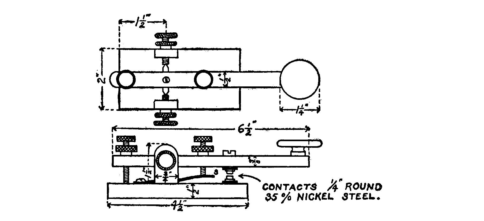
The plans and dimensions for a heavier key are shown in Fig. 68. A wooden pattern of the base and bearings is made and taken to a brass foundry where a casting in brass may be secured. The pattern should be of the same shape and size as the finished article represented in the figure. It is given a slight taper so that it may be easily withdrawn from the sand mold. The brass casting is finished up square and smooth by grinding on an emery wheel or by careful filing. The lever is a piece of brass rod 1/2 inch square and 6 1/2 inches long. One end is fitted with an ordinary hard rubber Morse key knob. The knurled nuts and thumbscrews are of the same size as those used on an ordinary key, and may be purchased from an electrical supply house.
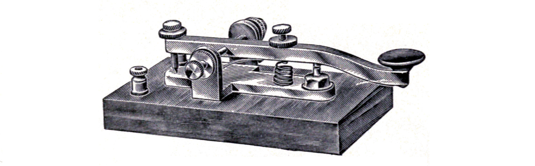
The pivot is a piece of 3/16 inch round steel 1 inch long, and passes through the lever 1 1/2 inches from the rear end. The ends are ground or turned to sharp points and rest in bearings formed by boring a recess in the ends of the thumbscrews. The thumbscrews pass through the center of the bearing, standards 3/4 inch above the base. The lever is clamped to the center of the pivot by means of a small machine screw. A heavy piece of spring brass, S, 1/2 inch wide and 3 inches long, is fastened to the base at one end with a short 8-32 screw. The other end is bent upward so that it presses hard against the lower end of an adjusting screw, which passes through the lever 1 1/4 inches forward of the pivot. This spring serves as an auxiliary conductor and saves the key from carrying an excessive current through its bearings. By adjusting the thumbscrew, the tension of the key may be regulated to suit the operator. The contacts of the key are 1/8-inch round nickel steel alloy or pure silver, set in short 1/4-inch machine screws which fit into correspondingly threaded holes in the base and the lever. This makes the contacts easily removable for renewal. The lower contact is set in a longer screw than the upper one so that connection may be made to it. It is insulated from the base by a hard rubber brushing.
The contacts must be directly above one another and in perfect alignment or else they will pit and stick.
CHAPTER XI. AERIAL SWITCHES AND ANCHOR GAPS.
Some form of switch for quickly connecting the aerial and ground to either the transmitting or receiving apparatus is necessary.
Low powered stations using an induction coil as a transmitter will find a 250-volt double pole, double throw porcelain base switch to be suitable. Such a switch is connected up according to the diagram shown in Fig. 70. As clearly illustrated, the receiving apparatus is in use when the switch is thrown to the right, and the transmitter is ready for operation when the switch is in the left-hand position. The ease and speed with which such a switch may be thrown from right to left or vice versa may be much facilitated by fitting it with a larger and longer handle than the one usually provided.

An ordinary double pole, double throw switch should be mounted on the wall within easy reach of the operator, while the two types of switch about to be described are best situated directly on the operating table alongside of the transmitting key.
All insulated parts of an aerial switch such as the base, insulating bar, handle, etc., should be made of some good insulating material, as porcelain, hard rubber or ebonite. All insulation which is used in power switches such as slate, wood, marble, etc., is worthless and should not be used.
If a loop aerial system is used, a switch is necessary, which will break the primary transmitting current so that in case of an accidental touch of the key while receiving, the high voltage discharge will not pass across the anchor gap into the receptor and badly damage the same or shock the operator. The connections of such a switch and the loop aerial are shown in the wiring diagram of the De Forest system.
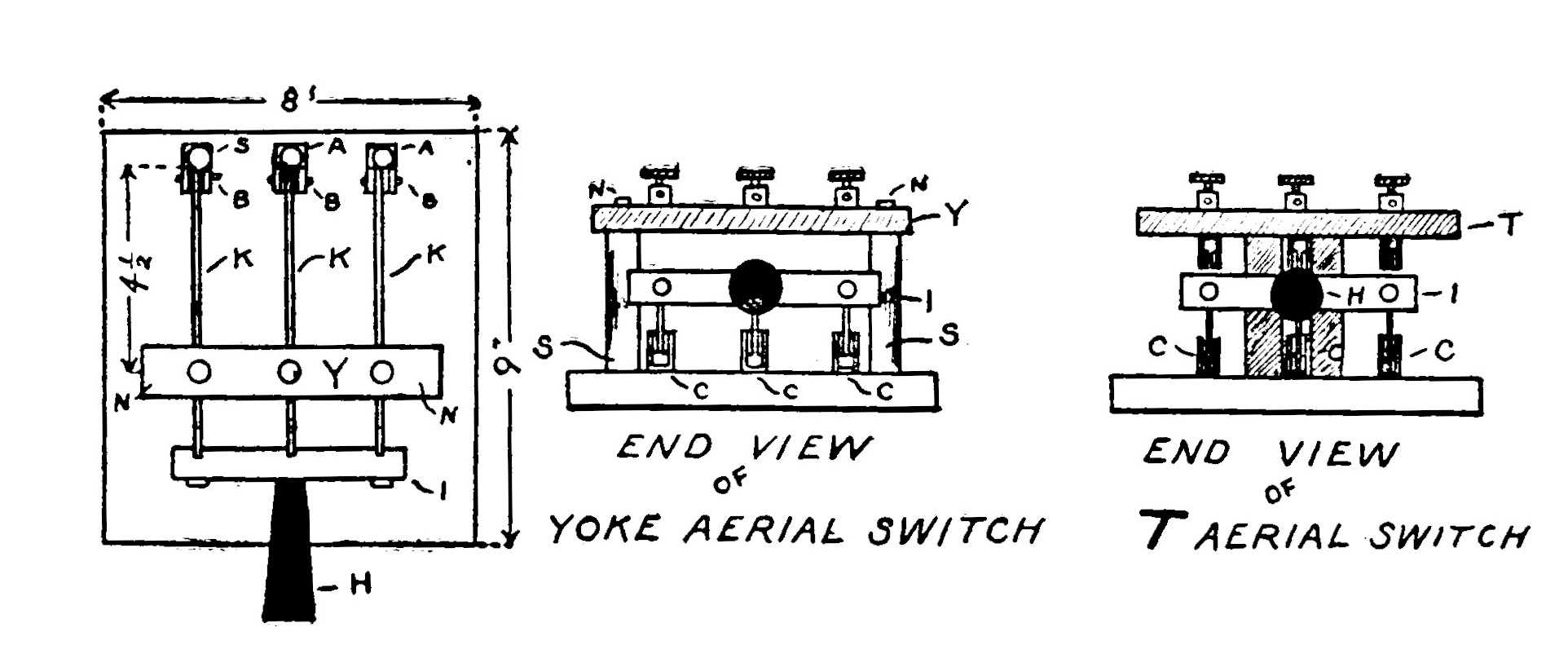
A switch may be easily constructed from a 50 ampere, single throw, triple pole, fuseless power switch. If it is mounted on a slate base remove it and set it up on a base of the same size made of fiber or porcelain. Flat unglazed tiles of various sizes are obtainable from tile setters at a very low cost. They may be easily bored with an ordinary steel twist drill. Such tiles are excellent insulators when not exposed to moisture and are useful for bases, etc., in many cases. A heavy coat of shellac varnish will make the tile impervious to moisture.
A hard rubber rod, S, 3 inches long and 5/8 inch diameter, is mounted on both sides of the base in alignment with the contacts. A strip of hard rubber, Y, 1 inch wide, 1/2 inch thick and 6 1/2 inches long is fitted with two contacts similar to those mounted on the base of the switch. The contacts are mounted at a distance apart equal to the distance between the outside knife blades of the switch. A 1/8-inch hole is bored through the strip at both ends, through the axis of the rods along their entire length and through the base. A piece of brass rod 4 inches long and threaded at both ends with an 8-32 die is passed through the holes and yoke, so that the rods may be held firmly to the base and the strip to the tops of the rods by two nuts screwed on the ends of the brass rod.
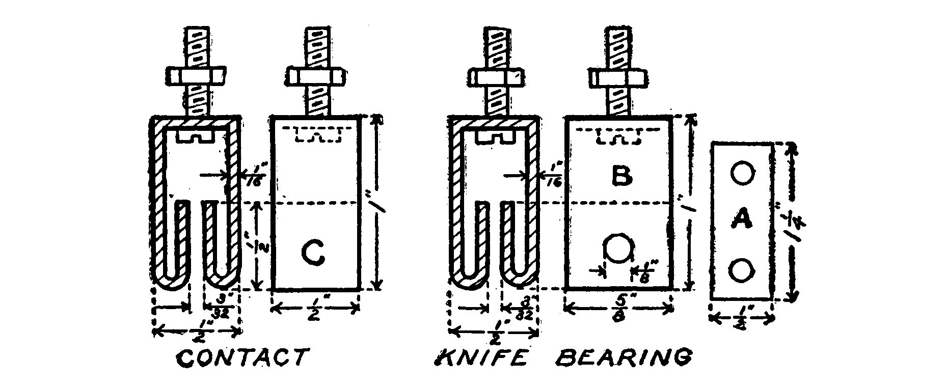
The upper contacts should be directly over the two outside lower ones. They are made from a strip of brass 1/2 inch wide, 3 1/2 inches long and 1/16 inch thick (bent as in Fig. 72). A binding post is mounted on the yoke directly above and connecting with each one of the contacts.
The middle pole of the switch is connected to the primary of the coil or transformer, so that when the switch is down, the primary circuit is completed, and when it is up it is broken.
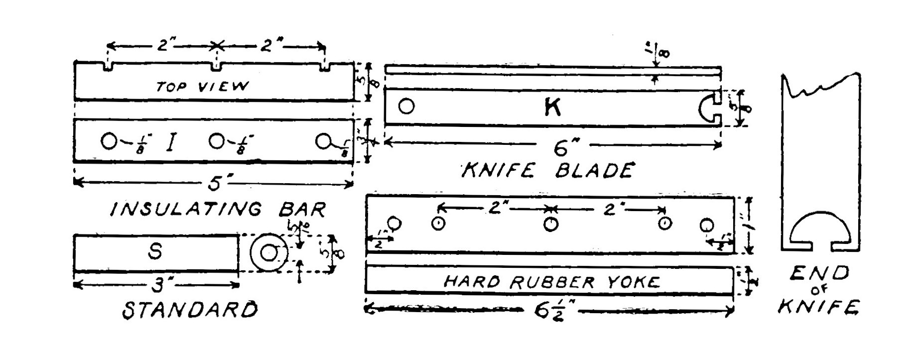
Some may prefer to make the complete switch, and in that case the dimensions given in Fig. 73 may be of aid. The knife blades are 6 inches long, 5/8 inch wide and 1/8 inch thick. Three are required. A 1/8-inch hole is bored 3/8 inch from one end, and the other end is cut out in the shape shown in the illustration. An insulating bar 5 x 3/4 x 5/8 inches is made of hard rubber and three notches are cut in the back face, one directly in the center and one 2 inches on either side.

Three 1/8-inch holes are bored one in the center of each groove and at right angles to it. An 8-32 machine screw 3/4 inch long is placed in the notch in the end of the knife blade and the screw passed through the hole in the insulating bar. The blade may then be clamped tightly in place by putting a nut on the end of the screw. The screw which holds the middle knife blade in place is longer than the other two so that a handle may be fitted on.
The bearings are made the same size and shape as the contacts illustrated in Fig. 72, with the exception that a 1/8-inch hole is bored through near the top so that a small bolt may be slipped in to hold the knife blades in place.
The base of the switch measures 8 x 9 x 3/4 inches. The parts are assembled as in Fig. 71.
Another type of aerial switch called a "T" switch is illustrated in the same figure. A piece of 3/4-inch hard rubber is sawed in the shape of a T, 3 1/2 inches high and 6 1/2 inches wide at the top. The upper contacts are mounted on arms of the "T" and connected to binding posts placed immediately above them, A slot, 1/2 inch wide and 3 inches long, sawed in the center of the leg of the T, permits the middle knife blade to move without obstruction.
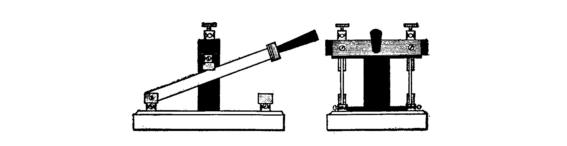
A double pole, double throw switch may be easily adapted to form a "T" switch. Two knives are cut from sheet brass, of the same shape as those already on the switch but twice as long. The contacts at one end of the porcelain base are removed and the bearings of the knife blade fastened there in their stead. This forms a single throw, double pole switch having knife blades twice the length of the original double pole, double throw switch. A "T" shaped support for the upper contacts may be sawed out of 1/2-inch hard rubber and smoothed up with a file. The support is fastened upright by means of two screws which pass through holes in the center of the base where the knife bearings originally were. The two contacts which were removed from the base are fastened to the support directly over the knife blades so that they make a good contact when the switch is up. Two binding posts mounted above the contacts make connection with them.
If desirable the switch may be fitted with a third knife blade and contact so that when the switch is up in position for receiving, the primary circuit of the induction coil or small transformer is open.
It is obvious that the dimensions, etc., need not be the same as those given here but may be adapted to suit the size and design of the switch which is to be altered. The knives should always be as long as convenient and the contacts separated by a wide space.
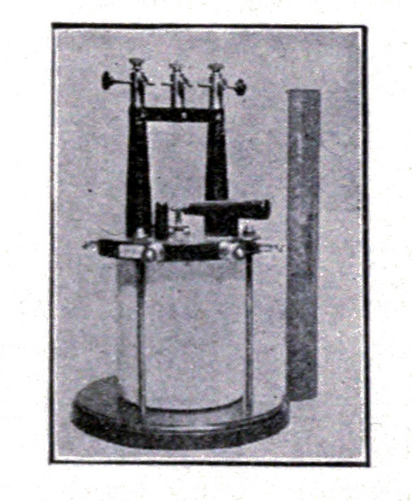
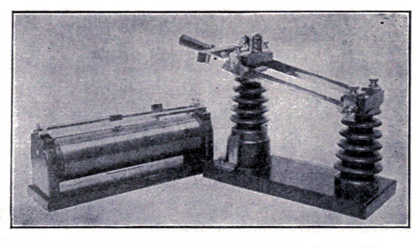
Figs. 76 and 77 illustrate the aerial switches used in the installations of the United Wireless Telegraph Company. These illustrations give a good idea of the long knife blades employed. The lightning switch is fitted with a micrometer spark gap on top of the switch which is in service when the handle is up. The small spark gap affords a path for the lightning to jump into the ground, but cannot be bridged by the receiving currents.
Anchor Gaps.—When a loop aerial system is employed for both transmitting and receiving, a device known as an anchor gap becomes necessary.
The construction and connection of a simple anchor gap are shown in Fig. 79. A ring 1 3/4 inches outside and 1 1/4 inches inside is cut out of 5/8-inch hard rubber or fiber and smoothed up. Three 1/8-inch holes are bored in the periphery of the ring at 120 degrees to each other. The holes are threaded with a 10-24 tap. Three small binding posts are each fitted with a 3/16-inch brass rod 7/8 inch long, having a 10-24 thread so that they may be screwed into the holes in the ring.
The gap between the ends of the two rods connected to the aerial and the receiving apparatus is adjusted until it is about 1/8 inch long. The third point is screwed in until it all but touches the other two.
CHAPTER XII. HOT WIRE AMMETER.
When a current passes through a conductor, it generates heat in proportion to the resistance offered and the amount of current flowing. Heat causes metals to expand sufficiently so that these two properties may be applied to the construction of a hot wire ammeter for the measurement of alternating currents of high frequency and potential.
The hot wire ammeter is placed in series with the aerial, so that by noting the deflection of the pointer, the inductance, capacity and spark gap may be adjusted until the meter gives a maximum reading.
A simple and crude form of meter which is sufficiently sensitive for most experimental work is illustrated in Fig. 80. A piece of No. 36 B. S. platinum wire is sealed in the bulb of an ordinary air thermometer. When the wire becomes heated by a passing current of electricity, it causes the air in the bulb to expand and change the height of the colored liquid in the tube.
An air-thermometer is simply a glass tube of fine bore having a bulb blown at the upper end and the free end immersed in a reservoir of ink or some other colored liquid. The instrument is put in working order by grasping the bulb in the palm of the hand, so that the warmth of the hand will expand the air and cause some of it to escape from the lower end of the tube. Upon removing the hand, the air will contract and suck some of the liquid up into the tube. It should rise only about half way to the bulb, and the tube should be about 18 inches long so as to leave room for changes in the position of the column due to variations in the outside atmosphere. A cardboard scale graduated in inches and reading downward is fastened in back of the tube.
The tube should have a fine bore so as to make the instrument as sensitive as possible. The best liquid to use is alcohol, colored with a little aniline dye. Alcohol has a lower specific gravity than water, and the column will be more sensitive to small changes of pressure. The same figure shows a form of meter devised and used with success by the author.
Two tubes are fitted to the bulb, a large one having a bore of about 0.1 of an inch and another about 0.04 inch. Connection is established by the aid of two corks and a short length of glass tubing one inch in diameter. The tubes are bent U shaped, and a little colored alcohol is placed in each, so that the bottle reservoir is unnecessary. The tube of large bore is fitted at the top with an ordinary glass stopcock such as that used in chemical laboratories.
The stopcock is left open and the transmitter is set in operation by holding down the key. The helix, etc., are adjusted until the larger tube shows a maximum reading. The stop-cock is then closed and the instruments further adjusted by noting the reading in the finer tube which corresponds to much smaller changes in current. The finer bore cannot at first be used alone because the large changes of current would blow the liquid out of the tube. In lieu of a glass stopcock, a piece of rubber tubing may be placed over the end of the tube and closed, when necessary, with a pinch cock.
Fig. 81 shows a more elaborate and sensitive form of meter which is not only suitable for experimental outfits but may be used with good results for more careful work. The advantage of the form of meter here described is that it is "pivotless" so to speak, and contains no bearings which require jewels to eliminate friction.
The "hot wire" is platinum, and in order to compensate for external changes of the atmospheric temperature, is mounted on a strip of glass. Glass and platinum expand at nearly the same rate, and the wire is thus kept taut and prevented from changing the position of the pointer except when the current passes.
Drill four 1/8-inch holes in a piece of window glass 6 inches long and 1 inch wide. The location of the holes is shown in Fig. 82. The two at the ends serve to mount the standards, A and B, and those at the center to fasten down the strip to the base. The holes are drilled with a small three-cornered file which has been broken off and set in a breast drill. The broken end should be used to drill the glass and be kept thoroughly lubricated with camphor and turpentine. With a little care and patience the holes may be drilled without breaking the glass.
Two brass standards are fastened on each end of the glass. They are bent out of sheet brass and are 3/4 inch high and 3/8 inch wide. A brass spring of the same width and 1 1/4 inches long is clamped under one standard. The standard which holds the spring in position is tapped for a small thumbscrew which may be secured from a binding post. Solder a small brass pin to the top of the spring and another one to the top of the standard which is fastened at the opposite end of the glass strip. Some paper or rubber washers must be placed between the feet of the standards and the glass strip to prevent it from cracking when the screws are tightened.
For a station up to one-half K.W. in power the hot wire must be No. 40 B. S. gauge platinum. For larger stations a single No. 36 wire may be used or three No. 40 wires in parallel. The wire must be about 7 inches long. Stretch it between the standard, A, and the spring, C. Wrap the ends around the pins and solder them there, using as small amount of solder as possible. The tension of the wire, which should be taut, is adjusted with the thumbscrew.
Take a piece of the platinum wire about 1/2 inch long and make a little eyelet at one end. Wrap the straight end around the center of the long hot wire and tie a piece of silk in the eyelet.
The glass strip and its standards supporting the hot wire may then be fastened to the baseboard of the instrument by means of two round headed brass wood screws. Two rubber washers must be interposed between the glass and the wood. A piece of 3/32 inch brass 1/2 inch wide and 3 1/4 inches long is bent in the shape shown by F in Fig. 84. The upper end is bored and tapped to receive a thumbscrew similar to the one in the standard on the glass strip. Two brass springs 1/64 inch thick, 3/8 inch wide and 1 1/4 inches long are soldered or riveted at opposite ends of F in the positions shown in Fig. 85. The springs should project one inch from the upright. A small hook made from an ordinary pin is soldered to the outside end of each.
The movement is shown in perspective by Fig. 85. G is a rectangle of very thin copper, 1/2 inch long and 1/4 inch wide, having a little projection 1/4 inch long bent in a curve so that it forms a sextant of a circle, of which the intersection of the diagonals of G would be the center.
The pointer is a piece of steel wire 5 inches long. It is slightly flattened by hammering so that it will retain its shape and not curl. About 1/2 inch is allowed to project through G and is weighted with a lead shot so as to partly counterbalance its weight.
Two loops of wire are fastened to the corners of G by tying them in holes which are bored there for that purpose. The wire is fine phosphor bronze .003-.005 of an inch in diameter, which is used for suspending the movements of delicate galvanometers. Pass the loops over the hooks on the springs and adjust until the pointer moves horizontally. Then fasten the wires permanently to the hooks by means of a small drop of solder.
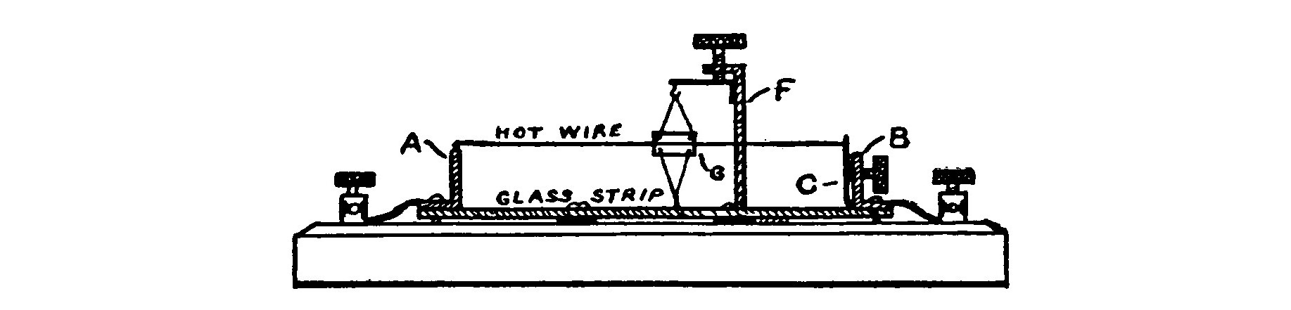
The movement is mounted in the position shown by Fig. 86. The silk thread tied to the eyelet runs to the little sextant and is cemented at the further end by means of a small drop of sealing wax. The scale is a piece of sheet copper or brass, covered with white paper and calibrated in degrees or made to read in amperes by connecting it in series with an ammeter and a source of direct current. A rheostat should be included in the circuit and the current varied so that various values may be marked off. All the different points must be located by sending an actual current of that value through the meter. An error is liable to result if any of the points are marked by guesswork, for the divisions grow smaller and smaller as they become farther away from zero. For example a position of the pointer corresponding to 0.1 of an ampere will not be half way between zero and 0.2 but will be nearer the 0.2 division.
The resistance of wires to high frequency currents is much higher than their resistance to constant currents. This would seem at first to indicate that our meter will give a higher reading for an equal current value, when used with a high frequency current after being calibrated with a direct current. But with wires of very small diameter such as No. 40 B. S. gauge there is almost no perceptible difference and consequently no error unless the frequency of the oscillations exceeds 1,000,000 per second, which is very unlikely with the "spark" method of wireless telegraphy.
Fig. 87 illustrates the form of hot wire ammeter used by the United Wireless Telegraph Co. for tuning their installations.
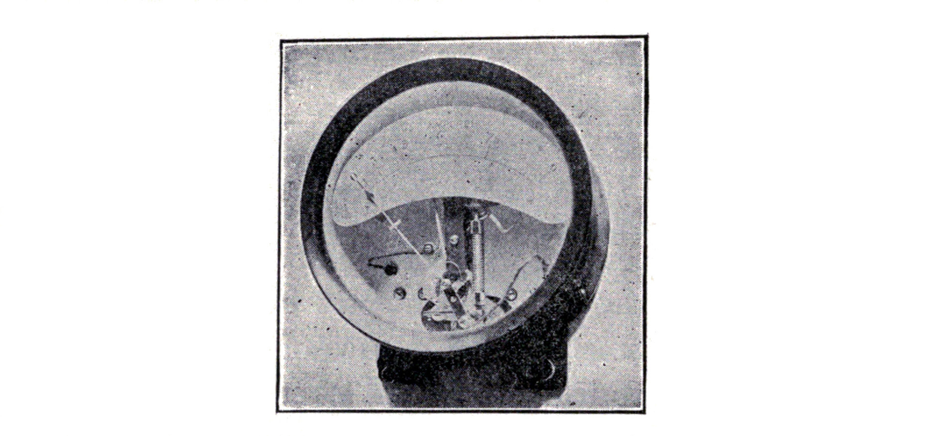
The pivotless meter just described should be fitted with heavy binding posts which are connected to the brass standards mounted on the glass strip by means of stranded copper wire.
The meter should be fitted with a case and glass cover to exclude dust and prevent injury to the working parts. It should be mounted in such a position that the weight of the pointer is sufficient to keep the silk thread taut so that when the wire expands the pointer which is normally at zero will fall of its own weight. When the wire cools after the current has ceased to flow, it will contract and draw the pointer up again.
Platinum wire will give good results, but for more accurate work an alloy known as platinoid is most suitable.
Detailed instructions for tuning the transmitting circuits by means of a hot wire ammeter are given in the chapter on Transmitting Helixes.
CHAPTER XIII. OSCILLATION DETECTORS.
"UNIVERSAL" DETECTOR.
The purpose and position of the detector in a wireless telegraph system has already received some notice in the first chapter, but its operation and adjustment are so important that this chapter deserves the most careful consideration. The receiving range of a station is not as much dependent upon the aerial system as it is upon the adjustment of the tuning circuits and the detector itself.
It is suggested that the amateur experimenter not confine his work to receiving only with a single type of detector but rather accustom himself to the different instruments.
During the past few years many wireless telegraph detectors have been invented which lend themselves readily to amateur construction. It is somewhat of a convenience to have a "universal" detector which with a little manipulation may be used as more than one type and thus save unnecessary expense and much labor.
The "universal" detector shown in Fig. 88 has been so designed as to present a good appearance and at the same time be successfully operated as an electrolytic, tantalum, peroxide of lead, silicon, carborundum or any of the crystal type detectors.
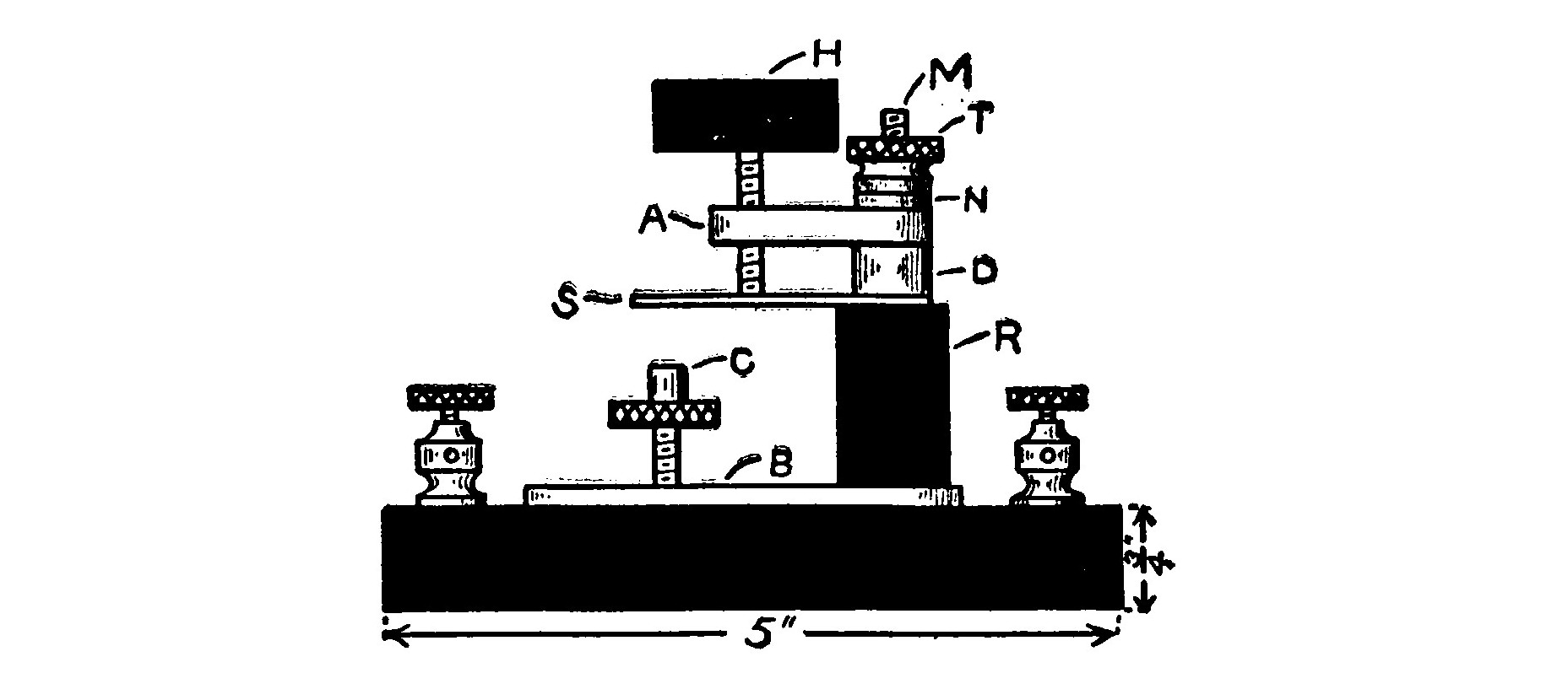
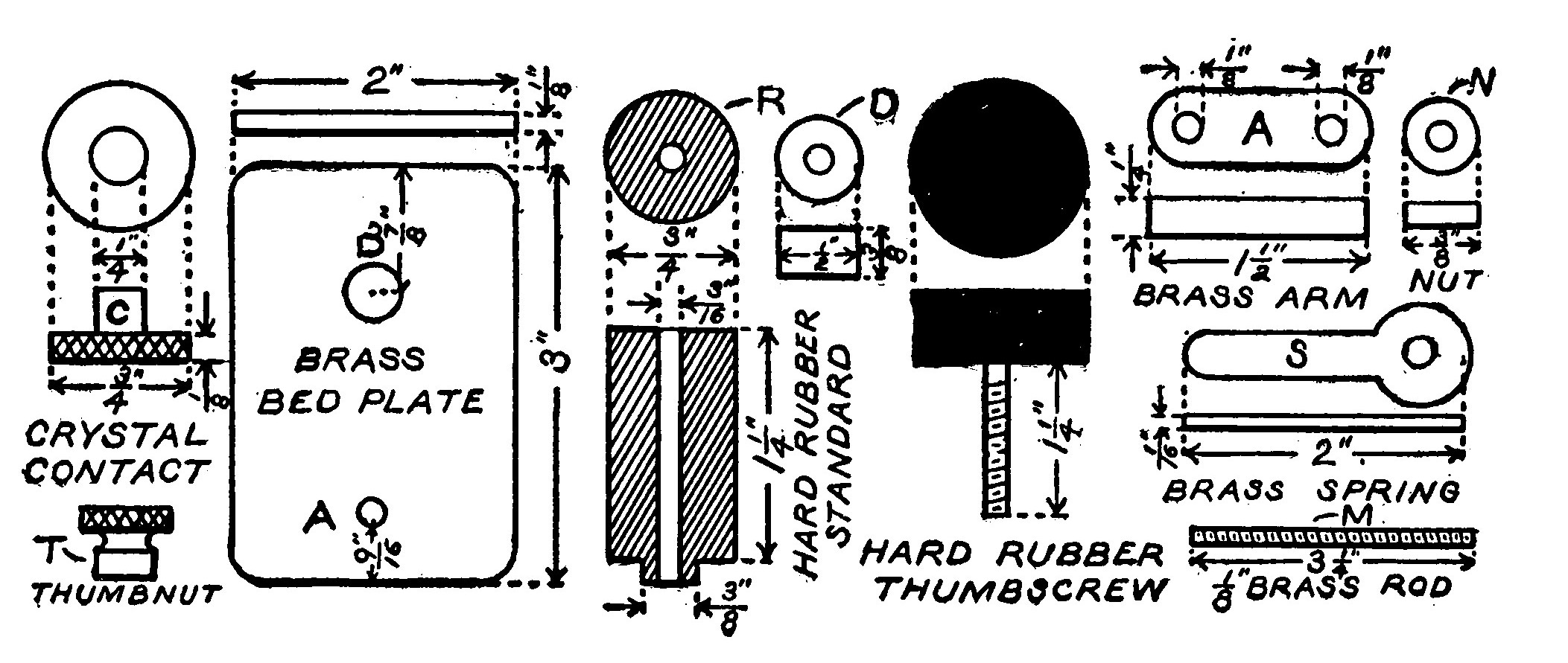
The standard, R, is a 3/4-inch hard rubber rod, 1 1/4 inches long, with a 3/16 inch hole bored through its axis. A spring, S, is made after the plan shown in Fig. 86. It is 2 inches long and 1/16 inch thick. A brass collar 1/8 inch thick and 3/8 inch diameter is soldered on the smaller end of the spring in order to so reenforce it that it may be bored and threaded with an 8-32 tap to receive a thumbscrew. The brass standard, D, is a small cylinder 3/8 inch high and 1/2 inch in diameter. A 3/16 inch hole is bored through its axis. The arm, A, is brass and measures 1 1/2 x 1/2 x 1/4 inches. The ends are rounded by filing or grinding so that they coincide with the semi-circumference of a circle having a diameter of 1/2 inch. Two holes are bored on the center line 1/4 inch from each end.
One is a 1/8-inch hole and the other is threaded with a 10-32 tap to fit the large adjusting screw. The adjusting screw, H, is 1 1/4 inches long and has a 10-32 thread. A hard rubber head 1 inch thick and 1 1/4 inches in diameter is clamped to the upper end by means of two hexagonal brass nuts. A small brass washer should be placed between the head and each of the nuts to give it a more finished appearance and prevent the nuts from marring the rubber.
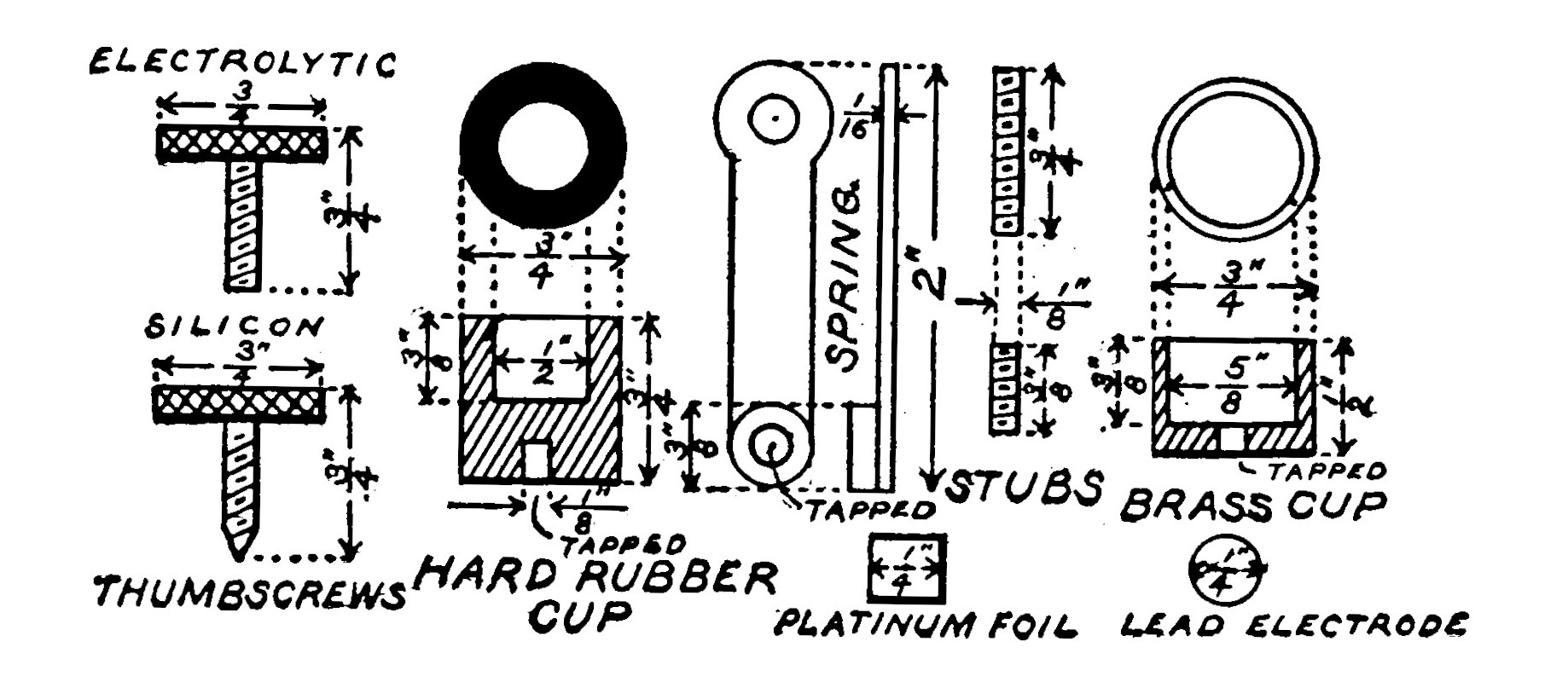
The brass bed plate, B, is 1/8 inch thick, 3 inches long and 2 inches wide. Two holes are drilled on the center line 9/16 inch and 7/8 inch from either end. One is 3/8 inch in diameter and the other is threaded with an 8-32 tap. An insulating bushing in the shape of a hard rubber washer on the lower end of R, 1/8 inch thick and 3/8 inch in diameter, has a 3/16-inch hole bored in its center and is fitted in the larger hole in the bedplate. The whole detector is assembled and mounted on a hard rubber base 4 x 5 x 4 inches. A brass binding rod, M, 3 1/4 inches long and having an 8-32 thread, is passed successively through the arm, the brass standard, the spring, the hard rubber standard and the bedplate. A hexagonal brass nut on the under side of the base and a thumb nut on the brass arm serves to bind the whole tightly together. Four binding posts are mounted on the four corners of the base. Two are connected to the brass binding rod and two to the bedplate. This completes the universal part of the detector. The remaining parts are each described under the headings of the respective detectors to which they belong.
ELECTROLYTIC DETECTORS.
"Bare Point" Type.—Although the electrolytic is the oldest of a long line of very sensitive detectors,3 it still holds first rank when in the hands of an experienced and skillful operator. It exists in two different forms, but the more favored is that known as the Fessenden "bare point" type, which consists of a very fine Woolaston platinum wire (.001-.00002 of an inch in diameter) dipping in a small cup of dilute acid. The acid is either 20 per cent chemically pure nitric or sulphuric.

A large electrode of platinum wire or foil dips into or is sealed in the bottom of the cup so as to make an electrical connection with the liquid. The fine Woolaston wire is clamped over the cup in a holder which permits of vertical adjustment, by means of a thumbscrew, so that the depth of immersion in the acid may be regulated.

Woolaston wire is covered with a comparatively thick coating of silver, which before using must be removed from the end for about 1/32 inch by dipping it in strong nitric acid, which will dissolve the silver and expose the almost invisible platinum core. Too much of the fine platinum core must not be exposed or else the surface tension of the acid will cause the wire to curl over and present a large flat surface instead of a fine point. This is a very necessary and important precaution, for the detector is more sensitive as the area of contact between the fine wire and the liquid is smaller.
Whenever this condition is reached the end of the wire should be cut off with a pair of sharp scissors and a new point exposed.
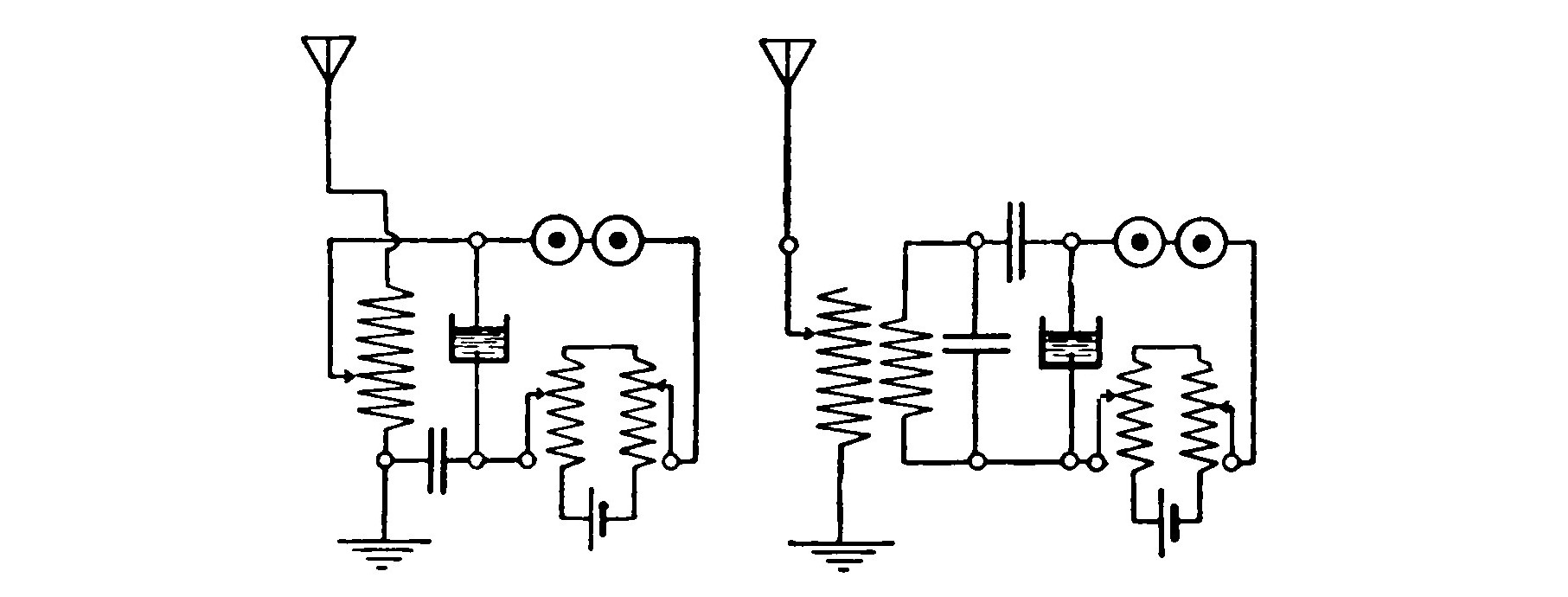
The detector circuit is shown in Fig. 93. The fine "bare point" is always made the positive or anode of the battery circuit. Otherwise the detector will not operate. A potentiometer must be shunted across the terminals of the battery to reduce the voltage to a value just below that which is required to break down the thin film of oxygen gas which collects on the "bare point" and polarizes it or insulates it from the liquid so that little or no battery current can flow. This film of gas is caused by the electrolysis of the acid solution and the decomposition of the water into hydrogen and oxygen gas.
When oscillations are set up in the receiving aerial and they surge through the detector, a sufficient e.m.f. is generated to break down the film of gas and permit the battery current to flow again. The passage of current causes the signals in the telephone receivers.
The electrolytic cup for the universal detector is illustrated in Fig. 90. It is made of a piece of hard rubber rod 3/4 inch in diameter and 3/4 inch high. A recess 1/2 inch in diameter and 3/8 inch deep is cut in the top to contain the acid. A small hole 1/4 inch deep is bored in the under side and threaded with an 8-32 tap. A brass pin 1/2 inch long, having a corresponding thread, is fitted in the hole. The pin may then be screwed into the small hole in the bedplate. A piece of No. 30 B. S. gauge platinum wire or a strip of platinum foil is clamped between the bottom of the cup and the bedplate and then bent over the top of the cup into the liquid.
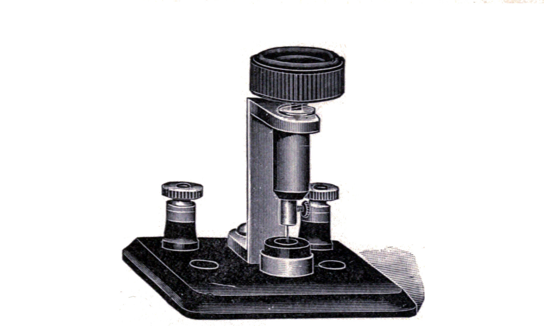
A 1/16-inch hole 1/4 inch deep is bored in the lower end of a thumbscrew having an 8-32 thread. A piece of Woolaston wire 1/2 inch long is placed in the center of the hole and tinfoil packed into the surrounding space with the head of a sewing needle until the wire is held firmly in position. The free end of the wire must then be dipped in some strong nitric acid to remove the silver. The thumbscrew is placed in the collar on the end of the spring of the universal detector and lowered until the "bare point" almost touches the surface of the electrolyte in the cup beneath. Pressure must then be applied to the spring by turning the large adjusting screw until the "bare point" touches the liquid and a click is heard in the telephone receivers and a faint bubbling sound is also audible. The adjusting screw must then be slowly and carefully turned in the opposite direction so as to raise the point until the bubbling changes to a hissing sound. The point is then above the level of the electrolyte in the cup but is still in contact with it because of the capillary action of the fine wire and the liquid.
By using the large adjusting screw as much as possible, instead of the small thumbscrew, the point is raised or lowered without giving it a circular motion and much finer adjustment is made possible. The potentiometer is adjusted until the hissing noise caused by excessive battery voltage just disappears. The detector is then in its most sensitive condition for receiving signals.
When the detector is in use for long periods, the potentiometer must be frequently readjusted to compensate the gradual loss in voltage of the battery. It is well to provide a small switch which will disconnect the battery from the potentiometer when the detector is not in use. In the same case the acid should be removed and placed in a tightly stoppered bottle. A pipette or fountain pen filler furnishes the most convenient means for filling or emptying the cup. The acid must be kept perfectly pure and out of contact with all metals other than platinum. Great care should be exercised in filling the cup, for the acid, if spilled, will not only badly corrode the metal fittings, but will also provide a current leak and seriously weaken the signals.
Shoemaker and Stone Detectors.—These two types of detectors make use of "glass points," so called because the fine platinum wire is sealed in a glass tube and the end of the tube is then ground down on a fine oilstone until the platinum wire is exposed. This results in a very fine contact area and insures constant immersion of the point without readjustment.

The fine platinum wire for a glass point may be secured from one of the flaming pocket cigar lighters making use of spongy platinum. The center of a thick walled glass tube is softened by heat and contracted as shown at A-B in Fig. 95. After cooling, the tube is cut in half at the point indicated by the dotted line. The platinum wire is placed in the contracted end of the tube and carefully fused in so that about one-half of the wire, which is about 1/2 inch long, is embedded in the glass. The contracted end of the tube containing the wire should be closed. Connection is established to the upper end of the fine platinum wire by filling the tube with mercury and dipping a piece of flexible conductor in the mercury. The upper end of the tube is closed and the mercury prevented from escaping by a small dab of sealing wax.
The "point" is slowly and carefully rubbed on a fine oilstone kept well wet with water. The tube must be held in a vertical position so that the glass will be ground away at right angles. When it is thought that the platinum wire has been exposed by the grinding, connect the flexible conductor to one pole of a battery. The other pole of the battery is connected to a pair of sensitive telephone receivers and the telephone receivers to a vessel containing dilute acid. If the platinum wire is exposed, a sharp click will be heard in the telephone receivers when the "point" is dipped in the acid. Do not confuse the sharp click with the sound which may be occasioned because the outside of the glass tube is damp or wet.
After the point has been sufficiently ground, disconnect the testing apparatus and connect the free end of the flexible conductor to a binding post placed on the end of the detector spring, S. The detector circuit is similar to that of the "bare point" type.

The illustration shows what is sometimes called a "primary cell" detector because it furnishes its own current and does not require a battery. A Stone detector may be very easily changed to one of the Shoemaker type by substituting an amalgamated zinc rod for the platinum wire anode which makes connection with the liquid in the cup. This combination of platinum and zinc results in an electromotive force of about 0.7 volt, and the telephone receivers are connected directly to the terminals of the detector without any local battery or potentiometer. The electrolyte in the cup must be a 20 per cent solution of pure sulphuric acid, as nitric acid would dissolve the zinc in a very few minutes. The zinc must be kept well amalgamated with mercury.
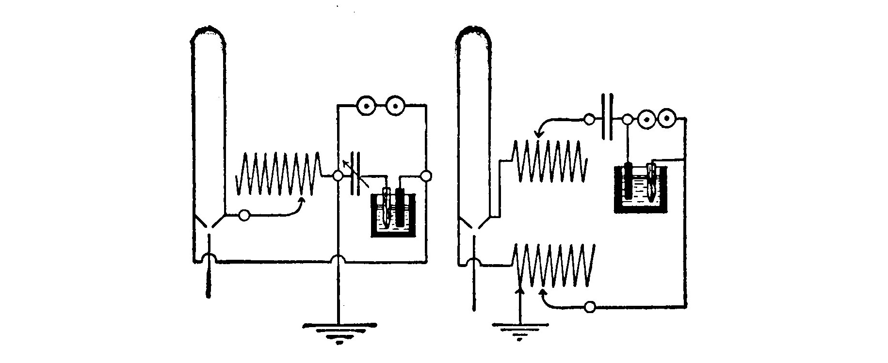
The Shoemaker system makes use of a loop aerial, and the circuits with a single and double coil tuner are illustrated in Fig. 97. It is not necessary to use these, and the detector will operate just exactly as well on a "straightaway" aerial.
Lamp Detector.—All electrolytic detectors, more especially those of the "glass point" type, are subject to the annoyance of "burn-outs." That is, the fine platinum wire melts when receiving strong signals from a near-by station.
In such case, the "bare point" must be lowered until it again makes contact with the liquid, and the "glass point" reground until the wire is again exposed.
When this trouble comes often it is very convenient to have at hand a simple detector which will not burn out and which may be substituted for the usual one when great sensitiveness is not required.
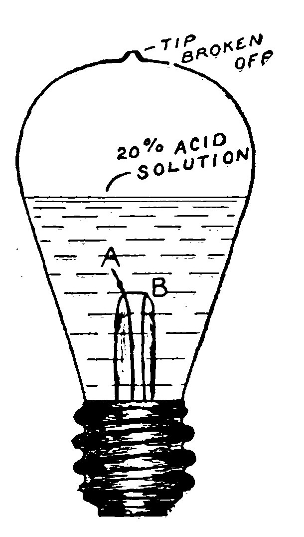
Such an instrument is made by snipping off the tip of a small incandescent electric lamp and removing the filament with a wire. One of the leading-in wires is broken off as close as possible to the glass stub and the globe half filled with a 20 per cent acid solution. The broken wire must be made the negative or cathode and connected like a Fessenden or Stone detector. This lamp detector though crude will give good service without burning out when used to receive from near-by stations.
In place of a lamp detector, a glass point having a larger wire than that of the cigar lighter may be used instead of the usual point, but it will not be so sensitive.
Fig. 99 illustrates a simple form of electrolytic detector which is not so sensitive as that shown in Fig. 100 but is still very serviceable.
The cup is made from the carbon of an old dry cell, the brass connecting cap serving very well to make the connections to. It has a recess about 1/2 inch in diameter and 1/4 inch deep cut in the top to contain the electrolyte. The cup should be about one inch high. A file will smooth up any rough edges and give it a good appearance.
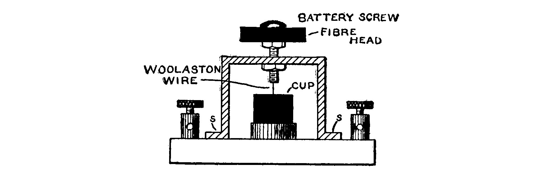
The yoke is made of a piece of 1/8-inch sheet brass about 3/4 inch wide, bent in the shape shown in the illustration. Two small holes are drilled in the feet, to serve to fasten the yoke firmly to the base and also to make connection to.
The adjusting screw may be made from the screw taken from the carbon of an old dry cell. To permit of accurate adjustment, it should be fitted with a large head made from a piece of 1/4-inch hard rubber or fiber cut in a circle about 1 1/4 inches in diameter. Bore a small hole about 1/8 inch in diameter through the center of the head and force it on the screw. A nut screwed on the under side will then clamp it tightly against the brass head. A hole is bored in the center of the yoke and a battery nut which will fit the adjusting screw soldered directly under it.
The platinum wire may be either soldered to the adjusting screw or fastened with tinfoil in the method which has been described.
The cup and yoke are best mounted on a piece of hard rubber 1/2 inch thick, 3 inches wide and 4 inches long. A binding post is placed near each of the four corners.
It is possible to do extremely fine and long distance work with the detector illustrated in Fig. 100. It is so arranged that the "bare point" need not necessarily be revolved when making an adjustment, and so it is possible to place it in a very sensitive condition.
A brass standard, U, 1 1/4 inches long is cut from a piece of 1/2-inch rod. A hole bored in the top and bottom of the standard is threaded with an 8-32 tap. A brass rod, R, 2 inches long is threaded with an 8-32 die throughout its entire length. One end is screwed in the top of U.
A piece of brass tubing, P, 1 1/4 inches long and having an internal bore of 1/2 inch is slipped over U. A slot cut in P fits over a small pin set in U and permits P to be slid up and down but not to turn around.
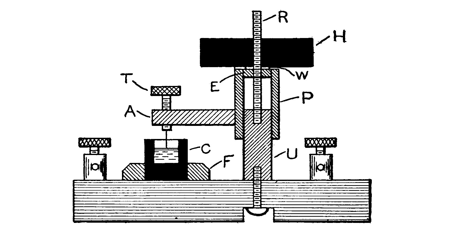
A head in the form of a circular brass washer, E, 1/8 inch thick, 1/2 inch in diameter and having a 5/32-inch hole bored in the center is soldered in the top of the tube, P.
A circular piece of hard rubber, H, 2 inches in diameter and 1/2 inch thick is fitted with a brass bushing having a hole in the center with an 8-32 thread to screw on the rod, R.
A spiral spring is placed around R between U and the head E. A small brass washer should be placed between H and E in order to eliminate friction. When H is turned in one direction, the spring will cause P to rise, and when turned in the other direction it will be lowered.
A brass arm, A, 1/4 x 1/4 x 1 1/2 inches carries a small thumbscrew, r, at one end, while the other end is soldered to P as shown in Fig. 96. The Woolaston wire is soldered to T.
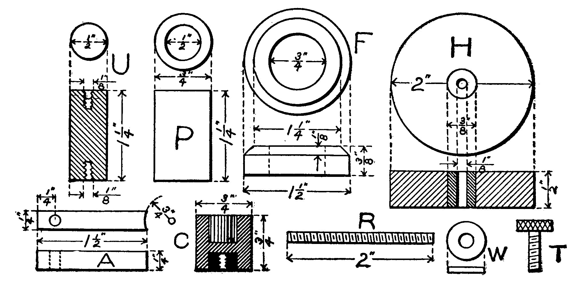
A small carbon cup 3/4 x 3/4 inch serves to hold the electrolyte. A 3/8-inch hole is bored 1/4 inch deep in the bottom of the cup and poured full of melted lead. The lead is then bored and tapped to fit a machine screw which fastens the cup to the base. Connection is made from a binding post to the machine screw. A second binding post is connected to the screw which fits into the bottom of U and holds it to the base.
If desirable a circular piece of hard wood, F, may be turned out and glued to the base around the cup in order to give it a more finished appearance.
The thumbscrew, T, is used to lower the "bare point" until it almost touches the liquid, and then the large head, H, is brought into play to make the finer adjustment.
Increasing the Sensitiveness of an Electrolytic Detector. The sensitiveness of an electrolytic detector may be increased in three ways, viz., by connecting two detectors in series, by warming the electrolyte and by agitating it.
The first method is clearly apparent.
The second is accomplished by placing the detector over a sand bath and gently warming it. It will then show a marked increase in the strength of the signals at a temperature of about 30 C. This increase will continue to rise with the temperature until it reaches a maximum at about 60 C.
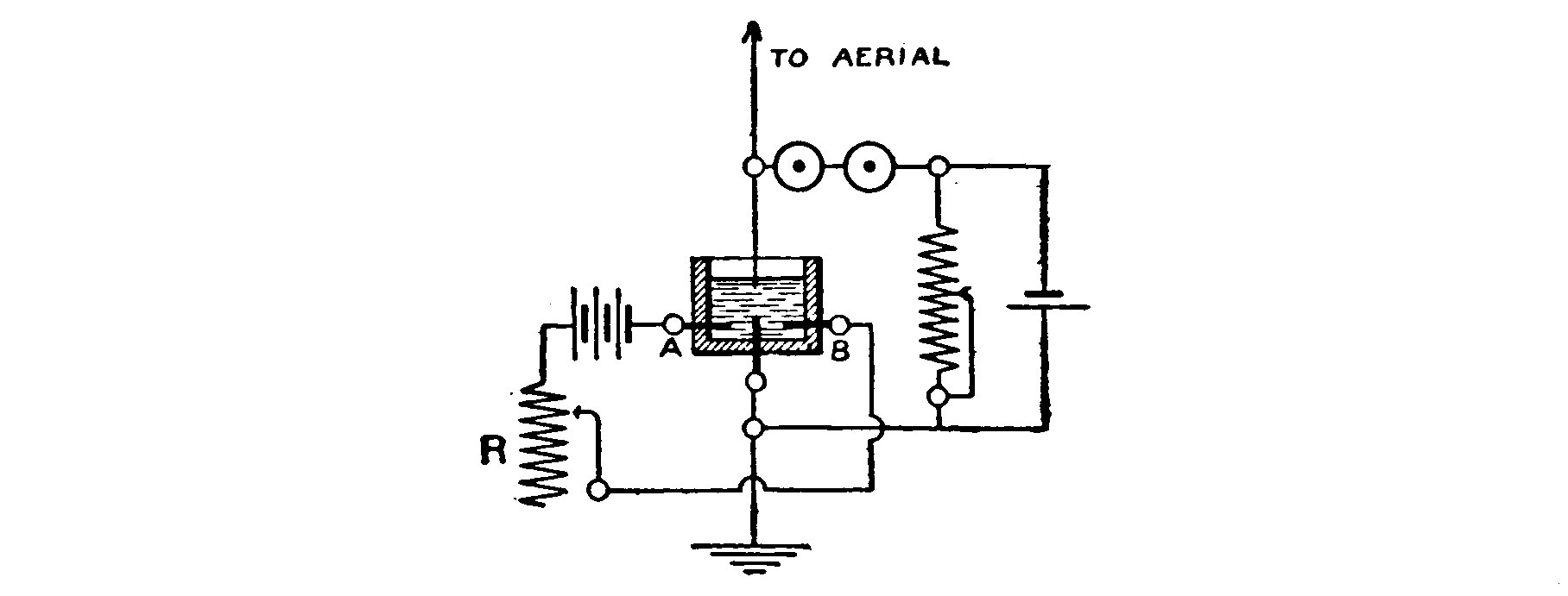
Branly discovered that a fine stream of gas passed through the electrolyte in order to agitate it increases the strength of the signals in the phones. He devised a detector provided with two extra platinum terminals sealed in the cup. When connected in series with a battery and an adjustable resistance, these terminals cause electrolysis of the water, and a fine stream of oxygen and hydrogen gas flows through the acid electrolyte. The stream of gas agitates the liquid just sufficiently so that when oscillations strike the detector they augment the breaking down of the film of gas which collects on the fine platinum point. This results in an increase in the battery current flowing through the telephone receivers of from two to four times and a corresponding increase in the volume of sound. The adjustable resistance is used to regulate the decomposition of the electrolyte and formation of gas, for if this proceeds too rapidly an undesirable rumbling noise will be produced in the telephone receivers.
TANTALUM DETECTOR.
The tantalum detector is especially suitable for the amateur experimenter because its change in resistance when struck by oscillations is so great that high resistance telephone receivers are not necessary. Its normal resistance is about 1000-2000 ohms, and this sometimes drops as low as 125-100 ohms when struck by oscillations of ordinary strength. It is not nearly so sensitive as the electrolytic or crystal detectors, but gives very much louder tones in the telephone receivers when used for short distance work.
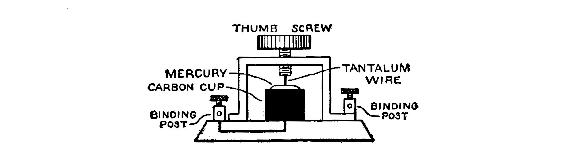
The detector is easily made by substituting a piece of tantalum wire for the Woolaston wire of an ordinary electrolytic detector. The dilute acid solution is removed from the cup and replaced by some pure mercury. The connections remain the same as for the "bare point." The potentiometer is adjusted until the potential of the battery is in the neighborhood of 0.2-0.4 volt.
The tantalum wire may be easily secured by breaking the globe of a tantalum lamp and using a piece of the filament. It is best to snip off the lamp tip before breaking the globe. This precaution admits the air and prevents an explosion which would shatter the glass and scatter the filament in fragments.
If the universal detector is used with a tantalum point, turn the small thumbscrew until the wire almost touches the surface of the mercury. Then lower it with the large adjusting screw until the tantalum touches the surface and a sharp click is heard in the telephone receivers. Adjust the potentiometer until the signals are the loudest.
CRYSTAL DETECTORS.
Certain minerals and crystals, principally members of the carbon and sulphur groups, possess the peculiar property of rectifying electrical oscillations and converting them into a pulsating direct current. These crystals conduct the current better in one direction than in the other. In the case of a current having a potential of ten volts and applied to the ends of a carborundum crystal, the current may be one hundred times greater when flowing in one direction than when flowing in the other. This ratio decreases as the voltage is raised, for with 25 volts it may be only about forty times greater. The crystals when properly inserted in the aerial circuit are enabled to rectify the oscillations and produce sounds in the telephone receivers without the aid of a battery.
The following is a partial list of the minerals and crystals exhibiting these properties to a sufficient extent that they are of value as oscillation detectors in wireless telegraphy.
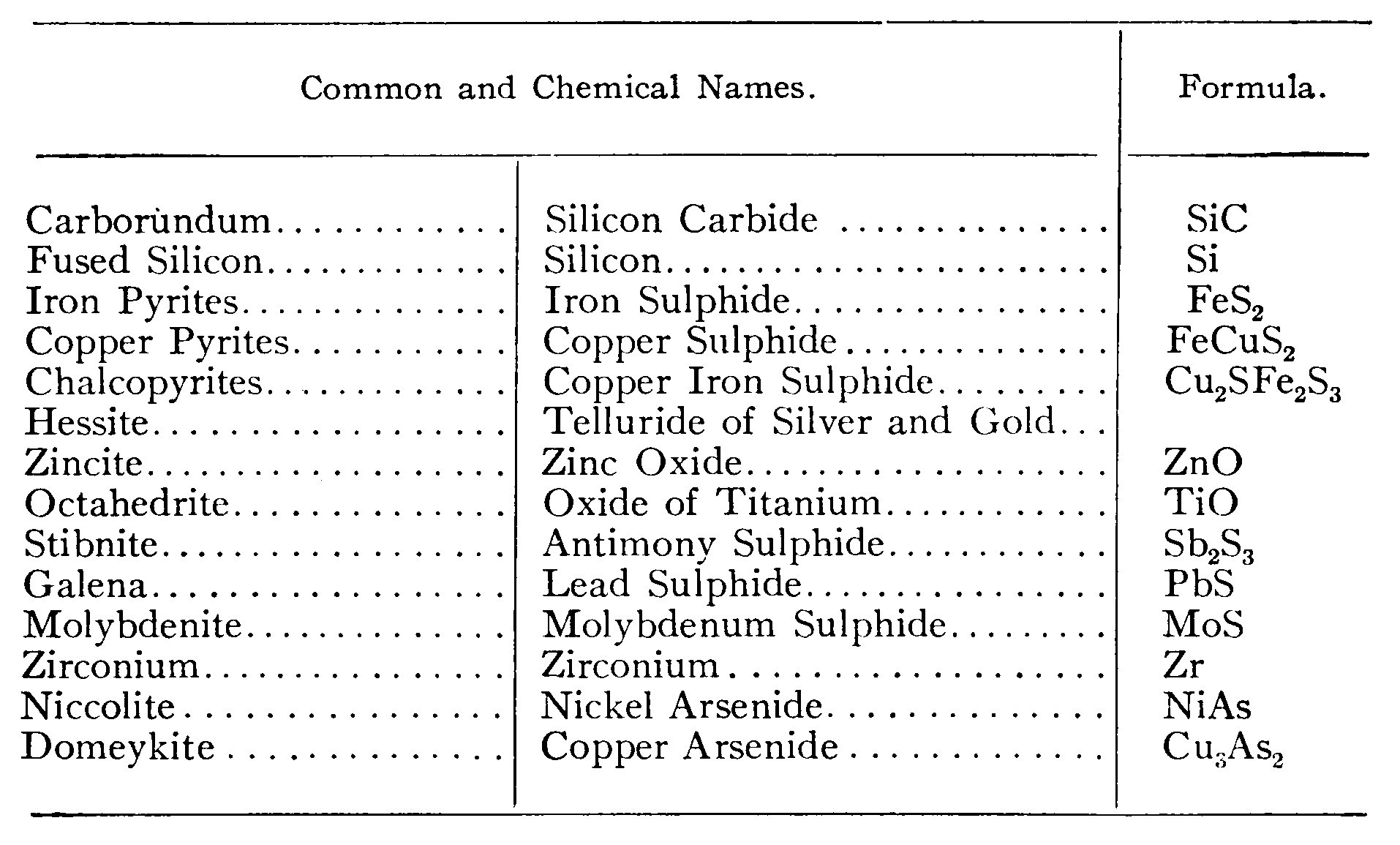
In the case of iron pyrites the writer has found that a specimen of this mineral containing very little or no copper as an impurity does not exhibit these properties to an appreciable extent.
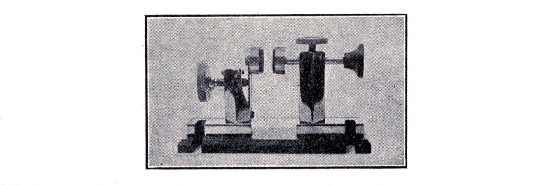
In order to use the universal detector for minerals, a special contact similar to that shown in Fig. 90 must be made. The contact is bored and threaded on its under side to fit a brass pin 3/4 inch long and having an 8-32 thread. The other end of the pin screws into the hole in the bedplate. The large knurled portion of the contact permits it to be raised or lowered without the fingers coming in contact with the crystal. The crystal is clamped between the contact and the spring, S. The position is varied until a sensitive spot is found and then the pressure is carefully regulated by means of the large adjusting screw until the signals in the telephone receivers are the loudest. If possible avoid touching the crystals with the fingers, as the oil and dirt, even though it cannot always be seen, spoils their value for long distance work. Use instead a pair of steel forceps.
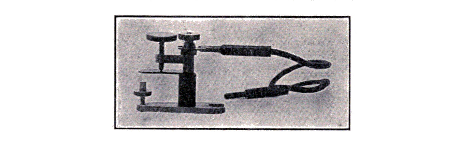
The United Wireless Telegraph Co. makes use of carborundum in the detectors shown in Figs. 104 and 105. The principal advantage of carborundum over such substances as silicon, etc., is that it is not affected by the heavy discharge of the transmitting apparatus and does not require a new adjustment after each period of sending. All the crystals will not work, and so a large cake should be purchased and the desired crystals selected. The dark blue portions of the mass, which are the hardest, will give the clearest tones in the telephone receivers, and are preferable to the lighter colored crystals. Since the crystals conduct better in one direction than in the other, as explained above, the adjustment must be made with the view of determining in which position the particular crystal will work the best.
Carborundum will produce sounds in the telephone receivers without the aid of any battery, but for careful work a battery and a potentiometer are necessary.
The other crystals given in the column merely require that the telephone receivers be connected to the detector terminals as in the wiring diagram in Fig. 108.
The Clapp-Eastham detector makes use of a crystal of iron pyrites held in a brass retaining cup beneath the metal contact point. It is not affected by strong signals and requires no battery or potentiometer. When adjusted it will remain in a sensitive condition for a long time without further attention.
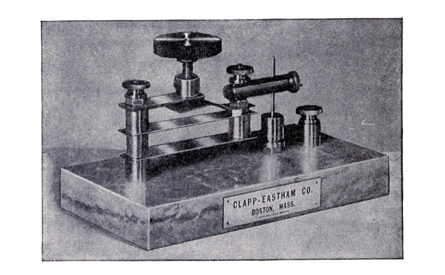
Silicon Detector.—While the silicon and "perikon" detectors are classed as mineral or crystal detectors they deserve special attention.

Silicon gives fair results if a crystal is placed between two metal electrodes as, for instance, between the contact and spring of the "universal" detector, but is much more sensitive when properly mounted. A brass cup such as that shown in Fig. 90 is made and the interior brightened by scraping with a file. The cup is then poured full of a molten fusible alloy and the silicon pressed in it until it cools and becomes set. It should then present an appearance similar to that shown by A in Fig. 107. The silicon is ground down by rubbing on the surface of a clean oilstone kept well wet with water, until the surface is flat and shows a polish.

The cup containing the silicon is placed over the hole in the bedplate of the universal detector. A knurled brass thumbscrew having a point on its lower end is screwed into the collar on the spring, S, and brought to bear on the polished surface of the silicon. The pressure may be easily regulated by means of the large adjusting screw until the signals in the telephone receivers are the loudest. It is not advisable to fasten the cup to the bedplate but merely to brighten the bottom so as to insure a good contact. The cup may then be moved around so that different portions of the polished surface of the silicon may be brought into play when desirable.
If the knurled brass thumbscrew is fitted with a platinum point which can be brought to bear on the surface of the silicon, the efficiency of the detector will be materially increased.
When mounting silicon or other crystals some careless experimenters use lead or a metal having a high melting point instead of a fusible alloy. This is poor policy because the high temperature coats the surface of the crystals and the interior of the cup with a non-conducting layer which destroys the sensitiveness and makes it unfit for long distance work. A fusible alloy melting at about the boiling point of water or even lower should be used. Such alloys are usually composed of tin, lead and bismuth. The addition of a little cadmium serves to make the fusing point considerably lower in each case. The alloys may be prepared by the experimenter from the following formulae, or are obtainable from a firm manufacturing fire plugs for automatic fire extinguishers.
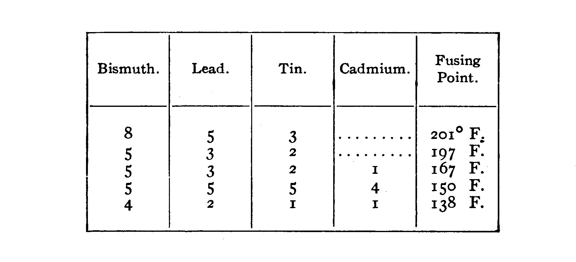
The lead should be melted first and then the bismuth, tin and cadmium added in the order named.
Perikon Detector.—The Perikon detector is one of the latest types to come into extensive use. It consists of two crystals, zincite and chalcopyrites,4 set in cups in the manner just described and placed in contact with each other. The minerals are mounted similar to those in Fig. 105. The zincite should present a rather flat surface with the grain of the crystal parallel to the sides of the cup so that the top surface corresponds to the end of a stick of wood sawed at right angles to the grain. More than one crystal of zincite is usually set in the same cup. The chalcopyrites should present a rather blunt point. The cup containing the chalcopyrites is the smaller and is bored and threaded to fit a thumbscrew which passes through the collar in the spring, S, of the "universal" detector. The bottom of the cup containing the zincite is brightened so as to insure a good contact and then placed on the bed plated under the cup containing the chalcopyrites which is fastened to the thumbscrew. The zincite may then be moved around until the most sensitive portion is found. The chalcopyrites is lowered until it comes into contact with the zincite and then the pressure regulated by means of the large adjusting screw.

The Perikon detector gives excellent results without a battery and is preferably used in that manner. If a battery is used, a potentiometer to lower the voltage is necessary.
When adjusting this or the carborundum detector where a battery is used, the pressure must be very carefully regulated until it is found to be the best. When the pressure is light the signals in the phones are due to an imperfect contact, and when it is slightly increased the rectifying properties of the crystal are brought into play.
The Perikon detector illustrated in Fig. 110 is somewhat similar to that used for commercial work.
The standards or posts supporting the cups which contain the elements are brass rods 1/2 inch square and 1 1/2 inches high. A hole is bored in the bottom of each and threaded with an 8-32 tap to receive a machine screw which passes through the base and holds them in an upright position. A hole is bored 1 1/8 inches from the bottom, in the face of one standard and threaded with an 8-32 tap. A brass rod 1 1/4 inches long, carrying at one end a cup 1 inch in diameter and 3/8 inch deep, is threaded to fit in the hole in the standard. The zincite is mounted in this cup.
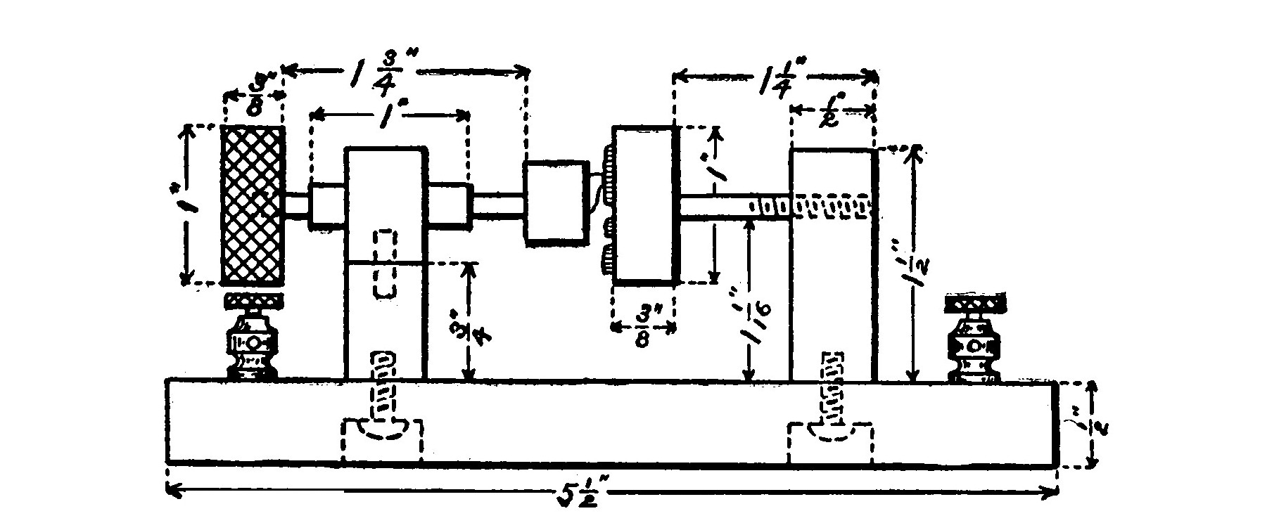
The other standard is cut in half with a hack saw and a 1/8-inch hole bored 1/4 inch deep in the axis of each piece. A pin, 1/2 inch long, is set in the lower half by soldering it in the hole. The upper half of the standard is placed over the pin and left free to move when twisted. A 1/8-inch brass tube, 1 inch long, passes through the upper part of the standard. A 1/8-inch brass rod, 1 3/4 inches long, passes through the tube.
The small cup containing the zincite is mounted on one end of the rod and a hard rubber handle on the other.
A brass spring is placed between the cup and the standard in order to press the chalcopyrites against the zincite. The cup is mounted out of center so that by revolving it and twisting the standard at the same time the chalcopyrites may be brought into contact with any portion of the zincite. By screwing the rod supporting the zincite cup in or out of the standard the pressure with which the two elements are pressed together may be regulated.
The base of the detector is hard rubber of the dimensions indicated in the illustration. Four binding posts on each corner of the base are necessary. The detector is connected in a similar manner to the silicon detector shown in Fig. 108. If a battery is used the circuit should be like that of the "bare point" electrolytic, and the current must flow from the zincite to the chalcopyrites.
LEAD PEROXIDE DETECTOR.
The peroxide of lead detector makes use of no liquids, but still may be classed as an electrolytic since its action is of that nature.

It consists of a pellet of lead peroxide held between an electrode of lead and one of platinum. Contrary to most other detectors, the resistance is increased upon the passage of electrical oscillations. The oscillations stimulate chemical action and increase a counter-electromotive force sufficiently so that a decrease in the current sent through the phones by the local battery takes place. The action may be outlined more in detail as follows. The current of the local battery decomposes part of the lead peroxide into its components, lead and oxygen. The lead ions are positively electrified and so they tend to pass upward toward the lead electrode which is negative. The negative ions of oxygen gas tend to pass downwards towards the platinum. But the lead and platinum electrodes with the intervening lead peroxide constitute a small cell acting independently of the local battery and sending a current in the opposite direction. This counter-electromotive force tends to send the ions in an opposite direction to that in which they are sent by the battery current. Upon the passage of electrical oscillations this counter electromotive force is increased and sufficient ions sent out in opposition to those of the battery current so that an appreciable drop in the current flowing through the telephone receivers takes place. The sudden current drop produces a sound in the receivers.
The lead pellets may be secured from a druggist who can mold them in his tablet press. They should be subjected to as great a pressure as possible in order to reduce resistance and prevent crumbling.
A piece of platinum foil about 1/2 inch square is placed beneath the pellet on the crystal electrode. A piece of clean, bright sheet lead 3/8 inch in diameter and 1/8 inch thick is laid on the pellet and the whole clamped together by tightening the thumbscrew passing through the collar on the spring, S. The detector is connected up similar to the "bare point," The platinum is made the positive of the local battery. Adjustment is secured by regulating the pressure.
It is very necessary that the pellets be kept dry, as otherwise a loud singing and hissing noise, due to the decomposition of the water, will render the reception of signals very difficult.
THE MARCONI MAGNETIC DETECTOR.
When an oscillatory discharge takes place through a coil of wire surrounding a needle, it magnetizes the needle in a totally different manner from a voltaic current. The needle will have several poles throughout its length, many of them reversed. Rutherford applied this phenomenon to the detection of electrical oscillations, but it remained for Marconi to improve it and give the magnetic detector its existing form. This type of detector is very sensitive, free from all adjustment and is not made inoperative by the heavier discharge of the transmitter during each period of sending.
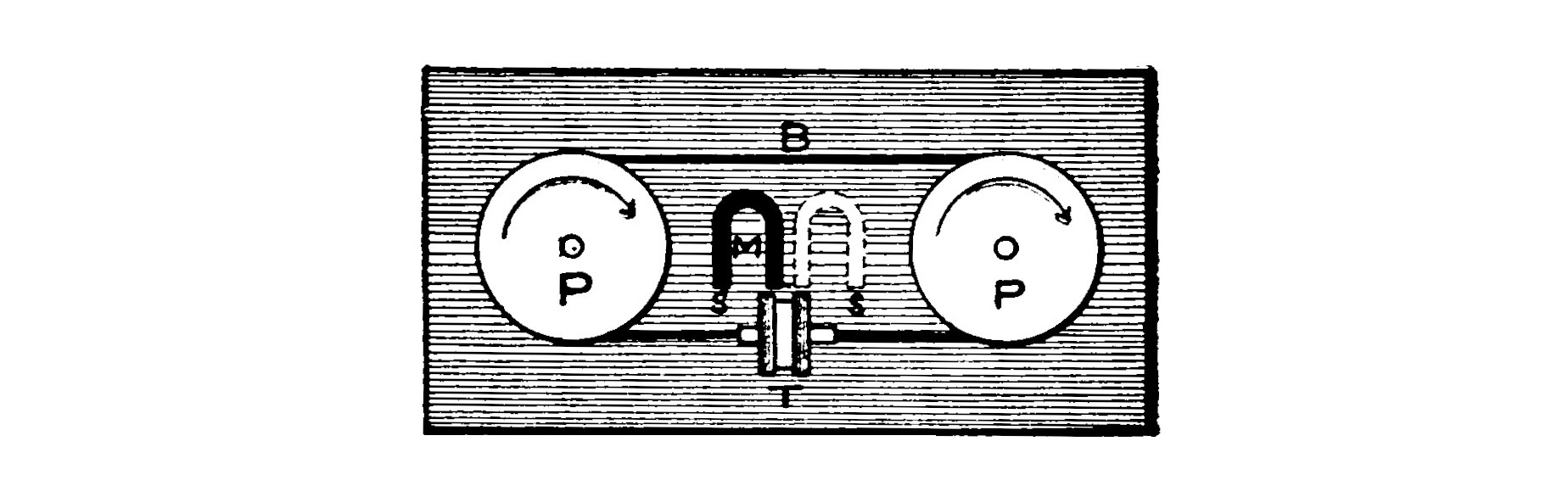
A small transformer is provided with a core composed of a band or cord of iron wires in the form of an endless belt which passes around two pulleys kept in motion by a clockwork motor. The band revolves in the field of a strong horseshoe magnet and passes directly over the poles after issuing from the transformer bobbin, so that the portion approaching the bobbin are constantly in a state of increasing magnetism. The actual operation is based upon the property of iron called hysteresis, for the magnetism of the core lags behind that of the permanent magnet and is of a different degree from what it ought to be, in view of its position in the vicinity of the permanent magnet. The moment the oscillations pass through the primary coil of the transformer, this lag is set free and the magnetism assumes its full value. The change in magnetism induces a current in the secondary, which registers as a sound in the telephone receivers.
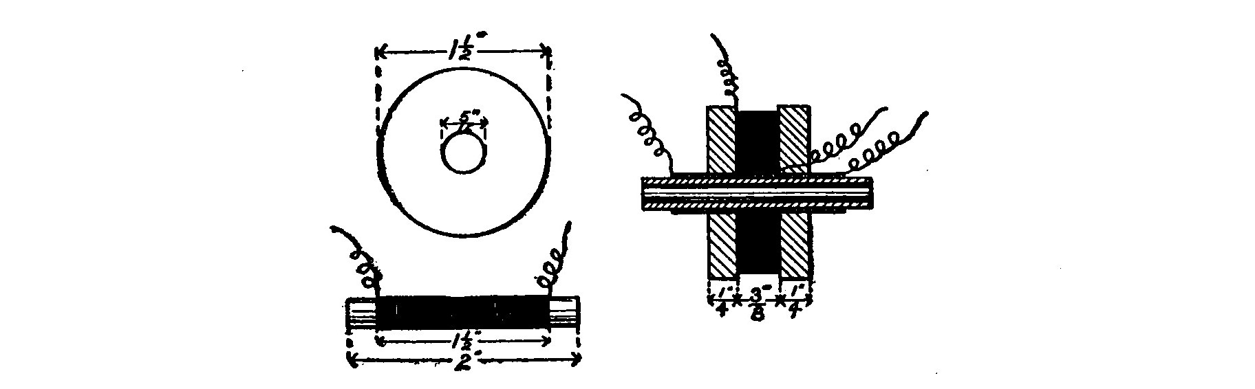
The primary coil is made up of a single layer of No. 36 B. S. gauge silk covered wire wound on a thin walled glass or hard rubber tube. The ends of the tube, which is 2 inches long and 1/4 inch external diameter, are slightly flared so as not to chafe the band. The primary is thoroughly shellacked and covered with a single layer of paper.
The secondary is also of No. 36 B. S. silk covered wire and is wound between two disks of hard rubber, 1/4 inch thick and 1 1/2 inches in diameter, placed 3/8 inch apart in the center of the secondary and the intervening space wound full of wire.
The terminals of both the primary and secondary are extended to binding posts mounted on the case of the instrument.

The core or revolving band is made by winding 100 strands of No. 36 silk covered soft iron wire between two small pegs, placed a distance apart, equal to twice the circumference of the oval formed by the two pulleys. The wire is all wound in the same direction. It should be carefully removed from the pegs and kept taut while it is slightly twisted, doubled, and then further twisted into a rope or cord. The ends are threaded together with a separate piece of insulated wire, into a link which will pass easily through the primary tube.
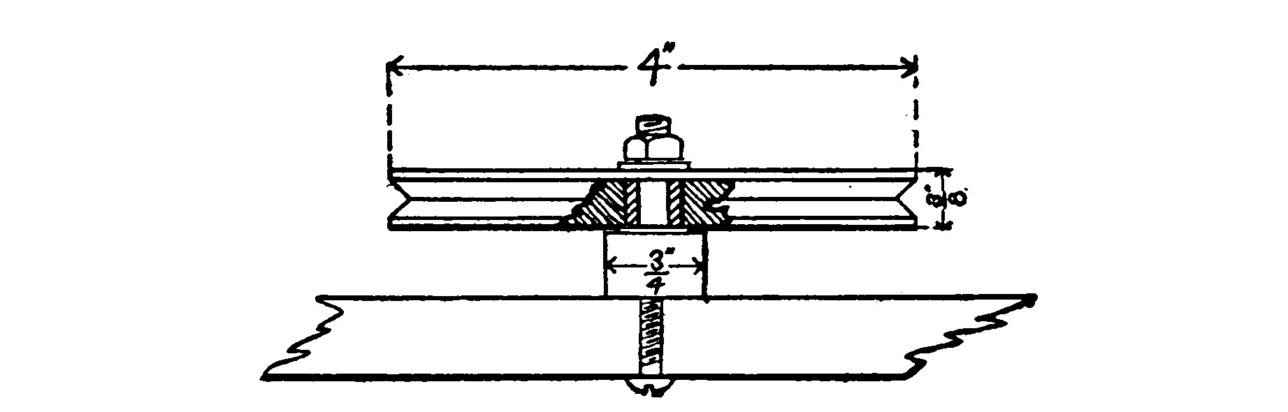
The pulleys around which the band revolves are made of hard wood. They are 4 inches in diameter and 3/8 inch thick and have a V-shaped groove cut in the edge. In order to minimize friction and wear, it is advisable to fit them with a bearing which may be made out of brass tubing and a couple of washers. One of the pulleys is geared to a clockwork motor so that the band makes a complete revolution about once every two minutes. An old eight day clock may be adapted for this purpose, or, what is much better, the motor from an old phonograph.
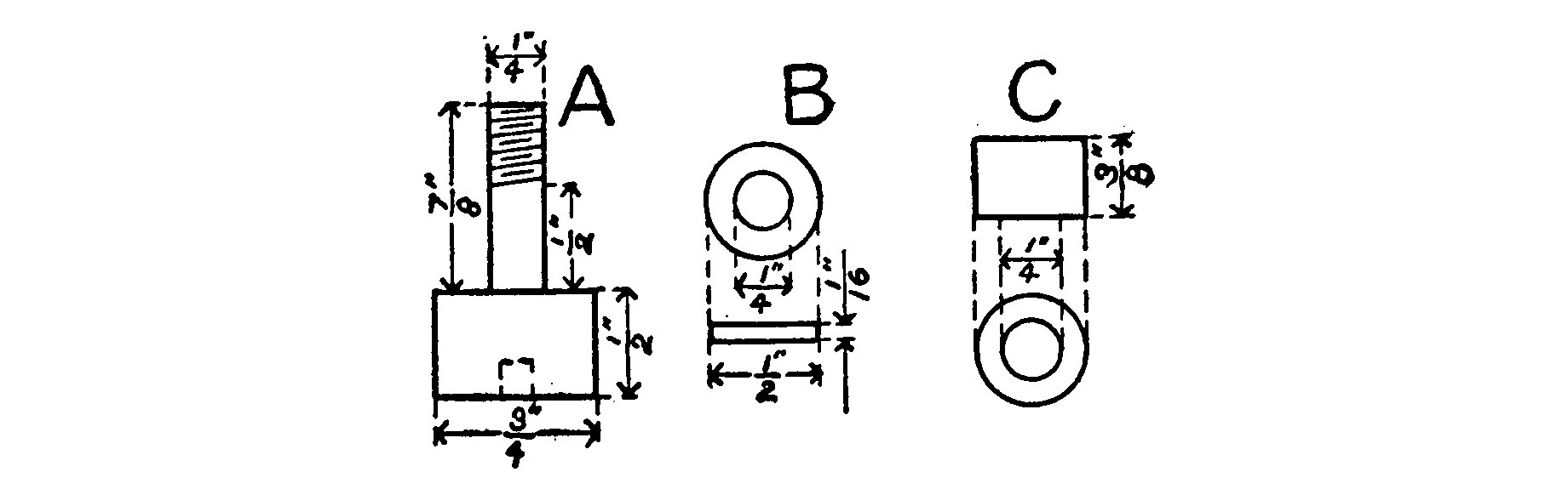
The horseshoe magnet is mounted with its north pole pointing towards and nearly touching the middle of the outside of the secondary. The south pole is placed opposite the end of the primary tube which is on the side towards which the band is revolving, that is, the band in revolving passes first over the north pole and then over the south. Two magnets are sometimes used with their north poles together in the center of the secondary, and a south pole opposite each end of the primary tube.

The commercial instrument is placed in a glass covered case which protects it from dust and injury. The clockwork motor is concealed in the lower part of the case. This is a good plan but an experimental detector may be merely mounted on a flat wooden base as illustrated in Fig. 112.
The secondary terminals are connected directly to the telephone receivers while the primary leads to the aerial and the ground. When the detector is started up it should make a very slight hissing sound in the telephone receivers as the band passes slowly through the coils. This shows the instrument to be in good working order and ready for the reception of signals.
The Audion.—Dr. Lee DeForest was led by the flickering of a sensitive gas flame to investigate whether or not it would respond to Hertzian vibrations as well as to those of heat and sound. His experiments led to the invention of the audion, a peculiar instrument making use of ionized gas for its operation.
The audion consists of an incandescent lamp having a metallic filament, on either side of which are a grid and a plate made of nickel. When the filament is lighted it throws off ions which act as a relay to high frequency oscillations passing between the plate and the grid. A properly constructed audion is exceedingly sensitive and produces very loud tones in the telephone receivers. It has the further advantages of entire absence of adjustment except the governing of the battery voltage, and is capable of extremely fine tuning.

Fleming originated the oscillation valve illustrated in Fig. 118. It consists of an ordinary incandescent lamp with a carbon filament, having a metal cylinder, C, placed around the filament, but attached to an independently insulated platinum wire sealed in the glass. When the lamp is lighted by passing a current through the filament, the incandescent carbon liberates negative ions. If oscillations are then set up in a circuit which includes a pair of sensitive telephone receivers and is formed by connecting the negative terminal of the filament with the platinum cylinder, negative electricity will be enabled to pass from the filament to the cylinder but not in the opposite direction, and so sounds will be produced in the telephone receivers. High frequency oscillations themselves could not be made to pass through the telephone receivers because of the choking action of the iron cores of the electromagnets.
The simple but sensitive form of detector illustrated in Fig. 119 is not of practical value for commercial work, but is very interesting as the progenitor of the audion, and provides a good field for amateur investigation. Its only drawback is that the gas flame is very difficult to keep steady and every flicker registers as a sound in the telephone receivers.
A Bunsen burner using coal gas furnishes the flame, and a salt of an alkaline metal heated in the flame, the ions. The hydroxides of caesium, potassium and sodium give the best results in the order named.
The salt is contained in a piece of trough-shaped platinum foil, about 3/8 inch long and 1/16 inch wide. This trough is made the cathode or negative of the telephone circuit and placed in the outer oxidizing flame just above its juncture with the interior reducing flame and must be kept incandescent. The upper electrode or anode is a piece of platinum wire about 1/16 inch above the trough.
The arrangement and construction of the detector is clearly indicated by the drawing so that it is unnecessary to go into details. The block, E, which fits on the tube of the Bunsen burner, is made of fiber. Two double binding posts, D, are fastened to E to support the rods, R, which are fitted at the tops with binding posts, B, into which the electrodes may be clamped.
Twelve dry cells are connected with a multiple point switch so that an electromotive force of 6-18 volts, varying in steps of one cell at a time, may be secured. The flame is best provided with a mica chimney to protect it from drafts. By keeping plenty of salt in the trough and carefully adjusting the voltage, this detector may be made marvelously sensitive.
| [3] | The different detectors in order of their sensitiveness are electrolytic, perikon, magnetic, silicon, carborundum. |
| [4] | Peacock ore or bornite, which consists of about 60 parts of copper, 14 parts of iron and 26 parts of sulphur, may be substituted for the chalcopyrites with excellent results. |
CHAPTER XIV. TUNING COILS AND TRANSFORMERS.
A tuning coil is merely a variable inductance wound in single layer on a suitable form.
Fig. 121 illustrates a double slide tuner. The base is a piece of hard wood, 12 inches long, 1 inch thick and 5 1/2 inches wide. Two wooden heads 4 x 4 x 3/4 inches support the form upon which the coil is wound.
The form is a piece of wooden curtain pole, 9 inches long and 3 inches in diameter. Some may prefer to use a cardboard tube in place of the curtain pole. A tube can be made by winding a long strip of cardboard 9 inches wide around a suitable form and cementing the layers together with shellac. The liberal use of shellac will stiffen the tube and cause it to better retain its shape. The tube is held tightly between the two heads by means of a brass rod which passes through the center and is clamped by two nuts.
A square brass rod 10 1/2 inches long is fastened to the center of the top of the heads and a similar rod to the center of the front face.

Fig. 122 shows two forms of sliders. The first one is the better and to be preferred. A short square brass tube, S, fits snugly upon the square brass rod, R. It cannot turn around but is free to slide back and forth. A strip of spring brass, C, is soldered to the lower face of the square tube. It is bent in a double turn and a punch mark made near the lower end as shown in the illustration. The indentation is made with a center punch, but should not be deep enough to break through the metal.
The little projection on the under side of C caused by the punch mark is the only part of the slider which should make contact with the wire on the tuning coil. It should slide easily but firmly along the wires and touch only one at a time. Long distance signals will be considerably weakened if the slider touches more than one wire at a time and short-circuits a turn.
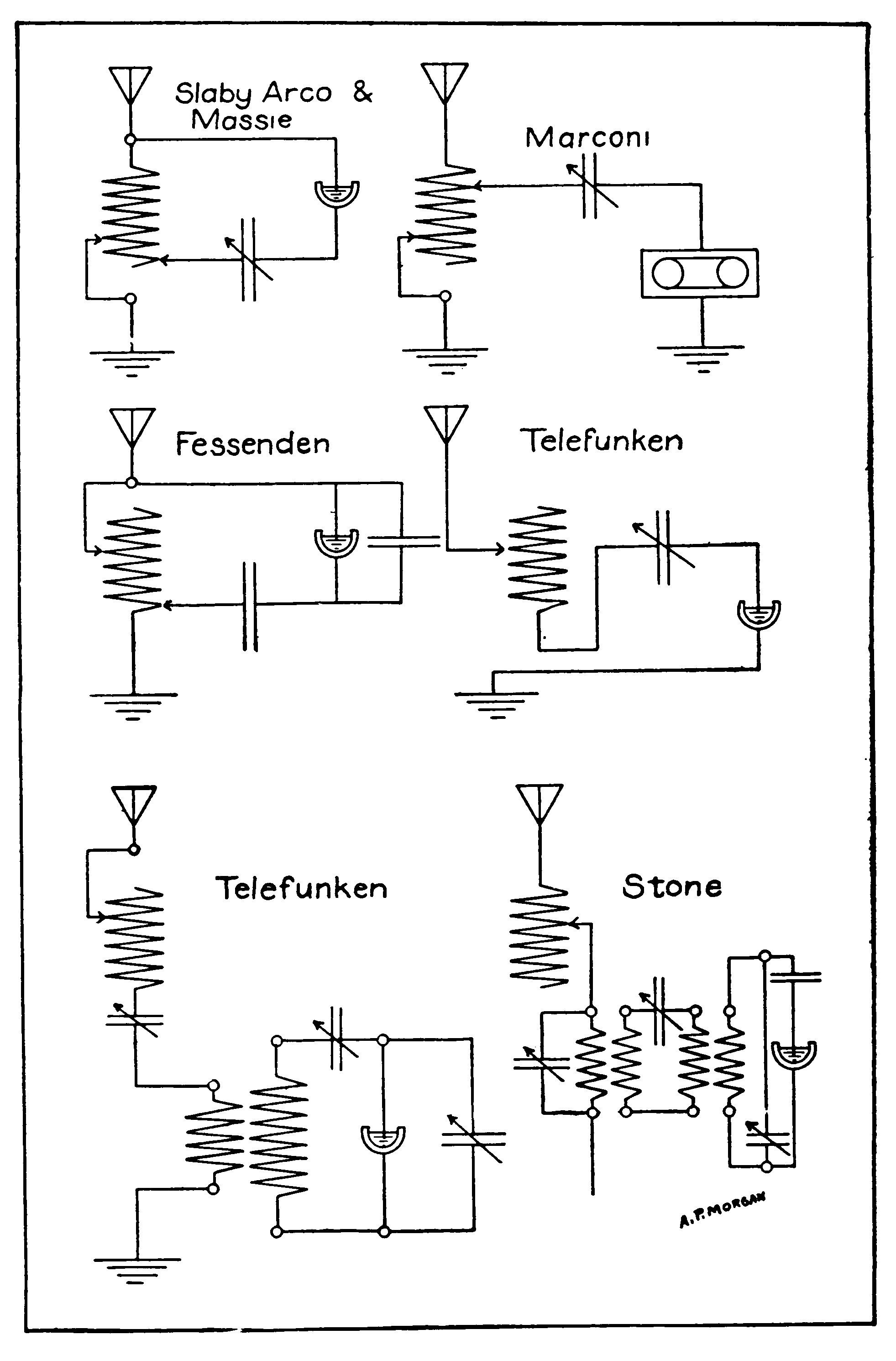
The slider, B, is similar to A except that it has a short length of brass tubing, T, soldered to the under side of S in place of the brass strip, C. A small ball bearing which just fits the bore of the tube is pushed down into contact with the wire by means of a small spiral spring inside of the tube. Both sliders are fitted with a hard rubber handle so that they may be adjusted without the ringers coming into contact with the metal.
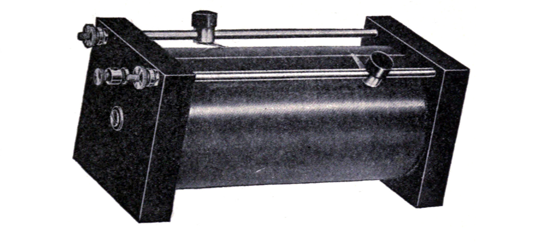
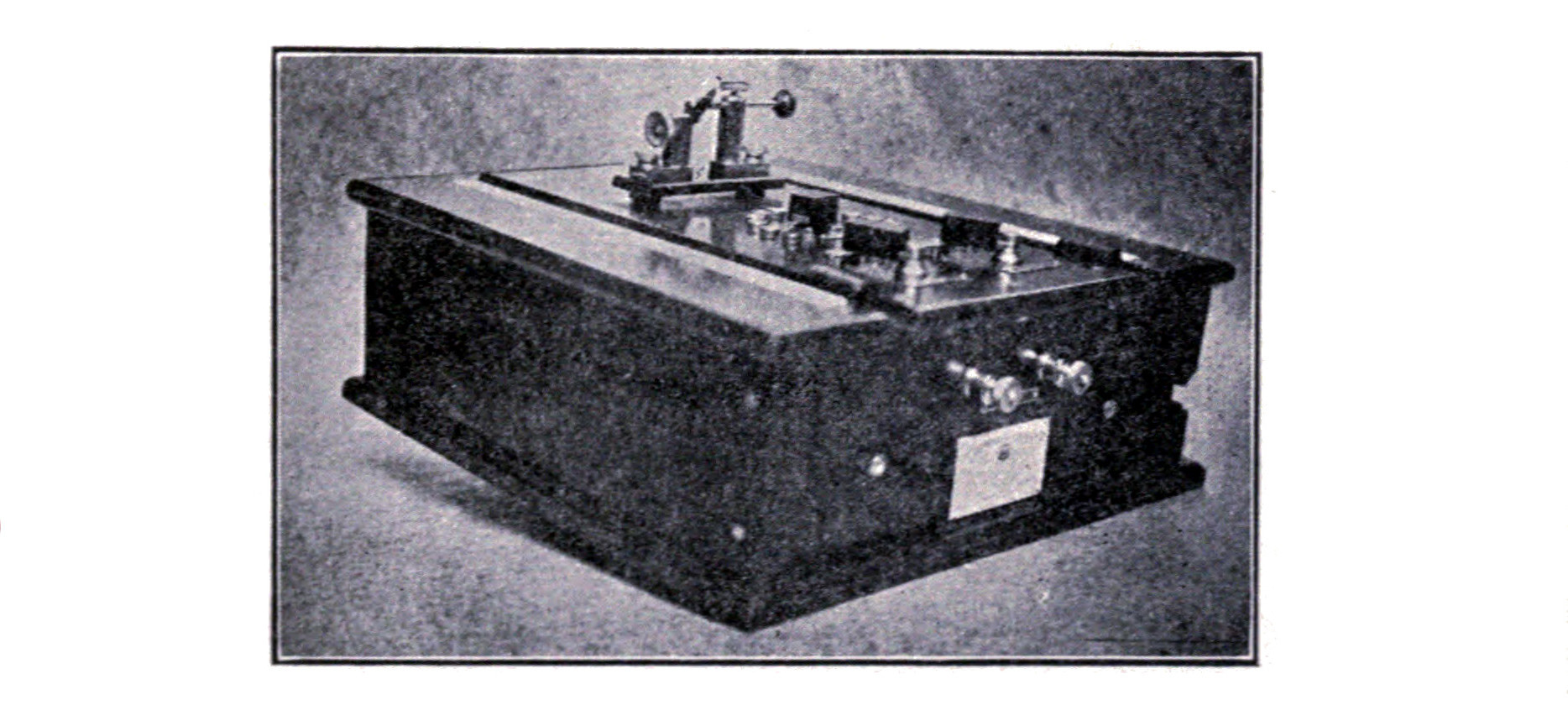
Two good circuits employing the double slide tuner are given in Fig. 123. Plates IV and V illustrate the oscillation or tuning circuits of the most prominent receptor systems.
If a loop aerial is used, more than one tuning coil is necessary as shown by the loop aerial oscillation circuits in Plate V.
Figs. 125 and 126 illustrate the instruments employed for receiving by the United Wireless Company.
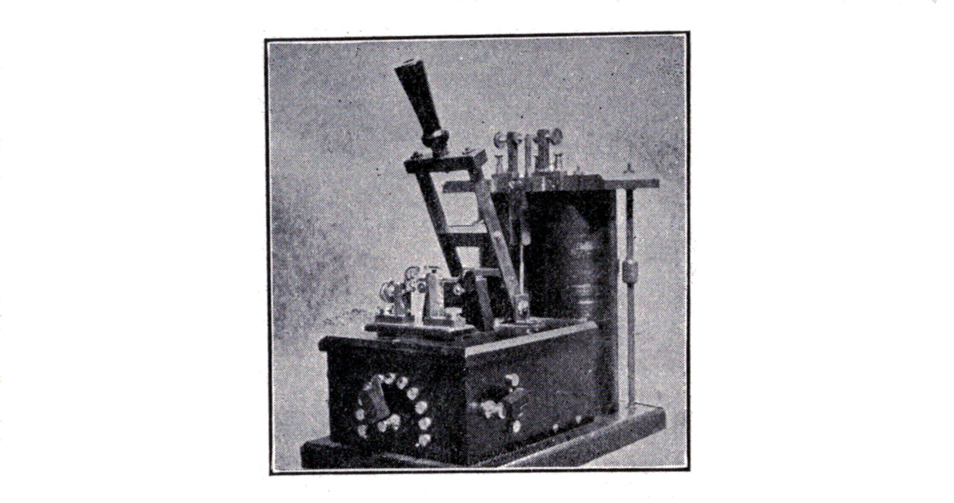
In Fig. 125 the handles which are attached to the sliders of the tuning coils project through long slots cut in the top and one side of the cabinet.
The tuning coils in the portable outfit are mounted in a vertical position in back of the aerial switch.
Loosely Coupled Tuning Coil.—By the use of a loosely coupled receiving tuner or transformer, the range of a station is considerably increased, as is also the strength of the signals, and much finer tuning and selectivity made possible.
Fig. 127 illustrates the construction of such an oscillation transformer.
The base is wood and measures 14 x 5 1/2 x 1 inches. The primary winding is wound on a cardboard or fiber tube 4 1/4 inches long, having an internal diameter of 2 3/4 inches and an external diameter of 3 inches. The heads, L and M, are the same size as those of the double slide tuning coil. The head, L, has a circular hole 2 3/4 inches in diameter cut in the center in order to permit the secondary coil to slide in and out of the primary.
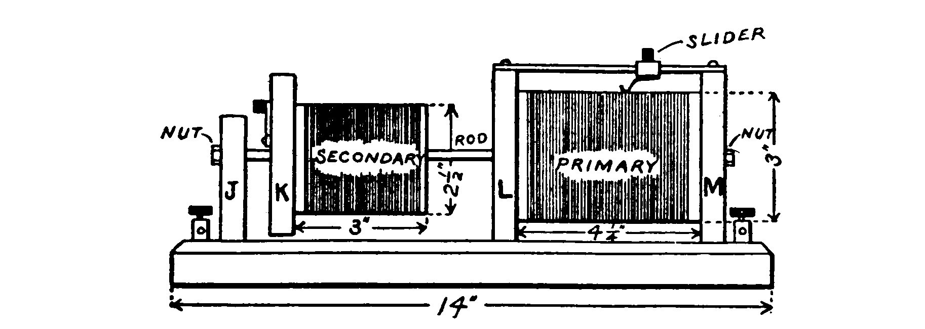
The secondary coil is a piece of round curtain pole 2 1/2 inches in diameter and 3 inches long. A 5/16-inch hole is bored through its axis. The head, K, of the secondary coil is 3 3/4 x 3 3/4 x 3/4 inches. A ten-point switch on K is so connected that it divides the secondary into ten equal parts and permits any number of the divisions to be used as desired.
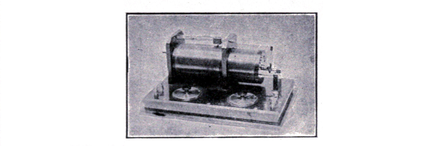
A wooden post, J, 2 1/2 inches high and 1 1/4 inches wide, supports one end of a 1/4-inch brass rod upon which the secondary slides back and forth.
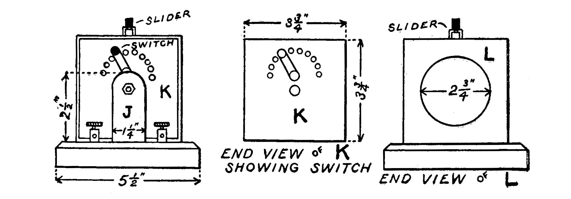
No. 24 B. S. gauge copper wire may be used for winding both the primary and secondary. It is also the proper size to use on the double slide tuner. The best method is to use bare wire, wound with a thread so that a thread is interposed between adjacent turns of the winding. Give the whole winding one or two coats of thick shellac and allow it to harden. Then use a strip of sandpaper to remove the shellac in a long narrow path immediately below the sliders so that they may make contact with the wire.

Some may prefer to make a loosely coupled tuner in which the inductance of both coils is adjustable by means of a sliding contact. In such a case the slider on the secondary coil must be constructed as illustrated in Fig. 130. The contact is long and narrow so that it can touch the innermost turns, when placed within the primary. By slipping the slider off the end of the rod and reversing it, the contact can be made to touch the turns next to the head. The square brass rod is set in a notch cut in the coil head so that the rod is flush with the top.
When tuning a receiving transformer, place both variable condensers in a halfway position and adjust the sliding contacts, first on the primary and then on the secondary, until the signals are the loudest. Then adjust the condensers.
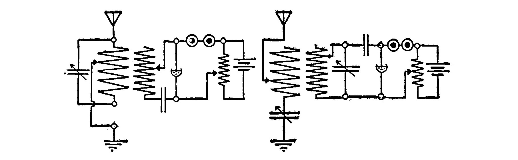
To cut out an undesirable station, vary the coupling between the two coils by sliding the secondary away from the primary. When several turns on the secondary seem to give the same results also vary the coupling.
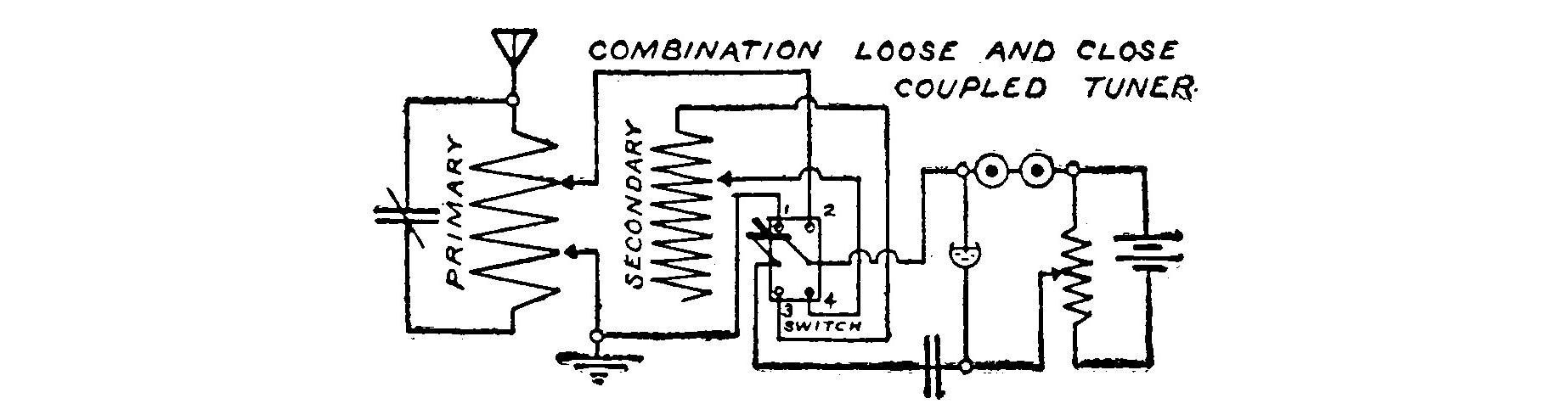
Fig. 132 illustrates the wiring diagram of a combination loosely and closely coupled tuner. Two sliding contacts are placed on the primary coil of the receiving transformer and connected with a double pole double throw switch as in the diagram. When the switch is thrown on contacts 1 and 2, the primary is connected to the detector as a double slide tuner, and when on 3 and 4 both the primary and secondary are brought into use as a transformer.
This arrangement may seem cumbersome and is recommended only as a convenience in experimenting. A loosely coupled tuning coil is capable of exact tuning, and unless one understands how to use it, he may not hear a station because the tuner is not properly adjusted. By using the double slide tuner first and then throwing the switch so as to tune in on the transformer, this difficulty may be eliminated.
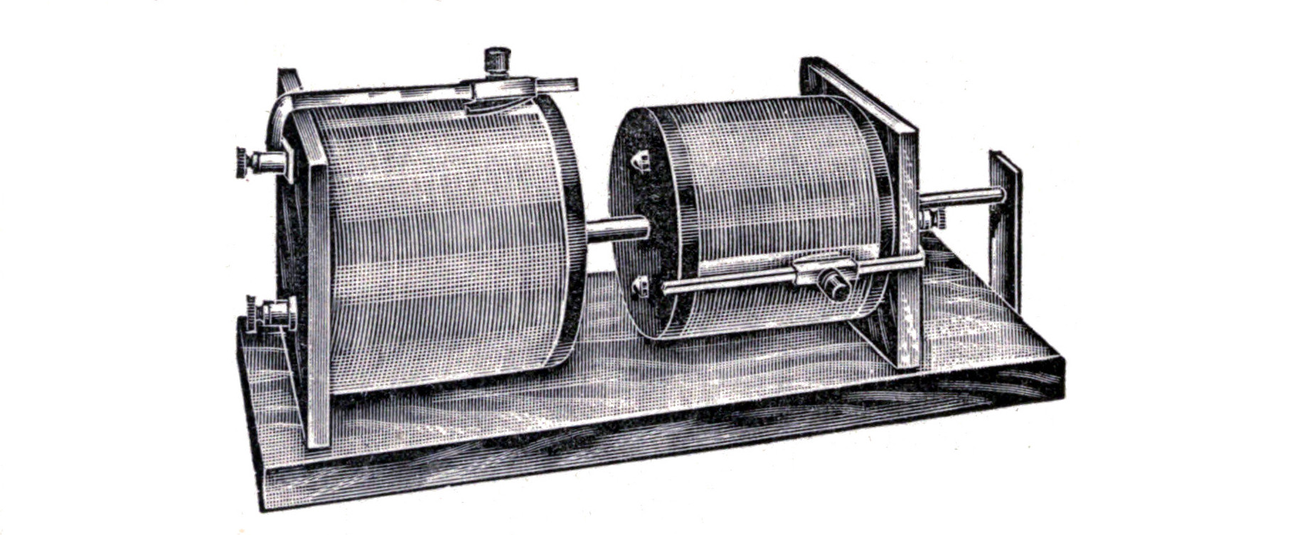
Potentiometer.—A potentiometer is not properly classed under the heading of tuning coils, but the construction may be made so similar that it well appears here.
The potentiometer is merely a variable resistance shunted across the terminals of the detector battery in the manner illustrated in the numerous detector circuits. It is used to reduce the voltage of the battery to a value slightly below the critical voltage of the detector. The critical voltage of a detector is the voltage at which its action commences. In the case of an electrolytic detector, it is the voltage required to break down the thin film of gas which collects on the "bare point."
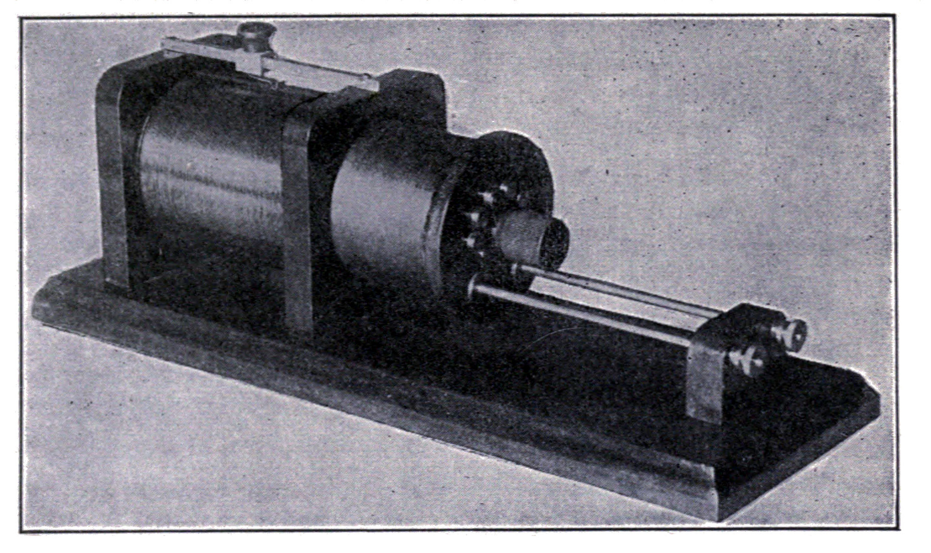
In construction, the potentiometer illustrated in Fig. 135 is in reality a small edition of a double slide tuning coil. It is wound with No. 28 B. S. gauge German silver wire. Three binding posts are mounted on the base, two of them connecting with the ends of the coil and one with the sliding contact.

In a finely balanced circuit where long distance work and close tuning are desired, the potentiometer must be non-inductive.
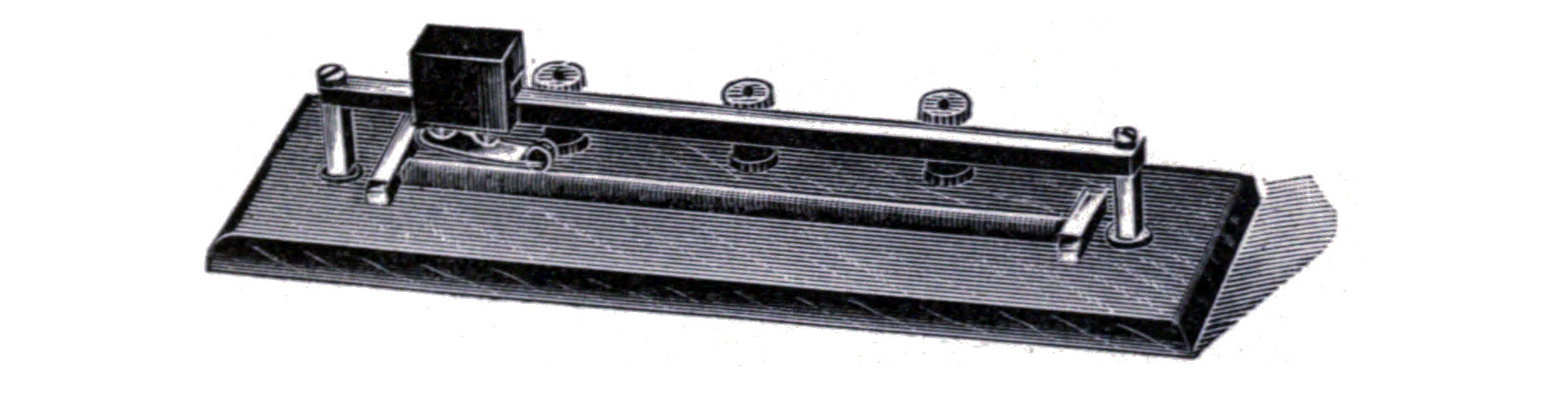
This may be accomplished by using two potentiometers wound in opposite directions from one another and connected in series. The two terminals of the windings are then connected across the battery and the sliding contacts led to the detector.
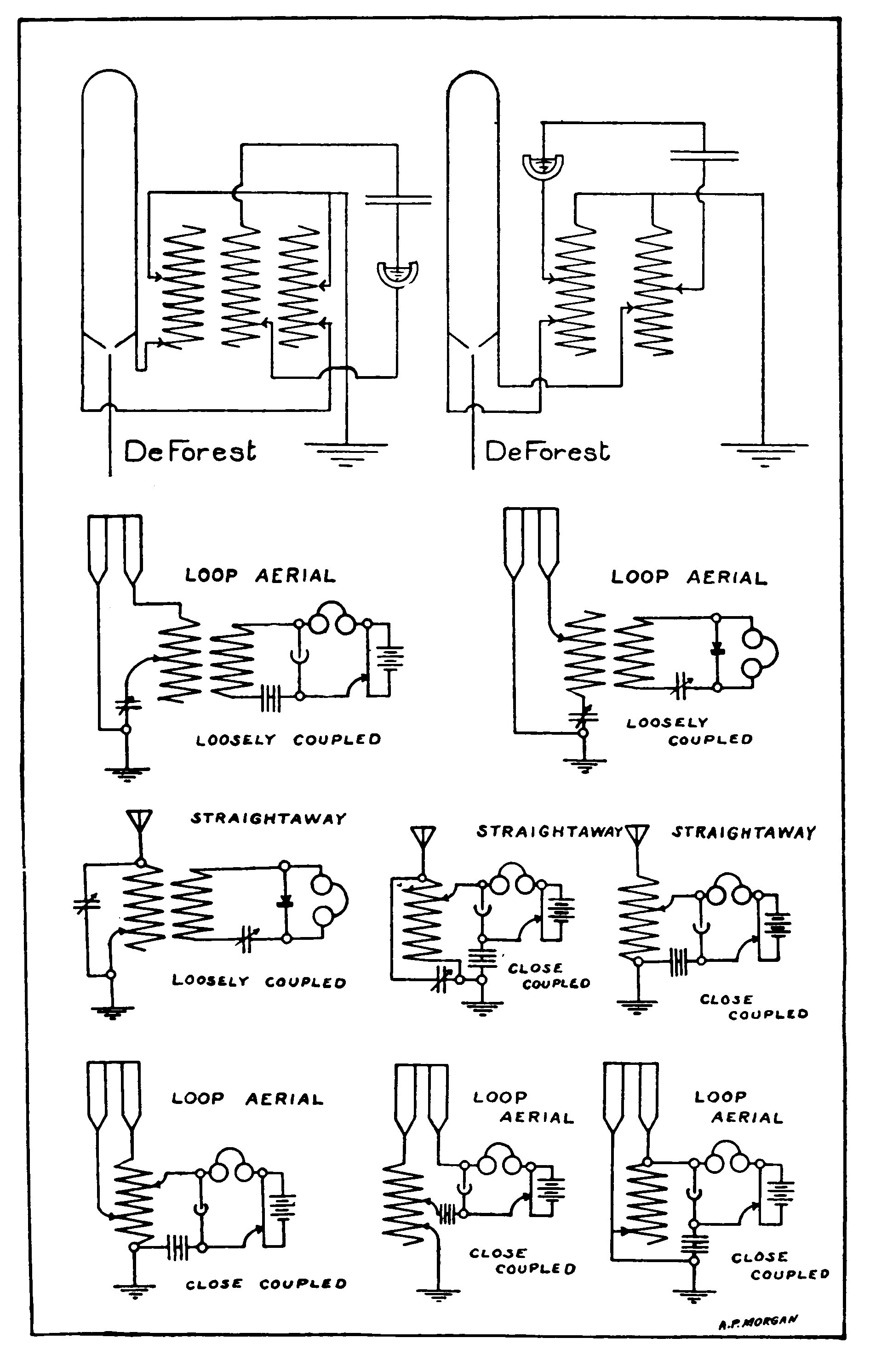
CHAPTER XV. RECEIVING CONDENSERS.
Condensers play an important part in tuning and adjusting the receiving circuits of a wireless telegraph station. They are inserted in the circuits for various purposes. In some places a small condenser shunts the detector to somewhat equalize any small changes in capacity which might occur in the detector and throw the circuit out of tune. In other cases where selectivity is desired they provide a path for undesirable oscillations and allow them to flow into the ground without passing through the detector. Wherever the double slide tuner or the Fessenden single slider circuit is used, a condenser must be inserted in the circuit to prevent the wire of the tuning coil from short-circuiting the telephone receivers and battery.
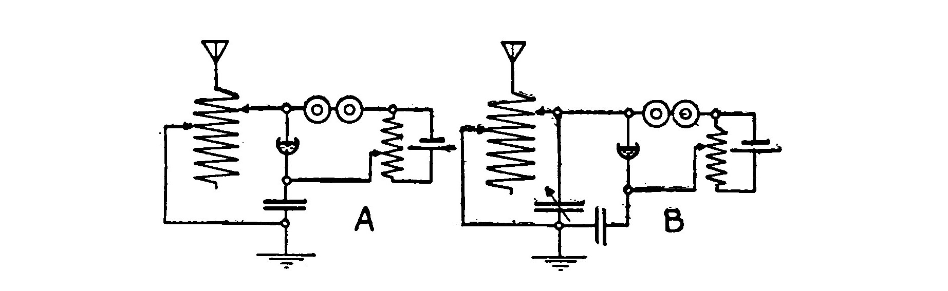
The value of a condenser may be readily appreciated by the following experiment. Connect up a detector according to the diagram shown by A of Fig. 137. This circuit will give good results and the signals will be clear. But change it to that shown in B, by connecting one side of a variable condenser to the upper contact of the tuning coil and leading the other side to the ground. Considerable selectivity may now be attained and the signals will be 50 per cent louder.
To be of any value for a receiving circuit the capacity of the condenser must be adjustable, but there are many places where a fixed condenser is of service.
The average capacity of such condensers generally ranges around .003 of a microfarad, but cannot be predetermined, as it depends upon many factors which vary greatly in different stations. Even if specific dimensions were given for the construction of a paper condenser of stated capacity, the experimenter would very seldom succeed in constructing his condenser and have it of this value when finished. The paper used as the dielectric and the pressure applied to the condenser would make the difference.
The best plan is to build one up in the form of a roll as follows. Three thin tin foil strips 3 1/2 inches wide and four feet long are separated by strips of thin paraffined paper 4 inches wide and four and one-half feet long. The two outside strips of tin foil are connected together and form one terminal of the condenser. The middle strip of tin foil is the other. The outside strips of tin foil are covered with paraffined paper and the whole rolled up. If thin paper and tin foil are used the condenser will form a roll 4 inches long and less than an inch in diameter.
Two or three such condensers should be constructed, and one of them connected up in the circuit where it is desirable to use it. By unrolling a little of the condenser and cutting one or two inches off at a time the proper size may be determined.
As explained in Chapter VII, two equal condensers connected in series have one-half the capacity of either. By connecting them in parallel the capacity is the sum of the two. In this manner it is not hard to first find the approximate capacity, which gives the best results before cutting the condenser.

When the proper value is found, place the condenser in a brass tube about 5 inches long and 1 inch in diameter. The tube is fitted with hard rubber flanges to close the ends. A binding post is mounted on each flange, and connects with the terminal of the condenser to which it is nearest.
Mounting a condenser in this manner gives it a much better appearance and it occupies less space than otherwise. Fixed condensers are used in two cases only, to shunt the condenser and to prevent the tuning coil from short-circuiting the telephone receivers. In any other position they are worthless.
Variable Condensers.—A simple form of adjustable condenser which may be quickly made for a special experiment is constructed in the following manner. A wooden curtain pole 2 inches in diameter and 18 inches long is covered with a layer of tin foil. The tin foil must be laid on smoothly and cemented with shellac. A layer of paraffined paper is then placed over the tin foil. A piece of sheet copper or tin 6 3/4 inches wide and 18 inches long is rolled up in a cylinder to fit over the rod with its tin foil and paper. The rod is fastened at one end to a base board about 20 inches long and 4 inches wide, by means of a bracket, or it may be mounted on a smaller base in a vertical position.
Connections are made to the tin foil and to the outside metal tube. By sliding the tube back and forth on the rod the condenser may be given a variable capacity.
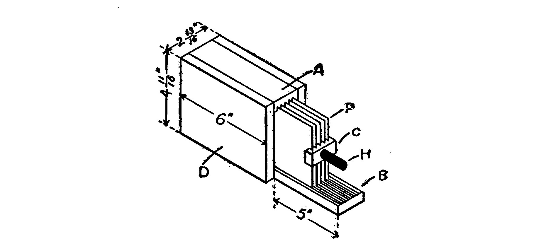
The best variable condensers are constructed so that the dielectric between the two plates is formed by air. There are consequently no losses of energy in the condenser, for this mode of construction eliminates all dielectric hysteresis.
Fig. 139 shows such a variable condenser and Fig. 140 the details. It is possible to do very close, selective tuning with this instrument. The efficiency of the receiving circuit may be considerably improved if one is used wherever a condenser is required.
A rectangular box is built up in the manner shown in Fig. 135. The sides, D, are 6 inches long, 4 11/16 inches wide and 1/2 inch thick. The top, A, is 6 inches long, 1 13/16 inches wide and 1/2 inch thick. The bottom, B, has the same width and thickness but is 11 inches long. Eleven grooves are cut in A and B as shown in the cross section. The grooves are 1/16 inch wide, 3/16 inch deep and 1/16 inch apart. They are formed by setting the blade of a circular saw so that it projects 3/16 inch above the table or bed. After cutting one groove, the guide is moved 1/8 inch and another cut made.
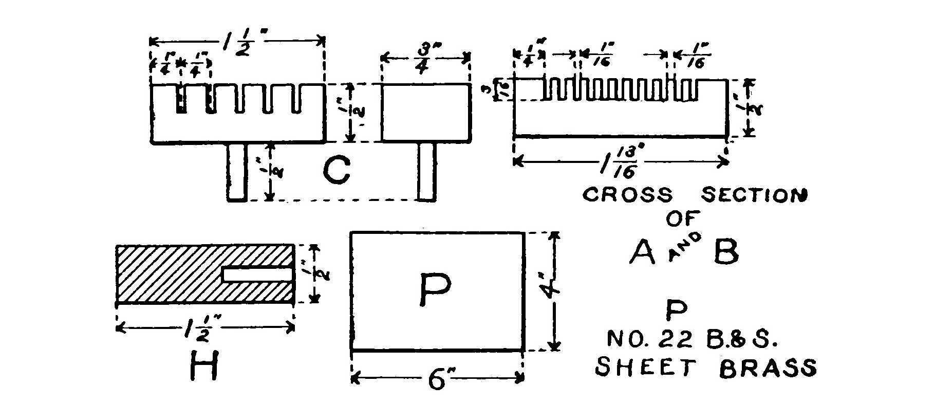
Eleven metal plates, P, are required, six fixed and five movable. They are made of No. 22 gauge sheet brass and measure 4 x 6 inches. Six of them are placed in the grooves in the box in such a manner that an empty groove is left between each one. The six plates are then electrically connected together by soldering a strip of brass across their rear ends.
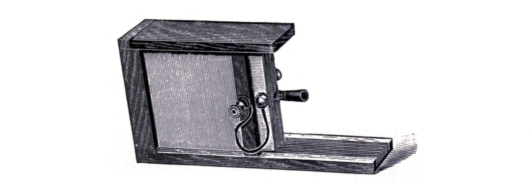
Five slots each 1/4 inch deep and 1/4 inch apart are made with a hack saw in a piece of brass, C, 1 1/2 inches long, 3/4 inch wide and 1/2 inch thick. A small pin 1/2 inch long is set in the center of C on the opposite side from the saw cuts. A fiber handle 1/2 inch in diameter and 1 1/2 inches long is fastened to the pin.
The five movable brass plates are set in the grooves between the six fixed plates. They are allowed to project three or four inches out of the box. The yoke, C, is then soldered across the ends so that each one of the movable plates fits into its corresponding saw cut.
The capacity of the condenser is varied by sliding the movable plates back and forth between the fixed plates.
A binding post is soldered to the yoke, C, and another one to the strip which holds the fixed plates together. Connections are made to the binding posts with lamp cord or some other flexible conductor which will not interfere with the movement of the plates.
The instrument is finished by staining the woodwork and giving it a coat of varnish or shellac.
CHAPTER XVI. TELEPHONE RECEIVERS AND HEADBANDS.
A pair of high resistance telephone receivers in nice adjustment constitute one of the most sensitive electrical instruments in existence and will detect an exceedingly weak current.
The only type of receiver of much service in wireless telegraphy is that known as a watch case or pony receiver. It is small and compact so that it may be attached to a headband and clamped against the ear.
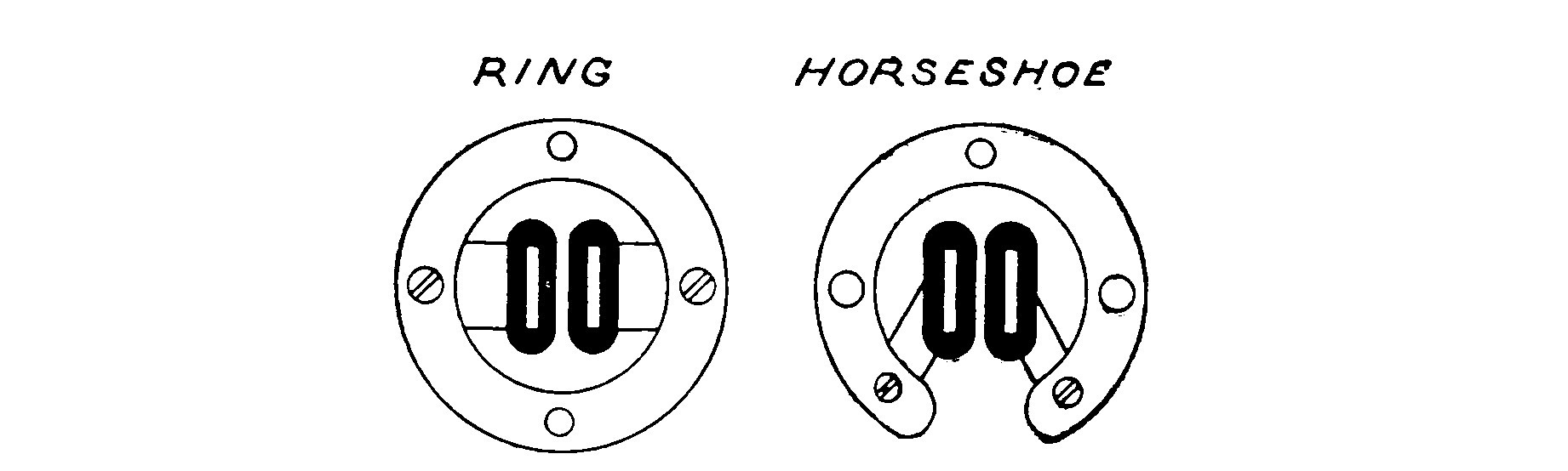
The permanent magnets of a watch-case receiver are usually in the form of either a ring or a horseshoe as shown by Fig. 142. The first form has "consequent" poles and is considered somewhat superior to the horseshoe, since the lines of force are not so liable to pass across the pole pieces before they pass through the electromagnets and the diaphragm.
The ordinary low resistance telephone receiver is perfectly well suited to the telephone work for which it was designed and adjusted, and will give good service on a wireless receptor for short distances, but can be considerably improved by following the suggestions and instructions given below.
The principal objection to the ordinary receiver is that it does not contain enough turns of wire on its bobbins. This is easily remedied by carefully rewinding them with a very fine silk covered, pure copper magnet wire no larger than No. 40 B. S. gauge. This will increase the number of turns and also the resistance, but it must not be inferred that resistance is to be desired. This is a common impression of amateurs who do not understand the underlying principle, that the strength of an electromagnet varies directly as the number of turns of wire, multiplied by the amperes flowing through the magnet. When a telephone receiver is wound with a finer wire the resistance is increased, cutting down both the current and the strength of the magnet. But if pure copper wire is used, and the winding not carried beyond the point where the circumference of the outside layer becomes twice as great as the circumference of the first layer, the number of turns increases faster than the resistance and the magnet strength is considerably greater than before the receiver was rewound.
No. 40 B. S. gauge silk covered wire is often used for this purpose, but the best results are obtained with enameled covered wire of the same size. It is possible to wind almost three times as much of the enameled wire on a telephone bobbin as silk wire of the same size. The difference is due to the thickness of the insulation. An ordinary double pole watch-case receiver will have a resistance of 800-1,000 ohms when wound with silk covered wire and 1,500-1,800 ohms when wound with enameled wire.
To rewind a telephone receiver, first unscrew the cap and remove the diaphragm, then remove the bobbins by unloosening the screws with the aid of a screw driver. Unwind the old wire and examine the empty bobbins to see that wherever the wire is liable to come into contact with the metal that it is well insulated with paraffined paper or some other equally good material. Then wind the new wire on in smooth even layers and when it is completed fasten the bobbins back on the permanent magnets and connect them up. The current should flow through in opposite directions so that the north pole of one and the south pole of the other is on top. Do not trust splice connections but solder them using acid as a flux.
The Navy Department specifies that its wireless receivers shall be wound with copper wire of not less than 0.0015 inch in diameter and the diaphragm to have a diameter of 1 3/4 inches and a thickness of 0.004 inch. The resistance of the coils is specified at 1,000-1,100 ohms. There is not much advantage in greatly exceeding the number of turns possible with this winding, for to obtain them a much finer wire than No. 40 B. S. gauge is necessary and the ratio between resistance and turns becomes greater.
The second objection to the ordinary receiver is that the diaphragms are very often too thick. A receiver having a thin diaphragm is preferable because when a weak current is sent through the coils, the change in magnet strength is greater. But this may be carried to excess and the diaphragm made so thin that it cannot absorb sufficient lines of force to properly play its part. The best thickness then for a diaphragm can only be determined experimentally and depends much upon the diameter. The distance from the poles and the strength of the magnets will also have considerable bearing on the thickness. The ordinary phone will be very sensitive and give clear tones with diaphragms ranging from .01-.004 inch.
The relation between the thickness and the diameter is shown by the following: If the diaphragm of a receiver is increased in diameter, the tones will become more distinct, but if the increase is carried too far they will become indistinct and the only remedy is to thicken the diaphragm. Likewise if after clearness is secured the diaphragm is thickened so that the tones again become indistinct, the diameter must be increased.
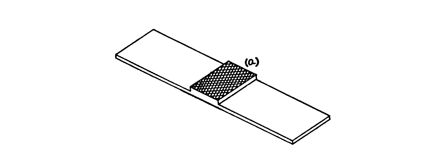
The third objection is that such receivers are not carefully and properly adjusted. The adjustment is also a matter of experiment and is accomplished by comparison of the receiver in question with one which is known to be in a sensitive condition. The adjusting may be done by means of the tool shown in Fig. 143.
This tool is made from an ordinary file by grinding off the teeth on one side save for a distance of about 3/4 inch in the middle. The grinding may be done on an emery wheel. The part (a) is used for filing the pole pieces and thus making the distance between them and the diaphragm greater. The tool has the advantage over an ordinary file of permitting the poles to be filed without removal from the receiver and without grooving the diaphragm bed or the receiver case.
To lessen the distance between the poles and the diaphragm, lay the receiver bed downward on a piece of fine emery paper and rub with a circular scouring motion. If the emery paper is placed on a perfectly flat surface no trouble will be experienced in grinding the bed down evenly.
When filing the pole pieces rub with the same circular motion so as to grind off all sides evenly. Test from time to time by passing a straight edge over the bed in all directions while holding to the light and looking between the straight edge and the poles. In this manner the distance separating the diaphragm and the poles may be gauged and whether or not it is the same on all sides. Bear in mind that if the diaphragm is thin, the attraction of the permanent magnets will cause it to bend in towards the poles.
In case you have a pair of receivers built for wireless work, which appear to be in good condition but do not give their former results, the last thing to do is to tamper with the adjustment. The most common cause, when the tones are impaired, is dirt or dust accumulated on the poles or diaphragm and damping its vibration. The cap should be carefully unscrewed and the diaphragm examined to see if it is bent. If so, replace with a new one of the same size. Remove any dirt or filings, and if the diaphragm is rusty clean it by laying it on a flat surface and rubbing it with a piece of fine emery paper. Then give it a thin coat of colorless lacquer. Examine the magnets and pole pieces to see if they have become loosened and if so tighten them.
Or the trouble may be that the permanent magnets have lost part of their magnetism, and almost any receiver which has been in use for some length of time will bear having its magnets strengthened. If they are found to be weak they should be removed and remagnetized. This is accomplished by winding a coil of No. 18 B. S. gauge wire around them and sending a heavy direct current through for a few minutes.
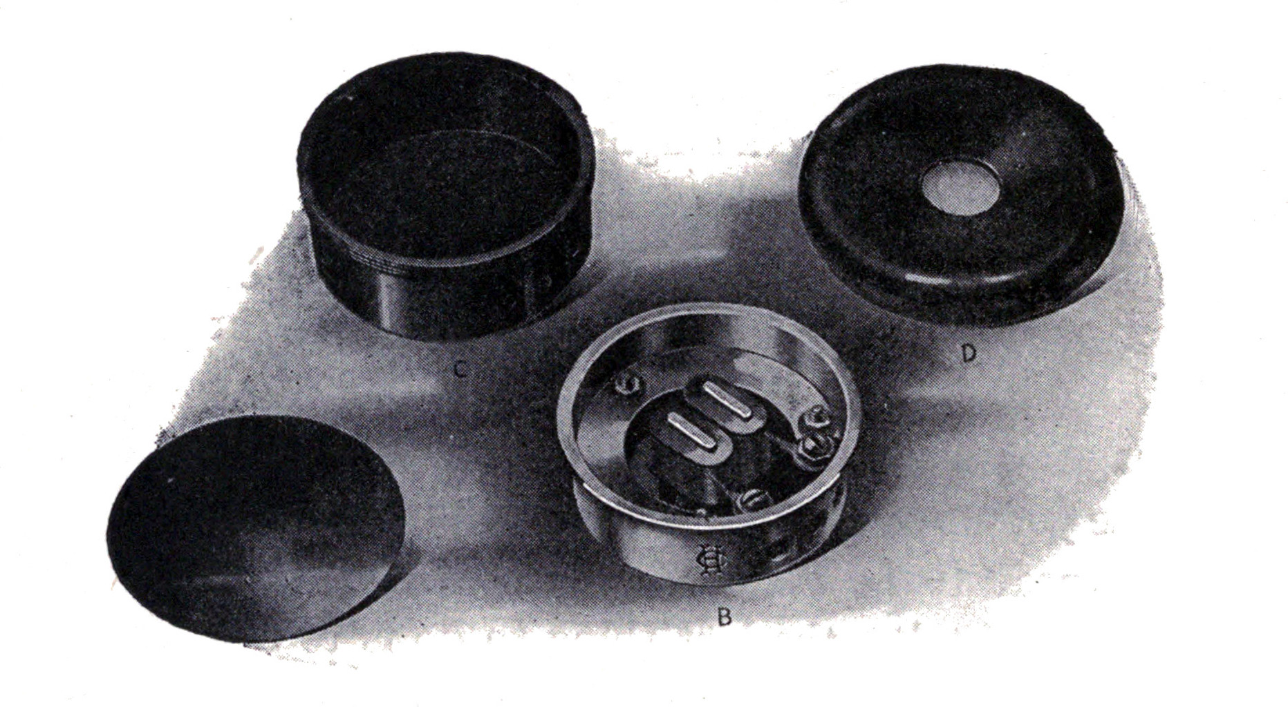
In carrying out any of these suggestions remember to work with one receiver at a time, keeping the other for comparison, so that by repeated tests you may tell whether or not an improvement is being made and when well enough is reached, let it alone.
Fig. 144 shows the construction of a telephone receiver manufactured by the Holtzer Cabot Co. of Brookline, Mass. The permanent magnets and bobbins are mounted in a metal cup, B, which supports the diaphragm, A. The metal cup is enclosed in a hard rubber shell, C, and fitted with a cap, D.
The complete receivers are mounted on an adjustable headband and fitted with pneumatic ear cushions which make them set more comfortably and shut out extraneous noise. These receivers are wound to all resistances used in the wireless field but, for the experimenter, those having a resistance of 1000 ohms apiece will give the best all around results.
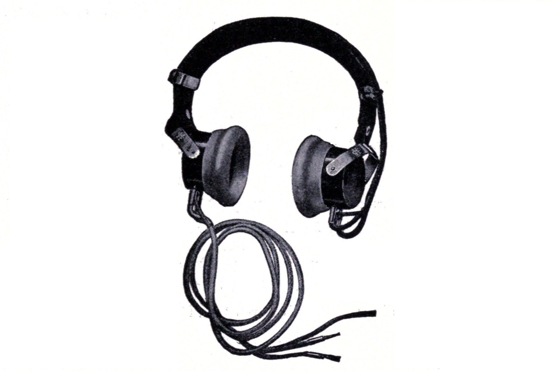
It is very desirable that the receivers should be fitted with a comfortable headband which will hold the telephones in close adjustment to the ears. Fig. 146 shows the construction of such a band.
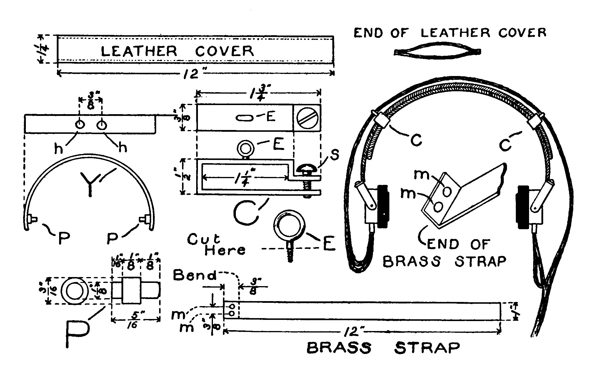
Two brass straps, 1 inch wide, 12 inches long and 1/16 inch thick are necessary. Two 1/8-inch holes, mm, are bored in them 3/16 inch from one end and the end bent up at an angle along a line 3/8 inch from the end as shown by the drawing. A cover is made for the straps, by sewing two strips of leather 1 1/4 inches wide and 12 inches long, together along their edges. The covers may then be slipped over the straps. Two 1/16-inch brass strips, 3/8 inch wide and a little longer than one-half the circumference of the watch-case receiver to be fitted to the head band, are bent into stirrups as shown in the illustration by Y. The ends of the stirrups are fitted with two pivots, PP, which are riveted in a hole. Two holes or recesses are bored in the shell of each receiver, on the sides 180 degrees apart. The pivots, PP, fit into these holes and form bearings in which the receivers can turn and adjust themselves to the ears. The stirrup has two small holes, hh, bored 3/8 inch apart at the top and tapped to receive a small screw. The screws pass through the holes, mm, and hold the stirrups at the end of their respective strap.
The leather-covered straps are bound together by means of two clamps which permit the head band to be adjusted to suit the wearer. The clamps, C, are made from 1/16-inch brass 3/8 inch wide. Their form and construction may be best understood from the drawing. A small screw eye is cut in half and soldered to the center of the upper side of the clamp so that the receiver cord may be passed through the eyelet, E.
The telephone receivers should be connected in series by means of a flexible telephone cord.
CHAPTER XVII. OPERATION.
The first essential in order to manage a wireless station, after learning the construction and handling of the instruments, is to acquire a thorough knowledge of the telegraph codes.
The two codes in use in wireless service are the Morse and the Continental. They are given below.
In some cases, the intending wireless operator has had some experience with a Morse sounder and then it is merely a matter of transition and of accustoming the ear to a new sound. However it is always best to learn the Morse code first as Continental is merely an adaptation in which no space characters appear.
A beginner may learn to receive most easily by communicating with another person to whom it is also new. They should first memorize all the letters of the code and practice transmitting before commencing any communication.
It is a great mistake for a beginner to start by writing down the dots and dashes as he receives them on paper. He should make an effort to translate them and set the characters and words down directly. This at first will sacrifice speed but will make a better operator and enable one to become proficient sooner than if he begins otherwise.
In case two complete sets of wireless apparatus are not convenient, one may learn to read from a buzzer connected to a key and a battery. The signals may be read directly from the sound of the buzzer itself, but if a pair of telephone receivers are connected across the terminals, a sound will be produced in the phones similar to that of a wireless receptor.
In sending, avoid a short, choppy or jerky style and handle the key with a light but firm touch. Keep the dots and dashes firm and of the proper relative length, as also the spaces between letters and words.
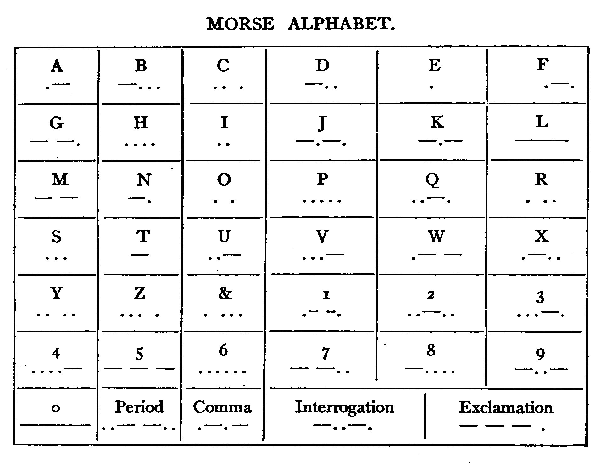
The following suggestions and instructions adapted from the Rules and Regulations governing Naval Wireless Telegraph Stations may be of value and service to many in operating their instruments.
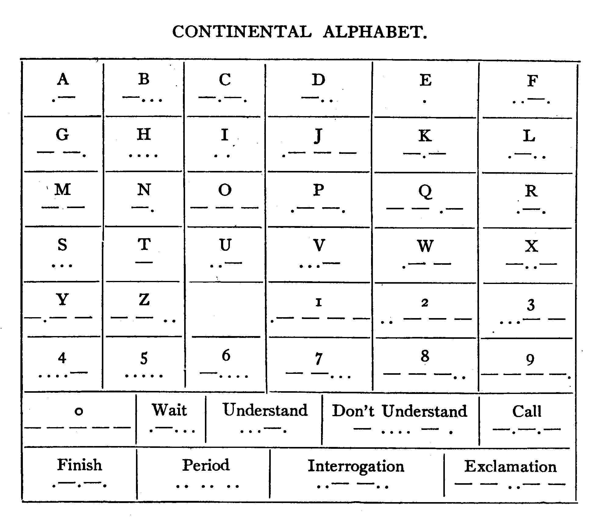
"The operating room should be well lighted and free from vibration. The room should have a well insulated entrance for the aerial and should be fitted with an operating table about two and one-half feet wide, not less than seven feet long and of a convenient height for working the sending key.
The table should be of dry, well-seasoned wood and the instruments should be mounted on the table at safe sparking distances from each other.
"The connections should all be as direct as possible and well insulated. High potential leads should be kept away from low potential leads and where they cross it should be at nearly right angles.
"Sending key contacts must be kept clean and flat with surfaces parallel to each other.
"All sliding contacts, especially in the receiving tuning coils, should be kept clean and bright and free from foreign matter. A sending set working at low power with all connections good, closed and open circuits in resonance, no sparking from edge of condenser, jar or plates, no glow from aerial and no sparking to rigging, is utilizing its power much more efficiently than the same set pushed to the limit with high resistance connections, sparking at all points and out of resonance."
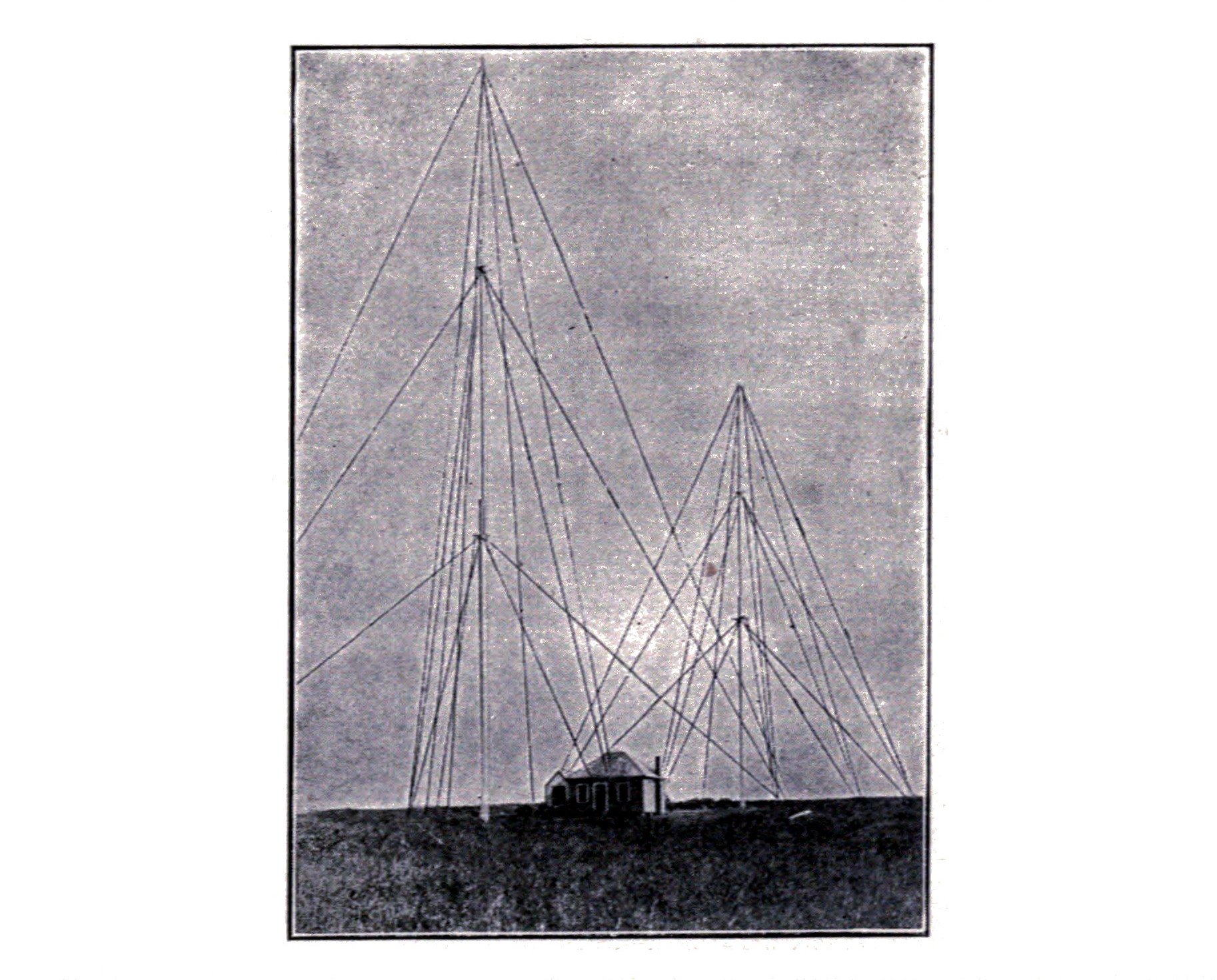
It is a good plan for any amateur to keep a note book in which he can record the various distances he has been able to receive and transmit. He should try more than one circuit and jot down the results. It is then possible to bring a station up to an efficiency which cannot be reached in any other manner.
ELECTRICAL TERMS AND DEFINITIONS.
- Accumulator:
A cell whose positive and negative electrodes are formed or deposited by a current flowing from a separate source.
- Aerial:
A network or a number of wires insulated from surrounding objects and suspended in the air to emit or intercept electromagnetic waves.
- Alternating Current:
An electric current, of which the direction of flow reverses a number of times per second.
- Ampere:
The quantity of current which will flow through a resistance of one ohm under a potential of one volt. The unit of current.
- Ampere Hour:
The quantity of electricity passed when flowing at the rate of one ampere for one hour.
- Anode:
The positive terminal of a broken circuit or a source of electricity. It is the carbon of a cell or the pole at which a current enters a solution.
- Capacity:
The relative ability of a conductor to receive and retain an electric charge.
- Circuit:
An unbroken conducting path for an electric current.
- Condenser:
A device for receiving and storing up electrostatic energy.
- Cycle:
The full period of reversal of an alternating current. A 60-cycle current is one making 60 complete reversals per second.
- Detector, Wireless:
An instrument for detecting oscillations in the aerial of a receiving station. It either varies its own internal resistance or generates a weak intermittent direct current similar in time and duration with the signals emitted by the transmitting station.
- Dielectric:
A non-conductor or insulator. It usually refers to the material interposed between the oppositely charged coatings of a condenser.
- Direct Current:
A current flowing in one direction only.
- Electrode:
The terminal of an open electric circuit or a conductor carrying a current and immersed in an electrolyte.
- Electrolysis:
The separation of a chemical compound into its elements by the action of an electric current.
- Electrolyte:
A solution which will conduct a current of electricity.
- Electromagnet:
A mass of iron which is magnetized by the passage of a current of electricity through a coil of wire wound around the mass and insulated therefrom.
- Farad:
The unit of electrical capacity. A condenser having a capacity of one farad would be raised to a potential of one volt by one ampere flowing for one second.
- Field of Force:
The space which is under magnetic stress in the neighborhood of a magnet or a wire carrying a current.
- Helix, Transmitting:
A coil of heavy wire which furnishes the inductance for the closed oscillation circuit of a wireless transmitter and acts as an auto-transformer to raise the voltage of the high frequency currents.
- Henry:
The unit of induction. It is the induction in a circuit when the electromotive force induced in this circuit is one volt, while the inducing current varies at the rate of one ampere per second.
- Inductance:
The property of an electric circuit whereby lines of force are developed around it.
- Induction Coil:
An instrument or device consisting of two independent coils of wire wound around an iron core, and which by magnetic induction steps up an intermittent direct current from a low to a high voltage.
- Insulator:
A non-conductor or a substance impervious to the passage of electricity.
- Key:
A device for making and breaking a current into periods corresponding to the dots and dashes of the telegraph code.
- Kilowatt:
1,000 watts. See watt.
- Leyden Jar:
A static condenser which will store up static electricity and is cylindrical in form. So-called because it was originated in Leyden, Holland.
- Multiple:
The term expressing the connection of several pieces of electrical apparatus in parallel with each other so that the current is divided between them.
- Ohm:
The unit of resistance. It is arbitrarily taken as the resistance of a column of mercury, one square millimeter in cross sectional area and 106 centimeters in height.
- Parallel:
The same meaning as multiple. Parallel circuits are those which start at a common point and end at a common point.
- Polarization:
The collection of hydrogen upon the positive electrode of a primary cell with a consequent loss of voltage.
- Potential:
Voltage or electrical force.
- Resistance:
The quality of an electrical conductor whereby it opposes the passage of an electric current. The unit of resistance is the ohm.
- Rheostat:
A variable resistance to regulate the strength of an electric current.
- Series:
Opposed to parallel or multiple. Instruments in series are so connected that the current passes from one to the other and does not divide.
- Spark Gap:
An air gap or open space between two electrodes for the passage of a high voltage discharge.
- Storage Battery:
See accumulator.
- Transformer:
A device for stepping up or stepping down the voltage of an alternating current by means of magnetic induction.
- Tuning Coil:
A variable inductance for changing the period of the receptor circuit.
- Volt:
The unit of electrical force or potential. The electromotive force which, if steadily applied to a conductor whose resistance is one ohm, will produce a current of one ampere.
- Voltmeter:
An instrument for measuring voltage.
- Watt:
Unit of work. It is the rate of work of one ampere flowing under a potential of one volt. Seven hundred and forty-six watts represent one electrical horsepower.
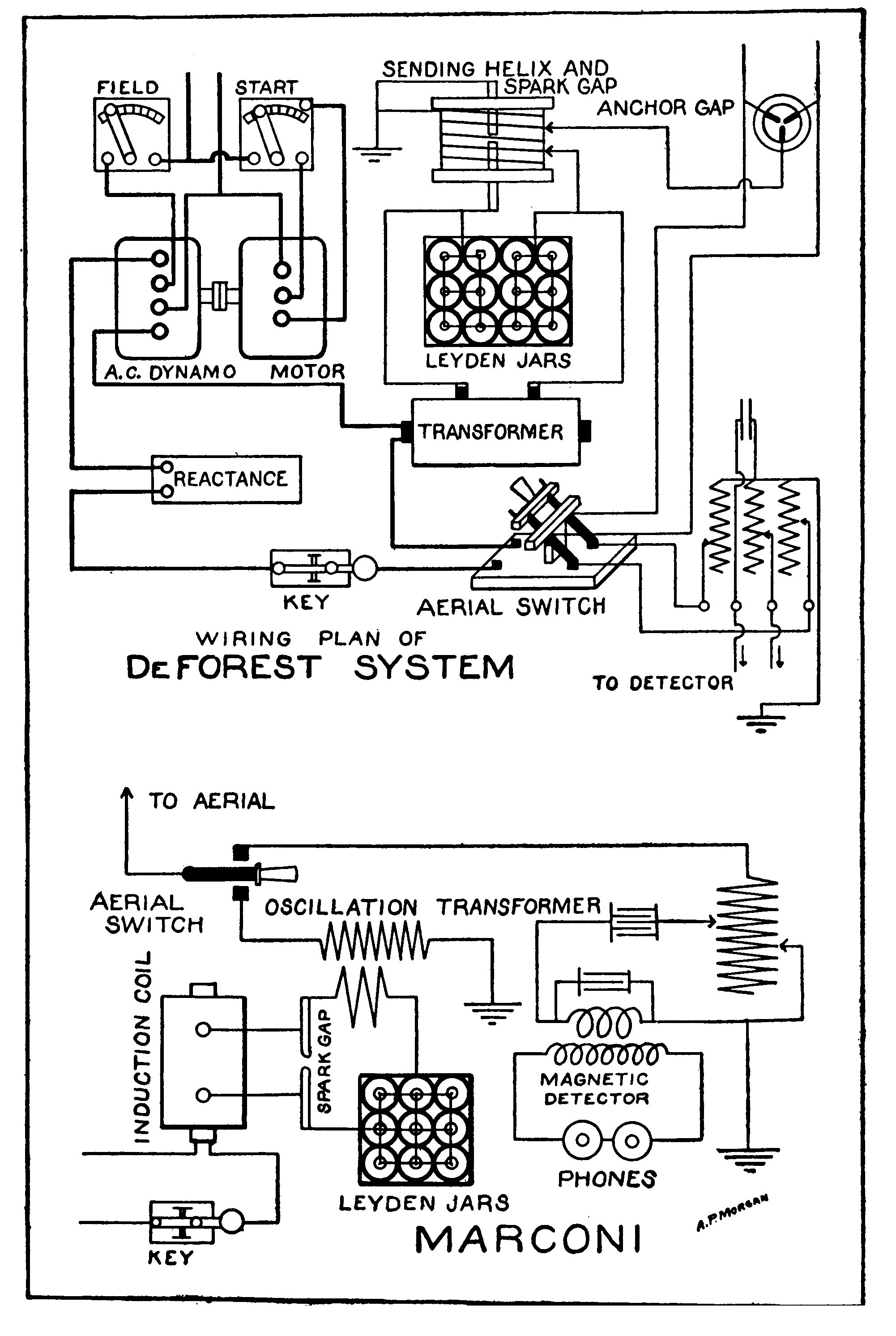
CHAPTER XVIII. THE AMATEUR AND THE WIRELESS LAW. WHAT IT IS; HOW TO COMPLY; HOW TO SECURE A LICENSE.
On August 13, 1912, Congress enacted a "Wireless Law" to regulate radio communication. The whole law may be found in the appendix of this book, but briefly as far as the amateur is concerned it is as follows:
An amateur may not use transmitting apparatus which is sufficiently powerful to send radio signals across any of the boundaries of the state in which he is located and which can be detected by a sensitive receiving set located just beyond the state boundary, nor can he use apparatus which is powerful enough to interfere with the reception of signals by others from beyond the state boundaries unless he has a license.
An amateur may receive messages from anywhere at any time without a license provided that his station is not also fitted with transmitting apparatus.
In other words if the amateur possesses a receiving outfit only which is in working order or if he has both transmitter and receptor and the former is not powerful enough to send signals out of the state in which he lives, or to interfere with the reception of messages by another when the messages come from beyond the state boundary a license is unnecessary.
This is of course somewhat unfair for those living near the center of large states for they may operate almost as they please with ordinary instruments with no fear of the signals going beyond the border, while those living within a few miles of another state must secure a license.
If an amateur has a license he may transmit messages beyond the state border, but he must not employ a wave length greater than 200 meters or a power input into the transmitter of more than 1 K.W. without special permission.
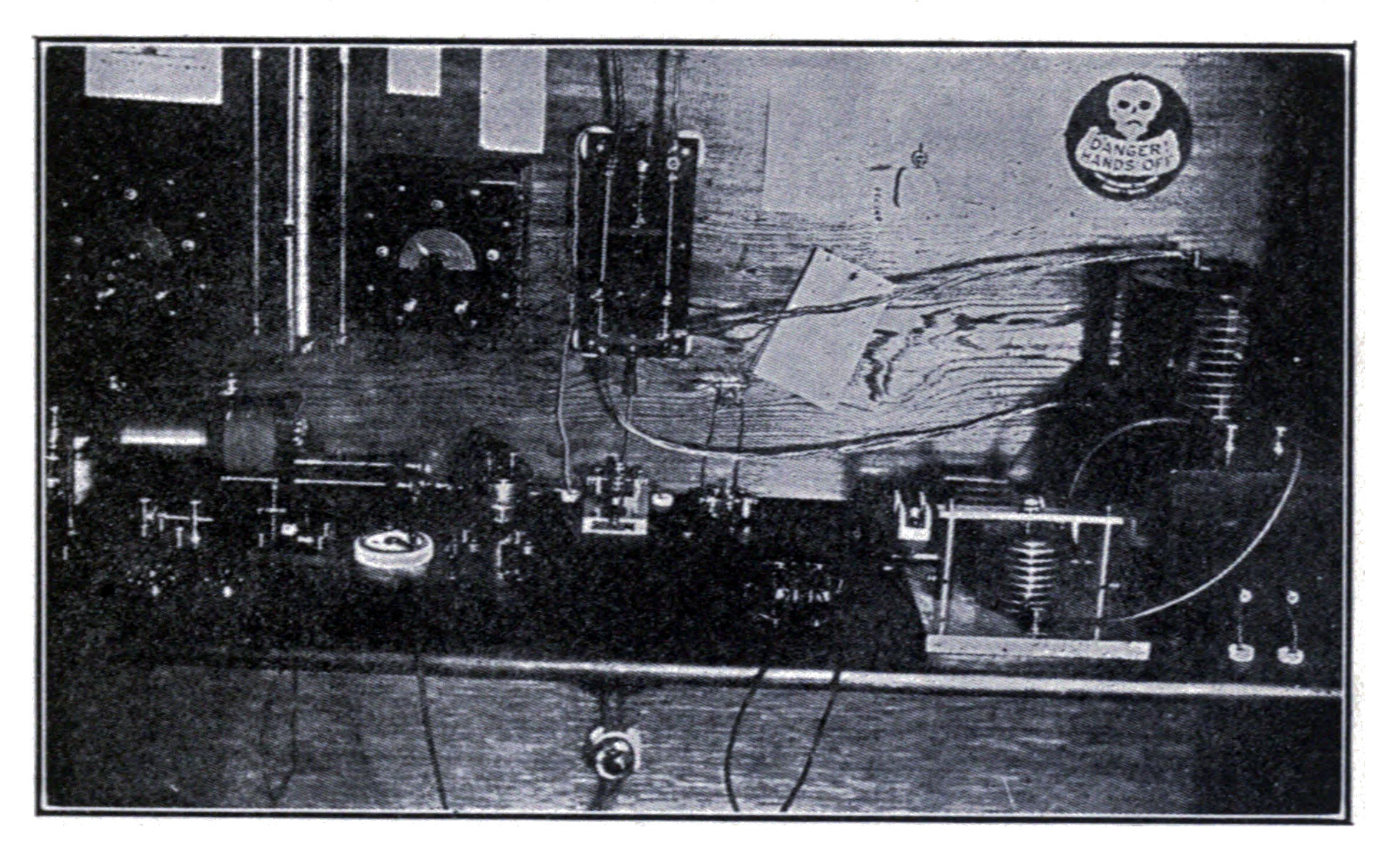
If the amateur is within five nautical miles of an army or navy station equipped with radio apparatus his power input must not be more than 1 K.W.
Complying with Law.—After a license is secured, or rather as a matter of fact in order to secure it, the wave length must not be greater than 200 meters. In order to secure such a wave length the effective portion of the aerial cannot usually be made greater than 115 feet in consideration of the amount which the lead-in, helix and ground wire add.
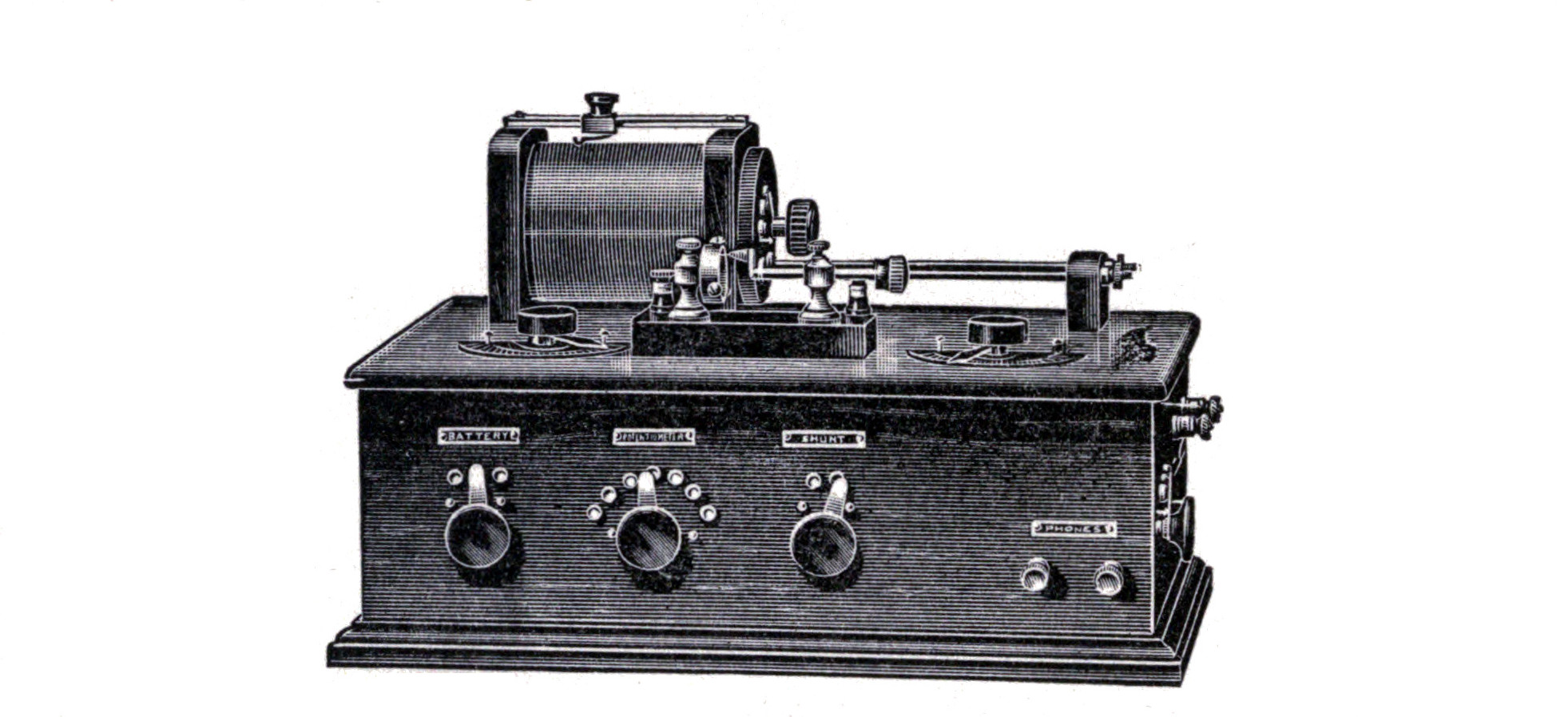
Such an aerial will serve well for transmitting purposes, but is too short for receiving very long distances. If the amateur desires to pick up long distance messages he must employ two aerials, a short one for transmitting and a long one for receiving. If it is desirable to use the long aerial for both transmitting and receiving its wave length may be brought down to 200 meters or under, while transmitting by placing a large glass plate condenser of the proper capacity in series with the aerial. It may be short-circuited with a suitable switch when receiving.
The law also says that the transmitting wave must be pure, and must be sharply tuned, which means that the wave must be of one length and not, as is very often the case, composed of two or more waves of different lengths.
In order to comply with this restriction, the use of an oscillation helix or loosely coupled helix is necessary. A rotary or quenched gap is also necessary in place of the ordinary spark gap.
The construction of all three of these instruments is described farther on.
How to Obtain a License.—In order to obtain a license send to the nearest Radio Inspector; Radio Inspectors are stationed at the Custom Houses at the following cities: Boston, Mass.; New York, N. Y.; Savannah, Ga.; Baltimore, Md.; Cleveland, Ohio; Chicago, Ill.; Seattle, Wash.; New Orleans, La.; San Francisco, Cal.; and obtain a copy of The Wireless Law, 8-6412, The Regulations Governing Radio Communication, The Berlin International Radio-telegraphic Convention, and the necessary Application Forms.
Look over the Wireless Law, the Regulations and the Berlin Convention pamphlet, then fill out Form 756. This is an application for an operator's license.
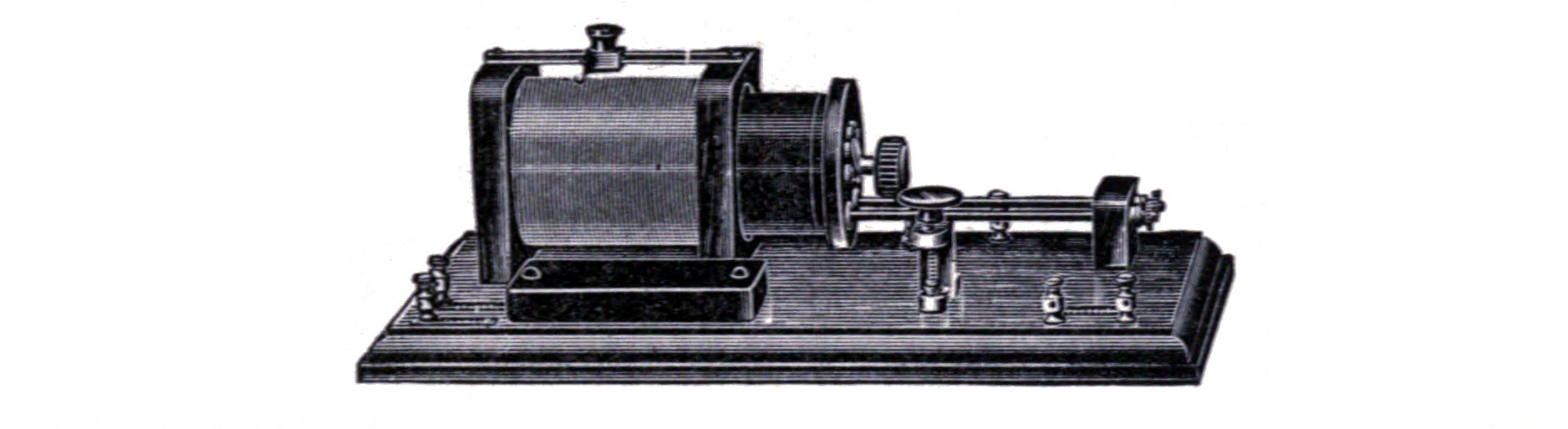
If the amateur is not already in possession of a certificate of skill as an operator it will be necessary to find out, from the commandant at the nearest one of the stations, listed on page 4 of the Regulations as being the places where examinations are given, on what days the examinations are held. If the amateur is able to pass the examination, an operator's license will be issued. Then fill out Form 757 and forward it to the Radio Inspector. If he thinks your station conforms to the regulations without inspection the license will be issued; if not, the license will be issued after inspection.
There are no fees to pay in connection with securing any of the licenses.
APPARATUS REQUIRED IN MANY INSTANCES IN ORDER TO COMPLY WITH THE WIRELESS LAW.
OSCILLATION HELIX
The oscillation helix has almost become a necessity in order to comply with the regulations of the Wireless Law regarding wave form, except in those stations where a quenched gap is used.
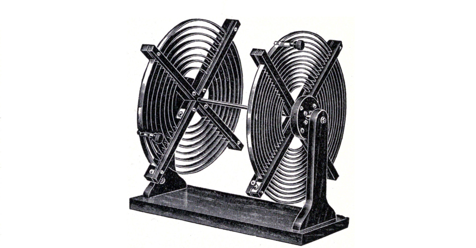
The wave emitted by many stations is not pure. It is composed usually of two or three separate waves of different lengths instead of all the energy being confined to oscillations of one period. It is possible to tune such a wave in two or more places or "humps," as they are called, on the tuning coil. It is obvious that a wave possessing such humps cannot be closely tuned and is liable to interfere with the signals of another station. This is one of the principal causes of interference.
The reason for this phenomenon is simple. The action of a transmitter is to first charge a condenser. When the potential of the condenser rises to sufficient value it discharges across the spark gap and sets up oscillations in the closed circuit. These oscillations immediately induce oscillations in the open circuit or aerial system and part of the energy passes off into the ether as electro-magnetic waves. However, the oscillations in the aerial system do not immediately die away after the oscillations in the closed circuit cease during the interim until the next condenser discharge, but continue to surge and react upon the dosed circuit to sufficient extent to induce therein currents which surge back and forth long after the current from the condenser discharge has died away.
We might call the oscillations due to the condenser discharge primary oscillations and those induced in the aerial thereby secondary oscillations. Those which are then set up in the closed circuit by the reaction of the secondary currents are tertiary. This third train of oscillations persist after the secondary currents have died away, and induce another set of oscillations in the aerial which send out a second set of electromagnetic waves differing in length from the first.
The oscillations which take place after the initial surge in the closed and open circuits are naturally somewhat weak. By using an oscillation helix in which the primary and secondary are separated from each other it is possible to eliminate the third and fourth trains of oscillations and all others having a tendency to follow, by placing the circuits apart so that the weak oscillations are not strong enough* to react across the intervening space. The immediate oscillations set up by the condenser discharge are strong enough to act across the space and set up powerful oscillations in the aerial.
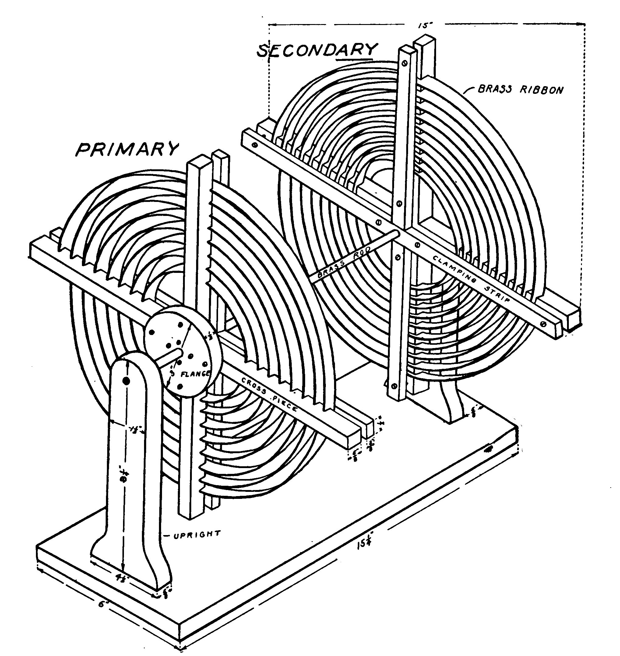
A hot wire ammeter placed in the aerial circuit of a transmitter employing an oscillation transformer will not indicate as much current as if placed in the same position in a circuit using an ordinary helix; but in spite of the fact, a transmitter using an oscillation helix will send farther because the energy is concentrated in waves of one length.
The construction of one type of oscillation helix has already been outlined on page 92. The form shown in Fig. 152 has no special advantages over the other but is preferred by many experimenters.
It is of the "pancake" type, so-called because of the flat form of the windings which are made in the shape of a spiral of brass ribbon set in a slotted frame.
The dimensions of the helix are clearly apparent from the drawing. The primary is composed of seven turns of brass ribbon 1/2 inch wide and 1/16 inch thick. The secondary should have from 10 to 15 turns of ribbon 3/8 x 1/16. The coils may be slid back and forth on the brass rod so that the distance between them is variable. Connection is made to the coils by means of suitable clips. A clip similar to that shown on page 92, but made to snap on a flat ribbon instead of a round wire, will serve the purpose.
QUENCHED SPARK GAP.
A "quenched" gap is made up of a number of brass or copper disks accurately turned to a true surface and separated by mica or rubber rings about .01 inch thick. The spark discharge takes place in the air-tight space at the center of the disks, inside of the mica rings.
The quenched gap has several advantages over other forms. It is practically noiseless and the nuisance of a crashing discharge may be avoided by its use.
The large surface offered to the spark by the disks cools the spark and quickly stops the oscillations in the closed circuit, and thereby leaves the open circuit and aerial system free to vibrate in its own period and therefore radiates pure waves. By pure wave a wave of one length is meant.
A quenched gap cannot be used on a set of over 1 K.W. power without artificial cooling by an air blast.
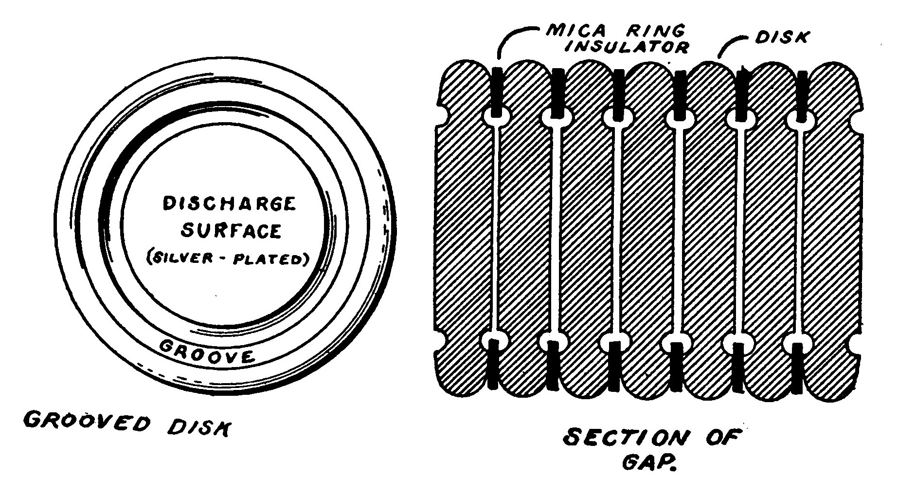
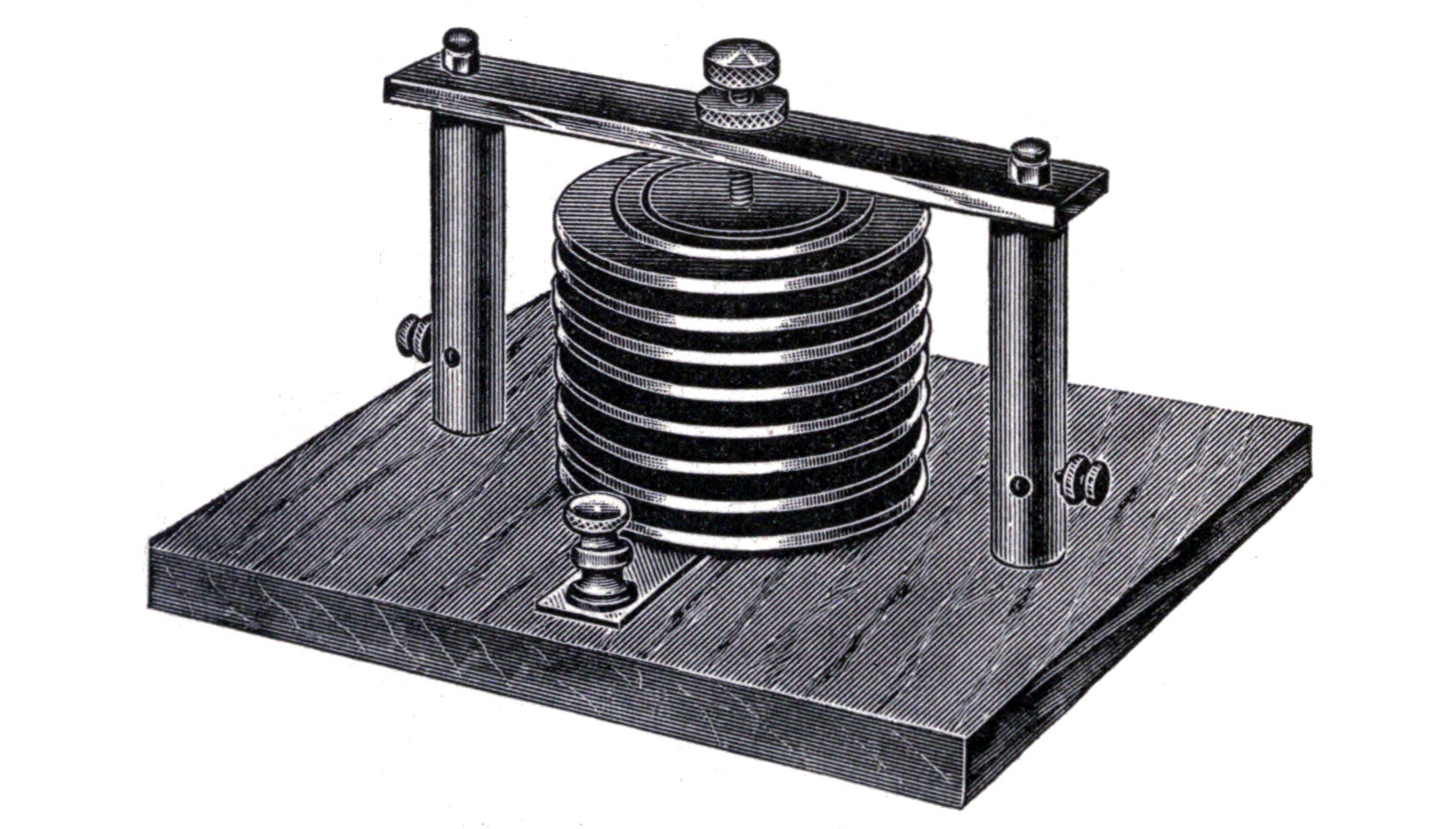
Fig. 154 shows an efficient form of quenched gap for use in stations up to 1 K.W. in power.
The disks are shown in detail in Fig. 155. They are cast out of copper and then turned perfectly true and smooth in a lathe. After surfacing, the discharge surface should be heavily silver plated and buffed smooth.
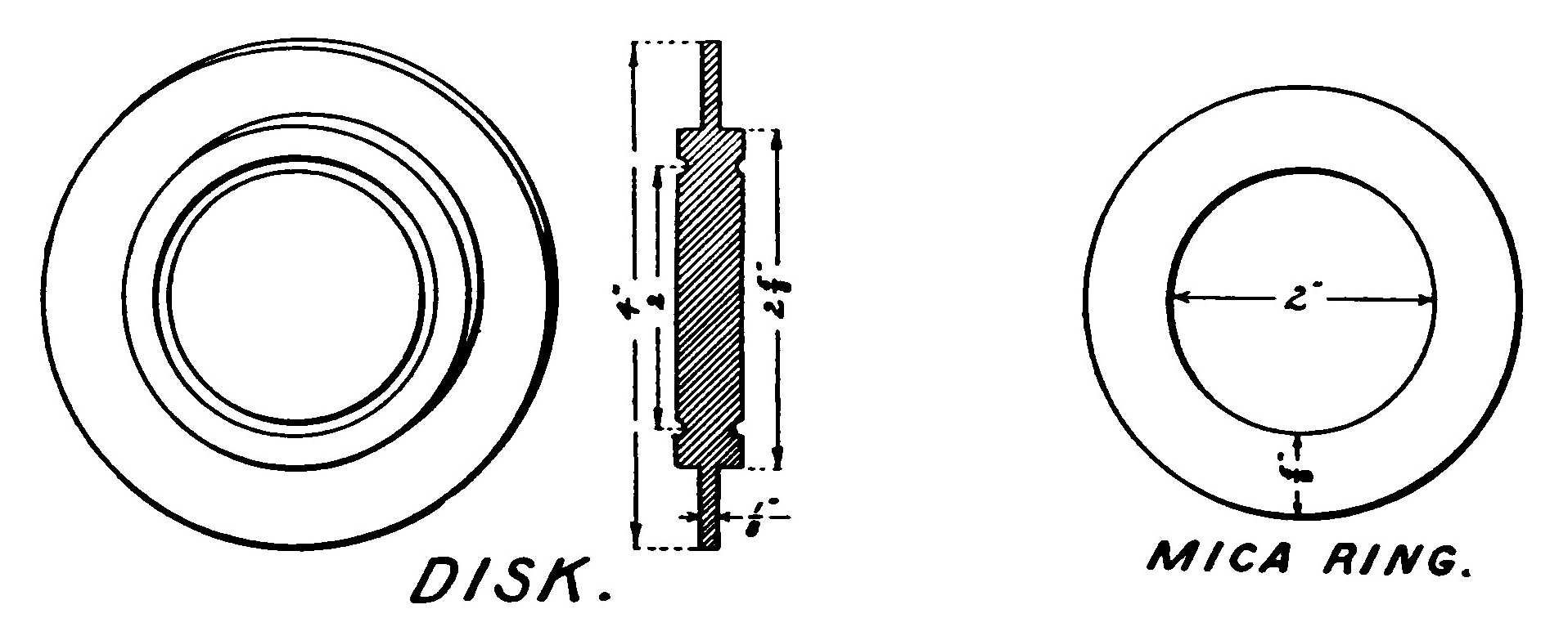
The disks are piled on a marble base with a mica ring between each. They are clamped down by a strong set screw mounted on a heavy brass yoke. Enough pressure should be brought to bear to force the plates tightly together and make them air tight.
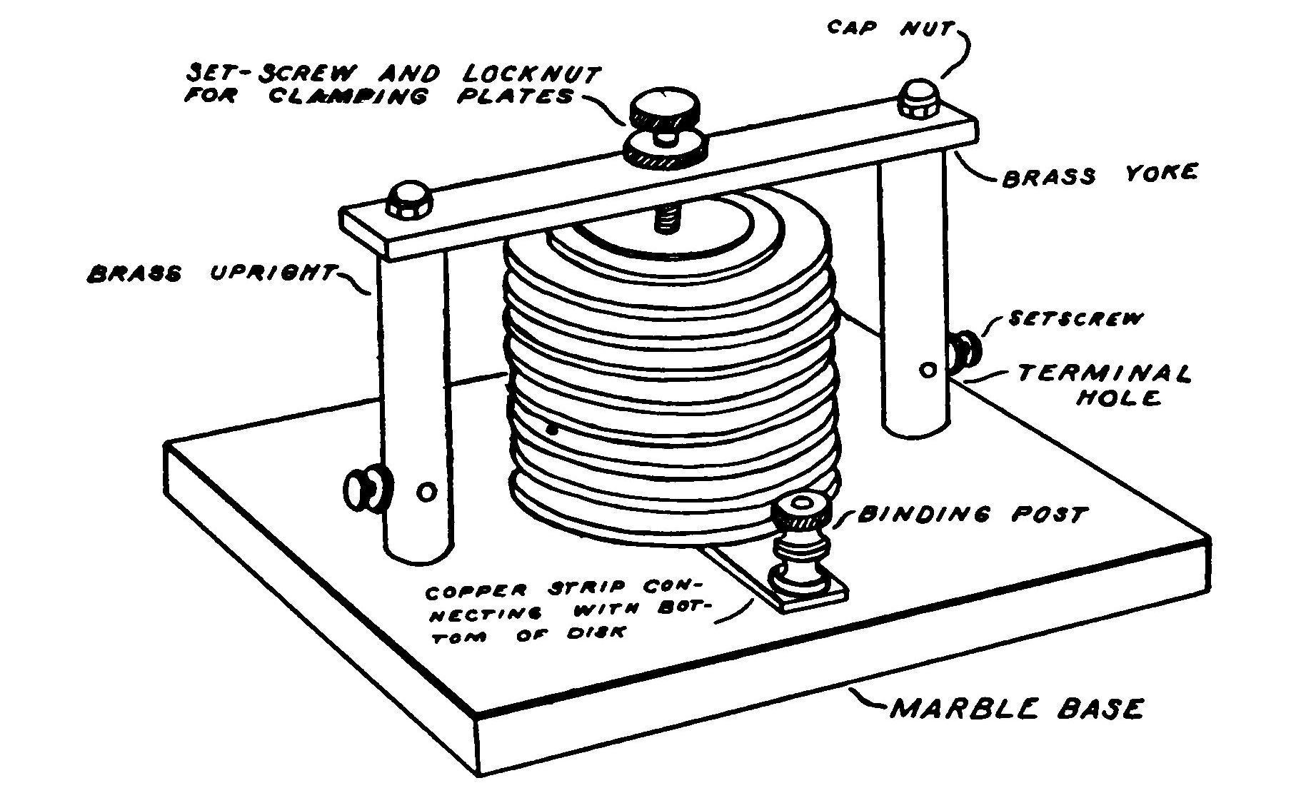
The number of disks required is governed by the voltage of the charging condenser. Generally speaking it is one section of .01-inch gap for each thousand volts delivered by the secondary of the transformer. It is very important to secure just the proper number of disks. If properly adjusted, the quenched gap will give one discharge for each alternation of the current and produce a musical tone.
The quenched gap is placed in the same position in the transmitting circuit as any other form of gap.
ROTARY GAPS.
Rotary gaps are divided into two general classes, the synchronous gap and the non-synchronous gap.
The former usually consists of one or more stationary electrodes and a rotating member made like a star wheel with projecting spokes. This rotary member is attached directly to the shaft of the alternator or motor generator and arranged so that a spoke always comes opposite a stationary member at the exact moment that the maximum of potential is obtained in the condenser. Such an arrangement permits one discharge for each alternation of the current and produces a pure musical note easily distinguished in the telephone receivers at a distant station.
In the non-synchronous rotary gap the wheel is driven at a high rate of speed without any regard to synchronism with the alternations of the current.
The rotary gap shown in Fig. 157 is of the non-synchronous type.
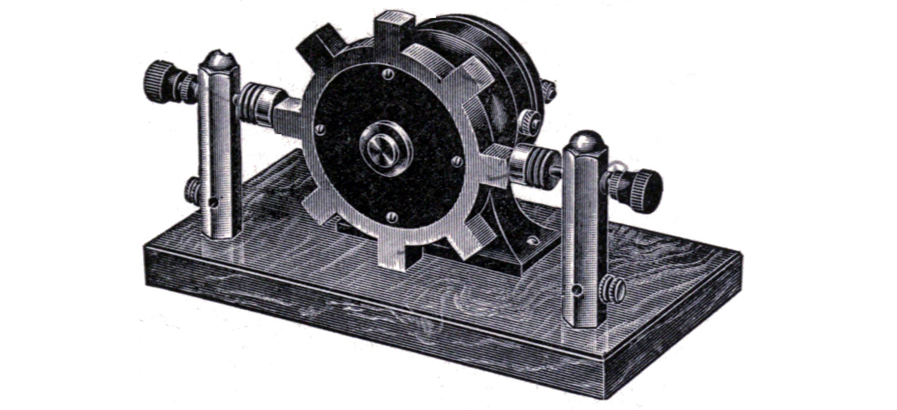
The rotating member is cast from an alloy of equal parts of zinc and aluminum. It is necessary to first make a wooden pattern from which the casting may be made. The details of the wheel are shown in Fig. 158. The casting must be placed in a lathe chuck and turned true. It is mounted on a hard rubber disk 2 7/8 inches in diameter and 1/4 of an inch thick. The disk serves to insulate the revolving electrodes from the motor shaft. The "rotor" is mounted upon the shaft by means of a small brass bushing which passes through the center of the disk.
The motor must be well built and capable of running at high speed. A "Juno" motor will be found very satisfactory. When running free its speed is about 4500 r.p.m. With the rotor in place the speed is about 3600 r.p.m.
The motor should be mounted on a heavy marble base capable of absorbing any little vibration that the gap may be subject to when running at high speed.
The stationary electrodes are made in the same manner as those for an ordinary gap and consists of two flanged zinc electrodes mounted upon threaded brass rods supported by two hexagonal standards. The axis of the electrodes should be the same height above the base as that of the motor shaft.
The rotor should be carefully balanced so that it is practically free from vibration by boring small holes in the back face so as to make the weight on opposite sides equal.
The motor may be driven by a battery or from the same source that supplies the transformer, in series with two or three suitable lamps. A motor wound to run directly from the 110-volt line or a higher potential must have its fields wound with very fine wire and is apt to give trouble through "burn-outs," due to "kick back." When the motor is operated on batteries or is wound for running in series with a lamp the danger is lessened.
A rotary gap is placed in the transmitting circuit in the same position as any other gap. Its use will result in a wonderful increase in the transmitting range of almost any station, for not only will the amount of energy passing through the aerial be raised, but the clear musical tone given off is more plainly distinguishable at a greater distance in the receiving station than a spark of the ordinary sort.
"KICK BACK."
The oscillations taking place in the closed circuit and aerial system of a wireless transmitter continue to surge after the current in the condenser has dropped below a certain value, and react upon the primary winding of the coil or transformer by induction and produce high voltage, high frequency currents termed "kick back," in wireless telegraph parlance.
"Kick back," wherever it exists to an appreciable extent, is liable to damage insulation and cause possible "burn-outs." The "kick-back" preventers illustrated in the accompanying diagrams will be found an efficient method of avoiding this danger.
The first method shows an ordinary pressed telephone condenser of about two microfarads capacity connected directly across the A. C. mains near the transformer terminals, in series with two 6-ampere fuses. The condenser is shunted by a small spark gap made of needle points with a very small space, about .005 of an inch, between them.
The second method is an elaboration of the first and shows two sets of condensers in series with fuses and bridged by spark gaps with a "ground" through a third condenser connected between. This second method is the best and is often used to prevent delicate instruments, such as a voltmeter, from the effects of "kick back."
A proper "kick-back" preventer is part of the Fire Insurance Underwriters requirements for a wireless telegraph station.
Receiving Apparatus.
THE VARIOMETER.
A variometer is a tuning device in which two coils of wire are placed in series and connected so that the turns can be made to oppose one another. One coil is movable and by turning it the currents flowing through the adjacent coils oppose each other and decrease the self-induction of the whole and consequently the period of the circuit.
The accompanying illustration shows the constructive details of an efficient form of variometer.
The coils are wound around two cardboard cylinders. One cylinder is 6 inches in diameter and the other 5 inches. Both are 2 inches long. The large cylinder is wound with twenty-five turns of No. 22 B. S. gauge single silk covered wire wound in two sections so as to leave a space 3/8 inch wide in the center. The small cylinder is wound in the same manner with the same size of wire but contains thirty turns so as to make the length of wire in each of the coils practically equal.
The space in the center of each of the coils allows a supporting rod to pass through without interfering with the wire. The shaft is a piece of 5/16 brass rod about 7 1/2 inches long. The upper end is provided with a knob and a pointer. The large coil is mounted on the under side of a wooden cover made to fit a containing case of the proper size to receive the variometer and of a style similar to that ordinarily used to enclose a variable condenser.
The shaft passes through the larger coil, at two points diametrically opposite, but should not fit tightly. It also passes through the smaller coil but is fastened to the latter by means of a cross bar so that when the knob is turned the coil will revolve also. The coils are connected by means of a piece of braided wire or flexible conductor, long enough so as not to interfere with the movement of the inner coil.
The outside terminals of the coils terminate in binding posts mounted on the top of the case. When making a variometer be careful not to employ any iron or steel in its construction, not even iron screws.
The variometer is placed in the receiving circuit by connecting it in series with the aerial before it reaches the tuning coil or loose coupler.
NEW CRYSTAL DETECTORS.
Silicon Detector.—The silicon detector is always interesting because it was one of the first mineral rectifiers to come into extended use. The photograph shown below illustrates one of the latest forms of the silicon detector.
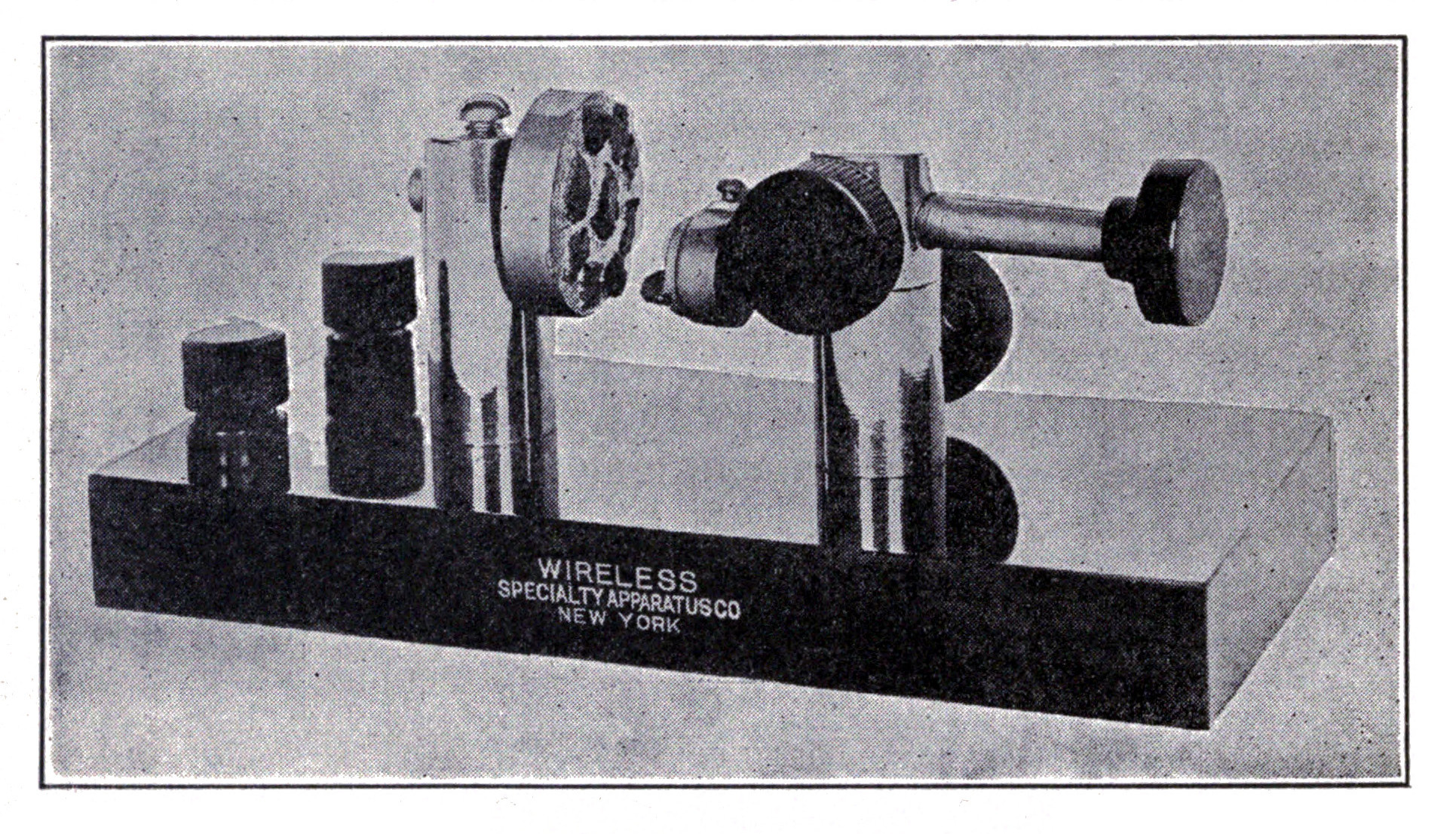
The large cup supported by the left-hand standard contacts several pieces of fused silicon embedded in fusible alloy. The right-hand standard supports a movable "offset" cup the same as that used on the Perikon type of Detector. A small piece of arsenic is mounted in this cup and may be brought to bear against any portion of any of the silicon crystals.
Pyron Detector.—The Pyron detector is not new, but the photograph shows a very simple and efficient form in which a fine wire is brought to bear against a crystal of iron pyrites mounted in a small cup.
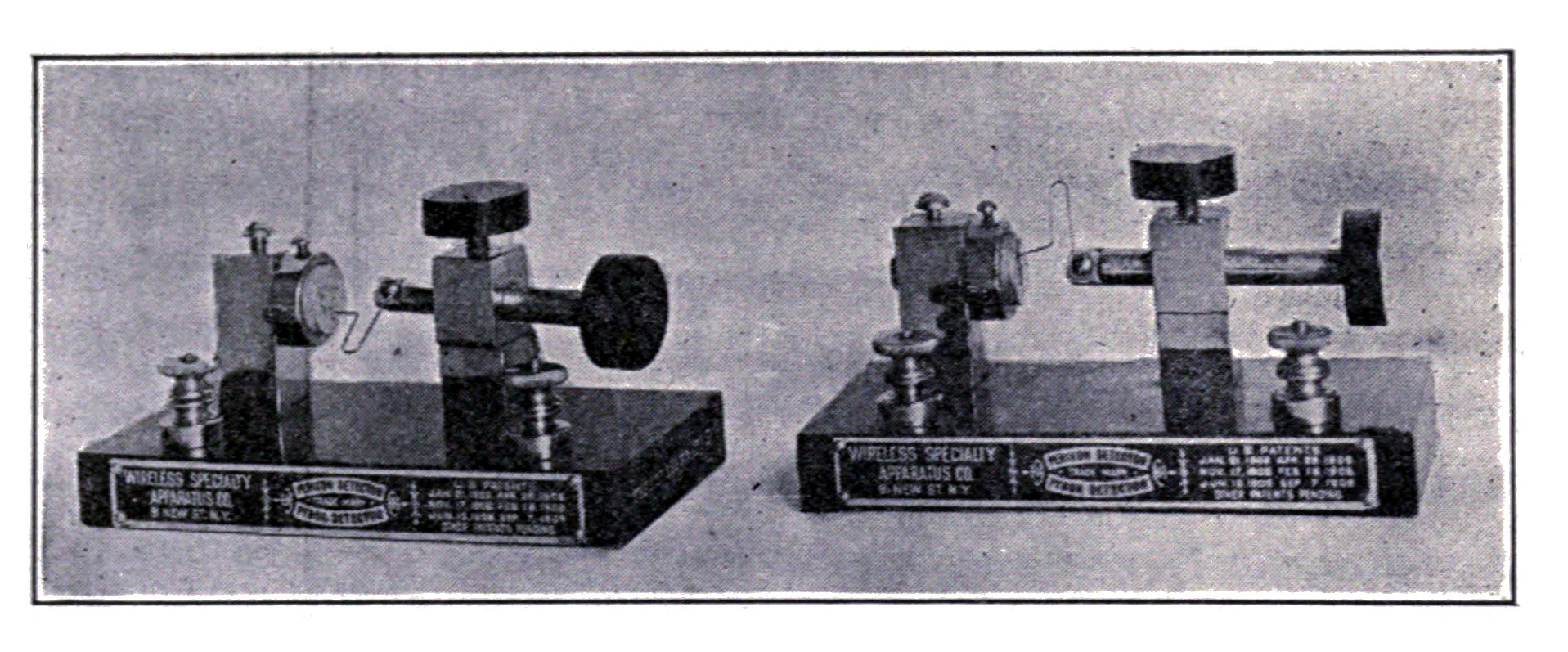
Galena Detector.—Although galena is named in the list of sensitive minerals on page 132 it has come into such extensive use as a detector since the first edition of this book to be worthy of special attention. Galena detectors are often spoken of as "cat-whisker" detectors because of the long fine wire used to secure a delicate contact with the mineral.
The mineral is usually placed in a cup and held in position by imbedding in fusible alloy or clamped with a set screw. The best surface of the mineral should be selected by testing previous to imbedding it in the cup. Contact is made with the surface of the mineral by means of a piece of No. 30 phosphor bronze wire mounted on the end of a short brass rod fitted with an adjusting screw so that by turning or twisting the surface of the mineral may be "searched" and the tension varied.
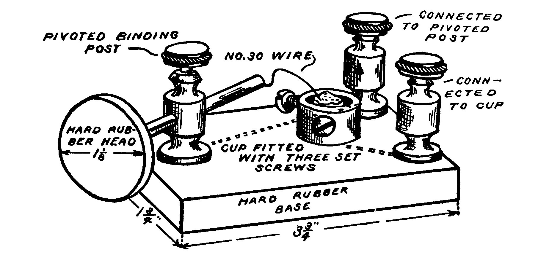
Such an arrangement is illustrated in Fig. 164. The base is a hard rubber block 3 3/4 x 1 3/4 x 1/2. The binding posts are of the type commonly used on electrical instruments. One of the posts is pivoted by placing a spring washer under the head of the screw which holds the post to the base. A short piece of brass rod fitted with a hard rubber knob passes through the wire hole in the post. A piece of No. 30 phosphor bronze wire is soldered to the end of the rod. By twisting the post and sliding the rod any portion of the mineral surface may be selected. Twisting the rod varies the tension of the contact.
The galena detector is connected in the receiving circuit in the same manner as other detectors of the mineral type.
THE AUDION.
The Audion—is finding favor in many amateur wireless stations, because of its almost entire lack of adjustment and of the loud clear signals which it gives even when used for long distance work.
The illustration shows the latest form of audion, the plate and the grid both being on the same side of the filament.
The filament of an audion is usually lighted by means of a six-volt storage battery. A small battery rheostat placed in series with the battery serves to regulate the amount of current flowing through the filament. Only one filament is used at a time, the other being saved as a reserve in case the first burns out.
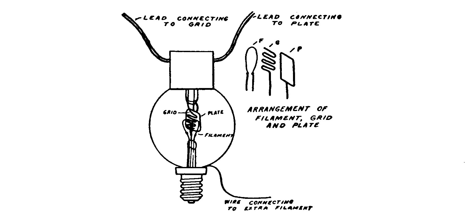
The higher voltage necessary to operate an audion is supplied by a battery consisting of fifteen flashlight batteries, each flashlight battery being composed of three separate cells. The batteries are connected to an eight-point switch so that throwing the switch on the first point will connect five sets of batteries. The second point places five more in circuit and each additional point one set only. It is also a good plan to connect a four-point switch and three separate cells of battery in series with the eight-point switch so that they may be added to the circuit one at a time and the potential varied more closely than the steps on the eight-point switch permit. The maximum voltage of such a battery is approximately 56 volts.
The diagram in Fig. 166 shows exactly how an audion is connected. The wires A and B are the terminals leading to the tuning coil or loose coupler. It is not necessary that the telephone receivers used with an audion be wound to a high resistance in order to secure good results.
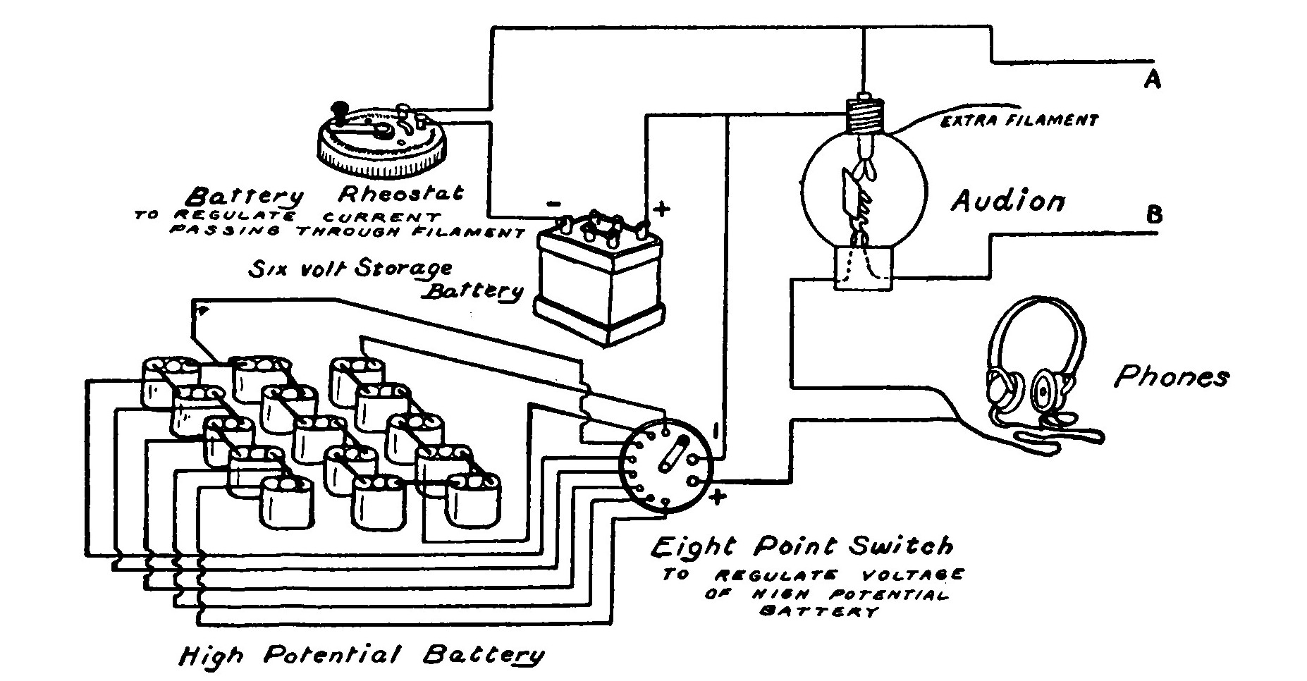
The audion is placed in operation by turning the rheostat until the filament lights brightly. Then adjust the voltage of the high potential battery until the signals are clearest. If the voltage is too high the audion will become filled with a bluish light and the voltage should be immediately reduced. The signals will be loudest when the filament is brilliantly lighted. No more current should be passed through the filament than is necessary to render the signals plain, for if "forced" its life will be limited to only a few hours.
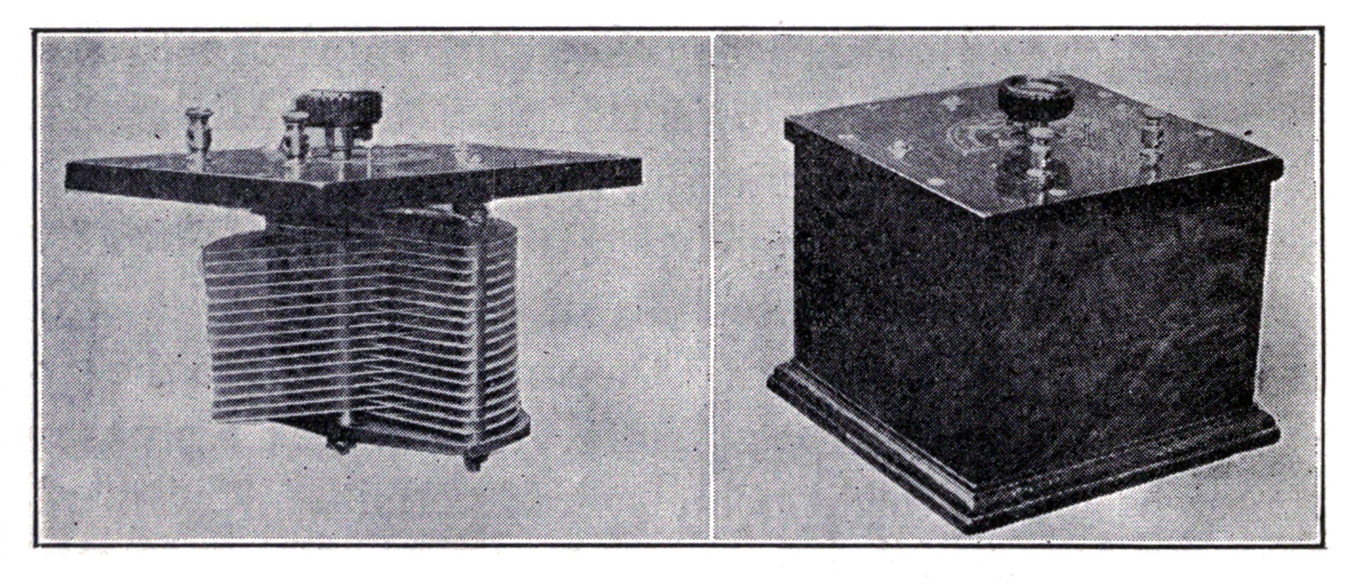
APPENDIX.
[PUBLIC No. 264.]
[S. 6412.]
An Act to Regulate Radio Communication.
Be it enacted by the Senate and House of Representatives of the United States of America in Congress assembled. That a person, company, or corporation within the jurisdiction of the United States shall not use or operate any apparatus for radio communication as a means of commercial intercourse among the several States, or with foreign nations, or upon any vessel of the United States engaged in interstate or foreign commerce, or for the transmission of radiograms or signals the effect of which extends beyond the jurisdiction of the State or Territory in which the same are made, or where interference would be caused thereby with the receipt of messages or signals from beyond the jurisdiction of the said State or Territory, except under and in accordance with a license, revocable for cause, in that behalf granted by the Secretary of Commerce and Labor upon application therefor; but nothing in this Act shall be construed to apply to the transmission and exchange of radiograms or signals between points situated in the same State: Provided, That the effect thereof shall not extend beyond the jurisdiction of the said State or interfere with the reception of radiograms or signals from beyond said jurisdiction; and a license shall not be required for the transmission or exchange of radiograms or signals by or on behalf of the Government of the United States, but every Government station on land or sea shall have special call letters designated and published in the list of radio stations of the United States by the Department of Commerce and Labor. Any person, company, or corporation that shall use or operate any apparatus for radio communication in violation of this section, or knowingly aid or abet another person, company, or corporation in so doing, shall be deemed guilty of a misdemeanor, and on conviction thereof shall be punished by a fine not exceeding five hundred dollars, and the apparatus or device so unlawfully used and operated may be adjudged forfeited to the United States.
SEC. 2. That every such license shall be in such form as the Secretary of Commerce and Labor shall determine and shall contain the restrictions, pursuant to this Act, on and subject to which the license is granted; that every such license shall be issued only to citizens of the United States or Porto Rico or to a company incorporated under the laws of some State or Territory or of the United States or Porto Rico, and shall specify the ownership and location of the station in which said apparatus shall be used and other particulars for its identification and to enable its range to be estimated; shall state the purpose of the station, and, in case of a station in actual operation at the date of passage of this Act, shall contain the statement that satisfactory proof has been furnished that it was actually operating on the above-mentioned date; shall state the wave length or the wave lengths authorized for use by the station for the prevention of interference and the hours for which the station is licensed for work; and shall not be construed to authorize the use of any apparatus for radio communication in any other station than that specified. Every such license shall be subject to the regulations contained herein, and such regulations as may be established from time to time by authority of this Act or subsequent Acts and treaties of the United States. Every such license shall provide that the President of the United States in time of war or public peril or disaster may cause the closing of any station for radio communication and the removal therefrom of all radio apparatus, or may authorize the use or control of any such station or apparatus by any department of the Government, upon just compensation to the owners.
SEC. 3. That every such apparatus shall at all times while in use and operation as aforesaid be in charge or under the supervision of a person or persons licensed for that purpose by the Secretary of Commerce and Labor. Every person so licensed who in the operation of any radio apparatus shall fail to observe and obey regulations contained in or made pursuant to this Act or subsequent Acts or treaties of the United States, or any one of them, or who shall fail to enforce obedience thereto by an unlicensed person while serving under his supervision, in addition to the punishments and penalties herein prescribed, may suffer the suspension of the said license for a period to be fixed by the Secretary of Commerce and Labor not exceeding one year. It shall be unlawful to employ any unlicensed person or for any unlicensed person to serve in charge or in supervision of the use and operation of such apparatus, and any person violating this provision shall be guilty of a misdemeanor, and on conviction thereof shall be punished by a fine of not more than one hundred dollars or imprisonment for not more than two months, or both, in the discretion of the court, for each and every such offense: Provided, That in case of emergency the Secretary of Commerce and Labor may authorize a collector of customs to issue a temporary permit, in lieu of a license, to the operator on a vessel subject to the radio ship Act of June twenty-fourth, nineteen hundred and ten.
SEC. 4. That for the purpose of preventing or minimizing interference with communication between stations in which such apparatus is operated, to facilitate radio communication, and to further the prompt receipt of distress signals, said private and commercial stations shall be subject to the regulations of this section. These regulations shall be enforced by the Secretary of Commerce and Labor through the collectors of customs and other officers of the Government as other regulations herein provided for.
The Secretary of Commerce and Labor may, in his discretion, waive the provisions of any or all of these regulations when no interference of the character above mentioned can ensue.
The Secretary of Commerce and Labor may grant special temporary licenses to stations actually engaged in conducting experiments for the development of the science of radio communication, or the apparatus pertaining thereto, to carry on special tests, using any amount of power or any wave lengths, at such hours and under such conditions as will insure the least interference with the sending or receipt of commercial or Government radiograms, of distress signals and radiograms, or with the work of other stations.
In these regulations the naval and military stations shall be understood to be stations on land.
REGULATIONS.
NORMAL WAVE LENGTH.
First. Every station shall be required to designate certain definite wave length as the normal sending and receiving wave length of the station. This wave length shall not exceed six hundred meters or it shall exceed one thousand six hundred meters. Every coastal station open to general public service shall at all times be ready to receive messages of such wave lengths as are required by the Berlin convention. Every ship station, except as hereinafter provided, and every coast station open to general public service shall be prepared to use two sending wave lengths, one of three hundred meters and one of six hundred meters, as required by the international convention in force: Provided, That the Secretary of Commerce and Labor may, in his discretion, change the limit of wave length reservation made by regulations first and second to accord with any international agreement to which the United States is a party.
OTHER WAVE LENGTHS.
Second. In addition to the normal sending wave length all stations, except as provided hereinafter in these regulations, may use other sending wave lengths: Provided, That they do not exceed six hundred meters or that they do exceed one thousand six hundred meters: Provided further, That the character of the waves emitted conforms to the requirements of regulations third and fourth following.
USE OF A "PURE WAVE"
Third. At all stations if the sending apparatus, to be referred to hereinafter as the "transmitter," is of such a character that the energy is radiated in two or more wave lengths, more or less sharply defined, as indicated by a sensitive wave meter, the energy in no one of the lesser waves shall exceed ten per centum of that in the greatest.
USE OF A "SHARP WAVE."
Fourth. At all stations the logarithmic decrement per complete oscillation in the wave trains emitted by the transmitter shall not exceed two-tenths, except when sending distress signals or signals and messages relating thereto.
USE OF "STANDARD DISTRESS WAVE."
Fifth. Every station on shipboard shall be prepared to send distress calls on the normal wave length designated by the international convention in force, except on vessels of small tonnage unable to have plants insuring that wave length.
SIGNAL OF DISTRESS.
Sixth. The distress call used shall be the international signal of distress: dot dot dot, dash dash dash, dot dot dot.
USE OF "BROAD INTERFERING WAVE" FOR DISTRESS SIGNALS.
Seventh. When sending distress signals, the transmitter of a station on shipboard may be tuned in such a manner as to create a maximum of interference with a maximum of radiation.
DISTANCE REQUIREMENT FOR DISTRESS SIGNALS.
Eighth. Every station on shipboard, wherever practicable, shall be prepared to send distress signals of the character specified in regulations fifth and sixth with sufficient power to enable them to be received by day over sea a distance of one hundred nautical miles by a shipboard station equipped with apparatus for both sending and receiving equal in all essential particulars to that of the station first mentioned.
FOR DISTRESS SIGNALS.
Ninth. All stations are required to give absolute priority to signals and radiograms relating to ships in distress; to cease all sending on hearing a distress signal; and, except when engaged in answering or aiding the ship in distress, to refrain from sending until all signals and radiograms relating thereto are completed.
REDUCED POWER FOR SHIPS NEAR A GOVERNMENT STATION.
Tenth. No station on shipboard, when within fifteen nautical miles of a naval or military station, shall use a transformer input exceeding one kilowatt, nor, when within five nautical miles of such a station, a transformer input exceeding one-half kilowatt, except for sending signals of distress, or signals or radiograms relating thereto.
INTERCOMMUNICATION.
Eleventh. Each shore station open to general public service between the cost and vessels at sea shall be bound to exchange radiograms with any similar shore station and with any ship station without distinction of the radio systems adopted by such stations, respectively, and each station on shipboard shall be bound to exchange radiograms with any other station on shipboard without distinction of the radio systems adopted by each station respectively.
It shall be the duty of each such shore station, during the hours it is in operation, to listen in at intervals of not less than fifteen minutes and for a period not less than two minutes, with the receiver tuned to receive messages of three hundred meter wave lengths.
DIVISION OF TIME.
Twelfth. At important seaports and at all other places where naval or military and private or commercial shore stations operate in such close proximity that interference with the work of naval and military stations can not be avoided by the enforcement of the regulations contained in the foregoing regulations concerning wave lengths and character of signals emitted, such private or commercial shore stations as do interfere with the reception of signals by the naval and military stations concerned shall not use their transmitters during the first fifteen minutes of each hour, local standard time. The Secretary of Commerce and Labor may, on the recommendation of the department concerned, designate the station or stations which may be required to observe this division of time.
GOVERNMENT STATIONS TO OBSERVE DIVISION OF TIME.
Thirteenth. The naval or military stations for which the above mentioned division of time may be established shall transmit signals or radiograms only during the first fifteen minutes of each hour, local standard time, except in case of signals or radiograms relating to vessels in distress, as hereinbefore provided.
USE OF UNNECESSARY POWER.
Fourteenth. In all circumstances, except in case of signals or radiograms relating to vessels in distress, all stations shall use the minimum amount of energy necessary to carry out any communication desired.
GENERAL RESTRICTIONS ON PRIVATE STATIONS.
Fifteenth. No private or commercial station not engaged in the transaction of bona fide commercial business by radio communication or in experimentation in connection with the development and manufacture of radio apparatus for commercial purposes shall use a transmitting wave length exceeding two hundred meters, or a transformer input exceeding one kilowatt, except by special authority of the Secretary of Commerce and Labor contained in the license of the station: Provided, That the owner or operator of a station of the character mentioned in this regulation shall not be liable for a violation of the requirements of the third or fourth regulations to the penalties of one hundred dollars or twenty-five dollars, respectively, provided in this section unless the person maintaining or operating such station shall have been notified in writing that the said transmitter has been found, upon tests conducted by the Government, to be so adjusted as to violate the said third and fourth regulations, and opportunity has been given to said owner or operator to adjust said transmitter in conformity with said regulations.
SPECIAL RESTRICTIONS IN THE VICINITIES OF GOVERNMENT STATIONS.
Sixteenth. No station of the character mentioned in regulation fifteenth situated within five nautical miles of a naval or military station shall use a transmitting wave length exceeding two hundred meters or a transformer input exceeding one-half kilowatt.
SHIP STATIONS TO COMMUNICATE WITH NEAREST SHORE STATIONS.
Seventeenth. In general, the shipboard stations shall transmit their radiograms to the nearest shore station. A sender on board a vessel shall, however, have the right to designate the shore station through which he desires to have his radiograms transmitted. If this can not be done, the wishes of the sender are to be complied with only if the transmission can be effected without interfering with the service of other stations.
LIMITATIONS FOR FUTURE INSTALLATIONS IN VICINITIES OF GOVERNMENT STATIONS.
Eighteenth. No station on shore not in actual operation at the date of the passage of this Act shall be licensed for the transaction of commercial business by radio communication within fifteen nautical miles of the following naval or military stations, to wit: Arlington, Virginia; Key West, Florida; San Juan, Porto Rico; North Head and Tatoosh Island, Washington; San Diego, California; and those established or which may be established in Alaska and in the Canal Zone; and the head of the department having control of such Government stations shall, so far as is consistent with the transaction of governmental business, arrange for the transmission and receipt of commercial radiograms under the provisions of the Berlin convention of nineteen hundred and six and future international conventions or treaties to which the United States may be a party, at each of the stations above referred to, and shall fix the rates therefor, subject to control of such rates by Congress. At such stations and wherever and whenever shore stations open for general public business between the coast and vessels at sea under the provisions of the Berlin convention of nineteen hundred and six and future international conventions and treaties to which the United States may be a party shall not be so established as to insure a constant service day and night without interruption, and in all localities wherever or whenever such service shall not be maintained by a commercial shore station within one hundred nautical miles of a naval radio station, the Secretary of the Navy shall, so far as is consistent with the transaction of governmental business, open naval radio stations to the general public business described above, and shall fix rates for such service, subject to control of such rates by Congress. The receipts from such radiograms shall be covered into the Treasury as miscellaneous receipts.
SECRECY OF MESSAGES.
Nineteenth. No person or persons engaged in or having knowledge of the operation of any station or stations shall divulge or publish the contents of any messages transmitted or received by such station, except to the person or persons to whom the same may be directed, or their authorized agent, or to another station employed to forward such message to its destination, unless legally required so to do by the court of competent jurisdiction or other competent authority. Any person guilty of divulging or publishing any message, except as herein provided, shall, on conviction thereof, be punishable by a fine of not more than two hundred and fifty dollars or imprisonment for a period of not exceeding three months, or both fine and imprisonment, in the discretion of the court.
PENALTIES.
For violation of any of these regulations, subject to which a license under sections one and two of this Act may be issued, the owner of the apparatus shall be liable to a penalty of one hundred dollars, which may be reduced or remitted by the Secretary of Commerce and Labor, and for repeated violations of any of such regulations, the license may be revoked.
For violation of any of these regulations, except as provided in regulation nineteenth, subject to which a license under section three of this Act may be issued, the operator shall be subject to a penalty of twenty-five dollars, which may be reduced or remitted by the Secretary of Commerce and Labor, and for repeated violations of any such regulations, the license shall be suspended or revoked.
SEC. 5. That every license granted under the provisions of this Act for the operation or use of apparatus for radio communication shall prescribe that the operator thereof shall not wilfully or maliciously interfere with any other radio communication. Such interference shall be deemed a misdemeanor, and upon conviction thereof the owner or operator, or both, shall be punishable by a fine of not to exceed five hundred dollars or imprisonment for not to exceed one year, or both.
SEC. 6. That the expression "radio communication" as used in this Act means any system of electrical communication by telegraphy or telephony without the aid of any wire connecting the points from and at which the radiograms, signals, or other communications are sent or received.
SEC. 7. That a person, company, or corporation within the jurisdiction of the United States shall not knowingly utter or transmit, or cause to be uttered or transmitted, any false or fraudulent distress signal or call or false or fraudulent signal, call, or other radiogram of any kind. The penalty for so uttering or transmitting a false or fraudulent distress signal or call shall be a fine of not more than two thousand five hundred dollars or imprisonment for not more than five years, or both, in the discretion of the court, for each and every such offense, and the penalty for so uttering or transmitting, or causing to be uttered or transmitted, any other false or fraudulent signal, call, or other radiogram shall be a fine of not more than one thousand dollars or imprisonment for not more than two years, or both, in the discretion of the court, for each and every such offense.
SEC. 8. That a person, company, or corporation shall not use or operate any apparatus for radio communication on a foreign ship in territorial waters of the United States otherwise than in accordance with the provisions of sections four and seven of this Act and so much of section five as imposes a penalty for interference. Save as aforesaid, nothing in this Act shall apply to apparatus for radio communication on any foreign ship.
SEC. 9. That the trial of any offense under this Act shall be in the district in which it is committed, or if the offense is committed upon the high seas or out of the jurisdiction of any particular State or district the trial shall be in the district where the offender may be found or into which he shall be first brought.
SEC. 10. That this Act shall not apply to the Phillippine Islands.
SEC. 11. That this Act shall take effect and be in force on and after four months from its passage.
Approved, August 13, 1912.
LIST OF WORKS
ON
ELECTRICAL SCIENCE
PUBLISHED AND FOR SALE BY
D. VAN NOSTRAND COMPANY,
25 Park Place, New York.
- ABBOTT, A. V. The Electrical Transmission of Energy.
A Manual for the Design of Electrical Circuits. Fifth Edition, enlarged and rewritten. With many Diagrams, Engravings and Folding Plates. 8vo., cloth, 675 pp Net, $5.00
- ARNOLD, E. Armature Windings of Direct-Current Dynamos.
Extension and Application of a general Winding Rule. Translated from the original German by Francis B. DeCress. Illustrated. 8vo. cloth, 124 pp $2.00
- ASHE, S. W. Electricity Experimentally and Practically Applied.
Second Edition. 422 illustrations. 12mo., cloth, 375 pp. Net, $2.00
- ASHE, S. W., and KEILEY, J. D. Electric Railways Theoretically and Practically Treated.
Illustrated. 12mo., cloth.
- Vol. I. Rolling Stock.
Second Edition. 285 pp Net, $2.50
- Vol. II. Substations and Distributing Systems.
296 pp Net, $2. 50
- ATKINSON, A. A. Electrical and Magnetic Calculations.
For the use of Electrical Engineers and others interested in the Theory and Application of Electricity and Magnetism. Fourth Edition, revised Illustrated. 12mo, cloth, 310 pp Net, $1.50
- ATKINSON, PHILIP. The Elements of Dynamic Electricity and Magnetism.
Fourth Edition. Illustrated. 12mo., cloth, 405 pp. $2.00
Elements of Electric Lighting, including Electric Generation, Measurement, Storage, and Distribution. Tenth Edition, fully revised and new matter added. Illustrated. 12mo., cloth, 280 pp $1.50
Power Transmitted by Electricity and Applied by the Electric Motor, including Electric Railway Construction. Illustrated. Fourth Edition, fully revised and new matter added. 12mo., cloth, 241 pp. $2.00
- AUSTIN, E. Single-Phase Electric Railways.
346 illustrations 8 x 11, cloth, 308 pp Net, $5.00
- AYRTON, HERTHA. The Electric Arc.
Illustrated. 8vo., cloth, 479 pp Net, $5.00
- BAKER, J. T. The Telegraphic Transmission of Photographs.
63 illustrations. 12mo., cloth, 155 pp Net, $1.25
- BARHAM, G. B. Development of the Incandescent Electric Lamp.
25 illustrations, 2 plates, 5 x 8 cloth. 206 pp $2.00
- BEDELL, FREDERICK. Direct and Alternating Current Manual.
With directions for testing and a discussion of the theory of electrical apparatus. Second Edition, greatly enlarged. Assisted by C. A. Pierce. Illustrated. 6 x 9, cloth, 373 pp Net, $2.00
- BLAINE, ROBERT G. The Calculus and Its Applications.
A practical treatise for beginners especially engineering students. 79 illustrations. 12mo., cloth, 330 pp Net, $1.50
- BONNEY, G. E. The Electro-Plater's Hand Book.
A Manual for Amateurs and Young Students of Electro-Metallurgy. Fifth Edition, enlarged. 61 Illustrations. 12mo., cloth, 208 pp $1.20
- BOTTONE, S. R. Magnetos For Automobilists; How Made and How Used
A handbook of practical instruction on the manufacture and adaptation of the magneto to the needs of the motorist. Second Edition, enlarged. 52 illustrations. 12mo., cloth, 118 pp Net, $1.00
- BROADFOOT, S. K. Motors, Secondary Batteries and Accessory Apparatus.
16 illustrations. 16mo., cloth. 100pp. (Installation Manuals Series) Net, 0.75
- BROUGHTON, H. H. Electric Canes.
Their design, construction and application. 600 illustrations and plates. 120 tables, 6 x 9, cloth, 848 pp Net, $9.00
- CHILD, C. D. Electric Arcs.
Experiments upon arcs between different electrodes in various environments and their explanation. 58 illustrations. 5 x 7, cloth, 203 pp Net, $2.00
- COLLIS, A. G. High and Low Tension Switchgear Design.
94 illustrations and folding plates, 6 x 9, cloth, 233 pp Net, $3.50
Switchgear and The Control of Electric Circuits. 47 illustrations. 4 1/2 x 6 1/2, cloth, 85 pp. (Installation Manuals Series) Net, 0.50
- COMSTOCK, D. F., and TROLAND, L. T. The Nature of Matter and Electricity.
An outline of modern views. Illustrated. 5 x 7, cloth, 200 pp Net, $2.00
- COOPER, W. R. Primary Batteries: their Theory, Construction, and Use
New Edition in Press
- CRAIG, J. W., and WOODWARD, W. P. Questions and Answers About Electrical Apparatus.
Third edition revised and enlarged. Illustrated. 4 x 6 Leather, 256 pp Net, $1.50
- CRAMP, W. Continuous Current Machine Design.
137 illustration. 8vo., cloth, 240 pp Net, $2.50
- CREED Y, F. Single-Phase Commutator Motors.
98 illustrations, 6 x 9, cloth, 120 pp Net, $2.00
- CROCKER, F. B. Electric Lighting.
A Practical Exposition of the Art for the use of Electricians, Students, and others interested in the Installation or Operation of Electric Lighting Plants.
Vol. I. The Generating Plant. Seventh Edition, entirely revised. Illustrated. 8vo., cloth, 482 pp $3.00
Vol. II. Distributing System and Lamps. Sixth Edition. Illustrated 8vo., cloth, 505 pp.
- CROCKER, F. B., and ARENDT, M. Electric Motors: Their Action, Control, and Application.
Second Edition, Revised and Enlarged. 169 illustrations. 6 1/4 x 9 1/4, cloth, 315 pp Net, $2.50
- CROCKER, F. B., and WHEELER, S. S. The Management of Electrical Machinery.
Being a thoroughly revised and rewritten edition of the authors' "Practical Management of Dynamos and Motors." Eighth Edition. Illustrated. 16mo., cloth, 232 pp Net, $1.00
- CUSHING, H. C., Jr. Standard Wiring for Electric Light and Power
Illustrated. 16mo., leather, 156 pp $1.00
- CUSHING, H. C., Jr. and HARRISON, N. Central Station Management.
5 1/2 x 7 1/4 cloth, 417 pp Net, $2.00
- DAVIES, F. H. Electric Power and Traction. Illustrated. 8vo., cloth
293 pp. (Van Nostrand's Westminster Series.) Net, $2.00
Foundations and Machinery Fixing. 52 illustrations. 16mo., cloth, 146 pp. (Installations Manuals Series) Net, $1.00
- DEL MAR, W. A. Electric Power Conductors.
Second edition revised. 69 illustrations. 5 1/2 x 8, cloth, 330 pp Net, $2.00
- DEVEY, R. G. Mill and Factory Wiring.
126 illustrations. 16mo., cloth, 209 pp. (Installation Manuals Series) Net, $1.00
- DINGER, Lieut. H. C. Handbook for the Care and Operation of Naval Machinery.
Second Edition. 124 Illustrations. 16mo., cloth, 302 pp Net, $2.00
- DUNCAN, W. G. and PENMAN, D. Electrical Equipment of Collieries.
157 illustrations, 6 1/2 x 8 3/4, cloth, 329 pp Net, $4.00
- DWIGHT, H. B. Transmission Line Formulas for Electrical Engineers and Engineering Students.
27 illustrations. 2 folding plates, 12mo, cloth, 143 pp Net, $2.00
- DYNAMIC ELECTRICITY:
Its Modern Use and Measurement, chiefly in its application to Electric Lighting and Telegraphy, including: 1. Some Points in Electric Lighting, by Dr. John Hopkinson. 2. On the Treatment of Electricity for Commercial Purposes, by J. N. Shoolbred. 3. Electric-Light Arithmetic, by R. E. Day, M.E. Fourth Edition. Illustrated. 16mo., boards, 166 pp. (No. 71 Van Nostrand's Science Series.) 50 cents
- ECK, J. Light, Radiation and Illumination.
Translated from the German of Paul Hogner. 59 illustrations. 5 1/2 x 8, cloth, 100 pp. Net, $2.50
- ECCLES, W. H. Wireless Telegraphy and Telephony.
Illustrated. 5 x 8 1/2 half leather, 418 pp Net, $4.50
- EDDY, L. C. Laboratory Manual of Alternating Currents.
21 illustrations, 5 1/2 x 8, cloth, 26 pp Net, 50 cents
- EDLER, R. Switches and Switchgear.
Translated by Ph. Laubach. 335 illustrations. 6 1/2 x 9, cloth, 412 pp Net, $4.00
- EDGCUMBE, K. Industrial Electrical Measuring Instruments.
Illustrated. 8 vo., cloth, 227 pp.
- ENGINEERING AS A CAREER.
By Prominent Engineers. Edited by C. E. Drayer and F. H. Newell. 5 1/4 x 7 1/2, 226 pp. Paper 75 cents, cloth $1.00
- EWING, J. A. Magnetic Induction in Iron and other Metals.
Third Edition, revised. Illustrated. 8vo., cloth, 393 pp Net, $4.00
- FISHER, H. K. C., and DARBY, W. C. Students' Guide to Submarine Cable Testing.
Fourth Edition, enlarged. Illustrated. 8vo., cloth, 252 pp Net, $3.50
FLEMING, J. A., Prof. The Alternate-Current Transformer in Theory and Practice.
- Vol. I.: The Induction of Electric Currents.
Fifth Issue. Illustrated. 5vo., cloth, 641 pp: Net, $5.00
- Vol. II.: The Utilization of Induced Currents.
Third Issue. Illustrated. 8vo., cloth, 587 pp Net, $5.00
Propagation of Electric Currents in Telephone and Telegraph Conductors. Illustrated. 6 1/2 x 9 1/2, cloth, 323 pp Net, $3.00
Handbook for the Electrical Laboratory and Testing Room. Two Volumes. Illustrated. 8vo., cloth, 1160 pp. Each vol Net, $5.00
- FOSTER, H. A. With the Collaboration of Eminent Specialists. Electrical Engineers' Pocket Book.
A handbook of useful data for Electricians and Electrical Engineers. With innumerable Tables, Diagrams, and Figures. The most complete book of its kind ever published, treating of the latest and best Practice in Electrical Engineering. Seventh Edition, completely revised and enlarged. Fully Illustrated. Pocket Size. Leather. Thumb Indexed. 1636 pp $5.00
Engineering Valuation of Public Utilities and Factories. 50 blank forms. 6 x 9, cloth, 361 pp Net, $3.00
Electrical Cost Data, Estimates and Working Tables. In Press
- FOWLE, F. F. The Protection of Railroads from Overhead Transmission Line Crossings.
35 illustrations. 12mo., cloth, 76 pp Net, $1.50.
- FREUDEMACHER, P. W. Electrical Mining Installations.
36 illustrations. 16mo., cloth, 192 pp. (Installation Manuals Series) Net, $1.00
- FRITH, J. Alternating Current Design.
27 illustrations. 6 x 9, cloth, 131 pp Net, $2.00
- GARRARD, C. C. Electric Switch and Controlling Gear.
423 illustrations, 5 3/4 x 8 3/4, cloth, 656 pp Net, $6.00
- GANT, L. W. Elements of Electric Traction for Motormen and Others.
Illustrated with Diagrams. 8vo., cloth, 217 pp Net, $2.00
- GEAR, H. B. and WILLIAMS, P. F. Electric Central Station Distribution Systems. Their Design and Construction.
Second Edition, revised and enlarged. 187 illustrations. 5 1/2 x 7 1/2, cloth, 455 pp Net, 3.50
- GERHARDI, C. H. W. Electricity Meters; their Construction and Management.
A practical manual for engineers and students. Illustrated. 8vo., cloth, 337 pp Net, $4.00
- GOLDSMITH, RUDOLF. The Alternating Current Commutator Motor. The Leakage of Induction Motors.
In one volume. 247 illustrations. 5 1/4 x 8 3/4, cloth Net, $3.00
- GORE, GEORGE. The Art of Electrolytic Separation of Metals (Theoretical and Practical).
Illustrated. 8vo., cloth, 295 pp Net $3.50
- GROTH, L. A. Welding and Cutting Metals by Aid of Gases or Electricity.
124 illustrations. 8 vo., cloth, 280 pp. (Van Nostrand's Westminister Series) Net, $2.00
- HALLER, G. F. and CUNNINGHAM, E. T. The Tesla High Frequency Coil; its construction and uses.
12mo., cloth, 56 illustrations, 130 pp Net, $1.25
- HASKINS, C. H. The Galvanometer and its Uses. A Manual for Electricians and Students.
Fifth Edition, revised. Illustrated. 16mo., morocco, 75 pp $1.50
- HAUSMANN, E. Telegraph Engineering. A Manual for Practicing Telegraph, Engineers and Engineering Students.
192 Illustrations. cloth, 416 pp Net, $3.00
- HAY, ALFRED. An Introductory Course of Continuous-Current Engineering.
Illustrated. 8vo., cloth, 327 pp Net, $2.50
- HAYES, H. V. Public Utilities, Their Cost New and Depreciation.
5 3/4 x 8 1/2, cloth, 275 pp Net, $2.00
Public Utilities; Their Fair Present Value and Return. 5 1/2 x 8 1/2, cloth, 200 pp Net, $2.00
- HEATHER, H. J. Electrical Engineering for Mechanical and Mining Engineers.
183 illustrations. 5 x 8, cloth, 344 pp Net, $3.50
- HEAVISIDE, O. Electromagnetic Theory. Two Volumes with Many Diagrams.
8vo., cloth, 1006 pp. Each Vol Net, $5.00
Vol. III. 529 pp Net, $7.50
- HOBART, H. M. Heavy Electrical Engineering.
Illustrated. 8vo., cloth, 338 pp Net, $4.50
Design of Static Transformers. 101 illustrations. 6 x 9, cloth, 189 pp Net, $2.00
Electricity. A text-book designed in particular for engineering students. 115 illustrations. 43 tables. 8vo.. cloth, 266 pp, Net, $2.00
Electric Trains. 88 illustrations. 8vo., cloth, 220 pp Net, $2.50
Electric Propulsion of Ships. 44 illustrations. 8vo., cloth, 167 pp. Net, $2.00
- HOBBS, W. R. P. The Arithmetic of Electrical Measurements.
With numerous examples, fully worked. Sixteenth Edition, revised and edited with six additional chapters by A. R. Palmer. 12mo. cloth, 126 pp 50 cents.
- HOUSTOUN, R. A. Studies in Light Production.
22 illustrations. 5 3/4 x 8 3/4, cloth, 120 pp Net, $2.00
- HUTCHINSON, R. W., Jr. Long-Distance Electric Power Transmission:
Being a Treatise on the Hydro-Electric Generation of Energy; Its Transformation, Transmission, and Distribution. Second Edition. Illustrated. 12mo., cloth, 350 pp Net, $3.00
and THOMAS, W. D. Electricity in Mining. Being a theoretical and practical treatise on the construction, operation and maintenance of electrical mining machinery. 12mo., cloth In Press
- INCANDESCENT ELECTRIC LIGHTING.
A Practical Description of the Edison System, by H. Latimer. To which is added: The Design and Operation of Incandescent Stations, by C. J. Field; A Description of the Edison Electrolyte Meter, by A. E. Kennelly; and a Paper on the Maximum Efficiency of Incandescent Lamps, by T. W. Howell. Fifth Edition. Illustrated. 16mo., cloth, 140 pp. (No. 57 Van Nostrand's Science Series.) 50 cents
- INDUCTION COILS: How Made and How Used.
Eleventh Edition. Illustrated. 16mo., cloth, 123 pp. (No. 53 Van Nostrand's Science Series.) 50 cents
- JEHL, FRANCIS. The Manufacture of Carbons for Electric Lighting and other purposes.
Illustrated with numerous Diagrams, Tables, and Folding Plates. 8vo., cloth, 232 pp Net, $4.00
- JOHNSON, J. H. Arc Lamps and Accessory Apparatus.
20 illustrations. 16mo., cloth, 135 pp. (Installation Manuals Series) Net, 75 cents.
- JOHNSON, T. M. Ship Wiring and Fitting.
47 illustrations. 16mo., cloth, 92 pp. (Installation Manuals Series) Net, 75 cents.
- JONES, HARRY C. The Electrical Nature of Matter and Radioactivity.
Third Edition, revised. 5 1/2 x 8 1/2, cloth, 218 pp Net, $2.00
- KAPP, GISBERT. Alternate-Current Machinery.
Illustrated. 16mo., cloth, 190 pp. (No. 96 Van Nostrand's Science Series) 50 cents
- KAPPER, F. Overhead Transmission Lines and Distributing Circuits.
297 illustrations. 2 plates, 7 1/4 x 10, cloth, 310 pp Net, $4.00
- KENNEDY, R. Electrical Installations of Electric Light, Power, and Traction Machinery.
Illustrated. 8vo., cloth, 5 vols. The set $15.00. Each $3.50
- KENNELLY, A. E. Theoretical Elements of Electro-Dynamic Machinery.
Vol. I. Illustrated. 8vo., cloth, 90 pp $1.50
- KERSHAW, J. B. C. The Electric Furnace in Iron and Steel Production.
Illustrated. 8vo., cloth, 74 pp Net, $1.50
Electrometallurgy. Illustrated. 8vo., cloth, 303 pp. (Van Nostrand's Westminster Series.) Net, $2.00
- KINZBRUNNER, C. Continuous-Current Armatures; their Winding and Construction.
79 Illustrations. 8vo., cloth, 80 pp Net, $1.50
Alternate-Current Windings; their Theory and Construction. 89 Illustrations. 8vo., cloth, 80 pp Net, $1.50
The Testing of Alternating Current Machines in Laboratories and Test Rooms. A practical work for students and engineers. Vol I. General Tests; Transformers, Alternators. 141 illustrations. 5 1/2 x 8 3/4, cloth, 164 pp Net, $2.00
- KLINGENBERG, G. Large Electric Power Stations.
Their design and construction, with examples of existing stations. 180 illustrations, 7 plates, 7 x 10, cloth, 260 pp Net, $5.00
- KOESTER, F. Hydroelectric Developments and Engineering.
A practical and theoretical treatise on the development, design, construction, equipment and operation of hydroelectric transmission plants. Second Edition. 500 illustrations. 4to., cloth, 475 pp. Net, $5.00
Steam-Electric Power Plants. A practical treatise on the design of central light and power stations and their economical construction and operation. Second Edition. Fully Illustrated. 4to., cloth 455 pp Net, $5.00
- LANCASTER, M. Electric Cooking, Heating and Cleaning.
Edited by W. E. Lancaster, American Edition by S. L. Coles, 305 illustrations, 6 x 8 1/2, cloth 340 pp Net, $1.00
LARNER, E. T. The Principles of Alternating Currents for Students of Electrical Engineering. Illustrated with Diagrams. 12mo., cloth, 144 pp Net, $1.25
- LEMSTROM, S. Electricity in Agriculture and Horticulture.
Illustrated. 8vo., cloth Net, $1.50
- LIVERMORE, V. P., and WILLIAMS, J. How to Become a Competent Motorman:
Being a practical treatise on the proper method of operating a street-railway motor-car; also giving details how to overcome certain defects. Second Edition. Illustrated. 16mo., cloth, 247 pp Net, $1.00
- LIVINGSTONE, R. Mechanical Design and Construction of Generators.
122 illustrations. 5 1/2 x 8 3/4, cloth, 228 pp Net, $3.50
Mechanical Design and Construction of Commutators. 62 illustrations, 5 1/2 x 8 3/4, cloth, 93 pp Net, $2.25
- LOCKWOOD, T. D. Electricity, Magnetism, and Electro-Telegraphy.
A Practical Guide and Handbook of General Information for Electrical Students, Operators, and Inspectors. Fourth Edition. Illustrated. 8vo., cloth, 374 pp $2.50
- LODGE, OLIVER J. Signalling Across Space Without Wires:
Being a description of the work of Hertz and his successors. Third Edition Illustrated. 8vo., cloth Net, $2.00
- LORING, A. E. A Handbook of the Electro-Magnetic Telegraph
Fourth Edition, revised. Illustrated. 16mo., cloth, 116 pp. (No. 39 Van Nostrand's Science Series.) 50 cents
- LUCKTESH, M. Color and Its Application.
126 illustrations, 4 color plates. 6 x 9, cloth, 350 pp $3.00
Light and Shade and Their Applications. 135 illustrations, 10 tables, 6 1/4 x 9 1/4, cloth, 278 pp Net, $2.50
- MALCOLM, W. H. Theory of the Submarine Telegraph Cable.
In Press
- MANSFIELD, A. N. Electromagnets: Their Design and Construction.
Second Edition. Illustrated. 16mo M cloth, 155 pp. (No. 64 Van Nostrand's Science Series.) 50 cents
Manufacture of Electric Light Carbons. Illustrated. 5 1/2 x 8, cloth. Net, $1.00
- MASSIE, W. W., and UNDERBILL, C. R. Wireless Telegraphy and Telephony Popularly Explained.
With a chapter by Nikola Tesla. Illustrated. 12mo., cloth, 82 pp Net, $1.00
- MAURICE, W. Electrical Blasting Apparatus and Explosives, with special reference to colliery practice.
Illustrated. 8vo., cloth. 167 pp Net, 3.50
The Shot Firer's Guide. A practical manual on blasting and the prevention of blasting accidents. 78 illustrations. 8vo., cloth. 212 pp Net, $1.50
- MIESSNER, B. F. Radiodynamics.
The wireless control of torpedoes and other mechanisms. 112 illustrations, 5 1/2 x 8 1/4, cloth, 211 pp. Net, $2.00
- MONCKTON, C. C. F. Radio Telegraphy.
173 Illustrations. 8vo cloth, 272 pp. (Van Nostrand's Westminster Series.) Net, $2.00
- MONTGOMERY, J. W. Electric Wiring Specifications
4 x 6 1/2, cloth, 107 pp Net, $1.50
- MORECROFT, J. H. and HEHRE, F. W. A Short Course in Testing of Electrical Machinery.
Third Edition. Illustrated. 8vo., cloth, 160 pp Net, 1.50
- MORGAN, ALFRED P. Wireless Telegraph Construction for Amateurs.
Third Edition. 167 illustrations. 5 1/2 x 7 1/2, cloth, 236 pp Net, $1.50
- NERZ, F. Searchlights, Their Theory, Construction and Application.
Translated by C. Rodgers. 47 illustrations. 6 x 8,, cloth, 145 pp. Net, $3.00
- NIPHER, FRANCIS E. Theory of Magnetic Measurements.
With an Appendix on the Method of Least Squares. Illustrated. 12mo., cloth, 94 pp $1.00
- OHM, G. S. The Galvanic Circuit Investigated Mathematically.
Berlin, 1827. Translated by William Francis. With Preface and Notes by Thos. D. Lockwood. Second Edition. Illustrated. 16mo., cloth, 269 pp. (No. 102 Van Nostrand's Science Series.) 50 cents
- OLSSON, ANDREW. Motor Control as used in Connection with Turret Turning and Gun Elevating.
(The Ward Leonard System.) 13 illustrations. 12mo., paper, 27 pp. (U. S. Navy Electrical Series No. 1.) Net, .50
- OUDIN, MAURICE A. Standard Polyphase Apparatus and Systems.
Sixth Edition, revised. Illustrated with many Photo-reproductions, Diagrams, and Tables. 8vo., cloth, 369 pp Net, $3.00
- PALAZ, A. Treatise on Industrial Photometry. Specially applied to
Electric Lighting. Translated from the French by G. W. Patterson, Jr., and M. R. Patterson. Second Edition. Fully Illustrated. 8vo., cloth, 324 pp $4.00
- PARR, G. D. A. Electrical Engineering Measuring Instruments for Commercial and Laboratory Purposes.
With 370 Diagrams and Engravings. 8vo., cloth, 328 pp Net, $3.50
- PARSHALL, H. P., and HOBART, H. M. Armature Windings of Electric Machines.
Third Edition. With 140 full-page Plates, 65 Tables, and 165 pages of descriptive letter-press. 4vo., cloth, 300 pp. $7.50
Electric Railway Engineering. With 437 Figures and Diagrams and many Tables. 4to., cloth, 475 pp Net, $7.50
Electric Machine Design. Being a revised and enlarged edition of "Electric Generators." 648 Illustrations. 4vo., half morocco, 601 pp Net, $12.50
- PATCHELL W. H. Application of Electric Power to Mines and heavy Industries.
91 illustrations 6 1/2 x 9 1/4, cloth, 203 pp Net, 4.00
- PATTERSON, G. W. L. Wiring Calculations for Light and Power Installations.
139 illustrations, 5 1/4 x 7 1/4. cloth, 203 pp Net, $2.00
Electric Mine Signalling and Installations. Illustrated. 5 1/4 x 7 1/8, 110 pp Net, $1.50
- PERRINE, F. A. C. Conductors for Electrical Distribution: Their Manufacture and Materials the Calculation of Circuits, Pole Line Construction, Underground Working, and other Uses.
Second Edition. Illustrated. 8vo., cloth, 287 pp Net, $3.50
- POPE, F. L. Modern Practice of the Electric Telegraph.
A Handbook for Electricians and Operators. Seventeenth Edition. Illustrated. 8vo., cloth, 234 pp $1.50
- RAPHAEL, F. C. Localization of Faults in Electric Light Mains.
Third Edition In Press
- RASCH, E. Electric Arc Phenomena. Translated by K. Tornberg.
52 illustrations. 5 x 7, cloth, 187pp Net, $2.00
- RAYMOND, E. B. Alternating-Current Engineering, Practically Treated.
Third Edition, revised. With many Figures and Diagrams. 8vo., cloth, 244 pp Net, $2.50
- REDFERN, T. B. and SAVIN, J. Bells, Indicators, Telephones, Fire and Burglar Alarms.
85 illustrations. 4 1/2 x 6 3/4, cloth, 123 pp. (Installation Manuals Series) .50
- RICHARDSON, S. S. Magnetism and Electricity and the Principles of Electrical Measurement.
Illustrated. 12mo., cloth, 596 pp. Net, $2.00
- ROBERTS, J. Laboratory Work in Electrical Engineering—Preliminary Grade.
A series of laboratory experiments for first and second-year students in electrical engineering. Illustrated with many Diagrams. 8vo., cloth, 218 pp Net, $2.00
- ROLLINS, W. Notes on X-Light.
Printed on deckle edge Japan paper 400 pp. of text, 152 full-page plates. 8vo., cloth Net, $5.00
- RUHMER, ERNST. Wireless Telephony in Theory and Practice.
Translated from the German by James Erskine-Murray. Illustrated. 5vo., cloth, 224 pp Net, $3.50
- RUSSELL, A. The Theory of Electric Cables and Networks.
71 Illustrations. 8vo., cloth, 275 pp Net, $3.00
- SAYERS, H. M. Brakes for Tramway Cars.
6 x 9, cloth, 76 pp. Net, 1.25
- SEVER, G. F. Electrical Engineering Experiments and Tests on Direct-Current Machinery.
Second Edition, enlarged. With Diagrams and Figures. 8vo., pamphlet, 75 pp Net, $1.00
- SEVER, G. F., and TOWNSEND, F. Laboratory and Factory Tests in Electrical Engineering.
Second Edition, revised and enlarged. Illustrated. 8vo., cloth, 269 pp Net, $2.50
- SEWALL, C. H. Wireless Telegraphy. With Diagrams and Figures.
Second Edition, corrected. Illustrated . 8vo., cloth, 229 pp Net, $2.00
Lessons in Telegraphy. Illustrated. 12mo., cloth, 104 pp Net, $1.00
- SEWELL, T The Construction of Dynamos (Alternating and Direct Current).
A Text-book for students, engineering contractors, and electricians-in-charge. Illustrated. 8vo., cloth, 316 pp $3.00
SHELDON, S., and HAUSMANN, E Dynamo-Electric Machinery: Its Construction, Design, and Operation.
- Vol.1.: Direct-Current Machines.
Ninth Edition, completely re-written. Illustrated. 12mo., cloth, 281 pp Net, $2.50
- Vol. II.: Alternating-Current Machines:
Tenth Edition, rewritten. cloth, 353 pp Net, $2.50
Electric Traction and Transmission Engineering 127 illustration. 12mo., cloth, 317 pp Net, $2.50
- SLOANE, T. O'CONOR. Elementary Electrical Calculations.
A Manual of Simple Engineering Mathematics, covering the whole field of Direct Current Calculations, the basis of Alternating Current Mathematics, Networks, and typical cases of Circuits, with Appendices on special subjects. 8vo., cloth. Illustrated. 304 pp Net, $2.00
- SMITH, C. F. Practical Alternating Currents, and Alternating Current Testing.
Third Edition. 236 illustrations. 5 3/4 x 8 3/4, cloth, 476 pp. Net $2.60
- SMITH, C. F. Practical Testing of Dynamos and Motors.
Third Edition, 108 illustrations. 5 1/4 x 8 3/4, cloth, 322 pp Net, $2.00
- SNELL, ALBION T. Electric Motive Power.
The Transmission and Distribution of Electric Power by Continuous and Alternating Currents. With a Section on the Applications of Electricity to Mining Work. Second Edition. Illustrated. 8vo., cloth, 411 pp Net, $4.00
- SODDY, F. Radio-Activity; an Elementary Treatise from the Standpoint of the Disintegration Theory.
Fully Illustrated. 8vo., cloth, 214 pp Net, $3.00
- SOLOMON, MAURICE. Electric Lamps.
Illustrated. 8vo., cloth. (Van Nostrand's Westminster Series.) Net, $2.00
- SWINBURNE, JAS., and WORDINGHAM, C. H. The Measurement of Electric Currents. Electrical Measuring Instruments. Meters for Electrical Energy.
Edited, with Preface, by T. Commerford Martin. Folding Plate and Numerous Illustrations. 16mo., cloth, 241 pp. (No. 109 Van Nostrand's Science Series.) 50 cents
- SWOOPE, C. WALTON. Lessons in Practical Electricity: Principle Experiments, and Arithmetical Problems. An Elementary Textbook.
With numerous Tables, Formulae, and two large Instruction Plates. Fifteenth Edition, revised. Illustrated. 5vo., cloth, 462 pp Net, $2.00
- THIESS, J. B. and JOY, G. A. Toll Telephone Practice.
273 illustrations. 8vo., cloth, 433 pp Net, $3.50
- THOM, C., and JONES, W. H. Telegraphic Connections, embracing recent methods in Quadruplex Telegraphy.
20 Colored Plates. 8vo., cloth, 59 pp $1.50
- THOMPSON, S. P., Prof. Dynamo-Electric Machinery.
With an Introduction and Notes by Frank L. Pope and H. R. Butler. Illustrated 16vo., cloth, 214 pp. (No. 66 Van Nostrand's Science Series.) 50 cents
- Recent Progress in Dynamo-Electric Machines.
Being a Supplement to "Dynamo-Electric Machinery." Illustrated. 16mo., cloth, 113 pp. (No. 75 Van Nostrand's Science Series.) 50 cents
- TOWNSEND, FITZHUGH. Alternating Current Engineering.
Illustrated. 8vo, paper, 32 pp Net, 75 cents
- UNDERBILL, C. R. Solenoids, Electromagnets and Electromagnetic Windings.
Second Edition. 218 Illustrations. 12mo., cloth, 345 pp Net, $2.00
- URQUHART, J. W. Electroplating.
Fifth Edition. Illustrated. 12mo., cloth, 230 pp $2.00
Electrotyping. Illustrated. 12mo., cloth, 228 pp $2.00
- VOSMAER, A. Ozone. Its Manufacture and Uses.
76 illustrations. 6 x 9, cloth, 210 pp Net, $2.50
- WADE, E. J. Secondary Batteries: Their Theory, Construction, and Use.
Second Edition, corrected 265 illustrations. 8vo., cloth, 501 pp. Net, $4.00
- WADSWORTH, C. Primary Battery Ignition.
A simple practical pocket guide on the construction, operation, maintenance, and testing of primary batteries for automobile, motorboat, and stationary engine ignition service. 26 illustrations. 5 x 7, cloth, 79 pp Net, 0.50
- WALKER, FREDERICK. Practical Dynamo Building for Amateurs. How to Wind for any Output.
Third Edition. Illustrated. 16mo., cloth, 104 pp. (No. 68 Van Nostrand's Science Series.) 50 cents.
Electricity in Mining. Illustrated. 8vo., cloth, 385 pp $.50
- WATT, ALEXANDER. Electroplating and Refining of Metals
New Edition, rewritten by Arnold Philip. Illustrated 8vo., cloth, 704 pp Net, $4.50
- Electro-metallurgy
Fifteenth Edition. Illustrated 12mo., cloth, 225 pp $1.00
- WEBB, H. L. A Practical Guide to the Testing of Insulated Wires and Cables
Sixth Edition. Illustrated. 12mo., cloth., 118pp $1.00
- WILKINSON, H. D. Submarine Cable-Laying, Repairing, and Testing.
Second Edition, completely revised. 313 illustrations. 8vo., cloth, 580 pp Net, $6.00
- WILSON, J. F. Essentials of Electrical Engineering.
300 illustrations. 6 x 9, cloth, 355 pp Net, $2.50
- WRIGHT, J. Testing, Fault Localization and General Hints for Linemen.
19 Illustrations. 16mo., cloth, 88 pp. (Installation Serious Manuals.) Net, 50 cents.
- YOUNG, J. ELTON. Electrical Testing for Telegraph Engineers.
Illustrated. 8vo., cloth, 264 pp Net, $4.00
- ZEIDLER, J., and LUSTGARTEN, J. Electric Arc Lamps: Their Principles, Construction and Working.
160 Illustrations. 8vo., cloth, 188 pp Net, $2.00
A 96 page Catalog of Books on Electricity, classified by
subjects, will be furnished gratis, postage prepaid,
on application.
D. VAN NOSTRAND COMPANY
are prepared to supply, either from
their complete stock or at
short notice,
Any Technical or
Scientific Book
In addition to publishing a very large
and varied number of SCIENTIFIC AND
ENGINEERING BOOKS, D. Van Nostrand
Company have on hand the largest
assortment in the United States of such
books issued by American and foreign
publishers.
All inquiries are cheerfully and
carefully answered and complete catalogs
sent free on request.
25 PARK PLACE - - NEW YORK
*** END OF THIS PROJECT GUTENBERG EBOOK WIRELESS TELEGRAPH CONSTRUCTION FOR AMATEURS ***
The Full Project Gutenberg License
Please read this before you distribute or use this work.
To protect the Project Gutenberg™ mission of promoting the free distribution of electronic works, by using or distributing this work (or any other work associated in any way with the phrase “Project Gutenberg”), you agree to comply with all the terms of the Full Project Gutenberg™ License available with this file or online at https://www.gutenberg.org/license.
Section 1. General Terms of Use & Redistributing Project Gutenberg™ electronic works
1.A. By reading or using any part of this Project Gutenberg™ electronic work, you indicate that you have read, understand, agree to and accept all the terms of this license and intellectual property (trademark/copyright) agreement. If you do not agree to abide by all the terms of this agreement, you must cease using and return or destroy all copies of Project Gutenberg™ electronic works in your possession. If you paid a fee for obtaining a copy of or access to a Project Gutenberg™ electronic work and you do not agree to be bound by the terms of this agreement, you may obtain a refund from the person or entity to whom you paid the fee as set forth in paragraph 1.E.8.
1.B. “Project Gutenberg” is a registered trademark. It may only be used on or associated in any way with an electronic work by people who agree to be bound by the terms of this agreement. There are a few things that you can do with most Project Gutenberg™ electronic works even without complying with the full terms of this agreement. See paragraph 1.C below. There are a lot of things you can do with Project Gutenberg™ electronic works if you follow the terms of this agreement and help preserve free future access to Project Gutenberg™ electronic works. See paragraph 1.E below.
1.C. The Project Gutenberg Literary Archive Foundation (“the Foundation” or PGLAF), owns a compilation copyright in the collection of Project Gutenberg™ electronic works. Nearly all the individual works in the collection are in the public domain in the United States. If an individual work is unprotected by copyright law in the United States and you are located in the United States, we do not claim a right to prevent you from copying, distributing, performing, displaying or creating derivative works based on the work as long as all references to Project Gutenberg are removed. Of course, we hope that you will support the Project Gutenberg™ mission of promoting free access to electronic works by freely sharing Project Gutenberg™ works in compliance with the terms of this agreement for keeping the Project Gutenberg™ name associated with the work. You can easily comply with the terms of this agreement by keeping this work in the same format with its attached full Project Gutenberg™ License when you share it without charge with others.
1.D. The copyright laws of the place where you are located also govern what you can do with this work. Copyright laws in most countries are in a constant state of change. If you are outside the United States, check the laws of your country in addition to the terms of this agreement before downloading, copying, displaying, performing, distributing or creating derivative works based on this work or any other Project Gutenberg™ work. The Foundation makes no representations concerning the copyright status of any work in any country outside the United States.
1.E. Unless you have removed all references to Project Gutenberg:
1.E.1. The following sentence, with active links to, or other immediate access to, the full Project Gutenberg™ License must appear prominently whenever any copy of a Project Gutenberg™ work (any work on which the phrase “Project Gutenberg” appears, or with which the phrase “Project Gutenberg” is associated) is accessed, displayed, performed, viewed, copied or distributed:
This eBook is for the use of anyone anywhere in the United States and most other parts of the world at no cost and with almost no restrictions whatsoever. You may copy it, give it away or re-use it under the terms of the Project Gutenberg License included with this eBook or online at https://www.gutenberg.org . If you are not located in the United States, you'll have to check the laws of the country where you are located before using this ebook.
1.E.2. If an individual Project Gutenberg™ electronic work is derived from texts not protected by U.S. copyright law (does not contain a notice indicating that it is posted with permission of the copyright holder), the work can be copied and distributed to anyone in the United States without paying any fees or charges. If you are redistributing or providing access to a work with the phrase “Project Gutenberg” associated with or appearing on the work, you must comply either with the requirements of paragraphs 1.E.1 through 1.E.7 or obtain permission for the use of the work and the Project Gutenberg™ trademark as set forth in paragraphs 1.E.8 or 1.E.9.
1.E.3. If an individual Project Gutenberg™ electronic work is posted with the permission of the copyright holder, your use and distribution must comply with both paragraphs 1.E.1 through 1.E.7 and any additional terms imposed by the copyright holder. Additional terms will be linked to the Project Gutenberg™ License for all works posted with the permission of the copyright holder found at the beginning of this work.
1.E.4. Do not unlink or detach or remove the full Project Gutenberg™ License terms from this work, or any files containing a part of this work or any other work associated with Project Gutenberg™.
1.E.5. Do not copy, display, perform, distribute or redistribute this electronic work, or any part of this electronic work, without prominently displaying the sentence set forth in paragraph 1.E.1 with active links or immediate access to the full terms of the Project Gutenberg™ License.
1.E.6. You may convert to and distribute this work in any binary, compressed, marked up, nonproprietary or proprietary form, including any word processing or hypertext form. However, if you provide access to or distribute copies of a Project Gutenberg™ work in a format other than “Plain Vanilla ASCII” or other format used in the official version posted on the official Project Gutenberg™ web site (https://www.gutenberg.org), you must, at no additional cost, fee or expense to the user, provide a copy, a means of exporting a copy, or a means of obtaining a copy upon request, of the work in its original “Plain Vanilla ASCII” or other form. Any alternate format must include the full Project Gutenberg™ License as specified in paragraph 1.E.1.
1.E.7. Do not charge a fee for access to, viewing, displaying, performing, copying or distributing any Project Gutenberg™ works unless you comply with paragraph 1.E.8 or 1.E.9.
1.E.8. You may charge a reasonable fee for copies of or providing access to or distributing Project Gutenberg™ electronic works provided that
You pay a royalty fee of 20% of the gross profits you derive from the use of Project Gutenberg™ works calculated using the method you already use to calculate your applicable taxes. The fee is owed to the owner of the Project Gutenberg™ trademark, but he has agreed to donate royalties under this paragraph to the Project Gutenberg Literary Archive Foundation. Royalty payments must be paid within 60 days following each date on which you prepare (or are legally required to prepare) your periodic tax returns. Royalty payments should be clearly marked as such and sent to the Project Gutenberg Literary Archive Foundation at the address specified in Section 4, “Information about donations to the Project Gutenberg Literary Archive Foundation.”
You provide a full refund of any money paid by a user who notifies you in writing (or by e-mail) within 30 days of receipt that s/he does not agree to the terms of the full Project Gutenberg™ License. You must require such a user to return or destroy all copies of the works possessed in a physical medium and discontinue all use of and all access to other copies of Project Gutenberg™ works.
You provide, in accordance with paragraph 1.F.3, a full refund of any money paid for a work or a replacement copy, if a defect in the electronic work is discovered and reported to you within 90 days of receipt of the work.
You comply with all other terms of this agreement for free distribution of Project Gutenberg™ works.
1.E.9. If you wish to charge a fee or distribute a Project Gutenberg™ electronic work or group of works on different terms than are set forth in this agreement, you must obtain permission in writing from both the Project Gutenberg Literary Archive Foundation and The Project Gutenberg Trademark LLC, the owner of the Project Gutenberg™ trademark. Contact the Foundation as set forth in Section 3. below.
1.F.
1.F.1. Project Gutenberg volunteers and employees expend considerable effort to identify, do copyright research on, transcribe and proofread works not protected by U.S. copyright law in creating the Project Gutenberg™ collection. Despite these efforts, Project Gutenberg™ electronic works, and the medium on which they may be stored, may contain “Defects,” such as, but not limited to, incomplete, inaccurate or corrupt data, transcription errors, a copyright or other intellectual property infringement, a defective or damaged disk or other medium, a computer virus, or computer codes that damage or cannot be read by your equipment.
1.F.2. LIMITED WARRANTY, DISCLAIMER OF DAMAGES – Except for the “Right of Replacement or Refund” described in paragraph 1.F.3, the Project Gutenberg Literary Archive Foundation, the owner of the Project Gutenberg™ trademark, and any other party distributing a Project Gutenberg™ electronic work under this agreement, disclaim all liability to you for damages, costs and expenses, including legal fees. YOU AGREE THAT YOU HAVE NO REMEDIES FOR NEGLIGENCE, STRICT LIABILITY, BREACH OF WARRANTY OR BREACH OF CONTRACT EXCEPT THOSE PROVIDED IN PARAGRAPH 1.F.3. YOU AGREE THAT THE FOUNDATION, THE TRADEMARK OWNER, AND ANY DISTRIBUTOR UNDER THIS AGREEMENT WILL NOT BE LIABLE TO YOU FOR ACTUAL, DIRECT, INDIRECT, CONSEQUENTIAL, PUNITIVE OR INCIDENTAL DAMAGES EVEN IF YOU GIVE NOTICE OF THE POSSIBILITY OF SUCH DAMAGE.
1.F.3. LIMITED RIGHT OF REPLACEMENT OR REFUND – If you discover a defect in this electronic work within 90 days of receiving it, you can receive a refund of the money (if any) you paid for it by sending a written explanation to the person you received the work from. If you received the work on a physical medium, you must return the medium with your written explanation. The person or entity that provided you with the defective work may elect to provide a replacement copy in lieu of a refund. If you received the work electronically, the person or entity providing it to you may choose to give you a second opportunity to receive the work electronically in lieu of a refund. If the second copy is also defective, you may demand a refund in writing without further opportunities to fix the problem.
1.F.4. Except for the limited right of replacement or refund set forth in paragraph 1.F.3, this work is provided to you ‘AS-IS,’ WITH NO OTHER WARRANTIES OF ANY KIND, EXPRESS OR IMPLIED, INCLUDING BUT NOT LIMITED TO WARRANTIES OF MERCHANTABILITY OR FITNESS FOR ANY PURPOSE.
1.F.5. Some states do not allow disclaimers of certain implied warranties or the exclusion or limitation of certain types of damages. If any disclaimer or limitation set forth in this agreement violates the law of the state applicable to this agreement, the agreement shall be interpreted to make the maximum disclaimer or limitation permitted by the applicable state law. The invalidity or unenforceability of any provision of this agreement shall not void the remaining provisions.
1.F.6. INDEMNITY – You agree to indemnify and hold the Foundation, the trademark owner, any agent or employee of the Foundation, anyone providing copies of Project Gutenberg™ electronic works in accordance with this agreement, and any volunteers associated with the production, promotion and distribution of Project Gutenberg™ electronic works, harmless from all liability, costs and expenses, including legal fees, that arise directly or indirectly from any of the following which you do or cause to occur: (a) distribution of this or any Project Gutenberg™ work, (b) alteration, modification, or additions or deletions to any Project Gutenberg™ work, and (c) any Defect you cause.
Section 2. Information about the Mission of Project Gutenberg™
Project Gutenberg™ is synonymous with the free distribution of electronic works in formats readable by the widest variety of computers including obsolete, old, middle-aged and new computers. It exists because of the efforts of hundreds of volunteers and donations from people in all walks of life.
Volunteers and financial support to provide volunteers with the assistance they need, is critical to reaching Project Gutenberg™'s goals and ensuring that the Project Gutenberg™ collection will remain freely available for generations to come. In 2001, the Project Gutenberg Literary Archive Foundation was created to provide a secure and permanent future for Project Gutenberg™ and future generations. To learn more about the Project Gutenberg Literary Archive Foundation and how your efforts and donations can help, see Sections 3 and 4 and the Foundation web page at http://www.pglaf.org .
Section 3. Information about the Project Gutenberg Literary Archive Foundation
The Project Gutenberg Literary Archive Foundation is a non profit 501(c)(3) educational corporation organized under the laws of the state of Mississippi and granted tax exempt status by the Internal Revenue Service. The Foundation's EIN or federal tax identification number is 64-6221541. Its 501(c)(3) letter is posted at https://www.gutenberg.org/fundraising/pglaf . Contributions to the Project Gutenberg Literary Archive Foundation are tax deductible to the full extent permitted by U.S. federal laws and your state's laws.
The Foundation's principal office is in Fairbanks, Alaska, with the mailing address: PO Box 750175, Fairbanks, AK 99775, but its volunteers and employees are scattered throughout numerous locations. Its business office is located at 809 North 1500 West, Salt Lake City, UT 84116, (801) 596-1887, email business@pglaf.org. Email contact links and up to date contact information can be found at the Foundation's web site and official page at http://www.pglaf.org
For additional contact information:
Section 4. Information about Donations to the Project Gutenberg Literary Archive Foundation
Project Gutenberg™ depends upon and cannot survive without wide spread public support and donations to carry out its mission of increasing the number of public domain and licensed works that can be freely distributed in machine readable form accessible by the widest array of equipment including outdated equipment. Many small donations ($1 to $5,000) are particularly important to maintaining tax exempt status with the IRS.
The Foundation is committed to complying with the laws regulating charities and charitable donations in all 50 states of the United States. Compliance requirements are not uniform and it takes a considerable effort, much paperwork and many fees to meet and keep up with these requirements. We do not solicit donations in locations where we have not received written confirmation of compliance. To SEND DONATIONS or determine the status of compliance for any particular state visit https://www.gutenberg.org/fundraising/donate
While we cannot and do not solicit contributions from states where we have not met the solicitation requirements, we know of no prohibition against accepting unsolicited donations from donors in such states who approach us with offers to donate.
International donations are gratefully accepted, but we cannot make any statements concerning tax treatment of donations received from outside the United States. U.S. laws alone swamp our small staff.
Please check the Project Gutenberg Web pages for current donation methods and addresses. Donations are accepted in a number of other ways including checks, online payments and credit card donations. To donate, please visit: https://www.gutenberg.org/fundraising/donate
Section 5. General Information About Project Gutenberg™ electronic works.
Professor Michael S. Hart is the originator of the Project Gutenberg™ concept of a library of electronic works that could be freely shared with anyone. For thirty years, he produced and distributed Project Gutenberg™ eBooks with only a loose network of volunteer support.
Project Gutenberg™ eBooks are often created from several printed editions, all of which are confirmed as not protected by copyright in the U.S. unless a copyright notice is included. Thus, we do not necessarily keep eBooks in compliance with any particular paper edition.
Each eBook is in a subdirectory of the same number as the eBook's eBook number, often in several formats including plain vanilla ASCII, compressed (zipped), HTML and others.
Corrected editions of our eBooks replace the old file and take over the old filename and etext number. The replaced older file is renamed. Versions based on separate sources are treated as new eBooks receiving new filenames and etext numbers.
Most people start at our Web site which has the main PG search facility:
This Web site includes information about Project Gutenberg™, including how to make donations to the Project Gutenberg Literary Archive Foundation, how to help produce our new eBooks, and how to subscribe to our email newsletter to hear about new eBooks.