SURVEYING INSTRUMENTS.
Punctuation has been standardised, and possible typographical errors have been changed.
Archaic, variable and inconsistent spelling and hyphenation have been preserved.
SURVEYING AND LEVELLING
INSTRUMENTS
FOR CONSTRUCTION, QUALITIES, SELECTION, PRESERVATION, ADJUSTMENTS, AND USES; WITH OTHER APPARATUS AND APPLIANCES USED BY CIVIL ENGINEERS AND SURVEYORS IN THE FIELD.
BY
WILLIAM FORD STANLEY
OPTICIAN, MANUFACTURER OF SURVEYING AND DRAWING INSTRUMENTS,
AUTHOR OF A TREATISE ON DRAWING INSTRUMENTS, PROPERTIES AND MOTIONS OF FLUIDS, NEBULAR THEORY, ETC.
FOURTH EDITION
Revised by H. T. TALLACK.
LONDON: E. & F. N. SPON, LTD., 57, HAYMARKET, S.W.
NEW YORK: 123, LIBERTY STREET
AND OF
W. F. STANLEY & CO., LIMITED
286, High Holborn, London, W.C.
1914
Notes were taken for many years before the production of this work of queries that came before the author for reply relative to functional parts of surveying instruments. These bore most frequently reference to optical and magnetic subjects, and to the qualities and action of spirit level tubes, also occasionally to graduation and the qualities of clamp and tangent motions. It was therefore thought that it would be useful to give notes upon these subjects in detail as far as possible in the early chapters. As the work proceeded it was found that this plan saved much space in avoiding the necessity for separate descriptions when parts of complex instruments were afterwards described.
To show the state of the art and render the work useful, it was necessary that the structure of surveying instruments should be given with sufficient detail to be worked out by the skilful manufacturer. Beyond this it was thought to be most important that the professional man, who must have limited experience of the qualities of workmanship, should be supplied with as many simple tests as possible for assuring the qualities of the instruments he might purchase or use, with details also of their adjustments. This matter is therefore carried into detail for one instrument at least of each class, as very little[iv] general information is to be found on the subject in our literature. In fact, large groups of instruments in extensive use, such as those used for mining surveying, and subtense measuring instruments, have remained heretofore nearly undescribed in our language.
The technical principles followed in working out details in these pages are given by illustrations of such parts of important instruments as present any difficulty of observation from an exterior view of the engraving of the entire instrument. The plans of construction in general use are selected for illustration. Certain constructions that are liable to failure are pointed out. Many recent improvements in instruments are recognised and some are suggested, but no attempt has been made to record the little differences of construction, often meritorious, which give only a certain amount of style to the work of each country and of each individual. Upon this point it must occur that the work done in any workshop must vary from other work according to the skill and judgment of the master. It is intended, therefore, that distinctly typical instruments only should be described, in a manner that details may be worked out therefrom. To make this matter as clear as possible, with few exceptions these pages were written with the instruments described upon my table, and the illustrations, when not taken directly from the instruments, were taken from workshop drawings to a reduced scale.
In practice it is found that instruments performing similar functions may be very much varied in construction, bearing reference frequently to the conditions under which they are to be used. The same may be said of the functional parts of instruments. We may also observe that English instruments differ in detail from foreign ones, and upon this point[v] there is no doubt much may be learned by comparison of some details of English with foreign work, although our own is admitted to rank high. Comparisons are therefore freely made in the following pages, and suggestions offered after study abroad of foreign work, and careful inspection of nearly the whole literature upon the subject, in which it is very observable that some modern continental books, treating upon parts of the subject, are much in advance of our own.
The surveying instruments described in these pages are nearly limited to those used in the field. Instruments for plan drawing and calculation of areas, which the surveyor uses in the office, have been described in the author's work on Drawing Instruments (now in Seventh Edition), to which this is intended to be the complement of the subject.
To render the work as complete as possible, it was thought necessary to give briefly the manner of using many instruments in practical surveying. This part of the subject, from the author's very limited experience in the field, is largely taken from inspection of the best works on surveying. The author, however, is very pleased to acknowledge the kindness of many professional friends for assistance on this and many other points, and for historical notes. For the description of the 36-inch theodolite, given in Chapter VII. (now X.), the author is indebted to the late Col. A. Strange, F.R.S., who gave every detail of his design and discussed many points. The author is also indebted to Mr. Thomas Cushing, F.R.A.S., Inspector of Scientific Instruments for India, who has given information and his opinions upon many subjects from his large practical experience. Also to Prof. George Fuller, C.E., who has kindly read proofs, examined formulæ, and made some technical points clearer. Also to[vi] Mr. W. N. Bakewell, M.Inst.C.E.; Major-General A. De Lisle, R.E.; Right Hon. Lord Rayleigh, F.R.S., for assistance on several technical points.
In this First Edition, entirely from manuscript, there will no doubt be errors and omissions; therefore the author will feel obliged by the receipt of any notes that he may make use of for future corrections, should another Edition be demanded.
W. F. S.
Great Turnstile, 1890.
The note at the end of the First Edition of this work referred to on the preceding page has brought the author many letters from professional men, who have kindly taken interest in the work by offering suggestions which are now incorporated as far as practical in this Edition, and for which thanks are tendered.
One important improvement of late years in the construction of surveying instruments is due to the greater perfection of modern machinery, and the adoption of special machines to shape out many parts of the work from the solid which were formerly screwed together in many pieces, which made the instruments heavier and also liable to become loose in parts by jars, so as to cause the necessity of frequent readjustments.
Another important improvement in modern surveying instruments is in their lightness, due to the discovery of permanent aluminium alloys, by which many parts of instruments that are shaped out in the solid may be reduced to one-third the weight of the gun-metal castings formerly used entirely for these parts.
In the present Edition, which represents forty-seven years of experience of the author's life devoted to the details of the[viii] subject, it is hoped that some permanent improvements in surveying instruments may be shown, and that many new designs now first described, founded upon this experience, may merit trial.
The author is pleased to acknowledge the zealous aid his working manager and at present co-director, Mr. H. T. Tallack, has given in perfecting this work to bring it to its present state.
W. F. S.
Great Turnstile, 1901.
Since the publication of the Third Edition of this work, the author has been taken from us, and it has fallen to my lot to revise it and bring it up to the present time. This work I have approached with the greatest diffidence, having to follow one who had such profound knowledge of the subject, and I have earnestly endeavoured, as closely as possible, to act as I think he would have done had he been alive, and having enjoyed over twenty years of the happiest and closest business relations with him—actively co-operating in bringing many of the instruments to their present state, I venture to hope that I have to some extent carried out what his wishes would have been.
I have carefully read over and corrected the whole work, and the additions to it are only in the nature of bringing it up to date.
H. T. Tallack.
286, High Holborn,
June, 1914.
| CHAPTER I. | |
| PAGE | |
| Introduction:—Historical Sketch—Classification of the Subject—Purposes and Qualities of Instruments—Workmanship—Metals—Aluminium—Framing—Tools—Axes of Instruments—Soldering—Finishing—Bronzing—Lacquering—Graduating —Engraving—Style—Glass-Work—Woodwork—Lubrication—Preservation of Instruments—Packing | 1 |
| CHAPTER II. | |
| The Telescope as a Part of a Surveying Instrument:—General Description—Qualities—Optical Principles—Refraction of Glass—Limit of Refraction—Reflection—Prisms—Lenses, Convex and Concave—Aberration—Formation of Images—Dispersion—Achromatism—Curvature of Lenses—Telescopes—Eye-pieces—Powers—Dynameter—Construction of the Telescope—Diaphragm—Webs—Lines—Points—Parallax—Examination and Adjustment | 24 |
| CHAPTER III. | |
| The Magnetic Compass as a Part of a Surveying Instrument or Separately:—Broad and Edge-bar Needles—Manufacture of the Needle—Magnetisation—Suspension—Dip and Adjustment—Lifting—Inclination—Declination—Variation—Correction— Compass-Boxes—Description of Compasses—Ring Compasses—Trough Compasses—Prismatic Compasses—Stand—Surveying with Compass—Pocket Compasses | 59 |
| [xii] | |
| CHAPTER IV. | |
| Levels:—Methods of Ascertaining—Level Tubes—Manufacture—Curvature—Sensitiveness—Testing—Reading—Circular Levels—Surveyors' Levels—Y-Levels—Parallel Plates—Adjustments of Y-Levels—Suggested Improvements—Dumpy Levels—Tripod Stands—Adjustment of Dumpy—Collimator—Improvements in Dumpy Levels—Tribrach Head—Diaphragms—Cushing's Levels—Cooke's Levels—Cheap Forms of Level—Hand Levels—Reflecting Levels—Water Levels | 85 |
| CHAPTER V. | |
| Levelling Staves:—Construction—Various Readings Discussed—Sopwith's—Field's—Strange's—Stanley's New Metrical— Simple Construction—Mining Staff—Papering Levelling Staves—Preservation—Packing Pads—Staff Plate—Staff Level— Practice of Levelling—Index of Bubble—Lamp—Curvature Corrections—Station Pegs—Refinement of Levelling—Levelling Books | 148 |
| CHAPTER VI. | |
| Division of the Circle and Methods Employed in Taking Angles:—Dividing Engine—Surfaces for Graduation—Vernier—Various Sections—Reading Microscopes—Shades—Micrometers—Clamp and Tangent Motions—of Limbs— of Axes—Use and Wear—Difference of Hypotenuse and Base | 175 |
| CHAPTER VII. | |
| Theodolites:—Constructive Details of 5-inch and 6-inch Transits—Special Additional Parts—Old Form with Four Screws—Improved Form—Additional Parts—Plummets—Striding Level—Lamp—Adjustments over a Point—Solar Attachment—Photographic Attachment | 214 |
| CHAPTER VIII. | |
| Specialties in Modern Forms of Transit:—Theodolites for General Surveying—Railway Work—Exploring | 246 |
| [xiii] | |
| CHAPTER IX. | |
| Plain Theodolites in which the Transit Principle is not Employed:—The Plain Theodolite—Improved Construction—Everest's Simple—Adjustments and Examination of Theodolites | 267 |
| CHAPTER X. | |
| Large Theodolites used only for Geodetic Surveys:—Stanley's 10- and 12-inch—14-inch Altazimuth—Col. Strange's 36-inch Theodolite | 293 |
| CHAPTER XI. | |
| Mining Survey Instruments:—Circumferentors—Plain Miner's Dial—Sights—Tripod Stand—Adjustments—Henderson's Dial—Lean's Dial—Adjustments— Hedley's Dials—Additional Telescope—Improved Hedley—Tribrach and Ball Adjustment—Reflectors—Continental Forms—Théodolite Souterrain— Tripod Tables—Stanley's Mining Theodolite—Pastorelli's and Hoffmann's Adjustable Tripod Heads—Mining Transit Theodolites—Stanley's Prismatic Mining Compass—Hanging Dial—Hanging Clinometer—Semi-circumferentor—Mining Lamps | 307 |
| CHAPTER XII. | |
| Instruments to Measure Subtense or Tangential Angles to Ascertain Distances:—Historical Notes of the Method—Principles Involved—Stadia Measurements, Direct and by the Ordinary Telescope—Corrections for Refraction of the Object Glass—Stanley's Subtense Diaphragm—Anallatic Telescope of Porro—Tacheometers—Stadia—Omnimeter—Field book—Bakewell's Subtense Arrangement | 355 |
| CHAPTER XIII. | |
| Instruments Constructed Especially for Facility of Taking Inclinations:—Inclinometer Theodolite—Gradiometer—Clinometers: Abney's—Troughton's—De Lisle's—Stanley's—Barker's—Burnier's—Watkin's—Clinometer Sights—Rule Clinometer—Road Tracer | 389 |
| [xiv] | |
| CHAPTER XIV. | |
| Instruments of Reflection:—Octant or Quadrant—Reflecting Circle—Sextant—Principle—Parallax— Construction—Examination—Adjustment—Artificial Horizon—Sounding Sextant—Box-Sextant—Supplementary Arc—Improvements upon this—Optical Square—Optical Cross—Apomecometer | 422 |
| CHAPTER XV. | |
| Graphic Surveying Instruments and Appliances Connected therewith:—Plane Tables—Alidades—Telescopic Arrangements—Subtense Measurements—Various Devices for Holding the Paper—Continuous Papers—Adjustment of Tripod Heads—Method of Using—Edgeworth's Stadiometer—Sketching Protractor—Sketching Case—Camera Lucida, etc. | 472 |
| CHAPTER XVI. | |
| Instruments for Measuring Land and Civil Works Directly:—Chains—Various Tellers—Standard Chains—Arrows—Drop Arrows—Vice for Adjusting Chain—Caink's Rule for Inclines—Steel Bands—Wire Land Measures—Linen Tapes—Offset Rods—Pine Standard Rods—Rods with Iron Core—Beam Compass Rods—Coincidence Measurements—Compensated Rods—Base Line Apparatus—Coast Survey Lines—Perambulator—Pedometer—Passometer—Sounding Chains—Sounding Lines—Telemeters—Hand Rods—Rules | 490 |
| CHAPTER XVII. | |
| Stations of Observation:—Pickets—False Picket—Permanent Stations—Referring Object—Heliotrope—Heliostat—Heliograph Signalling—Morse Alphabet—Night Lights—Oil Lanterns—Magnesium Light | 533 |
| CHAPTER XVIII. | |
| Measurement of Altitudes by Differences of Atmospheric Pressure:—Historical Note—Mercurial Barometer—Construction—Operation—Aneroid Barometer—Construction—Various Improvements—Hypsometer | 548 |
| [xv] | |
| CHAPTER XIX. | |
| Miscellaneous Surveyors' and Engineers' Instruments, Appliances, and Accessories:—Cross Staff—Mechanics' Levels—Boning Rods—Footner's Railway Gauge—Girth Strap for Timber Measurement—Girth Tapes—Timber Marker—Slashing Knife—Bill-Hook—Reconnoitring Glass—Telescope—Sun Spectacles—Whistles—Pioneer Tools—Sketch Block Book—Camera—Geological Tools—Wealemefna—Opisometer—Boucher's Calculator—Slide Rules—Fuller's Calculator—Engineers' Pocket-Books—Chronometer—Outfits | 573 |
| Index | 601 |
HISTORICAL SKETCH—CLASSIFICATION OF THE SUBJECT—PURPOSES AND QUALITIES OF INSTRUMENTS—WORKMANSHIP—METALS—ALUMINIUM—FRAMING—TOOLS—AXES OF INSTRUMENTS—SOLDERING—FINISHING—BRONZING—LACQUERING—GRADUATING—ENGRAVING—STYLE—GLASS-WORK—WOODWORK—LUBRICATION—PRESERVATION OF INSTRUMENTS—PACKING.
1.—Historical Sketch.—Although the aim of this work is to show the state of the art it is intended to represent at the present period, a large amount of literature, ancient and modern, has been consulted for its production, principally with the object that the authorship, as far as possible, should be given of the instruments described which have come into general use. Many of these instruments have been brought to their present state of perfection by small consecutive improvements upon older forms. Therefore, it is hoped, a brief historical sketch of the literature of the subject may be thought to form a fit introduction.
2.—Land surveying was possibly first practised in Egypt, where landmarks were liable to be washed away or displaced by the overflow of the Nile. That it was also used otherwise is shown in that there is extant in Turin a papyrus giving the[2] plan of a gold mine of about 1400 B.C. The earliest surveying instrument of which we have record is the diopter of Hero of Alexandria, about 130 B.C. This instrument appears to have been a wooden cross, with sights to take right angles. In the astrolabe of Hipparchus, we have a divided quadrant of a circle sighted from the centre. In Tycho Brahé's Astronomica Instaurata Mechanica, 1598, we have descriptions and engravings of the astrolabe of Hipparchus, Ptolemy, Alhazen, and of his own instruments. These all embrace the principle of the quadrant, but the sighting of the star or object with the instrument by movable parts is effected in various ways. These instruments were made at first only for astronomical observations; but they appear to have been applied, at a very early date, with slight modifications, to topographical surveying.
3.—In Thomas Digges' Pantometrie, 1571, we have several instruments described for surveying purposes:—The geometrical quadrant is an arc of 90°, with sights to the 90° radius, and a plummet from the radiant angle to read degrees of elevation. The geometrical square, sighted upon one edge, with an alidade centred from the corner from which the 90° radiate to take horizontal angles. In another instrument the two instruments described above are combined. The theodolitus—the origin of the theodolite, a word probably derived from theodicæa, taken in the sense of perfection, as being the most perfect instrument. It consists of a complete circle divided and figured to 360°, mounted upon a stand, with a sighted alidade moving upon its centre and reading across the circle into opposite divisions. An artificial horizon is also described for ascertaining altitudes by reflection.
4.—In 1624, Edmund Gunter, to whom science is indebted for the invention of the slide rule, sector, and chain of 100 links, published a work giving descriptions of the cross-staff, his improved form of quadrant, with improvements on some other instruments. In 1686 we have the first treatise[3] on mine surveying, the Geometria Subterranea of Nicolaus Voigtel, published in Leipzig, in which we have the hanging compass, still much in use on the Continent, described. Beyond this, few improvements are recorded upon surveying instruments in the seventeenth century.
5.—Near the commencement of the eighteenth century we have a somewhat important work, published in Paris, written by Nicolaus Bion, Constructions des Instruments de Mathematique, 1718. This treatise was translated into English by Edm. Stone, who made many additions to it in 1723. It formed an important work in its day, and is excellently illustrated. In this we find an account of the circumferenters, plane tables, magnetic compasses, and other instruments then in use. The next important work treating upon the subject is Gardiner's Practical Surveyor, 1737. In this we have the theodolite much improved and brought to nearly its present form by Jonathan Sisson, but it was not, however, perfected until the introduction of the achromatic telescope by John Dollond, about 1760. Gardiner gives also a careful consideration of the best instruments employed generally in the practice of surveying. Nothing from this time appears except transcriptions and incidental descriptions of instruments in works on surveying, until the publication of Geo. Adams's important Geometrical and Graphical Essays, Containing a Description of Mathematical Instruments, in 1791. In this work we have an able discussion of the best surveying instruments then in use. It was much extended in later editions by the descriptions of the great improvements made in the construction of instruments by Jesse Ramsden, as also by the invention of the box-sextant by Wm. Jones. The last edition carries the subject well up to date at the beginning of the last century (1803).
6.—In the last century no original work appeared on the subject till F. W. Simms's treatise on Mathematical Instruments, 1834. This small work is limited to descriptions[4] of popular instruments for land surveying and levelling. It was probably called hurriedly into existence to supply a want at the commencement of the railway mania. Another small popular work, by the late J. F. Heather, 1849, appeared in Weale's Rudimentary Series. This was almost entirely compiled, old and even then obsolete engravings being used. No work in the English language, from an early date in the last century, is found to treat the subject comprehensively, or to bring it nearly up to date with the advanced work of our best opticians of the period at which it was published.
7.—In Germany we have recent works of an altogether higher order in Die Instrumente und Werkzeuge der hoheren und niederen Messkunst, sowie der geometrichen Zeichnenkunst; ihre Theorie, Construction, Gebrauch und Prufung, by C. F. Schneitler, 1848; and a work upon the larger instruments, Die geometrischen Instrumente, by Dr. G. C. Hunäus, 1864. These works are original, and enter ably into constructive details. The authors, however, do and mention, and were possibly unacquainted with, many excellent instruments in the hands of the British surveyor. As regards reflecting instruments, which derive their first principles from Hadley's sextant, there is no work in which these are treated so ably as that of the Italian, Captain G. B. Magnaghi, in Gli Strumenti a Reflessione per Misurare Angoli, 1875. The consideration of these instruments is, however, in this work more in reference to astronomical and nautical observations than to surveying.
8.—The important class of subtense instruments, the use of which was first proposed by our countryman, James Watt, in 1771, and brought out by Wm. Green in 1778, since reinvented in Italy by J. Porro, 1823, of which we have a description in his work, La Tachéomètre, ou l'Art de lever les Plans et de faire les Nivellements, 1858, is now in extensive use on the Continent, and to some extent in America. Their use is becoming more general in this country but they are not nearly so well known as they should be. One of the first was[5] Edgecombe's little-used stadiometer, of which we have descriptions, without any recognition of the optical correction always required to render this instrument practical; and some descriptions of Eckhold's omnimeter, given generally with an illustration of an early abandoned form of the instrument. More recently we have the subject of subtense instruments ably discussed in a paper by B. H. Brough, C.E., on "Tacheometry," as it is termed, read before the Inst. C.E.s, 1887.
9.—Classification.—The surveying instruments necessary to be employed on any particular survey will depend, in a great measure, upon the nature of the work to be performed. Thus, if it is for a simple plan of an estate, the surveyor requires to ascertain the positions of buildings and important objects, the internal divisions of the land, and the surrounding boundaries of the estate, placing all parts in their true horizontal positions and bearings in relation to the points of the compass. If it is for a topographical survey of great extent, he requires these matters in less detail, but, in addition to the above, means of finding the true latitudes and longitudes, and the relative altitudes of the parts of his work. If for a railway, a canal, or water-works, he requires to ascertain, besides the general horizontal plan, especially the altitudes of all parts of his work very exactly. If it is for coast survey, he requires, besides the bearings, the exact relative trigonometrical positions of all parts of the coast-line, as also the relative soundings on the sea front. If for a mining survey, he requires to ascertain, besides the horizontal plan, sections showing the position and depths of strata, faults, veins, etc.; and, as the work is principally underground, it is necessary that he should be able to take his observations by artificial light. It becomes, therefore, clear that special instruments can be adapted, more or less perfectly, to these various kinds of work without that amount of complication and of weight which would be required in any single instrument constructed to perform many of the above-named functions.
10.—Taking the subject in a general way, the instrumental aid of the greatest importance in the work a surveyor has to perform is such as will provide measurements of distances and of angles by which he may be enabled to make a horizontal plan or map of the ground he surveys to a measurable scale. The method employed to secure this object is by taking linear measurements in certain lines to fixed positions, or stations, as they are termed, and by taking angles in relation thereto from such stations to prominent points of view, which may be either natural or artificial objects. To obtain this end, he requires means of measuring such lines, and some instrument that will take angles of position in the horizontal plane, or, as it is termed, in azimuth.
11.—The instruments used in practice for measuring the complete circle in angles of azimuth are the various kinds of theodolites, including transits, omnimeters, tacheometers, circumferenters, also mining-dials of various kinds, prismatic compasses, and plane-tables. Instruments limited to measuring angles upon the plane, within a segment of a circle, are sextants, box-sextants, and semi-circumferenters. Instruments adapted to take certain fixed angles only are the optical square (90°), the cross-staff (90° and 45°), the apomecometer (45° only). The theodolite being a universal instrument, is used for taking angles in altitude as well as in plane. The sextant is also adapted to this. Circumferenters and mining dials are generally constructed to measure altitudes less exactly than the theodolite. In extensive surveys of countries a constant check is required by taking the latitude and longitude, for which a good transit instrument is required to take observations of celestial bodies, and a reliable chronometer.
12.—Practically for taking altitudes for railway, canal, road, and drainage survey, a telescopic level is used, either with or without a magnetic compass. For topographical work and measurements of great altitudes in extensive surveys, the theodolite, aneroid or mercurial barometer, or boiling-point[7] thermometer is used. In important surveys of mountainous countries, all of these instruments are used, the one as a check upon the other. For taking merely angles of inclination of surface, angles of embankment or cutting, and dip of strata, a clinometer of some kind is used. Some general details of construction will be considered in this chapter before proceeding with the details of the instruments mentioned above, and some particulars also which it would be difficult to introduce hereafter.
13.—Qualities of Work.—The qualities that instruments should possess will be separately discussed, with the description of each special instrument. It may be stated generally that much of the quality of surveying instruments depends upon the perfection of the tools used in their manufacture, but very much also depends upon the character of the man who produces them—not only upon his intellect, but whether his chief object is the perfection of his work, or the amount of profit he can obtain from it. It is generally known in all branches, as a rule, that the cheaper kinds of work, from the less care required in details, secure the greatest profits. In the author's and some other optical works, a completely fitted engineer's shop is employed to keep tools in perfect order, make special tools, and produce the heavier class of work, for which the engineer is better adapted than the mathematical framer. It is also advantageous at all times to have at least one skilled engineer, who is styled the engineer, in a workshop where as many as fifty men are employed.
14.—Metals.—The alloys generally used in the construction of surveying instruments are brass, gun-metal, bell-metal, and occasionally electrum or German silver, silver, aluminium, gold, and platinum. These are required to possess certain qualities, and, where the magnetic needle is used, to be perfectly pure or free from iron. The certainty of copper alloys being quite free from iron is one of the great troubles with which the manufacturer of magnetic instruments has to[8] contend when obtaining his castings from the ordinary commercial founder. This has led the author, and some others in his line of business, to cast their own metals as the only means of getting them pure. Where the metal is had from the commercial founder, every part of the casting should be carefully brought within the influence of a delicately-suspended magnetic needle. If the slightest attraction be found in any part of the casting it should be rejected.
15.—Aluminium, from its much lower price of production than formerly, and from its extreme lightness and freedom from tendency to oxidation, except when exposed to sea air, as the presence of common salt appears to completely decompose the surface, is now recognised as a metal which may be used for the manufacture of parts of surveying instruments. This metal, in its pure state, is too soft and malleable to be used advantageously for many parts of these instruments. It, however, appears to alloy with many metals, some of which increase its hardness and stiffness without making its specific weight more than one-third that of gun-metal, and without greater liability to oxidation. The following alloys are now offered in commerce:—Aluminium-nickel, al-chromium, al-tungsten, al-titanium. These possess many distinct qualities, and may be found, under judicious handling, useful for many parts of these instruments. There is, however, from the fineness of grain of aluminium, even in its alloys, a tendency to fret in surfaces exposed to friction. This can be avoided in many cases by lining such parts with a suitable metal without materially changing the general lightness of the instrument. The author has devoted much time to forming and testing aluminium alloys, particularly with nickel, but there is no doubt there is still much to be learned of the alloys of this beautiful metal, as it is still, comparatively, so new to manufacturers. The author has found many difficulties to be overcome in obtaining fine solid castings, and, as far as his experience goes, there are[9] only very imperfect solders offered for it in commerce. It therefore remains advisable to work up all parts in the solid in this metal as far as possible, and where there is risk of exposure to salt air to confine the aluminium alloys to such parts of the instrument as may not be seriously injured by surface oxidation. On the whole this metal is only recommended where lightness is of more importance than durability.
16.—The general object to be obtained in the distribution of metals to the various parts of an instrument is to get good wearing surface with solidity, and an even balance of the moving parts with moderate lightness. In practice, such parts as can be thoroughly hammered, drawn, or rolled in a cold state will form stiff, elastic, and durable parts in brass. For the composition of this metal the author uses copper ·69, zinc ·30, tin ·01. The tin is used in place of the lead of the ordinary founder, and produces thereby a stiffer alloy. For such parts as require stiffness, where sufficient hammering is impossible, or the metal is in considerable mass, gun-metal should be used. The author has found the best practical mixture for this—pure copper ·88, tin ·12. For centres requiring great rigidity, as those of the theodolite, level, or sextant, bell-metal is used by all the best makers. This should be of such composition that it cannot be permanently bent without immediate fracture. It should possess about the hardness and stiffness of untempered steel. The best alloy the author has found for the bell-metal for these instruments is copper ·83, tin ·17. If very small castings are made with this alloy they are somewhat brittle, probably from the rapid cooling of the surface in the mould, therefore, for small castings, a safer alloy is copper ·85, tin ·15.
17.—In making all the above alloys, for the best results the metals are assumed to be commercially pure. The introduction of a little uncertain scrap, which the ordinary founder is so fond of using to make his metal run down, will[10] often foul a pot of metal. In all cases of copper alloys the copper should be entirely melted before the addition of the zinc or tin, after which it should be thoroughly stirred with a charred stick or earthenware rod, and then be cast in small ingots, to be re-melted and cast a second or, even better, a third time before melting for the final castings.
18.—Workmanship.—It would be quite impossible, within the limits of this work, to give such particulars of the workmanship in surveying instruments as to enable a person to manufacture them without practical knowledge of the manipulation of the various branches of the art, but it is thought that a general sketch of the various operations entailed, which vary somewhat in different workshops, may be useful. Some of these particulars may be also useful to the surveyor, not only as general knowledge of the instruments he uses, but in some cases of accidents and emergencies, and for the sake of keeping his instruments in order when he is far away from the manufacturing optician.
19.—Framing Work.—The ordinary turning and filing of metals, and some knowledge of the workmanship of the business, are assumed to be understood by those who may use this book for special constructive details. The tools in a mathematical or philosophical instrument-maker's workshop, where high-class work is done, nearly resemble in every way those of a good engineer's shop, except that on an average the tools are much lighter, and run at a higher speed. Where the works are extensive, steam-power, a gas engine, or electric-motors are used. In small shops the foot lathe is the only important tool. There is a great advantage in using power for good work, as the oscillation of the tool, which is always caused by the action of the foot, produces what is termed a chatter upon the work. For turning brass and silver, a high speed is desirable with a lathe of sufficient rigidity to give no sensible vibration. A surface cut speed of about 250 feet per minute should be aimed at. For turning gun-metal, German silver,[11] and mild wrought-iron, about 100 feet per minute is required. For turning bell-metal and cast-steel, a very slow speed is required—about 16 feet per minute. The lathe should therefore possess means of ensuring these differences by back gear, overhead motions or otherwise.
20.—Tools.—The lathe of the most suitable construction for surveying instruments has the upper surfaces of the bed, one side of Λ section, and the other flat—not both flat as in many engineers' lathes. This ensures the certainty that rests and other tools can be firmly clamped down without possibility of lateral shake. The slide-rest should have a broad base and be provided with direct perpendicular and rotatory motions, with means of clamping the motive parts not in immediate use, as smooth cuts can only be obtained on copper alloys by perfect rigidity of all parts of the tools. The lathe should also possess a bed-screw and overhead motions suitable for applying flying cutters and milling-tools in every desired direction upon the piece of work when it is once chucked in the lathe. A universal shaping machine and a milling machine generally replace the planing machine of the engineer. These tools are sufficient for producing the flat surfaces for all ordinary work. Even when power is generally used, small hand planing and shaping machines, worked with a lever, are very useful for working up single pieces and small parts. A circular saw and a good grindstone are also indispensable. With good rigid tools, well applied, very little work is left for the rough or bastard file; on many instruments none whatever—only a little fine scraping, superfine filing and stoning being required.
21.—The greatest technical skill required in the manufacture of surveying instruments is in the principal axes of these instruments, particularly in theodolites, tacheometers, sextants, and some kinds of mining dials, wherein a class of work is demanded which must be performed by a skilful, experienced, and careful workman. The axis of these instruments, as already mentioned, should be formed of a casting[12] of good bell-metal. This axis must be turned upon its own centres, which should be drilled up sufficiently to keep a steady bearing, so that the truth of the work is quite independent of any fault there may be in the lathe. The turning must be performed with a point-tool, the upper angle of which should be about 60°. This should be kept constantly sharp, and be allowed to take only the finest possible cut at a slow speed. The slide-rest should be set to the exact angle of the taper of the axis. The socket, if it is not very stout, should be placed in a massive metal box and embedded in plaster of Paris, which must be allowed to set perfectly hard before use. The socket is turned out, if possible, or otherwise it is roughed out with a hard steel fluted cutter, and finally cut up by another fluted cutter which has been carefully ground to the correct cone intended for the finished axis. The axis is chambered back in its central part, so that it may fit the socket for about from half to three quarters of an inch, only at its extreme ends. After turning and boring as correctly as possible, the axis and socket are ground together with soft oil-stone dust to true form. After this, the surface is turned, or scraped entirely off, with a sharp tool, and the axis is again fitted by rubbing contact only. It is most important to be sure that no grit remains embedded in the metal from the grinding, as this will be sure to work out and abrade the axis afterwards.
22.—The same care as is necessary to be bestowed upon the centres of instruments, is required for tangent motion screws when these act directly without counter springs. These should be made, if possible, of hard drawn wire. They should be turned on their own centres, the cut of the tool being extremely light to avoid flexure, all screws of over 1/8-inch diameter should be cut direct in a light screw-cutting lathe, although it is advantageous to run a pair of dies lightly over them afterwards to make the thread smooth, and ensure a perfect fit in the nut.
23.—Soldering.—Besides the tubes of instruments, all parts which are difficult or impossible to be formed advantageously in a single casting, are hard soldered or brazed together where this will render the part of the instrument more rigid than by screw attachment. The pins of all screws should be made of drawn metal, to which the part to form the milled head may be a casting. Hard soldering in this country is now generally performed with one of Fletcher's gas blow-pipes, the parts of the instrument, if large, being embedded in a pan of charcoal. The author uses a pair of gas blow-pipes, taking the blast of a centrifugal blower driven by an electric motor. These blow-pipes are placed opposite to each other, so that the pieces being soldered together are entirely surrounded by the flames projected from both sides. The flames of the gas blow-pipe may, with this apparatus, be reduced to mere points for small pieces. The solder employed for ordinary work is fine spelter with a flux of ground borax. The most convenient method of using this is to put about a quarter of a pound of spelter and an ounce of ground borax in a saucer, and add sufficient water to cover it. The borax and spelter may then be taken up together with a small spoon and placed directly upon the clean part of the metal which is to be soldered. With deep or difficult joints it is well to soak the whole of the pieces an hour or so in a saturated solution of borax before commencing the soldering.
For soldering very small pieces, or for soldering steel to brass, silver solder is better than spelter; it appears to bite the steel more firmly and it runs at a lower heat.
24.—Soft Soldering, or what is termed in the trade sweating, should be resorted to as seldom as possible. It is necessary in making attachments to drawn tubes, as the heat of hard soldering would destroy the rigidity of the tube, due to the drawing processes. In this case, where soft solder is employed, the tube should be, if possible, surrounded by a band of solid metal, which forms a part of the attachment, or[14] the attached part should be well secured with screws, tapped dry, before the soldering is commenced. Soft soldering on brass is generally very deceptive; the solder may form a glaze round the joint with no attachment within. Many surveyors will recognise this who may have had one of the slop-made soldered-up levels fall to pieces in their work by a simple jar accidentally given to the instrument.
25.—Finishing mathematical work: the surface as it leaves the superfine file is brought up by cutting it down to a mat with Water of Ayr stone, and finally clearing with soft grey slate-stone.
26.—Polishing.—Where brightness is desirable, particularly for steel work, wash-emery and French polishing paper are used. Heads of screws and small turned parts are better finished off by a clean cut or with the burnisher on the lathe.
27.—Optical Black.—The interior parts of telescopes are painted over with a dull black paint, the object of which is to cut off the reflection of extraneous light entering the object-glass obliquely. Optical black is made by finely grinding drop-black in turps or spirits upon a stone with a muller, this is afterwards strained through fine muslin; if it is ground in turps a little good gold-size is added; if in spirit, a little spirit varnish. The black should be tested. It should appear quite dull, and yet be sufficiently firm to bear the finger rubbing upon it without soiling. For eye-pieces, the dull black generally employed is due to oxidation obtained by burning off an acid solution of cuprous-nitrate in a gas flame.
28.—Bronzing.—For the protection of finished metal work in surveying instruments the surface is generally bronzed, as it is termed, leaving bright only such parts as are required to be easily seen, such as milled-heads, heads of screws, etc. The dark gray of the bronze is also much more pleasant to the eye than a bright surface, particularly when out in the sunlight, so that bright instruments have gone nearly out of use.[15] The bronzing is effected by the application of a liquid that will corrode the metal and, at the same time, leave a dark pulverent deposit upon it. There are a great number of bronzes to be had, but that which the author has found to be the most permanent and safest from after corrosion is platinic-chloride, dissolved in sufficient water. This bronze is well known, but is not used so frequently as it should be from its great expense. The bronzes which are to be particularly avoided are those containing mercuric-dichloride. These are very cheap, and they give a fine dark surface; but they are certain to rot the brass and produce a pitted or spotted appearance after the instrument has been much exposed. The bronze, whatever kind is used, is put on with a brush upon the surface of the metal, which must be quite clean to receive it. After the colour is well brought up by passing the brush over the work several times, the work is then thoroughly gone over with a hard brush and fine black lead until every trace of free corrosive liquid is removed, as far as possible, from the surface, and the work is left quite dry in all parts. Some makers put a thin coat of asphaltum, dissolved in turpentine, over this, which produces a light black surface. Some, to save trouble and expense, simply paint the instrument with black varnish without bronzing. This looks very smart at first, but the black is very liable to chip off in use and make the instrument unsightly.
29.—Lacquering.—All parts of instruments intended to be left bright, as well as all properly bronzed parts, are separately covered with a thin coating of lacquer, the application of which is technically termed varnishing. The metal is raised to an equal temperature of about 200° Fahr., and the varnish is applied with a fine, flat camel-hair brush. The process requires considerable skill, so that only a few workmen do it to perfection. Special varnishes are made for the philosophical and mathematical instrument trades, all of which have a base of fine shellac, dissolved in absolute alcohol.
30.—Engraving of figures, words, etc., where there is much repetition, is best done by the engraving machine—general work by the ordinary skilled engraver.
The method employed for the graduation of instruments will be considered further on in the discussion of instruments reading with a vernier scale.
31.—Style.—This must, of course, depend upon the taste of the manufacturer. In modern machinery, and in scientific instruments, there is a strong tendency to avoid all useless mouldings or ornaments, and to finish all parts of the work uniformly with clean smooth cuts. In surveying instruments which have to be handled, it is desirable to avoid angles as much as possible, both by form and by rounding off all corners neatly, so as to produce a general feeling of smoothness over the whole instrument; useless metal, as, for instance, in milled heads of screws, should be hollowed away to avoid weight, and this object should be observed in the general distribution of metal, never neglecting at the same time to insure the firmness of the instrument. Parts shaped out of the solid may be made much lighter than when screwed together in separate pieces and are of greater rigidity, and admit of better style. The leading makers all have a style of their own, some more graceful than others; most of the smaller makers make bad copies of these designs.
32.—Glass-Work.—The most important technical work, except perhaps the graduation in surveying instruments, is found in the optical parts, of which only a brief description can be given. The glass used for the lenses, particularly for the achromatics, is that manufactured by Messrs. Chance Bros., of Birmingham, or by M. Mantois, of Paris, both of which firms use the process discovered by Guinard, of Solothurn, in Switzerland, which was afterwards much improved by Geo. Bontemps. This glass is nearly white and transparent, of uniform density, and free from veins and striæ. It is also perfectly annealed, which is important. The following[17] kinds of glass are usually employed for the object-glasses of surveying instruments:—
| Density. | Index of Spectrum Lines. | ||||
|---|---|---|---|---|---|
| C | D | F | G | ||
| Hard Crown | 2·485 | 1·5146 | 1·5172 | 1·5232 | 1·5280 |
| Dense Flint | 3·660 | 1·6175 | 1·6224 | 1·6348 | 1·6453 |
These particulars are given by the glass-makers who supply the glass. For cheapness the optical crown-glass is often replaced by common plate-glass. A specially clear and hard glass is made by Shott, of Jena, but early specimens of this glass did not appear to stand climatic influences. This defect is now remedied, and the glass is very pure in body, but not free from air-bubbles.
33.—Two pairs of tools are used for glass-grinding for every curve. These possess two spherical surfaces, one of each pair resembling a shallow basin, and the other, of the same diameter, fitting into this. After turning the tools they are ground together, and are afterwards kept in order by constant regrinding together. These tools may be of cast-iron or brass. The working surface of the tool is, of course, of the reverse curvature to that of the glass to be ground in it. When the glass is ground by hand, each tool possesses a screwed socket by which it can be screwed to a stump or post, fixed in the ground, or to a short knob-handle to be used as the upper tool by hand. For working a glass, or several glasses, it or they are cemented upon a hand tool or holder, which is of less curvature than the working tool. The working is performed by rubbing in a straight alternately with a circular direction, with a certain stroke difficult to describe, at the same time walking round the post to reverse all positions.[18] The grinding is continued over the spherical tool until the surface of the glass is brought up to its curvature, being supplied at first with coarse emery, 60-hole, which is kept in a very moist state, and afterwards with finer emery, 100-hole, and then by eight or ten still finer grades, carefully washing off between the processes, and reserving the mud most carefully for wash-emery, which is used in completing the grinding. Where machinery is employed, hand motions are imitated as nearly as possible by the motion of the tools, particularly for the forming processes.
34.—The wash-emery is formed of particles which are held suspended for a minute or so when the mud is stirred in a large vessel of water. This water is drawn off for final settlement to form the wash. The final grinding with the wash is continued until the emery appears jet black on the surface of the glass, which has then a semi-polished, almost metallic, lustre.
35.—Polishing.—This is performed in various ways, generally moist cloth is placed over the tool. The better way is to cover the polishing tool with patches of hard pitch, which are made to take the form of the hand tool by having the fellow tool to that used in working pressed upon the surface while the pitch is still warm, using a sheet of moist tissue-paper to prevent adhesion. The polishing is effected in the same manner as the grinding, but with peroxide of tin (putty powder), or rouge.
36.—The great difference in the value of achromatic lenses depends upon the truth of the curvature due to the accuracy of the tools and the continuity of the grinding processes until a perfect surface is produced before polishing, so that a given lens may have treble the labour bestowed upon it to one of inferior quality in the grinding only. Beyond this its ultimate perfection will depend much upon the polish.
37.—It may be well here to note how this may be observed. A good test is to throw the shadow of a thin object,[19] as that of a piece of wire upon the surface obliquely. This should show clear edges when the lens is changed to all positions for reflection. The test of polish is really only the test of brightness of the surface of the glass, which may be distinguished in many ways that will readily suggest themselves. The importance of the perfect grinding is that to which attention is desired to be drawn.
38.—Centring—Figuring and Testing.—After the above described processes, the glass is centred by grinding off the edges until its axis is exactly central with the periphery, so that it can be mounted in its cell. It is then tested for figure. The technical difficulties of figuring are too great to be discussed briefly in this treatise; much of this work is performed by the skilled workman in the manner he works his tool and applies his grinding and polishing material, every stroke giving a slightly different figure. Some method, however, may be given of testing, which will be useful in estimating the quality of a lens, irrespective of its manufacture. To test the objective it may be mounted in its telescope and focussed upon a star, or more practically in workshops, upon the reflection of the sun as this is seen in the mercury of a small bulb of a thermometer placed conveniently on a black background at as great a distance as it is clearly visible in the telescope—a common distance is 20 feet. The telescope is made to traverse the sighted object so as to cross the field of view. If the focus under this test remains constant, so that the image of the sun in the mercury bulb appears sharp and without colour, the objective is fairly corrected. Further information on this subject may be gained from a very important paper read by Sir Howard Grubb, the eminent optician, before the Royal Institution.[1]
39.—The Woodwork of the Stands of instruments made in this country is generally of straight-grained Honduras mahogany. For occasional work the mahogany is better if [20] seasoned for three or four years in boards which are cut to thicknesses increasing by quarter inches, so that about the thickness of the finished work in one dimension may be used. Where a number of stands of constant dimensions, as for ordinary theodolites and levels, is required, it is better to cut the mahogany a little over finishing size directly from the fresh log, and then allow it to season three or four years. In this manner any natural warp of the wood takes place before it is worked up, which causes it to stand well afterwards.
40.—Lubrication of Instruments.—For the lubrication of all screws, good watch oil should be used. Where this cannot be obtained, salad oil filled up in its bottle with fresh-cut shavings of lead will produce a perfect oil free from acidity. For working centres and collars, a grease is better—that extracted from pork fat, by leaving it in the sunshine, answers very well, but what the author has found best for the purpose is pure vaseline. This keeps its greasiness, and appears to be perfectly non-corrosive. For the collars of tangent screws, a mixture of tallow, wax, and soap is employed. This mixture does not fret out to cause a bite upon the surfaces. As the instrument-maker leaves the working centres of instruments they will generally perfectly maintain their lubrication for four or five years, and it is not well to disturb them; so that this note may be considered only for the restoration of old instruments to order, or for cleaning them up generally, which is nevertheless best done by skilful hands.
41.—Preservation of Instruments.—Instruments that have by any accident become splashed, or dirty by exposure to rain and dust or otherwise, may be washed with damp wash-leather. If a piece of soft, dry leather be afterwards moistened with a little linseed-oil, and this rubbed over the instrument when it is quite dry, it will restore the original brightness, and tend to preserve it. For wiping[21] object-glasses some prefer a piece of clean old linen, others an old silk handkerchief; either will answer if kept quite clean. If the glasses are only dusty, the application of a soft camel hair brush is all that is necessary, and this is quite safe from carrying grit. If glasses are stained by slight corrosion, this can be partially removed by clean spirit. In replacing glasses, it is important to observe that the notch marks, if any, on the edges of the glass agree, and that the double-convex lens is placed outwards in the telescope.
42.—Packing of Instruments.—This is really a very important matter seldom estimated at its proper value. An instrument should lie or stand in its case in such a manner that its most solid parts only take the bearing surfaces, and thus perfectly secure it. When this is effected there should be no possibility of an exceptional jar on any delicate part from the jolting of the conveyance of the instrument. Great care should be taken to note how the parts of the instrument were originally arranged by the packer, and this arrangement should always be followed in replacing the instrument in its case to its position, into which it should fall with perfect ease. Instruments are frequently strained by being placed wrongly in their cases. Even with all these precautions, the wood of the case may shrink or warp to a certain extent, particularly in tropical climates, so that the instrument may be exposed to external pressure from closing the case or otherwise, so as to injure it or to spoil its adjustment. In such cases it is better to examine the packing occasionally, and, if the case does not easily and perfectly close, there is a risk that the instrument is being strained. If this is the case, assuming the instrument to be in its correct position, the bearing surfaces should be lowered with the penknife or other tool, so that it is just free, but not to shake. The author was the first to place a piece of cork under each bearing surface. This gives a certain amount of elasticity, with sufficient rigidity for support, to preserve the instruments from injurious jar, and it[22] may afterwards be cut away more easily with the penknife than wood.
43.—With complicated instruments there are always a number of loose pieces which are used occasionally upon or with the instrument. These, for compactness of packing, are often placed one above the other, and are liable to get astray. It is very desirable that complete parts should be arranged, as far as possible, to go into their cases in any state of adjustment,—this is, however, not always possible. As a rule, before putting an instrument or any portions of it by, all movable parts, such as the telescope, eyepieces, etc., should be closed in their closest form. Parallel plates should be left square to the instrument, with the screws loose. Generally the packer leaves little liberty. Instruments are often packed so that they will go into their cases only just in one state of adjustment, and in one position of the movable parts. In this case, great care must be taken at first in examining the position in which the instrument and its parts arrive from the maker. The late M. Gavard, of Paris, who was celebrated for his delicate pentagraphic instruments, and to whom the writer owes many useful hints, put initial letters on the parts of his instruments, and placed printed labels on the parts of the cases where these should go. Mr. Hennessey, First Assistant in the great Trigonometrical Survey of India, gives some excellent notes upon the subject of packing in his Topographical Instructions for the use of the Survey Department. He recommends upon opening a case that a sketch should be made of the contents as they lie, and all possible particulars should be recorded; but his most useful hint is, always to replace an instrument gently, and in no case to use force if the instrument will not fall into its place. Unless the packings have been damaged in some way, the instrument will go easily into its case, and if it does not, it shows that some part is not in its proper position, and this must be carefully looked into to avoid injury.
44.—Leather Over Cases.—For an instrument for use in the field it is better to have a solid leather case over the ordinary mahogany one. This acts as a kind of buffer, and takes off the jar of an accidental blow upon the case, which might otherwise injure the instrument. It also protects the mahogany case from the warping effect of direct sunshine and rain, and closes the meeting-joint to keep out the dust.
Solid leather cases are also general for all light instruments, rendering a stiff case of wood or pasteboard unnecessary. These admit most perfectly of straps being placed conveniently to adapt them to the person for carrying.
Waterproof Covers.—In very rainy climates a waterproof cover for a delicate instrument is desirable. This can be thrown over the instrument instantly in case of a sudden storm, and the instrument left ready for continuing the work when it clears up.
THE TELESCOPE AS A PART OF A SURVEYING INSTRUMENT—GENERAL DESCRIPTION—QUALITIES—OPTICAL PRINCIPLES—REFRACTION OF GLASS—LIMIT OF REFRACTION—REFLECTION—PRISMS—LENSES, CONVEX AND CONCAVE—ABERRATION—FORMATION OF IMAGES—DISPERSION—ACHROMATISM—CURVATURE OF LENSES—TELESCOPES—EYE-PIECES—POWERS—DYNAMETER—CONSTRUCTION OF THE TELESCOPE, DIAPHRAGM—WEBS—LINES—POINTS—PARALLAX—EXAMINATION AND ADJUSTMENT.
45.—General Description of the Telescope.—This instrument forms part of the theodolite, level, some kinds of miner's dials, sextants, plane tables, and other surveying instruments. For this purpose it is made of similar construction to that of the refracting telescope used for astronomical purposes. The great object desirable in the telescope, when used as a part of a surveying instrument, is that it shall assist vision in obtaining the true direction, or pointing to the position of an object in such a manner that it can be employed to ascertain the angular position of two or more objects in relation to the position of the centre of the instrument upon which it is fixed; also to obtain relative altitude to this centre in relation to a distant station by the reading of a divided measure or staff placed thereon.
46.—The qualities desirable in a surveying telescope are, that sufficient rays of light may be collected from the object[25] observed for it to be clearly seen as a whole, and in some cases that sufficient magnifying power should be available, in order that details or divisions painted upon a staff may be sharply defined. The amount of light received by the eye which is effective in producing distinct vision is in proportion to the extent of active surface of the object-glass converging the light rays. The magnifying power is regulated by the sum of the convexities of the lenses of the eye-piece upon principles to be explained. The surveying telescope is required to possess only a very limited field of view, but very great focal range, so that objects may be seen at any distance.
By the necessary optical arrangement of the telescope, which will be further described, the object observed is generally inverted. This inversion of the image as it appears, at first presents a little difficulty to the learner, but in practice this soon becomes so familiar as not to be even recognised mentally.
47.—Optical Principles involved in the Telescope.—To commence with the optical construction of the telescope, that this may be thoroughly understood, it is necessary to give brief details of some first principles upon which it is constructed, assuming that optics have not been made a special subject of study.
48.—Refraction of Glass.—The properties of a lens depend entirely upon the fact that a ray of light passing from air obliquely into the surface of a dense transparent medium (in this case of glass) and equally from the glass into air is bent, or, as it is termed, refracted, to a certain angle at the surface of contact of the air and glass. The ray of light entering the glass is termed the incident ray, that proceeding from it the emergent ray.
49.—There is no known medium, glass or other, which refracts a ray of white light at one uniform angle. The white ray is universally separated upon refraction,[26] or dispersed, as it is termed, into rays of all colours of the rainbow. In considering refraction, therefore, in its simplest aspect we are compelled to take the refraction of one uniform ray which is distinguished by one colour, that forms a part of the white ray, as for instance the red, yellow, green, or blue, that is, a monochromatic ray, as it is termed, which gives a sharp refraction of its own coloured light only in its ray. Incandescent soda produces monochromatic rays, but in practice an intense flame behind a bright-coloured glass will answer the same purpose, as the coloured glass may be arranged to absorb all, or nearly all, parts of the white ray, except that of its own colour.
50.—Every transparent medium has a special quality of refraction. Therefore, different kinds of glass refract in different degrees within certain limited angles which will be hereafter considered. The refraction is uniformly in the plane containing the incident ray, and the perpendicular to the surface separating the two media. Every medium refracts monochromatic light equally according to the following law for any angle of refraction:—
Whatever the obliquity of the incident ray may be, when it passes from a rarer to a denser medium the ratio which the sine of the angle of incidence bears to the sine of the angle of refraction is constant for any two transparent media.
51.—The natural law by which the power of refraction of any medium may be shown, and consequently the magnifying power of a lens in the ratio of its curvative through this refraction may be exemplified, is illustrated by the diagram on the following page (Fig. 1).
PP′, a line perpendicular to the surface of the plane of the medium (glass) with air above it, a ray of light would pass directly P to P′ through the glass surface SS′ without refraction, and so for all perpendicular incidences or emergences. By this perpendicular line PP′, termed the normal, all refractions are measured. The incident ray I to C is[27] refracted to R. Then if we call the angle ICP I, and the angle RCP′ R, it is found by experiment that the perpendicular from I on PP′ (or sin I) bears a certain proportion to the perpendicular from R on PP′ (or sin R) according to the density of the glass. This proportion is generally expressed by the formula—sin I = µ sin R. Another incident ray I′ to C would be refracted to R′, and using similar notation to the above we have sin I′ = µ sin R′, and from this it follows that (sin I)/(sin R) = (sin I′)/(sin R′) = µ, which is called the index of refraction. Thus, if in a certain glass the sine of I measure 3 equal parts on any scale of length, and the sine R 2 parts on the same scale, the index of refraction of this glass would be 3 divided by 2 or 1·5.

Fig. 1.—Diagram of Refraction and Reflection.
If the above process be reversed, and the ray of light R be refracted on passing from the glass to the air, it will be projected to I in the emergent ray, and follow the same law as that given above.
52.—Limit of Refraction—Reflection.—The sines to the angles ICP and I′CP′ being constantly greater in proportion to the obliquity in the case of glass we are considering by 1/3 than the sine of the angles RCP′ and R′CP′ of the[28] rays of incidence thrown upward upon the surface SS′, it will be seen that at a certain angle or that in which the sine is 2/3 the radius, namely, 41° 48′ 37″, the equation given above makes sin I = 1 its maximum value; therefore, at any angle of incidence greater than this, the sine of refraction to continue in proportion would exceed the radius—an impossibility. The refraction, if possible, would carry the ray into the substance of the glass. This is therefore called the critical angle or angle of total reflection. At this point we may consider what must happen. By our rule, refraction must cease at the angle refraction becomes impossible by increase of sine, and as light cannot be extinguished in a transparent medium it must be reflected. Thus the ray r cannot be refracted in the proportion according to the rule given for sine I to sine R, as this would exceed the greatest sine, that is SC the radius, this ray will therefore be reflected at the surface from the point C, and pass in the direction r′. This property of refraction, continuing, as it were, into reflection, is made use of in many instruments.
53.—It may be worthy of repeating, as it is a mistake occasionally made by persons designing instruments for special purposes (as telemeters), that the refractions are not equal for varying angles of incidence, but only, as before stated, in the ratio of the sines. Thus there is no refraction P to P′ a certain refraction I to R, and a greater refraction I′ to R′, the refraction constantly increasing with the angle of incidence.
54.—The Reflection of Light follows a very simple law, viz.:—The angle of reflection of a ray of light from a reflecting surface is equal and opposite to the angle of incidence upon it. Thus, in Fig. 2, let a ray of light IA fall upon the reflecting surface SS′ at 30° of inclination to this surface, then this ray will be reflected from A to R at the angle RAS′, which is also 30°. If an object be at O, and the eye at I, then the object will appear as though it were at O′, as the eye only recognises the object in the direction from which it actually[29] receives the light. The apparent angle S′AO′ is equal to IAS, so that the point of a mirror from which an object reflected is received is in direct line between the eye and the apparent object. This observation will be found useful in placing mirrors.
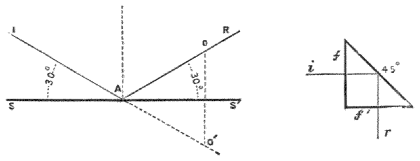
55.—Prismatic Reflection. The same law as given above applies to internal reflection from glass. Let Fig. 3 represent the section of a prism ff′, two plain surfaces of glass at right angles to each other, and the third side making an angle of 45° with each of the other two. The ray i will therefore pass perpendicularly through the plane f without refraction to meet the plane 45° and the angle of reflection, being equal to the angle of incidence, will leave this plane at 45°, and reach r. The angle of glass here given of 45° being greater than 41° 49′, its extreme angle of refraction, the internal reflection will be therefore perfect.
56.—Prismatic Reflection, as this is termed, is largely used in optics in preference, where practicable, to open reflecting surfaces, from the certainty of keeping the reflecting surface clean; as dirt exterior to the reflecting surface of the prism does not affect the internal reflection in any degree.
57.—The reflection is shown for clearness from the plane (Fig. 2) as it actually occurs, or as it is measurable, independent of theory. In optics it is found much more convenient to take the reflection in relation to an imaginary line drawn[30] perpendicular to the plane. In Fig. 4 NA is termed the normal. Taking the angles as before as 30° to the plane, the optical expression of this would be 60° to the normal, and the reflection of the incident ray IA to R would be in the angle IAR 60° + 60° = 120°, the amount the incident ray is deflected from its former course. This principle is important to be understood in the construction of the sextant and other reflecting instruments. In reflection the ray is found to follow the shortest path,—that is, the path I to R by reflection is shorter in the lines IAR, placed at equal angles to the normal, than it would be by any other possible path. As, for instance, it is shorter than IaR, shown by dotted lines.

Fig. 4.—Measurement of angle of reflection in optics.

Fig. 5.—Diagram illustrating the principle of the lens.
58.—Passage of a Ray of Light through a Prism or a Lens—Convex Refraction. If we comprehend the law of refraction exemplified above, art. 51, the path of a monochromatic ray through a prism or a lens is easily determined, taking into consideration the refraction index of the glass. In Fig. 5 let a″a‴ be the base of an equilateral prism, which[31] base may also represent the axis of a lens linear or parallel with the direction from the centre of the eye to O. Now, if a ray of light pass from a small luminous object at O in the path a′ to the prism, we may assume all other parts of the prism covered, and the refraction of the glass be such that the ray will pass through it from this position in a horizontal direction, or that parallel to the assumed axis a″a‴, then the same ray will pass through the prism to equal distance from the centre of the prism,—that is, to the position of the eye shown by the ray continuing in the path a, the angles to or from the prism being equal; so that if we cover up all parts of this prism except a line parallel with its base joining the ends of the lines aa′, where it is shown passing through the prism, any ray of light from O, under the conditions given, will appear as a spot of light on the plane parallel to the base of the prism; or if we place our eye at the position shown, we shall see the image of the light O. If we take a prism of the same kind of glass, but of less angle, whose base is b″b‴, the refraction would then be less (that is in the ratio of the sines), that is if the ray pass through the prism at less distance from the base, so that the ray Ob′ would pass through horizontally as before, and emerge from the prism in the path b, also with equally less refraction, so that the ray would reach the eye at the same point as the more refracted ray. In like manner, if the prism were of still less angle with base c″c‴ and pass through the prism at a lower position, the refraction would be proportionally less, and therefore reach the eye at the same point.
59.—If we take the half lens shown in section in the figure, this may be considered to touch the surface of the prisms described tangentially in the lines a″a‴, b″b‴, and c″c‴, where the angles of contact of O, a, b, or c upon the prism would be equal to those upon the lens for an infinitely small extent of surface. Therefore, if we make the lens of such form that a ray of light may pass from any single point[32] upon the line of its axis, and be refracted by every point of the surface of the lens to a single point or focus on the opposite side of the axis, such form would be a perfect lens. For simplicity of demonstration the refractions given above are made parallel with the axis of the lens. This parallelism could only occur with the object and the eye at equal distance from the centre of the lens, and with this distance also proportional to the amount of refraction of the glass used in the construction. If the rays were all parallel to each other upon incidence they would still be bent in the same ratio (to the sines of the angles of contact and departure), and this would bring the focus nearer to the glass; but it is evident the same principles would hold.
60.—As regards the action of the eye in this matter, it can only recognise the direction from which it receives the light, and not the processes the rays may have undergone before reaching it. Therefore the ray proceeding from O in the path b′, passing through the lens or prism and emerging in the path b, is recognised by the eye as the ray b only. So that the point of light O appears visually as proceeding from the direction bs, and this convergence or expansion of the point O, with its coincidence from the opposite side of the lens, produces the effect of magnification of the object represented by O.
61.—Concave Refraction.—In Fig. 6 a convex lens is shown in which the parallel rays L are drawn to a focus at F upon the principles just demonstrated. If the lens were made concave, as shown in section Fig. 7, by the same principles of refraction, it is evident that the rays would diverge, as the refraction bends the ray uniformly towards the thickest section of the glass. If two lenses are brought together, one with convex face, and one of the same radius of curvature, but with concave face, the rays in passing through would not be refracted. In this case the lens would be said to be corrected. A convex lens has a focus where the[33] rays converge. A concave lens is said to have a negative focus equal to the focus of the convex lens, that will correct it, or make it equal, as regards refraction, to plane parallel glass.
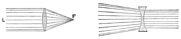
62.—Spherical Aberration.—If the surfaces of convex lenses are truly spherical, it is found, by an analysis too complex to be described in this work, that the rays which pass through at different distances from the axis converge to slightly different points of distance. This subject was at one time seriously discussed for the proper formation of objectives for telescopes; but at present it is entirely neglected by the optician, as it is found practically to be as difficult to make a lens truly spherical as one of the convergent or divergent form required under the special conditions present. The spherical form, as it is approximately produced from the grinding with spherical tools, being always nearly correct, the correct forms of object-glasses are made by figuring, which has been already referred to, art. 38. In eye-pieces the spherical aberration would cause some confusion were the glasses not adjusted in such a manner as largely to prevent this.
63.—The Formation of Images by Refraction from a Convex Lens.—If we take any double convex lens, as that shown in section Fig. 6, we find, if it is held towards the sun at a certain distance from a solid surface, we form a burning-glass,—that is, we produce an image of the sun where his rays of light and heat are refracted by the whole of the surfaces of the glass. The distance from the centre of the lens to the point of greatest light is called the solar focus of the[34] lens,—that is, the point at which it concentrates or converges parallel rays, and forms the image of the sun. With parallel rays from the sun, the distance of focus is less than if these rays were divergent in any degree. Consequently the solar focus is less than that subtended by any object on the earth.
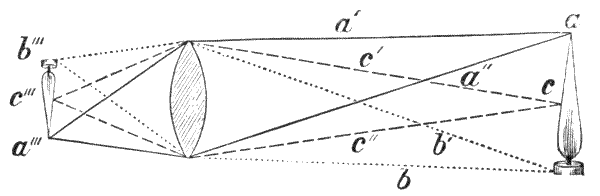
Fig. 8.—Diagram of the convergence of rays of light.
64.—In the diagram, Fig. 8, a candle-flame at acb forms its focus at a‴c‴b‴, where all rays converge to form an image in the following manner:—Every point of the candle throws its light upon every point of the surface of the lens, and, therefore, throws the image of each point to its focal position behind the lens, according to the direction of its refractions; so that, if we take all the separate points of light thrown from the candle, we then have a perfect image of it formed by an infinite number of separate focal points, and as the rays by their direction necessarily cross over the axis the image is in an inverted position.
65.—The whole of these lines would form a confusion if shown in a diagram. We may, therefore, take for illustration the exterior of a cone of rays proceeding from three points only. Thus the clear lines aa′ and aa″ from the point of the flame would refract to the lower part of the image a‴. The dotted lines bb′ would proceed to the upper part of the image, as shown by the continuation of the dotted lines to b‴, whereas the central dash lines c′c″ would form their images in the centre following the dash lines to c‴, and thus, from the number of luminous points, the whole image of the candle[35] would be produced at the foci b‴c‴a‴ in an inverted position.
66.—Dispersion of Light.—The conditions stated above for refraction of monochromatic light would not answer for perfect vision, which is only possible in clear white light. It therefore becomes necessary in practice to correct the quality of dispersion which light suffers in refraction through any dense medium. The evidence of dispersion by glass may be shown by a prism, as in the following diagram:—

Fig. 9.—Diagram showing chromatism of light by the prism.
67.—In Fig. 9 let P represent the section of a prism of glass, covered except at the narrow opening a. Let a strong light, as shown, be covered, except from a narrow slit, then the ray from the light, refracted from a towards a′ in the prism, will be dispersed or split up at a into the colours of the rainbow, shading from blue, green, and yellow, to red, within the prism. Upon emergent refraction at a′ this dispersion will increase so that an image of the slot near the light, if thrown on a plane proceeding from the base of the prism to the right, will be represented at BGR by a prismatic or chromatic spectrum, as it is termed, shading off from blue to green, yellow, red.
68.—Achromatism of the Prism in the same Quality of Glass.—Taking the prism, Fig. 10, C as before, and applying a second exactly similar prism C′ reversed upon the face of the first—then at every part of the process of dispersion from a point of white light under diffraction into the first prism, will by equal diffraction, in passing through the second prism, be brought to a point, where it will issue a white ray at the[36] point a″, as it entered at the point a; or, practically, the emergent ray will be achromatised. This principle must be followed in the manufacture of achromatic lenses, although under various indices of refraction and dispersion from differences in qualities of glasses. It is made use of in the achromatism of eye-pieces, and in combinations, and assures the achromatism of parallel glasses used for sextants under different angles of incidence.
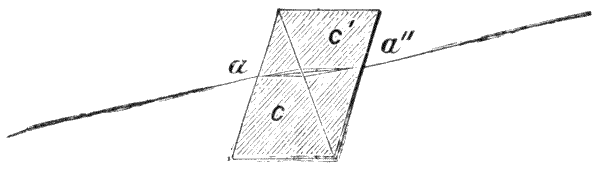
Fig. 10.—Diagram perfect achromatism.
69.—The Achromatic Lens.—The achromatism of a pair of lenses by which a large amount of refraction of pure white light is obtained, depends upon differences in the qualities of glasses which are due to their density and chemical composition, so that in one glass a less amount of dispersion is produced at an angle which gives an equal amount of refraction than in another. The combinations of glasses in use are crown and flint, as already described, art. 32, the crown being a light glass of soda and silica, the flint being a heavier glass containing silica, potash, and lead. In a certain kind of flint glass used for optical purposes, for a prism giving only slightly greater refraction than one of crown glass, the dispersion is about double. Therefore, we may combine a pair of glasses so as to obtain a desired amount of refraction from the combination if we make the crown glass refract something over double the amount we require for the perfected lens or prism, and diminish this quantity by the reverse refraction of the flint glass, thereby correcting the dispersion, as may be shown by the diagram on this page.
70.—In fig. 11 let C be a prism of crown glass giving over[37] double the amount of refraction to a prism of flint glass F, but only of total dispersion equal to the thicker crown glass. The compound white ray of light a will then be dispersed upon refraction at the meeting faces of the two prisms, a certain quantity represented by the cone of rays shown, and again converge at a′, an equal quantity on emergence from the exterior surface of the flint prism, so as to issue again a white ray, of which this system of prisms has refracted, but not dispersed, the light.

Fig. 11.—Showing principles of achromatism.
71.—That the same principles given above for the prism will hold in the achromatic compound lens, is already demonstrated by the comparison of lenses and prisms shown in Fig. 5; but for the sake of clearness it may be again shown diagrammatically in Fig. 12 for an actual objective, wherein the parallel rays ab, proceeding from a distant object or star, are shown refracted to a′b′, and coming to a focus at F, although dispersed at the meeting surfaces of the two glasses, as shown diagrammatically, by the internal cone of rays.
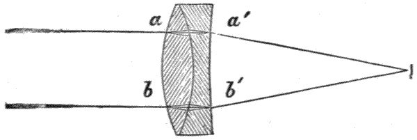
Fig. 12.—Showing achromatic objective.
72.—Practically, the matter is not quite so simple as it would appear to be theoretically, by the above-described conditions, as we actually find the spectrum of a prism of flint[38] glass of equal dispersion to one of crown glass does not give exactly similar extent of separate colours within its spectrum, the medium ray of the spectrum in the flint glass being nearer the blue than in the crown. Thus, this compound lens does not perfectly correct by inversion as it does in the perfect case discussed, and shown in Fig. 10. For this reason better definition is found by slight displacement and slight difference of total extent of dispersion of one of the spectra in coincidence on the meeting planes between the lenses, leaving in all cases a certain amount of residual colour, blue or red, uncorrected, by making the glass under- or over-corrected, as it is termed, which does not, however, seriously impair distinct vision. It is quite possible that, by some future improvements in the chemical constitution of the glass, this defect may be remedied. English glass-workers prefer to over-correct, German and French glasses are more often under-corrected.
73.—The measurements of refraction and dispersion being both in one direction, may be taken together within certain angular limits in one term in the construction of a lens as the ratio of dispersive powers, the indices being certain dark lines which are observed uniformly in the spectrum of the sun projected from a narrow slit. These lines or bands in the sun's spectrum are known to be due to metallic vapours which are present in his atmosphere, and can therefore be reproduced by the deflagration of like metals on a small scale. To certain of these lines letters of the alphabet have been applied. Of these letters, a pair of lines due to sodium vapour marked D, and three lines due to hydrogen, marked C, F and G, are commonly taken for reference of dispersion. Achromatism is generally considered duly corrected when the lines C and G are united. The middle of the spectrum between these lines is about E; and chromatic dispersion of optical flint and crown may be taken to be fairly corrected if the spectra are coincident in colour at this line.
74.—Curvatures in the Achromatic Lens.—A large amount[39] of mathematical power has been expended upon this matter, but the perplexity of the subject is due to small differences of the material; and the impossibility of working absolutely true spherical curves has rendered this work of little practical value to the optician, who still resorts to the formulæ of Dollond and Tully. Those who care to follow the subject beyond the scope of this work will find numerous papers in the Phil. Trans., and in the works of Herschel, Barlow, Coddington, Robinson, and Stokes, wherein what is known theoretically of the subject is fully investigated and discussed.
75.—For all small achromatics, such as are employed in surveying instruments with Chance's hard crown and dense flint, the following approximate formula is commonly employed, expressed in terms of the radius of the curved surface into f, the total focus of the finished objective, for first working before trial:—
1st.—Outside surface, f 2 convex,
2nd.—Inside " f 3 convex,
crown.
3rd.—Outside " f 3 concave,
4th.—Inside " 4f convex,
flint.
76.—By different makers the surfaces are changed as far as reversing the curvature of the front glass, and indeed very good glasses are made with the 1st, 2nd and 3rd = (f/2·5). In all cases true convergence of the white ray is only obtained by correction of the outer and inner surfaces, or by figuring, as it is technically termed, in which the curvature is not only made greater or less, but its character is altered generally in the direction from circular to elliptical section. The qualities of the object-glass cannot be over-estimated by the practical surveyor. A heavy instrument with inferior object-glass may be carried about for years, whereas a lighter instrument with[40] good object-glass would perform better work. Excellent information upon this subject was given in a lecture before the Royal Institution by the eminent optician, Sir Howard Grubb, of Dublin.
77.—Optical Arrangements of the Telescope.—The earliest form of telescope is that of Kepler, Fig. 13. In this the rays from the object-glass cross in front of the eyeglass; consequently, the image is inverted. This form is at present little used except in combination with a separate eye-piece.
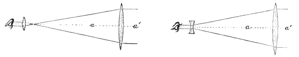
78.—Galileo's Telescope, Fig. 14.—In this the eye-piece is a concave glass. This glass is placed inside the focal distance, so that the rays from the object-glass are bent to less convergence, that they may enter the pupil of the eye in a direction possible to reach the retina. The image in this telescope is maintained erect. This principle is used entirely for field and opera glasses, also for sextants and some other instruments where it is desirable to keep the image erect, and small power is required, sufficient only to obtain more distinct vision. The lines aa′ in Figs. 13, 14 are termed the axis of the telescope.
79.—Optical Arrangement of the Huygenian Telescope.—In surveying instruments, where angles and directions are not taken by coincidence of direct and reflected images, it is necessary that the direction of the axis of the telescope should be clearly indicated. In this case the focus of a distant object—that is, its exact image—is projected upon a plane termed the diaphragm, Fig. 15, SS′ upon which a visible[41] object or index is placed, the position of which is picked up by a secondary telescopic arrangement, or eye-piece as it is technically termed.
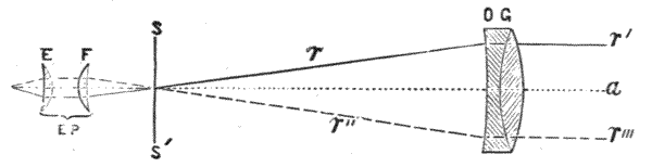
Fig. 15.—Diagram of arrangement of lenses.
80.—The arrangement of lenses in a surveying telescope is shown in the illustration above, where OG is the object-glass or objective, E the eye-glass, F the field-glass. The two lenses E and F, in their mountings, form the eye-piece EP. The dotted line a is the axis of the telescope, SS′ is the focal plane of the object-glass, where a metal disc is placed with an opening in its centre—this is termed the diaphragm or technically, the index-stop. Across the opening in the disc, spider's webs or other fine visible objects are placed, to be described further on.
81.—Both the object-glass and the eye-piece are fitted in sliding tubes, which will be described presently, in such a manner that they may be made to approach or recede from the focal plane SS′. The nearest distance of the object-glass to this plane is the solar focus, or the distance at which a sharp image of the sun or a star placed in the axial line would be formed. The greatest distance of the object-glass from the focal-plane in most instruments is such that a clear image will be given on this plane SS′ of an object placed at about twenty feet from it.
82.—The Ramsden Eye-piece, the optical arrangement of which is shown in Fig. 16, is also known as a positive eye-piece. It consists of two plano-convex lenses, the convex surfaces of which are turned towards each other. They are separated by a distance equal to two-thirds the focal length[42] of either glass, and placed so that the diaphragm is one-fourth this focal length from the field-glass.
83.—This eye-piece is considered not to be quite so achromatic as another form known as the Huygenian eye-piece, but its spherical aberration is less than any other, and it gives what is necessary in all measuring instruments—a flat field of view, requiring no change of position to see the centre and border of the field with equal distinctness.

Fig. 16.—Ramsden eye-piece.
84.—The Field of View should be as bright as possible. To ensure this, the field of the object-glass which is taken by the eye-piece at the position of the front of the eye should not be larger than the pupil. If the whole field of light enter the eye as it should do, the brightness will then vary directly as the square of the diameter of the object-glass, and inversely as the square of the magnifying power. The directions of the rays are shown by dotted lines as aa and a′a′ for the Ramsden eye-piece in Fig. 16. This eye-piece is sometimes called an inverting eye-piece. It is not really so: the object-glass inverts its image and the eye-piece picks up the image in its inverted position. Two or three eye-pieces of this kind, of different magnifying powers, are sometimes supplied with one surveying instrument. The same form of eye-piece, being also a simple microscope, is used to read the divisions on the divided circles of theodolites, sextants, and other instruments, and for such purposes it is often desirable to ascertain its focal length.
85.—The Focal Length of the positive or Ramsden eye-piece is found by dividing the product of the focal lengths of the two lenses by their sum, diminished by the distance between them. Thus, if the focal length of each of the lenses be 1·5 inches, the distance between them 1 inch:—
1·5 × 1·5 3 - 1 = 1·125 inches.
86.—The Magnifying Power of the Telescope.—The focal length of the objective divided by that of the eye-piece gives the power of the telescope. Thus, a 14-inch telescope with the above eye-piece would have a power,
14 1·125 = 12·444, or 12½ nearly,
a very general lower power eye-piece with telescopes of this focus.
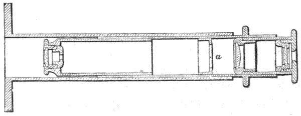
Fig. 17.—Dynameter.
87.—Dynameter.—The magnifying power of a telescope may be ascertained, without any knowledge of the focus of the glasses used in its construction, by the use of a dynameter. This instrument, Fig. 17, consists of a compound microscope in which a finely divided transparent scale is placed in the mutual focus of its object-glass and of the eye-piece at a. The divisions of the scale may be ·01, ·02, or ·001 inches apart, adjusted so that a disc ·1 inch diameter at the exterior focus of the eye-piece may read a given quantity upon the scale. To use this apparatus, the flanged face is placed in[44] front of the eye-piece of the telescope, previously set at solar focus. The telescope throws a circular image of its object-glass through the eye-piece, where it is picked up by the object-glass of the dynameter and brought to focus on the scale a, where it appears as a circular disc of light. If this image be measured by the scale, and the diameter of the object-glass be divided by this measure, the quotient will be the magnifying power of the telescope. There are several other forms of dynameter.
88.—The Erecting Eye-piece, sometimes supplied with theodolites and occasionally with other instruments, is the ordinary one of the common telescope, Fig. 18. The glasses are so arranged that the image brought to the focus of the telescope inverted is again erected, so that objects appear in their natural position. The complete eye-piece is of the same optical arrangement as that of a compound microscope. The arrangement of lenses is shown in the engraving on next page.
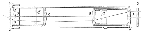
Fig. 18.—Optical arrangement of erecting eye-piece.
89.—A object lens, B amplifying lens, C field lens, D eye lens. Stops are placed at d and d′ to cut out extreme rays. The image is formed by the objective at O, and the light passes in the direction shown by fine lines, being thrown from side to side of the lenses. The ray is achromatised proportionally to its dispersion by the separate lenses, upon principles discussed art. 68 and shown Fig. 10, as independently of the small amount of opacity of the lenses, extreme rays are cut off, so that central portions only are used. This eye-piece suffers loss of light at each of the four lenses; therefore, a[45] telescope with it, for equally distinct vision to that obtained by using the Ramsden eye-piece previously described, would require a larger objective.
This eye-piece is rarely used now, excepting with American instruments in which they are almost universal, as the very slight advantage of seeing the image erect is far outweighed by the loss of light it entails. The American manufacturers place them inside the telescope instead of outside, thus the telescopes look much the same as our ordinary ones, but the focal length of the object-glass is shortened by the length of the eye-piece, and as this takes up from three to four inches, a telescope which would appear to be say 10 inches solar focus is, in reality, only six or seven inches and consequently only about two-thirds the power.

Fig. 19.—Diagonal eye-piece, full size; S G sun-glass.
It is astonishing that the Americans, who are usually so quick in adopting the most practical appliances, are so slow in seeing the advantage gained by the use of the now almost universal inverting eye-piece.
90.—The Diagonal Eye-piece, Fig. 19, is used upon transit instruments, theodolites, and occasionally upon mining-dials. It permits the telescope to be used by the observer[46] looking at right angles to its axis. Thus, by the natural direction of the eye, stars or the sun may be observed to near the zenith, or the direction of a line cut by two lights at the bottom of a shaft may be observed from above by the telescope of a theodolite having a hollow centre on its ordinary stand, to check the magnetic bearing of the needle below ground, if this is assumed to be subject to local disturbance. The socket of this eye-piece screws upon the telescope and has a free inner tube for rotation, so that the 90° to the axis of the telescope may be placed at any angle to the axis of its cylindrical circumference; as, for instance, instead of being used vertically or for zenith stars, it may be used horizontally, where precipitous ground would not permit direct axial vision through the telescope. The reflecting arrangement of this eye-piece may be adapted either to the Ramsden or the erecting form. In either case the reflector is placed in the central portion of the eye-piece. In surveying instruments the reflector is generally a piece of polished speculum metal for portable instruments, but a prism of glass for larger fixed instruments. The general arrangement is shown in the section of a diagonal Ramsden eye-piece on page 42, full size. A object lens, D eye lens, adjustable for distance from the reflector R, S outer casing which permits adjustment for focusing, SG sun glass, the diaphragm being in front of A.
91.—When a rectangular prism is used for the reflector, it is worked with one plane 45°, as previously discussed, art. 55, Fig. 3. In place of one or both the 90° faces these surfaces are sometimes worked convex so as to form a magnifier, dispensing with one of the convex lenses of the eye-piece. A long diagonal eye-piece is necessary, where stars towards the zenith are to be observed, to prevent interference of the limb of a theodolite with the face of the observer.
92.—Reflecting Eye-piece is used to observe small stars, as for instance the circumpolar stars in the southern hemisphere,[47] by illuminating the front of the webs or lines. A strong light thrown down the telescope from a reflector to illuminate the webs would tend to dim the effect of blackness of the sky and render these stars indistinct. In the eye-piece, Fig. 20, a piece of plain parallel glass is placed at an angle of 45° to the axis. This permits the webs to be clearly observed through the glass at the same time that it throws light from a lamp placed at a distance from the glazed aperture L by reflection of the surface of R sufficient for front illumination. The amount of light required is regulated by the distance of the lamp from L. This eye-piece is made to fit into the diagonal eye-piece casing, as S Fig. 19, E Fig. 20 being the position of the eye, F field-lens.

Fig. 20.—Reflector in eye-piece to illuminate the front of diaphragm.
93.—Sun-glass.—Sextants and theodolites are supplied with a very dark glass or a combination of dark glasses fixed in a rim to form an eye-piece front, which screws or fits on in front of any eye-piece, to take observations of the sun for longitude or bearing, Fig. 19, SG. It needs no description, but is necessary to be mentioned to complete the optical arrangements of a telescope, as it is sometimes used for surveying purposes.
94.—The Body of a Telescope that forms part of a surveying instrument is constructed of a pair of triblet drawn tubes, Fig. 21, TT′ T′. These tubes should be truly cylindrical and straight, so as to fit smoothly together, the one[48] within the other, and slide in and out quite freely but without any play. The inner tube should be as long as practicable, so as to remain steady when racked out to the full extent required to focus near objects. The object-end R is generally enlarged so as to take the cell in which the objective O is placed, without cutting off any part of the light, or entailing the weight of larger tubes than is necessary to make use of the full field of the objective. The objective is generally held in its cell by an internally fitting screwed ring with milled edge, so that the glasses may be taken out and separated to be cleaned, and be easily replaced. Two notches or grooves are commonly made in the edges of the glasses, each of which is deep enough to take a small brass pin which is soldered to the inside of the cell. The second notch indicates relative position, so as to secure the glasses being replaced properly. In all cases the double convex crown glass is placed outwards from the telescope. A glass of large size should have a loose ring within the cell to act as a spring to save distortion of the objective from expansion or contraction of the metal; but this is not necessary in small surveying instruments. In some common telescopes the object-glass is burnished into its cell, in which[49] case the glasses of the objective cannot be separated for cleaning.
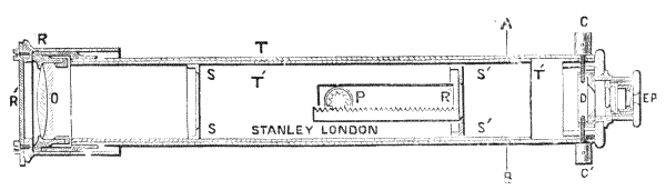
Fig. 21.—Body of surveying telescope.
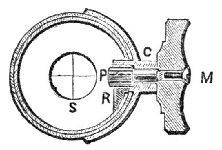
Fig. 22.—Section Fig. 21, A to B.
95.—Stops.—Within the inner tube two or more thin metal rings, termed technically stops SS and S′S′, are placed to cut off any extraneous light that may enter the telescope obliquely, and which, if not stopped off, would produce a fogginess over the whole field of view. It is important that these stops should not cut out any part of the full aperture of the object-glass if it be a good one. In the manufacture of the telescope this is easily seen by looking in at the eye-piece of the unglazed telescope to see if the stops clear the objective cell. In the finished glazed telescope another method will be discussed further on.
96.—The inner or the outer tube of the body of the telescope slides towards or from the objective for focussing by means of a rack R″ and pinion P. The rack is soldered to the inner tube, and the pinion fitted in a cock-piece, as shown Fig. 22 C, on the outer tube. The pinion is moved by a large milled head M. This fitting should be made with care. The pinion should be very free, so that it does not lift the body at any tooth, and at the same time there should be no shake on the gearing. It needs considerable practice to rack a telescope properly.
97.—The outward part of the object end of the telescope is generally turned to fit the interior of a separate short tube, shown at R, which is placed over it. The outer end is closed by a ring to the size of the aperture of the objective. This is termed a ray-shade or sometimes a dew-cap. The ray-shade is extended when the telescope is directed to such an angle that the sun's rays would fall upon any part of the objective, and thereby cause internal reflections. A swivel shutter, Fig. 21, R′, is placed upon the outward end of the ray-shade, which, when closed, as shown in the cut, forms a cap to the telescope. The eye-piece EP before described, art. 82, Fig. 16, is placed in a tube constructed upon the end of the telescope, in which[50] it slides freely, to focus upon the diaphragm to be presently described. The telescope is mounted sometimes solidly upon a transverse axis, or it is mounted in turned bearings, or it has two collars placed round it which are turned quite equal and true, and are mounted on Y's to be hereafter described.
98.—Mechanical Adjustment of the Eye-piece.—In some large instruments the eye-pieces are racked for adjustment in the same manner as the object-glass already described. A better plan is to have an inner tube to the socket tube cut with a screw into this, and provided with a milled edge, so that the eye-piece may be screwed gently to focus upon the webs of the diaphragm.

99.—The Diaphragm of the Telescope is so constructed as to permit the displacement of spiders' webs or other fine objects in any direction at right angles to the axis of the telescope, or in the vertical only in the dumpy level, to be described, the object in all cases being to adjust the crossing of the webs, lines, or points to the axis of the telescope. It will be convenient here to discuss a general form of diaphragm applicable to theodolites, mining-dials, and plane-tables only, which gives movement in two directions at right angles to each other.
100.—The diaphragm, Fig. 23, is formed of a stout disc of brass having a centre hole of about ·30 inch diameter. Upon the side which is placed next the eye-piece the hole is brought to a thin edge by an internal bevel or countersink, which leaves the hole much larger at its off surface, Fig. 24 P. The disc is held in its place and adjusted by four capstan-headed screws, termed collimating screws, two of which are shown in section as CC′, the screws being tapped into the rim of the diaphragm frame P. The screws are placed through a stout collar. The theodolite diaphragm has generally three spiders' webs or lines crossed in the manner shown in the centre of Fig. 23. The eye-piece is screwed into the thick plate, Fig. 24, TT′, and adjusts to the focus of the webs.
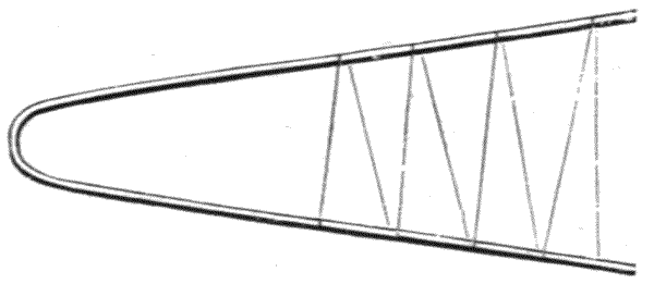
Fig. 25.—Webs wound off for use.
101.—Webs.—It is a somewhat delicate process to web a diaphragm, but it is necessary that every surveyor abroad, out of the reach of an optician, should understand the method if his instrument were originally webbed. The webs are taken from a small or young garden spider. The best are taken when the spider has first commenced spinning. To wind off the web a fork is bent up out of a piece of thin brass wire. A long hairpin will answer for this purpose very well, or even a fork formed of a thin branching twig of a shrub; but if this last be used it should be thoroughly dry, or the webs will be broken or be baggy by its warping in drying.
102.—The web in connection with the spider is first attached to one prong of the fork by looping or by any sticky matter, if the web be not sufficiently sticky naturally. The[52] spider is then suspended from the fork and jerked down a foot or so, and the web is wound off as shown in Fig. 25. The last length of web being attached by gum. A dozen or so of the forks may be taken from the same spider before she is exhausted. The webs are then gummed or varnished to the sides of the fork, and are ready for use at any future time. They are best preserved if placed in an air-tight box, which may have slots in an internal fitting to hold them. The small amount of spring given by the fork keeps the webs always taut. Where a living spider cannot be found, the open ties of an old web may be taken; but in this case, after the web is wound on the fork, it should be carefully washed by immersing it in clean water, and, if necessary, brushing it gently under water with a light camel-hair brush, examining it occasionally with a magnifier to see that it is sufficiently clean and free from knots for its purpose.
103.—To Fix the Webs, lines are drawn on the diaphragm, into which the webs are to fall. It is then varnished over the divided side with Canada balsam, laudanum, or other quick-drying, sticky varnish—at a pinch, sealing-wax dissolved in strong whisky will answer. The outer, or the unused web upon the fork, is lowered carefully over one of the most nearly vertical lines, and lightly pressed down to assure its perfect adhesion to the varnish. It is then either broken off or cut loose. The second nearly vertical line is then webbed in the same manner, and the horizontal line finally, being sure that this last cuts the intersection of the others. The diaphragm should then be put in a warm place to be allowed to thoroughly set without disturbance before it is fitted in the telescope.
104.—Platinum Wires are sometimes used in place of webs. These wires are made by drawing a piece of fine platinum wire, which has been previously soldered into a silver tube, to the greatest fineness possible with the draw-plate, and afterwards dissolving the silver off the platinum by nitric acid.[53] The platinum wire is thus produced of less than ·001 inch diameter. For a time these wires were very popular, and it was thought that they would supersede the use of webs, but they do not appear entirely to answer expectation. The platinum drawn in this manner appears to lose some part of its elasticity. It is not easily attached, that is, it is liable to shift from its fixing, possibly from its contraction and expansion with change of temperature, not being of the same metal as the diaphragm. It also oxidises a little or becomes in some way corroded in use out of doors. It appears to answer better for astronomical telescopes, but the finest platinum wire obtainable is not so fine as a spider's web.
105.—Lines Ruled upon Glass.—A glass diaphragm is frequently used in a surveying instrument to replace the webs. Lines are ruled upon the glass in similar positions to the webs already described. They appear quite sharp in the eye-piece, and are more permanent than webs. Glass is also convenient for permitting space lines to be ruled for subtense measurements, a subject to be considered further on. The objections that have been found to glass are that it obstructs a little light, and is subject to dewing. The dewing is particularly annoying when temperature is lowering quickly, as a diaphragm may become bedewed many times in a few hours. In all cases where a glass diaphragm is used it should be placed in a ground metal fitting, so that it may be taken out in a minute to clean and be replaced with perfect certainty of its adjustment. It is a very convenient practice where webs are used to have a spare glass diaphragm to replace them should they become broken. This may be constructed by means of a ground metal fitting to be put in a webbed instrument in perfect adjustment in cases where it might be impossible to find a new web.
106.—Points.—The author for a large number of instruments employs very fine points in place of webs, which he highly recommends. These are fixed for support upon the[54] margin of the diaphragm, and projected therefrom into the field of view. The points are formed of a special alloy, 75 platinum, 25 iridium, which has the hardness of steel, and is perfectly non-corrosive in air or moisture. They are made sufficiently stiff to be dusted with a camel-hair brush, supplied in the instrument case, without the slightest fear of disturbance of position in the instrument. They form a perfectly permanent index of sufficient stability to last in perfect adjustment as long as the instrument lasts in wear. One objection is that a point gives less field of observation for levelling than a line, but this does not hold if there is tangent adjustment to the instrument to bring the point up to its reading position. The value of the reading from these points will be discussed further on.
107.—Position of the Diaphragm in the Telescope.—If the objective be accurately centred, and its mounting true, the intersections of the webs, lines, or points should come exactly in the axis of the telescope; but it would never do to accept this without critical examination. Therefore the webs may be placed approximately in the centre, and adjusted true to the axis of the objective and the telescope by what is technically termed collimation. The first point, however, to be studied in this adjustment is to get the eye-piece and the objective accurately in focus with the webs. The same description of focussing which answers for collimation will answer also for ordinary use of the telescope.
108.—Adjustment of the Eye-piece to the Webs is effected by pushing in or drawing out the eye-piece in its tube with a slight screwing motion until the webs, lines, or points appear quite distinctly. To prevent confusion from the sighting of objects, it is better to take off the ray-shade, to point the telescope to the distance in opposition to the direction of the sun, and to keep the telescope rack fully extended, so that it is quite out of focus. When the light is not very bright a sheet of notepaper or an envelope may be placed obliquely in[55] front of the object-glass to obtain a soft reflection from the sky. This method is always employed by some observers.
109.—Adjustment to Focus of the Objective.—Parallax.—The eye-piece remaining in focus, the telescope is racked out until the object desired to be brought into view, either for the collimation or for ordinary reading, is sighted. After this the milled head is moved as slowly as possible until what is thought to be the exact focus is obtained. The certainty of exact focus is not easily obtained by direct observation, but it may be obtained by what is termed observation for parallax, which must be taken in all cases when adjustment is required for collimation. Thus, having obtained the nearest possible adjustment by sighting a small object or a division upon the staff, bring the object to read exactly in a line above the horizontal web in the centre of the stop or the corner against a vertical web. If now the eye be moved up and down as far as the range of the eye-piece will permit vision of the centre of the webs, and the object sighted appears fixed at the same position to the webs, the focus is perfect. If, in moving the eye, the object sighted appears to follow its motion about the intersection of webs, the focus of the telescope lies beyond the webs; the objective must therefore be moved slightly nearer the webs by turning the milled head very gently. If, on the other hand, the object sighted moves in the opposite direction to the eye about the intersection of the webs, the focus of the telescope is towards the eye-piece, and the telescope requires slightly racking outwards by moving the milled head in the reverse direction. After a few trials the object and webs appear stationary, however obliquely observed.
110.—Collimation is the adjustment of the crossing of the webs of the diaphragm to the axis of the telescope and its object-glass. This is effected by adjustment of the opposite collimating screws, Fig. 24, CC′, in two directions at right angles to each other. Where the telescope is placed in Y's or[56] collars, this adjustment is made by placing the webs or lines in focus of the eye-piece and the object-glass of the telescope in focus upon a small distant object. Then if the telescope is rotated in all directions, and the small distant object cuts the crossing of the webs in all positions, it is said to be truly collimated. It is necessary to discuss the structure of various instruments to show the methods of collimating in special cases; therefore this subject will be again brought forward.
111.—The Qualities of a Telescope of a surveying instrument are best ascertained by its performance. The general method is to place a staff at the full range, 10 to 15 chains, and to see if the ·01 foot in fine bright weather is read clearly and sharply. This outdoor observation is not always possible, particularly in large towns, but it may very well be supplanted by reading at a short distance. The author made for the late Colonel Strange, F.R.S., whose knowledge of scientific instruments was of the highest order, a test-card for the Lambeth Observatory, to be placed at 25 feet from the instrument. This card had on one part fine lines ruled ·01 inch apart. A 14-inch telescope was considered sufficiently good if these lines could be clearly separated at this distance by the telescope when it was in correct focus. The dial of a watch, or an ivory scale, answers very well as a test object, as sharpness of outline is the point to be ascertained.
112.—A more refined technical method than that described above, which also tests the general accuracy of the optical arrangement of the telescope, is to fix a small disc of white writing-paper, say 1/8 inch diameter, cut out with the point of a pair of compasses with sharp outline, on a black surface of a board, paper, or cloth. If this be placed as before, 30 feet or more distant in a good light, and be correctly focussed in the telescope, a sharp image of it should be obtained. This focal position of the telescope may be temporarily marked upon the inner tube with a fine soft black-lead pencil. If now the object-glass be racked outwards or inwards from this line, say[57] for about a twelfth of an inch, and the image appears to be surrounded with a uniform haze, the objective may be considered to be correctly formed, or to be free from spherical aberration, as it is termed, and the combination to be correctly centred. If the haze appears more on one side than the other the centring is defective. If the object remains fairly sharp when out of exact focus the curves of the lens are defective, as the shorter the range of focus the more perfect is the correction from spherical aberration.
113.—If the curves are not sufficiently correct to bring the image from all parts of the objective to a focus, such incorrect parts are useless, and a good glass of smaller size would be better. The fault is generally found in the marginal portion of the objective, which requires the greatest skill of the glass-worker. Therefore, a very good test to find whether the whole of the aperture of the objective is in effective use is to cut out a piece of card of the size of this aperture and to cut a second piece out of the centre of this, of half the diameter, so as to form a disc and a ring. If the objective be now covered by the ring and accurately focussed upon a test object, and this be then removed and replaced by the disc fixed over the centre of the objective, and the focus remains equally sharp, the curves may be said to be, practically, correctly worked.
114.—As the central part of an objective is more easily brought to correct curvature than the marginal parts it is not uncommon in inferior instruments to make the aperture of the central stop of the telescope cut off the margin of the objective. This renders it only equal to a smaller glass.
115.—Whether the full aperture of a telescope is used may be discovered by employing a second eye-piece—outside the regular eye-piece that is placed in the telescope—to pick up the image of the object glass formed through the eye-piece which is placed against the telescope in the manner of using a dynameter, art. 87. With the ordinary surveyor's level, two[58] eye-pieces are commonly sold; one of these may be placed in the telescope and the other used to pick up the image of the object-glass. With a theodolite one eye-piece may be placed in the telescope, and one of the readers used to magnify the divisions of the limb may be used to pick up the image. The best manner of proceeding is to fix with water or thin gum two or three small pieces of paper, say 1/20, 1/10, and 1/7 inch square, close against the edge of the cell upon the face of the objective. Then focus the telescope on an object at some distance, say a chain or two. Now use the second eye-piece in front of the one in the telescope, and an image of the object-glass will be seen; and if the aperture is fully open all the pieces of paper in their places will be clearly distinguishable. If one or other piece is invisible, the margin of the glass is cut off to this extent. If the objects in front of the telescope tend to confuse, a piece of white paper may be placed obliquely to reflect the light of the sky into the telescope, which will at the same time fully illuminate the objective.
The discussion of the principle of the anallatic telescope, used only with the tacheometer, is deferred to another chapter, wherein subtense instruments are described.
THE MAGNETIC COMPASS AS A PART OF A SURVEYING INSTRUMENT OR SEPARATELY—BROAD AND EDGE-BAR NEEDLES—MANUFACTURE OF THE NEEDLE—MAGNETISATION—SUSPENSION—DIP AND ADJUSTMENT—LIFTING—INCLINATION—DECLINATION—VARIATION—CORRECTION—COMPASS-BOXES—DESCRIPTION OF COMPASSES—RING COMPASSES—TROUGH COMPASSES—PRISMATIC COMPASSES—STAND—SURVEYING WITH COMPASS—POCKET COMPASSES.
116.—The Magnetic Needle, which forms part of a great many surveying instruments, is made of the form adapted to the special purposes of the instrument in which it is placed. There are two prevailing forms commonly in use—one in which the needle is made pointed at one or both ends to read directly upon a divided circle fixed upon the instrument, and the other form in which it is made to carry and to direct a divided circle by its magnetic force.
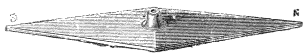
Fig. 26.—Broad needle.

Fig. 27.—Edge-bar needle.
The magnetism which gives directive force to the needle has been found by experiment to reside in every separate part[60] of the magnet, that is, it is assumed to be a molecular force. Therefore, it would not appear to be very important, within certain limits, of what form the magnetic needle is made, and this is found by experiment to be to a large extent true. The only important conditions appear to be that the needle shall be of such form that the inducing magnet, to be described, arts. 120–123, which is used for magnetising may be brought into contact upon every part of its surface, and that the molecular continuity of the parts should mutually support the general directive influence of the magnetism longitudinally in parallel lines.
117.—Magnetic needles are generally made in the form of flat bars, which are balanced upon a standing point falling into a cup which forms the centre. When the greatest section of the bar is placed horizontally it is termed a broad needle, as shown Fig. 26. This may be made of the lozenge form shown, or be parallel throughout. When the greatest section is placed vertically it is termed an edge-bar needle, as shown Fig. 27. The north pointing end of the broad needle is commonly tempered dark blue, or has a deep cut across it, if the needle is left open. This is not necessary if it carries a ring. The edge-bar is generally used where it is required to read into a fixed circle of division, in which case its ends are brought to fine knife-edges.
118.—From the difficulty of reading a sharp point in bright metal against the black line of a divided circle, the author occasionally makes one point of the needle with a fine cut, sawn vertically for a short distance from its end, so as to form a kind of split which is afterwards closed, so that it presents the appearance of a fine black line of the same character as the divisions into which it reads. With this, as shown Fig. 28, the reading is found to be much more easy. The point is also more readily adjusted by grinding, as the end of the needle being broad, less care is necessary to avoid reducing it so much that it may leave the interior of the circle[61] short where it reads into the divisions. This form of needle is not adapted to mining instruments, which have often to be read in an oblique direction.
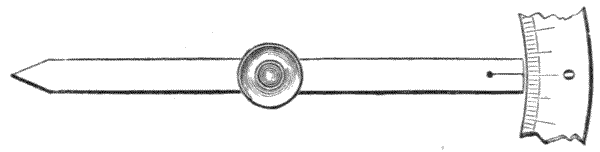
Fig. 28.—Author's plan of needle reading.
119.—In the Manufacture of the Needle it should be made of the finest cutler's cast steel, or, better still, of steel containing 3 per cent. of tungsten. If not left in a parallel strip as it is drawn or rolled, it should be brought as nearly to its form as possible by forging at a low heat. The steel should not be over-heated for hardening. It should be hardened in cold water or oil, and be tempered afterwards down to a very pale straw-colour—in fact, the temper colour should only just appear. Long needles may have the temper sufficiently lowered at the centre to set them approximately straight during the tempering; but the temper should not be lowered even in the centre below a pale blue, spring temper. After tempering, the setting and working up to balance is best done by grinding, and for the final adjustment, by stoning with Water-of-Ayr stone.
120.—Magnetisation of the Needle may be performed in many ways by means of a permanent magnet or an electro-magnet, or electrically by means of a solenoid. When the magnetism is induced from another magnet it is only important that the properly hardened needle should be regularly and equally magnetised over its surface by pressure upon it of the proper poles of the inducing magnet—that is, that the north pole of the magnet should induce magnetism in the southern half of the needle only; and the south pole in the northern half only.
121.—Method of Magnetisation by Single-touch.—This method is more generally applied to touching up needles than magnetising them at first. The northern pole of a strong permanent magnet is stroked down the southern end of the needle from its centre to its end three times on one side of the needle. The needle is then turned round, and the northern end is stroked down in like manner with the southern pole. The needle is then turned over, and the process is repeated on the other side. This may be done a second time and the edges of the needle be stroked down also.
122.—Method with both Poles.—In this process the needle is held down firmly with pegs on a board, and a strong horse-shoe magnet with rather close poles is laid on the bare needle without its cap, in a manner that both terminals press upon it. It is then drawn backwards and forwards from end to end of the needle several times, lifting the magnet finally from about the centre. The process is then repeated on the opposite side of the needle and its edges.
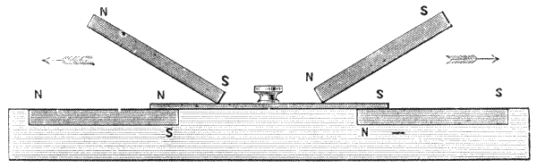
Fig. 29.—Divided-touch magnetisation.
123.—Method of Divided-touch is a somewhat quicker process, which does not entail removing the cap, the general plan of which is shown in the engraving below. The poles of the magnets, or one of them, is marked. Two good straight bar magnets are used. The needle is fixed down on a board and the poles of the two magnets are laid upon it at an angle of about 30°, applying one north or marked pole, and one south or unmarked pole. The magnets are then drawn apart[63] in a horizontal direction along the needle, with constant pressure upon it, so as to reach the opposite ends of the needle simultaneously, and then again pressed back to the centre. After this operation is performed three or four times on one side of the needle, it is turned over and the process is repeated on the other side, being careful as before to use the same ends of the magnets upon the same ends of the needle. The operation may be repeated several times to be sure of saturation of the needle. It is better to lift the magnets off at the termination of the operation at the centre of the needle.
124.—It is found that the needle is magnetised a little more quickly if it is laid upon a strong magnetised bar during magnetising, or upon the ends of two bars, as shown in the engraving, Fig. 29, or on the two ends of a wide horse-shoe magnet.
125.—Needles are now more generally magnetised electrically by placing them in a solenoid or coil of stout insulated copper wire through which a strong direct current is passing from a dynamo or powerful battery. This method is employed in the best shops. The touch system above described is convenient for the profession for remagnetising a needle when weak, as a horse-shoe magnet at small cost may be kept for the purpose. It is generally used in small shops, as being at all times ready to hand, less expensive, and sufficient to ensure saturation if it is skilfully done.
126.—With every care in the manufacture of the needle there remains a little difference in the qualities of needles which are apparently otherwise identical. Little local differences in the quality of the steel, slight over-crystallisation from over-heating in hardening or unequal tempering, or unequal magnetising, are liable to form weak parts, or even what are termed consequent points. These are points in which the magnet possesses a reversal of its general longitudinal polarity. This can be made quite evident by experiment, as it is possible to make a needle not only with poles at each end, but with[64] intermediate poles which are easily detected by sifting iron filings over it. The filings are found to adhere strongly at other local points than those near the ends, where a good magnet is alone strongly attractive.
127.—Mounting of the Needle.—The needle for a surveying instrument has a female centre upon which it is suspended. The centre, termed technically cap, is generally formed of a hard precious stone, agate, chrysolite, ruby or sapphire, the latter being best, simply from the high polish it attains in grinding out with diamond dust. Rubies and sapphires are like minerals, except in the colour, which varies very much; the off-colour stones, which are of small value for jewellery, are used for scientific purposes. The cap is mounted in a brass or aluminium cell made as light as possible for sufficient stability.
The needle is supported upon a hardened steel point, upon which it is perfectly balanced. The base of the point is tempered down to a low degree in order to admit a certain amount of bending to counteract the slight warping which generally occurs in the hardening.
128.—Correction of Errors.—The needle, after it is mounted, although in balance may not have the steel placed symmetrically about its axis through slight curvature, unequal thickness about the cap, or otherwise, so that the magnetic direction is not perfectly linear between the points and the centre. If the points and centre are not magnetically linear, the correction for declination, which will be presently considered, cannot be made accurately. On this account it is better for the manufacturer to mount the needle on a slate bed with two sliding heads that may be brought up to the points of the needle. The heads have upon their upper surfaces lines drawn perfectly linear with the centre point of suspension of the needle, and a few lateral divisions to these lines for determining errors. On this bed the needle is placed upon the centre point to be examined how nearly its reading points are true with the axis. The error being[65] recorded, the needle is demagnetised, and remagnetised end for end, and again examined. Corrections are then made by grinding or stoning from observations of bisections of the points cut in the separate readings, until the needle is made symmetrical and invariable, whichever end is magnetised for the north or south.

Fig. 30.—Section of mounted needle.
129.—Lifting the Needle.—The needle of a surveying instrument should never be supported upon its centre except for the time it is in use for observation, as a fine steel point against a hard stone must, by any jar in conveyance from place to place, receive a certain amount of abrasion that will make it duller. For this reason a lift for the needle is always provided in scientific instruments. In the engraving, Fig. 30, an edge-bar needle is shown in section with its lift. The lift is made in the form of a bent lever, whose fulcrum is upon the bottom of the box. On the left-hand side of the broken line at B the needle is shown lifted. On the right-hand side A the needle is shown at its position for use, floating just slightly above the divided circle D. The pressure of the milled-head screw C depresses the bent lever or lift on the bottom of the box and thereby raises the point under the centre of the needle. This point has a hollow cone formed upon it which fits over the standing-point to keep the lift in position. The cone fits externally into the cap to lift the needle vertically. The screw C should always be clamped down when the needle is out of use. In place of the screw a wedge shaped sliding piece is sometimes fixed inside the compass-box, which is moved by a stud projecting through the outer case. Another plan of raising the lift is by a cam, or[66] what is technically termed a kidney-piece, applied to the exterior part of the lift. Either of these plans answer, but the screw first described, being the gentler motion, jars the needle least. A screw is occasionally used longitudinally to the needle connected with a cam lift, the object in all cases being to lift the cap entirely clear of the standing-point.
130.—The Inclination or Dip of the Needle is the position a needle balanced level upon a free centre before magnetisation takes in the vertical plane after magnetisation. This inclination or dip varies in different parts of the globe, and at different times. At the present time at Greenwich (Jan., 1914) the angle is 66° 50′ from the horizontal. It is uniformly nearly nil at the equator, and increases until over one of the magnetic poles, where it becomes vertical. There are two magnetic poles in the northern hemisphere active in directing the needle, one in Siberia, but the most active is about Melville Island; also two in the southern hemisphere, which are supposed to be nearly together, but the exact positions of which are not ascertained. As we require only the horizontal component in surveying and not the dip, it is necessary to balance the needle in opposition to the direction of the dip until it keeps in a horizontal position. This may be done by making the needle lighter on the dip side—that is, the northern in this hemisphere. But the plan adopted in all scientific instruments is to place a rider over the needle, as shown Fig. 30 under B. This clips the needle sufficiently to hold it firmly to its place, and yet is loose enough to be moved by the fingers to balance. The rider has to be shifted when the instrument is taken into a country where the dip is different from its position at home. When a needle is taken abroad without any rider, it may be balanced by means of a little sealing-wax placed upon its uptending end.
131.—To get at the needle for suppression of dip when it is placed in the compass-box, it is necessary to raise the spring[67] ring, which is placed over the glass to keep it down, by inserting the point of a pocket-knife between the ring and the glass, moving the knife entirely round it and using a little twist upon it if necessary until the ring is free. This must be done gently or the glass will break. The needle is then adjusted to read correctly to the plane of the divided circle and is replaced in its box. The glass is then replaced and the spring ring is pressed down by passing the finger firmly round it until it is tight upon the glass. Sometimes a little extra pressure by a hard body is needed, but this must be done with care or the glass will be broken.
132.—The Declination of the Needle, that is, its variation in pointing in a true northernly and southernly direction, is necessary to be known and considered by the surveyor where the needle is used, both in relation to the locality and to the time, as this declination not only varies in different countries but also from year to year. For instance, this year (Jan., 1914) it points 15° 12′ West at Greenwich. The following chart, Fig. 31, gives the declination variation for 1914. The whole system of declination lines is now moving westward at the rate of about seven minutes per annum, but the rate varies slightly and from year to year. The declination lines, independently of correction, which will be presently considered, may not be exactly represented by the symmetrically curved lines shown in the figure. There are small local deflections from the theoretical curves here given, which are permanent and need local consideration when using the needle for obtaining very correct bearing. These have been ably considered by Professor Rücker and Dr. Thorp, but the subject is too complicated to be entered upon here, except for this note of observation.[2]
133.—For new countries, where the needle often becomes most important from the impossibility of tying up lines by direct observation through forests and other obstructions, [68] reference must be had to magnetic charts which give systems of lines easily worked through by symmetry, even for unexplored countries. At present the declination is west in Europe and in Africa; east in Asia and the greater part of North and South America.
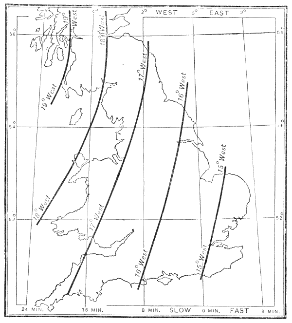
Fig. 31.—Magnetic and Greenwich time chart for Great Britain, 1914.
134.—The Magnetic Variation of Declination in Time, becomes important in reference to old plans in which the magnetic north of the period has been plotted for the true north very much to the pecuniary advantage of the legal[69] profession when engaged upon actions with regard to disputed boundaries. The following table gives an idea of the variation in declination for Greenwich approximately for a few dates:—
| Year | 1580, | Dec. | 11° 36′ E. | Year | 1860, | Dec. | 20° 40′ W. |
| " | 1663, | " | 0 | " | 1870, | " | 20° 19′ W. |
| " | 1700, | " | 8° 20′ W. | " | 1880, | " | 18° 58′ W. |
| " | 1818, | " | 25° 41′ W. | " | 1890, | " | 17° 9′ W. |
| " | 1850, | " | 19° 31′ W. | " | 1900, | " | 16° 30′ W. |
It will be seen by the above table that the needle pointed due north in 1663, that it attained its greatest western declination in 1818, and that it is now losing its westerly declination at the rate of about 7′ annually.
135.—Annual Variation.—The declination is subject also to a small annual variation which is greatest about spring time, diminishes towards the summer solstice, and increases again during the following nine months. It varies at different periods, and seldom exceeds 16′ of arc.
136.—Declination Correction to true north may be made for the compass by observation in this hemisphere of the pole star, which is practically due north in January at 6 p.m., February at 4 a.m., March at 2 a.m., April at midnight, May at 10 p.m., August at 4 a.m., September at 2 a.m., October at midnight, November at 10 p.m., December at 8 p.m. Most surveying instruments, except the transit theodolite, are not made convenient for this observation. More generally observations of the position of the sun may be made where a sun-glass is provided to the telescope of the theodolite, Fig. 19, SG, page 45, with the aid of a chronometer or a good watch. For this observation we may remember that the sun is true south at twelve o'clock on the 16th April, 15th June, 1st September, and 25th December. The following table may be useful for some intermediate times to show how much the chronometer[70] (mean time) is faster or slower than the sun's southing approximately at noon:—
| Jan. | 1 | subtract | 4 | min. | July | 15 | subtract | 6 | min. |
| " | 16 | " | 10 | " | " | 30 | " | 6 | " |
| " | 31 | " | 14 | " | Aug. | 14 | " | 4 | " |
| Feb. | 15 | " | 14 | " | Sept. | 13 | add | 4 | " |
| Mar. | 2 | " | 12 | " | " | 28 | " | 9 | " |
| " | 17 | " | 8 | " | Oct. | 13 | " | 14 | " |
| April | 1 | " | 4 | " | " | 28 | " | 16 | " |
| May | 1 | add | 3 | " | Nov. | 12 | " | 16 | " |
| " | 16 | " | 4 | " | " | 27 | " | 12 | " |
| " | 31 | " | 3 | " | Dec. | 12 | " | 6 | " |
| June | 30 | subtract | 3 | " | " | 31 | subtract | 3 | " |
137.—As variation in time of southing is from fourteen minutes fast to sixteen slow, or a difference of thirty minutes, correction becomes important, as the sun passes over 7½° in this period. In these observations the diaphragm lines, webs, or points must bisect the sun's disc. This is done more exactly by taking the mean positions of the sun's eastern and western limbs or its semi-diameter, which is given for every day of the year in the Nautical Almanac.
138.—The Compass-box.—The needle, as it is generally mounted for the theodolite, mining-dial, and many other instruments, reads into a divided circle of 360°. The circle is raised up from the bottom of the compass-box to the height of the top of the needle, as shown in section Fig. 30, D, and is generally silver-plated. The bottom of the compass-box is sometimes divided with a compass-rose giving the points N. E. S. W. The E. and W. in some cases are reversed from their natural directive positions from the centre of the box, so as to read the letter indicating the point nearest to the division instead of that opposite to it. In modern surveying instruments, however, no regard is paid to the points of the compass, north being 0°, east 90°, south 180°, west 270°.
139.—In the manufacture of the compass-box very great[71] care should be taken that the metal is quite free from iron, and that no iron comes near it. On this point the maker cannot be too guarded. The author has in several instances found the compass-box of perfectly free metal; but a single foul screw made of commercial brass wire, being used to fix the ring or the rose plate, has by its influence entirely destroyed the value of the compass.
140.—In the construction of the compass-box the author has found the most certain method of getting the divisions correct with the centre is to make the division directly from the standing-point of the compass, and not to try to get this point correct to the divisions afterwards. The standing-point may be fixed directly to the box by screwing, or be attached to a brass plate before fixing. It is adjusted to the compass-box by bending until the needle turns freely, but at the same time nearly touches the circle. The needle is then removed and the circle is divided with the point as its centre. Where the divisions read to the point of the needle, or to a line upon it without a magnifier, the divisions of the circle may be made directly upon the lathe by a lever to the slide-rest if the lathe has a well-divided headstock. When the divisions are magnified and require great accuracy, or where a floating ring is used upon the needle, the circle should be divided upon the dividing engine, which will be described further on, the centre used being still the point or pivot on the bottom of the case, from which the divisions are to be made radially.
141.—Preservation of the Magnetism in Needles.—It is most important that the magnetism of the needle, particularly in mining-dials where so much depends upon it, should be preserved to near saturation in order to secure certain direction in opposition to the friction of the centre, necessarily always present. This is often much neglected from carelessness, or want of knowledge of the principles of magnetic action. In the first place we know that a bar of soft iron, possessing no[72] evident magnetism, if it be placed in the magnetic meridian with proper dip, will after a time manifest strong magnetic properties. Thus, such a bar in London placed due north and south, with a dip of 67° to the north, becomes a weak magnet. From this we may also infer, and this experiment shows, that a needle placed in this position will not lose its magnetism. But what is most important to observe is that if the needle is placed in a contrary direction, as, for instance, with its northern end towards the south, it is in constant opposition to the influences of terrestrial magnetism, and will certainly become weaker. Therefore, although it is necessary to lift the needle when carrying the instrument, which must necessarily place its poles in all directions, it is not at all necessary that the needle should be lifted when the instrument is put by out of use. Indeed, magnetism is materially preserved by releasing the lift to let the needle take its true bearing. This does not at all injure the standing-point, as there is no movement upon it to cause wear. Of course if the needle is at first magnetised beyond its permanent condition it will lose this surplus magnetism, but the residual magnetism in this position will remain nearly constant.
142.—A valuable precaution for a needle in constant wear is occasionally, say twice a year, or much oftener if it is used in a dusty mine, to take it out of its box and wipe out the cap with the point of a small sable brush. The standing-point may at the same time be sharpened if necessary by gently rubbing it all round with a slip of oiled Arkansas stone at its former pointing angle. The sharpness of a needle is easily ascertained by sliding the thumb-nail over the point at an angle of about 30° to it. If the point sticks and holds the nail, it is sharp; if it glides upon it, it is dull. The author has often had compasses of various kinds sent to him for remagnetisation whose only fault has been dulness of centre.
143.—Ring Compasses.—In modern theodolites, levels and prismatic compasses, the magnetic needle carries a light[73] divided circle, which is now generally made of aluminium on account of the extreme lightness of this metal. A broad needle is used of about ¼ inch in width and 1/18 inch in thickness. There is considerable difficulty in mounting the circle to get it truly concentric and correct for bearing, therefore ring compasses are often found to be inaccurate. The author has followed two methods of construction, either of which answers fairly well:—The one is to leave a bar across the compass when cutting out the compass ring from a plate of aluminium. In this case, when the outer edge of the ring is chucked in the lathe to be turned, a centre hole is also made in the cross-bar which exactly fits over the cap of the needle, so that the adjustment for centre is practically secured, and attention is only necessary to get the adjustment correct for bearing—that is, the 0° at true magnetic north to the axis of the needle. Another method, which was suggested to the author by the late Mr. Thos. Cushing of the India Office, answers perfectly, and only entails a little extra trouble in setting for dividing. This is to permanently mount the ring on the needle without any means of after-adjustment, and to divide the circle from a point placed in the axis of the dividing engine, upon which the ruby centre is placed, being of course particular that the zero line 0° cuts the magnetic axis true north in the graduation.
144.—Mariners' Compasses, and an inexpensive class of prismatic compasses, are made with a paper disc in place of the ring above described answering the same purposes. The paper disc is generally made in two thicknesses with a thin sheet of talc placed between them. Mariners' compasses have frequently the divisions painted directly upon talc for transparency by lighting from beneath, also for general lightness combined with stiffness.
145.—The reading of mariners' compasses, and the compasses on levels where the needle carries a divided ring, is taken from a line drawn vertically up the inside of the box or a[74] pointer. This lead line in the mariners' compass gives the direction of the head of the vessel; a pointer in the level compass gives a direction in line with the axis of the telescope. In high-class theodolites, a microscope is used by the author reading to a spider's web in the diaphragm.
146.—Trough Compass, sometimes termed a long compass. Where an instrument possesses a double vertical axis and a divided circle, as the theodolite, the division of the circle may take the place of the divided ring of the compass and save the repetition of the graduation, at the same time the needle may often be made longer, as the bulk of the compass-box is proportionately less. In fact in all cases where the magnetic north only is required the trough compass is to be preferred. The ordinary construction of this compass is in the form of a narrow box, Fig. 32, A representing a plan, and B a parallel section taken through it horizontally. About 10° are graduated on each side of the meridian line, aa being adjusting screws to bring the scale true with the needle.

Fig. 32.—Trough compass for attachment to an instrument.
147.—Magnification of Reading.—With the trough compass it is very common to have some form of microscope for reading the needle more exactly. This may be done by a Ramsden eye-piece being placed directly over the needle, as is common in some German instruments. A much more convenient plan for certain instruments is to read the needle longitudinally. This is generally done by means of a transparent scale being placed across the end of the needle which is divided upon glass or horn. This may read to either the near or distant point of the needle. A very good form of[75] needle reading is found in some French instruments. This is shown Fig. 33, where the compass is shown entirely enclosed in a tube C which protects it from dust. The needle N has a vertical point fixed upon its end at P which reads pretty closely to a scale of 10° divided upon glass at G by the eye-piece E. It has a lifter L pressed up by a milled-head screw M. Fig. 34 shows the graduated glass. This compass is attached beneath the limb of a theodolite, or in any other convenient position upon an instrument. The author has placed a compass constructed upon this principle in a telescope, in such a manner that the needle may be read with the eye-piece, so as to cut a line with a distant object coincident with the line cut by the principal telescope of the instrument at 0° of its graduation. This plan will be more fully explained with tacheometers, Chapter XII.
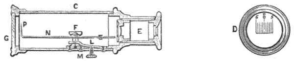
148.—The Prismatic Compass, shown Fig. 35, was invented by Charles August Schmalcalder in 1812. It is the most convenient portable instrument for reading magnetic bearings. Angles may be taken with great rapidity within about 15′ of arc by holding the instrument in the hand, or perhaps within 5′ if the instrument is of 4 to 6 inches diameter and placed on a stand. It is a most valuable instrument for filling in close details, such as may occur among buildings, trees, etc., after the principal points have been laid down from observations taken with the theodolite. The principles of the reflection of a prism were discussed, art. 55, Fig. 3, p. 29.

149.—Prismatic Compasses are made from 2½ to 6 inches in diameter. The compass needle is sometimes made to[76] carry a card dial for the 2½-inch size; for larger sizes the ring is now made uniformly of aluminium. The reading of the compass ring is effected by means of a glass prism, Fig. 36, P, which is cut to 45° upon one face and 90° for the two others, one 90° face being worked convex, so as to give magnifying power simultaneously with reflection of the ring at right angles, so that the reading of the compass appears to stand erect before the user of the instrument, and to be considerably magnified. As the reading is made on the side of the ring nearest the observer, the figures on the ring are engraved right to left. The prism is placed in a box, with a vertical sight slit SS over it, which cuts a line with the centre of the top of the prism. The box with its prism moves upwards or downwards in a sliding fitting SL by means of a thumb nail stud, which adjusts the prism until it is in exact focus with the divisions on the ring. The back of the prism-box has a hinge H, so that this box may be closed down to the level of the compass-box to render it portable when out of use. On the opposite side of the compass-box to that upon which the prism is placed a long vertical window SV is attached, having a central hair placed so as to cut a direct line from the slit SS in the prism-box across the axis of the needle. This window-piece is jointed to turn down upon the face of the compass-box and[77] simultaneously to lift the compass needle off its centre by a part of it pressing the outer end of the lifting lever L. To prevent too great a continuity of the oscillation of the compass needle and the ring, through unsteadiness of the hand in holding it, a pin is placed at S, through the compass-box under the window, which carries a light spring B that just touches the ring lightly when the pin is pressed in, and thereby brings the compass ring to rest, or fixes it for reading with some degree of certainty. An open ring under the prism-box is sometimes used for placing a piece of ribbon through it, to attach it to some part of the person to save dropping the compass accidentally when it is used in the hand. When the instrument is out of use a metal cover is provided to protect the glass. The instrument is uniformly carried in a leather case with strap to pass over the shoulder. As these instruments are often carried by military surveyors, they are better made of a stiff aluminium alloy, which makes the instrument less than half its ordinary weight.
150.—Additional Parts commonly provided with the prismatic compass are a mirror and sunshades, shown only in section Fig. 36. The mirror M is carried in a frame attached with a sliding piece to the window, upon which it can be placed either upwards or downwards. It is jointed with a hinge so as to be set at any angle. By reflection from the mirror, bearings in azimuth are taken much above or below the horizontal plane. Sun-glasses are also provided in front of the prism, which are used for taking the sun's place either with or without the mirror, a single sun-glass being also used very comfortably for working towards the sun at all times. The sun-glasses, which are simply small, dark-coloured glass circles in frames, are not shown in the engraving.
151.—To Prepare to take Observations with the Prismatic Compass. After the window and prism are opened out, the prism is adjusted to read the divided ring sharply when[78] the compass is about level, by raising or lowering the prism P by pressure of the thumb and forefinger of the right hand upon the stud placed upon the prism slide fitting, shown below SL, until the divisions appear clear.
152.—In Using the Prismatic Compass, the compass-box is held with the thumb of the right hand under the prism at SL and the forefinger upon the stud S. The object which it is desired to observe is sighted through the slit SS, cutting the left-hand side of the hair in the window SV, while the division which comes opposite the reading point at its edge by the reflection from the prism is noted. The ring when free oscillates for a time, but is easily brought to rest for reading by gently pressing the pin S upon which the forefinger is placed.
153.—Where objects are observed for taking their bearings above the horizontal plane, the length of the window will be sufficient to take in a vertical angle of 20° to 30°; but for such altitudes it is necessary to take very great care that the compass is held level, to get magnetic angles even approximately true. Below the horizon, angles can be obtained with somewhat greater certainty by means of reflections from the mirror. Altogether, except for taking nearly horizontal angles, or for very close work in filling in after the theodolite, it is much better to have the prismatic compass mounted upon a tripod stand. With a stand, where the angle in azimuth is much above or below the horizontal plane, it is better to have a small glass level, described further on, art. 181, to place across the compass when setting it up. If the compass ring is very carefully balanced across 90° to 270° two bright wire points may be placed inside the compass-box, level with the compass ring, which will answer for the cross levelling.
154.—Stands.—The author has made a very simple and inexpensive tripod stand for the prismatic compass, the head of which consists of a ball and socket only, clamped by a large[79] milled-head screw. An axis through the ball permits horizontal adjustment, shown in section, Fig. 37.
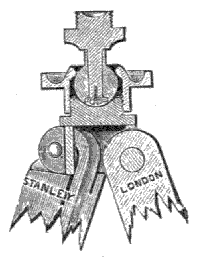
Fig. 37.—Improved prismatic compass stand.

Fig. 38.—Hutchinson's prismatic compass.
155.—Hutchinson's Prismatic Compass, Fig. 38, is now very generally used by military men. In this compass the metal cover is fixed on the top of the compass-box, and a glazed opening is placed in the cover, occupying about one-eighth of its area, near the prism. This opening gives sufficient light to the compass card to permit it to be easily read, and the loose cover is dispensed with; besides which, the cover being fixed, this, as well as the whole instrument, may be made much lighter, while retaining equal rigidity for wear. This compass is not fitted with shade and mirror arrangements as[80] before described. Size, 2½ inches diameter, ¾ inch in thickness; weight, only 8½ oz. in brass; 3¼ oz. in aluminium.
156.—Captain Burnier's Military Compass.—This portable compass is more generally used on the Continent than other forms. It is generally combined with a clinometer, therefore the illustration is deferred, seq. with clinometers. The compass ring is set up vertical to the plane of the needle, and is read by an index point by means of a cylindrical lens. It has a pair of sights formed of a slit near the eye-piece, and a hair in the window as in the prismatic. When this instrument is held horizontally, at about a foot distance from the eye, the sight line and the index line read distinctly into the graduations of the ring. A lifter is provided to raise the compass off its centre, as with the prismatic compass, and a spring clutch to prevent continuity of oscillation. It is adapted to be set up on a plain rod stand, the socket fitting to which is held in the hand when it is used as a hand instrument.
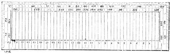
Fig. 39.—Sketching protractor for use with prismatic compass.
157.—Surveying with the Compass only.—In modern practice very little surveying is performed with the compass, except for sketch or exploring maps and filling in details, wherein the prismatic compass is useful. The magnetic needle was formerly much used for surface work, and depended upon almost entirely for underground work; but this has been found practically in many cases unsafe, from the uncertainty of magnetic variations, local and other, in the[81] district surveyed. Mining compasses, or dials, as they are termed, are now in modern practice made with means of taking angles with the compass, and independently of it. This subject will therefore be deferred to a future chapter on mining instruments.
158.—In Plotting Military Sketch Surveys from angles taken with the prismatic compass, the paper employed is ruled lightly all over with parallel lines an inch or less apart. The angles taken with the prismatic compass from 0° to 360° (northern zero) are set off with an ivory military protractor, which has lines to correspond with latitudinal lines drawn over its face at 90° to its base, so that the protractor may be placed transverse to any line drawn on the paper with its centre in any position. Particulars of this method are given in every detail in Major Jackson's Course of Military Surveying, and in my work on Drawing Instruments. The military protractor is shown Fig. 39.
159.—For making a sketch plan with the prismatic compass, a very convenient way is to use the tee-square, the upper edge of the blade of which represents magnetic east to west, the upper end of the board magnetic north and the lower end south, according to the reading of the compass. The bearings taken from any starting-point are set off on the plot by a semicircular protractor with its base resting along the tee-square. The northern angles are raised with the square at the left-hand side of the board and the southern with it at the right. The distances from the station for all bearings are measured and set off by scale.
160.—It is indifferent how many stations are taken by the prismatic compass. The measurements in any direction may continue all round an estate, and will be found fairly correct if carefully made, as the small personal errors in reading the prismatic, which may be plus or minus, tend to correct each other on the whole, and to tie up the lines.
161.—The rolling parallel rule may replace the tee-square,[82] if it is thought desirable to place the plan in a direction other than that erect to magnetic north with the paper, or that it is inconvenient to use the tee-square. In this case a few parallel lines may be at first drawn correctly across the paper, at about equal distances, with a sharp pencil E. to W. for references to reset the parallel rule at any position desired.
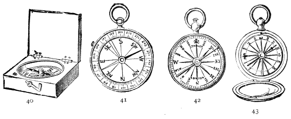
Figs. 40, 41, 42, 43.—Pocket magnetic compasses.
162.—Pocket Magnetic Compasses.—The subject of compasses will scarcely be complete without mention of the small pocket compasses which are so useful and universal. Several well-known forms are shown in the next illustration. The square form shown first, Fig. 40, will be found the most useful for very rough sketching. The edges may be sighted for the direction of roads, etc., or the box may be placed against a wall for taking the magnetic direction of a building. In like manner also the compass-box may be laid on a drawing and lines drawn along by the edges of the box to the magnetic directions taken. This in most cases is sufficiently accurate for architectural work, in which the exact direction is not generally thought to be important. Fig. 41 is a French form of compass with step reading level with the upper surface of the needle. Fig. 42 is an old English form with enamelled dial, with lifter under the bow of the handle. Fig. 43 is the same make in a hunter case. In this the lifter rises upon the case being closed.
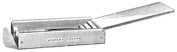
Fig. 44.—Trough form "Egyptian compass."
163.—The author has made a small pocket magnetic compass, which is represented in the illustration above. The needle is placed in a long box. It reads at its point into a single line when the needle is exactly parallel with the sides of the box. The lid turns up endwise. The needle is lifted by closing the box.
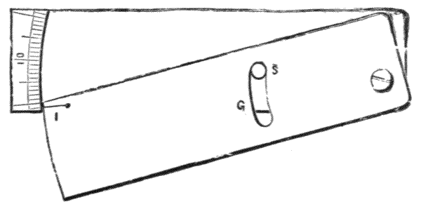
Fig. 45.—The author's under slide for setting off variation.
164.—In a form of compass similar to the above, the author has added a thin slide to the under side of the box, by means of which the magnetic variation may be adjusted, as shown Fig. 45. This slide moves out just the amount of magnetic variation, the stud S being made concentric for this adjustment. If the slide box be made of ivory a few useful scales may be divided upon it. The compass slips into a light leather case, and is the most portable for its length of needle of any compass made. The edges of the box are used as directing lines, as above described for the square form. The[84] illustrations show a compass made for Great Britain, but a similar instrument is also made universal. In this case the box is a little wider, with the centre of the slide in the middle, so that the magnetic variation can be set off west or east. A rider also on the needle enables it to be balanced in southern latitudes.
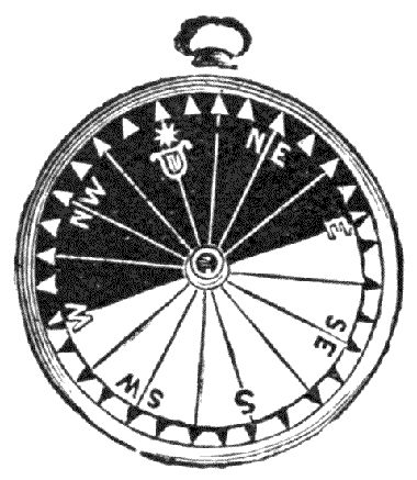
Fig. 46.—Barker's luminous compass.
165.—Barker's Luminous Compass, with floating dial of mother-of-pearl, one-half of this being engraved with black figures and the other half painted black with the figures left white, permits magnetic direction to be observed in the dusk and by moonlight. These compasses, Fig. 46, are much used by travellers. Mr. Francis Barker has also designed a compass in which the needle carries a bar coated with luminous paint.
LEVELS—METHODS OF ASCERTAINING—LEVEL TUBES—MANUFACTURE—CURVATURE—SENSITIVENESS-TESTING—READING—CIRCULAR LEVELS—SURVEYORS' LEVELS—Y-LEVEL—PARALLEL PLATES—ADJUSTMENTS OF Y-LEVELS—SUGGESTED IMPROVEMENTS—DUMPY LEVEL—TRIPOD STANDS—ADJUSTMENT OF DUMPY—COLLIMATOR—IMPROVEMENTS IN DUMPY LEVEL—TRIBRACH HEAD—DIAPHRAGMS—CUSHING'S LEVEL—COOKE'S LEVEL—CHEAP FORMS OF LEVEL—HAND LEVELS—TELESCOPIC LEVEL—REFLECTING LEVELS—WATER LEVELS.
166.—A Level Plane is understood technically to be a plane truly tangential to the theoretical spheroidal surface of the earth, as represented by any spot upon the mean surface of the ocean or of still water free from local attraction. The importance of having the means of constructing efficient instruments that can be conveniently employed to obtain the correct relative altitudes of points or stations upon the earth's surface, in relation to such a plane or datum, can scarcely be overrated. Such instruments are not only used for topographical surveys of countries, but also in designing and carrying out public works adapted to the local conditions of natural inclination of the land surface, for railways, drainage, irrigation, canals, water-works, and other constructions.
167.—The force constantly at our command to enable us to ascertain relative altitudes and to form mentally or graphically local level lines on the earth, is that of gravity; and[86] it is only a question in any case how the action of this force shall be employed. There are four principles which we may accept as data for employing gravity, each depending upon a natural phenomenon:—(1) The open upper surface of a liquid unaffected by currents of air, or the influence of solid objects in close proximity causing capillary action, or local attraction of solid masses, represents a level plane. (2) The line of a plummet unaffected by currents or lateral attractions forms a vertical line to which the level plane is everywhere at right angles. (3) The atmospheric pressure, from the approximated equality of its density due to its weight in proportion to its height over limited areas, gives pressure according to its gravity—therefore altitude or difference of level relatively to lesser pressure compared with a lower datum. This pressure is measurable with a barometer or other form of pressure gauge. (4) The resistance to ebullition in a liquid is inversely proportional to the weight or pressure of the aërial fluid resting upon its surface. This is measurable by the temperature at which liquids boil under varying atmospheric pressures. Various instrumental refinements have been discovered to render these natural phenomena available in practical use for ascertaining difference of height. The first and most exact method employed for this purpose, by means of the liquid plane, will be considered in this chapter. The other methods will be deferred to later pages.
168.—In taking the level of a liquid surface contained in a vessel, we have, as just stated, to keep this surface free from the disturbing influence of air currents, and to surround the surface with equal conditions of capillary attraction, or to make these conditions equal in the direction in which we desire to ascertain our level. This is found practically to be best performed by means of a sealed glass tube, in which the liquid will by gravitation naturally occupy the lower place, and any air or lighter fluid contained therein the space above this.
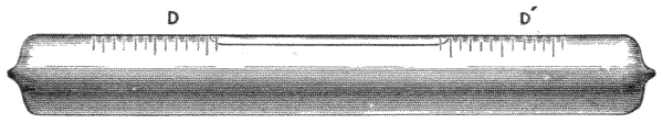
Fig. 47.—Level tube (bubble).
169.—Level Tubes, or Bubble Tubes, as they are[87] technically termed, are used as a part of nearly all important surveying instruments. One of these is represented Fig. 47. The glass for the construction of these tubes is drawn at the glass-houses in lengths of about 6 feet, and may be ordered of any desired size and substance. The tubes are drawn of as nearly straight and equal bore as possible. They are, nevertheless, found to be, when examined after annealing, curved more or less in various directions at different parts of their lengths. They are found also generally to be slightly tapering from end to end and of slightly unequal substance. In the manufacture of level tubes parts of the tube are selected with approximately regular longitudinal curvature, and these parts are cut off into the required lengths by a triangular file dipped in spirits of turpentine, to be ready for the future operations of grinding, sealing, and dividing. After the tube is cut off and carefully examined to get its most concave internal surface upwards, this is then marked by a test mark, with the flat of a file, near one end for future work and reference. The grinding of the inside of the glass tube to true curvature is performed by passing it over a brass mandrel or core, which is employed to grind the glass by means of fine emery. The core is turned slightly barrel-form to the longitudinal curvature intended for the upper surface of the finished tube. It is made of full three-quarters the diameter of the interior of the tube, and a little longer than the entire tube. This core is attached by its ends to two stiff but flexible wires of brass, about 8 B.W.G. for a tube of ·7 inch diameter, and these wires are held firmly by their ends in two vices, so that the core is slung, as it were, to permit a certain amount of flexibility under the pressure of the[88] hand used in grinding. Some good makers do not use a mandrel core, but only a strip of brass on the mandrel, extending about 60° of the circumference. In this case the strip has to be corrected for curvature during the grinding, which plan is sometimes preferred for certainty. The grinding of a tube cannot be commenced with coarse emery, such as is used in the grinding of lenses, as the cut of a coarse emery will quickly split the tube. After the glaze is removed there is not so much risk, so that a little time may be saved by passing a current of hydrofluoric acid gas through the tube; but more careful testing is required afterwards, as the cut of the grinding tool is not so evident at sight when the glazed surface is removed.
170.—The operation of grinding is very much the same as that described for lenses, p. 17. The surface is required to be traversed in every direction longitudinally and transversely, which is effected as far as possible by a twist of the hand alternately to the right and left. The tube should also be frequently taken off and turned end for end. Slight variations of curvature are readily made by differences of pressure of the hand on parts of the tube; and a little coaxing is allowed to get the centre of the tube quick where the tube is to be used for levelling only, and not for measuring small angles, so that in this case the finished tube is slightly parabolical. The finishing touch is produced with wash-emery. The inside should be left smooth but not polished, as the slight roughness of a fine ground surface assists the capillary action by causing better adhesion of the spirit, and gives a quicker run to the bubble. Where the tubes are required of a given radius they are tested frequently, during the grinding, upon the bubble trier, by placing two corks in the ends of the tube, which is nearly filled first with water for rough trial, and then with spirit for final correction.
171.—The Bubble Trier is a bar or bed 12 to 20 inches long, with two extended feet ending in points at one[89] end, and a micrometer screw at the other, the point of which is a resting foot, thereby forming a tripod. This stands on a cast-iron or slate surface plate. The micrometer screw has a fine thread, and a large head with divisions upon it to read seconds of arc. The tube is supported on the bar by two Y's, which are adjustable for distance apart, according to the length of the tubes to be tried.
172.—The Sensitiveness of a Level Tube, the upper curvature and ground surface being equal, depends very much upon the capillary action due to its internal diameter, the larger tube, from the freedom of restraint by capillarity, being the more active. As regards the ultimate settling to gravitation equilibrium, perhaps there is no difference, but small tubes are sluggish and take time to work. The following are about the usual dimensions of the interior of sensitive tubes—8 inches × 1 inch diameter, 7 inches × ·9, 6 inches × ·8, 5 inches × ·7, 4 inches × ·6, 3 inches × ·5, 2½ inches × ·45, 2 inches × ·4, 1½ inches × ·35, 1 inch × ·3. The larger the volume the greater the expansion of liquid with heat; the longer the tube the less torsion it is liable to suffer from sealing, so that if possible, as expansion is a serious defect, it would be better to have short tubes, if these could be sealed without disturbance of curvature. Much shorter tubes are used in America than in Great Britain.
173.—The Curvature of a Level Tube is worked to radius according to the delicacy of the work to be performed with it afterwards. The radii of curvature of different level tubes used for scientific purposes vary from about 30 feet to 1000 feet or more. The radius of any curve may be conveniently measured by the relation of its versed sine to its chord of arc, the chord being the length of the tube. If this is first calculated out, a piece of shellac may be attached by melting it down upon the centre of the edge of a parallel glass straight-edge, to represent by its thickness the versed sine. The spot of shellac may be brought to the exact height required from the[90] straight-edge by filing and stoning, at the same time taking its protuberance by a calliper gauge provided with vernier or micrometer to read ·001 inch. The versed sine of a given radius is formed for a given chord—
versed sine = rad - √(rad2 - (½ cho)2).
174.—The general instruction, however, given to the maker is the distance of run of the bubble that is required to give seconds or minutes of arc; and perhaps this is after all the best test for accuracy of the tube which, like all other articles in glass submitted to the process of grinding, is subject to a certain amount of local error. By this method the local error is discovered by testing with the bubble trier. When the run is given, the radius of the curve of the tube may be found if desired by the use of a common multiplier, as follows, very approximately—
Arc equal to radius expressed in minutes, 3437·74677.
" " " seconds, 206264·80625.
The run of a good sensitive tube is frequently made 1/30 inch to the second, here (omitting decimals)—
arc sec (206264·8) × 1/30 inch = 573 feet radius nearly.
For scientific purposes a millimetre run per second is commonly used, then—
arc sec (206264·8) × ·001 metre = 206·264 metres radius or 680 feet nearly.
For an ordinary 12-inch dumpy level the tube is divided into minutes at about 1/10 inch apart, radius 28 to 30 feet; for a sensitive 14-inch Y-level of good construction the same divisions may represent five seconds, radius of bubble tube about 170 feet.
175.—The Divisions upon Ordinary Level Tubes are made after the tube is finished, but with the highly sensitive ones the divisions are made first. The run is taken from[91] ten to thirty divisions on each side of the centre of the tube, where it is lightly marked with a marking diamond. These spaces are then equally subdivided and etched in with hydrofluoric acid or marked with a hard steel edge dipped in turps. If further refinement be required, the errors of run in relation to the divisions are tabulated from the testing of the tube with the bubble trier. A less careful method is employed by some makers of leaving the level tube undivided and fixing an independent metal or ivory scale over it.
176.—Level tubes are generally filled with pure alcohol for ordinary purposes; for trade purposes with methylic alcohol, which is much cheaper. For very delicate tubes sulphuric ether or chloroform is used. The sensitiveness of the bubble depends very greatly upon the mobility of the liquid with which it is filled, and to the quality of adhesion of the liquid to the glass. The relative mobility of the above-mentioned liquids is found by delicate tests with the bubble trier for small distances under the microscope at a temperature of 60° Fahr. Taking water as 100:—we find commercial methylic alcohol 22, absolute alcohol 13, sulphuric ether 5, chloroform 3,—that is, for equal small runs taken in 15 seconds of time. All bubbles appear to be more or less affected by temperature, particularly where the spirit is not nearly absolute. In the higher temperatures the bubbles are more active. The objection to chloroform, where it is likely to be subject to great changes of temperature, and where there is no provision made for regulating the size of the bubble—the means of doing which will be presently discussed—is that its expansion from heat is so great that it is very liable to burst its tube. It can therefore only be used with ordinary sealed tubes where these are small and strong. Sulphuric ether has the same fault, but in a lesser degree.
177.—The sealing of ground tubes requires the skill of a very experienced glass-blower, and is a technical matter on which no written instructions would be of value under any[92] conditions. A little strain is unavoidably put upon the tube in sealing with the blow-pipe, so that the curvature to which it is worked is more or less disturbed. For this reason level tubes which are required to be of the highest degree of accuracy are sometimes left as they are ground, and closed at the ends by small discs of glass grooved to the end surfaces. These are fixed on with glue, and when the glue is set are bound over with silk and finally varnished; but this plan is much too delicate for instruments for use in the field.
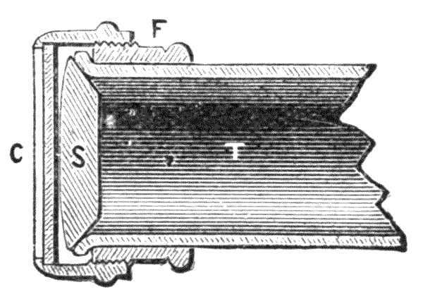
Fig. 48.—Colonel Strange's level tube.
178.—Colonel Strange's Level Tube.—These tubes, Fig. 48, are blown with an outward bead at each end of the tube, two outwardly screwed collars, F, being first placed over the tube before the blowing. The tube is then ground to curvature. A plug, S, is formed for each end of the tube from a plano-convex lens, ground to a bevel on the plano side, and also ground into the end of the tube as a stopper. A cap, C, is screwed over the end upon the collar. The springiness of the cap keeps the stopper always tight. As there is no blow-pipe used after the grinding, the tube remains constant as it is ground, or it can be adjusted by grinding to any desired sensitiveness. This cap, for security, is better covered with silk tied over it, and afterwards well varnished. In this class of tube there is always a little risk of evaporation. The system is not adapted to instruments to be used in the open air.
179.—Chambered Level Tubes.—As the run of a bubble varies slightly with its size, for exact purposes and[93] extreme climates it is very desirable to be able to adjust the size of the bubble to the surrounding temperature, so that it shall be kept at about equal dimensions for all measurements made with it. This becomes particularly important where chloroform is used, from the expansion being very great. A general way of doing this is to have a stopper ground into one end of the tube, which is itself a small bottle, on the under side of which a hole is ground, so that by turning the tube over and raising it more or less, any amount of the highly rarefied air it contains may be taken to form the bubble that may be desired. The stopper is fixed with thin glue. The general construction is shown below, Fig. 49. Of course where such a tube is used there must be means of tipping and turning the instrument in which it is fixed over, or the bubble itself must have separate fixings. The portability of a surveyor's level admits readily of the necessary tipping; with theodolite levels at right angles to each other upon the vernier plate it would be impossible.
Fig. 49.—Bubble with supplemental air-chamber.
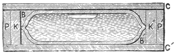
Fig. 50.—Colonel Scott's patent protected bubble.
180.—Extra Strong Level Tubes.—Colonel Scott's very ingenious device of enclosing a level tube within another tube of thoroughly annealed glass will be found valuable in all cases where the tube is much exposed, or where it is difficult[94] afterwards to procure a new tube in the case of accident. These tubes are at present only made by the author for Scott's telescopic gun-sights, which are nearly like small theodolites. The level tube, Fig. 50, is made as stout as possible to be soundly sealed after filling. It is then enclosed in an annealed tube, CC′, of about ·08 to ·12 inch in thickness, the interspace between the two tubes being filled with Canada balsam. It is then plugged with elastic marine glue, KK′ and cemented over PP′. The annealed tube is of great strength, so that the complete naked tube thus formed will bear dropping on the ground, and also when attached to a large gun will bear the violent vibration of firing without injury.
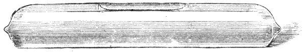
Fig. 51.—Artificial horizon level.
181.—The Level Tube may form a Complete Instrument in itself.—In this case the lower surface is ground to a flat plane to rest on any plane surface. This level is generally contained in a small pocket case, and is most convenient for adjusting instruments to level. It is commonly used with the black glass artificial horizon, to be described.
182.—Mounting Tubes.—Level tubes when applied to instruments are generally mounted in brass covering tubes. Small level tubes under 2½ inches are conveniently mounted in such tubes with a fixing of slaked plaster of Paris inserted at each end of the brass tube. Larger level tubes should be bound round with thin paper pasted round the ends, which is allowed to get quite dry, to be afterwards fitted to the brass tube with a file. Fitted in this manner the tubes admit of adjustment to the difference of expansion of the metal and glass by change of temperature without distortion. There is no objection, however, to thoroughly fixing one end of the[95] tube with plaster if the other be left free, and this is perhaps advisable for portable instruments.
It is convenient in mounting level tubes to place white glazed paper under the bubble to reflect the light that passes through it to ensure better observation.
183.—In Fixing Undivided Level Tubes, or replacing them in instruments, it is important to observe that the side with the test mark, which is a small ground facet, should be placed on the top.
184.—In the Use of Level Tubes generally, it is not well to have them of greater sensitiveness than the general construction of the instrument upon which they are placed permits. Thus the centre of a surveyor's level that may be under constant strain from the unavoidable inequality of the pressure of parallel plate screws, will appear never to reverse properly if it has a very sensitive bubble, the cause of the irregularity being entirely due to the distortion from the strain on the vertical axis of the instrument. The same irregularity occurs in a lesser degree with the Y's of a theodolite, where these and the collars become corroded by exposure. The optician often gets an undue amount of credit for perfecting such instruments when he has merely replaced the sensitive bubble by a dull one—that is by doing what is really in this case the best for the instrument.
185.—When an instrument that depends entirely upon the level for its possible working is to be used abroad, an extra tube should be taken, as the level tube is very generally more exposed and is more delicate than any other part of the instrument. The tube may not only be accidentally fractured with a slight bow, but even the heat of the sun's rays will sometimes burst it.
186.—Reading the Bubble.—The exact position of the capillary concave surface of the spirit in the tube is liable to deceive the observer by the difference of refraction and reflection it gives, whether the light is towards the right or left hand.[96] To avoid this cause of error it is better, in sunlight, to hold a piece of white paper at a short distance over the end of the bubble during the observation taken of its terminal reading into the divided scale on the tube. It is also important to note that the observer should stand at right angles to the tube to see the position exactly where the upper capillary line of the spirit cuts, as the tube itself refracts the light unequally. It is not at all difficult to read the bubble if the observer stand over it; but generally, as it is mounted upon an instrument, it is at the height of the eye. In this position the hollow surface round the bubble, caused by the adhesion of the liquid to the sides of the glass tube, reflects the light in a manner that the hollow may be taken for the end of the bubble, and a false reading made. It is better if possible to take the convenient side reading first, and afterwards get a glance at the upper surface reading for certainty. In some cases this may be much assisted by the employment of a small mirror of about the size of a spectacle eye, which is carried open in the pocket, or, as the author has made it, it may close in a horn case with a pocket lens, as in the Fig. 52 shown below. C sheath, M mirror, L lens.
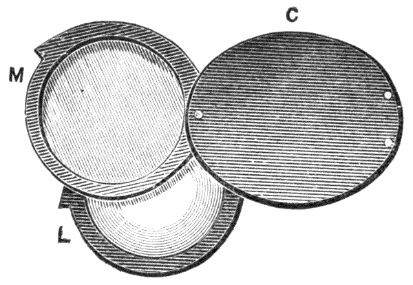
Fig. 52.—Pocket lens and mirror.
187.—Circular Levels have been made tentatively for a long period. They consist of a worked concave lens fitted into a brass cell with indiarubber seating, the glass being secured by burnishing over a bezel. This construction[97] answers very well when new, but the spirit the level contains is certain to evaporate slowly under every possible care. Mr. J. J. Hicks has patented a hermetically sealed circular level, in which he has succeeded in working the upper surface of the glass to curvature. These levels, of course, are not subject to evaporation, and are very useful and portable for approximate levelling—as for plane tables, cameras, etc.
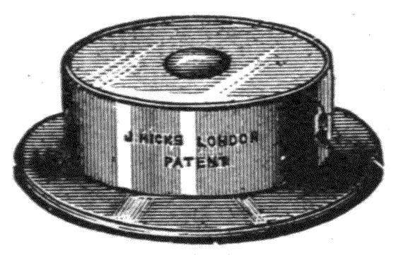
Fig. 53.—Hicks' patent circular level.
188.—Surveyors' Levels, of which there are many forms, consist essentially of a telescope with a diaphragm at the mutual foci of the objective and the eye-piece, the axis of the telescope being placed in a direction truly parallel with the crown of a sensitive level tube. The telescope with its level is mounted upon metal frame-work, carried up from a vertical axis upon which the telescope rests. The vertical axis is adjustable in relation to the axis of the telescope, so that they may be brought perfectly perpendicular, the one to the other. The whole instrument is also adjustable to a position of verticality of its central axis, and the horizontality of the telescope in relation to the surface of the earth in what is termed the setting-up of the instrument; so that when it is set up in this position levels may be taken from it in any horizontal direction from one point of observation, by rotation of the telescope about the vertical axis. Having these essential objects in view in the construction of the level, the form of the instrument may be varied as to details according to the mechanical skill and taste of the maker and the special demands of the civil engineer.
189.—In the design of a surveyor's level very important considerations are:—That the metal should be so distributed that every part is as light as possible, consistently with sufficient solidity to take a moderate amount of accidental rough usage, and ensure freedom from vibration; that the whole structure should be in equilibrium about its vertical axis when the telescope is extended at mean range, that is, at about the focus of three chains—this is a quality often neglected; that there should be sufficient light in the telescope, and that it should possess a firm and durable stand. Every form of level should embrace these qualities.
190.—The Oldest Form of Surveyor's Level is that termed the Y-level, so named from the telescope being supported in Y-formed bearings. This instrument was originally invented by Jonathan Sisson, a leading instrument maker of the 18th century. It was much improved and brought nearly to its present state of perfection by Ramsden, to whom practical opticians owe so much for many advancements of their science, and to his liberal publication thereof. This instrument is now very little used in Great Britain; but it still maintains its original position, to a certain extent, on the Continent and in America. In the eyes of the optician it is still the most perfect level, possessing all the instrumental refinements of adjustment he can desire. The reasons for its partial abandonment by the profession will be discussed further on.
191.—The Y-Level in a modern form is represented in the engraving below, Fig. 54. The Y's are shown at YY″ edgewise. They are supported by standards SR upon the limb L. The telescope is surrounded by two collars which are soldered upon it at positions exactly corresponding with the Y's. The collars are turned perfectly cylindrical and parallel on the surface with the axis of the telescope, and ground in a gauge-plate to exact size so that the telescope may be turned end for end in the Y's without altering the linear direction of its axis in reversing it. The telescope is held from shifting[99] longitudinally in its Y's by a pair of flanges placed on the inside of the collar pieces.
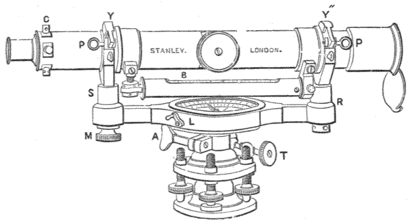
Fig. 54.—Surveyor's Y-level.
192.—The Y's are erected upon the limb, to which they are each fixed firmly by a clamping nut R at one end, and a milled head clamp at M. The telescope is held down by strap pieces, each of which has a joint at one end and a loose pin at the other, PP. The pin is secured from dropping when out of use by a piece of cord attached to a part of the instrument and to a loop through its head. At the top of the inner side of the strap-piece under YY″ a piece of cork is inserted in a cave. The cork by its elasticity keeps an equal but light pressure upon the collar of the telescope. It will be seen that by the above plan of holding the telescope, it is so far free that it may be revolved on its axis, by which perfect adjustment of the diaphragm to the axis of the instrument may be made in any direction.
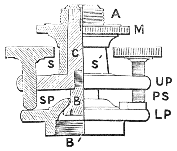
Fig. 55.—Section of parallel plate and vertical axis—arrangement of Y and other levels.
193.—Parallel Plates as a mode of adjustment of the vertical axis will be first described, as they present the oldest form of setting up adjustment. The vertical axis of the Y-level was formerly carried tapering downwards, and the upper parallel plate was placed at about the centre of the[100] socket. Under this construction the socket was more liable to strain from the use of the parallel plate screws. It is more general now to construct the axis as represented in the illustration above, Fig. 55, for Y and other levels with parallel plates. This construction also renders the instrument more portable, as the parallel plates and axis may be detached and lie closer in the case; the plan is nevertheless open to many risks, which will be referred to in discussing a three-screw arrangement. The general construction is shown in the figure, of which the left-hand side is a half-section. A is a screw by which the parallel plates are attached to the limb of the instrument; M a large milled head, by means of which the screw can be brought up firmly to its collar; SS′ the socket which is ground to fit the cone C; C forms a part of the upper parallel plate UP; B a ball pin which screws firmly into C; LP lower parallel plate, part of which forms the ball socket, so that the whole instrument rocks about the ball B as a centre, by the action of the parallel plate screws PS; B′ female screw for fixing this part, which is called altogether the parallel plates, to the tripod head. A clamping screw is sometimes placed upon the axis for slow motion. The parallel plate screws are tapped, that is, have female threads cut into the[101] upper plate UP, and their points press the lower parallel plate LP at certain points, there being a stop-piece placed round the point of one screw to prevent rotation. The pressure upon the screws can be increased as desired by means of the milled heads, and the instrument made rigid in proportion; but it is very undesirable that the pressure should be greater than that just necessary to support the instrument firmly, as it is easy by the power of the screws to disturb the figure of the axis and thereby derange it.
The diaphragm of the telescope of the Y-level is generally webbed with plain cross webs. The diaphragm and webs were described arts. 99 to 106.
194.—The Setting-up of the Y-Level is necessary to be understood before the instrument can be adjusted. The same description which answers for the setting up for adjustment will also answer for the setting-up of the instrument in the field for actual work. In this description it will be convenient, therefore, to consider the instrument as being in this case in adjustment as it leaves the hand of the maker. The after adjustments will be presently taken as from the original state of the instrument, as the maker has to do them in the first instance. Practically, the civil engineer has only to make slight differential adjustments at any time, as an instrument, by the solidity of its construction, will retain the general adjustment nearly, upon which further adjustments take more the nature of final corrections, which become necessary only from accidental causes.
195.—Setting-up of the Y or other Level with Parallel Plates.—The tripod stand is opened out so that the legs stand, if on level ground, inclined towards the centre of the instrument at an angle of about 70° to the horizon. The toes of the legs are each separately pressed into the ground sufficiently to make the instrument stand quite firmly. The instrument is then taken from its case and screwed down tightly upon the tripod head.
196.—The Eye-piece is Adjusted, art. 108, by sliding it gently in and out until the webs can be seen most distinctly. On a bright day a white pocket-handkerchief may with advantage be thrown singly over the object-glass to prevent any confusion from objects in the field of view during the focussing of the eye-piece. For the setting-up adjustment of the telescope, it is brought in position to lie directly over one pair of parallel plate screws, Fig. 55, PS, SP.
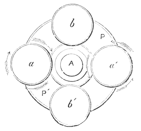
Fig. 56.—Diagram plan of parallel plate screw milled heads.
197.—The milled heads only of these screws are represented in plan in the diagram Fig. 56, aa′ being the opposite pair over which the telescope will be assumed to be at first placed. The level tube is now brought to adjustment by bringing the bubble to the centre of its run by means of the parallel plate screws aa′, by taking the milled heads of these screws, one between the ball of the thumb and forefinger of each hand, and rolling them simultaneously the one in one direction and the other in the reverse. This action tips the axis of the telescope in one direction or the other. Thus by the screws being rolled inwards, as shown by the direction of the arrows in the diagram, the left-hand side of the instrument would be raised. If turned the reverse way, the right hand end would be raised. The opposite end, from that to which the[103] bubble runs, always requires to be raised. Where the ground is rather soft, adjustment when nearly correct may be made partially by pressing down one or other of the legs; in this case the telescope should be placed parallel with the toe of the leg which is pressed down and the axis of the instrument.
198.—When the level tube is adjusted over the screws aa′ it is then placed over bb′ and adjusted in a similar manner, returning again to the position aa′ for final adjustment. When the level is in perfect adjustment the bubble should stand in the centre of its run in making a complete circuit of the horizon by rotation of the instrument upon its vertical axis.
199.—In and during the setting-up adjustment it is most important that the screws should not be made tight enough to cause, by their pressure upon the parallel plates, distortion of the vertical axis. Should this occur, the instrument will not level in all positions by the same setting. The action of the screws also, from the great elasticity of the metal, should distribute the pressure about equally between the opposite pairs aa′ and bb′. The difficulty of accomplishing this with certainty makes another form of adjustment, with three screws only, preferable for setting-up, which will be considered further on. Where the instrument is set up for use, if the adjustment of the bubble be fairly correct to the centre of its run, the reading of the staff may be sighted and the telescope brought to true focus upon it by moving its milled head until the divisions of the staff are as sharp as possible, and then moving the eye upwards and downwards to be sure there is no error of parallax, art. 109. After this the final adjusting of the bubble should be made, noting particularly that there are the same number of divisions in its run on each side from the centre if it is a divided bubble.
200.—Adjustment of the Axis of the Telescope in true parallel direction with the periphery of its supporting collars in its Y's. This is performed entirely with the four capstan-[104]headed screws which adjust the diaphragm, one of which is shown, Fig. 54, C. Having the adjustment of the eye-piece in focus for the webs in the manner described, arts. 108, 109, the object-glass focussed upon a distant distinct small object or mark, and without parallax, the instrument which carries the telescope is then exactly adjusted to make the intersection of the webs cut the mark. The telescope is now turned half round on its axis, so that the lower part becomes the upper, and observation is again made of the distant small object or mark. If the same intersection of the webs falls on the same point of the object, the collimation adjustment is perfect. If it does not do so, the upper capstan-headed screw at C, or the under opposite one, is loosened by means of the small pin provided with the instrument, and the opposite screw tightened until the webs are brought over a point situated half-way between the points cut by the first and second observation. The telescope is again directed to the point first observed, and the adjustment checked to see if it has been done correctly, that is, if the level reverses, cutting the same point, or whether it requires further adjustment by the same process as before. The other web of the diaphragm, at right angles to the first, is adjusted in a similar manner, but with the other pair of capstan-headed screws.
201.—It is sometimes inconvenient to adjust out of doors: this may be performed very well indoors. By daylight a small cross may be made with ink on a sheet of white writing-paper for the sighting object, which should be placed at as great a distance as convenient, say 20 or 30 feet. By night a pin-hole may be made through a piece of paper and a candle or a lamp be placed behind it.
202.—Adjustment of Vertical Axis.—For this the eye-piece is first brought to focus on the webs. The telescope is then placed directly over one pair of parallel plate screws opposite each other, and the instrument is levelled. The Y's are then opened out; and the telescope is directed so that the intersection[105] of the webs cuts or covers any distinct small mark upon a distant object, or preferably upon the centre reading of a foot line upon a levelling staff. There is no objection to adjusting slightly to this by the parallel plate screws, as this adjustment is independent of the level of the instrument. The telescope is then taken out of its Y's and is turned end for end and replaced. The telescope is now turned half a revolution on its vertical axis, and the webs are again brought to read on the staff, if one is used. If they now fall upon the same spot or foot line, the vertical axis is perfectly perpendicular to the axis of the telescope in this direction. If the webs do not fall upon the first reading or point, the amount of difference of reading is recorded and this space is bisected; so that now, if the telescope be adjusted by the milled head M, at its bearings upon the limb upon which it is supported, for the webs to cut the bisection, the axis will be perfectly perpendicular in the direction of its bearing socket. The same process must now be repeated with the telescope placed at right angles to its first position, that is by bringing it over the other pair of parallel plate screws which were not used at first. There is at all times a certain amount of disturbance of the instrument due to handling it; it is therefore necessary to repeat the whole of the above process until the instrument reverses in any direction, but this final adjustment is better deferred until the adjustment of the level tube, to be next described, has been made.
203.—Adjustment of the Level Tube.—The telescope is placed as before over an opposite pair of parallel plate screws, and these are adjusted until the bubble is in the centre of its run. The telescope is then turned half a revolution, so that it is placed over the same pair of screws in the reverse direction, and the displacement from the bubble from the centre is now noted. The capstan-headed bubble screws at the end of the level B are then adjusted to one-fourth of the difference observed, and the parallel plate screws are adjusted for the[106] other fourth, so that by these two adjustments the difference of the run in the two positions is bisected. The same process is repeated over the second opposite pair of parallel plate screws. If this be very carefully done with a correctly divided bubble, the Y's of the telescope may be opened out and the telescope be reversed end for end in its Y's, and the bubble remain true. But it is quite as well to go over all the adjustments a second time, as before recommended.
204.—If the level is to be adjusted by night, this can be done very correctly by a fine cross drawn on paper placed on a wall, with a candle or gas burner shining brightly on it at twenty feet or so distance from the instrument. For this adjustment by night the instrument must be well constructed, as the tubes require drawing out to their full extent for focussing near objects. If the tubes are not quite straight, the object-glass suffers considerable displacement in the drawing out, or technically droops, which is a very common fault in badly-made instruments.
205.—Where webs are used for the reading, they are liable to become baggy or dirty, art. 101, and very frequently to break; nothing can, therefore, be more useful than to be able to re-web a stop in the evening, with command of the easy and certain means of readjustment described, when far from the optician's aid.
206.—As the Y-level is so perfect in its arrangement for adjustments, and so nearly meets the optician's ideal, it will be well to inquire what are the objections made to its use by the majority of British surveyors. The first and most important is that it possesses so many loose parts, to which the practical man honestly objects. The author was, many years ago, when Y-levels were more popular, trying to persuade a cautious practical surveyor who appeared to be very anxious for the certainty of his work, and who was going abroad, to take a Y-level instead of a dumpy one he was selecting, when he had his arguments stopped by the following question:—[107]"Suppose you were surveying in a tropical country, thousands of miles and an ocean voyage from civilisation, where your native porter objected to carry much weight, and your instrument case had to be left at a back station—when your umbrella was all the burden you felt you could support. In this case, suppose your porter, whom you had lost sight of for a short time, arrived with your level, minus the telescope—lost by becoming loose, perhaps from having been played with while he was resting—how would you praise the Y-level?" This gentleman assured me that he did not, and that this was a true account of his experience with the last Y-level he possessed. Other objections, besides loose parts, are that Y's and collars do not remain as perfect as when they leave the optician—that they are liable to wear by friction of constant movement in being carried about upon the points in contact between them, and thereby form facets; that the collars become corroded by exposure, and that they have open spaces that collect sand from flying dust which fixes itself into the collars and Y's, so that this arrangement loses the perfection the optician claims for it. Further, that the cross bubble, which is uniformly placed on the dumpy level, effects a great saving of time over swinging the telescope backwards and forwards with every movement of the adjusting screws. Another feature is that in the dumpy level, to be described, the vertical and horizontal webs of the diaphragm cannot be disturbed from their position by rotation of the telescope after the level is once set up; and this verticality indicates conveniently at once whether the staff is held vertically, which is otherwise a great difficulty with the ordinary form of Y-level reading.
207.—Improved Y-Level.—The above-described defects the author has tried to remedy by a modification of the Y arrangement, by forming the Y's with much broader bearings, and instead of the old loose pins screw fastenings are fitted, which firmly lock the telescope in position with the[108] webs vertical. This, so far, obviates the danger from loose parts, as by this arrangement the telescope also becomes practically firmly fixed. In adjustment the collars are opened out, and in closing press a stud into the telescope by which it takes a given position. This enables a cross bubble, shown on Fig. 57, to be also placed on the telescope for approximate adjustment, which saves the frequent disturbance of the telescope by making cross adjustments. The diaphragm of this Y-level is exactly the same as that of the dumpy, to be described art. 210. From the limb downwards the author uses the same construction as he now employs on his improved dumpy level. This will be described with that instrument further on, art 231, seq. Also the setting-up adjustment with it, which is different from that already described where parallel plates are employed.
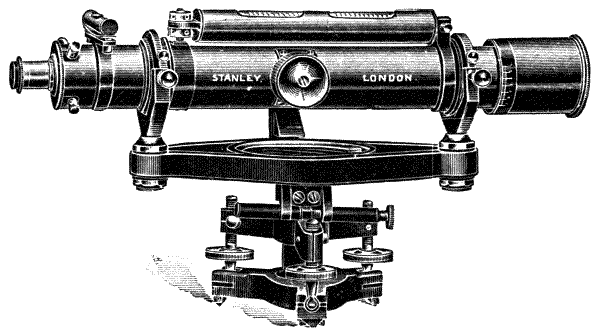
Fig. 57.—Improved Y-level.
208.—Perhaps, upon the whole, the conditions which formerly rendered the Y-level undoubtedly the best practical level have so much changed that the more solid construction of the dumpy may entirely supersede it, as it seems likely to do in modern practice, and the optician will lose his ideal. Some reasons for this may be stated, but whether sufficient is a question. The manufacture of object-glasses of good[109] figure and proper centring was formerly understood by a few scientific opticians, who were principally engaged upon astronomical telescopes, so that, with the exception of those made by Troughton and Simms, no very good and accurately centred lenses were used in surveying instruments. With bad centring alone, in ordinary telescopes, the webs in collimating were drifted aside, and needed the Y system of adjustment to make the telescope workable for levelling. In the modern good object-glass, of which there are now several makers, the centring is so nearly perfect that the webs in adjustment fall in the centre of the diaphragm when it is placed true to the cylindrical axis of the telescope. If the webs are placed as suggested without further adjustment, no very serious interference is caused by want of collimation of the axis. With this fact in view, the instrument maker needs leave little space for adjustment of the webs for centre displacement to become a source of error to persons not used to adjustments.
209.—Further, with a well-centred object-glass, as it leaves the hands of the scientific optician, and a solidly constructed adjustment to collimation being provided for in the making of a level, true working may be done even if there is a small error in the collimation. The late William Gravatt, C.E., was of opinion that firm construction, compact form, and plenty of light in the telescope were more important than easy facilities of adjustment. There is no doubt he found the less open adjustments the better in the hands of the imperfectly trained assistants who were pressed into service during the railway mania of 1848. At any rate, at this period we have his invention of the "Gravatt," or, as it was afterwards termed, the "Dumpy" level, which has remained with us with slight modifications in its mechanical parts and with increasing popularity until the present time. The late Mr. Troughton, recognising the same facts, also made a level in which there was no adjustment to the supports of the telescope after[110] it left the hands of the maker. In his level he also left no adjustment to the bubble tube, which no doubt would prevent tampering, but which could scarcely be called an improvement; as this tube is liable at all times to be broken, therefore to need replacing with another tube, which cannot be made quite similar, and therefore needs easy means of adjustment for a surveyor to replace it when abroad. This level has gone out of use, but it is mentioned here, as the old engraving of it remains in some of our modern text-books.
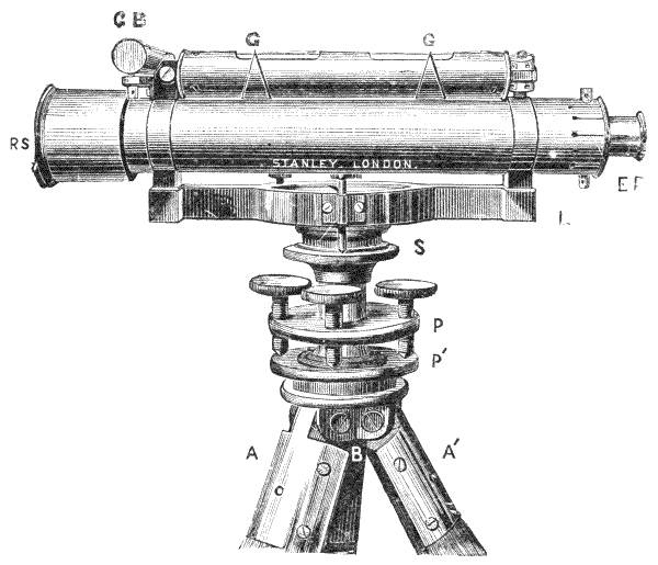
Fig. 59.—Dumpy level.
210.—The Dumpy Level.—One of the most important structural improvements made by the late William Gravatt in his dumpy level, was the addition of a cross bubble, shown end-view in Fig. 59 at CB. This improvement over the old form of Y-level permitted the setting-up of the instrument to be completed approximately, without turning the level[111] a quarter revolution backwards and forwards several times during the operation, as was necessary in the setting-up of the Y-level. The compact form, lightness, and large field of view in the telescope otherwise commended it to civil engineers, when Gravatt had pointed out the possibility of sufficient practical adjustment without resorting to the cumbrous proportions of the Y-level as it was then made. Modern experience has shown that the dumpy form of telescope could very well be applied to the Y construction, and this has been done, as shown in the preceding pages; but at the time the dumpy was invented by Gravatt, the Y-levels were very commonly made 20 inches or more in length of telescope, and were altogether very flimsy affairs. Gravatt's 12-inch level was found to be quite equal in power and of less than half the bulk and weight. A 12-inch dumpy should read the ·01 foot on a Sopwith staff, which is described in the next chapter, at 5 chains with a webbed or glass diaphragm, Fig. 61; with a more open reading than Sopwith's staff a greater distance than this. A 14-inch dumpy should read the ·01 foot at 10 chains.
211.—The Dumpy Level of modern form is represented in the engraving, Fig. 59. It consists of a telescope, fully described art. 94, which carries a ray shade RS at the object-glass end, to work in the field to eastward or westward facing a low sun. The eye-piece EP is adjustable to the webs in the telescope by pressure in or out. Two straps or bands are accurately fitted and soldered round the tube of the telescope; one of these carries a hinge joint, and the other a pair of locking nuts to support the level tube GG, and at the same time permit its adjustment. The level casing tube has two three-quarter bands, which slide upon it, pointed at one end GG: these adjust to the length of the bubble for changes by temperature. The lower part of each strap-piece is left a solid block of metal, to give very firm support to the telescope as it rests upon the limb L beneath. The limb may be either a[112] casting with a socket screw only in its centre, or a compass box may be formed in the centre and the socket screw be placed under this, as it is shown in the figure at S. The attachment of the telescope support to the limb is made by three screws, two of which draw the limb down, and one in the centre presses it upwards, as shown in the section Fig. 60—CC′ telescope, TT′ drawing screws, P pressing screw.
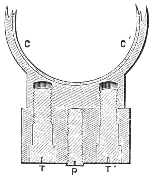
Fig. 60.—Attachment of telescope block to limbs.
212.—It will be seen that by this means firm adjustment may be made either by raising or lowering one end of the telescope, as also by a lateral rocking motion should the web or bubble not be quite to position. This plan is certainly moderately solid, and little fault can be found with it, except that a little torsion may be put on the telescope by unequal screwing, and that it appears slovenly in leaving an open gap between the limb and block; therefore the author prefers in his own form of level, which will be presently described, that the block be solidly fitted down upon the limb, as is shown in the section Fig. 60, and the telescope be placed permanently exactly parallel with it. If the vertical axis be once fixed truly perpendicular to the axis of the telescope as solidly as possible there is very little risk of a bell-metal centre of ¾ inch or so diameter being bent; therefore all parts may be closely[113] fitted between the axis and the telescope. Some makers, instead of screwing down at both ends of the limb, make one end a rocking centre and adjust only by screw at the other end. This plan lacks a little of the stability looked for in the dumpy system. The general construction of the vertical axis is the same as that of the Y-level already described. The parallel plates, tripod head, and tripod are also the same, art. 193, Fig. 55.
213.—As the telescope of the dumpy level does not possess any simple means of determining the accuracy of the fitting of its sliding tube, it is a very important point in these levels that this fitting should be good, so that the object-glass does not droop when extended. For this reason the inner sliding tube of the telescope should be as long as possible, and its adjustment by the rack sufficient to bring an object in focus at 15 to 20 feet distance. This point is sometimes neglected. The author was once amused by a young surveyor bringing him an invention, which was to fix two points by the side of the telescope to enable him to read at short distances. It was seen on examination of his own level that his telescope, a badly-fitted one, would not read at half a chain, hence the ingenuity of his invention. In some cheaply made levels the solid ring fitting to the telescope, above described, which connects the limb firmly with the bubble tube, is replaced by blocks soldered on the telescope with soft solder: the method is very unsound from risk of imperfect soldering. The blocks are very liable to become loosened by a jar.
214.—The diaphragm of the dumpy level is generally webbed with two vertical webs and one horizontal. In use the image of the staff is brought between the vertical webs, which indicate whether it is held upright. The upper margin of the portion of the horizontal web between the two vertical ones is the index of level to which all readings are made, either for adjustment or for reading the levelling staff in the field. The somewhat loose and slovenly four-screw adjustment[114] for a level diaphragm used in rough work with capstan-head screws, shown Fig. 23, p. 50, which is necessary for the adjustment of the telescope in Y's, has been abandoned for many years in the better-constructed dumpy levels by all good makers, and the more solid construction, shown below, Fig. 61, used in the place thereof. In this plan there is no lateral adjustment: the diaphragm is carried as a frame in a dovetail slide, and is adjustable by vertical screws only. The figure shows the face of diaphragm:—BB′ slide pieces, A slide moved by capstan-head screws.
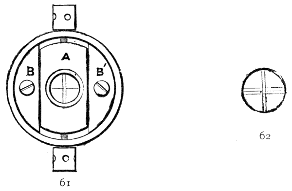
215.—Subtense or Stadia Webs.—It is very advisable in all levels to have two extra webs, or lines cut on glass, placed one on each side of the central horizontal web or line, fixed at such a distance apart that the image of 10 feet of the staff when placed at 10 chains distance may exactly cut the inner space between the lines. These webs or lines may be used as a means of measuring distances often more exactly than can be performed with the chain if the surface of the land is irregular; or, in any case, they form a good check upon chain measurement. If the webs or lines are separated so as to subtend an arc whose chord is 10 feet at 10 chains, it is easily seen that 1 foot of the staff will represent this chord at 1 chain, and that each ·01 of the foot on the staff will represent[115] 1 link in distance. A diaphragm webbed or lined in the manner described is shown in Fig. 62. There is some difficulty in placing webs in exact position, and allowance should be made for the optical conditions by the addition of a plus factor. This important subject will be fully discussed hereafter in Chapter XII.
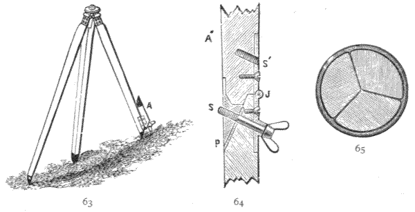
Fig. 63.—Tripod.
Fig. 64.—Section of one turn-up leg of the same.
Fig. 65.—Section of tripod.
216.—Tripods, or Stands.—This matter was deferred when describing the Y-level. The same form of tripod is used for both Y-level and dumpy. In this country the tripod is generally made of straight-grained, well-seasoned Honduras mahogany, which stands better than any other wood. When the tripod is folded up for carrying or for putting by it forms a cylindrical pole which is bellied out at about one-third its length from the top, and diminishes downwards and upwards from this point. For a 14-inch Y-level or dumpy the dimensions of the tripod are about 3½ inches at its greatest diameter when closed, tapering off to 2½ inches at both the top and the bottom ends. For a 12-inch level the section is somewhat less. Each leg of the tripod takes an equal section of the cylinder, the inner angle meeting in the axis being at an angle of 120°, as shown in section Fig. 65. Shovel-pieces are shown[116] in Fig. 59 AA′ (p. 110), attached to the top of each leg by four screws passing from the brass to the wood. There should be also two screws from a brass plate inside the leg to the shovel-piece, making connection brass to brass: this is important, as fixings from the brass to the wood only become loose and shaky by shrinkage. The shovel-piece is formed into a strong tenon at its upper end, through which a bolt passes connecting the book-pieces together. The book-pieces are plates cut to an angle of 120°, so as to fall true on the tenons of the shovel-pieces. Where hand-work is used for making the tripod head, the book-pieces are attached by three screws; where machinery is used, the head is made in the shaping machine out of a solid casting, which is much better. The tripod head carries a screw about 1½ inches diameter with coarse thread, which fits into a socket on the lower parallel plate of the level, whether Y or dumpy. There should always be a plain piece, technically a lead, above the screw. This holds the instrument steady before it is screwed down, and also leads the screw directly to its corresponding thread, thus saving risk of crossing the thread. A common defect in tripod heads is the thinness of the tenon, so that the leg, if twisted, is felt to be rickety. This tenon is better made wide, as shown in the staff head in Fig. 70A, seq.
217.—There is a little difference of opinion as to the form of the woodwork of the tripod for 14-inch levels, some preferring an open framed stand in place of the solid form shown in section Fig. 65. These open framed stands are not so compact to carry, and, as the author thinks, unnecessary for levels of 12 inches and under where the tripod head is solidly made. They are well adapted for larger levels and for theodolites, therefore the description of a framed tripod will be deferred to the discussion of these instruments further on.
A few engineers prefer yellow pine for the tripods instead of mahogany: this is much lighter for its relative stiffness, but[117] it is rather soft for the fixing to the shovel-pieces, and therefore scarcely so reliable as mahogany for durability. Where lightness is important the author employs cedar, which is as light as pine but harder.
218.—The lower points of the legs, technically toes, are pointed to an angle of about 60°, and are shod on the insides with steel plates to bite the surface upon which the tripod stands when the legs are extended for use. Two brass rings slip over and bind the legs together when the tripod is out of use.
219.—Many years ago the author introduced the plan of having one of the legs to turn up at about 1 foot distance from the toe. This is shown Fig. 63 at A, and in detail section Fig. 64. The joint is made perfectly firm by a winged screw at S, which screws from a boss cast on the hinge J to a solid metal shoe P. When the leg is turned up, the screw fixes it in the female screw S. This plan is very convenient for use in mountainous districts, as it enables the level to be set up fairly well without an uncomfortable angle to any of the legs, or risk of the instrument toppling over. This plan is now nearly superseded by a ball joint as a part of the setting-up adjustment.
The tripod head shown under the level of Fig. 59 is by no means the best, but it is the easiest made therefore, it is the general trade form in use, both for the level and theodolite. Some very superior forms will be discussed further on in description of the instruments to which they are attached.
220.—The adjustments of the Dumpy Level.—As this instrument does not possess the means of revolving the telescope upon its axis as with the Y-level, the adjustments are somewhat more complicated, and are performed in an entirely different manner when they are to be made by the civil engineer. The differences are not so great in the hands of the optician, as he generally possesses a movable pair of Y's upon which he can adjust the telescope conveniently for collimation within his own works, by supporting the telescope[118] tube in Y's at a position exterior to the bands which surround it. The tools for this adjustment the author has occasionally supplied upon demand with the dumpy level. But what is necessary here will be to give the mode of adjustment which the civil engineer can accomplish at any time without supplementary apparatus.
The bubble is handier to work with when adjusted to reverse in the centre of its run, but it does not really matter, as equally accurate work can be done with it in any other position. Should the bubble not reverse in the centre of its run, adjust the instrument by the levelling screws until it reverses in some position. Say you start with bubble in the centre, and on reversing, it runs towards the eye end of the telescope six divisions, then alter the levelling screws until it is only half this, or three divisions towards the eye end, then, if properly levelled, the telescope will make an entire revolution with the bubble in that position, which will prove that the axis is vertical. The bubble can now be adjusted by the opposing nuts at the one end by means of the tommy pin (provided in the case) until it is in the centre of its run, and it will then reverse in that position instead of three divisions towards the eye end.
221.—Adjustment to Collimation.—Upon a fairly level piece of ground the staff plate, fully described further on, is trodden well down on the ground, and the level is set up at say 3 chains from this, in which position the staff is read as a back sight. Now in the opposite direction in the same line, at 3 chains distance from the level, a second staff plate, or in defect of this if the surface be not firm, a stake or a boulder, is driven firmly down in the earth, and the staff is placed upon this erect and face to the instrument as a foresight. The instrument is turned half round and the second station is read. These readings of the staves taken will be truly level with each other, if the axis of the instrument has been set up quite vertically, so that the bubble has kept its centre in all positions.[119] This is true although the axis may have been out of collimation. This arrangement is shown in Fig. 66, L the first position of the level taking sights at equal distance from S and S′. Let the level be now removed to L′: if correct it should cut the staves SS′ at equal distances above or below the first readings at aa′, which are at equal distances from bb′ readings from L′, therefore level and parallel with the first reading.
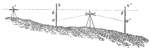
Fig. 66.—Adjustment of dumpy level.
222.—In the dumpy level, as it leaves the hands of any respectable maker, the subsequent adjustments required can never be great, unless the level has suffered a serious fall so as to bend the limb. The rewebbing the stop, if carefully done, would require only a slight readjustment; but it may be convenient to give an exact method for extreme cases, which may be given in detail for clearness, and at the same time we may also consider the influence of the curvature of the earth.
223.—Original Adjustment of the Dumpy Level to Collimation with consideration of the Curvature of the Earth.—Suppose the readings of the two levelling staves at 10 chains apart, taken with the level placed at intermediate distance as before, read 7·50 and 4·50, and that we now place the level linearly at 1 chain outside the first reading and it reads the near staff 6·50 and the distant staff 5·50, by the inclination of the ground, this would be a + and a - reading; but we require both readings of one sign, and as the distant staff reading is much too high, it is clear we require - readings for correction. The correction will be of the difference of[120] reading in proportion to the distances, calling the lower reading minus—
7·50 - 6·50 = -1, 4·50 + 5·50 = +1, difference = 2.
That is -2′, as our readings are - and as the -2′ is in 10 chains, at 1 chain the distance of - the near staff = -·2, and 11 chains the distant staff = -2·2. The correction will therefore be for the near staff 1 chain distant 6·50 - ·2 = 6·30, and for the distant staff at 11 chains 5·50 - 2·2 = 3·30 = -1·2 below each of the first readings. If the telescope be now collimated to the near staff reading 6·30, by adjusting the screws immediately under it for distance between the limb and the telescope, and the bubble be readjusted to the telescope without moving the instrument or touching the parallel plate screws, the adjustment will be perfect, less the small error due to the earth's curvature in 1 chain. If the telescope be adjusted to the distant staff 3·30, curvature of the earth will be corrected by the level for 11 chains, which is 0·0106 foot or ·01 nearly, the smallest reading we have on the staff.
224.—It was claimed by the late William Gravatt for his method of adjustment,[3] which was equivalent to that given above, but more complicated and with three staves, that the fixed correction for curvature at 10 chains would be uniform in the working of the level pro ratâ for all distances. There is some difference of opinion on this subject: at any rate, a 10 chain correction would only be applicable to very approximately level ground where average 10-chain stations could be taken.
225.—Where space is not at command and curvature correction is not desired, adjustments of the level may be made with care at 1 chain distance on each side of the setting-up of the level with one staff only, which can be moved from one stake to the other, and with the final setting-up of the instrument at 1 chain distance from these stakes as before, [121] art. 221. For this the staff only requires moving twice, if the collimation adjustment is to the last reading only calculated out as above. This close system has a certain amount of merit, that by reading from one staff only for both stations it is more accurate, as any inequality between the divisions of two separate staves is avoided.
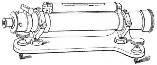
Fig. 67.—Collimator for adjustments to horizontality of the telescope.
226.—Collimator.—Optical manufacturers in populous districts, and some observatories, as that of the India Store Department at Lambeth, adjust by means of the collimator by the exact method due to the late eminent German mathematician, Carl F. Gauss, which is hence termed the method of Gauss. The collimator consists of any good telescope permanently adjusted to solar focus, with a webbed diaphragm placed in the focus, where it may be illuminated by a lamp or by the reflection of daylight, and provided with means of bringing the telescope to a level position. As the collimator is generally constructed, it consists of an 18-inch telescope, Fig. 67, of the same description as that used for a Y-level, described art. 94, in which the telescope is surrounded by accurately turned collars formed to rest in Y's. The Y's are supported upon a heavy cast-iron stand, of somewhat triangular form, of nearly the length of the telescope, about 6 inches wide at one end and 2 inches at the other. The stand has two feet extended to the full width at the wider end, and one foot at the narrower end under the telescope. Each foot[122] has an adjusting screw. The complete collimator is supported, at about the height of the telescope of the level on its stand, on a very solid pier of stone or brickwork in cement capped with a stout slate slab. The telescope is brought to perfect collimation as with the Y-level, already described art. 200, and the level is fixed true with the axis of the telescope, when the collimation is perfect.
227.—A lamp or gas flame is placed at a short distance from the eye-piece end of the telescope, so as to illuminate the webs that they may be distinctly seen when looking into the objective end of the telescope. In bright daylight, if there is a skylight over, a reflector will answer the same purpose. At the Lambeth Observatory a fine needle-point hole is used instead of webs.
228.—The instrument to be adjusted may be placed at any convenient distance from the collimator. For adjustment of a level, where the collimator is already in adjustment, the level is raised upon its stand until the axis of the telescope sensibly coincides with the axis of the collimator; then if the telescope of the level to be adjusted be focussed into the objective end of the collimator, the illuminated webs will be clearly seen; and if these webs be brought by adjustment of the level exactly to coincide with its own webs, the collimation lines of the two instruments are exactly parallel. In this adjustment it is only necessary to be sure that the vertical axis of the level is truly vertical, so that the bubble reverses without displacement, in which case the whole instrument must then be in perfect adjustment.
229.—It would be very difficult to use this method of adjustment if it were necessary that the axes of the level and collimator should exactly coincide. It is only necessary that they should nearly coincide, on account of the imperfection of object-glasses, which rarely work so well near the edge as towards the centre; otherwise any directly parallel position in front of the object-glass would answer, as the next diagram[123] will show. Let O, Fig. 68 be the object-glass of the collimator, whose solar focus is at F. Then the rays PP, and all other parallel rays falling on the object-glass, will be brought to a focus at F; and reciprocally all rays departing from F in passing through this object-glass will leave in parallel lines PP. Let O′ be the object-glass of a telescope to be collimated, F′ its solar focus. Then all rays from P to P departing from F that fall within the parallel space P′P′ will be brought to focus at F′. When the image at F is illuminated by a lamp L, the webs or other index will be clearly seen by the eye-piece at F′ when the two telescopes are exactly parallel with each other. In this position the webs of the level are adjusted to make this coincidence. It is easily seen that by this method we eliminate all errors of atmospheric refraction, and are quite independent of the state of the atmosphere for obtaining distinct vision for adjustment.
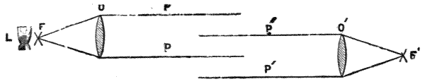
Fig. 68.—Diagram of collimation by two telescopes.
230.—When two levels are at command, one a Y-level, or even a dumpy in perfect adjustment, the one may be used as a collimator to the other by setting them up at a distance within their focal range on a firm basement floor. A candle or a lamp will give sufficient light to illuminate the webs of the instrument, which is used as a collimator, being certain, of course, that this instrument is first placed in level adjustment and set at solar focus, and that the instrument used as a collimator has a good object-glass.

Fig. 69.
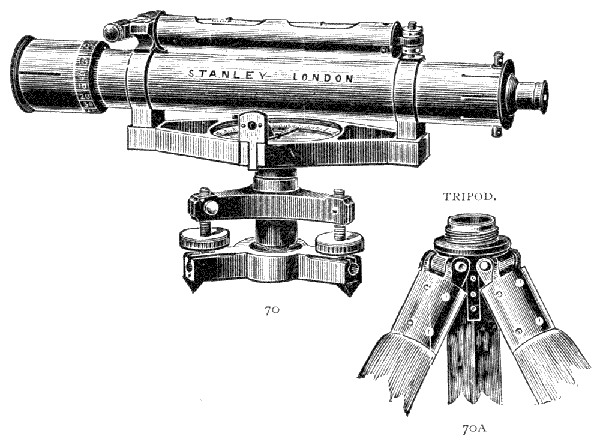
231.—Improved Dumpy Level.—The writer has made some improvements in the dumpy level, which have so far met with very general approbation from the profession, Fig. 70.[124] These improvements are directed to ensure much greater sensitiveness in the longer bubble, therefore greater accuracy in the work performed by it; more solidity of construction without increase of weight; and permanence of reading index, with some additional matters. In these improvements the mounting of the longer level tube, instead of being placed in a stiff joint at one end, or between rigid clamping nuts at both ends, has a barrel-fitting at one end which is ground into a parallel hole. This plan admits of circular self-adjustment to[125] the bubble tube, which the clamping of the nuts can never twist or strain during vertical displacement; and the joint can be made perfectly sound with certainty, which saves the risk of accident to the bubble from expansion by heat and some other conditions. A more recent form of cross level, Fig. 69, shown in perspective near the ray-shade in the engraving Fig. 70 has been designed by the author, in which the level casing is bored entirely out of the solid. It is supported upon the side of one telescope strap by three stout pins, the centre one fitting its hole, and the two outer ones are loosely held by cross screws to permit a small amount of adjustment, which is all that is necessary. By this construction the level fixings are made in five pieces only, including screws, instead of thirteen as usual, at the same time making the level more portable and solid for hard wear. The telescope straps are fitted at their stumps solidly down upon the limb, as shown Fig. 60, p. 112. Adjusting screws are placed under this as in the dumpy level described, but the pressure screw is not employed except in case of accident far away from an optician, when it is found to be there ready for use. The limb is framed out into two edge bars: this gives greater vertical sectional strength and resistance to torsion without increase of weight in the instrument. Where a compass is used, this is included in the frame of the limb, as shown in the engraving. The compass is read with a prism, this being much more convenient and exact than looking down upon the divided circle, the instrument being necessarily placed for use at nearly the height of the eye. The compass ring is made of aluminium.
232.—The further improvement, which the author considers of the greatest moment, is that the vertical axis is fixed directly and firmly upon the limb, and not through a loose screw fitting for separation at this point as in the ordinary dumpy. This is shown to be important in that, with the dumpy, where a loose screw is employed, any little difference[126] of screwing down upon the axis when the instrument is set up causes so much derangement of a sensitive bubble in relation to the vertical axis, that the optician is bound to use a rather dull bubble with the ordinary dumpy. Further, a particle of grit or the slightest bruise on the collar in replacing the instrument in its case throws it out of adjustment at this important point. The objection to the author's plan is that it makes the case for the instrument somewhat larger; but the advantage of certainty of permanent adjustment appears to him very far to counterbalance this objection where accuracy is aimed at.
233.—Tribrach.—The setting-up adjustment of the instrument is upon tribrach limbs with three screws only. These screws can never strain the vertical axis, which in this instrument is somewhat deeper and more firmly made than that of the dumpy. In the old form of tribrach the points of the screws were held down by a spring plate placed above them. This plate, in carrying the instrument upon its stand over the shoulder, which is the most comfortable way if the stations are not far apart, was very liable to strain sufficiently for the screws to get loose. The author patented a much more solid method, by which the old spring plate is entirely dispensed with. In this plan each screw has a ball at the lower end, which is inserted in a tubular fitting formed in a solid tribrach, made of exact dimensions to take it. The tube is open on the upper side, as shown in longitudinal section H, Fig. 71. Many years' experience and the fact that numbers of makers have copied this form since the expiration of the patent, shows this plan to be perfectly successful. The general construction of the lower part of this level may be seen from inspection: L limb, fitted with compass; C axis, in one casting with the limb; S sprang, carrying the socket and supporting the instrument. PH shows the ball head arrangements to the screws. A central screw in this part detaches the tripod. One point is shown[127] at P, of which there are three, to support the level upon a wall or rock in cases where the tripod cannot be used—a most important advantage in town levelling. The tripod head is made much more firmly than that of the ordinary construction, by extending two wing fittings from the top of the shovel-plates as wide apart as possible, instead of the narrow tenon fitting before described. The shovel-plates are screwed to the staff by means of a stout nut-plate inside the tripod F. Those who have experienced how much defective levelling is due to a shaky tripod head will appreciate this precaution. The general arrangement is also shown in Fig. 70A.

Fig. 71.—Details of Stanley's dumpy level: half elevation to left, half section to right.
234.—As the tribrach system of adjustment is of somewhat recent adoption to ordinary surveying instruments in this country, it strikes the stranger to it as being more difficult in use. It is really the most simple and expeditious system as is clearly explained by the foregoing diagrams, Figs. 72, 73 of the plan of a level, omitting its lower parts.

Figs. 72 and 73.—Tribrach adjustment.
235.—The bubble of the level is placed parallel with two of the screws of the tribrach, that is as B and C, Fig. 72, and is adjusted to the centre of its run. It is then placed at right angles to the first position, so that the screw A comes directly under the bubble, to be adjusted by this screw only until it again comes in the centre of its run. Fig. 73 shows this second position with the screw A underneath. The level should after this read all round true, but it is well to try it round parallel with the different pairs of screws in all positions to give small adjustment if required. Where there is a cross bubble the level may remain for adjustment in its first position, but it is well to try it all round, as the long bubble is made uniformly the more sensitive.
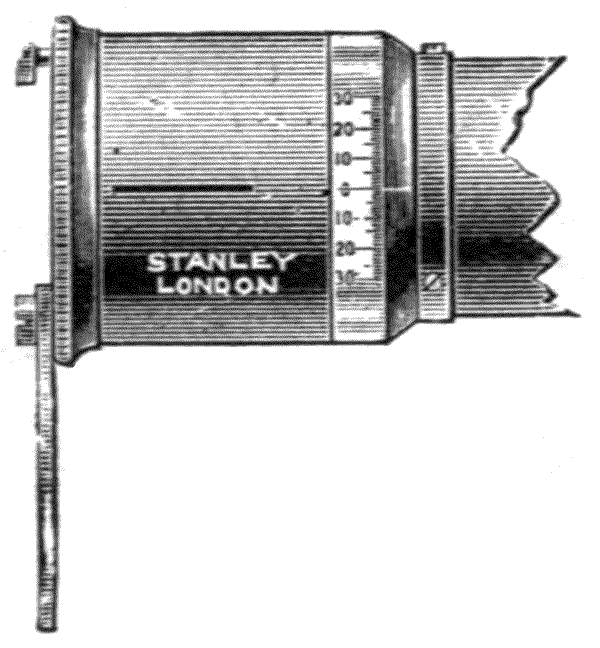
Fig. 74.—Ray shade.
236.—The Ray Shade to the telescope used in the above-described level has two narrow slits opposite each other at 180°. A zero line is carried from one slit to a line on the ray shade fitting when the slits are quite horizontal. Sights through the slits at zero enable an approximate cross-level to be taken. The edge of the tube of the ray shade is divided 30° on each side of the zero line to 2°, so as to take approximate lateral inclines of the surface of the land in levelling. This useful plan of cross-sighting was originally proposed by Gravatt.

Fig. 75.—Stanley's platino-iridium point level stop.
237.—The most important variation from the telescope of the dumpy level described is in the diaphragm, where webs or lines of any kind are entirely done away with, and are replaced by a special form of index. This is represented in Fig. 75. The movable part carrying the opening of the diaphragm is[130] placed in a sliding fitting, as previously described, art. 214, for the dumpy level. The index which replaces the web is a finely-pointed needle formed of platino-iridium (platinum ·75, iridium ·25). This alloy has about the hardness of spring-tempered steel, and is, as far as known, perfectly non-corrosive in air or moisture. A pair of vertical points indicate the position for holding the staff. It will be found by experiment that the point reading is much more exact than with the web, as irradiation due to edge reading of the web is entirely avoided, and also the covering of the object as it would be intersected by the web due to the angle its thickness subtends upon the staff, which is very palpable at 10 chains distance. The iridium point is sufficiently strong to be kept perfectly clean by touching it occasionally with the point of a camel-hair brush if it appear dusty. With care this point will last in adjustment for as long a period as the level itself remains in use. Upon first impression the point may not appear so fine as a web, but practically it is more exact, as the previous exaggerated images will show—Fig. 76 is the image of a division of the staff partially covered by a web WW′; Fig. 77 that of a magnified image of the point P brought towards a division for reading. It will be readily observed that the fractional part of the 1/100 foot block, which the point P cuts, is much more easily estimated than that in which the web WW′ covers a part of a similar block.

238.—In early levels of improved construction, as shown Fig. 70, a difficulty was experienced in practice in bringing[131] the index point exactly up to the edge of the line as it is shown in Fig. 77 at P. This difficulty has been obviated in recent highest class instruments by making a tangent screw adjustment to the axis as shown under the level in Fig. 78. There was a great objection to the old form of tangent adjustment by clamping on the axis, as this was found to disturb the centre. In the plan shown in the illustration the clamp is left free by jointing to the axis until it grips one of the arms of the tribrach upon a vertical surface; in this way it cannot disturb the axis. The level, Fig. 78, is shown mounted on a framed stand, which is preferred by the Indian Government, and is generally necessary for rigidity for large instruments of over fourteen inches. This will be described further on with theodolites, art. 447, on framed stands.

Fig. 78.—Stanley's improved dumpy.
239.—Stadia Points.—The author commonly makes the points, Fig. 75, VV′ stadia points, by making the distance of the extreme ends of these subtend an angle, equal to 10 feet of the levelling staff at ten chains distance, or 1 foot of the[132] levelling staff at 100 feet distance (+ a constant to be discussed Chapter XII.), by which measurements of the distance of the staff can by taken or checked by observation through the telescope only.

Fig. 79.—Stanley's quick setting-up level.
240.—Quick setting-up Tribrach.—One objection has to be made to the tribrach over the four-screw system of adjustment, that the four-screw admits of greater inclination to the tripod, which is important in hilly countries. To remedy this defect the author designed a ball arrangement to the axis, which permits the level to be set 15° to the inclination of the tripod independently of the screw adjustment, so that the level, when the tripod is set at its best angle, may be brought immediately to nearly its final position. The arrangement is shown in the engraving Fig. 79. The axis carries a cup formed in the metal casting, which can be clamped down upon a ball-shaped recess formed upon the tribrach by means of a winged nut placed under it, the wings of which project between the tribrach screws. A very slight pressure is sufficient to firmly clamp the ball. This form of level is now very popular with civil engineers. With a point diaphragm and a tangent screw to the axis, not shown in the engraving, it is, in the author's opinion, the best practical level he has been able to design.
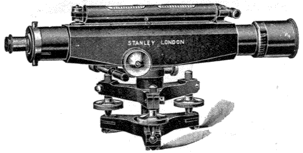
Fig. 80.—Stanley's Engineer's level.
Since the last edition was written the reviser of this work introduced, in conjunction with Mr. Stanley, his new solid bodied engineer's level, which has practically revolutionized the form of dumpy level and has proved such a success that more of this form are now made than all other forms put together. In this level, Fig. 80, the centre, body of telescope, object end and bubble fitting are all combined in one piece of gun-metal, so that although of vastly greater strength and rigidity it does not weigh as much as the old form of tubular body with its collar and stage. This does away with many separate pieces which are usually soldered and screwed together. It thus forms the strongest and most compact level yet made, and with ordinary care it will last in perfect adjustment a lifetime. The pinion for focussing is fitted to the side of the cast body, instead of to a tube, thus greatly increasing its firmness. Its form is equally adapted to the four-screw levelling if desired, as shown on next page, Fig. 81, in which it will be seen the four-screw levelling is of much improved form, giving greater strength and far more wearing and bearing surface to the levelling screws.
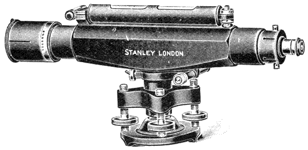
Fig. 81.—Stanley's Engineer's level.
The reviser has also patented a new form of spherical joint, which has met with equal favour. This improvement consists of a section of a ball (screwed to fit the stand head)[134] fitted within the lower plate and a simple means of clamping it in any position, which, when released allows of sufficient rocking movement in any direction to compensate for any uneven setting up of the stand. It does not add to the height of the instrument, may be instantly set nearly level, and less than half a turn of the levelling screws will bring the instrument into true position. It is shown fitted to the new engineer's level at Fig. 82 below, but is equally applicable to any other form of instrument.
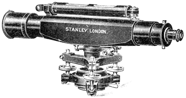
Fig. 82.—Stanley's Engineer's level fitted with quick setting spherical lower plate.
As ninety per cent. of the orders now for levels are for the form shown at Fig. 82, the reviser ventures to think that[135] this must be favoured by the profession as the best practical instrument yet made.
A further improvement has been made by making the diaphragms interchangeable, so that any form of diaphragm that is preferred may be instantly fitted without disturbing the adjustment, and when lines on glass are used it may be removed for cleaning, and replaced without interfering with the adjustment.
The diaphragms illustrated below, Fig. 83, are usual forms, and it is recommended that when webs are preferred a glass one should be carried as a spare in case of accidents.
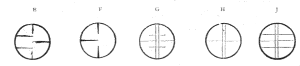
E Stadia points for clamp and tangent levels.
F Stadia points for ordinary levels.
G Stadia glass diaphragm.
H Webs.
J Stadia webs.
Fig. 83.
241.—The further discussion of the subject of high-class levels becomes somewhat difficult. Leaving out of consideration the levels sold by the trading optician, who deals in the commercial article but sometimes superadds a little fad, every genuine manufacturer has his pet plans of carrying out details, some of which may be very meritorious, but which could scarcely be described without a fuller discussion than our space permits. There is also, no doubt, a great number of mistakes that have been made in the construction of surveyor's levels. The direction in which the scientific optician generally fixes his attention is to give the advantages of the Y-level in the dumpy form, assuming the civil engineer holds a certain amount of prejudice against the use of the Y, for which, in its old form at least, the writer must admit that he[136] was fully justified. Whether the professional man, nevertheless, will ever depart from the solid construction of the dumpy remains an open question.

Fig. 84.—Cushing's 12-inch improved level.
242.—Cushing's Level.—The level illustrated above, Fig. 84, by the late Mr. Thos. Cushing, F.R.A.S., Inspector of Scientific Instruments for India, would under any circumstances claim attention, from this gentleman's well-known high technical scientific attainments. It has also the merit of being in practical use in India at the present time.[4] The principal improvement in this instrument over the dumpy form, which it otherwise represents, is in the construction of the telescope, which is said to possess all the necessary adjustments of the Y-level. The telescope is firmly fixed in collars soldered to the tube, as in the dumpy. The tube at each end is formed into a stout socket collar. These socket collars are exactly alike, and are ground to fit either the objective or the eye-piece end of the telescope, so that these [137] parts may be reversed, the one for the other. This reversing is nearly equivalent to turning the telescope end for end in the Y-level. The end also rotates in its fitting, which is nearly equivalent to rotating the telescope half a revolution in the Y-level. The reversible ends of the telescope are held in their ground fittings by studs and slides (bayonet notches). It is easily seen that by this plan adjustments may be made of collimation and of fixing the line of collimation perpendicular to the vertical axis, as with the Y-level, if the object-glass be originally correctly centred. The stop is of the slide form described for the dumpy, Fig. 61, and a glass diaphragm is used. One important arrangement is also made in this part of the instrument—which is necessary, as glasses become frequently bedewed in the telescope—viz., that the eye-piece end may be removed from its ground fitting and the glass cleaned and replaced without disturbing the adjustment in any injurious degree. The general construction of the instrument can be seen from the illustration. The supports of the telescope have a rocking axis at one end, and are adjusted by capstan-headed nuts at the other. The adjustable support for setting up the instrument is upon Everest's tribrach system for theodolites, to be described further on, in Chapter IX. The tripod head has also wider bearing than is general, which is attained by extending the book-plates into the form of a socket fitting. The illustration given is of a 12-inch level; in the 14-inch an open framed stand is used in place of the solid tripod, as in Fig. 78, which will be described further on, for theodolites. The level is a decidedly good one; but the author has experienced with it some slight defects when compared with his own Y form. The ground collars are a little inclined to bite, particularly if the instrument has been laid by for some time, so that in reversing for adjustment there is great risk of disturbing the instrument. The glass index, although permanent, has the same defect as the web—of covering the image of the staff reading. It also[138] obstructs a little light, and is subject to dew, which the point system avoids. The weight of the instrument is increased by the collar fittings.
243.—Cooke's Level.—An instrument somewhat equivalent to the above has been patented by Messrs. T. Cooke & Sons. In this, instead of the objective and eye-piece ends of the telescope only being reversible in the collar fittings, as in Mr. Cushing's level, the entire telescope reverses end for end in an extra outer tube, which is fitted between the collars. This tube also permits the rotation of the whole optical parts about the axis of the telescope for adjustment for collimation, although in a manner more frictional, and therefore more likely to disturb the instrument than in the simple Y adjustment. In this instrument, again, it is easily seen that it is the perfection of the Y-level, without its outward appearance, that is aimed at, and to gain this the weight is increased by extra fittings and double tubes, which are liable to become fixed by a slight dent upon the outer tube. Taken altogether it is not quite so convenient or so simple as the best constructed Y-level; but if it gives the adjustments the optician holds to be most important, in a disguised form it may be acceptable to the civil engineer. We may in this manner, perhaps, from the optician's point of view, count it a certain gain in the same direction as Mr. Cushing's level just described; but if we may accept the late Mr. Wm. Gravatt's ideas, already mentioned, the complication is unnecessary.
244.—A few other structural variations of details may be mentioned, as these are constantly cropping up as new inventions. The bubble tube is sometimes placed upon the stage instead of being upon the telescope. This is thought to protect it. It is not, however, so easy to read it in this position. The compass is sometimes made a loose part—when it is not required on the work its weight is saved. Various forms of locking screws are made to the supports of the telescope; these are only necessary to correct imperfect[139] work. The axis collar is sometimes extended to a limb bearing. This is common in French instruments; it makes the movement stiffer, and is quite unnecessary unless the axis is made too short. A well-known German firm recently brought out a level with internal focussing, by means of an auxiliary lens mounted in a tube inside the telescope, moved by a rack and pinion, but any internal lens is a source of trouble, as it cannot be got at to be cleaned, and in hot, damp climates it becomes bedewed. The device is very old, having been patented in America many years ago and discarded.
245.—Supplementary Parts to Levels.—As a rule, supplementary parts fixed to the instrument, beyond the magnetic compass sometimes required, are very objectionable if the object of the level is to be levelling, as these additional parts inevitably increase the weight which has constantly to be borne in carrying the instrument. Supplementary parts have been carried, in various schemes, to the extent of combining the entire level with the theodolite, at the same time nearly combining the united weights of the two instruments. As a rule, professional men rarely care for complex combinations; and even after a limited popularity is granted to extra parts not absolutely required, these are generally finally abandoned. Mention of two such parts, therefore, only will be made, as these owe their introduction to the late William Gravatt, and are found applied to many levels in use, or at least contained in the case with the instrument.
246.—Bubble Reflector.—This was formerly placed upon all dumpy levels. It consists of a small mirror about 2 inches by 5/8 inch fixed in a frame that is jointed at its lower end to a short piece of tube partly cut away so as to form only a little over a semi-cylinder. This tubular part just clips firmly upon the brass casing tube of the spirit level. The reflector, when placed vertically on the level tube, can be adjusted by its joint, so that the run of the bubble may be observed by reflection in looking above the eye-piece to see[140] that it is in adjustment at the time of taking an observation. Its use was thought to be a precaution in levelling, particularly on marshy ground. The observation of the bubble is less exact than by a side reading, and cannot be relied on.

Fig. 85.—Compact cheap form of dumpy level.
247.—Sight Vanes.—Two sight vanes are placed above the telescope, either as loose fittings or to hinge down upon the level tube. One vane has a vertical narrow slit and cross hair; the other has a window with a vertical horse-hair placed in its centre. This arrangement gives sight of distant landmarks in line with the direction of the telescope, upwards or downwards, beyond its field of view. A slider, fixed upon the window sight, reads at its upper edge into divisions cut on the vane, by means of which an approximate rate of forward inclination of the land may be taken. This sighting arrangement adds about half a pound weight to the instrument. It was useful with object-glasses of small field of view, but is useless with good modern glasses of wide angle.
248.—Lower-class Levels.—A level is often required by an architect or a contractor for works of limited area, where it is quite unnecessary to go to the expense of a civil engineer's level of refined manufacture. In such cases the level may only be used occasionally and under favourable circumstances, so that extreme solidity is not demanded, neither is distant view in the telescope required. The level generally made for such work is a simple dumpy, without cross bubble, compass, or any extra fittings, and with one eye-piece only.
249.—The instrument Fig. 85 illustrates the author's newest design for a simple level. It has a light form of tripod. The legs clamp directly between angle plates—these are not quite so portable or so neat as cylindrical legs, but they are easily made, very firm, and will bear considerable wear and keep in order. A still cheaper form is made with smaller telescope and turned legs for the tripod.

Fig. 86.—Contractor's or builder's level.
250.—The illustration Fig. 86 represents the cheapest form of level with a tripod stand that has been constructed,[142] which contains the important factor of a telescope. The telescope has a sliding fitting, which is moved by a knob outside, this being made more quickly than a rack and pinion fitting. The level tube is solidly supported in collars. The adjustment is in one direction only, so that the bubble must be set and examined at the time of reading the staff. The instrument is supported on a sprang, jointed at one end and held by a milled-headed screw at the other. Any shakiness of the thread of screw there may be is taken up by a stiff German silver spring between the sprang and the limb. It is sometimes made with a ball and socket joint for first adjustment, but this renders it nearly as costly as a superior level. The tripod head is of simple construction. The legs are oak or ash, and are clamped on the head by bolts. This simple tripod is fairly firm in use. The level is good enough for ordinary building works, laying short drains, etc., within limited areas. It is much more accurate than any form of open sighted level without telescope. Sir George Leach has recently made a modification of this old form of level by placing a pendulum to rock the axis to cross level position, which is a refinement, although rather a costly one.

Fig. 87.—Sighted reflecting pocket level.
251.—Sighted Pocket Level.—This consists of a tube, which is generally drawn of square section. A pin-hole sight is made in the closed end of the tube, Fig. 87, at E. The field end of the tube is left open. The sight is taken by looking through the centre of the pin-hole across the edge of the reflector R. A level with a small bubble is placed[143] or inserted in the top of the tube at B. The metal casing of this is cut away on the upper and under sides to render the bubble visible from the interior of the tube by means of the reflector R, which occupies one half vertical section of the interior of the tube. This is placed at 45° to the axis. The reflector is fixed upon an inner tube so that it may be withdrawn to be cleaned. When the level is set horizontally, a distant object in the direct sight line is seen through half the tube, and simultaneously the reflection of the bubble in the other half appears. A line engraved upon R indicates when the bubble is central, and when these coincide the distant object and the eye are level. The instrument is about 4 inches long, and weighs about 8 oz. in its case.

Fig. 88.—Pocket telescopic level.
252.—Pocket Telescopic Level.—In the above-described pocket level, where it is made short, the average middle-aged man will not have sufficient accommodation of vision to be able to see the bubble and the screen sharply defined simultaneously with the distant object to which the level is to be taken. In Captain Barrie's[5] level these objections are avoided by making the reflector and bubble form part of a telescope, Fig. 88. An achromatic glass of short focus is used, and the eye-piece is of long focus so as to bring the bubble to focus in the centre of the mirror, which is made of curved form to decrease the apparent size of the bubble. The image of the bubble does not give by bisection a very definite index. The author has found that this level may be much improved by placing a point in the telescope at the mutual foci of the [144] object-glass, eye-piece and the bubble. The appearance of the mirror and point is shown at B. The point is shown by a dot at P. The curved mirror R. The dotted line shows the path of reflection from the bubble. This level will work with very fair accuracy as a hand instrument. Size, about 4½ inches by ¾ inch. Weight in case, about 8 oz.

253.—Reflecting Level.—This simple level, Fig. 89, the invention of Colonel Burel, is one of the most portable. When it is used with a fair amount of care it will give good approximate results. It consists of a piece of parallel glass, which has half the surface silvered to form a reflector. It is suspended in such a manner that the glass hangs vertically by gravitation. The position of the mirror to the plain glass may be that shown in the engraving, or horizontally if preferred. The mirror, Fig. 89, is inserted in a solid metal frame suspended from a gimbal, which permits it to hang perfectly free to the action of gravitation. The centres of suspension are made with slightly-rounded knife-edges. A ring at the upper part of the instrument is placed over the thumb or finger to support the instrument when in use. A stout pin passes through a prolongation of the lower part of the frame, screwed or otherwise, which permits adjustment by filing to[145] bring the mirror when it is suspended exactly into a vertical plane. The instrument, fitted into a neat case, weighs from 5 oz. to 9 oz.
254.—In using the Reflecting Level, it is held upon the thumb at about arm's length, and adjusted by raising or lowering the arm until the reflection of the pupil of the eye seen in the mirror is exactly bisected by the line cut by the mirror against the clear glass. The distant object seen in front, that cuts this sight line and the image of the pupil of the eye, will then be in true level position with the eye of the observer, provided the air is still, so that the mirror is not deflected from verticality. From the natural unsteadiness of the hand there is some little difficulty of getting this level quite free from oscillation. This may be obviated, or nearly so, by clutching a picket or staff with the hand and suspending the level from the thumb projected out for the purpose, or by resting the hand against a tree or other firm support. Capt. A. H. East, R.A., has suggested to the author a very capital device which he employs for hand instruments. This is to place the handle of a stick (or umbrella) in the waistcoat pocket, to clutch the body of the stick with the hand which holds the instrument, and to steady it with the other hand. In this manner the two arms and the stick form a tripod of surprising steadiness.
255.—Reflecting Level in Case.—In windy weather much greater exactness may be secured by placing the pendulous level, just described, in a tubular case, Fig. 90. The case is made of double tubes, so that the aperture cut on one side may by a half turn of the outer tube close and protect the instrument when out of use. The transparent side of the inner case is sometimes closed by thin glass tube of its own internal diameter. It is much better if made with two vertical sides glazed with parallel glass. When this form of instrument is used, it may be, if required, made to fit on the top of a light staff. The eye is then brought with much[146] greater certainty to the point of bisection on the edge of the mirror, and much greater accuracy is thus attained in levelling with it.
256.—Water Levels.—The antique form of level, composed of two vials fixed on the ends of a tube and partly filled with water, by which a level is sighted in looking over the surface of the water, is still used to a limited extent in rural districts on the Continent; but the spirit level in some simple form is fast superseding it. The same principle of level, but with long tube, has been found convenient for the surveyor in measuring through close buildings, Fig. 91.

257.—Browne's Water Level[6] is found to be a convenient instrument for levelling in close towns. It consists of a pair of glass tubes of about 2 feet in length, placed in a casing tube for protection. The casing tube is divided into inches and parts, or the scale is a detached piece of painted wood, or any rod or rule. A cock at the bottom admits the water to flow to level in the pair of tubes, one of which is shown, Fig. 92. There is a handle at the top which unscrews to fill the level, and a small air cock. It is easily seen that the water finds its level, and the difference of reading of the [147] two standards is the difference of level of the surfaces upon which they are placed. By closing the cocks the level is made portable. In this position it does not matter how high the centre of the pipe is placed—for instance, in crossing over a wall—as the water will still find its level when the cocks are released by syphoning the water from the one side or the other. It is a very convenient and exact level for laying drain pipes in open weather, and for making foundations for heavy machinery, etc., but of course it will not stand frost.
Platelayers' levels and mechanics' levels generally are deferred to consider with useful hand tools and apparatus employed by surveyors in the final chapter.
LEVELLING STAVES—CONSTRUCTION—VARIOUS READINGS DISCUSSED—SOPWITH'S—FIELD'S—STRANGE'S—STANLEY'S NEW—METRICAL—SIMPLE CONSTRUCTION MINING STAFF—PAPERED LEVELLING STAFF—PRESERVATION—PACKING PADS—STAFF PLATE—STAFF LEVEL—PRACTICE OF LEVELLING—INDEX OF BUBBLE—LAMP—CURVATURE CORRECTIONS—STATION PEGS—REFINEMENT OF LEVELLING—LEVELLING BOOKS—INK BOTTLE, ETC.
258.—Levelling Staves.—Since great improvements have been made in the telescopes used as part of all modern surveyors' levels, particularly by increasing their light-receiving capacity, all systems of vanes which were formerly made to be seen distinctly at a distance have disappeared from use by British surveyors; it is now found that the plain reading of a divided staff can be taken by means of the telescope at a sufficient distance from the observer for all practical purposes. In this country one construction of staff is now generally adopted; and the only variations that are made in this are found occasionally in the readings. The construction of the level staff in common use is that invented by the late Thomas Sopwith,[7] called the telescopic staff, the face view of which is shown Fig. 96. For ordinary open field work this is made 14, 16, or 18 feet in its extended length; but generally, except for levelling on mountainous land, the 14 feet is used. This staff when closed is about the same length as the tripod, [149] 5 feet 4 inches, and may be conveniently stowed away under the seat of a railway carriage. Sopwith's staff, as it was formerly made, consisted of two square parallel tubes and one inner solid parallel slide. Made in this manner it was liable to be rather shaky when extended, besides which it frequently got jammed in the telescopic boxes if put away damp from rain: this tended at first to limit its use. It is now usual to make the boxes slightly conical, that is, diminished towards the upper part, so that they are rigid when opened out but are very free when closed, which quite remedies the defects just mentioned.
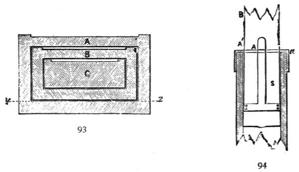
Figs. 93, 94.—Section of Sopwith's staff.
259.—The ordinary construction of Sopwith's staff and the best mode of manufacture is shown, with the joints grooved together, in section Fig. 93. The outer tube or case A, which in the 14-feet staff is 5 feet in length, is made of mahogany 5/16 inch thick, the front being ¼ inch. The outer dimensions of the section are 3-1/8 inches by 2 inches. The second tube B is 5 feet 1 inch long, of outer dimensions 2-3/8 inches by 1¼ inches. The inner slide C is solid, 5 feet 2 inches long, 1¾ inches by ¾ inch. All the slides are sunk on the face about 1/16 inch to prevent the divisions being rubbed by exposure in sliding together. The slides have each a brass shoe and cap. They are held when extended by[150] a spring catch, the detail of which is shown in Fig. 94, section y to z of Fig. 93—S spring of T form screwed firmly to the edges of the box. The catch is made at A over the edge of the brass cap A′. The spring should be of very hard rolled brass. It is well to have one or two brass bands round the body of the outer casing to secure this as far as possible from being split by accident.
260.—The most important consideration in the manufacture is that the telescopic work should fit well, and that the boxes should be glued up quite square and out of winding. The boxes should, after the glue is quite set, be screwed with brass screws at distances of about 6 inches apart, to secure the joints which may afterwards in use be exposed to long-continued rain. The fittings should be carefully made, so that when the staff is extended there should be no shakiness sufficient to cause serious vibration when it is used in windy weather. The interior of the slides when finished should be thoroughly oiled with raw linseed oil, and the outer surfaces be well soaked in shellac dissolved in spirit, and then French polished over this. The brass work should be well lacquered.
Fig. 95.—Section of semi-cylindrical staff.
261.—Semi-circular Staff.—This is another kind of telescopic staff, with Sopwith sliding arrangement, which possesses a certain merit, but is more expensive to make. It is semi-cylindrical, the cylindrical part being made without any joint. This is shown in the section Fig. 95. The general dimensions of the face of the staff are the same as those[151] given for the Sopwith staff. This staff is a little stiffer, but there is more risk of its not standing true. As in the union of four pieces of wood in the square form, previously described, the tendency of one piece to warp in a certain direction is resisted by the other pieces; but in this cylindrical form there is no such resistance, so that it is found that these staves when exposed to wet are much more liable to become warped and fixed in their slides. There is also more difficulty in getting the conical form fairly accurate in the working. One particular merit, when a pair of staves of this kind is used, is that the two go together and form a cylinder, which is a very compact form, but perhaps a little more difficult to carry, owing to the tendency of a cylinder to roll off the shoulder.
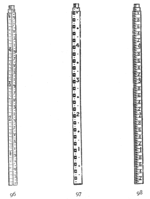
Fig. 96.—Sopwith pattern staff.
Fig. 97.—Field's pattern.
Fig. 98.—Stanley's old pattern.
262.—What was originally considered as the defect of the[152] Sopwith staff, besides its shakiness, as it was first made, was the diminished width of reading of the upper length, this being only 1¼ inches wide. This caused for a long period other forms of staves, which maintained the same width of reading surface quite to the top, to be preferred by many. This fault has been partly remedied by the author in making the feet readings of the upper staff by dots, instead of the narrow figures, which were very difficult to read. In other respects the light and portable form of the Sopwith staff has ensured its general use.

Fig. 99.—Sopwith's staff.
Fig. 100.—Rogers Field's staff.
Fig. 101.—Col. Strange's staff.
263.—The original form of reading designed by Sopwith is still much more in use than any other. It is similar in pattern to Fig. 96, shown in detail for 1 foot Fig. 99. The dots at the end of the lines shown in the figure were[153] introduced by the author to render this staff more distinct than when lines only are used, as in the ordinary pattern.
264.—Sopwith's pattern is sometimes printed on paper for pasting on the staff, and in this manner the staff comes out much cheaper than by drawing the readings in solid paint. Paint, however, is strongly recommended, not only because it wears much better and keeps cleaner, but that the painting and varnishing add very much to the durability of the staff, exposed as it must necessarily be to rainy weather; further, the paper, however well it is fixed at first, is liable to creep away from the edges of the staff, and leave a space into which rain enters very freely by capillary attraction; but it does not again freely evaporate, so that it rots the staff and makes the paper reading after a time mouldy. It is, nevertheless, convenient to take a set of first length papers if a surveyor is going abroad, as from accidents—grazing by carrying the staff with the tripod of the level, etc.—the first length of surface is very liable to become too much injured and effaced for fair reading. A description of fixing the paper will be given further on.
265.—For Reading the Sopwith Staff, the foot readings are taken from the tops of the red figures. The ·1 foot figures are in black, and are all odd numbers, 1, 3, 5, 7, 9. These read also from the top. The height of the figure is exactly ·1 foot, so that the bottom of each figure reads the lower even number—thus the bottom of 3 reads 2, of 5 reads 4, of 7 reads 6, and of 9 reads 8. The 6 and 9 foot figures if made alike, from effect of telescopic inversion, may cause error. The author has for many years made the head of the 9 a solid black block to avoid this.
266.—Various Readings.—A very large number of surveyors design their own staff readings. This was formerly very much the fashion, consequently a great number of patterns come before the manufacturer. The author for about twelve years kept a copy of what he considered the most[154] meritorious of these patterns, both for future reference and to judge of their comparative merits. This was discontinued, as it was found that the number of designs became a little perplexing, and they were rather dangerous to show to a customer, who often selected from its appearance a pattern which proved afterwards unsatisfactory in use.
267.—Rogers Field's and Colonel Strange's Readings.—The author made some experiments to obtain a clear staff, readable beyond the ordinary range of staves with a 14-inch level; but much more complete experiments were made with the author's set of patterns by Mr. Rogers Field, C.E., whose ingenuity is well known. This gentleman finally designed a staff which in the author's opinion is still one of the best, but it has not generally pleased the profession: this is illustrated, Figs. 97, 100. The author has tried it at all distances: at 20 chains he has found a reading of ·01 foot could be taken approximately with a good 14-inch level with his point index-stop level, Fig. 75. The late Colonel Strange made a series of experiments with the author's patterns placed at 10 and 20 chains distance. He also had for these experiments one of Mr. Rogers Field's staves. He arrived at the conclusion, for distant reading particularly, that the black markings on all the twenty staff patterns he had were excessively heavy, so that the lightest and most open readings were the clearest. This led him to design a staff, a part of which is shown in Fig. 101, which has been since generally used on the great India survey. This staff somewhat resembles the English ordnance pattern. The fault found with these patterns is that they do not read the ·01 foot, which is necessary for close reading in hilly districts, otherwise they may be read very clearly at a distance of 20 chains, where the Sopwith becomes a blur. We may take it that the surveyor, if he be a fairly good draughtsman, would subdivide the ·05 block to the ·01 foot; but it is argued that his assistant, who might be a fair leveller, might not. Another objection is that the reading is on one side and[155] is not cut through by the horizontal web, so that a white margin can be seen in the telescope on both sides of the vertical webs, between which it is most pleasant and exact that the reading should be taken. This objection does not, however, hold for the point reading, Fig. 75. Colonel Strange's pattern has not been very generally accepted by civil engineers. The author tried to meet the matter by making the block ·05 foot, but so subdivided as to indicate ·01 foot. This has frequently been preferred to his dotted Sopwith.
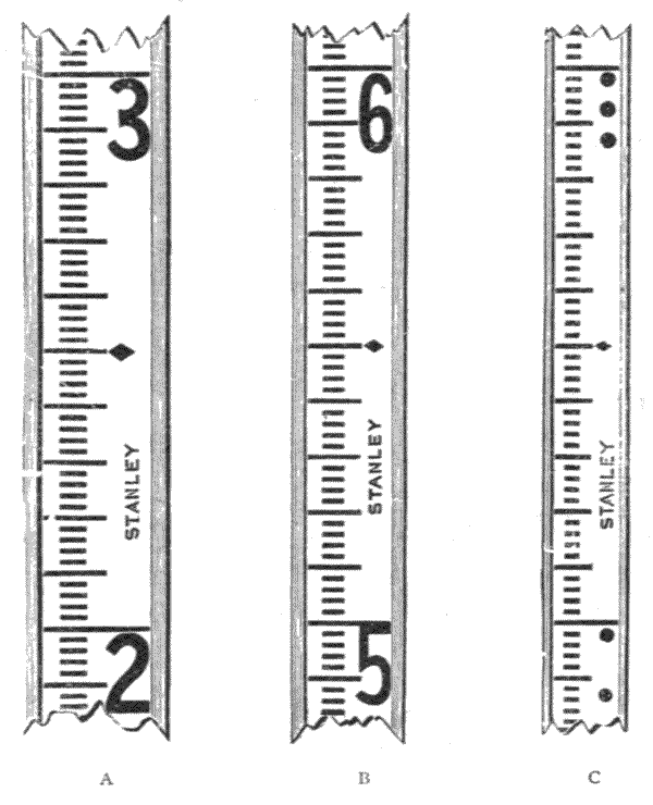
Fig. 102.—Details of Stanley staff; A bottom length, B middle, C top with dot figures.
268.—The author designed another staff especially for his point index. This is shown above, Fig. 102. It has had a very fair popularity, being good both for distant and near sighting. In this staff for the close figures 11, 12, 13, on[156] a 14-feet staff, which are with great difficulty distinguishable at a distance, the author employs dots only as before mentioned—one dot for the 11, two for the 12, and three for the 13, as shown C for the 12 and 13 in the right-hand figure. It must be remembered that a good clear staff is a great desideratum, as it means less size, weight, and cost in the level necessary to be used with it for equal exactness. A clear staff with a 14-inch level is quite equal to a complex misty one with a 16-inch level, with the advantage of saving expense in the purchase, and about 2 lbs. in the weight of the level to be carried in work.
269.—Our space will not permit the discussion of the various staff readings that have been designed, many of which are, in the author's opinion, superior to the Sopwith; but some variations are necessary occasionally for personal reasons. Some surveyors, from imperfect colour vision perhaps, strongly object to the red foot figure as being indistinct at a distance, hence in many patterns a clear black figure is employed. Some get confused with the number of equal lines of ·01 foot in the Sopwith, what is sometimes termed Sopwith's ladder. In this case these lines may be made unequal in different ways: several patterns have this peculiarity. Some persons cannot get over the inverted figure as seen in the telescope. In this case it would be much better, perhaps, to read with an erecting eye-piece to the level; but practically the manufacturer has to invert the figures. Other less important variations are common.
270.—Metrical Staves.—These are in this country generally made 14 feet, to keep the length the same as the tripod. The most approved patterns are shown Figs. 103 and 103A. In using the metre pattern at short distances often a complete metre cannot be taken in the field of view, so that there is a little difficulty in being certain to what metre interspace the subdivisions belong. To avoid this the author places a dot or dots after the decimetre figures that follow the metre—one dot for 1 metre, two dots for 2 metres, three dots for 3 metres.[157] Thus 1·4 metre reads ·4; 2·4 metre reads :4. The dots need only be very small, as they are not required except for very close readings, that is, within about 30 metres: at 40 metres distance one complete metre comes into the ordinary telescopic field.

Fig. 103.—Metres and Half Centimetres.
Fig. 103A.—Centimetres.
Stanley's metre levelling staves.
271.—Feet and Inches Staff.—For building works, drainage, and some other cases, the staff is divided into feet and inches, and subdivided again into eighths or tenths of inches. This is most convenient when the work has to be carried out with 5 or 10 feet rods and the 2-feet rule. The intermediate inches between the feet are better marked 3, 6, 9 only than fully figured. For rough usage the author has made a solid 10-feet pine staff, well painted. This has a strong hinge in the centre, and is kept stiff when open by a strong open hook. It closes face to face in two parts, which keeps the face clean.[158] This is important for dock and drainage works, where the staff holder's hands in many cases necessarily get dirty by climbing; otherwise it bears much more rough usage than the telescopic staff, and is much cheaper to make. Fig. 104.
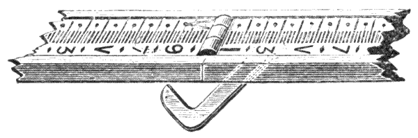
Fig. 104.—Stanley's rough levelling staff.
272.—Mining Staves.—For levelling in mines, large sewers, and other cases were there is no height for the ordinary staff, the Sopwith staff is made in its closed form commonly 2 feet 3 inches and 3 feet 3 inches only in length, to open out respectively 5 feet and 8 feet, or in some few instances even shorter than these dimensions. The mine staff is in every way, except its length, similar to the ordinary Sopwith, art. 259.

Fig. 105.—Stanley's patented mine staff.
273.—Stanley's Portable Staff.—The writer has made a portable staff in lengths of 18 inches, somewhat like a French folding rule. It may be formed of three, four, five, or six lengths, opening out respectively 4 feet 6 inches, 6 feet, 7 feet 6 inches, and 9 feet. The separate pieces are flat boards, slightly sunk on the face to prevent the divisions being scratched in opening and closing, but left solid at the[159] joint ends. The boards are attached together with a kind of rivet at each joint. A strong spring at the end of each piece with a catch and notch keeps the length opened or closed with sufficient rigidity.[8] The entire length of the staff when closed in 20½ inches. The same kind of staff forms a very useful builder's or drainage staff, divided in this case in feet and inches; and it is conveniently portable for carrying abroad. Fig. 105—E shows back view, F front view, G cross section, A longitudinal section. The holding springs are shown at BB′B″.
274.—A portable mine staff designed by Mr. G. J. Jee,[9] is said to be a useful staff for colliery work. It is constructed in three lengths, sliding one into the other. The bottom length of three feet is graduated in the ordinary way. The top of this length has a band attached to it, painted to continue the lower division of the staff upwards. The other end of the band passes over a roller attached to the top division of the staff. The roller contains a spring which keeps a constant tension on the band. By extending the lengths of the staff and clamping them, the staff may be lengthened out any distance to 9 feet. The weight of the staff is 5 lbs.
275—Papering or Repapering a Sopwith Staff.—The staff, if new, is painted with three coats of rather flat, thin white-lead paint on the face, and left to season till the paint is quite hard. It is then washed thoroughly with a sponge dipped in stout, until this adheres without beading, and is again left to dry. For repapering an old staff, this is soaked with hot water in which there is some washing soda, and rubbed until the old paper is brought off. After the staff is in either of the states described above, it has to be made warm and coated with one or two coats of size. The size may be made of a piece of glue left in water for a night, and then melted in a jam-pot placed in a saucepan [160] of water over a slow fire. When the staff is sized and dry, if ordinary papers be used, it has to be divided carefully into foot lengths, which are marked with a set square in pencil across the face of the staff. The foot lengths may be set off accurately from an engine-divided chain scale, or by beam compasses. The papers, which are printed short, are then pasted over, preferably with paste made of starch with boiling water, but not afterwards boiled. As the lengths of paper are pasted they are laid aside, pasted side upon pasted side, to thoroughly absorb the paste for a few minutes, the time varying according to the increased length required above that of the original printed paper. While still wet, the upper paper of the two is lifted up and cut with scissors, at the same time fitting to the boundary lines. This wet cutting ensures the paste being equally distributed quite up to the edges. The foot length of pasted paper is then laid by setting the upper edge exact to the upper foot line, and gradually bringing the paper down from this by dabbing with a clean cloth or straight hat-brush. If the paper does not reach the foot mark when laid, it is again lifted, and a little more pressure used in laying it the second time, which will lengthen it out as required. Other lengths are laid in the same manner. The skilled workman requires no lap to the joins of the papers, but brings them up edge to edge; with the amateur a lap of 1/8 inch is advisable.
To avoid the trouble of marking off and stretching each foot, the author has introduced jointless levelling staff papers, so that the entire length of each section may be put on in one piece. These are of special paper, and it is only necessary to paste the face of the staff well and smoothly, and lay the paper unpasted down in position upon it.
After the papers are thoroughly dry they require two coats of thin isinglass size, and then a coat or two of varnish. Paper varnish can be bought; but in defect a varnish may be made of Canada balsam dissolved in oil of turpentine. This should[161] be laid on with a flat bristle brush (varnish brush), and set in a warm room to dry for a day or two.
276.—Preservation of the Levelling Staff in Use.—Where two staves are used they may be placed face to face for carrying, and be strapped together, and will take little harm with moderate care. Where one only is used it is generally strapped to the tripod. A strip of wood is sometimes used to protect the face of the staff.
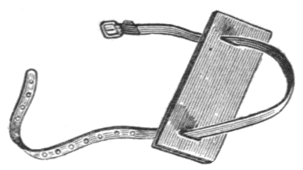
Fig. 106.—Pad for holding a staff and tripod.
277.—For carrying the staff with the tripod, a convenient plan is to have two pads formed of stout ox-hide butt, each pierced with two slots near their ends at the exact distance apart of the width of the staff, Fig. 106. The strap of calf leather is passed from one slot round the staff into the other slot, and then passed round the tripod and pulled up tightly and buckled. The pad of course protects the front of the staff from grazing by the friction of the tripod against it.
There is a certain amount of risk, under any circumstances, of the cylindrical tripod pressing against the front of the staff and splitting it. To avoid this the author has lately made the pads with a mahogany bridge piece, so that the pressure is distributed, coming upon the edges of the front where the staff is strongest to resist it. This is shown, Fig. 107.
278.—For the entire protection of the staff a leather-bound sailcloth case is very generally used. This may be divided into two compartments for the staff and the tripod, with pads between. The whole case has a neat appearance, and forms a protection from slight bruises and dirt, either in travelling or when set up in an office corner for future use.

Fig. 107.—Improved pad for staff and tripod.
279—Repairing Figures and Divisions.—Surveyors going abroad will find it very convenient to have a few tubes of artist's oil colours—white, black, and vermilion, with one or two sable brushes to touch up any divisions or figures upon the staves that have become accidentally injured or worn off by friction. A tube of medium is also useful, which will cause the colour to dry quickly and leave it bright. The tubes of colour will keep any number of years if the caps are carefully replaced. The brushes after use should be well washed with soap and hot water, rubbing the soap in quite thickly till they are quite clean, and then well rinsed before putting them by.

Fig. 108.—Iron triangle to support a staff.
280.—Iron Triangle.—For use of the staff in the field, particularly in open grass or moist lands, a triangular plate of iron, as represented Fig. 108, is very useful. This is trodden down firmly by the staff holder before he places the staff upon it. In use it gives a certain base to turn the staff upon from fore to back sight. It is very inexpensive.
281.—Staff Level.—This is a small circular level, shown at Fig. 109, the upper surface of which is formed of a glass worked slightly concave and fixed into a short cylindrical box. The glass is hermetically sealed after being nearly filled with spirit. The circular level is mounted on a plate with a dovetail fitting which fits in a slot in the holding plate attached to the back of the staff. In use the staff holder has to observe when the bubble under the concave glass is in its centre. A very little practice is required to hold the staff vertically by means of this little contrivance, which only weighs, about 2 oz.
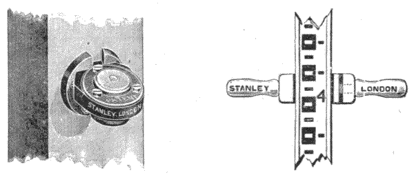
282.—Staff-holder.—This implement, shown Fig. 110, striding a staff, is very generally used in Germany and other parts of the Continent. The staff is sunk into one side of a hardwood block. The block is turned at one end to form a handle. A second similar handle is cut with a strong screw and screwed into the end of the block. This screw handle by turning brings up a following piece, shown inside next the staff, which is covered with leather. When it is screwed up, the staff may be held firmly by the handles only, without the risk of the fingers coming in front. With this accessory it is also held more easily and truly vertical. It is a comfort in use in cold weather.
283.—Practice of Levelling with the Staff.—This subject can be followed here only so far as to exemplify the uses of the instruments and of accessories connected with such[164] instruments. For practical levelling we have the standard original works of Simms, Ainsley, and others, with many modern works.[10]
284.—For Holding the Staff, Mr. Holloway, in the work referred to in the last note, gives instructions in such concise form that they may be quoted with advantage. He says:—"I generally enter into confidential chat with my staff holder, in which I explain to him the vast importance of his duties, i.e., I endeavour to make him a man of importance in his way, and I never fail to get those duties properly performed. My instructions to him are seven in number:—
"1. Draw out the slides of the staff, and be sure the joints are properly locked. Draw out one length only unless signalled to do otherwise.
"2. When the staff is once on a point never move it unless signalled to do so.
"3. Examine the staff regularly before setting it down to see that no dirt is sticking to the bottom of it.
"4. Always stand erect behind the staff, so that the figures face the level.
"5. Do not let any part of the hand come before the face of the staff.
"6. In no case put a downward pressure on the staff.
"7. If the grass be long, mossy, or spongy, tread it down, so that the staff shall have a firm footing—select a firm spot if the selection is left to yourself."[11]
285.—The manner of setting up a level has been already described in the previous chapter. The leveller generally [165] follows a definite track which he has previously arranged and marked out on a map. The distances apart for placing the staves or staff are measured by the chain, or by the subtense system to be fully described hereafter. Where the levelling is very important, as for canal work, topographical survey, etc., wooden pegs are driven down at the measured stations where the staff is to be placed from which the levels are to be taken. A general rule followed, as far as practicable, for starting is to select an easily recognised, permanent, solid station for first placing of the staff—a mile-stone, large boulder, or other solid object answers: a datum line is generally assumed to be at a certain depth below this, to which all levels are referred. From this station, if the ground be fairly level, 5 chains is the ordinary advanced position where the level is set up and the first staff reading taken. The level is set up at the measured distance from the staff, which is indicated by a mark left by the chainman.
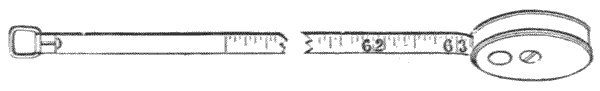
Fig. 111.—Level height tape.
286.—Occasionally in town surveys the height of the level has to be taken. For this a small steel spring pocket tape is used to take the height of the axis of the telescope, Fig. 111. The tape may be adjusted by taking a piece off the first end, and allowing for the width of the tape case, so that by placing the ring of the tape upon the hook under the instrument and bringing the case just to the ground, the height of the axis of the telescope above the ground may be read off at the point where the tape leaves its case.
287.—The Reading of the Staff.—The first position, which is afterwards termed the back reading, is taken at a distance behind the first forward position of the level. This is recorded exactly as it appears in the telescope, the height[166] of the telescope being also noted in the levelling book, to be described. Thus in Fig. 112, S the first staff; L the first station for taking levels. The fore reading L to S′ reads to a higher part of the staff S′; L′ next level station back sight. L′S′ reads high on the staff S′; fore sight L′S″ reads low; back sight L″S″ again low, following the contour; fore sight L″S‴ low; thus giving data in the levelling book from which the contour can be plotted from the datum line, which is taken low to make all readings plus.
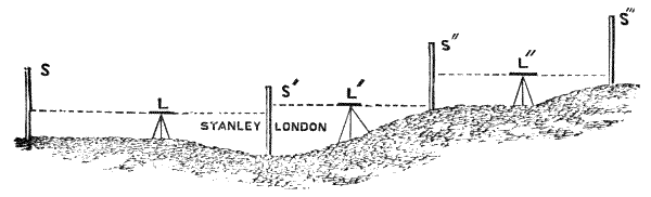
Fig. 112.—Practice of levelling.
288.—The staff reading, as already described, is divided into feet, with two places of decimals. The safest method of taking this reading is to take the second decimal place first and then record it, then the first decimal, and finally the foot. In this manner no effort of memory is required, and the staff being sighted three times assures the certainty of the reading. The telescope should not be touched during the operation, so that the reading in this manner is only a cautious transfer.
289.—If two staves are used on fairly level ground, the second staff is now advanced 5 chains from the level to a measured station, the staff holder here sighting the line through the level to the back staff, and firmly treading down the staff plate if the land is soft or grass, or otherwise requires it, or an iron triangle is used. When time is given to hold the staff vertically by means of the staff level, the reading is taken in this position by the leveller as before, and this is recorded in the levelling book. The level is now moved[167] forward 10 chains, that is, 5 chains ahead of the forward staff. The staff is carefully turned half round without pressure upon its standing place or plate to face the level as now placed, in which position it is then read off by the level as the back sight, the back staff now being moved 5 chains forward of the level, and so on alternately staff and level until the distance required to be levelled is completed, if there is no obstruction which causes another method of procedure to be adopted. A similar plan is pursued with a single staff; but care has to be taken in securing the right line of march, which will be by placing the staff in a sight line through the level with a fixed landmark instead of the back staff mentioned.
290.—The equal back and fore sights as far as practicable are insisted upon by all levellers, as by this means any inaccuracy in the level, if the run of the bubble is kept constantly true, is thereby compensated; but it is not always convenient, and when it is not the accuracy of the work must depend largely upon the qualities of the level. It is not necessary or convenient at all times to take the back and fore sight in a line—obstructions of woods, rivers, etc., may occur. In these cases very often what is quite equivalent may be done by taking equal angular back and fore sights from the apex of an equilateral triangle thus:—Say an obstruction occurs for the chain by a pond or wood, but that both points to which the levels are to be taken are visible at some lateral position. Levels may be taken from this place, and if the intermediate point of distance is equal from both stations there will be no instrumental error. Thus, suppose the direct level line east (90°), and that the two stations can be seen and the staves read at 150° and 210°; here, evidently, this is equivalent to a direct back and fore sight, the right angle to the level course being 180°—the one station is 150° = 180° - 30°, and the other 210° = 180° + 30°. If these equal angles can be even approximated with a fairly good level the error will be small. In this manner intermediate and extended points may often be[168] conveniently taken by previous arrangement with a good staff holder. It is in this angular levelling that the greatest use of the compass is found to give the angles, to make entries of the work in the levelling book.
291.—In levelling hilly ground great loss of time would sometimes be incurred from taking equal back and fore sights; the best plan in this case is to make as much use as possible of the length of the staff in use. It is in hilly districts only that a staff longer than 14 feet is advantageous. With any staff in descending a hill only 5 feet of the staff can be used for the back sight, that is, a part of it equal to the height of the level, and sometimes 4 feet or less if there is grass, brambles, or other obstruction. Whereas for the foresight all the staff upwards of the height of the level, that is, about 9 feet in a 14-feet staff, can be used with certainty. The distance of setting up of the levels and staves must in this case entirely depend upon the length of the staff and other conditions present.
292.—For near reading of the staff on sharp inclines, reading to two places of decimals is not near enough, as errors may accumulate rapidly. It is in such cases that a fully divided staff is best. The divisions upon a near staff appear in the telescope much magnified; and three places of decimals may easily be taken by anyone used to reading a chain scale, particularly if a point diaphragm be used. Through valleys the level may be often checked at some point from hill to hill by a back sight: the contour must nevertheless be followed for the section. It is in these shorter unequal ranges and in distant sights that accuracy in the level is demanded; and it becomes interesting to know how nearly this may be depended upon for such readings.
293.—As already mentioned, a sensitive 14-inch level of Y construction, or a dumpy in perfect adjustment supported on the tribrach system, will work with a level tube divided to read 5 seconds in divisions 1/20 inch apart. There will be a little personal error in reading the bubble from difference of reflection,[169] according to the direction of the light from the two ends of the bubble, as before discussed; but the bubble may be assumed to be read within less than half a division, that is, within 2½ seconds—say 2 seconds. A distinct staff may be read with a good glass within ·1 foot at one mile. A second of arc subtends ·025598 of a foot = approximately ·3 inch at a mile distance. Therefore a back reading at this distance can be taken within an inch or so of allowance for instrumental errors. A reading taken in this way at a mile distance would require a plus allowance for curvature of the earth of 8 inches, minus say 1 inch for refraction = 7 inches. From these data we can get a fair check level for hilly ground, possibly more accurate than by contour levelling for a distant station, even if we allow double the probable error, say ·1 foot for error of reading the staff at a mile distance.
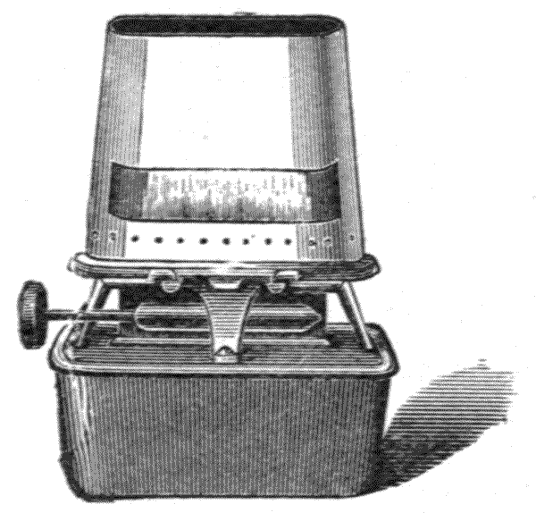
Fig. 113.—Calder stove used as a lamp.
294.—Lamp.—At heights between hills in wide valleys check levels may be taken from five to ten miles very well with a good 14-inch level in still clear weather in dark nights by the use of an oil lamp. Coincident points above datum being selected, the lamp is set upon the ground, or at a measured height at a calculated point, or raised or lowered to lantern signals, allowance being made for curvature and refraction. The wide band of light is read very easily by shifting the observer's position and raising or lowering his tripod. The "Calder" lamp stove answers very well as a[170] lamp. It has a wick about 3½ inches wide, and by means of a masked chimney may be made to present a clear white line of light of 1 inch in depth, Fig. 113.
The heliostat is sometimes used for check levelling in sunlight. This will be described further on with the theodolite.
295.—Curvature Corrections of the earth and of Refraction to be made use of occasionally for check levelling. The rule for finding curvature is "That the difference between true and apparent level is equal to the square of the distance between two places or stations in miles—divided by the earth's mean diameter, 7916 miles"; consequently, by this rule the correction is always proportional to the squares of the distances. By proportioning the excesses of height to the squares of the distances, we may obtain a curvature table for corrections. This is, however, always in excess of the true curvature by the refraction caused by the increase of density of the air towards the earth's surface, which bends the visual ray. The curvature of the earth may be corrected for refraction one-fifth to one-sixth,[12] which varies according to the atmospheric pressure.
296.—The following table, which takes curvature minus refraction, will be found useful to have at hand: it may be written out and pasted inside the lid of the level case:—
| Distances in Chains. | Curvature minus Refraction in Dec. Ft. |
Distances in Chains. | Curvature minus Refraction in Dec. Ft. |
|---|---|---|---|
| 1 | ·000089 | 14 | ·0175 |
| 2 | ·000358 | 17 | ·0258 |
| 3 | ·000804 | 20 | ·0357 |
| 4 | ·001435 | 22 | ·05 |
| 5 | ·002233 | 24 | ·06 |
| 6 | ·003216 | 26 | ·07 |
| 7 | ·00437 | 28 | ·08 |
| 8 | ·0057 | 30 | ·09 |
| 9 | ·0072 | 40 | ·14 |
| 10 | ·089 | 60 | ·31 |
| 11 | ·011 | 80 | ·56 |
Where great precision in levelling is required, as for important trigonometrical surveys, many precautions are required to be taken which would be quite superfluous, for instance, in railway work. Thus much greater exactness and freedom from personal error is secured by having two levellers to go over the same ground simultaneously. Errors by two persons in the same part of the track are very unlikely to occur, and by comparing books every part may be checked.
297.—Pegs.—Where the work is to be entirely pegged for chain measurements, the pegs may be made of natural sticks sawn off and pointed up with a bill hook. If they are sawn from timber they are generally made about 9 inches long and sawn to a point, the head being full 2 inches by 2 inches. Where great precision is required a cast-brass or iron nail is driven into the head after the peg itself is driven down. This is used to turn the staff upon, Fig. 114. A the peg shown with a nail in its head, 1/8 size. B nail about full size.

Fig. 114.—A, staff pegs of sawn timber, 1/8 scale; B, nail, full size.
298.—It is considered a precaution with an ordinary level to mark one leg of the tripod and always place this in the same position to the staff. Thus, if the marked leg is placed to the forward staff at first, it is put at the next station backward to the back staff. This corrects any general error from defective work in the instrument and want of adjustment; and if the staves are placed at equal stations any instrumental defect whatever, to act cumulatively upon a distant station, is[172] then prevented, as this principle produces an alternate plus and minus error.
299.—Differences of true level have been found between working southward towards the sun from working northward from it, which are caused by the expansion of the instrument and bubble tube upon the side heated by his rays. These matters of higher refinement may be followed in some of our best works on levelling. Most excellent instructions in this matter will be found in the appendix of A Manual of Surveying for India,[13] in a paper by Colonel J. T. Walker, R.E., F.R.S., etc., of the great Trigonometrical Survey of India, wherein levels have been carried across from ocean to ocean for over 1500 miles of land surface.
300.—Levelling Books which record the levels as they are taken are considerably varied in form, much influenced, no doubt, by the method pursued by the civil engineer for the execution of his work. The illustration, Fig. 115, shows the most general forms, but there are many others.
301.—Entries are very generally made in levelling books in black lead. Faber's artists' pencils, which require no cutting, are very generally used, No. 2 being black and moderately hard. It is very convenient to carry a small file for sharpening the lead frequently. In the author's surveyor's knife, described further on, a file forms one of the blades.
302.—Where it is desirable to make the original levelling book readings permanent for reference or otherwise, they are very commonly written in ink, Morrell's registration ink being very generally used, or the author's drawing ink answers; this being permanent is not liable to corrode the pen, nor permit the writing to be effaced in any degree by moisture.
Fig. 115.—Specimens of levelling books, 1/3 scale.

Ordinary Level Book with columns for No., Back Sight, Intermediate, Rise, Fall, Reduced Level, Distance, Remarks.

Collimation Level Book, with columns for Back Sight, Intermediate, Fore Sight, Height of Collimation, Reduced Level, Distance, Remarks.
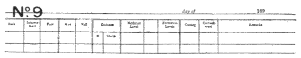
Railway Engineers' Level Book, ruled for Back, Intermediate, Fore Sight, Rise, Fall, Distance, Reduced Level, Formation Levels, Cutting, Embankment, Remarks.
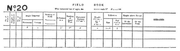
Tacheometer Survey Book, ruled as above illustration.
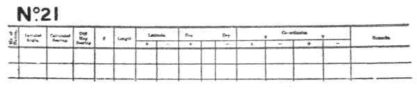
Traverse Survey Book, ruled as above illustration.
303.—The Ink Bottle mostly used is that known as the [174] excise bottle. This is of a smooth, oval form, covered with black leather, with a tab and buttonhole to hang upon a button of the coat, Fig. 116. One of the numerous fountain pens is now generally used instead of the bottle described.
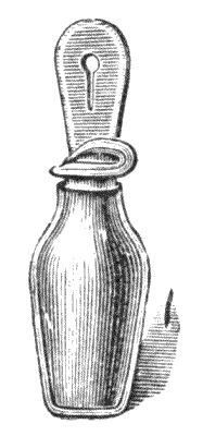
Fig. 116.—Excise ink bottle.
DIVISION OF THE CIRCLE AND METHODS EMPLOYED IN TAKING ANGLES—DIVIDING ENGINE—SURFACES FOR GRADUATION—VERNIER—VARIOUS SECTIONS—READING MICROSCOPES—SHADES—MICROMETERS—CLAMP AND TANGENT MOTIONS—OF LIMBS—OF AXES—USE AND WEAR—DIFFERENCE OF HYPOTENUSE AND BASE.
304.—Division of the Circle.—Sexagesimal Division.—All true surveying instruments depend, as their special function, upon taking the direction, or angular position, of surrounding objects or definite parts of the surface of the earth from positions which are at first accurately measured or ascertained. The instruments required for such work must possess an accurately divided circle or arc, with means of subdividing the visible divisions of this to greater closeness than any possible method of drawing lines simply would permit. The lines upon the circle in general practice in Great Britain are divided into degrees, which are subdivided to 30, 20, 10, or 5 minutes, according to the size of the instrument, and arranged for further subdivisions by means of a vernier into minutes or 30, 20, or 10 seconds of arc. Upon large circles, say of 10 and 12 inches diameter, and with modern 5, 6, and 8 inch diameters, angular displacements in the direction of the telescope are ultimately read off with a microscope by means of a screw with divided head, termed a micrometer, placed tangentially to the divided circle; or by a series of lines placed at equal distances apart in front of an eye-piece or[176] within a microscope; but in the ordinary portable instruments, or those that a surveyor can personally carry about the country, the ultimate subdivisions of the circle are still generally made by a vernier scale only, which will presently be described, although the smaller modern micrometer reading instruments are slowly but surely coming into favour for all high class work.
305.—Centesimal Division.—Ten to fifteen years ago on the Continent generally, and in America occasionally, the division of the circle into 400-grades and ½-grades, and the subdivision of these decimally to centigrades, appeared to be coming more and more into use, particularly with the more extended use of the tacheometer. Under this system it will be seen that the right angle subtends 100 grades. This division, with its centesimal parts, was found to blend conveniently with logarithmetical calculation and to permit the free use of the slide rule with great saving of time over ordinary calculation, but it is now very little used.
The decimal division of the ordinary degree of 90 to the quadrant greatly facilitates the calculation compared with what is necessary with the sexagesimal division into minutes and seconds, and the reading of the verniers is much simpler and less liable to errors; moreover, the mental conversion of the sexagesimal division into decimals of the same degrees is much simpler than the conversion into the centesimal degrees of 100 to the quadrant.
306.—Dividing Engine.—This important tool is used for cutting the graduations on all surveying instruments. If possible a position should be secured for it on a ground floor at a mile or more distance from any railway, and at a good distance from roads upon which there is heavy traffic, as small vibrations are sufficient to cause unpleasant working and some error in the division of large instruments. For very accurate work some makers divide at night for the sake of stillness. The principles of construction of this machine, as at present[177] in general use, were invented by Jesse Ramsden, of which an account was printed by the Board of Longitude in 1777. Refinements of detail have been added to the invention, and the steady action of steam or electric power has been applied in place of the foot, but otherwise the machine remains practically the same. Therefore a brief description of this machine as originally invented will be sufficient for the purposes of this work, which is not intended to fully describe the tools used in the manufacture of instruments.
307.—Ramsden's Engine consists of a circular brass surface plate, made generally of 36 inches diameter. This plate is supported from below upon a hollow vertical axis, which moves in an adjustable collar placed at its upper end and in a conical point or pivot at its base. The pivot rests in a cup of oil and supports the weight of the plate and axis, so that this part rotates with little friction. The outer edge of the surface plate is cut with 2160 teeth or threads, into which an endless or tangent screw works, so that the plate can be revolved any desired quantity by means of the screw. Six turns of the tangent screw moves the plate 1°. The head of the tangent screw is divided as a micrometer into 60 parts; therefore the movement of one of the divisions of this head revolves the plate 10″ of an arc. A ratchet wheel of 60 teeth is attached to the tangent screw, and so arranged that by reciprocating motion applied to a rack which works into it the circle can be advanced any multiple of 10″. Motion is given to the tangent screw by a catgut over a pulley worked by the foot. The work is centred and clamped down upon the surface plate. While the divisions are being cut this surface plate remains for the time quite stationary.
308.—The dividing knife is attached to a swinging frame having a reciprocating motion. The forward extent of its swing is regulated by a detent wheel with teeth of varied heights, which, as they are brought by the mechanism consecutively forward, stop the knife at a definite position; so[178] that the cuts upon the circle—technically the limb—are regulated for lengths to represent 10 degrees, 5 degrees, degrees and parts. In the use of this dividing machine the divider who worked it had alternately to press his foot upon a treadle and then pull a cord attached to the dividing knife frame. These motions are now performed by self-acting mechanism. For full particulars and details of the dividing engine see Troughton's Memoir, Phil. Trans., 1809: Memoirs of the Royal Astronomical Soc., vol. v. p. 325; vol. viii. p. 141; vol. ix. pp. 17 and 35. For various plans that have been tried see Holtzapffel's Turning and Mechanical Manipulation, pp. 651–955.
309.—The Material upon which the limb or circle of an instrument is divided is almost uniformly of silver, except for mining survey instruments, which need a very strong cut. Silver being dense and of extremely fine crystallisation, or grain, as it is technically termed, bears a uniform smooth cut with sharp outline. Occasionally circles or arcs are divided on platinum, certainly the best metal, as it keeps constantly clean; but it is expensive. The verniers are then made either of this metal or of gold. The silver of the circle, when this metal is employed, is rolled down from a surfaced cast plate of about ·25 inch in thickness to about ·045 inch, by means of which it becomes uniformly dense and fine grained. In all cases possible, that is, upon all flat internal surfaces, the silver is placed in an undercut groove and planished down to fill the groove without any other fixing being necessary. This plan of insertion is employed for all vertical circles—the horizontal circle of Everest's theodolite, limbs of sextants, box sextants, etc. In Fig. 117 the silver is shown at A, in the section to which it is drawn by a plate after it is cut in slips. It is shown placed in its groove B ready for planishing down. By this method certainty of dense surface is obtained for the future division.
310.—Upon bevelled edges and outer surfaces the rolled[179] silver is planished to form, and then soldered to the metal of the part of the instrument to be divided. The surface, after being made as dense as possible by planishing or otherwise is turned to form and stoned to surface ready for the dividing knife.
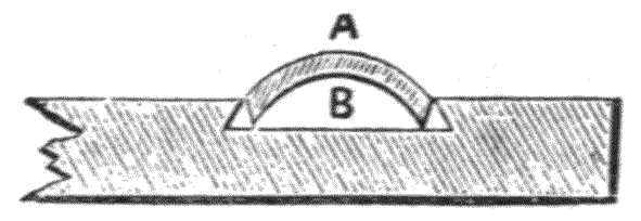
Fig. 117.—Insertion of silver in circle.
311.—Graduating.—The object aimed at by the skilful divider is to obtain as deep a sharp-edged cut as possible, which shall be at the same time as fine as it can be read clearly by the microscope with which it is to be used. This matter is most important to the possessor of the instrument afterwards for use, as in the atmosphere the silver soon forms an oxide and a sulphuret upon its surface which has to be cleaned off; and at every cleaning a portion of the silver is necessarily removed, so that in old or badly divided instruments the divisions become dull or lost from this reason.
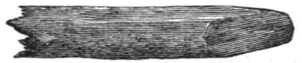
Fig. 118.—Piece of charcoal.
312.—After the instrument is divided it is engraved with figures and stoned off with fine blue-stone, and finally finished with willow or pearwood charcoal, which has just sufficient cut in it to leave a hard edge to the division lines.
313.—It may be useful to the surveyor, far from aid of the optician, to know that divisions on silver which are much oxidised may be brought up to sharp lines by the use of a piece of fine-grained charcoal, sharpened by a clean file to a chisel point. This should be frequently dipped in water, and[180] rubbed lightly with the flat of its end surface, Fig. 118, keeping the motion of the hand in the direction of the circumference of the circle. The piece of charcoal before being used should be first tried upon a piece of plain, smooth metal—an old coin which is worn smooth will do—to see that it is not scratchy. No kind of polishing powder should in any case be used for cleaning limbs or verniers, as this is sure to rub down the edges of the cuts and thereby ruin the divisions of the instrument.
314.—It must be understood that the above directions are not intended for the ordinary cleaning of the circle for an instrument in general use, as such would be injurious to it. In the ordinary daily use of the circle, if it is not in any case touched by the hand, and is kept carefully brushed with a large, soft camel-hair brush when taken from the case, and the same when returned to it, it will keep a long time in an excellent state. If the circle is slightly tarnished, this tarnish may be removed by a piece of quite clean wash leather; but the brush is always the safest if sufficient. If the vernier gets grubby against the circle, a piece of clean thin writing-paper may be passed between these parts, which will clear out any dirt or grit there may be between sufficiently.
315.—The Vernier Reading Index.—This is one of the most important inventions ever applied to instruments of precision for measuring upon the circumference of the circle. It was invented or brought into practical use by Pierre Vernier, a native of Ornans, near Besançon, in Burgundy. The first publication of the invention appears in a pamphlet published in Brussels in 1631, Construction, Usage, et Proprietes du Quadrant Nouveau de Mathematique. This invention was possibly foreshadowed, as it is mentioned by Cristopher Clavius in his Opera Mathematica, 1612, vol. ii. p. 5, and vol. iii. p. 10; but he did not propose to attach it permanently to read into an arc, that is, to place it in its practical form.
316.—The value of the vernier as a means of reading[181] small quantities depends upon the fact that the eye cannot separate lines, drawn at equal distance apart, of above a certain degree of closeness, there being a point for all vision where such lines appear to mix with the ground upon which they are drawn and form a tint; therefore, an index reading into such close lines would be, unless under extreme magnification, most indefinite; whereas the eye can see a single separate line clearly and detect any break in it. The vernier for reading subdivisions depends upon the functions of the eye having power to detect any break in an otherwise straight line, so that a line that appears without a break may be taken as the index of reading from among others that appear broken or separated. It is found in practice that a line as fine as it can be clearly seen will appear broken in its continuity with another equally fine line, if at the meeting the rectilinear displacement is as much as ·25 to ·2 part of the width of the line. It therefore follows that we may read closer by displacement of parts of a single line than by any possible series of lines that can be drawn in spaces apart upon a surface; so that if we can arrange lines in such a manner that they open out or separate into distinct lines to admit of this principle, we obtain the full value of the unbroken single line reading, and this is the principal aim of the vernier.
317.—On the same principle that we can find the straight or most direct line of a series of lines to take as our index, we can also estimate the amount of the displacement of our selected line, if this does not read perfectly straight from the vernier division to the circle division. This small difference is detected in practice by many experienced surveyors, so that a vernier reading nominally to minutes only is recorded n′ + 15″, 30″ or 45″, that is to 15″. There is no doubt that this will be approximate, but it may be much nearer than the even minutes, say to the 30″ on a 5-inch, or the 15″ on a 6-inch sharply divided circle.
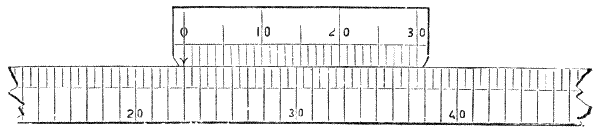
Fig. 119.—Origin of vernier scale.
318.—The Vernier Scale, as employed by Vernier, was[182] divided to read minutes upon a circle or limb divided to half degrees, by taking thirty-one divisions of the scale and dividing these in thirty equal parts for a separate scale to read against it. This plan is now termed an inverse reading, the reading being the reverse to the direction of that of the arc. In modern practice the vernier to read minutes is divided to the length of 29 half degrees, and this length is subdivided into thirty equal parts: consequently, where the vernier and scale are placed edge to edge or reading to reading, every division of the vernier advances consecutively on the scale one-thirtieth of the half degree, that is = 1′ of arc on the scale divided to half degrees. In the above diagram, Fig. 119 represents the scale and vernier at the position from which the description is taken, wherein the vernier is shown to cover 29 half degrees or 14° 30′, and this length is divided into thirty parts. The consecutive advance of the vernier on the scale is shown + 1′ for each half degree. In this position of the vernier, or at a similar position in relation to any other half degree of the circle the arrow placed at the zero of the vernier reads direct into the degree or half degree, so that[183] this reading must be n° or n° 30′ at any equivalent position in relation to any line on the limb.
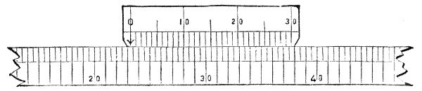
Fig. 120.—Vernier scale, reading 23° 12′.
319.—In Fig. 120 the arrow upon the vernier scale is shown reading at a position beyond 23°, which we then know must be 23° n′. Now, if we look along the vernier, the lines of this and the scale appear coincident at the twelfth division of the vernier; consequently, the n′ is 12′, and the reading is altogether 23° 12′.
320.—Learning the reading of the vernier is very similar to that of the clock, wherein a child at first gets confused by the difference of value of the minute hand and the hour hand. In the case of the vernier we have only to get clearly in our minds that the degree reading and the vernier reading are quite distinct processes, in which the vernier reads minutes only, and this by coincidence of lines only, and that it has nothing to do with degrees, which are indicated by the arrow only. The arrow may be assumed to be placed on the vernier scale to save an unnecessary line of division; but this practically might just as well be placed quite outside of it, as it has nothing whatever to do with the vernier reading.

Fig. 121.—Vernier scale, reading, 23° 47′.
321.—It is important to make this matter of reading the vernier clear; therefore in Fig. 121 the index arrow and vernier are shown reading past a half degree. At this position the arrow reads 23·30 on the limb + the vernier, or 23° 30′ + n′ of the vernier reading. We find the coincident line of the vernier with the limb is at 17, therefore the reading is 23° 30′ + 17′ or 23° 47′.
322.—The principle of the vernier, upon which it takes[184] its reading from the coincidence of lines, as just stated, points out that the figuring of values of points of coincidence may be varied at discretion, and the zero index may be in any convenient position. The above described is the common reading to the theodolite and many other instruments. In mining dials and some other instruments the zero is placed in the centre. We may, for example, take a central reading with a vernier reading to 3′, wherein the circle being divided into degrees; the vernier is then, necessarily, in the direct method, divided into twenty divisions (20 × 3 = 60) which correspond with nineteen degree marks of the circle. With a central reading the vernier in this case is figured 30, 45, 0, 15, 30. This is rather a simple reading, as the zero to which an arrow is attached gives the true bearing, and it is readily seen to which degree it refers.
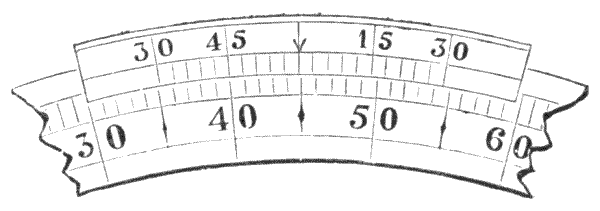
Fig. 122.—Vernier reading centrally to 3′.
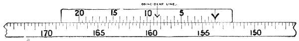
Fig. 123.
In Fig. 122 the 45 of the vernier is coincident with a line of the limb, this must, therefore be 45′; and as the index arrow is past 44°, it is 44° 45′. If the vernier had read the division next past the 45, the division being to 3′, this reading would have been 44° + 45′ + 3′ = 44° 48′. The same principles may be applied to any subdivision. Circles are commonly divided by the vernier in various ways to give readings from 5′ to 5″.
Theodolites reading to 30 seconds are usually divided degrees and thirds of degrees on the circle and minutes and halves on the vernier, as illustrated (Fig. 123), the reading in this case being 153 degrees 40 minutes on the circle and 8 minutes 30 seconds on the vernier, giving a total reading of 153° 48′ 30″.
A 20 second reading usually has divisions of 20 minutes on the circles and these are subdivided into minutes and thirds by means of the vernier.

Fig. 124.
28 degrees 40 minutes on the circle and 12 minutes 20 seconds on the vernier, giving a total of 28° 52′ 20″.
A 10 second reading is designed in the same manner as the above, but each division of the circle is 10 minutes instead of 20 minutes, with minutes and sixths on the vernier. Fig. 125 is an illustration of this, showing a reading of 7° 16′ 30″.
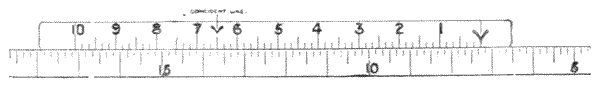
Fig. 125.
323.—For Centesimal Division the vernier to read minutes is generally divided 50 into 49 for the half grades, for small circles 4 inches to 5 inches. For larger circles, 6 inches to 8 inches, verniers are cut 25 to 24. The circle is then divided to ·25. Where there is space for five divisions to the grade, ·20, the third decimal place, may be estimated or read exactly[186] to ·005 by a vernier 40 to 39, or more closely if desired by a micrometer, to be described presently.

Figs. 126, 127.—Sections of scales and vernier for circular readings.

Figs. 128, 129.—Sections of scales and vernier for circular readings.
324.—Surfaces of Limb and Vernier.—To get a perfect reading of a vernier the scale and vernier should be brought into contact upon a plane. This, for many reasons, is impossible in a great number of cases upon an instrument, from the conditions of its construction, convenience of vision, and in some cases for want of means of ensuring durability of the edges which work together. Therefore verniers and scales are more commonly constructed upon the methods shown in section Figs. 126, 127, where VV are verniers, LL limbs. The plan shown in section Fig. 128 gives a nice reading on a new instrument; but the part of the edge not covered by the vernier is open to accident, or if nearly covered by a part of the instrument, open to the introduction of gritty dust, which wears the meeting line open, and thereby causes loss of edge to edge reading. Fig. 129 shows a section we find on some French instruments. This plan was introduced by the late Colonel A. Strange for the section of the limb reading of theodolites for India, but it was found in practice awkward to use upon this instrument, as it required unpleasant stooping to[187] read it. It is, nevertheless, one of the best permanent vernier readings, as the division remains constant under the amount of wear occasioned by the sliding of the vernier upon its circle.
325.—With the reading planes shown in section Fig. 126 we require great care to bring the eye, whether open or through the microscope, directly radial with the centre of the circle at the line into which the vernier cuts. If we read the line in the slightest degree one-sided it is quite possible to make a difference of a minute on a 5-inch or 6-inch circle. This is the section of the general reading plane of theodolites, where, from the necessary height of the telescope, the limb has to be placed much lower than the eye. With this section the circle comes fairly square to a comfortable position for reading. It will be noticed that there is a slight lap shown to the vernier over the limb at a, Fig. 126, which is always found in new instruments of this section. It gives an allowance for wear between the vernier and the limb caused by the fretting of the metals together, as also by the intrusion of grit, which is always present in instruments used in the open air. The lap should not be great, and it should be nearly equal along the edge of the vernier, although it is a difficult matter for the maker to get it perfectly so.
Fig. 127 is a section of the reading planes common to sextants and parts of many instruments. This plan requires the same care to obtain a truly perpendicular reading to the division as that described above for Fig. 126.
326.—In the very best of work there is at all times a certain amount of error, both between the divisions themselves, and in the place of the axis in relation to the centre of the divided circle, and of the position of the vernier in relation to both these. It therefore becomes necessary, where exactness is required, to place at least two verniers to read opposite sides of the circle. These bisect every reading through the axis of the instrument, and detect very[188] small errors in the work, as well as personal errors of the observer, of which the mean reading of the minutes or seconds only may be taken and used for correction to mean position. Where very great precision is aimed at, three or even five verniers are sometimes placed round the circle, and the mean reading is taken of the small differences in minutes or seconds, after calculation for correction, to find the direct position of the axis of the telescope required for the record of the observation.
327.—Reading Microscope.—The microscope usual for reading the vernier is either a simple plano-convex lens of short focus or a Ramsden eye-piece of the kind described for observing lines on the diaphragm of a telescope, art. 82. Frequently the microscope, technically called the reader, is made of a compound form, sometimes with a diagonal prism or mirror. It is uniformly mounted in such a manner that it may move concentrically to the divided circle into which it reads. In English instruments it is placed normal to the surface of the vernier, so that following its curvature it may read opposite any line upon it. In French instruments the reader is frequently placed obliquely, so as to look along the line of the limb into that of the vernier, which is said to be advantageous in certain lights.
328.—In theodolites for reading the horizontal circle, the reader is sometimes mounted to slide in an undercut groove near the circumference of the limb to follow its curvature. This motion is not pleasant; it is better in this and all cases of vernier reading, if possible, to mount the reader on frame-work proceeding directly from and moving upon the axis. Where it is practicable, it is much better to have two readers where there are two verniers, and in all cases to have one to each vernier, than to shift one reader about after the instrument is placed in position, which is liable to disturb it. With opposite readers mounted on a pair of arms formed of one piece of metal, where these bisect the circle working through[189] its axis, by the setting of one reader truly normal to the coincident division of the vernier the opposite reader will be set also; so that this does not only save time, but the instrument need not be touched for reading the second vernier. The same principle should be applied to any greater number than two verniers as nearly as it may be practical.
329.—Instruments that have to be packed in cases for conveyance should always have readers removable from the instrument, with proper fittings in the case provided for them, or they should be hinged to turn up to a secure position, the latter being a more expensive but a much better way. It is better also, if possible, to remove the light frame with the reader if this does not turn up, so that it cannot be injured in replacing the instrument in its case.

Fig. 130.—Reader fixed normal to surface.
Fig. 131.—Jointed reader to set to any angle.
330.—Fig. 130 shows a good rigid form of reader for an oblique plane of division:—V vernier, L limb. This reader is placed on an arm radial from the centre of the instrument, more generally in pair with an opposite reader. The connection with the arm is commonly made for portability with a dovetail slide fitting to the reader, sprung by a saw-cut down it to ensure constant contact after wear, as shown in section Fig. 132; N arm of reader, O fitting to arm. The better form is shown in Fig. 131. In this the arm is jointed, so that the reader out of use is turned up into the central part of the[190] instrument. This plan admits of adjustment of the reader for reflection of light from the division, or for reading down the lines if preferred. The magnifying power of either of these microscopes is generally two to three diameters. The adjustment of the glasses should be such as will produce a flat field (Ramsden's principle, p. 41), so that several divisions of the vernier and limb may be read sharply when it is in focus, although the central division only is taken for the reading.
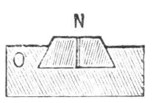
Fig. 132.—Section of movable arm fitting to reader.
331.—Surface Reflection to Reader.—In reading with the microscope the silver surface, from its brightness in certain lights, gives unpleasant reflections which render the reading difficult. In practice the hand or a piece of white paper is used to shade the open vernier in such cases. In large instruments a piece of ground glass is fixed in a frame over the vernier, which throws a soft light, producing the effect of a dead surface upon the silver, or the light is reflected from a cardboard or ivory surface. Fig. 133 shows a common form of microscope for reading a vertical circle, by which the light is reflected from a white surface surrounding the field-glass end of the reader.

Fig. 133.—Reflecting surface reader.
332.—Shades for Vernier.—It is very general on the Continent to place the divided reading of the circle and its vernier on a plane perpendicular to the axis, Fig. 128, and to place the reader at a fixed angle for down-the-line reading, the object-glass of the reader being constructed to focus parallel rays. In this way the division of the circle is followed into its vernier or vice versa. In this case the silver may be shaded by ground glass, which gives a soft, pleasant reading in most lights. The general arrangement is shown, Fig. 134; L limb, V vernier, S shade of ground glass, M reader. Objection is made to glass shades by civil engineers as being too delicate and liable to fracture, with risk of the particles of glass getting into the working parts of the instrument. To obviate this the author has made the shade of a piece of thin horn or transparent ivory, which appears to answer very well and to save this risk.
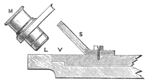
Fig. 134.—Oblique reading microscope with shade, French plan.
333.—For ordinary instruments with no provision for shading, a piece of transparent horn about 2¼ inches by 1¼ inches may be carried in the waistcoat pocket, and will be found a great comfort if held over the vernier when the lines appear glary, or the horn may be placed in a pocket frame with the case containing reflector for bubble reading, Fig. 52. In large theodolites, used for geodetic surveys, the object-glass of the micrometer microscope is sometimes surrounded by a thin belt of turned ivory. This throws a very soft light upon the divisions.
334.—Micrometer Microscope, for Reading Subdivisions.—Where more exact reading is required than is possible with the vernier, as in the case of the reading of circles 10 inches or more to seconds, a micrometrical microscope is employed, which gives means of measuring the distance from line to line of the division upon the limb by the displacement of a web, point, or line moved by a fine screw with a divided head.
The great demand of late years for reducing the size and increasing the accuracy of theodolites has induced the highest class makers to introduce micrometer reading instruments of six, five, and even four-inch circles, and their accuracy is far greater than is possible with any instrument of the same size that reads by verniers. Of course the workmanship in these instruments has to be of a higher order, and the reviser estimates the accuracy of the micrometer through magnification and the necessary refined workmanship to be at least four times as great as the vernier reading, with the advantage that the micrometer is much more certain and easier to read.
335.—The construction of the reading micrometer as originally designed by Troughton has not been materially modified in those in general use. Certain refinements have been introduced for astronomical work: these are sometimes expensive and often cumbersome, so that they need not be considered in relation to surveying instruments.
336.—In all cases where micrometers are used, the structure of the framework of the instrument which carries them should be made extremely rigid, as very minute deflections or vibrations render the reading to seconds of arc impossible. The number of micrometers applied to a circle is generally 2, 3, or 5.
337.—If a circle is to be read by micrometers, the vernier is generally dispensed with. The circle is usually divided to read in 5′. The first approximate reading used to be taken by a single index line with the aid of the ordinary reader,[193] Fig. 130. From the index line the degrees or minutes were taken to the last 5′ line indicated. Since the introduction of high-class engraving machinery the figuring is made at each degree and is clearly read in the microscope, so that the index reader is unnecessary. This engraving is quite a nice piece of work, as to figure from 0 to 360 means nearly a thousand figures, and on a 5-inch circle these have to be less than 1/100th of an inch high. Only the highest class makers are able to do this work. When a microscope is adjusted to one line it should be observed that all the other microscopes upon the same circle should also read exactly to a line that should be true from microscope to microscope to the arc they subtend between each other.
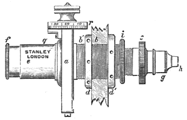
Fig. 135.—Side elevation of Troughton's micrometer.
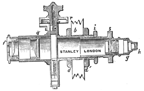
Fig. 136.—Section of micrometer.
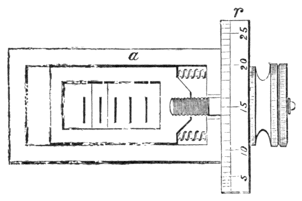
Fig. 137.—Micrometer slide.
338.—The Micrometer, as it is now technically termed to include the whole piece of apparatus, is a compound microscope consisting of three lenses, with measuring apparatus at the mutual foci of the field-glass and of the two lenses which form the eye-piece. The field-glass, which is placed nearest the divided arc, is generally an achromatic microscopic lens of an inch or more in focus. The eye-piece is of the Ramsden form, Fig. 16. By the construction of the compound microscopic arrangement the eye of the observer may be placed at any convenient distance from the limb, and any desired magnification may be obtained to assure micrometric nicety of measurement. The engravings represent the micrometer, Fig. 135 in side elevation, Fig. 136 longitudinal section, and Fig. 137 the micrometrical slide, which is shown partly in section for demonstration in all the figures; a the micrometer, q microscope body tube. This has a male screw outside at b′, upon which there are two collars dd′ with capstan heads. These collars hold the microscope upon the reading frame b at any required distance from the limb to secure proper focal adjustment. g objective tube. This screws into the body tube and permits adjustment of the objective to the division of the limb and the micrometer index web by the milled head s. This tube has a locking nut i to secure it from after movement when it is once properly adjusted. h an achromatic object glass of half an inch or[195] over in focus. e the casing that receives the eye-piece which screws into the outer plate of the micrometer. f the eye-piece, generally made about one inch long. This slides by friction in its cell to produce distinct vision of the spider lines in the micrometer.
339.—The micrometer frame, Fig. 137, a has a fixed scale or comb, with five or more points or teeth formed upon it, and a movable sliding frame, upon which a spider web or webs are inserted and cemented in finely engraved lines to form an index, brought as nearly as possible to the mutual focal plane of the object-glass and the eye-piece. The index web frame has a fine screw of about a hundred threads to the inch tapped into it. The micrometer screw, divided drum, and milled head are now generally constructed as shown in Fig. 137. Two springs press upon the index frame and the outer frame, and thus keep the drum up to its collar. The drum r is divided upon its edge into sixty equal parts, to read seconds of arc generally to a single line index. The screw is moved by the milled head beyond the drum, so that the divided surface of the drum need not be touched.
340.—The portion of the arc measured being generally 5′, the distance of it, as it appears at the magnified image of the arc at the position of the index of the micrometer, is made to correspond with five turns of the micrometer screw, the head of which divides each turn into 60. By this means the 5′ is divided into 300, that is, to single seconds, and by approximation of the interspaces on the micrometer head, as far as the reading is concerned, to fractions of a second. The fixed scale, or comb, as it is termed, is commonly placed in the focus of the eye-piece with five webs upon it, fixed to agree with five turns of the screw or a rack with points at the bottom. These webs or rack divide the 5′ of arc in minutes, and indicate the number of revolutions of the screw, as shown by the displacement of its index line. A pair of lines or webs are commonly placed in modern instruments at[196] 1′ part, to ensure certainty of reading by the mean of two observations.
341.—The magnitude of 5′ of arc depends necessarily upon the radius of the divided circle; therefore the microscope of the micrometer has to be made to suit the division it is required to subdivide—that is, using the same micrometer, the smaller the circle the higher the magnifying power is required to be to take register by the same screw. Within a wide range the micrometer is perfectly adjustable, to ensure exactness upon this point, by varying the distance of the object-glass from the limb, for which purpose the microscope is made adjustable by the pair of screws dd′ which clamp it to its standard as already mentioned. The principle of this adjustment is easily seen, for if we place the object lens at a distance equal to its solar focus from the limb, the image will emerge in parallel lines; but as we cause it to recede from the limb, the image may be brought to any position within the tube greater than the solar focus of the objective of the microscope. The image is therefore brought to a position where it may be picked up conveniently by the eye-piece. In this manner we have only to make the adjustment of the object-glass from the limb such as the space of any pair of divisions of the limb may be magnified up equal to the displacement of five turns of the screw for seconds measurement.
342.—The two points where the divisions and their images are situated are termed the conjugate foci of the lens, and the magnifying power is proportional to these distances; thus, if we call the distance of the object, that is the limb, from the object lens f, and the distance of the focal plane of its image within the tube F, the image will exceed that of the object in the ratio of Ff, or F/f will represent the magnified image. By this method it will be seen that the expression F/f will have an increased value, if we either increase F or diminish f, which[197] we have to consider in the construction of the microscope to bring it to the conditions under which it will adjust to bring the micrometer screw exactly to its required reading.

Fig. 138.—Grubb's plan of securing micrometer screw.
343.—It is very general in instruments at the present time to tap the micrometer screw directly into the micrometer frame, and to make the drum and milled head a part of the screw. In this case a very soft motion may be given to the screw by dividing its nut longitudinally and bringing the parts together with a certain amount of spring. Sir Howard Grubb, of Dublin, has placed a spring ball fitting, as shown Fig. 138 at EE′, over the screw upon his astronomical instruments, which gives a very soft motion to the screw. These refinements are very important, as it is not desirable that any undue pressure should be put upon a delicate instrument which under all conditions must be made rigid enough to resist it, and the greater the pressure required to bring the instrument to bearing the stronger it must be made.
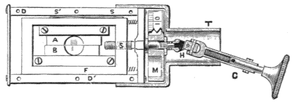
Fig. 139.—Stanley's micrometer slide.
344.—Stanley's Micrometer.—The author has made an arrangement in which the screw has a long, double tubular sliding stem, Fig. 139. The inner stem which carries the[198] milled head has a groove cut down it, into which a stud from the inside of its covering tube slides. This arrangement permits the milled head to be pressed inwards or outwards in turning it without any pressure coming upon the micrometer greater than the friction upon the sliding tube, and that of a weak spring which keeps the stem nearly extended in its tube. A simple Hook's joint H is formed at the head of the screw, so that no part of the weight of the hand comes upon the screw. A tubular guard-piece T prevents the milled head hanging down too far when out of use. When the screw is used it is lifted to about the centre of the guard tube. With this arrangement, as no practical weight or pressure comes upon the micrometer from handling it, the supporting frame-work may be made much lighter than is necessary with any other form of micrometer.
345.—The author prefers to form the micrometer scale and the index of fine lines engraved upon parallel worked glass for surveying instruments. This avoids the risk of breaking webs, and, what is much more important, he finds that with engraved lines on glass he is able to bring the scale and index exactly and permanently into the plane of mutual foci of the object-glass and eye-piece by placing the lines upon the same faces of glass, thus avoiding the great difficulty of focussing to guess-work of an intermediate position between two sets of webs at different distances.
The strip of glass A is fixed by a clamp and two screws to the side of the micrometer box. The slip B is ground and polished to fit A. B is carried by the micrometer frame F, which holds it in a clamp by two screws. A spring, not shown, presses B against A, so that any displacement of the micrometer lines may be made by the milled head. The lines upon A are adjusted to the position of the circle they are intended to read at exactly 5′ or other quantity.
For the smaller instruments which will be much more frequently used by the surveyor a simpler form of reading is used, and as the reviser is convinced that in future this form of reading[199] will gradually replace the vernier for all high-class work, a full description of this very simple reading is here given. The reviser is confident, after many years of practice for the most accurate form of index, that a point certainly stands first, a pair of webs or lines on glass, between which the division is seen, second; and a single web or line on glass placed over the division, third. The comb mentioned in art. 339 is done away with, and one revolution of the micrometer screw made to carry the index over one division of the limb. For clearness the engravings show only a 10″ reading; for a 5″ reading the divisions on the limb are to 5′ instead of 10′, and the micrometer head is divided and figured accordingly.

Fig. 140.—Stanley's micrometer reading.
Fig. 140 shows at C a portion of the theodolite circle as seen through the micrometer microscope. P is the movable pointer, M the micrometer head, and I the index or reading line.
To use the micrometer the first steps are to carefully focus the pointer P by means of the eye-piece until it appears clear and perfectly sharp, and set the reflector at the bottom of the microscope so that it reflects sufficient light to illuminate the divisions on the circle. Then, by turning the micrometer head M, set the pointer P to the centre of its travel, so that it covers the V cut in the bottom of the slide, and leave the 0 of the micrometer head exactly opposite the index line I. Now proceed in the same manner with the other microscope. After setting the microscopes as described above, lightly clamp[200] the lower clamp screw of the instrument and release the upper one. Now revolve the upper part of the theodolite until 360 degrees on the circle appears exactly under the pointer of one of the microscopes. The other will then be pointing to 180 degrees, and the instrument is set ready for measuring the first angle.
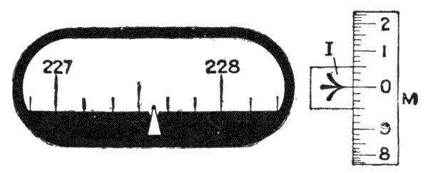
Fig. 141.
We will presume now that a bearing has been taken by the telescope and it is required to read the angle, and that on inspection of the micrometer it is seen to be in the position illustrated at Fig. 141, viz., between 227 and 228 degrees. Now as the degree is subdivided into 6 parts, each of these subdivisions must represent 10 minutes of arc, therefore the pointer is situate between 227° 30′ and 227° 40′. It is now necessary to measure exactly the distance of the pointer from the division 227° 30′, which is done in the following manner, by means of the micrometer head M.

Fig. 142.
This micrometer head is so constructed that one complete revolution of it causes the pointer to exactly travel over the space of one division on the circle.
The head itself is divided into 10 primary parts, which indicate single minutes, and these are subdivided into 6 parts of 10 seconds each, therefore in order to measure the exact position of the pointer in Fig. 141 it is only necessary to turn the head M until the pointer is exactly over the previous division of the circle (as shown in Fig. 142) and read the distance on the micrometer head M. In this case the head has been turned through six main divisions of 1 minute = 6 minutes and two subdivisions of 10 seconds = 20 seconds, giving a total reading of 6′ 20″, this, added to the circle reading of 227° 30′, gives 227° 36′ 20″, which is the correct reading of the angle.
It will be seen that this method is very much simpler and a great deal more accurate than any form of vernier reading, and also that its greater accuracy permits the use of smaller instruments. Thus a 5-inch micrometer reading theodolite is more accurate than a 6-inch one with verniers.
Six-inch micrometer theodolites are usually divided to read to 5 seconds of arc. The method of reading is the same as described above, but in this case the circle is divided to spaces of 5 minutes each and the micrometer head to 5 main divisions of 1 minute, each of these having 12 subdivisions of 5 seconds, which it is possible to again subdivide by estimation and so measure angles to 2½ seconds.
Another feature in favour of micrometer reading instruments is the ease with which they can be adjusted. With verniers, should they get out of adjustment through damage, the instrument must be returned to a maker; with micrometers, if through rough usage or accident, it is found that after bringing the pointers to the centre of their V's and setting the micrometer heads to 0 they are not exactly opposite one another (180 degrees apart), then their setting has become disturbed and must be readjusted in the following manner:—First bring the V of one micrometer to the 360° on the circle, then see if the V of the opposite micrometer is exactly at 180°, if not[202] this can be easily set to it by means of the small adjusting screw which will be found at the left end of the micrometer box, that is, the opposite end to the divided head. Having examined the V's and adjusted them if necessary, the next step is to set the pointers P exactly to 360° and 180° respectively, in which position the divided heads should both read 0; if they do not do so reset them as follows: Take a screw-driver and slacken the small screw which is in the centre of the divided head; this will free the divided rim so that it can be turned without shifting the position of the pointer. Turn the divided rims until they read exactly 0 at the index line and retighten the screws. This completes the adjustment.
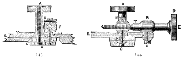
Fig. 143, 144.—Sections of clamp and tangent in two directions.
346.—Clamp and Tangent Adjustment.—The vernier reading to the circle, when this was adjusted by the hand, was scarcely practicable at nearly its full value until the discovery of the clamp and tangent screw motion was made. This useful invention is due to Helvetius, the celebrated astronomer of Danzig (about 1650). By this mechanical arrangement the circle or arc is left quite free to move about its axis until the clamp is screwed down, which then fixes it firmly. The fixing arrangement of the clamp is attached to a solid part of the instrument, but is so constructed that when it is clamped it may yet be moved without unclamping, in relation to the fixed part of the instrument, by the tangent screw which, as its name indicates, is placed in a direction tangential to the circle or arc. This arrangement may take many forms[203] in detail, two of which, the most general and especially adapted to surveying instruments, will be described.

Fig. 145.—Elevation and part section of clamp and tangent.
347.—The above illustrations, Figs. 143, 144, represent a clamp and tangent motion in two sections at right angles to each other. This form is common to vertical circles and arcs generally, of a theodolite, arc of sextant, circles upon some mining-dials, protractors, and many other instruments. Fig. 145 is partly a front elevation of the same, but with part of the clamp screw A cut off. The stem of the tangent screw is shown in section at E. In all the figures L is the limb of the circle or arc. This has a groove at its under side at G, into which a fillet of the clamping piece C is inserted to make the clamp slide freely about the periphery of the circle when the clamping screw A is loose. A spring is sometimes inserted to open the clamp between the sliding piece K and the clamp C. FF, Figs. 143, 144 is the tangent nut to E. This nut is sawn down and has a cross screw to keep sufficient tightness to prevent loss of time, and yet to allow the tangent screw to work pleasantly at the same time that it holds the circle and vernier quite dead to the position to which it is adjusted by the screw. The tangent nut F has to move to the direction[204] horizontal to the plane of the tangent screw; therefore it has an axis vertical to the plane of the clamp. This is shown at K. The axis is held down firmly by a nut and a washer fitted with a square hole, to prevent the nut unscrewing. The tangent screw has a collar fitting or shank at the tangent boss B, which is turned down from the full-sized metal of the screw. The fellow collar on the outer side of the boss is formed by the shank of the milled head of the tangent screw D. The hole through the milled head is made square, so that it can be adjusted up to the boss without risk of after unscrewing by friction by the screw E. This is tightened up by means of a screw-driver applied at E. The boss B has a vertical axis N, similar to the tangent nut, and is attached to a solid part of the instrument by the washer and nut shown at 0.
348.—The above construction is solid and good, and will bear considerable wear; but there is a little delicacy of touch required to adjust the collars to the boss and to give pleasant tightness to the screw; a better plan is to dispense with the split in the tangent nut and the inner collar turned on the tangent screw, and place a spiral spring over the tangent screw which follows the adjustment, or in some cases a long bow spring may be conveniently used in place of the spiral. These plans answer very well: one of them will be presently described for axis clamping. In place of the groove at G the clamp is sometimes constructed to move on an arm direct from the axis of the circle. This is on the average a pleasanter motion, but in complex instruments it would often interfere with the motion of other necessary parts.
349.—Axis Clamp and Tangent.—This is generally used to bring the horizontal axis of an instrument to bearing, and is made independent of the circle and vernier. The ordinary form, which is very effective when properly constructed, is shown Fig. 146. This form is used for clamping the vertical axis of a theodolite, mining-dial, Y-level, and some other instruments. The clamp C surrounds the axis as a[205] collar, from which two lugs in the same casting are projected at a. These are brought tight upon the outer axis socket B by means of the screw W, which has a wing-nut head to give good purchase. In the construction of this form of clamp the collar should be fitted and ground to its bearings with the lug in the solid, and the cut at a be sawn through afterwards.
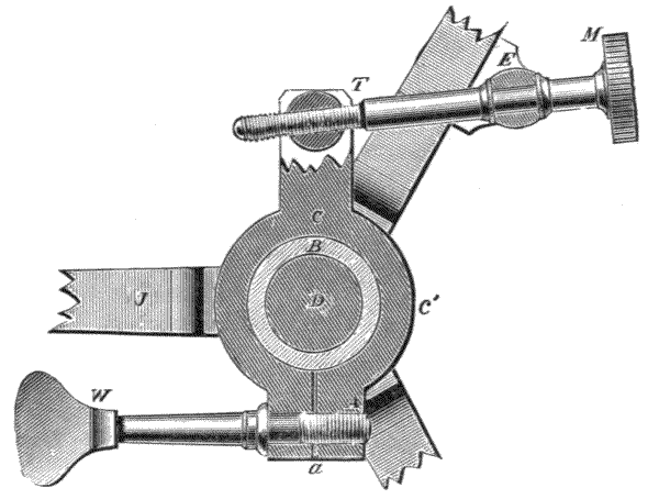
Fig. 146.—Clamp and tangent to a vertical axis.
350.—The tangent screw adjustment is shown at T, moved by the milled head M, the boss E being fixed to the instrument. This part of the arrangement is just the same as that described above for a vernier tangent. Objection has sometimes been made to this form of clamp, that it tends to become weak after a time from the constant clamping and releasing, which causes loss of elasticity in the metal. When this occurs it is no doubt due to the metal of the clamp not being good gun-metal; or, if brass, not thoroughly pressed or hammered before the piece is made up. A plan, in not uncommon use in Germany, of avoiding this supposed source of weakness is to bring up a tumbling piece direct on the axis by a screw. This is shown in Fig 147, screw W; tumbling piece A. This produces a direct clamp upon the[206] axis socket B′. The clamp ring CC′ is made loose on its socket.
351.—In practice it is found impossible to clamp the axis of a theodolite without disturbing the centre more or less. In some experiments the author made he found the direct or tumbling piece clamp Fig. 147, although it holds firmly, disturbs the centre much more than the clasping clamp Fig. 146. Therefore when the former is used the clamp should be upon a strong flange. This increases weight, and it can scarcely be so well for a portable instrument. In all cases, in the construction of the instrument, clamps should be fitted and screwed down before the centre is ground and finished. This ensures the centre being made correct in its clamped position, in which it will afterwards be used.

Fig. 147.—Clamp and tangent to vertical axis, German plan—Hunäus.
The arrangement Fig. 147 shows also a spring S falling upon a stud at E, fixed upon a part of the instrument upon which it acts as a fulcrum. The spring should be of hard rolled German silver. In this case the tangent screw needs no split or other adjustment to make it tight, as all loss of time is taken up by the spring.[14] The plan is found practically [207] to answer fairly; but unless this is very carefully made there is a want of solidity in the movement which a well-fitted, direct-acting tangent screw possesses.
352.—The French generally in all their superior instruments clamp upon a flange carried out from the lower rim of the socket, with the screw placed longitudinally to the axis. When this plan is very carefully carried out, so that the clamping has neither tendency to raise or lower the socket-piece, it is no doubt very good. In large instruments, where weight is no object and the flange may be made large, it is certainly the best plan. In such cases the clamp may be released as a free fitting to prevent the possibility of strain. Fig. 148 shows the French plan attached to a tribrach: S socket, F flange, C clamping screw, T tangent screw. The tangent in this arrangement acts against a spiral spring contained in a tube A, which gives a very steady motion to the instrument.
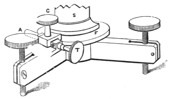
Fig. 148.—French axis clamp and tangent.
353.—Some particulars of the care required in the manufacture of the tangent screw were given, art. 22. The test for the equality of this screw, which is important when it moves a vernier, is to loosen its clamp and to see whether it works equally, firmly, and smoothly at all parts when it is turned down from end to end. The test for its straightness is to screw down the clamp, then to notice any little mark on the milled head of the tangent screw, or make a slight mark upon[208] it, and to place this mark uppermost, and then to take a reading with the vernier, then to turn the milled head a quarter turn and take another reading, and again another quarter, and so on consecutively. By comparing the rates of reading of the vernier at the quarter turns, if we find these equal the screw is straight. A little allowance is necessary for imperfect work. If the work is very bad at some quarter turns there will be an advance at the opposite quarter of nearly double the proper mean quantity.
354.—For Testing and Adjusting the Fitting of the Tangent Screw.—The clamp should be tightened down and the ball B, Fig. 144, held tightly between the thumb and forefinger; then, by using a gentle reciprocating motion in the direction of the tangent just sufficient to move the circle, if there is any looseness in the screw or the ball fitting B it will be felt as a jar, or technically, a slight loss of time. If this be in the ball B it can be taken up by the screw E at its end. If it be in the screw it can be taken up by the cross clamp screw. If it be in neither of these, it may be in one or both of the axes N and K. In this last case it will need refitting. It appears a somewhat simpler test with a theodolite to lightly press the telescope on one side of the eye-piece and take a reading of the vernier, and then to press the other side and again take a reading. This, possibly, indicates loss of time in the clamp and tangent if there is found any difference in these readings; but this would not be with any certainty, as the fault might be in some other part of the instrument. It, nevertheless, is a simple plan to test the whole instrument, including the clamp and tangent, although this does not localise any defect there may be in any special part of it.
355.—Use and Wear of the Clamp.—The common fault of a novice when he commences to use an instrument is that he applies too much violence to all clamping parts. Thus we find the lower parallel plate of an instrument soon becomes deeply indented, and the clamp of the tangent screw often[209] strained, or its screw worn loose by extreme clamping. The best rule to avoid this with a clamp is to make a personal test of how little force is required to produce sufficient hold for the action of the tangent screw, and when this is found out to try to clamp only slightly in excess of this. A novice scarcely recognises the power of a screw. It is, perhaps, a fault of some makers of giving much too large heads to clamp screws which to a certain extent permits this overstraining from clamping. In discussing this matter with a scientific civil engineer upon an instrument which had been very much strained, to which small clamping screw heads were suggested, this gentleman replied that he looked to the optician to "supply instruments, not brains," and made the user responsible; but, really, a young surveyor is generally so intent on the object of his work that he cannot consider the mechanical details of his instrument, to which his attention possibly has never been properly directed; so that there is a policy in cutting off possibility of injury to the instrument where this can be conveniently done.
356.—Use and Wear of the Tangent Screw.—Seeing that the axis of an instrument is quite free to the extent of the loss of time on the tangent screw which holds it, and that this freedom, by any slight touch of the telescope, may cause a difference of reading—in some cases of several minutes of arc—it becomes important to observe that the tangent screw is in good order. This matter considered at its full value, we may wonder, perhaps, what kind of work may have been done with the tangent screw loose and worn down in its central part, as we find it in many old instruments sent for repair. A great amount of the common defects we find in worn tangent screws might have been prevented by using certain precautions; and even the much-worn tangent screws would sometimes go on fairly by a different method of use from that to which they have evidently been submitted. The wear of a tangent screw is due principally to the fact that this screw is necessarily[210] oiled to make it work freely, and that the oiled part being exposed to dust, this dust attaches itself and works into the thread with the oil so as to cut both the screw and the nut. Precaution is necessary that this should be obviated as far as possible. One precaution may be taken, that when the screw is oiled, say once in three months, the parts outside the nut should be cleaned off quite dry with a few strands of thread. The oil left in the nut, if the screw has been turned through it, will be quite sufficient to lubricate the screw. Another better precaution is to use only one part of the screw for a period, say one month. The screw may be divided mentally into three parts—near part, middle part, and end part. If one part only be used for a period, and the vernier be set in using the instrument so that not more than about 1° of motion is required of the screw, no grit can be carried far into the centre of the nut; and if the precaution of cleaning the screw with thread be taken every time the instrument is returned to its case after a day's work, the screw being left at about the same place on the screw and nut, it will keep true with little wear. When another part of the screw is taken into use, this part should be first cleaned with thread and then oiled with watch oil, after which the former position of the nut should be cleaned quite dry with thread. Treated in this manner a tangent screw will last, in constant wear, for ten years or so, keeping in fairly good order. Where a spring is used to take up loss of time there is less risk, and the only precaution necessary is to be sure the spring continues to act properly. There is generally, however, a little more wear with a spring than with a free thread.
357.—If the instrument be not touched after the tangent is set, and there is no wind to cause vibration, the instrument will read correctly although the tangent may be out of order. But after the adjustment by the tangent screw, which may cause a disturbance, it is always necessary to set the microscope to the vernier. This is one important reason why the microscope[211] should move as softly as possible, and that it is advisable to centre it upon the axis. Where any doubt of the quality of the tangent exists, the telescope should be reobserved for verification of its position after reading, which is also undoubtedly the safest in all cases.
358.—Some contrivances have been applied to tangent screws to prevent wear from dust, and also to take up the nut after wear. A very good plan, common in American instruments, is to insert the end part of the screw beyond the nut in a closed tube. This entirely prevents dust from resting on this part; and if the precaution be taken to clean the exposed part of the screw after use it is very effective for preservation. This plan the author has combined with a spring arrangement, which appears to render it very safe from loss of time and much wear. This arrangement is, however, a little expensive to make, therefore can only be applied to high-class instruments. Fig. 149, C nut, through which tangent screw passes; B tangent boss, A milled-head, H covering tube to the point of the screw, GG′ EE′ pair of telescopic tubes which cover the screw. A German silver or platinum spring works inside these tubes, keeping a constant separating pressure between C and B to take up any loss of time in the screw.

Fig. 149.—Protected tangent screw with helical spring.
359—Free Tangent Screw.—There is always a risk of a tangent screw of any fixed kind producing a certain amount of strain upon the instrument, therefore, where practicable, it should be made free. The illustration, Fig. 150, shows the[212] form of free tangent the author now applies to many instruments. The centre stud is clamped to the lower part of the instrument by the screw shown in dotted lines. To the left hand a piston containing a spiral spring carries a pressing-rod against which the screw to the right hand works.
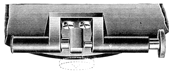
Fig. 150.—Free tangent adjustment.
360.—Loss of Time by Wear of the nut is variously taken up when no spring is used. One plan was shown of splitting it up. A plan common in Germany is to make the nut in two pieces, which are brought up by two screws. This is a very effective plan. The author has found a tumbling piece arrangement also effective. Fig. 151, S section of tangent screw, T tumbling piece moved by the adjusting screw, shown above, for wear of the tangent screw. This adjusting screw A should be tapped tight without oil, and put together dry to prevent its receding by pressure.
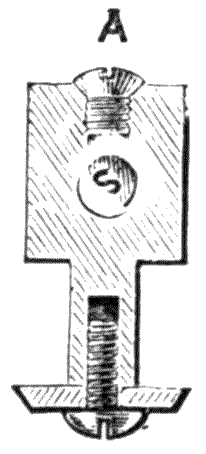
Fig. 151.—Tumbling piece adjustment for wear of tangent screw.
361.—Hypotenuse and Base.—Other trigonometrical values besides the division of the circle into equal parts are occasionally placed on instruments for special purposes. The most[213] common of these is the scale of difference of hypotenuse and base, which is generally placed upon the back of the vertical arc of a theodolite and upon some dials and clinometers. The division for this purpose is generally done by hand. The scale gives a percentage difference for certain angles. Thus when used with chain measurement, it gives the number of links of the chain to be deducted per chain of 100 links for the inclination of land that the theodolite or other instrument indicates in following the surface contour.
362.—A Horizontal Scale of Tangents was placed upon the surveying theodolites by Ramsden. This was divided upon a scale carried by the vernier plate, which read to the zero line (0°) of the limb. It is found in practice more accurate to take the tangent to any curve from a scale of tangents, as, for instance, that in Molesworth's pocket-book, and set this off upon the limb by means of the vernier.
363.—Gradient Scale.—Civil engineers engaged on railway work occasionally have a scale of gradients upon the back of the vertical arc 1 to 100, 150, 200, etc. These are better read from the circle with vernier from a table of gradient arcs.
THEODOLITES—CONSTRUCTIVE DETAILS OF 5-INCH AND 6-INCH TRANSITS—SPECIAL ADDITIONAL PARTS—PLUMMETS WITH SCREW ADJUSTMENTS OF IMPROVED FORM—STRIDING LEVEL—LAMP—ADJUSTMENT OF AXIS OVER A POINT—SOLAR ATTACHMENT—PHOTOGRAPHIC ATTACHMENT.
364.—The Theodolite is the most perfect instrument for measuring both horizontal and vertical angles by the aid of a telescope and graduated circles. For the purpose of surveying, the theodolite is mostly employed to take a system of triangles upon the horizontal plane of the surface of the land, and of objects at any position in which they may be placed. When altitude angles are taken separately these are generally applied to give corrections to chain or other actual measurements upon the surface by calculation of the difference of hypotenuse and base.
365.—The theodolite in all its essential features, as differentiated from sighted compasses for taking angles, mentioned by Digges,[15] was the invention of Jonathan Sisson, a celebrated mathematical instrument maker of the beginning of the 18th century.[16] Great improvements were afterwards made in this instrument by Ramsden, who brought it up nearly to its modern efficiency by the introduction of the transit principle.[17] Later improvements in portable instruments consist [215] in the application of the transit principle to the telescope, which was formerly applied to astronomical and the larger geodetic instruments only. Other improvements have been made more recently in constructive details.
366.—Theodolites were commonly made of two distinct types, which were originally distinguished as plain theodolites and transit theodolites. In the plain theodolite the telescope moves through an arc of about 45° upwards or downwards from the horizontal plane, but very few of these are now made compared with the number of transit theodolites in which the telescope may take a complete revolution upon its horizontal axis, so that a back and fore sight may be taken by a half revolution. This difference of construction entails a difference in the manner of mounting the telescope to correct its adjustments. In the transit the accuracy of centring and reading is easily discovered by taking a back and fore sight at a distance as equivalent to an arc of 180°, which may be read on any part of the limb by transitting the telescope, wherein the correspondence of this arc to the reading of the limb to right and left hands will detect error. With the plain theodolite the equivalent method of examination is effected by placing the telescope in Y's, as previously discussed for the Y-level, and turning it end for end on its bearings, a process liable to disturb the direction of the telescope unless special care be taken. In the following description of the details of construction of a theodolite it will be convenient to take the transit form of instrument, as this is more comprehensive, the original pattern being selected, as this may be constructed with the limited amount of tools generally found in a surveying instrument workshop.

Fig. 152.—5-inch transit theodolite (old form).
367.—The size of a theodolite is fixed technically by the diameter of the line of division upon the horizontal circle. A 5-inch or 6-inch theodolite is the largest size that may be carried comfortably in a single case; and no great advantage is gained by having an instrument beyond this size if the work[216] is that of the ordinary surveyor on town and county surveys. The verniers of 4- and 5-inch instruments read sharply to single minutes of arc, which is as nearly as can be plotted with any degree of certainty with an ordinary protractor reading by vernier also to minutes only; 6-inch instruments read to 30 but generally to 20 seconds. Occasionally 4-inch theodolites are selected for lightness at a sacrifice of capability and of distinct and exact reading. The following table gives[217] the average weight of the transit theodolite illustrated on the last page:—
| Instrument. | Case. | Overcase. | Tripod. | ||||||
|---|---|---|---|---|---|---|---|---|---|
| 4-inch | Transit. | 11 | lbs. | 8 | lbs. | 4 | lbs. | 8 | lbs. |
| 5-inch | " | 13½ | " | 9 | " | 5 | " | 9 | " |
| 6-inch | " | 19 | " | 10 | " | 6 | " | 11 | " |
| 8-inch | " | 36 | " | 20 | " | 10 | " | 18 | " |
If with lamp extra about ¾ lb. If with striding level extra about ¾ lb.
It will be seen that the 5-inch instrument of this class with cases and tripod, say altogether 36 lbs., is really of quite as much weight as a fairly strong man can carry through a hard day's work. The 5-inch instrument is therefore becoming more and more popular with practical civil engineers, and its performance, if of good modern work, is quite equal to the 6-inch of less than half a century ago.
368.—By giving a description in detail of a transit theodolite, the general principles of a great number of other instruments, particularly those of larger dimensions, will be included, except for certain details that the specialities of the particular instruments demand. The most convenient plan to follow in this description will be to take the structure of a 6-inch transit theodolite of common construction, as it is built up from its base, piece by piece, according to the rule of ordinary structure; where more modern theodolites vary mostly from this is in having many parts shaped out of the solid, which are screwed together in the form illustrated.
369.—The Tripod Stand of a theodolite of 6 inches and
under is generally made identical with that of a level, a
common form being that described for a dumpy, art. 216.
The arrangement of one turn-up leg, as shown Fig. 63, is
very advantageous for the theodolite if it is to be used on
[218]
[219]mountainous or even very hilly ground. For instruments exceeding
6 inches a framed stand, which will be described further on,
is better. Some makers use a framed stand for a 6-inch instrument.
The rigidity of the stand ought to be quite equal to that
of the work in the theodolite, or a little in excess, and when
this is attained it is sufficient. Where the stands of theodolites
so often fail is from the defective construction of the tripod
head, not at all from deficiency of timber in the tripod itself;
and overloading this, in adding weight without attention to
scientific construction, is worse than useless.
370.—In the following description of the transit theodolite the parallel plate setting-up arrangement is taken, as this is at the present time (1914) still in use in this country and in America. There is nevertheless great probability that it will not long continue to be so, as year by year the tribrach system, described art. 233, for levels is coming more forward, both for levels and theodolites. This tribrach system the author holds to be much more scientific, and when thoroughly understood, more simple and expeditious to work with. It is also to be recommended, as there is no possible risk of strain upon the general work of the instrument, nor risk of error from distortion of the vertical axis from strain in setting it up to adjustment. A constructive drawing of a common transit theodolite with parallel plates is shown Fig. 153, of which the following is a detailed description.

Fig. 153.—6-inch transit theodolite—back view, with sections.
371.—The Lower Parallel Plate N.—This has a large boss-piece taken up from its central part, which forms a dome of a hollow globular section, technically termed the socket, shown at X. In the interior of the lower part N a coarse female screw is cut, of about fourteen threads to the inch, which is used to attach the instrument to its tripod.
372.—The Upper Parallel Plate is constructed as a flange from a solid boss L. This piece is generally made in gun-metal of a form as solid as possible, to resist the straining action of the parallel plate screws. The boss is prolonged[220] downwards by a stem-piece, upon the lowest part of which a ball collar of globular section is firmly screwed. The screw is turned by means of two opposite holes, into which a powerful forked screw-driver is inserted, until it is jambed up too tightly against its shoulder to ever become loose by the ordinary use of the instrument. The ball collar fits into the socket carried up from the lower parallel plate. The whole of this globular arrangement is termed the ball and socket. The boss L of the upper parallel plate, with its stem, has a hollow conical hole through its axis, into which the body-piece, to be described, fits accurately. Upon its outer upper part an inset collar is formed which acts as a guide to the clamp K. At the outer edge of the parallel plate M′ four vertical, conical holes are made, which take socket-pieces, which are tapped as nuts to the parallel plate screws M. These socket-pieces are jambed into their holes tight home to their shoulders. The socket-pieces are made separate, both to give a greater length of female screws than the thickness of the plates, and that they may be easily restored at any time if worn loose in the threads by the action of the plate screws.
373.—The Parallel Plate Screws.—One in elevation is shown at M, with its point dotted, and one in section at M′. The four parallel plate screws are in opposite pairs, placed exactly at right angles to each other in a line passing through the vertical axis of the instrument. These are made of gun-metal about 3/8 inch in diameter, with a deep thread of about thirty-two to the inch. They require cutting on a nice steady screw-cutting lathe. The lower points of the screws are slightly domed, sufficiently only for the amount of rocking they have to take, so as to impress the lower parallel plate as little as possible. The milled heads M are placed between the parallel plates, not above, as previously described for levels. There being a constant strain upon these screws in use and by intrusion of grit from flying dust they soon become worn. After wear the threads may be recut deeper, and new socket-pieces[221] fitted to the upper parallel plate. To prevent wear the upper parts of these screws are sometimes encased in tubes—a plan very generally adopted in America. At the foot of one of the parallel plate screws a stay-piece is fixed to the lower parallel plate, which forms a kind of ring round the screw. This prevents the parallel plates from shifting upon the axis at the ball and socket. The parallel plate screws should be without any shake or what is technically termed loss of time. They should move firmly but softly. They should support the instrument against the ball and socket upon which the whole rocks to position by their aid, but not be screwed down too tightly, as this has a tendency to disturb the axis of the instrument however solidly it may be made. Makers often have instruments in their hands for repairs in which the parallel plate screws have been deeply indented into the lower parallel plate, with the centre of the instrument permanently strained more or less.
374.—The Body-piece.—The only outward part seen in elevation of this is shown at T: it is shown in section T′. This piece carries the limb of the instrument SS′ by a centred collar to which it is attached by screws. About the centre of the body-piece an inset collar is formed to take the clamp KK which bites upon it. The lower outer part of the body-piece forms a conical fitting in the boss of the upper parallel plate L. The interior is a hollow conical axis. The body-piece is generally made of hard gun-metal. The greatest possible care is required in its manufacture, art. 21. The interior and exterior should be perfectly concentric at every part. Much of the value of the instrument depends upon the perfection of the work in this piece.
375.—Axis Collar Clamp K has been already described, art. 349, and is illustrated in Fig. 146, which is taken from a theodolite, so that only specialities in relation to the instrument Fig. 153 need be noted. This clamp surrounds the body-piece and clamps it by means of the screw K shown on[222] the left hand. The clamp is connected with the upper parallel plate through the tangent screw, the head of which is shown at P, so that when the screw K is tightened the parts L and T are fixed together, except that a slow motion can be given to these parts by the tangent screw P. By this clamp and tangent arrangement the whole of the upper part of the instrument is rendered free to revolve, to bring the instrument to bearing when the clamp is loosened, the final adjustment being secured after clamping by the tangent screw. It is this part of the instrument which is used after setting it up to bring the magnetic needle true to magnetic north, or otherwise to direct the telescope to any established distant mark, object, or star that may be fixed for the zero or other index point of the horizontal circle, to which all readings from its position are referred.
376.—The Central Vertical Axis is shown only in half section at Z. This is made uniformly of bell-metal, in the form of a truncated cone, extending from the horizontal circle plate S to the interior of the socket N. Its fitting surfaces are at the two ends of the cone, extending about half an inch, the central part being chambered back. At the upper part a pin-piece centres the vernier plate, to which it is attached by a wide collar with three or four screws. A square shoulder rests with weight only just sufficient to support the instrument upon the body-piece. This part has to be so adjusted that the axis perfectly fits and yet moves freely. A square-hole collar and screw are fixed on the lower end of the axis, just to touch the socket of the body-piece, so as to secure the axis in its position when the instrument is lifted. An eye or a hook is fixed into the screw at the lower end to take the cord of the plummet used for fixing the instrument over a definite point on the ground. This is not shown in the engraving.
377.—The axis of an ordinary theodolite is made the weakest part. It is generally considered in the trade right for it to be so, as in case of accident no other part of the vertical axis system is likely to be deranged; and this is the easiest[223] part to replace, being, as it were, independent of other fittings. Whether this should be taken cum grano salis is a question; at any rate with the axis weak it is not policy to load the upper part of the instrument with metal—which in places at least, is generally made ten times as strong as the axis—when the instrument has to be carried about by a person over his shoulder. Some suggestions will be made on this point hereafter.
378.—The Horizontal or Lower Plate or Limb.—Sometimes the whole of the piece SS′ is termed the limb, but more generally this word is applied to the divided part only. This plate is of brass, and is attached to the body-piece by screws. The outer rim, which is somewhat triangular section, is undercut upon the inner side of its lower surface to support the clamp-piece, the outer edge being turned to a fillet to take the clamp which is rebated to fit it. The upper surface of the rim, or the limb proper, is turned to the frustum of a cone of about 45°. This part is covered with silver, which is beaten out to the conical form and soldered down upon it, and afterwards turned to true form. The dividing has been discussed in the last chapter.
The 6-inch instrument is generally divided to 20′, but sometimes to 30′, and the vernier reads to 20″ or 30″. The figuring is from 0 to 360, right to left, taken facing the instrument.
379.—The Vernier Plate is shown in section under P′. The vernier from which it is named is shown at VV′, Fig. 155. The vernier plate is carried from the central axis and forms the foundation for all the superstructure. The upper and lower plates are left very free where they are brought together, the verniers being generally sprung down just to gently touch the limb. The vernier surface is let down some distance into its plate for protection. The reading of the vernier has been discussed in the last chapter.
380.—It may be particularly noted, as already stated,[224] that the central axis and the body-piece are attached to the vernier and horizontal plates by screws. This plan might strike one as being unsound: it is not really so, the reason for this construction being that these axes are, or should be, of bell-metal, and that this metal being very hard and brittle it would not be so easily worked, or so serviceable as brass for the limb and vernier plate, neither would there be means of correcting errors which generally occur both in the workmanship and in the dividing of this delicate part. The adjustment for fixing the limb and vernier plate, technically called centring, in particular requires considerable technical skill. It is generally performed by the divider, who is a specially intelligent artisan. In the author's improved theodolite, to be described further on, the axis is in one casting with the standard; but in this case the construction is different, the axis being made larger and the whole body being in a special gun-metal which approaches bell-metal in hardness.
381.—The vernier plate carries the ball nut of the tangent screw, shown at Fig. 153J. The general arrangement may be seen by the section, but is more fully described art. 347. One thing is important in this screw, viz., that it should range without strain quite parallel with the plates, so as not to give the slightest tendency to elevate or depress the edge upon which it is placed during motion in any part of its thread. The clamp is sometimes placed between the plates.
382.—The Compass-box.—The general construction of this is shown, Fig. 155, W. In the transit theodolite it is fixed firmly by screws to the vernier plate and is made to form a steadying piece to the A-frames C′ C″ which support the upper part of the instrument. For this purpose the compass-box is made as a solid casting in brass, which is much stiffened by the raised step which forms the divided circle. Four solid lugs in the same casting project from the rim of the compass, and form stiffening pieces between the lower[225] parts of the A-frames; these are secured to the lugs by four screws, one of which is shown, Fig. 153, at a. The lug screws hold the whole superstructure together quite independently of the vernier plate, to which it is afterwards firmly fixed. The compass needle is lifted by means of a milled head, just inside one of the standards, not shown. For a general description of the compass-box see art. 138. The vernier plate carries two or more verniers. The verniers are read by a pair of microscopes, Fig. 155 MM′ placed one on each end of a radial arm N having its axis of motion upon a large collar of the vertical axis. By this plan, when one microscope is set to read by the coincidence of lines upon one of the verniers, the other microscope on the other arm or arms will be set also in like position over the other vernier or verniers.
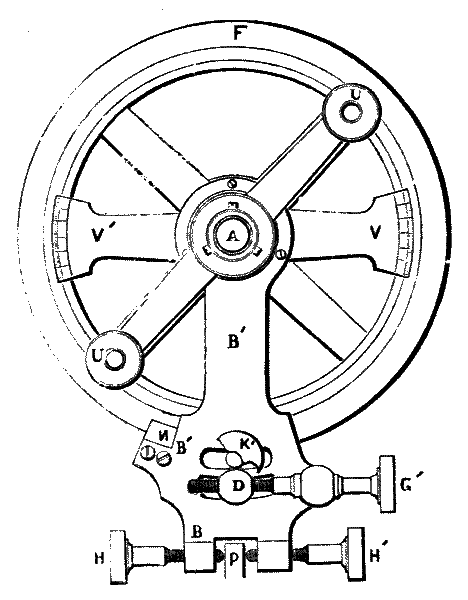
Fig. 154.—Vertical circle with clipping arm of transit theodolite.
The verniers are adjusted ready for reading when the[226] telescope is accurately directed upon any object of which it is desired to ascertain the angular position in relation to magnetic north, or a definite object. The vernier plate also carries a spirit level at O, Fig. 153, which is adjustable by a pair of capstan-headed screws.
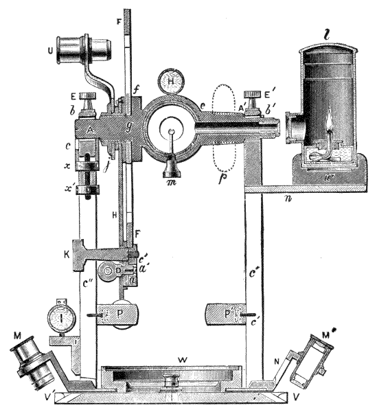
Fig. 155.—Cross section of the upper part of a transit theodolite.
383.—The Standards or A-Frames, shown C′ C″ Fig. 155, are solid castings in brass of about 7 inches in height. They are set up upon the vernier plate, to which they are attached by four stout screws, as also by cross screws to the compass as stated. This renders the superstructure of the transit as firm as may be in a built-up construction. Upon[227] the front of one of the standards a spirit level, Figs. 153, 155, I, is placed adjustable by two capstan screws. This level, and one shown Fig. 153 at 0 on the vernier plate are used entirely in setting up the instrument; and being placed at right angles to each other, are a means of making the vernier plate quite level. Upon the inside of each of the standards, at about 2 inches from the vernier plate, a clip-piece, Figs. 154, 155, P is secured by two screws. This takes the clipping screws, Fig. 154 HH′ to be described. At the top of the standards two V's are formed, upon which the transit axis rests. One of these is cut out of the solid casting. The other as shown in half section Fig. 155 c is formed as a parallel sliding piece with the V at the top placed in a vertical slot formed in the standard. This sliding piece has a screwed stem continued from its lower surface that passes through a vertical hole at the top of the A-frame, which is formed here as a cross-piece. Upon the screw two capstan nuts are placed, one on each side of the cross-piece, Fig. 155 xx′; these permit the adjustment of this in height so as to get the transit axis perfectly horizontal when the vertical axis is perfectly perpendicular to the horizon. The sliding piece is covered by plates back and front to render it firm in its position. The transit axis in practice is adjusted with a striding level which will be described presently.
With the author's theodolites from 6 inches downwards the old-fashioned adjustment to one upright for levelling the horizontal axis has been dispensed with for many years, and is only fitted if specially ordered, as it has been found to be a frequent source of error. Long experience has proved beyond doubt that the fewer adjustments there are, and the more parts that can be fashioned from the solid metal correctly, the longer will the instrument keep in adjustment. Should there ever be any wear on either of the V's a few strokes with a piece of very fine emery paper upon the opposite one will put it right in half the time that it could be corrected with the old-fashioned[228] adjustable V, and no amount of vibration can alter it as with the adjusting screws.
An axis cover cap bb′ is placed on the top of each standard. The cap is screwed down at one end with a cut screw and collar. The screw is used for adjustment to gentle pressure on the axis. The second screw is a milled head EE′. Under this screw the cap is slotted out to one side, and turns on the cut screw as an axis to open the cap without removing its milled-head screw, so that the telescope can be lifted out to turn its face to the opposite side of the instrument. In the under side of the centre of the cap a cell is bored out, into which a small cork is fitted, which produces, when the cap is clamped down, a soft elastic pressure on the axis.
384.—The Transit Axis which supports the telescope rests at its ends upon two trunnions, Figs. 154, 155 AA′, technically called pivots, in the V's of the standards already described. The pivots are turned as true as possible, and afterwards ground to exactly equal size in a collar, so that they may be reversed end for end in their bearings without changing the linear direction of the transit axis, except by the little difference of pressure that one end of the axis imposes by the weight of the vertical circle and its attachments being eccentric. In larger instruments this difference of weight is counterbalanced, as shown in dotted lines at p, Fig. 155. The centre of the transit axis is formed into a collar e of about 1¼ inches in width, which exactly fits the outer tube of the telescope, and to which it is fixed with soft solder. The collar is directly connected with and supports a flange f. Upon this flange the vertical circle FF is fixed by three or four screws.
385.—In front of the vertical circle a flanged collar-piece carries the vertical vernier frame VV′, Fig. 154, centred upon it. The vernier frame is attached by three screws to the clipping arm to be described, and in front of this the vertical microscope arms are centred. These carry two[229] readers U, Fig. 155, exactly similar to those which read upon the horizontal circle, and they are similarly centred, so that by setting one, the other is set at exactly 180° from it. In front of the centre of the microscope arms on the transit axis, an axis collar-piece j is attached by three screws cut directly into the axis. This collar and one at the other end of the axis A′, turned out of the solid, are nicely fitted to the opening between the standards to prevent lateral displacement of the axis.
386.—The Clips.—The clipping arm, which is centred on the transit axis and attached to the verniers, is shown Fig. 154 BB′B′. It is fitted to move freely on its axis at A, so as to permit unrestrained motion of the telescope. A milled-head clamping screw with clamp, Fig. 155, K, and the same partly cut away to show the slot in which it works, are shown at K′ Fig. 154. This is used to fix the verniers stationary on the circle, except for the adjustment by the tangent screw G′, which has its collar attached to the clipping arm, and its ball nut attached to the clamp at D when using the telescope for levelling. This clamp and tangent sets the vernier to zero on the circle. It is also used in setting the telescope before angles of altitude or depression can be measured. The clipping screws HH′ are used to bring the principal bubble B, Fig. 153, on the top of the telescope to the centre of its run after the verniers have been brought to zero by means of the clamp and tangent screws. The clipping screws hold the clips, Fig. 155, P or P′ to the one standard or the other. The whole of the vertical adjustment is exactly equivalent to that already described for the horizontal motion, except that it is placed in the vertical plane.
387.—The Vertical Circle, Figs. 154, 155, F is carried by four arms from a central boss attached firmly by screws to the transit axis. It is grooved at the edge to take the clamp-piece. The silver is inlaid in this circle in the manner shown Fig. 117. The vernier is read upon the circle on the plan[230] shown Fig. 127. The circle is divided generally to half degrees or 20′, and is figured 0 to the horizontal with 90° upwards and downwards. The zero lines are made directly coincident with the optical axis of the telescope when it is level. The vernier reads to half minutes or 20″, in either direction, the rising arc above the level datum being considered as plus, the falling arc as minus.
388.—On the outer edge of the circle or at the back a scale of difference of hypotenuse and base reads to a line on a fiducial edge upon a part of the clip BB′, Fig. 154, at N. This scale is calculated for decimal quantities, and gives the percentage number of links, feet, or metres to be deducted from the chain measurements upon the ground line to give the horizontal distance corresponding to the angle of inclination at which the telescope is set for observation.
389.—The Telescope, Fig. 153, DD′ has been described art. 94. Its general construction is also shown in partial sections in the figure. Its body tube passes through the transit axis in which it is soldered.
390.—The Principal Level Tube is generally mounted on the telescope upon two stiff screws which rise from plates attached to the telescope body by pairs of screws. Each level screw has a pair of capstan nuts. The level is mounted in a brass tube with stop-pieces at the ends, each of which carries a tenon with a hole in its centre through which the level screw passes to be clamped top and bottom by the capstan nuts. These nuts give adjustment to the level, so that the centre of its inner upper surface may be placed parallel with the optical axis of the telescope.

Fig. 156.—Stanley's new model of 4-screw transit theodolite.
391.—Until 1898 the author was unwilling to attempt to remodel the old form of transit theodolite, believing the 4-screw adjustment would soon become a method of the past, but as a small demand continued from the Colonies and United States for this form of instrument he felt bound to make it of more solid construction to bring it somewhat up to[231] date. The illustration shown, Fig. 156, is of an instrument, following in construction the transit theodolite already described in many details, the marked exception being that the standards are in one casting with the compass-box and axis, these being entirely shaped out in the solid metal. The upper parallel plate is of special design, being far stronger, yet lighter, and gives a much longer bearing to the levelling screws. The lower parallel plate is also shaped with three feet so that the instrument may be set up without its stand when required. It has also modern spring tangent adjustments with covered screws. The limb is covered, and the readers are jointed[232] across the axis to turn up without separation. It has a floating aluminium compass read by a microscope, so that the instrument, except in the four-screw arrangement for setting up, embraces many modern improvements formerly applied only to special high-class theodolites. The improved construction permits greater rigidity with fifteen per cent. less weight.

Fig. 157.—The plummet.
Fig. 158.—Gurley's plummet.
Fig. 159.—Loop.
Fig. 160.—Ring plummet, Shortt's Patent.
Of later years, however, the demand for four-screw levelling instruments has been maintained, especially from Canada, owing to the influence of the American school of teaching, and in consequence all the author's improved theodolites are fitted with either three- or four-screw levelling, whichever is desired. It is a strange fact, however, that with all the American makers, although they list all their ordinary instruments with four-screw levelling, their refined ones, which they term "precision" instruments, will be found with three-screw levelling.
392.—Detached parts of a Theodolite.—The Plummet supplied with the theodolite is made to hang from a hook under[233] the centre of the axis of the instrument, the cord, which is of soft silk, being looped or knotted to hold in the hook. The lower end of the plummet is brought to a point which, when in use, falls directly under the vertical centre of the instrument upon the surface of the ground. In Fig. 157 the screw and plummet are shown detached. The cord C is attached to the plummet by passing it through a hole in the milled-head screw S at the top of the plummet, and by making a knot K in the cord. Fig. 160 shows an ingenious ring plummet recently invented and patented by Mr. W. H. Shortt, A.M. I.C.E. The chief object was the production of a plumb bob whose plumbing point should be situated at, or very close to, the centre of oscillation in order that the position of the point might be unaffected by oscillation of the bob itself, apart from any swing which it might have about the point of suspension of the string. A further object was to shape the bob so that a person holding the string, or standing close to it when attached to an instrument and looking down at the bob, should be able to see readily the exact position of the plumbing point.
These objects have been attained by making the bob in the form of a ring, so that the centre of oscillation which lies in the centre of the ring can itself be used as the plumbing point, since it can be readily seen and indicated by the extremities of pointers projecting towards the centre from the inside of the ring.
A great advantage of this bob is that when plumbing on to a flat surface it does not fall over when lowered, but may be allowed to actually lie on the surface while the position of the point is being marked. Also it can best be steadied by lowering into contact with the ground and raising again.
The plumbing pointers are largely protected from injury when the bob is in use, and when not in use the suspension string can be wound diametrically across the bob, in recesses provided for the purpose, thus completely protecting the points.
393.—The Loop.—It is somewhat difficult in the ordinary way to adjust the plummet to the station mark on the ground or on a peg. The cord is sometimes placed in an ivory runner fixed to the top of the cord, Fig. 159. This gives friction on the cord and permits extension and contraction of the loop for adjustment. Where the plummet has to be suspended from the instrument as well as from a hook inside the stand, which is sometimes convenient, it is better to have the runner cut out on one side. This permits easy change and it is just as firm.
394.—Messrs. Gurley Bros. of Troy, N.Y., have a good plan for shortening the plummet line. This is effected by making a reel in the plummet, which is wound by a milled head at the top of it, Fig. 158.
395.—Screw-drivers, Tommy Pins, etc.—A screw-driver and a tommy pin, the last to turn the capstan heads, are placed in the case with the theodolite. Two screw-drivers with proper handles are better, as there are small and large screws. A camel-hair brush to dust the instrument, a piece of wash-leather, a little vaseline, and a small bottle of good watch oil are also very useful. These little refinements are generally kept out to keep down the price of the instrument.
396.—Additional Parts, and Variations in Theodolites.—Illuminated Axis.—4, 5 and 6-inch transits sometimes, and larger instruments always, have the transit axis bored on one side through to the interior of the telescope, as shown on Fig. 155. Through the hole a small pencil of light is sent by a lamp l with a plano-convex lens front, to a lens placed in the end of the axis. This, by a slight adjustment of the lamp on its stand, focusses the light upon a small mirror placed within the telescope, which reflects its rays to the diaphragm. The lamp gives a faint light only sufficient to distinguish the webs for night and underground observations. The mirror is about 1/10 inch in diameter, and is generally mounted upon a milled head screw tapped into the trunnion[235] band of the telescope m. The point of the screw is extended as a thin stem into the axis of the telescope, where the mirror is held by it. This arrangement permits the mirror, which is generally made of silver, but is much better of platino-iridium, to be removed for cleaning. The lamp is mounted upon a wooden stand w carried upon a slide n or upon two brass pins direct to the A-frame. The wood is employed in this case to cut off conduction of heat to the near standard from the lamp as much as possible to prevent disturbance of the axis from expansion by heating. The stand may be removed when the lamp is not required and placed in the case. In large theodolites a pair of lamps are used, that the transverse axis may not be heated more on one side than on the other.
397.—The Lamp, which is found so convenient for bringing a star or distant light to read with the webs, becomes difficult to use when the object is very faint, as the light thrown into the telescope by the lamp takes off the effect of blackness of the night sky or that of total darkness. This becomes important in taking observations of small stars, as for instance, the circumpolar stars of the southern hemisphere. In some theodolites, made first for the Sydney Government, the author placed a very small lamp to throw light upon the face of the webs only, making these appear as light lines on a black ground. The reflecting eye-piece, Fig. 20, will be found to answer very well, and this is a simple, inexpensive contrivance. Any amount of illumination desired may be thrown on the front of the diaphragm, according to the distance at which the light is held from the eye-piece: generally a very faint light only is required.
398.—The author has illuminated the webs front and back by means of a very small (one-quarter candle power) incandescent lamp, which is charged by a portable battery, or a secondary battery where a dynamo is at hand for charging it, and for countries where these cannot be renewed or where the extremes of temperature are too great for their use, he has[236] devised a small hand dynamo for generating the current and a rheostat for controlling the power of the lamp, so that resistance may be employed to reduce the light to the faintest possible glimmer.
The electric lamp is far superior to the old oil lamp and safe to use in gaseous mines; it is far cleaner, does not give out a tithe of the heat, and may be removed from its socket and used in the hand for reading the verniers in a bad light. All the author's modern instruments that are required with illuminated axis are now fitted with electric lamps.
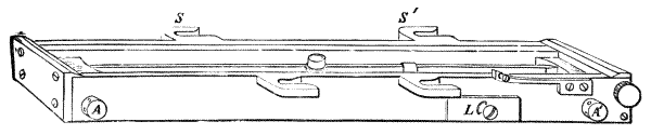
Fig. 161.—Trough needle for transit theodolite.
399.—A Trough or Long Compass, used in place of Circular Compass.—A long compass, Fig. 32, p. 74, is often applied to a theodolite, either upon the top of the telescope, or more generally and conveniently for reading under the limb. In this last case the trough needle is a separate piece, which is only attached to the limb of the theodolite by means of loop slides or bayonet fittings under the limb, when required to take a bearing. The engraving Fig. 161 shows the long compass with bayonet fittings. There are four slots, two of which are shown SS′, which fit in under the heads of round-headed, shouldered screws. The author has somewhat modified this pattern recently by making it slide into grooves.
The trough needle is generally made 5 or 6 inches long, and reads into a short scale of about 10° at each end. The divisions are best placed upon sliding fittings, so that they may be adjusted by four screws from the outside of the box—screws shown AA′. This enables the needle to be adjusted to its own axis, and also to the 0° reading of the horizontal[237] limb of the theodolite. A slide lift to the needle is shown at L. When the same form of compass is used upon large instruments a reader is placed at each end of the needle.

Figs. 162, 163, 164.—Striding level.
400.—Striding Level.—For the adjustment of the transverse axis of a theodolite a very sensitive spirit level is used. This is mounted upon a bed, which may be formed of brass tubing, from the two ends of which adjustable legs descend, the ends of which are forked, the hollows of the forks forming V bearing surfaces. The V's rest upon the pivot of the axis. By reversing the striding level on the pivots the transverse axis of the telescope, or transit axis, can be readily adjusted truly perpendicular to the vertical axis. In the construction of the striding level, shown in detail in Fig. 162, the two striding standards SS are carried down from the ends of the casing tube B of the spirit level. These are adjustable: one, Fig. 164, by raising or lowering the end of the level tube by the capstan screws CC′, and the other, Fig. 163, by a lateral adjustment of the capstan screws PP′ that act upon the stud S, which is fixed upon an arm centred upon the axis of the tube. This connection is shown by dotted lines. By these two motions the standards are brought to perfect parallelism with each other for their bearing surfaces and adjustment of the crown of the bubble tube.

Fig. 165.—Wallis' shifting centre for theodolites.
401.—Adjustment of the Axis for Setting it up over[238] a Point.—Every surveyor experiences an amount of difficulty in getting the plummet to fall from the axis of the instrument exactly over a point upon the ground, or a mark upon a rock, or still more so upon a point in street paving in a town, which is necessary for exact work. It is easily set near the point, that is, within half an inch or so, by pressing or shifting the legs; but the difficulty increases as the exact point is approached, so that the setting has generally to be left at a certain state of approximation. There are a great number of schemes in use for moving the axis by adjustment of the instrument the small quantity required, without disturbing the legs of the tripod when they are firmly set down nearly correct to position. One of these would no doubt be generally applied to the theodolite, except for the reason that every means yet devised adds to its weight, and also to the expense of the instrument. A moderately simple plan, which is especially adapted to the parallel plate adjustment, is to make the lower flange of the theodolite, upon which it stands when set down off its tripod, somewhat larger and thinner. This flange, instead of being screwed directly down upon the tripod head, is placed between two ring plates, which are clamped together when the theodolite is set in position. The large hole in the centre of the ring permits movement of the lower plate of about 1 inch. Fig. 165 is an arrangement of this kind by Mr. J. Wallis. This is made entirely independent of the theodolite, and may be used or not as required. I is a screw that corresponds with the head[239] of the tripod which takes the theodolite; T similar female screw to take the tripod head when the shifting centre is used; CC′ a box formed by screwing two tray-pieces firmly together; S clamping flange; HH′ clamp screwed into the top of box C. This has two handles by which the screw is moved to clamp when the instrument is in position. The weight of this additional part is about 3 lbs. The arrangement is particularly adapted to parallel plate adjustments.
402.—In an American plan of a transit by Messrs. Heller & Brightly, the flange is lifted by the parallel plate screws, which tighten it at the same time.[18] Messrs. Troughton & Simms have a plan of shifting the axis by means of a pair of eccentric plates, which carry the instrument in two directions nearly at right angles to each other. By this arrangement an amount of leverage is secured which produces an easier motion than that of shifting the weight of the instrument on the plans mentioned above. The author's schemes will be described as a part of his new theodolites a few pages on.
403.—Stadia Webs or Lines used for taking subtense angles by the telescope for measuring distances, which are frequently applied to theodolites, will be fully described, Chapter XII., in treating of subtense instruments generally.
404.—Solar Attachment to a Theodolite.—This appliance is an adaptation to the theodolite of the solar compass of W. A. Burt, of Michigan, which was made to replace the magnetic compass in determining a true meridian, or north and south line, by observation of the sun only. It was brought into general use in the surveys of the United States public lands. The solar compass consists mainly of three arcs of circles by which the latitude of a place, the declination of the sun, and the hour of the day can be set off. In the solar attachment to the theodolite the latitude arc is found unnecessary, as this is formed by the vertical arc of the [240] theodolite; therefore the hour and declination arcs need only be described.

Fig. 166.—Burt's solar attachment to a theodolite.
405.—The Hour Circle, Fig. 166, H is fixed upon the centre of the telescope upon a socket axis S, which is placed perpendicularly to the optical axis and to the transverse axes or pivots of the theodolite. This circle is divided to read five minutes of time, and is figured I to XII twice, or I to XXIV, the index being a fine line carried down on a plate from the lower arm of the declination arc, which is fixed to the socket S. The hour circle, when set to any reading, may be clamped to this position by means of the milled head placed over the socket M.
406.—The Declination Arc is of 5 inches radius, divided[241] to read on the same plane with a vernier V to single minutes of arc. The vernier arm is fixed by a clamp at C, which carries tangent adjustment T. At the back of the vernier arm two spur-pieces are carried out directly from it, L and I. These are blocks of metal about 1½ by 1¼ by ¼ inches, which carry each a lens of a focus L to I, and a silver plate to be presently described, upon which the sun's image is received in one direction or the other.

Fig. 167.—Image plate of solar attachment.
407.—The Image Plate, Fig. 167, is marked with two sets of lines intersecting each other at right angles. The lines bb are termed hour lines, the lines cc equatorial lines; these lines having reference respectively to the hour of the day and the position of the sun in relation to the equator. The intervals between the lines bb and cc are just sufficient to include the circular image of the sun formed by the solar lens on the opposite end of the vernier arm. The axes of the solar lenses and corresponding image plates are placed parallel with each other, and with the direction of the vernier arm. Below the lower line c three other lines are cut at 5 minutes apart. These are useful for making allowance for refraction. The following description for the use of the instrument is partly extracted from Messrs. Gurley's manual.
408.—When the instrument is made perfectly horizontal, the equatorial lines and the opposite lenses being accurately adjusted to each other by a previous operation, the sun's position in the heavens with reference to the horizon will be defined with precision. Suppose the observation to be made at the time of one of the equinoxes; the arm R set at zero on the declination arc V; and the polar axis is placed exactly parallel[242] to the axis of the earth. Then the motion of the arm R, if revolved on the polar axis around the hour circle H, will exactly correspond with the motion of the sun in the heavens on the given day and at the place of observation; so that if the sun's image be brought between the lines cc on the image plate in the morning it will continue in the same position, passing neither above nor below the lines as the arm is made to revolve in following the motion of the sun about the earth.
409.—In the morning as the sun rises from the horizon, the arm R will be in a position nearly at right angles to that shown in the illustration, the lens being turned towards the sun and the silver plate, on which his image is thrown, directly opposite. As the sun ascends, the arm must be moved around, until when he has reached the meridian, the graduated side of the declination arc will indicate XII on the hour circle; and the arm R, the declination arc V, and the latitude arc, that is the vertical arc of the theodolite, will be in the same plane.
As the sun declines from the meridian the arm R must be moved in the same direction, until at sunset its position will be the exact reverse of that it occupied in the morning.
410.—Allowance for Declination.—Let us now suppose the observation made when the sun has passed the equinoctial point, and when his position is affected by declination. Then, by referring to the Nautical Almanac and setting off on the arc his declination for the given day and hour, we are still able to determine his position with the same certainty as if he remained on the equator.
When the sun's declination is south, that is, from the 22nd of September to the 20th of March in each year, the arc R is turned towards the plates of the instrument in the opposite position to that shown in the engraving, using the solar lens at I, with the silver plate opposite at L.
The remainder of the year the arc is turned from the plates, and the lens at L and plates at I are employed in the position shown in the figure.
411.—When the solar compass is accurately adjusted and its plates made perfectly horizontal, the latitudes of the place and the declination of the sun for the given day and hour being also set off on their respective arcs, the image of the sun cannot be brought between the equatorial lines until the polar axis is placed in the plane of the meridian of the place, or in a position parallel to the axis of the earth. The slightest deviation from this position will cause the image to pass above or below the lines and thus discover the error.
412.—We thus, from the position of the sun in the solar system, obtain a certain direction absolutely unchangeable from which to run our lines and measure the horizontal angles required.
The transit theodolite will, without the solar compass, perform the same functions; but by means of this instrument the calculation for position is much more simple.
413.—Photographic Apparatus in Connection with the Theodolite.—The application of photographic apparatus as an accessory to surveying instruments has been tried tentatively for many years. A practical introduction to the subject was first given by M. Laussedat in a paper published in the Comptes Rendus de l'Academie des Sciences, 1859. The subject has since been well studied by many writers, and is written up extensively by Dr. E. Deville, LL.D., Surveyor-General of Canada, in a work entitled Photographic Surveying, published in Ottawa, to which we must refer the reader for full discussion of the subject. In England, Mr. J. Bridges Lee has invented a very suitable camera in which a negative glass photograph of 4½ × 3½ inches is taken, with an axis line from the shadow of a hair permanently photographed coincident with the axis to the telescope as it appears to view. At the same time degrees and subdivisions are taken on the photograph to right and left of the axial line. The edge of the magnetic circle is also photographed upon the plate, indicating clearly the bearing of the station taken by the axis line.[244] The whole of these operations are performed at once in a perfect manner.
414.—Mr. J. Bridges Lee's photo-theodolite was made in excellent workmanship by Messrs. Troughton & Simms. The inventor has published a paper on the subject, to be had of the Society of Engineers, Westminster.
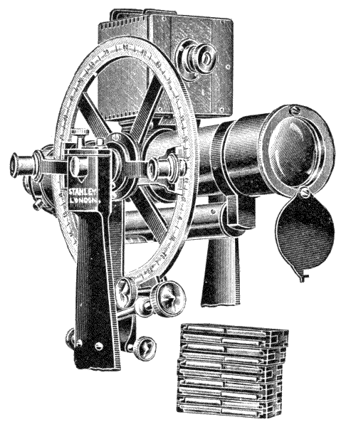
Fig. 168.—Light camera upon the telescope of a theodolite.
At the present time a camera is very commonly taken by a civil engineer for prospecting in new countries,—a convenient form of this will be discussed at nearly the end of this work—but it is not generally held that photography will ever offer a means of expeditious surveying, except possibly in very mountainous countries where the necessary stations for observation become difficult of approach and of clear definition. The objections to the more general adoption of photography are, otherwise, that the processes are in degree tedious, and require special skill in manipulation, and that the apparatus is heavy and expensive with sensitive glass plates for use with it.
415.—There are many cases, no doubt, where a photograph would be valuable for the exact definition of a station. To meet this case the author has made a small light camera, shown Fig. 168, giving photographs 2 × 2 inches only, with axis line from shadow of a point. The camera to be placed when required upon the telescope of a theodolite for special cases. He has lately used his patent slide for this camera that carries films which will be further described at the end of this work. The films are unbreakable, and remain sensitive many years if kept dry. The weight of this camera with its double slides and 100 films is about 1 lb. There is ample room for it in the ordinary theodolite case.
SPECIALITIES IN MODERN AND IMPROVED FORMS OF TRANSIT THEODOLITES FOR SURVEYING—RAILWAY WORK—EXPLORING.
416.—The description given in the last chapter of a 6-inch transit theodolite gives all particulars of the original Old English form, which in a general way comprises the constructive principles of all others. When we consider modern instruments the details are found to vary greatly, but most particularly in the direction of uniting in solid castings many parts that may be shaped out by machinery in a manner impossible by hand-work, which avoids the instability of the work being screwed together in many pieces, and makes it at the same time lighter, more rigid, and less liable to jar out of adjustment. This direction of construction is also followed in the best modern work on the Continent and in America. It would extend this work beyond convenient limits to offer details of the wide variations employed in practice, but as the author has made this subject a life study, and has embraced, modified, and endeavoured to improve this class of work in all its details, freely adopting any improvement he has observed, his own instruments will represent largely his present ideas of the best forms, with the economy of having engravings for illustration to hand. Transit theodolites of portable form will be considered here, leaving larger stationary instruments to another chapter.

Fig. 169.—Stanley's patent new model theodolite.
417.—New Model Transit Theodolite.—In this[247] instrument the principles of construction are the same as in the ordinary transit theodolite fully described in the last chapter, but the distribution of materials and details are very different. The general arrangement of a 5-inch instrument is shown in Fig. 169. One important difference, as before mentioned, is that the work is not built up so much in separate castings and pieces as is usual, but every possible casting is shaped out of the solid to the finished form. The vertical axis is of nearly the same construction as the ordinary transit, except that the central axis is about double as strong, being of once and a half the ordinary diameter. It is made in one casting with the upper framework. The vernier plate is[248] formed of thin hard hammered gun-metal, which is screwed upon the axis. This plate has not in this construction to support the superstructure as in an ordinary theodolite, but has only to hold the two axis bubbles, which are thereby brought distinctly in view, and the clamp and tangent motion, which is also placed conveniently for use upon this upper plate, in a position where there is less risk of accident than when it is placed upon the outer edge of the limb.
418.—The Readers to the horizontal limb are jointed to turn up against the standards and adjust for reflection, as shown Fig. 131. In this manner the readers do not need detachment to place the instrument in its case.

Fig. 170.—Section of standards of new model theodolite.
419.—The Central Axis and the standards are made in one casting in hard gun-metal. The standards are of light cylindrical and ribbed section. This construction, although of only about one-half the weight of the A-frame arrangement with its attachments, described in the last chapter, was found upon testing to have more than double the rigidity in resisting deflection, with perfect certainty of avoiding the accidental occurrence of imperfect fitting of parts, or of screws jarring loose, Fig. 170. The making of the vertical axis and the standards in one piece was in a certain sense an experiment. It has been found in practice of many years now to give much greater resistance to all ordinary strains and jars, and ensure the instrument keeping in order and adjustment when jolted by carrying over the shoulder, just as the same principle acts in the dumpy level; but at the same time, in cases of violent accident, such as the fall of the instrument from a height, it renders repairs somewhat more expensive, as this entire part[249] might have to be reinstated instead of the axis only, the axis of the theodolite being generally made very weak that it may go first, often indeed with a slight jar. Many details are the same as the transit theodolite before described, adopting what is thought to be the soundest principle in all cases.
420.—The Compass-box in this instrument is attached under the limb. It is of the trough form shown Fig. 32, page 74. The magnetic north is set to zero. The tribrach is of the form described for levels, illustrated Figs. 72 and 73, p. 128.
421.—The weights of transit theodolites of this construction are about
| 6-inch | in gun metal | 14 | lbs., | aluminium, | 8 | lbs. |
| 5-inch | " | 11 | " | " | 6 | " |
| 4-inch | " | 7¾ | " | " | 4½ | " |
This pattern embodies all the essential features of a thoroughly reliable and convenient instrument for all-round general surveying. It has no unnecessary elaborations and is a strong, light and compact instrument suitable for continuous hard wear. It has fewer pieces than any other design and is packed in its case complete in one piece ready to screw upon its stand upon being taken out of its case.

Fig. 171.—Stanley's simple sliding stage for tribrach theodolite.
422.—The author has devised a special arrangement for displacement of axis for this theodolite, which does not interfere[250] with its valuable quality of standing the tribrach on a wall or flat surface, Fig. 171. In this scheme the arms of the tribrach are slightly elevated by the foot screws. A flange is formed on the top of the head with a leading tube through it to the upper surface of the lower tribrach plate; upon this tube an upper flange is screwed, so that the plate comes between the two flanges, where it may be fixed by means of rotation of the flange by a thumb-piece. The engraving shows the arrangement with the axis displaced to its extreme point, about ¾ of an inch from the centre.
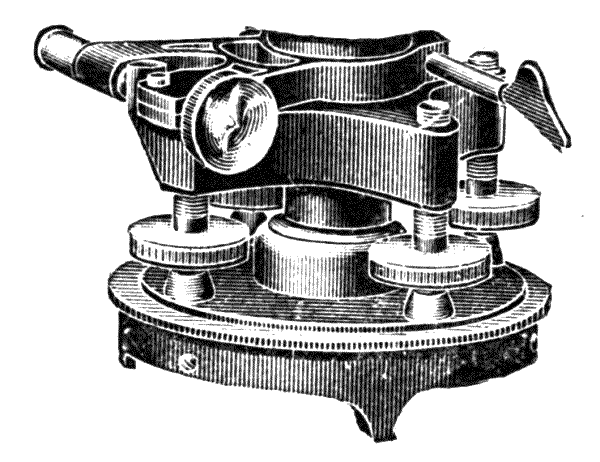
Fig. 172.—Stanley's 4-screw sliding stage.
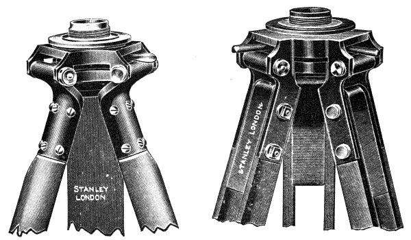
Fig. 173.—Stanley's solid round form tripod with sliding head.
Fig. 174.—Stanley's telescopic tripod with sliding head.
A somewhat similar arrangement is made for four-screw[251] levelling instruments shown on page 250 at Fig. 172, but in this the sliding motion is fixed to position by the action of the levelling screws. It is sometimes preferred to have the sliding adjustment upon the tripod head instead of upon the instrument, and in some cases for getting a greater range of movement, on both, and for this purpose the reviser has designed the two tripods shown at Figs. 173 and 174, the former being of the round solid pattern, and the latter having adjustable sliding legs. A somewhat similar arrangement is made for a sliding head to a framed tripod as shown below, Fig. 175.

Fig. 175.—Stanley's framed stand with sliding head.
423.—Improved Transit with Adjustable Axis.—This instrument, Fig. 176, in general, resembles that last described, except that it has a larger telescope and it is mounted on a sliding stage with screw adjustments, which is particularly described below. It is frequently provided with a tacheometrical eye-piece for giving horizontal distances by subtense taken on the incline, which will be described in Chapter XII.
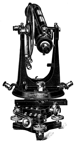
Fig. 176.—Stanley's patent new model theodolite, with mechanical stage.
424.—The Mechanical Tribrach Stage.—This important addition to the theodolite above described permits exact adjustment over a station. The upper plate of the tribrach[252] with the movable stage is shown in Fig. 177. A dovetail slide is fitted upon the base of the stage adjustable for wear by a slip-piece with two screws at the narrow part. The slide is adjusted to position in the direction of its dovetail fitting by a large milled screw so as to move the whole instrument above it for centring in this direction. An upper slide acting in the same manner, with dovetail fitting pieces at sides moves for an equal distance for centring transverse to the lower slide by a milled head. This gives the same kind of motion[253] of displacement that we have in the slide rest of a lathe or the mechanical stage of a microscope, except that in this case we have a kind of three-point bearing surface. The motion given to the screws permits the perfect adjustment of the theodolite over a point on the ground corresponding with the suspended plummet, after the instrument is set up to nearly its true position by movement of the tripod legs. The range of motion is from ¾ to 1 inch, a quantity quite sufficient for final adjustment, but which does not materially affect the equilibrium of the instrument upon its rigid tripod, as it has in this case a broad solid base even in the extreme positions of the slide.
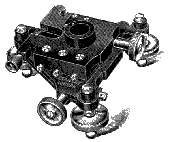
Fig. 177.—Stanley's patent tribrach mechanical stage.
This movement being above the levelling screws, the adjustment of the instrument for level is not affected by its use, as in the case of all sliding arrangements below the levelling screws. Suitable means are provided for taking up any wear that might occur in the slides.
425.—The above stage is supported upon three foot screws, the female fittings being specially long to give plenty of bearing surface to prevent wear; they are sawn down on one side so that they spring lightly upon the screws, and are provided with cross capstan screws for tightening up when[254] necessary. This plan gives the screw about ¾ inch of thread, and permits adjustment for comfortable movement and for wear without any risk of shakiness. The screw in larger instruments of this class has a cap to exclude dust. The foot of the screw has a ball which rests in a slotted tube before described, Fig. 71, p. 127.
426.—This theodolite with mechanical stage is generally fitted with illuminated axis for tunnel work, art. 383. The lamp is not shown in the illustration.
The weights of this make of theodolite are about
| 6-inch | in gun-metal | 18¾ | lbs., | aluminium | 10 | lbs. |
| 5-inch | " | 13¾ | " | " | 7½ | " |
| 4-inch | " | 9½ | " | " | 4½ | " |
427.—8-inch Transit Theodolite.—For ordinary surveying the smaller instruments are sufficient. For opening a survey in new countries the 8-inch instrument, Fig. 178, or a larger one, is generally used for the superior triangulation, particularly for observations at night of distant lights when greater light-grasping power is demanded of the telescope. The larger circle gives a more exact reading of the limb, which is generally divided to read clearly to ten seconds of arc, and by estimation sufficiently near to obtain five seconds reading very approximately with the verniers. When instruments exceed 8-inches, the reading is by means of microscopes, the application of which will be described further on.

Fig. 178.—8-inch transit theodolite.
428.—The 8-inch transit illustrated is of the author's
model. It is in general structure similar to the 6-inch just
described, except in certain specialities. The instrument does
not clamp upon the vertical circle, but a similar circle is provided
upon the opposite side of the axis. This answers two
purposes, it balances the pressure upon the pivots and obviates
disturbance of the division by the clamp. The principal
bubble is supported upon the vernier frame, as special exactness
is not required for the instrument to be used as a level.
The base support is upon the Everest tribrach system, which
[255]
[256]will be described in the next chapter. A long compass is
shown, but a telescopic compass is sometimes used. The
instrument is shown with an axis-lamp and diagonal eye-piece
for star observation.
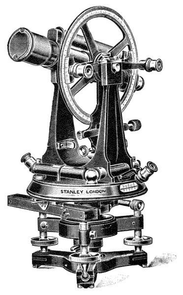
Fig. 179.—Stanley's quick-setting transit theodolite.
429.—The vertical axis of this instrument is sometimes pierced for a look-down telescope to sight its vertical position on the ground to the centre of a peg. This will be described with geodetic instruments in the next chapter. It is an expensive refinement, seldom necessary, as the axis with plummet may easily be brought within the tenth of an inch.
Theodolites of eight inches and over are uniformly packed[257] in two cases. The lower part is packed in a case by itself, the upper parts connected with the vertical circle and all the accessories, eye-piece, plummet, etc., forming the contents of another case, each part being sufficient for one man to carry without the tripod. The weight of the entire instrument is 29½ lbs.
430—Quick-setting Theodolites.—The demand for instruments with quick-setting arrangements has greatly increased of late years. They save a great deal of time in setting up, and also save wear of the levelling screws, as the instrument may be instantly set nearly level by its means, so that less than half a turn of the levelling screws will bring it to true level. An ordinary transit is shown Fig. 179, fitted with a similar arrangement to that described art. 240, p. 132.
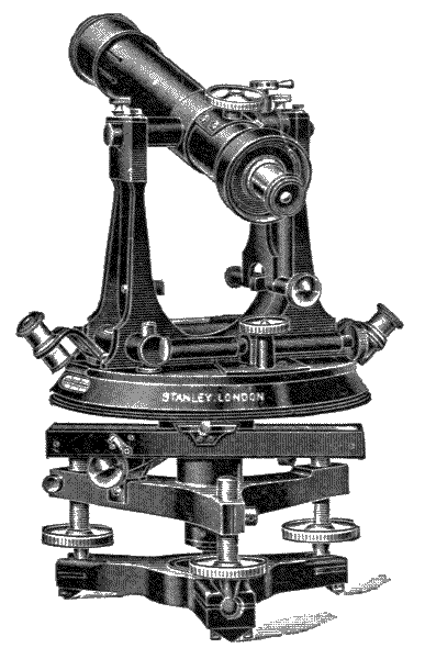
Fig. 180.—Railway theodolite.
431.—Railway Theodolite.—There are objections made to the transit theodolite by some civil engineers that it is a large and heavy instrument, only to be accepted for its perfect convenience over lighter forms. To meet this objection the author has made a special transit theodolite, Fig. 180, which is sufficient for railway work and general surveying upon moderately level country. The transit principle is conserved by balancing the telescope on its axis to permit it to transit over the eye-end only. The vertical arc is omitted as being unnecessary for railway work. The instrument is constructed especially low and of great rigidity and solidity, with light weight. The compass is of the trough kind. The limb is covered for protection. It is extremely portable. Weight of 4-inch, 7¼ lbs.; 5-inch, 9½ lbs.; 6-inch, 12¾ lbs. Being constructed for rough, hard wear and local use it is not made in aluminium.
432.—For tunnelling underground railways the mining theodolite described further on will be found the most valuable for railway engineers.
433.—Mountain Transit Theodolite.—This instrument, Fig. 181, is designed for geographical exploration, and making sketch surveys. It embraces the transit principle for the convenience of taking zenith stars. It is made in 3-inch and 4-inch sizes. It has two verniers to the horizontal limb reading to minutes, and a single vernier to the vertical circle. It has been made by the author in aluminium alloy only, the total weight being 2¼ lbs. for the 3-inch and 3½ lbs. for the 4-inch. The eye-piece reads direct or diagonally. It has clamp and tangent adjustment to both circles, and a trough compass. The tripod slides up to half length, each leg being adjustable to fix to any length within the range of the slide to accommodate it to the surface of inclined rocks.
434.—A Mountain Theodolite is a term applied to any very small or light theodolite. These are generally made to order, very frequently to a reduced model of a larger theodolite,[259] 3 inches being a common size. The telescope is occasionally placed upon the side of the horizontal axis to transit. Theodolites of this class generally weigh much more than the above-described instrument, a common weight being 5 to 7 lbs.
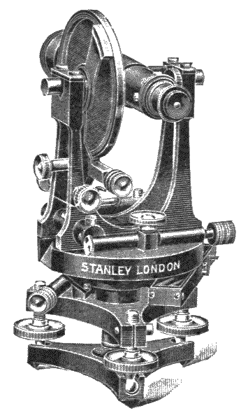
Fig. 181.—Stanley's mountain transit theodolite.
435.—Improved Solar Attachment.—The reviser's improved solar attachment admits of a full vertical circle being employed; it also has a clamp and tangent to the hour circle and declination arc and quick acting clamp and fine adjustment to the solar arm. An instrument so fitted is shown on p. 260, Fig. 182.

Fig. 182.—Stanley's solar attachment.
436.—Micrometer Reading Theodolites.—The favor with which the smaller micrometer reading theodolites have been received and the ever increasing demand for them owing to their much greater accuracy has induced the reviser to [260] introduce a whole range of these instruments. In many cases where greater accuracy is required for horizontal than for vertical angles, the micrometers are only fitted to the horizontal[261] circle and the vertical circle has verniers as usual. A useful instrument for general surveying without any unnecessary elaboration is shown below at Fig. 183.
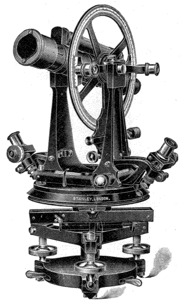
Fig. 183.—Stanley's micrometer transit theodolite.
The 6-inch instrument reads to 5 seconds of arc on the horizontal and to 10 seconds of arc on the vertical circle, and the 5-inch instrument to 10 seconds of arc on the horizontal and to 20 seconds of arc on the vertical circle.
A full micrometer reading instrument is shown at Fig. 184,[262] the 6-inch reading to 5 seconds of arc on both circles and the 5-inch reading to 10 seconds of arc on both circles.

Fig. 184.—Stanley's full micrometer transit theodolite.
A specially light form of micrometer reading transit (Fig. 185) has recently been designed by the reviser which has met with much favour. It has a 4½-inch horizontal circle reading by micrometers to 20 seconds of arc which may be approximately read by mental subdivision to 5 seconds,[263] and a 4-inch vertical circle reading by verniers to single minutes. It is also made micrometer reading to 20 seconds of arc to both circles. The compass is of circular form reading by microscope to ¼-degrees, which may easily be estimated to a third of this.
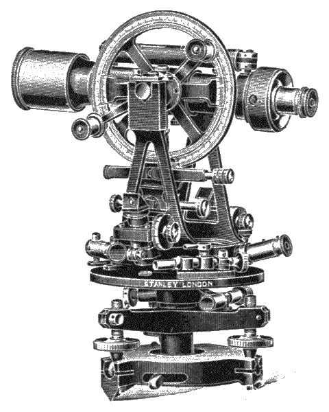
Fig. 185.—Stanley's light micrometer transit.
An example of a more refined micrometer transit is shown at Fig. 186. This instrument was designed by Dr. E. Deville, LL.D., Surveyor-General of Canada, and is arranged for latitude determination by Talcott's System, and general geodetic work.
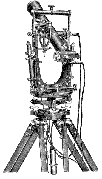
Fig. 186.—Dr. Deville's transit.
It has a 6-inch horizontal circle reading by micrometers to 5 seconds of arc, and a 4-inch vertical circle reading by vernier to 1 minute, with zenith spirit level graduated to 2 seconds of arc, detachable and interchangeable with a small [264] level for ordinary use. The telescope is 14 inches solar focus with large object glass so that observations may be taken of [265] stars up to the sixth magnitude; it has a revolving micrometer [266] diaphragm and electric illumination to micrometers, to diaphragm both front and back, and to zenith spirit level, it has also a rheostat for regulating the amount of light, and a dynamo generator for supplying the current.
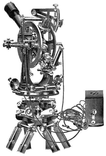
Fig. 187.—Stanley's patent universal transit theodolite.
The universal transit designed by the reviser is shown at Fig. 187.
This is an 8-inch instrument, reading by micrometers on both circles to 2 seconds of arc, and is fitted with all the necessary arrangements for universal work.
A description of the larger geodetic instruments is given in a subsequent chapter.
PLAIN THEODOLITES IN WHICH THE TRANSIT PRINCIPLE IS NOT EMPLOYED—THE PLAIN THEODOLITE—IMPROVED CONSTRUCTION—EVEREST'S—SIMPLE—ADJUSTMENTS AND EXAMINATION OF THEODOLITES.
437.—The plain theodolite is of nearly its original form as invented by Sisson. It still retains a limited popularity, which is principally due to its portability, being of less bulk and weight than the transit of equal diameter of circle. If we consider the railway theodolite described in the last chapter as a simple form of transit, this must be considered as an exception with regard to the bulk and weight, not being greater than that of the plain theodolite.
438.—The Plain Theodolite.—For the general description we may follow that given in Chapter VII. for the 6-inch transit for all parts of the instrument below the vernier plate, and for the compass-box above this plate. The construction of the instrument varies from the transit in having a half vertical circle only, with a single vernier, and in the differences in the arrangement of the fittings connected with the telescope. A single microscope is generally used on the horizontal circle, and this passes in a groove from one vernier to another, instead of having two microscopes on arms jointed upon the vertical axis, as in the better construction of transits before described.
The standards or A-frames in the ordinary plain theodolite are attached to the vernier plate, but not generally to[268] the compass-box. The pivots of the transverse axis, which are made exactly equal in size, rest on coupled bearings on the tops of the standards, which are in construction made together, and therefore exactly alike. The transverse axis is not adjustable, as in the transit theodolite previously described; the standards have therefore to be adjusted to height in the manufacture by filing, with the application of a special striding level, until the transverse axis is brought permanently perpendicular to the vertical axis.

Fig. 188.—5-inch plain theodolite.
439.—The vertical arc is fitted over the transverse axis; that is constructed with a turned flange to which the arc is firmly screwed. The arc is divided to 30′ and reads with a[269] vernier to minutes. The vernier is fixed directly to the vernier plate, and reads generally with a microscope jointed on the transverse axis, but sometimes with a loose magnifier for economy. Divisions for difference of hypotenuse and base are occasionally divided on the back of the arc. The vertical arc has a clamp and tangent placed at the back, therefore this cannot be shown in the engraving. Along the bar above the vertical arc a stout plate is attached by screws. From this a pair of Y's with clips and eye-pins, as described for the Y-level, art. 192, supports the telescope.
The telescope is of the same construction as that described for Y-levels, with turned collars. The diaphragm is cross-webbed. For economy a simple cap is generally put to the telescope instead of the better plan of a ray shade. The principal level is fixed to collars fitted round the telescope, to which are attached one slot-piece for lateral adjustment of the level, and one screw-piece for linear adjustment by means of two capstan nuts. The level is placed under the telescope for compactness.
440.—The parts of the plain theodolite below the standards are the same as those already described for the transit theodolite, except that the vernier plate carries one level only at right angles to that of the telescope. The telescope is therefore set to zero by the vertical arc, and the two levels are then used as the pair upon the vernier plate of the transit. The means provided for the adjustment are the same as those of the Y-level, but the Y's are adjusted firmly by the maker by fitting them down upon the Y-plate in the manufacture.
441.—The plain theodolite, except where price is the first consideration, appears to be going gradually out of use, being superseded by the transit. It has had a long day since its first conception by Sisson about 1730. For 4-inch and 5-inch instruments the makers still find a small demand. The 6-inch is rarely enquired for. The plain theodolite cannot compete with the transit for perfect utility, but it holds the merit of less[270] weight and of greater portability. The weights of the three sizes in general use are as follows:—
Weights of Plain Theodolites.
| Instrument. | Case. | Outer Case. | Tripod. | |||||
|---|---|---|---|---|---|---|---|---|
| 4-inch | 7 | lbs. | 7½ | lbs. | 3½ | lbs. | 8 | lbs. |
| 5-inch | 11 | " | 8½ | " | 4 | " | 9 | " |
| 6-inch | 17 | " | 10 | " | 5 | " | 11 | " |
Very light 3-inch and 4-inch plain theodolites of from 5 lbs. to 7 lbs. complete are made occasionally for travellers.
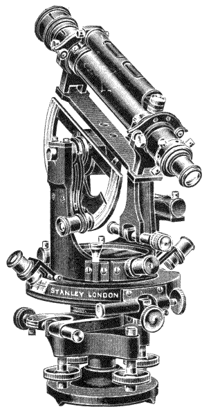
Fig. 189.—Stanley's new model plain theodolite.
442.—The author has recently modified the plain theodolite, Fig. 189, for which there still remains a small demand[271] in the Colonies, by making the construction much more solid by shaping the work out of single castings in gun-metal for parts formerly screwed together in many pieces, which formerly was necessarily arranged to permit facility of construction by hand-work. There are also in the new instrument some improvements made in detail. The limb dividing is covered for protection. The readers are joined through the vertical axis and are hinged to turn up. The compass has an aluminium ring with a microscope which permits it to be read at a convenient height and much more accurately. The tangent screws are covered to exclude dust, and some other improved details.
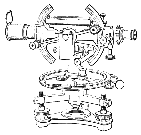
Fig. 190.—Everest's theodolite.
443.—Everest's Theodolite, Fig. 190, designed by the late Sir George Everest, and used for details of the great trigonometrical survey of India, is built up very much upon a well-known common French model. In service in India it has proved an excellent instrument. The horizontal[272] circle or limb of this instrument consists of a single plate, upon which the silver is inlaid flat upon the surface, upon the plan shown, Fig. 128. In place of the ordinary vernier plate three arms are extended from the central axis, which carry each a vernier at its end, reading to a fiducial edge, Fig. 127, p. 186. The verniers trisect the circle, and are marked A, B, and C. A fourth arm, proceeding from the same relative position of the centre as the arms of the vernier, carries a clamp and tangent which is similarly constructed to that of the ordinary theodolite described. The instrument has also an under clamp and tangent for setting the telescope to bearing, or for repeating, as in the ordinary theodolite.
444.—The horizontal axis carries the telescope in a cylindrical fitting as in the transit theodolite, terminating in two pivots which are set to permanent position as in the plain theodolite. The pivots rest in bearings upon short standards carried out from the centre upon a flat horizontal bar to which a spirit level is attached for adjustment of the pivots to horizontality. Vertical angles are read off upon two arcs which have a horizontal axis as their centre attached to the telescope, so as to move with it in the vertical plane, with clamp and tangent adjustment. An index, upon the same centre carries two verniers and has a spirit level attached to it. The verniers are read by a pair of microscopes. Upon the upper side of the telescope a trough needle is placed.
445.—This instrument has been used in military surveys by the Royal Engineers. The objections that civil engineers have made to Everest's theodolite are that the working parts are made very open, so that the wet and dust intrude; further it lacks the general convenience of the transit principle, which is necessary for astronomical observations. The tripod is sometimes made of the ordinary solid section, art. 216; but for India, where carrying labour is cheap, a heavy framed stand is used, which is special, as follows:—
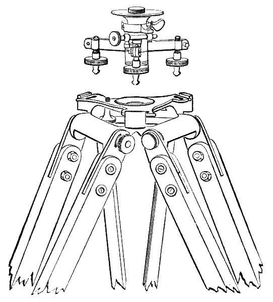
Fig. 191.—Everest's locking plate tribrach.
446.—Everest's Tribrach.—The upper part of the engraving,[273] Fig. 191, shows this tribrach that supports the upper part of the instrument directly upon its vertical axis. The three arms of the tribrach carry each a milled-headed adjusting screw, the nut of which is formed in the arm. The arm is sawn up to admit of adjustment, that the milled head may turn softly but without any shake. The lower points of the milled-headed screws, technically feet, fall into V-grooves in the head of the tripod. The V's are not shown in the engraving. Above the upper surface of the tripod head, a thin, three-armed plate of metal, termed the locking plate, is centred upon the hollow axis of the head, so that it will move laterally. The locking plate has a hole and slot at the end of each of its arms, the holes of which admit the toes of the feet of the tribrach into the V-grooves formed in the head of the tripod. The locking[274] plate when moved laterally locks all the toes in at once, so that the instrument is secured by this means to a certain degree from accident. This locking plate has commonly a milled-headed screw clamp which fixes it in its locked position. The head of this screw is under the tripod head, and consequently cannot be shown in the engraving. It is a defect of this locking plate that the screws, unless they fall perfectly in the V-grooves have a tendency to ride. To avoid this the author has for many years made the ball feet fall upon a plain surface, being at the same time held in their places by a slotted plate which fits over the neck of the balls. This plan, which is not shown in the engraving, is now adopted by other makers. The author uses also his patent tribrach sometimes on this instrument.

Fig. 192.—Stanley's Everest theodolite.
447.—The Framed Tripod of Sir Geo. Everest's design is made of straight-grained mahogany, each leg being formed of two side-pieces, with one or two cross-pieces. The engraving, Fig. 191, shows the head of a tripod of this construction. The side-pieces are spliced together at the lower ends, where they form a rather obtuse point, which is shod with a gun-metal shoe. The upper ends of the side-pieces carry strap plates that receive a bolt which holds them firmly by means of winged nuts to the tripod head. The legs can be detached after use and the tripod head be placed in the case with the instrument in a packing provided for it. Some modification of this form of tripod is generally used for all large field instruments. The author's improved Everest theodolite is shown at Fig. 192.

Fig. 193.—Simple theodolite.
448.—Simple Theodolite.—The plain theodolite being of the cheapest construction may be stripped of its superior functions, which are used for testing its adjustments, and be made into a simple angle measurer for laying out or plotting small parcels of ground, small estates in building ground, local[276] sewage, gas and water works, and many other cases of small surveys, for which purpose it will be found sufficient, with a saving of about half the cost of a perfect theodolite. The instrument shown above, Fig. 193, was designed by the author to meet the above cases. In this instrument there is no vertical arc. The telescope has a socket axis carried upon a single standard. The axis cannot be seen in the figure from interference of the telescope placed in front of it. The telescope is arranged to be fixed in a level position by means of the loose pin being pressed in a pair of holes. It may then be used as a level by means of the spirit level shown on the vernier plate. The horizontal circle is divided to read with a single vernier to 3′ of arc by means of a hand magnifier which is placed in the case with the instrument. There are internal and external axes, each provided with clamp and tangent motions to the horizontal circle, as with the plain theodolite. It is supported on a tribrach, the legs of which are upon the plan, art. 249.
If it be made with two verniers and divided upon silver it becomes a useful light instrument for filling in details of superior triangulation. Weight, about 4¾ lbs.
449.—Examination and Adjustment of the Theodolite.—The description given of a transit theodolite, arts. 369 to 389, will show that this instrument is provided with means of adjustment in every requisite direction. Larger transit instruments possess the same means of adjustment, but in some parts these have greater refinement. Plain theodolites have the like methods, except in the case of the transverse axis, which is adjusted once for all by the maker. It will be necessary, therefore, to limit our space to a discussion of the examination and adjustments of the transit theodolite only, of which we have given a full description, arts. 369 to 389, noting only where variations occur from partial differences between this and others.
450.—A theodolite as it comes from a respectable maker[277] is usually carefully adjusted in all its parts. If it has travelled a long journey it is, however, well for an experienced surveyor to put it through its various adjustments. The corrections, if any are required, will be generally very small, and these in all probability will be of the same kind as will occur in the use of the instrument and in the accidental conditions to which it may be subjected during conveyance from place to place upon a survey; therefore it is well to be familiar with them.
When a new instrument is received from the maker, it is necessary to observe attentively the manner of its packing as it lies in its case. It is well at first to lift the parts a few times gently out of the case and replace them, so that this may be done at any future time with certainty and without any risk of strain upon the instrument, remembering always that an instrument in conveyance is much more liable to be thrown out of adjustment by carelessly replacing it in its case than from its ordinary use, art. 42.
451.—For examination or adjustment of the theodolite the tripod stand should be at first firmly fixed with legs extended to an angle of about 70° to the ground, which should be solid and hard. As the telescope has to be brought to the height of the observer's eye, it is well to mention his stature in ordering an instrument. The tripods that are made for tall men are often awkward and unsteady if the legs are extended to bring the telescope down to the height of a short person. They may always be cut down and refinished by the maker. When the tripod is set up the toes should be each separately pressed down, so that future slips are impossible. This being done the instrument is taken from its case and grasped firmly by the body part under the horizontal circle, and placed on the tripod at once, then screwed firmly but not too tightly down upon its bearing surface. With a 6-inch transit theodolite the upper part is sometimes detached and packed separately in its case. Where this is so, after the body part is fixed on the tripod, the cleats on the top of the[278] standards must be opened out, and the upper part of the instrument, lifted by its telescope, be slowly lowered into its bearings, being particular at the same time that the clips under the telescope embrace their stay-piece on the standard. The cleats must then be closed over the pivots. The instrument being set up to position, all levels may be adjusted to the centres of their runs, and every part clamped sufficiently to make the instrument firm, but in no case using violence to produce a strain in any part. The clamps or other fittings are afterwards separately released as they are required for examination or adjustment of the parts to which they relate.
452.—Examination for Coincidence of Exterior and Interior Vertical Axes.—The theodolite being set up solidly, and all clamps fixed as above described, unclamp the lower or exterior axis clamp and set the vernier plate levels parallel with opposite pairs of parallel plate screws if the instrument adjusts on the parallel plate system, art. 193, or one level parallel with one pair of foot screws if it is made on the tribrach system, art. 234. Now adjust both levels. Turn the instrument half round (180°) and observe if the levels keep the centres of their runs. If they do so they are in adjustment to the exterior axis. If found imperfect, the adjustment by the capstan heads of the levels is set, by means of the tommy or pin which is provided in the instrument case, for half the error as it appears by the bubble, the other half being given by readjustment of the parallel plate or tribrach screws. In these adjustments it is necessary to be particular always to observe the bubbles after the hands have left the instrument, not during the adjustment, which produces strain upon the instrument. Now clamp the lower clamp and note if this clamping has disturbed the levels. If the levels are very sensitive it will do so in a slight degree, but the disturbance should be very small if the clamp is perfect. Now unclamp the vernier plate and note again if this clamp[279] disturbs the levels: this should also affect them very little. Now observe the levels if they stand exactly as they did when the exterior axis was unclamped at their present position, and also at right angles to this. If they remain as before the axes are truly concentric. If they do not, there is no remedy except at the hands of the maker. The vertical axis to which the above examination applies is considered the most important part of the instrument, and the work should be thoroughly well done; nevertheless, if the levels are very sensitive, which they seldom are, such minute faults may be detected, that a small allowance may be made for imperfection of work, and the instrument still be considered a sound one. In the use of the instrument it is always well, after the circle is set either by the magnetic compass or by sighting a distant point for direction, to clamp the lower clamp and readjust the levels to the vernier plate. In this way the axis that will afterwards be used for triangulation will be vertical, and small errors due to want of coincidence of axes be eliminated.
453.—Examination of the Azimuthal Level.—This level, which is placed over the telescope, being made of superior sensitiveness to the vernier plate levels, is much more accurate for adjusting the vertical axis, but much slower in operation for testing. The verniers of the vertical circle should be accurately set to zero, in which position the run of the bubble should exactly agree with those on the vernier plate when placed parallel with them in any direction, but this level may also be considered by itself. Assuming the circle and verniers correct, or otherwise, it may be reversed over the axis by half turns in all positions over the parallel plate or tribrach screws, and adjusted by the capstan heads half the error, as before described, for the vernier plate levels.
454.—Examination of the Divisions and Centring.—The vernier plate being unclamped, the verniers, if two, should be brought approximately to 0° (360°) and 180°, and then the plate be lightly clamped. The microscopes or readers[280] are then to be set truly radial with the zero reading of the verniers, and the tangent screw adjusted to make one of the readings, say the 360°, exact. The opposite reading, 180°, is then carefully examined, and the error discovered, if any, is due to the imperfection of centring, assuming the dividing perfect. At this point it is well to record the amount of difference. The same examination is then repeated with the 90° and 270°. In a properly centred and accurately divided 5-inch or 6-inch theodolite this difference will not amount to more than 1′ error, in larger instruments proportionately less. Owing to the difficulties at all times of reading the circle correctly from difference of direction of light, and what is termed personal error, it is well to entirely repeat this examination, turning the instrument half round. It is also well to repeat the examination at what are termed the half points, 45°, 235°, and 135°, 315°. This will sometimes detect the error of centring, if there be any, in its true direction. The purpose of the two verniers is to discover this error. In practice the two readings are always taken, and the mean is considered as the true reading. Where there are a greater number of verniers exactly the same principle is followed, but the mean of three or more readings is taken, which of course assures great accuracy.
Examination of the telescope has been discussed arts. 107 to 115.
455.—Testing an Instrument for its Stability.—The stability of an instrument will depend principally upon the quality of the workmanship; but the same test will also indicate, at any time, whether the instrument has been submitted to sufficient wear to need the repair of the optician. For this examination the eye-piece of the telescope requires to be focussed against a piece of white paper held obliquely in front of the object-glass so as to throw a soft white light into the telescope. After the eye-piece is focussed, any distant point may be taken for a sighting object upon which to direct the[281] telescope. This point should be focussed by the telescope so that its image falls centrally upon the intersection of the webs. The eye should then be shifted up and down or sideways within the range of clear vision of the webs in the eye-piece to ascertain that there is no parallax, that is, that the adjustments of the eye-piece and the telescope are in true focus upon the webs. This preliminary arrangement being made, which will serve in future examination for other adjustments, all parts of the instrument should be examined to see that the clamps are firmly clamped. The object to be used as an index or sighting point should be brought by the clamp and tangent motions exactly upon the intersection of the webs as they appear in the telescope, when the following examinations are to be made.
456.—Tripod Head Examination.—The telescope being sighted upon an index point, and all clamps screwed down and the tripod firmly fixed on the ground, take the tripod head of the theodolite in both hands and give it a twist of about a pound pull in one direction; then examine the telescope to see if the index point is displaced in the telescope. If it still stands correct give a like twist in the opposite direction and again examine the telescope. If it stands these opposite firm twists retaining its position the stand is good and in good order. If it does not, assuming good construction of stand, the remedy may be found in tightening up all its screws; but if its construction is bad it will not, even after this tightening, keep in order. There is no doubt that more inaccurate triangulation is caused by defective tripods than from any other cause whatever. A perfect instrument is useless on a bad tripod.
457.—General Examination of Fixed Parts.—The stand being found good by the above process, the general fittings of the instrument may be examined, after clamping all parts and directing the telescope to a distant point, by taking a quill pen by its root or pipe and pressing its feathered end[282] upon one side of the eye-piece of the telescope sufficiently to bend the quill, and afterwards examining the telescope to see that the webs are not displaced from the index point. This may be done first to the right hand and then to the left. If the webs still cut the same object it is clear that the whole of the centres, fittings, clamps, and tangent screws of the horizontal circle are correct. If any displacement be discovered, the amount of difference between the right and left handed twists will be the total error due to imperfection of work or wear as the case may be. In exactly the same manner, but by pressing the eye-piece upwards and downwards, the transit axis and its fittings may be examined. If the instrument be not generally sound enough to bear the above tests, other critical adjustments become necessary. For the correction of faults that may be included in the above operations, the parts of the instrument must be separately examined.
458.—Examination of the Transit Axis.—The best means of adjusting this axis in a theodolite is by a striding level, art. 400. When this is not provided with the instrument, and it is often omitted for economy, the axis is generally better to be left as it is adjusted in this particular, by the maker. To adjust the transit axis the vernier plate bubbles are set exactly true by reversing angles of observation. The cleats are opened and the striding level is mounted above the instrument resting upon the pivots. The telescope is placed exactly over an opposite pair of parallel plate screws, or parallel with two screws if the base adjustment be on the tribrach principle. The striding level is then carefully observed and reversed on the pivots. If there be any difference in the run of the level bubble the transit axis is adjusted by raising or lowering the movable V on which one pivot rests by turning the capstan nuts until it is quite correct, if the instrument has this old-fashioned arrangement, or if not, by a few strokes of fine emery paper upon the V which is higher. This adjustment is almost superfluous, as the axis is generally set right at first,[283] and is not subject to change, especially if solid without an adjustable V.
459.—For larger theodolites of 12 inches and over, the transit axis is much better adjusted by means of an artificial horizon, which will be described further on. By the use of this instrument in the northern hemisphere the pole star is first observed directly by the telescope, and then by its reflection from the horizontal surface of clean mercury placed on the ground at 12 feet or so from the instrument. If the star and its reflection cut the webs equally in directing the telescope by movement of its transit axis only from the one to the other, this axis must be truly horizontal. If the vernier plate be then turned a quarter of a revolution and the exterior axis a quarter of a revolution, the telescope transitted and observation be repeated, the verticality of the principal axis may be adjusted with perfect certainty. The principal axis should be moved one-eighth of a revolution all round and the bubble examined at every position to assure perfect adjustment. With the plain theodolite, Everest's and some others, the transverse axis is fixed to position by the maker, therefore cannot be adjusted.
460.—Examination and Adjustment of Webs, Lines on Glass, or Points.—The ordinary manner of webbing the diaphragm of a theodolite was shown Fig. 23. Horizontal angles are taken by the upper intersection of the diagonal webs or lines. A single web is placed horizontally for taking vertical angles: it is necessary that this should be nearly true. When the theodolite has its axis vertical, as shown by the vernier plate bubbles being in the centre of their runs, if one end of the horizontal web or line be set to cut a small distant object by sight in the telescope, the same object should keep on the web while the tangent screw of horizontal circle is moved a distance sufficient to traverse it, the hand being always taken from the screw while the observation is made. If it does not do so, the collimating screws should be lightly tapped with the back of a penknife in the[284] direction to set it right. These screws have a slot in the body of the telescope, under the loose covering plate, sufficient to permit of this small adjustment.
461.—Adjustment of the Telescope to Vertical Collimation.—The eye-piece is first focussed as before against a piece of white paper held obliquely in front of the object-glass until the webs are sharply seen. The axis of the telescope is then examined for vertical collimation error. The method of doing this has been already described for a telescope placed in Y's, as it is in the Y-level, and the plain theodolite, art. 200. The only difference with the transit theodolite is that instead of turning the instrument in its Y's, the telescope is transitted, as it is termed, over on the transverse axis exactly half a revolution, or 180° as seen by the vernier reading; and the horizontal circle is moved also half a revolution, so that the telescope points again on the same distant point which is used for an object. If the webs or lines still cut the same point or small object, they are in vertical collimation, or truly in the optical axis of the telescope, as regards the vertical direction which this adjustment is intended to secure, presuming the circle has been correctly divided and centred and the verniers accurately set. If the webs or lines do not cut the same point, half the error is corrected by the top and bottom collimating screws near the eye-piece. This process is repeated until it is exact, being particular to observe, as before mentioned, that there is no parallax. This adjustment cannot be made with the plain theodolite; but the zero of altitude may be examined on both sides of the arc.
For the transit theodolite, adjustment by means of a collimator, art. 229, is much more convenient and exact, as lateral and vertical errors in the position of the webs can be detected in one operation. When a Y-level is at hand, this may be used as a collimator if it is first set to solar focus.
462.—Examination for Perpendicularity of Transit Axis and Telescope.—The whole of the lower part of the instrument retaining its position with all clamps firm, open the cleats[285] upon the top of the standards so as to release the transit axis. Now release one of the clip screws and gently lift the upper part of the instrument out of its bearings. Turn the telescope the reverse way upwards, which will be in this case bubble downwards. Release the clamp and turn the clips to the reverse position of the telescope, and reverse the position of the pivots in their bearings. If the telescope be now directed to the same point as before, and the webs still fall upon it, the telescope adjustment is at right angles to the transit axis.
463.—Examination of the Magnetic Needle.—If the needle be placed in a circular box, as shown in the engraving, Fig. 30, it admits of no adjustment. If it is placed in a trough, Fig. 161, it admits of adjustment generally by lateral screws to a portion of its division. If the needle is used for a survey, it is set to the zero of the horizontal circle by clamping the vernier plate and bringing the northern vernier to zero, then releasing the exterior axis and bringing the needle by the motion of the lower tangent screw to the zero of its circle. The corrections of the needle for giving true north have been discussed, art. 132. It is difficult to read an ordinary edge-bar needle correctly, it is also difficult to mount it perfectly true. It may be read at both ends, and if the 0° and 180° points cut the line fairly it is considered correct; if not, the mean of the difference may be taken. In some instruments a microscope is mounted over the needle point that the needle may be adjusted to a web; but British surveyors seldom feel confident of surveys by the magnet, and for triangulation generally prefer to employ a certain number of distant fixed points, the bearings of which are at first as accurately ascertained as possible, for referring objects, rather than to refer frequently to the magnet. When the needle is out of use it should always remain lifted off its centre. When the instrument is put by for a long period it is better to place it in a vertical position and free the needle, so that it rests in the[286] magnetic meridian, in order to preserve its magnetism as much as possible.
464—Use of the Theodolite.—In setting up a theodolite, place the tripod nearly over the position in which it is to be used. This is frequently the socket hole formed in the earth by the removal of a ranging pole or picket, to be described Chapter XVII. Then, after it is set up, suspend the plummet from the hook, which will be found inside the head of the tripod. If the ground be solid and level, then by shifting the toes of the tripod slightly, and firmly pressing them down one by one, the centre of the plummet may be brought easily within about ·25 of an inch of its true position. The theodolite is then placed on its tripod, observing that the telescope is in a position easy to be used. The centre of the picket-hole, when this is used for a station, is generally taken by guess-work, which is considered near enough. It may be taken with a little more refinement by placing, in the same hole, a short false picket of nine inches or so in length, but of the same diameter as the ordinary picket, the top of which is cut off smooth and polished, and has lines sawn across its centre inlaid with ebony, described in Chapter XVII. The false picket is carried about with the theodolite. With Everest's and many other forms of theodolites the hook is fixed under the axis of the instrument. In this case it is usual to set the theodolite before adjusting it to the station, as there is no separate hook to the tripod, which also occurs with all framed stands.
465.—Where there is no hook to the tripod an excellent plan is to have a false centre, which may be a piece of turned wood with a hole through it, to fix on the top of the tripod head. The plummet cord adjusts through the hole. This false centre is also convenient where the axis adjusts to position by a mechanical stage. Fig, 194 shows a false centre formed of a piece of ivory with two slots to permit the cord to loop over and yet hang centrally.
466.—It may be observed that if the tripod be set up out[287] of level, which it must necessarily be in many cases, the hook, if attached to the stand and following its inclination, will not hold the cord at a truly vertical position to the axis. Surveyors commonly allow a little for this inclination. It is much more accurate to have the cord suspended directly from the axis of the instrument when it is constructed to admit this. Then if a false centre be used the plummet should be suspended a second time from the axis hook. With the kind of runner shown in the figure this need take little time, as it is instantly detached and replaced.

Fig. 194.—False centre for a tripod head.
467.—After the tripod is fixed with the theodolite upon it, the readers are set to exact focus. The horizontal circle is then brought to zero by the vernier plate clamp and tangent, and the compass brought to magnetic north, if all angles are taken in reference to this as a check, by means of the lower clamp and tangent. The vernier plate clamp is then released. The eye-piece is correctly focussed upon the webs, lines or points against the northern sky, or upon a piece of white paper held obliquely if this is preferred. The telescope is then ready to be directed towards a picket or other station mark to be observed, and set correctly to focus this, after which the[288] eye is moved to the right and left, to the extent of clear vision in the eye-piece, to see that the object appears to remain fixed upon the intersection of the upper V of the webs, or does not dance, as it is sometimes termed. The observation, if of a picket, should be taken as near the ground as possible, as it may not be set quite upright. If the telescope is directed to objects where the sun's rays would enter it, the ray shade should be pulled out sufficiently to quite shield the object-glass. The initial reading to be recorded is always taken on the face of the instrument, in which position the upper tangent screw is always on the right-hand side. When the observation is clear and satisfactory, it is recorded in the field-book. If the sight lines taken are to be measured by the chain, the amount of inclination is taken by the vertical circle reading to the top of the picket if this is the 6-feet ordinary length, or to a marked band if this is longer. The inclination may be taken exactly to angle by vernier, or roughly by scale of difference of hypotenuse and base if this is engraved on the vertical circle, or by both of these—the one as a check upon the other. It is common to take the upper inclination as a plus (+) and the lower as a minus (-). Inclination observation is recorded at the same time as the horizontal position. Other observations of the various positions or pickets are taken in a similar manner at the same time. When a stadia or tacheometrical diaphragm is used the angle is recorded and the stadia reads the distance. It is thought well when the theodolite is in position to take as many exact observations as possible in all directions of intended stations. It is also convenient to take a number of observations, which from the circumstances present may be inexact, such for instance as the angles subtended by trees, gates, rough buildings, or even sometimes the corners of fields, as from such observations these objects may be placed nearly enough for ordinary plotting by the angles they subtend from this and another station upon the plan. In any case[289] they form a check to positions if taken with pickets afterwards more definitely. These may be marked in the field-book inx. for inexact.
468.—Field Book.—This book is generally made 8 inches by 4 inches, covered with red leather, with elastic closing band and sheath for pencil, as an ordinary pocket-book. It contains about 100 pages of good stout writing-paper. Two lines are ruled in red ink, ¾ inch apart, vertically down the centre of each page. The column between the lines is used for distances measured by the direct chain line at which hedges are crossed, stations, offsets, or other measurements are taken. In the right and left columns observations are made of objects desirable to be recorded or triangulated.
469.—For superior triangulation, definite and prominent fixed objects are taken at as great distances as possible, so as to include the details of measured triangles within a superior triangle. A church steeple, for instance, is a favourite sighting object. This cannot, however, generally be made, a station for future triangulation unless a scaffold is built up around it. Generally the most convenient method on fairly level ground, if the survey is large, is to have an ordinary scaffold pole, 20 feet or so in length, carefully straightened by a village carpenter with a stretched chalk line and then painted white. This may be squared at the end and fixed vertically in a socket formed of crossed boards to a depth of about 3 feet in the ground, with long crossing tail pieces rammed firmly with the soil to keep it steady. When this is used for a triangulating station, the pole is taken out of its socket and its exact position is centred for placing the theodolite. Flags are sometimes used to indicate stations: their defect is that the wind may blow them from or to the observer and thus render them invisible. Other methods will be found in practical works on surveying. This subject will also be reconsidered in Chapter XVII.

Fig. 195.—Diagram bisection of circle.
470.—Elimination of Instrumental Errors during Triangulation—Changing Face.—It is generally advised to change face with the theodolite after angles are taken in the ordinary way, that is, to take first the initial angles reading from the face vernier with the tangent screw on the right hand, and then to take the same angles with the back vernier, the telescope being transitted. This, of course gives a reading on a different part of the circle and corrects the error of position of the vernier, or centring, in the following manner:—In Fig. 195 let a be zero (360°), the reading of the face vernier. Let the opposite reading (180°) be at a′. Suppose at 180° on the left-hand side of the instrument the 180° reads at b, then observe by the telescope an object that cuts this reading, or place a picket to do so. Change face; then the same arc will come to c, and the telescope must traverse cb to come to the first direction. The instrumental error is half bc, which bisected in a′ gives 180° exactly. The same principle of repetition with changed face may be made an any part of the circle, and the mean will be the correct reading.
471.—Repeating Angles.—This is performed by taking all parts of the circle for reading a given angle, so that errors of division and centring of the instrument are eliminated. The process is as follows:—Take the angular positions of two objects in azimuth, commencing with the zero of the horizontal[291] circle, say the two objects subtend from the centre of the instrument 36° 10′; then turning the telescope back from its advanced position at 36° 10′ by releasing the lower or axis clamp, we may bring the first reading to the original zero position. Now clamp the lower clamp and release the vernier plate clamp and take again a forward reading. If this reads 36° 10′ + 36° 10′ = 72° 20′, the circle and centring appear so far correct; but it will probably read 72° 21′, and the corrected reading would be the mean 36° 10′ 30″. If we continue this system round in ten pairs of readings the whole circle will be embraced, then the mean of the sum of the minutes divided by the number of pairs of observations will give the true reading of the minutes. By taking the readings of two opposite verniers separately, the circle would be encompassed by five readings. This plan is followed in all important triangulations where the work is submitted to calculation. Such refinement is scarcely necessary for direct plotting with the protractor.
472.—It may be observed that if the horizontal circle is placed with its zero constantly to magnetic north—not necessarily for taking angles in reference to this—that the same part of the circle will always be used in the same direction; so that the sum of errors of the whole circle must necessarily tend to tie, even if the division is to a certain degree imperfect, provided also that the protractor used in plotting is also kept in one direction. This plan has otherwise no inconvenience, as any arc or angle may be taken by the difference of the circle reading in any position in which it may happen to fall. This does not mean that it is advisable to survey above ground by the needle—it is quite otherwise. It is best to have some distinct, sharply defined object to which all angles are referred, and therefore called a referring object, as the general index. The magnetic bearing need only be the initial position of the horizontal circle of the instrument.
473.—With larger, what are termed geodetic instruments, to be described in the next chapter, constructive errors are not permissible; but these instruments are observed under altogether different conditions, which are suitable to the precision demanded. A large theodolite is generally fixed upon solid rock, or masonry with good foundation, or upon a very firm solid framed stand, and is protected from wind, sun and rain. Where it is necessary on level ground to elevate the instrument for more extensive view, a proper structure is built, in which the theodolite is isolated from the outer walls or enclosure carrying the stage upon which the observer works, so that no vibration or deflection of this, caused by the wind or the weight of the body, affects the instrument. Under such conditions angles are read on various points of the circle by micrometer microscopes so as to obtain a sufficient number of means, that personal and instrumental errors may be reduced to a minimum.
LARGE THEODOLITES USED ONLY FOR GEODETIC SURVEYS—STANLEY'S 10- AND 12-INCH—14-INCH ALTAZIMUTH—COLONEL STRANGE'S 36-INCH THEODOLITE.
474.—Large theodolites employed upon geodetic surveys. Where the complete survey of a country has to be made, a system of large triangles is formed over the country from convenient positions which are naturally or artificially elevated so as to obtain distant views with the telescope. These triangles are correctly measured by angles subtended from a very carefully measured base or bases set out upon approximately level planes, which are generally of a mile or more in length. Where measurements are derived from such bases by constant intersection of angular positions extended therefrom to large triangles or other polygons, it becomes important that the theodolite employed should measure such angles with great accuracy. In this case the vernier reading does not possess sufficient refinement, and the divisions representing the degrees have to be magnified to appear wider apart, so that they can be more finely subdivided for the reading to be taken by means of a micrometer microscope capable of subdividing the divisions made upon the instrument even to single seconds of arc. The theodolites used for the superior triangulation of Great Britain were Ramsden's 36-inch and 18-inch, which, although constructed in the last century, remain excellent instruments.
475.—The construction of large theodolites is varied very [294]considerably according to the conditions present in the country to be surveyed. This subject if carried into detail would extend much beyond the intended limits of this work. This [295]chapter will therefore be limited to the description of a 10- or 12-inch instrument, and to two historical instruments which have been used successfully for geodetic work.

Fig. 196.—Stanley's 10-inch transit theodolite.
476.—10- or 12-inch Theodolite.—These instruments approach the limit in size of portability for movable stations in triangulation. The illustration, Fig. 196, is of the author's latest 10-inch model, the patterns of which were made for a theodolite with vernier readings to be used for the construction of a spiral tunnel through the Andes, now completed. The object in its construction was to obtain great rigidity with moderate weight. To this end the gun-metal of which it is made is shaped out from castings as comprehensive in unity of parts as possible. It has a framed mahogany stand (not shown) which is braced in every way and provided with a very rigid head. In general construction of the instrument illustrated it has a mechanical sliding stage and an extra powerful clamp and tangent arrangement for the lower limb, the adjusting screws being all covered to exclude dust. The circles are divided to 5 minutes, and are read by micrometers to single seconds of arc. Two vertical arcs are used, the second one carrying the clamp and tangent arrangements, which also serves to balance the trunnion. The 10-inch instrument carries a 16-inch telescope with 2-inch object-glass, and the 12-inch instrument an 18-inch telescope with 2-1/8-inch object-glass. The tangent screws all act against springs to avoid loss of time.
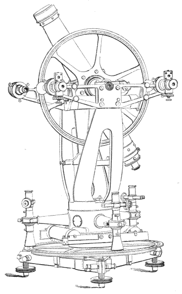
Fig. 197.—14-inch altazimuth theodolite.
477.—14-inch Theodolite.—For this description a modern instrument is taken which Colonel A. R. Clark selected for illustration in his excellent article on Geodesy in the ninth edition of the Encyclopædia Britannica, to the publishers of which the author is indebted for the illustration, Fig. 197. The instrument is a combination of a transit theodolite with special arrangements as an altazimuth instrument[296] with fixed base, one side of the vertical circle being divided to place the zero in a direction coincident with the polar axis. The construction as a simple fixed transit theodolite for support upon a pedestal in stone wherein the axis remains permanent for a principal geodetic station, and therefore requires only a single setting to bring it to true north and south for zero, renders change of position of horizontal limb unnecessary for a permanent station. For this the instrument is well adapted, and will be discussed here. The telescope is of 18 inches focus, with 2 inches clear object-glass. The axis pivots are of hard steel: one is perforated for illumination by a lamp. The vertical circle is placed almost directly upon the side of the telescope, and the tangent arm on the opposite side is of nearly equal weight, so that there is no counterbalance necessary. There are three Ramsden eye-pieces giving powers of 17, 35, and 54, and one diagonal eye-piece. A level is attached inside the standard, divided to read 10″ of arc: this has cemented ends, art. 177, and is enclosed in an outer tube for protection. Two other exactly similar levels are attached to the exterior axis of the instrument. The circle is divided to 5′ of arc and reads by two micrometer microscopes to single seconds. The vertical axis of the instrument is of steel. It is placed with the apex of the cone upwards, and terminates on a triangular spring with three adjusting screws by which any portion of the weight of the upper part of the instrument can be relieved from the axis, so that the whole instrument moves quite freely. The horizontal circle reads with three micrometer microscopes on the upper circle to single seconds. Originally the light was thrown down on the divisions by three ivory cones placed over the fronts of the microscopes, as shown in the illustration; but these have been changed in the present instrument for concave swivelled reflectors, which may be set to any angle convenient to throw sufficient light upon the circle. The microscopes are supported from the body of the instrument upon hollow conical arms upon the same excellent plan originally used by Ramsden. The[297] microscopes have adjustments in three directions, so as to bring them exactly into place for trisection of the horizontal circle. The clamp and tangent motion is placed directly upon the divided circle, and has adjustments to secure freedom from strain; but this is not perfect—it is perhaps the worst feature in the instrument, some modification of[298] the plan shown, Fig. 196, being much better for large instruments.
The whole instrument is mounted on a tribrach frame, which is adapted to stand upon a portable table or upon masonry. The screws have lateral adjustment to prevent loss of time by wear.
478.—It is a common custom with this class of instrument to make the axes of hard steel. This plan is no doubt very satisfactory as it leaves the optician's hands, but the author very much prefers good hard bell-metal. When he saw the above described instrument at Southampton, there was quite sufficient evidence of rust on the pivots to destroy all perfection of centring, and this could scarcely have occurred with bell-metal. Of course the brittleness of bell-metal would be objectionable where the instrument might be subjected to severe jar in carriage from place to place; but the author has obviated this by a plan he would strongly recommend for general adoption—of having the axis of good gun-metal, and to silver-solder a ring of bell-metal thereon where the fitting surfaces occur. If the gun-metal is pure it will bear the average reliable strain of hardened steel, which in hardening and tempering is not with certainty always free from flaws; and the average wear of pure bell-metal is perhaps quite as good as steel.
479.—36-inch Theodolite, Fig. 198, was designed by the late Colonel A. Strange and constructed by Messrs. Troughton & Simms for the Great Trigonometrical Survey of India. It is probably the most complete and perfect theodolite ever constructed. The leading characteristics of this important instrument only will be given. It has a horizontal circle 36 inches diameter, and a vertical circle 24 inches diameter. The telescope has a focal length of 36 inches: the aperture of the object-glass is 3·25 inches.
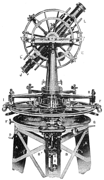
Fig. 198.—36-inch theodolite—Great Indian Survey. From a photograph.
480.—The Stand has three massive mahogany legs AA braced together with horizontal and oblique wrought-iron[299] bars B. Each leg is divided vertically, and contains a long, gun-metal, square-threaded screw C which is made to rotate by means of a worm-wheel and endless screw worked by a winch handle D, and capable of being firmly clamped after[300] adjustment at points about 15 inches apart E. The upper ends of these screws are conical, and fit into three inverted radial grooves formed in the lower side of a cast-iron circle or table, which is thus supported by the three screws without being attached to them, and is therefore free to accommodate itself to expansional changes without restraint. The upper surface of the cast-iron circle is turned flat and true to receive the tribrach of the instrument. The three screws F which pass through the side of this circle are intended to adjust the centre of the instrument over the station mark. A lever G also passes through the side of the circle and actuates three rollers, which, when in action, support the greater part of the weight of the instrument, and so enables the horizontal zero to be set without difficulty. As the instrument weighs over 400 lbs., it will be seen that some such arrangement is absolutely necessary to enable it to be moved on the cast-iron circle. When the correct position has been obtained, the lever is thrown out of action, and the instrument remains immovably seated upon its circular frame.
481.—The Foot Screws are tapped through the ends of the tribrach arms in the usual way, but have a range of motion not exceeding 1/10 inch. This range may appear small, but is really much more than is required, as the upper surface of the cast-iron circle can be levelled by the long screws in the mahogany legs before the instrument is placed on it, so that not more than about 1/100 inch of motion is required. The foot screws do not rest directly on the cast-iron circle, but on the extremities of an intermediate three-armed plate, securely bolted to the centre of the instrument, the distance between the tribrach and the plate being about 1/10 inch. The object of this arrangement is to obviate the disturbance of level and azimuth which arises from clamping foot screws of the ordinary construction after adjustment, as well as that due to looseness of the foot screws in the tribrach arms. The arms of the spring plate, being of considerable width, have[301] great horizontal rigidity, but being comparatively thin are easily bent vertically. The outer ends of the arms rest on the cast-iron circle or stand; the foot screws pass through the tribrach arms, but not through the spring arms. It is evident therefore that when the foot screw is turned inwards with the screwing motion, the solid end of the tribrach will be raised and the slit between the two arms widened; but since the end of the screw does not rest on the stand, but on an intermediate arm, which is actually a portion of the tribrach itself, it is clear that if a lateral pressure be applied to the tribrach no motion will be caused thereby, however loose the screw may be, so long as the pressure is less than the lateral rigidity of the intermediate arm. The lateral pressure caused by turning the instrument in azimuth when taking observations is greatly within this limit. This plan is perfectly successful, but it is only available where a moderate range of vertical movement is needed. In the present instance, as the cast-iron ring or stand on which the instrument is supported is always first made practically level, the vertical range of the foot screws need not be more than a small fraction of an inch. Another point with regard to the foot screws is their delicacy and certainty of action. This is attained by applying to them a clamp and tangent screw arrangement H very similar in principle to that sometimes applied to circles. Although the foot screws themselves are rather coarse, having only about eight threads to the inch, the arrangement is such that one entire revolution of the slow motion tangent screw alters the level only about one second of arc. Hence the foot screws in this instrument, though coarse and strong enough to bear great weight are probably for the first time made in keeping, in point of refinement, with its most delicate parts.
482.—The Horizontal Circles.—The inner or working circle is 36 inches in diameter. It is very finely divided on silver to 5 minutes, and is read by five equidistant micrometer microscopes to tenths of a second of arc. It is fixed at the[302] centre to the tribrach, but everywhere else is perfectly free. The outer or guard circle consists of a second horizontal circle exterior to and concentric with the inner circle. There is a space of about 1/10 inch all round between the two circles, and the upper plane of the outer circle stands about the same quantity above that of the inner or principal circle. The guard circle is supported by radii of its own, quite independent of those of the inner circle. This circle has several functions. It protects the working circle from accidental injury; it helps to distribute changes of temperature uniformly over the circumference of the working circle; it receives the clamp and tangent screw, leaving the working circle absolutely free from contact at all times; and it bears a strongly-cut set of divisions, more visible to the naked eye than those of the working circle, which are exceedingly fine, and therefore would be inconvenient for setting the instrument approximately in azimuth.
483.—The Horizontal Tangent Screws.—It will be seen at II′ that there are two clamps and two tangent screws to the horizontal circle. It is necessary to have both, on account of the large size of the circle. In use, of course, they are not both used at the same time. In the present position of the instrument the clamp and tangent screw on the left-hand side of the illustration would be employed; but on reversing the telescope this clamp would be released and the one on the opposite side made use of. It is necessary with this, as with smaller instruments, to avoid loss of motion in the tangent screws. Many methods have been employed to obviate this loss of motion, but while they are suitable to small instruments they are not so effective with large ones, such as that under consideration. The plan adopted in this case is that known as the divided nut principle. The block into which the tangent screw is tapped is divided transversely and the two halves are forced asunder, and therefore act against the contrary sides of the screw threads by four internal spiral springs. The tension of these springs is[303] necessarily constant, and therefore not subject to the disturbance and slow recovery of elastic force unavoidable in an external spring. Means are supplied for regulating the tension of the four springs, which must be a little in excess of the force necessary to move the revolving mass, without taking the parts to pieces.
484.—The Vertical Axis is a truncated cone of steel with its base downwards. It is about 6·5 inches high and 3·3 inches and 2 inches in diameter at the base and summit respectively, the flange being about 4·5 inches in diameter and constructed on the isolated principle. The vertical axis socket and the five horizontal microscopic arms are cast in one piece of aluminium bronze, the elliptical table carrying the telescope supports being bolted to the central boss in which the socket of the vertical axis is formed. The vertical axis and the elliptical table are both perforated in the centre so as to allow of a look-down telescope being employed in adjusting the instrument accurately over the station mark.
485.—The Telescope is furnished with two separate eye-ends, carrying respectively a vertical and a horizontal parallel wire micrometer J. It is also supplied with both bright and dark field illumination, the latter being employed when faint stars are observed. The vertical circle K is divided on silver similar to the horizontal circle, and is read by two opposite micrometer microscopes when the instrument is used for terrestrial work: but when required for astronomical purposes four micrometers can be used, and they can be shifted to any part of the circle on which they are clamped. In the illustration the four micrometers are shown in position. The two rods or handles seen parallel with the telescope at LL′ are attached to the middle of the transit axis where the telescope passes through it, and are intended to raise or depress the telescope without touching it by hand. These rods are also used for carrying adjustable counterpoises, the instrument being so balanced in every part that the equipoise is as nearly[304] perfect as practicable through any diametrical section of the vertical axis.
486.—The Spirit Levels, both horizontal M and vertical N, are very delicate. They are constructed so that the divisions on their scales represent as nearly as possible one second of arc. The scales are divided to twenty per inch. The glass bubble tubes are mounted on V bearings, and are kept in position by light springs in such a manner that they are free to adapt themselves to changes of temperature with perfect freedom. They are also enclosed in external cylindrical glass covers to protect them from sudden changes of temperature. The arrangements for adjusting the levels are such as to obviate strains without risk of shake, and to ensure delicacy of action.
487.—The Five Micrometer Microscopes O for reading the horizontal circle are carried by the same number of equidistant radial arms branching from the central boss which carries the whole of the instrument above the horizontal circles. These micrometers are made on Robinson's principle, Fig. 199, that is, with a short bow spring S having a central nut tapped through it to keep the tension between the bearing of the micrometer screw on the end of the outer box and the slide which carries the webs constant with whatever part of the screw may be in use. The radial arms each carry a vertical socket which is bored out cylindrically to receive the microscope. These sockets are slotted vertically, and have three clamping screws at the side to hold the microscopes firmly in position when they are once adjusted. The two webs in these micrometers are placed parallel to one another, and at such a distance apart that when in proper adjustment they are a trifle wider apart than the width of one line on the circle, as shown in Fig. 200. The micrometer heads are divided into sixty parts, and the whole is arranged so that in practice ten revolutions of the micrometer screw traverse the webs over ten minutes of arc or two divisions on the circle. Each division therefore[305] on the micrometer head represents one second of arc; and as the divisions are clearly cut on silver and about one-tenth of an inch apart, there is no difficulty in reading to the tenth of a second, which, on a circle of 36 inches in diameter, is equal to the ·00000872 of an inch, or the three-thousandth part of one division of the circle; this, as before stated, is equal to five minutes of arc, or the ·02616 of an inch. The illumination of the microscopes, or rather of the divisions of the circle, is a most important matter. When such exact measures are to be taken it is effected by means of perforated silver reflectors attached to the micrometer arms and mounted quite independently of the micrometers themselves. The axis of each reflector coincides with the axis of its microscope. All the reflectors have both vertical and horizontal movements, and are therefore readily adjustable to the best position for securing effective illumination under the varying conditions in which the instrument may be employed.
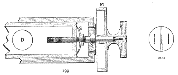
488.—Relieving Apparatus.—It will be readily understood that the moving parts of so large an instrument must necessarily be very heavy. In this case the telescope, vertical circle, pillars, elliptical table, horizontal micrometer arms, and vertical axis socket weigh nearly 300 lbs. It would of course be impossible to take horizontal angles with so much friction[306] on the flange of the vertical axis as this weight would produce, hence the necessity for some form of relieving apparatus. That employed in this case is a system of forty spiral springs, each of a definite length, which when adjusted support about 6·25 lbs. The spiral springs are mounted on a flat ring in two circles with projecting pins to keep them in position. The upper ends of the springs support a steel ring with a circular groove on its upper surface, between which and a corresponding groove in the outer part of the vertical axis socket three equidistant, nearly frictionless steel rollers run; so that by this means about 250 lbs. weight is taken off the flange of the vertical axis, the remaining weight being sufficient to allow of the instrument moving with the necessary freedom, and at the same time giving all the stability requisite for accurate levelling.
MINING SURVEY INSTRUMENTS—CIRCUMFERENTORS—PLAIN MINER'S DIAL—SIGHTS—TRIPOD STAND—ADJUSTMENTS—HENDERSON'S DIAL—LEAN'S DIAL—ADJUSTMENTS—HEDLEY'S DIAL—ADDITIONAL TELESCOPE—IMPROVED HEDLEY TRIBRACH AND BALL ADJUSTMENT—REFLECTORS—CONTINENTAL FORMS—THEODOLITE SOUTERRAIN—TRIPOD TABLES—STANLEY'S MINING THEODOLITE—PASTORELLI'S AND HOFFMANN'S ADJUSTABLE TRIPOD HEADS—MINING TRANSIT THEODOLITES—STANLEY'S PRISMATIC MINING COMPASS—HANGING DIAL—HANGING CLINOMETER—SEMI-CIRCUMFERENTOR—MINING LAMPS.
489.—Miner's Circumferentor.—In the original form of theodolite, as it was at first designed by Digges, open sights took the place of the telescope. The sights in this case were extended on arms. The compass-box, afterwards added, was placed over the axis and made as free from obstruction as possible, so that the needle, upon which general surveying formerly depended, could be read correctly by placing the eye vertically to the plane of the horizontal circle of division against which the needle read. After the introduction of the telescope to the theodolite this old form of instrument took the general designation of the circumferentor; and subsequently, being best adapted to underground surveying,[308] it became, with some slight alterations, the miner's dial.
490.—Upon this original circumferentor improvements have been made in the various mining dials we possess, in all of which the large open compass is still preserved. This prominence of the compass does not indicate that the modern scientific mining engineer has any desire to depend upon it for taking horizontal angles, but that in close and tortuous workings it provides the nearest and often the only possible means of taking angles having regard to the extreme difficulties of observation of any kind. Where workings are open and fairly plane the telescope and circle with vernier reading can be used, so that at the present time the better instruments possess the means also of taking observations of angular direction by vernier reading. Several other very important factors specialize mining from ordinary surveying instruments, which may be stated as follows:—1. That there shall be means of shortening the tripod for work in strata of small depth. 2. That the instrument shall be low and compact in itself, that the head of the surveyor may be placed above it if possible, even in shallow workings. 3. That great extent of adjustment of the compass-box to horizontality shall be given in the fittings of the instrument, on account of the difficulty of extending the legs at all times for tripod adjustment and from the extreme inclination of the floor of the working in some cases. 4. That it is desirable in mining survey instruments that the telescope, if there is one, shall take sights at all angles upon the surface of the earth in the locality in which the instrument is used, as also about a vertical position, so as to be able to sight lines from the top to the bottom of the shaft, or vice versa, to set off angles in the same azimuth as those taken at the surface by direction of stretched wires or otherwise. This last contrivance will also give the means of sighting a perfectly vertical point beneath the centre of the instrument placed at the top of the shaft, to[309] make a concurrent station below during ventilation, when the plummet would be disturbed. The devices by which these various requirements have been met more or less perfectly will go far to explain the specialities of construction found in mining surveying instruments, which will now be described, commencing with the oldest and most simple specialised form upon which improvements have been made in many directions.
491.—Plain Miner's Dial.—The original simple form of specialized miner's dial is shown in Fig. 201. It consists of a compass, divided to single degrees, read by a finely pointed edge-bar needle mounted on a jewelled cap. The needle has a sliding rider placed upon it, art. 130, so that it may be carefully balanced to horizontality in any locality in which it is used. The divided compass is raised on a step, and the upper surface of the needle is made to be quite level with the division when the compass is horizontal. In erecting the instrument with the needle correctly balanced, the compass may therefore be brought to horizontality by the coincidence of the upper surface of the needle with the plane of the divisions, without the necessity of having spirit levels.
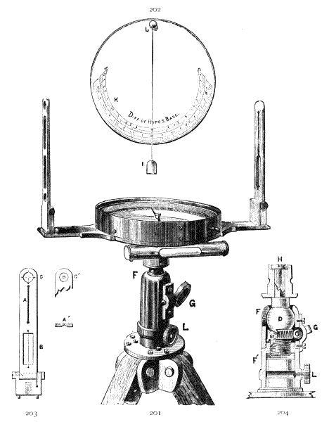
Fig. 201.—Mining dial.
Fig. 202.—Cover to the same.
Fig. 203.—Sight.
Fig. 204.—Section of ball and socket joint.
492.—The compass-box is extended in one meridian, north to south, by strong arms that carry a pair of sights hinged to turn down to the surface of the cover for portability. The compass-box and arms together are termed the limb. The limb of the instrument is mounted upon a ball and socket joint to be described. The socket is slotted down on one side to permit the limb to be turned to a vertical position. In this position the level shown on the front of the instrument is used for levelling by means of the sights: this level is not, however, put on all plain dials.
493.—The cover of the compass-box, Fig. 202, is fixed on the box to a given position by a stud and slot. It has an arc divided upon its outer surface, which is centred from a small hole placed near the outer edge. A line from the centre of[310] the hole to the zero of the arc is made perpendicular to the central indices of the sights. A piece of silk or a horse-hair carrying a small plummet is fixed to hang from the hole. By this means when the limb is turned down in the slot of the socket and the silk or hair stretched by the plummet to permit it to hang in front of the arc, it will then cut the divisions,[311] and thus form a reading index to the arc, giving thereby approximately the vertical angle at which the sights are set to degrees.
494.—The instrument is mounted on a simple jointed tripod to be described. It will be seen by the above description that this instrument is cheaply made, and is not designed for very exact work. It is now giving way for more exact instruments, but it forms the groundwork on which mining survey instruments are most generally constructed. The height of this dial with sights erect is 11 inches; weight, 6 lbs. Some of the separate parts above enumerated, which are common to many other forms of mining instruments, will now be more particularly described.
495.—Sights, one of which is shown separately, Fig. 203, are common to mining instruments. They are constructed essentially in two parts, technically termed the slit and the window. The slit A is a narrow parallel cut made through the metal upon the inner surface of the sight, which is turned towards the centre of the instrument. The thickness of the metal is hollowed away on the outer side which comes next the eye, so as to present a thin edge only for the sighting slit, as shown in section at A′. In some instruments the slit is formed of two thin plates fixed to the sight by screws in slots, which render it adjustable both to width and position; this is the better way if machinery be not used for cutting the slit. The window B is an oblong opening, across which a hair wire or a thin plate placed edgewise is fixed in line with the slit. The hair or wire is laid in a deeply engraved line, so that it is in the same plane as the centre of the slit. The ends of the hair are held firmly by drawing them through small holes and fixing them therein by means of dry, conical, pinewood pins pressed tightly in the holes. When a thin plate is used edgewise, this is soft-soldered into the top and bottom of the window. In the pair of sights the window of one sight is placed at the lower[312] position and the slit in the upper. In the fellow sight the positions of these parts are reversed, the observation being always taken from the slit through the window. The duplication of parts in each sight permits it to be used in either direction.
496.—In the use of the Sight the point or object to be observed from the slit should appear to be bisected by the hair in the window at the same time that it appears to the eye to stand in the centre of the slit. For this reason it is not necessary that the slit should be very narrow. It is generally more comfortable to take the sight with the eye at the distance of 10 to 12 inches in front of the slit to obtain clear vision of it. In this case if it be made too narrow it shuts out the field of view.
497.—It is not quite certain that the old slit and window is the best form. Many mining engineers prefer a pair of equal slits, one of which replaces a window. In this case, instead of the wire covering the object sighted in the use of the instrument, the object is made to appear in the centre of the forward sight slit. In this construction the sight apertures are made much narrower so that they do not cover too much of the field of view. Excellent work is done with this open form of sight, and its construction is much more solid than that of having loose hairs.
498.—Universal Sight, termed technically hole and cross sight, consists of a small hole C′, Fig. 203, on the inner side of one sight that is hollowed away on the outer side which comes next the eye, so as to present a thin edge of the hole only. The fellow sight C has a hair cross placed centrally in a circular window. This is of occasional use for sighting angles approximately in altitude and horizon simultaneously; but the cross occupies so much of the sight space that observation with it cannot be depended upon.
499.—Ball and Socket Joint.—This is shown in elevation Fig. 201 at F, and in section Fig. 204 F, D. It is one of[313] the oldest forms of adjustment, and is common to many dials. When the clamping screw G is released the ball is free in its socket F to move about its centre, to the extent of the opening at the top of the socket, in any direction. A plug E, which really forms the lower half of the socket, is screwed into the part F′ at the lower part of what is technically called the socket-piece. The plug is turned upwards by its screws so as to tighten the ball by means of a tangent screw G which works in a rack thread cut in a part of the circumference of the plug, thus forming a screw and cross screw, which, as the construction indicates, clamps the ball with great rigidity. There are several other ball and socket arrangements; these will be discussed in describing the special instruments to which they are affixed. The only objection to this form is that it elevates the dial very much more than others.
500.—The Tripod Stand of an Ordinary Miner's Dial.—The upper part is shown in Fig. 205. This form of tripod is common to many dials. The legs are made about 1¼ inches in diameter. The heads of the legs are fitted directly without brasswork between the book-plates A, to which they are held by cross screws or bolts which form the joint on which the legs move for extension. Unless the head be worked out of the solid, the book-pieces are screwed to a plate that carries a male plug centre to which the dial is fixed by a milled-headed screw shown at Fig. 201 L. The plug is grooved at the position of the point of the screw so as to permit rotation of the instrument when the screw is slightly released. This tripod head remains permanently fixed to the legs. Each leg is jointed to part in its centre by unscrewing, to present when disjointed a metal point to hold the surface of the ground, to form a short stand. The usual height of the full tripod legs is 5 feet; the upper part only 2 feet 6 inches. The usual form of joint is shown in detail in section Fig. 205. C the male screw, which is fitted to the woodwork by a socket and cross pinned to it. This piece has a[314] point at its lower end. D the socket-piece is screwed over the point to extend the leg when the tripod is required of full length. The woodwork of this lower piece has a conical metal point to bite the ground when it is set up in use. Occasionally for close work shorter legs are provided, or the legs are jointed in three parts. In the common dial shown, the legs are left exposed when out of use; with superior instruments they are packed in a deal case that protects the socket fitting to which the instrument is attached. Another much better form of tripod will be discussed further on with the instrument to which it is attached.

Fig. 205.—Jointed tripod legs of a miner's dial.
501.—Examination and Adjustment of the Plain Miner's Dial.—The tripod should be first set up to full length and each length separately twisted to right and left to see that its socket fittings are good and free from shakiness. The legs should each be separately pressed in and out at its centre to see that the screws clamp the parts firmly and are free from shakiness. The instrument should then be set up and its socket fitting be felt to see that it is free from shake, and also be turned round to see that it moves freely. The ball fitting should be clamped and its rigidity be tested by fair pressure on the two ends of the limb separately. The[315] sights should be examined to see that they are quite linear with hair and slit. The compass-box should be levelled by the coincidence of the upper surface of the needle with the plane of the division, and be reversed in every direction by turning the compass-box, the reading being observed with the N. point of the needle at N. E. W. S. to see that it bisects the graduation by angles 180° apart. The compass-box being level, the sights should be ranged with an external object at a distance—a plumb-line is best—a piece of string suspending a stone answers—to see that they are vertical, and that they cut the same line with the position of the sights changed fore to back. If the sights are coincident, but do not range with the plumb-line, the needle is out of balance, and this may be corrected by shifting the rider.
502.—Henderson's Dial.—This is an improvement upon an old form of circumferentor,[19] in which four sights are centred in opposite pairs so as to revolve about the vertical axis, so that one pair of sights may take any angle to the other pair. In Mr. J. Henderson's dial the improvement consists in making the compass larger, the needle being made to read by a vernier placed upon one end to 3′ of arc. Mr. Henderson prefers plain slit sights instead of slit and window sights, as before stated, which avoids the accidental derangement of the horse-hair.[20] The instrument combines some of the parts of Lean's dial, to be next described. Illustration of this instrument is given in Mr. B. H. Brough's Mine Surveying.
503.—Lean's Dial.—The inventor of this instrument was Mr. Joel Lean, a Cornish mine manager, who was well known at the end of the 18th century for his important improvements in mining apparatus. This dial is still popular in Cornwall and other mineral districts. In general construction the sights and limb on which they are mounted are the same as in the plain dial just described, art. 491. The legs are also
the same—other parts are additional or modified. In the engraving, Fig. 206, the sights and vertical arc with its telescope are shown mounted together on the limb. This is done to show the relative position of these parts: they could not in practice be used simultaneously upon the instrument. They are separately attached to the limb by the same pair of milled headed screws. As a general rule the telescopic arrangement, which will be described further on, is used above ground and the sight arrangement below. The details of construction are as follows:—
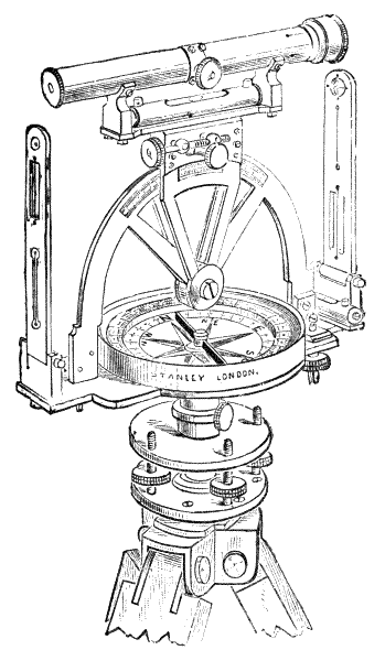
Fig. 206.—Mining circumferentor or Lean's dial.
504.—The Tripod—of the mining circumferentor, in common with many other forms of dial, has the legs fitted directly[317] between book-pieces, which are fixed to the lower parallel plate, as shown Fig. 206, thus dispensing with the separate tripod head, common to levels and theodolites. Otherwise the parallel plates are similar to those described for levels and theodolites, art. 193, and are used in the same manner. The upper parallel plate in this dial carries the male axis, which fits into a socket attached below the centre of the limb in the manner just described for plain dial. The tripod stand, with its parallel plates attached, is generally packed in a pinewood case when out of use. The reason for attaching the legs directly to the lower parallel plate instead of having a tripod head is that it saves the extra elevation of the instrument by the depth of one screw fitting. At the same time it must be observed that it exposes the axis to the air by separating the instrument at this part when it is put by, which renders the axis difficult to be kept lubricated and in smooth working order. On the Continent and in America it is general to detach the legs only, on a plan shown, Fig. 85, p. 140. This keeps the axis attached, and is probably the better plan, although it may be found a little more troublesome to erect the instrument.
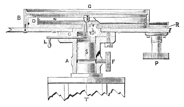
Fig. 207.—Section of compass-box and axis of Lean's dial.
505.—Revolving Compass forms a part of Lean's dial and many other dials. It is shown in section Fig. 207. As the axis is constructed in this instrument, the socket-piece A is ground to fit the male axis S, and at the same time it is shouldered to fit the surface of the parallel plate T to prevent excess of friction on the axis fitting, so that it may move easily to set the needle to magnetic north of the compass-box if desired. The socket-piece is attached to the compass-box through a collar. The compass has a step D which is divided to degrees on its inner edge to read to the point of the needle, and similarly to degrees on its outer edge to read with a vernier scale, shown D to 3′. The vernier is set off on each side of the zero line in ten divisions, which are figured 30, 45, 0, 15, 30, art 322, p. 184. The upper surface of the needle[318] is made level with the upper surface of the step. The bottom plate of the compass-box is divided to 10°: in some difficult positions in the use of the instrument this last is the only reading that can be sighted. The compass-box, which carries the vernier B, is fixed centrally on the arm plate. The arm plate is centred upon a step fitting between the compass and the socket-piece, so that it carries the whole superstructure of the instrument around the compass, its relative position being read by the vernier. The edge of the compass plate is formed into a toothed wheel, as shown in section in the figure on the right-hand side, into which a small wheel or pinion R is fixed in a box upon the arm plate that works by means of a large milled-head screw P. By means of this milled head the instrument may be rotated about the compass, so that the line of division on the compass step reading into the vernier performs the functions of the horizontal limb of a theodolite. In this manner angles may be taken by means of the vernier, quite irrespective of the reading of the needle. When the compass is set to the zero of the vernier at north (360°) it may be fixed in this position by means of a pin fitting in opposite holes to the arm plate and bottom plate of the compass, not shown; and when thus fixed the needle only is used as in the plain dial. Between the collar-piece C and the socket-piece A a wedge-shaped[319] lift raises the needle off its centre by pressing in a slide shown at L.
506.—The Vertical Arc is erected upon the limb as close as possible to the compass-box, so as to leave room for a level to be placed between the seatings of the arc and sights. The axis of this arc is a simple hinge joint, brought down nearly to the surface of the cover which protects the glass of the compass-box: this is done to keep the instrument as low down as possible. The telescope, which is of the same kind as that used for the theodolite, traverses the arc tangentially, permitting it to be adjusted for reading the arc by its vernier by means of a clamp and tangent motion at any position. The arc is divided on one side into degrees, and reads by the vernier to 3′ in the same manner as the horizontal circle. On the opposite side it is divided with a percentage scale of difference of hypotenuse and base which reads to an index line. A spirit level is placed under the telescope, in line with its axis, to which it is adjustable by means of capstan-headed screws. The telescope when fixed is placed just sufficiently above the arc to permit it to be brought to a vertical position at 90°, or a degree or two over this, with the full aperture of the object-glass beyond the extreme edge of the horizontal circle. By this construction a bearing may be taken of any object upon the surface from the top of a shaft, and a line may be sighted to the bottom of the shaft in exact azimuth with this without changing the horizontal adjustment of the instrument. In the same manner, if the vertical axis be perfectly adjusted by the level on the vernier plate, the telescope at 90° + n will indicate a perfect vertical to the station of the instrument above, the + n being the allowance to be made for the eccentricity of the telescope, provided the collimation is perfect. If this is not perfect, the vertical may still be taken accurately by means of three observations taken from equal division of the entire horizontal circle, say at 360°, 120° and 240°.
507.—It will be noticed that the vernier to the compass circle comes directly under the vertical arc, therefore it can only be read obliquely when this arc is mounted: with open sights the vernier can be read directly. This is a defect in this instrument, as the vernier is mostly required for exact work when the telescope is used.
508.—Lean's dial possesses the qualities 1 and 4, pointed out in art. 490 as important to dials; in 4 the power of setting the telescope to the vertical with great facility being the most important. This quality has kept the dial a favourite with many mining engineers in mineral districts for many years. Otherwise for general work the compass is most inconveniently obstructed by the arc above it, and the instrument, although, of course, of less height than the theodolite, some of the functions of which it performs indifferently, is too high to be used in shallow workings. The height of a 5-inch Lean's dial to the central apex of the telescope is 9½ inches; to the top of the sights placed in a level position, 8 inches; weight of instrument only, 6½ lbs. The 6-inch instrument is about 1 inch higher, and weighs 1 lb. more.
509.—A number of variations have been made in Lean's dial; but none that the author is aware of has proved successful. In an instrument of this class, designed by Mr. J. Whitelaw,[21] the vertical arc is brought down to the compass-box by placing pivots on each side of the box after the manner of Hedley's dial, to be next described. This lowers the instrument about an inch, and is an improvement; but this is effected at the expense of placing a striding bar across the compass box, which is a great impediment to the clear sighting of the compass.
Messrs. Newton & Son have made the telescope to detach from the arc of Lean's dial to be placed directly upon the limb. In this way they claim for it that it combines a [321] miner's dial and dumpy level. The arrangement appears to the author to make the instrument top heavy as a dial, and to give too little power for a good level, added to which it costs about the same as the two separate instruments of equal quality. Of course any telescopic dial may be used as a level by clamping it at zero. Practical surveyors generally object to compound instruments that entail many loose pieces. These were a fashion in the middle of the nineteenth century.
510.—Examination of Lean's Dial.—As regards the stand, sights and parallel plates, particulars have been given upon the plain dial just described. The revolving compass should be turned round by the milled head P, Fig. 207, of the pinion wheel R to see that the compass-box revolves steadily at all points without disturbance of the needle. It may also be particularly observed that the needle does not oscillate at any part of the circle, to be sure that the compass-box is quite free from iron. The vernier should be examined at four opposite positions of the needle to see that the needle is truly centred and is in accord with the vernier. The lifter should be tried to see that it lowers the needle gently on the centre, and that it holds the needle firm off the centre. The telescope should be set up and directed to an object, and all parts of the instrument clamped and the needle observed. The telescope should then be detached and the sights set up, to see that they range fairly with the telescope. If they do not do so the difference should be noted and treated as a constant in any case of change from telescope to sights on the same survey. The difference ought to be very small, otherwise the instrument should be returned to the maker.
511.—The Adjustment of Lean's Dial is the same as that of the plain theodolite, so far as this can be carried out; but generally the adjustment is depended upon as it leaves the manufacturer. For the general use of this and other[322] dials some notes will be made further on, but as regards vertical position and the taking of azimuth angles, for which this dial is specially adapted, notes may be made here.
512.—To set a line in Azimuth with one taken above Ground.—This is necessary where there is local attraction to the needle below, or there is a suspicion of this, so that the needle cannot be depended upon with certainty. The instrument is placed on staging over the pit and a vertical is taken to its centre either by the means briefly discussed art. 506 by the instrument, or by suspending a plummet, a ball, or a bullet from the centre of the instrument by a thread and burning the thread when the ball is free from vibration. The ball is allowed to fall upon a smooth horizontal surface formed of earth or otherwise, in which it makes a dent which will be vertical to the axis of the instrument if the ball has not been deflected by ventilation currents. Two lights, as distant as possible to be seen to range in line with the dent, are placed at the bottom of the pit. The lights, if thought desirable, may range north and south with the needle; but in whatever direction this may be set the correct azimuth of this may be taken by cutting them by the webs of the nearly vertical telescope of the dial; and this azimuth may be correctly set out on the surface by a pole or other station mark, or its true direction by a pair of these, one on each side of the pit's mouth, the second station mark being set out after a shift of the horizontal vernier exactly 180° on the circle. A straight-edged flooring board painted white may be made to cut the line from light to light, which is more definite for bearing than the lights themselves.
513.—Hedley's Dial, the invention of John Hedley, H.M. Inspector of Mines, in 1850, has now become the most popular form of miner's dial, modified, however, from its original form in various ways. The peculiar feature of this form of dial is that the sights move upon a framework centred upon a horizontal axis, so that they may by a rocking motion[323] take horizontal angles within a wide azimuth without obstruction to the sight of the compass.
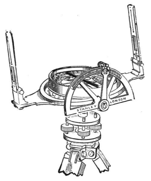
Fig. 208.—Hedley's dial.
514.—For consideration of the general features of Hedley's dial, the tripod and the ball and socket are the same as that described for the plain dial; but the socket is not cut down on one side to change the position of the axis, as the compass-box in this instrument is required to be kept uniformly level. The general appearance is shown Fig. 208. For districts in which the working strata are fairly level, parallel plates are put to this instrument in place of the ball and socket joint. The compass-box revolves, as that described for Lean's dial; but it is more general in this instrument to have a clamp and tangent motion, as in a theodolite, than the rack and pinion motion. Two levels for setting the compass horizontal are sunk into the plate of the compass-dial low enough to miss the edge-bar needle. The step of the compass is divided into degrees and the plate of the dial to 10°. The vernier, which is placed on the opposite side of the box to the vertical arc, reads to 3′, as described for Lean's dial.
515.—The Rocking Centre forms the peculiar feature of Hedley's dial. From opposite points of the under side of the compass two pivots are projected. These are set perpendicular to the vertical axis, which is placed above the ball and socket. The pivots are placed central with the vernier and in line with E. to W. of the compass when this is set to zero (360°). The pivots form the axes of a stout ring—rocking ring—which surrounds the compass-box, with space sufficient to clear it when the ring is rocked about its axis. The ring has two extended arms which carry sights as shown. These turn down upon the compass-box when out of use. One of the pivots is prolonged for about ¾ inch beyond the outer circumference of the ring. The prolongation is made generally of triangular section. This forms a fitting to the vertical arc, which is attached by a milled-headed screw when required, the arc being an encumbrance when this dial is used for making horizontal plans only.
516.—The Vertical Arc, with its index arm, forms a separate piece. The arm is centred upon the arc with a ground fitting, which is retained in its position by a collar fixed with three screws. The arm-piece forms the axis, through the centre of which a triangular hole is made to fit the triangular prolongation of the pivot, so that the index arm remains fixed, and the arc moves with the rocking ring, to which it is held by a pair of dowels. The arc is divided into degrees on the outer edge of its surface, and a scale of difference of hypotenuse and base upon its inner edge. The graduations read to a single index line upon a fiducial edge carried down from an opening in the index arm.
Hedley's dial can be locked by a pin, which is attached to the under side of the compass-box, so as to work by the compass only. The ring can also be locked level with the compass by a sling latch-piece so as to convert it into a plain dial.
517.—The great merit of Hedley's dial is that the rocking[325] centre permits a greater range of open sighting than any other; and the instrument is very low, permitting its use in shallow workings. Further, that it is a very strong instrument to resist accidents, and is very portable. The height of a 6-inch Hedley's dial above the tripod head, in a level position, is 9 inches to the top of the sights. Weight of instrument, 7 to 10 lbs.
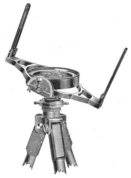
Fig. 209.—Hedley's dial with ball clamp.
518.—In the author's simple dial, Fig. 209, which is of a modern form, the ball is clamped by a capping-piece over it moved to clamp by two stout pins. This form gives a little less height and still holds the dial firmly. The horizontal axis moves rather stiffly, so that no clamp to the arc[326] is required. It is a very cheap form of dial, but substantially made. It answers for a small mine survey.
519.—There have been many variations made and proposed for Hedley's dial. Mr. Casartelli, of Manchester, places the arc over the centre of the compass-box.[22] This plan is intended to make the rocking centre firm; but the arc interferes a little both with the sights and the view of the compass box. Messrs. Davis and Son connect wheel-work with the arc, so as to magnify the scale of motion. Other less important variations in Hedley's dial are common.
520.—Examination and Adjustment of Hedley's Dial.—The general examination of the stand and of such parts of the instrument as correspond with Lean's dial is the same as just given. The rocking ring should be lifted and pressed down at each end alternately to see that there is no loss of time on the axis. The arc should be examined in like manner. The dial should be set up in front of a plumbed line to see that its sights range properly when the instrument is set level by its bubbles. A point should be observed, say through the hole and cross webs at the top of the sight; and with this point kept in view the rocking ring should be moved upwards or downwards so that the point traverses the plumb-line to the extent of the rocking motion. If it does not do so, possibly the transverse level in the plate of the compass-box may be adjusted to make it do so; but in this adjustment it must be particularly observed that the balance of the needle remains so that it still reads the graduation with its upper edge, and that the sights traverse the same plumb-line when turned about, as it is possible to set the level right with one pair of sights and throw other parts out. There are no simple means of adjustment provided, so that if the instrument is not accurate it should be returned to the maker for correction.
521.—Improvement in Hedley's Dial, by Addition of Telescope.—Surface work being generally performed with [327] the theodolite, surveying with open sights following this cannot be effected with sufficient accuracy; therefore there becomes a necessity for the use of the telescope, which was first placed on this instrument by the author at the suggestion of Mr. W. Preece, C.E. In mines, also, although sights present often the only possible means of directing angular positions in cramped and tortuous workings, on the other hand, better work can very often be done and the telescope be conveniently used. Under these conditions, this addition forms an important improvement in the instrument, to be at hand to apply when desired. The telescope of this instrument detaches exactly as with Lean's dial, but the sights are made with an angle piece, so as to extend them to a distance of about 12 inches apart for sighting. Fig. 211 is of one cranked sight. The instrument illustrated Fig. 210 has parallel plates, art. 193, p. 99, suitable for fairly level workings. A ball and socket joint is sometimes fitted to this instrument in place of these.
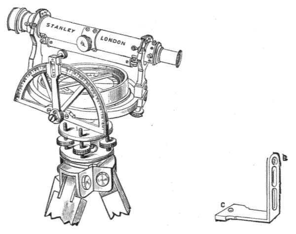
522.—The Telescope is placed on Y's, and is of exactly[328] the same form as that described for a plain theodolite. The Y's in this instrument offer a great convenience for reversing the telescope for back sights in range when the vertical axis is fixed. The level under the telescope is sufficiently good to convert this instrument into a level for drainage, etc., when the rocking ring is locked with the compass. Its examination and adjustment are the same as those last given, except for the telescope, which is the same in all particulars as that of a 5-inch plain theodolite.

Fig. 212.—Improved miner's dial.
523.—Improved Miner's Dial.—The illustration given, Fig. 212, is of the form of dial introduced by the author, a part of the arrangement only being of his own design. The telescope with Y supports is the same as that just described, and the sights, not shown, are cranked in the same manner as shown Fig. 211. The horizontal circle, instead of being in the interior of the box, is placed on the exterior rim,[329] and reads with two verniers—not for correction, but for convenience of reading in different positions. The compass is divided upon the upper surface of the step to degrees, and in the same manner on the interior cylindrical surface of the step. This last often permits the compass to be read in a close working when the upper surface could not either be lighted or sighted. This plan was used on old circumferentors.[23] The plane of the compass is divided to 10° as usual. The compass adjusts by clamp and tangent motion. The axis of the instrument is supported upon a ball and socket arrangement designed by the author for roughly bringing the compass to level, and a parallel plate adjustment for final setting. The ball is fixed by clamping a pair of plates together by a thumb-screw. Each plate is hollowed in the centre to hold nearly half the ball. When fixed, the instrument is found to be very rigid.
524.—A plan of clamping designed by the author to meet the conditions of the tribrach system of adjustment of equal rigidity to that above described, is shown in elevation, Fig. 213 B. In this the upper half of the socket is screwed down outside the lower half socket by means of three projecting handle pins. This is a somewhat neater arrangement than that shown in Fig. 212. Either of the above-described ball arrangements elevate the instrument, and are better omitted for close working if there is a special adjustment in the tripod attached to the instrument, as that to be described presently, which will be found sufficient in most cases. The height of the instrument from the tripod is about 6½ inches; weight, 11 lbs. for both parallel plate and tribrach adjustments.
525.—Adjustable Tripod for Dials.—The author's improved form of tripod is adjustable to all heights between 30 inches and 57 inches, Figs. 213, 214. Each leg is formed of two stiff bars of mahogany, shown in detail, Fig. 214 G of [330] section, about 1¼ inches by 5/8 inch, and a third bar or leg G′ of about 1¼ inches square, which slides between the other two. The sliding surfaces are grooved and tongued together in V grooves in the solid. Two strap-pieces of brass SS′ are fixed near the ends of the bars. One of these S′ is firmly soldered to a boss-piece that takes a thumb-screw, which has quite sufficient power to hold the leg G′ firmly at any position of extension. It is a rigid stand, which may leave the tripod head nearly vertical upon any inclination of the floor surface.
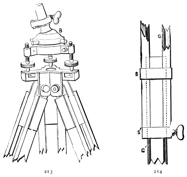
Fig. 213.—The author's adjustable ball joint and socket tribrach stand.
Fig. 214.—Adjustment to leg of tripod.
526.—Hedley's Dials, with Pastorelli's and Hoffmann's Ball Arrangements.—By either of these arrangements the ball and socket is brought down close into the parallel plate adjustment so that the dial is of less total height. Hoffmann's is now becoming the most popular system, as practice has shown it to be the most perfect for mining survey. By either of these arrangements the[331] ball and socket is clamped by the same screws that bring the instrument to final position. In Pastorelli's arrangement[24] the socket is drawn down upon the ball by the adjusting screws. In Hoffmann's[25] the ball is pressed up into the socket, which is the exact mechanical equivalent. When the screws are lightly clamped the ball can be moved with moderate force, or even quite loosely by careful adjustment; and in either case, when the ball is once set, care must be taken to keep pressure constantly upon it during the final adjustment by the screws. The general arrangements are shown in two Figs. 215, 216, which are taken from the drawings of the respective patents. In Fig. 215, va, the axis of the instrument terminates in a ball e which works in a cup f. The axis has also a portion of a ball of greater radius b concentric with the lower ball e. The upper parallel plate d is cupped over this ball. When the parallel plate is moderately free on b, the axis va may be set to any angle within the range of the central opening of d; and as the friction upon bd is greater than that upon fe, the axis moves by the adjustment of the parallel plate screws aa. In Fig. 216 the action is precisely the same, except that the pressure is upwards instead of downwards. In Fig. 215 there are springs s under the parallel plate screw heads to keep contact when the screws are loosened. In Fig. 216 the spring [332] is a plate under the screws s, the action being the same in both cases.

Fig. 215.—Pastorelli's ball and socket adjustment.
Fig. 216.—Hoffmann's ball and socket adjustment.
527.—Some objections have been made to this class of arrangement, over the simpler one of clamping the ball independently and then adjusting by the screws, as being more complex. On the other hand this compound arrangement has the merit in underground instruments of being lower and more compact, which is very important. The author has somewhat modified the arrangements of Hoffmann's head, as shown in the engraving on next page, to render it still more compact for mining instruments.
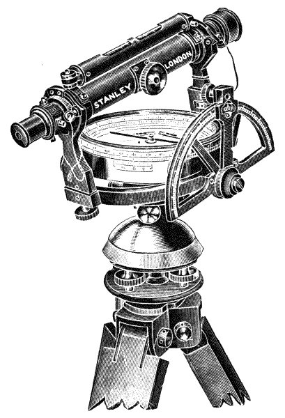
Fig. 217.—Improved Hedley's dial, mounted on Hoffmann's head.
528.—In Fig. 217 an improved Hedley's dial is mounted upon an improved form of Hoffmann's head. The whole arrangement is very compact, rigid, and rapid in action.[333] The height of this dial is 9½ inches; the weight 8 lbs. for a 6-inch instrument, in aluminium 5 lbs.
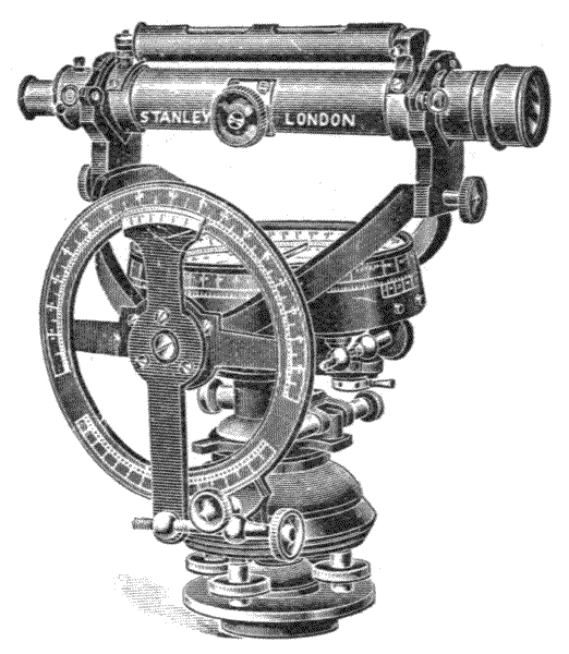
Fig. 218.—Improved Hedley, with cradle ring.
529.—Hedley's Dial with Cranked Rocking Centre.—One defect of the Hedley's dial, which in certain cases makes Lean's preferred, is that with the rocking ring the sights cannot be brought vertical for looking up or down a shaft. The author has devised a means of getting over this difficulty by making the ring of cradle form, thus throwing the bearing surfaces to sufficient height to cause the ring, when the arc is raised to about 90°, to fall under the compass-box and its adjustments, Fig. 218. This dial presents possibly the greatest refinements of the Hedley principle at the time of its patent, No. 9134, 1898. Since this date the reviser has introduced a few further refinements as illustrated at Fig. 219.
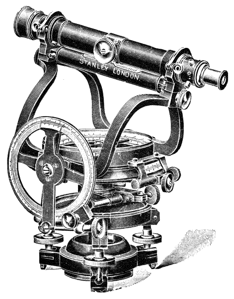
Fig. 219.—Stanley's improved dial.
This instrument has tribrach levelling with quick-setting spherical lower plate, a sliding tribrach for centring over any[334] desired spot, and full clamp and tangent motions to both horizontal centres. The dividing is upon silver on a 6-inch covered limb reading by two verniers to single minutes, folding sights interchangeable with telescope Y's, and this dial may be used upon any staging without its stand. The somewhat peculiar shape of the cranked rocking ring is necessitated by the movement of the sliding tribrach, which it has to clear in all positions for reading vertical sights.
530.—Accessories Common to Hedley's Dials are a vertical reflector and a diaphragm illuminator.
Reflecting Cap.—One of the disadvantages of Hedley's dials over Lean's was pointed out to be the impossibility of vertical sight where the two last described dials are not used. Some years ago the author devised a plan of obtaining this vertical sight by reflection by means of a reflecting cap,[335] Fig. 220, placed over the end of the telescope. The cap is formed of a tube which fits the outer surface of the object end of the telescope. This is prolonged sufficiently to lock it by a dowel in correct position against revolution when the points that are used for index in the diaphragm of the telescope are vertical. The tube is cut in two and hinged to turn up, as shown in two positions H and H′. When turned up it leaves the tube open for direct vision. A reflector R is placed in the cap, and there is an opening below it equal to the full aperture of the telescope. It is easy to see that by this means a pair of lights or a line may be sighted up or down a shaft, and the azimuth of its direction be reflected to follow a line by slightly rocking the telescope upon its pivots. This may be done, however, with more refinement if there is a clamp and tangent motion to the vertical arc, which is placed only on first-class instruments.
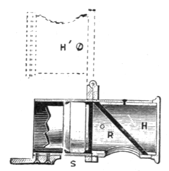
Fig. 220.—Reflecting cap to miner's dial.
531.—Illumination of the Diaphragm for observing the webs or a point, may be conveniently effected underground by employing a conical ring reflector in front of the object-glass. The aperture through the cone leaves the field of the object-glass nearly free, as it is only necessary that the cone should project in front of this for a very small distance. This reflector is placed over the object end of the telescope when it is required, just the same as the ray shade. The vertical[336] reflector, Fig. 220, goes on the same fitting. The reflector Fig. 221 R may be made of silver or platinum. A light placed anywhere opposite this, and perpendicular to the axis of the telescope will throw sufficient light to show the webs or point. Sometimes a simple, plain mirror placed on an arm bent over to the centre of the front of the object glass, in which the mirror stands at 45° to the axis, is used; but this plan is not so good as that shown Fig. 221, as the light has to be brought to face the mirror quite perpendicular to the axis of the telescope, and this process is frequently difficult to accomplish underground.
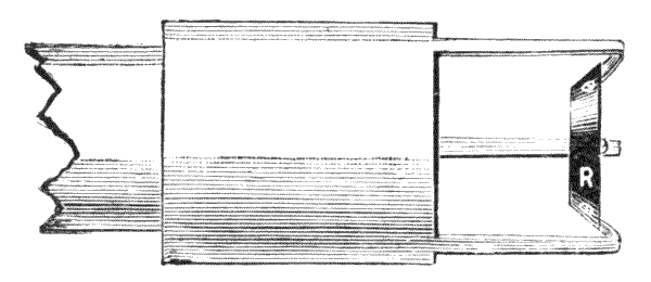
Fig. 221.—Conical reflector to illuminate axis of telescope.
532.—Continental Forms of Miner's Dials.—On the Continent generally sights have been abandoned for miner's dials. The telescopes are usually of short form, with large object-glass and wide field of view. The telescope is generally placed eccentrically, which permits the instrument to be made of very low form. There is a certain amount of disadvantage in the eccentricity of the telescope, as angles cannot be taken direct from the centre of the instrument but this is compensated for in the plotting by making each station a small circle equal to the amount of the eccentricity of the instrument to scale, and setting off angles tangentially to this, which may be done with a little more trouble than that of plotting the angle from a point.
533.—French Miner's Compasses.—Fig. 222 shows the simpler form of this instrument. The needle is open and quite free from obstruction. The telescope is centred about[337] level with the compass-box. The vertical axis has clamp and tangent adjustment. The transverse axis is set entirely by hand as with the plain dial. The instrument is set up level by its tribrach adjustment. The height with 5-inch needle in a level position, without tripod head, is about 5 inches; weight about 11 lbs. without the tripod table. The extremely squat form of the instrument permits its use in very close workings, with a short tripod, if the workings are fairly level. It is used also as a cheap form of surface surveying instrument, consequently it is not generally very carefully made. As a good instrument of the class it cannot compete with that to be next described.

Fig. 222.—French form of miner's dial.
534.—It will be seen by Fig. 222 that the instrument has no direct connection with its stand or tripod. This is general with all French and German instruments, even with theodolites and surveying levels, it being the rule that the top of the tripod should form a kind of table upon which the instrument is set up. The table is almost uniformly made of wood, and is somewhat bulky and clumsy in construction, therefore not very well adapted to mining surveying, particularly in wet mines. Neither is the tribrach system of adjustment, unless it is supplemented by some form of ball and socket arrangement, or with adjustable stand. This subject will be further discussed in the description of superior instruments presently.

Fig. 223.—French miner's transit survey instrument.
535.—Miner's Transit Instrument.—This is the théodolite souterrain of the French, and is of a construction very general throughout the Continent—Fig. 223. The compass is placed clearly in view. The vertical axis has a clamp and tangent motion to bring the compass to exact bearing if desired, or to permit surveying with the compass only. The axis has also a clamp and tangent screw to the exterior divided circle, which reads with two verniers. The telescope is placed on the side of the instrument, and has clamp and tangent motions to read the vertical circle which the vernier traverses in transit. All the divisions are made strong to be read clearly by lamp-light, either to 1′ or 3′ by the vernier, as desired. A second level is generally placed on some part of this instrument at right angles to the one shown. The instrument is balanced by a counterpoise weight to keep its vertical axis in equilibrium. The height of an instrument with 5-inch needle is about 6¼ inches; the weight without the tripod table is about 14 lbs. The tripod table is constructed in various ways by different makers.
536.—The value of the transit principle applied to mining instruments, for taking back and fore sights for hanging lines in undulating strata, by simply turning the telescope over on[339] its axis, cannot be overrated for exact work such as the telescope alone can perform. Further, with this construction the inclination and difference of hypotenuse and base for correction of the chain measurements may be taken. But it is important in the use of this instrument to observe the side upon which the telescope is situated at the time of observation, right or left. For this a column should be placed in the field-book. As a rule fore sights are taken with the telescope left; back sights with the telescope right, remembering that in plotting all angles are taken eccentrically from the axis of the instrument, that is, tangential to a small circle which represents the eccentricity of the telescope according to the scale used in plotting.
537.—The Tripod Table of a superior class of Continental instruments, whether this is used for surface or mining surveying, is usually made with some form of adjustment to bring the upper surface approximately level before setting up the instrument. In this case the table is made a combination of wood and metal; and the only difference between mine and surface tables is that in the former case there is a jointed arrangement for shortening the legs, but not in the latter. The table surface for superior work is generally adjusted to approximate level either by a ball and socket joint or by a pair of knee joints placed at right angles to each other, with clamps to hold it firmly when adjusted. Radial V-grooves are commonly made for the points of the tribrach, and a hole is sometimes made in the centre of the table for suspending a plummet from the axis of the instrument. There are many forms of tripod table in use, a modified form of one of which in metal will be described further on in the chapter on plane tables. There are certain merits in this table arrangement over connective stands, as the table is convenient to set up fairly level, and the instrument need not be exposed until the operation is complete. On the other hand there is more risk of upsetting and injuring the instrument by accident when loosely[340] placed on the table. There are, however, schemes more or less complicated to prevent this, as by a screw fixed in the tripod head acting against a spring which draws the instrument constantly down when attached, and other contrivances, none of which is perhaps equal in simplicity to Everest's arrangement for the tribrach, Fig. 191, p. 273, on this particular point.

538.—Improved Mining Survey Transit.—The author has modified the form of instrument last illustrated, retaining the general principles. In Fig. 224 the compass is made larger and reads in the inside of the step as well as upon the surface, which is the only way in many cases that it can be read in a close working. The reading of the horizontal circle is placed nearly vertical, so that it may be seen clearly when the instrument is near the roof of the mine. The vertical circle is made smaller than the horizontal, as this circle, as a rule, is of less importance, and it can generally be read more exactly from its convenient position. The arrangement also permits greater freedom for the use of the tribrach. The telescope is made with a much larger object-glass than is[341] usual, to take a wide field of view; therefore it forms a good level.
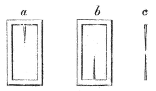
Fig. 226.—Stanley's miner's dial sight.
539.—Two pairs of sights are placed upon the telescope, either for roughly sighting an object or station, or to be used in difficult positions. These are made on a new principle, shown Fig. 226. The sights are placed in two windows, each of which is formed of a needle point of platino-iridium. In sighting, the points are brought over each other, the distant lamp or object appearing between them. A sharp point gives much clearer definition than a hair, as it subtends of itself no angle to the axis of the eye. ab represent the pair of sights, c as they appear superimposed. This instrument is very conveniently fitted with subtense points in the telescope, by which distances may be taken with the author's staff, Fig. 105, p. 158, without actual measurement, for the particulars of which see next chapter. The subtense points are arranged to measure the staff either vertically or horizontally. As a rule it will be found with this instrument better to take rough positions first with the points, and afterwards by the telescope. The instrument cannot be recommended universally for underground surveying, but it is valuable under certain conditions in close strata. Its height is 6 inches and weight 13 lbs.
Fig. 225 is an ordinary tripod, like that used with a level. This is preferred by many mining engineers as being firmer than any jointed arrangement, and is sufficient for working in a seam of fairly equal thickness. The legs vary from 9 inches to the full height, 5 feet 4 inches. An ordinary set of three[342] tripods would be 1 foot 6 inches, 3 feet 6 inches, and 5 feet 4 inches.

Fig. 227.—Stanley's underground theodolite.
540.—Mining Theodolite.—This theodolite is of the most convenient form for underground railways, Fig. 227. The telescope transits on its axis to be brought to a vertical position. The vertical axis is pierced so that about 10° of angle may read below the vertical most conveniently by means of a diagonal eye-piece. The centre is supported upon a sliding fitting so that it may be displaced about 1¼ inches about the centre of the tripod and be clamped to its position. The horizontal axis is pierced to permit the diaphragm to be[343] illuminated by a lamp. The tripod stand is fitted with sliding legs, if it is to be used for mine survey, to adjust for irregularity of surface of the ground and for low workings. The form of the instrument is very compact, rigid, and portable.
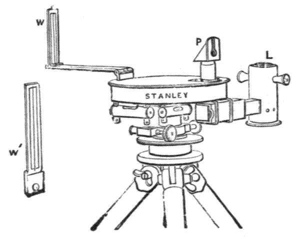
Fig. 228.—Stanley's prismatic mining compass.
541—Prismatic Mining Survey Compass.—This arrangement is designed by the author for very close workings. The entire depth of the instrument being only 4 inches, any reading may be taken from one point of view simultaneously with the observation. The 5-inch compass, Fig. 228, has a floating ring divided to half degrees, and the reading of this is reflected through a prism so that it appears directly under the fore sight, to be seen at the same time. The prism has a slight magnifying power, so that by estimation a bearing may be easily taken to ¼ degree or nearer. The principle of the compass is described art. 148, the prism art. 55; but in this case the prism is raised and has a second lens under it, so that it forms a kind of prismatic Ramsden eye-piece. This elevation of the prism permits sighting under a certain amount of downward inclination, regulated by the height of the prism and the length of the back sight, as well as the upward inclination which is common to the use of prismatic compasses. The most important feature in this compass is the mode of lighting, which is effected by means[344] of a large prism, Fig. 229 R, placed under the compass-box in a square tube, and a small movable lamp to throw light into it, Fig. 228 L. The floating ring, Fig. 229 C, is made of celluloid, quite transparent, so that the divisions upon it are clearly read through the small window in the cover of the compass-box. The fore sight W is jointed in two folds jj, so that it extends the distance of sights to about 10 inches apart in use, and yet folds away closely to the compass for portability when out of use. On the near sight a cut is made transversely to the slit. A second similar cut on the fore sight is made level with this to take levels roughly. About 20° are set off on each side of the cut on the fore sight, so that angles of altitude may be approximately taken—although the instrument is not well adapted to this. Two levels set at right angles to each other, to be used in setting up the instrument, are fixed under the compass-box. Weight of instrument, 4¼ lbs. without the tripod stand.

Fig. 229.—Section of prismatic mining compass.
542.—Hanging Compass.—A very general method of underground surveying in mineral districts upon the Continent is by means of the hanging compass; this instrument is therefore generally found in catalogues of surveying instruments in[345] France, Germany, and Italy. The original hanging compass was invented by Balthasar Rössler about 1660.[26] It appears to the author to be a valuable instrument for surveying in tortuous mineral veins where sighting is difficult. The measuring line upon which it is used is either a hempen or copper cord or a chain. The compass is hung upon the cord or chain, which may be stretched to any point out of sight, and the compass will then indicate the bearing of the line. In Germany two instruments are used simultaneously—the hanging compass for taking the bearing, and a clinometer, composed of a light brass semicircle graduated to degrees, with a small plummet for taking the inclination.
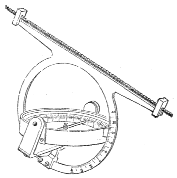
Fig. 230.—Stanley's hanging dial.
543.—Hanging Dial.—Fig. 230 represents a modification of the hanging compass designed by the author, by which inclination may be taken simultaneously with bearing, if the dial can be suspended near the centre of the line or chain where the catenary curve is parallel with its points of support.
544.—In the construction of the instrument a circle of brass about 6 inches diameter, ½ inch wide, and 1/8 inch thick, [346] has two arms extended to 12 inches at the upper part, on the end of each of which a hook is formed for hanging the instrument upon a cord or chain. Upon the lower part of the circle a fork-piece, with a bearing clipping the circle, is attached by two screws. The fork-piece is constructed to support two axes concentric to the vertical circle, in which the compass-box is suspended much above its centre of gravity, so that it falls by its own weight in use to a level position. Upon the edge of the compass-box an index is brought up nearly to the interior surface of the vertical circle, which reads into graduations upon this circle into degrees and half degrees.
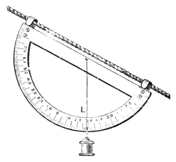
Fig. 231.—Hanging clinometer.
545.—A Light Hanging Clinometer, Fig. 231, shows the kind that is used in Germany, of 5 inches diameter, graduated to degrees, made of thin brass. It is packed in the case with the hanging compass, described art. 542. The ends of the semicircle are formed into hooks for hanging on the line. The plummet has a horse-hair line, which cuts the degrees. The clinometer may be used only when the hanging dial Fig. 230 cannot be suspended near the centre of the line, in which case this light semicircle will cause less deflection of the line, and give the inclination approximately. For further details of the use of the hanging compass the reader is referred to Mr. B. H. Brough's admirable work on Mine Surveying.

546.—Semi-circumferentor.—This simple instrument[347] can scarcely be enumerated with mining surveying instruments, as it is much more used for surface work; but being of the class of circumferentors to which miners' instruments generally belong, this is the most convenient place for its description. It has very general use on the Continent. Its construction is very simple, Fig. 232. It is supported on a ball and socket joint. The socket is formed in two pieces, which are clamped together to hold the ball by a winged-headed screw. One pair of sights is mounted upon the extreme ends of lugs upon the limb. The limb is divided to half degrees. When the ball is loosely clamped the fixed pair of sights may be adjusted to cut any desired object. A second pair of sights is jointed upon an axis to move centrally between the first pair. These are made shorter to pass within the first pair to any angle around the arc, except the small angles with which the sights themselves interfere when they are superimposed. The movable sights carry verniers to read on the limb to 2′. There is a small compass attached to the limb. As a cheap instrument for taking angles approximately it is very useful, particularly for workmen employed in carrying out work from drawings plotted from a survey by a better instrument. The weight of the[348] instrument with 6-inch circle is about 2 lbs.; height above tripod, 7 inches.
547.—The tripod of this instrument is made of wood. The head is shown Fig. 233. The legs are simply extensions of the upper parts, which are shown attached with bolts. The point of each leg has a steel shoe to prevent it slipping in use. The head is turned to a cone, which fits into the socket-piece of the instrument and permits it to be rotated with moderate friction. The head is made of triangular section that the legs may be clamped firmly to it. When used for underground work a separate set of short legs is provided, which attach to the head by the same bolts.
548.—Lighting Underground.—The old underground station, formed of a lighted candle or lamp, is not now considered good in practice where surface land is exactly defined by boundaries held by legal clauses and rights. The system of underground surveying now very generally followed is that first recommended by Mr. Thomas Baker, C.E., and afterwards fully developed by Mr. H. Mackworth,[27] by which a station taken for angular directions is formed by the position of the centre of a tripod. For this system three tripods are provided for each instrument, with head adjustment complete. These tripods are made in such a manner that the instrument can be placed on any one of them in a level position. Two lamps are provided, the flame of either of which will take the position of the vertical axis of the instrument when the lamp is placed upon the tripod formerly occupied by it. It is easily seen that by this system fore and back sights or angular positions can be extended with all the accuracy that the uniformity of the flame of the lamp will permit.
549.—Mining Survey Lamp.—The author constructed this lamp from an idea given to him by Mr. Geo. Kilgour, C.E., Fig. 234. It is somewhat different from the ordinary form. Its accuracy does not depend upon the regularity of [349] the flame. A vertical axis is formed under the lamp, which is made to the same fitting on which the mining survey instrument is placed. The lamp is placed entirely eccentric to the vertical axis in such a manner that a vertical line formed by a wire upon its face may stand central and linear with the axis. A cross line is also placed at the same height above the tripod head as the centre of the axis of the telescope or cross sight. By this means, although the lamp throws its light broadly in one direction only, the cross is a perfectly defined object, easily picked up and brought to exact bearing in the instrument when placed upon another tripod. In converting this lamp from a fore to a back sight it has simply to be turned half round on its axis, which is done without any displacement of the relative position of the cross in vertical or horizontal directions. Where this lamp is required in mines liable to fire-damp, it is made on the safety principle of the Davy lamp.
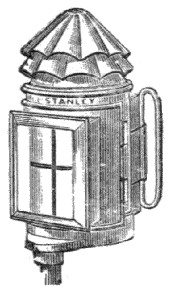
Fig. 234.—Mining survey lamp.
Electricity has been applied to lamps for surveying. This plan has been found successful where a secondary battery is used that can be charged by a dynamo upon or in the mine, or with some of the modern dry batteries.

Fig. 235.—Stanley's complete mining outfit.
550.—Mining Targets.—The three tripod system has been much improved by the introduction of accurate targets made specially for the instrument used, and interchangeable[350] with the instrument on either stand. The reviser has designed several forms of these. They are generally used with a mining theodolite for high-class mine surveying, and the lower part is similar to the lower part of the theodolite they are used with. Instead of a horizontal circle, they simply support a plate carrying cross levels, and a pillar carried up to bring the target level with the optical[351] centre of the telescope of the theodolite; this part is made to fit the outer centre of the lower part into which it is held by a special clamp. The theodolite is made with a double outer vertical centre, and this is held to the lower part similarly clamped, so that the theodolite and targets all lift out of their centres and interchange with each other. A complete mining set of this description is shown at Fig. 235. This forms a very complete mining outfit. It consists of a highest-class tacheometer with quick setting spherical lower plate, mechanical centring stage, auxiliary top and side telescope, illuminated axis, striding level, also two targets with quick setting spherical lower plates, mechanical stages, cross levels, and swivelled sighting crosses. All three are made with lift-out centres, which are interchangeable, and all have base plates permitting their use on any staging or fixing without their stands. The targets are sometimes made to hold candles instead of the swivelled cross, and sometimes with plain steel points only.
The auxiliary telescope is the special form designed by Mr. Dunbar Scott, and it embraces all the advantages and eliminates all the disadvantages of all other types.
The particular feature is its interchangeability with top or side positions, and the means provided to ensure perfect adjustment with the minimum of trouble, thus forming a mining transit which will perform with exactness all the complex functions in mine surveying and requiring no correction for eccentricity.
The auxiliary telescope is provided with a centre that may be screwed to the threaded extension of either the transverse axis or the vertical pillars of the main telescope. In either position it is clamped firmly and ranged quickly into alignment with the main telescope by two opposing screws. The diaphragm of the auxiliary telescope has one web only, so placed that it is vertical when on the top and horizontal when at the side.
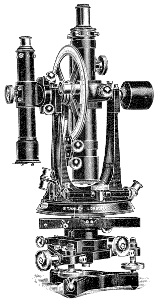
Fig. 236.—Stanley's Dunbar Scott auxiliary.
The observation of steep horizontal angles is made only with the auxiliary on top, and of precipitous vertical angles with the auxiliary on the side. A counterpoise is provided, which exactly balances the auxiliary, so that there is no strain upon the instrument.
For vertical sighting it is also most useful and accurate, as[353] by transferring the lines of both positions of auxiliary two lines are transferred down a shaft, at right angles to each other, which, if produced, will intersect each other exactly under the centre of the instrument, and no allowance or calculation whatever has to be made to ascertain the centre.
The whole attachment adds very little to the weight, the greater part being of aluminium, and it is packed separately in the case so as not to interfere in any way with the instrument when not in use.
In Fig. 235 the auxiliary telescope is shown at top; Fig. 236 shows it attached at the side.
551.—Pocket Instruments.—A very light pocket instrument has been designed by Mr. D. W. Brunton, which will be found useful; he terms it a pocket mine transit, but of course it has nothing to do with a transit. It is designed for roughly taking horizontal and vertical angles, and answers the purpose of a prismatic compass, clinometer and Abney level, and is very portable, made in aluminium, and weighing only 8 oz. It is shown at Fig. 237.

Fig. 237.—Pocket mine transit.
The cover is provided on its inside with a mirror, and this acts as a back sight; it is opened out to an angle which reflects the fore sight, and the object sighted and the reading of the needle is then taken. It is necessary to hold the instrument firmly against the body and see that it is level sideways by[354] placing the spirit level across the box and bringing the bubble to the centre of its run, while any turning movement should be made by turning the body from the hips. For vertical sighting the fore sight is used as the back sight, and the mirror in the lid moved to reflect the bubble, the back sight being formed by the hole in the mirror seen at the bottom of the centre line, the clinometer bubble is then moved till the air bell is seen in the centre of its run and the vernier reading taken.
552.—Dip Compass.—This consists of a magnetic needle suspended between centres so as to move readily in a vertical plane, and is shown at Fig. 238. When in use the ring is held in the hand and the compass-box by its own weight takes a vertical position; it must then be held in the plane of the meridian. In this position the needle when unaffected by the attraction of iron assumes a horizontal position. When brought over any mass of magnetic iron ore it dips, and thus detects the presence of such ore with certainty.
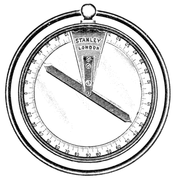
Fig. 238.—Dip compass.
If held in a horizontal position it serves as an ordinary pocket compass and thus indicates the magnetic meridian in the plane of which it should be held when used to ascertain dip.
INSTRUMENTS TO MEASURE SUBTENSE OR TANGENTIAL ANGLES TO ASCERTAIN DISTANCES—HISTORICAL NOTES OF THE METHOD—PRINCIPLES INVOLVED—STADIUM MEASUREMENT, DIRECT AND BY THE ORDINARY TELESCOPE—CORRECTIONS FOR REFRACTION OF THE OBJECT-GLASS—STANLEY'S SUBTENSE DIAPHRAGM—ANALLATIC TELESCOPE OF PORRO—TACHEOMETERS—STADIUM—FIELD-BOOK—OMNIMETER AND ITS FIELD-BOOK—BAKEWELL's SUBTENSE ARRANGEMENT.
553.—Direct Subtense Measurement of Distances, by an Instrument, depends upon our powers of measuring the image of a distant staff or stadium, or the divisions marked thereon as they appear at the focus of the telescope. If the stadium is placed at right angles to the direction of one of two sight lines which subtend a given angle, the number of units divided upon the stadium cut by these lines will be proportional to units of length of base or cotangent for a constant focus of the telescope; so that if we can measure at a fixed angle the number of equal units of measurement of a stadium correctly, we can obtain its exact distance; and whether this method is more or less exact than chain measurement will depend entirely upon the perfection with which either of these operations may be practically performed.
554.—The Origin of the Invention of Subtense Surveying was thought to be due to Wm. Green, an optician[356] of Great Moulton Street, London, who was awarded a premium for its invention by the Society of Arts in 1778. He published a pamphlet giving a description of his method in 1778.[28] This subject he pressed upon the notice of professional men at the time, and his method has continued in use in this country ever since. His refracting telescope, which alone has remained in use, formed part of the theodolite. A micrometer was placed in the focus of the eye-piece of the telescope, which revolved a quarter turn in its axis to read angles vertically or horizontally. He constructed his micrometer with lines fixed at a given distance apart, and by a second method with the lines adjustable. For this adjustment a fine line was ruled upon one side of two pieces of glass. The ruled sides were placed face to face, so as to be at the same focus. One of the lines was adjustable by a micrometer screw. His staff was 20 links in length by 4 inches in width, divided decimally into 1000. His description of the manner of using his instrument will give a general idea of working the others which have been derived from it—tacheometers, omnimeters, etc.—and this is worthy of note, as the invention, though generally attributed to him, was not his:—
555.—"To find the contents of a field with either of the instruments described, let the telescope be placed so that the observer may see all its angles from his station. If near the centre of the field the better. The person who carries the scale (staff) is to go all round the field, stopping at every angle, and to place the scale at right angles to the axis of the telescope (passing) from corner to corner (from right to left if required) with the help of a signal by the observer. After the distances all round the field are taken (by measurement of the image of the micrometer) and all the angles included betwixt them, with the theodolite, plot it out in the usual manner, e.g., [357] with a nonius protractor. Describe a circle, and on this circle set off all the angles from the centre through each point upon the circumference. Set off the length of every line by a scale of equal parts. These points will give the limits of the field, which may be laid out in trapeziums, triangles, etc., and measured from the same scale of equal parts. The surveyor will comprehend how easily the contents of the field are found by trigonometrical calculation, since by this method there are two sides and one included angle given.
"The common method of measuring with the chain, besides the inaccuracies to which it is liable, does only give the length of the surface of the ground between two objects, and therefore not its proper distance, unless the surface be straight and no object to hinder its being measured from one end to the other. How often this is practicable I leave to the consideration of those who are most accustomed to measure lines, and doubt not that upon the whole they will find the telescope method has besides ease, accuracy, and universality, necessity itself to recommend it."
He points out the utility of the system for levelling, as "both distance and inclination may be taken at the same time." He finds by experiment that the accuracy of the method exceeds that which he could reasonably expect by calculations deduced from theory, by several circumstances in its favour being inseparable from it.
"The observer's station is the centre of circle whose radius is the distance required, which is obtained by measuring the length, that is, the tangent or subtense, of the small arcs whose limits are defined by viewing their image in the focus of a telescope between two points there placed, and moving them up and down until they appear to touch the very extremities of said limits exactly. The manner of seeing is natural and by practice will become habitual, and therefore continually approach nearer to perfection.
"Thus may any surveyor in less than two hours take all[358] the dimensions of an irregular polygon necessary for obtaining its area, if it be as much as 80 or 100 acres and limited by twenty or thirty unequal sides."
Green points out that if the subtense angle is taken horizontally, atmospheric refraction error is eliminated. He proposes to use both reflecting and refracting telescopes. With the reflector he possibly obtained accurate results, but with the refracting telescope he does not appear to have recognised a constant correction which is necessary and important.
It has since been found that in 1778 the Danish Academy of Sciences awarded a prize to G. F. Brander for a similar device, which he had applied to his plane-table, six years before. Its real discoverer was James Watt, who used it in 1771 for measuring distances in the surveys for the Tarbert and Crinan Canals. In James Patrick Muirhead's Life of James Watt, he gives a statement by Watt himself that he constructed his instrument in 1770 and showed it to Smeaton in 1772.
556.—Subtense Instruments, as that originally made by Green, are of some form of theodolite, the telescopes of which are constructed to measure either the angle subtended by the chord of a small arc or the tangent of the same. For convenience the tangent is more generally taken upon a graduated stadium or staff, which is erected for measurement perpendicularly to the horizon, the principle of which is shown in the following scheme:—
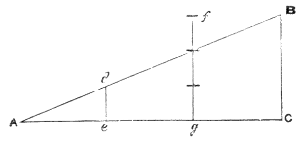
Fig. 239.—Diagram of tangential angle measurement.
Let AC, Fig. 239, be a horizontal line; BC a stadium set up vertically. Then if the angle BAC and the height BC are known, the distance of AC can be easily calculated. For any intermediate distance between A and C a vertical will be in length proportional to this distance. Let de be at one-third the distance from A; then the line de will be one-third the length of BC. If we divide BC into three parts and place the stadium at fg two-thirds the distance from A, the angle dAe given by an instrument subtending a fixed angle will cut the staff at the second division, equal to two thirds the staff, which demonstrates the principle of all tacheometers, Cleps, etc.
If the tangent be made a constant equal to the length of the stadium BC, and this stadium be placed at another position, say de or fg; then the angle subtended by its entire length will vary in a manner that can only be estimated by trigonometrical calculation.
In case of reading two distant marks on the stadium only for the subtense, the single central web of the telescope being directed first to one and then to the other of these webs, the distance is calculated as follows:—
Given the tangent BC and the angle BAC, required the distance AC. Let the angle BAC be represented by D; then—
| CA | = cotan D, or CA = CB × cotan D. |
| CB |
Reducing by logarithms, we have—
log CA = log CB + L cotan D - 10.
For example, make CB 14 feet, and the angle D 2° 45′ 50″, thus:—
| log CB | = 1·146128 | |
| L cotan D - 10 | = 1·316265 | |
| log CA | = 2·462393, | or CA = 290 feet. |
The above gives the principles followed with instruments of[360] the theodolite class simply; but arrangements are made in omnimeters and similar instruments to read the tangent directly and determine the height CB in equal parts, so that observation of the heights BC gives rectangular co-ordinates and thus saves reduction from degrees of arc.
In practice the staff or stadium is made of the greatest length convenient for portability. With a telescopic staff, 14 or 16 feet is commonly used. If a unit tangent be not employed, the foot is divided into 100 parts, each of which parts, with the tacheometer, represents 1 foot of the base, and the whole staff 1400 or 1600 feet. The ordinary Sopwith staff, art. 263, answers the purpose, but art. 268 better.
557.—Measuring Distances by the Ordinary Telescope by Measurement of its Focal Image.—When we apply a refracting telescope to measure a subtense angle by webs fixed in the diaphragm, vision is not direct as in the scheme Fig. 239, but subject to bending caused by the refractive quality of the lens, art. 58, the telescopic focus varying with the distance from the staff. Thus with a 12-inch telescope there will be a difference of about ·25 inch in the focus, whether the staff is held at 50 or 500 links from the telescope; and this difference of focus is equal to a difference of base or cotangent between the points A and C in the last figure, so that these distances do not remain proportional to the fixed unit of the tangent or stadium. It is important to go carefully into this subject of the use of subtense webs in the ordinary telescope, as the necessary correction does not appear to have been recognised by English writers on instruments, and no doubt this is the principal reason that subtense measurement has not been more practised in this country.
558.—At the commencement of the last century, Riechenbach, a Bavarian engineer, pointed out a method still in use on the Continent. The author is indebted to the[361] kindness of Lord Rayleigh for the following demonstration of Riechenbach's formula:—

Fig. 240.—Subtense diagram.
Let Fig. 240 AB = s, ab = i, OA = d, Ob = r. O is the optical centre of the object-glass; ab a pair of webs at variable distance r from O according to telescopic focus; f focus for parallel rays. Then by similar triangles s/d = i/r or d = rs/i, r is found by optical laws to vary in the proportion of 1/r + 1/d = 1/f. We may therefore eliminate the variable r by substituting its value r = fd/(d - f), by which we find d = sf/i + f, which gives the true correction; and the distance from the axis of the instrument will be d = sf/i + f + c where c is the constant distance of the object-glass from the axis of the instrument. It is usual to place the vertical axis of a theodolite central between the object-glass and the diaphragm at solar focus, so that the constant c becomes f/2.
It is seen that sf/i represents the direct subtense, whereas the refraction, which is a constant, gives f and the position of the object-glass f/2. Riechenbach's formula being true for parallel rays is evidently also true for any subtense with refraction for the staff at any distance. We may therefore adopt a plus constant of 1½f, which added to the apparent subtense is found to produce no error. Thus with a telescope of 1 foot[362] solar focus, and using the decimal system of notation, as before mentioned, if a stadium or distinct scale be placed at 301½ feet distance from the centre of the instrument, and the webs or points of the diaphragm be adjusted to read 3 feet = 300 divisions, every subtense may afterwards be taken as number of divisions read + 1½ feet for distance in feet. If the subtense is to be taken in links or metres the dividing of the stadium will be to these measures, but the constant remains the same 1½ feet always.
559.—When the line of sight is inclined from the horizon and the stadium is held erect—a convenient method commonly followed upon the Continent—the reading becomes in excess of the true reading, in the ratio of the cosine of the angle of the stadium, represented by a line tangent to the sight-line subtended to the foot of the stadium, as shown in the following diagram.

Fig. 241.—Diagram of vertical stadium on an incline.
Thus, Fig. 241, let the portion cut by the lines AB, S′ be the reading of the stadium; then
S′(cos a) = S.
The inclined distance is then equal to
(f/i)S′(cos a) + f + c
and the horizontal projection of that distance or
a = ((f/i)S′(cos a) + f + c)cos a;
or as f + c is small and the angle generally small also, f + c may be taken equal to (f + c) cos a. Then
a=(f/i)S′ cos2 a + f + c.

Fig. 242.—Stanley's patent subtense diaphragm.
560.—The Subtense-diaphragm of the author, Fig. 242, forms the eye-piece of a theodolite. It has movable indices which are separated according to a scale formed by calculation upon the data of the above formulæ. By this, distances may be taken in the horizontal plane for land of any inclination without after calculation. This result is obtained by observing the angle of inclination upwards or downwards on the theodolite and setting the micrometer to this angle before reading the subtense distance. The reading is taken by points which are arranged to measure the subtense 1 to 100, so that the ordinary Sopwith staff may be used. The diaphragm at zero appears as an ordinary subtense-diaphragm. It may be observed that this diaphragm may be used as a good check, as distances may be taken over any irregularities of intervening incline and give the true base for the entire distance.
561.—If the mean contour distance is required from station to station, this may be taken directly by subtense from the staff-reading held at right angles to the axis of the telescope.[364] The means of doing this, devised by the author, is to place a sight director of a special form upon the side of the staff, Fig. 243. This small piece of apparatus is shown attached to the staff. It consists of a small telescope three inches long attached at right angles to the staff by means of a dovetail slide fitting when in use as shown. The staff-holder sights the tacheometer through the short telescope, which can only be seen to appear therein by moving the staff until it is approximately at right angles to the direction of the tacheometer.

Fig. 243.—Sight director for stadium.
562.—The Anallatic Telescope.—In this telescope the focus is constant, and consequently the tangential measurements indicated by the numerical qualities subtended by a constant angle are directly proportional to the base, so that there is no constant to be added. The invention of this instrument and its modern application to subtense measurement was due to Professor J. Porro, of Milan, who put it to practical test in 1823,[29] in an instrument termed a tacheometer. The telescope will be best understood by the following details:—
The object-glass O, Fig. 244, is made of a focus that falls well in front of the axis of the instrument CC′, so that the rays cross before falling upon the anallatic lens A, the optical arrangement being such that if the rays fell direct without any [365] refraction they would reach the axis and subtend angles therefrom inversely proportional to the distance of the stadium. The object-glass and anallatic lens are of the same focus, so that the rays after crossing from equal refraction may emerge parallel in the space A to M. The stop at S and at the axis CC′ cuts off eccentric rays that would otherwise give internal reflections from the telescope tube. The eye-piece, represented by MF, may be made to pick up the image of the stadium in front of it upon an ordinary webbed diaphragm or upon ruled glass. The diaphragm webs are fixed, or the glass surface engraved with three or five horizontal lines and one vertical. The outer horizontal lines are used generally as the subtense lines, and the central line for levelling and taking altitudes. The vertical line is used for triangulating on the surface of the ground.

Fig. 244.—Diagram of anallatic telescope.
563.—There is an adjustment made by sliding tubes to bring the object-glass and anallatic lens within mutual focus to ensure the parallelism of the emergent rays and to adjust magnification. This is commonly effected by means of a rack and pinion, moved by a separate key kept in the instrument case, but which should not be touched after the instrument is once adjusted by the maker, except in the case of accident. It is much better made without this rack adjustment and permanently fixed by the maker, as if it has the[366] adjustment it is likely to be tampered with and thus defeat its object. The eye-piece adjusts to distance from the object-glass in the ordinary manner of the surveying telescope—by rack and pinion.
564.—The eye-piece of the anallatic telescope is generally made of much higher power than those ordinarily employed for levels and theodolites—25 to 30 diameters is usual. Where a diaphragm is used the subtense lines are commonly placed on a slip of glass in two or three sets, so that greater magnitude of image may be taken for objects at distances of from 2 to 7 chains with the 14-feet staff, or that the staff may be read at greater distances than 14 chains. This series of lines is distinguished as 50, 100, and 200, Figs. 245, 246 and 247; so that with this as great a distance as 28 chains with a 14-feet staff may be estimated, but this is beyond the safe power of the instrument. The intermediate line, as shown Fig. 220, is valuable in all cases for levelling. The advantage of the increased power of the eye-piece is more than neutralized by the loss of light.

Figs. 245, 246, 247.—Subtense lines ruled on glass.
Fig. 248.—Adjustable point diaphragm with stadia points.
565.—While many civil engineers are satisfied with a single percentage pair of subtense lines the author much prefers using the point system, arts. 237 to 239. In this case the diaphragm, as made by the author, possesses two systems of adjustment; that shown Fig. 248 at a for the single point for altitudes, and the pair of points separated by the spring ss for subtense angles. These points adjust by separate screws top and bottom[367] with a milled-headed key f. The two verticals are fixed permanently. These points are all made of platino-iridium, which possesses the hardness and elasticity of spring steel, and is at the same time, as far as is known, perfectly non-corrosive. In case of any light dust or moisture resting upon the points, it is perfectly safe to brush them lightly with a soft camel-hair brush to clean them. Where the 200 factor is required, a mean may be taken of two observations above and below the central point. Where 50 is required, the vertical points may be adjusted to this.
566.—In adjusting the lines, webs, or points to a given subtense, the anallatic lens may be moved to give more or less angular displacement or magnification of the image. Greater accuracy is obtainable when the staff is held normal to the line of sight instead of vertical. If the staff be held incorrectly in the inclined position at great angles of elevation or depression, the resulting error is very much smaller than in the case of an equal variation of the staff from the true vertical position. When adjustment is made upon a distant stadium at small angles of elevation or depression, the subtense of the small arc will vary so little from a tangent to one of its radii that the one or other may be taken without sensible error. The plan originally proposed by Green of placing a sight tube through the stadium at right angles to its face, as a means of keeping it in the chord of the arc, is as good as any other, but is more cumbersome than that described art. 561. If the vertical stadium be preferred, this may be set up by the small level, Fig. 109, p. 163.
567.—It is well to note that with the anallatic telescope the stadium must not be so near that the rays from the object-glass do not cross in front of the anallatic lens or the subtense will appear much increased, so that there is a fixed nearness at which this form of telescope can be used, say 50 feet. For this reason engineers generally[368] prefer an ordinary telescope, making use of the addition of a constant. The author also prefers the plain telescope, as being more correct according to his experiments where the constant is correctly allowed. There are many advantages in the use of a plain open telescope instead of the anallatic telescope for tacheometers, among them the following may be mentioned. More light reaches the eye because there are fewer lenses; there is no intermediate lens requiring adjustment and which becomes dirty and bedewed and is inaccessible for cleaning, and for the same dimensions of the telescope greater power can be obtained. A larger telescope and of higher power is of great advantage in subtense measurement, but the full advantage is not obtained in the anallatic telescope. The idea which appears to be still common that an ordinary open telescope will not give accurate results at all distances by means of stadia readings, plus the distance of the anterior principal focus of the object-glass from the axis of the instrument, is entirely erroneous. When a staff is held at any distance in front of the object-glass of an open telescope, an inverted image of the staff is formed at the conjugate focus which subtends an angle at the corresponding nodal point of the lens, equal to that subtended by the staff at the other nodal point. If a diaphragm with two stadia points or webs be placed at this conjugate focus the ratio i/f′ = the ratio l/D; where i is the space between the stadia points, l the height on the staff which these points appear to intercept when viewed through the eye-piece accurately focussed on them, D the distance of the staff from the object-glass, and f′ the distance of the diaphragm from the object-glass. Now in this equation i is a fixed space, l is the observed height on the staff, and both f′ and D are variables, of which it is desired to find the value of D. From the laws of optics it is also known that 1/f′ + 1/D = 1/F where F is the principal focal length of the lens.[369] Therefore f′ = FD/(D - F) for all values of D. Substituting this value of f′ in equation (1) we get i × (D - F)/FD = l/D; and multiplying both sides by D, i × (D - F)/F = l. ∴ D - F = (F/i)l and D = (F/i)l + F which is true for all distances. But this distance is measured from the object-glass, and the distance S required by the surveyor is that from the axis of the instrument, and it is therefore necessary to add that of the object-glass from the axis d. ∴ S = D + d = (F/i)l + F + d, and F + d is the constant of the instrument = c. ∴ S = (F/i)l + c.
When the range is greater than that at which the divisions of an ordinary levelling staff can be clearly read with the stadia points, target stadia rods or targets fixed to a levelling staff are used. It is usual to use plain targets fixed with their centre lines at exactly 10 or 20 feet apart or other convenient distance, and the angle subtended by these is measured by a micrometer diaphragm. The reviser, in conjunction with Mr. C. W. Scott, B.A.I., A.M.I.C.E., has designed a micrometer diaphragm which has been proved to give very accurate results. It is made to revolve, so that either horizontal or vertical stadia rods may be measured, and it is fitted with fine fixed platino-iridium points, which are much more satisfactory than webs or lines engraved on glass. These are fixed on one side of the diaphragm, two each 1/200 part of the principal focal length of the object-glass above and below the axial point. On the other side of the diaphragm is a movable point which can be traversed over the fixed points by a micrometer screw, every complete turn of which moves the point over a distance equal to 1/1000th of the principal focal distance and the head of the micrometer being divided into 100 parts,[370] it reads to the one hundred-thousandth part of the same; while a small star-wheel records the number of complete revolutions, five of which cover the space between any two of the fixed points. In using this micrometer with say a 10-foot target, let the lower target cross-bar be clamped to the level staff at 2 feet, and the upper target cross-bar at 12 feet. Direct the axial point to the centre between the targets at 7 feet and read the angle, then bring the nearest fixed point to the top or bottom mark by means of the tangent screw, and bring the micrometer point to the other mark by the micrometer screw. The micrometer reading is the reading on the divided head plus the hundredths indicated on the star-wheel plus 500 for each included complete space between the fixed points. See whether the micrometer reads up or down, and set the fixed point to the lower or upper mark on target accordingly. To obtain the distance from the axis of instrument, divide 100,000, multiplied by the length of the target by the micrometer reading, and add the constant of the instrument S = 100,000l/x + c where x is the micrometer reading, and l the length of the target. The tacheometer which the author has lately made has a plain open telescope, but this is of the same size as that used upon the Porro system, and consequently it gives much more light and better definition.
568.—Tacheometers consist essentially of any form of theodolite that is provided with means for reading distances by its telescope. Stadia work is simply another name for tacheometry, which is derived from the Greek tacheos (quickly), and metreo (I measure), and signifies the art of measuring rapidly. The graduation of the arcs and circles of these instruments is sometimes made upon the centesimal system, the circle reading 400 grades, which are subdivided to half grades to read with the vernier or micrometer to centigrade minutes of ·01 grade. The centesimal system facilitates[371] calculation, and permits a free use of a logarithmic slide rule of a special kind. In France, where working with this system at one time became more general, we have very complete centesimal trigonometrical tables adapted to the tacheometer published in stereotype,[30] but it has not gained favour, and very few instruments are now so divided. A compromise which has found a certain amount of favour is the decimal division of the ordinary degree of 90 to the quadrant; this greatly facilitates the calculation compared with what is necessary with the sexagesimal division into minutes and seconds and the reading of the verniers is much simpler and less liable to errors. Moreover, the mental conversion of the sexagesimal division into decimals of the same degree is much simpler than the conversion into the centesimal degree of 100 to the quadrant. Any instrument divided sexagesimally can be converted by simply changing the vernier if the divisions on the limb are degrees or half degrees. The theodolite, Fig. 169, the author made specially for a tacheometer. Any theodolite may be converted into a tacheometer by fitting it with a subtense diaphragm. A modern tacheometer should be a high-class theodolite in which every possible refinement is included.
569.—The tacheometer, although manufactured for many years for export, has been very little used in this country. The instrument to be described, shown Fig. 249, is the author's latest pattern. It is made with sexagesimal division or ingrades, to read by the verniers to 20″ or to centigrade minutes. The telescope is of much larger and of higher power than that of the ordinary theodolite. For a 6-inch instrument the telescope is of 11 inches focus, with an object-glass of 1¾ inches aperture. The eye-pieces are of the Ramsden form of powers 18 and 25. The points in the diaphragm are set to cut 100 divisions of the stadium at 100 units + constant of the measurement intended to be taken, links, feet, or metres. This precludes distant measures, say of over 15 [372] chains, where a 16-feet stadium is used, but they are made adjustable so that they may be set, if desired, for any other subtense, although this is not recommended. It is doubtful whether the subtense method can be considered as reliable at a distance of over 1500 links; or at any rate we must assume that much greater accuracy can be obtained by dividing distances greater than this into two by an intermediate station for observation, independently of the additional convenience of having the staff-holder within easy distance of communication.
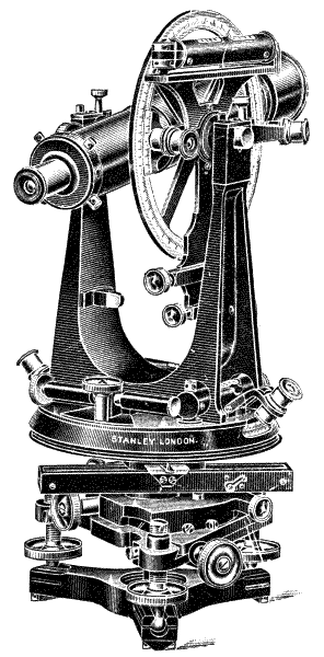
Fig. 249.—Stanley's 6-inch tacheometer.
570.—Where points are not used in the diaphragm or where lines are preferred, these may be divided upon glass[373] in fine lines as Fig. 246; or spider webs may be used, but these are more difficult to set exact for stadia.
571.—Stadium.—Any accurate levelling staff will answer for the stadium, but the ordinary Sopwith, Fig. 99, is slightly confusing. A more open reading is generally recommended—that shown Fig. 102, p. 155, which the author designed for the purpose, answers perfectly. It is better to read the stadium low, as there is less vibration; but it is not often possible or at any time advisable to read it from the bottom—1 foot up is generally most convenient. Readings are taken and recorded of each subtense web, or point, separately, and the difference of reading subtracted for the subtense of tangent. With a point diaphragm for taking the subtense angle a fair certainty of accuracy of measurement of distance within ·002 may be assured, which is much nearer than can be attained by average chaining, taking six times the labour.
572.—The General System of Working the Tacheometer, with sufficient detail for practice, would take too much of our limited space to be given here. We now have several good works published in Great Britain, in addition to the able paper by Mr. Brough before mentioned, such as The Tacheometer: Its Theory and Practice, by Mr. Neil Kennedy; Surveying, by Whitelaw; Aid to Survey Practice, by L. D'A. Jackson, &c. There is a small work published in New York giving some details.[31] There are complete works in French, Italian, German, and Spanish. In French, Leves de Plans a la Stadia, by M. J. Moinot, engineer to the Paris, Lyons, and Mediterranean Railway, gives very complete instructions for all conditions of country, upon surveys which he has personally carried into practice with this instrument.
There are several tacheometers made upon the Continent, of more complicated forms than those herein described, but they do not produce better work.
573.—Field-books for the tacheometer are ruled in various ways in columns, which vary in number in different books from twelve to twenty. The French generally have fourteen columns, giving the number of the station, time, heights of line of collimation above point levelled, numbers of points selected, horizontal and vertical angles observed, reading of subtense webs and their differences, height of staff by reading central web, and columns for calculations and remarks; most English forms are more simple.

Fig. 249a.
574.—A convenient protractor in which the equivalent of surface reading is taken from a scale upon its lower part directed from the centre of the protractor is here shown.
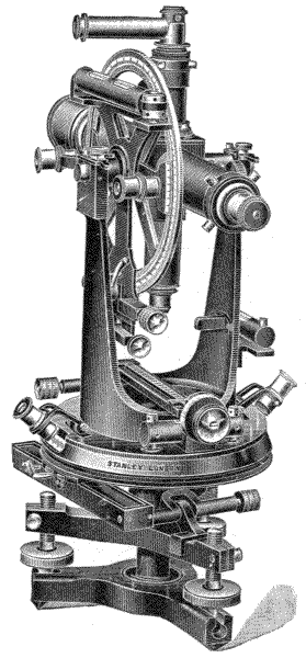
Fig. 250.—Perspective view of 5-inch omnimeter.
575.—The Omnimeter is one of the class of instruments in which the tangent to a radius proceeding direct from the axis of the telescope is represented by the stadium made of constant length, the subtense angle varying with the distance. The omnimeter is the invention of Chas. A. C. Eckhold, a German engineer, described in the provisional British patent[32] as "a person living in Alexandria." The instrument as originally devised consisted of a kind of theodolite to which the subtense tangential system was added as an entirely separate part. The important part of the provisional specification shows that the principle of the invention consists in the use of two sights to the instrument, one a telescope to sight the object, and the other a powerful compound microscope to read divisions upon a tangential scale. The telescope and microscope are firmly united together in parallel position with their [375] axes exactly crossing the transverse axis of the theodolite, so as to move together through the same angle by the motion of the telescope in traversing the azimuth. A delicate level is placed upon the telescope, and when the bubble is in the centre of its run the scale is truly at right angles to the axis of the[376] microscope. The scale in the early instruments stood vertically at the extreme edge of the instrument in a position lateral to the object-glass of the telescope. It was finely divided to millimetres, and read the intervals of the divisions by means of a micrometer screw with a vernier.
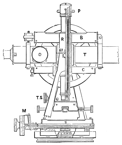
Fig. 251.—Details of omnimeter, showing section of microscope and scale.
576.—With the instrument as originally constructed, it was found that the delicate scale, protruding vertically to the extreme edge of the instrument, was very liable to injury unless supported by heavy metal work, which rendered the instrument cumbersome. A great improvement was made in this instrument, which brought it to its modern form, by[377] placing the tangent scale in a horizontal position, where it could be firmly fixed upon the vernier plate as shown Fig. 251 S, and reading the scale by means of a reflecting prism P in the eye-piece of the microscope. In this improved instrument, as the microscope and telescope are still united on one axis so that they move at equal angles to each other, it is clearly indifferent whether the scale be placed vertically or horizontally, provided it is placed truly at right angles to the microscope when the axis of the telescope is horizontal. The scale, which is 4 inches long, is placed in a sliding fitting to adjust longitudinally to its position by means of a micrometer screw. In the English instrument the scale is divided into 100 parts for calculation. The divisions are subdivided by shorter lines, making the actual division 200. The micrometer screw has 50 threads to the inch, and moves over one of the divisions of the scale only. The micrometer head is divided into 100, numbered at the tens; a vernier placed against the head subdivides each of these divisions into 5, making the total micrometer 500 for one complete revolution. The total division of the 4-inch scale therefore becomes: 200 (divisions of scale) × 500 (micrometer) = 100,000 in 4 inches. The scale is placed centrally to the instrument, so that when the telescope is level the microscope is vertical, and reads 50,000 when in perfect adjustment.

Fig. 252.—Details of prismatic eye-piece.
577.—The general appearance of the instrument resembles the transit theodolite, already described art. 368, in every way except for the addition of the microscope and scale, shown in perspective in Fig. 250. The details of construction of the microscopic apparatus may be followed in Fig. 251. T telescope with sensitive level B mounted upon it; R body of microscope connected solidly upon the same axis as the telescope, shown in half section. The eye-piece is placed at right angles to the microscope and telescope, and reads through the reflection of a prism P to the face of the instrument. The details of the eye-piece are shown in section Fig. 252. The tangential scale is shown in section Fig. 251 S with the micrometer with edge reading vernier at M. The compass of the instrument C is of the trough form, and placed on the opposite side to the level to be used after transitting the telescope from the position in which it is shown in the figure. The axis of the connected telescope and microscope is exactly 6 inches above the surface of the tangential scale S.
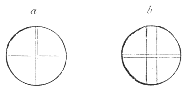
Fig. 253.—Omnimeter webs; a telescope, b microscope.
578.—The telescope diaphragm is generally webbed with one horizontal and two vertical webs, Fig. 253 a, the altitude reading being taken from the top of the horizontal web, and the horizontal angular position from the centre of the interval between the vertical webs. The microscope diaphragm b has two horizontal webs, and reads from the centre of the interval, which is judged by the eye. Observed in this manner, there is no error due to covering angle subtended by the webs themselves. The most exact reading is obtained with a fine point.
579.—Reading of the Tangent Scale.—As the micrometer divides half a principal division into 500, the complete figured divisions are therefore divided into 1000. This is done for the sake of decimal notation. In reading it is only necessary to observe that the shorter or half division is 500, which must be added to the micrometer reading when it is past this division; as for instance 65½ reading is 65,500, and say the micrometer reads 234 past this, the reading is then clearly 65,500 + 234 = 65,734, just as before described for reading half degrees with the vernier.
580.—Value of the Scale taken in Rectangular Coordinates.—The radius from the transverse axis of the telescope to the tangent surface of the scale is exactly 6 inches. The scale is 4 inches divided into 100,000 parts, as it is read with the aid of the micrometer and vernier. The radius therefore in terms of the scale would be at 6 to 4, that is 150,000. By this we see that the divisions of the scale by the angle subtended give tangents, the value of each division of which is the reciprocal of this on 150,000 of the radius or base to any unit we may select. If we make the unit 1 foot, then one division represented by a unit of change of position of the vernier reading, and consequently of equal angular change in the direction of the axis of the telescope, would give a tangent of 1 foot upon a stadium placed at 150,000 feet distance. If the stadium were made 10 feet, as is usual, the same angular magnitude would be traversed in ten times this distance, or over 280 miles, making the value of the units of the vernier 1,500,000. This will give a general idea of the delicacy of the instrument so far as constructive principles are concerned, and not its performance.
581.—The Stadium is marked off in a number of feet, links, or metres, according to the unit taken for measurement of the surface of the land. The English stadium is generally formed of a 14-feet levelling staff, with the surface painted with a ground of plain white. At 10 feet apart two black[380] bands about 2 inches wide are painted in, leaving in the centre of each band a clear white line of about one-tenth of an inch in width. These white lines are carefully set to 10-feet standard centre to centre. But a better plan is to have two equilateral triangles painted, with their apices meeting to the centre. An intermediate 5-feet line is drawn in black, which is found convenient for near measurements, to avoid too great angular displacement of the telescope. When the measurement is in chains, 15 links or 20 links may be taken for the distance of the lines apart to give the tangent. For metre measurement 3 metres are commonly taken for the stadium division. These are in each case subdivided. The lowest stadium reading should be 1 foot at least from the ground to avoid grass and other obstructions.
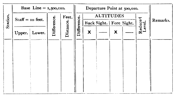
Fig. 254.—Ruling of omnimeter field-book.
582.—Field-book.—The field-book as shown above, Fig. 254, was recommended by the inventor.
583.—Mode of Operating with the Omnimeter.—Carefully set the instrument up at its station in perfect adjustment as a theodolite, noting the departure point upon the scale reading through the microscope. Place the stadium in a vertical position at the point to which measurements are[381] required. Direct the telescope so that the horizontal web cuts the upper line of the stadium, and lightly clamp it. Now read the microscope and record the reading as observed in the field-book. Unclamp the telescope and take the reading of the lower point of the staff and record this. Record the bearing of the instrument on the horizontal circle as with a theodolite.
584.—To Determine the Horizontal Distance in Feet.—Divide the constant radius of 1,500,000 given before by the difference of the two readings of the stadium mark, which are 10 feet apart. For example:—
| First reading | of scale | 67,500, | micrometer | 235 = | 67,735 |
| Second | " | 64,000, | " | 450 = | 64,450 |
| Difference | 3,285; |
then
1,500,000 3285 = 456·6 feet distance.
The process is somewhat simplified by logarithms, as we have only the log. of the difference to subtract from the constant, the 1,500,000 mantissa of which is 1,760,913. Thus—
| log. 1,500,000 | 6·1760913 | |
| log. 3,285,000 | 3·5165354 | |
| 2·6595559 | = 456·6 feet. |
585.—To Determine Horizontal Distance in Chains the stadium should be marked as just described for feet, but at 20 links distance from line to line. Then the radius 150,000 × 20 gives 3,000,000. Taking for example, readings as before with difference of 3285 we have—
3,000,000 3285 = 913·2, or 9 chains 13·2 links distance.
To Determine Horizontal Distance in Metres, the stadium is divided to 4 metres. Then radius 150,000 × 4 = 600,000. Taking, for example, difference of reading as before 3285 then
600,000 3285 = 182·64 metres.
586.—Levelling—Taking Altitudes.—To take the elevation of the staff above the level of the instrument, subtract the reading of the scale, when the axis of the telescope is level, from the lower reading of the staff on the scale, and divide by the distance difference, as found by the method discussed before, then multiply this by 10 feet. Thus taking the lower reading as before 64,450 and the constant for the level position of the instrument, say 50,010, we then have—
| Lower | reading | 64,450 |
| Level | " | 50,010 |
| Difference | 14,440 |
then
14,440 3285 × 10 = 43·96 feet nearly.
The heights, in relation to the position of the instrument, are positive or negative according as the scale readings are greater or less than the constant level reading or departure point.
587.—Work of the Omnimeter.—The perfection of the principles of the omnimeter would lead anyone to infer that work might be done with it of the highest degree of accuracy. The testimony of the greatest authorities show by comparison that it is unable to compete in this respect with the best made tacheometers. A large number of these instruments are employed in India. Colonel Laughton reports upon it—"It has been found to give very accurate heights of buildings, etc., also to be wonderfully accurate when used as a levelling instrument; but it is not so accurate for measuring distances over 600 feet, and even at this distance the error sometimes amounts to as much as 1 foot. It is recommended as admirably adapted for city surveys and traversing, also in hilly and jungly countries, and for railway and similar purposes."[33]
588.—Wherein the instrument fails to give exact results is no doubt in the difficulty of its manipulation. For taking two readings, which are necessary for every operation in distance, [383] the instrument has necessarily to be set twice, the hand being placed upon the micrometer for the second observation while the attention is upon the sighting of the telescope; and even when the readings are taken by the telescope, the microscope has to be separately adjusted to read the micrometer scale. In the repetition of these processes it is almost impossible to avoid some slight disturbance of centre by pressure. In distant readings atmospheric changes giving difference of refraction occur quickly, so that there is more risk of error from two separate observations than if the observations of the subtense webs are taken simultaneously, as with the tacheometer. Further, any defect in workmanship or wear tells seriously against the readings of the instrument. Its advantages are theoretically that a wide angle is subtended by the stadium with the omnimeter in short distances which must be in every way an advantage. Further, since the early general use of the omnimeter, the tacheometer has been greatly improved, particularly in providing it with a larger and better object-glass so as to obtain greater field of view, that fairly near stations may be taken with it that were formerly only possible of reading with the omnimeter. The manufacture of omnimeters is now very limited; the subject is only retained in this edition because there are still some hundreds of these instruments in use.
589.—Improvement in the Omnimeter.—One improvement in this instrument by Mr. W. N. Bakewell, M.Inst.C.E., consists in turning the body of the microscope to a right angle at the position of the transverse axis of the omnimeter, and placing a reflecting prism at the angle. By this means the eye-pieces of the telescope and the microscope are brought side by side, greatly facilitating the joint readings. A second improvement is in making the scale 1,000,000 instead of 150,000, which much facilitates calculation, but it is doubtful if these improvements will stay the declining popularity of the omnimeter.

Fig. 255.—Bakewell's tangential arrangement to a theodolite.
590.—Bakewell's Tangential Arrangement to a Theodolite for Measuring Distances.—This arrangement, which gives the distances by direct reading without calculation, was devised by Mr. W. N. Bakewell to extend the power of an ordinary 6-inch transit theodolite fitted with subtense webs. The observations are made on marks at 3 feet and 13 feet on an ordinary Sopwith staff—a 10-feet base, as is usual with the omnimeter. Any other base may be used if the distances registered are proportionally altered, or the scale may be divided to suit. It was first applied by the author to a theodolite that had been in good service, without the necessity of making any structural alterations in the instrument.[34] The measuring apparatus consists of a tangent screw impinging upon a radial plane, with micrometer and vernier. The details will be readily comprehended from the engraving, Fig. 255, and the following full description.
591.—The transverse axis of a theodolite, upon the opposite side of the telescope to that upon which the vertical arc is fixed, is turned down to a cylindrical surface true with [385] the pivots. A collar A, which fits the cylindrical surface, is slit up on one side to enable it to be clamped firmly to any position of the axis by a clamping screw B. The collar is connected in the same gun-metal casting with the radial arm C that terminates at T in a plane, which is made truly radial with the transverse axis of the telescope. This radial arm C has a long German-silver spring S at the opposite side to the radial plane, which keeps it up firmly in contact with the point of the micrometer screw. A screw is cut on the drum of the micrometer D; on the spiral the scale of distances is engraved; and readings are taken from a line on the index I which slides on the bar E. The scale being one of reciprocals the divisions are at unequal distances, so a vernier cannot be used; consequently at long ranges where the divisions are close, the subdivisions must be estimated. Where this is too rough a method, resort must be had to calculation. The outer end of the drum D is divided into 200, and reads by vernier V carried by the arm E in 5 or thousandths of a revolution. The micrometer screw has twenty-five threads to an inch, and the radius of the arm C is 4 inches. One complete revolution of the screw is one-hundredth of the radius, and using a base of 10 the radius factor is 1000 × 100 × 10 or 1,000,000; consequently Barlow's or any other table of reciprocals can be used, and the distances obtained, by inspection with comparatively little labour. This additional part has not range sufficient for altitudes, being available for about 2 degrees only. The distance may be taken as a subtense or small tangential angle at a radius which, with the azimuthal angle taken by the vertical arc of the theodolite, will give altitude by its sine and horizontal distance by its cosine in the usual manner. The principle is that of the omnimeter, and it possesses the same objection for perfect performance, that the theodolite has to be handled twice for the two observations necessary.
592.—The Gradienter Screw.—This is no doubt a[386] simplified copy of Bakewell's tangential arrangement and is shown at Fig. 256.
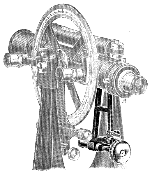
Fig. 256.—Gradienter screw.
It is a micrometer screw fitted to a tangent arm, which can be clamped to the trunnion of telescope when the latter is in any position.
The screw is cut of a value that causes the web of the telescope to move 50/100 of a foot at 100 feet distance for each revolution, and the head of the screw is divided into 50 parts, consequently each division upon the head represents a movement of the cross web of the telescope of 1/100 of a foot upon a scale placed at 100 feet distance. The scale on the arm over the gradienter screw indicates the number of complete revolutions of the head, therefore, if the screw be revolved two whole revolutions the two divisions covered on this scale indicate 50/100 × 2 = 1 foot to the 100 feet.
To establish any grade with this screw.—Set the gradienter[387] head to zero, then level the telescope and clamp the gradienter arm. Suppose grade required be 1·75. Turn the gradienter head through three whole revolutions, which will equal 150, then go on turning through 25 of the divisions on the head and the total movement will be 1·75, the required grade.
For Measuring Distance.—First with a staff for moderate distances. Any space on the staff covered by two complete revolutions of head is 1/100th part of distance, thus, if the difference between the two readings be 3·475 feet the staff is distant 347·5 feet.
Second Method.—For long distances with any rod of known length, such as a 20-foot stadia rod. Send out a man with the rod which he holds vertical at place to be measured. Then measure its length with the gradienter screw; say it takes 2 revolutions and 45 divisions over, thus 2 revolutions = 100 and 45 extra divisions = 145. Then—
20·00 feet 1·45 × 100 = 1379·3 feet.
Another instance.—Suppose the man at a distance has no stadia rod. He simply holds up any stick, say a walking stick. Measure this in telescope. Say it subtends 1 revolution and 28 divisions. This = 78. When your man comes in with the stick, measure its length. Say it was 3·25 feet. Then—
3·25 feet 0·78 × 100 = 416·6 feet.
The above illustrations are for readings taken approximately level. If there be much elevation or depression the angle must be read and the difference of hypo and base calculated and the stadia rod or staff must be inclined so that its face is at right angles to the line of sight from telescope. This can be done by the rod man inclining the staff or rod until the shortest reading is given if a staff be used, or the longest measurement is recorded by the gradienter screw head if a stadia rod be used. It is better in this case to have the[388] staff fitted with a director (see art. 561), so that the person holding the staff may sight into the telescope of the instrument, thus ensuring the staff being exactly at right angles to the line of sight.
No constant should be added with either this, Bakewell's, or omnimeter measurements, as the angles are taken from the centre of the instrument. This gradienter screw has the same fault as mentioned for the two foregoing, viz., that all readings are taken by two movements of the instrument.
INSTRUMENTS CONSTRUCTED ESPECIALLY FOR OFFERING FACILITY OF TAKING INCLINES—INCLINOMETER—THEODOLITE—GRADIOMETER—CLINOMETERS—ABNEY'S, TROUGHTON'S, DE LISLE'S, STANLEY'S, BARKER'S, BURNIER'S, WATKINS'—CLINOMETER SIGHTS—RULE CLINOMETERS—ROAD TRACER.
Certain instruments are constructed specially with the object of taking inclines, where this is the predominant work to be performed with them. They form an important branch of surveying instruments, and for their special kind of work present many time-saving capabilities.
593.—Lister's Inclinometer Theodolite.[35]—This instrument is the invention of Mr. James Lister, C.E. It was originally designed to set out upon the surface of land the widths of slopes or batters by pegs, as required in the execution of railway, canal, and other earth works. In general construction it resembles a theodolite as before described, arts. 370 to 391, with the addition of an extra vertical axis to the telescope piercing the horizontal axis at right angles, Fig. 257. In this construction the telescope upon the horizontal axis can be set by the vertical supplementary axis to any inclination, so that if the vertical axis be set to the slope of a railway cutting, any number of points or pegs may be set out continuously with the same setting by direct observation through the telescope across any irregularity or inclination of the land surface. In this operation an immense amount of [390] labour is saved over the ordinary system of pegging by calculation with the aid of a theodolite, where each peg requires a separate setting of the instrument. When the inclinometer theodolite is used for surveying purposes, the telescope is fixed by a spring catch which places it firmly true to the reading of the ordinary vertical arc.

Fig. 257.—Lister's inclinometer theodolite.
The instrument is also fitted with a mechanical device for repeating the tangential angles when operating on curves, which obviates the necessity of reading them on the horizontal arc, thus facilitating the work. This will be referred to in the following explanation of the manipulation of the instrument as the "angle repeater."
The main difference between the method of taking cross sections by the level and by the inclinometer theodolite is in[391] substituting inclined bases for horizontal ones, which will be clearly understood by reference to the following diagrams, which illustrate somewhat extreme surface inclination.
Fig. 258 shows the levelling method and Fig. 259 the method by the inclinometer theodolite. In the first it will be seen that each section requires to be taken singly with repeated changes in the position of the instrument at each section, involving numerous readings on the staff, booking, and reduction of the levels for changes only. Also the sectional measurements require to be taken in short horizontal lengths with the plumbing of the end of the tape at each length. By the inclinometer method this unnecessary labour is avoided, there being no changes in the position of the instrument, as from one setting a series of sections may be[392] taken on either side of it. There is no reduction of levels, and the sectional measurements are taken on the surface to which the base line is always approximately parallel.
The saving of labour is even more marked in the setting out of slope pegs than in the taking of cross sections, for in addition to the transference of level from the centre pegs to the outcrop of the slope several approximate calculations have to be made before the exact position of the slope peg can be found, while by using the inclinometer theodolite it is only necessary to put in normal slope pegs at intervals of a quarter of a mile, or at such distances apart that a ranging rod may be seen from one point to the other, and by setting up the instrument at each alternate peg, or at half mile intervals, the whole of the intermediate pegs for a quarter of a mile on each side of it can be "boned" as simply as ranging a straight line, the telescope being inclined to, and revolving in the plane of the slope. In this manner as much work may be done in a few hours as will take a week with the levelling method, and this without the slightest physical or mental strain to the operator.
594.—Explanation of the Method of Operating with the Inclinometer Theodolite.—For setting out a centre line of railway, etc., and putting in level pegs the instrument may be used as an ordinary theodolite, or even as a level, and the work performed in the usual manner. It may also be used as a level when setting out the normal slope pegs on slightly inclined ground surfaces, but when the inclination is considerable it may be used in a special manner with advantage as hereinafter explained.
595.—To take Cross Sections when the Line is Straight.—It is unnecessary to explain the use of the instrument when the ground surface is comparatively level, so as to require no change in position and resetting of the instrument, it being obvious that in this case it may be used simply as a level with advantage; but when the surface is inclined in the direction of the centre, and also at a right angle thereto[393] in the direction of the section lines, the method of procedure is as follows:—
Assuming that it is desired to take a series of 15 sections (and this is within the limit of the number that can be taken from one setting of the instrument), set up the inclinometer, preferably over the centre peg of the series, in such a position that the two front legs of the tripod stand across the centre line, and the back leg (which has a distinguishing mark) rests upon the centre line. Set the lower limb of the tribrach stand upon which the instrument is supported to a level condition in its lateral direction by manipulating the back leg, and at the same time observing the bubble on the stand. This will enable the instrument to be subsequently tilted to a certain extent in a perfectly vertical position. Clamp the horizontal arc to zero and direct the telescope to the centre line. Clamp the lower limb and bring the arc round to an angle of 90°. The vertical arc is now at right angles to the centre line and parallel with the section lines. Now release the telescope from the vertical arc and turn it again on the centre line, and by working the back adjusting of the instrument (or in case of necessity manipulating the back leg) tilt the instrument until the cross web of the telescope is elevated to a short distance above the seventh or most distant peg of the sections, or site of the first section to be taken. Now tilt the vertical arc until the cross web assumes a position parallel to the general inclination of the ground surface laterally. Clamp the arc to this inclination and note the angle thereon, for this will be the angle of the inclined base from which the whole of the sections will be taken and subsequently plotted.
Commencing at the seventh peg at this side of the instrument, the sections may now be taken consecutively to the seventh peg on the other side by taking readings on a level staff held in an inclined position at a right angle to the cross web or base, as shown in Fig. 259, and oscillated that the lowest reading may be taken. A reading must be taken on[394] the centre peg at each section to establish the height of the base above the peg. The base may be raised or lowered at any section, or part of a section, to meet any excessive elevation or depression of the ground surface which might prevent the staff being read, but a separate reading on the centre peg at each variation of the base must be taken, thus:—Fig. 260.
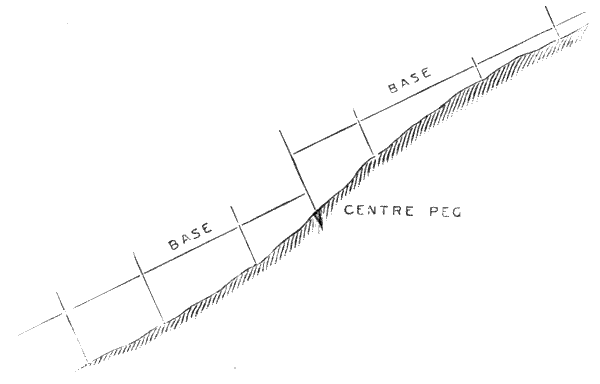
Fig. 260.
The bases being parallel the angle of inclination remains the same. The tilting of the instrument produces a variation in the angle of the vertical arc, but this is only to such an infinitesimal extent that unless the tilt be excessive it may be disregarded. The correction, however, may be simply made after the instrument has been adjusted for any operation by ascertaining or simply noting approximately the angle of the tilt, and setting off this angle on the horizontal arc towards the tangent line, thus varying the chord or base line to this extent, or it may be found by referring to a table of natural sines, etc., and multiplying the cosine of the angle of the tilt by the tangent of the vertical arc angle, the result being the tangent of the corrected angle, thus:—if the angle of the tilt be 10°, and the vertical arc angle 25°—Referring to tables, cosine 10° = ·98481, tangent 25° = ·46631. ·46631 × ·98481 = ·45924 = tangent 24° 40′, the corrected angle making a variation of 20′.
596.—To take Cross Sections when the Line is on a Curve.—This operation is similar to that explained above for taking cross sections when the line is straight, except that being on a curve a variation of the tangential angle must be made at each peg or section. As this is performed mechanically by a single movement of the angle repeater and no reading of the angle is required, the work is just as readily performed. To more clearly elucidate the method, we will take a case in point and assume that the number of sections to be taken is 15 and that the radius of the curve is 50 chains, which the accompanying diagram illustrates.
Diagram (Fig. 261) showing the adjustment of the instrument for taking sections on curves and the variation of the tangential angles for each section.
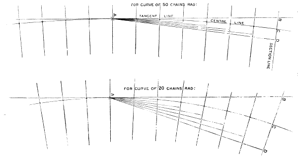
Fig. 261. If the centre pegs be taken as slope pegs, the diagram applies to illustrate the setting out of half widths.
Having set up the instrument at A, Fig. 261, over the centre peg of the series in the manner before described, ascertain the tangential angle for the first chain of the curve by dividing the constant, 1719, by the radius of the curve in chains, which gives the angle in minutes or 1719 ÷ 50 = 34′ 24″, and set the angle repeater to give a movement of double this angle or 1° 8′ 48″, ready for application at each change of section.
Set the horizontal arc to the tangential angle for the seventh peg from the instrument at which the first section has to be taken, or 34′ 24″ × 7 = 4° 0′ 48″, and direct the telescope to the peg. Zero is now on the chord line AD, which is parallel to the tangent at the seventh peg, and at an angle of 8° 1′ 36″, from the tangent line AB, which divided by 7 gives the variation of the tangential angle at each section, or 1° 8′ 48″, to which the angle repeater has been set. Release the horizontal arc and bring it round to an angle of 90° from zero, and the vertical arc will be at a right angle to the line A D and parallel with the section line at the seventh [396]peg. Release the telescope from the arc and turn it at right angles thereto in the direction of the zero line AD. Now, [397]by working the back adjusting screw of the tribrach, tilt the instrument until the cross web comes somewhat above the seventh centre peg, then tilt the vertical arc until the cross web is parallel with the lateral inclination of the ground surface. Clamp the arc and note the angle thereon to determine the inclination of the base to plot the sections from, and the instrument is then in adjustment for taking the first section at the seventh peg in the manner already described, being careful that the lateral bubble on the instrument is in a perfectly level condition. To take the second section at the sixth peg, one movement of the angle repeater must be made and the lateral bubble adjusted, which operation must be repeated for every succeeding section.
The movement of the angle repeater brings the vertical arc parallel to the section line at each peg, and the adjustment of the bubble maintains the angle of the inclined base uniform throughout.
When the sections are all taken on this side of the instrument, the telescope is turned to the other side and the operation continued until the whole fifteen are completed.
From the above detailed description it may be thought that the adjustment of the instrument for the operation is somewhat complicated, but in practice it is not so. After the first experience and the method is understood, it is only a matter of two or three minutes, and once in position the sections may be taken as rapidly as on level ground, and the saving of labour is practically the same as in taking sections when the line is straight.
597.—To set out Half Widths or Slope Pegs when the Line is straight.—In commencing this operation it is necessary in the first instance to set out two or more half widths, according to the length of the cutting or embankment. These may be a quarter of a mile apart, or so far as a ranging rod may be clearly seen from one point to the other. The pegs put in at these points act as normals from which to[398] "bone" or range in all intermediate pegs by sight simply, without further recourse to levelling measurement or calculation. If the ground surface be comparatively flat, these normals may be put in in the usual way by using the instrument as a level, but if the surface is much inclined and the slope deep, a simpler method may be adopted, which will be hereafter explained.
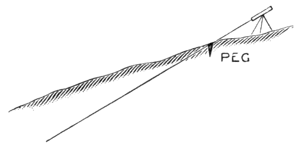
Fig. 262.
Assuming that the normals have been put in, set up the instrument at any intermediate peg in such a position that the telescope when set to the angle of the slope shall line with the top of the peg, as per sketch, Fig. 262. Then release the telescope from the vertical arc and direct it to one or other of the nearest normals, adjusting the cross web to cut the top of the peg by turning the instrument on its axis. Clamp in this position and the telescope will revolve in the plane of the slope, and any point on the intermediate surface intersected by the cross web is the outcrop of the slope and the position of the peg. When all the pegs on the one side of the instrument are put in, turn the telescope to the other side to cut the next normal and proceed in the same manner. When all the pegs have been put in for this half mile distance, the instrument may be moved to the next half mile normal and the operation repeated, until the whole cutting or embankment is completed, the last normal point being in all cases the formation width at the ends.
In speaking of half-mile distances we are assuming the[399] most favourable conditions of surface and application of the method, but in practice where the surface is undulating the positions of the normals should be at the most elevated points from which a considerable range of sight may be obtained.
In fixing the points for the slope pegs, a rod should be held in an inclined position and be brought to line exactly with the cross web of the telescope, the pegs should then be driven level with the ground surface where the foot of the rod has rested.
598.—To set out Slope Pegs when the Line is on a Curve.—The operation is similar to that described above, except as explained for taking cross sections on a curve. A variation of the tangential angle must be made for each peg, and if the centre peg shown on the diagram accompanying that explanation be taken as one of the slope pegs, it will also serve the purpose of illustrating the present one, and a brief recapitulation of the manipulation of the instrument to bring it into adjustment for the operation is all that will be required.
The normal slope pegs having been set out and the instrument set up at an intermediate one, as before explained, instead of directing the telescope in the first instance to intersect one of the next normals, set the angle repeater to double the tangential angle for the first chain in the curve, and the horizontal arc to the tangential angle for the distance in chains that the normal is from the instrument. Then turn the telescope to cut the normal peg and clamp the lower limb. Now bring the horizontal arc round to an angle of 90° from zero and clamp. Release the telescope from the vertical arc and turn it at a right angle thereto in the direction of the zero line AD, and by working the back adjusting screw tilt the instrument until the cross web cuts the normal peg again. Adjust the lateral bubble on the instrument to a level condition and it is in adjustment for the operation.
To put in the first peg from the normal, make one movement of the angle repeater and adjust the bubble. To put in[400] the second one, make another movement of the repeater and adjust the bubble, and so on until the whole is completed. It will thus be seen that by a simple mechanical operation a vast amount of work can be done in an incredibly short space of time as compared with the levelling method, and that with little or no effort on the part of the operator.
599.—Alternative method of setting out the Normal Pegs.—Let the diagram, Fig. 263, represent the section of a cutting at the point opposite which the normal has to be set out, when the section depth may be assumed to be 16 feet, the formation width 30 feet, and the slope 1½ to 1, or at an inclination of 56° 18′. The distance bc for a 1½ to 1 slope is one-third the formation width, or 10 feet. The data required for the operation is the distance ad from the centre peg to the plane of the slope, which is found by multiplying ac by the natural sine of the slope angle 56° 18′, thus: 26 × ·831 = 21·60 feet.
The operation when the line is straight is to set up the instrument at a centre peg some distance away from the normal in the manner previously described, viz., with the front legs set across the centre line, the back leg on the centre line, and the bubble on the tribrach set level before adjusting the instrument, which manipulation produces a perfectly vertical tilt.
After adjustment, set the horizontal arc to zero and direct the telescope to the centre line, clamp the lower limb, set the vertical arc to the angle of the slope, and bring the horizontal arc round to an angle of 90°, or a right angle to the centre line. Liberate the telescope and direct it again to the centre line, and by working the back adjusting screw tilt the instrument until the cross web intersects the top of the centre peg at the normal. The telescope will now revolve in the line ag parallel with the plane of the slope and at a distance of 21·60 feet from it. Therefore any point on the surface in the line of the slope where 21·60 can be read on the staff is the outcrop of the slope and the position of the peg.
In this example, when the required reading is higher than the ordinary staff, lower the tilt and take an intermediate reading, as at f in the diagram, Fig. 263, which may read, say, 12·00, when the required reading on the peg will be reduced to 9·60.

Fig. 263.
In setting out normals on a curve by this method the only difference in the operation to that above described is that instead of in the first instance clamping the instrument with zero on the centre line, it must be clamped with zero on the chord line, i.e., at double the tangential angle for the distance the instrument is from the peg, as before explained in detail for operations on curves.
By this method two normals may be set out at least 20 chains apart from one setting of the instrument, or several slope pegs may be set out in like manner, which under certain[402] contingent difficulties of ground surface is an advantage of considerable importance.
In this connection there is also an alternative method of putting in the slope pegs after the normals have been set out, which, under certain conditions, may be employed with advantage.
Instead of setting up the instrument at the back of the normal with the telescope set to line with the plane of the slope, and to range the pegs in by means of a rod or staff held at the inclination of the slope, as before described, it may be set up in any position in the line of slope where a reading can be taken on the peg, as at a on the sketch (Fig. 264), and at the point read, as at b, a disc should be clamped to the staff, as this can be much more clearly seen than the staff graduations when sighting long distances. The staff should then be transferred to the next normal and held on the peg. If the telescope be now turned in this direction and the cross web adjusted to cut the disc, any point on the intermediate surface where the disc can be intersected is the outcrop of the slope and position of the slope peg.

Fig. 264.
It is necessary to observe in the setting out of slope pegs that when there is a change of gradient the operation must cease, but if the point where this occurs be made the position of a normal the operation may be proceeded with, if the instrument be set up at this point.
600.—To set out Slope Pegs on both sides of the Line simultaneously without moving the Instrument from the Centre[403] Line.—Conditions. Single Line. (ab) Formation 15 feet. (cd) Depth of cutting 14 feet. Slope 1 to 1.
The point e, Fig. 265, is the extension of the slope lines to cut the centre line, and its depths below formation for 1 to 1 slope is half the formation width, or 7′ 6″.
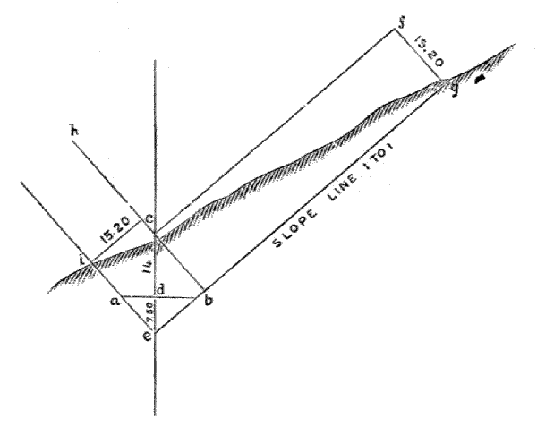
Fig. 265.
Operation.—The instrument being set over a centre peg with the telescope at the slope angle, turn the telescope to any other peg and adjust the cross web to line therewith (on line c f). Take the section depth cd (14 feet), to which add de (7′ 6″) = 21′ 6″. This multiplied by ·707, the natural sine of the slope angle (45°) will give the distance from the axis of the instrument to the slope line, thus: 21·50 × ·707 = 15·20 feet, and the point on the surface at g where 15·20 can be read on the staff is the position of the slope peg. This is similar to that described in the last paragraph, but if the telescope be now changed to the angle of the slope on the other side of the line ch, the peg i is instantly found by the same reading (15·20).
601.—The Use of the Inclinometer in Mining.—A lode having been discovered, it is required to mark out on the[404] ground the general line of the outcrop. Hitherto the method employed has been to find the strike and drift of the lode and to level and survey the surrounding country and plot on a contour plan. Lines parallel to the strike and spaced according to the trigonometrically calculated bases are ruled in. The points of intersection of the contour line with that of the parallel line to the strike of the same height above datum will be a point of outcrop. The bearings of these points are read, and their distances scaled from the plan, the theodolite is then taken to the field, and the points found are marked out on the ground. This entails a considerable amount of labour and careful work both in the field and office, and then only points at intervals are obtained and not a continuous line.
The inclinometer, having an adjustable axis at right angles to the horizontal, enables the line of sight to be made to revolve in any plane. If at the spot where the lode has been discovered the instrument be set up in line with the strike, and the movable axis adjusted to the angle of dip, it is evident the line of sight lies wholly in that plane, and a continuous line of outcrop may be pegged out on a flat or undulating country, which can be produced to any length required by taking the instrument to a fresh station. This feature of the instrument is equally, if not more, important than its use for rapidly pegging out railway slopes.
602.—The Gradiometer.—This instrument, while performing all the duties of a first-class level, is designed also for taking vertical inclines at small fixed angles for railways, drainage works, steep incline levelling, etc., etc., and also telemetrical readings up to great distances.
In general construction, as regards telescope, stand, etc., it resembles a level, and when set at zero is equal in every way to one of the best, with the additional advantage that it may be used for rapid work without the trouble of setting up by the levelling screws, as the telescope may be levelled at any sight by means of the gradienter drum milled head. The[405] gradiometric arrangement is effected by the telescope being mounted in trunnions, one pair being adjusted vertically; the amount of elevation or depression is indicated by a drum carrying an open extended scale graduated to read rise or fall, from 1 in 12 to 1 in 1,200, which may be conveniently and distinctly read without the use of a vernier.
The additional parts do not increase the bulk of the case and add very little to the weight.

Fig. 266.—Stanley's gradiometer.
By its use a great saving of work is effected. For instance, for a town drainage in which it is desired to work out an inclination, say the levels indicate a fall of 10 feet between the extreme points: if the line the drainage is intended to take be measured, however angular or zigzag it may be, and the length of that line be divided by the amount of fall, this will give the gradient; say the line of streets measures 5,000 feet, this, divided by 10 feet, gives a gradient of 1 foot in 500. Therefore if the drum be set to that proportion, all the pipes may be laid directly without further setting. The gradients for any railway may be instantly found by merely turning the drum until the telescope sights, up or down the incline to be measured, a reading on the staff equal to the height of the[406] instrument, and taking the reading of the drum at the position of the indicator.
For levelling steep inclines it also saves a great number of settings up, as, instead of levelling for, say every 14 feet rise or fall, the gradient of the total distance can be taken and also the distance measured by stadia reading, when the incline is not too great for taking one reading with telescope level, or by gradient reading when this cannot be done, and by adding the staff reading to the distance divided by the gradient, and deducting the height of the instrument the difference of level can at once be ascertained.
Example: Sighting a staff at a gradient which falls conveniently upon it, say 1 in 35 and this reads 8·7 feet. Distance measured, as explained later, say 735 feet, then 735/35 = 21 feet + 8·7 feet = 29·7 feet; deduct the height of instrument, say 4·9 feet, difference of level 24·8 feet.
For measuring long distances beyond the range of the stadia lines or points in the diaphragm, or for measuring distance on inclines, the gradiometer will also be found very useful, as by taking the difference of any two suitable gradients, the base distance is given without calculation for difference of hypo and base.
If the gradient be not very steep or below the height of the staff, the simplest method is to sight the staff with the telescope level and take the staff reading; say this is 12·45 feet, then set the gradient drum to 1 in 100 and again take the staff reading and, say this is 4·30 feet, the difference between these readings = 8·15 feet. Strike out the decimal point which multiplies it by 100 and we have the base distance 815 feet.
For shorter distances a larger base upon the staff may be taken, thus giving greater accuracy; for instance, if the gradient drum after taking the level reading be set to 1 in 50 and the resulting difference divided by 2, any error in taking exact readings is reduced by one half, or 1 in 33-1/3 and divide[407] difference by 3; or 1 in 25 and divide difference by 4: or 1 in 20 and divide difference by 5, etc. Any error of reading would be reduced by one third, one fourth, one fifth, etc.
The difference of readings obtained by either of the following two gradients will also give base measurement without any calculation whatever: 100 and 50 | 63-2/3 and 40 | 60 and 37½ | 50 and 33-1/3 | 33-1/3 and 25 | 25 and 20 | 20 and 16-2/3 | 12½ and 11-1/9 | 11-1/9 and 10.
Example: Suppose the top of staff is below level altogether, turn the drum until the top of staff is sighted in the telescope; say the gradient of this is 27½ go on turning until gradient 25 is indicated and take the staff reading; say this is 12·75, then move the drum until gradient 20 is indicated and take the staff reading: suppose this to be 3·40, then
| 12·75 |
| - 3·40 |
| = 9·35 |
Omit the decimal point and the measurement reads 935 feet, which is the horizontal distance. The two most suitable gradients would of course be used according to the position.
Distances may be set out with equal facility with the gradiometer by the subtense method, by working out a subtense suitable for the distance. This is easily done by dividing the distance required by any two numbers having a difference of the required subtense, the result being two gradients, which, when worked with, will give that subtense at the required distance.
Example: If the distance required to be set out be 650 feet, a suitable size for an object to be plainly visible at this distance would be 10 feet. Then take as divisors two numbers having a difference of 10, say 10 and 20.
650 ÷ 10 = 65
650 ÷ 20 = 32½
These two gradients will give a subtense of 10 feet at a
distance of 650 feet, and all that is necessary is to send a man[408]
out in the required direction with a 10-feet rod (preferably
having  ends,
thus
ends,
thus  ,
for long distances, to facilitate
distinct reading), and signal him to move farther off, or nearer
until the length of the rod, held vertically, is exactly covered
by the movement of the telescope caused by revolving the
drum between gradients 65 and 32½.
,
for long distances, to facilitate
distinct reading), and signal him to move farther off, or nearer
until the length of the rod, held vertically, is exactly covered
by the movement of the telescope caused by revolving the
drum between gradients 65 and 32½.

Fig. 267.—Stanley's gradioplane.
It is always preferable to make the subtense as large as possible, as the larger it is the more accurate the result will be. All distances set out by this method are base distances, no matter what the difference of level may be, and such figures for divisors should be used as give the gradients below 100. Gradients between 12 and 65 are the best and quickest to work with, and with care more accurate results are obtained than with chaining.
Thus, at one time, a distance may be set out or measured, the difference of level taken, and also the gradient ascertained, and the drum can instantly be set to zero and all ordinary levelling operations continued.
If preferred the gradient drum can be divided to percentage gradients ·001 to 8 instead of ordinary gradients 1 in 12 to 1 in 1,200.
603.—Gradioplane.—This is a new instrument, specially designed by the reviser for very accurate underground surveying, such as is required for large sewage work or water works, long tunnels, or any work requiring a very rigid and accurate instrument, with a very powerful telescope for measuring all horizontal and small vertical angles.
The horizontal circle is 6 inches diameter, and reads by two verniers to 20 seconds of arc, or it is fitted with micrometer microscopes reading to five seconds of arc if desired.
In the former case it carries a floating bevelled aluminium ring compass divided to ¼ degrees, reading by microscope, and in the latter a long trough compass.
Vertical angles are measured by a very accurate form of gradiometer screw carrying a drum with open extended scale in exactly the same manner as the foregoing instrument, and the remarks regarding that and its working apply equally to this instrument. The telescope, which is 14 inches long and carries a 1¾ inch object glass is so mounted that it will revolve in the plane of any inclination set by the gradiometer drum, and is provided with a locking arrangement for fixing it absolutely true for fore or back sight, and it carries a long sensitive spirit bubble to enable it to be used as a most accurate level and for rapid levelling; this may instantly be set level by the drum at any sight without troubling to level the instrument. The diaphragm is fitted for subtense measurements.
A further refinement is fitted to the telescope when desired, by which any grade may be instantly divided into any desired number of parts; this is effected by means of a[410] horizontal circle fitted to the stage under the telescope, which is read by a vernier attached to the telescope. This circle is divided from 0 when the telescope is fixed at zero round each way to 90 degrees into 100 parts, the vernier divided to read 100ths or 10ths of each division. It will be seen that when the telescope is in line with the gradient drum, that is at zero, it will be raised or depressed to whatever grade is indicated upon the drum, and is then capable of being revolved 180 degrees for taking a back sight, when it sights the opposite grade to that which it does when at zero. When it has revolved 90 degrees only the telescope becomes level at any grade, and therefore at any position it is set between zero and 90 degrees it sights a part of that grade; supposing the telescope at zero is set by the gradienter drum at 1 = 1,000 then by revolving the telescope from that to level, it passes over 100 parts of that grade, each of which may be subdivided by the vernier to 100 parts again, consequently 100 × 100 × 1,000 which equals 1 in 10,000,000 or any desired number of 10,000,000ths may be readily set by means of the clamp and tangent fitted to the telescope, or if the grade be set by the gradient drum to 1 = 100 then 100 × 100 × 100 equals 1 in 1,000,000, or any other grade which is set by the gradient drum may, with equal ease, be divided by 10,000 or any other proportion that the horizontal circle vernier may be divided to give.
A sliding lower plate is provided for accurately centring the instrument, the levelling screws are adjustable for wear, and the tribrach is fitted with quick-setting spherical joint.
This instrument will also be found of great utility in mining work, to mark out the general line of the outcrop when a lode has been discovered. This, by the ordinary method, entails a considerable amount of labour and careful work both in the field and office, and then only points at intervals are obtained, not a continuous line. With this instrument the line of sight may be made to revolve in any plane, so that if it be set up in[411] line with the strike at the spot where the lode has been discovered and the gradient drum adjusted to the angle of dip, it is evident that the line of sight will be wholly in that plane, and a continuous line of outcrop may be pegged out on a flat or undulating country and can be produced to any length required by taking the instrument to a fresh station.

Fig. 268.—Stanley's gradioplane.
The above illustration, Fig. 268, shows the gradioplane fitted with a horizontal circle to the telescope for subdividing the grades of the gradienter drum, and when thus fitted forms the most exact instrument for setting out or ascertaining gradients that has been devised.
604.—Abney's Clinometer.—This very popular little instrument, the invention of Captain Abney, Fig. 269, embraces the same form of sighted level with reflector as that[412] shown in section, Fig. 87, p. 142, but the level instead of being fixed in line with the tube is placed above it upon an axis which forms the centre of a divided arc. The axis with the bubble is turned to any angle by means of a light milled-edged wheel placed in front of the arc. It carries an index which reads on the arc the angular position of the level to the centre of the instrument by a vernier to 10′. There is also a scale placed upon the arc giving gradients from 1 in 1 to 1 in 10. As the bubble of the level in its course passes the centre over the axis its reflection is made to become coincident with the sight line through the tube only when it is quite level. Therefore whatever the inclination of the tube, the bubble may be brought level by turning the milled head until it appears centrally in the sight axis of the tube, and the angle at which this occurs can be clearly read afterwards upon the arc. The size of the instrument in its case is 5 by 2½ by 1½ inches; weight, 8 oz.

605.—Troughton's Abney's Clinometer.—In the Troughton form, Fig. 270, the arc is toothed, and it is moved by a pinion similar to the movement of the box sextant, so that the bubble moves slowly in relation to the motion of the fingers when adjusting. The arc is read by a single index line instead of by a vernier.
606.—Telescopic Hand Clinometer.—The author has recently added a telescope to the Abney form of clinometer, as shown Fig. 271. The arc is moved by rack and[413] pinion and reads by a vernier to single minutes, therefore good reading within one minute of arc may be made with it. Captain East, R.E., suggested a mode of steadying the instrument for observation which appears to answer admirably for hand observation. He puts the hook-end of his walking-stick into his waistcoat pocket and clutches a part of the stick by his right hand at the height of his eye. Then holding the instrument in his right hand supported by the stick it is kept quite steady for observation.

Fig. 271.—Telescopic Abney clinometer.
607.—De Lisle's Reflecting Clinometer.—There have been several arrangements made for converting the Burel level, Fig. 89, into a clinometer; that devised by General A. De Lisle, R.E., with modifications by Colonel Bell and Mr. Alfred Cooke, as represented in Fig. 272, is the most popular. In this a heavy arc is constructed upon the lower part of the instrument. This is jointed upon a vertical axis at C so that it may be revolved to bring the mass of the arc either forward or backward, to take inclines upwards or downwards, or to rest at an intermediate position to make the instrument flat and portable in its case, it takes the position shown in the figure. The arc has a stiff centre axis with a radial bar, the edge of which forms the index. A sliding weight is placed on the radial bar, which is sufficiently heavy[414] when at its greatest extension to exactly counterbalance the weight of the arc in a horizontal position and to make the mirror quite vertical. In this position it forms a simple Burel level. A set of graduations are made upon the arc, which are numbered 1 to 50 to 1 to 1. The radial bar index set to one of these numbers gives the amount of inclination that will result from the coincidence of the reflection of the centre of the pupil of the eye cutting the object to be observed. The length of this instrument is about 6 inches; its weight about 10 oz.

Fig. 272.—De Lisle's reflecting clinometer.
608.—Prismatic Clinometer.—This instrument was originally devised by the author about 1860. The form of the instrument, Fig. 273, is that of a prismatic compass, art. 155. A similar metal or card and talc dial to that of the prismatic is used, but this is centred upon a transverse axis which is pointed at the ends to fit into hollow centres. This card is weighted on one side, so that when the sights are in a truly horizontal position the prism will show the zero of the card cutting the sight line. If the instrument be inclined upwards or downwards, the degrees of elevation or depression will be indicated by the card retaining its pendulous position. This[415] is a very convenient instrument for use with the box sextant, and as it is only of about half an inch in thickness, and of the same diameter, it will pack conveniently in the case with that instrument—weight, 8 oz.

In Using this Form of Clinometer the prism is raised or lowered in its sliding fitting until the divisions of the card are sharply defined. Then in looking over the edge of the prism through the slot above it, the hair in the window of the back sight will appear to cut the divisions of the card; and the object seen in the distance, in front of the hair to which the instrument is directed, will appear coincident with the number of degrees of inclination indicated by the card.
This clinometer is sometimes fitted upon a prismatic compass, so that inclines may be read by the same prism and sight arrangement. This is, however, done more neatly by the arrangement next described, if the instrument is intended to be used with the prismatic compass only, and is not wanted separately for use with the chain.
609.—Barker's Combined Prismatic Compass and Clinometer,[36] Fig. 274.—The prismatic compass of this arrangement is that of Hutchison's form, art. 155. The clinometer is of the same kind as that just described, but this, instead of being a separate part of the instrument capable of [416] detachment, remains permanent. To effect this arrangement the clinometer card is mounted over the compass card on a pin axis instead of centres. A part of the clinometer card is cut away so as to permit the compass card to be read beneath. This cut-away part is held by a stop to a position out of the field of the prism when the instrument is to be used as a prismatic compass. When the stop is released and the instrument is held with its face vertical, the pendulous clinometer card comes into view, and cuts by its reading through the prism the sight line, as before described for the prismatic clinometer. The prism is focussed to the upper or lower dial by a long, sliding fitting. It is used as the instrument last described.

610.—Continental Form of Clinometer.—Hand clinometers on the Continent are generally made on Captain Burnier's plan, Fig. 275, which was explained for the prismatic compass, art. 156. Indeed this instrument is more generally combined with the prismatic compass. The graduation is set up on a plated ring vertical to the plane of the[417] swing of a pendulum, shown in section Fig. 276. The reading index is a hair which is read on the graduation by means of a cylindrical lens, B, when this is brought coincident with the sights D′W′ as described for Burnier's compass. When the clinometer and compass are combined the vertical rims stand opposite to each other, AC. A lifter, Fig. 275, L, is provided to take the working parts out of bearing, and a stop S′ to prevent oscillation. The illustrations show the combined instrument: B cylindrical lens reading the drums; A clinometer; C compass; DD′ fore sight; WW′ windows, both of which fold down on the top of the instrument.

Fig. 277.—Major Watkins clinometer.
611.—Major Watkins' Clinometer.[37]—The vertical plane of division is adopted, as in that of Captain Burnier, but the reading, instead of being taken on the exterior of the ring by a magnifier, which entails a projection, is placed on its interior. This reading is magnified by a concave reflector, shown Fig. 277 at R, which reads to a line on a slip of ivory placed just beside the eye-hole E shown in the engraving. The pendulum is stopped by a pin, upon which it springs when the box is rotated vertically to prevent wear when out of use. There is much less work in making this instrument than Burnier's, and the round form is more portable. The only point on which it does not bear comparison is in that the concave mirror represents a uniform distance sight which makes the reading indistinct to persons [418] of weak sight, whereas Burnier's admits of adjustment by placing the instrument nearer to or further from the eye, the cylindrical lens being made large to admit of this form of adjustment. This instrument could be improved by the mirror being made adjustable. Weight, 6 oz.

Fig. 278.—Compass with clinometer sight.
612.—Clinometer Sights.—A clinometer sight is often attached to a light pocket compass, as shown Fig. 278 at the upper part of the engraving, consisting of a pin hole and hair cross. This, used in the manner shown by the position of the eye in the engraving, can only be made to take sight inclines by another person reading the pendulum index, which marks the inclination in the degrees to which the compass is divided. This portable pocket instrument is, however, useful in other ways. Standing face to the instrument it will measure inclines directly very fairly by looking over the top edge and bringing this to the visual rate of inclination at which the pendulum index can be read in front view. Geologists commonly use it in this way to take the dip of strata. It can also be used by putting it on or against any inclined surface. The case is generally gilt or nickel plated, and is about 2 inches diameter, and the instrument weighs about 3 oz.
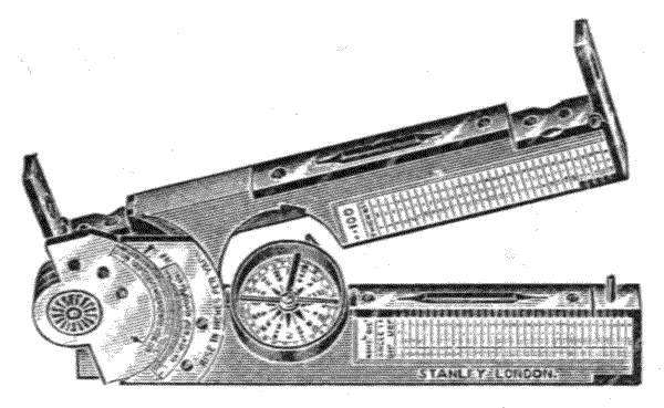
Fig. 279.—Rule form clinometer.
613.—Rule Form Clinometer.—This is made in the form of a stout 12-inch, one-fold boxwood rule, Fig. 279. It is much used by civil engineers as a working tool, and[419] intended to be applied directly to an inclined surface, either placed on a straight-edge or otherwise, generally to take the inclination of earth work. It may be placed upon a picket laid upon the ground to take natural slope. When used in this manner the lower surface is placed on the straight-edge or picket, and the rule is slowly opened until the bubble in the level in the upper limb becomes central. The arc of the head joint will then indicate the inclination. It may be used in another way: the lower limb may be set level on the dumpy level compass or on any flat plane, and the inclination may be sighted through the pin-hole and cross-hair sights[420] shown at the ends of the upper part of the instrument. Its size is 6¾ by 1¾ by ½ inches; weight 9 oz. There are several varieties of this instrument.
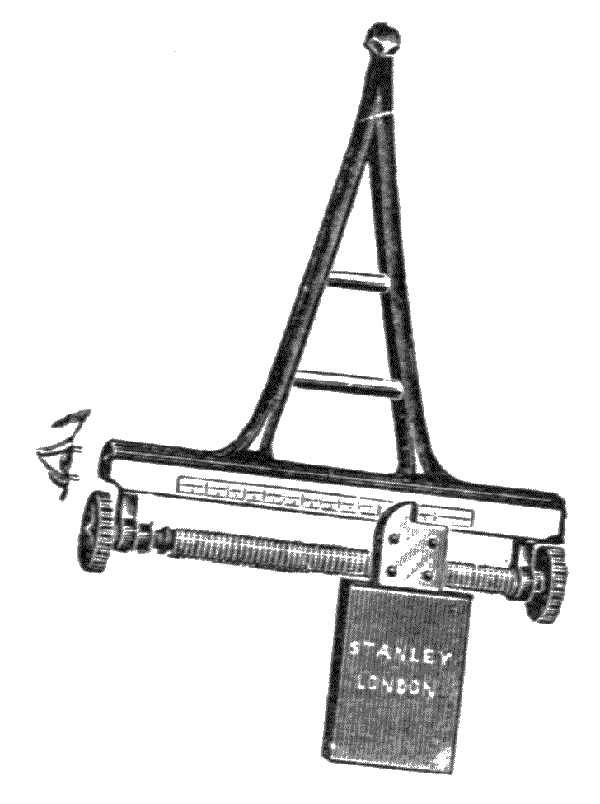
Fig. 280.—Road tracer.
614.—The Road Tracer is a balanced clinometer much used by natives in India and China for road making, Fig. 280. It consists of a pendulum, supported upon a stand that carries a sighted tube which indicates the level of the ground when the weight is carried in the axis of suspension. The weight is adjustable to a scale by a screw. The scales read inclines, by displacement of the weight, up and down in percentages or gradients, to which it may be divided.
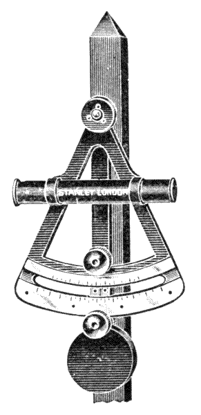
Fig. 281.—Bellamy's road tracer.
This instrument has been improved by Mr. C. V. Bellamy, M.I.C.E., M.I.M.E., F.G.S., &c., Director of Public Works, Lagos, West Africa, a civil engineer who has had great experience in the colonies, and it will be found much more accurate, less liable to get out of order and far more convenient to use than the old forms. It is shown at Fig. 281.
The chief feature of this pattern lies in the adoption of the arc of a circle instead of a straight scale, and a pendulum[421] weight actuated by a rack and pinion in place of the screw and sliding weight. This admits of greater nicety in the divisions and allows a stronger and lighter construction.
The sighting tube is provided with reversible sliding shutters, so that back readings may be taken without unclamping the instrument or altering the vernier or index. A powerful clamp is provided for locking at any desired grade.
A recent further improvement by Mr. Bellamy has been made by making this instrument in a form to give readings in degrees of arc as well as in gradients. Fig. 282.

Fig. 282.—Bellamy's improved road tracer.
INSTRUMENTS OF REFLECTION—OCTANT OR QUADRANT—REFLECTING CIRCLE—SEXTANT—PRINCIPLE—PARALLAX—CONSTRUCTION—EXAMINATION—ADJUSTMENT—ARTIFICIAL HORIZON—SOUNDING SEXTANT—BOX SEXTANT—SUPPLEMENTARY ARC—IMPROVEMENTS UPON THIS—OPTICAL SQUARE—OPTICAL CROSS—APOMECOMETER.
615.—The Octant or Quadrant measures angles within 90° by an arc of 45°. This instrument is generally termed an octant on the Continent from the space of the divisions; a quadrant by English-speaking races, from the extent of angles it takes. The idea of bringing the reflection of an object from a mirror in line with the direct sight line from another object, to measure the angle at the position of the observer subtended by the two objects, was originally proposed and worked out in a manner by Hooke,[38] and also by Newton.[39] Newton's invention was the more simple and important. This was communicated to Dr. Halley, then Astronomer Royal, but it was left unpublished until after his death, when it was found in Newton's own handwriting among Dr. Halley's papers.
Newton employed two mirrors to obtain the reflection of an object placed at any angle of less than 90° to the axis of the telescope or sight tube, to throw an image directly through [423] the tube. One of these mirrors was placed at an angle of 45° to the axis of the telescope and covered half its field aperture, so that a direct image of an object could be received by the eye from the open uncovered part of the telescope at the same time as the reflected image of another object from the mirror. The second mirror was placed so as to throw its reflection into the mirror on the end of the telescope without giving any obstruction to the open aperture. This side mirror was fixed with the centre of its plane over the axis of a movable arm which read upon an arc the amount of its angular displacement to 90°. The mirrors were so arranged that their faces should be parallel to each other when the movable arm was placed at the zero of the arc. The graduation of the arc was of double the closeness of the ordinary arc reading, so that the angular positions of the two mirrors in relation to each other was indicated according to the following law:—
That the angle between two reflections in the same plane is equal to twice the inclination of the reflecting surfaces to each other.
616.—Hadley's Quadrant.—In Newton's quadrant the arc was brought most inconveniently in front of the face. By Hadley's arrangement the telescope or sight line is brought in a direction about parallel with the chord of the arc, producing the very convenient form of instrument now in use. This instrument was exhibited at the Royal Society, 13th May, 1731.[40] It was tried experimentally by the Astronomer Royal, August, 1732, in a yacht excursion, when readings were taken satisfactorily within a minute of arc.[41] It afterwards came into general use.
The quadrant was at first held to be sufficient for measuring the sun's altitude for obtaining latitude, but Hadley, as early as 1731, saw the advantage of extending the [424] arc so as to be able to observe the opposite horizon if the direct one was obscured. It was also found that measuring the moon's angular distance from a star beyond 90° was serviceable in determining longitude. He therefore proposed by a duplicate system of reflections to extend the arc by what is termed a back sight to 220°. The means he suggested, which were commonly carried out in instruments of the period, were found to be too complicated for practice.[42] In the meantime the construction of these instruments, originally framed of a combination of wood, ivory, and metal, was much improved by making the frame entirely of metal. There were also great improvements made in the optical parts, by which the arc of 90° was extended. In 1757 Captain Campbell had an instrument constructed of metal of 60° of arc which therefore read to 120°. This instrument, with details of improvement, principally by Ramsden,[43] became the modern sextant.
617.—Reflecting Circle.—As soon as the success of the sextant was assured there appeared to be a general desire to complete the circle by reflections, many inventors thinking this would possess great advantages over the arc of 120°, and we find therefore no lack of inventions to this end, even by eminent men. Reflecting circles, as they are termed, that were of sufficient merit to come into limited use, were designed by Mayer, 1770; Borda, 1787; Mendoza, 1801; Hassler, 1824; Fayrer, 1830. Troughton's circle of about this period was no doubt the best instrument of the class.[44] We have also meritorious reflecting circles by Pistor and Martins, and by Amici.[45] Although these instruments were used at sea to a limited extent, particularly on foreign ships, they were also used on land, where indeed they were more manageable. As [425] no further reference to these reflecting circles will be given, anyone interested in the matter may refer to the books mentioned in the notes, where very full particulars of their structure are given. It was felt necessary to mention the subject here, as the same ideas are constantly cropping up as assumed advantages where previous experience is forgotten. Reflecting instruments at sea are tedious to use when the angle to be taken exceeds that taken in by the eye without movement of the whole body. On land, when the angle exceeds 120°, a theodolite is better; but supplementary angles may be taken with the sextant conveniently on land, where the portability of the instrument is of great consideration. This will be again brought forward in discussing box sextants with supplementary arc.
618.—The Sextant, of the invention of which some particulars have just been given, is only used as a surveying instrument for the exploration of new countries, for which employment—it may be used with or without a tripod or stand—it is found to be a most convenient, light, and portable instrument for the traveller for ascertaining longitude, latitude, and time with the aid only of an artificial horizon. Triangulation may also be taken with it of terrestrial objects, even for the complete circle, by repetitions from station to station in angles within 120°. The same principles which are followed in the construction of the nautical sextant are followed also in the manufacture of two modified forms of this sextant which are used for surveying only, the sounding sextant and the box sextant. As the nautical sextant is most open to observation of its parts it will be more convenient to discuss the construction and general arrangements of this instrument first.
619.—Optical Arrangements of the Sextant.—Newton in the description of his instrument placed the mirrors parallel to each other, that is, to zero of the arc, in his illustration for the demonstration of the principle. In this[426] position he showed that the direction of the reflected ray is coincident with the direct ray entering the eye from the same object or star. This scheme the author has generally found the clearest for illustrating the principle to persons not well acquainted with optics, there being some difficulty in explaining the law just given, art. 615, from a more complicated scheme.
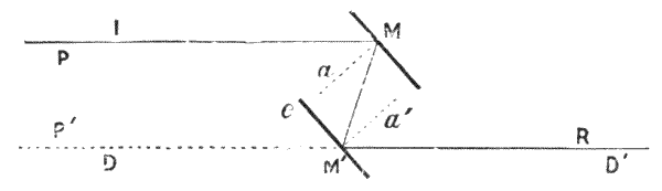
Fig. 283.—Reflection in direct line from two plain mirrors.
620.—If two mirrors be placed with their faces parallel to each other in such a manner that a ray of light may continue after two reflections from them, the ray will continue its path parallel in its direction to its incidence upon the first mirror.
Let MM′, Fig. 283, be two mirrors placed with their faces opposite and parallel to each other. Let the incident ray IM fall on the mirror M whose normal is a. Then, as the angles of incidence and reflection are equal, art. 54, it will be reflected at equal and opposite angle to the normal to M′. Let the normal of M′ be a′. Then again, the incident line MM′ will be reflected at equal angles to the normal to D′, that is, as shown by the diagram, it will continue parallel with the incident ray and in such a position that an object at P would appear to the eye, placed at D′, as though it were at P′ in the direct line of sight.
621.—Parallax.—It will be seen by the figure that the point P does not appear to the eye at D′ in its true position but at P′ therefore with the mirrors MM′ quite parallel, the points P and P′ appear coincident, and would read as one point with the index of the sextant set at zero, that is, at the position when the mirrors are parallel to each other; whereas[427] the points P and P′ really subtend a small angle if direct lines be drawn from them to D′. It is therefore clear that the angle read by coincident reflection and direct or, as it is sometimes called, visual image is less than the true angle at about the position shown. This difference is called the error of parallax. When the object is distant this error is immeasurably small. The parallax error varies proportionately to the distance of the mirrors apart and with their angular position. If the mirrors are in such an angular position that the rays proceeding from an object impinging upon the centre of the first mirror would, if continued, reach the eye, there would be no error of parallax. This occurs in the nautical sextant at about 60°, and the parallax error increases on either side of this point.
622.—In the practice of surveying this small error is neglected. When the box sextant is used the mirrors are placed at a very small distance apart, and the parallax error therefore is extremely small even for near objects. Where two objects are to be triangulated, the one near and the other distant, the parallax error is much decreased or eliminated by taking the near object by direct vision, and the distant object by reflection. In this case, if the near object be towards the right hand, the sextant must be used in an inverted position. If the two objects be both near, a distant object may be sighted in the direction of one of them for the reflected image.
623.—It is readily seen that if the parallelism of the glasses shown in the figure be disturbed, say by a change in the relative angular position of M′ so that the planes M and M′ continued to subtend an angle to each other, then the normal of M′ must also be changed in direction equal to this; but the ray MM′ remaining constant, as there is no movement of M, this ray will therefore be displaced in its reflection from M′ an amount equal to the angle of incidence on M′ from its normal, plus the angle of reflection from the[428] opposite side of the normal, that is, to double the amount of angular change of the position of the mirror or of its normal, which is the same thing. The sextant therefore reads, by change of position of one of its mirrors, half the angle of reflection upon its arc; and to make it read to the angular value of its reflection the divisions on the arc are made twice as close, that is, half degrees are made to read as degrees. This will be better explained by the following scheme.—

Fig. 284.—Principles of reflection of the sextant.
624.—The above scheme, Fig. 284, is taken from Captain Magnaghi's admirable work before mentioned, which gives a very clear geometrical demonstration of the value of angular positions in compound reflection. A ray of light SR directed to a plane mirror R is reflected therefrom to a plane mirror R′, following a plane of reflection perpendicular to the intersection of the two mirrors. The direction R′T of the ray reflected by the second mirror falls into the same plane of reflection, and makes with the direction SA of the incident ray an angle double that which is comprised between the two mirrors.
The two planes of reflection SAB and ABT unite in[429] one because they both contain the line AB and the normal BP to the mirror R′.
In prolonging the normals of the mirrors to their point of intersection P we find that—
BTS = BAS - ABT;
but as ½ BAS - ½ ABT = BPA = BDA,
therefore BTS = 2 BDA.
625.—The mirrors being placed in the position shown in the figure, if we look through a telescope whose visual axis is placed in the line ET, with its objective to the mirror R′, we see in the centre of the field of view the image of the object S reflected consecutively by the mirrors R and R′. We also see in the telescope whether the mirror R′ is only a certain height above the plane of reflection, so as to permit half of the object-glass to receive the rays coming from the point E situated in the prolongation of the line TB, also the image of E which is necessarily coincident with that of S, because the rays by which each image is formed enter the telescope in the same direction BT. Therefore when the images of the two objects E and S appear superimposed or coincident in the middle of the field of view, we have an index given that the mirrors form an angle with each other which is half that which is made at the point T from the same objects, and when one is known the other is easily deduced.
626.—Nautical Sextant.—The ordinary construction of this instrument, Fig. 285, consists of a cast gun-metal frame, forming approximately in outline a segment of a circular disc AA″ including within its extreme radii about 155°.
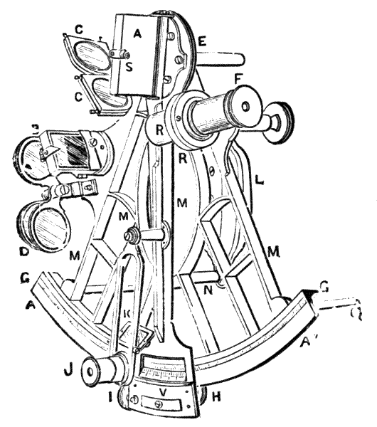
Fig. 285.—Nautical or astronomical sextant.
627.—The Limb G, which is made only about 1/12 inch in thickness, has generally a face of about ¾ inch in width, which is inlaid with silver or platinum, as Fig. 127, p. 186, to take the graduation to about 140°. The limb is stiffened by a deep, thin rib about ½ inch wide, supported by a corner[430] hollow. The exterior radial arms and interspace framing, Fig. 285 MM, which vary very much in design according to the taste of the maker, is made generally of about 1/14 of an inch in width upon the face of the bars, with a depth of 3/8 inch. This arrangement of the bars placed edgewise gives great stiffness to the surface of the arc with little weight. A handle L, made generally of ebony, is supported on two standards or brace-pieces N, which are carried off to about 2 inches from the back of the frame to hold the handle parallel with the face. The handle has sometimes a hole bushed through it with metal, to support the sextant upon a corresponding pin forming part of a stand or tripod when the instrument is used for taking observations on land. Three feet are placed at the corners of the frame of the sextant, one shown at Q, to support it conveniently on a table to take the reading of an observation just made.
628.—At the centre of the arc a female axis of about 1½ inches in depth E is attached by three screws to the frame perpendicular to the plane of graduation. This carries the male axis, which centres the vernier on the vernier arm M.[431] The axis is covered by a protecting tube which forms one of the three feet upon which the instrument rests when laid down. The vernier arm is made of gun-metal of about 1/16 inch in thickness and from 1 inch diminishing to ¾ inch in width. This is stiffened by a light rib on its upper side.
629.—The Vernier V reads upon an 8-inch sextant, that is, one of eight inches radius, to 10″, the graduations being to 20′ and the vernier taking 120 divisions. A description of the vernier reading was given, art. 318. The vernier falls upon the arc on the plan shown Fig. 127, p. 186. It is clamped near to position by the milled-headed screw H, and is adjusted by the tangent I. A magnifier J is placed on a jointed sling-piece K which traverses the vernier. This is sometimes provided with a ground glass shade to dull the silver for reading. The sling-piece moves the magnifier opposite to any division of the vernier.
630.—Over the axis of the vernier arm a large, oblong mirror, termed the index glass, A, is fixed with its face in a plane cutting the centre of the axis. The index glass is placed with its longest sides approximately in line with the vernier arm. This mirror is placed in a metal tray and is sometimes made adjustable by three screws; but it is better fixed by the maker by screwing the flange-piece, which forms one end of the tray, hard down. The index glass moves with the index arm and gives the first reflection of sun, moon, or star which falls thence upon the horizon glass B.
631.—The Horizon Glass B is placed upon a spur-piece formed in the same casting as the frame. This glass, which is worked perfectly parallel, has the lower half of its surface next the frame silvered. The silver is cut to a sharp line against the plain part. The horizon glass placed in its metal tray has adjustments given to it by means of capstan-headed screws in a manner that will be presently described.
632.—The Telescope screws into a ring fitted at R, which stands upon a bar erect from near the edge of the frame. The[432] female screw by which the telescope is held is formed of two rings which adjust for the amount and direction of separation, so that the telescope may be directed coincident with the horizon glass. The bar or standard supports the ring fitting and is made of either square or triangular section, fitted accurately in a deep socket fitting, in which it slides to raise or lower the ring by means of a milled-headed screw placed on the end of the bar. This permits adjustment only sufficient to bring the axis of the telescope opposite the line of division between the plain and silvered parts of the horizon glass.
633.—Four Circular Shades, carried in square frames fitted with dark bluish-grey glasses, are jointed to the frame at C. These have nib-pieces at the upper corners, so that one or more of the shades may be turned up at a time by the finger-nail to intercept any surplus amount of light from a luminous body reflected from the index-glass; or the whole of the shades may be turned up when observation is made of the mid-day sun. Three other similar shades, but placed in circular frames are fixed at D, which hinge over and back, to be thrown in or out of interception, and are used to subdue the light from the horizon if required.
634.—The Telescopes used as a part of the sextant are generally two in number. One for direct vision is a short tube of about 3 inches in length, focussing at about 4 inches. The optical arrangement is the same as that of an opera glass, consisting of an achromatic object-glass of about 4 inches focus and a concave eye-glass of about 2 inches negative focus, Fig. 14. The second telescope is about 7 inches to 8 inches in length. This has two Huygenian eye-pieces, which have each a wired diaphragm at the mutual focus of the eye-piece and the object-glass. One of these has two fine wires placed parallel for use in adjusting the telescope, and the other has two pairs of crossed wires to indicate the centre of the field of view. There is also a plain pin-hole sight provided for open vision.
635.—The Case in which the instrument is packed is generally made of well-seasoned mahogany, dovetailed together at its corners. The fittings are made to put the instrument back in its case as it was last used within a wide range. A tommy-pin for adjustments and a hand magnifier are supplied with the instrument. The case is generally French polished inside as well as out to prevent absorption of moisture from sea air.
636.—Manufacture and Examination of the Nautical Sextant.—Besides the general good work that this instrument demands, the important points to be observed are, that the glasses should be of hard crown glass worked perfectly parallel from face to face; they should also be well polished. These observations apply to both the reflecting glasses and the shades. The silvering of the mirror should be protected with a good coating of copal varnish. The mirrors should be held by three points only, and be quite free from strain. The upper of the three points should detach, so as to be able to remove the glass at any time for resilvering. The axis should be fitted with all the care necessary for a theodolite, and be placed truly central to the arc. The extremity of the vernier arm when free of its clamp should traverse the arc at equal distance from its face and move with very light friction. The extreme lines of the vernier should cut equal divisions all along the arc 0° to 140°, observations being taken particularly at both ends and in the centre of the arc. The vernier should lie flat on the limb from end to end of the arc. The standard or stem-piece for elevating the telescope should move upwards and downwards stiffly but equally by the motion of its milled-headed screw. The division lines of the limb and vernier should be cut fine but very deep: they should be cut on the dividing engine from the axis of the sextant to ensure true centring of the arc, and not as in the usual plan of having the axis adjusted to the divisions.
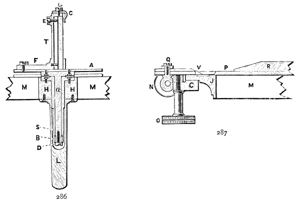
Fig. 286.—Section of axis and index glass of sextant.
Fig. 287.—Section of limb and clamp and tangent.
637.—Axis.—This is the most important part of the[434] instrument, and requires the greatest care in construction. Fig. 286 represents this to a scale half size. a the axis, made of hard gun-metal, has a collar by which it is attached to the index arm. The axis is ground and burnished carefully into S the socket-piece, which is fitted into the frame and held down by three screws. At the end of the socket there is a collar-piece B attached upon an angular or tight conical fitting by the screw D, which prevents the axis rising out of its socket. The axis is covered by a cap L which protects it from injury, and this at the same time forms a leg to the instrument as before mentioned. The index glass I is mounted in a tray T shown in section. There are two points of contact at the lower part of the back of this glass, formed by pins, and one point of adjustment pressing against the clip G by a spring C in front, acting contra to a screw at the back E, which adjusts only a small distance to bring the index glass to perpendicularity. The flange-piece F is adjusted in[435] the manufacture so as to leave very small separate adjusting to the index glass necessary.
638.—Section of the Limb and Clamp and Tangent.—The general arrangement is shown in Fig. 287. M arms of the frame; J section of the limb; C clamp attached to the tangent N for clamp and tangent motion, described art. 346; O milled head to clamp; N milled head to tangent. The vernier is shown at V, reading through an opening on the face of the index arm P. The rib to stiffen this arm is shown at R.
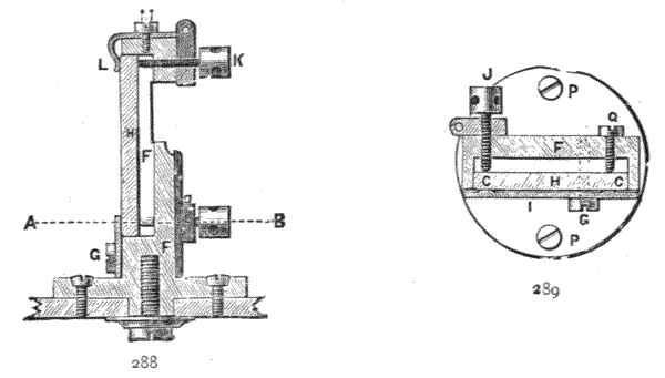
639.—The Adjustment Arrangement of the Horizon Glass.—This most important adjustment is constructed in various ways. The plan now generally thought to be the best is for the maker to fix the horizon glass frame firmly in its true position perfectly perpendicular to the surface of the frame, and to allow a small amount of adjustment to the glass only. A convenient plan of doing this is shown in the vertical section full size in Fig. 288. The frame FF is made in one casting, which has its base collar firmly fixed to the frame of the sextant. Fig. 289 is a cross section A to B. H the horizon glass is held upon its face by three points, one of which is shown at L, which is placed in the centre of the[436] top. The lower front points are the exterior corners of a plate which is cut away between. This plate is held by the screw G. The screw G forms a kind of hinge which, together with the elasticity of the plate, gives a slight pressure directing the glass hard upon the points of the screws J and Q. The screw J resists this pressure lightly and permits adjustment of the horizon glass H to angular position in relation to the plane of the index glass to a small extent, by means of a pin placed in the capstan head J. The perpendicular position of the horizon glass, H, is secured by slight adjustment of the capstan head K, which moves against a spring L in the vertical centre of the top of H. This piece, with screw and spring, is attached to the horizon glass frame FF′ by the screw M, so that it may be easily removed to replace or resilver the glass. The silver on the glass is cut to a sharp line at about the point H with a razor.
640.—Testing the Parallelism of the Surfaces of the Glasses.—The best method is to firmly fix a telescope provided with webbed or pointed index diaphragm so that the webs or points cut a distant, sharply defined object, or its edge only, quite clearly. If the glass to be tested be now placed in four directions agreeing with its four sides in front of the object-glass of the telescope, and it is worked perfectly parallel, and is free from striæ, the distant object will not appear to be displaced by its presence in the slightest degree at any position. If the glass be not mounted and is quite square, should there be any very small error, the thickest or thinnest edge should be placed towards the frame; but in this case only a very small error is permissible. The coloured glasses require the same test as the white ones. Where the parallel glass to be tested is small, the object-glass of the telescope may be covered by a paper cap, with a small hole only left through its centre, sufficient to take the glass.
641.—The glasses, when fixed in the sextant, may be examined for parallelism approximately by setting them end up singly to the sun, with the sextant set at an angle that the direct and reflected images of the sun's limb appear just to touch, the eye-piece of the telescope being constantly covered by the sun-glass. If there be a want of parallelism, the image will be disturbed. One reason that the telescopic plan first proposed is better to be followed in the construction of the instrument, is that the telescope is fixed and that there is no indistinctness from unavoidable motion of the body, such as occurs when the sextant is held in the hand.
642.—The Quality of the Surfaces of the Glasses may be examined, both for flatness and brightness and for equality of density, by holding them so that the reflected image of a straight body, as for instance a stretched thin string placed at a distance, may be observed by reflection in glancing over the surfaces with the eye nearly parallel with its plane. If the glass be imperfect the image that reaches the eye will appear to be wavy. If the reflection appear misty, this is generally due to want of parallelism of the glass; but this mode of observation is altogether somewhat technical and difficult to attain without skill.
643.—To Silver the Index or Horizon Glass with Mercury.—Clean the glass thoroughly by boiling it in water containing an alkali (potash or soda), and then polish it off with whiting and water, using a clean piece of old linen or perfectly clean wash-leather. Do not touch the surface with the fingers. Take a piece of clean tin-foil freshly opened from the roll and cut out a piece slightly larger than the glass to be silvered. Lay this upon a smooth pad—an old leather book-cover answers. Place a single drop of clean mercury about the size of an ordinary shot upon the tin-foil and rub this gently over the surface until it is entirely silvered. Now pour very gently sufficient mercury upon the foil till the surface appears[438] to be flooded. Take a sharply cut straight-edge formed of stiff writing-paper, and draw this over the surface of the mercury to clear it. Take a slip of clean smooth writing-paper very little wider than the foil and of about one and a half times its length: spring the paper to a slight curve and place one part of it over the silvered foil so that when it springs open it will cover it and exclude the air from the surface. Now give the glass a final polish and lay it upon the paper over the foil. Hold the glass down with slight pressure with the left hand, and slowly and steadily draw out the slip of paper in the linear direction of the surface of the glass with the right hand. This will take out the air between the foil and the glass, so as to bring the mercury in contact and leave a perfect mirror. It must now be set aside with the glass turned face downwards in an inclined position, so that the surplus mercury may drain off from the foil. Small slips of foil should be put at its lower edge, which, by their attraction for the mercury, will accelerate the draining. The mirror should not be touched after setting it up to drain for twelve hours at least, after which the surplus foil may be trimmed off. After another thirty hours or more it may have any varnish or other protection applied to the back of the silver.
644.—Where instruments are taken abroad mercury silvering may become spotted, so that a small store of mercury and tin-foil should be taken out with the sextant for resilvering. But it should be particularly observed that the mercury should never be placed in the same case with the instrument, as the smallest particle, if it touch the frame, will eat into the brass and destroy its strength. Sealing-wax dissolved in spirit answers for a varnish at the back of the foil fairly well after resilvering if proper varnish be not at hand. It is advisable before attempting to silver a sextant mirror to practise on a few slips of ordinary glass in order to get into the way of doing it. In modern practice base silver is deposited, and no mercury is used, but the process requires special skill.
645.—Adjustment of the Index Glass.—Hold the sextant clamped to about 60° in a horizontal position with the index glass near the eye. Look nearly along the plane of the glass in such a manner as to be able to see one part of the plane of the arc by direct vision, and another part by reflection of it at the same time. If the direct view and the reflected join in one line, and the arc appears as the continuity of a single plane, the index glass is perpendicular to the plane of the sextant. If this be not the case it can be adjusted by turning the set screw placed at the back of its upper centre, Fig. 286 E, very gently.
646.—Adjustment of the Horizon Glass to Perpendicularity.—Place the vernier at zero. Hold the plane of the sextant parallel to the horizon and observe if the image of the horizon seen by reflection at the edge of the silver line coincides exactly with the image received directly through the plain part of the glass. If it does so the horizon glass is perpendicular to the plane of the instrument, that is, assuming the index glass is also perpendicular. In this adjustment it is well to rock the plane of the instrument say 20°, to see that the horizon is cut as a clear line about its horizontal position for this amount of angle. If the mirror be not perpendicular adjust gently by the single screw at the top of the horizon glass frame. If the horizon be not water, the sharp outline of any distinct distant object will answer, or a piece of fine string placed at a distance and stretched straight.
647.—Adjustment for Index.—This is the adjustment for parallelism of the two mirrors at the zero of the arc. The sextant is clamped at zero as before: the arc of the instrument is turned in a vertical position and the horizon again observed. If this appears to cut a clear line through the plain glass and the mirror there is no index error, and the planes of the glasses are truly parallel to each other in this position. If the line is not continuous adjust gently by the lower screw, Fig. 288, at G.
648.—Adjustment of the Horizon Glass by the Sun.—This is a better adjustment than that given above, except that it introduces any error that may be due to the imperfection of the shades; and it is more difficult particularly for the first approximate adjustment. Arrange the telescope and shades so that a clear outline of the sun's limb may be observed without distressing the eye. Place the vernier at zero. Observe the sun, which will be most conveniently sighted at about 40° elevation, first with the plane of the frame vertical, and then horizontally perpendicular to this. If the sun presents a round disc in both these positions the sextant is in adjustment. If in the vertical position there appears to be a small notch at top and bottom of the sun's limb, the glass is not perpendicular to the plane of the instrument, and this requires adjustment by the screw at Fig. 288 K. If notches appear at the sides of the limb when it is held horizontally there is an index error, which may be adjusted at G if it be small.
649.—Index Error after Adjustment Allowance.—The limb of the sextant is graduated 5° beyond the zero position when the glasses are parallel to each other. This is called the arc of excess. The vernier is also divided three lines beyond its zero position, which is marked by an arrow. These extra divisions are placed on the instrument for correcting the index error by measurement of the angle subtended by the diameter of the sun's disc alternately on one side and the other of the zero line, in which observations, if the two readings agree, the sextant must be in perfect adjustment; when they do not agree half the error may be adjusted by the horizon glass. The same observations may also be made with a bright star by setting the index alternately on one and the other side of zero. When the sun is used the reflected and direct images are brought together, so that the two suns that appear in the instrument just touch limb to limb, first upon direct reading and then upon the arc of excess. When[441] the division is adjusted very nearly, any small error, plus or minus, may be allowed as a constant for all readings. In observations of the sun care should be taken that the eye is protected, both by the sun-glass cover to the telescope and by sufficient use of the shades.
650.—Adjustment of the Telescope to Set its Axis Parallel to the Plane of the Sextant.—In fixing up the instrument after manufacture, the ring standard which carries the telescope is set at a measured distance from the plane of the frame, so that the centre of the ring coincides with the height of the silver line cut on the horizon glass. This is necessarily a primary adjustment. For final adjustment the long, inverting telescope is screwed home in the ring, and the eye-piece which has two parallel wires across its diaphragm placed in it. The telescope is brought to focus on any distant object, the eye-piece being turned at the same time to bring the wires parallel with the face of the instrument. Two objects are taken subtending an angle of 90° or over,—as the sun and moon, or the moon and a bright star,—and the index is moved so as to bring the objects, say the limbs of sun and moon, in contact with the wire nearest to the sextant, and fixed there. Then by changing the position of the instrument a little, the images are made to appear upon the wire furthest from the sextant. If the limbs of the sun and moon still remain in exact contact as they appeared before, the axis of the telescope is truly adjusted. If the limbs of the two objects appear to separate at the wire furthest from the sextant, the ring-adjusting screw furthest must be loosened a very little and the screw nearest the sextant tightened the same amount. If the reverse, and the images appear to overlap, adjust in the reverse direction. By repeating this operation a few times the contact will appear to be the same at both wires, and the axis of the telescope will be in collimation, that is parallel with the plane of the instrument. After the telescope is truly adjusted it may be raised or lowered a[442] little to make the reflected and direct images appear equally clear.
651.—Final Examination of the Sextant.—It will be readily seen that an instrument, although correct in theory but depending upon perfection of workmanship in centring, division, surface and parallelism of glasses, and also in its adjustments, can scarcely be brought to perfection. The errors generally increase from the zero point, where adjustments are possible, and are greatest at 140°. In the ordinary commercial sextant of the dealers the errors of centring alone are commonly 3 minutes to 5 minutes, with like errors in other parts. It is therefore better, where the sextant has to be absolutely relied upon, to subject it to actual trial. The zero point can be readily fixed by rules already given; besides this the meridian altitude of several bright stars subtending angles of about 30°, 60°, 90°, and 120° should be measured either from a clear horizon or from a mercury artificial horizon, to be described presently, for angles under 60°, and the errors plus or minus tabulated. The data for the meridian altitudes of certain stars upon any night may be taken from the Nautical Almanac, which will require correction for the latitude and longitude of the observer. This subject is too complicated to be entered upon in detail here. At the present time the National Physical Laboratory undertakes the examination of sextants for a moderate fee. This is effected by means of fixed collimators, art. 229. For angles distributed over the arc the parallax error is eliminated by placing the collimators in pairs. The N.P.L. certificate may now be had with good instruments when purchased. It may be noted that an originally well-made instrument retains its qualities for all time, the wear of such instruments being inappreciable.
652.—To Use the Sextant the right foot should be placed nearly 2 feet in advance of the left and directed at right angles to it. In this position the body is firm. The[443] instrument is supported by the right hand, the elbow being brought down firmly upon the body. The clamp screw first and then the tangent screw are moved by the thumb and finger of the left hand. Some practice is required to make a steady observation. To bring two objects into apparent juxtaposition, methods of observation for terrestrial objects will be reconsidered in discussing the box sextant further on. As regards celestial observations reference should be made to works on practical astronomy, as the subject would take too much space to be entered upon here. The whole subject, with many refinements of correction of parallax, etc., which fall beyond the limits of practical surveying with the sextant, is ably discussed in Chauvenet's Spherical and Practical Astronomy.
653.—Artificial Horizon.—For ascertaining the latitude of a place from the observation of a celestial body by means of a sextant, it is necessary to have some means of estimating the position of the horizon. A method of doing this, originally proposed by the elder George Adams, optician, 1748,[46] was to float a parallel disc of glass upon a basin of mercury, and to receive the reflected image of a star from the mercury by the sextant simultaneously with its direct image. The angle then given by the reading of the arc is double the angle at which the true horizon is placed relatively at the same time. This idea, carried out in a practical form in an instrument henceforth called the artificial horizon[47] is due to Wm. Jones, a well-known optician at the end of the 18th and beginning of the last centuries, who arranged convenient means of making the instrument portable, and to keep the mercury from disturbance of the air by covering it with a glass roof. The form of artificial horizon that he invented has been in common use ever since. He also invented another simpler form, which was that of taking the reflection from a [444] piece of silvered, or of black, glass. The performance of the artificial horizon depends in any case entirely upon means of obtaining a reflection from a perfectly horizontal surface.
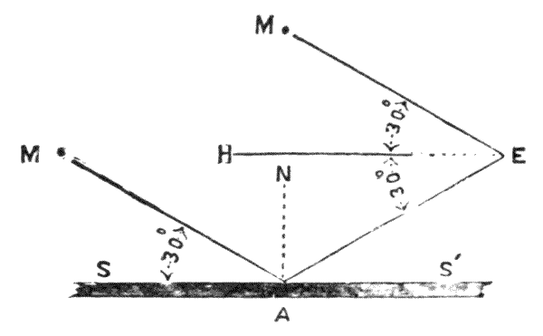
Fig. 290.—Diagram of artificial horizon.
654.—Theory of the Artificial Horizon.—A ray M′ Fig. 290, from a luminous body, at infinite distance will have its image reflected from a level reflecting surface SS′ at an angle equal and opposite to the incident ray, the angles M′AS and EAS′ being equal. Let E be the place of the eye or the sextant: this will receive a ray from the same distant body in direction ME, which is sensibly parallel with M′A. The angle MEA being double the angle of incidence M′AS, the half of this angle will therefore produce the horizontal line EH at the height of the observer's eye if the plane of reflection SS′ be level. Therefore if we take half this angle MEA as it appears in the sextant, it will give an angular position of the object in relation to the horizon at the height of the eye, or be tangential to the surface of the earth. If M′AS be 30°, the angle AEM will be 60°, showing the elevation of object half this or 30°. The sextant takes 120° with certainty; therefore 60° will be the limit of meridian altitude the artificial horizon will measure.

Fig. 291.—Artificial horizon of black glass.
655.—Artificial Horizon in Black Glass.—This instrument is the most portable, packing in a close pocket case. It is made of both circular and square form in plan. Fig. 291 is the Admiralty pattern. The black glass[445] should have a truly plane surface. It is fixed over a brass tray by being floated on plaster of Paris to avoid strain. A light rim of brass is screwed down over the glass to keep it in position. There are three adjusting screws AA′A″. It is adjusted to level by a loose level tube ground on its under face P. The level tube shown in detail Fig. 51, p. 94, is placed on the surface lineally with the two screws, Fig. 291 AA′, and afterwards at a right angle to its first position with one end of the tube towards A″. It is finally tested by traversing at the position shown in the Fig. 291, and at right angles to this direction. There is a great risk of getting a strain on the glass in fixing it in its frame. The author therefore prefers the circular form that leaves the glass quite free except at its fixings at three equidistant points only. In this kind of artificial horizon there is only one surface of glass to be worked true; therefore, there is perhaps less risk of error on this account than in other forms. On the other hand the mercury[446] presents a more perfectly level plane. The circular artificial horizons are commonly made 3¼ inches diameter; weight, ¾ lb.; the oblong, Fig. 291, 4 inches by 3 inches; weight 2 lbs.

656.—Artificial Horizon of Mercury, Fig. 292. This instrument consists of an oblong tray of about 6 inches by 3 inches by ¾ inch in depth made of wrought iron. It is covered by a roof with two sloping sides at about 45° to the plane. The sides of the roof are glazed with worked parallel glass fixed by screws at three points. The mercury when out of use is contained in an iron screw-stoppered bottle, Fig. 293. It is poured into the open tray for use, and the tray is afterwards covered by the roof to prevent currents of air disturbing the level of the surface. After use the mercury is poured back into the bottle from the corner of the tray. It should be particularly observed that it is perfectly drained, as any free particles in the case in which all parts of the instrument are packed would be certain to attack the roof, which is made of brass and simply varnished. The instrument is packed in a mahogany case, size 7½ inches by 6 inches by 5 inches; weight, with 1 lb. of mercury, about 4¾ lbs.
657.—The Bottle, Fig. 293, is made of cast iron. It has a screwed plug stopper with a leather collar and a covering cap with a small hole through its apex. To pour out the mercury the cap and stopper are unscrewed, the plug is taken away, and the cover is screwed on again. The mercury then issues from the small hole in the cap. To return the mercury the cap is reversed and screwed upon the bottle. It then forms a funnel. The tray has a covered corner at which there is a small hole. This permits the mercury to be poured into the funnel without splashing. Both plug and cap are then screwed down firmly, and the bottle is placed in a secure fitting in the case.
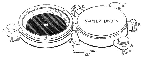
Fig. 294.—Captain George's artificial horizon.
658.—Captain George's Artificial Horizon,[48] Fig. 294. This is a great improvement on that last described. [447] The instrument being made entirely of iron there is no risk of getting it injured by escape of the mercury. It is also much more portable and convenient. Two chambers E and M are connected together by a tube through a stem-piece in which there is a strong iron cock at a. The chamber E is cored out and form a bottle into which about 1 lb. of mercury is introduced by removing a screwed stopper at B. The chamber M is an open tray with a cover formed of a piece of parallel glass placed in an iron rim which screws down upon it. A milled-headed screw at C forms an air plug. The cock moves very stiffly by the leverage given by a tommy-pin, shown a′, which is inserted in the hole at a. The chamber E is slightly elevated to cause the mercury to flow from it to M, the cock being turned on at the same time and the air screw C released a little. By the same arrangement, M being raised, the mercury flows back into the bottle for storage.
659.—For Using this Artificial Horizon, when the mercury is poured out in the tray M, it is levelled by the three screws AA′A″ so that it covers the bottom of the tray and presents a clear, level surface. A separate disc of parallel glass, which fits the tray M very loosely, is provided with the instrument. This floats on the surface of the mercury and keeps it quite still, even when the covering glass is removed. This arrangement is useful also in case of an accident to either of the glass covers. The disc is kept when out of use in a[448] soft leather bag which fits in the tray M. This artificial horizon is generally carried in a solid leather case with sling to go over the shoulder. Its weight complete is about 4½ lbs.; size, 9½ inches by 4 inches by 1½ inches. The surface of mercury is a circle of 3 inches diameter.
660.—Improved Captain George's Artificial Horizon.—Mr. S. A. Ionides, C.E., has devised an improved form of the foregoing instrument shown at Fig. 295.
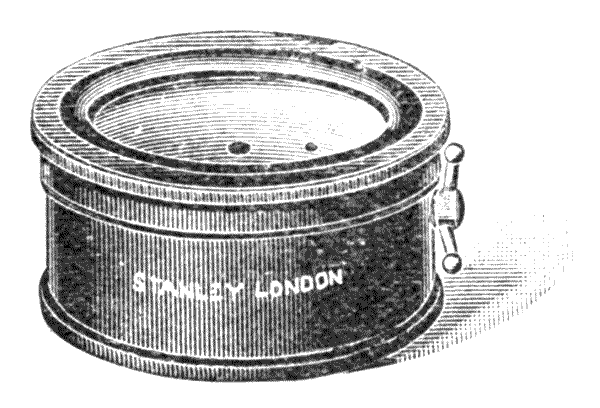
Fig. 295.—Ionides's artificial horizon.
In this the container is formed beneath the horizon box with a plug tap fitted in the thickness of metal between the two; this form makes the whole much lighter and less than half the size of the usual Captain George's pattern.
661.—In Using the Artificial Horizon with the Sextant it is generally placed on the ground at such a distance in front of the observer that he can conveniently see the required reflection of the star or sun, the observer moving about until the reflection is obtained. This is a tedious process and requires some practice. It is much more easily effected if the sextant be mounted on a tripod or other stand. When a stand is used it has generally a universal joint, so as to be able to take surface angles also from the fixed position. When the altitude of objects on the earth is taken, the observation requires reduction for refraction, which becomes an important factor, although this is variable with atmospheric conditions; but upon the whole it always tends to make the object appear higher than it really is. Commonly one-seventh of curvature[449] is used as an approximate correction. For solar and stellar refraction, works on astronomy should be consulted.
The index error of the sextant is corrected before refraction, when the natural horizon is employed. When the artificial horizon is used the index error is allowed before taking its half as a single measure. The artificial horizon is used also with the theodolite. It forms the most perfect means of adjusting the transverse axis by taking an observation of the pole star with the telescope, first directly and then by its reflection from the artificial horizon. If the images cut the centre of the webs in the two positions by the movement of the transverse axis only from the one to the other, this axis is proved perfectly level.
662.—Various schemes for obtaining the horizon by some system of levelling apparatus attached to the sextant have been devised, none of which are very practical, as they all depend upon a pendulum or a gravitation surface of a liquid or a gyroscope, and are all unstable as hand instruments. There have been numerous patents taken out with this object from that of Winter (1760) downwards, which anyone interested in the subject may consult.[49] The matter is mentioned here as the recurrence of the idea appears to be frequent.
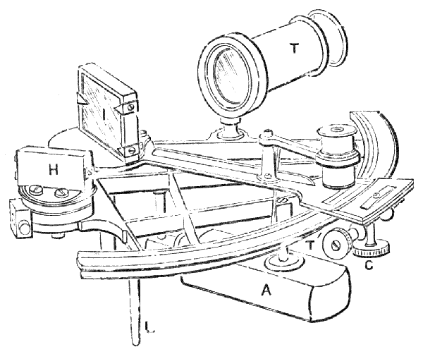
Fig. 296.—Sounding sextant.
663.—The Sounding Sextant.—This instrument is used for coast surveys. Angles are taken with it of objects, buoys, etc., from the land and also from a boat on the water for such objects or for others upon land. It is constructed upon the same principle as the ordinary nautical sextant; but as it is to be used as an all-day working instrument, and not for a few diurnal observations only, it is made much more solid, and its optical parts take a more extended field of view. The graduation is also stronger, such precision of reading only being [450] required as may afterwards be plotted on a chart. This instrument is shown in perspective, Fig. 296. The index glass is large—about 2¼ inches by 1¼ inches. This is secured on all sides by a firm rim to the tray in which the glass is held at three points. The adjustment of the index glass is left under control, as it may occasionally be necessary to remove it from effects of spray upon and about it. The horizon glass is made about 1½ inches in width and ¾ inch in depth. This is entirely enclosed in a tray, the whole surface being a mirror without any plane part to the glass as with the ordinary sextant, so that it is entirely protected by the metal. By this arrangement the eye receives the direct ray from the object immediately before it, and the reflected ray from an object whose angular position is desired to be taken with it: but these images do not come exactly into contact, as the narrow frame interposes. It is, however, sufficiently near for terrestrial observations. The adjustment of the horizon glass to the perpendicular of the plane of the arc is the same as that shown in detail for the box sextant further on. The adjustment of the horizon glass to the index is by a stiff arm extended[451] from the sole-plate projected into a loose opening, where it is held firmly by two opposing capstan-headed screws, as before described. The arc of the sextant is of 6 inches radius, graduated upon silver to 20′, and reading by the vernier to single minutes only by the microscope. The clamp and tangent are the same as those described for the nautical sextant. The frame is straight braced. The telescope has a wide field, with achromatic object-glass of 4½ inches focus, the clear aperture being 1-1/8 inches. The supporting ring of the telescope has no rising stem or collimating adjustment, but is solidly fixed in its true position by the maker. The ring carries a plain disc pin-hole sight, which takes the place of the telescope for near observations. The instrument in use is held in the hand by a firm oblong handle. The instrument rests, if required for reading, upon three legs as the ordinary sextant. Its weight is about 2¾ lbs., or when packed in its case, 5 lbs. Its examination and adjustment are of the same kind as those just described for the nautical sextant.
664.—Box Sextant.—This very neat and portable instrument was invented by the late William Jones.[50] It is used for taking angles within 120° upon the surface of the land to within a single minute of arc. It has become deservedly popular with British surveyors as a land surveying instrument, and is equally so as a military one. It is the same in principle as the nautical sextant already described, but it possesses the great merit—as a surveying instrument constantly in hand—that all its glasses and delicate parts are securely protected from accidental injury by being covered; whereas the nautical sextant, made for one or two diurnal observations only, has all these parts exposed. And it is not only that all parts are protected when the instrument is in use, but they are all doubly protected by the covering [452] box when carried about out of use; so that it is found that a well-made box sextant set originally in perfect adjustment will retain this adjustment in average use for very many years. The author has seen an instrument twenty years in use still in perfect adjustment. The box which covers the instrument out of use forms also a most convenient handle or support for it when in use by attaching it in a reversed position underneath, as it appears in Fig. 297. This attachment is made either by a screw cut entirely round the body of the instrument, or, what is much better, by a bayonet fitting, for the reason that large screws of this description are liable to cross thread. The general description of the outer parts is as follows:—
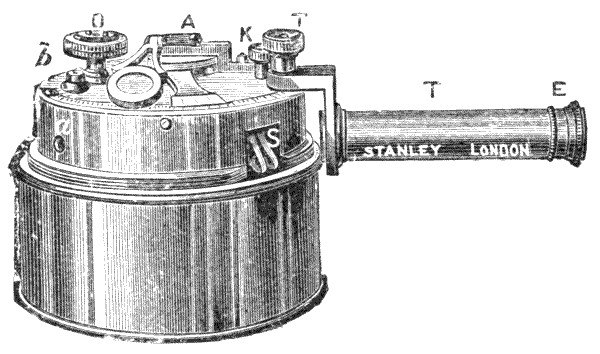
Fig. 297.—Perspective view of the box sextant ready for use.
665.—C a covering box which inverts from the position shown in the figure and covers the instrument. This has a diameter of 3 inches and a depth of 1½ inches. B box containing the optical and moving parts of the sextant. A axis of index glass. This axis also carries a toothed segment fixed close under the front of the box, by which both the index glass and index are moved by means of a pinion to be described. The index carries a vernier divided into 30, which reads into the arc to single minutes; the arc is divided to half degrees on silver. The magnifier is centred by a swivel hinge joint over the axis, so as to permit it to be[453] brought to focus upon the arc at any position. This magnifier is held down on the front of the box when out of use by a nib catch at a position of about 80° of the arc. O a milled head, the axis of which carries a pinion which works into the segment above described under the index glass. The pinion is about 1 to 9 of the segment, so that the index traverses the arc of 60° (reading 120°) by one-and-a-half turns. This gives a conveniently slow motion to the index glass, and enables this sextant, if it be well made, to be set rapidly with great precision. S two nibs, part of two levers for putting the shades in or out of action.
666.—In the closed form of sextant the shades block the reflecting position between the index and the horizon glass. For surface surveying they have therefore to be opened out, through an opening closed by a slide shutter which moves by a stud in a slot on the under side. The shades consist of one green and one dense red glass which must be worked parallel, as before described for the nautical sextant. These are used for taking altitudes of the sun, for adjustments only.
667.—The Key K is a milled head which screws out, and carries a watch-key pipe at the end of its stem by which adjustments may be made from three square-headed screws fitting its pipe, two of which are close to b, the axis of the horizon glass. These adjust perpendicularly to the plane of the arc. One screw at a adjusts the parallelism of the index and horizon glasses when the index is at zero.
668.—The Telescope is achromatic, with draw tube for focussing. It magnifies about 2½ diameters. It has a concave eye-glass, and therefore gives an erect image, Fig. 14. A sun-glass E screws over the eye-glass when it is required for sun observations. The telescope is attached to the sextant by means of a crank-piece upon the telescope which is fixed by the mill-headed screw T′ and two steady pins. The crank-piece screws in reverse position upon the telescope for portability before putting it by in its case.
669.—By some makers the telescope is made to slide into the body of the sextant and thus become quite portable. This plan is a very neat one, but it requires care to see that the shades do not interfere before it is put by. The weight of the entire sextant with its solid leather case is about 18 oz. only. For close work the telescope is not generally used. A sliding shutter pierced with a small hole covers the telescope opening into the sextant, which is used as a sight hole.
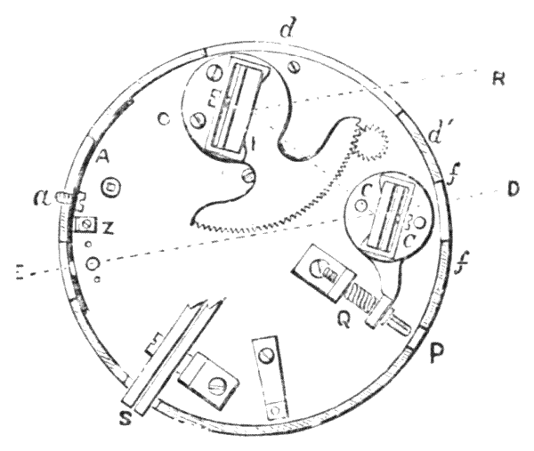
Fig. 298.—Box sextant under the face.
670.—The Interior or Optical and Mechanical part of the Sextant is shown Fig. 298. I index glass, fixed over the toothed segment on the same axis. The pinion is shown working into the segment moved by the milled head O of Fig. 297 on the face of the sextant. Fig. 298: horizon glass, cut by ED, adjusts to the vertical by screws CC′, which have square fittings on the face of the instrument, shown Figs. 299 and 300 full size. The differential adjustment between horizon and index glasses is made by a screw with a square fitting at P. This adjustment acts by screwing against a helical spring, shown at Q. The reflected rays enter by a wide window in the side of the box, Fig. 298 d, the direct rays by a small window f. The path of a ray is shown by fine lines from R to E, for the positions in which the index and horizon glasses are placed. The pin-hole opposite which the eye is placed is shown white. S shades with their axis are[455] shown cut off, to prevent confusion of other parts. They are simply round discs of parallel glass on arms which rise from the back of the face by pressure of the nibs at S.

671.—The Construction of the Box Sextant may be fairly inferred from inspection of the engravings. The face-plate is made of a casing in brass 1/8 inch thick, which should be well hammered to harden and stiffen it. The axis, which has a wide collar, is fitted into a hole in the plate, first by turning it as exactly as possible, and then by burnishing it in by friction, the hole being broached slightly conical with a D-broach. The careful fitting of the axis is an important part. The horizon glass frame, Fig. 300, is held down by a central screw which fits tightly both in its fore hole and thread. The flange of the tray F is cut to an angle on its under side to permit adjusting to verticality by rocking over this angle, by tightening and loosening the adjusting screws cc′ which protrude in square heads to the face of the instrument. The horizon glass, H, which is half silvered, is fixed in a tray-piece which has two narrow fillets turned to the face of the glass, and a spring-piece at the back brought up by a screw a. This glass is entirely open at its unsilvered part. The toothed segment should be cut upon its own axis, and although fitted to the pinion without any looseness, it should not press the index axis. The silver is inlaid in the arc on the plan shown[456] Fig. 127. The vernier is soldered closely on the index and should read down to a fine clean edge.
672.—Examination of the Box Sextant.—The glasses should be cleanly silvered, with a sharp, clear cut between the silver and the clear glass of the horizon glass. The pinion should move softly and equally in causing the index arm to traverse the arc. If the pinion be moved in little jerks backwards and forwards there should be no shake, but the index should follow every slight motion. The magnifier rising joint should move rather stiffer than the traversing joint, so that the focus is not changed by traversing across the arc. The magnifier should have about 1 inch or less focus, and should stand square to the plane of the sextant when in focus. The graduation should be deep and fine, and the vernier should read 30 = 29 at the two ends and the centre of the arc. If there be a small excess or defect of vernier to arc, this should be noted and allowed for, either at the time of reading or as an index error. The sliding fittings of the pin-hole sight, shades, and under shutter should move firmly but not stiffly. The telescope should fit without shake. The covering box should fit well in both positions of cover or hand-hold.
673.—Adjustment.—The box sextant is best adjusted by the sun upon the plan described art. 648. The adjusting screws, as already stated, are moved by the key, which unscrews from the face of the sextant, Fig. 297 K. The adjustment is made permanently by the maker, except only that of the horizon glass, which is at the command of the user. The adjustment to perpendicularity of face is made by the two screws upon the face near b; adjustment to zero of arc by the screw at the side a. In defect of appearance of the sun, the sextant may be adjusted to any clear, sharp line, as that of a stretched piece of twine, for perpendicularity of plane, and to any object of clear outline sufficiently distant, say at half a mile, to avoid error of parallax for index zero, art. 621.
674.—Use of the Box Sextant.—The sextant has its[457] under shutter opened by pressing the stud attached over in its slot. The nibs of the shade levers, Fig. 297 S, are then raised and the shades depressed. The cover is then screwed, or slid on if it fixes with bayonet notches, upon the under side of the sextant to form the hand-hold. The pin-hole sight is pressed over for use if not already in its position, unless it be intended to use the telescope. The box sextant is held in the left hand, with the right-hand thumb and forefinger constantly holding the milled head, and turning this so as to bring the two objects, of which it is desired to obtain the angular position, from the observer, exactly in apparent juxtaposition, the one over the other. In turning the milled head it is better to let all the other fingers of the right hand clutch and steady the instrument. To take angles objects should be observed that cut sharp, erect outlines, as buildings, posts, trees, etc., if possible. In open country it is necessary to use pickets, to be described further on. With pickets the reflected image of the upper half of one picket should form a continuous outline with the direct image of the lower half of the other picket in the eye, so that the pair of pickets appear as one. Where an angle greater than 120° is required an intermediate picket is set up, and angles taken to the right and left of this are added together.
675.—It must always be remembered that the sextant takes angular positions actually, whereas plans are made in azimuthal angles. There are some not very satisfactory means of approximate correction for this, for which books on surveying may be consulted; but altogether the sextant is not very useful for taking angles for plans on other than fairly level ground, wherein it has proved a most valuable and sufficiently exact instrument. Where ground is undulatory fairly good work may be done with it by taking stations for exterior triangles at equal heights on the hillsides, as ascertained by a hand level or clinometer to be described, or sometimes from hilltop to hilltop where these are of fairly[458] equal heights. For sketch plans of very hilly or mountainous districts the prismatic compass, art. 148, is better, as this gives, although with less precision than the sextant, its angles in azimuth.
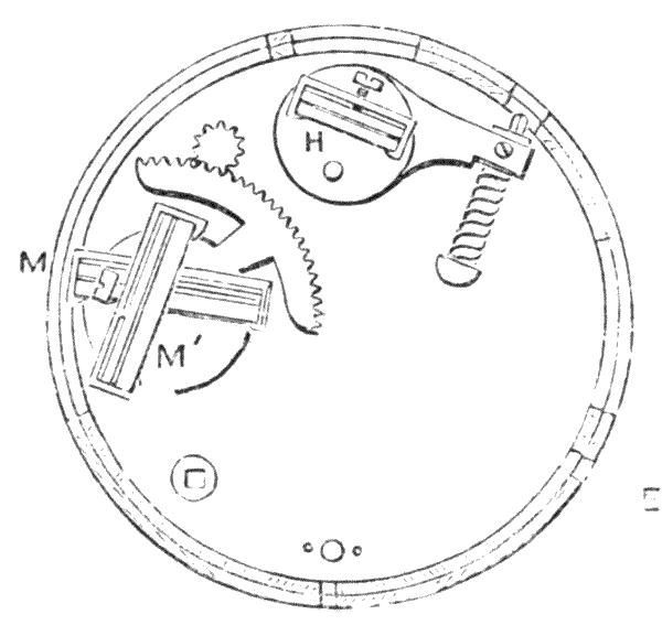
Fig. 301.—Interior construction of box sextant with supplementary arc.
676.—Box Sextant with Supplementary Arc.—This sextant is preferred by many because of its more extended use. It is complete as an ordinary sextant for angles up to 120°; but if it be thought desirable to extend the angles to 220°—by a single observation this may be done. The ordinary arrangement of the box sextant just described is left intact and forms the upper part of the instrument. This arrangement, as in the box sextant, is attached entirely to the face or arc plate, the only difference being that the index glass is made of less depth. For the supplementary arc arrangement a mirror is fixed upon the lower or sole plate exactly under the position of the index glass. This mirror is termed the supplementary index glass. The position of the face of the index glass is at right angles to the face of the ordinary index glass when the index is at zero. The arrangement of glasses is shown Fig. 301: MM′ index glasses. The supplementary angle is read through a separate pin-hole sight which is placed at about 90° from the pin-hole sight of the proper sextant and a little lower down on the rim. The arc of this sextant reads in the ordinary manner, left to right, to an inner circle of figures for angles from 0° to 130°. The supplementary arc[459] reads by the same vernier, and is figured in the same manner at the tens; but it reads into an outer circle of figures which progress in the reverse direction, that is, right to left. The readings of the supplementary arc are from 90° to 220°, so that for a certain range, that is, for angles from 90° to 130°, these may be taken either by direct arc or by supplementary arc. The supplementary angle is taken by means of the coincident images of two reflections, one from the index glass and one from the supplementary index glass, and not by one direct and one reflected image as in the sextant proper.
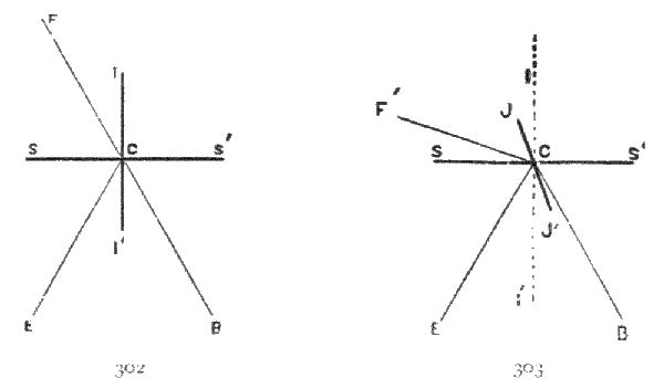
Figs. 302, 303.—Diagram of supplementary arc sextant.
677.—Theory of Supplementary Angles to the Sextant.—For the measurement of these angles we have to consider direct reflections only of two reflecting planes placed one above the other nearly in contact, so that the images projected from both planes may reach the eye superimposed. Let Fig. 302 II′ be the surface of a mirror (index glass) which is movable to any angle in relation to the face of the mirror SS′ (supplementary index). For demonstration of the principle these mirrors are shown in this diagram at 90° to each other; therefore coincident reflections will be at 90° + 90° = 180°. Let the lines FC and BC form a right line (180°); F fore sight and B back sight. An object at F would be reflected from the mirror II′ to the eye at E, the angles FCI and[460] ECI′ being equal. Another object at B reflected from the face of the mirror SS′ would also reach the eye at E, the angles BCS′ and ECS′ being equal. And as the angles FCI and BCI′ are equal in crossing a right line, the line FCB must be also a right line (180°) which is indicated by the angle of coincidence of the two reflections to E. The positions of the reflections are shown as angular measurements upon the graduated arc.
678.—In Fig. 303 let SS′ remain as before, angle BCE will remain as shown in both figures. Move the index glass from the position II′ of Fig. 302 to the position JJ′ of Fig. 303, so that after this movement the eye at E would receive the image of an object at a new position F′ as reflected from the mirror JJ′, F′CJ and ECJ′ being equal. In this process, as the reflector JJ′ in the angle ICJ would have moved half the angle JCF, the record of this movement upon the index, which moves with JJ′, is at the same time double the true angular difference, as with the sextant proper fully described, the graduations being in both cases the same pro ratâ. The increase of angle is taken supplementary to the angle given by the first reflection, by addition to this angle in a direction right to left from the right line of the former sight EC; consequently this increase is read backward on the sextant, that is, right to left, and is indicated by the outer line of numerals.
679.—Manufacture.—The general structure of this instrument is nearly the same as the ordinary box sextant, except the parts just referred to. The supplementary index glass is an ordinary mirror similar to the index glass but of only ¼ inch in depth: it is mounted in the same way. Its adjustments are similar to the horizon glass in kind, but there are no exterior screws, this glass being permanently fixed by the maker. Opposite the supplementary index glass a wide window is cut through the rim of the case near the sole plate to take sight of the object at angles exceeding 120°, so that in[461] this sextant two large windows are cut out opposite to each other. The diameter of this sextant is 3 inches; the exterior depth about 1-5/8 inches, that is, 1/8 inch deeper than the ordinary box sextant. It weighs about 20 oz. It is carried in a solid leather case with strap to pass over the shoulder.
680.—Examination and Adjustment.—Examination will be nearly the same as for the common box sextant. The most important point is that the readings taken within both arcs should be alike, assuming, which is necessary, that the part comprising the sextant proper is perfectly adjusted. Thus there is a 90° on both direct and reverse arcs. The 90° may be measured by any pair of objects on the direct arc, and afterwards compared by shifting the index to the 90°, on the supplementary arc. If no object be found at 90°, then 95° 30′ or any other quantity may be compared. It is also well to compare readings at or about 120° on both arcs. The 90° and 120° fall in the same position in the reading, and this checks any error in either. If the adjustment be not fairly perfect, the instrument should be returned to the maker. Indeed, this sextant would be better without any external means of adjustment, leaving these to be made by the optician in such a permanent form that they will not be liable to change. It is, as the plain box sextant, exceptionally protected from accident.
681.—In using this instrument the arc up to 120° is taken exactly as with the plain box sextant. Beyond 120° the sextant is shifted to take sight through the supplementary pin-hole, being particular to observe that the pinion is now turned the reverse way to increase the angle, and that the vernier reads for the supplementary arc right to left. It is in this reversing, if not carefully performed, that a little difficulty is experienced in using this instrument.
682.—Box Sextant, with Continuous Arc to 240°.—This instrument is an improvement by the author upon one originally designed by Mr. W. Franklin. The reading[462] is taken continuously from the same sight-hole and by the same arc, and in a direct manner without any reversal for part of the arc. This sextant reads with certainty to 240°.
683.—In the construction of this sextant there are two horizon glasses superimposed one above the other and crossing each other, with faces which are adjustable for perpendicularity at an angle of 120°. The horizon glass is divided top from bottom by a clear band cut through it, as in the old form of back-sight nautical sextants. One of the wide glasses reflects into the upper, and the other into the lower mirror of the horizon glass. The pin-hole sight or the telescope is placed in the same position as in the plain box sextant described. The horizon glass is fixed and both the index mirrors adjust to angular positions, or one index glass only and the horizon glass is adjusted, this arrangement being optional. The arc is graduated as the plain box sextant, but it reads with two rows of figures from 0° to 120°, and from 120° to 240°, the 0° of the under line being under 120° of the upper. When the arc is set to zero the index glasses are in such a position that the direct vision and the reflection as seen in the upper mirror of the horizon glass are coincident for direct images, as at the zero of the plain sextant, but at this point the lower mirror of the horizon glass reflects to the eye an object at 120°. When the index is moved forward the angles continue onward, reflected from both glasses, so that the upper reads on 10°, 20°, 30°, etc., whereas the lower read 130°, 140°, 150°, etc.; so that if the objects desired to be triangulated are under 120° the coincidence is seen in the upper mirror, and if over this in the lower, the great distance of 120° apart of the angles preventing the risk of accidentally taking the one for the other. In the compact form of a box sextant this instrument embraces the uses of the ordinary reflecting circle of double the diameter, due to the entire circle graduation; and the range is sufficient, as beyond 240° the head materially interferes with observation. The size and weight of the instrument are generally but little[463] over that of the plain box sextant. The adjustments are made permanently by the maker. The use of this instrument is fully inferred from the description given. The construction is shown in Fig. 304, E place of the eye with direct ray through the horizon glass H to O. The index glass I is that of the ordinary sextant, shown by dotted lines, throwing the image of an object at P to the upper horizon glass and thence to the eye at E. B is the fixed supplementary glass with its surface at 60° to the lower horizon glass at A. The sight lines from an object at Q are reflected from B to A and thence to E. A spring arrangement shown SS with a milled head underneath permits the lower glass A to be drawn down to convert the instrument into a simple box sextant.

Fig. 304.—Stanley's continuous arc box sextant.
Fig. 305.—Section of supplementary horizon arrangement.
684.—Details of Spring Arrangement to the supplementary horizon glass are shown in Fig. 305 full size in section. The springs SS in Fig. 304 and S Fig. 305 form two points of support to the horizon glass, the silvered face of which is shown at A. A third point of contact is near D, placed in the centre of the end of the supporting plate for the horizon glass. When the screw R, which is placed in a loose fitting, is released, the springs bring the supporting plate tight up to D and hold the horizon glass firmly in an elevated[464] position. When the screw R is tightened it brings this glass down. The horizon glass is adjusted over a rocking centre by the screws CC′. A screw and collar b prevent the loss of the screw R. By this arrangement the horizon glass is brought in or out of the field of view, in order to use the supplementary arc or for leaving it as a plain sextant.
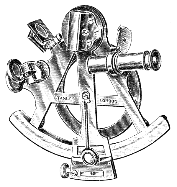
Fig. 306.—Stanley's portable surveying sextant.
685.—Open Surveying Sextants, similar to nautical sextants but generally smaller and of stronger construction, preceded the box sextant, and are still used to a limited extent upon the Continent, particularly with some form of supplementary arc, or arrangement to produce a large part of the reflecting circle. These forms are also occasionally revived by the opticians of our own country. The reason of this is easily seen. To the optician who lives in a town, moves on a level surface, and has comfortably warm hands, even in the winter, to hold and move the separate parts of an instrument, the open sextant appears the most perfect, as he can get at every part of it easily to clean and adjust. The surveyor takes another view of the subject. He is exposed in the open[465] country to all weathers and all difficulties of movement over the land; therefore that form of instrument which is best protected and least liable to injury by a fall will be sure to be popular with him. It is upon these conditions the box sextant of some form is generally preferred.
A handy form of portable surveying sextant has been devised by the author and is shown at Fig. 306.
The arc is of 4 inches radius and is divided on silver to read 20″, is complete with shades and telescope and packs into a case 7 × 6 × 2½ inches.
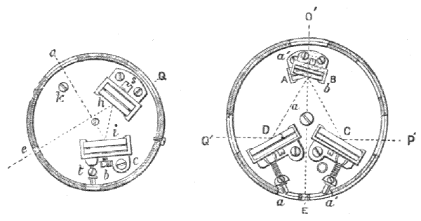
686.—Optical Square.—This extremely handy little instrument is invaluable for taking offsets in chaining for any irregularity or obliquity to the right line in the boundaries of fields, hedgerows, fences, streams, etc., giving as it does instantly at sight a right angle to any object that may be sighted on either hand. The instrument is optically constructed exactly as a box sextant; but the glasses are fixed with their faces permanently at the angle of 45° to each other, by which means the reflection of 90° is truly given on principles fully discussed at the commencement of this chapter. This instrument being made very small, that is, 2 inches or less in diameter, it is found most convenient for[466] manipulation to place the adjustments to the larger glass, that is, the index glass. The horizon glass, Fig. 307, h is therefore fixed firmly, like the index glass of the box sextant, by two screws to the sole plate. The index glass i is held and adjusted in exactly the same manner as the horizon glass of the box sextant, as shown in detail, Figs. 299, 300, the only difference being that the frame which holds the glass is made of the entire height. The rim of the case of the optical square is formed of a short length, 3/8 inch to 5/8 inch, of a pair of telescope tubes which slide easily together. One of these is attached to the sole plate and the other to the cover, so that at first they close together as a box and lid. All the openings required for sight, as Fig. 307 at Q for horizon sight, o for index sight, and e for pin-hole or eye sight, are cut through the two tubes.
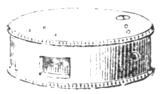
Fig. 309.—Optical square.
687.—The inner case is cut in the plane of some part of the circumference of the instrument from a pin-hole into a bayonet notch, made with a horizontal slot for the two cases to revolve upon each other upon a pin, sufficiently to close and open the sight holes. This plan secures the instrument from any intrusion of dust when it is closed and out of use. An adjusting key is placed in the case, held by a tube or stud at the position k. The weight of the entire instrument is about 4 oz. if of ordinary make; but smaller ones are made in German-silver or silver, 1¼ inches diameter, 3/8 inch thick, weighing under 2 oz. These latter are very convenient for the waistcoat pocket, and are equally as exact as the larger instruments. Fig. 309 shows the general outward appearance of the optical square.
688.—Examination and Adjustment of the Optical Square.—Place two pickets in an open space at a distance apart, the further the better. Range an intermediate short picket in right line with these or the top of a stake the height of the eye, or what is better still, if at hand, the top of a tripod stand. Place the optical square over the intermediate station or tripod. Place another picket, which we will distinguish as the 90° picket, at a distance, and make this appear in the optical square coincident by reflection with the direct sight of one of the pickets in the right line from our station. Turn the optical square right over on its place, and looking in the opposite direction take a sight at the other right line picket and observe the 90° picket. If this still appears coincident with the direct line in reflection the optical square is in perfect adjustment. If it does not appear so, half the difference must be adjusted by means of the key taken from the interior of the case and placed on the square at k, Fig. 307, and this observation repeated until the 90° is correct.
689.—In Using the Optical Square it is customary to walk along the chain line at about the desired position for taking an offset, looking by direct vision through the plain part of the horizon glass h at a fore sight object until the required object is sighted by reflection at right angles to this, where it appears by coincidence of image with the fore sight. The heel of the forward foot in stepping indicates fairly the vertical position of the optical square; but some surveyors prefer the use of a drop arrow to fix the point. The offset is then chained in the line.
690.—Double Optical Square.—This instrument is exactly what its title indicates, that is two optical squares, the one placed exactly over the other, the one reflecting to the right hand and the other to the left. A simpler name, however, would be an optical cross. This arrangement of reflectors greatly extends it use. First, as regards the 90°, this need not depend in any way upon the position of the observer, as[468] two objects may be observed, one to the right and one to the left, to appear to cut the direct forward line of sight, and therefore to cut the base line at the exact position of the instrument at right angles to it. Secondly, an intermediate station can be found in direct line between any two points, as the 90° + 90° forms this line.
691.—The arrangement of the optical part of the instrument is shown Fig. 308. The two index glasses CD are fixed at equal angles to the direct line of sight EO. The two horizon glasses AB are superimposed with the interval of a small space, 1/16 inch, between them. The horizon glasses are each separately adjusted so that their reflecting planes are respectively 45° to the index glass from which they receive the reflections. The diameter of the instrument as usually made is about 2¼ inches; its depth 7/8 inch. The weight is about 9 oz. It is generally carried in a light, solid leather, sling case. Total weight with instrument, 12 oz.
692.—Examination and Adjustment of the Double Optical Square.—1. Place the instrument, as already described for the optical square, at a station intermediate between two pickets. Examine the right angles, first looking towards one picket and then towards the other from the same position, as with the optical square, turning it over for this examination. 2. Turn the instrument half round and examine it this way also by turning it over again in like manner. Adjust either horizon glass if required. 3. Now take the position for the eye of the former 90° and see whether the extreme pickets appear in true position by the exact coincidence of their images at 180°. 4. Do this again, facing the opposite way and turning the instrument half round. If the extreme pickets still range in line from the central station the adjustment is perfect. If they do not do so half the error must be corrected by returning to the first and second adjustments to find out between which pair of mirrors it lies. For this adjustment the instrument is much better to be placed upon the top of a tripod, as the[469] position of the axis should remain fixed after turning it over or changing the direction of the instrument. It is only from severe accident that the maker's adjustment will be disturbed.
693.—Apomecometer.—This little instrument, the invention of Mr. R. C. Millar, is intended to measure the height of buildings, trees, etc., by measuring the distance from the vertical upon the surface of the ground. It performs one of the functions of the box sextant in the same manner as the optical square, that is, to measure a single angle by reflection. The angle measured is 45°, consequently by measuring a space upon level ground up to a vertical, the vertical will be known, this being equal to the horizontal. Of course this will always be approximate, as the ground will seldom be truly level; but by taking a position, even on an incline, as nearly as possible level with the object, a very fair estimate may be made. Horizontal distances may be measured in the same manner from a perpendicular to any line.
694.—The instrument is constructed in exactly the same manner as the optical square just described as regards its mirrors and its adjustments, but the faces of the mirrors are fixed at the angle of 22° 30′, so as to give a reflection of 45°, upon principles fully discussed. In Fig. 310, A is the index glass, B the horizon glass, E the pin-hole sight. There is a window opposite the index glass, and one behind the horizon glass, each sufficient to take in a wide field of view at about 45° and in the direct line E to H. These windows close by rotation of the casing of the box, which is made as the optical square. When closed the instrument is dust-tight and may be carried in the waistcoat pocket loose, or in a light snap leather case. Its size is 1¼ inches diameter, 3/8 inch in thickness, weight 2 oz. in German silver.
695.—The Use of the Apomecometer.—To measure the altitude of a building the open side nearest level is selected, and a station for observation is taken which is at a distance thought to be approximate to the height. The instrument is[470] held edgewise with the pin-hole sight to the eye, and the reflection of a point of the building about level with the eye is observed by direct vision through the instrument. At the same time there will appear a reflection of the summit of the building. If we now walk backwards or forwards, as the case demands, keeping sight of a level object, as for instance in Fig. 311 the plinth of a building, then at a certain point the summit of the building will appear by coincident reflection. The height of the object will be the same as the distance plus the height of the observer's eye. This distance may be measured on the ground, or if a rough estimate is sufficient it may be stepped, the principle of which is shown by Fig. 310 in the line OH, being equal to FH. If a part of an object is required to be measured such part may be taken on the horizontal plane, as for instance the height of the figure in Fig. 311, by ab being = ed, as the base ab can easily be measured. An approximate may be found by dropping a small pebble at a and at b and then measuring the distance apart of these pebbles.

696.—The distance of an inaccessible object may be measured, as for instance a buoy at sea, by measuring in any straight line double the distance and taking equal angles thereto by the apomecometer on any direct line. An approximate idea may be formed by walking over measuring points. As for instance, b being a buoy at sea, Fig. 312, walk from e, at which a walking-stick may be set up, towards an object o. At E the buoy and object o will appear to be coincident. Then drop a stone or make a mark directly under the instrument. Walk on till beyond E′ and turn to face e. Now in returning, the buoy and the object e will appear coincident at E′. The distance EE′ is double that of the intermediate a to b.

Fig. 312.—Scheme for measuring distances.
GRAPHIC SURVEYING INSTRUMENTS AND APPLIANCES CONNECTED THEREWITH—PLANE TABLES—ALIDADES—TELESCOPIC ARRANGEMENTS—SUBTENSE MEASUREMENTS—VARIOUS DEVICES FOR HOLDING THE PAPER—CONTINUOUS PAPERS—ADJUSTMENT OF TRIPOD HEADS—METHOD OF USING—EDGEWORTH'S STADIOMETER—SKETCHING PROTRACTOR—SKETCHING CASE—CAMERA LUCIDA, ETC.
697.—Plane Tables.—These instruments have been used for filling in the greater number of topographical surveys in all countries. They possess the merit that any intelligent, untrained person can be readily brought to comprehend their manipulation in the work to be performed, as angles of position of objects are taken directly by drawing lines pointing to them from a point upon a sheet of paper stretched upon a table. In new countries natural objects without very marked outline are conveniently defined for position. The objection to this method, from a point of view of the practical surveyor, is that the work which can be done with equal facility in a comfortable office from the field-book is with this instrument performed in the open air, under risk of rain, dust, and other atmospheric discomforts affecting both the person and the material on which he works. But for countries where the climate can be depended upon, the facility with which surveyors with little experience can map details for filling in superior triangulations made with the theodolite, its use has gained[473] much favour. Natives can be easily taught to use it, and the check on their work through the previous triangulation is perfect. The subject of plane tables will in these pages be considered only in its general aspect, with the examples of a few good instruments, referring the reader who cares to follow the subject further to an excellent paper by Mr. J. Pierce, Jun., read before the Institute of Civil Engineers, February, 1888.[51]
698.—The Plane Table in its simplest form consists of a small drawing-board mounted upon a firm tripod stand, and is shown at Fig. 313.

Fig. 313.—Simple plane table.
A rule termed an alidade, with sights placed at its ends, gives the direction of any object from a given point on the sheet of paper stretched upon the table, to which a fine line is drawn by an HH pencil to point the direction. The alidade sometimes carries a trough compass fixed upon it, but this is generally a separate instrument which is placed against its fiducial or ruling edge to give a magnetic north to south line, to which all other lines are assumed to take angular direction. A loose [474] spirit level is also provided, by means of which the board may be set level by shifting the legs of the tripod.
699.—Plane Table with Telescope.—Where greater refinement of observation is required than is possible with sights, a telescope is mounted on the alidade, which moves in the vertical plane upon an axis, so that it may be directed in a linear direction with the fiducial edge of the rule to any point in azimuth. The telescope sometimes carries a level, so that the table may be set level by means of the alidade.

700.—A class of plane table which meets all necessary refinement for ordinary filling in of field work is shown in the illustration, Fig. 314. This nearly resembles those made by the author for filling in details of the great trigonometrical survey of India. The drawing surface of this table consists of a loose panel which stretches the sheet of paper by pressing it into its frame, where it is afterwards held by a pair of ledges which fit at their ends into long slots. The panel of the board, shown in detail Fig. 316, is mounted upon a firmly braced tripod stand. The head of the tripod stand, shown Fig. 315, is secured to the board with a central screw (not shown) which permits the board to be set in any direction, it being the[475] rule that the edge W should always take a north to south direction. Three screws sss at the corners of the triangular head can be raised or lowered by milled heads from the under side. These screws permit about 15° of adjustment to the table without any unsteadiness, as the centre screw clamps it finally hard down upon them when all adjustments are made. A small trough form of magnetic compass a is placed upon the rule to strike the magnetic north to south line, to which all angles are referred in transposing the work of the plane table. The diaphragm of the telescope is provided with a platino-iridium point fixed vertically at the mutual focus of the object-glass and the eye-piece. A pair of points to subtend an angle to measure a staff for distance, Fig. 319, is a convenient addition.

Fig. 316.—Panel board of plane table.
701.—The Telescopic Arrangement of the alidade is varied in different countries. In some cases it is placed near to one end, which is perhaps better than in the centre of the rule, as it is more easily read. In the modern French military alidade a prismatic eye-piece is used, so that observation is made by looking directly down upon the eye-piece of the telescope. In the Prussian alidade adjustment is made to the standard of the telescope so as to bring the horizontal axis upon which it moves level, that the telescope may move in azimuth, however irregular or uneven the surface of the paper on the board may be. This is necessary for any great degree of refinement in the plane table, as the surface of a piece of[476] wood upon which the paper is stretched will be almost certain to warp if exposed to all weathers, and this, added to the small width of the alidade, can scarcely retain the axis in exact horizontality, placed as it is high above the surface of the table. Some plane tables made by the author for General Robinson for Indian service were of papier-maché to remedy the defect of warping, but even this material warps upon exposure. Plane tables have been made in Germany of metal and of glass, but in this case the weight is a great objection. The author has found surfaced slate very good, but it has the same objection of too much weight for a portable instrument.
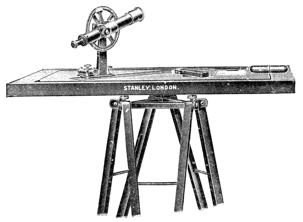
Fig. 317.—Stanley's plane table.
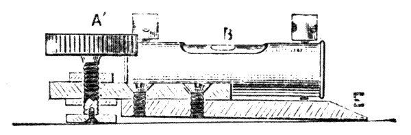
Fig. 318.—Alidade to plane table.
702.—Lateral Adjustment to the Alidade.—The author's[477] plan of obtaining this is to increase the practical width of the rule by giving it an extended point of support on one side so as to set the telescope in azimuth. For this construction the telescope is mounted upon a plate with an arm extending outwards upon the back of the rule. This has a milled-headed screw placed at the near extremity of the arm. The screw is inserted in a deep bush for wear; this attachment is shown in section Fig. 318. The adjusting screw A′ has a collar fixed upon its point which is centred upon a tight screw tapped into the milled head. This collar, as it does not turn with the milled head, does not abrade the surface of the paper by contact with it. A small cross level B is put upon the arm between the milled head and the standard of the telescope. The under side of the rule is cut away or placed obliquely to the surface, so that it bears on the outer ruling edge only. The milled-headed screw being at its normal position and the table level, less than half a turn one way or the other will bring the small cross bubble to its centre in a few seconds for any average irregularity of the surface of the table, and by this means cause the telescope to move correctly in azimuth.
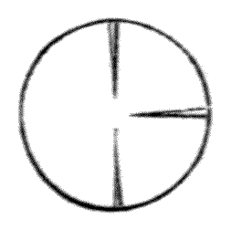
Fig. 319.—Subtense points.
703.—The Telescope Arranged for Subtense Measurements.—Where a stadium, art. 556, is to be used for estimating distances from station to station, when an ordinary telescope is used, the author places two platino-iridium points vertically from top and bottom of the diaphragm, and adjusts these by a screw until a subtense angle upon the stadium of 1 foot cuts the point at a distance of 100 feet, or according to the measurements to which the land is taken. In this case it is necessary to have an altitude arc to the telescope, as shown[478] upon the alidade in Fig. 317. This has a degree scale reading by vernier to about 3 minutes.
704.—Various Devices for Fixing the paper on the Surface of the Table have been made. Many prefer simply pinning it with drawing pins on a quite plain pinewood surface. In this case the table is better slightly sunk round the edges with a rabbet of the depth of the thickness of the head of the pin, so that the alidade may rest firmly even over the pin heads. The French plane tables have very generally rollers at each end of the table, upon which a long slip of paper is rolled, sufficient for twelve or more stations. The rollers for small tables are made of brass tube about 5/8 inch in diameter. They commonly move with a turn-key which is inserted in a square fitting in the end of the roller. The rollers keep the paper tight by means of ratchet wheels and spring pawls at their ends. This plan is very convenient for topographical work, as for instance a river may be followed from station to station right down its course and appear on a single slip, its bearing being indicated by the compass north line. Fig. 320 shows the manner in which the author has made this plane table.
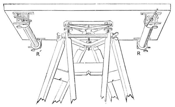
Fig. 320.—Plane table with rollers.

Fig. 321.—Gurley's plane table adjustment.
705.—Adjustment of the Plane Table.—There are a great many devices for this. Mr. Pierce, in the admirable paper already mentioned, gives illustrations of the different plans. Some of these have all the complication of the adjustment of the stage of a theodolite, and one has superadded to this a slide-rest motion. These things of course are necessary if the field work is made to take the place of finished office work. One general feature of plane table tripods is some means of adjustment of the table to uneven ground, when the tripod-head cannot be brought nearly level. Gurley's plane table adjustment is perhaps the simplest of any of these devices, and appears to the author to be as good as any other. Fig. 321, D the table top; A a ball fitting turned inside and out, and attached firmly to the table top; C a socket fixed firmly in the head of the tripod; B a bolt with globular head fitting the interior of A, and carried through the head to a winged nut which clamps it firmly. A spring is placed to act against the winged nut, so that when this is slightly loosened the ball fitting A may move between B and C with moderate firmness when the table is being set to an angle.
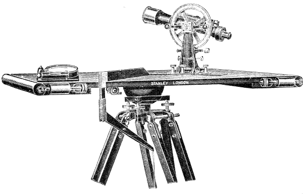
Fig. 322.—Stanley's high-class plane table.
To meet all conditions the revisor has designed a high-class plane table shown at Fig. 322. This has a ball and socket rough levelling arrangement and parallel screws for fine levelling, circular motion to table with clamp and tangent, spring rollers[480] for taking any length of paper and instantly clamping it, alidade with extra powerful telescope with vertical circle divided on silver reading by two verniers to minutes with clamp and tangent motion, cross levels, diagonal scale, and[481] adjustment for setting telescope to revolve in vertical plane, circular compass with cross levels and plumbing bar. The board is generally made 30″ × 24″. The telescope is stadia reading and is made with long sensitive bubble mounted upon it or upon the verniers if preferred as shown at Fig. 323.
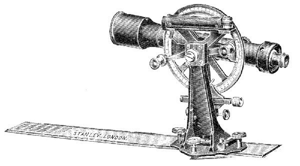
Fig. 323.—Stanley's high-class alidade with bubble on verniers.
706.—Method of Using the Plane Table.—The table is first set and levelled up at a commanding position to observe the extent of country it is intended to plot from observation from a single station. Let Fig. 324 1 be the first station for plotting the enclosure abcdef. Draw lines by the alidade pointing to these angles represented by the letters from a point near 1. Set up a picket or stadium at the station 2 where it is intended that the plane table shall next be set up, and draw the line 1 2 distinctly on the paper. Measure the line 1 2 either by its subtense on the stadium or by direct chain measurement, and plot this from station 1 on the paper according to the scale to be worked to in making the plan. On removing the table set up a picket or distinct land mark vertical with the position of station 1 occupied on the paper. Move the table to station 2 at the measured distance and set the[482] direction of the board by means of the alidade so that the line 2 1 cuts the picket left at station 1. Now draw lines from station 2 to all the points abcde, cutting the former lines as represented by dotted lines in the figure, and the intersections of these lines will give the true positions of abcde, according to the scale selected for the base 1 2, and these may be tied up to represent the boundaries, as shown on the plane table 2. It will be readily seen that the line 1 2 represents a bearing in azimuth; so that if the edge of the table be set, say truly N. to S., in both positions the line on the paper 1 2 will agree in both these positions of the table; but the check by the alidade of this line is valuable to save risk of error.

Fig. 324.—Diagram of plane table work.
707.—Where an extent of land is to be surveyed by the plane table, longitudinal bands of a mile or so in width are taken. Where the roller plane table with continuous paper, Fig. 320, is used, the forward points of observation are lined in and the backward ones simply tied up, being certain by observations written in pencil upon the paper that identical objects are tied up from the positions of both stations. Where an object cannot be seen from both stations its position may be indicated by the stadium from a single bearing, or it may possibly be tied up from a further advanced station.
708.—Edgeworth's Stadiometer.[52]—The general construction of this instrument is given in the inventor's specification of patent, from which the engraving, Fig. 325 is taken. The vernier plate of an ordinary theodolite is extended to a plate of about 10 inches in diameter. This is adjusted to level by means of parallel plate screws. The plate or plane table is divided on its edge ¼°. The part representing the limb of a theodolite is carried out from its axis by two arms only: upon these the standards RR of the telescope are mounted. These standards leave a striding space near the plate, into which any scale S of equal parts with a zero centre [483] is introduced, which is intended to be used for the plotting, the striding space being so arranged that the fiducial edge of the scale shall pass exactly over the axis of the instrument. The standards unite in the same casting to form the horizontal axis bearing of the telescope. This axis permits the telescope to move in azimuth. The telescope carries a vertical arc divided to degrees, also a scale of centesimal differences of hypotenuse and base, with the ordinary clamp and tangent adjustment of a theodolite. It is also fitted with a level above it which is used in setting up the instrument. Stadia webs are placed in the diaphragm and are made adjustable to subtend upon the stadium a percentage of arc agreeing with the unit to which the land is measured. The inventor does not appear to have known the optical error of the system proposed for measuring distance, art. 558. Neither does this appear to have been recognised by others writing upon the instrument, who have generally followed the late J. F. Heather's description.[53]
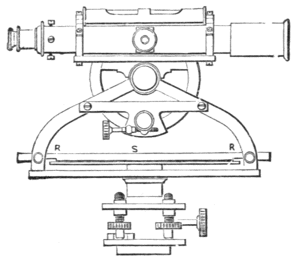
Fig. 325.—Edgeworth's stadiometer.
709.—To Use Edgeworth's Stadiometer.—After it is set up, a circular disc of paper of about an inch less diameter than the [484] table is held down upon it by four spring clips. The telescope is directed consecutively from object to object, the positions of which it is desired to take. It is clamped by the screw below the plate during the observation. The stadium is placed against the object and the distance taken by the subtense of the webs in the diaphragm, which may be exact if a constant be added after proper adjustment, art. 558. If the stadium be above or below the horizontal plane it is inclined by means of a sight-hole through it, as originally proposed by Green, so that the subtense is equal under all conditions. The horizontal distance is taken by the difference of hypotenuse and base, as shown on the vertical arc, so that the record of a complete observation appears for calculation as—
stadium reading + constant - altitude correction.
This distance is at once set off from the centre of the instrument by the scale on a line drawn upon the disc of paper, and observations are written against the line. In making a number of observations from one station two or more discs of paper may be employed to save confusion of lines and interference of descriptions. These papers are separately used in plotting as protractors by pricking holes through the stations defined in the field from the centre of the disc which represents the station of observation.
710.—The Sandhurst Protractor, Fig. 326, is a military protractor adapted especially for topographical delineation, which is commonly used with the plane table. It is different from many instruments of its kind in having only useful matter upon it. It is made of boxwood, upon which the protractor is cut, and has also one scale of 6 inches to a mile in yards, at the lower edge, the tens of which are carried across to make parallels of 90° in the manner of an ordinary military protractor. Over the back of the protractor is a scale which gives a standard for shading slopes of land upon topographical maps, Fig. 327, from 2° to 35°, also lines for contour shades. A small plummet, the cord of which is passed through[485] a hole in the centre, from which the degrees are protracted, is supplied with the instrument. When the protractor is held up, degrees downwards, the cord of the plummet will pass over the degrees and indicate the angle at which it is held. By looking over the edge the angle of inclination of the land may be taken directly, as with a clinometer, or by looking along the edge by a second person reading the plummet the angles of altitude may be taken more exactly.
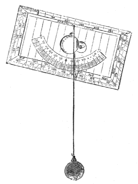
Fig. 326.—Sandhurst Sketching clinometer protractor.

Fig. 327.—Example of scale of shades for slopes.
711.—Military Sketching Board.—This sketching board, Fig. 328, the invention of Mr. Graham F. Hodgson, will be found a very great improvement upon the old pattern boards. It is designed to meet the requirements of military and other officers not conversant with the higher branches of surveying,[486] and it will also be found of great use to surveyors, explorers, and other travellers.
It consists of a mahogany board revolving on a circular metal plate attached to a handle held in the operator's left hand.
Mounted on the metal plate is a compass, which is visible through a glass plate flush with the face of the board and the tracing paper or cloth on which the map is made; the paper being stretched tightly over the board by means of rollers.
A magnetic north line is drawn on the paper over the centre of the compass. The operator invariably has his board in its relatively correct position by always keeping the magnetic north line immediately over the top of and aligned with the compass needle when his sights are taken.

Top view.
The sights are taken by means of an alidade moving along a slotted bar, which itself slides along a bar fixed at the side of the board.
The object aimed at is sighted in a mirror attached to the end of the alidade and aligned with a point at its other end, and the alidade is clamped into position by a thumb-screw on the slotted bar.
The advantages of this instrument are many and will only be fully realised when it is in practical use. No backsights are necessary. Sights can be taken with one hand. The operator is always in a comfortable position and the object aimed at is always immediately in front of him. The alidade remains in position by means of the clamp screw along the ray drawn till the object sighted at is reached and the distance known, which is merely marked off by means of the scale on the alidade. It is invaluable when sketching rivers from launches or canoes when backsights are often impossible. It is light and portable, being easily carried slung over the shoulder in a canvas case.
712.—The method of using is simple and ensures a great degree of accuracy with a minimum amount of time and trouble:—
(1) The tracing cloth is first fixed by means of the rollers over the board. (2) A magnetic north line is then ruled across the paper and passing immediately over the centre of the compass visible under the paper. (3) The operator then, holding the board by the handle underneath, proceeds to make his map and first brings the magnetic north line immediately over the top of and aligned with the compass needle. (4) He then from some point, marked as his starting point on the paper, proceeds to take sights to any objects he may wish to delineate on his map. These sights are taken by means of the alidade fixed above the board. The sighting rule is pushed along a slotted bar, which itself slides along a bar at the edge of a board until the edge of the alidade is against the starting point and is sighted on the object aimed at. The object is sighted in a small mirror fixed at the end of the alidade and aligned with the point at its other end. The alidade is then clamped[488] into position with the thumb-screw on the slotted bar and the operator draws his ray corresponding with the direction of the object aimed at. The distance is then marked off on the scale on the alidade. (5) When the operator moves to the next station no back-sight is necessary. He at once puts the board into its relative correct position by merely revolving it until the magnetic north line is again lying over the top of and aligned with the compass needle and he then proceeds to take all necessary sights at that station.
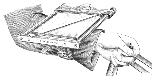
Fig. 329.—Cavalry sketching case.
713.—Cavalry Sketching Case.—This forms a very convenient exploring sketching board, permitting sketches to be made on horseback while en route. The pattern shown in Fig. 329 is that of Captain W. Vernier. It consists of a small board 9¼ inches by 7½ inches, at two sides of which there are small rollers to hold paper 7 inches wide and from 3 feet to 6 feet in length, according to its thickness. Two stout indiarubber bands, which hold a small straight-edge to scale in any position on the paper with sufficient firmness to be able to draw a line against it, are passed over the board. A small compass on one side of the board indicates direction. After one sketch is made, a new part of the paper is rolled forward.
714.—Camera Lucida—Optical Compass.—In new[489] countries where landmarks are not clear a sketch of the general aspect of the country will make the points of triangulation more clear. Where the plane table is not used these sketches may be made with accuracy as to positions by the use of the photograph camera, the camera lucida, or points of observation may be taken in correct bearing by the optical compasses. These latter instruments are described in the author's Treatise on Drawing Instruments, seventh edition.
INSTRUMENTS FOR MEASURING LAND AND CIVIL WORKS DIRECTLY—CHAINS—VARIOUS TELLERS—STANDARD CHAINS—ARROWS—DROP ARROW—VICE FOR ADJUSTING CHAIN—CAINK'S RULE FOR INCLINES—STEEL BANDS—WIRE LAND MEASURES—COMPENSATION SYSTEMS—LINEN TAPES—OFFSET RODS—PINE STANDARD RODS—RODS WITH IRON CORE—BEAM COMPASS RODS—COINCIDENT MEASUREMENTS—COMPENSATED RODS—BASE LINE APPARATUS—COAST SURVEY LINES—PERAMBULATOR—PEDOMETER—PASSOMETER—SOUNDING CHAINS—SOUNDING LINES—TELEMETERS—HAND RODS—RULES.
715.—The Instruments Generally Employed for Measuring Land are chains, steel bands, and tapes. Where roads are roughly measured, pedometers are commonly used. Where very exact measurements are required, rods have been used. Rough approximate measurements are obtained by stepping, with the use of the passometer to count the steps.
716.—Land Chains.—Although these are made in many qualities the forms vary very little. They are too well known to need much description. In the British Isles and some of our colonies the chain of 100 links, equal to 66 feet, the invention of Edmund Gunter about 1620, is generally used, 10 square chains (100,000 square links) giving the statute acre, presenting a decimal system of measurement much in advance of any other at the present time. The best land chains are made of steel, which is afterwards[491] hardened and tempered to spring temper, in the process of which the surface is burnt off with asphalt varnish in order to produce a covering to resist the rusting effects of moisture. Steel chains are made light and strong. The light chain, of No. 12 Birmingham wire gauge, weighs under 5 lbs. The strong chain, of No. 8 B.W.G., weighs about 12 lbs. A light chain of 50 links, of weight under 3 lbs., is sometimes used with the complete chain of 100 links for taking offsets.
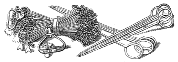
Fig. 330.—Land chain and arrows.
All the best chains, whether of steel or iron, are made with long links formed by turning up the ends of a length of wire. Three small oval links are placed between each pair of long links. These three interval links are found to cause the chain to kink less than when only two are used. Each oval link is sawn through at the meeting line, which is brought up on one flat side of the oval in bending it from the wire. The saw-cut forms the point of adjustment. The small link is afterwards re-sawn and closed to shorten it, or forced open to lengthen it. There are generally four swivels in the length of the chain, two of which are at the handles: these prevent the chain from becoming twisted in turning the handles over in use. A swivel is shown Fig. 331 at S. Iron chains are sometimes galvanized to prevent rust. This process, however, makes the chain much more brittle, and cannot be recommended. It may be noted that all link chains lengthen with use.
717.—Tellers are small pieces of brass suspended to the[492] chain by a spare link placed at every ten links. They divide the chain decimally from either end equally. Proceeding from one end of the chain the tellers read 10, 20, 30, 40, 50, and the other end they read by subtraction from the complete chain: 100 - 10 = 90, 100 - 20 = 80, 100 - 30 = 70, and 100 - 40 = 60. Fig. 331 shows detached pieces of chain with value of the tellers figured under. S inserted swivel. The 50 teller shows the link attachment. A shows the position at which the arrow or other mark is placed to commence or finish the chain measurement, the handle being included in the first link. These tellers are liable to catch and get dragged off in chaining. When this chain is used abroad, or far from home, it is well to have an extra set of tellers to repair losses.

Fig. 331.—Gunter's land chains.
718.—Inserted Tellers.—This form of teller is preferred by many, Fig. 332. It is much less liable to get dragged off, but it is not considered quite so distinct, and it is a little liable to get clogged with grass and weeds.

Fig. 332.—Inserted tellers.
719.—The author's design for inserted tellers is shown[493] Fig. 333. These are perhaps quite as distinct as the last. The holes in wet weather fill up with mud and the surfaces keep bright, so that they remain very readable. There is much less drag, and the chain therefore wears longer.
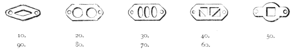
Fig. 333.—Stanley's inserted tellers.
720.—Feet Chains are usually made 100 feet, more rarely 50 feet. They are generally made in foot lengths, but sometimes for flexibility are preferred in 6-inch lengths. They are commonly made of No. 8 B.W.G. steel or iron. The weight of 50 feet is 6 lbs.; 100 feet, 11 lbs. If made of light steel, No. 12 B.W.G., the 100 feet weighs 6 lbs.
721.—Mining Chains used in mineral districts are made generally 10 fathoms, or 60 feet, 6-inch links counted off by tellers in fathoms. They are made entirely of brass. The weight is about the same in brass as steel—No. 8 B.W.G., 9 lbs. Occasionally they are made extra strong, No. 7 B.W.G.; weight 12 lbs. In coal mines Gunter's chains are generally used.
722.—Metre Chains are made 20 or 25 metres long. They are marked with tellers at every two metres with a plain ring at the metre. The tellers are generally of the inserted kind, Fig. 332. In taking measurements the sign of the teller is doubled: thus the ordinary 1 or 10 is counted 2 metres; the 2, 4, and so on. 20-metre chains in light steel, No. 12 B.W.G., weigh 4½ lbs.; strong, in No. 8 B.W.G., 9 lbs. 25-metre, light, 6 lbs.; strong, 11 lbs.
A land chain is generally secured for carrying by a leather strap with a buckle. Occasionally it is carried in a sailcloth bag with a strap over the shoulder.
723.—Standard Chains.—These are of the same form as the ordinary steel chain, but all the links are hard soldered after being adjusted link by link. They are not intended to be used for regular chaining, except it be for laying down rough base lines. Their special employment is to test chains, or to set out with two pegs on a straight piece of ground a standard length or station where the common chains in use may be tested daily. A standard chain is commonly enclosed in a box with a lock to prevent its accidental use for an ordinary chain.
724.—Arrows.—These are sometimes called pins. Ten form a set. They are shown with the chain in Fig. 330, and are commonly made of the same wire as the chain—No. 8 B.W.G. They are much better made one gauge stouter (equal to about 1/7 inch), and preferably of hardened steel than of iron. The common length is 15 inches. Where heath, stubble, or woodlands prevail 18-inch are better for use, and in some exceptional cases even 2-feet are very convenient. Surveyors going to new countries are recommended to take the longer arrows as well as those supplied with the chain. It is common either to tie a short length of scarlet webbing upon each ring of the arrow or to sew a piece of red flannel or bunting upon it to find it easily in long grass. Arrows are sometimes carried in a quiver with a strap over the shoulder, Fig. 334, which leaves the hands of the fore chainman free to remove obstructions where they occur.
725.—Drop Arrow, Fig. 335. Where ground is very hilly it is common to roughly level the chain by holding the lower position shoulder high, either by guess work or by using any kind of rough hand level or clinometer to ascertain this. The arrow is then dropped, and the point, held at first lightly in the ground, is pressed hard down or another arrow supplanted for it. The chain in this case is used in odd multiples of links as they occur, of which record is taken separately at each station. In going downhill a drop arrow answers very well. In going uphill a plummet to the last arrow is better. Some[495] use the drop arrow as a plummet, carrying for this purpose in the pocket a piece of fine whipcord, with a bent hook tied to one end, to be used when required.
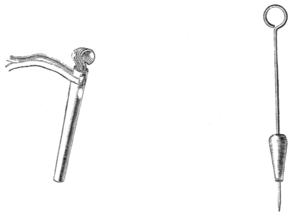
726.—Examination and Adjustment of Chains.—Respectable makers send out chains tested to within half of one of the small links of standard, that is, within a quarter of an inch; but in use this error may increase either by the bending of the long links of the chain, when it becomes shorter, or in the more general case of friction from wear and from strain, by which it becomes longer. In London, standards are fixed upon the pavement in Trafalgar Square and at the Guildhall. These standards are also fixed at many municipal town halls. Surveyors very commonly lay down a standard on the pavement, or by pegs on a level gravel path. Where a peg is used it should be driven home nearly to the surface. It should if possible be made of a piece of heart of oak 12 inches long and about 2½ inches square. The standard length, which may be set off by a standard chain or new steel tape, should be from a saw-cut across the centre of one peg to a similar cut on the other. It is well also to have the centre space (50 links) indicated by a smaller peg.
727.—The Chain to be Adjusted should be first examined[496] and its long links set straight by means of a hammer on a flat, hard stone or anvil, after which the error will be, if it has been much used, that it is too long. It should be then laid in direct line on the standard just described, and stretched lightly with a pull of about 7 lbs., and then left to rest. Assuming it too long, the centre of the chain should be observed to ascertain which half is of the greater length, then short links should be taken out at distributed distances, if more than one be required, by twisting the link open in a vice, and opening and closing another link to restore the chain.

Fig. 336.—Stanley's vice for adjusting and repairing land chains.
728.—Chain Vice.—The links of steel chains can seldom be twisted open without breaking, and broken links cannot be restored by steel links. Iron links answer, but they are very stiff to twist open. Generally it will be found best for professional men to repair the chain with spare brass links. These wear very well. Where a smith is near with his vice and a light hammer the links are readily opened. It often occurs in open districts and abroad that no smith's shop is to be found. To meet these cases the author has constructed a special vice, as shown Fig. 336. This vice is let into a piece of hard wood—an old oak post answers admirably. In stone districts it is perhaps better to let it into a stone and fix it by pouring hot lead round it. The part B is used for an anvil for straightening the links. The vice V holds the link edgewise very firmly by bringing up the slide J by means of the screw S. The link may then be knocked open by the pane end of a light hammer. The link is closed again in the same manner. If the vice be[497] left out of doors the screw should be well greased and the whole covered with a leaden cover. The weight of the vice is about 6 lbs. It is made of cast iron with chilled face, or the jaws are faced with steel.
729.—Opening and Closing the Chain for Use.—The chain is most readily unfolded by taking the two handles in the hand and walking away from it as it lies on the ground. It is most convenient to place it about 45°, and half a chain length from the first station, each chainman taking a handle and moving to his position. The only danger in undoing a chain is from two chainmen taking one handle each and walking in opposite directions, in which case, if there happens to form a kink, the opposite movement of the two men will probably stretch or break the chain. In closing the chain it is taken by the middle links and folded up two links at a time till the handles are reached. If the links be placed consecutively in position round the axis formed by the first links, it may be folded up very compactly in a twisted form ready for the strap, by which it is carried, to be passed round it.
730.—Chaining is performed by two chainmen, termed the leader and follower. The follower, having pressed a stake into the ground for a starting point, then places the centre of the outside of the handle of the chain against it. The leader takes ten arrows in his right hand and one handle of the chain in his left, and walks directly towards a point which is to be the termination of the measurement, stopping at nearly the length of the chain, examining the chain to see that it is straight. He then places an arrow lightly outside the centre of his handle. The follower looks over this arrow to the distant station to see whether it is in direct line. If it be not so, he waves his right or left hand once, twice, or thrice for 1, 2, or 3 inches for movement to right or left. The follower picks up the arrows consecutively as left by the leader, and when he has the ten, 10 chains have been measured, which is then recorded in the field-book, or earlier[498] than the ten if a shorter distance or object completes the measurement. It is most important to observe that if an arrow be taken for the first station, the follower having ten counts nine only for the first ten. To prevent accident it is therefore safer to start from a stake or other landmark, not one of the arrows. Some surveyors advise eleven arrows. If eleven be used, one should be distinctly marked from the rest so as never to be counted. This may be done by omitting the red webbing tie, or using a green tie for the odd arrow. The French always make the drop arrow the eleventh arrow, which is never counted in direct chaining.
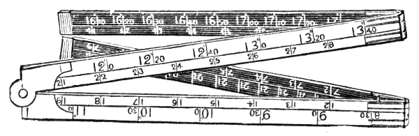
Fig. 337.—Caink's rule for correcting inclines.
731.—Caink's Rule for correcting inclines in chaining is the invention of Mr. Thos. Caink, C.E., of Malvern, Fig. 337. It is made four-fold, each fold being one link. The link is divided decimally along the inside of the rule. On the outer edge of the rule there is a scale marked degrees, a part of which is subdivided where the scale is open to read closer, that is, to 20 or 30 minutes. These degree divisions, which read up to 16° on one side of the rule, indicate the space from the end of the rule to be allowed in addition for the same degrees of inclination of the land up to 4 links of measurement. On the opposite side of the rule the inclination scale is carried from 16° to 22° 10′. For these higher numbers the length of the rule is first set off, and then plus such part of the rule as is indicated by the position marked upon it of the required number of degrees.
732.—To Use Caink's Rule.—The follower has a clinometer of one of the kinds shown, Figs. 260 or 264. He[499] notes at starting the position upon the face or body of the leader that corresponds with the height of his own eye. He takes the inclination of the land to this point of the leader's body while he is standing upright at one end of the chain and the leader standing at the other, noting the number of degrees shown by the clinometer. He then places the rule in the direction of the chain, with the number of degrees indicated, in front of the arrow, and moves the handle of the chain to this position. For the sake of verification, if he has a second arrow he may place it in the new position, which gives the true allowance. In either case the leader moves the chain forward by the amount required and places his arrow ready to continue the work. By this method it is seen that there is no after calculation or separate record necessary for undulating land, but the true horizontal position is given correctly at each chain measured. The same form of rule is made for feet and metres.
733.—In mountainous countries the eight links of the rule is insufficient allowance for common inclinations. Such countries are measured much more accurately by some system of subtense measurement, for which see Chapter XII.; but where a small piece of sudden steep inclination occurs half a chain may be taken, and the number of degrees indicated upon the rule be doubled, so that the full rule, instead of taking 22° only, will take 44°.
734.—Steel Bands for measuring, termed steel band chains, are made in various forms in this country, and sold by nearly all opticians. They are much lighter than chains of equal strength, and are made of standard length. They are also lighter to use, being smooth and without any projection. On the other hand the reading is less distinct than with the chain, and they need more careful usage in chaining. They also require oiling before being put by. From the thinness of the metal they are altogether more delicate and less durable than the chains for hard wear; but it is thought[500] by many to be a compensation that they are always of true length.
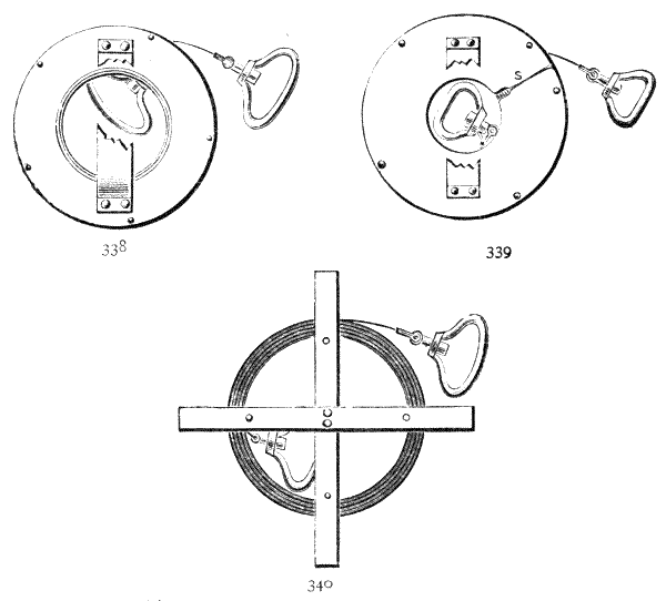
Figs. 338, 339, 340.—Steel bands and tapes.
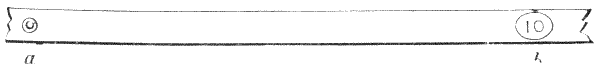
Fig. 341.—One link of steel band.
735.—The bands commonly used for land measuring are made 3/8, ½, 5/8, and ¾ inch wide, of Nos. 26 and 24 B.W.G. in thickness, respectively. The chain is divided into links by a small stud riveted through the centre of two small washers, a large stud being placed at the fives and an oval plate held by two rivets at the tens, which are numerically indicated in plain engraved figures, as shown in detail, Fig. 341 b, or perforated with holes indicating the number of tens. These band chains are made in links, feet, metres, or to any foreign[501] measure to order, and of any length corresponding with land chains. Weights, approximately—100 feet: ¾ inch, 7 lbs.; 5/8 inch, 4¾ lbs.; ½ inch, 4 lbs. 100 links: ¾ inch, 4¾ lbs.; 5/8 inch, 2¾ lbs.; ½ inch, 2¼ lbs. 20 metres: ¾ inch, 5 lbs.; 5/8 inch, 4 lbs.
736.—Steel band measures are also made with divisions throughout, etched upon them with acid in such a manner that the divisions and figures stand in relief up to the original surface, whereas the new surface, which is etched back to form the ground, appears dull. The brightness of the figures and divisions on the dull ground makes them easily read. These bands are divided into links, feet and inches, metres and decimeters, or closer quantities either on one or both sides of the band as required. With the etched band there is perhaps a little risk of weak places from over-etching, although these bands are most carefully made, but perhaps this is not greater than in the inserted stud band, where weak places are necessarily caused by the loss of width at the points where the holes are made for the studs, wherein moisture hides after use in damp weather.
737.—The steel bands have handles the same as a land chain. They are wound upon a steel cross, Fig. 340. They are commonly placed in a wind-up case similar to that of an ordinary measuring tape, but in steel, provision being made that one of the pair of handles may be secured about the position of the axis of the tape for winding it up. In Fig. 338 the axis is made very large, so that the handle may be pressed in from an opening in one side of it. The newest idea is to cut a slit in one side of the plate up to the centre, as shown, Fig. 339. In this case the handle and band are put in from the side, so that the axis is no larger than is necessary to take the handle. A strap is placed on the side of the case for holding it. This is shown cut off to admit sight of the handle.
738.—The French make the handle generally T-shaped[502] and hollow in the cross part, which renders it very light and perhaps less cramping to hold. The arrows are very commonly held by loops to the cross on which the band is wound. This general arrangement is very portable and convenient to carry; it is shown Fig. 342.
739.—Wire Land Measures.—Where long open stretches of new country are to be measured, it is common to employ a steel wire chain, of 5 chains or of 500 feet in length, fitted with a pair of strong cross handles only.

740.—The author has made many chains of 500 links; in Fig. 344 a part of one is shown full size. This band, as we may term it, is wound upon a reel in an iron case, Fig. 343. A spring brake is placed at the position A, which holds the reel and prevents the band from springing out into loose hoops when it is run out. The 50 and 100 links are indicated by short lengths of brass tube placed over the band—single at the 50 links, but numerically indicated by number of bands as 2, 3, and 4 chains. In Fig. 344 a 50 and a 300 links are shown; weight, 3½ lbs. This flat, narrow, steel band chain was unknown until introduced to the notice of the profession in the first edition, 1890. It is now in very general use, and lengths may be had from[503] stock of 2, 3, 4, or 5 chains, or 200, 300, or 400 feet wound upon a steel cross.
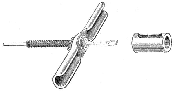
Fig. 345.—Richmond's tension handle.
741.—Richmond's Tension Handle.—Various devices have been employed for giving equal tension to chains and bands to ensure equality of measurements. Salter's spring balance has been very commonly used attached to one handle of the chain to give a uniform pull, say of 15 lbs. This appears to answer very well. Mr. Richmond, surveyor, of Sydney, has devised a very simple plan for tension of light bands, which, being lighter and attached, is much more convenient than Salter's balance. This is shown Fig. 345. The band passes through a fitting in the centre of the handle, and a spiral spring is fixed to this and the band at a short distance along it. By pulling the handle a given tension can be applied, which is shown by the mark it reaches towards the end of the band. This is adjusted to standard length, and a small notch is placed in the centre of the end, from which a plummet may be suspended if necessary.[54]
The engraving is of a slightly modified form by the author, in which a thin tubular cap covers the free end of the band to save this exposed part from accidents.
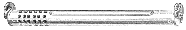
Fig. 346.—Copper case thermometer for suspending to a band chain.
742.—Chain and Band Thermometer.—Where very [504] great accuracy of chain or band measurement is aimed at, temperature is taken to allow for expansion of the metal. A thin plain glass thermometer of the clinical form is the most sensitive of any. This is carried in a wooden pull-off case lined with indiarubber. When it is used it is placed upon the ground by the side of the chain. The delicacy of the clinical form of thermometer is often objected to by the practical surveyor, hence there are several other forms with boxwood and ivory scales. These are not very satisfactory, as the boxwood and ivory retain the heat of the body, from being carried in the pocket, for a long time after exposure. The author has enclosed the clinical form of thermometer in a copper case with open face, Fig. 346. The copper being a good conductor of heat, this is very sensitive to the temperature of the air. Two turn-down hooks are placed at the ends of the tube to suspend it on the band. The thermometer stem has two indiarubber caps, so that it will bear dropping on grass. It is contained in the same form of pull-off case as the clinical.
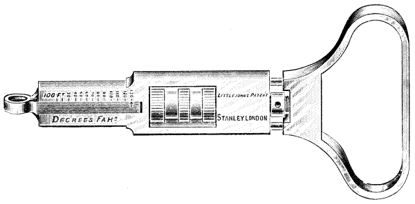
Fig. 347.—Littlejohn's temperature handle.
743.—The coefficient of expansion for steel between 32° and 212° Fahr. is about ·000012, which is less than ·01 inch per degree per chain. Temperature corrections can therefore be recognised only upon very exact work, appreciable only when long bands of the Marchant type, lately described, of from 5 chains to 10 chains in length are used.
744.—Mr. Littlejohn has patented an adjustable handle for temperature. This is divided for allowance for the 100-feet or other band for every degree Fahr. or centigrade. Fig. 347. The handle is set to the temperature as it changes during the day. It offers, perhaps, the highest refinement in ordinary land measurements.

Fig. 348.—Stanley's repairing sleeve.
745.—Repairing Sleeve for Steel Bands.—The reviser has patented a sleeve which will be found useful, as by its use a broken band can be immediately and permanently repaired in the field without the use of tools. They are made to fit all sized bands, but it is necessary that the correct sized sleeve should be used. One of these sleeves is shown attached to a band at Fig. 348.
In order to effect a repair it is merely necessary to clean the broken ends of the band, and insert them into the sleeve, then hold a lighted match under it until the soldering material is melted, when the repair is completed.
The central hole in the sleeve is to enable the user to see when the broken ends are in contact, and the other two are to indicate when the soldering material is melted, which takes place when it either bubbles up in or runs away from these holes.
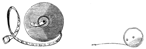
746.—Linen Tapes.—This most useful implement, Fig. 349, is one of the most unsatisfactory measures the trader[506] and user has to do with. It consists, as is well known, of a tape oiled, painted, and varnished, which is rolled up in a leather case when out of use. When the weather is moist it shrinks, and when dry it expands. If it be too heavily painted it becomes brittle and rotten; if it be lightly painted it remains more flexible, but is more affected by moisture. A good tape bears very well a stretching force of 7 lbs. to 14 lbs., but if strained over this it is permanently stretched. There is no plan known to the author by which these defects can be remedied. Numerous attempts have been made—often valueless or worse—some, although popular, mere claptraps, such as the insertion of wire. The best tapes for strength and permanency are made entirely of green, hand-made, unbleached flax. The tape is said to come from Holland to this country. These are at first oiled with a drying oil (boiled linseed oil), and when seasoned for a month or so, painted once or twice with white lead colour—not too thickly. The printing is more permanent if done in oil; but the tape is somewhat more flexible if the figures are stencilled in Indian ink and the whole afterwards thinly varnished over with copal varnish. The great secret for preserving the tape is to use it very carefully and only in fine weather. In wet weather for taking offsets a light steel 50-link chain is quite as convenient as the tape, and safer.
Tapes are divided into links, feet and inches, metres, and all measures as required. A decimal yard is commonly[507] placed on tapes for measuring earth work. For use with the chain a 66-feet tape is usually employed, but many think a 33-feet better, using the chain for dimensions above this. For measuring buildings, 50-feet or 100-feet tapes subdivided to inches are employed.
747.—Steel Tapes.—Thin steel tapes, 3/8, ½, and 5/8 inch wide are in very extensive use. They are more accurate and more costly than linen tapes, but less flexible and less durable. Where dimensions are important they should always be used for short measurements. In all cases it is advisable for a surveyor to keep a steel tape for examination of the lengths of linen tapes in use. They are made to all the measurements of linen tapes.
748.—Pocket Steel Tapes 6 feet to 12 feet, Fig. 350, are used more generally by mechanical engineers. These tapes, which are very light, are held open by a catch, and closed by a spring.

Fig. 351.—Jointed offset rod, top and centre.
749.—Offset Rods are generally made 10 links long, either in one piece or jointed in the centre with a bayonet joint. They are about 1-1/8 inches in diameter, diminishing towards the top to 7/8 inch, and made either of yellow pine or ash. A hook is commonly put at the top, Fig. 351, which takes the handle of a chain to draw it through a hedge or other obstruction. The author's plan of making this is shown at H. The lower end of the offset is shod with a steel or wrought iron socket point, so that it may be set up in the ground and used if required as a picket. Bands are painted alternately black and white at every link. Square or flat rods are occasionally used for the same purpose, but they are not generally so convenient.
The offset is Used in the manner of an ordinary rule to take rectangular short measurements from the chain as it lies upon the ground, commonly in order to obtain the contour of irregular outlines.
750.—Measurement by Rods has become less general than formerly, from the greater accuracy of Konstat or Invar steel tapes, by which practically correct base lines may be laid down. For geodetic works requiring the greatest accuracy the bases have been laid with rods of various forms. These rods will be briefly described. It is only in the construction of iron bridges, roofs, etc., that rods are at present generally employed in the work of the civil engineer.
751.—Pine Standard Rods, made of straight-grained pinewood seasoned five or six years and then well soaked in linseed oil, make good standard rods. The ordinary length in use is 10 feet by 1¾ inches square. If the rod be used for butt measurement the ends are tipped with gun-metal in which a turned steel stud is hard-soldered. The stud is afterwards ground to true face in a lathe, and left of standard length at 60° Fahrenheit (15·5 centigrade), Fig. 352. A disc of brass 1 inch diameter is inlaid at every foot for 5 feet from one end of the rod, with a line at the true foot. These rods, after the work upon them is finished, are lightly French polished to keep them clean and to prevent the effects of moisture. The effect of temperature upon deal was found by Roy to be about the same as upon glass—·0000085, average of total length per degree centigrade, which is about three-fourths that of iron.

752.—Where butt rods are used for continuous measurement, it is necessary that they be brought very carefully[509] together. In base line measurement three or four are used, but for metal work or masonry two 10-feet only are generally employed. It is necessary that the rods should lie upon a straight surface or be supported in a straight line. In bringing them together, a piece of indiarubber 1/8 inch or so in thickness temporarily placed at one end will prevent any palpable disturbance of the percussion if the fixed rod be well weighted. One 5-feet more fully divided butt rod is very commonly supplied with a pair of 10-feet rods for supplemental measurement.
753.—Angle-piece.—A solid angle-piece with two planes at right angles is very convenient for use with butt rods to give means of scribing the true length down to a surface, Fig. 353 S.
754.—Butt Rods with Iron Core.—Where rods are to be used for preparing iron work it is better to have an iron core through the rod, that may expand and contract with the metal on which they are used. The rods that the author has designed for this purpose are made out of a length of seasoned pine 2¼ inches square, sawn down and turned cut sides outwards to prevent warping. A 10-feet length of iron steam tube about ½ inch diameter is painted several times and then bound round with paper soaked in paraffin. This is placed in a pair of meeting grooves, as shown in section Fig. 355. The two pine flitches are cross-tongued together and glued up with the inserted tube between them. The tube has a turned steel cap placed over each end, Fig. 354, and this is ground in a lathe to true standard at the temperature of 60° Fahr. A steel pin is placed through the centre of the rod to indicate 5 feet. The finished size of the rods is 2 inches square.
The author has made these rods in sets, consisting of two 10-feet and one 5-feet packed together with an angle-piece, Fig. 353 S, in a deal case.
755.—The 5-feet Rule is of steel, ¾ inch by ¼ inch, inlaid[510] in a piece of dry pine, altogether of only half the thickness of the rods, so that it stands the correct height for central butt measurement, Fig. 356. The rule is divided into feet and inches, with one foot to eighths. A centigrade thermometer is placed in one of the rods to indicate the prevailing temperature, and a small piece of scale showing amount to be allowed in 10 feet per degree centigrade for temperature above or below 15·5° centigrade is engraved upon the thermometer scale. The coefficient for the expansion of wrought iron is given by Lord Kelvin as ·000019 mean per degree centigrade.

Figs. 354, 355, 356.—Butt rods with iron core.
Where a long length is laid down for a base line or other purpose, it is better to take the thermometer reading at each measurement and defer correction to the completion of the work; the temperature errors may then be added together as a total, and the space allowance may become a measurable quantity. For example, say ten 10-feet lengths give by these united centigrade degrees, plus and minus, shown at separate readings + 167°, and that the standard of the rods is true at 15·5°. Then 167 - (10 × 15·5) = + 12° per foot total allowance, that is, 12° × 10 feet × ·000019 = ·0228 feet or ·2736 inches to be added. In measuring iron of course no correction has to be made.
756.—Beam Compass Measurements are occasionally preferred for iron work. In this case the beam is moved from centre punch mark to mark along a surface by the beam producing a scratch for the forward position in which to place[511] the punch mark. Rods of pine are commonly employed. Figs. 357, 358 will sufficiently illustrate the instruments.
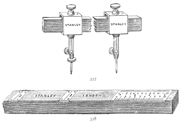
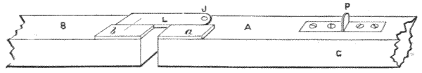
Fig. 359.—Coincidence rods.
757.—The Method of Coincidence in measurements by rods has often been applied to measurement of base lines. The plan consists in allowing one rod, or a lighter continuous part of it, to pass the other rod, so that a line cut to standard on one rod may be read into one on the other. The best plan to do this is to have a scale fixed along the face of one rod near its end, as shown Fig. 359, and to have an extension from the other end of the second rod to pass alongside this scale, so that two lines may be brought into coincidence. The rod B has a fixed scale b placed on top of it at one end. The rod A has a scale protruding from it.[512] This scale may be jointed with a good ground joint at J for portability. The rods are laid lightly together, and any final adjustment is given by light taps with a small hammer or mallet upon one or the other side of the stud P until exact coincidence of the lines shown at b is brought about. This tapping operation appears a rather rough process, but practically it is very exact.
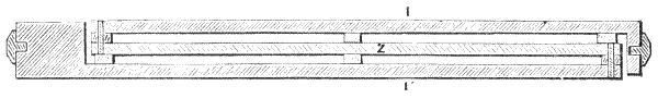
Fig. 360.—Bessel compensated rod.
758.—Compensated Rods.—The plan used by Bessel for the measurement of a base upon the shores of the Baltic in 1836 is looked upon as a model of the most perfect work of its kind. The rods were composed of two bars of iron having surfaces accurately planed, with a similar bar of zinc placed between them. The bars were laid one on the other, but not in contact, the surfaces being kept apart by glass plates, upon which they could slide with little friction. The linear expansion of zinc per degree centigrade is about ·0000292 (Fizeau); that of iron much less than half this—about ·0000119 (Thomson). The bars are attached to each other in such a way that the expansion of the zinc may act in the opposite direction to the expansion of the iron. The form followed for the construction is shown in Fig. 360 where II′ are the iron bars, Z zinc. The length of the zinc required for compensation between the junctions is found in the equation—
(S + Z)(0000119) - Z(0000292) = 0,
S being the total length of the standard rod in feet, and Z the length of zinc in feet required for compensation. This plan is that adopted for the compensation of pendulums. For the[513] verification of a rod it may also be made to form the rod of a pendulum, by which temperature expansion and contraction upon the system will be clearly indicated by difference of time rate in the change of temperature during night and day. This test becomes important where great precision is aimed at, as the expansion in metals varies according to their purity and state. The standard lines in rods made upon this model are placed upon small inserted discs of platinum placed near the ends, which are read by microscopes in coincidence upon a pair of rods.
759.—Colby Compensated Rods, the invention of Major-General T. F. Colby, who was for twenty-seven years superintendent of the Ordnance Survey, upon which these rods were used. Each rod is composed of one rod of iron and one of brass, which are so arranged in pairs that the difference of expansion of these metals shall act to diminish the amount of entire expansion at the points measured, a quantity equal to its increase by temperature, in a manner to be described.
The Rods are each made 10 feet 1·5 inches long, 5 inches broad, and 1·5 inches deep. Fig. 362 i is a side elevation of one rod, Fig. 363 ib plan of iron and brass rods, Fig. 365 ib perspective view. By this it will be seen that the rods are placed edgewise. The distance apart is 1·125 inches. They are supported in the middle upon rollers, Fig. 362 F. They are firmly fixed together at their centres by transverse steel cylinders, Fig. 363 RR′ 1·5 inches diameter, each rod being left free to expand or contract from the neutral central point independently of the other. The neutral point is formed of a T-piece E, Fig. 363, fixed firmly on the bottom of the box bx. At the extremity, and at right angles to each of these bars, is a flat steel tongue, Figs. 364, 365 A, 6·2 inches long, 1·1 inches broad, and 0·25 inch thick, which projects 3·25 inches from the side of the iron bar i. The tongue A is jointed by double conical pivots at f and f′, which form axes perpendicular to[514] the surface of the tongue, allowing it to be inclined to slightly different angles to the direction of the bars according to the expansion or contraction the system experiences by heat. The pivots are 0·5 inch diameter, and are placed at 2·3 inches from the end of the tongue next the brass bar. On the tongue at P, flush with its upper surface, a small stud of platinum is inserted, upon which a small dot is struck to form the point of standard measurement.
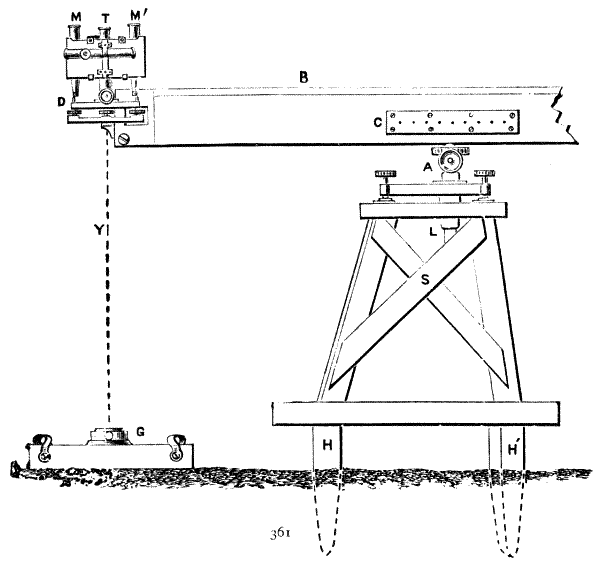
Colby Compensated Measuring Rods.
Fig. 361.—End of rod mounted with microscopes, trestles and ground plate.
The bars are placed in strong wooden boxes, to the bottoms of which are fixed the plates that hold the brass rollers upon which the bars are supported, Fig. 362 F, and the central stay E mentioned before prevents any displacement[515] of the bars when the rods are held by the rollers RR′. To protect the tongue A, which projects beyond the boxes, there is a special covering nozzle having a hole and cover over the dot. A level is placed on one of the bars, which is seen through a window in the lid of the box. At the ends of the box plates are fixed for supporting the tripod of the double compensated microscope, Fig. 361 D, employed to observe the standard points of one pair of rods brought by adjustment to true position MM′. A pair of sight vanes which shut down are placed on the ends of the box for setting the rods approximately in line.
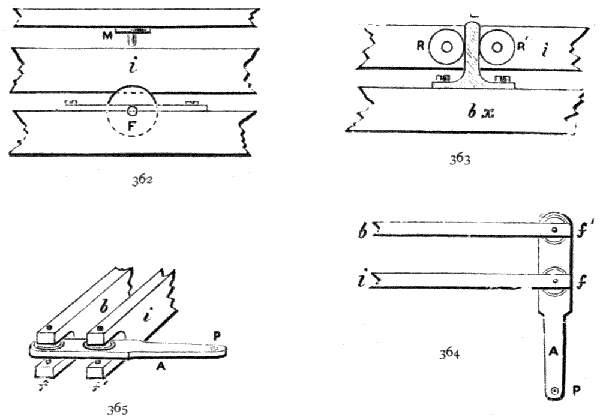
Colby Compensated Measuring Rods.
Fig. 362.—Side elevation of point of support of rod.
Fig. 363.—Side elevation of centre, with section of box bx.
Fig. 364.—Plan of rods and compensating arm.
Fig. 365.—Perspective view of the same.
Two Rigid Tripod Stands Fig. 361 S are used to each of the rods placed under the rollers Fig. 362 F upon which the bars are supported in the box. The tripods carry a[516] universal slide-rest by which the rod may be adjusted to position both in horizontal and vertical planes Fig. 361 A. Six rods were used for the Ordnance Survey at one time, and were designated by the letters A B C D E F. The weight of each rod complete with microscopes in its case is 136 lbs.
Compensated Microscopes.—The compound microscopes, Fig. 361 MM′, used with the Colby apparatus form a complete separate instrument, consisting of two microscopes placed parallel to each other and united together for reading the rods when they are brought with their standard points the distance apart that separates the axes of the two microscopes. In the intermediate space between the two microscopes, and parallel with them, a telescope T is fixed on the same piece of apparatus, with adjustment for reading a point on the ground G perpendicular to the measuring rod. The microscopes are held apart by two bars of brass and iron 7 inches long, 0·5 inch broad, and 0·375 inch thick, which are placed at 2·5 inches apart and secured with the telescope, which forms the fixed centre, by collars to the bodies of the microscopes. The difference of expansion of the iron and brass maintains the separation of the microscopes at their foci at one distance with every change of temperature of the air. The object-glasses are of 2 inches focus. The microscopes are brought to adjustment and bearing by levelling on a tribrach whose base is fixed firmly to one of the rod cases, and by lateral adjusting screws. Special microscopes are used with each of the six rods of the Colby apparatus, and are distinguished by the letters M N O P Q R S. The weight of each compound microscope is 5 lbs. Very full particulars of the Colby apparatus with engravings of all parts, are given in "The Ordnance Survey Account of the Measurement of the Lough Foyle Base."
In measuring a base line a piece of nearly level land is selected, and the rods are supported upon the trestles or[517] tripod stands at about 3 feet from the ground. The heights of the upper surfaces of the tripods are ranged by a theodolite or level for all intermediate points between the two ends of the line. Generally twelve trestles are employed with these rods, which are fixed firmly to the ground at every station by legs well rammed in, Fig. 361 HH′. The cases containing the rods, or the rods themselves, are made sufficiently strong to be supported upon two points only without serious deflection.
The Colby system of measurement of base lines varied in detail has been employed by nearly all the nations of Europe and in America.
760.—Modern Base-line Apparatus.—The introduction of "Konstat" steel (highest grade Invar) tapes and wires has revolutionised the method of measuring base lines. These tapes offer a means which is far superior to anything obtained by measuring bars, because they combine the advantages of great length and simplicity of working, with more precision than the shorter laboratory standards, providing that suitable apparatus is used in applying them to their work. Base lines may now be rapidly measured with long "Konstat" steel tapes so that much longer lines are laid down than was formerly the practice when measured with bars, with the result that any errors that may be introduced do not affect the ultimate expansion so much owing to the greater length of the base.
The coefficient of expansion of "Konstat" steel is under ·0000005 per degree Fahrenheit, so that provided accurate means of suspending the tape and reading it and transferring the readings to a plate properly let in the ground are used, we have a most exact and rapid method for this important work.
The tapes are usually 100 feet or 30 metres long, but 300 feet or 100 metres are often used. The tapes are a few feet longer than these measurements, so that the rings are well clear of the reading lines. A silk cord is attached to these rings and passes over the end suspension supports, one of which is[518] shown at Fig. 366. These are made with two steel bars rigidly mounted on two tripods; upon the bars a sliding carriage is mounted carrying a pulley running on ball bearings with a vertical motion for final adjustment of the tape for height. A weight is attached to the other end of the silk cord to give the same tension as that under which the tape was divided.
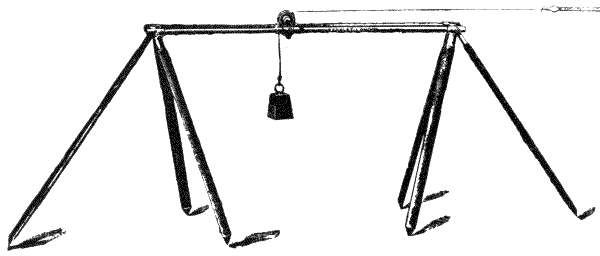
Fig. 366.—One of the two end supports of the band, showing tension weight, with cord running over the ball-bearing pulley.
To prevent catenery light intermediate stands, as shown at B Fig. 367, are used at about every ten feet; these have a rising cross piece with guides which are adjustable for height and sideways to support the tape in perfect alignment. Having the tape properly suspended the reading instruments, C Fig. 367, are placed in position at either end. These are mounted on rigid-framed stands and provided with levelling screws, cross levels, transverse screw motions and movement in azimuth, with clamp and tangent motions and aligning telescopes. A powerful microscope is rigidly fixed over a little table over which the tape passes and reads its division with great exactness, coincidence with the division being made by the traversing screw. By the side of the reading microscope, and in exact collimation with it, a plumbing telescope is rigidly fixed, and this sights down to a transferring apparatus, D Fig. 367, which is over the plate let into the ground.
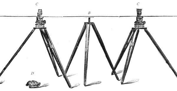
Fig. 367.—Two reading and plumbing instruments, C, C; transferring instrument, D; and one of the adjustable intermediate supports, B.
The transferring apparatus is a spring centre punch rigidly mounted truly vertical on a supporting plate having transverse motions, cross levels and levelling screws. The top of the centre punch has a small platinum disc let in a recess, and upon this disc very fine cross lines are marked. This apparatus is placed on the ground over whatever has been let in to receive the mark, it is then levelled and the cross lines upon the punch top brought by means of the transverse motion screws exactly to coincide with the spider web of the plumbing telescope, and in this position the centre punch is lightly struck with a mallet which marks the plate let in the ground in the exact position of the centre of the cross lines at its top, so that if now the transferring apparatus be removed the cross webs of the plumbing telescope would cut the dot marked in the plate by the centre punch. This method is far more exact than any hanging plumb-bob, as even if they are screened to prevent swinging very few hang with the point perfectly true. In laying down a base line No. 1 reading and plumbing instrument is set up and levelled over the starting[520] end block, which is usually of hard stone or granite set on a firm foundation, with a copper plate let in its top about the centre, the line having been previously set out with a theodolite, and the intermediate stations being roughly measured with an ordinary steel tape. At each intermediate station or length of Konstat tape used a teak post is driven into the ground and a zinc plate screwed upon its top; the other end block is similar to the starting one. The Konstat tape is now mounted between the end suspension supports, one being outside the starting end block and the other outside the first teak post which has been put in for the first length. No. 2 reading and plumbing instrument is set up over this post, and No. 1 and No. 2 are aligned upon each other by their aligning telescopes, and the Konstat tape adjusted over the little tables under the microscope of each; the intermediate stands are then put in and adjusted for height to prevent catenery, and the guide pieces are brought up to the tape on either side and clamped to prevent side deflection by wind. The tape being properly suspended it can be easily moved with the fingers lengthways, as it is suspended at either end by silk cords over ball-bearing pulleys. It is brought in position with its starting end division somewhere under the microscope of No. 1 reading apparatus, and the microscope is then brought into exact coincidence by the traversing screws. The transferring apparatus is put on the granite block with the centre punch in the field of view of the plumbing telescope and then levelled; the cross lines in the top of the centre punch are then brought to exactly coincide with the plumbing telescope webs by the transverse motion of the transferring apparatus, the centre punch is struck and the mark thus made in the copper plate has a line engraved through it. The transferring apparatus is then removed to the position under No. 2 reading and plumbing apparatus. No. 2 microscope is made to coincide with the end division on the Konstat tape by its traversing screws, the centre punch of[521] transferring apparatus, brought by its traversing screws to coincide with the webs of the plumbing telescope and struck, marks the first section. No. 1 reading and plumbing apparatus is then transferred to the next post, No. 2 remaining over the first section post, the first end suspension stand is transferred outside No. 2 post and the tape mounted between as before, the traversing motion of No. 2 reading apparatus must not be touched, but the end division of the tape brought to coincide with its microscope web by shifting lengthways. No. 1 microscope at the further end is adjusted to coincide by its traversing screws and the transferring apparatus as before, and so on until the entire length is measured, the last centre punch mark on the copper plate let in the further end block or stone having a line engraved through it.
A few 1-100th of an inch divisions, or 1-10ths of a millimetre, are divided on either side of one end division of the Konstat tape so that any allowance for expansion or contraction may be made under the microscope at the time, but with Konstat tapes this is very small indeed. With fairly level ground any slight differences of level can be allowed for in setting up the stands, so that the tape remains level; if the difference is too great for this the difference of hypo and base must be calculated. Thermometers are used, generally one suspended on the tape at each end.
761.—Perambulator.—A very ancient instrument, described by Vitruvius as being among the effects of the Emperor Commodus; it was used by hand, or attached to a carriage to measure distances. The instrument is at present used as formerly for measuring roads. Upon pavements and asphalt roads it measures accurately, where by reason of traffic it is sometimes a difficult or very slow process to use the chain. The plan of manufacture is varied considerably. The author makes the felloe of the wheel in segments of well-seasoned mahogany in two rings, Fig. 368. These are rivetted[522] together from side to side in such a manner that the grain of the wood is crossed as much as possible to prevent lateral warping. The tyre, which is 6 feet in circumference, is made of hard rolled brass 1 inch by ¼ inch thick. The spokes are light steel tubes covered with brass tube, and screwed into a brass hub. The axle of the wheel is placed in a steel fork which is formed by screwing, by means of a winged nut, two bars of about 18 by 1½ by 3/8 inches upon a boss formed at the end of the steel stem of the turned wood handle. Made in this manner the handle may be easily detached and placed flatwise upon the wheel, so that the whole may be packed in a square deal case of moderate dimensions for transport.

The Registering Part of the Instrument, Figs. 369, 370. The axle is protruded through the fork on the left-hand side, and thence through the registering box supporting one of its ends. The other end of the box is supported by a stud which fits into the side of the fork. The axle in the part contained within the box is cut into a screw, Fig. 370 S, of about sixteen threads to the inch. The screw works in the edges of a pair of discs R, placed one upon the other upon the same axis; these are cut on their edges with teeth to form worm wheels in which the screw upon the axis of the wheel[523] works. The upper disc has 110 teeth. This therefore moves one revolution by 110 turns of the wheel. It is divided into 110 divisions at its circumference, but is figured 20 yards to 220 yards or 1 furlong, so that each division represents 2 yards, corresponding with the circumference of the wheel, Fig. 369 O. The divisions are read by a point attached to the side of the box shown at the top of the figure. Single yards are shown by the intermediate position of the pointer between the divisions, but single feet may very well be estimated approximately. The lower disc is cut with 111 teeth. The ratio 110 to 111 gives a differential displacement of one tooth only after 110 revolutions of the wheel, or of 220 yards traverse. The two discs take, therefore, by revolution over the surface 220 × 110 = 24,200 yards or 13·5 miles before they return to the same relative position as at starting. This is, therefore, the space this perambulator will traverse without resetting. To enable the lower disc to be read the upper disc is cut away for half the interior circumference of its circle. A part of the upper disc is formed into a point, to read direct from the centre into divisions on the lower disc, in furlongs up to 13½ miles.
The Measuring Box is covered with glass for protection. The box can be taken off by removal of the milled-headed screw at any time to set it back to zero, but in practice it is often found more convenient to spin the wheel round to zero or an even mile of the outer circle, and record differences of reading, if this can be done in the distance within the record of 13 miles of the lower disc. The screw and axis, which are of hard steel, should be occasionally oiled with watch oil to keep the perambulator in good working order.
762.—The reviser has designed a light form of perambulator on the bicycle wheel principle. It is shown at Fig. 371, and is very light and portable. The rim of the wheel is of gun-metal and is usually made two yards in circumference. It is fitted with a counter which denotes two yards to every revolution, and the distance is given in number of yards only.[524] The handle is detachable from the fork for packing, and the whole is contained in a light pine case. The wheel is also made two metres and ten links in circumference.
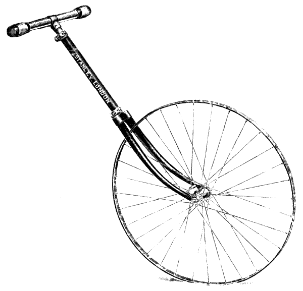
Fig. 371.
763.—Pedometer.—Used for roughly ascertaining distances passed over in walking. This ingenious instrument was the invention of William Payne in 1831 (patent No. 6078). It is the size of an ordinary watch, and has a similar face; but between the figures, which indicate miles 1 to 12, there[525] are four divisions only, to indicate quarter miles. The pedometer is slung up by a loop, Fig. 371, H fixed upon the handle, which in use is passed over the edge of the waistcoat pocket so as to keep the instrument in an approximately vertical position.

764.—The Registering Apparatus consists of a pendulum, Fig. 372, P placed horizontally by being supported by a delicate spring L to its highest position, where it rests against a stud. The action of the pendulum is caused by its following the motion of the body in stepping, until stopped by the foot reaching the ground, when the momentum attained by the pendulum carries it from its upper position of rest where it is sprung against the stop to its lower free position, where it is stopped by a screwed adjustable stud S, shown under it. The axis of the pendulum is free upon the axis of the ratchet wheel R. When the pendulum falls, a fine spring, fixed to its upper surface, drops its end into the teeth of the ratchet, moving over two or three teeth, which are held against retrograde motion by the spring pawl D. When the pendulum rises, the ratchet is moved forward the number of teeth that the spring at first slipped over. The ratchet is connected with a pair of geared wheels, not shown, the axis of the second of which forms the axis of the hand. In this manner each oscillation of the pendulum is communicated to the index hand. The ratchet is made with extremely fine teeth, so that by adjustment of the screw stud S a greater or less number of these teeth may be taken by one beat of the pendulum, and thus the mileage rate may be adjusted approximately to the step. This is done, however, very imperfectly, as the variation of the average steps of men amounts to one or two inches, and the difference from the number of teeth taken will scarcely indicate less than three inches in the step.
765.—Passometer.—This instrument was originally invented by the author as an improvement upon the pedometer (1868). The instrument, Fig. 373, is not intended to[526] indicate miles or any distance, it simply counts the number of steps taken. The action is just the same as the pedometer, but the ratchet teeth are larger and less liable to miss a tooth, as it is made to take one tooth only at a single step. The dial arrangement is entirely changed. The steps are numerically indicated by a separate hand which reads into the graduations up to 50 steps upon a small dial. Each revolution of the small hand reads through gearing one division of the central hand, which moves over the complete circumference of the dial, reading up to 25,000 steps. This is the extent of indication. It is necessary in continuation beyond 25,000 steps to take a record of progression per 25,000 where a greater distance is required to be measured.
766.—The average step may be estimated perhaps within 1 or 2 per cent. by training in walking several miles steadily, counting the steps, always remembering that we take shorter steps uphill and when we are tired. But the mean step of the individual under all the different circumstances is the only rule that can be followed.
Fig. 374.—Sounding chain.
767.—Sounding Chains used for coast surveys are generally made of iron, but sometimes of brass. They are usually made of 10 fathoms entire length. The links are 1 inch, and the feet are indicated by tellers. The form of teller designed by the author is shown in Fig. 374 for the 3. A leaden weight, similar to that shown Fig. 375, is used upon the end of the chain—of 28 lbs., for ordinary coast work, or[527] heavier if there are strong currents. The chain is contained in a strong wooden box.

Fig. 375.—Sounding line and weight.
A very elaborate apparatus with steel wire line has been made for deep-sea sounding by Lord Kelvin and others; but this subject is beyond the province of the present work.
768.—Sounding Lines, used for survey of shallow coasts and harbours, are made of water-laid line of fine green hemp, about ¾ inch circumference, Fig. 375. White tapes are inserted as tellers at every foot, and red tapes at every fathom. 3 to 6 fathoms are the ordinary lengths employed. If the water is shallow the fathoms are easily counted, but if thought necessary knots may be tied to indicate the number of fathoms on the red tellers. The weight is about 7 lbs. for 50 feet line, about 15 lbs. for 100 feet. The under side of the weight is commonly recessed to take tallow when it is desired to bring up a specimen of the bottom, if this is loose sand or mud.
769.—Coast Survey Lines.—For surveying distances, from point to point of soundings along a coast, lines of fine copper wire rope marked with tellers at 50 and 100 feet are commonly used. The line is generally allowed to rest on the bottom of shallow water, and is floated up by means of[528] attached corks in deep water. It is usually laid and picked up by means of a reel fixed at the stern of the surveying boat. The lengths of line used vary from 1000 to 5000 feet.
770.—Telemeters.—These scarcely enter within the practical limits of surveying instruments, but as several attempts have been made to introduce their use it is necessary to mention them. The general attempt has been to measure a great distance, 1000 feet or more, by means of the angles subtended from the ends of a short base to a distant point. This base in the telemeter of Piazzi Smyth is 60 inches; Colonel Clarke, 72 inches; Otto Struve, 73·5 inches; and Adie, 36 inches. The angles are usually taken upon the principle of the sextant by coincidence of image. Very much greater success has been attained recently by Messrs. Barr and Stroud by means of their range-finder of 54 inches base. The author, as far as his information reaches, is assured that no instrument of the class is satisfactory for surveying purposes. Further, the subject is one to which he has devoted some study, and designed two telemeters.[55] One of these appeared to him for a time satisfactory within certain limits. The base in this instrument was 50 feet, formed of a fine pianoforte wire stretched between two observing telescopes, the tension of the wire directing the one telescope to a right angle, and the other telescope to an arc which read either degrees and minutes or absolute distances in the eye-piece to the direction in which the telescope was pointed. In first trials this instrument was found fairly satisfactory; but subsequently in windy weather the deflection of the wire rendered the action of a pair of instruments quite unreliable.
There are some instruments, as Colonel Gautier's telemeter used in the French army, which depend upon combined reflectors placed normally at 15° to 45°, as in the apomecometer, art. 693, but with a tangent screw to give a [529] small motion of displacement to one mirror which reads on a scale of calculated distances to angle from a certain base measured between two stations of observation. A very similar instrument, invented by Labez, has one reflector only at 45°. These instruments may be useful for measuring approximate distances for range in the army, but can scarcely rank as surveying instruments, the box sextant, art. 664, being in every way a superior telemeter for the purpose when a measured base can be fixed and well-known trigonometrical calculation used.
771.—The simplest and best telemeter for surveying purposes is the subtense telescope, and all good, up-to-date surveying instruments have their telescopes so fitted, but for those who do not carry an instrument with a telescope the reviser has designed a small subtense telemeter, Fig. 376, which consists of a small telescope fitted with subtense points, and mounted in a collar which has vertical and horizontal motions and a centre socket to fit a Jacob's staff. The stadia is set to read 1 in 100. The telescope has rack and pinion focussing and may be revolved in its socket so that the stadia rod may be read held either horizontally or vertically. It is packed in a leather holster case, and a four-fold 10-feet spring-pointed stadia rod is supplied with it divided into feet, tenths, and hundredths.
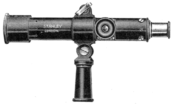
Fig. 376.
772.—Hand Rods, although used more generally by building surveyors, are extremely useful also to the civil engineer and land surveyor for town work among buildings and in mines. They are made 5 feet in length, less generally 10 feet. The 5-feet are made of single blades of lancewood or of two jointed to fold. The 10-feet are always jointed and made much stouter than the 5-feet. The 5-feet are generally sold in pairs.
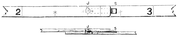
Fig. 377.—Ordinary 5-feet jointed rods—plan and section of joint.
773.—Ordinary 5-feet Rods are divided to every 3 inches, with feet only stamped with numbers, as shown Fig. 377. Where the rod is jointed the best form of folding joint is shown in the figure in section and plan. The spring S is sunk into the face of the rod at the joint on one side, and springs into a groove (housing) in the other side so as to lock the joint when it is either open or closed. The most useful dimension for the rod is 1 inch by 1/6 inch. Rods are nearly always made of lancewood, but they are preferred dyed black for neatness by many surveyors. A pair of rods is usually carried in a cowhide case. They are also often carried in the stem of a walking-stick hollowed out for the purpose. The rod or rods in this case are made much lighter, generally ½ inch by 1/8 inch for a pair of rods, or 7/16 inch by 7/32 inch for a single rod. The single rod is to be preferred in this case for its extra strength.
774.—Fully Divided Rods.—The author has made rods for many years divided to single inches. These measure from both ends—one end direct as Fig. 378 and the other end reversed by turning the rod over as Fig. 379. By this plan[531] the rod gives direct measurement in feet, inches, and parts from either end, and the division is always placed outwards against the work, so that measures may be taken from either end by turning the rod over sideways, without turning it end for end.
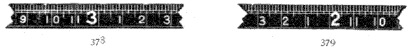
Figs. 378, 379.—Stanley's surveyors' rods.
775.—Connecting Link for Rods, which weighs only 1 oz. and may be carried loose in the pocket, is often found convenient for measuring heights, as it permits the ends of a pair of rods to be brought together, Fig. 380. By this means the arm will raise the rods about 7 feet, and with 10 feet, the height of the pair of 5-feet rods, this will make 17 feet of measurement. When the 10-feet is set against a wall, its height, if 20 or 30 feet, may be guessed very approximately by standing at a distance from it.

Fig. 380.—Connecting link for rods.
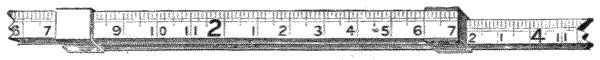
Fig. 381.—Slip jointed rod.
776.—Slip Jointed Rod.—This form is less general, but it is a very convenient form of rod. The jointing is effected by two loops which are fixed to the centre end of one part of the rod in such a manner that the other part may slide through the loops. When the rod is extended to 5 feet there is a stop which prevents further extension, and a spring to keep it at this exact position, Fig. 381. The outside of the rod is[532] divided into feet and inches. The inside is divided so that any addition to the half rod, produced by extending it; may give the measurement from end to end of the rod at this position, thus:—The half rod being 2 feet 7 inches closed, if the loose side be drawn out 19 inches the rod from end to end will be 4 feet 2 inches, which will be indicated by the division and figuring inside the rod. This is very convenient for measuring openings such as doorways or passages.
777.—Brace-piece.—A 10-feet rod is sometimes made with a brace-piece, which folds up inside the rod. This brace-piece is jointed to fix both half rods to 90° when it is desirable to use the rod as a square.
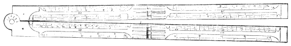
Fig. 382.—Civil engineer's rule.
778.—Civil Engineer's Rule is made fourfold in both boxwood and ivory, Fig. 382. The most convenient size is 1 inch wide. Some of the profession prefer them narrow for lightness—¾ inch; and some wide for strength—1¼ inches. This rule is generally well made, with German-silver joints and outside joint-plates. The divisions placed on the rule outside are inches in eighths and tenths; the inside, the ordinary architects' scales, 1/8, ¼, ½, 1, and four chain scales, 20, 30, 40, and 50. A 10 is got by halving the 20; 60, by doubling the 30. A protractor reading to 5° is divided on the head. With silver joints and in fine ivory this rule is often made a presentation instrument.
STATIONS OF OBSERVATION—PICKETS—FALSE PICKET—PERMANENT STATIONS—REFERRING OBJECT—HELIOTROPE—HELIOSTAT—HELIOGRAPH—SIGNALLING—MORSE ALPHABET—NIGHT LIGHTS—OIL LANTERNS—MAGNESIUM LIGHT.
779.—Stations of Observation vary materially according to the extent of the survey and its purpose. For geodetic works stations are raised at great expense, often in masonry or solid woodwork. For ordinary local or civil surveys the stations are commonly formed of single poles set up vertically, which vary in dimensions according to the extent of survey and the difficulties which may be encountered by various obstructions to direct visions by woods, lakes, marshes, etc. The apparatus that may be useful in the work of the civil engineer in ordinary practice will only be considered here.

Fig. 383.—Ranging pole or picket.
780.—Pickets or Ranging Poles, Fig. 383, as the name indicates, are used for ranging a direct line through a district, either by a series of poles sighted from one to the other or by being placed in position convenient for triangulating by the theodolite where the country is open, or free from many buildings, trees, or other convenient landmarks.
781.—The picket (Fr. piquet) is a straight, slightly tapering[534] pole shod with wrought iron or steel. It is generally made of about 1-1/8 inches diameter, and is painted in alternate feet red and white with an enamel paint that will not soil the hands or take dirt from them. The shoes should be made with strap-pieces, so that the picket, which is generally made of yellow pine for lightness, should not be liable to break off at the shoe in use. Fig. 381 represents the lower part of a picket as made by the author: B black, W white, R red. It is usual to have six pickets at least out in use with a theodolite in open country.
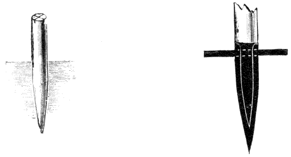
782.—False Picket.—For the placing of a picket it is usual to clear the sod with a small spade where possible, so as to suspend the plummet from the theodolite into the hole made by the picket to triangulate from its position. In marshy lands and under many conditions this is not easily done. It will generally be found more expeditious to carry about one of the author's false pickets, to place directly in the hole from which the picket is removed, which saves the trouble of removing the grass. This is shown in Fig. 384. It consists of a wooden peg, upon the top of which a cross is sawn to represent the axis. This cross is filled in with a veneer of ebony, and the whole is polished over to keep it clean. It will be readily seen that any picket accidentally broken will[535] make a false picket. In setting up the theodolite over it the plummet is brought to verticality with the centre of the cross. In moving the false picket the original one is easily replaced, if required, in the same position for continuing the work.
783.—Spur-shod Picket.—Much stouter poles than may readily be pressed in by hand, as for instance, of 2 inches diameter, may be driven into the ground by having a spur or cross-bar of steel, about 7 inches long and about 3/8 inch diameter, placed through the pole, say at 1 foot distance from the point, a form which is much used on the Continent. This picket may be jerked down for a certain distance by pressure of the foot on each side, and then jerked home to the ground by standing upon it, to make a 10-feet or 12-feet pole stand sufficiently rigid for temporary work, Fig. 385.

Fig. 386.—Socket for station pole.
784.—Permanent Stations are commonly constructed upon hilltops or other commanding positions. A very general way is to set up a long pole of fir or other wood at command, from 10 to 20 feet in height, according to the circumstances. Occasionally it is desirable to remove the pole and place the theodolite centrally over its vertical position. A very good[536] way to do this is to have a slightly tapered wooden socket, Fig. 386 S, constructed of stout boards, say 1½ inches thick, made into a hollow square with a cross of boards, WWWW fixed to it. The socket is placed in a hole dug out entirely below the ground, and is rammed in and fixed as an ordinary gate post. The pole P is squared at the end to fit the tapered socket up to shoulders which are formed by leaving the other part of the pole round. The socket for a 15-feet pole should be 18 inches deep; for a 20-feet one, 2 feet deep. Where these poles are properly prepared they may be jointed together in two or more parts for portability. Bunting flags, red and white, about 18 inches by 9 inches, may be fixed at the tops of the poles. In fixing the socket the pole should be erected in it to be able to keep it constantly vertical during the ramming. A plummet suspended at arm's length, at a distance from the pole in two positions at about right angles to each other from the centre of the pole, will provide a means of keeping it erect during the fixing of its socket. The socket hole, upon lifting the pole out, forms the centre for erecting the theodolite over its position.
785.—Referring Object.—It is desirable that all arcs taken by the theodolite from an important station should contain one point in common, for which the best defined object to be found at a distance may be selected. Colonel Clark, of the Ordnance Survey, recommends as a referring object two rectangular plates of metal placed with their edges parallel to each other in the vertical plane, at such a distance apart that the light of the sky seen through the opening appears as a vertical line of about 10″ in width. The best distance for this object is from 1 mile to 2 miles. Two pieces of board, fixed a small distance apart by ledges screwed thereon, answer the same purpose. The description fully conveys the method without illustration.
Stations Visible at Great Distances are formed by means of reflection of the sun's rays or by artificial light.

Fig. 387.—Stanley's heliotrope.
786.—Heliotrope, or heliostat as it is sometimes called, may be any form of mirror to throw the sun's ray in a constant direction or to a distant station at a time of day fixed for making observation. The instrument is uniformly constructed with a small glass mirror having a plane surface. The angle of divergence of the extreme rays in the reflection is the same as that subtended by the sun's diameter at the position of the mirror, that is, of about 32 minutes of arc. This divergence is sufficient to render the reflector visible at a great distance. The plan upon which the author has constructed this instrument is shown in Fig. 387. It consists of a reflector M formed of a plain glass mirror of about 5 or 6 inches in diameter, placed in a metal tray. The mirror is centred vertically upon an axis to which a worm wheel B is attached upon one side that works into a tangent screw which is moved by[538] a milled head so as to place the mirror at any angle to the horizon. The mirror and its vertical adjustment just described are carried by a fork which is erected from the base board of the instrument upon a socket joint which permits the mirror to be turned about. Upon the lower part of the fork above its socket another worm wheel is constructed centrally to the axis. This works into a tangent screw attached by fittings to the base board. The tangent screw has a long shank leading to a milled head A. By means of the milled heads the mirror may be set to any position, so as to throw the reflection of the sun in any required forward direction. A small hole is cut through the silver in the centre of the mirror to sight the position to which the sun's reflection is directed.
787.—The Base Board is of ¾ inch mahogany about 20 inches by 10 inches, and is supported upon a very firm tripod stand, like that described for a plane table, art. 700. At one end of the board a sighting screen of mahogany, 10 inches by 10 inches and ¾ inch thick, is hinged, so as to be held erect by means of a stay bar E. In the centre of the screen an opening is turned out 3½ inches diameter, and a frame-piece of half circle only is placed over this. The frame piece is grooved out at the back so as to hold discs, shown abc in the figure.
788.—The Discs abc, are of thin brass and have openings respectively ¼, ¾, and 1½ inches wide, so as to reduce the width of the line of light which appears through them when the reflection of the sun is thrown from the back. These have each a fine wire stretched across them to indicate the centre. A fourth disc, not shown, has a double cross of wires to indicate the centre only.
789.—To Pack the Instrument, the screen is turned down the index frame, falling into the opening F; the mirror with its fork is lifted out and secured to the surface of the base board by buttons; and the whole apparatus is put in a pine case. Its weight without tripod stand is 8 lbs.
790.—To Use the Heliotrope, the station on which the sun's light is to be thrown is sighted by looking through the small hole in the centre of the mirror, and adjusting the base board until the station appears in the centre space of the disc opening. The mirror is then turned towards the sun by means of the milled heads until its image, reflected upon the back of the screen, appears central with one of the discs which is intended to be used. All parts of the stand and fittings being made quite firm, the attendant moves the milled heads, as required, to follow the apparent motion of the sun, at intervals of five minutes or less. It must be observed that the centre of the slit in the disc represents the station visible to the observer. This point must therefore be plumbed to the station point in setting up the instrument. A part of the screen at P is cut away to admit of the suspension of a plummet.
791.—The heliotrope was much used in India for the great trigonometrical survey. Colonel H. Thuillier states from experiment that "A heliotrope of 9 inches diameter answers for 90 to 100 miles. For nearer distances it is much too bright to be observed through a telescope, and the light must be diminished in the following proportion. For distances of 2 or 3 miles (the usual distance of a referring mark) an aperture of 0·25 of an inch will answer, and for longer distances about 0·1 of an inch of aperture per mile of distance will suffice, viz., an inch for 10 miles, 2 inches for 20 miles, and so on, provided always the apparatus is carefully adjusted and the man who works is alert and skilful."[56]
Practically the discs here described will give all the variation required. In less favoured climates than India more opacity will be found in the atmosphere, and larger apertures required than those just stated.
Signalling with the Heliotrope.—A thin wooden bat D is [540] moved over and off the outside front of the open disc aperture, following the rule of Morse signals, which will be presently described for the heliograph.
792.—Heliostat.—Is a smaller instrument than the heliotrope, in which the mirror or mirrors are moved by clockwork, so as to keep the sun's reflection in a uniform direction throughout the day. This instrument is delicate and not generally well adapted to field work.
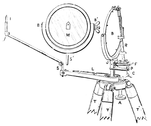
Fig. 388.—Heliograph.
793.—Heliograph.—This instrument is the invention of Sir H. C. Mance,[57] since improved by Major Macgregor, Colonel Bonham, and others. It is used for a military signalling apparatus, but it is also employed, on account of its portability in place of the heliotrope for surveying, where great precision by limiting the area of light reflection is not required. The construction of the instrument is shown in Fig. 388. B is the back of a plain circular [541] mirror of 5 inches diameter, supported upon pivots on a fork frame J, the lower part of which forms a socket. The socket is furnished with a thumb-screw to secure the mirror and its frame when placed upon a cone projecting from the apparatus connected with the base plate formed on the top of the tripod head. The cone is erected upon a disc or wheel cut at its edge in teeth and centred upon the axis of the tripod head. The wheel is revolved by means of a pinion connected with a milled head A which moves the mirror and the entire apparatus above in horizontal revolution.
794.—The Sighting Arm L is attached to a collar fitting projected from the tripod head. This may be fixed in any horizontal direction by means of the tangent clamping screw C. The arm L has a supplementary extension by the piece Sj, which is jointed at the position of these letters and also by a socket fitting into the arm. The termination of the extension is a sighting point I formed of a thin blade of metal. The arm and its fittings permit the sighting point I to be set in any direction or elevation to follow the inclination of the land.
795.—The Sighting Vane is a piece of white metal upon which there is placed a black dot termed the sighting spot. A small circle, about 1/5 inch diameter, is left unsilvered in the centre of the mirror, which does not reflect the sun's rays. It therefore causes a small disc of shadow in the centre of the reflection of the mirror, termed the shadow spot. The shadow spot is made to appear upon the sighting spot when the instrument is adjusted to throw the sun's image upon a distant station.
796.—The Supplementary Mirror M is similar to that already described, centred also on pivots and placed in a forked frame. This is mounted on a cone S′ which fits into a socket at S, when the extension arm J is removed. This mirror is intended to receive the image of the sun when placed towards[542] the back of the pointing of the instrument to throw the sun's image from the mirror M to B, to signal by double reflection, when the sun is at a forward angle to the distant station. The coincidence of reflection is taken with this mirror by the reflection of a piece of paper pasted on its centre of the same form as the index I.
797.—Telegraphing Apparatus, called technically flashing apparatus. This consists of a rod R hinged to the top of the mirror at its upper end and also to a lever which forms a Morse key at the lower end. The rod is formed of a screw of about half its length, which passes into a female screw tube so as to shorten or lengthen it as required to direct the reflection of the sun's rays by turning the milled head above R, which forms a part of the tube. The Morse key is hinged at J to the stem of the instrument, and is kept up to a fixed stop by means of a spring P extended by an arm from the stem of the instrument, so that pressure upon the disc F moves the key down to its stop P, and also tilts the mirror to throw its reflection off the observing station during the pressure. The flashing described by the jar of its action is liable to displace the mirrors. The use of the bat, shown at Fig. 387 D, is more certain for signalling words.
798.—The Tripod of the Heliograph TT′T″ consists of three circular mahogany legs 1-1/8 inches in diameter and about 4 feet 9 inches long. The legs are capped with sockets carrying collar-pieces which are attached to the tenon-pieces of the head. The head forms a box for the revolving apparatus and remains attached to it when the mirror apparatus and arm are removed. The tripod head is protected when out of use by a leather cap attached by a strap to one of the legs. The weight of the tripod is 6 lbs. In fixing the tripod for use it should have the legs extended nearly 60°, and the toes should be firmly pressed into the ground. At windy stations it is well to dig holes and[543] sink the toes, or to have a heavy stone suspended under the centre of the head.
799.—The Case for the Heliograph is made of solid leather, with separate divisions for mirrors, arm, and sight. A spare mirror is sometimes packed in the same case that the instrument may not be made useless by accidental breakage. A strap is provided with the case to go over the shoulder. The instrument weighs 5 lbs. complete in its case. Great care should be taken to observe the arrangement and position of the parts of the instrument before taking it from its case, as it is always packed closely.
800.—To use the Heliograph with a Single Mirror.—In this case the reflection is direct. The instrument is approximately directed by looking through the mirror from behind, moving the arm L and the sight I to cut the distant station, and then clamping the screw C. After this is done the exact position is found by placing the head nearly in front of the mirror, with the back to the distant station with which it is intended to communicate. Then to adjust the mirror, if required, and move the eye until the distant station appears reflected in the exact centre of the mirror. After this, without moving the head, finally to adjust the sight vane I until the reflection of the sighting spot is brought exactly in line with the centre of the mirror and appears reflected upon the image of the distant station. The sighting spot is then in direct line between the distant station and the centre of the mirror, in whatever direction or inclination the mirror may be afterwards placed to reflect the sun's image. Care should be taken not to disturb the stand nor arm in future movements of the mirror.
801.—To Adjust the Mirror, stand behind the instrument and adjust the vertical screw R and the horizontal pinion A until the black spot, as it appears on the mirror from the[544] reflection of the hole through it, is seen upon the centre of the point of the sight vane surrounded by a ring of bright reflection from the silvered surface of the mirror. The distant station will then receive the reflection, which must afterwards be kept constantly upon it by gently moving the screw R and pinion A, following the apparent path of the sun.
802.—To Use the Heliograph with Two Mirrors, which is necessary when the sun is shining towards the distant station and its image can only be projected by double reflection, the second mirror is placed upon the end of the arm in the socket S. This has a white paper vane cemented upon it, as shown at M. The mirror B is placed roughly facing the sun. The mirror M is turned towards the distant station upon which it is intended to direct the rays, being careful at the same time to observe that the two mirrors do not intercept each other's rays. Now from the back of the mirror M we look into the mirror B, moving the head until the centres of the two mirrors appear in a line with the eye. Then without moving the head, adjust the direction and inclination of M until the reflection of the distant station appears in the centres of the mirrors. Now clamp the mirror M in this position, from which it must not be moved so long as it is required to keep the same station in communication.
To keep the reflection following the sun a position is taken at the back of the mirror B, and this mirror is worked as before described, when it is used singly, by the milled heads, only that in the present case the paper vane M takes the place of the metal vane I.
803.—Telegraphing by the Heliograph.—The communication is made by the alternate pressure and release of the Morse key F, each pressure throwing the reflected image of the sun off the observing station. The Morse alphabet, which is universally used, consists of rapid touches represented by dots, and pressures of at least four times the time[545] of a touch represented by dashes. The following arrangement forms the alphabet:—
| A | · – | N | – · |
| B | –··· | O | – – – |
| C | –·–· | P | ·– –· |
| D | –·· | Q | – –·– |
| E | · | R | ·–· |
| F | ··–· | S | ··· |
| G | – –· | T | – |
| H | ···· | U | ··– |
| I | ·· | V | ···– |
| J | ·– – – | W | ·– – |
| K | –·– | X | –··– |
| L | ·–·· | Y | –·– – |
| M | – – | Z | – –·· |
The time between the words is double that of a dash. Many other signs are commonly used for figures, etc., for which the reader may consult The Manual of Instructions in Army Signalling. The same system is used for signalling by flags; and by stopping off light of lamps this system is most valuable for the surveyor in new countries for information of forward ground and other matters.
804.—Lights for Observations by Night.—Under many conditions an observation of a distant station may be much more conveniently and accurately taken at night by observation of a luminous object of limited area. For this purpose the arc light, lime light, blue signal light and others have been employed. For the civil engineer where regular stations are not erected, as with geodetic work, oil lights or the burning of magnesium ribbon are the most convenient.
805.—Oil Lanterns.—In the great trigonometrical[546] survey of India large reverberatory lamps were used, which were furnished with Argand burners with circular wicks about 2 inches in diameter. The back arc of rays was reflected by a parabolic reflector 12 inches in diameter and 4·9 inches in depth. The lamp was enclosed in a strong box with a plate-glass face 12 inches in diameter, with apertures to admit sufficient air and chimney to carry off fumes. The box was constructed to form a packing case for conveyance of the apparatus.[58]
806.—The oil lantern which will be found most convenient for the civil engineer will be one of the same form of construction as the bull's-eye lantern, but much larger—6 inches square is a good size. This may be made to go on the same tripod as the heliograph, and will take its place for signalling by night, or telegraphing by the Morse signals by the hand or bat shown Fig. 387, D. A 6-inch bull's-eye lamp with treble wick may be seen well in clear weather 5 miles to 10 miles off. A railway signalman's hand lamp forms a very good signal, or even an ordinary 4-inch bull's-eye is very useful in working over new countries.
807.—Magnesium.—The intense light given by burning ribbon magnesium, and the extreme lightness in weight of this material, render it of especial value for night signalling. Magnesium ribbon is now sold at a very low price (about two shillings per oz.), and 1 oz. will give a continuous intense light, visible at 30 miles, for over an hour, whereas for a night signal arranged to be given at a stated time, fifteen minutes is amply sufficient for a single observation. Great difficulty is often found in lighting magnesium ribbon when this is slightly oxidized from exposure to air. The best method is to employ the flame of a portable spirit lamp, made for the purpose. Under any condition the burning ribbon [547] should be shaded from wind. A common plan is to hang a straight slip of ribbon from the centre of a tripod which can be readily shaded by a pocket handkerchief. Where expense is not the object to be considered, lamps may be had for burning the wire. Tin cases are made for soldering up and storing the ribbon in for use abroad.
MEASUREMENT OF ALTITUDES BY DIFFERENCES OF ATMOSPHERIC PRESSURE—HISTORICAL NOTE—MERCURIAL BAROMETER—CONSTRUCTION—OPERATION—ANEROID BAROMETER—CONSTRUCTION—VARIOUS IMPROVEMENTS—HYPSOMETER.
808.—Historical Note.—The observation that the atmosphere decreases in density with increase of height is due to Alhazen the Saracen, about a.d. 1000. By this he explains that a ray of light entering the atmosphere obliquely follows a curvilinear path, bending towards the denser strata, that is concave towards the earth. He showed that a body will receive difference of pressure in a rare and a dense atmosphere, and calculated that the height of the atmosphere to its final attenuation would be from his data nearly 58½ miles. The practical instruments that have been devised for measuring altitudes, by the differences of pressure due to the weight of superincumbent atmosphere are the barometer, the aneroid, and the hypsometer. The barometer was invented by Torricelli about the year 1640. Its principle was demonstrated and first applied to altitude measurement by Pascal in 1647. The aneroid barometer was suggested by Conti in 1798, and said to be devised as a practical instrument by Vidie in 1808. The hypsometer or boiling-point thermometer, which depends for its boiling temperature upon the pressure of the atmosphere above the liquid which surrounds it, was suggested by Fahrenheit in 1724, experimented with by de Luc[549] in 1772, and brought to its present practical form by Regnault about 1840. At the present time the aneroid is almost exclusively used by the civil engineer, as this instrument when made with great care is sufficiently reliable, more portable, and not so delicate in use as the others. So that it is only when very great precision is desired, or when the one instrument is used as a check upon the other, that the mercurial barometer, or the hypsometer, or both are now employed. At the same time it must be understood that the aneroid barometer scale is in a certain degree arbitrary, as the divisions at best are only made up from a certain number of points taken from observations of the mercurial barometer placed simultaneously with the aneroid under an air pump, and therefore its errors comprise those of the particular mercurial barometer with which it is compared, and those due to the difficulties of the comparison, and of making subdivision afterwards in the same relative proportion, by copying to the scale of the aneroid.
809.—The Mercurial Barometer.—The principle of the barometer is generally understood. If a glass tube, closed at one end, 33 inches long, say of ¼ inch or over in bore, be filled brimful of mercury and the point of the forefinger be firmly pressed on the surface of the mercury, the tube may be inverted without the admission of air. If the covered end of the tube be now plunged into a basin of mercury and the finger slowly withdrawn from under the tube beneath the surface of the mercury, the latter will sink in the tube to about 30 inches above the surface of that in the basin—that is, if the experiment be performed at about the sea level. The empty space in what now becomes the top of the tube is termed a Torricellian vacuum.
810.—In removing the pressure of the atmosphere from its surface in the tube, which in the above experiment produces the barometer, the pressure of the atmosphere then falls only upon the exposed surface of the mercury in the[550] basin, or what is technically termed the cistern. This pressure is equal per area, according to hydrostatic laws, to the upper surface area of any equal column of mercury that the barometer may contain. Therefore the weight of the column of mercury in the tube, if cylindrical, above the surface of that in the cistern, is the same as that of a column of air of equal size reaching upwards to the full height of the atmosphere. In fact the one exactly balances the other, and it is by the difference of the weight or quantity of air above the barometer per area of bearing surface that it is possible to ascertain the altitude of its position by means of the height of mercury in the tube, after proper allowance is made for sudden changes of conditions of the atmosphere itself from time to time, capillary attraction of the tube, temperature, etc.
811.—The mean height of the barometrical column in Great Britain, at sea level at the temperature of 32° Fahr., is about 29·95 ins. A cubic inch of mercury at this temperature weighs 0·48967 lbs. Therefore
29·95 × 0·48967 = 14·66 lbs.
gives the mean pressure of the atmosphere on each square inch of surface of the earth in this latitude. Nearer the tropics the pressure is greater, near the poles less. It can be shown that as the heights ascended by the barometer increase in arithmetical progression, the pressure upon the mercury diminishes in geometrical progression.
812.—Mountain Barometer.—The barometer used for measuring altitudes, to which the above term has been applied, is now made only upon Fortin's plan, in which the bottom of the cistern wherein the glass tube is plunged is made of fine, close-grained leather, the best for the purpose being a stout kid. The pores of the leather must be sufficiently fine not to admit of the escape of the mercury, and yet at the same time sufficiently soft and pliable to transmit the exterior pressure of the air. Fortin's construction permits the cistern to be closed entirely secure from leakage of the mercury,[551] in whatever position the barometer may be placed. The closing is effected by means of an adjusting screw, Fig. 390 F, which by its pressure decreases the capacity of the cistern and forces the mercury up the tube, or adjusts it to a given height, so that the scale of the barometer may be read correctly from a given point X placed within the cistern. To prevent injury to the tube the adjusting screw is made of a length just sufficient to force the mercury to fill it, so that when it is closed home there is no jar or percussion of the mercury in carrying the barometer. The details of the mountain barometer may be best followed by the illustrations.
813.—The Glass Tube is made of mild flint glass thoroughly annealed and sufficiently stout to resist all the strain and percussion that may occur with fair usage. One end of the tube is slowly sealed by the blow-pipe, so that the closed end may be as strong as the other parts.
814.—Mercury—Filling the Barometer Tube.—The mercury of commerce is generally impure, and it contains occluded air. For standard and mountain barometers the mercury should be distilled in an iron apparatus, at just its boiling heat, leaving about one-sixth of the mercury in the still. The tube, which should be perfectly clean, is left about 12 inches too long for the barometer. It is charged with clean mercury for about 36 inches in height. It is then boiled in a special circular charcoal stove, in the centre of which there is a vertical iron tube of 2 inches diameter. The barometer tube is introduced from the bottom of the stove, to heat about 4 inches of the top of the mercury only. The tube remains in this position till the mercury boils. It is then elevated for another 4 inches and again brought to boiling point, and so on until the end of the tube is reached. Under this process the air and some impurities rise to the surface of the mercury, and the tube is considered to be properly boiled. The end of the tube is then cut off to its proper length and inserted in the cistern,[552] in which there is left sufficient clean mercury to complete the barometer.
815.—The lower part of the barometer tube, after it is filled, is attached to a thin boxwood socket of about an inch in depth by means of hot thin glue. The socket piece is afterwards bound over with sewing silk, which is again covered with glue, and is finally varnished so as to form an elastic, secure fitting upon the glass. The socket-piece is secured to a wide boxwood collar, Fig. 390, D. Upon the under side of the collar an ivory gauge peg X is inserted, which forms the index point for reading the surface of the mercury in the cistern upon the Fortin principle.
816.—The Cistern.—The glass sighting tube, Fig. 390 H, of the cistern, through which the mercury and gauge point X are visible, is made about 1½ inches long and from 1 inch to 1½ inches internal diameter, the glass being 1/8 inch to 1/5 inch in thickness, ground square at its ends. The upper end of the glass fits upon the boxwood collar D, with the interval of an indiarubber band to make the fitting air-tight. The lower end of the glass tube fits upon the boxwood collar I, with an interval of a turned leather collar. The boxwood collar prolonged forms the lower part of the cistern. This has a second boxwood collar screwed upon it, to which the leather bag E is attached by silk and glue. A stout leather capping plug is glued upon the lower end of the bag, upon which the boxwood cap of the adjusting screw F presses for adjustment of the mercury, or to close the tube.
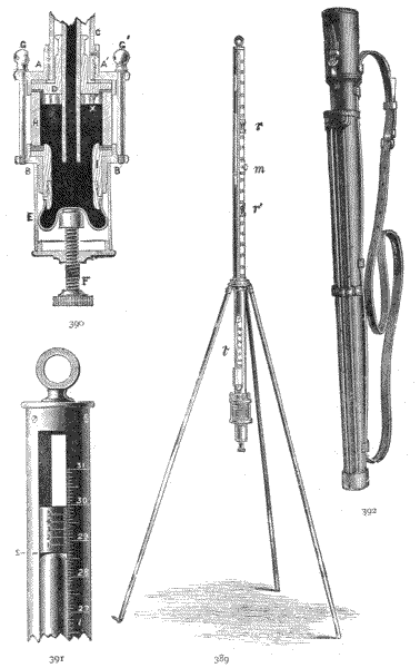
Fig. 389.—Mountain barometer erected for use.
Fig. 390.—Section through the cistern.
Fig. 391.—Vernier reading, showing gauge point S.
Fig. 392.—Sling case for carrying.
817.—The Cistern Casing, which is of brass, consists of
upper and lower collar pieces, Fig. 390 AA′ and BB′, and
their attachments. The upper collar is fixed to the casing
tube of the barometer. In the inside of this collar a leather
washer is placed, which comes above the boxwood collar on
the glass tube D and makes soft contact between these parts.
The lower collar has been partly described with the cistern.
This has a brass tube E screwed upon it, covering the
[553]
[554]bag and lower part of the plug of the cistern. The lower
closed end of the covering tube is formed into a nut for
the adjusting screw F placed in the axis of the tube.
There are four bolts or screws GG′ which bring the two
collars of the cistern casing towards each other, support the
lower part of this casing, and produce a pressure between the
boxwood collar on the barometer tube and the top of the glass
sighting tube with the intervening rubber collar, so that the
mercury at this point is secured.
818.—The Stem, or Barometer Casing Tube, is made of brass, about ¾ inch diameter. This has a slot, of about ¼ inch in width, down two concentrically opposite sides, from near the top of the tube downwards for about 20 inches. The tube is graduated along one open edge next the slot in inches and tenths, these being again subdivided to twentieths, and figured to read from 13 inches to 32 inches of mercury, as shown in detail for the upper part in Fig. 391. The same space is divided into centimetres and millimetres if metrical measure be used. Within the outer tube an inner tube of about 12 inches in length fits telescopically to move with a soft smooth motion. This inner tube carries one vernier at top and one at bottom, Fig. 389, rr′. The top vernier, shown Fig. 391, is placed above a slot in this tube which corresponds with the outer tube, so that the level of the mercury can be seen below the top vernier-piece at S. The verniers are divided into 50, so that, reading into the 20, they give reading 50 × 20, or 1000 to the inch. The inner tube carries a rack about 11 inches long, which moves by a pinion fixed upon a cock-piece, Fig. 389 m, on the outer tube in the same manner as before described for telescope racking, art. 96. Two stay-pieces placed over the outer tube hold the slots firmly at an equal opening. A ring is placed at the head of the barometer to suspend it in a room, to be used, if required, as an ordinary meteorological barometer, as shown at the top of Fig. 391.
819.—Mounting of the Barometer.—The barometer is mounted upon a tripod formed of three light tubes with steel points, as shown Fig. 389. These screw into a collar which is packed in the cap of the leather case. The collar has two opposite screws that screw into a second collar, which is also held by two opposite points at right angles to the first. The points of the screws form axes in the manner of a Hook's joint, permitting the barometer to take a vertical position by the superior gravity of its cistern and lower parts.
820.—The Thermometer, shown at Fig. 389 t, has its bulb brought as nearly as possible into contact with the glass tube enclosed in the casing tube. It is commonly divided with both centigrade and Fahrenheit scales. Correct observation of the thermometer is necessary to be made with every observation of the barometer, as the specific gravity of the mercury, and consequently the height of the column, depend partly upon this for its correct determination.
821.—The Packing Case, Fig. 392, is made of solid leather lined with thick felt to fit the barometer. The legs are placed in packings outside the case. In packing for carriage the screw of the cistern is turned nearly home, leaving only sufficient space for any probable expansion of the mercury from increase of temperature. The barometer should always be carried in an inverted position, as this precludes the possibility of air getting into it, and even tends to exclude, by the jarring motion of carrying, any air that may have accidentally become occluded. A strap is attached to the case for holding it over the shoulder.
822.—Reading the Barometer.—It will be observed that the mercury against the sides of the tube presents an upward curved appearance, due to the resistance of the glass to perfect contact, and the cohesion of the mercury in what is termed capillary action. This beading, as it is termed, varies according to whether the mercury is rising or falling. It[556] is always necessary before taking an observation to raise the mercury, by turning the screw F, until its surface just touches the peg X, to make observations uniform. The reading is taken by slowly lowering the index-piece by means of the milled screw until light is just excluded between the fore and back index surfaces, as shown Fig. 391 at S, at the highest point of the surface of the mercury. The inches, tenths, and half-tenths (·05) are read on the scale, and the thousandths on the vernier. Thus, suppose the scale reads 26·45 and the vernier 25 = 25 thousandths, the reading will be—
| 26·45 |
| ·025 |
| 26·475 |
For altitude the upper and lower stations are taken, and the difference subtracted for difference of barometrical scale.
823.—Difference in Altitude in feet taken from Barometrical Inches.—Complete barometrical tables for this comparison will be found in Molesworth's and other pocket-books in use by all engineers. It is therefore unnecessary to occupy our space with them. A very approximate rule may be given, which was proposed by Mr. R. Strachan in the Meteorological Magazine, as follows:—
"Read the barometer to the nearest hundredth of an inch; subtract the upper reading from the lower, leaving out the decimal point; and then multiply the difference by 9, which gives the elevation in feet. Thus:—
| Lower | station | 29·25 | inches |
| Upper | " | 28·02 | " |
| 123 | |||
| 9 | |||
| Elevation | 1107 | feet." |
824.—Capillarity.—For meteorological observations a quantity must be added to the reading equal to the resistance of the tube in capillary action to the rise of the mercury. This is greater in an unboiled tube than in one in which the mercury is boiled. For altitude measurements with a single barometer, or by two barometers with equal tubes, it may be neglected, as it will be equal in all parts of the tube. Where two barometers of different bores are used, the following table gives the correction:—
| Diameter of Tube in Inches | ·6 | ·55 | ·5 | ·45 | ·4 | ·35 | ·3 | ·25 | ·2 | ||
| Unboiled | Tube, | Inches | ·004 | ·005 | ·007 | ·01 | ·014 | ·02 | ·025 | ·04 | ·059 |
| Boiled | " | " | ·002 | ·003 | ·004 | ·005 | ·007 | ·01 | ·013 | ·02 | ·029 |
825.—Temperature Correction.—As the mercury increases in temperature it becomes specifically lighter, therefore rises higher in the tube under equal atmospheric pressure. The temperature is indicated by the thermometer, shown at Fig. 389 t. The expansion of mercury for 1° Fahr. is 0·000101; but the brass tube also expands 0·0000104, and it is the difference between the two expansions that we require, the mercury expanding about 7·15 more than the brass. If we subtract from the reading ·00014 of the observed altitude for every degree of Fahrenheit above 32°, the correction will be practically very near. Thus for a single reading—thermometer, 52° Fahr.; barometer, 30 inches
-(52 - 32) × 30 × ·00014 = ·084,
making the true reading 30 - ·084 = 29·916 inches at 32° Fahr.
Tables for correction without any calculation will be found in Molesworth's and other pocket-books.
826.—Gravity Correction.—The force of gravity decreases as we ascend to a higher level in proportion to the square of[558] the distance from the centre of the earth. It follows that the force of gravity as we ascend at the equator diminishes at a less rapid rate than at the poles. Its amount is always small—on an average it may be taken at about 0·001 inch of mercury per 400 feet of ascent.
Time.—Humboldt discovered that the barometer varied within the tropics at different hours of the day. This has also been found to be general to some extent in all countries, depending upon many conditions. It is only important for consideration of altitude measurements, that it is advisable if possible to take the upper and lower stations simultaneously by a pair of barometers for exact determination of altitude.
827.—Aneroid Barometer.—The first introduction of this instrument into England was by Pierre Armand, le Comte de Fontainmareau.[59] This instrument consisted of a vacuum chamber as its prime mover. The chamber was made a flat cylindrical box, with its upper surface of thin metal, with corrugations covering its surface in concentric rings. The chamber was filled with a number of spiral springs which resisted the pressure of air, to prevent the collapsing of the corrugated surface when the chamber was exhausted, and so placed the surface in equilibrium with the pressure it received from the atmosphere. The movements under various pressures were multiplied by gear work and levers so as to make a small movement of the corrugated surface evident in the extent of motion of an index hand reading upon a dial.

Fig. 393.—Stanley's civil engineer's aneroid.
The aneroid practically in its present form was devised by Lucien Vidie from 1848 to 1862.[60] In this instrument the vacuum chamber, which is a thin, flat, circular box, is corrugated equally on both sides, so as to obtain double area of active surface under atmospheric pressure to that of the older form. The chamber has its surfaces drawn apart by an [559] exterior spring, the point of communication or tension being placed at the centre of its corrugated sides only.
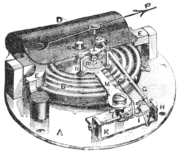
Fig. 394.—Perspective view of the interior of an aneroid.
828.—The construction of this aneroid is shown in Fig. 394, which is of a 4½-inch instrument, aneroids made for surveying being of two sizes, 3 inches and 4½ inches. A is a solid plate of metal 1/8 inch in thickness, termed the base plate; B the vacuum chamber, circularly corrugated on both sides, made of thin, hard-rolled German silver containing a large percentage of nickel.
829.—An axis is projected from the lower side of the chamber, of about 1/5 inch diameter. This is tapped with a screw and screwed firmly down into the base plate with a counternut. On the upper side of the vacuum chamber the axis is projected upwards to receive the tension of a strong, very flexible spring D above it, to be described. A bridge-piece EE of steel of strong section strides over the vacuum chamber. This piece has a stout arm-piece projecting from it towards A, which is secured to the base plate by a screw that is left open to a hole indicated near A through the outer case of the instrument, by means of which the bridge-piece can be rocked so as to produce more or less[560] tension of the spring D upon the vacuum chamber for final adjustment. The bridge-piece has two points of rigid support in right line, which form a primary—adjusted when the instrument is made—of the spring contra to the pull of the vacuum chamber. The main spring D is made of fine thin steel, carefully tempered, as broad as the chamber. This spring is constructed so that by its elasticity it may have sensitive movement under the pull of 10 lbs. to 15 lbs. per inch of active surface of the vacuum chamber. It is upon the perfection of this spring as much as upon the construction of the vacuum chamber that the sensitiveness of the instrument depends. The upper axis of the vacuum chamber is secured by a cross cotter pin C which gives an exact point of resistance and yet secures flexibility of the spring at the junction. This cotter pin is placed in the centre of the three points of support of the bridge-piece EE. A lever arm G is fixed to the main spring D upon a stout plate of metal which is in direct connection with the point of tension of the vacuum chamber. It is the small movement of this lever arm (about ·01 inch at the chamber) that gives motion to the indicating apparatus. The lever moves a cranked arm on the axis HK, which communicates through the axis to a second[561] cranked arm placed at right angles to the first I. This pulls a chain Q attached to the arm J. The chain is wound round a small drum fixed upon the axis which carries the hand near R. The drum keeps the hand in one direction contra to the pull of the chain by a hair spring R which is just sufficient to overcome the friction of the axis of the hand F. The hand and drum and their fixings are carried by the plate M, which is a light piece of brass projected from a stiff standard fixed from the base plate K. The compound lever apparatus described moves the point of the hand about five hundred times the amount of movement over the first fulcrum of the lever at the chamber.
830.—Compensation for Temperature.—This is a somewhat difficult matter, which is generally brought about by several modifications of parts. Some ordinary aneroids will move upwards about 1/10 inch of mercury by a rise of temperature of 8° centigrade only. This is caused principally by the increase of temperature softening the spring to render it less rigid, and the softening of the vacuum chamber to render it more flexible or sensitive to atmospheric pressure. Some little difference is also caused by the unequal relative expansion of the lever, arms, spring, and chain, these parts being of steel and brass. Compensation can be made in the lever arm G by making this curved and of two unequally expansive metals, as zinc and steel, so that the curvature increases with increase of temperature and the lever shortens. Compensation can also be partially made by making the base plate in two metals—iron and brass—so as to press the standards fixed through the two metals nearer or further apart with temperature changes. But the whole subject is too technical to be entered upon in our limited space, as it depends so much upon the construction of the instrument, which is modified in various ways by different makers in order to effect this correction.
831.—Dial and Hand.—From the delicacy of the structure[562] of the aneroid it becomes evident that no two instruments can be made to exactly the same rate of movement; therefore each instrument has to be separately graduated when it is intended to measure altitudes with it exactly. However close or open the scale may be, it becomes closer as greater altitudes are ascended, the density of the atmosphere as a gaseous fluid decreasing in geometrical progression as the altitude increases in arithmetical progression. From this we can understand that a vernier to the index hand can only read approximately, although it will act fairly well at a certain point of the scale. The best and possibly only correct method of dividing the scale is to put at first a false scale to the instrument, and to read this scale by the index hand with a microscope under an air-pump, compared at every half-inch of height of the column of the mercury by the gauge attached to the pump. When this is carefully done, a zero point is taken of the position of the index hand at the atmospheric pressure at the time, as indicated on the false scale. The proper scale, as it appears upon the dial, is divided from the position of the readings of the false scale, the two scales being superimposed upon a special dividing machine. The dial is afterwards figured and finished.
832.—The ordinary method of reading the aneroid is to let the index point read over the divisions. The author devised a plan, which he has used for many years, of fixing a small plate of aluminium upon the point of the hand, level with the scale, which is raised on a step to read it upon its inside edge, to a fine line on the aluminium. By this means error of parallax in reading is entirely avoided. The author also places an adjustable magnifier to move over the index for reading. This last improvement is now followed by other makers. A pointer also revolves with the outer rim to show the last reading before ascent or descent.
Instruments made with care in the points just indicated must necessarily become expensive. Where the aneroid is to[563] be used as a weather glass, or even as a travelling companion to judge of approximate heights in climbing mountains, such care is not needed, and the instrument may be produced very cheaply of useful quality. On the other hand, where precision is required, a delicately made aneroid will indicate a movement of 3 feet or less in raising or depressing, when holding the instrument horizontally in the hand and giving a light tap on the glass with the finger-nail before reading, so as to put all motive parts in equilibrium.
833.—The Altitude Scale is generally placed near the periphery of the dial; it is the all-important part to the surveyor. This scale is usually set out from a mean of atmospheric pressure at sea level, taken from Sir George B. Airy's tables, which give the extreme pressure of 31 inches barometric pressure for zero at sea level. With this pressure altitudes are taken at intervals according to the indices tested under the air-pump, and the intermediate divisions are graduated to scale. These index points are shown in the table below for a few points:—
| Height in Feet. | Barometer in Inches. |
Height in Feet. | Barometer in Inches. |
| 0 | 31 | 6000 | 24·875 |
| 250 | 30·717 | 7000 | 23·979 |
| 500 | 30·436 | 8000 | 23·125 |
| 750 | 30·159 | 9000 | 22·282 |
| 1000 | 29·883 | 10,000 | 21·479 |
| 1500 | 29·340 | 11,000 | 20·706 |
| 2000 | 28·807 | 12,000 | 19·959 |
| 2500 | 28·283 | 13,000 | 19·236 |
| 3000 | 27·769 | 14,000 | 18·535 |
| 4000 | 26·769 | 15,000 | 17·853 |
| 5000 | 25·804 |
It may be generally observed that the more open the scale the less altitude can be obtained by a single revolution of the[564] hand; therefore the more points can be taken per 1000 feet. Thus, with an altitude barometer reading to 3000 feet, readings can be pointed in construction at every 250 feet; with one of 6000 feet, at every 500 feet; and over this at every 1000 feet.
834.—Movable Altitude Scale.—In this the altitude scale revolves so as to be able to set it at zero for ascending from any point. As the barometrical scale diminishes, it is necessarily inaccurate, and cannot therefore be used upon a surveying aneroid; but the plan is pleasant for approximate measurements for amusement in making ascents. It is only mentioned here for the reason that the inaccuracy of the movable scale is not always recognised.
835.—Adjustment of the Aneroid.—There is a screw at the back of every aneroid somewhere under the point A, Fig. 394, by means of which an aneroid may be brought to the reading of a mercurial barometer at the position the mercury may be read. Where a good instrument has been set by the maker to a standard barometer, it is not wise to alter it frequently if it keeps in good working order for altitude measurements without being again set by a standard. On the other hand, however well the aneroid may have been made it works gradually to a slight change, caused by the smooth wearing of parts in action. It is well to have an aneroid, after one or two years' wear, cleaned and adjusted by the maker. It will then, if a good instrument, work well for many years.
836.—Directions for Measuring Altitudes.—Turn the outer rim of the instrument until the index carried thereby reads to the same point as the index hand. Raise the magnifier until the reading comes into sharp focus. Hold the instrument as nearly horizontal as possible, and tap the case lightly with the thumb-nail two or three times, so as to overcome any slight friction of its mechanism. This places the action of the works in equilibrium. Write down the observation as it now reads in the pocket-book, taking thousands[565] from the right hand (large figures), hundreds from the right hand (small figures), tens from the lines to the left of this, and units from observation of the position of the index line in the space between the last and the next line. Say this observation reads 2465. Whether we ascend or descend, the instrument acts similarly. We will now presume we ascend to the height we require to ascertain, and take a second reading, 1945; the difference between these numbers, 2465 - 1945 = 520 feet, is the number of feet ascent. It is necessary, where exact measurement is required, to take the reverse reading, as the atmospheric pressure may have changed. We now descend, taking the last observation, 1945, and find the reading at the first position 2463 instead of 2465, that is 2 difference, which proves that the atmospheric pressure has decreased. If we take half this difference = 1 and correct the first deduction, 520 - 1 = 519 will give us the correct measurement, subject only in this instance to the irregular possible fall of atmospheric pressure, which will not in many instances, if the times of observation have been nearly equal, be a quantity worthy of consideration. It is not necessary to make any correction for the height of the observer in positions above ground, as the instrument must be placed at a uniform distance from the eye to obtain the reading. In mines it will frequently be necessary to measure the heights from the ground at which the observation is made.
837.—Various Improvements in the Aneroid.—It is uncertain whether any great internal improvements have been made in this instrument, except by Vidie, at various times. Many attempts have been made to increase the length of scale to obtain more open reading. These attempts have all been in the direction of increasing the difference of space between the fulcra of the levers or by additional gearwork, producing thereby a greater multiplication of the small unit of displacement of the axis of the vacuum chamber beyond the normal × 500, which is already great. The multiplication has been[566] taken up to × 2000 or more. This increases the difficulty of manufacture and certainty of permanent action. Many of these plans were tried by Vidie and abandoned. A plan of Vidie's[61] of giving the hand three or four revolutions, and to register this upon a spiral scale upon the dial, also by counting on a second dial the number of revolutions, has been repeated with slight variation by E. T. Loseby in 1860[62] and by Major Watkin later. Vidie's plan of drawing back the hand to read the spiral has been modified also by Major Watkin in a manner which may be a little less frictional.[63]
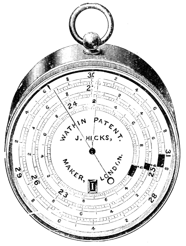
Fig. 395.—Watkin's extended scale surveying aneroid.
838.—Watkin's Extended Scale Aneroid.—This instrument is shown at Fig. 395, and has a very extended reading, consisting of three complete circles, in place of the usual single scale, with a hand or pointer sufficiently long to extend [567] across them all. In order to show clearly which circle of scales should be read there is an indicator attached to the movement of the instrument which causes a series of figures (I., II., III., corresponding with the three circles) to be exhibited through an aperture in the dial. For instance, when the instrument is in its normal state the hand will point to the first or outer circle, and the figure I. will appear and remain in the aperture until the barometer falls to 27·8, where the break takes place in the circle, as will be seen in the illustration. The hand then takes up the reading on the second circle (where the break appears at 27·8) and figure II. replaces figure I. in the aperture, remaining there until the barometer falls to 25, when the reading is transferred to the third circle, and figure III. appears in the aperture.

839.—Watkin's New Patent Mountain Aneroid Barometer.—This instrument, of which both a front and back view is shown above at Figs. 396 and 397, is the invention of Colonel H. S. Watkin. The special feature is that it can be put in or out of action as required, and when out of action is impervious to the influence of variations in atmospheric pressure. This relieves the strain on[568] the mechanism of the aneroid, as it is only put into action when a reading is required. The lower portion of the vacuum-box instead of being a fixture (as is the case with ordinary instruments) is allowed to rise, which is effected by attaching to the lower portion of the vacuum box a screw arrangement actuated by a fly nut on the outside of the case. Under ordinary conditions this screw is released, and the vacuum-box put out of strain. When a reading is required, the fly nut is screwed up as far as it will go, thus bringing the instrument into the normal condition in which it was graduated.
It has an aluminium case for lightness, is made in two sizes (3 inch and 4½ inch), and has a sling leather case.
These plans are again on their trial. It is the author's opinion on the subject, knowing the delicacy and skill shown in Vidie's work, that little improvement is likely to be obtained by magnification of the small motion of the vacuum chamber by mechanical means, which must necessarily be by a process both delicate and highly frictional. Attempts, he thinks, may otherwise be successfully made in the magnification of the small motion of the hand in a frictionless manner by optical means to obtain clearer definition.
840.—An improvement was made in the aneroid in one direction by the late Thomas Cooke[64] by replacing the chain by a thin gold band upon, and leading from, the drum. This obviated the small difference of rate of displacement due to separate jointed links as they leave the tangent of the drum. It is said, however, to cause a little springiness at this point, where it should be very dead, which somewhat minimises the improvement; so that it has not been very generally adopted.
841.—Bourdon's Aneroid, invented by C. Bourdon in 1849.[65] The motor of this instrument consists of a flat, oval tube bent into a circular form. This tube opens to [569] greater and lesser curvature by difference of external pressure upon it. The small motion given at one free end of the tube is multiplied up by gearwork. This instrument is found to act most delicately as a steam gauge; but experience has shown that it is not so sensitive or durable for indicating atmospheric pressure as the vacuum-chamber aneroid last described.
842.—Hypsometer, or Boiling-point Thermometer.—That water or any other liquid boils at a certain temperature, according to the amount of atmospheric pressure surrounding it, is easily observed by placing a cup of boiling hot water under the receiver of an air-pump. At first the surface will remain still, but as the pressure of the air is pumped off it may be made to boil time after time until it arrives at a low temperature. The temperature at which the water boils as the air is rarified may be easily followed by observation of a thermometer immersed in the cup of water; and at the same time, if a barometer be placed in connection with the receiver it will indicate the pressure, from which the scale of differences may be practically made. For the civil engineer this instrument, accompanied by the aneroid, is in every way superior to the mountain barometer, which must necessarily have a three-feet tube, as the hypsometer is much lighter, more portable, and less liable to injury, and perhaps, from the uncertainty of keeping a pure vacuum in the barometer, safer as a means of observation.
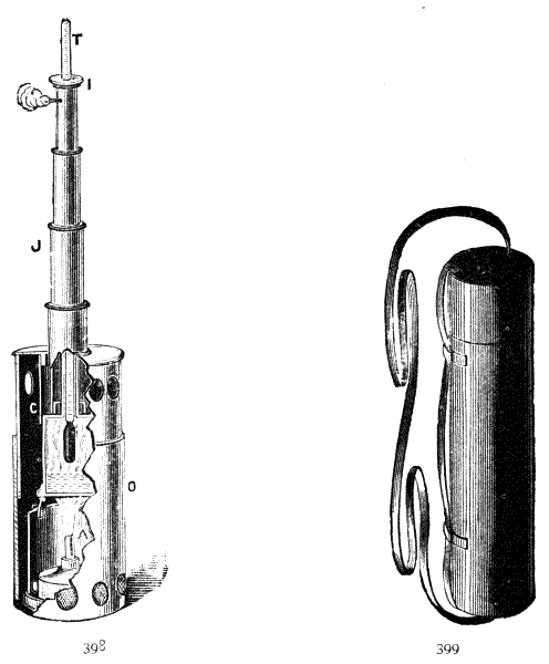
843.—The modern form of instrument is shown in Fig. 398. The boiler shown immediately over the lamp is filled about half full of rain water by lifting off its covering tube C. The covering tube has a smaller tube, about 3 inches long and ½ inch diameter leading upwards from it, through which the thermometer bulb is passed into the boiler. This tube is covered by the jacket J, formed of four telescopic tubes that are extended, as shown in the figure, for use, but which close up quite compactly when the instrument is put in its case. The upper drawer of the jacket tube is about[570] ¾ inch diameter, so that the tube enclosing it passes over the leading tube when the apparatus is closed. The lamp, which is filled with pure spirit, draws out from the bottom of the outer casing O. It carries a wick holder with screw cap, and this again has a covering cap to secure the spirit perfectly when the instrument is carried about. The inner casing A is perforated with holes to admit air at the level of the body of the lamp. When the lamp is lighted and complete for use it is placed vertically in its outer case O, which is jointed in two parts and perforated by large holes surrounding it top and bottom: the bottom holes are covered with wire gauze. By[571] this arrangement the flame is not seriously disturbed by wind or rain.
844.—The Thermometer, upon which the action of the instrument depends, has a stout stem about 6 inches long and ¼ inch diameter, with a very fine, flat, oval bore about ·01 inch wide and not much over ·005 inch in thickness. The stem is divided very openly for about 25° below 100° centigrade, each degree being subdivided into 10, below 212° if Fahrenheit scale be used, with each degree divided into 5. The divisions are filled in with lamp-black, and the stem is backed with white enamel to give clear reading. The thermometer T when in use is surrounded by a vulcanized indiarubber collar I which slips over its stem to adjust it to position in the boiler tube as shown.
In placing the thermometer in its jacket, it is important to hold it erect to be sure it passes into the leading tube from the boiler, as there is generally just room for it to catch by the side of this tube, where if it were pressed down it would break the bulb. When the thermometer is out of use the rubber collar is removed, and the thermometer is placed in a tubular metal case which is lined with indiarubber tubing, so that no jar can injure it.
The whole apparatus when closed is carried in a solid leather case, which contains divisions for the separate parts of the apparatus, and a strap for passing over the shoulder for carrying it. Fig. 399 shows the general form of case.
845.—Use of the Hypsometer.—Saussure calculated, from data of his ascents of Swiss mountains, that the temperature of boiling water decreased 1° centigrade for every 978·5 feet of ascent, where the mean temperature of the atmosphere was estimated at 0° centigrade, or freezing point. If the temperature of the surrounding atmosphere be taken as 5·5° centigrade, the ascent per degree of that scale is 1000 feet. This becomes, therefore, the most convenient data to calculate from, allowing 3·9 feet per 1000 per degree centigrade for[572] temperature above or below 5·5° centigrade at any two stations of observation, of which the difference of level is required. Thus:—If at the first station the temperature of air be 15·6 centigrade, the boiling point 95·5° centigrade; second station temperature of air 14·1° centigrade, boiling point 94·2° centigrade, the barometrical pressure of the lower station being taken as a constant, or referred to the aneroid for correction; then 15·6° - 5·5° = (9·1) (3·9) = 29·2 + dif. 95·5 - 94·2 = (1·3) (1000) = 1329·2 - dif. external temperature (15·6 - 14·1) (3·9°) = 1323·4 difference of level in feet.
Sometimes the thermometer is divided to Fahrenheit degrees, subdivided into 5 to read by interspace and line to ·1° F. This may be changed to centigrade for use of the above formula by taking 32° F. lower than the reading and multiplying by 5/9. Thus—
60° Fahr. = 5/9 (60 - 32) = 15·55° centigrade.
The calculation proposed by Lefroy is, however, simpler for Fahrenheit scale. To allow for diminution of boiling temperature, with height from 212°, with barometer at 30 inches, take 511 feet of altitude for the first degree and add 2 feet for each succeeding degree. Thus, taking height of first station = h corrected for 212° Fahr., 30 inches barometer, remembering decrease of barometrical pressure acts the same as increase of height. Then—
| 211° | boil point | h + 511 feet. |
| 210° | " | h + 511 + 513 = h + 1024 feet. |
| 209° | " | h + 511 + 513 + 515 = h + 1539 feet. |
MISCELLANEOUS SURVEYORS' AND ENGINEERS' INSTRUMENTS, APPLIANCES, AND ACCESSORIES—CROSS STAFF—MECHANICS' LEVELS AND CLINOMETERS—BONING RODS—FOOTNER'S RAILWAY GAUGE—GIRTH STRAP FOR TIMBER MEASUREMENT—GIRTH TAPES—TIMBER MARKER—SLASHING KNIFE—BILL-HOOK—RECONNOITRING GLASS—TELESCOPE—SUN SPECTACLES—WHISTLES—PIONEER TOOLS—SKETCH BLOCK BOOK—CAMERA—GEOLOGICAL TOOLS—WEALEMEFNA—OPISOMETER—BOUCHER'S CALCULATOR—SLIDE RULES—FULLER'S CALCULATOR—ENGINEERS' POCKET BOOKS—CHRONOMETER—OUTFITS.
846.—Cross Staff.—Those of Tycho Brahé and of Gunter were very elaborate affairs, consisting of a pair of notched cross-bars sliding on a divided rod which gave directions to form any angle in a quadrant from the eye by sliding the bars further from or nearer to it. The surveying cross staff, after better instruments were invented to take angles, became a cross at right angles, sawn upon a disc of wood and supported upon a staff which was pressed into the ground. This was used by looking along the saw cuts to take offsets to the chain, and for setting out buildings. The fixed cross-head was much improved by making it a cross of metal with turned-up ends, down the centre of which vertical saw cuts were made at right angles, Fig. 400. This, in the author's opinion, is still the best form.
847.—Cylindrical heads superseded the open cross-head.[574] The modern instrument in use is the French form, Fig. 401, which is made of octagon brass tube. This is cut with alternate sight slit and opposite window, with vertical hair on each of four rectangular sides of the octagon. On the other four sides there are plain slits subtending 45° to those first mentioned. The octagon tube is mounted upon a socket-piece which fits upon a conical pointed staff. The defect of this cross-head is the closeness of the slits, due to the small diameter of the tube, which renders the direction given for sighting uncertain.
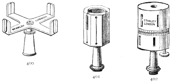
Fig. 400.—Open cross-head.
Fig. 401.—French form.
Fig. 402.—Adjustable cross staff head.
848.—Adjustable Cross Staff Head.—The cross staff head is sometimes made cylindrical, in two parts, Fig. 402. The upper part is centred upon the lower so that the upper series of sights move to any angle in relation to the lower. In this construction a wheel is cut about the axis of the upper part, which works into a pinion in the lower part, so that the upper part may be revolved horizontally by it. The meeting planes of the two cylinders are divided, the lower into degrees and the upper with a vernier. The vernier is almost an unnecessary refinement, as the sighting distance from slit to hair is only about three inches, and no very great exactness can be obtained in the sighting. This instrument has commonly a magnetic compass upon the upper surface. It is about as expensive as the semi-circumferenter, shown Fig. 232, p. 347,[575] and very inferior to that instrument owing to the extreme closeness of the sights. Its use is obvious.
Many of the following articles, briefly described, may be beyond the direct province of this work; but the utility of these implements for completing the equipment of a surveyor or engineer for special work it is hoped will be sufficient apology for their introduction. The subject can scarcely be treated except in a desultory manner.
849.—Mechanics' Levels.—In crowded Eastern cities, in levelling through close passages, in many cases the surveyor has to resort to mechanical levelling to carry his levels through. Mechanics' levels are too well known to need much description. The ordinary good kinds are made from 6 inches to 18 inches long, generally of rosewood, as this wood is very hard and stands well. They have a brass plate at the top, and tips of the same metal at the base. The illustration, Fig. 403, is of a 12-inch level. The level tube, which is of blown glass, is fixed in plaster of Paris, and the upper plate screwed down over it.

Figs. 403, 404.—Mechanics' Levels.
850.—The Author's Hand Level is shown Fig. 404—12 inch. This is made of a casting either of iron or brass. The level tube is ground to curvature and is somewhat superior to the ordinary run of this class of work. The level tube is fitted with ball socket at one end and stiff spring fitting[576] at the other, which is adjustable, so that the tube may be easily replaced if broken.
These levels are commonly fixed upon a stout fir straight-edge of about 5 feet to 10 feet in length by the lugs at the ends. The level is taken by blockings upon the ground. Corrections of error, both in level and straight-edge, may be made for any considerable distance by reversing the forward and backward position of the level with its straight-edge alternately.
851.—Square Level—Circular Level.—Fig. 405 represents a very useful class of level for setting up some instrument stands, plane tables, etc., in which a pair of level tubes are placed at right angles to each other. It is generally made very small—1½ inches square only. A circular level, the upper surface of which is formed of a worked concave glass, was lately very popular, and is still used to a small extent. As the spirit cannot be hermetically sealed in, it evaporates, and this level soon fails. Mr. J. J. Hicks has taken out a patent for a hermetically sealed circular level, described p. 96, which appears to answer very well.

852.—Incline Level.—For laying railway rails and drainage works the bubble is frequently made adjustable by the tube in which it is contained being hinged at one end and fitted in slides to rise with a screw at the other end, as shown Fig. 406. A scale of percentage of inclination S is commonly divided upon the adjustable end. The tube is raised or[577] lowered by the key A, which is removed after setting and cannot be tampered with.

Fig. 407.—Stanley's sight for mechanics' levels.
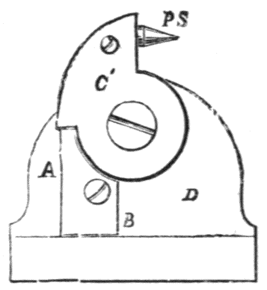
Fig. 408.—Section.
853.—Sighted Levels.—A mechanic's level is commonly made with a hole longitudinally through it of about ½ inch diameter, closed at one end, except a small hole of 1/30 inch or so, and a cross upon a piece of glass at the other end. This plan permits a sight to be taken through it which gives an approximate level. Occasionally the same form of sight as that described is hinged on the top surface at each end of the level. The author has found a better plan of sighting to be given by a pair of sights placed on a centre upon the ends of the level to turn up when required for use, as shown Fig. 408, P S one of the pair of points. This, when turned up, shoulders on the stop-piece A B. The stop-piece is made of sufficient thickness to admit the point in the hole near B for protection when it is folded away out of use. The section of[578] the level, as shown by the end view D, is the same as that of the level, Fig. 404. Very fair accuracy may be obtained by making these sights appear coincident upon a distant staff or rod.

854.—Boning-Rods, Fig. 409. These are very commonly employed with mechanics' levels. They are made somewhat like a stout T-square of 3 feet to 4 feet in length, about 3 inches in width, and ¾ inch in thickness both of the stem and head. They are at first placed at a distance apart, 9 or 10 feet, and a straight-edge of this length is laid from one to the other, upon which the mounted level is afterwards placed, the boning-rod being tapped down in the ground till the bubble is in the centre of its run. A third boning-rod is then placed at the same distance as the first pair, and the straight-edge with the level upon it is reversed end for end. This, if the work be fairly down, leaves the two outer boning-rods level, however imperfect the straight-edge and level may be, if the run of the bubble be taken correctly. By removing the central boning-rod from the outer pair of rods, levels may be continued by sighting over them, or boning forward as it is termed. On the Continent boning-rods are commonly fixed by driving a separate standard into the ground, which has a pair of brass slings by its side to hold the rod, Fig. 410. This[579] is a much neater plan than that in common use of blocking the rod up with stones. Boning-rods are also sometimes used conveniently with a proper surveying level, from the tops of water-pipes, etc.
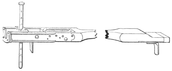
Fig. 411.—Footner's railway gauge and clinometer.
855.—Railway Gauge, combining level and clinometer. This high-class gauge, Fig. 411, is the invention of Mr. H. Footner, C.E., late of the London and North-Western Railway. It is formed of a bar of Spanish mahogany neatly shaped. The end fittings are of steel. The gauging part is formed of two turn-up steel flap-pieces with back stops. A spirit level is sunk in the end fitting, shown in the figure towards the left hand. The clinometer is formed by a gun-metal pin of ½ inch in diameter; 9 inches long. This slides perpendicularly in a spring fitting sufficiently stiff to support the gauge, and is made to fall on the centre of the rail. The pin is divided into inches and eighths. When it is out of use it slides up the end of the gauge and leaves the whole instrument smooth and portable to carry open or go into a leather case. Its use is implied.
856.—Timber Girth Strap.—The direction for removal and estimate of the value of timber often falls into the hands of the surveyor. The height of standing timber may be taken by a long rod, or a pair united by a link, art. 775, or by the apomecometer, art. 693. The girth is most conveniently taken[580] by a leather girth strap, of which there are various patterns: but that illustrated below, Fig. 412, is perhaps the most popular form. This strap is made of two straps of bullock's hide 1 inch wide, thinned down to about 1/8 inch in thickness; the two pieces are stitched together to make it 12 feet to 14 feet long. The strap is divided by lines into inches, but figured in units at every 4 inches = single inches of quarter-girth. The figures and lines are stamped. A brass weight, shown at one end of the strap, is thrown by the strap with a swing round the standing tree, and encompasses it in a second of time. The weight is caught by the hand and the strap brought up to it to read the quarter-girth. The quarter-girth gives roughly the equal sides of a square; as, for instance if a quarter-girth reads 10, the size of the tree is 10 × 10 = 100 inches, or 8·4 cubic foot-inches per foot run.
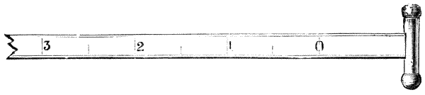
Fig. 412.—Leather girth strap with throwing reel.
Some surveyors prefer a hook instead of a weight, as being more convenient to measure close timber. This is shown Fig. 413. The hook is stuck into the bark and the tree is girthed by walking round until the hook is met.

Fig. 413.—Leather girth strap with clutch hook.
857.—Girth Tapes, similar to measuring tapes, Fig. 349, p. 506, are occasionally used, but these are more convenient for felled timber. Tapes for the purpose are made from ¾ inch to 1 inch wide, and 6, 12, and 24 feet long. They[581] have the ordinary feet and inches on one side and quarter-girths on the other.
It is customary to allow 1 or 1½ inches, and sometimes more for bark, according to the species of tree and the custom of the country.
858.—Marking off Timber.—For this a special tool with a gouge point, Fig. 414, and strong buck-horn handle, termed a timber-marker, is used for standing timber intended to be felled. The contents of the tree are sometimes marked with the marker upon it if for sale, good bark allowance being made in cases of difficulty of extraction from the forest, etc. A plain knife is usually put with the marker, which is useful as a food knife.
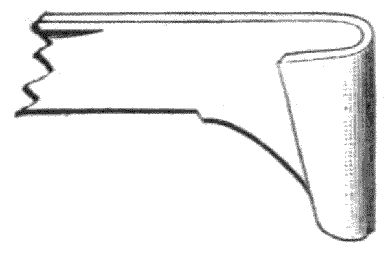
Fig. 414.—Timber marker, nearly full size.
859.—The author makes a very small, neat surveyor's knife, with marker, for the waistcoat pocket, Fig. 415, which combines—M tree marker (small); S screw-driver for small screws of instruments; P tommy-pin for turning capstan heads; F file for sharpening lead of pencil, when this is used for the field-book; and E R two penknife blades. The knife is similar to the author's architect's knife, which is well known. The tree marker is not strong enough for constant work.
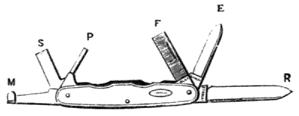
Fig. 415.—Surveyor's pocket knife.
860.—Slashing Knife—Bill-Hook—Axe.—In new countries where sight way has to be obtained for the survey through forests and jungles, one or more of the tools illustrated next is most valuable as a part of the surveyor's equipment. The slashing knife, Fig. 416, which is over a yard long, wielded by a strong man will remove light brushwood very quickly. Where the wood is close and of larger growth the bill-hook, Fig. 417, is better; and with thickset timber the axe becomes necessary. The well-known Canadian axe is found to be the best.
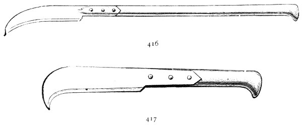
861.—Hedging Gloves—Iron Hooks for Climbing Trees.—For clearing land to avoid spines hedging gloves are generally used; these are made of soft horse-hide, and although pliable resist thorns to a great extent. Clutch hooks are also very convenient to climb trees, to look forward for the easiest direction for sight way.
862.—Rods for Measuring Standing Timber.—These are generally made 25 feet long, jointed in 5 feet lengths, similar to a fishing rod, but much stiffer. The rod is set by the side of a tree to be measured and observed from a distance where the first breech cuts its length.

Fig. 418.—Reconnoitring glass, India pattern.
863.—Reconnoitring Glass.—At present it is customary to use a binocular field-glass in preference to a telescope. The telescope gives greater penetration from its[583] higher power; the field-glass is preferred for its wider field of view. The field-glass the author has supplied to the Indian Government has neutral-tint glasses centred on the eye-pieces to take off the glare when looking towards the sun, Fig. 418. These have also hinge joints between the pair of bodies, which permit adjustment of distance of centres to the distance of the eyes. The object-glass should be 1¾ inches, not over this. Where a telescope is used, the 30-inch—the original, not the present—India military telescope is to be recommended, Fig. 419. This is portable, has a sling case and a good 2-inch object glass. For lightness, aluminium bodies are preferred by many for both field-glasses and telescopes; at[584] present the price of this metal is very low, so that it is probable it may become in a short time general for the purpose.
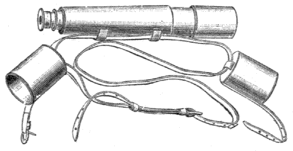
Fig. 419.—Army telescope.
864.—Prism Binoculars.—These will be found a great improvement on the old form of field-glasses, as owing to the optical arrangement a high power is obtained combined with a larger field of view and good illumination. Fig. 420 shows the most modern form with all refinements; hinged body, central focussing and separate focussing to suit each eye. It has a very compact and strong body, and the size magnifying 8 diameters or about 64 times weighs only 13 ozs.

Fig. 420.—Stanley's prism binocular.
865.—Dome Spectacles—Bogles.—Spectacles of neutral tint are most comfortable for general wear in sunny or snowy countries. The dome or globular form is generally preferred. Where there is hot dust gauze sides are to be preferred. There is a very cheap form with gauze sides, which holds on the head by an elastic band, termed bogles. These are rather hot to the face, and the band after a time becomes sticky. The spectacle form is much better. The glasses are made in various shades to choice: some very dark or even black, the latter being made for viewing and tending arc lights.
866.—Whistles made very powerful are much used in exploring abroad to bring the party together, and for signalling generally by sound, using the Morse signals, art. 803.
867.—Pioneers' Tools.—A small set of these is often very useful to the surveyor in new forest countries. The common set consists of a claw-hammer, wood-chisel, stone-chisel, pincers, screw-driver, gimlet, and brad-awl. The leather case is 8 by 4 by 2½ inches; it weighs 1¾ lbs. with strap. This may be supplemented by a small American saw, cutting both edges, about 20 inches long, and the axe previously described, with a few pounds of wire nails. The tools serve for marking trees or rocks, erecting signals, temporary covers, etc.
868.—Sketch Block Book—Pocket Book.—In reconnoitring no better information can be given of a track than forward sketches from commanding station to station. Sketch books about 7 inches by 5 inches are generally found sufficient. The drawing-paper should be thin, and the pocket large enough to contain all the separate sheets as they are taken off by the penknife after completion from the block. The sketches may be made with pencil, or a fine fountain pen; or if the surveyor be a colourist a light box of moist colours and a water bottle will often leave pleasing sketches as reminiscences. Pocket-books with section lines to 1/8 inch or 1/10 inch scale are sometimes used to give approximate plans to scale of buildings, etc., where required, as well as the ordinary field-book record.
869.—Camera.—Recently the camera has been much used for reconnoitring. These are now made very light and portable to take ¼ plate or 3 × 3 inch films, either on rollers or in separate films.
870.—Cement Testers are made in various manners, generally to test the cohesion of the cement as a homogeneous hard body. Mr. Mann's cement tester, Fig. 421, goes on another principle—it tests the adhesion of the cement to[586] stone, which appears to the author to be its most important function; it is always hard enough.
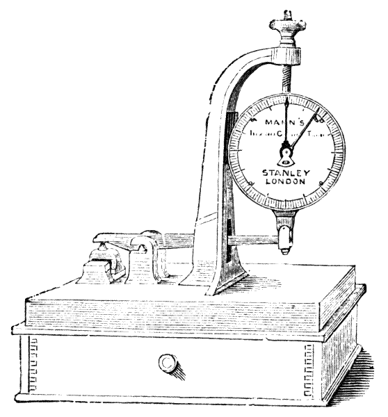
Fig. 421.—Mann's cement tester.
871.—Watson's Improved Vicat Needle is a most refined and accurate instrument for determining the time taken by cement in setting. The cement is placed in the circular container shown in the illustration, and the weighted needle is[587] lowered into it by means of the handle at the top. The depth of penetration is shown in millimetres on the divided arc.
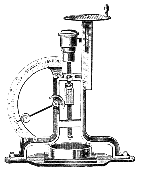
Fig. 422.—Watson's vicat needle.
872.—Geological Tools.—Acid-bottle—Blow-pipe—Touch-stone.—Where countries are prospected for railways it often becomes important to examine the rocks, both to detect the softer rocks for cutting and to find limestone suitable for mortar. A geological hammer, weight about 2 lbs. to 3 lbs., is the ordinary tool. This, with a chisel and sailcloth bag with strap, is all the necessary appliance. In searching for limestone a small bottle of sulphuric acid sewn up in a leather case is useful. A dipper is blown on the stopper of the bottle, and a single drop of acid will detect limestone by the bubble of froth it produces. Where minerals are to be examined, a small blow-pipe apparatus is necessary. This should be accompanied by a book of instructions. Where the surveyor has not been trained to use the blow-pipe, one with constant blast should be employed. For examination for precious metals a touch-stone and two-acid bottle—sulphuric and nitric—for silver and gold, are useful. The metal is merely rubbed on the stone and the acid applied. If the metal is base the acid removes it from the surface of the stone. If precious it removes other matter and leaves it visible.
873.—Wealemefna—Opisometer.—The wealemefna is a very neat form of space runner invented by Mr. E. R. Morris, which is found a very convenient instrument for measuring distances on maps in prospecting. It is very small and light, and may be, if desired, attached to the watch-chain. It gives distances run over in inches and eighths, to be afterwards calculated to the scale of the map, Fig. 423. The opisometer for the same purpose, Fig. 424, is formed of a spur wheel at the end of an ivory handle running upon a screw. This instrument gives measurement by reversing its run upon the scale of the map.
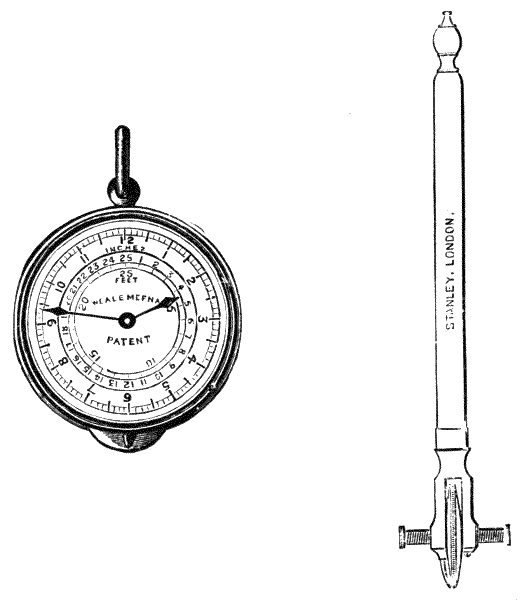
874.—Boucher Calculator, the invention of M. Alex. E. M. Boucher, engineer, of Paris.[66] This is one of the most convenient pocket calculators that a civil engineer can desire, being only of the size of an ordinary watch. The instrument was formerly made in France for this country in a very slovenly manner. It is now made in London by the author, of sound work and accurate centring, Fig. 425. It has face back and front. The front one, which is shown in the illustration, carries logarithmic scales of sines, numbers and square roots, and is made to revolve by turning the milled head placed under the handle, as the winder of a keyless watch. The back dial, which is fixed and does not revolve, has upon it a scale of equal parts giving the decimal parts of logarithms, and a logarithmic scale of cube roots. There are three index hands, one fixed on the side of the case over the front dial, [589] as shown in Fig. 425, and one on each end of the central axis made to revolve simultaneously over the back and front dials by means of the milled head at the side of the case. Any operation involving multiplication, division, proportion, powers or roots can be performed approximately with great rapidity by the aid of this calculator, and it is practically as simple to use as an ordinary slide rule, as will be seen from the following explanation of its use:—

Multiplication, using the second circle of divisions from the outside of the front dial:—Bring the first factor under the fixed index, set the movable index to 1, then bring the second factor under the movable index, and the product will be found under the fixed index.
Division is performed on the same scale as follows:—Bring the dividend under the fixed index, set the movable index to the divisor, then bring 1 to the movable index, and the quotient will be found under the fixed index.
For proportion the second circle is also used:—Set the first factor under the fixed index and set the movable index to the second one, then the proportionate equivalent of any number brought under the former will be found at the movable index.
Square roots, using the same scale:—Bring the number under either of the indices, and the square root will be found upon one of the two inner circles of the same dial.
Cube root:—In this case it is necessary to first bring the 1 on the front dial under the fixed index, then set the movable index to the number, and the cube root will be found on one of the inner circles of the back or fixed dial.
To use the trigonometrical dial:—Bring the needle of this dial over the angle of which the sine or tangent is required, and read upon the other dial (indicated by the needle) the natural trigonometrical line upon the inner circle, or its logarithm upon the outer circle.
The book of instructions supplied with the instruments, written by Professor George Fuller, C.E., for the author, gives all directions for working and also gauge points from which calculations are made as with the slide rule.
875.—In reduction of factors of a calculation collectively Boucher's calculator may take more than one turn or less than unity. The author has added a central index to record the number of turns. This is said to be of great value for the perfection of the instrument, Fig. 426.
876.—Slide Rules, of which there are great varieties, are of too complex a nature to discuss, except very briefly, in our limited space, particularly as general descriptions have been often given. The ordinary logarithmical scales of Gunter (1619), known as Gunter's lines, are placed upon most slide rules. The arithmetical lines are lettered A, B, C, D, and E. A and B are alike: these are technically termed double radius log. lines. They are used for all processes of multiplication and division. C and D are also alike and are termed single radius log. lines. They are used together for ordinary multiplication and division, and in conjunction with A and B scales for squares and square roots. The E line, not originally a Gunter's line, but found early in the century on several rules, is termed a triple radius log. line.[591] The numbers of the divisions on this line are the cubes of the numbers of the corresponding divisions of the D line, with which it generally works. All these lines work reciprocally together, performing the most complex calculations by simply setting them to numbers or gauge points of which given solutions are required, as for instance, the first four lines in combination give answers to such questions as:—To divide by a number two numbers multiplied together, one of which is squared; to divide the product of two numbers by the square of a third number, etc., each of which calculations is performed at a single setting. By inversion of the slide A to C the reciprocal of a given number is found, also the mean proportional between two numbers, the fourth term is inverse proportion, etc. Trigonometrical calculations are performed by the lines of sines, tangents, etc. Instructions are to be found in the books supplied with the rules, and as a part of many works. Among the most complete books may be mentioned "The Slide Rule," by R. G. Blaine, M.E., and "The Slide Rule," by Chas. N. Pickworth. These both contain very full information on the subject.
877.—The Slide Rules in most general use are A. Nestler's and A. W. Faber's. Both these well-known firms make a very complete series, applicable to a great variety of technical calculations.
878.—The reviser has recently completed from the designs of the author an entirely automatic dividing engine for these rules, which is the only one in existence.
A great number of slide rules are made for special purposes only: some of these are very useful to the civil engineer.
879.—Hudson's Slide Rules give strength of shafts, beams, and girders; pump duty; and computation of horse-power in engines.
880.—Honeysett's Hydraulic Slide Rule gives discharge of[592] water from channels and pipes of different forms and inclinations.
881.—Tacheometrical Slide Rules with scale of sine2 and sine × cos. for calculating the horizontal equivalents and vertical heights from tacheometrical observations. These are made either for use with instruments divided sexagesimally to 360° or centesimally to 400.
882.—Sheppard's Slide Rule has duodecimal lines, double reading, for squaring and cubing timber.
883.—Young's Slide Rule is designed for squaring and valuing timber simultaneously, which operations it performs in a very expeditious manner.
884.—Essex's Slide Rule is the best for calculating the rates of velocity and discharge from sewers, water mains, channels, and culverts of different forms, as it works with all formulæ.
885.—The Slide Rule of Prof. Geo. Fuller, C.E., Fig. 427, presents perhaps the highest present refinement of this class of rules, capable of greatly facilitating the numerous arithmetical calculations of the civil engineer. Its range is greater than most calculating machines, and besides the operations of multiplication and division, squaring and cubing, results requiring the reciprocals, powers, roots, or logarithms of numbers can be quickly and easily worked out by its use.
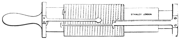
Fig. 427.—Professor Fuller's calculating slide scale.
The rule consists of an outer cylinder that can be moved up or down, and turned round upon the cylindrical axis which is held by the handle. Upon the outer cylinder a single spiral,[593] logarithmical scale is continued from end to end, the total length of which makes the scale 500 inches long. This is graduated into 7250 divisions. One index is fixed to the handle. A second index is attached to the inner tube blocked out by a flange to read upon any part of the scale; so that altogether there are three tubes which work together telescopically, by means of which the indices may be set to any position on the graduated cylinder. Stops are placed so that the indices may be brought to zero. By these means, the indices being set to any of the gauge points, the logarithmical scale, moving by itself, will maintain the same proportion for any numbers. In this rule a single log. radius is repeated by[594] coincidence of indices, so that its scale of divisions, 41 feet 8 inches long, if compared with an ordinary double radius slide rule, becomes equal to a slide rule of 83 feet 4 inches long. The ordinary 12-inch slide rule has about 80 divisions to each radius, so that it is easily seen how much more exact quantities may be brought out with a rule of 7250 divisions. It is a most valuable rule for calculations for the tacheometer. Copious tables of gauge points for civil engineers are printed upon the central tube, which is supplemented by a book of instructions. The value of this rule has been much extended by scales to facilitate subtense calculations, by Mr. W. N. Bakewell, C.E., in the "Fuller-Bakewell" slide rule.
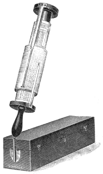
Fig. 428.—Improved Fuller's slide rule.
An additional improvement, as shown at Fig. 428, has now been effected in these instruments by adapting the case to support the rule when in use, thus overcoming the objection of being always obliged to hold it in the hand.
The use of Professor Fuller's rule is, however, confined to arithmetical computations. The numerical solution of formulæ comprising trigonometrical functions can only be performed by extracting, with considerable loss of time, the values of these functions from a book of tables. To do so requires a certain effort of mind with its consequent risk of mistakes. This limitation has restricted its use in a considerable body of calculations, such, for example, as in the computation of the co-ordinates of surveys from the lengths and bearings of their lines, a method of plotting which is very largely used by land surveyors at present; in astronomical computations; in civil and mechanical engineering, etc.; the use of logarithms being preferred on the score of speed, although the degree of accuracy attained with Professor Fuller's rule is amply sufficient in the large majority of cases.
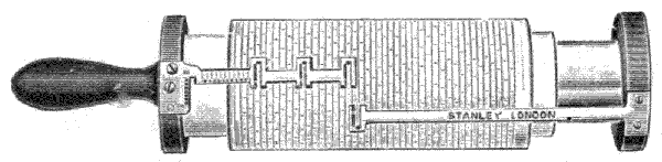
Fig. 429.—Barnard's co-ordinate spiral slide rule.
886.—The Co-ordinate Spiral Slide Rule has been designed to meet these requirements by Mr. H. O. Barnard, A.C.H., F.R.A.S., etc., Superintendent of Trigonometrical[595] Surveys, Ceylon, Fig. 429. Like Professor Fuller's rule, upon which it is an improvement, it enables the user to perform with speed and accuracy arithmetical computations involving multiplication, division, proportion, continuous fractions, powers, roots, and logarithms; but in addition, the natural and logarithmic values of trigonometrical functions of any angle can be determined by inspection with the same accuracy as in numerical computation, while the products, quotients, etc., of these functions, by lengths or numbers, integral or fractional, are obtained with equal ease, rapidity and precision. The scope of its operations will be gathered from the examples which are given to illustrate its use in the instructions supplied with the rule.
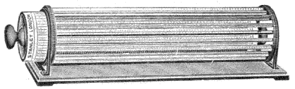
Fig. 430.—Thacher's slide rule.
Although the co-ordinate spiral rule, as all varieties of slide rules, is based primarily upon the theory of logarithms, a knowledge of that theory is by no means essential to its practical use.
887.—Thacher's Slide Rule.—Fig. 430. This contains a shorter scale than Professor Fuller's, and the system is not quite so simple. Full printed instructions are given in the[596] book supplied by the inventor, Mr. Edwin Thacher, of Pittsburg, U.S.A., or of the author, who is his agent for this country. The original divisions of this rule were made by the author. The scale is manufactured in the United States. There appears to be found some difficulty in its construction to keep the scales to true length and get them to exact position.
888.—Pocket Sets of Chain Scales.—These are made 3, 4, 5, and 6 inch. Three of 6 inch form the ordinary set. The chain scales, if three only, are 10, 20, 30, 40, 50, and 60; if six they generally contain the same scales with feet equal to the links. An extra scale with the ordnance or other scale of the country is found also useful for measuring from maps or plans. Some civil engineers prefer the pocket scales made wide with quite square ends, to be used as offsets or for sketching. These scales are generally made in ivory and placed in a light morocco or Russia leather case. The numbers of divisions of the scales should be stamped on the ends to prevent the wrong scale being drawn from the case.
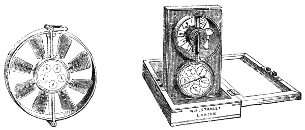
889.—Anemometers are used by mining engineers for testing the ventilation of mines. The original and best known form is that of Biram, Fig. 431. This instrument is held in any current of air, and the velocity of the current is registered by the motion of oblique fans, by means of ordinary decimal gearwork on five dials giving feet and multiples by 10. Lowne's anemometer, with the author's improvements, Fig. 432, is of[597] similar principles of construction, but it is arranged in portable form to go in a pocket case. Another well-known form of anemometer is built upon the same principle, but of cubical form. It is customary to take the velocity of the current for one minute by a watch, there being a detent provided in most instruments to start and stop the motion of the hands upon the dials.
890.—Books of Tables and Formulæ.—Few British Surveyors are without Molesworth's pocket-book. This contains all the useful tables and notes of reference valuable to the civil engineer in his ordinary work—weight, 5 ozs. Many pocket-books have been written on the same plan. Hurst's pocket-book contains all matters of reference for the town surveyor among buildings. Trautwine's Civil Engineer's Pocket-book (American) is the most complete, but it is of double the weight of the Molesworth. Spon's Engineers' Tables for the Waistcoat Pocket—weight, little over ½ oz.—is a very useful little book. Of Traverse Tables both Gurden's and Boileau's are comprehensive and reliable. There are several pocket-books of Curve Tables, those of Cutler & Edge, Beazeley, and Kennedy & Hackwood being perhaps in the most general use.
891.—Technical Books—Ordnance Maps are published on special districts and subjects which are often relative to the country or the special conditions of work abroad and at home for minerals, etc. It is very useful to possess such of these as may be required, and the note is only made here as a reminder.
892.—Sling Case for Drawings.—The most convenient method of carrying maps or drawings for public works in execution is to have a solid leather case similar to a telescope case. This is best if made with the cap or lid of the same length as the body: it can then be drawn out any distance according to the length of the rolled drawing. If thought more convenient, and the map or drawings are heavy, a strap may be added to pass over the shoulder, Fig. 433.
893.—Chronometer.—This may be any form of watch with compensated escapement. At present the prices run high for this class of work; but from the simplicity and moderate certainty of compensation it does not appear that this should be necessary for the production of a fair working instrument useful for the surveyor in new countries to check his longitude. Where a good chronometer is used it is better to keep it to Greenwich time without alteration. If there is a gaining or losing rate this will most probably remain constant in equal times, so that corrections may be made pro ratâ for all observations until a check can be taken with certainty when arriving at a town which possesses an observatory. The quality of a chronometer is fully ascertained by having a certificate from one of our observatories, that of Kew being the most popular.
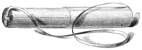
Fig. 433.—Sling case for drawings.
894.—Chronograph.—For the observation of stars in transit for the purpose of taking longitude, a dead-stop watch or chronograph is most useful. This can now be had in combination with an otherwise fair going watch at a very moderate price.
895.—Outfit of a Surveyor for Work in a New Country.—The ordinary items of strong, dust-coloured woollen clothing, good boots, saddle, firearms, etc., do not come within the province of this work. The instruments he will require will depend partly upon the nature of the country and the kind of work to be done. If for prospecting only, light instruments are commonly selected—the sextant,[599] or box sextant with glass artificial horizon, good pocket chronometer, telescope, aneroid barometer, prismatic compass, and clinometer. If a general survey is to be made, the first instrument of importance is the theodolite, the 4 or 5-inch being the most usual. With this, pickets, land chain and arrows, a steel tape for testing, and a linen tape. If for survey in mineral districts, a good mining-dial is required, with all accessories of chains, etc. If for railway work, a 5-inch theodolite, a good level, staves, pickets, clinometer, and prismatic compass. In all cases, field-books, drawing instruments, supply of paper, drawing boards, squares, parallel rule, pencils, Indian ink, colours, stencil plates, and other articles for office use, of which the established optician or trader will give full information from his experience, or general reference may be taken from any complete catalogue of such instruments.
This Book
WIRING HOUSES—SCHNEIDER
Shows you in detail how to install
electric wires. Read the contents.
Contents of chapters: 1, Introduction; 2, Planning the wiring; 3, Completing the installation; 4, Installing the lights; 5, Other methods of wiring; 6, Materials and notes; 7, Conduit and protected wiring, armored cables, pipe conduits, latest condulet fittings and concentric wiring; 8, Digest of 1916 edition of the National Code, Underwriters rules and notes. 128 pages, 45 illustrations and 9 plates, 12 mo, cloth.
Price 55 cents—Postpaid
LEARN TO DO THINGS
Model Library Series
OF COPYRIGHTED BOOKS
In paper covers Price 25c each Postpaid.
* These books can also be had in cloth binding
at 55c each postpaid
SPON & CHAMBERLAIN
PUBLISHERS OF TECHNICAL BOOKS
123-5 LIBERTY ST., NEW YORK
[1] Proc. Royal Institution, vol. xi. p. 413.
[2] See Phil. Trans. 1896, vol. 188, Map. 9.
[3] See Simms' Mathematical Instruments, p. 3.
[4] See pamphlet on A New Form of Levelling Instrument, by Thos. Cushing, F.R.A.S., 1879.
[5] Patent No. 69, Wm. Barrie, 1856.
[6] Patent No. 6742, John Browne, June, 1834.
[7] Brit. Assoc. Report, 1838, p. 154.
[8] Patent No. 12590, 1889.
[9] Colliery Guardian, vol. xxxviii. p. 576, 1879.
[10] A Treatise of the Principles and Practice of Levelling, by F. W. Simms, 1842; A Treatise on Land Surveying, by John Ainsley, revised by William Galbraith, 1849. Quite modern works—Aid to Survey Practice, L. D'A. Jackson, Crosby Lockwood, 1910; On Levelling and its General Application, by Thomas Holloway, Spon, 1887; revised 1914.
[11] Levelling, p. 49.
[12] Deschanel's Natural Philosophy, by Prof. Everett, p. 1018, 1876.
[13] A Manual of Surveying for India, by Colonel H. L. Thuillier, C.S.I., F.R.S., etc., and Lieutenant-Colonel R. Smith. Thacker, Calcutta, 1875. (Now out of print).
[14] The illustration is taken from Die geometrischen Instrumente, Dr. G. Chr. K. Hunäus. Hanover, 1864.
[15] Digges's Pantometria, see p. 2.
[16] Gardiner's Practical Surveying, p. 59, 1737.
[17] Adam's Geometrical Essays, pp. 217–229, 1803.
[18] Civil Engineers' Pocket-Book, by J. C. Trautwine, C.E.
[19] Plate xiv., fig. 5. Geometrical Essays, Geo. Adams, 1803.
[20] Proc. Min. Inst., Cornwall, 1883, vol. i. p. 317.
[21] Patent No. 1592, April 1878.
[22] Patent No. 1857, J. L Casartelli, May, 1874.
[23] Illustrated plate xv. Fig. 1., Geometrical Essays, John Adams, 1803.
[24] Pastorelli's patent, No. 2714, 1863.
[25] Hoffmann's patent, No. 2084, 1878.
[26] Geometria Subterranea, Voitel, 1686.
[27] Subterranean Surveying, Thos. Fenwick, Lockwood.
[28] Description and use of an Improved Reflecting and Refracting Telescope and Scales for Surveying, by William Green, 1778.
[29] La Tachéomètre, ou l'Art de Lever les Plans et de Faire les Nivellements, Paris, 1858.
[30] Tables Trigonométriques Centésimales, by J. L. Sanguet, Paris.
[31] Manual of the Theory and Practice of Topographical Surveying by Means of the Transit and Stadia, by J. B. Johnson. New York.
[32] Patent, prov., No. 1859, June, 1868; patent No. 3759, Dec., 1868.
[33] Report on Omnimeter, by Major G. A. Laughton, Superintendent, Bombay Revenue Survey.
[34] Proc. Inst. C.E., vol. xcii. part ii. p. 248, 1887–1888.
[35] Lister's Patent, No. 2375, 1864.
[36] Francis Barker's patent, No. 1926, 1881.
[37] British patent, No. 217, 1884.
[38] Posthumous Works, p. 502; also Animadversions to the Machina Cælestis of Helvetius, p. 49.
[39] Phil. Trans., vol. xlii. p. 155.
[40] Phil. Trans., vol. xxxvii. p. 147.
[41] Ibid. p. 340.
[42] See Nicholson's Navigator's Assistant.
[43] Pearson's Practical Astronomy, p. 537.
[44] Ibid. p. 577.
[45] Gli Strumenti a Reflessione per Mesurare Angoli, by G. B. Magnaghi, 1875.
[46] Description of a New Quadrant, by George Adams, 1748.
[47] Adams' Geometrical Essays, edited by William Jones, 1803.
[48] Prov. Patent No. 2624; Christopher George, 1868.
[49] See British patents—Winter, 1760, No. 752; Ould, 1791, No. 1842; Nugent, 1794, No. 1980; Wright, 1796, No. 2081; Cook, 1796, No. 2087; Roxby, 1822, No. 4695; Glover, 1839, No. 8256; Lane, 1857, No. 1669; Rahill, 1860, No. 1845, etc.
[50] Adams' Geometrical Essays, p. 264, 1803.
[51] Proc. Inst. Civil Engineers, vol. xciii. part iii. paper No. 2308. See also Military Surveying in the Field, by Major The Hon. M. G. Talbot, Prof.; Papers Royal Engineers, vol. xiv. p. 25.
[52] Patent No. 1202, D. R. Edgeworth, April 1866.
[53] Heather's Surveying Instruments, 1870, p. 85.
[54] The Surveyor, vol. ii. No. 5. Sydney, Nov. 1889.
[55] Patent No. 2142, May, 1880.
[56] Manual of Surveying for India, p. 478, 1875.
[57] Patent No. 3390, October 1874.
[58] For full description and plate, see Everest's Measurement of the Meridional Arc of India, Introd. p. cxv.
[59] British patent, No. 10157, April, 1844.
[60] British patents—No. 13332, November, 1850; and No. 682, March, 1862.
[61] Patent, No. 13332, May, 1850.
[62] Patent No. 3454, December, 1862.
[63] Patent No. 3425, March, 1886.
[64] Patent No. 2714, October, 1865.
[65] Patent No. 12889, December, 1849.
[66] Patent, No. 4310, November, 1876.
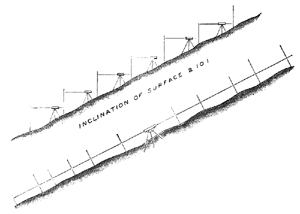
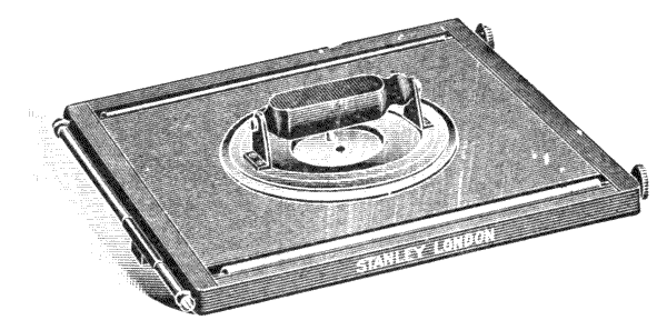

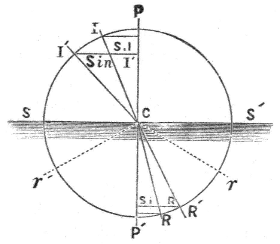
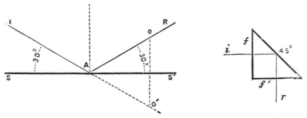
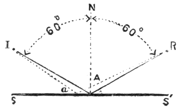
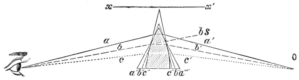
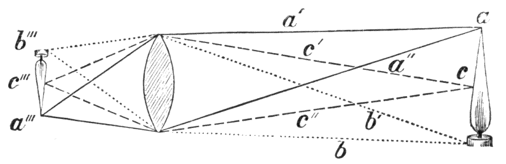
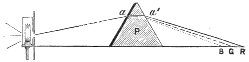
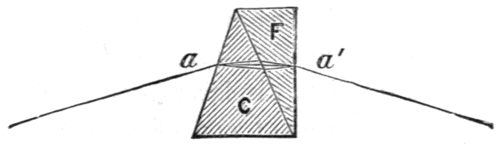
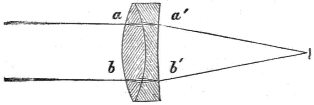
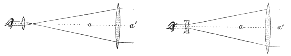
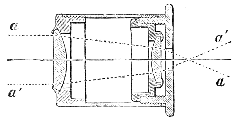
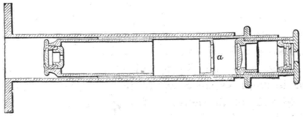
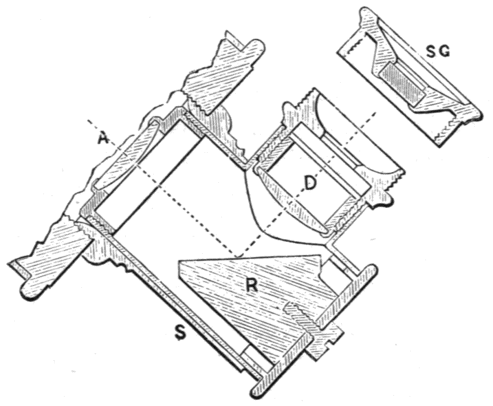
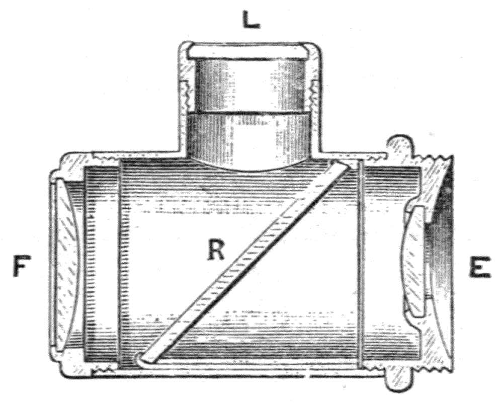
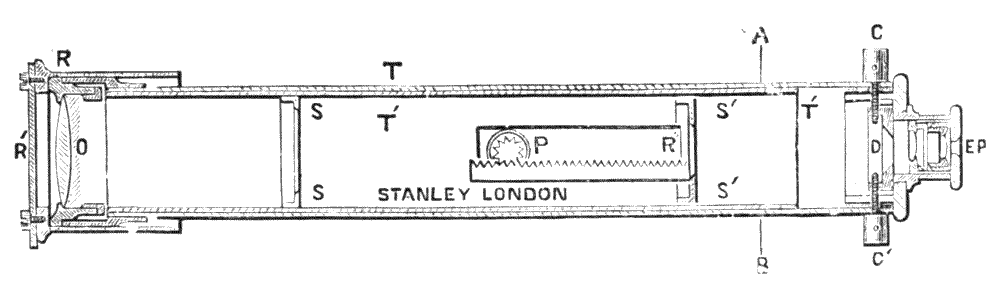
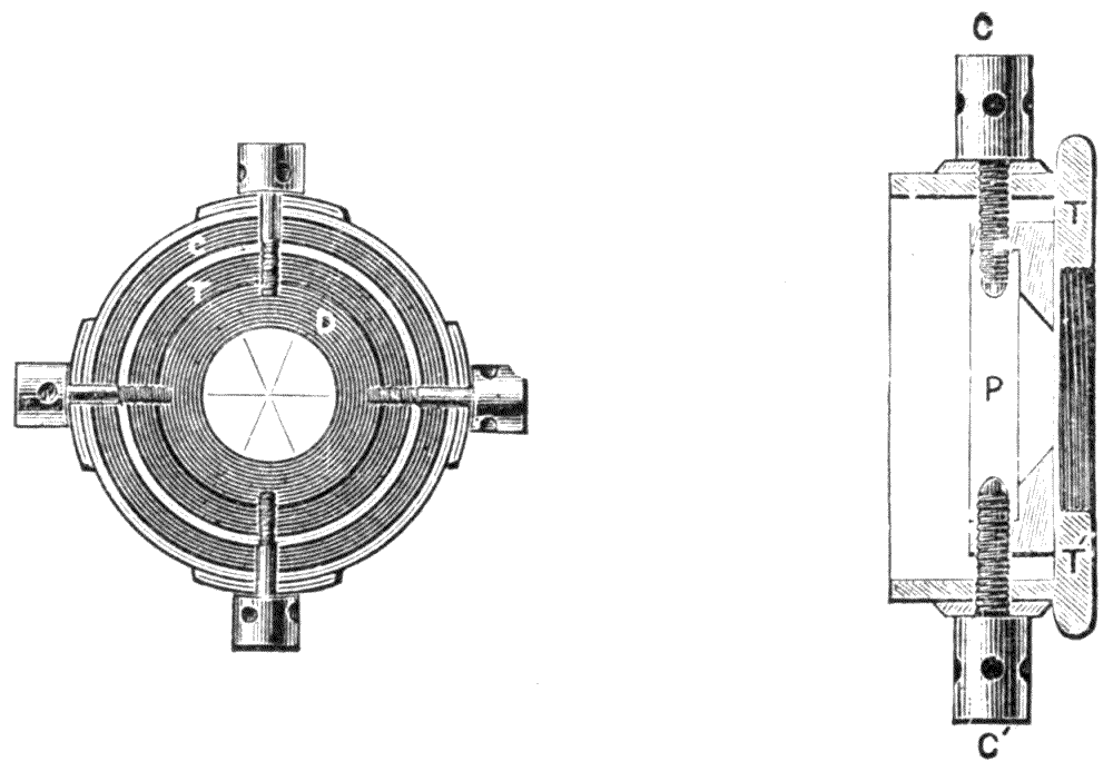
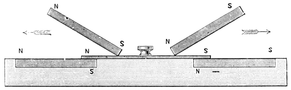
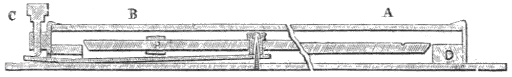
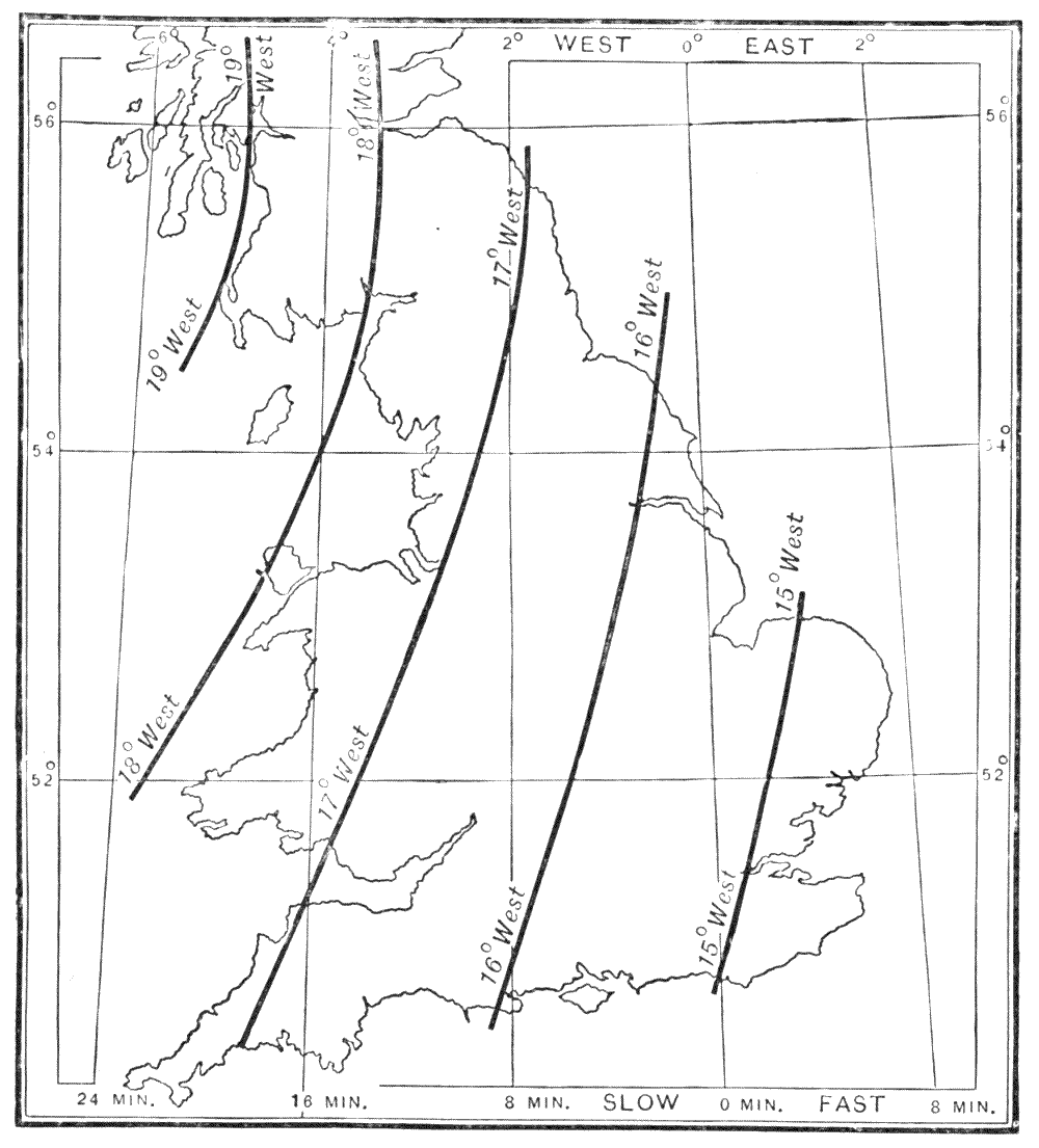
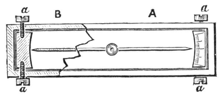
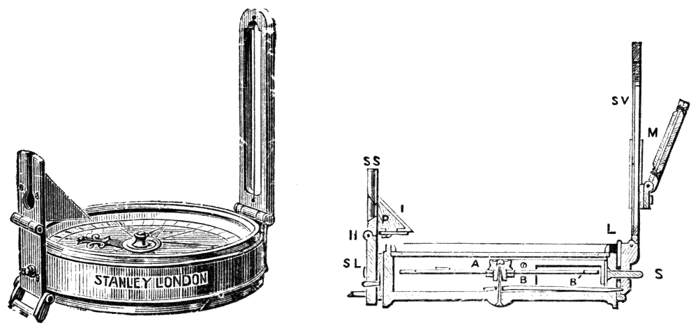
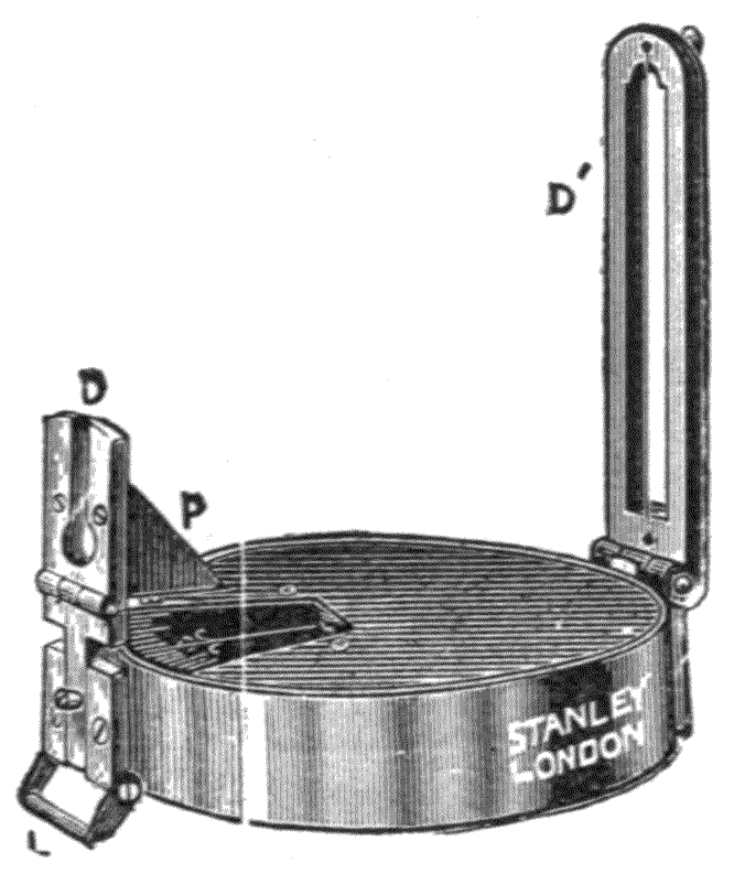
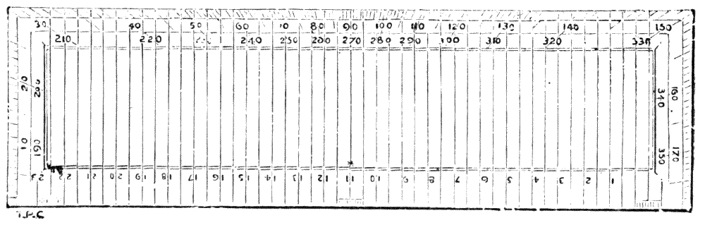
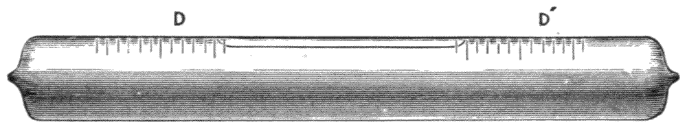
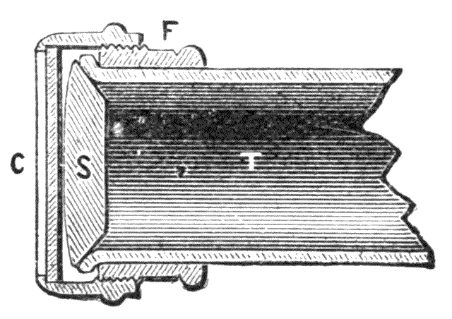
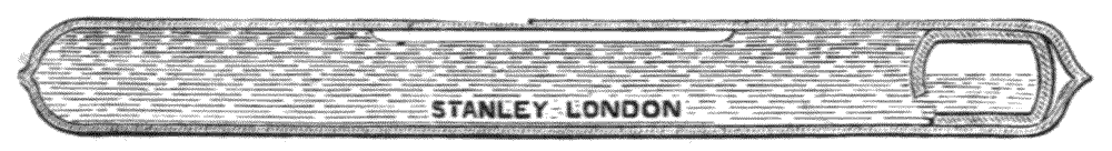
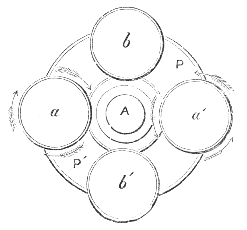
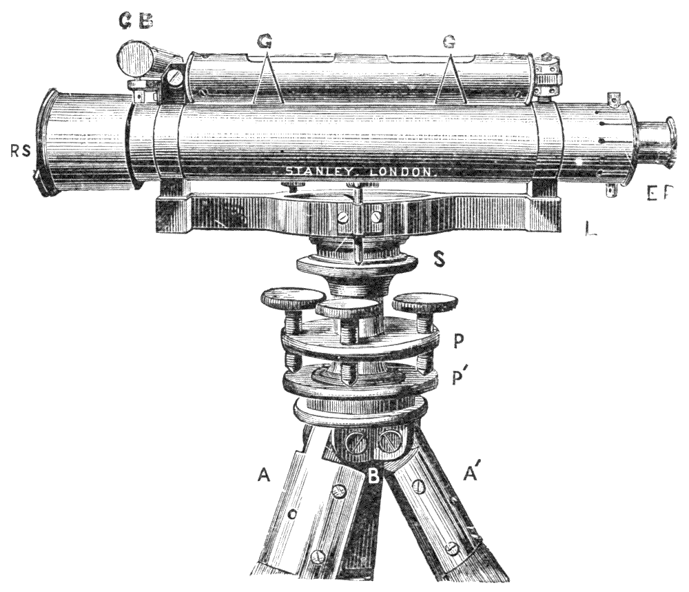
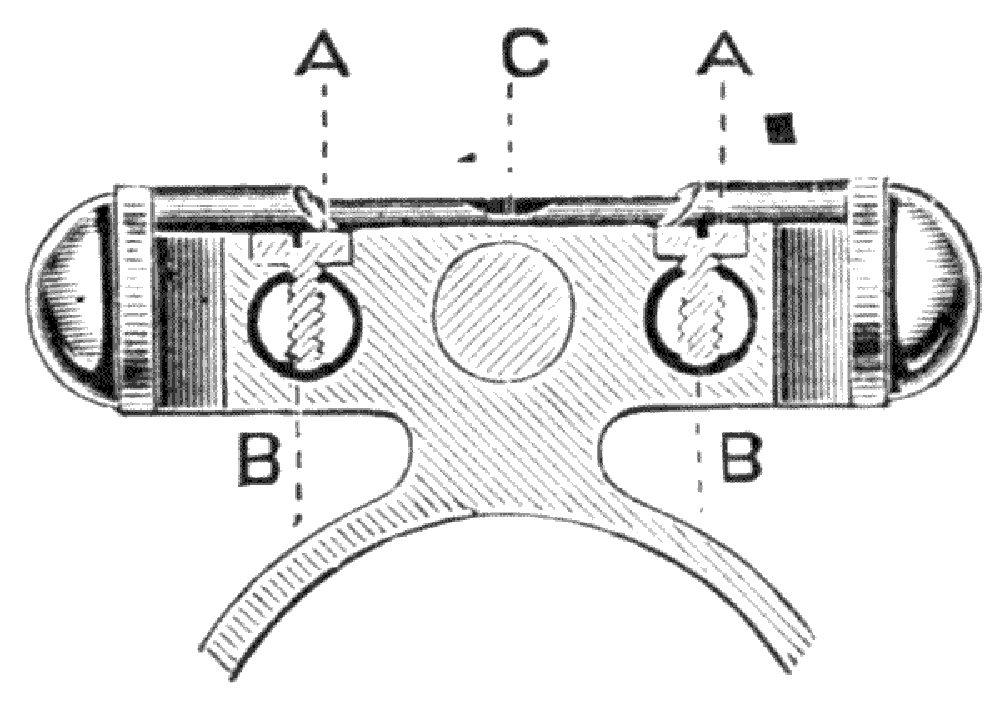
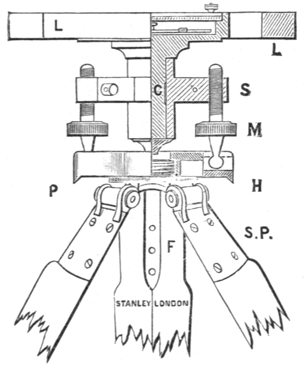
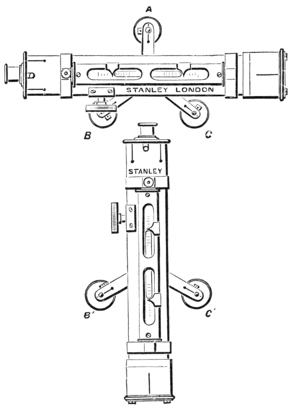
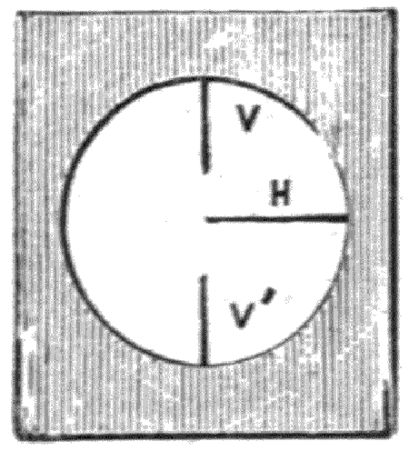
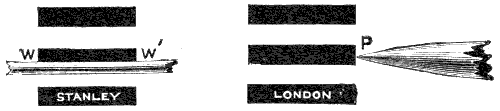
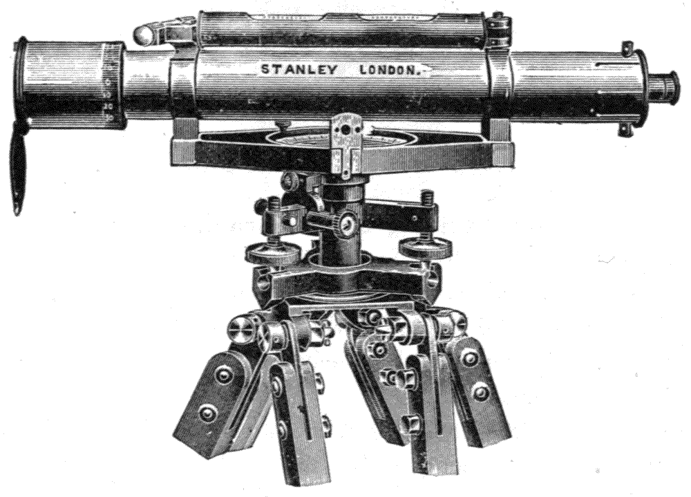
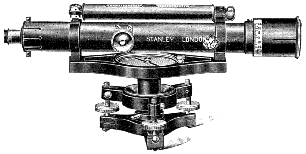
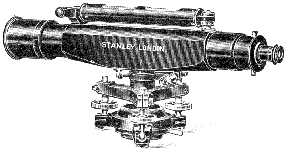
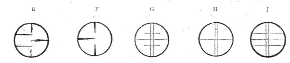
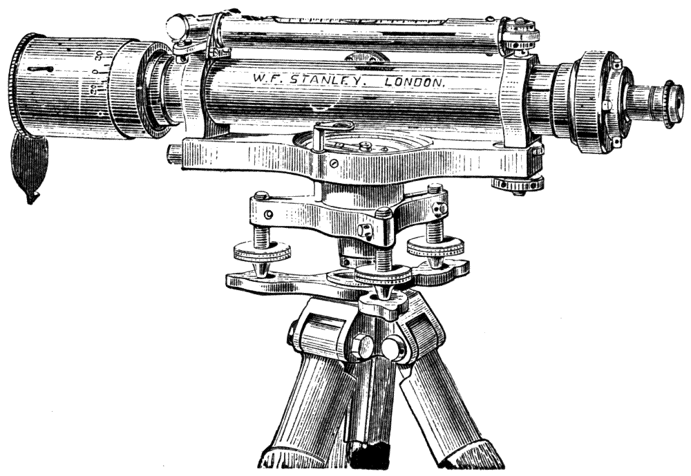
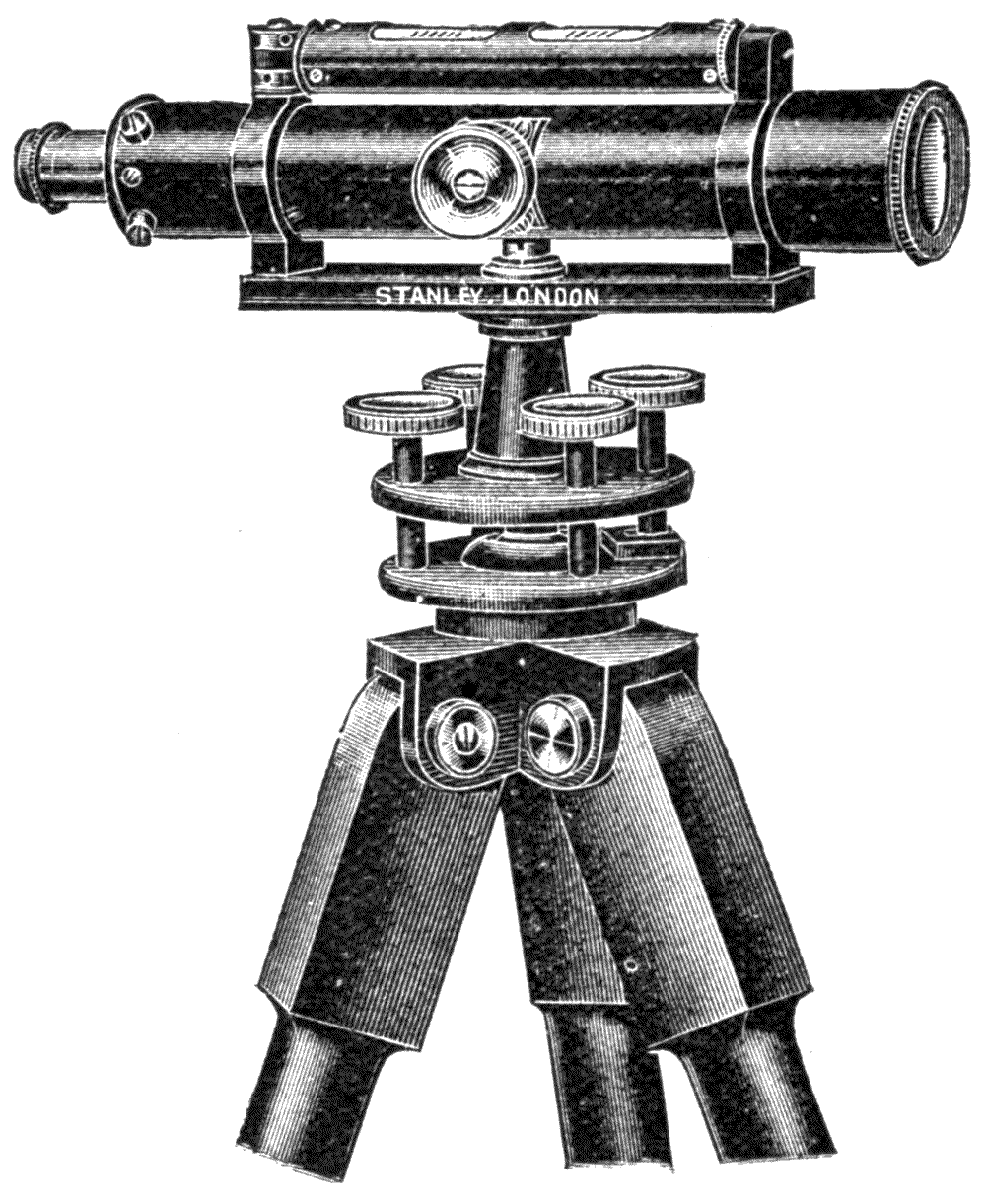
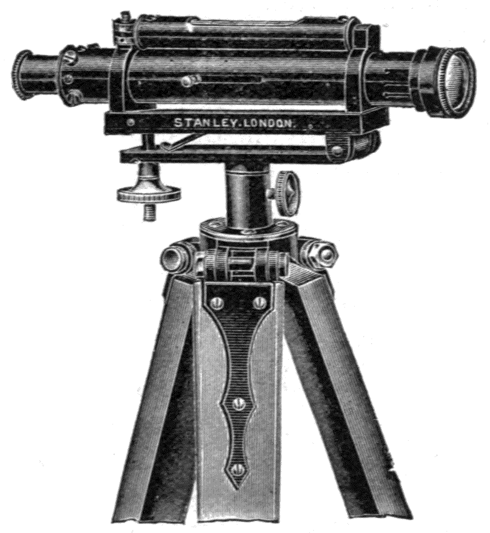
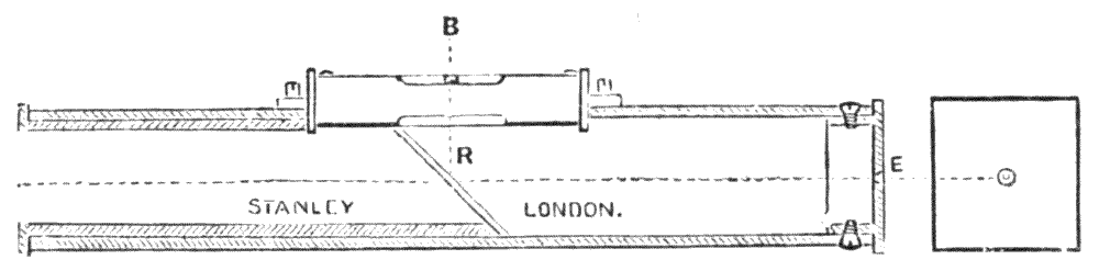
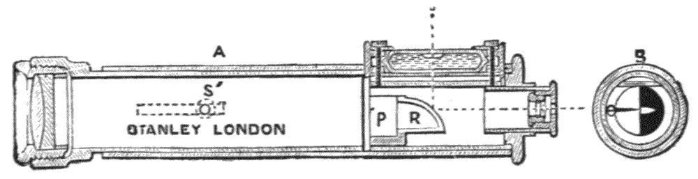
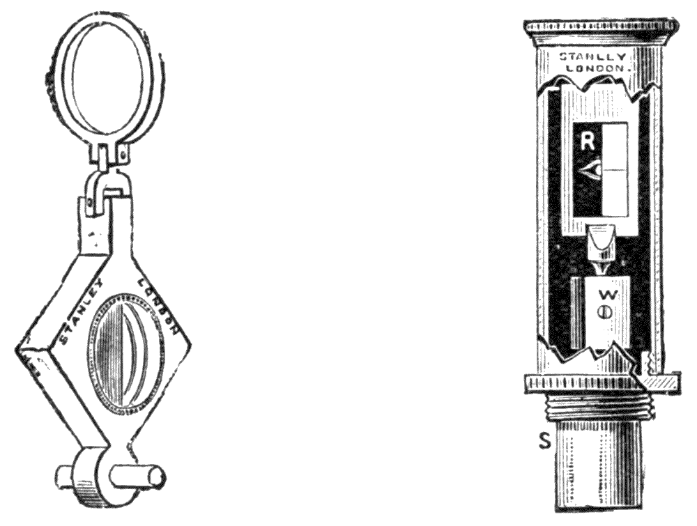
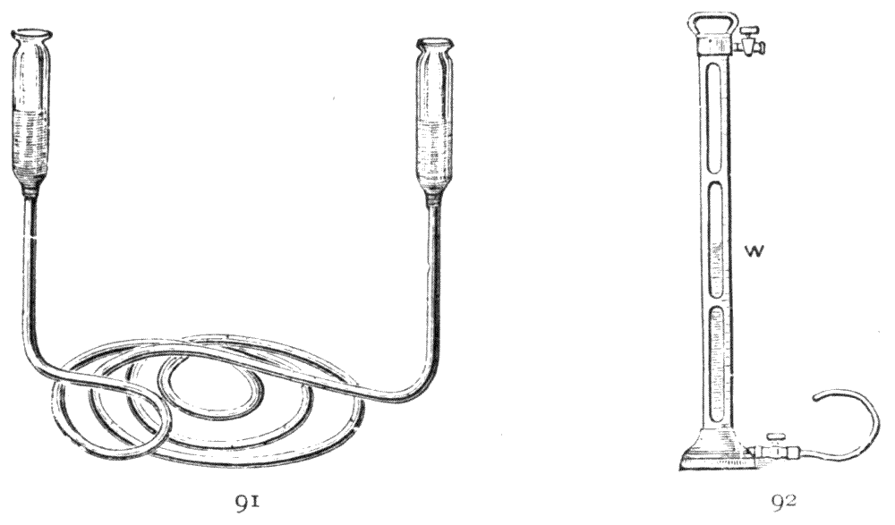
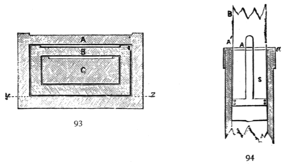
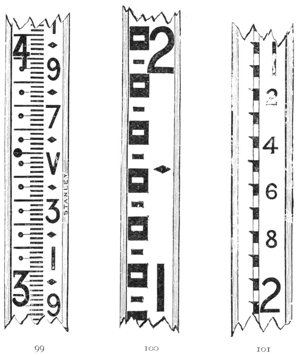
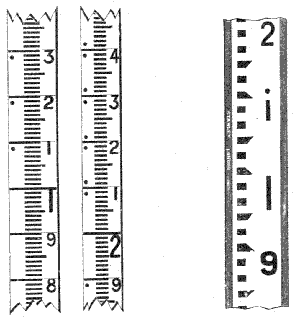
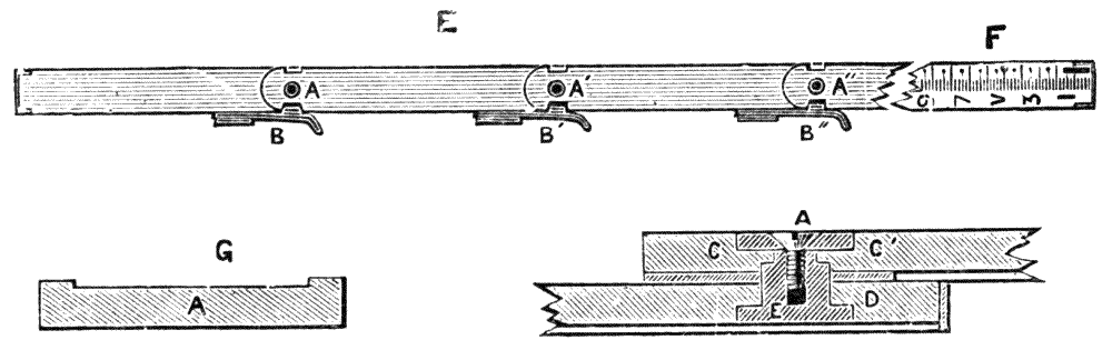
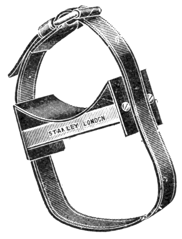
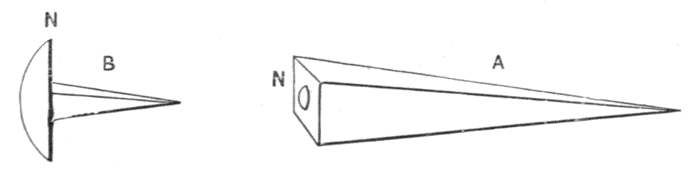
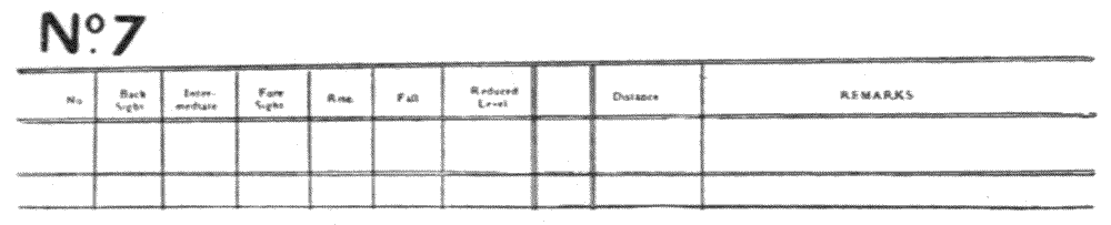
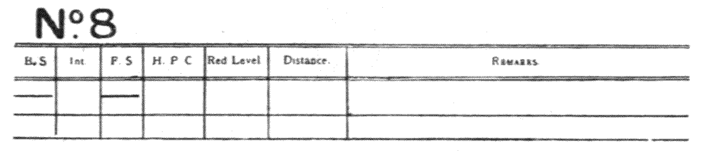
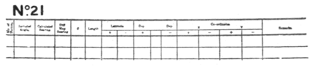
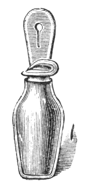
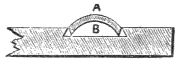
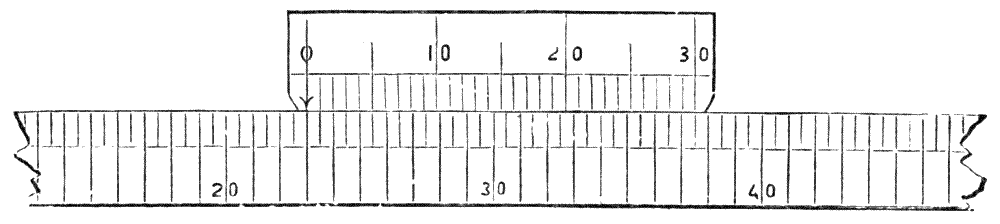
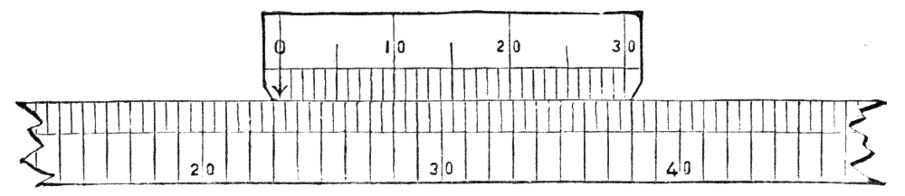
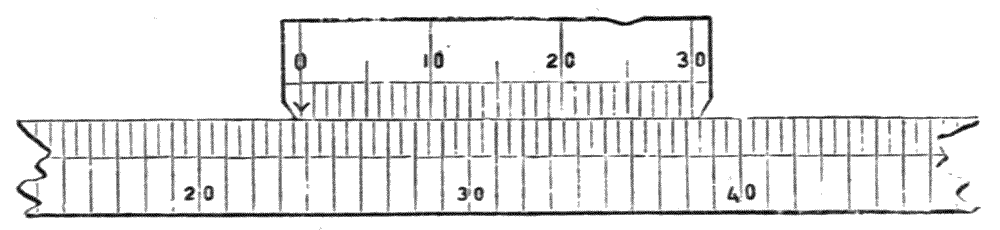
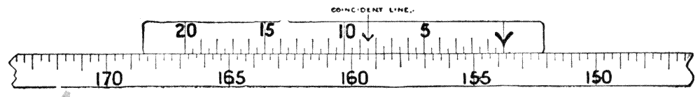
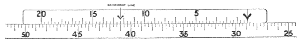
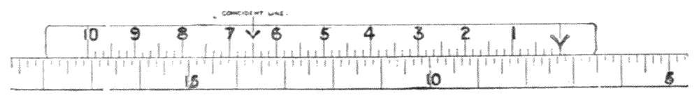
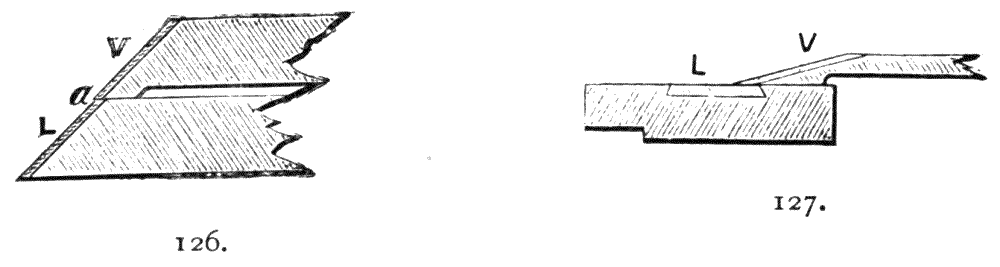
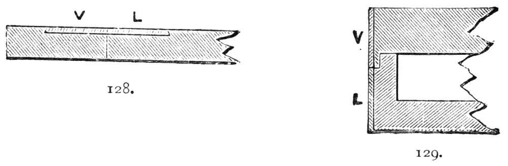
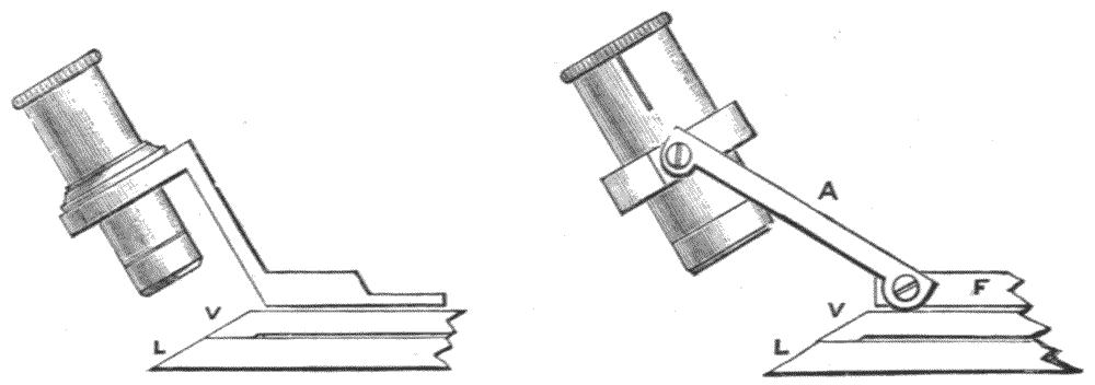
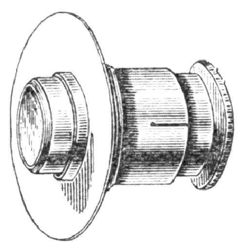
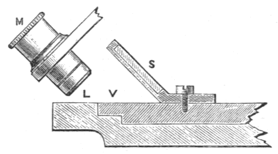
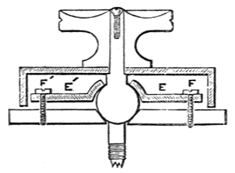
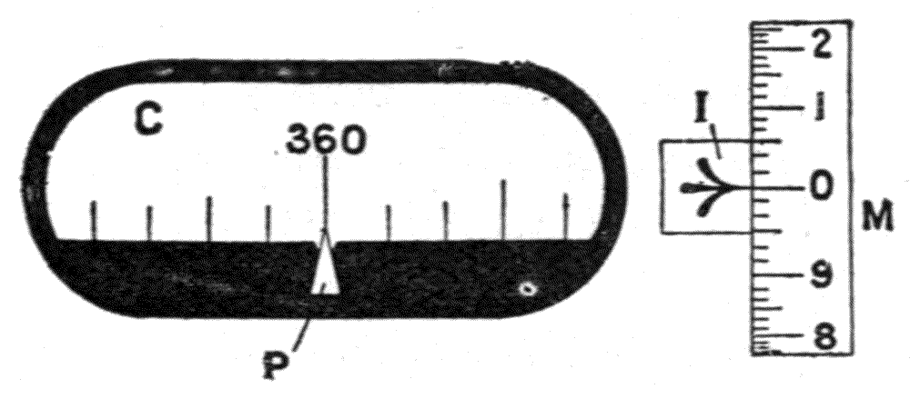
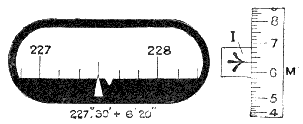
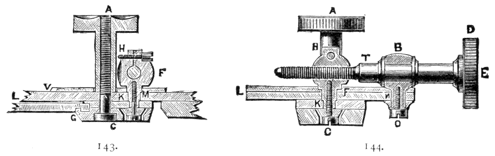
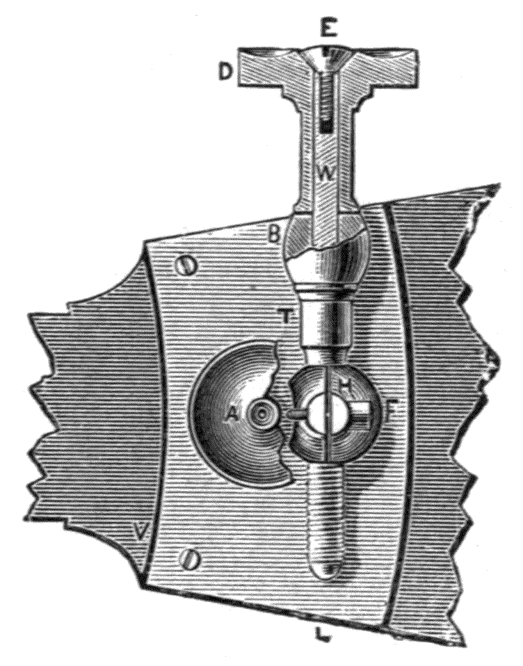
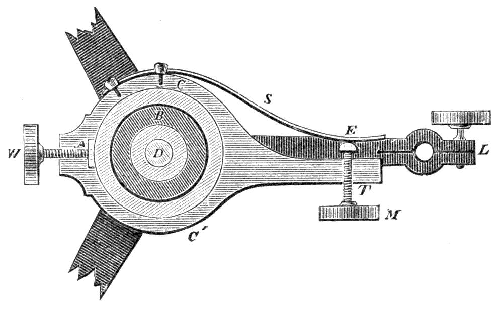
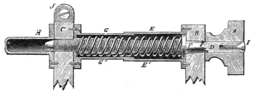
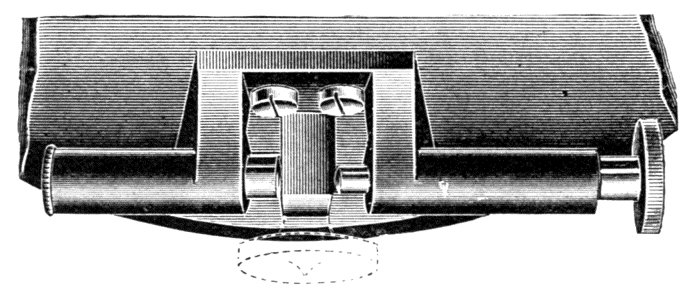
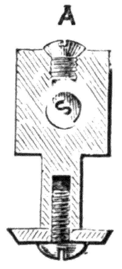
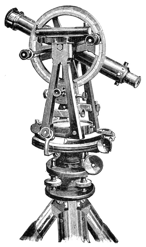
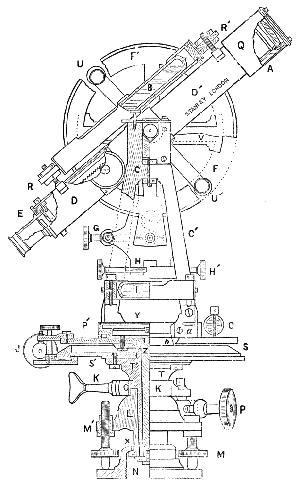
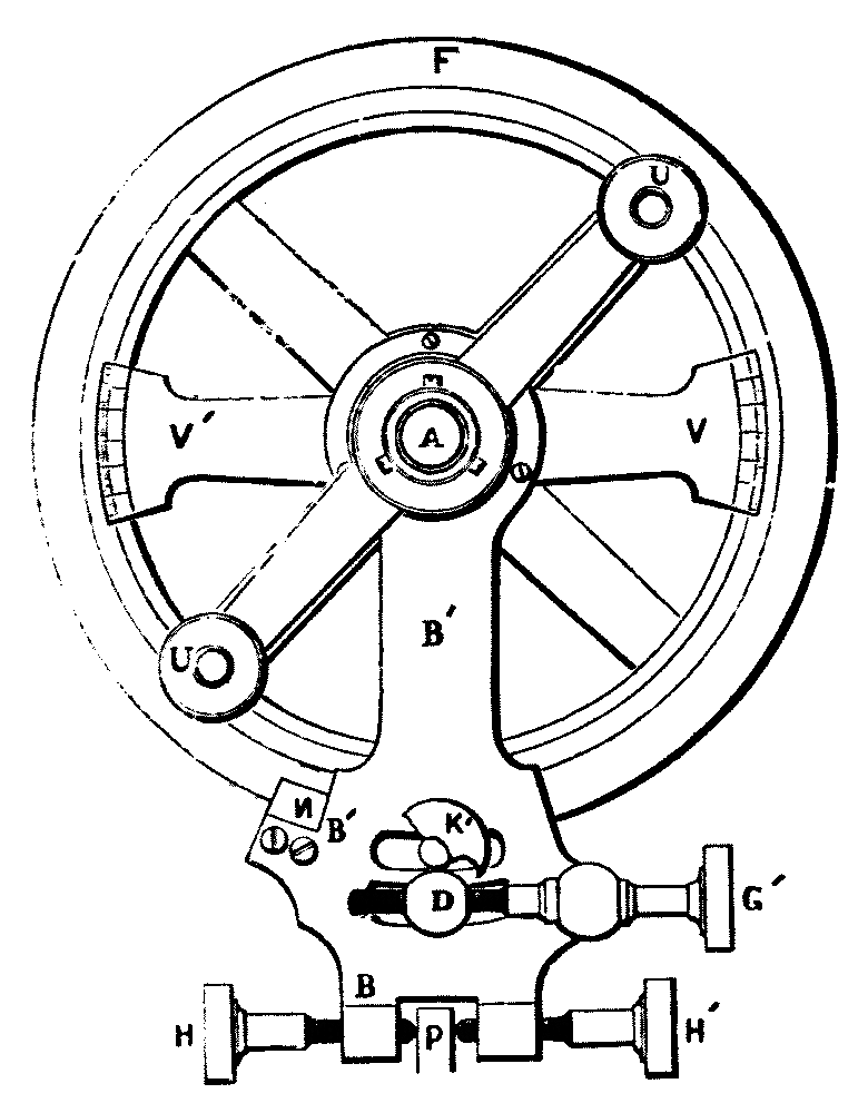
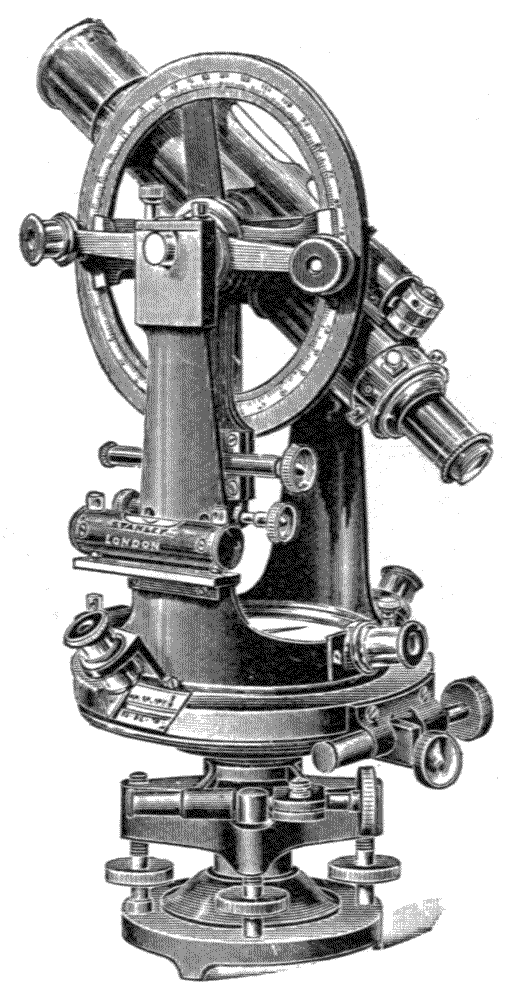
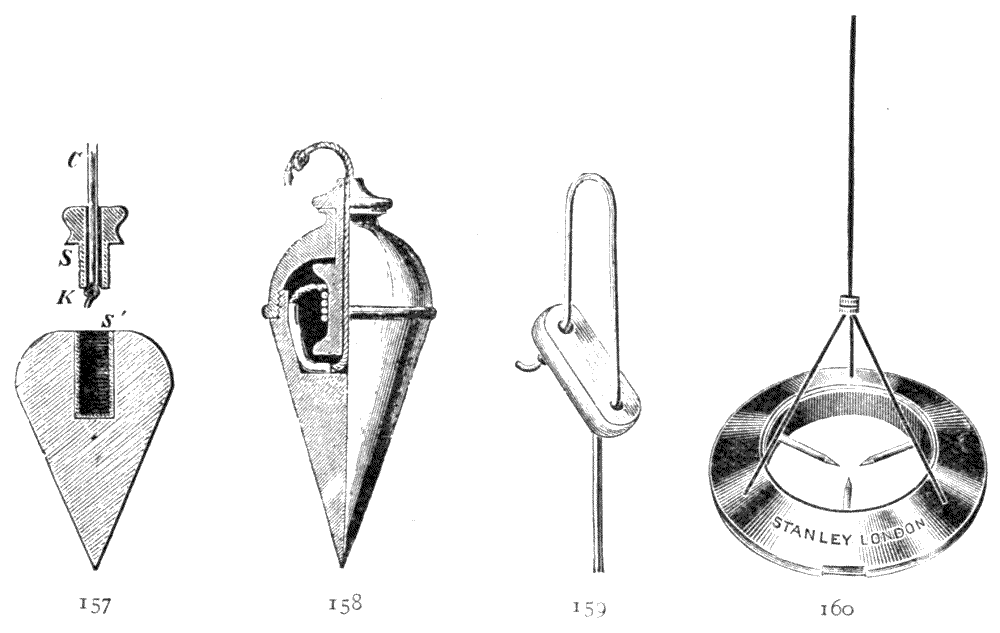
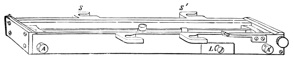
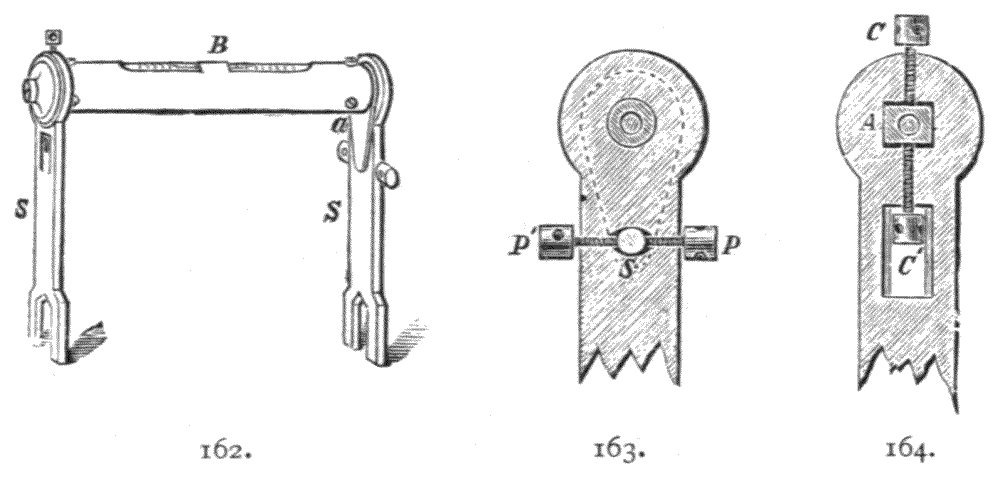
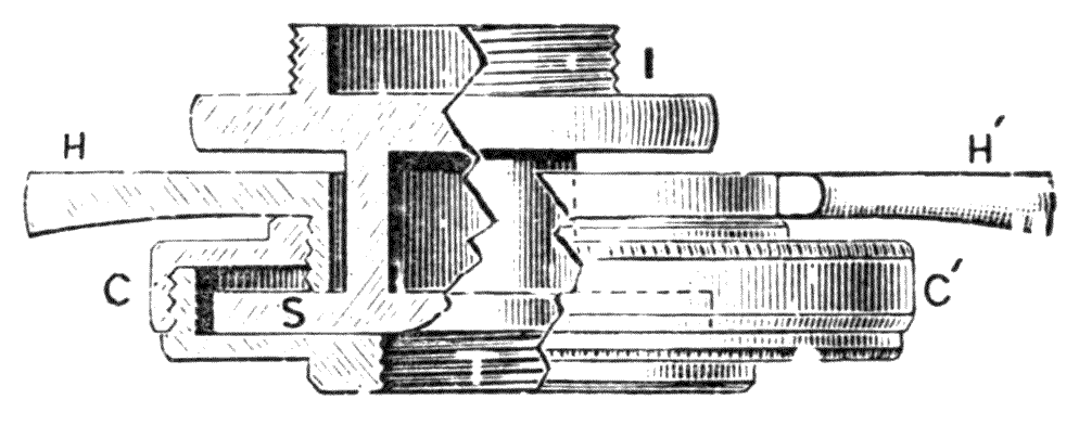
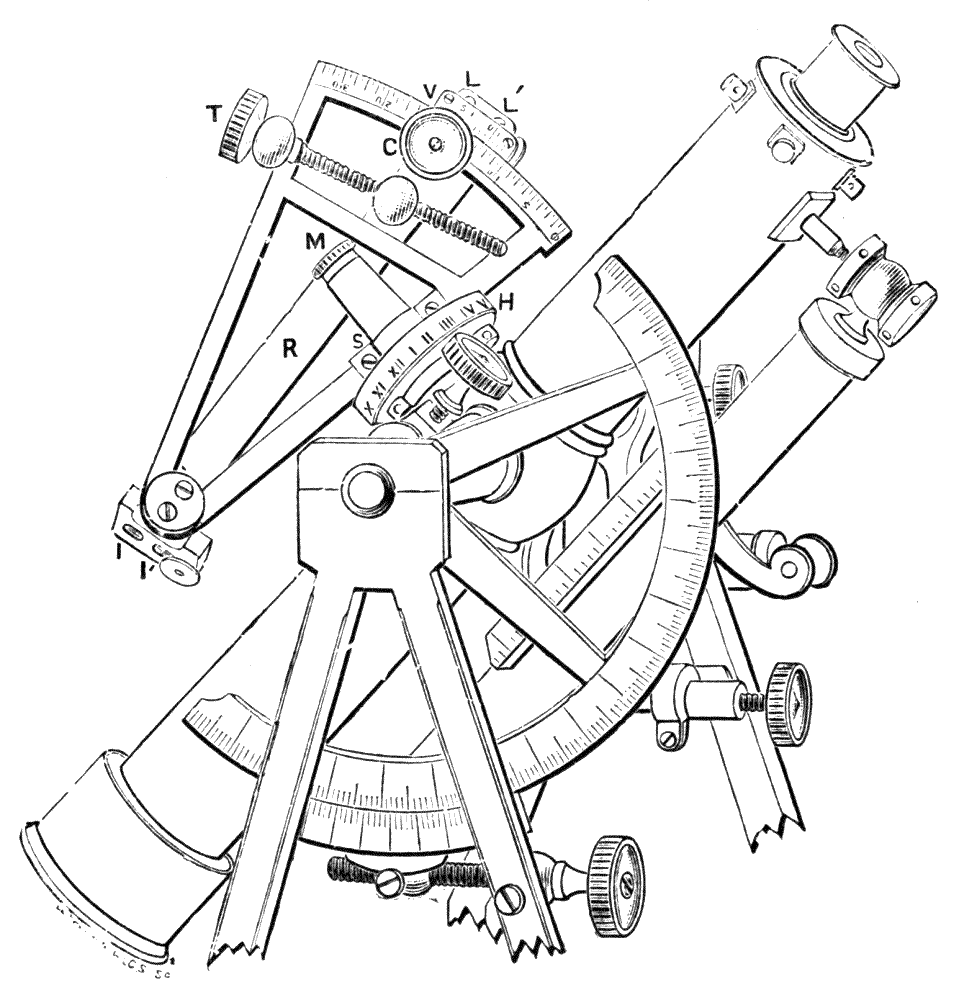
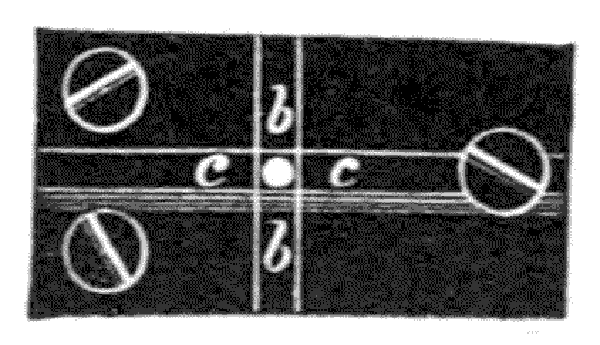
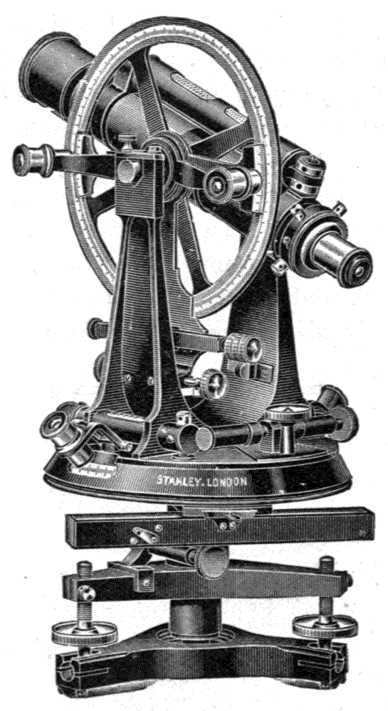
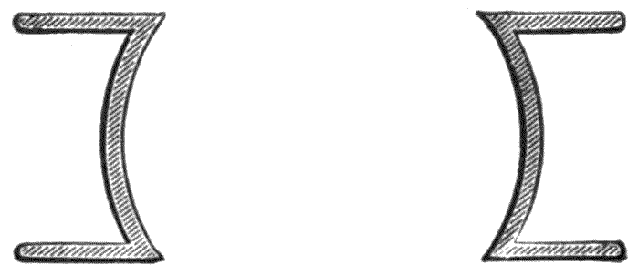
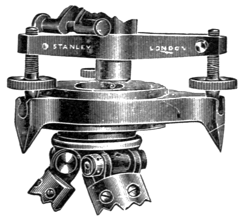
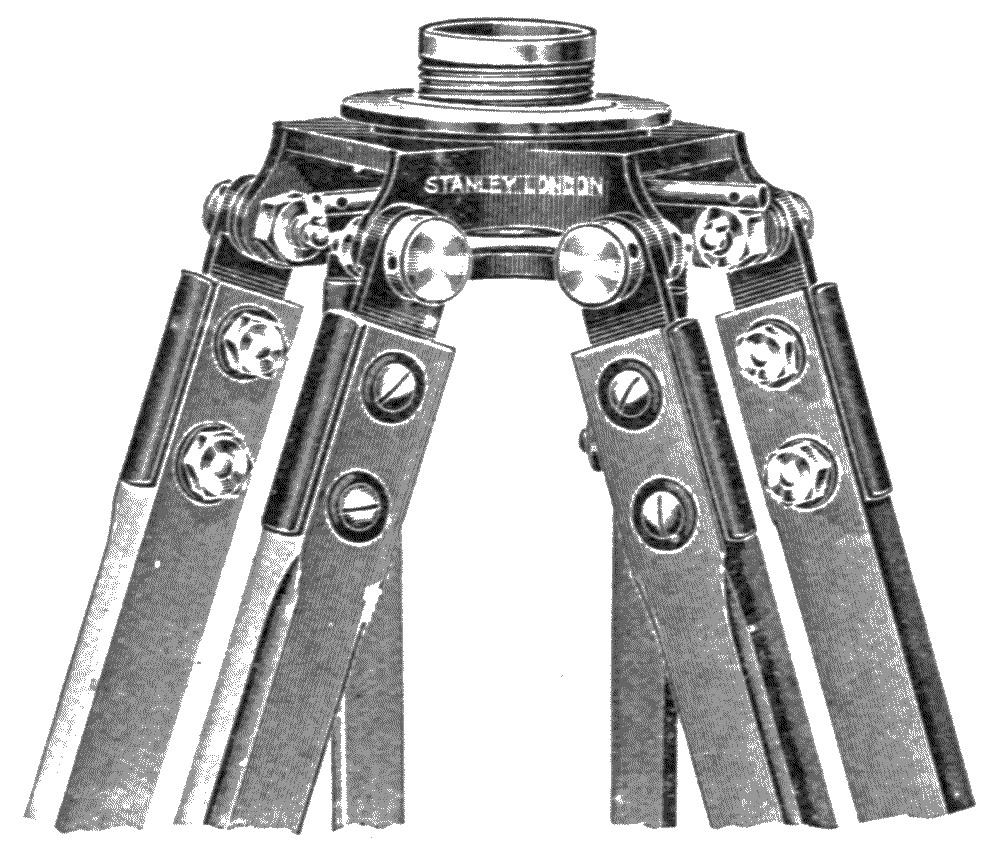
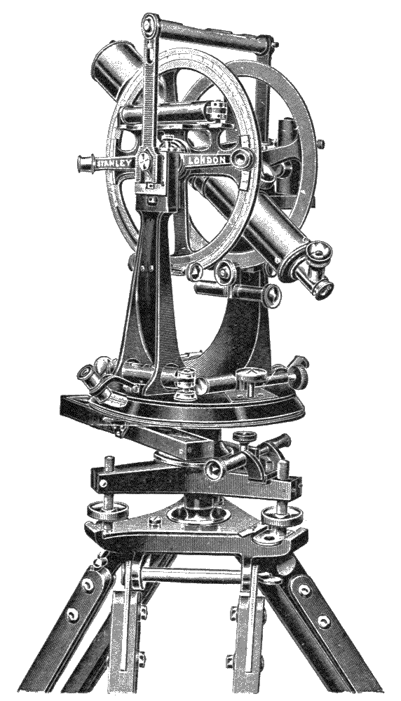
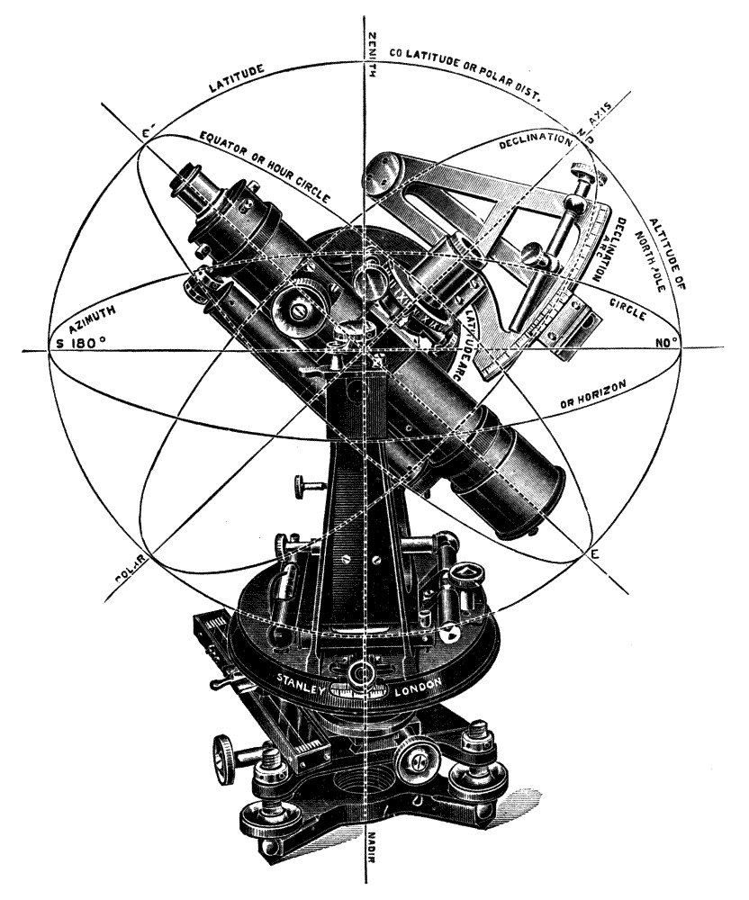
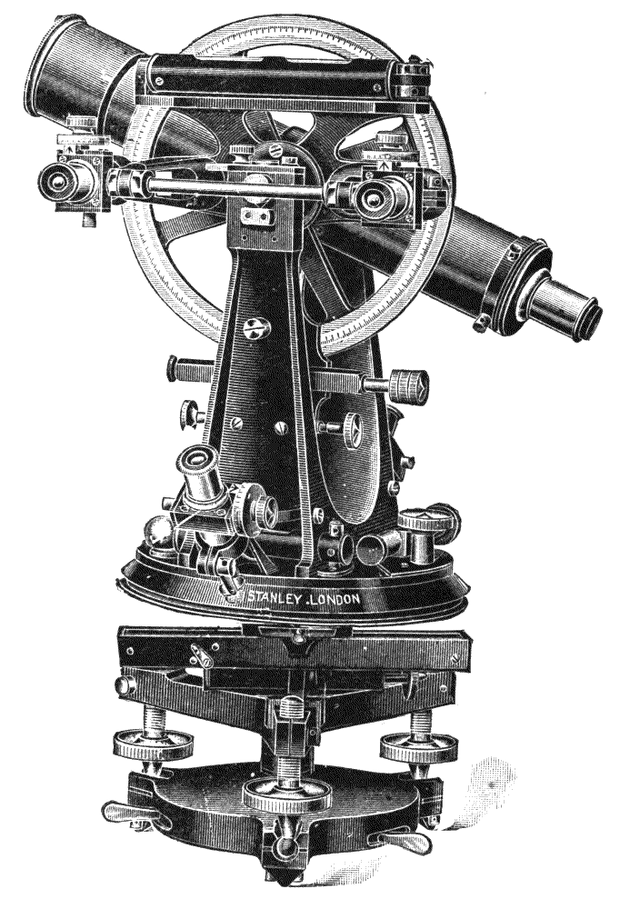
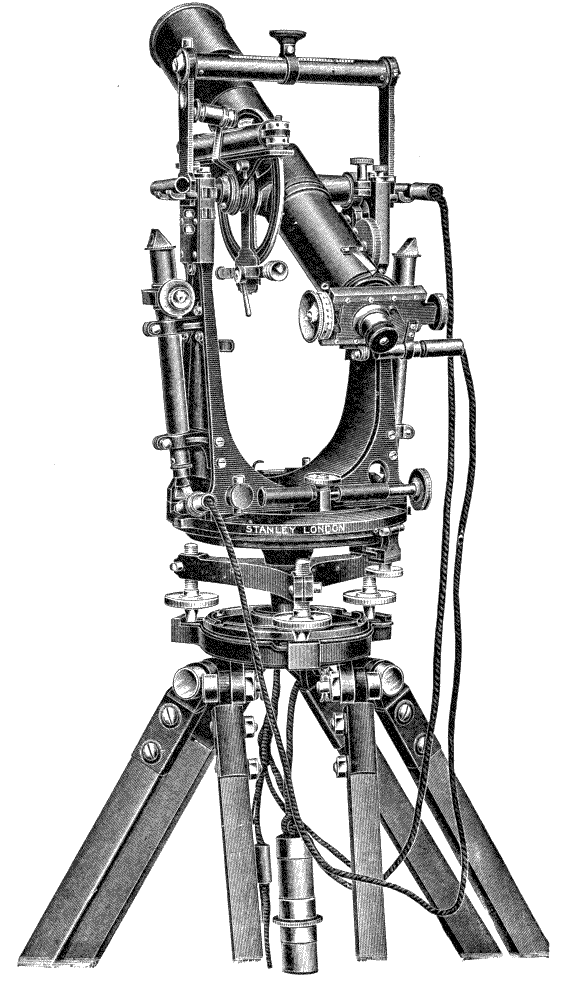
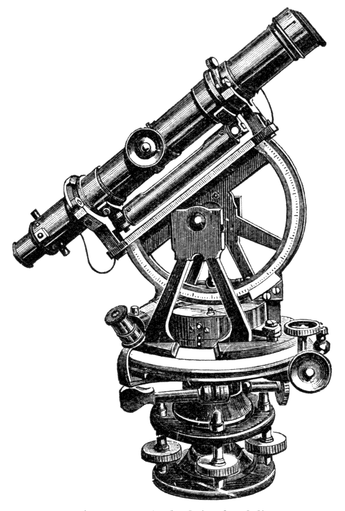
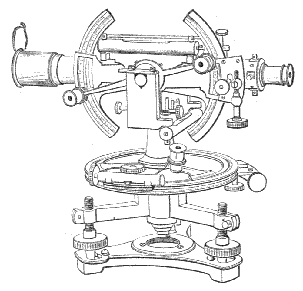
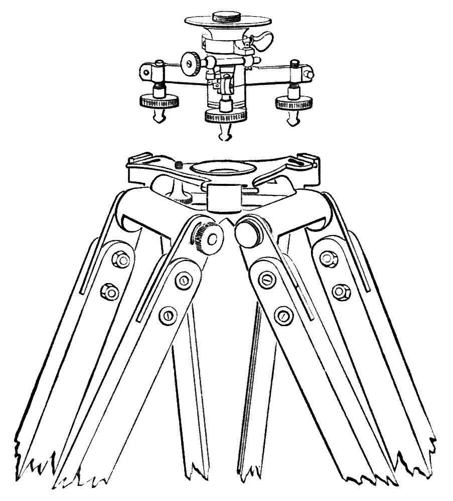
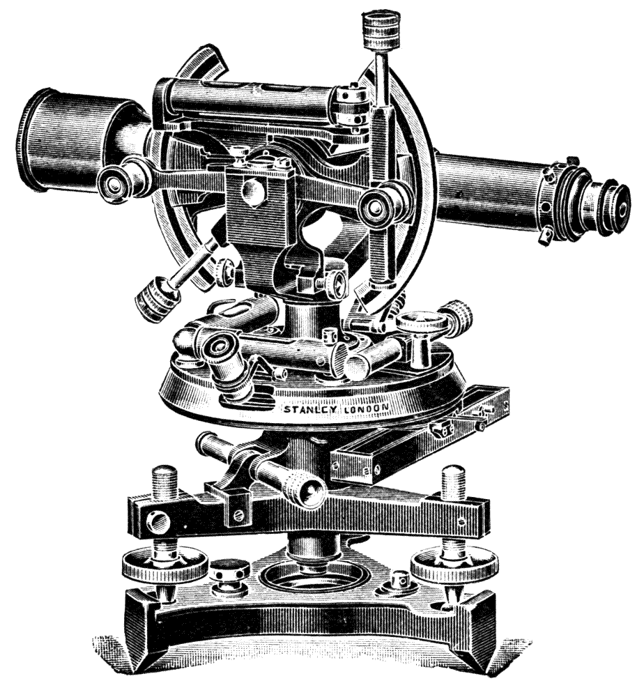
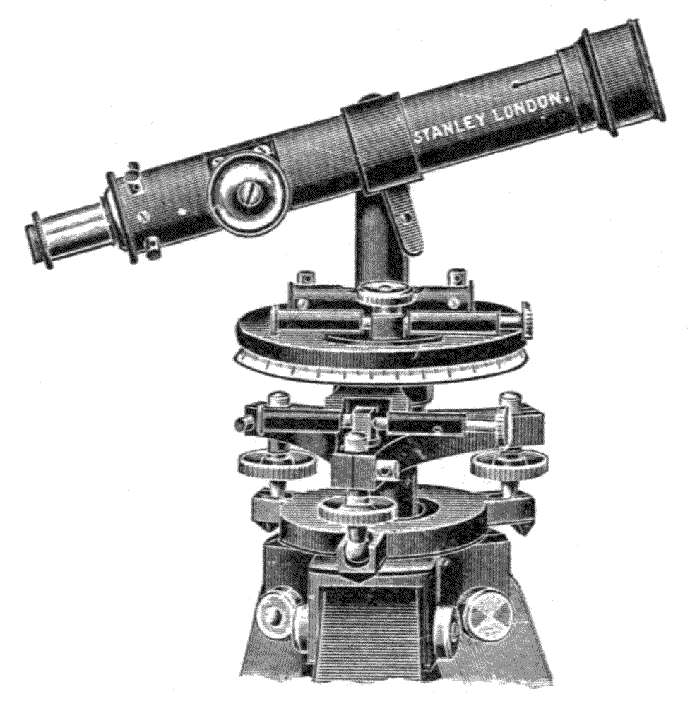
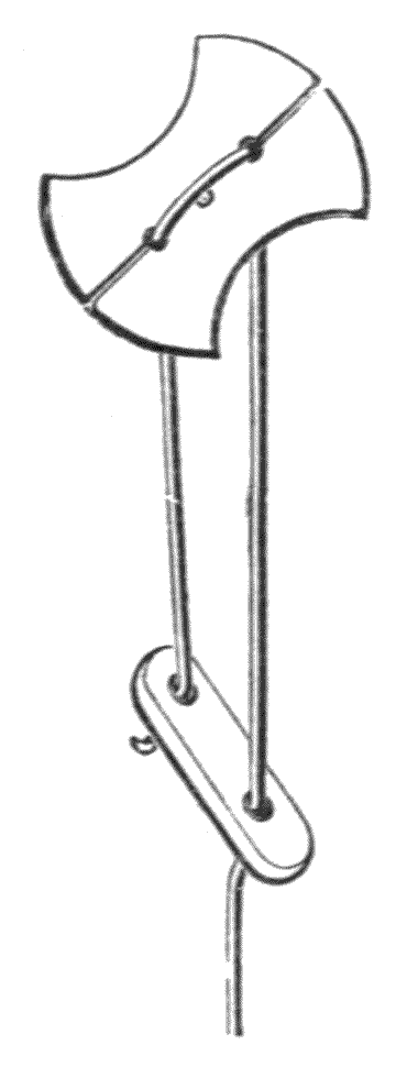
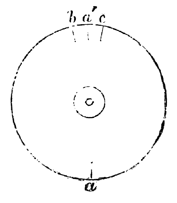
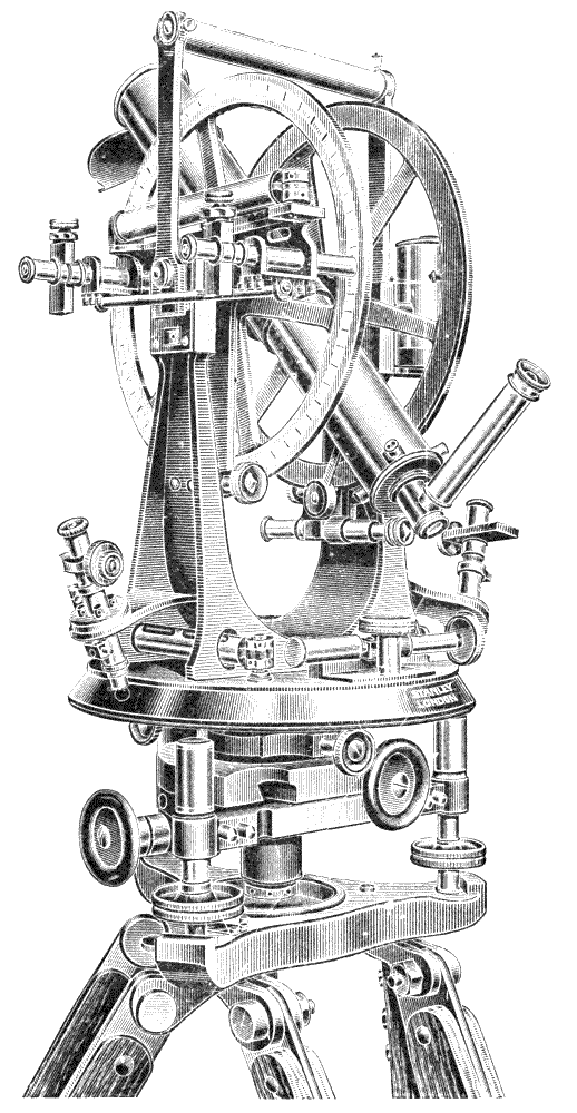
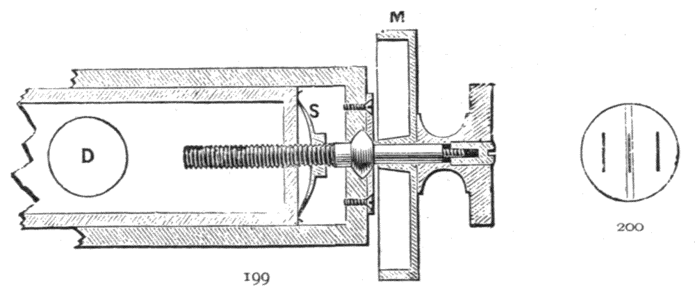
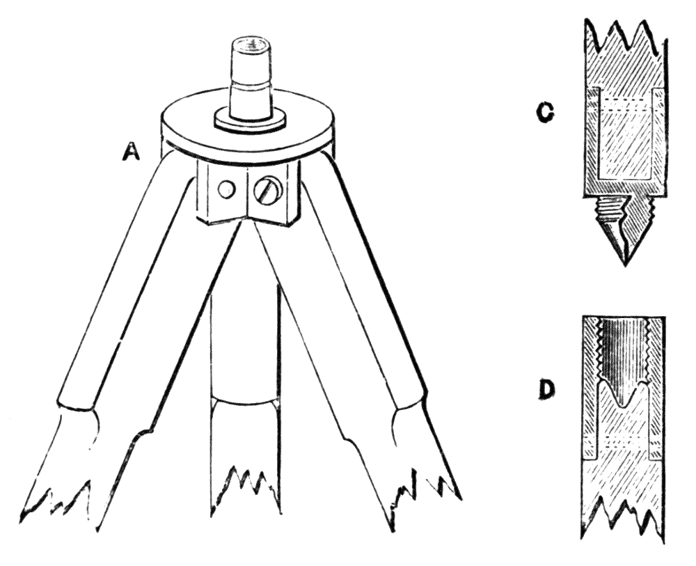
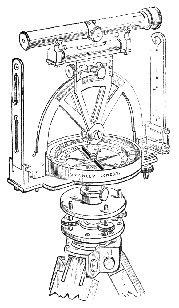
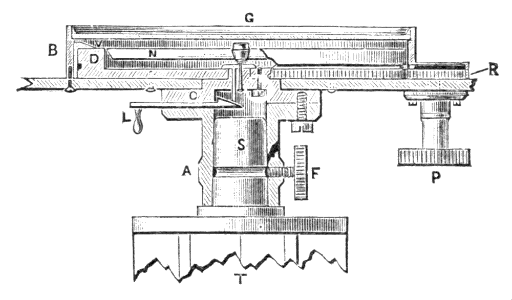
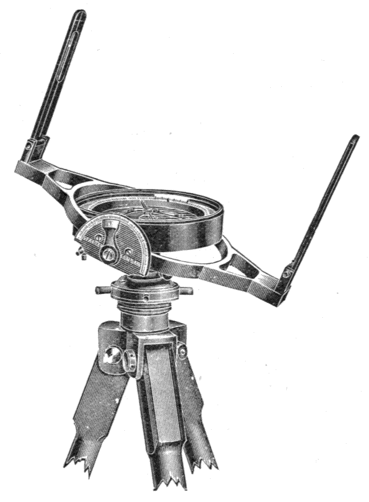
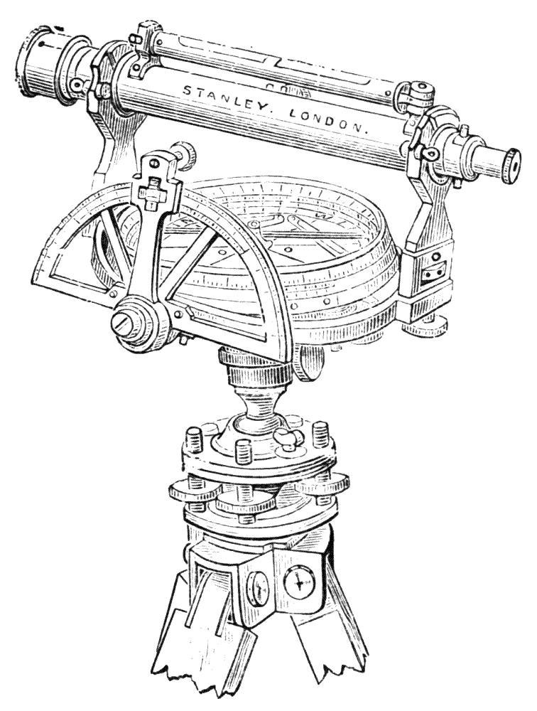
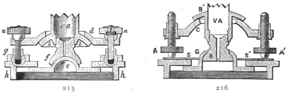
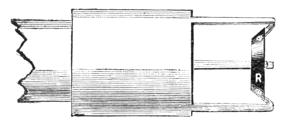
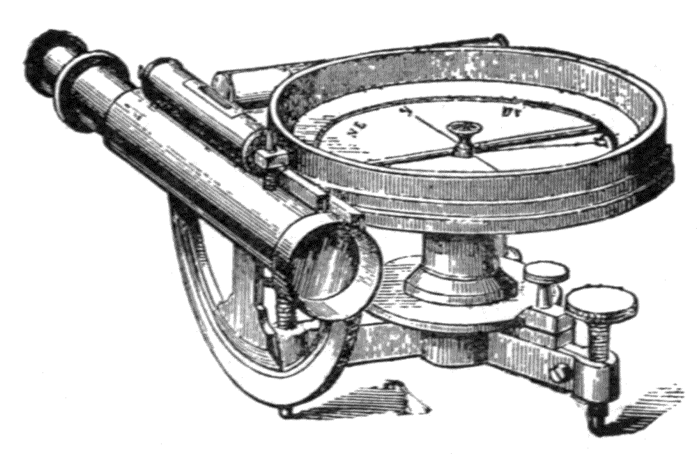
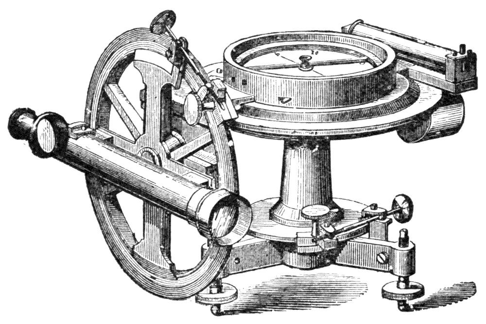
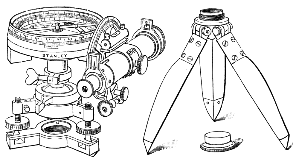
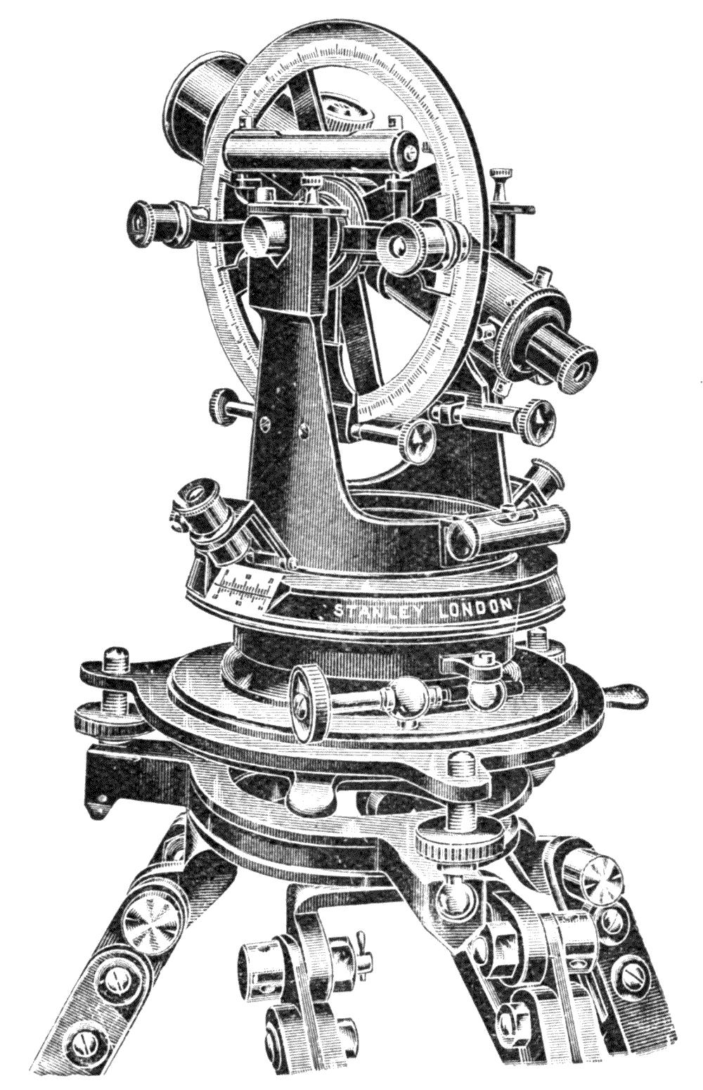
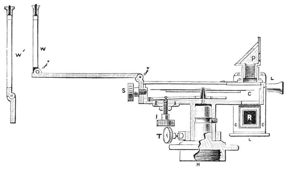
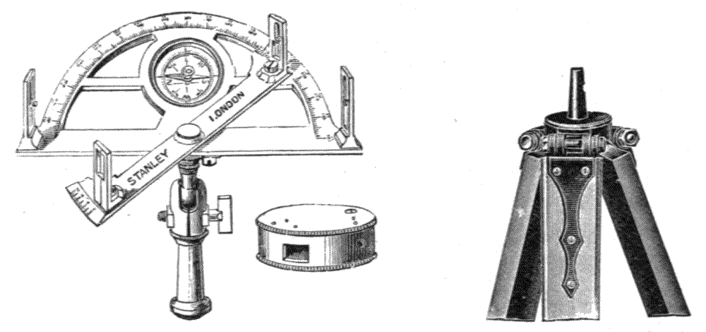
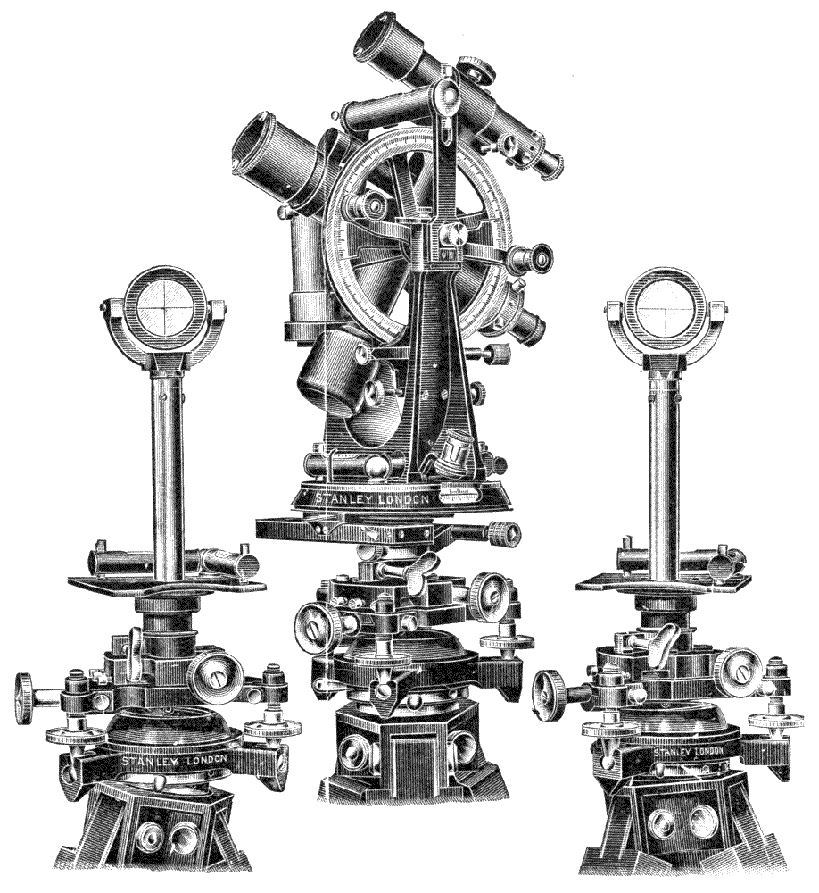
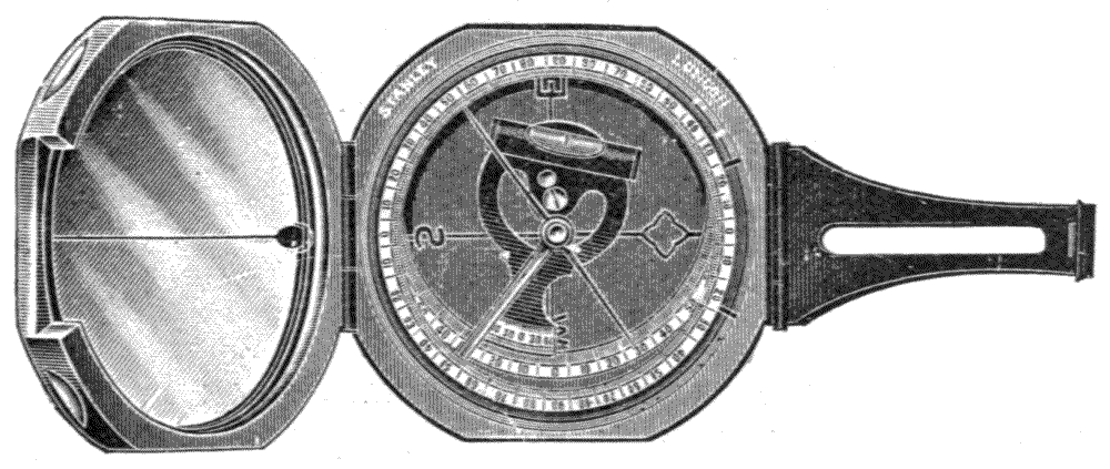
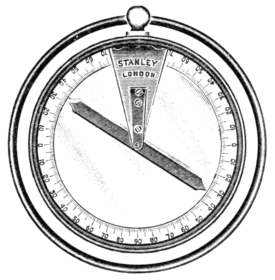
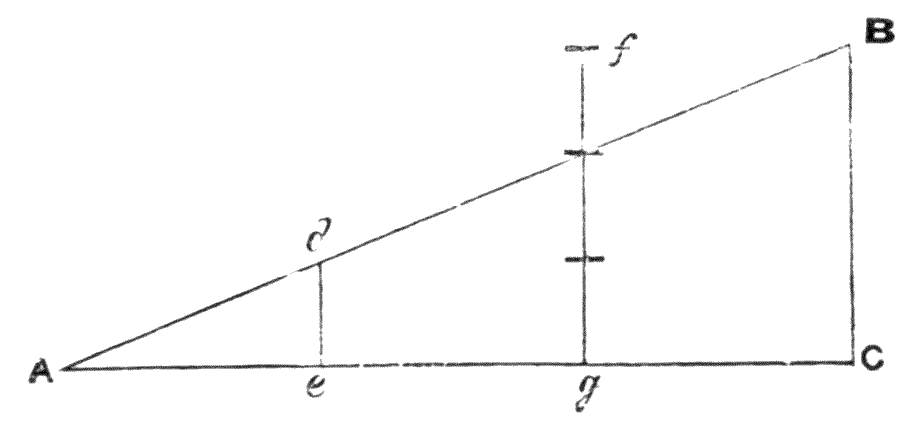
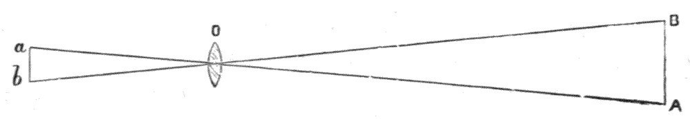
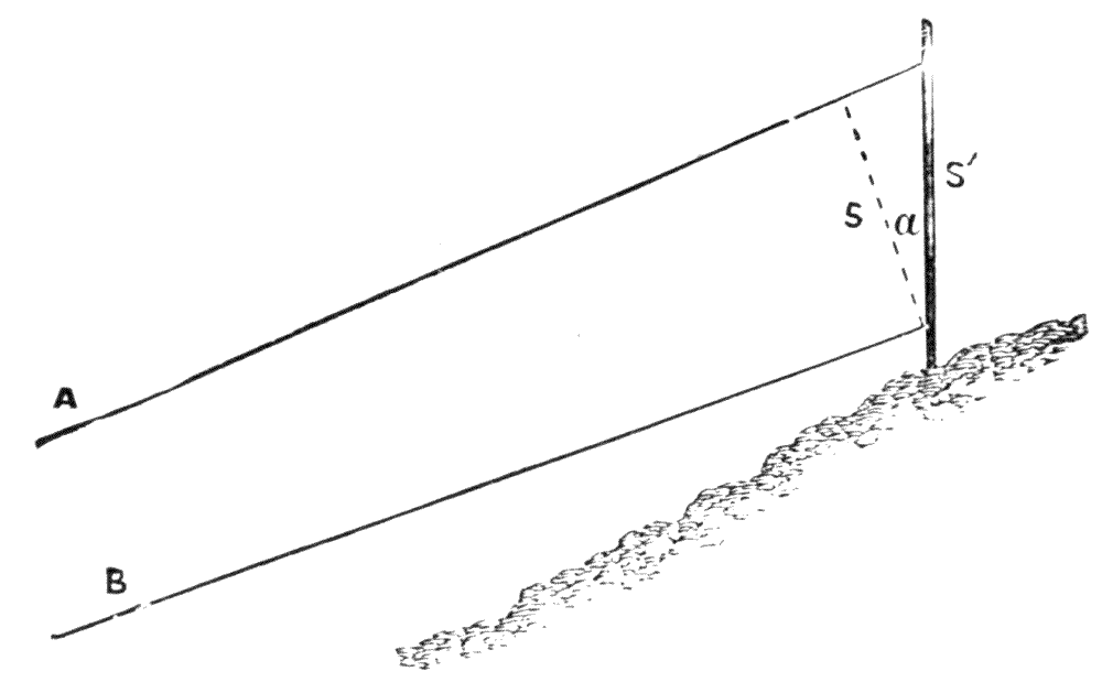
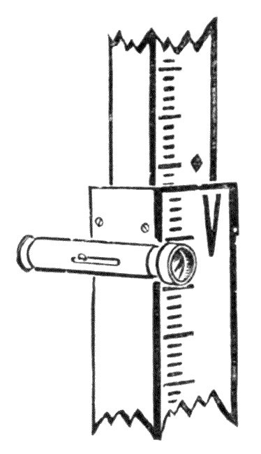
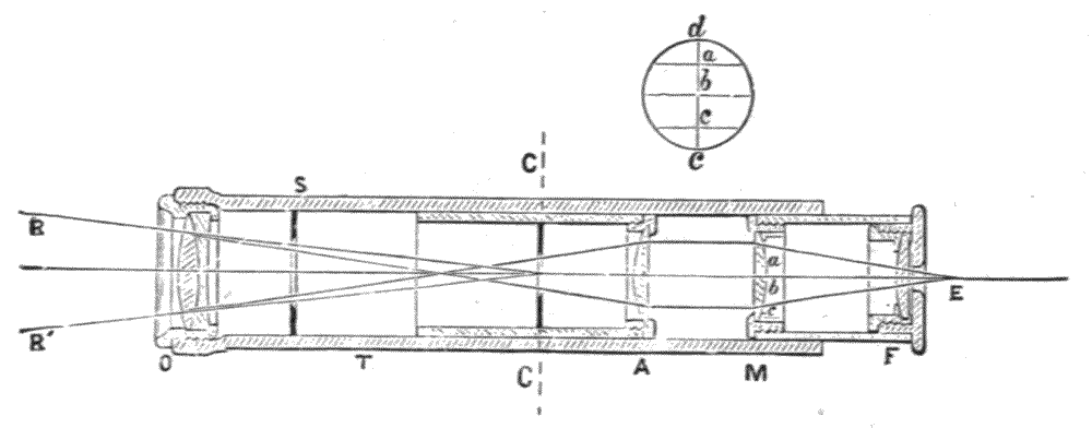
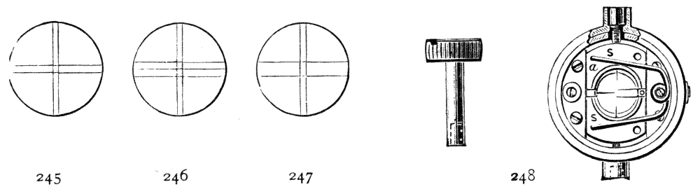
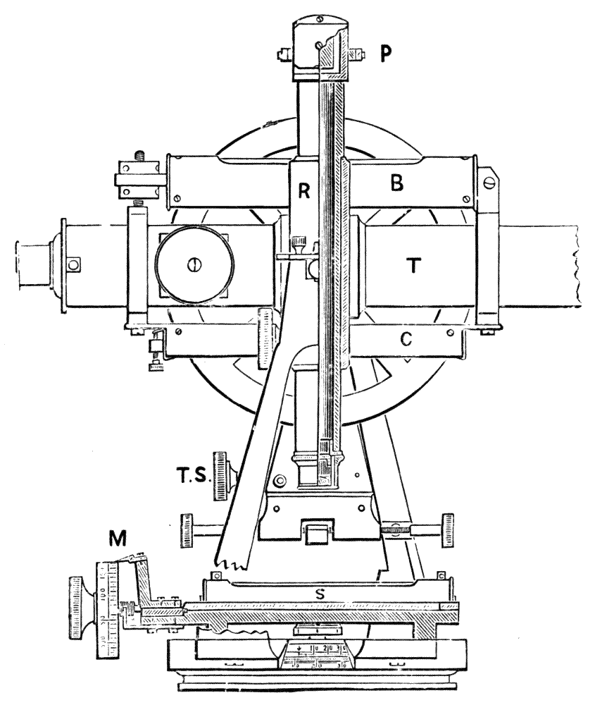
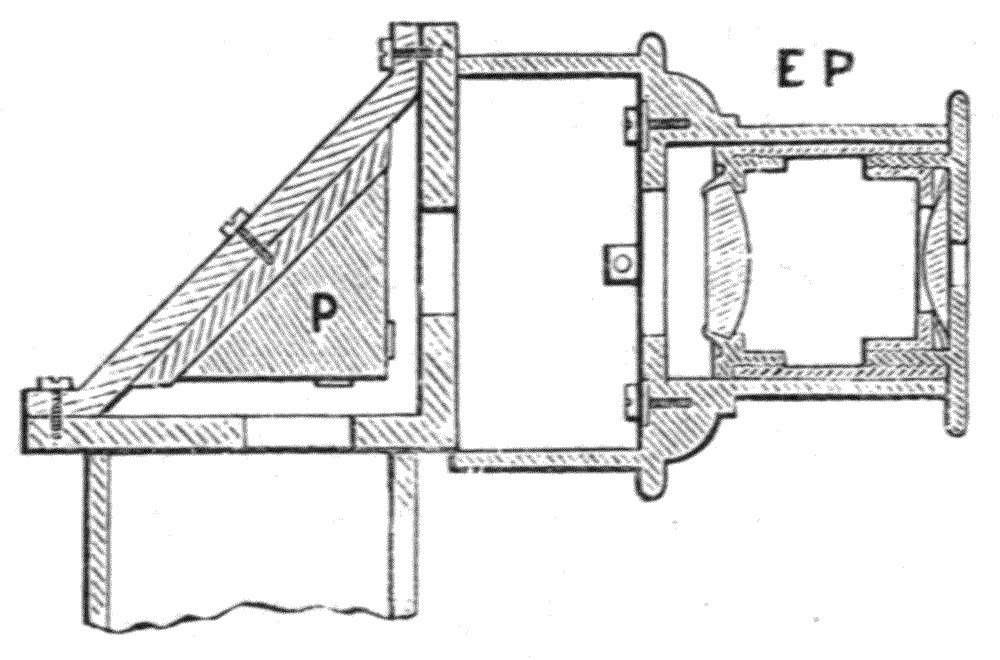
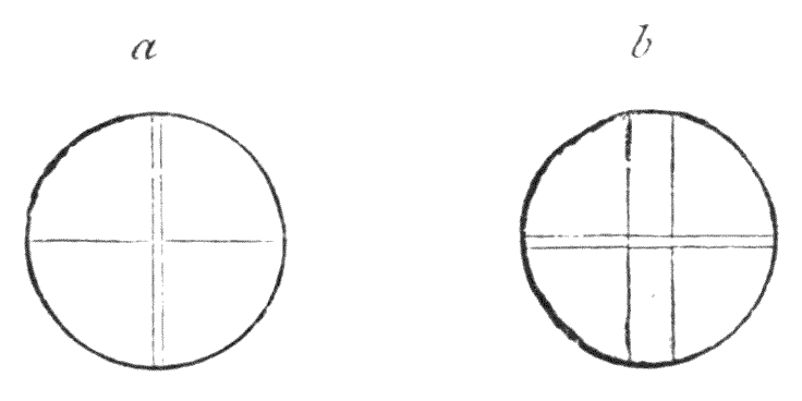
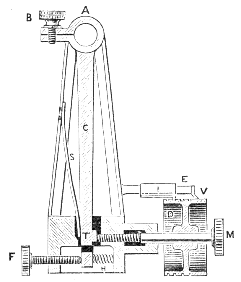
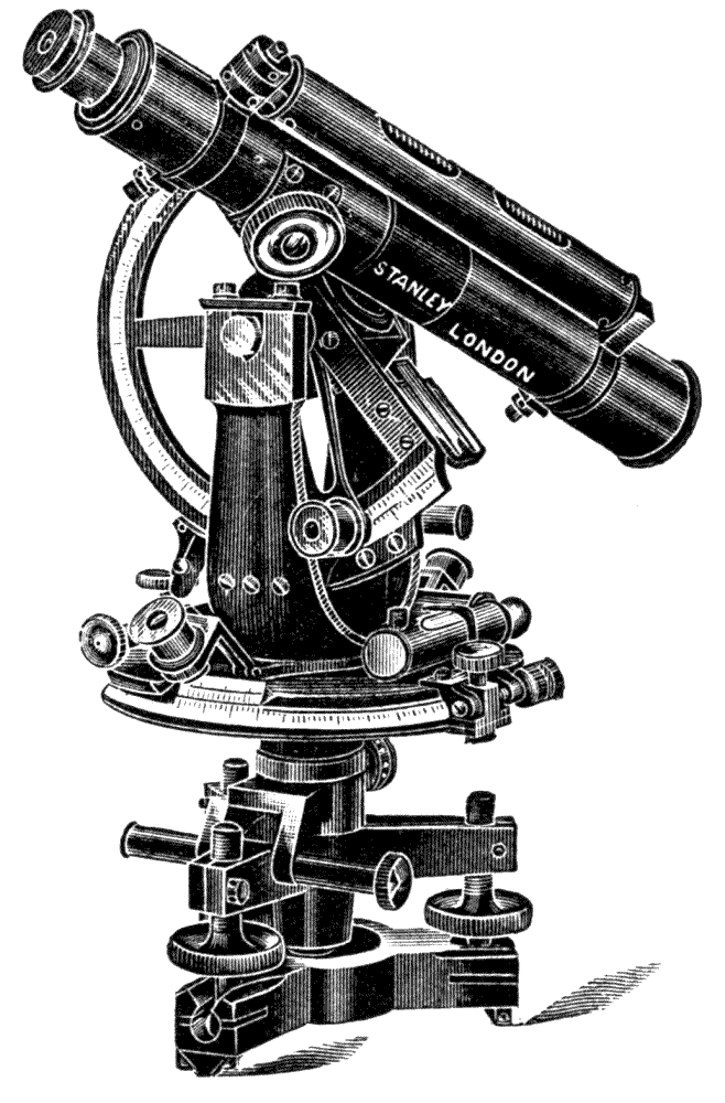
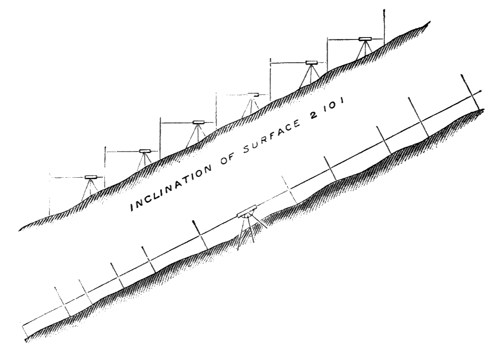
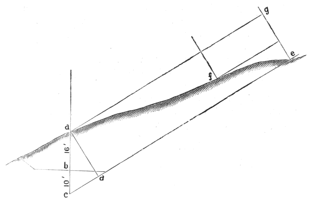
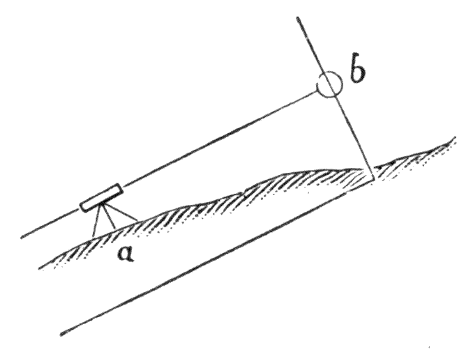
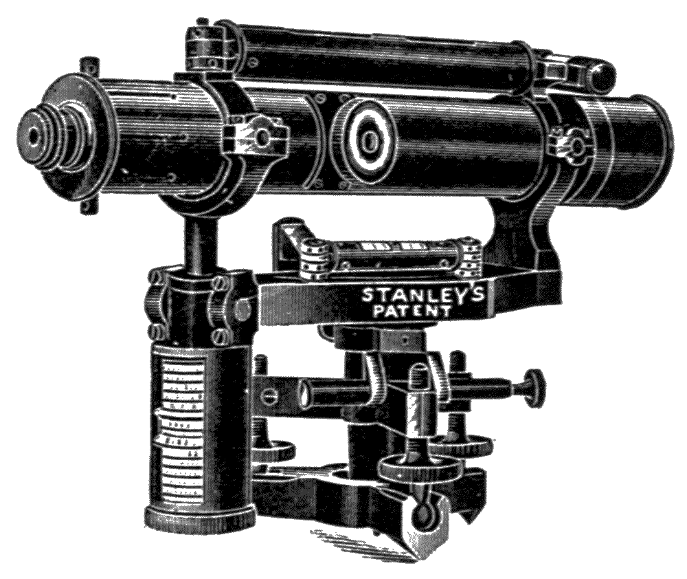
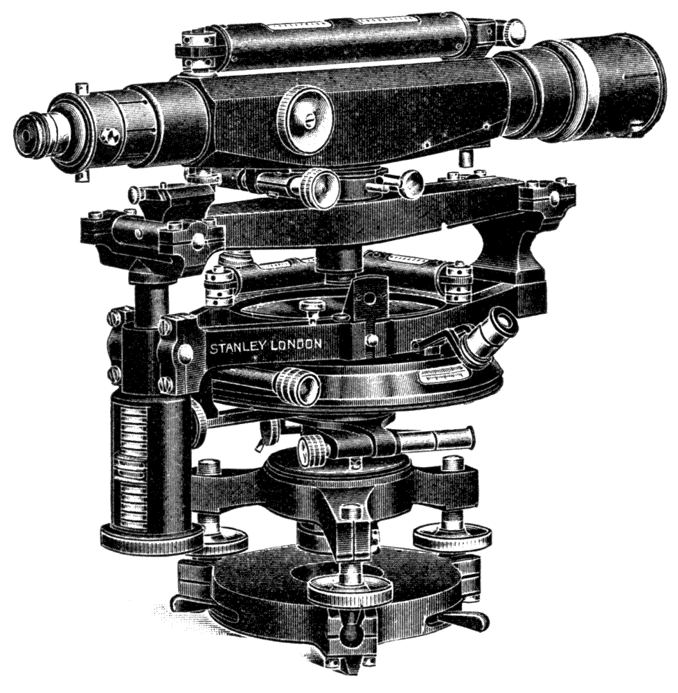
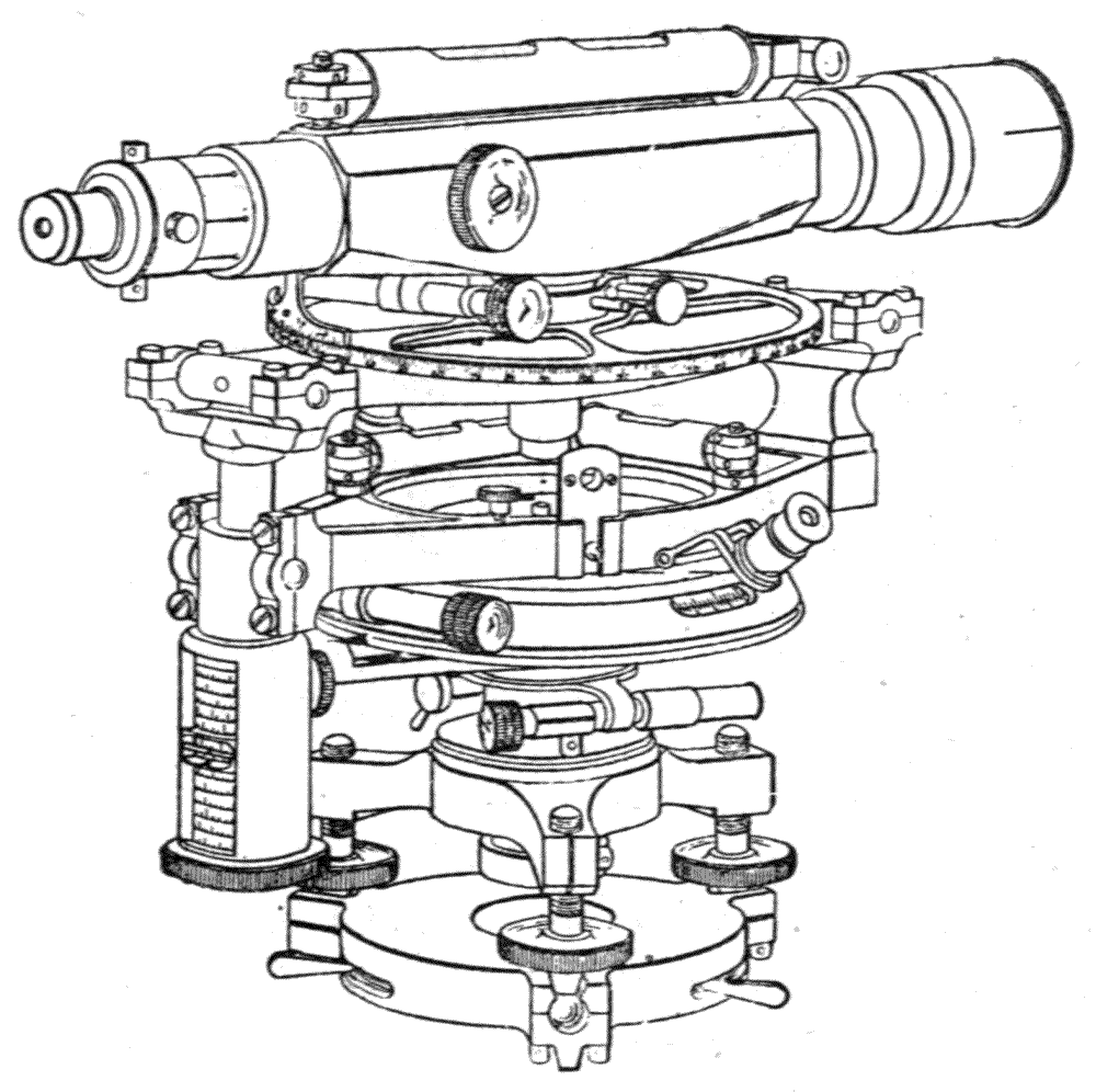
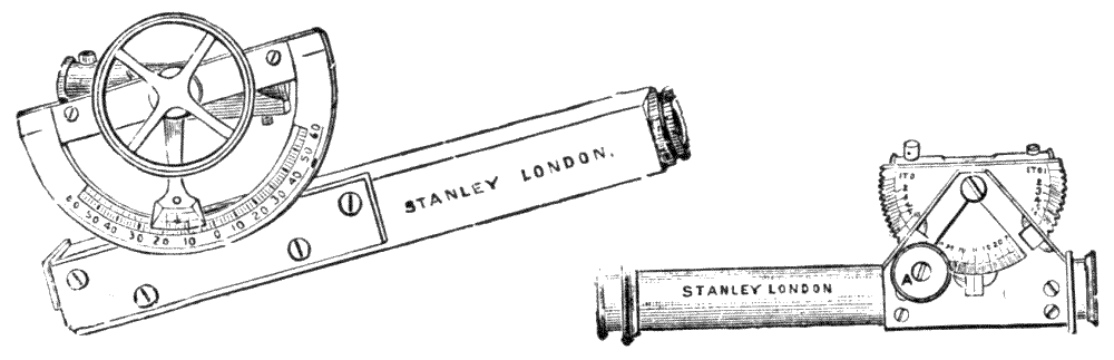
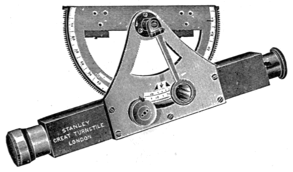
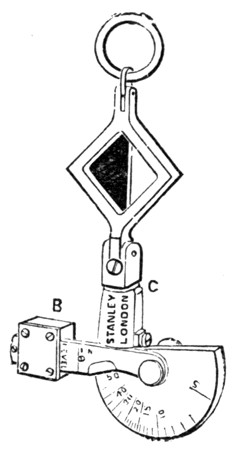
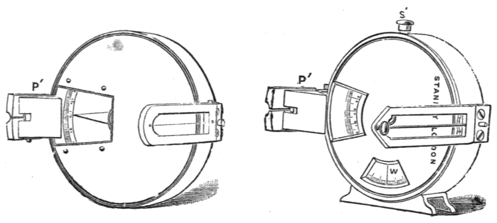
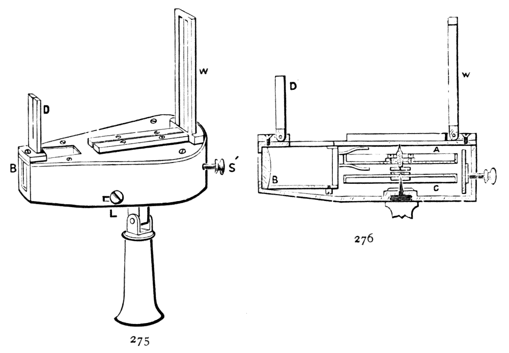
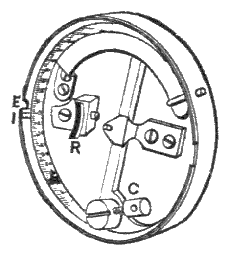
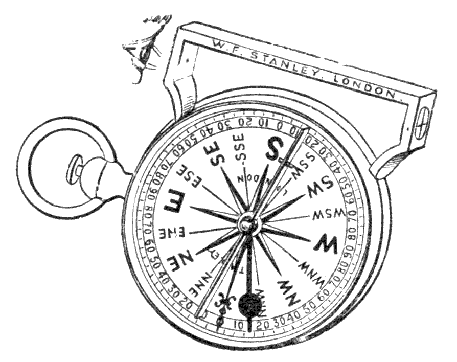
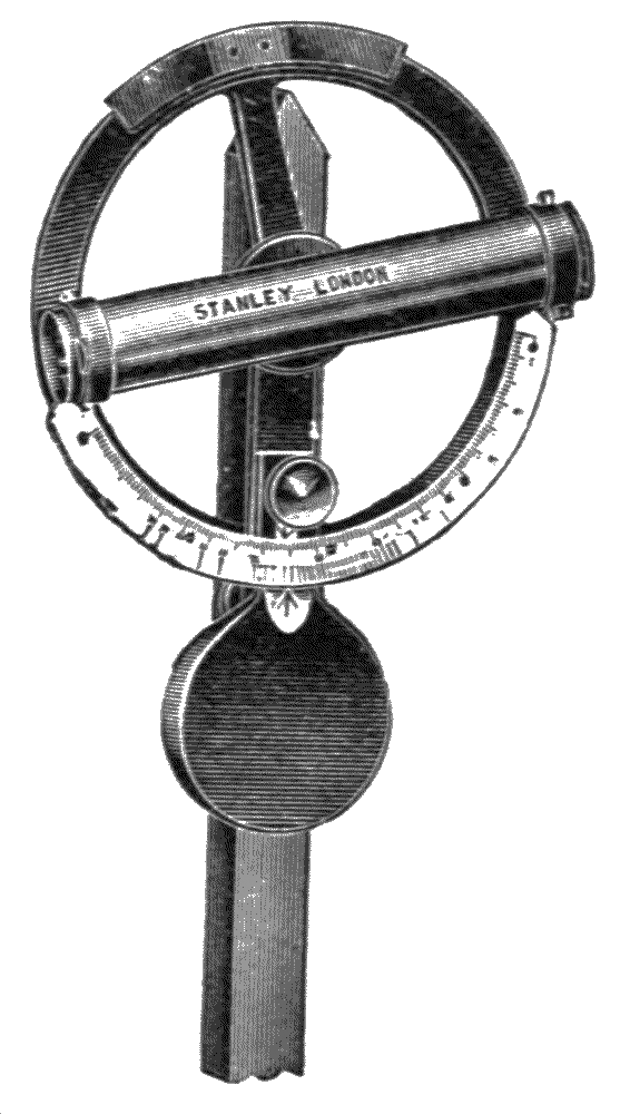
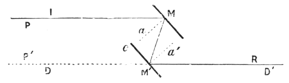
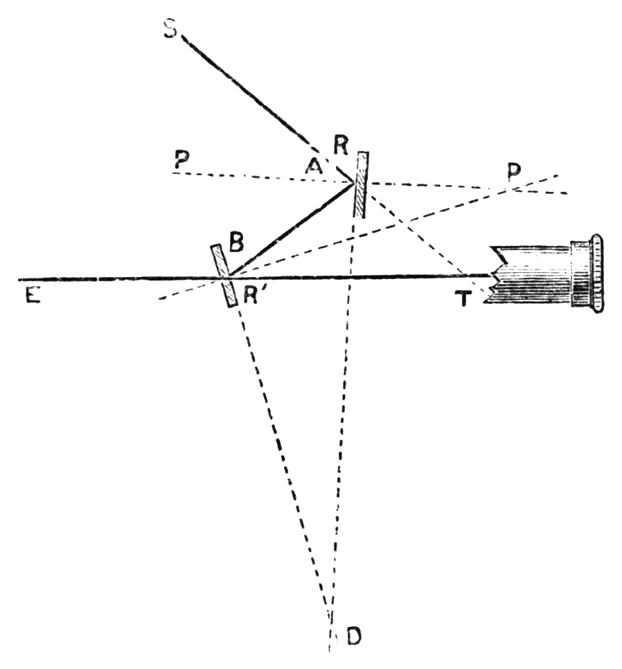
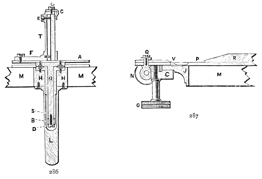
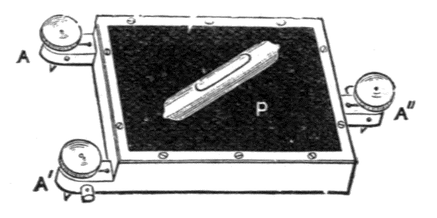
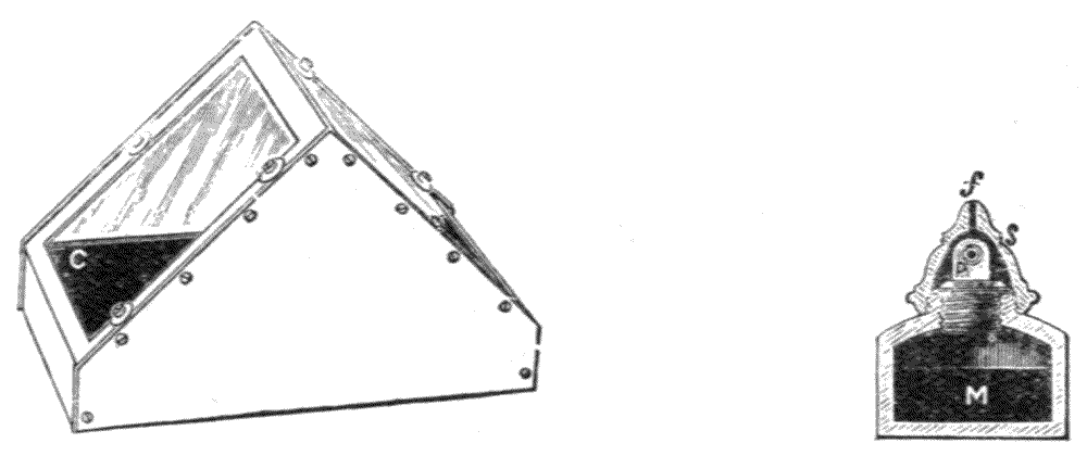
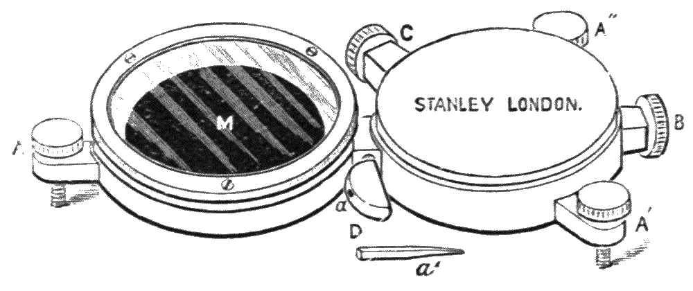
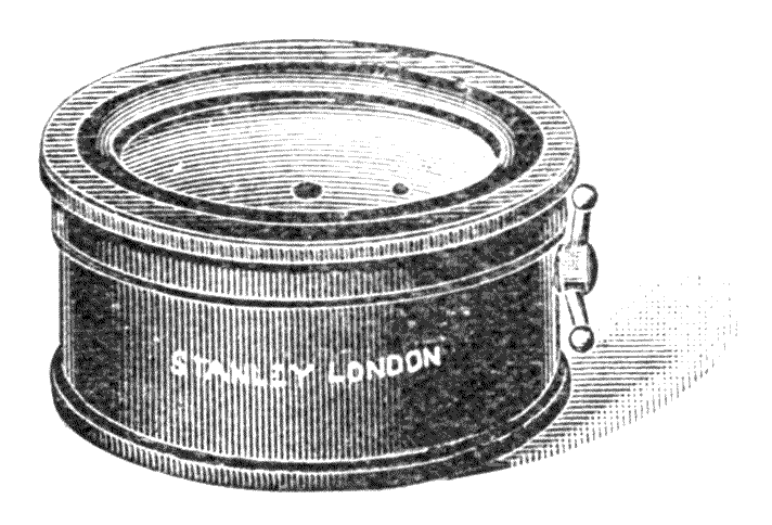
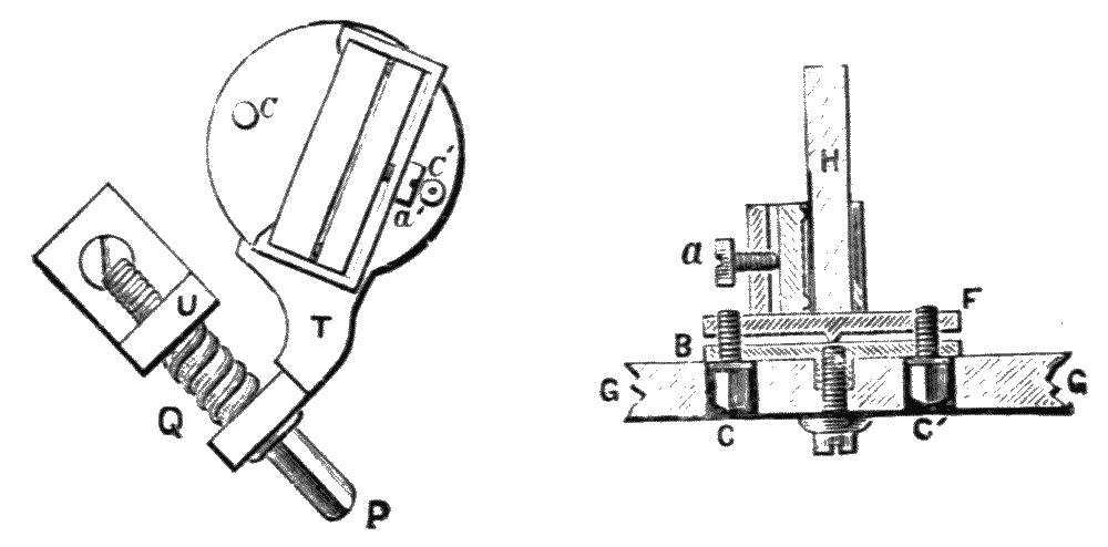
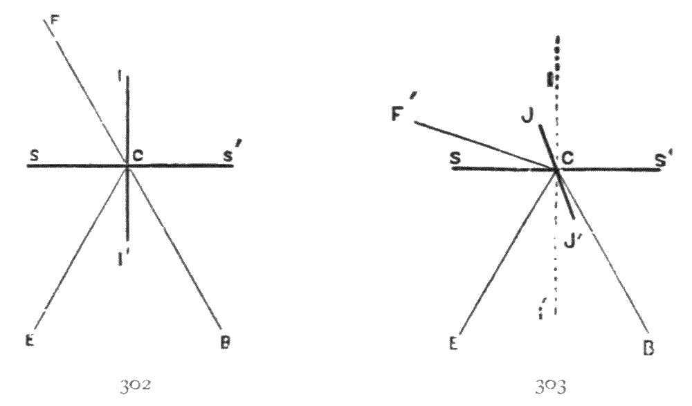
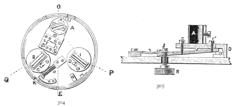
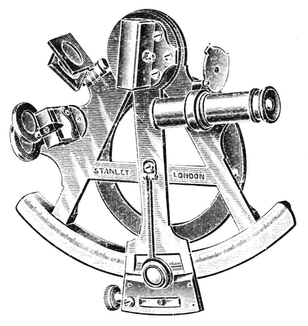
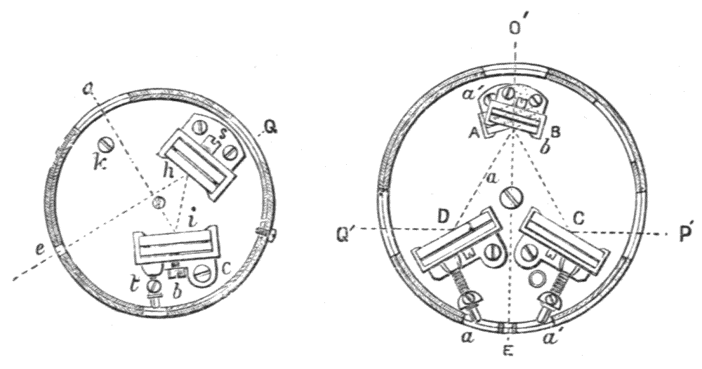
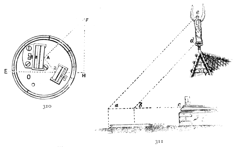
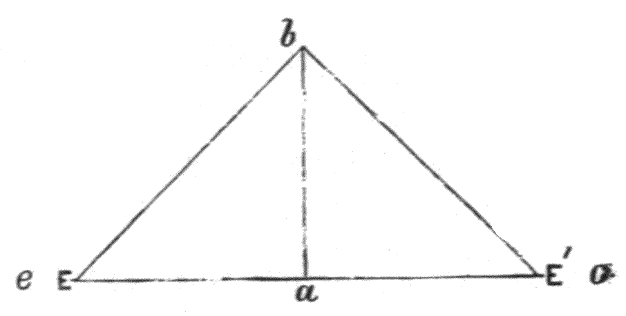
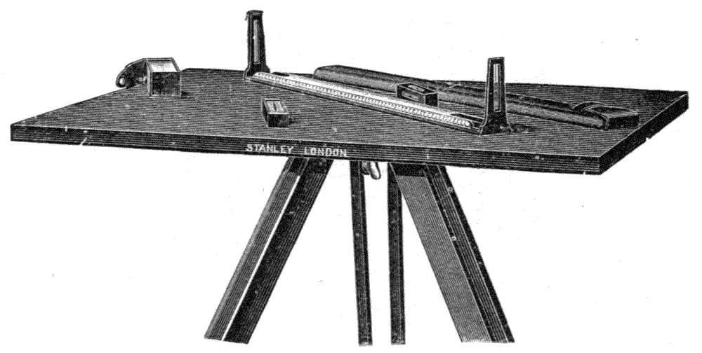
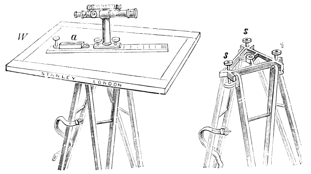
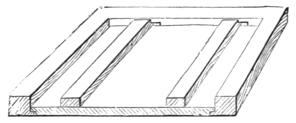
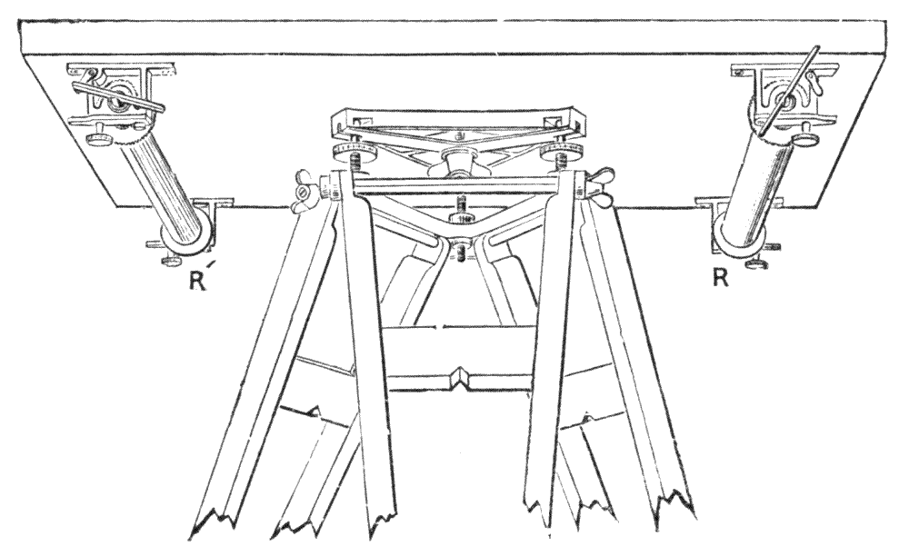
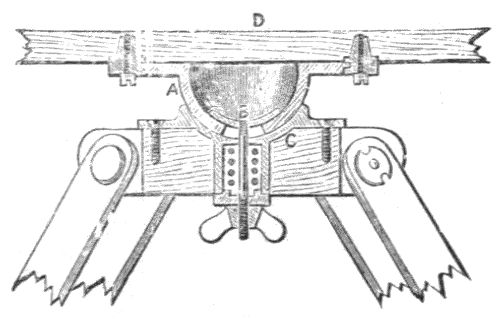
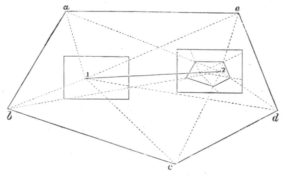
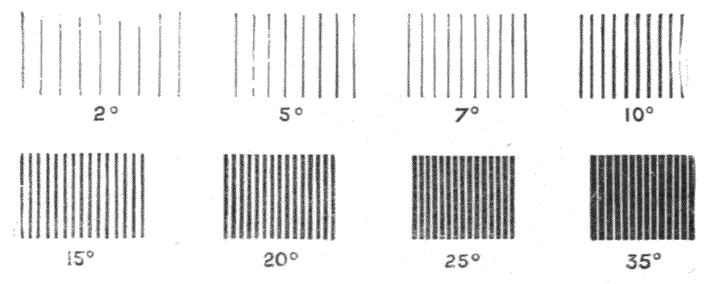
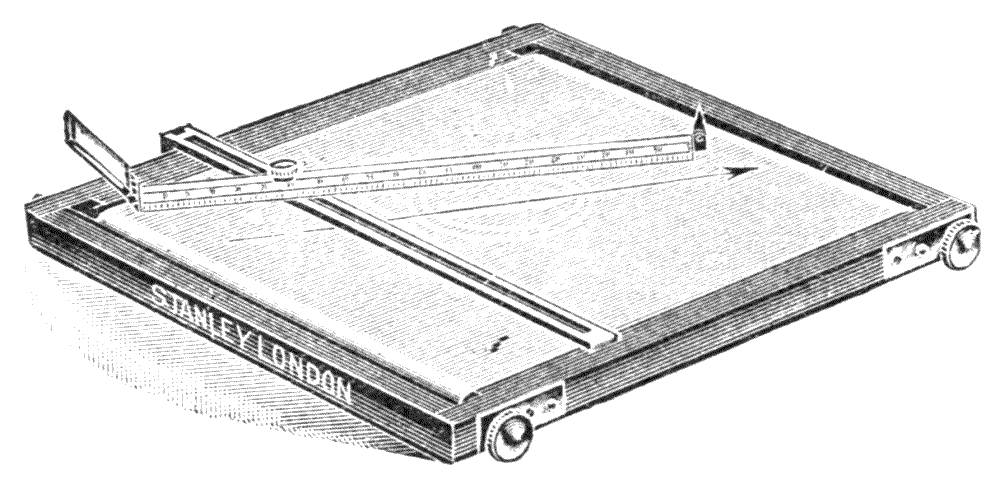
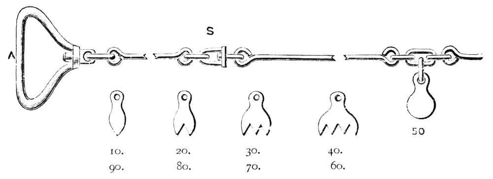
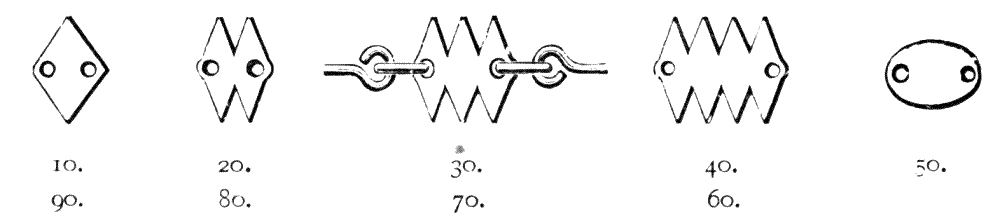
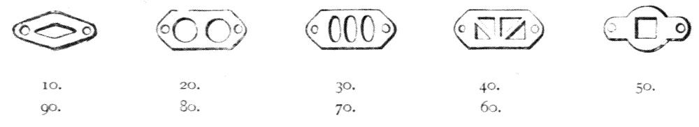
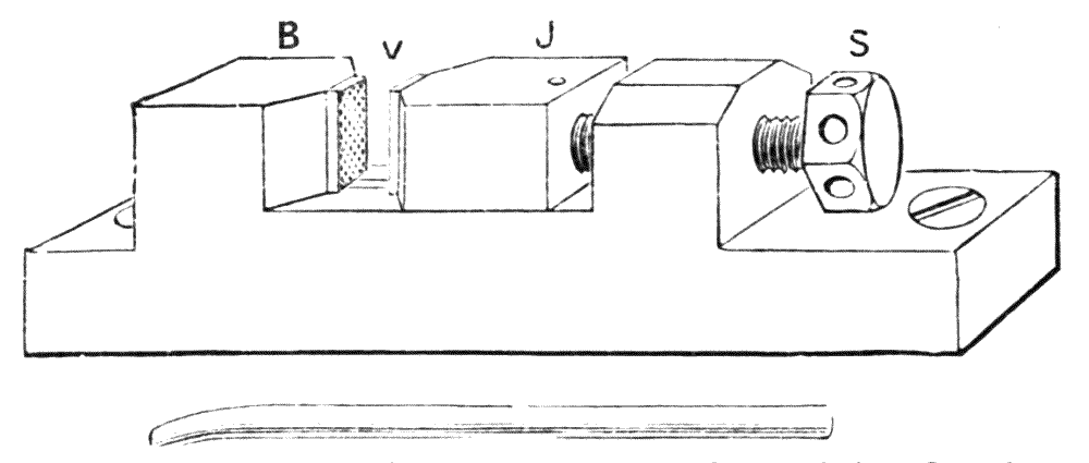
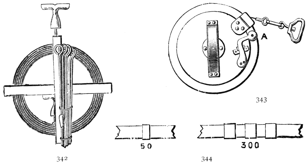
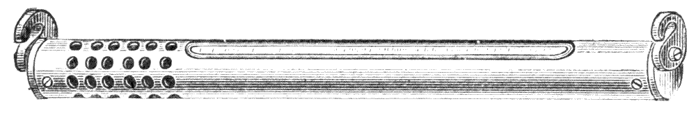
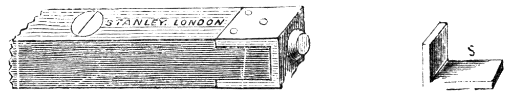
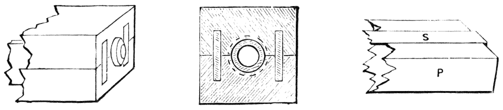
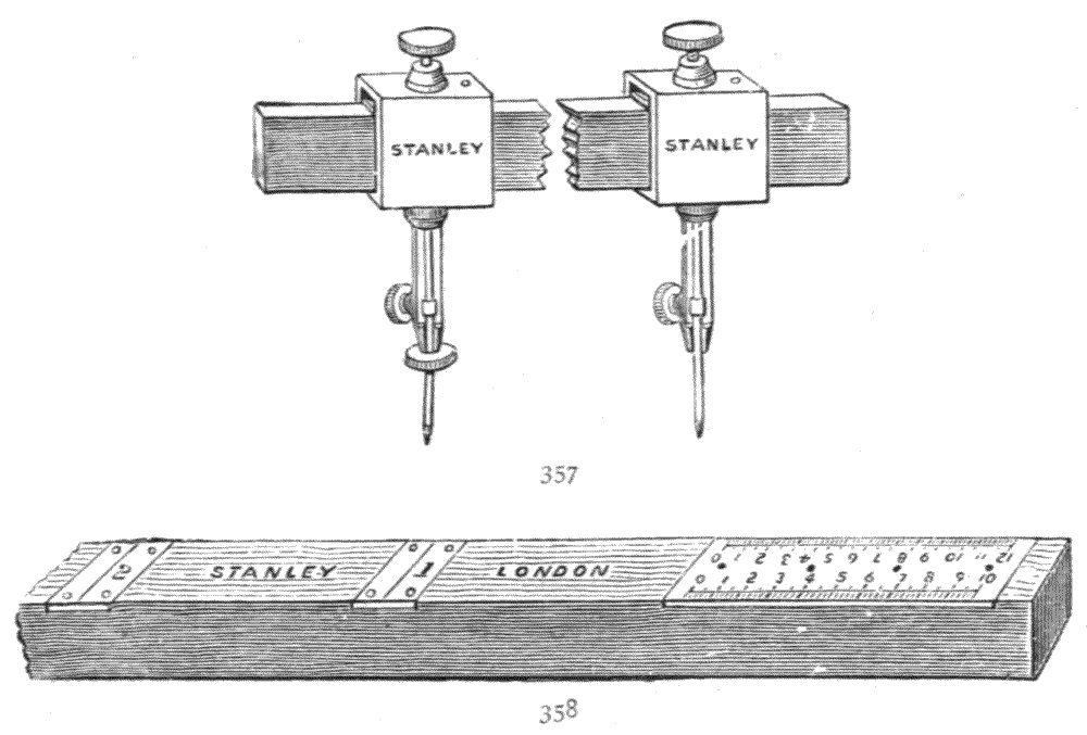
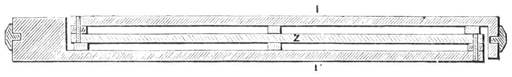
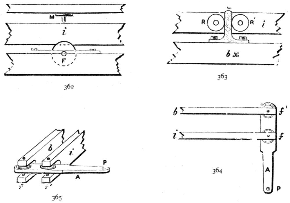
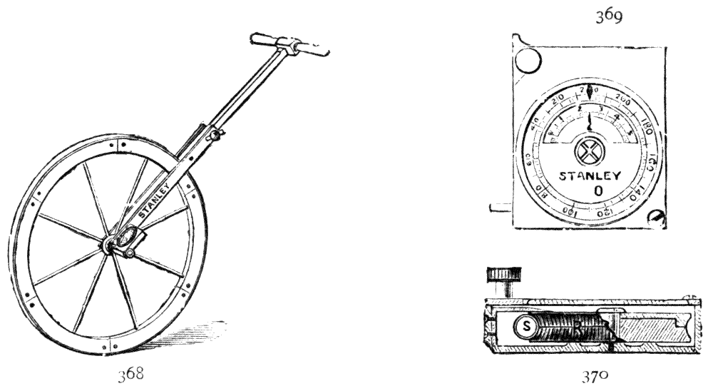
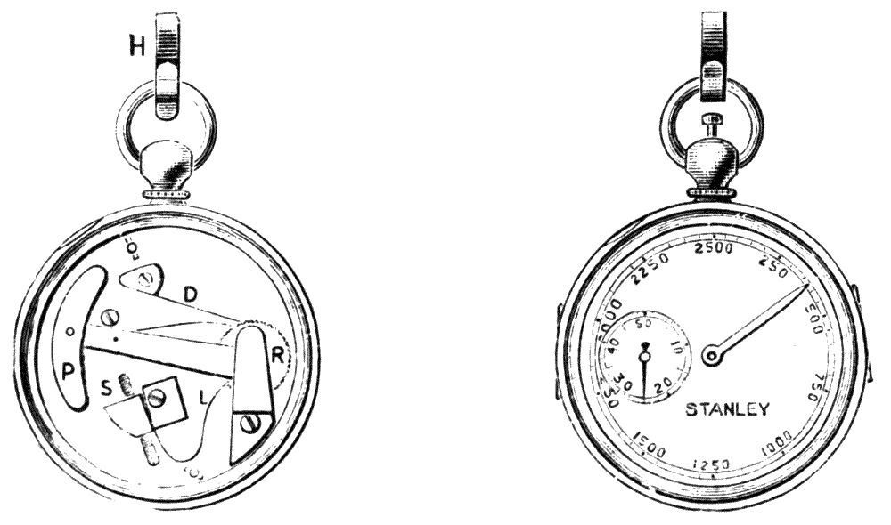
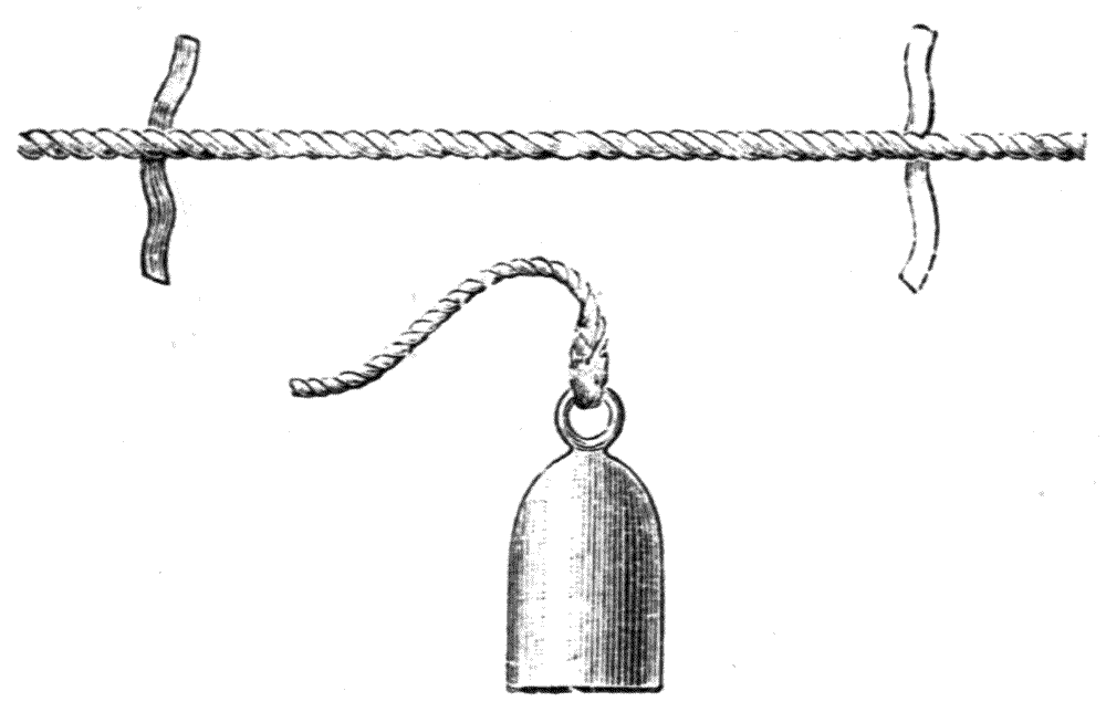
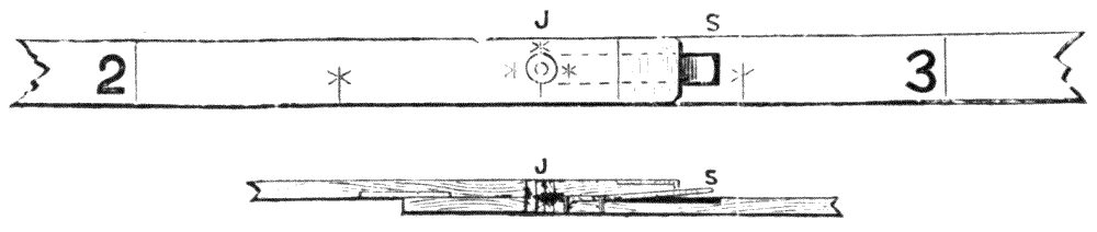
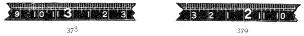
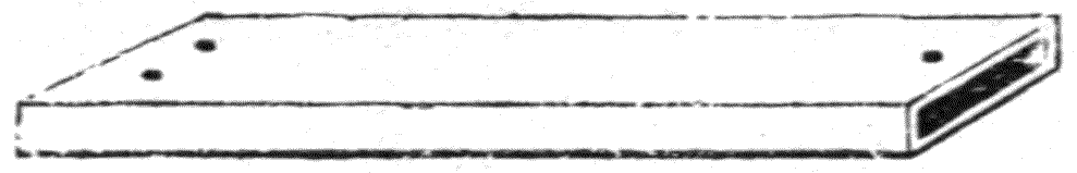
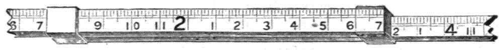
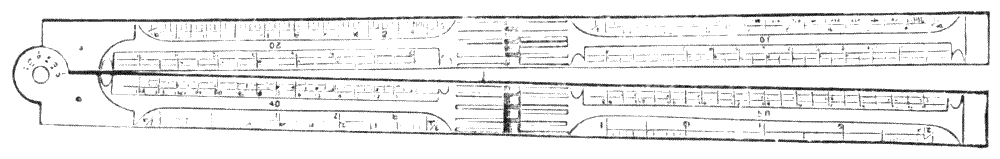
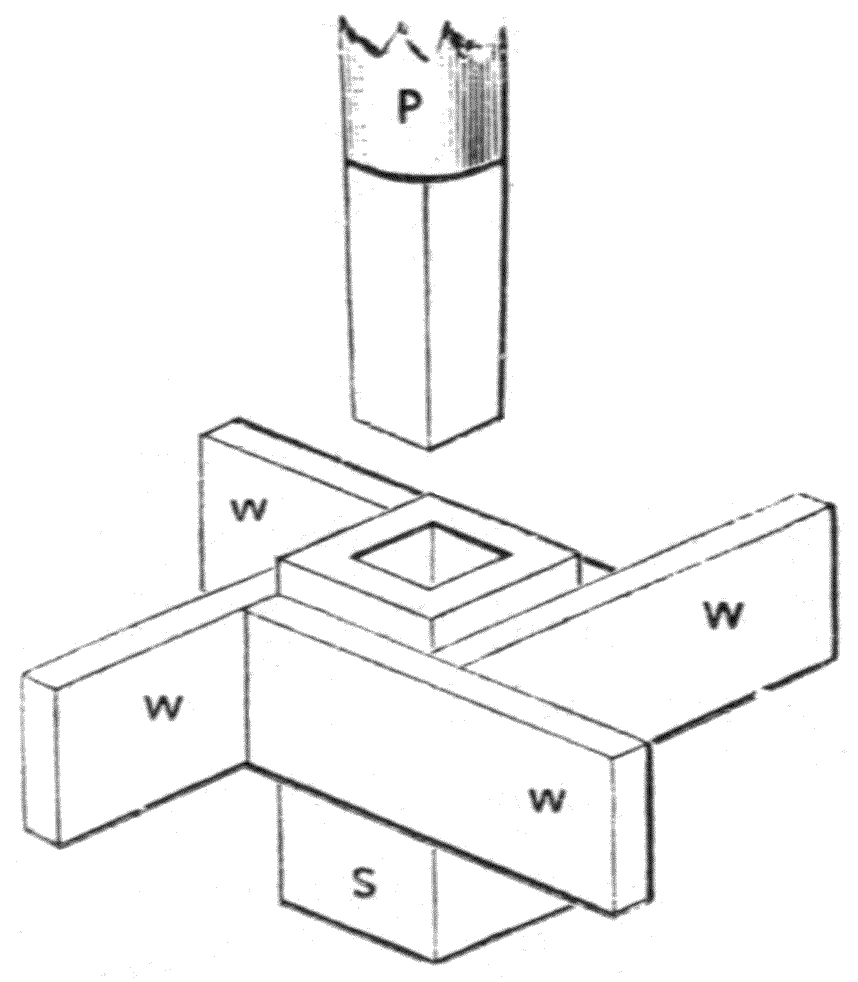
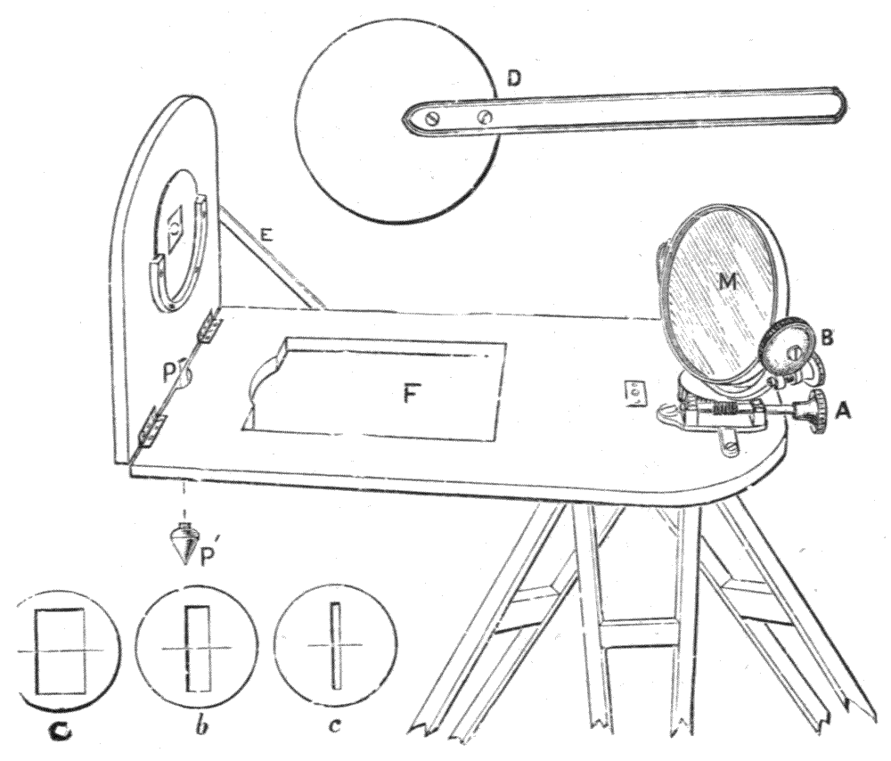
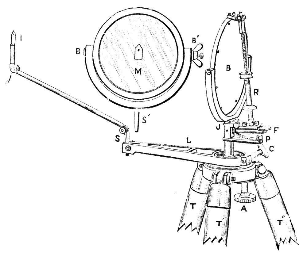
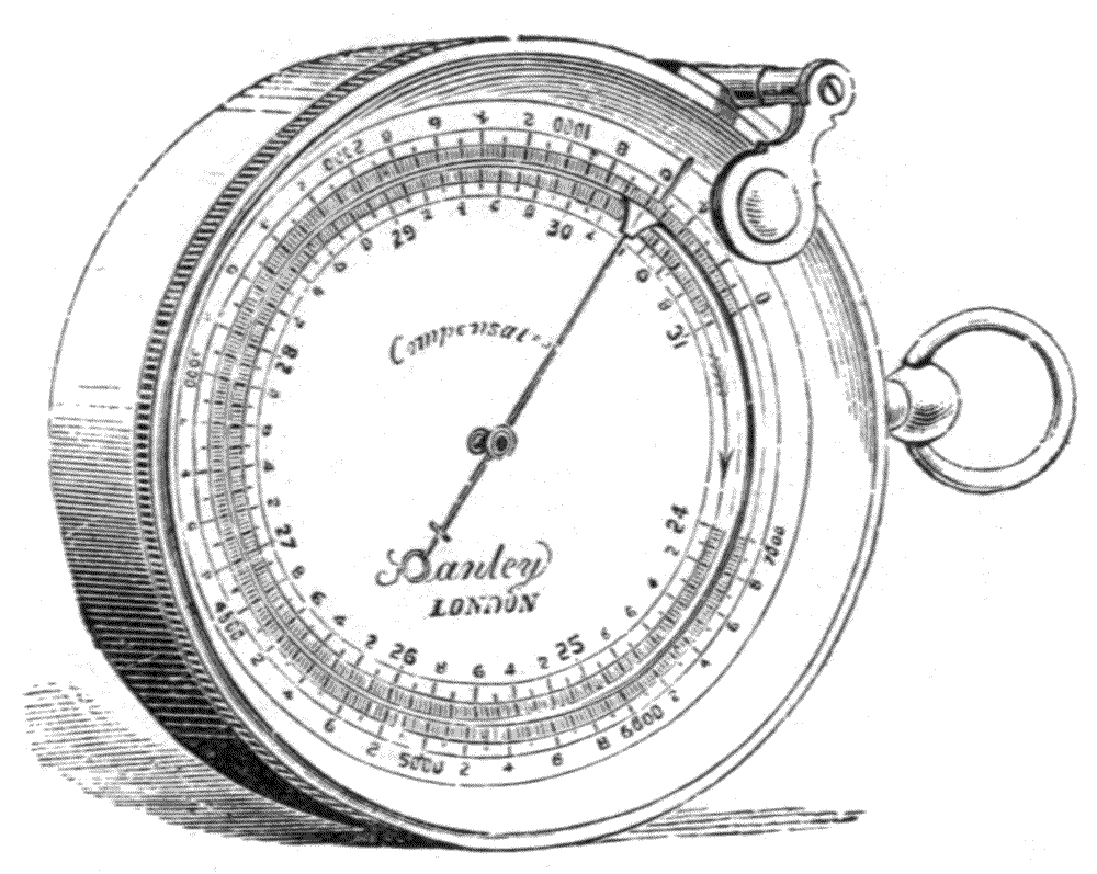
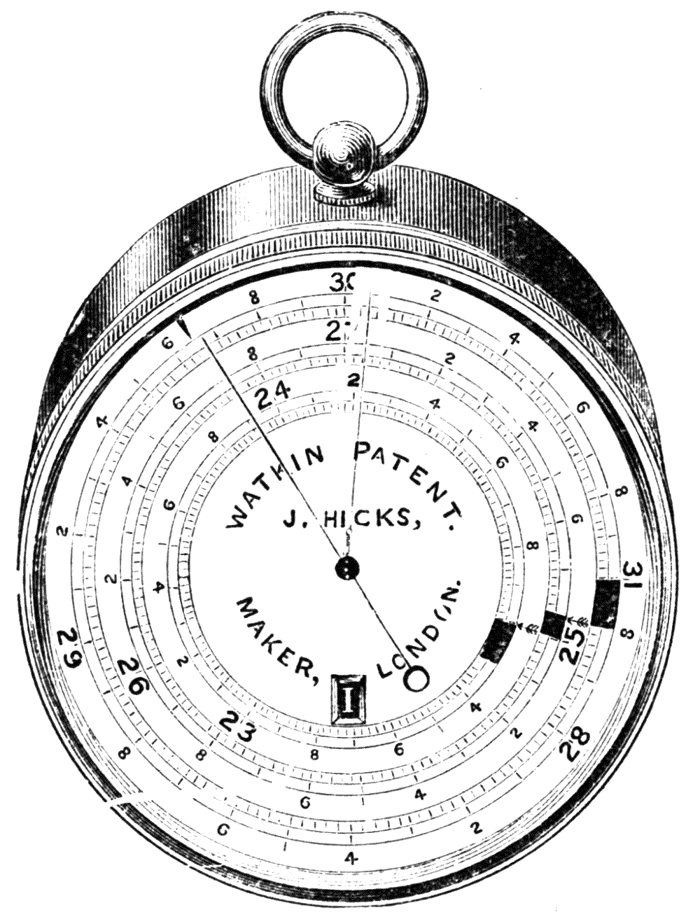
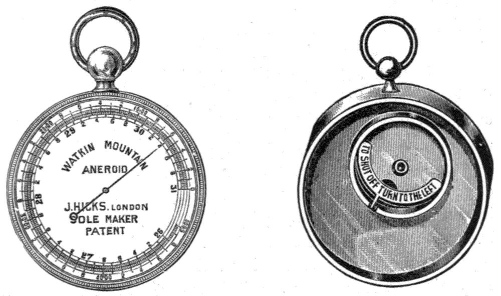
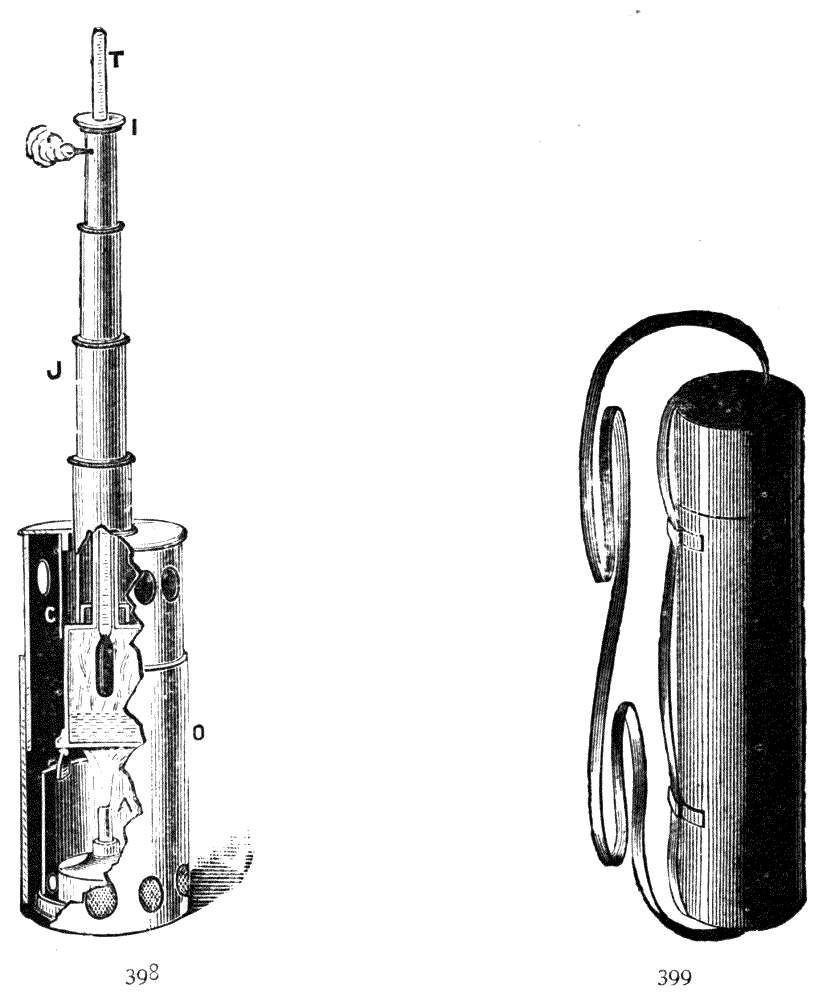
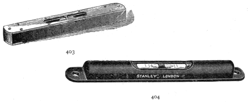
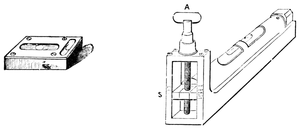
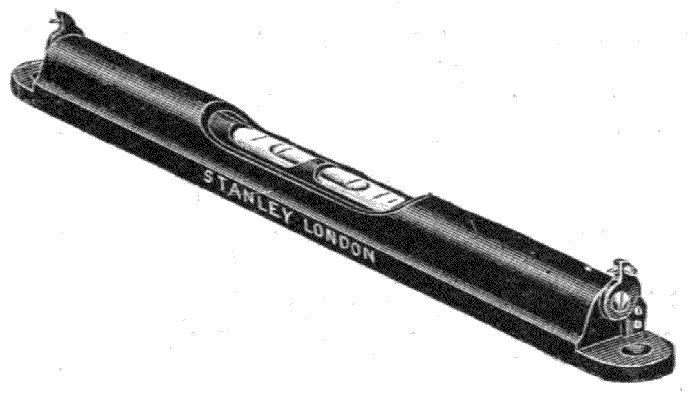
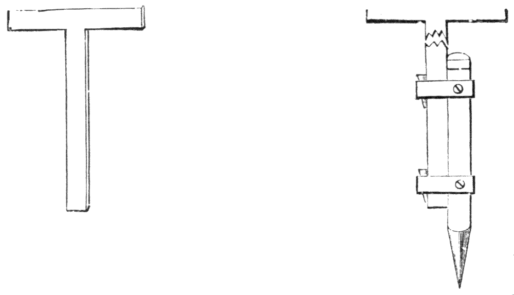
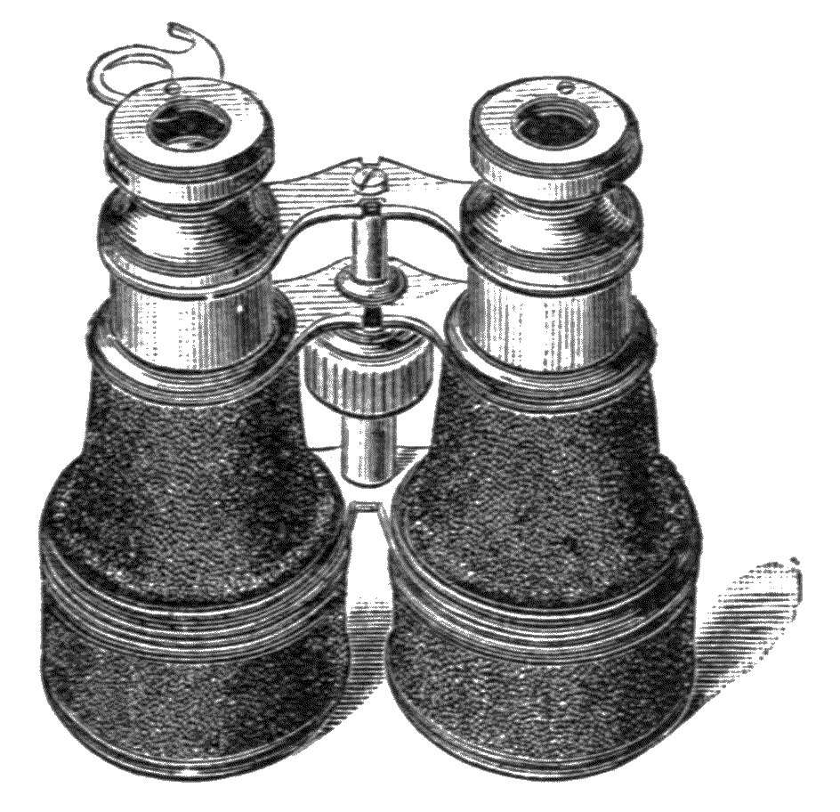
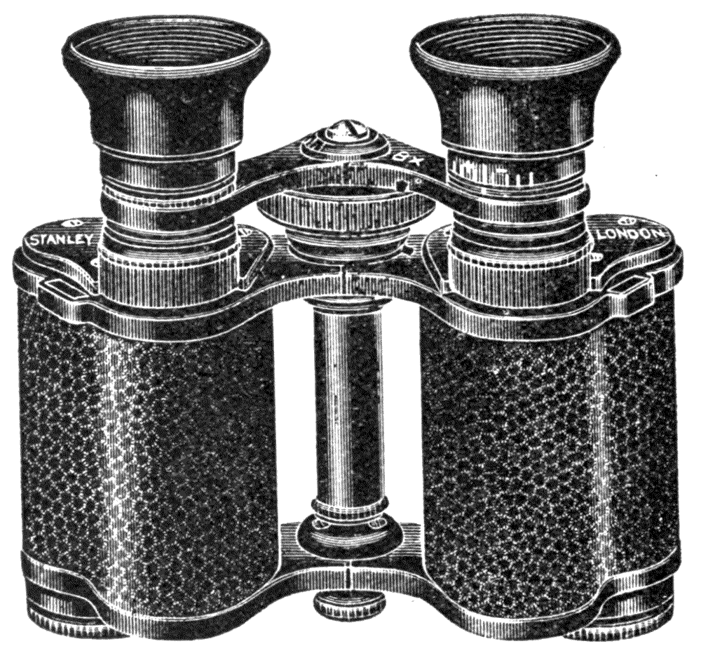
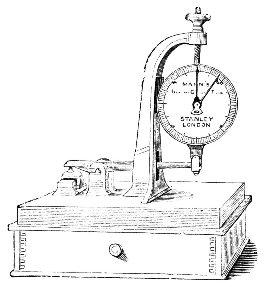
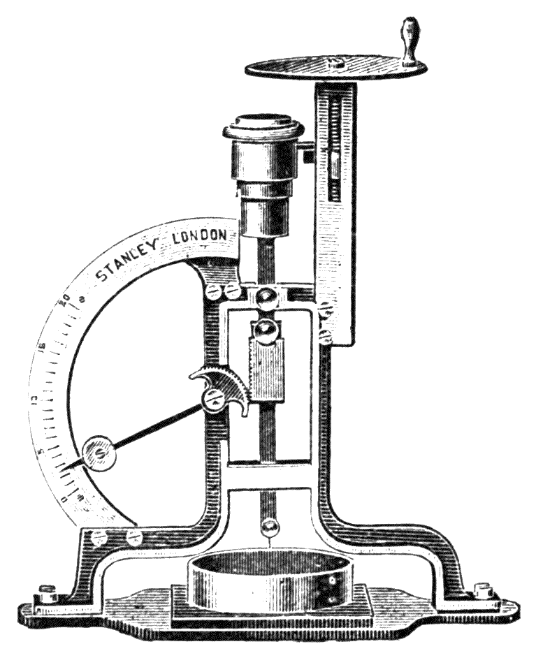
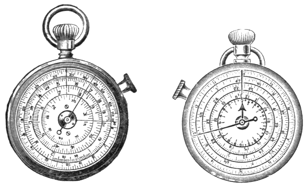
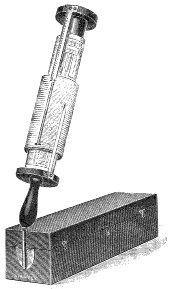
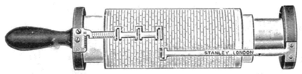
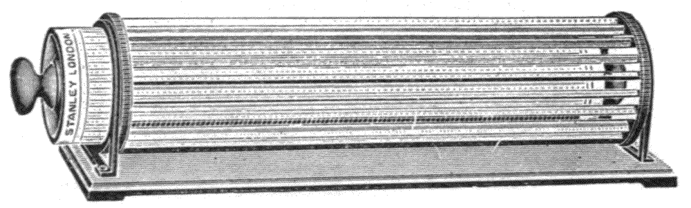
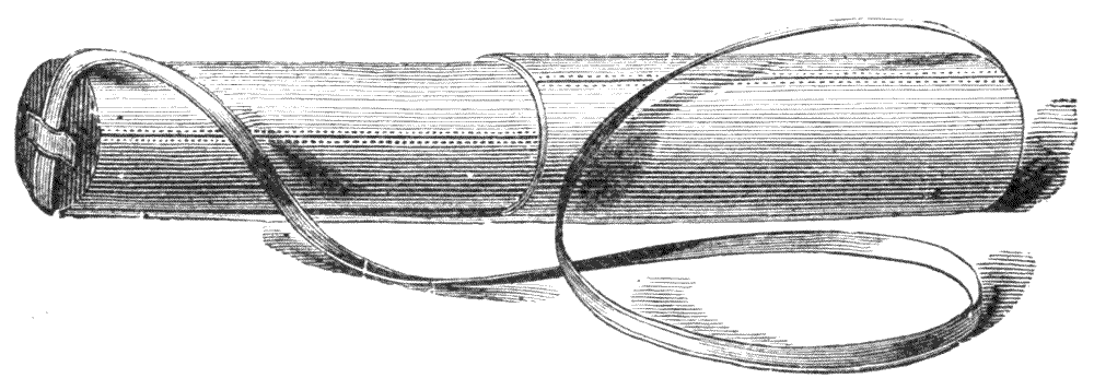