Lessons in Wireless Telegraphy
This ebook is for the use of anyone anywhere in the United States and most other parts of the world at no cost and with almost no restrictions whatsoever. You may copy it, give it away or re-use it under the terms of the Project Gutenberg License included with this ebook or online at https://www.gutenberg.org/license. If you are not located in the United States, you'll have to check the laws of the country where you are located before using this ebook.
Title: Lessons in Wireless Telegraphy
Author: Alfred Powell Morgan
Release Date: September 29, 2020 [EBook #63345]
Language: English
Character set encoding: UTF-8
*** START OF THIS PROJECT GUTENBERG EBOOK LESSONS IN WIRELESS TELEGRAPHY ***
Produced by James Simmons.
This file was produced from page images at the Internet Archive.
Transcriber's Note
This book was transcribed from scans of the original found at the Internet Archive. I have included the ads for other books found in the back pages of these scans.
LESSONS
IN
WIRELESS TELEGRAPHY
A SYSTEMATIC ELEMENTARY COURSE IN THE
PRINCIPLES OF WIRELESS TELEGRAPHY
AND THE ELECTRICAL LAWS
UPON WHICH IT DEPENDS
BY
A. P. Morgan
THIRD EDITION, Revised and Enlarged
PUBLISHED BY
COLE & MORGAN
Publishers of The Arts and Sciences Series
P. O. Box 1473 NEW YORK CITY
Printed in U.S. A.
COPYRIGHT 1912. 1917
BY
COLE & MORGAN
LESSONS IN WIRELESS TELEGRAPHY
INTRODUCTION
This little book has been brought forward in order to supply the demand for a systematic elementary course in the principles of wireless telegraph apparatus and the electrical laws upon which it depends.
Many operators, both amateur and professional, although perfectly well able to send and receive messages, do not thoroughly understand the rudimentary theory of the instruments.
It is readily realizable that it is quite impossible to enter into all the engineering details in a book of this size, but at the same time it has been possible to present a very comprehensive treatise of the subject and embody sufficient material to give a thorough grounding in the subject.
In order to avoid repetition and confusion and to make each instrument or principle which has been discussed stand distinctly by itself, the text has been divided into separate lessons following in their arrangement, as far as has been possible, the logical sequence.
For the same reason, and also because of lack of space all details pertaining to the actual maintenance and adjustment of the instruments has been embodied in another book called "The Operation of Wireless Telegraph Apparatus."
LESSON ONE. MAGNETISM.
Natural Magnets. Artificial Magnets. Magnetic Field of Force.
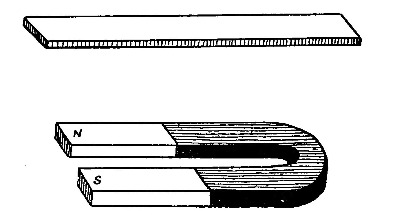
It was known to the ancients that certain hard, black stones, an iron ore consisting of iron and oxygen found notably at Magnesia in Asia Minor, possessed the power of attracting small pieces of iron or steel. This almost magic attribute of the stone was early turned to account in navigation and secured for it the name of Lodestone (leading-stone) because of its remarkable property of pointing north and south when suspended by a thread. The name of magnet (magnes lapis) was also given to these stones.
Magnetism is the peculiar property occassionally possessed by certain bodies (more especially by iron and steel) whereby they attract or repel one another.
If a piece of hard iron or steel be rubbed with a lodestone it will be found to have also acquired the properties of the stone. If hung up by a thread it will point north and south, will attract light bits of iron and if dipped into iron filings will cause the latter to cling in two small tufts near the ends with few, if any, near the middle.
This indicates that the attractive power of the magnet is concentrated in two opposite parts. These parts are called the Poles. The line joining the poles is the Magnetic Axis.
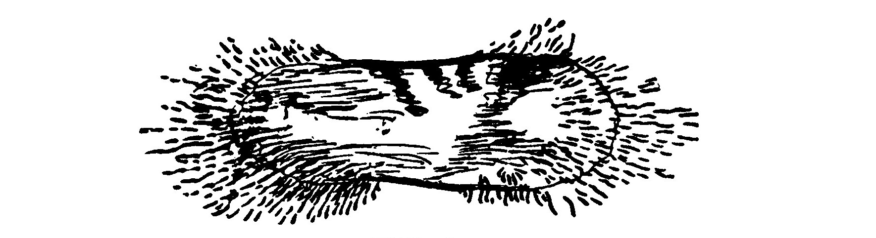
Artificial Magnets are those made from steel by the aid of a lodestone or some other magnetising force. The principal forms of artificial magnets are the Bar and Horseshoe, so called from their shape.
If a magnet (either artificial or natural) is suspended by a thread so that it may swing freely, and a second magnet held in the hand is presented successively to the two poles of the first, it will be observed that one pole is attracted and swings toward the magnet held in the hand, but that the other is repelled and swings away.
Furthermore, if the poles of the suspended magnet are marked so as to easily be identified it will be found that it is always the same pole that swings towards the north. There would therefore appear to be two kinds of magnetism or at least two kinds of magnetic poles. The end swinging toward the north is termed the "north seeking pole" and the opposite end called the "south seeking pole." In common parlance they are simply termed the North and South poles. It is usual to mark the North Pole with the letter N.
There is no known insulator of magnetism: it passes through everything. A magnetic substance is one which offers little resistance to the field of force.
Magnetism flows along certain lines called Lines of Magnetic Force. These lines always form closed paths or circuits. The region in the neighborhood of a magnet through which these lines pass is called the Field of Force and the path through which they flow is called the Magnetic Circuit.
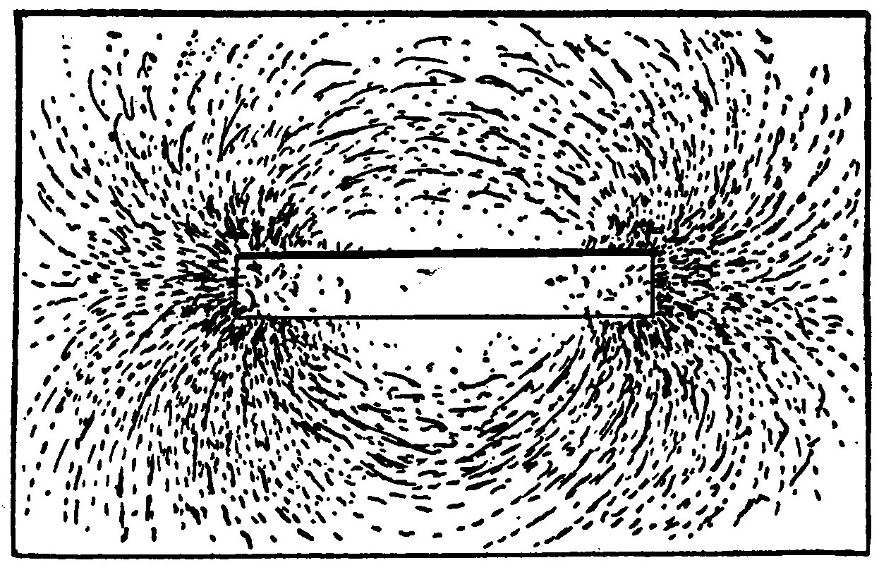
The paths of the lines of force can be demonstrated by placing a piece of paper over a bar magnet and then sprinkling iron filings over the paper which should be jarred slightly in order that the filings may be drawn into the magnetic paths. The filings arrange themselves in curved lines, diverging from one pole of the magnet and meeting again at the opposite end. The lines of force are considered as extending outward from the North pole of the magnet, curving around through the air to the South pole and completing the circuit back through the magnet.
The phenomena of magnetism and its laws form a very important branch of the study of electricity, for they play a part in the construction and operation of almost all electrical apparatus.
LESSON TWO. MAGNETIC INDUCTION.
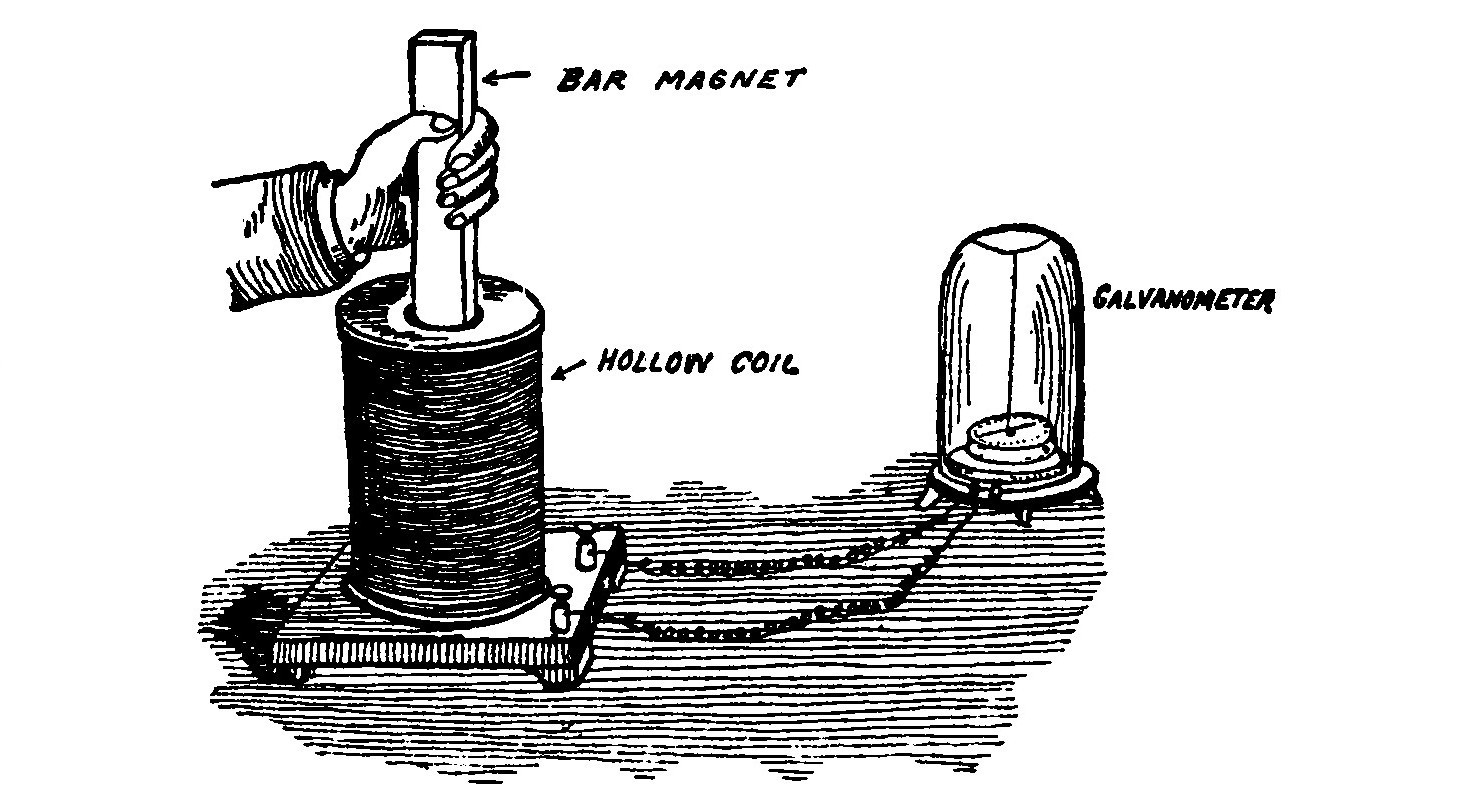
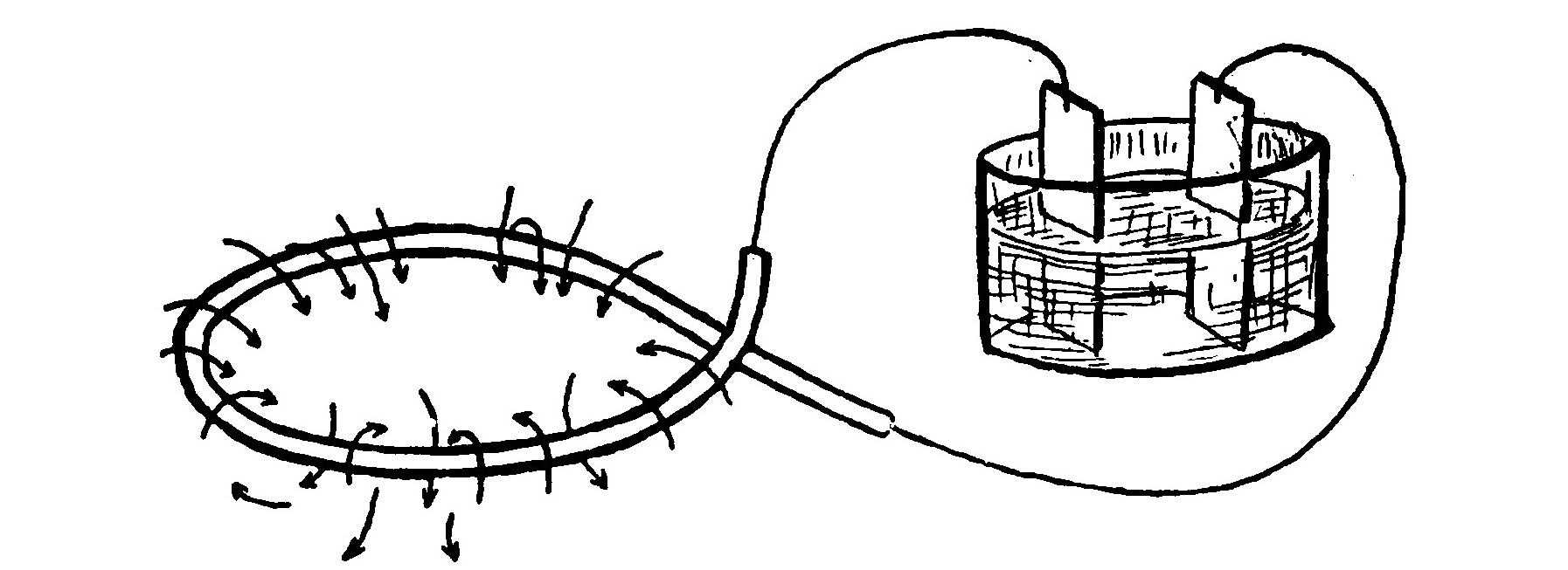
In 1831 Michael Faraday, the great physicist, made the valuable discovery that electric currents are induced in a closed circuit by moving a magnet near it or vice versa, by moving the circuit across the field of force, If a coil of insulated wire be connected in circuit with a sufficiently delicate galvanometer (a galvanometer is an instrument for detecting feeble electric currents) and a bar magnet suddenly plunged into the hollow of the coil as shown in the illustration, a momentary current will be indicated as flowing through the galvanometer while the magnet is being moved in the coil. If the magnet is then rapidly pulled out of the coil another momentary current will be observed to flow in the opposite direction from the former.
So long as the magnet lies motionless in the coil it induces no currents. The field of force in the neighborhood of a magnet grows weaker as the distance from the magnet increases. When the magnet is plunged into the coil, the strength of the magnetic field in the vicinity of the coil grows stronger due to the approach of the magnet, and when it is withdrawn the field becomes weaker.
Currents are only induced in the coil when the magnet is moving, or in other words when the strength of the magnetic field is changing, either increasing or decreasing.
The currents generated in the coil are called induced currents. The action of the magnetic field in producing induced currents is termed Induction.
LESSON THREE. PRIMARY CELLS. SECONDARY CELLS.
If a piece of zinc is dipped in dilute sulphuric acid, the zinc will be attacked by the acid and replace hydrogen in it, the hydrogen appearing as bubbles on the zinc and passing off as a gas.
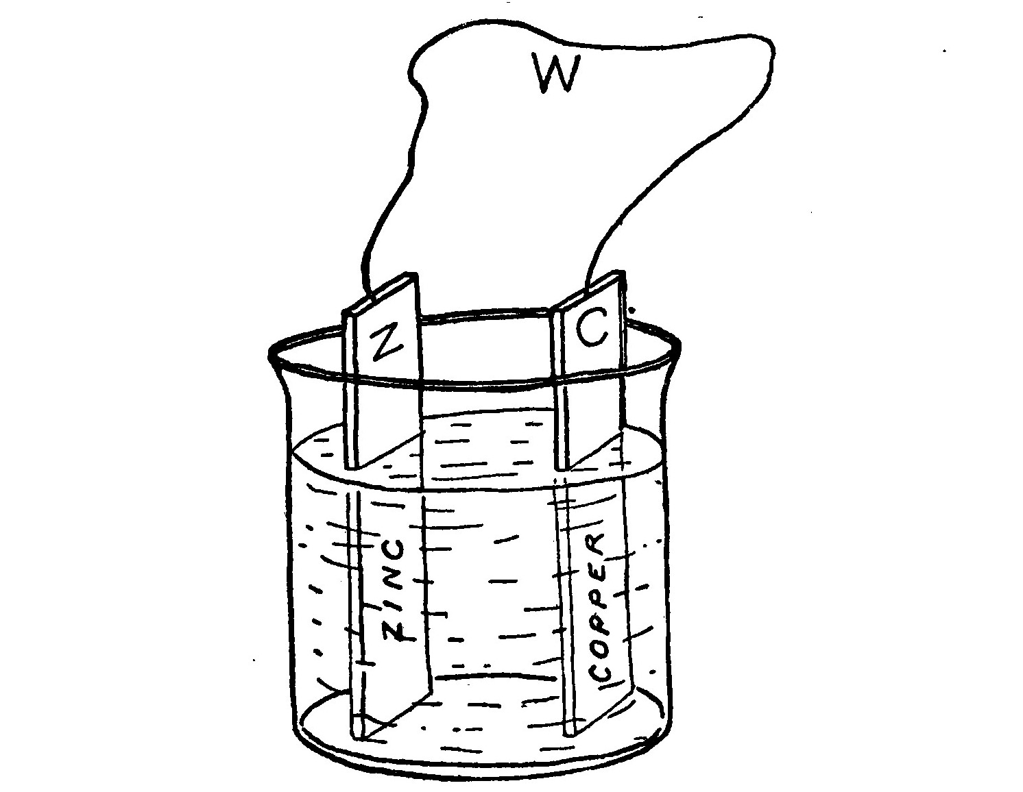
If the zinc is connected by means of a wire, W, with a strip of copper, C, dipping in the same solution, the zinc will still to continue to dissolve but the hydrogen bubbles will now form on the surface of the copper strip as well as on the zinc. It will be found that the wire W becomes heated. If the copper and zinc are connected to a galvanometer it will show the presence of an electric current passing through the circuit. The cell may be considered as a sort of chemical furnace in which fuel is burned to drive the current. The zinc is the fuel. The copper is merely present to "pick up" the current and takes no part chemically.
If a number of such simple cells are properly united, the zinc of one being joined to the copper of the next and so on, a battery is formed. The current flows from the copper, called the positive pole, through the wires (when they are joined) to the zinc or negative pole and back to the copper through the solution.
The electricity generated by the cells exerts a certain pressure or tendency to pass through the wires. This tendency is called the potential. The potential is measured in volts. The potential (also called the electromotive force) in the case of the Voltaic Cell just described is 1.07 volts. If the copper strip is replaced with one of graphite or carbon, the voltage will rise to 1.73 volts.
After a cell has been in action for a short time, the positive plate (copper or carbon, as the case may be) becomes covered with a film of hydrogen. The cell is then said to be polarized. The film of gas bubbles partially shields the plate from contact with the liquid. When the plate becomes in this condition, the current is much feebler than when it is clear.
The most effective way of removing the hydrogen is to add some chemical to the sulphuric acid solution which will combine chemically with the hydrogen as soon as it appears. The usual substance is bichromate of potash. The voltage of the battery will rise to 2.2 volts and the polarization be stopped when bichromate of potash is added. The bichromate of potash enters into chemical action with the sulphuric acid and forms chromic acid. Such cells are usually termed chromic acid cells.
One of the principal disadvantages of a cell such as that just described lies in the fact that the zinc is continuously consumed whether the cell is in action or not and in order to prevent its rapid waste must be lifted out of the solution and washed each time after using.
Various methods have been devised for overcoming this objection, the most prominent of the resulting cells being known as the Fuller, Gordon and Edison-Lalande Cells.
The liquid excitant of the Gordon and Edison-Lalande cells is a strong solution of sodium hydroxide. The positive pole of these cells is a block of compressed copper oxide and the negative a pair of zinc plates. In the Gordon cell the positive is enclosed in a porous chamber.
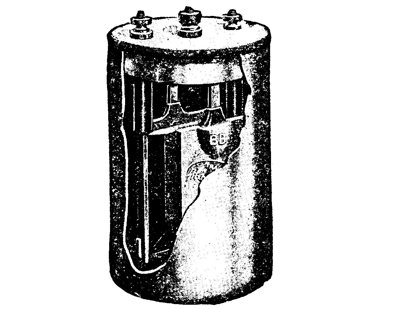
One of the best known forms of cell is the dry cell. It consists of an outer shell of zinc forming the negative electrode and a central rod of carbon as the positive. The active agent of the cell is a paste composed principally of sal ammoniac lining the interior of the zinc shell. The depolarizing agent of the cell is manganese dioxide mixed with crushed carbon and packed tightly around the carbon rod. The cell is not as its name implies perfectly dry inside, but the chemicals are in paste form. The cell is sealed at the top by a bituminous compound making the cell air tight and portable. Dry cells are only successful for intermittent work, that is, where they are not required to deliver a heavy current continuously. They deteriorate after long standing because the moisture evaporates. Dry cells, however, are a very convenient source of current where the demand is not too great and portability is desired.
The cells so far described are all of the type known as primary cells.
SECONDARY CELLS.
The storage cell or secondary cell is made up of plates of lead, or an alloy of lead, cast in the form of a grid or framework of bars. The spaces formed in the plate by the little bars are filled with a paste of lead oxide. The paste for the positive plates are made of red lead while litharge is used for the negatives.
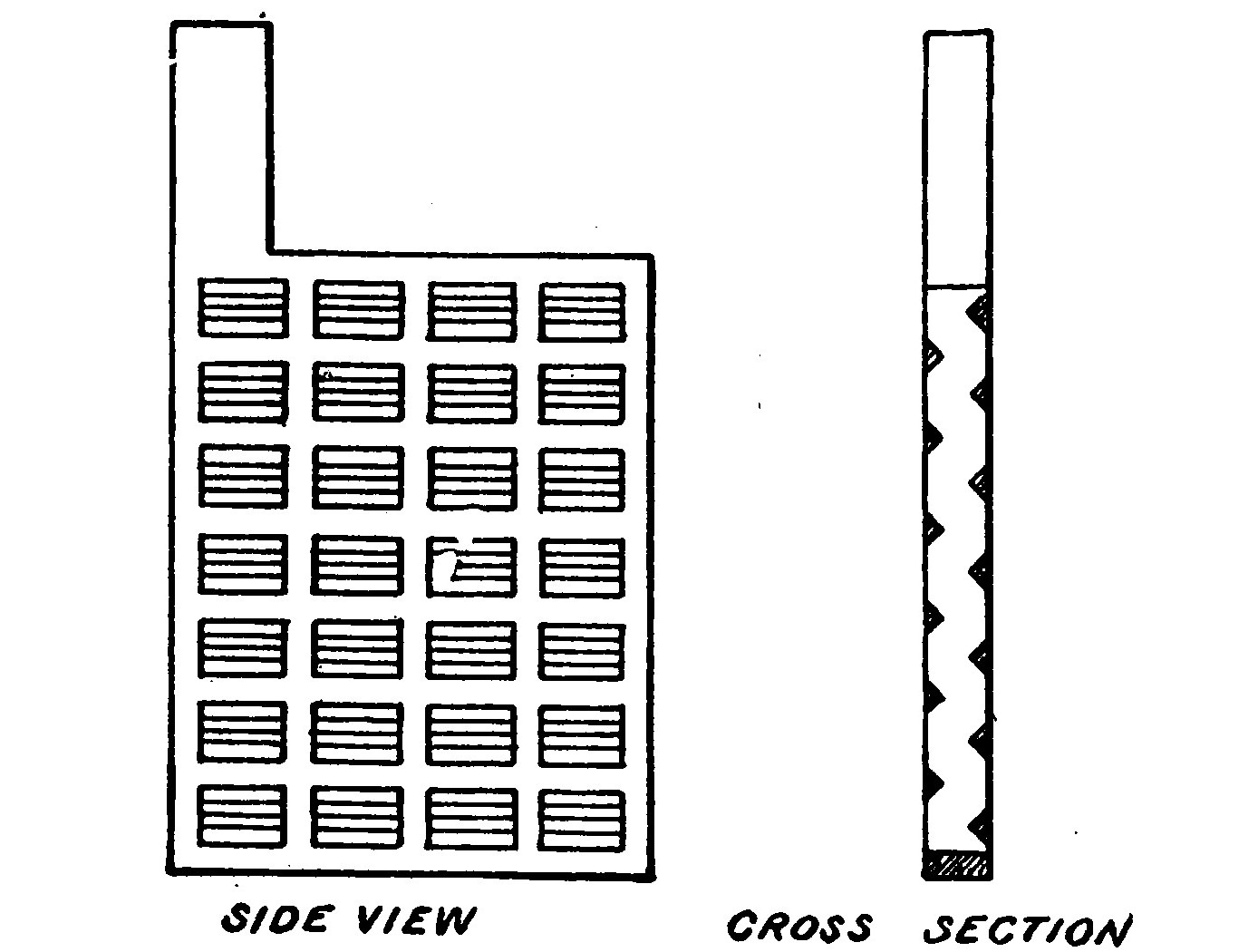
The positive and negative plates are placed alternately in a bundle with a wooden or rubber separator between, there always being one more negative plate than positive. The negative plates are all connected in parallel at one end of the cell by means of lead connecting strips. The positive plates are connected at the other end. The plates are placed in a jar, usually glass or hard rubber, and covered with a dilute sulphuric acid solution.
The storage cell is then connected to a dynamo, the positive pole of the cell being connected to the positive pole of the dynamo and the current allowed to flow through until the plates are formed, that is to say, until the paste in the positive changes to peroxide of lead and that in the negative to spongy lead. When the cell is disconnected it will give out a current of its own lasting until it becomes discharged. The charging and discharging must be repeated several times before the cell really becomes efficient.
What is effected in the storage cell is really the storage of chemical energy and not the storage of electricity, for, properly speaking, the energy is put into the form of chemical affinity and there is in reality no more electricity actually in the cell at the end of a charge than there is when the cell is discharged.
The storage battery is the most convenient means of absorbing electrical energy at one time or place and using it at another time or place.
Storage cells are very often employed in wireless stations for emergency purposes so that in case the dynamo supplying current fails the station will not be thrown out of operation.
The voltage of a storage cell is about two volts.
LESSON FOUR. ELECTRIC CURRENTS.
The Units of Measurement. Direct and Alternating Currents. Ohm’s Law.
Electric Currents may be divided into two classes known as direct and alternating current. Either one may be measured or qualified by two electrical units called the Ampere and the Volt. The volt may be explained by likening it to the "unit of pressure" of the current, while the ampere measures the unit rate of current flow. For example, in the case of water the voltage corresponds to the pressure in pounds while the amperage would indicate the rate of water flowing.
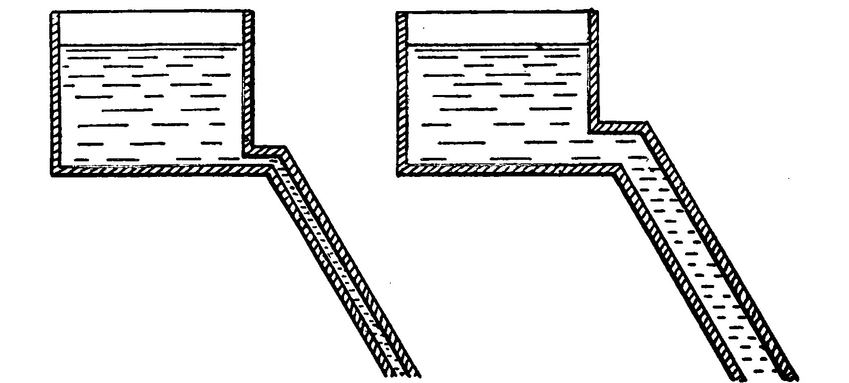
The accompanying sketches show graphically the analogy between the voltage and amperage of an electric current and the pressure and volume of a stream of water. In the first illustration a tank is shown at a high elevation from which a small pipe leads. The voltage or pressure in such a pipe would be high in comparison with that in a pipe leading from a lower tank.
In the second illustration the pipe leading from the tank is much larger than that from the first and consequently the amperage or volume flowing is greater in comparison. From this it may be readily seen that every circuit through which a current is flowing must exhibit both quantities.
The unit of electrical work or energy is the Watt. Seven hundred and forty-six watts constitute an electrical horse-power. The number of watts is indicated by the voltage times the amperage. Thus the amount of energy in a circuit in which 50 amperes at 100 volts pressure are passing is 50 x 100 or 5,000 watts.
The Couloumb represents the quantity of electricity flowing in a circuit-where the rate of flow is one ampere per second.
In order to properly indicate comparative amounts of energy the element of time must also be taken into consideration. One watt passing for one hour is a watt-hour. Seven hundred and forty-six watts passing for one hour or one watt passing for seven hundred and forty-six hours is a horse-power hour.
The instruments used for measuring the amperage and voltage of a circuit are called respectively the ammeter and the voltmeter. That used for registering watt-hours is called the integrating watt-meter.
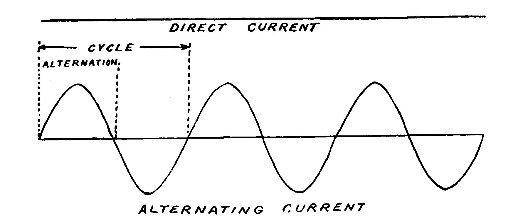
Direct current is current that passes or flows in one direction only. The current of all primary and secondary cells and of certain forms of dynamos is direct.
Alternating current is current that repeatedly reverses its direction of flow. A direct current may be represented by a straight line. An alternating current is shown by a wavy line crossing and recrossing a straight line. The current gradually rises from zero to a maximum and then dies away. It does not stop at this point however, but starts to rise again, this time flowing in a reverse direction. After reaching a maximum it dies away again and the cycle is repeated. From a to c represents a cycle and from a to b an alternation. Alternating currents usually have a frequency of 30, 60 or 120 cycles per second. Sixty is the most common frequency. Many wireless telegraph stations now employ currents having a frequency of 500 cycles.
Ohm’s Law.
Mention has been made above of certain electrical magnitudes, namely, voltage or electromotive force and amperage or strength of current. These bear an important relation in determining a property of an electric circuit called resistance.
No conducting body possesses perfect electrical conductivity, but presents a certain amount of obstruction or resistance to the passage of electricity. The practical unit of resistance is the Ohm. It is represented by the resistance offered to an unvarying electric current by a column of mercury at the temperature of melting ice, 14.4521 grams in mass, of a constant cross sectional area and of the length of 106.3 centimetres.
The resistance of a conductor is proportional to its length, that is, provided two conductors are made of the same material and of the same diameter and one is twice as long as the other, the resistance of the longer will be twice that of the shorter conductor. The resistance is inversely proportional to the cross sectional area, which is to say that a conductor of smaller cross section has a greater resistance than one of larger section.
The laws of resistance are conveniently expressed by the following formula called Ohm’s Law.
If two factors are known, the third can be found by substitution.
LESSON FIVE. ELECTROMAGNETISM.
The Electromagnet. The Solenoid.
If a current of electricity is passed through a copper wire, the wire will attract to itself iron filings, etc., as long as the current continues to flow. There is then a magnetic field around the wire. As soon as the current is shut off the filings drop away because the field immediately disappears with the cessation of the current.
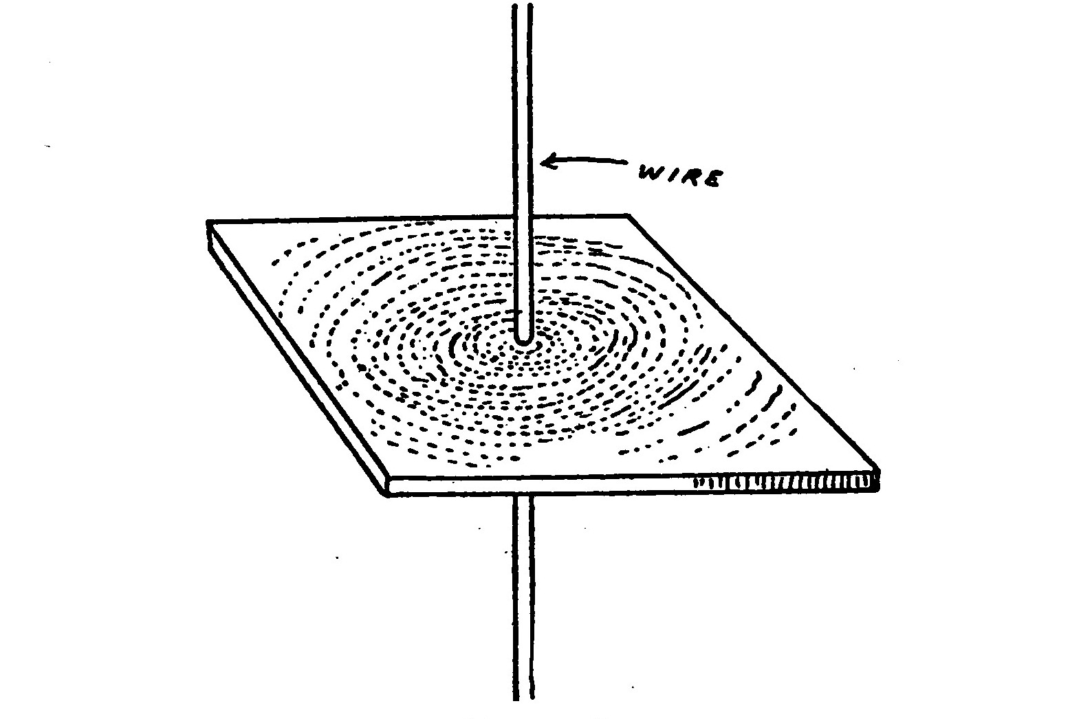
The lines of force flow around the wire in a circle. The circular lines of the field of force surrounding a straight wire may be shown by passing a wire vertically through a hole in the centre of a horizontal card. Iron filings are sifted over the card and a strong current passed through the wire. On tapping the card gently, the filings near the wire set themselves in concentric circles round it.
The creation of a magnetic field by a conductor in its own neighborhood when carrying a current of electricity is one of the most important phenomena of electrical science.
Electrical energy must be expended in producing a magnetic field. When a current of electricity is turned on in a wire the magnetic field grows around the wire, some of the energy of the current being used for the building process.
This reactive effect of the surrounding magnetic field is one reason why electric currents do not instantly rise to their full value.
If a wire is connected to a battery or some other source of electric current and a portion of the circuit twisted so as to form a loop, the entire space enclosed by the loop will be a magnetic field and possess magnetic properties.
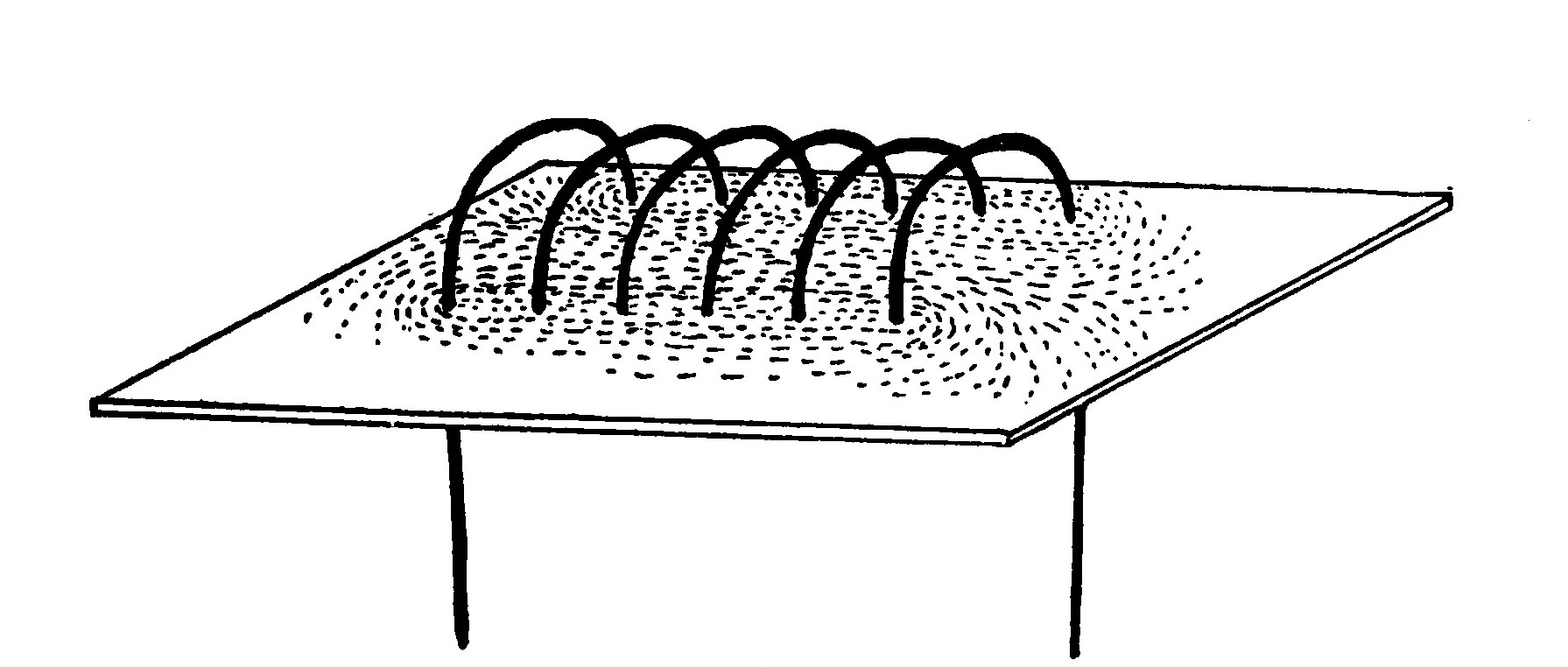
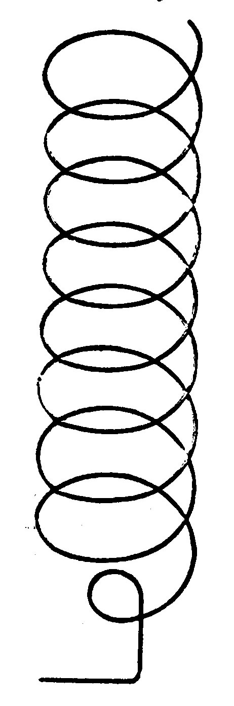
By forming a wire into a spiral coil the combined effect of each individual turn is concentrated in a small space and a powerful field of force is produced. If the coil is provided with an iron core, the lines of force can be concentrated and will exercise a very powerful attractive effect upon any neighboring masses of iron or steel. Such a coil is called an electromagnet. A hollow coil without any core is called a solenoid.
Solenoids and electromagnets play a very important part in the construction of most electrical instruments.
The strength of an electromagnetic coil is proportional to its ampere turns. The ampere turns of a coil are obtained by multiplying the number of amperes flowing through the coil by the number of turns of wire composing it.
LESSON SIX. DYNAMO ELECTRIC MACHINERY.
The Dynamo. The Alternator. The Motor.
The discovery of the induction of currents in wires by moving them across a magnetic field led to the construction of electrical machines, called dynamos, to generate current in place of batteries.
The dynamo is perhaps the most important piece of electrical apparatus there is for it is the source of ninety-nine percent of all the electricity now in use. It is practically necessary in any case where a considerable quantity of electricity is used to have a dynamo on the spot or else bring the currents over a wire from some supply station where dynamos are kept running.
The operation of a dynamo is dependent upon current induction. It contains a system of closed conductors revolving in a magnetic field in such a way as to continuously vary the number of lines of force threading among them.
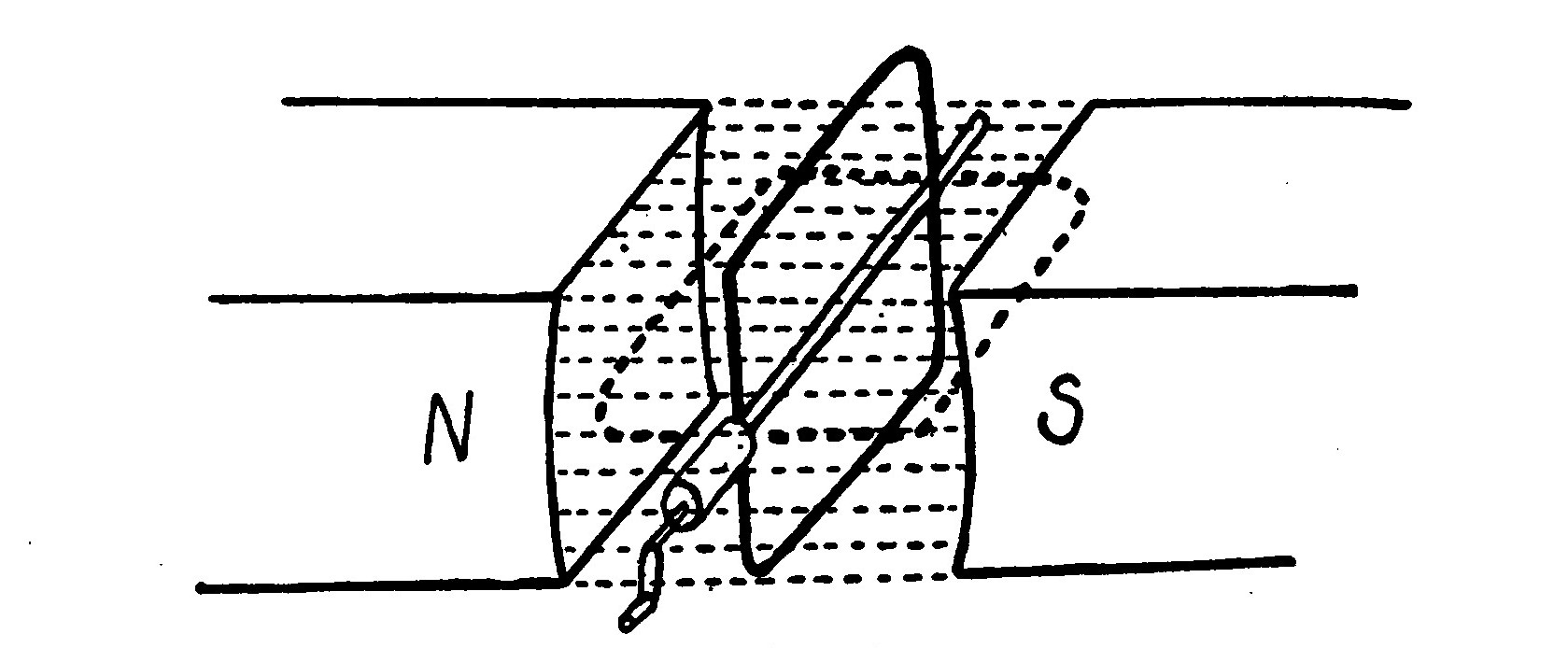
The illustration show's the ideal simple dynamo, which consists of a loop of wire arranged to revolve between the poles of a permanent magnet in the direction of the arrow and around a horizontal line as an axis. The lines of magnetic force (represented by the fine straight lines) pass across from N to S as indicated. When in the position shown, the coil of wire encloses the largest possible number of lines of magnetic force. When it has revolved ninety degrees or a quarter of a turn as shown by the dotted lines, the lines of force will be parallel to the plane of the coil and none will pass through. During this quarter of the turn the number of lines of force has been decreasing. During the next quarter of a turn the lines will increase again, but will this time pass through from the opposite side of the loop. This decrease and increase of the number of lines of force passing through the loop generates therein a current of electricity. The same process is repeated during the next half of a revolution. However, since the lines of force flow through from opposite sides of the coil every half revolution, the current reverses twice during the same period.
In the illustration the loop is represented as forming a complete closed circuit in itself. In order to draw any current for external use some method of establishing connection to the terminals of the coil must be had. This is furnished by two circular rings called collector rings. The little strips of metal or carbon employed to form contact with the rings are called brushes.
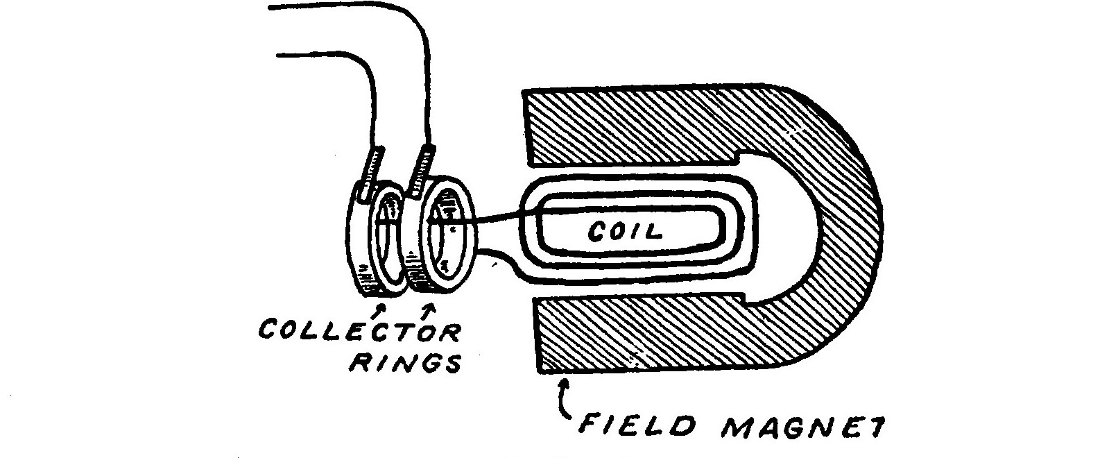
Such a machine, so equipped will deliver alternating currents and illustrates the principle of the alternating current dynamo or alternator.
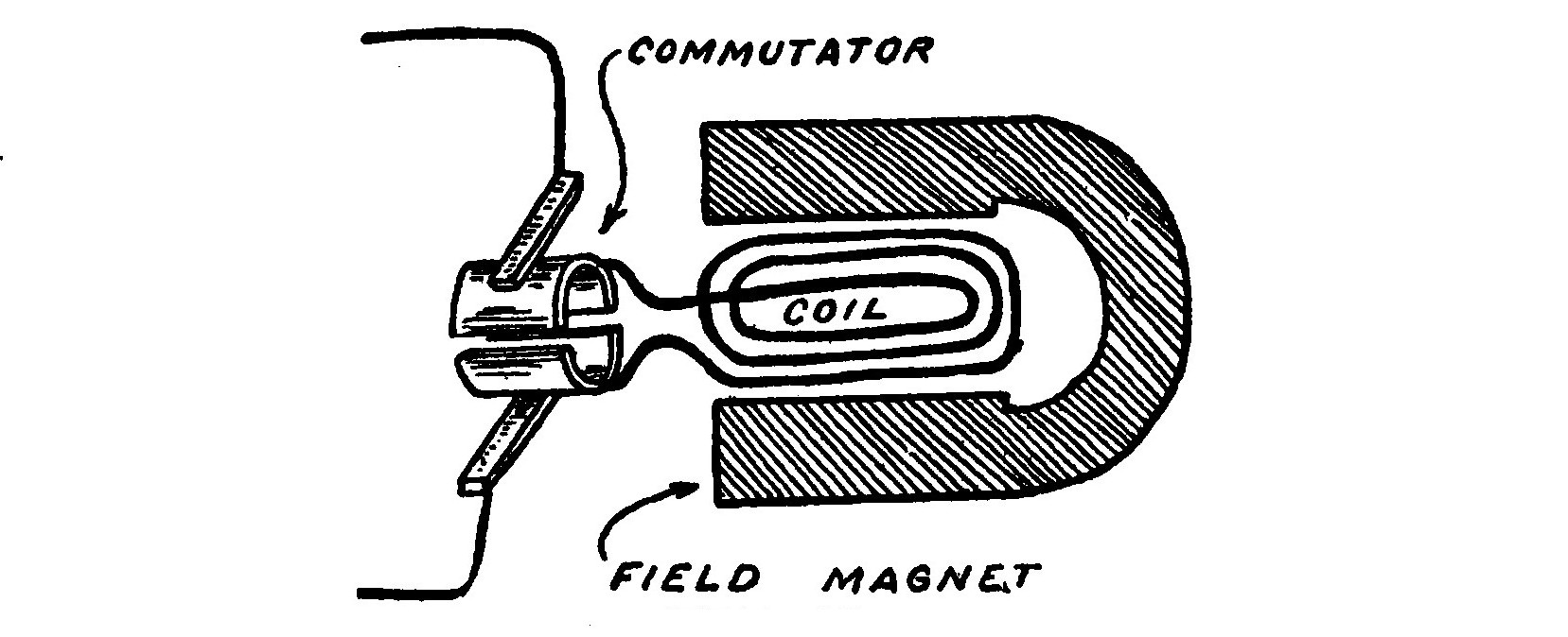
With the aid of a device called a commutator and consisting of a ring split in sections as shown in the illustration, all the successive current impulses may be turned in the same direction and the current made direct.
In practice many coils of wire wound around an iron core called the armature, the purpose of which is to concentrate the magnetic lines of force, are made to revolve in a powerful field between the poles of adjacent electromagnets. Electromagnets are used because they are capable of producing a stronger magnetic field than magnetized bars of steel. The electromagnets used for this purpose are called field magnets. The central iron portion upon which the revolving coils are wound, called the armature, is usually built up of a number of thin sheets of soft steel called armature disks or laminations.
The modern armature is very complex. A simple coil such as those shown in Figs. 17 and 18 will not yield a steady current for twice in each revolution the electromotive force dies away to zero. The coils of large dynamos are grouped so that some of them are always active.
There are three general methods of supplying current to the held magnets of a dynamo, known as the series, shunt and compound windings.
The series dynamo is arranged so that the coils of the held magnets are in series with those of the armature.
In the shunt dynamo, the coils of the held magnet form a shunt to the main circuit and being made of many turns of thin wire, draw off only a small fraction of the whole current.
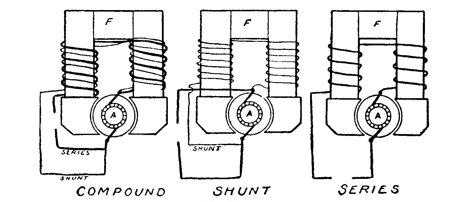
The compound dynamo is partly excited by shunt coils and partly by series coils.
Each variety of dynamo winding has a certain advantage depending upon the condition of use.
In the case of alternating current dynamos, the field magnets are sometimes supplied from a separate dynamo called an "exciter." In other cases the dynamo is provided with two sets of windings, one connected to a commutator producing a direct current which excites the field coils and the other connected to a set of rings and supplying the alternating current.
In case a supply of either direct or alternating current is available and it is desirable to change the supply from direct to alternating or vice versa, it may be accomplished by employing a Motor-Generator. A motor-generator consists of an electric motor operating from the source of current supply on hand and driving a dynamo which supplies current of the kind desired.
A motor is exactly the reverse of a dynamo. If a current of electricity is passed into a dynamo, the armature will be dragged around by the mutual action of the currents flowing in the copper conductors and the magnetic field in which they lie. Such a device constitutes a motor and may be employed to do useful work.
Motors are classified as alternating and direct current machines accordingly as they are built to operate on either kind of current.
LESSON SEVEN. THE INDUCTION COIL.
The Induction Coil is an apparatus for producing currents of a very high electromotive force. It consists of a helix of large, insulated wire surrounding an iron core, and this again surrounded by a second coil consisting of many thousand turns of very fine wire carefully insulated. The inner or primary coil is connected in series with a battery, the circuit also including a device called an interrupter. The object of the interrupter is to make and break the primary circuit in rapid succession. Every time the current is turned on in the primary circuit, the primary coil creates a magnetic field which induces a current in the secondary in accordance with the laws of induction.
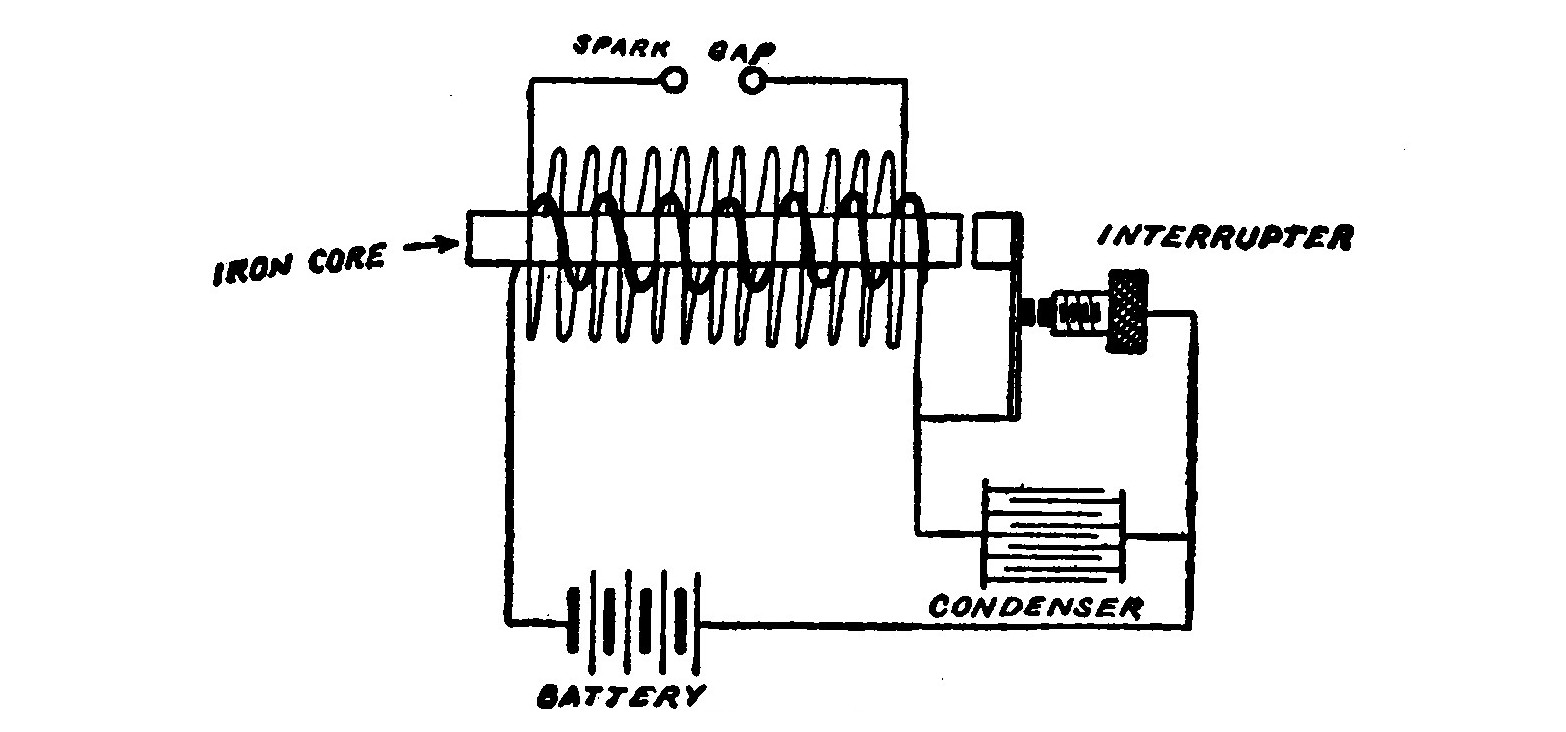
Likewise at every "break" in the circuit caused by the interrupter, the lines of force disappear and a second current impulse is induced in the secondary coil. As the number of lines of magnetic force created and destroyed at each make and break is the same, the two electromotive impulses in the secondary are equal. By adding a condenser, however, the current at "make" is caused to take a considerable fraction of time to grow, while at "break" the cessation is instantaneous in comparison. The rate of "cutting" of the lines of force is very much more rapid at "break" than at "make" therefore. The currents at "break" manifest themselves as a brilliant torrent of sparks between the ends of the secondary wires when they are brought near enough together.
The central iron core around which the coils are wound is for the purpose of increasing or concentrating the number of lines of force that pass through the coils. Magnetic lines flow more easily through iron than through air and so prefer that path. It is made up of a bundle of fine iron wires in order to avoid induced currents which would be set up in the iron were it a solid mass and so retard its rapidity of magnetization or demagnetization as to hamper the efficiency of the coil.
LESSON EIGHT. THE PRINCIPLE OF THE TRANSFORMER.
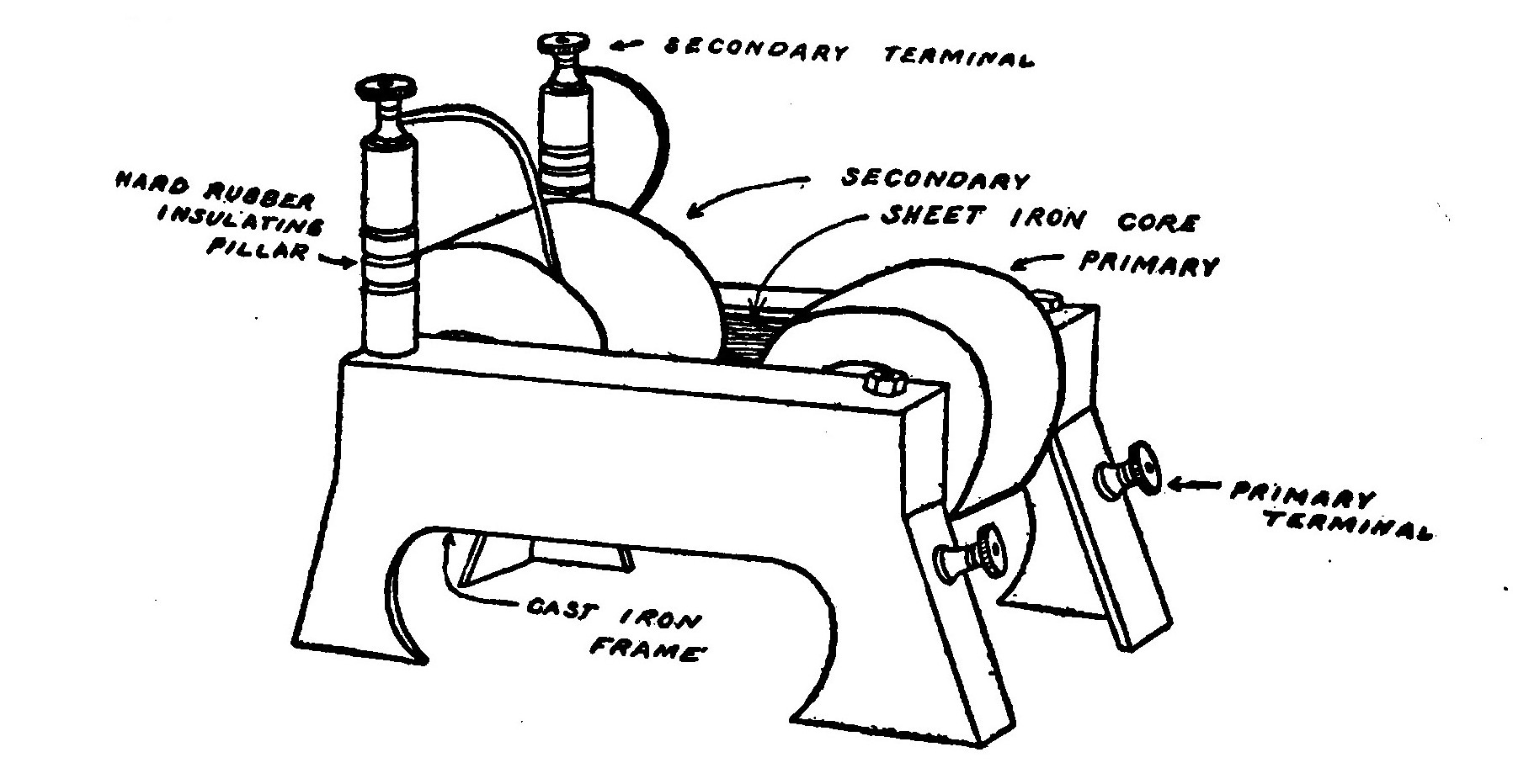
The transformer is a device for raising or lowering A the electromotive force of an alternating current. In principle it consists of two insulated coils of wire called the primary and the secondary wound around an iron ring as shown in the illustration.
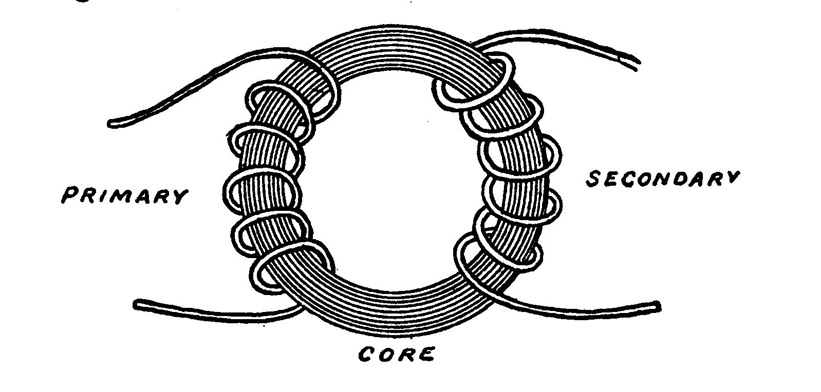
If the primary coil is connected to a source of alternating current it will rapidly magnetize and demagnetize the iron ring. The magnetic lines thus created will pass through the secondary coils setting up induced currents.
The ratio of the electro-motive force of the induced current to that of the primary current is in direct proportion to the ratio of the number of turns in the two coils. For example, if the secondary contains twice as many turns as the primary, its electro-motive force will be twice as great.
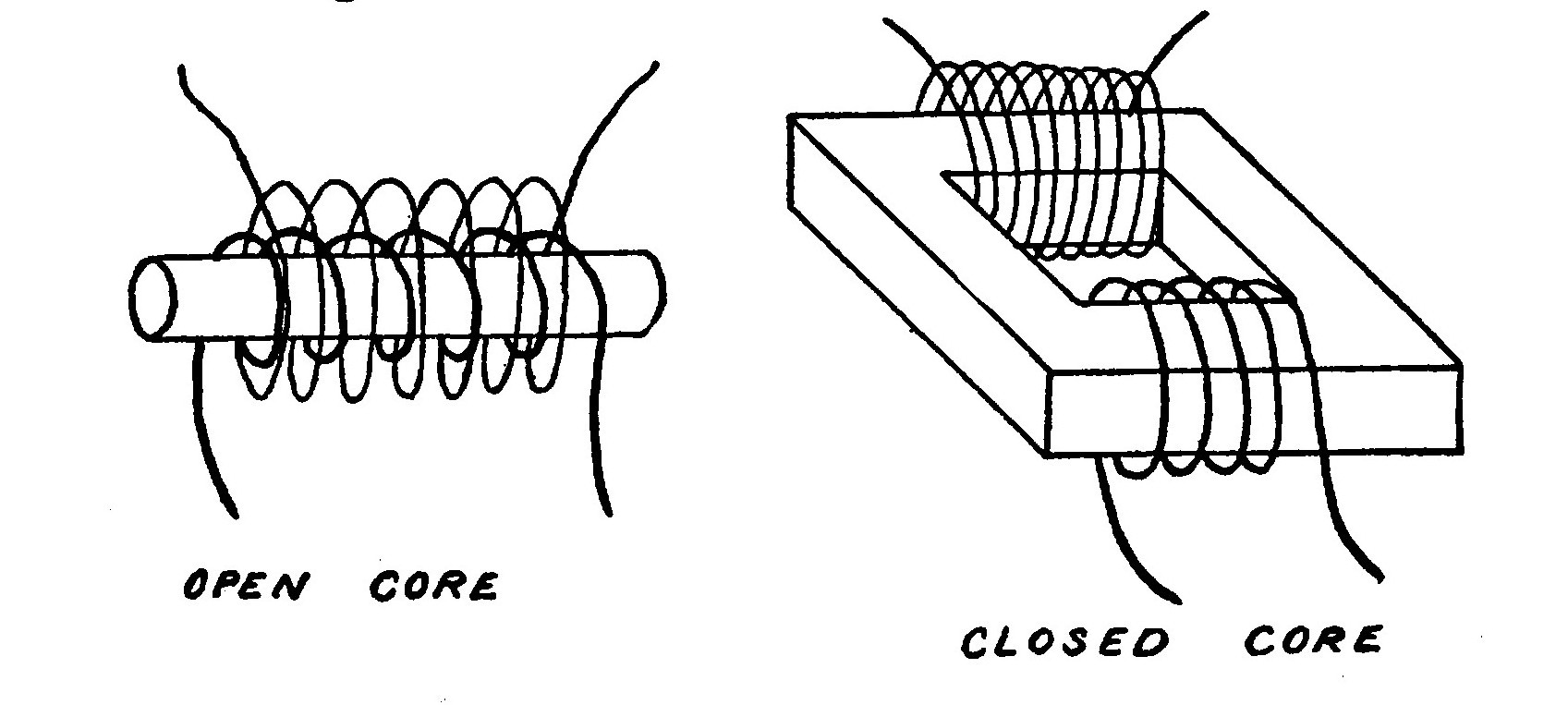
Transformers are of two general types, the "open" core and the "closed" core. Closed core transformers are the most efficient. The open core transformer is similar in construction to an induction coil, the core being a straight bar, while that of the closed core machine is usually in the form of a hollow square or rectangle.
In practice, the cores of transformers are built up of laminations, usually of thin, soft sheet iron strips piled together and shaped so as to constitute a closed magnetic circuit of rectangular shape in order to avoid constructional difficulties incurred in making a ring.
LESSON NINE. THE LEYDEN JAR AND CONDENSER.
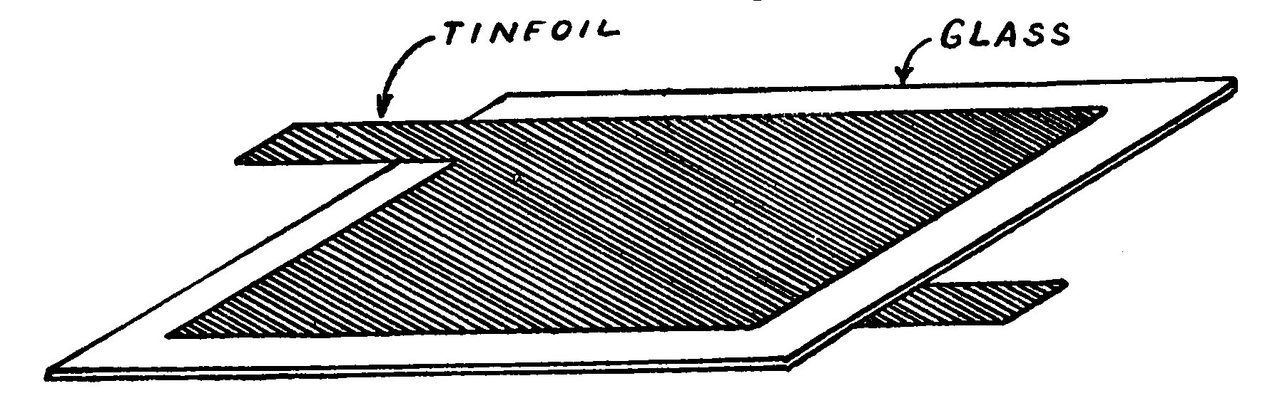
The Leyden Jar, called after the city of Leyden, Holland, where it was invented, is a form of condenser consisting of a glass jar coated up to a certain height inside and out with tinfoil.
A Leyden jar may be charged by holding the rod to the prime conductor of an electric machine, the outer coating being held in the hand. If a piece of wire connected to the outer coating is then brought near the rod a brilliant snapping spark will pass across the space.
Any two conductors, separated by an insulating medium termed the dielectric, constitute a condenser and possesses the property of receiving and retaining an electric charge.
If a charged condenser or Leyden jar is discharged slowly by allowing the electricity to pass through a high resistance conductor the flow of current increases in strength at first and then gradually dies away.
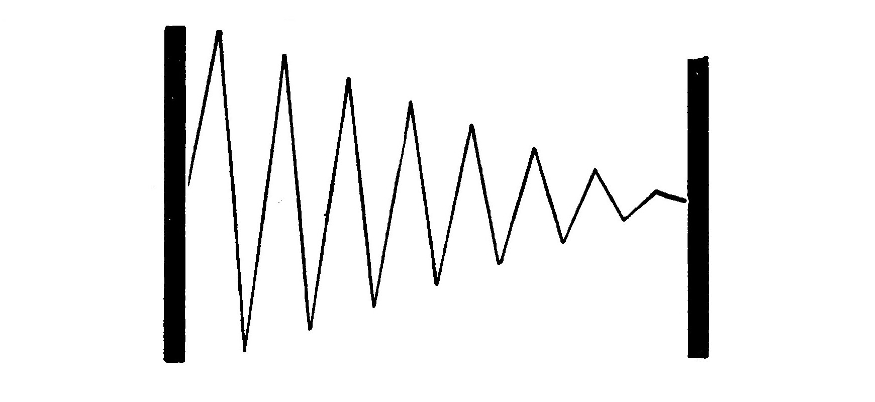
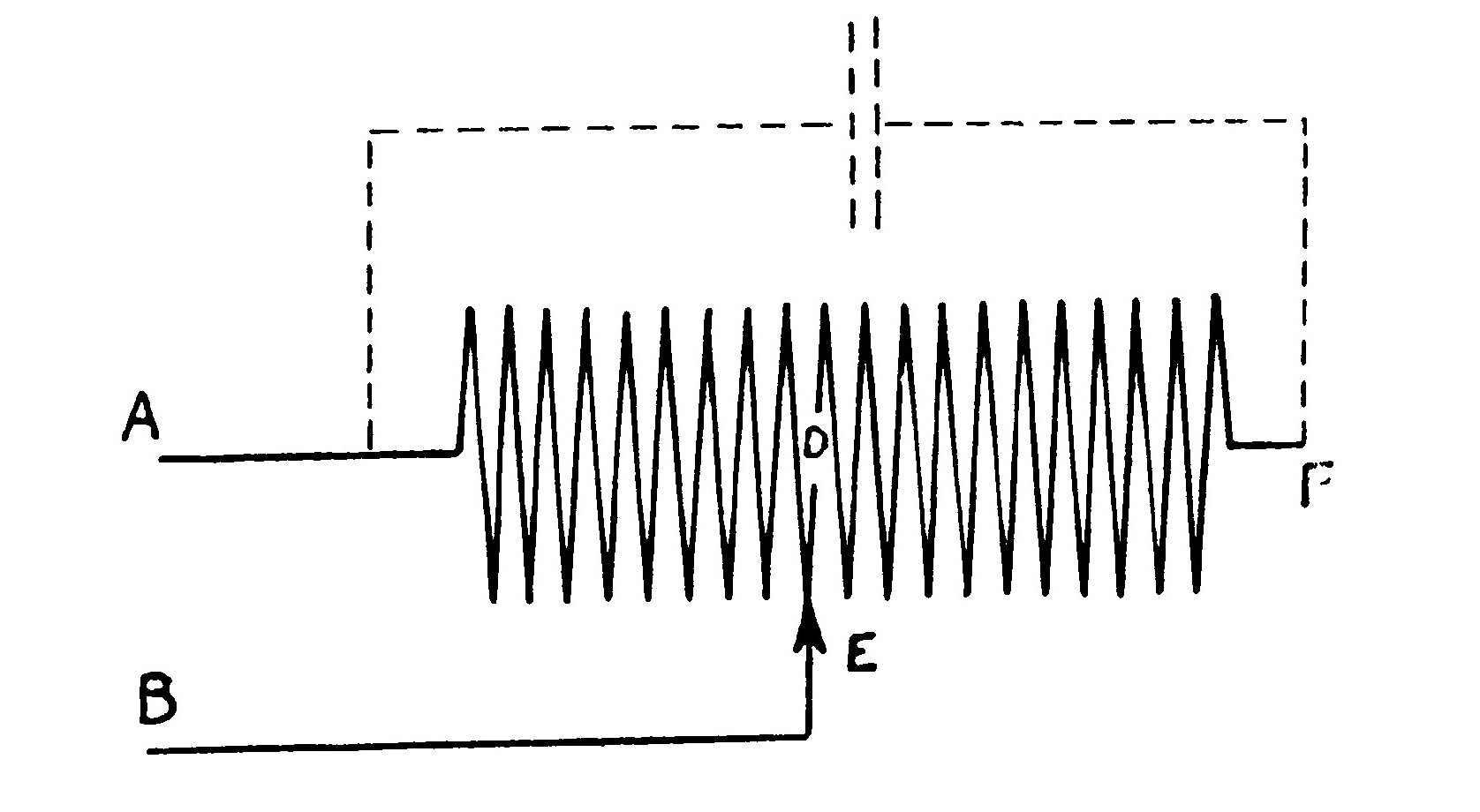
If, however, the condenser is discharged through a coil of wire of one or more turns, the discharge consists of a number of excessively rapid oscillations or surgings. The first rush of current serves to more than empty the condenser and charges it the opposite way, then follows a reverse discharge, which also oversteps itself and charges the condenser the same way as the first and so on, each successive oscillation being weaker than the one before until the discharge dies away as in Fig. 36. The discharge of a condenser under such conditions consists of a number of successive sparks in reverse directions.
The ability of a condenser to receive and retain an electrical charge is termed the capacity and is measured by a unit called the farad. The farad is so large a quantity, however, that it is never met in practise and for convenience the micro-farad which is one millionth of a farad has been adopted.
A condenser of one farad capacity is such as would be raised to a potential of one volt by a charge of one coulomb of electricity.
The capacity of the condenser is dependent upon the thickness and nature of the insulating medium or dielectric. The quality of a dielectric which decides the capacity of a condenser in which it may be a part is called its specific inductive capacity. The following table shows the relative specific inductive capacity of several materials, air being the standard:
Substance. |
Constant. |
|---|---|
Air |
1.00 |
Paraffin |
1.68—2.47 |
Petroleum |
2.02—2.19 |
Gutta Percha |
3.00 |
Hard Rubber |
2.28 |
Mica |
6.64 |
Glass |
6.72—7.38 |
LESSON TEN. THE ETHER AND THE ELECTROMAGNETIC THEORY OF LIGHT.
All space is filled with a weightless, invisible medium called Ether. It is the substance with which the universe is filled, it reaches to the stars and through the very earth itself.
It has been known for some time that light consists of vibrations or motions in the ether. In 1867, Clerk Maxwell offered the theory that these light waves are not merely mechanical motions of the ether, but are electrical undulations. According to this theory, the phenomena of electro-magnetism and the phenomena of light are all due to certain modes of motion in the ether.
Twenty years later, Heinrich Hertz discovered convincing proofs of Maxwell’s theory and succeeded in producing electro-magnetic waves in such a manner that they possessed the same properties, traveled at the same speed, and were capable of being reflected, refracted, polarized, etc.
Hertz employed an apparatus consisting of two metallic balls connected by metal rods to two metal sheets. The two balls were also connected to the secondary terminals of an induction coil. This apparatus comprised the oscillator and served to create the electro-magnetic waves.
In order to detect the waves, he employed a resonator consisting of a circle of wire having in it a minute spark gap capable of fine adjustment.
As soon as the coil is set in operation a spark snaps across the gap and sets up a temporary conducting path for the surgings that follow. Each spark sent by the coil across the gap consists of a dozen or so oscillations, each lasting less than a millionth of a second.
Then if the resonator is placed a few feet away from the oscillator and turned broadside on to the oscillator, it will be found that small sparks jump across the gap. Hertz employed various arrangements for reflecting and polarizing the waves and definitely proved that their nature is the same as that of light.
LESSON ELEVEN. ELECTRIC WAVES.
When a Leyden jar discharges under the conditions set forth in one of the previous lessons, portions of the energy of the current or discharge are thrown off from the conductor and do not return to it, but go traveling on in space.
If a current is sent through a circuit, as the current increases, the magnetic field also increases, the magnetic lines enlarging and spreading outward from the conductor like the ripples on a pond. If the current is decreased, the magnetic lines all return back and close up upon the conductor, the energy all being re-absorbed into the circuit.
If electrical oscillations of extreme rapidity such as those generated by a condenser discharge are substituted for a current slowly rising and falling, part of the energy radiates off into the ether as electromagnetic waves and only a part returns back.
The discharge of a Leyden jar or condenser only oscillates when the circuit contains a certain amount of capacity and inductance in proportion to the resistance of the circuit.
Inductance is the property of a circuit by virtue of which lines of force are developed around it. Circuits containing a certain amount of inductance, capacity and resistance tend to oscillate electrically at a certain frequency.
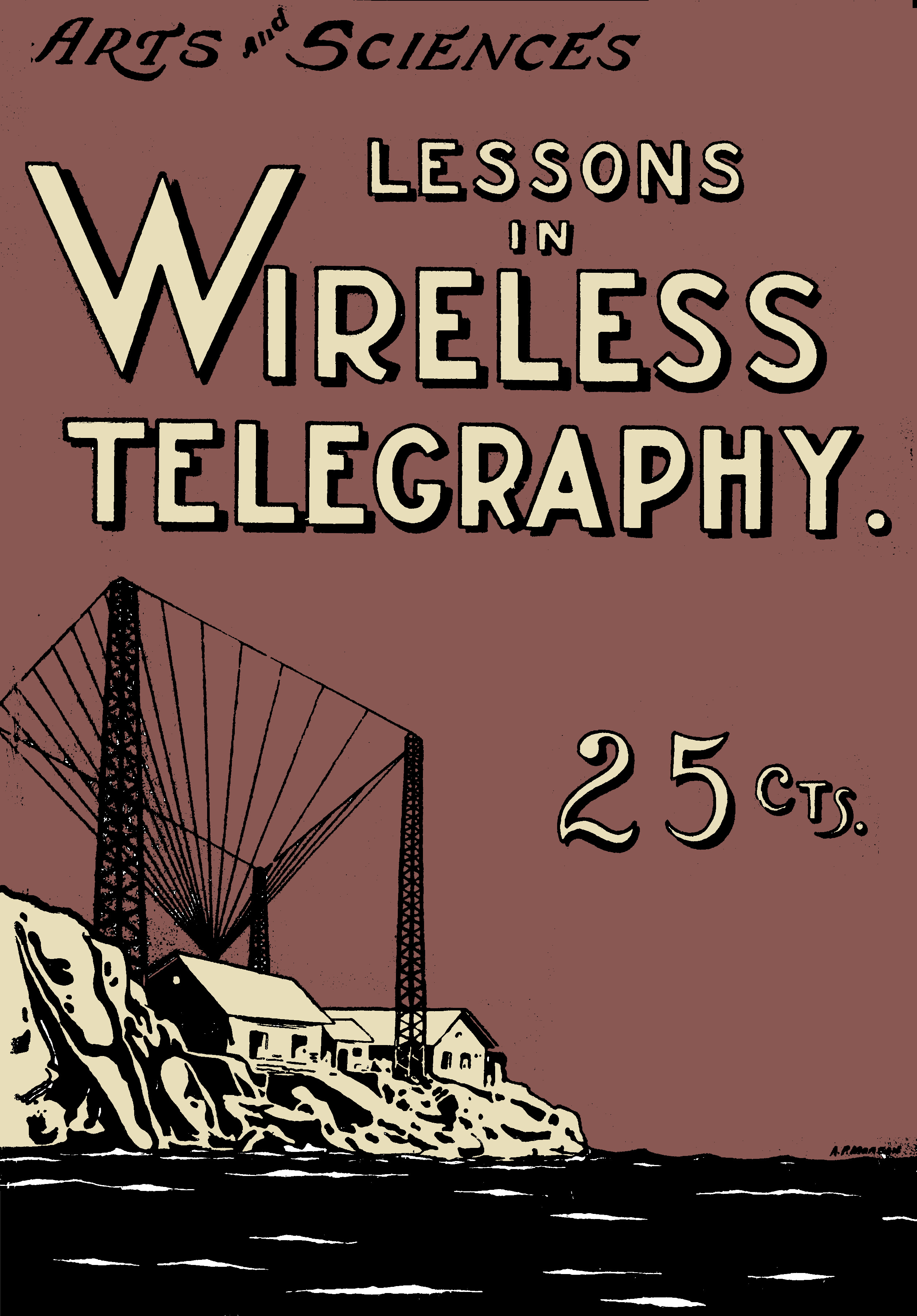
The electromagnetic waves thrown off by the aerial system follow the contour of the earth and so may cross mountains or travel anywhere. The waves emitted by the ordinary wireless station, making use of an aerial and a ground are half waves terminating in the earth as shown in the illustration. In passing over the earth they are accompanied by ground currents which waste a certain amount of their energy in overcoming ohmic resistance and so reduce the intensity of the waves. For this reason propagation is always the best over water or moist earth whose resistance is low.
A further peculiar weakening of the waves due to the absorbtion taking place in the air during sunlight. The difference between the signals in the day and their strength at night is very marked, being much stronger in the later case.
LESSON TWELVE. PRINCIPLES OF WAVE TELEGRAPHY.
Wireless Telegraphy as practiced to-day is merely a method of setting up electromagnetic waves in the ether and then detecting their existence at a distant point. It may be divided into four distinct and individual operations, namely:
The generation of electrical oscillations.
The transformation of electrical oscillations into electrical waves.
The transformation of electrical waves into electrical oscillations.
The detection of the electrical oscillations.
We have already learned how electrical oscillations may be generated by the discharge of a Leyden jar or a condenser. In order to perform the first two operations named above, it is therefore merely necessary to arrange a condenser in such a way that it is most effective.
The induction coil or transformer is employed to charge the condenser because the currents of these instruments are much more powerful than those of a static electric machine. The induction coil is connected to a set of batteries and a key so that the periods during which the current is on and off may be controlled at will by the pressure of the fingers.
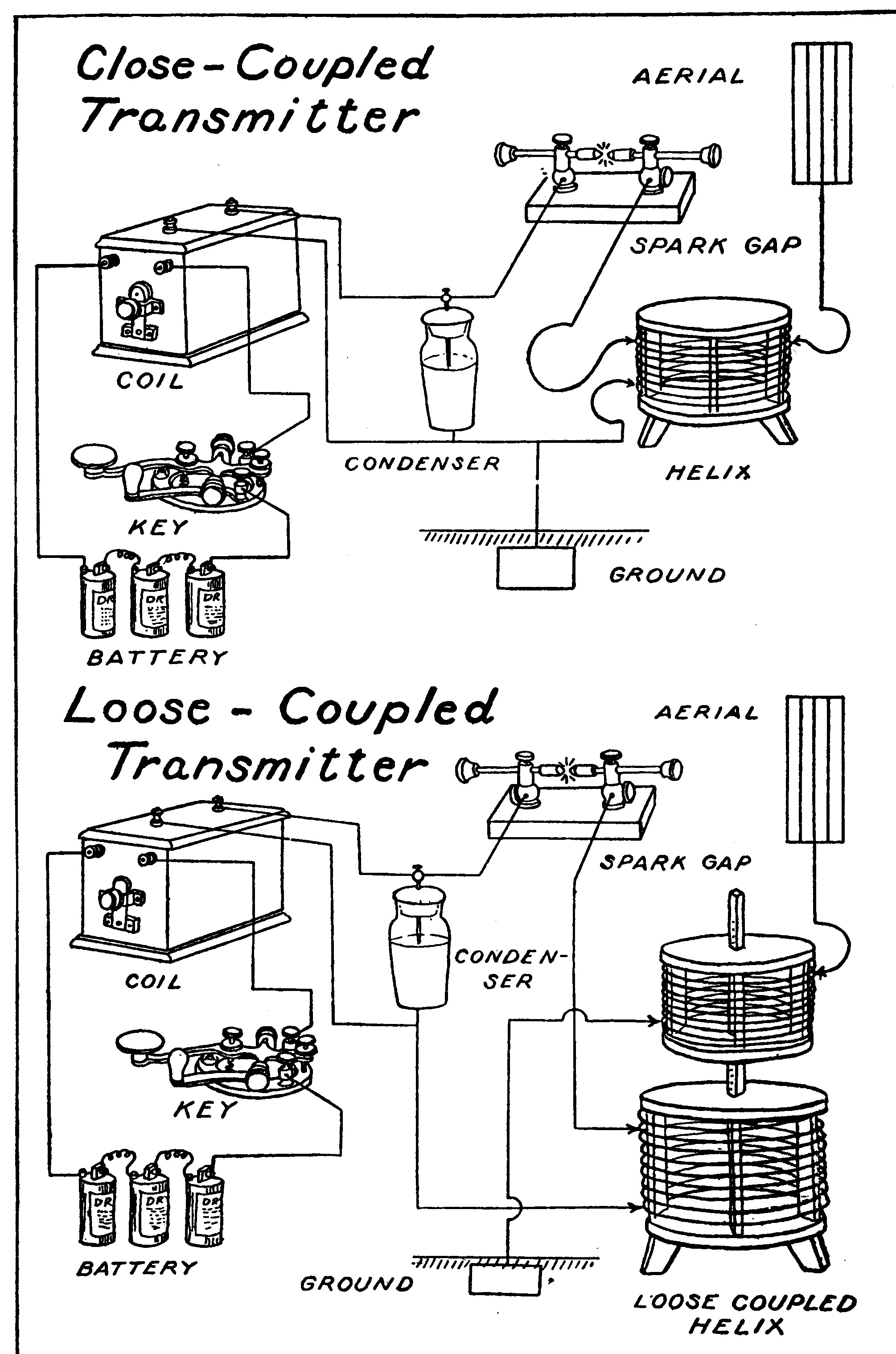
The secondary of the coil is connected to a battery of Leyden jars or a condenser. The fact was mentioned above that a certain amount of inductance in the circuit is necessary for the production of electrical oscillations This is furnished, or at least the greater part, by a device called a helix which consists of a coil of heavy wire wound around a suitable framework.
The spark discharge takes place across a device called a spark gap.
When the key is pressed, the high potential currents of the induction coil charge the Leyden jar or condenser and cause it to discharge through the helix and across the spark gap. High frequency oscillations are immediately created in this part of the circuit. The spark gap, condenser and that part of the helix included, constitute the closed circuit. The electromagnetic waves thrown off by such an oscillatory system would not be very far reaching in their effects because the disturbances would be confined to the immediate neighborhood of the apparatus, so recourse is had to the aerial and ground. The aerial consists of a network of wires elevated high in the air. The ground or earth connection is simply a large metal plate buried in moist earth or thrown into the sea. By connecting the aerial and ground to the helix in the manner shown in Fig. 27, the high frequency currents are caused to surge up and down the aerial system into the ground and create very powerful electromagnetic waves which possess the power of exciting electrical oscillations in another aerial even though it may be located many miles away.
The existence of these oscillations is made known to the receiving operator by a device known as a detector, described fully in one of the following lessons.
LESSON THIRTEEN. THE AERIAL.
The aerial system or antenna might be termed the mouth and ear of the wireless station, for it is this huge network of wires stretching high into the air that emits or intercepts the electromagnetic waves upon which such systems of communication depend.
The value of an aerial is dependent upon its height above the surface of the earth. The greater its height the wider will be the field of force or strain set up in its neighborhood and consequently more powerful electric waves will be developed. Proximity to all large conductors, such as smokestacks, telephone lines, etc., is always avoided because these obstacles would absorb appreciable amounts of the energy sent out from the station and also shield it somewhat from the incoming waves. Aerials are usually constructed of conductors made up of a number of wires stranded together. High frequency currents only travel near the surface of conductors and stranded wires consequently offer less resistance because they possess more surface than a solid conductor of equal cross section.
The aerial is always carefully insulated by means of special high tension insulators, made of insulating composition molded into a corrugated bar having iron rings embedded in each end to which the wires may be fastened.
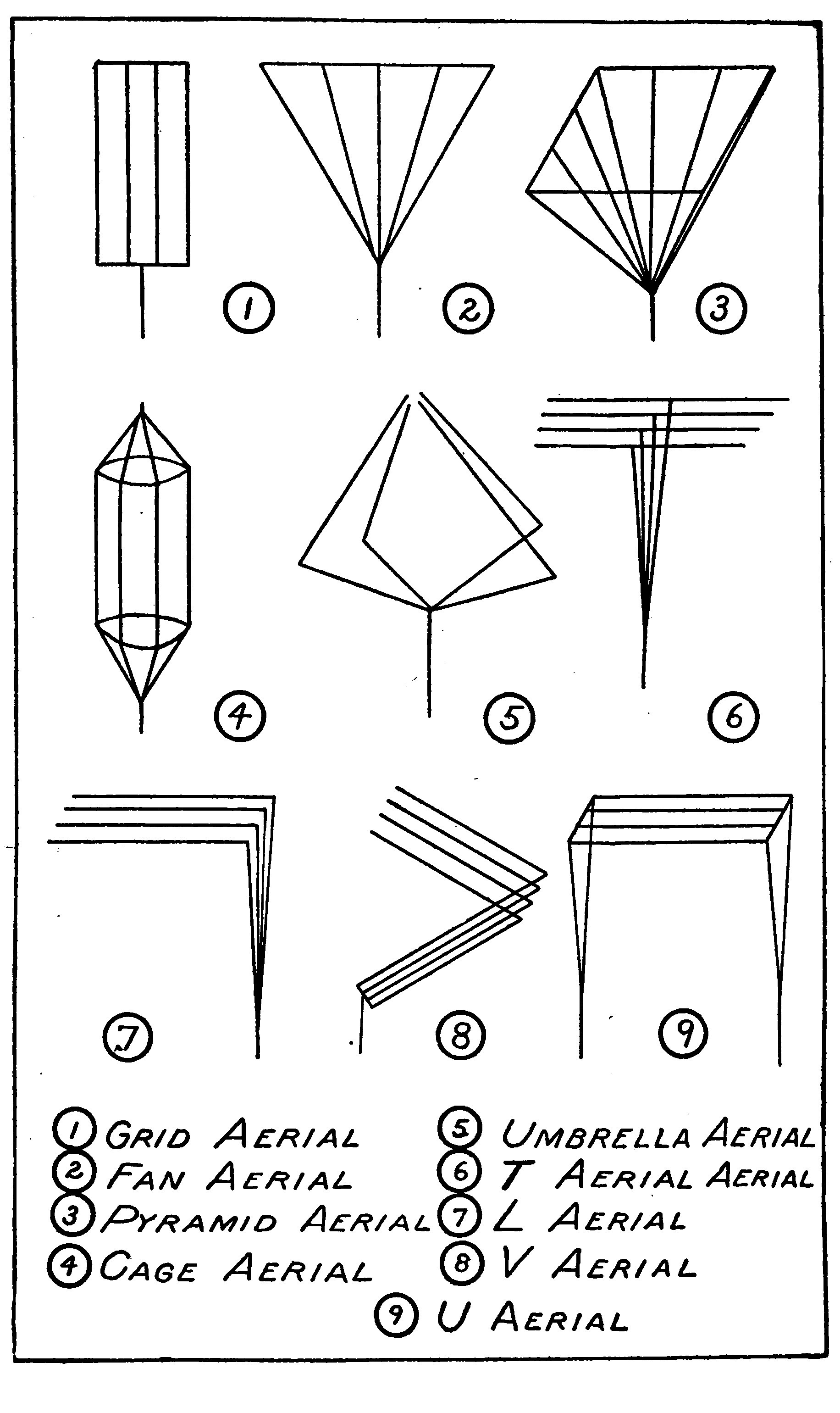
Aerials take many different forms, but may be classified into two general groups called the vertical aerials and flat top aerials.
Vertical aerials compose the grid, fan, cage and umbrella forms.
Flat top aerials are known as the T, inverted U, L and V types, according to their shape.
The Pyramid Aerial is only employed in ultra-powerful stations and is becoming an obsolete form.
The Fan Aerial is a good type of especial value in crowded quarters.
The Grid Aerial is probably the best form of vertical aerial, but is gradually giving way to those of the flat top class.
The Cage Aerial is rarely used nowadays and may be considered obsolete.
The Umbrella Aerial is a very good type now being employed in many high power stations. A metallic pole or mast insulated at the base used to support the wires, so that it is part of the aerial itself.
The "T" Aerial is the most nearly perfect and gives the best "all around" results.
The "L" or Horizontal type of aerial is used wherever it is desirable for any reason to send the most powerful waves in one direction.
The "V" type is used where the highest point must be near the station.
The wire leading into the station, from the aerial is called the "rat-tail" or "lead-in." It is always very carefully insulated and usually enters the station through a hole in the window or wall by means of a "window pane bushing" or "leading-in insulator."
Certain aerials possess a directive action, that is they radiate and receive messages in some directions better than others. Flat top aerials possess this peculiarity more noticeably than the vertical types. Flat top aerials receive and radiate waves coming from and going towards a direction opposite to that in which the free end points.
The free end is the opposite end to that to which the "rat-tail" is connected.
There are two free ends on a "T" aerial and so this form radiates and receives its waves equally well in two directions.
The inverted "L" and "V" types possess a very decided directive action.
Certain aerial forms may be classed as loop and straightaway accordingly as they are connected and led into the station. In the straightaway form of antenna, the wires are connected together as a whole and one rat-tail led into the station. In the loop form the wires are all connected together and divided into two sections. Two wires are led into the station.
The loop form gives slightly better results in a short aerial, but in most cases the straight away is decidedly the most efficient.
LESSON FOURTEEN. THE WIRELESS COIL.
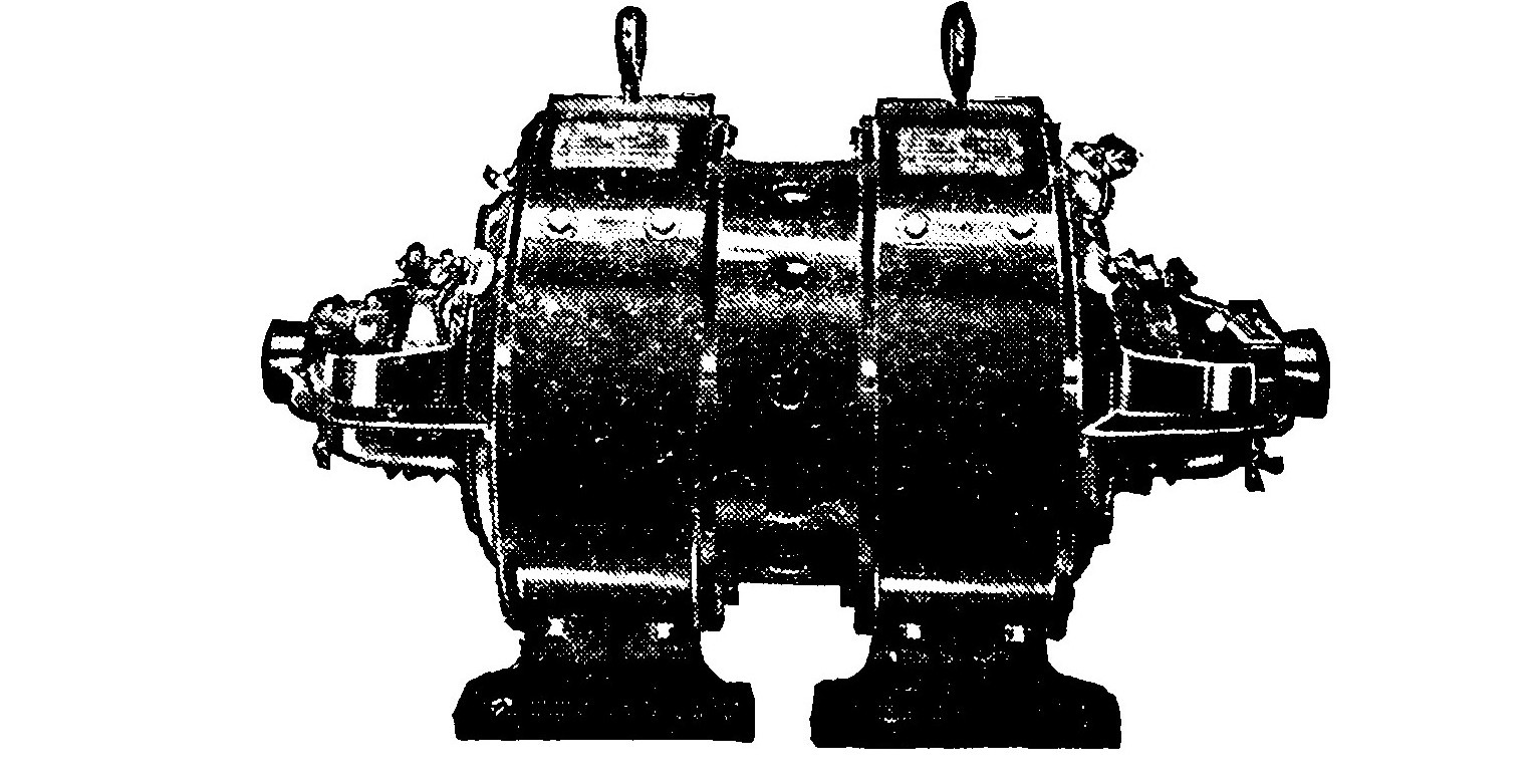
The induction coil used for wireless telegraph purposes differs from the ordinary coil commonly employed in the laboratory in that it is usually built in a more substantial manner and gives a heavier, more powerful discharge from the secondary.
Induction coils of this type are usually enclosed in a strong wooden case filled with insulating compound and are sometimes termed box coils. They are fitted with an interrupter arranged to give a very long period of "make" and a short "break."
Coils giving sparks greater than six inches in length are usually provided with an independent interrupter which may be one of several types.
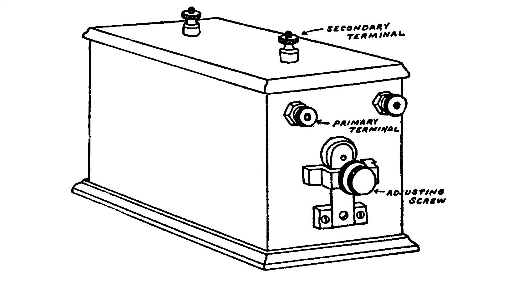
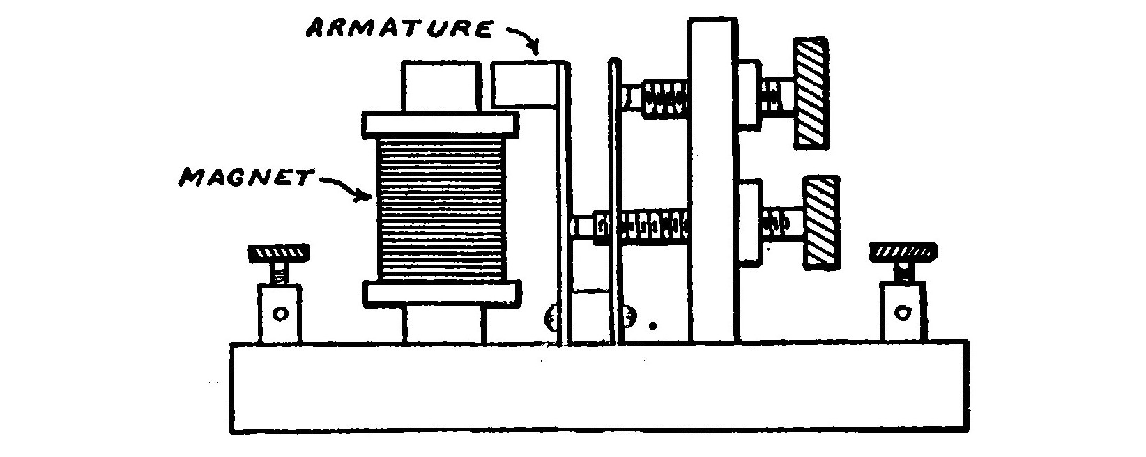
The ordinary independent interrupter consists of the usual form of interrupter, but is operated by the magnetism of a separate electromagnet in place of that of the coil primary itself. An independent interrupter of this type is usually provided with screws for adjusting the speed, and the duration of make and break.
The Mercury Turbine form of interrupter is a very unsuccessful type in which a stream of mercury is made to play against a number of saw-shaped metal teeth. A spiral worm terminating in a nozzle-at the top is rapidly revolved by an electric motor. The lower end of the tubular worm dips into a mercury reservoir so that when the spiral is revolved, the mercury rises in the tube by centrifugal action and is thrown out from the upper end in the form of a jet.
When the revolving jet strikes one of the metal teeth the circuit is made and when it passes between it is broken. Raising and lowering the saw teeth so that the mercury strikes either the lower or upper part varies the ratio of time of the make and break.
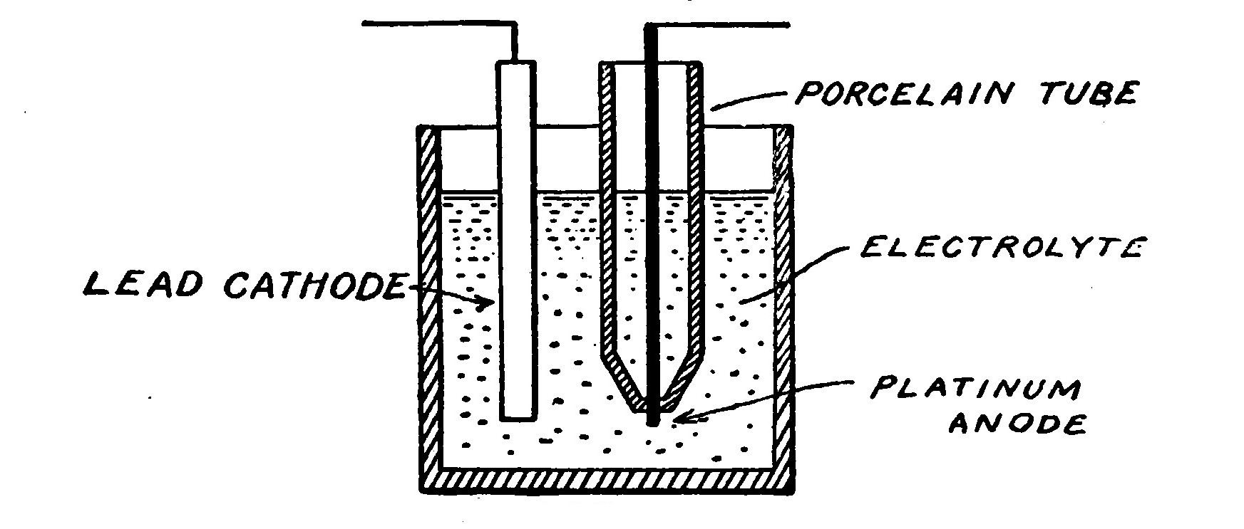
The electrolytic interrupter consists of a cathode or negative electrode of sheet lead immersed in diluted sulphuric acid and an anode composed of a piece of platinum wire placed in a porcelain tube and projecting through a small hole in the bottom, so that only a very small portion of the wire is exposed to contact with the liquid. When a strong electric current is passed through the acid electrolyte, the current is very rapidly interrupted by the formation of gases on the small platinum electrode. The number of breaks per second possible with an electrolytic interrupter is extremely high. A potential of at least 40 volts is required to operate such an interrupter, however.
LESSON FIFTEEN. THE HIGH POTENTIAL TRANSFORMER.
The transformer, like the induction coil, steps up the voltage of the current to a value where it is sufficient to charge the condenser.
The transformer for wireless work should have a potential of from 15,000 to 40,000 volts. Several manufacturers claim advantage for low voltages and build machines having a potential of only about 8,000 volts, but experiments have shown that under most ordinary conditions higher voltages permit greater range of transmission.
Both open and closed core machines may be used with good results. Probably, however, neither one is the best.
The core of a wireless transformer is built up of sheet iron "laminations" to reduce core losses and eddy currents.
The secondary windings are very carefully insulated with empire cloth or paper and may or may not be immersed in oil accordingly as they are designed.
A transformer, more especially than an induction coil, produces a "kick-back" on the line. "Kick-back" is a high potential current caused by the counter action of currents in the condenser and aerial system, due to the fact that they continue to surge after the current has dropped to zero or so low that it is unable of its own accord to produce secondary currents which will jump the spark gap.
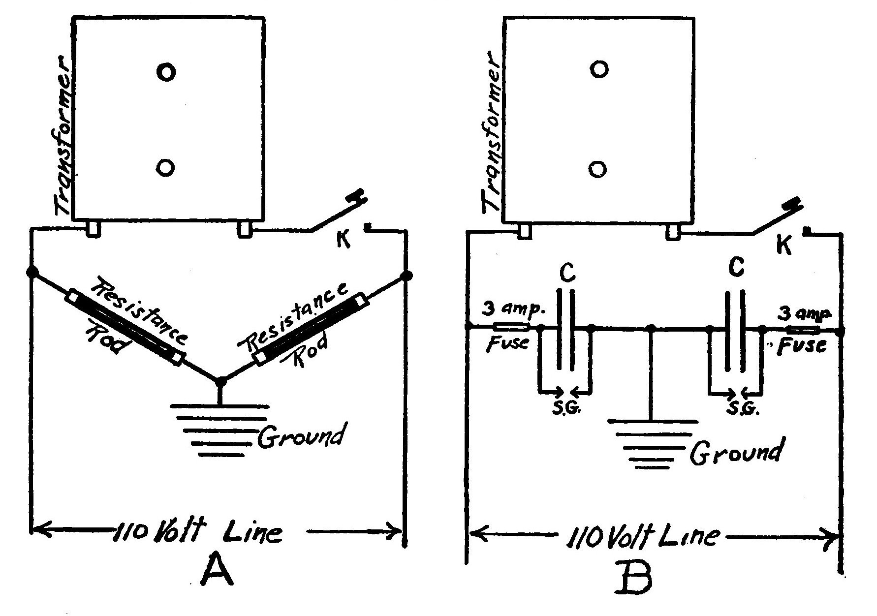
"Kick-back" destroys insulation and is liable to cause burnouts of other electrical instruments supplied from the same system. It may be guarded against by providing the line with a protective device which consists of a condenser having a capacity of one or two micro-farads placed directly across the terminals of the transformer in series with two five-ampere fuses. A small spark gap open about 1/64 of an inch wide is connected across the terminals of the condenser.
In case special protection is desired for some instrument in the circuit, such as a meter, a protective device should be connected directly across its terminals.
LESSON SIXTEEN. THE OSCILLATION CONDENSER.
The Oscillation Condenser might almost be termed the most important part of a wireless station.
Transmitting Condensers usually take the form of a battery of Leyden jars arranged in a suitable case or container. Very often they are placed in a tank of oil to eliminate brush discharges or leakage which takes place from the edges of the tinfoil.
Leyden jars are usually covered with very heavy tinfoil or thin sheet copper to prevent blistering. The best method, however, is to deposit a metallic covering electrolytically.
The principle objection to Leyden jars is their bulk.
Glass plate condensers are not so bulky or expensive and do not blister.
Plate condensers are sometimes merely placed in racks, but more often in a tank of oil to eliminate all brush discharges.
Condensers are always made so as to be adjustable in order that the capacity of the circuit may be carefully regulated.
Only the finest selected glass of the greatest dielectric strength is used in making condensers, in order to avoid all losses and possibility of breakdown.
Whenever condensers must withstand a very heavy voltage, they may be connected in series so that the voltage is divided between them and the strain is not so great. This method reduces the capacity just one-half, however, and when used requires four times as many plates or jars, as the case may be, than if they were connected in one multiple set.
LESSON SEVENTEEN. THE HELIX.
The Helix supplies the greater part of the inductance to the closed circuit of the transmitter. It also acts as a transformer, serving to raise the voltage of the currents surging through the closed circuit and impress them upon the aerial system. The turns of the helix included in the closed circuit constitute the primary of the transformer, while those in the open circuit form the secondary.
A helix consists of a heavy conductor, either brass or copper, wrapped around a suitable frame of wood or hard rubber. Some forms consist of a spiral of copper ribbon clamped between two cross-shaped frames.
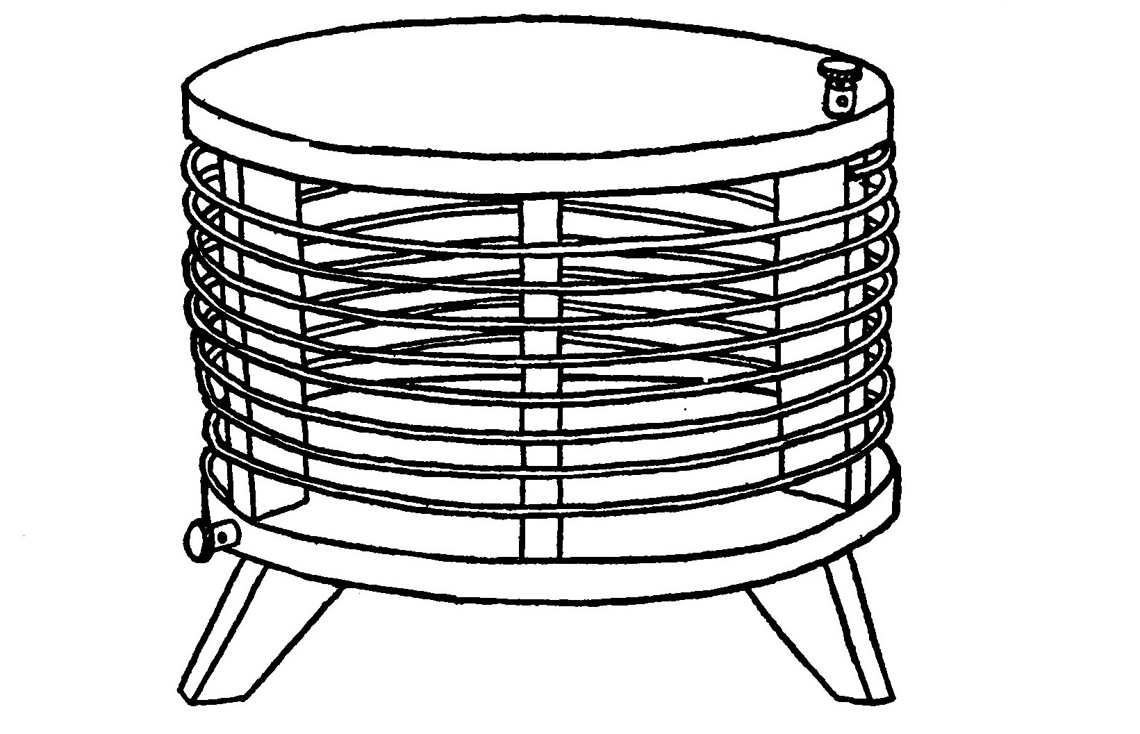
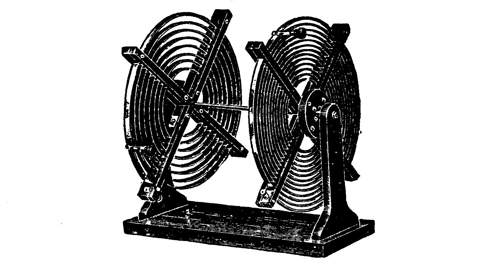
Helixes are of two kinds, known as "close" or direct coupled and "loose" or inductively coupled. In an inductively coupled transmitter the primary and secondary are wound upon separate frames and are not connected together.
The U. S. Government Radio regulations place a limit on the amount of damping permissable in a transmitter.
It has already been explained in one of the previous lessons how the oscillations or surgings of the spark discharge rapidly die away. A spark which thus rapidly dies away is said to be rapidly damped. The damping of a loose coupled transmitting set is never as great as that of a close coupled set.
For this reason the old style helixes are now practically obsolete and the loose or inductively coupled helix is the one most commonly used. Loose coupled helixes are also often termed oscillation transformers.
An ordinary transmitter tends to emit two sets of waves of different length. By carefully adjusting the coupling, pure trains of waves are formed by attracting the apices of the two sets of waves into one.
LESSON EIGHTEEN. SPARK GAPS.
A Spark Gap is the medium across which the oscillatory discharge takes place. It usually consists of two electrodes of zinc alloy, nickel steel or brass, suitably mounted on an insulating base and standards.
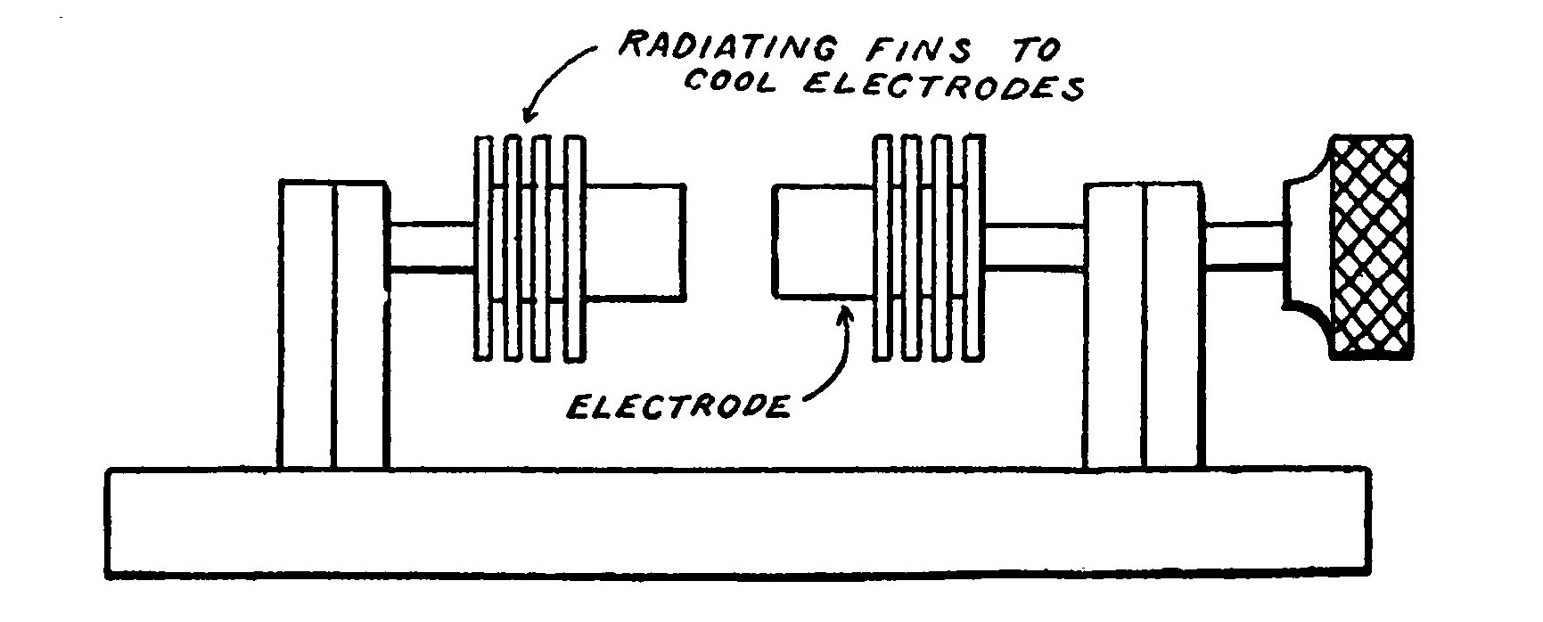
The electrodes are usually provided with flanges or radiators which tend to dissipate the heat and keep them cool. If the electrodes should become very hot the spark would arc, that is, pass across the gap without generating any electrical oscillations. Spark gap electrodes are usually flat or else hollow on the sparking surface.
The proper adjustment of the gap, i.e., the distance between the electrodes is a matter of the utmost importance for there is a point just where the maximum amount of energy will be radiated.
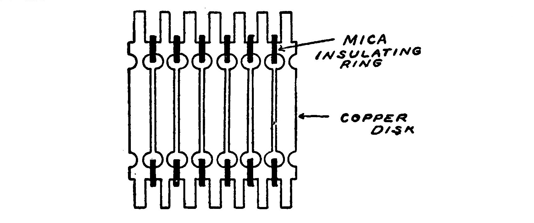
The Quenched Gap, consists of a number of brass or copper disks placed in a pile, each disk being separated from the other by a thin mica ring. The distance between two adjacent disks is usually only about .01 inch. The effect of the quenched gap is to considerably reduce the damping of the system and make it possible to send signals very great distances with the consumption of only comparatively small amounts of energy.
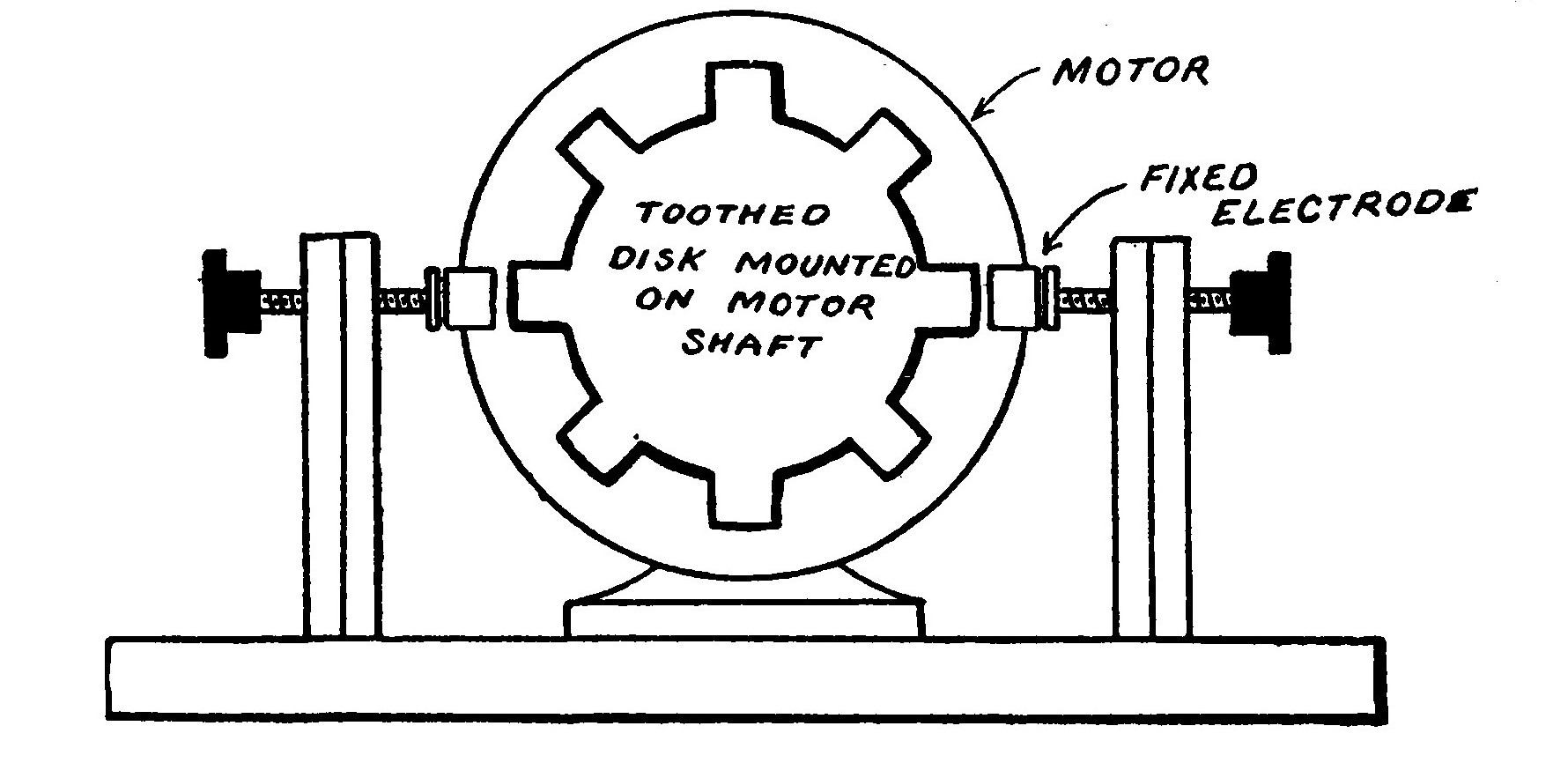
The Rotary Gap consists of a number of electrodes mounted on a motor shaft and arranged to revolve rapidly. The spark discharge takes place between the revolving electrodes and one or two fixed contacts. The effect of a rotary gap is to considerably increase the efficiency of the transmitter by allowing the condenser to become highly charged before it discharges and also reducing the possibility of arcing by keeping the electrodes cool and moving.
Rotary gaps are of two types, synchronous and non-synchronous. Synchronous rotary gaps are mounted directly on the shaft of the generator supplying current to the transmitter and arranged so that the electrodes are opposite each other once during each alternation of the current.
The rotary gap, commonly used by amateur experimenters and consisting of a toothed disk mounted on the shaft of a small motor is of the non-synchronous type.
Rotary gaps are sometimes enclosed in an air tight case and the electrodes arranged so that the results obtained are characteristic of both the quenched and rotary gaps. This type of gap is known as the rotary quenched.
LESSON NINETEEN. THE KEY.
Some means of controlling the currents flowing through the transmitter in order to divide them into periods corresponding to the dots and dashes of the Morse Code is necessary.
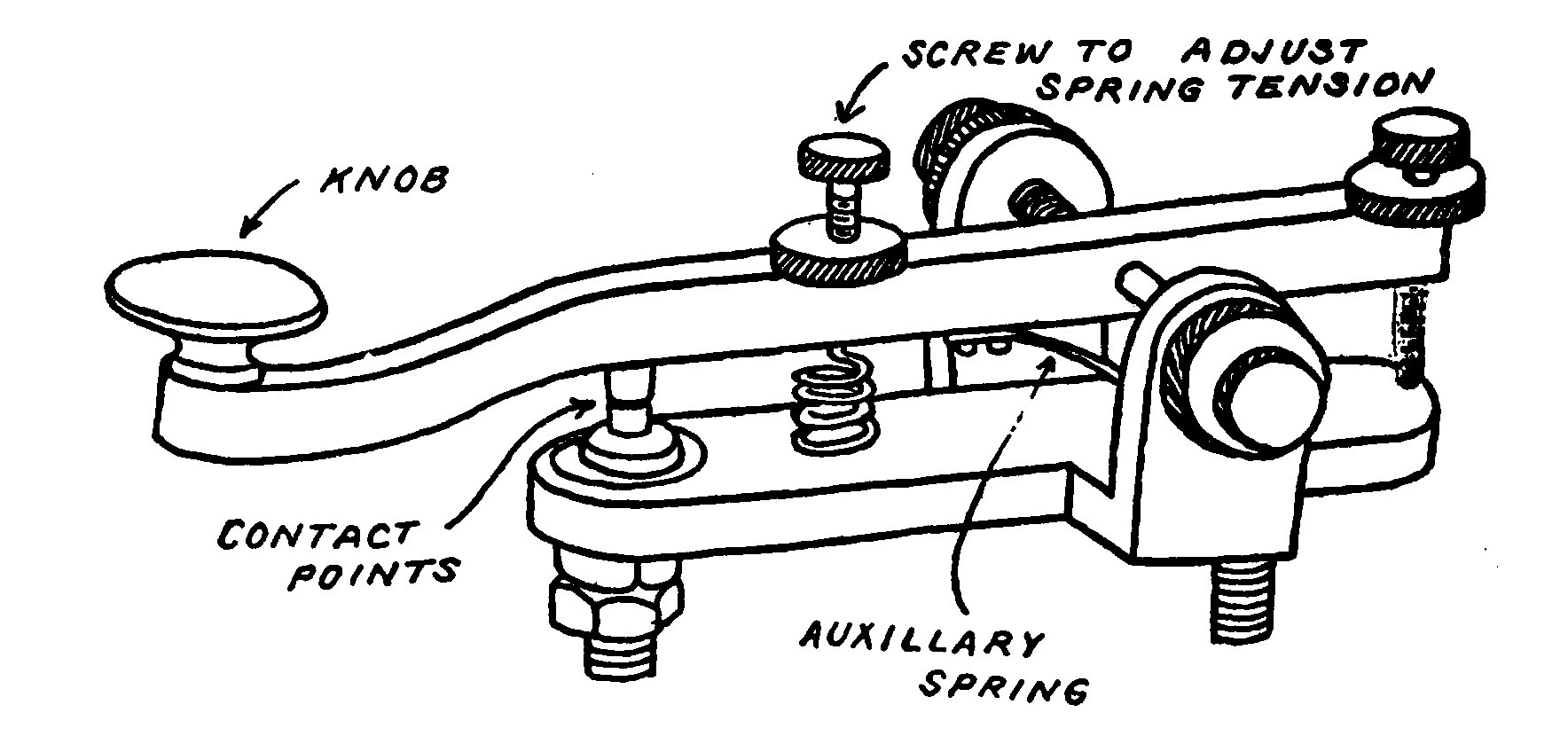
This is supplied by a hand operated switch, called a key. A key used for wireless purposes must be much larger and heavier than an ordinary key employed for line work in order to carry the more powerful currents.
In spite of the size and weight of a wireless key, if it is properly balanced, it may be handled with perfect control and ease.
The contact points of a wireless key are necessarily large and heavy. Special alloys found to be the most suitable for the purpose are usually employed. A large condenser having a mica dielectric is very often connected across the contacts to reduce the sparkling.
In very large stations where extremely heavy currents must be handled, the key controls a large switch operating in oil. Every time the key is pressed the switch closes and when the key is released, opens. The currents of the transmitter are "made" and broken by the switch without passing through the key.
LESSON TWENTY. AERIAL SWITCHES.
Since the same aerial is used both for transmitting and receiving, some method of quickly connecting it to either the transmitter or receiving apparatus must be provided. This is accomplished by means of an aerial switch.
The best and most efficient switch adopted generally by the commercial stations is the "T" type, consisting of a double pole, double throw switch having very long blades. One set of contacts is mounted on the switch base and the second are carried on a "T"-shaped support from which the switch derives its name. The aerial and ground are connected to the blades of the switch.
The lower contacts lead to the transmitting apparatus and the upper ones to the receiving instruments. By simply moving the switch up or down the aerial and ground may be connected to either the transmitter or the receptor at will.
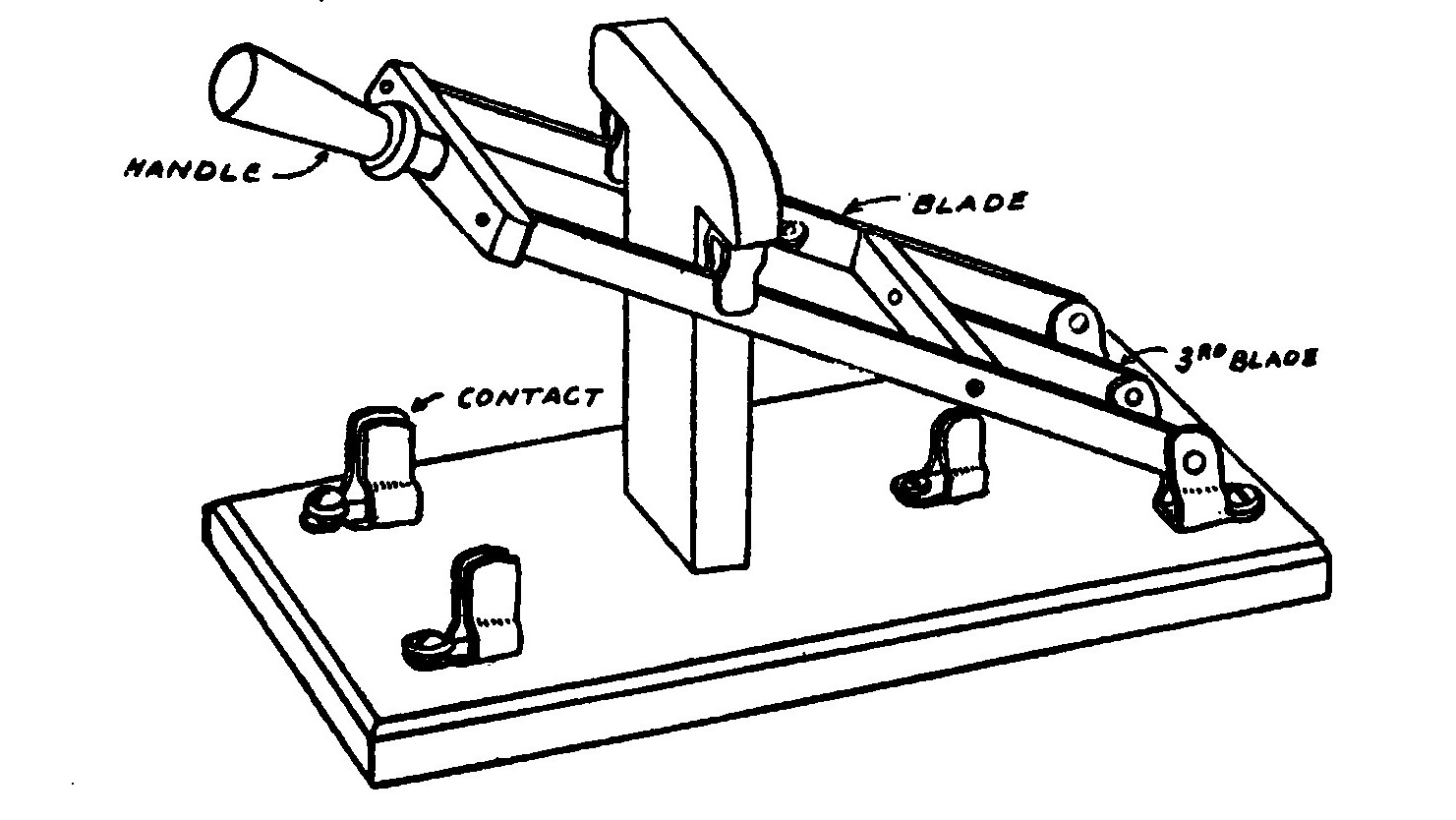
A third blade, much shorter than the other two is usually provided and connected by means of an insulating bar to the other blades so that when they are moved it also moves. It connects with a contact arranged so that when the switch is thrown into position for transmitting the two come together. This blade and contact are made a part of the circuit supplying current to the primary of the coil or transformer so that in case the key should be accidentally touched while receiving the powerful discharge of the transmitter would not destroy the adjustment of the detector.
LESSON TWENTY-ONE. ANCHOR GAPS.
Certain types of aerial switches require the use of what is known as an anchor gap.
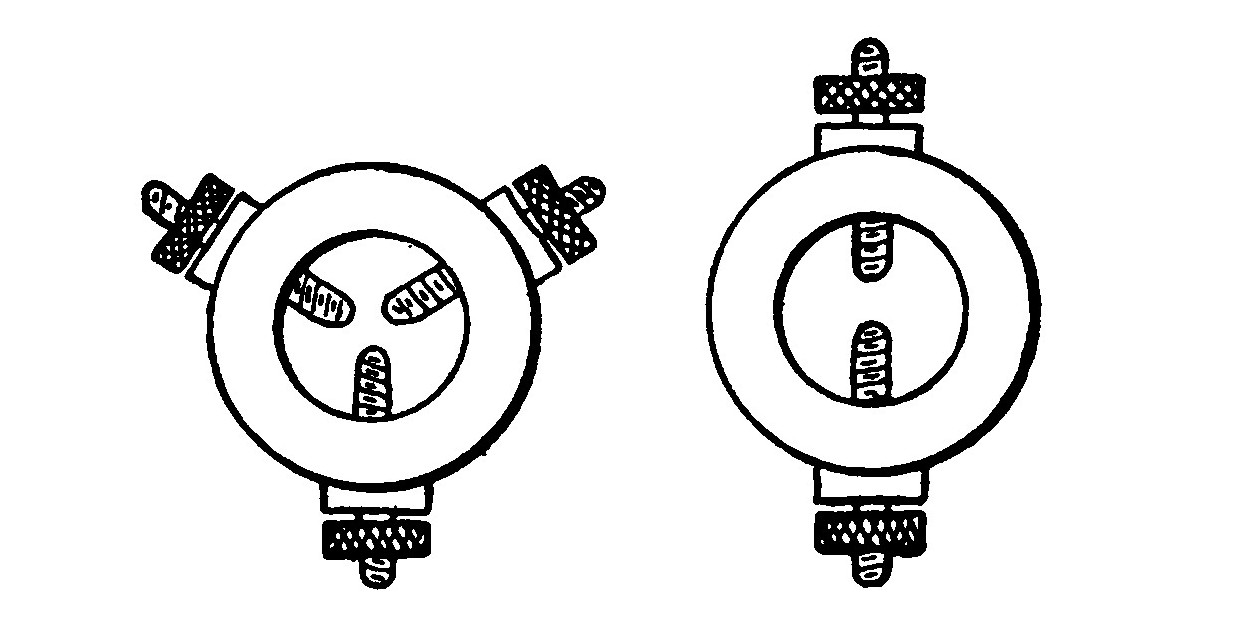
An anchor gap consists of a small insulating ring, usually hard rubber, having two and sometimes three electrodes set in the periphery and almost touching each other at the sparking points.
Anchor gaps having two electrodes are used in the aerial circuit of most Break-in-Systems to prevent the receiving currents from flowing directly into the ground through the transmitter without passing through the detector.
A Break-in System enables the operator to hear the signals of any other station which may be transmitting at the same time when he is operating his own key.
The three-electrode anchor gap is commonly used on loop aerial systems. Two of the points are connected to the aerial, one to each half and the other to the lead from the helix. The high potential currents from the helix easily leap across the little gap and divide between the two halves of the aerial.
LESSON TWENTY-TWO. DETECTORS.
The little bobbins of the telephone receivers exert a very powerful choking action upon the currents of high frequency which effectually blocks their passage and prevents them from having any action upon the receiver.
The purpose of the detector is to change these currents into such as will flow readily through the magnets of the telephone receiver and manifest themselves as sounds recognizable from their duration and periodicity as signals of the telegraph code.

Probably the most well known form is the electrolytic detector which consists of an exceedingly fine platinum wire dipping into a cup of dilute nitric acid far enough to just touch the surface of the liquid. The telephone receivers are connected to the detector, in series with a battery. The current from the detector causes bubbles to continuously form on the end of the wire and insulate it from the liquid so that the current cannot flow. When the aerial is struck by a wave, the feeble alternating currents break down the bubbles and permit the currents to flow, causing a sound in the telephone receivers.
The detectors in most common use to-day are of the crystal or rectifying type. There are a great many different forms of this type of detector, each one of which possesses certain features making it peculiarly adaptable under certain circumstances.
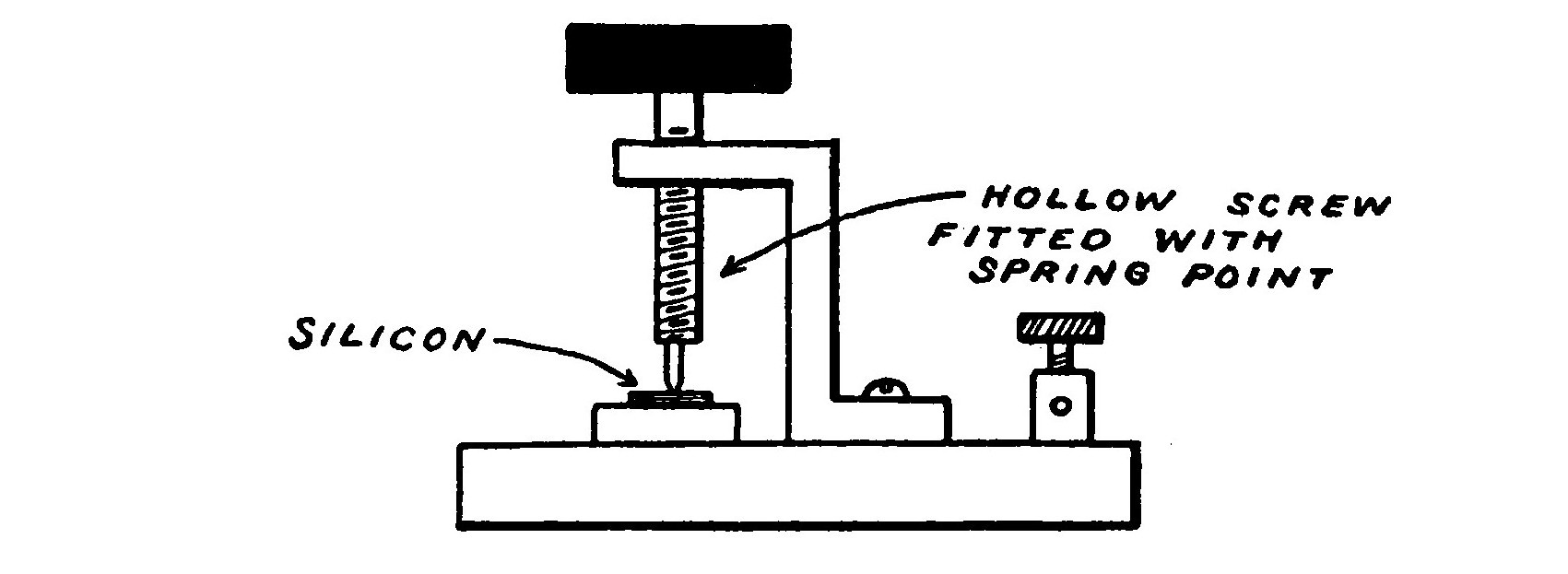
The silicon detector consists of a flat surface of highly polished silicon upon which rests a brass point.
The Pyron detector is composed of a crystal of iron pyrites embedded in a cup of fusible metal. A small wire spring bears against the surface of the crystal. The Pyron detector is somewhat harder to adjust than other forms of crystal detector, but remains in a sensitive condition much longer.
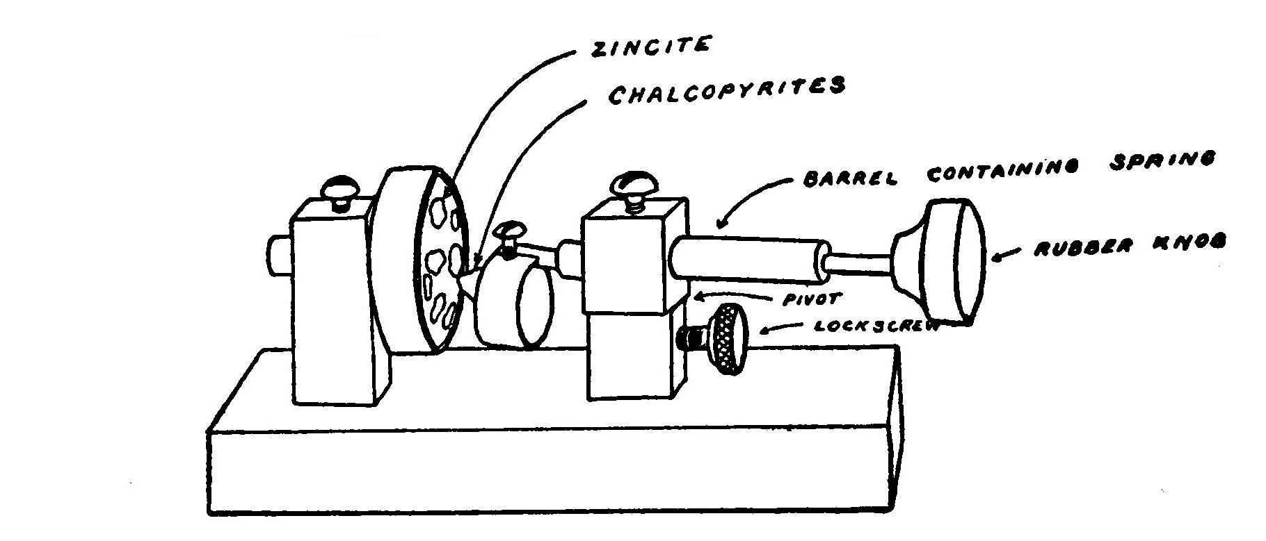
The Perikon detector consists of a cup of fusible alloy in which are imbedded several pieces of a mineral called zincite. Another cup containing a fragment of chalcopyrites or bornite is held in a cup carried on the end of a rotating rod. The chalcopyrites is brought into contact with one of the crystals of zincite and the pressure adjusted by means of a spring. The Perikon detector will operate without a battery, but that latter is necessary in order to obtain the best results when receiving faint or far away signals.
The Perikon Electra detector is a very sensitive form of the regular Perikon detector fitted with a micrometer adjustment.
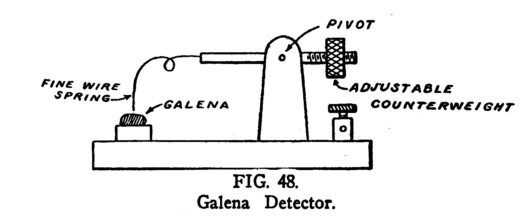
The Galena detector consists of a crystal of that material to which contact is made by means of a fine wire spring exerting very light pressure.
Crystal detectors act as rectifiers and change the alternating currents Into direct currents, which will pass through the telephone receivers. Minerals used for this purpose are said to possess unilateral conductivity, that is, they conduct currents better in one direction than the other and act much the same as a valve which allows water to flow in one direction, but not in the other.
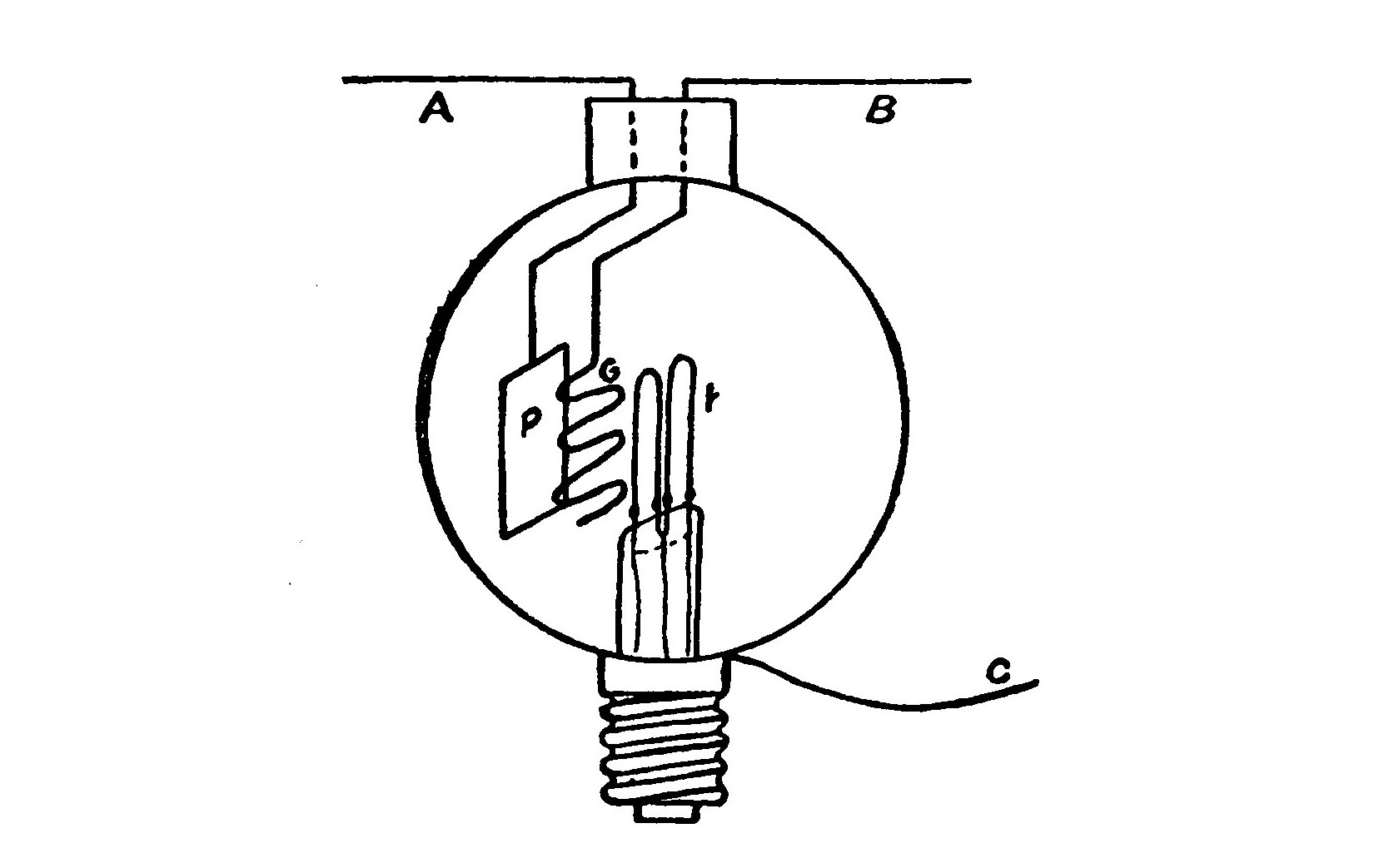
Another well known detector of the "valve" type is that known as the Audion, consisting of a small incandescent lamp containing a small grid and plate of nickel. When the lamp is lighted by connecting a battery to the filament, a flow of ions passing from the hot filament through the grid to the plate is set up. The grid and plate form part of the receiving circuit containing the telephones. The flow of ions carries the oscillatory currents from the grid to the plate, but does not allow them to pass back again. In this manner, the alternating oscillatory currents are converted into direct currents, which will pass through the telephone receivers.
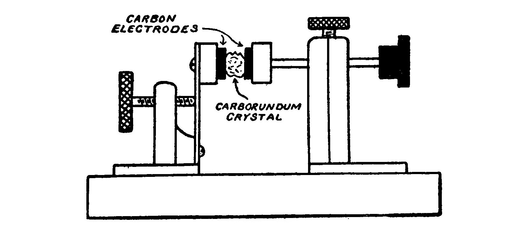
The Carborundum detector, as its name implies, is a device making use of the unilateral conductivity of carborundum. This form of detector is very sensitive and has been employed for a number of years in all the installations of the United Wireless Telegraph Co.
It consists of a small crystal of carborundum clamped tightly between two carbon electrodes. It may be used with or without a battery. The battery is preferred.
The Magnetic detector is a very sensitive device utilizing the changes in the magnetic state of iron, which are caused by rapidly oscillating currents. If a core of iron wires be placed in a varying magnetic field, the magnetization of the iron will lag behind the magnetizing force on account of hysteresis or "magnetic friction."
But if a rapidly oscillating current is passed through a coil surrounding the iron, a sudden change in magnetization occurs, sufficient to induce an E. M. F. in a second coil surrounding the core and thus operate a telephone receiver in series with this coil.
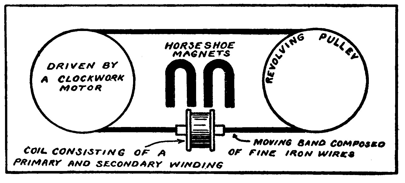
The usual form of magnetic detector consists of a belt of fine iron wires passing over two pulleys which are driven by clockwork. A pair of permanent magnets supply the field which induces a continuously varying magnetization in the moving core. The core passes through the centre of a double coil, one part of which is connected to the telephone receivers and the others to the aerial and ground.
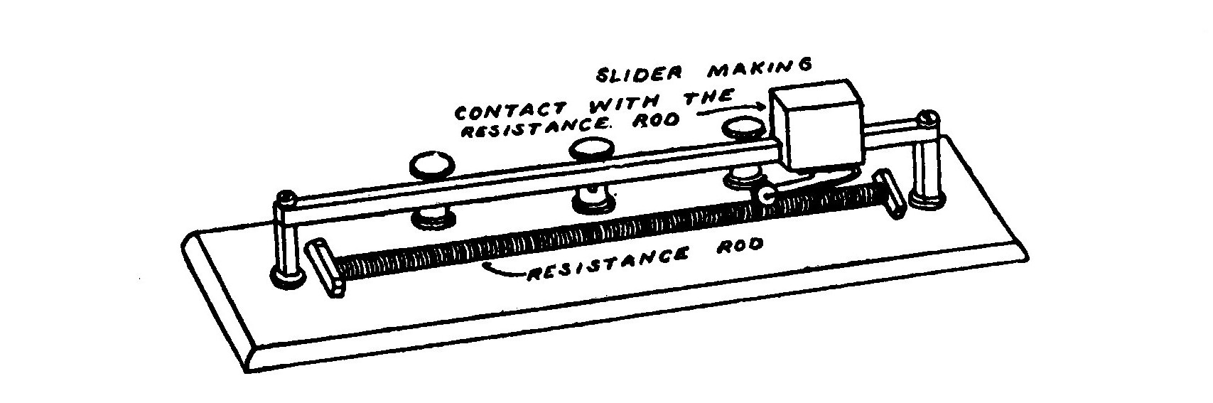
LESSON TWENTY-THREE. TUNING COILS.
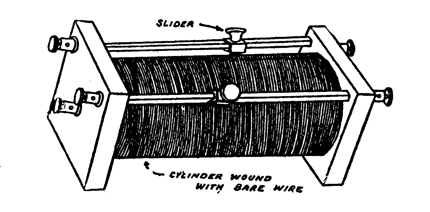
The tuning coil is a device consisting of a large number of turns of wire wound in the form of a cylinder and provided with one or more sliding contacts which can be brought into touch with any one of the turns at will in order to increase or decrease the electrical length or period of the circuit to suit the incoming waves.
A circuit containing a certain amount of inductance, capacity and resistance tends to oscillate at a certain frequency. Therefore, the oscillations in every transmitting set have a certain frequency depending upon these factors. It is necessary to adjust the receiving apparatus so that it possesses the same frequency as the transmitter. The electro magnetic waves from the transmitting station will strike the aerial of the receiving station at a certain frequency and induce currence in it. If the receiving station is tuned to the same period as the transmitter each wave will give a slight impulse to the readily excited oscillations, which will grow in intensity just as small impulses given to a pendulum at the right times will make it swing violently.
The purpose of the tuning coil is to adjust the receiving circuit to the same period as that of the transmitter.
Tuning coils are wound of bare copper wire over a core composed of a specially treated cardboard tube. The wires are spaced apart so that they do not touch one another. Either one, two or three variable contacts or sliders are provided. The coils are consequently known as "single," "double" or "three" slide tuners.
A loading coil is a supplementary coil sometimes placed in series with the regular tuning coil to give a greater inductance to the circuit so that it may be given a much lower frequency in order to receive waves of greater length.
LESSON TWENTY-FOUR. LOOSE COUPLERS.
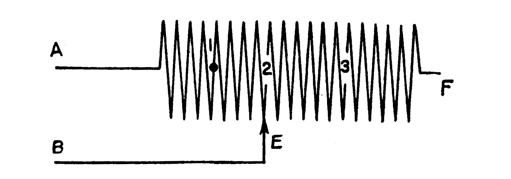
A Loose Coupler or Receiving Transformer is a tuning coil in which the coupling, as well as the inductance, is variable. We have already explained that an ordinary transmitting set throws off two sets of wave trains of slightly different length, one being somewhat weaker than the other.
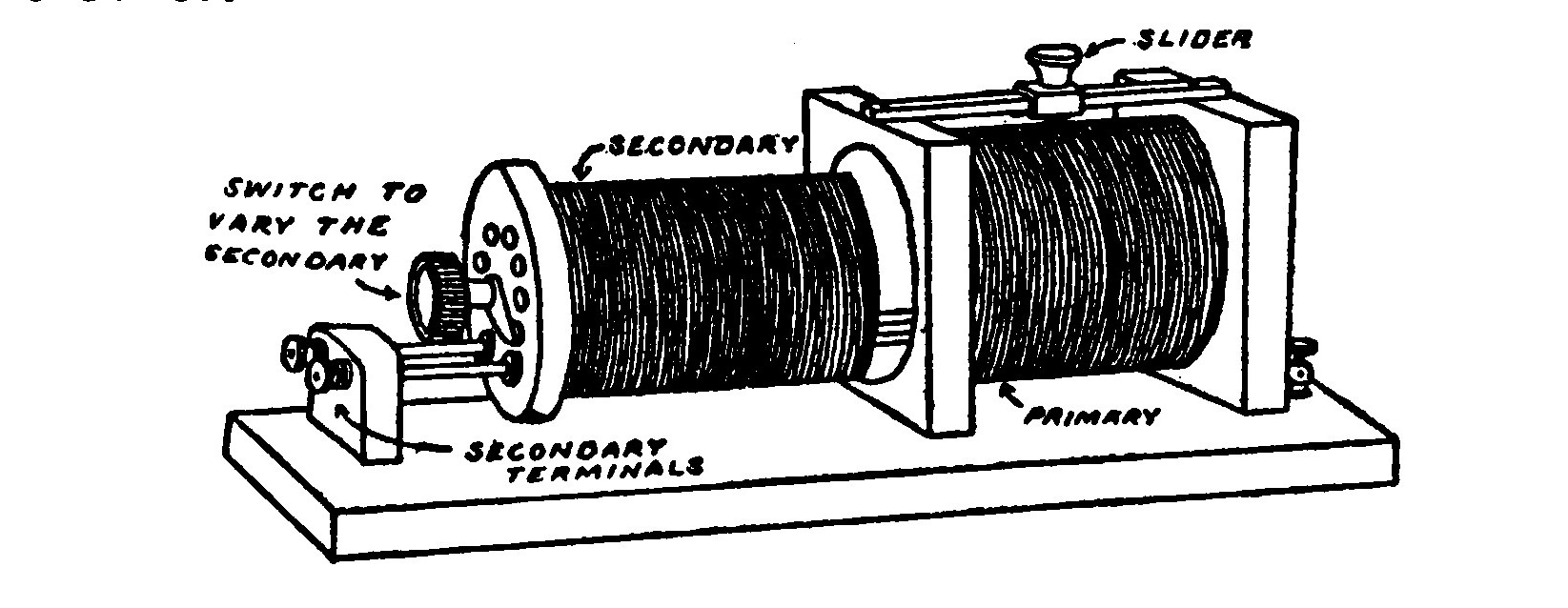
The purpose of the loose coupler is not only to adjust the receiving set to the period of the transmitter in the manner of the tuning coil, but by varying the coupling to attract the apices of the weaker trains of waves to the same apex as the stronger waves and so really create a pure wave out of the other two.
This may be more easily understood from the accompanying illustration which represents diagrammatically a double train of waves and a pure train.
In construction, the loose coupler consists of a primary winding much the same as an ordinary tuning coil provided with a single slider.
A second winding called the secondary, divided into a number of sections and adjustable by means of a multi-pointed switch mounted on one end, slides in and out of the primary.
LESSON TWENTY-FIVE. FIXED CONDENSERS.
A fixed condenser usually implies the condenser used in the receiving circuit to furnish part of the necessary capacity and to shunt the telephone receivers, or as in cases where a battery is used in connection with the detector to force the current to choose a path through the comparatively low resistance turns of the tuning coil.
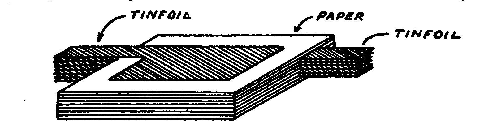
A fixed condenser, as its name implies, has a fixed value or capacity. It is usually constructed of sheets of tinfoil interposed between sheets of thin paraffined paper or mica. The capacity of a fixed condenser usually varies from .002 to .005 microfarads.
An alternating current passes readily through a condenser but a direct current is effectually blocked.
When a direct current is led into a condenser as shown in the diagram, the half of the condenser represented by A becomes positively charged. When A receives a positive charge it repels the positive charge from B and attracts the negative thus making B negative. There is no change in the direction of the current after the first connection and the charge remains fixed and no currents pass.
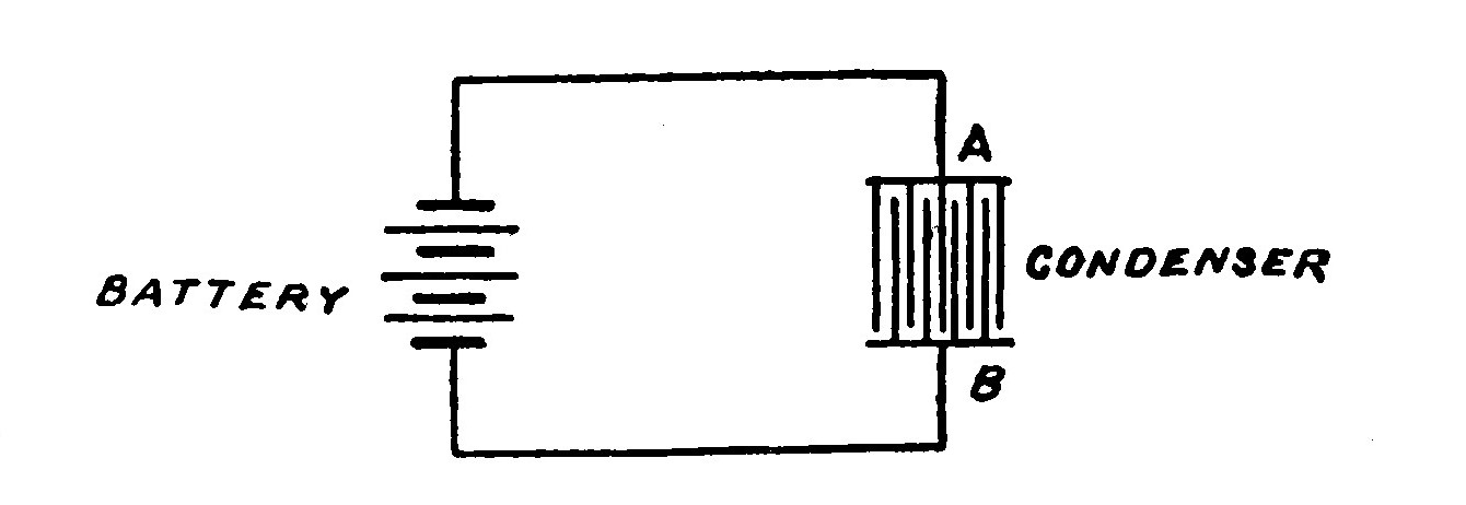
If an alternating current is applied to the condenser when A receives a positive charge, B becomes negative. When A reverses and becomes negative B becomes positive. This process goes on, the two halves constantly changing their charge with the result that the current continues to flow.
A fixed condenser may occupy one of two places in a receiving circuit, either in series with the tuning coil and detector or directly across the telephone receivers. In the illustration A shows a detector requiring a battery with a fixed condenser in series with it and the coil. The oscillations set up in the circuit by the incoming waves can readily pass through the condenser and effect the detector because they are alternating. If it were not for the condenser the direct battery current would pass through the tuning coil instead of the detector because of the comparatively low resistance of the former.
Crystal detectors do not require a battery and may be connected to a tuning coil with a condenser in series and the telephone receivers either across the terminals of the detector or across the terminals of the condenser. When in the latter position, the proper capacity for the fixed condenser will depend upon the resistance of the telephone receivers, the higher the resistance the less the capacity that will be required and vice versa.
LESSON TWENTY-SIX. VARIABLE CONDENSERS.
The point of sharpest resonance does not always happen to come on a turn of the tuner where it can be reached by the slider. The variable condenser makes it possible to adjust the circuit to the exact point of resonance.
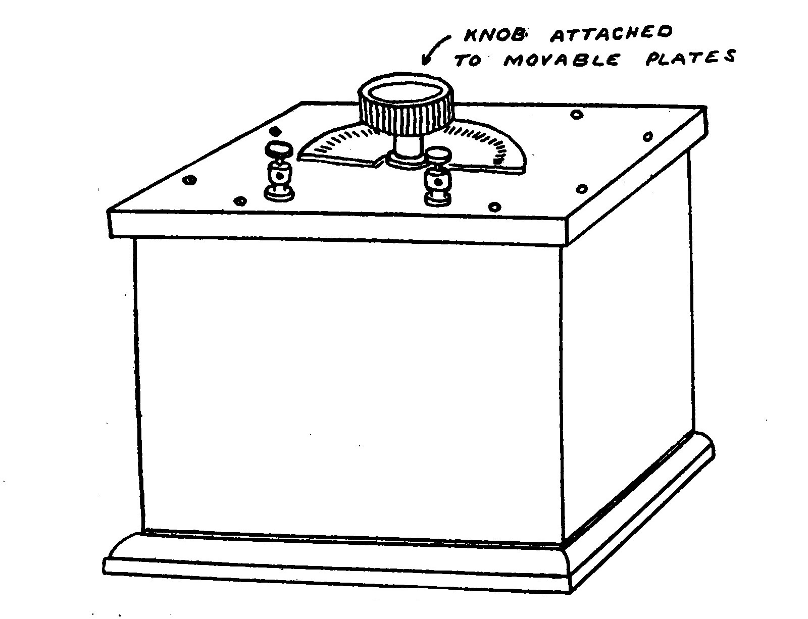
Variable condensers are of two general types, the Sliding Plate and the Rotary Variable. The rotary variable is the most convenient and easy to manipulate. It consists of a number of fixed semi-circular metal plates between which swings a set of smaller movable semicircular plates. The fixed plates form one half of the condenser and the movable plates the other. In this way the capacity of the condenser is very closely adjustable. The movable plates are provided with a pointer moving over a graduated scale so that the comparative amount of capacity in the circuit is indicated.
The sliding plate type of condenser consists of a number of rectangular fixed plates between which slide a set of movable plates.
The dielectric between the plates of a variable condenser is air. There are no losses of energy due to hysteresis in a condenser having an air dielectric. Rotary condensers employing silk or some such material are not to be recommended.
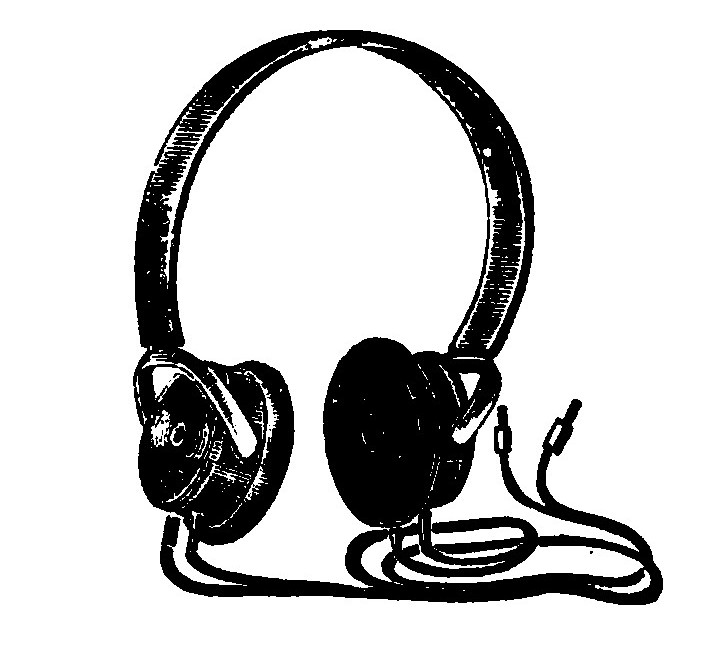
LESSON TWENTY-SEVEN. TELEPHONE RECEIVERS.
Telephone receivers employed for wireless telegraphy are the same in principle as the ordinary telephone receiver but differ in construction and detail slightly.
They are always of the watch case type, this style being small and light, and consist of a ring or horseshoe shaped permanent magnet upon the poles of which are mounted two small bobbins containing many turns of fine insulated wire. Over the magnets, very close to but not quite touching, is placed a circular diaphram of thin sheet iron. The lines of force created by the permanent magnet pass through the cores of the little bobbin and exert a constant pull on the diaphram.
The little bobbins of wire or electromagnets are connected in series. If a current of electricity is sent through them they will create a little field of force of their own which will strengthen or decrease that of the permanent magnets according in which direction the current flows. Each change in the pull exerted on the diaphragm causes it to move and send out little sound waves which may be heard when the receiver is held close.
We have already learned that the strength of a magnet depends upon the ampere turns. Suppose that a current of one ampere passed through a coil containing 100 turns x 1 amp. = 100 ampere turns. If only one-tenth of an ampere was available and we wished to retain the same magnetic strength in the coil, the number of turns would have to be increased to one thousand in order for the ampere turns to remain equal; 1/10 amp. x 1.000 turns = 100 ampere turns.
The currents passing through the receiver from the detector are exceedingly weak, and so in order to produce the maximum effect on the diaphragm, the electromagnets must be wound with a large number of turns of very fine wire. The resistance of fine wire is very great and for this reason wireless telephone receivers are usually termed high resistance receivers.
Winding a receiver with many turns of fine wire does not make it more sensitive in the true sense of the word or from the standpoint of efficiency, but makes it better suited to the minute fluctuations of a weak current.
The classification of receivers, according to their resistance is a method of indicating the comparative number of turns and the finess of the wire used in winding the electromagnets. Receivers should be wound with copper wire only.
Wireless receivers come in pairs provided with a head-band so that they may be securely clamped on the ears.
The receiver cases are made of rubber, composition, brass and aluminum depending upon the design and manufacture. It is immaterial which.
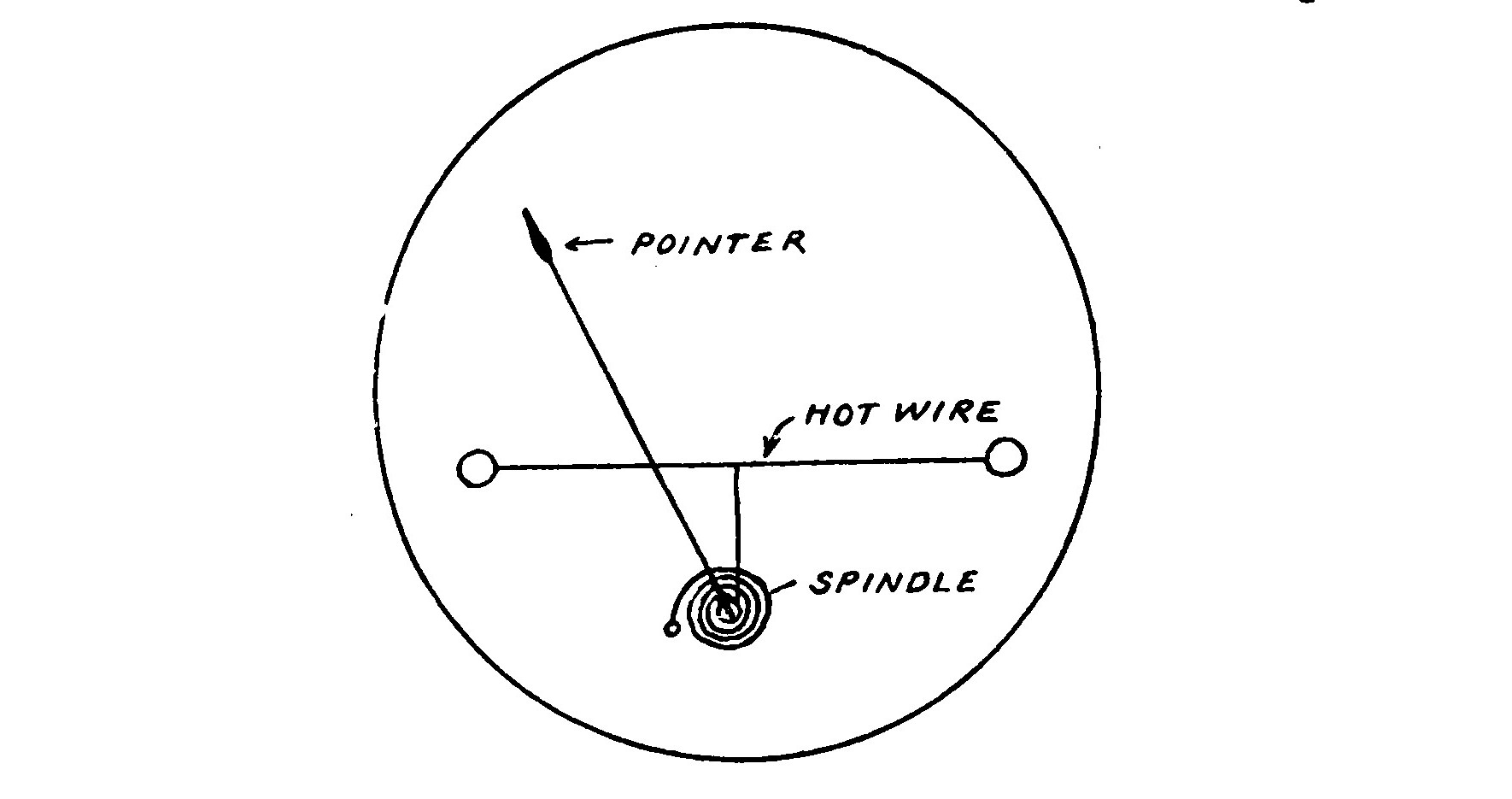
LESSON TWENTY-EIGHT. THE HOT WIRE AMMETER.
The hot-wire ammeter is a device for indicating when the transmitting circuits are properly adjusted and arranged to emit the maximum amount of energy. It is placed in series in the aerial circuit so that the high frequency currents surging in the latter must pass through the meter and indicate their strength by moving the pointer a certain distance over a graduated scale.
When a current of electricity flows through a wire it develops a certain amount of heat therein. If the wire is of high resistance the heat will be great enough to cause the wire to expand. Advantage has been taken of this fact in the construction of the hot-wire ammeter. This device consists of a piece of platinum wire or a platinum alloy stretched taut between two posts. The wire is included in the aerial circuit. The platinum wire is connected to a spindle carrying a pointer in such a manner that when the heat causes the wire to expand the expansion is conveyed to the spindle and the pointer moves over the scale magnifying the motion. The greater the current flowing through the wire the greater will be the deflection of the pointer. The scale is calibrated by comparison with a standard meter to read in amperes.
When a hot-wire ammeter is placed in circuit the latter is tuned by moving the position of the helix clips on the helix, altering the length of the spark gap and the condenser capacity until the maximum deflection is indicated. It is then removed from the circuit.
LESSON TWENTY-NINE. POTENTIOMETER
The potentiometer is an instrument for carefully regulating the voltage of the battery supplying a detector of the electrolytic or carborundum types with current.
It is necessary to bring the potential of the battery to a certain critical point where it is just insufficient to "break down" the detector, that is, overcome the resistance which it offers to the oscillatory currents. In construction, the potentiometer usually consists of a small rod wound with German silver wire and provided with an adjustable contact. Graphite resistance rods are merely a cheap method of making a potentiometer and are to be avoided as entirely unsatisfactory for the purpose.
LESSON THIRTY. DEAD END LOSSES AND "NO DEAD END" SWITCHES.
Practically every radio circuit includes an adjustable inductance of some sort, usually consisting of a layer of wire wound over a tube and arranged so that the amount of wire in the circuit can be varied by means of a switch, a plug or a slider. These methods of variation are familiar in the ordinary tuning coil, loose coupler, loading coil, etc.
If the plug, switch or sliding contact, depending upon the method of variation employed, is at E as in Fig. 60 so that only the portion of the coil A E B is in the circuit, then the portion E F together with A E may form an oscillator which, in order for the reader to obtain a better conception, may be likened to a sort of secondary winding, with A E considered as the primary. The oscillations of this part of the system may produce some very undesirable disturbances, especially so when the frequency of the currents in the circuit A E bear a certain relation to the natural frequency of the oscillator or E F. The losses due to the disturbance of these undesirable oscillations and also those resulting from eddy currents induced in the free portion or oscillator E F by the magnetic flux of A E are known as "dead-end effects."
These losses are very much more noticeable in receiving circuits than in transmitters on account of the very weak currents in the former and the importance of preserving all the energy when it is already very small.
Dead end losses take place principally in receiving transformers, loading coils and tuning coils. The losses are much more marked on short waves than long waves.
The presence of these highly objectionable losses, and they are large enough to not only seriously decrease the strength of signals but also to make selective tuning impossible, may be avoided by only using coils which are just the right size so that they can be entirely included in the circuit.
This is a very easy matter when only one wave length or at the most, two or three wave lengths are to be received, because it is then easily possible to quickly connect the coil of the proper size in the circuit. It is desirable however in most stations, and especially so in amateur stations that the apparatus be universal so as to be quickly and easily tunable to any wave length within its range.
Many amateurs build large loose couplers having a very wide wave length range under the impression that they have an ideal instrument. The truth of the matter is however that such an arrangement is decidedly inefficient especially on the shorter waves when only a portion of the windings are in circuit and there is a large dead end portion.
The better types of receiving transformers are now provided with "no dead end loss switches" which automatically break the windings up into a number of groups so that only that portion which is actually required to tune the circuit to a certain wave length is in circuit and the remainder of the coil is entirely disconnected.
These switches are located at certain definite points as previously determined by measurements of the coil with the aid of a wave meter.
The diagram in Fig. 61 illustrates the principle of such an arrangement. The points marked 1, 2 and 3 are the places in the coil where the switches are located so as to divide the winding up into separate parts. Suppose that it is necessary to move the slider or switch to such a point on the coil as represented by its position in the illustration marked E. The switch located at 1 would then automatically close as the slider or switch moved past 2 and 3 would however still remain open because that part of the winding which they connect would not be required. If it became necessary to include more of the winding in the circuit, 2 and 3 would automatically close as the slider or switch was moved along the coil and open again as it was moved back.
The automatic arrangement of the switches is easily accomplished in a number of different manners by means of levers, cams, trips, or some other mechanical means.
LESSON THIRTY-ONE. DISTRIBUTED CAPACITY AND CAPACITY LOSSES.
Every coil of wire possesses the property, not only of carrying a current of electricity but of holding a charge of electricity as well. This property is called capacity. The capacity of a condenser is its property for holding a charge of electricity. The capacity of a coil is termed its "distributed capacity" in order to distinguish it from the capacity of a condenser. The distributed capacity of a coil is due to the condenser effect which exists between the adjacent turns of the wire. The effect of this distributed condenser is exactly the same as if a small condenser was connected across the ends of the coil as shown in the accompanying illustration.
Distributed capacity is very objectionable in most receiving circuits because a radio detector depends upon voltage for its operation and when a circuit contains an appreciable amount of distributed capacity the voltage is considerably lower than it would be otherwise.
The usual method of reducing the distributed capacity of a coil is to use wire having comparatively thick insulation so that the wires are spaced farther apart. Certain shellacs and varnishes used in impregnated windings increase the specific dielectric capacity of the space between the turns and increase the distributed capacity of the winding.
The same objection to distributed capacity also holds good in the case of what might be termed capacity losses which are due to improperly arranged connections, contact points, etc. Every pair of leads or taps from a coil possesses capacity. They really form a miniature condenser, the wires corresponding to the tinfoil or metal sheets of the condenser and the air between being the dielectric.
For that reason the leads should always be as far apart from one another as possible and contact points should be as small as possible. It is unwise to use "double conductor" having two parallel conductors bound together for leading out connections or connecting radio apparatus.
If capacity losses and distributed capacity are reduced to a minimum in a circuit, it is possible to employ more inductance than would be otherwise in order to tune the circuit to a certain frequency and the voltage is thereby preserved and full benefit derived therefrom by the changes which it produces in the detector.
LESSON THIRTY-TWO. THE POULSEN ARC OR GENERATOR.
Method of Producing Undamped Oscillations for Radio Telegraphy and Telephony.
A radio transmitter whose waves are generated by undamped oscillations has many advantages over the ordinary spark transmitter, the oscillations of which are necessarily damped.
The efficiency of an undamped wave transmitter is far greater in almost every respect. The selectivity at a receiving station listening to undamped wave signals is very marked in comparison to that when spark signals are received.
The problem of producing undamped oscillations by means of an arc was first solved by Poulsen and is known as the Poulsen arc or generator. This type of generator is used for radio work in this country, by the Federal Telegraph Co., in the stations at Sayville and Tuckerton, in many U. S. Naval stations and on board all the U. S. first line battleships.
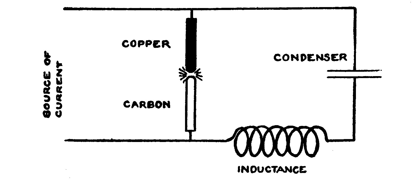
An arrangement by which such oscillatory currents may be produced is shown in its simplest form in Fig. 62. It consists of an arc, around which is shunted a condenser in series with an inductance. The arc is connected to a source of direct current, preferably having an E. M. F. of 500 volts or more.
The positive electrode of the arc is copper, kept cool by circulating water through a hollow interior or a water jacket. The gap in itself is enclosed in a chamber filled with hydrogen gas or a gas containing hydrogen. The arcs in practical use for generating undamped oscillations are arranged so that they operate in a strong magnetic field. The carbon electrode is constructed so that it is slowly revolved by a small electric motor.
The hydrogen gas atmosphere in which the arc is enclosed is produced by a small feed cup, similar to the ordinary lubricating oil cup, located over the case and filled with alcohol which continuously drips into the flame chamber, where it is vaporized by the heat.
Arc transmitters of large capacity are not as expensive or as bulky as spark transmitters of equal power. The difficulties of handling and controlling a large amount of power in connection with a transmitter of this sort are also not as great as in the case of a spark transmitter. The condenser used with an arc is not nearly so large as that required for a spark transmitter of equal capacity and the voltage of the current is much lower. Condenser breakdown, leakage and insulation problems are therefore not as great.
For telegraphing with damped transmitters, a key which alternately makes and breaks the primary circuit is sufficient. This is not possible, however, with an arc. The distance between the arc electrodes is usually greater than the gap length which the dynamo voltage would jump and form an arc whenever the key should be closed. It is therefore usual to arrange a key or relay so that it short circuits a portion of the aerial inductance or helix when closed. This short circuit is sufficient to throw the circuit out of tune so that it cannot be heard at the receiving station without readjusting the instruments.
The Poulsen arc may be used for radio telephony. A telephone receiver is arranged so as to vary the currents and impress the vibrations of the voice upon the oscillations set up by the arc.
LESSON THIRTY-THREE. RECEIVING UNDAMPED WAVES. THE TICKER.
A decided difference is encountered between damped and undamped oscillations when receiving signals. The ordinary detector cannot be used for receiving undamped oscillations without first being properly modified.
When telegraphing the dots and dashes of the code by undamped oscillations the change taking place in the detector circuit would merely move the telephone receiver diaphragm from its normal position at the beginning of each dot or dash, causing a click to be heard and nothing more. The telephone receiver diaphragm would remain in a fixed position just as long as the waves from the transmitter kept coming in during each signal. Both dots and dashes would be heard simply as clicks and not appear distinguishable from one another.
The most common and perhaps also the best method is to employ a device called a "ticker" in place of the detector for receiving undamped oscillations.
This arrangement is illustrated in Fig. 63. The left hand part of the illustration is the circuit diagram. A detail of the "ticker" wheel is shown at the right.
The condenser F C is of comparatively large capacity and is fixed. The condenser C is also fixed but is of much smaller capacity. F C is usually a condenser having a capacity of several tenths of a microfarad while C has only a few thousands of a microfarad capacity.
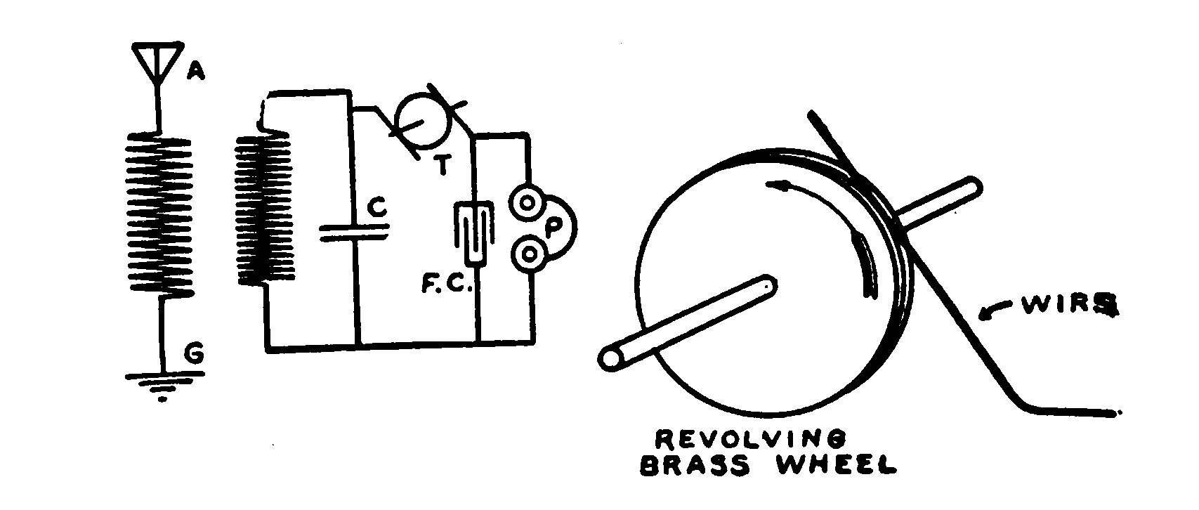
T is the ticker wheel and consists of a small brass wheel having a groove in the periphery like a pulley. This wheel is mounted on the shaft of a small motor so that it can be revolved at high speed.
A fine wire is arranged to rub against the groove in the wheel and make contact with the latter.
When the wheel is revolving at high speed, the wire does not make perfect contact at all points but tends to vibrate and to act as the equivalent of a very high speed interrupter by rapidly opening and closing the circuit.
The basic idea in employing a device and a circuit of this sort in receiving undamped waves is as follows:
When the contact is broken at the ticker wheel and the condenser F C is disconnected from the oscillating circuit formed by the condenser C and the secondary of the receiving transformer, the condenser C accumulates a relatively large amount of energy.
Then when the ticker connects the condenser F C in parallel with C, F C takes the major part of the stored energy and discharges it through the telephones P, causing a click to be heard in the latter.
The interruptions of the "ticker" are very rapid, a great many taking place during the duration of a dot or a dash, so that the resultant clicks occur very close together and the dots and dashes sound very similar to the spark signals of a transmitter sending forth damped waves.
The sensitiveness of the ticker arrangement is very great, in fact much greater than that of any detector.
LESSON THIRTY-FOUR. THE AUDION AMPLIFIER.
The audion amplifier is an arrangement whereby an A audion bulb such as that which has already been described in the Lesson on Detectors is so connected that it acts as a relay and also amplifies minute pulsating electric impulses. An ordinary audion detector bulb will serve as an amplifier bulb but it is usual to modify it somewhat and provide a grid and a wing on both sides of the filament as this arrangement gives the best results.
The audion amplifier is of especial advantage in amplifying weak wireless signals from a detector which would otherwise be unreadable. It is not necessary that the audion amplifier be used in connection with another audion serving as a detector. It will amplify the signals of any other form of detector such as an electrolytic, crystal, magnetic, etc.
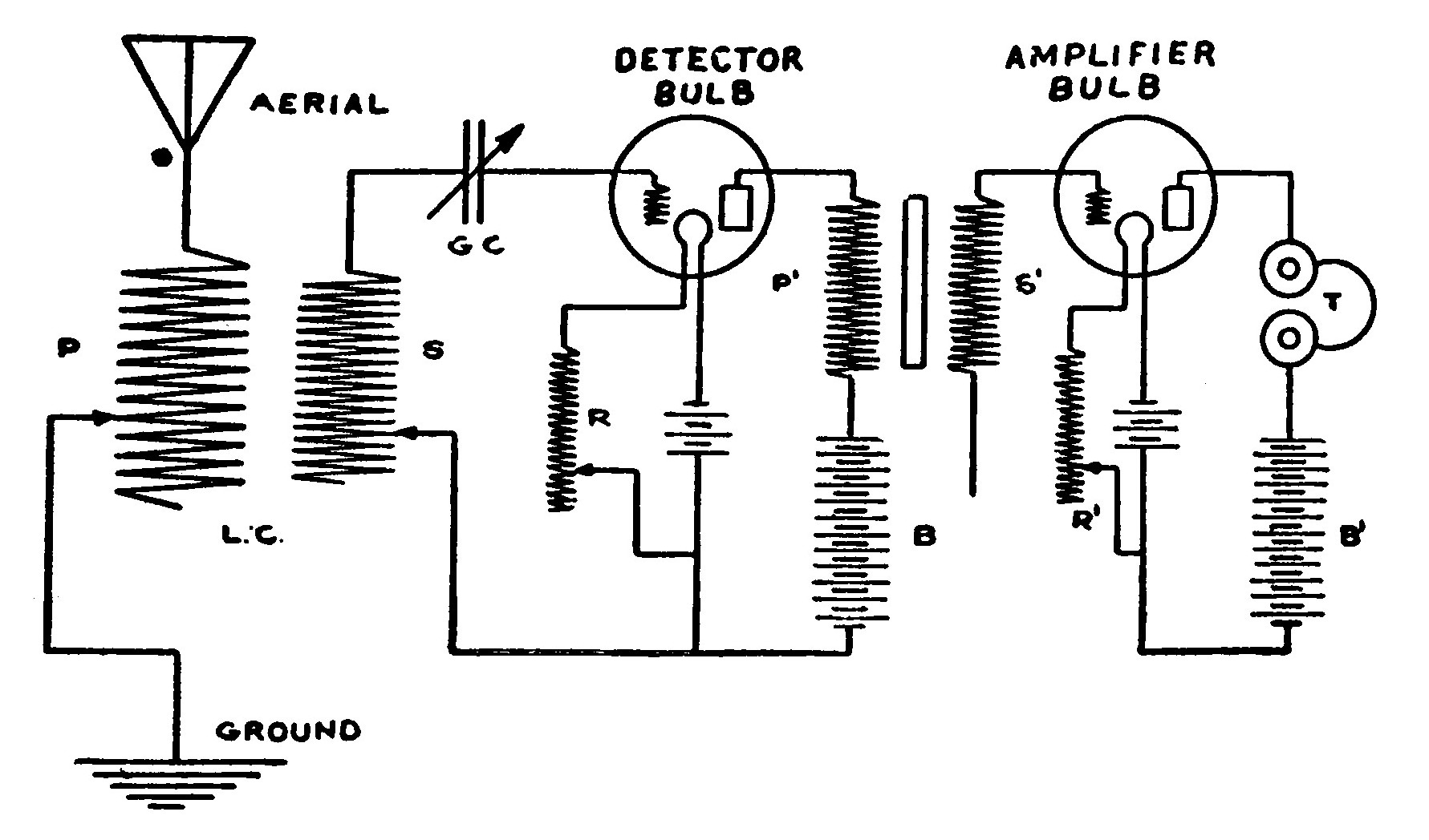
Figure 64 shows an audion amplifier connected to an audion amplifier connected to an audion detector so that the signals from the latter will be greatly increased in strength.
L C is a loose coupler connected to the aerial and ground in the ordinary manner. P and S are respectively the primary and secondary of the loose coupler. B is the "wing" battery of the detector circuit and B¹ is the "wing" battery of the amplifier circuit. T is the telephone receiver headset in which the amplified signals are heard.
P¹ and S¹ are the primary and secondary of a small open core transformer called the "Amplifier Coil." The windings contain a great many turns of very fine wire. The primary of the transformer is connected so as to be included in the wing circuit of the detector. It should be noticed that only one terminal of the secondary is connected to the amplifier circuit, this one terminal being connected to the grid of the amplifier bulb.
An arrangement of this sort, where one amplifier bulb is used is called a "one step amplifier." Amplifiers having two and three bulbs, respectively known as "two step" and "three step" amplifiers give much greater amplification than a one step amplifier and are often used.
LESSON THIRTY-FIVE. "HOOK-UPS."
Or Methods of Connecting the Instruments.
"Hook-ups" or circuit diagrams showing the manner of connecting various instruments are well worth considerable study if one is desirous of securing the greatest selectivity and distance from his apparatus.
There are almost an endless number of ways and combinations of ways of connecting apparatus, and strange to say, different people seem to be able to secure the best results with widely different methods. In spite of the fact that circuits of this kind are very numerous they can all be reduced to a few fundamental forms and an understanding of these forms will enable a person to devise his own "hook-ups" at will.
Transmitting circuits are fundamentally almost the same. The only real difference in arrangement is made by interchanging the condenser and spark gap. Either one may be placed across the terminals of the induction coil or transformer. There is no difference in the results.
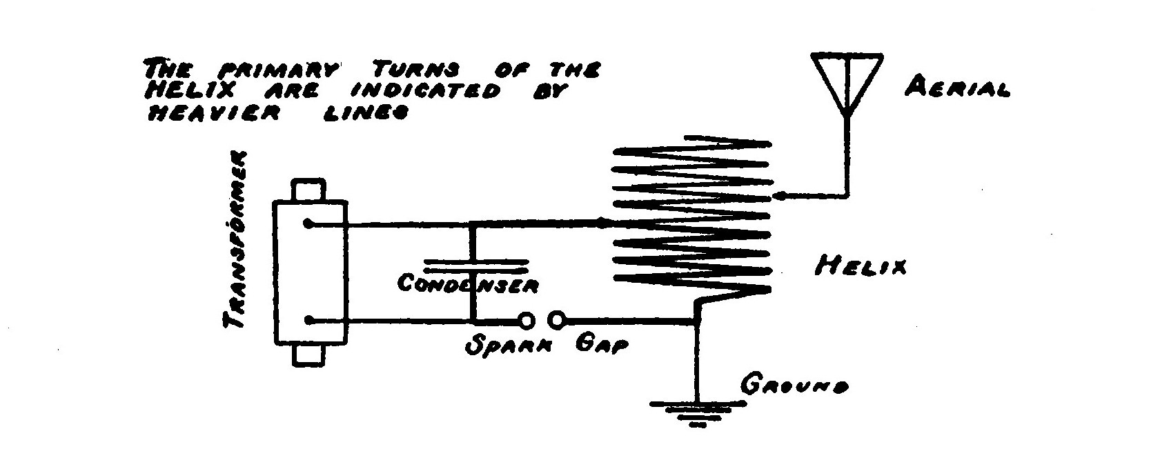
Consider the circuit shown in the accompanying illustration. The action of the transformer is to charge the condenser to such a point that the voltage is sufficient to leap the spark gap and cause a discharge. The rush of current which is oscillatory takes place through the condenser, spark gap and primary turns of the helix, or in other words through the closed circuits. The secondary turns of the helix, which are those forming part of the aerial circuit, are larger in number than those of the primary, and because of this ratio cause currents of higher voltage than those of the condenser to be impressed upon the aerial system. The currents in the aerial system surge up and down the aerial through the helix into the ground.
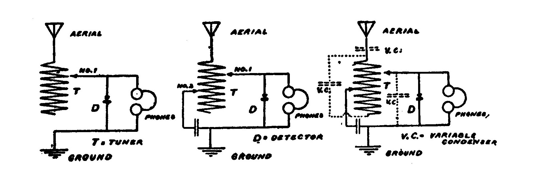
A shows a simple receiving circuit wherein a single slide tuning coil is connected to a detector. The high frequency currents generated in the aerial surge up and down the system and pass through the detector on their way to the ground. By moving the slider back and forth the electrical length of the circuit may be varied to suit the length of the incoming waves. Oscillations may be forced upon such a circuit, that is, if the waves are very powerful they will pass through the system and effect the detector no matter whether the slider is adjusted to suit them or not. This would cause interference and confusion in case more than one station were operating at a time.
By adding a second slider and a condenser as shown in B, this may be avoided to a considerable extent, for slider No. 1 may be adjusted to the desired signals and slider No. 2 placed in a position such as will give the branch of the circuit from the aerial, through the coil and into the ground of which it is a part, a period suited to the objectionable wave and so carry off the latter into the ground without effecting the detector. The desired signals will pass into the ground through the other branch of the circuit and operate the detector which lies in their path. The selectivity of the outfit may be further increased by the addition of a variable condenser.
A variable condenser may be placed in one or more of a great many positions. The accompanying illustrations show several. The effect of a condenser placed in series with the ground or aerial is just the opposite of that of a loading coil. It decreases the period and shortens the wave length to which it is adapted.
The Amateur’s Wireless Handy Book shows over one hundred wiring diagrams starting from the simplest and going to the most complicated in a natural sequence.
Any of the Following
Practical Books
will be sent At Once, Post-paid on receipt of price.
There is very little danger of losing currency in a letter if the following directions are observed:
Cut a circular hole the diameter of
the coin in a piece of cardboard, of
sufficient size to fit closely in the
envelope. The cardboard should
be no thicker than the coin.
Insert the coin in the hole and paste
a piece of paper on both sides of
the cardboard to prevent the coin
from falling out.
COLE & MORGAN
Publishers of the Arts and Sciences Series
P. O. Box 1473 New York, N. Y.
The Boy Electrician
Practical Plans for Electrical Toys and Apparatus, with an Explanation
of the Principles of Everyday Electricity.
By ALFRED P. MORGAN.
Author of "Wireless Telegraph Construction for Amateurs" and "Wireless
Telegraphy and Telephony," etc.
With full-page Illustrations and 324 Working Drawings and Diagrams
by the author. 8vo., Cloth, Net Price, $2.00.
This is the age of electricity. The most fascinating of all books for a boy must therefore be one dealing with the mystery of this ancient force and modern wonder, even a mere list of whose services is impossible. The best qualified of experts to instruct boys, Alfred P. Morgan, has in a book far superior to any other of its kind told not only how to make all kinds of motors, telegraphs, telephones, batteries, etc., and to do so economically, but has explained the principles upon which these depend for operation, and how the same thing is done in the every-day world be well presented and so attractive is this really great book that it will be an education for any bright boy to have it, as well as the best kind of a moral safeguard, by leaving no time or thought for evil, and a means of future benefit beyond the power of any one to reckon. Glancing over the pages of this book, one cannot but be impressed by the excellent illustrations, clearness of expression and the large number of subjects that are covered. It is beyond doubt the best book in this line that has ever been written or published. It is a book that will delight every boy who has a leaning towards electrical experiments. The author writes in a clear and chatty style and while he has a thorough technical knowledge of his subject he has succeeded in treating it in a simple manner so that it is readily intelligible to his young readers.
Among the Chapter Headings and Contents are:
Magnets and Magnetism—Static Electricity—Static Electric Machines—Cells and Batteries—Electro-Magnetism and Magnetic Induction—Electrical Units—Electrical Appurtenances—Electrical Measuring Instruments—Bells, Alarms and Annunciators—Electric Telegraphs—Microphones and Telephones—Induction Coils—Transformers—Wireless Telegraphy—Wireless Telephony—Electric Motors—Dynamos—An Electric Railway—Miniature Lighting—Miscellaneous Electrical Apparatus.
READ WHAT HAS BEEN SAID OF IT.
"Even a casual glance through the many pages of the book does not fail to emphasize the fact that Mr. Alfred P. Morgan has indeed succeeded well in giving the juvenile electricians a work that has long been sought."—Popular Electricity.
"We have no hesitation in commending the book to the attention of the juvenile audience for which it is intended."—Boston Post.
"A great book for enterprising boys. Bright boys will highly appreciate it and feel like thanking the wideawake publishers for putting such a reliable and interesting work in the field."—New Haven Journal.
"The book covers the subject of electricity thoroughly in all its phases and is a splendid acquisition to any boy’s library."—Detroit Times.
"In this age of electricity a book like the present one is both fascinating and valuable especially to boys. The book is attractive with its many illustrations and will prove of much educational value for any bright boy."—Zion’s Herald.
"This is an admirably complete and explicit handbook for young boys who fall under the spell of tinkering with electrical apparatus."—Boston Transcript.
"Well presented and attractive this book will be a source of great benefit and delight for any bright boy."—New Orleans Times-Picayune.
Price, $2.00, Postpaid
COUNTLESS OTHER MAGAZINES, NEWSPAPERS AND LIBRARIES HAVE
ENDORSED THIS GREAT BOOK. SEND FOR A COPY NOW.
If you are interested in this great book, write for our 8-page special
descriptive circular.
Wireless Telegraphy and Telephony Simply Explained
By ALFRED P. MORGAN.
A NEW BOOK by the author of "Wireless Telegraph Construction for Amateurs."
This is undoubtedly one of the most complete and comprehensive treatises on the subject ever published, and a close study of its pages will enable one to master all the details of the wireless transmission of messages. The author has filled a long-felt want and has succeeded in furnishing a lucid, comprehensible explanation in simple language of the theory and practice of wireless telegraphy and telephony. The book treats the subject from an entirely new standpoint. Several very novel and original ideas have been carried out in its making. It is well illustrated by over one hundred and fifty interesting photographs and drawings. All diagrams have been made in perspective showing the instruments as they actually appear in practice. The drawings are carefully keyed and labeled. Many of the photographs are accompanied by phantom drawings which reveal the name and purpose of each part.
It is a book which the wireless experimenter cannot afford to be without. It will prove even more valuable to the layman.
Among the contents are: Introductory. Wireless Transmission and Reception. The Ether. Electrical Oscillations. Electromagnetic Waves. The Means for Radiating and Intercepting Electric Waves. Aerial Systems. Earth Connection. The Transmitting Apparatus. Current Supply. Spark Coils and Transformers. Condensers. Helixes. Spark Gaps. Anchor Gaps. Aerial Switches, Etc. The Receiving Apparatus. Detectors, Etc. Tuning Coils and Loose Couplers. Variable Condensers. Tuning and Coupling. Directive Wave Telegraphy. The Dignity of Wireless. Its Applications and Service. Wireless in the Army and Navy. Wireless on an Aeroplane. How a Message is Sent and Received. The Wireless Telephone. The Ear. How We Hear. Sound and Sound Waves. The Vocal Cords. The Structure of Speech. The Telephone Transmitter and Receiver. The Photophone. The Thermophone. The Selenium Cell.
Handsomely Bound in Cloth with Embossed Cover. (Postpaid, $1.00)
Build Your Own Wireless Instruments
Complete Up-to-the-Minute Authentic Practical
WIRELESS TELEGRAPH CONSTRUCTION FOR AMATEURS
By ALFRED POWELL MORGAN
3d EDITION
220 Pages 163 Illustrations
Price, $1.50, Postpaid
Handsomely Bound in Silk Cloth
Thoroughly up to date and unusually complete. Gives in minute detail, full directions for constructing wireless apparatus and various outfits capable of receiving from 100 to 1,500 miles and transmitting 3 to 100 miles. Also clearly explains the purpose and action of each instrument. Directions for Operating and Adjusting, etc.
A SPLENDID TREATISE OF WIRELESS ALONG
CONSTRUCTIVE LINES
Price, $1.50, Postpaid
The value of this book has been greatly increased by the addition of much new subject matter and many illustrations of recent interest.
The new text explains fully how to build the most recent forms of Quenched Gaps. Rotary Gaps, Dough-Nut Tuners, Kick-back Preventers, Audion Detectors and numerous other instruments, accompanied by dimensioned working drawings. Several very interesting and instructive photographs have been included.
I.—Introduction. II.—The Apparatus. III.—Aerials and Earth Connections. IV.—Induction Coils. V.—Interrupters. VI.—Transformers. VII.—Oscillation Condensers and Leyden Jars. VIII.—Spark Gaps or Oscillators. IX.—Transmitting Helixes. X.—Keys. XI.—Aerial Switches and Anchor Gaps. XII.—Hot Wire Ammeter. XIII.—Oscillation Detectors. XIV.—Tuning Coils and Tuning Transformers. XV.—Receiving Condensers. XVI.—Telephone Receivers and Headbands. XVII.—Operation. XVIII.—The Amateur and the Wireless Law. How to Secure a License. Oscillation Helix. Quenched Spark Gap. Rotary Gaps. Kick-Back. The Variometer. New Crystal Detectors. The Audion.—Appendix.
ENDORSED BY WIRELESS CLUBS THROUGHOUT THE COUNTRY AS BEING
THE MOST PRACTICAL BOOK PUBLISHED ON WIRELESS.
IF YOU ARE INTERESTED IN WIRELESS YOU NEED THIS BOOK
Model Flying Machines
HOW TO BUILD AND FLY THEM
Will prove interesting and valuable.
Have you ever built and flown a Model Racer?
If not, you have missed something.
Price, 25 Cents, Postpaid.
Model Aeroplaning is one of the most fascinating and instructive of sports.
Thousands of young men and boys have formed Model Aero Clubs and organized Flying Contests throughout the country.
"MODEL FLYING MACHINES" of the Arts and Sciences series is the only book giving reliable data and instructions for the construction of practical Model Aeroplanes.
IF YOU ARE A BEGINNER, this is the book that you ought to have. It will start you right. It tells how to build seven different types of machines, starting with the simplest Monoplane and finishing with several Long Distance Racing Models.
IF YOU ARE INTERESTED IN MODEL AEROPLANING, this book will prove the one you have been looking for. Gives valuable "Kinks". Tells how to carve propellers, make winders, adjust and fly machines, etc. Fully illustrated with large size, detailed working drawings, showing the exact size of each part. Twelve full-page plates.
Printed on first-class paper. Heavy cover in three colors.
Sent postpaid by return mail upon receipt of 25 cents.
EVERY MODEL AVIATOR OUGHT TO HAVE A COPY
Experimental Wireless Construction
EIGHTY-SIX PAGES NINETY-THREE ILLUSTRATIONS
Only 25 Cents, Postpaid
Here at last is the book which every young experimenter interested in constructing his own wireless apparatus has been looking for.
A book which tells how to build apparatus which anyone would be proud to own. It is a more advanced book than "Wireless Construction and Installation for Beginners," and describes apparatus which is much more elaborate and sensitive. The instruments have all been the subject of considerable experimental work and study. All the apparatus has been put to practical test and carefully improved by clever experts. By purchasing this book you get the benefit of vast knowledge and experience and are enabled to build far better instruments than by following your own designs and haphazard methods.
THE TREMENDOUS POPULARITY OF THIS VALUABLE LITTLE BOOK IS ONLY AN INDICATION OF ITS GREAT WORTH.
It has only been on the market a short time, yet the sales will undoubtedly soon reach a point which would indicate that experimenters unquestionably consider, that in proportion to its size, it is the best book on the market.
It does not describe any old or obsolete forms of wireless apparatus but only the latest types of aerials, spark coils, keys, gaps, condensers, helixes, oscillation transformers, loose couplers, tuning coils, detectors, loading coils, variable condensers, aerial switches, etc.
IT IS ONE OF THE MOST DETAILED AND THOROUGH BOOKS EVER PUBLISHED.
The information is all intensely practical. Complete directions and dimensions are given. Nothing is left to be guessed at. The book must really be seen to be appreciated.
Partial Contents
Chapter I.—THE AERIAL. The Location of the Station. The Construction of an Operating Bench. The Aerial and Ground. The Supports or Masts. Types of Aerials. How to Erect an Aerial. Protection from Lightning, Etc.
Chapter II.—SPARK COILS. The Construction of Spark Coils. A 1/4-inch Spark Coil. A 1/2-inch Spark Coil. A 1-inch Spark Coil. A 1 1/2-inch Coil. A 2-inch Coil. Sources of Current. Dry Cells. Storage Cells. Wireless Keys, Etc.
Chapter III.—TRANSMITTING APPARATUS AND ITS CONSTRUCTION. Step-down Transformers. Spark Gaps. The Oscillation Condenser. Leyden Jars. Helixes. Oscillation Transformers, Etc.
Chapter IV.—THE RECEIVING APPARATUS AND ITS CONSTRUCTION. A Silicon Detector. A Galena Detector. The Double Slide Tuning Coil. How to Make a Fixed Condenser. Building a Loose Coupler. The Loading Coil. How to Make a Variable Condenser, Etc.
Chapter V.—ARRANGEMENT AND OPERATION OF THE APPARATUS. Aerial Switches. The Buzzer Test. Using More Than One Detector. Shunting the Detector. Complete Outfits. Portable Sets. The Operation of the Station, Etc.
The New Amateur’s Wireless
Handy Book
FOURTH EDITION
Completely Revised and Enlarged
You Cannot Afford To Be
Without This Book
Price 25 Cents, Postpaid
If you want to be an expert and an authority you must surround yourself with all available aids and helps. You have one of the best in the AMATEUR’S WIRELESS HANDY BOOK.
THERE HAVE BEEN MORE COPIES OF THIS GREAT BOOK SOLD THAN OF ANY OTHER WIRELESS BOOK.
It contains nearly SIX THOUSAND calls of Wireless Stations, including all Land Stations, Ship Stations, U. S. Army and Navy Stations and all AMATEURS licensed to date of publication.
Every registered station of the U. S. is included. They are all there. All the calls are classified alphabetically. The list is the most reliable and complete in existence. All obsolete stations have been abolished. All corrections and changes have been made from the official lists.
BUT, THAT IS NOT ALL.
THE CODES, BOTH MORSE AND CONTINENTAL, are shown in the form of two large full-page charts printed in heavy black type so that they can be read from a distance.
A BEGINNER’S SPEED CHART of both Codes so arranged that the codes may be quickly learned or consulted is provided.
ALL THIS ABBREVIATIONS used so constantly by the wireless operator to save time and labor are included. There are a couple of pages of them.
AND LAST BUT NOT LEAST
Nearly 100 large hook-ups of wiring diagrams fully illustrated in a concise and clear manner. Loop and straightaway aerials, grounds, helixes, spark gaps, anchor gaps, leyden jars, induction coils, transformers, keys, aerial switches, tuning coils, loading coils, loose couplers, variometers, fixed condensers, silicon, electrolytic, carborundum, perikon and audion detectors, telephones, potentiometers, etc., you can find them all and how to connect. A hook-up for any set accompanied by full explanation. None are missing. They are all there. There are no two alike.
The most complete and reliable data ever collected. The result of thousands of experiments by some of the most famous wireless experts in the country.
Read now before the supply is exhausted or you forget. You will be sorry if you don’t.
SENT ANYWHERE POSTPAID FOR 25 CENTS
Note: This book is always kept up-to-date by frequently issuing new editions. Send for the latest copy.
Wireless Construction and Installation for Beginners
SEVENTY-THREE PAGES SIXTY-SEVEN ILLUSTRATIONS.
(Second Edition.)
A Practical Handbook giving detailed instructions for the Construction and Operation of a Boy’s Wireless Outfit.
Only 25c. Prepaid
An indispensible book for the young wireless experimenter. It not alone shows how to build the various instruments but describes their actual workings and tells how to operate them.
EVERY BOY IS ADVISED TO
SEND FOR A COPY
Written in a very clear and simple style, the book is invaluable to a beginner. He will be able with its aid to construct simple apparatus of the latest and approved type. The instruments described in the book have been the subject of considerable experimental work and special study. They are modeled along simple lines so that they will be easy and inexpensive to construct, but at the same time combine features which make them very sensitive and capable of receiving or transmitting messages greater distances than some more complicated apparatus.
THIS BOOK, CONSIDERING ITS WORTH, IS A GIFT AT 25c.
There are no old or obsolete forms of wireless apparatus discussed, but only the latest types of tuning coils, receiving transformers, fixed condensers, keys, spark coils, detectors, etc. The book is illustrated by numerous detailed working drawings giving all dimensions. Several full-page views of the apparatus enable the beginner to fully comprehend the text.
THE MOST THOROUGH AND COMPLETE ELEMENTARY WIRELESS
CONSTRUCTION BOOK PUBLISHED
The pages on the construction and installation of aerials will be found to be of considerable help to the experimenter, for it is here that the most trouble is experienced by the beginner. The practical and helpful information on this subject is alone worth several times the cost of the book.
PARTIAL CONTENTS
Chapter I.—WIRELESS TELEGRAPHY. An intensely interesting subject; amateur wireless telegraphy; the purpose of the aerial and ground; the apparatus used to send messages; the apparatus used to receive messages.
Chapter II.—AERIALS AND GROUNDS. Where to put up the aerial; types of aerials; the "T" aerial; the masts; the wire; insulators; leading in the wires; the ground.
Chapter III.—HOW TO BUILD AND OPERATE THE SIMPLEX DOUBLE SLIDE RECEIVING OUTFIT. The tuning coil; the tube; the sliders; the fixed condenser; the detector parts; assembling the set; connecting the instruments; operation.
Chapter IV.—HOW TO BUILD THE SIMPLEX LOOSE COUPLER, DETECTOR AND CONDENSER. The base; the primary; the secondary; the pillar; the switch; How to make the Simplex cat whisker detector; How to make the Simplex fixed condenser; How to connect the apparatus; How to tune with the loose coupler; How to adjust the detector.
Chapter V.—TELEPHONE RECEIVERS AND HEADBANDS.
Chapter VI.—HOW TO BUILD THE SIMPLEX SPARK COIL. The core; the secondary; the condenser; the coil heads; the base; the interrupter parts; the bridge.
Chapter VII.—HOW TO MAKE THE SIMPLEX KEY.
Chapter VIII.—HOW TO CONNECT AND OPERATE THE APPARATUS. How to connect and operate a complete wireless station; How to operate; the code, etc.
The Operation of Wireless Telegraph Apparatus
Do your Wireless friends come to you for advice on constructing and operating their apparatus or do you go to them for information?
Here is a chance for YOU to become the authority.
This book is a necessity to every Progressive Experimenter.
It shows how to obtain the very highest efficiency from any station, and how to comply with the law. How to tune, adjust your detector, spark gap, phones, etc.
Price, 25 Cents, Postpaid.
This book was written for the wireless experimenter who has passed the amateur stage, but explains how the beginner also can obtain the very best results from his station. It contains much useful information to this end and many "kinks".
IT SHOWS HOW to receive or send on long or short wave lengths with highest efficiency, to tune for longest distance reception of messages, to use the buzzer test, how to test and connect condensers, receivers, etc., how to use receiving transformers, variometers, etc., all with highest efficiency in view.
IT ALSO DESCRIBES the construction and use of a simple, inexpensive wave meter to tune the station to any desired wave length, and tells how to obtain a sharp wave and a pure wave.
EXTRACTS FROM THE LAW are also given in such a manner that they are easily understood.
If you want to get the best results from your station this is your opportunity.
Three New Books on Home Made
Electrical Apparatus
or rather, three parts of one book, each 25 cents per copy, are now in preparation and should be ready in June, 1917.
They will cover every kind of electrical apparatus, including primary and storage batteries, dynamos and motors, induction coils, rectifiers, transformers, telegraphs and telephones, etc.—all of which have actually been built.
The three parts will also be furnished as a single volume in cloth covers at $1.00 per copy, postpaid.
If interested, simply send us a postal and when the books are ready we will send you full descriptions.
COLE & MORGAN
Publishers of the Arts and Sciences Series
P. O. Box 1473 NEW YORK, N. Y.
*** END OF THIS PROJECT GUTENBERG EBOOK LESSONS IN WIRELESS TELEGRAPHY ***
The Full Project Gutenberg License
Please read this before you distribute or use this work.
To protect the Project Gutenberg™ mission of promoting the free distribution of electronic works, by using or distributing this work (or any other work associated in any way with the phrase “Project Gutenberg”), you agree to comply with all the terms of the Full Project Gutenberg™ License available with this file or online at https://www.gutenberg.org/license.
Section 1. General Terms of Use & Redistributing Project Gutenberg™ electronic works
1.A. By reading or using any part of this Project Gutenberg™ electronic work, you indicate that you have read, understand, agree to and accept all the terms of this license and intellectual property (trademark/copyright) agreement. If you do not agree to abide by all the terms of this agreement, you must cease using and return or destroy all copies of Project Gutenberg™ electronic works in your possession. If you paid a fee for obtaining a copy of or access to a Project Gutenberg™ electronic work and you do not agree to be bound by the terms of this agreement, you may obtain a refund from the person or entity to whom you paid the fee as set forth in paragraph 1.E.8.
1.B. “Project Gutenberg” is a registered trademark. It may only be used on or associated in any way with an electronic work by people who agree to be bound by the terms of this agreement. There are a few things that you can do with most Project Gutenberg™ electronic works even without complying with the full terms of this agreement. See paragraph 1.C below. There are a lot of things you can do with Project Gutenberg™ electronic works if you follow the terms of this agreement and help preserve free future access to Project Gutenberg™ electronic works. See paragraph 1.E below.
1.C. The Project Gutenberg Literary Archive Foundation (“the Foundation” or PGLAF), owns a compilation copyright in the collection of Project Gutenberg™ electronic works. Nearly all the individual works in the collection are in the public domain in the United States. If an individual work is unprotected by copyright law in the United States and you are located in the United States, we do not claim a right to prevent you from copying, distributing, performing, displaying or creating derivative works based on the work as long as all references to Project Gutenberg are removed. Of course, we hope that you will support the Project Gutenberg™ mission of promoting free access to electronic works by freely sharing Project Gutenberg™ works in compliance with the terms of this agreement for keeping the Project Gutenberg™ name associated with the work. You can easily comply with the terms of this agreement by keeping this work in the same format with its attached full Project Gutenberg™ License when you share it without charge with others.
1.D. The copyright laws of the place where you are located also govern what you can do with this work. Copyright laws in most countries are in a constant state of change. If you are outside the United States, check the laws of your country in addition to the terms of this agreement before downloading, copying, displaying, performing, distributing or creating derivative works based on this work or any other Project Gutenberg™ work. The Foundation makes no representations concerning the copyright status of any work in any country outside the United States.
1.E. Unless you have removed all references to Project Gutenberg:
1.E.1. The following sentence, with active links to, or other immediate access to, the full Project Gutenberg™ License must appear prominently whenever any copy of a Project Gutenberg™ work (any work on which the phrase “Project Gutenberg” appears, or with which the phrase “Project Gutenberg” is associated) is accessed, displayed, performed, viewed, copied or distributed:
This eBook is for the use of anyone anywhere in the United States and most other parts of the world at no cost and with almost no restrictions whatsoever. You may copy it, give it away or re-use it under the terms of the Project Gutenberg License included with this eBook or online at https://www.gutenberg.org . If you are not located in the United States, you'll have to check the laws of the country where you are located before using this ebook.
1.E.2. If an individual Project Gutenberg™ electronic work is derived from texts not protected by U.S. copyright law (does not contain a notice indicating that it is posted with permission of the copyright holder), the work can be copied and distributed to anyone in the United States without paying any fees or charges. If you are redistributing or providing access to a work with the phrase “Project Gutenberg” associated with or appearing on the work, you must comply either with the requirements of paragraphs 1.E.1 through 1.E.7 or obtain permission for the use of the work and the Project Gutenberg™ trademark as set forth in paragraphs 1.E.8 or 1.E.9.
1.E.3. If an individual Project Gutenberg™ electronic work is posted with the permission of the copyright holder, your use and distribution must comply with both paragraphs 1.E.1 through 1.E.7 and any additional terms imposed by the copyright holder. Additional terms will be linked to the Project Gutenberg™ License for all works posted with the permission of the copyright holder found at the beginning of this work.
1.E.4. Do not unlink or detach or remove the full Project Gutenberg™ License terms from this work, or any files containing a part of this work or any other work associated with Project Gutenberg™.
1.E.5. Do not copy, display, perform, distribute or redistribute this electronic work, or any part of this electronic work, without prominently displaying the sentence set forth in paragraph 1.E.1 with active links or immediate access to the full terms of the Project Gutenberg™ License.
1.E.6. You may convert to and distribute this work in any binary, compressed, marked up, nonproprietary or proprietary form, including any word processing or hypertext form. However, if you provide access to or distribute copies of a Project Gutenberg™ work in a format other than “Plain Vanilla ASCII” or other format used in the official version posted on the official Project Gutenberg™ web site (https://www.gutenberg.org), you must, at no additional cost, fee or expense to the user, provide a copy, a means of exporting a copy, or a means of obtaining a copy upon request, of the work in its original “Plain Vanilla ASCII” or other form. Any alternate format must include the full Project Gutenberg™ License as specified in paragraph 1.E.1.
1.E.7. Do not charge a fee for access to, viewing, displaying, performing, copying or distributing any Project Gutenberg™ works unless you comply with paragraph 1.E.8 or 1.E.9.
1.E.8. You may charge a reasonable fee for copies of or providing access to or distributing Project Gutenberg™ electronic works provided that
You pay a royalty fee of 20% of the gross profits you derive from the use of Project Gutenberg™ works calculated using the method you already use to calculate your applicable taxes. The fee is owed to the owner of the Project Gutenberg™ trademark, but he has agreed to donate royalties under this paragraph to the Project Gutenberg Literary Archive Foundation. Royalty payments must be paid within 60 days following each date on which you prepare (or are legally required to prepare) your periodic tax returns. Royalty payments should be clearly marked as such and sent to the Project Gutenberg Literary Archive Foundation at the address specified in Section 4, “Information about donations to the Project Gutenberg Literary Archive Foundation.”
You provide a full refund of any money paid by a user who notifies you in writing (or by e-mail) within 30 days of receipt that s/he does not agree to the terms of the full Project Gutenberg™ License. You must require such a user to return or destroy all copies of the works possessed in a physical medium and discontinue all use of and all access to other copies of Project Gutenberg™ works.
You provide, in accordance with paragraph 1.F.3, a full refund of any money paid for a work or a replacement copy, if a defect in the electronic work is discovered and reported to you within 90 days of receipt of the work.
You comply with all other terms of this agreement for free distribution of Project Gutenberg™ works.
1.E.9. If you wish to charge a fee or distribute a Project Gutenberg™ electronic work or group of works on different terms than are set forth in this agreement, you must obtain permission in writing from both the Project Gutenberg Literary Archive Foundation and The Project Gutenberg Trademark LLC, the owner of the Project Gutenberg™ trademark. Contact the Foundation as set forth in Section 3. below.
1.F.
1.F.1. Project Gutenberg volunteers and employees expend considerable effort to identify, do copyright research on, transcribe and proofread works not protected by U.S. copyright law in creating the Project Gutenberg™ collection. Despite these efforts, Project Gutenberg™ electronic works, and the medium on which they may be stored, may contain “Defects,” such as, but not limited to, incomplete, inaccurate or corrupt data, transcription errors, a copyright or other intellectual property infringement, a defective or damaged disk or other medium, a computer virus, or computer codes that damage or cannot be read by your equipment.
1.F.2. LIMITED WARRANTY, DISCLAIMER OF DAMAGES – Except for the “Right of Replacement or Refund” described in paragraph 1.F.3, the Project Gutenberg Literary Archive Foundation, the owner of the Project Gutenberg™ trademark, and any other party distributing a Project Gutenberg™ electronic work under this agreement, disclaim all liability to you for damages, costs and expenses, including legal fees. YOU AGREE THAT YOU HAVE NO REMEDIES FOR NEGLIGENCE, STRICT LIABILITY, BREACH OF WARRANTY OR BREACH OF CONTRACT EXCEPT THOSE PROVIDED IN PARAGRAPH 1.F.3. YOU AGREE THAT THE FOUNDATION, THE TRADEMARK OWNER, AND ANY DISTRIBUTOR UNDER THIS AGREEMENT WILL NOT BE LIABLE TO YOU FOR ACTUAL, DIRECT, INDIRECT, CONSEQUENTIAL, PUNITIVE OR INCIDENTAL DAMAGES EVEN IF YOU GIVE NOTICE OF THE POSSIBILITY OF SUCH DAMAGE.
1.F.3. LIMITED RIGHT OF REPLACEMENT OR REFUND – If you discover a defect in this electronic work within 90 days of receiving it, you can receive a refund of the money (if any) you paid for it by sending a written explanation to the person you received the work from. If you received the work on a physical medium, you must return the medium with your written explanation. The person or entity that provided you with the defective work may elect to provide a replacement copy in lieu of a refund. If you received the work electronically, the person or entity providing it to you may choose to give you a second opportunity to receive the work electronically in lieu of a refund. If the second copy is also defective, you may demand a refund in writing without further opportunities to fix the problem.
1.F.4. Except for the limited right of replacement or refund set forth in paragraph 1.F.3, this work is provided to you ‘AS-IS,’ WITH NO OTHER WARRANTIES OF ANY KIND, EXPRESS OR IMPLIED, INCLUDING BUT NOT LIMITED TO WARRANTIES OF MERCHANTABILITY OR FITNESS FOR ANY PURPOSE.
1.F.5. Some states do not allow disclaimers of certain implied warranties or the exclusion or limitation of certain types of damages. If any disclaimer or limitation set forth in this agreement violates the law of the state applicable to this agreement, the agreement shall be interpreted to make the maximum disclaimer or limitation permitted by the applicable state law. The invalidity or unenforceability of any provision of this agreement shall not void the remaining provisions.
1.F.6. INDEMNITY – You agree to indemnify and hold the Foundation, the trademark owner, any agent or employee of the Foundation, anyone providing copies of Project Gutenberg™ electronic works in accordance with this agreement, and any volunteers associated with the production, promotion and distribution of Project Gutenberg™ electronic works, harmless from all liability, costs and expenses, including legal fees, that arise directly or indirectly from any of the following which you do or cause to occur: (a) distribution of this or any Project Gutenberg™ work, (b) alteration, modification, or additions or deletions to any Project Gutenberg™ work, and (c) any Defect you cause.
Section 2. Information about the Mission of Project Gutenberg™
Project Gutenberg™ is synonymous with the free distribution of electronic works in formats readable by the widest variety of computers including obsolete, old, middle-aged and new computers. It exists because of the efforts of hundreds of volunteers and donations from people in all walks of life.
Volunteers and financial support to provide volunteers with the assistance they need, is critical to reaching Project Gutenberg™'s goals and ensuring that the Project Gutenberg™ collection will remain freely available for generations to come. In 2001, the Project Gutenberg Literary Archive Foundation was created to provide a secure and permanent future for Project Gutenberg™ and future generations. To learn more about the Project Gutenberg Literary Archive Foundation and how your efforts and donations can help, see Sections 3 and 4 and the Foundation web page at http://www.pglaf.org .
Section 3. Information about the Project Gutenberg Literary Archive Foundation
The Project Gutenberg Literary Archive Foundation is a non profit 501(c)(3) educational corporation organized under the laws of the state of Mississippi and granted tax exempt status by the Internal Revenue Service. The Foundation's EIN or federal tax identification number is 64-6221541. Its 501(c)(3) letter is posted at https://www.gutenberg.org/fundraising/pglaf . Contributions to the Project Gutenberg Literary Archive Foundation are tax deductible to the full extent permitted by U.S. federal laws and your state's laws.
The Foundation's principal office is in Fairbanks, Alaska, with the mailing address: PO Box 750175, Fairbanks, AK 99775, but its volunteers and employees are scattered throughout numerous locations. Its business office is located at 809 North 1500 West, Salt Lake City, UT 84116, (801) 596-1887, email business@pglaf.org. Email contact links and up to date contact information can be found at the Foundation's web site and official page at http://www.pglaf.org
For additional contact information:
Section 4. Information about Donations to the Project Gutenberg Literary Archive Foundation
Project Gutenberg™ depends upon and cannot survive without wide spread public support and donations to carry out its mission of increasing the number of public domain and licensed works that can be freely distributed in machine readable form accessible by the widest array of equipment including outdated equipment. Many small donations ($1 to $5,000) are particularly important to maintaining tax exempt status with the IRS.
The Foundation is committed to complying with the laws regulating charities and charitable donations in all 50 states of the United States. Compliance requirements are not uniform and it takes a considerable effort, much paperwork and many fees to meet and keep up with these requirements. We do not solicit donations in locations where we have not received written confirmation of compliance. To SEND DONATIONS or determine the status of compliance for any particular state visit https://www.gutenberg.org/fundraising/donate
While we cannot and do not solicit contributions from states where we have not met the solicitation requirements, we know of no prohibition against accepting unsolicited donations from donors in such states who approach us with offers to donate.
International donations are gratefully accepted, but we cannot make any statements concerning tax treatment of donations received from outside the United States. U.S. laws alone swamp our small staff.
Please check the Project Gutenberg Web pages for current donation methods and addresses. Donations are accepted in a number of other ways including checks, online payments and credit card donations. To donate, please visit: https://www.gutenberg.org/fundraising/donate
Section 5. General Information About Project Gutenberg™ electronic works.
Professor Michael S. Hart is the originator of the Project Gutenberg™ concept of a library of electronic works that could be freely shared with anyone. For thirty years, he produced and distributed Project Gutenberg™ eBooks with only a loose network of volunteer support.
Project Gutenberg™ eBooks are often created from several printed editions, all of which are confirmed as not protected by copyright in the U.S. unless a copyright notice is included. Thus, we do not necessarily keep eBooks in compliance with any particular paper edition.
Each eBook is in a subdirectory of the same number as the eBook's eBook number, often in several formats including plain vanilla ASCII, compressed (zipped), HTML and others.
Corrected editions of our eBooks replace the old file and take over the old filename and etext number. The replaced older file is renamed. Versions based on separate sources are treated as new eBooks receiving new filenames and etext numbers.
Most people start at our Web site which has the main PG search facility:
This Web site includes information about Project Gutenberg™, including how to make donations to the Project Gutenberg Literary Archive Foundation, how to help produce our new eBooks, and how to subscribe to our email newsletter to hear about new eBooks.