| Note: | Images of the original pages are available through Internet Archive. See https://archive.org/details/rudimentarytreat00hobb |
Please see the Transcriber’s Note at the end of this text.
LONDON:
PRINTED BY LEVEY, ROBSON, AND FRANKLYN,
Great New Street and Fetter Lane.
[iii]
RUDIMENTARY TREATISE
ON THE
CONSTRUCTION OF LOCKS.
EDITED BY
CHARLES TOMLINSON.
“Il n’y a point de machines plus communes que les serrures: elles sont assez composées pour mériter le nom de machine; mais je ne sais s’il y en a qui soient aussi peu connues par ceux qui les emploient. Il est rare qu’on sache en quoi consiste la bonté d’une serrure, le degré de sûreté qu’on peut s’en promettre. Leur extérieur est presque la seule chose à quoi l’on s’arrête. Les usages importans auxquels elles sont employées devraient cependant exciter la curiosité à les connaître, si la curiosité était toujours excitée raisonnablement.”—M. de Réaumur, “Des Serrures de toutes les espèces,” forming the fifth chapter of M. Duhamel’s Treatise “Art du Serrurier,” in the “Descriptions des Arts et Metiers faites ou approuvées par Messieurs de l’Académie Royale des Sciences.”
LONDON:
JOHN WEALE, 59 HIGH HOLBORN.
MDCCCLIII.
[iv]
“There are no machines more common than locks: they are sufficiently complex to merit the name of machine; but I know of no others the structure of which is so little understood by those who use them. It is rare to find any one who knows wherein the goodness of a lock consists, or the degree of security that he can attach to it. The outside of a lock is usually all that attracts attention. Doubtless the important uses to which locks are applied would excite curiosity respecting their structure, if curiosity were always excited for worthy objects.”—M. de Réaumur.
[v]
The reader is entitled to know the origin of the small work which he holds in his hands.
In August 1852, being about to write a short article on Locks for a Cyclopædia of Useful Arts, of which I am the editor, I consulted my esteemed and lamented friend, the late Professor Cowper, of King’s College, as to the desirability of explaining to the general reader the defects of some of our English locks, which, previous to the celebrated “lock controversy” of 1851, had borne a high character for skilful construction, beauty of workmanship, and undoubted security. Professor Cowper expressed his strong conviction that by exposing the defects of our locks, the cause of mechanical science, as well as the public in general, would be benefited; that if our locks were defective, inventors would be stimulated to supply the defects, and the art of the locksmith would be raised accordingly. He considered that Mr. Hobbs had made a considerable step in advance in the constructive details of his art, not only in having detected the weak points of some of our best English locks, but also in having introduced two or three new locks, which appeared to be more secure than any of those previously produced. Professor Cowper gave me an introduction to Mr. Hobbs, who placed at my disposal a variety of literary materials relating to the history and construction of locks, and stated his intention at some future time of bringing out a small book on the subject, if he could meet with a publisher. I recommended him to offer the work to Mr. Weale, for insertion in his series of Rudimentary Works. This was accordingly done, and I was invited to prepare the work; but as my engagements did not leave me sufficient leisure to write the book, I requested my friend Mr. George Dodd to put the materials together, and to search for[vi] more. Mr. Dodd acceded to my request; and having completed his part of the work, I subjected it to a careful revision, and added various details which seemed to be necessary to completeness, at least so far as the narrow limits of a small rudimentary work would admit of completeness. The manuscript was then sent to press: each sheet as it was received from the printer was submitted to Mr. Hobbs, who read it with care, and made his annotations and corrections thereon. Mr. Hobbs and I then had a meeting, when the additions and corrections were read and discussed, and admitted or rejected as the case might be. The sheet having been thus corrected was sent to press.
It should also be stated that, during the progress of the work, Mr. Weale, at my request, wrote to Messrs. Bramah, and also to Messrs. Chubb, informing them that a Rudimentary Treatise on the Construction of Locks was being prepared, and requesting them to state in writing what alterations or improvements they had made in their locks since the date of the Great Exhibition. The communications which we have received from these celebrated firms are inserted verbatim, in their proper places, in the present work.
Such is the mode in which this small volume has been prepared. I have endeavoured to perform an editor’s duty conscientiously, without entertaining the feeling of a partisan in the matter. My chief object in superintending the production of this book (an object in which the Publisher fully participates) is to advance the cause of mechanical science, and to supply a deficiency in one of the most interesting portions of its English literature.
C. TOMLINSON.
Bedford Place, Ampthill Square,
July 1853.
[vii]
The first edition of this volume, though at the date of its appearance co-ordinating with the state of knowledge of the period, and containing matter well arranged and lucidly described—as must have been expected from the reputation of its author—had, through the lapse of the few intervening years, inevitably become somewhat behind the state of the art of which it treats—one which is daily receiving the attentive consideration of many skilful men, and occasional marked improvements. Amongst those of later years none are more noteworthy than the locks patented by Mr. Fenby, of Birmingham; of these an account, with accurate illustrations, for which the drawings are supplied by the inventor, is now added,—together with a brief essay upon the important but popularly ill-understood subject of iron safes.
ROBERT MALLET.
April, 1868.
[viii]
In reference to Mr. Smyth’s letter, which is given at pp. 130, 131, that gentleman is desirous to state that it was in consequence of the defects there pointed out that Mr. Hobbs was enabled to pick the Bramah lock operated upon, which had been manufactured forty years previously, when the sliders were made of iron instead of steel as they now are, and yet, notwithstanding that and the other defects pointed out, it took Mr. Hobbs sixteen days to pick it. In proof of the security of the Bramah lock, Mr. Smyth mentions that Mr. Hobbs’s best workman failed in picking an ordinary 3-inch Bramah box lock; and that a person in the employ of Messrs. Johnson and Ravey, of Conduit Street, failed also in his attempt to pick a 6-inch cellar-door lock, though he had the lock in his possession for twelve months, employing his evenings in making instruments and trying to pick it. Mr. Smyth contradicts the statement made at page 128, that the new lock was removed from the window through any fear of its being opened. On the contrary, it was put up especially to afford an opportunity for Mr. Hobbs to make, if he thought fit, another trial, and it remained in the window four months. The sole cause of its removal was to stop the impertinent applications of men and boys, which interfered too much with the general business of the firm.
[ix]
| CHAP. | PAGE | |
|---|---|---|
| I. | On Locks and Lock-literature | 1 |
| II. | Ancient Locks: Grecian, Roman, Egyptian | 8 |
| III. | Lock classification. The Puzzle-Lock and the Dial-Lock | 16 |
| IV. | Warded Locks, with their varied appendages | 27 |
| V. | On Tumbler or Lever Locks | 43 |
| VI. | The Bramah Lock | 64 |
| VII. | American Locks | 82 |
| VIII. | The Lock Controversy: previous to the date of the Great Exhibition | 102 |
| IX. | The Lock Controversy: during and since the time of the Great Exhibition | 115 |
| X. | Effects of the Great Exhibition of 1851 in improving English Locks | 140 |
| XI. | The Lock and Key Manufacture | 154 |
| XII. | English Patents for Locks. Aubin’s Lock Trophy. Conclusion | 164 |
| Appendix. | ||
| XIII. | On an Improved Construction of Lock and Key: Fenby’s Adytic Lock | 176 |
| XIV. | Fenby’s Stop Lock | 193 |
| XV. | Note upon Iron Safes | 201 |
[1]
ON THE
CONSTRUCTION OF LOCKS.
The manufacture of locks, and a consideration of the mechanical principles involved in their construction and security, have never yet been treated with any degree of fulness in an English work. Lock-making has occupied a large amount of ingenuity, and lock-patents have been obtained in considerable number, though not always, we are satisfied, with a commensurate return for the expense incurred,—but lock-philosophy (if so it may be designated) has not been largely attended to.
And yet it may safely be said that much which is both mechanically and commercially important is comprised in a lock. Every improvement in the manufacture of iron, steel, and brass—that is, in the tool-making and machine-making processes—may be made to reflect its light on the lock-manufacture; the stamping, the casting, the planing, the slotting, the screw-cutting, the polishing of metals,—all, in proportion as they are improved, impart some of their aid to the lock-maker. Then, in the finer kinds of locks, the works are so delicate as to approach to the nicety of clockwork; thereby combining the manipulative skill of a talented[2] artisan with the rougher mechanical work of the smith. The principles of mechanical science are also appreciated by many lock-makers. The lever, the inclined plane, the eccentric, the cam, the screw, the wheel and pinion, the ratchet, the spring,—all are brought to bear on the internal mechanism of locks, frequently in many novel combinations.
The commercial importance of locks—though of course never seriously questioned when once fairly brought before one’s attention—has been recently rendered so apparent as to have risen to the position of a public topic. If a strong room, containing gold and silver, notes and bills, books and papers—if such a room be necessarily shielded from intrusion, it becomes no less necessary that the shield should be really worthy of its name, trusty and reliable: a good lock is here nearly as indispensable as a faithful cashier. And without dwelling on such an auriferous picture as a room fall of gold, we shall find ample proof of the commercial importance of lock-making in the ordinary circumstances by which we are every day surrounded. Until the world becomes an honest world, or until the honest people bear a larger ratio than at present to the dishonest, the whole of our movables are, more or less, at the mercy of our neighbours. Houses, rooms, vaults, cellars, cabinets, cupboards, caskets, desks, chests, boxes, caddies,—all, with the contents of each, ring the changes between meum and tuum pretty much according to the security of the locks by which they are guarded.
A commercial, and in some respects a social, doubt has been started within the last year or two, whether or not it is right to discuss so openly the security or insecurity of locks. Many well-meaning persons suppose that the discussion respecting the means for baffling the supposed safety of locks offers a premium for dishonesty, by shewing others how to be dishonest. This is a fallacy. Rogues are very keen in their profession, and know already much more than we can teach them respecting their several kinds of roguery. Rogues knew a good deal about lock-picking long before locksmiths discussed[3] it among themselves, as they have lately done. If a lock—let it have been made in whatever country, or by whatever maker—is not so inviolable as it has hitherto been deemed to be, surely it is to the interest of honest persons to know this fact, because the dishonest are tolerably certain to be the first to apply the knowledge practically; and the spread of the knowledge is necessary to give fair play to those who might suffer by ignorance. It cannot be too earnestly urged, that an acquaintance with real facts will, in the end, be better for all parties. Some time ago, when the reading public was alarmed at being told how London milk is adulterated, timid persons deprecated the exposure, on the plea that it would give instructions in the art of adulterating milk; a vain fear—milkmen knew all about it before, whether they practised it or not; and the exposure only taught purchasers the necessity of a little scrutiny and caution, leaving them to obey this necessity or not, as they pleased. So likewise in respect to bread, sugar, coffee, tea, wine, beer, spirits, vinegar, cheap silks, cheap woollens—all such articles as are susceptible of debasement by admixture with cheaper substances—much more good than harm is effected by stating candidly and scientifically the various methods by which such debasement has been, or can be produced. The unscrupulous have the command of much of this kind of knowledge without our aid; and there is moral and commercial justice in placing on their guard those who might possibly suffer therefrom. We employ these stray expressions concerning adulteration, debasement, roguery, and so forth, simply as a mode of illustrating a principle—the advantage of publicity. In respect to lock-making, there can scarcely be such a thing as dishonesty of intention: the inventor produces a lock which he honestly thinks will possess such and such qualities; and he declares his belief to the world. If others differ from him in opinion concerning those qualities, it is open to them to say so; and the discussion, truthfully conducted, must lead to public advantage: the discussion stimulates curiosity, and the[4] curiosity stimulates invention. Nothing but a partial and limited view of the question could lead to the opinion that harm can result: if there be harm, it will be much more than counterbalanced by good.
The literature of lock-making is, as we have implied, very scanty, both in England and America. The French and Germans, though far below our level as lock-makers, are very superior to us in their descriptions of the construction and manufacture of locks. Take, for instance, the French treatise published more than eighty years ago by the Académie des Sciences, and forming part of a folio series of manufacturing treatises, illustrated very fully by engravings. It is worth while to examine this work, to see how minutely and faithfully the writers of such treatises performed their task nearly a century ago. The Art du Serrurier, with the distinguished name of M. Duhamel du Monceau as the author or editor, was published in 1767. It occupies 290 folio pages, and is illustrated by 42 folio plates. The first chapter gives us an introduction and general principles, in which the choice and manipulation of materials are touched upon; the different qualities of iron and steel; and the processes of forging, founding, welding, stamping, filing, polishing, &c. In the copper-plates representing these smiths’ operations and the tools employed,[1] there is a smithy, with about a dozen smiths engaged in all these various occupations, with stockings down, and a due amount of workshop slovenliness. The next chapter takes us into what may perhaps be called “smith’s work in general,” or at least it treats of the manufacture of various kinds of ironmongery for doors, windows, and house-fittings generally. Then the third chapter treats of “smith’s work which serves for the security of houses,” consisting of railings, palings, bars, and gates of various kinds—such at least as are made of iron. In chapter four we have a notice of such kinds of[5] smith’s work as relate to the fastenings for doors, windows, closets, chests, &c.; such as hinges, hasps, latches, bolts, and other contrivances less complex than an actual lock. This brings us, by a natural transition, to locks in general, which form the subject of chapter five, to which is attached the illustrious name of M. de Réaumur as the author. Here are given a hundred folio pages of description, illustrated by twenty folio plates relating to locks, lock-making, and locksmiths. The sixth chapter relates to the iron-work of carriages, or the labours of the coachsmiths; while chapter seven, to wind up the work, relates to bell-hanging.
[1] It is worthy of remark, that the tools described are the same as those which are used by the locksmith at the present day; shewing how little improvement has been made in the means of producing locks.
That chapter of the work which has reference to locks is the only one with which we have to do here. It is arranged in a systematic manner, beginning with the simpler locks, without wards or tumblers, and proceeding thence to others of more complex construction. The period at which the work was written was too early to lead us to expect to find a tumbler-lock described and delineated: there are, however, numerous examples of single tumbler-locks, many of them of great ingenuity. The use of multiple bolts, that is, of many bolts shot at once by one action of the key, seems to have been familiar enough to the locksmiths of those days. One lock represented is remarkable; it is attached to a strong and ponderous coffer or chest. The chest is open; and the whole under or inner surface of the cover is seen to be occupied by a lock of intricate construction; there are no less than twelve bolts, three on each long side, one on each short side, and one in each corner; these bolts are so placed as to catch under a projecting rim fixed round the top of the coffer. The collection of keys, exhibited on a separate plate, is remarkable for the great variety of forms given to them. We shall by and by copy some of the drawings of this curious work.
It was to be expected that in the Encyclopédie Méthodique, published in the same country and in the same century, the locksmith’s art would be treated at some such length as in the work just described. Among the two hundred volumes of[6] which the Cyclopédie consists, several are devoted to arts and manufactures; and one of them contains the article in question. It occupies 168 quarto pages, and is illustrated by 35 copper-plate engravings, shewing in detail not only the parts of various locks, but the tools used by the lockmaker. It is proper, however, to remark, that much of the letterpress and many of the plates relate to smith’s work generally, and not exclusively to lock-work; the French name serrurerie being applied not only to lock-making, but to most of the smith’s work required in dwelling-houses. This affords, indeed, a striking illustration of the fact, that until lately a lock-maker has been regarded rather as a smith than as a machinist, rather as a forger and filer of pieces of iron, than as a fabricator of delicate mechanism. One of the most curious features in this treatise is a vocabulary, containing, in alphabetical arrangement, a minute account of all the French technical terms employed in the locksmith’s art. This vocabulary alone occupies 38 quarto pages.
The Germans, like the French, bestow great attention on their treatises relating to the manufacturing arts. Some of these are, indeed, worked up to a degree of minuteness which would seem superfluous, where little distinction is drawn between the importance of fundamental principles and that of mere technical details. Locks have had their due share. The article on locks in Prechtl’s Technological Encyclopædia written by Karmarsch, and published in 1842, occupies about 140 pages. Locks are very minutely classified by the author, according to their purposes and their modes of action, and are illustrated by many plates. One of his classifications is into German, French, and Bastard locks, referring in part to the extent to which the key turns round in the lock; and the last of the three having an intermediate character between the other two. After treating of the ordinary warded locks, he comes to the combination principle; and it is profitable here to notice, how well the works of our machinists are understood on the continent, when they have[7] any thing to recommend them; there are a dozen closely printed pages devoted to a minute description of Bramah’s invention, with all the separate parts illustrated by copper-plate engravings. After this comes a more general account of the details and manufacture of locks, similarly illustrated by engravings.
Whatever may be the merits of the different articles relating to locks in the various English cyclopædias, there are none approaching in length to the article in Prechtl’s work. But when we consider that Prechtl devotes twenty large volumes to technological or manufacturing subjects, he is of course able to devote a larger space to each article than is given in English works. Both in England and in America, men are more disposed to do the work than to describe it when done. In the Encyclopædia Britannica, in Rees’ Cyclopædia, in Hebert’s Engineers’ and Mechanics’ Cyclopædia, in the Encyclopædia Metropolitana, in the Penny Cyclopædia, and in other similar works, locks are described as well as can be expected within the limits assigned to the articles. Mr. Bramah’s essay on locks, and on his own lock in particular, is one of the few English pamphlets devoted expressly to this subject. An excerpt from the proceedings of the Institute of Civil Engineers, in 1851, gives an interesting paper on locks by Mr. Chubb; and shorter reports of papers and lectures have been published in various ways. Perhaps the best account of locks which we have, considering the limited space within which a great deal of information is given in a very clear style, is that contained in Mr. Tomlinson’s Cyclopædia of Useful Arts.
[8]
Locks and door-fastenings have not, until modern times, been susceptible of any classified arrangement according to their principles of construction. They have been too simple to require it, and too little varied to permit it. That some such fastenings must be employed wherever doors of any kind are used is sufficiently apparent; and there is a little (though only a little) information obtainable, which shews the nature of the fastenings adopted in early times. The bolt, the hasp, the chain, the bar, the latch, the lock, all were known, in one or other of their various forms, in those ages which we are accustomed to consider classical. Travellers, generally speaking, do not descend to locks, or rather they do not think about them; otherwise they might have collected much that would have been novel and applicable to the present work; and, indeed, there is some ground for the assertion, that a notice of the door-fastenings of all nations would reveal to us something of the social and domestic habits of various members of the great human family. Be this as it may, however, we may profitably make a little inquiry into the locks of ancient times.
In the volumes of Lardner’s Cyclopædia relating to the “Manners and Customs of the ancient Greeks and Romans,” we do not find any mention of the kinds of locks used by those nations; but the author, while describing the houses, says:—“Doors turned anciently upon large pivots in the centre, let into sockets in the lintel and threshold, so that one of the sides opened inwards, the other outwards; and Plutarch gives the following curious reason why persons were to knock and[9] alarm the porter, viz. lest the visitor entering unawares should surprise the mistress or daughter of the family busy or undressed, or servants under correction, or the maids quarreling.” As the visitors had thus the power (if permitted so to do) to open the outer door of a house, it would appear that very little in the nature of a lock was employed under ordinary circumstances, unless indeed it were a mere latch. In respect to Roman houses it is stated, that “the doors revolved upon pivots, which worked in a socket below, and were fastened by bolts which hung from chains.” There is no mention of locks here. Mr. St. John, in his work on the same subject, says: “The street-door of a Grecian house, usually, when single, opened outwards; but when there were folding-doors they opened inwards, as with us. In the former case it was customary, when any one happened to be going forth, to knock, or call, or ring a bell, in order to warn passengers to make way.” After describing the various kinds of wood of which the doors were made, he proceeds: “The doors at first were fastened by long bars passing into the wall on both sides; and by degrees smaller bolts, hasps, latches, and locks and keys, succeeded. For example, the outer door of the thalamos in Homer was secured by a silver hasp, and a leathern thong passed round the handle, and tied, perhaps, in a curious knot.”
Mr. Yates, in a learned article on this subject in Smith’s Dictionary of Greek and Roman Antiquities, collects numerous details scattered through various early writers. We will string together a few of these details, so far as they have any relation to the fastenings of doors. The outer door of a Roman house was generally called janua; whereas the inner doors were called ostia. The doorway, when complete, consisted of four indispensable parts—the threshold or sill, the lintel, and the two jambs. The threshold, on which the feet trod, was often regarded with a kind of superstitious reverence; the lintel, which crossed the doorway at the top, having a considerable superincumbent weight to bear, was usually made of one piece of timber or stone of great strength; the jambs, or side[10] uprights, were also made in one piece each. The doorway, in every building of the least importance, contained two doors folding together; even the internal doors had their bivalve construction. But in every case each of the two valves was wide enough to allow persons to pass through without opening the other; in some cases even each valve was double, so as to fold like our window-shutters. These doors, or valves, were not hinged to the side-posts, as with us, but were, as has already been stated, pivoted to the lintel above and the threshold below. The fastening usually consisted of a bolt placed at the base of each valve or half-door, so as to admit of being pushed into a socket made in the sill to receive it. The doorways in some of the houses at Pompeii still shew two holes in the sill, corresponding to the bolts in the two valves. At night, the front door of the house was further secured by means of a wooden and sometimes an iron bar placed across it, and inserted into sockets on each side of the doorway; hence it was necessary to remove the bar in order to open the door. Chamber-doors were often secured in the same manner. In the Odyssey there is mention of a contrivance (adverted to by Mr. St. John) for bolting or unbolting a door from the outside; it consisted of a leather thong inserted through a hole in the door, and by means of a loop, ring, or hook, capable of taking hold of the bolt so as to move it in the manner required. We have here evidently the elements of a more complete mechanism; for the bolt was a rude lock in the same degree that the thong was a rude key. That the Romans afterwards had real locks and keys is clear; for the keys found at Herculaneum and Pompeii, and those attached to rings, prove that a kind of warded lock must have been well known.[2] There are the remains of a tomb at Pompeii, the door of which is made of a single piece of marble, including the pivots, which were encased in bronze, and turned in sockets of the same metal; it is three feet high, two feet nine inches wide, and[11] four and a quarter inches thick; it is cut in front to resemble panels, and thus approaches nearer in appearance to a modern wooden door; and it was fastened by some kind of lock, traces of which still remain.
[2] An examination of the Roman keys in the British Museum sufficiently attests this fact.
The same facts frequently become more clear when described in different words by different writers. We shall make use of this circumstance. Mr. Donaldson, in his Essay on Ancient Doorways, presents us with details which illustrate many of the foregoing remarks. “Homer describes the treasures and other valuable objects (mentioned in the Odyssey) as being kept in the citadel, secured merely by a cord intricately knotted. This, of course, was soon found to be a very insufficient protection, and therefore a wooden bar was adopted inside the doors of houses, to which it was attached by an iron latch, fastened or removed by a key adapted to it; this key was easily applied from within; but in order to get at it from without, a large hole was made in the door, allowing the introduction of the hand, so as to reach the latch and apply the key. The lock called the Lacedæmonian, much celebrated by ancient writers, was invented subsequently; it was especially fitted for the inner chambers of houses, the bar fastenings continuing to be employed for closing the outer doors of dwellings and the entrance-gates to cities. The Lacedæmonian lock did not require a hole to be made in the door, for it consisted of a bolt placed on that side of the entrance-door which opened, and on the inside of a chamber-door. When a person who was outside wished to enter, it was necessary for him to insert the key in a little hole and to raise the bolt; and in time this species of fastening was improved by the insertion of the bolt in an iron frame or rim permanently attached to the door by a chain, and fastening the door by the insertion of the hasp, through the eye of which was forced the bolt inside the lock by applying the key.” After quoting a Latin sentence from Varro in elucidation of his subject, Mr. Donaldson proceeds to observe, that for the most part the locks of the ancients were different in principle from those of modern days, not being inserted[12] or mortised into the doors, nor even attached except by a chain; they were, in fact, padlocks.
One of the passages in the Odyssey alluding to the primitive mode of fastening the valves or folding-doors of a house runs thus:—
Most of the other great nations of antiquity resembled either the Egyptians or the Greeks and Romans, more or less closely, in their domestic and domiciliary arrangements; or, at any rate, so far as such humble matters as locks and keys are concerned, we need not seek far from those nations for examples. The Nineveh and other Assyrian explorations have, however, revealed many curious and unexpected facts; from the temples and the palaces we may by and by penetrate into the houses and rooms of the citizens sufficiently to know how their doors were fastened. In the mean time ancient Egypt awaits our notice.
Sir J. Gardner Wilkinson, in his Manners and Customs of the Ancient Egyptians, gives the following information concerning the doors and door-fastenings of that remarkable people, on the authority of models, sculptures, and paintings, still existing. The doors were frequently stained so as to imitate foreign and rare woods. They were either of one or two valves, turning on pieces of metal, and were secured within by a bar or by bolts. Some of these bronze pins have been discovered in the tombs of Thebes; they were fastened to the wood with nails of the same metal, the round heads of which served also as ornaments. In the stone lintels and floors behind the thresholds of the tombs and temples are still frequently to be seen the holes in which the pivot-pins turned, as well as those of the[13] bolts and bars, and the recess for receiving the opened valves. The folding-doors had bolts in the centre, sometimes above as well as below; a bar was placed across from one wall to the other.
In many of the ancient Egyptian doors there were wooden locks fixed so as to fasten across the centre at the junction where the two folds of the door met. It is difficult, by mere inspection of the bas-reliefs and paintings, to decide whether these locks were opened by a key, or were merely drawn backwards and forwards like a bolt; but if they were really locks, it is probable that they were on the same principle as the Egyptian lock still in use. For greater security, these modern locks are occasionally sealed with a mass of clay; and there is satisfactory evidence that the same custom was frequently observed among the ancient inhabitants of that country. Sir J. G. Wilkinson gives a representation of an iron key, now in his possession, which he procured among the tombs at Thebes, and which looks very much like a modern burglar’s picklock. In relation to keys generally, and after mentioning the use of bronze for their manufacture, he says: “At a later period, when iron came into general use, keys were made of that metal, and consisted of a straight shank about five inches in length, and a bar at right angles with it, on which were three or more projecting teeth. The ring at the upper extremity was intended for the same purpose as that of our modern keys; but we are ignorant of the exact time when they were brought into use; and the first invention of locks distinct from both is equally uncertain; nor do I know of any positive mention of a key, which, like our own, could be taken out of the lock, previous to the year 1336 before our era; and this is stated to have been used to fasten the door of the summer parlour of Eglon, the king of Moab. The description here adverted to is that contained in Judges iii. 23-25: ‘Ehud went forth through the porch, and shut the doors of the parlour upon him, and locked them ... his servants ... took a key, and opened them.’”
[14]
The curious and ingenious wooden lock of ancient Egypt is still in use in Egypt and Turkey. In Eton’s Survey of the Turkish Empire, published towards the close of the last century, the locks then and there in use are thus described: “Nothing can be more clumsy than the door-locks in Turkey; but their mechanism to prevent picking is admirable. It is a curious thing to see wooden locks upon iron doors, particularly in Asia, and on their caravanserais and other great buildings, as well as upon house-doors. The key goes into the back part of the bolt, and is composed of a square stick with five or six iron or wooden pins, about half an inch long, towards the end of it, placed at irregular distances, and answering to holes in the upper part of the bolt, which is pierced with a square hole to receive the key. The key being put in as far as it will go, is then lifted up; and the pins, entering the corresponding holes, raise other pins which had dropped into these holes from the part of the lock immediately above, and which have heads to prevent them falling lower than is necessary. The bolt, being thus freed from the upper pins, is drawn back by means of the key; the key is then lowered, and may be drawn out of the bolt. To lock it again, the bolt is only pushed in, and the upper pins fall into the holes in the bolt by their own weight.” Mr. Eton, probably seeing how well the tumbler-principle is here understood, says: “This idea might be improved on; but the Turks never think of improving.” The locks on the doors of modern houses in Cairo seem to be of this long-established form, except where iron locks have been imported from Europe.
A letter was inserted in the Journal of Design for July 1850 from Mr. W. C. Trevelyan; in which, after adverting to the Egyptian lock, he says: “It is remarkable that the locks which have been in use in the Faröe Islands, probably for centuries, are identical in their construction with the Egyptian. They are, lock and key, in all their parts made of wood; of which material, if I mistake not, they have also[15] been found in Egyptian catacombs; and so identical with the Faröese in structure and appearance, that it would not be easy to distinguish one from the other.”
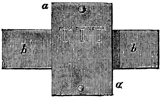
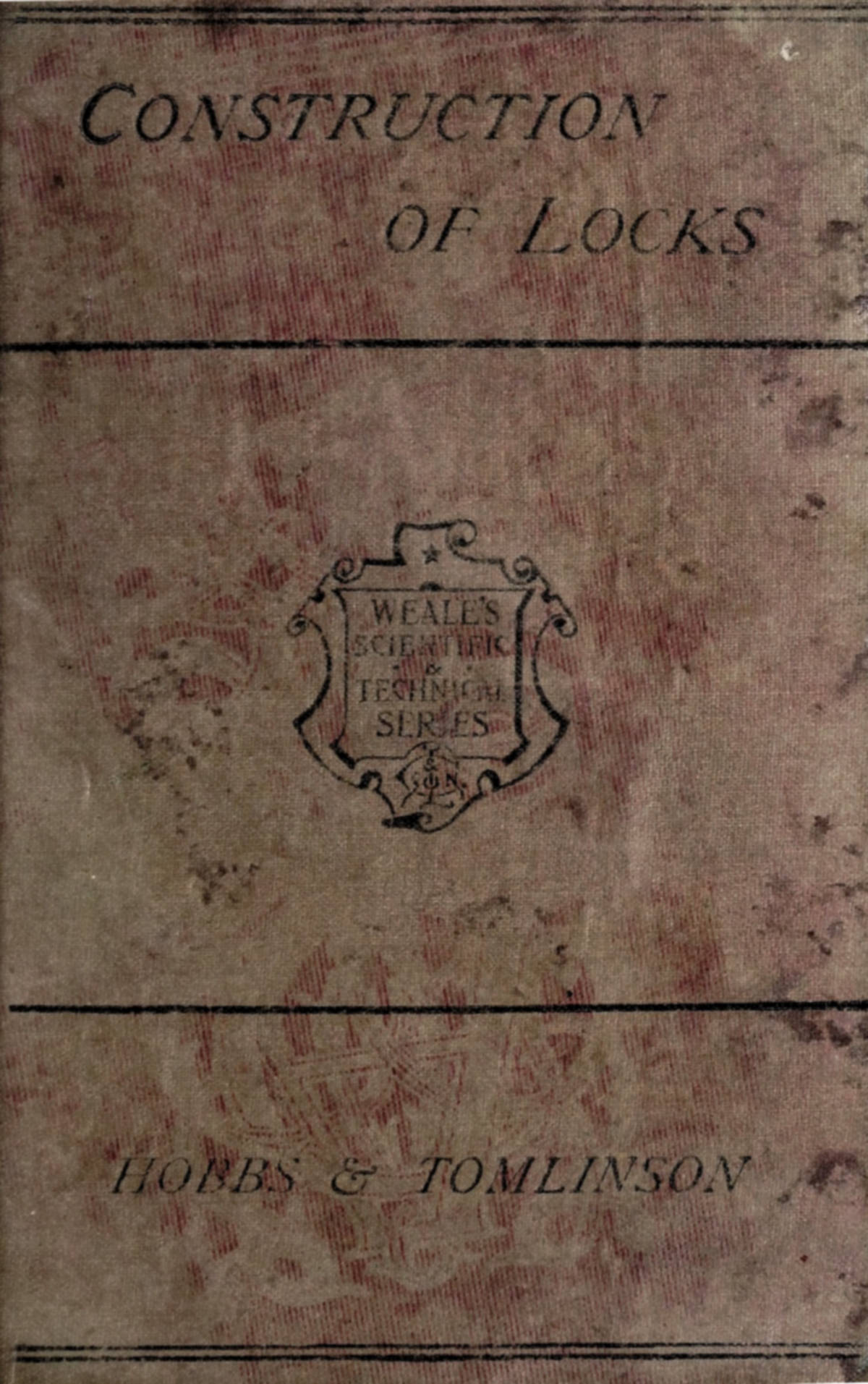
fig. 1.
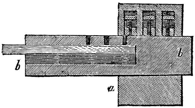
fig. 2.
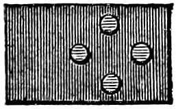
fig. 3.
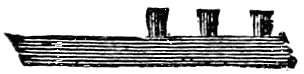
fig. 4.
The construction of this remarkable Egyptian or pin-lock will be understood from the accompanying engravings. The quadrangular portion, a a fig. 1, is the case of the lock, screwed or otherwise fastened to the door, having a wooden bolt, b b, passing horizontally through a cavity in it. In the part of the case above the bolt are several small cells containing headed pins, arranged in any desired form; and in the top of the bolt itself are an equal number of holes similarly arranged. The effect of this arrangement is such that, when brought into the right positions, the lower ends of the headed pins drop into the corresponding holes in the bolt, thereby fastening the bolt in the lock-case. A large hollow, or cavity, is made at the exposed end of the bolt, the cavity extending as far as and beyond the holes occupied by the pins. The key consists of a piece of wood (shewn in two positions, figs. 3 and 4,) having pins arranged like those in the lock, and projecting upwards just to a sufficient distance to reach the upper surface of the bolt. This being the arrangement, whenever the key is introduced and pressed upwards, its pins exactly fill the holes in the bolt, and by so doing dislodge those which had fallen[16] from the upper part of the case. The bolt may, under these circumstances, be withdrawn (as shewn in fig. 2), leaving the headed pins elevated in their cells, instead of occupying the position shewn by the dotted lines in fig. 1. The cavity in the bolt must of course be high enough to receive the thickness of the key, and also the length of the pins protruding from the key.
This primitive lock comprises many of the best features of the tumbler or lever-locks of later days, as will be seen in a future chapter. There will also be opportunities of shewing how the pin-action has been applied in other ways in some of the modern locks.
In approaching the subject of modern locks it becomes necessary to decide upon some method of treating the widely-scattered and diverse materials which are presented to our notice. One plan would be to trace the subject chronologically, by describing, in the order of their invention, the most important locks which have been presented to public notice. But this would be attended with some disadvantages: the peculiar characters of the several locks would not be brought out with sufficient distinctness; and the result, so far as the reader is concerned, would rather tend to confusion than to a clear appreciation of the subject. There are more advantages belonging to a classification of locks under certain headings, according to some marked peculiarities in their modes of action. This is a convenient plan, but it is not an easy one to put in execution; for inventors have not sought to place their locks in any particular class, but rather to call attention to their merits. Moreover,[17] many locks embody two or three distinct principles so equally, that it will often be difficult to decide in which class to place them. This, nevertheless, may be done with an approach to correctness. It is necessary first, however, to explain certain technical terms by which locks are distinguished one from another.
Locks, in truth, admit of an immense variety, which, however important to be known to locksmiths, carpenters, and others employed on them, need only be glanced at very cursorily by the general reader. Some locks are named according to the purposes to which they are to be applied; others according to their shape, or the principles of their construction. In the first place, there is the distinction between in-door and out-door locks. Of in-door locks, one principal kind is the draw-back lock, for street-doors, in which the bolt is capable of maintaining any one of three positions: it may be locked by the key, or left half-way out by the pressure of a spring, or be drawn back by a handle. In the first position, it can only be withdrawn by the key; in the second, it closes the door, but can easily be withdrawn by the handle; and in the third, it leaves the door unfastened. If these locks are made of iron and carefully finished, they are further called iron-rim; but if made of wood, suitable for back-doors and inferior purposes, they are spring-stock. For the doors of rooms, there are the iron-rim, the brass-case, and the mortise lock; the second supplants the first, and the third the second, as we advance in the elegance of the door-fittings. Other designations for room-locks depend on the number of the bolts: thus, if there be only one bolt, it is a dead lock or closet lock; if there be a second bolt, urged by a spring and drawn back by a handle, it is a two-bolt lock; and if there be also a third, a private bolt acting only on one side of the door, it is a three-bolt lock. Again, according to the kind of handle employed, it may be a knob lock or a ring lock. According to which edge of the door it is to be fixed, it becomes a right-hand or a left-hand lock. If the wards of the lock are of somewhat superior quality, and[18] bend round nearly to a circle, the lock is one-ward round, two-ward round, and so forth. If the lock has no wards at all, it is plain; if the wards are of common character, they are often called wheels, and then the lock becomes one-wheel, two-wheel, &c. Sometimes the lock is named from certain fancied resemblances in the shape of the ward, as the L-ward, T-ward, or Z-ward. If the wards are cast in brass, instead of being made of slips of iron or copper, the lock is termed solid ward.
Of the numerous but smaller varieties known by the collective name of cabinet locks, there are the cupboard, the bookcase, the desk, the portable desk, the table, the drawer, the box, the caddy, the chest, the carpet-bag, and many other locks. All these locks are further called straight, when the plate is to be screwed flat against the wood-work; cut, when the wood is to be so cut away as to let in the lock flush with the surface; and mortise, when a cavity is excavated in the edge of the door for the reception of the lock.
Out-door locks are usually wooden stock locks, for stables, gates, &c.; comprising many varieties of Banbury, bastard, fine, &c. There are D locks and P locks, for gates, designated from their shapes; and there are the numerous kinds of padlocks.
The above terms are employed chiefly between the makers of the locks and the persons who fix them in their places; but there are other terms and names, more familiarly known, which will come under notice in future pages.
It is scarcely worth while to descant upon the “middle age” of lock-making—to impart to the subject so much of dignity as to be susceptible of regular historical treatment. True, we know that wards were employed before tumblers (unless, indeed, the pins of the Egyptian lock be considered as tumblers—a character to which they present considerable claim), and that wards may be taken as the representative of the medieval period of lock-making; but it may be more profitable to proceed in our notice of the different kinds of locks in an order which will in itself partake somewhat of the historical character.
[19]
Apart from all the warded and tumbler locks are the very curious puzzle or letter-locks; a construction which we propose to dismiss out of hand in the present chapter, before treating of those which have more commercial importance.
The puzzle-lock is generally in the form of a padlock, which is opened and closed without the use of a key, and which has certain difficulties thrown in the way of its being opened by any one who is not in the secret of the person who closed it. It is, in fact, one of the locks in which the doctrine of permutation is made to contribute to the means of security. The key to open it is a mnemonic or mental one, instead of one of steel or iron. Two centuries ago, the puzzle-lock attracted far more attention than any other. It has always certain movable parts, the movement of which constitutes the enigma. Some of these very curious and out-of-the-way locks are so formed as to receive the name of dial-locks; but the chief among them are ring-locks—a name the meaning of which will be presently understood.
The puzzle or letter-lock of the ring kind, then, consists essentially of a spindle; a barrel, encompassing the spindle; two end-pieces, to keep the spindle and barrel in their places; and the shackle, hinged to one of these end-pieces. To unfasten the lock, one of the end-pieces must be drawn out a little, to allow the shackle or horse-shoe to be turned on its hinge; and the question arises, therefore, how this end-piece is to be acted upon. This is effected in a very ingenious way: there are four studs or projections in a row on the spindle, and as the spindle fits pretty closely in the barrel, the former cannot be drawn out of the latter unless there be a groove in the interior of the barrel, as a counterpart to the studs on the exterior of the spindle; four rings fit on the barrel, on the interior of each of which there is a groove; and unless all these four grooves coincide in direction, and even lie in the same plane as the groove in the barrel, the studs will not be able to pass, and the spindle cannot be drawn out. Each ring may be easily made to work round the barrel by means of the[20] fingers, and to maintain any position which may be given to it. There are outer rings, one over each of the rings just described, with the letters of the alphabet (or a considerable number of them) inscribed on each; and these outer rings, by means of notches on the inside, govern the movements of the inner rings.
The action is, therefore, as follows: when the padlock is to be locked, the rings are so adjusted that all the grooves shall be in a right line; the spindle is thrust in, the end-piece is fixed on, and the shackle is shut down. The padlock is now fastened; but a reverse order of proceeding would as easily open it again, and therefore the “safety” or “puzzle” principle is brought into requisition. The outer rings are moved with the finger, so as to throw the various interior grooves out of a right line, and thus prevent the withdrawal of the spindle. As each ring may be turned round through a large or a small arc, and all turned in different degrees, the variations of relative position may be almost infinite. The letters on the outer rings are to assist the owner to remember the particular combination which he had adopted in the act of locking; for no other combination than this will suffice to open the lock. There may, for instance, be the four letters L O C K in a line, which line is brought to coincide with two notches or marks at the ends of the apparatus; and until all the four outer rings are again brought into such relative position as to place the letters in a line, the lock cannot be opened.
There are many allusions to locks, apparently belonging to the letter or puzzle principle, in authors who flourished two or three centuries ago. Thus, in Beaumont and Fletcher’s play of the Noble Gentleman, written in the early part of the seventeenth century, one of the characters speaks of
And in some verses by Carew, written about the same time, there is an analogy drawn, in which one of the things compared is—
[21]
In the Memorabilia of Vanhagen von Ense, written about the middle of the seventeenth century, a commendatory notice is given of a letter-lock, or combination-lock, invented by M. Regnier, Director of the Musée d’Artillerie at Paris. “Regnier,” we are told, “was a man of some invention, and had taken out a patent for a sort of lock, which made some noise at the time. Every body praised his invention, and bought his locks. These consisted of broad steel rings, four, five, or eight deep, upon each of which the alphabet was engraved; these turned round on a cylinder of steel, and only separated when the letters forming a particular word were in a straight line with one another. The word was selected from among a thousand, and the choice was the secret of the purchaser. Any one not knowing the word might turn the ring round for years without succeeding in finding the right one. The workmanship was excellent, and Regnier was prouder of this than of the invention itself. The latter point might be contested. I had a vague recollection of having seen something of the sort before; but when I ventured to say so, my suspicions were treated with scorn and indignation, and I was not able to prove my assertion; but many years afterwards, when a book, which as a boy I had often diligently read, fell into my hands, Regnier’s lock was suddenly displayed. The book was called Silvestri a Petrasancta Symbola Heroica, printed at Amsterdam in 1682. There was an explanation at p. 254, attached to a picture; these were the words:—Honorius de Bellis, serulæ innexæ orbibus volubilibus ac literatis circumscripsit hoc lemma—Sorte aut labore.[3] However, neither luck nor labour would have done much more towards discovering the secret of opening Regnier’s locks, from the variety of their combinations; and their security seemed so great, that[22] the couriers’ despatch-boxes were generally fastened with them.”
[3] “Honorius de Bellis wrote this inscription,—By chance or by labour,—round a lock composed of revolving rings graven with letters.”
This curious extract, which was brought forward by Mr. Chubb, in a paper on locks and keys (read before the Institution of Civil Engineers in 1850), seems to take away the credit from one (Regnier) with whose name the letter-lock has been most intimately associated. We shall presently explain, however, what it was that Regnier effected towards perfecting the letter-lock. In the meantime it may be interesting to note that the British Museum contains a copy of the work mentioned by Vanhagen. At the page indicated there is an engraving (a fac-simile of which is given in fig. 5) containing a drawing of a veritable puzzle or letter-lock; the lock consists of a cylinder or barrel, on which seven rings work; each of these rings is inscribed with letters, and the ends of the cylinder are grasped by a kind of shackle.
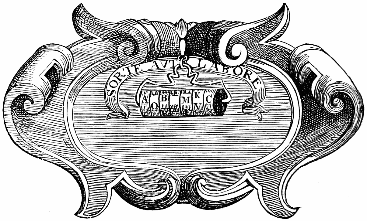
fig. 5. Puzzle-lock of the seventeenth century.
It was a natural result of the arrangement of the letter-lock, as invented (conjecturally) by Cardan, that only one particular word or cipher or key could be used in each lock; and it was to increase the puzzle-power of the lock that Regnier[23] doubled all the rings, making each pair concentric, and enabling the user to vary the cipher at pleasure.
The principle of the letter-lock, when applied to doors, requires that sort of modification which renders it what is termed a dial-lock. There are to such a lock one or more dials, with a series of letters or figures stamped on them; there is to each dial a hand or pointer connected by a spindle with a wheel inside the lock; on the wheel is a notch which has to be brought to a certain position before the bolt can be moved. There are false notches, to add to the difficulty of finding the true notch in each wheel. To adjust the notches to their proper position, a nut on the back of the wheel is loosened, and the pointer is set at any letter or figure chosen by the user. The pointers and the dials perform the part of the outer rings, the wheels that of the inner rings; and it is easy to see that the same leading features prevail in the two kinds of lock, however they may differ in detail.
These dial-locks have not been numerous; they require wheel and pinion work within the body of the lock, which gives delicacy and complication to the mechanism. The letter padlock, be its merits great or small, is strong and durable, not liable to get out of order; and in so far as it requires no key or key-hole, it occupies rather a special position among locks. One of our great “merchant-princes” has been a letter-lock inventor, as the following will shew.
Early in 1852, Mr. William Brown, the distinguished member for South Lancashire, read a paper before the Architectural and Archæological Society of Liverpool, of much interest in relation to our present subject. His object was to describe a letter-lock which he had invented, and which had up to that time given high satisfaction. We cannot do better than transcribe the paper, as reported in one of the Liverpool Journals, with a few abridgments.
“As your society are desirous of seeing any improvements or attempts at them, I send you a stock-lock for inspection. The idea for its construction I took from a letter-padlock.[24] I had a lock of this description made by Mr. Pooley twenty-five years ago, which has been in use ever since on Brown, Shipley, and Co.’s safe....
“Its advantages I conceive to be—First, it cannot be picked, for there is no key-hole. Second, it cannot be blown up by gunpowder, for the same reason. Third, you cannot drill through the door so as to reach the lock, for you are intercepted by a steel plate on which your tools will not act: thus you cannot introduce gunpowder that way to force the lock off. Fourth, you cannot bounce off the wheels in the interior with a muffled hammer, for vulcanised India-rubber springs resist this. Fifth, you cannot drill the spindles out, as their heads are case-hardened. Sixth, you cannot drive them in, for they are countersunk in the door about half-way through....
“Now let us set the lock to the word W O O D (any other four letters might be used). When you set the lock, make a private record of them, so that you may not forget them. If parties do not know your letters, nothing but violence, applied by some means or other, can enable them to get into your safe; for the lock will not open to any thing but its talisman. Take off all the large wheels and open the lock: you will see that the large wheels have a number of false chambers; if you get the spurs of the bolt into three real chambers and one false, you are as fast as ever, for all four must be right.
“Having placed your key and pointer outside the door to point to W on brass-plate No. 1, the small wheel inside obeys the same impulse; then maintain your small wheel steadily on this point, and the large wheel No. 1 will only fit on at the right place, the true opening compartment being opposite the spur of the bolt. It being necessary at the time you set your lock that it should be open, proceed with Nos. 2 and 3 in the same way, your pointer standing steadily at O. No. 4 is the same, the pointer being held steadily at D. You should then shoot your lock two or three times, to be sure you have[25] made no mistake. Every time you shoot your bolts out, turn your wheels away from the true chamber, and see when you again turn your pointers to W O O D that your lock opens freely; it is the proof that you have made no mistake, and you may now venture to lock your safe. When you unlock the door, and find it necessary to leave it open for a time, you should shoot the bolts as if locked, and turn the wheels, so that no one may find what your real letters are; and again adjust them to their proper places, in order that the bolt may go back and enable you to re-lock. Once having locked the door and turned the wheels from your real letters, you need not trouble yourself with carrying the key, but leave it in any place beside the lock.
“I believe two wheels would make a perfectly safe lock; three would be quite so. I adopted four to make security doubly sure, as it would be impossible in any given time to work the changes. On two wheels by chance the lock might open; you can, however, calculate the chances against this; and also three or four, the false compartment on the outer rim being taken into calculation. ***
“If this lock is of any value, it should be known; if it has weak points, let them be pointed out, and they may admit of a remedy; for we ought not to be led to believe a lock is safe which is not so.”
In relation to the “first advantage” which Mr. Brown not unreasonably supposed to be possessed by his lock—viz. that “it cannot be picked, because it has no keyhole”—we shall have something to say in a future page, where certain fallacies on this subject will be noticed. In the meantime we may remark, that it is not a little creditable that a leading Liverpool merchant should have invented a lock worthy of occupying a position on his own safe for a quarter of a century; for we may be quite certain that he would not have allowed the lock to maintain that post of honour unless it had really (so far as experience had then gone) served worthily as a safeguard to his treasures. And if it were possible to[26] collect all the by-gone specimens of lock-oddities, we should probably find among them many highly-ingenious letter-locks; for supposing a man to have a mechanical turn of mind, a lock is by no means an unworthy medium for displaying it; the pieces of metal are so small as to be easily manageable at a small work-bench in a small room. The fondness for this sort of employment evinced by the unfortunate Louis XVI. of France led to the common remark, “He is a capital locksmith, but a very bad king.”
In an amusing article in the Observer, during the progress of the “lock controversy,” was the following paragraph relating to combination-locks of the letter or puzzle kind: “The French, in their exposition of 1844, availing themselves of the permutation principle, produced some marvels in the art; but the principle has not been adopted in this country. The Charivari had an amusing quiz upon these locks when they first came out. It said the proprietor of such a lock must have an excellent memory: forget the letters, and you are clearly shut out from your own house. For instance, a gentleman gets to his door with his family, after a country excursion, at eleven o’clock at night, in the midst of a perfect deluge of rain. He hunts out his alphabetical key, and thrusts it into his alphabetical lock, and says A Z B X. The lock remains as firm as ever. ‘Plague take it!’ says the worthy citizen, as the blinding rain drives in his eyes. He then recollects that that was his combination for the previous day. He scratches his head to facilitate the movement of his intellectual faculties, and makes a random guess B C L O; but he has no better success. In addition to his being well wet, his chances of hitting on the right combinations and permutations are but small, seeing that the number is somewhere about three millions five hundred and fifty-three thousand five hundred and seventy-eight. Accordingly, when he comes to the three-hundredth he loses all patience, and begins to kick and batter the door; but a patrol of the National Guard passes by, and the disturber of the streets is marched off to the watch-house.”
[27]
The more ordinary locks are of an oblong quadrangular shape. In nearly all of them, either a bolt shoots out from the lock, to catch into some kind of staple or box, or a staple enters a hole in the edge of the lock, and is there acted upon by the bolt. A common room-door lock will illustrate the first of these kinds, a tea-caddy lock the second. The key, as is well known, enters a receptacle made for it; and the shaft of the key generally serves as a pivot or axis around which the web or flat part of the key may move in a circular course. During this movement the web acts directly or indirectly on the bolt, driving it in or out according to the direction in which the key is turned; the key impels the bolt one way, certain springs act upon it in another, and the balance between these two forces determines the locking and unlocking of the bolt. Wards, or wheels, are contrivances for rendering the opening difficult without the proper key; and it is of warded locks that we shall chiefly treat in this chapter.
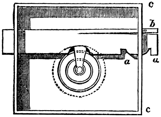
fig. 6. Interior of a back-spring warded lock.
The annexed cut, fig. 6, represents the interior of an ordinary back-spring lock, without tumblers. Such a lock may[28] usually be known from a tumbler-lock by this simple circumstance, that it emits a smart snapping noise during the process of locking, occasioned by the pressure of the spring when the bolt is in a particular position. In the woodcut the bolt is represented half out, or half shot. At a a are two notches on the under side of the bolt connected by a curved part; b is the back spring, which becomes compressed by the passage of the curve through a limited aperture in the rim c c of the lock. When the bolt is wholly withdrawn, one of the notches a rests upon the rim c c; and the force with which the notch falls into this position, urged by the spring b, gives rise to the snapping or clicking noise. When the bolt is wholly shot, the other notch rests in like manner upon the edge of the aperture in the rim.
It must be obvious at a glance, that this back-spring lock is objectionable on the score of security, on account of the facility with which the bolt may be forced back by any pressure applied to its end, a pressure which may often easily be brought to bear. At the centre of the lock is seen the end of the key acting on a notch in the bolt, and surrounded by wards.
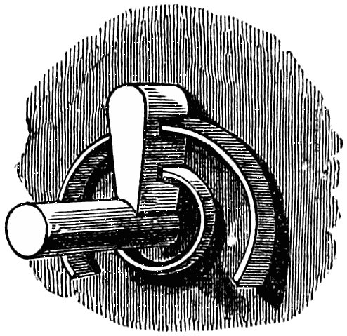
fig. 7. Section to shew the action of wards.
It is not at a first glance that the relation between the clefts in a key and the wards of a lock can be duly appreciated; because the wards present themselves to view as portions of circles to which nothing in the key seems to correspond; but if it be borne in mind that the key has a rotary[29] motion within the key-hole around the pipe or barrel as an axis, the circular form of the wards will be accounted for, and their section will be regarded as exhibiting the looked-for relation to the wards of the key. In the annexed cut, for example (fig. 7), which represents a portion of the interior of a warded lock, the curved pieces of metal are the wards (two in this case); and there are two clefts in the bitt of the key to enable the latter to take its circular course without interruption from the wards. If the clefts were other than they are, either in number, position, or size, this freedom of the key’s movement could not be obtained.
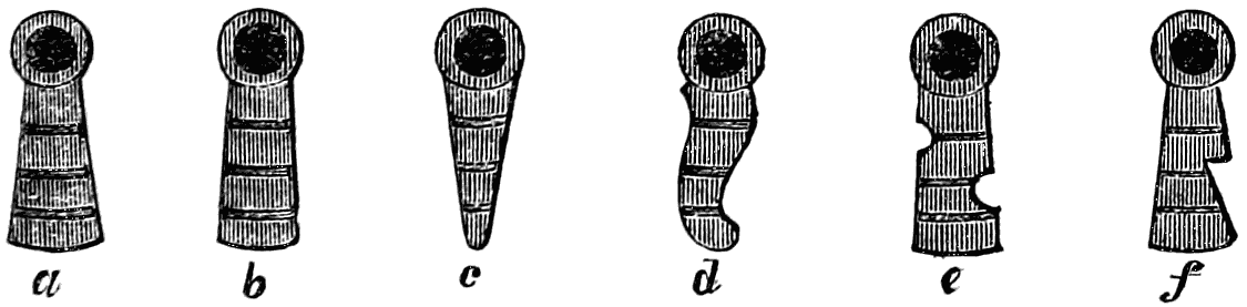
fig. 8. End sections of keys.
When once the opinion became established that a lock is rendered secure by virtue of its wards, (a theory which we shall have to discuss in a later page,) much ingenuity was displayed in varying the wards of the lock, the clefts of the key, and the shape of the keyhole. Even if the two former were unchanged, a change in the latter might add to the puzzlement of the arrangement. For instance, in the annexed cut (fig. 8), all the six keys represented may have clefts or cuts exactly alike, all alike adapted to the wards of one particular lock; yet the differences in the thickness of the web are such, that if the keyholes were shaped in conformity therewith, each keyhole would be entered by one of these keys; b and c differing from a in the relative thickness at different points, and d, e, and f having certain curvatures and cavities not to be found in the other three.
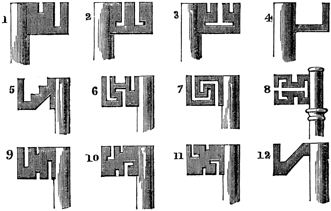
fig. 9. Examples to shew the action of “master,” or “skeleton keys.”
But without waiting for the detailed examination of the relative security and insecurity of locks, we may at once shew how simple is the principle which renders the warded system[30] fallacious. In fig. 9 we shall be able to illustrate this. Numbers 1, 2, and 3, all appear very different keys, and it is quite true that neither one would open a lock adapted for either of the other two; and yet the very simple arrangement No. 4 would open all three. This No. 4 is called a skeleton-key; and the relation which it bears to the others may be expressed in the form of a proposition thus: at any point where there is solid metal in all the keys, there must (or may) be solid metal in the corresponding part of the skeleton-key; but at any point where there is a vacancy or cavity in any of the keys, there must be a cavity in the corresponding part of the skeleton-key. If Nos. 1, 2, 3, 4, be examined, this proposition will be found to be borne out; there is so much cavity in No. 4 that it avoids the wards in all the three locks, nothing being required but the tongue of metal to move the bolt. Sometimes, to add to the safety, wards are attached to the front as well as the back plate of the lock; and then there may be a double series of notches required in the key, such as in No. 5; but if this be compared with Nos. 9, 10, 11, it will be found that although no one of the four would open a lock[31] adapted for either of the other three, yet the skeleton-key No. 12 would master them all, having cavities wherever any of the others have cavities. This is the theory of the master-key, by which one key may be made to command many locks. Nos. 6 and 7 have complicated wards; but the key is so much cut up as to be weakened more than is desirable. No. 8 enables us to point out the difference between two distinct classes of keys. Keys with pipes or barrels fitting on a pin or pipe-shaft can only open a lock on one side of the door or box; but a key with a solid stem, as No. 8, has the clefts so cut as to open the lock from either side, as in a street-door lock: it is, in fact, two warded keys fixed end to end, only half of which is employed at one time in opening the lock.
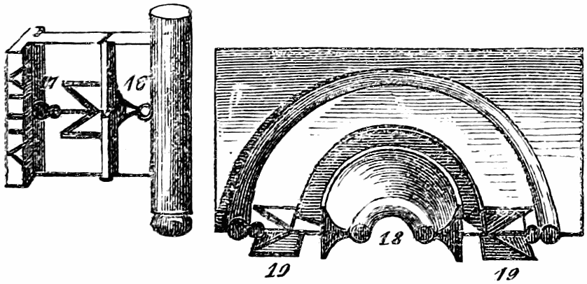
fig. 10. Wards of an old French lock.
Some of the warded locks of the last century are curious. While the idea prevailed that a complicated ward gave security, there was room for the exercise of ingenuity in varying the shape of the wards. Fig. 10 is copied from the great French work. It represents the cuts in the key, and also (seen perspectively) the complicated forms of the pieces of metal which constitute the wards corresponding with those cuts. The aperture in the key at 16 fits upon the metal surrounding the keyhole at 18; and the M-shaped cuts at 17 fit in like manner upon the similarly-shaped metal pieces at 19.
Another example of a similar kind is shewn in fig. 11, where an anchor appears to have been the favourite form. The[32] anchor cuts in the key are shewn at 26; while in the wards the bottom of the anchor is near the keyhole at 28, and the top at 29.
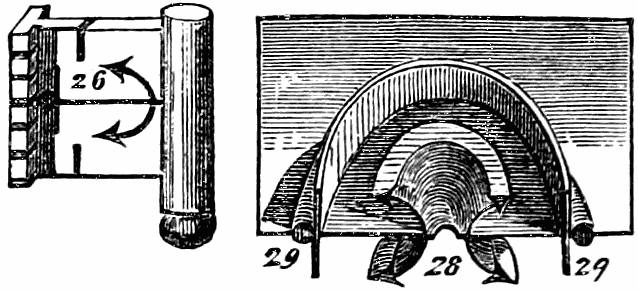
fig. 11. Wards of an old French lock.
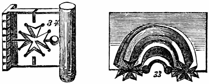
fig. 12. Wards of an old French lock.
A similar illustration occurs in fig. 12, where the star-like cuts at 34 on the key correspond with the star-like wards at 33.
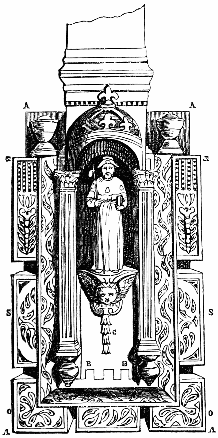
fig. 13. Exterior of an old secret lock.
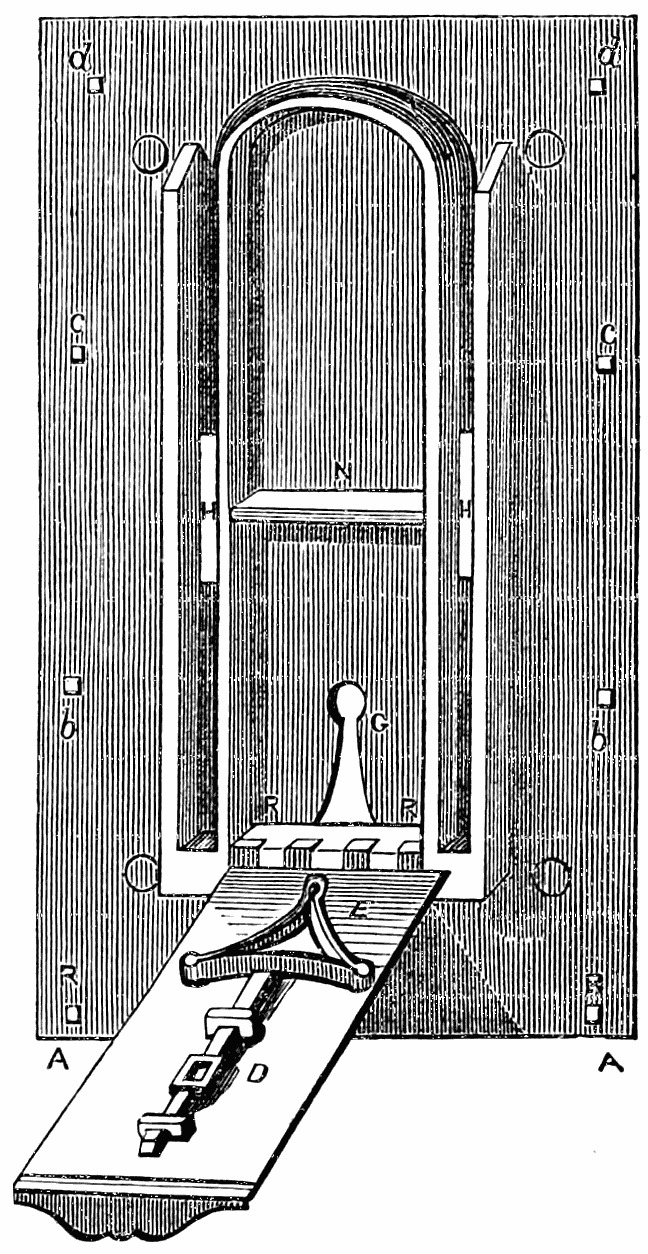
fig. 14. The same, with a portion of the front let down, shewing the key-hole.
From the fifteenth to the eighteenth centuries locks were made in France, on which a vast amount of care and expense was bestowed. They were, in an especial degree, decorative appendages as well as fastenings. They were of three kinds: room-locks, buffet-locks, and chest-locks; they were fixed on the outside of the door or lid, so as to be fully visible. The key had a multitude of perforations which bore no particular relation to the wards of the lock, but which were regarded as tests of the workman’s skill. The honorary distinctions awarded to apprentices and aspirants in the art depended very much on the number and fine execution of these perforated keys. The locks, considered as fastenings, had slender merit; although usually throwing four bolts, they were not very secure. Fig. 13 represents the exterior of a lock made about the year 1730, by Bridou, a celebrated Parisian locksmith. It was a lock belonging to a coffer or strong[33] chest; all the works being sunk below the level of a carved architectural moulding or ornament. There is a secret opening near the part C, forming a portion of the ornamental design; it allows a bolt, shewn at D, fig. 14, acted on by the spring E, to be touched, by which a doorway opens upon the hinges at B B. A A are a sort of pilasters, which aid in forming a hold for the bolts. The little ornament at C is drawn down by the hand, opening the secret door and revealing the key-hole G. S S, O O, Z Z, are ornaments fastened on at b c d, fig. 14, by nuts and screws, intended to display the skill of the workman.[34] The lock itself, access to the keyhole of which is obtained within the secret door, has nothing very remarkable about it.
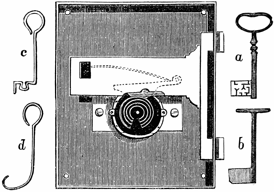
fig. 15. Examples of true and false keys.
Mr. Chubb, in his paper read before the Institute of Civil Engineers, illustrated the insecurity of the warded lock by the example of one which had actually been placed in the strong-room of a banking house, and which is represented in the annexed cut (fig. 15). The wards are here shewn, surrounding the central key-pin; and from the appearance of the key, shewn at a, it is evident that these wards must have been rather complex. But the uselessness of the wards was proved by the result. A burglar employed an instrument, shaped like that at b, having on one of its faces, or sides, a layer of wax and yellow soap; this instrument, being introduced through the keyhole and turned a little way round, brought the soft composition in contact with the ends of the wards, and these ends thus left their impress on the composition. A false key was then made, as at c, which, however clumsy it may appear, has a cavity, or vacuity, where there is a cavity in the true key; and by such a surreptitious instrument was the lock opened. Even so rude an instrument as d, by passing round the wards, might open such a lock.
We are somewhat anticipating the full consideration of this[35] subject; but it is desirable at once to explain how and why an improvement on the warded lock was sought for.
In connexion with the fanciful eighteenth-century locks, lately adverted to, we may remark, that no less a man than Louis XVI. was an amateur workman in this department of mechanical art—or at least in smith’s work, which in France is generally considered to include lock-making. Sir Archibald Alison says, in his History of Europe:—“He had an extraordinary fondness for athletic occupation and mechanical labour; insomuch that he frequently worked several hours a-day with a blacksmith of the name of Gamin, who taught him the art of wielding the hammer and managing the forge. He took the greatest interest in this occupation, and loaded his preceptor in the art with kindness; who returned it by betraying to the Convention a secret iron recess which they had together worked out in the walls of the cabinet in the Tuileries, wherein to deposit his secret papers during the storms of the Revolution.” There are not wanting indications that the unfortunate monarch wrought upon locks, as well as upon safes and strong-rooms.
Besides wards, there have been numerous other contrivances for adding to the security of locks—including screws, escutcheons, spiral springs, wheel-and-pinion work, alarums, and multiple bolts. As these are not of sufficient importance to be treated in separate chapters, we shall here give just so much notice of them as will illustrate their general character. Some of them are found combined with the “tumbler” principle, presently to be described; but all of them, it is now well known, were employed in various, ways when the tumbler lock was but little understood, and when the warded lock was held in esteem.
The Marquis of Worcester, whose curious Century of Inventions, written nearly two hundred years ago, contains so many suggestions which ingenuity has since developed into practical completeness, gives four of his inventions in the following words:—
[36]
69. “A way how a little triangle screwed key, not weighing a shilling, shall be capable and strong enough to bolt and unbolt, round about a great chest, an hundred bolts, through fifty staples, two in each, with a direct contrary motion; and as many more from both sides and ends; and, at the self-same time, shall fasten it to the place beyond a man’s natural strength to take it away; and in one and the same turn both locketh and openeth it.
70. “A key with a rose-turning pipe and two roses pierced through endwise the bit thereof, with several handsomely contrived wards, which may likewise do the same effects.
71. “A key, perfectly square, with a screw turning within it, and more conceited than any of the rest, and no heavier than the triangle screwed key, and doth the same effects.
72. “An escutcheon, to be placed before any of these locks, with these properties: First, the owner, though a woman, may with her delicate hand vary the ways of causing to open the lock ten millions of times beyond the knowledge of the smith that made it, or of me that invented it. Second, if a stranger open it, it setteth an alarum a-going, which the stranger cannot stop from running out; and besides, though none shall be within hearing, yet it catcheth his hand as a trap doth a fox; and though far from maiming him, yet it leaveth such a mark behind it as will discover him if suspected; the escutcheon or lock plainly shewing what money he hath taken out of the box to a farthing, and how many times opened since the owner had been at it.”
Mr. Partington, in his edition of the marquis’s singular work, makes a few comments on these lock-and-key contrivances. He says that the lock is evidently intended to operate on the principle of applying a screw for the purpose of moving the bolt, instead of using a key as a lever for this purpose. That such a plan might be applied to locks generally, he observes, there can be no doubt; and by a similar contrivance the large keys at present in use for outer doors, iron chests, &c. might be advantageously reduced by this means. By[37] employing the escutcheon mentioned by the marquis, much additional security would be obtained. It must be confessed, however, that many of the marquis’s statements are difficult to credit.
The escutcheon has been a favourite resource with lock-makers. Mr. Mordan’s escutcheon, for instance, introduced before the Society of Arts in 1830, is a contrivance to be placed temporarily over the keyhole of a door, to prevent the picking of the lock during the owner’s absence. The escutcheon, or “protector,” has a short pipe which, after the door has been locked, is thrust into the keyhole; attached to the pipe is a small lock, on Bramah’s or any other convenient principle, so contrived that, on turning its key, two lancet-shaped pieces fly out laterally and bury themselves in the wood. The escutcheon cannot be removed until the small key has reacted upon the small lock; and until this removal has taken place, the large key cannot reach the keyhole.
A curious application of the escutcheon principle attracted some attention among locksmiths about seventy years ago. One of the first premiums awarded by the Society of Arts, after the commencement of their “Transactions,” was to Mr. Marshall, for a “secret escutcheon,” in 1784. In his description of his new invention, he adverts to the marquis of Worcester’s wonderful escutcheon, and to the many attempts which have since been made to produce an apparatus which should realise the marquis’s description. He supposes that the letter padlock originated as one among many varieties of these imitative inventions; but this may be doubted. Mr. Marshall’s contrivance, however, was in effect an endeavour to improve upon the letter-lock. He considered it an objection that, in ordinary locks of this kind, the letter-rings admit of no variation of place; and he sought to remedy this defect. It is not so much a new lock, as an escutcheon for a lock, which he produced. There is a studded bar passing through a barrel; there are five rings which work concentrically on this barrel; there are letters on the outer surfaces of the rings,[38] and notches on the inner surface; but when, by the usual puzzle-action of the rings, the notches in them have been brought into a right line with the studs of the bar, the result is, not that the hasp of a padlock is raised, but that the escutcheon is removed from the keyhole of an ordinary lock. Mr. Marshall’s contrivance, therefore, is not so much a ring padlock, as a puzzle-ring security for the escutcheon of a fixed lock.
Some locks work by a screw and a spiral spring, instead of an ordinary key. Mr. W. Russell received a silver medal from the Society of Arts, about thirty years ago, for a new mode of locking the cocks of liquor-casks. Under ordinary circumstances, as is well known, the cock of a barrel or cask is in no way secure from the action of any one who can approach near enough to touch it; and different methods have been adopted of obtaining this security or secrecy. One plan is to employ a perforated cap, soft-soldered to the barrel of the cock, immediately over the grooved plug, the top of which plug is formed to the shape of the perforation, and a socket-key of the same form is introduced to turn the plug or open the lock. Another plan is to employ an iron saddle or staple, passing over the plug and below the bottom of the cock, through which a bolt is put, and a pendent padlock attached. The first method is very inefficient; the second is much superior, and has been largely adopted for locking the cocks of coppers, stills, vats, and other large vessels. But Mr. Russell thought some further improvement wanted. He caused a hole to be bored through the barrel, and to some depth into the plug when the latter is in the position for closing the cock. A stud works into this hole in such a way, that when the stud is driven home, the plug cannot be turned or the lock opened. The stud is attached at its other end to a spiral spring connected with a screw; a key is employed, the hollow pipe of which has an internal screw; and when this key is inserted in the cock-barrel and turned twice round, it draws back the stud, and allows the plug to be turned round in the proper way for opening the cock.
[39]
It is not often that wheel-and-pinion work is introduced into locks; the delicacy, the costliness, the weakness, and the tendency to get out of order, would all militate against the frequent adoption of such a course. It is, however, adopted occasionally. Mr. Friend’s secret-lock, introduced to the notice of the Society of Arts in 1825, had a train of wheels which acted upon the bolt, driving it out whenever the circular arcs of three wheels moved against it, but allowing a spring to force it back again whenever a deep cleft in each of the wheels locked into a stud on the bolt. There were certain numbers on a guide-plate, and a power of combining these numbers in great variety; and a provision that the bolt could be unlocked only by the same combination of numbers which had locked it. The guide-plate was a separate piece of apparatus, carried in the pocket of the user as a companion to the key. The key was of no use without the guide-plate, nor the guide-plate without the key. The user ‘set’ the numbers on the guide-plate, then applied it to the face of the lock, then introduced the key into the key-hole, and turned the key partially round; the bolt was now shot, and the guide-plate removed. If the key were used without the guide-plate, the bolt might be locked, but it was always unlocked again by the time the key had made a complete circuit. There was considerable ingenuity in the idea of this lock; but we believe it never went further than a model. Indeed many of the locks elaborately described in books have never had an existence as acting working locks.
A very ingenious principle has been occasionally introduced, in which clock-work regulates the interval of time which must elapse before a lock can be opened, even with its proper key. The object is, to ensure the safety of the lock during a journey, or until a particular person be present, or until the locked article is conveyed to a particular room. A patent was taken out in 1831 for a lock on this principle by Mr. Rutherford, a bank agent at Jedburgh. Against the end of the bolt of the lock is placed a circular stop-plate, so[40] adjusted that the bolt cannot be withdrawn until a particular notch in the rim of the circular plate is opposite the end of the bolt. The plate is put in rotation by clock-work. As the notch can be set at pleasure to any required distance from the end of the bolt, the lock may be secured against being opened, either by its own or any other key, until any assigned number of minutes or hours after it has been locked; for the plate may be made to revolve either slowly or quickly, by varying the number of wheels in the clockwork. When the lock is used for boxes or portable packages, the clockwork must be moved and regulated by a spring; but when it is applied to closets or safes, a descending weight and a pendulum may be employed. It is manifest that this system is susceptible of being greatly varied in its mode of application; and it has many points of interest about it. That a man cannot open his own lock with his own proper key, until the lock gives permission by assuming a particular state or condition, certainly strikes one as being susceptible of many useful applications, where time is an element taken into the account.
A curious alarum-lock was invented by Mr. Meighan, in 1836, in which the bell or alarum is not placed behind a door, as in many alarum contrivances, but within the lock itself. Two or more studs are placed on the bolt, which press against the lower end of a small tumbler; the movement of the tumbler elevates a hammer; but as soon as the point of the tumbler becomes released from the stud, a spring presses the hammer down forcibly, and causes it to strike against a small bell placed near it. This sounding of the bell will be repeated, during the shutting of the bolt, as many times as there are studs to act upon the point of the tumbler.
Much of the ingenuity which has been displayed in locks depends on the employment of multiple bolts, there being all the additional strength which results from the use of two or more bolts instead of simply one. Ordinary doors seldom afford us examples of these double bolts; but they may be frequently seen in cabinets and desks, where two staples fixed to[41] the lid fall into two holes in the lock, and are retained by two bolts. The most remarkable and complicated varieties, however, are those in which the bolts, instead of shooting parallel and nearly together, shoot in wholly different ways; one up, one down, one to the right, one to the left, and so on. It is on safes, strong boxes, and the doors of strong rooms containing valuable treasures, that such locks are usually placed. The mechanism is such that the key acts upon all the bolts at once, through the intervention of levers and springs of various kinds.
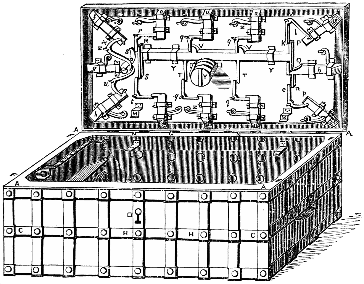
fig. 16. Multiple bolts of an old chest-lock.
The above woodcut represents a very curious specimen of these multiple-bolt locks. It is copied from the great French work; and the ponderous chest to which it is attached is, we are told by Réaumur, “known at Paris by the name of the strong German coffer.” He further says, “nothing is wanting in these coffers on the score of solidity. They are made entirely of iron; or if of wood, they are banded both within and without with iron; and can only be broken open by very[42] great violence. Their locks are almost as large as the top of the coffer, and close with a great number of bolts. The one which we have engraved has twelve fastenings; they have been made with twenty-four, or more.” His next remark on the subject is a sensible one: “Notwithstanding the large size of these locks, and all the apparatus with which they are provided, they correspond but ill with the solidity of the rest of the coffer. If we have given a representation of one, it is chiefly to shew how little confidence one could have in such a lock, and what are its defects, in order that we may avoid them.” It is not difficult, by tracing the action of the several levers, to see how one movement of the key, in the centre of the lid, would act upon all the bolts. In the engraving (fig. 16) a, f, h, c, are the four corner bolts; six others, a d e, a d e, are on the long sides, three on each; and two, b g, on the short sides. Every bolt is provided with a spring, of which three or four are shewn at Z Z Z. There is no staple or box to receive each bolt; but all shoot or snap beneath the raised edge E running round the top of the box just within the exterior at A A. The keyhole in the front of the box at D is a deception or mask; the real keyhole is in the middle of the lid concealed by a secret door opened by a spring. When the key has moved the great central bolt, this acts upon the other bolts P Q R S T, &c.; V V are studs which act upon two of the bolts; Y Y are staples confining the great bolt; k, l, c, p, x, are small levers which transmit the action to the corner bolts; q, r, s, t, n, are the small levers which render a similar service to the side and end bolts; L L within the chest, and M M on the lid, are contrivances for limiting the movement of the latter; C H, H C are iron straps or bands by which the interior of the chest is strengthened. After all, this is not so much a lock as a series of spring latches.
If a lock can be picked, the picking is as effective whether the lock has one bolt or twelve bolts. This fact led Mr. Duce, in 1824, to construct, instead of a four-bolt lock, four distinct one-bolt locks, fixed in the same frame and opened by the[43] same key; the bolts to be moved in succession instead of simultaneously. It would require four times as long to pick this as a four-bolt lock of similar action.
There have been many other varieties of the multiple bolt, but we need not stop to describe them.
Security being the primary object in all locks, any considerations as to mechanical ingenuity and graceful decoration give place to those which relate to safety. A spring lock may be ingenious and even beautiful in its construction, but an imitative key will easily open it. Hence arose the invention of wheels or wards; and as wards failed in trustworthiness, they in their turn yielded to something better. We have already explained how the insecurity of mere warded locks arises; and we shall have something more to say on the subject in a future chapter. It is sufficient here to remark, that wards, springs, screws, alarums, wheel-work, escutcheons,—all, however useful for particular purposes, are wanting in the degree of surety which we require in a lock. Hence the invention of tumblers, levers, or latches, which fall into the bolt and prevent it from being shot until they have been raised or released by the action of the key. We have been unable to ascertain at what time, or in what country, or by whom, tumbler-locks were invented. The invention has been claimed by or for persons subsequently to the year 1767, when the celebrated French treatise (Art du Serrurier) already referred to was published; and yet this treatise contains numerous examples of simple tumbler locks of ingenious construction, as will presently be shewn.
[44]
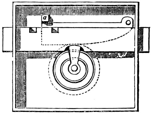
fig. 17. Simple tumbler lock.
One of the most elementary forms of tumbler-lock is shewn in fig. 17. In this case the bolt, instead of having two notches in the bottom edge, like those in the back-spring lock, fig. 6, has two square notches or slots in the upper edge; and as the key acts upon the bolt, these notches must of course share in whatever movements the bolt is subjected to. Behind the bolt is a kind of latch or tumbler (the lower part of which is shewn by dotted lines), with a stump or projecting piece of metal at a; the tumbler moves freely on a pivot at the other end, and is made to rise through a small arc whenever the key acts upon the bolt. When the bolt is wholly shot, the stump falls into one notch and prevents the motion of the bolt; when wholly unshot or withdrawn, the stump falls into the other notch, and equally prevents the motion of the bolt. It is not, therefore, until the key, by elevating the tumbler, has raised the stump out of the notch, that the bolt has freedom of movement. If the shape of the key does not enable its web to effect this elevation to a sufficient degree, the bolt remains immovable; and to this extent a certain additional security is obtained by making the shape of the key significant as well as the wards.
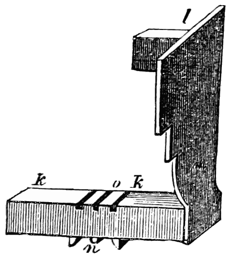
fig. 18.
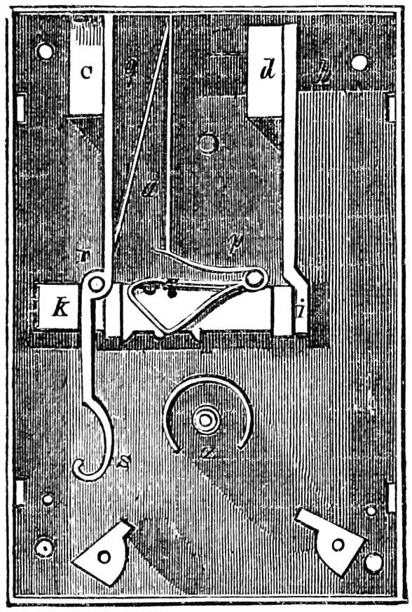
fig. 19. Old French lock.
The tumbler-principle, as we have said, is difficult to trace to its origin on account of the various aspects which it presents; but the great French treatise proves that the locksmiths of France were familiar with tumbler-locks a century ago. The plates of that work represent the details of numerous locks, on the upper edge of the bolts of which were notches called encoches, as at o k fig. 18; into these notches sank a[45] small iron stud or stump called the arrêt du pêne, or bolt-stop, shewn in fig. 19, attached to the upper portion of the gâchette or tumbler, which, for the sake of economy of metal, is made in the form of a triangular spring in front of the bolt k i; and not until the key, by its circular action, had raised this stud out of one or other of the notches, could the bolt move to the right or left. The stud was generally fixed to a spring which forced it down again into the notch as soon as the action of the key had ceased. Sometimes, however, the stud was fixed to the bolt, and the notches were in a separate tumbler or gâchette (see E E, fig. 21); and in other instances, again, the stump was fixed to the case of the lock and caught into notches in the bolt. It will be seen, when we come to treat of tumbler-locks of later date, that there was much in these early locks to point out the way. Fig. 19, copied from the French work, represents a lock of the box or casket kind. Two staples, fixed into the cover, fall into two cavities or receptacles at C d; and a short bolt in each receptacle catches into each staple, one near g and one near h. The small bolt q is attached to the upper extremity of the lever q r s, fig. 19, and shewn separately in fig. 20; and by the pressure of a spring a (fig. 19) upon this lever, the bolt[46] q is kept locked in the staple. The vertical portion of this spring presses at its lower end on another spring p (fig. 19) of singular curvature; and attached to the horizontal part of this second spring is the stud, which falls into a notch in the top of the bolt. The action of these parts, then, is as follows: when the key is placed upon the key-pin at Z, and turned round in the direction in which the hands of a watch move, the bitt presses against the tail s of the lever, moves it upon its centre Z, fig. 19, v, fig. 20, to the left, and consequently moves the upper part q to the right, drawing it out of the receptacle and liberating the staple within C. Thus it will be seen that the lever q r s, held in one position by the spring a, forms in itself a simple kind of spring catch-lock, and was, in fact, formerly used as such, without any other appendages except the staple in the lever, into which the catch q fitted on shutting down the lid. So also we may regard the other portion, fig. 18, or k i p h (fig. 19), as forming a separate lock; for the key after having passed S comes in contact with the triangular spring, which it raises thereby, lifting the stud out of the bolt, and exerting pressure against the barbs of the bolt n. Fig. 18 shoots the bolt k, and also the short bolt l, which passes through the staple in the cavity d, fig. 19.
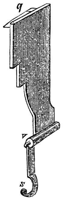
fig. 20.
The lock represented in the four following figures is also from M. de Réaumur’s chapter on locks in the work referred to. In this lock the tumbler-principle is carried out in a very[47] elaborate manner, for not only is the stump or stud H (fig. 23) attached to a very strong spring (best shewn at H, fig. 22), which holds it with considerable force in one of the three notches of the principal bolt R S (fig. 24); but there is also a second set of notches E E in the gâchette G O (fig. 21), and a pin attached to one of the plates of the lock fits into one of these notches, thereby preventing the bolt from being moved until the gâchette is lowered by the revolution of the key; so that[48] in attempting to pick this lock, not only must the spring H be raised so as to release the stud from the notches of the great bolt, but the gâchette must be lowered to disengage the fixed pin from the notches. There is yet a third source of security. Attached to the large bolt are short projecting pins F (fig. 21), against which an arm or detent, G F, of the gâchette projects, thus preventing the bolt from being shot back by any pressure applied to its extremity S.
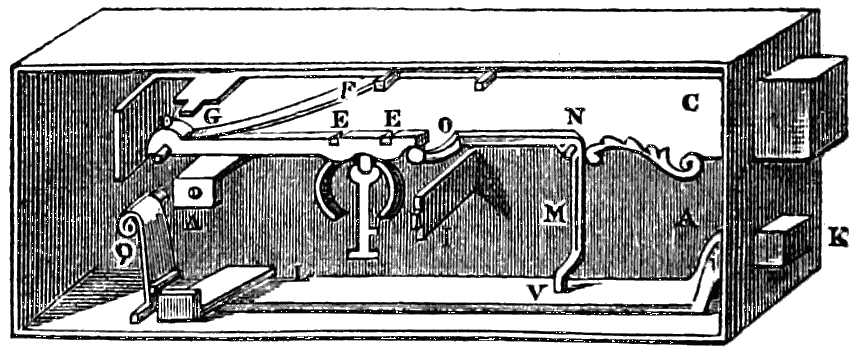
fig. 21. Details of an old French lock.
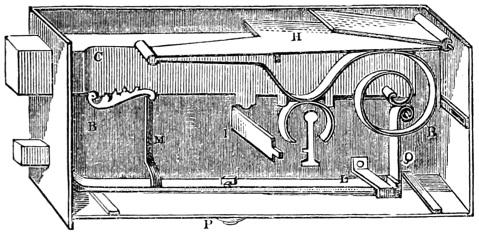
fig. 22. Another view of the same.
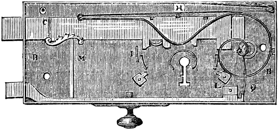
fig. 23. Another view of the same.
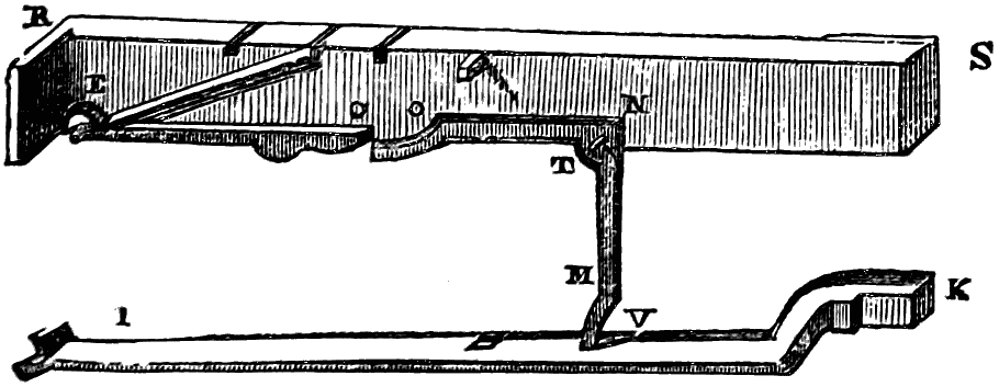
fig. 24. The two bolts detached.
There are a few details relating to this remarkable lock, which may as well be introduced here in order to complete the description. The principal bolt can be shot twice, or be double-locked; hence it is furnished with three barbs for the key to act against, and with three notches for the spring-stud. The lower bolt I K can be shot by the horizontal pressure of the button P (figs. 22, 23), which is situated on the inner side of the door to which this lock is attached, so that a person inside the room can secure the door against any one on the outside who is not furnished with the proper key, for it must be remarked that the small bolt as well as the large one is acted on by the key. Now supposing the small bolt to be shot or locked, it is kept so by the pressure of the coiled spring Q (figs. 21, 22). But this small bolt is connected with the large one by means of the bent lever O N M (figs. 21, 24), which turns on a pin N attached to the main bolt. Now, when both bolts are either fully shot or unshot, the arm O N lies flat against and parallel with the main bolt; but when the large bolt is unshot and the small one not moved, the arms O N, N M, fall into an inclined position, and the arm O N passing a little below the main bolt comes within the range of the web of the key, which in its revolution causes the bent lever to move upon its centre N, thereby restoring O N to its horizontal position, and at the same time causing the arm N M to move from right to left, or in the direction for unshooting the small bolt; the end of this arm thus catches into a mortise V (figs. 21, 24) in the small bolt, and immediately unlocks it.
But to return to the subject of tumbler-locks. About the[49] year 1778, Mr. Barron introduced that species of double-action (as it may perhaps be termed) which so greatly increases the security of the simple tumbler, fig. 17. In the tumbler-locks previously made, if the tumbler were raised sufficiently high, the lock could be opened: there was no such possibility as raising it too high; but Mr. Barron, by his invention, patented 31st October, 1778, rendered it absolutely necessary that a limit should be put to the height to which the tumbler should be raised, by rendering the bolt equally immovable whether the tumbler were too much or too little raised. Another important improvement was the introduction of two tumblers instead of one. The bolt has in its middle a slot or gating notched on both edges, the notches being fitted for the reception of studs fixed to the tumblers. Supposing the studs or stumps of the tumblers to be resting in the lower notches, they require to be elevated to the general level of the gating before the bolt can be moved; whereas, on the other hand, if the tumblers were raised ever so little too high, the studs will enter the upper notches, and prevent the shooting of the bolt. The lower edge, or belly, of each tumbler is acted on by the steps of the key during its circular movement; the leverage of the key being so exactly adjusted as to raise the tumbler to the desired height and no further. The tumblers are made unequally wide, so that steps or inequalities in the bit of the key are requisite to lift them both to the proper height. There are thus two improvements introduced: there are two tumblers instead of one, and each tumbler has a double instead of a single action.
This ingenious and very useful lock is represented, so far as regards its governing principle, in fig. 25. The bolt is here seen to have a peculiar slot or hole cut in it, consisting of a narrow horizontal passage or gating, with three notches above it and three below it. These double notches might be available even for one tumbler only; but Barron used two or more for the sake of additional security. In fig. 25 there are two tumblers shewn, expressed by dotted lines; both are hinged to[50] one pivot, both are raised by the same action of the key, but the stump on the one tumbler does not coincide in position with that on the other. It will be seen that if the studs of the tumblers rested in the lower notches, they would require to be elevated to the level of the gating before the bolt could be moved; while, on the other hand, if lifted too high, the stumps would be caught in the upper notches, and would equally prevent the passage of the bolt, The tumblers are unequally wide; and the bitt of the key is stepped or notched in a corresponding way, that there may be one step fitted to act upon each tumbler. Mr. Barron also adopted the reverse arrangement of having the stump on the bolt, and the openings in the tumblers; so that the principle of his patent may be concisely expressed as being “an arrangement to allow a stump on the tumbler to pass through an opening in the bolt, or a stump on the bolt to pass through an opening in the tumbler.”
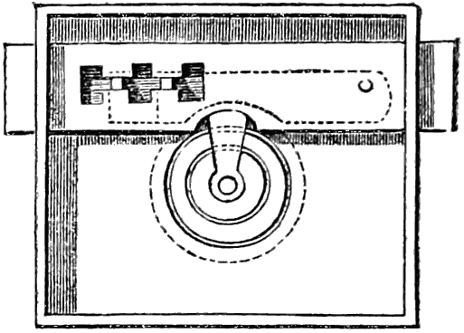
fig. 25. Action of Barron’s tumbler-lock.
A very elaborate tumbler-lock, patented 23d February, 1790, by Mr. Rowntree, contrasts remarkably with the simplicity of Barron’s lock. Mr. Rowntree’s lock consisted of tumblers combined with revolving discs or wheels. Its mechanism may be understood from the following description and engravings. The same letters refer to the same parts in the several figures.
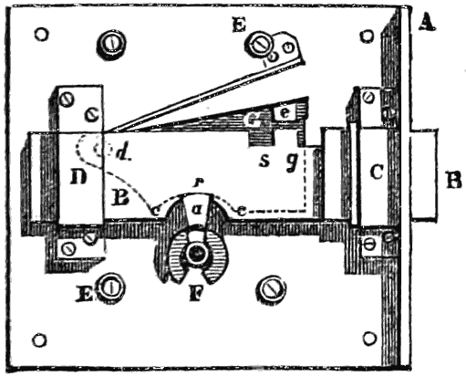
fig. 26.

fig. 28.
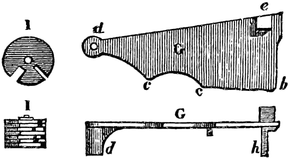
fig. 27.
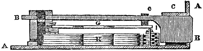
fig. 29.
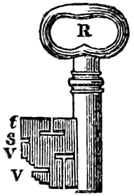
fig. 30.
Details of Rowntree’s tumbler-lock.
A A is the plate which encloses the whole mechanism of the lock, and fastens it to the door; B B is the bolt, guided in its motion by sliding under the bridges C D; E E are pillars[51] which support a plate covering the works; F are the circular wards surrounding the centre or key-pin; and a shews the position of the key, which, in turning round, acts in a notch r in the bolt, and propels it; G, the tumbler, is a plate situated beneath the bolt, and moving on a centre-pin at d; it has a catch or stump e projecting upwards, which enters the notches s or g in the bolt, and thereby retains the latter for backward or forward motion, as the case may be; H is a spring which presses the tumbler forward. The key a, in turning round, acts first against the part c c of the tumbler, and raises it so as to remove the stump from the notches; it can then enter the notch r in the bolt, and move it. So far there is no particular security; but Mr. Rowntree sought to obtain it by the following means. There is a piece of metal h fixed to the lower side of the tumbler, called the pin; when the tumbler is caught in either notch of the bolt, the pin applies itself to a cluster of[52] small wheels I, fitted on one centre-pin beneath the tumbler; the edges of these wheels stop the pin, and prevent the tumbler from being raised. But each wheel has a notch cut in its circumference I; and it is only when the wheels are so placed that all their notches lie in a right line, that the pin can enter this compound notch and allow the tumbler to rise. The wheels must therefore be all adjusted to position; and this is effected by a number of levers K centred on one pin at k; at the opposite end each lever has a tooth m entering a notch in the wheel belonging to it; so that when any lever is pressed outward, it turns its wheel round. Now this pressure of the levers is brought about by a spring n applied to each; and when so pressed, the levers rest against a pin o fixed in the plate. The key is so cut as to determine the extent to which the levers shall act upon the wheels. The key first operates from the curved part p p of the levers K, and raising them, turns all the wheels I at once into the proper positions; in turning further round, it then operates on the part c c of the tumbler, causing the latter to rise and to release the bolt; and in turning still further round, it (the key) seizes the notch r of the bolt, and shoots it. The key is cut into steps of different lengths, as shewn at V V; each step operates on its respective lever K in a different degree from the others; the notch at s acts upon the tumbler, and the plain part t moves the bolt.
We now proceed to notice the modern tumbler-lock. This was arranged by Bird, whose patent, bearing date 29th October, 1790, was for a series of four double-acting tumblers, differing in no respect from those patented by Barron, and closely resembling those in use at the present time in the best tumbler-locks. We will describe the modern tumbler-lock more particularly when we have gone through a few historical details on the subject.
Messrs. Mitchell and Lawton obtained a patent bearing date 7th March, 1815, for a lock in which were combined with the bolt and double-acting tumblers, a series of movable wards, and a revolving curtain for closing the key-hole. The[53] action of the wards was peculiar. On introducing any key or instrument, and passing it round, a number of movable wards or pieces were thrown out so as to prevent the key from being turned back or withdrawn. It was necessary therefore to pass round the key so as to unlock the lock, and if that were not possible, as in the case of a false key being used, it was held permanently, and could only be released by destroying the lock, When the bolt was once shot, the wards were carried up so as to leave a clear passage for the key. This lock does not appear ever to have come into use, on account of the violence required in case a wrong key should be used either by accident or design.
The detention of a wrong key in this lock appears to have suggested the contrivance of a detector. This was first made by Ruxton, whose patent is dated 14th May, 1816. His detectors were of various kinds, the object of each kind being to give information to the owner in case any one of the tumblers should be overlifted in an attempt to pick the lock, which fact would be discovered on the next application of the true key. This is precisely the object of the detector in tumbler-locks at the present day, and Ruxton accomplished it by somewhat similar means. He also had a contrivance for holding a false key, as in Mitchell and Lawton’s lock; and he recommended this form of detector in the following words: “It is true that in this case the lock will have to be destroyed in order to open the door: the result is frightful; but we think the more terrible the result, the less likely would any one be to tamper with it.”
We now come to Chubb’s lock, patented 3d February, 1818, which consisted of double-acting tumblers and a peculiar kind of detector. This lock has been made the subject of various patents obtained in the years 1824, 1833, 1846, and 1847. This lock[4] consists of six separate and distinct double-acting[54] tumblers, all of which must be raised to a particular height, neither more nor less, in order that the bolt may pass. It also comprises a detector, by which, should any one of the tumblers be lifted too high in an attempt to pick or open the lock by a false key, it would be immediately detected on the next application of the proper key. The tumblers are flat pieces of iron or steel, with the plane of the surface vertical, and pivoted at one end; and the following is the mode in which the key, the tumblers, and the bolt, are brought into mutual action.
[4] The lock about to be described is the latest and most complete form of Chubb lock up to the date of the Great Exhibition. The various additions and alterations which have been made in the lock since that date will be noticed in a subsequent chapter.
The bolt shoots in and out of the lock in the usual way. It has a square stud or stump riveted on one surface; and it is to furnish obstructions to the passage of this stud that the tumblers are provided. All the six tumblers are pivoted to one pin at the end, giving to each of them a small leverage, each independent of the others. There are six springs which press these tumblers downwards, one to each tumbler. There is a longitudinal slot or gating in each tumbler, large enough to receive the stud of the bolt; and unless all the six slots (supposing there to be six tumblers) coincide in height or position, the stud will not have a clear passage for moving to and fro. Now the slots are purposely made nearer the upper edge in some of the tumblers than in others, all the six being different in this respect; so that if they are all lifted equally, the slots do not coincide, and the bolt and its stud will not pass. The tumblers must then be raised unequally, those to be most raised which have the slot nearest to the lower edge. To effect this, the bit of the key is cut into six steps or inequalities, each to act upon one particular tumbler, and each cut or stepped to the exact depth which will suffice for the proper raising of the tumbler. The key is inserted in the keyhole, and is turned; the six steps raise the six tumblers all to the proper height, to leave a clear passage along the slots; and the extreme end of the key then acts upon the bolt itself, and shoots it. To unlock it again, the same or a duplicate key must be used; for if another key be employed, differing by ever so little from the proper one, some one or more of the tumblers will be lifted either a[55] little too much or not quite enough; and in either case the stud of the bolt will catch above or below the slot, instead of having a clear line of movement along the slot itself. After both locking and unlocking, the springs force the tumblers down as far as they can go, burying the stud in the recesses above the slot; so that the tumblers must be raised by the key both for locking and unlocking.
The doctrine of chances has wide play in determining the relative position of the six tumblers. In Mr. Chubb’s essay this part of the subject is treated in the following way: “The number of changes which may be effected on the keys of a three-inch drawer-lock is 1 × 2 × 3 × 4 × 5 × 6 = 720, the number of different combinations which may be made on the six steps of unequal lengths (on a six-tumbler lock), without altering the length of either step. The height of the shortest step is, however, capable of being reduced 20 times; and each time of being reduced, the 720 combinations may be repeated; therefore 720 × 20 = 14,400 changes. The same process, after reducing the shortest step as much as possible, may be gone through with each of the other five steps; therefore 14,400 × 6 = 86,400, which is the number of changes that can be produced on the six steps. If, however, the seventh step, which throws the bolt, be taken into account, the reduction of it only ten times would give 86,400 × 10 = 864,000, as the number of changes on locks with the keys all of one size (that is, with one key of definite size in all save the lengths of the steps). Moreover, the drill pins of the locks and the pipes of the keys may be easily made of three different sizes; and the number of changes will then be 864,000 × 3 = 2,592,000, as the whole series of changes which may be gone through with this key. In smaller keys, the steps of which are capable of being reduced only ten times, and the bolt-step only five times, the number of combinations will be 720 × 10 × 6 × 5 × 3 = 648,000. On the other hand, in larger keys, the steps of which can be reduced thirty times, and the bolt-step twenty times, the total number of combinations will be 720 × 30 × 6 × 20 × 3 = 7,776,000.”
[56]
These enormous numbers have been the cause of much of the wonderment which the six-tumbler locks have excited; and, as we shall see further on, the Bramah lock presents still more of the marvellous in respect to this ringing of the changes.
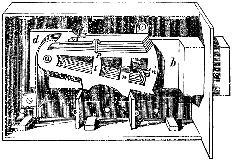
fig. 31. Chubb lock, with detector and six tumblers.
The construction and action of the Chubb lock may be further illustrated by means of an engraving, fig. 31, in which b is the bolt of the lock, with a stump riveted to it marked s. The six tumblers are shewn perspectively, the front or anterior one being marked t; they all move on the centre-pin a, but are nevertheless perfectly distinct and separate, to allow of being elevated to different heights. At d is shewn one end of a divided spring, the divisions being equal to the number of tumblers, one to each, and so bent that each spring may press upon its particular tumbler. At e is the detector-spring, so placed that a projecting piece in the hindmost tumbler shall be near it; this tumbler having also fixed into it a stud or pin p. This being the arrangement, especially in relation to the stump s and the tumblers, it follows that all the tumblers must be lifted to exact and regulated heights in order that the stump may pass through the longitudinal slits of the tumblers; unless it can do so, the bolt cannot be withdrawn. As there are gaps or notches in each tumbler both[57] above and below the proper line of passage, and as there are no ordinary means of ascertaining when any one tumbler is lifted too high or not high enough, the safety of the lock is greatly increased by this uncertainty; especially when it is considered that this uncertainty is multiplied sixfold by the different modes in which the six tumblers are slotted. If, through the insertion of a false key, or by any other cause, any one of the tumblers be raised above its proper position, the detector spring e will catch the hindmost tumbler, and retain it so as to prevent the bolt from passing; and thus, upon the next application of the true key, it will be instantly felt that some one of the tumblers has been overlifted, because the true key will not unlock it. To relieve the bolt from this temporary imprisonment, the key must be turned the reverse way, as for locking; all the tumblers will thus be brought to their proper position, and allow the stump to enter the notches n n´; the bevelled part of the bolt will then lift up the detector-spring, and allow the hindmost tumbler to fall down into its proper place; and all this being effected, the lock may be opened and shut in the ordinary way. The pin p is so adjusted that if any one of the tumblers—front, back, or intermediate—be lifted too high, the pin will be lifted with it, and will catch into the detector-spring, thus producing the result just described.
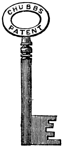
fig. 32.
Key to Chubb’s lock.
The key is represented in fig. 32. It has six steps, besides a terminal step to act upon the bolt. The height of each step, or the distance to which it extends from the pipe of the key, depends of course on the height to which its corresponding tumbler is to be lifted; and it matters not whether the steps of the key are adjusted to the slots of the tumblers, or the slots to the steps, provided the agreement be brought about. It is simply a matter of manufacturing convenience that the key-steps are cut first and the tumbler-slots afterwards.[58] We may here remark that bit, or bitt, is the name given, somewhat indefinitely, either to the whole flat part of a key, or to the small stepped portions of it. The flat part was formerly termed the web of the key, probably from the webbed appearance of the keys to complex warded locks.
After the reading of Mr. Chubb’s paper before the Institution of Civil Engineers, Mr. Owen narrated one or two circumstances connected with the early history of Chubb’s lock. A convict on board one of the prison-ships at Portsmouth dockyard, who was by profession a lock-maker, and who had been employed in London in making and repairing locks for several years, and subsequently had been notorious for picking locks, asserted that he had picked with ease one of the best of Bramah’s locks, and that he could pick Chubb’s locks with equal facility. One of the latter was secured by the seals of the late Sir George Grey, the Commissioner, and some of the principal officers of the dockyard, and given to the convict, together with files and all the tools which he stated were necessary for preparing false instruments for the purpose, as also blank keys to fit the pin of the lock. A lock exactly the same in principle was placed in his hands, that he might examine it and make himself master of its construction. If he succeeded in opening the lock, he was to receive a free pardon from the Government, and a reward of 100l. from Messrs. Chubb. After trying for two or three months to pick the sealed lock—during which time, by his repeated efforts, he frequently over-lifted the detector, which was as often re-adjusted for his subsequent trials—he gave up the attempt. He stated that Chubb’s were the most secure locks he had ever met with, and that it was impossible for any man to pick or to open them with false instruments.
Mr. Owen further stated, that in order to compare the merits of Bramah’s and Chubb’s locks, he had suggested a mechanical contrivance, which was applied to one of Bramah’s six-spring padlocks belonging to the Excise. It was hung[59] upon a nail, in a vertical position, secure from lateral oscillation. A self-acting apparatus was then applied, consisting of a pipe with hexagonal grooves, and a stud or bit corresponding with the division of the lock, and secured to it by a spring. In the grooves of this pipe small slides were inserted, which pressed against the spring keys of the lock; to these slides were attached levers, acted upon by eccentrics, moved by a combination of wheels, whose teeth differed in number so as to perform the permutation required for the different depths of the spring keys, corresponding with those of the proper key to the lock. The automaton machine was set in motion by a line working over a barrel, and acted upon by a weight; and was thus left acting upon the mechanism for a considerable time. At right angles to the pipe or false key was attached a rod and weight; and when the notches in the spring keys were brought in a line with the plane of the plate or diaphragm of the lock, the rod and weight turned the false key, opened the lock, and stopped the further motion of the automaton. In that state the slides indicated the exact depth of the grooves in the proper key, and gave the form of a matrix by which to make a key similar to the original one. The automaton worked during a period varying from half an hour to three hours, according to the state of permutation of the apparatus at the moment of being applied, compared with that of the slides in the lock. We confess that it is difficult to understand the action of this automaton from Mr. Owen’s description. We imagine that the false notches would effectually prevent the operation of the instrument, and openings would be required on each slide to bring it back, so as to meet the motions of the machine.
Mr. Owen did not state whether his apparatus had been successful with one only of Bramah’s locks or with several; nor did he describe any apparatus invented with the view to the picking of Chubb’s locks. He stated, however, that in order to ascertain the effect of friction on one of these last-named locks, it was subjected to the alternate rectilinear motion of a steam-engine in Portsmouth dockyard, and was locked[60] and unlocked upwards of 460,000 times consecutively, without any appreciable wear being indicated by a gauge applied to the levers and the key, both before and after this alternate action. Mr. Owen concluded by expressing his individual opinion that Chubb’s lock had never been picked. “The detector was the main feature of its excellence; and additional precaution, therefore, was only departing from its simplicity, and adding to the expense, without any commensurate advantage.”
In a subsequent chapter the degree of security afforded by various descriptions of locks, and the obstacles which they present of being picked, will come under notice; we therefore now proceed to describe briefly a few other tumbler-locks, or application of the tumbler-principle.
In Mr. Somerford’s lock, for which the Society of Arts gave a premium in 1818, an attempt was made to improve upon the ordinary action of tumblers. In most such locks, all the tumblers must ascend, although to different heights, before the stud of the bolt can pass through the slots; “which arrangement,” says Mr. Somerford, “gives an opportunity of introducing a nail, or a piece of stout wire, into the lock, and thus raising the tumblers without the necessity of using the key.” In his new lock, however, he made one lever to ascend while the other descended, by a somewhat complicated arrangement of slotted plates above and below the bolt. The key was so perforated as to be much endangered in respect to strength.
In Davis’s lock there is a double chamber with wards on the side of the key-hole. The key is inserted into the first chamber and turned a quarter round; it is then pushed forward into the inner chamber, where there is a rotating plate containing a series of small pins or studs, which are laid hold of by the key. By turning the key, the plate is moved round, the tumbler is raised, and the bolt is shot backwards and forwards. This lock, which is somewhat expensive, is used to some extent on Cabinet despatch-boxes.
The lock invented by Mr. Nettlefold is so constructed,[61] that when the bolt is shot out by the key, two teeth or quadrants are projected from the sides of the bolt, which take a firm hold of the plate fixed on the door-post or edge. This construction is said to answer well for sliding-doors.
Mr. Alfred Ainger, in 1820, received a silver medal from the Society of Arts for a draw-back spring latch, in which the objects proposed were the two following—to render the lock more difficult of violation by a pick than those ordinarily in use; and to apply to it a key of which no ordinary person could take an impress, and which would be difficult of access even in a workman’s hand. The key is very peculiar; its pipe consists of three divisions, the section of the upper and lower divisions being circular, and that of the middle division triangular; the triangular portion is intended to give motion to some part of the interior of the lock during the rotation of the key. There are collars fixed on the extremity of the key, to act each on one tumbler; and there are modes, by varying the arrangement of these collars on an octagonal stem, to give something like a permutation to the number of variations to which the action of the key may be subject. The notches or slots are rather in the bolt than in the tumblers; and there are many peculiarities in the general arrangement.
In a lock invented and patented by Mr. Parsons, the tumblers are of a particular form, being hinged on a pivot at their centres, and working into and out of two notches cut in the under side of the bolt. It must be obvious that many variations in the adjustment of the tumblers of locks might be made, without vitiating the principle on which the action depends.
Many inventors have tried the use of an expanding web to the key, so planned that if the step of the web be long enough to reach the tumbler, it would be too long to pass through the key-hole; and therefore a principle of safety would operate by enabling the key to adjust itself at one moment to the size of the key-hole, and at another to the height of the tumbler. Mr. Machin of Wolverhampton invented such a key in 1827. The web of the key is movable on a countersunk[62] pin, on which it can so far slide as to be drawn one-eighth of an inch from the barrel. The key-hole is of such a size as to admit the key only when the web is pressed close up to the barrel. When the key in this state is introduced, and is begun to be turned round, one of the notches in the web works into a raised circular edge of steel, placed eccentrically with regard to the lock-pin; so that as the key is turned, the web becomes drawn out, and is at its greatest elongation when it arrives at the tumblers: in the second half of its circular movement, the key becomes contracted to its original dimensions, and can then be removed from the lock.
Another mode of modifying the key has been introduced by Mr. Mackinnon, the object being to enable any person to change at will the pattern or arrangement of the movable parts of a lock and key; or to keep the key, when not actually in use, in such a state as to render it unavailing to any one but himself. It was a complex arrangement, which does not seem to have come much into use.
The lock invented by Mr. Williams, in 1839, may be designated a pin-lock, involving a principle analogous in many points to that of the Egyptian lock. This lock has a series of pins which reach through the cap, and are pressed to their places with a key like a comb or a rake-head. On the inner end of each pin is a flat piece of steel, in which is cut a notch for the passage of the bolt; but this passage is not clear until the notches in all the pieces of steel are in a right line. The pins are movable, and can be pushed either too far or not far enough to bring about the coincidence of position in the notches; and on this ground they are “double-acting.” Now the teeth of the key are of irregular lengths, each having a length just suited for pushing the pin to the proper depth: any other lengths of teeth would fail to open the lock. There is a mechanism of springs and levers to shoot the bolt when the pins in the plate are rightly adjusted. The arrangements in respect to the key are singular and somewhat awkward. The teeth which lock the bolt are not the same as those[63] which unlock it, the user having to change ends and adjust the bit to a socket-handle. This is one among many examples in which a lock embodies several principles, the inventor having set himself the task of combining the excellences of many diverse locks.
In respect to the tumbler-locks generally, the simplicity of action, the strength of construction, and the non-liability of disarrangement, have given them a high place among safety-locks. The only danger seemed to be, that any person once obtaining possession of the key could take an impression from it, and thence form a key which would command the lock. Attempts have been occasionally made to obviate this danger, by supplying the key with movable bits which could be changed at pleasure, so as to constitute any number of effectively different bits in succession. But the locks being so constructed that the bolt could only be moved when the tumblers were in a certain position, the owner was placed in this predicament: that it was useless to alter the arrangement of the bits in the key, unless the tumblers were altered in a corresponding manner; and this would entail the removal of the lock from the door, and the re-arrangement of the interior mechanism.
One of the great defects of tumbler-locks made previously to the last ten years was, that the tumblers, when lying at rest in the lock, presented at their bellies or lower edges precisely the same arrangement as the steps of the key. Indeed, in many locks of the present day, a good idea of the form of the key may be gained by feeling the bellies of the tumblers. The bellies are in fact cut out so as to compensate for the circular motion of the key, to allow them to remain at rest while the stump is passing through the gating. Even in tumbler-locks of the best construction the tumblers will vibrate more or less during the motion of the key; a defect which must be provided against in adjusting the lock, or the stump will be caught in its passage through the gating. Mr. Hobbs provides a simple remedy by enlarging the back part of the[64] gating, the effect of which is as follows: when, in shooting back the bolt, as in unlocking, the key has got to its highest point, the stump enters the narrow end of the gating; but in shooting the bolt forward, as in locking, the stump enters the gating before the key has got to its highest point, and to allow for the slight vibratory motion of the tumblers during the passage of the stump, the gating is widened. The usual method of adjustment is to alter the forms of the bellies of the tumblers, thus greatly risking the security of the lock, a defect which was clearly perceived by Bramah [see pp. 67-70], and was one of the reasons which induced him to construct locks with slides instead of tumblers.
American locks on the tumbler-principle, and the relation which all such locks bear to the Bramah lock, will be better understood after the details of the following chapter.
The lock which was invented by the late Mr. Bramah deservedly occupies a high place among this class of contrivances. It differs very materially from all which has gone before it; its mechanical construction is accurate and beautiful; its key is remarkable for smallness of size; and the invention was introduced by the publication of an essay containing much sensible observation on locks generally. The full title of this essay runs thus: “A dissertation on the Construction of Locks. Containing, first, reasons and observations, demonstrating all locks which depend upon fixed wards to be erroneous in principle, and defective in point of security. Secondly, a specification of a lock, constructed on a new and infallible principle, which, possessing all the properties essential to security, will[65] prevent the most ruinous consequences of house-robberies, and be a certain protection against thieves of all descriptions.” A second edition of this Dissertation was published in 1815; but the work is now extremely scarce, and hardly attainable.
It is remarkable to observe the boldness and self-relying confidence with which Mr. Bramah, some sixty years ago, declared that all locks were, up to that time, violable; he felt that this was strictly true, and he hesitated not to give expression to his conviction. The following is from his Dissertation:—
“It is observable that those who are taken in the desperate occupation of house-breaking are always furnished with a number and variety of keys or other instruments adapted to the purpose of picking or opening locks; and it needs no argument to prove that these implements must be essential to the execution of their intentions. For unless they can secure access to the portable and most valuable part of the effects, which in most families are deposited under the imaginary security of locks, the plunder would seldom recompense the difficulty and hazard of the enterprise; and till some method of security be adopted by which such keys and instruments may be rendered useless, no effectual check or opposition can be given to the excessive and alarming practice of house-breaking.
“Being confident that I have contrived a security which no instrument but its proper key can reach; and which may be so applied as not only to defy the art and ingenuity of the most skilful workman, but to render the utmost force ineffectual, and thereby to secure what is most valued as well from dishonest servants as from the midnight ruffian, I think myself at liberty to declare (what nothing but the discovery of an infallible remedy would justify my disclosing), that all dependence on the inviolable security of locks, even of those which are constructed on the best principle of any in general use, is fallacious. To demonstrate this bold and alarming proposition, I shall first state the common principles[66] which are applied in the art of lock-making; and by describing their operation in instruments differently constructed, prove to my intelligent readers that the best-constructed locks are liable to be secretly opened with great facility; and that the locks in common use are calculated only to induce a false confidence in their effect, and to throw temptation to dishonesty in the way of those who are acquainted with their imperfections, and know their inefficacy to the purpose of security” (p. 5).
Tumblers had been so little thought of and used at the time Bramah wrote, that his attention was almost exclusively directed to warded locks. The mysterious clefts in a key, connected with some kind of secret mechanism in the lock, had given the warded locks a great hold on the public mind, as models of puzzlement and security; and it was to shew that this confidence rested on a false basis, that he to a great extent laboured. The following is his exposition of the principle and the defects of the warded lock.
“Locks have been constructed, and are at present much used and held in great esteem, from which the picklock is effectually excluded; but the admission of false keys is an imperfection for which no locksmith has ever found a corrective; nor can this imperfection be remedied whilst the protection of the bolt is wholly confided to fixed wards. For if a lock of any given size be furnished with wards in as curious and complete a manner as it can be, those wards being necessarily expressed on what is termed by locksmiths the bit or web of the key, do not admit of a greater number of variations than can be expressed on that bit or web; when, therefore, as many locks have been completed of the given size as will include all the variations which the surface of the bit will contain, every future lock must be the counterpart of some former one, and the same key which opens the one will of course unlock the other. It hence follows that every lock which shall be fabricated on this given scale, beyond the number at which the capability of variation ends, must be as subject to[67] the key of some other lock as to its own; and both become less secure as their counterparts become more numerous. This objection is confirmed by a reference to the locks commonly fixed on drawers and bureaus, in which the variations are few, and these so frequently repeated, from the infinite demand for such locks, that, even if it were formed to resist the picklock, they would be liable to be opened by ten thousand correspondent keys. And the same observation applies in a greater or less degree to every lock in which the variations are not endless.
“But if the variation of locks in which the bolt is guarded only by fixed wards could be multiplied to infinity, they would afford no security against the efforts of an ingenious locksmith; for though an artful and judicious arrangement of the wards, or other impediments, may render the passage to the bolt so intricate and perplexed as to exclude every instrument but its proper key, a skilful workman having access to the entrance will be at no loss to fabricate a key which shall tally as perfectly with the wards as if the lock had been open to his inspection. And this operation may not only be performed to the highest degree of certainty and exactness, but is conducted likewise with the utmost ease. For the block or bit, which is intended to receive the impression of the wards, being fitted to the keyhole, and the shank of the key bored to a sufficient depth to receive the pipe, nothing remains but to cover the bit with a preparation which, by a gentle pressure against the introductory ward, may receive its impression, and thus furnish a certain direction for the application of the file. The block or bit being thus prepared with a tally to the first ward, gains admission to the second; and a repetition of the means by which the first impression was obtained, enables the workman to proceed, till by the dexterous use of his file he has effected a free passage to the bolt. And in this operation he is directed by an infallible guide; for, the pipe being a fixed centre on which the key revolves without any variation, and the wards being fixed likewise, their position must be accurately[68] described on the surface of the bit which is prepared to receive their impression. The key therefore may be formed and perfectly fitted to the lock without any extraordinary degree of genius or mechanical skill. It is from hence evident that endless variations in the disposition of fixed wards are not alone sufficient to the purpose of perfect security. I do not mean to subtract from the merit of such inventions, nor to dispute their utility or importance. Every approach towards perfection in the art of lock-making may be productive of much good, and is at least deserving of commendation; for if no higher benefit were to result from it, than the rendering difficult or impossible to many that which is still practicable and easy to a few, it furnishes a material security against those from whom the greatest mischiefs and dangers are to be apprehended.”
There can be little doubt, in the present day, that Bramah did not over-rate the fallacies embodied in the system of wards for locks. He was sufficiently a machinist to detect the weak points in the ordinary locks; and, whatever may have been his over-estimate of his own lock (presently to be described), he was certainly guilty of no injustice to those who had preceded him; for their locks were substantially as he has described them. To understand the true bearings of his Dissertation too, we must remember that housebreaking had risen to a most daring height in London at the time he wrote (about the middle of the reign of George III.); and men’s minds were more than usually absorbed by considerations relating to their doors and locks.
Mr. Bramah, after doing due justice to the ingenuity of Barron’s lock, in which, if the tumbler be either over lifted or under lifted the lock cannot be opened, pointed out very clearly the defective principle which still governed the lock. “Greatly as the art is indebted to the ingenuity of Mr. Barron, he has not yet attained that point of excellence in the construction of his lock which is essential to perfect security. His improvement has greatly increased the difficulty but not precluded the[69] possibility of opening his lock by a key made and obtained as above described (by a wax impression on a blank key); for an impression of the tumblers may be taken by the same method, and the key be made to act upon them as accurately as it may be made to tally with the wards. Nor will the practicability of obtaining such a key be prevented, however complicated the principle or construction of the lock may be, whilst the disposition of its parts may be ascertained and their impression correctly taken from without. I apprehend the use of additional tumblers to have been applied by Mr. Barron as a remedy for this imperfection.” Mr. Bramah thought that Barron had a perception of a higher degree of security, but had failed to realise it; because, by giving a uniform motion to the tumblers, and presenting them with a face which tallies exactly with the key, they still partake in a very great degree of the nature of fixed wards, and the security of the lock is thereby rendered in a proportionate degree defective and liable to doubt.
To shew how this insecurity arises, Mr. Bramah illustrates the matter in the following way: “Suppose the key with which the workman is making his way to the bolt to have passed the wards, and to be in contact with the most prominent of the tumblers. The impression, which the slightest touch will leave on the key, will direct the application of the file till sufficient space is prepared to give it a free passage. This being accomplished, the key will of course bear upon the tumbler which is most remote; and being formed by this process to tally with the face which the tumblers present, will acquire as perfect a command of the lock as if it had been originally made for the purpose. And the key, being thus brought to a bearing on all the tumblers at once, the benefit arising from the increase of their number, if multiplied by fifty, must inevitably be lost; for, having but one motion, they act only with the effect of one instrument.”
It is worthy of notice, that even while thus shewing the weak points of the Barron lock, Mr. Bramah seems to have[70] had in his mind some conception of infallibility or inviolability attainable by the lock in question. After speaking of the defect arising from the bad arrangement of the tumblers, he says: “But nothing is more easy than to remove this objection, and to obtain perfect security from the application of Mr. Barron’s principle. If the tumblers, which project unequally and form a fixed tally to the key, were made to present a plane surface, it would require a separate and unequal motion to disengage them from the bolt; and consequently no impression could be obtained from without that would give any idea of their positions with respect to each other, or be of any use even to the most skilful and experienced workman in the formation of a false key. The correction of this defect would rescue the principle of Mr. Barron’s lock, as far as I am capable of judging, from every imputation of error or imperfection; and, as long as it could be kept unimpaired, would be a perfect security. But the tumblers, on which its security depends, being of slight substance, exposed to perpetual friction—as well from the application of the key as from their own proper motion—and their office being such as to render the most trifling loss of metal fatal to their operation, they would need a further exertion of Mr. Barron’s ingenuity to make them durable.”
It may perhaps be doubted whether the principle of Bramah’s lock is not more clearly shewn in the original constructed by him than in that of later date. In appearance it is totally different, but the same pervading principle is observable in both; and the cylinder lock can certainly be better understood when this original flat lock has been studied. The annexed woodcut is taken from the first and very scarce edition of Mr. Bramah’s Dissertation; the description is somewhat more condensed, but perhaps sufficient for the purpose.
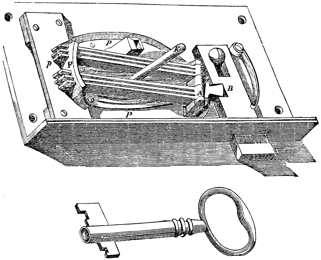
fig. 33. Bramah’s first model.
The lock is supposed to be lying flat, with the bolt B half-shot. Ranged somewhat diagonally are six levers, turning on a horizontal joint or pivot at A, each lever having a slight extent of vertical motion independent of the others. Each[71] lever rests on a separate spring of sufficient strength to sustain its weight, or, if depressed by a superior force, to restore it to its proper position when the force is withdrawn. F is a curved piece of metal, pierced with six grooves or passages; these grooves are exactly equal in width to the thickness of the levers, but are of sufficient depth to allow the levers a free motion in a perpendicular direction. The ends of the levers are inserted in these grooves, and have this freedom of motion, whether lifted by the elastic power of the springs or depressed by a weight from above. In the bolt B is a notch to receive a peculiarly-shaped lever, which shoots or withdraws the bolt according as it traverses to the right or the left. This lever, the six long levers, the springs beneath them, the bent piece F, and the pivot, all alike are fixed to a circular platform P, which turns on a centre; so that if any force can make this platform turn partially round, the bolt must be shot or unshot by the lever which works in the notch. The six long levers[72] are the contrivances whereby the platform shall not be allowed to turn until the proper moving agent (the key) shall have been applied, the plate p being one of the assistants in this obstruction. This plate, which is hollow underneath, has six notches in one of its edges; the points of the levers catch into these notches; and while so caught, the levers cannot move horizontally, and all the machinery is at a stand-still. To enable the key to set the mechanism in action, other contrivances are necessary. Each lever has a notch at its extreme end, and the six are notched very irregularly in respect one to another. These notches must be brought all into one plane, to enable the levers to pass horizontally out of the notches in the plate, in the same way as the two prongs of a fork might traverse one above and the other below the blade of a knife; and when the lever-notches are in this position, all in one plane and in the plane of the plate, the levers can be moved, and with it the stump which shoots the bolt. To ensure this due pressing down of the levers, a key is used such as is shewn in the cut, having six steps or bits to correspond with the six levers; this key, put upon the pin K, presses down all the levers to the exact distance necessary for bringing their notches into one plane, viz. the plane of the plate; the key then being turned round turns the movable platform P, and shoots the bolt. It is evident at a glance, that unless the various steps of the key are so cut, that each shall press down its own lever to the proper extent, the ends of the levers cannot pass the notches in the plate, and the bolt can neither be locked nor unlocked.
It may be well to give Bramah’s own words in relation to this lock: “I may safely assert that it is not in art to produce a key or other instrument by which a lock constructed on this principle can be opened. It will be a task, indeed, of great difficulty, even to a skilful workman, to fit a key to this species of lock, though its interior face were open to his inspection; for the levers being raised by the subjacent springs to an equal height present a plane surface, and consequently[73] convey no direction that can be of any use in forming a tally to the irregular surface which they present when acting in subjection to the proper key. Unless, therefore, a method be contrived to bring the notches on the ends of the levers in a direct line with each other, and to retain them in that position till an exact impression of the irregular surface which the levers will then exhibit can be taken, the workman will in vain attempt to fit a key to the lock, or by any effort of art to move the bolt. And when it is considered that this process will be greatly impeded, and may perhaps be entirely frustrated, by the action of the springs, it must appear that great patience and perseverance, as well as great ingenuity, will be required to give any chance of succeeding in the attempt. I do not state this circumstance as a point essential or of any importance to the purpose of the lock, but to prove more clearly what I have before observed upon its principle and properties; for if such difficulties occur to a skilled workman, as to render it almost, if not altogether impracticable to form a key when the lock is open to his inspection and its parts accessible to his hand, it pretty clearly demonstrates the impossibility of accomplishing it when no part of the movement can be touched or seen.”
It is evident that Mr. Bramah had his thoughts directed to that mode of picking locks which depends on taking impressions of the moving parts, rather than to the mechanical or pressure method which has been developed in later times. There can be little doubt that a lock was, to his mind, a beautiful and admirable machine, far elevated above the level of mere blacksmith’s work; and his name will ever be associated with what may be termed the philosophy of lock-making.
After the model-lock, which has just been described, was constructed, and found to corroborate the idea which was working in Mr. Bramah’s mind, he proceeded to the construction of his barrel or cylinder-lock, embracing similar elements placed in more convenient juxta-position. In his Essay he gives an engraving to illustrate the principle on which his lock[74] acts, rather in the manner of a diagram than as depicting any lock actually made; his main object being to impart a clear notion of the action of the slides which form such a distinguishing feature in his lock.
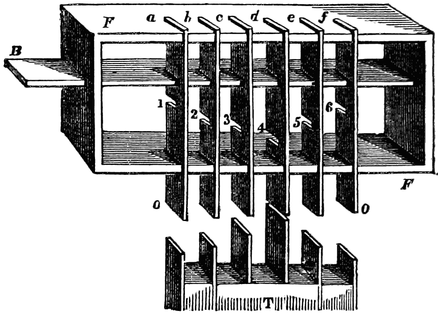
fig. 34. Diagram to illustrate the Bramah lock.
Viewed in this sense, therefore, simply as an illustrative diagram, the annexed cut may represent the action of the safety slides. B is a sliding bar or bolt, having a power of longitudinal motion in the frame F. This frame has six notches cut on each of its long sides, the two series being exactly opposite each other; and there are six similar notches cut in the bolt B. The concurrent effect of all these eighteen notches is, that the six slides a b c d e f can move freely up and down across the bolt. When the slides are thus placed, the bolt cannot move, and may in this case be considered to be locked. There are six clefts or notches in the six slides, one to each (1, 2, 3, 4, 5, 6); and until all these are brought in a right line, the bolt cannot move through them. If a tally or key be prepared, as shewn at T in the lower part of the cut, with six projections, and if these projections thrust up the six slides till their clefts rise to the plane of the bolt, then can the bolt be withdrawn or the lock opened. This serves to illustrate the relation between the slides and the key, as carried out in the way now to be described.
One peculiarity of the Bramah lock is, that from the[75] essential part of the apparatus being a barrel or cylinder, much of the working can be conducted in the lathe; and this has given a beauty to the details generally and deservedly admired. Mr. Bramah, when he worked out the theory of his lock, resolved to discard altogether the use of fixed wards, and also the use of tumblers working on a pivot at one end; substituting in their stead a system of slides, working in a very novel way. The body of a Bramah lock may be considered as formed of two concentric brass barrels, the outer one fixed, and the inner rotating within it. The inner barrel has a projecting stud, which, while the barrel is rotating, comes in contact with the bolt in such a way as to shoot or lock it; and thus the stud serves the same purpose as the bit of an ordinary key, rendering the construction of a bit to the Bramah key unnecessary. If the barrel can be made to rotate to the right or left, the bolt can be locked or unlocked; and the problem is, therefore, how to ensure the rotation of the barrel. The key, which has a pipe or hollow shaft, is inserted in the keyhole upon the pin, and is then turned round; but there must be a very nice adjustment of the mechanism of the barrel before this turning round of the key and the barrel can be ensured. The barrel has an external circular groove at right angles to the axis, penetrating to a certain depth; and it has also several internal longitudinal grooves, from end to end. In these internal grooves thin pieces of steel are able to slide, in a direction parallel with the axis of the barrel. A thin plate of steel, called the locking-plate, is screwed in two portions to the outer barrel, concentric with the inner barrel; and at the same time occupying the external circular groove of the inner barrel; this plate has notches, fitted in number and size to receive the edges of the slides which work in the internal longitudinal grooves of the barrel. If this were all, the barrel could not revolve, because the slides are catching in the grooves of the locking-plate; but each slide has also a groove, corresponding in depth to the extent of this entanglement; and if this groove be brought to the plane of the locking-plate,[76] the barrel can be turned, so far as respects that individual slide. All the slides must, however, be so adjusted that their grooves shall come to the same plane; but as the notch is cut at different points in the lengths of the several slides, the slides have to be pushed in to different distances in the barrel, in order that this juxta-position of notches may be ensured. This is effected by the key, which has notches or clefts at the end of the pipe equal in number to the slides, and made to fit the ends of the slides when the key is inserted; the key presses each slide, and pushes it so far as the depth of its cleft will permit; and all these depths are such that all the slides are pushed to the exact position where their notches all lie in the same plane; this is the plane of the locking-plate, and the barrel can be then turned.
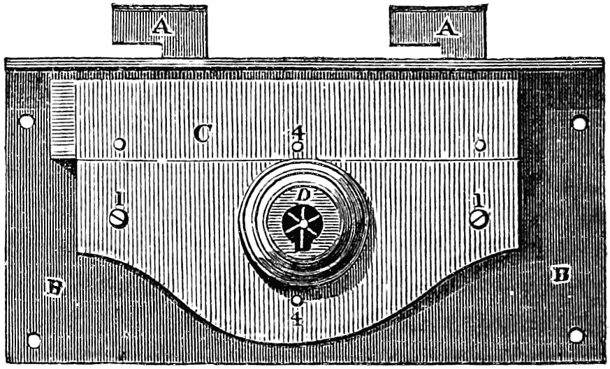
fig. 35. Exterior of a Bramah lock.
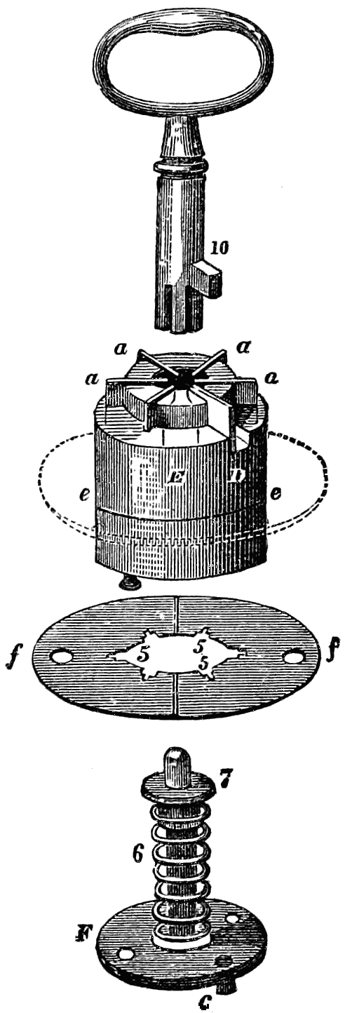
fig. 36. Details of the Bramah lock.
This is the principle which Mr. Bramah adopted; and we have now to trace it, step by step, by means of illustrative details. Fig. 35 represents the exterior of a box or desk lock, one among many varieties which the Bramah lock presents. A A shews the bolt, formed something like two hooks rising out of a bar of metal, which bar has a backward and forward motion upon the plate B B. The upper edge of this plate is turned over at right angles, forming a small horizontal surface through which two openings are cut to receive the two hooked portions of the bolt. The movements of the bolt are otherwise guided by the edges of square holes through which it works;[77] the holes being made in the edge-pieces of the lock, riveted to the main plate. The bolt is further prevented from rising out of its place by means of a plate of metal C, which is secured to the edge-pieces by two screws 1, 1, and by two steadying pieces. This plate has on its surface a cylindrical projection D, which contains in effect all the working mechanism of the lock. The pins 4 4 are employed for securing a plate, which we shall have to describe presently. When such a lock is fixed upon a desk or box, the portion D projects to a small distance through a hole in the wood-work, forming in itself a very neat escutcheon, with a key-hole in the centre.
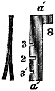
fig. 37. The slides.
So much for the exterior. We must now proceed to examine the interior of the lock, especially the part contained within the cylinder. In fig. 36, for convenience of arrangement, the several parts are exhibited separately, and as if the plane of the lock were horizontal, with the key acting vertically. The essential part of the mechanism is a barrel or cylinder E, pierced or bored with a cylindrical hole down its centre. The inside of the bore has six narrow grooves, cut parallel with the axis, and in the direction of radii; the grooves are not cut through the thickness of the cylinder, but leave sufficient substance of metal for strength. In every groove is fitted a steel slide of peculiar form, such as is shewn at a´ a´ in fig. 37. Each slide is split in its thickness (seen in section), so that it may move up and down in its groove with a slight friction, and[78] thereby not fall simply by its own weight. Each slide has three small notches (3, 2, 3´), the use of which will presently appear. Reverting to fig. 36, the lower part of the opening through the cylinder E is closed by a circular plate of metal, fixed to it by two screws; this plate is represented at F, in the lower part of the figure. This plate has a vertical pin rising from its centre (also seen at b, fig. 39), and serving as a key-pin on which the pipe of the key may work or slide; and it has also a short circular stud c projecting from its under side, and fitted to enter into a curved opening in the bolt presently to be described.
The point to be now borne in mind is this, that if the cylinder E turns round, the plate F will also turn round, and with it the stud c; and as this stud works into the peculiarly formed cavity d in a portion of the bolt (fig. 38), it causes the bolt to be shot backwards or forwards. Now, in order to prevent this rotating of the cylinder unless the proper key be employed, the following mechanism is introduced: the cylinder has a groove cut round its circumference at e e, extending sufficiently near to the internal bore to produce the desired effect without too much weakening the metal. Into this notch is introduced the thin circular plate of metal f f, it being divided into two halves for this purpose; and when so placed, it occupies the position shewn by the dotted portion e e. When this plate is screwed to the case of the lock by the screws 4, 4, it cannot of course turn round; but the cylinder itself will or will not[79] turn round according to the position of the slides. The plate f f has six notches, 5, 5, 5, &c. in the inner edge or circle; so adjusted that, when the plate is in its place, the slides a a can move up and down. The cylinder cannot move round in a circle without carrying the slides with it; and these cannot so move unless they are all depressed to such exact distances in their respective grooves, that the deep notch of each slider (shewn at 2 in fig. 37) shall come into the plane of the circular plate: when all are so brought, the cylinder can be turned. If any one of the slides be pressed down either too low or not low enough, this turning of the cylinder cannot be effected, because the slides will be intersected by the edges of the notches 5, 5; and it is the office of the key, therefore, to press all the six slides down to the exact distances required. When the slides are not pressed upon by the key, they are forced upwards to the top of the cylinder by a spiral spring 6, coiled loosely round the pin b; this pressure forces up a small collet, 7, on which the upper part of the slides rest by a sort of step.
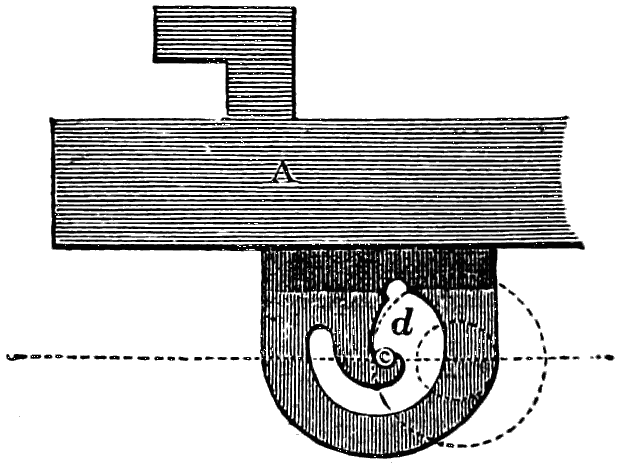
fig. 38. The bolt.
The first locks were made with a separate and independent spring to each slide; but it is a very great improvement, the introduction of one common spring to raise up the whole number; because if a person attempts to pick the lock by depressing the slides separately by means of any small pointed instruments, and by chance brings two or more of them to the proper depth for turning round, should he press any one too low, it is difficult to raise it again without relieving the spring 6, which immediately throws the whole number of slides up to the top, and destroys all that had been done towards picking the lock. Another improvement of this lock, and one which very much increased the difficulty of picking, and its consequent security, was the introduction of false and deceptive notches cut in the sliders, as seen at 3, 3. It was found that in the attempt to pick this lock, an instrument was introduced by the keyhole to force the cylinder round. At the same time that the slides were depressed by separate instruments, those slides which were not at the proper level[80] for moving round were held fast by the notches 5, 5 in the plate f f bearing against their sides; but when pressed down to the proper level, or till the notch 2 came opposite f f, they were not held fast, but were relieved. This furnished the depredator with the means of ascertaining which slides were pressed low enough, or to the point for unlocking. The notches 3, 3 in the slides are sometimes cut above the true notch 2, sometimes below, and at other times one on each side (one above and one below); they are not of sufficient depth to allow the cylinder to turn round, but are intended to mislead any one who attempts to pick, by his not knowing whether it is the true notch or otherwise, or even whether the slider be higher or lower than the true notch.
We have not yet sufficiently described the key of the Bramah lock. One merit of the lock is the remarkable smallness of the key, which renders it so conveniently portable. The key, as shewn in the upper part of the figure, has six notches or clefts at the end of its pipe or barrel; these clefts are cut to different depths, to accord with the proper extent of movement in the slides. There is a small projection, 10, near the end of the pipe, fitted to enter the notch D in the cylinder; this forces the cylinder round when the parts are all properly adjusted. The bolt of the lock, when properly shot or locked, is prevented from being forced back by the stud c on the bottom, F, of the cylinder coming into a direct line with its centre of motion, as shewn in fig. 39; in this position no force, applied to drive the bolt back, would have any tendency to turn the cylinder round.
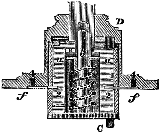
fig. 39. Section of the Bramah cylinder.
To facilitate the comprehension of this very curious and beautiful mechanism, the cylinder is shewn in section in the annexed fig. 39, the same letters and figures of reference being used as before. In the whole of this description we have spoken of six slides, and six only; but Bramah locks may be, and have been, constructed with a much larger number.
There have been several attempts made to modify the action of Bramah’s lock, or to combine this action with that of[81] some other inventor. It will suffice to describe one of these. The lock invented by Mr. Kemp of Cork, and for which a patent was obtained in 1816, is called by him the Union lock, as combining the principles of Barron’s and Bramah’s locks. It contains two, three, or more sliders or tumblers, operated upon by two, three, or more concentric tubes. These concentric tubes are of different lengths, and are placed inside the barrel of the key; so that the barrel may, in fact, be conceived to consist of a series of concentric tubes. These tubes are made of such respective lengths as to push back the tumblers, sliders, or pins which detain the bolt; and this to the precise extent that will bring certain notches in all the sliders to the position which will allow the bolt to pass. The inventor gives this lock its distinctive appellation because it combines something of the pushing motion which Bramah gives to his key, with something of the tumbler-motion observable in Barron’s locks. The principle of safety is considered here to rest chiefly on the extreme difficulty of imitating the key.
Mr. Bramah calculates the number of changes of position which the slides of his lock are capable of assuming before the right one would be attained. “Let us suppose the number of levers, slides, or other movables by which the lock is kept shut, to consist of twelve, all of which must receive a different and distinct change in their position or situation by the application of the key, and each of them likewise capable of receiving more or less than its due, either of which would be sufficient[82] to prevent the intended effect. It remains, therefore, to estimate the number producible, which maybe thus attempted. Let the denomination of these slides be represented by twelve arithmetical progressionals; we find that the ultimate number of changes that may be made in their place or situation is 479,001,600; and by adding one more to that number of slides, they would then be capable of receiving a number of changes equal to 6,227,020,800; and so on progressively, by the addition of others in like manner to infinity. From this it appears that one lock, consisting of thirteen of the above-mentioned sliders, may (by changing their places only, without any difference in motion or size,) be made to require the said immense number of keys, by which the lock could only be opened under all its variations.”
The lock-manufacture in America has undergone some such changes as in England. The insufficiency of wards to the attainment of security has been for many years known; and the unfitness of even tumblers to attain this end, without auxiliary contrivances, has been fully recognised for a dozen years back. In this, and in other mechanical arts, the American machinists depended primarily on the invention of the artisans in the mother country, rather than on those of any continental European state. But the development of the art in the United States has not been wanting in originality; the varieties of locks have been very numerous, and many of them exceedingly ingenious. It is not necessary, however, to describe or depict any of those of simple form. The warded locks of different countries very much resemble each other; the intricate warded[83] locks made in France in the last century have long fallen into disuse, in consequence of the general conviction that no arrangement of wards, however intricate, can afford the degree of security required in a good lock. It will be more to the purpose, therefore, to proceed at once to a notice of those American locks which, during the last few years, have acquired some celebrity; first, however, noticing one of older date.
Stansbury’s lock, invented in the United States about forty years ago, may be regarded as a modification of the Egyptian lock. It had a bolt, case, and key-hole somewhat similar to those of modern locks; but there were peculiarities of construction in other respects. There was a revolving plate, pierced with a series of holes, and having a bit or pin which moved the bolt. On the lock-case were a series of springs, each having a pin at one end; and the arrangement was such that, when the bolt was locked or unlocked, each pin would be pressed into some one of the holes. Like as in the Egyptian lock (figs. 1 to 4), each pin had to be pushed out, and all of them simultaneously, to allow the plate to turn and move the bolt. The key was made with a barrel and bit; and on the front end of the bit was a series of pins corresponding in position with the holes in the plate. The mode of locking or unlocking was as follows: the key was inserted in the key-hole, and turned to a certain position; it was then pressed in with some force, until the pins on the key met those in the plate; when the latter, yielding to the pressure, left the plate free to turn and move the bolt. Modifications of the Egyptian lock, more or less resembling this, have been brought out in some variety on both sides of the Atlantic; but scarcely any have equalled in simplicity the curious wooden relic of by-gone ingenuity in the art of lock-making.
A lock made a few years ago by Mr. Yale, in the United States, somewhat resembles the Bramah lock in having a cylinder or barrel, or rather two concentric cylinders, one working within the other. These cylinders are held together by pins which pass through them both into the key-hole. On the back[84] of the inner cylinder is a pin that fits into a slot in the bolt, and moves it whenever the cylinder is turned. The pins that hold the cylinders together are each cut in two; the pieces of the various pins differing in lengths as irregularly as possible. The key is so peculiarly formed, that, on inserting it in the key-hole, it thrusts the pins radially outwards; each pin being pushed just so far that the joint of the pin shall coincide with the joint between the two cylinders. The inner cylinder can then be turned, by which the bolt is locked or unlocked. If, by the use of a false key, any pin be pushed in too far, it will be as ineffectual in opening the lock as if it were not thrust in far enough; and some of these locks having been made with as many as forty pins, the chances are very numerous against the right combination being hit upon. There is a combination of something like the Egyptian with something like the Bramah lock, here attempted.
One of the principal constructions adopted in America a few years back for bank-locks is that of Dr. Andrews of Perth Amboy, in New Jersey. It was up to that time (1841) believed that the best locks, both of England and America, were proof against any attempts at picking derived from knowledge obtained by inspection through the key-hole; but there still remained the danger that the sight of the true key, or the possession thereof, for only a few minutes, would enable a dishonest person to produce a duplicate. It was to contend against this difficulty that Dr. Andrews directed his attention; and he sought to obtain the desired object by constructing a lock, the interior mechanism of which could be changed at pleasure. The lock of his invention is furnished with a series of tumblers and a detector. The tumblers are susceptible of being arranged in any desired order; and the key has movable bits which can be arranged so as to correspond with the tumblers. When the lock is fixed in its place, no change can be made in the tumblers, and consequently only one arrangement of the bits of the key will suit for the shooting and withdrawing of the bolt. The owner can, however, before the fixing of the bolt, adopt[85] any arrangement of tumblers and bits which he may choose. But though the tumblers cannot be actually re-arranged in any new order within the lock while the latter is fixed, yet by an ingenious contrivance the tumblers can be so acted upon as to render the lock practically different from its former self. The purchaser receives with his lock a series of small steel rings, each ring corresponds in thickness with the thickness of some one of the bits of the key; so that, by suitable adjustment, any one of the bits may be removed from the key, and a ring be substituted in its place. The effect of this substitution is, that the particular tumbler which corresponds with the ring is not raised by it; it is drawn out with the bolt, as if it were part of the bolt itself. Supposing the lock to be locked by this means, the original key would not now unlock it; for one of the tumblers has now been displaced, and can only be re-adjusted by the same ring which displaced it. If an attempt be made to open the lock by the original key, or by the key in its original adjustment, a detector is set in action, which indicates that a false key or other instrument has been put into the lock. One, or more than one, of the bits may be removed from the key, and rings be substituted, and consequently one or more of the tumblers may be disturbed in this peculiar way; so that the lock may change its character in all those permutating varieties which are so observable in most “safety-locks.” The shape of the tumblers is, of course, such as to facilitate this action; they have each an elongated slot, and also two notches; when a tumbler is raised by one of the bits of the key, one of the notches closes around a stump fitted into the case of the lock, and prevents the tumbler from being moved onward with the bolt; but when a ring has been substituted for a bit on the key, the tumbler cannot be raised at all; it is carried onward by a stump on the bolt.
Dr. Andrews is also the inventor of a lock which he terms the snail-wheel lock. In this lock a series of revolving discs, or wheels, taking the place of the tumblers, are mounted on a central pin, on which the pipe of the key is inserted. Each[86] disc has a piece cut out of it, into which the bit of the key enters, and in turning round moves the discs according to the various lengths of the steps on the key. On the outer edge of each disc is a notch, and by the turning of the key all these notches are brought into a line, so that a moveable tongue, or toggle, attached to the bolt, falls into the notches; the key is then turned the reverse way, by which means the bolt is projected.
About the time when Dr. Andrews invented his first lock, Mr. Newell, of the firm of Day and Newell of New York, constructed a lock which possessed the same distinctive peculiarity as that of Andrews, viz. that the key might be altered any number of times without rendering it necessary to remove the lock or change its internal mechanism. This was brought about, however, in a different manner. Instead of having, as in the Andrews lock, a two-fold movement to every tumbler, Mr. Newell employed two sets of tumblers, the one set to receive motion from the other, and having different offices to fill, to be acted upon by the key in respect to the first series, and to act upon the bolt in respect to the second. Calling these two sets primary and secondary, the action of the lock may be briefly described as follows. A primary tumbler being raised to the proper height by the proper bit in the key, raises the corresponding secondary tumbler; the secondary tumbler is held up in a given position during the locking, while the primary becomes pressed by a spring into its original position. It results from this arrangement that the bolt cannot be unlocked until the primary tumbler has been raised to the same height as before, so as to receive the tongue of the secondary tumbler. And as this is the case in respect to any one primary and its accompanying secondary tumblers, so is it the case whether each set comprises four, five, or any other number. The key may be altered at pleasure, and will in any form equally well shoot the bolt; but the lock can only be unfastened by that arrangement of key which fastened it.
It is, however, desirable to trace the course of improvements[87] more in detail, because every successive change illustrates one or other of the several properties required in a good lock. Messrs. Day and Newell’s lock was not finally brought to an efficient form without many attempts more or less abortive. Mr. Newell conceived the idea of applying a second series of tumblers, so placed as to be acted on by the first series. Each of these secondary tumblers had an elongated slot, such that a screw could pass through all of them; the screw having a clamp to overlap the tumblers on the inside of the lock. The head of the screw rested in a small round hole on the back of the lock, so placed as to form a secondary key-hole, to which a small key was fitted. There was thus a double system of locking, effected in the following way: when the large key had been applied, and had begun to act on the primary tumblers, the small key was used to operate on the clamp-screw, and thus bind all of the secondary tumblers together, ensuring their position at the exact heights or distances to which the primary key had caused them to be lifted. The bolt was then free to be shot, and the first series of tumblers reverted to their original position.
But such an arrangement has obvious inconveniences. Few persons would incur the trouble of using two keys; and besides this, there were not wanting certain defects in the action and reaction of the several parts; for if the clamp-screw were to be left unreleased, the first series of tumblers would be upheld by the second series in such a way that the exact impression of the lengths of the several bits of the key could be obtained through the key-hole while the lock was unlocked or the bolt unshot. To remedy one or both of these evils was the next object of Mr. Newell’s attention. He made a series of notches or teeth in each of the secondary tumblers, corresponding in mutual distance with the steps or bits of the key; and opposite these notched edges he placed a dog or lever, with a projecting tooth suitable to fall into the notches when adjusted properly in relation to each other. When the key was used, the primary tumblers were raised in the usual[88] way, and acted on the secondary tumblers; these latter were so thrown that the dog-tooth caught in the notches and held them fast, thereby rendering the same service as the clamp-screw and the small key in the former arrangement. No other relative position of the bits of the key could now unlock the lock.
Still, improvement as it was, this change was not enough; Mr. Newell found that his lock, like all the locks that had preceded it, was capable of being picked by a clever practitioner; and candidly admitting the fact, he sought to obtain some new means of security. He tried what a series of complicated wards would do, in aid of the former mechanism; but the result proved unsatisfactory. His next principle was to provide a number of false notches on the abutting parts of the primary and secondary tumblers, with alterations in other parts of the apparatus. The theory now depended upon was this, that if the bolt were subjected to pressure, the tumblers would be held fast by false notches, and could not be raised by any lock-picking instrument. To increase the security, a steel-curtain was so adjusted as to cover, or at least protect, the key-hole. Great anticipations were entertained of this lock, but they were destined to be negatived. A clever American machinist, Mr. Pettit, accepted Messrs. Day and Newell’s challenge (500 dollars to any one who could pick this lock); he succeeded in picking the lock, and thus won the prize.
Once again disappointed, Mr. Newell re-examined the whole affair, and sought for some new principle of security that had not before occurred to him. He had found that, modify his lock how he might, the sharp-eyed and neat-fingered mechanician could still explore the interior of the lock in such a way as to find out the relative positions of the tumblers, and thus adapt their means to the desired end. How, therefore, to shut out this exploration altogether became the problem; how to make a lock, the works of which should be parautoptic—to coin a word from the Greek, which should signify concealed from view. The result of his labours was the production of[89] the American bank-lock now known by that name. The details of this lock may now conveniently be given.
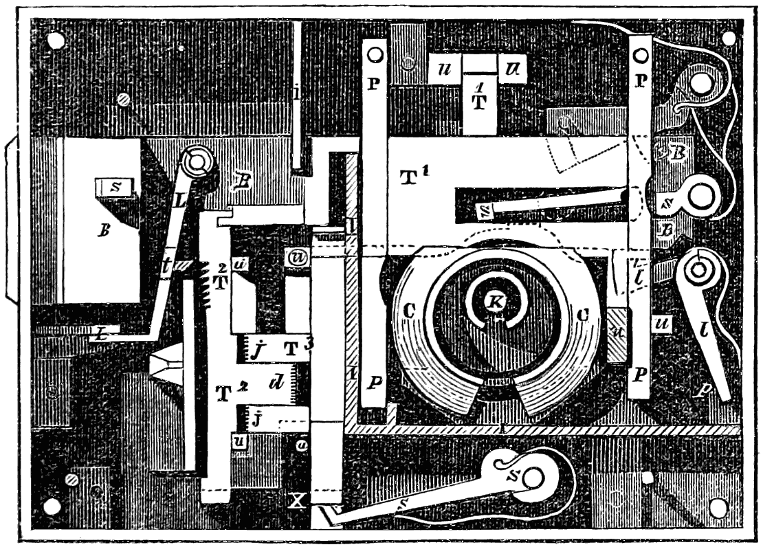
fig. 40. The American Parautoptic lock; bolt unshot.
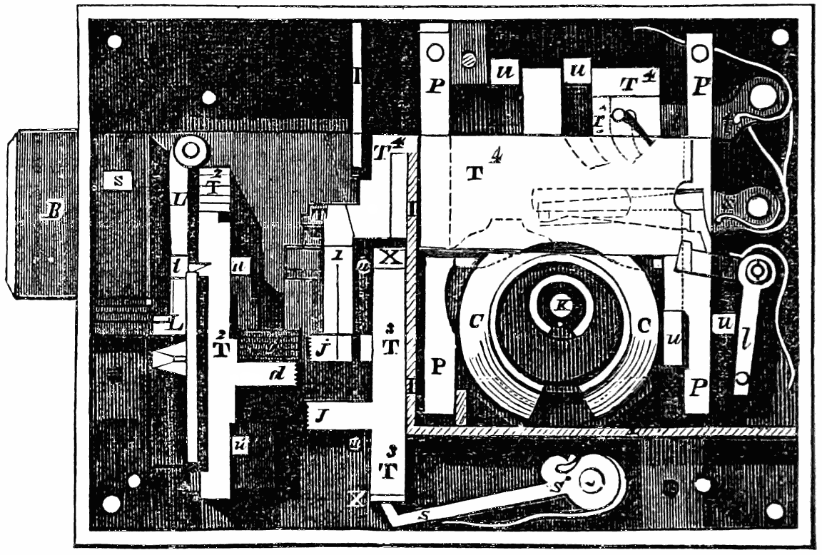
fig. 41. The same with the bolt shot.
In fig. 40 the lock is represented in its unlocked state, with the cover or top-plate removed; the auxiliary tumbler and the detector-plate are also removed. In fig. 41 it is represented as locked, with the cover and the detector-plate also removed, and the auxiliary tumbler in its place. In these two figures, the same letters of reference apply to the same parts, unless otherwise stated. B B is the bolt; T1 are the first series of movable slides or tumblers; s shews the tumbler-springs; T2 the secondary series of tumblers; and T3 the third or intermediate series—these latter coming between the first and secondary series; P P are the separating plates between the several members of the first series of tumblers; s1 are the springs for lifting the intermediate tumblers. On each of the secondary tumblers T2 is a series of notches, corresponding in mutual distance with the difference in the lengths of the movable bits of the key. It thence happens that, when the key is turned in the lock to lock it, each bit raises its proper tumbler, so that some one of these notches shall present itself in front of the tooth t in[90] the dog or lever L L. When the bolt B is projected by the action of the key, it carries with it the secondary tumblers T2, and presses the tooth t into the notches; in so doing, it withdraws the tongues d from between the jaws j j of the intermediate tumblers T3, and allows the first and intermediate tumblers to fall to their original position. By the same movement, the secondary tumblers T2 become held in the position given to them by the key, by means of the tooth t being pressed into the several notches, as shewn in the closed state of the lock (fig. 41). Now let us see what results if any attempt be made to open the lock with any arrangement of key but that by which it has been locked. In such case, the tongues d will abut against the jaws j j, preventing the bolt from being withdrawn; and should an attempt be made to ascertain which tumbler binds and requires to be moved, the intermediate tumbler T3 (which receives the pressure), being behind the iron wall I I, which is fixed completely across the lock, prevents the possibility of its being reached through the key-hole; and the first tumblers T are quite detached at the time, thereby making[91] it impossible to ascertain the position of the parts in the inner chamber behind the wall I I. K is the drill-pin, on which the key fits; and C is a revolving ring or curtain, which turns round with the key, and prevents the possibility of inspecting the interior of the lock through the key-hole. Should, however, this ring be turned to bring the opening upwards, a detector-plate D, fig. 42, is immediately carried over the key-hole by the motion of a pin p1 upon the auxiliary tumbler T4, which is lifted by the revolution of the ring C, thereby effectually closing the key-hole. As an additional protection, the bolt is held from being unlocked by the stud or stump S bearing against the detector-plate; and, moreover, the lever l l holds the bolt, when locked, until it is released by the tail of the detector-plate pressing the pin p1; l1 is a lever which holds the bolt on the upper side, when locked, until it is lifted by the tumblers acting on the pin p1; X are separating-plates between the intermediate tumblers T3; u u1 are the studs for preserving the parallel motion of the different tumblers.
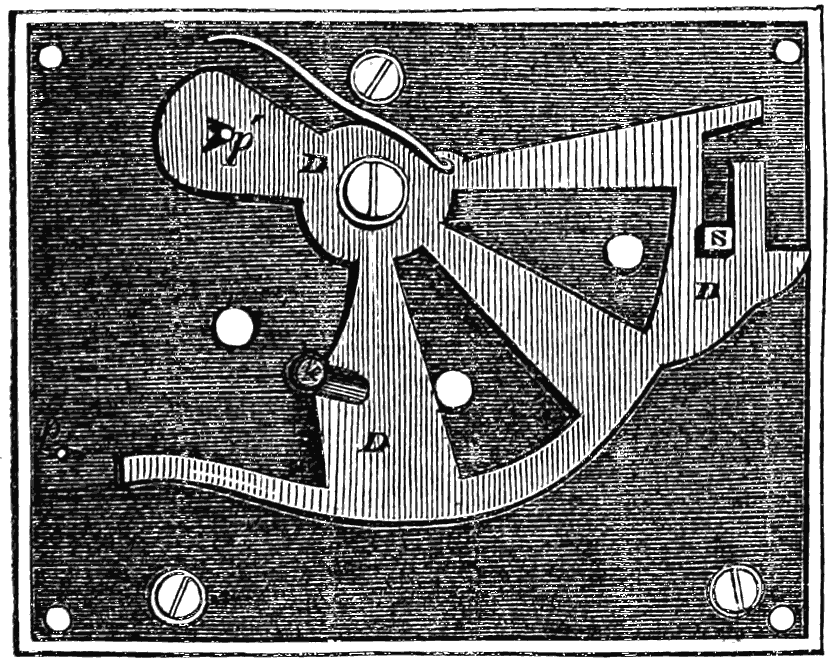
fig. 42. The detector plate of the Parautoptic lock.
Fig. 43 represents the key in two different forms, or with the bits differently arranged. Either form will lock the lock, but the other will not then unlock it. The end of the key is represented in fig. 44, shewing the screw which fixes the bits[92] in their places. The bits for a six-bitted key are shewn separately in fig. 45.
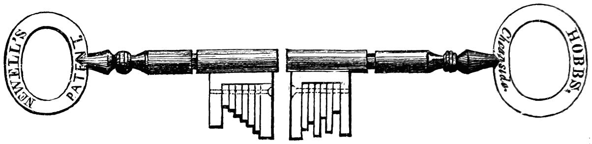
fig. 43. Key of the Parautoptic lock.
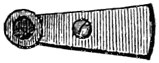
fig. 44. End view of the key.
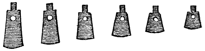
fig. 45. Separate bits of the key.
In 1847 the parautoptic lock was exhibited at Vienna before the National Mechanics’ Institute of Lower Austria; and towards the close of the year Mr. Belmont, consul-general of Austria at New York, placed in the hands of Messrs. Day and Newell a letter, a diploma, and a gold medal, forwarded by the Institute. The letter was from the president of the Institute to Mr. Newell, and was couched in the following terms:
“The Institute of Lower Austria, at its last monthly session, has passed the unanimous resolution to award to you its gold medal, as an acknowledgment of the uncommon superiority of the combination-lock of your invention; and this resolution was ratified in its general convention held on the 10th instant.
“Whilst I, as president of this Institute, rejoice in seeing the services which by this invention you have rendered to the locksmith’s art thus appreciated and recognised, I transmit to you, enclosed, the said medal, together with the documents relating[93] to it; at the same time availing myself of this opportunity to assure you of my esteem.
“Colloredo Mannsfeld.
“Vienna, May 31st, 1847.”
The diploma and the medal were similar to other honorary distinctions of the same class, and need not be described here; but the report of the special committee may be given, as it expresses the opinions of the Viennese machinists on the relative principles by which safety is sought to be obtained in different kinds of locks.
REPORT
Of a Special Committee on the new Parautoptic Permutation Lock of the American Newell, made known to the Lower Austrian Institute by the Councillor, Professor Reuter, and on the motions relating to it made by the same and accepted by the Institute. Presented at the monthly meeting, April 6th, 1847, by Mr. Paul Sprenger, Aulic Councillor on Public Works, &c. &c.
Gentlemen:—At our last monthly meeting, Mr. Reuter, Aulic Councillor and Secretary of the Institute, directed your attention to a newly invented lock of Mr. Newell, of North America, which was represented as excelling all other changeable combination-locks hitherto known, and as being without a rival.
The Special Committee which was intrusted with the examination of this lock, and of the motions made by the said Secretary, and accepted by the Institute, has conferred on me the honour of making you acquainted with the results of its investigations.
The attention of your committee was chiefly occupied with the three questions proposed by the said Aulic Councillor in relation to the lock in question:
First: Whether the idea of Mr. Newell was of any practical value for already existing and still-to-be-invented combination-locks;
Secondly: Whether the idea was of sufficient importance to be published and minutely described in the transactions of the said Institute; and
Thirdly: Whether the merits of the inventor were of sufficient importance to entitle him to a distinction from the said Institute.
The deliberations on the first question, viz. the newness of the idea, and of its practical value, would of necessity enlist the particular attention of your committee, especially since by far the greater number of its members are by their avocation called upon to be interested in the execution of all kinds of locks.
It is therefore the unanimous opinion of your committee, that the idea[94] of the American Parautoptic Combination-Lock is entirely new and without example.
The combination-locks with keys have, with few exceptions, such an arrangement that a determinate number of movable parts (the so-called combination-parts) must by the turning of the key be raised or lifted into a certain position, if it is desired to project the bolt, or, what is the same thing, to lock it out; consequently these parts, or, as they are technically termed, tumblers, could not be transposed or changed, from the circumstance that the key-bit was one solid piece, with various steps or notches adapted to the several tumblers, and one impression from it destroyed the security of the lock.
In order, however, to add more security to such a combination-lock, and to make the key, in case it should be lost, or any counterfeit made from a wax impression, useless for an unlawful opening of the lock, another step was taken: the key-bit was made to consist of several bits or movable parts, in such a manner that the owner of the lock was enabled to change the bits, and to form, as it were, new keys different from the former. But since the bolt of the lock can only be projected whilst the combination parts or tumblers are in a certain position, which position depends upon the order of the bits in the key, it is evident that the owner, when changing the key, must at the same time make a corresponding change in the position of the tumblers in the lock itself, before the lock can be of any use for the newly changed shape of the key, which rendered it troublesome, and impracticable for the purpose designed, from the fact that no positive change could be made in the lock, without taking it from the door, and then taking the tumblers out of the case, to change them in a suitable form for the key.
This principle of changing the lock is rarely adhered to, as few men understand the machinery of a lock sufficiently to undertake the task; and this circumstance rendered the lock quite as insecure as the former one described.
Another step toward the perfection of combination-locks consisted in this, that the key remains unaltered whilst the combination parts of the lock can, before it is locked, be brought into different positions by means of movable plates on the frame of the lock. These plates were arranged by hand to certain figures, and depended on the memory for adjustment at each time the bolt was to be locked out or in, the key operating only on the bolt, to move it back and forth when the plates were set in proper positions for the purpose; and should the owner forget the arrangement of the plates, after projecting the bolt, his key is of no use to him, and he must resort to the skill of the locksmith to gain access.
The same case may occur in the far less perfect ring-lock of Reynier, which is operated without keys, and is opened by means of the rings being turned in a particular position; on these rings are usually stamped letters, which, by introducing some word readily suggested to the memory, thus point out the relative position of the rings.
But although in case of these ring-locks the owner is enabled to produce[95] a change in the rings in such a manner that the opening of the lock can, as it were, only become possible by rightly arranging the altered position of the letters, still this lock of Reynier’s does not possess that safety and perfection which could have insured it universal application.
M. Crivelli, formerly professor at Milan, has given a minute description of the imperfection of ring-locks generally, in the annals of the Imperial Royal Polytechnic Institute.
It is the unanimous conviction of your committee that the American Lock of Newell surpasses, in the ingenuity displayed in its construction, all other locks heretofore known, and more especially in this, that the owner can, with the greatest facility, change at pleasure the interior arrangement of his lock to a new and more complex one, at every moment of his life, simply by altering the arrangement of the bits in the key, and this is accomplished without removing the lock or any part of it from its position on the door.
Its operation is as follows:—At the closing or locking of the lock, whilst the bolt is projecting, the movable combination parts assume precisely the position prescribed to them by the key, according to the particular arrangement of its bits at the time the key is turned.
The combination parts do not consist in one set of tumblers only, such as are found in all other locks, but there are three distinct sets or component parts fitting into each other. When the bolt is projected, it dissolves the mutual connexion of the constituent pieces, and carries along with it such as are designedly attached to it, and which assume the particular positions given them by the key in its revolution. These parts are rendered permanent in their given form by means of a lever adapted for the purpose, while the parts not united with the bolt are pressed down by their springs to their original places.
If now the bolt is to be returned again, i. e. if the lock is to be unlocked, then the constituent pieces or tumblers which are in the original state must, by means of the key, be again raised into that position in which they were when the lock was closed, as otherwise the constituent parts attached to the bolt would not lock in with the former, and the bolt could not be returned. Nothing, therefore, but the precise key which had locked the lock can effect the object.
This idea in itself, considered by your committee, is as ingenious as it is new, and is accompanied by a perfection in its execution which reflects the highest honour on Mr. Newell, the inventor and manufacturer of the lock.
The lock is built strong and solid, and the several parts are admirably adapted to the functions which they are designed to perform. The walls of steel or iron which separate the security parts from the tumblers, and the cylinder which revolves with the key, present formidable barriers to all descriptions of pick-locks, and render the lock a most positive and reliable security. The tumblers consist of rolled very smooth steel plates, in which the fire-crust has not been filed away, partly in order that the lock might not need oiling, as all these parts are very smooth, and partly that the[96] combination pieces might not easily rust, a thing to which the adhering fire-crust is not favourable. The springs, which by the turning of the key must be raised together with the tumblers, are attached to levers, and press upon the latter at their centre of gravity, in consequence of which all crowding towards either side is prevented, and the key can be turned with facility, in spite of the many combination parts which it has to raise; and the springs themselves are by their positions so little called into action, that their strength can never be impaired by use.
The lock has also another very complete arrangement in the detector-tumbler, which is attached to the cap or covering of the lock. This tumbler, on turning the key either way, closes the key-hole, and not only prevents the use of false instruments in the lock, but detects all attempts at mutilating its interior parts.
This lock is especially useful for locking bank-vaults, magazines, counting-houses, and iron-safes, in which valuable effects, money, or goods are to be deposited for safe keeping. When it is considered that the bits of the key belonging to this lock can be transferred into every possible form within its limits, and since the construction of the lock admits of every combination of the slides resulting from the changes of the key, therefore the lock in question is, in every respect, deserving of the appellation given to it by the Secretary of the Institute, namely, the Universal Combination Lock; and justly so, when we consider that the ten bits attached to the key admit of three millions of permutations, and upward; consequently forming that number of different kinds of keys and locks.
If we consider further, that we need not be limited to the given bit, but that others can be applied, differing in their dimensions from the former; and again, if we consider that from every system arising from a difference in their relative dimensions, a large number of new keys differing from each other will result, and that this can be effected in a space scarcely occupying a square inch,—then we cannot refrain from confessing that the human mind, within this small space, has shewn itself to be infinitely great.
After this preliminary and general exposition, your committee can answer the three questions propounded to them the more briefly, as the locks heretofore known have all been noticed.
To question first.—On the practical value of the invention of Mr. Newell, your committee were unanimous and positive that the principle on which it is based should be preserved.
To question second.—For this reason the committee deemed it desirable that a drawing and description of the American lock in question should be published in the Transactions of the Institute of Lower Austria.
To question third.—With regard to the claims of the inventor, Mr. Newell, to an honorary distinction from the Institute of Lower Austria, the committee recommend that he be presented with a Diploma of honourable mention and a Gold Medal.
The members of your committee, consisting mostly of fellow-tradesmen of Mr. Newell, experience great satisfaction in the fact that it has fallen to[97] their lot to vote to their colleague on the other side of the ocean an acknowledgment of his successful ingenuity, and they close the Report with the request that the Institute will transmit to Mr. Newell of New York, in North America, the Diploma and Gold Medal, together with a copy of this Report, according to the motion of the Aulic Councillor and Professor Reuter.
[An exact copy of the original Report as preserved in the archives of the National Mechanics’ Institute of Lower Austria.]
DR. SCHWARTZ,
Assistant Secretary of the Institute.
There are other circumstances connected with the American bank-lock, in relation to events both in the United States and in England, to which attention will be directed in a subsequent chapter.
The English patent for Messrs. Day and Newell’s lock, dated April 15, 1851, runs as follows: “The object of the present improvements is the constructing of locks in such manner that the interior arrangements, or the combination of the internal movable parts, may be changed at pleasure according to the form given to, or change made in, the key, without the necessity of arranging the movable parts of the lock by hand, or removing the lock or any part thereof from the door. In locks constructed on this plan the key may be altered at pleasure; and the act of locking, or throwing out the bolt of the lock, produces the particular arrangement of the internal parts which corresponds to that of the key for the time being. While the same is locked, this form is retained until the lock is unlocked or the bolt withdrawn, upon which the internal movable parts return to their original position with reference to each other; but these parts cannot be made to assume or be brought back to their original position, except by a key of the precise form and dimensions as the key by which they were made to assume such arrangement in the act of locking. The key is changeable at pleasure, and the lock receives a special form in the act of locking according to the key employed, and retains that form until in the act of unlocking by the same key it resumes its original or unlocked state. The lock is[98] again changeable at pleasure, simply by altering the arrangement of the movable bits of the key; and the key may be changed to any one of the forms within the number of permutations of which the parts are susceptible.”
The “claims” put forth under this patent are the following:—
“1. The constructing, by means of a first and secondary series of slides or tumblers, of a changeable lock, in which the particular form or arrangement of parts of the lock, imparted by the key to the first and secondary series of slides or tumblers, is retained by a cramp-plate.
“2. The constructing, by means of a first and secondary series of slides or tumblers, of a changeable lock, in which the peculiar form or arrangement of parts of the lock, imparted by the key, is retained by means of a tooth or teeth, and notches on the secondary series of slides or tumblers.
“3. The application to locks of a third or intermediate series of slides or tumblers.
“4. The application of a dog with a pin over-lapping the slide or tumblers, for the purpose of holding-in the bolt when the lock is locked or unlocked.
“5. The application of a dog operated on by the cap or detector-tumbler for holding the bolt.
“6. The application of a dog for the purpose of holding the internal slide or tumbler.
“7. The application to locks of curtains or rings, turning and working eccentrically to the motion of the key, for preventing access to the internal parts of the lock.
“8. The application to locks of a safety-plug or yielding-plate, at the back of the chamber formed by such eccentric revolving curtain or ring.
“9. The application to locks of a strong metallic wall or plate, for the purpose of separating the safety and other parts of the lock from each other, and preventing access to such parts by means of the key-hole.
“10. The application to locks of a cap or detective tumbler,[99] for the purpose of closing the key-hole as the key is turned.
“11. The constructing a key by a combination of bits or movable pieces, with tongues fitted into a groove and held by a screw.
“12. The constructing a key having a groove in its shank to receive the detector tumbler.”
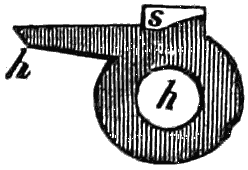
fig. 46. Movable stump.
When the American locks became known in England, Mr. Hobbs undertook the superintendence of their manufacture, and their introduction into the commercial world. Such a lock as that just described must necessarily be a complex piece of mechanism; it is intended for use in the doors of receptacles containing property of great value; and the aim has been to baffle all the methods at present known of picking locks, by a combination of mechanism necessarily elaborate. Such a lock must of necessity be costly; but in order to supply the demand for a small lock at moderate price, Mr. Hobbs has introduced what he calls a protector lock. This is a modification of the ordinary six-tumbler lock. It bears an affinity to the lock of Messrs. Day and Newell, inasmuch as it is an attempt to introduce the same principle of security against picking, while avoiding the complexity of the changeable lock. The distinction which Mr. Hobbs has made between secure and insecure locks will be understood from the following proposition, viz. “that whenever the parts of a lock which come in contact with the key are so affected by any pressure applied to the bolt, or to that portion of the lock by which the bolt is withdrawn, as to indicate the points of resistance to the withdrawal of the bolt, such a lock can be picked.” Fig. 47 exhibits the internal mechanism of this new patent lock. It contains the usual contrivances of tumblers and springs, with a key cut into steps to suit the different heights to which the tumblers must be raised. The key is shewn separately in fig. 48. But there is a small additional piece of mechanism, in which the tumbler stump shewn at s in[100] figs. 46 and 47 is attached; which piece is intended to work under or behind the bolt of the lock. In fig. 47, b is the bolt; t t is the front or foremost of the range of six tumblers, each of which has the usual slot and notches. In other tumbler-locks the stump or stud which moves along these slots is riveted to the bolt, in such manner that, if any pressure be applied in an attempt to withdraw the bolt, the stump becomes pressed against the edges of the tumblers, and bites or binds against them. How far their biting facilitates the picking of a lock will be shewn further on; but it will suffice here to say, that the movable action given to the stump in the Hobbs lock transfers the pressure to another quarter. The stump s is riveted to a peculiarly-shaped piece of metal h h (fig. 46), the hole in the centre of which fits upon a centre or pin in a recess formed at the back of the bolt; the piece moves easily on its centre, but is prevented from so doing spontaneously by a small binding spring. The mode in which this small movable piece takes part in the action of the lock is as follows: when the proper key is applied in the usual way, the tumblers are all raised to the proper heights for allowing the stump to pass horizontally through the gating; but should there be an attempt made, either by a false key or by any other instrument, to withdraw the bolt before the tumblers are properly raised, the stump becomes an obstacle. Meeting[101] with an obstruction to its passage, the stump turns the piece to which it is attached on its centre, and moves the arm of the piece p so that it shall come into contact with a stud riveted into the case of the lock; and in this position there is a firm resistance against the withdrawal of the bolt. The tumblers are at the same moment released from the pressure of the stump. There is a dog or lever d, which catches into the top of the bolt, and thereby serves as an additional security against its being forced back. At k is the drill-pin on which the pipe of the key works; and r is a metal piece on which the tumblers rest when the key is not operating upon them.
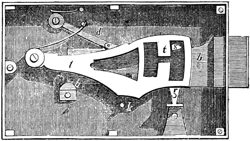
fig. 47. Hobbs’s Protector Lock.
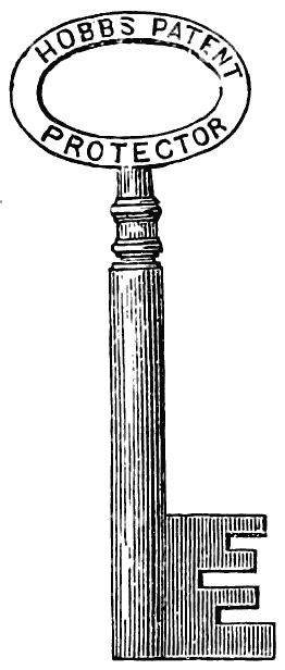
fig. 48. The key.
Another lock, patented by Mr. Hobbs in 1852, has for its object the absolute closing of the key-hole during the process of locking. The key does not work or turn on its own centre, but occupies a small cell or chamber in a revolving cylinder, which is turned by a fixed handle. The bit of the movable key is entirely separable from the shaft or stem, into which it is screwed, and may be detached by turning round a small milled headed thumb-screw. The key is placed in the key-hole in the usual way, but it cannot turn; its circular movement round the stem as an axis is prevented by the internal mechanism of the lock; it is left in the key-hole, and the stem is detached from it by unscrewing. By turning the handle, the key-bit, which is left in the chamber of the cylinder, is brought into contact with the works of the lock, so as to shoot and withdraw the bolt. This revolution may take place whether the bit of the movable key occupy its little cell in the plate or not; only with this difference—that if the bit be not in the lock, the plate revolves without acting upon any of the tumblers; but if the bit be in its place, it raises the tumblers in the proper way for shooting or withdrawing the bolt. It will be understood that there is only one key-hole, namely, that through which the divisible key is inserted; the other handle or fixed key working through a hole in the cover of the lock only just large enough to receive it, and not being removable from the lock. As soon as the plate[102] turns round so far as to enable the key-bit to act upon the tumblers, the key-hole becomes entirely closed by the plate itself, so that the actual locking is effected at the very time when all access to the interior through the key-hole is cut off. When the bolt has been shot, the plate comes round to its original position, it uncovers the key-hole, and exhibits the key-bit occupying the little cell into which it had been dropped; the stem is then to be screwed into the bit, and the latter withdrawn. It is one consequence of this arrangement, that the key has to be screwed and unscrewed when used; but through this arrangement the key-hole becomes a sealed book to one who has not the right key. Nothing can be moved, provided the bit and stem of the key be both left in; but by leaving in the lock the former without the latter, the plate can rotate, the tumblers can be lifted, and the bolt can be shot.
It must be evident, even on a cursory glance at the past history of the lock-manufacture, that the prime motive for the introduction of novelties and improvements in construction is the desirability of producing a lock which no one can open without the proper key. From the earliest and simplest lock, down to the latest and most complex, this object has been constantly held in view; and every clear proof or evidence that this object has not been attained has led to the invention of some new contrivance. It has been a succession of struggles—to attain security—to shew that this security has not been attained—to make a further and more ingenious attempt—to detect the weak point in this renewed attempt—and so on. We need not repeat here, what was stated in an early chapter,[103] that benefit must ultimately result from a candid discussion of this question. When M. Réaumur proposed to explain how the locks of his day could be picked or opened without the true key, his object was to shew to persons who were not locksmiths how far they could depend upon the principle of security offered by locks. But before proceeding on his inquiry, the illustrious naturalist asks, “Ne craindra-t-on pas que nous ne donnions en même tems des leçons aux voleurs?” And he replies, “Il n’y a pas grande apparence qu’ils viennent les chercher ici, et qu’ils en aient besoin; ils sont plus grands maîtres que nous dans l’art d’ouvrir les portes. Apprenons donc l’art d’ouvrir les portes fermées, afin d’apprendre celui de les fermer d’une manière qui ne laisse rien ou qui laisse peu à craindre.”[5]
[5] “But is there not this danger, that at the same time we shall be giving lessons to the thieves? It is not very probable that they will seek instruction of us, or that they have any need of it; they are greater masters in the art of opening doors than we can pretend to be. Let us then learn the art of opening locked doors, in order that we may acquire that of securing them in such a way as to leave little or nothing to be feared on account of their security.”
Before treating of lock controversies and lock violability in England, it will be desirable first to refer to America, where this subject attracted much attention some years earlier than the Great Exhibition—an Exhibition which will always be associated in a remarkable manner with the history of locks.
Soon after the inventions by Dr. Andrews and Mr. Newell, in 1841 (described in a former chapter), the rivalry between the two locks ran high; each lock being ‘unpickable,’ according to the estimate of its inventor. Mr. Newell thought the best mode of shewing the superiority of his own lock would be by picking that of his competitor; and after several trials, he succeeded in bringing into practical application that system of picking which we may designate the mechanical, as contra-distinguished from the arithmetical. Mr. Newell not only picked Dr. Andrews’ lock, but he wound up the enterprise by picking his own! He was probably the first person who honestly confessed to having picked his own unpickable lock. This discovery[104] led Mr. Newell, as has been noticed in a former page, to the invention of the triple-action or parautoptic lock.
The mechanical principle, as applied to the picking of a tumbler lock, is nearly the same whatever form of construction be made the medium of experiment. When a pressure is applied to the bolt sufficient to unlock it if the tumbler-obstructions were removed, the edges of the tumbler bite or bind against the stump of the bolt, so as not to move up and down with such facility as under ordinary circumstances. By carefully trying with a small instrument each tumbler, and moving it until the bite ceases, the gating of that particular tumbler may be brought to the exact position for allowing the stump of the bolt to pass through it. (See page 118.)
This violability is observable in the tumbler-locks under very varied forms of construction. Mr. Newell, after he had picked his own lock, devised a series of complicated wards, to add to the difficulty of reaching the tumblers; but he could not thereby get rid of the importance of this fact, that wherever a key can go, instruments of a suitable size and form could follow: his wards did not render his lock inviolable. His next contrivance was to notch the abutting parts of the primary and secondary tumblers, or the face of the stump and the ends of the tumblers; but this failed also. Mr. H. C. Jones, of Newark, N. J., added to all this a revolving pipe and curtain, to close as much of the key-hole as possible. But so far were all these precautions from being successful, that a lock provided with all these appendages, and affixed to the door of the United States Treasury at Washington, was picked. The makers of locks have, each one for himself, contended against such difficulties as were known to them at the time of inventing their locks; and, mortifying as failure may be, it would be cowardly to yield up the enterprise whenever any new difficulty presented itself. Difficulties, in locks as in other matters, are made to be conquered.
To shew how numerous are the sources of insecurity which have to be guarded against, to meet the skill often[105] brought to bear upon this lock, we may adduce the reasons which led Mr. Newell to apply a curtain to the key-hole of his lock. Supposing the interior arrangement of the triple set of tumblers, and the metallic shielding wall, to be perfect, still, if the first set of tumblers can be seen through the key-hole, the following plan may be put in operation. The under-side of the tumblers may be smoked, by inserting a flame through the key-hole; and the key will then leave a distinct mark upon each tumbler the next time it is used, shewing where it began to touch each tumbler in lifting it. This may be seen by inserting a small mirror hinged into the lock through the key-hole. There may even be an electric light used from a small portable battery, to illumine the interior of the lock. By these and other means the exact length of each bit of the key may be determined; and from these data a false key may be made. It is to prevent this inspection of the works, or any other examination of an analogous kind, that the revolving curtain was applied; but, as stated in the last paragraph, even this did not suffice: ingenuity devised a mode of baffling the contrivance of curtains as well as that of the wards and false notches in the tumblers.
When the parautoptic lock was completed, it was keenly criticised in America, owing to the long discussions respecting the merits of previous locks. In a matter of this kind, where a commercial motive would lead bankers and companies to apply a very severe test to the security of locks and similar fastenings to strong-rooms and receptacles, any experiments made with their sanction became important. Mere letters or certificates emanating from individuals, expressive of opinions concerning a particular lock, would be out of place in a volume relating to locks generally; but it is quite within the limits of the subject, and has indeed become part of the history of locks, to notice experiments and attempts of a more public character. We may therefore introduce a few paragraphs of this description, relating to the career of the American lock in America itself.
The principal bankers at Boston (U.S.) held a meeting to[106] take into consideration measures for testing the security of bank locks. Consequent on this meeting, Messrs. Day and Newell deposited five hundred dollars with the cashier of the State Bank at Boston, to be by him paid to any one who could pick the parautoptic lock: the trial was to be conducted under the auspices of the bank. One of the locks was brought to the bank, and was minutely examined by two machinists on two afternoons, after which it was secured to an iron chest, and locked by a committee appointed by the bank. The key was to remain in the hands of the committee during the trial; and it was to be used at their discretion, in unlocking and locking the door, without the knowledge of either of the other parties—provided that in so doing no alteration was made in the combination-parts of the key. Ten days were allowed to the operators for the examination and the trial; if they succeeded they were to have five hundred dollars; but if they injured the lock they agreed to forfeit two hundred, as a purchase price. At the end of the period the lock remained unopened and uninjured; and the two deposited sums were accordingly returned to the respective parties.
Messrs. Page and Bacon, of St. Louis, had a strong-room lock made by one of the chief locksmiths of that city. To test its security, the proprietors requested Mr. Hobbs to attempt to pick it; he did so, and succeeded. Whereupon the proprietors, having purchased one of the parautoptic locks, deemed it no more than fair play to subject this lock to a similar ordeal, an additional zest being given by a reward of five hundred dollars offered by Day and Newell to the successful picker. The maker of the former lock accepted the challenge; he was allowed to examine the new lock piecemeal, and was then allowed thirty days for his operations in picking. He failed in the enterprise. Of course, in this, as in all similar cases, the operator had not access to the true key.
It follows from the nature of this lock, as noticed in a former chapter, that when the bolt has been shot, if the bits of the key be re-arranged in any other form, the lock becomes[107] to all intents and purposes a new lock, so far as that key is concerned, and cannot be unlocked unless the key revert to its original arrangement. To test this principle, a box with a parautoptic lock was placed in the room of the American Institute in 1845; it was locked; the bits of the key (12 in number) were then re-arranged, and the key was placed in the hands of any one who chose to try to open the lock—with the offer of a reward of five hundred dollars in the event of the lock being opened. Here, instead of the operator being called upon to devise new pick-lock implements, he had the actual key placed in his hands, modified however in such a way that, though the modifier could restore the original arrangement (provided he had kept some kind of record), the operator had numerous chances against his success. The lock remained unopened notwithstanding this challenge.
We shall have occasion to shew presently, that if the number of tumblers (and consequently the number of bits in the key) be small—not exceeding six, for instance—the possession of the true key gives any one the power of opening the lock, provided he has time and patience to go through a few hundred changes of the bits of the key; for, as some one arrangement must have been that by which the lock was locked, it must again occur if the user takes care to make all the arrangements in turn, and tries the lock after each. Whether this constitutes picking a lock, each lock-owner will decide for himself. All that it is at present meant to state is, that without access to the true key, the parautoptic lock has not hitherto been opened; and that with the true but altered key the process of opening is possible, but is slow and tedious.
In 1846 the American Institute appointed a committee to examine into the merits of the parautoptic lock. On the 18th of September in that year the Committee made their report, signed by Professor Renwick and Mr. T. W. Harvey, as follows:—
“The Committee of the American Institute, to whom was referred the examination of Newell’s Parautoptic Bank[108] Lock, report that they have given the subject referred to them a careful and attentive examination, and have received full and complete explanations from the inventor. They have remarked in the lock a number of important advantages, and, in particular, very great improvements upon the permutation-lock formerly submitted by him to the American Institute. Thus, while it retains the advantages of the permutation principle, combined with the property that the act of locking sets the slides to the particular arrangement of the bits in the skeleton key, the parts thus set are completely screened from observation, from being reached by false instruments, or from being injured by any violence not sufficient to break the lock to pieces.
“Having in the course of their inquiries examined the different existing modes in which locks may be picked, forced, or opened by false keys, the Committee have come to the conclusion that the parautoptic lock cannot be opened by any of the methods now practised, unless by a person in possession of the key by which it was locked, in the exact form of combination in which it was used for the purpose, or in the almost impossible case of the bits being adjusted to the skeleton key by accident in that very form. As the chances of such accidental combination range according to the number of movable bits, from several thousands to several millions to one, the Committee do not conceive that so small a chance of success would ever lead to an attempt to profit by it.
“In conclusion, the Committee feel warranted in expressing the opinion, that unless methods hitherto unknown or imagined should be contrived for the specific object, the lock in question may be considered as affording entire and absolute security.”
The latest form which Messrs. Day and Newell have given to their challenge, after the experience of the last few years, is the following:
“First, a Committee of five gentlemen shall be appointed in the following manner: viz. two by the parties proposing to[109] operate, and two by ourselves; and by the four thus appointed a fifth shall be selected.
“In the hands of this Committee shall be placed Two Thousand Dollars, as a reward to the operator if successful in picking the lock by fair means.
“We will place upon the inside of an iron door one of our best bank locks. The operator shall then have the privilege of taking the lock from the door, and have it in his possession for examination; it shall then be returned to the Committee for our inspection, so that we may be assured that it has not been mutilated or injured. The operator shall then, in the presence of ourselves and the Committee, place the lock upon the door in its original position; after which the Committee shall place upon it their seals, so that it cannot be removed or altered without their knowledge. The lock being thus secured to the door, we shall then be allowed to lock it up ourselves, upon any change of which it is susceptible.
“The time for operation to continue thirty days; and if at the end of that time he shall consider that he has made any progress towards picking the said lock, he shall have thirty days more in which to continue operations.”
The Austrian report concerning the American lock was given in a former page, to which we may here refer; and then direct attention to England, and to the discussions which have lately been carried on respecting the safety of locks.
It is of course natural that each inventor of a new lock should, while describing the product of his ingenuity, point out what he conceives to be the imperfections of locks which have preceded: use has sanctioned the custom not only with regard to locks, but also in other important matters. Hence there have been many “lock controversies” in England during the last seventy years. We have seen how freely and justly the late Mr. Bramah criticised all the locks that preceded his own; and he was certainly not the man to shrink from criticism in his own case. Twenty years ago the Bramah lock was itself made the subject of criticism.
[110]
Mr. Ainger, in his lecture on the subject delivered at the Royal Institution, London, and afterwards in his article “Lock” in the Encyclopædia Britannica, thus narrates the circumstances which led to the adoption of the false notches in the Bramah lock as a means of security: “At length (after the original lock had acquired much celebrity,) an advertisement appeared in the public papers, requesting those who had lost keys of Bramah’s locks, not, as had hitherto been done, to break open their doors or drawers, but to apply to the advertiser, who would undertake to save this destructive process by picking. And it appeared that an individual of great dexterity could perform this operation almost with certainty. The effect of this discovery on the demand for the locks may easily be imagined; but the effect it had in stimulating ingenuity to provide a remedy is one of the best illustrations of the proverb, that necessity is the mother of invention. Within a few days or weeks, Mr. Russell, who was at that time employed in Mr. Bramah’s establishment, devised an alteration which at once, and without any expense, entirely overcame the difficulty, and converted the lock into one of perfect security. This contrivance is the most simple and extraordinary that ever effected so important an object; but before we describe it, we will endeavour to explain what has been called the tentative process of lock-picking, and which had been so successfully applied to Bramah’s locks.”
Mr. Ainger illustrates the subject by an engraving—not of an actual lock, but of an hypothetical arrangement of bolts and notches; and he then makes his reasoning apply to the actual process adopted by the picker of the real lock. “A tendency to revolve was given with some force to the barrel; then, by means of a pair of small forceps, the tumblers (sliders) were tried, and it was ascertained which one was most detained by the pressure against the locking-plate. That which offered most resistance was gradually depressed till its notch was felt to hang itself upon the locking-plate; and so on till the whole were depressed in succession, exactly as they would[111] have been depressed simultaneously by the key.” Mr. Ainger then describes the contrivance which, in his judgment, seemed to render any further attempts to pick the Bramah lock hopeless. This consisted in cutting false notches in the sliders; so as to render it impossible for the picker to tell when he has brought a notch to the plane of the locking-plate, whether it is a true notch, or one of shallower depth, unfitted to admit the movement of the plate.
This is a very interesting statement, for it shews that the mechanical or tentative method of opening was known in England long ago, although very little attention has been since paid to it. In a complex Bramah lock, and in locks on the combination principle, the difficulty of picking is almost insuperable, so long as what may be termed the arithmetical method is adopted. It is perfectly true, as has been so often stated, that the varied combinations in the arrangement of the slides amount to millions and even billions, when the slides are in any degree numerous; and if a person attempt to pick the lock by ringing the changes on all these combinations, it would very likely require the lives of a dozen Methuselahs to bring the enterprise to an end. But by the mechanical method, sketched so clearly by Mr. Ainger, the exploit puts on a different aspect. The experimenter passes through the keyhole an instrument so arranged as to give a tendency in the bolt to withdraw in the wished-for direction; and a pressure produced in the slides by this tendency gives information concerning the state of the slides; and then comes the tentative process on the slides themselves. Mr. Ainger was quite right in describing the false notches as an admirable addition to the safety of the Bramah lock; but he was not correct in stating that these notches rendered any further attempts on the lock hopeless. The false notches are not so deep as the true; they will permit the barrel to turn partially but not wholly round. But even supposing that the false notch had been hit upon in nearly every slide instead of the true, and that the barrel had been partially turned to the extent which these notches permitted,[112] there would then be a binding action at the false notches different from that in the true, and this would guide the operator in his search for the true notches. It would not add a new principle different from the one before in action, but it would add to the time during which the search would have to be carried on.
We make these remarks in connection with Mr. Ainger’s article, which was probably written twenty years ago. We now come to the year 1850.
At the meeting of the Institution of Civil Engineers, when Mr. Chubb’s paper was read, many challenges and counter-challenges were made, as to the possibility of picking certain locks. Mr. Chubb described, among others, a lock on the patent of Mr. Davies, which, ingenious though it be, he considers not safe. Captain D. O’Brien differed from Mr. Chubb in this matter; he had had occasion to open from ten to twenty of Davies’s cabinet-locks daily, during a period of two years, and he never once observed the locks to be out of order; in fact, they always appeared to afford great security. Mr. Chubb thereupon rejoined, that he was prepared to produce a workman who would pick any number of Davies’ cabinet-locks, of different combinations, which he had never seen before, taking only half an hour for each lock.
As another instance, Captain O’Brien stated that, in his capacity as Inspector of Government Prisons, his attention had been much directed to the subject of secure locks; and he produced, among others, specimens of those in use at the Pentonville Prison; though not of first-rate workmanship, he characterised them as being safe, strong, and cheap. They were on Thomas’s principle. The locks had been in use eight years, during which period not one had required to be replaced; and any trifling derangements had been made good whilst the prisoners were at exercise. Mr. Chubb, after making his offer concerning Davies’s lock, stated that “he was willing to make the same offer with respect to the locks from the Pentonville Prison; and he might state that, in point of[113] security, he considered them absolutely worthless;” in proof of which he exhibited one of them, and a common burglar’s tool, by which the lock could be opened with the greatest ease.
In respect to Bramah’s lock, there was no particular challenge associated with the proceedings of the evening; but incidental observations were made as to the degree of security pertaining to it. Mr. Farey, after passing a high eulogium on the ingenuity of the principle and the beauty of the workmanship, considered it nevertheless objectionable that the sliders should be so completely exposed to view. He then proceeded to make the following observations: “It had been suggested, that a universal false key for Bramah’s locks might be made, with the bottoms of its several notches formed by as many small steel sliders, extending beyond the handle of the key, so as to receive pressure from the fingers, for moving each one of the sliders within the lock, with a sliding motion in its own groove, independently of the other. During such sliding motion, a gentle force could be exerted, tending to turn the barrel round. Under such circumstances, supposing that the motion of the barrel was prevented by any one slider only; that one, having to resist all the turning force, would be felt to slide more stiffly endways in its groove, and therefore it could be felt when its unlocking notch arrived opposite the steel plate, and left some other slider to begin to resist the turning force. Such a circumstance (continues Mr. Farey) presumes a palpable inaccuracy in the radiating correspondence between the notches in the steel plate and the grooves for the sliders in the barrel, which could not happen with Bramah’s workmanship.”[6] He further remarked: “Unfortunately, if a Bramah’s key fell into dishonest hands, even for a short time, an impression could be easily taken, and a false key as easily made. A turkey-quill, notched into the form of a key, had sufficed to open a Bramah’s lock; and an efficient false key could be formed out of a pocket pencil-case. Such facility of fabrication was an invitation to dishonesty; and as an[114] abortive attempt left no trace, the impunity was an encouragement to repeat the attempt until success is attained.”
With respect to Chubb’s locks, a discussion arose out of a statement made by Mr. Hodge. Mr. Chubb had himself stated it to be a general opinion that a skilful workman, furnished with impressions taken from the true key, in wax or soap, could make a false key to open any lock; and he considered that, in common locks, with the most elaborate wards, but with only one tumbler, as also in Bramah’s locks, there was much truth in the notion. In respect to his own lock, however, with six double-acting tumblers, “a false key made ever so carefully from impressions would not be likely to open the lock, for want of exactitude in the lengths of the several steps; and if the key could not be made exact from the impressions, there would be no chance of rectifying it by trial in the lock, on account of the total uncertainty as to which part required alteration.” Mr. Hodge stated that, in America, he had repeatedly seen impressions taken of locks having twelve or fourteen tumblers, in consequence of the bellies of the tumblers, when at rest, coinciding with the form of the key (see page 63). He also suggested a method of taking an impression of the bellies of the tumblers; but Mr. Chubb, Mr. Farey, Mr. Stephenson, and Mr. Whitworth, all expressed a disbelief that a Chubb’s lock could be opened by the means indicated by Mr. Hodge. Mr. Hodge admitted that he was not aware of any lock actually made by Messrs. Chubb having been picked in America; but that the locks to which he had adverted were such exact imitations, that he had no doubt of the Chubb lock yielding to similar treatment. He further stated that there were persons in New York who would undertake to pick a real Chubb lock.
[115]
We next come to the remarkable year 1851, which produced so many unexpected results in connection with the industrial display in Hyde Park, and conferred a lasting benefit on the useful arts and manufactures of the United Kingdom, by bringing their products into contrast and competition with those of other nations. It was to be expected that such a trial as this would afford evidences of national failure as well as of success; but probably no one suspected before the trial, that English locks, so celebrated over the greater part of the world for skilful mechanical design, beauty of workmanship, and perfect inviolability, would readily yield to a well-arranged system of lock-picking. Such, however, was the case; and we are bound to admit that Mr. Hobbs, the author of this system, is a mechanician of great skill, and with a profound knowledge of the art of the locksmith.
The first step in the celebrated lock controversy of 1851 was taken by Mr. Hobbs himself, who declared to a party of scientific men in the Crystal Palace, that all the locks made in this country up to that date admitted of being very easily picked; and in order to explain to these gentlemen the principle upon which this was to be done, Mr. Hobbs picked one of Chubb’s patent detector-locks in their presence in a few minutes.
The fairness of this experiment having been called in question by certain persons who were not present at the time when it was made, Mr. Hobbs, on July 21st, 1851, wrote a letter from the American department of the Great Exhibition, to Messrs. Chubb, simply announcing that an attempt would be made, on the next following day, to pick a lock manufactured by[116] them, and which was at that time on the door of a strong room in a house named by Mr. Hobbs. Messrs. Chubb were invited to be present at the operation; but no member of the firm attended. What occurred on the day specified may best be given in the words of a letter written by those who witnessed the operation.
“London, July 22, 1851.
“We the undersigned hereby certify, that we attended, with the permission of Mr. Bell, of No. 34 Great George-street, Westminster, an invitation sent to us by A. C. Hobbs, of the City of New York, to witness an attempt to open a lock throwing three bolts and having six tumblers, affixed to the iron door of a strong-room or vault, built for the depository of valuable papers, and formerly occupied by the agents of the South-Eastern Railway; that we severally witnessed the operation, which Mr. Hobbs commenced at 35 minutes past 11 o’clock A.M., and opened the lock within 25 minutes. Mr. Hobbs having been requested to lock it again with his instruments, accomplished it in the short space of 7 minutes, without the slightest injury to the lock or door. We minutely examined the lock and door (having previously had the assurance of Mr. Bell that the keys had never been accessible to Mr. Hobbs, he having had permission to examine the key-hole only). We found a plate at the back of the door with the following inscription: ‘Chubb’s New Patent (No. 261,461), St. Paul’s Churchyard, London, Maker to Her Majesty.’”
This letter was signed with the names and addresses of the following gentlemen:—
| Mr. | Handley. | Mr. | T. Shanks. |
| „ | William Marshall. | Colonel W. Clifton. | |
| „ | W. Armstead. | Mr. | Elijah Galloway. |
| „ | G. R. Porter.[7] | „ | Paul R. Hodge. |
| „ | F. W. Wenham. | „ | Charles H. Peabody. |
| „ | A. Shanks. | ||
[7] Late Secretary to the Board of Trade.
Several of these names are well and publicly known in England and the United States.
[117]
This event gave rise to much newspaper controversy; and attempts were made to shew that, as this was not a test lock, prepared expressly for challenge, the picking proved nothing as regards the finest of the manufacturers’ locks. Two circumstances, however, have to be noticed—that the lock was of sufficient commercial importance to be placed on a door enclosing valuable papers, and that the makers had an opportunity to attend and witness, and comment on the trial, if they so chose. We may here remark, that one of the ingenious contrivances of the Chubb lock, the detector, excited some doubt no less than fifteen years ago, as will be seen from the following. The writer of the article “Lock” in Hebert’s Engineers’ and Mechanics’ Encyclopædia, while speaking with much commendation of Chubb’s locks, points out a curious feature, which seems to him to render somewhat doubtful the surety of the detector apparatus. “In Barron’s and Bramah’s locks,” he observes, “the picker has no means of knowing whether the tumblers are lifted too high or not; but in Chubb’s he has only to put the detector hors de combat in the first instance, by a correct thrust from the outside of the door (which might be accurately measured), so as to fix it fast in its place; the detector then becomes a stopper to the undue ascent of the tumblers, and the extent of their range is thereby correctly ascertained. Thus, it appears to us, the detector might be converted into a director of the means for opening the lock.”
Much will depend on the view which is taken of the circumstance just noted. The object of the detector is, not to prevent the lock from being picked, but to shew that an attempt has been made to pick it; or, at least, to attain a given purpose by an indirect instead of a direct method. But if there be really any truth in the surmise, that the detector actually guides a skilful hand in determining how high the tumblers should be raised, the supposed advantage will be purchased at rather a dear rate. As we are here, however, speaking of facts and not of mere opinions, it is proper to say,[118] that the lock opened by Mr. Hobbs had the detector apparatus, but that it was not disturbed by him in picking the lock.
But instead of reiterating opinions, we will state the method by which most of the tumbler-locks made in England, up to the date of the Great Exhibition, can be opened or picked.
Bearing in mind the principle on which the picking of locks is said to depend, namely, that “whenever the parts of a lock which come in contact with the key are affected by any pressure applied to the bolt, or to that portion of the lock by which the bolt is withdrawn, in such a manner as to indicate the points of resistance to the withdrawal of the bolt, such a lock can be picked,” the first step is to produce the requisite pressure.
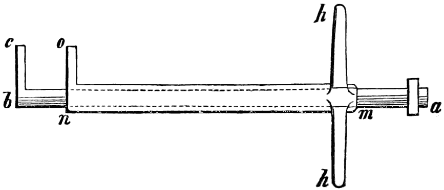
fig. 49.
If the end of the bolt were exposed, this pressure might be applied by some force tending to shoot back the bolt; but as the bolt, whenever it is shot, is buried in the jamb of the door, or otherwise concealed from view, the pressure can in general only be applied through the key-hole. In order, therefore, to apply this pressure, the operator provides himself with an instrument capable of reaching the talon of the bolt, which in the case of the Chubb lock was a pipe-key of the form shewn at a b, fig. 49, furnished at the pipe-end with that portion of the bit of the key b c which moves the bolt (see fig. 32, page 57, where the step which acts on the bolt is called the terminal step). The other end of the pipe-key is made square, as at a, for the purpose of receiving the square eye e of the lever e f, fig. 50, to the further end of which f a weight w is attached by means of a string s. Now it is evident that if this pipe be introduced into the lock as far as it will go, and be turned[119] round as in the act of unlocking, and the lever and weight be attached to the end a, the bit b c of the pipe-key will maintain a permanent pressure on the bolt, which, if the weight be sufficient, will throw back the bolt as soon as the tumblers are raised to the proper height to allow the stump to pass.
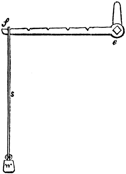
fig. 50.
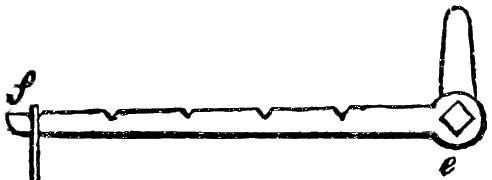
fig. 50.
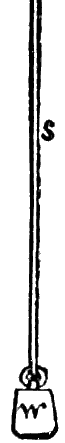
The next step in the operation is to raise the tumblers to the proper height. For this purpose a second pipe m n is made to slide upon the first with an easy motion, and by means of the cross handle h h can be turned round or slid backwards and forwards on the tube a b. This tube m n is also furnished with a single projecting bit or step n o, corresponding with one of the six steps of the key, fig. 32, and made of the proper length for entering the key-hole.
Now for the operation of opening a tumbler-lock with this simple apparatus. Referring to fig. 31, page 56, it will be evident that if the pipe a b, fig. 49, be passed over the pin of the lock and turned round towards the left, and the weight be attached, there will be a tendency in the bolt to shoot back, which tendency will bring the stump s, fig. 31, up against the inner angle or shoulder of one or other of the tumblers, whichever happens to project, however slightly; or, as Mr. Hobbs expresses it, “one or more of the tumblers will bind.” By moving forward the pipe m n and turning round the bit n o in the lock, it is easy to ascertain, by delicate touch, which of the tumblers it is that binds. It may be found that all are free to move except one or two against which the stump is pressing with the force of the weight w, fig. 50. The bit n o is therefore brought gently under the bellies of the tumblers which bind, and they are moved slightly upwards until they cease to bind. As soon as they are set free another tumbler[120] will bind; that is, the bolt will move through a small space, so as to bring the stump into contact with that particular tumbler which now projects; this in its turn is relieved, another tumbler binds and is relieved, and so on until the tumblers are, one by one, raised to the proper height for the stump to pass. When the last binding tumbler is raised to the proper height, the weight w being no longer resisted, shoots the bolt back, and the work is done.
Now it must be evident that in this operation the detector apparatus need not come into operation. But if, as has been proposed, a detector-spring be added to each tumbler, it may be converted into a friend or a foe according to the use that is made of it. If the tumblers are lifted too high, they will be detained or detected in that position, and the operator will have to release them by turning the bit round in the opposite direction before he can begin his work again. The same force, however, which detains the tumblers when they are lifted too high will obviously detain them when they are lifted only just high enough, and thus the detector-springs would really be of great assistance to the operator in picking such a tumbler-lock.
The apparatus which we have described for picking the tumbler-lock must be varied to suit the form of key employed in opening the lock; but it is not difficult, in the case of most locks, to ascertain this form through the key-hole, without examining the key itself.
It is but fair to state in this place, that since the above method of picking tumbler-locks was made known,[8] Mr. Chubb[121] has added a series of teeth and notches to the stump and tumblers; the effect of which would evidently prevent the application of the above method of picking, because any permanent pressure applied to the bolt would send a tooth of the stump into a notch of the tumbler, and prevent all further motion. But recurring to the principle, that whenever the parts of a lock which come in contact with the key indicate the points of resistance when any pressure (whether permanent or temporary) is applied in attempting to withdraw the bolt, that lock can be picked, it follows, if this principle be admitted, that although the notches prevent the application of the form of instrument described, yet there is sufficient indication afforded by the pressure to enable a skilful operator, with proper instruments, to form a false key, as was done in the case of the lock referred to at page 104. We now proceed to the second stage in the lock controversy of 1851.
[8] We believe the method was first made publicly known at a special general meeting of the members of the Institution of Mechanical Engineers, held at the rooms of the Society of Arts, London, on the 30th June, 1851, when a paper was read by Mr. Paul R. Hodge “On the progress of improvements in locks in the United States of America.” A report of this paper, together with the discussion thereon, was published by Waterlow and Sons, London Wall, 1851. Plate 34 (figs. 9 and 10) of this report contains representations of the lock-picking apparatus, from which we have copied our figures.
Soon after the picking of the Chubb lock in Great George-street, and consequent on the excitement and discussion to which that operation led, a committee, consisting of Mr. G. Rennie, Professor Cowper,[9] and Dr. Black, agreed to superintend the arrangements for a more severe testing of Mr. Hobbs’s power to open locks. There had been for many years exhibited in the window of Messrs. Bramah’s shop, in Piccadilly, a padlock of great complexity and beauty; to which an announcement was affixed, that a reward of two hundred guineas would be given to any person who should succeed in picking that lock. This challenge was accepted by Mr. Hobbs; and the committee managed all the arrangements, as arbitrators between Mr. Hobbs on the one side and Messrs. Bramah on the other. The lock was removed to an upper room in Messrs. Bramah’s establishment; where it was placed between two boards, and so fixed and sealed, that no access could be[122] obtained to any part of it except through the key-hole. The room was to be given up to Mr. Hobbs; he was not to be interrupted by the presence or entrance of any other persons; and he was allowed a period of thirty days for opening the lock. If the lock was not picked at the expiration of that period, Mr. Hobbs was to be considered as having failed in his attempt.
[9] In mentioning the name of the late Professor Edward Cowper, we cannot refrain from deploring the loss which mechanical science has suffered by his too-early death. The application of mechanical principles to manufactures was treated by him in his lectures and illustrations with a felicity which has been rarely equalled.
There was much negotiation and correspondence before and during Mr. Hobbs’s operation on this lock. On July 2, he, with a view to this enterprise, applied for permission to take wax impressions of the key-hole. This permission being given, and the parties having met to discuss the necessary arrangements, an agreement was signed on the 19th, reciting the terms of the challenge, and providing that thirty days should be allowed to Mr. Hobbs to effect his enterprise; that the lock should be secured in a certain specified way; and that the key should remain in the possession of Messrs. Bramah, who were to retain the right of using it in the lock when Mr. Hobbs was not at work. Messrs. Bramah subsequently relinquished this last-mentioned privilege, in order that the trial might be perfectly fair; and it was agreed that the key should be sealed up during the whole period, beyond the reach either of Mr. Hobbs or Messrs. Bramah; and that the key-hole should be secured by an iron band, sealed, when Mr. Hobbs was not at work. These and other conditions were embodied in the agreement noticed in the last paragraph.
Mr. Hobbs commenced his labours on July 24th. After a few visits to the lock, Messrs. Bramah wished to have the privilege of inspecting it, or else that such an inspection should be made by the arbitrators; and, during a correspondence which arose out of this request, the operations were suspended. Mr. Hobbs resumed his work on August 16. On the 23d, Messrs. Bramah drew the attention of the arbitrators to the challenge, that the reward of two hundred guineas was offered to the artist who should make an instrument that would pick or open the lock; that he was to be paid the money on the production of the instrument; and that, unless some person were present, it[123] was impossible that any one could know that the lock had been opened by the instrument which might be produced. This letter was not allowed by the arbitrators to affect the arrangements made. We may now consistently give the “Report of the Arbitrators.”
“Whereas for many years past a padlock has been exhibited in the window of Messrs. Bramah’s shop, in Piccadilly, to which was appended a label with these words: ‘The artist who can make an instrument that will pick or open this lock shall receive two hundred guineas the moment it is produced;’ and Mr. Hobbs, of America, having obtained permission of Messrs. Bramah to make trial of his skill in opening the said lock, Messrs. Bramah and Mr. Hobbs severally agreed that George Rennie, Esq., F.R.S., of London; and Professor Cowper, of King’s College, London; and Dr. Black, of Kentucky; should act as arbitrators between the said parties.
“That the trial should be conducted according to the rules laid down by the arbitrators, and the reward of two hundred guineas be decided by them; in fine, that they should see fair play between the parties.
“On July 23 it was agreed that the lock should be enclosed in a block of wood, and screwed to a door, and the screws sealed, the key-hole and the hasp only being accessible to Mr. Hobbs; and, when he was not operating, the key-hole was to be covered with a band of iron and sealed by Mr. Hobbs, that no other person should have access to the key-hole. The key was also sealed up, and was not to be used until Mr. Hobbs had finished his operations. If Mr. Hobbs succeeded in picking or opening the lock, the key was to be tried; and if it locked and unlocked the padlock, it should be considered as a proof that Mr. Hobbs had not injured the lock, but had fairly picked or opened it, and was entitled to the two hundred guineas.
“On the same day, July 23, Messrs. Bramah gave notice to Mr. Hobbs that the lock was ready for his operations.
“On July 24 Mr. Hobbs commenced his operations; and[124] on August 23 Mr. Hobbs exhibited the lock opened to Dr. Black and Professor Cowper (Mr. Rennie being out of town). Dr. Black and Mr. Cowper then called in Mr. Edward Bramah and Mr. Bazalgette, and shewed them the lock opened; they [the last-named two gentlemen are of course meant] then withdrew, and Mr. Hobbs locked and unlocked the padlock in presence of Dr. Black and Mr. Cowper.
“Between July 24 and Aug. 23 Mr. Hobbs’s operations were for a time suspended; so that the number of days occupied by Mr. Hobbs was sixteen, and the number of hours he was actually in the room with the lock was fifty-one.
“On Friday, Aug. 29, Mr. Hobbs again locked and unlocked the padlock in presence of Mr. G. Rennie, Professor Cowper, Dr. Black, Mr. Edward Bramah, Mr. Bazalgette, and Mr. Abrahart.
“On Saturday, Aug. 30, the key was tried, and the padlock was locked and unlocked with the key, by Professor Cowper, Mr. Rennie, and Mr. Gilbertson; thus proving that Mr. Hobbs had fairly picked the lock without injuring it. Mr. Hobbs then formally produced the instruments with which he had opened the lock.
“We are, therefore, unanimously of opinion, that Messrs. Bramah have given Mr. Hobbs a fair opportunity of trying his skill, and that Mr. Hobbs has fairly picked or opened the lock; and we award that Messrs. Bramah and Co. do now pay to Mr. Hobbs the two hundred guineas.
George Rennie, Chairman.
Edward Cowper.
J. R. Black.
Holland Street, Blackfriars,
Sept. 2, 1851.”
It may be here stated, in reference to the space of time during which the operations were being conducted, that the actual opening of the lock occurred much earlier, so far as concerned the principle involved, though not in a way to meet the terms of the challenge. On his fifth visit, Mr. Hobbs succeeded[125] in adjusting the slides and moving the barrel, preparatory to withdrawing the bolt; but the instrument with which the barrel was to be turned round, being too slight, slipped, and defeated the operation. Mr. Hobbs had then to readjust the barrel, and to make a new instrument to aid him; this new instrument, when completed, enabled him to open the lock in the space of an hour or two.
On the same day Messrs. Bramah addressed a letter to the arbitrators, stating the reasons which induced them to think that, though Mr. Hobbs had succeeded in opening the lock, the manner of doing so did not come within the meaning of the challenge originally made by them. The arbitrators, however, were unanimous in their award, and Messrs. Bramah bowed to it.
In an article written in one of the daily newspapers immediately after the opening of the lock, the following notice was given of the lock and its production: “We were surprised to find that the lock which has made so much noise in the world is a padlock of but 4 inches in width, the body of it 11⁄4 inches thick, and its thickness over the boss 23⁄4 inches. Upon opening the outer case of the lock, the actual barrel enclosing the mechanism was found to be 21⁄4 inches in length and 11⁄2 inches in diameter. The small space in which the works were confined, and its snug, compact appearance was matter of astonishment to all present. The lock and key were made forty years since by the present head of the eminent firm of Messrs. Maudslay and Co., Mr. Maudslay being at that time a workman in the employ of Mr. Bramah.”
We may here remark, as indeed has been remarked in former pages, that the Bramah lock is, and will probably continue to be, deservedly celebrated for the amount of mechanism contained in a small space, as adverted to in the last paragraph. The cylindrical form is well calculated for this concentration of power within narrow limits; and the smallness of the key is a great merit.
The objections made by Messrs. Bramah to the award of[126] the committee were embodied in the following letter to Mr. Rennie, dated 9th September:
“Dear Sir,—We beg to acknowledge your letter of yesterday’s date, and will not trouble you to attend here to-morrow, but beg to hand you the 210l. awarded by the arbitrators to Mr. Hobbs. We need scarcely repeat that the decision at which the arbitrators have arrived has surprised us much; and we owe it to ourselves and the public to protest against it. We do so for the following reasons:
“1. Because the arbitrators, having been appointed to see fair-play, and that the lock was fairly operated upon, did not, although repeatedly requested in writing to do so, once inspect or allow any one to witness Mr. Hobbs’s operations during the sixteen days he had the sole custody of the lock and was engaged in the work.
“2. Because the arbitrators did not once exercise their right of using the key, although repeatedly requested in writing to do so, till after Mr. Hobbs had completed his operations; and then, instead of applying at once to prove that no damage had been done to the lock, allowed him twenty-four hours to repair any that might have occurred.
“3. Because the lock being opened by means of a fixed apparatus screwed to the wood-work in which the lock was enclosed for the purpose of experiment (which it is obvious could not have been applied to an iron door without discovery), and the addition of three or four other instruments, the spirit of the challenge has evidently not been complied with.
“4. Because from the course adopted an opportunity of some good scientific results has been taken from us; as neither arbitrators nor any one else saw the whole or even the most important instruments, by which it is said the lock was picked, actually applied in operation, either before or after the lock was presented open to the arbitrators.
“5. Because during the progress of Mr. Hobbs’s operations, and several days before their completion, we called the attention[127] of the arbitrators to what we considered the interpretation of the challenge, begging at the same time that they would apply the key and appoint some one to be present during the residue of the experiment; feeling that whatever might be the result in a scientific point of view, the reward could not be awarded.
“We would add, that we think that several points which appear in your minutes should not have been mentioned in your award; more especially that Mr. Hobbs on the 2d of June took a wax-impression of the lock, and had made, as far as he could, instruments therefrom between that date and the commencement of his operations.
“We are, dear sir,
“Your obedient servants,
“Bramah and Co.”
In order that the opinions of Messrs. Bramah and others may be given with as much fairness as possible, on a matter which they could not feel but otherwise than important to them, we may state, that among the letters to which the picking of the Bramah lock gave rise in the public journals, was the following addressed to the Observer newspaper on 10th October:
“Sir,—This controversy having excited an unusual degree of public attention for some time past, perhaps you will be good enough to allow us to state in your journal, that the lock on which Mr. Hobbs operated had not been taken to pieces for many years, and it was only on examining it (after the award of the committee) that we discovered the startling fact, that in no less than three particulars it is inferior to those we have made for years past. The lock had remained so long in its resting-place in our window that the proposal of Mr. Hobbs somewhat surprised us. After his appearance, however, no alteration could of course be made without our incurring the risk of being charged with preparing a test-lock for the occasion; we were therefore bound in honour to let the lock remain[128] as Mr. Hobbs found it when he accepted the challenge. No one inspected his operations during the sixteen days he had the sole custody of the lock and was engaged at the work. We are therefore compelled to advertise another 200 guineas, in order that we may see the lock operated upon and opened, if it be possible; and thus gain such information as would enable us to use means that would defy even the acknowledged skill of our American friends. We believe the Bramah lock to be impregnable; and we cannot open it ourselves, with the knowledge Mr. Hobbs has given us. We have fitted up the same lock with such improvements as we now use, and some trifling change suggested by the recent trial, and restored it with its challenge to our window. We have not done this in a vain, boasting spirit; on the contrary, we feel it rather hard that, from the way in which the former trial was conducted, we are driven to adopt this course. Had any one inspected Mr. Hobbs’s operations during that trial, it would not have been necessary.
“We are, sir, &c.,
“Bramah and Co.”
Messrs. Bramah are well entitled to offer any explanation concerning the relative perfection of the lock in question, and of one that they could now produce with certain improvements in some parts of the working mechanism; but if these improvements do not involve any new invention, patented or otherwise,—that is, if the lock be really a carrying out of the contrivances already made public,—it is difficult to see why it should not yield to the same treatment as the other. It is true that, shortly after the decision of the arbitrators, Messrs. Bramah exhibited a new lock in their window, and repeated their challenge in the same terms as before, with the single addition, that applications were to be made in writing only. We have reason to know that an application was made, and that the consequence was the withdrawal of the challenge. In respect to the actual contest, however, the character and position of[129] the arbitrators ought surely to hold Mr. Hobbs justified in his proceedings. They were not all Americans (supposing nationality to give a bias in the matter); two were Englishmen, both of distinguished rank in respect to mechanical knowledge; and as Mr. Hobbs was as much bound by their decision as Messrs. Bramah, he was entitled to claim any advantage resulting from a favourable decision.
The following is a description, so far as can be given in words, of the mode in which Mr. Hobbs operated on the Bramah lock. The first point to be attained was to free the sliders from the pressure of the spiral spring; the spring was very powerful, pressing with a force of between 30 and 40 lbs.; and until this was counteracted, the sliders could not be readily moved in their grooves. A thin steel rod, drilled at one end, and having two long projecting teeth, was introduced into the key-hole and pressed against the circular disc between the heads of the sliders; the disc and spring were pressed as far as they would go. In order to retain them in this position, a curved stanchion was screwed into the side of the boards surrounding the lock, and the end brought to press upon the steel rod, a thumb-screw passing through the drilled portion of the instrument and keeping it in its place. The sliders being thus freed from the action of the spring, operations commenced for ascertaining their proper relative positions. A plain steel needle, with a moderately fine point, was used for pushing in the sliders; while another with a small hook at the end, something like a crochet-needle, was used for drawing them back when pushed too far. By gently feeling along the edge of the slider, the notch was found and adjusted, and its exact position was then accurately measured by means of a thin and narrow plate of brass, the measurements being recorded on the brass for future reference. The operator was thus enabled, by this record, to commence each morning’s work at the point where he left off on the previous day. The lock having eighteen sliders, the process of finding the exact position of the notch in each was necessarily slow. Mr. Hobbs employed a small[130] bent instrument to perform the part of the small lever or bit of the key; with this he kept constantly pressing on the cylinder which moved the bolt. He thus knew that if ever he got the slide-notches into the right place, the cylinder would rotate and the lock open. He could feel the varying resistance to which the sliders were subjected by this tendency of the cylinder to rotate; and he adjusted them one by one until the notch came opposite the steel plate. The false notches added, of course, much to his difficulty; for when he had partially rotated the cylinder by means of the false notches, he had to begin again to find out the true ones.
This description accords pretty nearly with that given in a former page; but we reproduce it here to shew not merely what might be the process adopted, but what really has been done. One circumstance ought at least to be noted in these transactions—there is no mystery; the method adopted is the result of a process of reasoning candidly and openly explained.
In justice to Messrs. Bramah we thought it our duty to give them an opportunity of stating what improvements they had made in their locks since the date of the Great Exhibition; and accordingly, on the 28th April, 1853, our publisher addressed to Messrs. Bramah a note, stating that a Rudimentary Treatise on the Construction of Locks was being prepared, and inviting them to contribute thereto. The following is a copy of their reply:
“124 Piccadilly, May 2d, 1853.
“Sir,—Pressure of business has prevented our sending an earlier reply to your favour of the 28th ult.
“The lock on which Mr. Hobbs operated during the Great Exhibition had been made nearly forty years, and when taken to pieces the sliders were found to be in iron, instead of steel; and the key-hole of the lock being three times larger than it ought to have been, enabled the operator to fix down the spring of the lock, and yet leave himself ample space to turn and bend the sliders (being in iron) at pleasure. The barrel of the lock in which the sliders act, instead of being whole length from[131] front to back of padlock, was not quite half its proper length; a serious oversight in the workman who put the lock together, as the barrel being short, the sliders were necessarily so, which diminished the number of notches in the sliders full one-half, and to that extent diminished the security of the lock, and increased the facility of the operator.
“We send for your inspection a box of guards, which will shew you the barrel and sliders of our Bramah lock. You will observe several notches in each slider, only one of which will turn on the locking-plate, the others being what are termed false, or security ones. These notches being cut only the exact width of the locking-plate, require the most perfect accuracy to carry each down to its proper distance. In the lock on which Mr. Hobbs operated, in addition to the sliders being so short, and only half the number of security-notches in each, the notch which passed round the locking-plate was found to be cut twice the width it ought to have been. The whole of these defects have been corrected since the Exhibition.
“We are, Sir, yours respectfully,
“Bramah and Co.
“per J. Smyth.
“To John Weale, Esq., 59 High Holborn.”
In the Jury Report of the Great Exhibition, Class XXII., are the following remarks: “On the comparative security afforded by the various locks which have come before the jury, they are not prepared to offer an opinion. They would merely express a doubt whether the circumstance that a lock has been picked under conditions which ordinarily could scarcely ever, if at all be obtained, can be assumed as a test of its insecurity.” [page 500]. The conditions here alluded to probably refer to the free access which Messrs. Bramah allowed Mr. Hobbs to have to their lock during a period of thirty days, and we are hence led to infer that the burglar is denied any such facilities. On this point we would refer to the opinion of a high authority. In a paper “on the History and Construction[132] of Latches and Locks,” by Mr. Chubb, read before the Society of Arts, 22d January, 1851, the following graphic passage occurs:
“In order to shew the absolute necessity of secure locks and safe depositories for property, especially in banking establishments, it may not be out of place to trace the systematic care and great sagacity with which the large burglaries are planned. You will bear in mind that an unsuccessful attempt is seldom made where the booty is of any magnitude. The first-rate ‘cracksmen’ always know beforehand where to go, when to go, and what they are going for. When a ‘plant,’ as it is termed, is made upon a house or a bank, precise information is gained, if possible, as to the depository of the valuables; and if it is found that the safeguards are too strong in themselves, and that the locks are invulnerable, the affair is quietly dropped. But if otherwise, then no expenditure of time or misapplied ingenuity is spared to gain the desired end. The house is constantly watched, the habits of its inmates are observed, their ordinary times of going out and coming in are noted; the confidential servants are bribed or cajoled, and induced to leave the premises when their employers are absent, so that impressions may be taken from the locks, and false keys made. When all the keys required are made, one or two men who have not been previously initiated are generally called in, and receive their instructions to be ready at a certain hour on the following day to enter the house. A plan of the premises is put into their hands, they are cautioned to step over a certain creaking stair or plank, and the keys of the different doors are given them. The day or evening is chosen when it is known that the inmates will be from home—the servant, taking advantage of their absence, fulfils a long-standing engagement with his new and liberal friends—a signal is given—the two confederates enter—the so-called safe is swept of its contents, all the doors are carefully re-locked, and not until the bank is opened for business next morning is the robbery discovered.”
[133]
In an article in Frazer’s Magazine for November 1852 the following observations were made on the Exhibition Jury Report on Locks: “This jury seems to have consisted of the only persons in England who did not hear of the famous ‘lock controversy’ of last year; for one can hardly imagine that, if they had heard of a matter of so much consequence to the subject they were appointed to investigate, they would have altogether abstained from saying any thing about it. They may be excused for not knowing, because very few people did know, fortunately for our safes and strong boxes, that the mode of picking Bramah’s and Chubb’s locks, by which the transatlantic Hobbs gained so much glory, was suggested and explained in the Encyclopædia Britannica nearly twenty years ago. But it does seem very strange that they, or at least their reporter, should not have known, long before the Report finally left his hands, that Hobbs had picked both of those locks, and taught every lock-picker in England how to do it, if he possesses the requisite tools and fingers. Of course, however, the reporter did not know it, as nobody could read any newspaper last autumn without knowing it. And this jury did exercise their judgment to the extent of declaring that Hobbs’s own lock (under the name of Day and Newell) ‘seems to be impregnable.’ Notwithstanding all which, they express their inability to ‘offer any opinion on the comparative security afforded by the various locks that have come before them.’ The only discrimination which they venture to make is, that the keys of Bramah’s and Chubb’s locks are of convenient size, while Hobbs’s is ponderous and bulky, and his lock complicated; and they might have added (without any very painful amount of investigation), enormously expensive, in consequence of its complication, and probably also more likely, on the same account, to get out of order and stick fast, and so become rather inconveniently impregnable—on the money door of a bank, for instance,—than the other two locks, especially Bramah’s.”
In relation to the opinion just given, it may be remarked that the American lock has shewn no tendencies to get out of[134] order; if well constructed (and good construction is a sine qua non in such mechanism), the parts work into and upon each other with very little friction. In respect to expense, and to the size of the key, a bank-lock is not one in which economy would be much studied, security being the great desideratum. No attempt is made to produce a parautoptic lock of small size or for cheap purposes. The lock, therefore, must be judged of with reference to what it undertakes to perform. And this brings us to notice the attempts made in England to pick the parautoptic or American bank-lock.
The following were the circumstances connected with Mr. Garbutt’s attempt to pick the American lock. It is of course known that a challenge was affixed to the American lock in the Great Exhibition, and it was this challenge which Mr. Garbutt accepted. Mr. Garbutt, it may be here observed, was a working locksmith and engineer; he had been entrusted by Messrs. Fox and Henderson with the care and adjustment of the metal check-tables at the pay-places of the Crystal Palace; he had at a previous period been in the employ of Messrs. Bramah. We mention these facts only on account of an erroneous rumour at the time that he was an agent of Messrs. Bramah in respect to the acceptance of the American challenge; whereas we believe he acted independently, by and for himself.
On Sept. 10th, 1851, Mr. A. H. Renton, Mr. E. H. Thomson, and Mr. W. F. Shattuck,—the first an engineer, and the other two American exhibitors,—were appointed arbitrators to superintend the arrangements, and they met Mr. Garbutt and Mr. Hobbs at the house No. 20 Knightsbridge. The following conditions were agreed to:—That a Newell lock should be selected, and should be screwed to a wooden box; that Mr. Garbutt should have access only to the key-hole of the lock, through which key-hole all his operations for picking the lock should be conducted; that Mr. Garbutt should have uninterrupted and exclusive access to the box, between the hours of nine in the morning and nine in the evening, for thirty days, beginning on the 11th of September, he having[135] during that time the privilege of introducing one associate, and the arbitrators reserving to themselves the right of inspecting the seals placed by them on the box; that, in order to afford every information concerning the internal arrangement of the lock, the trial-lock should be taken to pieces in presence of all the parties; that it should be examined by Mr. Garbutt; that it should be locked and unlocked with the proper key by him and by Mr. Hobbs; that it should be fastened to a box, and the fastenings sealed by the arbitrators; that the key, when the lock was finally locked, should be sealed up by the arbitrators and delivered to Mr. Hobbs, who would retain it until required by the arbitrators to hand it over to them. That at the expiration of the thirty days, or earlier in case either of the success or the abandonment of the attempt, the arbitrators should examine the lock. And, finally, that if Mr. Garbutt should have succeeded in picking the lock (that is, in withdrawing the bolt without injuring the lock), the sum of 200l. should be paid to him by Mr. Hobbs.
In accordance with the above agreement, Mr. Hobbs produced a parautoptic lock, with ten tumblers, marked No. 8560. The key and the lock were examined by Mr. Garbutt. The lock was again put together, affixed to a box, and sealed. Mr. Hobbs set the bits of the key (ten in number) to an arrangement chosen by himself, and the lock was then locked by all parties in succession; the key, after the final locking, being sealed up and returned to Mr. Hobbs. Mr. Hobbs at the same time delivered to Mr. Garbutt a similar but smaller lock, which he was to be allowed to retain during the whole period of the trial, to assist in rendering him familiar with the construction of both locks.
On the 11th of October, the day on which the prescribed period expired, the arbitrators met at the house in question, when Mr. Garbutt delivered up to them the lock uninjured, but unopened. The award of the arbitrators was thereupon given in the following terms: “We therefore hereby certify that Mr. Garbutt having had uninterrupted and exclusive access[136] to the lock during the period of thirty days, and, availing himself of the conditions of the agreement, had every facility for opening the lock that could be obtained without possession of the true key, has delivered up the same into our hands unopened and uninjured; and the said lock has been delivered by us to Mr. Hobbs.”
It will of course be understood that it was one condition of this enterprise, that the particular combination of bits in the key wherewith the lock was finally locked should not be seen by Mr. Garbutt. The key was in the first instance tried by Mr. Garbutt and by the members of the committee, and was found to turn readily in the lock; Mr. Hobbs then left the room, and re-arranged the bits of the key so as to produce a new combination; he then returned to the room, and locked the lock with the key in its altered form; he allowed all present to feel the key turn freely, and then, without allowing any one to see the combination, wrapped the key up in paper, in which it was sealed as above described. Whether Mr. Garbutt, or any one, could have succeeded better by a momentary glance at the arrangement of the key, was not at that moment the question: the terms of the challenge were that he should not see it. What are the circumstances likely to occur if the operator really has access to the key (provided the bits are not very numerous) we may shortly explain.
It is necessary to draw a distinction between picking of a lock and ringing the changes on a permutating key; otherwise some of the late occurrences connected with locks can hardly be understood. After the reading of a paper by Mr. Hobbs before the Society of Arts, a discussion arose, in which it was stated that the Newell lock had been picked in London. Mr. Hobbs deemed it necessary to refute this statement. The report was circulated in many of the London newspapers; and Mr. Jeremiah Smith, the operator in question, supported it by his own statement. Under these circumstances Mr. Hobbs, on April 2, 1852, addressed a letter to the editor of the Observer; of which the following paragraph was intended to[137] point out the distinction above mentioned between “picking” and “ringing the changes:”
“Early last autumn I lent to Mr. Potter, of South Molton Street, one of my locks, for the purpose of giving him an opportunity to make himself acquainted with its principle and construction. After he had had the lock in his possession several weeks, a report reached me that one of Mr. Potter’s workmen had picked my lock. I immediately called on Mr. Potter to ascertain the fact. Mr. Potter informed me that for the purpose of testing the possibility of opening the lock by means of an impression taken, or a copy being made of the true key, Mr. Smith had made a copy of the key by means of a transfer instrument, which instrument he shewed me at the time. After the key was made, it was tried, and found to lock and unlock the lock as readily as the original key. Mr. Potter then sealed the screws of the lock, changed the combination of the key, and locked it. Mr. Smith then took the lock, and with the key that he had made by copying the original, hit the combination, and unlocked it. The lock was of the smallest size, having but six tumblers; the number of changes that could possibly be made were 720. The time occupied by Mr. Smith, according to his own statement, was six hours and fifty-five minutes; this, allowing one minute for each change, would give him time to have made 415 out of the 720 changes before hitting the right one. I asked Mr. Smith why he did not use the original key instead of making a copy? His answer was, that ‘he could change the one he made faster, as he did not have to screw the bits in.’ Any person will readily understand the difference between ringing the combination of a key and picking a lock.”
In other words, the process was this: the operator had the true key, and might have used either this or one which he made from it. This would have sufficed for opening almost any lock ever constructed instantly; but in the American lock he had to find out which of 720 combinations was the right one, and he was employed almost seven hours in doing this.[138] The exploit shewed patience, but had little bearing on the practical subject of lock-picking.
In March 1852 Mr. Smith put forth an offer to accept the challenge made by Mr. Hobbs in respect to the Exhibition lock. Mr. Hobbs agreed to the offer, and chose, as arbitrators on his part, Mr. Hensman, Engineer to the Bank of England, and Mr. Appold, inventor of the centrifugal pump which attracted so much attention at the Great Exhibition. Mr. Hobbs requested Mr. Smith to appoint arbitrators on his side also; but this was not done. Mr. Smith, at a meeting held by the four persons named, expressed a wish that an ordinary commercial lock should be the one experimented on, instead of the more complicated test-lock which had been at the Great Exhibition. This was a departure from the terms of the original challenge; but Mr. Hobbs waived his objection on this point, and offered to substitute a bank-lock with ten tumblers for the Exhibition lock with fifteen, the former being similar in construction but less complex. Another meeting was agreed upon, but Mr. Smith did not attend; and the matter was, by himself, brought to a sudden termination.
To shew the effect of difference in the number of tumblers and key-bits, we may state that, while, at a minute per change, it would take twelve hours to go through all the combinations with a six-bitted key, it would require seven years with a ten-bitted, and 2,500,000 years with a fifteen-bitted key! So much for power of combination, in the arithmetical mode of picking.
We now proceed to notice the violability of sundry minor locks. It might at first appear that the letter-lock is exceedingly difficult to pick; and so it unquestionably is, as long as we merely attend to the chance-medley trials by turning the rings round and round until we happen to hit upon the right combination. But there is another mode of solving the riddle, mechanical rather than arithmetical. A piece of common wire, bent in the form of the shackle, is put in between the ends of the lock; the spring or elasticity of the wire tends to force[139] the ends apart; this causes the pins or studs on the rod to press against the inner edges of the rings. By trying all the rings in succession, some one of them will be found to bind or cling more than the others; this is turned round until the cessation of the bind shews that the notch in the ring has been brought into its right position relatively to the pin on the rod. Then another ring which binds more than the rest is treated in a similar way; until at length all the rings seem to be so far liberated as to indicate that the notches are in the right positions. In the dial-lock, similarly, when a pressure has been brought to bear upon the bolt in the right direction, a trial of the pointers will soon bring the notch in each wheel to the required position.
Some short time after the events in London connected with the lock controversy, Mr. William Brown of Liverpool described the letter-lock noticed in a former page, characterising it as a lock which he believed no one could pick. An incident in the history of this lock was thus narrated in one of the Liverpool newspapers. “Mr. Hobbs was taken by Mr. Milner to the office of Messrs. Brown, Shipley, and Co., and shewn this lock. The safe-door was closed and locked by the cashier at Mr. Brown’s request; and then Mr. Hobbs began to illustrate his views of the construction of the lock by manipulation and explanation, with which the subject of them appeared to sympathise so entirely and promptly that the door opened in a few minutes.”
In respect to the picking of the Egyptian lock, the main difficulty would be in obtaining any false key that would correspond with the pins of the lock; but this might be accomplished in a way analogous to that which is practised in many other cases. If a small piece of wax be laid on a blank key, the key inserted into the lock, and the blank pressed upwards against the pin-holes, there would be left an impression of those holes on the wax; this impression would furnish a guide to the fabrication of a false key. There is also very little difficulty in picking this lock by one of the ordinary instruments.
[140]
For the Yale lock, combining something like the pin-action of the Egyptian with the cylinder-action of the Bramah locks, the picking requires the use of an instrument that will fit between two of the pins, and to the outer end of which is attached a lever and weight; by this means a pressure is exerted upon the cylinder in the right direction for it to turn, and the pins are made to bind. Then, with another instrument, the pins are felt, and each one moved until it seems to be relieved from the bind: this indicates that the joint in the pin coincides with the joint between the two cylinders; and when all have been similarly treated, the weight acting on the inner cylinder will turn it. It is evident that this method is the same in principle as the one applicable to the Bramah lock.
We have now to refer to the effects of the lock controversy. It was no doubt annoying to be told, on good authority, that the machines on which we so much prided ourselves were wrong in principle; and that our locks, in order to afford the degree of security which are expected of such contrivances, must be re-constructed. The grumbling with which the first part of this proposition was received would alone have sufficed to lead to a suspicion of its truth, if the large number of new locks that have actually appeared had not confirmed it. Whether the second part of the proposition has been fairly carried out, is a point which must now be considered.
One of the first locks produced during or immediately after the lock controversy was Mr. Parnell’s, to which the bold term[141] of patent defiance lock is attached. This lock is said to depend for its security on a mode of arrangement which may best be described in the inventor’s own words: “Viewing the lock from its exterior, it presents nothing remarkable; but, upon removing the plate, it will be seen that all possible access to the mechanism with false or surreptitious keys is effectually prevented by a solid cylinder of hardened [?] brass, with protecting wards extending the whole depth of the lock, and having in the centre the aperture for the key, which fits to a mathematical nicety so exact as to preclude the possibility of any second instrument being used to open it.... This protecting cylinder must revolve with the key to get to the works; and the moment it passes from the key-hole in going round to lock or unlock, the solid portion moves into its place, and so completely closes that aperture that the point of a pin, or a fine steel-pen, has failed to be inserted between it and the outer plate or cap, to say nothing of the utter hopelessness of perforating the metal.
“The cylinder or protecting cap, though it revolves by the action of the key somewhat in the same way as the cylinder of the Bramah lock, appears to be intended rather for closing or protecting the key-hole than for governing the movements of the bolt. The internal arrangements of the lock are as follow: Supposing the bolt to be shot, and to be about to be unlocked, the key, by the time it has made about one-third of a rotation, meets with a forcible resistance in the shape of an upright spring-bolt or detector of strong steel acting on the revolving cylinder. The key passes this detector, and arrives at the levers or tumblers. In the bolt-stud which works in the slot of these tumblers there is a small deep serrated notch on one side, corresponding to similar notches on each of the tumblers; if, therefore, the bolt be forced, these notches would lock into each other in a similar manner to the catch on a ship’s windlass or a hoisting crane. There is also a double-action tumbler-bolt, so adjusted, that if any of the tumblers be overlifted, this little appendage becomes thrust down at one end into the bolt of the lock, where it[142] wedges all fast until the tumblers become properly re-adjusted. The double-action tumbler-bolt also falls into the lock-bolt when the latter is locked or shut, thereby imparting an additional strength to the lock. The key has a power of expansion or enlargement while turning in the lock; it meets with an eccentric plate which draws out the bits somewhat; so that, at the moment of acting on the tumblers, they protrude farther from the pipe of the key than when the key entered the key-hole. The key is, in fact, larger when in than when out of the lock. There is connected with the works of the lock a ‘detention-cap,’ so formed that, in the event of a false key being used, a powerful bolt instantly locks into the revolving cylinder, and holds fast the surreptitious instrument.” Such is, in substance, the account which Mr. Parnell has given of his own lock. It must, however, be stated, that the points of security or novelty claimed by Mr. Parnell for his lock were patented by previous inventors. The revolving cylinder or curtain was claimed by Mitchell and Lawton in the patent of 7th March, 1815, as noticed at page 52 ante. The expanding key-bit was claimed by Mr. Machin of Wolverhampton in 1827, as noticed at page 61, and by Mr. Mackinnon (page 62); while the serrated notches in the tumbler were used by many lock-makers long before the date of Mr. Parnell’s patent. The detention-cap for catching and holding a false key when put into the lock was also patented by Mitchell and Lawton, as noticed at page 53 ante.
We come now to notice a lock lately invented by Mr. E. B. Denison (the author of the Rudimentary Treatise on Clocks in this series), which has the merit of combining considerable novelty in construction with security. After the details given in the two preceding chapters, it will certainly be no small praise when we express our conviction that in the present state of the art of lock-picking, this lock may be considered as secure. Mr. Denison has furnished us with a description of his lock, which we insert almost in his own words. Mr. Denison claims for this lock the following advantages:—
[143]
1. That a very large and strong lock on this construction only requires a very small key. 2. That no key is required to lock it, although it is free from the inconvenience pertaining to spring-locks, viz. that the door cannot be shut without locking itself. Moreover this lock is more secure than any spring-lock can be. 3. That it cannot get out of order from the usual causes of the tumblers sticking together or their springs breaking, inasmuch as the action of the tumblers does not depend on any thing but the key and the handle, and there are no tumbler-springs. 4. That for the same reason, the parts of this lock do not require any polishing or delicacy of execution. 5. That the key-hole being completely closed by a curtain, except when the key is in, the lock is protected from the effects of the atmosphere and dust entering at the key-hole. 6. That this lock is secure against any known mode of picking; the smallness of the key-hole prevents the insertion of any instrument strong enough to open the lock by violence. 7. That this lock, from the simplicity of its construction, admits of being made at small cost.
These objects are accomplished as follows:—In the large-sized locks, such as would be used for safes and large doors, the tumblers T, fig. 51, are made of pieces of hoop-iron, 6 or 7 inches long and 11⁄2 inch wide: these tumblers are supported by and turn on a pin a, placed at about the middle of their length; so that being balanced on the pin, or nearly so, and having their separating plates P between them, which cannot turn, the tumblers will stand in any position indifferently; and in order to secure sufficient friction to keep them steady, one or more of the separating plates P is bent a little, so as to act as a spring when the cap of the lock is screwed down. The lock is shewn in fig. 51 as locked, the bolt B having been shot by the fantailed piece f on the handle, and the tumblers sent down, so that the stump s cannot enter their jaws by the other piece of the handle; and it is evident that the handle cannot draw the bolt back again until the tumblers have all been raised by the key to the proper position to allow the stump s to enter their[144] jaws. It will be observed that in the position shewn in the figure, the stump does not touch the tumblers; and consequently, so long as the bolt is kept in the position represented, no pressure of the stump against the tumblers can be felt, although by means of a false key or pick-lock the tumblers be raised to any height. No implement, however, can be pushed into the key-hole without first pressing in the curtain K, which is held up against the cap of the lock by the two spiral springs c c on each side of the key-hole; and at the back of the curtain there is a square plug p, which goes through a hole in the back of the lock, and has a notch in it through which the bolt can pass when the curtain is up, closing the key-hole, but at no other time. In other words, the act of pushing in the key sends down the curtain plug, the effect of which is to hold the bolt fast in the position in which the stump cannot be made to touch the tumblers. If the proper key be used and turned about half round to the right, it will bring the tumblers to the proper height for the stump to pass. The key is then taken out; for so long as it is in the lock, the bolt cannot be moved; and then turning the handle to the right, the bolt is drawn and the door opened.
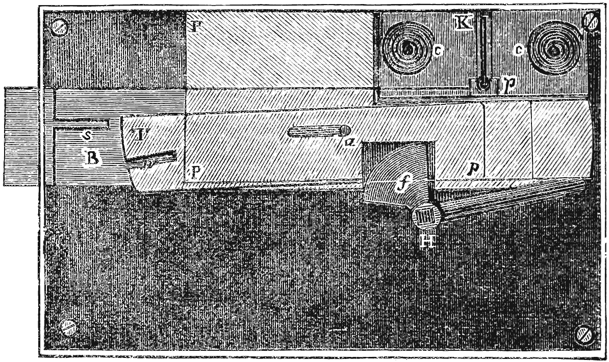
fig. 51. Mr. Denison’s large lock.
The handle H should be so made, that as soon as the fantailed[145] piece f has sent the bolt just clear of the tumblers, the other arm to the right of H may begin to move the tumblers; but the fantail need not send the stump above one-sixteenth of an inch beyond the tumblers; and the curtain-plug and bolt must be so adjusted that the curtain cannot be pushed in until the bolt is so far out that the stump is this one-sixteenth of an inch beyond the tumblers. The curtain K need only be a thin piece of steel, and the bolt B must be thick enough for the curtain to go down just to the level of the thin plate P between the bolt and the first tumbler T. The curtain-plug p is made as long as the key-hole and rather broader, and of the shape represented, partly for the sake of steadiness in pushing in the curtain, and also for more completely protecting the key-hole; for if an attempt be made to pick the lock by drilling into the key-hole, the drill will pass into the inside of the door and not into the inside of the lock.[10]
[10] Mr. Denison informs us that there is a further contrivance, which he will explain privately to any persons who wish to manufacture these locks, of which the object is, not to add any thing to the security of the lock under ordinary circumstances, but to provide against the unusual case of a very dexterous thief having occasional access to the lock when open; in which case (but for some such further provision) he might manage to construct a false key capable of opening the lock at any other time, by a method which, for obvious reasons, it is not advisable to publish.
It is true that iron safes have been made for some years in which any number of large bolts are shot by a handle and then locked by a very small key. But in such locks the key must be used in locking, and this leads to certain objections, viz. the key must occasionally at least be confided to some person whose duty it is to lock up the safe after the owner has left the place; there is also the temptation to leave the key in the lock, since it will be wanted in locking up; and thus there is the danger of some dishonest person taking an impression of the key. Besides this, the real strength and security of such safes is only that due to the small lock which locks into the main bolt; whereas in Mr. Denison’s lock the security and strength are those due to the lock itself, with its large and[146] strong tumblers, and other provisions peculiar to its construction; and the key for a lock of the largest size, which was lately exhibited at the Society of Arts by Messrs. S. Mordan and Co., the makers, only weighs a little more than a quarter of an ounce. It may be mentioned that for large locks the key may be solid, although in the small ones it is more convenient to have a pipe-key, on account of the different construction of the curtain.
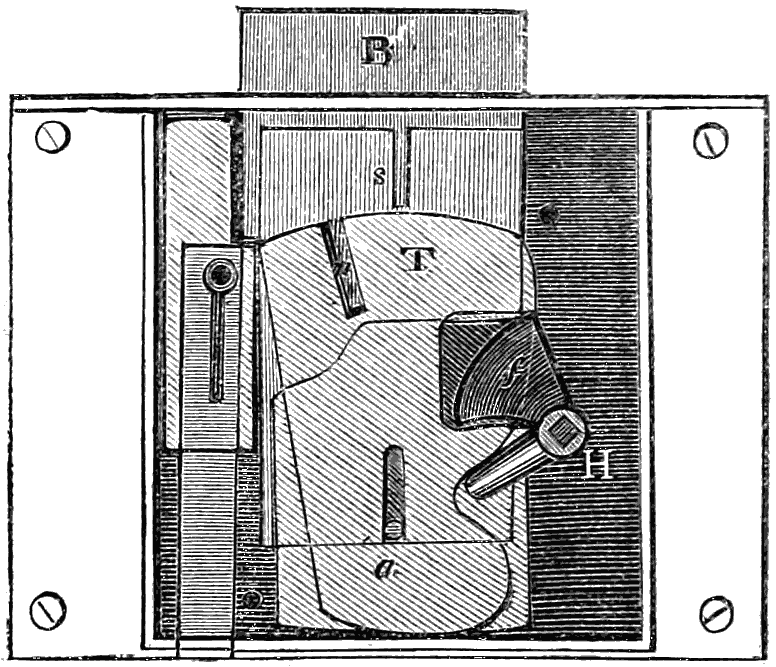
fig. 52. Mr. Denison’s small lock.
The arrangement of the small lock for drawers, &c. is somewhat different from that of the large ones, and will be understood by referring to fig. 52. The action of the handle H on the bolt B and on the tumblers T is sufficiently clear from the figure. The curtain in this case has no plug, but is only a flat plate held up by a thin spring behind it, and moving up and down on the drill-pin of the key, and kept from turning by having one edge against the side of the lock. The bolt has a kind of second stump, only coming up so high as to be able just to pass under the corner of the curtain when it is up, but not able to pass when the curtain is at all pressed down by any thing inserted in the key-hole. In a drawer lock the key has only to be turned a quarter round in order to raise the tumblers. In small locks, the friction of the tumbler-plates is[147] quite enough to keep them in any position, without putting the pin in the middle so as to balance them, as in large locks with heavy tumblers.
In the making of these locks the key must be made first, with proper provisions to prevent the repetition of the same pattern; a kind of pattern or model for locks of each size should be made; the tumblers put on the pin with plates of the intended thickness between, and when raised by the key to the proper height they should be clamped down; and the jaws for the stump of the bolt may then be cut by a circular saw moving in a slit in the model corresponding to the place of the stump. The tumblers for large locks may be cut off from a strip of hoop-iron to the proper lengths by a stamping cutter, giving them the proper circular end, and a punch might at the same time make the pin-hole in the middle. The tumblers for small locks should be stamped out of sheet brass or iron.
It will thus be evident that from the general simplicity of construction, and the small amount of finish required in the working parts, this lock can be made at small cost. We may also add that this lock is as creditable to the public spirit as to the mechanical skill of the inventor; for the lock is not patented, patents being, in Mr. Denison’s estimation, obstructions to the progress of science.
The next result of the “lock controversy” which we have to notice is the production of not less than three improved locks by Messrs. Chubb. We thought it our duty to invite the attention of this celebrated firm to the preparation of this Rudimentary Treatise, and in answer to the application of our publisher we received the following communication from Messrs. Chubb, which we insert verbatim:—
“It will not be necessary to describe the lock as originally made, as a description of it will be found in Mr. Chubb’s paper read before the Institution of Civil Engineers.
“Lock No. 1.—The first of the improvements introduced consists of a barrel, to which a circular curtain is attached, revolving round the drill-pin in the lock; so that if any instrument[148] is introduced to attempt to pick it, the curtain immediately closes up the key-hole, and prevents the introduction of any auxiliary instruments, there being several required in action at once to produce any effect.
“If by any means these several instruments can be introduced simultaneously, the barrel keeps them all confined in a very small space, preventing their expansion, and renders it impossible to work them independently of each other; therefore they are of no avail, being incapable of acting as more than a single pick, which is perfectly useless. The barrel and curtain have each been previously used separately in locks, but until patented by Mr. De la Fons in 1846 they had not been used in combination. Neither of them, used separately, is of much use, but when combined they afford a very great security. Locks have been, and still are shewn, containing either the barrel or curtain singly, and as these have been picked, it has been asserted that the improvement now introduced in Chubb’s lock is equally insecure; but a slight examination of the difference in their construction will prove the contrary. Mr. Chubb has purchased the patent-right of this part of Mr. De la Fons’ invention, and applies it to all his locks.
“Lock No. 2.—The next improvement, recently patented by Mr. Chubb, is based upon the assumption that there may be a possibility of overcoming the security of the barrel and curtain as already described (although this assumption is not in the slightest degree admitted), and consists in applying what is called a ‘tumbler-bolt,’ working on a hinge connected with the main bolt. The web of the key does not in any case touch the main bolt in unlocking, but acts only on the tumbler-bolt. All the tumblers must first be lifted, each to its proper position, before the tumbler-bolt will act. Should any pressure be applied to either bolt before the tumblers are all at their exact position, the effect would be to throw the bolts out of gear, and thus effectually to stop the stump of the main bolt from passing through the racks of the tumblers. None of the many plans of picking which have been suggested, such as smoked key-blanks,[149] thin key-bits, &c., would be of the least avail against a lock made on this principle. Different kinds of detectors may be applied to these locks. It is submitted that this lock, retaining all the simplicity and durability which have distinguished Chubb’s lock for so many years, and combining with them these important improvements, affords a complete security against all surreptitious attempts of any nature. Locks on the same principle are being made on the permutation plan, with any number of tumblers, and any number of changes in combination that may be desired.
“It has been suggested that the ‘detector,’ instead of giving additional security to Chubb’s lock, affords a partial guidance to a person attempting to pick it. This objection holds good to a certain extent in these locks as originally made, in which all the tumblers had an equal bearing against the detector-stump; but in the locks as now constructed this objection is entirely obviated, by giving the tumblers an unequal bearing, whereby, if an operator feels the obstruction of the detector-stump, he cannot tell whether the tumbler which he is lifting is raised too high, or not high enough.
“Lock No. 3.—For banks, Mr. Chubb has introduced what he particularly calls his ‘bank lock.’ It contains a barrel with a series of curtains. While the key-hole is open, all access to the tumblers from the key-hole is completely cut off by two sliding pieces of solid metal, which fit closely on either side of the barrel. These pieces are acted upon by an eccentric motion, so that when the key is applied to the lock, and turned in it, the key-hole is shut up by the revolution of the curtains, and then only do the sliding pieces of metal move aside to allow the key to act upon the tumblers. These pieces return to their position when the key has passed; therefore, while the key is lifting the tumblers, all communication is cut off from the exterior of the lock by these sliding pieces and the series of curtains. The bolt is made in two pieces, the main bolt never being in contact with the key, which acts only on the talon-bolt, and by it transmits the motion to the main bolt. After[150] the action of locking, the talon-bolt is partly repelled, and a lever or ‘dog’ connected with it locks into a series of combinations arranged upon the front parts of the tumblers, and holds them securely down, so that none of them can be lifted in the least degree until the talon-bolt is thrown forward to release them, If, therefore, any pressure be applied to this talon-bolt, to endeavour by its help to ascertain the combinations of the tumblers, it will only the more tightly lock them down, and render the attempt ineffectual. By another contrivance it is rendered impracticable to move a pick or picks round in the lock more than a small distance, unless the tumblers could previously be all lifted to their right positions, which can only be done by the right key. Should one or more of the tumblers be surreptitiously raised by any possible means, they cannot be detained in this uplifted position, for the action of turning back the pick to try to raise another tumbler sets in motion a lever which allows the tumblers already raised to drop to their former position, leaving the operator just as far from the attainment of his object as at the outset.”
Such is the statement with which Messrs. Chubb have favoured us respecting their three new locks. We are willing to admit the enterprising spirit which has led to their production, and the ingenuity which has been bestowed on their construction; but whether they mark a step in advance in the art of lock-making may perhaps admit of doubt. With respect to the lock No. 1, we would remark, that locks with the barrel and curtain combined were made by Mr. Aubin of Wolverhampton in 1833, and that a specimen of such a lock was exhibited on his stand of locks in the Great Exhibition. Locks with the combined barrel and curtain were also made and sold by Mr. Jones of Newark, N.J., as stated at p. 104.
With respect to the lock No. 2, the object of the tumbler-bolt is evidently intended to produce the same effect as the movable stump in Mr. Hobbs’s protector-lock, fig. 47, page 100; but with greater complexity in the construction, there is less efficiency in the action of this part of Mr. Chubb’s lock as[151] compared with that of Mr. Hobbs, inasmuch as a pressure of the stump against the tumblers, corresponding with the strength of the spring which holds the bolt in its place, can always be produced, thereby giving friction, and affording indication as to which tumbler it is that is in tight contact with the stump.
With respect to the barrel and curtains of lock No. 3, and all similar contrivances, the object of which is said to be to prevent the entrance into the key-hole of all instruments except the proper key, we would offer the self-evident remark, that the same aperture which admits the key will also admit some other instrument. In the case of Mr. Chubb’s “bank-lock,” it may be questioned whether the revolving curtain, &c. give it any advantage over the other locks already referred to which are furnished with similar contrivances. The effect of the talon-bolt in this lock appears to be the same as that of the false notches, namely, to hold the tumblers in the position in which they were placed when the pressure was applied. Hence, a pressure applied to the talon-bolt affects the parts which come in contact with the key in the act of locking and unlocking; and this circumstance brings the lock under the application of the principle stated at page 99, and thus, if this principle be admitted, may render the security of the lock somewhat questionable.
Various other locks have been brought out since the date of the “lock controversy” in the year 1851. We would gladly notice them all, did they shew novelty of design and mark an advance in the art of the locksmith. We must, however, admire the ingenuity with which Mr. Hobbs’s movable stump has been more or less adopted; but in the attempts to imitate it the objection has not been removed, that it is possible to produce on the tumblers a pressure or friction equal to the strength of the spring which holds the tumblers down.
There is, however, a lock which has lately been introduced to the public, which calls for special notice, on account of the high honours which have been bestowed upon it. We refer to[152] the prize lock of the Society of Arts, London, the invention of Mr. H. J. Saxby of Sheerness, who has received the Society’s medal and the sum of ten guineas as the reward of his ingenuity. The interior of this lock consists of a cylinder with four pins or slides radiating from the centre, and pressed into the key-hole by means of spiral springs. The pins project beyond the periphery of the wheel or cylinder, and into slots in a ring which is affixed to the case of the lock, thereby preventing the cylinder from being turned. On each pin is a notch, so placed that when the proper key is inserted into the key-hole, the notches on the several pins will be brought into a position such as will allow the cylinder to turn. The turning of the cylinder in this, as in the Bramah lock, shoots the bolt.
A lock on precisely the same principle, but more secure in its construction, was described by Mr. Hobbs in a paper read by him before the Society of Arts in January 1852, when diagrams illustrative of the same were exhibited. This paper was not reported at any length in the journal of the Society’s proceedings; but the same paper was read by Mr. Hobbs, March 1, 1852, before the Liverpool Polytechnic Society, and a full report thereof, and a description of the lock in question, is given in the “Transactions” of that Society, from September 1849 to December 1852 (8vo, Liverpool, 1853). This lock is no other than the Yale lock already noticed at page 83, and is thus described at page 196 of the “Transactions:”
“Another description of cylinder-lock was invented, a few years since, by a Mr. Yale of the State of New York, U.S.A.
“The Yale lock has two cylinders, one working within the other; and they are held together by a series of pins reaching through the cylinders into the key-hole, which is in the centre. On the back of the inner cylinder is a pin that fits into a slot in the bolt, and moves it as the cylinder is turned. The pins that hold the cylinders together and prevent the inner one from turning, are cut in two at different lengths. The key is so made, that by inserting it into the key-hole the pins are moved, so that the joint in the pins meets the joint between[153] the cylinders, and allows the inner one to be turned. But, as with the slides of the Bramah lock, should any one of the pins be pushed too far, the cylinder is held quite as firmly as though it had not been touched. Some of these locks have been made with as many as forty pins; and to a person unacquainted with the principles on which locks are picked, they would seem to present an insurmountable barrier.
“Figure 1[11] represents the case of the lock containing the bolt A, having a groove B, to receive the pin C on the cylinder. Figure 2 shews the cap or top-plate of the lock, and the cylinders; D D is the outer cylinder, that is stationary, being fastened to the plate; E E the inner or moving cylinder; F F the four rows of pins, being cut in two at different lengths, and reaching through the cylinders into the key-hole; G G are the springs that press the pins to their places; C the pin that fits into the groove and moves the bolt. Figure 3 is an end view of the key, shewing four grooves. Figure 4 is a side view, shewing the irregular surface of the grooves by which the pins are adjusted.
[11] This and the following figures refer to the diagrams exhibited by Mr. Hobbs.
“For the purpose of picking the lock, an instrument is made that will fit between two of the pins; to that is attached a lever and weight, thereby getting a pressure on the cylinder and causing the pins to bind; then with another instrument the pins are felt, and as they are found to bind, they are pressed in until they are relieved (as they will be when the joint comes to the right place), thereby easily opening the lock. There is a great similarity in the operation and security of this and the lock manufactured by Mr. Cotterill of Birmingham.”
In the Society of Arts Journal for the 24th June, 1853, is a letter from Mr. Hobbs on the subject of the prize lock, which, it appears, he picked, “in the presence of parties connected with the Society, in the short space of three minutes.”
[154]
The manufacture of locks and keys, considered as a department of working in iron, is one that requires, and indeed admits of, very little description. The hammer, the file, the drill, the fly-press, are the chief instruments employed; the iron itself being brought to something like the desired state and form by rolling or casting, or both. But the manufacture is interesting in its social features—in its relation to the persons employed and the buildings occupied. One by one, several departments of industry have progressed from the handicraft to the factory system—from that system in which a man and a few apprentices work in a small shop in the lockmaker’s garret or kitchen, to that in which organisation is maintained among twenty or fifty or a hundred men. Locks have scarcely yet passed out of the first stage, but there is no good reason whatever why they should so remain; there are as many reasons for progress in this as in other arts, and indications are not wanting that some such progress will be made.
So far as England is concerned, the neighbourhood of Wolverhampton is the great storehouse whence locks are obtained. Eminent lock-makers reside in London and in other principal towns; but Wolverhampton is regarded by all as the centre of the trade. This is not a modern localisation, for we have information respecting the locks of Wolverhampton a century and a quarter ago. Among the Harleian Manuscripts is an account of “The Voyage of Don Manuel Gonzales (late merchant), of the City of Lisbon in Portugal, to Great Britain: containing an Historical, Geographical, Topographical, Political, and Ecclesiastical Account of England and Scotland; with a Curious Collection of things particularly rare, both in Nature and Antiquity.” This Ms. appears to have been written[155] about 1732; it was translated from the Portuguese, and printed in Pinkerton’s Collection of Voyages and Travels. With reference to Wolverhampton, Gonzales says: “The chief manufacturers of this town are locksmiths, who are reckoned the most expert of that trade in England. They are so curious in this art, that they can contrive a lock so that if a servant be sent into the closet with the master-key, or their own, it will shew how many times that servant hath gone in at any distance of time, and how many times the lock has been shot for a whole year; some of them being made to discover five hundred or a thousand times. We are informed also that a very fine lock was made in this town, sold for 20l., which had a set of chimes in it that would go at any hour the owner should think fit.” If Gonzales were correct in these descriptions, they indicate an exercise of considerable ingenuity in lock-construction, especially in reference to the lock which keeps a registry of the number of times it has been opened. There is abundant evidence that the old lock-makers were very fond of these knick-knack locks, which would do all sorts of strange and unexpected things; and this may in part account for the great favour in which locks have been held by amateur machinists.
The lock-manufacture in South Staffordshire is of a remarkable character, comprised as it is within so small an area. Although Wolverhampton is known commercially as the chief depôt of the English lock trade, yet it is at Willenhall, three or four miles eastward of that town, that the actual manufacture is chiefly carried on. When the Commission was appointed a few years ago to inquire into the condition of children employed in trades and manufactures, Mr. R. H. Horne was deputed to examine the Wolverhampton district; and his report is too curious, and too closely connected with our present subject, to be passed unnoticed. We here give an abstract of such parts of his report as bear reference to the lock-makers of Willenhall.
Almost the entire industry of Willenhall is in the three[156] articles of currycombs, locks and keys, and articles connected incidentally with locks, such as bolts and latches. At the time Mr. Horne wrote, in 1841, there were among the master manufacturers 268 locksmiths, 76 key-makers, 14 bolt-makers, and 13 latch-makers; besides many small masters living in such out-of-the-way corners that they escaped enumeration. In the Post-Office Directory of that district, of later date, there are entries of rather a curious character. In the first place it is observable that different kinds of locks are made by different persons, each manufacturer confining his operations apparently to one kind of lock; one is a rim-lock maker, another a trunk-lock maker, a third a cabinet-lock maker, a fourth a padlock maker, a fifth a mortice-lock maker, and so on. But a much more singular feature is, that lock-making is combined with retail dealing of a totally different kind; thus among the occupations put down opposite the names of individuals are, “key-stamper and beer-retailer,” “door-lock maker and beer-retailer,” “grocer and trunk-lock maker,” “Malt-Shovel tavern-keeper and rim-lock maker,” “lock-maker and provision-dealer,” “grocer and key-maker,” “cabinet-lock maker and Woolpack tavern,” “key-stamper and registrar of births, &c.,” “Hope and Anchor and cabinet-lock maker,” “auctioneer and locksmith,” “rim-lock and varnish maker,” and so forth. It is probable that in some of these cases the wife attends to the retail shop, while the husband attends to the workshop.
Among all the lock-manufacturers of the town there are scarcely half a dozen in what may be termed a large way of business; there are many who employ from five to fifteen pairs of hands, but the great majority are small masters who are themselves working mechanics, and are aided by apprentices from one to four in number, perhaps two on an average. Mr. Horne thinks that there were not fewer than a thousand boys at work in the town, chiefly upon locks and keys. The children and young persons are employed at all ages, from seven up to manhood; from the earliest age, indeed, in which they are able to hold a file. It is a characteristic fact, where so[157] many of the male inhabitants are employed at the bench from such early years, that a certain distortion of figure is observable; the right shoulder-blade becomes displaced and projects, and the right leg crooks and bends inwards at the knee, like the letter K,—it is the leg which is hindermost in standing at the vice. The right hand also has frequently a marked distortion. “Almost every thing it holds takes the position of the file. If the poor man carries a limp lettuce or a limper mackarel from Wolverhampton market, they are never dangled, but always held like the file. If he carry nothing, his right hand is in just the same position.”
The hours of labour among the small masters are scarcely brought within any system at all; for all the work is piecework, not paid for by the day or hour; and each man works as long as he likes, or as long as his business impels him. Some will file away from four or five in the morning till eleven or twelve at night. In the larger shops, where there are many hands employed, they come to work when they like, leave when they like, and do as much work as they like when there; this freedom of action being spread over a working-day of perhaps sixteen hours. The masters say that the men prefer this system, or want of system, to any thing more precise and regular. In the beginning of the week there is often much idleness and holiday-keeping; and the Willenhall men make up for this by a day of sixteen, eighteen, or even twenty hours’ work towards the end of the week. In the beginning of the week, men and boys have defined hours and definite periods for meals; but towards the end of the week, when hurry and drive are the order of the day, they eat their meals while at work, and bolt their victuals standing. “You see a locksmith and his two apprentices, with a plate before each of them, heaped up (at the best of times, when they can get such things) with potatoes and lumps of something or other, but seldom meat, and a large slice of bread in one hand; your attention is called off for two minutes, and on turning round again, you see the man and boys filing at the vice.”
[158]
In the processes as carried on at Willenhall, they are applied chiefly to the manufacture of mortice, box, trunk, rim, cabinet, case, bright, dead, closet, and padlocks. Except some of the parts of the brass-work, which are cast, these locks are made by forging, pressing, and filing. The forging is a light kind of smith’s work, aided by a light hammer and a small pair of bellows; children and young persons are largely employed in this process. Pressing is a kind of work by which certain parts of the lock are pressed or stamped out. The presses are of various sizes, but all require much strength to work them; the press has a horizontal lever, crossing the top of a vertical screw, and there is generally an iron weight at the end of each arm or half of the lever to increase the power; one of the lever arms is grasped in the right hand of the presser, and whirled round with a jerk; while the fingers of the left hand place the metal in its proper position, and remove it when it has been stamped or pressed. There is, of course, a die or cutter attached to the press, to cut the metal in the proper form. Sometimes the press has only one arm to the lever, and no weight at the end of this, so that the labour of working is much increased. Children and youths are employed at this process, so far as their strength will admit. The last process, filing, is that by which the separate pieces are shaped and smoothed for adjustment in their proper places; here children and youths are almost exclusively employed; they stand upon blocks so as to be able to reach the vice, and then work away with the file, unrelieved by any change in the nature of the process.
In key-making the processes may be said to comprise forging, stamping, piercing, and filing. The forging differs very little from that required in making the pieces for a lock. The stamping is effected by placing the end of an iron wire, taken red-hot from the forge, into one half of a key-mould made in a block or kind of anvil; a heavy weight is then raised between an upright framework, in the grooves of which it runs by means of a cord; the cord is drawn by both hands, with[159] the assistance of one foot in a stirrup attached to the end of the cord; at the bottom of the weight thus raised is the other half of the key-mould. Such being the nature of the stamping apparatus, the process is thus conducted: the foot in the stirrup being suddenly raised, and the cord loosed, the weight falls upon the red-hot wire, and the blow stamps it into the two moulds or half-moulds, which are brought accurately together by means of the slides or side-grooves in the framework. The rough key is also trimmed and cleared by the pressing apparatus; that is, the surplus metal all round is cut off by a single blow; and the metal which fills up the ring or handle of the key is cut or pressed out in the same way. This is a heavy part of the key-work, for which the labour of men rather than that of boys is required. The process of piercing the key consists in making the pipe or barrel, required for most keys, except those which are intended to open a lock for both sides; the pipe is drilled by a small machine worked with the foot like a lathe; it is a process requiring more skill than strength, relatively to other parts of the manufacture. The filing of a key is important; for not only is the whole key made bright, but the wards are cut by the file and chisel. Boys and youths are employed in filing the common keys; but those of better quality are entrusted to men.
The apprenticeship system is carried on to a remarkable extent among the lock and key makers of Willenhall. The small masters take apprentices at any age at which they can work. Some of them employ only apprentices, never paying wages for journeymen, but always taking on a new apprentice as soon as a former one is out of his time. The boys are mostly procured from other towns, and they bring with them a small apprenticeship-fee and a suit or two of clothes. They are bound to the masters by legal indenture or contract; and the masters board and lodge and clothe them during their apprenticeship. One consequence of this system is, that when the apprentice has served his time, he is almost driven to become a small master himself from want of employment as a journeyman;[160] and he then takes apprentices as his master did before him. This accounts for the fact that in Willenhall there are few large manufacturers and few journeymen; while there is a constantly-increasing number of small masters and of apprentices.
The Willenhall makers nearly all look to the Wolverhampton factors or dealers for a market for their wares—so far at least as concerns locks and keys; there are some other articles which they sell more frequently to Birmingham houses. The master and an apprentice, or perhaps two, generally trudge off to Wolverhampton on a Saturday, bearing the stock of locks which he may have to sell; and the money receipts for the locks or keys sold are usually in part spent at the large market of Wolverhampton previous to the homeward journey. The Willenhall men take contracts at so low a price as to prevent the competition of other places; it is stated, that whatever be prices elsewhere, nothing can come below the Willenhall prices for cheap locks. The men work hard for small returns, and yet they have a strong yearning for their own town. A Willenhall girl will seldom marry except to a townsman; and thus they intermarry to an extent which maintains their characteristics as a peculiar community. As an example of their disinclination to leave their own town, Mr. Horne states the following circumstance: “Some years ago a factor, who had projected a manufactory in Brussels, engaged some five-and-twenty Willenhall men, whom he was at the expense of taking over. He gave them all work, and from hard-earned wages of from 9s. to 15s. a-week, these ‘practised hands’ found themselves able to earn 3l. a-week and upwards. But they were not satisfied, and began to feel uncomfortable; first one left, and returned home; then another; then one or two; till, in the course of a few weeks, every man had returned to Willenhall”—there to work harder and earn less.
It is just possible that the application of the factory system to lock-making may first become important by making the best locks cheaper than they can be made by the handicraft method;[161] for there seems not much probability, at least for a great length of time to come, that any new system will be able to compete with Willenhall in the common locks—those of which more thousands are sold than there are tens of the better locks. In this, however, it would not do to predict rashly. Hand-loom weaving is cheap enough, unfortunately for those who practise it; but yet the factory system comes down as low as the lowest hand-loom weaving.
The editor of Hebert’s Encyclopædia, after noticing the facilities for opening most locks by copying the key, makes the following announcement: “It affords the editor of this work much satisfaction to state, that he has in his possession a lock, the key of which cannot be copied, a locksmith possessing no tools by which an exactly similar one can be made; the machine by which the original one was made is so arranged as to be deprived of the power of producing another like it. The lock is very simple, very strong, and can be very cheaply made. The cost of a complete machine to make them would be about 100l.; with that they might be manufactured at one-half the expense of any patent lock. The inventor is desirous to have the subject brought before the public under a patent; but want of time to devote himself to such an object at present obliges him to lay it aside.” The invention not being patented, the editor of course gave no diagram or engraving of the lock or machine; nor does there appear to have been a patent obtained during the sixteen or eighteen years which have elapsed since the above notice was published. There are, however, mechanical principles sufficiently well known to lead to a belief that such a machine is practicable; a ticket-printing or numbering machine will, in printing 100,000 tickets, produce such variations that no two impressions shall be identical; and a key-making machine might, after fashioning a particular part of each key, modify the arrangement of certain wheels and pinions so far as to produce a slightly different result when the next key is to be operated on.
In the manufacture of locks and keys generally, there is[162] no reason why the factory system should not, to a certain extent, be applicable. By this will be understood, the production of similar parts by tools or machines, graduated in respect to each other with more care than can be done by the hand method. If we suppose that a lock of particular construction comprises twenty screws and small pieces of metal, and that there are required, for general disposal in the market, five sizes of such a lock; there would thus be a hundred pieces of metal required for the series, each one differing, either in shape or size, from every one of the others. Now, on the factory or manufacturing system, as compared with the handicraft system, forging, drawing, casting, stamping, and punching, would supersede much of the filing; the drilling machine would supersede the drill-stock and bow, and other machines would supersede other hand-worked tools. This would be done—not merely because the work could be accomplished more quickly or more cheaply—but because an accuracy of adjustment would be attained, such as no hand-work could equal, unless it be such special work as would command a high rate of payment. For any one size in the series, and any one piece of metal in each size of lock, a standard would be obtained which could be copied to any extent, and all the copies would be like each other. To pursue our illustration, the manufacturer might have a hundred boxes or drawers, and might supply each with a hundred copies of the particular piece of metal to which it is appropriated, all so exactly alike that any one copy might be taken as well as any other. Ten pieces, one from each of ten of these boxes, would together form a lock; ten, one from each of another ten boxes, would form a second lock, and so on; and there would be, in the whole of the boxes, materials for a thousand locks of one construction, a hundred of each size.
Now the advantage of the machine or factory mode of producing such articles is this, that they can be made in large numbers at one time, whenever the steam-engine is at work; and that when so made, the pieces are shaped so exactly[163] alike, the screws have threads so identical, and the holes are bored so equal in diameter, that any one of a hundred copies would act precisely like all the others, thereby giving great advantages to the men employed in putting the lock together.
These principles are being applied by Messrs. Hobbs and Co. in their London establishment. A number of machines, worked by steam-power, are employed in shaping the several pieces of metal contained in a lock; and all the several pieces are deposited in labelled compartments, one to each kind of piece. The machines are employed—in some cases to do coarse work, which they can accomplish more quickly than it can be done by men; and in other cases to do delicate work, which they can accomplish more accurately than men; but so far is this from converting the men into lowly-paid automatons (as some might suppose), that the manufacturers are better able to pay good wages for the handicraft labour necessary in putting the locks together, than for forming the separate parts by hand; just as the “watchmaker,” as he is called, who puts the separate parts of the watch together, is a better-paid mechanic than the man who is engaged in fabricating any particular parts of the watch.
It may be observed that the system of manufacturing on a large scale, by many men engaged in one large building, is more nearly universal in the United States than in England. The workshop system, as pursued at Willenhall by the lock-makers, is very little practised in America. Being comparatively a new community, and being at liberty to select for imitation or for improvement whichever of the usages or systems in the old country they may prefer, the Americans have preferred to adopt the factory system rather than the workshop system, and to carry out the former to an extent not yet equalled in England—not yet equalled, we mean, in the number of trades to which it is applied.
[164]
We propose to conclude this small work with a few details respecting the various patented inventions in locks, and concerning Mr. Aubin’s remarkable lock trophy. These two subjects relate to locks in general, rather than to any specified constructions in particular, and can on that account more conveniently be given here than in connexion with any of the foregoing chapters.
Mr. Chubb, in the appendix to his paper on locks and keys read before the Institution of Civil Engineers, gave a useful list of all the patents taken out in England in relation to this subject, down to the year 1849. We here transcribe this list:
List of Patents for Locks and Latches granted since the Establishment of the Patent Laws.
“As no complete list of the patents granted for locks from the time of James I. has hitherto been published, it is believed that the following list, which has been very carefully drawn up, and which comprises all patents from the year 1774, when the first patent for a lock was granted, to the present time, will be found useful as a reference for all who are interested in the subject.
| 1774 | May | 27 | Black, George, Berwick-on-Tweed. |
| „ | „ | „ | Barron, Robert, London. |
| 1778 | May | 29 | Martin, Joshua Lover, Fleet-street, London. |
| 1779 | May | 28 | Henry, Solomon, Swithin’s-lane, London. |
| 1780 | March | 4 | Campion, J. Newcastle-court, Strand, London. |
| 1782 | January | 18 | Hutchinson, Samuel, Marylebone, London. |
| 1784 | „ | Bramah, Joseph, Piccadilly, London. | |
| 1789 | July | 7 | Cornthwaite, Thomas, Kendal, Westmoreland. |
| 1790 | February | 23 | Rowntree, Thomas, Surrey-street, Blackfriars, London.[165] |
| „ | October | 29 | Bird, Moses, Wardour-street, London. |
| 1791 | July | 19 | Ferryman, Rev. Robert, Gloucester. |
| „ | November | 3 | Antis, John, Fulneck, near Leeds. |
| 1797 | November | 18 | Langton, Daniel. |
| 1798 | May | 3 | Bramah, Joseph. |
| „ | December | 8 | Turner, Thomas. |
| 1799 | April | 11 | Davis, George. |
| 1801 | February | 10 | Scott, Richard, Lieut.-Colonel. |
| „ | June | 24 | Holemberg, Samuel, London. |
| „ | ... | Roux, Albert, Switzerland. | |
| 1805 | May | 18 | Stansbury, Abraham Ogier, New York. |
| „ | December | 29 | Thompson, William, Birmingham. |
| 1815 | March | 7 | Mitchell, William, Glasgow; and Lawton, John, London. |
| 1816 | May | 14 | Ruxton, Thomas, Esq., Dublin. |
| 1817 | February | 8 | Clark, William, Esq., Bath. |
| 1818 | February | 3 | Chubb, Jeremiah, Portsea. |
| 1819 | October | 18 | Strutt, Anthony Radford, Mackeney. |
| 1820 | April | 11 | Jennings, Henry Constantine, Esq., Middlesex. |
| „ | December | 14 | Mallett, William, Dublin. |
| 1823 | July | 10 | Fairbanks, Stephen, Middlesex. |
| „ | November | 13 | Ward, John, Middlesex. |
| 1824 | June | 15 | Chubb, Charles, Portsea. |
| 1825 | May | 14 | Young, John, Wolverhampton. |
| 1828 | May | 17 | Chubb, Charles, London. |
| 1829 | June | 1 | Gottlieb, Andrew, Middlesex. |
| 1830 | January | 18 | Carpenter, James, and Young, John, Wolverhampton. |
| „ | January | 26 | Arnold, John, Sheffield. |
| 1831 | April | 14 | Rutherford, William, Jedburgh, N.B. |
| „ | May | 23 | Barnard, George, Bristol. |
| „ | July | 27 | Young, John, Wolverhampton. |
| 1832 | December | 20 | Parsons, Thomas, London. |
| 1833 | December | 3 | Parsons, T., Newport, Salop. |
| „ | December | 20 | Chubb, Charles, London; and Hunter, E., Wolverhampton. |
| 1834 | September | 6 | Longfield, William, Otley. |
| „ | October | 11 | Audley, Lord Baron Stafford. |
| 1835 | March | 18 | Hill, R., Birmingham. |
| „ | December | 16 | Warwick, J., London. |
| 1836 | February | 10 | Fenton, Rev. S., Pembroke. |
| 1838 | June | 30 | Uzielli, M., London. |
| „ | November | 13 | Thompson, S., London. |
| 1839 | February | 21 | Uzielli, M., London. |
| „ | June | 12 | Sanders, J. Stafford. |
| „ | July | 3 | Cochrane, A., Strand, London. |
| „ | July | 20 | Schwieso, J. C., London. |
| „ | August | 1 | Williams, W. M., London. |
| „ | December | 2 | Guest, J., jun., Birmingham. |
| 1840 | February | 27 | Williams, W. M., London. |
| „ | March | 20 | Gerish, F. W. |
| „ | May | 2 | Pearse, W., Hoxton, Middlesex. |
| „ | June | 13 | Wolverson, J., and Rawlett, W., Stafford. |
| „ | October | 22 | Clark, T. |
| „ | December | 23 | Baillie, B., London. |
| 1841 | March | 29 | Tildesley and Sanders, Willenhall and Wolverhampton. |
| „ | May | 6 | Hancock, James, Sidney-square, Mile End.[166] |
| „ | July | 14 | Berry, Miles, Chancery-lane. |
| „ | September | 28 | Strong, Theodore Frederick, Goswell-road. |
| „ | November | 9 | Smith, Jesse, Wolverhampton. |
| 1842 | January | 15 | Poole, Moses, Lincoln’s-inn. |
| „ | May | 24 | Duce, Joseph, Wolverhampton. |
| „ | June | 1 | Williams, W. M., 163 Fenchurch-street. |
| „ | December | 29 | Rock, Joseph, jun., Birmingham. |
| 1843 | November | 25 | Tann, E. E. and J., Hackney-road. |
| „ | „ | „ | Rock, Joseph, jun., Birmingham. |
| 1844 | July | 30 | Fletcher, Rev. William, Moreton House, Buckingham. |
| 1845 | April | 15 | Carter, George, Willenhall. |
| „ | July | 12 | Ratcliff, Edmund, Birmingham. |
| „ | December | 4 | Poole, Moses, Lincoln’s-inn. |
| „ | December | 22 | Smith, Philip, High-street, Lambeth. |
| 1846 | July | 6 | De la Fons, John Palmer, Carleton-hill, St. John’s Wood. |
| „ | July | 15 | Thomas, William, Cheapside. |
| „ | December | 14 | Chubb, John, St. Paul’s Churchyard. |
| 1847 | January | 11 | Chubb, John, and Hunter, Ebenezer, sen., St. Paul’s Churchyard. |
| „ | April | 15 | Collett, Charles Minors, 62 Chancery-lane. |
| 1848 | September | 28 | Newall, Robert Stirling, Gateshead. |
| 1849 | May | 8 | Wilkes, Samuel, Wednesbury-heath, Wolverhampton. |
Mr. Chubb also gave a list of such papers m the Transactions of the Society of Arts as refer to locks and keys.
List of References to the “Transactions of the Society of Arts,” on the subject of Locks.
| vol. | page. | vol. | page. | ||||
|---|---|---|---|---|---|---|---|
| 1. | 317 | Mr. | Moore. | 38. | 111 | Mr. | A. Ainger. |
| 2. | 187 | „ | Cornthwaite. | „ | 205 | „ | Bramah. |
| 3. | 160 | Marquis of Worcester. | 42. | 125 | „ | J. Duce. | |
| „ | 165 | Mr. | Mr. Taylor. | 43. | 114 | „ | W. Friend. |
| „ | 163 | „ | Marshall. | 45. | 123 | „ | Machin. |
| 18. | 239 | „ | T. Arkwright. | 48. | 132 | „ | S. Mordan. |
| „ | 243 | „ | Bullock. | 50. | 86 | „ | A. Mackinnon. |
| 19. | 290 | „ | W. Bullock. | 51. | 128 | „ | J. Meighan. |
| 36. | 111 | „ | M. Somerford. | ||||
Among the most curious mechanical productions in the Great Exhibition of 1851, was one which attracted very little notice, viz. that forwarded by Mr. C. Aubin of Wolverhampton. Whether it was that attention, so far as regards locks, was too much absorbed by the “lock controversy,” or whether there was a deficiency of descriptive cataloguing, no juror or newspaper critic, as far as we are aware, took notice of the production in question. In the Official Illustrated Catalogue it is entered simply as “Specimens to illustrate the rise and progress[167] of the art of making locks, containing forty-four different movements by the most celebrated inventors in the lock trade.” This trophy of lock ingenuity (for such it may be justly considered to be) is now in the possession of Mr. Hobbs. Springing from a hexagonal base-piece is a central axis, about three feet in height, supporting four horizontal circular discs, placed at different parts of its height. Each of the vertical faces of the base-piece contains a lock, which is worked by its respective key. Each disc contains a number of locks: 16 on the lowest, 12 on the next above, 9 on the third in height, while a Bramah lock surmounts the whole. All the locks on the discs are so arranged that their bolts shoot outwards, or radially away from the axis of the machine. Every lock has its own proper key inserted in the key-hole; and as the locks lie down horizontally, the shaft of each key is of course vertical. There are delicate pieces of mechanism contained within the central axis and within the discs, consisting of levers, racks, and pinions; and the Bramah lock is contrived so ingeniously, that the Bramah key, by acting upon that lock, acts upon all this mechanism. The Bramah barrel, in rotating horizontally under the action of its key, gives a rotary movement to a rod passing vertically through the centre of the whole apparatus; this rod, at the levels of the several discs, acts upon racks and pinions, and these in turn act upon the key-pins of the several locks. When, therefore, the Bramah key is turned, the whole of these key-pins rotate, each exactly in the same way as if the lock were being closed or opened, and the bolts shoot in or out accordingly. The Bramah key, although it acts as a master-key, is not such as usually obtains that designation; it is simply a means of putting in action certain rack-and-pinion mechanism, which does not belong to lock-work considered per se. All the locks are faithful representatives of the several patents or modes of construction to which they severally refer; and each exhibits the works sufficiently open to display the principle on which it is arranged. Each lock is numbered, and is referred to in an accompanying description. The works are finished with[168] the utmost care and polish; and the trophy being somewhat tastefully arranged, and kept under a glass shade, forms a really elegant specimen of mechanical skill.
For an account of the locks themselves which constitute this trophy, we cannot do better than avail ourselves of the description given in the article “Lock” in Tomlinson’s Cyclopædia of Useful Arts, adding a few further details in respect to some of the locks of the series. The locks are arranged and numbered according to their similarity of construction; and it is instructive to remark the evidence here afforded, that many patentees would have saved much time and money if they had better known the productions of their predecessors. In describing these locks we shall do so briefly, sufficient to shew their relative principles of construction; many of them having been described more or less fully in former chapters.
No. 1 on the list is called a Roman lock; it consists of a single bolt, with a binder-spring for holding the bolt in any position in which it may be placed until a sufficient force is applied to overcome it: it embodies the simple principle on which thousands of common locks are annually made.
No. 2, called a French lock (all such designations are of rather doubtful correctness), resembling No. 1 in every thing except having the addition of a friction-roller. The bolt of either of these two locks can easily be forced back by pressing on the end.
No. 3 is marked Ancient; it is a bolt-lock, and was found in an ancient building. It exhibits an improvement on both the former specimens, in so far as the bolt requires, before it can be shot, to be pressed down, in order to release it from a catch at the back end of the bolt; this release cannot be effected without the aid of a key or some other implement applied through the key-hole, and thus the bolt answers the purpose both of bolt and tumbler.
No. 4, also marked Ancient, is in principle a single-acting tumbler-lock; that is, one in which the tumbler may fail to be lifted high enough, but cannot be raised too high, to release the bolt: whereas a double-acting tumbler, being susceptible[169] both of too much and too little ascent, must be raised to one definite and precise height to attain the required object.
No. 5, an old English lock, exhibits a great advance in principle, being provided with the double action just described as being wanting in No. 4.
No. 6, modern English (no maker’s name), is a single-acting tumbler-lock.
No. 7, by Mace, is a double-acting tumbler, but without exhibiting any peculiarities of construction.
No. 8 is Somerford’s first patent. It is a double-acting draw tumbler-lock; that is, there is a tumbler which is drawn down instead of being lifted, as in most locks.
No. 9, designated, we know not on what grounds, an Indian lock, has a single-acting tumbler with a pin.
No. 10, patented by Thompson in 1805. In this lock there are two tumblers, one of which is single and the other double-acting.
Next follow a considerable number of locks, which differ one from another too slightly to render any formal description necessary. No. 11, by Daniells, is a single-acting tumbler, differing only in form from those previously used. No. 12 is by Walton. No. 13 is Barron’s first patent, taken out in 1774. No. 14 is by Bickerton. No. 15 is a Dutch lock. No. 16 is by Duce, senior. No. 17, by Sanders, is a lock with four double-acting tumblers. No. 18, patented by Cornthwaite in 1789, is so nearly like Sanders’s, brought before public notice in 1839, as to corroborate what we have said concerning the identity, or at least close resemblance, of inventions widely asunder in point of time. No. 19 is by Richards and Peers.
No. 20 is Somerford’s second patent; a lock which seems to embody the principle of Mr. Tann’s “reliance-wards,” patented many years later. No. 21 is Rowntree’s lock, patented in 1790. No. 22 is the first patent lock of Duce, junior, dated 1823. No. 23 is Parsons’ first patent, of 1832. No. 24 is Bickerton’s second. No. 25, patented by Price in 1774; this, so far as at present appears, was the first lock ever constructed[170] with four double-acting tumblers, bearing a closer resemblance than would generally be supposed to those patented by other persons in more recent years. No. 26 exhibits a somewhat similar coincidence. It was introduced by Aubin in 1830, and is furnished with a revolving curtain for the purpose of closing the key-hole during the revolution of the key. Other inventors have since then adopted the revolving curtain; and in a patent taken out so recently as 1852, this appendage is claimed as part of the patent.
No. 27 is Barron’s second patent, dated 1778; a lock which has perhaps been the model for a larger manufacture of plain simple tumbler-locks than any other. No. 28 is by Bird, 1790. No. 29 is the second patent of Duce, junior. No. 30 is Ruxton’s, 1818. No. 31 is Chubb’s simplified lock, 1834. No. 32 is by Marr. No. 33, by Tann, is the “reliance-ward” lock adverted to above as having been anticipated, in respect to its leading principle, by Somerford’s second patent. No. 34 is by Hunter, 1833. No. 35 is Parsons’ second patent, of the same year. No. 36 is by Lang, 1830. No. 37 is Lawton’s, dated 1815. No. 38, patented by Strutt in 1839, has an arrangement for holding the tumblers, in the event of a pressure being applied to the bolt; an arrangement bearing a considerable resemblance to one recently adopted in Chubb’s bankers’ lock. No. 39 is by Scott, 1815. No. 40, Chubb’s patent of 1818, is the original detector-lock of this maker. Most of the detectors since patented by various persons are little other than variations of Chubb’s original.
No. 41, Parsons’ third patent of 1833, is a changeable lock of peculiar construction. The elevation of the tumblers is regulated by an adjusting-screw passing through the lock to the inside of the door; this screw changes the positive but not the relative positions of the tumblers; so that the same difference in the steps of the key must be retained, the change being made only in the length of the bit: the number of changes for each lock is very limited.
No. 42, invented by Pierce in 1840, seems to be a carrying[171] out of the plan suggested by the Marquis of Worcester in his Century of Inventions, where he says that “a lock may be so constructed that if a stranger attempteth to open it, it catches his hand as a trap catcheth a fox; though far from maiming him for life, yet marketh him so, that if once suspected he might easily be detected.” In Pierce’s lock a steel barb or sharp arrow-head is concealed below the key-hole, in such a manner that if any person in attempting to open the lock should over-lift the tumbler, the barb would be thrust by a spring into his hand. It is said that the patentee himself experienced the efficacy of this invention, by receiving the barb into his own hand.
No. 43, by Ruxton, patented in 1816, is furnished with a tell-tale, so arranged that if the tumbler be over-lifted in an attempt to pick the lock, a pin or catch is thrown out from the lock, which would be visible on opening the lock with the proper key. This invention preceded Chubb’s detector by two years, and would be entitled to some of the honours of originality were not Chubb’s arrangement much more simple and effective.
No. 44 is Bramah’s, the patent of 1784, and the crowning lock of the trophy, by which all the others are opened. Similar locks by Russell and Mordan are applications of the Bramah principle, with little or no variation.
No attempt has been made in these pages to describe every variety of lock that has been introduced. Several forms of puzzle locks, known as Russian and Chinese locks, have the forms of various animals, and they are locked and unlocked by pressing upon or moving some portion of the body of the animal: the security of such locks depends in many cases upon keeping the part to be pressed or moved secret. There are also various forms of alarum locks; but these do not greatly differ from common locks, except in having certain appendages, such as a pistol, which if loaded and properly adjusted, will be fired on any attempt being made to open[172] the lock, either with its own key or some other instrument. Some locks are furnished with a bell or a rattle, which is rung or sprung on attempting to open the lock, and in this way the inmates of the house are informed of the attempt to effect an entrance. It will, however, be evident to any one who has read the preceding pages, that devices of this kind do not add to the security of the lock; they rather tend to degrade the art of the locksmith to that of the toyman. The locksmith, in common with every other artist, can only improve in his art by studying the principles upon which it rests, and illustrating them by the most approved examples which the constructive genius of his predecessors or contemporaries has furnished.
[173]
[12] By J. Beverley Fenby, Mechanical Engineer, of Birmingham. Extracted chiefly from the Proceedings of the Institution of Mechanical Engineers, 1866.
The simple fixed-guard or warded lock is so utterly worthless for security, no matter what amount of good workmanship be bestowed upon it, that it demands but short notice. It was contrived with the intention of making the passage to the bolt intricate; but it will be seen at once that this intricacy does not really offer any security. The wards of a lock are circular arcs of thin metal, so arranged as to require a key of peculiar pattern to pass amongst them, the shape of the cuts in the key being a section of the wards. To make a really complicated box of wards, and to cut keys which shall accurately fit their sweep, is a matter requiring considerable manual dexterity; and some warded locks are therefore expensive. But even with the best of them, all that it is necessary to do for opening the lock is to take a blank key which will properly fit the keyhole, coat it with wax, and then inserting it in the lock, press it round against the wards, which will cause them to leave an accurate impression of their section on the key. The parts impressed are then cut out with small files, drills, and saws, and the occasional use of fine cross-cut chisels. The key will then pass those wards which impressed themselves upon it; and if these are the[174] only wards, it will go completely round and open the lock. If there are also other wards in addition, not brought up flush with the first wards, the key is waxed again and pressed against them, and then further cut out, as before. This process is evidently one of absolute certainty, and the key so made is in all respects as capable of mastering the lock as the original key.
These warded locks are however easily opened with merely a piece of bent steel wire,—bent into such a sweep as will reach right round the wards instead of passing amongst them, thus escaping all chance of being obstructed by them. Such an instrument is called by burglars a “twirl.”
The fixed-guard or warded lock was the one in general use in the middle ages.
The next kind of lock is the tumbler lock, in which the bolt is moved backwards and forwards by the key as usual, but these movements cannot take place till a small lever with a stump on one side be lifted. This lever and stump form the tumbler, which is held down by a spring; and in the tail of the bolt are two notches, into one of which the stump fits when the bolt is shot, and into the other when it is withdrawn. All that is necessary to effect the picking of this lock is to lift the tumbler high enough for clearing the stump out of the notch, and then draw back the bolt. The tumbler may be lifted with one pick, and the bolt drawn back with another; but generally one pick will suffice for both purposes.
In the Barron tumbler lock the principle of double-action was introduced.
The next improvement was the lever lock properly so called, under which designation the majority of the modern locks may be classed.
The Bramah lock was an admirable contrivance with remarkably beautiful mechanism contained in a small compass; and since its invention there have been several ingenious modifications of the same principle in different radial locks,[175] such as the Yale lock, in which the slides move radially instead of axially. One advantage in these radial locks is the greater difficulty in copying the keys, in comparison with the flat keys of ordinary lever locks: this difficulty however is not an insurmountable one.
A very ingenious addition was made to the action of the lever lock in Newell’s American lock, which was shown in the 1851 Exhibition, and described at page 89 of the present volume.
Though locks such as those already referred to exhibit great dissimilarity of construction, yet there is one point in which they all agree, and that is in the possession of a direct passage from the outside to the works. Although various locks have been devised with the object of having no direct passage to the works from the outside, one consideration shows the inevitable existence of such a passage; namely, that without it the key could not possibly at one and the same time touch the hand of the operator and the works of the lock. It therefore follows that any instrument which can pass in the same space as the key may be brought to bear on the works, whatever may be their construction.
It can now be shown that, if picking instruments are thus brought to bear on the works through the keyhole, there is a regular tentative system whereby the picking of any lock with an open keyhole can sooner or later be effected.
From the foregoing observations it is evident that there are two important defects in the principle of the previous lever locks, which being defects in principle are fatal to their security; namely, the means of access to the works of the lock through the keyhole, allowing of a series of attempts being made to open the lock by picking instruments; and also the facility afforded for repeating the trial of a false key made from a wax impression of the true key, and thus perfecting it by successive alterations after trial. In consequence of the possibility thus allowed of making these successive attempts either by picking instruments or by a false[176] key, it has been shown by the cases that have occurred of locks of the best makes which have been falsely opened, that, however numerous and complicated may be the secondary impediments introduced into these locks, there can be no real security against the ultimate success of sufficiently numerous and persevering attempts, except by the adoption of some new principle of construction specially meeting the above two defects.
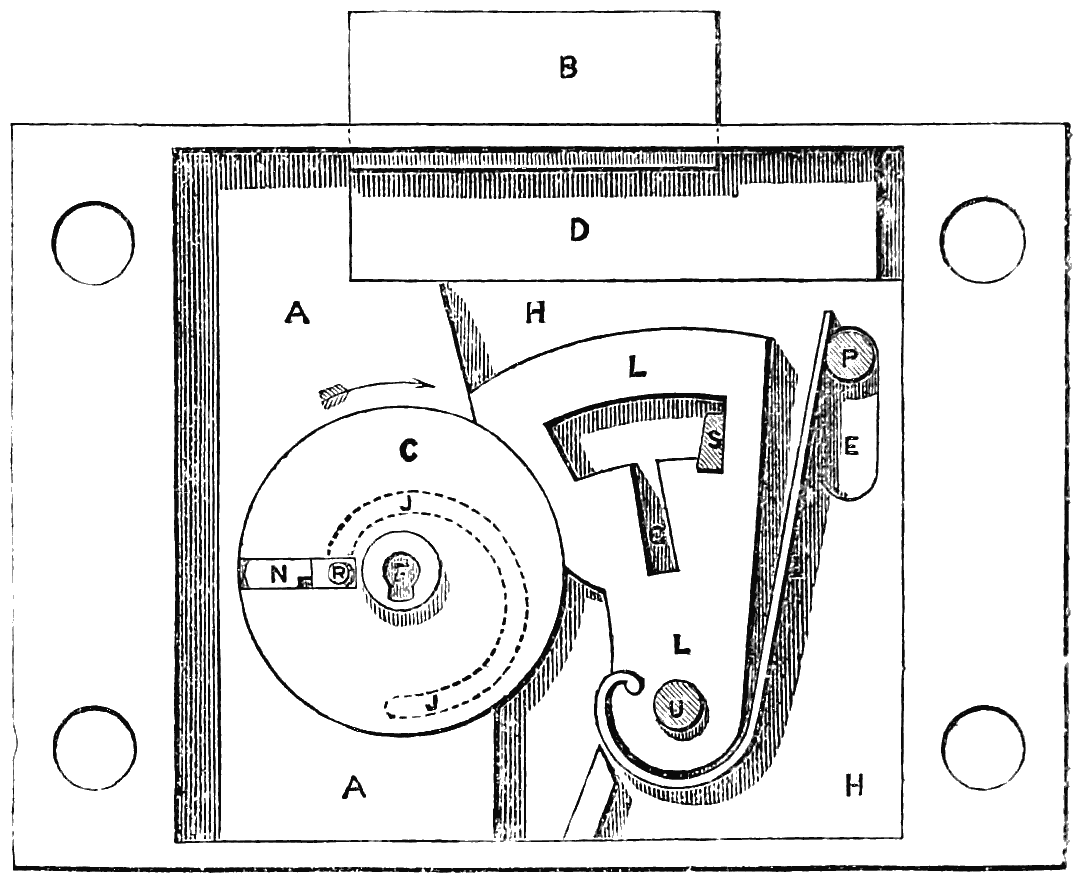
fig. 53.
In the invention of the Improved Lock and Key now to be described, and which has been termed the adytic lock,[13] the writer’s object has been to meet this requirement. In fig. 53 is shown an elevation of this lock, such as is made for an iron safe; two of the front cover plates being removed to show the construction.
[13] From the Greek αδυτος, inaccessible.
The head B of the main bolt is of such a thickness as to be flush with the face of the levers L and guard A; and the[177] strap or tail D of the bolt is thin, and passes behind the levers and guard, and also behind the plate H H. The part of the tail D which would lie under the levers L and cylinder C is removed, as seen in fig. 54, and replaced by a separate flat plate or stump-bolt, carrying the stump S. This stump-bolt has a projection K upon it, let into a recess in the tail D of the main bolt, but with 1⁄10th inch vertical play in the recess. A spring in the tail of the main bolt presses the stump-bolt downwards, keeping the stump S in the notches of the levers L, as shown in fig. 53. The stump-bolt can thus descend 1⁄10th inch at first without moving the main bolt, and this amount of vertical movement is sufficient to carry the stump in and out of the notches in the levers; but the stump-bolt cannot descend further without taking the main bolt with it.
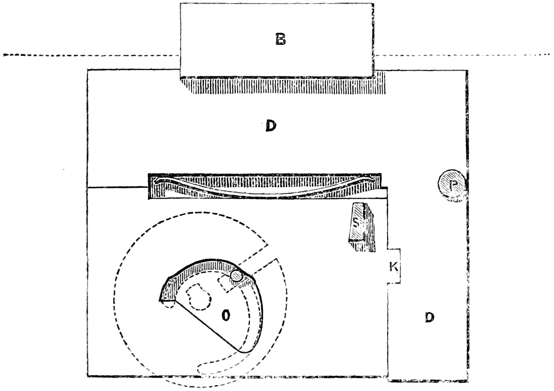
fig. 54.
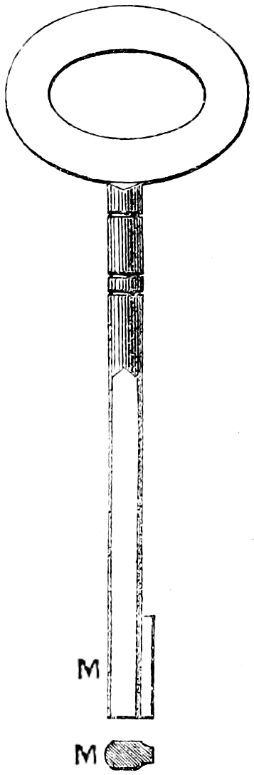
fig. 55.
Immediately in front of the bolts comes the fixed plate H H, in which is cut the cam groove shown by the dotted line J J; and also the vertical slot E for the pin P to work through, together with another vertical slot in which the stump S fits and works. This plate carries the centre pin U on which the levers L turn. The levers are six in number, though any[178] other number may be used; and they occupy collectively 3⁄8ths inch thickness. In front of the plate H is fixed the guard A, which is made of iron or steel, and has the brass cylinder C ground into it. The guard is made a shade thicker than the levers L, in order to prevent the back plate H and the corresponding front plate from being so tightened on the levers as to impede their freedom of movement. The cylinder C is the same thickness as the levers, excepting the centre boss F, which projects from the back of the cylinder and works in a bearing in the back plate H, and also projects in front through the thickness of the two front cover plates. The small keyhole in the centre of the boss goes only a short distance into the cylinder C, being merely for the purpose of enabling the stem of the key M, fig. 55, to turn the cylinder; the bit of the key is a separate piece, N, fig. 57, which is inserted through a separate keyhole into the radial slot of the revolving cylinder C, as shown at N in fig. 53.
This radial slot is cut in the side of the cylinder C that is furthest from the levers when the cylinder is in the position shown in fig. 53; and in the slot fits the slide block R, which is a steel block having a pin projecting on each side. The back pin enters the guide groove J J in the back plate H, as shown by the dotted line, and the front pin enters the corresponding guide groove in the front cover plate, which is shown removed. The back pin of the slide block projects through the back plate H, as shown in fig. 56, and works in the cam groove O in the tail of the stump-bolt S, fig. 54, which is so shaped that as the slide block travels round the guide groove J J, shown by the dotted lines, it moves the stump-bolt[179] vertically as may be required according to the position of the bolts and levers.
In the position of the lock shown in fig. 53, the bit N has been inserted into the vacant space of the radial slot in the cylinder C, in front of the slide block R. The size of this vacant space is 3⁄8ths inch long by 1⁄8th inch wide and 3⁄8ths inch deep; and in the two front cover plates of the lock, and also in the door to which the lock is attached, a hole is made of the same shape. In the door there is no bearing for the centre boss F, but only a small keyhole corresponding in size with that in the boss F for inserting the stem of the key.
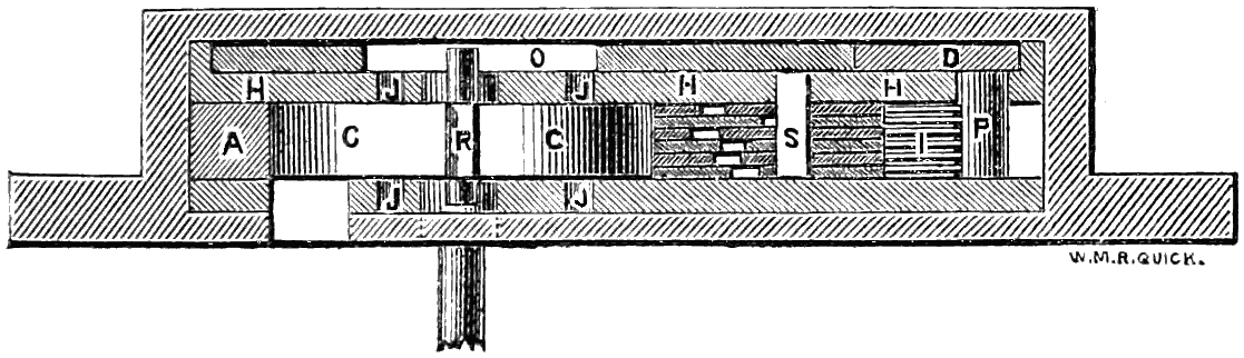
fig. 56.
In the position of the parts shown in fig. 53, it will be seen that the levers L are held pressing down against the circumference of the cylinder C by their springs I bearing against the pin P. In this position also the bolt spring between the main bolt and the stump-bolt, fig. 54, presses the stump S down into the notches of the levers, so that the levers are completely locked by the stump, as seen in fig. 53.
In order to unlock the lock, which in fig. 53 is shown with the bolt shot, it is necessary that all the gatings G in the levers should be brought precisely under the stump S. Through the centre keyhole F there is no communication possible at any time with the levers L; nor will any instrument, however slender, if passed into the radial slot through the aperture at N be able to reach them, whether the cylinder C be in the position shown in fig. 53 or turned round into any[180] other position. For the only difference made by turning the solid cylinder C is that the radial slot in it is carried away from the aperture in the external plates, and the solid part of the cylinder is brought opposite to the aperture, which is thereby completely closed against the insertion of a picking instrument. This construction accordingly not only precludes the possibility of opening this lock with an ordinary key, in which the part that acts on the levers is attached to the stem of the key, but it also renders it an absolute impossibility to introduce a pick of any form, as nothing can reach the levers L except a detached piece of such a size and shape as to be capable of travelling round in the vacant space left in front of the slide block R in the radial slot of the cylinder C.
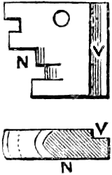
fig. 57.
For the purpose of unlocking the lock the bit N, fig. 57, is used. This bit is of such a size as to fit into the vacant space of 3⁄8 × 3⁄8 × 1⁄8 inch in the radial slot of the cylinder C; and the indent at V is merely for the purpose of ensuring the insertion of the bit in the right direction, the external aperture for the bit being made with a corresponding projection to fit the indent in the bit. This bit being inserted through the aperture in the door, is pushed in by means of the key stem M, which is flattened on two sides for that purpose, as shown in fig. 55; and the bit is thus pushed home into its place in the radial slot of the cylinder, as shown at N, fig. 53.
The key stem M is now inserted into the centre keyhole F, and the cylinder is turned round by it in the direction shown by the arrow, carrying round the slide block R and the bit N. The slide block R, while moving through the concentric portion at the commencement of the guide grooves J J, does not affect the bit; but by means of the cam groove O in the tail of the stump-bolt, fig. 54, it moves that bolt so far as to lift the stump S completely out of the notches in the levers L, which are thereby left free to be raised. On continuing to turn the cylinder C, the eccentric part of the guide grooves J J causes[181] the slide block R to move outwards along the radial slot, pushing the bit N before it; and the bit is thus made to project beyond the circumference of the cylinder, which it can then do, being no longer confined by the guard A. The further projection of the bit as the cylinder revolves causes the steps in the bit to lift their respective levers; and the steps in the bit are so arranged that, when the cylinder arrives at the position shown in fig. 58, all the gatings G are brought simultaneously opposite the stump S, which is instantly shot down through the distance of the 1⁄10th inch play by the bolt spring. The bit N remains in contact with the extreme part T of the levers while the stump S is entering the gatings, the action of the bolt spring being so rapid that the bit cannot move through any appreciable distance during the time.
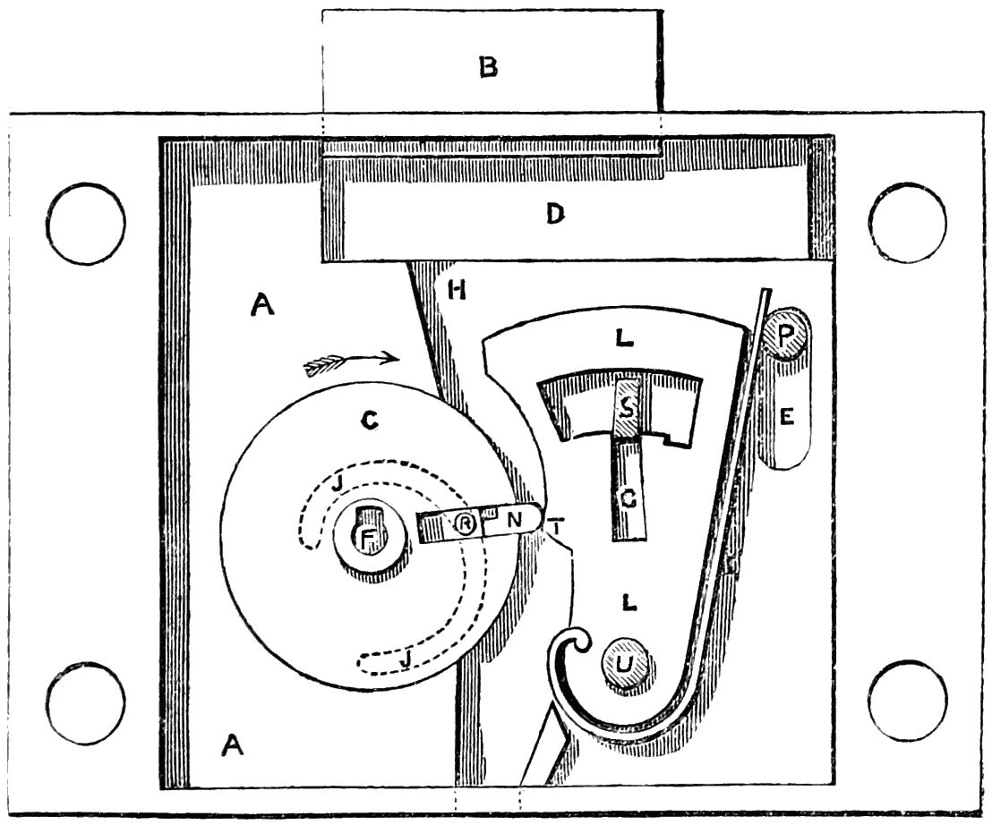
fig. 58.
In other locks a spring action of this kind would greatly facilitate the picking, inasmuch as it would afford the gentle uniform pressure desired upon the levers. In other locks, therefore, the bolt is caused to move, and the stump to[182] enter the gatings, by the direct contact of the key with the bolt, instead of by a spring; but as the key, while moving the stump into the gatings, is also altering its position under the levers, a slight tremulous motion of the levers is thereby occasioned, which no care in manufacture can obviate. This tremulous motion is aggravated by the circumstance that, as the keyhole is open to inspection, it is necessary to make all the levers fit flush with one another when down, in order to avoid affording any clue to the shape of the key from the positions of the levers; but as the various steps of the key, being of different lengths, describe different arcs, the curves of the levers when raised are of necessity in error to them all. The result of these combined faults is that the gatings have to be made wider than the stump, to allow a sufficient amount of play, thus introducing a fatal element of insecurity in the construction of the lock, since the security is of course enhanced in proportion as the gatings fit the stump accurately. In the new lock, on the contrary, the arc T, fig. 58, in each lever, can be shaped truly to its own proper radius, independent of all the rest of the levers; and as the action of the stump is instantaneous in catching the gatings as soon as they are all brought simultaneously under it, the stump and gatings can be made to fit one another with the most perfect accuracy, and without the slightest play.
On turning the cylinder C further round, the bit N passes from under the levers, which remain held back by the insertion of the stump in the gatings; and just before reaching the position shown in fig. 59, the slide block R has pushed the bit completely out of the radial slot, and the bit falls down as shown in fig. 59, and drops through a hole into the inside of the safe that is locked. At this point the back pin of the slide block comes in contact with the lower side of the cam groove O in the stump-bolt, fig. 54; and by turning the cylinder C onwards to the position shown in fig. 60, the withdrawal of the bolt B is completed, bringing the parts into the position shown in fig. 60. In these drawings only one lever[183] L is shown; but there are altogether six levers, as shown in the sectional plan, fig. 56. The pin P is fixed in the tail D of the main bolt, so as to travel with the bolt; and by this means the springs I are released from strain, as shown in fig. 60, as soon as the bolt is withdrawn.
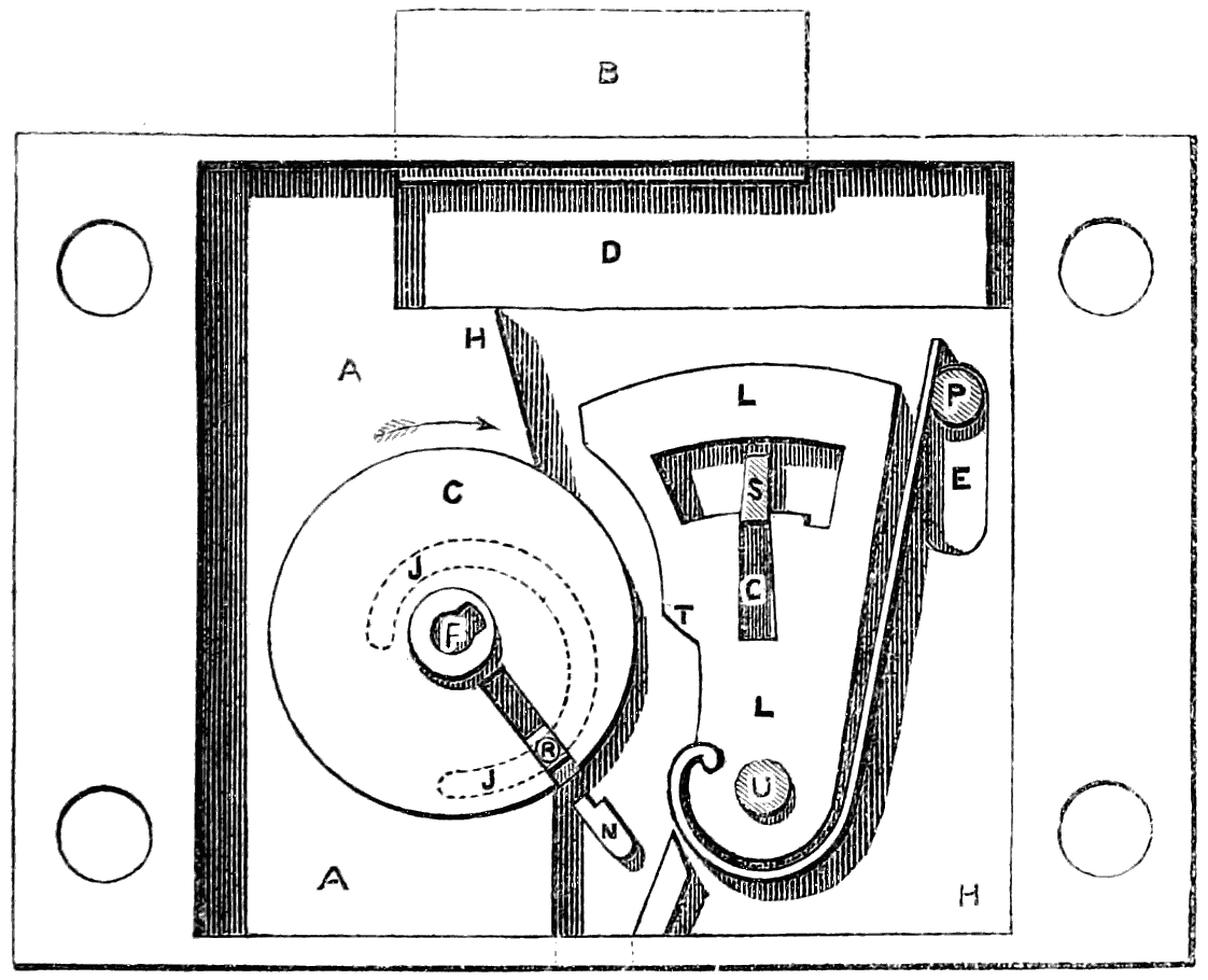
fig. 59.
From the nicety with which the various parts of this lock are constructed, it is evident that the levers must be very accurately lifted by the bit of the key in order to withdraw the bolt; and therefore any error in the bit, such as would occur with a false bit, will effectually prevent the lock from being opened. This may be illustrated by supposing the false bit to be so close an imitation as to have five of its steps absolutely correct, and the sixth only slightly wrong: though it is almost impossible that such a near approach to correctness could be attained in practice. The counterfeit bit being inserted in the lock, and the cylinder turned round, all will go on the same as with the true bit, up to the time when the[184] false bit reaches the point T of the levers, as previously shown with the true bit in fig. 58. Here a change of action takes place; but what is the nature of the change the operator has no means as yet of ascertaining. In the case supposed, where five of the steps in the bit are right, but the sixth is wrong, the gating of the sixth lever does not precisely coincide with the others, nor with the stump S; and the consequence is that, at the critical moment when the stump ought to spring into the gatings and hold back the levers from falling forwards, it will be prevented from entering the gatings, owing to the entrance being partly blocked up by the one lever, which stands more or less across it.
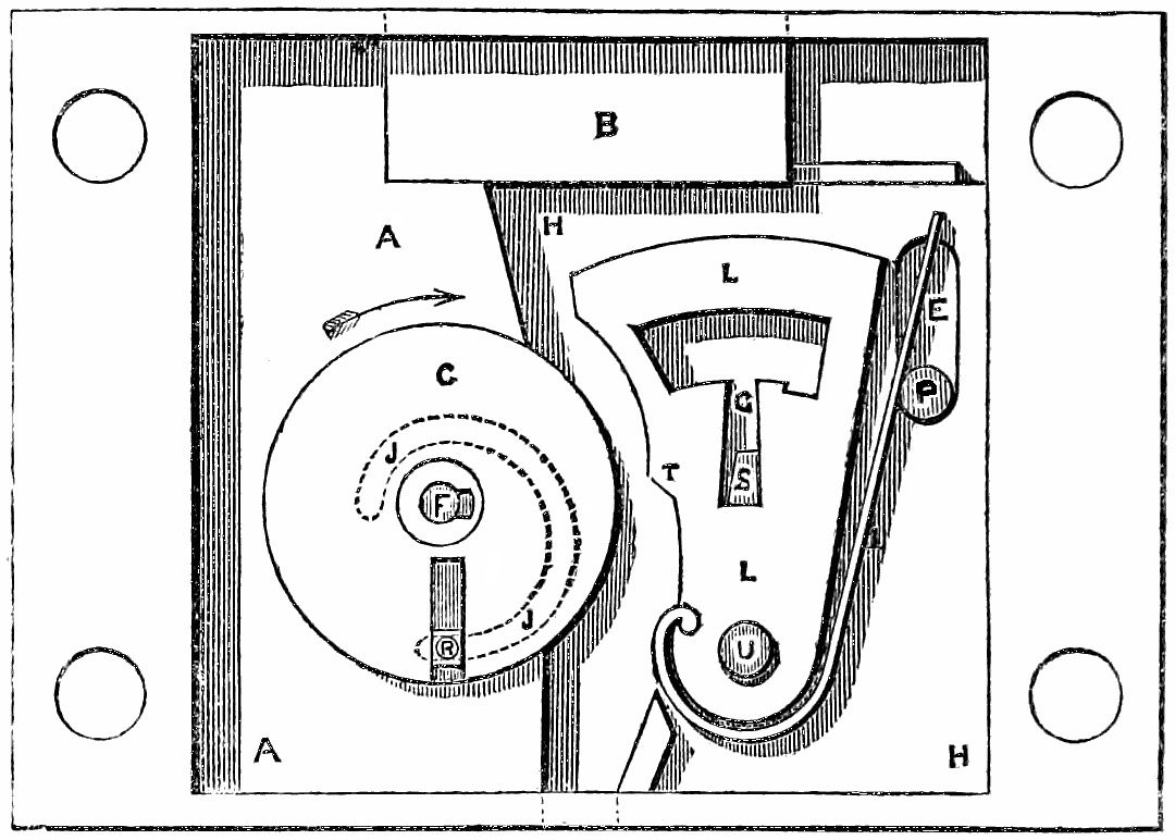
fig. 60.
The fact, however, that the stump cannot enter the gatings, does not become known to the operator until the cylinder C has been turned further round, so as to bring the slide-block pin in contact with the lower side of the cam groove O in the stump-bolt; and before this point has been reached the false bit has already passed clear of the levers, which, not being retained by the stump, are instantly thrown forwards again by their springs, and locked in their original position by the[185] stump entering the notches. At the same time the false bit has dropped into the inside of the safe in the same manner as the true bit, as shown in fig. 61.
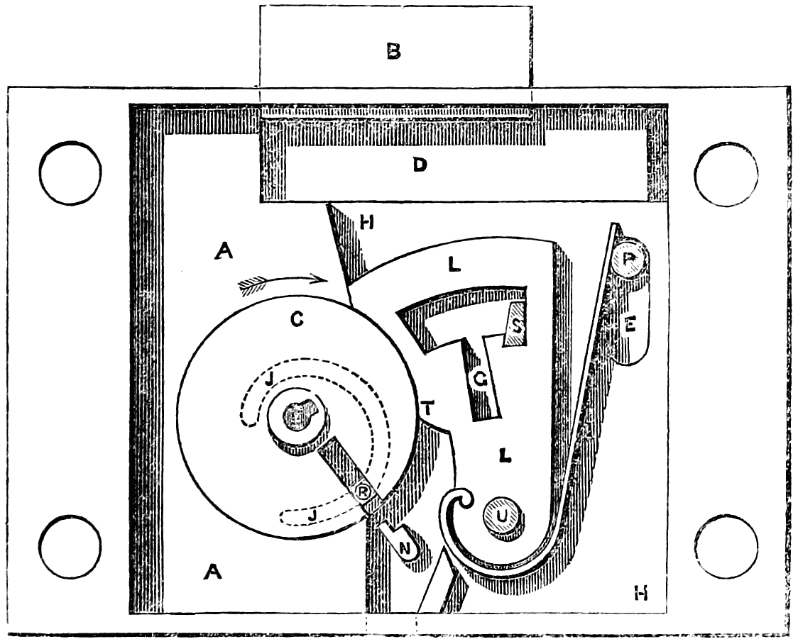
fig. 61.
Hence a person putting a false bit into one of these locks will not only infallibly lose it at the very first trial, but will do so without gaining any information as to the nature of its inaccuracy; for as the gatings of the levers cannot be seen or felt, all that can be told about the action of a false bit is, that it has failed to open the lock. In fact, a counterfeit bit passes under the levers, and through the lock, just like the true bit; and it is only the stoppage afterwards met with of the bolt that indicates the failure of the false bit, which is by that time gone beyond recovery. Whatever amount of labour, therefore, may have been spent on the fabrication of a counterfeit bit, this bit can only be tried once, so that no alteration can afterwards be made in it.
Nothing that can be inserted into the radial slot of the cylinder C through the aperture in the front plates can do any injury to the lock; and a charge of gunpowder inserted in[186] that way would only blow out again at the orifice without damaging the lock, both the apertures for the key being merely blind holes with parallel sides.
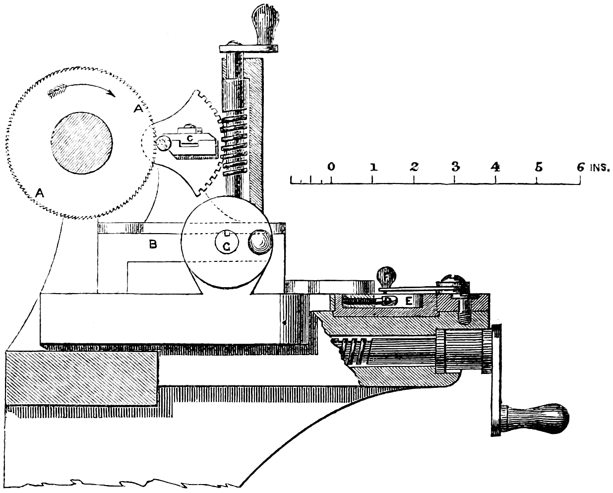
fig. 62.
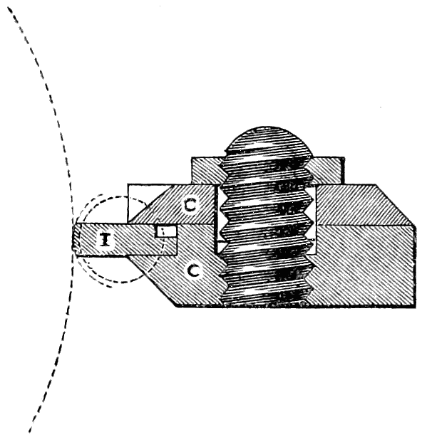
fig. 63.
For the manufacture of the bits for the keys of this lock a self-acting machine is employed, in which the height and width of the several steps in the bit are regulated by adjustments of very great accuracy, and admitting of an almost endless variety of figure for the bits. This key-cutting machine is shown in figs. 62 to 64, and consists of a small circular saw A running vertically, of the same[187] thickness as each step in the bit I, which is brought up to the saw by the slide-rest B. The bit I is fixed in the holder C, which rocks upon a centre, so as to give the required curvature to the edge of each step in the bit when cut by[188] the saw, as shown in the full-size section of the bit-holder, fig. 63. The adjustment of the depth of cut is effected by the set screw D upon the slide-rest coming up against the eccentric ring E upon the bed of the slide-rest; this ring is turned round by hand, and set to sixteen different positions by means of the catch-pin F and the sixteen holes on the circumference of the ring, allowing of sixteen different depths of cut. The lateral adjustment for the pitch between the successive steps of the bit is effected by the two bed-screws G G acting on the slide-rest B, having a dividing plate on the head, and such a pitch of thread that one turn of the screws traverses the slide-rest through the exact distance of one step in the bit. The occurrence of any play or backlash is entirely prevented by having the screws placed one at each end of the slide-rest; so that by slacking back one screw through one or more turns, and then advancing the other through the same number of turns, the slide-rest is always held with perfect steadiness between them, filling exactly the space between the ends of the two screws.
The number of changes admissible in this key-cutting machine, if used for making keys for locks having six levers, is the number of permutations that sixteen terms are capable of when taken six together, which is upwards of sixteen millions. Some of these changes are so slight that too great accuracy of workmanship would be required to make the locks accordingly; but of those changes that differ from one another so far that no lock could be opened by any other than its own key, more remain than could be used up by all the locks in the world.
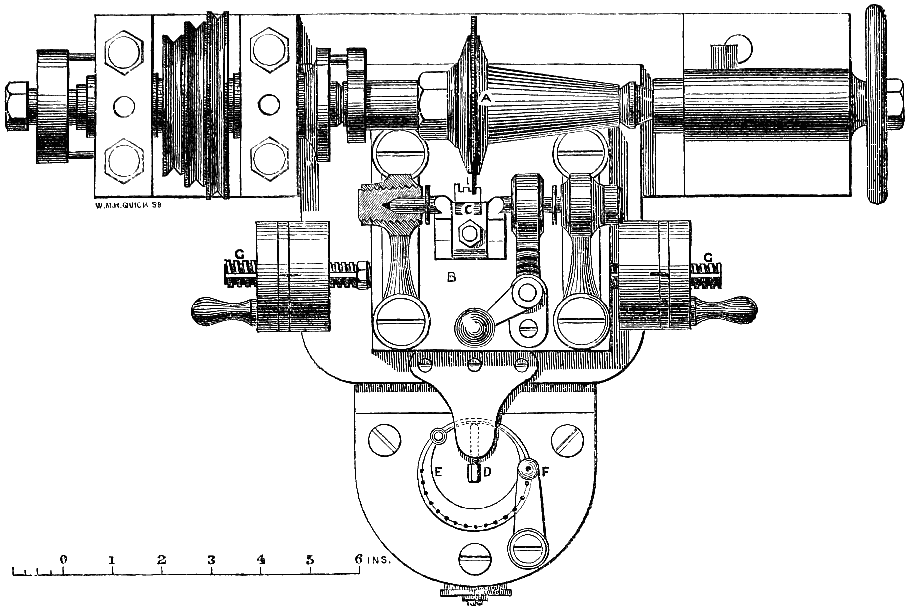
fig. 64.
The writer may observe that it was the study of the circumstances of the great gold robbery on the 15th of May, 1855, by Agar and his confederates (when two of the best lever locks were picked, and gold stolen weighing upwards of 200 lbs., while in transit on the South-Eastern Railway from London to Paris, packed in three sealed iron-bound boxes, inclosed in a bullion safe, secured by those locks),[189] and of the various modes of picking locks, which led him to turn his attention to the achievement of what had been so long and perseveringly sought after, namely, an unpickable lock. The principle of a detached bit has been previously tried, in so far as that locks have been made in which the bit of the key was deposited in the lock by unscrewing the key stem, and then withdrawn by screwing in the stem again. But inasmuch as the detached bit, even though it failed to open the lock in the case of a counterfeit key, could always be brought back again to the keyhole and removed, this admitted of a repetition of attempts with successive alterations of the one counterfeit key, without the certainty that any warning would be given by the lock of such attempts having been made.
In another still more complicated lock with a detached bit there were two keyholes, into one of which the bit of the key was put, and the stem being then unscrewed from the bit, was put into the second keyhole and turned round so as to close the first keyhole over the bit; a separate handle was then turned to work the lock, six separate operations being required for either opening or closing the lock. Further, a kind of retainer has been attempted by so arranging the lock that, if any key was put in but the right one, it was held in the keyhole in such a manner that it could never be got out. In this case, however, if the false key would not open the lock, neither would it let even the right one do so, and it would be necessary to break open the door secured by the lock.
In the new lock here described, the special points that have been aimed at are the following:—
Firstly, in no position of the lock is there any access to the works from the outside through the keyhole. This access through the keyhole is more or less a defect in all other principles of lock, as it admits of feeling and manipulating the works for the purpose of getting information for picking the[190] lock in the absence of the right key; whereas in the new lock there is no opening whatever at any time, except the two plain parallel recesses into which the key and the bit are fitted. From the moment the turning of the lock commences both these recesses are effectually blocked up: the one for the bit being conveyed bodily away from the keyhole, and its place taken by the solid metal of the cylinder; while the other is completely filled by the key, which cannot be withdrawn except by turning it back to the original position. In consequence of this construction no injury can be done to the lock by explosion of gunpowder in the keyhole, the only openings from the outside being parallel at their sides, and not communicating with any portion of the interior of the lock; and the simplicity and solidity of construction are such that the revolving cylinder is made practically air-tight within its bearing. This effectually prevents all attempts to open the lock by picklocks, and leaves no alternative but the attempt to make a sufficiently accurate copy of the true key.
Secondly, as no clue whatever can be obtained from the outside of the lock respecting the key required, the attempts upon the lock are thus limited to the chance of obtaining a wax impression of the true key. The difficulty of making a counterfeit key sufficiently correct by this means for opening one of the best of the previous constructions of lock is very great; but in the new lock this difficulty is greatly increased by the fact of the levers remaining absolutely stationary while the stump enters the gatings, in consequence of which the gatings are made so close a fit to the stump that an exceedingly minute error in the lifting of any of the levers is sufficient to prevent the lock being opened. This extreme delicacy of construction can be carried out practically without objection in the new lock, because there is no possibility of putting a strain from the key upon the stump, so as to cause injury by forcing it at the moment of entering the gatings; for the only force acting upon the stump at that time is the uniform pressure of its own spring. In addition to this[191] source of increased safety, there is the still more important circumstance that only a single trial can be made of each counterfeit bit; because, if carried forwards far enough to try its effect in opening the lock by passing the levers, the bit is inevitably lost by falling through the lock and inside the door. Thus not only is all chance prevented of a second trial with the same key, but the bit retained inside the door gives warning of the attempt having been made, and shows how near the counterfeit key has approached to the original. The numerous cases that have occurred of attempts to open locks by counterfeit keys, such as the remarkable instance previously referred to, show that even with the most practised hands it is next to impossible to make from a wax impression a key that will serve for opening a good lock the very first time it is tried; and the striking importance is therefore seen of this arrangement in the new lock, which prevents more than a single attempt being made with a counterfeit.
Thirdly, another advantage to be named in this lock is that the stem alone of the key is required to lock it, but it can only be unlocked by the complete key. The stem, therefore, can be left by the principal of an establishment for locking up by a subordinate; but the bit, which is the essential part of the key required for opening the lock, need never be used or seen by any one but the principal himself. As the hole in the external door-plate for the stem of the key has a notch on one side only to admit the key stem, and the cylinder is prevented from making a complete revolution, the stem of the key cannot be withdrawn from the lock except when the bolt is shot; so that its absence from the keyhole serves as a proof that the bolt is shot.
Fourthly, one other advantage in this lock is its simplicity and solidity of construction. It contains no more parts than the simpler forms of lever lock having the same number of levers, and the total number of separate pieces in the complete lock is only sixteen. The principle of security, therefore, upon which the new lock is constructed, avoids entirely the[192] complications and the delicate and minute class of work rendered necessary in other locks by the use of detectors and the other auxiliary contrivances employed for increasing the difficulty of picking.
Mr. Fenby exhibited, at a conversazione of the Institute of Civil Engineers, and at the meeting of Mechanical Engineers, specimens of his adytic lock, and showed its action both with the true key and with counterfeit keys; and he showed by trial that the counterfeit failed to open the lock, notwithstanding that by means of the permutating cutting machine it had been made a much nearer approach to a perfect copy than was practicable in the best handwork from a wax impression. He also exhibited the key-cutting machine employed for cutting the bits; and also a set of burglar’s tools employed for drilling into the door of an iron safe sufficiently for breaking open or removing the lock, showing that the hold required for giving the cutting pressure upon the powerful drill employed for the purpose was obtained by a steel cross piece inserted into the keyhole and turned at right angles, so as to hold across inside the lock; but in the new lock, as the keyhole had no opening into the lock, and only a slight shoulder on one side, no means were afforded for obtaining the required hold for the drill.
The following are the salient points of the discussion that followed the reading of his paper:—
The Chairman remarked that the paper just read gave a very excellent and clear description of the detailed working of the new lock, and he thought this construction of lock was a most valuable one, as affording real security against all fraudulent attempts. He inquired whether there would be any possibility of tampering with the lock by examining it upon the inside of a safe door, whenever the door might happen to be left unlocked.
Mr. Fenby replied that there was no means of tampering[193] with the lock from the inside of the door, as the two keyholes for working the lock were only in the front face of the door, and the lock was all closed up on the inside of the door, excepting the hole through which the bit was allowed to drop out; but this would be useless for the purpose of tampering with the lock, as the bit dropped down a tube leading to the bottom of the door, through which no examination of the lock could be successfully made.
The Chairman inquired whether there was any provision against the bit being accidentally locked up inside the safe, in which case it appeared the lock could not be opened again.
Mr. Fenby replied that the owner of the safe must of course be careful after unlocking the safe to take the bit out before locking it again, otherwise there would be no means of opening the lock afterwards with that key. As a precaution, however, against any such accident, each lock was provided with three bits, all duplicates, one of which would be kept in the pocket for use, while the two others would be preserved in a place of safety for the chance of any such contingency. Moreover, in most of the safes fitted with these locks, the tube through which the bit dropped had been made of such a length as to carry out the bit on opening the door, dropping it into a small tin tray outside the safe; and by this means the accidental locking in of the right bit was rendered impossible. One of the advantages of the new lock was that the stem of the key was not required to be kept constantly in the possession of the owner, but it might be left in the lock, as the bit alone was the valuable part of the key; and as the bits were of such small size and convenient shape, a number of them might readily be kept in the pocket by a person having charge of a number of safes, without the inconvenience attending a large bunch of ordinary keys. In the case of an attempt being made to open the lock with a counterfeit bit, the advantages of retaining the counterfeit inside the safe were not merely that the person attempting the lock was deprived of his instrument, while the proprietor immediately[194] discovered the attempt upon the next occasion of opening the safe; but the retention of the counterfeit itself afforded the means of judging, by a comparison with the true bit, whether the attempt had been made altogether in the dark as to the actual construction of the lock, or whether it was likely that some clue regarding the true bit had been obtained by means of a wax impression or otherwise. In the latter case the owner of the safe might think it desirable to have the lock taken off, and the arrangement of the levers altered, and a new bit made so as to baffle any further attempts.
Mr. W. S. Longridge observed that the inconvenience that had been alluded to with the new lock, of accidentally locking up the bit inside the safe, was no greater than occurred with an ordinary safe lock if ever the key was accidentally lost; in either case, unless the precaution was taken of keeping a duplicate in reserve, it would of course be necessary to have the safe broken open.
The Chairman inquired how the ideas had been arrived at of separating the bit from the key, and of preventing all access to the works through the keyhole, and also of retaining the bit inside the door after any attempt at unlocking.
Mr. Fenby replied that his attention had in the first instance been attracted to the subject of the picking of locks as a mechanical problem, and he had found that there had hitherto been no principle in lockmaking which could effectually baffle persevering attempts at picking. For although there were certain complicated constructions of locks, having many points of excellence, they had all yielded in time to the picking instrument in clever hands; and it must be remembered that any individual lock when once constructed remained stationary as regarded subsequent improvement, whereas the art of picking that lock was continually progressing towards success, with all previous constructions of locks, and it was clear therefore that the lock must ultimately be defeated. He had been further stimulated in the investigation of this subject by the occurrence of the great gold robbery referred[195] to at page 188; and the circumstance which had struck him most forcibly in connection with that robbery had been that locks of the best make hitherto known had admitted of seven successive trials being made upon them without detection, each trial furnishing the information for further perfecting the counterfeit key, until the locks were at length opened.
These considerations had led him to the conclusion that two points were established and were required to be kept in view for the construction of any lock that should be really secure against fraudulent attempts. The first point was that wherever a man could get instruments into the lock he could ultimately solve any problem laid before him by the maker of the lock, as the lock when once made could be tried any number of times if an instrument could be got into it at all. Hence he had concluded that it was requisite for all access to the interior to be cut off, so as to preclude all possibility of getting a pick-lock in; and this was accordingly accomplished by adopting the plan of separating the bit from the stem of the key. The second point established was that it was necessary to prevent the possibility of making a succession of trials with the same counterfeit key; and it had then struck him that, if the bit of the key were arranged to drop inside the safe in unlocking, there would be no means of going on gradually improving and touching up the counterfeit from the results of previous trials, as the false bit would be irrecoverably lost in the very first attempt, without furnishing any clue whatever as a guide for alteration in a subsequent trial. The first lock that he had invented for meeting the requirements thus pointed out had been made with a solid block having a tunnel through it, but involving the same principle of retaining the bit of the key and keeping the levers inaccessible from the outside. Subsequently, however, he had abandoned that construction and produced the new lock shown in the drawings, having the revolving barrel with radial slot.
The Chairman proposed a vote of thanks to Mr. Fenby for his paper, which was passed.
[196]
This lock has been designed with a view to doing away with several weak points in the construction of lever locks.
The introduction of the movable stump by Mr. Hobbs, in order to defeat picking by the tentative method of applying pressure to the bolt, so as to cause binding between the stump and the levers, was a great advance in the art of lock-making.
The movable stump, as so constructed, was, however, open to this objection, that while sufficiently delicate and certain in its action to render picking very difficult, it was at the same time, through the smallness of its parts—resulting from the confined space available for its action—unsuited to withstand any amount of force applied to push back the bolt.
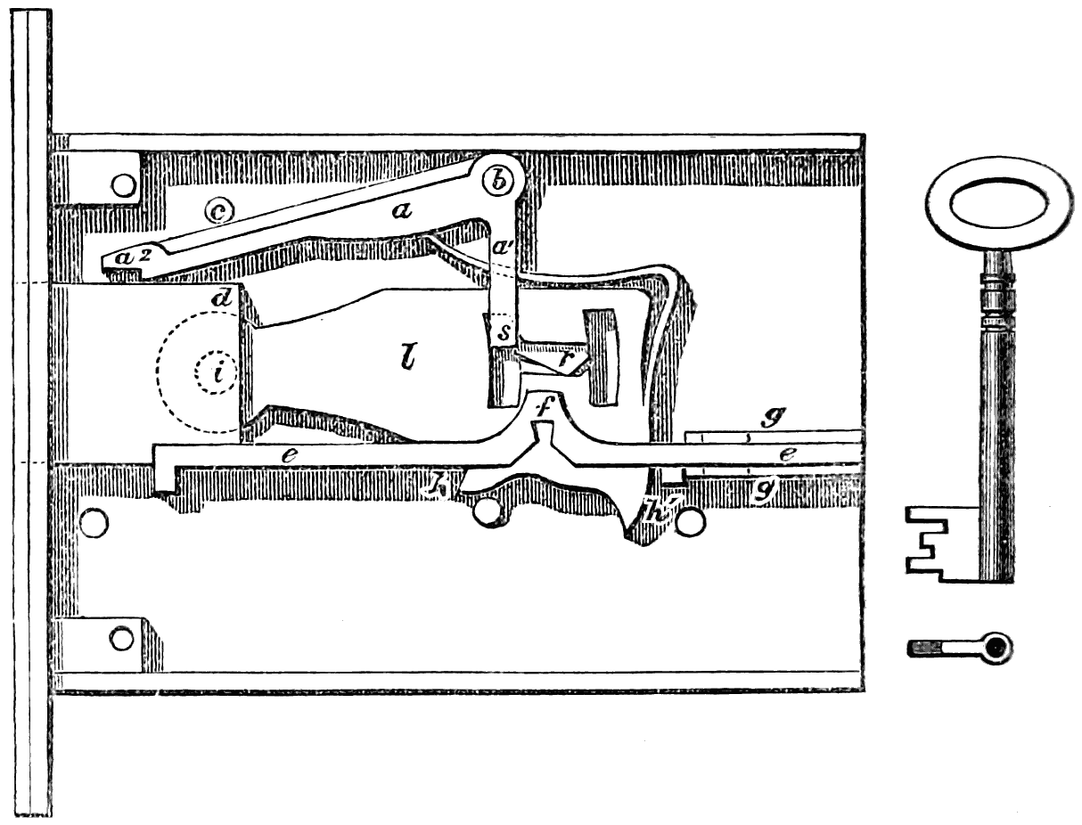
fig. 65.
In the lock under notice the stump s is formed in the solid on the shorter arm a1 of a cranked lever or oscillating stop a. This stop a works on the steel pin or centre b, which[197] latter has a bearing in both plates of the lock. At the end a of the stop a is a recess formed to fit the corner d of the bolt-head. c is a stud limiting the range of a in an upward direction, so that when in its normal position the stop a may just clear the bolt-head, as shown in figs. 65, 66, and 67. The tail of the bolt, instead of being in the form usually adopted, is formed of the bar e set on edge so as to reach from the back to the front plate of the lock, completely dividing the lower part, in which the keyhole lies, from the upper, in which the main parts of the works are placed.
This bar e works between the guide pieces g g, so that in whatever position the bolt may be, the division of the lock into two chambers is complete. At f is the recess in which the key acts to move the bolt. The levers l turn upon the pin i formed in the solid of the bolt-head. The part of each lever on which the key is to act passes through a slot or recess in e, the parts h and h1 of the levers being struck to the arcs of circles, having their centres coincident with that upon which the levers turn at i.
As it is not possible to lift the levers out of this slot in the bar e, and further, as the levers and bolt move together in a longitudinal direction, the movements necessary to locking and unlocking open no communication between the upper and lower chambers of the lock.
The springs of the levers are formed out of the solid metal of the levers themselves, and are thus not liable to that displacement which so often occurs with separate springs, nor to the corrosion by oxidation incidental to steel springs. They are cut round the corner, and down the front of the lever, to gain greater elasticity.
In fig. 65 the lock is shown with the front plate removed, and the works as they stand when unlocked. Fig. 66 is the same, except that the works are shown locked, and the back plate removed instead of the front. Fig. 67 shows the front view of fig. 66. Fig. 68 shows the result of any attempt to pick the lock by pressure.
[198]
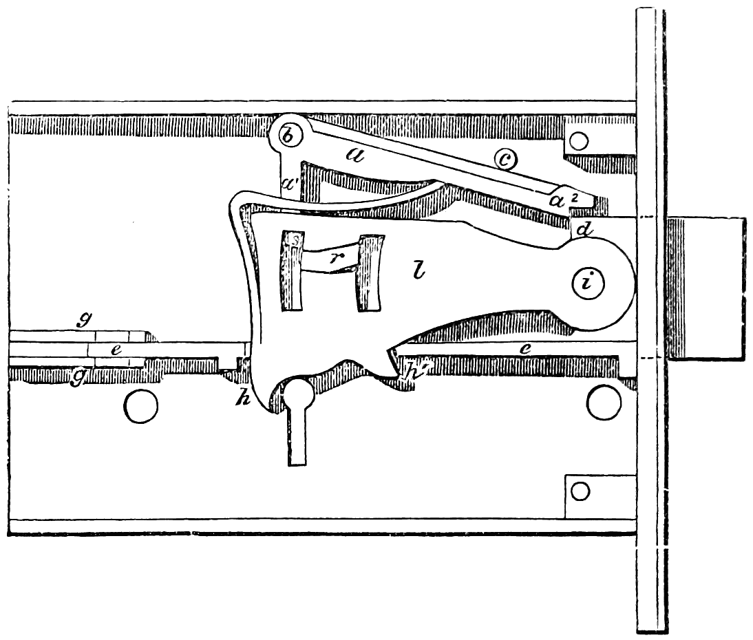
fig. 66.
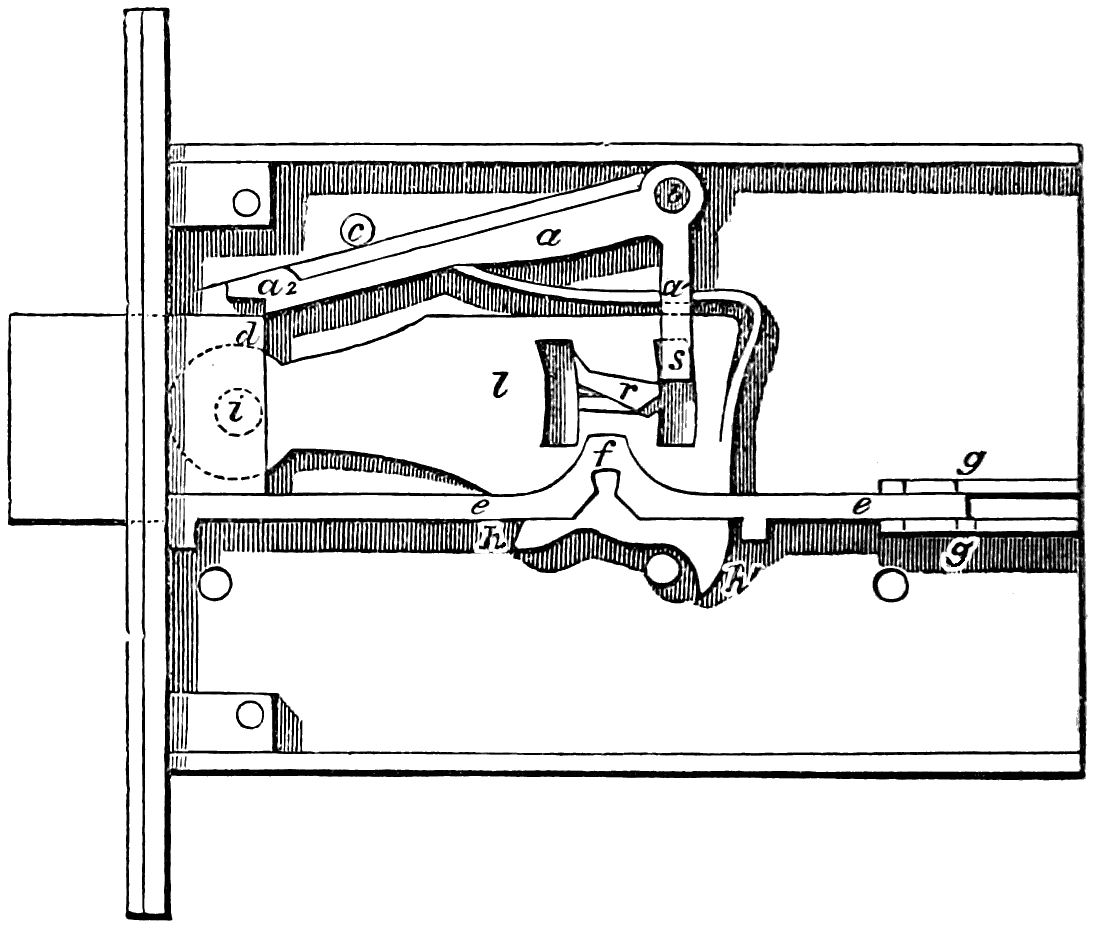
fig. 67.
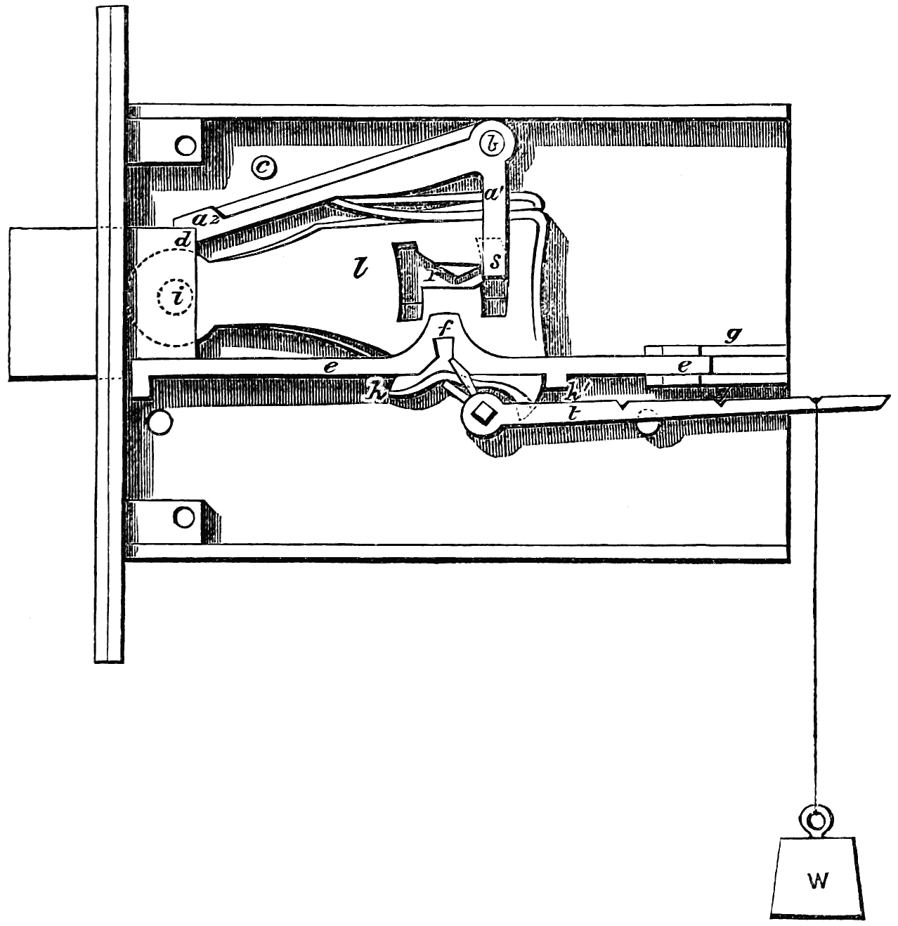
fig. 68.
The lock being locked, as shown in figs. 66 and 67, it will be seen that the stop a just clears the angle d of the bolt-head.[199] Further, that the gatings r of the levers l cannot pass the stump s, unless the levers be so lifted as to coincide with each other and the stump. The stop a being held up by a very light pressure from the lever springs, a small force applied to the stump s is sufficient to upset its equilibrium, and bring down its end a2 upon the bolt-head at d, as shown in fig. 68. This occurs whenever an attempt is made to “feel” the stump with the levers; and not only does the stop a free the levers from all pressure, and so preserve them and the stump from injury, and the lock from being picked, but it also forms a strut for securing the bolt: in fact, no violence short of that necessary to shear the pin b can make the bolt yield.
[200]
The drawings show a mortise lock, but the improvements shown are universally applicable in the construction of locks of all kinds.
For the manufacture of these and other locks, and kindred articles, Messrs. J. B. Fenby and Co., engineers of the Liverpool Works, Birmingham, have put up, from the designs of their managing partner, Mr. J. Beverley Fenby, an experimental set of machinery, almost entirely self-acting, and calculated to turn out large quantities of the component parts of locks and other articles with extreme accuracy and rapidity.
The whole set works on the interchangeable system—as already in use for military small arms. It is not, however, to be supposed that, because the parts of the locks are interchangeable, one key will open several locks—such a source of insecurity being guarded against by the permutating key-cutting machines invented by Mr. Fenby. These machines give complete command over the making of keys, whether it be required to make a comparatively unlimited number, all differing from each other, to make a number alike, or to make sets with master keys.
Atmospheric and hydraulic pressure also plays an important part in shaping many of the parts of the locks.
[201]
At the conclusion of this work upon locks it will not be out of place to make a few remarks upon the degree of real safety that attaches to what are commonly called “safes,” and to point out in a common-sense way what are the chief dangers that these may incur from depredators (whether burglars or in times of public anarchy and violence), and what are the main conditions to be relied upon for safety—assuming that, by one or other of the constructions pointed out in the preceding pages, the lock of the safe be such as to be practically unpickable, and that carelessness shall not have placed the true key in the possession of the thief.
There can be no doubt upon the mind of any mechanic or engineer, thoroughly acquainted with practical working in metals, that a good deal of what has been brought forward and affirmed, both by safe-makers and by burglars themselves (turned approvers), as to the wonderfully-ingenious devices resorted to by the latter, by which, if we were to believe it all, nothing in the shape of steel or iron can possibly withstand ultimately the redoubtable powers of these people, is simply fiction—imaginary ingenuity utterly impracticable if tried. Such, for example, is the notion of its being possible, by an ounce or two of gunpowder exploded in the interior, to so blow asunder and dislocate the parts of a well-made safe-lock that the bolts shall then be easily got loose, or that a steel-plated safe which resists the drill can be softened “by the blowpipe.” And just as absurd are some of the wonderful pieces of ingenuity by which some of the burglars’ actual devices are supposed to be met and frustrated; as, for example, one for which we believe a patent has been obtained, consisting in filling-in the hollow space between the inside and outside plates of the safe with cast-iron bullets left loose. These might, no doubt, break a flat-stemmed drill, after that had[202] pierced the outer plate, but could have no effect whatever upon a round-shanked drill, such as one of the ordinary American spiral, or teredo-pointed drills.
That there are some methods of violence still untried, and yet at the command of the burglar who dares to risk a tolerably loud noise of explosive agents, is well known to skilful mechanical engineers, and for obvious reasons it would be unwise that we should give any information as to such; but the real practical and too-often effectual methods of the burglar limit themselves almost entirely to the use of the succession of steel wedges, followed by the powerful steel-pointed pinching bar, or bars, to the forcing or prizing-screw, and to making more or less way for this by cutting out beforehand by the pin-drill.
A safe, to be safe, must be so circumstanced or so constructed, or both, that it should be able to resist the best efforts that can be made by these methods for several hours; perhaps we might say as much as thirty to thirty-six hours—viz., from Saturday night to Monday morning.
Now we hesitate not to say that the unsafeness of “safes” arises not from any structural difficulty whatever, but almost always from the parsimony and ignorance of those who purchase and employ them. Safes, like razors, are made to sell, and if the public demand is for cheap safes, such as we see every day advertised in the newspapers, it was sure to have been, and is, met by a supply of things called safes which are utterly unsafe. The great mass of the showy green and gold gewgaws that one sees in the safe-shop windows, with flaming testimonials as to their fire and burglar-proof powers, are simple shams: a genuine safe could not be made at their prices.
The very first condition to constitute a genuine safe is that it shall have an ample mass of metal—i.e., not of cast-iron, but of wrought-iron, or best of steel, all round it; and especially that the margins of metal all round the door shall be of such huge and surplus scantling that no amount of wedging,[203] by construction possible, should be able to bend any one side sensibly. The next is that the workmanship of every part of the safe be first-class: not that there be merely a moulded door with a showy lock and a trumpery brass-plate upon it, but that every corner and joint of plate with plate in sides and back be effectually united and jointed in the best manner, and that the fitting of the hardened edges of the door shall be like those of a valve, and not even let a watch-spring be got in between. If these obvious conditions be observed, and that the safe itself be properly posited in the premises, it will be found, even with ordinary forms of construction as to doors and bolts, but with a really unpickable lock, a very hard nut for the best burglar to crack.
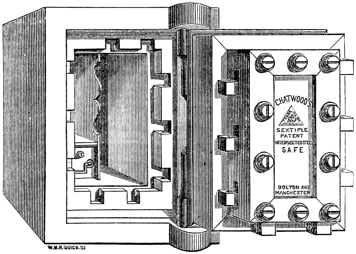
Chatwood’s Safes.
But much more may be effected without any serious increase of cost. Several forms of safes are now made, the rabbets of the doors of which are so formed that it is almost a physical impossibility to get any wedge, however thin, to drive in between the door and the frame. This is effected in Chatwood’s patent safes (of Bolton and Manchester), as figured above, by making the door rabbets in cross section curvilinear,[204] so that even if the fit be not so perfect but that the edges of a very thin wedge can still be inserted, it yet cannot be driven—for, as it goes forward, it must become curved, and if soft, so as thus to bend, the thin steel will not bear the severe strain of driving, but if hard, it breaks off into short bits close to the entrance. In addition to this Chatwood’s (and we believe other makers’) safes have bolts so constructed, as seen in the figure, that they hook or lock into the bolt recesses in the frame in such a manner as to hold the opposite sides of the frame together, so that, independent of its own proper stiffness, it cannot be bent anywhere, unless by tearing asunder the end on the iron bar constituting each cross-bolt. The bolts, in fact, not only secure the door (as in ordinary) from opening, but secure the door and frame together. With such a safe, if the owner will only provide a proper position for it in his premises, he may rest pretty easy in mind.
Safes are very commonly stood upon a wooden floor, or made to form part of a wood-framed bookcase, or press, or stand in a recess. Often they are comeatable all round, and even underneath, with nought but an inch board below them, and almost always they are left with the front door freely and fully exposed, and with ample and convenient room left all round. This for two or three workmen to manipulate the safe as they may.
Now the only real conditions of safety are that the iron safe should be bedded into brickwork set in Portland cement and sand; or, what is much better, in hard granite or gritstone masonry, bedded in like manner. Without this be done, a fire-proof safe is simply a delusion; constructed how it may be, it is only a crucible of more or less badly-conducting power, in which, after a time longer or shorter, deeds, bank-notes, documents, &c., will be calcined, and coin or jewellery melted, and gems flawed and destroyed. We say this in the full face of the delusive so-called “fiery ordeals” to which many of the so-called double-cased fire-proof safes are alleged to have been for hours exposed. The safe should always be[205] embedded in masonry, and rest upon that in such a way that it cannot get undermined by either fire or burglars.
Whenever the premises admit of it, the door of the safe itself should be set back 10 or 12 inches from the face of the wall in which it is embedded, and an outer door, flush with the face of the wall, should be provided of iron, with a good lock and multiple bolts. The door of the safe should open to the right; and if so, the outer door should open to the left; and neither should open more than square to their position when shut. No one but a practical workman or engineer can have an adequate notion of the extent to which any mechanical operation upon the door of a safe thus circumstanced is hampered by its being set back into the wall, and with an outer door that even when open, cuts off all ready manual access to the inner door from one side.
When premises are constructed, as they should be for all banks and bullion merchants, jewellers, &c., having special regard to a safe as an indisputably secure depository, then the safe should be completely iron or steel cased, and embedded in hard stone masonry (we shall not here go into additional special precautions against the remoter effects of fire), covered in with a strong fire-brick arch, and with nothing but the solid ground below. The door of the safe should only be approachable through an iron or stone-lined passage, just the size of the safe-door, and no more. This should be some feet in length, and have an outer double-cased steel door, or perhaps that and an intermediate iron falling-door or portcullis, between the outer door and the safe-door. With a safe-door so circumstanced, even supposing both these outer doors forced and open, it is almost impracticable for even a single workman, however agile or adroit, to perform any mechanical operation whatever upon the door, least of all upon its surrounding rabbates. These are so close to the solid granite walls, starting out at right angles from the rabbate all round, that he has no room to do anything; and to get a prizing-bar at the door-rabbate, or[206] even to get a second man to assist the first in any way, is impossible, simply for want of room.
The whole of the doors and all the surfaces of such passage should be painted a dull, lustreless black. No one who has not tried it, has any idea of the difficulty of illuminating such a black passage, by even several candles, sufficiently to perform any delicate mechanical operation; and good light is essential to the safe-breaker.
In banks there is no better plan than has been ere now adopted of making the iron safe a great cube, with the door at one side, placing the whole safe with its bottom resting upon the stem or plunger of an hydraulic press, the cylinder of which is fixed in the bottom of the pit in the solid earth, of a size capable of enabling the whole safe to be bodily lowered down into the cavity at the end of the day’s work, and pumped up again out of its hiding-place the next morning. The lever of the hydraulic pump is taken away, and the socket into which it fits is plugged, and the plug locked into its place, and then the pump—situated in a recess in solid masonry—is itself locked up. The top of the safe itself, when it has been lowered to the bottom of its chamber, stands 10 or 12 inches below the floor-level of the stone floor, and a pair of iron doors is then closed over it and locked down.
A safe executed in this way, though requiring a considerable expenditure at first, if well done, might bid defiance to anything almost, even unlimited gunpowder, for some days. The only addition of safety that almost could be conceived would be that adopted at the bullion vaults of the Bank of France in Paris, where these, situated in casemates two stories under ground, are only approachable by one narrow, winding staircase, which can be itself, in case of emergency, rapidly rendered useless, and the cylindrical well in which it is placed filled up with about 30 feet in depth of water, which cannot be pumped out until a continuous supply be shut off by distant means only known to one or two trusted employés.
[207]
Since this revision has been in type the great “safes’ contest” or wager of battle between the rival safes of Mr. Herring of New York, and Mr. Chatwood of Bolton, for £600 a side, has come off, at the International Exhibition, Paris, Mr. R. Mallet and Mr. Robert F. Fairlie, C.E., being the representatives of the English interests upon the occasion. The result, which, owing to the conduct of some of the parties concerned, assumed an unpleasant and incomplete form, may be found detailed fully in a pamphlet published by Tinsley Brothers, London. It is referred to here because, although no decision of the wager made could be come to, the facts ascertained are of great interest and importance as respects the proper construction of safes. They show conclusively that an effectively constructed door and jambs is really the one thing needful to absolute security, provided the safe itself be built up, as we have urged, into masonry.
They also show that there are good grounds for doubting that the American (Herring’s) “safe within safe” construction, with a thick mass of so-called fire-proofing powdery composition between them, is at all as protective against mere violence and the persevering use of wedges, as Chatwood’s simpler but far more effective construction, especially of his door and jambs. If one of the latter safes, wholly of steel plating, be fairly embedded into masonry, and another outside flush door of his construction, with curved rabbates and hooking locking bolts, be supplied to the masonry ope itself, it is scarcely an exaggeration to call such a safe “Invincible,” so far as anything that burglars, in any civilised place in Europe at least, can effect.
PRINTED BY VIRTUE AND CO., CITY ROAD, LONDON.
Inconsistent spelling and hyphenation have not been standardised.
The calculations in the text regarding the number of combinations and permutations have been transcribed without further comment, even when they might be open to discussion.
The reference letters and numbers given in the descriptions of illustrations are not always present in these illustrations, but they may be present in other illustrations of the same object.
Page 33, S S, O O, Z Z, are ornaments fastened on at b c d: this does not appear to be in accordance with the illustrations.
Page 153, footnote [11]: these figures are not present in this book.
Page 164: “As no complete list ...: the closing quote mark is missing.
Page 164 ff, table, entry 1784: the date column was blank in the source document.
Changes made
Footnotes have been moved to under the paragraph in which they were referenced.
Where necessary, parts of the hatching or other details in illustrations have been removed to make reference letters (better) visible.
Page 9: closing quote mark inserted after "curious knot".
Page 45: "receptacles at C d" changed to "receptacles at c d".
Page 48: fig. 23 was printed upside-down in the source document.
Page 51: "the notches f or g in the bolt" changed to "the notches s or g in the bolt", cf. fig. 26.
Page 57: "the notches n n" changed to "the notches n n´".
Page 77: "shewn at a a in fig. 37" changed to "shewn at a´ a´ in fig. 37"; "3, 2, 3" changed to "3, 2, 3´".
Page 89: "T the third" changed to "T³ the third" cf. illustration.
Page 100: "piece of metal h p" changed to "piece of metal h h" cf. illustration.
Page 104: "ged" changed to "get".