Please see the Transcriber’s Notes at the end of this text.
The cover image has been created for this e-text and is in the public domain.
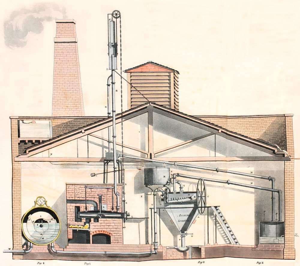
Pl. II.
Accums’, Description of Gas Works.
to Face Title.
Mulholland Delt. W. Read, Sculpt. Maiden Lane, Covent Garden.
Gas Light Apparatus,
Erected by Order of Government at THE ROYAL MINT, by Fredck. Accum.
WITH SEVEN PLATES.
By FREDRICK ACCUM,
OPERATIVE CHEMIST,
Lecturer on Practical Chemistry, on Mineralogy, and on Chemistry applied to the Arts and Manufactures; Member o£ the Royal Irish Academy, Fellow of the Limnæan Society, Member of the Royal Academy of Sciences of Berlin, &c. &c.
London.
PRINTED FOR THOMAS BOYS. No. 7. LUDGATE-HILL. (FROM No. 3, PATERNOSTER ROW)
MDCCCXIX.
[i]

Compton Street, Soho.
The extraordinarily rapid progress which the recent invention of lighting with coal gas has made in this country, is perhaps without a parallel in the history of the useful arts.
It was an invention not exempted from the misfortune common to all innovations on established practises, of encountering opposition, but it had the fortune common to few, of obtaining an almost instantaneous triumph.
A single exhibition of the gas lights in actual use was sufficient to determine the public judgment in favour of the new mode of illumination; to see was in this case, indeed to believe.
[ii]
The legislature responsive to the popular voice, and fortified in its responsibility, by the results of special enquiries which were ordered to be made into the merits of the invention, and in which I had the good fortune to be professionally engaged, gave the most liberal and decided encouragement to its adoption.
Capital, often wanting even in this opulent country for undertakings of magnitude, came to the promotion of the new art of procuring and distributing light in overflowing abundance; and already ere many years are elapsed, such has been the rapidity with which the gas light illumination has advanced, that there is not a city and scarcely a town of any note in Great Britain, in which the art of lighting by means of gas, has not been carried into effect, or in which active measures are not in progress, to participate in the benefit of this important discovery.
When the art was yet in its infancy, I published a Treatise, containing a description of the apparatus and machinery best calculated for illuminating streets, houses, and public buildings, by means of coal gas, with remarks on the utility, safety, and general nature of this new branch of domestic economy, as far as then understood, and practised in the metropolis.
The universal avidity for information on the subject, more perhaps than any particular merit in the work[iii] itself, produced a demand in this country for four large impressions of this work, in the course of a few years, and I have also had the satisfaction of finding that the Treatise has been translated into the French, German, and Italian languages.
Since this work was written, however, the art of manufacturing and applying coal gas, has undergone so many material improvements, all combining to bring it to a degree of simplicity, precision, and economy, far surpassing every thing which the original mode of practice exhibited, that I have felt I should be guilty of an injustice to the constant demand which still exists for my former Treatise, had I not made it my duty to publish the work I now present to the reader; superseding altogether the former publication, but superseding it from circumstances of necessity, and with a view to good, which I trust will be found not illusory.
The present treatise, as its title expresses, is intended to exhibit the superior process of manufacturing coal gas now employed in the metropolis and the provincial towns of Great Britain, and to lay before the reader the elevations, sections, and plans of the improved Gas Light machinery, which has stood the test of practice, and is now in action at the most celebrated Gas Light Establishments.
In the first and second part of the Treatise, I have, as[iv] introductory to the rest, given a sketch of the chemical theory and production of Gas Light. I have pointed out the leading objects of public and private utility, to which the art of lighting with gas has been, or remains to be applied: and added such other facts and observations as may serve to remove all doubt in the minds of the reader as to the important benefit which this country in particular, and the world at large, have gained by this discovery.
In the third part I have stated the maximum quantities of gas obtainable in the large way, from different kinds of coal.
In the fourth part, I have given a description of all the various forms and dimensions which the distillatory vessels or retorts have successively assumed, as well as of the improvements that have been made in the mode of setting the retorts, with a view to saving them from undue deterioration, and preventing any improvident waste of fuel. I have here given a particular account of the distillatory apparatus now used at the most celebrated gas works in the metropolis.
The fifth and sixth parts, lead the reader considerably further into a knowledge of the economy and practice of this art. They contain an account of a great variety of experiments which have been pursued on a large scale, in order to ascertain the most profitable mode of employing[v] the retorts, the differences of opinion which have existed among practical men with respect to the degree of temperature fittest to be applied, and the number of hours at a time during which the retorts may most advantageously be kept in action, with the particular results which the experiments instituted into these points have afforded; and such other data, as will enable the reader to adopt that mode of operation, which under every circumstance of locality will be found most advantageous.
The changes which have taken place with respect to the retorts, have been before detailed in part fourth; but in order to give the manufacturer a nearer insight into the superior advantages attending retorts of the construction lately brought into use, I have given in part seventh, a detailed description of the horizontal rotary retorts, the application of which has led to a more economical, expeditious, and easy method of manufacturing coal gas than heretofore practised. I have distinctly pointed out the advantages which these retorts present, the particular results they afford, and the method of applying them.
The purification of coal gas forms the subject of part eighth. I have compared here, the apparatus for purifying coal gas, as it was originally constructed, with the improved machinery lately adopted, showing the[vi] inefficacy and defects of the former, and the decided superiority which belongs to the latter.
The ninth part gives an account of the various improved gas holders which have been invented, and now are in action at the most recent establishments, for the purpose of storing large quantities of gas. The improvements that have been made in this department of the Gas Light machinery, are particularly valuable and have contributed more perhaps than any other, to lessen the expence of manufacturing gas for commercial purposes.
In the tenth part, I have given a description of an entirely new machine, called the gas-metre, or self-acting guage, lately adopted at the Birmingham, Chester, and other gas works, which measures and registers the quantity of gas manufactured in any given time, from any given quantity of coal, or consumed during any period, by any number of burners or lamps. The great services which such a machine must render both to the manufacturer and consumer of gas, are particularly pointed out, and illustrated to the manufacturer, by serving as a complete check on his workmen as to the quantity of work that ought to be performed, and to the consumer, as an exact measure of the quantity of gas he receives, and ought to pay for.
The eleventh part is appropriated to the description of[vii] another apparatus, called the governor, also of recent invention, and now in use at numerous establishments. The design of this machine is, to regulate the pressure of the gas, before it enters into the mains, the importance of which must be sufficiently manifest. I have also pointed out the application of this apparatus for regulating the magnitude of the flames of gas burners and lamps.
The twelfth part treats on gas mains and branch pipes, I have here stated the rules and practical proceedings necessary to be observed, for applying and distributing gas pipes to the greatest advantage.
The most efficient method of introducing the gas to the interior of houses, forms the subject of part thirteen. All the necessary instructions are here given to workmen, for adapting the gas pipes, and insuring success at the least cost, under every variety of circumstances.
The fourteenth part gives an account of the illuminating power of coal gas—the quantity of gas consumed in a given time, by different kinds of gas burners and lamps, the relative cost of gas, tallow, and oil lights of different intensities, and the most improved method employed for ventilating apartments lighted by gas.
In the fifteenth and sixteenth parts, I have added an account of the manufacture of carburetted hydrogen gas, from coal tar, vegetable tar, and oil, with such other observations as may enable the reader to form a proper[viii] estimate of the comparative advantage of manufacturing gas from oil, or tar, under certain circumstances. I have here also given an account of the manufacture of carbonate of ammonia, as now practised, from the ammoniacal liquor obtained in the Gas Light process, and of the manufacture of other saleable products obtainable from coal, namely; pitch, coal tar, and oil.
In conclusion I have to observe that my object throughout has been to make the work a compendium of all the best information which the practice of the art down to the present moment has been able to afford, embodying a great number of data, with which I have been obligingly favoured by gentlemen, the most practically versant in the art, and for which I beg they will individually accept this public expression of my thanks, and obligations, as well as the results which my own labours in this department, neither few, nor inconsiderable have furnished.
To supply the reader with a work of practical utility in a most valuable, and growing branch of national economy has been my object; and I need scarcely add, that the suffrages of the public to the zeal and industry at least with which I have endeavoured to obtain that object, will be a source of infinite satisfaction.
FREDRICK ACCUM.
LONDON, 1819.
[ix]
| PART I. | |
| PAGE | |
|---|---|
| GENERAL NATURE AND ADVANTAGES OF THE ART OF PROCURING LIGHT, BY MEANS OF CARBURETTED HYDROGEN, OR COAL GAS | 1 |
| PART II. | |
| OUTLINE OF THE NEW ART OF PROCURING LIGHT BY MEANS OF COAL GAS, AND THEORY OF THE PRODUCTION OF GAS LIGHTS | 33 |
| PART III. | |
| CLASSIFICATION OF PIT COAL, AND MAXIMUM QUANTITY OF GAS, OBTAINABLE FROM DIFFERENT KINDS OF COAL | 41 |
| PART IV.[x] | |
| FORM AND DIMENSIONS OF THE RETORTS ORIGINALLY EMPLOYED FOR MANUFACTURING COAL GAS | 51 |
| APPLICATION OF HEAT—FLUE PLAN ORIGINALLY ADOPTED | 59 |
| REPORT ON A COURSE OF OPERATIONS, MADE WITH SETS OF 66, OF 30, OF 116, AND OF 64 RETORTS, WORKED ON THE FLUE PLAN | 61 |
| OVEN PLAN LATELY ADOPTED | 67 |
| DESCRIPTION OF THE RETORT OVEN | 69 |
| PART V. | |
| DIFFERENCE IN THE QUANTITY OF GAS EVOLVED DURING DIFFERENT PERIODS OF THE DISTILLATORY PROCESS, AND ECONOMICAL CONSIDERATIONS RESULTING THEREFROM IN THE MANUFACTURE OF COAL GAS | 77 |
| EXPERIMENTS WITH 18 CYLINDRICAL RETORTS, CONTAINING ONE CHALDRON OF COAL | 80 |
| EXPERIMENT WITH THIRTY-SIX PARALLELOPIPEDAL RETORTS, EACH CONTAINING TWO BUSHELS OF COAL | 81 |
| REPORT ON A COURSE OF EXPERIMENTS MADE TO ASCERTAIN THE COMPARATIVE ECONOMY OF MANUFACTURING EVERY WEEK, 857,667 CUBIC FEET OF GAS, BY MEANS OF CYLINDRICAL RETORTS VARIOUSLY WORKED | 84 |
| PART VI.[xi] | |
| TEMPERATURE BEST ADAPTED FOR WORKING CYLINDRICAL RETORTS | 94 |
| ANNUAL CREDITOR AND DEBTOR ACCOUNT OF MANUFACTURING DAILY, FROM 50,000 TO 102,000 CUBIC FEET OF GAS, AT THE PRICE WHICH COAL BEARS IN THE METROPOLIS, THE OPERATION BEING COMMENCED WITH NEW RETORTS, AND THE RETORTS BEING LEFT IN A FIT WORKING STATE | 97 |
| COMPARATIVE FACILITY WITH WHICH THE DECOMPOSITION OF DIFFERENT SPECIES OF COAL IS EFFECTED | 106 |
| PART VII. | |
| HORIZONTAL ROTARY RETORTS, LATELY BROUGHT INTO USE FOR MANUFACTURING COAL GAS | 110 |
| DESCRIPTION OF THE HORIZONTAL ROTARY RETORTS AT THE ROYAL MINT | 112 |
| ACTION AND MANAGEMENT OF THE HORIZONTAL ROTARY RETORTS | 120 |
| ADVANTAGES OF THE METHOD OF MANUFACTURING COAL GAS BY MEANS OF HORIZONTAL ROTARY RETORTS | 124 |
| DIRECTIONS TO WORKMEN WITH REGARD TO THE MANAGEMENT OF HORIZONTAL ROTARY RETORTS | 134 |
| PART VIII.[xii] | |
| PURIFYING APPARATUS, OR LIME MACHINE | 140 |
| LIME MACHINE ORIGINALLY EMPLOYED FOR THE PURIFICATION OF COAL GAS | 141 |
| LIME MACHINE LATELY ADOPTED | 149 |
| TEST APPARATUS, FOR CERTIFYING THE PURITY OF COAL GAS, AND THE PROPER MANNER OF WORKING THE LIME MACHINE | 157 |
| BEST METHOD OF PREPARING QUICK-LIME FOR THE PURIFICATION OF COAL GAS | 161 |
| PART IX. | |
| GAS HOLDER | 164 |
| GAS HOLDER AS ORIGINALLY EMPLOYED | 165 |
| GAS HOLDER WITH GOVERNOR, OR REGULATING GUAGE, LATELY BROUGHT INTO USE | 169 |
| GAS HOLDER WITH GOVERNOR OR REGULATING GUAGE AT THE CHESTER GAS WORKS | 175 |
| GAS HOLDER WITH GOVERNOR OR REGULATING GUAGE AT THE BIRMINGHAM GAS WORKS | 177 |
| REVOLVING GAS HOLDER AT THE WESTMINSTER GAS WORKS | 181 |
| RULE FOR FINDING THE CAPACITY OF A REVOLVING GAS HOLDER OF GIVEN DIMENSIONS | 185 |
| COLLAPSING GAS HOLDER | 185 |
| RULE FOR FINDING THE CAPACITY OF A COLLAPSING GAS HOLDER OF GIVEN DIMENSIONS[xiii] | 195 |
| RECIPROCATING SAFETY VALVE | 196 |
| PART X. | |
| GAS METRE, OR SELF-ACTING GUAGE, WHICH MEASURES AND REGISTERS, IN THE ABSENCE OF THE OBSERVER, THE QUANTITY OF GAS PRODUCED IN A GIVEN TIME, FROM ANY GIVEN QUANTITY OF COAL, OR CONSUMED DURING A GIVEN PERIOD, BY ANY NUMBER OF BURNERS OR LAMPS | 200 |
| DESCRIPTION OF THE GAS METRE AT THE ROYAL MINT GAS WORKS | 214 |
| RULE FOR CALCULATING THE WEIGHT, WHICH A GAS METRE OF GIVEN DIMENSIONS, WILL RAISE, TO A GIVEN HEIGHT, IN A GIVEN TIME | 220 |
| GAS HOLDER VALVE | 221 |
| SIPHON, OR WATER RESERVOIR | 221 |
| PART XI. | |
| GOVERNOR OR REGULATING GUAGE | 225 |
| DIRECTIONS TO WORKMEN FOR FIXING THE GOVERNOR AND GAS METRE | 229 |
| PART XII.[xiv] | |
| GAS MAINS AND BRANCH PIPES | 239 |
| WEIGHT OF CAST IRON GAS MAINS OF DIFFERENT LENGTHS AND BORES | 251 |
| PART XIII. | |
| GAS LAMPS AND BURNERS | 253 |
| DIRECTIONS TO WORKMEN, FOR ADAPTING GAS PIPES TO THE INTERIOR OF HOUSES | 258 |
| PART XIV. | |
| ILLUMINATING POWER OF COAL GAS, AND QUANTITY OF GAS CONSUMED IN A GIVEN TIME, BY DIFFERENT KINDS OF BURNERS, AND GAS LAMPS | 269 |
| PART XV. | |
| GAS FROM COAL TAR | 282 |
| GAS FROM OIL | 289 |
| PART XVI.[xv] | |
| OTHER PRODUCTS OBTAINABLE FROM COAL, NAMELY: | |
| COAL TAR | 298 |
| COAL OIL | 300 |
| PITCH | 302 |
| AMMONIACAL LIQUOR | 303 |
| MANUFACTURE OF CARBONATE OF AMMONIA FROM THE AMMONIACAL LIQUOR | 303 |
| MANUFACTURE OF MURIATE OF AMMONIA FROM THE AMMONIACAL LIQUOR | 307 |
| DESCRIPTION OF THE PLATES | 315 |
| INDEX TO THE WORK | 321 |
| LONDON PRICE LIST OF THE MOST ESSENTIAL ARTICLES EMPLOYED IN THE MANUFACTURE AND APPLICATION OF COAL GAS | 331 |
The author of this work respectfully informs the public, that they may be furnished with estimates, and plans for the building of Gas Works, particularly adapted to the circumstances of the places where they are to be established, and that he proposes to superintend the erection of the works.
Mr. Accum also engages to supply the whole of the Gas Apparatus ready for immediate use, and to guaranty its efficient performance.
Or he will contract with any committee, directory, or public company, for Lighting with Gas, any Town, Manufactory, or Building, upon whatever scale of magnitude, for an annual specific sum.
Of the qualifications for the services which he thus proffers, he would speak with diffidence. Such proofs as he is able to offer of them, are to be found in the work here laid before the reader, beyond which he would add no more than the flattering testimony of approbation, with which his labours have been honoured, in having been selected by His Majesty’s Government to plan and erect the Gas Works at the Royal Mint, and since entrusted with the active management and superintendance of that establishment.
Compton Street, Soho,
May 28, 1819.
The following particulars are required to be stated by those who are desirous of receiving estimates, concerning the comparative economy of applying coal gas as a substitute for oil, wax, or tallow light.
1. A plan of the place to be lighted with Gas, drawn to a scale not less than one tenth of an inch, to ten feet. The design must exhibit the particular spot, where the Machinery is to be erected.
2. The kind of gas lights required, namely; whether the lights shall be equal in illuminating power to one, or more tallow candles of a given weight, or equal to an argand lamp.
3. The number of lights.
4. The average time the lights are to burn, throughout the year.
5. The average price of coal, and rate of workmen’s wages, at the place where the light is wanted.
[1]
AN
ACCOUNT
OF THE
PROCESS OF MANUFACTURING
Coal Gas.
The new art of lighting houses, streets and manufactories, with carburetted hydrogen, or coal gas, is one of those modern discoveries on which the admirers of science and the inhabitants of this country in particular, have greater reason to congratulate themselves, than any other invention or discovery of the present age.
This art is so wonderful and important, it speaks so forcibly by the effects it has already[2] produced, that it cannot fail to increase the wealth of the nation by adding to the number of internal resources, as long as coal continues to be dug in this island from the bowels of the earth.
For if we distribute the catalogue of human wants which a civilized state of society has introduced, the production and supply of artificial light, holds next to food, clothing and fuel, the most important place. We might indeed exist without it, but how large a portion of our lives would in that state be condemned to a state little superior in efficacy to that of the animals around us.
If we could for a moment suppose the privation of artificial light, during the absence of the Sun, it would follow as an immediate consequence that the greatest part of the globe on which we dwell, would cease to be the habitation of man. Whether he could ensnare or overtake those animals upon whose unprepared remains he would then be compelled to feed; whether he might store the fruits of the earth for his winter supply—what might be the physical and moral consequences of a state of such desolation, may perhaps be conjectured,[3] but no estimate can show its dreadful magnitude.
How much do our comforts, and how greatly does the extent of our power depend upon the production and supply of artificial light. The flame of a single candle animates a family, every one follows his occupation, and no dread is felt of the darkness of night. It might be a curious speculation to enquire how far, and in what respect, the morals of men would become degraded by the want of this contrivance. But it is sufficient on the present occasion, that, previous to entering upon a dissertation respecting a new art of procuring light, a train of ideas has slightly been hinted at, which cannot fail to show its magnitude and importance.
The progress of the new art of lighting houses, streets and public buildings, by means of the inflammable gas obtainable from coal, has been within these few years uncommonly rapid. The number of gas-lights already in use in the metropolis alone, amounts to upwards of fifty-one thousand. The total lengths of mains in the streets through which the gas is conveyed from the gas-light[4] manufactories into the houses, now measures two hundred and eighty-eight miles.
The gas-light illumination has also spread far and wide through the country. Establishments for the supply of the new lights are carried on at Edinburgh, Glasgow, Liverpool, Bristol, Bath, Cheltenham, Birmingham, Leeds, Manchester, Exeter, Chester, Macclesfield, Preston, Kidderminster, and in many other towns and places of Great Britain.
Every body is now convinced that pitcoal is capable of furnishing light superior to that obtained from oil, wax, or tallow. The public attention is awakened to the new value of coal, and will not rest till the art of lighting with gas is pushed to the utmost of its extent.
In order to arrive at a full and accurate knowledge of the many advantages attending the application of carburetted hydrogen or coal gas, as a substitute for candles or lamps, it may be necessary, especially for the information of those readers who have never personally witnessed this mode of illumination, to take a brief preliminary view of some of the leading objects of public and private[5] utility, to which this mode of procuring and distributing light may be applied, and of the extent to which it is entitled to national encouragement.
The chief advantages attending the use of gas, are superiority and uniformity of light, saving of labour, cleanliness, safety and cheapness.
It must be difficult for a person wholly unacquainted with this art, to imagine with what facility and neatness gas-lights are managed. The gas being collected in a reservoir, is conveyed by means of tubes, which branch out into smaller ramifications, until they terminate at the places where the lights are wanted. The extremities of the branching tubes are furnished with burners, having small apertures out of which the gas issues with a certain velocity corresponding to its degree of pressure. Near the termination of each tube, there is a stopcock, or valve, upon turning which when light is required, the gas instantly flows out in an equable stream. There is no noise at the opening of the valve, no disturbance in the transparency of the atmosphere; the gas instantly bursts on the approach of a lighted taper into a peculiarly brilliant, soft and beautiful[6] flame; it requires no trimming or snuffing to keep the flame of an equal brightness. Like the light of the Sun itself, it only makes itself known by the benefit and pleasure it affords.
The gas flame is entirely free from smell. The gas itself has a disagreeable odour before it is burnt, and so has the vapour of wax, tallow and oil, as it comes from a candle or lamp newly blown out. This concession proves nothing against the flame of gas, which is perfectly inodorous.
The gas-light flame is perfectly steady; a benefit which persons accustomed to read or write by candle-light, are particularly capable of appreciating. With the other modes of illumination we have never the light of the same intensity for two minutes together, independent of that unpleasant dancing unsteady flame which is so harassing to the sight.
The size, form and intensity of the gas flame, are regulated by simply turning the stop-cock which admits the gas to the burner or lamp. The flame may at command be made to burn with an intensity sufficient to illuminate every corner of a room, or so low and dim, as barely to be perceived.[7] It is unnecessary to point out how valuable lights of this description are in nurseries, stables, warehouses, and chambers of the sick. From the facility with which the gas flame can be conveyed in almost any direction, from the diversified size and shape which it can be made to assume, there is no kind of light so well adapted for ornamental illumination.
The flame of coal gas is of a pure white colour, and of a body full and compact. In large masses, it becomes of the same flickering character which is common to all flames of large dimensions, and is owing to the agitation of the surrounding heated atmosphere.
The saving of labour connected with the employment of gas-light, may seem on a small scale to be trifling; but when it is considered that in large manufactories, it is not unusual to find several persons employed for no other purpose than trimming the lamps or setting and snuffing the candles of the establishment, the advantage gained on this head by the use of a species of light which require no sort of attention whatever, cannot but appear very considerable.
[8]
The cleanliness of the gas-lights is also a consideration of no small importance, they are attended with none of that spilling of oil, and dropping of grease, which makes the employment of oil-lamps and candles so injurious in many warehouses, shops and private dwellings.
The flame of a gas-light compared in point of brilliancy to that of a candle, is as the flame of a common oil lamp, compared to the flame of a lamp of Argand. The difference between a street, on the night of a general illumination, and any other night when the street is under the dull glimmering light of the ordinary oil lamps, is scarcely more remarkable, than the difference between a street lighted by gas, and one lighted by oil. While the ordinary oil lamps may be said merely to serve the purpose of making “darkness visible,” the gas-lights really dispel the dominion of night, and diffuse a body of light so wide-spreading and intense, as almost to rival the clearest moonshine.
The same brilliancy which makes the gas-lights of such utility out of doors, in lighting the streets, has been found of equal advantage in illuminating the interior of private dwellings, and large public[9] buildings, such as churches, and theatres, &c. From a cluster of gas-lights, fewer by one-half than the number of oil lamps and candles required for lighting up a public edifice of this description in the most ordinary manner, a body of light is furnished which diffuses through the whole, a degree of mellow clearness which is not to be attained by the greatest number of oil lamps, or candles, which a due regard to respiration will admit of being employed. As examples of this, we have only to name the public theatres of the metropolis, all of which are lighted with gas, and in a manner which excites universal admiration.
It may perhaps be imagined that with a substance so inflammable, and amidst the blaze of resplendent flame which produces such beautiful effects, there is a peculiar risk of accidents by fire, but so far is this from being the case, that gas-lights are the safest of all lights. No danger can arise from these lights in any way, but what is common to candle lights and lamps of all kinds, and is the fault of none of them. The gas-lights are in fact a great deal less hazardous. There is no risk of those accidents which often happen from the guttering[10] of candles, from sparks being detached, or from carelessly snuffing them. The gas-light lamps and burners, must necessarily be fixed to one place, and therefore cannot fall or otherwise become deranged, without being immediately extinguished. And further, at any time by shutting the main tube which conveys the gas to the burners and lamps, all the lights in the house can be immediately extinguished. In short, where gas is used, the master of the house, when he has turned the main stop-cock which conveys the gas into the collateral branch pipes, may retire to rest free from any of those apprehensions, which before harassed him, lest a candle might have been left burning, of lest the accidental dropping of a spark might become the cause of enveloping himself and family in destruction.
But the best proof of the great safety of the new lights is, that notwithstanding upwards of fifty-one thousand gas-lamps burn nightly in London, we have not heard of a single accident occasioned by them, though the lamps and burners are generally carelessly managed, while we have too often occasion to lament the effects arising[11] from sparks of candles, or carelessness in snuffing them.
Hence the fire-insurance-offices engage to insure manufactories and public works, at a less premium, where gas is used, than when lighted by other means.
The excessive expence of insurance, arising from the numerous candles employed in most of the first-rate manufacturing establishments, and the combustible nature of the structure of the buildings; the great difficulty of retrieving the injury resulting to a well-organised business, from the accidental destruction of the machinery, are considerations alone sufficient to furnish the strongest economical, as well as political recommendations, for the adoption of the new lights in all manufactories where work is done by candle-light.
We have as yet only adverted to the application of gas in the more ordinary cases where light is wanted, but among other special purposes to which gas-lights may be applied, it would be improper to overlook the peculiarly advantageous use which may be made of them in the supplying of light-houses. From the splendour and distinguishing forms[12] which the gas-light flame is capable of assuming, nothing can possibly be better calculated for such a purpose; and in point of economy, the employment of it would be attended with a saving of at least one half of the ordinary expence of oil lights. By means of a single furnace, as much gas may be produced in three hours, as will furnish during the longest winter night, a flame of greater brilliancy than is now furnished by any lighthouse in Britain, or indeed in the world. The body of flame may be increased to any size, merely by increasing the number of burners; and whatever may be the magnitude of the flame, it will continue to burn, without becoming in the least clouded by smoke, or the reflectors being in the least obscured. Should these considerations lead, as it is to be hoped they will, to the actual employment of gas in the lighthouses around the British islands, it will readily occur, that in proportion as the gas would be found attended with less expense than the present mode of lighting by oil, it would enable the commissioners for light-houses, out of the surplus means which would be thus placed at their disposal, to multiply the number of lighthouses,[13] and thus to add most essentially to the security of British navigation. Nor is it in the case of maritime signal-lights alone, that the use of gas is applicable, by its superior efficacy and cheapness. The saving of expences to the country which would be effected by the substitution of coal gas, for oil and tallow in these and other public establishments, is a consideration which cannot be too much pressed on public attention. The annual expenditure for lighting the barracks of Great Britain alone, is said to fall little short of fifty thousand pounds; for less than one half of which sum, they might be lighted by means of gas much better, and a great deal more safely. Some idea may be formed from the practical saving in this department—how great might be the total saving, were this new mode of lighting adopted in all our national establishments.
In the case of the public arsenals, however, the saving from the employment of coal gas is a consideration of far inferior importance to the superior security attending it. On the preservation of the stores which they contain may depend in a time of war the whole chance of success against the enemy[14] nor can any body who has lived in this country at such a time have forgot the feverish alarm with which the people have frequently seen this security endangered by accidents arising from the use of moveable lights. Were coal gas exclusively employed in such establishments, the fixed position which can be given to the burners, and the absence of all danger from sparks must give a degree of security to those places from fire, far beyond what they at present possess, even when superintended with the greatest possible caution and fidelity.
The same remark is equally applicable to the government offices, public libraries, museums, in short, to all public establishments where the national value of the articles preserved is such that no possible means of increasing their security from destruction should be neglected.
We have now to turn our attention to another general point of view in which the introduction of lighting by gas is not less an object of interest to the public; we allude to the application of gas as a means of heating as well as lighting. Mr. Maiben[1][15] was the first who directed the attention of the public to this subject; he ascertained that gas from coal gives nearly the same heat when put into combustion, which is yielded by a third part of the coal from which it is extracted. In other words, it has been found that a quantity of fuel giving a particular degree of heat, may be employed so as to produce at the same time another substance yielding nearly an equal degree of heat in a different and more manageable form; a form in which it can be preserved for any length of time, divided into any portions, distributed in any direction, consumed in an open fire-place, or in a stove concealed in any shape; a form in which the flame may issue equally well from iron or from stone-ware, be instantly lighted up and instantly extinguished, be made to burn as long or as short a time as may suit us, and in any degree of intensity between the most animating and brilliant blaze and its total extinction; be extinguished in one room, and the next moment lighted up in any other; in short such a form, that by one proper arrangement from the beginning, with the same portion of fuel, we may at any time have the command of a chearful[16] fire, an adequate and comfortable warmth in any part of our dwelling to which we may have occasion to move, as manageable, and in this way as portable, as the taper by the touch of which it is kindled. To those who have been accustomed to see before them a solid mass of burning fuel, this gas flame may at first have the less satisfactory appearance of a fugitive blaze which we perceive nothing to support. But its uniformity and permanence will soon banish this impression, while it is attended with other advantages not inconsiderable with respect either to comfort or convenience. There are no coals to be carried in, no ashes to be carried out; there is no blowing, no sweeping of cinders, no dust, no interruption of servants; there is no excessive heat in one stage, no sudden damping at another: we have the choice of any temperature, and which we can regulate with the utmost ease. The fire itself is lively and pleasant to the eye: inclosed in transparencies it receives a degree of splendour not easily imagined. Numerous applications of gas, as a source of heat for airing rooms, and other purposes, have already been adopted. It is used in kitchens for keeping[17] meat warm, and for boiling water; in store rooms, in picture galleries, in libraries, for maintaining them at an equal temperature. By copper-plate printers, it is used for warming their plates; and by jewellers and other artists, for soldering.
[1] A Statement of the advantages to be derived from coal gas.—p. 42.
It remains further to be observed that the coal, by yielding gas and other products, namely, tar, pitch, and ammoniacal liquor, is not entirely lost. It produces, besides light, an excellent fuel, namely, coke; and as a manufactory, or workshop, generally requires heating as well as lighting, there is a gain both ways. The manufacturer, by distilling his coal instead of burning it as it comes from the pit, saves his candles and improves his fuel. One effort at the outset in erecting a gas apparatus, will reduce his annual disbursement for those two articles of prime necessity, much in the same manner, though in a greater degree, as the farmer gains by building a thrashing machine and laying aside the use of the flail.
The coal is so far from being reduced in consequence of the gas-light process, to an useless mass, that in many places immense quantities are reduced to the state of coke for the purpose of rendering[18] the coal a better fuel than it was in its natural state; for coke gives a strong and lasting heat. It is equally valuable for kitchen and parlour fires, and still more as a necessary requisite in some important branches of manufacture, so that in whatever quantity coke may be produced, it can never want a good market. The demand for coke in this capital, since the establishment of the gas-light works, has prodigiously increased. Numerous taverns, offices, and public establishments, which heretofore burnt coal, now use coke to the total exclusion of coal; and in almost every manufactory, which requires both extensive lighting and heating, gas and coke are now the means jointly employed. A coke fire emits a very uniform and intense heat; it produces no sparks, and burns free from soot and smoke; it requires no trouble in managing, and to those who have the misfortune of being plagued with a smoaky chimney, affords the only certain cure.
Another valuable product is the tar which is deposited during the production of the gas, this tar when rectified by a slight evaporation, has become an article of commerce. Large establishments,[19] both of coal tar, coal oil, and pitch, are in full action, and the commodities which they furnish have become in great demand. The ammoniacal liquor which the gas-light process affords, has of late given rise to very important branches of chemical manufacture, carried on upon a large scale. But as the gas is at present supposed to be the only object in view, for the sake of the light which it yields, the other products being only accidentally connected with its extraction, let us leave the idea of profit on them out of the question, and with the utmost latitude of concession, require them only to stand as in part for a portion of the coal employed in the process, we have still the gas, an article which performs the functions of the oil, the tallow, or the wax for which it is substituted; and to the price of which we have no need to call the attention of those who make use of them. There remains only to be opposed on the other side, the expence of the apparatus by which the gas is to be prepared, and the lights maintained. From the materials and the workmanship, with the interest of the capital sunk, the expence in the first instance, must be very considerable. But[20] where the quantity of light must be great, even from cheap substances, or where, with a less quantity of light, the substances from which it is derived must be of the costliest kind; such is in either case the enormous expence of these materials, that by superseding them and making every reasonable allowance to the engineer who erects the gas apparatus, the sum it costs, both principal and interest, is soon liquidated, leaving at last a total saving, excepting the expence of accidental repairs, which, from the durability of the materials employed, seldom exceeds a trifling sum.
The principal expence in the pursuit of this new branch of civil and domestic economy, is therefore, the dead capital employed in erecting the machinery for obtaining and conveying the gas. The floating capital, after the first cost incurred in erecting the apparatus, is comparatively small; even if usurious interest is allowed for the first cost of the apparatus, and its deterioration, the saving must always be considerable, especially if the number of lights furnished are comparatively in a small place.
[21]
At the same time were we to offer advice to the public on this subject, it would be, that no private individual resident in London, should attempt to light his premises, for the sake of economy, with coal gas by means of his own apparatus, whose annual expence for light does not exceed forty pounds. But when a street, or small neighbourhood is required to be lighted the operation may be commenced with safety; the sum required for erecting the apparatus, and the labour attending the process, together with the interest of money sunk, will then soon be liquidated by the light and other products.
Individuals have accordingly engaged successfully in the distillation of coal, and trade with advantage in the articles produced by the process.
In like manner may the lighting of cities be accomplished without the aid of incorporated bodies; and parishes may be lighted by almost as many individuals as there are streets in a parish.
The supplying of light to the street or parish lamps alone, of any district of street lamps only, can never be undertaken with economy in this[22] capital, nor indeed in any other; for the money sunk in furnishing the mains or pipes only, must always greatly exceed what any revenue from the lighting of the streets alone can compensate.
The most beneficial application of gas-lights unquestionably is in all those situations where a great quantity of light is wanted in a small place; and where light is required to be most diffused, the profit of this mode of illumination is the least. Hence, the lighting of the parish, or street-lamps alone, without lighting shops or houses, can never be done with economy.
It may be objected to the universality of our conclusion that the price of coal differing very much in different places will occasion a variation in the expence of the new mode of lighting.
The price of coals can however have but little effect upon the cost of the gas-lights; because the very refuse, or small coal, which pass through the screen at the pit’s mouth, and which cannot be brought into the market, nay, even the sweepings of the pit, which are thrown away, may be employed for the production of coal-gas. It makes no difference in what form the coal is used. This[23] circumstance may contribute to enable coal-merchants to furnish coals in larger masses, and as they come from the mine, instead of increasing the bulk by breaking them into a smaller size, which is a practice commonly followed.
The demand which the gas-light occasions for inferior sorts of coal may hereafter contribute to lower the price of the superior kinds, and keep a level which cannot be shaken under any circumstances. It may contribute to prevent combinations which do certainly operate to the prejudice of the public, and sometimes put this great town at the mercy of a few proprietors in the north, who deal out this commodity in any way they please. The competition thus produced, it is impossible not to consider as an advantage, which would tend to prevent such combinations, and put the inhabitants of London out of the reach of them.
The advantages which the coal trade must reap from the introduction of the gas-light must be very considerable. There is already less waste, but a greater consumption of coal than formerly. The lower classes of the community are scantily supplied with firing; and nothing but a reduction of[24] price is necessary to increase to a very large amount the average quantity of fuel consumed in the country. The lightness of the coke produced by the gas-light manufacture diminishing the expence of land carriage, facilitates its general diffusion—the comforts of the poor are becoming materially augmented, and a number of useful operations in agriculture and the arts are beginning to be carried on, which have been hitherto checked by the extravagant price of fuel. If any additional vent were wanted for the coke, it would readily be found in the continental market; coke being better suited than coal to the habits of most European nations.
Many, and unquestionable as are the advantages of this new mode of procuring and distributing light, it was not to be expected that an invention which went to impair a branch of trade, in which a large portion of skill and capital had hitherto been successfully employed should escape encountering very considerable opposition. On the first introduction of the gas-lights, great but happily unsuccessful endeavours were made to alarm the public mind by dismal forebodings of the destruction[25] which would ensue to the Greenland trade, and the consequent loss of a valuable nursery of British Seamen. When impartially considered it will be found that there was nothing more in this objection than the common clamour that is always set up against every new means of abridging labour, to which had the public listened, an interdict would have been laid upon the spinning and threshing machines, the steam engine, and a thousand other improvements in machinery.
Such clamour scarcely ever fails to be made when the extension of machinery, the application of inanimate power, and the abridgment of labour consequent on either, is a matter proposed. We are then sure to be told that the scheme of mechanical or chemical improvement is pointed against the human species, that it tends to drive them out of the system of beneficial employment and that, on the whole, the sum of the improvement is not only a less proportion of good to society, but a positive accession of misery to the unemployed poor.
The misfortune of this argument is that to be good for any thing, it would prove a great deal[26] too much. It is not confined in its scope to any particular species or defined extent of improvement, but is equally proscriptive of all improvements whatever. It is a principle for savage life, not for a state of civilization. It takes for its basis that it is an advantage to perpetuate that necessity for hard and incessant labour under which man finds himself originally placed by nature, with all the wants, privations, ignorance and ferocity, which are attendant on that condition, and that every discovery, invention, or improvement which tends to abridge the quantity required of human labour, and to augment the resources for living and enjoyment is a serious injury to society. The advocates of this narrow theory do not go the whole length of maintaining that diminishing labour, and increase of substance, are in themselves positive evils, a position too absurd perhaps for any one to uphold; but they maintain what ends in a consequence nearly as untrue, namely, that neither the one nor the other is of any advantage to society at large. The palpable error of this theory is, that it supposes that all improvements which tend to supersede human labour, are[27] necessarily made for the benefit of a few, and not for the common benefit of the many; that instead of lessening to each individual the share of labour requisite to obtain the means of his subsistence, their only tendency is to lessen the value of each personas labour, and to oblige him to work more in order to live equally well.
Now, however the existing state of things may be in this country, or in other countries, arising out of a variety of arbitrary circumstances, foreign to the natural, and in all cases the ultimately inevitable course of industry, it is a matter of justice, clear and undeniable, that every improvement in society ought to be the property of the many, and not of a few; and that it ought either to lessen the quantity of labour necessary for acquiring the means of living, or to increase the profit to be gained by continuing the same quantity of labour. Nor does there seem any reason for believing that, in point of fact, the actual distribution of things is so far from according with this principle of justice as some superficial and prejudiced observers are fond of representing. The labourer, or artizan, may now work a greater number of hours daily[28] than he did years ago; but how seldom do we find this to be the case without his comforts being more than proportionally multiplied, and his ultimate independence from labour essentially promoted. In general, however, the fact is, if we may give credit to well informed economists, that the working classes do not labour more than formerly, and yet live, or at least have the means of living better; and that by working even less than formerly, they can obtain the means of living quite as well.
Let the real state of matters in this respect, however, be as it may, the question comes to be one merely as to the distribution of the produce of nature and of art, and instead of opposing improvements because they tend to encrease that produce, the object of those who have really the good of their fellow-creatures at heart, ought to be, to encourage such improvements as much as possible, but at the same time to obtain a correction of any partiality or injustice which may have crept into the distribution of their beneficial consequences. It is not to be denied that all new improvements which interfere with and change the occupations[29] and habits of the working classes of people, must at first expose them to inconvenience and distress, against which it is in fairness the duty of society to protect them; but let not that temporary inconvenience and distress which can and ought to be provided against, be held as an insuperable obstacle to the adoption of an improvement the ultimate tendency of which it is to better the condition of mankind.
It is likewise true that the manufacturing classes often suffer great want by the occasional suspension of employment, and sometimes actual oppression, by the demand for labour; but that involves a question more immediately connected with political economy than the present subject.
It is not the machinery that is in fault in such cases, but those speculators who occasion an inordinate excess of employment, or those statesmen who, with their folly, derange the great machine of human interests and intercourse.
Every invention which tends to diminish the labour of men must be a benefit to the species; and it is wicked to argue against the use of any thing from its occasional abuse.
[30]
If the application of mechanical inventions thus tends to improve the humanity of the public, if it reduces the necessity of hard labour, and diminishes the danger of many occupations which we contend it does, they who contribute to this object deserve our respect and gratitude.
It may be true that we have now no such minds as those of Homer, or Bacon, or others of their stamp; but we should reflect that the circumstances which produced such characters are gone by, and great faculties have found other objects and other materials to work with.
The use of mechanical industry not only improves and augments the comforts of domestic life, but it also, perhaps, does as much to soften the feelings of mankind towards one another as the precepts of philosophy. It tends to engender a detestation of hard labour, and to make the world consider not what the labourer may be able to do in tasking him, but what he ought to do without detriment to himself. It effects this by withdrawing, to a great degree, from observation, the distressing spectacle of men and animals toiling beyond their strength.
[31]
It ought never to be forgotten, that it is to manufactories carried on by machinery, and abridgment of labour, that this country is indebted for her riches, independence, and prominent station among the nations of the world.
Authentic estimates have shewn, that the use of machinery in Great Britain, is equivalent to an addition to the population of upwards of one hundred millions of adult persons.
This immense accession of power, has enabled this country to withstand assaults, and to achieve objects of political ambition, that appear almost miraculous when compared with the geographical extent and numerical population of the kingdom.
With respect to what has been advanced as to the probable injury that would result from the general adoption of the gas-lights all over the country, to the Greenland trade, it may be observed that the traffic might with more propriety be called a drain than a nursery of the naval force. The nature of the Greenland service requires that the crew should consist of able bodied sailors; and being protected men, not subject to the[32] impress law, they are rendered useless for national defence. The nursery of British seamen is the coasting trade; and as the gas-light illumination becomes extended it will increase that trade as much as it diminishes the Greenland fishery.
Even on the extreme supposition that it would annihilate the Greenland fisheries altogether, we should have no reason to regret the event. The soundest principles of political economy must condemn the practice of fitting out vessels to navigate the polar seas for oil, if we can extract a superior material for procuring light at a cheaper rate from the produce of our own soil. The consequence of lighting our dwellings and manufactories with gas can in fact prove injurious only to our continental friends, one of whose staple commodities, tallow, we shall then have less occasion to purchase, although the new lights can never supersede entirely the use of candles and moveable lights.
[33]
All substances, whether animal, vegetable, or mineral, consisting of carbon, hydrogen, and oxigen, when exposed to a red heat, produce various inflammable elastic fluids, capable of furnishing artificial light.
The gases thus obtained are called carburetted hydrogen; they produce, from their combustion, water and carbonic acid. The species of carburetted hydrogen, procured from pit-coal, has of late been called coal gas.
We perceive the evolution of this elastic fluid, during the combustion of coal, in a common fire.[34] The coal, when heated to a certain degree, swells and kindles, and frequently emits remarkably bright streams of flame. And after a certain period these appearances cease, and the coal glows with a red light.
The flame produced from coal, wood, turf, oil, wax, tallow, or other bodies, which are composed of carbon, hydrogen and oxigen, proceeds from the production of carburetted hydrogen gas, evolved from the combustible body when in an ignited state.
It must have been noticed at the same time, that in the common mode of burning coal in a fire-place, or stove, nearly the whole of this inflammable gaseous matter is lost. We often see a flame suddenly burst from the densest smoke, and as suddenly disappear; and if a light be applied to the little jets that issue from the bituminous part of the coal, they will catch fire and burn with a bright flame. The fact is, that the greater part of the carburetted hydrogen gas, capable of affording light and heat, continually escapes up the chimney, during the decomposition of the coal, whilst only[35] a small part is occasionally ignited, and exhibits the phenomena of the flame.
If coal instead of being burnt in the way now stated, is submitted at a temperature of ignition in close vessels, all its immediate constituent parts may be collected. The bituminous part is melted out in the form of coal tar, there is disengaged at the same time a large quantity of an aqueous fluid, contaminated with a portion of oil, and various ammoniacal salts. A large quantity of carburetted hydrogen, carbonic oxide, carbonic acid, and sulphuretted hydrogen also makes their appearance, and the fixed base of the coal, alone remains behind in the distillatory apparatus, in the form of a carbonaceous substance called coke. An analysis of the coal is thus effected by the process of destructive distillation. The products which the coal furnishes may be separately collected in different vessels. The carburetted hydrogen, or coal gas, when freed from the foreign gases may be propelled in streams out of small apertures, which when lighted may serve as a flame of a candle and then form what we now call Gas Lights.
[36]
It is in this manner that from pitcoal a production of our own soil, we procure a pure, lasting and brilliant light, which in other cases must be derived from materials in part imported from abroad.
In order to apply this mode of procuring light on a large scale as now practised with unparalleled success in this country, the coal is put into vessels called retorts and furnished with pipes connected with reservoirs to receive the distillatory products. The retorts are fixed into a furnace, and heated to redness. The heat developes from the coal the gaseous and liquid products, the latter are deposited into receivers, and the former are conducted through water in which quick lime is diffused by which the carburetted hydrogen gas is purified. The sulphuretted hydrogen and carbonic acid which were mixed with it, become absorbed by the quick-lime, and the pure carburetted hydrogen is stored up in a vessel called the gas-holder, and is then ready for use.
From the reservoir in which the gas has been collected, proceed pipes, which branch out into[37] smaller ramifications until they terminate at the place where the lights are wanted and the extremities of the branch pipes are furnished with stop-cocks to regulate the flow of the gas into the burners or lamps.
The production of gas-lights, is therefore analogous to that of flame produced from tallow, wax, or oil. All these substances possess, in common with coal, the elements of certain peculiar matters, which are capable of being converted into inflammable elastic fluids by the application of heat.
The capillary tubes, formed by the wick of a candle, or lamp, serve the office of the retorts, placed in the heated furnace in the gas-light process and in which the inflammable gaseous fluid is developed. The wax tallow or oil, is drawn up into these ignited tubes, and is decomposed into carburetted hydrogen gas, and from the combustion of this substance the illumination proceeds. In the lamp as well as in the candle, the oil, or tallow, must therefore be decomposed before they can produce a light, but for this purpose the decomposition of a minute quantity of the materials successively, is sufficient to[38] give a good light. Thus originates the flame of a candle or lamp.
Nothing more therefore is aimed at in the gas-light process, than to separate the immediate products which coal affords, when submitted to a temperature of ignition in a close vessel; to collect these products in separate reservoirs, and to convey one of the products, the inflammable gas, by means of pipes and branching tubes, to any required distance, in order to exhibit it there at the orifice of the conducting tube, so that it may be used as a candle or lamp.
The whole difference between the gigantic process of the gas light operation, and the miniature operation of a candle or lamp, consists in having the distillatory apparatus at the gas-light manufactory, instead of being in the wick of a candle or lamp. In having the crude inflammable matter decomposed previous to the elastic fluid being wanted, and stored up for use, instead of being prepared and consumed as fast as it proceeds from the decomposed oil, wax or tallow; and lastly, in transmitting the gas to any required distance, and[39] igniting it at the burner or lamp of the conducting tube, instead of burning it at the apex of the wick. The principle of the gas-light manufacture is therefore rational, and justifiable by the general mode in which all light is produced.
It only remains to be observed that while the new and important use to which pitcoal may thus be applied, affords a strong confirmation of what has been well observed, that of all subterraneous combustible substances, coal is in this country by far the most important natural production.[2] “It is connected not only with the necessities, comforts and enjoyments of life, but also with the extension of our most important arts, our manufactures, commerce and national riches.
[2] Davy on the Safety Lamp.
“Essential in affording warmth and preparing food, it yields a sort of artificial sunshine and in some measure compensates for the disadvantages of our climate.
“By means of it metallurgical processes are carried on, and the most important materials of civilized life furnished, the agriculturist is supplied with a[40] useful manure and the architect with a necessary cement. Not only manufactories and private houses, but even whole streets and towns are lighted by its application, and in furnishing the elements of activity in the steam-engine, it has given a wonderful impulse to mechanical and chemical ingenuity, diminished to a great extent human labour, and increased in a high degree the strength and wealth of the country.”
[41]
We have stated already that pitcoal is in this country the cheapest crude natural production from which carburetted hydrogen gas can be obtained in the large way. It is that which yields it in abundance, and which can with the least trouble and expence be subjected to the operation it has to undergo for the production of the gas.[3] Nature has dealt this mineral out to us, with an unsparing hand, and has provided mines of coal which seem to defy the power of man to exhaust.
[3] Other Substances from which carburetted hydrogen gas, may be economically obtained, are animal and vegetable oil, tar, both vegetable and coal tar; pitch, resin, the essential oils obtainable from vegetable and from coal tar, and the compact species of turf. On this subject we shall speak hereafter.
[42]
The principal coal mines in England are those near Newcastle and Whitehaven. The town of Newcastle stands on beds of coal which extend to a considerable distance round the place, and which as far as concerns many hundred generations after us, may be pronounced inexhaustible.
Pitcoal like all other bituminous substances is composed of a fixed carbonaceous base in the state of bitumen, united to a small portion of earthy and saline matter, which constitute the ashes left behind when the coal is burnt. The proportions of these parts differ considerably in different kinds of coal; and according to the prevalence of one or other of them, so the coal is more or less combustible, passing by various shades from the most inflammable coal into blind coal, Kilkenny coal, or stone coal, and lastly into a variety of earthy, or stony substances, which although they are inflammable do not merit the appellation of coal.
All the varieties of coal used in this country for fuel may be divided into the following classes.
The first class comprehends those varieties which are chiefly composed of bitumen only, which take fire easily, and burn briskly with a strong and[43] yellowish white blaze, which do not swell or cake on the fire, and require no stirring, which produce no slag, and by a single combustion are reduced to light white ashes. Some of this species of coal when suddenly heated crackle and split into pieces, especially if laid on the fire in the direction of the cross fracture of their laminæ.
Cannel coal, deserves to be placed at the head of this class; next to this, we may rank all those descriptions of coal known in the London market by the names of Hartley, Cowper’s Main, Tanfield Moor, Eighton Main, Blythe, and Pont Tops. It also includes the sort of coals found in several parts of Scotland, called Splent coal, and some of those raised on the Western Coast of England.
Most of the coals raised in Staffordshire ought likewise to be classed among this species of coal, but the line of distinction between these, and the classes subsequently named, cannot be accurately drawn.
The following table exhibits the maximum quantity of gas obtainable from the first class of coal.[4]
[4] Own Experiments, made at the Royal Mint Gas-Works.
[44]
| One Chaldron of Coal, produces | Cubic feet of Gas. |
|---|---|
| Scotch Cannel coal | 19,890 |
| Lancashire Wiggan coal | 19,608 |
| Yorkshire Cannel coal, | |
| (Wakefield) | 18,860 |
| Staffordshire coal,[5] | |
| First variety,[6] | 9,748 |
| Second variety, | 10,223 |
| Third variety, | 10,866 |
| Fourth variety, | 9,796 |
| Gloucestershire coal,[7] | |
| First variety, (Forest of Dean, High Delph) | 16,584 |
| Second variety, (Low Delph) | 12,852 |
| Third variety, (Middle Delph) | 12,096 |
| Newcastle coal, | |
| First variety, (Hartley) | 16,120 |
| Second variety, (Cowper’s High Main) | 15,876 |
| Third variety, (Tanfield Moor) | 16,920 |
| Fourth variety, (Pontops) | 15,112 |
[5] They require a much higher temperature, than is necessary for the decomposition of Newcastle coal.
[6] For the maximum quantity of gas produced from this and the three succeeding varieties of coal, I am indebted to J. Gostling, Esq. Proprietor of the Birmingham Gas Works.
[7] Most varieties afford a porous, and very friable coke.
[45]
The second class of coal, comprehends all those varieties which contain a less quantity of bitumen, and a larger quantity of carbon than the first class. They burn with a flame less bright and of a more yellowish colour, and the last portion of flame they are capable of yielding is always of a lambent blue colour, they become soft after having laid on the fire for some time, swell in bubbles and pass into a state of semi-fusion, they then cohere and coke, puff up and throw out tubercular scoriæ, with a hissing noise, accompanied with small jets of flame.
In consequence of the agglutination and tumefaction, the passage of air, if this sort of coal be burnt in an open grate, is interrupted, the fire burns as it is called hollow, and would become extinguished if the top of the coal were not from time to time broken into with the poker.
The coke formed from this species of coal is more compact than that produced from the first sort of coal, and is well calculated for standing the blast of bellows in metallurgical operations. In respect to weight the second class of coal is considerably heavier than those of the first class, the difference[46] amounts to not less than from twenty-eight pounds to thirty-three pounds in the sack of coal. A chaldron of some varieties of this class of coal, if the coals are in large lumps, weighs upwards of twenty-eight hundred weight.
The usual denomination by which the second class of coal is known in the London market, is that of strong burning coal. The following varieties are sufficiently known, Russel’s Walls-End; Bewick’s and Craister’s Walls-End; Brown Walls-End, Wellington Main, Temple Main, Heaton Main, Killingsworth Main, Percy Main, Benton Main, and some varieties of the Swansea coal.
The smaller kinds of coal of this class are preferred by smiths, because they stand the blast well. They make a caking fire so as to form a kind of hollow, space or oven, as the workmen call it. Some varieties abound in pyrites, and others are intersected with thin layers of slate and lime-stone. They require more heat for being carbonized than the first class, and the fluid obtained from it by distillation, contains a considerable portion of carbonate, sulphate, and hydrosulphuret of ammonia. They are well calculated[47] for the production of coal gas; the coke which they produce is not very brittle, and will bear moving from place to place, without crumbling into dust.
The following table exhibits the maximum quantity of gas obtainable from the second class of coal.[8]
[8] Own Experiments, made at the Royal Mint Gas-Works.
| One Chaldron of Coal, produces | Cubic feet of Gas. |
|---|---|
| Newcastle coal, | |
| First variety, (Russel’s Wall’s End) | 16,876 |
| Second variety, (Bewick and Craister’s Wall’s End) | 16,897 |
| Third variety, (Heaton Main) | 15,876 |
| Fourth variety, (Killingsworth Main) | 15,312 |
| Fifth variety, (Benton Main) | 14,812 |
| Sixth variety, (Brown’s Wall’s End) | 13,600 |
| Seventh variety, (Mannor Main) | 12,548 |
| Eighth variety, (Bleyth) | 12,096 |
| Ninth variety, (Burdon Main) | 13,608 |
| Tenth variety, (Wears Wall’s End) | 14,112 |
| Eleventh variety, (Eden Main) | 9,600 |
| Twelfth variety, (Primrose Main) | 8,348 |
[48]
The third and last class of coals includes those which are destitute of bitumen, being chiefly composed of carbon in a peculiar state of aggregation, evidently combined chemically with much earthy matter. Coals of this class require a still higher temperature to become ignited than any of the former classes, they emit little or no smoke. When laid on a fire they burn away with a feeble lambent flame, indeed some varieties give no flame at all, but burn merely with a red glow, somewhat like charcoal, and at length become consumed without caking. They leave a small portion of heavy ashes.
When submitted to distillation they afford little or no tar; of a consistence almost resembling pitch, and a gaseous fluid chiefly composed of gaseous oxide carbon and hydrogen gas. It is scarcely necessary to add that they are altogether unfit to be employed for the manufacture of coal gas. The Kilkenny, Welch, and stone or hard coal belong to this class. They require a strong draught when burnt in an open fire-grate, and the large quantity of gaseous oxide of carbon which they furnish during their combustion is extremely offensive.[49] This is particularly the case with Kilkenny coal. The Welch stone or hard coal is better adapted for culinary purposes, and there is reason to believe that this species of coal might be rendered useful in the smelting of iron ore, by a slight modification in the metallurgic process employed for extracting the metal from its ore, but to eradicate prejudice, and to alter established practices is a work which nothing but time can effect. This species of coal is sent all over the kingdom; it is well calculated for the operations of drying malt and hops, and its small coal or culm has been found a more economical fuel, than Newcastle and Sunderland coals, for the burning of lime and bricks, and for all other processes where no blazing fuel is required.
The following table exhibits the maximum quantity of gas obtainable from this class of coals.
| One Chaldron of Coal, produces | Cubic feet of Gas. |
|---|---|
| Welch coal. First variety, from Tramsaren, near Kidwelly,[9] | 2,116 |
| Second variety, from the yard vein at the same place[50] | 1,656 |
| Third variety, from Blenew, near Llandillo | 1,416 |
| Fourth variety, from Rhos, near Ponty Barren | 1,272 |
| Fifth variety, from the Vale of Gwendrath | 1,292 |
| Sixth variety, from ditto | 1,486 |
[9] The coal for these Experiments was supplied gratuitously, to the Gas Works of the Royal Mint, by Sir W. Paxton of Middleton Hall.
When we consider the before mentioned varieties of coal in an economical point of view, as fuel to be used in the gas-light process, for heating the retorts, it appears from a series of experiments that have been made under my direction, that the second class of coal comprehending those varieties which contain a larger quantity of carbon than bitumen (p. 45,) afford the most economical fuel, they act less on the grate bars, and fire bricks of the furnace than those varieties which take fire easily and burn briskly with a strong blaze. A mixture of Welch Stone coal, and Newcastle coal forms an excellent economical fuel, where an intense glowing fire is required.
[51]
The proper mode of constructing the retorts in which the coal is distilled, and the art of applying them form an object of primary importance in every gas-light establishment. According as the manufacture is conducted in these respects with a due regard to physical principles, depends the quantity of gas which can be obtained in any given time, from any given quantity of coal, the consumption of fuel requisite for the production of that quantity of gas, the degree of deterioration to which the distillatory vessel is subjected, the quality in some measure, of the gas itself; and, as the ultimate result of all these circumstances, the cheapness at which the gas light can be furnished to the consumer.
[52]
The essential influence of these various particulars on the value of the art of lighting with coal gas, has led to much assiduous enquiry to ascertain that sort of construction and mode of operation in respect to each of them which may be most advantageous. And in no branch of the new art of procuring light, has a greater variety of plans of improvement been submitted to the several directing boards of gas works, or more labour and expence been incurred in experiments conducted on a large scale, to ascertain the relative merits of these plans. Nor is there any part of the gas-light process in which a greater number of material alterations have been put in practice.
In the earlier periods of lighting with coal gas the retorts employed at some of the gas-light establishments in the metropolis, were hollow cast-iron cones from six to seven feet in length. The greatest diameter of the cone which formed the mouth of the retort, measured from twelve to fifteen inches, and its smallest diameter at the vertex from nine to ten inches.
At other gas works the form of the retort was a parallelopiped from six to seven feet long, the[53] horizontal, and vertical sides were respectively to each other, as 20 to 15 inches. The angles of these retorts were slightly rounded. Fig. 16, plate V. exhibits a vertical section of this retort.
Again at other establishments semi-cylindrical retorts, placed horizontally upon their flat surfaces were employed; fig. 18. pl. V. The length of these retorts was from five to six feet, and their vertical and horizontal diameters were to each other as 6 inches, to 18 inches. And at a few establishments, ellipsoidal retorts, fig. 17, plate V. were used; these measured from five feet and a half, to six feet in length, their major and minor axes bore different proportions to each other at different establishments. At the first adoption of these retorts, the proportions varied but little from the cylinder, but subsequently the difference between the major and minor axes became gradually increased till at last the major axis has become to the minor axis, as 20 to 10 inches, and at some gas works the proportions are as 25 to 10 inches.
With vessels of these forms the distillatory process was carried on for some years, and the quantity of fuel employed to decompose a given quantity of[54] coal by means of them, amounted to from thirty to thirty-six per cent.
When the dimensions of the retorts were increased, both the quantity of fuel and time required for the decomposition of a given quantity of coal was in a far greater ratio; and the operations of charging and discharging the retorts, very troublesome.
Retorts of smaller dimensions have likewise been tried, but the more frequent charging and discharging, which they require, occasioned such a waste of time and labour, and such intermissions, in the temperature necessary for the process of distillation, (besides being attended with other disadvantages which will be afterwards explained), that they were speedily discontinued at the gas works where they had been adopted.
The use of conical retorts, as well as of those of a semi-cylindrical and parallelopipedal form, has of late been discontinued in most establishments. The conical shape not only diminishes the capacity of the vessel, but also renders it incapable of being heated economically.
From two comparative series of operations[55] made on a large scale, and continued for upwards of six months with conical and cylindrical retorts, with a view to determine the comparative power of these vessels, it has been proved that the same quantity of gas which can be obtained by means of forty conical retorts, may be procured in the same time and with the same quantity of coal and fuel, by means of thirty-four cylindrical retorts.[10]
[10] These Experiments were made at the commencement of the new art of lighting with gas, at the Westminster Chartered Gas Works, by Messrs. Grant and Hargraves.
Similar experiments have been undertaken, to determine the comparative action of semi-cylindrical and parallelopipedal retorts.[11] The latter, when kept in action day and night, do not long retain their shape; their sides collapse, their capacity becomes diminished, their angular form causes the heat to act upon them unequally, in whatever manner it may be applied, in consequence of which they suffer more deterioration in some parts than in others. Besides, they require a much larger proportion of fuel for decomposing[56] a certain quantity of coal than the cylindrical retorts.
[11] At the Birmingham Gas Works.
Semi-cylindrical retorts, with the base of the retort bent inwards, so as to give the vessel a kidney-shaped form, have likewise been tried. But this shape is still less advantageous; they could not be made to work uniform, they required more heat, and their deterioration was more rapid than cylindrical retorts. They could not be kept fit for use when worked day and night, more than about five months. And with regard to ellipsoidal retorts, it must be confessed, that the experiments that have as yet been made upon a large scale to ascertain their powers, are not of a nature to enable us to decide on their merits. No experiments have been carried on with retorts of this description in the metropolis for a sufficient length of time, with that care and attention which the subject demands, to ascertain their comparative power. From what however has been done, there is reason to believe that ellipsoidal retorts, might be found more advantageous, than those of a cylindrical form now in use. An ellipsoidal retort, 20 inches by 10 in diameter, and six feet long, weighs 14 Cwt.
[57]
The reader will thus observe, that of all the forms of retorts which have been hitherto fairly tried, upon a large scale, it has been satisfactorily ascertained, (excepting only as to the ellipsoidal retorts), that the cylinder is the best form for decomposing coal in masses, from five to eight or ten inches in thickness.
It is perhaps needless to state that in making experiments on the comparative value of the best form of cast-iron retorts, it is obvious that the operations should be continued for some months uninterruptedly; no conclusion can be drawn that may become practically useful in the large way, from processes carried on for a few weeks only. It is absolutely essential that the comparative trials be continued for months together, and that the inferences be taken from the total quantity of coal used during that period, compared with the total quantity of gas obtained, the deterioration of the retorts, and the time and labour expended.
Proceeding on erroneous data, many have persuaded themselves of having noticed that parallelopipedal and semi-cylindrical retorts last[58] longer fit for use than those of a cylindrical shape, an assertion of which subsequent trials, conducted in the manner just stated, has clearly shown the fallacy. Enough has been done at the different gas works in the capital to settle this point, and there is now but one opinion amongst those who are best qualified to judge of the subject. Every body who has made the trial on a large scale, is convinced as already stated, that the best form of the retort for manufacturing coal gas where the process is conducted on the plan of decomposing coal in masses or layers of from four to eight inches in thickness, is a cylinder six and a half feet long, and one foot in diameter, and accordingly retorts of this shape and dimensions are now used in all the best regulated gas establishments in the metropolis.
A cylindrical retort of the description before named, weighs about nine and a half to ten hundred weight. These and all other shaped retorts are furnished with a moveable lid or cover having a conical edge to fit the mouth-piece; the cover is rendered air-tight, not as formerly by grinding,[59] a mode which was costly, but by the interposition of a thin coat of loom, between the lid and the mouth of the retort.
The mouth-piece forms a separate part of the retort. It is bolted and screwed to a flanch which terminates the mouth of the retort, so that when the retort is worn out, the mouth-piece may be detached and applied to new retorts.
There are now in action 620 cylindrical retorts, at the two chartered Gas Works[12] in the metropolis; and the total number of retorts at all the London gas establishments amounts to 960.
| Westminster Gas Works, | - | Westminster Station | 250 | Retorts. | |
| Brick Lane ditto | 190 | ditto | |||
| Norton Falgate ditto | 50 | ditto | |||
| City of London Gas Works, | Dorset Street, | 130 | ditto | ||
| 620 | |||||
It must be obvious that the durability of the distillatory apparatus, greatly depends on the manner in which the heat is applied, to effect the decomposition of the coal contained within the[60] retort. If the heat be very intense the whole vessel is rapidly destroyed. If it be too languid, the distillatory process is protracted, and much fuel, time, and labour wasted to no purpose; and the retort is speedily deteriorated, if the heat acts upon one part of it more than upon another.
The different kind of retorts of which a description has been given in the preceding pages, were originally heated by means of flues passing under and over them. The retorts were placed horizontally and fixed in brick-work. One fire-place at the extremity of the mouth of the retort where the coals are introduced, and whence the coke is withdrawn, was allotted to every two retorts in the series.
At the commencement of the new art of procuring light the quantity of fuel as before stated, necessary to decompose a given quantity of coal, amounted to from thirty to thirty-six per cent of the coal decomposed; that is to say, it required from thirty to thirty-six parts of fuel to decompose one hundred parts of coal. This quantity has been much lessened by a better mode of setting the retorts, and it is now the general opinion that[61] the operation of decomposing coal, by means of cylindrical, parallelopipedal, or semi-cylindrical retorts, must be considered as well conducted when one hundred parts of coal are decomposed by twenty or twenty-five parts of fuel. This appears to be the minimum quantity of fuel, that can be employed for the complete decomposition of coal by means of these retorts, and with the least deterioration of the distillatory vessel.
The following statement will exhibit what has been done in this branch of art.
In order to determine the relative value of the best method of setting cast-iron retorts, it was deemed necessary to ascertain whether three retorts might not be heated, instead of two, as before stated, by one fire-place and branching flues. To determine this the following processes were carried into effect.
[62]
Sixty-six cast-iron cylindrical retorts, of the usual size, namely, six and a half feet long, (exclusive of the mouth-piece) and one foot in diameter, internal dimensions, where set on the plan of three retorts to one fire-place, at the Westminster gas-work station, and a series of 30 similar retorts were erected at another station belonging to the same company, at the East end of London.
The experiments were pursued with every degree of justice in the detail, the retorts were kept in action day and night for upwards of four months, and the results noted down with exactness. The final reports from the two establishments were found to concur in showing that nothing was to be gained by this method over that previously in use.
The time occupied for the distillatory process was not abridged. The consumption of fuel was greater—no larger quantity of gas was obtained from the quantity of coal carbonized. The produce with regard to coke was in the usual ratio, and the retorts were destroyed in about one third less time than when only two were heated by one fire-place.
[63]
The apparently conclusive results of these experiments did not, however, prevent another set of experiments from being made on the same principle, extended even a degree farther. The problem now proposed to be solved, was, whether four retorts might not be heated with economy, in a manner which had been found already wasteful with respect to three, that is, whether four instead of two retorts might not be heated economically by means of one fire-place.
On this plan one hundred and sixteen cylindrical retorts of the usual dimensions were again erected at the Westminster gas establishment, and sixty-four at another station belonging to the same chartered company. These retorts were kept in action in the best possible manner night and day, and the results, as might have been anticipated, only served to confirm the facts already established by experiment with three retorts.
Nothing was found to be gained; and so far from their being any saving in respect of fuel and wear and tear of the retorts, the waste beyond that which takes place on the plan of two retorts to one[64] fire-place, was increased to nearly twenty-five per cent., accompanied by a corresponding acceleration of injury to the retorts.
It was still imagined, however, that the great waste of fuel and the ultimate unfavourable result of these proceedings, which were repeated with as little success at several other gas-works in the metropolis with parallelopipedal retorts, and at other works with retorts of a semi-cylindrical form, set in a way different from that pursued at the Westminster station, might probably have been owing to the unavoidable circumstance, that the heat was not made to act upon all the retorts employed uniformly in each series of four retorts, but in a manner so variable that one, or even two of the series would become destroyed and rendered useless, while the others continued uninjured in a sound and working state.
The excessive waste of fuel was occasioned, we are told, by the number of injured retorts, which became useless, and were nevertheless required to be kept red hot to no purpose; for it was actually found that when one retort of a series of four became injured, the same fire which had heated[65] the whole four, still required to be kept up to maintain in action the remaining three of the series, and so on with respect to the whole range, till ultimately when there might remain only eighty retorts actually in use, as many fire-places were required to be in full action as would have been sufficient to serve for one hundred retorts.
Attempts accordingly were now made to get over this supposed cause of the losing results, already obtained from the plan of four retorts to one fire-place, by a new series of similar operations, in which the retorts were fixed in such a manner, that those which happened to become injured during the process, might easily and immediately be withdrawn without materially disturbing the rest, and replaced by new ones. The waste of fuel was, it is clear, greatly lessened by the expedient; yet still upon the whole there was no such variation from the general results obtained by the preceding experiments, as to justify the adoption of this plan of increasing the number of retorts worked by one fire-place, on any principle of sound economy.
The great obstacle, as the reader will at once perceive, to working more than two retorts,[66] no matter whether cylindrical, or of any of the other forms before named, with economy, by means of one fire-place, evidently arose from the difficulty of conducting the heat by means of flues around the series of retorts, in such a manner that the heat shall act with equal force on all the retorts.
It is almost needless to state, that the construction of the fire-places, and the direction of the flues for applying the heat to the retorts, were varied by different workmen, who prided themselves on being able to aid the object in view, but the result always showed even that when the draft of the fire-place was well obtained, the action of the heat upon the series of retorts could not be distributed equally and kept up uniformly, except at a great expence of fuel and vast deterioration of the distillatory vessels. The retorts always became injured more in some parts than in others. The concentration and rapidity of the draught of the fire, beyond a certain velocity was always found highly injurious to the retort, and this observation has been since amply confirmed.
In a well constructed furnace, the deterioration of all the retorts in the series is uniform over the[67] whole vessel; no part of the retort is burnt out, as the workmen call it, sooner than another part; and whenever the contrary happens, we may pronounce the fire to be badly applied. When there is such misapplication of the heat, the manufacturer cannot depend upon the duration of the distillatory vessel; he is always in a state of uncertainty with regard to their wear and tear, and it not unfrequently has happened, under such circumstances, that a whole series of retorts have become suddenly deteriorated.
The results before detailed, with regard to the mode of setting cylindrical retorts suggested the propriety of an entire change in the mode of applying the heat, and this was at length fully carried into effect by the adoption of ovens, or air furnaces, in which the retorts are equally exposed to the action of heat on all sides. Mr. Rackhouse has the merit of having first carried into effect this method, since generally known by the name of the oven plan.
[68]
The first experiments with these ovens were made on only one retort, exposed in an oven to air intensely heated; but they were afterwards repeated on two, three, four, and five retorts, successively. The retorts suffered the action of heat thus applied, exceedingly well; their deterioration was uniform, and the quantity of fuel required to work them, was found always to be in a direct ratio to the number of retorts employed. These experiments were carried on for upwards of nine months, and it was found, that with five retorts in one oven, so that the heated air could act upon all of them equally, without the flame being directed forcibly upon them, this plan had a decided advantage, in point of economy, over every other method previously adopted. Each oven, containing five retorts, is heated by means of three fire-places, and although it is true that the number of retorts is less by one, than what could have been heated by three fire-places, on the original plan of two retorts to one fire, yet still this method has been found to be far more productive. The front wall of the oven may be readily taken down so that a retort, when damaged,[69] may be withdrawn, and replaced without materially disturbing the rest.
The oven plan of applying heat has been found equally advantageous for parallelopipedal and semi-cylindrical retorts.[13]
[13] The only gas-light establishment of great extent in the metropolis, at which parallelopipedal retorts are still in use, is the South London Gas Works. But it is solely owing to the very peculiar care and economy with which all the details of this establishment are conducted, under the immediate superintendence of a few active, skilful and scientific proprietors, that they are able to compensate for the loss, which in all ordinary cases is inseparable from the employment of vessels of that description.
Fig. 1, plate IV., represents a transverse section of one of the retort ovens now in action at the Westminster Chartered Gas-Light Company’s Works; similar ovens are likewise in use at the City of London Chartered Gas-Light Works, and in many other provincial gas establishments.
Fig. 2, plate IV., exhibits a longitudinal section, and fig. 1, plate V. shows the front elevation of the oven, built about ten feet above the ground, upon[70] piers or arches, which saves brick-work and allows a stage or platform to be erected in front of the fire-places of the ovens. See fig. 2, plate IV.
Between the back part of the ovens and the wall of the building in which they are erected, is left an empty space of a few inches to prevent the heat of the oven being communicated to the wall, as is seen at Y in fig. 2, plate IV.
The whole interior of the oven, as well as the horizontal flue which pass underneath the crown of it, near the upper tier of retorts, is lined with fire bricks. The uppermost part or crown of the arch is constructed of large fire bricks of such a shape as will allow to flatten the upper part of the arch as much as possible, in order to contract the space between the two upper retorts and the crown of the arch of the oven.
R. R. fig. 1, and 2, plate IV. and fig. 1, plate V. are cylindrical retorts, placed horizontally in the oven, the lower series are either supported by a large fire-brick, placed edgeways underneath the retort, or by means of a stout wrought-iron pillar, as shown in the design. The two upper retorts are supported by wrought iron straps, T, T,[71] T, fig. 1, and T, fig. 2, plate IV. The straps pass through the brick-work of the upper part of the oven, as shown in the designs, and they are secured with screws and nuts to an iron bearing bar, the extremities of which are supported by the outer walls of the oven. Each retort is furnished at the extremity opposite to the mouth-piece, with a short projecting piece or tail let into the brick-work of the oven, as seen in the design, fig. 2, plate IV.
M. Fig. 2, plate IV. shows the mouth-piece of the retort with its cross bar and hand-screw; and fig. 6, plate V. shows the mouth-piece drawn to a larger scale. E. is the hand-screw, with its cross or bearing bar D, which passes through the projecting arms C. C. The lid of the mouth-piece has a conical edge, so that it fits close when pushed into its place by means of the hand-screw E. Fig. 7, plate V. is the lid which closes the mouth-piece; the handscrew E, fig. 6, presses the lid close, to render it air-tight, a thin stratum of loom luting being first applied to the orifice of the mouth-piece.
F. fig. 2, plate IV., is the fire-place, with the[72] ash-pit E of the oven. The door of the ash-pit is provided with three slits covered within by a register slide, to regulate the admission of air as occasion may require.
The fire passes freely and uniformly round all the retorts, and the whole cavity of the oven acquires an equable temperature, which it retains, if the workman takes care to admit as little air as possible, through the register door of the ash pit, when the upper part of the arch, or crown of the oven has acquired a bright cherry red heat.
We have stated already that in front of the oven, is a platform, as represented in the sketch, fig. 2, plate IV. In the floor of this platform, and directly underneath the mouth-piece of the retorts, all of which project beyond the brick-work of the oven, is an opening covered with an iron trap door; through this door the red hot coke, discharged from the retorts, is suffered to fall below the stage or platform into a cellar, or other fire-proof place, that it may not annoy the workmen. O, O, fig. 1, plate V. denotes this opening through which the coke falls.
P, fig. 2, plate IV., and P. P. fig. 1, plate V. is a[73] pipe proceeding perpendicularly from the upper part of the mouth-piece of each retort, the other extremity of which descends into the horizontal hydraulic main H, which is shown in fig. 2, plate IV. and plate V., supported upon iron columns. This pipe serves to convey away the liquid and gaseous products which become disengaged from the coal in the retort during the distillatory process.
The liquid substances, namely the tar and ammoniacal fluid, collect in the hydraulic main H, plate IV. and V., which is furnished with a perpendicular diaphragm or partition plate to cause a certain quantity of the liquid deposited in it to accumulate to a certain height, and thus to seal the perpendicular pipe P. The liquid cannot flow out of the horizontal pipe H, till it rises to the level of the diaphragm. This arrangement is distinctly shewn at H. fig. 2, plate IV., where the diaphragm or partition plate is seen in the section of the hydraulic main, together with the extremity of the perpendicular pipe P., descending into the fluid contained in the hydraulic main.
K, Fig. 1, plate V. is the discharging pipe, connected[74] with the upper part of the horizontal main H: it serves to convey away the gaseous and liquid products from the hydraulic main H. By means of this pipe the tar and ammoniacal fluids are conveyed into any convenient reservoir, called the tar cistern, which is perfectly air-tight, and from this vessel the liquid may be drawn of by means of a pipe or stop-cock. The extremity of the pipe which communicates with the liquid, is bent downwards, so that no air can enter the vessel: this arrangement is shown at fig. 3, plate II.
It is essential that the condensation of the vaporous fluids should be fully completed before they reach the tar cistern. To effect this, there is usually allowed a considerable distance to intervene between the discharging pipe K, fig. 1, plate V., and the reservoir destined to receive the condensible products; or the pipe is made to pass through a vessel containing water, called the condenser, which acts in a similar manner as the refrigeratory of a common still. It is obvious that it is immaterial how the condensation of the vaporous fluid is effected; it is essential, however, that the condensation should be complete before the liquid tar and ammoniacal[75] fluid reach the reservoir destined to receive these products.
The gaseous fluid which accompanies the condensible products, are then made to pass into the lime machine, of which we shall speak hereafter, in order to be deprived by means of quick-lime and water, from the portion of sulphuretted hydrogen and carbonic acid gas which was combined with the gas. And when this has been accomplished, the purified gas is conveyed into the gas-holder, where it is stored up for use. This part of the operation will be rendered more obvious hereafter. In some establishments, the hydraulic main is furnished with two discharging pipes, the one carries away the condensible fluid, into which the perpendicular pipes P, fig. 2, plate IV. dip, whilst the other serves to convey away the gaseous fluids to a condensor, in order to deposit the vaporous portion of condensible liquid it may contain, and from thence the gas passes into the purifying apparatus, or lime machine. X, fig. 2, plate IV., is a small screw plug, which, when opened, restores the equilibrium of the air within and without the retort previous to the lid being taken off, to prevent[76] the loud report, which otherwise happens when the lid or cover of the retort is suddenly removed. To avoid these explosive reports which had become a nuisance to the neighbourhood of gas works, the practice of gradually withdrawing the lid of the retort, and at the same time presenting a lighted torch has been adopted at some works, which fully remedies the evil.
The number of retort ovens at the Westminster Chartered Gas Works’ Stations, amounts to four hundred and ninety.
[77]
In conducting the decomposition of coal, the evolution of the gas is far from being, with regard to quantity, uniform during different periods of the distillatory process. The formation of the gas is more rapid in the beginning of the process, and gradually slackens as the operation proceeds. The gas also differs in its chemical constitution, at different periods of the process; although in the case of large supplies, this difference is of little consequence after the gas is purified in the[78] usual manner. The former consideration, however, has given rise to various modes of operating, of which it will be proper to take some notice.
It must be obvious, that in proportion as the mass of coal in the retort becomes carbonized or converted into coke, the exterior surface becomes a gradually increasing obstacle to the action of the heat upon the interior or central part of the coal remaining to be decomposed. The heat required on that account must be more intense, and kept up to no purpose, and the extrication of gas becomes slower and slower, as the operation proceeds.
The loss occasioned by this rapid diminution of the means employed, is serious in every point of view, in regard as well to the quantity of fuel used and time wasted, but it is unavoidable in the operation of decomposing coal in masses or layers from 5 to 10 inches in thickness, and must be a great drawback on the value of the gas-light discovery.
The loss of fuel, it is obvious, must be just in proportion to the quantity of carbonised matter, or coke, which is kept hot to no purpose, awaiting the decomposition of that portion of coal, which it[79] is the very means of protecting from becoming decomposed.
A striking exemplification of this statement will be seen in the following table, exhibiting the result of the progressive produce of coal gas, obtainable, in a given time, by means of cylindrical and parallelopipedal retorts.
Experiment with one cylindrical Retort, containing two bushels of coal.
| Hours of the distillatory process |
Quantity of Gas produced. |
|
|---|---|---|
| First hour | 115 | cubic feet |
| Second ditto | 81 | ditto |
| Third ditto | 78 | ditto |
| Fourth ditto | 70 | ditto |
| Fifth ditto | 66 | ditto |
| Sixth ditto | 55 | ditto |
| Seventh ditto | 49 | ditto |
| Eighth ditto | 42 | ditto |
| 555 | cubic feet. | |
The quantity of gas is at the rate of ten thousand cubic feet to the chaldron (27 cwt.) of coal.
[80]
Experiment[14] with eighteen cylindrical Retorts, containing one chaldron of coal.
| Hours of the distillatory process |
Quantity of gas produced. |
|
|---|---|---|
| First hour | 2000 | cubic feet |
| Second hour | 1488 | |
| Third hour | 1400 | |
| Fourth hour | 1301 | |
| Fifth hour | 1208 | |
| Sixth hour | 1000 | |
| Seventh hour | 897 | |
| Eighth hour | 691 | |
| 9985 | ||
This experiment was made with retorts set on the flue plan.
The coal employed was (Bewick and Craister’s Wall’s End), Newcastle coal.
[81]
[14] Communicated by Mr. T. S. Peckston, of the Westminster Gas Works.
Experiment with thirty-six parallelopipedal retorts, each containing two bushels of coal.[15]
| Hours of the Distillatory Process |
Quantity of Gas produced. |
|
|---|---|---|
| In the first hour | 4,058 | |
| Second hour | 3,028 | |
| Third hour | 2,871 | |
| Fourth hour | 2,526 | |
| Fifth hour | 2,380 | |
| Sixth hour | 1,971 | |
| Seventh hour | 1,754 | |
| Eighth hour | 1,450 | |
| 20,038 | ||
[15] Own Experiments.
The same heat as we have seen from the preceding table, p. 79, which is necessary during the first hour of the operation, for the evolution of one hundred and fifteen cubic feet of gas, is required in the eighth hour for the production of no more than forty-two cubic feet, being a decrease in effect of nearly two-thirds.
[82]
When larger retorts are employed for decomposing coal in masses, from five to ten inches in thickness, the loss of heat is in a much greater ratio.
In the hope of remedying in some measure the evils thus distinctly ascertained to arise from the undue thickness of the masses of coal subjected to the distillatory process, there have not been wanting manufacturers who have had recourse to experiments on a large scale, to ascertain with certainty whether they might not be gainers by suffering the distillatory process, when the retorts are charged with two bushels of coal, to proceed only for the space of six hours, instead of eight. But the result of these experiments, as will be presently explained, has shown satisfactorily that it is more profitable to keep up the distillatory process for a period of eight hours, with the retorts fully charged, than to abridge the operation by terminating it at the end of six hours.
Others again, have imagined, that it would be more economical to decompose a less quantity of coal at once, or to decrease the thickness of the stratum of coal in the cylindrical, or in any of the before named retorts; but then again, serious difficulties[83] occur in the practice. The more frequent charging of the retorts and luting on the covers,[16] which such a mode of operating require, occasions a prodigious waste of fuel, time and labour. A greater number of retorts and more workmen must likewise be employed, in order to produce the requisite quantity of gas daily, which the manufacturer is called upon to supply; more space of ground is required, and more dead capital must be sunk in the establishment. The more frequent and sudden alterations of temperature which the retorts necessarily suffer, by the more frequent introduction of cold coal, renders them extremely liable to become injured; and it is almost impossible to maintain a number of retorts thus worked, at an uniform temperature.
[16] When the cover is ground on, air-tight, the cost of the retort is much increased.
From various statements, which I have been favoured with, in confirmation of my own observations on the best method of working cylindrical retorts, it may suffice to lay before the reader the result of a series of operations instituted by one of the largest and best conducted establishments in[84] this country; the public-spirited and indefatigable directors of which have done more in the way of extensive, costly, varied and long continued experiments, to improve the new art of lighting with gas, than any other similar body in the kingdom; and without whose exertions the gas light illumination would never have reached the state of perfection it has attained.
[17] The cost of materials and price of labour in this estimate, as well as in all subsequent statements, is given such as they actually were, at the time, when the experiments to which they refer were made.
Gas Light and Coke Company’s Works,
Westminster Station.
February 8th, 1819.
Sir,
Enclosed are the result of a series of experiments made under my direction with a view of ascertaining the relative value of the different modes of working cast-iron cylindrical[85] retorts, from which you will perceive that it is more economical to work eight hours charges, as the workmen call it, that is to say, to suffer the distillatory process to go on for eight hours, when nearly two bushels of coal are contained in each retort, than to discontinue the operation at the end of six hours.
I am with respect,
Sir, Yours, &c.
T. S. Peckston.
To Mr. F. Accum,
Compton Street, Soho.
| Number of Days the Retorts were worked. |
Number of Retorts in action. |
Quantity of Coal decomposed for obtaining Gas. |
Quantity of Coal used for Fuel. |
Quantity of Gas produced. |
Quantity of Gas from one Chaldron of Coal. |
|||||
|---|---|---|---|---|---|---|---|---|---|---|
| Chaldron. Bushel. | Chaldron. Bushel. | Cubic Feet. |
Cubic Feet. |
|||||||
| Monday | 87 | 10 | - | 30 | 4 | - | 24 | 94,987 | 8,768 | |
| Tuesday | 88 | 14 | - | 24 | 6 | - | 8 | 128,597 | 8,784 | |
| Wednesday | 88 | 14 | - | 24 | 6 | - | 8 | 122,188 | 8,331 | |
| Thursday | 94 | 15 | - | 24 | 6 | - | 26 | 131,176 | 8,373 | |
| Friday | 96 | 16 | - | 0 | 6 | - | 32 | 127,696 | 7,981 | |
| Saturday | 96 | 16 | - | 0 | 6 | - | 20 | 127,536 | 7,971 | |
| Sunday | 96 | 15 | - | 18 | 6 | - | 4 | 125,487 | 8,092 | |
| 103 | - | 12 | 43 | - | 14 | 857,667 | 8,300 | [18] | ||
[18] Average proportion of gas from a chaldron of coal.
[86]
Expenditure of Process A.
| Coals, decomposed, 103 chaldron 12 bushel, at £ 2. 11s. 6d. the chaldron, (27 Cwt.) | £ 266 | 2 | 0 |
| Small Coal, 43 chaldron, 14 bushels, used for fuel, at £ 2. 2s. the chaldron | 91 | 2 | 4 |
| Wages of two additional workmen (not required had the retorts been worked at eight hours charges,) at £ 1. 16s. each man, the week | 3 | 12 | 0 |
| Total expenditure, | £. 360 | 17 | 0 |
Products of Process A.
| Coke, 103 chaldron, 12 bushel, at £ 1. 7s. the chaldron | £ 139 | 10 | 0 |
| Breeze, or small coke, 6 chaldron, 9 bushels, at 18s. the chaldron | 5 | 12 | 6 |
| Tar, 73⁄4 tons, at £ 6. the ton | 46 | 10 | 0 |
| Ammoniacal liquor, 1864 gallons, at 11⁄2d. the gallon | 11 | 13 | 0 |
| Gas, 857,667 cubic feet, at 15s. the thousand cubic feet | 643 | 5 | 0 |
| Total for products, | £ 846 | 10 | 6 |
[87]
Hence the amount of expenditure for procuring 857,667 cubic feet of gas, is £ 360. 17s.
The value of the saleable products £ 846. 10s. 6d.
And the average proportion of gas obtained from one chaldron of Newcastle coal, 8,300 cubic feet.
| Number of Days the Retorts were worked. |
Number of Retorts in action. |
Quantity of Coal decomposed for obtaining Gas. |
Quantity of Coal used for Fuel. |
Quantity of Gas produced. |
Quantity of Gas from one Chaldron of Coal. |
|||||
|---|---|---|---|---|---|---|---|---|---|---|
| Chaldron. Bushel. | Chaldron. Bushel. | Cubic Feet. |
Cubic Feet. |
|||||||
| Monday | 57 | 9 | - | 18 | 2 | - | 13 | 94,987 | 10,000 | |
| Tuesday | 77 | 12 | - | 31 | 3 | - | 8 | 128,597 | 10,000 | |
| Wednesday | 73 | 12 | - | 8 | 3 | - | 2 | 122,188 | 10,000 | |
| Thursday | 79 | 13 | - | 4 | 3 | - | 10 | 131,176 | 10,000 | |
| Friday | 76 | 12 | - | 27 | 3 | - | 7 | 127,696 | 10,000 | |
| Saturday | 77 | 12 | - | 27 | 3 | - | 6 | 127,536 | 10,000 | |
| Sunday | 76 | 12 | - | 20 | 3 | - | 6 | 125,487 | 10,000 | |
| 103 | - | 12 | 21 | - | 16 | 857,667 | 10,000 | [19] | ||
[19] Average proportion of gas from a chaldron of coal.
[88]
Expenditure of Process B.
| Coal, decomposed, 85 chaldron, 27 bushels, at £ 2. 11s. 6d. the chaldron | £ 220 | 16 | 10 | 1⁄2 |
| Small Coal, 21 chaldron, 16 bushels, used for fuel, at £ 2. 2s. the chaldron | 45 | 0 | 8 | |
| Total expenditure, | £. 265 | 17 | 6 | 1⁄2 |
Products of Process B.
| Coke, 100 chaldron, at £ 1. 7s. the chaldron | £ 135 | 0 | 0 |
| Breeze, or small coke, 3 chaldron, at 18s. the chaldron | 2 | 14 | 0 |
| Coal tar, 6 Tons, 8 Cwt. at £ 6. the ton | 38 | 8 | 0 |
| Ammoniacal liquor, 1536 gallons, at 11⁄2d. the gallon | 9 | 12 | 0 |
| Gas, 857,667 cubic feet of, at 15s. the thousand cubic feet | 643 | 5 | 0 |
| Total for products, | £. 828 | 19 | 0 |
[89]
From the result of this process it appears, that at the expence of 265l. 17s. 61⁄2; the value of the products obtained is £ 828. 19s.
By comparing the two preceding processes, A and B, it will be observed that the same quantity of gas was generated each day, notwithstanding there were fewer retorts in use, and less coal decomposed by process B, than by Report A, and that the expence of fuel, when the distillatory process was continued for a term of eight hours, was considerably less. Also, that the proportion of gas obtained from a chaldron of coals, was greater than when the process was continued for only six hours.
Hence, if from the products of
| process A, | £. 846 | 10 | 6 |
| we take the products of process B, | £. 828 | 19 | 0 |
| The difference is, | £. 17 | 11 | 6 |
which, being subtracted from the difference between the expenditure, as specified in the process alluded to, namely
[90]
| Process A, | £. 360 | 17 | 0 | |
| Process B, | 265 | 17 | 6 | 1⁄2 |
| The difference is | £. 94 | 19 | 5 | 1⁄2 |
| Less | 17 | 11 | 6 | |
| And leaves a balance of | £. 77 | 17 | 11 | 1⁄2 |
in favour of working eight hours charges, for one week, and producing a like quantity of gas, as had been obtained by working six hours charges.
Thus, having compared the quantity of coals actually used when working six hours charges, with what was used to produce a like quantity of gas from eight hours charges, I shall next point out, in process C, the quantity of gas obtained when working the same number of retorts for a period of eight hours which had been worked at the process of six hours.
[91]
| Number of Days the Retorts were worked. |
Number of Retorts[20] in action. |
Quantity of Coal decomposed for obtaining Gas. |
Quantity of Coal used for Fuel. |
Quantity of Gas produced. |
Proportion of Gas to a Chaldron of Coals. |
|||||
|---|---|---|---|---|---|---|---|---|---|---|
| Chaldron. Bushel. | Chaldron. Bushel. | Cubic Feet. |
Cubic Feet. |
|||||||
| Monday | 87 | 16 | - | 18 | 3 | - | 22 | 165,000 | 10,000 | |
| Tuesday | 88 | 14 | - | 24 | 3 | - | 24 | 146,667 | 10,000 | |
| Wednesday | 88 | 14 | - | 24 | 3 | - | 24 | 146,667 | 10,000 | |
| Thursday | 94 | 15 | - | 24 | 3 | - | 33 | 156,666 | 10,000 | |
| Friday | 96 | 16 | - | 0 | 4 | - | 0 | 160,000 | 10,000 | |
| Saturday | 96 | 16 | - | 0 | 4 | - | 0 | 160,000 | 10,000 | |
| Sunday | 96 | 15 | - | 18 | 3 | - | 32 | 155,000 | 10,000 | |
| 107 | - | 0 | 26 | - | 27 | 1,070,000 | 10,000 | [21] | ||
[20] Worked at six hours charges in process A, page 85, but here worked at eight hours charges.
[21] Average proportion of gas from a chaldron of coal.
Expenditure of process C.
| Coal decomposed, 107 chaldron, at £ 2 11s. 6d. the chaldron | £ 275 | 10 | 6 |
| Small coal, 26 chaldron, 27 bushels, used for fuel, at £ 2 2s. the chaldron | 56 | 3 | 6 |
| Total expenditure | £ 331 | 14 | 0 |
[92]
Products of process C.
| Coke, 124 chaldrons, at £ 1 7s. the chaldron | £ 167 | 8 | 0 | |
| Breeze, or small coke, 4 chaldrons, at 18s. the chaldron | 3 | 12 | 0 | |
| Tar, 8 tons, at £. 6 the ton | 48 | 0 | 0 | |
| Ammoniacal liquor, 1945 gallons, at 11⁄2d. the gallon | 12 | 3 | 1 | 1⁄2 |
| Gas, 1,070,000 cubic feet, at 15s. for a thousand cubic feet |
802 | 10 | 0 | |
| Total for products | £ 1033 | 13 | 1 | 1⁄2 |
RECAPITULATION.
| Products by process C. | £ 1033 | 13 | 1 | 1⁄2 |
| Products by process A. | 846 | 10 | 6 | |
| Difference | £ 187 | 2 | 7 | 1⁄2 |
| Expenditure by process A. | £ 360 | 17 | 0 | |
| Expenditure by process C. | 331 | 14 | 0 | |
| Difference | £. 29 | 3 | 0 |
From the above recapitulation it will appear, that by working equal numbers of retorts, at six and at eight hours charges, the balance is considerably in favour of the latter method; for, from the foregoing statement, there appears to be on[93] the practice of the latter method an increase of saleable products amounting to
| £ 187 | 2 | 7 | 1⁄2 | ||
| obtained at | 29 | 3 | 0 | less expence; | |
| consequently there is a balance of | £ 216 | 5 | 7 | 1⁄2 |
in favour of working the retorts, as stated in process C, over that method shewn in process A; and in such proportion, let the number of retorts worked be what it may, an advantage will always be gained in this mode of manufacturing coal gas, by working the retorts at eight hours charges, as the workmen call it, in preference to adopting the shorter process.
From a series of operations made[22] with twenty parallelopipedal and with twenty cylindrical retorts, worked for one month, it has been ascertained that the decomposition of coal is most economically conducted when each retort is charged with 100 pounds of coal, and the distillatory process be continued for eight hours. Two men, one by day and one by night, can attend nine or ten retorts.
[22] By H. Morrison, Esq. and Self; the coal used, was Newcastle (Bewick and Craister’s Walls End) coal.
[94]
There is perhaps no subject in the art of manufacturing coal gas, on which practical men are less agreed, than they are on the temperature most economically to be employed for the production of coal gas in the large way. It must be sufficiently evident, that cast-iron retorts, when worked at a low temperature, will last longer, than when exposed to higher degrees of heat.[23] Hence, according to some operators, the economy of the process consists in saving the retorts, at the expense of a[95] diminution, even though considerable, in the quantity of gas obtained; whilst, according to others, it is more economical to obtain the largest possible quantity of gas at the expence of any consequent injury to the distillatory vessel.
[23] It is essential that the retorts should be kept in constant action night and day, or at least never allowed to go below a red heat. The first portion of oxide which forms upon the surface, when allowed to cool, cracks and falls off, leaving a new surface to be acted upon the next time it is heated. By thus being every day heated and cooled, a retort will be speedily destroyed.
The truth appears to be wholly with neither of these extremes, nor indeed in any absolute general rule which can be ventured on the subject.
The degree of temperature proper to be adopted in gas works, where the method of decomposing coal in masses, or layers from four to eight inches in thickness, and upwards, is practised by means of the cast-iron retorts, of which a description has been given, p. 53, chiefly depends on circumstances of a local nature, with regard to the price of coal and labour, so that where in one place it may be more profitable to employ a very high temperature for the production of the gas, it may be in others quite the reverse.
The utmost therefore that can be done on this head, is to state what these circumstances are, and to shew the value which belongs to them under every supposable situation.
In this metropolis, and in all other places where coal and labour bear a higher price than probably[96] elsewhere in this country, and where saving of time is also an object of primary importance, it is clearly established, that the manufacturer who pursues the method of decomposing coal in masses from five to eight inches and upwards in thickness, by means of cast-iron retorts,[24] will consult his interest best, by employing such a high temperature for the decomposition of the coal, as will produce in the shortest time the greatest possible quantity of gas, from a given quantity of coal, without regarding the unavoidable deterioration of the retorts. But in places where coal and labour is cheap, it will be his interest to save the retorts at the expence of the coal. But that this fact may not rest on mere general assertion, I shall subjoin for the satisfaction of the reader a few statements of experiments made upon a large scale for the purpose of ascertaining these facts.
[24] The Retorts should be manufactured of what is called in commerce, iron of the second process. The best cast-iron of this kind, is of a light grey colour, its fracture is granulated and dull, it receives a dent from the blow of a hammer. The cast-iron which exhibits a dark grey or black colour inclining to blue, and presents granular concretions, readily friable, and therefore unfit for vessels intended to stand a long continued heat.
[97]
The first of the following processes was conducted on the principle that coal and labour, being of an high price, as in London, it is most economical to obtain the greatest possible quantity of gas from a given quantity of coal in the least possible time, without any regard to the injury done to the distillatory vessel.
The second process is intended to illustrate the correctness of that principle, by shewing that where coal and labour are at the high prices stated in the first process, it is a losing system to work the retorts at a lower temperature, in order to make them last longer.
In some respects a similarity will be observed between these experiments, and those already given[98] in page 85, but besides their having reference to the separate and distinct circumstance of the high prices of coal and labour in London, it will be found that they also differ from the former statements, in exhibiting, not merely the expence of working, but the original cost of erecting the retorts, as well as the expence of replacing them.
The quantity of gas to be supplied each night, was 50,000 cubic feet.
In order to produce this quantity, thirty cylindrical retorts, each containing two bushels of Newcastle coal, were put in action. The temperature at which the retorts were worked, was a bright cherry redness, at which they produced at the rate of ten thousand cubic feet of gas, from a chaldron of Newcastle coal.
To work the retorts, three workmen by day and three by night, were required.
The retorts were charged three times every twenty-four hours. The first total expence of erecting the retorts, was £. 23 each, and it was found, that when worked night and day, they could[99] not, with the utmost care, be made to continue fit for use for more than from five to six months; hence, a double set of the original number of retorts was requisite each year.
The whole annual operation pursued on this plan stood as follows:
| Cost of sixty retorts, thirty at work and thirty to spare, with brick-work foundation, iron coke hearth, perpendicular pipe connected with hydraulic main, see P, fig. 2, plate IV., at £ 23. each. | £. 1380 | 0 | 0 | |||
| Six workmen, three during day-time, and three at night, at £ 1. 6s. each the week | 405 | 12 | 0 | |||
| Coals, 1825 chaldron, requisite for producing the gas, at £ 2. 8s. the chaldron | 4380 | 0 | 0 | |||
| Wear and tear of grate bars, fire-shovels, tongs and rackers | 42 | 0 | 0 | |||
| 4561⁄4 chaldron of Coal for fuel, £. 2 1s. the chaldron | £. 935 | 6 | 3 | |||
| Total expence, | £. 7142 | 18 | 3 | |||
| [100]Subtract the market price of saleable Coke[25] produced by the process, viz. 1825 chaldron, at £ 1. 3s. the chaldron | £. 2098 | 15 | 0 | |||
| 4561⁄4 chaldron of small Coke or Breeze, at ten shillings the chaldron | 228 | 2 | 6 | |||
| 2326 | 17 | 6 | ||||
| There remains | £. 4816 | 0 | 9 | |||
for the annual expence of maintaining the apparatus on this construction.
[25] The tar and ammoniacal liquor afforded by the process, not being always saleable articles, are omitted to be charged in the estimates.
The next experiment made was, to ascertain the contrary practice of operating, namely the mode of working the retorts, on the principle which holds out, that it is more economical to be satisfied with a less quantity of gas than what the coal is capable[101] of furnishing, because by so doing the retorts become less deteriorated and remain for a longer time in a state fit for use.
The quantity of gas to be supplied each night, was, as in the preceding process, fifty thousand cubic feet.
The number of retorts required to produce that quantity, was forty-two, and to make them last twelve months instead of six months, as in the preceding process, it was necessary to work them at a temperature, at which a chaldron of coal produces from seven thousand, to eight thousand cubic feet of gas.
The result of this operation was as follows:
| Cost of forty-two retorts, with brick-work foundation, cast-iron coke hearth, perpendicular dip pipe, connected with the hydraulic main, at £. 23 each | £. 966 | 0 | 0 | |||
| Eight workmen, four by day and four by night, at £ 1. 6s. each the week | £. 540 | 16 | 0 | |||
| [102]2555 chaldron of Coal, requisite for producing the gas, at £. 2 8s. the chaldron | £. 6123 | 0 | 0 | |||
| Wear and tear of grate bars, fire shovels, tongs and rackers | 42 | 0 | 0 | |||
| 638 chaldron of Coal for fuel, at £ 2. 1s. the chaldron | 1307 | 18 | 0 | |||
| £. 8979 | 14 | 0 | ||||
| Deduct the market price of 2555 chaldron of coke, produced by the process, at £ 1. 3s. the chaldron. | £. 2938 | 5 | 0 | |||
| 6383⁄4 chaldron of small coke, or breeze, at 10s. the chaldron | 319 | 7 | 6 | |||
| £. 3257 | 12 | 6 | ||||
| There remains for the annual expence of maintaining the apparatus | £. 5722 | 1 | 6 | |||
| Subtract the annual expence of Process I. | 4816 | 0 | 9 | |||
| The balance in favour of Process I. is | £. 906 | 0 | 9 | |||
[103]
In the following additional processes, the retorts when begun to be worked, were also new, and were left in a fit working state. The quantity of gas required to be produced daily, was 102,000 cubic feet.[26]
[26] These Experiments were made at the Westminster Gas Works, under the superintendance of Mr. Clegg, to whom I am indebted for this communication.
The retorts were worked at a temperature at which they produced 10,000 cubic feet of gas from the chaldron, (27 Cwt.) of Newcastle coal.
| To sixty-eight retorts, twice replaced, at £ 15. each | £. 2040 | 0 | 0 | |||
| Deterioration of grate bars, fire shovels, tongs, and rackers | 91 | 16 | 0 | |||
| 3723 chaldron of coal for obtaining the gas, at £ 2. 8s. the chaldron | 8935 | 4 | 0 | |||
| 930 chaldron, 27 bushels of Coal, for fuel, at £ 2. 1s. the chaldron | 1908 | 0 | 9 | |||
| 14 Men at £ 1. 6s. each, the week, [104]being 7 for the day, and 7 for the night | 946 | 8 | 0 | |||
| £. 13,921 | 8 | 9 | ||||
| Deduct the market price of 3723 chaldron of saleable coke, at £ 1. 3s. the chaldron | £. 4281 | 9 | 0 | |||
| 9303⁄4 chaldron of small coke, or breeze, at 10s. the chaldron | 465 | 7 | 6 | |||
| £. 4746 | 16 | 6 | ||||
| Cost of obtaining, 37,230,000 cubic feet of gas | £. 9174 | 12 | 3 | |||
Producing 8000 cubic feet of gas, from the chaldron of Newcastle coal.
| Eighty-five retorts, once replaced at £. 15 each | £. 1275 | 0 | 0 | |||
| Deterioration of grate bars, fire shovels, tongs and rackers | 117 | 16 | 0 | |||
| 4653 chaldron of coals for obtaining the gas, at £ 2. 8s. the chaldron | 11,167 | 4 | 0 | |||
| 11633⁄4 chaldron of coal for fuel, at £ 2. 1s. the chaldron | 2385 | 13 | 9 | |||
| [105]Eighteen men at £ 1. 6s. each man the week, being nine for the day, and nine for the night | 1216 | 16 | 0 | |||
| £. 16,162 | 9 | 9 | ||||
| From which deduct 4653 chaldron of saleable Coke, at £. 1 3s. the chaldron | £. 5350 | 19 | 0 | |||
| 11633⁄4 chaldron of small coke, or breeze, at 10s. the chaldron | 581 | 17 | 6 | |||
| £. 5932 | 16 | 6 | ||||
| Cost of obtaining 37,230,000 cubic feet of gas, according to process B, | £. 10,229 | 13 | 3 | |||
| Deduct the cost of Process A, | 9174 | 12 | 3 | |||
| Balance in favour of Process A. | £. 1055 | 1 | 0 | |||
The reader will have no difficulty in calculating from the preceding experiments, every variation which can possibly take place, as to the degree of[106] temperature most economically to be employed in consequence of a variation in the prices of coal, coke and labour.[27]
[27] The average cost at which coal gas can be manufactured on a large scale in London, is seven shillings the thousand cubic feet, deducting not only the interest of the capital sunk in erecting the establishment, rent and taxes, the cost of the coal, labour, wear and tear of the machinery, and superintendence, but all other necessary and incidental expences that may occur.
The temperature necessary for the decomposition of different kinds of coal, varies. Some species of coal are more readily decomposed, and require a less portion of fuel than others; they yield up their maximum quantity of gas, in an almost equal stream from beginning to end, and no extraordinary increase of temperature is required to terminate the distillatory process. Other kinds of coal require a different treatment; the temperature necessary to[107] complete their decomposition requires that the heat should be considerably increased as the process advances; and without this condition the evolution of the gas would cease altogether.
A striking proof of this statement may be seen when Newcastle or Sunderland coal are attempted to be decomposed at a temperature which is sufficient for the decomposition of Scotch Splent coal, or Lancashire Wiggan coal.
The decomposition of the latter, will be fully effected when the distillatory vessel exhibits to the eye a dull cherry redness, and the evolution of the gas at such a temperature will take place in torrents from beginning to end. In order, on the other hand, to complete the decomposition of Newcastle and Sunderland coal, the heat must be increased as the process proceeds, and the production of the gas will be extended far beyond the time required for decomposing a like quantity of Scotch, or Lancashire Wiggan coal, when exposed to the same degree of heat.
It must be allowed, however, that few experiments have been yet made on this subject. I have reason[108] to believe that all those varieties of coal which afford an incoherent friable coke, are decomposed at a much lower degree of heat, than such as produce, when treated under like circumstances, a ponderous compact coke. And if we give credit to the assertion of those workmen, whose business it is to manufacture a given quantity of gas by means of a certain quantity of coal delivered to them, it would appear that coal which affords gas abounding in sulphuretted hydrogen, is the kind of coal most easily to be decomposed. This, as far as it regards the decomposition of Scotch Splent or cannel coal, is certainly true. No species of coal affords gas at a lower temperature, and of none is the gaseous product more loaded with sulphuretted hydrogen gas. The subject is important and deserves to be pursued; particularly in places where coke is not, as it is in the metropolis, and all places where coal bears a high price, next to gas, the primary article to which the attention of the manufacturer of coal gas ought to be directed.
The following are the result of a series of experiments on the subject made at the Westminster[109] Gas Works,[28] the same temperature being employed throughout the process.
[28] Communicated by Mr. T. S. Peckston.
| Varieties of Coal. | Ratio of time in Decimals. |
|---|---|
| Scotch Splent or Cannel coal | 1,00 |
| Newcastle coal, (Nesham) | 1,04 |
| Gloucestershire coal | |
| Forest of Dean first variety (Low Delph) | 1,08 |
| Newcastle coal, | |
| Second variety, (Middle Delph) | 1,09 |
| Third variety, (Heaton Main) | 1,15 |
| Fourth variety, (Brown’s Wall’s End) | 1,18 |
| Fifth variety, (Hutton’s Low main) | 1,30 |
| Sixth variety, (Tyne Main) | 1,54 |
| Warwickshire coal, | |
| First variety, | 1,60 |
| Second variety, | 1,65 |
| Third variety, | 1,68 |
[110]
The many disadvantages attendant on the plan of decomposing coal in masses from five to ten inches in thickness, as already sufficiently exposed in the preceding parts, had naturally the effect of developing a principle of manufacturing coal gas, which practice has now fully established, namely: that to decompose coal, in thin layers from two to four inches in thickness, is to obtain the greatest quantity of gas from a given quantity of coal at the least expence.
Mr. Clegg was the first person who pointed out to the public the advantages that must accrue from this mode of operating, and to him we are indebted for[111] the construction of an apparatus, the great ingenuity and superiority of which, entitles what is called the horizontal rotary retort, to all the merit and praise that belongs to the character of an original invention.
The numerous and great advantages of this distillatory apparatus, the rapidly increasing adoption of it,[29] and the almost certain prospect which exists of their ultimately superseding all former methods of decomposing coal, make it proper that I should lay before the reader, as full an account as my limits will permit, of the construction and operation of this retort, and the mode of applying it; and this becomes the more necessary on account of the many important improvements which the apparatus has undergone since its first adoption,[30] and of which no description has yet been laid before the public.
[29] Retorts of this description have been lately adopted, in the Gas Works at Bristol, Birmingham, Chester, Kidderminster, and at many other provincial Gas Establishments.
[30] An account of the original construction of the rotary retort may be seen in the Repository of Arts, No. CLXXVI, 1816, page I. and also in the Journal of Science, Vol. II. page 133.
[112]
The following account will render the construction of this retort sufficiently obvious:
[31] The retorts lately erected at the Gas Works, at Birmingham, Chester, Bristol, &c. are similar to those at the mint.
The horizontal rotary Retorts at the Royal Mint, are hollow cylinders, eight feet six inches in diameter and 15 inches high, arched a little at the top. They are made of wrought-iron plates, half an inch thick, rivetted together in the manner of a steam-engine boiler; A, A, A, fig. 2, plate III. exhibits a perpendicular section of the rotary retort. In fig. 1, plate II. the retort is seen fixed in the brick-work; a, fig. 1, plate II. shews the mouth of the retort, through which the coals are introduced, and from whence the coke is withdrawn. It is also shown in perspective at B, B, B. fig. 2. plate VII. The mouth is closed with a cast-iron door fitted on air-tight by grinding.
The door is connected at its upper and lower extremities, with a frame and adjusting rod, see B, B, fig. 1, plate II., and also plate VII., by means of which it may readily be slided down below the[113] mouth of the retort, when the coals are to be introduced, or coke is to be withdrawn. To the upper extremity of the rod B, fig. 1, plate II., is fixed a lever, loaded with a counterpoise weight C, to balance the door, and to render the opening and closing of it easy and expeditious.
The mouth-piece and its door is three feet long, and nine inches wide; it projects nine inches beyond the brick-work or furnace in which the retort is fixed, as may be seen at fig. 1, plate II.
The fire-place, which is on the opposite side to that of the mouth of the retort, heats only one-third part of the whole capacity of the retort to that degree which is proper for the complete and rapid decomposition of the coal, while the remaining parts, which are not over the fire-place, and to which the fire flues do not extend, are kept at a lower temperature.
The flues are directed under about one-third of the area of the bottom of the retort, and after having passed over one-third part of the area of the top of the retort, they pass into the chimney. Fig. 1, plate VI., exhibits the direction of the flues; A, A, the[114] flues, and the fire-place. The whole retort is guarded from the contact of the fire, which would soon destroy it, by fire-bricks; it notwithstanding speedily receives the full effect of the heat, and retains its temperature when once heated for a long time. Fig. 1, plate II., exhibits one of the retorts fixed in its furnace. A perspective view of three retorts may be seen in fig. 2, plate VII.
Through the centre of the retort, passes perpendicularly, an iron shaft D, as shown in the section of the retort, fig. 2, plate III., and also in fig. 1, plate II. The lower extremity of the shaft revolves upon the bottom of the retort, in a cup-shaped cavity, while its upper extremity passes through the roof of the retort, where the latter is made air-tight by means of a pipe E, fig. 1, plate II., and E, fig. 2, plate III., closed at the top and surrounding the shaft, and hence the shaft must always preserve its centre.
To the lower extremity of the shaft is keyed a box or centre piece, (technically called a rose centre,) F, fig. 2, plate III. It is also seen in the perpendicular section of the retort, fig. 1, plate II. From this shaft radiate twelve wrought-iron arms,[115] G, G, fig. 2, plate III.,[32] fixed in sockets made in the box. These arms are elevated three inches above the bottom of the retort, and extend to nearly within its whole inner circumference. They are wedge-shaped, and their greatest diameter is at right angles to the base of the retort, so that the weight of the arms rests on the axis. They are intersected by two concentric rings, as will be seen on inspecting fig. 5, plate III., which exhibits the plan of the retort, together with the iron arms, G, G, and concentric rings. The centre of figure 5, shows also the plan of the rose centre F, fig. 2, plate III., into which the arms are keyed.
[32] In the horizontal rotary Retorts at the Chester, Birmingham and Bristol Gas Works, which are twelve feet six inches in diameter, there are fifteen arms. At some Gas Works the arms are made of cast-iron.
Between the arms are placed twelve shallow iron trays or boxes, destined to contain the coal from which the gas is to be obtained. They are formed to the segment of a circle, hence the whole series of them when arranged in the retort, exhibits a shallow circular tray, which, when motion is given to the shaft, may be made to revolve within the retort.
[116]
Fig. 12, plate III. exhibits one of the shallow trays, or coal boxes in perspective.
It will be obvious, that by the motion of the shaft, any number of the trays or coal-boxes can readily be brought from the coldest, into the hottest, and from the hottest into the coldest part of the retort.
H, fig. 1, plate II., and a, plate III., or H, plate VII., is a perpendicular pipe situated at the margin of the retort, close behind the mouth-piece, and consequently in the coldest part of the retort. It serves to carry off the distillatory products evolved from the coal, and causes part of the vaporous tar, which becomes condensed in it, to trickle back again upon the coal in the retort, in order to become converted into gas, when the coal on which it falls becomes situated over the fire-place.
This pipe is furnished at its upper extremity with a hydraulic valve, J, fig. 1, plate II. It consists simply of an inverted cup X, applied over the upper open extremity of the perpendicular pipe H, and submersed into a cup formed of a portion of larger pipe, surrounding the pipe H, containing tar. The smaller, or inner cup X, is represented[117] in the design raised out of the liquid contained in the outer cup J, to show an aperture Y, made in the smaller or inner cup; the use of which will be mentioned hereafter. The inverted cup X, is furnished with a chain, one extremity of which is fastened to the upper extremity of the cup, the other passes over a small wheel, and descends through the roof of the building, as shown in the design.
K, fig. 1, plate II., or K K, fig. 2, plate VII., is a branch pipe proceeding laterally from the perpendicular pipe H; it communicates with the hydraulic box L, fig. 1, plate II. N, is a pipe which proceeds from the hydraulic box L; it serves to carry away the gaseous and liquid products to their places of destination. The liquid products, namely, the tar and ammoniacal fluid, become deposited in the tar cistern, fig. 3, plate II., into which the pipe N terminates. The tar cistern is furnished with two floats Y Y; the one serves to indicate the quantity of tar, and the other the quantity of aqueous ammoniacal fluid contained in the vessel. These fluids may be drawn off[118] without admitting air into the vessel by the stop-cock and bent tube, exhibited in the figure.
The shorter pipe N, which proceeds from the tar cistern, fig. 3, plate II., and communicates with the purifying apparatus or lime machine, fig. 2, plate II., serves to convey the gaseous fluid, which accompanied the condensible liquids deposited in the tar cistern, back again into the lime machine, or purifying apparatus, fig. 2, plate II., the construction of which, together with the conveyance of the gas from this vessel to its place of destination will be stated hereafter.
L, fig. 1, plate II., or fig. 2, plate VII., is an iron flap table, placed level with the bottom of the mouth of the retort. It is convenient to hold several coal trays ready charged with coal in a state fit to be introduced into the retort.
The fire-place, flues, and ash-pit of the furnace, in which the retort is fixed, are sufficiently obvious by mere inspection of fig. 1, plate II. The front elevation of the retort is seen in fig. 2, plate VII., which exhibits three horizontal retorts; two of which have the door of the mouth-piece slided[119] down, and one with the door in its place, or shut. The circular ring seen in this design, at the top of each retort, which rests on iron-bearing bars, the extremities of which are let into the end walls of the furnace, serves to support the roof of the retort by means of bolts, proceeding from the inner side of the roof. This arrangement is likewise shown in the section, fig. 1, plate II.[33] At the bended part of the perpendicular pipe H, fig. 1, plate II., is seen a bonnet, or cover, which closes an opening made into the pipe H, through which, by means of an iron rod, the lower extremity of the pipe H, may, from time to time, be examined, to guard against an incrustation of decomposed tar or carbonaceous matter that might happen to accumulate in that part of the pipe. The upper part of the pipe H, above the bonnet at the bended part, requires no examination.
[33] A more economical method of supporting the roof of the retort has lately been adopted by Mr. Clegg. It consists in giving the roof the form of an inverted arch, supported on the Catenaria plan, by two bolts only, placed at the most elevated extremity of the arch and secured to an horizontal beam.
b, fig. 2, and b, fig. 5, plate III., is the flanch of the[120] retort; c, fig. 2, plate III., the flanch of the mouth-piece; d, the cutter, or wedge, which draws the mouth-piece close; e, the cross bar, against which the cutter d, bears, to render the mouth-piece air tight; f, fig. 2, one of the eye-bolts or arms which support the cross bar e; it is also seen at e, in the plan of the retort, fig. 5, plate II. In this figure b is the flanch of the retort, and c the door.
These few particulars will be sufficient to enable the reader to understand the construction of the retort; its action is as follows.
When the retort is heated to the proper temperature for the decomposition of the coal, the door is slided down, and the coal boxes charged with small coal are slided into the retort from the table, L, fig. 1, plate II., one by one, so that each box rests firmly upon the concentric rings placed between the arms of the retort; the door is then slided up again into its place and rendered air-tight by means of wedges.
When the whole circle fig. 5, plate III. is thus filled[121] with coal-boxes, (the coal should be spread in the boxes, in layers two or three inches in depth,) it is obvious that of all the twelve boxes, four only can be situated directly over the fire-place, while the remaining eight are placed right and left towards the door of the retort. The coal in the former boxes receives the full effect of the heat, (see the plan of the fire flues of the retort, fig. 1, plate VI.,) while the remaining eight boxes to which the fire does not extend, are less heated. The coal in the four boxes which are in the hottest part of the retort becomes rapidly decomposed, whilst the coal in all the other boxes is gradually heated, and consequently deprived only of moisture, previous to being subjected to the greatest heat. The box which is situated under the condensing pipe H, plate II., near the entry door, receives the condensed tar which trickles down the pipe H.
Now let us suppose that the coal in the four boxes over the fire place is fully decomposed, which will be the case if 321⁄2 pounds of coal are in each box, in two hours, the workman then turns the shaft E, fig. 1, plate II., one-third part of the circumference[122] of a circle, by pulling towards him by means of an iron hook the nearest iron arm that may happen to be opposite to the door; this moves those boxes which at the commencement of the operation were over the fire-place, towards the coldest part of the retort, namely, towards the door which is opposite to the fire-place, and a second series, or four of the adjacent boxes, are brought in turn into the hottest part of the retort, or over the fire-place, from whence the preceding boxes were removed.
When the coal in the second series of boxes has been two hours in the hottest part of the retort, its decomposition will be completed; the workman therefore turns the shaft again one-third part of a circle, and a third series advances in their place, while at the same time the first series becomes situated opposite the entry door of the retort, from whence they may be withdrawn and exchanged for an extra set of trays, ready charged with coal and placed on the iron table for that purpose.
In this manner the operation proceeds. One-third part of the whole charge of coal within the retort is[123] always in the act of becoming decomposed; another third part is gradually heated, and totally deprived of moisture, previous to its being exposed to the temperature necessary for its decomposition; and the remaining third part placed in the coldest part of the retort, receives that portion of tar, which escapes decomposition, and trickles down the perpendicular pipe, in order to be decomposed when the coal upon which it falls becomes situated over the fire-place. Hence the quantity of tar obtained from one chaldron of Newcastle coal, when decomposed by means of an horizontal rotary retort, seldom amounts to more than sixty or seventy pounds, whereas the same quantity of coal when decomposed by means of cylindrical or parallelopipedal retorts, yields never less than from one hundred and fifty, to one hundred and eighty pounds. An horizontal rotary retort, twelve feet six inches in diameter, and fifteen inches high, furnishes in the ordinary way of working every twenty-four hours, fifteen thousand cubic feet of gas, when five trays of the retort are charged with three bushels of Newcastle coal. The weight of the retort is three tons; its capacity, one hundred and fifty cubic feet.
[124]
The hydraulic valve described page 116, serves merely to restore the equilibrium, between the gas within the retort, and the atmospheric air without, previous to the opening of the door of the mouth of the retort. To effect this the workman raises the cup X, by means of the chain, so that the small hole Y, in the cup X, becomes raised out of the tar in the cup L, and he closes it again when the retort is charged: this operation requires two minutes. We have stated already, that the door of the retort is ground air-tight, and hence it requires no luting.
The advantages of the mode of manufacturing coal gas by means of horizontal rotary retorts, consist in a saving of fuel, time, labour, and machinery, a gain in the quantity of gas, and increase in the quantity of coke.
Saving of fuel.—The mass of coal subjected to decomposition being reduced from the dimension[125] required in the old plan (by means of cylindrical retorts) to the narrowest available limits, there being no outward crust of coke to be kept red hot for hours to no purpose, while the decomposition of the interior mass of coal is going on;—the coke itself being as soon as formed removed from the source of heat, and applied while cooling, to warm up a fresh supply of coal next in order of becoming decomposed, instead of being discharged in a red hot state, into the open air, as requires to be done in the practice before detailed—the whole fuel in short being necessarily and beneficially expended—the saving of coal employed as fuel in this respect, is exactly the gaining of all that is lost on the plan of employing cylindrical or any of the retorts before described. Hence one chaldron of coal is decomposed at the gas establishments where horizontal rotary retorts are in action by means of twenty per cent of fuel, and at some establishments an expert stoker will work the retorts with fifteen per cent of fuel.
Saving of time.—The saving of time does not merely amount to what is consequent on the speedier decomposition of the coal, and the saving of[126] that heat which formerly required to be kept up a length of time to no adequate purpose; it also includes all that is gained in consequence of the revolving motion to which the coal is submitted, superseding, as has been already mentioned, the necessity of discharging the coke in an ignited state from the retort.
When the coke is removed, as previously explained, page 72, red hot from the cylindrical, parallelopipedal, semi-cylindrical or ellipsoidal retorts, the charging of the distillatory vessel with fresh coal produces such a sudden reduction of temperature, that from three to four hours inevitably elapse before the retort is again in a full working state, and to this circumstance the workmen (perhaps very justly) attribute the frequent sudden injury which the distillatory cast-iron vessel sustains.
Another striking advantage of the new mode of decomposing coal is, that besides saving the time which is wasted in keeping up an intense temperature unnecessarily the revolving apparatus prevents entirely the loss occasioned by these three or four hours of unnecessary cooling of the distillatory[127] vessel. For each series of trays, or coal boxes, containing the ignited coke, of the horizontal rotary retort, being suffered to cool within the retort before the coke is discharged, and being placed in contact with a fresh supply of coal, the temperature of the retort is kept up uniformly the same from beginning to end.
Saving of Labour.—In consequence of the superior facility with which the mode of decomposing coal in thin layers and removing the coke as fast as it is formed is effected, the saving in point of labour is very great. The charging and discharging of the retort is performed in two minutes. Hence one chaldron of coal may be decomposed by means of three horizontal rotary retorts, each twelve feet six inches in diameter, and with the attendance of two men, in eight hours, and produces from fifteen thousand, to eighteen thousand cubic feet of gas, whilst ten thousand cubic feet of gas can only be obtained from the same quantity of coal in eight hours, by means of twenty cylindrical retorts, attended by the same number of workmen.
Saving of machinery.—When we compare the original cost and wear and tear of the horizontal[128] rotary retorts, with the cost and deterioration of a set of cylindrical, parallelopipedal, ellipsoidal, or semi-cylindrical retorts of an equal power, (that is to say to produce a like quantity of gas, in a given time,) a difference not less striking presents itself in favour of the horizontal retort.
We have stated already, that cylindrical, ellipsoidal, parallelopipedal, or semi-cylindrical retorts, when constantly kept in action, and worked to the greatest advantage, cannot be made to last longer than six months.[34]
[34] They are frequently rendered unfit for use in three months, and at some works in two months, owing not less to the irregularity of the temperature at which they are worked, than to the carelessness of the workmen.
Only one-third part of the top and bottom plates of the rotary retort being exposed to the action of heat, are alone liable to deterioration. It is only necessary therefore that these parts of the vessel be renewed, while the other parts remain uninjured for years. The new top and bottom plates being rivetted to the old and undecayed part, without deranging the rest, the retort is rendered as good as new.
[129]
Gain in the quantity of gas.—A large increase in the quantity of gas obtained, is a natural consequence of the mode in which the decomposition of coal is effected by means of the horizontal rotary retort.
Every body knows that coal, when decomposed slowly, affords a larger quantity of tar and ammoniacal liquor, but a less quantity of gas than when decomposed rapidly.
In the former case, the formation of the proximate products which coal is capable of furnishing is effected properly; the bituminous part of the coal is developed under the most favourable circumstances.
But when coal, after being previously deprived of moisture, is very suddenly heated to a high temperature, in thin strata, and small portions at a time, so that the vaporous products instead of becoming condensed, are made to come into contact with a substance (which in this case is the roof of the retort,) kept constantly at a temperature rather higher than that at which gold, silver, and copper melts, (32°, Wedgwood, or 5237°, Fahrenheit,) a very different arrangement of principles takes place.
[130]
The greatest portion of tar which the coal is capable of furnishing, instead of being produced in a liquid form, becomes then decomposed into carburetted hydrogen, and olifiant gas. That portion of tar which escapes decomposition, is condensed in the perpendicular pipe H, fig. 2, plate II., or H, fig. 2, plate VII., and falls back again into the retort, where it is also decomposed when the coal upon which it falls comes under the process of decomposition.
Hence the quantity of tar obtained by means of horizontal rotary retorts, is very small; it seldom exceeds the proportion mentioned page 123, when the retort is worked to the greatest advantage. This quantity is considerably diminished, when Newcastle coal, broken into pieces of the size of split pease is decomposed in strata, not exceeding two inches in thickness. The quantity of tar afforded by a chaldron of coal then amounts to thirty pounds, whilst at the same time the quality of the gas is improved; because coal tar furnishes olifiant gas, which the coal alone, when distilled by means of cylindrical or other shaped cast-iron retorts of the usual form, cannot produce, or at[131] least but in a small quantity. One gallon of coal tar yields 15 cubic feet of olifiant gas, which greatly increases the illuminating power of the carburetted hydrogen.
From what has been so far stated, it will be understood why one chaldron of Newcastle coal, when decomposed by the new process, may readily be made to produce from 15,000 to 18,000 cubic feet of gas and upwards, whereas the same quantity of coal, if decomposed by the old method, yields only upon an average 10,000 cubic feet of gas.[35]
[35] The experiments exhibiting the maximum quantity of gas obtainable from coal, see page 44, were made with the horizontal rotary retorts at the Royal Mint. Similar results have also been obtained at the Westminster Gas-Works.
In the former case, the greater part of the essential oil and tar which the coal would have afforded is decomposed, as stated already by virtue of the high temperature to which the vapourous tar is suddenly exposed in the horizontal rotary retort, which is not the case when coal is decomposed in the retorts of the old construction.
Gain in the quantity of coke.—With the cylindrical or cast-iron retorts of the old shapes, the quantity[132] of coke obtained from a given quantity of coal is upon an average 25 per cent. increase by measure from the best kind of Newcastle and Sunderland coal, but taking into account the waste incurred in breaking out and removing the red hot coke from the retort, which requires the application of rakers and crow bars, a considerable portion of it becomes reduced to dust or breeze, and hence no more than bulk for bulk of the coal decomposed can seldom be depended upon as the ultimate saleable quantity of coke.[36]
[36] There is a vast difference with regard to the quality as well as quantity of coke obtained from different kinds of coal. Some kinds of coal produce a species of coke which is so friable that it will hardly bear being moved from place to place without crumbling into dust, others produce coke in pieces of the size of small pebbles, while a third sort affords coke of a stony hardness.
In the new mode of carbonizing coal by means of the horizontal rotary retorts, the increase of coke is 150 per cent. by measure, so that one chaldron of Newcastle coal produces two and a half chaldron of coke—this is the quantity produced upon an average. But when the retort is worked at a temperature to[133] produce at the rate of 18,000 cubic feet of gas from the chaldron of coal, the increase of coke by measure is 175 per cent.; in that case, the layers of coal in the coal boxes must not exceed two inches in thickness, so that the volume of coke is in the ratio of the quantity of gas produced and the rapidity and elevation of temperature at which the decomposition of the coal is effected.
The coke being withdrawn from the place where it is formed by merely turning the boxes containing it, upside down, all waste is avoided.
With respect, again, to the quality of the coke, it will be observed that when the coal is rapidly carbonized in thin layers, and has full liberty to expand freely, as in the case of the horizontal rotary retort, it affords a light and porous coke, whereas in the cylindrical, paralellopipedal, semi-cylindrical, or ellipsoidal retorts, the coke being compressed, the intense heat to which it is so long and superfluously exposed, renders it extremely dense, and of a stony hardness.
The latter sort of coke is unquestionably preferable for the smelter, and all furnace operations, standing the blast of the bellows well. But the coke[134] produced in the new mode of operating, is better suited for the great majority of domestic purposes, kindling more readily, and making a more cheerful fire. The combustion of the dense, or as it is now called, cylinder coke, can be only kept up when used in a common grate, by a strong draft of air, and it is therefore not so well suited for fuel for domestic purposes, to make a small fire; but the coke obtained by the horizontal rotary retort, readily maintains its own combustion, even when in small masses; hence it may be used without any trouble, either in the fire-place of the cottager, or of the prince, and accordingly it bears a higher price in the market.
The circumstance most essential to the economical application of the horizontal rotary retort, is, as has been repeatedly stated, that the coal shall be spread in thin layers in the boxes of the retort, not exceeding from two to four inches in thickness; and it may be laid down as a general rule, that the[135] thinner the layers, and the higher the temperature, the greater will be the proportion of gas, the greater the bulk of coke, and the smaller the quantity of tar.
The coal before it is submitted to the distillatory process, should be as dry as possible, and the more it is comminuted the better. The very refuse of the coal called slack, provided it is perfectly free from foreign matter, answers best. It should also be spread in the trays, in even layers.
When the retort is in a good working state, the temperature should be kept up by the application of small quantities of fuel at a time. A prodigious saving of fuel may be effected by attending the fire properly, and it is this which distinguishes a careful stoker from a bungler. For in the working of this retort particularly, it is a wasteful process to clog up the fire-place with a large quantity of fuel injudiciously applied. The difference in this respect, with regard to the economy of fuel is so great, that an expert stoker will work the retort with one-third less of fuel and half the labour that would be employed by a negligent workman.
The quantity of gas produced from a chaldron of[136] coal may be ascertained by the gas metre, or by the gas holder, if the outlet valve of the latter be shut during the distillatory process.
The heat at the same time employed for working the retort, will be best defined for the stoker’s guide, by copying carefully on paper the red tint of the retort, as seen through the sight hole, made for that purpose in the brick-work directly over the fire-place.
The first six feet of the perpendicular pipe H, fig. 1, plate II., which conveys the distillatory products from the retort, should be well cleaned out once a month, the bonnet at the bended part of the pipe H, fig. 1, is provided for that purpose, as already stated, page 119.
When the retort remains uncharged, the fire must be kept low in order to prevent its getting beyond the usual temperature, and the arms and moveable axis should be turned occasionally, and the door kept close.
The fire tiles which cover the flues under the retort should be examined about once a fortnight, and if a tile is melted or broken, it must be replaced[137] by a new one, because the preservation of the retort greatly depends upon this precaution.
All the parts of the arms composing the moveable disc within the retort, may be taken out of the door of the retort, if they should require a repair, first taking off the cap from the perpendicular pipe E, fig. 1, plate II., surrounding the shaft of the retort, then the centre piece, or rose centre, F, fig. 2, plate II., the shaft D, fig. 2, plate III., may be drawn up through the pipe which surrounds it.
When the retort requires cleaning, which should be done once every six or eight months, a screw may be attached to the upper extremity of the shaft D, which passes through the retort; by this means, the arms and rose centre within the retort can easily be raised, to leave the bottom of the retort quite clear, in order that the lumps of coke, that may be scattered about, may be easily removed. And if an incrustation of coke should happen to be attached to the bottom of the retort, it may be readily detached by a crow bar, or other suitable instrument.
The trays or coal boxes, fig. 12, plate II., may be made by the stoker, of sheet iron, (called in commerce No. 16,) framed upon a wooden mould made for the purpose.
[138]
The temperature best suited for the decomposition of coal by means of the horizontal rotary retort depends, as has been already stated in the case of cylindrical cast-iron retorts, altogether on the price of coal, and the price which can be obtained for the coke.
In all places where the average price of coal, equal in quality to (Bewick and Craister’s Walls End) Newcastle coal, or any other species of coal, capable of producing from fifteen to eighteen thousand feet of gas from one chaldron, is not less than £ 2. 8s. the chaldron (27 Cwt.) or upwards, and where coke can be sold at the average price of £. 1 the chaldron, the horizontal rotary retort should be worked at such a temperature, that when viewed through the sight hole, it shall appear of a bright cherry redness, and at which it produces from 15,000 to 16,000 cubic feet of gas, from a chaldron of coal.
But in all other places where coal of the same quality to (Bewick and Craister’s Walls End) Newcastle coal, may be purchased at £. 1 8s. the chaldron, or at a less price, it will be more advantageous to the manufacturer, to work the horizontal[139] rotary retort, at a lower temperature, so as to produce only at the rate of thirteen or fourteen thousand cubic feet of gas from the chaldron of coal. In the latter case the manufacturer expends coal in order to save his retort, whereas in the former case he economizes the fuel, as productive of a gain more than commensurate for the waste of the retort.
When the supply of gas required, happens at any time to be less than the retort when in action is capable of furnishing, the fire must then be kept low, but the retort should never be suffered to acquire a lower temperature, than that of a dull red heat visible by day-light.
[140]
Coal gas, even as obtained from the best species of coal, must be rendered pure before it is fit for the purpose of illumination. The gas in its crude state always contains a portion of sulphuretted hydrogen and carbonic acid; and when burnt, although its illuminating power is greater in an impure than in a pure state, it produces an oppressive and suffocating odour, which is speedily perceptible in confined places. The gaseous product evolved during its combustion, blackens paint and tarnishes metallic bodies; an impure gas besides strongly acts upon the copper branch pipes through which it is conveyed.
[141]
To obviate these defects the sulphuretted hydrogen and carbonic acid which are the cause of them must be removed, and to effect this, no method more economical and efficacious, has as yet been discovered, than to bring the gas confined under a pressure equal to a column of water, not less than eight or ten inches in height, into contact with quick-lime, diffused through water. Other means have been tried, but all of them have failed to be sufficiently efficacious or economical on a large scale.
In the lime-machine, until lately in use, the gas was made to pass in the apparatus, through passages which could not be guarded from being stopped up in the course of time by the concretion of a quantity of carbonate and hydro-sulphuret of lime, formed during the purification of the gas, so that when the stoppage occurred, a prodigious pressure was produced in the machine, in consequence of which, it was either found impossible to keep the distillatory[142] apparatus air-tight, or if this was accomplished, a great part of the gas was forced through the purifying apparatus, without coming in contact with the lime, by driving the column of mixture of lime and water before it, and of course without being rendered fit for use, previous to its passing into the gas reservoir. This effect was unavoidable without the precaution of employing a very dilute mixture of quick-lime and water.
Numerous instances have also occurred where from the increased pressure which the gas exerted in the lime apparatus, the tar from the hydraulic main was driven up with a prodigious force through the dip pipe, P, fig. 2, plate IV., into the retort when the retort was opened, where it took fire to the imminent danger of the whole establishment.
The apparatus originally employed was composed of a large vessel closed on all sides to receive the gas; within this was a smaller vessel or lime trough open at top containing the quick-lime and water; and there was also a third vessel, or inverted trough into which the gas was received.
This inverted trough was open at bottom, and the edge of the open part was immersed beneath[143] the surface of the mixture of lime and water contained in the lime-trough, so that the gas which was introduced in the last-mentioned inverted trough could not escape therefrom, except rising up through the lime and water. To facilitate this, holes or openings were made in the inverted trough near the bottom edge thereof, and beneath the surface of the purifying mixture, so that the bubbles of gas were obliged to rise up through these openings. From this construction of the machine the apertures through which the gas had to pass, were extremely liable to become stopped up, and dangerous consequences ensued.
In order to remedy in some measure the evil, a plan was adopted by Mr. Malam, for making the gas to pass in thin strata underneath a series of shelves, placed horizontally in the machine so as to expose the gas in as large a surface as possible to the contact of the lime and water, and employing the purifying mixture at the same time in a more dilute state:—this arrangement is as follows.
Fig. 4; plate V., represents a vertical section of the machine; it is made of cast-iron plates, rendered air-tight by screws, bolts, and iron cement. It consists of[144] three separate chambers, a, a, a, destined to contain the mixture of quick-lime and water. At the under side of each chamber, is bolted a cylinder, h, h, h, the lower extremity of which is furnished with a large flanch, extending nearly to within the whole inner diameter of the machine.
From the bottom of each of the chambers, a, a, a, proceeds a pipe curved upwards, and communicating with a circular vessel, C, C, C, which serve for the purpose of charging the chambers, a, a, a, with the mixture of quick-lime and water, and regulating the level of the fluid within the chambers. The curved pipe likewise prevents the escape of the gas when the contents of the chambers a, a, a, are discharged.
The vessels, C, C, C, are provided with a waste pipe and stop-cock, as shown in the sketch, for discharging the contents of one chamber into the chamber placed below it, and lastly into the reservoir e.
b b, are pipes which convey the gas into the chambers, one extremity of each pipe communicates with the cylinders h, h, h, and the other with the chamber below it, and the lower pipe communicates[145] with the valve M, so that by this means a communication is formed from the lower cylinder h, to the middle cylinder h, and from the middle to the uppermost cylinder. K, is the exit pipe which conveys the purified gas from the uppermost chamber into the reservoir destined to receive it. Through the centre of the machine passes a wrought-iron shaft, furnished with agitators or arms, to stir up the mixture of quick-lime and water. The arms are not immediately connected with the shaft, but proceed from cast-iron hydraulic cups, of the usual construction, by this means the escape of the gas is prevented, nor can the fluid pass from one chamber into another. The axis is put in motion, by wheel-work as shown in the design e, the handle for turning the shaft.
g, is a receiver to collect the condensible products. The contents of this vessel may be discharged by a hand pump being attached to the upper extremity of the pipe f, after the cap with which it is closed is removed.
The operation of this lime machine is obvious. The gas first passes into the lowermost chamber of the cylinder h, where it comes in contact[146] with the purifying mixture and passes through the fluid to the top of the same chamber, and thence through the pipe b, into the cylinder above it which communicates with the lower chamber, where it is acted on again by the lime and water, and bubbles up through the fluid to the top of the chamber. From this compartment the gas passes into the third cylinder, where it bubbles up and passes through the lime and water; and lastly it makes its exit through the pipe K, into the gasholder or vessel destined to receive it.
When the mixture of quick-lime and water in the compartments a, a, a, of the machine, requires to be renewed, it is let off by the stop-cock at the bottom of the lowermost vessel into the reservoir e. The fluid contained in the upper chamber may be discharged into the chamber below it, and so on with the chambers below it, care being taken to close the stop-cock of the lower vessel. The machine may be recharged at the uppermost chamber with the purifying mixture. Fig. 5, exhibits the plan of the machine. b, b, b, the tubes connecting the chambers. B, the flanch of the cylinder h.
This machine has in part remedied the inconveniences[147] stated pages 141, 142, but the increase in the quantity of the purifying materials which the apparatus requires, is of itself productive of most serious disadvantages.
The greater accumulation of waste lime which such a practice occasions, renders it necessary that capacious reservoirs and sewers should be constructed to receive and carry off the refuse materials, and where an outlet by such means cannot be obtained, the carting away the increased quantities of waste matter adds greatly to the cost of the gas.
If attempts are made to convey the waste substances into the common sewers or drains of the neighbourhood, the proprietors of gas works are exposed to indictments for a nuisance at the suit of the inhabitants, and when the near proximity of any river or lake induces an attempt to convey the waste materials thither, the most serious injury may be done to the water, which becoming impregnated with hydrosulphuret of lime is rendered unfit not only for domestic but for many manufacturing purposes. The latter evil indeed is one which operates also in a greater or lesser degree,[148] even when the fœtid refuse or hydrosulphuret is discharged into the common sewers, all of which ultimately empty themselves into some water course, rivulet or lake. I would here beg to suggest, that considering how rapidly the new mode of procuring light is extending throughout Britain,[37] and how much the waters of the country are liable to be contaminated, from discharging into them the noxious refuse from the process of purifying coal gas, so as to be rendered proportionably unfit for the various purposes of domestic and manufacturing economy, it is well deserving the attention of the legislature, whether such contamination ought not to be guarded against by prohibiting enactments.
[37] The Towns of Edinburgh, Glasgow, Liverpool, Bristol, Bath, Cheltenham, Birmingham, Leeds, Manchester, Exeter, Macclesfield, Kidderminster, Preston, Waterford, Rochester, Chatham and several others, have been lighted with gas within these few years.
It appears to me that it would be a wise exertion of authority, to insert in every act of Parliament granted for incorporating Gas-light Companies, a clause prohibiting the proprietors from ever conveying the waste material, or any other produce from the manufacture of coal gas, either directly[149] or indirectly into the common sewers, drains or water courses, or into rivers and lakes adjacent. The salubrity of the water we use is of as much consequence to us, as any superior excellence or saving of cost in our light can possibly be, and we ought to take care that in profiting by an improvement which science and art have discovered, we do not unnecessarily depreciate one of those primary blessings we owe to the bounty of nature.
In the improved purifying apparatus[38] lately brought into use, of which we shall now give an account, a shaft or axis furnished with teeth or claws, is applied within the interior of the vessel, and made to act in such a manner as to scrape out the openings or slits through which the gas has to pass every time the axis is moved round, and by which regular clearance all chance of stoppage is[150] avoided without any augmentation of the purifying mixture.
[38] This machine has been adopted at the gas works at Chester, Birmingham, Kidderminster, Bristol, and in many other provincial Gas Establishments.
The lime trough is also made moveable on a centre or axis, in such a manner that it may readily be inverted by a lever from the outside, for the purpose of emptying its contents into the bottom of an exterior vessel, from which the waste materials may be discharged at pleasure.
With this machine we are farther enabled to employ the purifying mixture in a semi-fluid state, and consequently in a much less bulk; and after having suffered it to remain in the reservoir destined to receive it, the waste substance speedily acquires such a degree of solidity that it may be dug out with a spade and carted away in a small compass. The safety of the apparatus is therefore insured and the construction of expensive drains and sewers is rendered unnecessary. The following description will render the construction of the improved apparatus obvious.
A, A, fig. 2, plate II., is a rectangular four-sided prism, made of cast-iron plates, screwed together air-tight with bolts and cement. The base of the prism terminates in a rectangular four-sided pyramid[151] placed with its apex downwards. It is surrounded by an iron stage, supported upon pillars, as shown in the design.
Within this vessel, which in fact composes only the outer case of the apparatus, is contained an oblong trough B, fig. 2, plate II., (it is shown in the design as if broken down), moveable upon an horizontal axis, fixed to one of its longest sides, so that by means of the wheel C, or lever communicating with the axis, and applied on the outside of the machine, the trough B, may be inverted, and its contents discharged into the exterior case, or lower part A, A, of the machine. The part B, of the machine is called the lime trough, because it is destined to contain the quick-lime and water, by means of which the crude coal gas is purified. Within this trough B, is inverted an oblong rectangular box D, closed at top and open at bottom, called the air-box, because it receives the gas to be purified.
In each of the longest sides of the box D, are perpendicular openings or slits (as shown in the design) exactly opposite to each other. Through the whole length of this box D, passes a horizontal axis furnished with as many teeth or claws as there are upright[152] openings, through each side of the box. These claws extend a little way through the openings so that when the axis, which passes through a stuffing box, is made to revolve by means of the handle X, the ends of the claws pass through the openings and scrape them out every time the axis is turned. The claws operate first on the openings of one side of the box and then on those on the opposite side. They pass quite through and therefore keep them clear; those parts of the claws which enter into the openings are narrow in the direction of their motion, and that part of each claw which is nearest to the centre, is broad and flat, hence they act as paddles or rowers whilst they are in motion, to stir up the quick-lime and water.
Fig. 10, plate III., represents a transverse section of this part of the apparatus. B, B, is the lime trough; D, the air box inverted into the lime trough; the dotted circle shows the sweep of the claws when the shaft is put in motion. The darts show the course of the gas.
Fig. 10, plate VI., represents a plan of the machine. G, shows the inverted air-trough with its axis, and the claws or teeth fixed upon the axis. H, is the lime trough. A, the outer case of the machine; R,[153] R, the axis, to which is affixed the wheel or lever, for inverting the trough H. L, the axis and handle to give motion to the shaft upon which the claws are fixed, for stirring up the contents of the lime trough.
The inverted air-box D, fig. 2, plate II., is supported within the outer case of the machine A, A, fig. 2, plate II., by cross bars, and the axis is put in motion by the handle X, on the outside of the machine. It is rendered air-tight by a stuffing box, and is provided with wheel-work, as shewn in the design, fig. 2, plate II., to communicate the motion to the axis.
The gas is brought into the air box by the pipe N, fig. 3, which proceeds from the tar vessel, fig. 3, plate II. The gas cannot escape out of the machine without displacing the column of fluid in the lime trough, in order to make its way through the openings or upright slits in the side of the air box D, and thus bubbling up through the mixture of quick-lime and water, the depth of which is one foot. The sulphuretted hydrogen and carbonic acid being thus made to combine with the lime, the carburetted hydrogen is left more or less pure, it[154] is conveyed into the gas metre, by the pipe V, where it is to be measured, and from thence by the pipe W, fig. 4, into the gas-holder.
When the purifying mixture is to be removed, the workman unbolts the wheel C, fig. 2, and turns it half way round; (if the emptying of the lime trough requires more power than can conveniently be applied by means of the wheel, the axis of the trough may be worked with a tooth and pinion, a small wheel being attached to the axis of the pinion as a perpetual handle;) this motion inverts the lime trough B, and its contents become discharged into the outer case forming the inverted pyramid of the apparatus, whence the waste materials may be conveyed into the reservoir or pit Q, by drawing open the sliding valve o, fig. 2, plate II., or o, fig. 3, plate VII., added for that purpose to the discharging pipe P, fig. 2, plate II., or p, fig. 3, plate VII. To prevent the air entering into the machine when the waste lime is discharged, the lower extremity of the outlet pipe P, dips into the basin Q, fig. 2, plate II., which always contains a portion of the waste fluid and thus seals the extremity of the pipe P.
One side of the lime-machine is provided with[155] two large lenses, to admit light into the interior of the apparatus, so that by means of an eye-glass fixed in a proper place, the workman is enabled to see into the interior of the apparatus. And when the machine requires to be cleaned out, the manhole as it is called, is opened for the workmen to enter into the apparatus to remove any solid incrustation of carbonate of lime, or hydrosulphuret of lime that may happen to be formed in the lime trough, or any other part of the apparatus.
The wheel C, is loaded with a counter-weight, to balance the weight of the lime trough. To bring the lime trough again into a proper position, to be re-charged with a fresh portion of the purifying mixture, the workman turns the wheel C half round, the contrary way to that which caused the trough to be turned topside-down, and the trough may then be re-filled with a fresh portion of lime and water from the reservoir R, fig. 2, plate II., (or R, fig. 3, plate VII.,) containing the mixture ready prepared. Y, is a pipe to bring water from a cistern into the lime reservoir R. The prepared lime which is to supply the machine is put into the vessel R, and a sufficiency[156] of water being mixed with it, the mixture is stirred up to the consistence of a semi-fluid mass.
T, shows the pipe furnished with a sliding valve S, for conveying the purifying mixture of quicklime and water into the lime trough from the reservoir R, which is furnished with an agitator to stir up its contents.
To give motion to the shaft for stirring up the contents of the lime trough D, the inventor of this machine (Mr. Clegg,) has happily applied the gas, to act as a power for that purpose. This operation will be explained hereafter in describing the gas metre.
The pipe N, which conveys away the purified gas, proceeds from an hydraulic valve, to cut off the communication between the gas holder and the lime machine, if occasion should require it, and to prevent the gas from passing back from the gas holder into the lime machine.
It consists of a box containing water into which dips a small pipe, by means of which the gas passes out of the lime machine, and from thence into the pipe V, communicating with the gas metre. The[157] box is furnished with a tube curved upwards to discharge the water when it accumulates above the required height, and to prevent any quantity being thrown out of the hydraulic valve, by the concussion of the fluid in the lime trough.
One cubic foot capacity of the lime trough is sufficient to purify 1000 cubic feet of gas obtained from Newcastle coal in twenty-four hours.
The proper purification of the gas being a matter of essential importance, as already illustrated page 140, it becomes of great consequence to have some ready means of ascertaining whether the workman does his duty in this respect, by keeping the lime trough D, fig. 2, plate II., properly charged with the requisite quantity of lime and water necessary for the purification of the gas.
For this purpose an apparatus has been adapted by Mr. Clegg to the lime machine, which serves not only to indicate the quantity of fluid contained[158] in the machine when gas is manufactured, but which also enables the workmen to appreciate the quantity of quick-lime necessary for the purification of the gas, and to ascertain its purity. The apparatus consists of a closed cup C, fig. 23, plate IV., partly filled with any coloured liquid. Into this cup is cemented, air-tight, a straight glass tube a, about 21⁄2 feet long and a 1⁄4 of an inch in the bore; the lower extremity of the tube nearly touches the bottom of the cup, and is therefore sealed by the fluid. d, d, is a small copper tube, which forms a communication between the air confined above the surface of the fluid in the guage cup C, and the gas which is proceeding into the lime-trough.
The communication may be established at any part of the pipe which conveys the gas into the lime machine. When the connection is made, the fluid in the guage cup C, will be driven up into the perpendicular measuring tube a, by the pressure of the gas, to an altitude equal to a column of liquid contained in the lime-trough. It is essential that the tube a, be at least 21⁄2 feet in height, if the depth of the lime-trough is one foot, for without this precaution, the[159] fluid will rise out of the tube in consequence of the oscillation which it suffers. By this means the overseer of the works will be enabled, by mere inspection, to know whether the workmen have charged the lime trough with the mixture of quick-lime and water to the requisite height, which should never be less than from ten to fifteen inches. Because the abstraction of the sulphuretted hydrogen and carbonic acid gas, from the carburetted hydrogen with which it is combined, is greatly facilitated by pressure, and there is no inconvenience whatever in operating under a pressure of a column of fluid of even double the height that has been stated, provided the apparatus is properly constructed. From experiments made on this subject, I am justified in stating that one half of the quantity of quick-lime that is required for the purification of coal gas in the ordinary way, is sufficient, if the column of the liquid opposed to the gas is raised to twenty inches high, nor is the evolution of the gas in any degree retarded under such a pressure.
The curved tube d d, which is cemented air-tight into the gauge cup c, has a free communication[160] with the gas in the guage cup c. It serves to enable the workmen to form some notion of the chemical constitution of the crude gas, before it passes into the lime machine. For if the stop cock e of the tube be opened, and the descending leg a of the bended tube d be immersed in a glass containing a solution of super acetate of lead, some notion may be formed by a little practice of the quantity of lime requisite for the purification of the gas, from the quantity of (black precipitate) hydrosulphuret of lead produced. Two per cent of quick-lime to the coal employed (if Newcastle coal) is usually sufficient for the complete abstraction of all the sulphuretted hydrogen and carbonic acid, contained in the crude gas, provided the operation be carried on under a pressure of not less than a column of water twelve inches in height.
The test tube f, properly so called, may be adapted to any part of the pipe which conveys the purified gas to its place of destination. It serves to ascertain the purity of the gas, after it has been acted on by quick-lime, by suffering the gas to pass from the tube into a solution of super acetate of lead, which speedily becomes discoloured, if the[161] gas contains sulphuretted hydrogen. The presence of carbonic acid is rendered obvious, by a white precipitate being produced when the gas is made to pass through barytic water. The precipitate, which is carbonate of barytes, effervesces with acids.
It must be obvious that the apparatus which we have now been describing does not require to be placed in the immediate vicinity of the gas light machinery. It may be arranged in the counting-house of the overseer, who, by mere inspection, can then at all times detect the slightest irregularity or insufficiency in the process thus given to the gas light manufacture, a degree of scientific controul of which few arts can boast.
The following method has been found economical and convenient, for preserving quick-lime in a ready state, fit for the purification of coal gas.
Take the lime as soon as possible after it is burnt; put it into a pit eight or ten feet long, five or six wide, and five or six deep, constructed of brick-work and level with the ground. By this pit set a wooden trough about six feet long, three feet broad, and two feet deep. The trough should have at one end a hole about six inches square, covered with an iron[162] grating, the bars of which are a quarter of an inch distant. Let this grating be provided with a slider, which can occasionally be drawn up to uncover, or pushed down to cover, the grating. Put three or four bushels of lime at a time into the trough; throw water on it, and mix it up into a thick fluid mass with a hoe perforated with holes. When there is a good quantity of liquid, draw up the slider and let the slacked lime run into the pit. Throw more water on the remaining unslacked lime, and lastly reject those pieces which will not slack. The trough should have a small inclination and project over the pit.
After the lime thus slacked has been five or six hours in the pit, it will take the consistence of a stiff paste, which it retains for years. It should then be kept covered to keep it clean and to exclude the free contact of the air. For those who use larger quantities of lime, several pits should be constructed in preference to one larger reservoir. When the lime is wanted for use it may be dug out with a spade, and readily diluted with a sufficient quantity of water.
The quick-lime thus prepared forms a perfect homogeneous[163] mixture. The practice of throwing lime simply slackened into the lime cistern is a wasteful and slovenly process, as will becomes obvious on examining the waste hydrosulphuret of lime discharged from the machine, which will be found to abound with lime in a concrete form, unacted on by the substances with which it was intended to combine.
[164]
The name of gas holder, or, as it is improperly called, gasometer, is given to the vessel employed for collecting the gas and storing it up for use. In the principle and construction of this part of the gas light machinery, peculiarly valuable improvements have of late been made. They have contributed to lessen the expence of the apparatus so much, that a reservoir for storing up any quantity of gas, may now be furnished for nearly one half the sum which such a vessel cost as originally constructed.
[165]
In the infancy of the art of lighting with coal gas, the reservoir was encumbered with a heavy appendage of chains, wheel-work and balance weights, and from the construction of the machine, it was necessary to guard it from the impulse of the wind, the action of which on the gas holder, would have rendered the lights which the machine supplied with gas, unsteady.
Hence it was necessary to inclose the gas holder in a building, called the gasometer house, which formed one of the largest items of expenditure which the proprietor of a gas light establishment was called upon to defray.
Now, however, the whole of these expensive appendages is dispensed with, nor is the gasometer house to contain the gas holder any longer necessary, and the machine as now constructed may be fixed in the open air.
The gas holder, of the original construction, consists of two principal parts; first, of a cistern or reservoir of water, usually constructed of masonry, or of cast-iron plates, bolted and screwed together;[166] and secondly, of an air-tight vessel which is closed at top and open at bottom, inverted with its open end downwards into the cistern of water. This vessel is always made of sheet-iron plates rivetted together air-tight, and was suspended by a chain or chains, passing over wheels, supported by a frame work.
If the common air be allowed to escape from the inner vessel, when its open end is under the edge of the water in the outer cistern, it will freely descend, and water will occupy the place of the air; but if the avenue of the escape be stopped, and air be made to pass through the water, the suspended inverted vessel will rise to make room for the air. And, again, if the suspended vessel be counterpoised by a weight, so as to allow it to be a little heavier than the quantity of water which it displaces, it will descend, if, the entering gas be withdrawn through an outlet made in the vessel to permit the gas to escape. But if the outlet be stopped, and air again be admitted under the vessel, it will rise again. The apparatus, therefore, is not only a reservoir for storing up the gas introduced into it, but serves to expel the gas which it contains, when required,[167] into the pipes and mains connected with this machine.
According to this construction of the apparatus the interior inverted vessel forms strictly what is termed the gas holder. It is suspended as already stated in the outer cistern, by a chain or chains, passing over pullies, supported by blocks and frame work, and to the chain there is affixed a counterpoise balance, of such a relative weight, as to allow the gas holder a slow descent into the water, in order to propel the gas into the mains or vessel destined to receive it, with a very small and uniform weight.
It will be obvious, that when a gas holder of this construction becomes immersed in the water, it loses as much of its weight as is equal to the bulk of water which it displaces, and hence to render its descent uniform, and to preserve the gas within, of an invariable density, at any degree of immersion, a greater counterpoise is required as the gas holder rises out of the water.
Among various methods which have been adopted to attain this object, the ends of the chains by which the gas holder is suspended, have been[168] fastened in separate grooves, in the edge of a large wheel or pulley, of such a diameter, that the gas holder rises to its full height, before the wheel makes one revolution.
In another groove in the edge of the same wheel, was fixed the end of another chain, to which a balance weight was suspended. This weight was made nearly equal to the weight of the gas holder. To equalize the density of the gas within the gas holder, at any degree of immersion of the vessel, the weight chain was made to pass over a wheel, furnished with a spiral groove, so as to make the radii of the wheel, change reciprocally with the relative weight of the gas holder, and consequently to render the pressure of the gas holder constant and uniform.
Another and more elegant method of obtaining an uniform elasticity of the gas within the gas holder, and which has been more generally adopted, consists in passing the chain or chains by which the gas holder is suspended over a pully or wheels, and making the weight of that portion of the chain, which is equal to the depth of the gas holder, or that part of it which becomes immersed into the[169] water, equal to one half of the weight of the specific gravity of the gas holder.
It is obvious that before the purified gas can be admitted into the gas holder, the vessel must be allowed to descend to the bottom of the exterior cistern, in order to get rid of the common air which it contains. This may be effected rapidly by opening the man hole at the top of the gas holder, to cause the vessel to descend completely into the outer cistern filled with water. The man hole is then screwed up again air-tight, and the machine is ready to receive the gas. It is obvious that the operation of opening the man hole for letting out the common air, requires only to be done once prior to the commencing of the working of the apparatus.
It must be obvious that the gas holder, of which a description has been given in the preceding page, requires a machinery at once ponderous and very delicate, qualities not easily reconciled in the construction of such a machine. It is necessary[170] that the specific gravity apparatus, or regulating chain, wheel work and balance weight, should be constructed so correctly as never to suffer the gas within the vessel, to alter its elasticity. The machinery requires an expensive framing for its support, and independently of this, the gas holder must be inclosed in a building, in order to protect it from the impulse of the wind, the action of which would render the lights supplied from the apparatus unsteady, as already stated. The expensive and cumbersome specific gravity apparatus has been wholly superseded by an ingenious contrivance called the regulator or governor. The action of this machine, for which we are indebted to Mr. Clegg, is, that it regulates the density of the gas prior to its entering into the mains, to any required degree, whatever its density may be in the gas holder.
To accomplish this object, the apparatus through which the gas passes into the mains, is provided with an aperture which is capable of being enlarged or diminished by a very slight force. To effect this object the gas is made to enter a small vessel, and then to pass through a regulating aperture, the capacity of which becomes enlarged or[171] diminished by the velocity of the gas to a certain standard. If the pressure of the gas in the gas holder becomes increased, the regulating aperture through which the gas passes into the mains, becomes diminished, in such a proportion, that the velocity with which the gas issues into the mains, remains constant and uniform. And on the other hand, if the pressure of the gas in the gas holder becomes diminished, the regulating aperture of the governor becomes enlarged to effect the intended regulation.
The following is a concise description of the manner in which this instrument is constructed.
A, B, C, D, fig. 9, pl. III. is a hollow cylindrical vessel, or the outer case of the machine. It is made of sheet iron or copper, japanned within and without, closed at the top and bottom. It is placed between the gas holder and the mains, into which the gas is to be conveyed. a, x, is a pipe which proceeds from the outer vessel and branches upwards in the centre of the base of the outer vessel A, B, C, D. It brings the purified gas into the governor. b, T, is the outlet pipe which conveys the gas from the governor into the mains. It is placed[172] above the inlet pipe and communicates with the interior vessel. G, H, a short projecting hollow cylinder, which proceeds downwards from the centre of the base of the outer case of the machine A, B, C, D. u, x, y, z, is the regulator, properly so called; it consists of a small conical vessel, also made of sheet iron or copper, closed at the top and open at bottom, japanned within and without. This vessel rises and falls vertically in the outer cylindrical case. A, B, C, D, of the machine, when the latter is filled with water. It is kept steady in its motion by two slender guide rods, as shewn in the sketch.
Between the inlet pipe which conveys the gas into the governor, and the outlet pipe which conveys the gas into the mains, is fixed horizontally a partition plate, having a circular aperture in the centre. This plate is seen between the letters x, T.
Through this orifice passes a perpendicular axis P, which is fixed at the top in the centre of the regulator or interior floating vessel u, x, y, z.
The interior extremity of the axis P, is furnished with a cone, having its base downwards, and projecting[173] beyond the pipe a, x, into the short cylinder G, H. The base of this cone slightly exceeds the diameter of the orifice x, T, so as to close up entirely, when the regulator is raised to its greatest height in the outer vessel A, B, C, D. But when the floating vessel u, x, y, z, descends in the outer vessel A, B, C, the vertex of the adjusting cone P, is just entering the aperture.
The regulator is conical, and its form is in exact proportion to the loss of the weight of water which it displaces; so that the gas conveyed into it always retains an invariable density at whatever height the regulator may be immersed in the water in the outer vessel. If the outer vessel be filled with water up to the top of the central branch pipe, the interior vessel will float, and the water will stand in the outer vessel at the same height as in the inside of the regulator; hence the density of the gas within will be the same as the outer air. But the density of the gas in the regulator may be increased at pleasure by applying a weight to the top of the regulator, the water will then stand higher on the outside of the regulator than within, and this adjustment will remain uniform, because the quantity[174] of matter of the regulator is in the ratio of its specific gravity or loss of weight as it becomes immersed in the water.
Let us suppose that the pipe above the partition plate be connected with a main, and that the outlet pipe below the partition plate be connected with a gas holder supplying gas into the machine; it will be evident that if the density of the gas in the inlet pipe becomes by any means increased, a greater quantity of gas must pass betwixt the sides of the adjusting cone and the aperture in the partition plate, the consequence of which will be that the floating regulator will rise, and therefore contract the area of the partition plate. And if, on the contrary, the gas in the inlet pipe decreases in density the regulator will descend, so that whatever density the gas may at any time assume in the gas holders or mains, its density in the floating vessel u, x, y, z, will remain uniform, and consequently the velocity of the gas passing into the mains will be regular.
For when the aperture of the partition plate would admit more gas than what is necessary for the density of the gas in the mains, the floating[175] regulator rises, and by that means raises the adjusting cone to diminish the aperture in the partition plate, and when, on the contrary, the aperture does not allow a sufficient quantity of gas to come from the gas holders, the gas passes out of the regulator into the mains, and in so doing the regulator descends, and consequently the adjusting cone increases the opening to admit the requisite gas into the mains.
The further application of this machine, for regulating the height of the gas flames issuing from burners or lamps of different kinds will be shewn hereafter.
Fig. 7, plate VI., exhibits a perpendicular section of the gas holder at Chester. A, A, are wooden beams or pillars fixed into sockets or shafts constructed on the outside of the brick-work, and descending as seen in the design to the depth of the tank. There are four of these pillars, three only are seen in the section. B, B, are round iron[176] guide rods rendered steady by stays at the upper extremity of the rods.
To the upper and lower edges of the gas holder are fastened eye bolts, C, C, through which the guide rods, B, B, are inserted, so that the gas holder must move steadily and firmly. D, E, are the inlet and outlet pipes which convey the gas into and out of the gas holder.
F, F, are diagonal stays for supporting the roof of the gas holder, which has a slope of ten feet from the centre to the circumference. G, is the wooden curb at the lower margin of the machine.
This gas holder is circular. It measures forty-eight feet in diameter, and thirteen feet in height; its weight is eight tons.
The regulator adapted to this gas holder, measures three feet across its base, and its height is three feet three inches. The base of the regulating cone is four inches, and its length two feet. The machine is made of sheet iron japanned within and without.
[177]
The construction of this gas holder, as exhibited plate V., fig. 2, shows a perpendicular section, and fig. 3, a plan of the machine; a, a, a, a, fig. 3, are upright pillars, two of which B, B, are seen in the section, fig. 2.
In the centre of the gas holder is fixed a pipe, which allows the gas holder to slide on the central guide rod G, made fast at the bottom of the cistern, and at the top of the cross framing. C, C, are diagonal stays; D, the inlet pipe which conveys the gas into the gas holder E; the outlet pipe F, the wooden curb.
The capacity of this gas holder is 30,000 cubic feet; its regulator is precisely similar to that before described. The weight of the gas holder, exclusive of the wooden curbs at top and bottom, is between eight and nine tons.[39]
[39] The gas holder without specific gravity apparatus, at the Bristol Gas Works, is constructed on a similar principle. Its capacity is 43,000 cubic feet. Its regulator is like those already described.
The gas holder thus disencumbered of its specific[178] gravity apparatus, requires no building to enclose it, it may be erected in the open air, for the machine cannot suffer from the rain or snow falling upon it, nor can the action of the wind render the lights unsteady.
The saving which has been effected by these improvements is very great. A gas holder without balance weight and specific gravity apparatus, with its governor, may be erected complete for action, for little more than half the cost that would be required for the erection of an apparatus of the same capacity constructed on the old plan.
The cheapest house constructed of sheet iron to surround a circular gas holder of 15,000 cubic feet capacity, supposing the surface of its cistern or tank to be level with the ground, costs no less than £. 320. The balance weights and chains £. 60, and the cast-iron framing for supporting the specific gravity machinery £. 150.
The cost of a gas holder of the before-mentioned capacity, will be £. 300, and a cast-iron tank for it, £. 800.—If the tank be constructed of brick-work, it will cost about £. 500, and if of wood (an iron-bound vat,) it will cost £. 600.
[179]
A governor or regulating guage adapted to a gas holder of from 10,000 to 40,000 cubic feet capacity, costs £. 50. In the construction of the gas holders, as hitherto described, it is always advisable when the situation will admit it, that the diameter to the height of the machine should be in the proportion as three to two. If these dimensions be observed, and the gas holder is not burdened by iron stays, it will not displace a column of water more than one inch and a half in height. And by adapting to the machine, a governor or regulating guage, a considerable saving will be effected. The gas holder may then be constructed as shown fig. 7, plate VI., or fig. 2, plate V. A circular gas holder of 30,000 cubic feet capacity, if properly constructed, weighs no more than eight or nine tons, including its wooden curb at its lowest extremity, and its diagonal stays.[40]
[40] Mr. Lee of Manchester supplies his house, two miles distance from the manufactory, by means of a portable gas holder.[41] A small carriage upon springs conveys two square close gas holders made of wrought iron plates, and each containing fifty cubic feet of perfectly purified gas, equivalent together to about six pounds of tallow. Each gas holder weighs about 160 pounds; and has a valve at the bottom, which is opened by the upright main pipe, the moment the gas holder is immersed in the pit. The strength of one man is found sufficient for the labour of removing the gas holder from the carriage to its place.
[41] Henry’s Experiments on the Gas from Coal, in the Memoirs of the Manchester Literary and Philosophical Society, 1819.
The roof of the machine ought to be constructed of thicker sheet iron than those forming its sides.[180] The only object of the balance weight, is to counterpoise the weight of the chain of the gas holder of the old construction, so that when the gas holder is wholly immersed in the cistern, the chain and balance weight are in equilibrium, deducting the required pressure with which the gas holder is intended to act. And this ought never to exceed from half an inch to an inch perpendicular head of water.
The sheet iron best adapted for constructing gas holders, is that known in commerce as No. 16, wire guage.[42] Gas holders made of plates of iron of this kind, have now been in use for upwards of nine years, and are not in the least injured or decayed. Self-interested views may sometimes lead unprincipled workmen to make use of sheet iron plates of a much greater thickness, but experience has sufficiently shown that any greater thickness than[181] what has been specified is wholly unnecessary, and only serves as a drawback to the facility of the general operation.
[42] A superficial foot weighs three pounds.
The revolving gas holder is an ingenious contrivance invented by Mr. Clegg, for storing large quantities of gas. A gas holder of this construction may be erected with advantage in situations where the nature of the ground will not admit of a deep cistern either above or below the ground being constructed, without an enormous expence.
The base which it occupies is no larger than what would be required for a gas holder of equal capacity, built on the plan of the gas holders of which descriptions have been just given.
It regulates its own specific gravity. And though more expensive in the construction, yet as it does not require a deep cistern, like the machines already described, it can be erected at the same cost. The revolving gas holder is exhibited, fig. 8, plate VI.[182] Its capacity is 15,000 cubic feet; it weighs 12 tons. Plate I., (on the title page,) exhibits a perpendicular section of the gas holder.
On inspecting fig. 8, plate VI., it will be seen that this machine is the segment of a hollow cylinder, or broad wheel, formed by two concentric cylindric surfaces of 250° each, revolving upon an horizontal axis, and supported upon a wooden frame or truss, in a brick cistern, I, K, L.
The extremity C, D, fig. 8, plate VI., or C, plate I., of the segment of the cylinder, is open, and the other extremity A, is closed. E, is a balance pipe, which connects the closed with the open extremity of the machine.
This pipe is made of such a weight as to counterpoise the interval between the open and closed end of the gas holder, so that the machine may move in a segment of a circle equally, in whatever position it may happen to be placed, and hence the gas will be discharged from the gas holder with an uniform velocity.
The balance pipe E, is closed at the part where the letter E is placed; H, is a straight pipe, which forms the communication between the balance[183] pipe E, and the horizontal axis upon which the machine moves. This axis is hollow: it is supported by stays and braces, as shown in the design on the title page. The cistern in which the gas holder moves is 71⁄2 feet deep. It must be evident that the gas being conveyed into the open end of the hollow axis, it will pass through the pipe H, into the balance pipe E, and this being stopped up near E, the gas will proceed into the closed end of the gas holder. The operation will therefore be as follows:
Let us suppose the closed extremity of the machine to be at the surface of the water in the cistern, and the gas flowing through the axis as described, the extremity of the machine will begin to fill, and consequently to ascend; the gas holder will therefore continue to move upon its axis until the open end C, D, fig. 8, plate VI., or C, plate I., comes nearly to the surface of the water, and when the gas is required to be discharged, it will return through the same channel by which it entered. A sufficient pressure is given to this gas holder for discharging the gas at the velocity required, by means of a weight suspended to one extremity of a chain,[184] passing over a pulley, whilst the other end is fastened into the groove of a small circle attached to the stays of the machine, as shown in the designs. The circle is graduated to express the capacity of the machine. Thus any degree of pressure may be given to the gas, and the gas holder will retrograde in an arc describing 270° of a circle, as the gas becomes discharged, until the end A, again arrives at the surface of the water.
The small curved pipe T, plate I., serves to let the common air escape out of the angular extremity of the machine, whilst filling with gas, when the margin of this part of the machine becomes immersed in the water, and to let the common air enter again, when the gas holder is discharging its contents.
S, plate I., is a friction sector, upon which the axis of the machine revolves. The advantage of this contrivance is, that the friction is very much diminished. The length of the friction sector is eight feet, the diameter of the gudgeon or axis four inches; therefore the space described by its outer circumference and its centre is in the proportion of 96 to 4.
[185]
To find the capacity of a revolving gas holder, of given dimensions, take the area of the whole diameter, then the area of the inner cylinder, multiply the difference by the length, and from this deduct one-fourth.
The collapsing gas holder is a still farther improvement by Mr. Clegg, on this part of the gas light apparatus, and certainly of all the contrivances which have been invented for collecting and storing up large quantities of gas, this machine must be pronounced to be by far the most simple, economical, and efficient. The striking advantage of the revolving gas holder which we have just been describing is, that it enables the dimensions of the tank to be very much diminished, where the nature of the ground will not admit of a cistern of great depth being sunk, except at an extraordinary expence; but the still superior feature of the collapsing gas holder which we now come to describe, is, that it[186] may be constructed of any required capacity, and adapted to a tank or cistern of such diminished depth, as scarcely to deserve that name. It requires a sheet of water no more than 18 inches in height, so that it may be constructed in or upon ground of all descriptions, not only with every possible facility, but at an immense saving of expence.
Fig. 1, plate VII., exhibits a perspective view of this gas holder. It is composed of[43] two quadrangular side plates joined to two end plates, meeting together at top in a ridge, like the roof of a house. The side and end plates are united together by air tight hinges, and the joints are covered with leather, to allow the side plates to fold together and to open in the manner of a portfolio. The bottom edges of the gas holder are immersed in a shallow cistern of water, to confine the gas. By the opening out or closing up of the sides and ends of the gas holder, its internal capacity is enlarged or diminished, and this variation of capacity is effected without a deep tank of water to immerse the whole[187] gas holder in, as required in the ordinary construction of rising and falling gas holders. The collapsing gas holder requires therefore only a very shallow trough of water to immerse the bottom edges of the gas holder to prevent the escape of the gas introduced into it. The lower edges of the gas holder which dip in water are made to move in an horizontal plane or nearly so, when they are opened, so that they dip very little deeper in the water when shut or folded together, than when opened out.
[43] From Mr. Clegg’s specification—the same letters of reference indicate the same parts in all the designs.
For this purpose the top or ridge joints which unite the two sides of the gas holder, are slightly raised up when the sides close or approach together, or slightly depressed when the sides open out or recede from each other. To guide the whole gas holder in this movement, two perpendicular rods rise from the bottom of the shallow tank which pass through sockets in the ridge joints at the upper part of the gas holder. These sockets are secured by collars of leather round the shafts or rods, to prevent the escape of the gas, and they are braced by chains proceeding from their upper extremities and fastened at the ground on each side of the tank.
The weight of the gas holder is balanced by levers[188] bent in the form of the letter L, and placed inside of the gas holder. These levers move on centre pins fixed at the bottom of the shallow trough, which pass through the angles of the L levers. The perpendicular arms of the levers are jointed at their upper extremities to the sides of the gas holder, nearly in the middle. At the ends of the horizontal arms of the L levers, are weights to counterbalance the weights of the gas holder, and both sides of the gasholder are provided with these kind of levers, which at the same time that they balance its weight cause the ridge joint of the machine to rise and fall, as before described, so that the under edges of the gasholder, which are immersed in the water to confine the gas, must move in an horizontal plane instead of describing an arc of a circle as they would do if the ridge joint was a fixed centre of motion.
When the gas holder is closed the perpendicular arms of the levers stand nearly in a perpendicular position, but when the gas holder is opened out the levers become inclined. And as they move upon a fixed fulcrum at their lower extremities, and are jointed to the sides of the gas holder at their upper extremities, they allow the whole of the gas holder[189] to descend gradually upon the guide rods, nearly in the same degree as the lower edges would rise up if the ridge joint was stable, and if the sides described an arc of a circle.
It is obvious, however, that the latter movement is not very essential, but it is convenient and necessary to make a very inconsiderable depth of water in the trough or tank serve the purpose it is intended. It may be also observed that the sides of the collapsing gas holder may be made to unfold or open on a fixed ridge point as a centre of motion, but it will then require a considerable depth of water in the tank to keep the lower edges of the sides and ends of the machine always beneath the surface of the water, because the sides of the gas holder then describe an arc of a circle when they are open. Fig. 1, plate VII., is a perspective view of the apparatus, as it appears when partly filled with gas. Fig. 2, plate VI., exhibits a perpendicular longitudinal section made through the middle of the gas holder and tank; fig. 3, plate VI., represents a transverse section; fig. 4, plate VI., is an end view of the machine, and fig. 5, exhibits an horizontal plan or section of part of the gas holder, or one[190] of its ends, to show how the end plates are jointed together, and the leather applied to prevent the escape of the gas.
A, fig. 2, is the inlet pipe which conveys the gas into the machine, it rises up perpendicularly through the water in the tank, high enough to prevent the water entering it. B, is the exit pipe for discharging the gas into the mains from the gas holder. It rises up nearly to the top of the machine. C, C, are the guide rods, they are firmly fixed at their lower extremities into a cast-iron framing D, D, beneath the bottom of the tank. The upper ends of these rods are kept steady by chains E, E, fig. 3, and fig. 4, descending on each side of the gas holder, and fastened at bottom to D, D, part of the same iron framing. F, G, K, K, are the balance (or L) levers which suspend or bear up the gas holders; they move on fixed centre pins supported in pieces a, a, fig. 2, and 3, of the framing D. The upper end of the perpendicular arms are jointed to the iron bars H, H, H, see fig. 2, which are riveted to the side plates of the gas holder; they are united by knuckle joints W, fig. 6, which allow[191] the sides of the machine to approach each other till they come together. The arms i, i, of the bent levers F, G, K, K, fig. 4, are placed nearly at right angles to the other arms F, G, fig. 3, and the extremities of the arms i, i, are loaded with counterpoise weights K, K, which always tend to bring the arms F, G, into a vertical position, and consequently to close up the sides of the gas holder, in order to expel the gas through the exit pipe B, fig. 2.
Three pairs of the above mentioned L levers are represented in fig. 2, in the length of the gas holder to support it in different parts and to prevent it altering its figure. The weight that must be used is according to the magnitude of the machine. The pairs of levers F, G, K, K, fig. 3, are placed side by side on the same centre pins, and cross each other. K, K, are counterpoises at the ends of the arms i, i, they are long pieces of iron extending from one lever K, to the next lever. The tank is furnished at the bottom with a recess, as seen in fig. 3, and 4, to allow the arms i, i, and counterpoises K, K, to descend beneath the edges of the gas holder. In the[192] course of the movement of the machine, the sides of the gas holder are shorter at the top or ridge joints than at the bottom edges, as seen in fig. 2, in order that the under edges of the folding ends can move in an horizontal plane. Each of the folding ends is made of two triangular plates, connected together by an air tight joint, and each plate is again jointed to its respective side plate, and they are made tight by introducing a piece of leather or oil-cloth, or any other flexible substance impervious to air in the angle at the joint.
Fig. 5, represents the end plates of the gas holder when nearly extended, but when it is closed up, the two parts N, O, of the end assume the position as shewn by dotted lines. L, M, fig. 5, shews how the ends of the two side plates are turned outwards at b, to render them stiff and firm. As all the flexible joints are made strong by metallic joints or hinges, the leather has no stress to bear but only to prevent the escape of the gas; R, R, fig. 2, are the collars of leather to prevent the escape of the gas at the openings in the top or ridge joint where the guide rods c, c, pass through.
[193]
The tank must be filled with water to such a level that the under edges of the sides and ends of the gas holder will be a few inches immersed in the water. The counterpoises K, K, fig. 3, tend to close the sides of the machine together, and expel the gas from the gas holder through the pipe B, fig. 2. The counterpoises are so adjusted in weight as to force out the gas with the requisite pressure.
If more gas be introduced by the pipe A, it distends the sides of the machine and moves them outwards upon the ridge joint. A man hole, as seen at S, fig. 2, is made in each side of the gas holder, to give entrance when any repairs are necessary, or to oil or examine the joining leathers. It is scarcely necessary to add that the form and dimensions of this gas holder, and the materials of which it can be made may be varied without any deviation from its essential properties as they have been now described. For instance, the ends of the gas holder may be formed of more than two folding plates, united together, if it is judged necessary, and the levers F, G, may be varied in number, form, or proportion, provided they balance[194] the weight of the sides and cause the lower edges of the gas holder to move nearly in an horizontal plane. Or the balance levers may be laid aside entirely, and the gas holder may be suspended from the upper part of the guide rods C, C, without moving up and down thereon. But in this case it will require more water in the tank to keep the open end of the gas holder always immersed in the water; the weight of the sides of the gas holder will then tend more to bring them together and to expel the gas.
In proportion as the quantity of water sufficient for the tank of the collapsing gas holder is less than that required for the tanks of other gas holders, it is attended with this further advantage, that the water can be let off or removed without any expence when repairs are necessary. If the repairs indeed are trivial, they can be made without letting off the water at all, the depth being no more than one foot. In the case, on the contrary, of the gas holder, with or without specific gravity apparatus, the quantity of water is so considerable, that the means provided for carrying it off must always be attended with great difficulty and expence; and[195] yet it is a provision which is in all cases indispensable, no matter however difficult or expensive, for no material repair to the interior of the apparatus can be otherwise effected.
With regard to the best size of a gas holder adapted to a certain number of retorts, it may be stated, that this machine should be of a sufficient capacity to hold the whole quantity of gas that is required for the supply of the lights during one night, exclusive of what may be furnished by the retorts during that time.
The bulk of gas which a collapsing gas holder of given dimensions will contain, may be found, by multiplying the area of the triangle contained between the side plates when at their greatest extent, and the surface of the water, by the mean length of the side plate. For example, suppose the base of the triangular end plate be 30 feet long,[196] and 30 feet high, and that the length of the side plate at the top be 40 feet, and at the bottom 60 feet,
30 × 15 = 450 area of end plate,
450 × 50 = mean length of end plate,
= 22,000 cubic feet capacity.[44]
[44] A collapsing gas holder of 22,000 cubic feet capacity, costs about £. 800, it weighs eight tons; a collapsing gas holder containing 15,000 cubic feet, which weighs seven tons, costs about £. 700, and a ditto containing 30,000 cubic feet costs about £. 1000. The depth of the cistern for either is one foot.
It must be sufficiently obvious that when the gas holder is full, and the distillation of the gas continues going on, that unless a provision is made for conveying away the surplus gas, it must escape by bubbling up from underneath the gas holder. And should the gas holder happen to be enclosed within walls, the gas may by chance accumulate, so as to give rise to serious accidents.
As a remedy for this evil the manufacturers of coal gas have until very lately contented themselves with what is called a safety tube, adapted to the[197] gas holder, by which, all the superfluous gas was carried away into the open air; or by leaving large apertures in the roof or upper part of the building, for the ready escape of the gas. By either of these devices the danger from the accumulation of waste gas, was in part only avoided, and instances might be named where dangerous consequences ensued from an accumulation of gas, in a confined atmosphere, in the vicinity of the upper part of the gas holder.
In some instances, indeed, recourse was had to the establishment of a communication between all the reservoirs and an auxiliary gas holder or gas holders, by means of a pipe furnished with an hydraulic valve; but this was an expensive arrangement which required personal superintendance, and depended, of course, for its efficiency on the integrity and good conduct of the servant employed.
Mr. Clegg has now, however, invented what has been termed the Reciprocating Safety Valve, which has a self-acting operation, and by which an exit for the surplus gas of any number of gas holders that may be in action is provided to an unlimited extent. A communication is established between[198] all the gas holders and a waste pipe, which communication opens or closes by the action of the gas, as occasion requires, and which may be extended to any number of gas holders at a trifling cost.
The apparatus has now been adopted at the greater number of gas light establishments, and has been uniformly found most efficient in its operation. Fig. 9, plate VI., presents a perpendicular section of the apparatus; h, h, h, h, is a small vessel made of sheet iron, about eighteen inches in diameter, and twenty inches deep, closed at top and open at bottom. It is inverted into an outer air tight vessel, i, i, i, i, of double the height and rather greater diameter, which is filled with water to a certain height; D, is a pipe communicating with the gas holders that are in action; this pipe branches upwards through the bottom of the outer vessel, i, i, i, i, and reaches a little above the surface of the water in the outer vessel. E, is a small pipe, the upper extremity of which is sealed by means of an inverted sheet iron cup G, the edge of which is submersed under the surface of the water in the outer vessel, i, i, i, i. This pipe conveys the waste gas into the upper part of any chimney.
[199]
For let us suppose that the gas holders become overcharged; the gas must then acquire an increased density before the wooden curb of the gas holder G, fig. 7, plate VI.,[45] at the lower extremity of the overcharged gas holder can begin to rise out of the water. But when the elasticity of the gas is thus far increasing, and before the curb can wholly emerge out of the water, the small vessel h, h, h, h, of the reciprocating safety valve, ascends, and consequently establishes a communication between the overcharged gas holder and the pipe D, of the reciprocating safety valve. The surplus gas thus passes into the waste pipe E, E, which had been before sealed by the inverted cup G, and is hence conveyed into the upper part of the chimney where it terminates, so that no accumulation of gas can ever take place above, or in the vicinity of any gas holder.
[45] Every gas holder ought to have a wooden curb at the bottom.
It must be obvious on the other hand, that when the gas in any of the gas holders has recovered its original density, the reciprocating safety valve will again be closed by the descending of the cup G.
[200]
For the invention of this machine we are indebted to the ingenuity and talents of Mr. Clegg, and undoubtedly, of all the improvements with which the new art of procuring light has been recently enriched, there is none which has been attended with results more beneficial to the interest both of the manufacturer and consumer of coal gas.
[201]
In this machine we see combined a standard or check on the conduct of the workmen, which enables the manufacturer of coal gas to assure himself of obtaining at all times the greatest possible produce from his establishment; a measure by which he can deal the gas out to his customers in whatever quantities they may require it, and an index which registers the exact quantities furnished, and thus serves as an infallible account of debtor and creditor between the seller and purchaser of gas.
This machine, therefore, performs at once all the duties of an overseer, meter, and book-keeper, and performs them all so much more effectually, that its operation is not dependant on matters so uncertain as the care or integrity of servants, but on unerring principles which are fixed and incapable of any hidden misapplication.
The view in which this machine naturally demands our particular attention is that in which as a standard of the work which ought to be performed, it enables the manufacturer to make sure of obtaining the greatest possible produce from his establishment.
The gas metre serves this purpose in the first[202] place by enabling the proprietors of gas works to know what is the utmost possible quantity of gas which can economically be obtained from any given portion of coal, with a given portion of fuel, in any given time.
It is necessary, in every gas light establishment, in order to know whether as much gas is obtained as might and ought to be produced, that it be previously ascertained by a series of experiments how much gas the species of coal used at the works is capable, on an average, of producing, and such data it is obvious, can only be obtained by means of an apparatus, which, like this gas metre, shall take measure of the quantities of gas supplied by the manufactory at all times, and under all circumstances.
It may, perhaps, be imagined, that assays sufficient for that purpose might be made by means of a few retorts, or small experimental apparatus, or by noting down the quantity of gas produced at the works during the time the valves which convey the gas into the street mains are shut, and during which time the capacity of the gas holders may afford a rule for ascertaining the quantity produced. But nothing can be further from the truth; assays of[203] this description to be practically useful and to serve as a basis for the operations of a large establishment, must be made on a scale of magnitude and be continued for a considerable period of time as well as under every variety of circumstances.
The quantity of gas obtained from any given quantity of coal, varies so much with the degree of heat applied, and the circumstances under which the decomposition of the coal is effected, that the solitary product of any one period of time can afford no positive criterion for the product of any other period. A correct general conclusion, in short, can only be drawn from the result of experiments carried on uninterruptedly through a succession of days and nights, and such a continuity of experiments could, previous to the invention of the gas metre, only be affected by means of two separate gas holders, one for measuring the gas as it is produced, and the other for receiving the gas after it is thus measured, in order to its being transferred into the mains. By the aid of a single gas holder, an admeasurement could obviously be effected only during the time the valves which transmit the gas into the street mains are[204] shut, and this, when the days are short, as in the winter season, the most productive period of the whole year, is only about eight hours out of the twenty-four, leaving nearly two-thirds of each day, during which, no account could be taken of the quantity of gas produced at the works.
It deserves further to be observed, that when two gas holders are employed, the utmost that can be effected by them, is the admeasurement of the gas produced, while the distinguishing feature of the metre is, that it not only measures, but by its own action registers the quantity of gas produced, or expended, in any given time.
Nor does the whole merit of this machine, in an economical point of view, consist in its thus furnishing the manufacturer with an infallible criterion of the quantity of gas which ought at all times to be produced; for, in the second place, it enables him by the several experiments which have supplied that criterion, to ascertain at what least possible expenditure of fuel, and in what space of time the greatest possible quantity of gas can be produced.
The advantage of the gas metre, in these additional respects, will be sufficiently demonstrated[205] by attending for a moment to the situation of the manufacturer of coal gas, when without any such protecting register. Suppose, for example, that the manufacturer desires to know whether his workmen have made during a given time, (say during the night), the quantity of gas which they ought to have produced from a given quantity of coal, or whether they have consumed no greater proportion of fuel for its production than was absolutely necessary. He may, upon examination, find all the retorts in an excellent working state, but whether they have been so during the whole of the night, or whether the requisite quantity of gas has been really produced during the time that the valves which convey the gas into the mains have been open, is to him a matter of uncertainty. The workman may, as has been too often the case, have neglected the fire during the night, and on every such occasion, in order to bring back again the retorts to a proper working state, as well as to redeem the time lost, he may have urged the heat to a degree of intensity much exceeding the temperature best suited for the most economical production of[206] the gas. And however injurious such irregular modes of operating may be for the master’s interest they are altogether shrouded from his observation. It deserves also to be noticed that the loss occasioned by this irregularity of operating is not merely a loss of fuel, for in consequence of it the retorts, (particularly if cast-iron retorts of the usual forms,) are liable to more injury in one day than they would be during a whole week, if properly attended.
When the proprietor of the establishment, on the contrary, has recourse to the gas metre, not one of all these evils can occur without being liable to certain and instant detection. From the data which preceding experiments on the productiveness of the species of coal used at the establishment have furnished, the overseer of the works is always enabled to determine, from the portion of coal he finds used, how much gas ought to have been manufactured during any space of time that has elapsed, and also the portion of carbonizing fuel which was necessary for the production of that quantity of gas; and comparing these data with the quantity of gas which the index of the gas[207] metre announces has been produced, he is enabled to determine by mere inspection, in an unerring manner, whether the workman has acted with that sedulous attention to his duty which the economy of the establishment demands.
The many important advantages in short which the manufacturer of coal gas derives from this machine, considered as a standard or check on the conduct of the workmen, may be summed up in this—that while, without the aid of the gas metre, no establishment can be possibly more exposed to suffer from the ignorance of managers or the want of fidelity in servants, than a gas manufactory, there is none which is more independent of either than a gas manufactory, possessed of this important apparatus. Nor can the amount of that possible loss be regarded as otherwise than extremely serious, when attention is paid to the difference in profit and loss between conducting the process of manufacturing coal gas on a system founded on the deductions of experience, and an assiduous attention to keeping up a regularly sustained temperature; and conducting the process on a system of random calculation and irregular[208] working,—a difference, which as appears from the details already laid before the reader, amounts in respect to the quantity of gas produced, to from fifty to one hundred per cent.; in respect to the waste of machinery, to upwards of eighty per cent.; and in respect to the consumption of fuel and time to a sum in the ratio of the loss experienced under both these other heads.
The Second General Point of View in which the gas metre claims our attention, is, its excellence as a standard of fair dealing between the seller and consumer of gas, by enabling the former to supply the gas in whatever quantities it may be required, and serving, at the same time, as a self-acting register of the quantities furnished. It is for this purpose merely necessary to connect the gas metre with the pipe of supply, which conveys the gas to any burner, or number of burners, or lamps, and the index of the instrument will regularly announce the precise quantity of gas which has passed through the machine during any period of time, from one day to a number of years, without requiring any particular sort of care whatever. Every person must have noticed how shamefully many individuals[209] disregard the terms on which they have contracted for a supply of gas, some by means of the excessive flame they keep up, and others suffering the lights to burn hours beyond the time stipulated and contracted with the gas light company which supplies them. The latter have officers, it is true, whose duty it is to check such abuses as far as is in their power, but having no right of access to the premises of individuals, their vigilance can only extend to shops and places open to public view and of general access; and to these, of course, but occasionally. In short in every place where gas is supplied on contracts to pay for burning it a limited time, by means of certain sized burners or lamps, instead of according to the quantity actually furnished, the seller must always be in a greater or less degree, and in some cases wholly dependent on the care and honesty of the purchaser for the protection of his commodity from waste and depredation. But when on the contrary the seller possesses, as he now does, by means of the gas metre, an infallible check of the exact quantity of gas consumed in a certain time, and the purchaser is bound to pay for as much as he[210] uses, the former is relieved from every apprehension or chance of being defrauded, and the latter is furnished with the same motives for economizing gas as he would have for economizing oil and candles.
The manufacturer is certain of obtaining what he has a just right to, value for the whole quantity of gas supplied, and the consumer is assured that if he wastes the gas unnecessarily, he must as he ought, pay the price of his own carelessness or profusion. Equal justice is done both to the consumer and seller, and the public at large are at the same time most materially benefited, in as much as they are saved from paying for the expence of that waste of gas by a few, which from the former impossibility of tracing it to the offending parties, was necessarily added to the whole cost of the gas, and equally partitioned upon all the individuals who made use of it. The waste being now transferred to those who occasioning the waste and ought alone in justice to bear it, the price of the gas to the equitable and honest consumer, is thus reduced to an equitable and correct measure of value.
The benefits of this invention have a yet wider[211] range; not only does it secure full value for the whole of the gas manufactured, but it tends to make the gas a greatly more marketable article. For in the system of charging for the supply of gas by the year, half year, or quarter, and at one common rate, many individuals who are only occasionally in want of gas lights, or whose demand is irregular and uncertain, such as the proprietors of public rooms, theatres, &c. are debarred of availing themselves of this kind of illumination, except at an expence quite disproportioned to what other more regular customers pay, and out of all proportion of the value of the quantity of gas consumed by them. The gas light under such circumstances is not as it ought to be, a light for all. It is not as oil and candle are, a benefit which every one may obtain who is in need of it, and in such quantities as may best suit his means and convenience. One of the capital advantages, of the gas metre, however, is, that it makes gas a substitute for oil and candles, applicable under all circumstances, and that it enables the manufacturer without the least prejudice or chance of prejudice to his interest, to supply gas[212] in whatever quantities it may be demanded, and at a fair proportioned price.
In speaking thus of the influence which the gas metre must have in attending the beneficial application of the new lights, we are not unaware that situations may present itself where the action of the metre might be impeded from the want of a sufficient pressure of the gas in the pipe of supply connected with it. But this can never be the case except where the pressure of the gas in the pipe of supply is so low as three-eighths of an inch of a column of water, and in all such cases it is only necessary to give a greater capacity to the wheel of the machine, than would be necessary under other circumstances, and this will at once make up for the inferiority of pressure. In point of fact, therefore, no situation can occur, where the application of the machine may not be rendered available.[46]
Nor do the various advantages which have now been detailed, form all the good that this important machine is capable of furnishing. The gas metre furnishes at its axis a power which has been ingeniously[213] applied to put in motion the shaft of the lime machine, employed for purifying the gas, see fig. 3, plate VII.[47] The importance of a power thus certain in its operation, and obtained free of expence, must at once be obvious, when it is considered that upon whatever plan the purifying apparatus or lime machine may be constructed, it is absolutely essential, that its contents be kept constantly in motion, in order to produce the desired effect upon the crude gas, which would otherwise pass away in an impure state.
[47] The upper axis communicates with the agitating shaft of the lime machine, and the lower axis is a continuation of the shaft of the gas metre. The two pullies are connected by a strap.
When the charge of keeping the agitating shaft of the lime machine in action, is intrusted to a workman, there is no positive security against his occasionally neglecting his duty, whereas by applying the gas metre to that purpose, the manufacturer is assured beyond the possibility of deception, that when gas is produced, that gas is as certainly purified, and a saving is effected in point of labour of the expence of two men, one during the day, and one during the night.
[214]
Fig. 4, plate II., represents a perpendicular section of the gas metre. It is placed between the purifying apparatus or lime machine, and the gas holder fig. 8, plate III., exhibits a front elevation; fig. 1, plate III., a perspective view, and fig. 6, plate III., a transverse section of the machine.
It consists of a hollow wheel or cylinder, made of thin iron plate, revolving upon an horizontal axis, in the manner of a grindstone; this wheel is enclosed in a cast iron air tight case containing water.
The cylinder or wheel, is composed of two circular channels, 1 and 2, fig. 4, plate II., concentric to each other. The larger or outer channel 1, is divided into three equal compartments, by partition plates, marked a, as shewn in the design. The compartments are provided with hydraulic ducts or valves, made at the upper part of every partition plate a, a, a, and by means[215] of them a communication is formed between the larger concentric channel 1, and the outer case in which the wheel revolves.
Similar valves are also placed at the foot of each partition plate, they are seen near the letters a, a, a, and by this means, a communication is established, between each compartment or chamber of the larger concentric channel 1, and the smaller interior circle 2, of the wheel.
On inspecting the design, it will be seen that the valves are situated in opposite directions to each other, hence there can be no communication either between the inner smaller concentric channel 2, and the larger compartment of the wheel 1, nor between the latter compartment, and the exterior case, in which the wheel revolves, except, through the valves a, a, a, which form the communicating ducts. It will be seen also, that these valves are carried from one chamber of the machine into another, but in opposite directions; the entry into one chamber, being in the opposite direction to the hydraulic duct, placed in the other chamber.
[216]
From these particulars the action of the machine will be obvious.
Let us suppose that the outer case (which is marked in the sketch by a black tint,) in which the wheel revolves, be filled with water, to about an inch above the axis of the wheel, and that gas is conveyed into the interior small channel, by a pipe, passing along the axis, so as to allow the wheel to turn freely round, and that the pipe is turned up at right angles in the inner chamber, and projects a little way above the surface of the water, as shewn in the design. The gas then must enter into the interior chamber of the wheel above the surface of the water, and must press against the adjacent partition; it will therefore cause the wheel to turn round, and in consequence of this motion, the next partition plate will press the gas against the surface of the water, and cause it to pass through the hydraulic opening, in an equal quantity to that, which is introduced into the exterior chamber.
This alternate filling, and discharging, of the contents of each chamber, will take place once[217] during every revolution of the wheel, and hence the number of times each particular chamber has been filled, and emptied of gas, may be known.
In fact this machine performs the office of three revolving gas holders, fixed on an horizontal axis, and moving in a cistern, which is the outer case of the machine. One gas holder, or one compartment of the machine, is always in the act of becoming filled with gas, another is emptying its contents into the outer case, from which it passes into the reservoir, where it is to be stored up, or to the lamps, where it is to be burned, and the third compartment is stationary, or in an equilibrium. The wheel in any situation will therefore always have one of its receiving, and one of its discharging valves open, and consequently it will revolve.
Now to ascertain the quantity of gas discharged by one revolution of the wheel, we need only to know the capacity of the chambers, and add them together. Let us for example suppose, that each chamber contains 576 cubic inches, then one revolution of the wheel, discharges a cubic foot of gas. To register the total number of revolutions which the wheel makes in a certain time, a train of wheel-work[218] is connected with the axis of the metre, see fig. 8, plate III.; it consists of a pinion impelling a common train of wheel-work, composed of any number of wheels. The pinion on the axis of one wheel, acts into the circumference of the next wheel, and the circumference of the wheel being as ten to one, it is obvious whilst the metre makes 100,000 revolutions, if the series consists of six wheels, the last wheel of the series, will only have made one revolution. Each axis of the wheels is provided with a finger and dial plate, divided into ten parts, therefore any number of revolutions may be read off at any time by inspection betwixt 10,000,000 and one.
The velocity with which the metre acts, is of course in proportion to the quantity of gas passing through it. Thus suppose there is a burner or gas lamp connected with the machine, of one foot capacity lighted, which consumes four cubic feet of gas in an hour, the gas metre performs four revolutions per hour, and so on for every number of burners or lamps, not exceeding the number which the machine is calculated to supply.
To render the construction of the gas metre[219] more obvious, we have at fig. 6, plate III., exhibited a transverse section of the machine; a, is the outer case of the machine in which the wheel revolves. B, B, the outer or larger concentric chamber, (marked 1, in fig. 4, plate II.) L, the inner or smaller concentric chamber, (marked 2, in fig. 4, plate II.) d, the index on the axis which passes through a stuffing box in front of the machine. 5, 5, 5, 5, are stays or braces for supporting the wheel; they are likewise seen in fig. 4, plate II. A, is the inlet pipe for the gas to enter into the machine. The gas passes through the pipe h, and from thence into the curved pipe i, into the interior chamber L, of the metre. The pipe h, is surrounded by a second pipe K, which has a small aperture at x, the office of which is, to act as a siphon, in order to preserve the proper level of the water in the machine. The water is poured into the machine, through the small funnel at the back of the entrance pipe A. y, is a float, which stops the performance of the metre altogether, if a fraudulent attempt should be made, to stop the registering of the metre, by drawing off the water with which it is charged. In fig. 1, plate III., a, is the inlet pipe; b, the outlet pipe[220] of the gas; and fig. 2, shows the interior chamber.
The registering wheel work, may be adapted to any part of the machine, and the motion may be communicated by a mitre wheel, from the shaft of the machine to the index.
The gas metre at the Royal Mint measures and registers 30,000 cubic feet of gas every twenty-four hours.[48]
[48] The gas metre at the Bristol gas works registers 60,000 cubic feet of gas every twenty-four hours. The metre at the Chester gas works registers 40,000 cubic feet every twenty-four hours.—One of the metres at the Birmingham gas works registers 40,000 cubic feet, and the other (now erecting) will register 100,000 cubic feet every twenty-four hours.
The following calculation will exemplify the power produced by a gas metre constructed to register 60,000 cubic feet of gas, in a day. The diameter of such a metre would be six feet, its depth three feet, and the depth of its rim eighteen inches.
[221]
The section of the rim would therefore contain 648 square inches, and supposing the pressure of the gas passing into the machine to be equal to a column of water two inches high, its buoyant power would then be equal to 1296 cubic inches of water, or forty pounds and a half weight. The mean diameter of the metre is 4 feet 6 inches, which multiplied by three, gives the perpendicular height that forty pounds and a half weight, would be raised by each revolution of the metre. The number of revolutions, in one hour which the metre makes, is 40, they would raise forty pounds and a half, 540 feet high in one hour.
Such a power is more therefore than sufficient to keep in motion the shaft of the lime machine.
This name is given to the principal hydraulic valve, by means of which a communication is established between the gas holder or gas holders, and the principal pipe, leading to the mains.
Fig. 7, plate III., exhibits a section of this valve.[222] It is composed of an air tight box, A, A, A, A, containing a portion of tar, or water; d, is the inlet pipe which communicates with the gas holder, B the outlet pipe; which conveys the gas into the mains. C, C, is an inverted cup, furnished with a sliding rod, passing through a stuffing box, so that by means of the rod, the cup may be raised or depressed. For it is obvious that a communication will be established between the inlet pipe d, and the outlet B, when the cup is raised above the surface of the tar or water in the box A; and that the communication will be cut off when the cup is depressed into the tar. In the latter position the cup is shewn in the design. The sliding rod which raises and depresses the cup, passes through a frame E, E, affixed to the upper part of the box A, and which serves as a guard for the rod, so that it may be locked by means of a cutter passing through the sliding rod, and the frame of the box.
Fig. 3, plate III., exhibits a similar valve, which at the same time may be used as a water reservoir, commonly called a siphon, for collecting the water that may happen to accumulate in the mains, a provision which it is essential should be made[223] at the lowest place, where two or more pipes incline towards each other. For it is obvious, that if a fluid should happen to accumulate in the angular part, where two descending pipes meet, to a height sufficient to fill the angular point, the communication between the two pipes would be completely cut off, so that the gas could not pass. x, x, x, x, fig. 3, is the reservoir; A, the inlet pipe; B, the outlet pipe; b, a short cylinder communicating with the exit pipe B, it is open at bottom and closed at top. D, d, the hydraulic cup which, when raised by means of the spindle e, closes the exit pipe B, by the open end of the cylinder b, becoming immersed in the tar or water contained in the cup D, d. The darts show the course of the gas when the valve is open: f is a small pipe furnished at top with a screw and covered with a cap; by attaching a hand pump to this pipe, the superfluous portion of fluid that may have accumulated in the reservoir, may be removed. c, c, is the equilibrium pipe, it connects the exit pipe B with the inlet pipe A, when the stop-cock with which it is furnished is opened. This pipe prevents the tar or water from being blown out of the[224] hydraulic valves that may be interposed between the different descending mains of a district, as would otherwise happen, in consequence of the sudden concussion that takes place when the main or gas holder valves are opened. Because the gas in the mains, and the gas in the gas holders, are not in equilibrium. But by means of the small pipe c, c, the equilibrium is obtained when the stop-cock of the pipe c, c, is opened, and this should always be done before the main or gas holder valves are opened. For by neglecting this condition, the water or tar is liable to be blown out of all the hydraulic valves, that may happen to be interposed in the system of the pipes for conveying the gas, and communications are thus opened, which were intended to be shut.
[225]
The governor or regulating guage, the construction of which has already been detailed, page 171, we shall here consider as an instrument by means of which the gas flames of lamps and burners are kept of one steady and uniform magnitude.
The velocity of the gas in the mains and pipes of supply, is in the first instance as various as there are differences in the altitude and extent of the mains and pipes of supply. A main, at one place will furnish with a certain pressure of gas, a flame one inch high, while at a different altitude it will furnish a flame double that height.
[226]
If again the direction of the pipe has many turns or angles, and contractions, the velocity of the gas will be different on that account, than if it were direct and uniform. And if the pipe is of any great length, and of an uniform bore, but unequally furnished with veins or branch pipes at certain parts, the burners will be very unequally supplied with gas, those which are near its head will be supplied with a fuller stream of gas, than those which are situated towards its termination.
And independent of these differences thus arising from diversity of local positions, there will always be one grand variety in the velocity of the gas, occasioned by the variety of periods during which lights are required by different individuals supplied from the same main or system of pipes, as for example: when a certain number of burners are to be supplied, and it happens that one half of these burners are shut sooner than the rest, then in consequence of this, the velocity of the gas in the mains will be materially altered.
The inequality thus occasioned, may be seen particularly exemplified in the case of houses situated in the vicinity of any large establishment,[227] such as either of the great theatres of the metropolis, and supplied with gas from the same mains. While the theatres are open, the lights in the adjacent houses are low and feeble, often too much so for the necessary purposes of the consumer, but the moment the theatres are shut, the great quantity of gas which they previously carried off, being transferred to such of the private houses as continue to be lighted, the gas flames at the latter are raised to an extravagant height, and burn with an intensity which makes the gas light partake more of the character of a nuisance than of a benefit.
It may be necessary for the better appreciation of the extent of this nuisance to observe, that it does not arise merely from the excess of light produced, but from the imperfect combustion of the gas, and hence a disagreeable odour is produced. When the flame is suffered to rise beyond the standard height, the combustion of the gas becomes imperfect, part of the gas passes through the flame unburnt, and occasions the source of the offensive odour alluded to, which the gas lights never produce when the combustion of the gas is complete. The remedy for all these inconveniences thus resulting from[228] the various degrees of velocity of the gas in the mains, is to be found in the instrument now under description.
The effect of this machine, as already mentioned, is, that it causes the gas to issue from the aperture of the burners or lamps with one uniform velocity, whatever may be the variations which take place in the pressure which urges the gas to pass through the pipes of supply. And such is the efficiency of the operation of the machine, that it regulates the flow of the gas through any burner, tube, or opening, with a greater degree of exactness, than the centrifugal apparatus, regulates the action of the steam engine.
The construction of the regulator to effect this purpose is precisely similar to the apparatus already described, page 171. When applied for regulating the magnitude of the gas flames, it is of course usually made much smaller, of iron plates, japanned within and without. Fig. 4, plate III., exhibits a perspective view of the machine; a, is the inlet pipe, b, the outlet pipe; P, is the regulating cone, passing through the regulating aperture x, T. The floating vessel u, x, y, z, receives the gas introduced[229] into the machine; A, B, C, D, is the outer air tight case of the regulator.
[49] Copied from Messrs. Clegg’s and Crossley’s printed directions to workmen, for fixing governors and gas metres.
The governor must be fixed perpendicularly, so as to admit its floating vessel u, x, y, z. Fig. 4, plate III., or fig. 9, plate III., to be taken out of the outer case of the machine if occasion should require it.
The gas enters into the machine from the street mains at the lowest branch a, and passes out of the machine by its highest branch b.
In connecting the pipes of supply, particular care must be taken that the work is not bound, or the governor by any means rendered leaky. It must be filled with water to the top of the central tube.
Examine the workmanship of the machine to see that it is perfect, and that the regulating cone[230] P, is firmly secured to the top of the floating vessel and well centered. The floating vessels u, x, y, z, should clear the sides of the outer case of the apparatus by a quarter of an inch; and when sunk down, it should rest even upon the top of the central pipe, which conducts the gas into, and out of, the machine. The aperture in which the cone moves will then be at its widest opening, and when the floating vessel u, x, y, z, has risen to its highest elevation, the regulating aperture x, T, will be closed.
In this situation particular attention must be paid, that the regulating cone does not stick or rub in any part, but that it descends freely.
To the lower extremity of the floating vessel u, x, y, z, may be adapted an air vessel for the purpose of reducing the pressure of the gas.
The governor must be so fixed, that the water which may condense in the pipes leading to the burners shall drain back to the street mains, in order that it may not accumulate in the machine so as to impede its operations; for this purpose the gas pipes should have a fall of half an inch in three or four feet.
[231]
When the locality of situation will not admit of the water that may accumulate in the pipes falling back to the mains, its accumulation within the governor above the proper level of the water is prevented by an inverted siphon affixed to the machine, which allows the water to drain off without any escape of the gas.
The governor must be firmly fixed to the nearest beam or wall, as the least vibration will render the lights connected with it unsteady.
When a situation cannot be obtained sufficiently warm to prevent the water from freezing, the machine must then be wrapped round with woollen cloth, or any other bad conductor of heat. The cellar where the gas enters the house, has generally been found the most convenient situation.
For supplying any deficiency of water which the governor may require; a small funnel with a curved tube is placed for this purpose at the top of the governor. When the governor is filled to its proper height, the water will begin to run out of the siphon.
The mode of regulating the height of the flames will be stated presently.
[232]
Fig. 11, plate III., exhibits a portable governor or regulating guage, combined with a gas metre in one case. A, is the inlet pipe which conveys the gas into the machine, and B, is the pipe leading from the governor to the lamps or burners. D, a label expressing the quantity of gas discharged by one revolution of the wheel, and the number of lights which the metre is capable of supplying when the pressure of the gas in the inlet pipe is of a density sufficient to support a column of water of half an inch in height.
In those situations where the pressure of the gas is equal in density to support only a column of water one-quarter of an inch in height, a metre of a larger capacity must be adopted for supplying the same number of lights; and if the pressure of the gas be equal only to support a column of water one-eighth of an inch in height, the capacity of the metre must be still larger, and thus the capacity may be increased so as to equal every pressure that may occur. The index which registers the number of revolutions, and consequently the quantity of gas which passes through the metre, is shut up in the projecting case, near H, furnished with a lock and key.
[233]
Previously to the gas metre being filled with water, ascertain that the regulating cone is screwed perfectly air tight into the top of the floating vessel which receives the gas, and that the regulating aperture in which the cone moves, together with its spindle and guide rods, work perfectly free and without friction. Raise the floating vessel to its highest elevation, thereby closing the regulating aperture suddenly with the cone; in this situation it must not rub when turned and tried on every side, but descend with the least friction.
The gas metre and regulator being thus examined and fixed, the machine may be supplied with the requisite quantity of water in the following manner:
Open the stop-cock which admits the gas into the machine; open also the aperture E, which serves to show the pressure of the gas in the machine, and likewise the opening G, which lets out the air whilst water is poured in at the aperture H. The superfluous quantity of water will run out by the siphon tube at K.
Pour water also into the governor until it runs out at the aperture at M; and when this has been[234] accomplished, till the gas metre with water at the opening H, until it overflows at the aperture K, when the surface of the water will appear at the cypher line on the scale board. The apertures F, G, H, K, and M, may then be closed, and the machine is ready for action.
Near to N, is an aperture communicating with the stuffing box in which the axis of the machine moves, and through which it should occasionally be supplied with a small portion of melted tallow.
To adjust the height of the gas flames of the burners, so that they be all uniform, open the stop-cock which admits the gas into the metre, and open also the stop-cocks of the burners, and as soon as the air has become discharged by means of one or two revolutions of the metre, light all the burners. Adjust the height of the flames in the first instance by their stop-cocks, that they become all of an equal height, which should be about double the diameter of the flame; if any of the flames be too low when the stop-cock is fully open, a small weight must be placed upon the top of the floating vessel of the regulator, sufficient to produce the required flame at the burner, and then again adjust[235] the remaining lights by their stop-cocks as before stated; this being done, the aperture to which each burner is screwed must be sufficiently narrowed, that it will admit no more gas than is requisite for the required height of the flame, when the stop-cock is fully open. The diminution of the aperture of the stop-cock may be effected by a brass plug fitted into it, with a hole in its centre, which must be gradually widened with a drill until the flame has required the proper height. It is recommended, instead of adding weight to the floating vessel of the regulator, that the tubes which supply the gas be sufficiently capacious to render the weight unnecessary.
The burners should also be examined from time to time. Observe that the plugs, sockets, and every other part of the gas metre and regulator be air tight, and that there be no escape of water or gas.
An escape of gas, either from the metre or from any of the tubes or burners, will be discovered by looking at the index of the metre, as the wheel cannot fail to move whenever there is an escape of gas, if the stop-cock is open which supplies the gas to the metre. The place where the gas escapes[236] will be found in the usual way, either by the odour which the gas produces, or by passing a lighted taper over the apertures and connections of the metre, and along the tubes leading to the burners, which will cause the gas to take fire at the place where the leak happens to be.
The following remarks will assist the workmen in correcting any irregularities which may occur in the lights connected with the apparatus.
A diminution, or extinction of the lights, may be occasioned by a deficiency of water in the gas metre or regulator; when this occurs the necessary quantity of water must be supplied as before directed up to the cypher line on the scale board E, of the metre, and opening the aperture M, where it may be seen when the water has risen to the proper height in the governor.
A diminution of light may also be occasioned by some obstruction or contraction of the tubes which supply the gas, or by a diminution of the pressure of the gas in the mains, to which the metre was originally adjusted.
When the lights increase above their standard height, and are variable with the changes in the[237] pressure or velocity of the gas in the mains or tubes of supply within the house or place, lighted, there is then reason to believe that the governor is not performing, which may arise from the following causes. Its floating vessel u, x, y, z, may have become fast by the friction of the spindle or guide rod, requiring cleaning, or by an accumulation of water in the air-vessel of the floating vessel u, x, y, z. The water may be drained off at a small plug by taking out the floating vessel. The same inconvenience would arise from a diminution in the proper level of the water.
In order to ascertain that the governor performs correctly, observe at the time of lighting or extinguishing any of the burners connected with it, that its floating vessel rises and falls every time the stop-cock is opened, and that the lights do not suffer any material change.
An instantaneous starting or dancing of the lights, is generally occasioned by an accumulation of water in the tubes through which the gas passes; if this should happen in the vicinity of the metre and governor, it may be drained off at the aperture K. A provision for a like purpose is also[238] made at the bottom of the governor when detached from the metre.
In order at any time to ascertain the pressure of the gas in the metre, close the stop-cock which admits the gas, and open the aperture G and F, which will shew the level of the water on the scale board E. This being first observed, close the aperture G, and open the stop-cock, and the pressure of the gas in the metre will be indicated by the rise of the water on the scale board E, above its original height.
[239]
The name of mains, is given in the strictest sense of the word, to the cast-iron pipes from two inches in diameter and upwards, placed under ground, for conveying the gas into smaller branch pipes; but in a more extended sense, the term is applied to every pipe from which smaller ramifications or branch pipes proceed.
All mains destined to convey coal gas should be proved, they should be submitted to the trial of sustaining a column of water 300 feet high, and the pipe should be rejected if the least moisture appears on any part of the side of the pipe whilst submitted[240] to this trial. For although such a pipe may remain impervious to gas for some time, the imperfection or fissure which permits the water to issue through under such a pressure, speedily increases, in consequence of the moisture to which the main under ground must necessarily be exposed. A skilful workman who is in the habit of proving pipes will distinguish, with an astonishing degree of correctness, a faulty pipe, by the sound produced by blows of the hammer upon the pipe. The faulty part, when struck upon, produces a jarring sound very different from the clear sound which a blow of the hammer produces when the pipe is in a perfect state. By this means the workman also detects, by the ear, inequalities in the thickness of the metal of the pipe.
Fig. 14, plate V., represents a longitudinal section of two flanch pipes, and the mode of connecting them. a, and b, are the pipes with their flanches connected; they are joined together, and rendered air-tight, by first interposing between the flanches a coat of iron cement, and then screwing up the faces of the flanches by means of screw bolts and nuts.
[241]
The composition of the cement is as follows:
Take four ounces of flour of sulphur, and two of muriate of ammonia, and mix them intimately together. When the cement is wanted, take five ounces of the above mixture, and add to it six pounds of cast iron borings, and blend them intimately together in a mortar; wet the mixture with water, and when brought to a proper consistence, apply it to the joints with a wooden or blunt iron spatula.
A degree of action takes place among the ingredients and the iron surfaces to which it is applied, which at last causes the whole to unite into one mass. In fact, after a time, the mixture and the surfaces of the flanches become a species of pyrites (containing a very large proportion of iron) all the parts of which cohere strongly together, and form one mass. It is essential that no larger quantity of the ingredients of the cement should be mixed up with water, than is required for immediate use.
Fig. 15, plate V., represents a longitudinal section of a spigot and faucet pipe. These pipes are most commonly used as gas mains. a, is[242] called the spigot, b, the faucet. The cavity between the inside of one, and the outside of the other, is partly filled with rope yarn, or oakum, and a good fitting of the two pipes being thus effected, melted lead is poured into the cavity, which when set, is hammered in by the end of a punch.
The inner parts of the faucet of these pipes ought to be no larger in diameter than just to fit the spigot. This supports the pipe, independently of the interposed lead and rope yarn, and prevents the risk of hurting the joint from any external stress. The inner faucet is commonly made about two and a half inches deep, and has the spigot inserted one and a half inch into it. The practice of some manufacturers is to make the outer faucet, or that which contains the lead six inches deep, for all pipes above six inches in diameter; and to make the faucets of all pipes below six inches, the same depth as the diameter of the pipes. It is usual to make the space for the oakum and lead all round the spigot, from one inch to one and a quarter inch; that width is required, in order that the lead may be firmly driven into the joint. When the space[243] is very narrow, this cannot be done. On the other hand, when too wide, there is a waste of lead, and a risk of injury from the unequal expansion of the two metals.
All gas mains laid in public streets should be placed at least eighteen inches below the surface of the ground, to secure them from being disturbed by carriages, or interfering with the paving of the street; they should be placed perfectly firm, so that they may not easily give way.
The course of all gas mains should be rectilinear, with a dip of about one inch, in every ten feet distance.
In all wide streets, where the number of houses on both sides of the streets, to be supplied with gas, is numerous, it is more economical to employ a separate gas main for each side of the street, than to make use of one larger main for both sides; because smaller mains may then be employed, and the collateral branch pipes leading into the houses are shorter; these circumstances amply compensate for the additional main. All branch pipes proceeding from a main, should have a dip of about one inch in ten feet, towards the[244] main from which they proceed, so that any fluid that may happen to collect in these pipes must run into the mains.
All small wrought iron branch pipes proceeding from the mains into the houses or places to be lighted with gas, should be covered with a thick coat of coal tar, before they are laid down into the ground; this may easily be done by heating the pipe, and laying on the boiled tar with a brush.
Every separate length of branch pipe should be tried by condensing the pipe under water, in order to be certain that the pipe is sound. The junctures of these pipes should be made by dipping the male screw of the pipe into a mixture of white lead and linseed oil, before they are screwed together.
Notwithstanding the usual care which can be taken in proving pipes, before the gas is admitted into them, a slight leakage may be sometimes subsequently detected.
Therefore, before the gas is suffered to enter the mains, they should be again proved, in order to be certain that all the junctures are air tight.[245] The most convenient manner of proving the mains when laid, is by means of a small portable gas holder filled with common air, and connected by means of a small pipe, with the system of the mains to be tried. This gas holder should be made to act with a pressure at least four times greater than the pressure which the pipes will have to sustain by the gas they are to convey. If the mains are air tight, the gas holder will remain stationary, but if they are not sound, the gas holder will descend, in proportion to the leak of the mains, the quantity of gas lost may be thus ascertained.
Every quarter of a mile of pipe should thus be tried separately. In this manner we become also enabled to detect instantly, whether any collateral branch pipe has been left open by the workmen, a neglect by no means uncommon in this department of the gas light business.
In order to guard against the danger of water entering from the external surface into the pipes, a reservoir should always be placed at the lowest point, where two or more descending mains meet and form an angle, so as to receive the water[246] that may happen to collect at this angular point, an accumulation of which would cut off the communication between the two pipes; this reservoir is usually called a siphon, see page 221. It ought to be at least twice the diameter of the bore of the mains, between which it is interposed, and four times that diameter in depth. These reservoirs afford the best indication to show the sound or leaky state of the system of the mains. In all instances where the pipes are perfectly sound, observation has shown, that half a mile of gas mains, three inches in the bore, does not deposit more than a quart of water in a year; on the other hand, if the mains are leaky, the water of the reservoir requires to be pumped out, sometimes as frequently as every fortnight, and during wet weather, much oftener. The loss of gas by such leakage is much greater than is generally imagined. Instances might be mentioned where, in order to keep the common air out of a system of faulty pipes, a constant influx of gas which a pipe two inches in diameter can supply has been found necessary, and this of course is just so much gas lost to the economy of the establishment.
[247]
With regard to the diameter of the mains, no general rule can be given. It must vary according to the number of branch pipes and lamps which the main has to supply within a given distance,—the angular direction of the mains,—the pressure of the gas holder, and above all, with the relative altitude of the place where the gas holder is situated, and the place at which the gas is to be supplied, or where the lamps are placed. Indeed this is one of the most important considerations with regard to the economical distribution of gas mains, and by attending to this circumstance, a prodigious saving may be effected.
If the gas flows through a main placed at an altitude of the gas holder, and with a pressure to support a column of water half an inch high, this gas at an altitude of 100 feet, will support a column of water 11⁄10 inch high, and as the velocity of the gas is as the 2√ of the height, or pressure, the quantity of gas which will flow through a given opening at an elevation of 100 feet, will be very nearly in the proportion of two to three. Hence if a gas burner, or gas lamp, produces a flame two inches high, at a place situated on a level with the base of the gas[248] holder, the lamp, if supplied by the same main, but situated 100 feet higher, will burn with a flame three inches high.
This important fact may be rendered obvious in the following simple manner:
Take a tube ten or fifteen feet long, and one inch in diameter, place it horizontally; let one end of the tube be open, and close the other with a plate pierced with a hole, of about 1⁄32 of an inch in diameter, and then fill the tube with gas. If a lighted taper be applied to the hole, when the tube is lying horizontally, the gas will not take fire; but on raising the end of the tube where the small aperture is, the gas will take fire, and the magnitude of the flame will become enlarged in proportion as the tube approaches towards the perpendicular.
Hence the diameter of gas mains must be varied, according to the altitude of the place to be supplied with gas. And it is in consequence of neglecting this principle that we observe so frequently certain parts of large towns scantily supplied with gas, whilst other parts furnished from the same mains, situated considerably above the level of the gas[249] holder, have the gas in the greatest profusion, but at the expense of those places situated at a lower level. And so true is this, that if a main were to descend 100 feet below the base of the gas holder, and if the pressure of the gas in the main was only equal to sustain a column of water half an inch in height, the gas lamps could not be lighted at all, at a point so low, because the pressure of the gas is then in an equilibrium with the pressure of the atmosphere. Hence in lighting a town or district with coal gas, the best situation for the gas apparatus, as far at least as it regards the economy of the mains for distributing the gas, is the lowest part of the town or district. For if the mains are placed at an elevated situation, they require to be proportionally larger, and if situated at a lower place than the level of the gas holder, they must be smaller; but in either case the mains must bear a proper proportion to each other, according to the conditions and circumstances already stated, and it is here, where the skill of the gas light engineer becomes conspicuous, for the saving that may thus be effected in the lighting of a district or town with gas, is very considerable.
[250]
The requisite pressure of the gas for different situations with regard to the altitude of the place to be lighted, may be readily known by ascertaining the altitude of the place by means of the mountain barometer. The Englefield mountain barometer is most commodious and suitable for that purpose. This instrument is not liable to be out of order, it may be used by a single observer, and affords an easy method of ascertaining the elevations and depressions of the surfaces of the earth with the greatest facility, and to a degree of precision, that may vie with trigonometrical mensuration. Thus supposing the pressure of the gas at the level of the gas holder to be equal to a column of water half an inch high, by inspecting the height of the barometer, the requisite pressure of the gas at that place may readily be found.
That part of a gas main which does not supply any gas to a branch pipe or lamps, as it proceeds in its course need only be a quarter of the capacity which is necessary at the part where the branch pipe or pipes commence. For no inconvenience can arise from the increased velocity which the[251] gas must assume in proportion to the diminution of the bore of the main, provided that the velocity of the gas is lessened by passing into a main of a greater bore, prior to it being conveyed into the pipe or pipes immediately connected with or supplying the lamps. The enlargement of the pipes should be in the proportion to the diameter of the two pipes, as four to one.
In order to avoid that the gas mains deposited under ground in public streets or other places, may not be on the one hand superfluously heavy, or as it is called thick in the metal, and consequently unnecessarily expensive, and on the other hand not too light, or too thin in the metal, so as to be liable to become injured, we shall exhibit the weight of gas mains of different bores and lengths best suited for conveying gas, now[252] employed at the best regulated gas works in the metropolis.[50]
[50] A mile of pipe of an average diameter, laid under ground ready for conveying gas, together with taking up and making good the pavement, costs in London, about £. 1000.—And in small towns where the lights are usually less clustered together than is the case in London, and where pipes of three inches in the bore are usually sufficient, a mile of pipe complete costs about £. 700.
| Bore of cast iron pipes. |
Length of pipe. |
Weight of pipe. |
|
|---|---|---|---|
| INCHES. | FEET. | POUNDS. | |
| 2 | 6 | 46 | |
| 2 | ½ | 6 | 63 |
| 3 | 9 | 120 | |
| 4 | 9 | 175 | |
| 5 | 9 | 248 | |
| 6 | 9 | 280 | |
| 7 | 9 | 364 | |
[253]
The lamps or burners for the combustion of coal gas, may be infinitely and tastefully varied. The varieties commonly employed, are the Argand burner, the Cockspur burner, and the Bat’s Wing burner.
The Argand burner, fig. 10, and 11, plate V., consists of two concentric brass tubes, about one and a half inch long, and seven-eighths of an inch in diameter, (the largest size burner employed.) The interval between the two tubes is closed at top and bottom. The upper part is closed with a ring[254] of steel, it is perforated with fifteen or eighteen holes 1⁄30 of an inch in diameter. The gas enters into the cavity between the two tubes, and issues from the circular row of apertures in the steel ring at the top of the burner where it is burnt. A double supply of air within and without the flame is effected by means of the glass which surrounds the flame. The combustion of the gas is perfect when the admission of air is in due proportion to the magnitude of the flame. The height of the gas flame should never exceed three times the diameter of the flame. When the flame is too large, the light is less brilliant, and it then produces an odour, because the combustion is imperfect.
The best shape of the glass for surrounding the gas flame of the Argand lamp, is a straight tube, shown fig. 8, plate V., or a tube enlarged at the base, shown fig. 9, plate V. Fig. 10, plate V., is called a crutched argand gas burner, it is used for pillar lamps; fig. 11, is called a branch argand burner.
It is essential that the apertures for the emission of the gas of the argand gas lamp, be perfectly round and of an uniform size, without this condition[255] the flame of the lamp is ragged, and not well defined.
Fig. 15, plate III., exhibits a swing bracket, furnished with a cockspur burner. The burner consists of a hollow flattened globe, about half an inch in diameter, pierced laterally with three or more holes, of about 1⁄30 of an inch in diameter; out of these holes the gas flame issues in streams as shown in the sketch. With this burner the combustion of the gas is imperfect, and it is a wasteful mode of burning coal gas. The surrounding holes of the cockspur burner, was it not for the upward current of air, would give flames radiating in straight lines from the centre of the burner, but the ascending current of heated air, causes them to curve upwards like the spur of a game cock, and hence the name cockspur burner.
If the gas be made to burn from a series of holes made in the lateral circumference of a hollow flat cylinder, it will produce a circular horizontal series of flames curving upwards.
Fig. 12. plate V., is called a bat’s wing burner; it consists of a small pear-shaped steel burner, about 1⁄16 of an inch in diameter, having a perpendicular[256] slit at its upper extremity, about 1⁄40 of an inch in diameter. This burner exhibits a tulip-shaped flame, as shown fig. 13, plate V., it is well adapted for street gas lamps.
The stop-cock for admitting gas into gas burners should always be placed at least six inches from the burner. The stop-cock in the brackets, fig. 8, or 9, plate V., is placed at a. Pendant gas lamps, into which the gas is conveyed from a pipe above, through the ceiling, should be provided with a mercurial joint, or ball and socket joint. The former contrivance is preferable, because it can never leak;[51] but the latter requires occasional repairs. Fig. 14, plate III., shews the mercurial joint. a, is the pipe which brings the gas; it terminates in a sheet iron cup open at bottom, but closed air tight at the top; this cup is inverted into a small iron bason, containing mercury. D the iron tube which communicates with the gas lamp or burner, and the upper extremity of which projects above the surface of the mercury in the iron[257] bason, whilst the other extremity proceeds to the burners or lamps.
[51] This contrivance has been adopted throughout the fitting up of the gas lights at the Royal Mint.
Swing bracket burners, fig. 13, plate III., should have the axis of motion at the joints A, A, A, perforated at right angles to each other, so as to admit the moveable joints at A, to be left open, without obstructing the passage of the gas when the bracket assumes different angular positions. All swing brackets ought to have a double, and not a single joint, because the latter soon wears oval in the two opposite edges; this is prevented by the double joint having an uniform bearing at top and bottom, it therefore can never leak.
Fig. 11, plate VI., exhibits the arrangement usually adopted for a pendant perpendicular sliding lamp, or chandelier, which requires to be raised or depressed. This contrivance is convenient for lighting theatres, or public buildings, by means of a large central gas light chandelier, that may be raised or depressed at pleasure.
The gas enters into the tube D, which is firmly fixed in the ceiling, as shown in the sketch; it passes through a hole near E, into a smaller tube j, which slides perpendicularly within the[258] tube D. This sliding tube is made air tight by means of two stuffing boxes filled with oil, placed near B, and C. The sliding tube j, together with the chandelier suspended to it, is counter-balanced by a weight concealed in a box W, connected with pullies in the usual manner, as shown in the sketch, so that the chandelier may be raised or lowered at pleasure.
The adapting gas pipes to the interior of houses, for the supply of gas, simple and easy as it may appear, has been the means of not a little contributing to bring the gas light illumination, on many occasions, into disrepute. It has required years to enable workmen of the best intention to acquire sufficient practical skill in the proper execution of a business, which must be pronounced to constitute an art entirely new, and in which no progress could be made, but after having committed many errors. A house neatly and judiciously[259] fitted up with gas pipes, displays to a person experienced in this art, a skill and judgment, equal to what is established in any other branch of mechanical employment. It must be obvious, that the art of arranging the pipes and adapting them, is one of that class of operations in which it is a real saving to employ the best materials and skilful workmen, to avoid repairs and subsequent alterations and derangements of the work. The supply and distribution of the pipes, or the fitting up, as it is called by the workmen, may be done almost at any price with regard to workmanship and materials, and to bargain for cheapness in the execution of it, with a faithful, honest, and skilful workman, must naturally be a losing concern to the person for whom the work is done. The cost of furnishing and adapting the pipes to one place, cannot serve as a standard for any other place, every separate place may present difficulties which could not be foreseen at the commencement of the work.
The stopping up and corrosion of the gas pipes, which at the commencement of the introduction of the new lights was complained of in many[260] places, it is now sufficiently established, originated entirely from the impurity of the gas, together with a faulty arrangement of the pipes, in consequence of which, the water of condensation accumulating in certain parts, exercised a strong chemical action on the copper pipes, and if the gas was not very pure, ultimately corroded the pipe. These objections do no longer exist, and it may safely be pronounced, that pure coal gas produces no action whatever on the copper tubes through which it is conveyed. In proof of this statement, we need only refer to the several districts of the metropolis, fitted up with gas pipes at the first introduction of the new lights, (1809,) all of which are still in perfect preservation.
It is perhaps unnecessary to add, that no pipe capable of being melted by a gas flame, should ever be employed for conveying or distributing gas through the interior of houses, because the facility with which such pipes might be perforated, could lead to serious consequences, if the gas issuing from the aperture of the pipe were lighted, the flame in that case would follow the melted part, through the whole extent of the pipe, and the hazard by[261] fire would be considerably increased. Therefore, pewter, lead, and tin pipes, are very improper for distributing gas through the interior of houses, and should never be used for that purpose. Hence copper, and iron pipes, are universally employed.
In order that the pipes for conveying the gas from the mains, and distributing it through the houses or other buildings to be lighted with gas, may in the first place not be unnecessarily large, or too small, the following rule may serve as a guide to workmen:
One gas lamp,—consuming four cubic feet of gas in an hour, if situated twenty feet distance from the main which supplies the gas, requires a tube not less than a quarter of an inch in the bore.
Two lamps,—30 feet distance from the main, require a tube 3⁄8 of an inch in the bore.
Three lamps,—30 feet distance from the main, require a tube 3⁄8 of an inch in the bore.
Four lamps,—40 feet distance from the main, require a tube 1⁄2 inch in the bore.
Six lamps,—50 feet distance from the main, require a tube 5⁄8 of an inch in the bore.
[262]
Ten lamps,—100 feet distance from the main, require a tube 3⁄4 of an inch in the bore.
Fifteen lamps,—130 feet distance from the main, require a tube 1 inch in the bore.
Twenty lamps,—150 feet distance from the main, require a tube 11⁄4 inch in the bore.
Twenty-five lamps,—180 feet distance from the main, require a tube 15⁄8 of an inch in the bore.
Thirty lamps,—200 feet distance from the main, require a tube 11⁄2 inch in the bore.
Thirty-five lamps,—250 feet distance from the main, require a tube 15⁄8 of an inch in the bore.
All copper pipes employed to convey gas through the interior of houses should be of the following weight, with regard to a given length of the pipe:
| Bore of the pipe. |
Weight per foot. |
|---|---|
| PARTS OF AN INCH. |
OUNCES. |
| 2⁄8 | 3 |
| 3⁄8 | 5 |
| 1⁄2 | 6 |
| 5⁄8 | 8 |
| 3⁄4 | 10 |
[263]
No coppered pipes should be used but such as have wrapt over and brazed joints. They should be well annealed, to render them pliable without being liable to break.
All the bends for connecting pipes must be circular, see fig. 22, plate V.
No branch pipe ought to proceed from a pipe of a quarter of an inch in the bore, and no more than two branch pipes should proceed from a pipe three-eighths of an inch in the bore.
All branch pipes before they are fixed for conveying gas, must be proved by condensing air into them by means of a condensing hand pump. The pipe should be placed in a trough of water, the leak will then be easily observed by the air bubbles which rise through the water whilst the air is condensed in the pipes.
All branch pipes should have a rectilinear course; pipes that are twisted have an unsightly appearance.
All pipes should have a descent of no less than a quarter of an inch in four feet.
The seams or brazed part of the pipes must always be out most and not towards the wall;[264] because if a leak should happen to take place in the brazed part of the pipe, it may then be easily discovered and more readily repaired.
When all the pipes have been furnished to a house or place intended to be lighted, the whole system of the pipes should be examined with the utmost rigour, to ascertain whether all the junctures are air tight. This should be done by condensing air into the pipes by means of a condensing syringe, and if the piston of the syringe lowers after condensation, it is a sure indication that the pipes are faulty, and consequently totally unfit for receiving the gas. The leak may be detected by passing a lighted taper carefully along the whole extent of the pipe filled with condensed air, when the flame of the taper will be affected as it passes over the faulty place of the pipe.
The aperture from which the gas can escape may however, be so small, as to render it a matter of difficulty to discover it in the manner just stated; but when the pipes are filled with coal gas, the escape of it, when all the stop-cocks of the lamps and burners are shut, will soon become obvious, by the peculiar odour of the gas,[265] if the apartment, or place, where the pipes are placed, is suffered to be closed for about twenty-four hours. The gas should not be introduced into pipes in which any defect of this kind is found, until it be completely removed. The most severe trial to ascertain the air tightness of any system of pipes is, the trial by exhaustion, by means of an air pump, for the guage of the pump will discover the minutest leak, which the preceding method of proving pipes can not discover.
All pipes after being proved should be painted of the same colour as the surface to which they are affixed.
The whole system of pipes should incline to one or more places, so that any moisture that may happen to accumulate in the pipes, may collect at such places, whence it may be readily removed by opening a screw plug adapted for that purpose.
All the different junctures of mains and branch pipes, should be effected by means of connecting pieces, so that any part of the system of the pipes, or any separate branch pipe may readily be detached,[266] and put up again if occasion should require it; fig. 19, plate V., exhibits this mode of connecting gas pipes by means of union joints. A, B, C, D, E, shows a gas pipe with its union or connecting joint, divided into its separate parts. D, is a collar of leather, which passes over the part C, of the union joint, close up to the shoulder of the joint; the opposite extremity of the pipe may be inserted into the socket B, so that the shoulder C, comes in contact with the fillet or rim in B, to prevent it passing over the shoulder C, when B and E are screwed together. The latter part of the pipe is furnished with a male screw to correspond with the thread in the collar B. The shoulder piece C, is of rather a larger diameter than the bore of the tube A, with which it is to be connected. The short piece E, furnished with a male screw, is of the same diameter as the part C. The pieces C, and E, of the pipe are soft soldered, one to the tube A, and the other to the tube E, but previous to soldering on C, it is necessary that the socket should be inserted into the tube A, it will then be ready for connecting, as will become obvious by[267] inspecting fig. 20, which shows the various parts of the union joint fitted for use. It is evident that if the extremity D, in the pipe B, be brought close to the pipe E, and if the socket C, be moved along the pipe A, and screwed upon the male screw at D, as far as it will go, the face of the part D, must press close against the leather collar which is placed on E, and render the joint gas tight. These kind of joints are very convenient for circular bends, fig. 22, and T, pieces, fig. 21. The T pieces, fig. 21, are very useful for collateral branch pipes, either for the same or of a less diameter as the pipe, from which they proceed, so as to branch off at right angles.
Fig. 22, is a quarter circular bend; it is convenient for adapting tubes along the angular parts of rooms, and to all such situations where the tube is to have a sudden circular course. Small copper tubes may be readily bent to the required angle without breaking, but if a tube should terminate in any angular part of a room, in that case a circular bend furnished with a male and female screw, is convenient for connecting the pipes together.
[268]
All pipes adapted to the exterior of buildings, should be kept a little distance off from the wall, to prevent the wet lodging between the pipe and the surface to which they adapted.
Sheet iron mains for the interior of houses, are preferable to copper mains, provided the course of the main with regard to the position of the branch pipes, does not require too many angular directions, or circular bends.
[269]
The illuminating power of coal gas, differs according to the nature of the coal from which it is obtained, and the manner in which it is purified, together with the quantity of naptha or essential oil chemically combined, or mechanically suspended in the gas. For if the gas be strongly agitated with water, its illuminating power is diminished. Coal gas, which abounds in olifiant gas or supercarburetted hydrogen possesses the greatest illuminating power, and hence carburetted hydrogen obtained from the decomposition of coal tar possesses a greater illuminating power than the[270] gas obtained from the coals which produced the tar. The illuminating power of carburetted hydrogen obtained from coal tar when compared to the gas obtained from the best Newcastle coal is in the proportion as six to five. In fact the intensity of light evolved during the combustion of gazeous bodies composed of carbon, hydrogen, and oxigen, is always in the ratio of the quantity of carbon contained in equal quantities of the gazeous compound, and hence the gas from animal oil which is chiefly composed of supercarburetted hydrogen or olifiant gas, surpasses in illuminating power the gas obtained from coal.
Half a cubic foot of coal gas, obtained in the ordinary way of manufacturing coal gas, from Newcastle coal, is equal in illuminating power and duration of time, to the light produced by a tallow candle six in the pound, burning for one hour, and as such a tallow candle lasts five hours, therefore fifteen cubic feet of coal gas, are equal in value with regard to illuminating power to one pound of candles. And as 112 pounds of Newcastle coal produce by the new method of manufacturing coal gas, at least 550 cubic feet of[271] gas, therefore the quantity of gas produced from a chaldron of Newcastle or Sunderland coal, (the minimum weight of which is 27 cwt.) is equal in illuminating power to 1000 pounds of tallow candles.
The illuminating power of coal gas may readily be ascertained. Though the eye is not fitted to judge of the proportional power of different lights, it can distinguish in many cases with sufficient precision where two similar surfaces are equally illuminated. As the lucid particles emitted from luminous bodies are darted in right lines, they must spread uniformly, and hence their density diminishes in the duplicate ratio of their distance. From the respective situations, therefore, of the centres of divergency, when the contrasted and illuminated surfaces become equally bright, we are enabled to compute their relative degrees of intensity. And for this purpose it is assumed as a principle, that the same quantity of light, diverging in all directions from a luminous body, remains undiminished in all distances from the centre of divergency.
Thus we must suppose, that the quantity of light[272] falling on every object, is the same as would have fallen on the places occupied by the shadow; and if there were any doubt of the truth of the supposition, it might be confirmed by some simple experiment.
Therefore, it follows, that, since the shadow of a square inch of any surface occupies at twice the distance of the surface from the luminous point the space of four square inches, the intensity of the light diminishes as the square of the distance increases. If, consequently, we remove the two sources of light to such distances from an object that they may illuminate it in equal degrees, we are authorized to conclude that their original intensities are inversely as the squares of the distances.
Hence, if two lights of unequal illuminating powers shine upon the same surface at equal obliquities, and an opaque body be interposed between them and the illuminated surface, the two shadows produced must differ in blackness or intensity in the same degree. For the shadow formed by intercepting the greater light, will be illuminated by the smaller light only; and reversely, the other shadow will be illuminated by the greater light;[273] that is to say, the stronger light will be attended with the deeper shadow.
Now it is easy by removing the stronger light to a greater distance, to make the shadow which it produces equal to that afforded by the less light. Experiments of this kind may be made in the following manner:
Fasten a sheet of white paper against the wall of a room, and place the two lights intended to be compared, so that the rays of light from each fall with nearly the same angle of incidence upon the middle of the paper. In this situation, if a book or other object be held to intercept part of the light, which would have fallen on the paper, the shadows may be made to appear as in this figure:
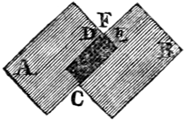
where A represents the surface illuminated by one of the lights only; B, the surface illuminated by the other light; C, the perfect shadow from which both lights are excluded. It will easily be understood that the lights about D and E, near the angle F, will fall with equal incidences when the[274] double shadow is made to occupy the middle of the paper; and consequently, if one or both of the lights be removed directly towards or from the paper, as the appearances may require, until the two shadows at E and D have the same intensity, the quantities of light emitted by each, will be as the squares of the distances from the paper.
By experiments of this kind, many useful particulars may be shewn; for, since the cost and duration of candles, and the consumption of coal gas, or oil in lamps, are easily ascertainable, it may be shewn whether more or less light is obtained at the same expense during a given time, by burning a number of small lights, instead of one or more of greater intensities. And thus we may compare the power of different kinds of lamps or candles, with gas lights of different intensities, so as to determine the relative cost of each particular kind of the combustible substance employed for furnishing light. For example; if a candle and a gas burner supplying coal gas, adjusted by a stop-cock, produce the same darkness of shadow, at the same distance from the wall, the strength or intensity of light is the same.
An uniform degree of intensity of the gas light[275] may readily be produced, by opening or shutting the stop-cock, if more or less light be required, and the candle kept carefully snuffed to produce the most regular and greatest quantity of light. The size of the flame, in experiments of this kind, of course becomes unnecessary, and will vary very much with the quality or chemical constitution of the coal gas. The bulk of the gas consumed, and the weight of tallow or oil used by weighing the candle or oil before and after the experiment furnish the data for calculating the relative cost of tallow, or oil and gas, when compared with each other.
The following statement exhibits the quantity of coal gas consumed in a given time, by different kinds of argand lamps. An argand burner which measures in the upper rim half an inch in diameter, between the holes from which the gas issues, when furnished with five apertures 1⁄25 part of an inch in diameter, consumes two cubic feet of gas in an hour, when the gas flame is one and a half inch high. The illuminating power produced by this burner is equal to three tallow candles eight in the pound.
An argand burner three quarters of an inch in[276] diameter between the holes in the upper rim, and perforated with holes, 1⁄30 of an inch in diameter, consumes three cubic feet of gas in an hour, when the flame is two and a quarter inches high, and produces a light equal in intensity to four tallow candles, eight in a pound.
An argand burner seven-eighths of an inch in diameter, perforated with eighteen holes 1⁄32 of an inch in diameter, consumes when the flame of the gas is three inches high, four cubic feet of gas in an hour, and produces a light equal in intensity to six tallow candles, eight in the pound.
When the flame obtained by these kind of burners rises to a greater height, than what has been stated, the combustion of the gas is imperfect, the intensity of the light becomes diminished, and there is a waste of gas. The same holds good with regard to the size of the holes from which the gas issues; if the holes be made larger than 1⁄25 part of an inch in these kind of burners, the gas is not completely burnt, and its illuminating power decreases.
The height of the glass which surrounds the flame, should never be less than five inches, and[277] the interval for the current of air within and without the flame, ought to bear the usual proportion adopted for the combustion of oil in the common argand lamps of similar diameters.
Before means had been devised for the effectual purification of coal gas, a disagreeable odour was found to attend its combustion in an impure state, and hence an opinion became prevalent, that the benefit of this new species of illumination must be confined to open places, and that it could not with any regard to pleasure or salubrity, be adapted to private dwellings.
The art of purifying coal gas, has at length however, been carried to such a perfection, that every possibility of a disagreeable odour arising from its combustion has been wholly removed, in all cases where attention is paid to the perfect combustion of the gas, by keeping the flame of the same of a proper magnitude.
And since this improvement, the use of coal gas,[278] as a means of illumination has become as general, and has been found attended with as superior advantages within doors as without, and hence a vast number of dwelling houses are now lighted throughout with gas.
Although there is no occasion therefore, to make provision for ventilating apartments where gas light is employed, on account of any odour which it can produce when honestly used, so that the combustion is perfect, yet on other accounts such means of ventilations are very salutary and necessary.
The flame of coal gas produces a degree of heat,[52] which in some places, such as large public offices, and warehouses of dry goods, is a strong additional recommendation in favour of its use, (page 15,) while in others, on the contrary, such as small rooms numerously frequented, and shops containing commodities requiring to be kept cool, it can only be used beneficially when means are provided for conveying away the heated air.
[52] Mr. Dalton’s method of ascertaining the comparative effect of heat evolved during the combustion of inflammable gases, and other substances capable of burning with flame, (Dalton’s System of Chemistry, vol. I. p. 76,) is simple, easy, and accurate. It is as follows:
Take a bladder of any size, (let us suppose for the sake of illustration, the bladder to hold 30,000 grains of water,) and having furnished it with a stop-cock and small jet pipe, fill it with the combustible gas the heating power of which is to be tried. Take also a tinned iron vessel with a concave bottom of the same capacity, pour into it as much water as will make the vessel and water together equal to the bulk of the water in the bladder, viz. 30,000 grains. Then set fire to the gas at the orifice of the pipe, bring the point of the flame under the bottom of the tinned vessel, and suffer it to burn there, by squeezing the bladder till the whole of the gas is consumed. The increase of temperature of the water in the tinned vessel before and after the experiment, expresses very accurately the heating power of the given bulk of the inflammable gas. It was thus proved that—
| Olifiant gas raises an equal volume of water | 14 | deg. |
| Carburetted hydrogen, or coal gas | 10 | |
| Carbonic oxid gas | 4 | |
| Hydrogen gas | 5 | |
| Spermaceti oil, 10 grains burnt in a lamp raised 30,000 grains of water | 5 | |
| Tallow | 5 | |
| Wax | 5,75 | |
| Oil of turpentine | 3 | |
| Spirit of wine | 2 | |
[279]
The best method for this purpose is to make an aperture of about two or three inches in diameter into the chimney near the ceiling, and inserting into it a tube bending upwards into the interior of the chimney. A complete ventilation of the room will thus be established, by producing an extra vent which will be amply sufficient for carrying[280] off the heated air. The aperture can easily be masked with some ornamental open work, corresponding with the style of the room.
If there happens to be no chimney in the apartment, the ventilator may be made in the ceiling, and the tube may be carried between the ceiling and the floor above, into the open air. The mode of ventilation now suggested, has been uniformly found most efficient, and has, under existing circumstances, a decided superiority over another method, which we see in some instances adopted. This method consists in enclosing the gas burner in a bell-shaped glass, from the upper part of which a large copper tube proceeds, and leads out into the open air. It is certain that by this means not only the heated air is carried off, and the possibility of any waste gas escaping into the apartment is also completely prevented. But at the same time, by taking away all occasion for a prudent limitation in the use of the gas, it exposes it to a degree of improvident waste, in the hands of dishonest and careless individuals, which must prove ruinous to the manufacturer. The mode of regulating the light of the flames by means of the governor, of which[281] a description has been given, page 232, indeed provides a check against such waste, and there can be no doubt that in proportion as this instrument gets into general use, the objection on this score must of course fall to the ground; but under any circumstances the inelegance of the contrivance of such an object in a chamber, as the large branching tube, must always induce a preference, for the more simple, and for all necessary purposes, equally efficient method, of the ventilator before described.
[282]
Although the tar which forms one of the products obtained from the decomposition of pit coal, in the manufacture of coal gas, has become an article of commerce, being found applicable to most of those purposes to which vegetable tar has hitherto been used, it appears from experiments made on a large scale, that instead of thus disposing of the coal tar, it is more profitable, under certain circumstances, to submit this substance to a destructive distillation, for the purpose of obtaining from it carburetted hydrogen gas, which it is[283] capable of affording, not only in abundance, but of a superior quality.
The chief circumstances which must determine the manufacturer of coal gas in this respect, is the price at which he can sell the coke produced in his establishment. If the price of this article is high, if he finds a ready market for coke, there is every reason to believe, that the manufacturer will find it more to his advantage to dispose of the tar, and to manufacture gas from coal alone, in order to increase his store of coke. But if coke happens to be at a low price, and not disposable with advantage, the manufacturer will do well to make the coal go as far as possible in the production of gas, and under such circumstances he will keep and convert the tar into gas, thus consuming less coal and having less of the burdensome article, coke, to dispose of.
The profit however, to be gained from the sale of coke, must be both certain and considerable, to induce a preference for the former course; because the decomposition of coal tar, besides superseding a proportionate quantity of coal, is attended with several other very tempting advantages.
[284]
From experiments lately made in the metropolis on this subject, in which I have been engaged, it appears that in all large gas light establishments, where the quantity of coal tar rapidly accumulates, and must be got rid of, and in all places where the tar cannot be sold for more than four shillings the hundred weight, it will be certainly advantageous to the manufacturer to decompose the tar for the production of carburetted hydrogen gas.
The price of coal cannot effect the operation, because where coal bears a high price, the manufacturer of the tar gas, will diminish the quantity of coal which he would otherwise be called upon to employ for the production of the requisite quantity of gas. And in places where coal is cheap, the decomposition of the tar will be attended with less expence.
The carburetted hydrogen gas produced from coal tar, possesses a greater illuminating power than the gas obtained from coal.[53] It consists chiefly of supercarburetted hydrogen or olifiant[285] gas, and a less quantity of it is of course sufficient.
[53] Vegetable tar, also affords carburetted hydrogen gas in abundance, and this no doubt might be employed to great advantage for the production of artificial light in places where it is cheap. 212 pounds of the most viscid Swedish tar, produce 1484 cubic feet of carburetted hydrogen, (or seven cubic feet to one pound of tar,) the illuminating power of this gas is equal to the gas obtained from pit coal.
The gas thus obtained, is purified likewise with far greater facility, taking only one hundred and twentieth part of the quantity of quicklime which is required for the purification of carburetted hydrogen obtained from pit coal. The apparatus for the production of carburetted hydrogen from coal tar, is moreover less bulky, less expensive, and less complicated; and it can be managed by fewer workmen. And as the combined result of these several advantages, it is obvious, that by the substitution of coal tar, the new mode of lighting by gas can be pursued on a smaller scale; which it can never be with any profit, where coal itself is immediately employed for the production of the gas.
The apparatus employed by Mr. Clegg, for the distillation of tar, is extremely simple. It consists of two hollow cast iron cylinders, twelve inches[286] in diameter, and nine feet long, furnished with moveable lids or mouth pieces, and joined together at the extremity opposite to the mouth piece. These cylinders are fixed in a brick furnace, so that each inclines eleven degrees, one above and the other below the horizontal base of the furnace.
When the apparatus has acquired a dull red heat, the coal tar is suffered to flow into the upper cylinder, by small portions at a time.
The tar is contained in a closed vessel, situated at any convenient place above the apparatus. It has a small aperture for the admission of air. But as a sufficient small quantity of viscid tar does not flow freely in a thin stream, a larger portion than is wanted, is made to flow first into a a small box, upon the apex of a pyramid which divides the stream, so that the excess runs off by a waste pipe, whilst a due quantity only is conveyed into the retort where it is decomposed.
This apparatus[54] therefore differs only from the apparatus described in the Journal of Science and the Arts, 1816, No. II., p. 282; that the cylinders[287] may be detached, for cleaning them out more conveniently.
[54] Now erecting at Birmingham.
The following statement exhibits the result of a series of experiments, made (1816,) at the Westminster Chartered Gas Light Establishment,[55] for the purpose of ascertaining how far, and under what circumstances the decomposition of coal tar is a measure of economy.
[55] Communicated by Mr. T. S. Peckston.
Two tar retorts worked seven hours, produced 3054 cubic feet of gas. The quantity of tar decomposed, amounted to 354 lb. therefore 8 cubic feet of gas, (omitting fractions), were obtained from 1 lb. of tar.
Two tar retorts, worked nine hours, produced 4591 cubic feet of gas. The quantity of tar decomposed, was 525 lb. Hence 1 lb. of tar yielded nearly 83⁄4 cubic feet of gas.
Fifteen cwt. 16 lb. of tar, produced 16,112 cubic feet of gas, = 91⁄2 cubic feet of gas, to 1 lb. of tar.
Five cwt. 3 quarters, 22 lb. of tar, produced 6660 cubic feet of gas, = 10 cubic feet of gas to 1 lb. of tar.
[288]
Five cwt. 17 lb. of tar, produced 5193 cubic feet of gas, = 9 cubic feet of gas to 1 lb. of tar.
One cwt. 81 lb. of tar, produced 1737 cubic feet of gas, = 9 cubic feet of gas to 1 lb. of tar.
One cwt. 30 lb. of tar, produced 13131⁄2 cubic feet of gas, = 8 cubic feet of gas to 1 lb. of tar.
Five cwt. of tar, produced 5880 cubic feet of gas, = 101⁄2 cubic feet of gas to 1 lb. of tar.
Two cwt. of tar, produced 2072 cubic feet of gas, = 91⁄2 cubic feet of gas to 1 lb. of tar.
Three cwt. 18 lb. of tar, produced 3717 cubic feet of gas, = 101⁄2 cubic feet of gas to 1 lb. of tar.
Two cwt. 6 lb. of tar, produced 22421⁄2 cubic feet of gas, = 93⁄4 cubic feet of gas to 1 lb. of tar.
From the preceding operations it becomes obvious, that 91⁄2 cubic feet of gas, were obtained in the large way from 1 lb. of tar. But this proportion appears evidently too small, our own operations assign fifteen cubic feet of gas to one pound of tar. Professor Brande, obtained eighteen cubic feet[56] from the same quantity of tar.
[56] Journal of Science and the Arts, 1816, No. II. p. 282.
[289]
“Messrs. J. and P. Taylor[57] are the first persons who have resorted to oil as a substance from which gas for illumination could be easily and cheaply prepared; and in the construction of a convenient apparatus for the decomposition of this body, they have fully shewn its numerous advantages over coal, while they have afforded the means of producing the most pure and brilliant flame from the inferior and cheap oils, which could not be used in lamps. The apparatus for the purpose is much smaller, much simpler, and yet equally effectual, with the best coal gas apparatus. The retort is a bent cast iron tube, which is heated red by a small convenient furnace, and into which oil is allowed to drop by a very ingenious apparatus; the oil is immediately volatilized, and the vapour in traversing the tube becomes perfectly decomposed. A mixture of inflammable gases, which contains a great proportion of olifiant gas passes off; it is[290] washed by being passed through a vessel of water (which dissolves a little sebacic acid, and which seldom requires changing), and is then conducted into the gasometer.”
[57] Copied from the Journal of Science and the Arts, Vol. VI. p. 108.
“The facility and cleanliness with which gas is prepared from oil in the above manner, may be conceived from the description of the process. A small furnace is lighted, and a sufficient quantity of the commonest oil is put into a small iron vessel, a cock is turned, and the gas after passing through water in the washing vessel, goes into the gasometer. The operation may be stopped by shutting off the oil, or, to a certain extent, hastened by letting it on more freely; the small quantity of charcoal deposited in the retort is drawn out by a small rake, and the water of the washer is very rarely changed.”
“The gas prepared from oil is very superior in quality to that from coal; it cannot possibly contain sulphuretted hydrogen, or any extraneous substance; it gives a much brighter and denser flame; and it is also more effectual, i. e. a lesser quantity will supply the burner with fuel. These peculiarities are occasioned, in the first place, by the[291] absence of sulphur from oil, and then by the gas containing more carbon in solution. As the proportion of light given out by the flame of a gaseous compound of carbon and hydrogen, is in common circumstances in proportion to the quantity of carbon present; it is evident that the gas which contains a greater proportion of olifiant gas, or supercarburetted hydrogen than coal gas, will yield a better and brighter light on combustion.”
“It is necessary, in consequence of the abundance of charcoal in solution, to supply the gas when burning with plenty of atmospheric air, for as there is more combustible matter in a certain volume of it, than in an equal volume of coal gas, it of necessity must have more oxigen for its consumption.[58] The consequence is, that less gas must be burnt in a flame of equal size, which will still possess superior[292] brilliancy; that less is necessary for the same purpose of illumination; and that less heat will be occasioned. From five and a half to six cubical feet of coal gas are required to supply an Argand burner for an hour; two cubical feet to two and a half of that from oil, are abundantly sufficient for the same purpose.”
[58] Dr. W. Henry’s experiments gave the following result:—100 cubic inches of carburetted hydrogen from coal, require, for burning, 220 cubic inches of oxigen, and produce 100 cubic inches of carbonic acid—100 cubic inches of carburetted hydrogen gas procured from lamp oil, require 190 cubic inches of oxigen, and produce 124 cubic inches of carbonic acid,—100 cubic inches of carburetted hydrogen obtained from wax, require 280 cubic inches of oxigen, and produce 137 cubic inches of carbonic acid.
“One important advantage gained by the circumstance, that so small a quantity of this gas is necessary for burners is, that the gasometer required may be small in proportion. The gasometer is the most bulky part of a gas apparatus, and that least capable of concentration; and where-ever it is placed, it occupies room to the exclusion of every thing else. Some very ingenious attempts have been made to diminish its size and weight, as in the double gasometer,[59] and others, but without remarkable success. Here, however,[293] where the room required to contain the gas is directly diminished, the object is so far obtained; and when that takes place to one half, or even one third, it is of very great importance. It in a great number of cases brings the size of the apparatus within what can be allowed in private houses; and in consequence of the rapidity with which the retort can be worked, the gasometer may again be reduced to a still smaller size.”
[59] This contrivance is more expensive and complicated than any of the gas holders of which a description has been given; nor is it safe, for if the slightest leak should happen in the interior vessel of the double gas holder, an explosive mixture would be formed, and dreadful consequences might follow; this can never be the case with any of the machines now in use.—Note of the Author.
“Another advantage gained by the small quantity of gas required for a flame, is the proportionate diminution of heat arising from the lights. The quantities of heat and light produced by the combustion of inflammable gases are by no means in the same constant relation to each other; one frequently increases, whilst the other diminishes; and this is eminently the case when coal gas and oil gas are burned against each other. The quantity of heat liberated is, speaking generally, as the quantity of gas consumed, and this is greatest with the coal gas; but the quantity of light is nearly as the quantity of carbon that is well burnt in the flame, and this is greatest in the oil gas.”
“The very compact state in which the apparatus[294] necessary for the decomposition of oil can be placed, the slight degree of attention required, its certainty of action, its cleanliness, and the numerous applications which it admits of in the use of its furnace for other convenient or economical purposes, render it not only unobjectionable, but useful in manufactories and establishments; and these favourable circumstances are accompanied, not from any inferiority in the flame or increased expense, but by an improved state of the first, and saving in the latter.”
“Messrs. Taylor have shewn great ingenuity in the construction of their whole apparatus, but the washer and gasometer deserve particular notice for their remarkable simplicity also. In the washer, two planes are fixed in a box or cistern, in a direction not quite horizontal, but inclined a little in opposite directions; the planes are traversed nearly across by slips of wood or metal, fixed in an inclined position on the under surface, and which alternately touch one side of the cistern, leaving the other open and free. These planes being immersed in water, the gas is thrown in under the lowest ridge, and by its ascending power is made[295] to traverse backward and forward along the ridges fixed on the planes, until it escapes at the highest part of the uppermost ridge. Thus, with a pressure of five or six inches of water only, it is made to pass through a distance of fourteen or sixteen feet under the surface of the fluid, and becomes well washed.”
“The smaller gasometers are made of thin plate iron, and being placed in a frame of light iron work, look more like ornamental stoves than the bulky appendages to a gas apparatus, which they supply. The larger ones are made very light, and when in pieces very portable, by being constructed of a frame of wood work, in the edges of which are deep narrow grooves; plates of iron fit into these grooves, which being caulked in and painted over, make a light and tight apparatus. These are easily put together in any place, and may therefore be introduced into a small apartment, or other confined space, where a gasometer already made up would not enter.”
For the following additional information on this subject, I am indebted to Messrs. J. and P. Taylor.
“The economy of obtaining gas for the production[296] of light from oil, may be judged of from the following data.”
“One gallon of common whale oil, produces about ninety cubic feet of gas.[60] An argand burner required a cubic foot and a half of gas per hour; and consequently a gallon of oil when converted into gas, will supply the same burner for sixty hours. The expence of the gas at a moderate price of oil, will be, allowing for coals, labour, &c. for producing the gas, three farthings per hour, and such a burner will give a light, equal in intensity, to two argand lamps, or ten mould candles.”
[60] Our experiments produced 105 cubic feet, from one gallon of common whale oil.—Note of the Author.
“The expence of an argand oil lamp, is usually admitted to be, about three halfpence per hour. Now supposing ten candles to be burning, four to the pound (two pound and a half,) they will cost 2s. 11d. of which one-tenth part will be consumed in each hour. The cost of the tallow light is then three pence halfpenny per hour.”
“If wax candles be employed, the expence of the light equal to an oil gas burner for one hour, by[297] the same mode of reckoning, allowing the candle to burn ten hours, and taking the price of the wax candles, at 4s. 6d. per pound, will be about 14d.”
“The comparative account will therefore stand thus:
| PENCE. | |
|---|---|
| Cost of an Argand burner, supplied with oil gas, per hour | 03⁄4 |
| Ditto of an Argand lamp, burning spermaceti oil | 3 |
| Ditto of Tallow mould candles | 31⁄2 |
| Wax candles | 14 |
“These calculations on the cost of light from oil gas, are taken at the usual price of good whale oil, but cheaper oils will answer the purpose nearly as well, and as many of these are often to be procured, the whole expence becomes materially reduced by their use.”
[298]
The coal tar is so called from its resembling common tar in its appearance, and most of its qualities.
This substance is deposited in the purification of the coal gas, in a separate vessel destined to receive it. See fig. 3, plate I.
In the year 1665, Becher, a German chemist, brought to England his discovery for extracting tar[299] from coal, this distillation he performed in close vessels. It is not mentioned in the records of the time, whether Becher obtained, or rather collected, any other articles than the tar.
Several works have been, at different times, erected both in England and on the continent, to procure from coal a substitute for tar; but they have turned out unprofitable speculations.
In 1781, the Earl of Dundonald invented a mode of distilling coal in the large way, which enabled him not only to form the coke, but, at the same time, to save and collect the tar. Even this process, however, for which a patent was taken out, gained very little ground. Its object was too limited; for though some of the proximate constituent parts of coal were procured, they were obtained at an expence that nearly balanced the profits; and no attention whatever was paid to the coal gas, which constitutes by far the most valuable part obtainable from pit coal.
Coal tar is now used with advantage largely in the Royal Navy, and also for painting and securing wood that is exposed to the action of air. The wood being warmed, the tar is applied cold, and[300] penetrating into the pores, gives the timber an uncommon degree of hardness and durability.
The quantity of tar obtainable from a given quantity of coal, varies according to the manner in which the decomposition of the coal is affected. See page 122.
The tar obtained from Newcastle coal is specifically heavier than that produced from cannel coal; hence it sinks in water, whereas the latter swims on the surface of that fluid.
To render coal tar fit for use, it requires to be evaporated to give it a sufficient consistence. If this process be performed in close vessels, a portion of an essential oil is obtained, which is known by the name of
To obtain this oil, a common still is charged with coal tar, and, being properly luted, the fire is kindled and kept up very moderate, for the tar is very apt to boil up in the early part of the process. The first product that distils over is principally a[301] brown ammoniacal fluid, mixed with a good deal of oil. As the process advances, and the heat is increased, the quantity of ammoniacal liquor lessens, and that of oil increases, and towards the end of the distillation the product is chiefly oil.
The oil and ammoniacal water which distil over do not mix, so that they may be easily separated by decantation. The oil is a yellowish inferior kind of naptha, which is very useful in painting ships, and for making common varnishes. It has lately been employed as a substitute for whale oil, to be burnt in out door lamps.
The contrivance by means of which this oil is burnt in lamps[61] consists of a fountain reservoir to supply and preserve a constant level. The burner with its wick is placed in the axis of the lamp, and supplied with the oil from the fountain reservoir, placed on the outside of the lamp. The air is admitted by an aperture at the bottom of the lamp. The current of air in passing through the lamp envelopes the burner and urges the flame, which is[302] extremely bright; but it is essential that the flame should be small. The draught tube proceeding from the centre of the reflector above the flame carries away the smoke.
[61] All the lamps on Waterloo Bridge, and the streets adjoining the bridge are lighted by means of tar oil.
1430 pounds of coal tar, produce 360 pounds of essential oil. The residue left after the distillation is
If the coal tar is wanted to be converted into pitch, without obtaining the oil which it is capable of furnishing, the evaporation of it may be performed in a common boiler; but as it is extremely liable to boil over, the greatest precaution is necessary in conducting the evaporation. A spout or rim is added to the common boiler into which the tar spreads itself as it rises, and by this means becomes cooled, and the boiling over is checked.
1430 pounds of coal tar produce 9 cwt. of pitch. A subsequent evaporation with a gentle heat, converts the coal pitch into a substance greatly resembling asphaltum.
[303]
The ammoniacal liquor obtained in the gas light manufacture, is employed for the production of carbonate of ammonia. The average quantity of this liquor, obtainable from a chaldron, (27 cwt.) of Newcastle, or Sunderland coal, amounts to from 180 to 220 pounds. It is chiefly composed of carbonate and sulphate of ammonia. The quantity of ammonia contained in it, varies considerably. The strongest liquor is obtained from coal that readily cake, (page 45); a gallon (or eight and a half pounds weight) of ammoniacal liquor usually requires for saturation, from fifteen to sixteen ounces of sulphuric acid of a specific gravity 1,84. The weakest ammoniacal liquor is obtained from those species of coal which do not cake, and which by a single combustion are reduced to light ashes. It requires only from eight to ten ounces of sulphuric acid, of the before mentioned specific gravity for its saturation.
The following process is employed in the large[304] way, for obtaining carbonate of ammonia from the ammoniacal liquor. To 108 gallons[62] of the liquor contained in a cask, are added 125 pounds[63] of finely ground sulphate of lime, which has been previously deprived of moisture by heat. The cask is bunged up, and the mixture after being stirred together for a few minutes, is left undisturbed for three or four hours. Sixteen ounces of sulphuric acid are then added, the mixture is again agitated, and is again suffered to stand undisturbed for four or six hours. If the liquor be now examined, it will turn blue litmus paper, red.
[62] One gallon of the strongest ammoniacal liquor, weighs eight and a half pounds.
[63] This quantity is evidently too large, but the workmen assert, that an excess of sulphate of lime causes the carbonate of lime which is formed, to subside more readily, and the excess of sulphate of lime can do no injury.
In this operation a double decomposition takes place, the sulphate of lime yields part of its sulphuric acid, to the carbonate of ammonia of the liquor, to form sulphate of ammonia, and the carbonic acid of the ammonia, combines with the lime of the sulphate of lime, to form carbonate of lime, which falls to the bottom, the supernatant fluid contains in solution, sulphate of ammonia.
[305]
When the liquor has become clear, it is pumped out of the barrel into shallow cast iron boilers, where it is evaporated slowly. During this process, a portion of sulphate of lime is deposited which is removed, and as the liquor becomes more concentrated, part of the sulphate of ammonia begins to crystallize and falls to the bottom. It is shovelled out from time to time into wicker baskets, placed slanting over the rim of the boiler, that the liquor which drains off from the crystals may not be lost, and lastly the whole fluid is evaporated to dryness.
108 gallons of ammoniacal liquor from Newcastle coal, produce upon an average, one and a half cwt. of dry sulphate of ammonia. To decompose it, one cwt. is mixt with one quarter of a cwt. of finely ground chalk, previously deprived of moisture by heat. The mixture is introduced (as expeditiously as possible) into cast iron retorts,[64] heated nearly to a dull redness, and when the lid of the retorts have been rendered air tight, the fire is raised gradually till the retorts are of a strong red heat.[306] The carbonate of ammonia developed from the contents of the retorts, is made to sublime into a leaden barrel-shaped receiver, connected with the retorts, by means of a pipe four inches in diameter, proceeding from the upper extremity of each retort, and opposite to the mouth piece. The leaden receiver is furnished with a leaden cover, fitting into a groove, where it is made air tight by lute. The receiver which is supported upon a stand is provided at its base, with a small pipe, furnished with a stopper. This pipe is left open till the liquid products are got rid of during the sublimatory process. In the centre of the cover, or at any other convenient part of the apparatus, is made a small hole, slightly stopped with a wooden peg, to give vent to the elastic fluid that becomes evolved during the process.
The time requisite for the operation depends on the mode in which the retorts are set, the temperature kept up and other practical circumstances. A charge of 120 pounds of the mixture of sulphate of ammonia and chalk in one retort, is usually decomposed in twenty-four hours. When the operation is at an end, and the receiver having[307] become cold, the cover is taken off, and the sublimed carbonate of ammonia adhering to the sides of the receiver is detached by a chissel and mallet, and after being freed from any casual impurities, is packed up in stone jars for sale.
One cwt. of dry sulphate of ammonia, produces from sixty pounds, to sixty-five pounds, of pure carbonate of ammonia. In some establishments, the carbonate of ammonia is subjected to a second sublimation by means of a gentle heat; but this is quite unnecessary if the process has been conducted carefully.
It must be obvious that the ammoniacal liquor may be employed with great advantage for the production of muriate of ammonia. For if the solution of sulphate of ammonia obtained from the ammoniacal liquor by means of sulphate of lime, as before stated, be mixed with common salt, (or any other muriate) another decomposition takes[308] place. The muriatic acid of the common salt, unites to the ammonia of the sulphate of ammonia, and produces muriate of ammonia, and the sulphuric acid of the sulphate of ammonia, combines with the soda of the common salt, and produces sulphate of soda, or glauber salt.
The liquor containing these two salts being evaporated, the glauber salt begins to crystallize, and is removed from time to time. The evaporation is continued till as much as possible of the glauber salt has been separated, and the muriate of ammonia begins to crystallize on the surface of the fluid in the form of a feathered star. The remaining fluid is then run off into coolers, and deposits little else than muriate of ammonia, till it gets below the temperature of 76° Fahr. at which time the crystals are to be removed, lest they should be mixed with glauber’s salt which now begins to be again deposited. After the muriate of ammonia has been suffered to drain in baskets, it is heated in shallow pans to drive off as much water of crystallization as possible. It is then removed whilst still hot, into earthenware jars, glazed within, and fitted with a cover, (having[309] a hole of about half an inch in diameter in its centre,) luted on with clay. The jars are put in a cast iron pot over a strong fire, in a furnace capable of containing from six to eighteen jars, surrounded with sand up to the edge of the pot, and also having about two and a half inches of sand on the cover, confined by an iron ring about three inches deep, and two inches less in diameter than the cover, in order that if the luting should give way in any part, it may be repaired without suffering the covers (which should be kept during the sublimation at about 320° Fahr.) to be cooled by the removal of a large portion of the sand.
These earthen jars may be filled to within two inches of the top, with the dried salt gently pressed in, but not rammed close; and the fire which has been lighted some time before, is now to be raised gradually till the iron pots are of a pretty strong red heat all round, being so placed by mean of flues in the furnace that the upper part may be first heated, the bottom resting on solid brick work.
During the first impression of the heat, a portion of the salt carrying with it a quantity of[310] watery vapour not separated during the drying of the salt, will escape through the hole in the cover, which must be left open till all the aqueous part is exhaled: this is known by bringing a piece of cold smooth iron plate near the hole, in order to condense the sublimate, which becoming more and more dry, at length attaches itself firmly to the plate, in the form of a dry semi-transparent crust.
At this time the hole is to be stopped with lute, more sand is to be put on the cover, and the heat continued till it is judged that nearly the whole of the muriate of ammonia is sublimed. The time requisite for this purpose depends on the construction of the furnace, the size of the pots, the briskness of the fire, and other circumstances only to be learnt by experience.
The process should be stopped before the sublimation has entirely ceased, as the heat in some parts of the jar may be too great when it is nearly empty, and either by volatilizing a part of the salt itself, or elevating a portion of foreign matter from which it can never be kept wholly free, and thus giving the cake a yellow tinge, and a scorched, opake, crackled appearance.
[311]
The same defects are likely to happen, when any part of the luting having given way, is obliged to be repaired by wet lute, when the sublimation is pretty far advanced: consequently glass vessels are preferable, except on account of the expence, as they must always be broken to pieces in order to get out the cake: the earthenware jars on the contrary will serve for several sublimations, even the covers, if well glazed, will last two operations. The sublimation being finished and the apparatus having become sufficiently cool, the tops of the jars are to be taken off, and the cakes of sal-ammoniac that are found adhering to them are to be separated, and placed for a day or two in a damp atmosphere, which softens their surface a little, and thus facilitates the removal of any superficial impurities. Lastly, the cakes are packed up in casks for sale.
The excise laws have hitherto operated strongly against the establishment of manufactories of muriate of ammonia in England. Hence an immense quantity of sulphate of ammonia obtained from the gas light ammoniacal liquor, is exported from this country to the continent, solely from the extreme[312] rigour of the excise relating to the use of common salt, and it is only this that has hitherto prevented the establishment of manufactories of sal-ammoniac from the ammoniacal liquor of the gas light process upon a large scale.
Chemical manufactories, of all others, will least bear excise, because many of them are worked according to secret processes, which, if made public, must pass into other countries; and the greatest part of the profit ceases together with the export. The vexatious introduction of excise officers into manufacturing laboratories, it is evident, puts an end to all secrecy of operation. There are several chemical processes which interruption will extremely injure, and others which it totally destroys, and as on the whole they in general are of a nature in which interference of others is most peculiarly vexatious, in all probability, if the excise be extended to manufactures of this nature, it will eventually put a stop to most of them, and greatly injure the revenue by causing thereby to cease the duties which at present arise from the exports and imports to a large amount, now depending on the chemical trade of Great Britain.
[313]
We have now gone through all the improvements by which the gas light manufacture has been distinguished during the interval which has elapsed since the publication of our former work[65] on this subject; and perhaps the reader may be inclined to think, from the extraordinary height to which improvement has been carried in this art, that little or nothing more remains to be desired with regard to it. Let it be remembered, however, that the whole art is only in its infancy. There is yet a wide field for improvement in the construction of the apparatus. Ingenious men may speculate from what has been done, to what remains to be effected, which no doubt will lead to objects of the greatest utility, and most extended national importance.
[65] A practical treatise on gas light.

| PLATE I. | |
| PAGE. | |
|---|---|
| Elevation of the Revolving Gas Holder at the Westminster Gas Works | 181 |
| PLATE II. | |
| Gas Light Apparatus at the Royal Mint. | |
| Fig. 1, Perpendicular Section of one of the Horizontal Rotary Retorts with its Furnace | 112 |
| Fig. 2, The Purifying Apparatus | 150 |
| Fig. 3, The Tar Cistern | 117 |
| Fig. 4, The Gas Metre | 214 |
| The roof of the building surrounding the Gas Works is furnished with a projecting Louver to let out the smoke. | |
| PLATE III.[316] | |
| Fig. 1, Represents a perspective view of a Portable Gas Metre | 219 |
| Fig. 2, Perpendicular Section of the Horizontal Rotary Retorts at the Royal Mint Gas Works—at Chester—Birmingham, &c. | 112 |
| Fig. 3, Perpendicular Section of the Gas Holder Valve and Siphon, or Water Reservoir | 222 |
| Fig. 4, Perspective View of the Governor, or Regulating Guage, for maintaining the Flames of Gas Lamps and Burners of an uniform intensity | 225 |
| Fig. 5, Plan of the Horizontal Rotary Retorts at the Royal Mint—Chester—Bristol—Birmingham—Kidderminster, &c. | 115 |
| Fig. 6, Transverse Section of the Gas Metre at the Royal Mint—Chester—Birmingham, &c. | 219 |
| Fig. 7, Perpendicular Section of the Gas Holder Valve | 221 |
| Fig. 8, Front elevation of the Gas Metre, at the Royal Mint, shewing the registering train of Wheel Work | 218 |
| Fig. 9, Perpendicular Section of the Gas Holder, Governor, or Regulating Guage, at the Bristol—Birmingham—and Chester Gas Works | 171 |
| Fig. 10, Transverse Section of the Air-Box, and Lime Trough, See purifying apparatus | 152 |
| Fig. 11, Perspective View of a Portable Governor or Regulating Guage[317] | 232 |
| Fig. 12, Coal Tray of Horizontal Rotary Retort | 116 |
| Fig. 13, A jointed swing Bracket Lamp | 257 |
| Fig. 14, A Mercurial Universal Joint for Pendent Gas Lamps | 256 |
| PLATE IV. | |
| Fig. 1, Transverse Section of the Retort Ovens, at the Westminster and City of London Gas Works, showing the mode of setting and arranging Cylindrical Retorts | 69 |
| Fig. 2, Longitudinal Section of the same | 69 |
| PLATE V. | |
| Fig. 1, Front elevation of the Retort Ovens at the Westminster and City of London Gas Works | 69 |
| Fig. 2, Perpendicular Section of the Gas Holder, without Specific Gravity Apparatus, at the Birmingham Gas Works | 177 |
| Fig. 3, Plan of the same | 177 |
| Fig. 4, Perpendicular Section of Mr. Malam’s Lime Machine | 143 |
| Fig. 5, Plan of the same | 146 |
| Fig. 6 and 7, Mouth Piece and Cover of cylindrical, parallelopipedal and semi-cylindrical Retorts, (exhibited fig. 1, plate IV,) drawn to a larger scale | 71 |
| Fig. 8, 9, 10, 11, 12, and 13, Gas Lamps and Burners[318] | 253 |
| Fig. 14 and 15, Profile View and Section of Gas Mains, and mode of connecting them | 240 |
| Fig. 16, 17, and 18, Perpendicular Section of the parallelopipedal, ellipsoidal, and semi-cylindrical Retorts | 53 |
| Fig. 19, 20, 21, and 22, Union Joint, and circular bends for connecting Gas Pipes | 266 |
| Fig. 23, Test Apparatus for certifying the proper manner of working the Lime Machine | 157 |
| PLATE VI. | |
| Fig. 1, Plan, showing the Fire Place and Flues, of the Horizontal Rotary Retorts | 113 |
| Fig. 2, Longitudinal Section of the Collapsing Gas Holder, and the Tank of ditto | 189 |
| Fig. 3, Transverse Section of the same | 189 |
| Fig. 4, End View of the same | 189 |
| Fig. 5 and 6, Horizontal plan shewing the mode of connecting the end plates of the Collapsing Gas Holder | 192 |
| Fig. 7, Perpendicular Section of the Gas Holder, without specific gravity Apparatus, at the Chester Gas Works | 175 |
| Fig. 8, Perspective View of the Revolving Gas Holder, at the Westminster Gas Works | 181 |
| Fig. 9, Perspective View of the Reciprocating Safety Valve | 196 |
| Fig. 10, Plan of the Purifying Apparatus, or Lime Machine, shewing the Air Trough of the Apparatus, with its axis and claws[319] | 152 |
| Fig. 11, Sliding part of a Pendent Gas Lamp, which may be raised or depressed | 257 |
| PLATE VII. | |
| Exhibits an economical arrangement of a Gas Apparatus, for lighting a town, or large districts. The central building exhibits the Retort House. The roof is furnished with a projecting Louver to let out the smoke. The gable ends, and one side of the building, are of brick-work, the other side of the house is open, and supported on iron columns. The building to the right hand side of the Retorts, is the Purifying House, it contains the Lime Machine, page 149. The trap door, marked A, indicates the Cistern or Reservoir for receiving the Waste Lime. The third and smallest building in the design, serves for an Office of the Director of the Works. The front wall is represented as taken away, to show the position of the Gas Metre, the axis of which drives the agitating shaft of the Lime Machine. The axis of the Metre and the shaft of the Lime Machine, are for that purpose connected by a strap, [320](page 213.) The small building-on the left hand side of the Retort House, is a Smith’s Shop. T, shows the situation of the Main Gas Holder Valve (page 221.) | |
[321]
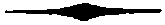
| A. | |
| PAGE | |
|---|---|
| Advantages of the art of procuring light by means of coal gas | 1 |
| Air box of lime machine | 153 |
| Ammoniacal liquor, quantity obtainable from a given quantity of coal | 303 |
| Ammoniacal liquor, quantity of sulphuric acid, required for saturating a given quantity | 303 |
| Ammoniacal liquor, conversion of, into carbonate of ammonia | 303 |
| Ammoniacal liquor, conversion of, into muriate of ammonia | 303 |
| Apparatus for obtaining carburetted hydrogen gas from coal tar | 285 |
| Apparatus for purifying coal gas | 141 |
| Apparatus for certifying the proper mode of working the lime machine | 157 |
| Argand gas lamp | 253 |
| Argand gas lamp, quantity of gas consumed by different kinds | 275 |
| Art of procuring coal gas, theory of | 33 |
| B.[322] | |
| Bat’s wing gas burner | 255 |
| Bends, for connecting gas pipes | 267 |
| Burner, argand | 253 |
| Burner, bat’s wing | 255 |
| Burner, cockspur | 255 |
| Branch pipes | 239 |
| Branch pipes, dip of | 243 |
| Branch pipes, mode of connecting | 263 |
| Branch pipes, mode of proving | 265 |
| Branch pipes, corrosion of | 260 |
| C. | |
| Carbonate of ammonia, preparation of, from ammoniacal liquor of coal | 303 |
| Cement, for connecting gas mains | 241 |
| Chandelier, sliding, for burning gas | 257 |
| Chester gas holder, description of | 175 |
| Coal, analysis of, by destructive distillation | 35 |
| Coal, chemical constitution of | 42 |
| Coal, classification of | 41 |
| Coal, comparative facility with which different species are decomposed | 106 |
| Coal, chiefly composed of bitumen only, varieties of | 42 |
| Coal, chiefly composed of bitumen, maximum quantity of gas obtainable from them | 43 |
| Coal, containing more carbon than bitumen | 45 |
| Coal, containing more carbon than bitumen, maximum quantity of gas obtainable from them | 48 |
| Coal, destitute of bitumen | 42 |
| Coal, maximum quantity of gas obtainable from them[323] | 44 |
| Coal, Gloucestershire | 49 |
| Coal, Kilkenny | 44 |
| Coal, Lancashire | 44 |
| Coal, Newcastle | 47 |
| Coal, Scotch | 109 |
| Coal, Warwickshire | 109 |
| Coal, Welch Stone | 48 |
| Coal, Yorkshire | 44 |
| Coal oil | 300 |
| Coal oil, quantity obtainable from a given quantity of coal tar | 302 |
| Coal tar | 298 |
| Coal tar, quantity obtainable from a given quantity of coal | 122 |
| Coke, quantity obtained in the gas light process from a given quantity of coal, by means of cylindrical retorts | 132 |
| Coke, quantity obtained by means of horizontal rotary retorts | 132 |
| F. | |
| Flue plan of setting cast iron retorts | 59 |
| Flue plan, report on a series of operations, made with retorts worked on the flue plan | 61 |
| Fuel, minimum quantity required for the complete decomposition of coal, by means of cylindrical retorts | 61 |
| G.[324] | |
| Gas, average cost of manufacturing it upon a large scale, in London | 106 |
| Gas, apparatus for lighting a town, best situation of, as far as it regards the most economical distribution of the pipes | 249 |
| Gas, apparatus for lighting a town, arrangement of | 319 |
| Gas, apparatus for lighting a town, at the Royal Mint | 112 |
| Gas, burners, different kinds of | 253 |
| Gas, quantity of, evolved during different periods of the distillatory process employed for decomposing coal, in cylindrical retorts | 77 |
| Gas, observations on the progressive evolution of, during different periods of the distillatory process with cylindrical retorts | 79 |
| Gas flame, mode of regulating the magnitude of | 234 |
| Gas holder, construction of, originally employed | 164 |
| Gas holder, sheet iron, best adapted for it | 180 |
| Gas holder, sheet iron, best adapted for it, cost of | 164 |
| Gas holder, sheet iron, lately adopted without specific gravity apparatus | 169 |
| Gas holder, at Birmingham without specific gravity apparatus | 177 |
| Gas holder, at Bristol without specific gravity apparatus | 175 |
| Gas holder, at Chester without specific gravity apparatus | 175 |
| Gas holder, collapsing | 185 |
| Gas holder, collapsing, rule for finding its capacity | 195 |
| Gas holder, revolving at the Westminster gas works | 181 |
| Gas holder, collapsing, rule for calculating its capacity | 185 |
| Gas holder, valve | 221 |
| Gas from coal tar[325] | 286 |
| Gas from coal tar, average quantity obtainable from a given quantity of tar | 286 |
| Gas from oil | 289 |
| Gas from oil, quantity obtainable from a given quantity of oil | 297 |
| Gas from vegetable tar | 284 |
| Gas from vegetable tar, average quantity obtainable from a given quantity of tar | 284 |
| Gas illuminating power of | 271 |
| Gas lamps | 253 |
| Gas lamps, diameter of the pipes for supplying them with gas | 261 |
| Gas mains | 239 |
| Gas mains, mode of proving them when laid | 245 |
| Gas mains, observations on | 247 |
| Gas mains, cost of a mile, laid under ground in London | 252 |
| Gas mains, of pewter, lead, and tin, why unfit for distributing gas | 260 |
| Gas mains, weight of different lengths, of a given bore | 251 |
| Gas metre, construction of | 214 |
| Gas metre, construction of, at the Royal Mint Gas Works | 214 |
| Gas metre, directions to workmen for fixing it | 229 |
| Gas metre, rule for calculating its power | 220 |
| Gas metre, at the Birmingham Gas Works, registering capacity of | 220 |
| Gas metre, at the Bristol Gas Works, registering capacity of | 220 |
| Gas metre, at the Chester Gas Works, registering capacity of | 220 |
| Gas pipes, directions to workmen for adapting them to the interior of houses[326] | 258 |
| Gasometer house, of sheet iron, of a given size, cost of | 178 |
| Gasometer, tank of cast iron, of a given size, cost of | 178 |
| Gasometer, tank of brick work, of a given size, cost of | 178 |
| Gasometer, tank of wood, of a given size, cost of | 178 |
| Governor, or regulating guage | 261 |
| Governor, its application and efficacy | 171 |
| Governor, directions to workmen for fixing it | 229 |
| H. | |
| Horizontal rotary retort. (See rotary retort horizontal) | 110 |
| L. | |
| Lamps for burning coal gas | 253 |
| Lamps for burning coal gas, quantity of gas consumed by different kinds, in a given time | 275 |
| Lime machine originally employed, defects, and dangerous consequences to which it gave rise | 141 |
| Lime machine, lately adopted | 149 |
| Lime machine, at Birmingham gas works | 149 |
| Lime machine, at Chester gas works | 149 |
| Lime machine, at Royal Mint gas works | 150 |
| Lime machine, capacity requisite for purifying a given volume of gas in a given time[327] | 157 |
| M. | |
| Mains for conveying gas | 245 |
| Mains, average cost of a mile when laid in London | 252 |
| Mains, manner of proving them when laid | 245 |
| Mains, kind of, most economical for conveying gas | 251 |
| Mains, which do not supply branch pipes or lamps, observations on | 250 |
| Mains, faulty, how distinguished | 240 |
| Mercurial joint for pendent gas lamps | 256 |
| Muriate of ammonia, preparation of, from the ammoniacal liquor of coal | 303 |
| N. | |
| Newcastle coal, maximum quantity of gas obtainable from different kinds | 47 |
| O. | |
| Oven, for heating retorts, (See retort oven) | |
| Oil, from coal tar | 300 |
| Oil gas | 289 |
| Oil gas, quantity obtainable from a given quantity of whale oil | 296 |
| Oven plan, of setting cast iron retorts | 67 |
| P.[328] | |
| Pendent gas lamp | 257 |
| Pipes, directions to workmen for adapting them to the interior of houses | 258 |
| Pitch from coal tar | 302 |
| Pitch, quantity obtainable from a given quantity of tar | 302 |
| Purifying apparatus, (See lime machine) | 150 |
| Q. | |
| Quicklime, best method of preserving it for the purification of coal gas | 160 |
| Quicklime, quantity required for purifying a given volume of coal gas | 162 |
| R. | |
| Reciprocating safety valve | 196 |
| Regulating guage, regulator, or governor | 171 220 |
| Regulating guage, at Birmingham Gas Works | 177 |
| Regulating guage, at Bristol Gas Works | 177 |
| Regulating guage, at Chester Gas Works | 177 |
| Retorts, cylindrical cast iron | 52 |
| Retorts, cylindrical, method of heating them by flues | 59 |
| Retorts, cylindrical, experiments on setting three to one fire place | 61 |
| Retorts, cylindrical, experiments on setting four to one fire place | 53 |
| Retorts, cylindrical, cost of erecting them | 99 |
| Retorts, cylindrical, best mode of working them | 94 |
| Retorts, cylindrical, minimum quantity of fuel required for working them | 61 |
| Retorts, cylindrical, temperature best adapted for working them[329] | 94 |
| Retorts, cylindrical, conical | 52 |
| Retorts, cylindrical, conical, comparative power of | 55 |
| Retorts, cylindrical, ellipsoidal | 53 |
| Retorts, horizontal rotary | 110 |
| Retorts, horizontal rotary, at the Royal Mint Gas Works | 112 |
| Retorts, horizontal rotary, at Birmingham | 111 |
| Retorts, horizontal rotary, at Chester | 111 |
| Retorts, horizontal rotary, at Kidderminster | 111 |
| Retorts, horizontal rotary, action and management of | 121 |
| Retorts, horizontal rotary, advantages of | 124 |
| Retorts, horizontal rotary, directions to workmen with regard to working them | 134 |
| Retorts, parallelopipedal | 52 |
| Retorts, parallelopipedal, comparative power of | 55 |
| Retorts, parallelopipedal, best mode of working them | 93 |
| Retorts, semi-cylindrical | 53 |
| Retorts, oven, description of, at the Westminster and City of London Gas Works | 69 |
| Retorts, oven, experiments on | 84 |
| Revolving gas holder, at the Westminster Gas Works | 181 |
| Revolving gas holder, rule for calculating its capacity | 185 |
| S. | |
| Safety valve, reciprocating | 196 |
| Self-acting guage, (see governor) | 171 |
| Siphon | 221 |
| Sliding chandelier | 257 |
| South London Gas Works[330] | 69 |
| Spigot and faucit pipes | 241 |
| Staffordshire coal | 44 |
| Swing bracket gas burner | 257 |
| T. | |
| Tar, quantity obtainable from a given quantity of coal | 130 |
| Tar gas, quantity obtainable from a given quantity of coal tar | 287 |
| Tar gas, from vegetable tar | 284 |
| Tar, retort | 285 |
| Temperature for working cast iron retorts, remarks on | 94 |
| Test apparatus, for certifying the proper manner of working the lime machine | 157 |
| Theory of the production of gas lights | 39 |
| Towns lighted with gas | 149 |
| V. | |
| Valve of gas holder | 221 |
| Valve, hydraulic | 116 |
| Valve, of horizontal rotary retort | 116 124 |
| Valve, lime machine | 156 |
| Valve, reciprocating | 196 |
| Ventilation of rooms lighted by gas | 276 |
| W. | |
| Water reservoir, (See Siphon) | 221 |
| Wheel work, registering of gas metre | 218 |
[331]
Of the most essential articles employed in the manufacture and application of Coal Gas; delivered free of expence at any Wharf between London and Vauxhall Bridge.
Cast iron Spigot and Faucit Pipes. |
|||||||
| DIAMETER. | THICKNESS IN THE METAL. | PRICE PER YARD. |
|||||
|---|---|---|---|---|---|---|---|
| £. | s. | d. | |||||
| 1 and a half inch | 5-sixths of an inch | 2 | 6 | ||||
| 2 inches | 3-eighths | 3 | 6 | ||||
| 2 and a half ditto | ditto | 4 | 0 | ||||
| 3 inches | 7-sixteenths | 4 | 6 | ||||
| 4 ditto | half an inch | 6 | 6 | ||||
| 5 ditto | ditto | 9 | 0 | ||||
| 6 ditto | ditto | 10 | 0 | ||||
| 7 ditto | ditto | 11 | 0 | ||||
| 8 ditto | 5-eighths | 12 | 3 | ||||
| 9 ditto | ditto | 16 | 6 | ||||
| 10 ditto | ditto | 19 | 6 | ||||
Cast iron Flanch Pipes. |
|||||||
| 1 and a half inch | 3 | 0 | |||||
| 2 inches | 4 | 0 | |||||
| 2 and a half inch | 4 | 10 | |||||
| 3 inches | 5 | 4 | |||||
| 4 ditto | 7 | 3 | |||||
| 5 ditto | 9 | 6 | |||||
| Quadrant flanch pipes | 14 | 0 | cwt. | ||||
| Bend pipes of different radii, branch pipes and accommodating pipes | 13 | 0 | cwt. | ||||
| From eight to six inches 13s. 6d. from 5 to 3 inches | 14 | 0 | |||||
| Two, and 1 and a half inch | 14 | 6 | |||||
| Siphon, water reservoir, or tar-well pipes, from 2 to 6 inches in diameter | 15 | 0 | cwt. | ||||
| Ditto, above 6 inches in diameter | 14 | 0 | |||||
| Gas holder, or hydraulic valve pipes, with boxes | 15 | 0 | |||||
| Wrought iron work and screws to ditto | 0 | 7 | 1⁄2 ℔ | ||||
| Retorts of best picked iron, from second process | 13 | 0 | cwt. | ||||
| Mouth pieces to ditto, ground and fitted | 20 | 0 | |||||
| Wrought iron work and screws to ditto | 0 | 7 | 1⁄2 ℔ | ||||
| Connecting and stride pipes, ground | 20 | 0 | cwt. | ||||
| Hydraulic cylinders | 15 | 0 | |||||
| Tapering pipes | 15 | 0 | |||||
| Outer fire doors | 15 | 0 | |||||
| Inner ditto | 11 | 0 | |||||
| Fire back, bearers, dead plates | 11 | 0 | |||||
| Top, register, and slide dampers | 14 | 0 | |||||
| Pullies, and friction sectors, turned and fitted | 22 | 0 | |||||
| Wrought iron gudgeons for ditto, turned and fitted | 1 | 0 | ℔. | ||||
| One inch bolts[332] | - | at | 0 | 0 | 5 | 1⁄2 ℔. | |
| Seven-eighths ditto | |||||||
| Three-quarters ditto | |||||||
| Five-eighths | 2 | 8 | 0 | gross. | |||
| Half-inch | 1 | 18 | 0 | gross. | |||
| Tar receivers and purifying vessels | 0 | 14 | 0 | cwt. | |||
| Condensing pipes, and inlet and outlet pipes for tanks | 0 | 14 | 0 | ||||
| Cast iron tanks put together complete, with bolts, screws, cement, &c. | 0 | 16 | 0 | ||||
| Gas holders, original construction, erected complete of sheet iron | 0 | 60 | 0 | ||||
| Gas holder, collapsing construction, complete, capacity 30,000 cubic feet | 1000 | 0 | 0 | ||||
| Gas holder, collapsing construction, complete, capacity 15,000 cubic feet | 700 | 0 | 0 | ||||
| Gas holder, collapsing construction, complete, capacity 22,000 cubic feet | 800 | 0 | 0 | ||||
| BORE. | PENCE PER FOOT. |
|
|---|---|---|
| 1 inch | 10 | |
| 7-eighths | 8 | |
| 3-quarters | 7 | 1⁄2 |
| 5-eighths | 7 | |
| Half an inch and 3-eighths | 6 | 1⁄2 |
| BORE OF TUBE. | PRICE PER FOOT. | ||||
|---|---|---|---|---|---|
| £ | s. | d. | |||
| 3-eighths of an inch | copper tubes | 0 | 4 | 1⁄2 | |
| Half ditto | ditto | 0 | 6 | ||
| 5-eighths ditto | ditto | 0 | 9 | ||
| 3-quarters ditto | ditto | 0 | 11 | 1⁄2 | |
| 7-eighths ditto | ditto | 1 | 4 | ||
| 1 inch | ditto | 1 | 8 | ||
| 1 and a half ditto | ditto | 2 | 2 | ||
| Union joints 3-eighths of an inch 8s. half an inch 9s. 5-eighths of an inch 10s. 6d. 3-quarters of an inch | 0 | 14 | 0 | per doz. | |
| Union T sockets, 3-quarters of an inch 20s. half inch | 0 | 14 | 0 | per doz. | |
| Three-quarters of an inch main cocks | 0 | 4 | 6 | each | |
| BORE OF TUBE. | PRICE PER FOOT. |
||
|---|---|---|---|
| s. | d. | ||
| 3-eighths of an inch | 0 | 3 | 3⁄4 |
| Half an inch | 0 | 4 | 1⁄4 |
| 5-eighths of an inch | 0 | 5 | |
| 3-quarters | 0 | 6 | 1⁄2 |
| 1 inch | 0 | 7 | 1⁄2 |
| 1 and a quarter | 0 | 10 | |
| 1 and a half | 1 | 3 | |
[333]
| £. | s. | d. | ||
|---|---|---|---|---|
| Ornamental gas lamp posts, and columns, fitted complete with York lamps glazed, tube, branches, cocks, and burners, ready for lighting | £. 6 | 6 | 0 | each |
| Or castings for ditto | 13 | 0 | cwt. | |
| Wrought iron work for ditto | 0 | 7 | 1⁄2 ℔. | |
| Argand burners complete, from 2s. 6d. to | 5 | 0 | each | |
| Iron roofs for retort and gas holder houses, erected complete, at £. 6 6 0 per square of 100 feet, superficial measure. | ||||
| DIAMETER OF MAINS. |
PER YARD. |
|
|---|---|---|
| s. | d. | |
| 3 inches | 1 | 6 |
| 4 ditto | 1 | 10 |
| 5 ditto | 2 | 1 |
| 6 ditto | 2 | 2 |
| 7 ditto | 2 | 4 |
| 8 ditto | 2 | 7 |
| 9 ditto | 3 | 0 |
| 10 ditto | 3 | 4 |
| £. | s. | d. | ||
|---|---|---|---|---|
| Tapping the mains and laying gun barrel, or branch pipes | 0 | 1 | 0 | per yrd. |
| Governor complete to regulate every 24 hours 30,000 cubic feet of gas | 60 | 0 | 0 | |
| A lime machine, new construction, to purify 30,000 cubic feet of gas every 24 hours | 220 | 0 | 0 | |
| A gas metre, to register 30,000 cubic feet of gas every 24 hours | 105 | 0 | 0 | |
| A gas light apparatus complete, capable of producing 48,000 cubic feet of gas every 24 hours, costs, if erected in London | 8000 | 0 | 0 |
| £. | s. | d. | |
|---|---|---|---|
| Five horizontal rotary retorts, 12 feet 6 inches in diameter, complete for immediate use | 2320 | 0 | 0 |
| Two lime machines, complete for immediate use | 536 | 0 | 0 |
| Two collapsing gas holders, 30,000 cubic feet capacity each | 2000 | 0 | 0 |
| A gas metre[334] | 200 | 0 | 0 |
| A governor or regulating guage | 100 | 0 | 0 |
| Tar well | 58 | 0 | 0 |
| Pumps | 67 | 0 | 0 |
| Connecting pipes | 265 | 0 | 0 |
| Condensing pipes, between the retorts, tar well, and lime machines | 219 | 16 | 0 |
| Retort house, with iron roof | 653 | 19 | 0 |
| Lime machine house, with ditto ditto | 230 | 0 | 0 |
| Workmen’s tools and sundries | 430 | 0 | 0 |
| £. 7079 | 15 | 0 |
This apparatus is capable of producing every 24 hours, 66,000 cubic feet of gas.
THE END.
C. Green, Printer, 15, Leicester Street,
Leicester Square.
In the Press,
A DESCRIPTION OF THE CHEMICAL APPARATUS
AND INSTRUMENTS,
WITH FIFTEEN QUARTO COPPER PLATES,
BY FREDRICK ACCUM.
WORKS
LATELY PUBLISHED BY FREDRICK ACCUM.
A PRACTICAL ESSAY ON CHEMICAL RE-AGENTS OR TESTS,
Exhibiting the general nature of Chemical Re-Agents or Tests—the Effects which they produce upon different bodies—the Uses to which they may be applied, and the Art of applying them successfully.
THE SECOND EDITION,
Illustrated by a Series of Experiments.Price 9s.
CHEMICAL AMUSEMENT,
Comprising a Series of curious and instructive Experiments in Chemistry, which are easily performed, and unattended by Danger.
The Fourth Edition.Price 9s.
A PRACTICAL TREATISE ON GAS LIGHT,
WITH SEVEN COLOURED PLATES,
Exhibiting a summary description of the Apparatus and Machinery best calculated for illuminating Streets, Houses, and Manufactories, with Coal Gas; with Remarks on the general nature of this new branch of civil economy.
The Fourth Edition.Price 12s.
ELEMENTS OF CRYSTALLOGRAPHY,
After the Method of Haüy,
WITH PLATES AND GRAPHIC DESIGNS,
Exhibiting the Forms of Crystals, their Geometrical Structure, and general Laws, according to which the immense variety of actually existing Crystals are produced.
Price 15s.
A MANUAL OF ANALYTICAL MINERALOGY,
Intended to facilitate the Practical Analysis of Minerals, by pointing out to the Student concise directions for performing the Analysis of Metallic Ores, Earths, and other Minerals.
Second Edition.2 Vols.Price 15s.
A SYSTEM OF THEORETICAL AND PRACTICAL CHEMISTRY,
IN TWO VOLS. WITH PLATES.
Second Edition. Price 15s.
Directions to the Binder.
Plate II, to face Title Page.
Plate III, IV, V, VI, and VII, at the end of the Book.
Pl. III.
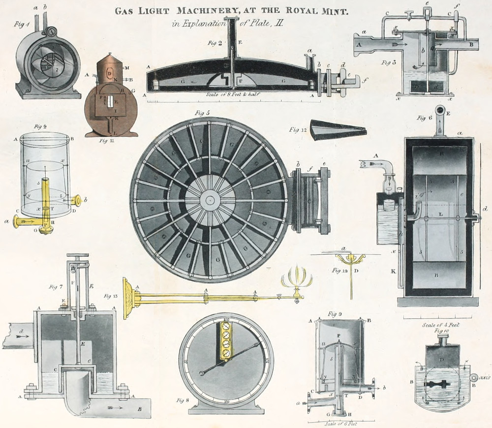
Accums, Discription of Gas Works.
Gas Light Machinery, at the Royal Mint.
in Explanation of Plate, II.
Pl. IV.
Accums, Description of Gas Works.
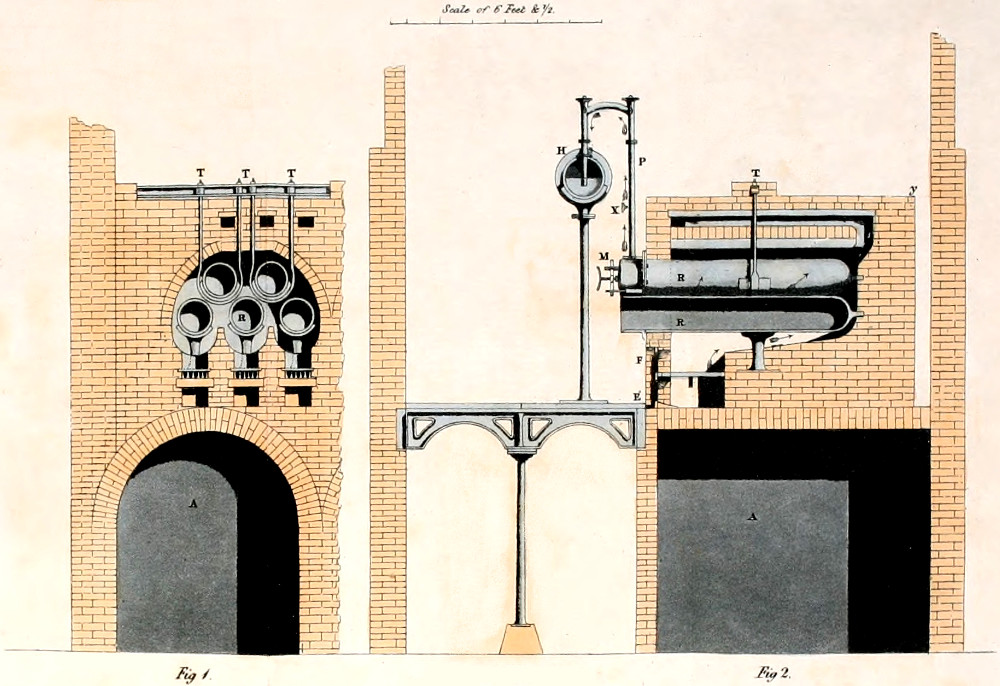
G. H. Palmer, Del.
Gas Works.
Westminster Station
Plate V.
Accums, Description of Gas Works.
W. Read, Sculp.t
Gas Holder at Birmingham
without Specific Gravity Apparatus,
capacity 30,000 Cubic Feet.
Plate VI.
Accums, Description of Gas Works.
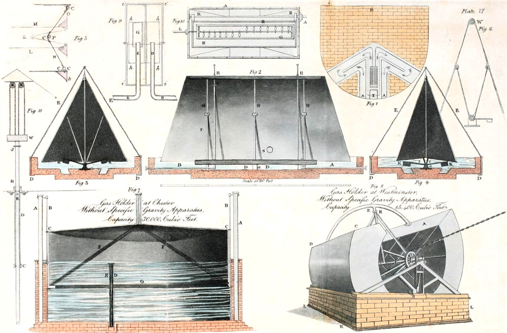
W. Read, Sculp.t
Gas Holder at Chester
Without Specific Gravity Apparatus,
Capacity 30,000 Cubic Feet.
Gas Holder at Westminster,
Without Specific Gravity Apparatus,
Capacity 15,400 Cubic Feet
Accums, Description of Gas Works.
Pl. VII.
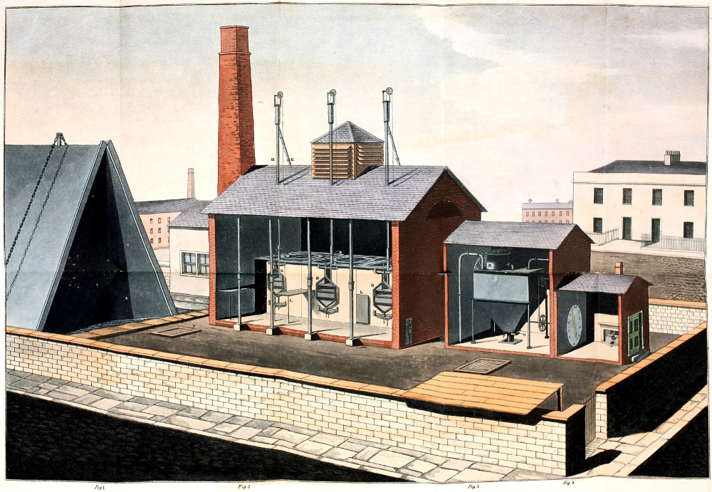
Lowry, Del.t & Sculp.t
Gas-Works.
Inconsistent, archaic and unusual language, punctuation and spelling have been retained, except as mentioned below. The book uses a comma for decimal point as well as for thousands separator.
The (minor) differences in wording between the Table of Contents and the actual text headings and the use of £ (with or without full stop and/or space) and l. have not been standardised.
Depending on the hard- and software used and their settings, not all elements may display as intended.
When relevant, texts have been removed from the plates and transcribed outside the plates. Such texts are enclosed in a dotted box.
Plate II, 'Accums’': as printed in original work.
Page xv, entry AMMONIACAL LIQUOR: there is no separate section for this material, but it is described in the first part of the section on Carbonate of Ammonia on page 303.
Page 43, 'Pont Tops': possibly Pontops.
Page 49, 'Tramsaren, near Kidwelly': possibly Trimsaran.
Page 79, table: the quantities given add up to 556 cubic feet.
Page 84, 'Enclosed are the result': as printed in the source document.
Page 86, Expenditure of Process A: the amounts given do not add up to the total.
Page 103/104, calculation: the numbers given do not add up to the first sub-total.
Page 196, example of capacity calculation: the dimensions given result in a capacity of 22,500 cubic feet.
Plate III, 'discription': as printed in the source document.
Changes:
Footnotes have been moved to under the paragraph where they are referenced.
Tables printed over multiple pages have been re-combined into single tables; where relevant, items such as Carried Over etc. have been removed. The lay-out of the tables with financial analyses has been standardised.
Several obvious minor typographical and punctuation errors have been corrected silently.
Page iii: 'as its little expresses' changed to 'as its title expresses'.
Page x: entries for pages 80 and 81 moved to their proper place.
Page xv: page number for entry AMMONIACAL LIQUOR changed to 303 (see above).
Page 42, 'principle coal mines' changed to 'principal coal mines'.
Page 43: 'Cowpers Main' changed to 'Cowper’s Main'.
Page 143: 'Melam' changed to 'Malam'.
Page 189, 'a fixed rigde point' changed to 'a fixed ridge point'.
Page 218, '10,00,000 revolutions' changed to '100,000 revolutions'.
Page 304: 'it will turn blue litmus, paper red' changed to 'it will turn blue litmus paper, red'.
Page 312: 'sal-ammonia' changed to 'sal-ammoniac'.
Index: Lines used as ditto marks and the word 'ditto' have been replaced with the dittoed words and phrases.
Price lists: in some cases the word ditto has been replaced with the dittoed text.
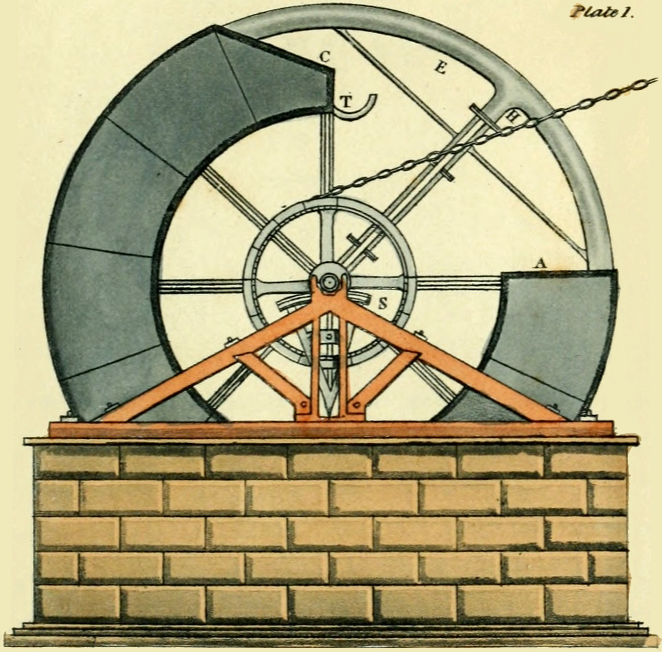
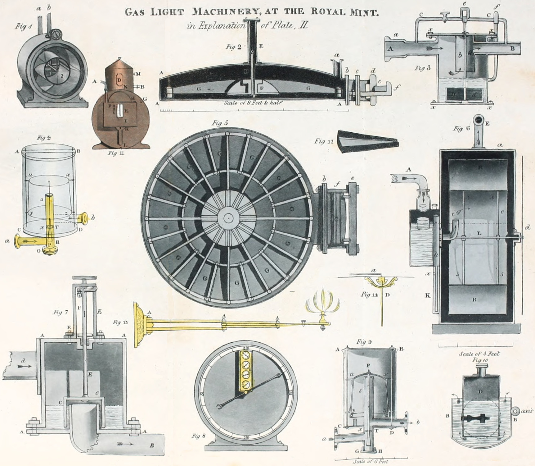
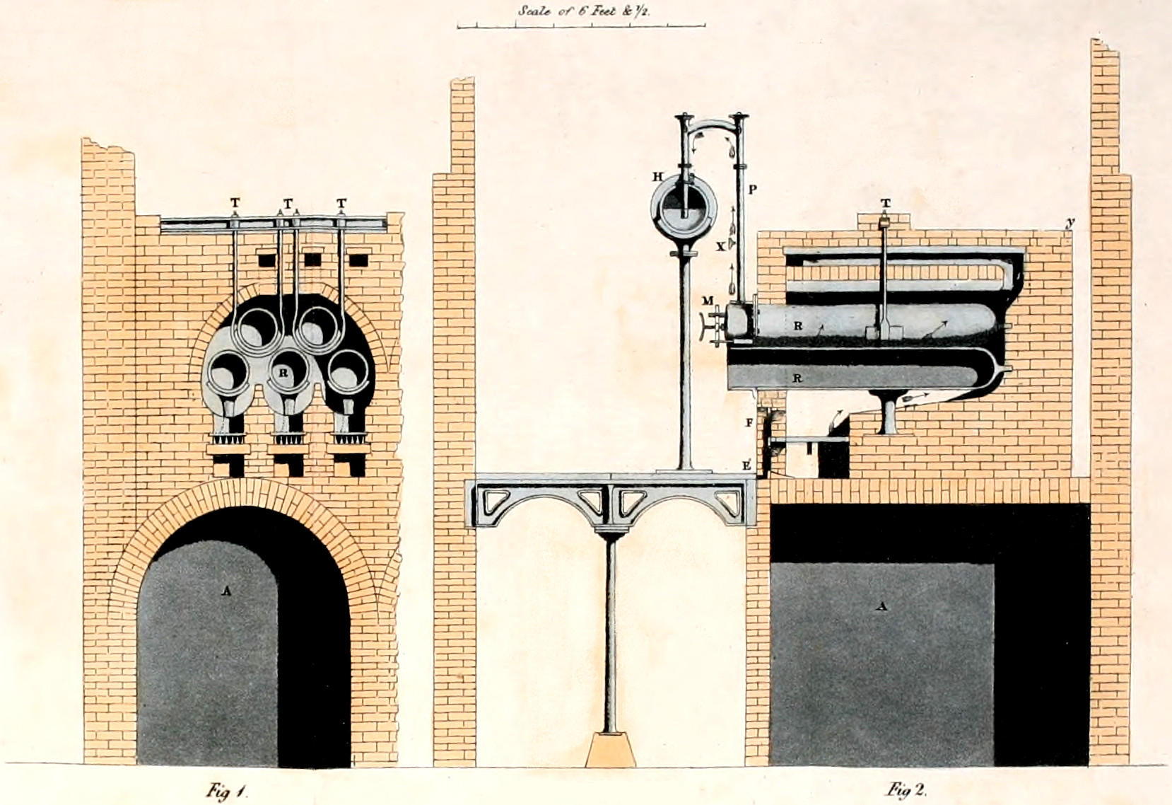
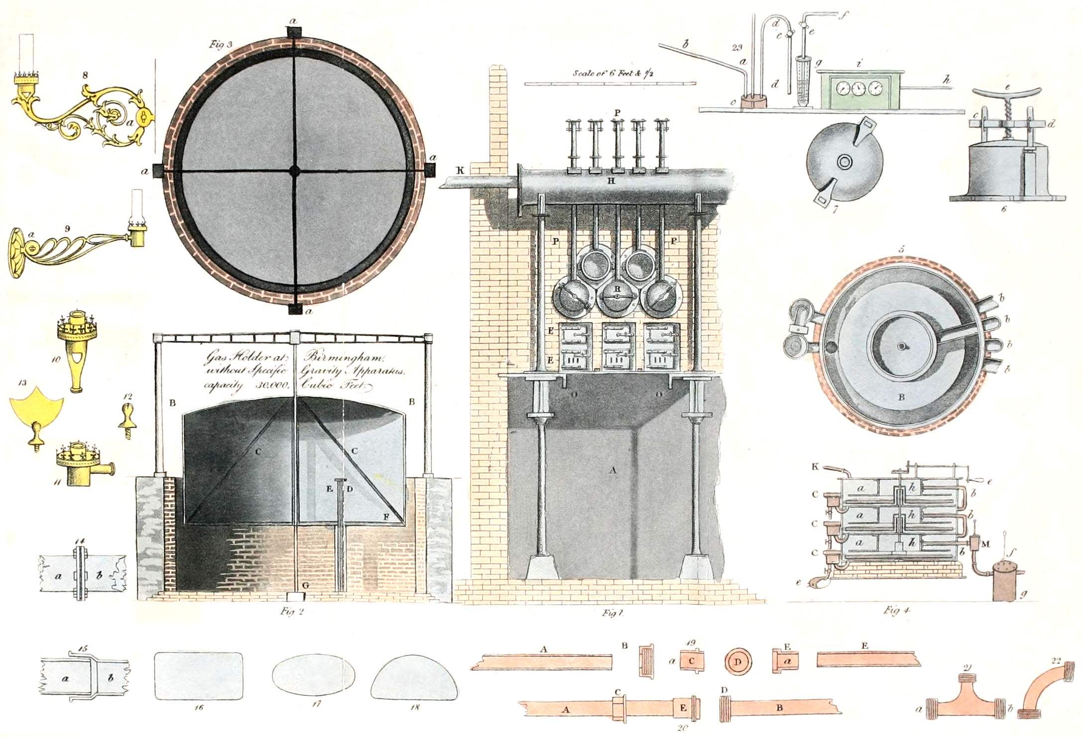