How To Build A 20-Foot Bi-Plane Glider
This ebook is for the use of anyone anywhere in the United States and most other parts of the world at no cost and with almost no restrictions whatsoever. You may copy it, give it away or re-use it under the terms of the Project Gutenberg License included with this ebook or online at https://www.gutenberg.org/license. If you are not located in the United States, you'll have to check the laws of the country where you are located before using this ebook.
Title: How To Build A 20-Foot Bi-Plane Glider
Author: Alfred Powell Morgan
Release Date: August 29, 2020 [EBook #63077]
Language: English
Character set encoding: UTF-8
*** START OF THIS PROJECT GUTENBERG EBOOK HOW TO BUILD A 20-FOOT BI-PLANE GLIDER ***
Produced by James Simmons.
This file was produced from page images at the Internet Archive.
Transcriber's Note
This book was transcribed from scans of the original found at the Internet Archive. I have rotated some images. Tables are treated as images. The back of the book contains ads for other books, which I have treated as additional chapters.
HOW TO BUILD A 20-FOOT
BI-PLANE GLIDER
A Practical Handbook on the Construction of a Bi-plane
Gliding Machine, Enabling an Intelligent Reader
to Make His First Step in the Field of Aviation;
With a Comprehensive
Understanding of the Principles Involved.
BY
ALFRED POWELL MORGAN
Editor Mechanical and Electrical Department of the
“Boy's Magazine.”
NEW EDITION, REVISED
NEW YORK
SPON & CHAMBERLAIN, 123 LIBERTY ST.
LONDON
E. & F. N. SPON, LIMITED, 57 HAYMARKET, S.W.
1912
Copyright, 1909, by
Spon & Chamberlain.
HOW TO BUILD A 20-FOOT BI-PLANE GLIDER
PREFACE
Gliding flight is a comparatively new field for the amateur to delve in, but the time has arrived when it is being extensively taken up both as a sport and a means of experiment.
Many very costly aeroplanes have failed to fly because of man’s total inexperience in the art of flying. All of the great aviators now before the world, whose machines are the result of their own genius learned to fly before succeeding in a motor driven machine.
The Wright brothers spent no less than three years on the sand dunes near the coast of North Carolina making gliding flights. They approached the difficulties in a methodical manner, working out each problem and determining which was the best means of accomplishing a certain result.
To control the tendency to pitching, they devised an elevation rudder and attached it to the front of their machine. The next step was to determine whether equilibrium should be maintained by shifting the centre of gravity or if there was not a better method and they introduced what is probably the most valuable feature of the modern aeroplane, namely the warping or twisting of the ends of the planes to secure lateral stability when a gust of wind strikes one end of the machine.
In this manner the Wright’s continued their experiments until every move had become a matter of habit and to balance and guide an aeroplane was almost an instinct.
A gasoline engine was then fastened in the machine and connected to drive two screw propellers at the rear. Dec. 17, 1903 the machine flew for a few seconds.
The leaps and bounds with which aviation has since progressed both in the hands of the Wrights and others is a matter too well known to be repeated.
There is therefore no excuse necessary to be made for this little book, coming as it does at this time and it is sincerely hoped that it may interest and lead many to experiment first and build their aeroplane afterward so that when their machine is complete it may be practical and not intended to operate in some "lift-yourself-by-your-boot-straps" manner.
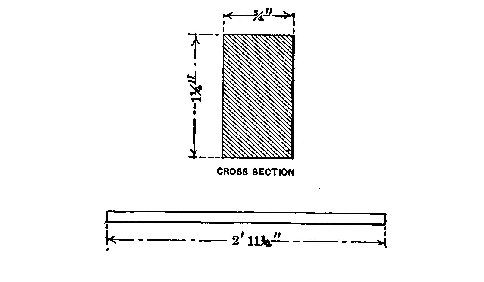
- Fig. 1 Horizontal Beam
- Fig. 2.—Strut.
- Fig. 3.—Position of Struts.
- Fig. 4.—Strut clamp.
- Fig. 5.—Stanchion.
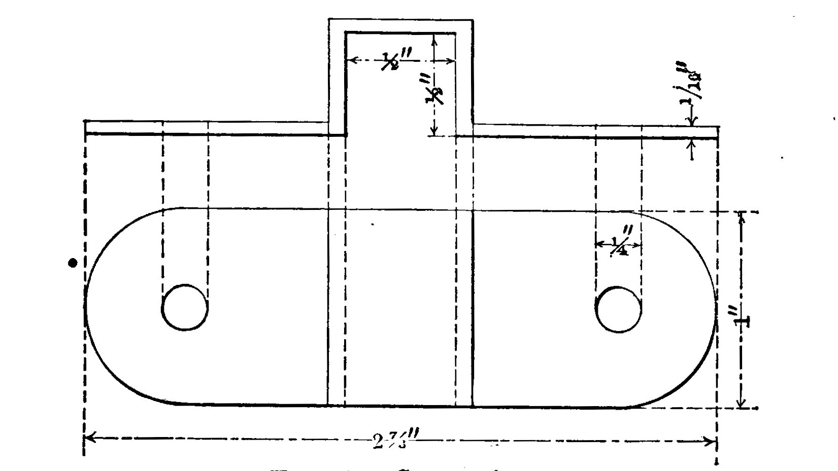
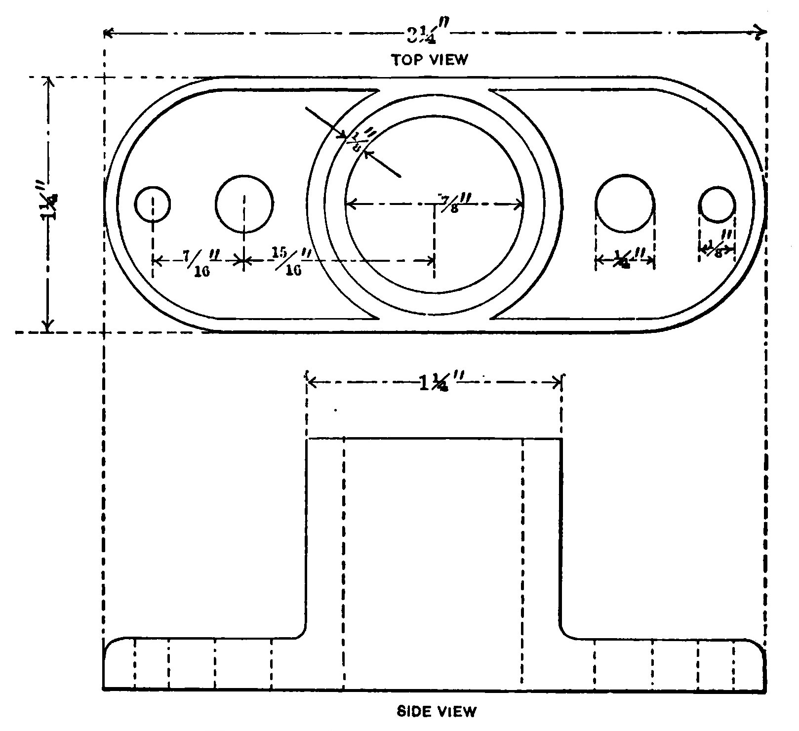
- Fig. 6.—Stanchion socket.
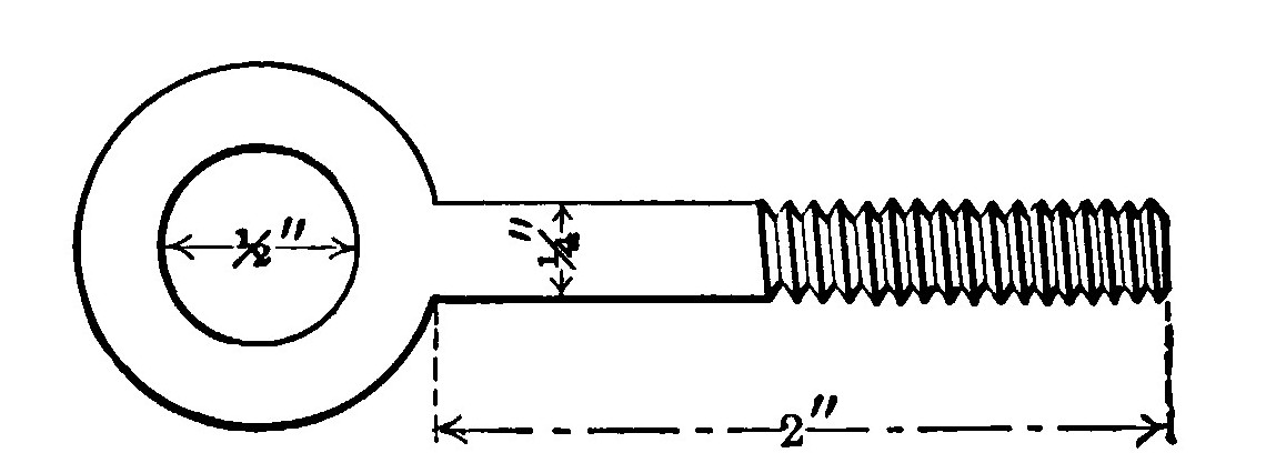
- Fig. 7.—Eyebolt.
- Fig. 8.—Assembly of stanchion, socket beam, strut and clamp.
- Fig. 9.—Rib.
- Fig. 10.—Rib clamp.
- Fig. 11.—Plan View of Planes showing Ribs.
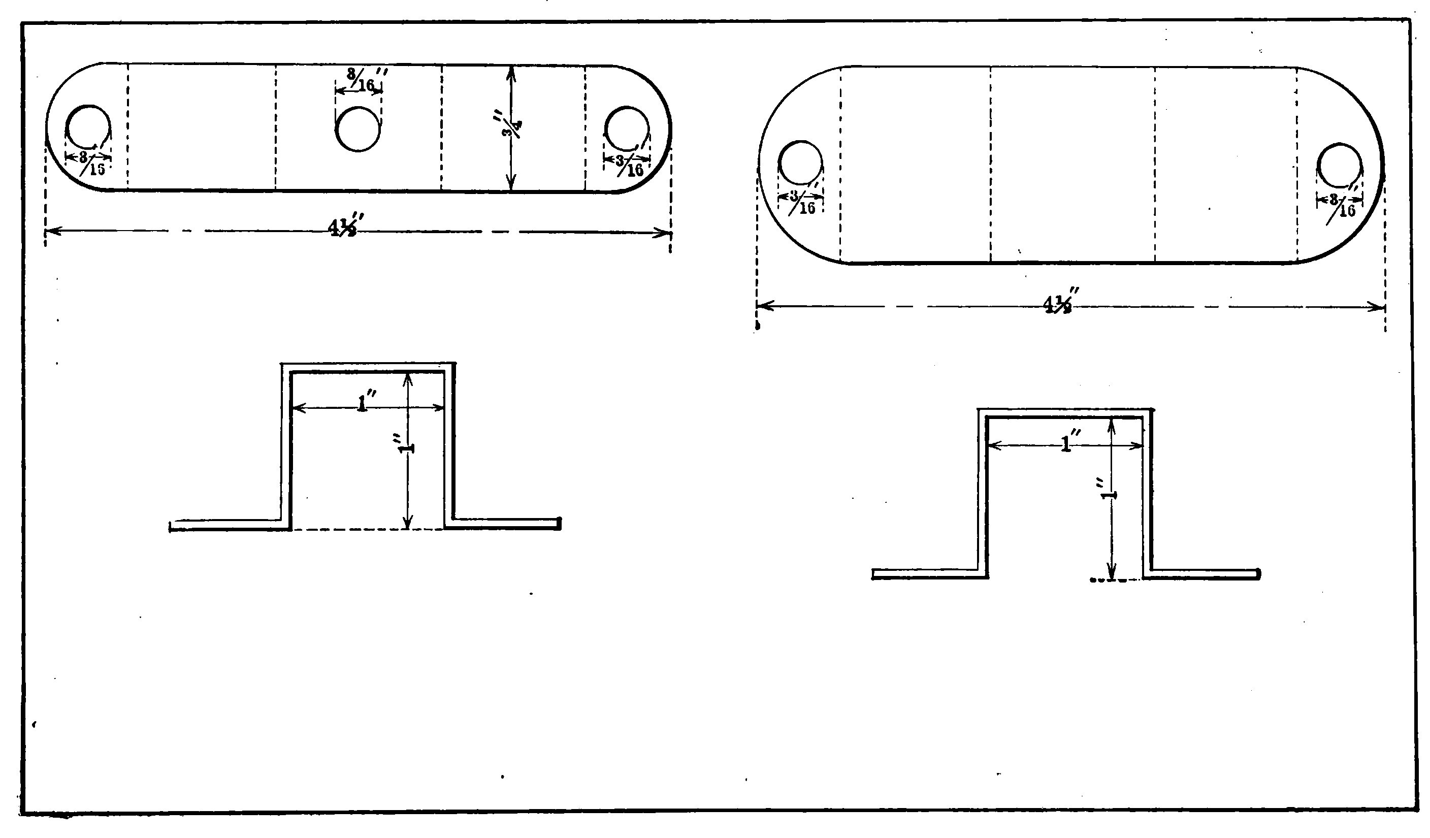
- Fig. 12.—Arm piece.
- Fig. 13.—Parts of rudder framework.
- Fig. 14.—Corners of horizontal rudder plane.
- Fig. 15.—Complete framework of rudder.
- Fig. 16.—Cross bar.
- Fig. 17.—Rudder Sockets, or Clamps.
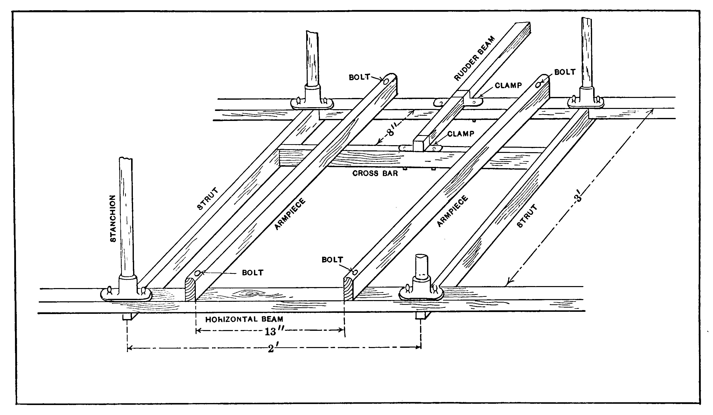
- Fig. 18.—Arrangement of Armpieces and Rudder Cross Bar.
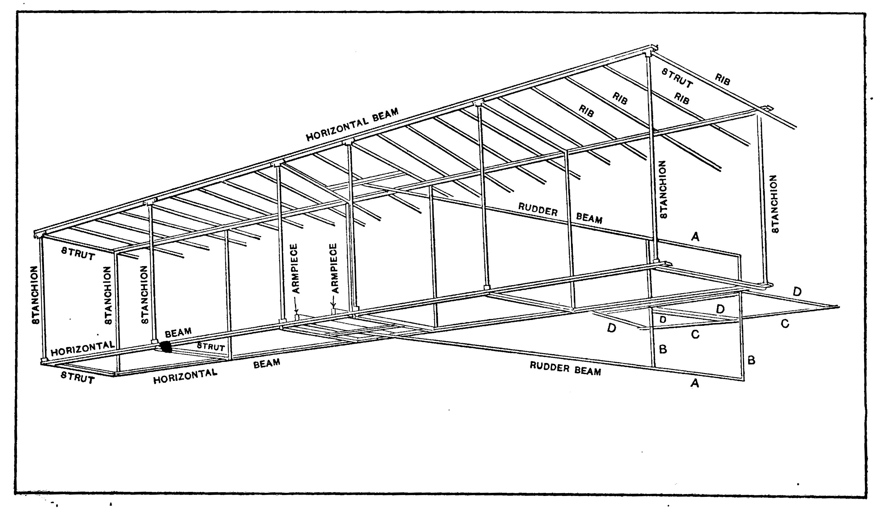
- Fig. 19.—Complete Framework Ribs on Lower Plane Not Shown
- Fig. 20.—Method of hemming up edge of cloth.
- Fig. 21.—Section of cloth hemmed, and reinforcing strips sewn on.
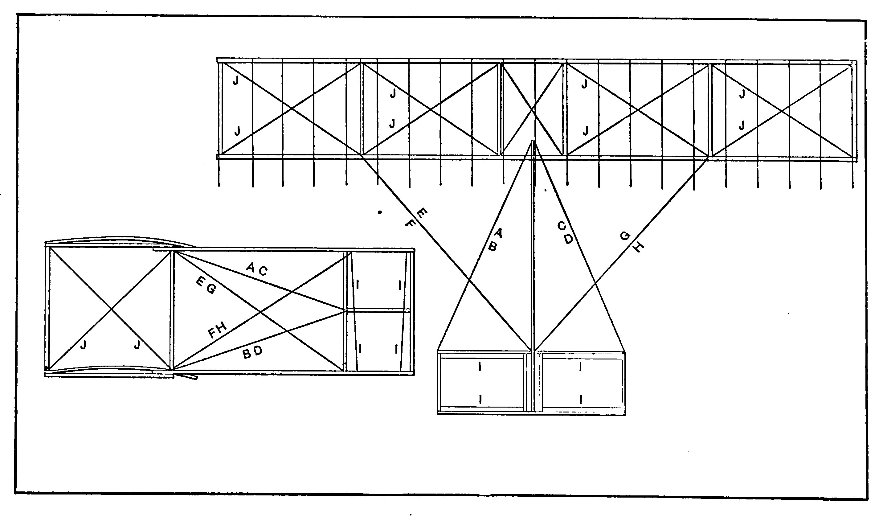
- Fig. 22.—Trussing Of Cells.
- Fig. 23.—Plan and Elevation Views of Piano Wire Bracing.
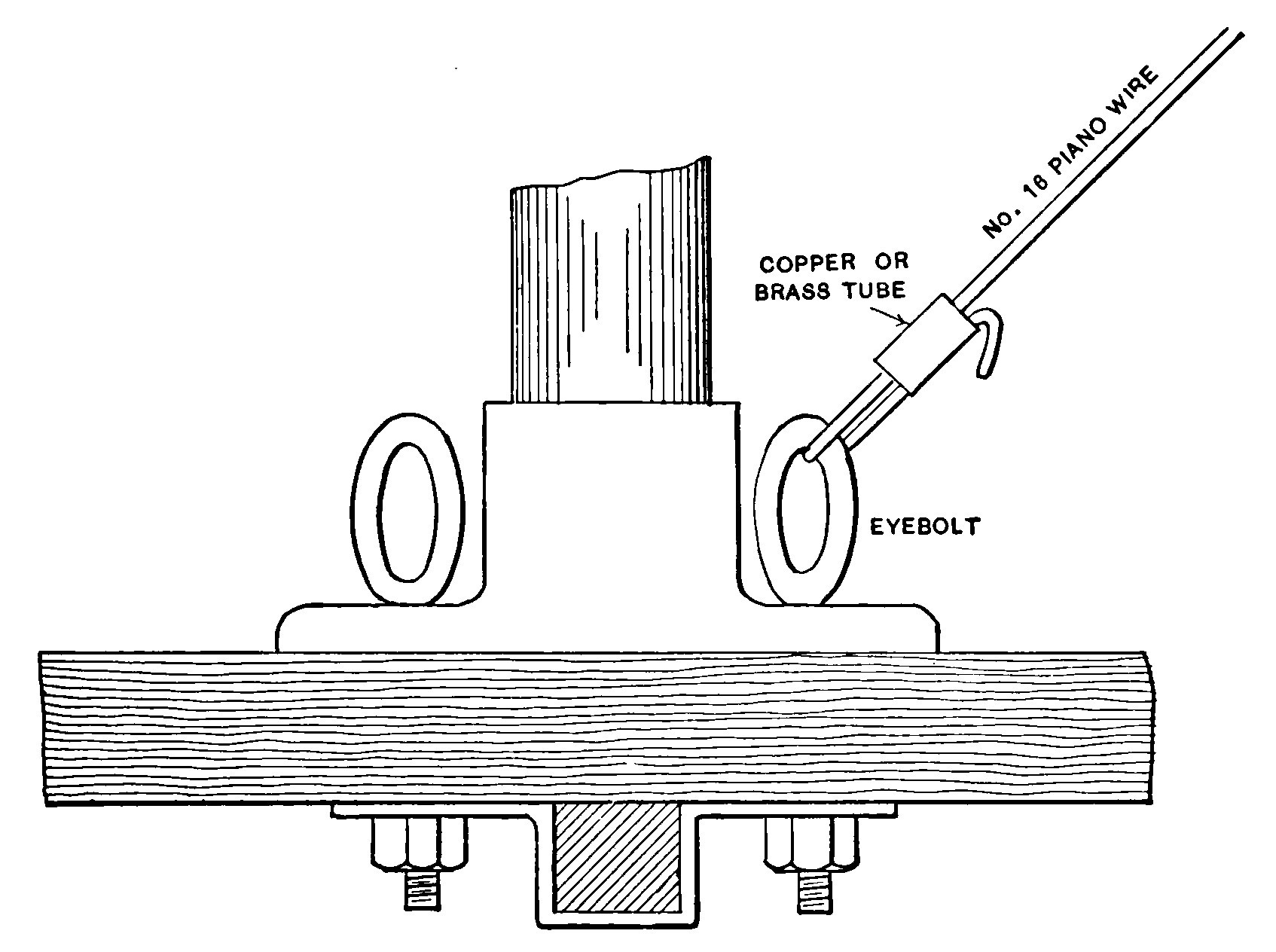
- Fig. 24.—Method of anchoring wires
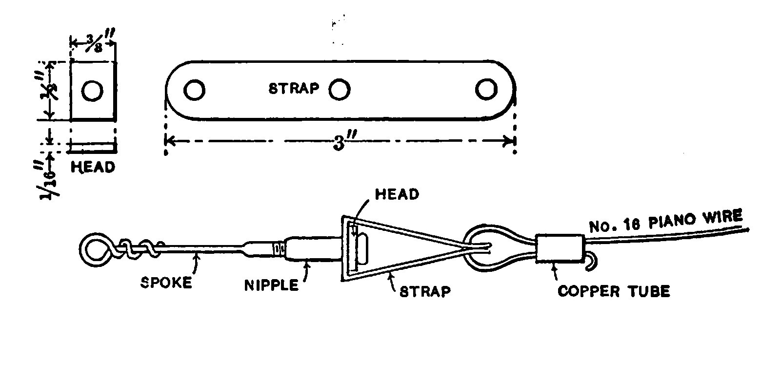
- Fig. 25.—Bicycle spoke turnbuckle.
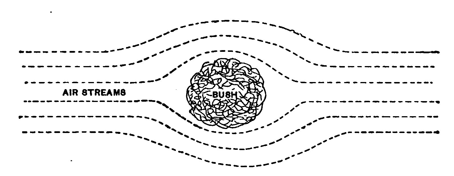
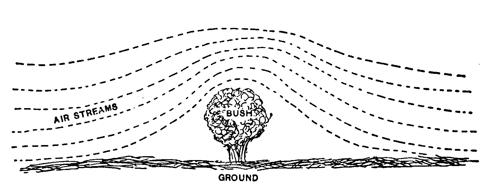
- Fig. 26.—Top view, showing how streams of air divide.
- Fig. 27.—Showing how air currents pass over objects.
- Fig. 28—Action of aeroplane.
- Fig. 29—Ready to Start
- Fig. 30—Lines of Flight
CHAPTER I. The Framework.
A gliding machine, more often popularly termed a glider, is simply a motorless aeroplane, operating by force of gravity to carry its passenger sailing through the air from the top to the foot of a slope.
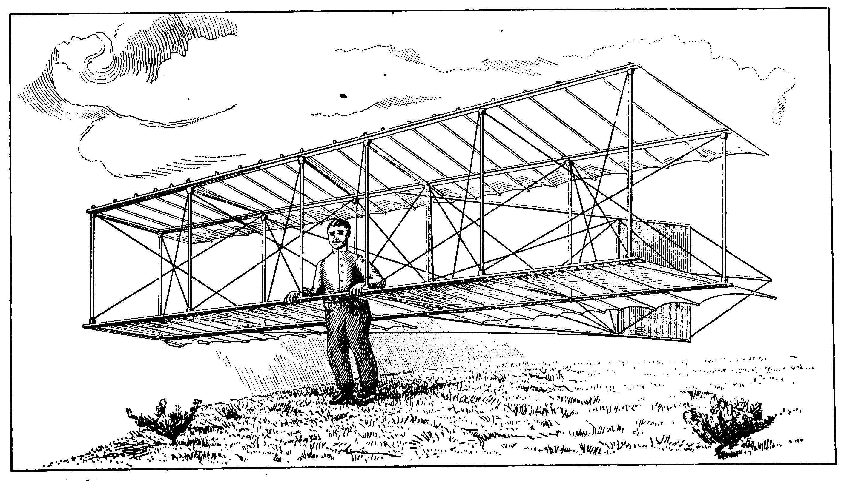
The glider described herein is the type developed by Octave Chanute and may be considered as the parent of the biplane machines with which the world has lately become so familiar. The machine is known as a biplane since its supporting surface is in the form of two superimposed trussed planes vertically above each other and having a tail in the rear for the control of direction.
There is always a tendency among experimenters to depart from the design and dimensions of any machine or apparatus offered for construction. This, since it develops originality is a good indication, but most of those who will undertake to build a glider are attempting something altogether new and so any radical change from the instructions in this little booklet are unadvisable.
It is better at first to benefit by the experience of others. The glider here described is considered as the "standard" of the biplane type. It has an active supporting surface of 152 square feet which is sufficient to carry the weight of an ordinary man. A machine having a larger surface will support the same weight when moving through the air at a slower speed, but larger surface means an increase in some of the general dimensions. An increase in surface by lengthening the planes will make the machine much harder to keep on an even keel, while increasing their depth in the direction of flight will require greater agility on the part of the operator to keep the centre of gravity in the proper position. A larger machine also means more weight and a heavy machine is hard to make a landing with.
On the other hand a light glider is dangerous and will not stand any rough usage.
The cost of the glider, provided the construction is accomplished by the intending owner is so low as to place it within the reach of any person of ordinary means. The expenditure for raw materials varies greatly. It is usually a little less than $20.00 and should not exceed $35.00. A finished glider is worth from $50.00 to $100.00 depending whether or not more than one is made at a time.
Housing. One of the first considerations is usually the housing and storing of the glider, but the machine under consideration is so designed that it may be quickly taken apart or "knocked down" and be put away in the cellar, under the porch or in some other out of the way place.
The framework is composed entirely of selected spruce, straight grained and free from knots. Spruce is very dense and tough but yet one of the lightest of woods.
The dimensions given are for the finished pieces after they have been planed up. The usual method of finishing wood for aeronautical work, so that it has a hard glassy surface and offers little resistance to the air is first to give it a thorough brushing over with hot glue and water. It is rubbed down after drying, using fine sand paper. The wood is then given a coat of thin shellac.
This is rather a tedious operation and instead some may prefer to first smooth up the wood by sand papering and giving it a coat of spar varnish.
The corners of all the woodwork are rounded off so as to reduce the resistance offered to the air.
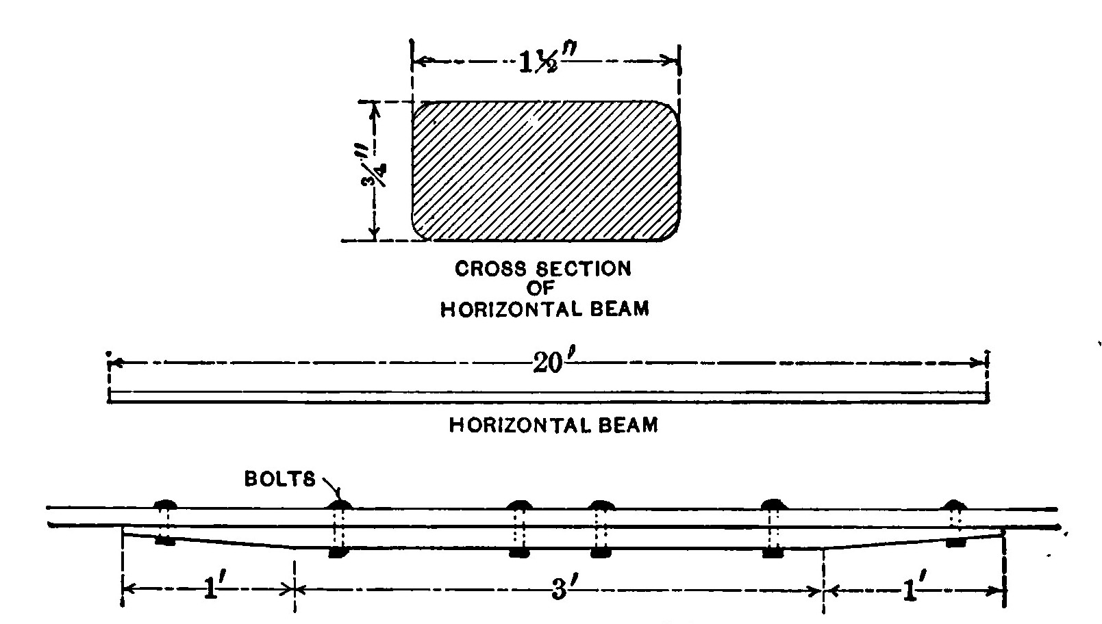
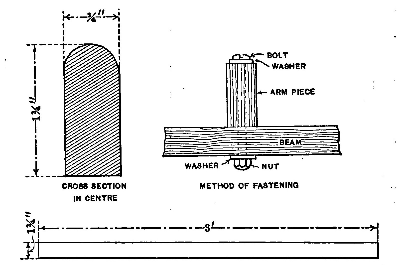
Horizontal beams. The principal members of the planes when smoothed up should measure 20 feet long, 1 1/2 inches wide and 3/4 inches thick. Four of these beams are required. In some lumber yards, twenty foot spruce free from knots is very hard to secure and so instead, two 10 foot pieces may be spliced together at the centre as shown in Fig. 1.
The splicing strip is 5 feet long and has the same cross section as the beams, save for a distance of one foot from each end where it begins to taper down to 1/4 inch thick. Six holes are bored through the splicing strip and the beams so that they may be fastened together by means of six 3/16 inch round headed stove bolts. The holes are located so that the space between the two centre bolts is six inches while the others are located one foot apart.
A large washer having a small hole in the centre is placed under the head of each bolt as well as the nut.
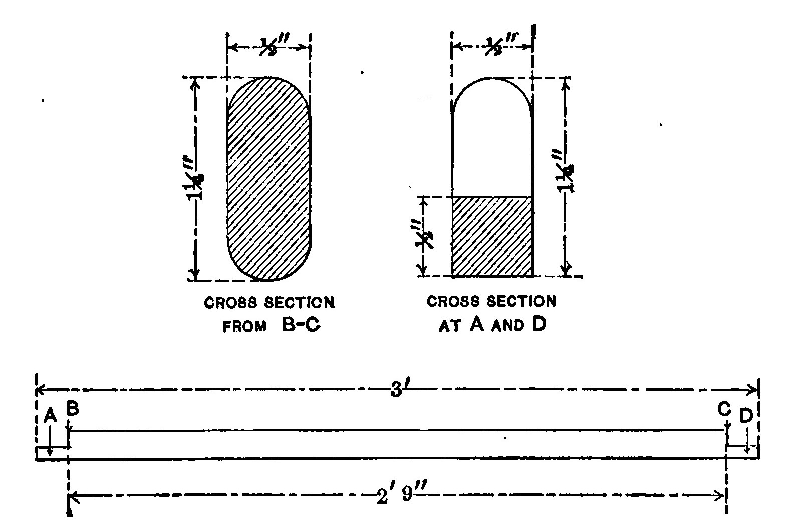
Struts. Each pair of horizontal beams are held parallel to each other and three feet apart by six horizontal struts. The form of these struts is illustrated in Fig. 2.
They are three feet long and 1/2 x 1 1/4 inches in cross section. A notch 1 1/2 x 3/4 inches is cut in each end so as, to form a projection 1 1/2 x 1/2 x 1/2 inches.
The location of the struts in the plane is illustrated in Fig. 3. The two in the centre are two feet apart and the others respectively 4 feet 6 inches and 9 feet on either side. The struts on the upper plane are placed so that the projections come above the horizontal members. Those on the lower plane are placed just the opposite, that is so that they come on the under side.
They are fastened with one or two small wire nails and then secured by means of a clamp. Two dozen clamps are required. They are bent out of a strip of sheet brass one sixteenth of an inch thick, 3 7/8 inches long and 1 inch wide. The ends are rounded and a 1/4 inch hole located and bored in each as in Fig. 4.
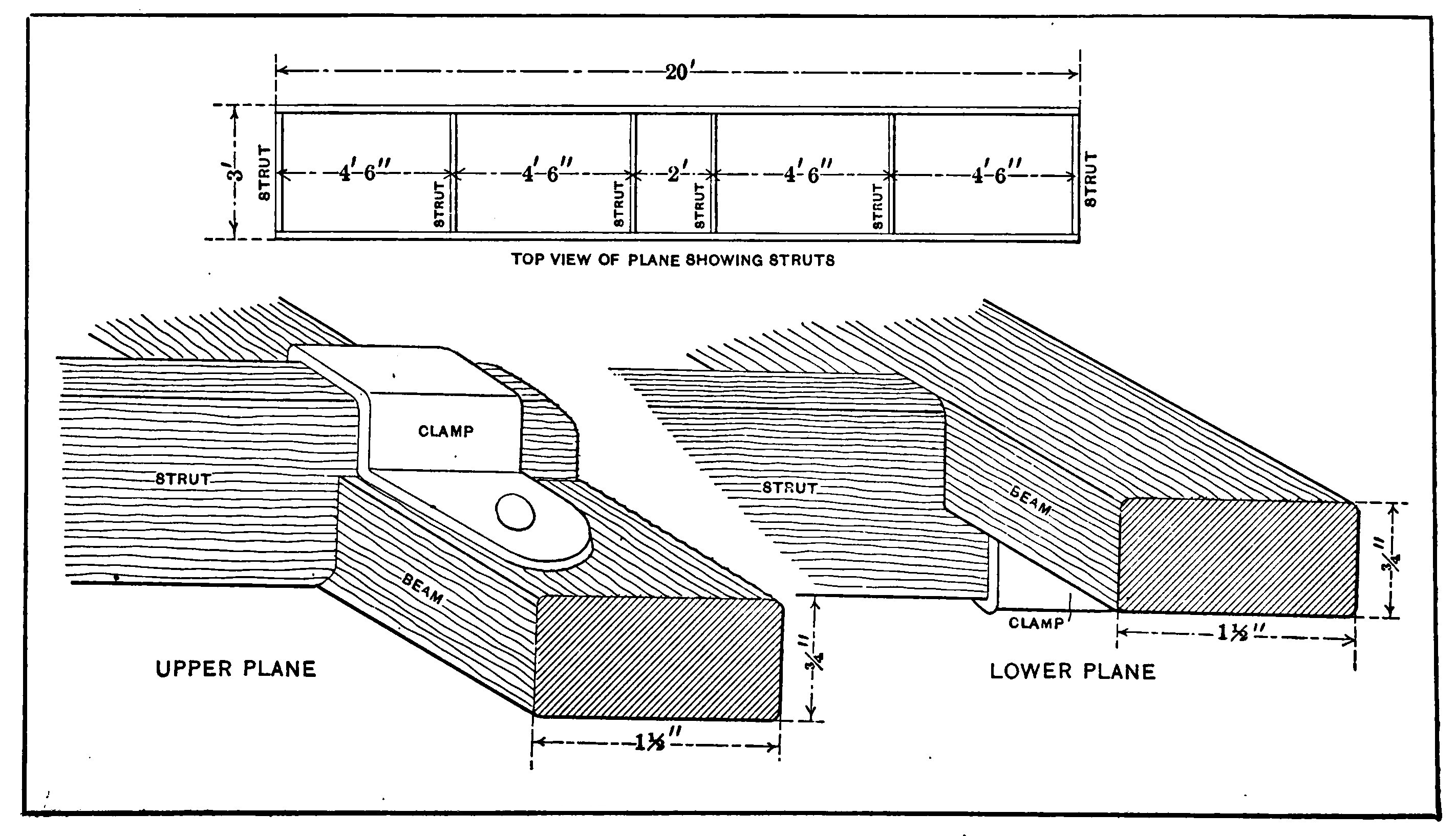
The clamp also serves to protect the under side of the beam from the action of the nuts on the ends of the eyebolts. The method of fastening the clamp is detailed a little later.
Stanchions. The planes are separated by twelve stanchions, four feet long and 7/8 of an inch in diameter.
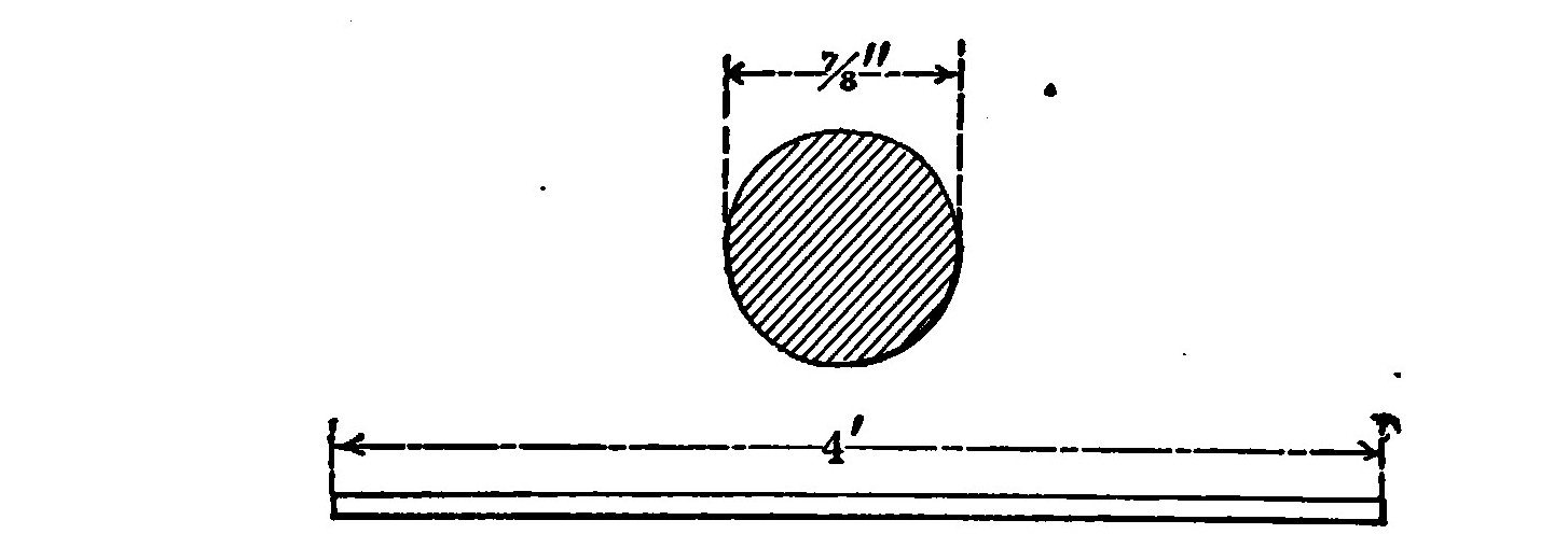
They are rounded and smoothed up so that the ends will fit snugly into the socket illustrated in Fig. 6. These sockets may be purchased1 already bored and finished or can be procured at a foundry. They are preferably made of aluminum which metal is at once light and strong but brass or even iron may be used if it is necessary to avoid expense.
There are other methods of joining the stanchions to the beams but the use of the socket is recommended because it is the strongest method and also permits the glider to be readily taken apart.
The base of the socket is 3 1/4 inches long, 1 1/4 inches wide and 1/4 of an inch thick. The cup has an internal diameter of seven eighths of an inch and an outside diameter of one inch and one quarter. It is one inch high above the base. Two 1/4 inch holes are bored 1 7/8 inches apart in the base. Two smaller holes 1/8 inch in diameter are bored 7/16 inch nearer the ends of the base than the larger holes.
The wooden pattern is made from the dimensions indicated in Fig. 6. It is thoroughly smoothed up by rubbing with sand paper and then given a coat of shellac. All parts should have a very slight taper towards the top so that the pattern may be withdrawn easily from the sand mould.
If the interior of the mould is coated with lamp-black, the castings will require no other finishing than boring the holes.
Two dozen of these sockets are required. Six are fastened to each of the four horizontal members by means of round headed wood screws which pass through the smaller holes in the base. The sockets are located exactly opposite the ends of each strut so that when the stanchions are in place, they will be separated by the same distances but all lie in a plane at right angles to that in which the struts are.
A 1/4 inch hole is bored through the horizontal beam directly under each one of the 1/4 inch holes in the base of the socket. These holes permit an eyebolt to pass through. The eye bolt is illustrated in Fig. 7. The stock is 1/4 inch in diameter and should be at least two inches long under the eye.
The diameter of the eye is one half an inch. These eye bolts are obtainable already threaded and ready for use with a nut and washers, but can be procured somewhat cheaper in blank form and threaded by the purchaser. Four dozen are necessary, two for each socket. The eye bolts pass through the socket and beam, coming out on the under side directly opposite the holes in the strut clamp. A nut placed on the under side as in Fig. 8 will then hold the clamp tightly against the under side of the beam and secure the position of the strut.
Ribs. Forty one ribs support the cloth forming the surfaces. They are each one half an inch square in cross section and four feet long.
They are fastened to the horizontal members one foot apart, flush with the front and projecting one foot in the rear. One or two small wire nails are used to fasten the front ends and then a clamp placed over them and screwed down with two No. 5 round headed wood screws, one half an inch long. A small brad awl should be used to make a hole before starting the screw and so avoid any possibility of starting a split in the wood.
The clamps are bent out of sheet copper strips, 2 1/4 inches long and 5/8 of an inch wide. The ends are rounded and a hole bored through which the screws may pass.
The surfaces of the planes are curved to give them an increased carrying capacity and add to the gliding power.
The best method is to steam the ribs and then bend them so that when they dry they will retain their curve and not tend to push the horizontal beams apart. Only a very slight curve should be given and the amount of curvature should be the same for all the ribs.
Some designers construct gliders having flat planes, intending that the pressure of the air underneath the fabric shall produce a natural curve but such a method is exceedingly poor practice and results in a very inefficient machine.
The ribs must be perfectly rigid and the frame of the whole machine strongly trussed so that it cannot possibly be distorted by the air pressure. The following extract from the report of the Smithsonian Institute well illustrates this point.
"This new launching piece did its work effectively and subsequent disaster was, at any rate, not due to it. But now a new series of failures took place, which could not be attributed to any defect of the launching apparatus, but to a cause which was at first obscure; for sometimes the aerodrome, when successfully launched would dash down forward and into the water, and sometimes (under apparently identical conditions) would sweep almost vertically upward into the air, and fall back although the circumstances of flight seemed to be the same. The cause of this class of failures was finally found in the fact that as soon as the whole machine was up-borne by the air, the wings yielded under the pressure which supported them, and were momentarily distorted from the form designed and which they appeared to possess. "Momentarily," but enough to cause the wind to catch the top, directing the flight downward, or under them, directing the flight upward, and to wreck the experiment. When the cause of the difficulty was found the cure was not easy, for it was necessary to make this great sustaining surfaces rigid, so that they could not bend.”
The report in question refers to the experiments conducted with Professor Langely’s model aerodrome.
Some experimenters claim that the parabolic curve gives the greatest lift with the least power required for propulsion but it can be safely doubted. The Wright machine is probably the most efficient in existence. Their curve is very nearly the arc of a circle and is not of the parabolic form.
Four per cent is about the proper curve to give the planes of a glider. This is about two inches for ribs four feet long. After fastening the front end of the ribs, curve them up in the centre by pressing down on the loose and at the rear. Then nail the rib to the rear beam with a small wire brad and screw on the clamp. The nails prevent the ribs from slipping longitudinally while the clamps serve to prevent them from moving sideways or pulling off when the fabric is under the pressure of the air.
Fig. 11 is a plan view of the top and bottom planes. Twenty one ribs, each one foot apart are used on the upper plane. Only twenty ribs are required on the bottom surface because an opening two feet wide must be left in the centre for the body of the operator.
Arm pieces. The operator is supported in the machine by two strips of wood passing under his armpits. These armpieces are 3 feet long, 1 inch wide and 1 3/4 inches deep.
They are fastened to the horizontal beams by means of a 3/16 inch round headed stove bolt. The distance between should be just wide enough to be comfortable and is variable with the breadth of the operator between his shoulders. Thirteen inches is about the proper distance for the average person. The upper side of the arm pieces is rounded so that they will not be quite so uncomfortable as they would be if left square. It is not a good plan to pad these pieces by wrapping them with cloth for it will impede the movements of the body in balancing.
Rudder. The rudder is composed of two planes at right angles to each other and in the rear of the main surfaces. The vertical portion keeps the machine headed into the wind and causes it to glide in the direction in which it is started or head on into the wind. The horizontal rudder steadies the machine longitudinally and prevents the machine from suddenly diving or pitching. Neither of the rudder planes are movable.
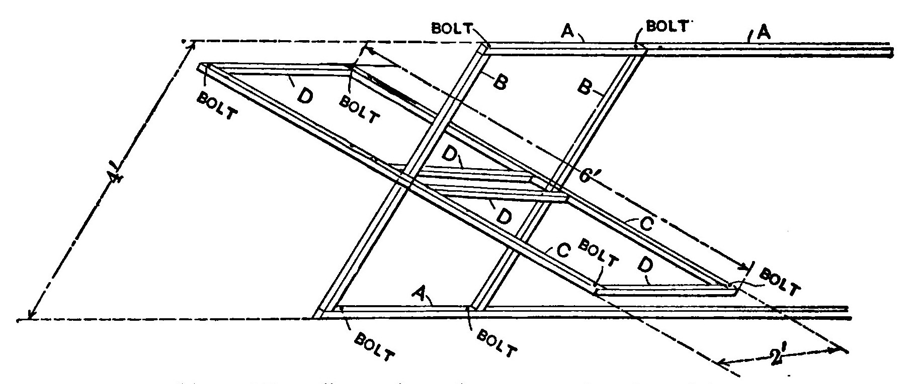
The separate parts composing the framework are illustrated in Fig. 13.
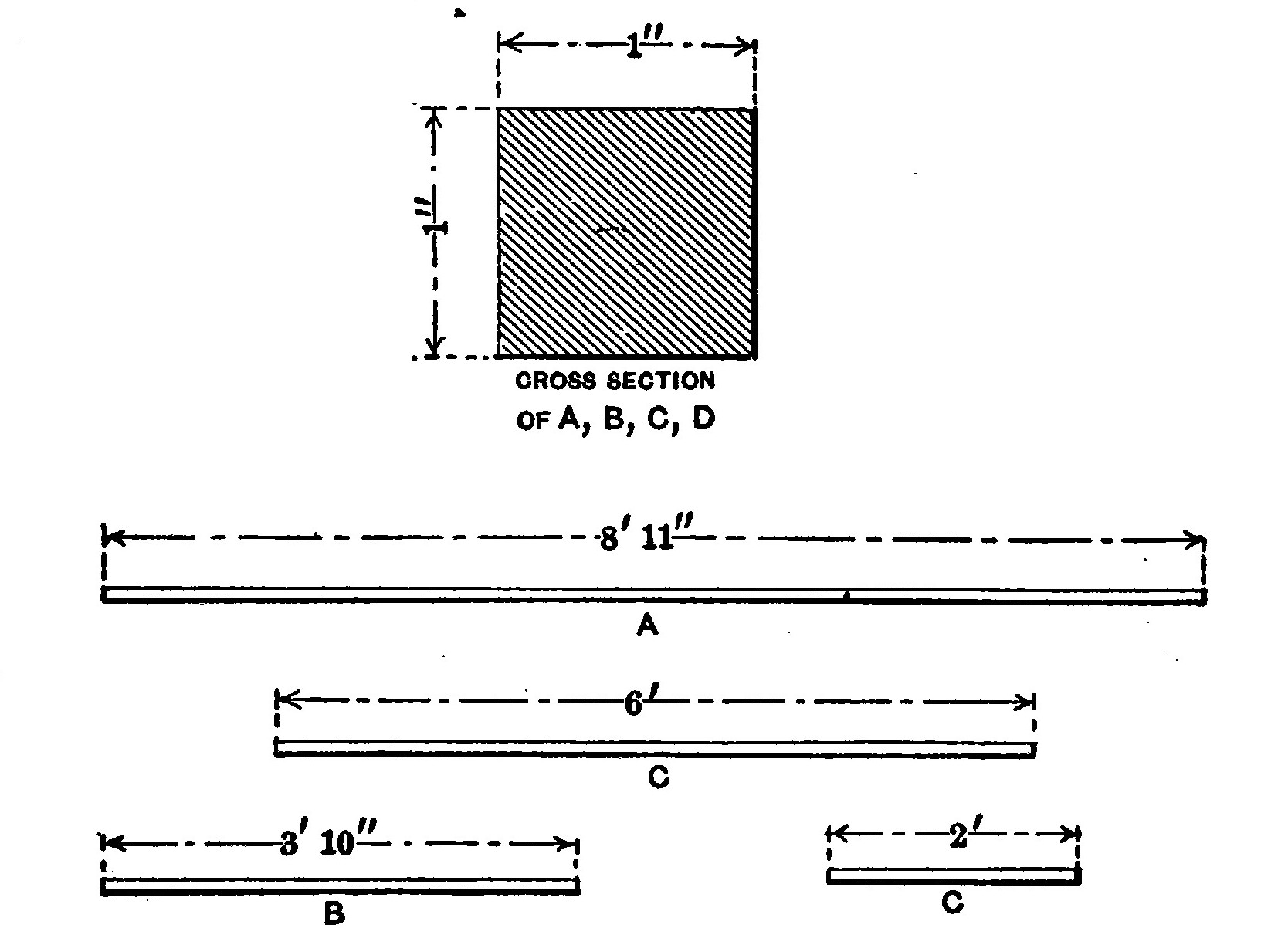
The cross section of all the sticks is the same, namely one inch square. The two long beams, A, are 8 feet 11 inches long. The two uprights, B, each 3 feet 10 inches long from the vertical members of the directional plane. The horizontal plane is made up of six horizontal strips, two of them, C, six feet long and four, D, two feet in length.
The horizontal plane is fitted together with half and half lap joints. It is first fastened with nails and then reinforced with brass corner braces.
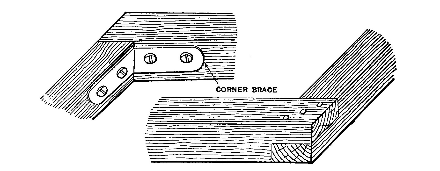
Corner braces are also used to strengthen the vertical plane.
The rudder beams are stepped into sockets on the body of the machine so that the rudder is detachable.
A short cross bar 2 feet inches long and 1 1/4 x 3/4 inches in cross section, is fastened between the two centre struts of both planes at a point eight inches forward of the rear beams.
These cross bars carry one of the sockets mentioned above as also do the rear horizontal beams. The cross bar and sockets in the upper plane should be directly over those in the lower plane but in an inverted position.
The construction of the sockets is illustrated in Fig. 17. The smaller one is fastened to the cross bar and is bent out of a strip of 1/16 inch sheet brass 4 1/2 inches long and 3/4 of an inch wide. The larger socket is the same length and thickness but is 1 1/4 inches wide and is fastened to the horizontal beam. Two of each size are required. The ends are rounded and a 3/16 inch hole bored in each so that a 3/16 inch round headed stove bolt may be used to fasten the sockets to the framework.
A hole is bored in the centre of the top of the smaller sockets so that a bolt may be passed through the rudder beam and cross bar to prevent the former from pulling out.
The two sockets in each plane must be in perfect alignment and lie on a line drawn at right angles to the horizontal members through the centre of the planes.
In Fig. 15 it will be noticed that four bolts pass through each plane near the corners. The bolts are 3/16 inches in diameter and serve to fasten the piano wires which brace the vertical and horizontal plane to each other.
The complete framework of the glider without the tie wires and the ribs on the lower plane will appear as in Fig. 19.
| [1] | From Spon & Chamberlain |
CHAPTER II. Covering the Planes.
The surfaces of a motor driven aeroplane are usually made of some material which is practically air tight. The Herring-Curtiss Co., use Baldwin’s rubberized silk, while most of the foreign aviators prefer a balloon cloth known under the name of "continental."
Ordinarily the surfaces of a glider are not covered with any preparation to make them air tight and is not necessary, but since it will considerably increase their efficiency it is offered as a suggestion to those who are able or care to undergo the expense.
Aero varnishes for this purpose are obtainable in the market and may be applied with an ordinary brush or by immersing the fabric. One gallon will cover approximately 100 square feet of ordinary Cambric, although much depends upon the weave. The more open or coarser the goods, the more varnish it will require, while fine fabrics take the least amount.
Varnish is expensive and is not considered in the estimate of cost made at the beginning of the book.
The surfaces are formed of cambric or muslin stretched tightly over the ribs. Thirty yards of material, one yard wide will be sufficient to cover the machine, including the rudders.
Seven strips 4 feet 6 1/2 inches long are cut and sewed together along the selvages so that a surface 4 feet 6 1/2 inches wide and a little over 20 feet long is formed. Twenty one strips, 4 feet 6 1/2 inches long and 1 1/2 inches wide are cut and sewed to the surface at right angles to the long edges and one foot apart, between their centre lines. The edges of these strips are turned under 1/4 of an inch on each side so that they form a reinforcement 1 inch wide which will come directly above each rib.
Reinforcing. The long edges of the surface are then doubled back and hemmed, turning under 1/4 of an inch and forming a 3 inch hem as illustrated in the upper part of Fig. 20. This 3 inch hem is then doubled back one inch and sewed again so that the result is a two inch hem, composed of two thicknesses of cloth save for one inch back from the edge where it is made up of four thicknesses.
This reinforcing is necessary to avoid ripping and tearing the cloth out from under the tack heads when it is under pressure during a flight.
The bottom planes. The cloth on the bottom planes is made up of two sections, divided by the space in the centre of the lower plane which the operator occupies. These sections are made and reinforced in exactly the same manner as that for the top plane just described but are one foot less than half as long.
The cloth is tacked over the front horizontal beam and then stretched tightly over the curved ribs and fastened with tacks at the ends. Fasten the corners of the cloth first and smooth it out before driving the tacks in the ribs. Ordinary brass headed upholsterer’s nails are used but they should not be long enough to pass all the way through the ribs.
A strip of felt 3/8 of an inch wide and four feet long is laid on the cloth directly over each rib so that it comes between the head of the tack and the cloth. This precaution may seem unnecessary to some, but it greatly reduces the liability of having the cloth tear when under pressure. The tacks along the ribs are spaced about 4 inches apart A heavy weight held against the under side of the rib by an assistant, when the tacks are driven in will provide a firm foundation to hammer against.
A very good method of fastening the cloth to the ribs is to sew a pocket on the under side of the surface and into which the ribs may be slipped.
The rear ends of the ribs may be fitted with metal tips by tapering the end down until it is round and measures 1/2 inch in diameter. A 1/2 inch brass ferrule such as that used on file handles is then forced on.
The rudder planes are covered on both sides. The fabric is stretched tightly over the frame and then tacked along the edges. The edges should be turned under before tacking so that there is no possibility of the cloth tearing out.
The cloth at the ends of the planes should be securely fastened to the struts by means of tacks. This will relieve the ribs of some of the strain and correct a tendency for them to pull in towards the centre.
CHAPTER III. Trussing.
The strength of the glider lies in its proper trussing with piano wires which when tightened up should so brace the framework that it will support without appreciable sag or strain, a heavy man hanging from the arm pieces and the ends of the planes resting on a pair of carpenters’ horses.
Two methods of trussing the planes are illustrated in Fig. 22. The machine is divided into five cells the vertical boundaries of which are formed by the stanchions. .
The first method illustrated is the one used in this case for the glider. It is somewhat simpler than the second and does not require the use of any turnbuckles.
Each wire is fastened to one of the eyebolts on the horizontal beams and then run diagonally across to the socket on the opposite beam in the other plane, considering front and rear to be opposed.
Four of these diagonal wires, represented by J in Fig. 23 brace each of the four large cells. The middle cell cannot be trussed up in this manner because the wires would interfere with the body of the operator. So the rectangles formed by the two centre struts with the upper horizontal beams and the two centre rear stanchions with the rear horizontal beams of the upper and lower planes, are braced by means of wires running across their diagonals.
The rudder is stiffened and trussed to the planes by sixteen wires. Two of these F and H run from the top of the vertical rudder plane to the lower sockets in the rear, 4 1/2 feet from the ends of the planes. The corresponding pair E and G run from the bottom of the rudder to the top sockets of the same stanchions. Four wires A, B, C, D steady the horizontal plane and run from its corners to the sockets in which the rudder beams are stepped on the frame of the glider itself. The remaining eight, indicated by I in the illustration brace the horizontal and vertical planes of the rudder to each other.
Fig. 24 illustrates the method of anchoring piano wires.
The wire is first passed through a short piece of 1/8 inch copper tubing about 3/8 of an inch long, then through the eyebolt. The end is doubled back passed through the tube again but now in a reverse direction. By bending the extreme end of the wire over in the form of a hook and shoving the tube down close to the eye bolt, the wire is secured and cannot pull out. The other end of the wire is fastened in the same manner but before the end is bent over into a hook, the wire must be first pulled tight.
After fastening all of the wires their tension may be regulated by turning the nuts on the lower ends of the eye bolts. It is very necessary that the frame should be perfectly true and not warped or twisted. Otherwise the machine will be very hard to balance and manage when making a glide. Especially must the rudder be true with the rest of the machine.
Since there are no eyebolts about the rudder which could be used to tighten or loosen the truss wires, a turnbuckle must be included in each wire for that purpose.
Turnbuckles. The construction of these turnbuckles which are very simple and inexpensive is illustrated in Fig. 25. They are made of a bicycle spoke and nipple by cutting off one end of the spoke and using the part which is threaded. The end of this piece is bent back and twisted into an eye. A piece of 1/16 inch sheet brass 1/2 x 3/8 inch has a hole bored in its centre, the diameter of which is such that it will just admit the spoke nipple. The nipple is prevented from passing all the way through by the shoulder on one end. A piece of sheet iron 1/2 inch wide and 3 inches long has a similar hole bored in its centre. The ends of this strap are rounded and bored so that the piano wire may be passed through. The turnbuckle is then assembled and connected as shown in the illustration. The tension of the wire is regulated by turning the spoke nipple while the spoke itself is held rigid.
The second method of bracing illustrated in Fig. 22 requires that a turnbuckle be included in the diagonals of every rectangle, except those formed by the stanchions with the horizontal beams. This method is used on almost all aeroplanes and is considered the strongest but the first method is plenty strong enough for an ordinary glider. If after trussing, the machine is found to be warped or twisted, it must be trued up. By sighting along the horizontal beams and tightening or loosening the necessary wire any curvature may be easily corrected.
The second method of trussing is considerably harder to true up than the first, since when one diagonal of a rectangle is tightened, the other must be loosened. But since it makes an exceedingly firm and rigid structure, it may be well recommended to those who care to undergo the added expense and labor involved by the extra turnbuckles and wires.
To take the glider apart, first remove the bolts holding the rudder beams in the sockets on the machine. Then unfasten the wires which brace the rudder to the machine by loosening the turnbuckles until the spokes and nipples unscrew and come apart. The rudder may now be removed from the machine.
Next take off all the nuts on the eye bolts in the lower plane and pull the eyebolts out of the sockets. The two planes will then come apart. Remove the stanchions by pulling them out of the sockets. The two planes are then laid one on top of the other and will occupy very little room.
CHAPTER IV. Gliding.
The first words which may well be said upon this subject are to emphasize caution. But by this I do not wish to imply that gliding is exceedingly dangerous. Neither do I by caution mean timidity but rather judgment and common sense.
Canoeing is generally considered a safe sport, but who would think of canoeing on the ocean in a storm. It is exactly the same extreme to glide from a very high object, or experiment in a high wind.
The atmosphere near the earth is a mass of whirling and swirling currents which are constantly rising and falling and become very pronounced in a high wind. Even in a comparative calm these eddy currents exist but of course not to a dangerous degree. Evidence of this may be seen by watching the little dust particles floating in the air and made visible by a sunbeam coming through the window of a quiet room. Although the sense of feeling cannot detect the smallest air current, these little particles are whirling around and constantly changing their direction.
When the wind strikes some natural object such as a tree or a stone, the streams of air divide, part of them passing to the sides and part going over the top. The air begins to divide some distance before it reaches the object and the result is a rising current on one side and a falling current on the other.
These currents are the bugbears of aviators for when one end of their machine passes into such a current that end rises or falls depending whether or not the current is rising or falling.
Other rising and falling currents are caused by the sun passing behind clouds. Portions of the atmosphere are thus chilled and commence to fall while others upon which the sun is reappearing are heated and rise. Balloonists constantly encounter these changes in temperature and the gas in the bag expands or contracts so rapidly that it often requires a skillful pilot to prevent disaster.
These rising and falling currents caused by changes of temperature may be clearly seen on the surface of a lake if the observer is stationed at a height where he may look down on the water. In some places the water is covered with smooth glassy streaks which run in various directions. These smooth streaks are evidence of rising currents of air at those places. The rough spots which suddenly spread out and run across the water are caused by descending currents.
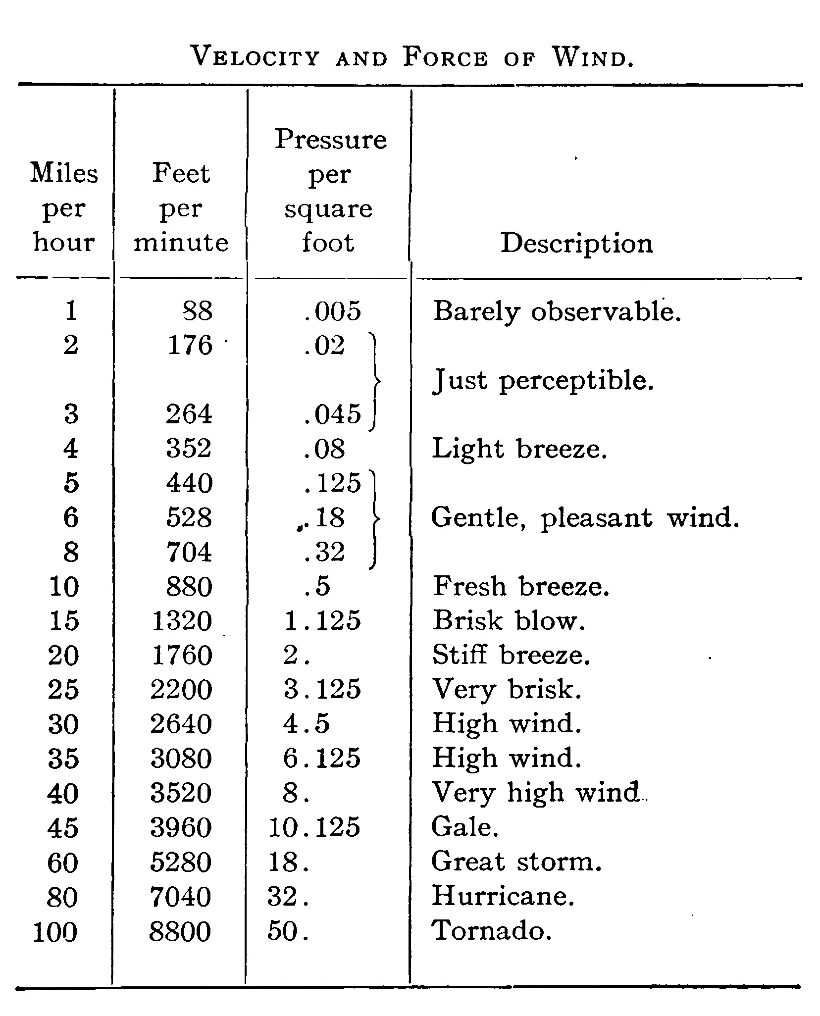
Therefore it is not good judgment to attempt gliding over ground broken by trees or other natural objects or when the wind is blowing over 12-15 miles per hour.
Do not under any consideration jump off from a height which rises prominently from surrounding objects. Otto Lilienthal, the brilliant German investigator and engineer who made over two thousand gliding flights specifically warned experimenters against starting glides from precipitous cliffs or buildings. There are two excellent reasons for this. First, because when jumping from such an elevation, a gust of wind rebounds from the sides and strikes the machine so that it requires great skill to counteract its influence. Second, because, the operator and machine are suddenly suspended high in the air.
Be satisfied at first by running against the wind on level ground and making short jumps. After some practice, operations may be transferred to a gentle slope and the length of the glides considerably increased. If the experimenter thus proceeds slowly without impatience, there is no danger in gliding. It is said that the Wright brothers never so much as turned an ankle in the hundreds of flights they made, before building a power driven machine.
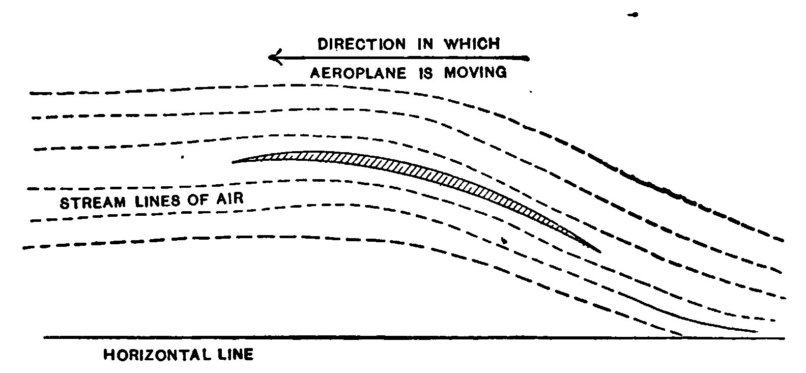
Action of an Aeroplane. Before starting to glide it is perhaps well to understand how the machine operates and supports its passenger. The illustration shows the cross section of an aeroplane moving forward through the air in the direction indicated by the arrow. The front edge of the aeroplane is elevated so that the surfaces form an angle with the horizontal. The front edge enters practically still air and causes it to follow the curve of the planes and leave at the rear in a downward direction. Since the action and reaction of two forces are always equal and opposite, there is a force exerted against the aeroplane causing it to rise.
A sky-rocket is caused to ascend by the reaction of gases formed by burning powder escaping downwards through a small hole. The aeroplane, by means of its curvature directs the air downwards and so rises itself.
The planes pass so rapidly on to new and undisturbed bodies of air, and stay over one body for so brief an instant, that there is no time to completely overcome the inertia of the air and force it downwards. This may be likened to a skater moving swiftly over very thin ice which would not bear his weight were he standing still, but since he is moving so rapidly, that any one portion of the ice does not have time to bend to the breaking point, is supported.
Equilibrium. A glider will remain in perfect equilibrium only so long as the centre of gravity of the machine and operator fall in the same vertical line as the pressure exerted by the air. If the former is forward of the latter, the machine will incline forward and travel downwards. If the centre of gravity is to the rear of the centre of upward thrust exerted by the air, the head of the machine will rise, while if it is to either the right or left side, the machine will lean or turn over respectively to the right or left.
The centre of pressure on the plane is somewhat in advance of the actual dimensional centre of the plane. This is due to the curvature of the plane and also to the disturbing action upon the air of the front edge.
To make a glide, carry the machine to the top of a slope. Have two assistants hold the ends of the lower plane. Get in underneath and stand up between the arm pieces. Grasp the front horizontal beam of the lower plane and lift the machine until the arm sticks are snugly under the arm pits as in the illustration.
If necessary have the two assistants prepared to run a short distance with the machine, but as soon as you are in motion you will be relieved of all weight and surprised at the lift exerted.
After getting the machine snugly up under the arm pits, face the wind, elevate the front of the machine slightly, run a short, distance and leap into the air. If you are in the right position you will sail to the foot of the slope in free flight. To land, push yourself towards the back of the machine, so that the glider tips upward slightly in front. It will then rise slightly but loose its momentum and slowly settle so that you drop gently on your feet.
Balancing is accomplished in flight by moving the legs and body towards that side which is highest.
Shifting the centre of gravity by swinging, the legs forward or moving the body in the same direction, will naturally cause the centre of gravity to assume a forward position, and being a force exerted downwards, the machine will dip and descend. A reverse movement of the centre of gravity will cause the front of the machine to tip up and ascend. But if the upward slant is continued too long the glider will loose its forward velocity and settle.
The tendency is always to place the weight of the body too far to the rear. After a little experience the experimenter will learn how to dip his machine to acquire velocity for a rise and to otherwise handle it.
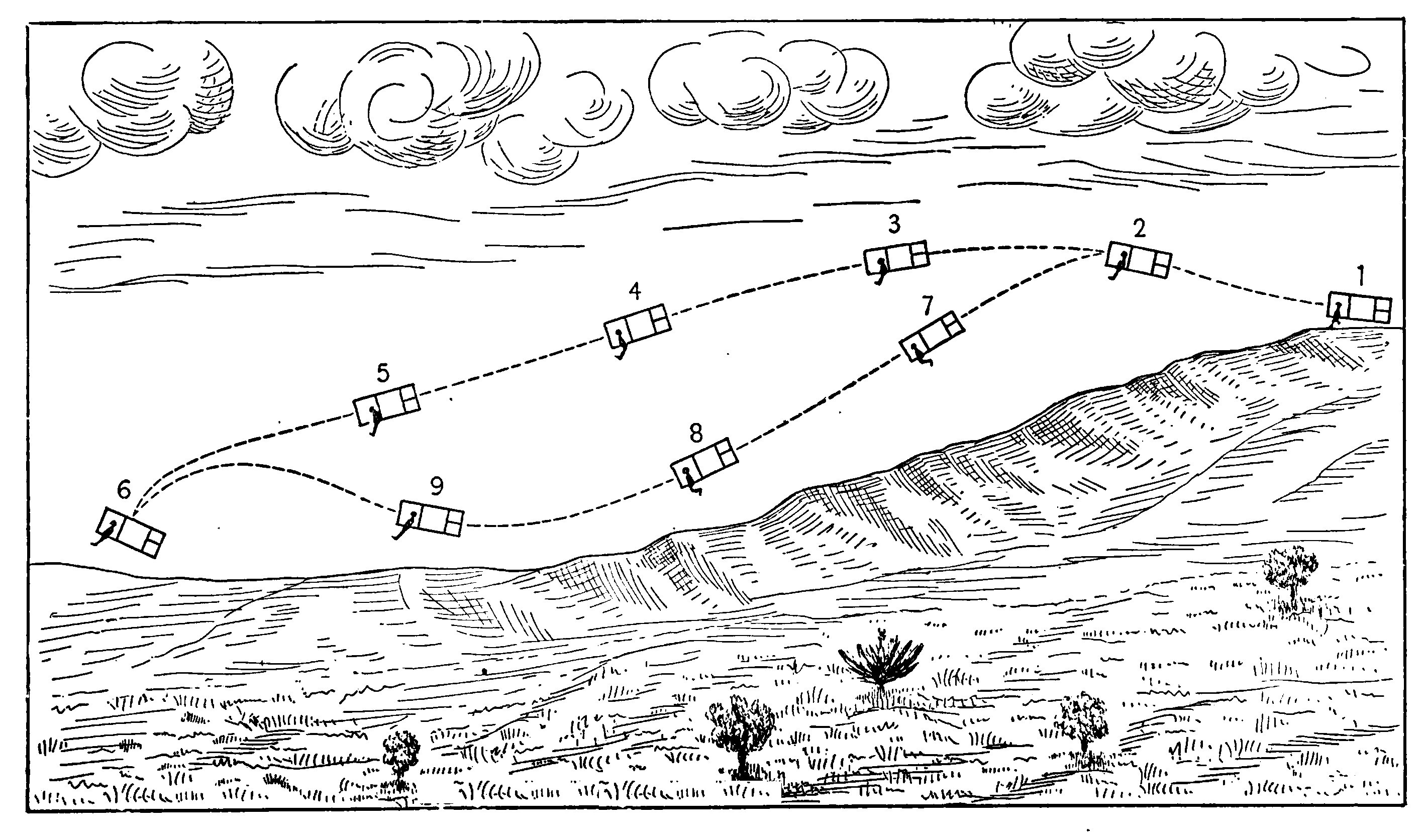
Fig. 29 illustrates two lines of flight in their successive stages. At 1 the operator is running along the top of the hill and the dotted line from 1 to 2 represents his course immediately after leaving the ground. In case the weight is back slightly too far and is not shifted much during the glide, the machine will follow the upper line indicated by 3, 4, 5 and land at 6. If instead, at 2, the body is moved forward, the machine will travel down as shown by 7 and approach the earth. Having attained considerable velocity at S, the operator moves back and the machine rises, travels upwards as at 9 and then settles about at the point 6. This latter line of flight is to be preferred since the machine does not rise quite so high in the air and moreover has more velocity so that the operator may rise if necessary.
If during a flight a gust of wind strikes the machine from the front, it will accelerate its vertical motion in regard to the earth. That is, if the machine is already rising it will rise higher and if descending will fall more quickly. A gust of wind from the rear will cause the machine to drop suddenly and so always glide into the wind.
CHAPTER V. Remarks.
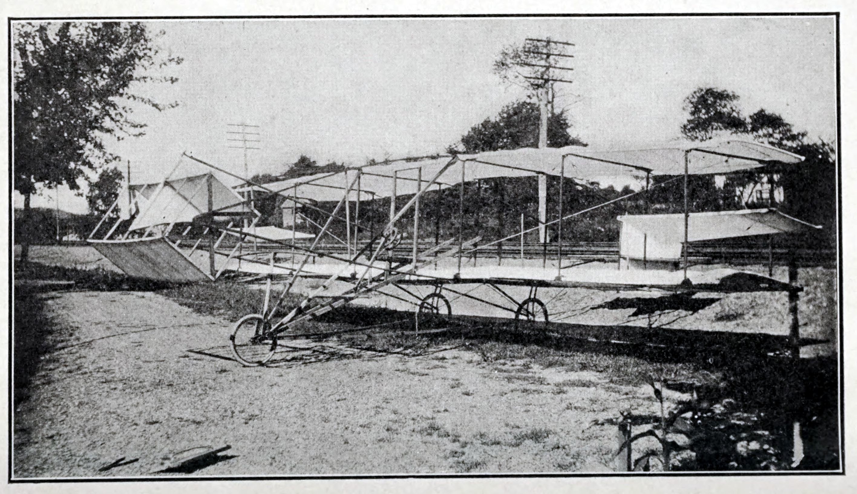
In a little booklet such as this it is even impossible to cover the subject of gliding flight fully much less power driven aeroplanes, but a short description of such a machine built by the author, assisted by Mr. Harold Dodd and Mr. Safford Adams will no doubt interest many since it has been used successfully as a glider in towed flights.
The machine was attached to an automobile by means of a long piano wire bridle. It rises at a speed of between 15 and 20 miles per hour and remains in the air as long as the auto keeps moving at this rate. The grounds used by the author in his experiments limited the flights to about 800 feet.
The automobile in one flight traveled about 50 miles per hour, but the machine soared on a perfectly even keel and without any pitching. Just as the author was about to descend, the towing wire broke, but the aeroplane glided so gently to the ground that it was impossible to tell where it first touched.
The following description of the machine is an extract from an article written by Mr. R. S. Brown.
"The two supporting surfaces of the aeroplane are five feet wide in the direction of flight and twenty six feet long. When the machine is moved rapidly forward, the action and reaction of the still air on the lower side of the moving surfaces, lifts the aeroplane from the ground and supports it in the air. The curvature of the planes is that segment of a parabola, whose depth is one ninth its length. They are spaced one vertically above the other and about four and one half feet apart in the middle. The ends converge slightly to make the machine less affected by cross gusts. The longitudinal curvature of the planes is maintained by spruce ribs half an inch square and spaced nine inches apart. Their front ends are ingeniously fastened in brass sockets on the front horizontal members and their rear ends project about a foot over the rear horizontal pieces. The fabric a close woven muslin is put on over the top and bottom of the ribs and is fastened by grommets to a wire running through the rear ends of the ribs, and by strips of felt fastened down to the ribs with upholsterer’s tacks.
"The stanchions are six feet apart except the middle two, which are only eighteen inches apart. The horizontal pieces of each surface are parallel and four feet distant from each other. All are of selected spruce, shaped so as to give the greatest strength with the least resistance to the air, and the least weight. All the many rectangles of the structure are braced diagonally with steel piano wire. In every one a small turnbuckle is inserted to adjust the length. The nuclei of these turnbuckles consists of bicycle spokes. By this wiring a perfectly rigid truss is formed.
"Ten feet to the rear of the main body, there is a horizontal tail, which halves a vertical rudder of about the same area. This vertical surface is movable and turns the aeroplane to the right and left when moved by rotation of the steering wheel. As can be seen in the accompanying illustration these rudders are strongly supported from the principal structure.
"At an equal distance in front of the supporting planes is the elevation rudder. This consists of two horizontal plane surfaces, six feet by two. These turn about a horizontal axis transverse to the direction of flight. Thus the angle which they present to the wind can be altered at the will of the operator. This is accomplished by pushing and pulling on the steering wheel. Through the middle of the horizontal surface runs a triangular vertical plane. This is designed to prevent the turning of the machine by a gust striking the rear vertical rudder, for if it strikes both vertical surfaces, one in front and one behind, the two neutralize each other and no turning takes place.
"On the ground the machine runs on three twenty-inch pneumatic tired wheels. These were especially made for the purpose, with seamless rims and heavy motorcycle spokes. Two are set in regular forks of tubing under the rear edge of the lower plane, while the third wheel is considerably in advance of the body proper. When running on the ground preparatory to rising, the machine is carried on these little wheels.
"The operators seat is in front of the supporting planes, and as the photograph shows is carried on two braces from the front wheel. Sitting in the seat, the aviator can direct the aeroplane from side to side by turning the steering wheel before him. This steering wheel is mounted on a post hinged at the bottom, and by pushing or pulling on the wheel the aviator is enabled to control his height above ground by means of the elevation rudder which is connected by a wooden rod to the steering post.
"Mid-way between the two main surfaces and at the front of each end is a small plane. These are tilted at positive and negative angles to the wind, by means of cords connecting them with a pivoted bar moved by the pilots feet. In flight, if one end rises, the aviator presses down the end of the bar on the rising side. This causes the 'balancing plane' on the high side, which is the name given to the movable planes just described, to form a negative angle with the wind so that the high side is forced down. The other balancing plane assumes an equal positive angle, so as to force up the lower side. Thus the machine is again brought to an even keel. After a little experience, this action becomes almost automatic, so that no difficulty is experienced in keeping the flyer level.
"The motor, which at present has not been installed, will be supported between the two main planes and connected to a laminated spruce propeller, six feet in diameter.”
Those who of until late have not been associated with aeronautics can scarcely realize the steps by which aviation had progressed and the trend towards building machines.
The aeroplane worker can no longer be classified with the seeker after perpetual motion. It is therefore to be lamented that so many of these machines partake of freak construction. Originality is always to be fostered but must bear some degree of proportion.
Only a very few favored people in comparison to the rest of civilization have been enabled to see an aeroplane in flight. Many times less are those who have had the privilege of examining a successful machine.
BOOKS FOR AVIATORS
THE BAROMETRICAL DETERMINATION OF HEIGHTS. A practical method of barometrical leveling and hypsometry. By F. J. B. CORDEIRO. With an appendix on the Air-Barometer. Full limp leather, $1.00.
TABLE OF BAROMETRICAL HEIGHTS TO 20,000 FEET. Computed by William H. Mackesy. The tables are mainly intended for use with the compensated mountain aneroid barometer but they are also suitable for the mountain mercurial barometer. A valuable little set of tables.
THE ATMOSPHERE ITS CHARACTERISTICS AND DYNAMICS. By F. J. B. CORDEIRO. In producing this work the author has endeavored to place before the public valuable data and information collected by him as to the origin of hurricanes, their causes and other atmospheric disturbances. In view of the fact that so much interest is now being taken in the navigation of the air every scrap of information that can be collected relative to atmospheric conditions will prove of considerable value to all those interested in this new science. The work is divided under the following headings:—Constitution. Temperature and density. Convective equilibrium. Various atmospheres. Aqueous vapor. Pressure of air. Practical barometry. Motion relative to the moving earth. Vertical motion. Horizontal motion. Frictionless motion over a rotating spheroid. Motion on the rotating earth without friction. General circulation of the atmosphere. Equatorial circulation. Polar Circulation. Middle circulation. Planetary circulation. Cyclones. Porto Rican hurricane of August 8, 1899. Horizontal velocity. Tornadoes. Other Phenomena occurring in the atmosphere. Sound. Merged explosions. Optical phenomena. The rainbow. Atmospheric conditions in relation to flying machines, etc. With numerous tables and 34 illustrations, 4to. Paper covers $1.50, full cloth, $2.50 net.
THE THEORY AND PRACTICE OF MODEL AEROPLANING. By V. E. Johnson, M.A. The object of this book is to give in plain language the general practice and principles of Model Aeroplaning. Model propellers and motors have been carefully dealt with, and much valuable data included from the author’s own experiments. Contents of Chapters.—Glossary of Terms used in Model Aeroplaning. Introduction. The Question of Weight. The Question of Resistance. The Question of Balance. Motive Power. Rubber Motors and other forms of Motors. Propellers or Screws. The Question of Sustention. The center of pressure. Materials for Aeroplane construction. Hints on the building of Model Aeroplanes. The Steering of the Model. The Launching of the Model. Helicopter Models. Experimental records. Model Flying competitions. Useful notes, tables, formulae, etc., etc. 163 pages, 82 illustrations, 12mo cloth, $1.50.
BOOKS ON AERONAUTICS.
RESISTANCE OF AIR AND THE QUESTION OF FLYING. By A. Samuelson. An important lecture of considerable interest to those interested in Aeronautics. Contents: Introduction. The Resistance of Plastic Bodies. Air-pressure on Flat Bodies. The Centre of Air-pressure. Distribution of the Air-pressure on the Single Elements of an Inclined Plane. The Normal Air-pressure on a Thin Plane Inclined at an Angle to the Direction of Motion. Lilienthal’s Balance of Rotation. The Numerical Value of the Normal Pressure. Flying in General. Flying in Reality. Horizontal Flight by Wing-Flapping. Steering and other Effects of the Stroke. Conclusions. 23 illustrations, 8vo., paper. 75c.
FLIGHT-VELOCITY. By A. Samuelson. This work is a short comprehension of extensive scientific investigation and experimental work. Contents: The Rowing Flyer No. 5. The Motor Mechanism. The Fundamental Conditions of Flying by Wing Flapping. The Wings. The Re-sail. Flight Velocity. Living Flyers. Plane or Concave Supporting Surfaces. The False Resolution of Forces. The Erroneous Opinion: the Breadth of an Incline Plane Prevails over its Length. The Centre of Air-pressure, and the Distribution of the Pressure. On the Single Parts of an Inclined Plane. The Principle: the Normal Air-pressure of an Inclined Plane is independent of the Angle of Inclination. Tables of Motion at Varying Angles. The Human Flight. Conclusions. With five plates, 8vo., paper. 75c.
FLYING MACHINES. Past, Present and Future. A popular account of flying machines, dirigible balloons. By A. W. Marshall and H. Greenly. Whilst the matter in this book is intended as a popular exhibition of the subject, it includes information which will assist the reader with serious intentions of making an attempt to produce a flying machine or air-ship. A great deal of sound experimental work has been done, forming a basis upon which future plans can be calculated. An account of some of this work is here given. Contents of Chapters: 1. Introduction. Dr. Barton’s Air-ship. Lebaudy’s Military Air-ship. The Deutsch Air-ship. The Wellman Air-ship. Motors of the Wellman Air-ship. Chapter 2. Dirigible Balloons. Giffard’s. Dupuy de Lome. Tissandiers’. Krebes’. Santos Dumont’s, No. 6 and No. 9. Spencer’s Air-ship. Barton’s. Maxim’s Flying Machine. Archdeacon’s Air Propeller Cycle. Barton’s, Rawson’s, Baulx, Zeppelin, Deutsch, Lambert, Wellman’s Air-ships. Trolanini’s Air-propelled Boat. Chapter 3. Flying Machines. Giving a Number of those made by Hargrave and also by Phillips, Ader, Maxim, Pilsher’s Soaring Wings, Langley, Bastine, Bleirot, Voison, Wright’s Gliding Aeroplane, and numerous others. Chapter 4. The Art of Flying. Chapter 5. Flying Machines of the Future. 134 pages, illustrations and page plates, 12mo. 50c.
MODEL AEROPLANES.
MODEL FLYING MACHINES, THEIR DESIGN AND CONSTRUCTION. By W. G. Aston. Contents of chapters:—1. General principles and their application. 2. Power. 3. Supporting surfaces. 4. Screws, and how to make them. 5. Tails and elevators. 6. Fins. 7. Designs. With a number of examples of monoplane, bi-plane, tandem bi-plane and tri-plane models. 8. Dirigibles. 9. Helicopters. 10. Ornithopters. 11. Winding apparatus. 12. Compressed air motor. A first-rate book for Model Makers, 125 pages, 95 illustrations, 12mo. boards, postpaid, for 55c.
MODEL GLIDERS, BIRDS, BUTTERFLIES AND AEROPLANES. How to Make and Fly Them. A booklet with one large sheet containing twelve butterflies and two birds in colors and material for making a small card-board Model Aeroplane Glider. Complete in folder, postpaid, for 55c.
MODEL AEROPLANES, HOW TO BUILD AND FLY THEM. By E. W. Twining. Consisting of one booklet and five large scaled drawings for three Twining Models, two of them being of the Bi-plane Glider type. Complete in folder, postpaid, for 55c.
TWINING’S MODEL NO. 2. A complete set of the materials in the rough, including the rubber of a Bi-plane Model without the drawings, postpaid, for 65c.
TWINING'S MODEL NO. 3. A complete set of materials in the rough with rubber for the construction of this handsome Model Bi-plane without the drawings, postpaid, for $1.15.
THE AEROPLANE PORTFOLIO. By D. Ross Kennedy. Containing nine sheets of scale drawings of the following celebrated Aeroplanes: Bi-plane type—Wright, Farman, Voisin, Cody, Herring-Curtis. Monoplanes—Rep. Antoinette, Santos Dumont, and Bleriot. Each of these machines are here shown in End View, Plan and Elevation. Including booklet which contains a description of each machine. This timely set of drawings should prove of value to everyone interested in this important new industry. The complete set in folder, postpaid, for 55c.
THE PERCY PIERCE FLYER. A large scale drawing of this prize-winning Monoplane. With all measurements and details showing a front elevation, a side elevation and a top elevation; with 8-page descriptive booklet of particulars postpaid, 15c.
PERCY PIERCE DRAWING, with booklet and complete set of materials in the rough from which any one can make an exact duplicate of this dandy Model complete, postpaid, for $1.15.
A THREE-FOOT MODEL AEROPLANE. Bleriot Type. By G. E. Alexander. A large scale drawing with measurements and descriptive matter showing the construction of a splendid Model Flying Machine. The Model from which this drawing is taken has proved a very successful flyer, postpaid for 15c.
GOOD BOOKS FOR WIRELESS OPERATORS.
PART I. PLANS AND SPECIFICATIONS FOR WIRELESS TELEGRAPH SETS, Complete and Detailed Instruction for Making an Experimental Set, also a One to Five Mile Set, 55 pages, 37 illustrations; price 25c.
Part 2. PLANS AND SPECIFICATIONS FOR WIRELESS TELEGRAPH SETS. By A. Frederick Collins. Will contain complete and detailed data for constructing a Five to Ten Mile Set, also a Ten to Twenty-five Mile Set, with about 60 illustrations, and 90 pages. Price, 25c.
Parts three and four in preparation.
MAKING WIRELESS OUTFITS. By Newton Harrison. A concise and simple explanation on the construction and use of simple and inexpensive wireless equipments, for sending and receiving, giving full details and drawings of apparatus, diagrams of circuits and tables. Including the Morse and Continental Codes. 61 pages, 27 illustrations. Price, 25c.; cloth, 50c.
WIRELESS TELEPHONE CONSTRUCTION. By Newton Harrison. A comprehensive explanation of the making of a Wireless Telephone Equipment. Both the transmitting and receiving stations fully explained with details of construction sufficient to give an intelligent reader a good start in building a Wireless Telephone system and in operating it. 74 pages and 43 illustrations. Price, 25c.
TELEGRAPHY FOR BEGINNERS. The Standard Method. An authoritative book of instruction in the methods and forms most approved, with a series of lessons. By Willis H. Jones. With the Morse alphabet and the Continental code. 64 pages, 19 illustrations, paper binding, 25c.; cloth binding, 50c.
INDUCTION COILS. How to Make and Use Them. By P. Marshall. A practical handbook on the construction and use of sparking coils for wireless telegraphy. With tables of windings for coils giving 1/4 in. spark up to 12 in. sparks. With full description for the construction of mercury interrupters. 76 pages, 35 illustrations. Price, 25c.; cloth binding, 50c.
Full descriptive circular of The Model Library Series of practical Handbooks FREE.
*** END OF THIS PROJECT GUTENBERG EBOOK HOW TO BUILD A 20-FOOT BI-PLANE GLIDER ***
The Full Project Gutenberg License
Please read this before you distribute or use this work.
To protect the Project Gutenberg™ mission of promoting the free distribution of electronic works, by using or distributing this work (or any other work associated in any way with the phrase “Project Gutenberg”), you agree to comply with all the terms of the Full Project Gutenberg™ License available with this file or online at https://www.gutenberg.org/license.
Section 1. General Terms of Use & Redistributing Project Gutenberg™ electronic works
1.A. By reading or using any part of this Project Gutenberg™ electronic work, you indicate that you have read, understand, agree to and accept all the terms of this license and intellectual property (trademark/copyright) agreement. If you do not agree to abide by all the terms of this agreement, you must cease using and return or destroy all copies of Project Gutenberg™ electronic works in your possession. If you paid a fee for obtaining a copy of or access to a Project Gutenberg™ electronic work and you do not agree to be bound by the terms of this agreement, you may obtain a refund from the person or entity to whom you paid the fee as set forth in paragraph 1.E.8.
1.B. “Project Gutenberg” is a registered trademark. It may only be used on or associated in any way with an electronic work by people who agree to be bound by the terms of this agreement. There are a few things that you can do with most Project Gutenberg™ electronic works even without complying with the full terms of this agreement. See paragraph 1.C below. There are a lot of things you can do with Project Gutenberg™ electronic works if you follow the terms of this agreement and help preserve free future access to Project Gutenberg™ electronic works. See paragraph 1.E below.
1.C. The Project Gutenberg Literary Archive Foundation (“the Foundation” or PGLAF), owns a compilation copyright in the collection of Project Gutenberg™ electronic works. Nearly all the individual works in the collection are in the public domain in the United States. If an individual work is unprotected by copyright law in the United States and you are located in the United States, we do not claim a right to prevent you from copying, distributing, performing, displaying or creating derivative works based on the work as long as all references to Project Gutenberg are removed. Of course, we hope that you will support the Project Gutenberg™ mission of promoting free access to electronic works by freely sharing Project Gutenberg™ works in compliance with the terms of this agreement for keeping the Project Gutenberg™ name associated with the work. You can easily comply with the terms of this agreement by keeping this work in the same format with its attached full Project Gutenberg™ License when you share it without charge with others.
1.D. The copyright laws of the place where you are located also govern what you can do with this work. Copyright laws in most countries are in a constant state of change. If you are outside the United States, check the laws of your country in addition to the terms of this agreement before downloading, copying, displaying, performing, distributing or creating derivative works based on this work or any other Project Gutenberg™ work. The Foundation makes no representations concerning the copyright status of any work in any country outside the United States.
1.E. Unless you have removed all references to Project Gutenberg:
1.E.1. The following sentence, with active links to, or other immediate access to, the full Project Gutenberg™ License must appear prominently whenever any copy of a Project Gutenberg™ work (any work on which the phrase “Project Gutenberg” appears, or with which the phrase “Project Gutenberg” is associated) is accessed, displayed, performed, viewed, copied or distributed:
This eBook is for the use of anyone anywhere in the United States and most other parts of the world at no cost and with almost no restrictions whatsoever. You may copy it, give it away or re-use it under the terms of the Project Gutenberg License included with this eBook or online at https://www.gutenberg.org . If you are not located in the United States, you'll have to check the laws of the country where you are located before using this ebook.
1.E.2. If an individual Project Gutenberg™ electronic work is derived from texts not protected by U.S. copyright law (does not contain a notice indicating that it is posted with permission of the copyright holder), the work can be copied and distributed to anyone in the United States without paying any fees or charges. If you are redistributing or providing access to a work with the phrase “Project Gutenberg” associated with or appearing on the work, you must comply either with the requirements of paragraphs 1.E.1 through 1.E.7 or obtain permission for the use of the work and the Project Gutenberg™ trademark as set forth in paragraphs 1.E.8 or 1.E.9.
1.E.3. If an individual Project Gutenberg™ electronic work is posted with the permission of the copyright holder, your use and distribution must comply with both paragraphs 1.E.1 through 1.E.7 and any additional terms imposed by the copyright holder. Additional terms will be linked to the Project Gutenberg™ License for all works posted with the permission of the copyright holder found at the beginning of this work.
1.E.4. Do not unlink or detach or remove the full Project Gutenberg™ License terms from this work, or any files containing a part of this work or any other work associated with Project Gutenberg™.
1.E.5. Do not copy, display, perform, distribute or redistribute this electronic work, or any part of this electronic work, without prominently displaying the sentence set forth in paragraph 1.E.1 with active links or immediate access to the full terms of the Project Gutenberg™ License.
1.E.6. You may convert to and distribute this work in any binary, compressed, marked up, nonproprietary or proprietary form, including any word processing or hypertext form. However, if you provide access to or distribute copies of a Project Gutenberg™ work in a format other than “Plain Vanilla ASCII” or other format used in the official version posted on the official Project Gutenberg™ web site (https://www.gutenberg.org), you must, at no additional cost, fee or expense to the user, provide a copy, a means of exporting a copy, or a means of obtaining a copy upon request, of the work in its original “Plain Vanilla ASCII” or other form. Any alternate format must include the full Project Gutenberg™ License as specified in paragraph 1.E.1.
1.E.7. Do not charge a fee for access to, viewing, displaying, performing, copying or distributing any Project Gutenberg™ works unless you comply with paragraph 1.E.8 or 1.E.9.
1.E.8. You may charge a reasonable fee for copies of or providing access to or distributing Project Gutenberg™ electronic works provided that
You pay a royalty fee of 20% of the gross profits you derive from the use of Project Gutenberg™ works calculated using the method you already use to calculate your applicable taxes. The fee is owed to the owner of the Project Gutenberg™ trademark, but he has agreed to donate royalties under this paragraph to the Project Gutenberg Literary Archive Foundation. Royalty payments must be paid within 60 days following each date on which you prepare (or are legally required to prepare) your periodic tax returns. Royalty payments should be clearly marked as such and sent to the Project Gutenberg Literary Archive Foundation at the address specified in Section 4, “Information about donations to the Project Gutenberg Literary Archive Foundation.”
You provide a full refund of any money paid by a user who notifies you in writing (or by e-mail) within 30 days of receipt that s/he does not agree to the terms of the full Project Gutenberg™ License. You must require such a user to return or destroy all copies of the works possessed in a physical medium and discontinue all use of and all access to other copies of Project Gutenberg™ works.
You provide, in accordance with paragraph 1.F.3, a full refund of any money paid for a work or a replacement copy, if a defect in the electronic work is discovered and reported to you within 90 days of receipt of the work.
You comply with all other terms of this agreement for free distribution of Project Gutenberg™ works.
1.E.9. If you wish to charge a fee or distribute a Project Gutenberg™ electronic work or group of works on different terms than are set forth in this agreement, you must obtain permission in writing from both the Project Gutenberg Literary Archive Foundation and The Project Gutenberg Trademark LLC, the owner of the Project Gutenberg™ trademark. Contact the Foundation as set forth in Section 3. below.
1.F.
1.F.1. Project Gutenberg volunteers and employees expend considerable effort to identify, do copyright research on, transcribe and proofread works not protected by U.S. copyright law in creating the Project Gutenberg™ collection. Despite these efforts, Project Gutenberg™ electronic works, and the medium on which they may be stored, may contain “Defects,” such as, but not limited to, incomplete, inaccurate or corrupt data, transcription errors, a copyright or other intellectual property infringement, a defective or damaged disk or other medium, a computer virus, or computer codes that damage or cannot be read by your equipment.
1.F.2. LIMITED WARRANTY, DISCLAIMER OF DAMAGES – Except for the “Right of Replacement or Refund” described in paragraph 1.F.3, the Project Gutenberg Literary Archive Foundation, the owner of the Project Gutenberg™ trademark, and any other party distributing a Project Gutenberg™ electronic work under this agreement, disclaim all liability to you for damages, costs and expenses, including legal fees. YOU AGREE THAT YOU HAVE NO REMEDIES FOR NEGLIGENCE, STRICT LIABILITY, BREACH OF WARRANTY OR BREACH OF CONTRACT EXCEPT THOSE PROVIDED IN PARAGRAPH 1.F.3. YOU AGREE THAT THE FOUNDATION, THE TRADEMARK OWNER, AND ANY DISTRIBUTOR UNDER THIS AGREEMENT WILL NOT BE LIABLE TO YOU FOR ACTUAL, DIRECT, INDIRECT, CONSEQUENTIAL, PUNITIVE OR INCIDENTAL DAMAGES EVEN IF YOU GIVE NOTICE OF THE POSSIBILITY OF SUCH DAMAGE.
1.F.3. LIMITED RIGHT OF REPLACEMENT OR REFUND – If you discover a defect in this electronic work within 90 days of receiving it, you can receive a refund of the money (if any) you paid for it by sending a written explanation to the person you received the work from. If you received the work on a physical medium, you must return the medium with your written explanation. The person or entity that provided you with the defective work may elect to provide a replacement copy in lieu of a refund. If you received the work electronically, the person or entity providing it to you may choose to give you a second opportunity to receive the work electronically in lieu of a refund. If the second copy is also defective, you may demand a refund in writing without further opportunities to fix the problem.
1.F.4. Except for the limited right of replacement or refund set forth in paragraph 1.F.3, this work is provided to you ‘AS-IS,’ WITH NO OTHER WARRANTIES OF ANY KIND, EXPRESS OR IMPLIED, INCLUDING BUT NOT LIMITED TO WARRANTIES OF MERCHANTABILITY OR FITNESS FOR ANY PURPOSE.
1.F.5. Some states do not allow disclaimers of certain implied warranties or the exclusion or limitation of certain types of damages. If any disclaimer or limitation set forth in this agreement violates the law of the state applicable to this agreement, the agreement shall be interpreted to make the maximum disclaimer or limitation permitted by the applicable state law. The invalidity or unenforceability of any provision of this agreement shall not void the remaining provisions.
1.F.6. INDEMNITY – You agree to indemnify and hold the Foundation, the trademark owner, any agent or employee of the Foundation, anyone providing copies of Project Gutenberg™ electronic works in accordance with this agreement, and any volunteers associated with the production, promotion and distribution of Project Gutenberg™ electronic works, harmless from all liability, costs and expenses, including legal fees, that arise directly or indirectly from any of the following which you do or cause to occur: (a) distribution of this or any Project Gutenberg™ work, (b) alteration, modification, or additions or deletions to any Project Gutenberg™ work, and (c) any Defect you cause.
Section 2. Information about the Mission of Project Gutenberg™
Project Gutenberg™ is synonymous with the free distribution of electronic works in formats readable by the widest variety of computers including obsolete, old, middle-aged and new computers. It exists because of the efforts of hundreds of volunteers and donations from people in all walks of life.
Volunteers and financial support to provide volunteers with the assistance they need, is critical to reaching Project Gutenberg™'s goals and ensuring that the Project Gutenberg™ collection will remain freely available for generations to come. In 2001, the Project Gutenberg Literary Archive Foundation was created to provide a secure and permanent future for Project Gutenberg™ and future generations. To learn more about the Project Gutenberg Literary Archive Foundation and how your efforts and donations can help, see Sections 3 and 4 and the Foundation web page at http://www.pglaf.org .
Section 3. Information about the Project Gutenberg Literary Archive Foundation
The Project Gutenberg Literary Archive Foundation is a non profit 501(c)(3) educational corporation organized under the laws of the state of Mississippi and granted tax exempt status by the Internal Revenue Service. The Foundation's EIN or federal tax identification number is 64-6221541. Its 501(c)(3) letter is posted at https://www.gutenberg.org/fundraising/pglaf . Contributions to the Project Gutenberg Literary Archive Foundation are tax deductible to the full extent permitted by U.S. federal laws and your state's laws.
The Foundation's principal office is in Fairbanks, Alaska, with the mailing address: PO Box 750175, Fairbanks, AK 99775, but its volunteers and employees are scattered throughout numerous locations. Its business office is located at 809 North 1500 West, Salt Lake City, UT 84116, (801) 596-1887, email business@pglaf.org. Email contact links and up to date contact information can be found at the Foundation's web site and official page at http://www.pglaf.org
For additional contact information:
Section 4. Information about Donations to the Project Gutenberg Literary Archive Foundation
Project Gutenberg™ depends upon and cannot survive without wide spread public support and donations to carry out its mission of increasing the number of public domain and licensed works that can be freely distributed in machine readable form accessible by the widest array of equipment including outdated equipment. Many small donations ($1 to $5,000) are particularly important to maintaining tax exempt status with the IRS.
The Foundation is committed to complying with the laws regulating charities and charitable donations in all 50 states of the United States. Compliance requirements are not uniform and it takes a considerable effort, much paperwork and many fees to meet and keep up with these requirements. We do not solicit donations in locations where we have not received written confirmation of compliance. To SEND DONATIONS or determine the status of compliance for any particular state visit https://www.gutenberg.org/fundraising/donate
While we cannot and do not solicit contributions from states where we have not met the solicitation requirements, we know of no prohibition against accepting unsolicited donations from donors in such states who approach us with offers to donate.
International donations are gratefully accepted, but we cannot make any statements concerning tax treatment of donations received from outside the United States. U.S. laws alone swamp our small staff.
Please check the Project Gutenberg Web pages for current donation methods and addresses. Donations are accepted in a number of other ways including checks, online payments and credit card donations. To donate, please visit: https://www.gutenberg.org/fundraising/donate
Section 5. General Information About Project Gutenberg™ electronic works.
Professor Michael S. Hart is the originator of the Project Gutenberg™ concept of a library of electronic works that could be freely shared with anyone. For thirty years, he produced and distributed Project Gutenberg™ eBooks with only a loose network of volunteer support.
Project Gutenberg™ eBooks are often created from several printed editions, all of which are confirmed as not protected by copyright in the U.S. unless a copyright notice is included. Thus, we do not necessarily keep eBooks in compliance with any particular paper edition.
Each eBook is in a subdirectory of the same number as the eBook's eBook number, often in several formats including plain vanilla ASCII, compressed (zipped), HTML and others.
Corrected editions of our eBooks replace the old file and take over the old filename and etext number. The replaced older file is renamed. Versions based on separate sources are treated as new eBooks receiving new filenames and etext numbers.
Most people start at our Web site which has the main PG search facility:
This Web site includes information about Project Gutenberg™, including how to make donations to the Project Gutenberg Literary Archive Foundation, how to help produce our new eBooks, and how to subscribe to our email newsletter to hear about new eBooks.