Building And Flying An Aeroplane
This ebook is for the use of anyone anywhere in the United States and most other parts of the world at no cost and with almost no restrictions whatsoever. You may copy it, give it away or re-use it under the terms of the Project Gutenberg License included with this ebook or online at https://www.gutenberg.org/license. If you are not located in the United States, you'll have to check the laws of the country where you are located before using this ebook.
Title: Building And Flying An Aeroplane
Author: Charles B. Hayward
Release Date: August 18, 2020 [EBook #62973]
Language: English
Character set encoding: UTF-8
*** START OF THIS PROJECT GUTENBERG EBOOK BUILDING AND FLYING AN AEROPLANE ***
Produced by James Simmons.
This file was produced from page images at the Internet Archive.
Transcriber's Note
This book was transcribed from scans of the original found at the Internet Archive and at Google Books. I have rotated some images. Tables are treated as images. There are two versions of this book: the first contains both parts and the second is published as two volumes with Examination Papers at the end of each, which the student would return to the American School of Correspondence for credit. I have included these Examination Papers at the end of each part.
This Photograph Protected By International Copyright
BUILDING AND FLYING
AN AEROPLANE
A PRACTICAL HANDBOOK COVERING THE DESIGN,
CONSTRUCTION, AND OPERATION OF
AEROPLANES AND GLIDERS
By
CHARLES B. HAYWARD
MEMBER, THE AERONAUTICAL SOCIETY; MEMBER, SOCIETY OF AUTOMOBILE
ENGINEERS; FORMERLY SECRETARY, SOCIETY OF AUTOMOBILE ENGINEERS;
FORMERLY ENGINEERING EDITOR, THE AUTOMOBILE
ILLUSTRATED
CHICAGO
AMERICAN SCHOOL OF CORRESPONDENCE
1912
Copyright 1912 by
American School of Correspondence
Entered at Stationers' Hall, London
All Rights Reserved
BUILDING AND FLYING AN AEROPLANE
INTRODUCTION
The field of aviation has, from the inception of successful flight by the Wright Brothers, had a wonderful fascination for the amateur mechanic. At first the strong element of mystery in the movements of this monster man-ridden bird appalled him, but an examination of approved designs has removed the mystery and has assured him that he can, with his own hands and at a cost well within his reach, build his own machine in his own back yard.
But in this ease of accomplishment lies a danger, namely, the belittling of the value of accurate design and the misjudging of the true importance of small things. The inventive mind usually believes itself capable of making improvements in almost anything, and the aeroplane inventor is no exception to the rule. Filled with the confidence born of ignorance, and with only the knowledge he has gleaned from newspaper and magazine accounts of the popular types of machines, he works out a brand new design. The usual, in fact, the invariable result is failure, discouragement, and a loss of time and money. How much more sensible for the young inventor to build his first machine without varying in one particular from a tried and proved model, leaving his flights of inventive fancy to his later years of maturer knowledge and judgment.
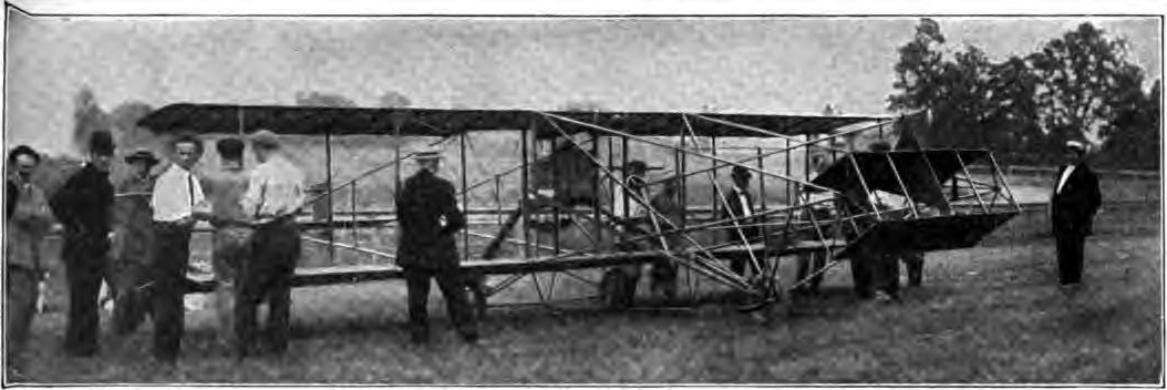
The author of this little book has followed, in both biplane and monoplane models, the well-known types of Curtiss and Bleriot, choosing each as the simplest representative of its class in construction and design. It is hoped that the book may not only be of assistance to the amateur builder, but may also be the means of turning the too confident inventor into safer and more established paths.
PART 1
One of the commonest phases of interest in aviation is the desire to build a flying machine. In fact, this is very frequently the first thing the experimenter undertakes after having gone into the theory of flight to some extent. Only too often, no effort whatever is made to get beyond theory and the machine is an experiment in every sense of the word. An experience of this nature is costly—far more so than is agreeable for the student, and is likely to result in disgusting him with aviation generally. There are hundreds of schemes and principles in the art that have been tried again and again with the same dismal failure in the end. Refer to the story of the Wright Brothers and note how many things they mention having tried and rejected as worse than useless. About once in so often someone "rediscovers" some of these things and, having no facilities for properly investigating what patent attorneys term the "prior art" (everything that has gone before, from the beginning of invention, or at least patented invention) becomes possessed of the idea that he has hit upon something entirely novel and wholly original. There is no desire in the present work to discourage the seeker after new principles—undoubtedly there are many yet to be discovered. The art of flight is in its infancy and there is still a great deal to be learned about it, but there is no more discouraged inventor than he who-discovers a principle and, after having experimented with it at great expense, finds that it is only one of many things that numerous others have spent considerable money in proving fallacious, a great many years ago.
If it be your ambition to build a flying machine and you believe that you have discovered something new of value, it will be to your interest to retain a responsible patent attorney to advise you as to the prior art, before expending any money on its construction. You will find it very much more economical in the end. There are probably not more than half a dozen men alive in this country today who "know all the schemes that won't work." The average seeker after knowledge is assuredly not likely to be one of these few, so that until he knows he is working along new and untried lines that give promise of success, it will pay him to stick to those that have proved successful in actual practice. In other words, to confine his efforts in the building line to a machine that experience has demonstrated will fly if properly constructed and, what is of equal importance, skilfully handled. Build a machine, by all means, if you have the opportunity. It represents the best possible experience. But as is pointed out under the "Art of Flying," take a few lessons from some one who knows how to fly, before risking your neck in what is to you a totally untried element. Even properly designed and constructed machines are not always ready to fly. An aeroplane needs careful inspection of every part and adjustment before it is safe to take to the air in it, and to be of any value this looking-over must be carried out by an experienced eye.
BUILDING AEROPLANE MODELS
The student may enter upon the business of building to any extent that his inclination or his financial resources or his desire to experiment may lead him. The simplest stage, of course, is that of model building and there is a great deal to be learned from the construction and flying of experimental models. This has become quite a popular pastime in the public schools and some very creditable examples of work have been turned out. The apparent limitations of these rubber-band driven models need not discourage the student, as some of the school-boy builders have succeeded in constructing models capable of flying a quarter mile in still air and their action in the air is wonderfully like the full-sized machines.
Models with Rubber-Band Motor. The limitations of the available power at command must be borne in mind, as the rubber-band motor is at best but a poor power plant. It is accordingly not good practice to have the spread of the main planes exceed 24 inches, though larger successful models have been built. In attempting to reproduce any of the well-known models, difficulty is often experienced in accommodating the rubber-band motor to them, as even where the necessary space is available, its weight throws the balance out entirely, and the result is a model that will not fly. This has led to the production of many original creations, but these, while excellent flyers, would not serve as models for larger machines, as of necessity they have been designed around their power plants. The rubber bands for this purpose may be purchased of any aeronautic supply house. The most practical method of mounting the motor is to attach it to the rear end of the fuselage, usually a single stick, which is accordingly made extra long for that purpose. At the other end it is attached to a bent wire fastened to the propeller in order to revolve the latter. An easy way to wand up the motor is to employ an ordinary egg beater, modified as described below, or a hand drill, inserting a small wire yoke in the jaws in place of the usual drill, or bit. This yoke is placed so as to engage the propeller blades, and the latter is then turned in the opposite direction, storing energy in the rubber band by twisting its strands tightly.
For those students who do not care to undertake an original design at the outset, or who would prefer to have the experience gained by building from a plan that has already been tried, before attempting to originate, the following description of a successful model is given. This model can not only be made for less than the models sold at three to five dollars, but is a much more efficient flyer, having frequently flown 700 feet.
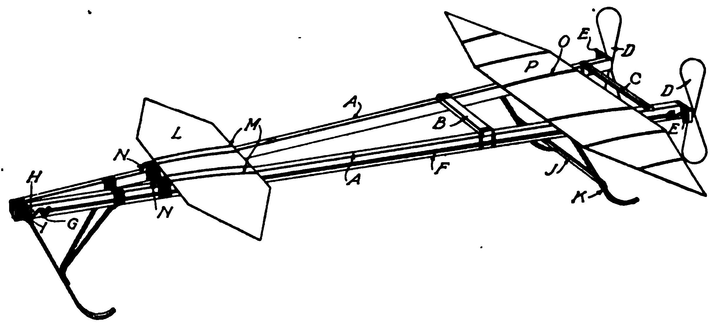
Main Frame. The main frame of the model monoplane consists of two strips A of spruce, each 28 inches long, and measuring in cross section 1/4 by 3/8 of an inch. As shown in Fig. 1, the two strips are tied together at the front with strong thread and are then glued, the glue being spread over and between the windings of the thread, Figs. 1 and 2. The rear ends of these strips are spread apart 4 1/4 inches to form a stout triangular frame, and are tied together by cross bars of bamboo B and C which are secured to the main strips A by strong thread and glue.
Propellers. The propellers D are two in number and are carried by the two long strips A. Each propeller is 5 inches in diameter, and is whittled out of a single block of white pine. The propellers have a pitch of about 10 inches. After the whittling is done they are sandpapered and coated with varnish. The thickness of the wood at the hub E₂, Fig. 3, of the propeller should be about 5/8 inch. At the rear ends of the strips A, bearing blocks E₁ are secured. These bearing blocks are simply small pieces of wood projecting about 5/8 inch laterally from the strips A. They are drilled to receive a small metal tube T₂ (steel, brass, or copper), through which tube the propeller shaft T₁ passes.
The propeller shaft itself consists of a piece of steel wire passing through the propeller hub and bent over the wood, so that it can not turn independently of the propeller. Any other expedient for causing the propeller to turn with the shaft may obviously be employed. Small metal washers T₃, at least three in number, are slipped over the propeller shaft so as to lie between the propeller and the bearing block.
That portion of the propeller shaft which projects forwardly through the bearing block E₁ is bent to form a hook T₄. To the hook T₁ rubber strips T₂ by which the propellers are driven, are secured. The rubber strips are nearly as long as the main strips A. At their forward ends they are secured to a fastening consisting of a double hook G H, the hook G lying in a horizontal plane, the hook H in a vertical plane. The hook holds the rubber strips, as shown in Figs. 1 and 4, while the hook H engages a hook T. This hook is easily made by passing a strip of steel wire through the meeting ends of the main strips A, the portions projecting from each side of the strips being bent into the hooks I.
Skids. Three skids are provided, on which the model slides, one at the forward end, and two near the rear end. All are made of bamboo. As shown in Fig. 2 the front skid may be of any length that seems desirable. A 6-inch piece of bamboo will probably answer most requirements. This piece N is bent in opposite directions at the ends to form arms Z and U, The arm Z is secured to the forward ends of the two strips A, constituting the main frame, by means of thread and glue. The strips and skid are not held together by the same thread, but the skid is attached to the two strips after they have been wound. Hence, there are two sets of windings of thread, one for the two strips A themselves, and another for the skid and the strips. Strong thread and glue should be used, as before. In order to stiffen the skid, two bamboo struts W will be found necessary. These are bent over at the ends to form arms V₁, Fig. 2. Each of the arms is secured to the under side of a strip A by strong thread and glue. The arms X are superimposed and tied to the bamboo skid V with strong thread and glue.
The two rear skids, of which one is shown in Fig. 5, consist each of two 5-inch strips of bamboo S, likewise bent at either end in opposite directions to form arms S₂ and S₃, The arms S₂ are fastened to the strips A by strong thread and glue. To stiffen the skids a strut C₁ is provided for each skid. Each strut consists of a 3-inch strip of bamboo bent over so as to form arms C₂. Strong thread and glue are employed to fasten each strut in position on the strip and the skid. In the crotch of the triangular space B₁, a tie bar J, Figs. 4 and 5, is secured by means of thread and glue. This tie bar connects the two skids, as shown in Figs. 1 and 4, and serves to stiffen them. The triangular space B₁ is covered with paper, preferably bamboo paper. If bamboo paper is not available, parchment or stiff light paper of some kind may be used. It does not need to be waterproof. Thus triangular fins are formed which act as stabilizing surfaces.
Main Planes. The main planes are two in number, but are different in size. Contrary to the practice followed in large man-carrying monoplanes, the front supporting surface is comparatively small in area and the rear supporting surface comparatively large. These supporting surfaces L and P are shown in detail in Figs. 6 and 7. It has been found that a surface of considerable area is required at the rear of the machine to support it, hence, the discrepancy in size. Although the two supporting surfaces differ in size, they are made in exactly the same manner, each consisting of a thin longitudinal piece of spruce R, to which cross pieces of bamboo Q are attached. In the smaller plane, Fig. 7, all the cross pieces are of the same size. In the larger plane, Fig. 6, the outer strips S are somewhat shorter than the others. Their length is 2 1/2 inches, whereas the length of the strips Q is 3 1/2 inches. In order to allow for the more gradual tapering of the plane, around the outer ends of the longitudinal strips R and the ribs Q a strip of bamboo is tied. The frame, composed of the longitudinal strip and cross strips, is then covered with bamboo paper, parchment paper, or any other style light paper, which is glued in place.
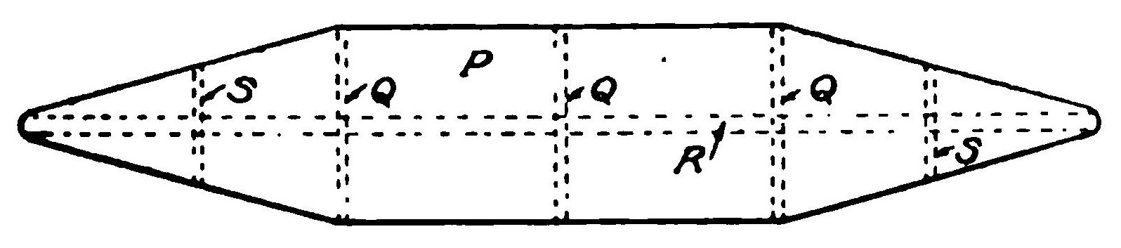
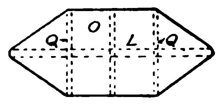
The forward or smaller plane has a spread of 8 1/2 inches and a depth of 3 1/4 inches. The main plane has a spread of 20 inches and a depth of 3 1/2 inches at the widest portion. The author has made experiments which lead him to believe that the tapering form given to the outer edge of the plane improves both the stability and endurance of the machine.
The planes are slightly arched, although it will be found that flat planes will also give good results. The rear edge of the main plane should be placed 4 1/4 inches distant from the forward edge of the propeller block E₁.
The front plane must have a slight angle of incidence, just how much depends upon the weight of the machine, the manner in which it is made, and various other factors. This angle of incidence is obtained by resting the front portion of the plane on two small blocks N, Figs. 1 and 2, which are fastened to the top of the main strip A by strong thread and glue.
The height of the blocks N should be about 1/4 inch, although this will necessarily vary with the machine. The blocks should be placed approximately 4 inches from the forward end of the machine. The front end of the forward plane should be elevated about 1/4 inch above the rear end, which rests directly on the main strips.
Both the front and rear planes L and P are removably lashed to the frame by means of ordinary rubber bands, which may be obtained at any stationery store. These rubber bands are lettered M in Fig. 1.
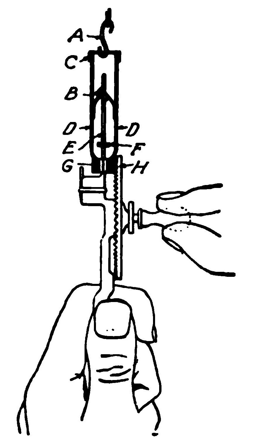
Winding the Rubber Strips. The rubber strips can be most conveniently wound up by means of an egg beater, slightly changed for the purpose. Fig. 8. The beater and the frame in which it is carried are entirely removed, leaving only the main rod E, which is cut off at the lower end so that the total length is not more than 2 or 3 inches. The two brass strips D on either side of the rod, which are attached to the pinion Q meshing with the large driving wheel H, are likewise retained. A washer F is soldered to the rod near its upper end, so as to limit the motion of the small pinion and the brass strips D attached to the pinion. Next a wire B is bent in the form of a loop, through which loop the central rod passes. The ends of the wire are soldered to the side strips D. Lastly, a piece of wire C is bent and soldered to the lower ends of the side strips. In order to wind up a rubber strip, the strip is detached from the forward end of the model, and the hook A slipped over the wire C. The opposite end of the rubber band is held in any convenient manner. Naturally the two strips must be wound in opposite directions, so that the two propellers will turn in opposite directions. By stretching the rubber while it is being wound, more revolutions can be obtained. It is not safe to have the propeller revolve more than 700 times. The ratio of the gears of the egg-beater winder can be figured out so that the requisite number of twists can be given to the rubber bands for that particular number of revolutions.
Model with Gasoline Motor. The next and somewhat more ambitious stage is the building of a power-driven model, which has been made possible by the manufacture of miniature gasoline motors and propellers for this purpose. Motors of this kind, weighing but a few pounds and capable of developing 1/4 horse-power or more, may be had complete with an 18-inch aluminum propeller and accessories for about $45. As is the case with the rubber-band driven model, the monoplane is the simplest type to construct, and the dimensions and details of an aeroplane of this type are given here. It will be found that a liberal-sized machine is required to support even such a small motor. The planes, Fig. 9, have a spread of 7 feet 8 inches from tip to tip, each wing measuring 3 1/2 feet by a chord of 15 inches. They are supported on a front and rear wing spar of spruce, 1/2 by 3/8 inch in section, while the ribs in both the main plane and the rear stabilizing plane measure 1/8 by 1/2 inch in cross section. There are eight of these spruce ribs in the main plane, and they are separately heated and curved over a Bunsen burner, or over a gas stove, which is the same tiling. They are then nailed to the wing spars 6 inches apart. The main spars of the fuselage are 7 feet long and they are made of 1/2 by 3/8 inch spruce, the struts being placed 1 1/2 feet apart, measuring from the rear, with several intermediate struts to brace the engine bed. Instead of using strut sockets for the fuselage, which would increase the cost of construction unnecessarily, a simple combination of a three-way wire fastener and a wire nail may be resorted to. The shape of these fasteners is shown at A in Fig. 9. They may be cut out of old cracker boxes or tin cans (sheet iron) with a pair of shears, the holes in the ends being made either with a small drill or by driving a wire nail through the metal placed on a board, and filing the burrs off smooth. A central hole must also be made for the 1 1/2 inch wire nail which is driven through the main spar and the fastener then slipped over it. As indicated, this nail also serves to hold the strut. A drop of solder will serve to attach the fastener to the nail. The front of the fuselage is 9 inches square, tapering down to 6 inches at the rear. The height of the camber of the main planes is 1 1/2 inches and the angle of incidence is 7 degrees, measured with relation to the fuselage. The non-lifting tail plane at the rear which is to give the machine longitudinal stability, measures 4 feet in span by 14 inches in depth.
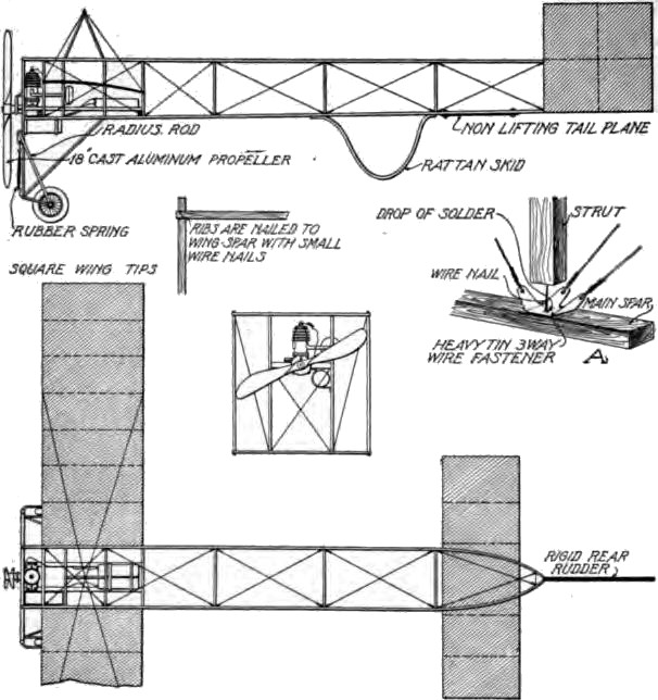
The running gear or front landing frame is made of 1/2 inch square spruce, all joints being made with 1/16 by 1 inch bolts. Aluminum sleeves, procurable at an aeronautic supply house, are employed for the attachment of the rubber springs and the radius rods running down to the wheels, which may also be purchased ready to install. Old bicycle wheels will serve the purpose admirably. Light steel tubes 1/2 inch in diameter are used to run these aluminum sleeves on. Two other steel tubes are joined to the lower corner of the frame by flattening them at the ends and drilling with a small hole for a nail. These are run diagonally up to the fuselage and serve as buffers to take the shocks of landing. For bracing the wings, two similar tubes are fastened to form a pyramid on top of the main plane just back of the engine. From these, guys are run to the wings as shown. The engine bed is made of 1/2 by 3/4-inch white pine, and to make it solid it is carried as far back as the rear edge of the main plane. The batteries and coil are directly attached to this plane, care being taken in their placing to preserve the balance of the machine. The rudder measures 14 inches square and is made of 3/8-inch square spruce, reinforced with tin at the joints, as it is necessary to make the frame perfectly rigid. Both sides are covered with fabric. In this case a 1-horse-power motor furnishes the necessary energy and it is fitted with an 18-inch aluminum propeller which it is capable of turning at 2,400 r.p.m. The carbureter and gas tank are made integral, and the gasoline and oil are both placed in this tank in the proportion of about four parts to one, in order to save the weight of an extra tank for oil.
Flights of half a mile are possible with this model in calm weather, but a great deal of measuring and testing of the fuel is necessary in order to regulate the flight, and "grass-cutting" should be practiced by the builder in order to properly regulate the machine. Trials have shown that the flat non-lifting tail on the fuselage gives excellent longitudinal stability, the machine rising nicely and making its descent very easy angle, so that it is seldom damaged by violent collisions in landing.
BUILDING A GLIDER
The building of hand- or power-driven models does not suffice to give that personal experience that most students are desirous of obtaining. The best method of securing this is to build a glider and practice with it. Any flying machine without a motor is a glider and the latter is the basis of the successful aeroplane. In the building of an aeroplane the first thing constructed is the glider, i.e. the frame, main planes, stabilizing planes, elevators, rudders, etc. It is only by the installation of motive power that it becomes a flying machine. The biplane will be found the most satisfactory type of glider as it is more compact and therefore more easily handled, which is of great importance for practicing in a wind. The generally accepted rule is that 152 square feet of surface will sustain the weight of the average man, about 170 pounds, and it will be apparent that the length of the glider will have to be greater if this surface is to be in the form of a single plane than if the same amount is obtained by incorporating it in two planes—the biplane. A glider with a span of 20 feet and a chord of 4 feet will have a surface of 152 square feet. So far as learning to balance and guide the machine are concerned, this may be mastered more readily in a small glider than in a large one, so that there is no advantage in exceeding these dimensions—in fact, rather the reverse, as the larger construction would be correspondingly more difficult to handle. The materials necessary consist of a supply of spruce, linen shoe thread, metal sockets, piano wire, turnbuckles, glue, and closely-woven, light cotton fabric for the covering of the planes.
Main Frame. The main frame or box cell is made of four horizontal beams of spruce 20 feet long and 1 1/2 by 3/4 inch in section. They must be straight-grained and perfectly free from knots or other defects. If it be impossible to obtain single pieces of this length, they may be either spliced or the glider may be built in three sections, consisting of a central section 8 feet long, and two end sections each 6 feet in length, this form of construction also making the glider much easier to dismantle and stow in a small space. In this case, the ends of the beams of each end section are made to project beyond the fabric for 10 inches and are slipped into tubes bolted to corresponding projections of the central section. These tubes are drilled with three holes each and bolts are passed through these holes and corresponding holes in the projecting ends after they have been fitted into the tubes, and drawn up tightly with two nuts on each bolt to prevent shaking loose. Ordinary 3/16-inch stove bolts will serve very nicely for this purpose. The upper and lower planes forming the box cell, are held apart by 12 struts, 4 feet long by 7/8 inch diameter, preferably of rounded or oval form with the small edge forward to minimize the head resistance. It is only necessary to space these equally, starting from both ends; this will bring the splices of the demountable sections in the center of the square on either side of the central section. The main ribs are 3 feet long by 1 1/4- by 1/2-inch section and their placing should coincide with the position of the struts. Between these main ribs are placed 41 small ribs, equally spaced and consisting of pieces 4 feet long by 1/2 inch square. These, as well as all the other pieces, should have the sharp edges of the square rounded off with sand paper. The ribs should have a camber of 2 inches in their length and the simplest method of giving them this is to take a piece of plank, draw the desired curve on it, and then nail blocks on both sides of this curve, forming a simple mould. The rib pieces should then be steamed, bent into this mould, and allowed to dry, when they will be found to have permanently assumed the desired curvature. Meanwhile, all the other pieces may be shellaced and allowed to dry.
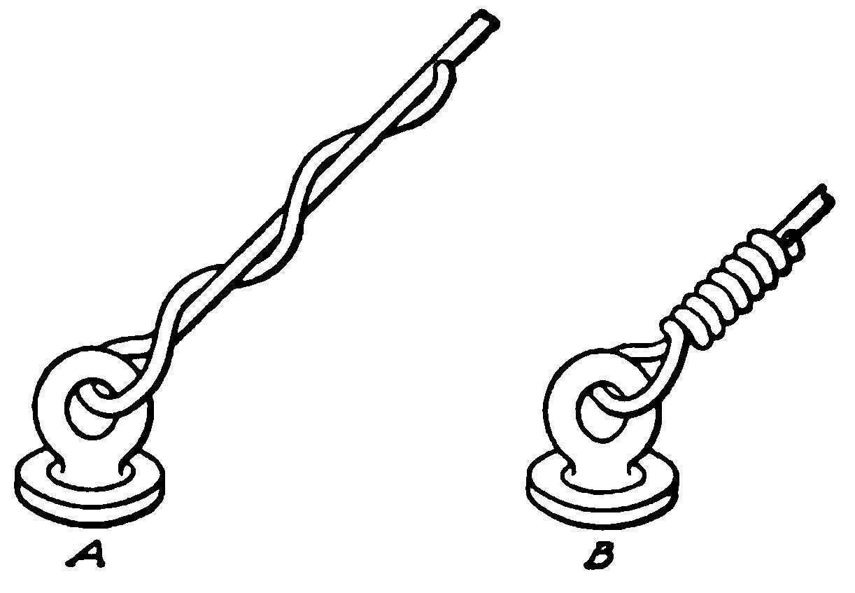
Assembling the Planes. To assemble the glider, the beams are laid out on a floor, spaced the exact distance apart, i.e., 3 feet, and exactly parallel—in the demountable plan, each section is assembled independently. The main ribs are then glued in place and allowed to set, after which they are strongly bound in place with the linen thread, and the various layers of thread given a coating of hot glue as they are put on. This method is not arbitrary, but it is simple and gives the lightest form of construction. If desired, tie-plates, clamps, or any other light method of fastening may be employed. This also applies to the ribs. They are assembled by placing them flush with the front beam and allowing them to extend back a foot beyond the rear beam, arched side up in every case. They may be glued and bound with thread, held by clamps, or nailed or screwed into place, care being taken to first start a hole in the beam with an awl and to dip the nails in soft soap to prevent splitting the wood. Twenty-one ribs, spaced one foot apart, are used in the upper plane, and 20 in the lower, owing to the space left for the operator in the latter. For fastening the two planes together, whether as a whole or in sectional units, 24 aluminum sockets will be required. These may be purchased either ready to fit, or an effective substitute made by sawing short lengths of steel tubing, slitting them with the hack saw an inch from the bottom, and then flattening out and drilling the right-angle flanges thus formed to take screws for attaching the sockets to the beams. In case these sockets are bought, they will be provided with eye bolts for the guy wires; if homemade, they may have extra holes drilled in the edges of the flanges for this purpose or some simple wire fastener such as that described in connection with the power-driven model may be used, heavier metal, however, being employed to make them. The sockets should all be screwed to the beams at the proper points and then the struts should be forced into them. The next move is to "tie" the frame together with guy wires. No. 12 piano wire being employed for this purpose. Each rectangle is trussed by running diagonal guy wires from each corner to its opposite. To pull these wires taut, a turnbuckle should be inserted in each and after the wire has been pulled as tightly as possible by hand, it should be wound upon itself to make a good strong joint, as shown at B, Fig. 6. A fastening as shown at A will pull out under comparatively little strain and is not safe. As is the case with most of the other fittings, these turnbuckles may be bought or made at home, the simple bicycle type of turnbuckle mentioned in connection with "Building a Curtiss," being admirably adapted to this purpose. In fact, the construction of the latter will be found to cover the requirements of the glider, except that the ribs are simpler and lighter, as already described, and no provision for the engine or similar details is necessary. All the guy wires must be tightened until they are rigid, and the proper degree of tension for them may be simply determined in the following manner:
After the entire frame is wired, place each end of it on a saw horse so as to lift it two or three feet clear of the floor. Stand in the opening of the central section, as if about to take a glide, and by grasping the forward central struts, raise yourself from the floor so as to bring your entire weight upon them. If properly put together the frame will be rigid and unyielding, but should it sag even slightly, the guy wires must be uniformly tightened until even the faintest perceptible tendency to give under the weight is overcome.
Stretching the Fabric. The method of attaching the fabric will be determined by whether the glider is to be one piece or sectional, and the expense for this important item of material may be as little or as much as the builder wishes to make it. Some employ rubberized silk, others special aeronautic fabrics, but for the purposes of the amateur, ordinary muslin of good quality, treated with a coat of light varnish after it is in place, will be found to serve all purposes. The cloth should be cut into 4-foot strips, glued to the front horizontal beams, stretched back tightly, and tacked to both the rear horizontal beams and to the ribs. Tacks should also supplement the glue on the forward beams and the upholstery style should be used to prevent tearing through the cloth. In case the glider is built in sections, the abutting edges of the cloth will have to be reinforced by turning it over and stitching down a strip one inch wide, and it will make this edge stronger if an extra strip of loose fabric be inserted under the turn before sewing it down. Eyelets must then be made along these edges and the different sections tightly laced together when assembling the glider. It is also desirable to place a strip of cloth or light felt along the beams under the tacks to prevent the cloth from tearing out under the pressure.
To form a more comfortable support for the operator, two arm pieces of spruce, 3 feet by 1 inch by 1 3/4 inches, should be bolted to the front and rear beams about 14 inches apart over the central opening left in the lower plane. These will be more convenient than holding on to the struts for support, as it will not be necessary to spread the arms so much and there will be more freedom for manipulating the weight to control the glider in flight. In using the struts, it is customary to grasp them with the hands, while with the arm pieces, as the name implies, the operator places his arms over them, one of the strips coming under each armpit. After the fabric has been given a coat of varnish on the upper side and allowed to dry, the glider is ready for use. The cost of the material should be about $30 to $40, depending upon the extent to which the builder has relied upon his own ingenuity in fashioning the necessary fittings—in any case, it will be less than the amount required for the purchase of the engine alone for a power-driven model.
Glider with Rudder and Elevator. It will be noted that this is the simplest possible form of glider in that it is not even provided with a rudder, but for the beginning of his gliding education the novice will not require this, as first attempts should be confined to glides over level ground in moderate, steady wind currents and at a modest elevation. Some of the best gliding flights made by Herring, Chanute's co-worker, were in a rudderless glider. After having mastered the rudiments of the art, the student may go as far as the dictates of his ambition impel him in the direction of improvements in his glider, by adding a rudder, elevator, and warping control. In fact, it is not necessary to confine himself to the simple design of glider here outlined at all. He may take either the Wright or Curtiss machines as a model and build a complete glider, following the dimensions and general methods of construction here given, though these may also be improved upon by the man handy with tools, bearing in mind that the object to be achieved is the minimum weight consistent with the maximum strength.
Learning to Glide. The first trials should be made on level ground and the would-be aviator should be assisted by two companions to help him in getting under way. The operator takes a position in the center rectangle, back far enough to tilt up slightly the forward edges of the planes. A start and run forward is made at a moderate pace, the keepers carrying the weight of the glider and overcoming its head resistance by running forward at the same speed. As the glider cuts into the air, the wind caused by running will catch under the uplifted edges of the curved planes and will buoy it up, causing it to rise in the air taking the operator with it. This rise will be probably only sufficient to lift him clear of the ground a foot or two. Now he projects his legs slightly forward so as to shift the center of gravity a trifle and bring the edges of the glider on an exact level, parallel with the ground. This, with the momentum acquired at the start, will keep the glider moving forward for some distance. When the weight of the operator is slightly back of the center of gravity, the leading edges of the planes are tilted up somewhat, increasing the angle of incidence and in consequence the pressure under the planes, causing the glider to rise, and if the glide is being made into a wind, as should always be the case, quite a height may be reached as the result of this energy. Once it ceases, the tendency to a forward and upward movement is lost, and it is to prolong this as much as possible that the operator shifts the center of gravity to bring the machine on an even keel, or where at a little height, slightly below this, giving it a negative angle of incidence, which permits him to coast down the air until sufficient speed is acquired to reverse the angle of incidence and again rise so as to provide a "hill" for another coast, thus prolonging the flight considerably. To put it in the simplest language, when the operator moves backward, shifting the center of gravity to the rear, the planes are tilted so that they catch or "scoop up" the advancing air and rise upon it, whereas when he moves forward and the planes tilt downward, this air is "spilled" out behind and no longer acts as a support, and the glider coasts, either until the ground is reached or enough momentum is gained to again mount upon the wind. A comparatively few flights will suffice to make the student proficient in the control of his apparatus by his body movements, not only as concerns the elevating and depressing of the planes to ascend or descend, corresponding to the use of the elevator on a power machine, but also actual steering, which is accomplished by lateral movement to the left or right.
Stable equilibrium is one of the chief essentials to successful flight and this can not be maintained in an uncertain, gusty wind, especially by the novice. The beginner should certainly not attempt a glide unless the conditions are right. These are a clear, level space without obstructions such as trees, and a steady wind not exceeding 12 miles per hour. When a reasonable amount of proficiency has been attained in the handling of the glider over level ground, the field of practice may be changed to some gentle slope. In starting from this, it will be found easier to keep the glider afloat, but the experience at first will prove startling to the amateur, for as the glider sails away from the top of the slope, the distance between him and the ground increases so rapidly that he will imagine himself at a tremendous height, but by preserving the balance and otherwise manipulating his weight in the manner taught by the practice over the level, a nice flight of much greater distance will be made and the machine will gradually settle down to the ground much farther away from the starting place than was possible in the earlier trials, this being one of the great advantages of starting from an elevation. There is nothing that will fit the beginner so well for the actual handling of a power machine as a thorough course of gliding flights, and it is recommended that those who build gliders become proficient in their use before attempting to pilot an aeroplane, whether of their own make or not.
A further step in advance is the actual building of a full-fledged power machine, and for those who desire a simple and comparatively inexpensive type, requiring very little work that can not be performed in the home workshop, a description of the construction of a Curtiss biplane is given, while for those who are more ambitious and also have greater financial resources, the details of the building of a Bleriot monoplane are given.
BUILDING A CURTISS BIPLANE
Cost. First of all, the prospective builder will want to know the cost. The best answer to this is that the machine will cost all its builder can afford to spend upon it and probably a little more, as the man to whom the expense is not of vital consideration will doubtless not undertake its construction. Speaking generally, and there can be nothing very definite about it, in view of the great difference in the conditions, an expenditure of three to four hundred dollars will cover the complete outlay for everything but the motor. If the builder has the time and facilities for doing all the work himself, this amount may be reduced very materially. On the other hand, if he finds it necessary to purchase most of the material in form ready to assemble, it may exceed this. But it will be a great aid to many to know that there is practically nothing about the modern aeroplane which can not be found in stock at one of the aeronautic supply houses. This makes it possible for many to undertake the construction of a machine to whom it would not be feasible, or at least not an attractive project in view of the time involved, were it necessary to make every part at home. So far as becoming involved in any legal difficulties is concerned owing to existing patents, the student need not worry himself about this in attempting the construction of a Curtiss biplane, so long as he restricts the use of his machine to experimental purposes and does not try to compete with the patentees in their own field—that of exhibiting and selling machines.
General Specifications. Just how long it will take to complete such a machine will depend very largely upon the skill of the builder and the extent of his resources for, as already mentioned, the expense may be cut down by making all the necessary parts at home, but it will naturally be at the sacrifice of a great deal of time. For instance, the oval struts and beams may be bought already shaped from the local planing mill, or they may be shaved down from the rough by hand. Turnbuckles can be made from bicycle spokes and nipples and strips of sheet steel, or they can be bought at 12 to 15 cents each. As a hundred or more of them are needed, their cost is quite a substantial item.
Aeroplane construction doubtless impresses the average observer as being something shrouded in considerable mystery—something about which there is no little secrecy. Quite the contrary is the case in reality. Any man who is fairly proficient as a carpenter and knows how to use the more common machinist's tools, such as taps and dies, drills, hacksaw, and the like, will find no difficulty in constructing the machine of which the details are given here. Having completed its building, he will have to draw upon his capital to supply the motor. One capable of developing 25 to 30 horse-power at 1,000 to 1,200 r.p.m. will give the machine considerable speed, as it will be recalled that Curtiss made a number of his first flights with a 25-horse-power motor. As to the weight, the lighter the better, but 400 pounds for the complete power plant will not be excessive. The machine can sustain itself in the air with less power than that mentioned, but with a heavy, low-power motor it will be sluggish in action. This is an advantage for the amateur, rather than otherwise, as it will provide him with an aeroplane that will not be apt to get away from him during his first trials, thus making it safer to learn on.
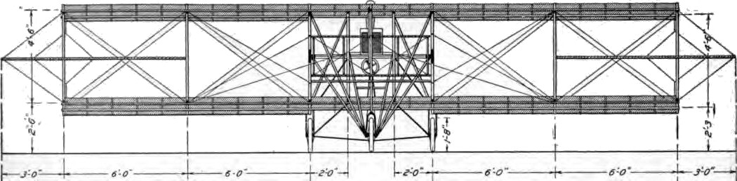
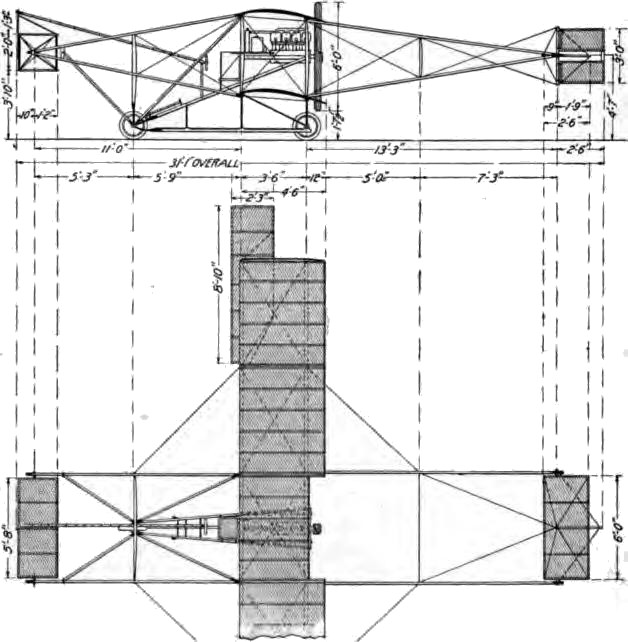
The Curtiss biplane has a spread of 30 feet, the main planes or wings being divided into sections of a length equal to the distance between struts, Figs. 11 and 12. There are five of these sections, each measuring six feet. The struts can be taken out and the sections laid flat on each other for storage. The framework for the front and rear rudders can also be jointed, if desired, making it possible to store the machine in small compass. The longest parts of the machine, when taken apart, are the two diagonal beams running from the front wheel back to the engine bed, and the skid. The horizontal front rudder is packed intact. The vertical rear rudder is unhung and laid flat on the tail. Two men can take the machine apart in a few hours, and can reassemble it in a day. Whether these particular features of construction are covered by patents can not be said, as Curtiss has declined to commit himself regarding any rights he may have to them.
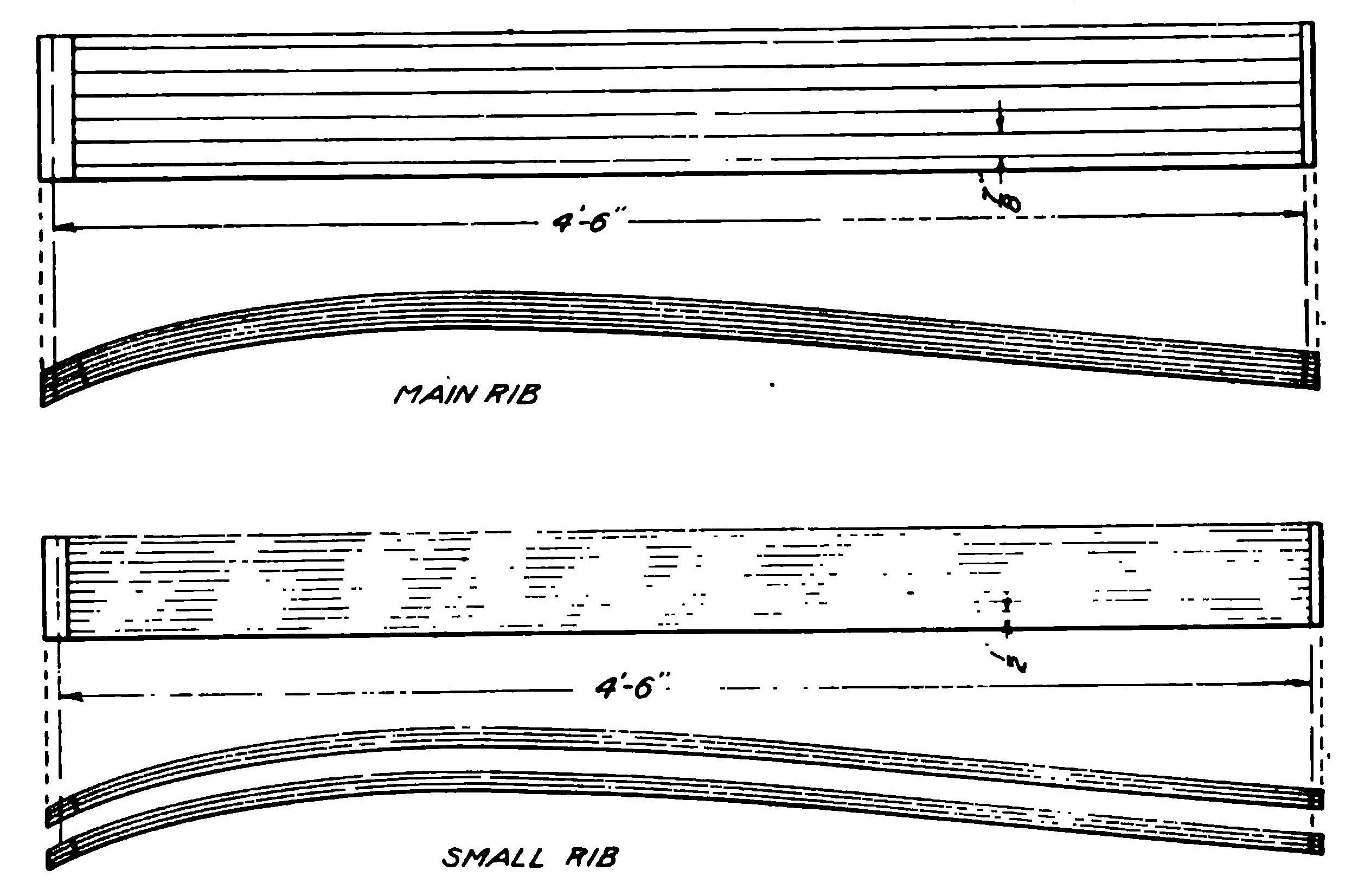
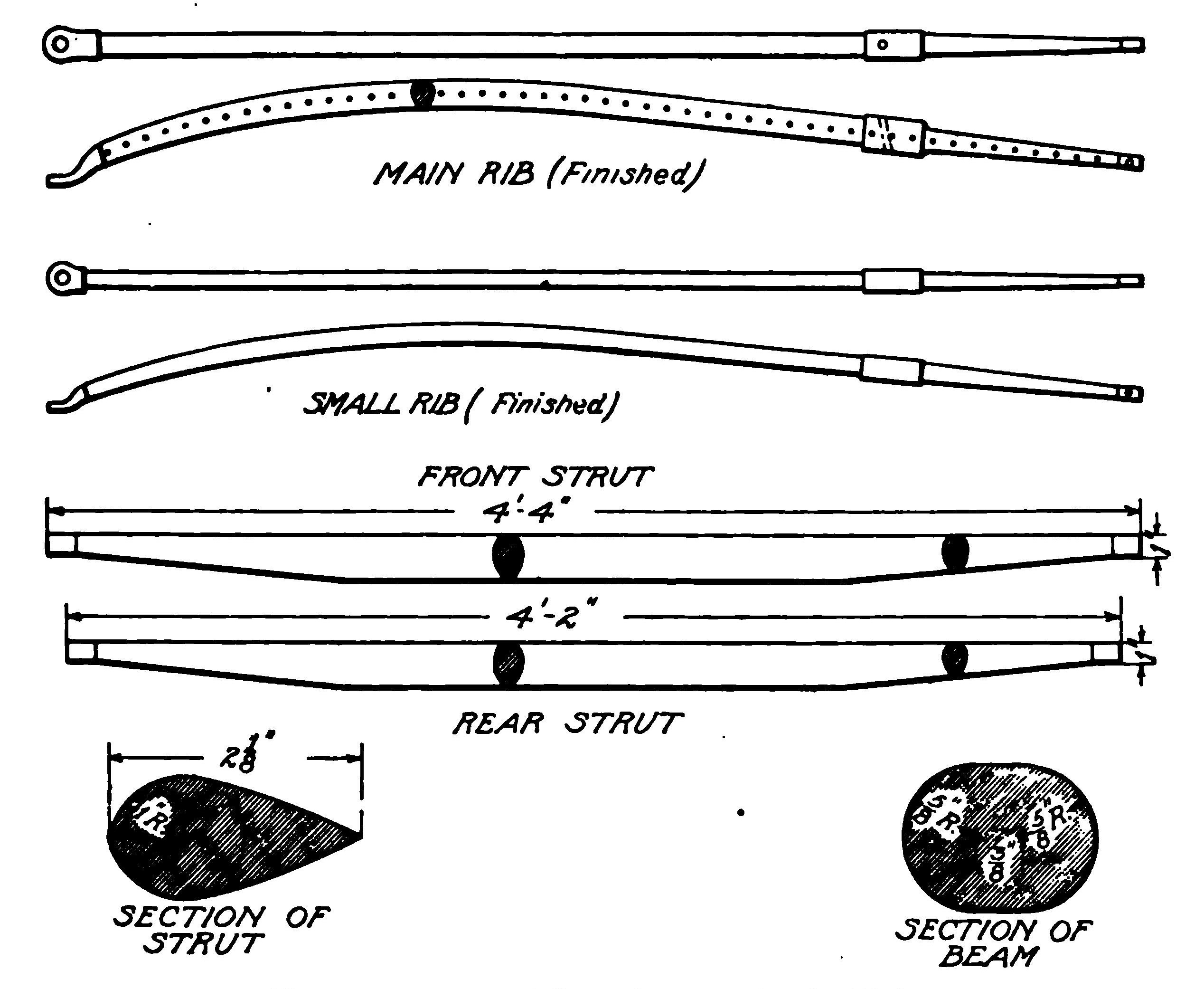
Ribs. Two distinct types of ribs are used, main ribs and small ribs, both of the same curvature, Fig. 13. The main ribs are used between pairs of struts, to hold apart the front and rear beams; they are heavy enough to be quite rigid. Three to four small ribs are laid across each section of the planes, between the pairs of main ribs, to give the cloth the proper curvature, and to maintain it in the form desired. The main ribs are built up of six 1/4-inch laminations of wood 7/8 inch wide and securely glued together. The small ribs are made of three layers 1/2 inch wide.
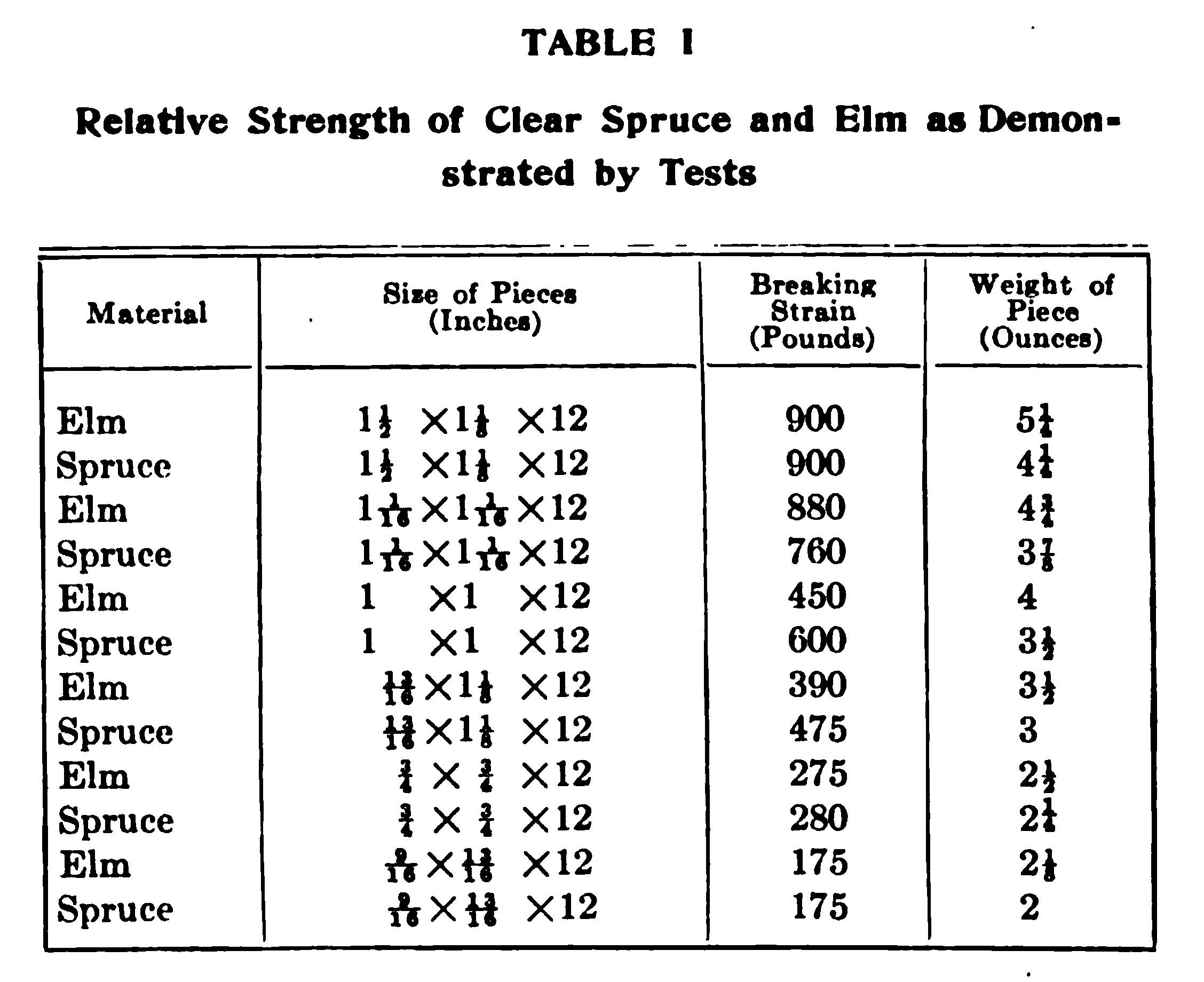
The first part of the actual construction will be the making of these laminated ribs, but before describing this detail, the question of suitable material should be well considered. Both weight and strength must be figured on and this limits the choice to a few kinds of wood. Of these spruce and elm are the best available, with the occasional use of ash to give greater rigidity. Spruce is, of course, the first choice. This wood was once considered as having no great strength, but a series of careful tests shows this belief to be unfounded. With the exception of the bed, or support for the motor and a few other parts, the Wright machines are constructed wholly of spruce.
Table I gives results of tests made with spruce from Washington and Oregon, and with elm from Michigan and Indiana. Testing scales were employed, the pieces being supported at their ends with the load in the center.
These tests were made with clear wood in each case, as knots naturally decrease the strength of a piece greatly, this depending on their size and location.
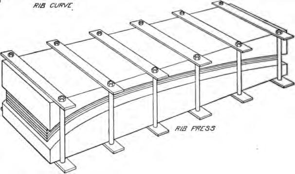
Before proceeding with the ribs themselves, the press for giving them the proper curvature must be made. Take a good piece of oak, ash, or other solid wood, 8 inches wide by 5 feet long, and dressed all over. On the side of the piece lay out the curve, the dimensions of which are illustrated in Fig. 14. First, rule the horizontal, or chord line, on it, marking off 4 feet 6 inches on this line, equidistant from each end. Then divide the chord into 6-inch sections and, at the point of each 6-inch section, erect perpendiculars beginning at the rear, 3/4 inch, 1 3/8 inches, 2 inches, and so on, as indicated on the drawing. The upper ends of these perpendiculars will form locating points for the curve. Through them draw a smooth curve as shown, continuing it down through the chord at each end. Take the piece with the curve thus marked on it to the local planing, sash and blind, or sawmill—any plant equipped with a band saw—and have it cut apart along the curve. This will cost little or nothing—acquaintance will obtain it as a favor, and acquaintance with any wood-working concern in the aeroplane builder's home town will be of great aid. Failing this aid, the operation may be carried out with a hand saw (rip), but the job will not be as neat and will have to be cleaned up with a draw knife and sand paper, taking care to preserve the outline of the curve as drawn. As the rib press is really a mould or pattern from which all the ribs are to be bent to a uniform curvature, care must be taken in its construction.
To clamp the two halves of the press together, a dozen machine bolts will be required; they should measure 3/4 X 15 inches. If obtainable, eye bolts will be found more convenient as they may be turned up with but one wrench and a bar. The steel straps are 3/8 by 1 1/2 by 10 inches long with 3/4-inch holes drilled 9 inches apart to centers, to enclose the 8-inch pieces.
Obtain a sufficient supply of boards of reasonably clear spruce, 1/4 inch thick, 6 to 7 inches wide, and at least 4 feet 9 inches long (dressed both sides), to make all the ribs necessary both small and large. This material should be purchased from the mill as it is out of the question to attempt to cut the ribs from larger sizes by hand. Buy several pounds of good cabinet makers' glue and a water-jacketed gluepot. This glue comes in sheets and in numerous grades—a good quality should be used, costing from 40 to 50 cents a pound if bought in a large city. Laminating the ribs in this manner and gluing them together is not only the quickest and easiest method of giving them the proper curve, being much superior to steam bending, but is also stronger when well done, as the quality of the material can be watched more closely.
Start with the making of the small ribs; apply the glue thin and piping hot in a generous layer to three boards with a good-sized flat paint or varnish brush. Omit on the upper surface of third board and apply between three others, Fig. 13. This will give two series of three each in the press. Tighten up the end bolts first, as the upper part of the press near the top of the curve is likely to be weak unless liberally proportioned. Then turn down the nuts on the other bolts. Do not attempt to turn any one of them as far as it will go the first time, but tighten each one a little at a time, thus gradually making the compression over the whole surface as nearly uniform as possible. This should be continued until the glue will no longer ooze out from between the boards, indicating that they are in close contact. Twenty-four hours should be allowed for drying, and when taken out the cracks between the boards should be almost invisible in the finished ribs.
Have the laminated boards cut by a power rip saw at the planing mill, to the dimensions shown in the drawing, making an allowance of 1/4 inch for the width of the saw blade at each cut in calculating the number of ribs which can be cut from each board. In addition, a margin should be allowed at each side, as it is impractical to get all the thin boards squarely in line. For the main ribs, apply the glue between all six boards, clamp and dry in the same manner. Thirty small ribs will be required, if three are used in each section, and forty if four are specified, while twelve main ribs will be needed for standard construction, and sixteen if the quick-demountable plan referred to is followed. It is advisable to make several extra ribs of each kind in addition. If the builder has not sufficient faith in spruce alone, despite the figures given in Table I, one of the laminations, preferably the center, or if two be employed, the outer ones, may be of ash, though this will add considerably to the weight.
To prevent the ribs from splitting open at the ends, they are protected by light steel ferrules, shown in Fig. 15. When received in the rough-sawed condition from the mill, the ribs must be tapered at the ends with a plane or spoke shave to fit these ferrules, and the sharp edges should be rounded off. In doing this, it must be remembered that the upper surface of the small ribs gives the curvature to the cloth surface, so that any tapering must be done on the lower side. The main ribs may be tapered from both sides, as it is the center line, or crack between the third and fourth laminations, that determines the curve. Every inch along this line A-inch holes are to be drilled for the lacing, Fig. 15.
The ferrules for the front ends of the small ribs are light 1/2-inch seamless steel tubing; they may be flattened to the proper shape in a vise without heating and are drilled with a 1/8-inch hole. They are driven tight on to the tapered ends of the ribs and fastened in place with a small screw. The rear-end ferrules are 1/2-inch lengths of 3/8-inch tubing, driven on and drilled with a 1/32-inch hole for the rear-edge wire. The rear ferrules of the main ribs may be the same 1/2-inch tubing used for the front of the small ribs; they should be cut off so that their ends will come in the same line as the holes in the ends of the small ribs. If the quick-demountable plan be followed, the second main rib from each end may be left long and drilled with a hole like the small ribs. The front ferrules of the main ribs should be 3/4-inch tubing of heavier gauge, drilled with a 1/4-inch hole. The finished ribs are sandpapered smooth and shellaced or coated with spar varnish. The latter is much more expensive and slower in drying but has the great advantage of being weather-proof and will protect the glue cracks from moisture. The ferrules may be painted with black enamel.
Struts. Before going into the detail of the construction of the remainder of the main cell and its attached framing, a brief description of its parts and their relation to one another will make matters clearer. The upright struts, Fig. 15, which hold the two planes apart, fit at each end into sockets, which are simply metal cups with bolts projecting through their ends. Fig. 16. Those at the bottom of the front row of struts pass through the eyes of the turnbuckles and connections for the wire trussing, then through the flattened ferrules of the main ribs, and finally through the beam, all being clamped together with a nut. Those at the top go through the turnbuckles first, then through the beam, and finally the rib ferrule. The bolts at the back row of struts must go through the full thickness of the main ribs, and so must be longer. The drawings. Figs. 15 and 16, show the method of attachment of both the main and the small ribs and illustrate a neat method of attaching the turnbuckles—instead of being strung on the socket bolt one after another, they are riveted to the corners of a steel plate which alone is clamped under the socket.
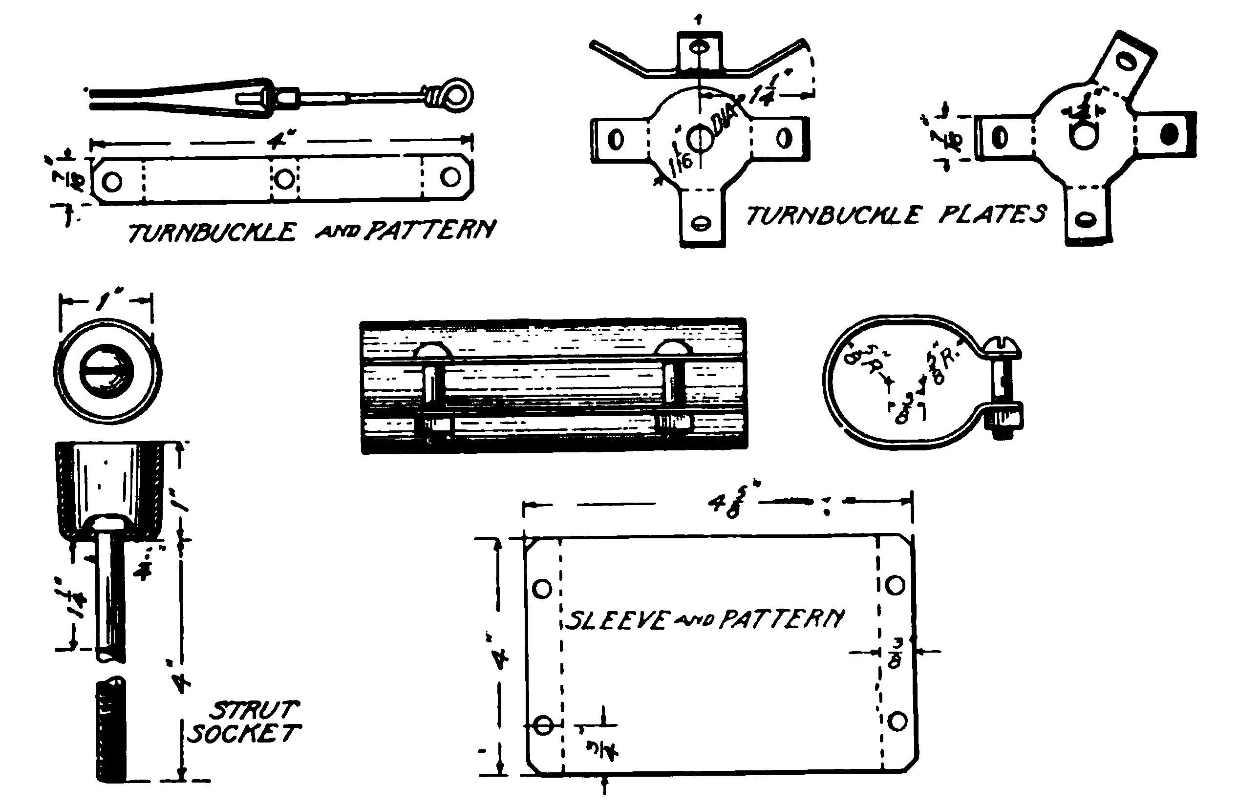
Beams. The beams are jointed at each strut connection, the ends being cut square and united by a sheet-steel sleeve, a pattern of which is shown in Fig. 16, clamped on by two small bolts. The hole for the socket bolt is drilled half in each of the two abutting beams. As it is very difficult to obtain long pieces of wood sufficiently straight grained and free from knots for the purpose, this jointed system considerably cheapens the construction. Both beams and struts are of spruce, but to give additional strength, the beams of the middle section may be ash. Special aero cloth, rubberized fabrics, or light, closely-woven duck (racing yacht sail cloth of fine quality, this being employed at first by the Wright Brothers in their machines) forms the surfaces of the wings. The front edge of each section of the surface is tacked to the beam and the rear edge is laced over the rear wire already referred to, this wire being stretched taut through the holes in the rear tips of the ribs, both main and small. After the cloth is stretched tight, it is tacked to the small ribs, a strip of tape being laid under the tack heads to prevent the cloth from pulling away from under them. If the aeroplane is intended to be taken apart very often, the standard design as shown by the large drawings, Figs. 11 and 12, may be modified so as to make it unnecessary to unlace the cloth each time. This is arranged by regarding the two outer sections at each end of the plane as one, and never separating them. Additional main ribs are then provided at the inner ends of these sections, and are attached directly to the beams, instead of being clamped under the strut sockets. In taking the machine apart, the struts are pulled from the sockets, leaving the latter in place. It will then be an advantage to shorten the main planes somewhat, say 3 inches on each section, so that the outer double sections will come under the "12-foot rule" of the Express Companies.
Running Gear. Three wheels are provided—one in front under the outrigger and two under the main cell for starting and landing. Two beams extend from the front wheel to the engine bed and serve to carry the pilot's seat, as will be seen from the elevator, Fig. 12. A third beam runs back horizontally from the front wheel and on rough ground acts as a skid. The rest of the running gear is made of steel tubing, the pieces being joined simply by flattening the ends, drilling and clamping with bolts; no sockets or special connections of any kind are necessary here. If desired, the wheels may be carried in bicycle forks and may be fitted with shock absorbers, some idea of the various expedients adopted by different builders for this purpose being obtainable from the sketches. Fig. 40 in "Types of Aeroplanes." Two separate tubes, one on each side of the wheel make a simple construction and will probably serve just as well. The details of the running gear will be given later.
Outrigging and Rudders. For the outriggers and the frames carrying the front horizontal or elevating rudder and the rear vertical rudder and tail, or horizontal keel, either spruce or bamboo may be employed. Bamboo will be found on machines turned out by the Curtiss factory, and while it is the lighter of the two, it is not generally favored, as spruce is easier to obtain in good quality and is far easier to work. At their ends, these outriggers are fitted with ferrules of steel tubing, flattened and drilled through. The outriggers are attached to the main framework of the machine by slipping the ferrules over the socket bolts of the middle section struts, above and below the beams. It is preferable, however, to attach the rear outriggers to extra bolts running through the beams, so that when the machine is to be housed the tail and rudder can be unshipped and the triangular frames swung around against the main frame, considerably reducing the space required.
The tail, horizontal and vertical rudders, and the ailerons are light frames of wood, covered on both sides with the same kind of cloth as the main planes or wings. These frames are braced with piano wire in such a manner that no twisting strains can be put on them. The front horizontal rudder, which is of biplane construction like the main cell, is built up with struts in the same way. Instead of being fitted with sockets, however, the struts are held by long screws run through the planes and into their ends, passing through the eyes of the turnbuckles.
DETAILS OF CONSTRUCTION
Main Planes and Struts. It is preferable to begin with the construction of the main planes and their struts and truss wires, the ribs already described being the first step.
The main beams offer no special difficulties. They are ovals 1 1/4 by 1 5/8 inches, all 6 feet long except the eight end ones, which are 6 feet 2 inches. The beams of the central section should be of ash, or should be thicker than the others. In the latter case, they must be tapered at the ends so that the clamping sleeves will fit and the additional wood must be all on the lower side, so that the rib will not be thrown out of alignment. The spruce used for the other beams should be reasonably clear and straight grained, but a small knot or two does not matter, provided it does not come near the ends of the beam. The beams may be cut to the oval shape by the sawmill or planed down by hand.
"Fish-shaped" or "stream-line" section, as it is more commonly termed, is used for the struts, Fig. 15. It is questionable whether this makes any material difference in the wind resistance, but it is common practice to follow it in order to minimize this factor. It is more important that the struts be larger at their centers than at the ends, as this strengthens them considerably. At their ends the struts have ferrules of the 1-inch brass or steel tubing, and fit into the sockets which clamp the ribs and beams together. The material is spruce but the four central struts which carry the engine bed should either be ash or of larger size, say 1 1/4 by 3 inches.
Care Necessary to Get Planes Parallel. The front struts must be longer than the rear ones by the thickness of a main rib at the point where the rear strut bolt passes through it, less the thickness of the rib ferrule through which the bolt of the front strut must pass. However, the first distance is not really the actual thickness of the rib, but the distance between the top of the rear beam and the bottom of the strut socket. In the drawings the difference in length between the front and rear struts is given as 2 inches, but it is preferable for the builder to leave the rear struts rather long and then measure the actual distance when assembling, cutting the struts to fit. The ends of the struts should also be countersunk enough to clear the head of the socket bolt.
One of the items which the builder can not well escape buying in finished form is the strut sockets. These are cup-shaped affairs of pressed steel which sell at 20 cents each. Sixteen of them will be required for the main frame, and a dozen more can advantageously be used in the front and rear controls, though for this purpose they are not absolutely necessary. They can also be obtained in a larger oval size suitable for the four central struts that carry the engine bed, as well as in the standard 1-inch size. The bolts which project through the bottom of the sockets are ordinary 1/4-inch stove bolts, with their heads brazed to the sockets.
For the rear struts, where the bolt must pass through the slanting main rib, it is advisable to make angle washers to put under the socket and also between the beam and rib. These washers are made by sawing up a piece of heavy brass tubing, or a bar with a 1/4-inch hole drilled in its center, the saw cuts being taken alternately at right angles and at 60 degrees to the axis of the tube.
The sleeves which clamp together the ends of the beams are made of sheet steel of about 20 gauge. The steel is cut out on the pattern given in the drawing, Fig. 16, and the 3/16-inch bolt holes drilled in the flanges. The flanges are bent over by clamping the sheet in a vise along the bending line and then beating down with a hammer. Then the sleeves can be bent into shape around a stray end of the beam wood. The holes for the strut socket bolts should not be drilled until ready to assemble. Ordinarily, 3/16-inch stove bolts will do to clamp the flanges together.
Having reached this stage, the amateur builder must now supply himself with turnbuckles. As already mentioned, these may either be purchased or made by hand. It is permissible to use either one or two turnbuckles on each wire. One is really sufficient, but two—one at each end—add but little weight and give greater leeway in making adjustments. As there are about 115 wires in the machine which need turnbuckles, the number required will be either 115 or 230, depending upon the plan which is followed. Those of the turnbuckles to be used on the front and rear controls and the ailerons, about one-fifth of the total number, may be of lighter stock than those employed on wires which carry part of the weight of the machine.
Making Turnbuckles for the Truss Wires. On the supposition that the builder will make his own turnbuckles, a simple form is described here. As will be seen from Fig. 16, the turnbuckles are simply bicycle spokes, with the nipple caught in a loop of sheet steel and the end of the spoke itself twisted into an eye to which the truss wire can be attached. The sheet steel used should be 18 or 16 gauge, and may be cut to pattern with a heavy pair of tin snips. The spokes should be 3/32 inch over the threaded portion. The eye should be twisted up tight and brazed so that it can not come apart. The hole in the middle of each strip is, of course, drilled the same size as the spoke nipple. The holes in the ends are 3/16 inch.
In the original Curtiss machines, the turnbuckles were strung on the socket bolts one after another, sometimes making a pack of them half an inch thick. A much neater construction is shown in the drawings, in which the bolt pierces a single plate with lugs to which to make the turnbuckles fast by riveting. The plates are of different shapes, with two, three, or four lugs, according to the places where they are to be used. They are cut from steel stock 3/32 inch thick, with 1/4-inch holes for the socket bolts and 3/16 inch, or other convenient size, for the rivets that fasten on the turnbuckles.
The relative merits of cable and piano wire for trussing have not been thoroughly threshed out. Each has its advantages and disadvantages. Most of the well-known builders use cable; yet if the difference between 1,000 feet of cable at 2 1/4 cents per foot (the price for 500-foot spools), and 8 pounds of piano wire at 70 cents a pound, looks considerable to the amateur builder, let him by all means use the wire. The cable, if used, should be the 3/32-inch size, which will stand a load of 800 pounds; piano wire should be 24 gauge, tested to 745 pounds. It should be noted that there is a special series of gauges for piano wire, known as the music wire gauge, in which the size of the wire increases with the gauge numbers, instead of the contrary, as is usual with machinery wire gauges.
One by no means unimportant advantage of the piano wire is that it is much easier to fasten into the turnbuckles. A small sleeve or ferrule, a 1/4-inch length of 1/8-inch tubing, is first strung on the wire. The end of the wire is then passed through the turnbuckle eye, bent up, thrust through the sleeve, and again bent down. When the machine is taken apart, the wire is not disconnected from the eye, but instead the turnbuckle spoke is unscrewed from the nipple. The shape of the sheet-steel loop should be such as to hold the latter in place. Cable, on the other hand, must be cut with about 2 inches to spare. After being threaded through the turnbuckle eye, the end is wound back tightly on itself and then soldered, to make certain that it can not loosen.
With a supply of turnbuckles and cable or piano wire at hand, the builder may go ahead with the main box-like structure or cell, which should be completed except for the cloth covering, and in proper alignment, before taking up the construction of the running gear and controls.
Running Gear. The running gear of the machine is built of seamless steel tubing, those parts which carry the weight of the machine direct being of 3/4-inch outside diameter, 16-gauge tubing, while the others are 5/8-inch outside diameter, either 18 or 20 gauge. About 25 feet of the heavy and 45 feet of the light tubing will be required, in lengths as follows: Heavy, four 3-foot, three 4-foot; light, one 6-foot, two 4-foot 6-inch, and seven 4-foot pieces. Referring to Fig. 17, two diagonal braces from the rear beam to the engine bed, the V-shaped piece under the front engine bed struts and all of the rear frame except the horizontal piece from wheel to wheel, are of heavy tubing. The horizontal in the rear frame, diagonals from the rear wheels and the rear end of the skid to the front beam, the two horizontals between the front and rear beam, and the forward V are of light tubing.
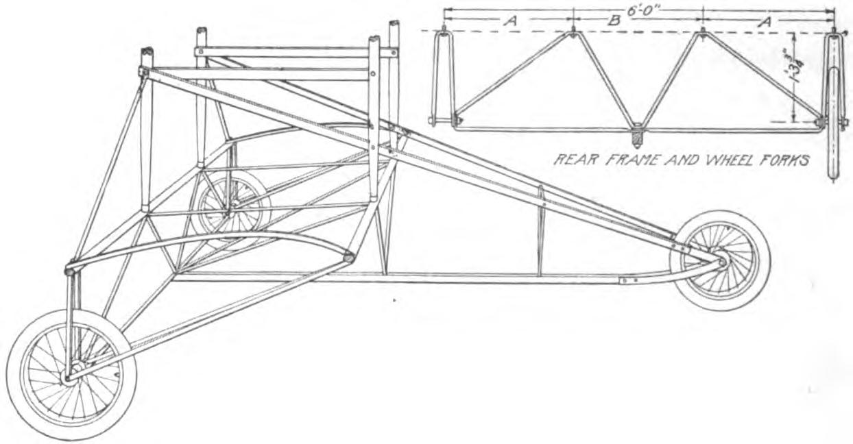
Three ash beams are used in the running gear. Two of these run diagonally from the rear end of the engine bed to the front wheel. These are about 10 feet long and 1 by 1 3/4 inches section. The third, which on rough ground acts as a skid, is 8 1/2 feet long and about 2 inches square. Between the joints where the tubing frames are attached to it, the upper corners may be beveled off with a spoke shave an inch or more down each side. The beams are attached to the front wheel with strips of steel stock 1 1/2 inches wide and 1/8 inch thick. The engine bed beams are also ash about 1 by 1 3/4 inches section. Their rear ends are bolted to the middle of the rear engine bed struts and the front ends may be 1/2 inch higher.
This Photograph Protected By International Copyright
This Photograph Protected By International Copyright
The wheels are usually 20 by 2 inches, and of the bicycle type, but heavier and wider in the hub; the tires are single tube. These wheels, complete with tires, cost about $10 each. This size is used on the standard Curtiss machines, but novice operators, whose landings are not quite as gentle as they might be, find them easily broken. Therefore, it may be more economical in the end to pay a little more and get heavier tires—at least to start with.
For working the tubing into shape, a plumber's blow torch is almost indispensable—most automobilists will already possess one of these. The oval, flat variety, holding about one pint, is very handy and packs away easily, but on steady work requires filling somewhat too frequently. With a dozen bricks a shield can be built in front of the torch to protect the flame and concentrate the heat. Whenever it is to be flattened and bent, the tubing should be brought to a bright red or yellow heat. Screwing the vise down on it will then flatten it quickly without hammer marks. Where the bend is to be made in the middle of the piece, however, it may be necessary to resort to the hammer and anvil.
It is convenient to start with the framework under the rear beam. This may be drawn accurately to full size on the workshop floor, and the tubes bent to fit the drawing. With this framework once in place, a definite starting point for the remainder of the running gear is established. Here and in all other places, when boring through wood, the holes should be drilled out full, and larger washers should be placed under the bolt head and nut. All nuts should be provided with some sort of locking device The perspective drawing. Fig. 17, should show the general arrangement clearly enough to enable the builder to finish the running gear.
Outriggers. Both the front and rear control members, or "outriggers" as they are termed, Fig. 12, may be conveniently built up on the central section of the main frame, which, it is assumed, has now been fitted with the running gear.
The horizontal rudder, or "elevator," is a biplane structure like the main cell of the machine, but with fewer struts; it is carried in front of the main planes on two A-shaped frames. The vertical rudder, at the rear, is split along the middle and straddles a fixed horizontal plane, or tail. This also is carried on two A-shaped frames. Lateral stability is controlled by two auxiliary planes or ailerons, one at each side of the machine and carried on the two outer front struts. These three control units—elevator, tail and rudder, and ailerons—will now be taken up separately and their construction, location on the machine, and operation will be described.
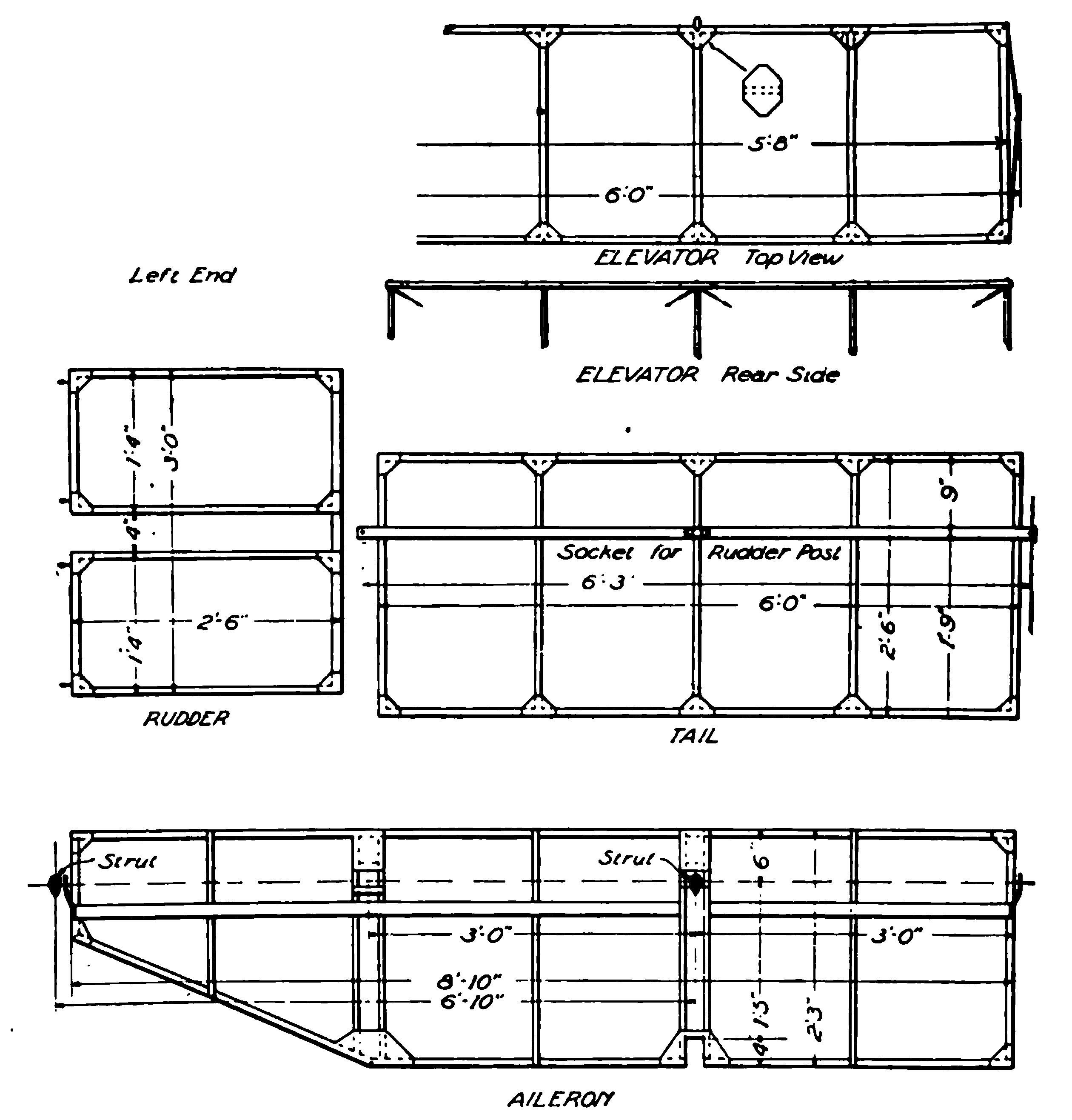
Horizonal Rudder or Elevator. The two planes of the elevator are 2 feet wide by 5 feet 8 inches long and are spaced 2 feet apart, being held in this position by ten struts. The frames of the planes are built of spruce sticks 1/2 by 1 inch, each plane having two sticks the full length and five evenly spaced crosspieces or ribs. These are joined together with squares of X-sheet tin, as shown in the detailed drawing, Fig. 18. With a little experimenting, paper patterns can be made from which the tin pieces can be cut out. The sticks are then nailed through the tin with 3/4-inch brads.
It is convenient to draw the frames out accurately on a smooth wood floor and then work over this drawing. The first few brads will hold the sticks in place. When all the brads have been driven, a little drop of solder should be run in around the head of each one. This is a tedious job. One must be careful to use no more solder than necessary as it increases the weight very rapidly. Two pounds of wire solder should be sufficient for all the control members which are built in this way. When the top side is soldered, pry the frame loose from the floor with a screwdriver and turn it over. Then the projecting points of the brads must be clinched and the soldering repeated.
At this stage, the two frames should be covered on both sides with the prepared cloth used for covering the main planes. The method of preparing this cloth is detailed a little farther along.
The struts, so-called, to continue the analogy with the main planes, are turned sticks of spruce 3/8 inch in diameter. They are fitted at each end with ferrules of thin 3/8-inch brass, or steel tubing, driven on tight. Instead of using sockets, the struts are held at each end, simply by a long wood screw driven through the tin and wood of the plane frame and into the strut. These screws also hold the turnbuckles for the truss wires. For trussing purposes, the elevator is regarded as consisting of two sections only, the intermediate struts being disregarded.
The turnbuckles and wire used here and in the other control members may well be of lighter stock than those used in the main planes. Piano wire, No. 18, or 1/16-inch cable is amply strong. The sheet steel may be about 22 gauge, instead of 16, and the bicycle spokes smaller in proportion. No turnbuckle plates are necessary. The screws running into the struts may be passed directly through the eyes of the turnbuckles, where they would have been attached to the turnbuckle plate. In order to secure a square and neat structure, those struts which have turnbuckles at their ends should be made a trifle shorter than the others.
At each end, the elevator has an X-shaped frame of 1/4-inch steel tubing; at the intersection of the X's are pivots on which the elevator is supported. Each X is made of two tubes, bent into a y and flattened and brazed together at the points. The ends of the X's are flattened and bent over so that the screws which hold the struts in place may pass through them.
To the front middle strut is attached an extension which acts as a lever for operating the elevator. This is a stick of spruce 3/4 inch in diameter and 3 feet 3 inches long. At its upper end it has a ferrule of steel tubing, flattened at the end. The lower part of the stick may be fastened to the strut by wrapping the tube with friction tape, or by improvising a couple of sheet steel clamps. The upper end of the stick is braced by a 1/4-inch steel tube, extending to the top of the rear middle strut, and held by the same screw as the strut. This extension lever is connected to the steering column by a bamboo rod, 1 inch in diameter and about 10 feet long, provided with flattened ferrules of steel tubing at each end. Each ferrule should be held on by a 1/8-inch stove bolt passing through it.
Front and Rear Outrigger Frames. Both the front elevator and the tail and rudder at the rear, are carried, as mentioned above, each on a pair of A-shaped frames, similar to one another, except that those in the rear are longer than those in the front. Both are made of spruce of about the same section as used for the struts of the main frame. These pieces may either be full length, or they may be jointed at the intersection of the crosspieces, the ends being clamped in a sheet-steel sleeve, just like that used on the beams of the main frame. In this case, it is advisable to run a 1/8-inch stove bolt through each of the ends.
The crosspieces of the A-frames are spruce of the same section, or a little smaller. At their ends may be used strut sockets like those of the main frame; or, if it is desired to save this expense, they may be fastened by strips of 1/16-inch steel stock with through bolts.
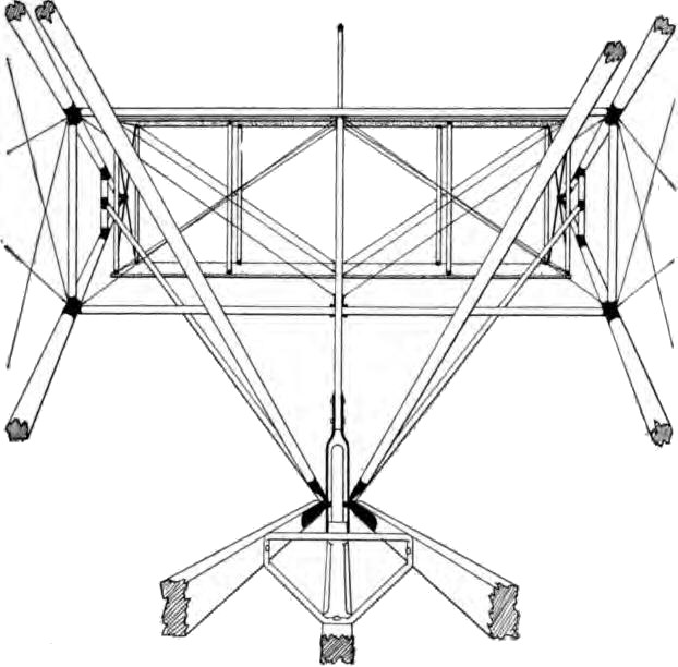
The front outrigger has, besides the two A-frames, a rather complicated arrangement of struts designed to brace the front wheel against the shocks of landing. This arrangement does not appear very plain in a plan or elevation, and may best be understood by reference to the photograph, Fig. 19, and the perspective drawing, Fig. 20. Fig. 20 is a view from the driver's seat. The elevator is seen in front, the A-frames at each side, and at the bottom the two diagonal beams to the engine bed and the skid.
Reference to this drawing will show the two diagonals run from the front wheel up and back to the top of the main frame, and two more from the wheel forward to the short crosspieces near the apexes of the A-frame: there is also a vertical strut which intersects two horizontal pieces running between the ends of the longer crosspieces of the A-frames. Altogether, there are five attachments on each side of the front wheel, through which the axle bolt must pass, viz, the connections to the skid, to one of the diagonals to the engine bed, to one of the rear diagonals, to one of the front diagonals, and to one side of the fork carrying the vertical strut. Of these the skid attachments should be on the inside closest to the wheel, and the engine bed diagonals next.
The four additional diagonals running to the front wheel may be spruce of the same section used in the A-frames, or turned one inch round. At each end they have flattened ferrules of steel tubing. The beams of the A-frames have similar ferrules at the ends where they attach to the main frames. These attachments should be made on the socket bolts of the struts on either side of the middle 6-foot section and on the outer side of the main beams—not between the beam and the socket itself.
It is possible, of course, to make all the A-frames and diagonal braces of bamboo, if desired, the qualities of this material already having been referred to. Bamboo rods for this purpose should be between 1 and 1 1/4 inches in diameter. Where ferrules are fitted on the ends, the hole of the bamboo should be plugged with wood glued in place.
Generally, in the construction of the outrigger frames, the builder can use his own discretion to a considerable extent. There tire innumerable details which can be varied—far too many to consider even a part of the possibilities in this connection. If the builder runs across any detail which he does not see mentioned here, he may safely assume that any workmanlike job will suffice. Often, the method may be adapted to the materials on hand. The diagonal wires from the crosspieces of the A-frames to the struts should be crossed.
Rudder and Tail Construction. The frame for the rudder and tail are constructed in much the same way as those for the elevator, Fig. 18. Spruce sticks 1 by 1/2 inch are used throughout, except for the piece at the back edge of the rudder and the long middle piece across the tail; these should be 1 1/2 by 1/2 inch. This long middle piece of the tail is laid across on top of the rest of the framework. When the cloth is put on, this makes the upper surface slightly convex while the lower surface remains flat. The ends of this piece should be reinforced with sheet steel, fairly heavy and drilled for 1/4-inch bolts, attaching the tail to the A-frames.
The rudder is hung from two posts extending above and below the tail. These posts may be set in cast aluminum sockets, such as may be obtained from any supply house for 20 cents apiece. The posts need not be more than 3/4 inch in diameter. At their outer ends, they should have ferrules of steel tubing, and the turnbuckles or other attachments for the truss wires should be attached by a wood screw running into the end of each. From these posts the rudder may be hung on any light hinges the builder may find convenient, or on hinges improvised from screw eyes or eye bolts, with a bolt passing through the eyes of each.
In steering, the rudder is controlled by a steering wheel carried on a hinged post in front of the pilot. This post should be ash about 1 by 1 1/4 inches. It hinges at the bottom on a steel tube of 1/2-inch diameter which passes through it and is supported at the ends on diagonal beams to the engine bed. Two diagonals of lighter tubing may be put in to hold the posts centered between the two beams.
The post is, of course, upright, and the hub of the wheel is horizontal. The wheel may be conveniently mounted on a piece of tubing of the same size as the hub hole, run through the post and held by a comparatively small bolt, which passes through it and has a big washer on either end. The wheel is preferably of the motor-boat variety with a groove around the rim for the steering cable.
The rear edge of the tail should be about 1 inch lower than the front. To make the rudder post stand approximately vertical, wedge-shaped pieces of wood may be set under the sockets.
The steering connections should be of flexible cables of steel such as are made for this purpose. There should be a double pulley on the post just under the wheel, and the cables should be led off the post just at the hinge at the bottom, so that swinging the post will not affect them. The cable is then carried under the lower main plane and out the lower beams of the A-frames. It is attached to the rudder at the back edge; snap hooks should be used for easy disconnection in packing. Perhaps the best way of guiding the cable, instead of using pulleys, is to run it through short pieces of tubing lashed to the beams with friction tape. The tubing can be bent without flattening by first filling it with melted lead, which, after the bending, can be melted out again.
Ailerons for Lateral Stability. The framework of the ailerons is made in the same way as that for the elevator, tail, and rudder, Fig. 18. The pieces around the edges should be 1 1/2 by 1/2 inch, as also the long strip laid over the top of the ribs. The ribs should be 1/2 by 3/4 inch. Each aileron has two holes, one for the strut to pass through, and the other for the diagonal truss wires at their intersection. The back edge also has a notch in it to clear the fore and aft wires. Each aileron is hung on four strips of soft steel about 1/2 by 3/16 inch, twisted so that one end is at right angles to the other. These are arranged one on each side of the strut which passes through the aileron, and one at each end. Bolts through the struts carry three of them and the outer one is trussed by wires to each end of the outer strut.
A frame of 1/4-inch steel tubing fits around the aviator's shoulders and is hinged to the seat, so that he can move it by leaning from one side to the other. This is connected by flexible cable to the rear edges of the ailerons, so that when the aviator leans to the left, he will raise the left and lower the right aileron. The upper edges of the ailerons are directly connected to each other by a cable running along the upper front beam, so that they must always move together.
Covering of the Planes. Mention has already been made of the fact, in the general description of the machine, that light sail cloth, as employed on the Wright machines, may be used for the planes or wings. As a matter of fact, many different materials may be successfully employed, the selection depending upon the builder himself and his financial resources. About 55 square yards of material will be required, and in comparing prices always compare the width as this may vary from 28 to 55 inches. Rubberized silk which is used on the standard Curtiss machines is the most expensive covering, its cost running up to something like two hundred dollars. There are also several good aero fabrics on the market which sell at 60 cents a square yard, as well as a number of brands of varnish for the cloth—most of them, however, quite expensive. The most economical method is to employ a strong linen cloth coated with shellac, which will be found very satisfactory.
The covering of the frames with the cloth may well be postponed until after the engine has been installed and tested, thus avoiding the splashing of oil and dirt which the fabric is apt to receive during this operation. The wire to which the cloth is laced, must be strung along the rear ends of the ribs of each plane. The wires pass through holes in the ends of the small ribs and are attached to the main ribs with turnbuckles. At the ends of the planes the main ribs must be braced against the pull of the wire by a piece of 1/4-inch tubing running from the end of the rib diagonally up to the rear beam. Both turnbuckles and tube are fastened with one wood screw running into the end of the rib.
The cloth should be cut to fit the panels between the main ribs and hemmed up, allowing at least an inch in each direction for stretch. Small eyelets should be put along the sides and rear edges an inch apart for the lacing. At the front edge, the cloth is tacked directly to the beam, the edge being taken well under and around to the back. Strong fish line is good material for the lacing.
After the cloth is laced on, it must be tacked down to the small ribs. For this purpose, use upholstery tacks as they have big cup-shaped heads which grip the cloth and do not tear out. As an extra precaution a strip of heavy tape must be run over each rib under the tack heads. All the control members are covered on both sides, the edges being folded under and held by tacks.
Making the Propeller. If the completed biplane is to fly properly and also have sufficient speed to make it safe, considerable care must be devoted to the design and making of the propeller. Every aeroplane has a safe speed, usually referred to in technical parlance as its critical speed. In the case of the Curtiss biplane under consideration, this speed is about 40 miles an hour. By speeding up the motor considerably, it may be able to make 42 to 43 miles an hour in a calm, such a condition representing the only true measure of an aeroplane's ability in this direction, while on the other hand, it would not be safe to let its speed with relation to the wind (not to the ground) fall much below 35 miles an hour. At any slower rate of travel, its dynamic stability would be precarious and the machine would be likely to dive to the ground unexpectedly. The reasons for this have been explained more in detail under the heading of "The Internal Work of the Wind."
The necessity of making the propeller need not discourage the ambitious builder—if he can spare the time to do it right, it will be excellent experience. If not, propellers designed for driving a machine of this size can be purchased ready to mount from any one of quite a number of manufacturers. But as the outlay required will be at least $50, doubtless most experimenters will prefer to undertake this part of the work as well as that of building the framework and main cell, particularly as more than 90 per cent of the sum mentioned is represented by labor. The cost of the material required is insignificant by comparison.
True-Screw Design. First it will be necessary to design the propeller to meet the requirements of the biplane itself. As this is a matter that has already been gone into in considerable detail under the appropriate heading, no further explanation of propeller characteristics or of the technical terms employed, should be needed here. We will assume that the biplane is to have a speed of 40 miles per hour in still air with the motor running at 1,200 r.p.m. With this data, it will not be difficult to calculate the correct pitch of the propeller to give that result. Thus
40 X 5,280 X 100 / 60 X 1,200 X 85 = 3.45
or in round numbers a pitch of 3 1/2 feet. 40 (the speed in miles per hour) times 5,280 (feet per mile) divided by 00 (minutes in an hour) gives the speed of the aeroplane in feet per minute. Dividing this by 1,200 (revolutions per minute) gives the number of feet the aeroplane is to advance per revolution of the propeller. The "100/85" part of the equation represents the efficiency of the propeller which can safely be figured on, i.e., 85 per cent, or an allowance for slip of 15 per cent. Forty miles an hour is the maximum speed to be expected, while the r.p.m. rate of the engine should be that at which it operates to the best advantage.
The merits of the true-screw and variable-pitch propellers have already been dwelt upon. The former is not only more simple to build, but experience has shown that, as generally employed, it gives better efficiency. Hence, the propeller under consideration will, be of the true-screw type. Its pitch has already been calculated as 3 1/2 feet. For a machine of this size and power, it should be 6 feet in diameter. Having worked out the pitch and decided upon the diameter, the next and most important thing is to calculate the pitch angle. It will be evident that no two points on the blade will travel through the air at the same speed. Obviously, a point near the tip of the propeller moves faster than one near the hub, just as in rounding a curve, the outer wheel of an automobile has to travel faster than the inner, because it has to travel farther to cover the same ground. For instance, taking the dimensions of the propeller in question it will be seen that its tips will be traveling through the air at close to 4.3 miles per minute, that is,
6 X π X 1200 / 5,280 = 4.28
in which 6, the diameter of the propeller in feet, times π gives the circumference of the circle which is traveled by the blade tips 1,200 times per minute; this divided by the number of feet per mile gives the miles per minute covered. On the other hand, a point on the blade but 6 inches from the hub will turn at only approximately 3,500 feet per minute. Therefore, if every part of the blade is to advance through the air equally, the inner part must be set at a greater angle than the outer part. Each part of the blade must be set at such an angle that at each revolution it will move forward through the air a distance equal to the pitch. This is known as the pitch angle. The pitch divided by the circumference of the circle described by any part of the blade, will give a quantity known as the tangent of an angle for that particular part. The angle corresponding to that tangent may most easily be found by referring to a book of trigonometric tables.
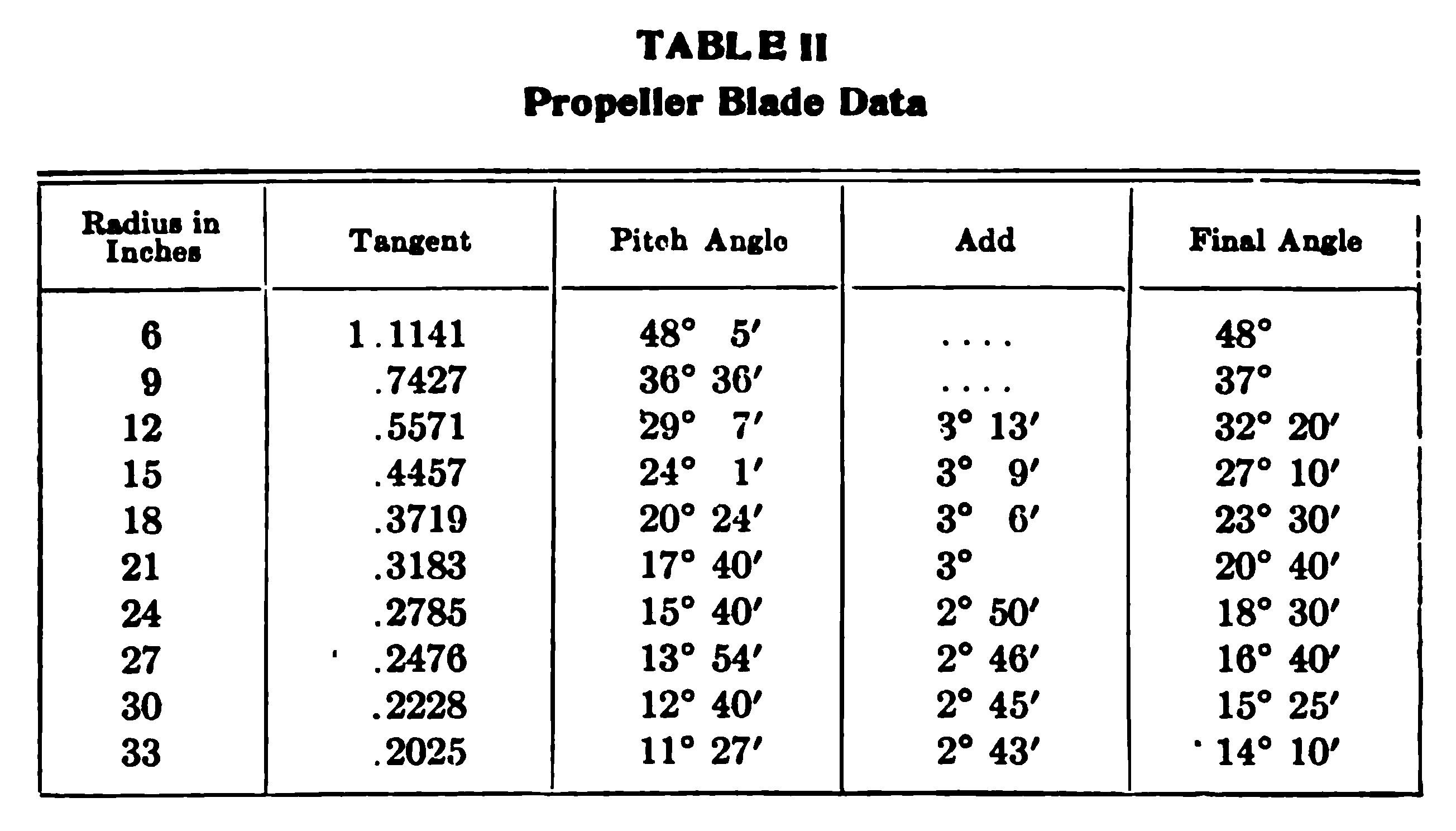
For example, take that part of the blade of a 3 1/2-foot pitch propeller which is 6 inches from the center of the hub. Then
3.5 X 12 / 6 X 2 π = 1.1141 tangent of 48 degrees 5 minutes
in which 3.5 X 12 reduces the pitch to inches, while 6 X 2π is the circumference of the circle described by the point 6 inches from the hub. However, in order to give the propeller blade a proper hold on the air, it must be set at a greater angle than these figures would indicate. That is, it must be given an angle of incidence similar to that given to every one of the supporting planes of the machine. This additional angle ranges from 2 degrees 30 minutes, to 4 degrees, depending upon the speed at which the particular part of the blade travels; the greater the speed, the less the angle. This does not apply to that part of the blade near the hub as the latter is depended upon solely for strength and is not expected to add to the effective thrust of the propeller.
Table II shows the complete set of figures for a blade of 3 1/2-foot pitch, the angles being worked out for sections of the blade 3 inches apart.
These angles are employed in Fig. 21, which shows one blade of the propeller and its cross sections.
It should be understood that these calculations apply only to the type of propeller known as the true screw, as distinguished from the variable pitch. The design of the latter is a matter of personal skill and experience in its making which is hardly capable of expression in any mathematical formula. There are said to be only about three men in this country who know how to make a proper variable-pitch propeller, and it naturally is without advantage when made otherwise.
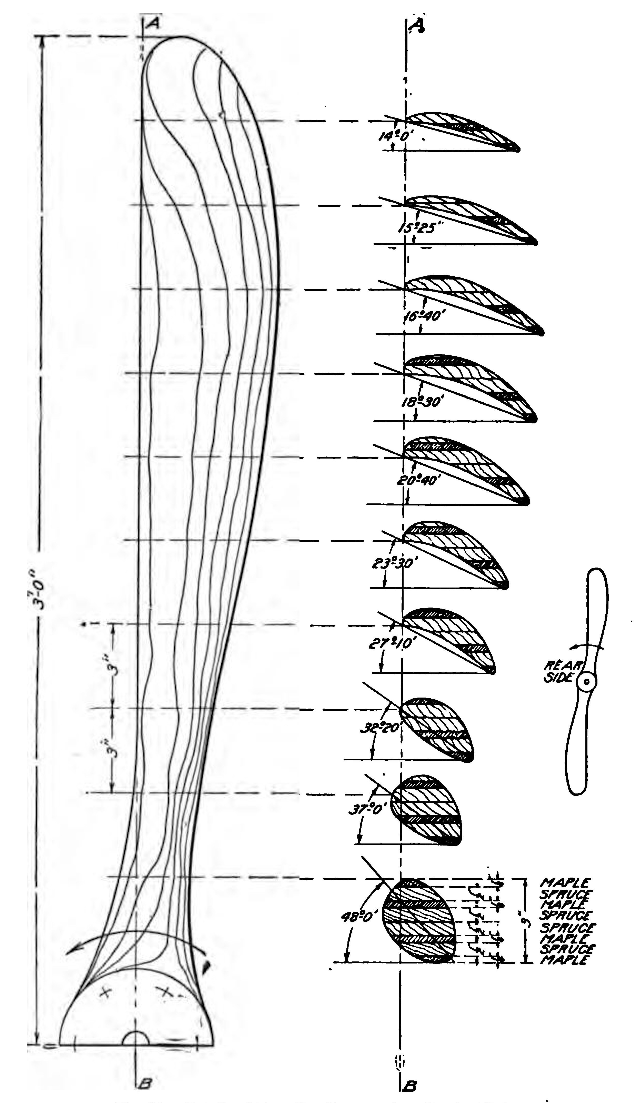
Shaping the Blades. Like the ribs, the propeller is made up of a number of laminations of boards finished true and securely glued, afterward being cut to the proper shape, though this process, of course, involves far more skill than in the former case. Spruce is the strongest wood for its weight, but it is soft and cracks easily. Maple, on the other hand, is tough and hard, so that it will be an advantage to alternate the layers of these woods with an extra maple board, in order to make both outside strips of the harder wood, so as to form a good backing for the steel flanges at the hub, the rear layer extending the full length of the thin rear edges of the blades. Other woods may be employed and frequently are used by propeller manufacturers, such as mahogany (not the grained wood used for furniture, but a cheaper grade which is much stronger), walnut, alternate spruce and whitewood, and others.
The boards should be selected with the greatest care so as to insure their being perfectly clear, i.e., absolutely free of knots, cross-grained streaks, or similar flaws, which would impair their strength and render them difficult to work smoothly. They should measure 6 inches wide by 6 feet 1 inch in length. Their surfaces must be finished perfectly true, so that they will come together uniformly all over the area on which they bear on one another, and the various pieces must be glued together with the most painstaking care. Have the glue hot, so that it will spread evenly, and see that it is of a uniform consistency, in order that it may be smoothly applied to every bit of the surface. They must then be clamped together under as much pressure as it is possible to apply to them with the means at hand, the rib press already described in detail forming an excellent tool for this purpose. Tighten up the nuts evenly a little at a time, avoiding the application of excessive or uneven pressure at one point, continuing the gradual tightening up process until it can not be carried any farther. This is to prevent the boards from assuming a curve in drying fast. Allow at least twenty-four hours for drying, during which period the laminated block should be kept in a cool, dry place at as even a temperature as possible.
Before undertaking the remainder of the work, all of which must be carried out by hand, with the exception of cutting the block to the outline of the propeller, which may be done with a band saw, a set of templates or gauges should be made from the drawings. These will be necessary as guides for finishing the propeller accurately. Draw the sections out full size on sheets of cardboard or tin and cut out along the curves, finally dividing each sheet into two parts, one for the upper side and one for the lower. Care must be taken to get the sides of the template square, and when they are used, the propeller should be laid on a perfectly true and flat block. Each template should be marked as it is finished, to indicate what part of the blade it is a gauge for. The work of cutting the laminated block down to the lines represented by the templates is carried out with the aid of the plane, spoke shave, and gouge. After the first roughing out to approximate the curvature of the finished propeller is completed, the cuts taken should be very fine, as it will be an easy matter to go too deep, thus spoiling the block and necessitating a new start with fresh material. For finishing, pieces of broken glass are employed to scrape the wood to a smooth surface, followed by coarse and finally by fine sandpaper.
Mounting. The hub should be of the same diameter as the flange on the engine crank shaft to which the flywheel was bolted, and should have its bolt holes drilled to correspond. To strengthen the hub, light steel plates of the same diameter are screwed to it, front and back, and the bolt holes drilled right through the metal and wood. This method of fastening is recommended where it is possible to substitute the propeller for the flywheel formerly on the engine, it being common practice to omit the use of the flywheel altogether. The writer does not recommend this, however, as the advantages of smoother running and more reliable operation gained by the use of a flywheel in addition to the propeller far more than offset any disadvantage represented by its weight. It will be noted that the Wright motors have always been equipped with a flywheel of ample size and weight and this is undoubtedly responsible, in some measure at least, for the fact that the Wright biplanes fly with considerably less power than is ordinarily employed for machines of the same size. If the motor selected be equipped with an unusually heavy flywheel, and particularly where the wheel is of comparatively small diameter, making it less effective as a balancer, it may be replaced with one of lighter weight and larger diameter. It may be possible to attach it by keying to the forward end of the crank shaft, thus leaving the flange from which the flywheel was taken free for mounting the propeller. An ordinary belt pulley will serve excellently as the new flywheel, as most of its weight is centered in its rim, but as the common cast-iron belt pulley of commerce is seldom intended to run at any such speed as that of an automobile motor, it should be examined carefully for flaws. Otherwise, there will be danger of its blunting with disastrous results under the influence of centrifugal force. Its diameter should not exceed 16 inches in order to keep its peripheral speed within reasonable limits. Where the mounting of the motor permits of its use, a wood pulley 18 to 20 inches in diameter with a steel band about 1/8 to 1/4-inch thick, shrunk on its periphery, may be employed. Most builders will ridicule the idea of a flywheel other than the propeller itself. "You do not need it; so why carry the extra weight?" will be their query. It is not absolutely necessary, but it is an advantage.
In case the flywheel of the engine selected is keyed to the crank shaft, or in case it is not possible to mount both the flywheel and the propeller on different ends of the crank shaft, some other expedient rather than that of bolting to the flange must be adopted. In such a case, the original flywheel, where practical to retain it, may be drilled and tapped and the propeller attached directly to it. Where the flywheel can not be kept, it will usually be found practical to cut off its rim and bolt the propeller either to the web or spokes, or to the flywheel hub, if it be cut down to the latter.
The drawing. Fig. 21, shows the rear or concave side of the propeller. From the viewpoint of a man standing in its wind and facing forward, it turns to the left, or anti-clockwise. On many of the propellers now on the market, the curved edge is designed to go first. This type may have greater advantages over that described, but the straight front edge propeller is easier for the amateur to make.
Mounting the Engine. Having completed the propeller, the next step is the mounting of the engine. Reference to the types available to the amateur aeroplane builder has already been made. There are a number of motors now on the market that have been designed specially for this purpose and not a few of them are of considerable merit. Their cost ranges from about $250 up to $2,500, but it may be possible to pick up a comparatively light-weight automobile motor second hand which will serve all purposes and which will cost far less than the cheapest aeronautic motor on the market. It must be capable of developing 30 actual horse-power at 1,000 to 1,200 r.p.m. and must not exceed 400 pounds complete with all accessories, such as the radiator and piping, magneto, water, oil, etc. Considerable weight may be saved on an automobile motor by removing the exhaust manifold and substituting a lighter flywheel for the one originally on the engine—or omitting it altogether, as just mentioned. A light-weight aeronautic radiator should be used in preference to the usual automobile radiator.
When placing the engine in position on the ash beams forming its bed or support, it must be borne in mind that the complete machine, with the operator in the aviator's seat, is designed to balance on a point about 1 1/2 feet back of the front edge of the main planes. As the operator and the motor represent much the larger part of the total weight, the balance may easily be regulated by moving them slightly forward or backward, as may be required. It will be necessary, of course, to place the engine far enough back in any case to permit the propeller blades to clear the planes. The actual installation of the engine itself will be an easy matter for anyone who has had any experience in either automobile or marine gasoline motor work. It is designed to be bolted to the two engine beams in the same manner as on the side members of the frame of an automobile, or the engine bed in a boat. Just in front of the engine is the best place for the gasoline tank, which should be cylindrical with tapering ends, to cut down its wind resistance. If the designer is not anxious to carry out points as fine as this, a light copper cylindrical tank may be purchased from stock. It should hold at least ten gallons of gasoline. In front of the tank is the radiator.
Controls. The controls may be located to conform to the builder's own ideas of accessibility and convenience. Usually the switch is placed on the steering column, and it may be of the ordinary knife variety, or one of the special switches made for this purpose, as taste may dictate. The throttle control and spark advance may either be in the form of pedals, working against springs, or of small levers working on a notched sector, at the side of the seat. The complete control, levers, and sector may be purchased ready to mount whenever desired, as they are made in this form for both automobile and marine work. This likewise applies to the wheel, which it would not pay the amateur to attempt to make.
Another pedal should work a brake on the front wheel, the brake shoe consisting of a strip of sheet steel, fastened at one end to the fore part of the skid and pressed against the wheel by a bamboo rod directly connected with the brake pedal. An emergency brake can also be made by loosely bolting a stout bar of steel on the skid near its rear end; one end of this bar is connected to a lever near the seat, so that when this lever is pulled back the other end of the bar tends to dig into the ground. As making a landing is one of the most difficult feats for the amateur aviator to master and sufficient space for a long run after alighting is not always available, these brakes will be found a very important feature of the machine.
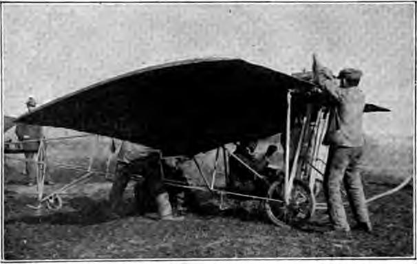
The engine is started by swinging the propeller, and this is an operation requiring far more caution than cranking an automobile motor. Both hands should be placed on the same blade. Fig. 22, and the latter should always be pulled downward—never upward. With the switch off, first turn the propeller over several times to fill the cylinders with gas, leaving it just ahead of dead center of one of the cylinders, and with one blade extending upward and to the left at a 45-degree angle. After closing the switch, take the left blade with both hands and swing it downward sharply, getting out of the way of the following blade as quickly as possible.
Tests. The first thing to be done after the propeller is finished and mounted on the engine is to test the combination, or power plant of the biplane, for speed and thrust, or pulling power. From these two quantities it will be easy to figure the power that the engine is delivering. The only instruments necessary are a spring balance reading to 300 pounds or over; a revolution counter, such as may be procured at any machinist's supply house for a dollar or two; and a watch. One end of the spring balance is fastened to the front end of the skid and the other to a heavy stake firmly driven in the ground a few feet back. The wheels of the biplane should be set on smooth boards so that they will not offer any resistance to the forward thrust. When the engine is started the spring balance will give a direct reading of the pull of the propeller.
With one observer noting the thrust, another should check the number of revolutions the engine is turning per minute. To do this, a small hole should previously have been countersunk in the hub of the propeller to receive the conical rubber tip of the revolution counter. The observer stands behind the propeller, watch in one hand and revolution counter in the other. At the beginning of the minute period, the counter is pressed firmly against the hub, and quickly withdrawn at the end of the minute. A stop watch is naturally an advantage for the purpose. The horse-power is figured as follows, assuming, for example, a thrust of 250 pounds at 1,200 r.p.m.
250 X 1200 X 3.5 X 100 / 33.000 X 85 = 37 h. p.
As before, the "100/85" allows for the slip and represents the efficiency of the propeller; 33,000 is the number of foot pounds per minute or the equivalent of one horse-power, and 3.5 is the pitch of the propeller.
Assembling the Biplane. Assembling the machine complete requires more space than is available in the average workshop. However, it is possible to assemble the sections of the planes in a comparatively small room, carrying the work far enough to make sure that everything will go together properly when the time comes for complete assembly at the testing ground. In this case, it is preferable to assemble the end sections first, standing them away when complete to make room for the central section, on which the running gear and outriggers are to be built up.
The builder will have decided by this time whether he will make his machine on the regular plan, with one main rib between each section, or on the quick-detachable plan, which has two main ribs on either side of the central section, as previously explained.
It is desirable to be able to assemble two sections at once and this should be possible anywhere as it requires a space only about 6 by 13 feet. Two wood 2X4's, about 12 feet long, should be nailed down on the blocks on the floor; make these level and parallel to each other at a distance of 3 feet 6 inches on centers, one being 3 inches higher than the other. Strips of wood should be nailed on them, so as to hold the main beams of the frame in place while assembling.
The two front and two rear beam sections are laid in place and joined with the sheet-steel sleeves, the flanges of the sleeves on the inner side of the beams. Then through the sleeves in the front beams, which are, of course, those on the higher bed, drill the holes for the strut socket bolts (1/4 inch). The holes for the outer ones go through the projecting ends of the beams; those for the inner ones are half in each of the two abutting beams. At the end where the central section joins on, a short length of wood of the same section may be inserted in the sleeve while drilling the hole. An assistant should hold the beams firmly together while the holes are being drilled.
Now lay in place the three main ribs belonging to the two sections under construction and fasten them at the front ends by putting in place the strut sockets for which the holes have been drilled, with a turnbuckle plate under each socket, Fig. 16. The strut socket bolt passes through the main rib and the beam. The bed on which the assembling is being done, should be cut when sufficiently under the joints to leave room for the projecting bolt ends. Set the ribs square with the front beams, then arrange the rear beams so that their joints come exactly under the ribs; clamp the ribs down and drill a true, vertical hole through the rib beam, holding the two sections of the beam together as before. Then put the rear strut sockets in place, using the angle washers previously described, above and below the rib.
When the quick-detachable plan is followed, the ribs at the inner ends of the double section, where they join the central section, should be bolted on an inch from the ends of the beam, using 1/4-inch stove bolts instead of the socket bolts. The sleeves should be slotted, so that they can slide off without removing these bolts, as the sleeves and ribs which occupy the position over the joints of the beams, belong to the central section.
The sections should now be strung up with the diagonal truss wires which will make them rigid enough to stand handling. The wires are attached at each end to the flange bolts of the sleeves. Either one or two turnbuckles may be used on each wire, as already explained; if but one turnbuckle be used, the other end of the wire may be conveniently attached to a strip of sheet steel bent double and drilled for the bolt, like the sheet-steel slip of a turnbuckle. The attachment, of whatever nature, should be put between the end and the flange of the sleeve, not between the two flanges.
Three or four ribs can be used on each section; four are preferable on sections of full 6-foot length. They are, of course, evenly spaced on centers. At the front ends, they are attached to the beam by wood screws through their flattened ferrules. The attachment to the rear beam is made with a slip of sheet steel measuring 1/2 by 3 inches, bent over the rib and fastened to the beam at each side with a wood screw. A long wire nail is driven through the rib itself on the beam.
Four double sections should be built up in this manner, the right and left upper and the right and left lower sections. Uppers and lowers are alike except for the inversion of the sockets in the upper sections. Rights and lefts differ in that the outer beams are long enough to fill up the sleeves, not leaving room for another beam to join on.
Inserting the struts in their sockets between the upper and lower sections of the same side will now form either of the two sides of the machine complete. Care should be taken to get the rear struts the proper length with respect to the front ones to bring the upper and lower planes parallel. The distance from the top of the lower front beam to the top of the upper front beam should be the same as the distance between the rows of bracing holes in the upper and lower main ribs just above and below the rear struts—about 4 feet 6 inches. It should hardly be necessary to mention that the thick edges of the struts come to the front—they are fish-shaped and a fish is thicker at the head than at the tail.
The truss wires may now be strung on in each square of the struts, beams, and main ribs, using turnbuckles as previously described. The wires should be taut enough to sing a low note when plucked between the thumb and forefinger. If the construction is carried out properly, the framework will stand square and true with an even tension on all the wires. It is permissible for the struts to slant backward a little as seen from the side, but all should be perfectly in line.
For adjusting the turnbuckles, the builder should make for himself a handy little tool usually termed a nipple wrench. It is simply a strip of steel 1 1/2 by 1/2 by 3/32 inches, with a notch cut in the middle of the long sides to fit the flattened ends of the turnbuckle nipples. This is much handier than the pliers and does not burr up the nipples.
It has been assumed in this description of the assembling that the builder is working in a limited space; if, on the contrary, he has room enough to set up the whole frame at once, the work will be much simpler. In this case, the construction bed should be 30 feet long. First build up the upper plane complete, standing it against the wall when finished; then build the lower plane, put the struts in their sockets, and lay on the upper plane complete.
Returning to the plan of assembly by sections, after the side sections or wings of the machine have been completed, the struts may be taken out and the sections laid aside. The middle section, to which the running gear and outriggers will be attached, is now to be built up in the same way. If the builder is following the plan in which there is one main rib between each section, it will be necessary to take off the four inner main ribs from the sections already completed, to be used at the ends of the central section. The plan drawing of the complete machine shows that the ribs of the central section are cut off just back of the rear beam to make room for the propeller. This is necessary in order to set the motor far enough forward to balance the machine properly. The small ribs in this section have the same curve but are cut off 10 inches shorter at their rear ends, and the stumps are smoothed down for ferrules like those for the other small ribs. In the plan which has one main rib between each section, the main rib on each side of the central section must be left full length. In the quick-detachable plan with two main ribs on each side of the central section, the inner ones, which really belong to this section, are cut off short like the small ribs.
In the drawing of the complete machine, the distance between the struts which carry the engine bed is shown as 2 feet. This is only approximate, as the distance must be varied to suit the motor employed. By this time, the builder will have decided what engine he is going to use—or can get—and should drill the holes for the sockets of these struts with due respect to the width of the engine's supporting feet or lugs, remembering that the engine bed beams go on the inside of the struts. In the drawing of the running gear. Fig. 17, the distance between the engine-bed struts has been designated A. The distances, B, on each side are, of course, approximately (6'— 2*A*), whatever A may be.
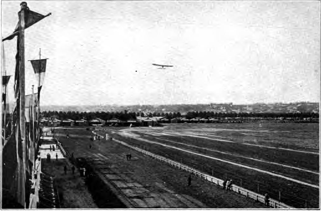
This Photograph Protected By International Copyright
EXAMINATION PAPER
BUILDING AND FLYING AN
AEROPLANE
PART I
Read Carefully: Place your name and full address at the head of the paper. Any cheap, light paper like the sample previously sent you may be used. Do not crowd your work, but arrange it neatly and legibly. Do not copy the answers from the Instruction Paper; use your own words so that we may be sure that you understand the subject.
What type of machine, biplane or monoplane, makes the best glider and why?
Give the dimensions of a glider which will support a man's weight.
In a glider which has no rudder, how is the machine controlled?
Give carefully the details of the start in making a glide.
In what direction relative to the wind should a glide be made? Justify your answer.
How must the stability and balance of a glider in flight be controlled?
State the proper conditions for a successful glide.
Give the essential characteristics of a Curtiss aeroplane, defining the various parts.
Describe briefly the details of construction of the main supporting surfaces of a Curtiss.
Draw a diagram of the assembled planes showing how the struts and cross wires are placed to give the required rigidity.
Give the details of the running gear of the Curtiss.
What is the office of the Curtiss ailerons and how are they controlled from the operator's seat? Draw sketch.
Describe the details of the front and rear outriggers.
What type of propeller is advised for the Curtiss? Give the details of its construction.
Describe carefully the manner in which a propeller should move through the air in order to give the maximum propulsion.
What determines the exact location of the motor in the aeroplane?
Give correct method of starting the motor when ready for a flight.
What tests should be conducted before a flight is undertaken?
After completing the work, add and sign the following statement:
I hereby certify that the above work is entirely my own.
(Signed)
PART II
BUILDING A BLERIOT MONOPLANE
As mentioned in connection with the description of its construction, the Curtiss biplane was selected as a standard of this type of aeroplane after which the student could safely pattern for a number of reasons. It is not only remarkably simple in construction, easily built by anyone with moderate facilities and at a slight outlay, but it is likewise the easiest machine to learn to drive. The monoplane is far more difficult and expensive to build.
The Bleriot may be regarded as the most typical example in this field, in view of its great success and the very large numbers which have been turned out. In fact, the Bleriot monoplane is the product of a factory which would compare favorably with some of the large automobile plants. Its construction requires skillful workmanship both in wood and metal, and a great many special castings, forgings, and stampings are necessary. Although some concerns in this country advertise that they carry these fittings as stock parts, they are not always correct in design and, in any case, are expensive. Wherever it is possible to avoid the use of such parts by any expedient, both forms of construction are described, so that the builder may take his choice.
Bleriot monoplanes are made in a number of different models, the principal ones being the 30-horse-power "runabout," Figs. 23 and 24, the 50- and 70-horse-power passenger-carrying machines, and the 50-, 70-, and 100-horse-power racing machines. Of these the first has been chosen as best adapted to the purpose. Its construction is typical of the higher-power monoplanes of the same make, and it is more suitable for the beginner to fly as well as to build. It is employed exclusively by the Bleriot schools.
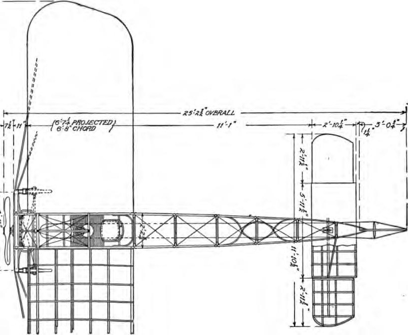
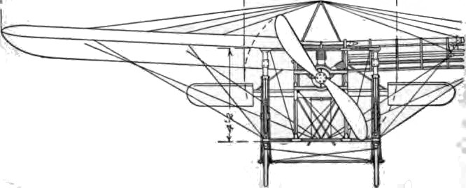
Motor. The motor regularly employed is the 30-horse-power, three-cylinder Anzani, a two-cylinder type of which is shown in "Aeronautical Motors" Fig. 40. From the amateur's standpoint, a disadvantage of the Bleriot is the very short space allowed for the installation of the motor. For this reason, the power plant must be fan shaped, like the Anzani; star form, like the Gnome; or of the two-cylinder opposed type. It must likewise be air-cooled, as there is no space available for a radiator.
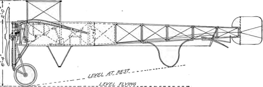
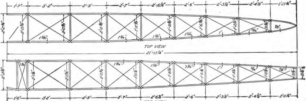
Fuselage. Like most monoplanes, the Bleriot has a long central body, usually termed "fuselage," to which the wings, running gear, and controls are all attached. A drawing of the fuselage with all dimensions is reproduced in Fig. 25, and as the machine is, to a large extent, built up around this essential, its construction is taken up first. It consists of four long beams united by 35 crosspieces. The beams are of ash, 1 3/16 inches square for the first third of their length and tapering to 7/8 inch square at the rear ends. Owing to the difficulty of securing good pieces of wood the full length, and also to facilitate packing for shipment, the beams are made in halves, the abutting ends being joined by sleeves of 1 1/8-inch, 20-gauge steel tubing, each held on by two 1/8-inch bolts. Although the length of the fuselage is 21 feet 11 1/4 inches, the beams must be made of two 11-foot halves to allow for the curve at the rear ends.
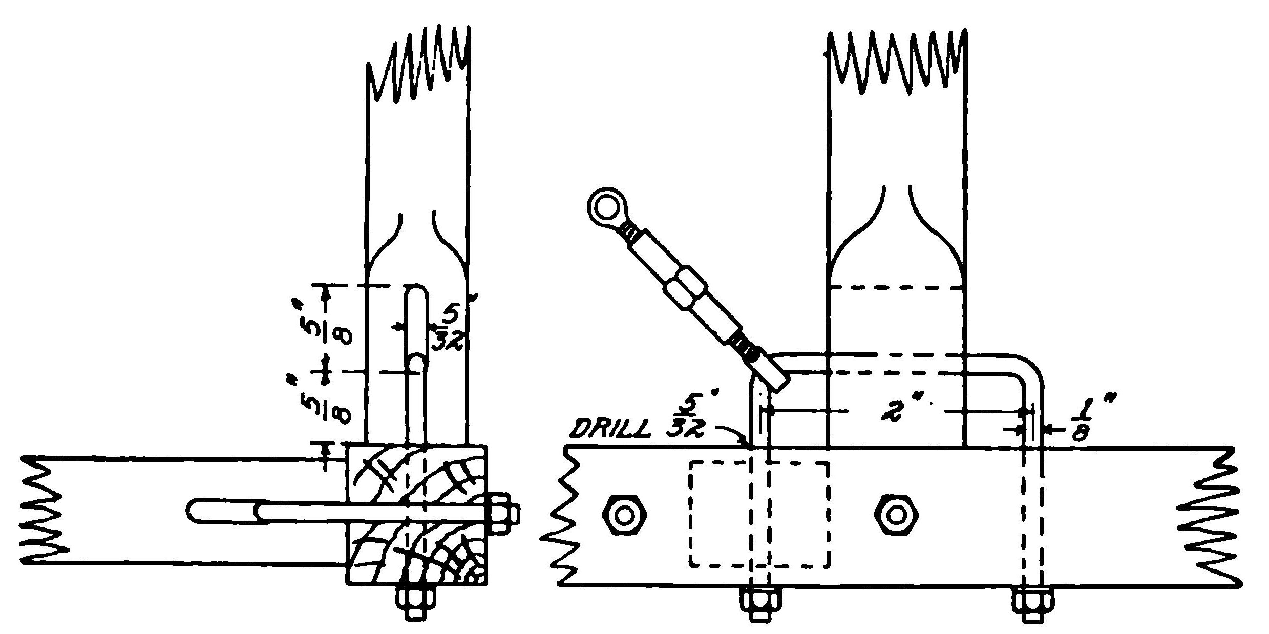
The struts are also of ash, the majority of them being 7/8 by 1 1/4 inches, and oval in section except for an inch and a half at each end. But the first, second, and third struts (counting from the forward end) on each side, the first and second on the top, and the first strut on the bottom are 1 3/16 inches square, of the same stock as the main beams. Practically all of the struts are joined to the main beams by U-bolts, as shown by the detail drawing, Fig. 26, this being one of Louis Bleriot's inventions. The small struts are held by 1/8-inch bolts and the larger ones by 3/16-inch bolts. The ends of the struts must be slotted for these bolts, this being done by drilling three holes in a row with a 5/32- or 7/32-inch drill, according to whether the slot is for the smaller or larger size bolt. The wood between the holes is cut out with a sharp knife and the slot finished with a coarse, flat file.
All of the U-bolts measure 2 inches between the ends. The vertical struts are set 1 inch forward of the corresponding horizontal struts, so that the four holes through the beam at each joint are spaced 1 inch apart, alternately horizontal and vertical. To the projecting angles of the U-bolts are attached the diagonal truss wires, which cross all the rectangles of the fuselage, except that in which the driver sits. This trussing should be of 20-gauge piano wire (music-wire gauge) or 1/10-inch cable, except in the rectangles bounded by the large struts, where it should be 25-gauge piano wire or 3/32-inch cable. Each wire, of course, should have a turnbuckle. About 100 of these will be required, either of the spoke type or the regular type, with two screw eyes—the latter preferred.
Transverse squares, formed by the two horizontal and two vertical struts at each point, are also trussed with diagonal wires. Although turnbuckles are sometimes omitted on these wires, it takes considerable skill to get accurate adjustments without them. The extreme rear strut to which the rudder is attached, is not fastened in the usual way. It should be cut with tongues at top and bottom, fitting into notches in the ends of the beams, and the whole bound with straps of 20-gauge sheet steel, bolted through the beams with 1/8-inch bolts.
Continuing forward, the struts have no peculiarity until the upper horizontal one is reached, just behind the driver's seat. As it is impossible to truss the quadrangle forward of this strut, owing to the position of the driver's body, the strut is braced with a U-shaped half-round strip of 1/2 by 1 inch of ash or hickory bolted to the beams at the sides and to the strut at the rear, with two 1/8-inch bolts at each point. The front side of the strut should be left square where this brace is in contact with it. The brace should be steam bent with the curves on a 9-inch radius, and the half-round side on the inside of the curve.
The vertical struts just forward of the driver's seat carry the inner ends of the rear wing beams. Each beam is attached with a single bolt, giving the necessary freedom to rock up and down in warping the wings. The upper 6 inches of each of these struts fits into a socket designed to reinforce it. In the genuine Bleriot, this socket is an aluminum casting. However, a socket which many would regard as even better can be made from a 7-inch length of 20-gauge 1 1/8-inch square tubing. One end of the tube is sawed one inch through the corners; two opposite sides are then bent down at right angles to form flanges, and the other two sides sawed off. A 1- by 3-inch strip of 20-gauge sheet steel, brazed across the top and flanges completes the socket. With a little care, a very creditable socket can be made in this way. Finally, with the strut in place, a 3/8-inch hole is drilled through 4 inches from the top of the socket for the bolt securing the wing beam.
The upper horizontal strut at this point should be arched about six inches to give plenty of elbow room over the steering wheel. The bending should be done in a steam press. The strut should be 1 3/16 inches square, cut sufficiently long to allow for the curve, and fitted at the ends with sockets as described above, but set at an angle by sawing the square tube down further on one side than on the other.
On the two lower beams, is laid a floor of half-inch boards, extending one foot forward and one foot back of the center line of the horizontal strut. This floor may be of spruce, if it is desired to save a little weight, or of ordinary tongue-and-grooved floor boards, fastened to the beams with wood screws or bolts. The horizontal strut under this floor may be omitted, but its presence adds but little weight and completes the trussing. Across the top of the fuselage above the first upper horizontal strut, lies a steel tube which forms the sockets for the inner end of the front wing beams. This tube is 1 3/4 inches diameter, 18 gauge, and 26 3/4 inches long. It is held fast by two steel straps, 16 gauge and 1 inch wide, clamped down by the nuts of the vertical strut U-bolts. The center of the tube is, therefore, in line with the center of the vertical struts, not the horizontal ones. The U-bolts which make this attachment are, of course, the 3/16-inch size, and one inch longer on each end than usual. To make a neat job, the tube may be seated in wood blocks, suitably shaped, but these must not raise it more than a small fraction of an inch above the top of the fuselage, as this would increase the angle of incidence of the wings.
The first vertical struts on each side are extras, without corresponding horizontal ones; they serve only to support the engine. When the Gnome motor is used, its central shaft is carried at the centers of two X-shaped, pressed-steel frames, one on the front side, flush with the end of the fuselage and one on the rear.
Truss Frame Built on Fuselage. In connection with the fuselage may be considered the overhead truss frame and the warping frame. The former consists of two inverted V's of 20-gauge, 1- by 3/8-inch oval tubing, joined at their apexes by a 20-gauge, 3/4-inch tube. Each V is formed of a single piece of the oval tubing about 5 feet long. The flattened ends of the horizontal tube are fastened by a bolt in the angles of the V's. The center of the horizontal tube should be 2 feet above the top of the fuselage. The flattened lower ends of the rear V should be riveted and brazed to strips of 18-gauge steel, which will fit over the bolts attaching the vertical fuselage struts at this point. The legs of the front V should be slightly shorter, as they rest on top of the wing socket tube. Each should be held down by a single 3/16-inch bolt, passing through the upper wall of the tube and its retaining strap; these bolts also serve the purpose of preventing the tube from sliding out from under the strap. Each side of the frame is now braced by diagonal wires (No. 20 piano wire, or 1/14-inch cable) with turnbuckles.
At the upper corners of this frame are attached the wires which truss the upper sides of the wings. The front wires are simply fastened under the head and nut of the bolt which holds the frame together at this corner. The attachment of the rear wires, however, is more complex, as these wires must run over pulleys to allow for the rocking of the rear wing beams when the wings are warped. To provide a suitable place for the pulleys, the angle of the rear V is enclosed by two plates of 20-gauge sheet steel, one on the front and one on the rear, forming a triangular box 1 inch thick fore and aft, and about 2 inches on each side, only the bottom side being open. These plates are clamped together by a 3/16-inch steel bolt, on which are mounted the pulleys. There should be sufficient clearance for pulleys 1 inch in diameter. The wires running over these pulleys must then pass through holes drilled in the tube. The holes should not be drilled until the wings are on, when the proper angle for them can be seen. The cutting and bending of the steel plates is a matter of some difficulty, and should not be done until the frame is otherwise assembled, so that paper patterns can be cut for them. They should have flanges bent around the tube, secured by the bolts which hold the frame together, to keep them from slipping off.
The oval tubing is used in the vertical parts of this frame, principally to reduce the wind resistance, being placed with the narrow side to the front. However, if this tubing be difficult to obtain, or if price is a consideration, no harm will be done by using 3/4-inch round tubing. Beneath the floor of the driver's cockpit in the fuselage is the warping frame, the support for the wires which truss the rear wing beams and also control the warping.
This frame is built up of four 3/4-inch, 20-gauge steel tubes, each about 3 feet long, forming an inverted, 4-sided pyramid. The front and back pairs of tubes are fastened to the lower fuselage beams with 3/16-inch bolts at points 15 inches front and back of the horizontal strut. At their lower ends the tubes are joined by a fixture which carries the pulleys for the warping wires and the lever by which the pulleys are turned. In the genuine Bleriot, this fixture is a special casting. However, a very neat connection can be made with a piece of 1/16-inch steel stock, 1 1/4 by 6 inches, bent into a U-shape with the legs 1 inch apart inside. The flattened ends of the tubes are riveted and brazed to the outside upper corners of the U, and a bolt to carry the pulleys passes through the lower part, high enough to give clearance for 2-inch pulleys. This frame needs no diagonal wires.
Running Gear. Passing now to the running gear, the builder will encounter the most difficult part of the entire machine, and it is impossible to avoid the use of a few special castings. The general plan of the running gear is shown in the drawing of the complete machine. Figs. 23 and 24, while some of the details are illustrated in Fig. 27, and the remainder are given in the detail sheet, Fig. 28. It will be seen that each of the two wheels is carried in a double fork, the lower fork acting simply as a radius rod, while the upper fork is attached to a slide which is free to move up and down on a 2-inch steel tube. This slide is held down by two tension springs, consisting of either rubber tubes or steel coil springs, which absorb the shocks of landing. The whole construction is such that the wheels are free to pivot sideways around the tubes, so that when landing in a quartering wind the wheels automatically adjust themselves to the direction of the machine.
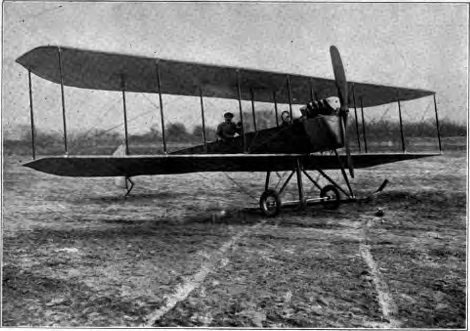
There is Little Resemblance to the Original Except in Wing Form and Warping
Framework. The main framework of the running gear consists of two horizontal beams, two vertical struts, and two vertical tubes. The beams are of ash, 4 3/4 inches wide in the middle half, tapering to 3 3/4 inches at the ends, and 5 feet 2 3/4 inches long overall. The upper beam is H inch thick and the lower 1 inch. The edges of the beams are rounded off except at the points where they are drilled for bolt holes for the attachment of other parts. The two upper beams of the fuselage rest on these beams and are secured to them by two 3/16-inch bolts each.
The vertical struts are also of ash, 1 3/16 inch by 3 inches and 4 feet 2 inches long overall. They have tenons at each end which fit into corresponding square holes in the horizontal beams. The two lower fuselage beams are fastened to these struts by two 3/16-inch through bolts and steel angle plates formed from 1/16-inch sheet steel. The channel section member across the front sides of these struts is for the attachment of the motor, and will be taken up later. The general arrangement at this point depends largely on what motor is to be used, and the struts should not be rounded or drilled for bolt holes until this has been decided.
From the lower ends of these struts CC, Fig. 27, diagonal struts DD run back to the fuselage. These are of ash, 1 3/16 by 2 1/2 inches and 2 feet inches long. The rear ends of the struts DD are fastened to the fuselage beams by the projecting ends of the U-bolts of the horizontal fuselage struts, and also by angle plates of sheet steel. At the lower front ends the struts DD are fastened to the struts CC and the beam E by steel angle plates, and the beam is reinforced by other plates on its under side.
Trussing. In the genuine Bleriot, the framework is trussed by a single length of steel tape, 1 1/8 by 1/16 inch and about 11 feet long, fastened to U-bolts in the beam A, Fig. 27. This tape runs down one side, under the beam E, and up the other side, passing through the beam in two places, where suitable slots must be cut. The tape is not made in this country, but must be imported at considerable expense. Ordinary sheet steel will not do. If the tape can not be obtained, a good substitute is 1/8-inch cable, which then would be made in two pieces and fastened to eye bolts at each end.
The two steel tubes are 2 inches in diameter, 18-gauge, and about 4 feet 10 inches long. At their lower ends they are flattened, but cut away so that a 2-inch ring will pass over them. To these flattened ends are attached springs and wires which run from each tube across to the hub of the opposite wheel. The purpose of these is simply to keep the wheels normally in position behind the tubes. The tubes, it will be noticed, pass through the lower beam, but are sunk only 1/8 inch into the upper beam. They are held in place by sheet-steel sockets on the lower side of the upper beam and the upper side of the lower beam. The other sides of the beams are provided with flat plates of sheet steel. The genuine Bleriot has these sockets stamped out of sheet steel, but as the amateur builder will not have the facilities for doing this, an alternative construction is given here.
In this method, the plates are cut out to pattern, the material being sheet steel 1/16 inch thick, and a 1/2-inch hole drilled through the center, a 2-inch circle then being drawn around this. Then, with a cold chisel a half dozen radial cuts are made between the hole and the circle. Finally this part of the plate is heated with a blow-torch and a 2-inch piece of pipe driven through, bending up the triangular corners. These bent up corners are then brazed to the tubes, and a strip of light sheet steel is brazed on to cover up the sharp edges. Of course, the brazing should not be done until the slides GG, Figs. 27 and 28, have been put on. When these are once in place, they have to stay on and a breakage of one of them, means the replacement of the tube as well. This is a fault of the Bleriot design that can not well be avoided. It should be noticed that the socket at the upper end, as well as its corresponding plate on the other side of the beam, has extensions which reinforce the beam where the eye bolts or U-bolts for the attachment of the steel tape pass through.
Forks. Next in order are the forks which carry the wheels. The short forks JJ, Figs. 27 and 28, which act simply as radius rods, are made of 1- by 3/8-inch oval tubing, a stock size which was specified for the overhead truss frame. It will be noticed that these are in two parts, fastened together with a bolt at the front end. The regular Bleriot construction calls for forged steel eyes to go in the ends of tubes, but these will be hard to obtain. The construction shown in the drawings is much simpler. The ends of the tubes are heated and flattened until the walls are about 1/16 inch apart inside. Then a strip of 1/16-inch sheet steel is cut the right width to fit in the flattened end of the tube, and brazed in place. The bolt holes then pass through the combined thickness of the tube and the steel strip, giving a better bearing surface, which may be further increased by brazing on a washer.
The long forks FF, which transmit the landing shocks to the springs, are naturally made of heavier material. The proper size tubing for them is 1 1/8 by 5/8 inches, this being the nearest equivalent to the 14 by 28 mm French tubing. However, this is not a stock size in this country and can only be procured by order, or it can be made by rolling out 15/16-inch round tubing. If the oval tubing can not be secured, the round can be employed instead, other parts being modified to correspond. The ends are reinforced in the same way as described for the small forks.
These forks are strengthened by aluminum clamps H, Figs. 27 and 28, which keep the tubes from spreading apart. Here, of course, is another call for special castings, but a handy workman may be able to improvise a satisfactory substitute from sheet steel. On each tube there are four fittings: At the bottom, the collar M to which the fork J is attached, and above, the slide G and the clamps K and L, which limit its movement. The collar and slide should be forged, but as this may be impossible, the drawings have been proportioned for castings. The work is simple and may be done by the amateur with little experience. The projecting studs are pieces of 3/4-inch, 14-gauge steel tubing screwed in tight and pinned, though if these parts be forged, the studs should be integral.
The clamps which limit the movement of the slides are to be whittled out of ash or some other hard wood. The upper clamp is held in place by four bolts, which are screwed up tight; but when the machine makes a hard landing the clamp will yield a little and slip up the tube, thus deadening the shock. After such a landing, the clamps should be inspected and again moved down a bit, if necessary. The lower clamps, which, of course, only keep the wheels from hanging down too far, have bolts passing clear through the tubes.
To the projecting lugs on the slides GG are attached the rubber tube springs, the lower ends connecting with eye bolts through the beam E. These rubber tubes, of which four will be needed, are being made by several companies in this country and are sold by supply houses. They should be about 14 inches long, unstretched, and 1 1/4 inches in diameter, with steel tips at the ends for attachment.
Hub Attachments. The hubs of the two wheels are connected with the link P, with universal joints N N at each end. In case the machine lands while drifting sidewise, the wheel which touches the ground first will swing around to head in the direction in which the machine is actually moving, and the link will cause the other wheel to assume a parallel position; thus the machine can run diagonally on the ground without any tendency to upset.
This link is made of the same 1- by 3/8-inch oval tubing used elsewhere in the machine. In the original Bleriot, the joints are carefully made up with steel forgings. But joints which will serve the purpose can be improvised from a 1-inch cube of hard wood and three steel straps, as shown in the sketch, Fig. 27. From each of these joints a wire runs diagonally to the bottom of the tube on the other side, with a spring which holds the wheel in its normal position. This spring should be either a rubber tube, like those described above, but smaller, or a steel coil spring. In the latter case, it should be of twenty 3/4-inch coils of No. 25 piano wire.
Wheels. The wheels are regularly 28 by 2 inches, corresponding to the 700 by 50 mm French size, with 30 spokes of 12-gauge wire. The hub should be 5 1/4 inches wide, with a 5/8-inch bolt. Of course, these sizes need not be followed exactly, but any variations will involve corresponding changes in the dimensions of the forks. The long fork goes on the hub inside of the short fork, so that the inside measurement of the end of the big fork should correspond to the width of the hub, and the inside measurement of the small fork should equal the outside measurement of the large fork.
Rear Skid. Several methods are employed for supporting the rear end of the fuselage when the machine is on the ground. The first Bleriot carried a small wheel in a fork provided with rubber springs, the same as the front wheels. The later models, however, have a double U-shaped skid, as shown in Figs. 23 and 24. This skid is made of two 8-foot strips of ash or hickory 1/2 by 3/4 inches, steamed and bent to the U-shape as shown in the drawing of the complete machine.
Wings. Having completed the fuselage and running gear, the wings are next in order. These are constructed in a manner which may seem unnecessarily complicated, but which gives great strength for comparatively little weight. Each wing contains two stout ash beams which carry their share of the weight of the machine, and 12 ribs which give the proper curvature to the surfaces and at the same time reinforce the beams. These ribs in turn are tied together and reinforced by light strips running parallel to the main beams.
In the drawing of the complete wing. Fig. 29, the beams are designated by the letters B and E. A is a sheet aluminum member intended to hold the cloth covering in shape on the front edge. C, D, and F are pairs of strips (one strip on top, the other underneath) which tie the ribs together. G is a strip along the rear edge, and H is a bent strip which gives the rounded shape to the end of the wing. The ribs are designated by the numbers 1 to 12 inclusive.
Ribs. The first and most difficult operation is to make the ribs. These are built up of a spruce board 3/16 inch thick, cut to shape on a jig saw, with 3/16- by 5/8-inch spruce strip stacked and glued to the upper and lower edges. Each rib thus has an I-beam section, such as is used in structural steel work and automobile front axles. Each of the boards, or webs as they are usually called, is divided into three parts by the main beams which pass through it. Builders sometimes make the mistake of cutting out each web in three pieces, but this makes it very difficult to put the rib together accurately. Each web should be cut out of a single piece, as shown in the detail drawing. Fig. 30, and the holes for the beams should be cut in after the top and bottom strips have been glued on.
The detail drawing, Fig. 30, gives the dimensions of a typical rib. This should be drawn out full size on a strip of tough paper, and then a margin of 3/16 inch should be taken off all round except at the front end where the sheet aluminum member A goes on. This allows for the thickness of the top and bottom strips. In preparing the pattern for the jig saw, the notches for strips C, D, and F should be disregarded; neither should it be expected that the jig-saw operator will cut out the oval holes along the center of the web, which are simply to lighten it. The notches for the front ends of the top and bottom strips should also be smoothed over in the pattern.
When the pattern is ready, a saw or planing mill provided with a saw suitable for the work, should cut out the 40 ribs (allowing a sufficient number for defective pieces and breakage) for about $2. The builder then cuts the notches and makes the oval openings with an auger and keyhole saw. Of course, these holes need not be absolutely accurate, but at least 3/4 inch of wood should be left all around them.
Nine of the twelve ribs in each wing are exactly alike. No. 1, which forms the inner end of the wing, does not have any holes cut in the web, and instead of the slot for the main beam B, has a 1 3/4-inch round hole, as the stub end of the beam is rounded to fit the socket tube. (See Fig. 23.) Rib No. 11 is 5 feet 10 1/2 inches long, and No. 12 is 3 feet long. These can be whittled out by hand, and the shape for them will be obvious as soon as the main part of the wing is put together.
The next step is to glue on the top and bottom strips. The front ends should be put on first and held, during the drying, in a screw clamp, the ends setting close up into the notches provided for them. Thin 1/2-inch brads should be driven in along the top and bottom at 1- to 2-inch intervals. The rear ends of the strips should be cut off to the proper length and whittled off a little on the inside, so that there will be room between them for the strip G, 1/4 inch thick. Finally, cut the slots for the main beams, using a bit and brace and the keyhole saw, and the ribs will be ready to assemble.
Beams and Strips. The main beams are of ash, the front beam in each wing being 3 1/4 by 3/4 inches and the rear beam 2 1/2 by 5/8 inches. They are not exactly rectangular but must be planed down slightly on the top and bottom edges, so that they will fit into the irregularly-shaped slots left for them in the ribs. The front beams, as mentioned above, have round stubs which fit into the socket tube on the fuselage. These stubs may be made by bolting short pieces of ash board on each side of the end of the beam and rounding down the whole.
To give the wings their slight inclination, or dihedral angle, which will be apparent in the front view of the machine, the stubs must lie at an angle of 2 1/2 degrees with the beam itself. This angle should be laid out very carefully, as a slight inaccuracy at this point will result in a much larger error at the tips. The rear beams project about 2 inches from the inner ribs. The ends should be reinforced with bands of sheet steel to prevent splitting, and each drilled with a 3/8-inch hole for the bolt which attaches to the fuselage strut. A strip of heavy sheet steel should be bent to make an angle washer to fill up the triangular space between the beam and the strut; the bolt hole should be drilled perpendicularly to the beam, and not to the strut. The outer ends of the beams, beyond rib No. 10, taper down to 1 inch deep at the ends.
The aluminum member A, Fig. 29, which holds the front edge of the wing in shape, is made of a 4-inch strip of fairly heavy sheet aluminum, rolled into shape round a piece of half-round wood, 2 1/4 inches in diameter. As sheet aluminum usually comes in 6-foot lengths, each of these members will have to be made in two sections, joined either by soldering (if the builder has mastered this difficult process) or by a number of small copper rivets.
No especial difficulties are presented by the strips, C, D, and F, which are of spruce 3/16 by 5/8 inch, or by the rear edge strip G, of spruce 1/4 by 1 1/2 inches. Each piece H should be 1 by 1/2 inch half-round spruce, bent into shape, fitted into the aluminum piece at the front, and at the rear flattened down to 1/4 inch and reinforced by a small strip glued to the back, finally running into the strip G. The exact curve of this piece does not matter, provided it is the same on both wings.
Assembling the Wings. Assembling the wings is an operation which demands considerable care. The main beams should first be laid across two horses, set level so that there will be no strain on the framework as it is put together. Then the 12 ribs should be slipped over the beams and evenly spaced 13 inches apart to centers, care being taken to see that each rib stands square with the beams, Fig. 31. The ribs are not glued to the beams, as this would make repairs difficult, but are fastened with small nails.
Strips C, D, and F, Fig, 29, are next put in place, simply being strung through the rows of holes provided for them in the ribs, and fastened with brads. Then spacers of 3/16-inch spruce, 2 or 3 inches long, are placed between each pair of strips halfway between each rib, and fastened with glue and brads. This can be seen in the broken-off view of the wing in the front view drawing, Fig. 23. The rear edge strip fits between the ends of the top and bottom strips of the ribs, as mentioned above, fastened with brads or with strips of sheet-aluminum tacked on.
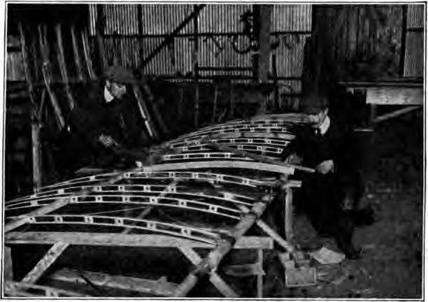
Each wing is trussed by eight wires, half above and half below; half attached to the front and half to the rear beam. In the genuine Bleriot steel tape is used for the lower trussing of the main beams, similar to the tape employed in the running gear, but American builders prefer to use 1/8-inch cable. The lower rear trussing should be 3/32- or 7/64-inch cable, and the upper trussing 3/32-inch.
The beams are provided with sheet-steel fixtures for the attachment of the cables, as shown in the broken-off wing view, Fig. 23. These are cut from fairly-heavy metal, and go in pairs, one on each side of the end beam, fasten with three 3/16-inch bolts. They have lugs top and bottom. They are placed between the fifth and sixth and ninth and tenth ribs on each side.
To resist the backward pressure of the air, the wings are trussed with struts of 1-inch spruce and 1/16-inch cable, as shown in Fig. 23. The struts are placed between the cable attachments, being provided with ferrules of flattened steel tubing arranged to allow the rear beam freedom to swing up and down. The diagonal cables are provided with turnbuckles and run through the open spaces in the ribs.
Control System. The steering gear and tail construction of the Bleriot are as distinctive as the swiveling wheels and the U-bolts, and the word "cloche" applied to the bell-like attachment for the control wires, has been adopted into the international vocabulary of aeroplaning. The driver has between his knees a small steering wheel mounted on a short vertical post. This wheel does not turn, but instead the post has a universal joint at the bottom which allows it to be swung backward and forward or to either side. The post is really a lever, and the wheel a handle. Encircling the lower part of the post is a hemispherical bell—the cloche—with its bottom edge on the same level as the universal joint.
Four wires are attached to the edge of the cloche. Those at the front and back are connected with the elevator, and those at the sides with the wing-warping lever. The connections are so arranged that pulling the wheel back starts the machine upward, while pushing it forward causes it to descend, and pulling to either side lowers that side and raises the other. The machine can be kept on a level keel by the use of the wheel and cloche alone; the aviator uses them just as if they were rigidly attached to the machine, and by them he could move the machine bodily into the desired position.
In practice, however, it has been found that lateral stability can be maintained more easily by the use of the vertical rudder than by warping. This is because the machine naturally tips inward on a turn, and, consequently, a tip can be corrected by a partial turn in the other direction. If, for example, the machine tips to the right, the aviator steers slightly to the left, and the machine comes back to a level keel without any noticeable change in direction. Under ordinary circumstances this plan is used altogether, and the warping is used only on turns and in bad weather.
It will be noticed that the Bleriot control system is almost identical with that of the Henri Farman biplane, the only difference being that in the Farman the cloche and wheel are replaced by a long lever. The movements, however, remain the same, and as there are probably more Bleriot and Farman machines in use than all other makes together, this control may be regarded almost as a standard. It is not as universal as the steering wheel, gear shift, and brake levers of the automobile, but still it is a step in the right direction.
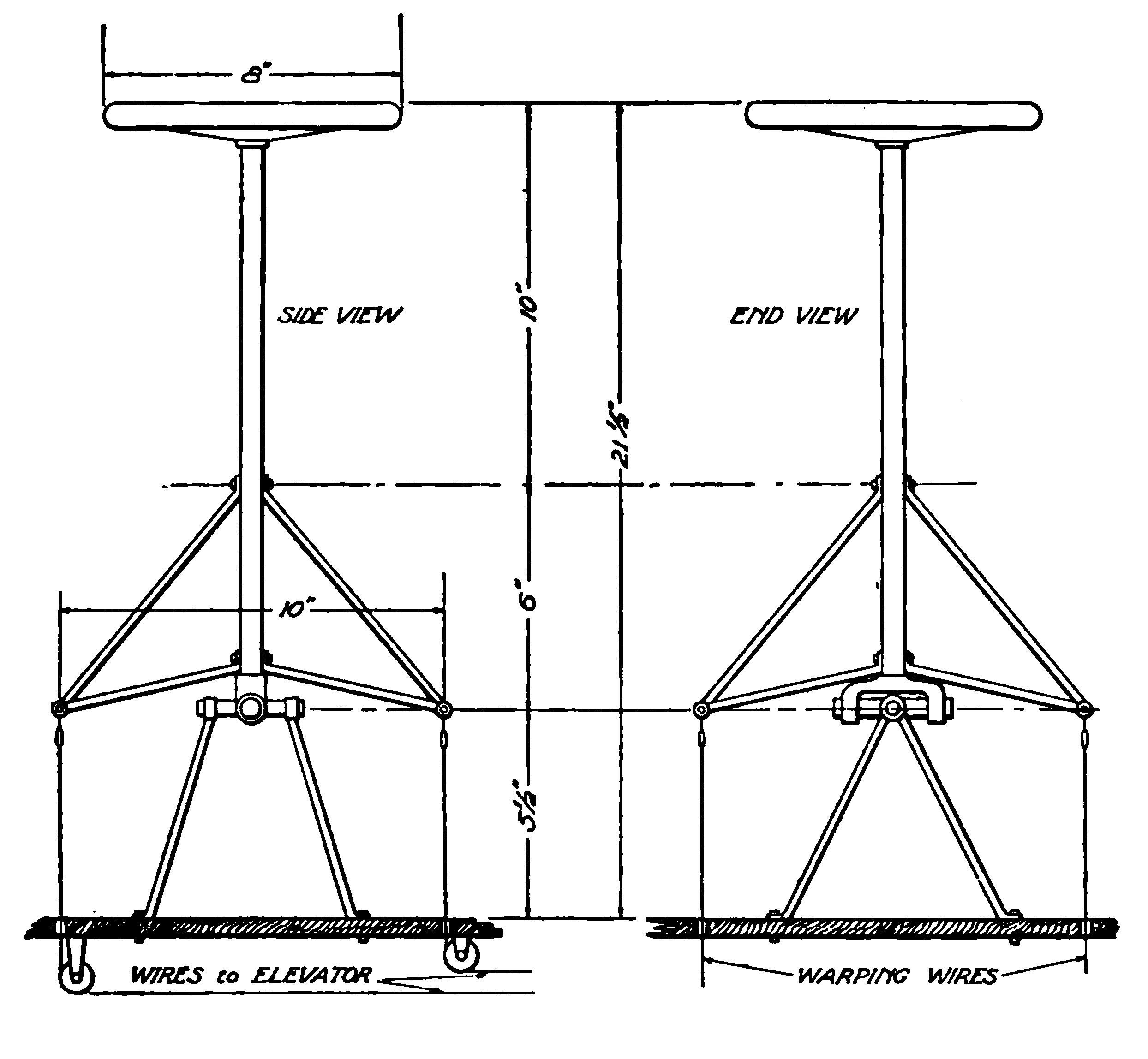
In the genuine Bleriot, the cloche is built up of two bells, one inside the other, both of sheet aluminum about 1/16 inch thick. The outer bell is 11 inches in diameter and 3 1/2 inches deep, and the inner one 10 inches in diameter and 2 inches deep. A ring of hard wood is clamped between their edges and the steering column, an aluminum casting passing through their centers. This construction is so complicated and requires so many special castings and parts that it is almost impossible for the amateur.
Steering Gear. While not so neat, the optional construction shown in the accompanying drawing, Fig. 32, is equally effective. In this plan, the cloche is replaced by four V-shaped pieces of 1/2-inch, 20-gauge steel tubing, attached to a steering post of 1-inch, 20-gauge tubing. At the lower end, the post has a fork, made of pieces of smaller tubing bent and brazed into place, and this fork forms part of the universal joint on which the post is mounted. The cross of the universal joint, which is somewhat similar to those employed on automobiles, can best be made of two pieces of heavy tubing, 1/2 inch by 12 gauge, each cut half away at the middle. The two pieces are then fastened together by a small bolt and brazed for greater security. The ends which are to go into the fork of the steering post must then be tapped for 3/8-inch machine screws. The two other ends of the cross are carried on V's of 1/2-inch, 20-gauge tubing, spread far enough apart at the bottom to make a firm base, and bolted to the floor of the cockpit.
The steering wheel itself is comparatively unimportant. On the genuine Bleriot it is a solid piece of wood 8 inches in diameter, with two holes cut in it for hand grips. On the post just under the wheel are usually placed the spark and throttle levers. It is rather difficult, however, to arrange the connections for these levers in such a way that they will not be affected by the movements of the post, and for this reason many amateur builders place the levers at one side on one of the fuselage beams.
From the sides of the cloche, or from the tubing triangles which may be substituted for it, two heavy wires run straight down to the ends of the warping lever. This lever, together with two pulleys, is mounted at the lower point of the warping frame already described. The lever is 12 inches long, 11 inches between the holes at its ends, and 2 inches wide in the middle; it should be cut from a piece of sheet steel about 1/16 inch thick. The pulleys should be 2 1/2 inches in diameter, one of them bolted to the lever, the other one running free. The wires from the outer ends of the rear wing beams are joined by a piece of flexible control cable, which is given a single turn over the free pulley. The inner wires, however, each have a piece of flexible cable attached to their ends, and these pieces of cable, after being given a turn round the other pulley, are made fast to the opposite ends of the warping lever. These cables should be run over the pulleys, not under, so that when the cloche is pulled to the right, the left wing will be warped downward.
It is a common mistake to assume that both pulleys are fastened to the warping lever; but when this is done the outer wire slackens off and does not move in accord with the inner wire, on account of the different angles at which they work.
Foot Levers. The foot lever for steering is cut from a piece of wood 22 inches long, hollowed out at the ends to form convenient rests for the feet. The wires connecting the lever to the rudder may either be attached to this lever direct, or, if a neater construction is desired, they may be attached to another lever under the floor of the cockpit. In the latter case, a short piece of 1-inch steel tubing serves as a vertical shaft to connect the two levers, which are fastened to the shaft by means of aluminum sockets such as may be obtained from any supply house. The lower lever is 12 inches long and 2 inches wide, cut from 1/16-inch steel similar to the warping lever.
Amateur builders often cross the rudder wires so that pressing the lever to the right will cause the machine to steer to the left. This may seem more natural at first glance, but it is not the Bleriot way. In the latter, the wires are not crossed, the idea being to facilitate the use of the vertical rudder for maintaining lateral equilibrium. With this arrangement, pressing the lever with the foot on the high side of the machine tends to bring it back to an even keel.
Tail and Elevator. The tail and elevator planes are built up with ribs and tie strips in much the same manner as the wings. However, it will hardly pay to have these ribs cut out on a jig saw unless the builder can have this work done very cheaply. It serves the purpose just as well to clamp together a number of strips of 3/16-inch spruce and plane them down by hand. The ribs when finished should be 24 1/4 inches long. The greatest depth of the curve is 1 1/4 inches, at a point one-third of the way back from the front edge, and the greatest depth of the ribs themselves 2 1/4 inches, at the same point. Sixteen ribs are required.
A steel tube 1 inch by 20 gauge, C, Fig. 33, runs through both tail and elevators, and is the means of moving the latter. Each rib at the point where the tube passes through, is provided with an aluminum socket. Those on the tail ribs act merely as bearings for the tube, but those on the elevator ribs are bolted fast, so that the elevators must turn with the tube. At its center the tube carries a lever G, of 1/16-inch steel 12 by 2 inches, fastened on by two aluminum sockets, one on each side. From the top of the lever a wire runs to the front side of the cloche, and from the bottom a second wire runs to the rear side of the cloche.
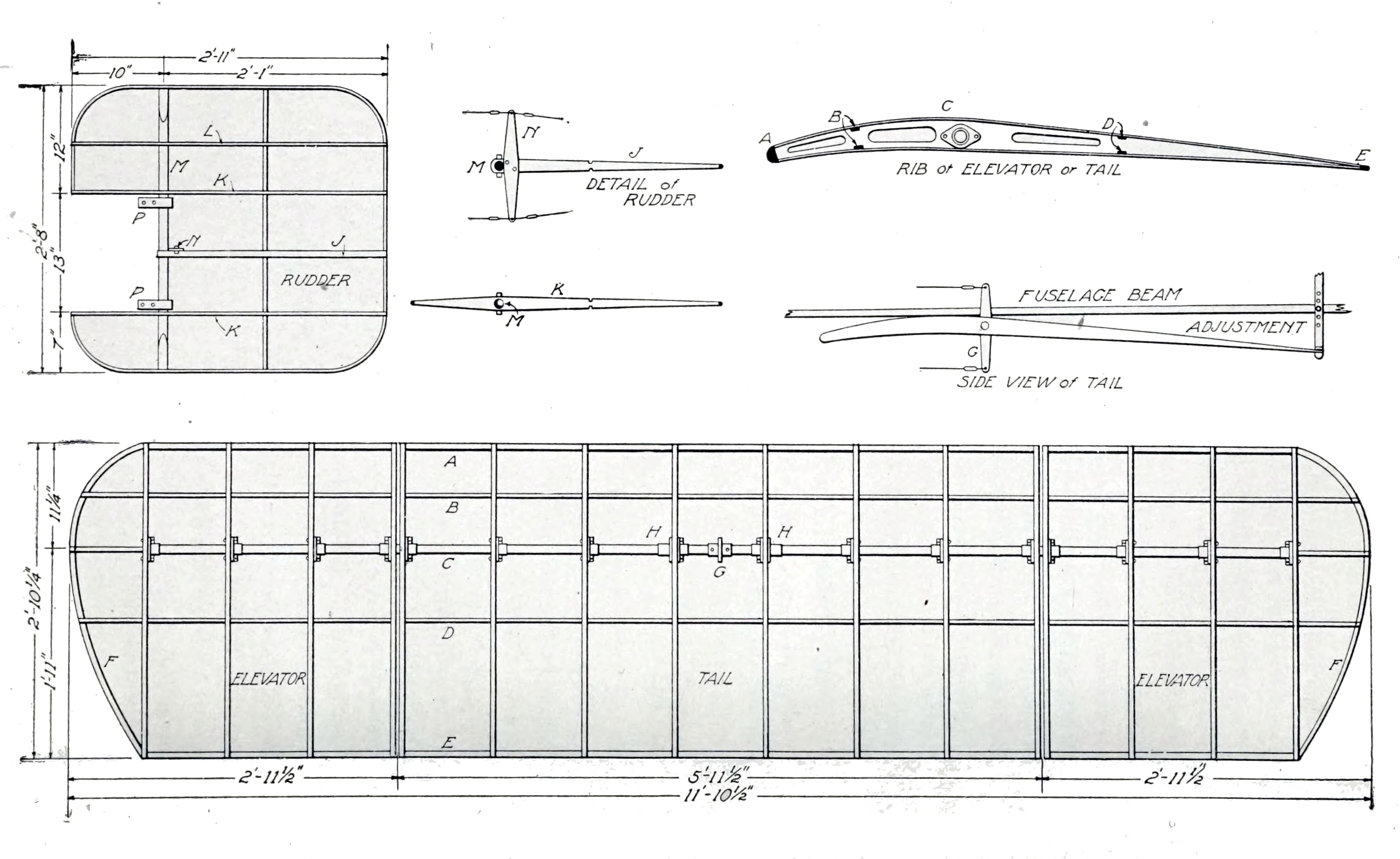

This Photograph Protected By International Copyright
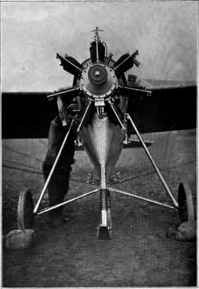
This Machine is the Work of One of the Cleverest Aeroplane Designers in Europe
The tube is carried in two bearings HH, attached to the lower beams of the fuselage. These are simply blocks of hard wood, fastened by steel strips and bolts. The angle of incidence of the tail is adjustable, the tail itself being held in place by two vertical strips of steel rising from the rear edge and bolted to the fuselage, as shown in the drawing, Fig. 33. To prevent the tail from folding up under the air pressure to which it is subjected, it is reinforced by two 3/4-inch, 20-gauge steel tubes running down from the upper sides of the fuselage, as shown in the drawing of the complete machine, Fig. 23.
The tail and elevators have two pairs of tie strips, B and D, Fig. 33, made of 3/16- by 5/8-inch spruce. The front edge A is half round, 1- by 1/2-inch spruce, and the rear edge E is a spruce strip 1/4- by 1 1/2-inches. The end pieces are curved.
Rudder. The rudder is built up on a piece of 1-inch round spruce M, corresponding in a way to the steel tube used for the elevators. On this are mounted two long ribs KK, and a short rib J, made of spruce 3/8 inch thick and 1 3/8 inches wide at the point where M passes through them. They are fastened to M with 1/8-inch through bolts. The rudder lever N, of 1/16-inch steel, 12 by 2 inches, is laid flat on J and bolted in place; it is then trussed by wires running from each end to the rear ends of KK. From the lever other wires also run forward to the foot lever which controls the rudder.
The wires to the elevator and rudder should be of the flexible cable specially made for this purpose, and should be supported by fairleaders attached to the fuselage struts. Fairleaders of different designs may be procured from supply houses, or may be improvised. Ordinary screw eyes are often used, or pieces of copper tubing, bound to the struts with friction tape.
Covering the Planes. Covering the main planes, tail, elevators, and rudder may well be left until the machine is otherwise ready for its trial trip, as the cloth will not then be soiled by the dust and grime of the shop. The cloth may be any of the standard brands which are on the market, preferably in a rather light weight made specially for double-surfaced machines of this type; or light-weight sail cloth may be used, costing only 25 or 30 cents a yard. About 80 yards will be required, assuming a width of 36 inches.
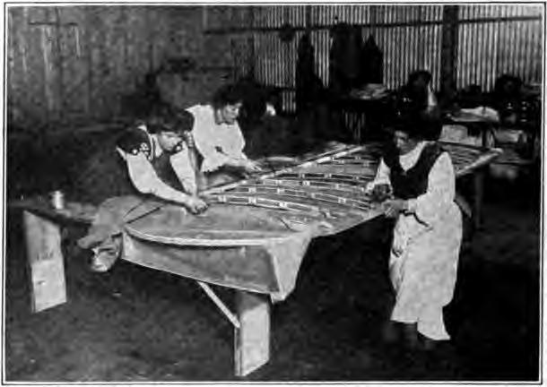
Except on the rudder, the cloth is applied on the bias, the idea being that with this arrangement the threads act like diagonal truss wires, thus strengthening and bracing the framework. When the cloth is to be put on in this way it must first be sewed together in sheets large enough to cover the entire plane. Each wing will require a sheet about 14 feet square, and two sheets each 6 feet square will be required for the elevators and tail. The strips of cloth run diagonally across the sheets, the longest strips in the wing sheets being 20 feet long.
Application of the cloth to the wings, Fig. 34, is best begun by fastening one edge of a sheet to the rear edge of the wing, stretching the cloth as tight as can be done conveniently with one hand. The cloth is then spread forward over the upper surface of the wing and is made fast along the inner end rib. Small copper tacks are used, spaced 2 inches apart on the upper side and 1 inch on the lower side. After the cloth has been tacked to the upper sides of all the ribs, the wing is turned over and the cloth stretched over the lower side. Finally the raw edges are trimmed off and covered with light tape glued down, tape also being glued over all the rows of tacks along the ribs, making a neat finish and at the same time preventing the cloth from tearing off over the tack heads.
Installation of Motor. As stated previously, the ideal motor for a Bleriot-type machine is short along the crank shaft, as the available space in the fuselage is limited, and air-cooled for the same reason. Genuine Bleriots are always fitted with one of the special types of radial or rotary aeronautic motors, which are always air-cooled. Next in popularity to these is the two-cylinder, horizontal-opposed motor, either air- or water-cooled. However, successful machines have been built with standard automobile-type, four-cylinder, water-cooled motors, and with four-cylinder, two-cycle, aeronautic motors.
When the motor is water-cooled, there will inevitably be some difficulty in finding room for a radiator of sufficient size. One scheme is to use twin radiators, one on each side of the fuselage, inside of the main frame of the running gear. Another plan is to place the radiator underneath the fuselage, using a supplementary water tank above the cylinders to facilitate circulation. These two seem to be about the only practicable arrangements, as behind the motor the radiator would not get enough air, and above it would obstruct the view of the operator.
It is impossible to generalize to much effect about the method of supporting the motor in the fuselage, as this must differ with the motor. Automobile-type motors will be carried on two heavy ash beams, braced by lengths of steel tubing of about 1 inch diameter and 16 gauge. When the seven-cylinder rotary Gnome motor is used, the crank shaft alone is supported; it is carried at the center of two X-shaped frames of pressed steel, one in front of and the other behind the motor. The three-cylinder Anzani motors are carried on four lengths of channel steel bent to fit around the upper and lower portions of the crank case, which is of the motorcycle type.
Considerable care should be taken to prevent the exhaust from blowing back into the operator's face as this sometimes carries with it drops of burning oil, besides disagreeable smoke and fumes. The usual plan is to arrange a sloping dashboard of sheet aluminum so as to deflect the gases down under the fuselage.
The three sections of the fuselage back of the engine section are usually covered on the sides and bottom with cloth like that used on the wings. Sometimes sheet aluminum is used to cover the section between the wing beams. However, those who are just learning to operate machines and are a little doubtful about their landings often leave off the covering in order to be able to see the ground immediately beneath their front wheels.
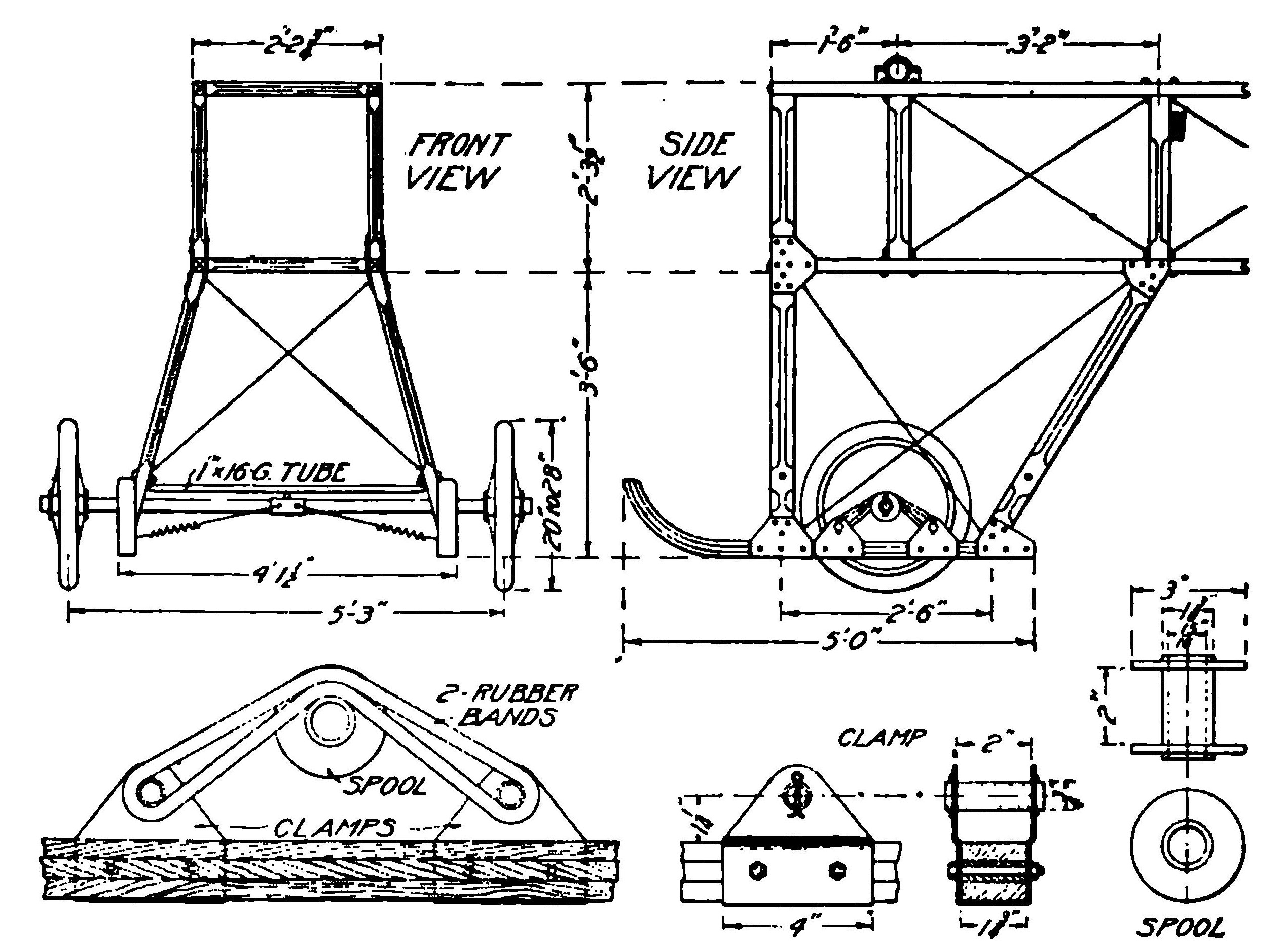
New Features. Morane Landing Gear. Although the regular Bleriot landing gear already described, has many advantages and ha.s been in use with only detail changes for several years, some aviators prefer the landing gear of the new Morane monoplane, which in other respects closely resembles the Bleriot. This gear, Fig. 35, is an adaptation of that long in use on the Henri Farman and Sommer biplanes, combining skids and wheels with rubber-band springs. In case a wheel or spring breaks, whether due to a defect or to a rough landing, the skids often save an upset. Besides, the tension of the springs is usually such that on a rough landing the wheels jump up and allow the skids to take the shock; this also prevents the excessive rebound of the Bleriot springs under similar conditions.
Another advantage which may have some weight with the amateur builder, is that the Morane running gear is much cheaper and easier to construct. Instead of the two heavy tubes, the four forks of oval tubing, and the many slides, collars, and blocks—most of them special forgings or castings—the Morane gear simply requires two short laminated skids, four ash struts, and some sheet steel.
The laminated skids are built up of three boards each of 5/8 by 2-inch ash, 3 1/2 feet long. These must be glued under heavy pressure in forms giving the proper curve at the front end. When they are taken from the press, three or four 1/2-inch holes should be bored at equal distances along the center line and wood pins driven in; these help in retaining the curve. The finished size of the skids should be 1 3/4 by 1 3/4 inches.
Four ash struts 1 1/4 by 2 1/2 inches support the fuselage. They are rounded off to an oval shape except at the ends, where they are attached to the skids and the fuselage beams with clamps of 1/16 inch sheet steel. The ends of the struts must be beveled off carefully to make a good fit; they spread out 15 degrees from the vertical, and the rear pair have a backward slant of 30 degrees from vertical.
Additional fuselage struts must be provided at the front end of the fuselage to take the place of the struts and beams of the Bleriot running gear. The two vertical struts at the extreme front end may be of the same 1 1/4- by 2 1/2-inch ash used in the running gear, planed down to 1 3/16 inches thick to match the thickness of the fuselage beams. The horizontal struts should be 1 3/16 by 1 3/4 inches.
The wheels run on the ends of an axle tube, and usually have plain bearings. The standard size bore of the hub is 15/16 inch, and the axle tube should be 15/16 inch diameter by 11 gauge. The tube also has loosely mounted on it two spools to carry the rubber band springs. These are made of 2 1/4-inch lengths of 1 3/8-inch tubing, with walls of sufficient thickness to make an easy sliding fit on the axle tube. To the ends of each length of tube are brazed 2 1/2-inch washers of 3/16 inch steel, completing the spool.
The ends of the rubber bands are carried on rollers of 3/4-inch, 16-gauge tubing, fastened to the skids by fittings bent up from 3/16-inch sheet steel. Each fitting is bolted to the skid with two 3/8-inch bolts.
Some arrangement must now be made to keep the axle centered under the machine, as the rubber bands will not take any sidewise strain. A clamp of heavy sheet steel should be made to fit over the axle at its center, and from this heavy wires or cables run to the bottom ends of the forward struts. These wires may be provided with stiff coil springs, if it is desired to allow a little sidewise movement.
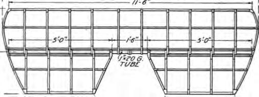
New Bleriot Inverse Curve Tail. Some of the latest Bleriot machines have a new tall which seems to add considerable to their speed. It consists of a fixed tail, Fig. 36, nearly as large as the old-style tail and elevators combined, with two elevator flaps hinged to its rear edge. The peculiarity of these elevators, from which the tail gets its name, is that the curve is concave above and convex below—at first glance seeming to have been attached upside down. In this construction, the 1-inch, 20-gauge tube, which formerly passed through the center of the tail, now runs along the rear edge, being held on by strips of 1/2- by 1/16-inch steel bent into U-shape and fastened with screws or bolts to the ribs. Similar strips attach the elevators to the tube, but these strips are bolted to the tube. The construction is otherwise like that previously described. It is said that fitting this tail to a Bleriot in place of the old-style tail adds 5 miles an hour to the speed, without any other changes being made.
Another slight change which distinguishes the newer Bleriots is in the overhead frame, which now consists of a single inverted V instead of two V's connected by a horizontal tube. The single V is set slightly back of the main wing beam, and is higher and, of course, of heavier tubing than in the previous construction. Its top should stand 2 feet 6 inches above the fuselage, and the tubing should be 1 inch 18 gauge. It also requires four truss wires, two running to the front end of the fuselage and two to the struts to which the rear wing beams are attached. All of the wires on the upper side of the wings converge to one point at the top of this V, the wires from the wing beams, of course, passing over pulleys.
These variations from the form already described may be of interest to those who wish to have their machines up-to-date in every detail, but they are by no means essential. Hundreds of the old-style Bleriots are flying every day and giving perfect satisfaction.
ART OF FLYING
Knowledge of the science of aeronautics and ability to fly are two totally different things. Long-continued study of the problem from its scientific side enabled the Wright Brothers to learn how to build a machine that would fly, but it did not teach them how to fly with it. That came as the result of persistent attempts at flying itself. A study of the theoretic laws of balancing does not form a good foundation for learning how to ride a bicycle—practice with the actual machine is the only road to success. The best evidence of this is to be found in the fact that several of the most successful aviators today have but a slight knowledge of the science of aeronautics. They are not particularly well versed in what makes flight possible, but they know how to fly because they have learned it in actual practice.
Reference to the early work of the Wright Brothers shows that during a period of several years they spent a large part of their time in actual experiments in the air, and it was not until these had proved entirely satisfactory that they attempted to build a power-driven machine.
Methods Used in Aviation Schools. Aviation schools are springing up all over this country and there are a number of well-established institutions of this kind abroad. In the course of instruction, the student must first learn the use of the various controls on a dummy machine. In the case of an English school, this dummy, Fig. 37, is a motorless aeroplane mounted on a universally-jointed support so as to swing about a pivot as desired. This is employed for the purpose of familiarizing the beginner with the means of maintaining equilibrium in the air.
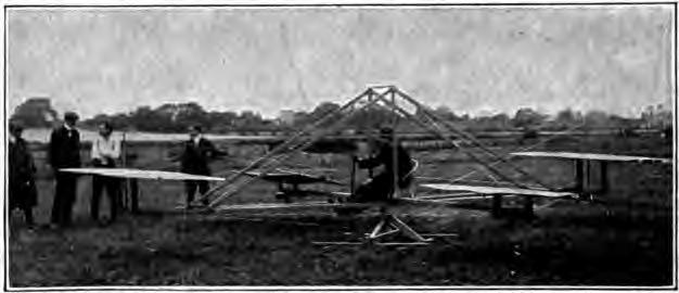
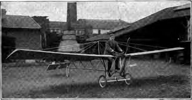
A French school, on the other hand, employs a wingless machine, which is otherwise complete, as it consists of a regulation chassis with motor and propeller, all steering and elevating controls. On this, the student may practice what has come to be familiarly known as "grass-cutting," to his heart's content, without any danger of the machine taking to the air unexpectedly, as has frequently been the case where first attempts have been made on a full-fledged machine. Usually, most of such attempts result disastrously, often destroying in a moment the result of months of work in building the machine.
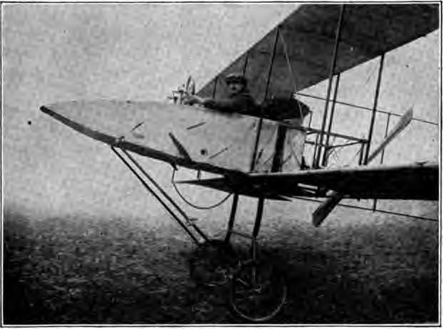
A French aerocycle, Fig. 38, a comparatively inexpensive machine, is also useful for practice in balancing and in short, low flights. The French apparatus in question may accordingly be considered an advance, not only over the English machine, even of the type shown in Fig. 39, which has a double control, and is especially designed for the teaching of beginners, but very much over the practice of attempting to actually fly for the first time in a strange machine, as it provides the necessary practice in the handling of the motor and the lateral steering. The machine can make high speed over the ground, but is perfectly safe for the beginner, as it is incapable of rising. Having gone through the stages represented by either of these contrivances, the best course for the learner to follow is to try gliding, taking short glides to attain the ability to quickly meet varying conditions of the atmosphere.
The fact that these glides are of extremely short duration at first need not be discouraging when it is recalled that, after several years of work, the Wright Brothers considered that great progress had been made when, in 1902, they were able to make glides of 26 seconds. During six days of the practice season of that year, they made 375 gliding flights of various distances, most of them comparatively short, but each one of value in familiarizing the glider with the conditions to be met. It is not material whether gliding or manipulation of the control levers is taken up first, as both should be mastered as far as possible before attempting to fly a regular machine.
Use of the Elevating Plane. So many things are necessary to the control of an aeroplane that thinking becomes entirely too slow a process—the aviator must be endowed with something approaching the instinct of the bird; he must be so familiar with his machine and its peculiarities that a large part of the work of controlling it is the result of subconscious movement. The control levers of many machines are so arranged that this subconscious movement on the part of the aviator directly operates the balancing mechanism. There is no time to think. When a machine rises from the ground, facing the wind as it should, its path of flight should be a gradual upward inclination, this being something difficult to accomplish at first, owing to the sensitiveness of the elevating rudder, the tendency almost invariably being to give the latter too great an angle of incidence. At this stage, the maximum velocity of flight has not yet been attained and care must be taken to keep the angle of ascent small. Otherwise, the power of the engine, which may not have reached its maximum, would not be sufficient to cause the machine to ascend an inclined path at the starting speed. If the speed of flight be reduced by the increased resistance at this point, the whole machine will slide back in the air, and if a sudden gust of wind happens to coincide with the attempt to rise at too great an angle, there is danger of it being blown over backward.
Where the machine is just leaving the ground and the elevator has been set at an excessive angle, the rear end of the skids or the tail may slap the ground hard and break off, or they will impose so much resistance upon its movement by scraping over the turf that the machine can not attain its soaring speed. It must be borne in mind, of course, that remarks such as the present can be only of the most general nature, every type of machine having its own peculiarities—in some instances, the extreme opposite of those characterizing similar machines. For example, in the Voisin 1910 type, the very large and powerful light tail tends to lift before the main planes, and if this be not counteracted, the whole machine may turn up on its end. In order to offset this tendency, the elevator must be raised so as to keep sufficient pressure beneath it; the moment of this pressure about the center of gravity must be at least equal to the pressure under the tail planes about the center of gravity of the machine, or the tail will rise unduly in the air. At least that is the theory of it—naturally, only practice with that particular machine would suffice to enable an aviator to familiarize himself with that particular peculiarity. Again, some machines are "tail heavy." But there is great difficulty in even approximating the degree of relative motion, for which reason it has been suggested, under "Accidents and Their Lessons," that a gradometer, or small spirit level, in plain sight of the aviator, should form part of the equipment of every machine. The Wrights long ago adopted the expedient of attaching a strip of ribbon to the elevator to provide an indication of motion relative to the wind.
Aeroplane in Flight. The sensation of motion after the machine leaves the ground is almost imperceptible, and it is likewise extremely difficult to tell at just what moment the aeroplane ceases running on the solid ground and takes to the air. There is a feeling of exhilaration but very little of motion. Whereas 40 miles an hour over the ground, particularly in an automobile, brings with it a lively appreciation of the speed of travel, the same speed in an aeroplane is a very gentle motion when high above the ground. If there be no objects close at hand, with which to compare the speed, the sense of motion is almost entirely lost.
Center of Gravity. The static balance of a machine should be carefully tried before commencing to fly, and particularly that of a biplane of the Wright type, in which the aviator sits behind the engine. When provision is made for carrying a passenger, his seat is placed in the center line of the machine, so that his presence or absence does not materially affect the question of lateral balance. As men are not all of the same weight, in cases in which the aviator only partly balances the engine about the center line, his weight being insufficient for the purpose, extra weights should be placed on the wing tip at the lightest end until the true balance is secured, otherwise a permanent warping, or gauchissement as the French term it, is required at this side in order to keep the machine on an even keel. In other words, the machine will carry what sailors term a port helm where the left side of the machine is lighter than the right, and vice versa, and it will be necessary to keep the rudder over to that side slightly during the entire flight to counteract this tendency.
In aeroplanes fitted with tails, the center of gravity is usually in the vicinity of the trailing edge of the main planes and, of course, should be on the center line of the machine. The center of gravity of the aviator on a monoplane should approximately coincide with that of the machine. If this be not the case, the stabilizers or the elevator must be permanently set to produce longitudinal balance. Much downward set, or the increase of the angle of incidence of the tail, will create undue resistance to flight and should be avoided when possible by bringing the weight farther forward. The center of pressure should coincide with the center of gravity, and balance will result.
Before even ground work is attempted, the position of the center of gravity should be determined in the manner shown in Fig. 40, the approximate location for four types of machines being shown. At what point the machine must be suspended, so that it can tip only frontward and backward and be evenly balanced, is a question that must be answered in order to ascertain the probability of the machine's pitching forward whenever mud, grass, or rough ground is encountered in alighting. If the center of gravity should lie in front of the axles of the ground wheels in a machine of the Farman type, trouble is sure to follow. Always consider the relation of the center of gravity to the wheels, in order that you may gain some idea of the distribution of the weight on the running gear when the machine is tipped forward 10 degrees. If the wheels are not forward far enough there will be trouble in running on the ground. The elevators must correct whatever variance there may be from the correct center of gravity and position of the wheels, and the manipulation of the elevators for that purpose requires skill. If the tail be very heavy, the elevator may not be able to counteract that defect.
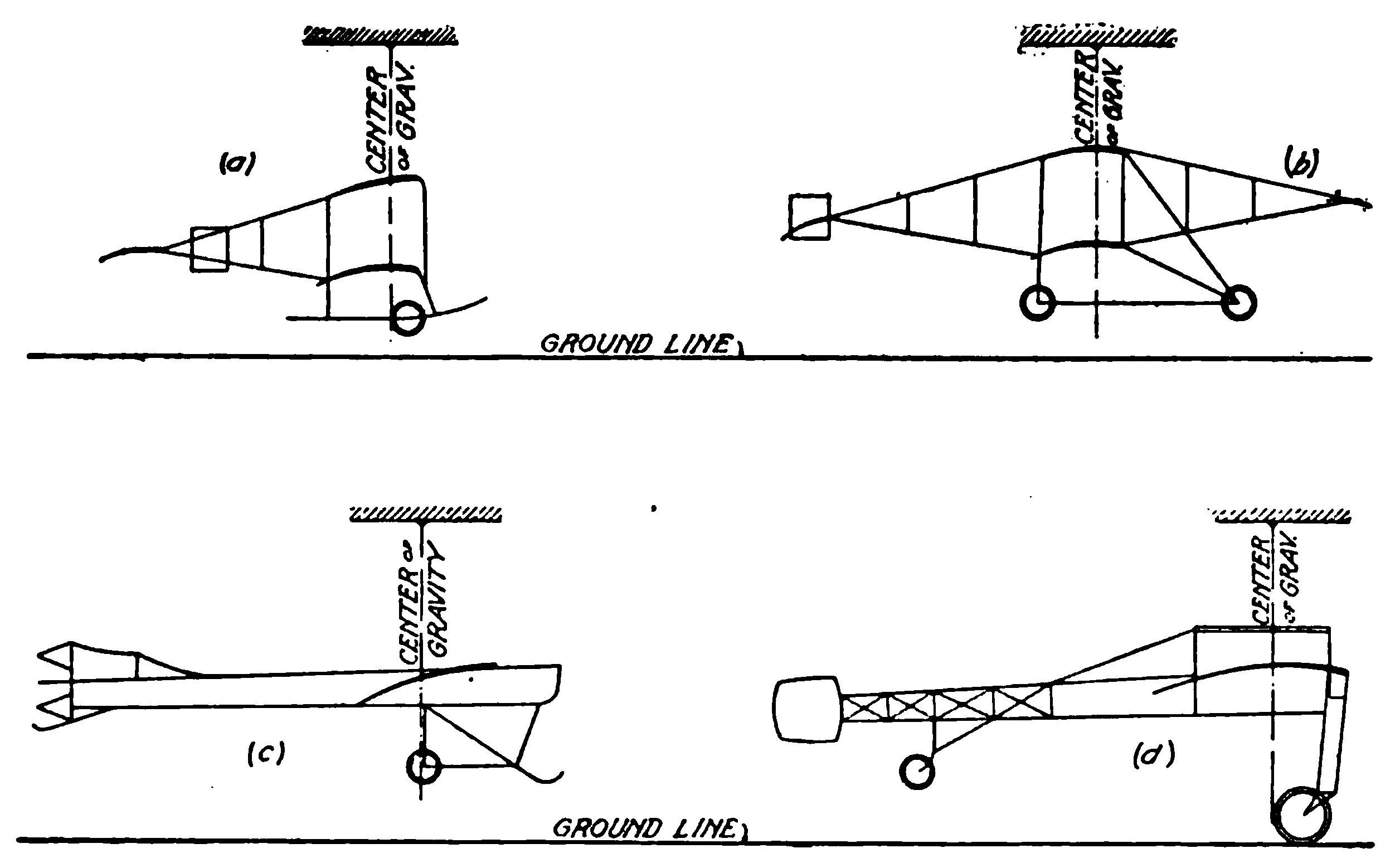
The position of the center of gravity of a machine in regard to lateral stability in flight is a matter of far greater importance than untried aviators realize. Having it too low is quite as bad as too high, as in either case there is a tendency to upset. Although the dihedral angle is considered wasteful of power, it seems to do more to secure inherent stability than any other device. Devices for maintaining stability automatically are to be frowned upon in the present state of the art. The sensitive perception and quick response which come with intimate knowledge of a machine's peculiarities, are at present worth more than gyroscopes and pendulums. To acquire this intimate knowledge, the aviator must familiarize himself thoroughly with the machine; he must become so accustomed to controls that he and the machine are literally one. A practiced bicycle rider does not have to think about balance, neither does the practiced aviator, yet he must always be prepared to meet motor stoppages, unusual air disturbances, and breakages. A leap from the ground directly into the air, without preliminary practice, means certain accident, to put it mildly.
Center of Pressure. But although the center of gravity remains approximately constant, the center of pressure is continually varying and is never constant for many seconds. The center of pressure on an aerocurve constructed to Phillips' design, Fig. 41, is about one-third of the chord from the leading edge of the plane under normal conditions, i.e., when the angle of incidence is about 8 degrees between the direction of motion of the plane and that of the air. At the moment this angle is increased the center of pressure moves toward the rear, and vice versa. The center of gravity must be moved to coincide with this new position, or the center of pressure must be artificially restored by the use of supplementary planes or elevators, moving in a contrary direction. A forward movement of the center of pressure tends to lower the tail of the machine, when the intensity of the pressure is unchanged, and to counterbalance this the rear elevator must have its angle of incidence increased in order to increase the lift at the rear of the machine, or it will slide down backward. The alternative to be adopted in case of temporary lack of engine power is to decrease the angle of the elevator and allow the aeroplane to sweep downward, thus gaining momentum. The increase of speed will then be sufficient probably to enable the machine to continue in a horizontal flight, when the center of pressure is again restored to its normal position.
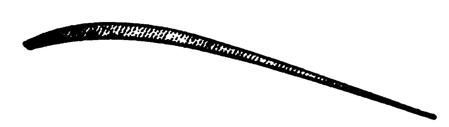
Ground Practice. First of all, the aviator should familiarize himself with his seat for it is from that place that he must judge wind effects, vibration, motor trouble, and the thousand and one little creaks and hums that will ultimately mean so much to him. Not until he has thoroughly accustomed himself to his seat, should he try to run along the ground. This done, hours should be spent running up and down and around the field to learn the use of the rudder, particularly on rough ground. The runs should be straight so that when the time comes to leap into the air, the aviator may be sure that he is on an even keel, and flying straightaway. In order to prevent the possibility of leaving the ground unexpectedly in practice, trials should be made only in calm weather and with the motor well throttled down so that the machine will be reduced to a speed of not more than 15 miles per hour. After a time this may be increased to 20, but the latter is the maximum for ground practice, as the machine will rise at speeds slightly exceeding this. In these practice rims on the ground, the student should learn to gauge the rush of air against his face, as when aloft his best gauge will be the wind pressure on his cheeks, as that will tell him whether he is moving with sufficient speed to keep up or not. It will also tell him ultimately whether he is moving along the ground fast enough to leap up.
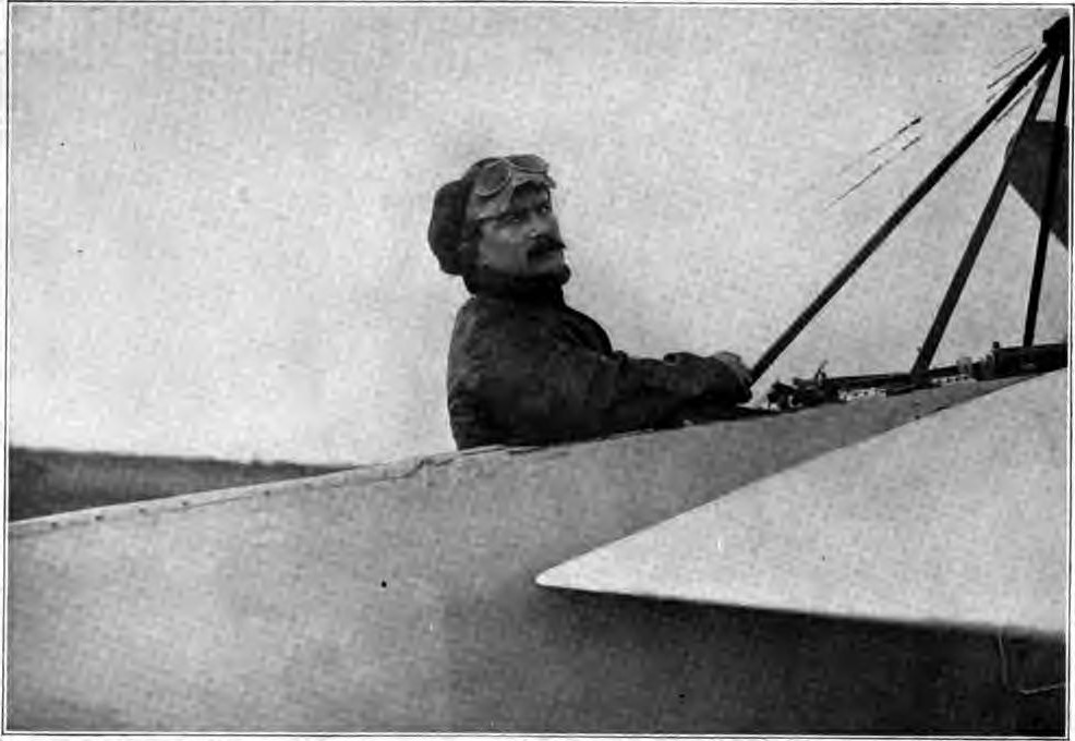
IN A DEPERDUSSIN MONOPLANE
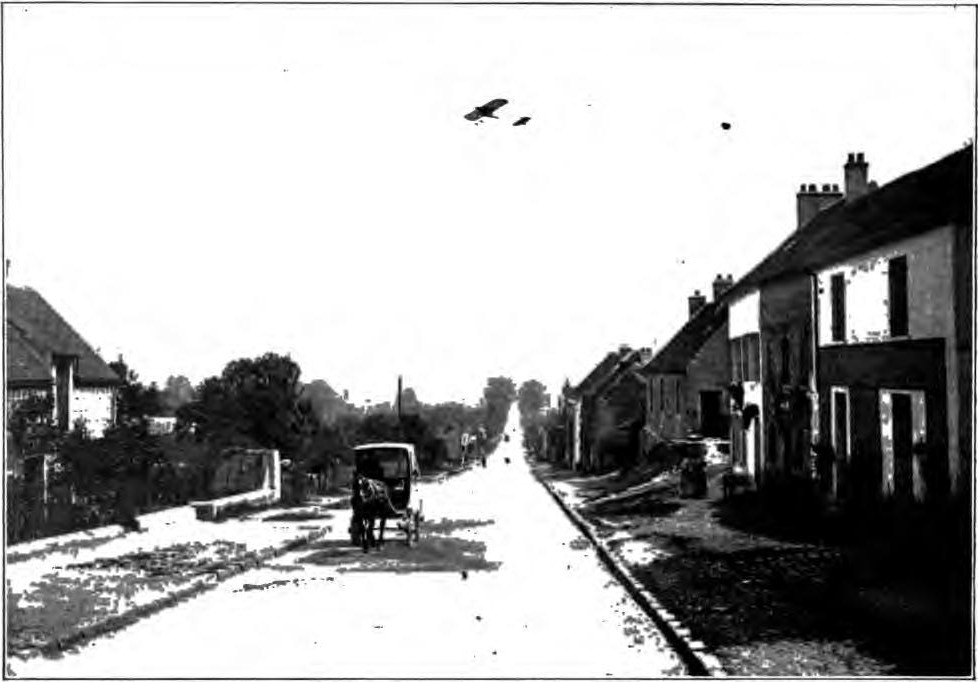
This Photograph Protected by International Copyright
In this stage of experimenting on the ground, the elevator is kept neutral as far as possible. With increasing skill its use may be ventured, but only sparingly, for it takes very little to lift the machine from the ground with a speed in excess of 20 miles per hour. It will soon be discovered that the elevator can be used as a brake to prevent pitching forward. The tail elevators on the Farman or Bleriot running gear are very effective owing to the blast of the propeller, even when the main planes are not moving forward at lifting speed. With the Curtiss type of running gear and a front elevator only, it is often possible at 18 to 20 miles per hour to raise the front wheel off the ground for a second or two—facts which indicate that at 25 to 28 miles per hour, the elevator is far more effective.
First Flight. The first actual flight should be confined to a short trip parallel to the ground and not more than one or two feet above it. At first, the student should see how close he can fly to the ground without actually touching it, which he can do by gradually increasing his forward speed. This must be done in an absolute calm as an appreciable amount of wind will bring in too many other factors for the student to master at so early a stage. This practice should be continued in calm air until short, straight flights can be made a foot or two from the ground with the motor wide open. If it be found that the machine barely flies straightaway with the full power of the motor, the latter is either badly out of adjustment, or a more powerful engine is required. In an under-powered machine turning would be suicidal. Moreover, the resistance encountered in the air is greater than on the ground and may be such that the speed is not sufficient for sustentation. Fig. 42, (a) and (b), show why it is possible to run along the ground faster than it is possible to travel in the air, under certain conditions, and why the ground can be left at low speed. If it were possible to drive a machine with such enormous projected areas as BB, shown in Fig. 42 (b), a man could fly slowly for an indefinite period. But the projected area is greater than the air displaced by the propeller, and it is impossible to fly except with a moderate angle of incidence, giving projected areas A A, Fig. 42 (a). The student, as he increases in skill, may venture to a height of 10 feet, which should be maintained as accurately as before, and after making a run of 100 yards, the machine should be pointed down, but ever so slightly. The wind pressure on the face immediately becomes greater. Within a foot or two of the ground the motor should be cut off or throttled. This should be tried ten or fifteen times, and the height increased to 30 or 40 feet, in order that the student may familiarize himself with the sensation of coasting. At the end of each glide the machine will seem to become more responsive, as indeed it does, for gliding down greatly increases the efficiency of the elevator and other controls, because of the increased speed. Gliding down steep angles is often the aviator's salvation in a tight place, particularly when the motor fails, a side gust threatens or an air pocket is encountered.
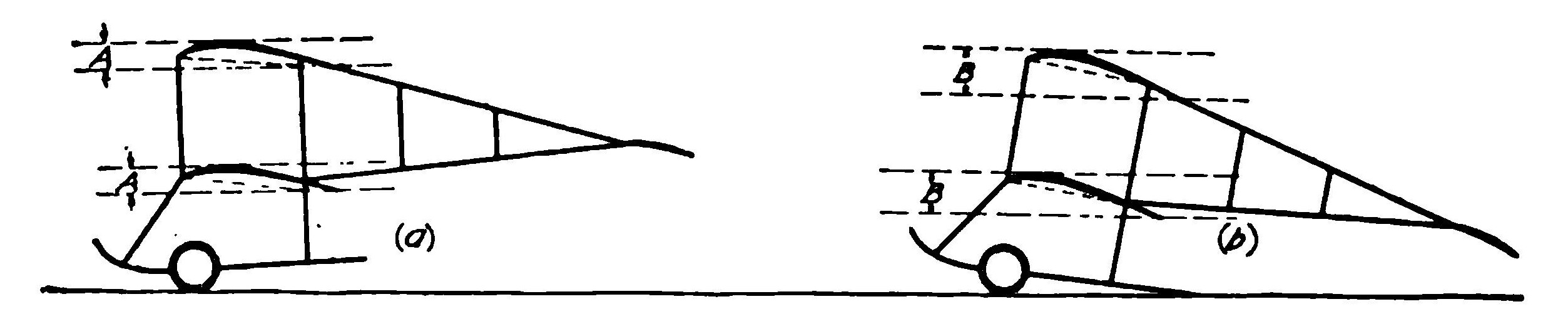
Running along Ground
Warping the Wings. When sufficient confidence has been attained at a height of 30 to 40 feet, the ailerons or warping devices may be tried judiciously. Here the intention should be to correct any tendency to side tipping, and not purposely to incline the machine as far as possible without actually causing a wreck. The use of the lateral control may cause the machine to swerve a little, but that may be ignored. Before landing, a straight course should be taken so that the machine will always come down on an even keel. With increasing practice, the student may fly higher, but always with the understanding that there is a limit to the angle of incidence. An automobile is retarded when it strikes a short, steep hill; so is an aeroplane. No aeroplane has yet been built that can take a steep angle and climb right up that grade continuously. Altitude is reached by a series of small steps and at comparatively low angles, as unless the course is straightened out at regular intervals, a machine will lose its speed and tend to plunge tail first, just as is the case when an attempt is made to rise from the ground at too sharp an angle.
In warping the wings an increase of lift imparted to one wing of the machine is produced by increasing the angle of incidence of the whole or part of the wing, or by an increase of pressure under that wing, and will tend to cause that side of the machine to rise and the other side to lower, the result being that the machine will be liable to slide through the air diagonally. In the majority of aeroplanes there are no fins or keels to counteract this movement, and lateral stability must be restored by artificially increasing the lift of the depressed wing. This can be done by warping, or lowering the trailing edge of the depressed wing and increasing its lift, and simultaneously raising the trailing edge of the other wing, thus decreasing the angle of incidence of the latter and reducing its lifting effect. This applies to flight on a straight course, whatever the cause may be that tends to upset lateral stability. It will be seen, therefore, that the center of gravity remains constant and the center of pressure must be manipulated to restore stability. This manipulation is much more rapid and positive than the alteration of the center of gravity by the movement of the aviator's body resorted to in the early gliding flights of pioneer experimenters.
Making a Turn. The first turn should be made over a large field and the diameter of the turn should be at least half a mile. The height should be not less than 50 feet. After that level has been maintained, the rudder should be moved very gingerly. The machine will lean in almost immediately, because the outer end travels at a higher speed than the inner and therefore has a greater lift. Warping or working the ailerons should be resorted to as a means of counteracting this tendency, and the rudder swung to the opposite direction, if necessary. It is obvious that if the rudder will cause the machine to bank when swung in one direction, it will right the machine again when swung in the opposite direction. It is even possible to turn the machine on an even keel by anticipating the banking, simply by correctly using the rudder, which was necessary in the old Voisin machine flown by Farman in 1908, because it had no mechanical lateral control. The student should learn the correct angle of banking, i.e. the angle at which the machine will neither skid nor slide down and which is most economical of power because it requires less use of the lateral controls. The necessity of "feeling the air" is greater in turning than in any other phase of flying. By "feeling the air" is meant the ability to meet any contingency intuitively and not until this is acquired can the student become an expert aviator. When it has been acquired, safe flying is assured and is dependent only upon the integrity of the planes, motor, and controls. By using the rudder discreetly and by banking simply far enough to partially offset the centrifugal force of turning, the use of the lateral control will not be necessary in still air. Even too short a turn can be corrected by a quick use of the rudder.
The peculiarities existing between different types of monoplanes become even more marked than between the biplane and the monoplane. For example, in piloting a Bleriot monoplane, Fig. 43, it is necessary to take into account the effect of the engine torque. As the engine rotates in a right-hand direction, from the point of view of the pilot, the left wing tends to rise in the air, owing to the depression of the right side of the machine. The machine also tends to turn to the right, and this must be counteracted by putting the rudder over to the left. An aeroplane answers its controls with comparative slowness, with the exception, perhaps, of the Wright machine, which is noted for its sensitive and quick response to every movement of the levers. All control movements must, therefore, be very gentle, as the behavior of an aeroplane is more like that of a boat than that of an automobile. The action of the elevator has already been described, and it is, perhaps, the most difficult of all the controls to manipulate, in that it requires the exercise of a new sense. The direction rudder is naturally a more familiar type of control, and in action is similar to the rudder of a boat.
The torque of the motor renders it advisable for a novice to turn his machine to the right, if a right-hand propeller be used, and vice versa. If two propellers, turning in opposite directions, are employed, as in the Wright biplane, there is no inequality from the torque of the motor. Since torque is not noticeable in straight flying, straightening out again will always serve the student when he finds himself in trouble on a turn. When the use of the rudders and ailerons has reduced the speed, a downward glide will increase it again, and if the motor should stop on a turn, such a downward glide is immediately imperative. When the machine is thus gliding, a change in the fore-and-aft balance becomes at once apparent, because the blast of the propeller no longer acts on the tail, and the elevator must then be used with greater amplitude to obtain the same effect.
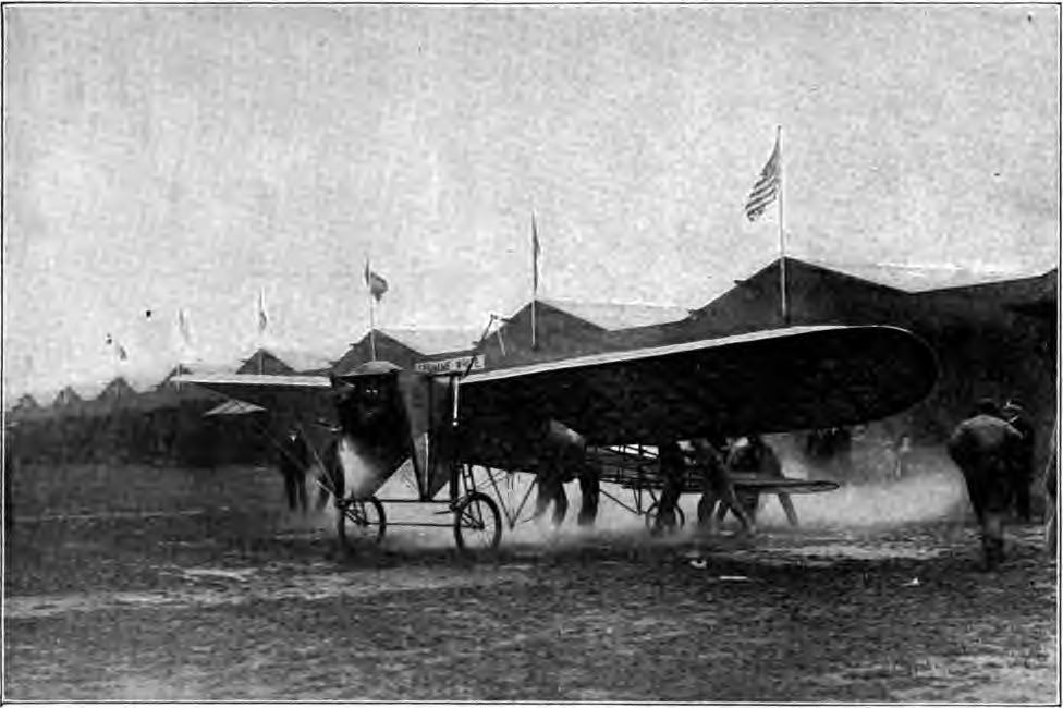
Only by constant practice in calm air can the student familiarize himself with exactly the amount of warping and rudder control to employ to property offset the lowering of the inner wing in rounding a turn. If this be not corrected, the whole machine tends to bank excessively and will be apt to slide downward in a diagonal direction, Fig. 44. This is a perilous position for the aviator and must be guarded against by the manipulation of the warping control so as to increase the lift of the inner wing of a biplane, at the same time, employing the rudder to counteract this tendency. The use of the rudder is of even greater importance on the monoplane, as, in this case, warping the inner wing tends to direct the whole machine downward instead of raising the inner wing itself. Several bad accidents have resulted from monoplanes refusing to respond to the warping of the inner wing when making a turn. In such machines, the rudder must be practically always employed in connection with the warping of the wings in order to keep the machine on an even keel, although the controls may not actually be interconnected, this being one of the grounds on which foreign manufacturers are trying to make use of the Wright principle, without infringing the Wright patents, as while they employ warping in connection with the simultaneous use of the rudder, the controls are not attached to the same lever as in the Wright machine.
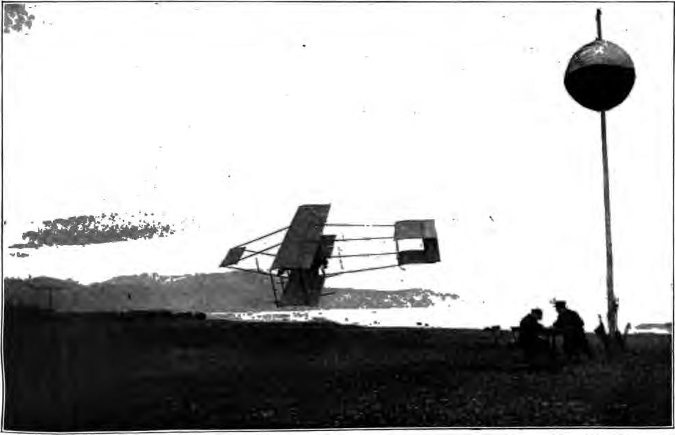
Lateral resistance must also be taken into consideration in turning, otherwise the machine, if kept on an even keel, will tend to skid through the air and turn about its center of gravity as a pivot. In the case of an automobile, the resistance to lateral displacement is great, though on a greasy surface it may be small, as when the machine skids sideways, a suitable banking of the road being necessary to prevent this on turns. Many hold that the banking of the aeroplane on turns is only the direct effect of the turning itself, but the fallacy of this will be apparent upon a consideration of the law of centrifugal force. It is obvious that to make a turn, some force must be imparted to the machine to counteract the effect of the centrifugal force upon the machine as a whole. And as the sidewise projection of the machine is small, a compensating force must be introduced. This can be done only by previously banking up the machine on the outer wing, so that the pressure of the air under the main plane can counteract the tendency to lateral displacement. The force then acting under the planes is in a diagonal direction, and the angle at which it is inclined vertically depends upon the banking of the planes, it being normal to their greater dimension. This force can be resolved into two forces, one perpendicular and one horizontal, the magnitude of each being dependent upon the degree of banking. When the speed of the machine is higher, the amount of banking must be greater in order to increase the value of the horizontal component in proportion to the increase of the value of the centrifugal force at the higher speed, in spite of the fact that the forces acting under the planes are also greater due to the higher speed.
As the curve commences, the rudder being put over, the difference of the pressures on the two wings, owing to their different flying speeds comes into account, as already explained, and care must be taken that the banking does not increase abnormally. When the turn is completed, the rudder is straightened and the machine is again brought to an even keel with the aid of the wing-warping control, or the ailerons. The effect of a reverse warping to prevent excessive banking, lowering the inside wing tip incidentally, puts a slight drag on that wing and assists in the action of turning, as does also the provision of small vertical planes between the elevator planes of the original Wright machine. Since the adoption of the headless type, these surfaces are placed between the forward ends of the skids and the braces leading down to them.
In making a turn, say, to the left, the outside or right-hand wing is first raised by lowering the wing tip on that side and the rudder is then put over to the left. When the correct amount of banking is acquired, the wing tip is restored to its normal position, and probably the left wing tip may have to be lowered slightly to increase the lift on that side owing to its reduced speed. When the turn is completed, the rudder is straightened out and the left wing tip lowered to restore the machine to an even keel. Both Glenn Curtiss in this country and R. E. Pelterie in France have shown that it is possible to maneuver without using the rudder at all, the ailerons or wing tips alone being relied upon for this purpose.
Before flights in other than calm air are attempted, much practice is required. The machine must be inspected over and over again, and the wind variations studied with a watchful eye. Not until this familiarity with machine and atmosphere be acquired should flying in a wind be attempted. To the man on the ground, wind is simply air moving horizontally, but to the man in the air it is quite different. Not only must he consider horizontal movement, but vertical draughts and vortices as well. A rising current of air lifts a machine, a downward current depresses it, and he must learn to take advantage of the former as the birds do. Horizontal currents affect forward speed over the ground; swirls and vortices create inequalities in wind pressure on the planes and disturb lateral balance. Familiarity with all these atmospheric conditions can be acquired only after long practice. Against every tree, house, hill, fence, and hedge beats an invisible surf of air; upward currents on one side and downward on the other. The upward draught is not usually dangerous, for it simply lifts the machine; but the down draught will cause it to drop. A swift downward glide under the full power of the motor must then be made, to increase the forward speed and consequently the lift. This explains why it is dangerous to fly near the ground in a wind; likewise why the beginner should never attempt flying at first in anything but a dead calm.
Turning in a Wind. When turning in a wind, two velocities must be borne in mind, that of the machine relative to the air and that relative to the earth. The former is limited at its lower value to that of the flying speed of the machine, and the latter must be considered on account of the momentum of the machine as a whole. Change of momentum is a matter of horse-power and weight and is the governing factor in flying in a wind on a circular course. Suppose the flying speed of a machine is a minimum of 30 miles an hour relative to the air, and a wind of 20 miles an hour is blowing. The actual speed of the machine relative to the earth in flying against the wind will be 10 miles an hour. If it be desired to turn down the wind, the speed of the machine relative to the earth must be increased from 10 miles to 50 miles an hour during the turn and a corresponding change of momentum must be overcome. There are two ways of accomplishing this, either by speeding up the motor to give the maximum power, or by rising just previous to making the turn and then sweeping down as the turn is made, thus utilizing the acceleration due to gravity to assist the motor. The wind's velocity will assist the machine also and during the turn it will make considerable leeway, a small amount of which is deducted to counteract the centrifugal force of the machine.
Turning in a contrary direction, i.e., up into the wind when running with it, requires considerable skill, as when flying 50 miles an hour, the tendency on rounding a corner into a 20-mile-an-hour wind would be for the machine to rise rapidly in the air. The centrifugal force at such a speed is also considerable, causing the machine to make much leeway with the wind during the turn. Turning under such circumstances should be commenced early, particularly if there are any obstructions in the vicinity, and considerable skill should be acquired before an attempt is made to fly in such a wind.
Starting and Landing. A machine should always be started and landed in the teeth of the wind, and no one but the most experienced aviators can afford to disregard this advice, certainly not the novice. The precaution is necessary because in landing the machine should always travel straight ahead without the possibility of lurching and consequently breaking a wing, as frequently happens. Contact with the ground is necessarily made at a time when the machine is traveling over it at a speed of 30 to 40 miles per hour and skidding sideways at 10 to 15 miles per hour, all circumstances which tend to wreck an aeroplane.
Planning a Flight. It is easy to lose one's way in the air. For that reason it is best to follow the Wright idea of starting out with a definite plan, and of landing in some predetermined spot, as aimless wandering about may prove disastrous to the inexperienced aviator, he may forget which way the wind was blowing, or how much fuel he had, or the character of the ground beneath him. Should the motor stop, he may make an all too hasty decision in landing. It is an easy matter to lose one's bearings in the air, not only because the vehicle is completely immersed in the medium in which it is traveling, but also because the earth assumes a new aspect from the seat of an aeroplane. Cecil Grace was one of those who lost his bearings and, as a consequence, his life. Ordinary winds blowing over a level country can be negotiated with comparative safety. Not so the puffy wind. To cope with that, constant vigilance is required, particularly in turning. In a circular flight in a steady wind, the only apparent effect is that the earth is swept over faster in one direction than in the other. Before a cross-country flight is attempted, the starting field should be circled over at a great height, as not until then may the long distance flight be started in safety. Cross-country flying is, of course, fascinating, and it is a sore temptation, at an altitude of a few hundred feet, to throw off all caution and fly off over that strange country below, which is, indeed, a new land as viewed from aloft. To quote a professional aviator: "Here the greatest self-restraint must be exercised. Not until the necessary practice has been acquired, not until the right kind of confidence has been gained, may one of these trips be attempted, and then only after it has been properly planned."
Training the Professional Aviator. Look back over the achievements in the air during the comparatively short time that man has actually been flying, and it will be noted that the beginners, burning up with the enthusiasm of the novice, have performed the most spectacular feats and flown with the greatest fearlessness. Curtiss was comparatively new at aviation when he won the Gordon-Bennett at Rheims in 1909. John B. Moisant, the sixth time he ever went up in an aeroplane, flew from Paris to London with a 187-pound passenger and 302 pounds of fuel, oil, and spare parts. Hamilton made his successful flight from New York to Philadelphia and return when he was hardly more than a novice, while Atwood's great flights from St. Louis to New York and Boston to Washington were made before his name had become known, and Beachey had been flying only a few months when he broke the world's altitude record at Chicago, while more recent achievements, notably Dixon's flight across the Rockies, have emphasized the work of the beginner. All of this substantiates the belief held at every aviation headquarters in the country—namely, that the older men already in aviation may improve the art by executive ability and scientific experiments, but most of them will degenerate as flyers. Beyond a certain point, frequency of flight does not necessarily create a feeling of confidence and safety; rather it brings a fuller appreciation of the dangers, and the men who best know how to fly are most content to stay upon the ground.
Professional aviators are drawn from every walk of life, but trick bicycle performers, acrobats, parachute jumpers, and racing automobile drivers make the most promising applicants. By a kind of sixth sense, both the Wrights and Curtiss weed out the promising ones after a brief examination. They select men who have an almost intuitive sense of balance. Most of these, provided they have nerve, have in them the stuff of which aviators are made, even though they may have had no experience in any line akin to aviation. Neither Curtiss nor the Wrights will accept women under any condition. The Moisant school does not share this discrimination and trained three women for pilot's licenses during 1911.
Curtiss and the Wrights are keen in their realization that recklessness is pulling a wing feather from aviation every time a man is killed, and they are doing their utmost to promote conservatism. Curtiss said in an interview:
I do not encourage and never have encouraged fancy flying. I regard the spectacular gyrations of several aviators I know as foolhardy and unnecessary. I do not believe that fancy or trick flying demonstrates anything except an unlimited amount of a certain kind of nerve and perhaps the possibilities of what is valueless—aerial acrobatics. Some aviators develop the sense of balance very rapidly, while others acquire it only after long practice. It may be developed to a large extent by going up as a passenger with an experienced man. Therefore, in teaching a beginner, I make it a point to have him make as many trips as possible with someone else operating the machine. In this way the pupil gains confidence, becomes accustomed to the sensation of flying, and is soon ready for a flight on his own hook. This is the method used in training army and navy officers to fly. I have never seen novices more cautious and yet more eager to fly than these young officers. They have always learned every detail of their machines before going aloft, and largely because of this they have developed into great flyers. Perhaps it is due to the military bent of their minds; at any rate, they have made good almost without exception.
ACCIDENTS AND THEIR LESSONS
Press Reports. Whenever an industry, profession, or what not, is prominently before the public, every event connected with it is regarded as "good copy" by the daily press. Happenings of so insignificant a nature that in any commonplace calling would not be considered worthy of mention at all, are "played up." This is particularly the case with fatalities, and the eagerness to cater to the morbid streak in human nature has been responsible for the unusual amount of attention devoted to any or all accidents to flying machines, and more especially where they have a fatal ending. In fact, this has led to the chronicling of many deaths in the field of aviation that have not happened—some of them where there was not even an accident of any kind. For instance, in many of the casualty lists published abroad from time to time, such flyers as Hamilton, Brookins, and others have figured among those who have been killed, ever since the date of mishaps that they had months ago.
It will be recalled that five years ago, when the automobile began to assume a very prominent position, every fatality for which it was responsible was heralded broadcast where deaths caused by other vehicles would not be accorded more than local notice. To a large extent, this is still true and will probably continue to be the case until the automobile assumes a role in our daily existence as commonplace as the horse-drawn wagon and trolley car. There is undoubtedly ample justification for this and particularly for the editorial comment always accompanying it, where the number of lives sacrificed to what can be regarded only as criminal recklessness is concerned. Still, the fact that in a city like New York the truck and the trolley car are responsible for an annual death roll more than twice as large as that caused by the automobile, does not call for any particular mention. Horses and wagons, we have always had with us, and the trolley car long since became too commonplace an institution around which to build a sensation.
As the most novel and recent of man's accomplishments, the conquest of the air and everything pertaining to it is a subject on which the public is exceedingly keen for news and nothing appears to be of too trivial import to merit space. Where an aviator of any prominence is injured, or succumbs to an accident, the event is accorded an amount of attention little short of that given the death of some one prominent in official life. During the four years that aviation has been to the fore, about 104 men and one woman have been killed, not including the deaths of three or four spectators resulting from accidents to aeroplanes, during this period—i.e., from the beginning of 1908 to the end of 1911. In view of the lack of corroboration in some cases, the figures are made thus indefinite. Naturally most of these deaths have occurred in 1910 and 1911—in fact, 50 per cent took place from 1908 to the end of 1910, and the remainder during 1911, since these years were responsible for a far greater development, and particularly for a greater increase in the number engaged, than ever before. More was accomplished in these two years than in the entire period intervening between that day in December, 1903, when the Wright Brothers first succeeded in leaving the ground in a power-driven machine, and the beginning of 1910.
Fatal Accidents. Conceding that the maximum number mentioned, 105, were killed during the four years in question, throughout the world, it will doubtless come as a surprise to many to learn that this is probably not quite twice the number who have succumbed to football accidents during the same time in the United States alone. Authentic statistics place the number thus killed at 13 during 1908, 23 in 1909, 14 during 1910, and 17 in 1911, or a total of 67. But we have been playing football for a couple of centuries or more and this is regarded as a matter of course. The death of a football player occurring in some small, out-of-the-way place would not receive more than local attention, unless there were other reasons for giving it prominence, so that, in all probability, the statistics in question fall far short of the truth, rather than otherwise.
The object of mentioning this phase of the matter is to place the question of accidents in its true light. That the development of any new art is bound to be attended by numerous mishaps, many of them fatal, goes without saying and it is something that can not be ignored. Nothing could be worse than attempting to gloss over or belittle the loss of life for which aviation has been responsible and doubtless will continue to be. Progress invariably takes its toll and it is more often founded upon failure than unvarying success, for every accident is a failure, in a sense, and every accident carries with it its own lesson.
Where the cause is apparent, it gives an indication of the remedy which will bring about the prevention of its recurrence. In other words, it serves to point out weaknesses and shows what is necessary to overcome them. For that reason alone is the question of accidents taken up here, as a study of those that have occurred points the way to improvement. Table III gives a resume of the more important fatalities that have resulted from the use of a heavier-than-air machine during the past four years:
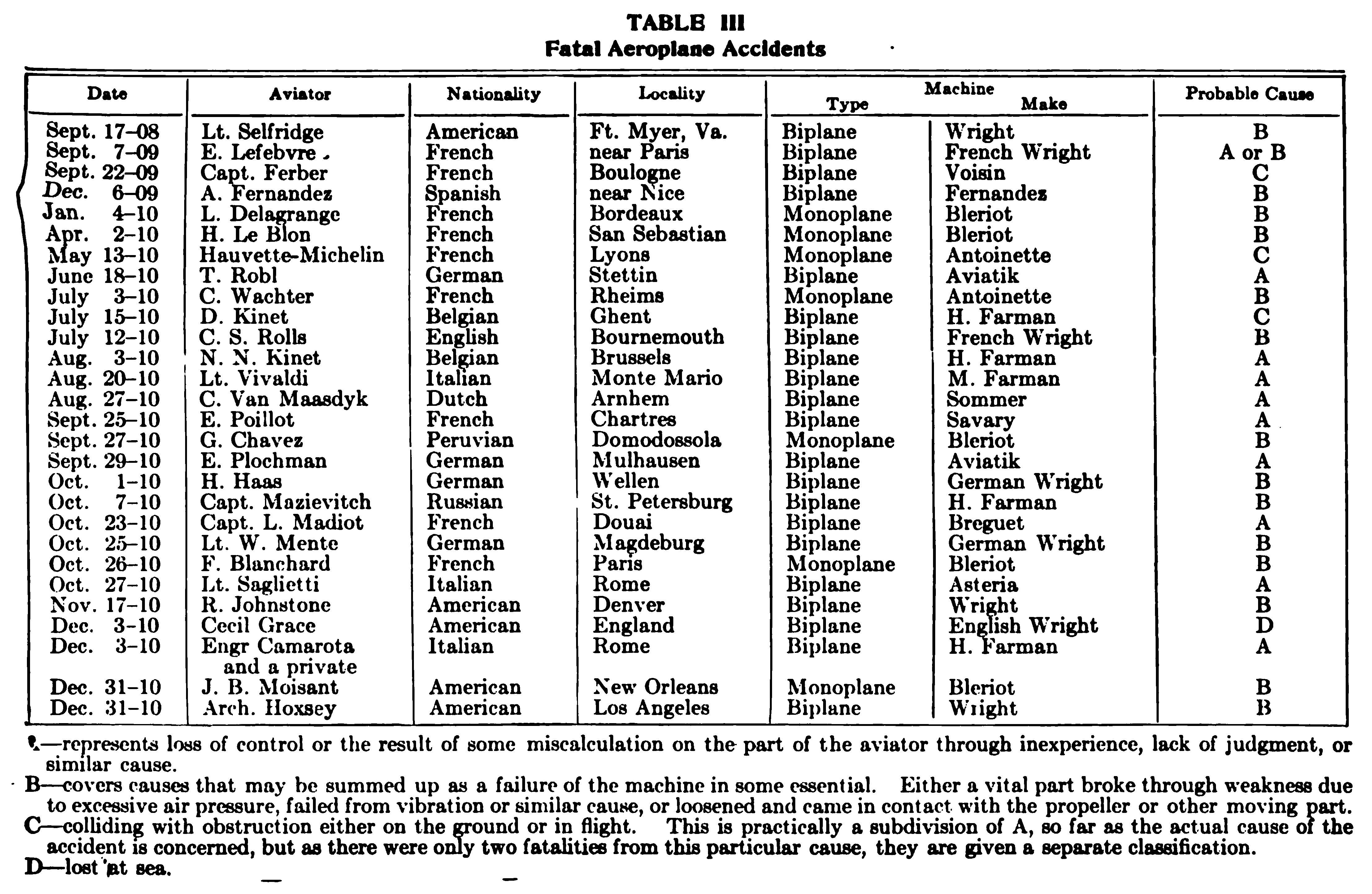
Fatalities greatly increased in number during 1911, but not out of proportion to the greatly augmented number of aviators. With comparatively few exceptions, however, the accidents were more or less similar in their nature to those already tabulated, so that it would be of no particular value to extend the comparison in this manner to cover them. Many of the fatalities during that year were not of the aviators themselves, but of the spectators, a fact which calls attention to a danger that has not been fully appreciated before. At the start of the Paris-Madrid race, the French minister of war and another official were killed by a monoplane plunging into the crowd, and on the same day, May 21, 1911, five people were killed at Odessa, Russia, in the same manner. An unusual type of mishap, not mentioned in the tabulation and in which three or four aviators lost their lives during 1911, was the burning of the aeroplane in midair, or the explosion of the gasoline, setting fire to the wings and either burning the aviator at his post or killing him by the fall. One such accident occurred in France in September, another in Spain two days later, and a third in Germany, in which two men were killed. Accidents of an even more unusual nature were the collision of two biplanes in midair at St. Petersburg, the collision of a motorcycle with a biplane as it swooped down on a race track, and the partial wrecking of Fowler's biplane by a bull upon landing near Fort Worth, Texas, but these, of course, had no bearing on the design of the machines.
Apart from those specially referred to, the great majority of accidents during 1911 may be ascribed to two or three of the causes detailed in connection with the comparative table. Of these, lack of experience and foolhardiness stand out prominently, the latter undoubtedly causing the double fatality at Chicago when two aeroplanes plunged into Lake Michigan, drowning one of the aviators, while a third machine collapsed in mid-air, hurling the aviator to his death on the field. Careful reading of the reports of a large number of these accidents usually brings to light the statement "in attempting to make a quick turn," or similar phrase, showing that the moving cause of the accident was due to subjecting the parts of the machine to excessive stresses, as outlined in the following pages.
Causes. Lack of Experience. It will be at once noticeable by Table III that out of a total of 28, no less than 16, or considerably more than half of the accidents, were due in one way or another to lack of experience. In other words, the aviators had not fully complied with the cardinal principle for success in flying upon which the Wright Brothers have always laid so much stress, i.e., you must first learn to fly before you can attempt to go aloft safely. Nothing short of a thorough mastery of the machine can suffice to give the aviator the ability to do the right thing at the right moment, in the great majority of cases. There will always be occasions when even the most skilled aviator will make errors of judgment and frequently they cost him his life. But this is equally true of every dangerous calling, whether it be running an automobile, driving a locomotive, or doing any of the thousand and one things where the responsibility for his own and other lives is placed in one man's hands and depends to a large extent on his discretion and judgment in cases of emergency, so that there will be fatalities from this cause as long as man continues to fly. This involves the personal equation that must always be reckoned with. Just how many of the accidents that have resulted in the fatalities set forth, have been due to the fallibility of the operator and for how much the design of the current types of machines is responsible, would be hard to say. Fig. 45, for example, which shows H. V. Roe in the act of striking the ground in his triplane, illustrates an accident due to bad design. Methods of control will be improved and simplified and made as nearly "fool-proof" as human ingenuity can accomplish, but experience in other fields has demonstrated unmistakably that they can never be developed to a point where it is impossible to do the wrong thing. With skill at such a premium in callings of responsibility which involve only conditions that have been familiar for years, how much more so must it be in the air about which so little is known? Consequently, the real danger is to be found in the personal equation, just as it is in every other mode of conveyance, despite the fact that it has been perfected to a point which apparently admits of little further development where safe-guarding it is concerned.
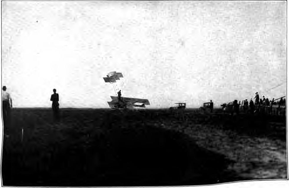
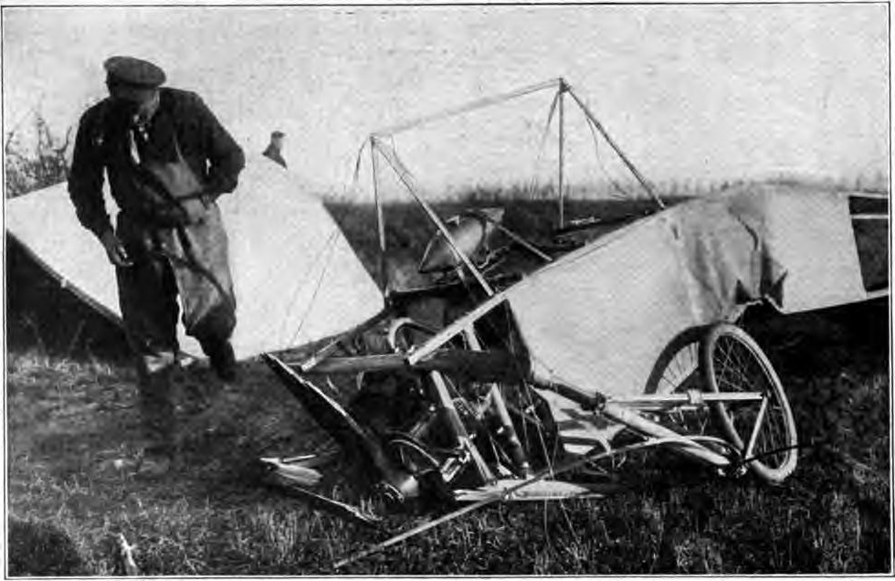
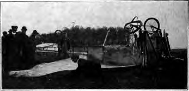
Obstructions. Obstructions are bound to play a prominent part in accidents to any method of conveyance, but less so in aviation than in any other, as it is only in rising and alighting that this danger is present. Of the two fatal accidents ascribed to this cause, one resulted from colliding with an obstruction while running along the ground preparatory to rising, and the other from striking an obstruction in flight, Fig. 46. In view of the numerous cross-country flights that have been made, trips across cities and the like, it is to be marveled at that up to the present writing no fatalities have been caused by what the aviator most dreads when leaving the safety of the open field, that is, being compelled to make a landing through stoppage of the motor, whether from a defection or lack of fuel. While no fatalities have as yet to be put down to this ever-present danger in extended flights, an accident that might have had a fatal termination, occurred to Le Blanc during the competition for the Gordon-Bennett trophy, which was the chief event of the International Meet in October, 1010, at Belmont Park, near New York. Le Blanc and his fellow compatriots who were eligible were all experienced cross-country flyers, the former having won the Circuit de L'Est, a race around France, and by far the most ambitious of its kind which had been attempted up to that time. They accordingly protested most vigorously against flying over the American course to compete for the cup which Curtiss had captured at Rheims the year before, owing to the fact that it presented numerous dangerous obstructions in the form of trees and telegraph poles. But as it was impossible to provide any other convenient five-kilometer circuit (3.11 miles) as called for by the conditions, the protest was of no avail. After having covered 19 of the 20 laps necessary to complete the distance of 100 kilometers in time that had never been approached before, Le Blanc was compelled to descend through lack of fuel, and as he had not risen more than 80 to 100 feet at any time during the race, this meant coming down the moment the motor stopped. The result was a collision with a telegraph pole, breaking it off and wrecking the monoplane, the aviator fortunately escaping any serious injury. During the same meet Moisant demolished his Bleriot monoplane by trying to start in the face of a high wind, Figs. 47 and 48.
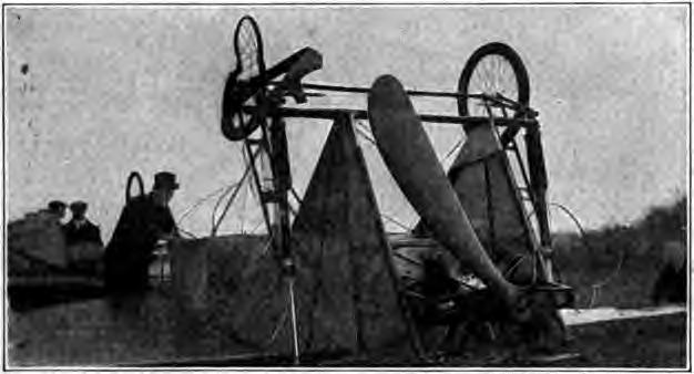
Stopping of Motor. The mere fact that the motor stops does not necessarily mean a disastrous ending to a flight, as is very commonly believed, this having been strikingly illustrated by Brookins' glide to earth from an altitude of 5,000 feet with the motor dead, and Moisant's glide from an even greater height in France. But it does mean a wreck unless a suitable landing place can be reached with the limited ability to control the machine that the aviator has when he can no longer command its power. Motors will undoubtedly become more and more reliable as development progresses, but the human equation—the partly-filled fuel tank, the loose adjustment that is overlooked before starting, and a hundred and one things of a similar nature—will always play their role, so that compulsory landing in unsuitable places will always constitute a source of danger as flights become more and more extended.
Breakage of Parts of Aeroplanes. In studying the foregoing table, it can only be a source of satisfaction to the intelligent student and believer in aerial navigation, to note how large a proportion of the accidents is due to the breakage of parts of the machine. This implies a fault in construction, but not in principle. It reveals the fact that, in the attempt to secure lightness, strength has sometimes been sacrificed, chiefly through lack of appreciation of the stresses to which the machine is subjected in operation. At a time when weight is regarded almost as the paramount factor by so many builders, it is inevitable that some should err by shaving things too fine. Lightness is an absolute necessity and failure to achieve it in every instance without eliminating the factor of safety has been due more to the crude methods of construction and lack of suitable materials, than any other cause—conditions that are bound to obtain in the early days of any art. Construction is improving rapidly, but progress is bound to be attended with accidents of this nature. The fact that their proportion is greatly diminishing despite the rapidly increasing number of aviators is the best evidence of what is being accomplished. When machines are built with such a high factor of safety in every part that breakage is an almost unheard-of thing, failures from this cause will have been reduced to an unsurpassable minimum.
Failure of the Control Mechanism. Under the general classification B, are included not alone those accidents directly due to breakage of some vital part, but also those instances in which some element of the control, such as the elevator, has become inoperative through jamming. When an accident happens in the air, it takes place so quickly and the machine is so totally wrecked by falling to the ground, that it is usually difficult to determine the exact nature of the cause through a subsequent examination of the parts, so that it can seldom be stated with certainty just what the initial defection consisted of, though it may be regarded as a foregone conclusion that, in the case of experienced aviators who have previously demonstrated their ability to cope with all ordinary emergencies, nothing short of the failure of some vital part could have caused their fall.
This was the case with Johnstone's accident at Denver—an occurrence illustrating another phase of the personal equation that must be taken into consideration when noting the lessons to be learned from a study of accidents and their causes. It is simply the old, old story of familiarity breeding contempt—the miner thawing out sticks of dynamite before an open fire. Due to the rarefied air of Denver, which is at an elevation of more than 5,000 feet, Johnstone had underestimated the braking powers of the air on the machine in landing the day previous and had crashed into a fence, breaking one of the right outermost struts between the supporting planes.
Proper regard for safety should naturally have called for its replacement by an entirely new strut, but conditions at flying meets as at present conducted make quick repairs to damaged machines imperative. The damaged upright was accordingly glued and braced by placing iron rings around it, the rings themselves being held in place by ordinary nails passing through holes in the iron large enough to let the nail head slip through. The vibration of the motor and the straining of the strut in warping the wings caused the nails to work out of the holes, permitting the rings to slide out of place as well. Johnstone was an accomplished aviator, much given to the execution of aerial maneuvers only possible to the skilled flyer of quick and ready judgment. But such performances impose excessive stresses on the supporting planes and their braces, and one of Johnstone's quick turns caused the repaired struts to collapse through the strain of sharply warping the wing tips on that side. He immediately attempted to restore the balance of the machine by bringing the left wing down with the control, then tried to force the twisting on the right side, succeeding momentarily, and a few seconds later losing all control and crashing to the ground. It appeared to demonstrate that even when disabled an aeroplane is not entirely without support, but has more or less buoyancy—something which is really more of an optical illusion than anything else due to underestimating the speed at which a body falls from any great height. Johnstone's accident was the first of its kind, in that he fell from a height of about 800 feet, during the first 500 of which he struggled to regain control of the machine, finally dropping the remaining 300 feet apparently as so much dead weight. It showed in a most striking manner the vital importance of the struts connecting the supporting surfaces of the biplane, any damage to them resulting in the crippling of the balancing devices and the end of all aerial support.
Biplane vs. Monoplane. It requires only a glance at Table III to show that the greater number of accidents have happened to the biplane, yet the latter is generally regarded as the safer of the two. Prior to Delagrange's fatal fall in January, 1910, there had been only four fatalities with modern flying machines: Selfridge and Lefebre were killed in Wright machines, the latter of French manufacture, Ferber lost control of his Voisin biplane, and Fernandez was killed flying a biplane of his own design. In one case at least, that of Lieutenant Selfridge, the accident appears to have been due to the failure of a vital part—the propeller. It has since become customary to cover the tips of propellers for at least a foot or so with fabric tightly fitted and varnished so as to become practically an integral part of the wood. This prevents splintering as well as avoiding the danger of the laminations succumbing to centrifugal force and flying apart. At the extremely high speeds, particularly at which direct-driven propellers are run, the stress imposed on the outer portion of the blades by this force is tremendous. In making any attempt to compare the number of accidents to the biplane and the monoplane, it must also be borne in mind that the former has been in the majority.
Delagrange's accident offers two special features of technical interest. It was the first fatality to happen with the monoplane and was likewise the first fatal accident which appeared to be distinctly due to a failure of the main structure of the machine. For obvious reasons, it is usually difficult to definitely fix the cause of an accident, but in this case there seemed good reason to suppose that the main framing of one of the wings gave way altogether. Curiously enough, Santos-Dumont had an accident the day following from an exactly similar cause, the machine plunging to the ground. But with the good fortune that has attended the experimenter throughout his long aerial career, he was uninjured. It was definitely established that the cause was the fracture of one of the wires taking the upward thrust of the wing. In the case of the biplane, the top and bottom members are both of wood, with wooden struts, the whole being braced with numerous ties of wire. In the monoplane, however, the main spars are trussed to a strut below by a comparatively small number of wires. The structure of each wing is, in fact, very much like the rigging of a sailboat, the main spars taking the place of the mast while the wire stays take that of the shrouds, with this very important difference, that the mast of the boat is provided with a forestay to take the longitudinal pressure when going head to the wind, while the wing of an aeroplane often has no such provision, the longitudinal pressure due to air resistance being taken entirely by the spar.
It is quite possible that this had something to do with Delagrange's accident, as, in the effort to make a new record, his Bleriot had just been fitted with a very much more powerful motor. In fact, double that for which the machine was originally designed, and this was given by the maker as the probable cause of the mishap. As the new motor was of a very light type, the extra weight, if any, was quite a negligible proportion of the total weight of the machine. The vertical stresses on the wings and their supporting wires would, therefore, not be materially increased. But as the more powerful engine drove the wings through the air a great deal faster, the stresses brought upon them by the increased resistance would be substantially augmented and, unless provision were made for this, the factor of safety would be much reduced. Whether the failure of the wing was actually from longitudinal stress or the breaking of a supporting wire, as in Santos-Dumont's case, will never be known, but it is quite clear that the question of ample strength to resist longitudinal stresses should be carefully considered, especially when increasing the power of an existing machine.
The question of the most suitable materials and fastenings for the supporting wires is, moreover, a matter which requires very careful consideration. In the case of the biplane, the wires are so numerous that the failure of one, or even more, may not endanger the whole structure, but those of the monoplane are so few that the breaking of but one may mean the loss of the wing. In this respect, as in others, the conditions are parallel to the mast of the sailboat. It is only reasonable to expect, therefore, that similar materials would be best adapted to the purpose. At present, however, the stays of aeroplane wings are almost invariably solid steel wire, or ribbon, while marine shrouds are always of stranded wire rope, solid wire not having been found satisfactory. Weight for weight, the solid wire will stand a greater strain when tried in a testing machine than will the stranded rope, but practice has always demonstrated that it is not so reliable. The stranded rope never breaks without warning, and sometimes several of its wires may go before the whole gives way. As the breakage of the strands can be easily seen, it is possible to replace a damaged stay before it becomes unsafe. In the case of a single wire, there is nothing to show whether it has deteriorated or not. It seems a doubtful policy to use in an aeroplane what experience has shown not to be good enough for a boat, and stranded wire cables particularly designed for aeronautic use are now being placed on the market in this country.
Record Breaking. Striving after records has undoubtedly proved one of the most prolific causes of accident. What is wanted to make the aeroplane of the greatest practical use is that it should be safe and reliable. The tendency of record-breaking machines is the exact opposite of this, as the weights of all the most essential parts must be cut down to the finest limits possible in order to provide sufficient power and fuel-carrying capacity for the record flight. It is, in fact, generally the case in engineering that the design and materials which will give the best results for a short time are essentially different from those which are the most reliable, and striving after speed records consists simply in disregarding safety and reliability to the greatest extent to which the pilots are willing to risk their necks, and there is no difficulty in getting men to take practically any risk for the substantial rewards offered.
The performance of specially sensational feats in the air is likewise a fertile source of accidents. One noted aviator who has the reputation of being a most conservative and expert operator, while endeavoring to land within a set space, made too sudden a turn, which resulted in the tail of the machine giving way, precipitating him to the ground. In fact, the number of failures resulting from abrupt turns shows conclusively that there is too small a factor of safety in the construction, not because the added weight could not be carried, but because the extreme lightness alone made possible the stunts for which there is always applause or financial reward. It may seem strange to the man whose only interest in aeronautics is that of an observer, that so many should be willing to take such unheard-of chances; that an aeronaut will rise to great heights, knowing in advance that a vital part of his machine has been deranged, or is only temporarily repaired; and that many others will attempt ambitious flights with engines or other parts that have never been tested previously in operation in the air. Many young and inexperienced aviators are not content to thoroughly test out each new part on the ground, or close to it, but must go aloft at once to do their experimenting, with the usual result of such foolhardiness. If in other sports safe conditions were absolutely disregarded in this manner—take football as an instance—the resulting fatalities would not be charged against the sport itself. But aviation is so extremely novel and likewise so mysterious to the uninitiated that this is never taken into consideration.
Excessive Lightness of Machines. If, even at the present early stage of aviation, machines are being made excessively light for purposes of competition, it is time that the contest committees of organizations in charge of meetings formulate rules as to the size of engines, weight of machines, and similar factors, so that accidents will not only be reduced to a minimum, but competition along proper lines will develop types of machines which are useful and not merely racing freaks, as has already been done in the automobile field. Hair-raising performances also should be prohibited, at least until such time as improvements in the construction of machines make it reasonably certain that they are able, to withstand the terrific strains imposed upon them in this manner. Suddenly attempting to bring the machine to a horizontal plane after a long dip at an appalling angle is an extremely dangerous maneuver, whether it be taken in the upper air or is one of the now familiar long glides to earth, which require pulling up short when within a few feet of the ground and after the dropping machine has acquired considerable inertia. The aviator is simply staking his life against the ability of the struts and stays to withstand the terrific stresses imposed upon them every time this is done.1
As at present constructed, many of the machines are not sufficiently strong to withstand the utmost in the way of speed and sudden turns which the skilled operator is likely to put on them. They should be made heavier, or of materials providing greatly increased strength with the same weight. That they can be made heavier without seriously damaging their flying ability has been clearly demonstrated by the numerous flights with one and two passengers, and on one occasion in which three passengers besides the driver were taken up on an ordinary machine. This was likewise tempting fate by overloading, but it served to show the possibilities.
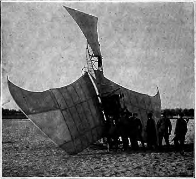
Landings. Then there is a class of accidents for which neither the aviator nor the machine is responsible, as where spectators have crowded on the field, causing the flyers to make altogether too sudden or impromptu landings at angles which would otherwise not be considered for a moment. This, of course, refers solely to exhibition meets, and the comparative immunity of cross-country flights from fatal accidents as compared with the latter, speaks for itself in this respect. In the open, even the novice seems to be able to pick a safe landing, especially if high enough to glide some distance before reaching the ground. This brings out the fact that, as a rule, the machines are safer in the air—a large part of the danger lies in making a landing. Starting places are usually smooth, but landing places may be the reverse. When alighting directly against the wind, which is the only safe practice, most of the machines will remain on an even keel until they come to a stop, but the slightest bump or depression, in connection with a side gust of wind, may swerve it around and capsize it, as demonstrated by the illustration of a bad landing by De Lesseps, Fig. 49. This was emphasized by some of the minor accidents at the International Meet near New York. There is no precision or accuracy in the movements of a flying machine when rolling slowly over the ground after the engine has been shut off, and the aviator is, to a certain extent, helpless. The wheels on most machines are placed too near the center and too close together. When an attempt is made to land with the wind on the quarter or side, although the machine may strike the ground safely, owing to the accuracy with which it may be controlled in the air while at speed, it is apt to turn after rolling a short distance and the wind will then easily capsize it, breaking a wing, smashing a propeller, and sometimes injuring the motor or the aviator. Accidents from this cause have been common.
These accidents and collisions with obstructions make plain the fact that brakes are quite as necessary on an aeroplane as on any other vehicle intended to run on the ground. Practically all aeroplanes are fitted with pneumatic tires and ball-bearing wheels and, as there is very little head resistance, they will run a considerable distance after alighting at a speed of 20 to 30 miles an hour. The employment of a brake on the wheels would have averted one of the fatal accidents abroad, as noted in Table III. They would have enabled Johnstone to stop his machine before colliding with the fence surrounding the aviation grounds at Denver, and they would have prevented several minor accidents at various meets, which, though not endangering the aviator in every instance, have often seriously damaged his machine. Every exhibition field is obstructed by fences, posts, buildings, and the like, and to avoid coming in contact with these, as well as with the irrepressible spectator, the aviator should certainly have an effective means of bringing the machine to a standstill when it is running along the ground. How much more so is this necessary for cross-country flying when the choice of a landing place is a difficult matter at best. Ability to come to a stop quickly would make it possible to land in restricted places where only a very limited run along the ground could be had.
Lack of Sufficient Motor Control. Another class of accidents that take place on the ground suggests the necessity for improving the motor control. In alighting, the motor is usually stopped by cutting off the ignition—ordinarily by grounding or short-circuiting. Throttling to stop appears to be seldom resorted to, but as several instances have occurred in which the aviator found it impossible to cut off the ignition, resulting in a collision with another machine or a building, it is evident that the control should be arranged so that both methods could be employed. With the increasing use of air-cooled motors that may continue to run through self-ignition after the spark has been cut off, this is more necessary than ever.
While it has been demonstrated that the stoppage of the motor does not necessarily involve a fall, most aviators will naturally prefer to command the assistance of the motor at all times, and in the case of motors using a carbureter this should be jacketed either from the cooling water or the exhaust, and means provided for increasing the air supply to prevent the motor stopping at a great height owing to the cold and the rarefied air. The reasons for this have been gone into more at length under the heading of "Altitude." With these and similar improvements that will be suggested by experience and further accidents, there appears to be no reason why aviation can not be made as safe as the personal equation will permit it to be. There will always be reckless flyers. Ignorance and incompetence can not be altogether eliminated any more than they can in sailing, hunting, or any other sport. The annual hunting fatalities from these causes in this country alone make a total beside which the aggregate of four years in aviation the world over, is but an insignificant fraction.
Parachute Garment as a Safeguard. To save as many as possible of these reckless ones from themselves, so to speak, a parachute garment has been devised to ease the shock of the fall. It will be recalled that Voisin would not fly in his biplane until he had provided himself with a heavily-padded helmet, somewhat on the order of the football headpiece. But neither a padded headpiece nor padded clothing would avail much against a fall of any kind from an aeroplane; hence, the parachute garment. Its object is not to take the shock of a fall, as are the pads, nor is it to prevent a fall, but to reduce the rate of drop by interposing sufficient air resistance to make the fall safe. This new parachute is in the form of a loose flowing garment, securely fastened to the body and fitted over a framework carried on the aviator's back. The lower ends of the garment are secured to the ankles. The arrangement is such that when the aviator throws out his arms, the garment is extended somewhat in umbrella or parachute form, thus creating sufficient resistance to prevent too rapid a descent. Experiments have been made with this parachute dress in which the wearer has jumped from buildings, cliffs, and other heights, and the garment has assumed its role of parachute at once, permitting a safe and easy descent.
Study of Stresses in Fancy Flying. To sum up, it will be seen that the most prolific cause of fatalities is the personal equation. Of all the many dangers encountered in aeroplaning, one of the most clearly defined, as well as one of the most seductive, results from fancy flying: from wheeling round sharp, horizontal curves; from conic spiraling; from cascading, swooping, and undulating in vertical plane curves, popularly dubbed "stunts." These are forms of flying in which aviators constantly vie with one another. They frequently result in imposing stresses upon the machine which are far beyond its capacity to withstand. The danger is particularly alluring to reckless young aviators engaged in public exhibitions. The death of St. Croix Johnstone, at the Chicago Meet in the summer of 1911, affords a typical illustration of what may be expected as the result of such performances. Nevertheless, partly because they do not adequately appreciate the risk, and largely, no doubt, because of the liberal applause accorded by an admiring throng which also fails to realize the hazardous nature of the fascinating maneuvers, there will doubtless always be aviators to undertake such feats.
Singularly enough, the exact magnitude of such hazards, or more accurately, the extent of the increased stress in the machine, though beyond even the approximate guess of the aviator, is capable of nice computation in terms of the speed and curvature of flight. During an exhibition meet in Washington, D. C, during the summer of 1911, Glenn H. Curtiss found difficulty in restraining one of his young pupils from executing various hair-raising maneuvers. He would plunge from a great elevation to acquire the utmost speed, then suddenly rebound and shoot far aloft. He would undulate about the field, and on turns would bank the machine until the wings appeared to stand vertical. Curtiss solemnly warned the young aviator and earnestly restrained him, pointing out the dangers of sweeping sharp curves at high speed, of swooping at such dangerous angles, and the like. Curtiss then turned to A. F. Zahm and expressed the wish that someone would determine exactly the amount of the added stress in curvilinear flight. The following, published by Zahm, in the Scientific American, gives the method of calculating this:
When a body pursues a curvilinear path in space, the centripetal force urging it at any instant may be expressed by the equation
Fn = m(V/R)² (absolute units) = (m/g)(V²/R) (gravitational units)
in which Fn is the centripetal force, m the mass of the body, V its velocity, and R the instantaneous radius of curvature of the path followed by its center of mass. Since the mass may be regarded as constant for any short period, the equation may be expressed by the following simple law:
The centripetal force varies directly as the square of the velocity of flight and inversely as the instantaneous radius of the curvature of its path.
In applying the above equation to compute the stress in an aeroplane of given mass m, we may assume a series of values for V and R, compute the corresponding values for Fn, and tabulate the results for reference. Table IV has been obtained in this manner. It may be noted that on substituting in the equation, V is taken as representing miles per hour, R as feet, and g as 22 miles an hour, in order to simplify the figuring, this being 32.1 feet per second. The table shows at a glance the centripetal force acting on an aeroplane to be a fractional part of the gravitational force, of weight of the machine and its load. For example, if the aviator is rounding a curve of 300 feet radius at 60 miles per hour, the centripetal force is 0.55 of the total weight. At the excessively high speed of 100 miles per hour and the extremely short radius of 100 feet, the centripetal force would be 4.55 times the weight of the moving mass. The pilot would then feel heavier on his seat than he would sitting still with a man of his own weight on either shoulder. For speeds below 60 miles per hour and radii of curvature above 500 feet, the centripetal force is less than one third of the weight. The table gives values for speeds of 30 to 100 miles per hour, by increments of 10 miles and for radii of curvature of 100 to 500 feet, by increments of 100 feet, so that intermediate speeds and radii may readily be calculated.
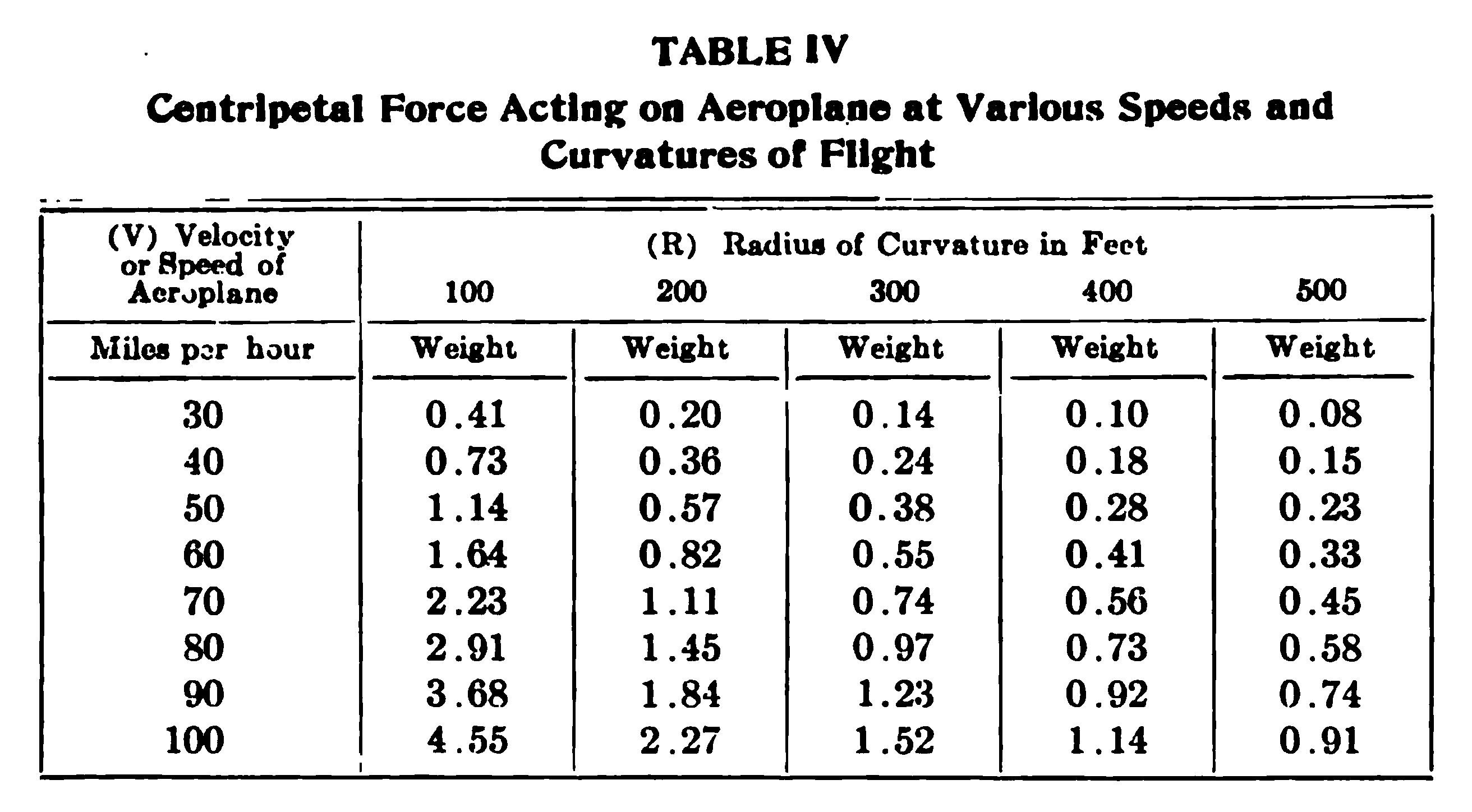
The entire stress on the aeroplane in horizontal flight, being substantially the resultant of the total weight and the centripetal force, can readily be figured by compounding them. Thus in horizontal wheeling, the resultant force as shown in the diagram, Fig. 50, is approximately
F = √(Fn²+W²)
In swooping, or undulating in a vertical plane, the resultant force at the bottom of the curve has its maximum value
F = (Fn+W)
and at any other part of the vertical path, it has a more complex though smaller value, which need not be given in detail.
It is obvious that the greatest stress on the machine occurs at the bottom of a swoop, if the machine be made to rebound on a sharp curve. The total force (Fn+W) sustained at this point may be found from the table, if V and R be known, simply by adding 1 to the figures given, then multiplying by the weight of the machine. For example, if the speed be 90 miles per hour and the radius of curvature 200 feet, the total force on the sustaining surface would be 2.84 times the total weight of the machine. In this case, the stress on all parts of the framing would be 2.84 times its value in level flight, when only the weight has to be sustained. The pilot would feel nearly three times his usual weight.
From the foregoing, it is apparent that in ordinary banking at moderate speeds on moderate curves, the additional stress due to centripetal force is usually well below that due to the weight of the machine, and that in violent flying, the added stress may considerably exceed that due to the weight of the machine and may accordingly be dangerous, unless the aeroplane be constructed with a specially high factor of safety. But there is nothing in the results here obtained that seems to make sharp curving and swooping prohibitive. If the framing of the machine be given an extra factor of safety, at the expense perhaps of endurance and speed, it may be made practically unbreakable by such maneuvers, and still afford to the pilot and spectators alike all the pleasures of fantastic flying.
Methods of Making Tests. In order to obtain actual data for the fluctuations of stress in an aeroplane in varied flying, it is suggested that the stress or strain of some tension or compression member of the machine be recorded when in action; or simpler still, perhaps, that a record of the aeroplane's acceleration be taken and particularly its transverse acceleration. A very simple device to reveal the transverse acceleration of an aeroplane in flight would be a massive index elastically supported. A lath or flat bar stretching lengthwise of the machine, one end fixed, the other free to vibrate, and carrying a pencil along a vertical chronograph drum, would serve the purpose. This could be protected from the wind by a housing as shown in the sketch, Fig. 51.
An adjustable sliding weight could be set to increase or diminish the amplitude of the tracing, and an aerial or liquid damper could be added to smooth the tracing. The zero line would be midway between the tracings made on the drum by the stationary instrument when resting alternately in its normal position and upside down; the distance between this zero line to the actual tracing of the stationary instrument would be proportional to the aeroplane stresses in level, rectilinear flight; while in level flight on a curve, either horizontal or vertical, the deviation of the mean tracing from the zero line would indicate the actual stress during such accelerated flight. Of course, the drum could be omitted and a simple scale put in its place, so that the pilot could observe the mean excursion of the pencil or pointer from instant to instant; also, the damper of such excursion could be adjusted to any amount in the proposed instrument if the vibrating lath fitted its encasing box closely with an adjustable passage for the air as it moved to and fro; or if light damping wings were added to the lath, or flat pencil bar.
Another method would be to obtain by instantaneous photography the position of the centroid of the aeroplane at a number of successive instants, from which could be determined its speed and path, or V and R of the first equation, by which data, therefore, the stress could be read from Table IV.
Perhaps the simplest plan would be to add an acceleration penholder, with its spring and damper, to any recording drum the aeroplane may carry for recording air pressure, temperature, speed, and so forth. Indeed, all such records could be taken on a single drum.
A score of devices, more or less simple, but suitable for revealing the varying stress in an aeroplane, will occur to any engineer who may give the subject attention. And it is desirable in the interests both of aeroplane design and of prudent manipulation that someone obtain roughly accurate data for the stresses developed in actual flight.
Increment of Speed in Driving. It is commonly supposed by aviators that the increment of speed due to driving is very prodigious. An easy formula will determine the major limit of such speed increment. If the initial and natural speed of the aeroplane be v, and the change of level in diving be h, while the speed at the end of the dive be V, the minimum change of level necessary to acquire any increment of speed, V—v, may be found from the equation
h = (V - v)/2g
If, as before, g be taken as 22 miles per hour, the equation reduces to the convenient formula
h = (V-v)/30
in which V and v are taken in miles per hour. Assuming various values for V and v, Table V has been found for the corresponding values of h in feet: For example, if the natural speed of the aeroplane in level flight be 50 miles per hour, and the aviator wishes to increase the speed by 20 miles per hour, he must dive at least 80 feet, assuming that the aeroplane falls freely, like a body in vacuo, or that its propeller overcomes the air resistance completely; otherwise the fall must be rather more than 80 feet.
It has been suggested that a contest be arranged to determine which aviator could dive most swiftly and rebound most suddenly, the prize going to the one who should stress his machine most as indicated by the accelerograph above proposed. But to avoid danger, the contest would have to be supervised by competent experimentalists, and would be best conducted over water. It is safe to say that more than one well-known aeroplane would be denied entry in such a contest because of lack of a sufficient factor of safety in its construction.
Dirigible Accidents. Because its wrecks are spectacular and the loss involved tremendous, the dirigible has probably earned an undeserved reputation, though it must be admitted that the big airships have come to grief with surprising regularity. The fact must be noted, however, that when an airplane is wrecked, the aviator seldom escapes with his life, while the spectators' lives are endangered to an even greater extent, whereas in the case of the dirigible, the loss is simply financial, both the crew and passengers usually escaping without a scratch. This is largely due to the fact that the majority of accidents to dirigibles have happened on the ground, and have been caused by lack of facilities for properly handling or "docking" the huge gas bag. Of course, lack of flotation or an accident to the motors, or both combined, have brought two of the numerous Zeppelins to earth in a very hazardous manner, though no one was killed, while four French army officers lost their lives in the Republique disaster, the exact cause of which was never definitely ascertained. This was likewise the case with Erbsloeh and his companion who were dropped from the sky, their airship having taken fire. It was thought that ignition was caused by atmospheric electricity, in this instance.
By far the great majority of later dirigible accidents have been due solely to the crude methods of handling the airships on the ground, and the frequency with which these have occurred should certainly have been responsible for the adoption of improvements in this respect at an earlier day.
For instance, the Morning Post, a big Lebaudy type bought for English use, had the envelope ripped open by an iron girder projecting from its shed. Repairs took several months, and at the end of the first trial thereafter, the ship was again Wrecked in landing. A company of soldiers failed to hold the big craft and it drifted broadside into a clump of trees, hopelessly wrecking it. In attempting to dock the Deutschland I, 200 men were unable to hold it down, a heavy gust of wand catching the big airship and pounding it down on top of a wind break that had been specially erected at the entrance of the shed for protection. A similar accident happened to the big Parseval, a violent gust of wind casting it against the shed and tearing such a hole in the envelope that the gas rushed out and the car dropped 30 feet to the ground. The big British naval dirigible of the rigid type, the Mayfly, was broken in half in attempting to take it out of the shed the first time. A cross wind was blowing and the gas bag of one of the central sections was torn, deflating it and showing in a striking manner that the solidity of a rigid dirigible results chiefly from the aerostatic pressure of the gas in its various compartments. Without the gas lift, a rigid frame is so in reality only for certain limited distances, as was shown by the total collapse of the Mayfly's frame after having been subjected to the opposed leverage of the parts on either side of the original break. This, of course, was an error in design, as the frame of a rigid dirigible should certainly not be so weak in itself as to collapse upon the deflation of a single one of the central compartments. The incident on the trip of the Zeppelin III to Berlin, in 1909, when the flying blades of a broken propeller pierced the hull without causing an accident, shows how much resistance it may offer.
| [1] | This is exactly what occured at the Chicago Meet, August 15, 1911, when Badger's Baldwin biplane collapsed at the end of a long dive, causing the death of the aviator. |
AMATEUR AVIATORS
It will probably come as a surprise to the average reader to learn that at the end of 1910, there were more than a thousand amateur aviators in this country, though all the flights which form the subject of newspaper reports have been the work of not more than a dozen flyers and doubtless half the population has not as yet seen an aeroplane in flight. The desire to fly, whether it be to satisfy one's desire to soar above the world in seeming defiance of natural laws, or merely to obtain the financial reward that is won by successful flight, attracts a great many from all stations and walks of life. This is particularly true among older boys who look on aviation as an advanced form of kite-flying. An example of rather serious work along this line may be cited of two high school boys of Chicago, Harold Turner and Fred Croll, who built a monoplane weighing 125 pounds, Fig. 52. This machine, although too small for a motor, was equipped with rudder and other operating planes and levers, the elevating plane and ailerons being automatically operated by an electrical device. On one of its flights the machine, carrying a 120 pound operator, was started and propelled by attaching it to an automobile; it rose to a height of 15 feet, and remained in the air 43 seconds.
Contrary to all precedent, the average amateur is bent upon achieving what the skilled professional considers as beyond even his talent and resources—that of building his own flying machine. With every other mechanical vehicle, the amateur learns to drive first and the majority are content with that achievement—for example, very few chauffeurs have any great ambition to build their own automobiles. With flying machines (one of the most difficult of mechanical contrivances), nearly all amateurs want to construct new types for themselves and all confidently expect to fly with no more knowledge than that gained in constructing them. We all have to be apprentices before becoming masters, so all aviators necessarily have to be learners and "grass cutters" before being professionals. Charles K. Hamilton was an exception, but he was already an expert pilot of dirigible balloons, and he did not try to build his own aeroplane. Willard, Mars, and Ely, all Curtiss pupils, flew after a very short training, but they did not attempt to construct aeroplanes for themselves. This is also true of Clifford B. Harmon, the champion amateur.
Classes of Amateurs. Inventors. Generally speaking, amateurs are of two classes. Those of the first class believe they have conceived some entirely new system or invention, or an improvement on some machine that has previously proved a failure; they think they have discovered the secret which other inventors who preceded them failed to grasp. They expend their meager capital in trying to realize high hopes. A comparatively small number ever get as far as completing the machine and one trial on the field is usually sufficient to put a quietus on those who do, as it is disappointing, to say the least, to see the result of a number of months' work undone in a twinkling without the machine having shown the least disposition or ability to get off terra firma.
Would Be Performers. The second class finds its chief incentive in the munificent reward to be gained with what appears to be comparatively little effort or expenditure, and the amateur who is seeking financial returns has no alternative except to build his own machine, or enter either the Wright or Curtiss school of flying and secure a berth with one of these companies.
Wright and Curtiss Patents. This is the result of conditions at present obtaining in the field of aviation. The only generally successful types of American aeroplanes are the Wright and Curtiss, and the acquirement of a biplane of either type means the expenditure of at least $5,000 for the machine alone, and they are sold only to individuals on the express condition that the machines are not to be used for exhibition or as a means of profit to the owner. The manufacturers have expert flyers of their own who attend meets and fairs throughout the country. It would make their monopoly impossible to allow outsiders to fly their aeroplanes publicly or to exhibit them. By this restriction the price of the machines is kept up and large returns are gained by exhibitions and flying.
To break this monopoly by importing European machines is not possible. All the successful aeroplanes made abroad such as the Farman, Cody, and Sommer biplanes; and the Bleriot, Antoinette, and Grade monoplanes are fitted with devices of control or stability, or both, covered by the Wright patents and can not be flown in this country without legal trouble. The numerous foreign aviators who brought over their machines in the fall of 1910 to compete at the International Meet, did so only on being granted a concession by the Wright Company to the effect that they would not be considered as infringers and sued. Similar arrangements were made at subsequent meets and this handicap will always be present where foreign machines are used.
Evasion by Invention of New Types. But when he thinks of the unprecedented sums paid professionals for simply exhibiting their machines and making short flights, the amateur is anxious to obtain a share of the profits. No thought is given the fact that were he and all his kind permitted to fly, the achievement would soon be commonplace and the aviator's golden age would be over. There are accordingly hundreds of would-be aviators in this country today who are striving to evade the Wright basic patents by either devising entirely new types of aeroplanes, or by inventing new methods of control and stability that will not infringe. Others, reasoning that the old aeroplanes built before the advent of the Wright machine cannot be held as infringements owing to priority, propose to develop Maxim, Langley, and Ader machines, though the dictum in the New York Court of Appeals decision referred to under the head of "Legal Status of Wright Patent," which states that a prior machine which had never been known to fly would not be considered an anticipation of a modern successful machine, may prove a stumbling block in their case as well. Thus, a round of the workshops of these enthusiasts reveals a host of heavier-than-air machines of every conceivable type and shape, every one of which, according to its builder, is an aeroplane that will fly. Mineola and Garden City, Long Island, harbor a score of these little shops the year round, but the same scenes are being enacted on a smaller scale in almost every state in the Union, and particularly in California, Ohio, Kansas, Massachusetts, and Arizona, in addition to which there are many who are carrying their experiments on in secret. Each believes deep in his heart that he will succeed where a master failed.
"Maxim failed with this type of machine," quotes one. "How did he expect to fly when his control was not proportionate to the machine's lift capacity?" Seemingly, nobody ever thought of that and our friend will make a fortune by going Maxim one better, but he does not. After months of labor and a great deal of expense he finds that some unforeseen difficulty develops which keeps his machine to earth as if it were part and parcel of it. Another has conceived a type of monoplane that is entirely new—different from any existing type—and as the latter are all foreign, he prides himself on having developed a monoplane that will be entirely American—the first and only American monoplane. Theoretically, it is a wonder; mechanically it is correct; and it speeds over the turf with surprising velocity; but when the elevating rudder is operated to make the machine rise, it balks and plunges head first into the ground. Again and again, the propeller and other broken parts are replaced at no small expense; again and again the inventor goes over every part of the machinery and computes the dimensions of the supporting surface to see if it all corresponds with the formula of his special theory. But time after time, the aeroplane acts like a jumping frog and lands head first. At last, its builder becomes convinced that there is something radically wrong and begins to depart from his original plans, involving changes that simply mean a waste of effort and money, since the inventor does not himself know what he is trying to correct and no one else knows better than he what the trouble is.
Evasion by Acquiring European Types. Others still, realizing from the foregoing experiences that it is almost impossible to construct an entirely new type of aeroplane off-hand, acquire European types and propose to fit them with new control and stability devices, such as are not covered by the Wright patents. So far, none has succeeded. Somehow, the Wrights seem to have covered all the conceivable working devices for control and stability, and the numerous attempts have accordingly resulted in failure. Undoubtedly, some of these aeroplanes built by amateurs may really be capable of flight; but how is the inventor to know it when he lacks the ability to operate it? To know how to fly an aeroplane is a condition precedent to success in the field of aviation that can not be met by building of a machine. The beginner is thus badly handicapped. Even though his machine may embody the elements essential to successful flight, he may never be able to establish the fact, since his first blundering attempt or two frequently ends by wrecking the machine, and many have neither the means nor the stamina to persevere further after a few bad wrecks, involving weeks and weeks of rebuilding each time. He can not engage an expert to fly his machine for him, as the expert's time per minute figures out a price that makes him gasp, and even at that the expert professional's time is pretty much all taken. Furthermore, very few would run the risk of attempting to fly an untried aeroplane—they have more to lose through accidental injury than the builder has through the failure of his theories.
And so it is with most inventors. They may have conceived something really good, but it is not complete, and an aeroplane is hardly worth its weight as junk unless it is. Hundreds of patents are taken out every year on devices to be used on heavier-than-air machines; inventors by scores make daily rounds trying to interest financiers in some seemingly wonderful mechanical scheme, and dozens of companies are organized each year to exploit some especially promising inventions. Numbers of aeroplanes are constructed and hailed as marvels, but, somehow, when a successful flight is made by an amateur it is always with some standard aeroplane, either of the Curtiss or Farman types, and mostly the former. In fact, the Curtiss has become a favorite with the amateur since the Federal court refused to sustain the granting of a preliminary injunction in favor of the Wright Company against Glenn H. Curtiss. It is accordingly being taken for granted in general that the outcome of the Wright vs. Curtiss litigation will be to declare the Curtiss machine non-infringing. Should it be the other way about, there will certainly be gloom and despair in the amateur camps throughout the country. However, neither the Wrights nor Curtiss impose any restriction upon the building of machines of their types for experimental purposes, so that the amateur who wishes to copy them may safely do so, provided no attempt be made to employ the machine for purposes of public exhibition or financial gain.
EXAMINATION PAPER
BUILDING AND FLYING AN
AEROPLANE
PART II
Read Carefully: Place your name and full address at the head of the paper. Any cheap, light paper like the sample previously sent you may be used. Do not crowd your work, but arrange it neatly and legibly. Do not copy the answers from the Instruction Paper; use your own words so that we may be sure that you understand the subject.
Contrast the Bleriot with the Curtiss in every essential particular.
Give details of the Bleriot running gear.
How is the supporting plane of the Bleriot built and reinforced?
What sort of fabric is used to cover the plane and how is it fastened on?
Describe by sketch the Bleriot control system.
How does the location of the motor in the Bleriot compare with its location in the Curtiss?
What is “grass-cutting” and why is it practiced?
Describe some of the devices used in aviation schools.
How is the elevating plane manipulated to start the aeroplane from the ground?
How is the static balance of a machine determined?
How does warping the wings affect the behavior of an aeroplane? How should this be practiced?
Give the process of making a turn in an aeroplane.
What is “banking”? What must be done to prevent excessive banking on a turn?
How can a turn be made in a wind?
Why should the start and the landing always be made in the teeth of the wind?
What is the attitude of the masters of aviation toward fancy flying?
Classify the most common sources of accidents.
What must an aviator do in case his motor stops in midair? Is this considered a dangerous situation?
What are the relative merits of biplane and monoplane as regards the avoidance of accidents?
What are some of the devices used to protect the aviator in case his machine collapses?
Analyze rather carefully the additional stresses put upon an aeroplane when an aviator suddenly swoops and then rights his machine by a quick movement of the control.
After completing the work, add and sign the following statement:
I hereby certify that the above work is entirely my own.
(Signed)
*** END OF THIS PROJECT GUTENBERG EBOOK BUILDING AND FLYING AN AEROPLANE ***
The Full Project Gutenberg License
Please read this before you distribute or use this work.
To protect the Project Gutenberg™ mission of promoting the free distribution of electronic works, by using or distributing this work (or any other work associated in any way with the phrase “Project Gutenberg”), you agree to comply with all the terms of the Full Project Gutenberg™ License available with this file or online at https://www.gutenberg.org/license.
Section 1. General Terms of Use & Redistributing Project Gutenberg™ electronic works
1.A. By reading or using any part of this Project Gutenberg™ electronic work, you indicate that you have read, understand, agree to and accept all the terms of this license and intellectual property (trademark/copyright) agreement. If you do not agree to abide by all the terms of this agreement, you must cease using and return or destroy all copies of Project Gutenberg™ electronic works in your possession. If you paid a fee for obtaining a copy of or access to a Project Gutenberg™ electronic work and you do not agree to be bound by the terms of this agreement, you may obtain a refund from the person or entity to whom you paid the fee as set forth in paragraph 1.E.8.
1.B. “Project Gutenberg” is a registered trademark. It may only be used on or associated in any way with an electronic work by people who agree to be bound by the terms of this agreement. There are a few things that you can do with most Project Gutenberg™ electronic works even without complying with the full terms of this agreement. See paragraph 1.C below. There are a lot of things you can do with Project Gutenberg™ electronic works if you follow the terms of this agreement and help preserve free future access to Project Gutenberg™ electronic works. See paragraph 1.E below.
1.C. The Project Gutenberg Literary Archive Foundation (“the Foundation” or PGLAF), owns a compilation copyright in the collection of Project Gutenberg™ electronic works. Nearly all the individual works in the collection are in the public domain in the United States. If an individual work is unprotected by copyright law in the United States and you are located in the United States, we do not claim a right to prevent you from copying, distributing, performing, displaying or creating derivative works based on the work as long as all references to Project Gutenberg are removed. Of course, we hope that you will support the Project Gutenberg™ mission of promoting free access to electronic works by freely sharing Project Gutenberg™ works in compliance with the terms of this agreement for keeping the Project Gutenberg™ name associated with the work. You can easily comply with the terms of this agreement by keeping this work in the same format with its attached full Project Gutenberg™ License when you share it without charge with others.
1.D. The copyright laws of the place where you are located also govern what you can do with this work. Copyright laws in most countries are in a constant state of change. If you are outside the United States, check the laws of your country in addition to the terms of this agreement before downloading, copying, displaying, performing, distributing or creating derivative works based on this work or any other Project Gutenberg™ work. The Foundation makes no representations concerning the copyright status of any work in any country outside the United States.
1.E. Unless you have removed all references to Project Gutenberg:
1.E.1. The following sentence, with active links to, or other immediate access to, the full Project Gutenberg™ License must appear prominently whenever any copy of a Project Gutenberg™ work (any work on which the phrase “Project Gutenberg” appears, or with which the phrase “Project Gutenberg” is associated) is accessed, displayed, performed, viewed, copied or distributed:
This eBook is for the use of anyone anywhere in the United States and most other parts of the world at no cost and with almost no restrictions whatsoever. You may copy it, give it away or re-use it under the terms of the Project Gutenberg License included with this eBook or online at https://www.gutenberg.org . If you are not located in the United States, you'll have to check the laws of the country where you are located before using this ebook.
1.E.2. If an individual Project Gutenberg™ electronic work is derived from texts not protected by U.S. copyright law (does not contain a notice indicating that it is posted with permission of the copyright holder), the work can be copied and distributed to anyone in the United States without paying any fees or charges. If you are redistributing or providing access to a work with the phrase “Project Gutenberg” associated with or appearing on the work, you must comply either with the requirements of paragraphs 1.E.1 through 1.E.7 or obtain permission for the use of the work and the Project Gutenberg™ trademark as set forth in paragraphs 1.E.8 or 1.E.9.
1.E.3. If an individual Project Gutenberg™ electronic work is posted with the permission of the copyright holder, your use and distribution must comply with both paragraphs 1.E.1 through 1.E.7 and any additional terms imposed by the copyright holder. Additional terms will be linked to the Project Gutenberg™ License for all works posted with the permission of the copyright holder found at the beginning of this work.
1.E.4. Do not unlink or detach or remove the full Project Gutenberg™ License terms from this work, or any files containing a part of this work or any other work associated with Project Gutenberg™.
1.E.5. Do not copy, display, perform, distribute or redistribute this electronic work, or any part of this electronic work, without prominently displaying the sentence set forth in paragraph 1.E.1 with active links or immediate access to the full terms of the Project Gutenberg™ License.
1.E.6. You may convert to and distribute this work in any binary, compressed, marked up, nonproprietary or proprietary form, including any word processing or hypertext form. However, if you provide access to or distribute copies of a Project Gutenberg™ work in a format other than “Plain Vanilla ASCII” or other format used in the official version posted on the official Project Gutenberg™ web site (https://www.gutenberg.org), you must, at no additional cost, fee or expense to the user, provide a copy, a means of exporting a copy, or a means of obtaining a copy upon request, of the work in its original “Plain Vanilla ASCII” or other form. Any alternate format must include the full Project Gutenberg™ License as specified in paragraph 1.E.1.
1.E.7. Do not charge a fee for access to, viewing, displaying, performing, copying or distributing any Project Gutenberg™ works unless you comply with paragraph 1.E.8 or 1.E.9.
1.E.8. You may charge a reasonable fee for copies of or providing access to or distributing Project Gutenberg™ electronic works provided that
You pay a royalty fee of 20% of the gross profits you derive from the use of Project Gutenberg™ works calculated using the method you already use to calculate your applicable taxes. The fee is owed to the owner of the Project Gutenberg™ trademark, but he has agreed to donate royalties under this paragraph to the Project Gutenberg Literary Archive Foundation. Royalty payments must be paid within 60 days following each date on which you prepare (or are legally required to prepare) your periodic tax returns. Royalty payments should be clearly marked as such and sent to the Project Gutenberg Literary Archive Foundation at the address specified in Section 4, “Information about donations to the Project Gutenberg Literary Archive Foundation.”
You provide a full refund of any money paid by a user who notifies you in writing (or by e-mail) within 30 days of receipt that s/he does not agree to the terms of the full Project Gutenberg™ License. You must require such a user to return or destroy all copies of the works possessed in a physical medium and discontinue all use of and all access to other copies of Project Gutenberg™ works.
You provide, in accordance with paragraph 1.F.3, a full refund of any money paid for a work or a replacement copy, if a defect in the electronic work is discovered and reported to you within 90 days of receipt of the work.
You comply with all other terms of this agreement for free distribution of Project Gutenberg™ works.
1.E.9. If you wish to charge a fee or distribute a Project Gutenberg™ electronic work or group of works on different terms than are set forth in this agreement, you must obtain permission in writing from both the Project Gutenberg Literary Archive Foundation and The Project Gutenberg Trademark LLC, the owner of the Project Gutenberg™ trademark. Contact the Foundation as set forth in Section 3. below.
1.F.
1.F.1. Project Gutenberg volunteers and employees expend considerable effort to identify, do copyright research on, transcribe and proofread works not protected by U.S. copyright law in creating the Project Gutenberg™ collection. Despite these efforts, Project Gutenberg™ electronic works, and the medium on which they may be stored, may contain “Defects,” such as, but not limited to, incomplete, inaccurate or corrupt data, transcription errors, a copyright or other intellectual property infringement, a defective or damaged disk or other medium, a computer virus, or computer codes that damage or cannot be read by your equipment.
1.F.2. LIMITED WARRANTY, DISCLAIMER OF DAMAGES – Except for the “Right of Replacement or Refund” described in paragraph 1.F.3, the Project Gutenberg Literary Archive Foundation, the owner of the Project Gutenberg™ trademark, and any other party distributing a Project Gutenberg™ electronic work under this agreement, disclaim all liability to you for damages, costs and expenses, including legal fees. YOU AGREE THAT YOU HAVE NO REMEDIES FOR NEGLIGENCE, STRICT LIABILITY, BREACH OF WARRANTY OR BREACH OF CONTRACT EXCEPT THOSE PROVIDED IN PARAGRAPH 1.F.3. YOU AGREE THAT THE FOUNDATION, THE TRADEMARK OWNER, AND ANY DISTRIBUTOR UNDER THIS AGREEMENT WILL NOT BE LIABLE TO YOU FOR ACTUAL, DIRECT, INDIRECT, CONSEQUENTIAL, PUNITIVE OR INCIDENTAL DAMAGES EVEN IF YOU GIVE NOTICE OF THE POSSIBILITY OF SUCH DAMAGE.
1.F.3. LIMITED RIGHT OF REPLACEMENT OR REFUND – If you discover a defect in this electronic work within 90 days of receiving it, you can receive a refund of the money (if any) you paid for it by sending a written explanation to the person you received the work from. If you received the work on a physical medium, you must return the medium with your written explanation. The person or entity that provided you with the defective work may elect to provide a replacement copy in lieu of a refund. If you received the work electronically, the person or entity providing it to you may choose to give you a second opportunity to receive the work electronically in lieu of a refund. If the second copy is also defective, you may demand a refund in writing without further opportunities to fix the problem.
1.F.4. Except for the limited right of replacement or refund set forth in paragraph 1.F.3, this work is provided to you ‘AS-IS,’ WITH NO OTHER WARRANTIES OF ANY KIND, EXPRESS OR IMPLIED, INCLUDING BUT NOT LIMITED TO WARRANTIES OF MERCHANTABILITY OR FITNESS FOR ANY PURPOSE.
1.F.5. Some states do not allow disclaimers of certain implied warranties or the exclusion or limitation of certain types of damages. If any disclaimer or limitation set forth in this agreement violates the law of the state applicable to this agreement, the agreement shall be interpreted to make the maximum disclaimer or limitation permitted by the applicable state law. The invalidity or unenforceability of any provision of this agreement shall not void the remaining provisions.
1.F.6. INDEMNITY – You agree to indemnify and hold the Foundation, the trademark owner, any agent or employee of the Foundation, anyone providing copies of Project Gutenberg™ electronic works in accordance with this agreement, and any volunteers associated with the production, promotion and distribution of Project Gutenberg™ electronic works, harmless from all liability, costs and expenses, including legal fees, that arise directly or indirectly from any of the following which you do or cause to occur: (a) distribution of this or any Project Gutenberg™ work, (b) alteration, modification, or additions or deletions to any Project Gutenberg™ work, and (c) any Defect you cause.
Section 2. Information about the Mission of Project Gutenberg™
Project Gutenberg™ is synonymous with the free distribution of electronic works in formats readable by the widest variety of computers including obsolete, old, middle-aged and new computers. It exists because of the efforts of hundreds of volunteers and donations from people in all walks of life.
Volunteers and financial support to provide volunteers with the assistance they need, is critical to reaching Project Gutenberg™'s goals and ensuring that the Project Gutenberg™ collection will remain freely available for generations to come. In 2001, the Project Gutenberg Literary Archive Foundation was created to provide a secure and permanent future for Project Gutenberg™ and future generations. To learn more about the Project Gutenberg Literary Archive Foundation and how your efforts and donations can help, see Sections 3 and 4 and the Foundation web page at http://www.pglaf.org .
Section 3. Information about the Project Gutenberg Literary Archive Foundation
The Project Gutenberg Literary Archive Foundation is a non profit 501(c)(3) educational corporation organized under the laws of the state of Mississippi and granted tax exempt status by the Internal Revenue Service. The Foundation's EIN or federal tax identification number is 64-6221541. Its 501(c)(3) letter is posted at https://www.gutenberg.org/fundraising/pglaf . Contributions to the Project Gutenberg Literary Archive Foundation are tax deductible to the full extent permitted by U.S. federal laws and your state's laws.
The Foundation's principal office is in Fairbanks, Alaska, with the mailing address: PO Box 750175, Fairbanks, AK 99775, but its volunteers and employees are scattered throughout numerous locations. Its business office is located at 809 North 1500 West, Salt Lake City, UT 84116, (801) 596-1887, email business@pglaf.org. Email contact links and up to date contact information can be found at the Foundation's web site and official page at http://www.pglaf.org
For additional contact information:
Section 4. Information about Donations to the Project Gutenberg Literary Archive Foundation
Project Gutenberg™ depends upon and cannot survive without wide spread public support and donations to carry out its mission of increasing the number of public domain and licensed works that can be freely distributed in machine readable form accessible by the widest array of equipment including outdated equipment. Many small donations ($1 to $5,000) are particularly important to maintaining tax exempt status with the IRS.
The Foundation is committed to complying with the laws regulating charities and charitable donations in all 50 states of the United States. Compliance requirements are not uniform and it takes a considerable effort, much paperwork and many fees to meet and keep up with these requirements. We do not solicit donations in locations where we have not received written confirmation of compliance. To SEND DONATIONS or determine the status of compliance for any particular state visit https://www.gutenberg.org/fundraising/donate
While we cannot and do not solicit contributions from states where we have not met the solicitation requirements, we know of no prohibition against accepting unsolicited donations from donors in such states who approach us with offers to donate.
International donations are gratefully accepted, but we cannot make any statements concerning tax treatment of donations received from outside the United States. U.S. laws alone swamp our small staff.
Please check the Project Gutenberg Web pages for current donation methods and addresses. Donations are accepted in a number of other ways including checks, online payments and credit card donations. To donate, please visit: https://www.gutenberg.org/fundraising/donate
Section 5. General Information About Project Gutenberg™ electronic works.
Professor Michael S. Hart is the originator of the Project Gutenberg™ concept of a library of electronic works that could be freely shared with anyone. For thirty years, he produced and distributed Project Gutenberg™ eBooks with only a loose network of volunteer support.
Project Gutenberg™ eBooks are often created from several printed editions, all of which are confirmed as not protected by copyright in the U.S. unless a copyright notice is included. Thus, we do not necessarily keep eBooks in compliance with any particular paper edition.
Each eBook is in a subdirectory of the same number as the eBook's eBook number, often in several formats including plain vanilla ASCII, compressed (zipped), HTML and others.
Corrected editions of our eBooks replace the old file and take over the old filename and etext number. The replaced older file is renamed. Versions based on separate sources are treated as new eBooks receiving new filenames and etext numbers.
Most people start at our Web site which has the main PG search facility:
This Web site includes information about Project Gutenberg™, including how to make donations to the Project Gutenberg Literary Archive Foundation, how to help produce our new eBooks, and how to subscribe to our email newsletter to hear about new eBooks.