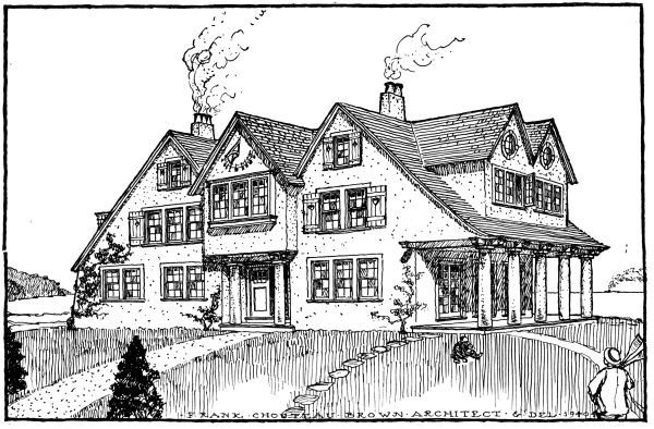
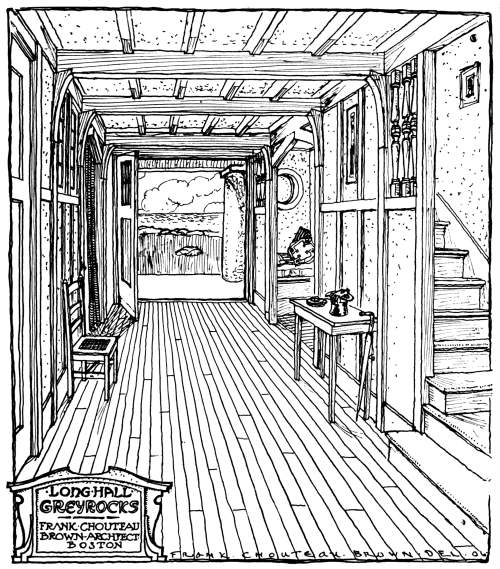
GREYROCKS, ROCKPORT, MASS.
Frank Chouteau Brown, Architect, Boston, Mass.
The cover image was created by the transcriber and is placed in the public domain.
A MANUAL OF PRACTICAL INSTRUCTION IN THE ART OF
STAIR-BUILDING AND HAND-RAILING, AND THE
MANIFOLD USES OF THE STEEL SQUARE
PART I—STAIR-BUILDING
By FRED T. HODGSON
AUTHOR OF “MODERN CARPENTRY,”
“ARCHITECTURAL DRAWING, SELF-TAUGHT,” ETC.
MEMBER OF ONTARIO ASSOCIATION OF ARCHITECTS
AND
MORRIS WILLIAMS
WRITER AND EXPERT ON CARPENTRY AND BUILDING
PART II—THE STEEL SQUARE
By MORRIS WILLIAMS
ILLUSTRATED
CHICAGO
AMERICAN TECHNICAL SOCIETY
1917
COPYRIGHT, 1910, 1916, BY
AMERICAN TECHNICAL SOCIETY
COPYRIGHTED IN GREAT BRITAIN
ALL RIGHTS RESERVED
INTRODUCTION
On entering a building, almost the first thing that meets the eye is the staircase and unconsciously it is made to serve as an indicator of the quality of the architecture. If the design is poor or the construction faulty, this flaw immediately gives the visitor a bad impression of the whole building. Furthermore, stair-building is a rather difficult subject and the principles involved are very little understood, which is evidenced by the fact that the layouts as furnished by architects in their plans are often improperly done.
Probably more mistakes occur in connection with the stairway of a building than with any other construction feature. It is with the idea, therefore, of giving a complete though simple presentation of the construction methods as applied to standard design of staircases, that this book has been prepared.
The article discusses straight and winding stairs, stairs with well hole, layouts for curved turns, the proper proportions of rise and width of tread, the design of hand railings and many other problems, the solution of which will be found very useful.
Coupled with this article is a most instructive section on the Steel Square, containing many applications of this useful instrument to roof and other types of construction.
GREYROCKS, ROCKPORT, MASS.
Frank Chouteau Brown, Architect, Boston, Mass.
CONTENTS
| PART I | |
| STAIR-BUILDING | |
| Page | |
| Stair construction | 1 |
| Definitions | 2 |
| Setting out stairs | 8 |
| Pitch-board | 10 |
| Well-hole | 18 |
| Laying out close-string stair | 22 |
| Open-newel stairs | 32 |
| Stairs with curved turns | 34 |
| Geometrical stairways and hand-railings | 43 |
| Wreaths | 43 |
| Tangent system | 44 |
| Bevels to square wreaths | 60 |
| How to put curves on face-mould | 68 |
| Arrangement of risers | 74 |
| PART II | |
| STEEL SQUARE | |
| Introductory | 1 |
| Specifications for steel square | 1 |
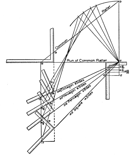
| Miter and length of side of polygon | 4 |
| Steel square in roof framing | 7 |
| General problems | 8 |
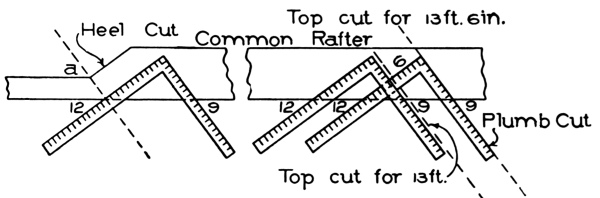
| Heel cut of common rafter | 13 |
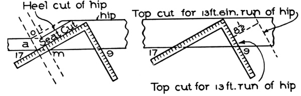
| Hips | 13 |
| Heel cut of hips and valleys | 16 |
| INDEX | 1 |
HALL AND PARTIALLY ENCLOSED STAIRCASE IN LONG HALL,
GREYROCKS, ROCKPORT, MASS.
Frank Chouteau Brown, Architect, Boston, Mass.
Introductory.
In the following instructions in the art of Stair-building, it is the intention to adhere closely to the practical phases of the subject, and to present only such matter as will directly aid the student in acquiring a practical mastery of the art.
Stair-building, though one of the most important subjects connected with the art of building, is probably the subject least understood by designers and by workmen generally. In but few of the plans that leave the offices of Architects, are the stairs properly laid down; and many of the books that have been sent out for the purpose of giving instruction in the art of building, have this common defect—that the body of the stairs is laid down imperfectly, and therefore presents great difficulties in the construction of the rail.
The stairs are an important feature of a building. On entering a house they are usually the first object to meet the eye and claim the attention. If one sees an ugly staircase, it will, in a measure, condemn the whole house, for the first impression produced will seldom be totally eradicated by commendable features that may be noted elsewhere. It is extremely important, therefore, that both designer and workman shall see that staircases are properly laid out.
Stairways should be commodious to ascend—inviting people, as it were, to go up. When winders are used, they should extend past the spring line of the cylinder, so as to give proper width at the narrow end (see Fig. 72) and bring the rail there as nearly as possible to the same pitch or slant as the rail over the square steps. When the hall is of sufficient width, the stairway should not be less than four feet wide, so that two people can conveniently pass each other thereon. The height of riser and width of tread are governed by the staircase, which is the space allowed for the stairway; but, as a general rule, the tread should not be less than nine inches wide, and the riser should not be over eight inches high. Seven-inch riser[Pg 2] and eleven-inch tread will make an easy stepping stairway. If you increase the width of the tread, you must reduce the height of the riser. The tread and riser together should not be over eighteen inches, and not less than seventeen inches. These dimensions, however, cannot always be adhered to, as conditions will often compel a deviation from the rule; for instance, in large buildings, such as hotels, railway depots, or other public buildings, treads are often made 18 inches wide, having risers of from 2½ inches to 5 inches depth.
Before proceeding further with the subject, it is essential that the student make himself familiar with a few of the terms used in stair-building.
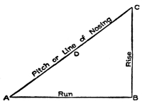
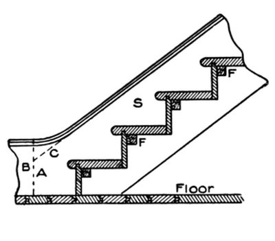
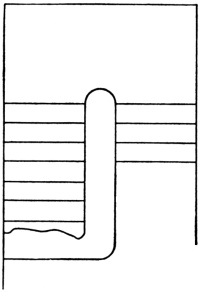
The term rise and run is often used, and indicates certain dimensions of the stairway. Fig. 1 will illustrate exactly what is meant; the line A B shows the run, or the length over the floor the stairs will occupy. From B to C is the rise, or the total height from top of lower floor to top of upper floor.[A] The line D is the pitch or line of nosings, showing the angle of inclination of the stairs. On the three lines shown—the run, the rise, and the pitch—depends the whole system of stair-building.
The body or staircase is the room or space in which the stairway is contained. This may be a space including the width and length of the stairway only, in which case it is called a close stairway, no rail or baluster being necessary. Or the stairway may be in a large apartment, such as a passage or hall, or even in a large room, openings being left in the upper floors so as to allow road room for persons on the stairway, and to furnish communication between the stairways and the different stories of the building. In such cases we have what are known as open stairways, from the fact that they are not closed on both sides, the steps showing their ends at one side, while on the other side they are generally placed against the wall.
Sometimes stairways are left open on both sides, a practice not [Pg 3] uncommon in hotels, public halls, and steamships. When such stairs are employed, the openings in the upper floor should be well trimmed with joists or beams somewhat stronger than the ordinary joists used in the same floor, as will be explained further on.
Tread. This is the horizontal, upper surface of the step, upon which the foot is placed. In other words, it is the piece of material that forms the step, and is generally from 1¼ to 3 inches thick, and made of a width and length to suit the position for which it is intended. In small houses, the treads are usually made of ⅞-inch stuff.
Riser. This is the vertical height of the step. The riser is generally made of thinner stuff than the tread, and, as a rule, is not so heavy. Its duty is to connect the treads together, and to give the stairs strength and solidity.
Rise and Run. This term, as already explained, is used to indicate the horizontal and vertical dimensions of the stairway, the rise meaning the height from the top of the lower floor to the top of the second floor; and the run meaning the horizontal distance from the face of the first riser to the face of the last or top riser, or, in other words, the distance between the face of the first riser and the point where a plumb line from the face of the top riser would strike the floor. It is, in fact, simply the distance that the treads would make if put side by side and measured together—without, of course, taking in the nosings.
Suppose there are fifteen treads, each being 11 inches wide; this would make a run of 15 × 11 = 165 inches = 13 feet 9 inches. Sometimes this distance is called the going of the stair; this, however, is an English term, seldom used in America, and when used, refers as frequently to the length of the single tread as it does to the run of the stairway.
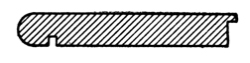
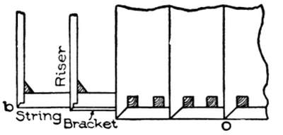
String-Board. This is the board forming the side of the stairway, connecting with, and supporting the ends of the steps. Where the steps are housed, or grooved into the board, it is known by the term housed string; and when it is cut through for the tread to rest upon, and is mitered to the riser, it is known by the term cut and mitered string. The dimensions of the lumber generally used for the purpose in practical work, are 9½ inches width and ⅞-inch thickness. In the first-class stairways the thickness is usually 1⅛ inches, for both front and wall strings.
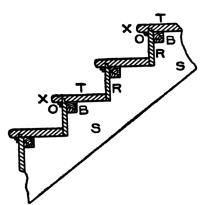
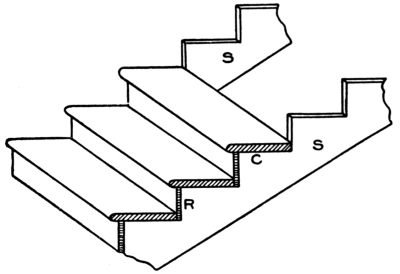
[Pg 4] Fig. 2 shows the manner in which most stair-builders put their risers and treads together. T and T show the treads; R and R, the risers; S and S, the string; O and O, the cove mouldings under the nosings X and X. B and B show the blocks that hold the treads and risers together; these blocks should be from 4 to 6 inches long, and made of very dry wood; their section may be from 1 to 2 inches square. On a tread 3 feet long, three of these blocks should be used at about equal distances apart, putting the two outside ones about 6 inches from the strings. They are glued up tight into the angle. First warm the blocks; next coat two adjoining sides with good, strong glue; then put them in position, and nail them firmly to both tread and riser. It will be noticed that the riser has a lip on the upper edge, which enters into a groove in the tread. This lip is generally about ⅜-inch long, and may be ⅜-inch or ½-inch in thickness. Care must be taken in getting out the risers, that they shall not be made too narrow, as allowance must be made for the lip.
If the riser is a little too wide, this will do no harm, as the over-width may hang down below the tread; but it must be cut the exact width where it rests on the string. The treads must be made the exact width required, before they are grooved or have the nosing [Pg 5] worked on the outer edge. The lip or tongue on the riser should fit snugly in the groove, and should bottom. By following these last instructions and seeing that the blocks are well glued in, a good solid job will be the result.
Fig. 3 is a vertical section of stair steps in which the risers are shown tongued into the under side of the tread, as in Fig. 2, and also the tread tongued into the face of the riser. This last method is in general use throughout the country. The stair-builder, when he has steps of this kind to construct, needs to be very careful to secure the exact width for tread and riser, including the tongue on each. The usual method, in getting the parts prepared, is to make a pattern showing the end section of each. The millman, with these patterns to guide him, will be able to run the material through the machine without any danger of leaving it either too wide or too narrow; while, if he is left to himself without patterns, he is liable to make mistakes. These patterns are illustrated in Figs. 4 and 5 respectively, and, as shown, are merely end sections of riser and tread.
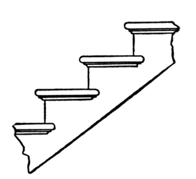
Fig. 6. Side Elevation of Finished Steps with Return Nosings and Cove Moulding.
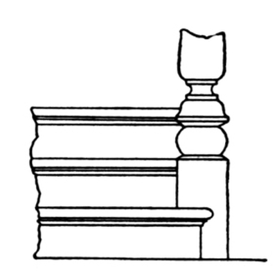
Fig. 7. Front Elevation of Finished Steps.
Fig. 6 is a side elevation of the steps as finished, with return nosings and cove moulding complete.
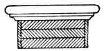
A front elevation of the finished step is shown in Fig. 7, the nosing and riser returning against the base of the newel post. Often the newel post projects past the riser, in front; and when such is the case, the riser and nosing are cut square against the base of the newel.
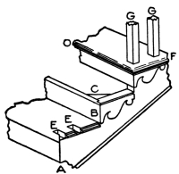
Fig. 8 shows a portion of a cut and mitered string, which will give an excellent idea of the method of construction. The letter O shows the nosing, F the return nosing with a bracket terminating against it. These brackets are about 5⁄16-inch thick, and are planted (nailed) on the string; the brackets miter with the ends of the risers; the ends of the brackets which miter with the risers, are[Pg 6] to be the same height as the riser. The lower ends of two balusters are shown at G G; and the dovetails or mortises to receive these are shown at E E. Generally two balusters are placed on each tread, as shown; but there are sometimes instances in which three are used, while in others only one baluster is made use of.
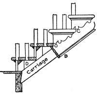
An end portion of a cut and mitered string is shown in Fig. 9, with part of the string taken away, showing the carriage—a rough piece of lumber to which the finished string is nailed or otherwise fastened. At C is shown the return nosing, and the manner in which the work is finished. A rough bracket is sometimes nailed on the carriage, as shown at D, to support the tread. The balusters are shown dovetailed into the ends of the treads, and are either glued or nailed in place, or both. On the lower edge of string, at B, is a return bead or moulding. It will be noticed that the rough carriage is cut in snugly against the floor joist.
Fig. 10 is a plan of the portion of a stairway shown in Fig. 9. Here the position of the string, bracket, riser, and tread can be seen. At the lower step is shown how to miter the riser to the string; and at the second step is shown how to miter it to the bracket.
Fig. 11 shows a quick method of marking the ends of the treads for the dovetails for balusters. The templet A is made of some thin material, preferably zinc or hardwood. The dovetails are outlined as shown, and the intervening portions of the material are cut away, leaving the dovetail portions solid. The templet is then nailed or screwed to a gauge-block E,[Pg 7] when the whole is ready for use. The method of using is clearly indicated in the illustration.
Strings. There are two main kinds of stair strings—wall strings and cut strings. These are divided, again, under other names, as housed strings, notched strings, staved strings, and rough strings.
Wall strings are the supporters of the ends of the treads and risers that are against the wall; these strings may be at both ends of the treads and risers, or they may be at one end only. They may be housed (grooved) or left solid. When housed, the treads and risers are keyed into them, and glued and blocked. When left solid, they have a rough string or carriage spiked or screwed to them, to lend additional support to the ends of risers and treads. Stairs made after this fashion are generally of a rough, strong kind, and are especially adapted for use in factories, shops, and warehouses, where strength and rigidity are of more importance than mere external appearance.
Open strings are outside strings or supports, and are cut to the proper angles for receiving the ends of the treads and risers. It is over a string of this sort that the rail and balusters range; it is also on such a string that all nosings return; hence, in some localities, an open string is known as a return string.
Housed strings are those that have grooves cut in them to receive the ends of treads and risers. As a general thing, wall strings are housed. The housings are made from ⅝ to ¾ inch deep, and the lines at top of tread and face of riser are made to correspond with the lines of riser and tread when in position. The back lines of the housings are so located that a taper wedge may be driven in so as to force the tread and riser close to the face shoulders, thus making a tight joint.
Rough strings are cut from undressed plank, and are used for strengthening the stairs. Sometimes a combination of rough-cut strings is used for circular or geometrical stairs, and, when framed together, forms the support or carriage of the stairs.
[Pg 8] Staved strings are built up strings, and are composed of narrow pieces glued, nailed, or bolted together so as to form a portion of a cylinder. These are sometimes used for circular stairs, though in ordinary practice the circular part of a string is a part of the main string bent around a cylinder to give it the right curve.
Notched strings are strings that carry only treads. They are generally somewhat narrower than the treads, and are housed across their entire width. A sample of this kind of string is the side of a common step-ladder. Strings of this sort are used chiefly in cellars, or for steps intended for similar purposes.
[A] Note.—The measure for the rise of a stairway must always be taken from the top of one floor to the top of the next.
In setting out stairs, the first thing to do is to ascertain the locations of the first and last risers, with the height of the story wherein the stair is to be placed. These points should be marked out, and the distance between them divided off equally, giving the number of steps or treads required. Suppose we have between these two points 15 feet, or 180 inches. If we make our treads 10 inches wide, we shall have 18 treads. It must be remembered that the number of risers is always one more than the number of treads, so that in the case before us there will be 19 risers.
The height of the story is next to be exactly determined, being taken on a rod. Then, assuming a height of riser suitable to the place, we ascertain, by division, how often this height of riser is contained in the height of the story; the quotient, if there is no remainder, will be the number of risers in the story. Should there be a remainder on the first division, the operation is reversed, the number of inches in the height being made the dividend, and the before-found quotient, the divisor. The resulting quotient will indicate an amount to be added to the former assumed height of riser for a new trial height. The remainder will now be less than in the former division; and if necessary, the operation of reduction by division is repeated, until the height of the riser is obtained to the thirty-second part of an inch. These heights are then set off on the story rod as exactly as possible.
The story rod is simply a dressed or planed pole, cut to a length exactly corresponding to the height from the top of the lower floor to the top of the next floor. Let us suppose this height to be 11 feet 1 inch, or 133 inches. Now, we have 19 risers to place in this space, to enable us to get upstairs; therefore, if we divide 133 by 19, we get 7 without any remainder. Seven inches will therefore be the[Pg 9] width or height of the riser. Without figuring this out, the workman may find the exact width of the riser by dividing his story rod, by means of pointers, into 19 equal parts, any one part being the proper width. It may be well, at this point, to remember that the first riser must always be narrower than the others, because the thickness of the first tread must be taken off.
The width of treads may also be found without figuring, by pointing off the run of the stairs into the required number of parts; though, where the student is qualified, it is always better to obtain the width, both of treads and of risers, by the simple arithmetical rules.
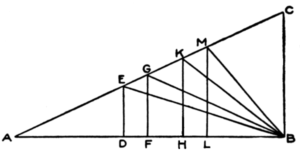
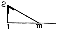
Having determined the width of treads and risers, a pitch-board should be formed, showing the angle of inclination. This is done by cutting a piece of thin board or metal in the shape of a right-angled triangle, with its base exactly equal to the run of the step, and its perpendicular equal to the height of the riser. It is a general maxim, that the greater the breadth of a step or tread, the less should be the height of the riser; and, conversely, the less the breadth of a step, the greater should be the height of the riser. The proper relative dimensions of treads and risers may be illustrated graphically, as in Fig. 12.
In the right-angle triangle A B C, make A B equal to 24 inches, and B C equal to 11 inches—the standard proportion. Now, to find the riser corresponding to a given width of tread, from B, set off on A B the width of the tread, as B D; and from D, erect a perpendicular D E, meeting the hypotenuse in E; then D E is the height of the riser; and if we join B and E, the angle D B E is the angle of inclination, showing the slope of the ascent. In like manner, where B F is the width of the tread, F G is the riser, and B G the slope of the stair. A width of tread B H gives a riser of the height of H K; and a width of tread equal to B L gives a riser equal to L M.
[Pg 10]In the opinion of many builders, however, a better scheme of proportions for treads and risers is obtained by the following method:
Set down two sets of numbers, each in arithmetical progression—the first set showing widths of tread, increasing by inches; the other showing heights of riser, decreasing by half-inches.
| Treads, Inches | Risers, Inches |
|---|---|
| 5 | 9 |
| 6 | 8½ |
| 7 | 8 |
| 8 | 7½ |
| 9 | 7 |
| 10 | 6½ |
| 11 | 6 |
| 12 | 5½ |
| 13 | 5 |
| 14 | 4½ |
| 15 | 4 |
| 16 | 3½ |
| 17 | 3 |
| 18 | 2½ |
It will readily be seen that each pair of treads and risers thus obtained is suitably proportioned as to dimensions.
It is seldom, however, that the proportions of treads and risers are entirely a matter of choice. The space allotted to the stairs usually determines this proportion; but the above will be found a useful standard, to which it is desirable to approximate.
In the better class of buildings, the number of steps is considered in the plan, which it is the business of the Architect to arrange; and in such cases, the height of the story rod is simply divided into the number required.
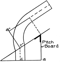
It will now be in order to describe a pitch-board and the manner of using it; no stairs can be properly built without the use of a pitch-board in some form or other. Properly speaking, a pitch-board, as already explained, is a thin piece of material, generally pine or sheet metal, and is a right-angled triangle in outline. One of its sides is made the exact height of the rise; at right angles with this line of rise, the exact width of the tread is measured off; and the material is cut along the hypotenuse of the right-angled triangle thus formed.
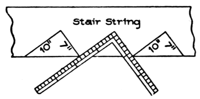
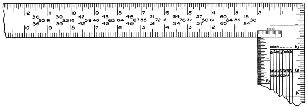
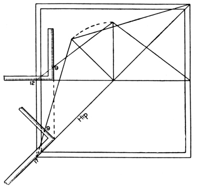
The simplest method of making a pitch-board is by using a steel[Pg 11] square, which, of course, every carpenter in this country is supposed to possess. By means of this invaluable tool, also, a stair string can be laid out, the square being applied to the string as shown in Fig. 13. In the instance here illustrated, the square shows 10 inches for the tread and 7 inches for the rise.
To cut a pitch-board, after the tread and rise have been determined, proceed as follows: Take a piece of thin, clear material, and lay the square on the face edge, as shown in Fig. 13. Mark out the pitch-board with a sharp knife; then cut out with a fine saw, and dress to the knife marks; nail a piece on the largest edge of the pitch-board for a gauge or fence, and it is ready for use.
Fig. 14 shows the pitch-board pure and simple; it may be half an inch thick, or, if of hardwood, may be from a quarter-inch to a half-inch thick.
Fig. 15 shows the pitch-board after the gauge or fence is nailed on. This fence or gauge may be about 1½ inches wide and from ⅜ to ¾ inch thick.
Fig. 16 shows a sectional view of the pitch-board with a fence nailed on.
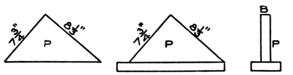
Fig. 14. Fig. 15. Fig. 16.
Showing How a Pitch-Board is Made.
Fig. 15 shows gauge fastened to long edge;
Fig. 16 is a sectional elevation of completed board.
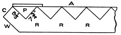
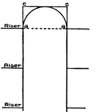
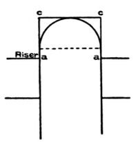
In Fig. 17 the manner of applying the pitch-board is shown. R R R is the string, and the line A shows the jointed or straight edge of the string. The pitch-board P is shown in position, the line 8⅓ represents the step or tread, and the line 7¾ shows the line of the riser. These two lines are of course at right angles, or, as the carpenter would say; they are square. This string shows four complete cuts, and part of a fifth cut for treads, and five complete cuts for risers. The bottom of the string at W is cut off at the line of the floor on which it is supposed to rest. The line C is the line of the first riser. This riser is cut lower[Pg 12] than any of the other risers, because, as above explained, the thickness of the first tread is always taken off it; thus, if the tread is 1½ inches thick, the riser in this case would only require to be 6¼ inches wide, as 7¾-1½ = 6¼.
The string must be cut so that the line at W will be only 6¼ inches from the line at 8⅓, and these two lines must be parallel. The first riser and tread having been satisfactorily dealt with, the rest can easily be marked off by simply sliding the pitch-board along the line A until the outer end of the line 8⅓ on the pitch-board strikes the outer end of the line 7¾ on the string, when another tread and another riser are to be marked off. The remaining risers and treads are marked off in the same manner.
Sometimes there may be a little difficulty at the top of the stairs, in fitting the string to the trimmer or joists; but, as it is necessary first to become expert with the pitch-board, the method of trimming the well or attaching the cylinder to the string will be left until other matters have been discussed.
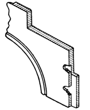
Fig. 18 shows a portion of the stairs in position. S and S show the strings, which in this case are cut square; that is, the part of the string to which the riser is joined is cut square across, and the butt or end wood of the riser is seen. In this case, also, the end of the tread is cut square off, and flush with the string and riser. Both strings in this instance are open strings. Usually, in stairs of this kind, the ends of the treads are rounded off similarly to the front of the tread, and the ends project over the strings the same distance that the front edge projects over the riser. If a moulding or cove is used under the nosing in front, it should be carried round on the string to the back edge of the tread and cut off square, for in this case the back edge of the tread will be square. A riser is shown at R, and it will be noticed that it runs down behind the tread on the back edge, and is either nailed or screwed to the tread. This is the American practice, though in England the riser usually rests on the tread, which extends clear back to string as shown at the top tread in the diagram. It is much better, however, for general purposes, that the riser go behind the tread, as this tends to make the whole stairway much stronger.
[Pg 13] Housed strings are those which carry the treads and risers without their ends being seen. In an open stair, the wall string only is housed, the other ends of the treads and risers resting on a cut string, and the nosings and mouldings being returned as before described.
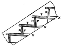
The manner of housing is shown in Fig. 19, in which the treads T T and the risers R R are shown in position, secured in place respectively by means of wedges X X and F F, which should be well covered with good glue before insertion in the groove. The housings are generally made from ½ to ⅝ inch deep, space for the wedge being cut to suit.
In some closed stairs in which there is a housed string between the newels, the string is double-tenoned into the shanks of both newels, as shown in Fig. 20. The string in this example is made 12¾ inches wide, which is a very good width for a string of this kind; but the thickness should never be less than 1½ inches. The upper newel is made about 5 feet 4 inches long from drop to top of cap. These strings are generally capped with a subrail of some kind, on which the baluster, if any, is cut-mitered in. Generally a groove, the width of the square of the balusters, is worked on the top of the subrail, and the balusters are worked out to fit into this groove; then pieces of this material, made the width of the groove and a little thicker than the groove is deep, are cut so as to fit in snugly between the ends of the balusters resting in the groove. This makes a solid job; and the pieces between the balusters may be made [Pg 14] of any shape on top, either beveled, rounded, or moulded, in which case much is added to the appearance of the stairs.
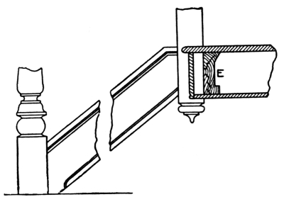
Fig. 21 exhibits the method of attaching the rail and string to the bottom newel. The dotted lines indicate the form of the tenons cut to fit the mortises made in the newel to receive them.
Fig. 22 shows how the string fits against the newel at the top; also the trimmer E, to which the newel post is fastened. The string in this case is tenoned into the upper newel post the same way as into the lower one.
The open string shown in Fig. 23 is a portion of a finished string, showing nosings and cove returned and finishing against the face of the string. Along the lower edge of the string is shown a bead or moulding, where the plaster is finished.
A portion of a stair of the better class is shown in Fig. 24. This is an open, bracketed string, with returned nosings and coves and scroll brackets. These brackets are made about ⅜ inch thick, and may be in any desirable pattern. The end next the riser should be mitered to suit; this will require the riser to be ⅜ inch longer than the face of the string. The upper part of the bracket should run under the cove moulding; and the tread should project over the string the full ⅜ inch, so as to cover the [Pg 15]bracket and make the face even for the nosing and the cove moulding to fit snugly against the end of the tread and the face of the bracket. Great care must be taken about this point, or endless trouble will follow. In a bracketed stair of this kind, care must be taken in placing the newel posts, and provision must be made for the extra ⅜ inch due to the bracket. The newel post must be set out from the string ⅜ inch, and it will then align with the baluster.
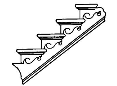
Fig. 24. Portion of Open, Bracketed String Stair,
with Returned Nosings and Coves,
Scroll Brackets,and Bead Moulding.
We have now described several methods of dealing with strings; but there are still a few other points connected with these members, both housed and open, that it will be necessary to explain; before the young workman can proceed to build a fair flight of stairs. The connection of the wall string to the lower and upper floors, and the manner of affixing the outer or cut string to the upper joist and to the newel, are matters that must not be overlooked. It is the intention to show how these things are accomplished, and how the stairs are made strong by the addition of rough strings or bearing carriages.[Pg 16]
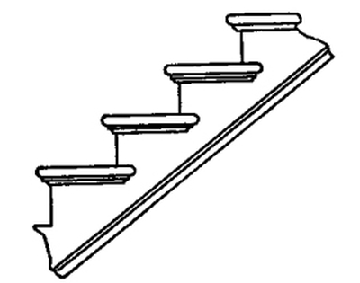
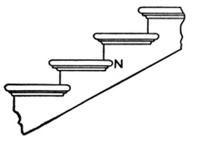
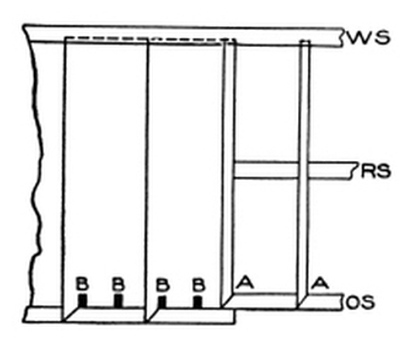
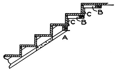
Fig. 25 gives a side view of part of a stair of the better class, with one open, cut and mitered string. In Fig. 26, a plan of this same stairway, W S shows the wall string; R S, the rough string, placed there to give the structure strength; and O S, the outer or cut and mitered string. At A A the ends of the risers are shown, and it will be noticed that they are mitered against a vertical or riser line of the string, thus preventing the end of the riser from being seen. The other end of the riser is in the housing in the wall string. The outer end of the tread is also mitered at the nosing, and a piece of material made or worked like the nosing is mitered against or returned at the end of the tread. The end of this returned piece is again returned on itself back to the string, as shown at N in Fig. 25. The moulding, which is ⅝-inch cove in this case, is also returned on itself back to the string.
The mortises shown at B B B B (Fig. 26), are for the balusters. It is always the proper thing to saw the ends of the treads ready for the balusters before the treads are attached to the string; then, when the time arrives to put up the rail, the back ends of the mortises can be cut out, when the treads will be ready to receive the balusters. The mortises are dovetailed, and, of course, the tenons on the balusters must be made to suit. The treads are finished on the bench; and the return nosings are fitted to them and tacked on, so that they may be taken off to insert the balusters when the rail is being put in position.
Fig. 27 shows the manner in which a wall string is finished at the foot of the stairs. S shows the string, with moulding wrought on the upper edge. This moulding may be a simple ogee, or may consist of a number of members; or it may be only a bead; or, again, the edge of the string may be [Pg 17]left quite plain; this will be regulated in great measure by the style of finish in the hall or other part of the house in which the stairs are placed. B shows a portion of a baseboard, the top edge of which has the same finish as the top edge of the string. B and A together show the junction of the string and base. F F show blocks glued in the angles of the steps to make them firm and solid.
Fig. 28 shows the manner in which the wall string S is finished at the top of the stairs. It will be noticed that the moulding is worked round the ease-off at A to suit the width of the base at B. The string is cut to fit the floor and to butt against the joist. The plaster line under the stairs and on the ceiling, is also shown.
Fig. 29 shows a cut or open string at the foot of a stairway, and the manner of dealing with it at its junction with the newel post K. The point of the string should be mortised into the newel 2 inches, 3 inches, or 4 inches, as shown by the dotted lines; and the mortise in the newel should be cut near the center, so that the center of the baluster will be directly opposite the central line of the newel post. The proper way to manage this, is to mark the central line of the baluster on the tread, and then make this line correspond with the central line of the newel post. By careful attention to this point, much trouble will be avoided where a turned cap is used to receive the lower part of the rail.
The lower riser in a stair of this kind will be somewhat shorter than the ones above it, as it must be cut to fit between the newel and [Pg 18] the wall string. A portion of the tread, as well as of the riser, will also butt against the newel, as shown at W.
If there is no spandrel or wall under the open string, it may run down to the floor as shown by the dotted line at O. The piece O is glued to the string, and the moulding is worked on the curve. If there is a wall under the string S, then the base B, shown by the dotted lines, will finish against the string, and it should have a moulding on its upper edge, the same as that on the lower edge of the string, if any, this moulding being mitered into the one on the string. When there is a base, the piece O is of course dispensed with.
The square of the newel should run down by the side of a joist as shown, and should be firmly secured to the joist either by spiking or by some other suitable device. If the joist runs the other way, try to get the newel post against it, if possible, either by furring out the joist or by cutting a portion off the thickness of the newel. The solidity of a stair and the firmness of the rail, depend very much upon the rigidity of the newel post. The above suggestions are applicable where great strength is required, as in public buildings. In ordinary work, the usual method is to let the newel rest on the floor.
Fig. 30 shows how the cut string is finished at the top of the stairs. This illustration requires no explanation after the instructions already given.
Thus far, stairs having a newel only at the bottom have been dealt with. There are, however, many modifications of straight and return stairs which have from two to four or six newels. In such cases, the methods of treating strings at their finishing points must necessarily be somewhat different from those described; but the general principles, as shown and explained, will still hold good.
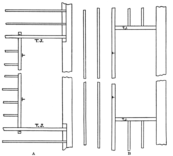
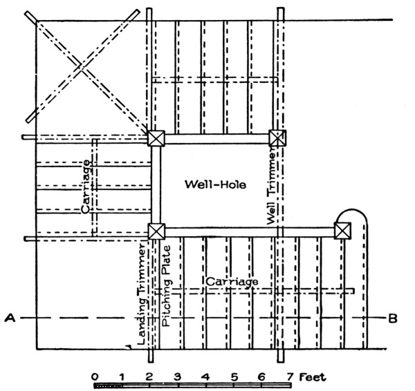
Before proceeding to describe and illustrate neweled stairs, it will be proper to say something about the well-hole, or the [Pg 19] opening through the floors, through which the traveler on the stairs ascends or descends from one floor to another.
Fig. 31 shows a well-hole, and the manner of trimming it. In this instance the stairs are placed against the wall; but this is not necessary in all cases, as the well-hole may be placed in any part of the building.
The arrangement of the trimming varies according as the joists are at right angles to, or are parallel to, the wall against which the stairs are built. In the former case (Fig. 31, A) the joists are cut short and tusk-tenoned into the heavy trimmer T T, as shown in the cut. This trimmer is again tusk-tenoned into two heavy joists T J and T J, which form the ends of the well-hole. These heavy joists are called trimming joists; and, as they have to carry a much heavier load than other joists on the same floor, they are made much heavier. Sometimes two or three joists are placed together, side by side, being bolted or spiked together to give them the desired unity and strength. In constructions requiring great strength, the tail and header joists of a well-hole are suspended on iron brackets.
If the opening runs parallel with the joists (Fig. 31, B), the timber forming the side of the well-hole should be left a little heavier than the other joists, as it will have to carry short trimmers (T J and T J) and the joists running into them. The method here shown is more particularly adapted to brick buildings, but there is no reason why the same system may not be applied to frame buildings.
Usually in cheap, frame buildings, the trimmers T T are spiked against the ends of the joists, and the ends of the trimmers are supported by being spiked to the trimming joists T J, T J. This is not very workmanlike or very secure, and should not be done, as it is not nearly so strong or durable as the old method of framing the joists and trimmers together.
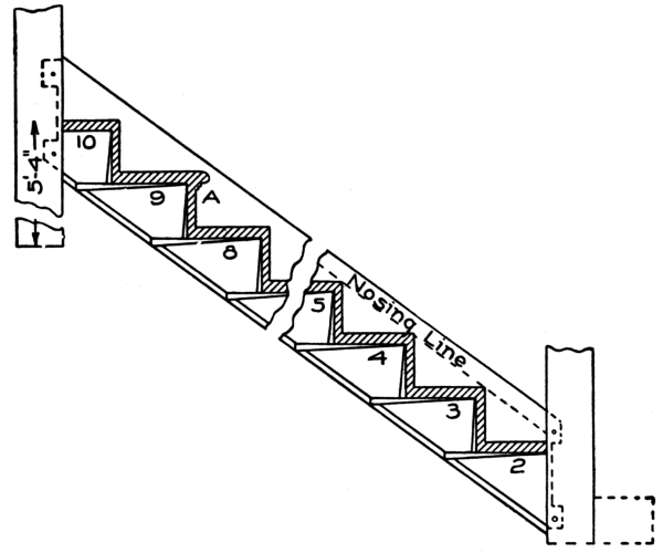
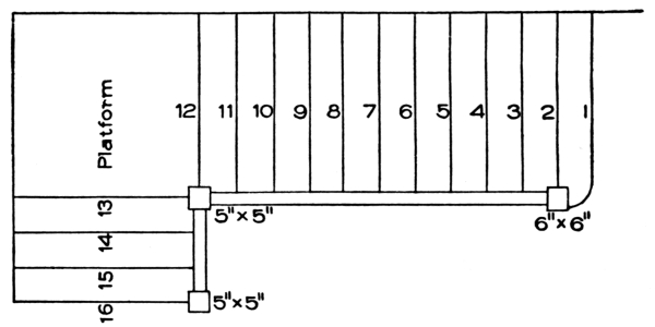
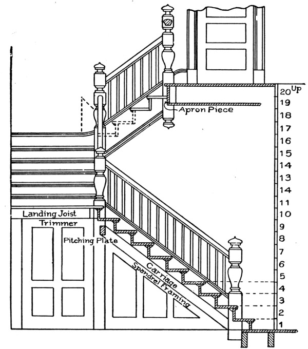
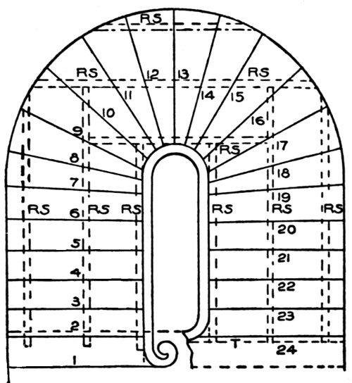
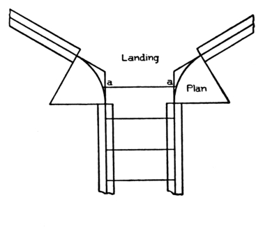
Fig. 32 shows a stair with three newels and a platform. In this [Pg 20]example, the first tread (No. 1) stands forward of the newel post two-thirds of its width. This is not necessary in every case, but it is sometimes done to suit conditions in the hallway. The second newel is placed at the twelfth riser, and supports the upper end of the first cut string and the lower end of the second cut string. The platform (12) is supported by joists which are framed into the wall and are fastened against a trimmer running from the wall to the newel along the line 12. This is the case only when the second newel runs down to the floor.
If the second newel does not run to the floor, the framework supporting the platform will need to be built on studding. The third newel stands at the top of the stairs, and is fastened to the joists of the second floor, or to the trimmer, somewhat after the manner of fastening shown in Fig. 29. In this example, the stairs have 16 risers [Pg 21]and 15 treads, the platform or landing (12) making one tread. The figure 16 shows the floor in the second story.
This style of stair will require a well-hole in shape about as shown in the plan; and where strength is required, the newel at the top should run from floor to floor, and act as a support to the joists and trimmers on which the second floor is laid.
Perhaps the best way for a beginner to go about building a stairway of this type, will be to lay out the work on the lower floor in the exact place where the stairs are to be erected, making everything full size. There will be no difficulty in doing this; and if the positions of the first riser and the three newel posts are accurately defined, the building of the stairs will be an easy matter. Plumb lines can be raised from the lines on the floor, and the positions of the platform and each riser thus easily determined. Not only is it best to line out on the floor all stairs having more than one newel; but in constructing any kind of stair it will perhaps be safest for a beginner to lay out in exact position on the floor the points over which the treads and risers will stand. By adopting this rule, and seeing that the strings, risers, and treads correspond exactly with the lines on the floor, many cases of annoyance will be avoided. Many expert stair-builders, in fact, adopt this method in their practice, laying out all stairs on the floor, including even the carriage strings, and they cut out all the material from the lines obtained on the floor. By following this method, one can see exactly the requirements in each particular case, and can rectify any error without destroying valuable material.
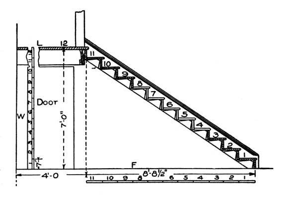
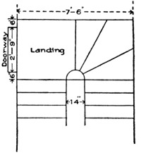
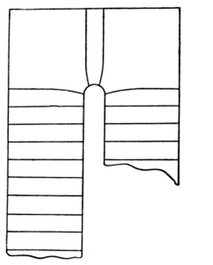
In order to afford the student a clear idea of what is meant by laying out on the floor, an example of a simple close-string stair is given. In Fig. 33, the letter F shows the floor line; L is the landing or platform; and W is the wall line. The stair is to be 4 feet wide over strings; the landing, 4 feet wide; the height from floor to landing, 7 feet; and the run from start to finish of the stair, 8 feet 8½ inches.
The first thing to determine is the dimensions of the treads and risers. The wider the tread, the lower must be the riser, as stated before. No definite dimensions for treads and risers can be given, as the steps have to be arranged to meet the various difficulties that may occur in the working out of the construction; but a common rule is this: Make the width of the tread, plus twice the rise, equal to 24 inches. This will give, for an 8-inch tread, an 8-inch rise; for a 9-inch tread, a 7½-inch rise; for a 10-inch tread, a 7-inch rise, and so on. Having the height (7 feet) and the run of the flight (8 feet 8½-inches), take a rod about one inch square, and mark on it the height from floor to landing (7 feet), and the length of the going or run of the flight (8 feet 8½ inches). Consider now what are the dimensions which can be given to the treads and risers, remembering that there will be one more riser than the number of treads. Mark off on the rod the landing, forming the last tread. If twelve risers are desired, divide the height (namely, 7 feet) by 12, which gives 7 inches as the rise of each step. Then divide the run (namely, 8 feet 8½ inches) by 11, and the width of the tread is found to be 9½ inches.
Great care must be taken in making the pitch-board for marking off the treads and risers on the string. The pitch-board may be made from dry hardwood about ⅜-inch thick. One end and one side must be perfectly square to each other; on the one, the width of the tread is set off, and on the other the height of the riser. Connect the two points thus obtained, and saw the wood on this line. The addition of a gauge-piece along the longest side of the triangular piece, completes the pitch-board, as was illustrated in Fig. 15.
The length of the wall and outer string can be ascertained by means of the pitch-board. One side and one edge of the wall string must be squared; but the outer string must be trued all round. On the strings, mark the positions of the treads and risers by using the pitch-board as already explained (Fig. 17). Strings are usually[Pg 23] made 11 inches wide, but may be made 12½ inches wide if necessary for strength.
After the widths of risers and treads have been determined, and the string is ready to lay out, apply the pitch-board, marking the first riser about 9 inches from the end; and number each step in succession. The thickness of the treads and risers can be drawn by using thin strips of hardwood made the width of the housing required. Now allow for the wedges under the treads and behind the risers, and thus find the exact width of the housing, which should be about ⅝-inch [Pg 24] deep; the treads and risers will require to be made 1¼ inches longer than shown in the plan, to allow for the housings at both ends.
Before putting the stair together, be sure that it can be taken into the house and put in position without trouble. If for any reason it cannot be put in after being put together, then the parts must be assembled, wedged, and glued up at the spot.
It is essential in laying out a plan on the floor, that the exact positions of the first and last risers be ascertained, and the height of the story wherein the stair is to be placed. Then draw a plan of the hall or other room in which the stairs will be located, including surrounding or adjoining parts of the room to the extent of ten or twelve feet from the place assigned for the foot of the stair. All the doorways, branching passages, or windows which can possibly come in contact with the stair from its commencement to its expected termination or landing, must be noted. The sketch must necessarily include a portion of the entrance hall in one part, and of the lobby or landing in another, and on it must be laid out all the lines of the stair from the first to the last riser.
The height of the story must next be exactly determined and taken on the rod; then, assuming a height of risers suitable to the place, a trial is made by division in the manner previously explained, to ascertain how often this height is contained in the height of the story. The quotient, if there is no remainder, will be the number of risers required. Should there be a remainder on the first division, the operation is reversed, the number of inches in the height being made the dividend and the before-found quotient the divisor; and the operation of reduction by division is carried on till the height of the riser is obtained to the thirty-second part of an inch. These heights are then set off as exactly as possible on the story rod, as shown in Fig. 33.
The next operation is to show the risers on the sketch. This the workman will find no trouble in arranging, and no arbitrary rule can be given.
A part of the foregoing may appear to be repetition; but it is not, for it must be remembered that scarcely any two flights of stairs are alike in run, rise, or pitch, and any departure in any one dimension from these conditions leads to a new series of dimensions that must be dealt with independently. The principle laid down, however, applies to all straight flights of stairs; and the student who has followed[Pg 25] closely and retained the pith of what has been said, will, if he has a fair knowledge of the use of tools, be fairly equipped for laying out and constructing a plain, straight stair with a straight rail.
Plain stairs may have one platform, or several; and they may turn to the right or to the left, or, rising from a platform or landing, may run in an opposite direction from their starting point.
When two flights are necessary for a story, it is desirable that each flight should consist of the same number of steps; but this, of course, will depend on the form of the staircase, the situation and height of doors, and other obstacles to be passed under or over, as the case may be.
In Fig. 32, a stair is shown with a single platform or landing and three newels. The first part of this stair corresponds, in number of risers, with the stair shown in Fig. 33; the second newel runs down to the floor, and helps to sustain the landing. This newel may simply be a 4 by 4-inch post, or the whole space may be inclosed with the spandrel of the stair. The second flight starts from the platform just as the first flight starts from the lower floor, and both flights may be attached to the newels in the manner shown in Fig. 29. The bottom tread in Fig. 32 is rounded off against the square of the newel post; but this cannot well be if the stairs start from the landing, as the tread would project too far onto the platform. Sometimes, in high-class stairs, provision is made for the first tread to project well onto the landing.
If there are more platforms than one, the principles of construction will be the same; so that whenever the student grasps the full conditions governing the construction of a single-platform stair, he will be prepared to lay out and construct the body of any stair having one or more landings. The method of laying out, making, and setting up a hand-rail will be described later.
Stairs formed with treads each of equal width at both ends, are named straight flights; but stairs having treads wider at one end than the other are known by various names, as winding stairs, dog-legged stairs, circular stairs, or elliptical stairs. A tread with parallel sides, having the same width at each end, is called a flyer; while one having one wide end and one narrow, is called a winder. These terms will often be made use of in what follows.
[Pg 26] The elevation and plan of the stair shown in Fig. 34 may be called a dog-legged stair with three winders and six flyers. The flyers, however, may be extended to any number. The housed strings to receive the winders are shown. These strings show exactly the manner of construction. The shorter string, in the corner from 1 to 4, which is shown in the plan to contain the housing of the first winder and half of the second, is put up first, the treads being leveled by aid of a spirit level; and the longer upper string is put in place afterwards, butting snugly against the lower string in the corner. It is then fastened firmly to the wall. The winders are cut snugly around the newel post, and well nailed. Their risers will stand one above another on the post; and the straight string above the winders will enter the post on a line with the top edge of the uppermost winder.
Platform stairs are often constructed so that one flight will run in a direction opposite to that of the other flight, as shown in Fig.35. In cases of this kind, the landing or platform requires to have a length more than double that of the treads, in order that both flights may have the same width. Sometimes, however, and for various reasons, the upper flight is made a little narrower than the lower; but this expedient should be avoided whenever possible, as its adoption unbalances the stairs. In the example before us, eleven treads, not including the landing, run in one direction; while four treads, including the landing, run in the opposite direction; or, as workmen put it, the stair “returns on itself.” The elevation [Pg 27] shown in Fig. 36 illustrates the manner in which the work is executed. The various parts are shown as follows:
Fig. 37 is a section of the top landing, with baluster and rail.
Fig. 38 is part of the long newel, showing mortises for the strings.
[Pg 28] Fig. 39 represents part of the bottom newel, showing the string, moulding on the outside, and cap.
Fig. 40 is a section of the top string enlarged.
Fig. 41 is the newel at the bottom, as cut out to receive bottom step. It must be remembered that there is a cove under each tread. This may be nailed in after the stairs are put together, and it adds greatly to the appearance.
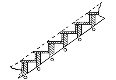
We may state that stairs should have carriage pieces fixed from floor to floor, under the stairs, to support them. These may be notched under the steps; or rough brackets may be nailed to the side of the carriage, and carried under each riser and tread.
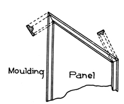
There is also a framed spandrel which helps materially to carry the weight, makes a sound job, and adds greatly to the appearance. This spandrel may be made of 1¼-inch material, with panels and mouldings on the front side, as shown in Fig. 36. The joint between the top and bottom rails of the spandrel at the angle, should be made as shown in Fig. 42 with a cross-tongue, and glued and fastened with long screws. Fig. 43 is simply one of the panels showing the miters on the moulding and the shape of the sections. As there is a convenient space under the landing, it is commonly used for a closet.
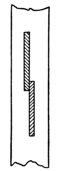
Fig. 38. String Mortises in Long Newel.
Fig. 39. Mortises in Lower Newel for String,
Outside Moulding, and Cap.
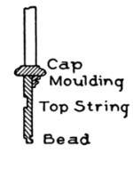
Fig. 40. Enlarged Section of Top String.
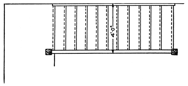
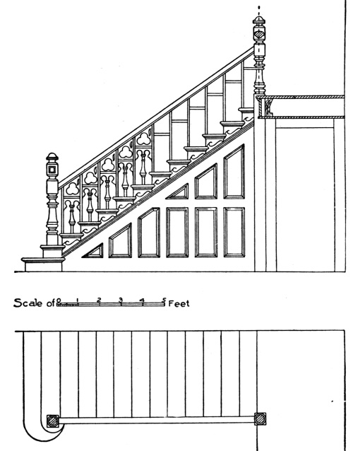
In setting out stairs, not only the proportions of treads and risers must be considered, but also the material available. As this material runs, as a rule, in certain sizes, it is best to work so as to conform to it as nearly as possible. In ordinary stairs, 11 by 1-inch common stock is used for strings and treads, and 7-inch by ¾-inch stock for risers; in stairs of a better class, wider and thicker material may be used. The rails are set at various heights; 2 feet 8 inches may be [Pg 29] taken as an average height on the stairs, and 3 feet 1 inch on landings, with two balusters to each step.
In Fig. 36, all the newels and balusters are shown square; but it is much better, and is the more common practice, to have them turned, as this gives the stairs a much more artistic appearance. The spandrel under the string of the stairway shows a style in which many stairs are finished in hallways and other similar places. Plaster is sometimes used instead of the panel work, but is not nearly so good as woodwork. The door under the landing may open into a closet, or may lead to a cellarway, or through to some other room.
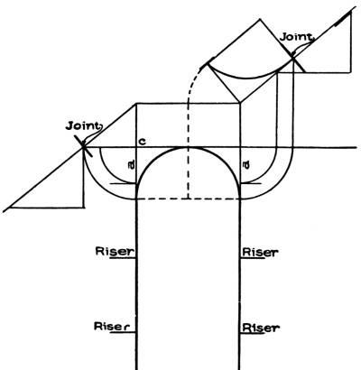
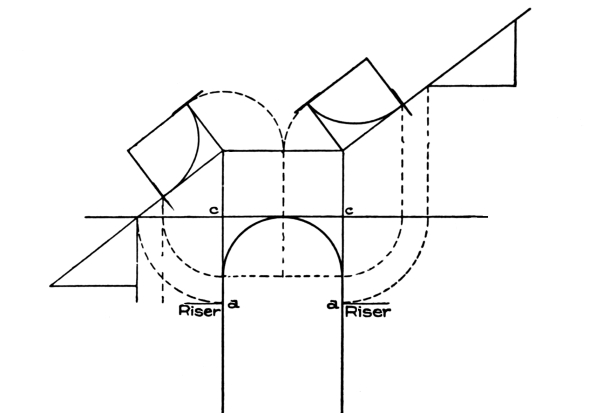
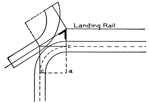
In stairs with winders, the width of a winder should, if possible, be nearly the width of the regular tread, at a distance of 14 inches from the narrow end, so that the length of the step in walking up or down the stairs may not be interrupted; and for this reason and several others, it is always best to have three winders only in each quarter-turn. Above all, avoid a four-winder turn, as this makes a breakneck stair, which is more difficult to construct and inconvenient to use.
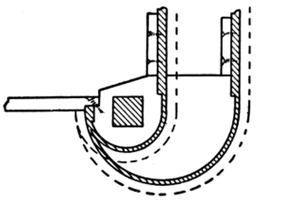
Bullnose Tread. No other stair, perhaps, looks so well at the starting point as one having a bullnose step. In Fig. 44 are shown a plan and elevation of a flight of stairs having a bullnose tread. The method of obtaining the lines and setting out the body of the stairs, [Pg 30]is the same as has already been explained for other stairs, with the exception of the first two steps, which are made with circular ends, as shown in the plan. These circular ends are worked out as hereafter described, and are attached to the newel and string as shown. The example shows an open, cut string with brackets. The spandrel under the string contains short panels, and makes a very handsome finish. The newels and balusters in this case are turned, and the latter have cutwork panels between them.[Pg 31]
Bullnose steps are usually built up with a three-piece block, as shown in Fig. 45, which is a section through the step indicating the blocks, tread, and riser.
Fig. 46 is a plan showing how the veneer of the riser is prepared before being bent into position. The block A indicates a wedge which is glued and driven home after the veneer is put in place. This tightens up the work and makes it sound and clear. Figs. 47 and 48 show other methods of forming bullnose steps.
Fig. 49 is the side elevation of an open-string stair with bullnose steps at the bottom; while Fig. 50 is a view showing the lower end of the string, and the manner in which it is prepared for fixing to the blocks of the step. Fig. 51 is a section through the string, showing the bracket, cove, and projection of tread over same.
Figs. 52 and 53 show respectively a plan and vertical section of the bottom part of the stair. The blocks are shown at the ends of the steps (Fig. 53), with the veneered parts of the risers going round them; also the position where the string is fixed to the blocks (Fig. 52); and the tenon of the newel is marked on the upper step. The section (Fig. 53) shows the manner in which the blocks are built up and the newel tenoned into them.
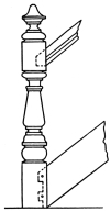
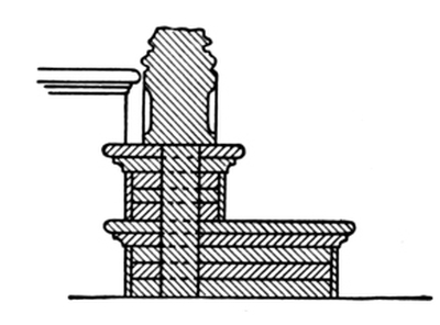
[Pg 32] The newel, Fig. 49, is rather an elaborate affair, being carved at the base and on the body, and having a carved rosette planted in a small, sunken panel on three sides, the rail butting against the fourth side.
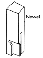
Before leaving the subject of straight and dog-legged stairs, the student should be made familiar with at least one example of an open-newel stair. As the same principles of construction govern all styles of open-newel stairs, a single example will be sufficient. The student must, of course, understand that he himself is the greatest factor in planning stairs of this type; that the setting out and designing will generally devolve on him. By exercising a little thought and foresight, he can so arrange his plan that a minimum of both labor and material will be required.
 |
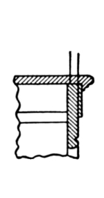 |
Fig. 50. Lower End of String |
Fig. 51. Section |
Fig. 54 shows a plan of an open-newel stair having two landings and closed strings, shown in elevation in Fig. 55. The dotted lines show the carriage timbers and trimmers, also the lines of risers; while the treads are shown by full lines. It will be noticed that the strings and trimmers at the first landing are framed into the shank of the second newel post, which runs down to the floor; while the top newel drops below the fascia, and has a turned and carved drop. This drop hangs below both the fascia and the string. The lines of treads and risers are shown by dotted lines and crosshatched sections. The position of the carriage timbers is shown both in the landings and in the runs of the stairs, the projecting ends of these timbers being supposed to be resting on the wall. A scale of the plan and elevation is attached to the plan. In Fig. 55, a story rod is shown at the right, with the number of risers spaced off thereon. The design of the newels, spandrel, framing, and paneling is shown.[Pg 33]
Only the central carriage timbers are shown in Fig. 54; but in a stair of this width, there ought to be two other timbers, not so heavy, perhaps, as the central one, yet strong enough to be of service in lending additional strength to the stairway, and also to help carry the laths and plaster or the paneling which may be necessary in completing the under side or soffit. The strings being closed, the butts of their balusters must rest on a subrail which caps the upper edge of the outer string.
[Pg 34] The first newel should pass through the lower floor, and, to insure solidity, should be secured by bolts to a joist, as shown in the elevation. The rail is attached to the newels in the usual manner, with handrail bolts or other suitable device. The upper newel should be made fast to the joists as shown, either by bolts or in some other efficient manner. The intermediate newels are left square on the shank below the stairs, and may be fastened in the floor below either by mortise and tenon or by making use of joint bolts.
Everything about a stair should be made solid and sound; and every joint should set firmly and closely; or a shaky, rickety, squeaky stair will be the result, which is an abomination.
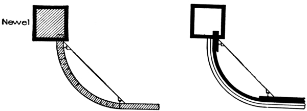
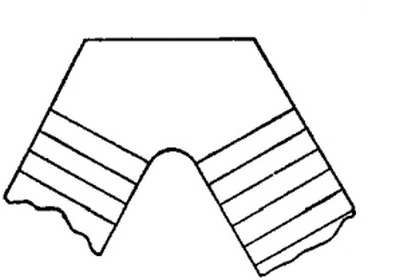
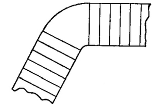
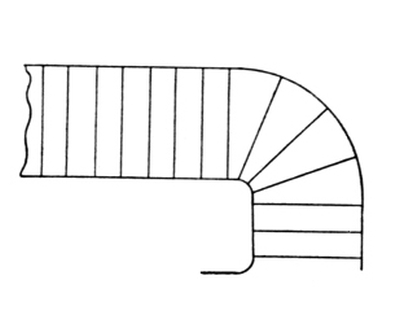
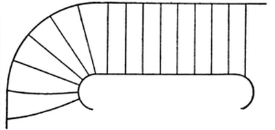
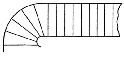
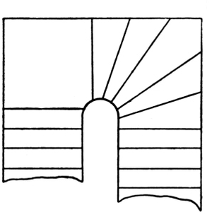
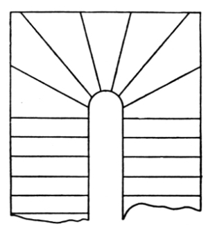
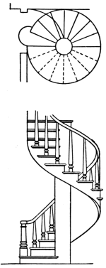
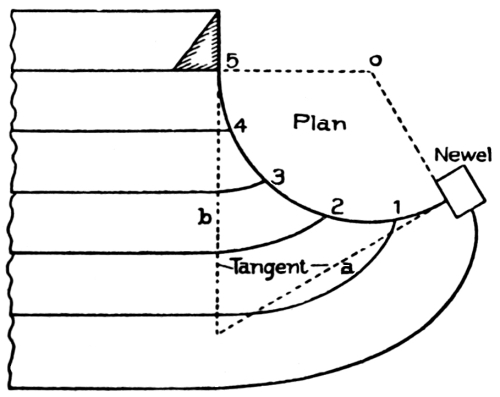
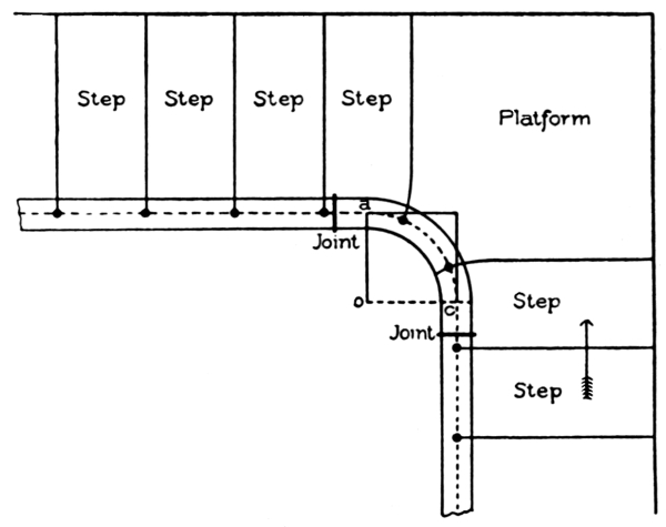
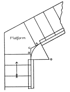
Sufficient examples of stairs having angles of greater or less degree at the turn or change of direction, to [Pg 35] enable the student to build any stair of this class, have now been given. There are, however, other types of stairs in common use, whose turns are curved, and in which newels are employed only at the foot, and sometimes at the finish of the flight. These curved turns may be any part of a circle, according to the requirements of the case, but turns of a quarter-circle or half-circle are the more common. The string forming the curve is called a cylinder, or part of a cylinder, as the case may be. The radius of this circle or cylinder may be any length, according to the space assigned for the stair. The opening around which the stair winds is called the well-hole.
Fig. 56 shows a portion of a stairway having a well-hole with a 7-inch radius. This stair is rather peculiar, as it shows a quarter-space landing, and a quarter-space having three winders. The reason for this is the fact that the landing is on a level with the floor of another room, into which a door opens from the landing. This is a problem very often met with in practical work, where the main stair is often made to do the work of two flights because of one floor being so much lower than another.
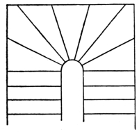
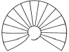
A curved stair, sometimes called a geometrical stair, is shown in Fig. 57, containing seven winders in the cylinder or well-hole, the first and last aligning with the diameter.
In Fig. 58 is shown another example of this kind of stair, containing nine winders in the well-hole, with a circular wall-string. It is not often that stairs are built in this fashion, as most stairs having a circular well-hole finish against the wall in a manner similar to that shown in Fig. 57.
Sometimes, however, the workman will be confronted with a plan such as shown in Fig. 58; and he should know how to lay out the wall-string. In the elevation, Fig. 58, the string is shown to be straight, similar to the string of a common straight flight. This results from having an equal width in the winders along the wall-string, and, as we have of necessity an equal width in the risers, the development of the string is merely a straight piece of board, as in an ordinary straight flight. In laying out the string, all we have to do is to make [Pg 36] a common pitch-board, and, with it as a templet, mark the lines of the treads and risers on a straight piece of board, as shown at 1, 2, 3, 4, etc.
If you can manage to bend the string without kerfing (grooving), it will be all the better; if not, the kerfs (grooves) must be parallel to the rise. You can set out with a straight edge, full size, on a rough platform, just as shown in the diagram; and when the string is bent and set in place, the risers and winders will have their correct positions.
To bend these strings or otherwise prepare them for fastening against the wall, perhaps the easiest way is to saw the string with a fine saw, across the face, making parallel grooves. This method of bending is called kerfing, above referred to. The kerfs or grooves must be cut parallel to the lines of the risers, so as to be vertical when the string is in place. This method, however—handy though it may be—is not a good one, inasmuch as the saw groove will show more or less in the finished work.
Another method is to build up or stave the string. There are several ways of doing this. In one, comparatively narrow pieces are cut to the required curve or to portions of it, and are fastened together, edge to edge, with glue and screws, until the necessary width is obtained (see Fig. 59). The heading joints may be either butted or beveled, the latter being stronger, and should be cross-tongued.
Fig. 60 shows a method that may be followed when a wide string is required, or a piece curved in the direction of its width is needed [Pg 37] for any purpose. The pieces are stepped over each other to suit the desired curve; and though shown square-edged in the figure, they are usually cut beveled, as then, by reversing them, two may be cut out of a batten.
 |
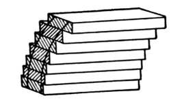 |
Fig. 59. |
Fig. 60. |
Methods of Building Up Strings. |
|
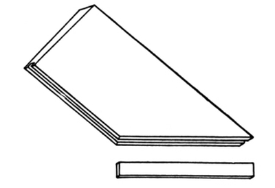
Panels and quick sweeps for similar purposes are obtained in the manner shown in Fig. 61, by joining up narrow boards edge to edge at a suitable bevel to give the desired curve. The internal curve is frequently worked approximately, before gluing up. The numerous joints incidental to these methods limit their uses to painted or unimportant work.
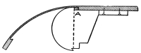
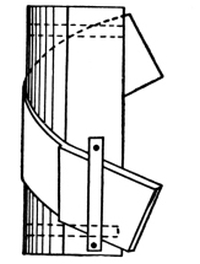
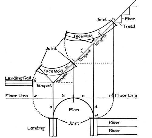
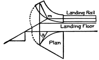
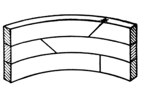
In Fig. 62 is shown a wreath-piece or curved portion of the outside string rising around the cylinder at the half-space. This is formed by reducing a short piece of string to a veneer between the springings; bending it upon a cylinder made to fit the plan; then, when it is secured in position, filling up the back of the veneer with staves glued across it; and, finally, gluing a piece of canvas over the whole. The appearance of the wreath-piece after it has been built up and removed from the cylinder is indicated in Fig. 63. The canvas back has been omitted to show the staving; and the counter-wedge key used for connecting the wreath-piece with the string is shown. The wreath-piece is, at this stage, ready for marking the outlines of the steps.
Fig. 62 also shows the drum or shape around which strings may be bent, whether the strings are formed of veneers, staved, or kerfed. Another drum or shape is shown in Fig. 64. In this, a portion of a cylinder is formed in the manner clearly indicated; and the string, being set out on a veneer board sufficiently thin to bend easily, is laid [Pg 38] down round the curve, such a number of pieces of like thickness being then added as will make the required thickness of the string. In working this method, glue is introduced between the veneers, which are then quickly strained down to the curved piece with hand screws. A string of almost any length can be formed in this way, by gluing a few feet at a time, and when that dries, removing the cylindrical curve and gluing down more, until the whole is completed. Several other methods will suggest themselves to the workman, of building up good, solid, circular strings.
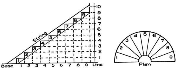
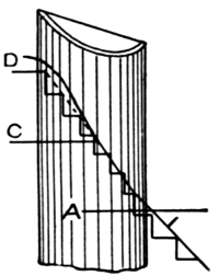
One method of laying out the treads and risers around a cylinder or drum, is shown in Fig. 65. The line D shows the curve of the rail. The lines showing treads and risers may be marked off on the cylinder, or they may be marked off after the veneer is bent around the drum or cylinder.
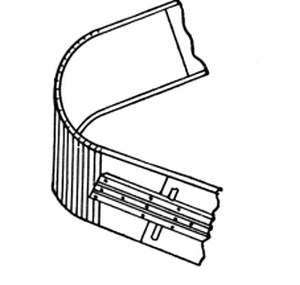
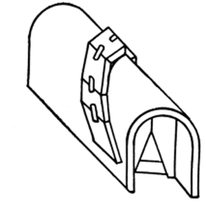
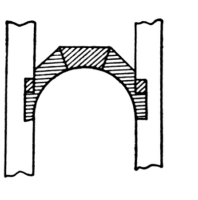
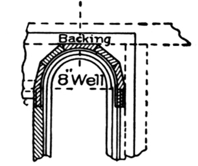
There are various methods of making inside cylinders or wells, and of fastening same to strings. One method is shown in Fig. 66. This gives a strong joint when properly made. It will be noticed that the cylinder is notched out on the back; the two blocks shown at the back of the offsets are wedges driven in to secure the cylinder in place, and to drive it up tight to the strings. Fig. 67 shows an 8-inch well-hole with cylinder complete; also the method of trimming and finishing same. The cylinder, too, is shown in such a manner that its construction will be readily understood.
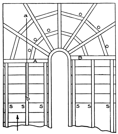
Stairs having a cylindrical or circular opening always require a weight support underneath them. This support, which is generally made of rough lumber, is called the carriage, because it is supposed [Pg 39] to carry any reasonable load that may be placed upon the stairway. Fig. 68 shows the under side of a half-space stair having a carriage beneath it. The timbers marked S are of rough stuff, and may be 2-inch by 6-inch or of greater dimensions. If they are cut to fit the risers and treads, they will require to be at least 2-inch by 8-inch.
In preparing the rough carriage for the winders, it will be best to let the back edge of the tread project beyond the back of the riser so that it forms a ledge as shown under C in Fig. 69. Then fix the cross-carriage pieces under the winders, with the back edge about flush with the backs of risers, securing one end to the well with screws, and the other to the wall string or the wall. Now cut short pieces, marked O O (Fig. 68), and fix them tightly in between the cross-carriage and the back of the riser as at B B in the section, Fig. 69. These carriages should be of 3-inch by 2-inch material. Now get a piece of wood, 1-inch by 3-inch, and cut pieces C C to fit tightly between the top back edge of the winders (or the ledge) and the pieces marked B B in section. This method makes a very sound and strong job of the winders; and if the stuff is roughly planed, and blocks are glued on each side of the short cross-pieces O O O, it is next to impossible for the winders ever to spring or squeak. When the weight is carried in this manner, the plasterer will have very little trouble in lathing so that a graceful soffit will be made under the stairs.
The manner of placing the main stringers of the carriage S S, is shown at A, Fig. 69. Fig. 68 shows a complete half-space stair; one-half of this, finished as shown, will answer well for a quarter-space stair.[Pg 40]
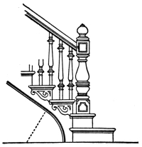
Another method of forming a carriage for a stair is shown in Fig. 70. This is a peculiar but very handsome stair, inasmuch as the first and the last four steps are parallel, but the remainder balance or dance. The treads are numbered in this illustration; and the plan of the handrail is shown extending from the scroll at the bottom of the stairs to the landing on the second story. The trimmer T at the top of the stairs is also shown; and the rough strings or carriages, R S, R S, R S, are represented by dotted lines.
This plan represents a stair with a curtail step, and a scroll handrail resting over the curve of the curtail step. This type of stair is not now much in vogue in this country, though it is adopted occasionally in some of the larger cities. The use of heavy newel posts instead of curtail steps, is the prevailing style at present.
In laying out geometrical stairs, the steps are arranged on principles already described. The well-hole in the center is first laid down and the steps arranged around it. In circular stairs with an open well-hole, the handrail being on the inner side, the width of tread for the steps should be set off at about 18 inches from the handrail, this giving an approximately uniform rate of progress for anyone ascending or descending the stairway. In stairs with the rail on the outside, as sometimes occurs, it will be sufficient if the treads have the proper width at the middle point of their length.
Where a flight of stairs will likely be subject to great stress and wear, the carriages should be made much heavier than indicated in [Pg 41] the foregoing figures; and there may be cases when it will be necessary to use iron bolts in the sides of the rough strings in order to give them greater strength. This necessity, however, will arise only in the case of stairs built in public buildings, churches, halls, factories, warehouses, or other buildings of a similar kind. Sometimes, even in house stairs it may be wise to strengthen the treads and risers by spiking pieces of board to the rough string, ends up, fitting them snugly against the under side of the tread and the back of the riser. The method of doing this is shown in Fig. 71, in which the letter O shows the pieces nailed to the string.
Types of Stairs in Common Use.
In order to make the student familiar with types of stairs in general use at the present day, plans of a few of those most likely to be met with will now be given.
Fig. 72 is a plan of a straight stair, with an ordinary cylinder at the top provided for a return rail on the landing. It also shows a stretch-out stringer at the starting.
Fig. 73 is a plan of a stair with a landing and return steps.
Fig. 74 is a plan of a stair with an acute angular landing and cylinder.
Fig. 75 illustrates the same kind of stair as Fig. 74, the angle, however, being obtuse.
Fig. 76 exhibits a stair having a half-turn with two risers on landings.
Fig. 77 is a plan of a quarter-space stair with four winders.
Fig. 78 shows a stair similar to Fig. 77, but with six winders. [Pg 42]
Fig. 79 shows a stair having five dancing winders.
Fig. 80 is a plan of a half-space stair having five dancing winders and a quarter-space landing.
Fig. 81 shows a half-space stair with dancing winders all around the cylinder.
Fig. 82 shows a geometrical stair having winders all around the cylinder.
Fig. 83 shows the plan and elevation of stairs which turn around a central post. This kind of stair is frequently used in large stores and in clubhouses and other similar places, and has a very graceful appearance. It is not very difficult to build if properly planned.
The only form of stair not shown which the student may be called upon to build, would very likely be one having an elliptical plan; but, as this form is so seldom used—being found, in fact, only in public buildings or great mansions—it rarely falls to the lot of the ordinary workman to be called upon to design or construct a stairway of this type. [Pg 43]
The term geometrical is applied to stairways having any kind of curve for a plan.
The rails over the steps are made continuous from one story to another. The resulting winding or twisting pieces are called wreaths.
The construction of wreaths is based on a few geometrical problems—namely, the projection of straight and curved lines into an oblique plane; and the finding of the angle of inclination of the plane into which the lines and curves are projected. This angle[Pg 44] is called the bevel, and by its use the wreath is made to twist.
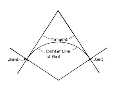
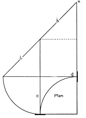
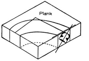
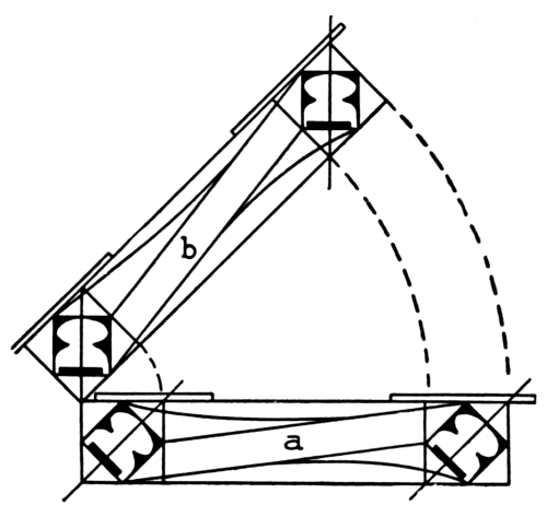
In Fig. 84 is shown an obtuse-angle plan; in Fig. 85, an acute-angle plan; and in Fig. 86, a semicircle enclosed within straight lines.
Projection. A knowledge of how to project the lines and curves in each of these plans into an oblique plane, and to find the angle of inclination of the plane, will enable the student to construct any and all kinds of wreaths.
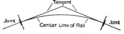
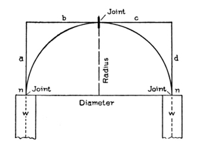
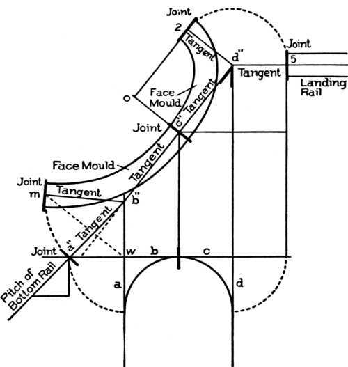
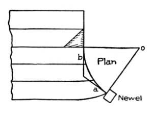
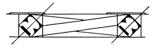
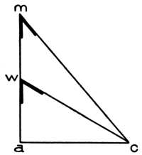
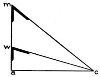
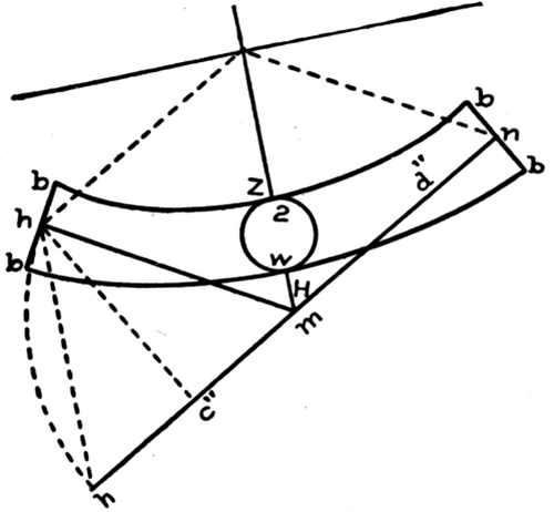
The straight lines a, b, c, d in the plan, Fig. 86, are known as tangents; and the curve, the central line of the plan wreath.
The straight line across from n to n is the diameter; and the perpendicular line from it to the lines c and b is the radius.
A tangent line may be defined as a line touching a curve without cutting it, and is made use of in handrailing to square the joints of the wreaths.
The tangent system of handrailing takes its name from the use made of the tangents for this purpose.
In Fig. 86, it is shown that the joints connecting the central line of rail with the plan rails w of the straight flights, are placed right at the springing; that is, they are in line with the diameter of the semicircle, and square to the side tangents a and d.
The center joint of the crown tangents is shown to be square to tangents b and c. When these lines are projected into an oblique plane, the joints of the wreaths can be made to butt square by applying the bevel to them.
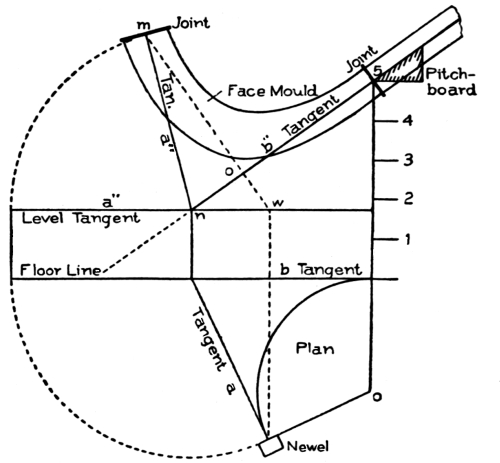
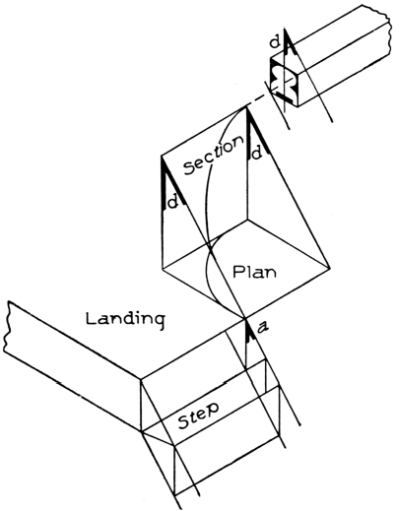
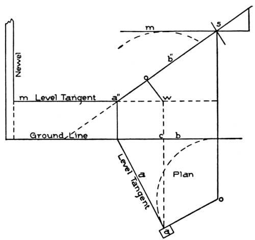
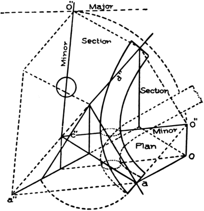
[Pg 45] All handrail wreaths are assumed to rest on an oblique plane while ascending around a well-hole, either in connecting two flights or in connecting one flight to a landing, as the case may be.
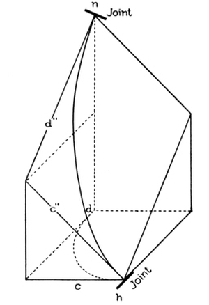
In the simplest cases of construction, the wreath rests on an inclined plane that inclines in one direction only, to either side of the well-hole; while in other cases it rests on a plane that inclines to two sides.
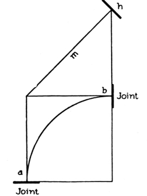
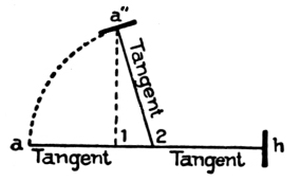
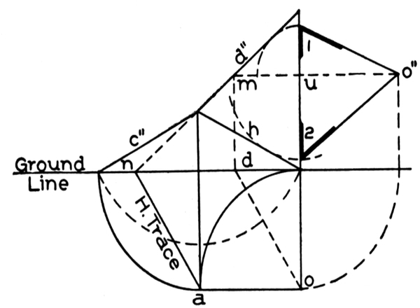
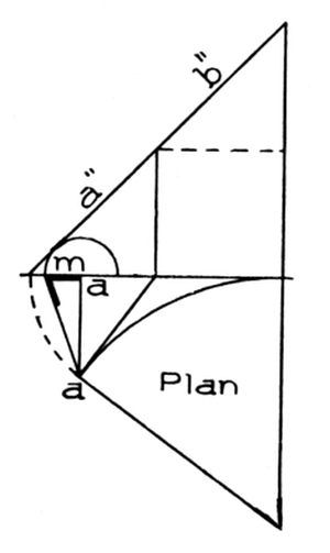
Fig. 87 illustrates what is meant by a plane inclining in one direction. It will be noticed that the lower part of the figure is a reproduction of the quadrant enclosed by the tangents a and b in Fig. 86. The quadrant, Fig. 87, represents a central line of a wreath that is to ascend from the joint on the plan tangent a the height of h above the tangent b.
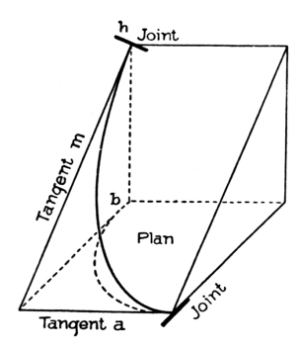
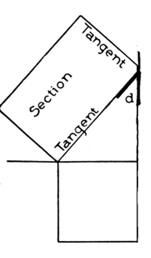
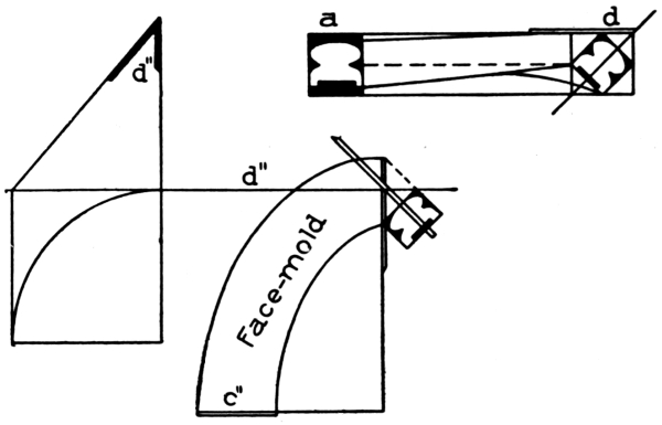
In Fig. 88, a view of Fig. 87 is given in which the tangents a and b are shown in plan, and also the quadrant representing the plan central line of a wreath. The curved line extending from a to h in this figure represents the development of the central line of the plan wreath, and, as shown, it rests on an oblique plane inclining to one side only—namely, to the side of the plan tangent a. The joints are made square to the developed tangents a and m of the inclined plane; it is for this purpose only that tangents are made use of in wreath construction. They are shown in the figure to consist of two lines, a and m, which are two adjoining sides of a developed section (in [Pg 46] this case, of a square prism), the section being the assumed inclined plane whereon the wreath rests in its ascent from a to h. The joint at h, if made square to the tangent m, will be a true, square butt-joint; so also will be the joint at a, if made square to the tangent a.
In practical work it will be required to find the correct geometrical angle between the two developed tangents a and m; and here, again, it may be observed that the finding of the correct angle between the two developed tangents is the essential purpose of every tangent system of handrailing.
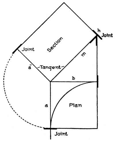
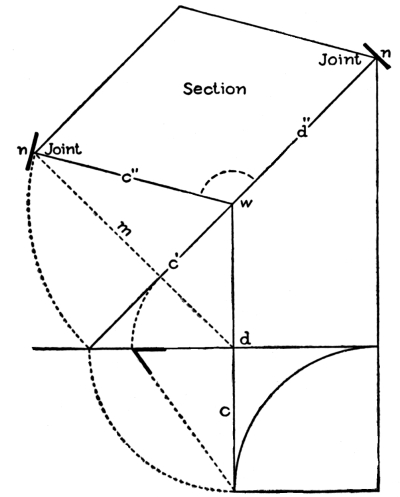
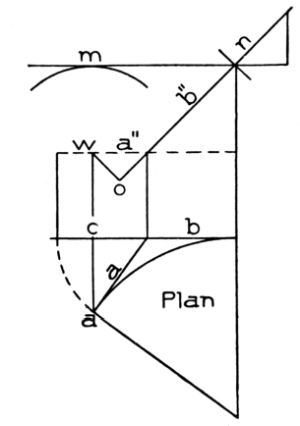
In Fig. 89 is shown the geometrical solution—the one necessary to find the angle between the tangents as required on the face-mould to square the joints of the wreath. The figure is shown to be similar to Fig. 87, except that it has an additional portion marked “Section.” This section is the true shape of the oblique plane whereon the wreath ascends, a view of which is given in Fig. 88. It will be observed that one side of it is the developed tangent m; another side, the developed tangent a″ (= a). The angle between the two as here presented is the one required on the face-mould to square the joints.
In this example, Fig. 89, owing to the plane being oblique in one direction only, the shape of the section is found by merely drawing the tangent a″ at right angles to the tangent m, making it equal in length to the level tangent a in the plan. By drawing lines parallel to a″ and m respectively, the form of the section will be found, its outlines being the projections of the plan lines; and the angle between the two tangents, as already said, is the angle required on the face-mould to square the joints of the wreath.
The solution here presented will enable the student to find the [Pg 47] correct direction of the tangents as required on the face-mould to square joints, in all cases of practical work where one tangent of a wreath is level and the other tangent is inclined, a condition usually met with in level-landing stairways.
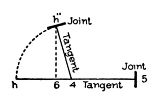
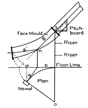
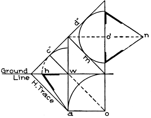
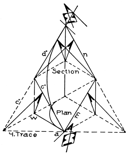
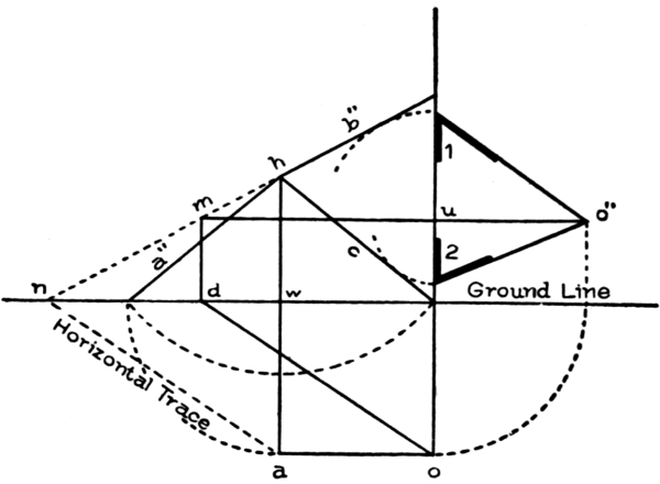
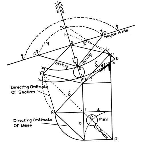
Fig. 90 exhibits a condition of tangents where the two are equally inclined. The plan here also is taken from Fig. 86. The inclination of the tangents is made equal to the inclination of tangent b in Fig.86, as shown at m in Figs. 87, 88, and 89.
In Fig. 91, a view of Fig. 90 is given, showing clearly the inclination of the tangents c″ and d″ over and above the plan tangents c and d. The central line of the wreath is shown extending along the sectional plane, over and above its plan lines, from one joint to the other, and, at the joints, made square to the inclined tangents c″ and d″. It is evident from the view here given, that the condition necessary to square the joint at each end would be to find the true angle between the tangents c″ and d″, which would give the correct direction to each tangent.
In Fig. 92 is shown how to find this angle correctly as required on the face-mould to square the joints. In this figure is shown the same plan as in Figs. 90 and 91, and the same inclination to the tangents as in Fig. 90, so that, except for the portion marked “Section,” it would be similar to Fig. 90.
To find the correct angle for the tangents of the face-mould, draw the line m from d, square to the inclined line of the tangents c′ d″; revolve the bottom inclined tangent c′ to cut line m in n, where the joint is shown fixed; and from this point draw the line c″ to w. The intersection of this line with the upper tangent d″ forms the correct angle as required on the face-mould. By drawing the joints square to these two lines, they will butt square with the rail that is to connect [Pg 48] with them, or to the joint of another wreath that may belong to the cylinder or well-hole.
Fig. 93 is another view of these tangents in position placed over and above the plan tangents of the well-hole. It will be observed that this figure is made up of Figs. 88 and 91 combined. Fig. 88, as here presented, is shown to connect with a level-landing rail at a. The joint having been made square to the level tangent, a will butt square to a square end of the level rail. The joint at h is shown to connect the two wreaths and is made square to the inclined [Pg 49] tangent m of the lower wreath, and also square to the inclined tangent c″ of the upper wreath; the two tangents, aligning, guarantee a square butt-joint. The upper joint is made square to the tangent d″, which is here shown to align with the rail of the connecting flight; the joint will consequently butt square to the end of the rail of the flight above.
The view given in this diagram is that of a wreath starting from a level landing, and winding around a well-hole, connecting the landing with a flight of stairs leading to a second story. It is presented to elucidate the use made of tangents to square the joints in wreath construction. The wreath is shown to be in two sections, one extending from the level-landing rail at a to a joint in the center of the well-hole at h, this section having one level tangent a and one inclined tangent m; the other section is shown to extend from h to n, where it is butt-jointed to the rail of the flight above.
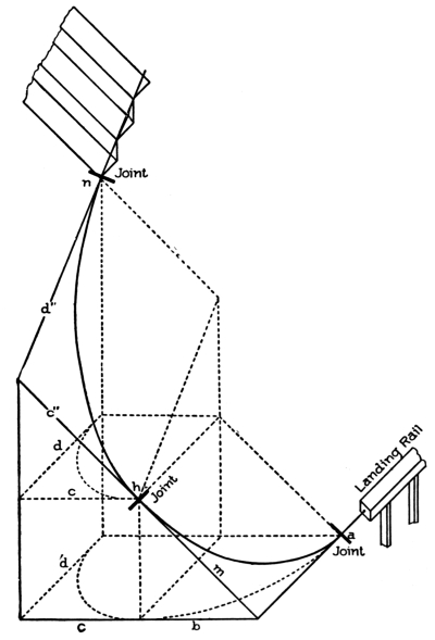
Fig. 93. Laying Out Line of Wreath to Start from
Level-Landing Rail. Wind around Well-Hole, and
Connect at Landing with Flight to Upper Story.
This figure clearly shows that the joint at a of the bottom wreath—owing to the tangent a being level and therefore aligning with the level rail of the landing—will be a true butt-joint; and that the joint at h, which connects the two wreaths, will also be a true butt-joint, owing to it being made square to the tangent m of the bottom wreath and to the tangent c″ of the upper wreath, both tangents having the same inclination; also the joint at n will butt square to the rail of the flight above, [Pg 50]owing to it being made square to the tangent d″, which is shown to have the same inclination as the rail of the flight adjoining.
As previously stated, the use made of tangents is to square the joints of the wreaths; and in this diagram it is clearly shown that the way they can be made of use is by giving each tangent its true direction. How to find the true direction, or the angle between the tangents a and m shown in this diagram, was demonstrated in Fig. 89; and how to find the direction of the tangents c″ and d″ was shown in Fig. 92.
Fig. 94 is presented to help further toward an understanding of the tangents. In this diagram they are unfolded; that is, they are stretched out for the purpose of finding the inclination of each one over and above the plan tangents. The side plan tangent a is shown stretched out to the floor line, and its elevation a′ is a level line. The side plan tangent d is also stretched out to the floor line, as shown by the arc n′ m′. By this process the plan tangents are now in one straight line on the floor line, as shown from w to m′. Upon each one, erect a perpendicular line as shown, and from m′ measure to n, the height the wreath is to ascend around the well-hole. In[Pg 51] practice, the number of risers in the well-hole will determine this height.
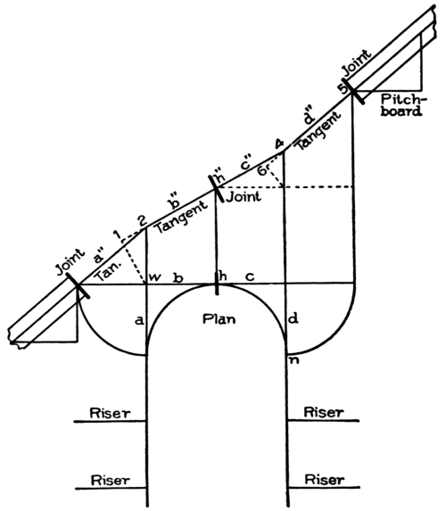
Fig. 95. Well-Hole Connecting Two Flights, with Two Wreath-Pieces,
Each Containing Portions of Unequal Pitch.
Now, from point n, draw a few treads and risers as shown; and along the nosing of the steps, draw the pitch-line; continue this line over the tangents d″, c″, and m, down to where it connects with the bottom level tangent, as shown. This gives the pitch or inclination to the tangents over and above the well-hole. The same line is shown in Fig. 93, folded around the well-hole, from n, where it connects with the flight at the upper end of the well-hole, to a, where it connects with the level-landing rail at the bottom of the well-hole. It will be observed that the upper portion, from joint n to joint h, over the tangents c″ and d″, coincides with the pitch-line of the same tangents as presented in Fig. 92, where they are used to find the true angle between the tangents as it is required on the face-mould to square the joints of the wreath at h.
In Fig. 89 the same pitch is shown given to tangent m as in Fig. 94; and in both figures the pitch is shown to be the same as that over and above the upper connecting tangents c″ and d″, which is a necessary condition where a joint, as shown at h in Figs. 93 and 94, is to connect two pieces of wreath as in this example.
In Fig. 94 are shown the two face-moulds for the wreaths, placed [Pg 52] upon the pitch-line of the tangents over the well-hole. The angles between the tangents of the face-moulds have been found in this figure by the same method as in Figs. 89 and 92, which, if compared with the present figure, will be found to correspond, excepting only the curves of the face-moulds in Fig. 94.
The foregoing explanation of the tangents will give the student a fairly good idea of the use made of tangents in wreath construction. The treatment, however, would not be complete if left off at this point, as it shows how to handle tangents under only two conditions—namely, first, when one tangent inclines and the other is level, as at a and m; second, when both tangents incline, as shown at c″ and d″.
In Fig. 95 is shown a well-hole connecting two flights, where two portions of unequal pitch occur in both pieces of wreath. The first piece over the tangents a and b is shown to extend from the square end of the straight rail of the bottom flight, to the joint in the center of the well-hole, the bottom tangent a″ in this wreath inclining more than the upper tangent b″. The other piece of wreath is shown to connect with the bottom one at the joint h″ in the center of the well-hole, and to extend over tangents c″ and d″ to connect with the rail of the upper flight. The relative inclination of the two tangents in this wreath, is the reverse of that of the two tangents of the lower wreath. In the lower piece, the bottom tangent a″, as previously stated, inclines considerably more than does the upper tangent b″; while in the upper piece, the bottom tangent c″ inclines considerably less than the upper tangent d″.
The question may arise: What causes this? Is it for variation in the inclination of the tangents over the well-hole? It is simply owing to the tangents being used in handrailing to square the joints.
The inclination of the bottom tangent a″ of the bottom wreath [Pg 53] is clearly shown in the diagram to be determined by the inclination of the bottom flight. The joint at a″ is made square to both the straight rail of the flight and to the bottom tangent of the wreath; the rail and tangent, therefore, must be equally inclined, otherwise the joint will not be a true butt-joint. The same remarks apply to the joint at 5, where the upper wreath is shown jointed to the straight rail of the upper flight. In this case, tangent d″ must be fixed to incline conformably to the inclination of the upper rail; otherwise the joint at 5 will not be a true butt-joint.
The same principle is applied in determining the pitch or inclination over the crown tangents b″ and c″. Owing to the necessity of jointing the two wreaths, as shown at h, these two tangents must have the same inclination, and therefore must be fixed, as shown from 2 to 4, over the crown of the well-hole.
The tangents as here presented are those of the elevation, not of the face-mould. Tangent a″ is the elevation of the side plan tangent a; tangents b″ and c″ are shown to be the elevations of the plan tangents b and c; so, also, is the tangent d″ the elevation of the side plan tangent d.
If this diagram were folded, as Fig. 94 was shown to be in Fig. 93, the tangents of the elevation—namely, a″, b″, c″, d″—would stand over and above the plan tangents a, b, c, d of the well-hole. In practical work, this diagram must be drawn full size. It gives the correct [Pg 54] length to each tangent as required on the face-mould, and furnishes also the data for the layout of the mould.
Fig. 96 shows how to find the angle between the tangents of the face-mould for the bottom wreath, which, as shown in Fig. 95, is to span over the first plan quadrant a b. The elevation tangents a″ and b″, as shown, will be the tangents of the mould. To find the angle between the tangents, draw the line a h in Fig. 96; and from a, measure to 2 the length of the bottom tangent a″ in Fig. 95; the length from 2 to h, Fig. 96, will equal the length of the upper tangent b″, Fig. 95.
From 2 to 1, measure a distance equal to 2-1 in Fig. 95, the latter being found by dropping a perpendicular from w to meet the tangent b″ extended. Upon 1, erect a perpendicular line; and placing the dividers on 2, extend to a; turn over to the perpendicular at a″; connect this point with 2, and the line will be the bottom tangent as required on the face-mould. The upper tangent will be the line 2-h, and the angle between the two lines is shown at 2. Make the joint at h square to 2-h, and at a″ square to a″-2.
The mould as it appears in Fig. 96 is complete, except the curve, which is comparatively a small matter to put on, as will be shown further on. The main thing is to find the angle between the tangents, which is shown at 2, to give them the direction to square the joints.
In Fig. 97 is shown how to find the angle between the tangents c″ and d″ shown in Fig. 95, as required on the face-mould. On the line h-5, make h-4 equal to the length of the bottom tangent of the wreath, as shown at h″-4 in Fig. 95; and 4-5 equal to the length of the upper tangent d″. Measure from 4 the distance shown at 4-6 in Fig. 95, and place it from 4 to 6 as shown in Fig. 97; upon 6 erect a [Pg 55]perpendicular line. Now place the dividers on 4; extend to h; turn over to cut the perpendicular in h″; connect this point with 4, and the angle shown at 4 will be the angle required to square the joints of the wreath as shown at h″ and 5, where the joint at 5 is shown drawn square to the line 4-5, and the joint at h″ square to the line 4 h″.
Fig. 98 is a diagram of tangents and face-mould for a stairway having a well-hole at the top landing. The tangents in this example will be two equally inclined tangents for the bottom wreath; and for the top wreath, one inclined and one level, the latter aligning with the level rail of the landing.
The face-mould, as here presented, will further help toward an understanding of the layout of face-moulds as shown in Figs. 96 and 97. It will be observed that the pitch of the bottom rail is continued from a″ to b″, a condition caused by the necessity of jointing the wreath to the end of the straight rail at a″, the joint being made square to both the straight rail and the bottom tangent a″. From b″ a line is drawn to d″, which is a fixed point determined by the number of risers in the well-hole. From point d″, the level tangent d″ 5 is drawn in line with the level rail of the landing; thus the pitch-line of the tangents over the well-hole is found, and, as was shown in the explanation of Fig. 95, the tangents as here presented will be those required on the face-mould to square the joints of the wreath.
In Fig. 98 the tangents of the face-mould for the bottom wreath are shown to be a″ and b″. To place tangent a″ in position on the face-mould, it is revolved, as shown by the arc, to m, cutting a line [Pg 56] previously drawn from w square to the tangent b″ extended. Then, by connecting m to b″, the bottom tangent is placed in position on the face-mould. The joint at m is to be made square to it; and the joint at c, the other end of the mould, is to be made square to the tangent b″.
The upper piece of wreath in this example is shown to have tangent c″ inclining, the inclination being the same as that of the upper tangent b″ of the bottom wreath, so that the joint at c″, when made square to both tangents, will butt square when put together. The tangent d″ is shown to be level, so that the joint at 5, when squared with it, will butt square with the square end of the level-landing rail. The level tangent is shown revolved to its position on the face-mould, as from 5 to 2. In this last position, it will be observed that its angle with the inclined tangent c″ is a right angle; and it should be remembered that in every similar case where one tangent inclines and one is level over a square-angle plan tangent, the angle between the two tangents will be a right angle on the face-mould. A knowledge of this principle will enable the student to draw the mould for this wreath, as shown in Fig. 99, by merely drawing two lines perpendicular to each other, as d″ 5 and d″ c″, equal respectively to the level tangent d″ 5 and the inclined tangent c″ in Fig. 98. The joint at 5 is to be made square to d″ 5; and that at c″, to d″ c″. Comparing this figure with the face-mould as shown for the upper wreath in Fig. 98, it will be observed that both are alike.
In practical work the stair-builder is often called upon to deal with cases in which the conditions of tangents differ from all the examples thus far given. An instance of this sort is shown in Fig. 100, in which the angles between the tangents on the plan are acute. [Pg 57] In all the preceding examples, the tangents on the plan were at right angles; that is, they were square to one another.
Fig. 100 is a plan of a few curved steps placed at the bottom of a stairway with a curved stringer, which is struck from a center o. The plan tangents a and b are shown to form an acute angle with each other. The rail above a plan of this design is usually ramped at the bottom end, where it intersects the newel post, and, when so treated, the bottom tangent a will have to be level.
In Fig. 101 is shown how to find the angle between the tangents on the face-mould that gives them the correct direction for squaring the joints of the wreath when it is determined to have it ramped. This figure must be drawn full size. Usually an ordinary drawing-board will answer the purpose. Upon the board, reproduce the plan of the tangents and curve of the center line of rail as shown in Fig. 100. Measure the height of 5 risers, as shown in Fig. 101, from the floor line to 5; and draw the pitch of the flight adjoining the wreath, from 5 to the floor line. From the newel, draw the dotted line to w, square to the floor line; from w, draw the line w m, square to the pitch-line b″. Now take the length of the bottom level tangent on a trammel, or on dividers if large enough, and extend it from n to m, cutting the line drawn previously from [Pg 58] w, at m. Connect m to n as shown by the line a″. The intersection of this line with b″ determines the angle between the two tangents a″ and b″ of the face-mould, which gives them the correct direction as required on the face-mould for squaring the joints. The joint at m is made square to tangent a″; and the joint at 5, to tangent b″.
In Fig. 102 is presented an example of a few steps at the bottom of a stairway in which the tangents of the plan form an obtuse angle with each other. The curve of the central line of the rail in this case will be less than a quadrant, and, as shown, is struck from the center o, the curve covering the three first steps from the newel to the springing.
In Fig. 103 is shown how to develop the tangents of the face-mould. Reproduce the tangents and curve of the plan in full size. Fix point 3 at a height equal to 3 risers from the floor line; at this point place the pitch-board of the flight to determine the pitch over the curve as shown from 3 through b″ to the floor line. From the newel, draw a line to w, square to the floor line; and from w, square to the pitch-line b″, draw the line w m; connect m to n. This last line is the development of the bottom plan tangent a; and the line b″ is the development of the plan tangent [Pg 59] b; and the angle between the two lines a″ and b″ will give each line its true direction as required on the face-mould for squaring the joints of the wreath, as shown at m to connect square with the newel, and at 3 to connect square to the rail of the connecting flight.
The wreath in this example follows the nosing line of the steps without being ramped as it was in the examples shown in Figs. 100 and 101. In those figures the bottom tangent a was level, while in Fig. 103 it inclines equal to the pitch of the upper tangent b″ and of the flight adjoining. In other words, the method shown in Fig. 101 is applied to a construction in which the wreath is ramped; while in Fig. 103 the method is applicable to a wreath following the nosing line all along the curve to the newel.
The stair-builder is supposed to know how to construct a wreath under both conditions, as the conditions are usually determined by the Architect.
[Pg 60] The foregoing examples cover all conditions of tangents that are likely to turn up in practice, and, if clearly understood, will enable the student to lay out the face-moulds for all kinds of curves.
The next process in the construction of a wreath that the handrailer will be called upon to perform, is to find the bevels that will, by being applied to each end of it, give the correct angle to square or twist it when winding around the well-hole from one flight to another flight, or from a flight to a landing, as the case may be.
The wreath is first cut from the plank square to its surface as shown in Fig. 104. After the application of the bevels, it is twisted, as shown in Fig. 105, ready to be moulded; and when in position, ascending from one end of the curve to the other end, over the inclined plane of the section around the well-hole, its sides will be plumb, as shown in Fig. 106 at b. In this figure, as also in Fig. 105, the wreath a lies in a horizontal position in which its sides appear to be out of plumb as much as the bevels[Pg 61] are out of plumb. In the upper part of the figure, the wreath b is shown placed in its position upon the plane of the section, where its sides are seen to be plumb. It is evident, as shown in the relative position of the wreath in this figure, that, if the bevel is the correct angle of the plane of the section whereon the wreath b rests in its ascent over the well-hole, the wreath will in that case have its sides plumb all along when in position. It is for this purpose that the bevels are needed.
A method of finding the bevels for all wreaths (which is considered rather difficult) will now be explained:
First Case. In Fig. 107 is shown a case where the bottom tangent of a wreath is inclining, and the top one level, similar to the top wreath shown in Fig. 98. It has already been noted that the plane of the section for this kind of wreath inclines to one side only; therefore one bevel only will be required to square it, which is shown at d, Fig. 107. A view of this plane is given in Fig. 108; and the bevel d, as there shown, indicates the angle of the inclination, which also is the bevel required to square the end d of the wreath. The bevel is shown applied to the end of the landing rail in exactly the same manner in which it is to be applied to the end of the wreath. The true bevel for this wreath is found at the upper angle of the pitch-board. At the end a, as already stated, no bevel is required, owing to the plane inclining in one direction only. Fig. 109 shows a face-mould and bevel for a wreath with the bottom tangent level and the top tangent inclining, such as the piece at the bottom connecting with the landing rail in Fig. 94.[Pg 62]
Second Case. It may be required to find the bevels for a wreath having two equally inclined tangents. An example of this kind also is shown in Fig. 94, where both the tangents c″ and d″ of the upper wreath incline equally. Two bevels are required in this case, because the plane of the section is inclined in two directions; but, owing to the inclinations being alike, it follows that the two will be the same. They are to be applied to both ends of the wreath, and, as shown in Fig. 105, in the same direction—namely, toward the inside of the wreath for the bottom end, and toward the outside for the upper end.
In Fig. 110 the method of finding the bevels is shown. A line is drawn from w to c″, square to the pitch of the tangents, and turned over to the ground line at h, which point is connected to a as shown. The bevel is at h. To show that equal tangents have equal bevels, the line m is drawn, having the same inclination as the bottom tangent c″, but in another direction. Place the dividers on o′, and turn to touch the lines d″ and m, as shown by the semicircle. The line from o′ to n is equal to the side plan tangent [Pg 63] w a, and both the bevels here shown are equal to the one already found. They represent the angle of inclination of the plane whereon the wreath ascends, a view of which is given in Fig. 111, where the plane is shown to incline equally in two directions. At both ends is shown a section of a rail; and the bevels are applied to show how, by means of them, the wreath is squared or twisted when winding around the well-hole and ascending upon the plane of the section. The view given in this figure will enable the student to understand the nature of the bevels found in Fig. 110 for a wreath having two equally inclined tangents; also for all other wreaths of equally inclined tangents, in that every wreath in such case is assumed to rest upon an inclined plane in its ascent over the well-hole, the bevel in every case being the angle of the inclined plane.
Third Case. In this example, two unequal tangents are given, the upper tangent inclining more than the bottom one. The method shown in Fig. 110 to find the bevels for a wreath with two equal tangents, is applicable to all conditions of variation in the inclination of the tangents. In Fig. 112 is shown a case where the upper tangent d″ inclines more than the bottom one c″. The method in all cases is to continue the line of the upper tangent d″, Fig. 112, to the ground line as shown at n; from n, draw a line to a, which will be the horizontal trace of the plane. Now, from o, draw a line parallel to a n, as shown from o to d, upon d, erect a perpendicular line to cut the tangent d″, as shown, at m; and draw the line m u o″. Make u o″ equal to the length of the plan tangent as shown by the arc from o. Put one [Pg 64] leg of the dividers on u; extend to touch the upper tangent d″, and turn over to 1; connect 1 to o″; the bevel at 1 is to be applied to tangent d″. Again place the dividers on u; extend to the line h, and turn over to 2 as shown; connect 2 to o″, and the bevel shown at 2 will be the one to apply to the bottom tangent c″. It will be observed that the line h represents the bottom tangent. It is the same length and has the same inclination. An example of this kind of wreath was shown in Fig. 95, where the upper tangent d″ is shown to incline more than the bottom tangent c″ in the top piece extending from h″ to 5. Bevel 1, found in Fig. 112, is the real bevel for the end 5; and bevel 2, for the end h″ of the wreath shown from h″ to 5 in Fig. 95.
Fourth Case. In Fig. 113 is shown how to find the bevels for a wreath when the upper tangent inclines less than the bottom tangent. This example is the reverse of the preceding one; it is the condition of tangents found in the bottom piece of wreath shown in Fig. 95. To find the bevel, continue the upper tangent b″ to the ground line, as shown at n; connect n to a, which will be the horizontal trace of the plane. From o, draw a line parallel to n a, as shown from o to d; upon d, erect a perpendicular line to cut the continued portion of the upper tangent b″ in m; from m, draw the line m u o″ across as shown. Now place the dividers on u; extend to touch the upper tangent, and turn over to 1, connect 1 to o″; the bevel at 1 will be the one to apply to the tangent b″ at h, where the two wreaths are shown connected in Fig. 95. Again place the dividers on u; extend to touch the line c; turn over to 2; connect 2 to o″; the bevel at 2 is to be applied to the bottom tangent a″ at the joint where it is shown to connect with the rail of the flight.
Fifth Case. In this case we have two equally inclined tangents over an obtuse-angle plan. In Fig. 102 is shown a plan of this kind; and in Fig. 103, the development of the face-mould.
In Fig. 114 is shown how to find the bevel. From a, draw a line to a′, square to the ground line. Place the dividers on a′; extend to [Pg 65] touch the pitch of tangents, and turn over as shown to m; connect m to a. The bevel at m will be the only one required for this wreath, but it will have to be applied to both ends, owing to the two tangents being inclined.
Sixth Case. In this case we have one tangent inclining and one tangent level, over an acute-angle plan.
In Fig. 115 is shown the same plan as in Fig. 114; but in this case the bottom tangent a″ is to be a level tangent. Probably this condition is the most commonly met with in wreath construction at the present time. A small curve is considered to add to the appearance of the stair and rail; and consequently it has become almost a “fad” to have a little curve or stretch-out at the bottom of the stairway, and in most cases the rail is ramped to intersect the newel at right angles instead of at the pitch of the flight. In such a case, the bottom tangent a″ will have to be a level tangent, as shown at a″ in Fig. 115, the pitch of the flight being over the plan tangent b only.
[Pg 66] To find the bevels when tangent b″ inclines and tangent a″ is level, make a c in Fig. 116 equal to a c in Fig. 115. This line will be the base of the two bevels. Upon a, erect the line a w m at right angles to a c; make a w equal to o w in Fig. 115; connect w and c; the bevel at w will be the one to apply to tangent b″ at n where the wreath is joined to the rail of the flight. Again, make a m in Fig. 116 equal the distance shown in Fig. 115 between w and m, which is the full height over which tangent b″ is inclined; connect m to c in Fig. 116, and at m is the bevel to be applied to the level tangent a″.
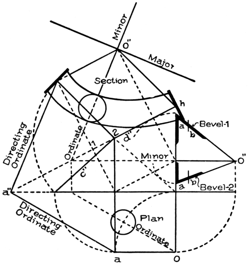
Fig. 121. Tangents, Bevels, Mould-Curves, etc., from Bottom Wreath
of Fig. 95, In which Upper Tangent
Inclines Less than Lower One.
Seventh Case. In this case, illustrated in Fig. 117, the upper tangent b″ is shown to incline, and the bottom tangent a″ to be level, over an acute-angle plan. The plan here is the same as that in Fig. 100, where a curve is shown to stretch out from the line of the straight stringer at the bottom of a flight to a newel, and is large enough to contain five treads, which are gracefully rounded to cut the curve of the central line of rail in 1, 2, 3, 4. This curve also may be used to connect a landing rail to a [Pg 67] flight, either at top or bottom, when the plan is acute-angled, as will be shown further on.
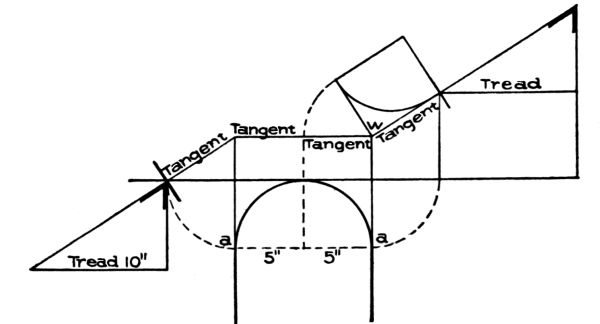
Fig. 123. Arranging Risers around Well-Hole on Level Landing Stair,
with Radius of Central Line of Rail One-Half Width of Tread.
To find the bevels—for there will be two bevels necessary for this wreath, owing to one tangent b″ being inclined and the other tangent a″ being level—make a c, Fig. 118, equal to a c in Fig. 117, which is a line drawn square to the ground line from the newel and shown in all preceding figures to have been used for the base of a triangle containing the bevel. Make a w in Fig. 118 equal to w o in Fig. 117, which is a line drawn square to the inclined tangent b″ from w; connect w and c in Fig. 118. The bevel shown at w will be the one to be applied to the joint 5 on tangent b″, Fig. 117. Again, make a m in Fig. 118 equal to the distance shown in Fig. 117 between the line representing the level tangent and the line m′ 5, which is the height that [Pg 68] tangent b″ is shown to rise; connect m to c in Fig. 118; the bevel shown at m is to be applied to the end that intersects with the newel as shown at m in Fig. 117.
The wreath is shown developed in Fig. 101 for this case; so that, with Fig. 100 for plan, Fig. 101 for the development of the wreath, and Figs. 117 and 118 for finding the bevels, the method of handling any similar case in practical work can be found.
It has been shown how to find the angle between the tangents of the face-mould, and that the angle is for the purpose of squaring the joints at the ends of the wreath. In Fig. 119 is shown how to lay out the curves by means of pins and a string—a very common practice among stair-builders. In this example the face-mould has equal tangents as shown at c″ and d″. The angle between the two tangents is shown at m as it will be required on the face-mould. In this figure a line is drawn from m parallel to the line drawn from h, which is marked in the diagram as “Directing Ordinate of Section.” The line drawn from m will contain the minor axes; and a line drawn through the corner of the section at 3 will contain the major axes of the ellipses that will constitute the curves of the mould.
The major is to be drawn square to the minor, as shown. Place, from point 3, the circle shown on the minor, at the same distance as the circle in the plan is fixed from the point o. The diameter [Pg 69] of this circle indicates the width of the curve at this point The width at each end is determined by the bevels. The distance a b, as shown upon the long edge of the bevel, is equal to ½ the width of the mould, and is the hypotenuse of a right-angled triangle whose base is ½ the width of the rail. By placing this dimension on each side of n, as shown at b and b, and on each side of h″ on the other end of the mould, as shown also at b and b, we obtain the points b 2 b on the inside of the curve, and [Pg 70] the points b 1 b on the outside. It will now be necessary to find the elliptical curves that will contain these points; and before this can be done, the exact length of the minor and major axes respectively must be determined. The length of the minor axis for the inside curve will be the distance shown from 3 to 2; and its length for the outside will be the distance shown from 3 to 1.
To find the length of the major axis for the inside, take the length of half the minor for the inside on the dividers: place one leg on b, extend to cut the major in z, continue to the minor as shown at k. The distance from b to k will be the length of the semi-major axis for the inside curve.
To draw the curve, the points or foci where the pins are to be fixed must be found on the major axis. To find these points, take the length of b k (which is, as previously found, the exact length of the semi-major for the inside curve) on the dividers; fix one leg at 2, and describe the arc Y, cutting the major where the pins are shown fixed, at o and o. Now take a piece of string long enough to form [Pg 71] a loop around the two and extending, when tight, to 2, where the pencil is placed; and, keeping the string tight, sweep the curve from b to b.
The same method, for finding the major and foci for the outside curve, is shown in the diagram. The line drawn from b on the outside of the joint at n, to w, is the semi-major for the outside curve; and the points where the outside pins are shown on the major will be the foci.
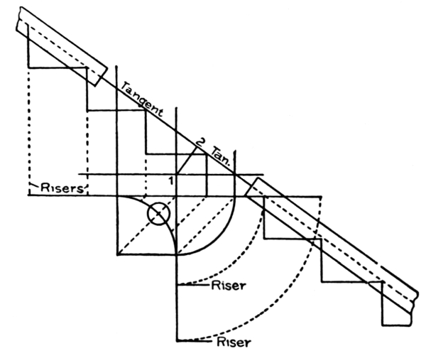
Fig. 132. Arrangement of Risers around Quarter-Turn
Giving Tangents Equal Pitch with Connecting Flight.
To draw the curves of the mould according to this method, [Pg 72] which is a scientific one, may seem a complicated problem; but once it is understood, it becomes very simple. A simpler way to draw them, however, is shown in Fig. 120.
The width on the minor and at each end will have to be determined by the method just explained in connection with Fig. 119. In Fig. 120, the points b at the ends, and the points in which the circumference of the circle cuts the minor axis, will be points contained in the curves, as already explained. Now take a flexible lath; bend it to touch b, z, and b for the inside curve, and b, w, and b for the outside curve. This method is handy where the curve is comparatively flat, as in the example here shown; but where the mould has a sharp curvature, as in case of the one shown in Fig. 101, the method shown in Fig. 119 must be adhered to.
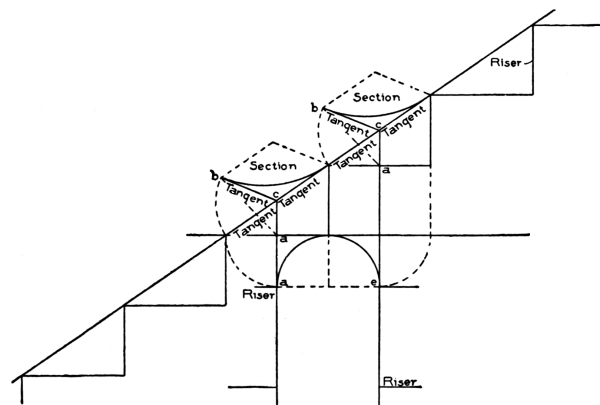
Fig. 134. Well-Hole with Riser in Center. Tangents
of Face-Mould, and Central Line of Rail, Developed.
With a clear knowledge of the above two methods, the student will be able to put curves on any mould.
The mould shown in these two diagrams, Figs. 119 and 120, is for the upper wreath, extending from h to n in Fig. 94. A practical handrailer would draw only what is shown in Fig. 120. He would [Pg 73] take the lengths of tangents from Fig. 94, and place them as shown at h m and m n. By comparing Fig. 120 with the tangents of the upper wreath in Fig. 94, it will be easy for the student to understand the remaining lines shown in Fig. 120. The bevels are shown applied to the mould in Fig. 105, to give it the twist. In Fig. 106, is shown how, after the rail is twisted and placed in position over and above the quadrant c d in Fig. 94, its sides will be plumb.
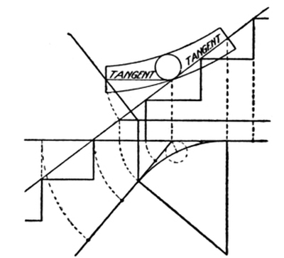
Fig. 136. Arrangement of Risers in Obtuse-Angle
Plan, Giving Equal Pitch over Tangents and Flights.
Face-Mould Developed.
In Fig. 121 are shown the tangents taken from the bottom wreath in Fig. 95. It was shown how to develop the section and find the angle for the tangents in the face-mould, in Fig. 113. The method shown in Fig. 119 for putting on the curves, would be the most suitable.
Fig. 121 is presented more for the purposes of study than as a method of construction. It contains all the lines made use of to find [Pg 74] the developed section of a plane inclining unequally in two different directions, as shown in Fig. 122.
An important matter in wreath construction is to have a knowledge of how to arrange the risers in and around a well-hole. A great deal of labor and material is saved through it; also a far better appearance to the finished rail may be secured.
In level-landing stairways, the easiest example is the one shown in Fig. 123, in which the radius of the central line of rail is made equal to one-half the width of a tread. In the diagram the radius is shown to be 5 inches, and the treads 10 inches. The risers are placed in the springing, as at a and a. The elevation of the tangents by this arrangement will be, as shown, one level and one inclined, for each piece of wreath. When in this position, there is no trouble in finding the angle of the tangent as required on the face-mould, owing to that angle, as in every such case, being a right angle, as shown at w; also no special bevel will have to be found, because the upper bevel of the pitch-board contains the angle required.
The same results are obtained in the example shown in Fig. 124, in which the radius of the well-hole is larger than half the width of a tread, by placing the riser a at a distance from c equal to half the width of a tread, instead of at the springing as in the preceding example.
In Fig. 125 is shown a case where the risers are placed at a distance from c equal to a full tread, the effect in respect to the tangents of the face-mould and bevel being the same as in the two preceding examples. In Fig. 126 is shown the plan of Fig. 123; in Fig. 127, the plan of Fig. 124; and in Fig. 128, the plan of Fig. 125. For the wreaths shown in all these figures, there will be no necessity of springing the plank, which is a term used in handrailing to denote the twisting of the wreath; and no other bevel than the one at the upper end of the pitch-board will be required. This type of wreath, also, is the one that is required at the top of a landing when the rail of the flight intersects with a level-landing rail.
[Pg 75] In Fig. 129 is shown a very simple method of drawing the face-mould for this wreath from the pitch-board. Make a c equal to the radius of the plan central line of rail as shown at the curve in Fig. 130. From where line c c″ cuts the long side of the pitch-board, the line c″ a″ is drawn at right angles to the long edge, and is made equal to the length of the plan tangent a c, Fig. 130. The curve is drawn by means of pins and string or a trammel.
In Fig. 131 is shown a quarter-turn between two flights. The correct method of placing the risers in and around the curve, is to put the last one in the first flight and the first one in the second flight one-half a step from the intersection of the crown tangents. By this arrangement, as shown in Fig. 132, the pitch-line of the tangents will equal the pitch of the connecting flight, thus securing the second easiest condition of tangents for the face-mould—namely, as shown, two equal tangents. For this wreath, only one bevel will be needed, and it is made up of the radius of the plan central line of the rail o c, Fig. 131, for base, and the line 1-2, Fig. 132, for altitude, as shown in Fig. 133.
The bevel shown in this figure has been previously explained in Figs. 105 and 106. It is to be applied to both ends of the wreath.
The example shown in Fig. 134 is of a well-hole having a riser in the center. If the radius of the plan central line of rail is made equal to one-half a tread, the pitch of tangents will be the same as of the flights adjoining, thus securing two equal tangents for the two sections of wreath. In this figure the tangents of the face-mould are developed, and also the central line of the rail, as shown over and above each quadrant and upon the pitch-line of tangents.
The same method may be employed in stairways having obtuse-angle and acute-angle plans, as shown in Fig. 135, in which two flights are placed at an obtuse angle to each other. If the risers shown at a and a are placed one-half a tread from c, this will produce in the elevation a pitch-line over the tangents equal to that over the flights adjoining, as shown in Fig. 136, in which also is shown the face-mould for the wreath that will span over the curve from one flight to another.
In Fig. 137 is shown a flight having the same curve at a landing. The same arrangement is adhered to respecting the placing of the risers, as shown at a and a. In Fig. 138 is shown how to develop the face-moulds.
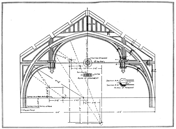
FINISHED ROOF TRUSS IN FIRST PRESBYTERIAN CHURCH, SYRACUSE, N. Y.
Tracy & Swartwout, Architects; Ballantyne & Evans, Associated.
Reproduced by courtesy of “The Architectural Review.”
The Standard Steel Square has a blade 24 inches long and 2 inches wide, and a tongue from 14 to 18 inches long and 1½ inches wide. The blade is at right angles to the tongue.
The face of the square is shown in Fig. 1. It is always stamped with the manufacturer’s name and number.
The reverse is the back (see Fig. 2).
The longer arm is the blade; the shorter arm, the tongue.
In the center of the tongue, on the face side, will be found two parallel lines divided into spaces (see Fig. 1); this is the octagon scale.
The spaces will be found numbered 10, 20, 30, 40, 50, 60, and 70, when the tongue is 18 inches long.
To draw an octagon of 8 inches square, draw an 8 inch square and then draw a perpendicular and a horizontal line through its center. To find the length of the octagon side, place one point of a compass on any of the main divisions of the scale, and the other point of the compass on the eighth subdivision; then step this length off on each side of the center lines on the side of the square, which will give the points from which to draw the octagon lines.
The diameter of the octagon must equal in inches the number of spaces taken from the square.
On the opposite side of the tongue, in the center, will be found the brace rule (see Fig. 3). The fractions denote the rise and run of the brace, and the decimals the length. For example, a brace of 36 inches run and 36 inches rise, has a length of 50.91 inches; a brace of 42 inches run and 42 inches rise, has a length of 59.40 inches; etc. [Pg 3]
On the back of the blade (Fig. 4) will be found the board measure, where eight parallel lines running along the length of the blade are shown and divided at every inch by cross-lines. Under 12, on the outer edge of the blade, will be found the various lengths of the boards, as 8, 9, 10, 11, 12, etc. For example, take a board 14 feet long and 9 [Pg 2]inches wide. To find the contents, look under 12, and find 14; then follow this space along to the cross-line under 9, the width of the board; and here is found 10 feet 6 inches, denoting the contents of a board 14 feet long and 9 inches wide.
In Fig. 5 is shown a pentagon figure. The miters of the pentagon stand at 72 degrees with each other, and are found by dividing 360 by 5, the number of sides in the pentagon. But the angle when applied to the square to obtain the miter, is only one-half of 72, or 36 degrees, and intersects the blade at 23⁄32, as shown in Fig. 5.
By squaring up from 6 on the tongue, intersecting the degree line at a, the center a is determined either for the inscribed or the circumscribed diameter, the radii being a b and a c, respectively.
The length of the sides will be 823⁄32 inches to the foot.
If the length of the inscribed diameter be 8 feet, then the sides would be 8 × 823⁄32 inches.
[Pg 5] The figures to use for other polygons are as follows:
| Triangle | 2025⁄32 |
| Square | 12 |
| Hexagon | 7 |
| Nonagon | 4⅜ |
| Decagon | 3⅞ |
In Fig. 6 the same process is used in finding the miter and side of the hexagon polygon.
To find the degree line, 360 is divided by 6, the number of sides, as follows:
360 ÷ 6 = 60; and 60 ÷ 2 = 30 degrees.
Now, from 12 on tongue, draw a line making an angle of 30 degrees with the tongue. It will cut the blade in 7 as shown; and from 7 to m, the heel of the square, will be the length of the side. From 6 on tongue, erect a line to cut the degree line in c; and with c as center, describe a circle having the radius of c 7; and around the circle, complete the hexagon by taking the length 7 m with the compass for each side, as shown.
In Fig. 7 the same process is shown applied to the octagon. The degree line in all the polygons is found by dividing 360 by the number of sides in the figure:
360 ÷ 8 = 45; and 45 ÷ 2 = 22½ degrees.
This gives the degree line for the octagon. Complete the process as was described for the other polygons.
By using the following figures for the various polygons, the miter lines may be found; but in these figures no account is taken of the relative size of sides to the foot as in the figures preceding:
| Triangle | 7 | in. and 4 in. |
| Pentagon | 11 | " " 8 " |
| Hexagon | 4 | " " 7 " |
| Heptagon | 12½ | " " 6 " |
| [Pg 6]Octagon | 17 | " " 7 " |
| Nonagon | 22½ | " " 9 " |
| Decagon | 9½ | " " 3 " |
The miter is to be drawn along the line of the first column, as shown for the triangle in Fig. 8, and for the hexagon in Fig. 9.
In Fig. 10 is shown a diagram for finding degrees on the square. For example, if a pitch of 35 degrees is required, use 813⁄32 on tongue and 12 on blade; if 45 degrees, use 12 on tongue and 12 on blade; etc.
In Fig. 11 is shown the relative length of run for a rafter and a hip, the rafter being 12 inches and the hip 17 inches. The reason, as shown in this diagram, why 17 is taken for the run of the hip, instead of 12 as for the common rafter, is that the seats of the common rafter and hip do not run parallel with each other, but diverge in roofs of equal pitch at an angle of 45 degrees; therefore, 17 inches taken on the run of the hip is equal to only 12 inches when taken on that of the common rafter, as shown by the dotted line from heel to heel of the two squares in Fig. 11.
In Fig. 12 is shown how other figures on the square may be found for corners that deviate from the 45 degrees. It is shown that [Pg 7] for a pentagon, which makes a 36-degree angle with the plate, the figure to be used on the square for run is 14⅞ inches; for a hexagon, which makes a 30-degree angle with the plate, the figure will be 13⅞ inches; and for an octagon, which makes an angle of 22½ degrees with the plate, the figure to use on the square for run of hip to correspond to the run of the common rafters, will be 13 inches. It will be observed that the height in each case is 9 inches.
Fig. 13 illustrates a method of finding the relative height of a hip or valley per foot run to that of the common rafter. The square is shown placed with 12 on blade and 9 on tongue for the common rafter; and shows that for the hip the rise is only 67⁄16 inches.
Roof framing at present is as simple as it possibly can be, so that any attempt at a new method would be superfluous. [Pg 8] There may, however, be a certain way of presenting the subject that will carry with it almost the weight assigned to a new theory, making what is already simple still more simple.
The steel square is a mighty factor in roof framing, and without doubt the greatest tool in practical potency that ever was invented for the carpenter. With its use the lengths and bevels of every piece of timber that goes into the construction of the most intricate design of roof, can easily be obtained, and that with but very little knowledge of lines.
In roofs of equal pitch, as illustrated in Fig. 14, the steel square is all that is required if one properly understands how to handle it.
[Pg 9] What is meant by a pitch of a roof, is the number of inches it rises to the foot of run.
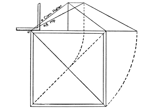
Fig. 13. Method of Finding Relative Height of Hip
or Valley per Foot of Run to that of Common Rafter.
In Fig. 15 is shown the steel square with figures representing the various pitches to the foot of run. For the ½-pitch roof, the figures as shown, from 12 on tongue to 12 on blade, are those to be used on the steel square for the common rafter; and for ⅜ pitch, the figures to be used on the square will be 12 and 9, as shown.
To understand this figure, it is necessary only to keep in mind that the pitch of a roof is reckoned from the span. Since the run in each pitch as shown is 12 inches, the span is two times 12 inches, which [Pg 10] equals 24 inches; hence, 12 on blade to represent the foot run, and 12 on tongue to represent the rise over ½ the span, will be the figures on the square for a ½-pitch roof.
For the ⅜ pitch, the figures are shown to be 12 on tongue and 9 on blade, 9 being ⅜ of the span, 24 inches.
The same rule applies to all the pitches. The ⅙ pitch is shown to rise 4 inches to the foot of run, because 4 inches is ⅙ of the span, 24 inches, the ⅓ pitch is shown to rise 8 inches to the foot of run, because 8 inches is ⅓ of the span, 24 inches; etc.
The roof referred to in Figs. 16 and 17 is to rise 9 inches to the foot of run; it is therefore a ⅜-pitch roof. For all the common rafters, the figures to be used on the square will be 12 on blade to represent the run, and 9 on tongue to represent the rise to the foot of run; and for all the hips and valleys, 17 on blade to represent the run, and 9 on tongue to represent the rise of the roof to the foot of run.
Why 17 represents the run for all the hips and valleys, will be understood by examining Fig. 19, in which 17 is shown to be the diagonal of a foot square.
In equal-pitch roofs the corners are square, and the plan of the hip or valley will always be a diagonal of a square corner as shown at 1, 2, 3, and 5 in Fig. 14.
In Fig. 18 are shown ⅙ pitch, ⅜ pitch and ½ pitch over a square corner. The figures to be used on the square for the hip, will be 17 for run in each case. For the ⅙ pitch, the figures to be used would be 17 inches run and 4 inches rise, to correspond with the 12 inches run and 4 inches rise of the common rafter. For the ⅜ pitch, the figures to be used for hip would be 17 inches run and 9 inches rise, to correspond [Pg 11] with the 12 inches run and 9 inches rise of the common rafter; and for the ½ pitch, the figures to be used on the square will be 17 inches run and 12 inches rise, to correspond with the 12 inches run and 12 inches rise of the common rafter.
It will be observed from above, that in all cases where the plan of the hip or valley is a diagonal of a square, the figures to be used on the square for run will be 17 inches; and for the rise, whatever the roof rises to the foot of run. It should also be remembered that this is the condition in all roofs of equal pitch, where the angle of the hip or valley is a 45-degree angle, or, in other words, where we have the diagonal of a square.
It has been shown in Fig. 12 how other figures for other plan angles may be found; and that in each case the figures for run vary according to the plan angle of the hip or valley, while the figure for the height in each case is similar.
In Fig. 14 are shown a variety of runs for common rafters, but all have the same pitch; they rise 9 inches to the foot of run. The main [Pg 12] roof is shown to have a span of 27 feet, which makes the run of the common rafter 13 feet 6 inches. The run of the front wing is shown to be 10 feet 4 inches; and the run of the small gable at the left corner of the front, is shown to be 8 feet.
The diversity exhibited in the runs, and especially the fractional part of a foot shown in two of them, will afford an opportunity to treat of the main difficulties in laying out roof timbers in roofs of equal pitch. Let it be determined to have a rise of 9 inches to the foot of run; and in this connection it may be well to remember that the proportional rise to the foot run for roofs of equal pitch makes not the least difference in the method of treatment.
To lay out the common rafters for the main roof, which has a run of 13 feet 6 inches, proceed as shown in Fig. 16.
Take 12 on the blade and 9 on the tongue, and step 13 times along the rafter timber. This will give the length of rafter for 13 feet of run. In this example, however, there is another 6 inches of run to cover. For this additional length, take 6 inches on the blade (it being ½ a foot run) for run, and take ½ of 9 on the tongue (which is 4½ inches), and step one time. This, in addition to what has already been found by stepping 13 times with 12 and 9, will give the full length of the rafter.
The square with 12 on blade and 9 on tongue will give the heel and plumb cuts.
Another method of finding the length of rafter for the 6 inches is shown in Fig. 16, where the square is shown applied to the rafter [Pg 13] timber for the plumb cut. Square No. 1 is shown applied with 12 on blade and 9 on tongue for the length of the 13 feet. Square from this cut, measure 6 inches, the additional inches in the run; and to this point move the square, holding it on the side of the rafter timber with 12 on blade and 9 on tongue, as for a full foot run.
It will be observed that this method is easily adapted to find any fractional part of a foot in the length of rafters.
In the front gable, Fig. 14, the fractional part of a foot is 4 inches to be added to 10 feet of run; therefore, in that case, the line shown measured to 6 inches in Fig. 16 would measure only 4 inches for the front gable.
In Fig. 16 is also shown a method to lay out the heel cut of a common rafter. The square is shown applied with 12 on blade and 9 on tongue; and from where the 12 on the square intersects the edge of the rafter timber, a line is drawn square to the blade as shown by the dotted line from 12 to a. Then the thickness of the part of the rafter that is to project beyond the plate to hold the cornice, is gauged to intersect the dotted line at a; and from a, the heel cut is drawn with the square having 12 on blade and 9 on tongue, marking along the blade for the cut.
The common rafter for the front wing, which is shown to have a run of 10 feet 4 inches, is laid out precisely the same, except that for this rafter the square with 12 on blade and 9 on tongue will have to be stepped along the rafter timber only 10 times for the 10 feet of run; and for the fractional part of a foot (4 inches) which is in the run, either of the two methods already shown for the main rafter may be used.
The proportional figures to be used on the square for the 4 inches will be 4 on blade and 2¼ on tongue; and if the second method is used, make the addition to the length of rafter for 10 feet, by drawing a line 4 inches square from the tongue of square No. 1 (see Fig. 16), instead of 6 inches as there shown for the main rafter.
Three of the hips are shown in Fig. 14 to extend from the plate to the ridge-pole; they are marked in the figure as 1, 2, and 3 respectively, and are shown in plan to be diagonals of a square measuring 13 feet 6 inches by 13 feet 6 inches; they make an angle, therefore, of 45 degrees with the plate.
[Pg 14] In Fig. 18 it has been shown that a hip standing at an angle of 45 degrees with the plate will have a run of 17 inches for every foot run of the common rafter. Therefore, to lay out the hips, the figures on the square will be 17 for run and 9 for rise; and by stepping 13 times along the hip rafter timber, the length of hip for 13 feet of run is obtained. The length for the additional 6 inches in the run may be found by squaring a distance of 8½ inches, as shown in Fig. 17, from the tongue of the square, and moving square No. 1 along the edge of the timber, holding the blade on 17 and tongue on 9, and marking the plumb cut where the dotted line is shown.
In Fig. 18 is shown how to find the relative run length of a portion of a hip to correspond to that of a fractional part of a foot in the length of the common rafter. From 12 inches, measure along the run of the common rafter 6 inches, and drop a line to cut the diagonal line in m. From m to a, along the diagonal line, will be the relative run length of the part of hip to correspond with 6 inches run of the common rafter, and it measures 8½ inches.
The same results may be obtained by the following method of figuring:
| As 12 : 17 | :: 6 | |
| 6 | ||
| 12) | 102 | |
| 8 | - 6 = 8½ | |
In Fig. 19 is shown a 12-inch square, the diagonal m being 17 inches. By drawing lines from the base a b to cut the diagonal line, the part of the hip to correspond to that of the common rafter will be indicated on the line 17. In this figure it is shown that a 6-inch run on a b, which represents the run of a foot of a common rafter, will have a corresponding length of 8½ [Pg 15]inches run on the line 17, which represents the plan line of the hip or valley in all equal-pitch roofs.
In the front gable, Fig. 14, it is shown that the run of the common rafter is 10 feet 4 inches. To find the length of the common rafter, take 12 on blade and 9 on tongue, and step 10 times along the rafter timber; and for the fractional part of a foot (4 inches), proceed as was shown in Fig. 16 for the rafter of the main roof; but in this case measure out square to the tongue of square No. 1, 4 inches instead of 6 inches.
The additional length for the fractional 4 inches run can also be found by taking 4 inches on blade and 3 inches on tongue of square, and stepping one time; this, in addition to the length obtained by stepping 10 times along the rafter timber with 12 on blade and 9 on tongue, will give the full length of the rafter for a run of 10 feet 4 inches.
In the intersection of this roof with the main roof, there are shown to be two valleys of different lengths. The long one extends from the plate at n (Fig. 14) to the ridge of the main roof at m; it has therefore [Pg 16] a run of 13 feet 6 inches. For the length, proceed as for the hips, by taking 17 on blade of the square and 9 on tongue, and stepping 13 times for the length of the 13 feet; and for the fractional 6 inches, proceed precisely as shown in Fig. 17 for the hip, by squaring out from the tongue of square No. 1, 8½ inches; this, in addition to the length obtained for the 13 feet, will give the full length of the long valley n m.
The length of the short valley a c, as shown, extends over the run of 10 feet 4 inches, and butts against the side of the long valley at c. By taking 17 on blade and 9 on tongue, and stepping along the rafter timber 10 times, the length for the 10 feet is found; and for the 4 inches, measure 5⅝ inches square from the tongue of square No. 1, in the manner shown in Fig. 17, where the 8½ inches is shown added for the 6 inches additional run of the main roof for the hips.
The length 5⅝ is found as shown in Fig. 20, by measuring 4 inches from a to m along the run of common rafter for one foot. Upon m erect a line to cut the seat of the valley at c; from c to a will be the run of the valley to correspond with 4 inches run of the common rafter, and it will measure 5⅝ inches.
Having found the lengths of the hips and valleys to correspond to the common rafters, it will be necessary to find also the thickness of each above the plate to correspond to the thickness the common rafter will be above the plate.
In Fig. 21 is shown a corner of a square building, showing the plates and the plan lines of a hip. The length of the hip, as already found, will cover the span from the ridge to the corner 2; but the sides [Pg 17] of the hip intersect the plates at 3 and 3 respectively; therefore the distance from 2 to 1, as shown in this diagram, is measured backwards from a to 1 in the manner shown in Fig. 17; then a plumb line is drawn through 1 to m, parallel to the plumb cut a-17. From m to o on this line, measure the same thickness as that of the common rafter; and through o draw the heel cut to a as shown.
In like manner the thickness of the valley above the plate is found; but as the valley as shown in the plan figure, Fig. 22, projects beyond point 2 before it intersects the outside of the plates, the distance from 2 to 1 in the case of the valley will have to be measured outwards from 2, as shown from 2 to 1 in Fig. 23; and at the point thus found the thickness of the valley is to be measured to correspond with that of the common rafter as shown at m n.
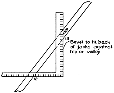
Fig. 25. Steel Square Applied to Jack Rafter to Find
Bevel for Fitting against Side of Hip or Valley.
In Fig. 24 is shown the steel square applied to a hip or valley timber to cut the bevel that will fit the top end against the ridge. The figures on the square are 17 and 19¼. The 17 represents the length of the plan line of the hip or valley for a foot of run, which, as was shown in previous figures, will always be 17 inches in roofs of equal pitch, where the plan lines stand at 45 degrees to the plates and square to each other.
The 19¼ taken on the blade represents the actual length of a hip or valley that will span over a run of 17 inches. The bevel is marked along the blade.
The cut across the back of the short valley to fit it against the side of the long valley, will be a square cut owing to the two plan lines being at right angles to each other.
[Pg 18] In Fig. 25 is shown the steel square applied to a jack rafter to cut the back bevel, to fit it against the side of a hip or valley. The figures on the square are 12 on tongue and 15 on blade, the 12 representing a foot run of a common rafter, and the 15 the length of a rafter that will span over a foot run; marking along the blade will give the bevel.
The rule in every case to find the back bevel for jacks in roofs of equal pitch, is to take 12 on the tongue to represent the foot run, and the length of the rafter for a foot of run on the blade, marking along the blade in each case for the bevel.
In a ½-pitch roof, which is the most common in all parts of the country, the length of rafter for a foot of run will be 17 inches; hence it will be well to remember that 12 on tongue and 17 on blade, marking along the blade, will give the bevel to fit a jack against a hip or a valley in a ½-pitch roof.
In a roof having a rise of 9 inches to the foot of run, such as the one under consideration, the length of rafter for one foot of run will be 15 inches. The square as shown in Fig. 25, with 12 on tongue and 15 on blade, will give the bevel by marking along the blade.
To find the length of a rafter for a foot of run for any other pitch, place the two-foot rule diagonally from 12 on the blade of the square to the figure on tongue representing the rise of the roof to the foot of run; the rule will give the length of the rafter that will span over one foot of run.
The length of rafter for a foot of run will also determine the difference in lengths of jacks. For example, if a roof rises 12 inches to one foot of run, the rafter over this span has been found to be 17 inches; this, therefore, is the number of inches each jack is shortened in one foot of run. If the rise of the roof is 8 inches to the foot of run, the length of the rafter is found for one foot of run, by placing the rule diagonally from 12 on [Pg 19] tongue to 8 on blade, which gives 14½ inches, as shown in Fig. 26. This, therefore, will be the number of inches the jacks are to be shortened in a roof rising 8 inches to the foot of run. If the jacks are placed 24 inches from center to center, then multiply 14½ by 2 = 29 inches.
In Fig. 27 is shown how to find the length with the steel square. The square is placed on the jack timber rafter with the figures that have been used to cut the common rafter. In Fig. 27, 12 on blade and 12 on tongue were the figures used to cut the common rafter, the roof being ½ pitch, rising 12 inches to the foot of run. In the diagram it is shown how to find the length of a jack rafter if placed 16 inches from center to center. The method is to move the square as shown along the line of the blade until the blade measures 16 inches; the tongue then would be as shown from w to m, and the length of the jack would be from 12 on blade to m on tongue, on the edge of the jack rafter timber as shown.
This latter method becomes convenient when the space between jacks is less than 18 inches; but if used when the space is more than 18 inches it will become necessary to use two squares; otherwise the tongue as shown at m would not reach the edge of the timber.
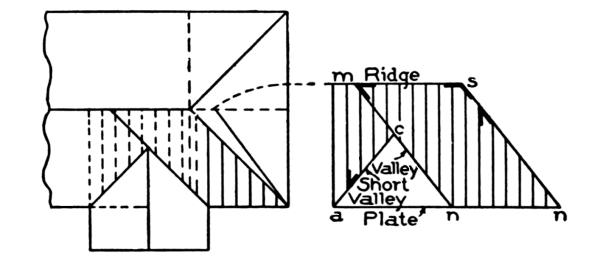
Fig. 29. Method of Determining Length of Jacks Between Hips
and Valleys; also Bevels for Jacks, Hips, and Valleys.
In Fig. 28 the same method is shown for finding the length of a jack rafter for a roof rising 9 inches to the foot of run, with the jacks placed 18 inches center to center. The square in this diagram is shown placed on the jack rafter timber with 12 on blade and 9 on [Pg 20] tongue; then it is moved forward along the line of the blade to w. The blade, when in this latter position, will measure 18 inches. The tongue will meet the edge of the timber at m, and the distance from m on tongue to 12 on blade will indicate the length of a jack, or, in other words, will show the length each jack is shortened when placed 18 inches between centers in a roof having a pitch of 9 inches to the foot of run.
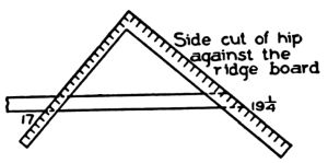
Fig. 31. Method of Finding Bevel 5,
Fig. 30, for Fitting Hip or Valley
Against Ridge when not Backed.
When jacks are placed between hips and valleys as shown at 1, 2, 3, 4, etc., in Fig. 14, a better method of treatment is shown in Fig. 29, where the slope of the roof is projected into the horizontal plane. The distance from the plate in this figure to the ridge m, equals the length of the common rafter for the main roof. On the plate a n n is made equal to a n n in Fig. 14. By drawing a figure like this to a scale of one inch to one foot, the length of all the jacks can be measured [Pg 21] and also the lengths of the hip and the two valleys. It also gives the bevels for the jacks, as well as the bevel to fit the hip and valley against the ridge; but this last bevel must be applied to the hip and valley when backed.
It has been shown before, that the figures to be used on the square for this bevel when the timber is left square on back as is the custom in construction, are the length of a foot run of a hip or valley, which is 17, on tongue, and the length of a hip or valley that will span over 17 inches run, on blade—the blade giving the bevel.
Fig. 30 contains all the bevels or cuts that have been treated upon so far, and, if correctly understood, will enable any one to frame any roof of equal pitch. In this figure it is shown that 12 inches run and 9 inches rise will give bevels 1 and 2, which are the plumb and heel cuts of rafters of a roof rising 9 inches to the foot of run. By taking these figures, therefore, on the square, 9 inches on the tongue and 12 inches on the blade, marking along the tongue will give the plumb cut, and marking along the blade will give the heel cut.
Bevels 3 and 4 are the plumb and heel cuts for the hip, and are shown to have the length of the seat of hip for one foot run, which is 17 inches. By taking 17 inches, therefore, on the blade, and 9 inches on the tongue, marking along the tongue for the plumb cut, and along the blade for the heel cut, the plumb and heel cuts are found. Bevel 5, which is to fit the hip or valley against the ridge when not backed, is shown from o w, the length of the hip for one foot of run, which is 19¼ inches, and from o s, which always in roofs of equal pitch will be 17 inches and equal in length to the seat of a hip or valley for one foot of run.
[Pg 22] These figures, therefore, taken on the square, 19¼ on the blade, and 17 on the tongue, will give the bevel by marking along the blade as shown in Fig. 31, where the square is shown applied to the hip timber with 19¼ on blade and 17 on tongue, the blade showing the cut.
Bevels 6 and 7 in Fig. 30 are shown formed of the length of the rafter for one foot of run, which is 15 inches, and the run of the rafter, which is 12 inches. These figures are applied on the square, as shown in Fig. 32, to a jack rafter timber; taking 15 on the blade and 12 on the tongue, marking along the blade will give the back bevel for the jack rafters, and marking along the tongue will give the face cut of roof-boards to fit along the hip or valley.
It is shown in Fig. 30, also, that by taking the length of rafter 15 inches on blade, and rise of roof 9 inches on tongue, bevel 8 will give the miter cut for the roof-boards.
In Fig. 33 the square is shown applied to a roof-board with 15 on blade, which is the length of the rafter to one foot of run, and with 9 on tongue, which is the rise of the roof to the foot run; marking along the tongue will give the miter for the boards.
Other uses may be made of these figures, as shown in Fig. 34, which is one-half of a gable of a roof rising 9 inches to the foot run. The squares at the bottom and the top will give the plumb and heel cuts of the common rafter. The same figures on the square applied to the studding, marking along the tongue for the cut, will give the bevel to fit the studding against the rafter; and by marking along the blade we obtain the cut for the boards that run across the gable. By taking 19¼ on blade, which is [Pg 23] the length of the hip for one foot of run, and taking on the tongue the rise of the roof to the foot of run, which is 9 inches, and applying these as shown in Fig. 35, we obtain the backing of the hip by marking along the tongue of the two squares, as shown.
It will be observed from what has been said, that in roofs of equal pitch the figure 12 on the blade, and whatever number of inches the roof rises to the foot run on the tongue, will give the plumb and heel cuts for the common rafter; and that by taking 17 on the blade instead of 12, and taking on the tongue the figure representing the rise of the roof to the foot run, the plumb and heel cuts are found for the hips and valleys.
By taking the length of the common rafter for one foot of run on blade, and the run 12 on tongue, marking along the blade will give the back bevel for the jack to fit the hip or valley, and marking along the tongue will give the bevel to cut the roof-boards to fit the line of hip or valley upon the roof.
With this knowledge of what figures to use, and why they are used, it will be an easy matter for anyone to lay out all rafters for equal-pitch roofs.
In Fig. 36 is shown a plan of a roof with two unequal pitches. The main roof is shown to have a rise of 12 inches to the foot run. The front wing is shown to have a run of 6 feet and to rise 12 feet; it has thus a pitch of 24 inches to the foot run. Therefore 12 on blade of the square and 12 on tongue will give the plumb and heel cuts for the main roof, and by stepping 12 times along the rafter timber the length of the rafter is found. The figures on the square to find the heel and [Pg 24] plumb cuts for the rafter in the front wing, will be 12 run and 24 rise, and by stepping 6 times (the number of feet in the run of the rafter), the length will be found over the run of 6 feet, and it will measure 13 feet 6 inches.
If, in place of stepping along the timber, the diagonal of 12 and 24 is multiplied by 6, the number of feet in the run, the length may be found even to a greater exactitude.
Many carpenters use this method of framing; and to those who have confidence in their ability to figure correctly, it is a saving of time, and, as before said, will result in a more accurate measurement; but the better and more scientific method of framing is to work to a scale of one inch, as has already been explained.
According to that method, the diagonal of a foot of run, and the number of inches to the foot run the roof is rising, measured to a scale, will give the exact length. For example, the main roof in Fig. 36 is rising 12 inches to a foot of run. The diagonal of 12 and 12 is 17 inches, which, considered as a scale of one inch to a foot, will give 17 feet, and this will be the exact length of the rafter for a roof rising 12 inches to the foot run and having a run of 12 feet.
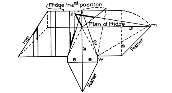
Fig. 38. Laying Out Timbers of Roof Shown in Fig. 36,
by Projecting Slope of Roof into Horizontal Plane.
The length of the rafter for the front wing, which has a run of 6 feet and a rise of 12 feet, may be obtained by placing the rule as shown [Pg 25] in Fig. 37 from 6 on blade to 12 on tongue, which will give a length of 13½ inches. If the scale be considered as one inch to a foot, this will equal 13 feet 6 inches, which will be the exact length of a common rafter rising 24 inches to the foot run and having a run of 6 feet.
It will be observed that the plan lines of the valleys in this figure in respect to one another deviate from forming a right angle. In equal-pitch roofs the plan lines are always at right angles to each other, and therefore the diagonal of 12 and 12, which is 17 inches, will be the relative foot run of valleys and hips in equal-pitch roofs.
In Fig. 36 is shown how to find the figures to use on the square for valleys and hips when deviating from the right angle. A line is drawn at a distance of 12 inches from the plate and parallel to it, cutting the valley in m as shown. The part of the valley from m to the plate will measure 13½ inches, which is the figure that is to be used on the square to obtain the length and cuts of the valleys.
It will be observed that this equals the length of the common rafter as found by the square and rule in Fig. 37. In that figure is shown 12 on tongue and 6 on blade. The 12 here represents the rise, and the 6 the run of the front roof. If the 12 be taken to represent the run of the main roof, and the 6 to represent the run of the front roof, then, the diagonal 13½ will indicate the length of the seat of the valley for 12 feet of run, and therefore for one foot it will be 13½ inches. Now, by taking 13½ on the blade for run, and 12 inches on the tongue for rise, and stepping along the valley rafter timber 12 times, the length of the valley will be found. The blade will give the heel cut, and the tongue the plumb cut.
In Fig. 38 is shown the slope of the roof projected into the horizontal plane. By drawing a figure based on a scale of one inch to one [Pg 26] foot, all the timbers on the slope of the roof can be measured. Bevel 2, shown in this figure, is to fit the valleys against the ridge. By drawing a line from w square to the seat of the valley to m, making w 2 equal in length to the length of the valley, as shown, and by connecting 2 and m, the bevel at 2 is found, which will fit the valleys against the ridge, as shown at 3 and 3 in Fig. 36.
In Fig. 39, is shown how to find the length and cuts of octagon hips intersecting a roof. In Fig. 36, half the plan of the octagon is shown to be inside of the plate, and the hips o, z, o intersect the slope of the roof. In Fig. 39, the lines below x y are the plan lines; and those above, the elevation. From z, o, o, in the plan, draw lines to x y, as shown from o to m and from z to m; from m and m, draw the elevation lines to the apex o″, intersecting the line of the roof in d″ and c″. From d″ and c″, draw the lines d″ v″ and c″ a″ parallel to x y; from c″, drop a line to intersect the plan line a o in c. Make a w equal in length to a″ o″ of the elevation, and connect w c; measure from w to n the full height of the octagon as shown from x y to the apex o″; and connect c n. The length from w to c is that of [Pg 27] the two hips shown at o o in Fig. 36, both being equal hips intersecting the roof at an equal distance from the plate. The bevel at w is the top bevel, and the bevel at c will fit the roof.
Again, drop a line from d″ to intersect the plan line a z in d. Make a 2 equal to v″ o″ in the elevation, and connect 2 d. Measure from 2 to b the full height of the tower as shown from x y to the apex o″ in the elevation, and connect d b. The length 2 d represents the length of the hip z shown in Fig. 36; the bevel at 2 is that of the top; and the bevel at d, the one that will fit the foot of the hip to the intersecting roof.
When a cornice of any considerable width runs around a roof of this kind, it affects the plates and the angle of the valleys as shown in Fig. 40. In this figure are shown the same valleys as in Fig. 36; but, owing to the width of the cornice, the foot of each has been moved the distance a b along the plate of the main roof. Why this is done is shown in the drawing to be caused by the necessity for the valleys to intersect the corners c c of the cornice.
The plates are also affected as shown in Fig. 41, where the plate of the narrow roof is shown to be much higher than the plate of the main roof.
The bevels shown at 3, Fig. 40, are to fit the valleys against the ridge.
In Fig. 42 is shown a very simple method of finding the bevels for purlins in equal-pitch roofs. Draw the plan of the corner as shown, and a line from m to o; measure from o the length x y, representing the common rafter, to w; from w draw a line to m; the bevel shown at 2 will fit the top face of the purlin. Again, from o, describe an arc to cut the seat of the valley, and continue same around to S; connect S m; the bevel at 3 will be the side bevel.
| PART | PAGE | |
| B | ||
| Bevel | I, | 44 |
| Bevels, application of in fitting wreaths to rail | I, | 58 |
| Bevels to square wreaths | I, | 60 |
| Bottom steps with obtuse-angle plan | I, | 56 |
| Bullnose stair | I, | 33 |
| Bullnose steps | I, | 32 |
| Bullnose tread | I, | 29 |
| C | ||
| Carriage | I, | 16 |
| Carriage pieces | I, | 28 |
| Circular stairs | I, | 25 |
| Close stairway | I, | 2 |
| Cove | I, | 28 |
| Curved steps and stringer, plan of | I, | 54 |
| Cylinder | I, | 35 |
| D | ||
| Dog-legged stairs | I, | 25 |
| F | ||
| Face-mould | I, | 68 |
| Face-mould developing (obtuse-angle plan) | I, | 56 |
| Flyer | I, | 25 |
| Foci | I, | 70 |
| G | ||
| Geometrical stair | I, | 44 |
| Geometrical stairways and handrailing | I, | 43 |
| K | ||
| Kerfing | I, | 36 |
| N | ||
| Newel post | I, | 14 |
| O | ||
| Open-newel stairs | I, | 32 |
| P | ||
| Pitch-board | I, | 10 |
| Plan lines | I, | 48 |
| Platform | I, | 20 |
| Platform stairs | I, | 26 |
| Projection | I, | 44 |
| [Pg 2]Q | ||
| Quarter-space stair with six winders | I, | 43 |
| Quick sweep | I, | 37 |
| R | ||
| Rail, plan line of | I, | 46 |
| Rise and rim | I, | 3 |
| Riser | I, | 3 |
| arrangement of | I, | 74 |
| Rough brackets | I, | 28 |
| S | ||
| Springing the plank | I, | 74 |
| Stair with five dancing winders | I, | 43 |
| Stair-building | I, | 1-75 |
| definitions | I, | 2 |
| introductory | I, | 1 |
| laying out | I, | 22 |
| open-newel stairs | I, | 32 |
| platform | I, | 20 |
| stairs with curved turns | I, | 34 |
| strings | I, | 7 |
| housed | I, | 7 |
| notched | I, | 8 |
| open | I, | 7 |
| rough | I, | 7 |
| staved | I, | 8 |
| well hole | I, | 18 |
| Stairs, plans and elevation turning around central post | I, | 44 |
| Stairs, setting of | I, | 8 |
| Stairs, types of in common use | I, | 41 |
| Steel square | II, | 1-27 |
| applied in roof framing | II, | 7 |
| applied to jack rafter | II, | 17 |
| back | II, | 1 |
| back of blade, showing essex board measure | II, | 3 |
| back of blade, showing rafter table | II, | 2 |
| back of tongue, showing brace measure | II, | 3 |
| bevels, method of finding for all timbers in roofs of equal pitch | II, | 20 |
| blade | II, | 1 |
| board measure | II, | 1 |
| brace rule | II, | 1 |
| common rafters, method of laying out | II, | 11 |
| face | II, | 1 |
| face side of tongue, showing octagon scale | II, | 2 |
| finding backing of hip in gable roof | II, | 22 |
| finding length of rafter for front wing in roof shown in Fig. 36 | II, | 24 |
| finding length to shorten rafters for jacks per foot of run | II, | 18 |
| giving various pitches to foot of run | II, | 10 |
| [Pg 3]heel cut of common rafter | II, | 13 |
| hips | II, | 13 |
| hips and rafters for roofs of various pitches over square corner, | ||
| method of laying out | II, | 12 |
| hips and valleys, how to treat the heel cut of | II, | 16 |
| hips and valleys of a ⅜-pitch roof, method of laying out | II, | 11 |
| jack rafter, finding length of | II, | 18 |
| jacks between hips and valleys, method of determining length | II, | 19 |
| laying out timbers of one-half gable of ⅜-pitch roof | II, | 22 |
| laying out timbers of roof with two unequal pitches | II, | 23 |
| method of finding bevels for purlins in equal-pitch roofs | II, | 27 |
| method of finding length and cuts of octagon hips | ||
| intersecting a roof | II, | 25 |
| octagon scale | II, | 1 |
| rise and run | II, | 1 |
| tongue | II, | 1 |
| use of to find miter of equilateral triangle | II, | 6 |
| use of to find miter of hexagon | II, | 7 |
| use of to find miter and side of pentagon, hexagon and octagon | II, | 4, 5 |
| Story rod | I, | 8 |
| Straight flights | I, | 25 |
| String-board | I, | 3 |
| Strings | I, | 7 |
| housed | I, | 7 |
| methods of building up | I, | 37 |
| notched | I, | 8 |
| open | I, | 7 |
| rough | I, | 7 |
| staved | I, | 8 |
| T | ||
| Tangent inclined-lower tangent level | I, | 63 |
| Tangent system | I, | 44 |
| Tangents and face-mould, diagram of | I, | 53 |
| Tangents unfolded | I, | 50 |
| Tread | I, | 3 |
| Treads and risers, housing of | I, | 13 |
| Trimming joists | I, | 19 |
| Twisted wreath raised to position | I, | 57 |
| W | ||
| Well-hole | I, | 18 |
| Well-hole connecting two flights | I, | 51 |
| Winder | I, | 25 |
| Winding stairs | I, | 25 |
| Wreath, cutting from plank | I, | 57 |
| Wreath with two equally inclined tangents, finding bevels for | I, | 59 |
| Wreath twisted, ready to be moulded | I, | 57 |
| Wreaths | I, | 44 |
Transcriber's Notes:
The illustrations have been moved so that they do not break up paragraphs and so that they are next to the text they illustrate.
Typographical errors have been silently corrected.
INDEX has been added to Table of Contents.