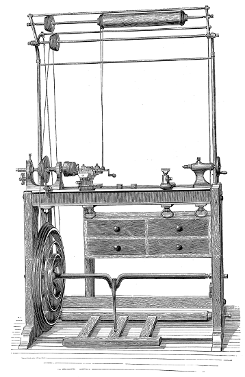
FIRST-CLASS 5-IN. CENTRE LATHE, WITH TRAVERSING MANDREL AND OVERHEAD APPARATUS, BY JAMES MUNRO, LAMBETH.
FIRST-CLASS 5-IN. CENTRE LATHE, WITH TRAVERSING MANDREL AND OVERHEAD APPARATUS, BY JAMES MUNRO, LAMBETH.
OR,
INSTRUCTION IN THE ART OF TURNING
WOOD AND METAL.
INCLUDING
A DESCRIPTION OF THE MOST MODERN APPLIANCES FOR THE
ORNAMENTATION OF PLANE AND CURVED SURFACES.
With an Appendix,
IN WHICH IS DESCRIBED AN
ENTIRELY NOVEL FORM OF LATHE FOR ECCENTRIC AND ROSE
ENGINE TURNING; A LATHE AND PLANING
MACHINE COMBINED;
And other Valuable Matter relating to the Art.
COPIOUSLY ILLUSTRATED.
NEW YORK:
JOHN WILEY & SON, PUBLISHERS,
NO. 2, CLINTON PLACE.
1868.
Although the title of this work is sufficient to declare its contents, a few prefatory remarks may not be superfluous as to its design and the manner in which that design has been carried out.
It has ever been to the writer a matter of surprise and regret, that although the art of turning has been so long and so successfully pursued in this country, both by artisans and amateurs, no work has appeared in the English language treating upon the subject, except one or two sketches and imperfect treatises.
Some years since Mr. Holtzapffel advertised a forthcoming series of seven volumes, intended to supply this manifest deficiency in our scientific and mechanical literature, and the subject would have been handled by him in a thoroughly exhaustive and masterly manner.
The untimely death of that gentleman occurred after the publication of the first three volumes, which are indeed complete in themselves, and of immeasurable value to the mechanic and amateur; but which are unfortunately only introductory, "simple turning by hand-tools" being the special subject of the proposed fourth volume. The present proprietors of the firm of Holtzapffel & Co. having, in their catalogue even up to the time of the most recent edition, continued to advertise the seven volumes, amateurs especially have anxiously hoped for the publication of some part at least of the remainder of the series. That expectation is, it is to be feared, little likely to be rewarded; and, not until that fact had been ascertained with something bordering upon certainty, did the author of the present work[iv] venture to take up the pen and endeavour to set forth the principles and practice of an art which, like so many others, he has found so absorbing and attractive, and withal so delightful a source of recreation to mind and body. Several things, however, contributed to make the writer hesitate to undertake such a work. In the first place he was aware that a number of possible readers would probably be more competent than himself for such a task, especially those whose means might have enabled them to procure a large amount of the most modern and approved apparatus connected with the Lathe, and whose occupations might allow of more leisure for their extensive use than falls to the lot of the writer.
In the next place the risk of publication was such as he felt himself hardly justified in encountering. Just at this time, however, chance placed in his hand two or three numbers of the "English Mechanic," in which some one else had begun, but speedily resigned, a series of papers "On the Lathe and its Uses," compiled from American journals.
The author of the present work at once put himself in communication with the editor and proprietor of the above periodical with a result now well known to the readers.
The following pages are not, strictly speaking, a mere reprint from the "English Mechanic." The papers have been carefully revised and re-arranged; some statements, the correctness of which appeared doubtful, modified or wholly withdrawn; while, in one or two instances, whole chapters have been re-written, and the suggestions and inventions relating to the Lathe, furnished by other correspondents, embodied (when they appeared of real value) in the work.
But, in addition, a valuable Appendix is now published, containing matter of great importance, contributed by one or two gentlemen, who most kindly placed their papers at the service of the author. Foremost among them stands a paper on the angles of tools, by Dodsworth Haydon, Esq., of Guildford. A clever arrangement of Lathe for Rose Engine Work, by the aid of the Eccentric[v] Chuck without Rosettes, is also added from the pen of Mr. Elias Taylor, of Brighton; and one or two matters, which did not appear so fully treated as they deserved in the body of the work, have been resumed and more fully discussed in the Appendix.
The author gratefully acknowledges the suggestions of various correspondents, amateurs and working men, from whom, as a rule, he has not failed to obtain any required assistance.
That the work, in its present form, is entirely satisfactory or complete, the writer cannot pretend; that many errors have crept in is highly probable; but, if it is acknowledged to be the best work yet produced on the Lathe, and should prove in any degree serviceable to amateur or artisan in the pursuit of this most delightful art—aye, if it should stir up some abler pen to write a better and more complete series, it will afford real pleasure and lasting gratification to
THE AUTHOR.
The Lathe has now for many years been steadily making its way from the workshops of our leading artisans to those of the amateur and lesser stars of the mechanical world. This is but the natural result of the various additions and improvements which have been introduced into its construction from time to time. The unworkmanlike and clumsy tool of olden days has long since been superseded by one of admirable finish and perfect aptitude for its designed uses; and now that its construction is no longer dependent upon the skill of the workman alone, but upon machinery moving with the precision of clockwork, the fitting of the various parts is accomplished with the greatest ease and certainty. The sale being thus extended, the price has considerably diminished—the monopoly enjoyed by one or two makers no longer exists; and there are few of a mechanical turn of mind who cannot now provide themselves with a lathe suited to their requirements.
Nevertheless, the adepts in the art of turning are by no means so numerous as might be expected, and, among amateurs especially, it is rare to find work executed in first-rate style by simple hand tools requiring skill and practice in their use, so that it not unfrequently happens that a workman who can turn out exquisite specimens of ivory carving and ornamental lathe work, is but a fourth-rate hand with the gouge and chisel.
But however beautifully executed such ornamental work may be, the credit is rather due to the tool than the workman, and a well turned box with accurately fitting cover may bespeak more skill in handiwork than the above elaborately designed specimen.
Moreover the one requires lathe fittings, which are not always to be had unless the purse is well filled, whereas the general mechanic (amateur or professional) can provide the tools needed for the other; hence we propose first of all to give some practical hints on plain hand turning of wood and metal. The ordinary form of foot lathe is well known and requires no special description, it is represented[2] in the frontispiece of this volume. There are, however, certain points of detail in its construction, to which it is necessary to direct the reader's attention.
First and foremost comes the mandrel, of which there are several patterns, according to the special purpose for which the lathe may be intended.
Now of whatever form it may be made this is the essential part of the lathe, and must run with the utmost truth in its bearings. Imperfection here will be imparted to all work executed upon it, and accuracy in this part alone will make up for any slight defects that may occur in less important parts of the machine.
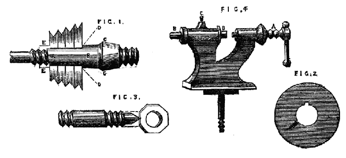
For ordinary work in wood alone or in brass the best form is represented in Fig. 1.
Figs. 1,2,3,4.
The part a, b, should be cylindrical, with a feather let in to fit a slot in the pulley shown in Fig. 2. This pulley, whether of hard wood or metal, is thus slipped on the mandrel as far as the collar d, d, and a nut e, screwed up tightly at the back of it, fixes it securely in its place, from which it may be moved if requisite and replaced without fear of being out of truth. This cannot be done if the mandrel is squared at a, b, and the pulley driven on with a hammer, as commonly done by inferior workmen. The part c, is made conical, to fit a hardened steel collar of similar shape. The angle of this conical part is of some importance, as if it is too small the mandrel is apt to jam and stick tight in its bearings. 35° will be found to work well. With regard to the length of this conical part, opinions differ considerably, but it must be remembered that friction is independent of the extent of the bearing surfaces and depends on the force with which they are pressed together (in the present case it depends on the tension of the lathe cord and the weight of the material to be turned), so that a tolerably wide margin may be allowed in this matter. Practically the question is decided by the thickness of the casting of the poppet head, which is regulated by the required strength and size of the lathe. The collar is sometimes of[3] hardened steel, sometimes of brass. The latter would theoretically cause less friction than the former, but practically nothing can beat a well finished collar of hard steel. Collars of this material made by the original Holtzapffel two generations back are now as good as ever, perhaps even better. The centre, which screws up against the left-hand end of the mandrel, should be of the form shown in Fig. 3—a plain cylinder with a screw cut at each end to receive clamping nuts. The central part is rather larger than the screwed parts, and passes truly through the poppet head. This form is much better than a simple screw with points, as the latter is not likely to keep the line of centres in being screwed up into its place.
It will be found of great convenience to have the screw on the nose of the mandrel (and indeed all screws about the lathe) of standard Whit worth pitch, as taps for the chucks are thus readily obtained, and nuts and screws of the various sizes may be also procured to remedy breakages and losses. Upon this subject, however, we shall have occasion to treat more fully when we pass from the description of the lathe itself to the work that is to be accomplished by its aid.
The only form of back poppet that need be particularised is that made with cylinder and leading screw. The simple pointed screw passing through the lathe head tapped to receive it, not only requires no special description, but it is only calculated for lathes of the commonest design, as it is seldom that the line of centres is accurately maintained by the point at every part of the revolution of the screw. Moreover, the latter soon works loose in the poppet, and for anything like accurate work becomes speedily useless. The cylinder and pushing screw is indeed far superior to the form just alluded to, and where cheapness is an object it has its advantages over the first-named and best form. It is represented in Fig. 4. The cylindrical part is shown at B, and may have at one end the usual point, and at the other a small conical hole or hollow centre. It may then be reversed in its bearings at pleasure, or other cylinders with different shaped ends can be substituted, as may be found convenient. Of course the pushing screw A is for the purpose of advancing the cylinder, which is clamped by the small screw at C. The cylinder and leading screw are shown in detail in Fig. 5, which is the poppet head bored throughout to receive the spindle or cylinder A. At the right hand[4] this bore is enlarged to form a recess, B, to receive the head of the leading screw, C. This screw is generally made with a left-handed thread, so as to withdraw the back centre when turned from right to left. The spindle A, A is bored, and a left-handed female thread is cut from end to end—this however is turned off at the place destined to receive the movable point or centre, and a hole slightly tapering is cut, or if preferred a cylindrical hole is made and tapped for the same purpose. The spindle has also a slot cut from end to end, into which a screw enters from the poppet, preventing the spindle from turning round while the internal screw is revolving by means of the small wheel and handle fixed to its right hand end. The spindle is now put in its place, the screw inserted and turned till the head or flange, C, rests in the recess before mentioned—a flat plate, F, is then attached to the back of the poppet by three or four screws, the head of the leading screw passing through its centre; the small wheel is then attached and the whole is complete.
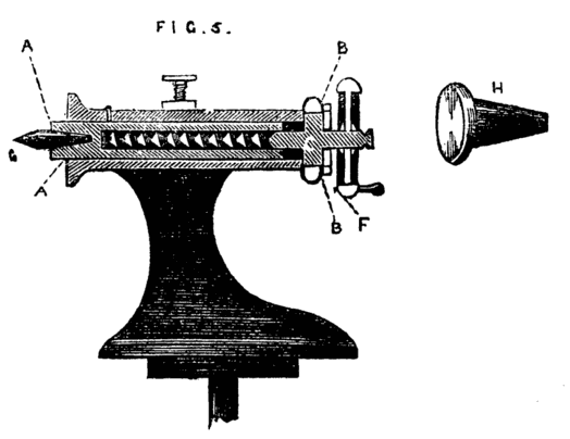
Fig. 5.
It is evident that by turning the wheel the internal screw is put in revolution, and as it is prevented by its flange from assuming any motion in the direction of its length, the movable cylinder will instead be withdrawn or thrust forward.
This form of poppet is the best that can be adopted and is of general use in all first-class lathes. In addition to the movable point g, a flange similar to H should be fitted. This will be found of great use when the lathe is used for drilling, the piece of work resting against it, while the pressure is regulated by the leading screw.
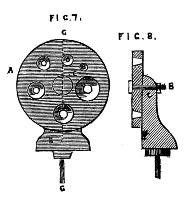
There are, in addition to the flange and pointed centre, other pieces of apparatus that can be substituted, as occasion may require, and these will be hereafter described in this series. With regard to the common rest for hand turning a lengthened description is unnecessary. The T or tee should for wood turning be of the form shown in Fig. 6 at A. It is often made as B, which is a very inconvenient pattern, as the cross piece on which the tool rests cannot be advanced sufficiently close to the work if the latter exceeds a diameter of two or three inches. For metal turning the top of the rest should be flat, and about one inch broad, as the heel of the hook tools used for turning iron must be able to take a firm bearing upon its surface. Sometimes a plate of brass is riveted on the flat top, as the tool takes a firmer hold on this metal, and when the latter becomes defaced and channelled it can be renewed without the cost of a new casting in iron. The turner should be provided with two or three tees for metal and for wood,—one may be long enough to have two legs and require[5] two sockets, as shown at C. This is convenient in turning long pieces of wood,—a very short tee, not more than an inch in length, should also be provided, and if one tee is specially kept with a very level and smooth edge, it will be found of great advantage in chasing screws—indeed the latter work can hardly be managed at all if the top of the rest is damaged and uneven. The next part requiring description is the boring collar, without which even a hand turning lathe can hardly be considered complete. This boring collar is intended so to support one end of the work, instead of its being held by the back centre, as to enable the workman to get at the end of it for the purpose of drilling it. Suppose for instance the work in hand is a tool handle, and that it is so far finished as only to require the hole for the reception of the tang of the tool. If this is bored by hand with a gimlet, it is seldom that the hole will be truly in the axis of the piece, but when this is done in the lathe by the help of the boring collar the bore will be truly central, and the tool when in place will fall in the same line with the handle. This will conduce to the correctness of the work in hand more than the amateur or other workman might suppose, and a row of tools thus truly handled and in good condition generally bespeaks an efficient and careful artisan. There are several plans for boring collar of nearly equal efficiency, and we shall describe one or two of the most common, and also one invented by the author, and which, if carefully made, is of great service. Fig. 7 represents a poppet head, B, which is but half the height of the other poppets of the lathe—a side view of this is shown at B, Fig. 8. Near the top of this poppet is a hole through which passes a bolt C, by which and its nut the circular plate A can be securely clamped in any desired position, as it revolves freely on the bolt as a centre pin. This plate is bored with a series of conical holes, which are so arranged that their respective centres will be in a line with the centres of the mandrel when any one of them is brought into a position corresponding with the line c, c. The hole thus brought into position for use (having been selected according to the size of the work to be bored), takes the place of the back centre; the end of the work rests in the cone, which is greased or soaped to reduce friction, and the rest being fixed at the other side of the boring collar, the drill can be readily used, and the bore afterwards enlarged if necessary with any convenient tool. This boring collar is generally made of iron, but a substitute of hard wood will[6] frequently serve the purpose, and can be made by the amateur, who may be unable to obtain one of more durable material. If made of wood the best unguent will be soap or black lead, such as is used for grates, or a mixture of the two. This black lead or plumbago (it has no lead in its composition) will always be found serviceable where wood works upon wood, and also to give a smooth surface to wooden patterns for casting.
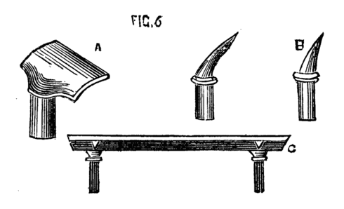
Fig. 6.
Figs. 7,8.
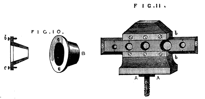
Where cost is an object, a simple substitute for the boring collar is frequently made by the ordinary workman by a piece of board one inch thick, shaped like Fig. 9, with a single hole of the size most generally required; and the work is then fitted to the boring collar, instead of the latter to the work. In turning tool handles, for instance, where a few dozen are required all of the same size, or nearly so, a device of this kind, which can be made in a few minutes, is sufficiently effective. This form has been modified in two ways, and either will be found convenient. In the first, the conical hole is made of the largest size likely to be required, a set of boxwood plugs are then turned to fit this hole and are themselves bored in a similar way to suit various sizes of work. The form of these plugs is shown in Fig. 10, which is a side sectional view, and at B, where the same is shown in perspective. Two small screws or pins b, c, Fig. 10, fitting into the holes a, a, Fig. 9, prevent these flange-shaped plugs from turning round in the board as the work revolves. The pattern of A, Fig. 9, may be varied, and is better made of hard wood, and of a form which will afford a good bearing upon the lathe bed.
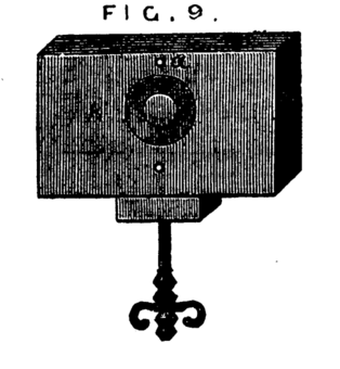
Fig. 9.
Figs. 10,11.
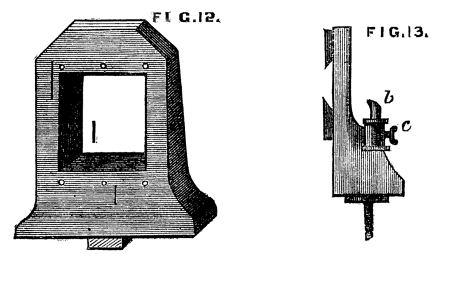
The second modification is more difficult to make, but equally effective. It is shown complete in Fig. 11. This form, arranged by[7] the writer, has many advantages over the two last-named, and is very serviceable. A is the poppet, of the full height of the ordinary lathe heads, or a couple of inches higher. B, the slide forming the support of the piece to be bored. The form of the poppet without this attachment is shown in Fig. 12. If for nice work it should be made of metal and the face of it planed, but for general purposes hard wood will suffice. b, b, Fig. 11, are two pieces of brass forming a groove or guide in which a slide B, with dovetailed edges is fitted to work. This slide is bored, like the ordinary collar, with conical holes of different sizes, and should be made of metal and planed on back and edges. Over each hole is a mark, and this is to be brought to a similar mark on the face of the poppet. The plate is then clamped in position by a screw at the back of the poppet. One or more of such slides may be fitted at pleasure, and in case of wear or damage these are the only parts requiring to be renewed.
Figs. 12,13.
It is a good plan to arrange a socket and tee of a rest as b, c, Fig. 13, at the back of this boring collar, especially as the position of the tool will be always the same, so that the rest may be a permanent part of the poppet. There is sometimes a difficulty with the ordinary form of boring collar in advancing the rest T sufficiently near the work (the foot of the poppet, and that of the rest preventing it, by coming in contact.) There is another modification of boring collar, forming at the same time a guide for the drill, which in slender work, where the tool is long and fine, becomes almost a matter of necessity.
This consists in making such a guide cone as mentioned and shown in Fig. 10, B, but with a continuation containing a smaller hole for the drill, as Fig. 14. Both this and the other shorter cones above-mentioned may be made to screw into the poppet A, [8]Fig. 9, instead of being kept in place by the pins at a, a, of that figure. In that case however the hole in the poppet must be cylindrical and only used as a support for the cones themselves. In addition to the use of these boring collars already alluded to, they serve for the purpose of turning up the points of screws like those of lathe centres. These are first formed between centres with carrier chuck, the back poppet is then removed and the extreme point fitted through one of the holes of the boring collar and the marks of the centre turned off.
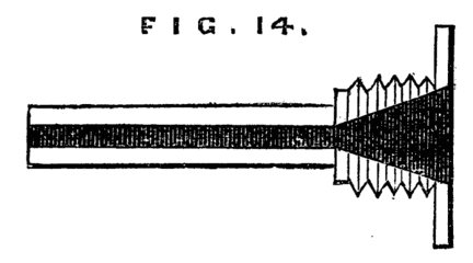
Fig. 14.
Another useful adjunct to the lathe is the back rest for supporting long and slender articles, which would otherwise bend under the pressure of the tool. The ordinary and simplest form is shown in Fig. 15, and this is of general use with brush handle makers and others whose work is confined to a few sizes and shapes only. A better form is shown in Fig. 16. A support of wood or metal shaped like A is clamped to the lathe bed. Through the upper part the slide B passes and is wedged up so as to support the work—or the socket of a lathe rest may be arranged to take the upright part A, which must then be rounded, as shown at C.
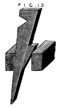
Fig. 15.
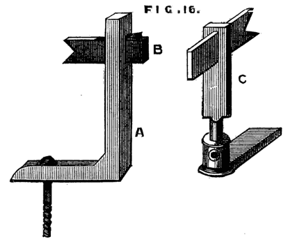
Fig. 16.
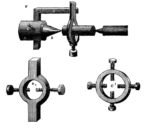
A modification of the latter, communicated to the English Mechanic, is shown in Fig. 16A. Its construction and mode of application is sufficiently evident without a detailed description. Fig. 16B is another form made in metal. It consists of two similar plates with a triangular opening A, through which the work is passed, and which has an oval slot D, by which the apparatus is secured to the short poppet of the boring collar. Between the two plates slides a third, partly visible at C, which can be clamped by a screw at B, this screw also serving as a stud by which the plate may be moved. The work is allowed to take up its own bearing in the triangular opening as it revolves in the lathe. The clamping screw of the poppet is then secured, and the centering thus made certain. The plate C is then made to descend so as to touch the work, and[9] clamped in that position. This is a very good central support for long slender articles.
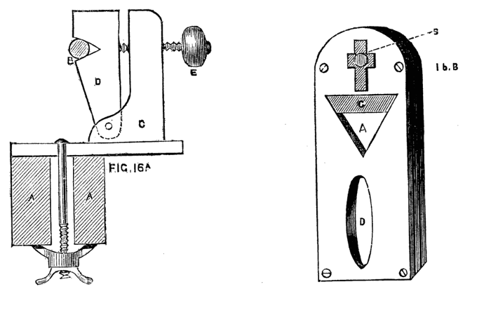
Fig. 16A,B.
There is a plan practised by German turners by which the back rest is in a measure superseded, and which may be mentioned here. It is simply the peculiar method of using the left hand. This is placed on the piece to be turned so that the fingers partly encircle the work while the thumb rests in the hollow of the gouge, or upon the end of the tool. The fingers thus form a back rest and keep the work pressed against the cutting edge, which is further steadied by the thumb. As the tool traverses the work the left-hand accompanies it, and with a little practice a ramrod or similar long and slender article may be readily and accurately turned. This position is shown in Fig. 17, and though the novice will find it difficult to work thus, it is well worth the trouble of mastering, as the method once acquired will be found of very great service.
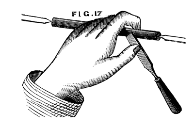
Fig. 17.
We have now described more or less in detail the principal parts of the lathe as adapted for hand turning. Before we dismiss this part of the subject, however, it will be necessary to say a few words respecting the bed and lower fittings, the flywheel, treadle, and their adjuncts.
Beyond question the iron bed, planed as it now is at a moderate price, by machinery, is the best that can be adopted, especially if it is intended eventually to fit up the simple tool with slide rest and[10] superior apparatus. Nevertheless, the pocket must in this case also frequently decide the question of material. If wood is preferred by necessity or otherwise, it should be hard wood, beech, or Spanish mahogany, unless it is proposed to plate the surface with iron. This latter plan costs little and, besides stiffening the bed, it prevents the wear and tear caused by the constant shifting of the back poppet and rest. A flat strip of iron one inch or an inch and a half wide can be picked out from the stores of any village blacksmith straight and level as it came from the rolls of the manufacturer. Selecting a piece of the required length and breadth, the eighth of an inch thick or rather more, the purchaser will have holes drilled and countersunk at intervals of nine or ten inches, to receive ¾-inch screws. These strips will have to be laid upon the top of the bed, at its inner edges; they need not be let in flush with the surface unless appearance is studied.
They must then be screwed down firmly, and by means of a file worked by both hands up and down their length (not across them) a good surface may be readily obtained. If the iron is let into the bed this filing will abrade the wood work, which is the reason why we prefer screwing it on the surface. This method produces a very excellent and durable lathe bed, and it will be free from much of the tremor which is so disagreeable while working upon a lathe entirely of cast iron unless the bed of the latter and the standards are more substantial than is usual with small lathes.
The standards supporting the axle of the fly wheel and bed may in like manner be of wood or iron. Even when the bed is of iron these may be of hard wood, although it is customary to make them of the same material as the bed. If of beech, oak, or mahogany, as in some of Holtzapffel's best lathes with iron beds, the tremor before alluded to will be considerably lessened. Iron is nevertheless very neat, and is quite the fashion with the majority of makers, but is too often faulty in respect of solidity.
The standards as a rule are too slight, an elegant pattern being studied to the sacrifice of substance and weight, The bed and stand of a lathe cannot be too strong and stiff.
Respecting this matter of stiffness and solidity we seldom find it sufficiently considered, and, even with practical workmen, a defect in this particular is more frequently acknowledged and put up with than remedied, although the comfort of a steady lathe is beyond question, to say nothing of its superiority when good workmanship is studied (as it always should be). The old French lathes made in the form of a thick table with four stout legs, forming the bed and back-board, are by no means to be despised as patterns; and instead of the usual method of making but one standard at end of the bed, there can be no question that two additional ones add considerably to the stability of the machine.
The fly wheel should be sufficiently heavy and have three speed grooves on the rim and two additional ones to produce a slow motion, which is required for turning metal. The latter may be worked with ease in this way when the article to be turned is small, but if heavy work is likely to be encountered the back geared lathe, to be hereafter described, must be substituted, and the slide rest will then also replace the hand tools. The crank axle is generally supported by two centre screws, the points being hardened, and also the ends of the axles, which are accordingly made of steel, and the holes for the centre screws neatly drilled and countersunk.
This is however not the most perfect method, and as we are speaking of better class lathes, as well as those of more common and cheaper make, we must by no means omit to speak of a very superior way of fitting the crank axle. The latter must be turned at both ends, the wheel bored and slipped on, and keyed in its place.
Two wheels of brass about two inches diameter, must then take the place of the centre screws. These are called friction wheels, and they must be placed sufficiently near each other to support the end of the axle between them, as shown in Fig. 17B, a and b. A pair of these must be thus fitted to each standard, and after the axle is placed in position a third may be placed above it to prevent the lathe cord from lifting the axle out of place by its tension. The axle and friction wheels will thus work together with an exquisitely smooth rolling motion—there will be no tendency to thrust the lathe standards apart as must result from tightening the ordinary centre screws, and the friction of the axle on its bearings will be reduced to a minimum. Any person acquainted with the use of the lathe may readily fit up these friction wheels, and the time and trouble so expended will be amply repaid by the superior ease with which the lathe can be used. We may say the same of the chain and eccentric, which can replace with similar advantage the crank and hook in ordinary use.
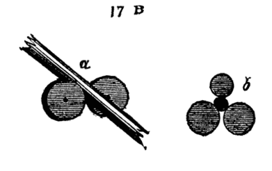
Fig. 17B.
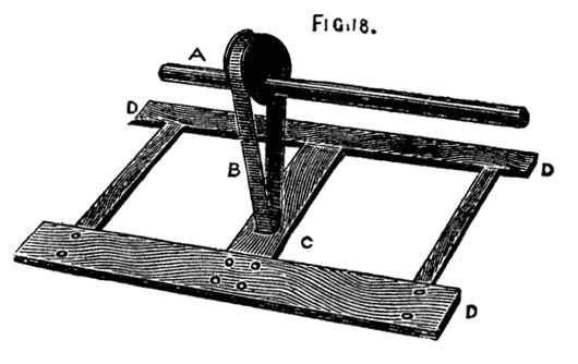
Fig. 18.
For the latter the following arrangements are necessary. A is the eccentric keyed to the crank axle, and may be either in the middle of the same or, as in Muir's patent lathes, at one end outside the standard. Around it passes the endless flat chain B (known as crank chain). This also passes round a roller in the treadle shown at C. This chain does not act as a mere link, but when the lathe is[12] in action it moves round and over the eccentric and treadle roller. The motion of the whole is smooth and regular, and, what is almost as important, noiseless. In Muir's and other lathes the crank chain is used without the eccentric, being applied to the crank instead. Perhaps there is not much to choose between the two, but no one who has studied the eccentric and observed its exquisitely gentle and smooth motion in an ordinary engine can have failed to be struck by these valuable qualities. It must however be remembered that its throw is half that of a crank of the same eccentricity and the latter will have the advantage in power size for size.
In whatever position the lathe may be set up let the rise of the treadle be moderate. It is exceedingly disagreeable to work at a lathe where the rise of the foot board is so great as to bring the knee into contact with the lathe bed, a consummation not infrequent in country made ones.
This is only to be escaped by giving up a certain portion of power. Let A, B, Fig. 19, be the line of the treadle when at rest; c, the crank. To gain power we should let part A, E, be longer than E, B, as in the sketch. But let this arrangement be made, and when the crank is at its highest point, the line G, B, will show the position of the treadle and foot board. Hence this kind of leverage is not practicably available to any extent, and the length taken from foot board to link may with advantage be even less than that from link to the axle on which the treadle works. In lathes, of all machine tools, it is essential that the workman should be able to stand easily, that the movements of the leg and body should not be communicated to the tool, the play of the treadle and such items of detail being of more consequence than might at first sight appear, and any method tending to diminish friction, vibration, and noise is well worth consideration in planning this machine.
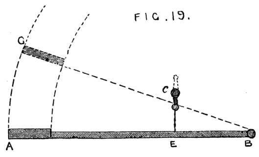
Fig. 19.
We may now suppose the reader the happy possessor of a well made foot lathe, long or short in bed, high or low in poppet, according to his need, but, of whatever size, carefully made and firmly fixed in a well-lighted place, and if possible on the basement floor—an upstairs workshop is objectionable owing to the certain vibration of a boarded floor. He will now require certain chucks and tools, many of the former of which he will have to make for himself.
No lathe can be considered well fitted until it is supplied with a large number of chucks, by which strange term are signified the[13] various appliances for fixing to the mandrel the article to be turned. When it is considered how varied are the forms which present themselves to the turner, it may readily be conceived that much ingenuity has to be exercised in contriving methods for mounting his work in the lathe; and when in addition to variety of form, variety of size has to be taken into consideration, it is plain that a large assortment of chucks is a necessary item in the workshop of the turner. A vast number of these chucks are of necessity made of wood, as required, and such wooden ones are altered from time to time to suit different-sized work, till they eventually become so completely used up as to be only fit for the fire. In addition, however, to these, there are certain chucks of metal (chiefly brass or gun metal) which should always be ordered with a lathe, or fitted to it before any work (even the making of wooden chucks) can be satisfactorily accomplished. The first of these, is represented in Fig. 20, the part A, screws to the mandrel; while the work is attached to the taper screw B. The use of this chuck is to hold short pieces or flat discs, which allow of a hole in the centre and require to be turned on the face. It is only used for wood-work. This is the chuck to be selected when it is desired to make a wooden chuck. A piece of sound wood being chosen of the requisite size, and roughly rounded by the axe or chisel, a hole is made in one face by a gimlet rather smaller than the tapering screw. The piece is then firmly screwed to the latter, the opposite end dressed with gouge and chisel, and the rest being placed across the end, a hand-drill for wood is brought to bear upon the piece. The hole thus made in the centre is then enlarged by any convenient tool until its diameter is only a little less than that of the screw cut on the lathe mandrel. An inside screw tool is then made use of to cut a thread of the same pitch as that of the mandrel, or a tap of similar size and pitch screwed into it (the former is the best but most difficult method to a novice), the piece detached from the taper screw chuck, which is removed, and the wood attached to the nose of the mandrel on which it may now be accurately fitted and finished to the requisite form and hollowed out or otherwise, as may be necessary. Numberless articles may be in a similar manner turned upon the above chuck such as the bottoms of candlesticks, ring or other stands, bread-platters, small wheels, and so forth; it may therefore stand as number one of these adjuncts to the lathe.
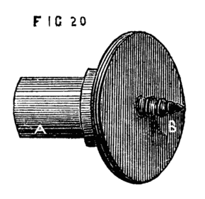
Fig. 20.
Fig. 21 is the face plate, another most serviceable chuck of almost universal application in such work as surface-turning and boring, and where a hole in the centre is inadmissible. To this belong various dogs or cramps, a few forms of which are shown at a, b, c, d.[14] These hold the work firmly down to the surface of the plate, being tightened from behind by screw nuts. It will be seen that there are four slots and numbers of holes in the face plate, some of the latter being tapped for screws. These slots and holes may be increased in number, and some of the latter may be square instead of round, and the cramps may be of all shapes and sizes, because sometimes it may be required to hold down a flat piece of brass the eighth of an inch thick only, and the next job may be to hollow an irregular block of wood of three or four inches in thickness, or it may be necessary to bore out the boss of a wheel, or to turn the rim—all of which, and a hundred others, are cases in which the aid of the face plate will be in requisition.
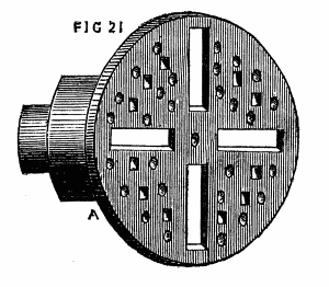
Fig. 21.
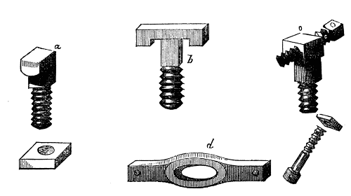
Fig. 22 is the chuck specially used for turning rods of metal. It consists of two parts, the body A, which screws to the mandrel, and the piece B, which passes through a slot and is clamped by a small screw at one side c. To these must be added the carrier which is of such forms as A1, B1, C1. Above is shown a rod of metal to be turned with this chuck in position for use. Of this we shall have to speak again when we arrive at the subject of metal-turning. There should be several sizes of carriers kept in stock, from ¼in. in the largest part of the ring to 2in. or 3in., or even much larger for heavy work. The amateur will, however, scarcely need these larger ones. The usual method of making the wood-holding chuck for work that is to be also supported by the back centre, is to have a socket cast like Fig. 23, C, with a central hole to take the fork A, which is held in place by a set screw. This socket is useful for other purposes as it will hold short pieces of iron to be turned, but[16] the fork is far inferior for general work to the piece b; this is made of iron, and the end of the cross (against which the wood to be turned comes) is sharpened but must not be too sharp. The end of the piece of wood has then two saw-cuts made at right angles to each other into which the sharpened edges of the cross fall, Fig. 23 D, and the whole will turn together without any chance of slipping. It often happens, when the ordinary fork is used, that if the tool chances to hitch in the work, the latter is either thrown quite out of the lathe, or the centre of the fork retains its place, while the other two points slip and score the work. This can never happen with the form B, which is the most reliable pattern that can be devised for work of this nature.
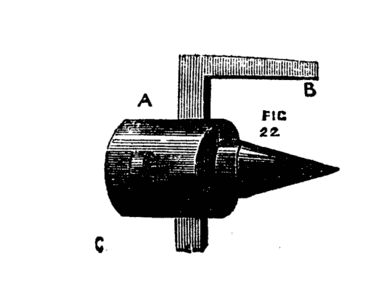
Fig. 22.
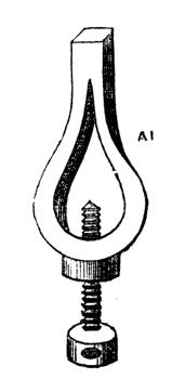
Fig. A1.
Figs. B1, C1.
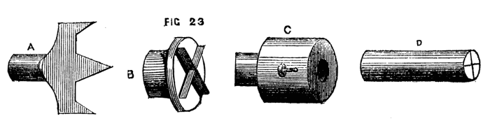
Fig. 23.
Fig. 24 is to some extent self-centering. A piece of wood hollowed out conically has three nails, or three-square saw-files so placed within the cone as to present three sharp edges inwards. Any piece of wood, if not too hard, will, if placed with one end in the chuck, while the back centre is screwed against the other, centre itself in some part of this cone, and, being at the same time held by the three sharp edges, will necessarily revolve in the chuck. There are many cases in which even in this rough form such a chuck will prove useful; but if it were cast in metal and the three edges formed by slips of steel, and the whole accurately turned, it would be a very efficient and good self-centering chuck. In its more common form it is largely used by the turners of mop and broom handles, who work rapidly and cannot afford to waste time in chucking their work. With the above, the lathe, if worked by steam or water power, is not even stopped,—the screw of the back centre has a quick thread, so that a single turn to or fro fixes or releases the work; and thus, one handle being finished, another piece takes its place in the chuck, is fixed by a half-turn of the back screw, and being set in rapid motion is turned and completed by a practised hand in a couple of minutes or less.
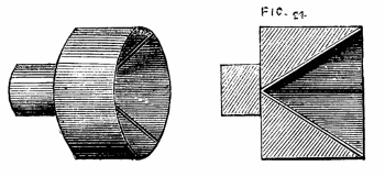
Fig. 24.
Fig. 25 represents another useful chuck, generally of boxwood, called the barrel stave chuck. It is turned conical, the largest part being towards the mandrel; it is then wholly or partially drilled through, after which saw-cuts are made longitudinally, as in the drawing. These allow a certain degree of expansion when a[17] piece of work is fitted into it, and it is tightened round the latter by driving on a ring of iron or brass. This ring is sometimes cut with a coarse thread inside, and a similar thread being chased on the outside of the chuck, it is screwed upon the cone instead of requiring to be driven by blows of a hammer. One important use of this chuck is to re-mount in the lathe, for ornamentation by the eccentric cutter or other apparatus, any finished work that could not be readily chucked in any other manner, or to hold rings requiring (like curtain rings) to be turned on the inside. Such articles will, from the nature of this chuck, be truly centred at once; and their exterior parts will not be liable to injury, as they would be by being driven into an ordinary chuck hollowed out to receive them.
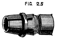
Fig. 25.
Another useful chuck for turning short pieces of metal such as bolts and binding screws, and which is in a great measure self centering is made of cast iron, and is usually called the dog-nose chuck, represented in Fig. 26. This is made with movable jaw hinged, as more plainly seen in B. The screw clamps these jaws firmly together, and any small piece of work is thus securely held. The centering, however, is not accurate, though sufficiently so for many purposes. The die chuck (Fig. 27) is accurately self-centering, and although somewhat expensive, is a valuable addition to the lathe. This chuck consists, first of all, of a socket for screw to fit the mandrel, and round flat plate of brass cast in one piece, as in Fig. 28. This must be carefully turned and faced in the lathe. Two pieces of iron or brass [18]are then screwed to the face, as B, B, 28A, leaving a space between, the sides of which are to be truly parallel. These pieces may either be chamfered to form V-pieces, or may be rectangular on their inner edges; at C, C, a part of each is cut away, and the outer or back plate is also filed down to receive the small plates D, D. E shows a groove in which a screw lies, half of which has a right and half a left handed thread; this is shown in Fig. 29. It will be evident that if this screw is placed in the groove of the bottom plate, and its ends pass through the pieces D, D, which are screwed to the plates, it can revolve in its bearings, but will have no endwise motion; the collar F resting in a recess under the top plate D. This screw passes through a projection in the back of the pair of dies, which projection also goes into the same slot in the back plate in which the screw works when turned by the key (Fig. 27, B.) The above being nicely fitted, the dies moving evenly but stiffly in their places, the plain top is screwed on, keeping all firmly together. This plate has a long opening or slot (Fig. 27), through which the jaws of the dies and part of the screw are visible. The ends of the screw should not project, as any such projection is calculated to bring to grief the knuckles of the turner—a consideration worth attention in every form of chuck—the squared ends of the screw lie in a recess in the small plates, as shown in the section of one of these plates (Fig. 28X). Into this recess the key fits over the screw end; and by turning this the dies are simultaneously moved asunder, or closer together so as to grasp centrally as in the jaws of a vice, any small article, such as a screw or short rod of metal placed between them, A similarly contrived chuck is often used under the name of a universal chuck, for holding pieces of large diameter, and is very useful for[19] taking pieces of ivory which have to be hollowed or otherwise worked, as will hereafter be detailed. In this case the jaws may be semicircular in form, as Fig. 30.
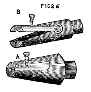
Fig. 26.
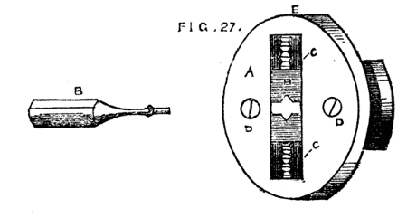
Fig. 27.
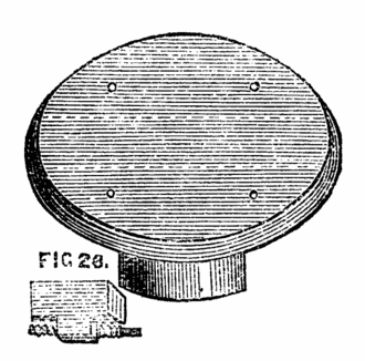
Fig. 28.
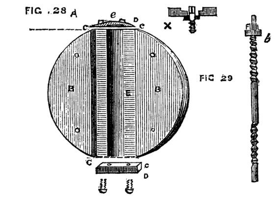
Figs. 28, 29.

Fig. 30.
It is however, evident that these two chucks have a rather limited range. The first can only be used for small work, and the only case in which the latter can take firm hold all round the work is when the jaws are just so far apart as that they form portions of the circumference of one and the same circle. Practically they will hold the work tightly under an extended range of sizes, and they are thus of great use to the turner. The following is however more perfect in operation, from the fact that it has four jaws instead of two which meet concentrically. This may be made either with two long screws at right angles to each other, with right and left-handed threads to each, as in the die chucks, or more simply and, in some respects more satisfactorily, with four distinct screws, all of the same pitch, and all with squared ends of equal size, to allow of the same key being used to turn them. It is possible to use such a chuck as an eccentric chuck if desired, which is certainly a recommendation in its favour over those which work always concentrically. The face of this chuck is shown in Fig. 31. The ends of the four screws have a bearing in the small centre plate b, whilst the collars or flanges rest in a recess under the several plates c, c. The face of this chuck is graduated by each die, so that it is easy to set the jaws concentrically or to place one or more eccentrically to take in work of other shape than round or square. The jaws of this form of chuck are used for two purposes, either to hold work inside them like a vice, or externally. A ring, for instance, requiring to be chased on the outside is slipped over the jaws, which are then caused to recede from the centre so as to hold[20] the work securely. If the latter does not run truly, one or more of the screws can be slackened, and the opposite ones tightened, or if the eccentricity appears to be in an intermediate part, two adjacent screws will have to be thus slackened and the others tightened. On the whole this is a most useful pattern of chuck.
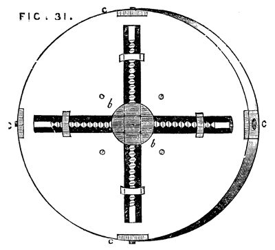
Fig. 31.
The following is a very excellent self-centering chuck now coming into extensive use. It has been noticed in more than one periodical. The description annexed is extracted from the pages of the English Mechanic. "The chuck hereby illustrated seems to be a very convenient form, easily adjusted and holding the drill securely. It is also well adapted for holding wire to be threaded. Every piece of which it is composed is of cast steel well hardened. It can be furnished with a shank to fit the hole for the centre, screwed on the spindle, or slipped on the centre. No wrench is necessary, the gripe of the fingers being sufficient to secure the shank of any drill. The inventor claims that he has used a one-inch drill, in tenacious wrought iron in one of them, receiving a shank of only three-eighths of an inch diameter without using a wrench."
Fig. 31A represents the shell of the chuck with milled bosses for the fingers. The core, B, is threaded and receives a steel wire spring which is inserted into the rear of each jaw, so that when relieved from pressure, the jaws open automatically.

Fig. 31A.
With this brief explanation, the operation of the chuck can be easily comprehended. These chucks are made of two sizes, one with an opening of three-eighths of an inch, and the other of three-sixteenths of an inch, and they can be made of larger sizes. Patented by L. H. Olmsted, Stamford, Connecticut, United States America.
Another chuck of self centering design, has likewise appeared in the periodical above named, into which it appears to have been copied from an American paper.
The accompanying engravings illustrate some improvements in[21] the arrangement of chucks which have been recently patented in this country, the inventors being Messrs. Smith and Haight, both of New York, U.S. The first part of the invention refers to an arrangement of adjustable chuck, by means of which tools and other articles of different diameters may be held firmly in the jaws of the chuck. Fig. 31B is a longitudinal view of the chuck, partly in section. The spindle, a, is fitted so that it may be inserted tightly in the mandrel of the lathe. On the front end of the spindle is a conical screw on which is fitted the cap, b; this part is formed with an opening at the front end, having three longitudinal slots in it. In each of these slots an adjustable jaw, c, is fitted, the inner part of which is threaded with a female screw, to fit the conical screw on the spindle, a. An outer casing d, encloses the front part of the chuck, and behind this is fitted a loose collar, which is screwed into the casing d, so as to connect the parts firmly together. By turning the cap, b, with the casing, d, and collar, in one direction, the jaws, c, are moved forward and project out through the openings, and they may thus be adjusted to grip a tool or other article of small diameter. The opposite motion of the cap causes the jaws to recede, and in this way they may be adjusted to grasp articles of different diameters.
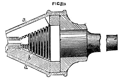
Fig. 31B.
Another arrangement of the adjustable chuck is shown in Fig. 31C, which is a front view, and Fig. 31D, a longitudinal section of the same. A, is the body of the chuck, the front part of which is formed with a rim or flange, in which are three radial recesses having fitted therein the sliding jaws, B. In the rear of each jaw is a bearing, in which is fitted a pin carrying a small lever, C, the front end of which is rounded, as shown in the section, and enters a slot made in the jaw, B; so that when the levers are moved outwards they cause the jaws to contract or move towards the[22] centre. The back part of the body, A, of the chuck is threaded, and on this part is fitted a collar, D, and in front of this is a sliding collar, E, which is connected to the collar, D, by means of a pin which enters a groove formed in the latter. The sliding collar is prevented from turning round on the body, A, by means of a feather, which works in a longitudinal groove formed in the inner circumference of the collar. Three inclined planes, F, are formed on the periphery of the collar, E, which extend to the backward ends of the levers, C, so that by moving the collar to and fro, the jaws, B, are caused to contract or expand, according to the size of the article to be grasped. A short cylindrical block, G, made of a conical figure internally is fitted loosely within the chuck, A, and serves to centre the end of a drill or other short article, but may be removed when it is desired to pass a rod or other article through the body of the chuck. To provide for the easy turning of the collar, D, it is shown as fitted with a hand wheel, H. With this arrangement of the several parts, the jaws of the chuck readily adapt themselves to drill or bit shanks as well as to articles of parallel form, or of a tapered or irregular figure.
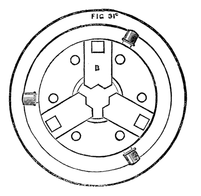
Fig. 31C.
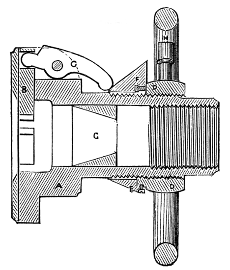
Fig. 31D.
The chucks last named belong to the class of compound or mechanical tools; and though their usefulness is beyond question, they need not be considered absolutely necessary, as the work which they are designed to facilitate can be and often is done without their aid. Indeed, success in the art of turning by no means depends absolutely upon the possession of expensive apparatus, and the amateur or mechanic will find the advantage of ransacking his own brain for the devising of divers makeshifts and off-hand contrivances—especially in this chuck-making department.
Among the simple expedients the following will be found well worthy of adoption.
A, Fig. 32, is a simple flange or flat brass plate with a boss behind, similar to a small face plate, and is to be turned up, drilled, and tapped to fit the mandrel. If the latter has a diameter of ¾ of an inch, a few of these brass pieces should be cast from a set of wooden[23] patterns ranging from two to three or four inches across the diameter of the plate, and, after having been fitted to the mandrel and turned, four holes, countersunk for wood screws, should be made, as shown in the sketch. These are intended to do away with the necessity of boring out and tapping each individual wooden chuck. They can be readily attached to any piece of wood by four screws, and a few minutes will be sufficient to adapt the same to any required purpose. A flat piece of board, for instance, itself too thin, or of too soft substance to permit of its being attached to the mandrel in the ordinary way, can thus be made into a temporary face plate, or a ring cut out of it, or any desired operation performed upon it. Indeed, these socket pieces will be found serviceable on many occasions, and will do away with the necessity of a large set of cup chucks.
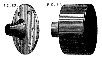
Figs. 32, 33.
A few of the latter, however, are very useful and will cost but little. The castings are sold by weight, and the turner will experience no difficulty in fitting and finishing them for himself. Fig. 33 is the form of these, and needs no description. The substance may be from ⅛ to ¼ of an inch, and need not be more, as that thickness will stand any reasonable shock caused by driving a piece of wood into the chuck, and it is always well not to overweight the mandrel with chucks of undue size or substance. The addition of three to six screws to one or two sizes of the cup chuck extends its usefulness. This form is represented in Fig. 34, A and B. In this case, the casting may be rather more substantial (¼ to ⅜ of an inch in thickness).[24] The screws must be strictly radial, pointing to the centre of the circle, and their ends must be turned off or filed flat. Their heads may be squared to enable a key or pair of pincers to be applied, or round with a hole through them. It is better to make this kind of chuck with six screws—three in one plane, and three again between these in another plane behind them. In fitting a piece of work into the chuck, it will not at first be found an easy matter to make it run truly. The best way is to centre it as nearly as can be guessed, by means of the three screws nearest to the open end of the chuck, and then, placing the latter on the mandrel, set the lathe in slow motion and correct the eccentricity of the piece by means of the three inner screws. Even after this it is probable that a little alternate slackening and tightening of the different screws may be necessary; but a little practice will quickly enable the turner to set a piece of work in the true axial line of the mandrel without much difficulty, and the work will then be held very securely. Any short piece, such as the ring of an eccentric to be bored truly inside, may be held by the outer set of screws alone; but if such a piece of work as a small cylinder is to be bored, the six screws must be brought into action. Here let the hint given when speaking of projecting screws, be repeated, Beware of the knuckles, which are peculiarly liable to be damaged in making use of these chucks. The shirt sleeve or coat, moreover, does not always enjoy perfect immunity from similar danger, and both should be kept out of harm's way, not for their own sake only, but because the arm may be brought into violent contact with the rest if the sleeve should get entangled (the momentum of the flywheel being great, and therefore not to be checked entirely at any given moment). A single rap of the above nature is not a delightful even if salutary lesson to the novice.
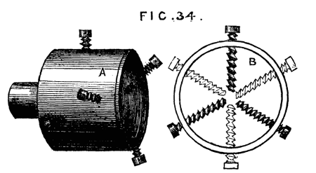
Fig. 34.
To hold rings and washers a tapering mandrel, Fig. 35, is used; and of these it is necessary to keep a few different sizes to suit different diameters. These may be made of iron or brass if for[25] permanent use, but box or other hard wood is a ready substitute, and may be turned down for smaller work when the surface gets spoiled by use. The expanding mandrel, "Hicks' patent," which will be treated of hereafter, is a convenient substitute for the simple conical form here spoken of; and in manufactories where large numbers of mandrels have to be kept of various sizes, a great saving of time, money, and labour is effected by their use. For amateurs and artisans in a smaller way of business the simpler form is generally sufficient. A slight modification is here appended, by which the common form may sometimes be made more efficient in the holding a ring tightly while undergoing the operation of turning, and this can be made applicable to metal mandrels, though specially intended for wooden ones. Fig. 36.
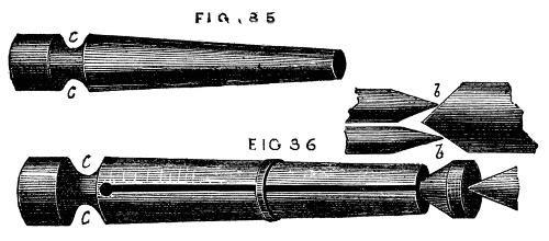
Figs. 35, 36.
The mandrel having been turned conical (N.B., the angle of the cone must be small, so that the size will diminish very gradually from the largest end), the wood is divided by a fine saw, just as the chuck already described with the outside rings was sawn into segments, a conical hole having been first made at the smallest end, as shown in the section b, b. Into this a short cone of larger angle is to be fitted, against the end of which the point of the back centre will press, tending to drive it into the mandrel, which will thus be made to expand. The ring to be turned will prevent the mandrel from splitting by the wedge-like action of the plug, unless the said ring is of light substance, in which case this form must not be used. The work will, by the above method, be securely and centrally held and not liable to slip towards the small end of the chuck.
In the Fig. 36, a groove, c, c, is shown at the bottom of the saw-cuts. This should also be made round the boxwood spring chucks with rings, as it gives more freedom of expansion to the segments. With such a groove and the chuck itself completely hollowed out, the pressure of a strong india-rubber ring will be sufficient to hold work whilst being polished: and this will, when the latter is delicate, be even superior to the screwed rings, as the pressure will be more gentle and equable. India-rubber rings for this purpose must not be thin and flat, like those used for bundles of papers or letters, but made of round material, the thickness of a quill or even larger. They may be had of all sizes at an india-rubber warehouse in Holborn, at the bottom of the hill on the left hand side going eastward, and not far from Negretti and Zambra's shop. The writer is not acquainted with the name of the proprietor.
Having had occasion to speak of tapping chucks of metal to fit the mandrel, it will be as well to speak here of the requisite tools for effecting this.
In the case of iron chucks it is not likely, as a general rule, that the amateur or workman will obtain access to a screw-cutting[26] lathe, and to cut an internal thread by hand with the chasing tool is hardly feasible, though readily accomplished in the case of brass chucks. When, therefore, a lathe is purchased, a set of taps of the diameter and pitch of the screw on the mandrel should be provided. Of these there must be three—an entering taper tap, an intermediate one rather less tapering, and a plug tap, which is cylindrical. And here we must enter a caution. Do not let the tapering taps be too long. For instance, let it be required to tap the boss of a face plate in which the hole cannot be drilled through the plate. It is first bored out to the size of the bottom of the mandrel threads, or rather less. Tap number one must then be screwed into it; but if this is too long, so that it cannot enter to the end of the threads cut upon it, the second tap will be too large and will not enter properly, but will most likely start a new thread for itself and spoil the first. Fig. 37, a, b, c, shows the form required; d, the form to be avoided, except in cases where, as in the cup chucks, a hole can be made quite through the article, so that the tapering tap can be worked to the line x, y, or nearly so. The long tap, gradually tapering as it does from end to end, is of course the easiest to use, and for nuts and such like is far the best; the conical tap of larger angle requires more power, but in the case named it is a matter of necessity to use it; and, if preferred, a set of four taps instead of three will remedy any difficulty. The novice must take great care to place the tap perpendicular to the face of the chuck, or the shoulder will not fit close to that on the mandrel. If much difficulty is experienced, such an arrangement as Fig. 38 may be of service. A represents the standard of an upright drill-post, of which B is the bench, C the screw by which to depress the drill and keep it to the cut. For the latter, and brace by which it is worked, substitute the tap, and place a spanner or wrench round the head of it. In[27] the centre mark, which is generally left from the turning, place screw point c. By means of a plumb line or square, D, test the perpendicularity of the tap; and as the latter penetrates, keep it to its work by the screw C; oil the tap freely, and the chuck will be easily and accurately cut with the required thread. Some kind of clamp will of course be required to secure the chuck to B, while it is being tapped.
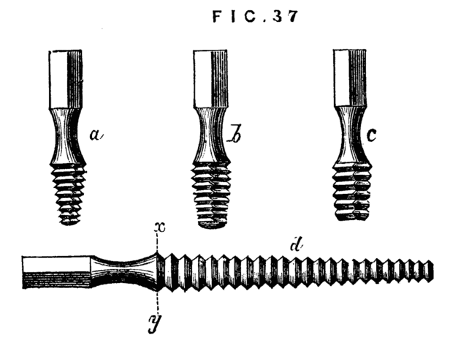
Fig. 37.
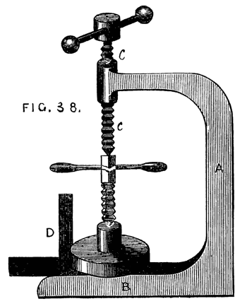
Fig. 38.
The upright drill should always have a place in the workshop. It is much easier to drill with it than in the lathe, and the mandrel will thus be saved considerably. The latter should never be used except for light work. A variety of drilling apparatus will hereafter be described in this series, so that we need not now write more upon this part of our subject.
Somewhat akin to the chuck described as the cup chuck with six screws, is a chuck mentioned in an old French work,[1] the purpose of which is to turn up a cylinder, with a point at the end, so as to insure the axial line being kept. In the ordinary course, the cylinder would be turned up with the point and carrier, or driver, chuck already described; the conical point would be then turned down as far as possible, and the mark of the back centre afterwards turned off by means of the boring collar. It is by help of a miniature lathe and boring collar in one piece that the pivots of the balance of a watch are finished. In both cases the work may be well done by the same process. The chuck now to be described requires no boring collar, but at the same time it does not seem to be well suited for any but light work; in which latter case however it would be advantageous, and must therefore have a place in our present paper. The body of the chuck is shown in section, in Fig. 39. A is the socket with screw to fit on the mandrel of the lathe. It will be seen that the chuck itself is hollowed out cylindrically, and in this cylindrical cavity slides a plug, c, bored conically, which can be fixed by a thumb-screw, h, traversing a slot in the body of the chuck. This cone is destined to receive one end of the cylinder to be pointed, which will, according to its diameter,[28] centre itself in some part of the conical hole in the plug. The latter is made movable, so as to be adapted to the length of the article to be turned. At the outer end of the chuck is a groove dovetailed to receive a slide, shown clearly in the cross section B. The slide must be of sufficient substance to allow a clamping screw, f, to be tapped into it at one end, which screw must be long enough to reach when fully advanced nearly to the apex of the triangular opening seen in the slide. The action of the whole contrivance is as follows:—The cylinder to be pointed is placed in the conical cavity of the plug—the latter slid to or fro till the point to be turned projects a short distance beyond the mouth of the chuck through the triangular opening in the front slide; when it is fixed by a turn of the screw, f, which forms the third point of resistance, the sides of the triangular opening forming the other two. As the point or apex of the triangle is always in the diameter of the cylindrical chuck, it will only be necessary to move the slide itself in order to bring the axis of the cylinder to be turned in a line with that of the mandrel. As soon as this is accomplished so that the piece runs truly, the screw, g, is turned, and the slide fixed in position. A good deal of ingenuity is displayed by the inventor of this chuck, a description of which was published twenty years ago, and there are very many cases in which it will be called into requisition by the mechanic. With a little care, moreover, the amateur might make one for himself—the body of brass or gun metal, the plug and sliding part of iron or steel.
[1] Manuel de Tourneur par H. Bergeron.
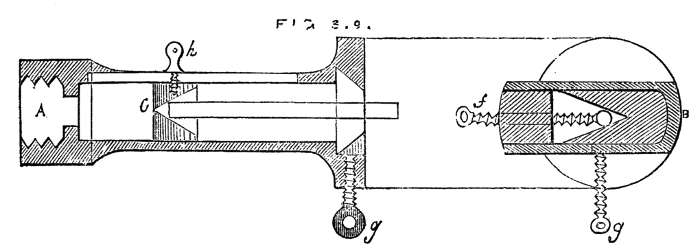
Fig. 39.
Amongst the various devices connected with the lathe, many of which, even as makeshifts, are valuable to the turner, is one not generally known for keeping up the tension of the lathe cord in whatever groove of the fly wheel or pulley it may be placed. The plan is not more ingenious than practical, and the writer is acquainted with one workman, a gasfitter by trade, who has had it in constant use for many years. Directly over the mandrel pulley is another of larger diameter, in which are two grooves of equal depth, fig. 40. This[29] upper pulley is suspended on a movable arm, D, which is pivoted at E, and kept up by an india-rubber spring, F, or, as in the original plan (before these rubber cumulators were known), by a cord passing over a pulley, and having a heavy weight attached, as shown by the dotted lines. In the fig. A represents the fly wheel, B the mandrel, C the upper pulley. The lathe cord is very long, and passes upwards from A, over the upper pulley in groove 1, down again and round the mandrel, a second time over groove 2 of the upper pulley and down to the fly wheel. The tension of the cord is thus always the same, and is regulated by the spring or weight. If the cord is slipped to a smaller part of the lathe pulley, the slack is instantaneously taken up by the descent of the weight, and rising of the arm D, which in like manner yields to allow the cord to be slipped to the larger groove of the mandrel pulley.
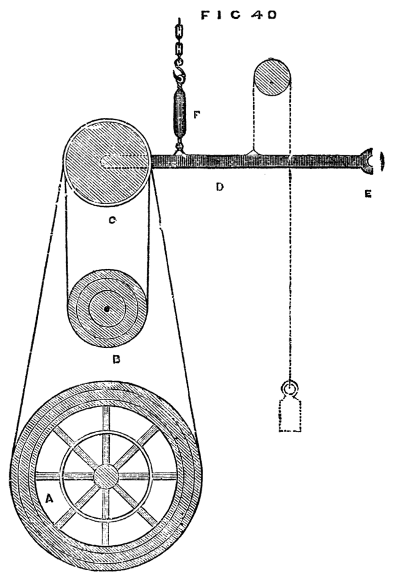
Fig. 40.
There are many other useful contrivances for chucking work in the lathe, a few of which will be noticed on a future page. The main thing[30] to be attended to is the holding securely as well as centrally the object to be turned. If this is attained, the precise form of chuck is of little importance, and it matters not whether it be made of metal or wood. The latter has indeed, in some respects, an advantage resulting from its elasticity and the ease with which its form is modified.
We have now described the simple foot-lathe and chucks adapted for hand turning, but of the latter a great number may be provided, and will, in fact, accumulate as the turner proceeds to work upon objects of varied form and size. No chuck once made should be thrown away until it has become so reduced, from repeated alterations, as to be no longer serviceable. And now, before we commence actual turning, it will be well to offer a few concluding remarks upon the selection of a lathe. It will be evident from our previous remarks and illustrations that there is room for great diversity in the size and quality of this machine, and it is astonishing what excellent work is often turned out by an experienced hand from a lathe of the worst description. The simple pole-lathe, which is so out of date that we did not deem it worthy of notice in this series, with its reciprocating motion, like the little tool of the watchmaker, has, before now, supplied the cabinet maker with first-class work, and not many years since we ourselves stood before just such a clumsy tool, taking first lessons in the art. Our next step was to a lathe with wooden poppets, and flywheel of the same material, a mandrel made by a country blacksmith, which scarcely did even him credit; the value of the whole, with stand and beechen bed complete, was £2 sterling, and sufficiently dear at that price. Now, we do not recommend such a tool, and in the present day a much better may be had at that price, but, notwithstanding its evident defects, very tolerable work may be produced from it. We state this to deter the reader from a very common fault—namely, the purchase of an expensive tool and elaborate fittings when the purse is shallow, and the skill shallower still. In fact, any amount may be spent in lathes, and in fitting up a workshop, but to gain real pleasure and satisfaction from the pursuit of the mechanical arts, the outlay should not be more than the probable result in work fairly warrants. A hundred pounds is often expended in the purchase of a lathe, and a hundred shillings would more than purchase the work done by it. We speak from our own experience in this matter, and believe our advice proportionately valuable; and we well know the satisfaction that ensues when good work has been produced in spite of the defects in the appliances at command. If the means do not admit of the purchase of a good lathe necessity must decide the question, and an inferior one must[31] take its place in the workshop. Nevertheless, we would rather counsel a certain amount of delay, and economy and hoarding, that a good foundation may be laid and a lathe purchased of such average excellence that future additions may convert it into a really serviceable tool.
It would be invidious and perhaps rather unfair in this little work to send the reader to any particular lathe-maker. There are several good and two or three first-class ones in London, and if prices range high, the work is at any rate of undeniable excellence.
There are also many cheaper firms than those alluded to, where the work is rather of rough-and-ready style; all depends on what class of work the would-be purchaser proposes to engage in, whether he intends to confine himself to plain hand-turning in wood, to the construction of steam engine, and other models of machinery in metal, or to the more beautiful finished work in hard wood and ivory, which develop the full power of the machine itself, and the skill of the accomplished turner. In the former cases, a very plain and inexpensive lathe will suffice. In the latter, it is absolutely necessary to purchase one of the best construction, at a tolerably high figure.
The best advice to those of slender means, and who, therefore, vastly predominate, is to sacrifice all else to the mandrel and collar. The latter may be bought at from twenty to thirty shillings, ready for mounting in detached wooden headstocks, and will be far superior to any that an ordinary smith can produce. In this case, the two poppets that carry the mandrel and centre screw should be connected together by a block of wood between them, which latter may be rounded off and shaped to something near the form of a cast-iron headstock.
The only care necessary in mounting such a mandrel, will be to keep the axial line parallel to the lathe-bed, and directly over the centre of the latter. Whether the mandrel is thus a separate purchase, as may happen from necessity, or obtained as part of the lathe, and fitted in a cast-iron headstock, it should certainly be hardened, and also the collar, if of steel. Both will take a higher polish for this process, and will run easier in consequence. The cost of such a mandrel is rather greater, because many warp or split in the process, and have to be thrown aside; and the labour of grinding mandrel and collar to an exact fit, is considerably increased. The gain, however, is greater than the loss to the purchaser, and the extra outlay must not, therefore, be grudged. It is very annoying to find a conical mandrel worn down by the collar after a twelvemonths' work; for a collar is thus formed on the conical part, so that it cannot be tightened up by the back screw.
The first tool to be noticed is the gouge, the form of which is a longitudinal section of a tube, and is shown in Fig. 41. Of this tool[32] not less than three sizes should be selected, of the respective diameters of one inch, half-inch, and a quarter or three-eighths. When purchased, they require grinding, the bevel being too short. It is essential that this tool and the turning chisel have a long bevel, so that the cutting edge should be a very acute angle. (Fig. 41, not like 42.) It is impossible to do good work with the latter form of tool which is, nevertheless, of frequent occurrence in the workshops of amateurs. Both gouge and chisel must be sharpened on an oilstone (Arkansas or Turkey will be found the best) to a keen edge, and no pains must be spared in preserving the tools in this condition. Three sizes of chisel to match the gouges should be selected. The latter tool is not made like that intended for carpenter's use, with the edge at right angles to the sides, but is sloped like Fig. 43, so as to present an obtuse angle A, and an acute one B, and the cutting edge is central, the bevel being alike on both sides, so that the tool may be[33] turned over, and used with either of the flat sides upwards. The handles of gouges and chisels should be much longer than those used by carpenters, and nicely rounded and shaped in the lathe. The most difficult thing to turn being a cylinder of soft wood; a description of the method of effecting this will be the best means of initiating the novice in the art of turning. In all the most perfect work by practised hands, there is a sharpness of edges and roundness of mouldings, that are exceedingly agreeable to the eye, and bespeak at once keenness in the tool with which the work has been done, and steadiness in the hand of the operator. The novice must aim at similar perfection, and to this end he must determine to avoid the use of sand-paper, and trust to his management of exceedingly keen tools to put a workmanlike finish to his work. To commence with the proposed cylinder. Let a piece of sound beech be selected for the first essay, as being less difficult to manage than deal, the grain of the latter tearing up in long shreds under the action of the tool. The first thing to be done, after sawing off the necessary quantity of sufficient diameter for the proposed work, is to round it off roughly by means of the hatchet and draw-knife, or spoke-shave. The next thing is to mount it in the lathe. For this purpose the prong chuck, or, better still, that represented as an improvement on the latter, and shown in Fig. 23B, must be screwed on the mandrel, and the work made secure by the aid of the back poppet centre. Care should be taken that the piece runs truly between the points of support, and that it revolves steadily without shake. There is no real necessity for using the compasses, or other contrivance for finding the exact centre at each end, as sometimes recommended, neither, indeed, is it always possible thus to find the axial line. It is easy to fix it at first lightly in its place, and ascertain by a turn or two of the mandrel, how nearly it runs as it ought to do. If it seems tolerably true, a turn of the back centre fixes it securely, if not, it can be shifted in any direction at pleasure. The tyro ought, however, to be warned that he is likely to be deceived in the size of the rough piece, and that he may very probably think it of sufficient diameter for the proposed work when in reality it is too small. Practice, or the use of the callipers, which are bow-legged compasses for measuring the diameters of work, will soon settle the question. The piece being properly fixed in the lathe, the latter is to be set in motion by means of the treadle, the rest having been first fixed as near as possible without touching the piece, and the T clamped parallel to it. If the tyro wishes to become a proficient, no pains must be spared to acquire the knack of working the treadle without moving the body to-and-fro. He must learn, therefore, to stand firmly on one leg, and after the wheel has been put in motion, he must let it and the treadle have its own way. He will thus soon feel when the crank has passed the dead[34] point at the highest point of revolution, and the proper moment to bear down with the foot. It is not necessary to describe the precise movement, as a few trials will teach the method much better than any written description. At first it is hard work, and constant change of leg from the right to the left, and back again, will have to be resorted to to diminish the fatigue. Practice will, however, remove all difficulties, and allow the whole undivided attention to be given to the management of the tool.
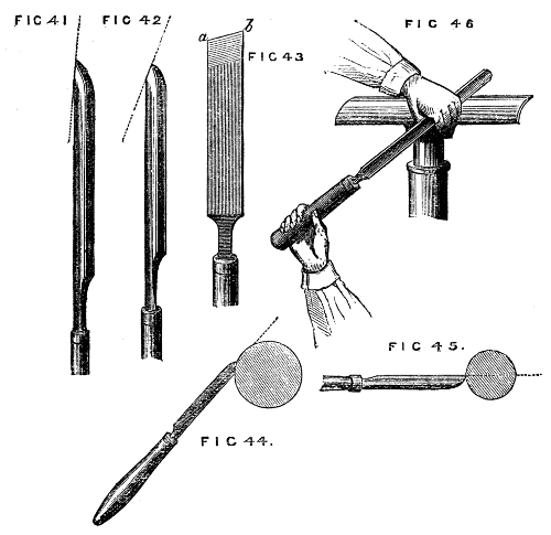
Fig. 41, 42, 43, 44, 45, 46.
The gouge must be held down firmly on the rest with the hollow side upwards, and the bevel of the edge forming a tangent to the work, Fig. 44. In this position it will cut freely and smoothly, and the edge will be preserved. If held horizontally, as in Fig. 45, it is evident that the fine edge of the tool will be immediately destroyed by the rapid blows it will receive as the rough wood revolves in contact with it. Its tendency in the latter position will be to scrape, instead of cutting, and the fibres of the wood will thus be torn out in threads, and the surface of the work be roughened. The gouge, then, being placed in the former tangential position, the right hand grasping the handle, the left the blade, as in Fig. 46, the tool is to be slowly slid along the rest, and a series of light shavings, more or less continuous, will be removed from end to end of the piece. Let the workman bear in mind that the tool is to take a firm bearing on the rest, and that it must not move to-and-fro with the inequalities of the piece to be turned. It is not necessary to remove large chips unless the turner has acquired from practice perfect command over the tools, and for the adept this chapter is not written. After the most prominent inequalities have been removed, the side of the gouge will come into use instead of the extreme end, and with this the work may be rapidly reduced to its intended size, always allowing, however, for the final cut with the chisel. Before the latter is taken up, the piece of work is to be rendered as level and true as can be done by the aid of the gouge alone; indeed, if the latter is of tolerable size, and skilfully used, a finish can be put upon the work by it almost equal to that which the chisel can produce and if the work in hand were a moulded pattern, with hollows and raised work, great part would have to depend on the gouge alone. In the present case the chisel must be used, and the method is as follows: Take a hold with both hands, as directed for the management of the gouge, but instead of the flat part lying evenly on the rest, the tool must be partly raised from it, so that only the lower edge takes a firm bearing. By this means the upper angle of the cutting edge (generally the most acute) is kept clear of the wood, and the latter is cut away only by means of the middle and lower part of the edge, as shown in Fig. 47. If placed as in Fig. 48, the acute angle, a, is sure to catch and stick into the work, spoiling in two seconds all that has been[35] done. The chisel can be used with either of its flat sides upwards, and moved along the rest from right to left, or from left to right, or turned upside down, as Fig. 49, so that the acute angle is downwards. These positions are shown in the Fig. 47 to 51. The only care necessary is to keep the upper point clear, allow the chisel to rest as flatly on the wood as the above precaution will permit, and to take as fine and continuous shavings as possible. The chisel will be found to draw itself along in some degree as the cut proceeds, and when this action is felt, it is doing its work properly—still, it is a difficult thing to use a chisel well, and the tyro will fail many times and oft before he will succeed.
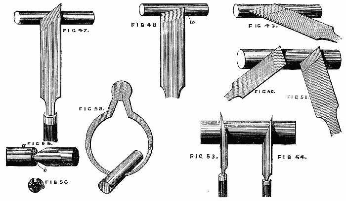
Figs. 47, 48, 49, 50, 51, 52, 53, 54, 55, 56.
The chances are that this initiatory lesson will result in anything but a correct cylinder—the surface will not be true like a ruler, but if tried by a straight edge it will be seen to be wavy. Tested by the callipers, Fig. 52, one part will be larger than another, even if the extreme portions be tolerably true to the proposed gauge. Now, the best turner on earth found just these difficulties, and nothing but perseverance and resolute determination will overcome them. Never mind spoiling the first piece of work, give up making it of a determined size, but do not give up making it a true cylinder. Keep the callipers at work, and gently level the prominent parts (you must work down to the size of the deepest hollow, for you cannot fill up such valleys like a railway engineer; you must throw down the adjacent hills instead), proceed gently, little by little; make the tool obey you, show it (as Ruskin speaks of pencil and brush) that you will not yield to its caprices and "henceforward it will be your most obedient servant." Having done the best you can with the surface of your cylinder, proceed to square up the ends, and mind the angle at this part is a right angle, square and sharp, not rounded off. Now this again requires care and a knowledge of the proper method. You will work chiefly with the lower corner of the chisel, and we shall best describe the management of the tool by supposing the cylinder an inch too long, and that the extra piece is to be removed. Now there are three positions in which the chisel can be placed to bring its lower corner in contact with the cylinder. First, with the blade perpendicular to the work; secondly, with the blade inclined to the left, Fig. 53, as if to round off the end of the piece; thirdly, inclined to the right, Fig. 54. Held perpendicularly it will cut a fine line, but penetrate slightly; alternately in the other positions it will remove a V-shaped piece, and thus the cutting off is to be begun. One side of the cutting, however, has to be perpendicular, the other may be as sloping as convenient. Now, it is to be remembered in[36] cutting the upright side, which is the end of the roller, the chisel is to incline rather to the right, for this reason,—if it incline to the left a momentary inattention will cause it to take the path a, b, Fig. 55,[37] the tendency being to cut a spiral track towards the left. The experiment may be made by gently resting the edge thus inclined on any part of the roller, when it will describe a spiral at once. To the right, then, the chisel must slightly incline, and it will cut off a thin curling shaving like Fig. 56, leaving the end of the piece quite smooth and shining. When the piece is nearly cut off, great care and lightness of hand must be used, as the central portion will have become weak and ready to break off before the work is finished. When it will no longer bear the chisel, take it out of the lathe, break it off, and neatly finish with the sharp chisel the central portion, and your first lesson is learnt. There is certainly very little of interest in turning an imperfect cylinder, for it is useless when done, but the alphabet of the art, though not amusing, must be first thoroughly mastered, and the rest will follow in due course. If, however, the work seem unreasonably dull and stupid, the cylinder may be converted into a tool handle, which will be at any rate a useful article, besides affording practice. No special directions are needed in addition to the above, except in respect to the ferrule. This is to be cut off a piece of brass tubing or an old gun barrel, or it may be had at the tool shops ready cut to any size. Begin by turning down the place for this ferrule, taking care not to cut it too small or the ferrule will drop off. Take the piece out of the lathe, and with a mallet hammer on the ferrule. Return it again, taking care to centre it in the old marks, and finish the handle. The brass or iron may be polished with a file for this first attempt.
It is now necessary to speak of hollowing out wood for the purpose of making boxes, cup chucks, &c., and the latter, which may be made in any quantity, and of all sizes, will afford excellent practice in this part of the turner's art. The majority of work of this kind is done rather by scraping or fretting out than by cutting; side tools of the forms of Figs. 51 and 56 being used for the purpose. These however, are specially adapted for ivory and hard woods, the grain of which, being very compact and close, is not torn out in shreds by the action of such tools, as would be the case with softer woods. Where the latter material is used in quantity, as in the manufacture of wooden bowls, hook tools, like Fig. 57, are made use of, which cut on their upper edges. These are exceedingly difficult to use, though the practised hands of those brought up to the art, make them cut with a surprising ease and rapidity—fairly surrounding the lathe with a ceaseless cloud of fine shavings removed in the progress of the work. The difficulty experienced in the use of these tools is not confined to the novice, for the majority of turners accustomed to hard[38] wood often cut a sorry figure in the manipulation of softer material with the aid of the tools in question. The hard and soft wood turners form, in point of fact, two distinct branches of the trade. We have in part anticipated this section, by speaking of the making a wooden chuck when describing the use of the metal chuck with taper screw. We shall, therefore, proceed to describe the best method of turning a plain wooden box with cover, but not screwed; the latter being reserved for more extended notice hereafter. The best material to work upon is sound Turkey boxwood, and care must be taken that it is quite dry and well seasoned, or, after it is worked up with, it may be, great care and trouble, the box will split, or the cover become so loose as to fall off, either fatality being sufficiently vexatious. We may mention, in passing, that hard woods of all descriptions may be had in large or small quantities of Messrs. Fauntleroy[2] and Co., 110, Bunhill-row, Finsbury, or of Jacques and Sons, Covent-garden. Most of the lathe-makers also supply it, especially Holtzapffel and Co., of Charing-cross, but the first-named is a large dealer, wholesale and retail, and his charges are moderate.
[2] Now Messrs. Mundy and Berrie.
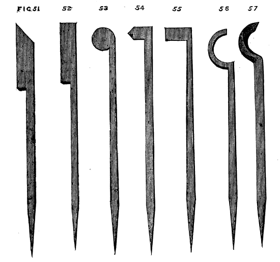
Figs. 51, 52, 53, 54, 55, 56, 57.
Supposing a selection made of size proportionate to that of the[39] intended box, including cover and a tolerable margin for waste and accidents, proceed as before to rough it down between two centres and thus to reduce it to a cylindrical form—there is, however, no occasion to use the chisel at present, as we only need a rough cylinder. Remove this from the lathe, and if you have no brass cup chuck into which you can fit it, proceed to make one out of a piece of beech, ash or, if you have plenty, boxwood. Do not hurry the work, but cut the chuck out neatly, screw and fit it, as previously directed, on the nose of the mandrel. We shall suppose it as yet merely a short neat cylindrical block, quite solid. Place the rest with the tee across the end of the piece of wood, the top edge a little below the centre (by the thickness of the blade of the tool). For the latter select one of the three following—either will answer well—58, 59, 60. With one or the other drill a hole in the centre, keeping the tool quite horizontal across the rest. Enlarge this hole by a left side tool, working from the centre of the piece towards the outside, not taking the whole depth at once, but a quarter or half an inch at a time. You must hollow it out about one inch, and see how nicely you can fit the hollow to the size of the piece you are going to turn. You will, of course, have squared up one or both ends of the latter, which must now be driven tightly into the hollow chuck. If you squared the ends of the cylinder correctly and left also the bottom of your chuck level and true, you will be gratified by seeing the piece run evenly at once.
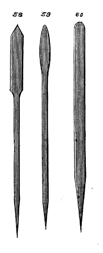
Figs. 58, 59, 60.
Fig. 61 shows a section of the chuck with the piece to be turned fitted inside it. Now take the gouge and chisel and reduce the piece to a plain cylinder, and take special care to square up the outer end. This may be done by the aid of a carpenter's chisel held across the rest, like the side-tool. If the end is much out of truth you had better use first the round-ended tool, Fig. 60, but if you have worked carefully from the commencement this will be unnecessary.
To ascertain the correctness of this part, apply a small steel square like Fig. 62, the blade of which slides through the brass part and is clamped by a small screw at the side. We show the method of applying this tool to gauge depth, test right angles, &c., in Figs. 63 and 64[40] . It is a most convenient and necessary instrument, and should be at once provided. Having thus ascertained that the end of your cylinder is at right angles with the side, take the point tool, Fig. 58, or the acute corner of your chisel, and, setting the lathe in motion, mark off the intended depth of the cover, as D, C, Fig. 61. (Observe, it is the cover and not the box that first demands attention.) Now proceed to hollow out the cover as you hollowed out the chuck, but with greater care. You must allow in the thickness of the top rather more material than you will eventually require, the thickness of the sides, also, may be a trifle in excess, but take the utmost care to make the inside rectangular, that is, the line f, g, perpendicular to g, D. Upon the correctness of this the fit of the cover will depend. This being done and tested as to truth with the square, as before, you may cut off the cover with a parting tool, Fig. 65. This tool is thin, with a cutting edge at the end, and is held edgewise upon the rest. The blade is made rather thicker near the end, so that as the tool penetrates the work it may not bind, but allow the small chips made by it to escape freely. The rest must be removed from its former position and placed parallel to the side of the piece, and the tee at such a height that the latter may, when the tool is held horizontally, point to the axis of the work. The tool should be occasionally withdrawn, and the point, instead of being kept precisely in one position,[41] may be slightly raised and lowered from time to time, describing a small arc. It will soon be ascertained in what position it cuts most easily. There are different sizes of parting tool, some very thin in the blade, for ivory and precious woods, some thicker, for box and less valuable stuff, some with a notched end, forming two points, for soft woods, the action of all being similar to a saw tooth, or, in the last, to two adjacent saw teeth set out to clear themselves in working. Care must be taken that the thin blades do not bend and twist while cutting, especially after the cut has become deep. To avoid this do not hurry the work, but take a little at a time, and be careful to keep the tool with its sides perpendicular to the rest. With these precautions the cover will soon be cut off neatly. If care is not taken to allow for the necessary thickness of the cover, the turner will be mortified by finding that instead of the latter, he has merely cut off a ring, and he will have to expiate his want of judgment by beginning a new cover and making a shallower box. We name this to put him on his guard. Supposing the above work satisfactorily accomplished—the top of the cover, however, being (as will probably be the case) either convex or concave, requiring a little touching up and finishing, it will be necessary to turn down on the solid bit of wood left in the chuck the part A, B (Fig. 66), on which the cover will eventually rest. On no account, however, must this be now turned small enough, it must be left so large as not quite to enter the cover, because if it is now nicely fitted, and the box subsequently hollowed out, the cover is sure to be too slack, the wood shrinking in the process of hollowing out. This shrinking may be accounted for by supposing the rings of woody fibre, the result of yearly growth, naturally elastic, with a tendency to contract, each one, like a series of india-rubber bands, embracing[42] that within it. The central ones being removed by the tool, permit the outer ones to contract, their particles approaching nearer to each other and the structure becoming more dense. This tendency causes those radial cracks so often seen in the ends of pieces of wood sawn from the trunk or limbs of the tree. The outer parts becoming drier than the inner, and prevented by the latter from shrinking, necessarily split, hence, when it can be done, the centre of such pieces is bored out, while the wood is yet full of sap, and the rest is thereby preserved. Where this cannot be done the ends may be covered with glue or resin; or paper may be glued on, to prevent access of air, and thus the drying of the outer portion may be so retarded as only to keep pace with that nearer the centre. The concentric rings thus shrink equally, and no radial splitting takes place.
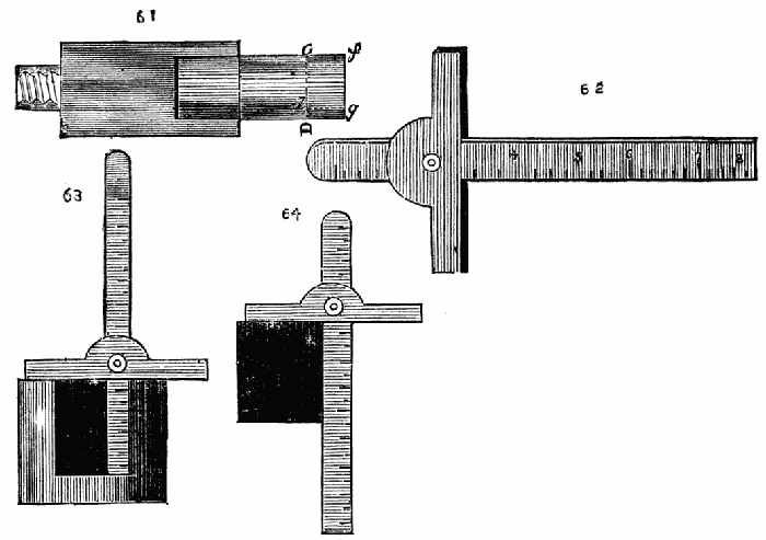
Figs. 61, 62, 63, 64.
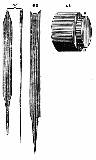
Figs. 65, 66, 68.
We will now return from this explanatory digression to the work in hand. Having cut down the flange for the cover to nearly the required size, proceed to hollow out the box. Work carefully, so that the sides shall be smooth and perpendicular to the bottom, and the latter plane and neat. Take care, as with the cover, to leave the necessary thickness of bottom, allowing for the cut of the parting tool, and, if possible, half an inch or more beyond it. Now finish that part on which the cover is to rest. Take great care, as before, to secure right angles, and cut away the wood little by little, trying on the cover from time to time, until at last it will just go smoothly and stiffly into its place. It must fit rather tightly, but take especial care not to force it on, or you will split and spoil it. We shall here introduce to the notice of the reader another form of callipers useful in such work as the above, and in many cases absolutely necessary. They are called in-and-out callipers, and are made as shown in Fig. 67. These are so arranged that whatever interval exists between a and b, exists also between c and d. If, therefore, the inside of a box cover (or similar article) is measured by the latter, the other end of the instrument will show the exact size to be given to the part A, B, Fig. 66. The convenience of such an arrangement for an infinity of cases will be apparent on an inspection of the figure.
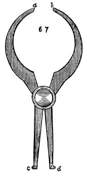
Fig. 67.
The cover of the box must now be put on, the lathe set in motion, and the outside, and also the top of the cover, carefully turned and finished. If the box is to be cylindrical, care should be taken that it is truly so, and that the angle formed by the junction of the top and sides is sharp. If sand-paper is used to finish the work, the edges[43] will be rounded and the workmanlike appearance spoiled. If, therefore, the article is made of box or other hard close-grained wood, this finishing-off may be done with a carpenter's chisel held so as to act as a scraper. The turning chisel will answer the same purpose, but it is a pity to spoil the edge, which should be always preserved keen and fit for use. If the box is made of soft wood, scraping will not answer; the turning chisel must then be made use of, held as previously, described. If the cylindrical form is not proposed, the sides of the box must be left thicker, and after the cover is fitted on the outside may be moulded by the gouge and chisel, and tools like 60 and 68 to 70, to any desired pattern. The only thing remaining to be done is to cut off the box with the parting tool, the same precautions being observed which we spoke of in separating the cover. If there should be any defect in the bottom after the work is detached, the box must be placed in a cup chuck turned to receive it, and the above defects removed.
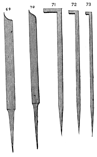
Figs. 69, 70, 71, 72, 73.
In hollowing out a piece of solid ivory or similar costly material, it would be exceedingly wasteful if the central part were removed as in a common box, by being reduced to small chips. It is possible to remove the whole interior in a solid block, and with exceedingly trifling loss of material. This is effected by means of side parting tools, 71, 72, 73. A common parting tool is first used and a groove cut therewith in the face of the block to be turned. Fig. 74 represents this face 75; the section after the groove is cut the depth of the box required. The shaded part in the centre represents the part to be removed. The smallest parting tool, Fig. 73, is now introduced, the back of the tool being laid across the rest, so that the crook takes a[44] perpendicular position, A, B, Fig. 74. When at the bottom of the groove the hook is turned to the left, so that it may cut a groove underneath the block, until stopped by its shank. It is then withdrawn and Fig. 72, and subsequently Fig. 71 introduced, and used in a similar way. In Fig. 76 the black line shows the tool in position, with the under cutting done by it. The sizes are thus increased until the last tool removes the block entire.[3]
[3] The side parting tools are sometimes inserted in the centre of the work, a hole being made for their introduction, they then cut from within outwards. In this case, however, instead of a solid piece a thick ring of the material is detached.
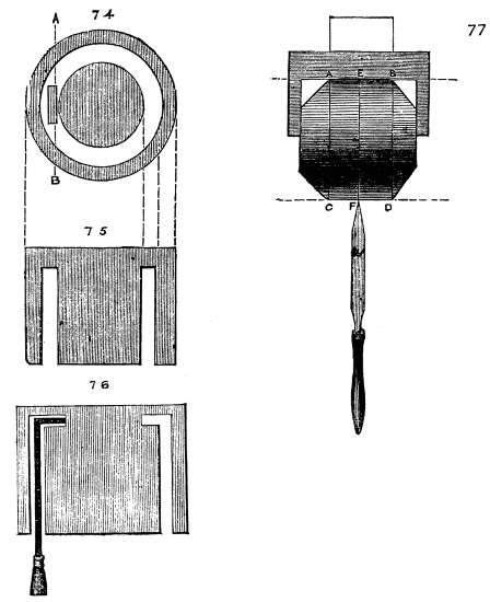
Figs. 74, 75, 76, 77.
We now propose to describe the method of turning a round ball or globe, and, to make the work more interesting, it shall contain a small box. The first thing necessary is to decide upon the diameter. In the present case let it be an inch and a half. Turn a cylinder of boxwood a little exceeding this, and cut off from it rather more[45] than an inch and a half in length. The excess is merely to allow for waste. You will thus have a cylinder whose diameter equals its length. Before removing it from the lathe, mark its centre by a groove with a point tool—subdivide the outer spaces with five lines, and from the latter remove the corners of the piece, thus reducing it to the form 77. Test the length and breadth by the callipers and take care that the ends of the cylinder are at right angles to the sides. Now place the piece in the chuck in the position shown in the figure, that is, at right angles to its original position in the lathe. It must be tested as to truth by holding a point tool on the central line E, F. If correctly placed this will only make a dot when the lathe is put in motion. If the piece does not lie evenly the point of the tool will make a small circle—it must then be corrected with a light tap or two, until it runs evenly.
If the inside of the chuck is rubbed with chalk the work will be less liable to slip. The following operation, however, must be conducted very gently and with exceeding care, or a satisfactory result will not be produced. It will be observed that the central line having been marked or cut upon the side of the cylinder is necessarily a circle, and its revolution on its axis forms a sphere.
We have therefore only to cut away the piece truly down to this line to finish what ought to be a perfect globe. Bergeron, however, justly remarks that although the theory is correct it is next to impossible to manage the tools with sufficient skill to complete in this way a true sphere. One great cause of this difficulty, is that as the work revolves in its new position the central line is not visible as a line, but simply becomes the boundary of the sphere. This may be in part done away by making a red line or black one (red is the best) instead of a mark with the tool. The work will then appear red as it revolves, and the gouge and chisel must be used to cut away this red part, great care being taken only just to remove what appears coloured. Thus you will in the end have cut the work away so as barely to remove the line. Work from the central part outwards, and always with exceeding care, and you will eventually succeed to your satisfaction. It is, nevertheless, a very difficult bit of work to finish even fairly well—mainly on account of the great obscurity of your landmark, the red line. For the more perfect finishing of the above a template of steel may be made like Fig. 78, with which to test the work—its diameter is equal to that of the sphere, and it will serve as a gauge or scraper. It should be made of saw plate if intended for the latter purpose, otherwise sheet brass will answer as well. After the semi-globe has been turned in the first chuck, it will be necessary to[46] turn another to receive the finished part, and for the more perfect formation of the same a semicircular template of the same gauge as the concave one first made may be provided, as the more nicely the ball fits the chuck, the less chance there will be of the work shifting during the turning of the latter half of the sphere.
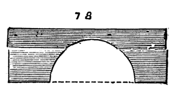
Fig. 78.
In order to obviate the difficulty of following the diametrical line with the cutting tool, the following contrivance has been suggested to the author by one who has followed lathe work as a profession for many years, and is an adept at the art. The lathe band is to be slightly slackened by partial untwisting (a turn or two will suffice), if of catgut, so that it will carry round the pulley, if desired, but will slip if the hand is placed on the latter. Thus, the tool may be applied, and a light cut taken, and the work instantly stopped for examination without stopping the lathe, as the flywheel continues to revolve all the time. This examination can be repeated, if necessary, every few seconds, by merely placing the hand on the pulley, and in this way the work being carried on little by little, a good result is attainable with comparatively little difficulty.
The best position for the rest during the above operations will be across the face of the work, as in hollowing out boxes, working carefully, little by little, from centre to circumference. Towards the finish a scraper should be used, the common carpenter's chisel being as good a tool as any. Now to proceed with the box. Before removing the finished ball from the chuck, bore it through with tool Fig. 59, enlarge with Fig. 51, and make the hole conical, unscrew the chuck, with the ball remaining in it, and put on another with a piece of boxwood large enough to make a plug to fit this hole. This plug, when fitted, is to be hollowed out, and converted into a box, like Fig. 79. The latter, when put in place, must fit so neatly that only a light circle shows its position. To conceal it still more completely, a series of circles are to be set at each of the six sides of the ball, as shown at Fig. 80. To remove the box, the thumb is placed[47] at the small end, and pressure made. This forms a neat pocket needle-case, and may be made of ivory as a present to your lady-love.
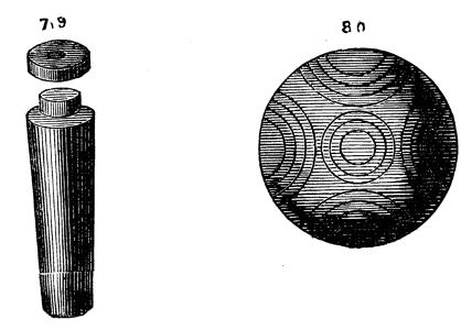
Figs. 79, 80.
There is no practical difficulty likely to be met with in the above after the round ball is itself made, unless it may arise in respect of the conical hole. Let this be turned out as directed, until at the furthest (smallest) end it will just allow a gauge, like the annexed figure, 80A, to pass through it.
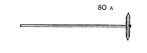
Fig. 80A.
Having also gauged the large end of the hole to the desired size, take care to finish the side evenly from one to the other. The gauge may be a disc of tin on a wire, or, still better, a short cylinder of box wood, on a similar handle, as there will be a little difficulty in feeling whether the disc is placed at right angles to the axis of the hole. Unless, however, you desire to work to a pre-arranged exact measurement, the above precautions will scarcely be necessary, inasmuch as the hole is first bored, and the conical plug afterwards fitted to it. The ball may, therefore, be taken from the chuck, each end of the bore measured, and the plug gauged at each end by the callipers, and turned to an exact fit.
In the above account the unmathematical phrase of "six sides of the ball" is used for want of a better; the meaning of the author will, however, be evident.
The ambition of amateurs, especially, is very commonly centered in a desire to cut screws in the lathe, and there is good reason for this, because in the first place there is a difficulty presented which it is pleasant to overcome, and in the next place, a screw is of absolute necessity in the greater number of turned works. There is an apparatus of simple but ingenious construction called a screw box, which is commonly used by carpenters and others who have not attained the skill necessary for chasing screws in the lathe, and which is very convenient even for those who have obtained this power. A sketch of this is given in Fig. 81. A, shows the tool complete, B is a view after the top plate has been removed, showing the knife or cutting tool, the latter being delineated alone at D on a large scale, C is a section. To make this tool, which is within the power of any person of average skill, a block of hard wood is first selected, and drilled with a hole corresponding to the proposed size of the screw to be cut. If no tap is at hand of the desired diameter and pitch, this block must be mounted in the lathe, and the thread chased as we shall presently describe. It is absolutely necessary that the block be nicely squared up and level on the face. A small place must then be cut to receive the knife, the edge of which is so constructed as to form part of the thread cut away to make room for it. It is V shaped like Fig. D, and very keenly sharpened. The method used to clamp the knife in position, which is shown in Fig. D, permits the cutter to be advanced or withdrawn until its position is accurately determined as above. The top plate of wood is now fitted, and adjusted—the central hole, which is not tapped, but as large as the outside of the screw-thread to be cut, forming a continuation of that which is tapped in the lower block. A slot b, Fig. A, forms a passage from the knife, to allow of the escape of the chips. The piece to be cut into a screw should be shaped like Fig. 82. The part a, will be left plain, b, is that on which the thread is to be cut, and must be truly cylindrical, and of such size as to just enter the hole in the top plate of the screw box. The part c must pass through the threaded part of the screw box, not loosely, but just so as not to damage the threads in the least. The lower part of the central division is sloped off as seen in the sketch. To cut the thread the screw blank is fixed in the vice by its head, which, after being turned, should be planed off at each side. The screw box being then placed upon it the lowest and smallest part of the blank should just project, as in Fig. 83. This part is intended to insure the perpendicular position of the blank in respect of the screw box. The latter is then turned from left to right until the screw is cut, which ought to come from the tool clean and smooth. Box wood is especially suitable for this purpose. This[49] method is, of course, wholly inapplicable to anything but wooden screw bolts, and for practice the tyro may set to work and make three or four of the following screw clamps, which are useful to hold pieces of wood that have been glued together. The tap for screwing nuts and the jaws of these clamps, is similar to that used for metal, but, the teeth, or cutting threads, are deeper and more pointed. The jaws of the clamps shown in Figs. 84, 85, are usually made of beech, which will take a very fair thread; or of birch, which is still better; and the screws may be made of the same material, box being too costly and scarce for such purposes. In making these clamps, there is to be no thread cut on that part at which the handle of the screws project, nor is there any thread on this part of the bolts, which pass through a smooth hole in one jaw and lay hold of the other only. Other forms will suggest themselves, but the two given will be found serviceable patterns.
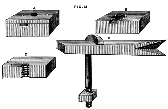
Fig. 81.
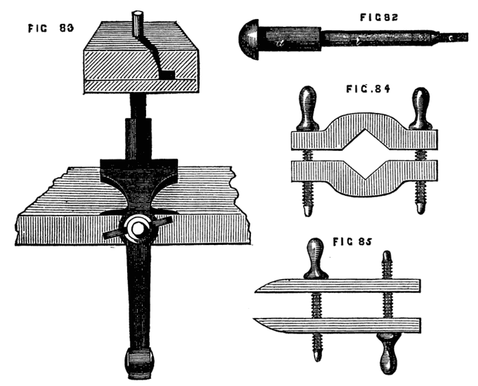
Figs. 82, 83, 84, 85.
The above method of cutting screws is not of anything like universal application, nor specially the work of the turner; we shall now, therefore, speak of cutting them by the chasing tool in the lathe. To effect this with certainty requires much care and long practice, and at first the attempt should never be made on a box or ornamental piece of work, otherwise finished, but on a plain cylindrical bolt, such as those of the clamps just described. For the inside, or female screw, the making of chucks will afford endless practice, and a failure in either of these will be of little importance. The[50] screw tool for male and female threads is represented in Figs. 86 and 87. It is of steel, and as each tooth inclines in the direction and with the pitch of the screw, it cannot be made with a file, but is cut by being held against a revolving tap (or screw hob, which is of similar form.) There is certainly a defect in the above common form of screw chaser, and a slight modification, to be presently described, will be found easier to use, and, in many respects, easier to make. To cut a thread with the chasing tool, the top of the rest must be quite level and smooth, so that the tool may readily slip along it. Suppose an outside thread to be required on a cylinder of box or other close grained wood. The rest being firmly fixed so that the upper edge is level with the axis of the piece, and about half an inch from it, as Fig. 88, the tool is advanced to touch the work, not in a line with the axis, but so as to bring the part, a, in contact with it first, and the moment the tool is felt to run along, which it will do as soon as this part of it indents the wood, the handle is raised a little so that the points of the teeth come into work. The tool in fact must describe the segment of a circle, as shown by the dotted line. If this is done cleverly the tool will not hitch, nor produce a drunken thread, but the latter will come out clean and sharp. It is, nevertheless, necessary to practise till the knack of thus chasing a thread[51] is attained, and, considering that once acquired, the necessity of traversing mandrel or other expensive (and yet more or less defective) apparatus, no longer exists, it is evident that the young aspirant should spare neither time nor patience in becoming an adept in this useful art.
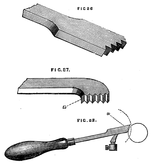
Figs. 86, 87, 88.
One great difficulty in cutting the screw-threads to the top of a box, or the inside of its cover, arises from the necessity for stopping short, and removing the tool instantly as soon as it touches the shoulder, or the top of the cover. The latter should be made rather deeper than is necessary, so that there may be a turn or two of screw to spare. This will give more room for the play and removal of the inside chasing tool.
The ordinary form of the latter is as shown in Fig. 87, the part under the plane upper surface (a) being either slightly hollowed or flat, generally the former, from having been cut by a revolving cylindrical hub.
Now, although this form may be suitable for outside screw tools, which have to work on cylindrical pieces, it does not appear equally suitable for inside tools, which are to act on concave work. The writer of this article has experimented upon many patterns of chasing tool, and has found it perfectly easy to chase an inside thread with an ordinary grooved tap, which seldom makes a false cut, or crosses the threads. From this the idea naturally arose of a convex edged tool for inside chasing, and a concave one for outside work, as Fig. 89.
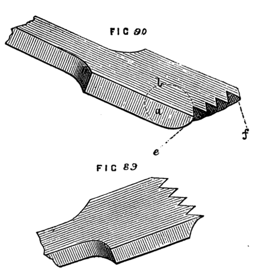
Figs. 89, 90.
Practically, however, the convex edge, Fig. 90, will answer satisfactorily for an outside cylinder. In order to obtain an efficient cutting edge from this form, the rounding must be very slight. The out or inside tool is used with a rolling movement on the rest as it advances. If for hard wood, a notch cut across in the line e, f, Fig. 90, with a saw-file, will, by making a partially cutting edge on the convex part, cause the tool to enter more readily at starting. Tools like the above must be necessarily the work of the amateur himself. The regular makers have a great objection to make any tool or machine out of the ordinary routine. Hence the same patterns are[52] constantly reproduced year after year, until some one connected with the manufacture invents an improved form, or some one else of mechanical genius, and possessed of means, registers a new design. Amateurs are apt to cavil at this system, and in some cases it no doubt interferes with, and checks improvement in tools and machines, but the evil is almost a matter of necessity. Tools are made not singly, one of each pattern, but so many score or hundreds of one form are forged out, and handed over to the grinding and finishing department, and it would sadly interfere with the system and order of the manufacturer to make a single tool or two for individual purchasers of different pattern to those ordinarily used. If a design is sent in by a retail dealer who can order a hundred or so at his own risk, the above objection is obviated, and the new pattern of tool or machine is at once introduced. If, however, any new design by an amateur, being submitted to such men as Holtzapffel, Buck, Fenn, or Whitworth, appears to them good and saleable, they will not only not object to introduce it, but may possibly give a premium to the inventor. We have thought it necessary to make these remarks to obviate the possible disappointment of amateurs in this respect. It is but natural to suppose that some ingenious device must have long since arisen to obviate the difficulty of thus cutting screws by hand. Every turner finds the difficulty, and few perhaps have failed to try some plan or other to counteract it. There are two methods whereby this can be done: one by causing the tool to traverse at a given rate according to the proposed pitch of the screw, the other by giving similar movement to the mandrel, while the tool remains still. For such work as screwing the lids of boxes, the traversing mandrel is commonly used, but for cutting long screws in metal, the tool is fixed in a slide rest, and the latter is made to traverse, if necessary, the whole length of the lathe bed, by means of a guide screw driven by suitable gearing put in motion by the mandrel itself, the speed being adjusted by a series of cog wheels which can be interchanged to cause various rates of motion. The latter method belongs to machine lathes, and will be treated of hereafter in this series.
The author has great pleasure in here introducing a device, not exactly for cutting, but for starting the threads of a single, or double screw, or, indeed, a quadruple one. It is the invention of a gentleman whose nom de plume is East Norfolk Amateur, and was by him kindly communicated to the English Mechanic, of June 21, 1867. The description is here given in his own words:—
"I think the plan to be described will produce to a certainty any required number of screws and turns to the inch. The screws are entirely cut with a common comb tool, but started by a revolving cutter set to the required angle, and applied firmly to the work, on the T-rest. I call it 'the universal screw guide tool,' contrived and[53] made by myself, and I believe will prove as useful to others as it has to me: the drawing will almost explain the tool. The cutter, A, is 9/16ths of an inch in diameter, turned to a cutting edge, and finely tempered. The stem, B, in which it revolves, is round, and fits into the shoe, C, having a graduated collar, D, in front of C, to set the cutter to the required pitch or angle, the set screw, E, makes it fast; having turned a piece of rod, of brass, iron, or steel, a little above the size necessary, and supposing a quadruple screw is to be cut having ten turns to the inch, there would, of course, be forty threads when complete; if one of these four can be truly traced, the comb tool will easily follow by inserting the outside tooth, either right or left hand, as found convenient, in the line traced, when the other three will soon appear with perfect accuracy, provided the first one exactly corresponded to five points of the comb, which is easily accomplished after a few trials, and if not successful at first,[4] can be removed by a dead flat file several times, without reducing the rod too much. When found to exactly fit the five points, the cutter may be applied with more force to leave a good chase for the comb. The T-rest requires a smooth surface for the shoe, C, to slide freely on, and to be set parallel with the work, and the tool held at a right angle as it proceeds along the rest, or the lines formed would be of unequal distance. After a little experience it will be found to work with beautiful accuracy, and for those who have not screw-guide mandrels, and are not practised hands at flying common screws, it will be found a great assistance, as it sets to anything. I described only the quadruple, but the same rule applies to all quick screws; for a double the chase must correspond to three points, and so on for any number, that is, one more point of the comb than the number of screws to be cut, and for a common one the chase must fit the comb altogether."
[4] This doubt seems to mar the invention. It is, however, on the whole a good design.
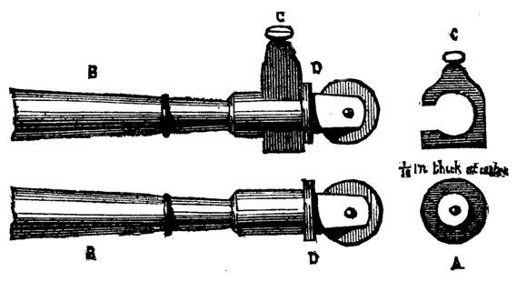
Figs. A, B, C, D.
The above simple apparatus will, it is believed, be of great service to those who find difficulty in hand chasing of screws; it is, however, necessary to speak of other methods, and especially of that so universally used by the turners of "Tunbridge ware"—viz., the traversing mandrel. This is represented in Fig. 91. A is the poppet; B, the mandrel, no longer conical at the place where it traverses the collar, but cylindrical, and passing through two cylindrical collars. It is prevented from advancing towards the left in its bearings by the shoulder, K, and in the other direction by a plain[54] cylindrical collar, or ferrule, C, which slips over the end, and is secured by a nut, D. The whole is thus ready for use, as an ordinary mandrel. To cause it to traverse from left to right, as it revolves, the nut and collar, C, D, are removed, and a ferrule, or guide, F, which has a screw of the desired pitch cut on its edge, is slipped on the mandrel over a short feather against a shoulder, where it is retained by a nut or pin. There are several such guide-ferrules supplied with the mandrel of different pitches of screws. The nut G is then removed and the piece E, which is of brass or gun metal ⅜ or ½ inch in thickness, with similar screw threads in each of the hollows is attached. This guide is slipped on at H, and secured by replacing the nut. The pin, which carries the guide, is frequently made to slide up and down the face of the poppet, by the action of a screw, M, working through a brass piece attached to that which carries the pin. It is thus readily lowered out of gear or drawn up again to touch the screw ferule. This is better than a pin screwed to the head of the poppet, and is always adopted in the best lathes. In the frontispiece is a photograph of this arrangement. This guidepiece acts like a half nut, and as the mandrel revolves it gears into the ferule and causes the required traverse. A single point tool, therefore, held against the work will trace a screw of the same pitch as that of the guides, and of a length equal to that of the ferule. The above is not intended for cutting long screws, which would have to be done in successive short lengths, but for screws of box lids, chucks, and similar work it is a most excellent contrivance, and peculiarly adapted for the use of the amateur. The guide threads in the commoner patterns of these lathes are cut on the mandrel itself, which is made of greater length than usual, and these several guides are cut upon the part within the poppet heads, as Fig. 92,[55] which represents such a lathe as is sometimes used by gasfitters and brass workers in general.[5] In the latter it will be noticed that there is added a sustaining screw at the back of the mandrel. This is a good addition, and indeed almost a necessary one if the lathe is to be used for ordinary rough work, especially drilling, as it takes off the pressure which must otherwise come against the shoulder, K, Fig. 91, and it must be remembered that these lathes are expensive, and, therefore, ought to be taken care of. The amateur may also be warned against bad work; none but the first-class makers can turn out a reliable lathe of this description. The collars and mandrel require perfect fitting, and they must be quite hard, because there is no possibility of tightening them when worn. They must be kept well oiled, therefore, when in use, and the oil holes in the top of the poppet should be fitted with brass covers, to prevent any particles of metal, and especially emery dust, from working in between collars and mandrel. Be sure to have one guide screw of the same pitch as that on the nose of the mandrel, for the purpose of tapping chucks to fit thereon. In using the traversing mandrel, either the cord should be slackened so that the pressure of the hand on the pulley may stop the revolution of the work in a moment, or the flywheel should not be brought into use, the cord being instead grasped by the left hand, because it is generally necessary to cut to a shoulder or given point. It is, however, possible sometimes so to arrange the guides by insertion of a washer or other expedient as to cause the action to cease of itself at the required point. In a future chapter, the cutting of long metal screws will be treated in detail, but before concluding the present chapter, it may be useful to say a few words concerning the nature of the screw itself as a mechanical expedient. A screw may be defined as a continuous inclined plane—or an inclined plane wound round a cylinder—the pitch being the inclination of the plane, that is, the ratio of its height to the length of its base. From the mechanical principle of the inclined plane it follows that the greater number of threads in a given space the greater is the power of the screw when used as in a press, or to draw along its nut, as in the slide rest, in which endlong motion in the screw itself is prevented. It seems, at first sight, easy to devise a method for cutting screws of any desired pitch, but this is far from being the case, and when it becomes necessary to increase the number of threads to fifty, sixty, eighty, or even more to the inch, with such accuracy that one turn of the screw shall always produce an equal longitudinal movement of the nut, the most delicate machinery scarcely suffices for the purpose. The microscope detects and shows errors even in the best work, and it is questionable whether a perfect screw of any length can be cut by machinery, as every imperfection in the latter is communicated to[56] the work done by it. If the amateur, therefore, requires a screw for a slide rest, eccentric chuck, microscope, or other delicate piece of machinery, or philosophical instrument, he had better get it cut by some practical mechanician, in the possession of the necessary apparatus.
[5] There should be a collar or shoulder to this mandrel, the same as at K in the other figure.
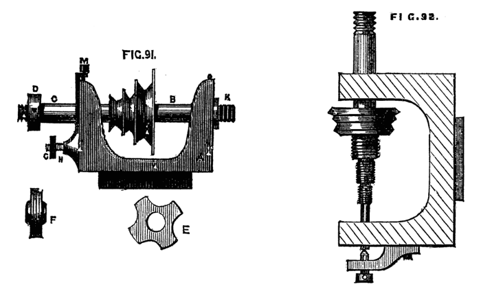
Figs. 91, 92.
In the "Manual Bergeron" is an ingenious contrivance, by an amateur, which is worth notice, although unsuited for any work where extreme accuracy of pitch is required in the screw. The following, Fig. 93, is a description:—The mandrel is made to traverse in its bearings, as before detailed in this series, but instead of its motion being governed by guide hubs, it is dependent on the action of a pair of differential pulleys, B. A bent lever, C, is pivoted at E to the face of the poppet, having a bit of hardened steel fitted to work in a semicircular groove in the mandrel itself, and so arranged that on raising the tail or long arm of the lever the mandrel is thrust forward from left to right, while a reverse action of this lever causes a similar movement in the opposite direction. The movement of the lever is thus regulated:—At the extreme end of the long arm is a pulley and hook, as shown in the drawing; the double, or differential pulley, is fixed to the end of the mandrel, and from the smaller part depends a cord which passes thence through the pulley on the lever, and is wound round the larger one on the mandrel when its end is secured. On the hook is hung a weight. It will be evident, on an inspection of the drawing, that on putting the lathe in motion the cord on the differential pulley will coil itself round the largest part of the same, and will draw up the end of the lever with a speed proportionate to the difference of diameter between the larger and smaller parts of the double pulley. The short end of the lever will at the same time with similar proportionate motion move the mandrel and work, and cause the fixed tool to cut a spiral or screw thread on the latter—a good deal of ingenuity is displayed in the above, and it has the advantage of being easily fitted up, but it is evident that some alterations and additions would be required to adapt it to any other use but that specified. A contrivance similar to Fig. 94, may in some cases be a sufficient makeshift, when a more perfect one is not at hand. A screw is here cut on the outside of the chuck, and a[57] kind of double tool is used, the tracer which is in contact with the guide thread being adjustable as to its length, and the cutting tool having a sidelong adjustment as well. The rest being placed between the connecting bar of the tool and the work, the former will be held with sufficient steadiness to enable the workman to traverse the whole easily by hand. The use of this tool is of course limited, but the plan is simple and fairly effective. The only really serviceable plan is the slide rest, to be hereafter described. But one other plan is here added, which is called "Healey's chuck." The description and sketch are from Holtzapffel's work, in which it was however copied from an older treatise. The author, it must be understood, has never seen the contrivance himself, and there is a fault in its principle of construction which must militate against its use except in a very limited degree. Since, however, Holtzapffel has considered it worthy of a place in his work, it is at any rate well to introduce it to the reader, especially as its defects will not be of great importance in tracing screws of half a dozen threads or so. The apparatus is represented in Fig. 95. in plan. C is the chuck which carries the work to be screwed, and T is the tool which lies upon R, R, the lathe rest, that is placed at right angles to the bearers and is always free to move in its socket S, as on a centre, because the binding screw is either loosened or removed. On the outside of the chuck C is cut a coarse guide screw which we will suppose to be right handed. The nut N, N, which fits the screw of the chuck is extended into a long arm, and the latter communicates with the lathe rest by the connecting rod C, C. As the lathe revolves backwards and forwards, the arm, N (which is retained horizontally by a guide pin, G), traverses to and fro, as regards the chuck and work, and causes the lathe rest R, R, to oscillate in its socket S. The distance S, T being half S, R, a right hand[58] screw of half the coarseness of the guide will be cut, or the tool being nearer to and on the other side of the centre, S, as in the dotted position T, a finer and left hand screw will be cut. The rod C, C, may be attached indifferently to any part of N, N, but the smallest change of the relation of S, T to S, R would mar the correspondence of screws cut at different periods, and therefore T and R should be united by a swiveljoint capable of being fixed at any part of the lathe rest R, R, which is omitted in Mr. Healey's perspective drawing of the apparatus.
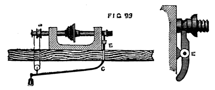
Fig. 93.
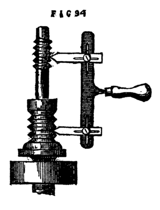
Fig. 94.
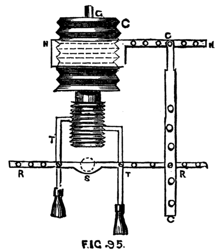
Fig. 95.
This is one of the least perfect modes of originating screws, it should, therefore, be only applied to such as are very short, as, owing to the variation in the angular relation of the parts the motion given to the tool is not strictly constant nor equable. When in the midway position the several parts should lie exactly at right angles to each other in order as far as possible to avoid the error. The inequality of the threads is imperceptible in a short screw. A little modification of the screw-chuck of Healey would result in a more correct and serviceable arrangement.
The disadvantage, for instance, of being obliged to set the T of the rest across the face of the work is apparent at once, and it is difficult to understand how such an arrangement could be made to answer when the work might be of a length to require the support of the back poppet. The following plan, Fig. 96, would obviate this and the other disadvantages, and make a more efficient apparatus. B is the chuck with screw chased on the outside, A the nut travelling upon the same. To this is attached a bar H, which[59] passes through the bar K, to which it is clamped by the binding screw visible at H. Two short pillars, F, F, are screwed into the bed of the lathe, in which there might be more than one hole for each to permit the pillars to be fixed at different distances from the line of centre. Through slots in these passes the square bar of polished iron or steel E, supporting the traversing rest socket, D, of which two other views are given at Figs. 97 and 98. It will be evident on inspecting the drawing that as the nut A travels to and fro, it carries with it in a line parallel to the lathe bed the rest socket and T. To enable the workman to steady the tool, the latter should rest against two short pins fixed in the top surface of the rest in holes made for the purpose; with the aid of these the tool will be made to traverse the work with great ease and regularity. In chasing a right-handed screw, the tool would have to lie on the left side of the pins, and the latter would insure its traversing with the rest. A longer T (or half T) being turned in its socket to stand across the face of the work will enable an inside thread to be cut with the ordinary tool either of one or more points. Of course, in this modification of Healey's chuck, the screw cut will be of the same pitch as that of the chuck itself; but as the latter may be of boxwood, there would be no difficulty in having from three to six with the most generally useful pitches of screws, as the arm may be screwed into the near side of the nut, and, therefore, it, and all the other parts of the apparatus, would answer for the whole set of chucks. If the work to be screwed is merely a box cover, or some such work where great length of screw is not required, it is evident that to rig up this kind of contrivance, or Healey's, or indeed anything of similar elaboration, would appear like summoning a gang of navvies to remove a mole-hill. Hence, if a traversing mandrel cannot be obtained, by far the simplest plan is the chasing tool used by hand; it is therefore well worth while to get into the knack of using this tool. To give confidence (which is essential to success, the least nervousness generally proving fatal to such work) the part on which the screw is to be cut may be left larger than will finally be necessary. The screw is then commenced, and if a failure takes place it is again levelled, but if, as is more probable, the attempt is successful, the chisel and chase are alternately used, the cuts of the latter not being obliterated by the former but always left sufficiently deep to form a guide until the desired object is satisfactorily accomplished.
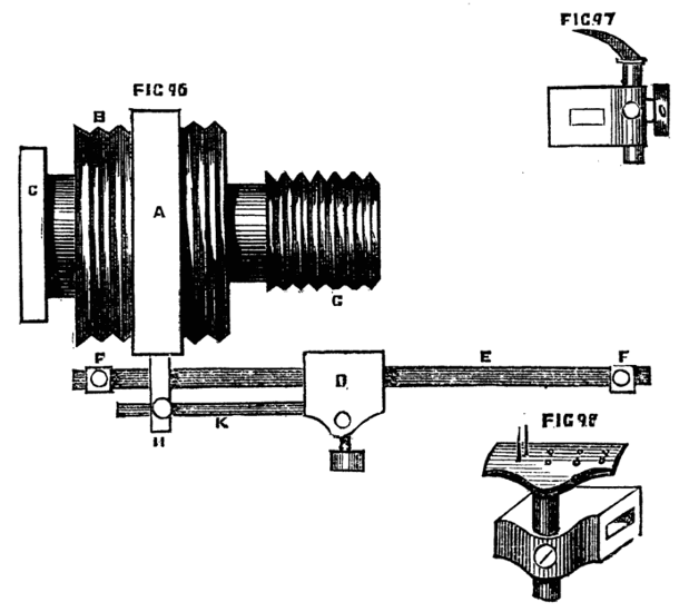
Figs. 96, 97, 98.
Having treated of screw cutting so far as we are able without trespassing on that section of the present series which is to be devoted to machine work with slide rest and change wheels, we shall enter on the matter of spirals, or Elizabethan twists, the method of making which was long kept a secret by the trade. These twists are[60] essentially screws of very extended pitch, and generally rounded threads. The latter sometimes embrace the central cylinder or core, and sometimes are detached so as to assume a more open form like a corkscrew, and in the latter case two, three, or more threads can be cut, so that the spirals appear to intertwine. These spirals, too, are frequently ornamented with the aid of the eccentric chuck, and thus the work becomes fit for the adornment of the drawing-rooms of the highest in the land. No turned work can in short exceed in beauty these delicate and elaborate specimens of the turner's art. To commence with a single twist of one thread. A cylinder of the requisite length must first be turned. The number of turns the thread or cord of the spiral is to make in a given space must next be determined. We will suppose the cylinder one foot long, exclusive of any mouldings or tenons at the ends, and that the spiral is to make three turns round it, that is, one turn in four inches of its length. Divide the cylinder into three equal parts by the lines B, C, Fig. 99. Next rule equidistant lines D, E, F, along the cylinder in the direction of its length; in the present case let there be four such lines. The three divisions first made must be subdivided each into four (always the number of the longitudinal lines). The angles of the parallelograms thus formed must then be connected diagonally as shown in the figure, which diagonals being continued, will be found to describe a spiral line. A second similarly constructed spiral determines the thickness of the thread or cord of the twist. These spirals may now be cut with a tenon saw, and all the material outside the cord carefully removed with the gouge, so as to form a semicircular hollow between the threads. This cannot be done by putting the treadle and flywheel in motion, but the work itself must be grasped with the left hand, while the right holds the gouge upon the rest and guides its edge. After the work has thus been roughed out, it must be finished by rasps and files, or by a kind of plane with a semicircular cutting edge. While the latter is being used, the flywheel must be brought into action, so that the work may be made to revolve with sufficient rapidity to ensure a clean and smooth cut. A hollow plane may be used to round the cord of the twist, and the whole finished with glass paper and polished.
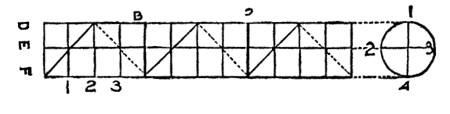
Fig. 99.
The "kind of plane" named was designed by a regular workman for his own use, and was made thus and grasped in the fist, or rather hollow of the hand. The iron was like c, sharp at one edge,[61] the block of wood being slightly bevelled off in front of the cutting edge. The workman, who made scores of these twisted works for the trade, of all dimensions, would run this along the hollows, while the lathe was in motion, with great speed and accuracy. He marked the spirals as described, and then grasping the work in the left hand, and the gouge in the right, turning the work round with the former (the cord thrown off the wheel), he cut out the wood boldly in large pieces with little apparent care, and perfect ease. Then came the plane described above.
Fig. 100 shows a simple spiral thus made. If the piece to be turned is dark it is not easy thus to mark out the divisions. In that case the following method will answer equally well. It is the plan used and contrived by the writer,[6] and specially handy when a number of similar twists are to be cut, as in ornamented pieces of furniture. A, Fig. 101, is a straight edge of hard wood, through which, at any given angle (regulated by the number of turns the cord is desired to make in a given length of cylinder), a knife edge is fixed. If this is held as in the figure, and the blade is pressed down upon the cylinder to be cut, the lathe being put in motion, a very correct spiral will be traced, which can be at once deepened by a tenon saw as before. The thickness of the cord being determined it only remains to place this tool again upon the work so that the second line shall be traced at the required distance from the first. A second, or any number of cords, may be thus traced in succession parallel to each other by this simple method. By a slight modification of this instrument, which allows the knife to be clamped at[62] any desired angle with the straight edge, the inclination of the cords, and, consequently, the pitch of the spiral can be varied at pleasure, and a second blade can be added to trace the second line, determining the thickness of the cord with one movement of the tool along the cylinder. The edge of the knife may be across the rest, the piece of wood just overlapping the T on the side next the workman, if the blade is long enough to reach across the work when thus held. The tool will be steadier and perhaps more easy of management in this position. One hand should then lightly press the back of the knife, while the other retains the wood against the rest as a straight edge. East Norfolk Amateur's design of a screw guide is on the same principle, the only difference being the substitution of a revolving instead of a fixed knife edge. In using either it requires some care to allow the tool free traverse, as the least check would spoil the thread.
[6] A similar plan is noticed in Holtzapffel's mechanical manipulation, which the writer had not seen. It is satisfactory to him to find the method thus authorised.
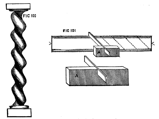
Figs. 100, 101.
The next class of spirals is that in which no central core exists, but the coils stand separate and distinct, two or more rising from the same base. The coils are sometimes flat, sometimes rounded, and still more frequently, in the best work, exquisitely, and (as a casual spectator would say) impossibly carved. The process is as follows:—Turn a cylinder of ivory or hard wood, forming at the end any required mouldings as a base and capital. Determine the number of coils and the pitch, and by one of the previous methods mark out the same. The cylinder is now to be bored out from end to end, leaving sufficient for the thickness of the required cords. This bore may with advantage be slightly larger at one end than at the other, so that a mandrel of wood may be fitted into it, to be afterwards easily withdrawn. This will certainly be necessary if the ivory cords are to be of light substance, as they require support to enable them to bear the action of the tool. After the cylinder has been bored as above directed, let a mandrel of common wood be inserted, and the lines, marked as shown, be cut quite through. The intermediate parts between the intended threads must then be removed carefully (with a round rasp, if of ivory) with any convenient tool if of wood. The cords must then in a similar way be rounded or otherwise moulded, and afterwards the common and now damaged mandrel removed. In the case of ivory the piece of work will not only be strengthened by the insertion of a polished mandrel of ebony, but its appearance will be improved. Sometimes, however, it may be preferable to line it with red velvet or silk, or it may be left entirely open. The further ornamentation of the cords, depending on the eccentric chuck or eccentric cutters, will not be described in the present paper. These open spirals are worth a vast amount of patience and trouble, which their elegant appearance when finished will amply repay.
The reader is not to suppose that this method of cutting spirals by rasp and file is the only or best method, especially when ivory is the substance operated upon. Further on will be described various modes of accomplishing the same ends by self-acting machinery, and by the spiral apparatus designed for use with the ordinary lathe, but all these need the slide rest, whereas it is quite possible in the foregoing manner to make spirals by hand tools alone, which for correctness and finish may vie with those which may have been worked with more elaborate and costly apparatus.
Before quitting the subject of plain hand turning in wood, a few more words may be necessary in respect of certain details of lathe manipulation, foremost among which comes Chucking work. This is often carelessly done, especially by amateurs, who, in consequence, are frequently annoyed by the shifting of the material under the influence of the cutting tool. If this is hard and valuable—as are many of the best woods for ornamental turning—the fork or prong chuck will not enter sufficiently to sustain the piece, and at the same time the stuff is too valuable to allow of the waste incurred in screwing it direct to the mandrel, or inserting it sufficiently far into a brass cup chuck. In such cases the best plan is to screw a piece of common wood upon the mandrel, face it truly, and cut a few shallow concentric circles upon the end thus levelled, both for the purpose of a guide to centrality, and also to give a hold to the glue by which the more precious material is to be attached to it. For this purpose, both chuck and work are to be well warmed, and the glue—boiling hot—brushed upon the parts to be united. The latter are then to be rubbed together a few seconds, and when the piece to be turned runs truly, the back poppet with boring flange attached—if the right hand end of the piece is level, otherwise, the point allowed to remain—is to be brought up and screwed as a clamp against it till dry. This process requires time, but is well worth the trouble, as the material will be securely held, and can be safely operated on. None but those who have had to contend personally with a tyro's difficulties, and have, in consequence, seen the work shift in the chuck when nearly completed, can truly appreciate the advantages of efficient chucking. In the case detailed, there is absolutely no waste of material, no possibility of the work becoming loose or out of truth; and the ornamentation by eccentric cutters, drills, and so forth, can be proceeded with, and carried out with that confidence which never fails to promote good workmanship. Even with the above arrangement the back poppet should be used while the excrescences are turned down, and retained as long as the gouge has to be used in bringing the design into an approximation to its intended form. This should be removed, however, before taking the final cut, as the work will generally seem to drop a little when the support is taken away,[64] in consequence of the mandrel, which has been forced against the back centre, returning to its place in the collar.
Pieces of six or seven inches in length, and of one or two inches diameter, requiring to be hollowed out, may frequently be turned by reversing the usual method and boring out the interior, previous to shaping the outside. A case for pencils, for instance, or a bodkin case, may be thus worked:—Mount in the square hole chuck, an American screw auger, sets of which are now to be had beautifully finished and polished. The kind meant has a scooping kind of edge above the screw, Fig. 102, and cuts cleanly and rapidly. The piece of wood—soft wood alone is meant—is brought against the tool, being grasped by the left hand, while the back centre, with flange, is steadily advanced with the right hand against the opposite end. This auger will run straight through several inches without requiring to be withdrawn, as the borings pass freely along the polished threads of the instrument and escape. If necessary, however, it can be readily withdrawn by reversing the action of the lathe, and replaced without difficulty. The piece thus bored may then be mounted in the lathe and finished on the outside. To do this satisfactorily, an arrangement is requisite by which the centrality of bore is insured, else in the process of[65] cutting the external surface, the material will, in all probability, be cut through in one part, while in another it will remain of considerable thickness. If the piece is bored quite through, so as to become a tube, Fig. 103 will be satisfactory, as the cones preserve centrality, whilst the use of the carrier will prevent the necessity of screwing the cones up so tightly as to endanger splitting the wood. This is the best way to chuck small cylinders and brass tubes. The more obtuse the angle of the cones the better.
Fig. 102.
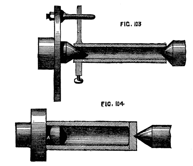
Figs. 103, 104.
In this method the bottom of the case must be turned as a plug and glued into its place. If the bottom of the case is left solid, an arrangement like Fig. 104 will answer well. The plug chuck, A, must not be at all conical, and the part that enters the work must be at least an inch long. If this is attended to, and the face of the work and of the chuck is square, the tube will be truly centred, only requiring the back poppet to take off the strain upon A, when the tool is applied. If A is chalked, there will be no slipping, provided it has been accurately fitted. Observe, nevertheless, that as a general rule, hollow work should be placed inside and not upon a chuck, unless you have to work upon the whole exterior surface. By this plan, there will be no likelihood of splitting the object, an undesirable consummation which not unfrequently takes place when the contrary method is pursued.
Thin discs of wood or brass are most conveniently turned upon a face-plate, to which they can be attached by turners' cement, already described. If, however, one surface only has to be worked, and the plate is not of less thickness than ⅛th of an inch, it may be mounted on a flat chuck with small projecting points, the back poppet being used to keep it firmly against the face of the chuck. Even a plate of brass may be thus turned if placed first of all against the chuck and gently tapped so as to mark the position of the points, and then drilled to suit them. Bread-platters are thus easily chucked, first of all face downwards, and then reversed with the bottom against the points, so that in the latter position, the chisel or broad may be applied to the face and the marks removed. The larger designs on these platters are carved by hand after their removal from the lathe, and the small figures forming the ground, which often appear round the main design, are made by figured punches.
Chucking Egg Shells:—The method of doing this so as to enable the turner to cut the shell evenly in two parts, is given by Holtzapffel, in his "Mechanical Manipulation," and has been copied elsewhere. It is ingenious and effective. The object is simply to obtain a pair of delicate vases, to be edged with ivory, and mounted on a pedestal, as a curiosity. The following account is from the pen of the inventor, Mr. G. D. Kittoe, as communicated to Mr. Holtzapffel:—"In the accompanying figure—Fig. 105—is represented the nose of a lathe,[66] with an egg chucked ready for cutting." Fig. 106 is the chuck used first "to prepare the egg, to be mounted in the above way. The latter is generally termed a spring chuck, and is made by rolling stout paper with glue upon a metal or hardwood cylinder, the surface of which has been greased to prevent the paper sticking to it, and upon which it must remain until perfectly dry, when it may be removed and cut or turned in the lathe as occasion may require." [N.B. Nothing is said in the above account of the evident necessity of fixing the paper cylinder to a wooden block, in which a screw must be cut to mount it on the nose of the lathe.] "This sort of chuck is very light—easily made and well adapted for the brittle material it is intended to hold. Before fixing the egg in it, the inner surface should be rubbed with some adhesive substance (common diachylon answers exceedingly well); when this is done the egg should be carefully placed in the chuck, the lathe being slowly kept in motion by one hand whilst with the other the operator must adjust its position until he observes that it runs perfectly true, then, with a sharp pointed tool he must mark the centre and drill a hole sufficiently large for the wire in the chuck, Fig. 105, to pass freely through. When this is done the egg must be reversed, and the same operation repeated on the opposite end, its contents must then be removed by blowing carefully through it. It is now ready for cutting, for which purpose it must be fixed in the chuck, Fig. 105. A is a chuck of box or hard wood having a recess turned in it at a, b, into which is fitted a piece of cork as a soft substance for the egg to rest against. B is a small cup of wood with a piece of cork fitted into it serving the[67] same purpose as that in A. A piece of brass, d, is to be firmly screwed into the chuck A, and into this a steel wire screwed on the outer end, on which a small brass nut e is fitted to work freely in a recess in the piece B. When the egg is threaded on the wire through the holes previously made in it, this nut is to be gradually tightened up until it presses the cup B against the egg sufficiently to hold it steady and firm enough to resist the action of a finely-pointed graver used to cut it. The tool requires to be held very lightly, as a little undue violence would crush the shell. Neither should the latter be pinched unduly tight in the chuck, as otherwise when the point of the tool divides the shell the two parts might spring together, and be destroyed by the pressure. It requires some delicacy of hand to attach the rings to the edges of the shell to constitute the fitting. The foot and top ornaments are fixed by very fine ivory screws, the heads of which are inserted within the shell."
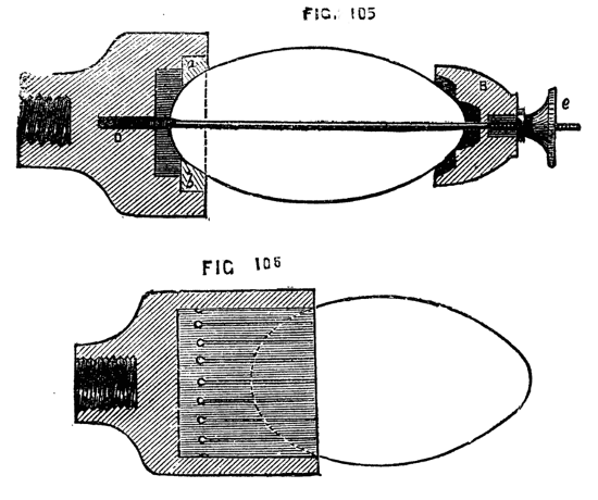
Figs. 105, 106.
Box wood is decidedly the best material for ordinary chucks, as it takes a screw almost as well as brass, is pleasant to work, holds the material firmly, and is of good appearance, which last is not unimportant to those who possess good lathes, and like to see everything in decent order about the workshop, and it is certain that a disorderly workman will commonly produce slovenly work. This wood, however, though tolerably plentiful, is sufficiently costly to be worth preserving, and by a little management chucks may be made to answer for a longer period than might be at first supposed. A chuck, for instance, too large to hold the work, may be plugged with a worn-out chuck of smaller bore, or with wood of inferior character, to save the necessity for hollowing out a new piece of box wood. The latter material, moreover, excellent as it is, may be replaced by other kinds of wood, provided the latter will bear a good screw.
Beech, if dry, will answer very well for the purpose.
Pear is tough and screws well.
Apple is little inferior.
Ilex or evergreen oak is sufficiently hard and tough and will be found quite satisfactory. Elder of large size is good, and screws well.
Sycamore screws well, but is not always equally tough.
All hollow or cup chucks should be furnished with rings of iron or brass to prevent splitting. About six sizes of rings will suffice for a great number of chucks. Bergeron, speaking of the barrel stave chucks already alluded to, prefers the encircling rings plain and not screwed. He gives the following reason:—"If a piece of work entered in such a chuck does not run quite truly, a tap on the ring in the proper place will, by closing the sawgates more in that part, rectify the error, whereas with a screwed ring this is impossible." There is reason in this, but at the same time it would be easy to unscrew the ring a turn or so, give a light tap to the work, test its position by[68] putting the lathe in motion, and when true fix it securely by screwing up the ring. There is, however, one precaution to be taken in making these useful chucks—namely, to cut the staves of equal width, else they will not yield equally to pressure, and the work will not be so readily centred truly. A grip chuck of inexpensive make (one additional pattern of which is introduced from a design by contributors to the English Mechanic) should always be provided. A rough block of ivory for instance may be seized in its jaws, and the exterior useless part cut off by a parting tool as a ring, leaving the nicely rounded material ready for chucking. Ivory nuts or corosos which are peculiarly awkwardly shaped for mounting in the lathe, may also be thus seized, and one portion faced up and rounded so as to allow of being fixed on a face chuck by glue or cement, or fitted into a cup chuck. Rough pieces, too, thus mounted may be faced up, bored and tapped to fit the mandrel as chucks, and a thousand similar works may thus be handled. The simple grip chuck in question is important as having the very useful addition of a centre point which the writer would, if he did not abominate and eschew puns, direct attention to, as the chief "point" of interest—"I call it," says the inventor, a "Universal Self-Centering Grip Chuck." The drawings 1, 2, and 3, almost speak for themselves, to practical turners.
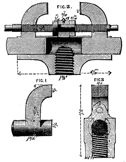
Figs. 1, 2, 3.
1, is an elevation of one of the grips. 2, a section through centre of chuck. 3, a side section of ditto. The body of the chuck is made of cast iron, to screw on to the mandrel; and the grips, 1, are moved simultaneously by a right and left-handed screw acting in a circular groove. The jaws of the grip are serrated and tempered, the same as in ordinary vices. In the centre of the grips, when closed, a three-sixteenth hole is bored true to the centre of the lathe. Behind this there is a true centre point screwed into the body of the chuck, as marked at a. The above hole and this centre point are to be particularly attended to, as on their truism depends the correctness of your work.
If I want to turn a solid cylinder I make the usual centre at each[69] end; put one on the above centre point and the other on the back centre of lathe, and then screw up the grips tight; but if the work is short you need not apply the above centre point or the back centre, as the grips are alone sufficient. The hole in the jaws of the grips admit of any kind of drill or other tool being put into them without using any centres, and the grips will admit anything up to two inches. In fact, I do almost every sort of thing with this chuck, and I think amateurs, if not others, will find it a most valuable and handy contrivance.
Fig. 108, A and B, represents a modified form—a chuck already spoken of and recommended for ordinary plain turning, in which the work is supported at both ends. The present form is to a great extent self-centering and will hold the work also without the saw-cuts otherwise needed, the sharp edges of the double fork entering the work with the pressure caused by the back centre. The chuck is useful not only for ordinary work, but for re-mounting pieces centrally, which it may have been necessary to remove when partly finished, and to return to the lathe for completion. A still further addition to this chuck of a steel point sliding through the centre, as in the section, Fig. 109, makes it a very complete and serviceable apparatus, as by this means it is easy to reverse the work without destroying its centrality. The point is intended, as in the chuck of Wilcox, to slide back stiffly (being if necessary kept up by a spiral spring as shown), as it is only intended as a guide to assist in mounting the piece. If the mandrel is not bored the chuck must be long enough to receive the pointed wire within its substance. This will be found in every way a most serviceable chuck. It may be of iron or brass, or even of wood, if a round plate of brass is mounted on its face, to which the holding pieces can be soldered or brazed.
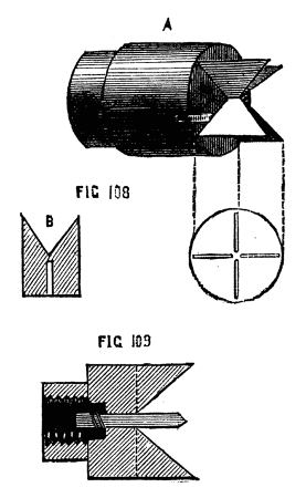
Figs. 108, 109.
This is done, as already described, by the regular soft wood[70] turners in Tunbridge and elsewhere, by means of hook tools. A great number of workmen, however, use only the gouge, and for boring out chucks, hollowing boxes, small bowls, and similar work, the latter tool will be found effectual if rightly held and carefully managed. It must not, however, be applied to the inner surface of the work at the point usual with scraping tools, but beyond the centre, Fig. 109A. The rest, B, does not require to be turned across the face of the work, but remains parallel to the bed of the lathe. The blade of the gouge is to press against the near side of the hollow as the work proceeds, which considerably aids in securing the position of the tool. The back of the gouge is to face the bottom of the hollow (next the mandrel), but the tool is generally rolled on the rest a little, so that its hollow side is often more or less below, towards the lathe bed, and the point is also lightly raised as it approaches the finish of the cut. Begin with the tool almost horizontal, and at the centre of the piece, the back against the wood, and, depressing the handle as the shaving is removed, finish at the top outer edge of the hollow, rolling over the tool, so that it shall leave the work with its back upwards and hollow downwards. Thus used it will not stick in its course, and, after a few trials, will be found to cut out the wood cleanly and rapidly.
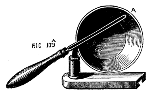
Fig. 109A.
Another grip chuck, or self-centering scroll chuck may here be introduced, from the source of information previously alluded to. The writer thus describes it—
This chuck is made upon the same principle as the Warwick Drill Chuck—namely, a flat spiral so acting on three jaws sliding in radial grooves as to make them recede from the centre to admit any object between certain sizes, and then to be tightened upon it. Fig. 1 is a plan of a 4-inch chuck. Fig. 2 is a vertical section of the same. Fig. 3 is a view of the outside of the chuck, and Fig. 4 is a separate section of the principal part a, a, taken through the line z, z (Fig. 1).
In Fig. 2, a, a is this piece, b, b, has the spiral cut on it which actuates the jaws 1, 2, 3 (Fig. 1), c, c screws on the piece a, a to keep b, b in its place and d, d is the plate which screws on the mandrel, and[71] which is fixed to c, c, by three countersunk screws, one of which is shown in section.
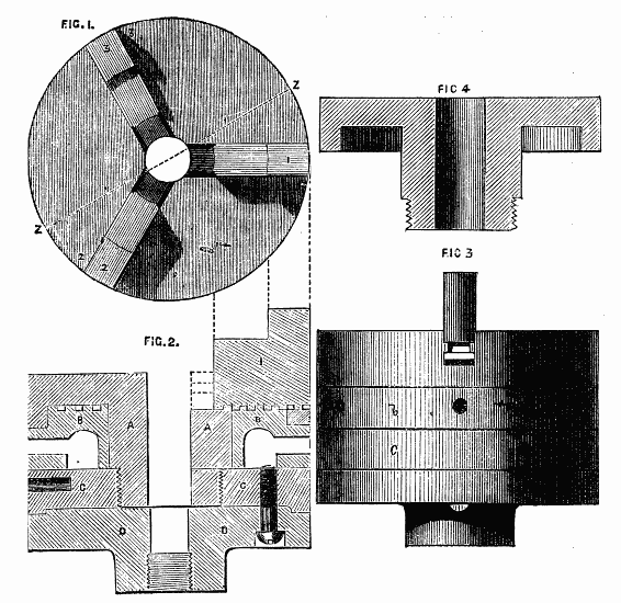
Figs. 1, 2, 3, 4.
If the foregoing observations are carefully studied the further practice of plain hand-turning in wood will not be difficult, and we shall proceed to speak of metal turning, before passing to a description of the Slide Rest and other apparatus usually added to the lathe. We may, however, observe here, that, for ivory and hard wood—especially the former, the first roughing down cannot be done with the gouge. A point or small round-ended tool must in these cases take its place, to be succeeded by one or more of those tools which[72] rather scrape than cut, as described in detailing the process of hollowing out boxes and similar work.
The first requisite for the above work is a well made and sharp tool, for, strange as it may appear, a keen edge is as necessary for making good work in metal as in turning wood. The principle of this cutting edge must be well understood, and this has been well explained by Nasmyth and others.
The remarks of the above eminent mechanic upon this subject, as also those of Professor Willis and Mr. Babbage have been embodied in a very excellent paper by Dodsworth Haydon, Esq., an amateur, and will be found in the Appendix to this work. The whole principle of the formation and application of cutting tools is explained in that paper, so that it only remains to treat briefly of a few special forms of tools which are required for metal-turning in the lathe, whether by hand or by the aid of the slide-rest. In the first place, however, a word or two may be necessary as to the kind or quality of steel required for such tools. What is called Blister steel may be at once passed over as unfit for the formation of tools—it is, however, the raw material (so to speak) from which, by the process of reheating and welding, the next quality, called Shear steel, is made. When bars of this are similarly heated and again welded into a homogeneous mass under the tilt-hammer or between rollers, double shear-steel is made, which is of extensive use for cutting tools, and must, moreover, of necessity be used in almost every case where there is to be an iron shank, for economy's sake, the steel being then welded to the iron, and forming that part of the tool intended for the edge. The third and best kind of all is Cast-steel, formed of blister steel, melted at an intense heat and run into iron moulds. This, however, can be welded only with great difficulty, and hence the whole tool, whatever its length, must be of the same material. This can be purchased in bars of a convenient size of round, triangular, square, or other section, and needs only the careful use of the hammer, file, and grindstone to become a tool of any required pattern. It would be very advantageous to an amateur to master the art of forging in a small way to enable him to make his own tools, for he may sometimes require them of unusual form, and if he lives far from a manufacturing town he will find it very difficult to get them fashioned to his liking. Cast-steel will not allow of the welding heat applied to iron—it will burn, and cannot then be made to recover its proper consistency, and is for ever useless for the purpose in question. Double shear will take a moderate white heat, while cast-steel must not be[73] brought to a higher temperature than that indicated by bright red—a point never to be forgotten when shaping a tool at the forge. There are in every workshop a number of files laid aside as worn out. These being made of the best cast-steel, are invaluable to the turner in metal, as they supply the best material for his tools at no cost whatever. To begin with the saw files (called, by a horrible perversion of mathematical definition, "three square"). Here you possess a tool at once for the mere trouble of grinding off the teeth and reducing the sides to a smooth surface. Each angle is equally useful—each 60°, which, as the paper above alluded to demonstrates, is the best angle for cutting iron. On brass, however, its use is by no means to be recommended, being, as Holtzapffel remarks, "too penetrative and disposed to dig into the work." It is to be used upon iron in the position shown in Fig. 110, where A is the rest, B the cross section of the tool, C the diametrical line. The side, of which D is a continuation, is to form very nearly a tangent to the circumference of the work, being, as explained in the Appendix, only 3° from that position. Worn out square files being of rectangular section, are exactly suited for brass turning, for which metal a cutting edge is required of 80° to 90°, the former for the first or roughing down cut, the latter for finishing. The position of such tool is shown in Fig. 111.
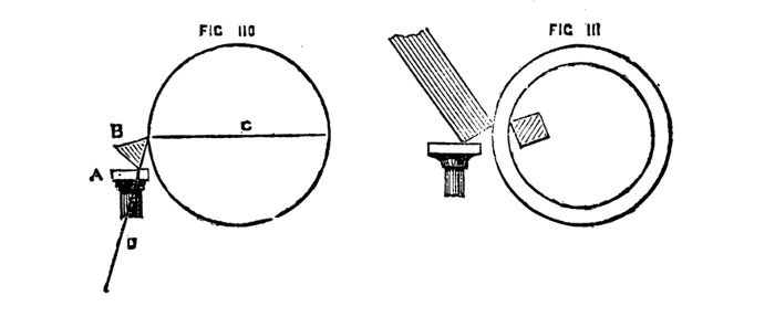
Figs. 110, 111.
The flat files are not altogether so useful for making turning tools as those alluded to; they are too thin in proportion to their breadth. Their sides, moreover, generally speaking, are not rectilineal, but curved, so that they are more fit for grinding off at the ends to form brass-turning tools with rectangular edges. They may, however, by careful forging, be made to assume a square section, and thence be formed as desired; but a rectangular bar of steel, ready-made, is then to be preferred. A round or rat's tail file is of far greater service than the last-named—not, indeed, in its own shape, for the reasons stated by Mr. Haydon, but as being capable, with very little labour at the forge, of being converted into a bar of square section. The first tool to be made from such a bar is the graver, the tool of the watchmaker, and not less useful to the general mechanician. This is formed by grinding the end of a square bar diagonally, so as to produce a lozenge-shaped face. The angle to be preferred in this operation is 45°, which will give two cutting edges of 60°. The latter may be varied at pleasure by varying the angle at which this face is ground, as explained in the chapter which treats upon this question. The graver will do all kinds of outside work, light or heavy, as it may be made of any size. It is represented in Fig. 112. Fig. 113 is the heel-tool shown in position for work; 114 and 115, two forms of nail-head tool very commonly used, but both requiring great attention to the angles of the cutting edge to become effective. All the above are for outside work, and are to be so held that the side[74] next to the work—the sole of the tool in Fig. 113—forms very nearly a tangent to the work—a position, as Holtzapffel remarks, strangely similar to that required by the soft wood chisel and similar tools. The heel-tool, indeed, if more keenly sharpened, will cut soft wood (on the face) with great rapidity, and is in principle similar to the broads used for that purpose. It is, however, an unsafe tool, owing to its great tendency to dig into the work. It is a good plan to make extensive use of various shapes of hand-tool before passing to the slide-rest, because the hand feels exactly the resistance which the tool meets with, and the best form and position is thus practically tested, and will be found to bear out to the utmost the theory advanced in this work, and founded on mathematical truths worked out and applied by Willis, Babbage, and others.
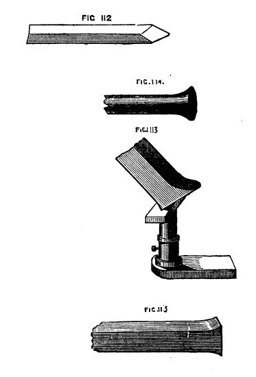
Figs. 112, 113, 114, 115.
Inside tools must of course be made upon the same principles as the last, the particular form alone being modified to enable the cutting edges to penetrate into the various nooks and corners that may occur in such work. The inside tool for iron (Fig. 116), with cutting angles of 60°, is of a general and useful pattern. It must be so curved and so placed that both cutting edges come into action, one on the face and one on the side of the cut, a condition explained in the Appendix as essential to all good work. It being quite impossible to cut metal like wood, and necessary to allow sufficient time for such work, a pointed tool is in most cases preferable to one of a semicircular or rectangular form of edge, and the greater part of the heavy work done in large factories is thus executed. Inasmuch, however, as such a tool, well formed on correct principles, may be made to take a tolerably deep cut, the shaving detached will be of sufficient thickness, and consequently sufficient width to reduce work a satisfactory quantity at each cut. The cut, too, must be continuous wherever possible, the tool being slowly and steadily advanced the whole of the acquired distance without being removed, and then re-entered for a second cut. The result should be a smooth, even surface, and that great exertion is not required when thus working with hand-tools is sufficiently evidenced by a remark of Mr. Haydon to the writer, "I have often detached, with a graver alone, a tolerably thick shaving of iron, two feet and more in length." From what has been said, it will be understood that in hollowing out a piece of metal such as a chuck, the tool should not be made with a long cutting edge, such as would be used if it were intended to scrape the whole depth of the side. A broad shaving is not to be thus aimed at, nor is the inside only to be thus attacked, but the tool advanced gradually inwards from the face of the work till it reaches the bottom, thus (to repeat the important point again) cutting at the same time the front and side of the shaving. The half-round or cylinder-boring bit already described is, of course, an inside turning[75] tool, but is used with the aid of the back centre. In principle it follows other inside tools, the end being bevelled or sloped off 3°, and the side being 90°. The latter is to be regarded as a blunt cutting tool, being the largest angle that can be used; but, nevertheless, this bit must be regarded as cutting in the two required directions—forward and sideways. If a regular Goniometer for measuring angles is not to be obtained, nor any apparatus for grinding a tool to the required bevel, an addition to Nasmyth's tool-gauge, described in the Appendix, may be made by constructing in tin a set of templates, with the angles marked upon them. The easiest way is to mount on the lathe a few round sheets of tin, and mark the degrees by the division-plate, the outer circle of which contains 360°. The tin may then have pieces cut out, as shown in Fig. 117, to be applied as gauges over the ends of the tool, or solid pieces of the required sections (those which are removed in forming the above) may be retained. It will, perhaps, be as well to finish up both neatly, taking care to mark the angles on each. The degrees most required are, as explained, 90°, 60°, 80°, and 3°; but intermediate numbers may be prepared, and will often be found convenient. An inside tool for brass must retain the angles 80° to 90°, the latter acting as a scraping tool to put a finish to the interior of work roughed out by a tool of the lesser angle. There are not many forms in general vogue, for brass work, whether internal or external. The round, the flat, and the point tools (Figs. 118 to 121) are more or less capable of hollowing out work, as well as surfacing. With the first ground to an angle of 80°, brass chucks can be hollowed, and, with the second at 90°, finished; and if there chance to be any internal angles out of reach by the point-tool, it is only necessary to use a similar one bent round at the end towards the left. Much of the turner's success in brass work depends upon the quality of the metal, which is often very hard and unequal in texture and perhaps blown and honey-combed. It is always the best plan to send patterns of any work of importance to some well-known firm, instead of trusting to a country foundry, whose business, if worthy the name, is generally iron work, and who only run brass once in a way, and make a terrible mess of it, too. The same may be said respecting iron castings. It is worth while, as an experiment, to test with turning tools the quality of a country casting, pulley, or what not, by the side of a similar work really made of malleable iron, such as is now so extensively used by the sewing-machine makers. Tools that will stand the first and make good work deserve a place in the British Museum, with a portrait of the turner!
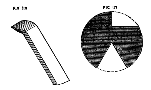
Figs. 116, 117.
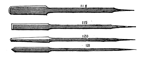
Figs. 118, 119, 120, 121.
For light brass work, such as small model engines now so generally[76] sold, a description of lathe may be used of which no mention has yet been made—namely, a bar lathe Fig. 122. Such a tool may be made for £3 or £4, and will be found sufficient for such work[77] as specified.
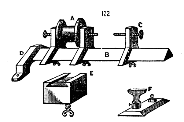
Fig. 122.
In place of the double bed a triangular bar of cast iron is used, on which the poppets slide, and are clamped. D shows one of two sockets with feet which hold the ends of the bar, and by which the lathe can be mounted on any stout plank or on the window sill. The pulley A is made for a strap, because this allows of a plain flywheel, which is much cheaper than those which are bevelled and turned. The rest is shown at E and F. The part E slides upon the bar like the poppet—at the top is a dovetailed groove to receive the slide F, which carries the socket for the tee, and is fixed by a turn of the screw seen on the top of it. There is much to be said in favour of triangle bar lathes, they are very stiff, and can be fixed anywhere. The flywheel can be supported on a separate frame, which is an excellent plan, for the jerk of the treadle and crank is not communicated to the poppets and mandrel. In Maudslay's triangle bar lathe, which was made for amateurs, a slide rest was attached, and the whole work was first class—of late they have gone out of fashion, but are nevertheless good tools.
Fig. 123 represents another very simple form of lathe for turning small articles of brass. It may be said to be one remove from the watchmaker's bow lathe, as it has no true mandrel or treadle; the small flywheel being attached to an arm at the back and worked by hand. The left hand is used for the latter purpose while the tool is held in the right. Through a tapped hole in the left hand poppet passes a steel pin shown at E, on a larger scale; this screws into the poppet after passing through a brass pulley B; this bolt ends in a point, and an arm fixed into the pulley becomes a dog to act against a carrier screwed on to the work as in turning iron. Thus the mandrel and point are fixtures, and the pulley only turns when motion is communicated to it by a catgut from the flywheel behind it. The back poppet and rest, which last is shown separately, slide on the[78] rectangular bar; the latter is about two inches wide, and three eighths thick, and is made with feet to screw to any convenient support. This lathe is especially adapted for work of small size which can be centred at both ends, and on which a carrier can be fixed to bear against the pin, E, of the pulley; nevertheless it is even possible to use chucks, if cast in metal with a pulley to each like G. A spindle must in this case be made like H, on which the chuck must be slipped, and fixed by the nut in the hollow of the chuck. Although however this form of lathe is sometimes met with, and may be used as a makeshift, a small triangle bar or 3in. lathe of the usual form is far preferable.

Fig. 123.
In centering a bar of iron in the lathe too much care cannot be exercised in causing it to run evenly. The ends should be drilled, first with a small, and afterwards with a larger drill, so that a countersunk hole may be obtained in order to keep the point of the lathe-centre from touching the bottom of the hole. If this is not done the friction of the work upon its bearing will soon spoil the lathe-centre, and the work itself will speedily get out of truth, and it will not be possible to screw up the spindle of the back poppet so as to correct this. Of course in turning up very small work this drilling cannot be done. A simple hole must then be made, sufficient for the safe support of the work while being turned, but even in this case the angle of the drill point should be less than that of the conical centre of the lathe, the point of which will then run free. To mark the true centres of a round bar of metal a punch has been devised like Fig. 124. This is figured in Bergeron's work, and is very[79] serviceable. To insure its working truly be careful that the bar of metal is filed flat on the ends, and that the surface of the latter is at right angles to the length of the bar. It is then only necessary to place the end of the piece in the conical part of the cup (which will be best effected by fixing the bar in a vice) and by raising the spring and letting it go sudden by a sufficient mark will be made to guide the point of the drill.
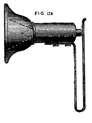
Fig. 124.
The proper place at which to commence turning an iron bar is at one end, the rest being placed so as to bring the tool just upon the line of centres; if applied lower the tool would take too deep a hold, and would either be broken or lift the bar out of the lathe, damaging the centre points. The ends of the bar should be squared up before the circumference is turned, and on no account must a file be used after the turning tool has done its work. It is only at the commencement before a cutting tool has been applied, that an old file may be made use of to take off the scale and roughness left from the forging or casting.
Brass may be attacked upon or just below the line of centres, because the form of tool is such as cannot penetrate deeply. This metal is perhaps easier in some respects to turn, but the tool is apt to form undulations on its surface (is apt to chatter). This is due, partly to the impos[80]sibility of obtaining continuous shavings, and partly to the vibration of the tool, and when once this has taken place there is a tendency to deepen these channels, which makes it difficult to produce a plane and even surface. If a rectangular tool is used in the position already shown and described under the head of tools for metal turning, this chattering will be avoided. If it takes place, the undulations should be worked off by gentle usage of the angle of the tool, the rest being placed close to the work, and only a light cut taken.
With regard to the method of mounting a piece of brass in the lathe, any convenient chuck may be used, but sometimes the piece is short or irregular and requires to be bored out. In this case use solder and firmly attach the piece to a face plate of brass. The easiest way is to smear the two faces to be joined with sal-ammoniac made into a paste with water, and laying a piece of tin-foil between the surfaces, which must be quite clean and bright, apply heat. The tin will melt and a perfect union will be effected. When the piece is finished it is re-heated and detached. This may be considered a wrinkle worth knowing. The flat flanges of brass spoken of under the head of chucks are just suited for this method of working, and they are not damaged by the process, as the solder can be wiped off quite clean when the chuck is made hot. This is a good way to mount small cylinders of brass for model engines, as they can be bored and turned on the outside at one operation with great ease and certainty. If a piece is to be drilled or bored in the lathe, the following is the arrangement to be adopted. Fig. 125, A is the face plate, B, the piece to be drilled, C the drill, which is advanced by screwing up the point, E, of the back centre; D is a hand vice or similar article to prevent the drill from revolving with the work. If it is more convenient to fix the drill itself in a chuck, the point of the back centre is to be removed, and a flange of brass or iron substituted, as A, Fig. 126. If the drill is to penetrate quite through the work a piece of wood must be interposed between the latter and[81] the flange to receive the point of the drill and protect it from injury. The pressure should be so regulated as to be constant and equal without being excessive, or the drill will be bent or broken. Boring is simply drilling on a larger scale, and is of such general use as to require detailed notice. In the first place there are several tools used for the purpose, according to the size of the work. The first is the cylinder bit, Fig. 127. This is a most excellent tool, as it will work very truly, and can hardly get out of place if properly directed at starting. The cutting part A is half a cylinder, the centre being just left visible, the end is not quite at right angles with the length of the tool, but is sloped off a little and bevelled also slightly below.[7] This forms the cutting edge. The other end of the tool has a central hole, drilled to receive the point of the back centre by which it is kept to its work. To use this tool, let the piece to be drilled be placed in a chuck, and a recess turned in it of the same diameter as the cylinder bit, the latter is then placed in this recess B, and when screwed up it cannot possibly rise or shift its position; a hand-vice or spanner is then fixed as shown in Fig. 125, and the lathe put in slow motion, oil or soap and water being freely used to lubricate the tool. Either a solid piece of metal, or a hollow casting can be thus bored.
[7] To an angle of 3°. See Appendix.
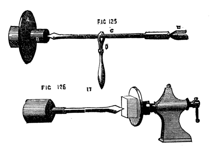
Figs. 125, 126.
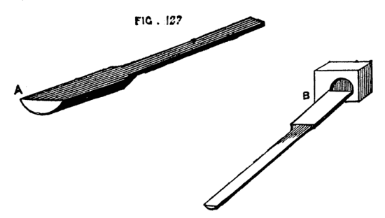
Fig. 127.
These cylinder bits can be had of all sizes, from one-eighth of an inch upwards.
Pipe stems are bored with the smallest of these tools. For this purpose they are made of round steel wire, which is sometimes merely flattened with a hammer at one end to spread and enlarge it, this part being afterwards rounded on the underside with a file, and with the same tool finished on the upper flat face. These slender drills require to be delicately used, and are conveniently held in a pin vice or pair of pin pliers, the handle of which being hollow, allows the greater part of the drill shank to lie within it, a small part only being drawn out at a time for use; thus the drill will be kept from bending, and will work quickly and well.
Of recent inventions in the matter of drills, the most important is the Morse American twist drills sold, in sets, at 30s. on a neat stand with a self-centering chuck, complete. The form is that of a cylinder with spiral grooves cut round it of extended pitch. The cutting edge is as difficult to draw as it is to describe, and must be seen to be understood. It is chiefly formed by the meeting of the spiral grooves and the solid end, the latter forming a blunt angular point rendered cutting by the edge of the grooves. They should have a place in every workshop.
The next tool to be described is also much used, especially in agricultural implement manufactories, for boring out the brasses, or bearings. It is called a rose bit, or grinder, and is shown in Fig. 128 A and B. In this case also a recess is cut in the work as a guide, and as the tool fills up the whole interior as it proceeds, no change of position can occur. The rose bit is used as shown in 125. A bit of this pattern is very useful for brass work of all kinds, such as the cylinders of small engines, bosses of wheels, bearings and collars, and one of these tools of the exact size for hollowing out the sockets of brass chucks, previously to their being tapped, will be found serviceable. The third kind of boring tool is made with movable cutters, which can be removed at pleasure, to be sharpened or replaced by more convenient ones. The simplest consists of a cutter bar, A, Fig. 129, with a slot in it to hold the tool, which is fixed by driving a wedge at the back of it. The tool here shown has two cutting edges, b and c which should be shaped according to the principles already enunciated respecting hand tools for iron and brass. The cutter bar is usually fixed between the lathe centres, and turned by a driver chuck and carrier, while the cylinder to be bored is clamped to the slide rest, and thereby advanced against the cutting edge. This form is chiefly used upon work that has been cast hollow, or drilled.
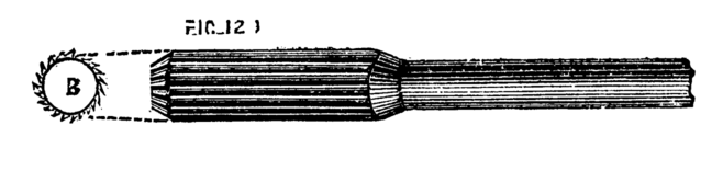
Fig. 128.
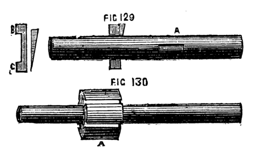
Figs. 129, 130.
Fig. 130 is another form of boring tool for large and heavy work. A boss, A, is fixed to the cutter bar, having a series of dovetailed grooves, or slots, on its surface, in which cutters are fixed by wedges. In this and every similar form, it is expedient always to complete the circle, or, at any rate, two-thirds or three-quarters of it, by driving in blocks of wood in the slots not occupied by the cutters. This preserves the concentricity of the tool. One edge of these movable cutters should be radial to the centre of the bar, or boss, the other rather less than a right angle, which will ensure a good cutting edge. The best lubricant is oil for the first cut, and soap and water, or pure water, for the finishing cut. The surface will thus be left bright. It[83] is not well to finish with emery any collar in which an axle is to work (as the collar in which the mandrel of the lathe runs). This substance imbeds itself in the pores of the metal, and by forming a grinding surface, considerably increases the friction and wear and tear of the parts.[8] Although boring and drilling are capable of being done in the lathe, a far superior plan is to employ an upright boring apparatus, as is now generally used in making steam cylinders. The work is not then suspended between two points, or carried on the slide rest, but takes up a firm bearing on a fixed support, and the boring tool descends by a pressure screw, or self-adjusting contrivance, as the work proceeds.
[8] Oilstone powder may be substituted, especially for the best brass work.
We have spoken of the slow motion as necessary for turning metal work. This is represented in Fig. 131 A B C D. The first is a plan seen from above. The poppet is cast double like F, so as to afford a bearing for the mandrel, and a second for the back spindle seen at A. This back spindle, it will be observed, passes through its two collars or bearings, and can slide freely in them from side to side. This can, however, be prevented by dropping a pin through a hole in the top of the poppet, which falls into a semicircular groove in the spindle. The pulley is securely attached to a small cog wheel, and can be firmly united to a larger one, as seen at A2, and separately at C and D. This pulley and small cog wheel run loosely on the mandrel, and do not revolve with it until clamped to the wheel, C, which is itself keyed to the mandrel. Suppose them to be thus free to revolve, and the wheels in position shown in the plan, A. On putting the fly wheel in motion, the pulley will revolve on the mandrel, carrying with it[84] the small cog wheel, which in turn will act on the large wheel on the back spindle. The small cog wheel on the latter will thus put in motion the large one geared with it, the which being keyed to the mandrel, will put the latter in motion. There are many ways of clamping the pulley to the large cog wheel, perhaps the following is as good as any. It must be so clamped for wood turning when the back spindle is to be slipped on one side out of gear.
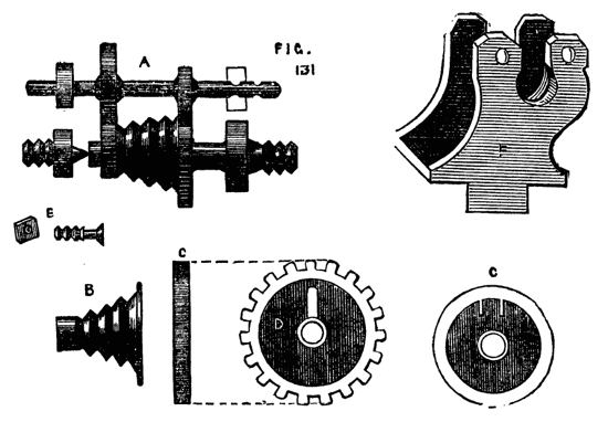
Fig. 131.
In the face of the pulley, which is concave, is a piece of brass flush with the rim, and which forms a dovetailed groove, into which the head of a clamping screw, E, fits. This screw projects through a slot in the wheel D. When it is required to fix the pulley, this screw is slid up towards the rim till the head rests in the dovetailed projection, and it is clamped in that position by a nut. When it is desired to put the back action into gear, this nut is loosened, the screw-bolt dropped towards the axle (thus freeing the head from the dovetail), and again fixed by the nut. The wheel and pulley are thus independent of each other, the back spindle is slipped sideways into gear, and held by the pin, and the slow motion will be obtained.
There is one fault in the arrangement of the back geared lathe that with amateurs in a private house is especially disagreeable, and it is questionable whether in large machinery establishments it might not with great advantage be corrected. In the action of toothed wheels, nuts and screws, and similar gearing, there occurs what is called back lash. If, for instance, the tool holder of a slide rest is advanced, and then the action is to be reversed, the movement of the nut and tool holder does not commence simultaneously with the movement of the screw. This is due to the play, or necessary looseness of the working parts, the pressure coming on one side of the thread when the screw is turned in one direction, and on the contrary side when the motion is reversed. In toothed wheels a similar defect exists, and gives rise to that disagreeable and ceaseless noise which assails the ear on entering a building where machinery is in motion. This may be avoided by the use of frictional gearing, a simple but excellent mechanical contrivance which deserves far more extensive notice than it has yet received. It is the invention of a Mr. Robertson, and is patented. A lathe fitted with it would be almost noiseless, and would work with a delicious smoothness, very conducive to the comfort of the workman. This gearing, represented in Fig. 132, is merely the substitution of V shaped or semicircular grooves for cogs, the former running round the periphery of the wheel like the grooves in an ordinary lathe pulley. In this method of gearing, it would be necessary to move the back spindle to-and-fro, the usual horizontal movement not being possible. This is easily effected by a screw or a cam, either of which might be made to act on the frame which carries the back spindle, and which may then work on a centre, as[85] Fig. 133, where A is the poppet, B, the support of the spindle, D, a cam; when the handle of the latter is raised, the standard, B, is allowed to fall back out of gear into the position shown by the dotted line, C. A screw movement would have the advantage of enabling the workman to regulate with greater precision the pressure of the friction pulleys against each other. The drawing shows the grooves of these pulleys larger and deeper than usually made. They are generally rather shallow and numerous, and it is astonishing with what firm hold they grip each other without that violent pressure which it might be imagined would be necessary to prevent slipping when in use.
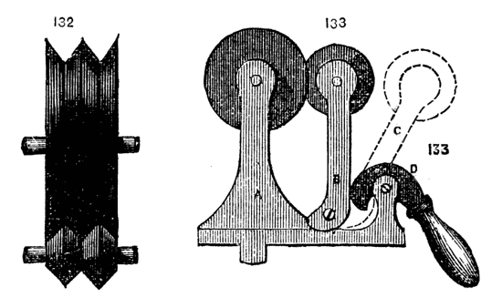
Figs. 132, 133.
The ordinary slide rest for hand lathes is made as follows:—That for ornamental turning will have a separate notice. Fig. 134, shows the slide rest viewed from above, and it is evident if the tool is clamped to the holder F on the top plate, it can be advanced from end to end of the top slide B, and also (with the upper frame itself) along the lower frame A, A, these movements being at right angles the one to the other. For parallel work this is sufficient. In this compound rest a third motion is arranged for turning cones or taper plugs like those of stop cocks, taps for screw plates and such like articles. For this purpose the upper frame is cast like Fig. 135, with a flat surface, but with two ribs underneath, uniting the frame to a circular plate with two concentric slots in it. This plate revolves on the plate G G, turning on a central pin, and it can be clamped by the two screws which pass through the slots into the plate in any desired position; once clamped at the required angle a piece of metal can be bored with a conical hole and a plug turned to fit it without possibility of failure. The details of construction allow of considerable variety, and different makers keep to their respective patterns; the main desideratum is strength and solidity, combined with accurate adjustment of the moving parts. The V's, underneath the frames, and the edges of the latter, must fit, so as not to be tighter in one place than[86] another, and the upper and lower frames must cross each other accurately at right angles. It is likewise essential that the tool traverse the work in a perfectly horizontal line. Every part must, therefore, be accurately made by means of the lathe and planing machine, and the whole carefully put together. Notwithstanding the above desiderata, a slide rest is not necessarily beyond the skill of the amateur. We have, indeed, seen one thus made quite equal to the work of a professed mechanic, though the file and scraper had to take the place of the planing machine. The rough castings can be bought for about half-a-crown, suitable for a five-inch centre lathe, and it would be much better to try and fit up a set of these castings than[87] to attempt such a substitute as a wooden slide rest. The latter has nevertheless been made, and we remember seeing one of mahogany edged with brass, the work of a cabinet maker, which did good service in turning and ornamenting wood.[9] This, however, was upwards of twenty years ago, since which time the facilities for obtaining slide rests of metal, properly constructed, have materially increased. As the dovetailed edges of the slides wear away by use, it is necessary to provide means for tightening up the V-pieces. This is shown in Fig. 136. The holes in the V-pieces through which the top screws pass are not round, but oval, so as to admit of lateral movement.
[9] In the Paris Exhibition of this year (1867) are some slide-rests made of hardwood and metal.
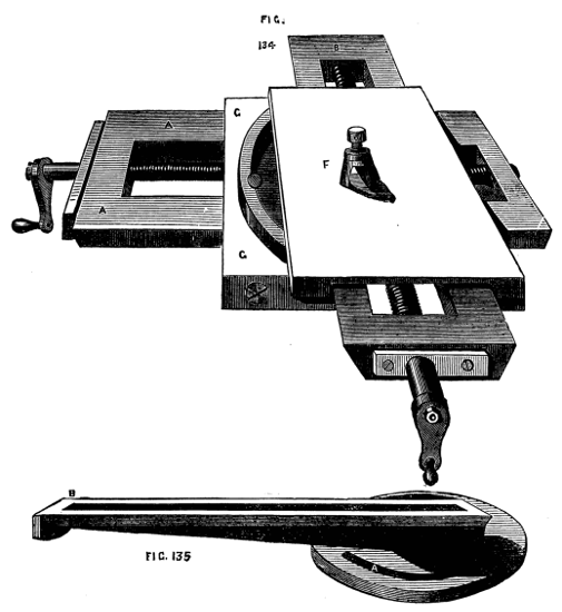
Figs. 134, 135.
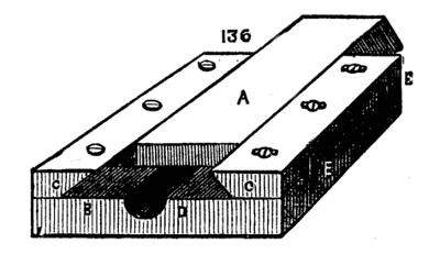
Fig. 136.
Two large headed screws, E, E, are tapped into the place on which the V-pieces rest, and when these are screwed up, their heads (which are sunk for the purpose in two recesses in the lower plate) press against the V-pieces, driving them closer to the dovetailed slide. When thus adjusted the top screws are made use of to fix the strips c, c. By this method the slides can be adjusted to work with the utmost ease and accuracy, without shake or side play. The edge of the circular plate and the heads of the leading screws are very frequently marked in graduated divisions, so that the advance of the tool or the angle to be made with the work by the tool can be accurately measured and preserved. There should at any rate be a mark on the circular plate to show when the rest is set for parallel work.[88] There are several patterns of tool holder, of which the forms shewn are convenient for light work. The one shown in 138 & 139 on the rest is somewhat different. The plate F, Fig. 134, is cast with a boss and socket, like that of an ordinary rest. In this socket the tool holder fits, and can be not only turned round so as to set the tool at any angle, but also slightly adjusted in height, which is a great advantage. The tool is clamped by a single screw as shown in the sketch. The drawback to this form, and that on the rest, is this single screw, which will indeed hold the tool when the work is easy, but will not always retain it with sufficient firmness when the work is rough, or of tolerable size. In large workshops one usually meets with the holder represented in Fig. 140. A plate, A, with central block B, and slide C, are in one casting. Through A pass eight screws. The tool lies on either side of the central square block and is clamped with three screws, it has thus a fair bearing on two sides, and the screws form a third above, so that accidental shifting of the tool during the progress of the work is hardly possible. The tool holder of Professor Willis, which is described in the Appendix, is perhaps the best of all at present in use. It holds the tool firmly at any desired angle.
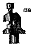
Fig. 138.
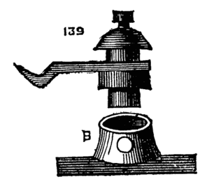
Fig. 139.
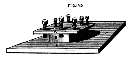
Fig. 140.
It is quite possible that the novice who has seen mere boys working with slide rests at manufactories will be disappointed at his own first attempts to use this piece of machinery. All the difficulty lies in the shape and set of the tool. When turning metal with hand-tools it is easy to feel one's way. If the cut is not satisfactory, the hand at once modifies the angle of the tool, and regulates its direction to a nicety, but the slide rest cannot thus adapt itself to its work. It must be set with its slides in position, and the tool once fixed must pursue its own course. Hence it requires a very accurate knowledge of the nature of cutting tools, such as we have given in the Appendix to this work. If the tool is well placed upon the axis of the work for iron, a little below it for brass—it will cut cleanly and easily, without rubbing or jarring, both of which are proofs of either a wrong angle of edge, or a wrong form of tool. The work should proceed with as much apparent ease as if the metal were an apple, and the shaving should curl off like its peel. Moreover, this case is not merely apparent, it is perfectly easy to cut iron, and the strain on the tool, whether held by the hand or by slide rest, is comparatively slight, if the tool is properly made and held. Fig. 141 is quite the best form[89] of tool for surfacing cylinders with the slide rest. It is to be so placed that both edges are made to cut near the point; hence the crank should slightly curve away to the left. It is not possible to cut metal quickly, be content with fine clean shavings curling off freely. You will soon see whether you can take a deeper cut with safety. The tool here sketched is not at all likely to dig in and hitch in the work; if it is not properly placed it will spring and jump, or its side will rub against it, and no cut will be made. To describe the exact position is very difficult, but the principle once grasped, little difficulty should be experienced in making and setting to work any tool, whether for inside or outside work. The rule of thumb was all well enough in olden days and in the infancy of the art of metal working, but it is time to discard it; to master and man it is equally advantageous to do so. Indeed, in some of our leading firms, the old system of follow-my-leader, when the leader was as ignorant of his work as the follower, is waning, and the "how" is now, as it ought to be, coupled with the "reason why." One of the best papers ever written on this subject is to be found in Weale's series, "Mechanism and Construction of Machines," by T. Baker, and "Tools and Machines," by J. Nasmyth, 2s. 6d. The latter part is that specially referred to, and is well worth the whole price of the work. The remarks, however, of that eminent mechanic are embodied in the paper in the Appendix, and therefore, after the reader has studied the latter, he should make trial for himself of the principles laid down. Expend a quarter or a half an hour experimenting thus, with keen and obtuse tools, held at divers angles, and you will see and understand what is meant by setting a slide rest, or hand tool to cut metal as it ought to do.

Fig. 141.
Fig. 141 is too much cranked; half the length of the hanging part would amply suffice.
Supposing the tool fixed in the tool holder in the position indicated, and just overlapping the circumference at one end (the right). Take hold of the handles, one in each hand, and with that which advances the tool from end to end of the bar try very carefully whether the tool will cut cleanly by making a turn or two while the lathe is in slow motion. If the tool bites too deeply, turn the other handle and ease it. If you still find the tool sticking into or scraping the work, instead of bringing off a fine shaving, look well to its position, and observe whether the edge is well placed on the axis of the piece. If it has been hitching in the work it is probably too low, if rubbing it, too high, and touches at some point below its edge. It is presupposed, of course, that the tool is made correctly as to angle of cutting edge. Do not lower the point by packing the end of the shank; pack the whole length or none. It is astonishing what a great difference is made to the cutting power of a tool by slight adjustments of this kind, and how smoothly a tool will work with proper attention to these details, which would otherwise be probably cast aside as unfit for the[90] work. Hence the greater ease in managing a hand-tool. The hand feels the error, and at once, if experienced, corrects it by an almost imperceptible movement—slightly raising or depressing the handle or gently varying the angle sideways on the rest. When once the tool is found to cut as it ought to do, nothing remains but to turn the handle in the right hand, and thus cause the tool to progress steadily along the work from end to end. Then free it by a half turn of the other handle, reverse the movement until the tool has arrived at its old place, and having slightly advanced it to take a fresh bite, repeat the process until the whole bar is reduced to the required size. If the piece is slender and bends away from the tool, add to the slide rest a support; let it be fixed opposite to the tool, and it will keep the work steadily up against the cutting edge. It can be fixed (if a hole is made for the purpose) anywhere about the slide which traverses in the direction of the length of the work. It is well to drill and tap a few holes about the slide rest, and some along the side of the bed of the lathe. These will be found very useful at various times for fixing apparatus. For, be it observed, (and we shall recur to this with some practical hints by and by) the lathe may and ought to do many kinds of work beyond ordinary turning. It may become a machine for planing, slotting, drilling, wheel cutting, &c., and is to be pressed into the service of the jack-of-all-trades, without compunction.
When ordering a slide rest let steel screws and nuts be specified, and gun metal V-pieces, and let the parts be strongly made (too strong for the supposed work); for the latter may unexpectedly turn out to be sometimes rather heavy. We have found the top plate of a 3in. slide-rest so weak that when the tool was clamped on the top of it, by the screw of the tool holder, the slide itself became jammed; a defect quite beyond remedy, except by the substitution of a new and stiffer plate. The same advice may be given respecting the tools. Let these also be strong; neat and pretty tools are all very well, but you seldom see them in a workshop; you don't require pretty tools, but good and serviceable ones. Nevertheless, let the material be of the best quality possible; and that you may not be ever at a loss, you should learn to make tools yourself. Procure some small square and round steel bars; save up as directed your old files, and you need but heat them red hot (not on any account white hot), and with hammer and file shape them to your mind. Then temper to a deep straw colour, and after being accurately ground and finished on the stone, they will be fit to use upon any metal. The form of tool given as the best for slide rest work may be exchanged, when the bar is nearly turned, to the required size, for a fresh one, keen, sharp, and of an almost flat edge instead of point. A tool, of which the edge is a segment of a very large circle, will serve the best as a finish[91]ing tool, just to take off the lines left by the pointed tool. With regard to lubricating the work, we may observe that the chief object is to prevent the point or edge of the tool from heating and losing temper; oil, water, or soap and water will therefore answer, but it is a curious fact that oil will not produce so polished a surface as water will. We should advise in all cases soap and water. Soft soap is best, boiled in water, and allowed to cool. The drills with which the huge armour plates of ships six inches thick are drilled are thus lubricated, and instead of throwing out dust in a wet state as usual, these large drills fairly turn out curled shavings similar to those produced by the planing tool. It is by no means a bad plan to lay the shank of the tool which falls upon the top plate of the rest, upon a piece of leather, wood, or sheet lead. The surface of the iron, when planed and finished, is often too smooth, and the tool will sometimes slip from this cause, unless screwed unduly tight, to the detriment of the rest. By the above plan this annoyance will cease at once.
We will now say a word about hollowed work. Finishing a chuck will serve our purpose, and here be it advised not to go to much expense about chucks—get those which must be of brass in the rough, and practice metal turning by finishing them yourself. If no slide rest is available do it by hand. However, we are supposing the slide rest to have been procured, and may therefore proceed to use it. First you must drill the back part of your chuck as directed in a previous chapter. The drill is to be the size of the diameter of the hollows in the mandrel screw, that is, smaller by the depth of a thread, than the full size of the nose. Having drilled it, proceed with the most tapering of your taps, which we suppose to be provided to form the internal thread (external if your mandrel has female screw, in which case, instead of a drilled hole, the chuck will have a projection to be turned truly cylindrical, and a screw cut outside with stock and dies or chasing tool).
Follow up with the intermediate and finish with the plug tap. If you were careful to square up the shoulder, the drill having been likewise placed perpendicularly to the face of the chuck, the latter will fit truly up to the collar or shoulder on the mandrel. If not, you must go to work again, and square up the back of the chuck till a good fit is produced.
Now, if you have a compound slide rest—that is, one in which the slides turn on a centre pin—you can loosen the screws and turn it a quarter of a circle. If not, you simply put the tool into the holder, at right angles to its former position, so that the movement of that slide which is parallel to the lathe bed will become that requisite to advance the tool into the hollow of the chuck. Whichever way you set to work put in a side tool, like Fig. 142, and, as it[92] is a brass chuck, remember that the bevel underneath is to be very slight. Introduce the tool so as to take a light cut at first, until the roughness is taken off, after which you may cause it to bite more freely. Repeat this until the chuck is sufficiently hollowed out, when you may substitute a similar shaped tool, but with a flat or slightly rounded edge, to take off the marks left by the point tool. To finish the bottom of the inside you will require a tool which cuts on the end, but it should not have a perfectly flat end—at any rate, not until, by means of a pointed or small round-ended tool, you have cut away the roughness left from the process of casting. This has always in its interstices a number of grains of sand fused, and very hard and detrimental to cutting edges of all kinds. The point tools dig these out very effectually, and should always precede those of other forms.
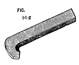
Fig. 142.
The outside must be turned in a similar manner, and a hole drilled to receive a pointed bar or wrench, for the purpose of unscrewing it when screwed up tightly. To turn up a face plate of iron or brass proceed in a similar way, but commence from the centre with a point tool. This tool is the best for taking off the rough outside of hard wood, instead of the gouge, as well as for removing the roughness of a fresh casting. It is absolutely necessary that the faces of these flat chucks, or surface chucks, be truly at right angles with the mandrel; hence it is very difficult to turn and finish them by hand. We may here also state the necessity of knowing when the slides of the rest are at right angles to each other, without which no work can be turned correctly. It is necessary to ascertain this by help of a small steel square. Once fixed truly, it is only necessary to make a mark on the quadrant (which should be marked in true degrees), by which the same position can be found again at any time. We have spoken here of the quadrant—we mean the arc, or arcs with slot—allowing the circular movement of the compound slide rest. The chief use of these is to enable the workman to turn true cones instead of cylinders, which latter will only be produced when one slide is parallel to the lathe bed. Such is the common use of the slide rest; and it will be evident from these few remarks that there is an infinity of work, not only produced with ease by its aid, but which cannot, even with expenditure of time and labour, be produced without it; hence we advise this to be the chief ambition of the tyro after he has mastered the difficulties of ordinary hand turning (and not before). The cost of a fair one for 5-in. lathe will be £5, or thereabout. At Munro's, £7 or £8; at Holtzapffel's, £10 or £12. Both the latter are of course perfect.
We have directed to tap the chuck where it is to be screwed to the mandrel with a set of three taps, or to cut it with stock and dies if an outside thread is required. In both cases more true and satisfactory work may be produced by the chasing tool. We speak of the latter as used by hand; an account of cutting the threads by help of the slide rest we reserve for the present. Mount the work in any convenient way, either driving it into a wooden chuck, or by clamping it to the face plate if you have one. Now in this way you have advantages. In the first place you need not have a drill the exact size, though it is convenient to have such a one, and also a cylinder bit. You can drill and enlarge the hole by the slide rest tools, and you can also with the slide rest ensure the perpendicular position of the hole with respect to the end. Thus it is sure to fit up close and snug to the shoulder of the mandrel. When bored thus it will be in position for chasing. It is not difficult to chase a thread in brass, as it does not chip away like wood, but cuts clean and sharp. Follow the directions already given and you will succeed in a few turns in getting the tool to run. Then let it have its own way; hold it lightly, but steadily, and do not force it either to cut too deeply, or to advance too quickly; it will run along of itself after the faintest thread is cut or scratched, and the lathe can be worked by means of the treadle all the time as soon as you have attained the knack of dropping the chaser into its place at the commencement of its cut, and suddenly withdrawing it when it has reached the bottom of the hole. A chuck thus turned and screwed entirely in the lathe is sure to prove a good fit, and there can be no better practice than to cut screws in all your brass and boxwood chucks in this way. A very good chuck to hold flat plates of brass was invented by a Mr. Wilcox, of Bishop's Stortford, some years ago—an amateur of rare ingenuity and mechanical knowledge, and who made all his own apparatus for plain and eccentric turning. The chuck, Fig. 143, as described by him in some unpublished manuscript, is made of boxwood, or may be of metal. It is a plain disc or surface chuck with three slots A B C. and a steel centre. This last must penetrate rather deeply into the wood of the chuck, but is only kept up so as to project from the surface by a spiral spring below it. Hence, when pressure is made upon its point by the application of the object to be turned, the pin recedes into the body of the chuck, suffering the work to lie flat on its surface. In[94] the three slots are three screws, with nuts at the back of the chuck the screws pass through two pieces of brass, forming a pair of jaws, one of which is shown separately.
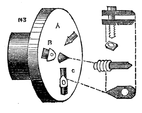
Fig. 143.
Fig. 143 shows the chuck complete. Suppose we have to face up a round disc in its central part, or to perform any surface work in which the jaws will not be in the way of the tool, the centre of the plate is marked at the back of it, and this mark laid on the central pin. The work can be clamped down by the three jaws, and the necessary work may be done. Now so far the chuck is but a simple affair, and the receding pin does not show itself to such great advantage; we will therefore suppose a plate is to be drilled at several spots; let these be marked at the back by a centre punch. It is now only necessary to bring these marks in turn upon the central point, and clamp the plate in position. Bring the point of the drill against the work and keep it up to cut by the back poppet screw. In the same way eccentric work or any operation may be done to such a plate, with the certainty that the point to be thus worked upon is precisely central with the axis of the pulley, or mandrel. Many similar applications of this chuck will present themselves to the reader upon due consideration. We present the chuck in this place because we have had occasion to speak of drilling as connected with the slide rest, and there are many pieces of work that could not otherwise be conveniently held in the desired position.[10]
[10] The MS. book containing the above was kindly lent to the author of the present work by Mr. Hoblyn, of Bishop's Stortford, who is the inventor of a new form of slide rest, which will be introduced in a later page. The chuck in question is, however, commonly attached to the watchmakers' lathes of the present day, and therefore may not, as the writer supposed, be actually the invention of the late Mr. Wilcox.
It now becomes necessary to speak of another addition to the lathe, by means of which the use of the slide rest is considerably extended. We mean the overhead motion. Of this there are several patterns, and we have sketched three of these. As to their respective merits we can hardly venture to speak. They all answer equally well the purpose for which they have been designed, and the turner must select according to his fancy, or, if he please, design a better for himself. A, Fig. 144, represents the lathe bed. From the left-hand standard rises a round iron rod, not less than one inch in diameter. This is not generally fixed, but is attached to the standard by two staples, a, b, which hold it securely in an upright position, but allow it to turn with its projecting bar F, F,[95] after the manner of a crane. It may thus be turned back, out of the way, or brought into any desired position. The part F, F is made to slide up and down on the part B, and is fixed by a clamping screw D. Thus, if the cord should break and require to be shortened, the arm can be brought nearer to the bed of the lathe. Upon F, F slide two rings, or rather short pieces of tube, from which depend two India rubber springs (door springs), E, E, now procurable at any ironmonger's at one shilling each. From these hang double pulleys, or better still two single ones. These pulleys, with their attachments, are adjustable at any position on the arm F, F, which may be round or square. If considered desirable, a second standard can be added, so as to uphold both ends of this bar; but it is hardly necessary, as the latter is seldom required of greater length than half that of this lathe-bed. It is evident that the above addition to the lathe can be made complete for a few shillings. The following are more expensive, but more general, the writer having devised the above to suit his own fancy, and for his own use. In Fig. 145 A represents the standard as before, the top[96] of which is forked, as shown at E, and sustains the ring, free to revolve in its arms, as seen in the sketch. Through this passes a bar, B B, with a heavy ball C cast on its end to act as a counterbalance to the longer arm and its connections, and to keep the cord stretched. By sliding this bar either way through the ring which supports it, the tension of the cord can be increased or lessened.[11] When in position it must be very securely fixed by the screw T, which should not simply press against it, but enter one of a row of depressions made for the purpose. The pulleys C, D are double, as in the previous plan of overhead, and are likewise adjustable at any position on the bar B, B. The only drawback to this pattern is the danger of the heavy ball slipping out and falling. We prefer to hang a weight from the end of the lever, as shown by the dotted line. This may be within a few inches of the floor, and if it should fall no harm can ensue. The third pattern, Fig. 146, is the most expensive, but although it is of a more finished appearance, and wears an aspect more stiff and stable, it is not practically any better than the last. From a standard A, with overhanging bar F, F, is suspended a frame H, by means of two coiled springs in brass boxes B, B, which keeps up the necessary tension on the cord, or rather cords, for in this case two are needed—one from the flywheel to the small pulley, and a second from the roller to the slide rest.
[11] Sometimes the bar is merely hung on pivots, and the weight is made to slide upon it.
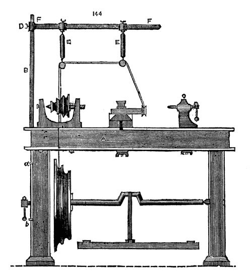
Fig. 144.
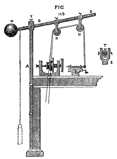
Fig. 145.
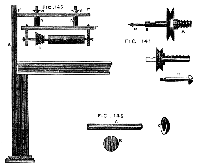
Figs. 143, 146, 148.
This roller, which may be grooved or plain, may be replaced by a second small pulley, which is capable of being slid along the round bar which forms its axle and turns with it between the centre screws. In this case the bar is made with a groove or channel along its length, Fig. 147, and a pin projecting from the central hole in the pulley enters this groove. Thus the two will turn together, and at the same time the position of the pulley is adjustable at pleasure. The tension of the springs B, B, is increased or lessened by a turn or two[97] of the nuts C, C, just in the same manner as the spring of the safety valve is adjusted on the boiler of a locomotive.[12] The application of the overhead motion is plainly shown in Figs.143 and 144. The work is fixed in the lathe, and the mandrel kept stationary. The cord passes to the overhead directly from the fly wheel, and thence to a pulley on the screw of the slide rest, as in 143, to a drill, as in 144, or to any other apparatus at pleasure. To fit the work in the lathe in such a manner as to enable any point in the face or side to be operated upon, a division plate and index are required. The first is a round plate of brass or gun metal, 1/16th of an inch thick, drilled with holes in concentric circles. The index is a steel spring with a projecting point, which, entering any one of the holes, retains the plate, and with it the pulley, on the face of which it is fixed immovable. There are generally four circles of holes, the number in each selected with reference to its divisibility by the greatest possible number of divisions—thus 360, which is usually on the outside or largest circle, can be divided without a remainder by 2, 3, 4, 5, 6, 8, or 9—144 is a good number for the second circle, being divisible by 2, 3, 4, 6, 8, 9. The other two may be 112 and 96. The uses of the division plate are many. Eccentric cutting and drilling could not be[98] done without its aid, and wheel cutting for clocks, or for making cycloidal and other chucks, is entirely dependent on this contrivance.
[12] The frontispiece shows another superior form of overhead, with balance-weights hanging close to the ground behind the lathe.

Fig. 147.
The division plate and index are shown in Figs. 147, A, B, C. The part B is a knob with a round hole through it, to take the tail of the spring C. This is shown again at C on a larger scale, to bring to view a slot which allows of some slight adjustment of the point, to suit the different-sized circles. The milled-headed screw clamps the point at any desired part of this slot. When not in use, the spring is drawn back so as to release it from the division plate, and turned down in the position shown by the dotted line.
The overhead apparatus is applicable not only to revolving cutters in the slide rest, but to other contrivances available where the latter is not possessed. There are many cases in which the back poppet may be brought into use to hold revolving drills, or stationary tools, if the resistance to their action is not too great. The only damage that can well happen in this method is to the pin working in the slot on the outside of the spindle. If this is of steel and tolerably stout and strong (being very short it cannot be subject to any very injurious strain), no harm is likely to result. With this it is possible to drill very neatly, and also to do a little eccentric cutter work, under certain conditions to be described. Screwing, or rather chasing, may likewise be done very passably. We do not, of course, advise this course when the more perfect slide rest is at hand, but there are many who are obliged to put up with all sorts of homemade contrivances, and to press into service for divers operations apparatus and tools not precisely meant to be thus used, and it is as well to learn how to act under an emergency, even if the practice is not intended to be carried out generally. The drill stock is shown in Fig. 148, in which the screw A fits into the spindle of the back poppet. If the hole in the latter is conical instead of cut with a screw thread, the drill must be made accordingly.
The pulley of brass has a hole drilled through it, and the screw is also drilled, the hole in the latter being rather larger than that in the pulley (which is tapped). The steel pin H, shown white in the sectional drawing, passes truly through the centre of the screw in which it revolves, and is screwed into the pulley. The socket of[99] steel to hold the drill is then screwed or soldered into the opposite face of the pulley. The black part shows a flange on the screw which abuts against the cylinder of the poppet into which it is screwed. Thus the pulley, being attached to the cord from the overhead apparatus, is free to revolve upon the steel pin with great rapidity, and will carry round any drills or cutters placed in the socket B. The simple straight drill being thus worked and advanced by the leading screw of the poppet, will suffice for holes in any work held on the mandrel. On page 335, vol. ii., of the English Mechanic, this method is mentioned, and also a similar pattern of slide tool to be used for boring, being, in fact, the head and spindle of the back poppet, but instead of the standard and sole, a pin, like that of a T, to fit the socket of the rest. This has the advantage of the back poppet, but must be made on purpose, and if any special slide tool is added, a proper slide rest is by far the best. Our present purpose is to describe the use of the back poppet as a substitute for a better tool.
With the following modification of the eccentric cutter, a fair amount of good ornamental work may be done. Fig. 149 represents the back poppet with the apparatus in position. The various parts are shown separately in A, B, C, D. A is a small frame, two or three inches long, and ¾ to 1 inch wide, cast in iron, with a circular piece at the back, 1½ or 2 inches diameter. This circular piece is to be accurately divided on the edge with any even number, which is divisible as above explained. This is turned and drilled through the[100] centre. B is a flange-shaped piece to screw to the poppet as before, and this is also accurately drilled, and the two are attached by a central steel pin, so that the two flanges can turn face to face, the outer one with frame revolving against the other. The pin must be put in its place in B, and turned at the same time as the face of B, that it may be truly central. The divisions on the edge of the outer flange are to be drilled like the division plate of the lathe, or cut into cogs, and in either case can be held at any point by a spring detent or index attached. C shows the front of the frame, with a screw down its centre and traversing slide f. The head of this screw is divided, and a small brass index marks its position; one side of the frame may likewise be divided. The small brass pulley and drill socket are fixed to revolve in the traversing nut or slide f, as shown in a side view at D. Drills of all shapes, as E 1, 2, 3, 4, may be fixed in the socket at pleasure.
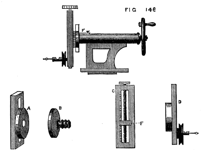
Fig. 149.
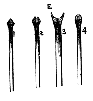
Fig. 149E.
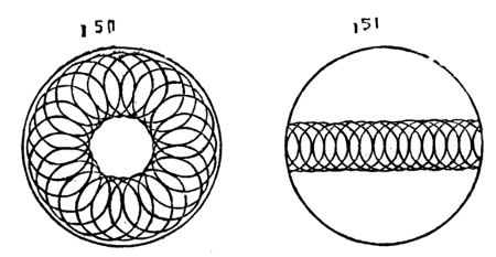
Figs. 150, 151.
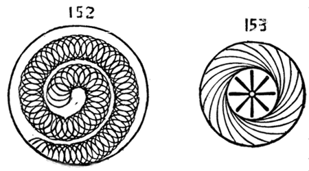
Figs. 152, 153.
It is evident that the cutter frame last described having a division plate of its own dispenses with the necessity of one on the pulley of the mandrel. Indeed it was the impossibility of supplying the latter on the face of the cogwheel of the author's back-geared lathe that necessitated the substitution of that alluded to. The latter may consequently be omitted if applied to a lathe already fitted with division plate and index. With crank-form drills the cutting edges of which may be as E 1, 2, 3, 4, or other form, such patterns can be cut, as shown in Figs. 149, 150, 151, 152, which are merely samples of the simplest combinations of circles intersecting in straight, spiral, or other lines. Although not now treating of eccentric work, we may state in passing that to produce the pattern round the edge of 150 the division plate of the instrument only is required. Select a crank-form drill which by its revolution will produce the required size of circle. Turn the divided screw head until you find upon trial that the circle will come at the required distance from the edge, and putting the lathe in motion cut the first circle. The work on the mandrel is understood to be stationary, the mandrel being fixed so as not to turn. The cutter frame is now turned on its axis, one, two, or more of its divisions, and fixed by its detent, and a second circle cut intersecting the first. This is repeated till the whole circle is[101] completed. The straight line of circles in Fig. 151 is cut as follows:—The first circle is made as before, but the cutter-frame should be placed so as to stand either horizontally or vertically. Between each cut the divided screw-head is moved so many points according to the proposed fineness of the pattern, and no movement of the cutter frame on its axis is to be made. The spiral, 152, is simply the result of a combination of the two movements. Start from the centre by turning the screw head until the shank of the crank-form drill is coincident with the axis of the mandrel. Cut the central circle. Thence for each successive circle turn the screw head and the frame an equal number of points, and the pattern will be formed. If the divided screw head is made to take off and a handle substituted, stars formed of channelled lines, or radial flutes can be made as Fig 153, but in this case the crank form drill is replaced by a plain straight tool with a rounded end like 149 E 4. Set the tool as for pattern 150 straight across the face of the work, put the drill in rapid motion, let it be advanced by the leading screw of the poppet so as to penetrate slightly, and with the handle that has been attached to the screw of the cutter frame cause it to traverse the face of the work as it revolves. When one flute is thus cut, turn the frame on its axis as many points as required, and proceed with number two, and so on to the completion of the star. It is not necessary at present to describe other patterns. Fig. 153 is therefore merely given without special details of the method of producing it.
We must now return from this digression to speak of other applications of the slide rest. It is evident that when connection is made between the overhead and a pulley on the screw of the slide rest, the latter becomes self-acting. The speed is, however, far too great, and in addition, the mandrel is stationary. The above connection, therefore, is not practically possible, and the overhead is only connected with the pulleys of revolving drills and cutters fixed in the tool-holders of the rest. It is, however, very important to be able to form some such connection between the lathe mandrel and the screw of the rest, for the purpose of cutting screws or spirals. A little consideration will show the principle of this arrangement, from which some practical plan is not difficult to design. If, for instance, the tool simply remains in contact with a cylinder while the latter revolves with the mandrel, a simple line will be cut round its circumference; but if, while the mandrel revolves once, motion is given to the screw of the rest by which the tool is made to traverse a distance of one-eighth of[102] an inch, the commencement of a spiral having that pitch will be made. A perfectly smooth surface, as it leaves the lathe, in which a slide rest has been used with a point tool, is in reality cut with a very fine screw thread readily discernable under the microscope. We have, therefore, only to devise some method of giving regular motion to the screw of the rest while the work revolves as usual, in order to turn plain surfaces, screws, or spirals. For the purpose of plain turning a plan is sketched by Nasmyth in the last chapter of "Baker's Mechanics," in Weale's series. A spur wheel is represented fixed to the slide rest screw, the teeth of which are alternately caught at every turn of the work, by an arm fixed to the latter, after the manner of a lathe carrier. This plan is simple, and might be to some extent used, but for one defect, due to the fact that the slides of ordinary rests are the reverse of what is required to make this plan available. The screw which advances the tool towards the work is generally underneath that which moves the tool along the surface of the work. The result is that, when the tool-holder is advanced to take the deeper cut the spur wheel is brought nearer to the arm which acts upon it, and greater traverse is thus given to the screw. This is shown in Fig. 154. A is the spur wheel, B the cylinder to be turned, C the arm or carrier. The arrow shows the direction of the movement. Now, if the lathe is put in motion, the arm will remain in contact with one tooth of the wheel until both arrive at b, giving a certain amount of motion to the screw, and thence to the tool-holder. After one cut is thus taken, the lower screw of the rest is turned to advance the tool nearer to the work, the effect of which is to cause the arm to extend further over the wheel. Suppose its position represented by the dotted line, it will remain in contact with the tooth till both arrive at c, having thus traversed a larger arc, and given more movement to the tool. Now if the frames of the slide rest were made to cross in the contrary direction so that the screw to advance the tool towards the work was above that which gave the traverse in the direction of the bed, this objection would no longer hold, and the above gearing would answer very well, since the necessary advance of the tool would not affect the relative position of the spur-wheel and carrier. In Fig. 5 of the same book, in which the gearing is effected by two cogwheels, this alteration in the rest appears in the drawing. In this case the work and rest are connected for screw cutting, and the arrangement is satisfactory and[103] simple, and for the amateur especially is the simplest and best that can be devised. The range of screw pitches is however limited, and the rest must have a left-handed screw, or the result will be a left-hand thread to that which is cut. Hence another device has been arranged, represented in Fig. 155, A, B, C. A shows the apparatus complete. B is an arm of iron or brass which is about ¼ inch thick or rather more. This is first slipped over the mandrel screw in front of the poppet and fixed in any desired position by a screw passing through the slot a, into the face of the poppet. This slot allows the arm to be raised or lowered at pleasure and adjusted, as will be presently described. In the slot formed in the long arm B, pins D with nuts, fit, on the rounded part of which cogwheels, b, c, d, are made to revolve and to gear with each other, and with a similar wheel attached to the back of the chuck, C. The centre of the outside wheel, whether one, two, or three are used, is connected to the screw of the slide-rest. For the production of a right-handed screw, the intermediate wheel comes into play, simply to reverse the direction of the motion imparted to the screw of the slide rest. The number of teeth which it may contain is of no importance, the calculation of the change wheel teeth being only necessary with the first and last. The central one is called an idle wheel, though its work is equal to that of the rest. Thus, suppose the wheel on the chuck to contain 40 teeth, and the third wheel 20, while the former revolves once, the third will, if in immediate contact with it, revolve twice, introduce an idle wheel with 10 teeth between these two. The wheel, with 40 teeth, revolving once, the idle wheel will revolve 4 times—the third wheel twice, just as if the idle wheel was not in use. In any train of wheels, if we regard relative speed, any number between the first and last become similarly idle wheels, and the ultimate result is the same as if the first and last were in immediate contact.
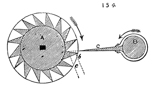
Fig. 154.
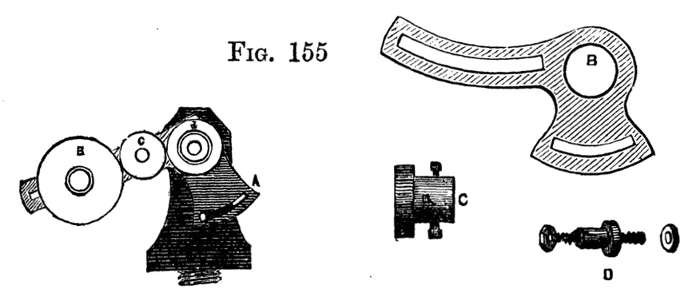
Fig. 155.
Take, for example, the following train of five wheels, even numbers being given for the sake of clearness, to represent the circum[104]ferences or number of cogs in each, Fig. 156. We have here, as the first and last, 6 in. and 120 in., and, if in contact, the first must revolve 20 times, while the latter revolves once. Interpose the three idle wheels of 10, 30, and 60 in. respectively. During one revolution of the largest wheel, the second will revolve twice, the third four times, the fourth twelve times, the fifth twenty times, the same precisely as if the first and last had been in immediate contact. The range of a slide rest-screw is quite long enough for many purposes of the amateur, and a connection thus made between the mandrel and such screw is what may be termed a miniature of the arrangement adopted in the large self-acting lathes. In the latter, however, a leading screw is added the full length of the bed along which the slide rest travels bodily. We may, therefore, consider the screw of the slide-rest a leading screw, and make use of the rules applied in the case of large lathes to decide the proportions of wheels required to cut a given screw. It is plain that when the pitch of the required screw is greater than that of the leading screw, the revolution of the latter must be at a quicker rate than the former. If, for instance, a spiral is to be cut, like the Elizabethan twist, containing but one perfect thread in two inches, while the leading screw contains twenty threads in the inch, or forty in the 2 in., the latter must be arranged to make forty revolutions while the former makes one, because it takes 40 revolutions to carry the tool along 2 in., which is the pitch of the required spiral. The two outside wheels must therefore bear that proportion to one another. Forty to one, however, would be a practically difficult ratio, to place as described, even a pinion of ten teeth on the leading screw requiring 400 teeth on the chuck. Hence a different arrangement would be necessary if such very great difference exist between the pitch of the leading or rest screw and that to be cut. The same obvious difficulty would occur where a very fine screw is required, and the pitch of the leading screw is coarse. This will have to be referred to again. One example, therefore, of the method of overcoming this difficulty will suffice. A train of wheels is shown in Fig. 157, of which A has 60 teeth, B 10 teeth, C, on the same axle and united to C, 30 teeth, D 20 teeth. While A turns once, B will turn six times, C necessarily six times also, D nine times. In this case, if the first and last had geared together D would have made but three turns, while A made one.
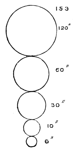
Fig. 156.
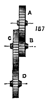
Fig. 157.
The following is an easy method of calculating a series of such change wheels:—
Write down the number of threads in the screw to be cut, and also the number of threads in the leading screw; multiply both by any convenient number likely to give such results as to tally with the cogs in the set of change wheels. Suppose it is desired to cut eight threads to the inch, and that the leading screw has two threads in that length. Then:
| 8 | ×10 | 80 | or | 8 | ×15 | 120 | or | 8 | ×20= | 160 | &c. | ||
| 2 | 20 | 2 | 30 | 2 | 40 |
If you have either couple of these wheels, you can put one on the leading screw, and another on the mandrel, and fill up the intermediate space with dummies.
If the above is inconvenient, or the wheels are not to hand exactly as required, proceed thus. If you have the wheel for the mandrel, and the one you wish to use for the leading screw has only half the proper amount of teeth, it is evident that the leading screw would revolve twice as fast as required, for they are proportioned as two to one—or if I have the proper wheel for the leading screw, and the wheel I wish to use for the mandrel has twice the proper number of teeth, it amounts to the same thing. You can get over the difficulty by using any two wheels which are in the proportion of two to one (say 20 and 40, 30 and 60, 40 and 80, &c.), and coupling the two firmly together, so that the larger wheel of the two works into the mandrel wheel (or dummy working into the mandrel wheel) and the smallest into the screw wheel (or its dummy); if the speed is wrong in the contrary way, so that the case is reversed, the coupled wheels are made to gear in a reversed direction; and whatever may be the amount of error, whether such as to cause either mandrel or screw to revolve ⅛, ¼, or ¾ too slow or too fast, the same arrangement may be pursued, the coupled wheels bearing that proportion to each other. The above method was communicated to the English Mechanic by a working man, James Connor, and is perhaps as easy as any; but tables are published of change wheels for any pitch, with any thread of leading screw. Where it is not possible or inconvenient to apply the above arrangement, and where only a few pitches are likely to be needed, another method can be arranged by connecting the lathe pulley to the overhead motion and thence to the screw of the rest. Such an arrangement is shown in Fig. 158. A is the fly wheel, B mandrel pulley, C, D, pulleys on the overhead, E pulley and screw of the slide rest. To facilitate calculation, let diameter of C equal that of the part of the mandrel pulley that drives it, by which it will[106] revolve in the same time. The calculation of the sizes of pulleys, D and E, will be the same as for the cogwheels of the screw-cutting lathe, circumference and number of cogs being, so far as calculation is concerned, the same thing. Let the leading screw have eight threads to the inch, and let it be required to cut a spiral of two threads to the inch. Proceed as before by dividing the required number of threads to be cut by the number on the leading screw 2-8 = ·25. The pulley on the leading screw will be therefore one quarter the size of that on the overhead (which is virtually that on the mandrel as it revolves at an equal speed with the latter). The overhead pulley may be conveniently twelve inches diameter, and that on the screw three inches. While the mandrel makes one revolution the screw will make four, advancing the tool half an inch, and cutting one thread of a spiral in that distance. The next revolution will advance the cutter a second half inch, cutting a second complete thread of spiral. Two threads will, therefore, have been cut in the space of one inch as desired. By the above method short screws and spirals of divers pitches may be cut at pleasure. The practical difficulty in this plan is due regulation of the various speeds.
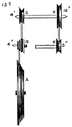
Fig. 158.
We here introduce a modification of self-acting lathe for cutting Elizabethan twist described by Mr. Wilcox in his MS. before alluded to. The work is here done by a leading screw and toothed gearing, the principle being that of the ordinary machine lathe. A chuck, A, with cogwheel attached holds the work as usual, the back centre being also required. The cogwheel gears with one of less diameter attached to the end of the guide-screw B. On the latter works the rest C, in which is a nut of the same thread as that on the guide screw, and which holds the tool in a notch or hollow upon its upper part. The tool is then used by hand, but is guided in its course along the surface of the work to be turned. This guide screw, with the rest and cogwheel, is mounted on a board as a separate piece of apparatus, and is, when used, clamped on the lathe bed. As the rest is after all little else than a large nut, it must be prevented from turning round, and must be arranged to bear the pressure of the tool, relieving the long screw from the strain that would be thus caused. This is effected by a long flat bar—like the rest of a chair maker's lathe—extending the full length of the bed shown here at[107] E, and supported by standards F, F. A projecting part of the rest bears upon this, and slides along it with the tool. The work is begun with the rest on the right hand, and some care is necessary as it nears the cogwheel on the left, when the work must be stopped and the whole run back by hand to its starting-place. This is one chief defect in this apparatus, for the rest very quickly traverses the length of the screw, and great delay is caused by having thus constantly to stop the lathe and reverse the motion. The closest attention is also necessary to prevent the rest from overrunning its mark and striking the cogwheel. It is evident that by using different pitches of cogwheels, many screws of varied threads can be cut in the above lathe. There is, however, another defect in the above tool not noticed by the writer of the MS. from which the description is taken, namely, the difficulty (common to all such contrivances for turning wood), of obtaining the requisite speed. If the work is put in rapid motion, without which wood will not be cut clean, the movement of the rest will be so rapid also, from the effect of the multiplying wheel, that the tool will be carried from end to end in a few seconds. We will therefore proceed to describe a modification of this and similar apparatus, which allows the tool a slow traverse lengthwise of the work, but gives it immense rapidity in the necessary direction. The following is applicable to the lathe described above, to the ordinary slide rest worked by hand, or to the large self-acting screw-cutting lathes used in manufactories, and is specially adapted for cutting spirals or other patterns in wood. In the Fig. 160, A represents a shank,[108] which may be made of any shape to fit particular patterns of tool holder. This shank is turned up and becomes a cylinder at B, like that of the ordinary revolving cutter. This part is bored, and fitted with a steel spindle, which should be of strength proportionate to the size of stuff likely to be operated on. One end of the spindle is fitted with a brass pulley, from which a cord is to be attached to the overhead apparatus, the other end terminates in a round or hexagonal boss, D, round the margin of which are securely held, by means of bridles B1 or other simple contrivance, a pair or more of small sharp gouges. This apparatus is put in the tool holder of the slide rest, set to the angle that corresponds with that of the screw or twist, and put in rapid revolution by means of the overhead apparatus. The whole rest, or merely the upper part, is then put in motion by one of the before-named means, and the tool advanced to make a cut. However slow the movement of the rest may be, the cutters move with such velocity as to make clean and beautiful work.[13] This may be applied to the slide-rest of the twist lathe, just described, or any similar apparatus. In the overhead, a roller, supplying the place of the second pulley, as described in a previous page, will allow the second cord sufficient power of traverse to keep up a proper position in reference to the pulley C. Revolving cutters on the same principle as the above, have of late years come into extensive use in wood-cutting and carving machinery. The steam planes now used in the preparation of flooring boards, the spoke turning lathe, moulding and shaping machines for wood are all thus fitted. The gouges or other cutters used must not be placed radially, but as tangents to the circumference of the boss in which they are fixed. An improvement upon the simple bridle to hold the cutters would be the substitution of Babbage's tool holder, four radial arms being substituted for the metal boss above alluded to. This tool is described and figured in Holtzapffel's "Mechanical Manipulation," to which the reader is referred for an accurate description. It chiefly consists of a shank turned up at the end like Fig. 161, the outside, at B, being rounded to fit hollow gouges such as Fig. 161H; against this the hollow of the gouge is laid, and opposite to it, at C, a small piece like D. A band or hoop, E, is now placed over both the above, and between the two a wedge-shaped piece, F, which is intended to bring a strain upon the hoop and tighten it round the gouge. This last piece is attached to the shank or holder by a screw passing through it into the shank. The tighter this screw is worked the lower the central wedge is drawn down, and the tighter the hoop is made to embrace the tool. This holder is also modified to suit flat chisels. The tool cannot possibly slip, but can be released in a few seconds if desired. Such a termin[109]ation of two, three, or four arms revolving on a spindle in place of the boss would form the best possible circular cutter for shaping lathes. The above lathe for producing Elizabethan twist introduces the reader to self-acting, screw-cutting, and machine lathes, such as are used in all large manufactories. Hand-turning, indeed, except in such light work as turning up the heads of small bolts, and finishing up work which, from peculiarities of form, cannot easily be done by self-acting tools, has become a thing of the past in factories of any pretensions; hand labour, in fact, not only no longer pays, but is quite insufficient to meet the requirements of the present age. Take, for example, a piston-rod requiring to be as "true as a hair," to use a common expression, from end to end. The traverse of an ordinary slide-rest would only enable us to turn a short length at a time, and the result, when accomplished, would not be satisfactory. With a self-acting lathe the tool traverses in a perfectly straight line from end to end, is returned to its starting-point by a quick traverse, and the movement repeated until the proper dimensions are attained. The process is not absolutely rapid, because time is requisite in cutting iron and steel, but the work is executed as speedily as the nature of the metal to be cut will allow, and the execution is perfect. Of late, however, even the above has been improved upon, for two cutters are used at once—one on each side of the bar, so that by one traverse of the rest a cut of double depth is taken, and the tendency of the work to spring away from one tool is counteracted by the operation of the other. But we require something more than speed in the present day. We must have work of absolute truth of measurement. What would our ancestors, or the immortal Watt himself, think of measuring work to the hundredth part of an inch, yet it can be and is done to the thousandth part. I believe I am correct in saying that Whitworth constantly gauges work to that or even a higher degree of nicety. It is not too much to assert that the best engines of the present day really work with the precision of clockwork, and even the bore of an Armstrong or Whitworth gun is executed with no less accuracy and precision. Look again at that ponderous affair, the steam hammer, so ponderous as to require a depth of solid masonry and timbers to sustain the force of its terrific blows. In a few minutes a solid mass of metal is reduced to a flat plate such as would have taken the united strength of a dozen men wielding the heaviest sledge-hammers for an hour at least. The ground beneath the feet of the spectator trembles at every blow of the machine. The work is done, and behold! with a touch the same ponderous concern becomes a nutcracker, not even injuring the kernel when it breaks the shell. Such is one of a hundred specimens of accurate workmanship carrying out in practice the clever designs of the mechanical engineer. Sweep away self-acting machinery, and such work would become a simple impossibility. Again, so long as turning, boring, planing, and such[110] work was performed by hand alone (even after the introduction of the slide principle), an attendant was required at each machine. Now that the latter is contrived to regulate its own movements, one man at two or three lathes is sufficient. Thus the same article that was once imperfect and costly, owing to the demand on skilled labour, which was difficult to procure and at best inefficient when procured, has now become cheap, and to all intents and purposes perfect; and although the demand for such work increases year by year, self-acting machinery being constantly improved and simplified, enables the manufacturer to keep pace with the demand.
[13] The spiral chuck for fine work in ivory and costly woods is described in a later page.
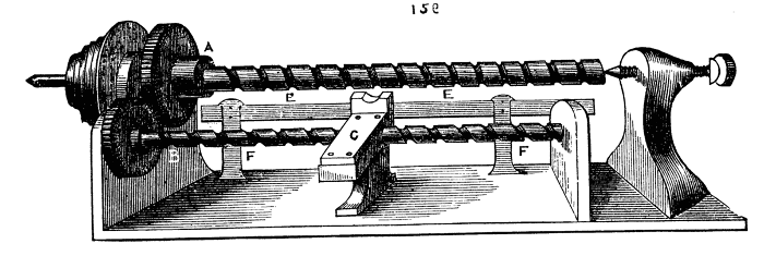
Fig. 159.
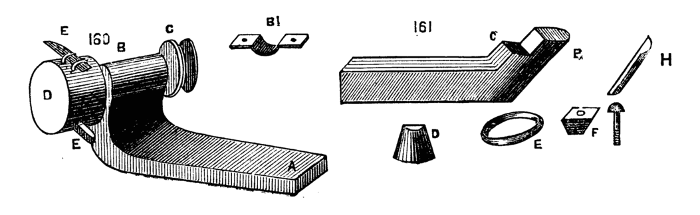
Figs. 160, 161.
The advantages of self-acting machinery are of course chiefly confined to the trade, and it is not often that the mere amateur requires such aid. Indeed, the expense necessarily attendant on the fabrication of these machines deters the great majority from making such a purchase.
The first requisite for fitting up a lathe for screw-cutting and plain turning is the fitting a guide-screw, and adding a saddle to the slide-rest. But it must be observed that the ordinary mandrel of small foot-lathes, which works in a collar and back centre, is not convertible, and must be replaced by one working through two collars, so that a part may project at the opposite end to that intended for the chucks. On this projection various cogwheels have to be fitted. Now there are divers patterns of mandrel suitable for the above purpose; some are perfectly cylindrical, some have one conical part, some are fitted with a second cone, independent of the mandrel, and which slides upon it, and can be adjusted by means of regulating nuts. This latter being a good pattern, when well constructed, we shall first describe in detail. In Fig. 162 is shown A, the mandrel complete, with fittings in section, but without any of the change wheels. The cone a is forged on the mandrel, which then becomes cylindrical. The cone is figured too large in proportion to size of mandrel; the latter should be represented as much more substantial. At b the second cone slides on, the latter shown again at B. It is bored truly, and a slot cut to fit a feather on the mandrel. Thus it will slide along it, but must necessarily turn with it. Beyond D on the left are two screwed parts, one slightly larger than the other, one being made with a left-handed, the other with[111] a right-handed thread. On these screw the two nuts, d, e, which drive the movable cone towards the right, causing it to fit more tightly into its collar, and also by the same movement tightening the fixed cone in its bearings. The mandrel is thus readily adjustable in the collars, and can be made to run very truly and easily without shake or endlong movement. Any pressure, however, against the front, such as would be caused by drilling, would jam the front cone in its collar, and tend to loosen the other. This is counteracted by the part f, g, with its screw, h, against which the end of the mandrel bears. That this form requires good workmanship is evident, for there are three points, or bearing surfaces, to be brought into a correct line, and the slightest deviation will cause the mandrel to jam in some part of its revolution. The nuts screw up in opposite directions to counteract the tendency in either to screw up more tightly, or to become looser by the revolution of the mandrel. On the whole the above is a good form of mandrel; if it has a fault, it is a slight tendency to work heavily. The next form is that of the ordinary mandrel, with single cone, but a second collar is added, which is cylindrical, through which the mandrel passes, and it then abuts on the sustaining screw as before. This is shown in Fig. 163, with the addition of the wheel, which is to be connected by intermediate wheels and pinions with the leading screw. If the conical collar is replaced by a cylindrical one, so that two similar bearings are made use of, a shoulder becomes necessary to prevent the mandrel from slipping endwise. The collars must also be split as in Fig. 164, so that they can be tightened up as they become worn. Either of the above forms of mandrel can be used; each has its advocates, and not unfrequently all may be found in different machines in the same manufactory. The bed of a self-acting lathe requires to be accurately surfaced, and formed by the planing machine with two V's or edges bevelled underneath, as 165 b, b. The saddle of which we have spoken is a flat plate of cast iron fitted with V pieces to match the bevelled edges of the lathe bed, along which it slides truly, its under-edge being planed.[112] To this plate the slide rest is attached securely, either turning when required on a central pin, and being clamped at any desired angle, as before stated when treating of the compound slide rest, or, when this movement is preferred to be given to the upper slide, fixed permanently by nuts and screws. The saddle is represented detached in Fig. 166. The principle of the self-acting lathe is very simple. Motion is given to the screw by means of cog wheels geared with the mandrel, a nut fitting the screw is attached to a hanging bracket of the saddle, and this with the rest is thereby carried along the bed. It is necessary, however, to add some contrivance for instantly throwing the screw out of gear, without the necessity of stopping the lathe itself. There are many ways of effecting this, the most common being the use of a split nut, which embraces the leading screw when the two halves are brought together upon it, but which is instantly freed by separating them through the action of levers and cams, or other simple mechanical contrivance. In Fig. 167, a is the bottom of the saddle from which depend the brackets E, E. The nut B, B, which is divided across the middle, slides up and down between these brackets, D being the leading screw which they embrace when closed. The movement of the halves of the nut is effected by the lever c, in the form of the letter T moving on a centre pin at K, and having two links, D, D, attached to the halves of the nut at one end, and to the ends of the cross lever at the other. A connecting bar pivoted to the part, L, is attached to a lever and handle, by which motion is communicated to the lever. When this rod is moved in the direction of the arrow the links will cause the nut to close and vice versa. The next form, 168 and 169, represents the split nut attached to two arms, A, A, hinged together at E. B, B, are slots in which work the pins attached to the cross head of the levers C, C. A heavy knob of iron keeps the latter in the position to which it may be moved. In 168 the pins keep the arms and nuts apart. When the lever is thrown over, as in 169, the nut is securely closed and held in gear. This form requires to be fixed to the lower part of a bracket attached to the saddle of the slide rest, such as is shown at B, C, Fig. 170. In this figure, A is the bottom of the saddle E, E, the V piece, that on the left, having an adjusting screw to tighten it on the lathe bed when necessary. At[113] F is a projecting piece of the saddle fitting accurately between the lathe bed, and kept down by a screw with bed plate underneath. This serves to steady the movement of the saddle and relieve the pressure and strain upon the V pieces. The bed-plate may be cut out to fit the lower part of the bed on which it slides, both being planed for the purpose, as shown at H.
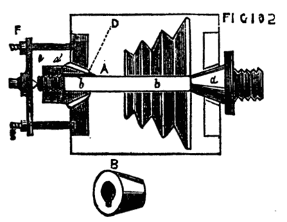
Fig. 162.
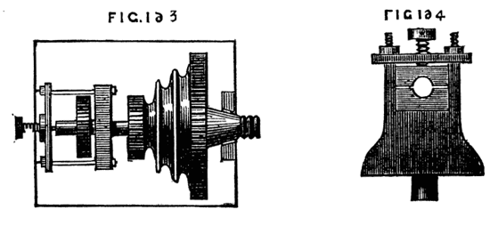
Figs. 163, 164.
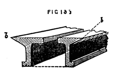
Fig. 166.
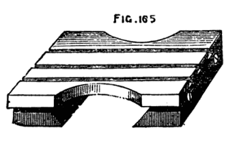
Fig. 165.
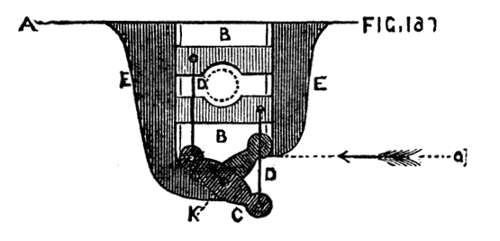
Fig. 167.
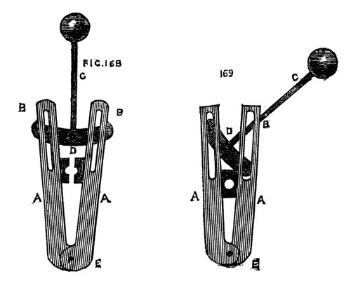
Figs. 168, 169.
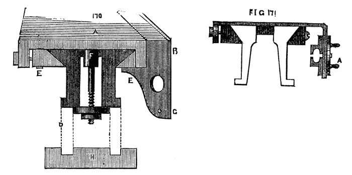
Figs. 170, 171.
In Fig. 171 the half nuts slide up and down on the front of the saddle, and are moved by a circular plate on the outside. The action is very similar to that of Fig. 167, intervening links, attached to the plate and to the halves of the nuts, giving motion to the latter as required. Cams and eccentrics of varied forms are also made use of for the same purpose, every lathe maker devising new and improved movements from time to time. There is indeed little difficulty in arranging a satisfactory method, the best being that which is under easy control, of adequate strength, and not likely to be easily disarranged by the rough treatment it is liable to receive at the hands of the workman. The leading screw may either be placed on the outside, in front of the bed next to the workman, or inside between the bearers. The former is preferable as being more accessible, but it is rather more exposed to injury. When between the bearers the large saddle of the slide rest serves to protect it from the falling chips and shavings of metal which,[114] mixing with the oil, are apt to clog the threads and add to the friction of the parts, besides increasing considerably the wear and tear, and no accidental blow is likely to reach the screw thus protected on both sides by the lathe bed. Nevertheless, all the various parts of a machine should be made as accessible as possible, and, with the exercise of ordinary care in its preservation, the position outside is on the whole the best. If the lathe bed is very long, it may be desirable to support the screw by allowing it to rest on friction wheels fixed to the saddle at both ends, or by allowing it to pass through a pair of brasses. Thus, as the saddle is often two feet in length, such bearings at each end, with the split nut between the two, form points of support which go far to prevent the screw from jagging or bending in the middle from its own weight.
The general arrangement of self-acting tools is similar with all the makers. Fig. 172 is a drawing of such a tool from a sketch of Eades & Son, an old firm in Lichfield-street, Birmingham, the screw being here placed in front. Whitworth, the eminent mechanician of Manchester, makes many lathes with the screw between the beds. He also uses a double slide rest, with a tool working at each side of the piece to be turned, which cannot thus spring away from the cut. This is called a duplex slide rest. By this method double the cut is taken, and the strain upon the work lessened. In addition to the screw there is usually a rack attached to the lathe bed, on the furthest side, and a cog wheel working upon this, attached to the back of the slide rest saddle, is turned by a handle in front of the rest, Fig. 173. This enables the workman, after having, by means of the screw, completed the cut to the end of the work, to run the rest back again very quickly, having first released the split nut from the screw. The tool is thus brought into position for the next cut far more rapidly than could be managed by reversing the motion of the screw. This is called, therefore, the quick return motion, and is almost always attached to the larger class of machine-lathes. Before entering upon the details of other forms of gearing, and the arrangement of change-wheels for cutting screws or for plain turning, we shall introduce a few remarks upon the often-repeated question as to the advisability of self-acting lathes for the purposes of the amateur. It must be remembered that the chief object of such a lathe is the manufacture of large screws, long shafts, and such work as the piston rods of engines, requiring perfect accuracy from one end to the other. Boring cylinders and similar work is now generally done in an upright or vertical boring machine, which is for many reasons more convenient. This class of[115] work, of course, the amateur has nothing to do with. The traverse of an ordinary slide rest is generally adequate for surfacing or boring to a length of six inches, which is sufficient for most purposes, and can readily[116] be done by turning the leading screw of the rest by hand. Then, as regards screw cutting in the lathe, it is questionable whether it is not easier to turn up the blank and cut with stock and dies. The thread thus formed is a copy of that of the tool, and the latter, as made by Whitworth and other first-class makers, is as perfect as machinery directed by talented workmen can produce. If it is really desirable, however, to make use of the lathe for this purpose, the plan already suggested is generally applicable, namely, gearing the leading screw of the slide rest to the mandrel, either by means of change-wheels attached to an arm, or by connection with the overhead pulleys. There is, in addition, a plan of attaching a pair of dies to the tool holder of the rest, after detachment of the screw from its nut, which may be available in some cases. There are also screw plates made in two halves, the plates being divided lengthwise and clamped together at pleasure, admitting of application to any screw-blank while revolving in the lathe; and, lastly, pairs of dies, fitted like pliers, can be similarly used by hand without any slide rest. On the whole, then, it will hardly pay to give £50, or £60, for a screw-cutting lathe that is merely destined for small work; that can be done sufficiently well in a common lathe with hand motion to the rest. For cutting short screws, such as those of boxes, a convenient and practically useful contrivance is still a desideratum. The traversing mandrel is, no doubt, the best, but it is an expensive pattern, if well made, and it is necessary to sacrifice, in a measure, general utility to questionable and certainly partial advantage. Turning is, moreover, an art, and to attain skill in it, perseverance and practice are necessary—hence the zest experienced in its pursuit by the real lover of it. This perseverance pays, and to attain the skill required to trace a short screw with the chasing tool is within the reach of any one who desires to accomplish it. The art once acquired, the desire for a traversing mandrel ceases; for no good workman would accept a contrivance of the kind when he can more easily and quickly accomplish his end without it. Writing this for the special benefit of amateurs, we would strongly advise them not to throw away money to purchase the means of doing what after all they will probably never, and certainly only seldom, carry into practice. The pleasure afforded by all the mechanical arts is greatly enhanced by meeting with and triumphantly surmounting all sorts of difficulties. Let it be a standing rule of our readers to make use of the appliances at hand instead of seeking others which only save[117] trouble and render skill unnecessary. What can be more aggravating than for an amateur, with his hundred guinea lathe and chests of tools, to be obliged to take his work to a mechanic, and to see him, whose whole stock might be bought with perhaps a tenth part of the money, take in hand and finish with ease what has baffled the skill of his more wealthy patron? The common fault of the amateur is undue hurry. To him time is seldom an object, yet the mechanic, to whom it is so precious, readily spends more upon his work. He never hurries, never compromises, but with lathe and file fits the several parts of his work with the most patient care and practised skill. The result is at once seen when his productions are placed side by side with those of the zealous but too hasty amateur.
It remains, as previously described, to arrange certain cogwheels gearing with each other upon the spindle of the mandrel and upon the end of the screw, to enable the workman at pleasure to vary their ratio of speed, in order to give him the means of regulating the pitch of thread to be cut. For this purpose a set of change wheels is supplied with the screw-cutting lathe, the number of cogs in which usually commencing at fifteen, increase by five, until the number one hundred and twenty is reached, then increasing by ten up to the complete set. Duplicates of some numbers are also convenient. The method of finding the proper sized wheels is, of course, based upon the proportion borne by the required pitch to that of the leading screw and one form of calculation for the purpose has already been given. Thus, supposing the leading screw to have two threads to the inch, it must revolve twice to move the tool that distance, and if we wish to cut a screw of ten threads to the inch, the work on the mandrel must revolve ten times while the leading screw revolves twice, or, which is the same thing, the mandrel must revolve five times while the screw revolves once. The cogs in the wheels must therefore be in the proportion of five to one, say fifty on the screw and ten on the mandrel, with an idle wheel on the stud to cause the motion of the tool to be such as will cut a right-handed thread, or to cause the mandrel and screw to take the same direction. Now, it seldom happens that two wheels and an idle one will give the requisite speed to the tool, and the number of cogs required soon mounts to inconvenient numbers. In this case, therefore, according to a principle already laid down, a stud-wheel with a pinion attached to the same, is placed in the train of wheels, and the object readily attained. A modification of the rule of calculation may make the system of change wheels still clearer. Let the pitch of guide screw be as before, namely, two threads to the inch, and let five be required. Place the numbers thus, 2-5, and divide both into their factors, twice one, or 2 × 1, and twice two and a half, or 2½ × 2.
Now, it is certain you can have no wheels containing half notches, nor of such small numbers of cogs, therefore multiply by any convenient numbers—ten, for instance, which give
This is all that is needed. Put a wheel of twenty cogs on the mandrel, and let it work into one of twenty-five on the stud, the latter carrying a pinion of ten cogs, driving one of twenty cogs on the screw. To prove this, as before, the screw must make two revolutions to carry the tool one inch, and during that time the mandrel (carrying screws to be cut) must make five revolutions. Let the screw wheel revolve twice, the pinion of ten teeth will revolve four times (twice 20 = 40 and four times 10 = 40); but as the stud wheel and pinion are as one, and revolve together, the stud wheel must also revolve four times (4 × 25 = 100). Thus the mandrel wheel will revolve five times as required (20 × 5 = 100). No other method is so easy to understand and work as the above. To give full details and provide working drawings of the various screw cutting lathes by different makers would be to extend the present series to an unnecessary limit, but we shall nevertheless describe another method by which these lathes with traversing rests are made self-acting when screw cutting is not required. Instead of a leading screw extending from one end of the lathe to the other, there extends a bar of steel about the diameter of the screw with a key groove or slot from end to end. This bar is supported in bearings at each end, and carries upon its surface a ferrule of steel with a screw cut upon its outside similar to Fig. 174, where A is the bar and B the ferrule. The pitch of screw is coarse, being similar in its object to the guide screw previously described. A pin fixed into this ferrule falling into the slot permits[119] it to travel along the bar but causes both to revolve together when the bar is put in motion by means of a cog wheel or strap pulley at one end. Along the same side of the lathe bed, and level with the surface, is a rack, C, upon the face of which works a pinion, D, carrying on the same axis a cog or rather worm wheel, E, to gear with the screw ferrule. The bearings of this axis are secured to the saddle of the slide rest. Consequently, when the bar revolves, the screw is also put in motion, the wheel, A, Fig. 175, and pinion, B, partake of the movement, and the latter traverses the face of the rack, carrying the saddle with its rest and tool holder along the bed of the lathe. By this movement the screw ferrule traverses the bar as it revolves, thereby virtually becoming a long leading screw. In Fig. 176, which is a view from above, looking down upon the lathe bed, A is the rack, B, B, the saddle cut away to show the rack and pinion C; E is the worm wheel, D the long bar, the screw ferrule, being under the worm wheel, is not visible. As above arranged it is evident that the ferrule might escape from the worm wheel instead of proceeding on its proper course. This is prevented by its lying in the hollow of a bracket attached to the rest, as Fig. 177, A and B. This retains it in contact with the worm wheel, and[120] also becomes a support to the long bar. Fig. 174 shows the side of the lathe that is furthest from the operator. The axle of the worm wheel and pinion carries a handle on the near side to give the workman power to use the rack by hand as a quick return movement. The above is frequently attached to those lathes provided with a long screw, the latter being on the near side and the bar on the other. Thus, the same lathe can be used for ordinary or screwed work. Whitworth, however, commonly uses the long screw placed between the beds or bearers of the lathe for screwing and surfacing, instead of adding the apparatus just described. A long screw being, however, an expensive affair, ought to be carefully cherished, and when the work is such as the bar will suffice to accomplish, it may be well made use of to preserve the screw. There is an arrangement for forward or cross-feed in the above apparatus, the principle of which is the connection of the cross screw of the rest by means of a pinion, either with the worm wheel or with a cogwheel on the same axle. When this is put into gear the rack and pinion are disconnected. It is also necessary to provide a method of reversing the motion of the long screw bar, especially when the cross feed is used in surfacing. There are several modes of accomplishing this, the best being the following, Fig. 178, which is a simple expedient applicable to lathes or other machines. A is the end of the screw rod, with bevel wheel attached, B, C, are similar wheels on the axle, D, the latter being movable endwise in its bearings by means of the lever handle; E, D, is the driving axle. By moving the lever to the right B is geared to A. A movement to the left brings C into connection. Between the two, both wheels are thrown out of gear, and though they may continue to revolve, the screw bar will remain still. By this contrivance the motion of the leading screw is reversed or stopped in a second, with the advantage of its being unnecessary at the same time to stop the working of the lathe altogether. It has probably struck the reader that as the size of the change wheels are various, there would be in some cases an impossibility of their touching so as to gear together. This is partly remedied by the interposition of dummies, or idle wheels, and partly by the following arrangement. The stud wheel, or dummies, as the case may be, are not upon axles fixed to the lathe-head or end standard, but upon such an arm as Fig. 179, which turns upon a pin at A, and carries in the slot the pins[121] upon which the different wheels centre. These pins being made similar to B, C, can be placed at any position in this slot, and are fixed by a nut underneath. This arrangement gives considerable power of adjustment, and enables the workman to place together wheels of various sizes according to his need. It would not be by any means difficult to arrange the above lathe for screw-cutting, especially if the pitch of the required screw is not of great importance. An amateur's lathe might be thus fitted to serve a good many purposes, although a leading screw is to be preferred as the more complete and perfect arrangement. It cannot, however, be denied that there is great friction produced by the worm wheel and endless screw, which soon tells its own tale by the wear and tear produced, and the power is not so economically used as it is when the screw works in a nut. Expediency, however, in this, as in many similar cases, must decide for or against the arrangement in any particular case. It is, at any rate, a good addition to a lathe provided with an ordinary leading screw, more especially in the facility with which it can be arranged as a self-acting cross-feed to the rest when used for surfacing.
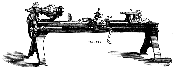
Fig. 172.
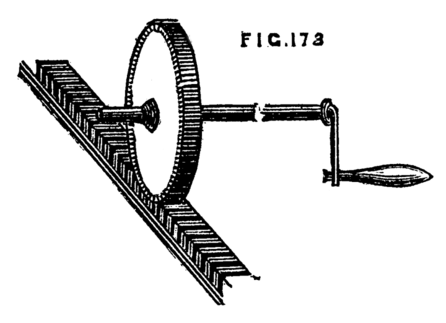
Fig. 173.
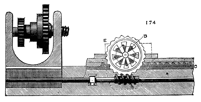
Fig. 174.

Figs. 175, 177.
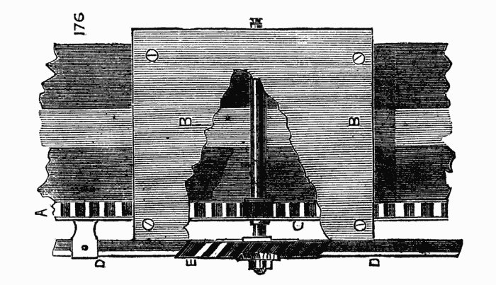
Fig. 176.
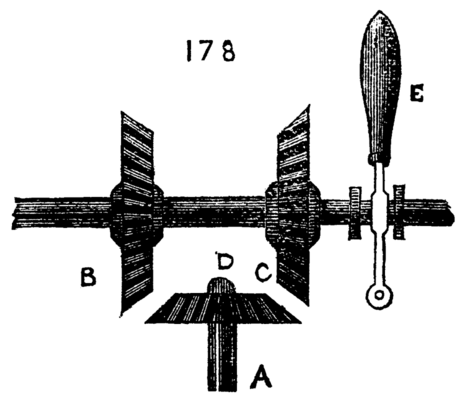
Fig. 178.
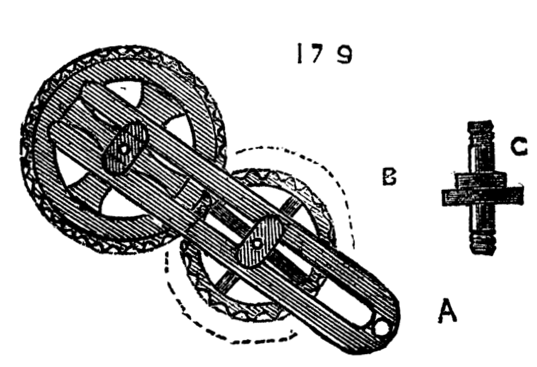
Fig. 179.
Among the various uses to which a lathe may be put, wheel-cutting is one of the most important, so many pieces of mechanism requiring cogged wheels of various pitches and forms of tooth. By the aid of the slide rest such an apparatus as figured may be readily arranged, and the work rapidly and accurately performed. The guide by which the cogs and spaces are determined is the division plate already alluded to, and which is not visible in the present drawing, but the index of which is shown at G. C is the cutter frame with a side pulley (one on each side) to conduct the catgut band from the revolving spindle to the overhead motion on to the flywheel. The spindle carries a pulley for the cord and a cutter wheel, I, to which an exceedingly rapid evolution is given. There are many patterns of these wheels, the edges of which, cut into teeth like a fine saw or file, are the exact form of the spaces required between the cogs; hence, some are rectangular,[122] some have a triangular section. The thicker the wheel to be cut the larger should be the cutter, so that the bottom of the cut may be virtually level.[123] In Fig. 181 another form of cutter is shown, which if put into sufficiently rapid motion answers as well, if not better, than the wheel-shaped cutters. It is a simple short bar of hard steel, with the edges bevelled in alternate directions, fitted into a slot in the spindle and held by a wedge or screw. The shape of the end is as before, a cross section of the space between two teeth. The cutter frame is here arranged to fit into the ordinary tool-holder of the slide rest, but the form may, of course, be varied at pleasure. It will be noticed that the slide rest, as delineated here, is different to that of which details have been given. It is made without the sole, and fits into the socket of an ordinary rest. Thus it can be turned on a centre, and becomes, to all intents and purposes, a compound slide rest. It is on this plan the small ornamental turning rest of lighter construction is made. The spindle fitting the socket projects from the centre of the lowest frame, and is cast in one piece with it. If the apparatus is compactly and strongly made, it becomes a very serviceable form, and is much used for the small lathes in sea-going steamers. The sides are made very short, so that the extent of traverse is small. We may here mention an addition to the rest socket, enabling the workman to raise this kind, or that used with drills and cutters, which is simple and convenient. Inside the iron socket a few turns of a screw are cut, and a second socket of brass with an outside thread is made to fit into it Figs. 182 A and B, the latter being a section. The edge of the inside socket is sometimes milled round, to facilitate holding it by the thumb and finger. In this way the height of the slide rest, or tee of the common rest, is adjustable to a great nicety.
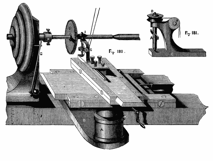
Figs. 180, 181.
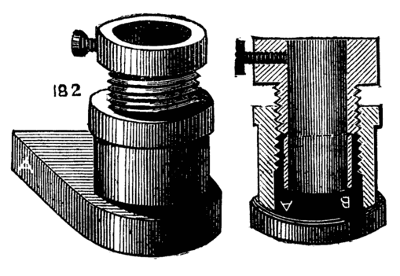
Fig. 182.
When a wheel is to be cut of large size, or of substance exceeding that of clock-wheel work, the above method is not suitable. The wheel is then generally laid flat, and the cogs are shaped by a slotting machine, the chisel of which has a vertical motion. The lathe is then no longer used; as a separate machine is more convenient and economical.
A most serviceable addition to a lathe, especially an amateur's foot lathe, is the circular saw, with guides for cutting parallel, taper, or mitred work. Great rapidity of work is thus combined with perfect accuracy. A five-inch lathe will of course take a saw nearly ten inches diameter, but it is not advisable to attach one of quite this size, for the larger the saw the greater is the leverage against which the turner has to contend, and[124] the friction caused by a deep cut in stuff of two inches diameter is quite sufficient to make the labour considerable. When such work is necessary, it must be very gently brought to bear upon the saw, and the flywheel of the lathe should be heavy. The cord should also pass from the latter to the slowest division of the pulley. If the workman, amateur or professional, desires a lesson in practical mechanics, he has nothing to do but turn a piece of ash six inches in diameter, with the lathe-cord extending from the flywheel to the smallest part of the pulley, the diameter of which is about half that of the object to be turned. This will teach him what hard work is. Then let him try the job with the cord, from the smallest part of the flywheel rim, to the largest diameter of pulley. The change to a slower motion and greater power will not be disagreeable. It must be remembered that a circular saw of six inches diameter will not penetrate three-inch stuff, owing to the boss or nut by which it is attached to its spindle. The above size will not make good work of stuff exceeding two inches in thickness, and even less thickness would be preferable. As to the size of saw, indeed, that is most suitable to a five or six-inch foot lathe, much depends upon the proposed work, and still more upon the weight and size of the flywheel. As a general rule it is better to err upon the size of smallness. The service to which this tool is commonly put is but light; sawing narrow strips of mahogany, such as used at the angles of bird-cages, cutting strips or segments of ivory (for which let the saw be kept wet) sawing out mitred or dovetailed joints, and similar work is within the compass of a five or six inch saw, and it is better not to exceed this. The teeth should be tolerably fine for hardwood and ivory, and coarser for deal and soft woods. Smaller saws of hard steel, and made of thick plate, are used for metal.
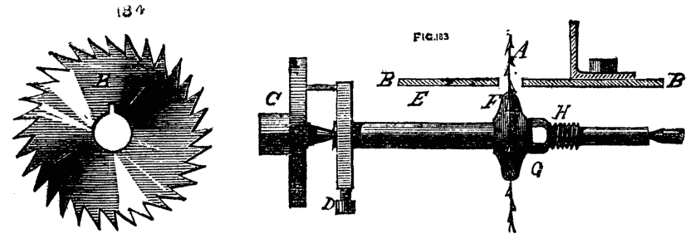
Figs. 183, 184.
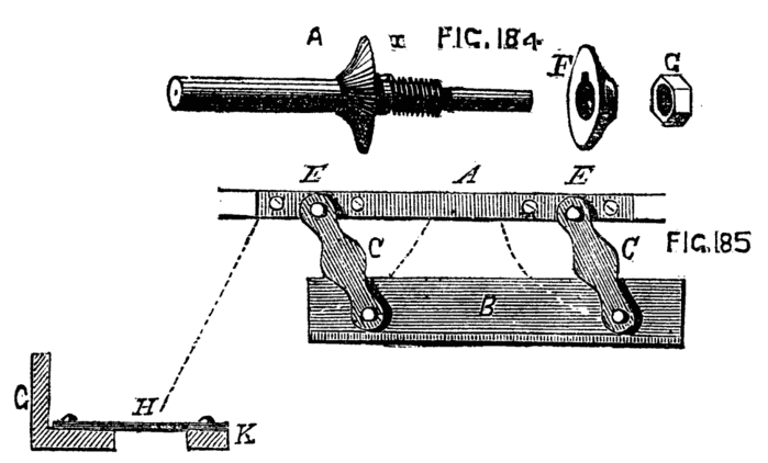
Fig. 184, 185.
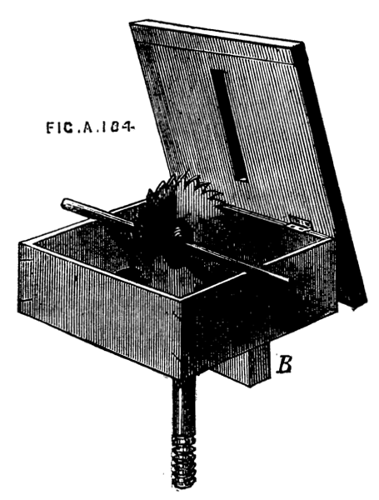
Fig. 184A.
The method of mounting saws of small size, such as are suited to be worked by the treadle of a foot-lathe, is shown in Fig. 183. E is a steel spindle, of which the diameter equals that of the central hole in the saw B. At F, about the middle of the spindle, is a fixed flange, at the base of which is a short feather or inlaid key, X 184, which fits the small slot seen in the centre of the saw and[125] reaches also within a similar slot in the movable flange, G, but it must not be so long as to come through to the back of the latter. This flange and nut H having been removed, the saw is slid upon the spindle till it rests against the fixed flange; the movable one is now to be brought against it and clamped by the nut. The spindle is sometimes made with a square end to fit the square hole chuck, and centred at the other, or it is drilled at both ends, so as to be driven by the carrier or driver chuck, C, D. It must be so placed as to run towards the operator. The above arrangement must now be made complete by the addition of a platform, B, on which to lay the work that is to be sawn, and on which some contrivance can be adjusted to guide the passage of the saw through the same, so as to cut the work in parallel pieces, or at any desired angle, such as would be necessary for mitred joints. For the general uses of the amateur a mahogany or hardwood platform is as good as any, and such as is delineated in vol. ii. of Holtzapffel's valuable work is perhaps the best arrangement. The saw table rests on the opposite ends of a kind of open box, which is represented without the two sides, although they may be added if desired, and the whole when removed from the lathe would then form a case for the saws, or serve other similar purpose. The platform is hinged, so as to overlap, as seen in the Fig. 184A, and there is in the middle of it a slit cut by the saw itself, which, when it is mounted on its centres will be in the position shown. If sides are added a notch must be made in the upper edge of both for the passage of the spindle. The fillet B fits between the bearers of the lathe, securing the parallelism of the whole. When made with four sides the box must first be placed on the lathe bed and loosely held by the bolt beneath. The saw is then mounted, and the box adjusted to its place and fixed. The cover is then (if for the first time) brought carefully down upon the saw, and the lathe being put in motion the slit is made, and its position will be truly at right[126] angles with the spindle and the lathe bed. Of course, in future operations the platform is lowered over the saw before the holding down bolt is permanently screwed up. The sides of the saw-kerf may be edged with brass if preferred, but on the whole the plan is not to be recommended, for if, as will occasionally happen, the saw should get slightly out of truth, or vibrate a little when in use, the teeth will come into contact with the metal and be blunted or broken. If the saw-kerf by constant wear should widen too much, the whole platform is renewable at little cost, or a new piece can be let in, and a fresh saw-kerf made. There are several guides for parallel work. The one shown in Fig. 185 is precisely such as is to be seen in the ordinary parallel ruler—A is the back bar screwed to the platform at the right-hand edge; B the guide or fence which, when the connecting links C, C are perpendicular to A, should touch the saw; D, D are arcs of circles of which E, E are the centres. They may be arcs of brass pivoted to the links and passing through a slot in the bar, A, A, or may themselves be cut as mortises in the platform, in which fit a pair of bolts with thumb-nuts passing through the links, by which to clamp the fence in any desired position. This form of parallel guide is not very substantial, and is not correct in practice unless the pins are very nicely fitted, and the links precisely of a length. The second figure shows the sectional form of the fence G, the links being represented at H, and the fixed bar at K. The following is a more solid and unyielding guide, and much to be preferred. Holtzapffel attributes it to Professor Willis. It is merely a modification of the T-square as used with the ordinary drawing board with an arrangement for fixing it in the required position. The present arrangement differs from that in Holtzapffel's work in the manner of fixing it and the addition of a second T-piece on the side next the workman. In Fig. 186 A is the upright part of the fence, B the bottom or sole, to which is attached at each end the T or cross pieces, E, E, which slide along the straight edges of the platform and secure the constant parallelism of the fence to the surface of the saw; C is the groove or slot, in which a screw, D, traverses, and the fence is thus fixed by a turn of the thumb-nut, D. This fence can by no possibility get out of truth; it is easily[127] removed by taking out the single screw, and it is far more simple and more easily made than the one previously described. The nearest edge of the platform may be marked in inches and eighths, and the fence can then be instantaneously adjusted for sawing pieces of any desired width. It is not always, however, that straight, rectangular, or parallel strips are required, and an additional arrangement is needed to form a guide for sawing angular pieces. Now it is not sufficient to lay the guide fence at a given angle, for if the latter were arranged for that adjustment by taking off the tees and causing it to turn upon the screw which secures it in place, and a piece of board were placed against it to be sawn, the latter would press against the saw sideways as seen in Fig. 187. The guide fence for angles must itself therefore travel in a line parallel to the saw and carry with it the piece to be cut. The simplest and usual arrangement is that given in Holtzapffel's work. A dovetailed groove in the platform running in a direction parallel with the saw carries a sector attached to a bar which fits the groove, and this bar is free to move forward or backward without lateral movement. The piece to be sawn is thus rested against the fence forming the straight face of the sector, and the whole is moved forward together against the edge of the saw. Fig. 188 explains this. It will be seen that several grooves are made side by side, all of which fit the slide alike, and by moving the latter into either of these a lateral adjustment is effected to suit pieces of different widths. The sliding strip[128] should be made of hard wood and nicely fitted, and may be lubricated with soap, or polished with black lead, either of which will cause it to slide with diminished friction. Fig. 189 shows a somewhat different arrangement, by which more lateral adjustment may be given. The sector is replaced by a T-square, the blade of which has a slot through which a screw passes into the sliding bar. A second jointed rod is added, passing through a staple in the slide, and by a screw in the latter the T is fixed as required. The staple must turn on a centre to accommodate itself to all positions of the T-square, and a second eye may be placed on the opposite arm to allow the guide rod to be removed to that side, which is sometimes more convenient. The sector also may be made adjustable as in Fig. 190, and clamped by a simple screw in the slot. Either of the above methods will allow sufficient range for small work, such as is likely to be the object of amateurs or those who add small saws to the foot lathe. The guide for angular pieces may indeed be in many cases dispensed with by making use of patterns of wood chiefly in the form of triangles; these sliding against the parallel guide, and carrying the work with them, will answer well in a number of cases where other provision for such work has not been made in arranging the saw table. It must be remembered, however, that in this case the length of the piece (supposing it to be the side of a picture frame to be mitred) is limited to the space between the fence and the saw, which in the more perfect arrangement is an evil plainly avoided. It may sometimes be necessary to cut pieces with various angles not in the same plane. By using the hinged platform, and adding a screw attached to the front of the box, and standing perpendicularly, the front of the table can be raised to a given angle, but those who are likely to enter extensively into the cutting mathematical figures are referred to vol. ii. of Holtzapffel's work, where the subject is fully explained and illustrated. The following remarks upon the proper speed of saws and sizes of teeth are copied from that work, and may therefore be relied on:—
"The harder the wood the smaller and more upright should be the teeth, and the less the velocity of the saw.
"In cutting with the grain the teeth should be coarse and inclined, so as rather to remove shreds than sawdust.
"In cutting across the grain the teeth should be finer and more upright, and the velocity greater, so that each fibre may be cut by the passage of some few of the consecutive teeth rather than be torn asunder by the passage of one tooth only.
"For gummy or resinous woods and ivory, the saw teeth must be keen, and the speed comparatively slow, to avoid the dust becoming adhesive (by reason of the heat engendered by friction), and thus sticking to, and impeding the action of the saw."
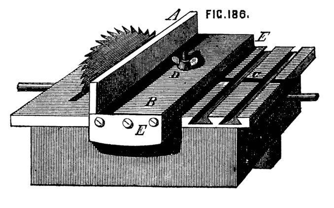
Fig. 186.
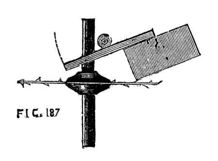
Fig. 187.
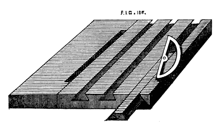
Fig. 188.
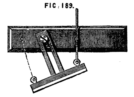
Fig. 189.
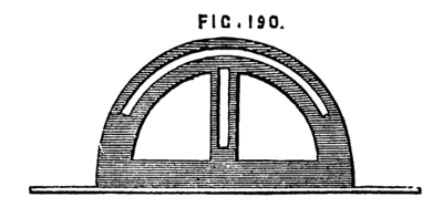
Fig. 190.
By raising the platform so as only to expose a small portion of the saw, it is easy to cut rebates, grooves for tongueing, and other work of a similar kind. The above arrangement of hinged table facilitates this application of the saw.
Convenient as the circular saw is when fitted as an adjunct to the lathe, its use is confined to pieces which are rectilineal. Curved lines cannot be cut by its means, and as it must frequently happen that portions of the proposed work are composed of arcs of various dimensions, it becomes necessary to provide the means of cutting them out. We may remark here, that although the circular saw, and that of which we are about to speak may be fitted to mount on the ordinary lathe bed; it is better for many reasons to have a separate stand, made like that of the lathe, but smaller, and fitted with crank, treadle, and flywheel, to serve for the various purposes of sawing, grinding, or polishing; the latter operations especially soiling and tending to damage the lathe. The above description of the methods of mounting circular saws will answer for a separate stand, as will the following details of saws for curvilinear work. In respect of the latter we have to provide for the perpendicular motion of the blade, which is necessarily thin and narrow, and also for stretching the blade so as effectually to prevent it from bending or buckling—guides are not required in general, as the work is moved about by hand in all directions according to the intricacies of pattern to be traced. For plain circular pieces, however, a very simple expedient is sometimes used, which will be described in its proper place, when treating of Bergeron's scie mecanique. The guides for parallel motion are various, and a selection may be made from the following Fig. 191. No. 1 is the arrangement used by Professor Willis, and detailed in Holtzapffel's work. A, A are wooden springs, one above, the other below the platform B. C is a guide pulley, D an eccentric. The catgut band which gives motion to the saw may be passed round this, or affixed to a metal ring as in the eccentric of a steam engine[130]—or may be attached to a ring slipped over the pin of a crank disc, as shown at E. This pin being adjustable, permits the traverse of the saw to be regulated, which gives it perhaps an advantage over the first method. In the above the motion of the saw is not truly in a right line, but the deviation in so short a traverse is unimportant. The reader may, perhaps, imagine wooden springs a somewhat primitive expedient, but this is by no means the case, as they will retain their elasticity longer than metal ones when they are subjected to the rapid vibration which they are called upon to undergo. No. 2 is the parallel guide, used by Mr. Lund, and also described by Holtzapffel; the metal springs, however, shown by the latter being here replaced by india-rubber, which is now formed into springs of various sizes and powers suitable for our present and many similar purposes. A, A, and D, here form guide pulleys, the saw, E, being suspended from the first by the two catgut bands, on the ends of which are the india-rubber springs, F, F. The lower end of the saw is attached to another catgut band which passes over the pulley, D, and thence to the eccentric or crank disc as before. The platform is at B, B. Number 3 is an arrangement similar to the[131] beam of Newcomen's engines. The arc at the end of the oscillating rod, and from the furthest point of which the saw is suspended, forms the guide for parallelism. Underneath the platform the pulley and eccentric may be used as before, and the saw is raised by the spring attached to the arc as shown. It will be evident on inspection that this arrangement is similar in principal to the last, as the arc forms part of a large wheel of which the centre is the point of oscillation. Watt's parallel motion, represented in the next diagram, is also suitable, the saw being attached to the centre of the short link—the springs being so contrived as to act upon the ends of the longer bars. With regard to the means of producing the necessary rapidity of movement, the above-described eccentric or crank disc can hardly be surpassed. In the saw patented lately by Mr. Cunningham, the disc is attached to the mandrel like a chuck, and the crank pin is connected to the oscillating rods that carry the saw by an intervening rod or link.
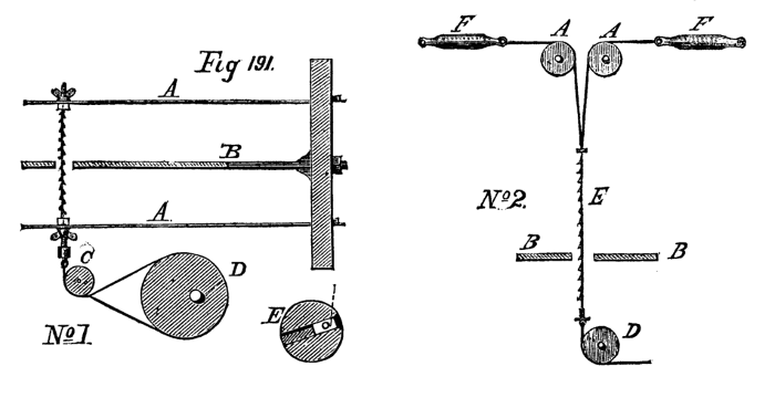
Fig. 191, no. 1 and 2.
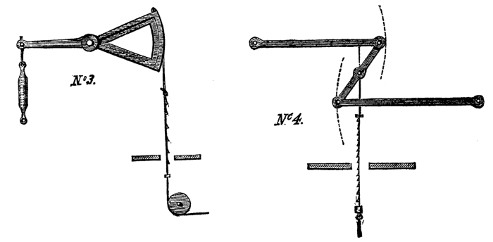
Fig. 191, no. 3 and 4.
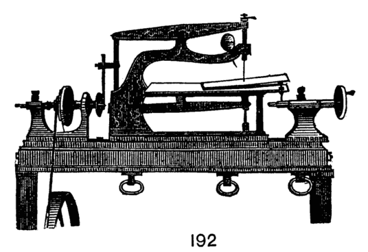
Fig. 192.
The whole is represented in Fig. 192, which is copied from the inventor's circular. There is a satisfactory parallel motion, and an india-rubber ball with a small tube attached is pressed at every stroke to blow away the sawdust. The whole plan and details are as good probably as can be devised, and as an addition to the lathe this saw is invaluable. Another form of mechanical saw to work with the foot, but without any flywheel, is figured by Bergeron, and is thence copied into Holtzapffel's book, and would therefore have been omitted here were it not that the price of Holtzapffel's work places it beyond the reach of many whom it is specially qualified to instruct; and that the former is in French and has not been translated. Therefore, as the arrangement of saw is exceedingly good, the writer has determined to introduce it here. Its construction is simple enough to be within the reach of any amateur in carpentry, and the only metal work required consists of a few iron rods screwed at the ends, such as the village blacksmith can readily supply. The saws are precisely those sold as turn or web-saw blades. It must be understood that the use of this tool is not the same as that to which[132] fret or buhl saws are applied, but merely the cutting of boards in strips or curved pieces, such as the felloes of small wheels, circular plates to be finished in the lathe, as bread platters, or such other curvilinear works as the chair or pattern maker is accustomed to cut out with the several sizes of frame saws.
A, B, Fig. 193, is a stout bench with cross bar, C, underneath, cut away to allow of the movement of the treadle and its rod. On the top of the bench is a pillar, D, to support the spring bow E, by which after depression the saw is raised to its original position. F, F, and G, G, are guide rods (not continuous). The lower ones are fixed to the cross bar, c, and under side of the bench. The upper form the sides of a rectangular frame, H, H, of which the top and bottom bars of wood are dovetailed at the back to slide up and down the chamfered bar behind them, K. The frame thus allows of being raised or lowered, not only to suit work of various thicknesses, but also to act as a stop to prevent the saw from lifting the[133] work as it ascends. The lower bar is extended on one side as in the figure, and is divided into inches, and on this graduated part is a slide with a point below, which can be fixed by a screw. This is, as the drawing plainly shows, intended for the guidance of the wood in cutting circular pieces. The saw is similar to the ordinary framed saw used by chair makers, but has two blades, and one central stretcher. The saw for curved work is narrow, that for straight cutting is broader. Near the latter a parallel guide is fixed, as described when treating of circular saws. This simple contrivance, although planned so many years ago, is of great value, and deserves to be far more generally known. To the joiner and cabinet-maker it would form a most useful addition to the usual tools of the workshop.
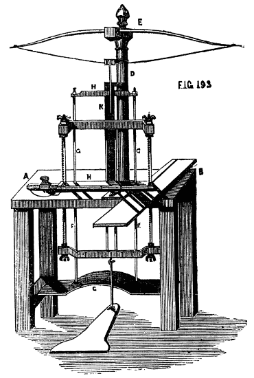
Fig. 193.
Akin to the circular saw are the various revolving cutters used either for the purpose of ornamentation or for grinding, such as circular files for flat surfaces, in which the teeth are cut upon the face or tool-cutters of particular sections for cutting the teeth of wheels, in the manner already described, to which may perhaps be added milling and embossing tools, although the action of the latter is rather that of a revolving die by which the work is stamped or indented with the pattern formed upon the edge of the cutter. The small grindstones and emery laps belong also to this section, as their action results from the abrasion of the material by means of the combined cutting power of innumerable small points or miniature teeth formed by the particles of emery or other material attached to the surface of the laps.
Most of the steel cutters may be made by the amateur, the metal being turned to the required shape and the teeth cut by small files or punches while the material is in a soft state. The little discs are then hardened and mounted, by a central hole previously made, on suitable spindles, the latter being either attached at one end to the mandrel as arbor chucks, or centred at both ends and driven like miniature circular saws. The ornamental cutters for embossing, Fig. 193B, A and B, are turned to the form of short cylinders, and the patterns cut by punches. These and the milling tools are mounted alike, Fig. 194. The rest is placed a short distance from the work, and the tool revolves against it. Some pressure is necessary to imprint the design, and this is easily obtained if the cutter[134] wheel is placed so as to attack the work below the axis; the rest then becomes a fulcrum, and the shank and handle of the tool acting as the long arm of a lever supply the required force with little exertion on the part of the operator. In this way the milling is done on the edges of screw heads, and the embossed patterns on soft wood boxes. It is not easy to understand how the patterns in these cases are produced clearly without one part cutting into and effacing another, unless the size of the work is exactly a multiple of that of the tool. The error is plain if the work is stopped exactly at the end of the first turn, but in successive revolutions this error becomes gradually obliterated, and the pattern is eventually impressed clear and well defined. The same shank is arranged for different patterns of wheel-cutters, as the pin which forms the central axis is readily withdrawn and is made to suit the holes in several sets of discs.
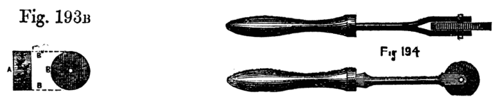
Fig. 193B, 194.
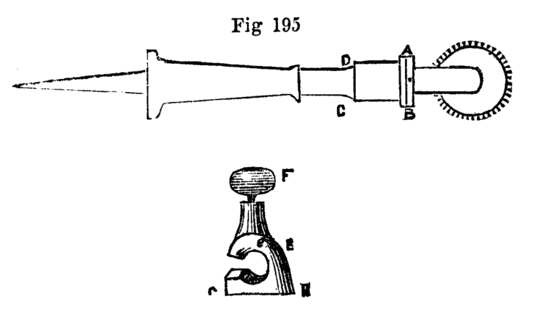
Fig. 195.
By the aid of the above simple tool a neat finish is readily given to many small works in wood and metal. A modification of the beading tools is here shown very similar to the screwing guide already given, but made with figured instead of sharp-cutting edge. This was communicated to the English Mechanic, Nov. 2, 1866. E, 195, is the guide which is placed on the handle A, B, C, D, and fixed by screw F. The mark i, on the guide, is placed against the rim, A, B, which is graduated and numbered. Each figure, as it is brought up and placed opposite i, will cut a different pattern when the guide is fixed. The tool must be held very firmly on the rest (the bottom of the guide G, H, being flat, is carried on the rest), the tool is advanced to the wood. The tool must be worked very steadily; but with a little practice, any amateur will soon use it perfectly, and produce many very pretty patterns. It is evident that provision is here made for placing the cutter at different angles to the work, by which means the circles of patterns may be traced spirally and in other positions varying from the ordinary one at right angles to the axis of the work.
The laps alluded to, which are to be mounted on spindles like the circular saw, are composed of wood and metal of determinate forms. First, there is the thin sheet-iron slitting wheel used by lapidaries, and which, when charged with emery, or sand and water, forms the nearest approach to the circular saw. It is, in fact, the circular saw of the stone worker, the ordinary saw used in their trade being a flat blade without teeth, stretched in a wooden frame and similarly[135] fed with sharp sand and water in lieu of being made with teeth, the latter being replaced by the grittiness of the material. The circular plate of iron, brass, or lead alloyed with antimony, mounted on a spindle vertically, is used in a similar manner for grinding flat surfaces with the aid of emery, crocus, oilstone powder, and other substances, and the same is used edgewise for other work, as grinding and polishing tools, the section of the lap being such as will form the article required by reproduction of the revised plan of its own edge. Thus a lap running horizontally with a convex edge will produce the concave form required in beading tools, the latter, however, are more conveniently ground on brass cones mounted like the arbor chucks used for turning washers, rings, &c. The face of the tool or flat side is held towards the small end of the cone, and the latter is armed with flour emery. See Fig. 196.
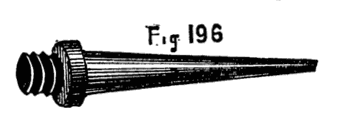
Fig. 196.
Before describing the eccentric and other compound chucks, a few examples will be given of the method of turning some of those forms in which the circle does not appear, where, in short, the boundaries of the figures are straight lines. It seems at first sight impossible to produce in the lathe by any simple means such solids as are formed from squares or triangles, of which the cube or die is the most common and most generally understood. This can, however, be accomplished, and a number of mathematical problems may be clearly demonstrated to the eye by such works skilfully made in the lathe. In this kind of work it is absolutely necessary to strive after perfection. In short, as Bergeron rightly says, the work imperfectly done is simply worth nothing at all; but when accomplished with exactness, nothing can be more worthy of a place in a cabinet of curiosities. The usual method of turning a cube is by shaping it out of a perfect sphere, but as the latter can hardly be made without a special slide rest made for the purpose, a method of turning the cube by hand alone will be given, the foundation of it being that which the lathe so readily produces, namely, a cylinder. By far the most proper material for the work in question is sound boxwood, and special care is to be taken to keep all angles as sharp as possible, and therefore to cut clean with sharp tools, and to avoid as far as possible the use of sand or glass paper. Fig. 197 shows a square described in a circle. The non-mathematical reader may be told to draw through the centre two diameters at right angles to each other, and to complete the square, as in the figure, by joining the extremities. The largest square that is possible to be drawn in the circle is thus described. This square will form one face of the cube, and the diameter of the[136] piece of wood must be regulated according to the proposed size of the finished work. It is evident that this diameter is equal to the line drawn from corner to corner called the diagonal of the square. Now, in turning a ball or sphere, a cylinder would be turned of the exact length of A, C, because every measurement taken on a diameter of the sphere would be of that length. In the present case, however, the cylinder must be of the same length as the line A, B. Turn, therefore, with great care a cylinder of any desired size, gauging it carefully with the callipers and squaring off the ends truly. On one end, in which the centre point just remains visible, draw diameters and construct the figure 197. Turn out a chuck to fit it exactly, and let the bottom of this chuck be truly square. Take the precise length of the line A, B, with finely pointed compasses that can be fixed with a screw, and measure off the same, and mark it on the side of the cylinder. When the figure is placed on the chuck, a mark must be traced round it at this point, A, B, Fig. 198, and this must remain to the end. It may be made with a hard pencil or steel scriber, and, though distinct, must be very fine. It is at this line the wood will have to be cut off, but in this operation keep beyond it so as not to erase it. While the piece is in the chuck, rule lines, as E, G, from the points C, D, E, F, 198. Bisect also the length of the cylinder by the line, H, K, also finely drawn. Draw two more diameters, as shown by the dotted lines bisecting the sides of the cylinder, which is now divided round its circumference into eight equal parts. The lines, E, G, &c., can be ruled along the edge of the rest, or, if the latter is untrue, the cylinder may be laid on a plane surface, and a scribing block, or gauge, Fig. 199, may be drawn across it, or, lastly, a small steel square may be[137] used; one part being carefully placed on the lines at the end of the piece in succession, the other part will lie evenly along the side, and will form a ruler by which to work. A division plate on the lathe pulley will facilitate the above measurements, but they can be readily made without it, and once carefully marked, all the guides required for cutting out the cube will be complete, and the work can be proceeded with, with confidence and decision. Proceed, therefore, to cut off the piece at A, B, with a parting tool, but with the precaution already named of not erasing the line by so doing. Now prepare a chuck which will take the piece lengthwise, Fig. 1992, and insert it in that position to the depth of the diameter so as to hold it securely, and the central line will show whether it lies evenly (which is, in fact, the use of this line). If even, a point-tool held on this line will form a mere dot upon it; if uneven, it will make a circle as it revolves. Place the rest across the face of the work, and, beginning at the centre, cut carefully towards the outside until you have cut away the wood as far as the line, A, B. You will thus complete one face of the cube, and an inspection of the end of the piece, shown black in the sketch to show the quantity removed, will prove that you thus produce a right line, C, D. Take out the work, and reverse it, and operate similarly on the opposite face; but in every case do not quite obliterate the lines first marked as guides. You have now a piece shaped like Fig. 200, A and B, and must make a smaller chuck to hold it; you have then to cut away in a similar manner the remaining parts of the cylindrical portion, and the cube will be complete. To finish the sides more neatly, lay upon the table the finest sand paper, and tack it at the corners, and with gentle movements work down precisely to the guide lines. This requires extreme care, for if once the piece is but in the slightest degree tilted up, an angle will lose its sharpness, and the beauty of the work will be marred. Hence we recommend to cut with sharp tools, instead of trusting to the finishing process. To cut, however, exactly to the line is very delicate work, and to the less practised hand the use[138] of the sand paper on the faces in succession may be the necessary expedient. The main secret of sharp edges in works of wood and metal is to finish with hard substances, as emery stick or glass paper glued to a piece of wood, or the same nailed on the bench, and to try always to work on the centre, leaving the edges or angles to take care of themselves. When the reader has made a cube, as above, that will bear delicate measurement, he will be more than usually gratified, and will be qualified for still more difficult work. A chuck figured by Bergeron, Fig. 201, is very convenient, as it holds the work truly central; the jaws work simultaneously by a right and left-handed screw as in the die chuck. It is, however, perfectly easy to do good work without it, but the chucks should be carefully made, turned very flat at the bottom, with side truly perpendicular. A little extra care bestowed upon chucks will save many disappointments, and conduce to good work. The formation of a four-sided solid, consisting of triangles solely, in the lathe is a work of difficulty, owing to the impossibility of fixing the work satisfactorily in an ordinary chuck. The natural way to form such a solid is to turn a cone A, B, Fig. 202, and on its base to mark a triangle of the required size. It is then necessary to place the cone in a chuck, so that the ends of one of the lines thus marked and the apex of the cone are precisely level with the surface of the chuck, as shown in Fig. 203. But it is evident that adequate support is not thus obtainable. The apex of the cone cannot, in point of fact, be inside the chuck at all, as it is necessary to cut clean to its extremity, and even the base of the cone is imperfectly held at two points. Hence it becomes necessary to make use of "turner's cement," and to imbed the work fairly in it, while both are warm, to such a depth as will hold it securely and still allow the guide lines to be seen. The latter should be carried from the three angles of the triangle marked on the base to the apex. On the whole, this is the easiest method of fixing such work in the lathe; and if the piece is itself warmed before being placed, there will be time to adjust it precisely before the cement is cold. To do this, place the rest parallel to the lathe bed, hold a pointed tool steadily upon it, and note whether, as the work slowly revolves, the three points in question, viz., the two angles of the triangle and the[139] top of the cone, are in one plane. When they are so placed, the rest is turned to face the work, and the material is carefully cut away till the gauge lines are just reached.[14] A pyramidical solid with a square base may be similarly turned. The following is the method of preparing the above turner's cement:—Burgundy pitch, 2 lb.; yellow wax, 2 oz. Melt together in a pipkin, and stir in 2 lb. of Spanish white. When the whole is well mixed, pour it out on a marble slab and roll it into sticks. Fine brickdust, whiteing, or any similar substance finely pulverised, will answer equally well to add to the pitch and beeswax. This cement is very useful, as it will hold the work firm enough to turn carefully, and nevertheless a slight blow will loosen it. To clean it off, warm or dip the work in hot water and wipe quickly with a piece of cloth. The above is from the "Handbook of Turning," the author of which has copied from Bergeron both the recipes given in his work; the one here described is stated to be specially serviceable in cold weather. It is perhaps rather less brittle than the first of Bergeron's, and for this cause is the best for general use. Holtzapffel sells this at one shilling the stick, which is of convenient size and generally of excellent quality. Bergeron gives a method of turning pilasters or balustrades, which is of great ingenuity, and applicable to work of various sections. The rectangular and triangular sections illustrated are not, indeed, strictly rectilineal figures, as the sides of the balustrades thus formed are not flat but rounded surfaces; they are, however, sufficiently curious, and when well turned are interesting specimens of lathe work. Bergeron's description relates to the pole lathe, or to work mounted between two centres with a pulley cut on the work itself to receive the lathe cord. The ordinary method of mounting on a foot-lathe will, of course, be much better and the whole operation of more easy performance. Let it be required to turn a moulded pillar or balustrade of the section Fig. 204, viz., a triangle with slightly curved sides. A piece of wood of the requisite length is planed up accurately to a triangular form, or, as it generally happens that a set of such pilasters are required, a number of such pieces are prepared which must be accurately planed to the same size, for which purpose a gauge or template, Fig. 205, should be made use of. Six or eight of these, if not too large, may be operated upon at the same time; but as six pieces of two inches across each face require a cylinder of about eight inches diameter, the number must depend on height of centres. The larger the cylinder, however (which, in fact, forms a chuck), the more nearly will the sides of the finished work approach to plane surfaces, as they will form arcs of a larger circle. Let a cylinder, then, be turned of sound wood with a reduced part at one end so as to form a shoulder. Divide the circumference into twice as many[140] equal parts as there are pieces to be turned, the divisions being equal to one of the sides of these pieces as measured in a cross section. These divisions are to mark the positions of the grooves or channels in which the triangular strips are destined to lie. Half the circumference will be so cut out, the alternate divisions being left. Thus, to turn four pieces, each two inches wide, a cylinder of sixteen inches will be required, affording four grooves two inches wide, and four intermediate pieces forming the partitions between the grooves. The latter must, by means of the saw and chisel or other tools, be made to receive the strips exactly, and the ends of the latter being carefully squared off, are to be made to rest against the plate C, Fig. 206, which is cut out and screwed against the shoulder, after the above-mentioned grooves have been cut. The whole are then secured by two rings, with screws. Probably the stoutest india-rubber rings now made would answer as well as the iron clamps in Bergeron's description. Lay the strips in their places, but as they are flat they will not form part of the cylindrical surface, but will lie lower, as Fig. 207, or higher, Fig. 208; the latter is the best, and the pieces may, for this cause, be cut out a trifle deeper than ultimately required and they may be planed down a little to remove the angles and assimilate them to the cylindrical surface. The whole may then be turned together so as to form a plain cylinder, the clamping rings, Fig. 209, being shifted when requisite. The whole is now to be formed into a balustrade, but as the proportions of the mouldings of such a large cylinder would not suit the small pieces, the hollows must be less deep, and the raised parts less prominent than they would ordinarily be made. The clamps are now to be loosened, and the pieces reinserted with another face upwards, the flange or plate against which their ends rest forming a gauge or stop to ensure their position, without which precaution the mouldings would not event[141]ually meet at the angles. In cutting a fresh side the utmost care is requisite, for if the work on the original cylinder is cut by the tool, it will be impossible to restore it, and the work will be spoiled. In replacing the strips, let the finished part lie below, so as to come first in contact with the tool, by which the angle will be clean. Extra care is for this purpose required in cutting the last side. It appears to the writer that another precaution should be taken which Bergeron omits, namely, to arrange the mouldings so that certain parts are left of the original size of the wood, in order to retain a certain number of points of contact with the sides of the grooves, so that the strips shall not fall deeper into them than at first. The extremities of the strips should certainly not be left smaller than the central portion, or the pieces will rock on the latter while in process of being turned. The two ends, therefore, should be allowed to retain their original triangular form, forming base and capital of the pillar, or the pattern may be so planned that, after the extremities have been left as supports they may be cut off when the work is complete. Care must be taken, in working as above, to have the cylinders so large above the estimated size that the inner apices of the triangles do not nearly meet at the centre, else the whole chuck would be very weak and split into triangular strips. The lathe called a spoke-turning lathe would accomplish this kind of work in a far more easy and speedy manner. The balustrade would have to be made by hand as a pattern, and cast in metal, and any number could be produced precisely similar. The lathe in question is on the following principle:—The frame carrying the tool (a set of revolving gauges) is made to oscillate backwards and forwards to and from the piece to be operated on. This is accomplished by its having attached to it a roller or rubber working against the cast-iron pattern placed parallel to the work, and below or one side of it. The rubber and frame are kept against the pattern by a strong steel spring. The cutters also travel in a direction parallel to the axis of the piece. Hence any elevated part of the pattern causes the tool to recede from the work in a corresponding degree, and a hollow allows a nearer approach of the tool. Thus, as the tool is carried by a screw slowly from end to end of the work, it is made to advance and recede in exact correspondence with the form of the pattern. An immense deal of work is done in this way, such as balustrades, spokes of wheels, the long handles of the American felling axes, and similar irregular forms.
[14] With the universal cutting frame this kind of work is much more readily accomplished.
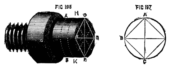
Figs. 197, 198.
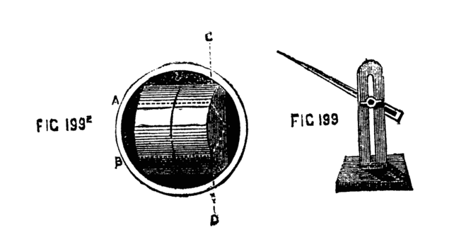
Figs. 1992, 199.
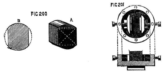
Figs. 200, 201.
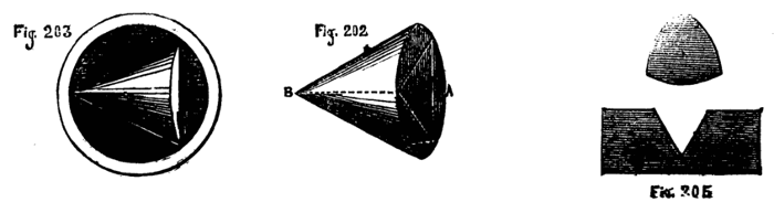
Figs. 202, 203, 205.
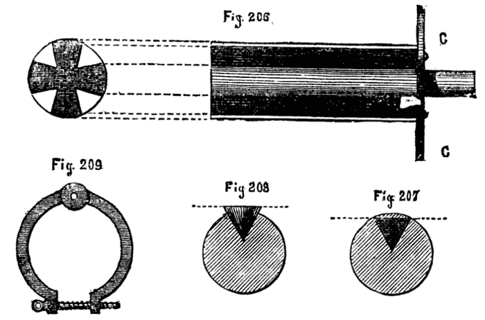
Figs. 206, 207, 208, 209.
The principle, indeed, is not new, as the rose engine is a similar tool, and, so long back as Bergeron's time, pattern plates were used giving any desired motion, endlong or otherwise, to the tool, or, which in effect is the same, to the work to be operated on.
We must now recur to the sphere of which we have already spoken. The method previously given for producing it is not sufficiently accurate, although a very close approximation can thus be made to the perfect figure. It is probably impossible without special apparatus, rendering the tool independent of the hand, to turn out an absolutely correct sphere—indeed, it is a sufficiently delicate operation, even with the following or similar apparatus. For ordinary purposes, indeed, where the object is simply to produce a croquet ball, a spherical box, or a globe to be afterwards covered with paper, or any such work, the plan already given will generally suffice, and, indeed, is very extensively used. Some practised workmen, too, will, without even the aid of ruled lines, turn out spheres of average excellence by the eye alone, aided by a template. When, however, it is proposed to hollow out a sphere so as to leave a mere shell of ⅛ in. or less, and perhaps include a number of such shells one within the other, and a star in the centre of all, it evidently becomes necessary to work with greater accuracy, and still more so with respect to billiard balls, in which even the slight variation caused by increased temperature will seriously affect the result of the most skilful play, and cause the very best players to fail. The principle of the spherical rest is displayed by the diagram, Fig. 210.
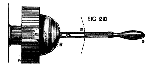
Fig. 210.
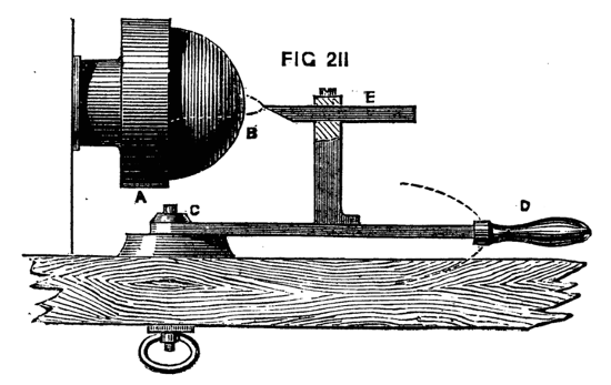
Fig. 211.
A is the chuck carrying the ball to be turned, of which C is the centre. In a right line with the latter, and below it, is a pin fixed to a block between the bearers of the lathe, and on this the arm, D, turns. The latter carries a tool-holder in which a pointed tool, E, is fixed. The point of this tool will evidently move in a circle, when the arm is moved by means of the handle, D; and, as the centre of the circle is exactly under that of the proposed sphere, the latter will be correctly shaped when the lathe is put in motion. Fig. 211 gives another view of the tool-holder. It is essential that the point of the tool should be in a line with the centre of the lathe mandrel, so that it shall act on a diametrical plane as it is carried round the work. Such is the principle upon which a practically useful tool for turning spheres has to be arranged.
The faults in the above simple machine are many. In the first place no provision is here made for the advance of the tool towards the work. In the second place the requisite firmness and stability cannot be obtained by merely causing the bar to revolve upon a centre-pin; and thirdly, as the tool post is fixed to the horizontal bar, the diameter of the ball must be limited. In point of fact, therefore, the above arrangement would not answer, and it is only described in order to illustrate the principle of all inventions for the production of spheres in the lathe. To give steadiness of action the pin forming the centre of motion is connected with a circular metal plate truly turned, upon which a second similar plate works, and to the latter is attached the tool-holding apparatus. It is difficult to make choice of a circular or spherical rest so as to give it precedence, since most of the patterns ordinarily made are good. To obtain the requisite movement is, indeed, by no means a matter of difficulty; and one or two adjustments in respect of the height and radius of the tool being[144] provided, a very simple apparatus will answer the purpose. To commence with Bergeron's, which, though venerable, is by no means inefficient. This is represented in Figs. 212 and 213. A, B, is the base, the tenon, B, accurately fitted to slide between the bearers of the lathe, the whole being held down as usual by the bolt and nut, c. The top part of the base is surmounted by the accurately faced plate 214, on which a side sectional view is given in Fig. 215. This is fastened to the base plate (which, in Bergeron's description, is of wood) by four countersunk screws. It is turned with a recess, so that the outer part stands up in the form of a rim, and from its centre rises a conical pin, b, the upper part of which is first octagonal, and then rounded and tapped. It is this strong pin which forms the centre of motion, and it must stand with its axial line precisely in the centre of the lathe bed, so that if the plate were slipped close to the poppet head this line would bisect the nose of the mandrel. This is essential in all patterns of spherical slide rest. Upon the lower circular plate rests that represented in Fig. 216, A and B, the latter being the sectional representation. This plate is drilled in the lathe with a central hole, the lower part conical to fit the pin in the base plate, the upper part countersunk as in the figure, to receive the octagonal part of the pin and the nut. The projections a, and b, in B, represent the projecting rim, a, in the Fig. 216, A, and this is made to fit very nicely within the rim of the lower plate, while the adjacent part, c, rests upon the rim itself. The accuracy of these bearing surfaces is of the utmost importance, It is evident that[145] this arrangement is calculated to give great stability during the revolution of the upper part of the rest, which is fixed securely to the plate last named. This plate has a hollowed edge cut with a set of fine teeth to be acted on by the tangent, screw D, Figs. 212, 213, and shown in Fig. 217 on a larger scale. The bearings of this screw are attached to the base plate, and the screw is prevented from moving endwise by collars as usual.
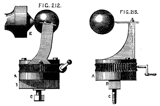
Figs. 212, 213.
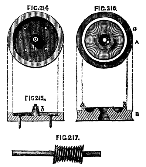
Figs. 214, 215, 216, 217.
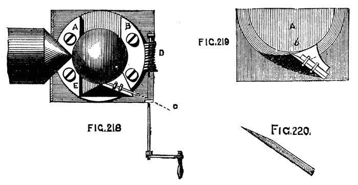
Figs. 218, 219, 220.
On the upper surface of the top plate are fixed parallel bars chamfered beneath like those of a slide rest, and between these the tool holder slides, the advance of the latter being effected by a screw precisely as in the slide rest already described. In the plan of this instrument, as seen from above, Fig. 218, A, B, are the bars. The tool is seen in position at C, the tangent at D. A scale is attached to the sliding part of the tool holder for determining the size of the sphere. The tool is again seen in position in 219, and detached in 220. In Bergeron's description of the above spherical slide rest the method of using the apparatus is thus described:—"Commence by placing in a chuck a cylinder of some sound wood, and reduce it to a convenient diameter, which should be a little greater than that of the proposed ball. With the gouge work down this, and give it roughly the form of a ball attached to a cylindrical base." This base serves to sustain the ball during the operation, and the form of an inclined plane is to be given to it where it is attached to the ball, as seen in the drawing, to facilitate the passage of the tool. After this preliminary work, place the instrument on the lathe bed, and cause the tool holder to advance by means of a screw (the one attached to the lower slide, not the tangent screw) until, reckoning from 0in., the starting point, the index attached to the sliding part has travelled over the graduated divisions of the scale, so as to[146] denote the size of the ball in its present rough state. Then slide the instrument along the lathe bed, until the tool, accurately adjusted as to height, just touches the ball at the quarter circle. This will be better understood by the diagram Fig. 221, in which A, B, are the lathe bearers; C, the tool in position; D, the ball; E, the chuck or the base of the cylinder. Having previously determined the size of the finished ball, the work may now be carefully begun by clamping the rest underneath the bed, and making use of the tangent screw. Little by little the work is to be reduced, taking care not to cut too near the base on which the ball is yet carried. This base is to be cut away little by little as the tool comes round, and at the last cut the ball will drop off finished, and it is not to be further touched with sand paper or other material. Hence, as it approaches the finish, the tool must be delicately and steadily made to traverse, so as to leave a finished surface as it advances. Bergeron adds certain precautions as follows:—"If the material is very rough from the gouge, so that at any point the tool is likely to meet with such resistance as would endanger the work, such part may be pared down again by using the machine as a common rest for gouge or chisel; for the apparatus once arranged should not be altered nor the fixed tool shifted until the work is done. The tool throughout is to be advanced very gently forward at each turn by means of the screw, which causes the parallel movement, and the tool is to be accurately adjusted so as to be exactly in a line with the centre of the mandrel; it is also to be very keenly sharpened, and even polished." The first impression given by an inspection of the above figures is that the ball would be liable to drop off before it could be fairly severed by the tool. The writer determined to test this objection personally. He selected a piece of sycamore, which is very fit for the purpose, and useful as a kind of medium between hard and soft woods. A ball was turned by hand from this material having a diameter of about two inches. The neck by which it was held was retained of the size of a cedar pencil during the final shaping of the rest of the ball. It was of course not thus reduced until the ball was nearly spherical. Gradually the neck was cut away until it was perhaps as small as the lead of a pencil, yet still the ball retained its position, and the final stroke cut it off truly and tolerably cleanly, E, 212 and 213. It is really astonishing how small a portion of sound wood will retain a ball so turned, but the lathe should not be allowed to stop, else the tendency to hang[147] down or sag would overcome the sustaining power of the fibres. Bergeron states, indeed, plainly, that the process answers satisfactorily, and as a man of large experience his opinion is certainly reliable. Nevertheless, since sand papering or after process is to be eschewed, it does appear to the writer that the final cut would leave a minute portion untouched requiring to be afterwards removed. Not having one of the rests in question the writer's opinion is to be taken quantum valeat. The spherical rest more commonly used is that represented in the "Handbook of Turning," since it is necessary not only that the machine should be efficient for turning a sphere, but likewise applicable to the ornamentation of the same by the revolving cutter and other apparatus used in such processes. This and some other forms will presently be described, and also an ingenious adaptation of the ordinary slide rest by means of guide pieces or templets to work of this character. A very good form of chuck for holding spheres during the operation of hollowing them out or forming stars or cubes within them will, however, be first introduced here as described by Bergeron. It will be at once seen how simply and efficiently a ball can be thus held during such processes.
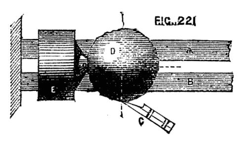
Fig. 221.
Fig. 222 represents a chuck for holding balls, A being a sectional view, B an elevation. In the first, b, b, represents the body of the chuck, made as usual to screw on the mandrel. At a, the chuck is formed with a shoulder like an ordinary box. This part of the chuck is to be hollowed out to fit the ball on which it is intended to operate. On the side of the chuck at b, is to be cut a screw of medium pitch. Mounting another piece of wood in the lathe a kind of cover, c, c, is now to be made to fit over the body of the chuck like the cover of a box, but hollowed out to the curvature of the ball. A ring of brass or wood of section D being screwed on the inside to the pitch of the male screw on the outside of the chuck will hold the three separate parts of the apparatus firmly together. Let them be thus arranged and finished as one piece on the mandrel. Afterwards drill a hole[148] in the centre of the part which forms the cover, and enlarge it so that its diameter shall slightly exceed that of the openings necessary to be made in the ball for the purpose of hollowing out and forming within it stars, or lesser spheres, box, cube, or other design, at pleasure. In this chuck the ball will be held not only centrally but securely. It is of course necessary to have a chuck specially made for each different sized ball, but when it is considered that such things as these are merely turned as curiosities and to prove the capabilities of the workman, it is not probable that more than two or three sizes of chuck will be needed, and the difficulty of making them is not great nor the necessary expenditure of time, either. They should be made entirely of sound boxwood, and so arranged as to the size of the respective parts that when the ball is inserted and the cover placed on, the latter shall not quite reach the shoulder on the base of the chuck. In the spherical rest of more modern times the principle of that already described is almost necessarily retained. It is figured in 223. The sole A is formed like that of an ordinary hand rest, so that it can be advanced across the lathe bed, and secured by the nut and screw underneath as usual. From this rises a central circular plate, which need not be more than a quarter of an inch thick, but turned truly flat, that it may be parallel with the surface of the lathe bed. From this rises the conical central pin upon which works the plate B, the edge of which is racked to be moved by the tangent screw C. Across this circular plate is securely fixed the chamfered frame D surmounted by the part E which carries the socket and tool receptacle, the details of which will be entered into when describing the rest for ornamental work.[15]
[15] The drawing shows a band at X encompassing the screw. This is an error, as the whole upper part, including this screw, is made to revolve by means of the tangent screw.
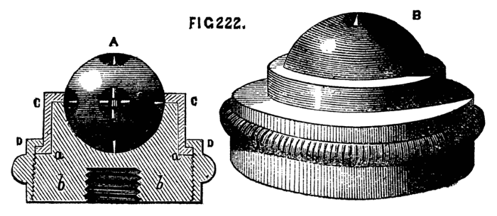
Fig. 222.
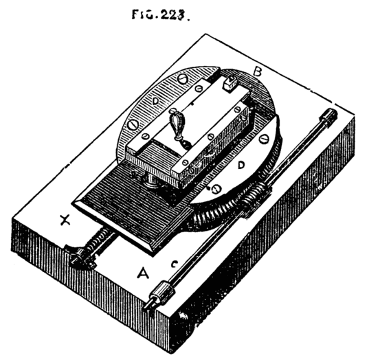
Fig. 223.
The method of turning from a pattern acting on the tool has been alluded to. In some cases a similar method is pursued, in which the hand supplies the place of automatic machinery, an instance of this is the application of pattern plates or templets to the small slide rest now to be described, by which not only parallel or spherical work may be done, but the elevations and hollows in moulded work may be followed without difficulty. The pattern plates can be made by the amateur or workman so that not only is no extra cost incurred, but any desired form can be given to the work and as many duplicates made as may be requisite. The simple slide rest itself is represented in Fig. 224. The lower iron or steel frame is rectangular, chamfered underneath, and is cast with a projecting part B underneath to the socket of the hand rest. There is, therefore, no sole or saddle required, and the height is adjustable at pleasure to suit 3, 4 or 5-inch centres. C is a plate of brass, cast with one V-piece similar to D, the second E being removable at pleasure, or both V-pieces or guide bars may be attached by screws. They are attached by two or three screws passing through oval holes in the plate and tapped into the bar, so that a little play to or fro is allowed, by which they can be adjusted to grasp with more or less friction the iron bevelled frame. They are kept up to their places by a pair of large headed screws tapped into the edge of the brass plate and marked e, e, in the drawing of the rest. On the top of the brass plate is fixed in a like[150] manner another pair of chamfered bars similar to those of a slide rest for metal, but in the ornamental turning slide rests, where lightness and accuracy are more needed than strength, the parts are proportionally smaller. The frame, for example, may be six inches or six and a half inches in length by two in width, the brass plate two inches square, or perhaps two and a half by two, the longest measurement in the direction of the upper guide bars, between which the tool receptacle will slide. This will be quite large enough for a five-inch lathe, although the measurement may be more or less if desired. If taken as above, the iron frame may be half an inch deep and the face of each side of similar size, leaving one inch between, in which the screw will lie. 224 B shows the under side of the frame with a cross piece to which the part, B 224, is attached. The guide bars for the tool receptacle may be similarly small and light. If the plate is ¼ in. thick and two in width the bars may be ⅜ in. stuff before being bevelled, the attaching screws can then be ⅓ in. or 3/16 in. in the shank, the heads being large and flat, and not countersunk. It is probable that many amateurs would like to attempt such a rest themselves, hence we have given the above details. We must however, warn them that as the above is for ornamental turning, where accuracy is of the utmost importance, great care must be exercised in the work, and the various parts must be fitted to the utmost perfection. The upper face of the lower frame must be quite level, and the sides quite parallel, and the upper or cross slide must be fitted precisely at right angles to it. Above all, the screw by which the upper part is advanced in either direction requires great precision. It should be made with a fine thread deeply cut, and must fit its nut under the brass plate, D, without shake. The nut itself should be long, and must be carefully bored and tapped; it should be also sawn through its length underneath, to give it a spring, so that it may grasp the screw tightly yet easily, and this will also compensate for wear. This will be understood when it is stated that the milled head by which the screw can be turned is graduated round its circumference, as is also the face of the bed or lower frame of the rest. Hence to give the head a turn, or half, or a quarter turn, must draw the sliding plate exactly the same distance to or fro, at whatever part of the frame it may be at the time. This necessitates all the threads being precisely alike. [We say precisely with a certain mental reservation, for, strictly speaking, perfection is hardly possible, and the skill and science brought to bear upon screw cutting when perfect work has been necessary, as for astronomical instruments, would hardly be credited, so extremely difficult is this part of the mechanical art.] It would be better for the amateur to get the screw and nut cut by Holtzapffel, Munro, or other first-class maker, who has the requisite means and can command the highest[151] skill. Between the upper guide bars are fitted various tool receptacles. The only one which need as yet be spoken of is that which holds the little inch-long tools for ordinary work or for use with the eccentric chuck. This consists of a brass plate bevelled to fit the chamfered bars, on the end of which is a small piece of steel with a rectangular hole and set screw, as seen in the drawing marked X. This plate has a tailpiece of rather thicker metal, through which pass two set screws, which regulate the depth of the cut to be made, their points bearing against the end of the brass plate on which this tool receptacle works. No screw is attached to move this upper slide, but a wooden handle projects from it at right angles to be moved by hand, or a lever Y is made use of. This has two projecting pins, the front one taking one of the holes, 1, 2, 3 of the slide, the other one of a set of similar holes in the top of the chamfered bars. By this the slide can be advanced with ease and great steadiness. We now come to the pattern plates or templets F, alluded to. These are formed of sheet iron about 1/20 in. to 1/16 in. thick, and must be long enough to reach from one end to the other of the iron frame A, underneath which at each end are two holes a, a., Fig. 224 B, to receive screws by which the templets are attached by means of the slots, b, b. The outer edge, a, of templet is the pattern to be copied. The dotted lines in Fig. 224 show a plate in position. The[152] tailpiece of the tool holder to be used has a projecting stud, or is made with a screw with or without the roller seen at H, and this is kept in contact with the templet by the hand or by a spring, so that when the slide traverses the lower frame the tool-holder necessarily follows all the curves of the pattern plate. An inspection of K will make it evident that the projecting screw must be so regulated as to length as to allow the tool-holder to go to the extremes of the projections and hollows. It must therefore in the pattern shown be at least as long as the line a, b, Fig. K, and a tool-holder of sufficient length must for similar reasons be selected, or the tailpiece might touch the fixed plate on which it works before the guide pin had penetrated the deepest hollow of the pattern. With these precautions nothing can exceed the ease with which this clever adaptation of the slide rest is made and used, the greatest advantage being that the workman can make his own templets to any curve or series of curves that may be desired.
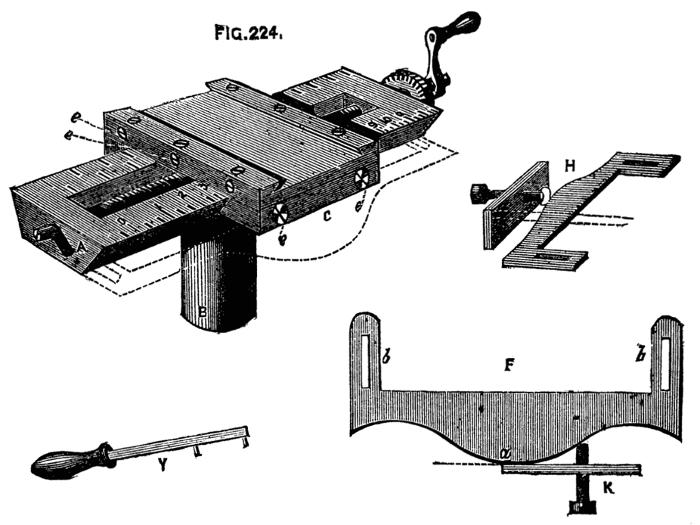
Fig. 224.
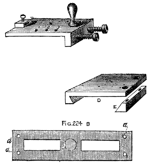
Fig. 224B.
At a later page is described a slide rest with the arrangements of the tool-holder somewhat improved, and calculated for the reception of larger tools and apparatus. The little rest here described is, however, very light and useful.
A compound spherical slide-rest, for ornamental turning lathes, which has been patented by Mr. Hoblyn, Rickling-green, Essex, is capable of turning and ornamenting accurately spheres and any segments of circles convex or concave, either on the surface or cylinder; also, it is stated that by the addition of templates any other curves, not segments of circles, can be turned out, in addition to the work performed by an ordinary compound slide-rest. In our illustrations, Fig. 1 is a side view, and Fig. 2, an elevation of the rest. A is the lower, and B the top plate, C the carriage, and the saddle as usual. The lower plate, of iron, is planed on bottom and sides, and has a longitudinal bevelled slot in the bottom to receive the fastening bolt, so that the plate can be tightened up at any point on the lathe bed. At one end of this bottom plate is a piece raised the whole of its breadth, accurately turned and faced, with a stout turned pin, b, for a pivot in the centre. A wheel, c, is placed around this raised piece, having any specified number of cogs, and on its top any specified number of small holes drilled to receive two pins as segment stops. The top plate is slightly narrower than the bottom one, and has on its underside a corresponding surface to that raised on the plate A, turned and faced with countersunk hole in the centre to fit on the pivot b, on which it is tightened by a screw and washer. The top of B is placed to receive two parallel bars of brass, bevelled on the inner edge, so as to form sliding bars for the carriage C, one bar being a fixture, the other capable of adjustment by tightening[153] screws. The sides are also accurately planed, and on one a tangent screw, e, is so fixed as to be put in and out of gear with the brass wheel, c, for the purpose of driving the top plate round the pivot b. In the raised surface of B, is a countersunk slot forming a quarter circle, with screw passing through it into the bottom plate; by this means the top plate can be firmly fixed at any angle to the bottom plate for the purpose of slide-rest turning. A small pointer, f, works clear of the brass wheel in the capacity of segment stop—two small pins being placed in the specified number of holes in c. On the opposite side of the screw, e, on the top surface, a screw, g, works in two standards screwed into the plate through slots in the bar, which works through a traveller, h, firmly attached to the carriage, C, and therefore capable of driving the carriage in a rectilinear direction—for slide-rest purposes. This carriage, C, consists of an iron plate i,[154] with standard k, top plate l, with parallel brass bars to receive tool receptacle m, the bottom plate and standard being in one piece with the plate, planed side and bottom, so as to slide truly between the parallel bar on B. The standard has its surface accurately turned with a pin in centre to form pivot. The top plate is planed true, bottom, sides, and top, and has a countersunk hole in the exact centre, so as to work on the pin, and tightens up with a large nut. In the plate is a countersunk slot forming a quarter-circle, with screw passing through into the standard, to set the tool receptacle either parallel with B for spherical turning, at right angles to B for slide turning, or at any angle for thick and thin cuts, and similar patterns when used either as a spherical or slide rest. The parallel bars are to be similar to those on B, to enable the tool receptacle to be advanced or retired by screw or lever. This part of the machine can be adjusted for height of centre thus:—The standard k to be a hollow cylinder with fixing screw on one side; the plate i to be made with turned pin on bottom, to fit into standard; elevating screw; saddle as usual, but with the addition of a small hole drilled in one of the sides, and a corresponding one in the side of the lower plate A, so placed that when a pin is fixed into these holes the pivot is exactly central to the lathe centre.
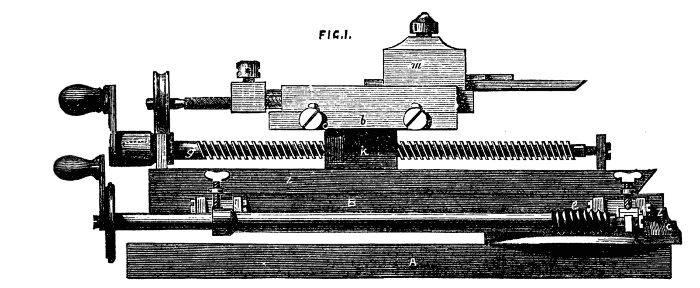
Fig. 1.
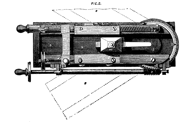
Fig. 2.
The way of using the spherical rest is thus described by Mr. Hoblyn:—"When altogether, and the point of tool adjusted by means of a square exactly over centre of pivot, it is evident, if the top plate moves round, the point of the tool will still be in the same place; but if we retire the point one half-inch, on moving the plate right round it would describe an inch circle, so that if the centre of pivot be exactly under the centre of the lathe, and we move the rest the half-circle, it will cut a perfect ball (or any part of one, if the cut be less than half a circle) of such size as the distance doubled of point of tool from centre of pivot. Therefore, by adjustment of the lower plate on the lathe bed according to the size of material (this, of course, does not allude to the act of turning a ball, when the centre of pivot must be exactly under centre of lathe), adjustment of carriage from centre according to the size of circle required, and adjustment of tool for depth of cut, we are enabled to turn any convex curve. To turn the concaves, instead of retiring from centre of pivot, it is only requisite to advance the point beyond the centre to the distance required, when the same rules apply as to the convex curves. In turning the concaves, however, it is necessary to turn the plates half-round, so that A and B are in the same straight line, instead of over each other. This enables you to work on any sized piece of wood, the object of the longitudinal slot in the lower plate being to enable you to adjust your previously arranged curve to any sized wood or ivory that your lathe will take, less 2 in., the height of[155] machine. The desired curve having been turned, take out the chisel, and place in the receptacle any ornamenting instrument, drill, eccentric, &c.; advance the point till it touches the work, then set your screw for depth of cut, and work according to fancy. Whatever it is it must be mathematically correct on the curve, as you have not altered it in any way. You then remove your rest to cut the next desired curve, and proceed as before. The best way to execute a piece of work is first to make a sectional pattern of your design, either by drawing or cutting it out with scissors from a double piece of paper, when, of course, both sides come the same, the line where the paper is doubled being the line of centre of lathe. You can then, with a pair of compasses, ascertain with accuracy the necessary size of circle, and the position of centre of pivot to procure the desired curves. You may also produce a very good effect by a combination of two different curves in this way:—Let your ornamental instrument be the universal cutter; working horizontally follow up your curve with it, but, instead of cutting right out on your curve, let the instrument finish of itself in wood previously turned so as to fit its curve, when you get the lesser and greater curves following in unbroken succession. With the eccentric chuck numberless effects of the most curious description may be produced, even work supposed to be only possible with a rose engine. We believe the tool is to be seen at the shop of Mr. Evans, 104, Wardour-street.
To turn a sphere by means of a template attached to the slide rest as described, the following adjustment of the rest and mode of proceeding should be followed. A, B, Fig. 225, is the chuck containing the material, H, to be worked into a sphere. Upon this the length, or diameter (equal to that of the template, as will be explained), is to be marked at K, K, which being divided equally by the line L, L, will give the dimensions of the ball as if it were about to be turned by hand. The corners are to be turned off with the gouge, as far as shown, K being equal to e L, and K f equal to K e. The outline of the ball will with these measurements not be touched. The angles left may also carefully be removed, but (as shown by the figure) this operation must be conducted with great care. A template must now be made containing a full semicircle, every part of which can be traversed by the stud or screw upon the under part of the slide, or the ball will not be severed by the final cut. It is evident that the traverse of the slide during the operation will be the full radius of the ball, and in this, and indeed all cases of deep recesses, and greatly projecting mouldings, the ordinary tool-holder with tailpiece had better be removed, and replaced with a slide like M, having a pin straight through it to rest in contact with the template. This will preclude the necessity for the long stud or screw spoken of before as necessary when the slide with the tailpiece is[156] used, but the tool cannot be advanced independently of the template as when the other form is used. Fix the rest so that when the top slide is at its central position the tool may stand as in the sketch exactly upon the central line of the ball. Take care that thus placed the tangent-pin of the slide is on the central mark of the template. The long frame of the rest must likewise be parallel with the bed of the lathe, keeping the top slide pressed against the template with the left hand, while the top part traverses the frame under the action of the screw moved by the right hand, the ball will be correctly cut.[16] One or two cautions must, however, be given here, to ensure a satisfactory result. In the first place the cylinder from which the ball is to be made must be exactly of the diameter of the semicircle on the template. H, H is the cylinder to be turned to a sphere, G, G, B shews the position of the tool at starting, the dot on A, the templet, the tangent pin of the slide, Fig. 226. As the work proceeds the tool will take the several positions shown, the dotted lines, D, being equal and parallel. The tool will thus repeat the form of the template. Let the latter remain as before, but let a smaller cylinder[157] be inserted in the lathe, or, which is the same thing, let the tool be now lengthened so as to start at C on the inner dotted line. When the pin, F, has reached K, which should be the axis of the ball, the tool will be at M, quite out of cut. Fig. 227 represents three forms of tool in contact with the ball at two points. The first two will evidently be out of cut at the axial line, as the side of these bevels will then touch the piece to be turned. C is a form that will remain in contact from the diameter to the axial line. The left side of the edge is slightly overhanging the side line of the tool, D.
[16] See Appendix
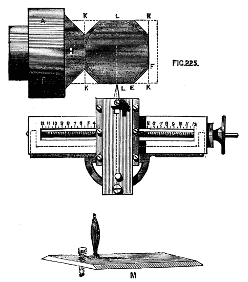
Fig. 225.
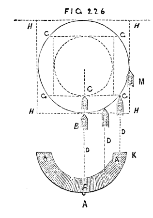
Fig. 226.
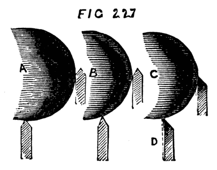
Fig. 227.
When the part shown has been cut this tool must be removed and a similar tool bevelled in the reverse direction, adjusted by reference to the central line of the ball as before.[17] It is recommended to roughly shape the work with the gouge, and partially to cut it off with the parting tool so as to relieve the tool as much as possible, and when the last finishing cut is to be taken a freshly sharpened tool is to be made use of. It is evident that in the above and similar work the rest may be placed across the end of the cylinder if preferred to turn the right hand hemisphere, but it would have to be moved for the second half, which should be avoided, if possible. The advantage which the circular rest has over the above is due to the fact that the tool and rest once in position, neither has to be readjusted until the work is complete. The slide rest and semicircular template forms, however, if judiciously used, a very serviceable substitute and makes very satisfactory work. Whether or no the reader has a complete rest for spherical work, he should decidedly provide templates to use as above. They are not only useful for turning or ornamenting spheres, but any forms whatever that may be desired, and they possess this special advantage, that when a dome or other pattern has been thus turned with a plain tool the same template used with revolving cutters will enable the work to be ornamented with perfect ease, doing away in a[158] great measure with the need of a dome chuck. Suppose, again, that a number of pieces are desired precisely similar, as a set of pawns for a set of chessmen, a sectional drawing made and transferred to a piece of sheet-iron, and the latter cut to form a pattern plate, will enable the most unskilful to work satisfactorily. Nothing more need be said of the uses of templates, and for the present the subject will be dismissed, though it may possibly be referred to again in a future page.
[17] Holtzapffel uses a tool, the plan of which is semicircular, like a small round tool, cutting on front and two side edges; the tool is very narrow and bevelled below.
The first of the chucks comprised under the above head is the oval or elliptical chuck, and it is introduced first in order because it is not essentially a machine for ornamental turning, as are the eccentric and others of this class. There are many plain works required of elliptical section, as bradawl and other tool handles, for which a very simple arrangement is required.
The principle of the oval chuck is as follows:—There is an arrangement of slide, by which as the piece revolves it is drawn gradually further from the tool during half a revolution, and in a similar manner caused to approach it during the remaining half revolution, each point in the circumference alternately partaking of such movement; the whole of these points together, which, of course, form the circumference, will become an ellipse. Let D, Fig. 228, be the centre of the mandrel, A, B the direction of the slide moving up and down in a right line, and carrying the work upon a screw in the centre of it. C, E become centres, and may be taken as the extremes, for as the work revolves a succession of centres are formed and instantaneously changed. The figure produced will be the oval shown. To render this, however, clearer, Fig. 229 may be taken, which represents the chuck in its most simple form with separate details of the parts which compose it. A is the chuck with central slider and chamfered bars, as described in speaking of the slide and rest and previous apparatus; B is the slide detached; D, front view of the same. The short arms a, b, pass through slots in the back plate as seen at C, which shows this plate with slide removed. Through these short arms pass a pair of adjusting screws; or still better a and b are themselves cross arms or pallets extending the width of the plate as seen next drawing, and in the chuck of Muir which follows. They are merely flat plates of steel embracing the guide ring, so that some point in their inner surface may rest against it during every part of the revolution of the chuck.
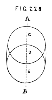
Fig. 228.
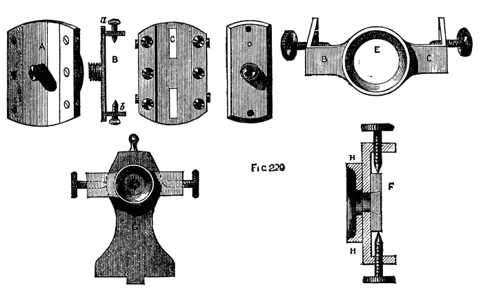
Fig. 229.
The guide ring here alluded to is shown at E, and also at G, fixed in its place upon the poppet. It is in the form of a raised ring with arms, B, C., which are turned at right angles near their ends, and through which pass adjusting screws with conical points. This plate is flat at the back and bears against the face of the poppet, the mandrel nose falling into the central opening E. It is kept in place by the points of the screws falling into conical holes at the sides of the poppet head. At F is a side sectional view of this plate, with its raised and accurately turned ring, H, and at G is seen the poppet[160] with the plate attached, the left arm being dotted to show the position of the adjusting screw. It is this ring and plate which regulate the movement of the slider, and, with it, of the work, the latter being attached to the screw in the centre of the sliding plate, which screw is a counterpart of that upon the nose of the mandrel. Suppose the chuck A screwed to the mandrel, and the ring accurately concentric with the mandrel, in which position, the pallets must touch at two opposite points. In the best chucks there is an adjusting screw to each, by which the contact can be regulated. In this position any object of a circular form can be turned, for the slider remains in one position, and its screw, upon which the work is fixed, is a continuation of the mandrel. But if now the adjusting screws of the part E are turned, the one being loosened and the other tightened, the guide ring will no longer be concentric with the mandrel, and, as the screws of the slider bear upon it, the slider will during its revolution be moved to and fro to a distance regulated by the eccentricity of the guide ring. The combination of this circular motion of the chuck and rectilineal movement of the slider will produce an ellipse, and a stationary tool applied to the work will cut it, into that form.
The above simple arrangement of oval chuck suffices only for plain work. The only figures that can be described by its means, upon the cover of a box, for instance, being a series of ellipses of which the longest diameters fall in the same right line, and of which the centres are coincident with the axis of the mandrel, as Fig. 229.
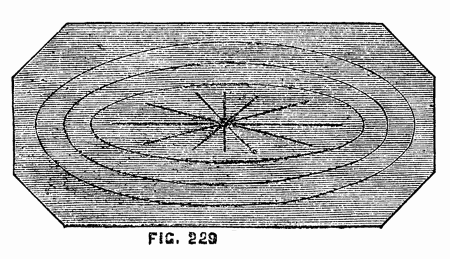
Fig. 229.
Even these, however, cannot be done without some compensating arrangement, as the minor axis does not diminish in length at the same rate as the major—hence the ellipses get narrower and narrower until the central one becomes a mere right line. This is referred to again in the ornamental section of this work.
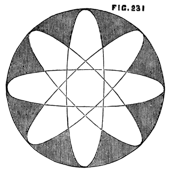
Fig. 231.
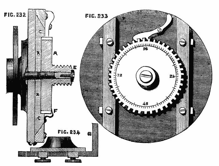
Figs. 232, 233, 234.
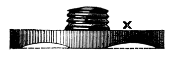
X
Combinations like 231, in which the ellipses intersect, cannot be so obtained. Hence the oval chuck is provided with a wheel, either racked to work by a tangent screw or fitted with a spring catch, by which it becomes a dividing plate. This wheel revolves on a central pin[18] fixed to the middle of the sliding plate, and carries a screw of the same pitch as that upon the mandrel to which other chucks can be attached. By this means the axial lines of the ellipse can be varied in direction. This addition is shown in Fig. 232, which is a section, and 233, which is a front view. In the former, A is the wheel,[162] which, as previously explained, should be so arranged as to contain a number of cogs divisible by as many figures as possible; 96 is such a number, being divisible by 2, 3, 4, 6, 8, 12; 72 is also a good number, as it will divide by 2, 3, 4, 6, 8, 9. If the edge is racked and moved by a tangent-screw with divided head a greater range can be taken and finer work done. In this case the face of the wheel can be marked with divisions, and a fine steel pointer, as shown at F, added to count by. The pin B, which is firmly attached to the centre of the slider plate, must be strong, and the lower part at least should be conical. It is drilled and tapped at the smallest end, and when the circular plate with its screw is slipped upon it, a screw, E, the head of which is countersunk into the face of the large screw, retains it in place. The slide, C, has a recess turned to fit the wheel plate, and the latter is cut as shown at X, which ensures a more accurate bearing than if it was left flat on the lower surface. In making this chuck certain precautions are necessary. In the first place, the guide ring fixed to the poppet must be exactly concentric with the mandrel when in its central position; and when it is drawn by the adjusting screws to the right or left the central line must remain parallel with the surface of the lathe bed. To ensure this centrality it is necessary to turn its outer surface when it is in position on the lathe head. So at least says Bergeron; and it is perhaps the best method whereby to ensure the accuracy that is required.[19] For this purpose Bergeron directs the use of a cutter similar to Fig. 234 attached to the mandrel as a chuck, the edge which is on the inside of the bent part at a acting on the exterior of the ring as the mandrel revolves. The screws allow the tool to be advanced closer to the ring as the work proceeds, while they secure it at any desired point. Such a contrivance as this, used merely as a finishing tool to correct any slight error, is no doubt sufficiently satisfactory. The various parts of this and other compound chucks should be first turned separately to near the required size, and accurately finished when in their respective places upon the chuck. Any parts which present a difficulty from the impossibility of retaining them in place while operated upon, may be soldered with tinman's solder, and thus turned, after which the application of moderate heat will detach them, and the fluid solder can at the same time be wiped off with a pledget of tow or cotton waste. As many of our readers may wish[163] to make such apparatus as the above, it may be desirable to add a few directions for the preparation of chamfered edges such as those of the slide and guide bars, the latter of which should be of iron or steel. Let the slide, for instance, be cast as a rectangular plate and the two flat surfaces be roughly levelled with a file. One of these must now be made perfectly true, either by mounting it with solder upon the face plate of the lathe, and levelling it with the aid of the slide rest, which is perhaps the safest plan, or by careful working with the file, using a straight-edge in all directions, and finishing by careful grinding upon a flat stone slab with water, or on a wooden grinder charged with emery and oil. After one side is finished, the opposite face may be similarly treated; but for this the plate may be secured to the finished surface of the lower plate of the chuck itself, and turned with a tool fixed in the slide rest. The edges must now be filed truly at right angles to the sides, care being taken to keep the long sides of the plate parallel. (The short sides or ends will be rounded by being turned true with the edge of the chuck.) The work must now be tested with the straight-edge and small steel square, and any error carefully corrected. Of course, if the reader is the happy possessor of a planing machine, all these operations will be facilitated and accuracy more likely to be ensured. It may here be mentioned that, to supply the want of such planing machine (a want often felt by amateurs who have not mastered the use of file and scraper), Monro, of Gibson-street, has cleverly added a planing apparatus to the ordinary foot lathe, rendering the latter tool complete for all purposes of amateur engineering.
[18] This pin should have been shown of a conical not cylindrical form, and much stronger in proportion.
[19] This part is always so turned by the best makers.
This handy apparatus will be found on a later page fully described and illustrated by a photograph of the machine. The writer has seen it and used it, and can testify to its satisfactory working, as a lathe thus fitted does not run heavier or require greater exertion than when used for ordinary turning.
The next step will be the chamfering of the edges of the plate. Let 235 represent the plate in its present condition, with rectangular edges. To produce a chamfer of 45°, draw a line, a, b, at a distance from the edge equal to the thickness of the piece. If a smaller angle is desired, the line must be drawn further back. An angle of 30° to 35°, is, in the writer's opinion, better than one of 45°, as the chamfered bars will then have a wider bearing on the upper surface of the plate, tending to hold it more securely down upon the lower part of the chuck. Nothing remains but to file carefully down from the line thus drawn to the lower edge, by no means a difficult operation if care is exercised not to obliterate the mark, or to trespass the least beyond the assigned limit. A template, cut like Fig. 236, of the desired angle, will be a gauge for the edges of the plate, as well as for those of the chamfered bars, and will serve to make assurance[164] doubly sure. The arms which stand out at the back of the slider to embrace the guide ring are not fastened to the plate immovably, but with power of adjustment. A pair of short slots are made in the slider, into which a square projection from the arms fits, and the whole is clamped by a screw, as shown in 237, A, B, and C.
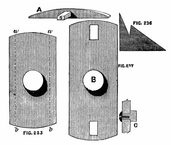
Figs. 235, 236, 237.
A more accurate method is shown in the Ornamental Section for finer adjustment than can be secured in this way, but for a home made chuck the above will suffice and is the easiest plan to carry into effect. To use this chuck, the guide is first arranged, so that its ring is concentric with the mandrel. A mark is generally made upon it, and also upon the lathe-head, by which this position can be readily insured. The chuck is then screwed upon the mandrel, and the arms adjusted, as just described, so as to embrace accurately, but not too tightly, the guide ring. They are then, once for all, fixed in that position by the screws alluded to. A few drops of oil are necessary to lubricate their inner surface and the exterior of the guide, and the latter being withdrawn by its adjusting screws to the desired eccentricity, the work may be proceeded with. A rough piece of wood, however, should always be first turned to a cylindrical form, as an oval chuck being an expensive article is to be carefully preserved, and not exposed to the shocks inseparable from the process of roughing down the work. Moreover, there should always be one or two screws passing through the slider into the back plate, to take[165] away the strain from the chamfered bars, which can be removed when the slider is to be brought into action. Two precautions are here laid down respecting oval turning, which, in all probability, a tyro would not suspect to be necessary until taught by failure. In the first place, at whatever point of the circumference the tool is held, at that point it must remain, or rather, it must remain in the same horizontal line, being neither raised nor depressed. Hence, for all work where accuracy is needed, oval turning should be done with the slide rest. In the second place, when it is desired to place a succession of ellipses one within the other on the face of the work, like Fig. 229, it will not be sufficient to place the tool nearer to the centre for each ring, but the eccentricity of the guide ring must be reduced at the same time; otherwise, when the middle is reached, a straight line will be the result, instead of the proposed ellipse, as already stated. The lathe should not be driven at a very high speed, and the moving parts should be lubricated from time to time. There are other ways of compensating the error produced by the oval chuck, or elliptic cutting frame, which however are so entirely connected with ornamental turning that they are reserved to be introduced into that section. A contrivance for turning ovals invented, and communicated to the English Mechanic by a Suffolk amateur, deserves a place here. It is thus described by the inventor:—
Ovals are generally turned by causing the work to move in and under guidance of an "oval chuck".
There seems no reason why the same result should not be arrived at by communicating a movement to the rest supporting the cutting tool in the following manner:—Let A, A, be lathe bearers, B, pulley,[166] C, screw of mandrel, D, template fixed thereon, E, friction wheel on the end of bar F, G rest (a board of any convenient width) moving on pivots at H. The friction roller, E, is to be kept in contact with the template by the cord running over the pulley T, stretched by the weight L. The rest will thus oscillate under the guidance of the template, which may be either oval or rose engine pattern, and the cutting tool form the pattern of the template used. There might be other modes of causing the rest to oscillate on the same principle. The lathe would require a slow motion, the same as with an oscillating mandrel.
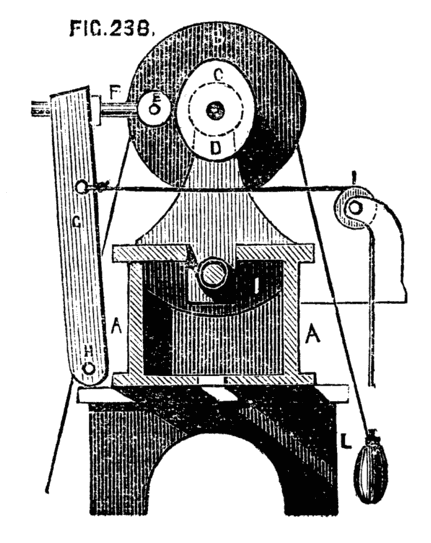
Fig. 238.
Next in order of the compound chucks stands the eccentric, the use of which is not entirely confined to mere ornamentation, as it is often very convenient to the turner to have the power of shifting the centre of his work. Thus, a solitaire board may be drilled with the necessary cup-shaped holes, or any work of a similar character completed by the help of this chuck without the necessity for constant re-centering. The general work of the chuck in question is nevertheless ornamentation, for which it is peculiarly adapted either alone or in combination with other compound chucks, or overhead apparatus. The sliding plate of this chuck works between chamfered steel bars, the same as in the oval chuck. There is, however, no guide ring on the lathe head to regulate the movement of the slide, and therefore also no necessity for the projecting arms at the back. The slide, in fact, is moved by a screw with a graduated head, similar to those already described. Fig. 239 represents the common[167] form of this chuck, in which the wheel which forms a dividing plate is moved by a tangent screw. The sliding plate is shown slightly drawn out by its screw, the degree to which it is moved being that of its required eccentricity. When the plate is drawn back to correspond with the base plate, the centre will be in a line with that of the mandrel, and any work turned upon the chuck in this position of the slide will be cylindrical. The central screw of all these compound chucks being alike and of the pitch of that on the mandrel, any of the ordinary cup chucks can be used with them to hold the work; or the eccentric chuck can be screwed to the elliptic, cycloidal, or any other in the set, by which means an endless variety of curves can be described. The effect produced by the simple eccentric chuck now described is as follows, the slide rest being used with it as a matter of course. Let a piece of box or other wood be fixed by means of a cup or other chuck upon the screw of the eccentric chuck, and the slide rest with a single point tool be brought in front of it. By means of this the work must be carefully faced, and made uniformly level. A ring A, Fig. 240, may now be cut, which will be concentric with the mandrel. The slide of the chuck being now drawn down by a few turns of the leading screw (the tool and rest being kept in its original position), the centre of the work will thereby be shifted, and the tool being advanced to touch the same, the[168] circle B will be formed of the same size as the first, but necessarily cutting it at two points. Another turn of the screw will enable C, and similarly D, or any number of circles to be successively formed. The centres of these circles will be in a line across the face of the work. The ratchet wheel is added to enable the turner to arrange his circles round a common centre, instead of being thus obliged to keep them in a right line, and it will presently be seen what a beautiful variety of interlaced circles can thus be accomplished. The dividing wheel is, as previously explained, divided on its edge into an equal number of teeth, or racked for a tangent screw and divided on the face and edge. We shall suppose the number of divisions to be 120. Face the work afresh, and, drawing back the slide until the centre is concentric with the mandrel, as at first, cut a boundary circle, A, Fig. 241. Move the slide of the chuck a few turns, as before, and cut an eccentric circle. Now move the dividing wheel thirty teeth, and cut a second, and, advancing by thirty each time, cut a third and fourth, and Fig. 241 will be the result; the centres of the eccentric circles falling upon four points of the inner dotted circle, which is itself concentric with that first made.
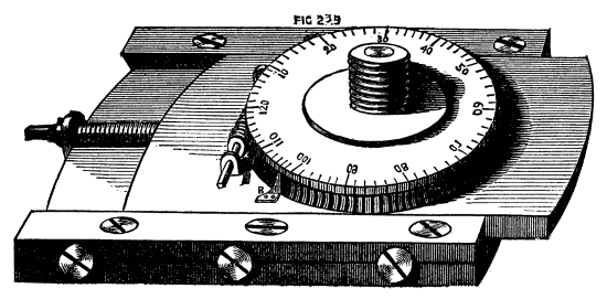
Fig. 239.
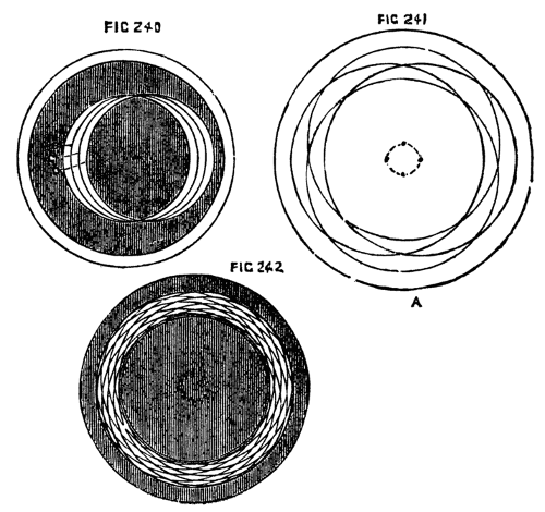
Figs. 240, 241, 242.
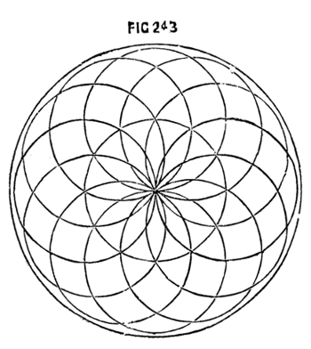
Fig. 243.
If the same process is followed, but the number of the circles increased, a very neat snake-like ring will be formed, constituting a border, in the inside of which other combinations may be made. In Fig. 242, twelve interlacing circles are shown; in Fig. 243, twelve circles, described upon centres, which lie upon the circumference of a central circle of equal size. This last pattern, when more finely executed, by doubling or trebling the number of eccentric circles, forms the device generally cut upon watch cases, under the name of engine-turned. The best way to try patterns, is to cover the face of a piece of boxwood with paper, using a pencil in the tool-holder of[169] a slide rest instead of a cutting tool. If a softer disc is used instead of box, round pieces of paper or thin card can be fixed upon it with ordinary drawing pins; and if the first pattern is unsatisfactory, a second, and any successive number of pieces, can be mounted, and fresh patterns traced by the same means. It would be mere waste of time to multiply specimens of the patterns that may be executed by the aid of the chuck just described; and, indeed, this could only be done by cutting in the lathe itself the blocks from which such specimens must be printed. For the present, at any rate, the principles only by which such devices may be executed will be given (as above,) and the designs will be left to exercise the ingenuity and taste of the reader.
It happens, moreover, that few as are the works devoted to the general principles and practice of plain turning, more than one has been published on ornamentation by the eccentric and other compound chucks, in which a variety of executed patterns appear, of more or less beauty; and in the English Mechanic has lately been printed a selection of exquisite designs by Mr. G. Plant, whose chuck, indeed (to be presently noticed), bids fair to supplant the most simple one now described. The chief recommendation, perhaps, in the latter, is its great simplicity, as it may be made by any amateur sufficiently practised in the use of tools; whereas the geometric chuck is too complicated to permit this. It will be observed, on inspecting the drawing, Fig. 239, that the divisions on the face of the wheel are continued on the side above the part that is racked; this permits them to be seen when the piece of work overlaps the circle of the wheel. The steel point shown at B, answers as an index, either to the surface marks, or to those on the side. The tangent screw is now generally fitted in a small frame, which is itself pinned at one end to the top plate, and kept up to the dividing wheel by an eccentric cam. This is not shown in the drawing; the plan is nevertheless good, as the screw is instantaneously released from gear at pleasure, when the wheel may be turned by hand to any desired position; after which a slight movement of the cam brings up the screw, and all is made ready for work. The eccentric chuck becomes available for such work as shown in Fig. 244, representing the bottom of a candlestick, ringstand, or similar article. In this case the centres of the eccentric work (now cut quite through) are on the circumference of a circle larger than, and outside, the work itself. Instead of cutting through the whole thickness of the stuff the outer circle may remain such, and the blackened part may represent an inner raised surface, when the contrast formed by the sharp edges round the pattern with the smooth circular part will be very agreeable to the eye. To improve still more this design, the outer part may be ebony nicely moulded and edged with ivory, and[170] the raised part ivory; or the same may be alternations of ebony and holly, which will form a contrast almost equally agreeable. A small chisel-ended tool must be made for this work if the whole is in one block, as it will be necessary to leave a level surface upon the face of the lower part. There are an infinite number of designs of similar nature, which will occur to the reader when the principles of the chuck have been mastered, some of which would at first sight appear to have been worked by other means. Fig. 245, for instance, which is but a modification of the last, scarcely looks like lathe work, but can be cut more rapidly this way than any other—of course the fret saw will do similar work, but it would first have to be marked out, and afterwards the marks of the saw teeth removed, whereas the above is cut and polished at once. It may here be observed that the eccentric chuck itself is used to fix the position of the various circles to be cut, whereas the size of these circles is determined by the slide rest. Thus in Fig. 246, while the centre of the chuck is concentric with the mandrel, bring up the tool in the rest and cut the circle F, G, H, of which B is the centre; draw down the slide of the chuck until its centre is at C, leaving the slide rest as it is, and the circle F, E, D, will be formed of equal size with the first. Now move the screw of the slide rest so as to draw in the tool towards the centre of the lathe bed without altering the chuck, and[171] the small circle will be the result, whose centre (being dependent on the chuck alone) is the same as that of the larger circle. Bearing in mind this principle, that the chuck determines the various centres only, and the slide rest the radii, little difficulty will be experienced in devising and executing designs. Such is the simple eccentric chuck, of which the use is tolerably extensive; but there are, nevertheless, certain positions in which the eccentric designs are required, which cannot readily be obtained by its means. Fig. 247 is one of these, in which a moment's inspection will show the necessity of two distinct movements of the slide at right angles to each other. Hence a second slide is attached to the first at right angles, much the same in effect as a second chuck screwed upon the first but standing across it. This is the compound eccentric chuck to be subsequently described in detail. There is one drawback to the use of these chucks, namely—their excessive weight, which causes a great deal of vibration in the lathe itself, especially when the eccentricity of the slide or slides is great. An accidental blow moreover from the chuck under the above condition would be very severe. Hence the various cutters eccentric and others, worked by the overhead apparatus already in part described are infinitely more pleasant to use and even more effective and more easily managed. The eccentric chuck can be used in combination with these, and the capabilities of the two will thus be vastly extended, but in this case the chuck is kept stationary while motion is given to the tool, and the defect just alluded to no longer exists. In cutting patterns upon hard wood and ivory a common defect is shallowness of work, the cuts should not be so light as to give merely an effect of a design scratched upon the surface. The cut should be deep and clean, and the tool not only sharpened but polished so as to leave the device boldly executed, the small triangular and other shaped pieces left between the cuts standing up clear and solid. Some patterns, as the shell, which will be presently spoken of, require to be deep at one part and shallow at another. Some devices look best when cut with a point tool with[172] double and others with single bevel to the edge, and the same design worked with different tools will appear almost like two distinct patterns.
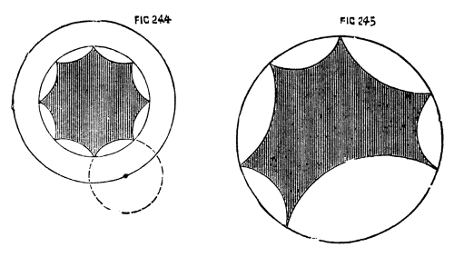
Figs. 244, 245.
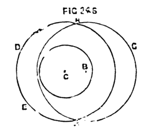
Fig. 246.
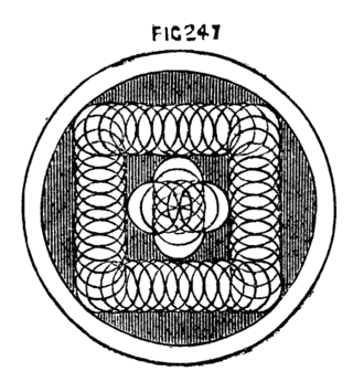
Fig. 247.
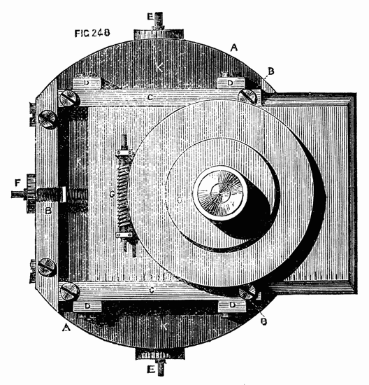
Fig. 248.
The double eccentric is represented in Fig. 248. The part A is the foundation plate, with a projection at the back, tapped to fit the mandrel. B, B, the lower guide bars; K, K, the lower sliding plate. All the above parts are precisely similar to those of the simple eccentric chuck. Upon the face of this lower slide are attached two chamfered guides, C, C, at right angles to the first. They are kept in place by screws passing through oval holes on their faces, and tightened when required by screws, tapped into four little square blocks, D, D. Between these guides slides the upper plate, which carries the screw for chucks, and the dividing wheel as before worked by a tangent screw, G; to either end of which a key is fitted. The leading screws, E and F, which move the two slides, have squared ends projecting both ways, so that the plates can be made to work eccentrically in either direction, which is sometimes an advantage. The chucks do not screw down upon the face of the[173] division plate, on account of their projecting parts at the back; and very commonly a round plate, O, somewhat smaller than the wheel and about ¼ in. thick is attached to the face of the latter to raise the work still higher, so that the dividing plate can be readily seen. The more compactly, however, the parts of this chuck are made, and the less the work projects from its face the better; as there will be the less strain upon the central pin, and upon the plates and their guide bars when the tools are applied to the work.
To be able thus to place in the centre of rotation any given point in a piece of work, whatever may be the form of its boundary lines, is of immeasurable advantage, even though the capabilities of this chuck are confined to objects of plane superficies, it being impossible to reach by its means the side of a cylinder, or the surface of a sphere or spheroid. It is evident that any line upon the face of a box, for instance, whether the latter be square, round, octagonal, or of any other form, may be followed with two movements of the slides, combined with the rotatory movement of the dividing wheel. Thus, a border of interlacing circles may be carried round the edge of such a box, Fig. 248; or, a series of such circles forming constantly diminishing octagons, hexagons, squares, &c., may be thus readily executed. Nevertheless, what was said of the simple eccentric chuck, applies with even greater force to the compound eccentric. It is a heavy piece of apparatus, requiring a lathe with substantial poppets and bed; the whole well braced to the floor and wall, to withstand the excessive vibration caused by the revolution of the apparatus. It was, indeed, in view of this and similar appliances that we insisted in our initiatory paper upon the great importance to the workman, of adequate strength and solidity in the various parts of the lathe itself.
In Fig. 249, we give a simple specimen of work to be executed by the compound eccentric chuck.

Fig. 249.
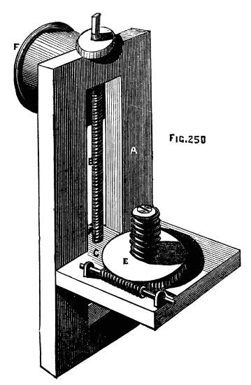
Fig. 250.
The compound geometric chuck of Ibbetson, manufactured by Holtzapffel and Co., is a double eccentric considerably improved and of very extensive application. A full description of it is published in a book written by the inventor, in which an immense number of patterns executed by its means is given with detailed directions for their execution. As these patterns are almost essential to a description of the apparatus as exemplifying the working of its several parts, the reader is referred to the book in question, or to a translation of it into French in the supplement to Bergeron's work. To enable the turner to execute patterns on the side of cylindrical pieces a chuck is used called a dome chuck, similar to Fig. 250. A rectangular frame of brass, A, carries a sliding plate C, at right angles to it, the latter having a tailpiece which fits accurately between the frame, and is tapped to receive the finely cut leading screw with divided head, B. A nut at the back of the frame clamps the slide in any desired position. Upon the upper face of the latter is a wheel racked on the edge so as to be moved by the tangent screw, E.[175] This wheel, like that of the oval and eccentric chucks, turns on a strong conical central pin, and has a screw attached of the same pitch as that on the mandrel. The chuck is screwed to the mandrel by the projecting flange, F. The work is thus mounted at right angles to its ordinary position.
By this arrangement any point in the side of a cylinder can be brought in contact with a tool fixed in the slide rest, and by means of the graduated screw heads of the latter and of the chuck various devices can be accurately made. This chuck may be used alone or in combination with the eccentric, and the quick revolution of such cumbrous pieces that would be a great drawback to their use is less frequently required, now that the following apparatus has been added to the lathe, and eccentric revolving cutters, with drills and other tools, have taken the place of heavier and more inconvenient apparatus. It is indeed much more convenient in the majority of cases to keep the work itself fixed, and to operate upon it by tools put in rapid motion, because the latter, from their excessive velocity compared with that which can be conveniently given to the material, make better work, and at the same time from their lightness impart no tremor to the lathe while in motion. The cuts thus made are in consequence very clean and smooth, and free from those slight undulations apparent when any vibration takes place in the lathe itself. The different varieties of overhead apparatus have been already described and illustrated, and it only remains to describe more in detail the revolving cutter frame, drills, and other apparatus used therewith.
The following pieces fit into the top of the slide rest in what is called the tool receptacle, and are advanced to the work by means of a lever as already described. Fig. 251 is the revolving cutter frame, the spindle of which is put in rapid motion by a cord from the flywheel passing to the small pulley through the medium of the overhead apparatus, as shown in a previous page. For the purpose of cutting small intersecting circles, a forked drill, Fig. 252, or a crank formed drill, 253, will suffice, and if these are made to cut deeply the result will be a succession of hemispherical knobs or beads (these must not intersect). A drill like Fig. 254 will give a knob raised in steps, and it is plain that by cutting the end of the drill to a section of the required moulding the latter may be rapidly executed. The flat inch long cutters used with the geometrical chucks (when the work revolves instead of the tool) are, of course, made of a variety of forms upon the same principle. Cases of these drills and cutters beautifully finished are sold by all the leading dealers in turning lathes and apparatus. It is essential that these tools be kept very sharp, and that their cutting edges should be polished if first-class work is to be done. The difference in the ap[176]pearance of execution is very evident when the cutter is thus perfect, as every cut bears a high polish, which cannot otherwise be imparted. Nothing can be applied to finish eccentric work except friction with a hard brush, and even this is much better avoided, as rubbing of any kind tends to round edges which should be kept sharp and to obliterate the finer and more delicate lines. It is likewise the best plan to finish with any particular tool all the work to be done by it without removing it from the tool holder for the purpose of sharpening. If, however, this is necessary the following contrivance must be used to insure the precise form which the cutter had at the commencement of the work. This being likewise necessary with respect to the fixed tools for ornamentation, the apparatus requisite in either case will be introduced here, the drawings and description being extracted from Holtzapffel's valuable work already alluded to.
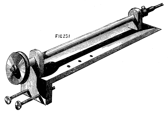
Fig. 251.
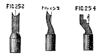
Figs. 252, 253, 254.
Fig. 255 is arranged for flat tools of various angles, or drills with single joints. A, is the stand of brass, with two turned and hardened steel legs. To this is hinged at G, by a screw joint, the part K, the[177] upper part of which forms a semicircular arc, C. A second arc, B is fixed at one end to the stand A, and passes stiffly through a mortise at the top of K. The latter can be raised, therefore or lowered at pleasure upon this second graduated arc, and clamped at any angle by the screw H. To the lower part of K is pivotted the tool holder, D, the upper part of which is pointed, and screws as an index upon the arc C, showing the angle at which it is placed. This tool holder is clamped by a nut at the back, which fits the end of a screw seen near the point. The figure below shows a tool holder which fits into the projecting parts of D, and serves to hold the small flat tools. Below is a similar holder, used for round-shanked drills. F is one of three flat slabs upon which the tools are to be ground,[178] there being one of iron, one of brass, and one of hard wood with a flat strip of oilstone imbedded in it, flush with its upper surface. The tool and its fittings are generally arranged in a box with three drawers; these contain the slabs of oilstone and metal, with the powders necessary for grinding and polishing. To use this instrument, the point of D is adjusted to the required angle for one side of the point of the tool. (It is shown at 40 deg. in the sketch.) The latter is then placed in the holder, and made to project until, when the angle of the chamfer is adjusted on the arc B, the part A is level, and therefore parallel to the surface of the grinding plate. The whole thus forms a tripod, the third leg of which is formed by the tool itself. The latter is first rubbed on the oilstone with a little oil. It is then finished more perfectly on the brass slab, dressed with oilstone powder and oil. Previous to this the tool is moved one or two degrees more upright by the arc B. A narrow facet is thus ground, having a dull grey polish. The tool is now carefully wiped clean, and polished with crocus and oil upon the slab of iron. If the point of the tool is central, with a chamfer both ways, the point of the tool holder is first adjusted on one limb of the arc and the tool ground, and then the same adjustment made on the opposite limb, so that the other side of the point can be operated upon. Thus tools of any angle and any bevel may be sharpened to a nicety without fear of altering the original form of the point, and this may be done, if necessary, during the process of eccentric turning, although, as before stated, it is better to fix the tools well sharpened at the commencement of the work, and not remove them until at least one complete set of circles or other patterns have been cut.
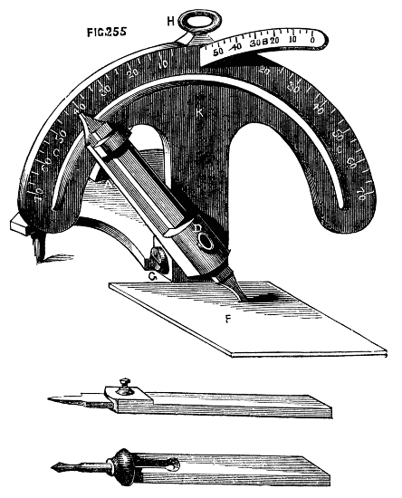
Fig. 255.
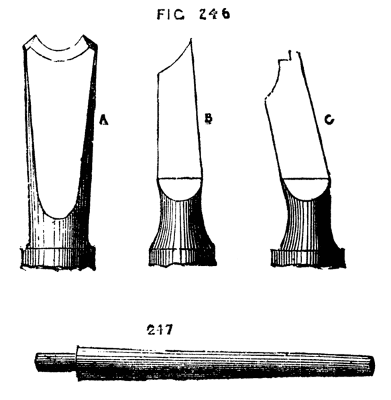
Figs. 246, 247.
The instrument just described is evidently unsuited for the drills and bead tools which present a concave edge like 246 A, B, C, enlarged[179] sketches of tools copied from Holtzapffel's work. For these the latter directs to use large or small cones (247) of iron and brass, to be dressed, the first (which is the polisher) with crocus, the second with fine emery and oil, the flat side of the tool being held towards the point of the cone, the bevel towards the thick end. Part of the edge of C must be delicately sharpened by hand, as no guide can be used for the step-like portion of the edge. The cones for sharpening are either mounted in the usual manner, by one or both ends in the mandrel of the lathe, or fitted into the spindle of a small drilling lathe-head, the pulley of which is connected by a catgut band with that of the mandrel of the small lathe-head, being fitted with a tailpiece to fit the rest socket, or otherwise mounted on the lathe-bed. The smaller cones especially require to be driven at a high speed. When larger circles or mouldings are to be cut, these small crank-form drills are no longer available, and are replaced by a very simple, but most effective contrivance called the eccentric cutter, by which any work that is within the scope of the eccentric chuck and fixed tool may be executed with great precision and rapidity. This is represented in Fig. 248[20]—a small oblong frame of brass, about two or two-and-a-half inches in length, and half an inch or so in breadth is traversed by a fine screw, prevented from moving endwise by a collar, as in the slide rest (of which, indeed, this is a miniature). A slide, C, with a little tool holder at the top of it, is moved along the frame by the leading screw, the head of the latter being graduated, and also the upper surface of one or both sides of the frame. The projection A, fits into the end of the drill holder, and is secured by a screw. Circles of a diameter equal to B, B" may thus be cut, and their effect varied by placing tools of any form of edge in the tool holder. Such a tool as A, will thus no longer cut a minute circle forming a hemispherical raised knob, but will form a circular moulding, such as that shown in part at Fig. 249, except when the tool holder is on the middle of the frame and the tool concentric with the mandrel. The single point tools, however, with single or double bevel, are more commonly used, in this cutter, as mouldings[180] can be turned as efficiently with hand beading tools, with or without the eccentric chuck, according to their required position. It may here be mentioned that eccentric work should always be cut on wood of one colour, or on ivory, as the veinings of the richer fancy woods, which are so beautiful in other cases, only serve to confuse the tracery made by the eccentric cutter. Of all woods for fancy work with the eccentric chuck or cutter, nothing equals African black wood. It is, however, costly, and only ranges to a diameter of five inches, as great part is unsound. The rind is hard, thick, and white, similar to boxwood. Next to this for such work stands, perhaps, cocus, or cocoa wood, which is not the tree bearing the cocoa nut, the latter being a palm, which is more like cane in texture. One of the most effective patterns to be formed by the eccentric cutter is the shell, Fig. 250, in which one side, or rather one portion of the circles composing it, is very deeply cut, while the opposite part is shallow. This can be simply effected by throwing the sole of the rest out of the level, by placing a thin piece of wood or metal across the lathe bed, so as to tilt up the rest and place it (with the cutter) in an inclined position. The tool will thus begin to cut at one part before it touches the surface elsewhere, and the desired effect will be readily produced. In using the eccentric cutter great rapidity of motion must be given to it, but the tool must be advanced very carefully, or it will be broken. The lever handle is the best to use for the purpose. Akin to the shell pattern are those in which part only of the circles are cut, leaving an effect shown by the border round Fig. 250. This is produced in the same way as the last, being, in fact, a ring of shells in their initiatory stages. This is a very effective snake-like pattern, when fairly and cleanly cut. When the eccentric cutter is used, it must be remembered that the principle of work is not quite the same as with the eccentric chuck. With the latter it was[181] stated that the size of the circles depends on the slide rest and the position of their centres on the chuck. In the present case the eccentric cutter regulates the sizes, and the screw of the slide rest itself the positions of the centres of the circles, since the part A of the cutter will always be in the centres of the same, and this part is attached to the rest. It will be understood that this remark respecting position of centres only relates to circles lying on the diameter of the work, such as Fig. 251, the distance between a and b will be taken from the division plate on the pulley of the lathe. The way to cut the above, for example, will be as follows:—Place the slide rest so that when the cutter tool is in the centre of the frame it shall be concentric with the mandrel. In this position it will only make a dot in the centre of the work. Turn the screw of the cutter frame until you have a radius sufficient for the centre circle. Set the mandrel pulley with the index in No. 360, put in motion the overhead apparatus and cut the circle, move the screw of the slide rest a few turns (thus fixing the centre of the second circle), until you find that the cutter will form the circle cutting the first, and passing through its centre. (Observe, this being the size of the first, the screw of the cutter frame is not turned.) Cut the circle in question, move the mandrel pulley a quarter round, so that the index is in No. 90, and cut another; repeat the process twice more, and 1, 2, 3, 4, will be cut. The position of the centres of Nos. 5, 6, 7, 8, will now have to be determined as before, by working the main screw of the slide rest; but, as their size is less than the preceding set, the screw of the cutter frame must likewise be turned to diminish them to the required degree. When by these combined movements their position and size have been determined, they must be cut by the aid of the division plate, in the same manner as the last, and so on, till the whole have been cut. With respect to the ratio in which the circles diminish, and the precise sizes of them, no rule can be given, as this[182] must depend on the taste of the operator. The sole object in this place is to show the principles whereby these patterns are to be executed. A good deal of care is requisite in practice, and the memory has to be often rather severely tasked. The best plan is always to try a proposed pattern upon boxwood or paper, before risking it upon more valuable material; and, where it can be done, it is well to write down the numbers to be used on the various division plates. A single false cut, it must be remembered, will spoil the whole work, at a great waste of time, loss of material, and annoyance, only to be appreciated by those to whom such an untoward accident may have happened. The drilling apparatus, without the eccentric cutter, but fitted with a round-headed drill, is used for the production of fluted works, such as that shown in Fig. 252, A and B. The drill being inserted in the end of the spindle, and its point or end (of any desired form, either round, flat, or pointed) being brought opposite one end of the flute, the lathe is to be put in motion as in ordinary ornamental drilling, the mandrel being, of course, held fast by the index and division plate. At the same time that the drill in rapid motion is brought against the work by the lever handle, the screw of the slide rest is slowly turned, and thus the groove or flute is drilled out by the combination of longitudinal and vertical action. The number of flutes in any given size of cylinder is determined, first by a horizontal sectional plan on paper, and regulated accordingly by help of the division plate and index. In making such an article as Fig. 252, it will economise material, whether ivory or blackwood, or a combination of the two, to form it of at least three pieces, making the divisions at C, D. Care should be taken to leave below the bowl, which should be as thin as paper if of ivory, the part C on which the beads are to be drilled. The pedestal can then be screwed into this, and will not penetrate the bottom of the bowl. Ivory may be screwed in an ordinary set of stocks and dies if care is taken not to screw up the latter too quickly. Lard may be used as a lubricant in cutting this material, whether for sawing or drilling. The part with raised mouldings between A and D is ornamented with a vertical or universal cutter, and for greater ease and exactness a template may be used in the slide rest by means of which all the curves of the moulding may be accurately followed by drill or cutter. The minute beads round the edges of the small mouldings are made with two sizes of A, Fig. 246; a little knob is thus formed rising from a hollow. The small knobs used as feet may be rapidly formed by a hand beading tool of semicircular section, similar also to A, Fig. 246. A pin may be left on each, or they may be drilled and attached by small screws of brass wire made on purpose. The following cement will enable the turner to make an ivory bowl for the above ornament so thin as to be transparent; indeed it may be thus made so[183] thin as to bend under the fingers, although such extreme tenuity is not required in the present case.
[20] A newer pattern appears on a later page.
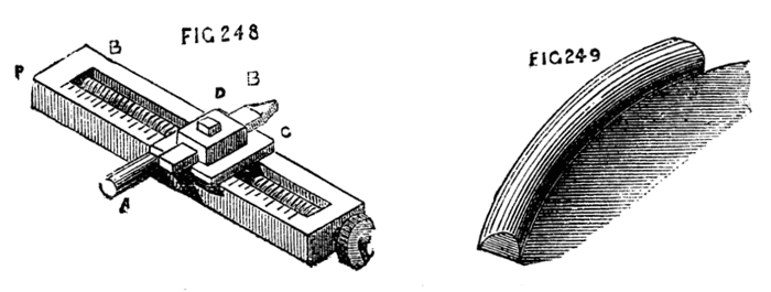
Figs. 248, 249.
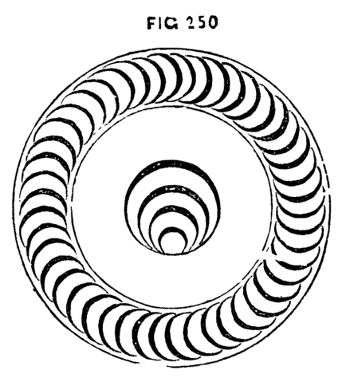
Fig. 250.
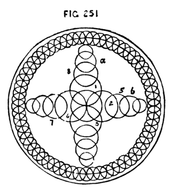
Fig. 251.
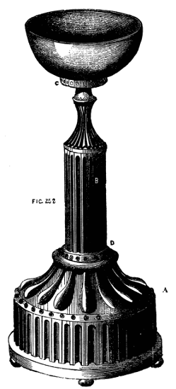
Fig. 252.
Take the finest sifted lampblack and make it into a paste with glue, about as thick in consistency as paint. After turning the ivory tolerably thin, paint this on the inside; let it dry, and repeat the process till sufficient is laid on to form a kind of hollow core, of strength sufficient to support the ivory against the action of the tool.[184] The material may now be thinned and ornamented from the outside. When finished, soak a few minutes in warm water, and then agitate in cold; it will become quite clean as before.
By altering the direction of the motion of the revolving cutter, the several cuts made by it will assume a different character, and the work will present a series of hollows scooped out, so to speak. The cutter, 253, being fixed in the tool holder of the top slide, will work vertically only, and produce patterns similar to Fig. 254, of the nature of basket work. This is exceedingly effective, and, as it may be cut so deeply as to penetrate the material of hollowed works, the latter may be lined with red or other bright coloured silk or velvet, and a variety of designs thus worked out. It is very necessary in using the vertical cutters to move the tool holder forward very gently, giving it at the same time great rapidity of revolution. Without this it will at once stick fast in the work. The character of the designs may, of course, be infinitely varied by using cutters of different sections, as in the case of work done with fixed tools with the aid of the eccentric chuck. The same cutters will, in fact, serve both purposes. Fig. 255 represents a tool similar to the last, but[185] arranged to cut horizontally. With this, fluted work can be done: but it is evident that the cord from the overhead apparatus cannot here be directly applied, owing to the horizontal position of the driving pulley. Additional guide pulleys, therefore, become necessary, and, when these have to be arranged, the apparatus is generally modified, and the universal cutter is used, of which one form is shown in Fig. 256, and though it is not so good a pattern as that which is described in a later page, it is nevertheless suited for use with the old pattern of slide rest already delineated. With this the direction of the cuts may be varied at pleasure—they may be perpendicular, horizontal, or radial, and, when the templates before mentioned are added to the slide rest, an infinite variety of devices may be cut upon spherical and curved surfaces, so that the cutter thus modified is fully entitled to its title of "universal." The design, Fig. 258, is entirely the work of revolving cutters and drills used with a template of the required section. It is intended for a lady's workbox, opening with a hinge on the line, a, b, and containing in separate compartments the various articles required. It may be made entirely of ivory, lined with red or blue satin, and the flutes[186] round the body may be cut through to allow the lining to appear. In the latter case, however, if the box is of ivory, black velvet may be used to enhance the contrast, and, as the glossy pile would be outwards, a second lining of any desired colour should be added with the best side inwards. The rings for the handles, as for all similar purposes, can be quickly made with the tool, Fig. 259. A hollow piece of ivory being taken, and turned smooth inside and out, one side of the tool is applied, as in the figure, so as to cut half through the work. It is then removed, and the opposite edge applied to the inside until the ring falls off completely finished. It is then cut through with a thin saw or knife, and inserted in the tailed ring or other projection intended to receive it. Handsome works in ivory should always be kept under glass shades. The universal cutter shown in Fig. 256 consists of a plate with chamfered edges to fit the tool receptacle of the slide rest, having near each end small[187] poppets which support the round rod connecting the pulley bearing piece, A, with the part, E, which carries the tool, F, the latter being attached by a small slot and set screw to a cylinder revolving in E, and having at its upper end the driving wheel, C. At G is a circular piece or wheel racked on the edge, and turned by the tangent screw, G. The hinder poppet is rectangular, and has divisions marked upon it on each side of the angle numbered from the apex. The racked wheel may with advantage be similarly graduated. When the part E is vertical the cutter will be in a position to work horizontally, and the pulley support will be vertical. By turning the tangent screw, both the parts move together; but if desired the pulleys can move independently by unscrewing D and L. The angular poppet may be made semicircular if preferred, the degrees being numbered either way from 0" in the centre. When the tool holder is horizontal, or approaching that position, the nut, D, must be loosened, and the pulleys placed so that the cord will not slip off. They may be dispensed with if the apparatus is to be used only for vertical cuts (the holder, E, will be horizontal); but if a radial pattern is to be cut, in which the angle is to be constantly varied, the pulley piece must be used and the pulleys re-arranged at D, as required from time to time. There is a somewhat neat and serviceable little apparatus represented in Fig. 259A, to take the place of the[188] slide rest and its revolving cutters, and although its powers are limited, much may be done with it. The spindle A, works through brasses in the poppets, B, B, and is put in motion by a cord from the overhead passing over the pulley in the centre. This spindle, which holds the crank-formed and other drills in a socket at one end, moves freely through the bearings endwise, and is kept back from the work by a spiral spring working against the end of the handle, C. This handle does not turn with the spindle, but is mounted like the handle of a carpenter's brace, or that of an Archimedean drill stock. The whole apparatus fits into the socket of the ordinary rest. A screw should have been shown in the drawing, passing through B towards the pulley, to regulate depth of cut.
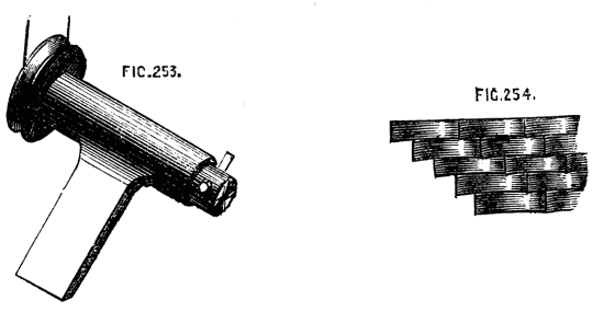
Figs. 253, 254.
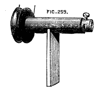
Fig. 255.
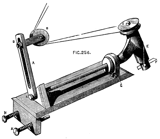
Fig. 256.
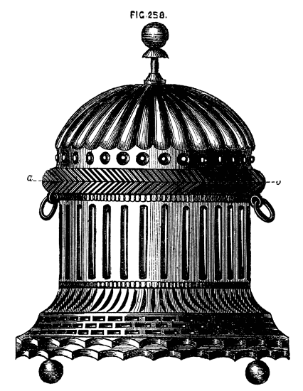
Fig. 258.
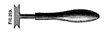
Fig. 259.
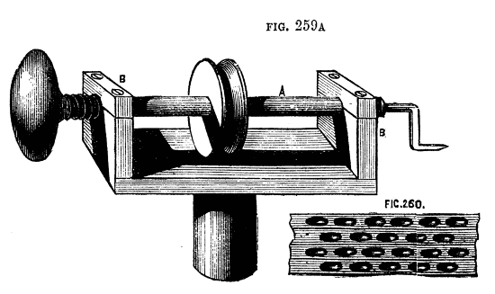
Figs. 259A, 260.
Once fixed by the screw of the latter in its intended position the tool is advanced to the work in a straight line by pressing the handle C, and is released from the cut as soon as this pressure is withdrawn. With different sizes of cranked, forked, or round ended drills, a good deal of ornamentation may be done with this simple tool, which is also useful for ordinary light drilling. By putting in the socket a round ended drill, and using the radial movement (turning the whole round in its socket in the arc of a circle), short flutes can be drilled out deep in the middle, forming basket work similar to Fig. 260, which is exceedingly pretty when carefully executed. There is little difficulty in making drills and cutters, as steel of all sizes in round and square bars may be had at the chief tool shops, especially at Fenn's, in Newgate-street. In making the revolving cutters, however, it is necessary to observe the position of the axial line, which must pass through the cutting edge. After the drill is roughly finished, therefore, it should be mounted in the tool holder with which it is to be used, and carefully tested upon a piece of unimportant work. If in revolving against the latter it leaves a part of the material untouched, the edge is not truly in the centre of rotation. The flat side of the drills are to be diametrical, and hence, as Holtzapffel remarks, these drills can only be sharpened on the end. The latter authority also says most of the drills embrace (in contour of edge) only about one-fourth of the circle, as when the drills are sharpened with one bevel they can only cut on the one side of the centre, and if the drills were made to embrace the half circle the chamfer of the edge on the second side would be in the wrong direction for cutting, and consequently it could only rub against the work and impede the action of the drill. All ornamental cutters and drills should be kept in a box with small separate divisions to fit the shanks, which are all of one size. The points can then be seen and the selection made of any required pattern.
Many turners take special interest in the production of objects in the lathe, that at first sight appear impossible to be produced solely by its means. Inasmuch as such works manifest the skill and patience of the artificer, they will always meet with appreciation; and, although otherwise useless, they serve as elegant objects of vertu, and are well worthy a place among the rare ornaments of the drawing rooms. When first the Chinese balls, consisting of a set of hollow spheres one within the other, all exquisitely carved, were brought to England, it was believed they were made in hemispherical pieces, united round the equatorial line with some kind of cement, the joint being carefully concealed. I am not sure that they are made in a lathe in China; but, at all events, they are so made in England, and our home productions almost rival those of that strange yet clever nation. I say almost, because the carving in ivory done by the Chinese is in some respects unequalled, nor do I suppose that work requiring in many instances years of patient industry could be made to repay the cost of manufacture in England. No sooner were these curiosities in vogue here than all kinds of similar impossibilities were manufactured. Stars with from three to a dozen rays made their appearance, enclosed sometimes in similar sets of hollow spheres—the rays projecting beyond the limits of the outer shell—others were wondrously enclosed in cases with flat sides, cubes, pyramids, six, eight, twelve-sided hollow cases, all turned fairly in the lathe, were produced with similar contents, so that the apple in King George's dumpling became a very secondary wonder. The starry inmates were evidently too large for the houses; yet there they were—legs and arms, of course, sticking out through doors and windows, simply because there was no room for them inside. We will penetrate the mystery, commencing with a single hollow ball containing a star of six rays, the bases of the latter standing on a central cube.
In the first place a perfect sphere is required, and consequently the slide rest and template, or spherical rest, must come into requisition unless the turner can produce a ball by hand tools alone. Let this sphere, or rather its boundary line, be drawn on paper of full size with the compasses, Fig. 262, A, B, C, D. Draw the diameters A, D, C, B, at right angles to each other. This will give you five points, which on the sphere itself (on which these lines will have to be drawn, including also another, answering to A, B, C, D) are centres of six openings, here represented by the circles, through which the tools have to be introduced to hollow out the sphere and form the star. The points of the latter will be in the centres of these openings. Draw in addition the plan of the central cube, and one ray of the[190] proposed star; next draw an inner circle, here dotted to mark the thickness of the outer envelope. The object of this drawing is to enable you to make a set of curved tools, one of which is shown black at E, and a set are marked on a plate of steel, from which they must be cut out. A close inspection of the figure will show that if ball, Fig. 262, were turning on the point A, A D being its axis of revolution, tools of the given section introduced at D would cut away the material round the point or ray, leaving the latter standing;[21] and this operation repeated at the five remaining openings would entirely free the central cube with its rays according to the proposed design. The tools have to be introduced in order, beginning with the smallest; and although the above remarks will make clear the principle, there are several points to be attended to in practice, and some few accessories are required which will now be explained. It is evident that for every different sized sphere fresh sets of tools will be requisite, which will also vary in pattern according to the intended form of the central base on which the rays stand; a cube or flat-sided solid requiring one tool at least, with a rectilineal edge; spherical or other solids demanding others whose ends are of different section. Hence, in all cases, full-sized plans of the proposed work must be drawn, and special tools designed therefrom.
[21] There is an error in the position of this tool, which, thus placed, would not leave the point of the star. Fig. 270 will explain the method better.
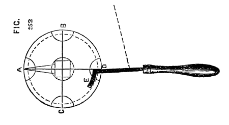
Fig. 262.
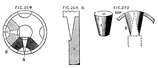
Figs. 269, 269B, 270.
Fig. 269A is introduced to show more clearly the result of the appli[191]cation of the first set of tools, or rather of the first application of the set, as the latter are used throughout.
The blackened part will be entirely cut away in this operation, the shaded part meeting it will be removed when the tools are transferred to the adjacent opening, the cuts meeting those first made. Hence the tools need only reach from a to b, and can be more easily introduced than if the curved part were longer. Gauges, Fig. 269B, A, must likewise be made of thin brass or tin, that the progress of the work may be examined, and each opening in the sphere should likewise be measured with a gauge, or with compasses fixed to one width by an adjusting screw.
The proper chuck for this work is the capped ball chuck already described, by loosening the cap of which any one of the six openings may be brought under the action of the tool, these openings being, in fact, bored out simultaneously with the formation of the star. After the first point or ray of the star has been completed, the ball may be reversed and the opposite ray formed. These are now to be secured by plugs, which are to be turned conical, to fit the opening of the ball at one end, and of a length to rest upon the central cube at the other, being also bored out to fit over the rays, which they should embrace closely at top and bottom, even if not at the other points of its length. (Fig. 269C, A and B.) This is to be repeated as each ray is formed, so that the central star may be held in place until the work is finished, when the plugs are removed, and the star will be entirely detached. The above-named tools being straight on the right hand side of the shank will not form a finished conical point or ray. Hence it is recommended to file away that side, so that when flat upon the rest, the back of the tool may be an exact counterpart of a ray, Fig. 270, A. There is, however, no absolute necessity for this, as the star point can be first made blunt, with perpendicular sides, which can then be neatly finished by a separate tool made for the purpose, and kept up to a very keen edge. The first and smallest[192] of the set of tools here shown, is the one with which the flat sides of the cube are formed, and it must be bevelled from underneath, so as to present a cutting edge on the end. The curved tools should cut on the end and both sides of the crook.
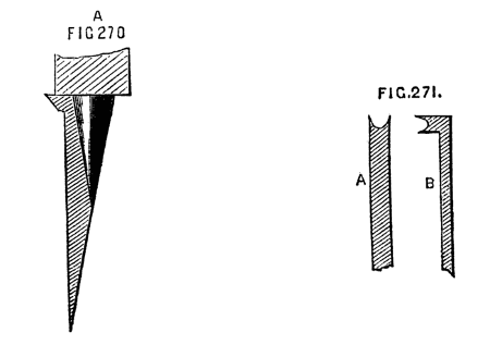
Figs. 270A, 271.
It is quite possible to make the above in mahogany, but a closer grained wood is much to be preferred, as the tools used—which are held flat upon the rest—are rather scraping than cutting, and mahogany, and fibrous woods in general, cannot be thus worked neatly. Boxwood is, in every respect, the best material to begin upon, ivory and blackwood being reserved until the eye and hand have become accustomed to such work. The whole operation requires great care, and is rather tedious, but the result ought to be a sufficient reward. The external surface may, of course, be ornamented with the usual apparatus, but the star should be left clear and sharp. The edges of the openings should have a light beading, cut with a bead tool, Fig. 271, A and B.
Amongst the various purposes to which it is possible to apply the lathe, may be noticed the drilling out grooves and mortises, a method used in some of our Government arsenals, for cutting the recesses for the reception of the Venetian lath work in cabin doors. The same method is, of course, applicable to numberless similar cases, although designed for the special object named. The apparatus is shown complete in the drawing, Fig. 272, and the component parts in the succeeding diagrams. A is a kind of compound slide rest, or vertical straight line chuck, having a movement in a direction parallel with the lathe bed at F; while the circular plate being pinned through its centre to a slide, H, can be moved up and down by means of the[193] handle G. This circular plate can be set in any position, and has a projecting shelf or rest to carry the work, which is steadied by guide pins, as will presently be explained. The part F, has a bed similar to that of an ordinary slide rest, which is clamped to the lathe bed by a bolt and nut, as usual. This carries likewise chamfered bars, between which slides the horizontal plate to which the vertical part of the apparatus is attached. This is first a plate with chamfered edges, Fig. 273 A, and a second similar but rather wider plate, Fig. 274 B, with guide bars, likewise chamfered, to slide upon A. From the front of B rises a stout pin, on which the circular plate, C, turns, which can be clamped by a central nut, or otherwise, as in an ordinary compound slide rest. This nut should not project above the general level of the plate. On the face of the latter is, as previously stated, a rest, or narrow metal shelf, D, and pins, e, f. The plate may be variously arranged in this respect by substituting any kind of holdfast or guide, according to the work desired to be done by its aid. The upper slide is depressed by a hand lever acting on a pin fixed in the sliding plate, Fig. 275; or, if preferred, by a similar lever, with a quadrant and chain, or rack movement. The horizontal slide is worked by means of a stirrup for the foot, with cord attached, acting on a bell-cranked lever, seen in the first figure. To cut the grooves in a bar, for Venetian blinds—as described—the lath to be[194] drilled is attached to a flat strip of thin iron, drilled with holes, Fig. 276 A, as wide apart as the required distance between the grooves. It is then laid against the shelf, and the guide pins are made to enter the holes in the iron. The clamping nut of the round plate is loosened, until the bar is set to such an angle that the grooves to be cut will form vertical lines, Fig. 276. It is then clamped securely.
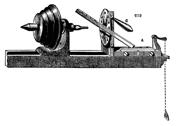
Fig. 272.

Figs. 273, 274, 275.
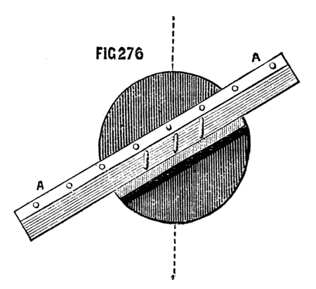
Fig. 276.
It is necessary to be able to adjust the piece to be cut, as regards its height, above the lathe bed. This is effected in part by the position of the movable shelf—fixed by pins—and partly by guide or set screws, which regulate the traverse of the slides. Suppose the bar adjusted as in Fig. 276, the groove to be cut being brought opposite to the drill. The set screws—two of which are seen at x, x, Fig. 275—acting on the handle, regulate the precise length of each groove. A similar stop, connected with the horizontal part of the machine, regulates the advance of the wood towards the drill, and thus the depth of the cut. Hence it is only necessary to set these carefully at starting—the pins on the guide plate insuring the proper width between the grooves—and the lathe being put in motion, any number of precisely similar grooves can be drilled with the utmost rapidity and neatness.
An inspection of the drawings will show what numberless purposes may be served by this simple apparatus, which may be modified in its details, while its principle of action is maintained. The drill should have a chisel and be kept to a keen edge. The lathe should be put in rapid motion, and if the required cut is to be deep, it should be cut at twice. The lower slide should return to its place by means of a spring when the foot is raised, the vertical[195] slide being movable in both directions by means of the slotted part of the handle.
Note.—The above being taken from an apparatus for a steam lathe, the stirrup action maybe used, as the foot is at liberty. A foot lathe would require a slight modification. In Fig. 275, the depressing handle is shown as if the chamfered bars were fixed to the sole plate, and the plate A, were movable, as is sometimes the case. When made according to the above description, the handle would, of course, be pinned to the fixed vertical plate, A, to which also the stops would be attached, and the pin which passes through the slot of the handle, must project from one of the chamfered bars. Either plan may be followed, but the pattern described is calculated for a stronger apparatus; inasmuch as the vertical plate can be secured more firmly to the chamfered horizontal slide than the mere pair of guide bars—the two might, in fact, be made in one casting, if preferred.
The slide rest previously described, although applicable to the purposes of ornamental turning, has one disadvantage. It is necessary that the various pieces of apparatus to be used with it should have a foundation plate with chamfered edges to fit accurately between the guide bars. This is often inconvenient, and adds to the difficulty of making, and consequently to the cost of such pieces. In addition to this drawback, it may happen that one of these fittings by being more frequently used becomes more worn than another, so that the guide bars require constant re-adjustment, and their accuracy and parallelism become impaired. To obviate these and similar inconveniences the slide rest is now commonly made like Fig. 277, and a tool receptacle, Fig. 278, is fitted to slide between M, M, and is so arranged as to hold securely the universal cutters and other apparatus required for ornamentation or for plain turning. These are all made with a rectangular bar fitting the longitudinal channel in the middle of the receptacle, and are secured by the following simple contrivance. It will be seen by the drawing that the central channel is widened at A, A, and that a groove or saw-cut B runs along the inside from end to end. This groove is continued in a similar manner on the side next to the reader. Fig. 280 represents an ordinary tool holder, with a rectangular shank A, and clamping screw B, by which the tool c is secured. The part A is laid in the central channel, and a small piece of metal shaped like Fig. 279 is inserted in one of the open spaces, A, A of the receptacle and slid along with its lower flange in the saw-cut until clear of the enlarged part of the channel. It is thus retained, and the clamping screw which passes through its centre is brought to bear upon the piece to be fixed, which is thereby securely held in its required position. Two of these holdfasts are generally[196] used at the same time. If the main bar of the tool holder is not quite thick enough to be clamped, then it is only necessary to lay a small plate below it.[197] By the above simple means, the necessity for fitting each individual piece of apparatus to work upon the chamfered guides is done away. In order to ensure the position of the sole of the rest at right angles to the lathe bed a kind of saddle, A,[198] Fig. 281, is used. This is of cast iron or brass, accurately planed on the upper surface, and has a projection fitting between the bearers of the lathe. The usual holding down-bolt passes through the hole in the centre, securing the saddle and the rest at the same time. The usual arrangement of a kind of double socket, the inner one rising at pleasure by being tapped into the outer, has already been described, and serves for accurate adjustment of the height of the rest. It is convenient, in addition, to have a stop or set screw under the bed of the rest, and a similar one on the top of the socket, so placed that when the frame is swung round it shall stop precisely at right angles to its former position. Thus, if the tool is first required to be used upon the side, and then upon the face of the object to be turned, these two positions are obtained at once, and can, if necessary, be alternated without any re-adjustment of the moving parts of the rest by the aid of the set square. The receptacle-holder is generally advanced by the hand lever, Fig. 279, one pin of which fits into the hole in the guide-bar as seen in the drawing, while the other falls into a short slot e, made in the upper surface of the receptacle, or of the piece of apparatus to be used in it. Of course, this arrangement may be reversed, one or both pins being fixed to the rest and its receptacle slide, and the holes made in the lever. Sometimes, however, a slower and more regular movement is required than it is possible to give in this way, and the lever is replaced by the leading screw C, D, Fig. 278, the head of which is removable, and can be replaced by a small winch handle. This screw is tapped into the lug cast upon the receptacle, and its point is of the form shown. The latter fits into a hole in the pillar A, 278, and is retained by a pin, which falls into the groove, D, Fig. 278, and prevents the screw from advancing or receding without carrying the sliding plate with it. The pin being removed, the screw will no longer act in this way, and the slide may be moved by the lever instead. The other screw, E, F, of fine pitch, serves to regulate the advance of the receptacle, and consequently the depth of cut of the tool—a round head with divisions on its edge is attached to one end, which abuts against the pillar B, Fig. 277, which latter has a mark on its top to act as an index. Thus the advance of the tool can be regulated to a great nicety, and successive predetermined and different depths may be reached and repeated at pleasure, as is sometimes necessary. C, C, Fig. 277, is one of a pair of stops which can be fixed by their screws at any two points of the bed of the slide rest. These serve to regulate the distance which the top slide and tool holder are intended[199] to traverse, as in drilling a number of flutes of equal length, and many similar works. They are usually made of gun-metal, the screws of iron or steel, or of a metal called homogeneous, which may be described as between the two, and, being pleasant to work, is worthy of notice. It is absolutely necessary that the slide rest for ornamentation should be made with the greatest nicety. The slides must work equally smoothly from end to end of their traverse. The pitch of the screws must be not only fine, but even and regular, and the screw itself of precisely the same diameter from end to end, else it will work loosely through its nut in one place, and jamb in another. It is extremely pleasant to feel the exquisite smoothness and oiliness, for no other word will express it, of the movements of sliding parts in the workmanship of Munro or Holtzapffel, especially if compared with inferior work. Good amateur's work indeed is often far superior to that which is sometimes advertised, and perhaps a few hints may not be out of place here, relative to the construction of this necessary addition to the lathe.
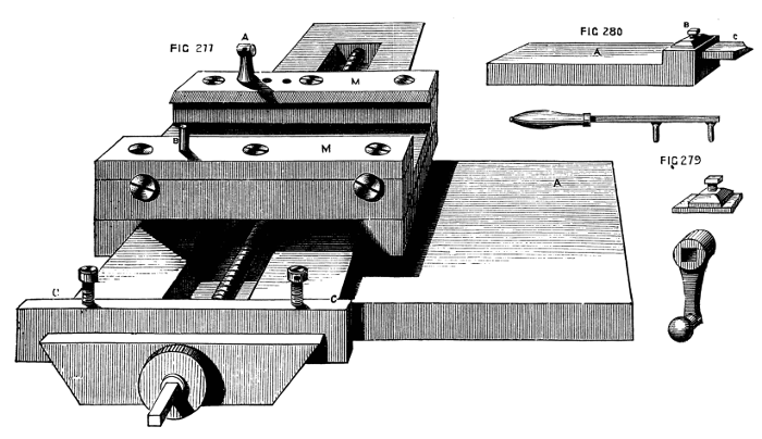
Figs. 277, 279, 280.
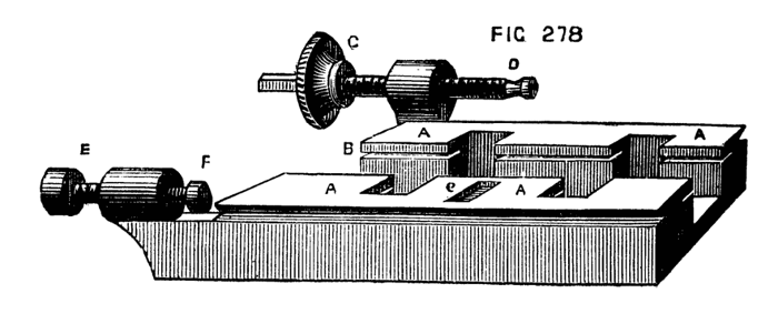
Fig. 278.
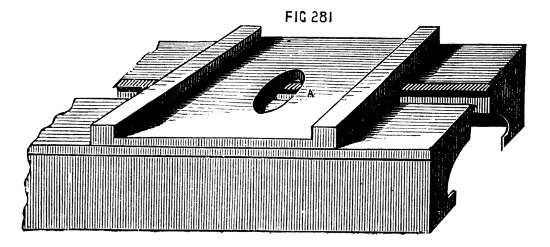
Fig. 281.
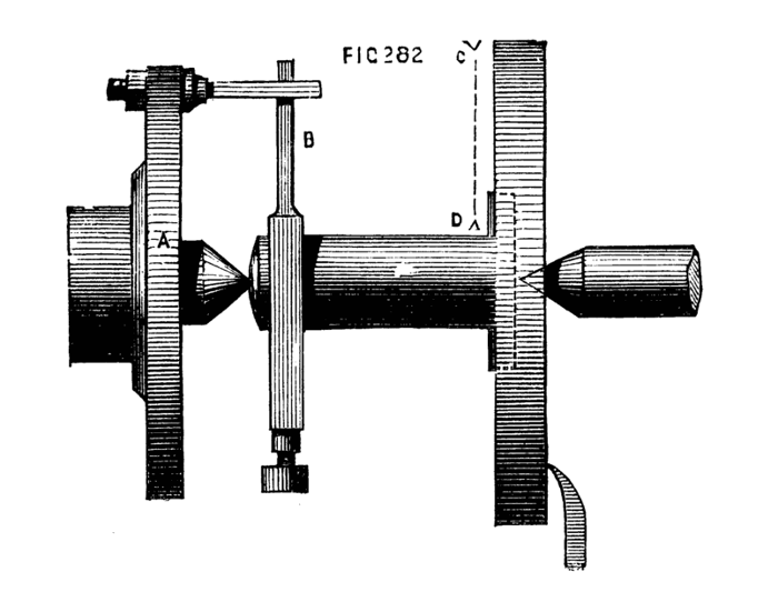
Fig. 282.
First of all, the frame of the rest must be accurately at right angles to the spindle, which fits into the socket. These should, therefore, be turned together, supposing the amateur not to have a planing machine. The whole may be mounted as Fig. 282, where A represents the carrier plate or chuck; B, the driver, the tail of which should be as long or nearly so as the frame from c to D; F is the side tool to be fixed in the slide rest for metal. The effect of this arrangement is to plane the face of the slide with transverse strokes instead of lengthwise. It may be afterwards finished and polished with oilstone powder on a flat slab of planed iron. When the face is finished, the whole must be reversed, the pin of the carrier plate will bear against the frame, which thus acts as a driver, and the spindle must be turned. In this way accuracy is ensured if the slide rest used is carefully set. The chamfered sides of the slides are difficult to work with the file, but may be so done with care, and with a template of the desired bevel as a guide. The great secret is to take plenty of time, not to press too much upon the file nor to move it too quickly over the surface; fine even strokes, especially towards the finish, must be given, and a final polish with oilstone powder and oil used on a piece of a stick. In turning the screw a back stay must be fixed opposite to the tool in the slide rest to insure the contact of the cutting edge without bending the work.
Presuming that the screw will be cut with stock and dies, it may be stated as a caution that the latter must not be tightened except at the commencement of cutting the thread deeper. The return of the tool by a backward motion (or unscrewing), should not be used as a cutting action, and therefore, should be carried on with the dies in the same position which they had during their descent.
At the beginning, therefore, of each downward movement the dies must be tightened and oiled, and they must not again be touched till the bottom of the screw has been reached, and the upward movement also has been completed, so that they have arrived again at the starting point. If tightened at any other time the screw will be either conical or of a wavy section, either of which forms would be fatal to its use. The castings for such a rest should be of malleable iron, if possible, as being much more easy to work; the guide bars may be of gun metal, as also the chamfered bars, which work on the main frame. This will give a more finished appearance, and will on the whole be more durable and satisfactory.
One of the most useful tools for ornamentation, especially of plain surfaces, such as the top of a box cover, is the eccentric cutter, Fig. 283. The shank, A, lies in the receptacle holder of the slide rest, and is drilled throughout to receive a steel spindle, carrying at one end a double pulley, B, to receive the cord from the overhead motion, and at the other frame, E, with its leading screw, of which the movable milled and graduated head is seen at H. This frame has one surface, level with the centre of the main spindle, which is cut away as shown, and, consequently, as the point of the tool is on its flat side, which latter rests upon the frame (the bevel being below), this point can, by the tangent screw, be brought into a line with the centre of the main spindle, so that when the cord from the overhead is passed round B, the spindle revolves with great rapidity,[201] and the point of the tool, K, in the position described, makes a simple dot. By turning round the milled screw head, H, either by the thumb and finger or by a small winch handle, fitted on the square part beyond the head of the screw, the tool holder, D (which is in one piece with the nut of the leading screw), is made to traverse the frame, and the tool will cut a circle small or large according to the eccentricity thus given to it. In Fig. 285 D, is the tool holder on the front of the frame; C, the end of the spindle; L, a bell-shaped washer, which is acted on by the small square-headed screw, drawing D towards the frame and clamping the tool. The whole is in the figure of full size. The tool holder is in one piece with the nut, through which passes the leading screw, and which is continued as a screw for the action of the bell-shaped washer and tightening nut; hence it is necessary to allow a degree of play between the nut and leading screw, to prevent bending the latter when clamping the tool. This is effected by filing off the threads in the nut at the top and bottom, to render the whole slightly oval. The remaining threads suffice for the action of the leading screw: a very slight degree of play in the required direction will be found sufficient. The powers of the eccentric cutter frame will be found sufficiently extensive to make it a most serviceable, perhaps necessary, piece of lathe apparatus. If it cannot be said absolutely to supply the place of the eccentric chuck, it has nevertheless the advantage of great lightness of construction, lowness of cost, and ease of manipulation. The weight of the eccentric chuck, whether single or double, as of all chucks in which sliding plates are used, is a sad drawback to their value—a drawback unfortunately beyond remedy, and specially felt when the slides are drawn out to a great degree of eccentricity. Combined together, these two form a compound eccentric chuck, and in this way are capable of nearly everything in the way of eccentric ornamentation. Where the chuck is not to be had, it is by all means advisable to procure the cutting frame, for which the writer confesses a great partiality. It appears, indeed, to him a far more rational proceeding, as it is also now of extensive application, to act upon fixed work by revolving or moving tools, instead of proceeding in the contrary way; and all these little tools used with the overhead apparatus are so lightly and elegantly constructed, and so well adapted for the parts they have to perform, that the originator of them (native talent devised them), deserves to be well and lastingly remembered; instead of which it is doubtful whether his name is even known. (Sic transit is a quotation too stale for this work.)
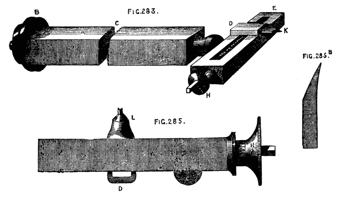
Figs. 283, 285, 285B.
To cut circles deeper in one part than another—the shell pattern, for instance—with this tool, it is not necessary to alter the level of the sole of the rest, as it is when the eccentric chuck is used with a fixed tool, as it suffices to set the rest itself at an angle, by moving[202] it round in the socket, so that the revolving tool should touch the face of the work sooner at one point than at an opposite one. In the same way the work may be considerably undercut on one side of the circles, by giving the angular set to the rest, and placing a tool in the holder, with a point of the form shown at 285 B. There is nothing prettier than this undercut work when well and sharply done, for which purpose the tool should not only be rendered keen on the hone, but burnished and polished on the brass and iron slabs already described. The following remarks on the work of this cutter frame on flat surfaces only, will be useful to the reader in designing and working out the various combinations of circles, intersecting or otherwise, which it is calculated to produce. On a surface represented by 286 A, the line of circles, a, a, is on a diameter, and, supposing them to be described by the eccentric cutter (or by a simple double-pointed drill), their centres are obtained by means of the leading screw of the slide rest, moved the requisite number of turns between each cut, while the work is retained in a fixed position on the mandrel. But if the line of circles is on such a line as b b, above or below the centre, and consequently not on a diameter, it is plain that no movement of the slide rest or cutter, or both, can avail to place them in position, except with great difficulty and tedious working with the division plate of the lathe and the screw of the slide rest. Hence the eccentric chuck must be brought into play, and being fixed with its slide in a vertical position, the screw is turned and the work is lowered thereby until the line b, b, is on a level with the point of the tool. The[203] eccentric cutter or double drill will then suffice to work the row of circles. When the centres of the circles are themselves on parts of the circumferences of other circles, the division plate of the lathe or of the eccentric chuck will be called into requisition, according as these circles are concentric with the mandrel or otherwise. In Fig. 286B, the curved lines are parts of circles of equal size with that representing the surface of the work, and their centres lie on one and the same diameter, viz., at opposite extremities of the line, a, b. Being thus eccentric to the work, the division plate of the chuck is used to arrange the intersecting circles of the pattern—its slide having been first drawn down, until the centre of the arc to be worked with circles is brought opposite to the tool. The work will be in position when, on turning the mandrel slowly, the cutting point of the tool passes across its centre. The division of the original circle is in this instance into four parts, two of which are thirds, and two sixths of its circumference. The arcs of circles are also lines equal to thirds of the circumference of the work. It is well to remember this division of a circle by other equal circles described round it from points on its circumference, these circles passing through the centre. The original circle will in this way be divided, as shown at C, into six equal parts. To produce it with the aid of the eccentric cutter is easy. Set the tool of the cutter first to the centre of the work, so that on revolving it will make a simple dot. This should always be done, whatever pattern is subsequently to be cut. Fix the index of the division plate of the lathe at 360. Move the screw of the slide rest until the point of the cutter, on being advanced, rests on the circumference of the circle previously cut upon the work, or on the circumference of the work itself, if the divisions are to reach the edge. Screw back the tool (not the rest) until its point reaches the centre of the work and cause it to revolve so as to cut one arc. Move the lathe pulley forward to 60° and cut a second arc, and so on, advancing 60° each time, and the figure will be cut. This division of the circle will form the groundwork of many handsome patterns. When the arcs thus formed are intended merely to be the lines of centres, and not themselves to form integral parts of the pattern, they should, nevertheless, be marked with a pencil in the tool holder, if possible, as there will be less liability to error in working the proposed pattern. In the present advanced stage of the art of turning, mere surface work done by the eccentric cutter is rather apt to be despised, owing to the extended powers of Ibbetson's or Plant's geometric chuck; but, valuable as the two latter are, they are necessarily so costly that few can obtain them, whereas the little cutter frame is comparatively cheap, and it is really capable of very exquisite work in skilful hands.
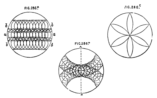
Fig. 286A, B, C.
In very many cases of ornamentation it is required that the mandrel, instead of making an entire revolution, should stop at a given point in both directions, so that, for instance, the turner should be able to move it 60, 80, or 100 divisions to and fro, with the certainty of its not advancing beyond that distance. This is effected by the racked and divided brass wheel B, fixed on the mandrel against the small end of the pulley. This wheel is sufficiently thick to allow of racking part of its edge to be acted on when necessary by the tangent screw, and leaving the other part for divisions, which are generally seventy-two in number, and marked in figures at every sixth division. On the other side of the plate are a number of holes drilled through its whole thickness to receive stop pins, Fig. 289, P, which are sawn through as shown, that they may spring, and fit the holes tightly. There are seventy-two holes corresponding with the divisions. These pins are about 3/16ths of an inch diameter, generally with flattened heads, and a hole through them to receive a pin to aid in removing them. The[205] holes are sometimes made in the edge, instead of the side of the segment plate, but the latter is the best position. At Fig. 288, T, is seen the interior part of the poppet, with a piece of brass let in, and fixed securely, in which are inserted two screws, against which the segment stops abut, and prevents further rotation of the pulley. Side by side with this latter piece is placed the frame which carries the tangent screw. It is shown at Fig. 289. This frame is not fixed to the base of the poppet, but pivotted at e, between two short standards screwed into the poppet for that purpose. When not in use, the whole frame, therefore, drops down towards the front, but it can be raised by the small cam, K, Fig. 289, so as to gear with the worm wheel. In many cases the latter is not used, but the pulley turned by hand. The screw, however, gives a steadier and more easily regulated movement, essential in delicate operations, and sometimes convenient, even when the stops do not require to be inserted. The use of the cam, acting on the frame which carries the tangent screw, is now generally followed in the eccentric and oval chucks, and also in the dome chuck. It enables the workman, by throwing out of gear this part, to turn the worm wheel with the fingers, to set it at the required number on the division plate, a slow process when effected by the screw.
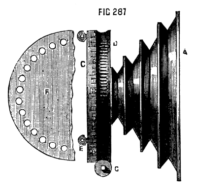
Fig. 287.
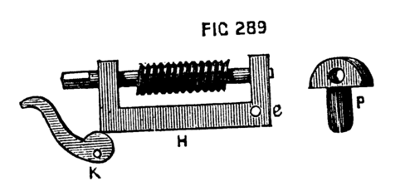
Fig. 289.
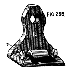
Fig. 288.
Among the newer devices for ornamental turning, must be mentioned the rose cutter frame of Holtzapffel and Co., an ingenious adaptation of the principle of the rose engine, without the drawback of cumbersomeness and costliness. It works like the ordinary eccentric and other cutters by a cord from overhead motion. The apparatus is represented in Fig. 290, and its various parts in Fig. 291, &c.
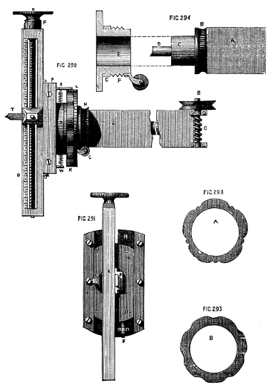
Figs. 290, 291, 293, 294.
In the first of these figures, A is the shank, fitting the receptacle of the slide rest, and drilled to receive a hardened spindle, at one end of which is a worm wheel, turned by tangent screw B C, and shown again at A, B, C, Fig. 292. By this are turned the parts beyond K, namely, the frame D, carrying the tool, as in the eccentric cutter, adjacent parts S, representing chamfered bar, P, back plate, and O, which is a round piece in one casting, with the back plate, and having a hole through it for the coiled spring seen between O and N. All these are secured to the spindle, and turn together as one piece with it. Fig. 291 is a front view of these parts. H is the back plate of brass, with steel chamfered bars on its face, E, E, as in the[206] eccentric chuck. Between these slides the plate, D, D, to the face of which is attached the long steel frame, carrying the tool holder. Close to the letter H, it will be noticed that a slot is cut in[207] the back plate, through which projects a hard steel pin, screwed into the back of the sliding plate. This is seen at O, Fig. 290, and is attached to one end of a coiled spring, the opposite end of which is secured to a pin fixed in the back plate of this part. The pin O, is thus kept in contact with the edge of the rosette or pattern plate, K, and, as the whole turns with the spindle while the rosette is fixed, the pin, or rubber, is compelled to follow the undulations of the pattern, the motion being, of course, communicated to the tool. An inspection of Fig. 294 will show the arrangement of the parts on which the rosettes are fixed, and which is capable of turning, but does not, unless the tangent screw and wheel, H, are brought into requisition, as will be presently explained. The end of the main shank of the instrument is round, as seen at C, the worm wheel B being screwed fast, by four small screws, to the end of the square part of the shank. Upon this rounded end fits what may be called the sleeve E, to which is fixed the tangent screw, and on which also are placed the rosettes. The latter have a large central hole, Fig. 293, A and B, and fitting closely beyond the screw F, F, of the sleeve, and, being prohibited from turning upon it by a small key or feather, are secured by a screwed ring or ferrule seen at L, Fig. 296, the edge of which is milled. At F, Fig. 291, is seen a short stop, or set screw, the head of which is divided into ten degrees. By this, the rubber is prevented from penetrating to the bottom of the undulations on the edge of the rosette, and, if it is allowed only just to touch the summits of them, the tool will cut a circle. Thus, as the screw stop can be accurately set, one rosette will produce at pleasure graduated waved lines, the waves growing less and less undulated as the centre (or circumference) of the work is approached, giving a most delicate and chaste pattern, and chased it certainly is.
Another variation of the pattern producible from any rosette results from the frame of the tool holder being extended beyond the axis of the spindle in both directions. When the tool is on that side of the axis nearest to the rubber pin, the undulations of the rosettes will be so followed as to produce their exact counterpart on the work. When the tool-holder is on the other side of the axis, the undulations become reversed, the raised parts of the rosettes producing hollows and vice versa. It may here be mentioned that in the case of the rose cutter, eccentric, and universal cutter, and similar apparatus, the screw heads carry ten chief divisions and ten smaller divisions. The screws are cut with ten threads to the inch, so that one turn advances the slide, or the tool, or wheel as the case may be, one-tenth of an inch. One large division, therefore, produces a movement equal to one-hundredth, and one small division one two-hundredth of an inch. If the screw is small it is generally[208] cut with a double thread equal to one-twentieth of an inch. It is evident that in addition to the movements of the various parts of the rose cutter, the turner also has in his power those of the slide rest, and of the division plate on the lathe pulley, by one or both of which further complications become possible. Six modifications of pattern produced from one rosette alone are shown in Holtzapffel and Co.'s catalogue, and these may be further multiplied according to the taste and skill of the operator.
It is not possible to apply rapid movement to this rose cutter, else the rubber would probably miss touching the rosette in places; hence the tangent or worm wheel is used to give motion to the central spindle. An end view of this is given in Fig. 292. The object of the other tangent screw is, to move the sleeve and therewith the rosette at pleasure, so that the higher parts of the undulations in the second cut may, if desired, be arranged to meet the lower parts of the same in the first cut or to fall intermediately. The effect of the gradual shifting of the rosettes in this way is perfectly marvellous, and the writer much regrets that he is unable to supply specimen plates, as he is not in possession of the rose cutter. In the end of Holtzapffel's latest edition of his catalogue are several such specimens, but without any drawing or description of the instrument, the cost of which is moreover omitted.
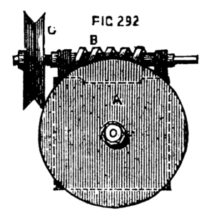
Fig. 292.
The centres of circles cut by this eccentric tool will be always regulated in regard to position by the slide rest, because these centres are, as explained, always in a line with the centre of the spindle. Hence, to place a circle in any desired position, it is only necessary to determine its centre, and, after drawing back the tool by means of the screw till its centre runs truly as a mere drill, turn the screw of the slide rest until the point touches the required spot.
This is represented in Fig. 284, in its latest improved form. It consists of a shank, A, which fits the tool receptacle, and is bored[209] throughout its length for the reception of a central steel spindle, to which is securely attached at one end the worm wheel, G, acting as a dividing plate, and at the other the crank-formed frame, B, C, with its small poppets, D, D. These are sawn lengthwise, and thus spring upon the centre screws, which pass through them and carry the revolving cutter spindle, K, L, M, in the centre of which is a slot to receive the tool, the latter being clamped by the tightening screw, L. There are certain points to be attended to in the construction of this instrument, which must on no account be neglected. In the first place, the screws which pass through the poppets must lie in the line which would bisect at right angles that of the main spindle in the same plane. A line, in fact (as dotted), passing from screw to screw will pass across the centre of the end of the spindle. In the next place, when the tool-holder, with its pulleys, is in place between D, D, this line must be even with the top line of the central mortise, H, for the point of the tool is level with its upper surface, it being bevelled below; and it is essential that this point be capable[210] of being so placed as to form a continuation of the centre of the main spindle. At E, E, are shown two of four thin pulleys. The two front ones are removed to show the poppets. They should not be made thicker than necessary, in order to avoid their interfering with the action of the tool. Either pair will be used with either pulley, K, K, according as the right or left side of the instrument is the highest, for, as will be explained, the cutter frame is used at all angles between the horizontal and the vertical lines, the cuts being consequently inclined in either direction, left, or right, at pleasure. The centre screws and points of the tool spindle must be carefully hardened. Before commencing to use this cutter, it is necessary to test the centrality of the point of the tool. Place the latter in its holder. Let the part C of the instrument be turned till vertical; cause the tool to revolve and to cut a light line or scratch on the face of the work. By means of the tangent screw cause C to become vertical in the opposite direction, so as to bring the other pulley upwards, and with the small screws in the poppets set the revolving tool holder, till the tool falls exactly on the line first made. It is, of course, understood that the line in question passed through the centre of the work. If in both positions of the tool the central point is passed through, the cutter tool is correctly placed. The poppet screws are for this purpose specially, though sometimes used to place the cutter purposely above or below the centre of the work. Compared with the old form previously given, this pattern of universal cutter is very superior.
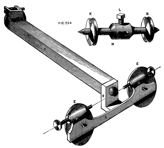
Fig. 284.
The rose engine, as hitherto constructed, has not been entirely supplanted by the neat little apparatus already described, but is still used almost universally by the watch case makers; and its construction differs little, if at all, from that described by Bergeron; although the slide rest used with it is somewhat modified and improved. There are two kinds of rose engine, in one of which the mandrel with its poppets and fittings oscillates between centres fixed beneath the lathe bed; while in the other, the frame carrying the slide rest is thus movable, the mandrel head remaining stationary as in an ordinary lathe. In both cases the mandrel is allowed a to-and-fro or pumping movement in its collars; as the rosettes used are cut upon the face as well as upon the edge; and the rounded parts of an article can be operated on as well as the plane surfaces.
The second pattern, in which the poppet remains a fixture, will be first described, because it is capable of being applied to an ordinary lathe for surface work, and if the lathe has a traversing mandrel, it can be completely fitted for rose work.
The drawings and description annexed are from Bergeron's work; but the slide rest there represented, and arrangement of screwed mandrel, are omitted as obsolete:—
A strong iron frame, A, A, Figs. 295 A, 295 B, and 296, is made with one of the ends carried up and branched, so as to embrace the mandrel and rosette; which latter is attached to the back part of the chuck which carries the work. The top of the frame is double, so as to form of itself a lathe bed of small dimensions, upon which an ordinary slide rest can be fitted. It must, however, be used with a short socket, or it will be too high; as the top of the frame alluded to stands slightly above the level of the bearers. B, is a point of hardened steel which fits into a conical hole in the bottom of the lathe poppet, or (if this is not long enough to reach a good way down between the bearers) into a piece of iron arranged for the purpose similar to that now to be described, and which is again shown in Figs. 297 and 298. This is a kind of poppet in a reversed position, the clamping nut and screw being above the bed, and the head with centre screw below. The frame lies, therefore, between the mandrel head and this reversed poppet, or between two of the latter, and oscillates upon their centres whenever the projections or depressions of the rosette compel it to assume such motion.
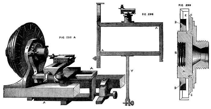
Figs. 295A, 296, 299.
Fig. 299 is a section of the chuck which carries the rosette, the latter being shown in position. A, is the body of the chuck; B, the inside screw to fit the mandrel. On the outside of this part are a few turns of a somewhat finer thread, beyond which a plain part is left next to the flange, C, and on this the rosette is placed, and is clamped by the nut, cut outside into beads, or milled, or left plain and drilled for the insertion of a lever pin; this nut is marked D in the figure. It will be seen to lie within a recess formed in the face of the rosette, E. The latter is shown in Fig. 300. A, is the recess just alluded to; B, C, the pattern on the face and edge; D, the large hole in its centre, allowing it to be slipped on the back of the chuck. It is prevented from turning on the latter by a pin, which fits into the small hole, F. From the front face of the chuck rises a conical pin, G, similar to that on the eccentric chuck, over which fits the circular division plate, I, with its projecting screw, H, to hold the ordinary chucks. This plate is recessed at the back, leaving a mere ring of metal, e, e, which fits a corresponding circular groove, and secures the steady movement of the plate, which is fixed by a conical washer and screw, as seen in the plate. This division plate is formed with cogs, into which a stop falls, as described, when treating of the eccentric, but the divisions are differently arranged, the cogs being divided into sets of eight or ten teeth. Let[212] the whole circumference be first divided into six equal parts, and, beginning at the first division, cut six or eight teeth, as if the whole circle were[213] to be divided into 60. Pass to the second portion, and cut eight teeth, as if the circle were to be divided into 72. Let the third carry eight teeth, with a pitch of 80 to the circle; the fourth a similar number, with a pitch of 84; the fifth 96; the sixth 100 to the circle. These must be cut with the same cutter, so that the spring click, or stop teeth, may fit any of the six sets. There will be several undivided spaces, which are to be left plain. The several sets are to be marked in numbers, so that the pitch may be discovered at a glance, and the teeth in each being so few will hardly require separate numbering. The part of the apparatus which carries the rubber—that is to say, the heads of the branched part of the swinging frame, are made flat on the top, which projects on three sides, forming small tables on which the actual holder or clamp can be fixed by a turn of the screw, X, in the first figure. The rubbers are merely flat pieces of steel, with edges sufficiently sharp to penetrate to the lowest depths of the undulations and recesses on the rosettes, but rounded off and polished, so as not to cut and damage the softer metal against which they act; other materials have been tried, as ivory, and the harder tusk of the hippopotamus, but hard steel is most generally preferred. It is, of course, necessary that the rubber press with some force against the rosette, which force should, moreover, admit of being regulated at pleasure. This is effected by a spring of steel under the lathe bed,[214] to the end of which is affixed the arm, W, which has a ring handle nearest to the operator, and is perforated with a row of holes from end to end. This arm is flat, and falls into a fork at the end of the tail piece, Y, which is seen in the second figure attached to the centre of the lower bar of the frame. A pin passes through holes in this fork, and through one of those in the arm. By this arrangement it is easy to regulate the force which the spring shall exercise, as this will be increased by moving the pin nearer to the spring, and diminished by placing it in a hole nearer to the ring handle. In forming the rosettes great care should be exercised to make the corresponding parts agree. The depth of similar hollows must be precisely equal, and elevated portions intended to match, must do so with great accuracy. Supposing, for instance, a rosette to be made with ten elevations and ten recesses, all of equal curves. If these are accidentally unequal, and it is desired to arrange a set of these waved rings one within the other, so that the depressions of the one shall be opposite to the elevations of the other, or so that this effect shall take place gradually—if the curves of the pattern are unequally cut the several portions of the device will not tally, and an irregularity will be produced of disagreeable appearance; an inspection showing at once that such irregularity is not part of the device, but unintentional and erroneous. This leads to a consideration of the division plate of this rose engine, and an explanation of the object of its peculiar construction. The pattern of the rosette is, as it were, in sections; either similar elevations and recesses are alternately repeated, or there may be a variety of such, extending over a part of the circumference, and forming a certain complete device, which may then give place to a second pattern, extending a similar distance; and these two may alternate regularly round the circumference. Each of these sections must be of precisely similar length, and the repetition of the pattern must also be precisely similar, for the reason stated above.

Figs. 295B, 297, 298, 300.
It is evident that all possible alternations of the device or set of devices may be obtained by means of six or eight notches of the division plate; for, by moving it forward to that extent, the whole pattern may be compassed. In treating of the second form of rose engine, and of the method of using it, this will again be adverted to, and illustrated by an example.
Hitherto we have spoken only of the use of the pattern on the edge of the rosette, but, as already stated, it is frequently repeated on the face, and by this means it becomes easier to work upon the outside of a cylindrical piece, as well as on the two ends. Patterns thus cut on the face of a rosette tend, of course, to move the mandrel to and fro in its collars, which is only possible when the lathe is made on the plan of a screw-cutting or traversing mandrel lathe. The[215] spring which keeps the rubber in contact with the face of the rosette is shown at P.
The head on the top of the arm, which forms the clamp or holder of the rubber, must be turned round to face the rosette, or a separate rubber must be used, which passes through the clamp at right angles to that used in surface work, and the frame must be prevented from oscillating by a stop which fits between the bearers of the lathe, and embraces the upright side of the frame. The top of the slide rest must be turned round, or a side tool used. In this case, the rest and frame with its rubber become fixtures, as in ordinary turning, the mandrel and work being alone moved in correspondence with the pattern on the face of the rosette. It would indeed be much better to do away with the frame altogether, fixing the rubber to an upright pedestal mounted on the lathe bed, and using the slide rest in the usual way, were it not that in general the work is constantly being varied, the side and face being worked in turn—and the apparatus is rather cumbrous to remove and re-mount often. It is, nevertheless, easy to finish the ornamentation of plane surfaces first, and then to remove the frame altogether, and substitute a fixed rubber, as stated.
The rose engine now described has certain evident advantages over the rose cutter frame, and is capable of the most exquisite devices. It may be, perhaps, a mere question of taste, whether rose engine work finely executed is not in point of beauty, superior to any that can be done by geometric chucks, however elaborate. That it is so, is decidedly the writer's opinion, more especially when this apparatus is used in combination with the oval chuck. Moreover, there is nothing in the form of rose engine described to make it a very expensive article, or beyond the skill of an amateur; and with a set of only three rosettes, the patterns may be varied continually, and multiplied—if not ad infinitum—yet quite sufficiently for the display of skill and taste of the operator.
In using the rose engine, it is necessary to carry the cord to the pulley from a very small wheel on the axle. Sometimes the lowest speed pulley of the flywheel may answer, but if the recesses of the rosette are deep and sharp, or only slightly rounded, it may become necessary to mount a still smaller wheel on purpose; else the rubber will jump over and miss parts of the design, thereby spoiling the work. The watch-case turners, indeed, altogether dispense with the flywheel, and use instead a small pulley, fixed to the side of the lathe bed, and turned by hand.
These artificers always use a more elaborate form of rose engine, which will be presently described, and which is the most perfect in detail of all similar contrivances, but it is necessarily costly, and cannot be said to be well adapted for plain turning also, except in a[216] limited degree. The work, if not of soft material, like a watch-case, should be turned first of all upon an ordinary lathe, the mandrel screw of which is a counterpart to that of the rose engine, and the latter should merely be used for the final cut, to perfect the form of the material previous to its ornamentation.
In the Appendix will be found a new method of obtaining the required oscillatory motion of the rose engine, which might apparently be applied to tool holder[22] frame here described, or to the poppet head.
[22] I.e., the main frame carrying the slide rest.
The rose engine proper is arranged with an oscillating poppet head carrying the mandrel and its rosettes, the tool being stationary. The following account of this machine, and the drawings, are copied almost exactly from Bergeron. The modern rose engine is not indeed made with the projecting lugs referred to as intended for the application of the guide ring in oval turning, as this guide is now altered to fit a poppet head of ordinary form, as already detailed. The pulley and division plate are also of obsolete form, but as the main arrangement of parts described are sufficiently similar to that now followed, Bergeron's drawing and description have been retained. Fig. 302 is a longitudinal view, and Fig. 303 a transverse view of the working parts of this lathe. A, A are the poppets, which are in one casting, with the connecting piece shown by the dotted lines, which latter has a tail piece firmly attached to its centre, to which a spring is affixed as in the lathe previously described. In the drawing the cylindrical collars carrying the mandrel are split, so that in case of wear they can be tightened in the usual manner by a screw at the top of the poppet marked B, 303. The lugs, f, f, with square holes e, e, are for the application of the guide for oval turning, the latter being originally a ring with slotted arms on either side. The points of oscillation are precisely similar to those of the rose engine first described, two short poppets C, Figs. 302 and 303, having centre screws, whose points fall into conical holes made in opposite faces of the poppet, a little below the level of the lathe bed. These are formed with a slit to receive the stop h, which is hinged at the point o, and which, when raised by a wedge, catches into a small projection p, thereby fixing the poppet in a perpendicular position and preventing its oscillation. The rose engine can then be used as an ordinary lathe, to finish the preparation of the work to be operated on, which should, if possible, be commenced and mainly formed on an ordinary lathe, the mandrel of which is a counterpart of that of the rose engine. The tail piece, E, does not require a separate description, being precisely similar to that already described. The to-and-fro movement of the mandrel caused by the action of the[217] rubbers on the face of rosette, is also arranged in a manner similar to the last. F is the spring, turning in the middle of its length on[218] a pin in a piece of iron fixed on the bed, so that if both ends wore free it could swing backwards and forwards between the cheeks of the lathe on this pin as a centre. The upper end of this spring is branched in a semicircular form to embrace the mandrel, this fork[219] falling into a groove formed to receive it. It can thus be brought to bear against either of the shoulders visible at this part. The lower end of the spring fits into a notch, or rather a slot in the arm H of the second figure; the handle of this arm being L in both figs. This piece is pivotted at K, and at its other end falls into one of the notches in the retaining plate, G, of the first figure. By this plan the tension of the spring, can be brought against the mandrel in either direction at pleasure, for if the lever is placed in one of the left hand notches, the tendency of the spring will be to move the mandrel towards the right, and vice versa. The tension of the spring can also be regulated by the use of the groove B or X at pleasure. In the second figure of Bergeron's the piece which at first sight appears to be a continuation of the holding down bolt of the short poppet carrying the centre screw, is the tail piece or lower end of the long spring just described, and its reduced extremity is visible passing through a short slot in the lever H, near the handle of which appears the edge of the notched piece G of the other figure. All the above parts are commonly of iron, the following are in brass or gun metal.
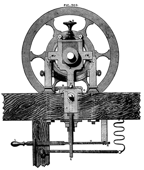
Fig. 303.
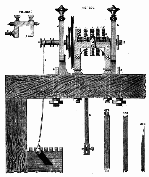
Figs. 302, 304, 305, 306, 308.
On the bed and parallel to it, two pieces of brass, or standards, rise, similar to H in the first figure, the two being opposite to each other, one on each side of the mandrel, as shown in the second figure. Both these are firmly secured to the bed by long bolts and nuts, it being of the utmost importance that they should not move or vibrate in the least. They are in addition united to each other by two horizontal braces, one of which is seen at N in the second figure. At l, l are seen two rectangular notches, which are the ends of grooves made in the upper part of the head piece, H, and which traverse its whole length. They receive the crooked part, a, of the rubber holder, Fig. 304, so that the latter can be slid along this bar, and brought opposite to any one of the rosettes, after which it can be secured in position by the screw, b, Fig. 304. The mandrel is thus arranged. It is cylindrical, with a shoulder against which the chucks can rest, as in an ordinary traversing mandrel, and a similar but reversed shoulder at g, Fig. 302. Against the latter abuts the end of an accurately turned sleeve of brass, which fits over the mandrel with slight friction, so as to have no shake or play upon it. Upon this sleeve the rosettes are placed. They fit accurately over it, and are prevented from turning round upon it by a feather extending the length of the sleeve, which fits into a corresponding notch cut on the inside of the rosettes. These are arranged in pairs[220] back to back, and each couple is separated from the next by a short sleeve or ferrule, which Bergeron recommends to be of wood, as tending to hold the rosettes more securely than metal when pressed together by the nut at the end of the set. The fibres of the wood are to be placed parallel with the mandrel, because there is no shrinkage of this substance as regards its length. The pulley is fixed beyond the rosettes on a part of the mandrel filed into six faces for that purpose, and lastly comes the nut, which secures all the parts to their several positions, but which nevertheless does not so jam them together but that the mandrel can be turned within the sleeve when the positions of the rosettes are to be changed in the course of working a pattern. The division plate is not attached to the pulley, though lying close upon its surface. It slips on to the sleeve on which the rosettes fit, and its spring-catch only on the face of the pulley. Thus the latter is held to the sleeve and its fittings when the catch is down, so that all turn together, but, when the catch is raised, the division plate, carrying with it the rosettes, can be turned round upon the mandrel as may be required. It is not necessary to repeat what has been said respecting the manner of graduating the division plate, as that used with the lathe already described is in that respect a counterpart of what is used with the rose engine now treated of.
Fig. 307.
The following description of the method pursued in turning a pattern shown in Fig. 307 will suffice to show the working of the rose engine:—First, says Bergeron:—It is not enough to know the general construction of the rose engine, it is necessary to know thoroughly the particular one in use, i. e., as regards the details of its construction, the slight defects or imperfections it may chance to have, and the means whereby they may be lessened or corrected. It is necessary, in addition, to know well, and to have always at hand, the numbers of each rosette, or any rate to have a table of them which can be readily referred to. It is equally necessary to recognise at a glance the various sets of divisions on the division plate, for which purpose, and that no mistake may be made, such numbers ought to be engraved upon each. The same holds good with regard to the slide rest, and, in addition, practice should be frequent upon box or other inexpensive material by which the turner may have made himself perfect in the several combinations possible, and the various effects producible by the rosettes and different shaped tools over which he has control. It is thus, by actual experiment only, that the turner can become acquainted with the powers of his own lathe and apparatus, and thus only, after working out the patterns already executed, will he be in a position to design new ones, and to work with ease and certainty. The rose engines are usually fitted with tools of variously shaped edges, as shown in Figs. 305 and 306,[221] by this means a pattern of some width and great variety is of course produced at once, and by one rosette. In the following, however, a tool with single point, Fig. 308, is to be used. This simplest design is supposed to be on the cover of a box or other plane surface, and it is evident that the movement or oscillation required of the mandrel is that at right angles to the bed of the lathe. To obtain this movement, when the rubber is fixed in its clamp, on the side of the workman, as it is necessary that the rubber should press against the rosette through the medium of the spring, the handle of the lever, Fig. 302, must be drawn forward towards the operator, and kept by a pin, as described, passing through it and the tail piece of the mandrel frame. The tension must not be too great, especially if the rosette to be used is deeply indented, and care must be taken to free the frame from the action of the stop, p, by removing its wedge before making any attempt to try the pressure by moving the mandrel. The design under consideration is produced from rosette numbered 2 in the drawing, and in fixing the rubber care must be taken that it does not bear against the adjacent rosette. Choose a rosette of forty-eight teeth or undulations, and as the second circle of ornamentation exactly intersects the first, the raised part of the one falling under the depression of the other, and as it were halving it, the set of divisions on the click plate to be used will be twice 48, or 96. Place the rest parallel to the face of the work and so that the forward motion of the tool shall be perpendicular to it. By means of the leading screw of the rest, place the tool near the edge of the work and level with the centre, and gently moving it forward and putting the lathe in motion, commence the cut. After having made a light cut, without moving the tool, stop the lathe and judge of[222] the depth of cut, and if sufficient, screw up the stop screw of the slide rest, to insure all the following cuts penetrating to the same depth. Observe the position of the tool as marked by the graduations of the slide rest, and then withdrawing it from the cut, move the click plate one notch, which will divide exactly in half the several undulations of the rosette. By the rest screw move the tool towards the centre of the work and mark the number of divisions passed over, so that the circles of undulations may be equidistant, and cut a second. Now for the third, go back or advance on the click plate one division, for the position of the undulations in the third is precisely that of the first circle. It is indeed immaterial whether an advance or retreat of one notch is made in this case, but now is evident the reason for not dividing the plate equally all round, five or six teeth being ample for each division. If there are eight rosettes the plate should be first divided into eight parts, and each rosette having a different number of undulations, these eight parts should be divided into degrees proportionate to the numbers on the rosette, the one being a multiple of the other. In working the side of a cylinder, that of a box, for example, the longitudinal movement of the mandrel is required, the poppet being retained immovable by the wedge and stop. The tool is to be placed at right angles to the side of the work, the rubber brought to bear on the face of the rosette. The method of working will be self-evident, after the description already given. It is impossible in a brief work like the present, to go into details of other patterns referred to and illustrated by Bergeron, one or two of which are nevertheless of great beauty, and are executed with the aid of the eccentric chuck mounted on the mandrel of the rose engine. There is, however, a different class of work, to which reference will be made in our next, and we shall also give a description of a simple addition to the slide rest, used by watch case turners, which does away with the necessity of counting the number of divisions upon this instrument when used as above.
The slide rest used by the watch case turners is almost identical in form with one figured and described by Bergeron. It is necessary that the tool holder should have a circular motion, somewhat similar to that of a spherical rest, in order to reach the sides and curved surfaces of the articles to be engine turned; hence the tool receptacle and its bed work upon a central pin. The pin here called "the bed" is usually a flat brass plate of a quadrant form, the central pin being at the apex, and carrying on its face the guides for the tool receptacle. The pin on which it turns is a reversed truncated cone rising from a similar flat plate, which itself forms the sole of the rest, or traverses the lower frame as usual; when the tool is beyond the central pin, it will ornament conical surfaces, and vice versa. On the edge of the[223] arc is a racked part, and a tangent screw works into it. The tool is moved to and fro by a lever, as usual, the depth of cut being regulated by a stop screw. These details being already entered into, in treating of slide rests and chucks, need not be more specially explained here; but a contrivance for regulating the traverse of the upper part upon the frame underneath, is ingenious and serviceable, and will therefore be described. The end of the leading screw is fitted with a ratchet wheel of the same construction as that of the ratchet brace for drilling, patented by Fenn, of Newgate Street, to which in the same way a handle and spring are attached, as shown in the drawing, Fig. 309, A, and Fig. 310. The handle rises between two semicircular plates drilled in the face, with holes for the reception of stop pins, B, C. These regulate the traverse of the handle, and thence of the screw. If the former, therefore, is thrown over till the left stop is touched, and then pulled forward to the other stop, between each cut of the tool, the latter will leave equidistant spaces upon the work, without need of counting divisions at each cut. As a traverse of one inch or more of the lever handle at the place of the stop pins only moves the screw a very minute quantity, the holes for the pins need not be very close together even for fine work. This is a very simple contrivance, and perfect in action, enabling the operator to work with ease and certainty, and with great speed.
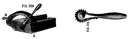
Figs. 309, 310.
Fig. 311 represents a modification of the eccentric chuck, when the latter is used as a fixture, to present to revolving cutters and drills the different parts of the work which is to be operated on. The eccentric chuck is commonly made to slide in one direction only, and the traverse is limited. In the present case there is ample traverse in both directions, the slide being arranged to descend to the lathe bed, and upwards to an equal degree. A is a cross section of this chuck, the length of which is 7½ inches. It is very strongly made in brass, and is altogether much more substantial than the eccentric chuck. B and C are the guide bars, between which works[224] the sliding part. The nut of the leading screw is below this as usual. The tangent wheel has 120 teeth, and is thus divided: 0—12—24, &c. The tangent screw head is divided thus: 0—1—2—3—4—5, with half divisions, marked but not numbered. This rectilineal chuck is most commonly used in a vertical position, but may be otherwise placed. In using it for any work likely to bring a strain upon it, the ordinary spring index attached to the lathe for use with the face plate, should not be entirely relied on to keep it in position. It is safer to make use in addition of the segment engine stops or other available contrivance. The special function of the chuck is the production of straight lines on the face of work forming stars or radial flutes, which can be worked with a drill. Fluting is also readily done by its aid, with the addition of the vertical eccentric, or dome chuck, already described. Its use is, however, by no means confined to ornamental work—small tenons, mortises, and even dovetails are producible by it; and in fitting together the various parts of temples, shrines, and similar complicated specimens, its uses will be [225]innumerable; and here may be noted the extension of the lathe and its apparatus to work apparently in no way suited to it. It has now become more of a universal shaping machine than it used to be, owing to the great accuracy of the work done by it, and the variety of fittings that can be added to it. In a later page will be found a drawing and description of a new device of the kind—a planing machine, devised by an ingenious and first-class maker, Munro, of Lambeth, and patented by him. Mention is made of it in this place, because the rectilineal chuck is in some degree capable of similar work. The slide moved up and down by a screw the handle of which is of extra length to allow the vertical traverse, is also capable of being moved by a cam-eccentric chain or rack and cogged wheel, so that by pulling down a handle the slide may be made to slide up and down more rapidly than by the screw motion; any piece of wood of rectangular or other figure may thus be planed on the face, by being fixed on the rectilineal chuck, and acted upon by a fixed tool in the slide rest, the latter affording the horizontal traverse of the tool across the face of the work, the former the perpendicular movement of the material. If a slide rest is thus arranged in combination with the chuck in question, and the lathe bed is imagined to be set up on end with the chuck downwards and horizontal, the whole will become, in fact, a precise counterpart of those planing machines, the bed of which traverses to and fro, with the work under a fixed tool. Munro's arrangement is, of course, of far more extended application, and more suited for metal work; but for lighter and more delicate operations of a similar kind the rectilinear chuck and slide rest will be found very serviceable. It is with such an adaptation of this chuck as has been alluded to, namely, a quick speed movement of the slide by a lever handle, that the rays are drawn so exquisitely[226] fine and close upon the faces of many gold dial plates of watches, the handle being arrested by a stop at any given point, so that these rays shall not transgress their appointed limits. It will be hardly necessary to allude to those other applications of this apparatus, or other particulars in which it is identical with the eccentric chuck, as the description already given of the latter applies to both alike, the extra traverse of the present in both directions being its chief distinguishing feature.
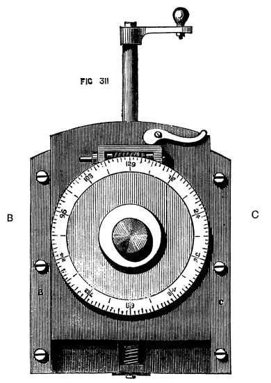
Fig. 311.
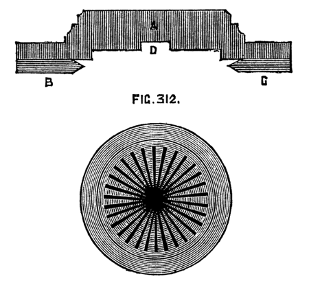
Fig. 312.
This chuck has been in use for many years, and has in consequence been of late rather neglected. It is, nevertheless, the parent of those more elaborate contrivances included under the general title of Geometric Chucks, of which Ibbetson's stands first in order of date, and possibly of merit, though this last qualification may admit of question. The epicycloid, defined mathematically, is a curve described by the revolution of a point in the circumference of a circle, when the latter is made to roll upon the concave or convex side of another circle. A pin in the rim of a wheel revolving round and in contact with another wheel, therefore, describes this curve, which constitutes two or more loops, as will be seen by the annexed illustrations. The number of these loops is variable, and the chuck will produce almost any number by changing the pinions, and thus altering the relative velocities of the revolving parts. The following description will make the action of this chuck clear, and enable any good mechanic to construct one for himself. In the first place, the above remarks show a necessity for a fixed wheel, round which another may revolve. Fig. 313 represents this attached to a plate[227] of brass, which can be fixed to the lathe head, the mandrel passing through its centre. This is the original pattern of plate, and need not, of course, be adhered to, as the form can be modified to suit the lathe to which it is to be applied. It is merely necessary to affix such a wheel to the face of the poppet, so as to be concentric with the mandrel [a plan done away with, however, or rather reversed, in Plant's geometric chuck]. The epicycloidal chuck, which screws to the mandrel as usual, consists of a foundation plate of brass, A, Fig. 314, behind which is mounted the cogwheel, B. The axis of this wheel passes through the plate, and is carried by another plate, e, which is curved and adjustable upon the former. The axis of this wheel carries a small pinion, D, so that the whole turn together. This pinion being one of a set of change wheels, necessitates the possibility of adjusting the plate which carries its axis, as all the several change wheels must gear with E, which always retains its position on the chuck. The sliding plate in question being put in place, is clamped by the screw F. A plate of iron, G, of the form shown, and of sufficient thickness for the secure attachment of the wheel and of the screw which carries the ordinary chucks, is fitted to turn on the axis of the wheel E. Its larger end traverses within the arc H, which is graduated. The arc is bevelled underneath, serving to hold down securely to the foundation plate the piece of iron which is chamfered to fit it. At the left side of the back plate is seen a stop, L, which is placed in such a position, that when the iron plate rests against it, the screw M is concentric with the mandrel, and[228] work may be turned as upon an ordinary chuck. To throw the iron plate, and consequently the nose of the chuck, on one side, or in other words to place the work eccentrically, the screws which retain the arc are loosened and the adjustment made by hand. The eccentricity is marked by an index on the iron plate, which points to the graduations seen upon the face of the arc. The eccentricity being determined, the arc is again screwed down to retain the movable plate in its new position. [Although this is Bergeron's method, it appears vastly inferior to the plan of racking the edge of the iron plate, and moving it to any required degree of eccentricity by the aid of a tangent screw.] When made as above, the chuck will produce loops varying in number according to the relative dimensions of the pinion (or change wheels gearing with E) and the central wheel, M. If the latter has 120 teeth, and the change wheel 60, two loops will result. If the pinion has ten teeth, the number of loops will be 12, and so forth. The practical limit to the number depends on the possibility of diminishing the pinion in size and number of cogs, and still keeping the latter of such size and pitch as to gear with E. If, therefore, a larger number of loops is required than can be obtained thus, it becomes necessary so to modify the form of chuck as to permit of intermediate change wheels, and when the modification is carried out, we have the geometric chuck, the most perfect, but the most complicated and expensive of all. To understand the nature of the work, the following is given in clear language by Bergeron, and will sufficiently explain and simplify matters.
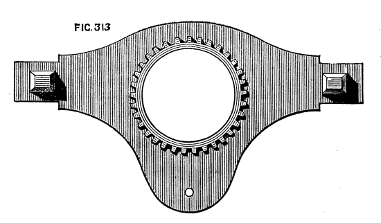
Fig. 313.
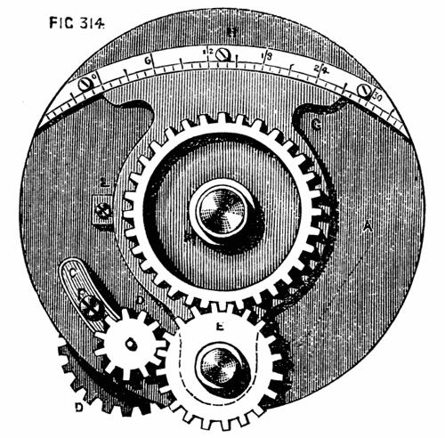
Fig. 314.
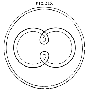
Fig. 315.
If one considers the movement of the piece (of work) when the wheel M is concentric with the mandrel, it will be perceived that although it makes two revolutions upon its axis, yet inasmuch as it has no eccentricity it will describe no particular curve or figure; but if an eccentricity of three divisions is given to it, two buckles or loops will result as in Fig. 315. Before cutting the material, how[229]ever, approach the tool as near the work as possible, and putting the lathe in motion, observe whether the buckle[23] passes too near the centre or too far from it, and also how near it goes to the circumference. If another change wheel with forty teeth instead of sixty is substituted, the slide C, being adjusted accordingly, three loops will be described (forty being one-third of one hundred and twenty), but it is always necessary before actually cutting the material, to try whether the buckles will pass near to the centre without going beyond it. The result of the latter movement will be shown presently, as it entirely alters the appearance of the pattern. The divisions commence on the arc at the left hand, the index resting at 0° when the plate is against the stop L, and the screw of the chuck concentric with the mandrel. The preceding figure of three loops will become similar to Fig. 317, retaining the same wheels and some degree of eccentricity, but by means of the slide rest moving the tool towards the circumference, so that the buckles overlap the centre. The effect thus produced is, that of a set of three curvilineal triangles of which the apex of one falls upon the base of the next. The use of this chuck is stated to require upon the part of the operator more care than any other, as regards the derangement of work or tool in the least during the operation, as, if either is once moved in the least out of position, it will be found next to impossible to strike the line again, owing to the peculiar nature of the curve, for although the tool may be replaced upon any one part of the line already cut with the intention of deepening—it is by no means certain that it will trace the same curve again. This curve, says Bergeron does not produce an agreeable effect on the cover of a box,[230] unless it is very finely cut, the tool, therefore, should be very sharp in the angle and very keen. Bergeron specially mentions this in reference to filling the cuts with thin strips of horn or shell, a method of inlaid ornamentation not much known or admired in the present day, but to which allusion may probably be made again in this series. To form the second set of loops, which are parallel with the first in these designs, it is only necessary to use the leading screw of the slide rest, to move the tool nearer to or further from the centre, while the eccentricity and the arrangement of change wheels remain as before. It is scarcely necessary to detail the formation of the larger series of four loops and upwards, as these are simply the result of different sized change wheels: the following principles, however, by which the buckling of the several loops is controlled or prevented, may perhaps be serviceable. "When, for example an eccentricity of sixteen divisions is used—if the tool is placed at a distance of two such divisions from the centre of the piece, a line only will be produced of as many curves as the wheel or pinion D would produce buckles. If the tool is moved further from the centre by a quarter division, the angles (connecting the curves) will be more defined, but still no buckles will be made. A little further movement of the tool will produce very small buckles which will thus gradually increase as the tool is set further and farther from the centre—until at last when the curves pass beyond the centre, the result is arrived at already shown in Fig. 317. Another form[231] of this chuck is shown in 318, in which, instead of the iron plate being pivotted for the purpose of eccentricity upon the axis of the wheel E, a parallel slide motion is given to the main wheel by guide bars, as in the eccentric and oval chucks. This form is figured in "Lardner's Cabinet Cyclopædia." The large front wheel carrying the screw for chucks is pivotted to the slide C, and protected by a plate D which nearly covers it. The wheel L, is arranged to follow this slide, so as to remain in gear with the large wheel without leaving the fixed wheel or ring on the face of the poppet. In both patterns of this chuck the front wheel is used as a division plate, being moved in either direction as many cogs as desired to produce interlacing of the looped designs. It is better, however, to add a racked division plate and tangent screw, as in the eccentric chuck to act as one piece with the chuck screw, and with the latter turning on a conical pin in the centre of the large wheel underneath. The above apparatus requires to be used with a slow motion owing to the complication of parts, and the whole ought to be so well constructed, that the various wheels revolve with perfect smoothness and without shake or noise.
[23] The word buckle is used to signify the small loops—not the large curves.
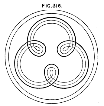
Fig. 316.
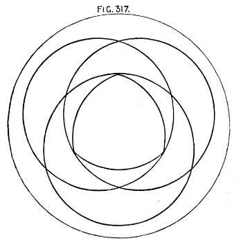
Fig. 317.
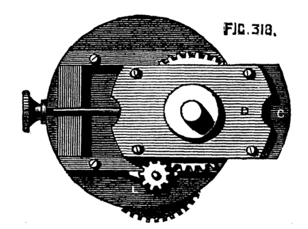
Fig. 318.
There is no class of work on the whole more interesting than that executed by the aid of the spiral chuck, especially with an addition to be described here. This apparatus has grown, almost as a matter of course, from the adaptation to the ordinary lathe of the system of change wheels for the production of screws of various pitches. A spiral is, in fact, a screw with very extended pitch, the threads either closely enwrapping a cylinder which forms the core or body of the screw, or being entirely separate and independent of such core, the latter being by far the most light and elegant. The chuck here described is used with the same arm or bracket as has been already[232] spoken of, standing out from the poppet to carry change wheels, and is itself adjustable to suit different diameters of the same. In the sectional view of this chuck given here, A, H, is the body with internal screw as B, to fit the mandrel. The cog wheel of the chuck which gears into the first on the movable arm or standard, is cast with a large central hole to allow it to be stopped on at D, where it is retained by a nut C. This permits a change of such wheel for one of different size or for the apparatus to be presently described.
Thus far the chuck is only applicable to the production of screws or spirals with a single thread. F, is a dividing plate with racked edge acted on by the tangent-screw E, and carrying the screw, G, a counterpart of that upon the mandrel. This plate carries 96 divisions or teeth. The latter may be used with a spring click if preferred; but the racked edge gives perhaps the more delicate power of adjustment. The spiral chuck constructed in this way is capable of producing any required number of screw threads or spirals, solid or detached, and of any ordinary pitch. It is, however, chiefly intended for the production of spirals or twists for articles of virtu. The method of proceeding has already been described in a previous page. It is one rather of care than skill, as the lathe apparatus ensures the correct movement of the tool where the shape of the latter determines the form of thread, angular, round, or moulded at pleasure. A few of the tools required are shown in the drawing. For finishing the rounded threads, Nos. 3 and 4 may be used, which are similar to those required for turning ivory rings, the one completing half the thread, the other applied in the opposite direction, meeting the cut of the first and finishing the operation. As it is necessary to get round to the back of the threads in this case, no inner mandrel can be used to support the work, and, therefore, great care and delicate handling are necessary to prevent breaking the twists. The stops should also be used upon the bed of the slide-rest, to limit the traverse of the tool and prevent it from striking the shoulder, and destroying any bead or other moulding formed there. This is more specially needed, when there are two or more such twists rising from the same base (that is when there are two or more threads to the screw). The additional apparatus now to be described, adds considerably to the powers of the spiral chuck. It is called the reciprocating apparatus, and its effect is, to cause a to and fro movement of the work, at the same time that the motion of the tool is continued in a horizontal direction. Fig. 320 shows the simplest of the effects thus produced. The screw is commenced and carried to any desired distance on the cylinder. The action and horizontal traverse of the tool is continued, but that of[233] the cylinder reversed, and the cut is thus carried upwards. The tool may be a revolving cutter, the action of which, being continuous and in the same direction, would seem[234] preferable, as the greater the speed with which the tool attacks the material the better is generally the result in work of this kind. A fixed tool, moreover, must have a central edge chamfered above and below, and there is also a tendency with any such fixed tool to unscrew the chuck, as the resistance occurs in that direction in the upward cut.

Figs. 320, 321, 322, 323, 324, 325.
The details of the arrangement are as follows:—The several parts being drawn of full size, Fig. 321 A is an eccentric capable of slight adjustment by the use of either hole, one being further from the centre than the other. Fig. 322 gives another view of this eccentric, which is precisely similar to that used in model engines. It is turned as a circular plate of gun-metal, with one flange. The plate being five-tenths of an inch thick, a second plate, forming another flange, is attached by four small screws, after the ring of the eccentric is in place. This ring is of iron, or, still better, of steel, and is made in one piece, with the arm B, which is six inches long; the main part of it is flat, but it is rounded towards the end, and turned at E, after which it is again flattened to work against the arm D, or still better forked to embrace the latter. It will be seen that D is also a flat plate, with a turned ring similar to the first, but without the enclosed eccentric. In this is drilled a series of ten holes, into any of which a pin can be fitted, so as to unite the arms B and D, the pin becoming a hinge or centre of oscillation. The circular ring of the part D fits on the part D, D of the chuck, on which it can be secured by the ferrule C, the arm D being then in a vertical position. The holes in the eccentric can (either of them) be fitted over and secured to the end of the leading screw of the slide-rest. The handle being then placed on the other end of the screw and turned by the hand, the eccentric will cause the arm D to oscillate to and fro through the medium of the connecting rod B, thereby giving to the chuck, and to the work attached to it, a similar to and fro movement. The extent of this movement depends upon the length of the lever D brought into action. With the pin in the holes 1, 2, 3, the oscillation will be inconsiderable, but with the pin in either hole numbered 8, 9, 10, it will be much increased. In the first, therefore, a short wave, Fig. 320, will result; in the second case these will be more like Fig. 320 B. This apparatus will completely alter the character of a spiral, which, if cut through a hollow cylinder (as in the case of detached twists) becomes a zigzag of curved sides curious enough to behold. The apparatus, it must be understood, is worked entirely by the handle of the slide-rest, the lathe-cord being thrown off unless the latter is carried to the overhead instead, to put in action revolving cutters. The reciprocal action is, in fact, a self-acting segment engine.
It has been already stated that for the production of spiral work[235] revolving cutters are preferable to fixed ones, unless, indeed, it is required to finish up a perfectly round thread, when Figs. 3 and 4 of the tools drawn are required. Revolving cutters must be placed in[236] the frame of the universal cutter and set to the rake of the thread. Drills may be used for the reciprocating movement, as they make very clean work, and the rake need not with these be attended to. In face[237] work drills are specially to be used to produce patterns like Fig. 325, and others derived from this simple one. An additional apparatus, represented in Fig. 323, is required for the latter process, to enable the rest to be turned in its socket so as to face the work, and notwithstanding the alteration of its position still to keep up the gearing of the wheels. A rest socket to be made and mounted as usual is fitted with a stem surmounted by an accurately drilled boss A, through which passes a spindle fitted with the wheel C, to gear with that on the arm carrying the change-wheels, and which may be changed for one of larger or smaller size. This is for cutting such work as Fig. 324, representing, of course, only a single spiral, very open and of itself of no beauty, but which by intersection of other spirals can be converted into a pattern of great elegance. When it is desired to produce the waved spiral the eccentric is fixed to the rod instead of the wheel C, and the work proceeds the same as when a cylindrical surface is to be worked. In the Fig. shown the division plate of this chuck is of course used.
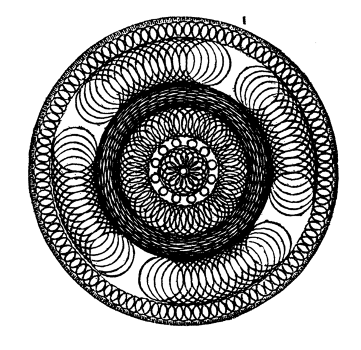
Fig. 1.
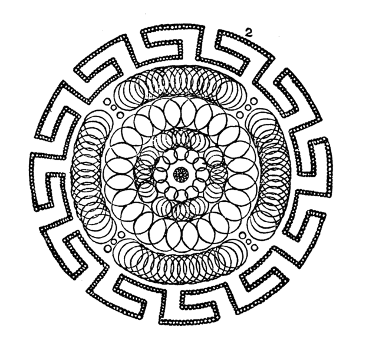
Fig. 2.
Fig. 3.
Fig. 4.
Fig. 5.
Fig. 6.
It is evident that the variations producible by working intersecting spirals and waved lines are very numerous, and these may be additionally varied by the combination of eccentric and spiral movements.
The following six patterns are re-engraved from Valicourt's Hand Book, which is almost identical with that of Bergeron. They were not engraved in time to be inserted under the head of eccentric chuck work. The notation and description annexed is from a manuscript book kindly lent to the writer by an amateur. "Bed-plate," 4 deg., must be taken to mean that the work is shifted (on one of the beds of the chuck) four of the marked divisions for eccentricity, counting from the axial line of the mandrel.
"Slide rest, 4 deg.," means that the cutting tool is moved four corresponding divisions in its bed for radius of the circle to be cut; and so throughout.
"4 *," means four times repeated.
The cutting tools, unless otherwise expressed, are double angled, and "25 cutting tool," means 25 deg. of cutting edge.
Holtzapffel's scale of divisions is
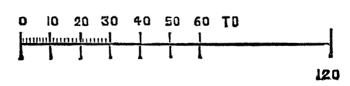
The scale used in Valicourt is
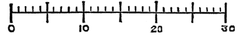
which is that here quoted.
If bed-plate and slide rest are both equally diminished at each cut, a shell results, with the close part internal. If bed-plate is increased and slide rest diminished, the close part of the shell is external.
SPECIMEN I.—Tools 25, 32, 36; Click-plate 96 or 288.
| Bed-plate moved. | Slide rest moved. | Circles done. | Tool. | |
| 3 | 2 | 12* | (1 done 7 missed) | 25 |
| 6 | 1 | 12* | (1 done 7 missed) | |
| 10 | 3 | 48* | (1 done 1 missed) | 36 |
| 3 | 16 | 24* | (1 done 3 missed) | |
| 23 | 4½ | 4* | (16 done 8 missed) | |
| 29½ | 2 | 96* | 25 | |
| 33 | 1 | 96* | ||
| or 33 | ⅝ | 288* |
SPECIMEN II.—Tools 28, 36; Click-plate 288.
| Bed-plate. | Slide rest. | Circles done. | Tool. | ||
| 1 | ½ | 12 | 28 | ||
| 4 | 1½ | 12 | |||
| 7½ | 2 | 4 | (8 done 4 missed) | 36 | |
| 13 | 3½ | 24 | 28 | ||
| 19¾ | 3½ | 4 | (16 done 8 missed) | 36 | |
| 19¾ | ½ | 4 | (in spaces) | ||
| 21¾ | 1 | 4 | (above last) | ||
| B 17¾ | 1 | 4 | (below last) | 36 | |
| 30 | ½ | 12 | (20 done 4 missed) | 28 | |
| 29⅜ | ½ | 12 |  |
( 1 " 18 " ) ( 1 " 4 " ) |
|
| 28¾ | ½ | 12 | Ditto. | ||
| 28⅛ | ½ | 12 | |||
| 27½ | ½ | 12 | |
(15 done 4 missed) ( 1 " 4 " ) |
|
| 26⅞ | ½ | 12 | |
(1 " 18 " ) (1 " 4 " ) |
|
| 26¼ | ½ | As before | |||
| 25⅝ | ½ | Ditto. | |||
| 25 | ½ | 12 | (20 done 4 missed) |
From B to here, border, if with 96 click-plate, not good-looking; tool a boring-bit.
| 331/16 | ⅞ | 12 | (7 done 1 missed) | ||
| 319/16 | 13/16th | 12 | |
(1 " 5 " ) (1 " 1 " ) |
|
| 291/16 | ¾ | 12 | |
(1 " 1 " ) (5 " 1 " ) |
|
| 279/16 | 11/16th | 12 | |
(1 " 1 " ) (1 " 5 " ) |
|
| 25¾ | ¾ | 12 | |
(1 " 1 " ) (7 " 1 " ) |
SPECIMEN III.—Click-plate 96.
| Bed-plate. | Slide rest. | Circles done. | Tool. | |
| 1¼ | 1⅛ | 8 | 36 | |
| 4¼ | 2⅛ | 24 | ||
| 5⅛ | 11¾ | 24 | ||
| 21½ | 4¾ | 96 | ||
| 27¾ | 1½ | 96 | 28 |
SPECIMEN IV.
The centre of this is a star of six curved rays, described by fixing the cutter at the centre and turning the mandrel by hand through so many divisions—for convenience so many 48ths of the circumference. These rays are marked by B. (The segment stop is constructed for this very kind of work, and is to be used in the present case):—
| Bed-plate. | Slide rest. | Arcs done for star. |
| 5 | B 5 | 6 (12/48ths of the circle) |
| 5 | B 5 | 12 (11/48ths " ) |
| 5 | B 5 | 12 (10/48ths " ) |
| 5 | B 5 | 12 ( 8/48ths " ) |
| 14⅛ | 5 | 24 (2 done, 2 missed) |
| 19¾ | ½ | 96 |
| 24¼ | 4 | 32 |
| 29½ | 2½ | 32 (intersecting) |
| 30½ | 2 | 32 |
SPECIMEN V.—Catherine wheel; tool 28.
The ground grailed by concentric circles contiguous to each other. The arcs by fours, all of same radius.
| Bed-plate. | Rest. | Arcs done. |
| 0 | ½ ¾ 1¼ &c. (for grailing) | |
| B 30 | 30 | 12 (16/48) |
(Repeat at three next divisions.)
SPECIMEN VI.—Tools 28, 36; Click-plate, 288.
| Bed-plate. | Rest. | Number. | |
| 1¼ | 1 | 8 | done |
| B 12 | 12 | 127/48 | (to meet next circle) |
| 4⅜ | 17 | 24 | |
| 30 | ½ | 12 | |
| 29½ | 1 | 12 | |
| (On same radius as the last, and surrounding it.) | |||
| 29 | 1½ | 12 | |
| 28½ | 2 | 12 | |
| 28 | 2½ | 12 | |
| 27½ | 3 | 12 | |
| 27 | 3½ | 12 | |
| 26½ | 4 | 12 | |
| 23½ | 1 | 12 | |
| (3 done, 21 missed between last, or if click-plate 96.) | |||
| 25 | 1 | 12 | (between last) |
Although in the matter of beauty the patterns here given are by no means comparable to many others, especially to some lately published from blocks cut by Mr. George Plant, for the English Mechanic; they are, by their comparative simplicity, well selected to give the learner a good idea of designing and working with the eccentric chuck. It is not, indeed, proposed by the writer to multiply patterns, as mere copying of such is of small interest to those who are really endued with taste and skill; and the variations producible by combinations of different numbers of divisions of the click-plate and slide rest are of such infinite number, that printed designs of a score or two would not serve to teach the nature of this work better than the half dozen now before the reader. When a new chuck, indeed, is brought out, it is well to give a few specimens of its work, to show the possible purchaser its value as a means of ornamentation and the extent of its capabilities; but when these are understood, the purchaser had much better design for himself, instead of becoming a lazy imitator and copying patterns laid down by others. Details of designs that are presented in a tabular form remind us sadly (for we are married) of the old "knit one, drop two," "purl" or some such mysterious and, to us, detestable jargon wherewith ladies were, or are, wont to worry the ears of mankind.
The chuck of Professor Ibbetson, and the elliptic cutting frame of Captain Ash, are not introduced here, partly because this work has reached its intended limit, and partly because the inventors themselves have published separate works entirely devoted to a description of the arrangements and capabilities of their respective chucks. A brief notice is appended of Plant's geometric chuck, contributed by the inventor to the pages of the English Mechanic.[24]
[24] See Appendix.
The author now concludes his pleasant labours, the result of which is contained in the preceding pages. These labours have been lightened, and the work itself benefited, by several kindly-written remarks received from various readers of the English Mechanic, while the articles were in course of production in that paper. Criticisms and suggestions also came to hand in which no such kindly feelings appeared. These also have, nevertheless, had an equal share of attention, and where they appeared to be of value they have been turned to profit, and have resulted in various more or less important alterations and additions. "The Lathe and its Uses," thus re-arranged and modified, must now take its chance in the world with other productions of a similar character; and the writer hopes it may suffice to help those who need such assistance, and may be well received by others who though able to walk alone may yet cherish a kindly feeling for the friendly walking-stick.
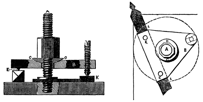
This—described and drawn first in "Holtzapffel's Mechanical Manipulation," to which work the author, and, indeed, most authors of books of the nature of the present, are indebted for much of their information—is now become very general, and from its perfect action ought to be universally used in all factories in which the lathe bears a part. It permits the tool to be set at any required angle upon the bed of the slide rest, and holds it securely when placed in position. It is likewise so constructed as to be easily removed from the table of the rest, so that other forms of apparatus may be attached if desired. One nut only has to be turned to fix the tool, this nut turning on a strong central screw, A, in the figure, the lower part of which, as far as the shoulder, is screwed into the top plate of the rest. This shoulder is directed to be made with flattened sides, so as to be capable of being unscrewed by the application of a wrench. The actual clamp is a triangular piece of cast or wrought iron, B, in the centre of which is a hole to allow this piece to go easily over the screw. The hole is hollowed out into a cup-shaped cavity, into which fits a hemispherical washer, shown at C in the section. The clamping nut, D, acts upon this washer, which permits the triangle to take up a position not necessarily quite parallel to the bed of the slide rest, and thus a tool whose upper and lower surfaces may not be strictly parallel will be securely grasped. The piece called triangular is not precisely of that form, but of the shape shown in the second figure, in which E, E, represent two hard steel pins, slightly projecting—one of these, E, appearing in the first figure. These pins rest upon the upper surface of the tool. At the third angle the[242] clamping piece is drilled and tapped to receive a screw, which must work stiffly in this hole. Thus when a tool is placed in position, as shown, the clamping nut maintains a pressure upon the three points beneath the apices of the triangle. As thus arranged the tool would be stiffly and securely held; but Professor Willis has added a second triangular piece, nearly similar to the first, except that it is provided with a boss, in which a notch or groove is cut, K, in both figures, into which the point of the small screw falls. This lower triangle, which is free to revolve round the central screw, is also cut away at the line L, L, of the second figure, so as to form a guide or rest for the side of the tool, which is thus kept at the same distance from the central screw, and placed in a moment exactly under the studs or points of the upper plate. A careful inspection of the two drawings will make the precise arrangement clear. In making it, which is not very difficult, care must be taken to make the triangle of such size and so to place it, that no angle can overhang the top plate of the rest, in whatever position it may be. The hole in the upper triangle or clamp must be tolerably large and slightly conical—the base of the cone upwards, to allow this piece to take up a bearing, as described. The hemispherical washer is always in a horizontal position, and the hole through it may be only of sufficient diameter to allow it to pass freely over the central screw.
In the English Mechanic of Nov. 2, 1866, a brief notice was given of the above. The author of the present work having carefully inspected the machine and seen it in operation, considers it of such great value to the amateur mechanic, as well as to the professional turner of metal work, that he has had an engraving of the machine carefully made from a photograph, and has here appended it to illustrate the description given.
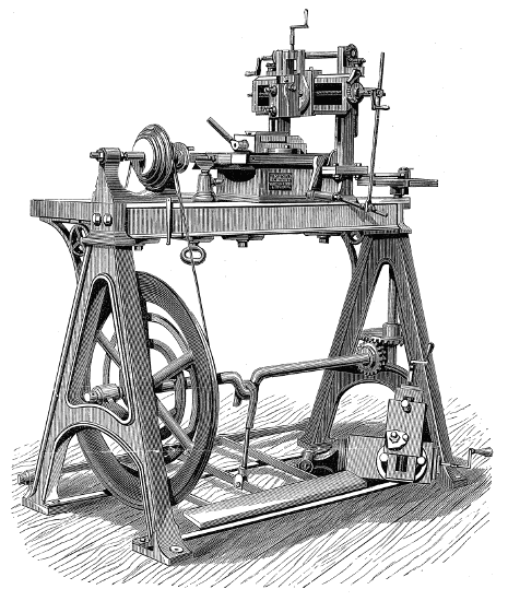
MUNRO'S MACHINE TURNING LATHE FOR PLANING, ETC.
It is a lathe for planing, cutting key-grooves in wheels, collars, &c., and cutting racks on the teeth of wheels. The lathe is of the usual construction, but outside the right hand standard is fixed a vertical spindle, which is made to rotate by a pair of bevel wheels, the pinion being fast to the end of the crank shaft, and in contact with a wheel of double the number of teeth on the vertical spindle. On the top of the latter is a crank-plate, which will give a stroke of ten inches or less at pleasure. The planing-machine is fixed by two bolts to the lathe-bed, and a connecting rod is attached to the sliding plate or bed of the planing machine, the other end of which is made fast to the pin of the crank-plate. The work is clamped by simple means to this sliding bed, and thus passes to and fro under the tool which, by self-acting gear, is made to traverse sideways [243]after each stroke as in the large planing machines. The whole works almost noiselessly and with the greatest ease, each part being accurately fitted, and the whole well finished. For such purposes as planing the face of the slide valve and its bed in small engines, or shaping the guide bars of eccentric and other chucks, facing the frames of slide-rests, &c., it is exactly what is needed by the amateur, rendering the workshop complete for all purposes without the necessity for adding a large and separate planing machine, which takes up room that cannot always be conveniently spared. With such a lathe as that in the frontispiece, fitted with one of these planing machines, there is scarcely a model of machinery that could not be made. Any of our readers interested in mechanics would be wise to trip over to Lambeth and view the machine in operation; and the writer will guarantee, not only the most civil and obliging attention from the inventor, but the greatest pleasure and satisfaction from the working of the machine itself. There is a simple arrangement for key-grooving and slotting, by attaching the upper slide of the ordinary rest to the crank plate of this machine, in which case most of the apparatus is removed.
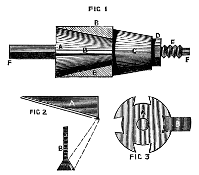
Figs. 1, 2, 3.
Mention of this has been made in the body of the work. It is used for turning rings and washers, and various sizes of these can be turned upon the same mandrel, so that a set of three will suffice for all the work likely to be met with even in the largest factories. Fig. 1 represents the mandrel complete. F, F is the central part, with a conical boss, A, cast upon it, and the whole turned with great accuracy. Four longitudinal dovetailed slots, seen plainly in Fig. 3,[244] are then planed in the conical part, and into these are fitted steel wedges, Fig. 2, A and B, and B, Fig. 3. C, Fig. 1, is a hollow conical washer, which can be advanced over the central part when driven forward by the nut D. This washer, acting on the ends of the sliding wedges, causes them to move towards the large end of the cone A, and, from the form of these and of the cone, any washer or ring will be held tightly when placed outside these wedges, and will also be mounted concentrically.
It is but right to state that the above method has been objected to by a practical workman, whose business has led him to study the matter closely. He states that it is impossible in this way to effect the desired object. As the writer has not been able to test the working of the apparatus on his own lathe, he felt inclined, at first, to withdraw the whole chapter. The objections offered, however, were not, to his mind, entirely satisfactory; and the opinion of other equally scientific and practical men being favourable, the chapter has been retained. It is possible, nevertheless, that there may be a mathematical reason which the writer is not competent to work out, and the objector being a man of great mechanical knowledge and experience, his remarks are worthy of consideration. The practical (not insuperable) difficulty appears to be the production of a proper tool for this work.
This chuck is put in motion by an entirely new method; none of its parts being attached to the lathe head, the whole can be put in motion or released in an instant, and without stopping the lathe.
The whole of its work is executed by the continuous motion of the lathe, so that, when the chuck is adjusted, any figure (no matter how complex) may be begun and completed without once stopping the lathe.
By the different arrangements and adjustments of the chuck and slide rest, an infinite variety of the most beautiful geometrical figures may be produced; and some of them of so strange and fortuitous a nature as to bid defiance to any imitation.
Description of the Drawings.
Fig. 1 is a front view, and
Fig. 2 a view of the back of the chuck.
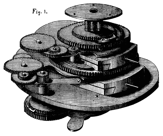
Fig. 1.
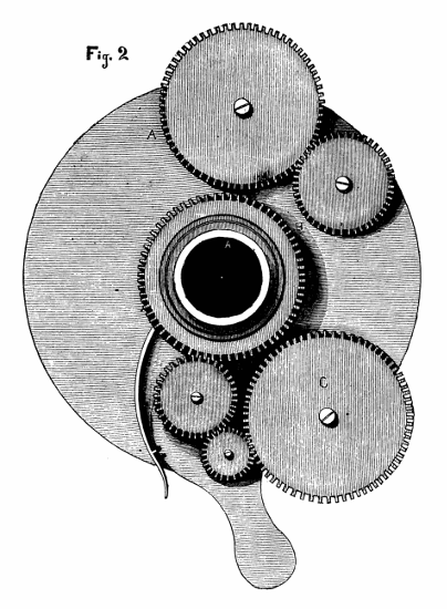
Fig. 2.
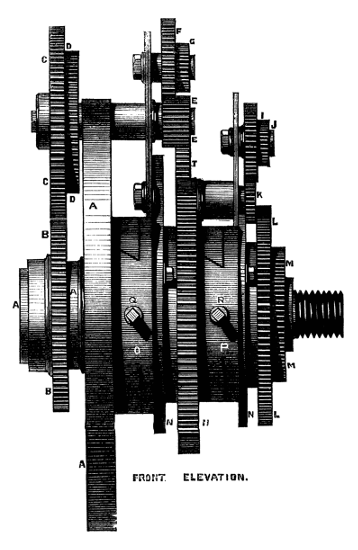
FRONT ELEVATION
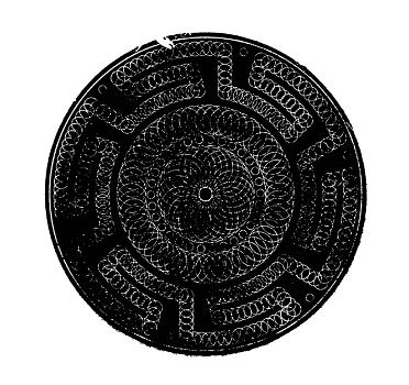
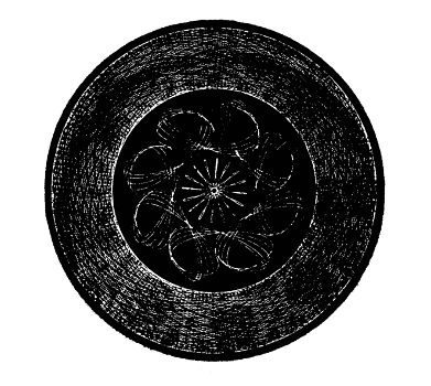
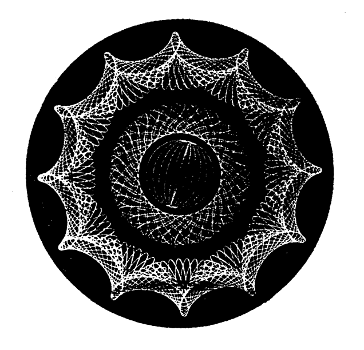
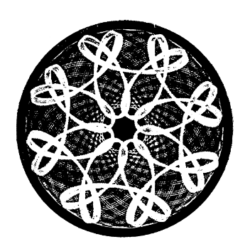
A A. The foundation plate screwing on the plate of the mandrel and carrying the whole of the other parts of the chuck.
B, C. The two driving wheels giving an independent motion to the chuck.
D. Angular wheel moving freely on the wheel C for the angular adjustment of the figures.
E. Pinion of any number of teeth fitting on the shaft carrying D and C.
H. Large wheel of 120 teeth, forming the foundation of the second part, and driven from the pinion E by the wheels F, G, and T.
L. Large wheel of 96 teeth driven by the pinions and wheels U, I, J, K, and forming the foundation plate of the third part, M, which carries the nose of the chuck.
N, N. Self-adjusting radius plates for carrying the various change wheels.
O, P. The eccentric slides of the first and second parts.
Fig. 2 shows the arrangement of the driving wheels and pinions on the back of the chuck.
The working of the chuck is as follows:—
If the pinion E has 20 teeth, and is geared direct into the wheel H, by means of an intermediate wheel, it will give six loops inwards if the motions are similar, and outward loops if the motions are contrary.
If the wheel H is driven from the pinion G it will give 12, 24, or 48 loops.
Pinion of 24 teeth will give 5, 10, 20, or 40 loops.
Pinion of 30 teeth will give 4, 8, 16, or 32 loops.
Pinion of 40 teeth will give 3, 6, 18, or 36 loops.
Pinion of 60 teeth will give two loops inwards, if the motions are similar, but, if the motions are contrary, it will produce an ellipse of any proportion from a straight line to a circle.
Other combinations will give circulating or overlaying loops.
By the different arrangements of wheels and pinions on the plates N, N any number of loops can be produced up to 2,592 in the circle.
On the opposite page we illustrate some work executed with this chuck by Mr. Plant.
Fig. 3 is a side elevation of the chuck full size.
A, A, the foundation plate screwing on the nose of the mandrel, and carrying the whole of the other parts of the chuck.
B, C, the two driving wheels giving an independent motion to the chuck.
D, D, angular wheel moving freely on the wheel C, for the angular adjustment of the figures.
E, E, pinion of any number of teeth fitting on the shaft carrying C and D.
H, H, large wheel of 120 teeth, forming foundation of the second part, and driven from the pinion E by the wheels F, G, and T.
L, large wheel of 96 teeth driven by the wheels and pinions I, J, K, and forming the foundation of the third part, M, which carries the nose of the chuck.
N, N, self-adjusting radius plates for carrying the various change wheels, &c.
O, P, the eccentric slides of the first and second parts.
Q, R, the screws working the eccentric slides.
"The formation of the tools used for turning and planing the metals is a subject of very great importance to the practical engineer, and it is indeed only when the mathematical principles upon which such tools act are closely followed by the workman that they produce their best effects."—Holtzapffel, vol. 2, p. 983.
As the best lathe can do no more than place the work in the most favourable position for the operation of the tool, and the best tool can only do good work when applied as well as constructed on true principles, no argument is needed to prove the truth of the statement taken as the text of this paper.
But while many of our most eminent practical authorities, such as Nasmyth, Holtzapffel, Babbage, Prof. Willis, and others, have contributed valuable papers on the subject, no single writer can be said to have embodied all that should be known upon it as a whole.
Principle may be looked upon as the essence of practice, and in connection with this particular subject, the reduction of practice to principle is of comparatively modern growth. This will account for the fragmentary character and occasional difference of opinion, which marks the treatises of the above-named eminent authorities when compared with each other. As a step towards some more concise and perfect code of principle, I have endeavoured to collate and arrange in consecutive order, all those laws which govern the action of acute edged turning tools.
The object of this paper is not to supply patterns of tools, as the best form will be no better than the worst unless properly applied; but to set forth those general principles, which may enable the workman to distinguish between forms which are accidental and those which are essential, and thus to make the shape of any tool his servant rather than his guide.
Whatever the shape or purpose of any acute-edged tool may be, its action will always depend on the manner in which the extreme[253] edge is applied to the surface acted upon; and as the same laws govern the action of every acute edge, whether formed on a razor or a tool for cast iron, it will assist a clear comprehension of this subject to consider first the action of edges generally, without reference to any particular tool.
The same edge may be made to act in four different ways, viz.: to cut, dig, chatter or scrape. Digging and chattering are intermediate stages between cutting and scraping, and are fatal to good work. Thus cutting and scraping remain the two standard principles, on one of which every tool should be made to act; and while cutting depends on the penetration of the edge, scraping results from using an edge so that it cannot penetrate. Consequently, the conditions most favourable to cutting will give the key to both principles of action.
Every cutting edge is simply a wedge, keen enough to guide its own path without depending on the grain or other accidental line of separation in the material on which it is employed; and when such a wedge is forced into any substance, it will show a constant tendency to penetrate in a line with that face which receives most opposition. The comparative amount of opposition which each face receives, will be determined either by one having more of its surface in contact with the material than the other as in Fig. 2, or by the material giving way on one side, as in Fig. 1 and 3. These last two figures illustrate the action of all paring tools, to which class cutting lathe tools belong. The dotted lines are added in Fig. 2, to show that the action of the edge is the same, whether it be formed by one or two bevels.
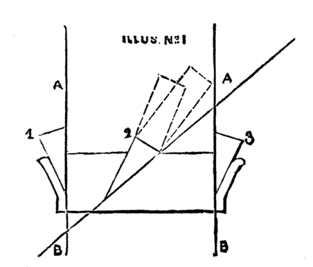
Illustration No. 1.(1, 2, 3)
Thus in all cases,—except when an edge is applied so that the pressure is equal on both faces,—one face will guide the course of the edge, and in paring tools this will always be the lower face, or that next the surface of the work.
The first consideration in placing any paring tool must therefore always be that, the lower face of the edge should lie as nearly as possible in a line with the direction the cut is intended to follow, so as to place[254] the whole edge in its natural wedge-like position: for when any edge is compelled to act in a manner contrary to this, it will assuredly assert its natural tendency by digging and chattering in the direction of its lower face. But when the action of the tool is continuous as in turning, planing, or boring, care must be taken that this face of the edge does not actually rub against that of the work; and, to avoid this, Nasmyth recommends that the face of the edge should be inclined from the surface of the work at an angle of 3°. Babbage calls this angle "the angle of relief," because it relieves the friction; and to show how little variation is admissible in this angle, Holtzapffel places its maximum at 6°. In cylindrical work the angle of relief is estimated from a tangent to the circumference. Thus, in Figs. 4 and 7, the lines C, D, may represent plane surfaces or tangents at pleasure, and in either case the lower face of each edge is supposed to make an angle of 3° with these lines respectively.
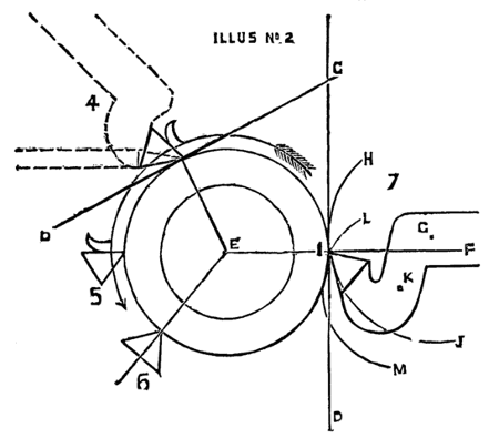
Illustration No. 2.(4, 5, 6, 7)
An examination of the nature of the force required to separate any shaving will show the importance of close attention to the above rule. Babbage has pointed out that this process involves two forces, which, though simultaneous in their action, are distinct in the nature of their operation. The first is that necessary to divide the material atom from atom, and depends on the kind of edge employed. The second force is that required to wedge back the shaving, so as to make way for the further progress of the edge, and depends on the manner in which it is applied to the work. Now in fibrous and cohesive materials, the amount of force required to wedge back the shaving is usually greater than that required to effect the initial penetration, and must always depend on the angle which the upper surface of the edge makes with the face of the work; while it is obvious that, whatever the acuteness of the particular edge employed may be, this angle will be reduced to the minimum obtainable with such[255] an edge, by keeping its lower face as close as possible to the surface from which the shaving is being wedged off.[25] A comparison of Figs. 4 4 and 5 will illustrate this. Both edges are supposed to be of the same acuteness, viz., 60°, and in Fig. 4, where the angle of relief is only 3°, the edge of 60° will wedge off the shaving at the smallest available angle, viz., 63°, while the position of the same edge in Fig. 5 increases this angle to 90°.
[25] In adopting Mr. Babbage's arguments I have varied their form. Mr. Babbage takes the square of 90° and divides it into three parts, viz.:
|
Angle of relief 3° |
 |
90° |
The angle of escape is thus estimated from the horizontal line perpendicular to a base line presented by the surface of the work or by a tangent to it. But as the value of this angle depends directly on its relation to the base line, and has only a complementary relation to the horizontal line, I have thought it better to confine the illustration to the same base as being more directly connected with the wedge-like action of the edge.
Thus, as far as regards the force required to bend back the shaving, the edge of Fig. 5 might just as well be nearly square, or 87°, taking off 3° for the angle of relief. Indeed, this less acute edge would work better than one more acute but badly placed, as in Fig. 5; for the lower face here points too much into the work, creating the tendency to dig explained above. The same arguments and illustrations apply with equal force to drills and boring tools, and Fig. 5 may be looked at as representing one edge of a common drill, in which the acuteness is obtained by bevelling the under sides only, leaving the upper face of each edge perpendicular to the surface acted upon. Nasmyth has pointed out that the less acute drills of this class are made the better and more smoothly they will cut; for, so long as the upper faces are left square to the surface of the work, increasing the bevel of the lower faces can only increase the tendency to dig and chatter. Thus, whenever acuteness is desired in any cutting edge, it should always be obtained from the upper face; and the dotted lines in Fig. 4, suggesting a tool for metal in one case, and a common wood-turning chisel in the other, are added to illustrate this, by showing that the line of the lower face is common to both. No tools afford a better illustration of this principle in boring tools than the American twist drills, which owe the ease and beauty of their action to the spiral flutes being placed so as to give the necessary acuteness from the upper face of each edge, thus allowing the lower faces to be kept as close as possible to the surface of the work. There is yet one more important practical advantage to be gained from adopting the smallest possible angle of relief. The arrow in Figs. 4 and 5 shows the direction in which the strain of the cut will fall on the edges respectively. It[256] has been shown that the position of Fig. 5 increases the amount of strain on the edge, and yet it is apparent that it is less able to bear this increased strain; for while this falls on Fig. 4 in its strongest direction—viz., almost down the length of one face—it falls on Fig. 5 across the end of the edge, thus rendering it far more liable to wear and fracture.
It is therefore evident that, in treating plane surfaces, the cutting action of any acute edge is most favoured when its lower face is placed nearly parallel with the surface acted on; and in treating cylindrical surfaces, when the same face occupies the same position with regard to some tangent of the circumference; or, in other words, when the lower face is almost at right angles to some radius of the circle, as in Fig. 4: and it follows that the tendency to penetrate will be most effectually counteracted when a line at right angles to the surface, or a radius of the circle, as in Fig. 6, bisects the edge, making each face equidistant from the surface which moves across it. Thus, Fig. 6 represents the scraping position; and it is obvious that all bow-drills or other tools, which are said to cut both ways, must really act on the scraping principle.
Practical illustrations in support of the universal application of these principles might be multiplied indefinitely; but two very common operations will suffice to prove that the position of the edge determines the nature of its action. If a penknife be not held with its blade perpendicular to the paper, when used for scratching out, it will be sure to hang and chatter; and the flatter a razor is held to the skin in shaving the more free will the chin be from uncomfortable digs and chatters afterwards.
The conditions which next demand notice in the case of turning-tools are those which must be observed to preserve the proper position of the edge under the strain put upon it. These relate to the form of the tool, and, in the case of cylindrical work with fixed tools, to the part of the surface at which the edge of the tool should be applied. Drills and boring tools require little notice in this respect, for, as the strain is round their axis, it is only necessary that their shafts should be strong enough not to twist or bend. It must, however, be remembered that when common drills are required to be very acute, the edges should be thrown up a little or hollowed out so as to give the acuteness on the upper face as explained above.[26]
[26] The common form of drill is rendered far more efficient with wrought iron and materials that require cutting, by twisting the flat shaft when hot, so as to reverse the position of each edge after the manner of a screw-auger. The lower faces can then be kept as close as possible to the face of the work while the twist will give a moderate degree of acuteness on the upper face.
Hand-turning is simply a matter of manual dexterity, and as any part of the same plane or the same circumference presents the same surface to the edge of the tool, the correct relation between the edge[257] and the surface can be obtained in many places, and therefore the particular point at which the edge should be applied is simply a matter of personal convenience, and may vary with the height of the lathe or that of the workman, or the shape and nature of the tool employed. The use of the graver affords a good illustration of this; and it may be remarked, in connection with this tool, that none is more simple in construction, more perfect in principle, or more convenient in application. When its use is once thoroughly mastered it will do anything from smoothing a pin to roughing out a cylinder four or five inches in diameter. The graver is simply a square bar of steel ground off obliquely at the end; and by varying the obliquity of this slope the act of grinding one plane face will give two cutting edges of any desired acuteness, and three heels from which to use these edges at choice. In hand-turning only one edge of the graver is used at a time, and the lozenge-shaped face is made the lower face common to each edge. Now, when the graver is used for roughing, the point is generally buried in the clean metal below the central line of the work, and the lower face is placed against, and takes the shaving from, the little shoulder which it forms on the cylinder. When the graver is used for smoothing, the lower face is placed nearly flat against the face of the work, and the edge is generally made to bite on, or a little above, the central line. But for very light finishing cuts the graver may be used from the heel at the bottom of its lozenge face, and in this position its point is over the top of the work, bringing the biting part of the edge still more above the central line. Thus, the only three points to consider in placing the tool in hand-turning are—first, that the lower face of the edge should occupy the proper position with regard to the surface; secondly, that the handle of the tool should come up conveniently to the hands of the operator; and thirdly, that while these two conditions are observed, the heel of the tool should be able to take a firm bearing on the rest.
The best rule for hand-turning is, therefore, to apply the tool to the work, with these ends in view before fixing the rest, and then to bring that up to the necessary position.
When the heel of any hand tool has a firm bearing on the rest, and the edge is applied in the wedge-like position, the preservation of this during the progress of the work depends on delicacy of touch rather than muscular power. But when the edges are applied out of their natural line, it puzzles a strong wrist to keep them to their cut at all without digging into the work. This affords the best practical illustration of the necessity of careful attention to the position of slide-rest tools, which are deprived of all power of accommodation to the sense of touch, and which therefore require accurate adjustment in the first instance.
For the motion of the tool is now confined to that of the rest, and as this moves in horizontal planes, the edge of the tool must be applied to the work on that parallel plane which passes through the lathe centres. The reason for this rule will be at once apparent, if the edge be not placed on this central line in facing up a plate—for then it will lose its cut before reaching the centre, leaving a core untouched. Now although it would require an exaggerated error in the position of the edge to lose cut altogether in turning a cylinder, yet this example proves that, unless the edge be applied exactly on the central line the relative position between it and the surface of the work, on which the cutting action depends, will imperceptibly change with the reduction of the work; and supposing this to vary much in diameter, the same tool may cut beautifully on one part and badly on another. Fig. 4, which illustrates the cutting action of the edge, has been purposely placed on a part of the circle where a slide-rest tool could only act for a very short time, in order to draw attention to the difference between those conditions which govern the cutting action, and those which depend on the motion of the rest from which the tool is used. It is obvious that if Fig. 4 were moved inwards on a horizontal line the edge would pass over the smaller circle without touching it. The illustration is of course exaggerated, but it proves that Fig. 7 is the only position in which the tool will cut over varying diameters without some change in the relative positions of its lower face and that of the work. Hence the usual instructions to apply the edge about the centre of the work. But Babbage has observed, that however good this direction may be as far it goes, it is insufficient and liable to mislead when given alone. It is impossible to do away with elasticity when the tool is supported at some lateral distance from the line of strain, as in the slide rest or planing machine; and unless this elasticity is counteracted by the position of the tool, it may upset the best position of the edge. To meet this, Babbage gives the following rule—First, consider whereabouts the tool itself will bend under strain on its edge, when fixed in the rest; and then take care that this part of the tool, which Babbage calls "the centre of flexure,"—is placed above a line joining the centre of the work and the edge of the tool. Fig. 7 will explain the reasons for this rule and the consequences of neglecting it when there is much strain put on the edge.
Let E, I, F, be the line joining the centre of the work and the edge of the tool. Then if G above this line be the centre of flexure, when the tool bends its edge must follow some part of the arc, H, I, J, from G as a centre, and will be thrown out of the work. But if K below the line, E, I, F, be the centre of flexure, then, under the same circumstances, the edge will follow some part of the arc L, I, M, from K as a centre, and must dig into the work. It is [259]important to recognise this principle, because while it shows that every tool in which the top of the edge stands above the shaft must be liable to the evils resulting from elasticity, it shows also that even cranked tools may fail to obviate the danger, unless care is taken to place the weakest point in the shaft above the central line. Babbage remarks, that although it is not always possible to strengthen any part of a tool, it is always possible and sometimes desirable to make some particular point weaker than the rest, by cutting away a little where the weak point should be. Fig. 9 shows that the crank principle may be applied in another form, and although the crank is upwards in this case, the same object is attained by making P the weakest point, and placing it above the central line, N, O. This form, however, is only used for light finishing cuts; for any unnecessary length of crank evidently adds elasticity, and Holtzapffel observes that, "in adopting the crank form tools the principle must not be carried to excess, as it must be remembered we can never expunge elasticity from our materials, whether viewed in relation to the machine, the tool, or the work." The crank, therefore, should only be just sufficient to give the edge the right direction if the tool should spring; and Holtzapffel remarks, that as a tool will generally bend somewhere in the central line of its shaft, it is sufficient if the top of the edge is kept on or just below this line, as in Fig. 8. Referring again to Fig. 7, and looking at the line C, D, as a plane surface, and I, F, as a line perpendicular to that surface, the same arguments and illustrations apply to the form of a tool in the planing machine. The point at which the tool is now applied ceases to be of moment.
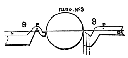
Illustration No. 3.(8, 9)
Having considered the conditions necessary to insure the best cutting action of acute edges and the preservation of that action during the progress of the work, it remains to treat of the edges most suitable to particular materials, the method of giving them any desired angle, and the manner of applying slide-rest tools so as to obtain the best work with the least expenditure of force and time.
Willis observes that different metals and qualities of the same metal require to be treated with edges differing in their degree of acuteness, and all the standard authorities concur in giving the following code as near enough for all practical purposes. The [260]modification of these angles is ruled by the general principle that fibrous and cohesive materials require more acute edges than crystalline and granular substances, as will be apparent in the following code:—
| Wrought iron and steel | 60° |
| Cast do. do. | 70° |
| Roughing brass | 80° |
| Finishing do. | 90° |
Thus the edges available for the metals commonly treated in the lathe find their maximum at 90° and minimum at 60°. The maximum requires no explanation, as when any edge is larger it ceases to be an acute edge.
With regard to the minimum of 60°, Babbage has pointed out that this is dependent not only on the strength necessary to resist the strain of the cut, but further and chiefly on the temper which must be preserved in the edge; and if this be less than 60° the mass of metal composing the extreme edge will be too small to carry off the heat generated by the cut, consequently the extreme edge would soon lose temper and become useless.
But these different edges are formed in very different ways according to the purpose for which the tool is intended; and this will be best understood by comparing the action of a hand-turning chisel with that of a pointed slide-rest tool. In the first case the edge is applied at an oblique tangent to the surface, and removes the shaving by passing under its whole width, much after the manner in which an apple is pared, or a ribbon unwound from a stick, when the lower edge of one turn just overlaps the top edge of the turn below it, and so on. In this case the shaving can be cleanly detached by one straight edge. But the position and motion of the slide-rest tool being perpendicular to the axis of the work, its action becomes that of uncoiling rather than paring; and as a cord or wire wound round a stick touches the face of the stick in one direction, and the coil next to itself in another, so in this case the width and thickness of the shaving lie in opposite directions, as illustrated by the dark band in Fig. 10. Consequently, unless the shaving be cut simultaneously in these two directions—viz., from the face of the work on one side, and from the matter under removal on the other, it is obvious that it must be torn from the work in one direction, thus increasing the labour and spoiling the appearance of the work if the tearing should be from its face. Now, in practice, at any rate in the rough cut, it is usual to take the width of the shaving from the superfluous matter; and if the tool be placed, as in Fig. 11, it can only cut on one edge; thus the edge of the shaving will be torn from the face of the work, while the point of the tool will trace a fine thread in its progress along it, leaving the face with a rough unfinished appearance.
But if the edges be formed so that they can be placed as in Figs. 10 and 12, then both can cut simultaneously, and the screw-like trace of the point may be obliterated. This method of using the tool will leave the work with a good face from the first rough cut, leaving very little for the finishing cut to do; in addition to which the labour will be reduced to a minimum, thereby permitting a much heavier cut from the same amount of force. In turning any plane surface the corner of the edge should be sufficiently relieved from it to avoid the danger of catching; but, in turning cylindrical surfaces, if the tool be carefully made and placed, the slope of the upper surface will carry the corner out of cut. Experiment must decide the exact adjustment; but the great aim should be to keep the face of the tool next the work as nearly parallel with it as possible, because it is only that face which leaves any trace of the tool's action on the face of the work—the action of the other edge being lost with the shaving.
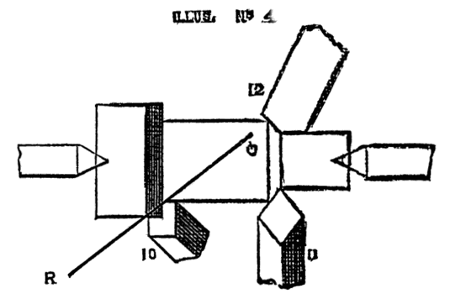
Illustration No. 4.(10, 11, 12)
Thus tools may be broadly divided into two classes—viz., single-edged and double-edged—remembering always that this distinction refers to the manner in which they should act, and not to the number of edges which it may be convenient to form on the same tool. In single-edged tools, whether there be one or many edges, each edge acts independently in removing its own shaving, and may therefore be formed separately. In this case a longitudinal section, showing the angle of the point, will give a true idea of that of the cutting edge. But, in the case of double-edged tools, as the two edges should co-operate in the removal of the same shaving, they must also be formed so that, while each lower face can occupy its proper position with regard to that surface of the work opposed to it, both edges shall possess the same degree of acuteness. In this case the two edges are formed by three planes—viz., two side faces and one upper surface common to both; and the angle of the point is now not only not that of the cutting edges, but has not even any fixed relation to them, for the cutting edges may vary some 25° or more on the very same longitudinal section of the point.
Prof. Willis has pointed out that in these tools the angles of the cutting edges depend on the section and plan angles of the point conjointly (Fig. 8 is a section view; Figs. 10, 11 and 12 are plan views). From this it follows that cutting edges of exactly the same angle may be obtained by a great variety of combinations in the plan and section angles; and in note A, U, of Holtzapffel's work, vol. ii. p. 994, Prof. Willis has given a table, showing some of the different combinations by which cutting edges of certain angles may be produced with accuracy and simplicity. The following short table is arranged from this source and though much abbreviated will be found sufficient for all ordinary purposes.

PLAN ANGLE WITH SECTION ANGLES
| 140° | 79.5° | 69° | 58° |
| 120° | 78.5 | 67 | 55 |
| 100° | 77 | 63.5 | 49.5 |
| 90° | 76 | 61 | 45 |
| 70° | 72.5 | 53.5 | 29 |
| WILL GIVE ——— CUTTING EDGES | |||
| 80° | 70° | 60° | |
The graver will again serve to illustrate the use of this table; for although only one edge is employed at the same time in hand turning, it belongs properly to the double edged class. This will be very apparent if a graver is held point upwards side by side with a point tool, and the dotted lines are added in Fig. 8, to make the similarity of form more evident. Now Holtzapffel has said of the graver when employed for its original purpose of engraving, that "no instrument works more perfectly," pointing out that, while both the edges are engaged in cutting the same shaving, both the lower faces of the edges are respectively inclined at the smallest possible angle from the sides of the V-shaped groove. Fig. 10 has already been used to illustrate the best position of the slide-rest tool,[263] and if the illustration be turned round until the letters Q, R, read horizontally, and this line be taken to represent a flat surface with the graver acting upon it, it will be seen that the shaving is removed in exactly the same manner in both cases; the only difference being that the section of the shaving is triangular in one case and rectangular in the other. But so far as the tool is concerned the action is identical in each case, thus proving that every point tool may be so made and placed as to merit Holtzapffel's eulogium on the graver, and that this simple tool is in fact the type of all double-edged tools.
The graver being made from a square bar has of course a plan angle of 90°, and using it to illustrate the table, we will suppose that it is desired to give it two cutting edges of 60° each. Referring to 90° under the heading of "plan angle," 45° will be found on this line in the column over "cutting edge" 60°; denoting that the section angle of the point, i.e., the slope at which the graver is ground, must be 45° to give the desired edges. In the same way, if the section angle were 61° the cutting edges would be 70°. But taking the plan angle of 120°, the table shows that this would produce the same cutting edges of 60° with the larger section of 55°; and from this we have the important rule that, in obtaining cutting edges of any given degree of acuteness the larger the plan angle is made, the larger also may be the section angle. Thus pointed tools though constructed on the principle of the graver are an improvement on it in its simple form; for by making both plan and section angles as wide as possible, it is obvious that the strength and durability of the point will be much increased. It is, therefore, always better to give slide-rest tools a large plan angle, as in Fig. 12; and plan 120°, with section 55°, will be found a very useful and durable tool for surfacing purposes with wrought iron. When there are rectangular corners to cut in and out of, of course the plan angle cannot be more than 90°, and then it is well to sacrifice a little of the acuteness, as the section of 45° makes the point rather too weak. It is also worthy of remark as a mathematical fact, that unless the plan angle exceed 60°, it is impossible to obtain two cutting edges of that degree of acuteness; and in any case, such a plan angle would be radically bad, because it could not be used on the double-edged principle without undercutting the shaving. It is somewhat remarkable, in connection with this point, that while Holtzapffel, vol. ii. p. 536, recommends prismatic cutters, he should add a footnote which indirectly but most conclusively corroborates Prof. Willis' condemnation of that particular form, by admitting that the proper degree of acuteness cannot be given to both edges.
As the practical result of a circular edge is to cut in two opposite directions,—the edge passing gradually from one to the other,—so[264] round-nosed tools belong properly to the double-edged class, and are open to great objections unless carefully formed on this principle.
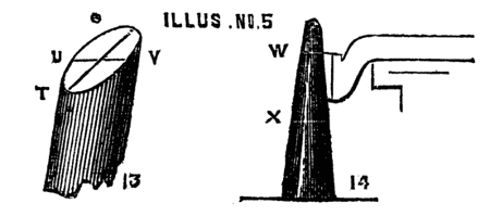
Illustration No. 5.(13, 14)
This is illustrated in Fig. 13, representing an oblique section of a round bar; and supposing the section to be made at an angle of 45°, it is obvious that the highest part of the edge at S will be exactly of this angle, while the lower point at T will be 135°, and the side points at U and V will be 90° each. Thus, between the point S and the points U and V on each side respectively, the edge will gradually pass through a range of 45°, consequently no two adjacent points on the same side will be of the same angle, and the highest point S may be too acute to stand while the lowest, U or V, is too blunt to cut.
Whenever, therefore, it is intended to round the nose of the tool, it should be first formed as a double-edged point tool, with a section angle agreeing as nearly as practicable with the intended degree of acuteness in the edge, so as to secure the highest points from being too weak, and the table given above will show what plan angle must be used, in combination with this section, to secure any part from being too blunt.
Thus, supposing a circular edge of about 60° is desired, the section of 58° approaches this most nearly, and if the plan of 140°, which, with this section, gives two straight cutting edges of 60°, be adopted, there can only be a variation of 2° in different parts of the edge. But it will be observed that this combination admits of very little rounding; and although less acute edges, being obtainable with a smaller plan-angle, admit of rather more rounding, it may be taken as a general rule that when any tool is much rounded on the nose, so as to present a large segment of a circle, different parts of the edge must vary considerably in acuteness. Although Professor Willis objects to rounding the nose of a tool at all on account of the necessary variation in the character of the edge and some other reasons, I am disposed to think that when the tool is carefully formed on the principles given above, it is very advantageous to round off the point slightly for taking heavy cuts; and I have found this form a favourite one in such workshops as Woolwich Arsenal and Portsmouth Dockyard. But care must be taken to place the nose of the tool towards the width of the shaving (presuming that this is taken[265] from the matter to be removed, as it usually is,) for unless the edge is straight, and almost parallel with the face of the work as it leaves it, the face would be marked with a series of concave grooves of greater or less width, according to the feed given to the tool; and even when this is very slow, if the curved part of the edge were placed towards the face of the work it would present the appearance of corrugated iron, when examined under a magnifying lens. Willis further advances against the round nose that, as the shaving removed by it must be of a curvilinear section, it will oppose more force in rolling itself off the edge, than a flat shaving. This would be quite true if a flat shaving could be rolled up on itself like a piece of tape or ribbon; but I think the professor has overlooked the fact that when two cutting edges have one common upper face the shaving must be bent laterally as well as in its length; and I am disposed to think, from practical experiment, that there is very little difference on the point of the force required, and that when a point of large plan angle is just rounded off it stands better and cuts sweeter than when the point is not so rounded. But this only applies to heavy cuts, and for ordinary surfacing work nothing can act more perfectly than a point tool of wide plan-angle placed as described above. If a double-edged tool, with edges of 60°, be thus used in turning wrought iron or steel, and be well lubricated with clean water during the progress of the work, its face may be left with a burnished brilliancy that a touch of the finest emery would spoil. But, as the scheme of this paper is confined to the principles which determine the action of edges, and the rules by which those edges may be formed with certainty, it will be well to conclude these remarks with a few hints as to the construction of ordinary slide-rest tools. Bearing in mind that all double-edged tools belong to the graver class, it is well to form the side faces carefully in the first instance, and then never to alter these, but to keep the tool in order by grinding in the upper surface only, just as the graver is treated. Nasmyth's cone gauge, illustrated in Holtzapffel, vol. ii., p. 534, and also in "Baker's Mechanism," p. 236, affords a ready means of forming the side faces with accuracy. But the range and convenience of this gauge is much increased by dispensing with every part of the arrangement, except the cone itself. This can be made of any piece of stout metal bar turned truly, with the slide-rest set at an angle of 3°, and the base should be broad enough to stand steady by itself when squared off truly in the lathe, as in Fig. 14. Two marks can then be made upon it: one as at W, showing the exact height of the lathe-centre when the cone stands on the bed of the lathe, and another as at X, showing the height of the centre when the cone is placed on any given part of the slide-rest. Thus, in whatever direction the tool is to be used, its adjust[266]ment can be accurately made in the first instance on the slide-rest itself, and again tested after the tool is clamped down.
It is too common a practice in setting slide-rest tools to wedge up one end or the other, with regard only to the application of the edge on the central line. But this generally sacrifices the position of the lower faces, which is essential, to a consideration which has been shown to be only secondary. The best plan is to keep several strips, varying from 1/32 to ½ inch in thickness, but all about as long and wide as the shaft of the tool. These can be made of bar iron for the thicker strips, and sheet iron or tin for the thinner ones; and by using any two or three of these together, the tool can be packed up parallel to the bed of the slide-rest. The adjustment of the edge can thus be made with the greatest ease and certainty without altering the relative position of the lower faces.
It may be well to remark that in using the cone gauge, it is the lower faces of each edge which are to be tried against it, and not the front line of the point, as the inclination of this rule will vary slightly with variations in the plan-angle of the tool, although the slope of the faces remains the same. But the section angle is always to be estimated from the front line, whatever its slope may be.
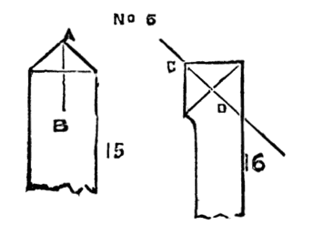
Illustration No. 6.(15, 16)
When the principles which this paper has endeavoured to embody are once thoroughly understood, no handy workmen need ever be at a loss to form and apply his edges with the best effect under any shape the circumstances may require. The first point to be observed is the manner in which the work should be attacked—that is to say, whether the removal of the shaving or scraping requires the use of a single or double-edged tool. The next point is the position of the lower face or faces of the edges, so that they may be applied in the required direction, and in the position explained above. This involves the nature of the treatment best suited to the material, both as regards the kind of edge employed and the principle on which it should be applied—viz., cutting or scraping. In double-edged tools the position of the two lower faces determines that of the point, which is simply an accident resulting from the meeting of the cutting edges; but which, when so determined, affords a guide for the slope of the upper face. This must be so ground that it gives each edge the same degree of acuteness. Thus, in Fig. 15,[267] the point of the tool being at A, the slope must be made in the direction A, B; while, in Fig. 16, the point being at C, the slope of the upper face must be in the direction C, D.
The writer is fully aware that those who expect to find "a rule of thumb" in this paper, will be miserably disappointed. But while he is conscious that the principles of which he has treated admit of a much fuller and yet more concise definition, he would remind the novice that there is "no royal road to learning," and that where practice of hand is wanting it can only be supplied by greater knowledge of principle. His object will therefore be fulfilled if this supplementary paper can supply any explanation or illustration of principle that may add to the practical utility of a work so exhaustive of its subject as "the Lathe and its Uses."
Where amateurs experience inconvenience in making their tools from the want of a forge, the use of detached cutters in a tool holder will be found of the greatest advantage for outside work. Even in plain turning there must always be some special forms for cutting into odd corners and deep grooves; but with a good tool holder and a grindstone, which is an indispensable piece of furniture in every metal turner's shop, the cumbrous array of slide-rest tools may be reduced to a few special forms and a very small box of cutters. These also possess another great advantage; for the spirit of the old adage quoted by Holtzapffel—
may be carried out far more conveniently than in the case of whole tools which are generally filed into shape before tempering, and when worn down must go to the fire again and have the process repeated. But the detached cutter admits of being tempered evenly throughout its whole length and ground up afterwards as long as it lasts, without going to the forge again to the deterioration of the steel.
The patterns of tool-holders are innumerable, but very few are good for general service, because most of them are arranged so that the natural sides of the cutter are used for the face or faces of the edge. Thus either the plan angle of the point is limited to the angles presented by the transverse section of the cutter employed, or else the section angle is fixed by the position in which the cutter is clamped. Holtzapffel's arrangement is open to the first objection, Babbage's to the second. To obviate this inconvenience, Prof. Willis arranged a holder which clamps the cutter at an angle of 55°[268] from the horizontal line. Thus no side can be used either for the lower or upper face of the edge, but any faces can be ground upon it; and the plan and section angle of the edge may be varied at pleasure within the whole range available for metal turning. Prof. Willis's holder for the cutter is almost a facsimile of his admirable tool-holder for the slide-rest, than which none is more convenient or can act more perfectly. But the arrangement is a little complicated for a cutter holder, and must be very carefully made with the knowledge of certain laws, if it is to insure a perfect grip of the cutter. It is also designed for the use of sound wire cutters which require filing flat on one side.
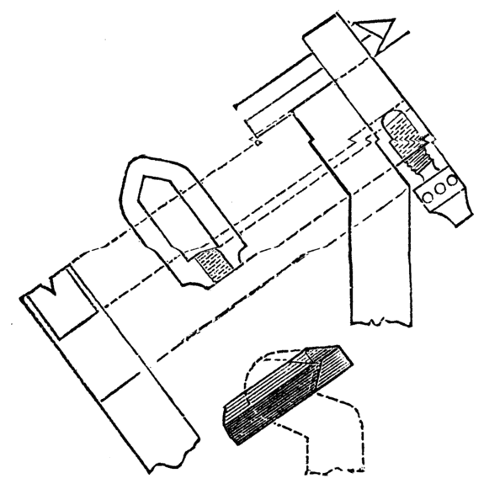
Adopting Willis's inclination for the cutter I have found that all its advantages may be secured with a simpler form of holder and common square for steel for the cutter. The holder is simply the modification of an old pattern to suit the inclination of 55°, and the sketch needs little explanation beyond saying that the nick in the solid part should be rather less than a square angle, and made perfectly true all the way down, or, if anything, rather hollowed in the middle, so as to insure the greatest amount of pressure at the top and bottom, as otherwise the cutter might not sit quite true and firm. The angle at the end of the strap against which the cutter bears should be rather more than square, both to allow for any want of exact truth in the squaring of the cutter and to avoid the wedging action which would be set up on tightening the screw if this angle were less than square, as this could of course create a risk of splitting the strap. The end of the screw and the cup in which it fits should be round, as this allows of a little play and insures a truer grip in the strap[269] than a pointed screw working into a conical hole. A perspective sketch of a detached cutter is added, with dotted lines to show how exactly the arrangement of the faces can be accommodated to the positions which have been shown to be the best in solid tools for the slide-rest.
D. Haydon.
Seeing that the Editor of the above Articles has illustrated and described Holtzapffel and Co.'s Rose Cutter and two methods of executing rose cutting, the latter being the ordinary rose engine, I am induced to send you a description of a method that I have adopted whereby I can with considerable despatch execute this description of turning.
I will first preface my description by saying some thirty years ago I purchased Ibbetson's Book on eccentric turning, and I was so much taken with it and the illustrations, that I determined to make myself in accordance with his description and engravings an eccentric chuck; and although I was a long time about it, being at the time much otherwise engaged, I succeeded beyond my expectations, and was enabled to do some very fine work with it; and I have never regretted the time I spent over the chuck, as I became familiar with metal turning and screw cutting flying in the lathe, which latter I was surprised to find how easily I could execute. However, I was much disappointed in the usefulness of the chuck (Holtzapffel's eccentric cutter, which I purchased is far more useful), and also with the tediousness of using it (fancy stopping the lathe to alter the chuck 360 times or 180 times to cut a row of circles either distinct or overlaying each other), and there was also a certain vibration occasioned in using the chuck which I also disliked. I therefore determined to cut up some rosettes and convert my headstock into a rose engine, to effect which object I got Holtzapffel and Co. to return up with a new steel collar and make my mandrel traversing. I cut myself a rosette both ways with 16 waves, and I was much pleased with the variety of work I could perform with this one, but the rosette took me a long time to make, and disheartened me from cutting up a variety. It, however, occurred to me that if I added an extra mandrel by the side of and attached to my headstock, and on which extra mandrel, if I had an eccentric chuck connected with a rod to the wall of my room, I could get my headstock to oscillate, and by connecting and multiplying wheels cause as many waves on each revolution of my principal mandrel I pleased; this after much time and patience I succeeded in doing, and worked it with the hand motion often adopted for rose work. After between[270] two and three years, I put the extra mandrel over my principal mandrel instead of by the side as before, to enable me to dispense with the hand motion and to work the upper mandrel with the slow motion on my lathe wheel, and which I found a very great improvement, and I now give the details of the plan I have adopted for the benefit of your numerous readers.
The drawings are to a two-inch scale, or one sixth of their full size.
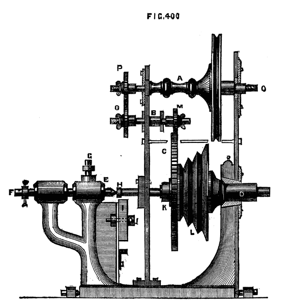
Fig. 400.
Fig. 400 is a side view of my headstock (part in section) with the upper mandrel, A, added, showing the connection by an intermediate spindle, B, with the large cog wheel, C, on my lower mandrel, D, and other additions.
The back centre, E, of my headstock is connected with the back screw, F, and drawn out or pushed in with it, and is fixed by the set screw, G. When drawn out the steel screw, H, at the end of the mandrel, D, removes to receive the screw guides which are then fastened by it, and the piece, I, with segments of a thread to match the guides, is slid up by a wedge to the guides and then fastened by the screw J, I, can also fix some roses cut on the side, and other apparatus with this screw H.[27]
[27] It is not a good plan to make the point, E, movable. It would be better to slip the guides or rosettes over it: and generally to arrange this part as usual with a traversing mandrel, P, H.
The large cog wheel, C, is screwed up with the screw, K, to the mandrel pulley, L. On the front of the pulley is the division plate as usual.
The intermediate adjustable spindle, B, is carried in a frame shown separately by Fig. 405; it is allowed to rise or fall as may be required for the wheel, M, to gear with the great wheel, C; provision being also made for an intermediate wheel, N, (see Fig. 403) to connect the wheel, O, with the wheel, P, on the upper mandrel when required.
The eccentric chuck is fixed on screw Q of the upper mandrel.
Fig. 401 is a plan of the mould for the back cast-iron upright, fixed to the headstock with screws at the foot, showing the circular grooves 1, 2 and 3, necessary for the spindles for the connecting wheels; the centre hole, 4, is for the gun-metal collar, or the upper mandrel.
Fig. 402, is a plan of the mould for the front cast-iron upright; the centre holes 1 and 2 are for the collars of the mandrels. No. 2 is made to just fit over the steel collar of the lower mandrel, and is fixed to the headstock by a brass rose and three screws; it is also fixed at the foot with two screws to the headstock.
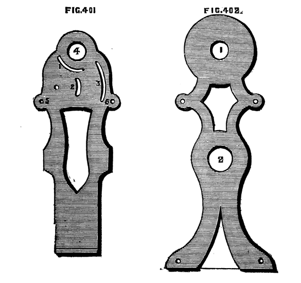
Figs. 401, 402.
These two castings, 401 and 402, are bolted together with two bolts and nuts through the holes 5 and 6, as shown in Fig. 400.[271] Fig. 403, is a back view of the additions, showing the cog wheels and their connections, also the brass bearings for the lower mandrel required when allowed to traverse. This was a solid piece of brass with a hole[272] bored out and ground to fit the mandrel. It was then drilled the whole depth in two places, for two steel steady pins, b, c, made to fit quite tight, and at both ends for bolts and nuts, a, d, afterwards sawn in two with the circular saw, and when put together and two holes drilled through the thickness for fixing it was put in its place, adjusted, and re-ground on. The holes for fixing were very carefully continued through the cast iron upright, and the whole was finally fixed with two screw bolts and nuts.
Fig. 404, is a front view, showing the eccentric chuck, R, on the upper mandrel, the slide of which when used is connected with the bracket in the wall, Fig. 406, causing the whole apparatus to oscillate in proportion to the eccentricity of the chuck on its centres one of which is marked at S. The chuck has a circular movement for laying the waves in any position with one another, but which also is effected by another plan to be presently described. The whole poppet with its fittings is hung on centres similar to the rose engine described in this work. The top part of the bed T removes, and the two screws, one shown at V, are taken out to allow the oscillation. The large cog wheel has 192 teeth.
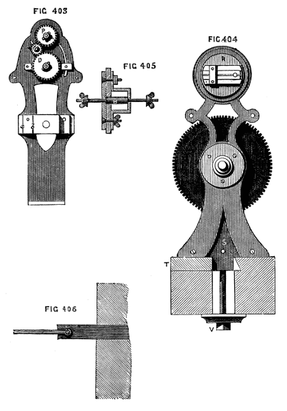
Figs. 403, 404, 405, 406.
The whole of the additions to my headstock were all of my own fitting up. The brass cog wheels were bored out and ground to fit an arbor made on purpose, exactly corresponding in diameter with the ends of the spindles so that they might fit indiscriminately on either spindle. When turned up, the teeth were cut with a circular cutter, which I made just of the exact shape and thickness required for the space between the teeth. The cutter was turned of steel; then wrapped in leather and enclosed in sheet iron. It was then put in the fire, made red hot, and left for the fire to go out, the next day being soft, it was cut with sharp chisels into a circular file and hardened, and with it in the cutter frame the teeth of the wheels were cut. The central boss of each wheel has a notch cut across the face to receive a pin in the arbor and in the spindles, which prevents the wheels from turning round on the latter when screwed up.
This rose engine works beautifully smooth and easy, and ornamentation can be done with it with greater rapidity than with the ordinary engine, by arranging the connecting wheels so that the upper mandrel makes so many waves and one-half, one-third, one-fourth, one-fifth,[273] one-sixth, or any other part of a wave, on each revolution of the lower mandrel, because then it requires certain revolutions of the lower mandrel before the tool comes into the same cut again—say,[274] for instance, it makes 45/6 waves on each revolution, then it takes 29 revolutions of the upper mandrel to complete the pattern, whereby certain patterns are completed without stopping the lathe, which is an advantage that the rose engine proper does not possess. Another great advantage is, that the waves can be either flat, sharp, or intermediate, as required for large or small work, by altering the eccentric chuck on the upper mandrel.
I give a few specimens, not for the beauty of design, but to illustrate the working of the engine. The centre of Fig. 407 is performed by having a wheel of 80 teeth on the upper mandrel, connected with one of 25 teeth on the intermediate spindle, which has another of 50 teeth connected with the large wheel of 192 teeth on the lower mandrel; thus,
| 80 | ||
| 25 | 50 | =11/5 |
| 190 |
producing on each revolution of the lower mandrel one wave, and one-fifth of another wave, requiring six revolutions to complete the pattern.
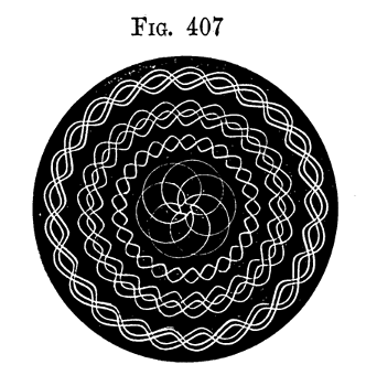
Fig. 407.
The remainder of the pattern is completed by wheels, 16, 50; 48, 192 making 12½ waves on each revolution of the lower mandrel, requiring 25 waves to complete the pattern, and laying the waves over each other, and with the slide rest movement of the tool.
Fig. 408 is produced by wheels 32, 48; 24, 192 making 12 waves. The centre is done by altering the eccentric chuck each time. It was purposely executed askew, by the tool not being placed in the centre, to show the importance of doing so for some patterns. The rim was executed with the same wheels, and with the slide rest movement of the tool, and, after two cuts, the chuck turned half round, to lay the waves over each other for the other two cuts.
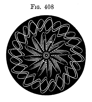
Fig. 408.
Fig. 409 is all executed with wheels 96, 30; 25, 192 making two waves and two-fifths of another wave, requiring 12 waves to complete the pattern. The two centre rims produced by placing the tool above the centre. The outside by four movements of the slide rest tool, illustrating how soon patterns are produced, and when well cut up look very pretty.
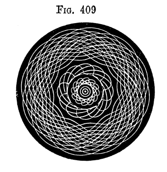
Fig. 409.
Fig. 410 is executed with wheels 80, 50; 25, 192 making four waves and four-fifths of another wave, requiring 24 waves to complete the pattern. The centre is all done without stopping; the outside rim by altering the eccentric chuck four times, to make each successive wave flatter.
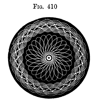
Fig. 410.
Fig. 411 is an illustration of the upper mandrel, making 5⅓ revolutions to one of the lathe, requiring 16 revolutions to complete the pattern and slide-rest movement.
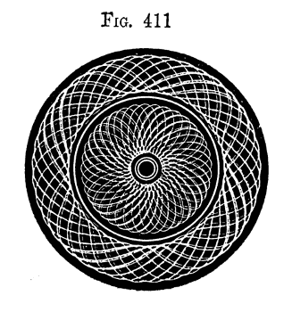
Fig. 411.
Fig. 412. The outer pattern of this figure is produced by the upper mandrel making 12⅘ revolutions to one of the lathe, requiring 64 revolutions to complete the pattern. The centre is a rosette of 5 waves, slide-rest movement and placed across each other.
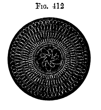
Fig. 412.
Fig. 413. The whole of this pattern produced by the upper mandrel making 3⅗ revolutions to one of the lathe, producing 18 waves[276] across each other with slide-rest movement for the middle rim.
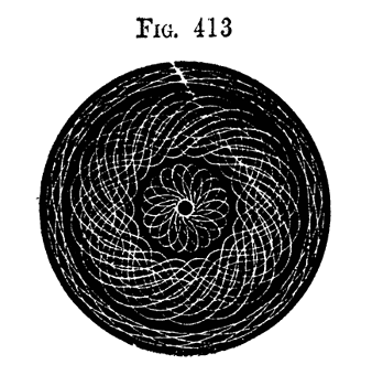
Fig. 413.
Fig. 414 illustrates a rosette of nine waves with slide-rest movement, and 3 divisions of the circular movement of the eccentric chuck for each successive line, producing the waved appearance.
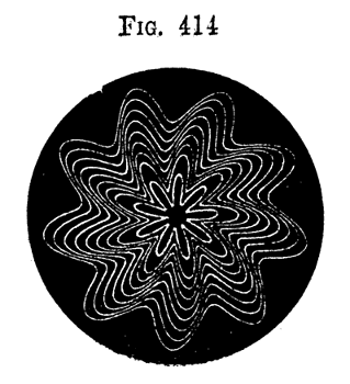
Fig. 414.
Fig. 415 illustrates a rosette of 24 waves with the slide-rest movement.
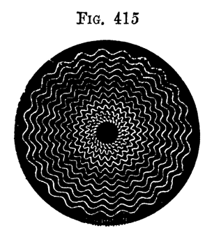
Fig. 415.
Fig. 416. Another illustration of a rosette of 24 waves, rather more sharp than in Fig. 415, with slide-rest movement and 9 divisions of the circular movement of the eccentric chuck, giving it a pleasing circular waved appearance.
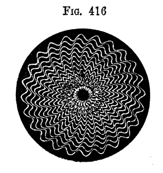
Fig. 416.
Fig. 417. Also another illustration as the last, but with the waves much sharper, the slide-rest movement and only two divisions of the circular movement of the eccentric chuck producing the star-like pattern.
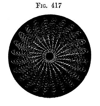
Fig. 417.
Fig. 418 illustrates also a rosette of 24 waves, with the eccentric chuck turned half-way round with each movement of the slide-rest, producing the pattern so often seen on the back of watches, only being on wood it is on a larger scale.
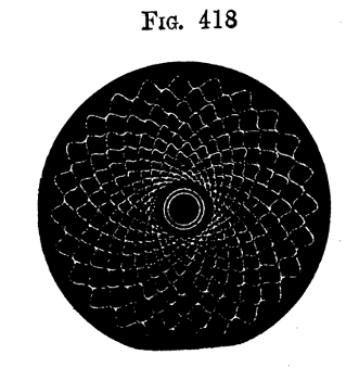
Fig. 418.
The above illustrations are sufficient to give a distinct idea of the working of my engine, and the last four show how easily patterns are multiplied and varied.
The whole of the preceding patterns were executed by the wood being chucked in the lathe in the usual ordinary way without any particular chuck whatever, but in combination with any of the ornamental chucks innumerable patterns can be produced.
Fig. 419 is one illustration with an eccentric chuck on the lathe mandrel.
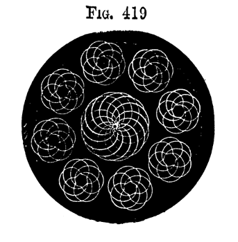
Fig. 419.
That my description may be complete I will now give drawings of my eccentric chuck for the upper mandrel. It requires to be constructed differently to the ordinary eccentric chuck, as the circular movement requires to be always central, and only the slide carrying the pin to receive the rod must move eccentrically.
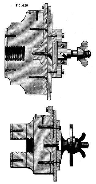
Fig. 420, also 422.
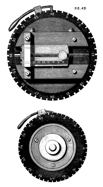
Fig. 421, also 423.
Figs. 420 and 421, are full-size drawings of my eccentric chuck on my upper mandrel, used for producing the foregoing specimens. In this case I have preferred a wood foundation, as not being so likely to run off as metal, on reversing the motion which is sometimes necessary on account of idle wheels for the connections. I used a piece of well-seasoned Spanish mahogany, taking care that the grain of the wood was at right angles with the length of the screw of the mandrel. A piece of brass is screwed at the back to prevent the screw cutting[277] into the wood. Fig. 420 is a section, and Fig. 421 a front view of the chuck, and I think all sufficiently clear. I will just say the long fine threaded screw I cut up with the stocks and[278] dies in the lathe, using steel wire of the necessary size. This I manage easily, and keep the wire straight by allowing it to expand in length. I chuck the steel wire concentrically, and removing the centre from the back poppet, substitute a brass centre with a hole the size of the steel wire, which is allowed about a quarter of an inch entry. I then turn down a little below the depth of the intended screw thread for about half an inch in length next the back centre, to allow the dies to come back to be tightened up, and which must only be done at the commencement and not on the return motion of the dies. The collar on the screw is a piece of brass with a hole of a size to drive on the wire tight, and is then pinned on and turned up true, and finished with the division marks.
Figs. 422 and 423 are full size drawings of my chuck, with circular movement for templates for my upper mandrel, which has also a wood foundation. Fig. 422 is a section, and Fig. 423 is a front view.
By removing the eccentric chuck from the upper mandrel, and substituting the chuck Figs. 422 and 423 with a circular movement, to receive templates of any pattern, ovals with the oval template can be turned and also with any irregular templates, patterns cut and placed in any direction over each other, by causing the templates to work against a rubber or roller as most desirable, with an india-rubber spring to keep them together.
The following illustrations will give some faint idea of productions from templates.
Fig. 424, is the production of an oval template and slide-rest movement, both mandrels making equal revolutions.
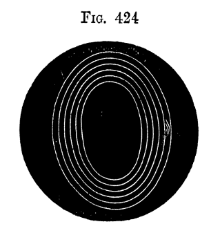
Fig. 424.
Fig. 425 the same as Fig. 424, with the patterns laid across each other by turning the circular movement of the chuck 12 divisions.
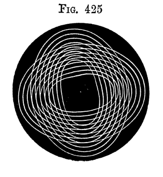
Fig. 425.
Fig. 426, is from an oval template, which is caused to make two revolutions to one of the lathe mandrel producing 4 waves and undulations and with the slide-rest movement. It will be perceived in this case the form of the oval is superseded by another pattern, and shows how great a change in the form of patterns from templates my rose engine with change wheels effects.
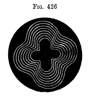
Fig. 426.
Fig. 427, is also from an oval template, caused to make 5 revolutions to one of the lathe, and with the circular movement of the chuck and the slide-rest movement, and in this case the form of the oval is also superseded. Indeed, none but those who have made the matter their study would have the slightest idea that this pattern could be produced from an oval template.
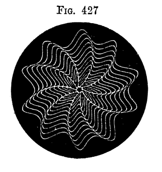
Fig. 427.
Fig. 428, is also from an oval template, it is finer than 427, but is done in the same way by the template making nine revolutions to one[280] of the lathe mandrel.
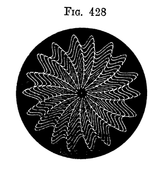
Fig. 428.
The above are a few specimens of the oval, but sufficient to draw[281] attention to the great variety of patterns that can be executed, and these illustrations have only been made to go even revolutions with the lathe mandrel; but of course can be made to go, as already[282] described, uneven revolutions, laying the lines over each other for variety of patterns.
Fig. 429, is a curiosity from a square template with equal revolutions, the outside rim and inside pattern by the circular movement of the template chuck.
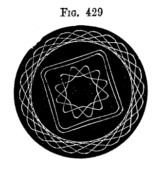
Fig. 429.
Fig. 430, is also from a square template made to go two revolutions to one of the lathe and with the slide-rest movement. The centre pattern with the circular movement of the chuck.
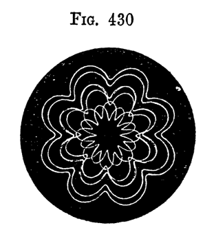
Fig. 430.
Fig. 431, is the production of a heart-shape template, and with the slide-rest movement and the patterns laid across each other, the mandrels making equal revolutions.
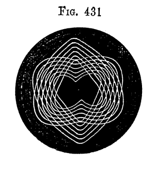
Fig. 431.
Fig. 432, is also from a heart-shape template made to go two revolutions to one of the lathe and the slide-rest movement. But in this case the slide-rest tool is used on the opposite side of the lathe bed to the roller against the template, and therefore reversing the pattern, that is, the projections of the pattern are the hollows of the template, and vice versa. I have introduced it to show how easily patterns are multiplied in the most simple way. It will also be observed that the form of the template is superseded.
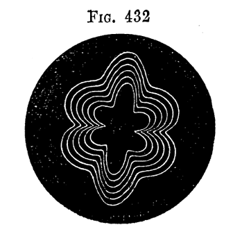
Fig. 432.
Fig. 433, is another illustration of the heart-shape template, but made to go five revolutions to one of the lathe, with the circular movement of the template chuck, and the slide-rest movement, and in which case the form of the template is entirely superseded.
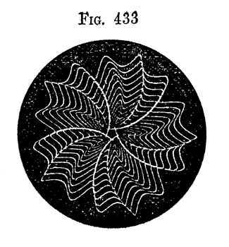
Fig. 433.
Fig. 434, is also a similar illustration to 433, only finer; they can be of course as fine as desired.
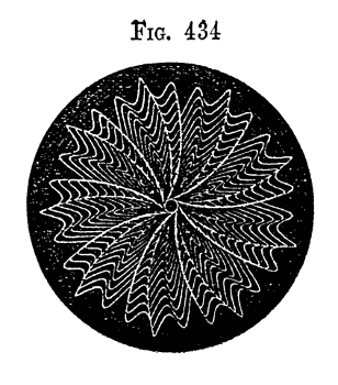
Fig. 434.
The above are, I think, sufficient to illustrate the productions from templates, some very pretty patterns can be executed. My object is more particularly to exhibit the use and extended application of my rose engine, and it will be perceived the last two are not the most easily working templates.
The variety of patterns that can be executed with this engine are so innumerable that one may say they are infinite. Well may you in your article quote what Bergeron says of the rose engine, "that it is[283] necessary to know thoroughly the particular one in use."
I also make use of the cogwheel on my mandrel, by connecting it by a spindle and the change wheels with a large compound slide rest, for executing spiral turning, and also with my slide rest for [284]ornamental turning, for small spiral work; and with a chuck with a circular movement I can cut several spirals to one stem.
In concluding my description I will say the specimens given have all been cut on a plain surface, and this has been unavoidable on account of printing, but for the information of those unacquainted with the rose engine, the very great advantages of which over the eccentric and geometrical chucks are that the work can be executed on concave or convex surfaces. I make use of mine for ornamenting the roofs of temples and Chinese pagodas, either domed, curvilinear, or circular pointed, by representing them covered with shingles, &c. The geometric chuck will produce very beautiful intricate lacework, but not more so than my apparatus, as they both are on the same principle of change wheels, and can both produce equally fine work; but with my apparatus the work is always concentric with the mandrel, and therefore much more pleasing to execute.
Elias Taylor.
Hartford Villa, Patcham, near Brighton, Sussex.
Judd & glass, phœnix printing works, doctors' commons, e.c.
ADVERTISEMENTS.
ESTABLISHED A.D. 1822.
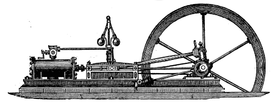
JAMES LEWIS.
41, GREAT QUEEN STREET, LINCOLN'S INN FIELDS,
(Late Lewis & Son, of Wych Street, Strand),
Engineer, Machinist, Lathe and Tool Maker, and Modeller of New Inventions, for English or Foreign Patents, from Drawings or Specifications, in Brass, Iron, or Wood.
Also Manufacturer of Steam Engines and Boilers for driving Amateur Lathes, Pleasure Boats, &c., the Boilers fitted with Messrs. Field's Patent Circulating Tubes; whereby a great saving of Fuel and space is effected; or can be fitted for Gas.
Model Steam Engines and Boilers kept in Stock, and the different parts may be had for making the same.
Estimates given for all kinds of Work. Country Orders punctually attended to.
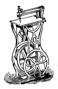
JOSEPH LEWIS'S.
PATENT
COMBINED DRILL, CIRCULAR SAW,
AND FRET MACHINE.
Patterns and designs for Picture Frames, Brackets, Reading Desks, etc., from 3d. each, or 2s. 6d. per dozen assorted.
| To fix on Lathe | £3 | 0 | 0 |
| Ladies' Machine | 4 | 0 | 0 |
| Ditto ditto | 5 | 0 | 0 |
| Gentlemen's ditto | 5 | 0 | 0 |
| Ditto, with drill | 6 | 10 | 0 |
| Gentlemen's Machines with Circular Saw | 8 | 0 | 0 |
| Ditto, ditto, ditto, with the improved Saw-shifting Apparatus complete | 9 | 10 | 0 |
Best Saws from 4½d. per doz., 4s. per gross. Ornamental Drills from 1s. each.
51, HIGH STREET, BLOOMSBURY.

JOSEPH LEWIS,
ENGINEER, MACHINIST, LATHE AND TOOL MAKER, AND MODELLER OF NEW INVENTIONS.
Manufacturer of every description of Plain and Ornamental Lathes, Chucks, Slide Rests, Tools, Drills, over-hand motions, Division Plates, &c.
Lathes £8 0 0, £10 0 0, £12 0 0, £14 0 0, £16 0 0, £25 0 0.
Amateurs supplied with Castings, Forgings of Lathe Engines, &c., and assisted in making the same.
JOSEPH LEWIS'S
Apparatus for cutting Screws of all nitches, self-acting, made and fitted to any Lathe.
51, High St., Bloomsbury, London.
JAMES MUNRO,
(From Messrs. HOLTZAPFFEL & Co.)
ENGINEER, MACHINIST,
LATHE AND TOOL MAKER,
MANUFACTURER OF ALL KINDS OF
LATHE APPARATUS FOR PLAIN OR ORNAMENTAL TURNING,
DIE STOCKS, TAPS, SCREW TOOLS, OVAL AND ECCENTRIC CHUCKS, CUTTING FRAMES, &c.
4, GIBSON STREET, WATERLOO ROAD,
LONDON, S.
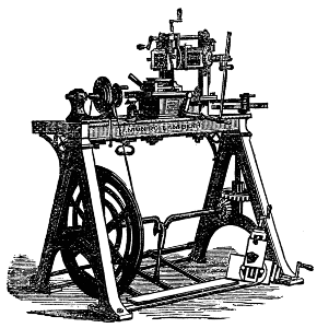
MACHINE TURNING LATHE FOR PLANING, ETC., ETC. INVENTED BY J. MUNRO.
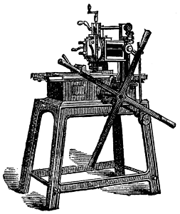
HAND PLANING MACHINE.
James Munro respectfully invites the attention of Amateurs and Manufacturers to the excellence of workmanship and construction of the various descriptions of Lathe Machines and apparatus produced in his manufactory, which has secured the approval of numerous patrons.
Specimens may be seen at the Museum of Patents, South Kensington.
THE ENGLISH MECHANIC
And Mirror of Science,
IS AN ILLUSTRATED RECORD OF
Engineering, Building, New Inventions, Photography, Chemistry, Electricity, &c., &c.
Weekly, price 2d.; post 3d. Monthly parts, 9d.; post 11d. Quarterly Subscription, post-free, 3s. 3d. Vol. VI. now ready, 7s.; post-free, 8s.
(From the Weekly Times.)
"Technical education forms just now a topic of more than ordinary importance, and, as far as we can see, 'The English Mechanic' fills a large space in providing technical food for the workmen of Great Britain. There is scarcely a subject in the scientific or mechanical world that is not practically described in this excellent journal, and all the technicalities explained with a particularity quite remarkable. Here the workman in all departments of trade will find something to interest him, and many things explained by which he will be able to make the best use of his knowledge. The editor is always anxious to satisfy the cravings of his readers by giving every information possible to those who may require it. The trouble taken in this department is apparent on reference to the 'Letters to the Editor' and 'Replies to Queries,' both of which form original, very important, and useful features of the magazine. Under the head, also, of 'Our Subscribers' Exchange Club,' a means is opened for persons to exchange one article for another on mutually advantageous terms, and for this accommodation no charge is made. For instance, one correspondent says he has a silver watch which he would exchange for 'The Lives of Eminent Men;' another wants 'a cottage piano' for 'a three-horse power horizontal engine;' and a third has 'a hand sewing machine,' which he would give for 'a parallel sliding vice.' The illustrations of 'The English Mechanic' are worthy of all praise; they are drawn with an exactness which is so necessary, and so much appreciated by workmen, and are also well printed. Throughout the whole publication there is a visible, a practical, and technical knowledge of a high order—a kind of knowledge that is highly prized by all mechanics and men of science."
(From the Morning Advertiser)
"'The English Mechanic.'—Illustrated with appropriate engravings, this valuable periodical is replete with information of the most valuable kind in every department of engineering, and in all applications of the principles of physical science. Its contents are exceedingly varied, and embrace, in a form adapted for immediate and convenient reference, a well-digested account of any noteworthy progress made in the mechanical or chemical arts, at home or abroad. For all purposes of the inventor, we do not know a periodical more likely to give him that assistance which he could expect to derive from recent means and appliances."
(From the Observer.)
"'The English Mechanic and Mirror of Science' is a publication which contains much that is new and instructive in various branches of science."
Now ready, price 9d.; post free, 10d.
THE ENGINEER'S SLIDE RULE, and its APPLICATIONS. A complete investigation of the principles upon which the Slide Rule is constructed, together with the method of its application to all purposes of the Practical Mechanic.
Published by the Proprietor, Geo. Maddick, 2 & 3, Shoe Lane, Fleet Street,
And to be had of all Booksellers.
ESTABLISHED A.D. 1810.
W. J. EVANS,
ENGINE, LATHE AND TOOL MAKER,
AND GENERAL MACHINIST,
104, WARDOUR STREET, SOHO, LONDON.
TURNING, PLANING, SCREW AND WHEEL CUTTING TO DRAWINGS AND MODELS.
Amateurs' turning Lathes of every description for Plain, Eccentric, Oval and Ornamental turning, also the various tools and apparatus the Mechanical Arts.
Instruction given to Amateurs in Plain and Ornamental Turning in all its Branches.
Contractor to Her Majesty's War Department.
LATHES,
AND EVERY DESCRIPTION OF TOOL FOR AMATEUR TURNERS.
Lathes complete, £7 5s., £9, £11, £16 16s.
CHUCKS & ALL KINDS OF APPARATUS FITTED TO LATHES.
Engineers' Files and Tools of every description.
AMERICAN TWIST DRILLS,
And Self-centering Chucks for holding all sized Drills.
AMERICAN SCROLL CHUCKS OF ALL SIZES
Can be readily fitted to any Lathe.
JOSEPH BUCK,
124, NEWGATE STREET, E.C.,
And 164, WATERLOO ROAD, S., LONDON.
W. BLACKETT,
HOPE IRON WORKS,
SOUTHWARK BRIDGE ROAD, LONDON,
MANUFACTURER OF
Engineers, Millwrights, Iron Ship Builders, and Boiler Makers' Tools.
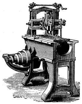
PLANING MACHINE.
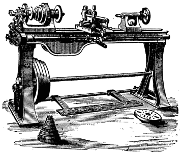
SCREW CUTTING FOOT LATHE.
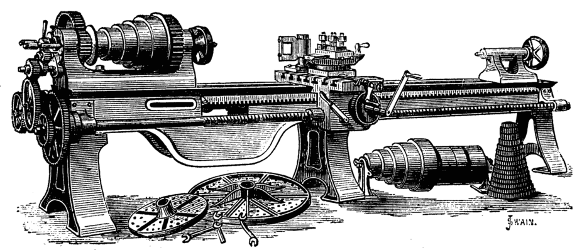
SLIDING AND SCREW CUTTING LATHE.
The Machines usually on hand consist of large and small Boring and Drilling Machines; Universal Shaping, Planing, Slotting, Bolt-screwing, Single and Double ended Punching and Shearing Machines; a variety of Self-acting, Sliding, and Screw-cutting Lathes, Hand Lathes, Foot Lathes, Compound Slide Rests, Planed Iron Lathe Beds, Ratchet Drill Braces, Screwing Tackle, Screw Jacks, and other Tools, such as are usually required in Engineering Establishments. Tools not in stock made to order.
| By Her Majesty's |
 |
Royal Letters Patent. |
CUNNINGHAM AND CO.,
480, NEW OXFORD STREET, LONDON, W.C.,
ORNAMENTAL WOOD
AND
METAL CUTTING MACHINES,
AND
DRILLING APPARATUS.
ADAPTED FOR LADIES' USE.
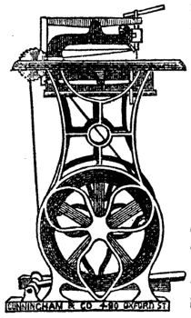
Useful to the following Trades—Organ Builders—Cabinet Makers—Pattern Makers—Chair Makers—Gun Case Makers—Marqueterie Makers—Toy Maker—Jewel Case Makers—Carvers—Cutlers—Leather Cutters—Engravers—Jewellers—Chandelier Makers—Electrotypers—Stereotypers—&c.
Will cut Brass a Quarter inch thick with ease.
The working of the Machine is very simple, and can be learnt by an amateur in five minutes.
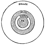 |
Patentees of the CAM ROLLER BUFFING, FOR Preventing Noise in Machinery. See ENGINEER, Jan. 24th, 1868. |
W. J. CUNNINGHAM AND CO.
Beg to call the attention of the Public to their newly-invented Ornamental Wood and Metal Cutting Machine. Its extreme simplicity of construction precluding the possibility of speedily getting out of order, having no springs, and its peculiar adaptability to all kinds of fret-work render it at once an acquisition and an indispensability where accuracy, expedition, and high finish are required. The working is exceedingly easy, requiring no more exertion than an ordinary Sewing Machine for ladies' use, and making as little noise. Its great utility, combined with neatness of construction, fits it not only for the workshop, but the drawing-room of the amateur. The saw takes the place of a pencil in the hands of the operator, enabling him to produce the most elaborate artistic designs in wood-work. Box or other hard texture woods, 1 inch thick, are as readily sawn through as the finest veneer; metallic plates of ⅛ inch thick are also speedily pierced. Magnificent specimens executed by this machine, which have been universally admired for their extreme delicacy and perfection, and acknowledged to be unrivalled, may be seen at the inventor's address. The length of stroke of the saw can be varied to the work in hand. A simple mechanical contrivance is attached for blowing the sawdust from the saw whilst working, also a Circular Saw.
An equally valuable invention is W. J. C. & Co.'s Patented Drilling Apparatus which is with the greatest advantage combined with the Sawing Machine, enhancing and enlarging its range of usefulness, or it may be adapted to a lathe, or as a distinct machine. Its great advantages over the ordinary lathe for drilling purposes must be apparent when by the addition of this apparatus to a 5 inch centre lathe the operator is enabled to drill in the centre of three or more feet, and the drill being vertical and worked by leverage, greater accuracy and facility is ensured. For ornamental purposes it surpasses all hitherto contrived methods, not being limited to one centre around which to describe curves, angles, circles, or any other mathematical figure, the operator is at perfect liberty to describe every conceivable device the fancy can dictate.
Advantages and Capabilities of this Machine.
This Machine can be adapted to any Lathe, see page 131.
This Machine has a Circular Saw.
This Machine has a Vertical Saw.
This Machine has a true Parallel Motion.
This Machine has no Springs whatever.
This Machine has a Bead and Moulding Apparatus.
This Machine has a Planing Apparatus.
This Machine has a Drilling and Grooving Apparatus.
This Machine has a Kinography that will engrave hundreds of different patterns on wood or metal.
This Machine will cut Spirals and Ovals.
This Machine has a Pentagraph, for reducing, enlarging, and cutting on the face of wood any drawing from paper or fret-work.
Circulars and all particulars on application.
Every kind of Materials, viz., Saws, Fret Patterns, Fancy Wood Drills, Cutters, &c., kept in stock.
MANUFACTURERS OF TURNING LATHES.
AND ALL KINDS OF MECHANICAL TOOLS.
MOSELEY AND SIMPSON,
 |
Late 17 & 18, KING ST.JOHN MOSELEY & SON, 17 & 18, KING ST. AND 27, BEDFORD ST., COVENT GARDEN, LONDON, W.C. ESTABLISHED 1730. |
 |
LATHE AND
TOOL MANUFACTURERS,
&c., &c.
PRICE LIST OF LATHES.
Turning Lathe, Iron Frame and Bed planed true, Wood Tool Board, Iron Cone Mandrel, Cylinder poppet head, Rest and two Tees, Turned Grooved Wheel Crank, Treadle complete with 3 Chucks:—
No. 1. 3½ inch centre, and 2 foot 6 inch Bed £10 10 0 " 2. 4½ " " 3 " Bed 12 12 0 " 3. 5 " " 4 " " 15 15 0 " 4. 5 " " 4 " " with Brass Pulley and Slide Rest 21 0 0 " 5. 6 inch centre and 4 feet Bed with Slide Rest complete 25 0 0 " 6. 7 inch centre, 6 feet Bed, self-acting, and Screw Cutting leading Screw, and 22 Change Wheels 40 0 0
For Lathes of other descriptions, Estimates are furnished on Application.
TURNING TOOLS.
s. d. Chisels for Soft Wood, the set of 6 handled 8 0 Gouges 9 0 Tools for hardwood and metal, handled and ready for use, per dozen 15 0 Drills handled 0 7 Arm Rests Handled 2 6 Callipers from 1 0 Turner's Squares from 6 0
All Kinds of Chucks, Cutters, &c., made to order.
Transcriber's Note:
1. Page 38, Bunhill-row, Covent-garden and Charing-cross seems to be
an old-fashioned way of writing.
2. All references to illustrations have been linked for ease of use, as the paragraphs are mostly extremely long,
and illustrations have been moved to end of paragraphs to facilitate smooth reading.
3. This table of contents has been created by the transcriber to aid the reader.
4. Footnote 20, Page 183: Footnote marker is missing.
5. Page 238: starting the 3rd table, there is a fraction 33-1/14. This has been changed this to 33-1/16, as it seems to be a mistake.
6. Spelling errors such as guidepiece, sawgates, swiveljoint, tongueing
and whiteing have been retained as they are in the original.
7. Discrepancies with 3/4-inch and 1/4in. have been retained as in the original.
8. Inconsistencies with images:
a. Page 22: Fig 31D is incorrect in the book as E. Changed to 31D and removed fig. no. on the image.
b. Pages 36 & 38: numbers 53-56 are repeated.
c. Page 74: It seems the reference (Fig. 126) should be Fig.116.
d. Page 89: There is no Fig. 137 or a reference to it.
e. Page 99: The number 9 on the image is back to front. There does not seem to be a Fig. 148, although it is referred to (page 98)
f. Page 98: Fig. 148 is incorrectly numbered on the image as 143.
g. Page 100: There is a 2nd reference to Fig. 149, which it seems has to be an illustration of a pattern, but there is no 2nd Fig. 149. It seems the Fig. nos. mentioned in the reference s/b 150 to 153.
h. Page 104: The illustration is incorrectly numbered as 153 (should be 156).
i. Page 107: The number 9 on the image is back to front.
j. Page 111: The number 6 on the images is back to front.
k. Page 112: Fig. 166 incorrectly numbered as 165.
l. Page 141: There is no Fig. 204. ( assumed to be the top image above Fig.205)
m. Page 159/160: Number repeat for Fig. 229.
n. Page 160: There is no Fig. 230. Possibly the 2nd no. 229.
o. Page 178-184: Numbers 246-255 are number repeats.
p. Page 185/6: There is no Fig. 257, but no reference to it either, so it is assumed this wast an omission by the author.
q. Page 189: There is no Fig. 261, although it is referred to on page 189. The reference has been changed to Fig. 262, which it pertains to.
r. Page 201: Fig. 284 is out of sequence, it appears on page 209.
s. Page 207: It seems the reference should be to Fig. 290, not 296 which has no L in the figure
t. Page 231: Fig, 319 is referred to, but there is no Fig. 319. Presumably the first figure on Page 233
u. Page 236: Illustration top un-numbered, presumably 4.
v. Page 278: Figs, 422/3 is referred to, but there are no Figs. 422/3. Based on extensive research, comparing two different copies of a matching
edition, and correlation of illustrations with the text, it appears that
the inconsistencies in numbering within the book make it seem that
something is missing. The images are in fact Figs. 420 and 421.