CONTAINING
DIRECTIONS FOR THE USE OF ALL KINDS OF TOOLS,
AND FOR THE
CONSTRUCTION OF STEAM ENGINES AND
MECHANICAL MODELS,
INCLUDING
THE ART OF TURNING IN WOOD AND METAL.
BY THE
AUTHOR OF “THE LATHE AND ITS USES”
“THE AMATEUR MECHANIC’S WORKSHOP,” &c.
FROM THE ENGLISH EDITION, WITH CORRECTIONS, &c.
G. P. PUTNAM’S SONS
NEW YORK
27 WEST TWENTY-THIRD ST.
LONDON
24 BEDFORD ST., STRAND
The Knickerbocker Press
1896
Entered according to Act of Congress, in the year 1871, by
G. P. PUTNAM & SONS,
in the Office of the Librarian of Congress at Washington.
In presenting the American edition of this little work to the public, we believe we are supplying a want that has long been felt by the Young Mechanics of this country, and many others who desire to become versed in the practical use of tools. We know of no other book published in this country or England, in which the method of using tools is so clearly explained; and although written more especially for boys and beginners, it contains much information that will be of great value to the practical mechanic. The author is evidently thoroughly acquainted with his subject, and understands how to communicate his ideas in a simple and concise manner.
The first six chapters are devoted to the description of Tools for working wood and the manner of using them, beginning with the simplest operations, requiring but few tools, and gradually leading on to the more difficult, giving examples of all the methods of joining and finishing work that are in common use among good workmen, and in this connection we would like to call attention to the small number of tools the author requires for performing all these different operations, the idea among amateurs and boys generally being, that if you only have tools enough you can make anything. This is not so, and if the beginner will follow the advice of the author, and buy a few good tools, and learn the use of them thoroughly, and gradually add to his stock as his knowledge of their use increases, he will find it greatly to his advantage.
The next five chapters relate to the lathe, and the art of turning. The author follows the same plan as in the first part of the book, and gives more practical information in these few pages than we have seen in any other book on the subject, most of them being written apparently for finished mechanics, and not for beginners. The Art of Turning as an amusement, is beginning to attract considerable attention in this country, but not so much[ii] as it deserves and would obtain, if it were more generally known how many beautiful and useful articles can be produced in the lathe. The expense of the necessary tools has deterred many from attempting to learn this branch of mechanics; but we believe if any one has the time and patience to devote to the work, they will never have occasion to regret the money spent for this purpose.
The last four chapters contain practical instruction in model-making and working in metal. This part of the book we would particularly recommend to inventors who desire to make their own models, as it contains information in regard to files, drills, and the various small tools used on metal, and also directions for laying out work, which are invaluable to a novice in such operations, and will save him much time and trouble.
As this book was originally published in London, where the facilities for getting many kinds of small tools are better than in this country, perhaps a little advice as to the best way of getting such tools as may be required will not be out of place. In most of the large Hardware Stores, carpenters’ tools will be found, put up in chests, at prices varying from five to fifty dollars or more; but we should not advise the amateur to buy any of these, as the quality of the tools is not always reliable, and as they are usually fitted up to make as much show as possible for the money, they contain many tools which are of very little use. The best way is to make a list of the tools required, and select them for yourself. The most important thing is to have the Cutting tools of good quality. We give below the names of some of the best makers of tools; if you purchase any of these, you may be sure of the quality.
If you live in the City, you will probably find no difficulty in procuring some of the above makes; but if you cannot find them there are some others that are good, and you must rely somewhat on the dealer. In regard to the probable cost of the tools, a set such as is described on pages 29 and 30, would cost from fifteen to twenty dollars.
Of Foot Lathes, the following are some of the makers:
From some of the above the amateur will probably be able to select a Lathe to suit him in size and price. The lowest price at which a serviceable lathe can be bought is about forty dollars this is without tools or chucks. About fifteen dollars more would be required for these. Lathes can be bought from this price up to hundreds of dollars, according to the style of lathe and the number of chucks, but of course the beginner would not need an expensive lathe, and seventy-five to one hundred dollars would buy a lathe and tools suitable for all kinds of small work in wood, ivory, or metal.
This volume being an exact reprint of the English edition, it may be well to explain that the material called Deal in England is much the same as our Pine. The article called in England a “Carrier,” is with us called a dog (see pp. 112, 114, 115). Articles priced in English currency would cost here now about 35 cents to the English shilling, or $7 per £ stg.

Of all people in the world who must not be neglected are, first and foremost, “Our Boys,” and, of all boys, mechanical boys deserve a very high place in our estimation. Whatever others may be, these, at any rate, are possessed of sound heads, and willing hands. Therefore, to help these to carry out their designs, appears to be a special duty of those who, once mechanical boys themselves, have lived to become the progenitors of others. In fulfilment of this very duty I have taken up the pen, and with special reference to young mechanics, but without entirely forgetting those of maturer growth, I have thrown together a few hints upon that absorbing question, “How to make and how to use?” In doing this, I have endeavoured to carry out the plan of[v] small beginnings, going from the simplest and easiest to the more complicated and difficult work, although here and there, of sheer necessity, a somewhat different order has been observed. The workshops of King’s College School prove the capabilities of boys to do high-class mechanical work when their efforts are rightly directed by a master’s hand. Where the latter cannot be obtained, guide-books must, however insufficiently, take his place; but whether instruction in mechanical art be oral or otherwise, practice and perseverance are the secrets of success.

| CHAP. | PAGE | |
| I. | INTRODUCTORY, | 1 |
| II. | HOW TO MAKE A CAGE, | 15 |
| III. | MORTICE AND TENON JOINTING, | 29 |
| IV. | HOW TO MAKE A TABLE, | 49 |
| V. | DOVETAILING AND MITRING, | 66 |
| VI. | REBATING, TONGUEING, AND GROOVING, | 89 |
| VII. | THE YOUNG MECHANIC AT THE LATHE, | 103 |
| VIII. | ON WOODS AND MATERIALS FOR TURNING, | 122 |
| IX. | SHARPENING AND SETTING TOOLS, | 144 |
| X. | HAND-TURNING IN WOOD, | 163 |
| XI. | HARD-WOOD TURNING, | 203 |
| XII. | HOW TO MAKE A STEAM-ENGINE, | 226 |
| XIII. | WATT’S ENGINE, | 264 |
| XIV. | HOW TO MAKE AN ENGINE, | 281 |
| XV. | HARDENING AND TEMPERING TOOLS, | 325 |

There never was a time when a taste for practical mechanics was so general among boys as it is now, in this year of grace 1870. There are comparatively few homes in which evidences of this hobby are not apparent in every odd nook and corner, in the shape of carpenter’s tools, not always in first-rate condition, nor by any means generally in their proper places. A saw here, a hammer there, a gimlet, bradawl, or chisel elsewhere.
This probably results from the giant strides which have been made of late years in mechanical enterprise, and the introduction of machinery into every department, as a means of saving labour and facilitating the production of the various necessaries of life.
Man is an imitative animal, and in this as in other things “the child is father to the man;” and hence it comes to pass that the boy whose eyes are continually resting upon machinery of one sort or another (agricultural implements,[2] if a villager; engines for planing, sawing, turning, and so forth, if resident in a town) sooner or later feels an innate desire to construct models of these gigantic mechanical labourers, by whose incessant but unfelt toil our several daily needs are so cheaply and plentifully supplied.
Even if the youthful mind does not always display highly-developed inventive faculties, there is very generally manifested a desire of personally constructing some one or more of those articles which conduce to the gratification of a particular hobby. If the boy has a taste for natural history, cases and cabinets will be made, for the reception of eggs, butterflies, and insects, or to contain stuffed specimens of animals and birds. If he has within him the elements of a sailor, his ingenuity will be exercised upon model boats and ships. If fond of dumb pets, rabbit hutches, dove-cots, or cages will afford him opportunities for the exercise of his constructive powers, and thus the young mechanic frequently lays the foundation of future eminence in that particular line of life to which his tastes naturally lead him.
There are few boyish hobbies in which assistance has not of late years been given by instruction books and guides of a high degree of excellence—natural history, botany, gardening, rearing and breeding all manner of pets—to each of these, well-written volumes have been devoted by able and experienced writers, but mechanical and[3] constructive art has been somewhat neglected. Here and there, in periodical magazines, a few pages are dedicated to the subject, but no book about practical mechanics, written expressly for boys, has yet appeared.
The author of the present volume, himself father of four lads, all of whom in turn occasionally try their hands at this kind of work, and who has himself for many years practised the mechanical arts of carpentry, turning, and model-making, hopes that the hints contained herein may prove valuable to those young friends whom he now addresses. Some of the following chapters will be arranged for very little boys, some for those who are older, while it is believed that other parts of the work may not prove altogether useless to those who have dropped jacket and knickerbockers and rejoice in the vigour of manhood. Thus the little boy, who receives the book as a present, will find it a fast and faithful friend as his years, and, we trust, knowledge and bodily powers increase.
“Small boys need few tools, but much perseverance.” Let this be their motto, as it will stand them in good stead. A pocket-knife, gimlet, hammer, and a few nails will generally serve their purpose; but there is one other tool, namely, a square, which is of great importance, and of which it is well to learn the use as early as possible. A small saw and a bradawl may also be added to the list, and likewise a chisel half an inch wide. Thus equipped,[4] a very youthful carpenter can do a good deal, and, let me tell him, a good deal has been often done without even this moderate supply of tools. It must be taken for granted that the knife and chisel are sharp, because blunt tools make bad work, and by far the best plan for small boys is to get some friend to sharpen them when blunt, as the operation is not easy and requires practice. It is a very foolish plan to try and work with a blunt knife, for the fingers are just as much in danger; and a boy who intends to learn how to use tools must learn at the commencement to use them with due care, so as not to damage himself.
There are small boxes of tools sold, containing generally a wooden mallet, saw, plane, chisel, and gimlet, at about 3s. 6d. or even 5s. Such a box is simply useless. The tools are of iron—will not take a good edge, and are generally disposed to bend and twist. Avoid these, and buy, or get a friend to buy, those I have named, of good quality, and be sure to take care of them, for which purpose you may try your hand at making a box. For this purpose, you will require some thin board (half-inch thick) planed on both sides. (The carpenter will prepare this for you.) Let us see how much you will need. Measure your longest tool, the chisel or saw, if the latter is quite a small one fit to go into a little box; if not, it can be hung on a nail, and you can make your box to contain your knife and chisel and gimlets. I daresay if the box is 9 inches[5] long, 4 inches wide, and 3 inches deep, it will be large enough to take these few tools, for I have just now measured such a hammer and chisel as I have recommended, and find them each about 9 inches in length. The top and bottom of a box should project a little all round, so that you will want them about an inch and a half wider and longer, which will also allow for the thickness of the wood; for you must remember we have given the size of the box inside. To make this clear, I shall here give a plan of the bottom of the box (Fig. 1).
Fig. 1.
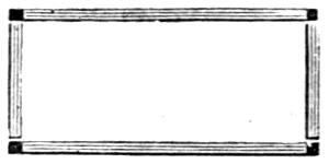
Fig. 2.
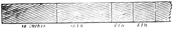
Fig. 3.
It is 10½ inches long, and 5½ inches wide. The broad black line shows where the edges of the sides and ends will come, these being half an inch thick, so that there is a quarter of an inch all round the outside as a border. Reckon across and you will understand this better. A quarter of an inch outside, half an inch for the black line (equals three-quarters of an inch), 4 inches for the inside[6] width, half an inch again for the black line, and a quarter of an inch outside as before,—altogether making 5½ inches. Now reckon the length. A quarter-inch border, half an inch for the black line, 9 inches inside, half inch for the second black line, and another quarter outside—making 10½ inches. You require, therefore, two boards 10½ inches long and 4½ wide for the top and bottom. Now the two long sides and the ends are to be 3 inches wide to form the depth of the box, and here you want no extra width, but as the inside of your box is to be 9 inches long, and the sides are usually nailed over the ends, like Fig. 2, where I have shown them put together, you see that you must have the sides as much longer than 9 inches as will allow them to lap over the ends; that is, half an inch at each end where I have made them black, or altogether, one inch; so that you will want two pieces 10 inches long and 3 wide. The ends will be also 3 inches wide and 4 inches the other way, and here no additional size is needed. Now, the usual way to cut the sides is to get a narrow strip of board of the required width and thickness, and long enough to make both the sides and ends, just such a piece as Fig. 3, on which are marked the lines where it will have to be cut across, and you will easily perceive that you require 28 inches in length and 3 in width.
But you must understand that when you cut with a saw you waste a little of the wood, which falls in the shape of[7] sawdust, and so if you did not allow for this, your box would be too small. The waste depends on the thickness of the edge of the saw, where you will, if you examine it, see that the teeth spread out right and left to prevent it from sticking fast as it is used. Probably, you would waste three-eighths of an inch, which is nearly half an inch in cutting off the pieces, so that instead of a piece exactly 28 inches long, you must have it 28½ inches, or even a little more.
I want you to understand all this before you set to work, even though at first you may get a carpenter to measure and cut it for you; because most small boys take no trouble of this kind, and consequently they are sure to make their boxes too large or too small, and they look very bad when done. However, as I said before, I expect my young readers to understand what they are about, and they must set out their work carefully, or they will never get on so as to be able to make good use of the later chapters of this book. A carpenter’s rule is made like this (Fig. 4).
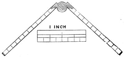
Fig. 4.
Sometimes there is a brass slide, to add to its length when necessary, and sometimes it is hinged so as to fold up again. If you want one for your box, you can get it so made, when it will go in nicely. It is 2 feet long—1 foot on each side of the central joint. A foot is 12 inches; the whole rule, therefore, is 24 inches. Now, you will see that each of these inches is divided by short lines into eight equal parts, called eighths; at the second, the line is rather longer, this being a quarter of an inch; at the fourth, there is a still longer line, this being the half-inch; then comes another eighth, then the three-quarters, another eighth, and the inch is made up,—eight-eighths being equal to one whole inch. Very likely you will find one edge of the rule, or sometimes only one inch, divided into smaller parts, which are sixteenths, or half-eighths; and sometimes, but not very often, divisions still smaller are used, which are half-sixteenths, or thirty-seconds, because thirty-two such divisions make the complete inch. Three feet make one yard, but carpenters always reckon by the foot and inch, and by eighths and sixteenths of an inch. In some trades the inch is divided into a hundred parts, and work is measured up and fitted so carefully, that it would be considered faulty if a mistake of less than a thousandth of an inch were made; but you will not yet understand how it is possible even to measure so very small a quantity. You should certainly learn and understand how to measure with a[9] common two-foot rule, and when you can add one to your box of tools, do so.
Now, let us examine the tool called a square, without which the marks could not readily be drawn as a guide for the saw, where the strip of board is to be cut to make the sides and ends of the proposed box. Here is a drawing of one (Fig. 5).
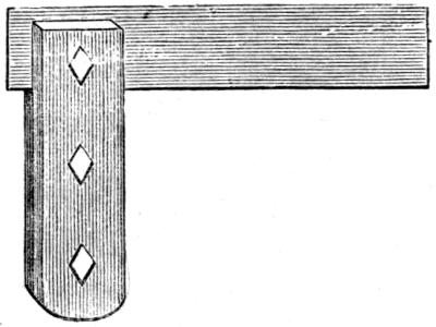
Fig. 5.
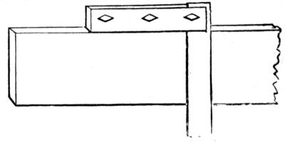
Fig. 6.
It is a handle and a blade, like a knife half opened, the one being fixed exactly square, or at right angles with the other. The blade is thinner than the handle, and when the latter is placed as in Fig. 6, a line marked across the board against the edge of the blade will be, of course, square to the side, so that when cut off, the piece will be like the end of Fig. 6. This is not the shape which the sides of boxes generally have when made by small boys, because they have not a square, and do not know how to work properly. Nevertheless, if one end of a board is cut square, you might get the piece right by measuring the same[10] distance on each side (say 10½ inches), and drawing a line across from point to point, as a guide for the course of the saw. But, then, as it is absolutely necessary that the end of the board should be square to the side, to do this you had better get a proper square at once, and learn how to use it. You will, indeed, find this tool most necessary for all kinds of work, and you will be quite unable to do without it, even though you only have, besides, a knife and gimlet.
Now, if you want to cut off a piece of board with the saw, you must never cut out the line you have marked as a guide by the help of your square, because if you do, you will get the piece too short, owing to the width of the saw-cut which I explained before. Cut, therefore, just beyond it, leaving it upon the piece you are going to use for the side of your box, or other article. At first, you will find it difficult to saw neatly and close to the line, but you will get used to it very soon; and if the saw does not go quite straight, you can trim the piece with a sharp knife neatly up to the line, which you see you could not do if you cut out that line by sawing exactly upon it. All these directions in little matters are very important, because you will find that, by attending to them, you will work well, and the various things you make will look neat and trim, and be fit to show to your friends.
Now, let us go on with the box, which was laid down[11] just to allow a little explanation about the carpenter’s rule and square. I shall suppose you to have cut off all the pieces quite squarely and neat, and that the edges are also square to the sides, which you must take care to insure by keeping the blade of the saw upright when you use it. It is a good plan to measure and mark both sides of your board for this purpose, and to mark the edges from one of these lines to the other. You will then have guide-marks all round, and, by keeping close to these, you will be sure to cut your work truly. It would not so much signify if the long sides were cut a trifle too long, as I shall explain presently; but the ends must be square and true to measure, 4 inches by 3 inches. You must now proceed to nail them together. This must be done with small brads, which are fine nails, and which for the present purpose may be one inch long. If your pieces are all exact to measure, draw a pencil line across the two side pieces, a quarter of an inch from the ends, by the help of the square, as if you wanted to cut off a quarter of an inch at each of those parts, and with your bradawl make two or three holes (three will be best) along those lines. Do not make the first and last too near the edges, or you will split the wood, and spoil the box. Now set up one of the short pieces, and place upon it the piece which you have bored holes in. If you have a bench with a vice, you can screw up the short piece into it; but it will stand up very well upon the[12] bench if you have no vice. It is now in the position of Fig. 7, C.
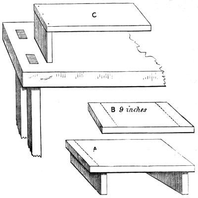
Fig. 7.
Hold it thus, and run the bradawl a little way into the lower piece, through the holes already made in the upper. Drive a brad through the middle hole first, which will hold it together, and then through the other two holes. If you have been careful, you will find this corner square and neat, and the wood not split in the least. Do the same with the other short piece, and then nail on the long side that is left. The frame of the box will now be complete.
I told you a short time ago, that it would not much[13] signify if the sides were cut too long. The reason is this: Suppose B to be the side half an inch too long. You would mark off 9 inches of the middle by two lines drawn with the square as before, which would be the length of the inside of the box; you would then place the inner edges of the end pieces against these lines, and nail them on like A, and afterwards neatly saw off the two pieces which lap over these at each end. If the wood is likely to split when the holes are made for the nails, or if the workman is pressed for time, he very frequently does his work in this way, and then cuts it off and planes it neatly. It is, however, better to work as directed, only be sure to bore holes carefully for the nails, so as never to split the wood.
No very special directions are needed about putting on the bottom. Leave all round an exactly even border of a quarter of an inch, and after it is nailed, you may neatly round off all its edges, to give it a finished appearance.
The cover is, of course, to be attached by a pair of small hinges. Brass hinges are the neatest, and when you buy them, ask for screws to match. The hinges may be three-quarters of an inch long, and they will be, when shut, about half an inch wide, which is the size you need. Lay them (shut up) upon the edge of the back, about two inches from the ends, and with a hard pencil cut to a fine point, or with the point of your bradawl, make a mark at each end, as if you were measuring the length of the hinges on[14] the edge of the box. Between these marks you have to cut out pieces like Fig. 8, which will be just the length of the hinges, and deep enough to allow them, when shut up, to fit and lie even with the top edge of the box. Open them, make holes with the bradawl, and put in the screws. If you have not a screwdriver, you can turn them with the end of an old knife; but you may as well get a small screwdriver, for if you intend to do good work, you will often use screws instead of nails. Hinges are always screwed on. Now lay the cover in place carefully, mark its position, so that you have some sort of guide-line to direct you, and then by laying the cover flat on the bench, and standing the (open) box on its side, you can screw on the hinges upon the cover. Round all the edges of the cover as you did the bottom, but keep the edges of the box square and sharp; and so you have now a really well-made little tool-chest. A little brass hook and eye will do to fasten it, for a lock is rather difficult for a small boy to put on.
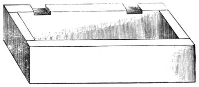
Fig. 8.
The method of constructing a simple box has been given in the first chapter, because so many other articles are made upon exactly similar principles. The rules laid down comprise two or three essential points, the neglect of which render the ordinary carpentry of boys so essentially bad. Foremost of these is the use of the square. There is no tool of more general use in the hands of workmen in wood and metal, and yet, generally speaking, either none at all, or a very faulty one is added to the collection of tools ordinarily supplied to boys. In the next place, I have insisted upon accuracy in measurement. The carpenter’s rule is not at all difficult for a young boy to understand; but even if he is not in possession of such at his first attempts, he should always be induced to work by measure of some kind. This causes him of necessity to exercise his mind as well as his hands, and teaches him to consider well at starting as to what he must allow for thickness of wood, the difference between[16] inside and outside measurement, and so forth; all this will greatly conduce to his success, and consequently satisfaction in his work, and will lessen the chances of his beginning a number of articles and casting them aside unfinished—a propensity too common in all boys.
I shall now resume my directions in the first person, which I think is the more easy method both for master and pupil. The next specimen I propose, because it requires even more care than a box, but is at the same time perfectly within a boy’s powers, is a birdcage. Of these there are such a number of varieties that it is difficult to settle upon the best kind to begin upon. I think, however, a wire cage will on the whole be the easiest to construct, only you must take great care in boring holes in the thin strips of wood, and, indeed, if you can get a birdcage-maker’s awl besides the one you have, it will save both time and trouble. It is not made round with a flat end, but is three-cornered with a sharp point, so that it has three edges, and when it is carefully used and twirled round and round by the fingers in making holes, it will hardly ever split even very thin strips and pieces of wood. However, if you cannot get one never mind, you must use the common bradawl according to directions here given.
I shall suppose you now in possession of a carpenter’s rule, and that you have carefully learned all I told you of the inches and eighths, so that you may be able to measure[17] and mark your work very truly. The front of the cage is represented in Fig. 9, before the projecting roof-boards have been put on.
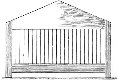
Fig. 9.
Here you see two upright strips at the corners, which shall be 8 inches long. These are 12 inches apart, outside measure. They are ⅜ (three-eighths) of an inch square, and you must get them ready planed from the carpenter. There will be four of them required, as they are at the four corners of the cage; so that, as they are each 8 inches long, you can get a strip 36 inches in length by three-eighths wide, and this being 4 inches more than you need, will allow for waste. At the lower part of the drawing, you see the edge of the bottom board, which projects a little all round. As the outside of the front pillars are 12 inches[18] apart, this board may be 13 inches long, which will allow a border of ½ an inch (half an inch), and it may be 8 inches wide. It need not be thicker than a quarter of an inch. A little above this board (say half an inch) is another board from one pillar to another, which is to be 1¼ inches wide and three-eighths of an inch thick. As the pillars are also three-eighths thick, and their outside edges 12 inches apart, you must take 6/8 (six-eighths) of an inch from 12 inches to find the length of this board.
If you look at the divisions upon your rule, you will see that six-eighths of an inch amounts to exactly ¾ (three quarters), so that your board must be 11 inches and one quarter long. This will also be the length of the board at the top where it falls between the pillars, and this too must be three-eighths thick.
I shall now show you how to mark and cut this top piece into the shape here sketched. Cut the board first of all into an oblong, and mind that you mark it by your square, so that the ends shall be square to the sides. Let it be 2½ inches wide. Here it is (Fig. 10). Measure a length of 6 inches from either end to the middle at A, and make a mark at that place. Draw a line, C B, one inch from the opposite side, the whole length of the board, and mind you draw it correctly. You should measure an inch at B, and at C, and then draw a line from one point to the other along the edge of your rule. You must[19] now draw two lines from the spot you marked at A to the ends of this line (where you see the dotted lines). In order to cut this piece, you must begin at A, not at B or C, or else if the saw should stick you will be sure to split off a strip right across the piece; but if it should stick when you are cutting from A, you will only split off a bit of one of the three-cornered outside pieces, which would not signify at all.
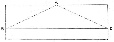
Fig. 10.
When you are sawing, be sure, as I told you before, not to cut into the line you have marked, but saw just outside it, so that the lines will be left upon the two sloping sides of the board. You may cut as close to it as you can, but you must not destroy it, and then you can with your knife neatly shave off the rough edges which the saw has made, until you have pared the wood quite neatly all along the line. If you cut this line out, you will no longer have any guide to work by. Cutting out guide lines is a very common fault, not confined to small boys or big ones. You will find it easy to pare this sloping side if you begin to[20] work from A downwards to B and C, but you cannot cut it in the other direction. A carpenter would, of course, run his plane down the slope, and so will you by and by; but planing is difficult, and it is better you should wait for a time before you buy a plane; for, remember, those foolish little things in boys’ tool-boxes are no use at all.
You had better now prepare the holes into which the wires are to be put as you see in the drawing. You can use either iron wire or brass, but the first is cheapest. These will have to be a quarter of an inch apart. Both the top and bottom strips, you will remember, are 11¼ (eleven and a quarter) inches long. Now, 11 inches will be 44 quarters, and one more will be 45; but as the first hole must be a quarter of an inch from the ends, you will find that 44 holes will be required. Look at your rule and count this. You must mark all these by little dots with a pencil on one piece, and then laying the other upon it, mark the rest exactly even with the first. Do this with great care, or the wires will not stand upright when the cage is finished. The space between the top and bottom pieces will be 5¼ inches, so that if you allow the wires to enter a quarter of an inch at the top and bottom, you will want 44 wires 5¾ inches in length—you may say, 6 inches. You can have them all cut and straightened for you, but if you have a pair of pliers with cutting edges, you can do it yourself, and it is almost necessary you should get a pair, or borrow[21] them, if you intend to construct wire birdcages. You will want a few less in each side of this cage, as it will not be there so wide as it is in front. We shall presently see how many it will require.
You may put together the front of the cage at once and set it aside, or proceed to cut out the rest of it. Generally speaking, it is the best plan to cut out and prepare all the main parts of your work before proceeding to fix them in their respective places; but the front of such a cage as I am describing, being complete in itself, you may do as you like about it. We will begin with the wires. Insert the ends one after the other in a row in one of the pieces, laying it upon the bench, or fixing it on its edge in a vice, but taking care not to bend them. When one piece is thus stuck full of wires, lay it flat on its side, and put the other piece in its place, and one by one insert into it the other ends of the wires. A pair of pliers will help you greatly in doing this. I daresay the two pieces of wood will not be very parallel, but will be closer at one end than at the other. This does not matter, because you will set it right in nailing on the upright strips or corner pillars. This, therefore, is the next thing you must do; and you must have two brads top and bottom, each an inch long, but as fine as you can get. Nail to the top board first, and then place the other in position half an inch from the bottom of the pillars. If you have no carpenter’s vice,[22] you had better work with the front of the cage laid down flat and near the right hand edge of the bench or table, so that the pillar almost overlaps it. In this position, you can bore the two holes and nail it together; but be guarded as to splitting the pillars.
You ought now to have the front well and firmly put together and standing square and true as in the sketch; only the bottom board, of which you see the front edge, is not to be attended to at present.
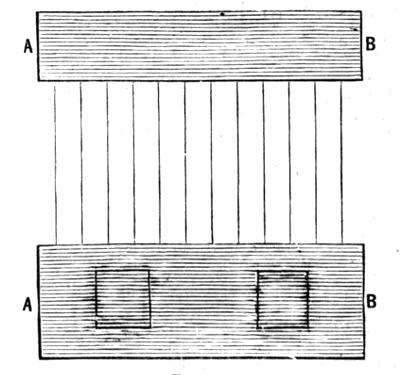
Fig. 11.
There is another way of going to work, namely, to put the whole framework of the cage together and add the wires afterwards. In this case (the holes having all been made beforehand as directed here) the wires are in turn inserted at the top, and then being slightly bent are put in place in the bottom piece—each wire being completely[23] fixed before the next is added. Either way may be tried, but in that given above the wires are not bent at all, and therefore have not to be straightened. Adding them, however, afterwards is the common practice among the cage-makers. Indeed, it generally happens in large establishments that one set of workmen make the woodwork, and another set add the wires—such division of labour proving more advantageous.
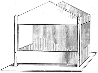
Fig. 12.
Attention is now to be given to the sides, of which Fig. 11 is a drawing. Here you need not make any corner pillars. You have only to cut out the top and bottom strips—the lower one, 1¾ inch wide, to match that in front: the top, 1 inch wide, to match the straight part of the ends of the upper front piece or gable, as you see in Fig. 12.[24] You will also see by this drawing that you must nail the side pieces inside the corner pillars, and not upon them, so that the nails go in from the front of the cage into the ends of the two side pieces which carry the wires. I have shown by dots (Fig. 12) where the nail holes are, and they must be carefully made, avoiding the places where the other two nails come, which you hammered in when you fitted together the front. The side strips, A B (Fig. 11), may be 8 inches long. Both sides of the cage are to be made exactly alike. I have told you to make the lower side-rails 1¾ inch wide, because they must come to the bottom of the pillars, for no half-inch space is required at the sides between these rails and the bottom of the cage. It is so left in the front, because a tray, or cleaning-board, has to be slid in there. You had certainly better put together the side pieces by means of the wires, as in Fig. 11, before you nail them in their places.
You now require a piece of board for the back, and quarter-inch stuff will do very well. Bought cages are made of much thinner wood, generally mahogany, but at first it will be easier for you to use thicker boards. If you round off the edges, they will not appear so thick. Very thin deal will warp or bend after it is made up; and, indeed, it is quite possible the back of this cage will do so. Get the wood, however, as dry as you can, and the top boards, when nailed on, will probably prevent it.
To cut out this back board, you may lay down upon the piece from which it is to be cut the whole front of the cage, and draw a pencil round it, only, when you come to the bottom of the side pillars, you must draw a line straight across from one to the other. Then cut from the point at the top, as you did before. Let the grain of the wood run up and down, not across, the back. Nail the back thus cut to the side strips, as you nailed on the front, and you will then only have the roof to put on, and the bottom.
This roof may consist simply of a thin board, cut square and true, nailed on to the two gables, and it will look much prettier if it is made to project beyond the front. If you measure down the slope of the front or back top-piece, you will find it 6 inches long, and a little more. Your board should therefore be 7 or 8 inches wide, because, although the roof pieces meet at the top, they should come down a little beyond the sides of the cage. As the sides are 8 inches wide, cut the top 11 inches long, which will allow it to project in front 3 inches.
If you look at the cage at the end of these directions, you will understand this. You must slope, or bevel off, the top edges of these roof boards, to make them fit neatly together along the ridge; and as you will paint the cage, you can glue on a narrow strip of paper, to make it quite water-tight. The door of these cages is generally in the back. You merely mark and cut out a square hole about[26] 3 inches square. You then fit a piece in, and hinge it either with wire, or (which is easier) by sticking on a strip of calico down the edge of it, and fasten with a wire hook. As the back is but a quarter of an inch thick, you will be able to cut out the hole (before nailing on the back), with a sharp pocket-knife; and again I say, don’t cut out the guide-lines—cut inside them, and then neatly pare exactly up to them. Make the bottom 13 inches long, and 10 wide, which will allow it to project in front, and also half an inch on each side.
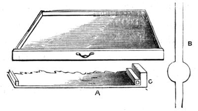
Fig. 13.
You have now to make the tray, to slide into the space left in the front below the bottom front rail. This is to hold sifted sand, and is made loose, because it requires to be taken out and cleaned every day (Fig. 13). It is merely a flat thin board (one-eighth of an inch will be quite thick enough), with a strip nailed on, or glued on, in front, to fit the space left for it, and other smaller strips glued on all round it, so as to form a very shallow tray or drawer. The[27] small strips can be glued on flat upon the top of the board, but to fasten on the front, you must first glue on a similar strip to those round the sides, and just such as you made the pillars of, but not quite so thick, and then glue, or nail on with very small brads, the front piece, nailing or gluing it to this strip. This will make it very firm, and will do well enough for your first cage. A, Fig. 13, shows a part of the drawer, C is the front, and D the strip it is glued to. The handle of this drawer or tray is to be made of wire, unless you can find some little knob or other that will do. If you succeed in making this cage, you will have learned a good deal, because, although not really difficult, it requires care and consideration; and if you are in a hurry, you will split the wood, or make it crooked, or cut the pieces too short. It should be neatly painted in oil-colour—green is a favourite colour—but the top boards may be red, and the wires should be left clean and bright, because the bird often pecks at them. If you paint the inside of the woodwork, it should be white.
I have not here put any feeding-boxes, or seed-drawers, because glasses are the best; but you will see two holes (Fig. 11), one inch across, in the lower side pieces, for the bird to put its head through to get at the seed and water. A bit of wire, forming half a hoop, supports the glasses or trays. These ought to be cut with a centrebit—a tool you have not, and the carpenter had better do it for you. Here is[28] the cage complete (Fig. 14). You can do without making holes in the sides, if you put two wires longer than the rest, and bend them, as you see at B in Fig. 13, before putting them in place.
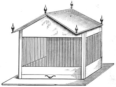
Fig. 14.
The previous chapters were devoted to such exceedingly simple and easy specimens of carpentry as can be made by any boy of eleven or twelve years of age, or even younger, who has the necessary perseverance, and will take sufficient care in measuring and fitting. In both and all similar cases, it is better for such to buy pieces of board already planed, and of nearly the desired size; but I shall no longer presuppose such necessity, but advance the young mechanic to the dignity of a plane, and a few more of the more necessary and useful tools. The list may therefore now comprise—
1 Hand Saw, 16 inches or so in length, a full-sized one being almost beyond the powers of a boy.
3 Firmer Chisels, quarter, half, and one inch wide.
1 Mallet.—Chisel handles should never be struck with a hammer, which splits the handles.
1 Hammer.—This should be light. The best way is to buy a hammer-head, and make the handle. A heavy one can be added, but will hardly be required at first, and is useless for light work.
1 Jack Plane, 1 Smoothing Do.—The jack plane is not usually added to a boy’s tool-chest, but it is impossible to plane up a long straight[30] edge without it; and as these planes can be had from 12 inches in length, I should certainly recommend one, say 12 to 15 inches.
3 Gimlets, 3 Bradawls.—One of each of these should be as small as can be obtained. Add a medium and a larger one.
1 Screwdriver, 1 Pincers, 1 Cutting Pliers.—Screwdriver should be of a medium size; the pliers such as are used by bellhangers.
1 Compasses.—These should be light carpenter’s compasses, not such as are made of brass and steel. They are very useful.
2 Gouges.—Carpenter’s gouges, not turner’s. They will answer for the present, in many cases, to make round holes in boards. The centrebits and braces are expensive.
1 Oil-stone.—There is a cheap and quick-cutting stone called Nova Scotia which will answer the purpose well.
Mortice-gauge.—The use of this will be shown presently.
1 Square, 1 2-Foot Rule, Glue Pot, and Brush.—These are, as before stated, indispensable. The rule need not have a brass slide; the square may be made entirely of wood, or with a metal blade 6 to 9 inches in length.
The above, with the addition of a carpenter’s brace and bit, two or three augers, about three mortice chisels, and a hatchet, would suffice for a very large amount of good work. Indeed, it represents almost a complete set of tools, the only additional ones that are at all likely to be needed being a longer (trying) plane, rebate plane, and pair of match, or tongue and groove planes. Without any of the latter, the young carpenter will find it easy to carry out a good many light specimens of his ingenuity.
It is much better, in general, to work with a few tools, and contrive to make them answer all sorts of purposes, than to lay in a larger and more expensive set at starting, for the latter are sure to be abused and kept in bad order, because if one chisel gets blunt, another is taken up, instead[31] of sharpening the first; and planes and other tools are treated in a similar manner, and a carelessness is engendered fatal to success. It is astonishing how much may be done with few and inefficient tools, but then the utmost patience and industry have to be exercised, much as we see prevailing among the native workmen of India and America, who execute the most beautiful and delicate work with tools which, in the hands of a European, would be generally simply useless.
The next work that should be attempted by the young mechanic should be mortice and tenon jointing, as used in constructing frames of various kinds for doors, window-sashes, tables, and other articles of everyday use. Perhaps one of the simplest and easiest examples will be a towel-horse, which, at any rate, will be of use when completed.
Now, it may be at once stated, that for work of this kind especially, but generally also for all work, it is essential to be able to square up truly the several pieces required. This will require practice—long and careful practice—and the beginner will meet here with his first and chief difficulty, but he must not despair.
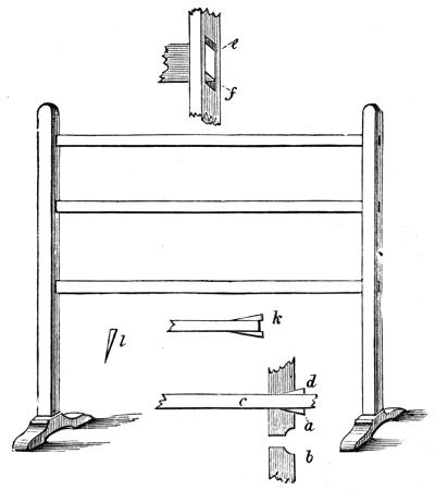
Fig. 15.
It has been presupposed that a strong work-bench, table-plank mounted upon trestles, or some sort of tolerably efficient and firm bench has been obtained, or is accessible, and, in addition, a strong stool upon which to saw, cut out mortices, and so forth. A small carpenter’s bench, with a[32] wooden vice, is most handy and serviceable, but is not absolutely necessary. It will be easy to make one by and by; for the present, any available substitute must be used. The height of the proposed towel-rail may equal the length. About 2 feet 6 inches will be a fair size, and it may be of the simplest possible form, such as is here delineated (Fig. 15). The upright sides may be made of strips of pine, one inch wide and three-quarters of an inch thick—the rails 1¼ wide and three eighths of an inch thick. The feet will be considered[33] presently. If careful attention is given to the following directions, not only will the result be certainly satisfactory, but the way will be paved for the workmanlike construction of a great number of similarly useful articles.
The size of the rough material must always be greater than that ultimately needed, to allow of the necessary waste in sawing and planing. Pine boards, however, are usually cut of certain general widths and thicknesses; and although we have here set down stuff of one inch by three-quarters, it may be cut from inch board, because very little will be wasted by the plane, and the finished work will be sufficiently near to the above measure for the intended purpose, one-sixteenth of an inch or so being of no practical importance in the construction of such an article as a towel-rail. Get, therefore, from the carpenter, a strip of pine 1 inch wide and 6 feet in length, cut from a board 1 inch thick, and also a strip for the rails (of which there will be three), 4 inches wide and 2 feet 9 inches long, cut from a half-inch board. The rails you are to saw yourself from the latter strip, which will give you practice in sawing a straight course, and the work is easy in half-inch stuff. You may therefore begin by cutting these, for which purpose you will want guide-lines dividing the strip into three of equal width. There is a very simple way of marking these by means of a chalk line, which I will here describe.
The width of the board I set down at 4 inches, because[34] the rails, when finished, will be 1¼ inches each, or, in all, 3¾ inches. As each contains eight eighths, as already explained, 4 inches will contain thirty-two eighths. Dividing by 3, we shall have ten eighths for each strip, or 1¼ inches, and two eighths, or a quarter of an inch, to spare for waste. Take the compasses, therefore, and open them to 1¼ and a little over (rather less than to the next division on the rule), and take it off at each end of the board (Fig 16, A B).
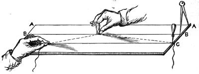
Fig. 16.
Take off, again, from this to mark the width of the next strip, and the board will be divided with sufficient accuracy for our present purpose. Take a piece of twine, long enough to stretch from end to end of the plank, and something over, and tie a knot at one end. Stick a bradawl through the string, close to this knot and into the board, as seen at C of the same figure. Take a lump of chalk, and chalk the line from end to end. Then strain it down the board, holding it by the left hand, so that it is stretched[35] from one mark to the other, where the saw-cut is to be made. With the finger and thumb of the other hand, raise it a little in the middle, and let it suddenly go, when it will make a perfectly clear and straight line upon the board. Make a similar and parallel line for the next saw-cut. In the present case, you need not mind cutting this chalk mark out. Try and saw right down, so as to split it.
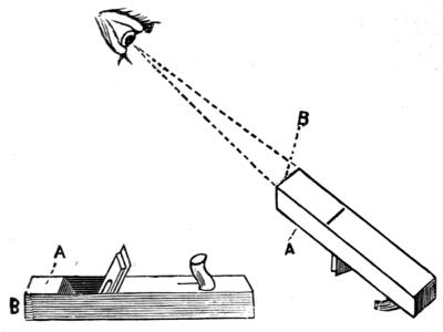
Fig. 17.
You now have your strips cut out, but they require to be planed. You might, indeed, with advantage, have planed the whole strip on both sides before marking and cutting it, but it is equally easy to do it afterwards. The jack plane is the one to be used for this purpose. I must suppose it to be sharp and in good order; if not, ask some carpenter to set it for you for the present, but I will soon tell you how to do it for yourself. Indeed, you will have[36] to learn how to sharpen all your tools before you can be called a good workman. If the plane is properly set, the cutting edge will project very slightly only from the bottom; so that when held as in Fig. 17, and the eye directed along the sole, only a narrow shining slip of metal will appear. If too far out, it will hitch and make bad work; if not far enough, it will not cut at all; but the common fault of beginners is to have it too far out, because from their imperfect handling of this tool they often fail to make it cut, when in the hands of a carpenter it would work well. Now, if the iron projects too far, hold it as shown, so that you look along the sole, and give it a tap with your wooden mallet on the upper face at A, and this is also the way to loosen the wedge and irons for removal. By a blow at B, you can send the cutting edge forward to cut more deeply, or in this case you may tap the iron itself with a metal hammer, but tapping the end of the wood is better.
To plane the edges of these strips, you ought to have a bench with a vice, but there are ways and means to do without it, and one is so good that I shall speak of it here, although it necessitates a somewhat abrupt break-off in my description of the towel-rail. It is a kind of vice that is fixed to a board which is laid upon the work-bench when required.
Fig. 18.
In Fig. 18 is a drawing of one of two kinds of such vices[37] which I will explain. This first consists of two pieces of wood (ash will be better than pine) about 9 inches long and 2 inches thick. They are cut in the shape given in the drawing, and screwed to the board, not tightly, but so as to move freely upon the screws. The board should be an inch thick to give the screws a firm hold. You can see by the figure that the tails of the pieces cross each other sometimes when in use. To allow of this, they are cut like B and C, so that one can go inside the other. Now, if you consider a little, you will understand that if we stand a strip of board between the two, and push it forward against the insides of the tails of these curiously-shaped blocks, it will make the opposite knobbed ends close nearer together, and these will grip the piece of wood, and the harder we[38] push it forward, the more closely it will be gripped and held; but the moment we draw back the piece, the two jaws will open to let it go free. You can try first of all upon a thin piece, which can be shaped by your knife, and make a model of this vice, and then if you can’t manage to cut out such a one of thick wood, the carpenter would do it for you, and it will be handy for many purposes. If you have nothing of this kind, nor a vice to your bench, drive in two pins or pegs of wood, or two nails, a little way apart, so as to allow your strip of wood to stand upon edge between them, and drive two more a little way from these; then one at the end to form a planing stop. A tap at the sides of these nails will cause them to hold the strip edgewise, quite well enough to allow you to plane it. There[39] are other ways, and I shall describe them by and by. In the meantime use nails, or any other plan that will answer.
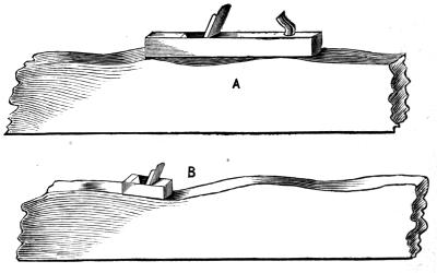
Fig. 19.
Fig. 20.
I shall suppose, therefore, that one of the narrow strips is thus set on edge upon your bench ready to be planed. Grasp the handle of your plane firmly with the right hand, and lay hold of it in front of the iron with the left. Draw it back, and then send it steadily forward, pressing it downwards at the same time. Now the advantage of a long plane is, that it does not descend into the hollows of the work, but rests upon the projections, as in Fig. 19, A. A short plane would do as seen at B, and therefore would never make a long straight edge. You have two special points here to attend to. You have to plane a level line from end to end, and also keep the edges square to the sides, which is by no means easy at first. You must keep trying it with your square, as I have shown you in Fig. 20, and not rest satisfied until the handle fits close to the side of the strip, and the edge lies also close upon that of the strip anywhere along its length. I daresay you will think this of no importance in such a common thing as a pine[40] towel-horse; but I may tell you this is the very secret of carpenter’s work, and when you can saw and plane truly, and work “to square,” you can make almost anything. It is true that the strips for the rails are not of great importance in this case, but the upright side pieces are, and if these are out of truth, the holes cut through them for the rails, which are called mortices, will be out of truth also, and you will see the towel-horse, when it is made, all twisted and awry, and nothing you can do will make it stand firm or look well. It is, in short, no use to pretend to learn carpentry unless you at once make up your mind to succeed, and therefore you must always use the square and try your work as you go on. All the difference between the usual work of carpenters, and that of boys or men who do not know how to work, consists of the squareness and good fit of what the former make. Boys never seem to trouble themselves about such things, and so you see their boxes and rabbit-hutches look twisted, and being badly fitted, they soon go to pieces.
Having planed up the sides and edges of the rails as square and true as you can, cut the other long strip in half, and square up this also, taking care that both pieces are alike and both truly worked. If your bench is sufficiently long to take the whole strip, plane it up before you cut it across, and you will be sure to have the sides of your towel-rail equal in size. You have now to make your first essay[41] in cutting mortices. Follow these directions, and you will not fail. I shall not limit the description to these special mortices, but give you general directions.
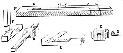
Fig. 21.
Fig. 21 represents a bar of wood—the side of the towel-horse, for instance—with a mortice cut through it at A, and others marked out at ab, cd. Below, at B, is a gauge, of which the construction and use will be explained presently. F shows how the feet are to be attached and cut. They are morticed while in a “squared-up” condition, and shaped afterwards according to fancy; sometimes they are left square, and knobs screwed below to make two feet.
These mortices may, of course, be of any desired length or width. Those required for the towel-rail sides will be 1¼ inch long by half an inch wide nearly. The planing of the strips may have reduced them more or less below the exact size specified, try therefore with the compasses what the precise thickness is of the ends, and measure that[42] thickness on your two-foot rule. You now want to draw the lines a t, which I have represented as extending the whole length of the strip, and as all the mortices are to be alike, you may so mark them. The gauge B is of two parts, a sliding piece, C, and a rectangular bar of wood about 9 inches long and half an inch square. This slides stiffly through the mortice in C, and is fixed at any part by the small wedge D. This gauge you can easily make. It is not a mortice gauge properly so called, because the latter has two marking points instead of the one seen at h, and which may be the point of a brad driven in and filed up to an edge. Loosen the wedge slightly, and draw back the rectangular bar, or push it forward, until you think that the space between the sliding piece and the point is about that which is required on each side of the mortices, so that if you set the wedge firm, and resting the sliding piece against the edge of the board, cause the point to make a mark, and repeat this on the other side of the same face of the wood, there will be left between the marks thus made the exact width of the required mortice. Try it, and if not, give a tap to the instrument, and adjust it until the space is exactly correct. Then fix all firm, and holding it so that the little point will mark the wood, while the head or sliding piece is against the side of the board, run the tool from end to end, or run it along just where the mortices are required, using both hands. You will thus make the two[43] long lines between which the mortices have to be cut. Now turn the wood over, and do the same on the other side. You are now quite sure that these lines, on opposite sides of the piece, agree exactly in position, which is the object of using a gauge; and as you have planed up a second strip to exactly the size of this first, you have but to repeat the process (no measuring being necessary) upon that; and you may be satisfied that thus far the two sides of the towel-rail will tally. You now set off with the compasses upon one of these lines the lengths of the mortices in their proper places, and at the points thus marked, using your square for the purpose, mark the end lines of these mortices; but when so doing, carry the lines across, as a b, c d, and down the sides and across the opposite side. With the square this will be easily done, the blade of it being laid flat, so that its edge becomes the ruler, while the handle becomes the guide or gauge resting against the side of the wood. At E, Fig. 21, this position of the square is shown.
By thus carrying round all the lines, you will have the mortices marked on both sides in exactly the same relative position, so that you can (and must) cut them half from one side and half from the other, using the chisel nearest to the size required, but always of less width (or length) than the mortice, because you must never cut out the guide lines, but must keep within them, only carefully paring[44] the wood at last close to them. You will never cut mortices correctly, unless you thus mark the position on both sides, and work as directed.
The ends of the cross rails will not have to be cut into tenons, as they will fit as they are, only requiring to be glued into their places, when, if you have worked carefully, the whole will look well, and will be square and true, without twist; but if you did not plane up the sides square, you will find the towel-rail awry and unworkmanlike. Although, however, there is no necessity to make regular tenons in the present case, the usual way is to do so, and to fix with wedges, as in Fig. 15. After a mortice has been cut straight through a piece as directed, this mortice is slightly eased, or sloped off, as seen at a b, which is a section of one. The rail or tenon c is put through after being brushed with glue; and when in exact position, two wedges are glued and driven in at each end, as seen in the drawing. After all is dry, these wedges being firmly united to the rail, as seen at k, prevent it from being drawn back or moved. Nearly all mortice and tenon joints are fixed in this way.
As I am describing this kind of work, I may as well explain the method of marking and cutting tenons, as it will answer not only for affixing the feet, as shown in Fig. 21, but for all similar work.
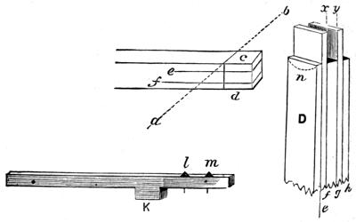
Fig. 22.
In Fig. 22, I have illustrated the mode of marking out[45] tenons, and at D is a double tenon, which is in wide pieces often substituted for the single, and makes an excellent joint. The longitudinal lines e, f, g, h, are marked as before with the gauge, whether for single or double tenons; the line a b, with the assistance of the square; the cheeks, c and d, are then cut off entirely with a fine saw, called on this account a tenon-saw,—and care must be taken as before not to cut out the guide lines. If, instead of the outer cheeks, the piece between them is to be removed to make a double tenon, this must be done with mallet and chisel, after carefully sawing down the lines x y; and the chisel is to be used first on one side and then on the other, by which means the shoulder will be cut true to the guide lines. If, however, the cut across should curve a little downwards like n, it will not much matter, so long as the edges fit closely. It is nevertheless better to cut straight across.[46] The outer cheeks of this will be marked and cut as in the single mortice (Fig. 22).
If a workman has to cut many mortices on pieces of the same size, he frequently constructs a rough mortice gauge with double points, which marks both sides of the mortice at once, like K. A fixed block at K, the right distance from the points, l m, of two nails, is sufficient when all the mortices are to be alike. There is, however, a regular double-pointed gauge, made generally of ebony, plated with brass, and a brass rule to which one of the points is fixed, and which is acted on by a screw at the end, which can be turned by the thumb and finger. This has the effect of separating or closing the two points according to the desired width of the mortice, its distance from the side of the piece being regulated as before by the sliding head fixed by a wedge. This is an expensive tool, and need not be purchased. There are also, let me add, many costly tools of various forms and uses; but let the boy’s motto (and man’s, too, for all that) be, “Do as well as you can without.” You have no idea how a little ingenuity and contrivance will save your pockets, and that, too, without in the least tending to spoil your work. All you require are a few of the most generally useful tools in first-rate condition—chisels, saws, and planes, sharp and well set, and fit for work at any moment.
With regard to uniting two pieces of wood or other[47] material with glue, it must be remembered that if you use this substance in a thick semifluid state, and in quantity, its effect will be lost. Make it a rule to put on as thin a coat as possible, and let it be not thicker than cream, so that it will freely flow into corners, and spread evenly over the surfaces to be united. Make the wood also quite warm, so that the glue shall not be suddenly chilled, and let it be used boiling. Always heat it either in a proper glue-pot, or at any rate, place the vessel which contains it (a small gallipot, for instance) inside another vessel in which water can be kept boiling.
The glue, which should be thin and transparent, being broken into small pieces, should be put into such a vessel as suggested, and covered with cold water, and it should be allowed to remain thus until swollen and softened. Then bring the water in the outer vessel to the boiling point, and do not use the glue until it is entirely dissolved and of one uniform consistence. It should be stirred while boiling with a piece of stick, and a brush used to lay it upon the pieces to be joined. It very generally happens that pieces glued by boys fall apart almost directly. This is almost entirely due to the fact that the glue is used thick and clotty, and in too great quantity, while the wood is never made warm as it should be. If two pieces are properly joined in this way, it is almost impossible to separate them at the joint—the wood itself will give way and split[48] before the glue will yield to the strain. Carpenters use various forms of clamps or vices to hold work together until the glue shall be dry; but for boys by far the best plan, where any such holdfast is needed, is to bind the parts together with twine, and then to set them aside for twelve hours at least. It is seldom that articles once united by glue and separated will unite firmly a second time.

The exercise of a boy’s mechanical tastes upon works of practical utility is, of course, far preferable to its expenditure upon mere trifles, made one day to be cast aside and destroyed the next; and as there is scarcely any household that does not need its furniture repaired or added to from time to time, I shall now give directions for the construction of one or two articles that seem to be within fair scope of a young mechanic’s abilities. The first is a plain, useful table, without a drawer, and with square legs, because without a lathe the latter cannot be made ornamental; and lathe work will occupy some future pages, since it is necessary first to give the young mechanic a fair insight into the principles and practice of plain carpentry and joinery.
The very young mechanic, so far as my experience of him goes (and it is rather extensive), makes his early attempt by sticking the points of four nails into the corners of any tolerably square piece of board he can lay hands[50] on. His next attempt, when he has risen to the dignity of a knife and gimlet, is to place four wooden legs at the corners of a similar board, which, if the said legs are glued in (by which a wonderful mess is always made of the structure), is considered a great feat, and worthy of the admiring patronage of fond parents and playmates. Now, a table does not consist of any such arrangement of pieces, although I certainly have seen sometimes, in the cottages of the poor, a three-legged affair of this nature, which is just nothing more than a magnified milking-stool. We cannot content ourselves now with anything of the kind. We shall have to work away with plane and chisel and square, and with neat tenon and mortice joints first construct the frame upon which the top will be placed, and then finish it secundum artem, the English of which, as I am writing to boys, I shall not reveal.
The table shall be 3 feet long, 1 foot 8 inches wide, 2 feet 4 inches high; the top board being half an inch thick when planed and fitted, for which it will therefore be required to be three-quarters of an inch in the rough. The legs demand attention first. Plane up strips cut from a 2-inch board, and let them be exactly 2 inches wide. These must be worked up with the greatest possible accuracy, or it will be impossible to fit the framework so as to make the table stand truly or bear inspection. After four such strips have been planed up, cut a piece from a half-inch board, or[51] from a board that will plane to half an inch. Let this be 4 inches wide and 9 feet long, and be sure to plane this also truly, and to make the edges square to the sides.
Fig. 23.
If you have no strip that will answer of 9 feet long, you can cut two or more instead, remembering that you will require two pieces each 18 inches long and two of 2 feet 9 at the least, all as nearly alike in width as possible. You have now all that you will need for the framework of your table—the top may be left till the rest is fitted. Now you may proceed to cut the requisite mortices in the legs, which you will understand by sketch Fig. 23, which represents one corner of the table before the top is added. There is[52] no more difficulty in this than in the previous work, except perhaps that somewhat more care is requisite in squaring up the several pieces and cutting the mortices with accuracy. Use the gauge as before in marking the mortices, trying it until it is so fixed that it will leave the proper width of the holes, namely, half an inch (which is the thickness of the strips which are to form the framework). This is upon the supposition that your gauge has but one marking point: but to explain its use.
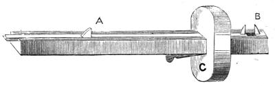
Fig. 24.
I shall now introduce to your notice a regular mortice-gauge of two points, which is vastly more convenient. This is represented in Fig. 24. The main stem is grooved along its length on one side with a dovetailed slit, that is, a groove which is wider below than above. This is generally made in a brass plate attached to the stem of the gauge, but sometimes in the wood itself. In this slides a slip of brass which can be drawn back by pulling the knob A, or by turning a thumbscrew at one end, as in the more expensive gauges. One of the marking points is fixed in the end of this slide, the other in the wood (or metal) beyond it, at[53] B, and when these are allowed to be together they form but one point, being flattened on one side, so that they will fit accurately against each other. Thus it is easy to separate the two points at pleasure to the exact width of the required mortice. By means of the wedged sliding piece C, we now have merely to determine how far the edge of the mortice is to be from one side of the piece. Thus, suppose that in the present case we should prefer to have the side of the frame nearer to the outside edge of the legs than to the inside, we can so arrange it easily; but we must then take care to gauge all alike, either from the inside edge or the outside. We do not, therefore, with this kind of gauge work from both edges, and leave the space between the lines for the width of the mortice, but we work from one edge only of the piece of wood, and mark the mortice at once in any desired position. I need hardly repeat, that for any particular job, a very good substitute for such gauge can be made by driving two small nails into a strip of wood cut with a projecting piece to serve instead of the movable head.
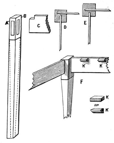
Fig. 25.
Let us now proceed with the work in hand. One of the legs of the table, before being worked into shape, is shown in Fig. 25; the dotted lines show how it will be eventually sloped off below the mortices which carry the top frame. These mortices must not now go through the legs, and therefore you will have to be very careful to hold the chisel[54] upright, so as to insure the squareness of the frame when put together. The mortices being in adjacent sides, will of course meet, but it will be advantageous to cut those which are intended to receive the two longest strips, viz., the front and back, rather deeper than the other two. First set off an inch from the top of the leg at the line A B. If less than this intervenes between the top of the mortice and the end of the leg, you will probably break the piece out and spoil your work. As the side boards are 4 inches[55] wide, and must come flush with the top of the legs, you will have to cut them like C, and there will be 3 inches left for the tenon, all of which may be left, as the wider this is the more hold it will have on the legs into which it is to be glued. It is plain, therefore, that the mortice will be 3 inches long and half an inch wide; and when you have marked it to this size, take care to cut it accurately, because if it is too small, you will break out the piece between the mortices when you try to force in the frame pieces, and if too large, you will scarcely get the whole to remain secure. Work therefore exactly to gauge. It is usual to keep these side and end pieces more to the outside of the legs than the inside, as F, where you are supposed to be looking at the inside corner; and if you look at D (which shows the top or cross section of a leg, as if after the pieces were fitted you had sawn off the leg close down to the mortices, exposing them to view), you will see that by thus keeping near the outside edges you get both mortices deeper than if you cut them, like E, in the middle of the sides of the leg. Of course, the deeper these tenons are let into the legs, the stronger their hold will be. There will now only remain to warm all the pieces and glue them into their respective places, with the precautions before stated as to the thinness of the glue and speed of the operation. See that all stands square and true; if not, a tap here and there as required will set it straight, and then let all stand till dry.
I have told you to cut the side and end pieces 18 inches and 2 feet 9 respectively, so that if the mortices are 1½ inches or so deep, your frame will be about 1 foot 6 inches wide, and 2 feet 6 inches long. The top, which is to overlap as usual, will be now prepared as follows. It will not be possible to make this of a single width of board; and nothing will more fully test the young workman’s skill, than planing the edges of two pieces so that they shall fit accurately together. It must, nevertheless, be attempted.
Cut two pieces of three-quarter-inch board, and plane the sides as accurately as possible. Then set them up edgewise, either singly or together, and plane the edges with steady, long strokes of the longest plane you have, set fine—that is, with the cutting edge projecting but slightly. Try each singly with the square from end to end, and then lay them on any perfectly flat surface, as on your bench, or on a table, and see whether the edges lie close all along. Remember, too, that they may do so when one surface is upwards, and not when turned over, as will occur when the edges are not square to the sides. In cutting out the pieces, therefore,—which, when finished, are to be together 1 foot 8 inches,—you should make them 1 foot 9, so as to allow you a whole inch to waste in planing and fitting. When both are as true as you can get them, lay them down near together, and brush the edges with boiling hot glue. Then immediately put them together,[57] and rub them a few seconds one against the other, till they seem to stick slightly. Then leave them in their exact position, and drive a couple of nails into the bench against the outside edges, so as to keep them together, or in any other way wedge them tightly in position until they are quite dry. When the glue is hard which has been squeezed out along the joint, you may run a plane all over the united boards, and you ought hardly to see the joint, which will be nearly as strong as any other part.
This top has now to be attached to the frame, as follows. Cut some pieces like K in Fig. 25, and glue them here and there along the inside edges of the frame, so that one side of them shall come quite flush with the upper edge. To these the top has to be glued. Lay it, therefore, with its under side upwards, upon the floor (I suppose the short pieces glued and dry on the frame), and having also glued the sides of the short pieces which will touch the under side of the table top, turn the whole upside down, with its legs in the air, adjusting it quickly. Its own weight will keep it in position until dry; or, if not, it is easy to lay an odd board or two across, and put some weights upon them. When dry, turn over your table, and plane round the edges where necessary; and, if it does not stand very well, trim the bottoms of the legs. Clean off glue, and rub any rough places with sandpaper or glasscloth, filling up any accidental holes with putty, after which it will be fit for receiving[58] paint or stain, if it is not considered desirable to leave it white. The corners and edges of the top may be rounded off, to give a finished appearance.
I showed by dotted lines the usual shape of the squared legs. They are planed off, tapering from below the frame, and this should be done after the mortices are cut, and before fitting the parts together. The best way to insure equal taper of all the legs, is to prick off at the bottom of each equal widths from the corners or edges, and to run a pencil line from the point where the taper is to begin to these marks. Then plane exactly to the lines thus made.
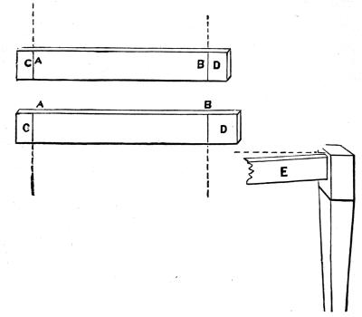
Fig. 26.
Let us now consider what errors of construction are most likely to occur in working out these directions. First, it is possible that the framework may be out of square. This may proceed from two causes. In the first place, the side or end pieces may not be of equal length between the legs, owing to some one or two being driven further into their mortices than the others. To avoid this, which is not uncommon in many works of a similar nature, it is well always to mark the length that each is to be, irrespective of the part within the mortices, as Fig. 26, A and B. If the space on each between the dotted lines (carefully marked by means of a square) is equal, it is no matter whether C and D are also equal. We have only to take care to let them into the mortices to a greater or less depth, until the line comes exactly even with the inside edge of[59] the legs. Again, it is possible that when the table is placed upon its legs, these may not rest truly on the floor. Probably one or two of the frame pieces run up like E, instead of standing at right angles to the legs. This results from the mortice not being cut correctly; and as you cannot, in this case, mark both sides and cut from both, as you did in making the towel-horse, this is not unlikely to happen. It will not, therefore, signify much if you purposely cut your mortices a little too long, and then, when you have placed the table on its legs, after gluing up the frame, and before it is dry, you can force it to stand[60] truly, and then wedge up with glued wedges where necessary. You cannot, however, do this with the sides of your mortices, because you require these to fit exactly; you must therefore use extra care in keeping these as true as possible. In many cases you can wedge the ends of tenons to correct a bad fit, but never the sides. These are the probable, or I will say possible, faults against which to be on your guard.
Fig. 27.
In making a similar table with a drawer, the same operations have to be gone through, but the upper frame is somewhat differently constructed, and the corners of the drawer are united with dovetails. Plane up the legs as before,[61] but cut mortices as at A. Fig. 27, which represents the right-hand hinder leg as you would see it standing in front of the table, and before the framework had been fitted in its place. B is the other hind leg, with the tenoned strips just ready to be driven in. The piece E is made as before, as is also C and its opposite piece at the ends of the table. But this pair of mortices, you see, are made shorter than before, and the strip C is notched at the bottom as well as at the top, forming a regular tenon, as it is called. Below this first is a second mortice, cut the other way, the longest side standing across the leg to receive a strip, D, upon which afterwards another strip, X, will be nailed or glued, forming the rebate in which the drawer will slide, and of which the upper surface must be level with that of the strip M. There is a plane for cutting out rebates without the necessity of adding a strip, but I do not suppose you as yet to have such a one. When these pieces, C and D, are driven up close into their places, they will touch along their sides, so that on the outside they will appear as one piece. Of course there will be a similar pair on the right-hand side of the table. D ought to be tenoned, so that the side on which X is to be nailed will lie flush or level with the corner of the leg, so that the strip X shall project wholly beyond it.
The left-hand front leg is shown at P, with its mortices, and the tenoned strips between which the front of the[62] drawer will lie, closely fitting when shut. These front strips should be each 2 inches wide, the mortices 1 inch long, or as long as you can safely cut them; you must tenon the cross pieces, of course, to fit these.
All the rails may be of half-inch board. Mark all tenons across with the square as before, so as to give the exact inside dimensions, and you cannot well go wrong. These lines, too, will guide you in keeping the framework square and true; for if you have planed the legs correctly, and your strips are inserted exactly to the aforesaid lines, it stands to reason the work will be satisfactory. To make the drawer, observe, first, that it is not like a box as most boys would make it, for when turned upside down, as in Fig. 28, Fig. B, you will find the sides projecting beyond the bottom, which projections rest in the rebate, X, of the last figure, and take the whole weight of the drawer, enabling it to slide easily and smoothly in and out, especially if those surfaces which are in contact are rubbed with soap or blacklead, or a mixture of the two. At C you have a drawing of the same, with the bottom removed. This, you see, is a square or oblong frame dovetailed together, and when it is glued and dry, the bottom is slid in along the grooves in the sides (one of which is seen at x x), and a couple of brads driven through it into the back rail, K, fixes it completely. The front board of the drawer is cut and planed to fit exactly between the two rails which were[63] morticed into the legs, as shown in the last fig., and is always of thicker stuff than the sides or bottom. It may, in the present case, be half-inch, and the rest quarter-inch.
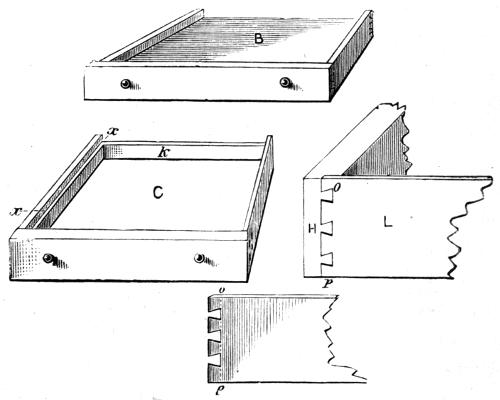
Fig. 28.
If you look at C, you will observe that the front and sides of the drawer are of the same depth, and that only the back is narrower. (Remember that in this cut the drawer is seen from below, the groove x x being near the bottom of the sides, and level with the bottom of the back.)
To cut dovetails is not difficult, but requires neatness and care—a fine saw (dovetail or light tenon-saw) and a really sharp chisel; and, above all things, remember not[64] to cut out the lines which have been drawn as guides. H is the end of the front of the drawer; L the left side. Having cut out the latter, and planed it up nicely, draw a line, by the aid of the square, one quarter or three eighths of an inch from the end across it. This will be the line o p of the bottom of the dovetails. Then mark and cut out two or three, as seen in the drawing, using the saw where you are able, and clearing out with the chisel in other places. From o p, measure the exact inside width of your drawer, and beyond the second line made across at that distance, leave a quarter of an inch for the second dovetails, and cut them out as you did the first. Now, prepare a second precisely similar piece for the opposite side. Next lay L in place upon H very truly, and with a fine-pointed hard pencil, or a scriber (a sharp-pointed steel marker), trace round the dovetails, marking them on the end of H, and with a sharp chisel cut them in a quarter of an inch deep, which will allow them to take the side piece exactly flush and level. Mark these two which have been so fitted, and proceed to do the same at the other end of the front piece, tracing these, as before, from the dovetails of the opposite side, which are to be there inserted. You do exactly the same with the back piece; but as this is both narrower and thinner, the dovetails will be cut quite through it, and will be seen on both pieces after being glued up, and there will only be room for one dovetail, instead of two. When all are cut, lay the[65] pieces in position, glue quickly, press all together, and contrive to wedge up or bind round the whole until dry, testing with the square and adjusting, as maybe necessary. We shall return to dovetailing again, but these not requiring excessive neatness, will be a good beginning, and show you in what special points care is needed in such work. Nothing remains but to plane a piece for the bottom, and slide it into place.
In the last chapter we entered a little upon the matter of dovetails, but as the mode of uniting the angles of boxes, drawers, and such like, is of almost universal application, it will be as well to devote a separate short chapter to the subject.
There are several different kinds of dovetails used, according as it may be desired to let them appear upon the finished work, or wholly or in part to conceal them. Carpenters generally use the kind which is visible on both sides, cabinetmakers, as a rule, take special pains to conceal it, only using the other form upon work that is to be afterwards covered with veneer (a thin covering of some ornamental and more expensive wood glued upon the surface of that which is of less value, and of which the article is made).
The dovetail described in the last chapter, as proper for the attachment of the sides to the front of a drawer, is not that which is ordinarily used by the carpenters, but the[67] following, which is somewhat more easy to make, and is the same as would be used for the other corners of such a common drawer as that described.
I must at the outset remind my young readers once again of the standard rule, without due attention to which they have no hope of success in this neat and delicate operation of carpentry. Never cut out your guide lines, but leave them upon your work, and use your square diligently upon the edges of your work, the bottom of the dovetails, sides of the same, and upon the sides of the pins. Never mind the time necessary for this. You are doing work, remember, that is to bear inspection,—work that will stand wear, and be really useful in the household to which you have the honour to belong. You would not therefore like to see open spaces here and there, requiring to be filled up with putty, or the side of the box not truly square to the back and front. And it may be noted here, that if dovetails are properly fitted together, the box or other article will stand firm, even before the glue is added; but if the same are badly cut, and put together carelessly, no amount of glue will avail to hold the work securely; and it would have been as well or better never to have attempted dovetailing, as such bad work would be stronger united by nails, and in any case is but a disgrace to the young amateur mechanic, whose motto should always be, “Whatever is worth doing at all is worth doing well.”
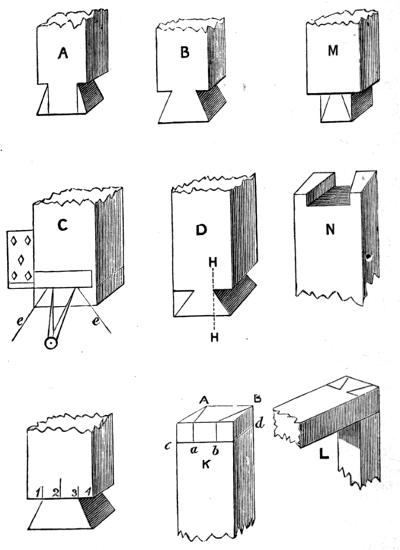
Fig. 29.
You will remember how you were taught to wedge up mortice and tenon joints with glued wedges, which, becoming part of the tenon, and rendering it larger below than above, prevents it from being withdrawn from the mortice. Now, a single dovetail has the same effect, and is in point of fact of the same shape and size as the tenon with its[69] wedges attached. See Fig. 29, A and B, the first being a wedged tenon, the second a dovetail.
We shall begin with a single dovetail, which is applied to the construction of presses used by bookbinders and others, and also domestically for house-linen. In these there is a strong tendency to draw the sides upwards, and to tear them from the bottom—a strain which this form of joint is exactly calculated to withstand. The same is also used in making many kinds of frames, where similar strength in one direction is necessary. If you have no special need of such at present, you should nevertheless make one or two for practice, and to give you a better insight into their construction. Indeed, if you cannot make single dovetails well, you will hardly succeed in making a whole row of them exactly alike, for joining together other articles, as drawers, boxes, and cabinets. C of this fig. represents a bar of wood truly squared up, and ready for being marked out. The square is laid across it as seen, and a line drawn on each side by its assistance, as far from one end as is the thickness of the other piece to which it is to be attached, and a little over (say one-eighth of an inch) which will afterwards be neatly planed off. This is allowed merely because the extreme angles at e e sometimes get damaged in cutting out the dovetail, and if they are, they will have to be removed. Having drawn the above line all round the piece, divide it into three by the aid of your compasses, as[70] shown, on what we may call the front and back, and then on both these sides draw lines, e e, to the angle. You now have the dovetail, or rather the pin of the dovetail, marked, and with a fine saw you have only to cut out this piece as you see at D, taking great care to cut accurately close to the lines, but to leave them, nevertheless, on the edge of the piece you are about to use.
If you can saw truly, you should not have to touch these pieces with a chisel, but if not, you must take a very sharp one, and pare the wood exactly true to the lines which you have marked. Now the dovetail made by dividing the width of the stuff into three, as given here, will not answer so well for pine, which is liable to split off in the line H H of the fig. D; but for ash, beech, elm, and such like, it is a good proportion. If the material, therefore, is pine, divide it into four instead of three, as seen at E, and draw lines to the angles from the two outer marks; or, without any such division, set out equal distances from each side, so as to give about this proportion to the pieces which are to be cut out.
Where there are a row of dovetails to be made (as in cabinet work), even this latter measurement into four would make them too angular, as you will learn presently. You must now fix upright in your vice the piece in which is to be cut the dovetail to receive this pin; and laying the latter in place as it will be when the frame or other work is put[71] together, draw round it with a sharp pencil or scriber, as seen on the end of K (the lines c d, at such distance from the end of the piece as is the thickness of the pin, and the perpendiculars, a b, are to be drawn with the square); and if the angles of such pin do not reach the angles of that in which the dovetail is to be cut, as will often be the case, the lines on the opposite side similar to a b must be also drawn with the square. So you see that I was quite right in directing you to add a square to your box of tools, even before many other requisites of carpentry.
If it is not considered desirable that the dovetail should reach the extreme angles of the pieces, as a b, fig. K, the pin piece is first marked as if for an ordinary tenon, and the dovetailed pin marked on this, as M. When the fellow-piece is cut out, it will then appear as N. The effect will be the same as the last, except that the end of the pin will be more conspicuous. A great deal depends upon the material, and on the intended use of the finished article, therefore you must use your own judgment, or consult that of others better acquainted with the art than yourself. L shows the dovetailed joint complete as last described.
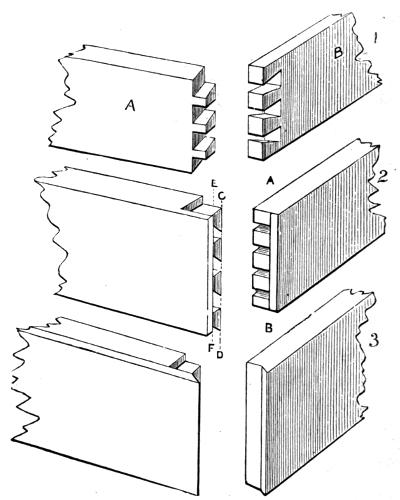
Fig. 30.
We now recur to the row of dovetails and pins—or dovetails and sockets, as the part is often called which is to receive the pins. The most common kind is that represented by A B, Fig. 30; and as you ought now to be thinking of a larger[72] tool-box, and would not like it roughly nailed together like the first, you might try your skill by constructing one more worthy of the name, and with a drawer or two in it. You must begin, as before, by marking the two lines across your work by the edge of the square, or, if you prefer it, by your gauge, which, when set to the thickness of one piece, will mark the others correctly; and remember to mark both[73] sides. Then set out your dovetails, but do not make them so angular as you did the single one; for remember you have a whole row of them to assist in holding the work together, and when glued, this will be of necessity a very strong and reliable joint, if well made.
Always make the pins before the sockets, and mark round them as closely as possible, and take great care when sawing not to break them, and if possible keep their angles also very sharp and clean. It is solely care in these particulars, and accurate cutting just to the gauge lines and no further, that makes carpenters’ work generally so superior to that of amateurs, and boys especially are generally careless, and in too great a hurry to get the work done, that they may go to something else. Remember, therefore, that when you begin to hurry your work, you begin to spoil it.
I have made the drawings of the three principal dovetailed joints so plain as to render special description almost unnecessary after the remarks already made. The second and third, however, may need a few words, as they differ slightly from that used in the drawer, of which a description has been given, chiefly because the piece in which the dovetails are, is, in this case, as thick as that used for the sockets.
Suppose the dovetails and pins marked out ready to be cut. Take your marking-gauge and set the slide about a quarter of an inch from the point, and run a line across the[74] ends of the two pieces at A B, and at C D, and also at E F. Stop at A B when you cut the sockets, and take care to get the bottoms of these quite square and even. Cut the dovetails or pins as directed in making the drawer, but stop on the lines e f and g h (the latter also to be made with the gauge on both edges of the work), thus the two pieces will, of necessity, fit nicely together, and only a single line will appear a little way from one corner. If all lines are made with gauge and square, this form of dovetail may require neatness and care, but will not be beyond the skill even of a young mechanic. I should indeed advise that every opportunity be taken of joining pieces of wood with tenon or with dovetail, because, after all, these are the chief difficulties to be encountered. If you can square up your work, and make true-fitting joints, there is little in carpentry and joinery that you cannot accomplish.
The third example is worked exactly like the second, but instead of leaving square the pieces projecting beyond the dovetails and pins, these are sloped off or bevelled carefully from the extreme corners down to the pins and sockets. The result is, that when put together, no joint appears, as it is exactly upon the angle. There is no neater or stronger method than this of joining the sides of drawers, boxes, trays, and such like articles. The cabinetmaker employs no other for heavy work; only when it is very light does he make use of a plan, the appearance of which is (when[75] finished) like the last-described, but it is less trouble to make, and less strong, yet sufficiently so for many purposes. This method is called mitring, and is accomplished in the following way.
The wood (let it be for a small tray) is prepared as usual, truly and evenly, and the ends exactly square to the sides. If you use stuff about a quarter or half an inch thick, or even an eighth (the first or last being suitable for such light work), you can make a mitred joint with the help of the gauge alone, but frequently a mitre-board or mitre-box is used, which saves some trouble in measuring and marking. It is well, however, that you should begin with this trouble, and take up the easier method afterwards; especially as it will in this case give you a simple lesson in mathematics, and teach you some of the properties of the figure called a square. Let us commence with this lesson.
A, B, C, D, Fig. 31, is a square; the lines at the opposite sides are parallel,—that is, they are exactly the same distance apart from one end to the other. To make this clear, E and F are given, which are not parallel, for they are further apart at one end than they are at the other. And as A B is parallel to C D, and A C parallel to B D, so A B is perpendicular to B D and to A C, or what we have called square to it, as you would find with your square, which is made, as you know, to prove your work in this respect. The consequence is, that the angles[76] (or corners) are all alike, and are called right angles. Understand what is meant by angles being the same size or alike. M and H are alike, though the lines of one are a great deal longer than those of the other; but though the lines of K and H are the same length, the angle K is much smaller than that at H.
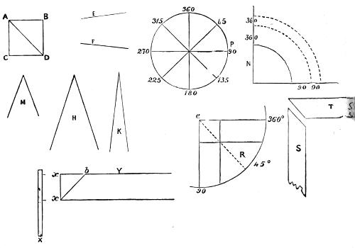
Fig. 31.
As I have gone a little into this subject, I will go a little further, for it is as well that you should learn all about the sizes of angles, and I only know of one way in which to make the matter clear.
Every circle, no matter how small or large, is supposed to be divided into 360 equal parts, called degrees. That large circle which forms the circumference of the earth is considered to be so divided. Now, if we draw lines from all these divisions to the centre, they will meet there, and form a number of equal angles. I have not divided the circle P all round, because it would make so many angles that you could not see them clearly; but I have put 360 at the top, and then 45, which means, that if I had marked all the divisions, there would be 45 up to that point. Then at 45 more I have marked 90, and so on, marking each 45th division, and from these I have drawn lines to the centre of the circle. Now, if you understand me so far, we shall get on famously. Look at the line from 360 to the centre, and that from 90°, and see where they join. This is a right angle, and this is the angle at each corner of a square. At N, I have drawn this separately to make it clear, and you see I have taken a quarter of the circle, or the quadrant, as it is called, of 90°. And you now see that I might extend the lines beyond the circle to any extent, but it would make no difference,—we should still have 90° of a circle, only the circle would be larger, as those which are partly drawn with the dotted lines.
Now, all angles are thus measured by the divisions of a circle; the line at 45, which meets the line from 360 at the centre, makes with it an angle of 45°, which is half a[78] right angle. A line drawn at 30° would make an angle of 30 with the same line from 360, and so on right round; only when two lines come exactly opposite one another, as 360 and 180, or 270 and 90, these make no angles—they are but one straight line passing through the centre, and are called diameters of the circle, a word which means measure through, or across the circle. Now, the corners of a square frame, or of a drawer or box, are right angles of 90°. At R, I have drawn such a corner of a frame, and if I place one point of a pair of compasses at e, and draw a circle cutting through the lines of the sides of the frame, you see I should make it 90°, or a quadrant, like N. Moreover, if I draw the sides of the frame as if they crossed as at e R, I draw a small square, and the line e R is the diagonal of such square: e R is the mitred joint I have to cut. Look at T S and you will see this, as here the two sides of the frame are represented as cut ready to be joined together.
A square has another quality: all its sides are equal, and this is very important, and will help us in cutting out the work. x Y represents the strip of wood to be properly sloped off for a mitred joint. With a gauge such as that just above x, or your regular marking gauge, set off on the side Y a distance equal to x x (the width of the pieces); join x b by a line, and you will have the right slope. Why? Because when you measured with the gauge[79] you marked the two equal sides of a square, and x b is the diagonal of it, which is exactly the same as you had at e R. By measuring in this way, therefore, you can, if your strips are already truly squared up, always mark out a mitred joint correctly. The two little angles at x and b are also, I should point out, equal—each half of a right angle or 45°, and the other strip or side of the frame will make up the other half right angle, or complete the exact square of 90°.
In all this I have clearly laid down the principles of mitred joints, and given you a lesson in mathematics. I shall now, therefore, go on to the work of practical construction (Fig. 32). You must be very careful to make the edge B square to the side A, as in all other work which I have explained to you; or, if this side is moulded like the front of a picture-frame, you must square the edge with the back. After having cut all the pieces, you have to glue them and fasten them together. Warm them, and use the glue boiling, as directed before, and quickly lay the pieces together. To do so effectually, you must place them flat on a board or on your bench, and having adjusted them, you can tie a strong cord round the whole, putting little bits of wood close to the corners, so that the string shall not mark your work, if such marks would be of consequence. Or you can wedge up strongly in another way. If you look at C you will see a square representing a frame[80] with eight spots round it. These are nail heads, and mark the position of eight nails driven round but not touching the frame into the bench. Then, having prepared eight small wedges, drive them in between the frame and the nails.
You will find this as simple and easy a way of keeping the frame together as any, and all must remain till the glue is dry and hard—probably till the same hour on the following day? Then remove the wedges and take up your frame, which should be trim and strong. Nevertheless, you are now to add considerably to the strength of it in one or both of the following ways.
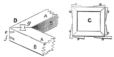
Fig. 32.
With a mitre-saw or tenon-saw cut one or two slits at each angle, as seen at D, Fig. 32, e and f. Cut little pieces of thin wood, and having glued them, drive them into these slits. If you saw them slanting, some tending upwards and some downwards, it will be better than cutting straight into the frame. Then, when all is dry, neatly trim off[81] these pieces even with the frame. You may also, if the work is of a more heavy kind, as a large picture-frame, finish with keyed mitres, g. Cut a place with a chisel of the shape here shown, about one-eighth of an inch deep, half into one piece and half into the other. Then cut out a key of the same form of thin hard wood, to fit exactly, and glue it in. The shape of the key prevents the joint from coming apart, and makes it very strong and durable. A very large number of light boxes are made with mitred joints, as workboxes, water-colour boxes, compass-boxes, and such like; and you can examine these for yourself; but you will not often see the keys at the angles, because most of such boxes are veneered, or covered when finished with a thin layer of some ornamental wood.
I shall now proceed to show you how these joints can be cut at once without the trouble of gauging and measuring to find the proper angle. Therefore I shall let you into the secret of mitring boxes and mitring boards, which, if you had much to do of this kind, would shorten your work considerably.
Fig. 33, A, represents a mitring-board, B a mitring-box. We must go into a little mathematics again, and try to understand these, because, if you do so, you may devise others, occasionally more suitable for any special work you have in hand.
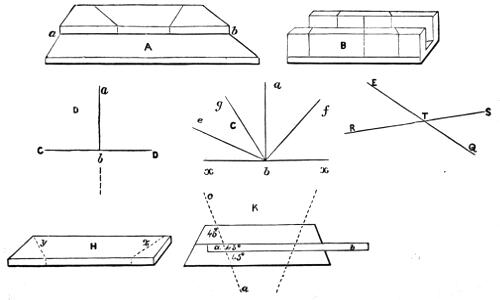
Fig. 33.
First, look at D of this figure. You have a line, a b, standing upon another C D, and perpendicular to it—that is, it leans neither to the right nor to the left. It makes two angles at b, one on each side of a b, and these are angles of 90°, or right angles, as I explained. Now, if one line like a b stands on another, these two angles are together equal to 180°, or twice 90°, whether this line is or is not upright or perpendicular to the other. Look at fig. C. Here you have the line x x, and standing on it several others; one, a b, is upright or perpendicular, making with it two angles of 90° each, or 180° together. Now, take f b, and suppose this to make 45° on the right-hand side, you see it makes therefore a proportionately larger angle on the other. It makes, in fact, an angle of 135°. But 135° added to 45° equals 180°, which is the same as before, and whichever line you take, the angles together made by it at b will equal 180° of the circle—that is, they will equal two right-angles.
Now, if I take the fig. D again, and carry on the line a b right through c d, where it is dotted, two angles will be made on the other side of c d, which will each be right angles of 90° as before, so that all the four angles thus made are equal. It follows from this, that whenever any two lines cut each other—E Q and R S for instance—the angles at T equal four right angles, no matter whether the lines are or are not perpendicular to each other: and what is more (and what I specially want you to note), the[84] opposite angles are equal—i.e., the two small ones, or the two large ones.
The action of a mitre-block or mitre-box depends upon the principles here laid down, so you see that although few carpenters understand much about mathematics, and simply work as they were taught, without knowing or caring why, those who planned the method of work, and invented mitre-boards and such like devices to shorten work and lessen labour, must have understood a great deal about such things. And so it is generally, as you will find with inventions: things look easy enough, and natural enough, when we see them every day; but it has taken a great deal of thought and sound knowledge to invent them in the first place, and a great deal of practical experience to construct them so neatly. Even a common pin goes through such a number of processes as would surprise you, if you have never been able to see them made.
Look carefully at A. It represents a block of wood, about 1½ or 2 inches thick, and 3 or 4 wide, firmly screwed on the top of a board 1 inch thick. The length is about 18 inches. Two saw-cuts are made with a tenon-saw, right through the block to the board, at angles of 45° with the line a b. These are guides for the saw to work in. The wood to be cut is laid against the edge of the block, and rests on the board, and the saw is then applied in one of the grooves while the wood is being cut by it. Let H be[85] such a piece. If the saw is put in the left-hand slit, it will cut it like y; if in the other, it will cut it the other way, like x; and thus, if a piece is taken off at each end, it will be as you see, ready to become one side of a frame. Now, examine K, which shows all the lines or edges of the mitring-board, as seen from above, with the strip a b sawn across in the line c a. The lines a b and c a cross each other, making the opposite angles equal; and as one angle is 45° the other must be 45° also, so that the right-hand side of the strip is correctly cut. But so also is the other end, and if we turn it over, it will exactly fit, and the two will form two sides of a square. I could prove to you that the second strip contains angles exactly similar to the first, but you ought to be able now to detect the reason for yourself, and I do not want to teach you more mathematics at present, as I am afraid you are tired of these, and will want to go on with the real work of fitting and making. I have, however, said enough, I think, to make you comprehend why the two saw-cuts must be at an angle of 45° with the edge of the top board.
Perhaps you wish to make your own board, however, and would like to know an easy way to get the saw-cuts at the right angle? I shall therefore show you how to do this, but you must be very exact in your workmanship. A B, Fig. 34, is the piece of thick board as seen from above, and close to it is a perspective view of the same which shows[86] the thickness. Set off a distance, A E, equal to A C, and join C E. The dotted line shows you that C E is the diagonal of a square, and the angles at C and E are consequently each 45°; but we do not want this line to end at C, it is too exactly at the corner for convenience. Measure, therefore, a distance, E b and C a, equal, and join a b, which will be the place for the saw-cut; and the other can be marked out in exactly the same way. a x, in the perspective view, must be carefully marked by the help of the square. Take care to mark the line on the bottom board, where the edge of this upper thick piece will fall, and screw the two firmly together. If the edge and face of the thick piece are not truly square to each other, the mitres cut thus will not be correct; but, if all is well made, they may be glued at once together, no paring of the chisel being necessary or desirable.
The mitre-box, Fig. 33, B, is on precisely the same principle, but is chiefly used to cut narrow strips not over 2 inches wide; it should be neatly made of mahogany, half an inch thick. There is also generally made a saw-cut straight across, at right angles to the length of the box or board, which is convenient in sawing across such strips of wood, as it saves the necessity of marking lines against the edge of the square: of course, it is specially used where a large number of strips have to be cut square across. In all these you observe one saw-cut leaning to the right, the[87] other to the left. This is necessary when picture-frames or moulded pieces have to be cut to 45°, because you cannot, of course, turn such pieces over and use either side, which you can do when the piece has no such mouldings.

Fig. 34.
Several modifications exist of mitring-boards; some arranged for sawing, and some for planing; and where thousands of frames have to be cheaply made, the angles are cut off with circular saws, of which I need not speak particularly here, but which I shall probably have to describe in a future page. In Fig. 34, K, I have shown one corner of a simple picture-frame, covered with what is called rustic work, that is—short pieces of oak, ash, or other wood cut from the tree, left with the bark on, or[88] peeled and varnished. These are nailed on with small brads; and, if well assorted and arranged, this will have a very neat appearance, suiting well for rooms fitted up in oak, as many studies and libraries are. In picture-frames, however, a rebate (called rabbit) has to be made at the back, like L, in which the picture with its glass and back-board has to rest; and this requires a special plane. The front also is always either sloped off or moulded. I shall therefore make this kind of work the subject of my next chapter, and describe the operations of rebating, grooving, tongueing, and moulding.
These operations, which are frequently required in carpentry, are done on a small scale by planes. On a larger scale, circular saws and other machinery are widely and extensively made use of for the same purpose, as being much more rapid and economical. Of course, the young mechanic will employ the more usual method, and the present chapter will therefore treat of the planes necessary for the above work, and the method of using them.
The common rebate or rabbit plane comes first. This is of various widths; an inch being a very useful size. It is different in many respects from the smoothing-plane, being made with a single iron only, which is so arranged as to reach into angular recesses, which could not be touched by the ordinary plane, of which the iron does not extend quite to either side of the sole. Fig. 35, A and B, will illustrate[90] this. A represents the plane as seen from above and at one side, B gives the perspective view of the sole, C represents the iron, D the wedge. Let us suppose a rebate required upon a strip 1 inch thick, the same to be half an inch wide and deep. A gauge is first set to the required distance, and a line is marked on both faces, as a guide for the action of the plane. After a little practice it will be found easy to guide the entry of the plane with the left hand, grasping it so as partly to overlap the sole, and thus determine the width of the cut, which must not at first be carried to the full width required, but may be brought within an eighth of an inch of such gauge line, and the material removed sometimes from one face of the rebate and sometimes from the other, taking care to keep it nicely square.
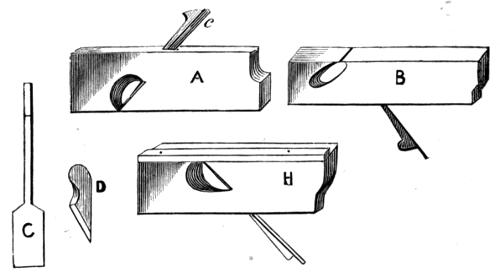
Fig. 35.
At first it is an easier plan to nail on with brads a[91] strip of wood accurately planed, which in this case, as the sole of the plane is 1 inch wide, must cover it from end to end to a width of half an inch. This will prevent the possibility of going too deep into cut, and insure the correctness of the rebate, Fig. 35, H. The injury to the sole will not be great if small brads are used, but at the same time it is better to learn the art of using the hand as a guide, which is the more general method of the working carpenter. As for the use of rebates, there are few pieces of cabinet-work or joinery in which they are not found, and as stated in the previous chapter, no picture-frame can be made without them. The shavings which escape from the rebate-frame do not rise out of the top, as in the smoothing-plane, but from the side, which is hollowed out for the purpose, as seen in the drawing.
The skew rebate-plane is made like the preceding one, but the iron, instead of standing at right angles to the sides, is placed at an angle. With this you can plane across the grain of the wood.
The next plane to be noticed, is that with which grooves are cut, such as you will often see in the sides of book-shelves, in which the several shelves slide. The same is done where two boards are to be joined lengthwise, and there is danger of their becoming separated as the wood shrinks in drying. The panels of doors, too, are slid into similar grooves in the styles and[92] rails of the framework, and there are innumerable other cases in which this mode of work is carried out. These grooves are generally cut with the plough, a curious-looking tool, by no means like a plane in appearance, but of great use to the carpenter. Of course, we require various widths of such grooves, according to the special purpose intended, and these are determined by various widths of the cutting irons, which, however, all fix into the same stock; a dozen or more of such irons are sold with a single plane.
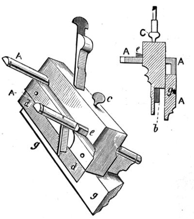
Fig. 36.
In Fig. 36 is a set of drawings explanatory of the above tool. The central part, or stock, is that which corresponds to the same in other planes, and it is only modified to suit the other parts, which simply act as guides or gauges regulating[93] the distance of the grooves from the edge of the board, and the depth to which they are to be cut. When the arms, A A, are removed, you have the plane as it appears with a brass fence, b, at one side, which can be raised or lowered at pleasure, and set at any point by the screw C; d is an iron plate which acts as the sole of the plane, the cutting edge being set to project a very little way below it.
The arms A A carry the fence g, which is flat on the inside next the plane, and moulded (merely for appearance sake) on the outside. The arms slide in two holes in the body of the plane, and can be drawn out at pleasure, and fixed by little wooden wedges, e e. Thus, while in use, the fence rubs along the edge of the board, while the groove is being cut at such distance as the fence is fixed, and to such a depth as is allowed by the position of the brass check or guide. Complex, therefore, as this tool appears, it is not so in reality. We shall presently describe a chest of drawers or cabinet calculated to receive small tools, or specimens of coins, shells, and such like, in which another kind of grooving-plane has to come into use, called (with its fellow, which makes a tenon to fit such groove) a match plane. This is of extensive use, less expensive than the plough, and on the whole more likely to be useful to the young mechanic. Indeed, although the plough has been here described and illustrated, it is not by any means to be considered essential, and its purchase may well be deferred[94] until other tools of greater importance has been effected. The side or sash fillister to be presently described, for instance, would be more useful.
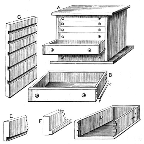
Fig. 37.
Fig. 37 is such a cabinet, with six drawers, dovetailed at the corners as usual. The bottom, however, projects beyond the sides, so that the latter are not made lower than the back, as was the case with the table-drawer previously described. The top and sides may be of mahogany, the back and bottom of pine (stained or not at pleasure), or if cost is an object, the whole may be of any other wood; but the grooves in which the drawers slide, can be cut more[95] sharply and neatly in harder wood than pine—birch, for instance, which is very fit for the purpose, and will take a good polish. The outer case is first made like an open box. The dimensions may be regulated according to the intended use, but generally the drawers increase in depth downwards. The top and bottom overlap the sides, the latter to a somewhat greater width than the former. The sides can therefore only be dovetailed to the back; the bottom may be attached with screws, and the top likewise, but the holes must then be plugged to conceal them. If the whole is of deal, and to be painted or veneered, this would be the best plan; but if the top is of mahogany, it is not so easy to fill up the holes above the heads of the screws so as to thoroughly conceal them. If, however, you have no plough to cut a groove to let the sides and back a little way into the top, glue alone will not hold sufficiently. In this case smaller holes may be made to admit 2-inch brads to assist the glue, such holes being easily filled with putty stained to imitate mahogany.
The peculiarity of the drawers consists in their meeting each other quite closely when shut, without the intermediate divisions ordinarily seen. Hence the necessity for a different arrangement of the sliding surfaces as before referred to. The insides of the case have five grooves ploughed across them, as seen at C of this figure, the sixth drawer only being made as usual to slide upon the[96] bottom of the case, and having its sides made lower than the back for this purpose.
In the grooves thus cut, the projecting part of the bottom of the drawers is made to fit and slide, and they will run more smoothly if cut so that the grain of the wood shall run across the bottom, from front to back, and not from side to side. The bottom of the drawer must not come below the level of the front, but either the front should be rebated to take one edge of it, as seen at E, which is the best way, or a slip of wood should be glued along as at F, on which that edge may rest, and to which it can be attached. D exhibits this distinctly, as it is drawn as if the nearest end was removed to show the position of the other parts. The bottom, therefore, will be let into the front, and nailed under the back and sides, and will project rather less than half an inch each way, to fit the grooves in which it is to slide. Another way to effect the same is to make the drawers as usual, with no such projections, and to nail a strip to run in the grooves in the middle of the side pieces, or, if preferred, near the top. The effect is, of course, the same, and such strips being planed up nicely, with the grain running lengthwise, will cause the drawers to work in and out very smoothly.
There is no neater way than this to make a cabinet; and sometimes the whole is closed with a panelled door, for[97] which purpose the case is left to project beyond the drawers. Unless well supplied in the matter of planes, which is hardly to be expected, you will not be able to cut the grooves in the side of the outer case in any way but the following, which, however, will answer very well when the piece in which they are to be cut is not above 9 inches or 1 foot wide. Mark out the places, spacing them with the greatest care, and cut just within the lines with a tenon-saw; then cut out with a chisel the narrow piece which intervenes. There is a plane called a routing-plane used for this by cabinetmakers and joiners, but you may as well exercise your ingenuity to do without it. If you have a plough, you may remove the fence, and let it follow up the saw and chisel, but it will be hardly required if you use the chisel carefully.
I shall now introduce to your notice another very excellent plane, called a side or sash fillister, for cutting rebates of any required depth and width. It is very like the plough in appearance, with a similar wooden guide or fence on two arms to regulate the width, and another of metal, moved by a screw at the top, to regulate the depth of the cut. Fig. 38, A, shows one side of this plane, and B the other. The cutting edge comes down to the level of c d in fig. A; the fence, of which the edge is seen at h, will draw up to the level of a b, or lower to that of the edge. This plane, therefore, is but a more complete rebate-plane, fitted with[98] guides for depth and width. It does its work very perfectly, and is of extensive use.
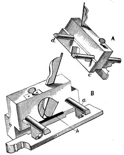
Fig. 38.
I have given descriptions of these planes, although the young mechanic will not at first possess them, as they are somewhat expensive, because I feel it as well to let him know how work is done by the trade, and why it is that such work is effected more rapidly and better than he himself can do it; but at the same time it is far better that he should, for a long time, work at a disadvantage, by using[99] few tools, and those of the simplest construction, before taking in hand others which cost a good deal of money, which might often be better spent. A look back over these pages will show that with a long (or jack) plane, a smoothing-plane and a rebate-plane, all the work previously alluded to can be done. As, however, I am writing upon the subject of planes, I may as well mention two more—match-planes and beading-planes—to which may be added those for moulding, being an extension only of the last named. Match-planes are always in pairs. Their use is to cut, the one a groove, Fig. 39, A, the other a tenon or tongue, or feather, as it is sometimes called, as Fig. 39, B, down the long sides (with the grain) of boards that are to be joined lengthwise (Fig. 39). If the plough is used, a groove is cut in both pieces, and a slip of board planed up to fit them; either method will answer equally well. When boards joined thus shrink, the tongue or slip fills up space.
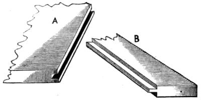
Fig. 39.
There is no necessity for illustrating the planes used for[100] beading and moulding after the description already given of others. The irons, instead of being flat, are filed into grooves and hollows of the required pattern, and of course transfer their own form to the wood upon which they are used. They are held on the slope of the moulding to be cut. When blunt, they have to be sharpened with slips of oilstone, which can be had for the purpose, of square and round section; sometimes they are sufficiently soft to be filed into shape, but a keen edge cannot thus be obtained. Mouldings, however, are generally finished off with fine sandpaper. They are always planed lengthwise of the grain in long strips, and are cut to the required lengths (generally with mitres). When very broad, they are made up of several narrower ones, glued side by side. The young mechanic had better get them cut for him by some friendly carpenter, as it is hardly worth his while to buy planes for which he will have comparatively little use.
I shall conclude these papers on carpentry by describing the method of making such a door as would suit the cabinet already described, especially as it will explain the way in which all panelling is done, whether for doors, shutters, or other similar articles. Panelling is indeed of very general application in every household, and it is well worth while even for the young mechanic to learn how it is accomplished. It is absolutely necessary, however, that he[101] should be possessed either of a plough or match-planes for routing out the grooves in which the panels slide.
Nearly all panels have a beading or a moulding running round them as a finish.
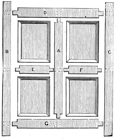
Fig. 40.
Fig. 40 illustrates the method of panelling. A, B, C are the styles, D, E, F, G the rails. The mortices and tenons are cut as usual. The inside edges of C, B, D, G are then grooved with the plough, and both edges of the other pieces. The panels are carefully squared up, and then bevelled off at the edges so as to fit the grooves. To put such a door together, A, D, G, E, and F would be first[102] arranged, then the panels slid in from the outside, and afterwards the styles B and C put in place. The part beyond the outer mortices in the latter pieces, which are left for safety in cutting these mortices, and to prevent splitting when D and G are driven home, are not cut off until the glue is dry. The process is simple, but it requires great care, both in setting out the various measurements, and in squaring up the different pieces composing the whole. After the whole is dry, strips of moulding, cut to mitre-joints at the corners, are nailed on with brads round the panels to give the whole a finished appearance.
In the above examples, in which I have gone from the more simple to the more complicated, are comprised the main principles of the art of carpentry. At any rate, when the young mechanic can do as much, he will be able to accomplish a great deal more.

There are a number of useful and ornamental articles which cannot be made with the carpenter’s tools alone, but which need a lathe for their construction. Wooden boxes of circular section, wooden and metal wheels and pulleys, ornamental chair and table legs, and a countless number of similar articles, all depend upon the skill of the turner. Models too of engines and machinery of all sizes and shapes, bring the lathe into constant requisition.
No one can say to whom this machine is to be attributed. Probably it has been developed by slow and imperceptible steps, from the potter’s wheel to its present elaborate and perfect form. As for the part that old Dædalus had in it, I believe he had just as much to do with it as he had with the saw, which he is said to have invented from seeing the backbone of a fish. Now, the backbone of a fish is not a[104] bit like a saw, but the jaw of a shark is, and very quickly it amputates legs, arms, and heads, when unfortunately the chance is given to it. We need not, however, stay to discuss this unimportant point; we will leave it to the researches of the Antediluvian Society, or Noahican Brethren, or any other known or unknown learned body, and proceed to consider the lathe as it is now generally constructed—the ambition of boys, the delight of adult possessors, and, to the writer, “gem of gems!”
At the very time I write, I am engaged in fitting up two lathes; one of which is for just such a “young mechanic” as this book is intended to instruct. The bed will be of dry hard beech, the fly-wheel of iron turned up with five grooves or speeds, as they are called. The heads, which are the only really important part, are to be made by a well-known London maker, whose work is sure to be the best possible at the price afforded. Nevertheless, this lathe will cost several pounds, although it is to be fitted for hand-turning only, and it is possible in London to find a much cheaper (not better) article.
When I was myself a “young mechanic,” so many years ago that I find I do not quite like to count them, I had a lathe at £2, rather shaky, wooden fly-wheel, wooden head—not at all the thing to recommend. Then I had another made by a gunsmith—all iron—for it was what is called a triangle-bar lathe; the bed being a bar of triangular[105] section, on which the heads or poppits slid, and also the rest. I think now it was not a bad lathe; but I am afraid the work I did on it was scarcely first-class; and I sold the machine one fine day under the impression that if I had a better I should do better work. This, however, proved a terrible fallacy; so I set myself upon high as a warning to young mechanics, who always fancy that their clumsy, bad work is due to some fault in their tools, whereas, after all, it is generally their own.
Well, I had a succession of lathes, after that triangle-bar one had passed into oblivion, by various makers; some good, some indifferent, some for heavy, and some for light work; and I fancy I am now fairly able to give an opinion upon the merits or demerits of any particular lathe which may come under my notice.
I was going to write a piece of advice, “Don’t give too much for a lathe,” when I remembered that I was scribbling for the edification first of boys; and experience tells me the caution is by no means generally necessary, few boys’ pockets being very heavily lined, owing to the constant claims upon them for peg-tops, knives, string, and etceteras—not to say lollipops and bulls’ eyes, and similar unwholesome luxuries.
I suppose, however, I must give some idea of cost, if only as a partial guide; but all depends upon the special object for which the lathe is to be used. If for models, for[106] instance, it would not be so expensive as if it was desired for elaborate ornamental work in wood or ivory, when the young mechanic has grown whiskers, and become an adult enthusiast at this delightful recreation. For there are all kinds of lathes to be had; some that will answer well for beginners, and for rough work in after years; some beautifully finished, intended to be used first for simple hand-turning, but which are of best construction, and therefore worth adding to from time to time; and if carefully used, will descend in good order from father to son. Then there are lathes for heavier work, and for screw cutting and engine making, fit for engineers; and others of minute size and exquisite finish, adapted to the special requirements of watch and clock makers—lathes you could put in your waistcoat pocket.
Now, if I were sure you would be very, very careful, I should like to recommend a good lathe, worth adding to as you grew more and more experienced; but these, even of simplest make, are costly, and not within reach of half my readers. I shall therefore say—get a good, plain, strong tool that will bear a little rough usage, and which will cost you as little as it is possible to make them for: and if you find, after a year or two, that you are becoming a proficient, and therefore not so likely to damage a good lathe, you can set this, your first, on one side, and let it become your hack to do any odd jobs, and buy yourself both a larger and a[107] better one. I know this will be a double outlay; but experience tells me it will be the best way and the cheapest in the long run. Perhaps you may like to go on as you are. Your small lathe may prove an accurate one, and quite sufficient for your need. In such case, of course, a new one will not be required at all. But if it should be otherwise, and circumstances allow you to improve upon it, you may rest assured your old friend will be ever a handy assistant, and save your better lathe very considerably in many ways.
You can get a lathe for about $20 to $25, with iron bed complete; and I really think it impossible to obtain a cheaper one. Of course it will be small, and of the plainest possible construction. It will, nevertheless, answer for light work in wood and metal, being designed to assist the young mechanic in making model engines and similar curiosities. From this you may go, pound by pound, to good, serviceable tools; and these to a £300 lathe for rose engine-work, and elaborate ornamentation in ivory and other costly materials. Most probably I shall be able to give you a catalogue or two at the end of this book, published by makers of such lathes, and you can then judge of the probable cost of your workshop. The drawing of the lathe (Fig. 41) will be readily understood even by those boys who have had no opportunity of seeing any work of this kind. There are, however, few towns or villages in[108] which a lathe does not exist, and may not be examined by any boy who desires to learn its construction and use. Its object is to give rotary movement to any material it is desired to form into a circular or cylindrical shape.
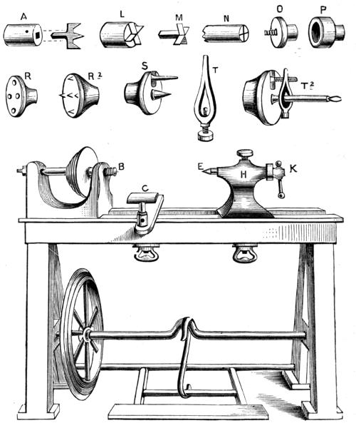
Fig. 41.
Motion being given to the fly-wheel by means of the[109] treadle and crank, is communicated to the pulley upon the mandrel. Upon the screw of this mandrel, B, the work is fixed; being usually held in a chuck suited to its particular form, but sometimes it is screwed directly upon the mandrel. The rest, C, is then fixed near it, and the tool is supported thereon and held firmly while the work revolves against it. All this is easy to understand—it is not so easy to carry it into practice. Attention to the following directions will enable the young mechanic to become a good turner in course of time; but the art cannot be practically learned in a day, and it needs experience and considerable practice to become anything like a proficient.
If the construction of the lathe itself is understood, the first consideration is what tools and chucks are necessary. I shall speak of the latter first, as little or nothing can be done without them. First comes the prong-chuck, for soft wood (Fig. 41, A). This, like all others, is made to screw upon the mandrel. Its use is to hold one end of any piece of wood while the other is supported by the point, E, of the poppit, H, which poppit can be moved at pleasure along the lathe-bed, and fixed at any given place by a hand-nut below. The point itself can be advanced or drawn back by turning the handle, K. A piece of wood thus mounted must of necessity revolve with the mandrel, because, although it can and will turn round upon the point of the back poppit, it cannot do so upon the fork or prong, which[110] enters and holds it securely. This chuck, or one of the same nature, is always used for cylinders of soft wood, which can be supported at both ends, such as tool-handles, chair-legs, and other work not requiring to be hollowed out.
It sometimes happens, however, especially if the work is at all rough, or considerably out of truth, that the piece slips round upon the fork or prong, especially if it does not enter deeply enough; and in addition, tool-handles and round rulers, and many articles that have to be similarly supported at both ends, are made of hard wood, into which this prong will not readily enter.
In such cases, and indeed as a general substitute for the first, a chuck called a “cross-chuck” is to be used (Fig. 41, L, M). The centre of the little cross (which is of steel, and fits into the same square or round hole in the socket which carries the prong, and which is also used to hold drills, pieces of iron rod which are to be turned, and other articles) is made to revolve in the precise axial line of the mandrel, or to run true with it, as it is called. The arms of the cross are to be imbedded in the work, which is best effected by making in the latter two saw-cuts at right angles with each other (Fig. 41, N), which represents a piece ready for mounting.
The next chuck is equally necessary (Fig. 41, O). It is a taper screw of steel, fixed in a socket which can be[111] attached to the mandrel. Two sizes of this chuck would be useful for a large lathe, but for such a one as will probably be purchased by the young amateur, one only, with a screw of medium size, will suffice. The use of this chuck is to hold pieces which only require to be supported at one end, so that a tool can be used to work upon the other, either to mould it into the required form, or to hollow it out for a box or bowl. Of course you might screw such work on the mandrel-nose itself, but it would make a very large hole in the end, whereas this taper screw only requires a moderately sized gimlet-hole. It is therefore a much more convenient way of attaching work to the mandrel, and is of extensive use.
The cup-chuck is the last required. It is sketched at P, and is sometimes of iron, but generally of brass. There are several sizes made and sold with lathes, but you need not have at most more than one or two, as I shall show you how to make wooden ones, which answer as well, if not better. The flat plates, R, R², can scarcely be called chucks, but they generally come into the list of such. The latter has five projecting points, which, sticking into such a thing as a flat-board (like a bread-platter, or round pulley), hold it sufficiently firm when the back centre is brought up against the other side of the piece, to allow of its being turned. The other is merely a flat plate with holes in it, through which screws can be passed from[112] behind into any odd bit of wood of 2 or 3 inches in thickness, whereby a chuck can be quickly made to suit any required purpose. Two or three of these would be convenient, one of which should be nearly as large as the lathe will carry; and in this one a great many holes and slots should be made. This is called a face-plate, and, in addition to the ordinary screws, whereby pieces of wood are attached to it, it is fitted with clamps and bolts of various forms, for the purpose of holding securely upon its face all kinds of flat works in wood or metal,—such as cog-wheels, which have to be bored out and faced. The young model-maker will find a face-plate of great service. The larger one should be of iron, as it will be cheaper than brass.
We now pass on to chucks for metal turning. These are of various shapes. First in order comes the centre chuck and dog, for holding rods of iron which can be supported at both ends. The commonest form is represented in Fig. 41, S, T. S is such a face-plate almost as I have described, but it has a pin projecting from it, and also a steel centre-point. The latter is often made to screw out and in, which is the best plan. The pin can be slid to any point in the face-plate, and clamped by a nut at the back. T is called a dog, and of these two at least will be required, if the young mechanic intends to work in metal.
The way of using these is shown at T². The rod of iron has a hole drilled at each end, as nearly in the centre as[113] possible. It is first indented with a punch, then a drill is put into the drill chuck, and one end of the rod brought against it as it revolves, while the back poppit centre-point is screwed against the indentation at the other end. A little oil is applied to the drill to assist its working, and the rod itself is prevented from turning round either by grasping it with the hand or screwing a hand-vice upon it, so that this comes against the bed or the rest; or it can be held in the hand, which has one advantage, namely, that the operator can feel exactly what is the resistance caused by the drill, and can regulate the pressure accordingly. The screw of the poppit is, of course, to be very slowly and steadily advanced during the process. All drilling in the lathe is done in this way, but in boring out long holes, the action is often reversed, the work being kept in motion while the tool is advanced, without being allowed to revolve. You need not bore more than one-eighth of an inch for light work, but must do the same at each end of the rod. The holes thus made should be of such a size as not to let the extreme end of the back centre-point touch the bottom, or it will soon be worn down and blunted;—remember this in all future work.
Supposing the rod to be thus bored at each end, place the centre-chuck upon the mandrel, instead of the drill-chuck, and mount the bar between this and the point of the back-centre. Thus placed, it will be accurately supported,[114] but if the lathe is put in motion, it will not turn round. Now come into use the little dogs. Remove the bar, and choosing a dog of which the open part is tolerably near the size of it, slip it over the end about half an inch, and there fix it by tightening the little screw, which, you observe, will drive the bar as far as possible towards the smaller part of the opening, and when it can go no farther, will secure it as in a vice. It is a good plan to file a slight flat upon the bar, just where the screw of the carrier will come. Now replace the bar, and when the lathe is put in motion, the tail of the carrier should come against the projecting pin in the face of the face-plate, which will compel the iron to go round with it. This is the way all bars of metal are mounted. I shall not tell you yet how they are to be turned, because this would interfere with the order of my description.
To mount in the lathe such pieces as cylinders of engines, which require to be bored, or any other objects which have to be turned on one or both faces, the young mechanic must make wooden chucks, and bore them out exactly to fit the article and hold it securely. There are metal chucks expressly made to take all work of this kind, and which are so contrived that they will also hold it truly central, but they are costly, and need not be obtained with the first lathe—at any rate, not until absolutely required, and that will be, I know, a long time hence; ay, a very long time,[115] for many good workmen have never even seen, much less possessed one of them. Perhaps I may draw and explain one in a future page, as well as some other chucks, which it is not necessary to notice here.
The chucks then absolutely necessary are these—
1. Square Hole Chuck, which will take the prong, the cross, the drills, and short bits of iron to be turned.
2. The Taper Screw.
3. Flange or Face Chucks, one with five points, and two with holes for screws, also one larger for a face-plate.
4. Two or three Cup-chucks (I can, however, scarcely call these absolutely necessary).
5. Chuck for Iron, viz., face-plate with centre-point, and two dogs to take iron from 1 inch diameter down to quarter-inch. These should have pear-shaped openings, not round; any blacksmith can make them, but somehow they do such work generally in a clumsy fashion; and they cost but 35 to 75 cents, according to size, beautifully made with turned screws.
Now as to tools. Their name is legion—tools for iron, brass, ivory, hard and soft wood; and many an odd shilling will be well laid out from time to time in adding to the stock. Happily those most needed are not costly—about $3 a dozen without handles, which latter may be had at 10 cents each and upwards, according to the material and finish, all with iron or brass ferules, so necessary to prevent splitting. You may buy your first few simple tools handled, but after you have these you can turn as many handles as you like, and you can buy ferules of all sizes at any regular tool-shop.
I may as well tell you that in a great many country towns you will be unable to obtain turning tools except gouges and chisels, so that when you buy your lathe in London, as you will find the best plan (or in Manchester, Birmingham, or other manufacturing town, if nearer to you), you must lay in a little stock of tools at the same time, and take future opportunities of getting more. In regular tool-shops you will have them laid before you by dozens of every conceivable shape and size, so that your great difficulty would be what to pick out if it were not for some such directions as I am now about to give you.
First, you will want gouges and chisels. Begin with two sizes of each—one of half an inch, the other of 1 inch in width. These are to be mounted in long handles.
Now, with these alone you can do all the plain work in soft wood which does not require to be hollowed out, tool-handles, chair-legs, legs of towel-horses, round rulers, and all sorts of things, and to a certain extent you can turn out the insides of wooden chucks, bowls, and boxes, but not very easily with these alone. Hence you must add some of those shown in Fig. 42. These I shall endeavour to assort as follows:—
A to F are for hollowing out hard woods; G and H are hook-tools (very difficult to use) for hollowing out soft wood boxes and bowls.
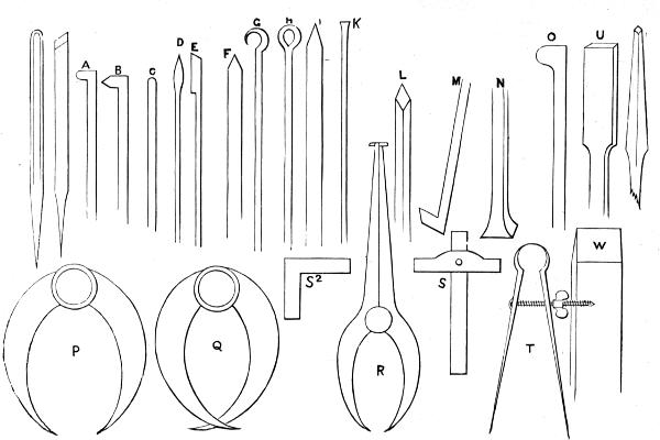
Fig. 42.
I and K show the edge and side of a parting tool for cutting off the ends of cylindrical pieces, separating the turned from the unturned parts, and for all similar work. [A tenon-saw held still against a piece revolving in the lathe will often serve to cut it in two, but parting tools must also be had, and two are better than one, as a thick one should be kept for common woods, and a thin one for ivory and precious materials; sometimes one with a notched edge is used for cutting off soft wood.]
L to O are for turning iron and steel. The first is a graver, of which all sizes are made; one of a quarter inch width on either face is large enough. It is a square bar of steel ground off cornerwise so as to form a lozenge-shaped face. This is an essential tool for iron, and will do all sorts of work.
M is a hook or heel tool, made sometimes with a flat edge and sometimes with a rounded one, the latter being most useful. It is a very powerful tool, much used by some, especially for heavy work—I don’t think you need get one at present. If I am able to teach you to use a graver it will do almost as much work, and is a neater tool. If you use a tool of the nature of heel-tools at all, I think, on the whole, the nail-head tool, N, either round or square, is the best. It is at all events handy for roughing down work, and when it is reduced nearly to the size required, and is partly smoothed, the graver will finish it.
O is an inside tool for hollowing out iron. There are[119] different shapes of this used, each turner giving the preference to some particular pattern to which he has habituated himself. None of these tools for metal have sharp edges—at least they would not appear so to an ordinary observer. The angle of the edge is 60° to 80°, or even 90°, which is, as you know, a right angle, and is that most generally used for the cutting edges of tools intended for brass, as U, V, W, of which V is a most useful pattern. Those for hard wood have edges a little more keen, but after all they scrape rather than cut; the only tools for wood with keen edges being the gouge and chisel.
P are callipers for measuring the outside of work of all kinds. Q and R are the same, arranged for in and outside work. The first is an ordinary pair closed until the ends have crossed, which they will all do; but if the inside of hollow work to be gauged is small, they will not enter it. In this case none are so generally useful as the in-and-out callipers, R, for when accurately made (and if not you can easily correct them with a small file), the one end will measure the external diameter of work, and at the same time the other end will be found to have its points separated to such a distance, that if you were to turn a box or chuck to this inside measure, the cylinder first turned will exactly fit it. Thus if you turn a box-cover, and take the size of it with the straight end of the callipers, and then turn down the rim of the box until it is just the size indicated[120] by the curved ends, the one will exactly fit the other. In turning a piston to fit the cylinder of an engine, you would work with this useful tool.
S is the turner’s square. The blade slides stiffly and accurately in a slot in the brass, being kept by a spring at one side from working loose. This square is used to gauge the depth of boxes and other works which are to be turned to an exact size, and it also serves to test the squareness of many kinds of work. Suppose, for instance, you had turned a box, you would put the blade of this tool against the bottom and press upon it till the brass rested across the rim, touching it in two opposite places. Now possibly the inside may be smaller at the bottom than at the top. Test it by bringing the steel blade edgewise against it. You will see whether the brass still touches in two places across the mouth of the box. The squareness of the outside with the top or bottom can be tested in a similar way. We shall have occasion to recur to this when we come to boring and fitting engine cylinders.
S² is another small square, which is often serviceable where the carpenter’s square cannot be used. If you intend to make models, you will want both of these; at the same time, it is quite possible to make the latter of iron, or even thick tin, if you have the former, as an accurate guide to work by.
T represents a pair of spring-compasses or callipers.[121] They are used to set off distances, and have the advantage of not being liable to shift their position when once they are set to any required width. You will require a pair of compasses of some sort, and if not already provided, these are the best you can have.
There are many other tools, which, though not absolutely turning tools, are more or less used in connection with the lathe, but these need not now be further alluded to, and I shall go on to describe as clearly as possible the method of working at the lathe with hand-tools, commencing with the operation of turning soft wood with the gouge and chisel; but I must first give a short chapter upon the nature of woods used.


As different materials require somewhat different management, and even in the matter of wood alone this rule holds good, it may be as well to have some idea of what is meant by hard and soft wood.
The young mechanic has most likely hitherto considered all wood under one head; but there is a vast difference, nevertheless, in the internal structure, even of such kinds as grow in England; and the woods of foreign countries differ again from these, some being of such close texture that it is almost impossible to work them with ordinary tools, and some (such as the palm) being little else than gigantic ferns, and in structure like that much-dreaded implement of flagellation—the schoolmaster’s cane.
In England the hardest wood found is that of the box-tree, the chief place of which is in Surrey, at Box Hill; it[123] is, nevertheless, found scattered here and there in all parts of the country, but not generally of a size greater than 3 inches in diameter. It is of very slow growth, and our own country would not nearly satisfy the demand made for it by various trades. Hence a large quantity of box, of larger growth, and generally of harder and better quality, is imported every year from Turkey, to be used in the construction of blocks for engravers, who alone require many tons weight annually, and for carpenters’ rules, mallets, turned boxes, and tool-handles; to which I may add the important item of peg-tops. I fear some of my readers may think I should have placed these first on the list! Opinions, however, I imagine, differ in this particular, as in most others, and upon all subjects.
The grain of boxwood is so close and even that it is one of the most valuable turning materials we possess. It takes excellent screw-threads, provided they are not too fine; is a very general material for boxes of all kinds, and also for chucks, although there is really no reason why it should be wasted in so applying it, when other woods of less value make such efficient substitutes. Probably its use for this purpose arose from the facility with which a screw can be cut in it to fit that on the mandrel, and that it is so hard as not to allow the collar beyond the screw to make much impression upon it. In consequence, when it is well fitted, such a chuck can be screwed on many times[124] exactly to the same point, and will continue to run true. But I myself have found that if the mandrel-screw is not very coarse, the threads cut in the inside of the chuck are apt to break off.
Somewhat similar in texture, though by no means generally used, is the wood of the Elder, which is quite different, be it observed, from the Alder, although I often hear the names confounded together. The wood I allude to is that of the tree which bears umbels of sweet, white blossoms, which give place to those jet-black berries we find upon them late in summer, and which are made into elder-wine, for home consumption at Christmas, when, no doubt, most of my readers have drunk it, hot and spicy and sugary, to keep out the wintry cold. From the same tree are commonly made those harmless engines of mimic warfare—pop-guns!
If it were not for the presence of the pith, which is in fact the very quality which makes it valuable to boys for the latter purpose, this wood would certainly have been eagerly seized upon by turners. Even with this defect, it is used instead of box for the inferior kinds of carpenter’s rules and other purposes, and the larger pieces will make very good chucks, if a little care is exercised to prevent splitting them. It is indeed a wood that might be far more extensively used in this way than it is.
The Yew, perhaps, should come next in order, for this too[125] is very close-grained and very beautiful, and when highly polished it will bear comparison with many foreign woods which we import at a high price; it is, however, brittle and apt to splinter.
Walnut varies considerably in quality, some being harder and richer in grain than others. This wood, however, is not to be classed among those which are properly speaking hard, as it can be cut with ease, and can only be planed and worked as deal would be, viz., with the grain; whereas the hard woods work with almost equal facility in either direction. This indeed in a great measure constitutes the difference between soft and hard woods, in the turner’s sense of the words. If you were to hold a chisel flat on the rest, so as to let it scrape a cylinder of wood as it revolved in the lathe, you would find in some cases that it would tear out the fibres in shreds—these are soft woods. In other cases it would leave the surface rough but otherwise tolerably even, and with some it would leave the same fairly turned.
I cannot call to mind any English wood but box that can be turned by a chisel held so as to scrape it, but the greater number of foreign woods are always turned in this manner, being hard and close in the grain.
Birch.—Oh, once-dreaded tree! birch! with its long, swaying, switchy boughs, drooping as in sorrow at the mean uses to which it was applied! It is nevertheless a very[126] useful tree, and the young mechanic can take full revenge upon it by cutting, and chipping, and turning it into all sorts of useful articles. It is, however, now more generally used in cabinetmaking, for wardrobes, bedsteads, chests of drawers, and such like, as it looks very neat when planed and varnished. Perhaps, as a wood for the exercise of the turner’s art, it must give place to
Beech, which is a common and excellent material for the essays of beginners, who can turn tool handles especially from the small trimmed billets of it which are kept by the chairmakers, and which can generally be bought for a trifling sum in any town, and in many villages. If not, the wheelwright may be applied to for a supply, as he uses it rather extensively for the felloes of his wheels. It is peculiarly liable to the attacks of the little worm, weevil or maggot, who drills such innumerable and such beautifully round holes in furniture that stands long unused.
Beech is often used for the screws of carpenters’ benches, as it takes very well a thread of such size as is required for that purpose. It will also, for the same reason, answer very well for chucks, for which it has the recommendation of cheapness and toughness.
Ash seems to come next upon the list. It is probably the most useful of all English woods, and where toughness, pliability, with moderate hardness, are valuable qualities, no English wood can exceed it. For frames of carts and[127] carriages, shafts, agricultural implements, wheelbarrows, and smaller articles of husbandry, it is precisely what is needed, and in the workshop of the turner it is equally valuable. Tool-handles of ash are very durable, and hold the tool with great firmness, owing to the natural elasticity of the material. It may be stained and polished, and is then, for real work, preferable to the more costly hard woods of which handles are very generally made for the workshops of rich amateur mechanics.
Oak is little used for turning, the grain being too coarse. The young mechanic need never make use of it for this purpose, and the same may be said of the elm.
Elm is, nevertheless, used by turners for the wooden buckets of pumps, and is a generally useful wood. Bulk for bulk, it is lighter than beech, and it makes a good material, it is said, for lathe beds, though beech is more frequently used. It will answer for chucks, as indeed most woods will that can be cut into screws; it is very tough.
Evergreen Oak, or Holm Oak, as it is called, is very different to the forest tree, and might be classed among shrubs. When dry, it is by no means a bad wood to turn, and will take a good screw thread, and make excellent chucks.
Acacia is an excellent wood. It is of a yellowish brown colour, tolerably hard, and will take a good polish. It is[128] most certainly to be set down among the woods valuable to the turner.
Sycamore is white, very soft until old, when it becomes much harder. This is also a turner’s wood, and used extensively for wooden bowls, backs of brushes, turned boxes, and what is generally called “turnery.” A little of this will be useful to the young mechanic. It will make excellent bread platters, stands for hot water jugs, and such like.
Holly.—The Christmas garland, with its red berries decorating even the poorest homes in midwinter, is a tree well worth the attention of the young mechanic. It is his substitute for the more precious material ivory, and from it he will turn the white draught or chess men, boxes, and many small articles. But it is necessary that this material should be perfectly dry, and to get it in perfection, carefully preserved to insure its whiteness, it will be generally necessary to procure it ready for the lathe at some lathemaker’s, or at first-class cabinetmakers’. If cut green, it requires long seasoning, during which it shrinks considerably. In fact, it takes some years entirely to rid it of the great quantity of moisture which it contains. It is well worth procuring, nevertheless, for it is nearly as white and free from grain as ivory.
Many of the fruit-trees of our orchards and gardens supply good material to the turner. Apple, Pear,[129] Cherry, Plum, and some others, are all more or less useful. The grain of the first is rather dark, the fibres often twisted. It looks well when polished.
Pear has a very fine, even grain, and is largely used for making the curved templates (or patterns of curves for architects and engineers); it will make good boxes, and is fairly serviceable to the turner. Its colour is light brown, but darkens by exposure.
The Plum has a wood veined very like that of the elm, but is a finer and better wood for the lathe. This is the wild plum, and not the grafted fruit-tree of our gardens, which is not nearly so good. The wild plum is excellent for small boxes, and looks well when nicely turned and polished.
Cherry is a very excellent wood, and naughty, fast boys, who take to smoking, like young Americans, when they ought to be filling their young brains with knowledge instead of narcotics, know very well that it is made into pipes and stems of pipes. Happily this is not its only use, for it is fit for many other purposes; and for light, elegant furniture, it is scarcely to be equalled. Dipped in lime-water, it darkens, and by doing this here and there, a beautiful mottled appearance is given to it. It takes an excellent polish, and should be among the stores of the young mechanic.
We now come to another soft, white wood. The Lime,[130] which, as it is more even in grain, more easily cut in any direction than most woods, is greatly used by carvers and pattern-makers (i.e., those who make wooden patterns of wheels, or lathes, or machinery, which are to be cast in metal). [The pattern is pressed into damp sand, and then removed, and the melted metal is then poured into the impression thus made. If the sand is too wet, the process will not only fail, but the hot metal will be scattered on all sides, inflicting dreadful burns and injuries; but with care, the young amateur may make castings in tin or lead, as will be explained by and by.] Even with a penknife alone, very pretty ornaments may be carved from the wood of the lime, and also from that which follows.
Willow.—This is even softer than the last, and will plane into long, thin shavings, which are made into hats. (Once on a time I should have said “and bonnets,” but in these days no one would recognise such articles. They are fast fading out of existence; but I think quite as much sound sense used to be found under them as is now found under the very inefficient substitutes worn by ladies of the present day.) This wood will, of course, turn very easily, but requires very keen tools. In fact, sharp gouges and chisels are invariably necessary for soft wood turning. Get some dry willow by all means, if you can.
The last wood of English growth which the young mechanic is likely to meet with is the thorn. This grows[131] to a tolerably large size, and is hard, close-grained, white, and altogether a good and serviceable wood. It will make capital chucks, taking a clean screw-thread, is easily procured, and is therefore strongly recommended to the notice of the young mechanic. The woods above named, except box, are all to be considered soft woods, and will work with gouge and chisel; but box, thorn, elder, and one or two of the more close-grained, will turn pretty well, and can be smoothly hollowed out, with hard wood tools held horizontally upon the rest.
All those woods, properly called hard, including the best box, are of foreign growth, mostly coming from the Tropics. I do not know why they should be so much harder than those of temperate climes, but so it is. There are, however, woods in New Zealand, of which the temperature is similar to that of our own country, which are also exceedingly hard and difficult to work. A very large number of foreign woods are yearly brought to England in logs or billets or planks, some of very large size, and all of great weight. They are mostly liable to one defect, viz., rottenness of the core or heart, which limits the size of the pieces which can be cut from them. They can all be procured from the London lathe and tool shops, and there are also dealers in these woods (Jacques of Covent Garden, Mundy & Berrie[132] of Bunhill Row, and some others). It is almost impossible to procure them in the country, but rosewood, ebony, kingwood, &c., may be sometimes had in such small pieces as the young mechanic may require, at the cabinetmakers’. Among the most useful are—
Ebony, of which there are two or three kinds, some harder and more close-grained and blacker than others, and one which is called green ebony, which is like lignum-vitæ (an English wood, but which grows to a larger size abroad; indeed, many so called English woods are not really so, but have been brought from other countries to be grown here). The general colour is green, but the veins are rather darker. Bowls and skittle-balls are made of it. It is not, however, of the same general use as the black ebony, which is very largely used both for cabinet-work and turning.
Black Ebony is very close and hard, and, of course, proportionately heavy. It splits readily, but when chopped, the chips come off more like charcoal, showing no consistency. This is the kind imported from the Indies, and especially from Madagascar and Mauritius, and is the best for all kinds of turned work. Portugal affords another kind, which bears the same name, but is more brown than black, and softer, less compact in grain, and generally of less value. Ebony will bear eccentric work, and all kinds of beautiful carving and ornamentation in the lathe.
Rose-wood is very commonly used for furniture and turned work. It is a rich red wood, grained with black. It is not very hard, less so than ebony, and has more evident grain or fibre. It turns well, and some pieces are very handsome.
African Black-wood is in appearance similar to ebony, but it is even more close and compact, and is the most valuable of all to the ornamental turner. When this or ebony is set off by being inlaid with ivory, or even holly, it is very lovely in its intense and brilliant blackness. Either this or ebony is used for black pieces for the chessboard or draughtboard, though stained boxwood, being less costly, is sometimes made to take its place.
African Cam-wood is a very beautiful material when first cut. Its rich red tint is diversified with the most brilliant yellow streaks. Unfortunately, however, these are not lasting. Exposed to the air, they gradually become darker, until they become red like the rest of the wood. This material, however, has a fine, close grain, is a genuine hard wood, and of general use to the turner for ornamental articles of various kinds.
Tulip-wood is not very hard. Cut across the log, the appearance is fine, owing to the rings of growth being wavy and irregular, in dark and light red alternations, that reminds one of the flower after which it is called. This tree, indeed, which grows to a large size, bears flowers[134] similar to those of our gardens imported from Holland, which grow upon short perpendicular stems. The centre or core of tulip-wood is generally rotten. It sucks up a good deal of polish before the grain shows out brightly and strongly, from being less hard and more fibrous than many others named above.
Partridge-wood is a nice, hard, and very pretty wood, rather dark or gray. The fibres seem to run both ways, giving a mottled appearance when turned.
Coral-wood is bright red, hard, and close in grain, well suited for red chessmen, where that colour is preferred to black. It looks very handsome in the midst of other coloured specimens; otherwise, like all material of one tint and free from veined lines, there is too much uniformity of appearance to make it pleasing to the eye of one who is gifted with appreciation of colour.
It is not necessary for me to go in order through a long list of foreign woods. The very young mechanic, unless living in London, will seldom meet with many of them; and a very good selection for the advanced turner will be composed of the following:—
Black Ebony.
Cocoa or Cocus, which is not the cocoa-nut tree, this being a palm, the wood of which is stringy like a fern or a cane; whereas, cocoa or cocus is firm, hard, and excellent.
Black-wood, which cuts finely with tools for eccentric work.
King-wood, a good and useful wood, something akin in appearance to rosewood.
Satin-wood, pale yellow grain, like watered silk, turns very well, but is by no means hard; there is also a red satinwood.
Rose-wood, already described; it loses colour after exposure, and is most beautiful newly cut.
If the above are added to the most useful of the English woods described above, it will scarcely be worth while to add to them except as specimens. It is, however, very interesting to collect and arrange these, and it is an employment well worthy of the attention of the young mechanic. Thin slices cut across the grain, and sometimes, or in addition, slices cut with the grain, should be arranged in order after being trimmed to shape (round, square, or triangular, or even six-sided). They should be very carefully polished to bring up the grain, and labelled with the common and Latin (or botanical) name. The country from which procured, with short notes relative to the size and general growth of the tree, should be added. This will compel inquiry, and a great deal of information will be thus gained and stored up. A similar collection of English woods may be made, and, of course, with much greater ease.
It will be observed that I have said nothing of the pines, deal, and larch. They are extensively turned in the lathe,[136] the greater part of the common painted furniture being made therefrom; but deal is, nevertheless, not a turning wood. It splits easily, has an open grain, with fibres loosely connected, and although it can be cut into mouldings with sharp chisels and gouges, it generally needs a little rubbing with Dutch rush, fish-skin, or glass-paper; after which, a handful of its own shavings held against it as it revolves rapidly in the lathe, is the best polisher. Of course, however, it may be varnished, and of late years it has become fashionable, when thus finished, for bedroom furniture. It is, however, in this case generally improved and embellished, by having thin strips of coloured woods inlaid in its surface. It is useless for hollow work; and wood that cannot be hollowed out satisfactorily, is not to be classed among those suitable for the turner.
Whenever you have time to spare, and are not inclined to turn, yet feel disposed to wander into your workshop, it is a good plan to trim and prepare pieces of wood for the lathe. You need a chopping-block, which is the end of a stick of timber sawn evenly across, and stood up in some out-of-the-way corner where chips will not be much in the way, and a light axe or adze, which latter is said to be the best. It is called the bassoohlah or Indian adze, but I never had one, nor ever saw it mentioned, except in one very excellent book by the late Charles Holtzappffel of London, who, indeed, keeps these tools. But a light axe is[137] easily obtained, and will do very well. Take care to saw the pieces off truly square—I mean straight across the log, and not slanting either way. Cut some from your evergreen oak, or beech, or elm, for chucks, remembering to have length for the mandrel screw, beyond what you will probably need for hollowing out, to take the pieces to be turned. Cut some longer than others, and from larger or smaller pieces; from 2-inch diameter to 4, which is a useful general size. But your lathe of 5-inch centre will take chucks or work of nearly 10 inches, so you can cut some few pieces rather larger. Probably, your only work of 6 to 9 inches diameter will be an occasional bread-platter, or a stand of some sort; your general work will be much less. Besides chucks, of which the number is in time very great, you will be constantly wanting tool-handles. Cut some for these, and placing one end on the chopping-block, trim them to something like the required size, but a good deal larger round than you think necessary, because you will find that the size will deceive you frequently.
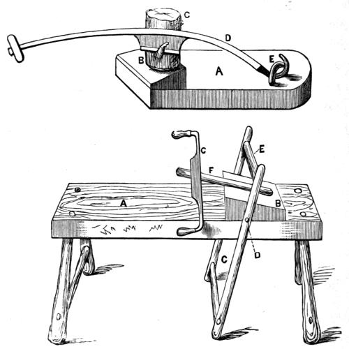
Fig. 43.
For finally trimming up short pieces, a peculiar knife is used by the lathe and tool makers; and when you can spare the money you should get one, as you will find it easy to use, and it will save you many a cut from the axe. In fact, I never advise very young mechanics to make use of the latter tool. It requires practice, strength, and a good deal of skill to use it well; and nothing is more easy than[138] to lop off the end of a finger or thumb, and, unfortunately, nothing is more difficult than to repair the damage. The paring-knife for short thick pieces mentioned above, is made like D, Fig. 43. It consists of a long and curved handle, turned up at one end to fit under a staple, E, with a cross piece of wood for the hand at the other end, and a broad strong blade with one bevel in the middle—(by one bevel I mean, that the edge is not like that of an axe, but like that[139] of a carpenter’s chisel, the bevel or sloping part being outside). C is the piece of wood to be pared, A the bottom board or platform, B a block fastened to it, and made on a slope to prevent the tendency of the wood to slip away from the knife. The whole of this may be screwed down to the bench, or to a heavy stool when in use. The hook and ferule should not be made so large and loose as in the drawing, and a better joint is that of an ordinary hinge. If made loosely, the blade twists about too much from side to side, escaping from the wood. There is no danger to the fingers from this useful tool, which the young mechanic should add to his workshop as soon as he can.
Another useful and easily-constructed apparatus for the preparation of long pieces is the shave-stool, used by coopers and chairmakers to hold the pieces securely while they are being shaped by the double-handled shave or drawknife, as it is often called, a tool omitted from our list, but very useful all the same. This is sketched at B, Fig. 43. It is often very roughly made, the chief necessity being that it shall be strong. It answers also for a sawing-stool. Upon the stool or bench, A, is fixed a sloping block, B. A swinging frame, C, is hinged or pivoted at D, so that if the lower part is pushed back from left to right, the upper cross-bar, E, will come forward and almost touch the highest part of the sloping block, B, so that any piece of wood, such as F, will thereby be pinched and held tightly[140] between the rail, E, and the block. The workman sits astride of the stool at A, facing the block, and his feet are placed on the bar C. When he wishes to hold the wood which is to be shaved by the drawknife C, he presses from him with his feet the lower part of the frame, and he can instantly loosen the wood by drawing his feet towards him. The movement is made in a moment, and the wood shifted round as required, and alternately turned about and held tight, while the drawknife is used almost ceaselessly. A very few minutes generally suffices thus to pare down a rough piece for the lathe. The cross-bar, E, should be tolerably strong, and is better if not rounded very nicely, as the edges help to hold the wood. The latter is sure not to slip away, because the pull of the drawknife tends to draw it up higher on the slope of the block, which pulls it into a still narrower opening. Nothing can exceed the ease with which this appliance is used, and the rapidity with which the required operation can be carried on. No wood-turner’s shop should be without one.
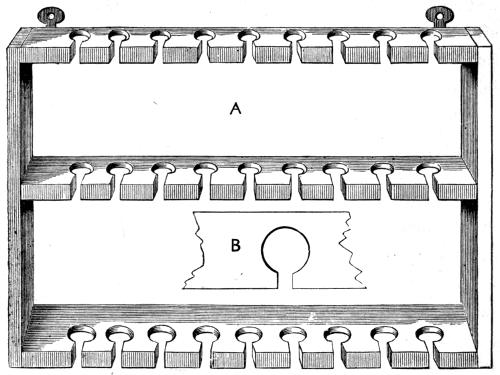
Fig. 44.
I must say a word or two as to neatness and order, especially in the arrangement of tools and appliances for the lathe. Whether you have a dozen tools or a hundred, always put them in the same place, so that any particular article can be found instantly, no time being wasted[141] hunting up and down, or examining a long row of tools for the one required at that particular time. Turning tools, moreover, should be kept distinct from those used for carpentry, and in a special rack by themselves. The best tool-rack, I think, which can be made, is one like Fig. 44. This may be made of deal, but the pieces between the holes are thus liable to get split off, and beech or ash is therefore preferable. The whole frame is made to be screwed to the wall; or, if the latter is damp, the frame should be first screwed to a board covered with baize, and this, in turn, fixed to the wall. Thus arranged, it will have a very neat[142] appearance, and the tools being kept dry, will remain generally free from rust. They should, nevertheless, be carefully looked over once a week and wiped, when those requiring to be ground should be subjected to that operation, and thus be ready for future use when required. They are bad workmen who allow blunt or damaged tools to accumulate, instead of at once setting them in order. The horizontal bars are bored with holes by means of a centrebit. The holes must be arranged as to size by the measurement of the ferules of the tool handles, some being larger and some smaller, so that when the tool is placed in any hole, the handle will drop in to the depth of the ferule and fit. Thus the tools will all stand upright, instead of leaning from one side or the other. After the holes are made, a piece is cut out (see fig. B) at the front edge, because the blades of some tools are wider than the ferules, and, in addition, if this were not done, the different tool-rails must be as far apart as the whole length of the tool (handle and all included), to allow of the latter being lifted sufficiently high to drop into the holes.
The strips for the holes should be about 2 inches wide, the lower one, for the larger chisels and gouges, rather wider than the upper ones. Sometimes these tool-racks are fitted up inside a cabinet, whose doors have similar racks; thus all can be shut in out of the reach of dust and dirt. Holtzappffel, the great lathemaker of London, fits[143] up such cabinets complete in oak or mahogany, all the tools being handled in hard wood and turned to one pattern. The cost, however, £5 and upwards, renders such less desirable to the young mechanic, who can rig up a common tool-rack, which will serve his purpose equally well. It is also far more satisfactory, in looking round your workshop, to feel that you have at all events been as little extravagant as possible, for amateurs get no return for outlay as tradesmen do.
There is no operation in which the young mechanic is so much at fault as in that of grinding and setting in order the various tools he has to use. Nevertheless he will never become either an independent workman or a good one, if he has to depend upon others for this necessary labour.
No doubt, to sharpen a tool which is in very bad order is a tedious and tiresome job; but it is not so wearisome an affair to keep tools in condition for work, after they have been once thoroughly sharpened by one who understands how to do it. Never, therefore, use a blunt tool, but at once go to the hone or grindstone with it, and put it in first-rate order. Time thus employed is never wasted, but rather saved; and the result will appear invariably in the work which you are engaged upon. You must, in the first place, understand precisely what it is you have to do; and[145] although the following details may be by some considered more adapted for advanced students than for young mechanics, a little attention to the explanations will render the matter clear to any boy of age and intelligence to take in hand, with reasonable prospect of success, the tools of the carpenter, turner, and fitter. I can only say, that boys of this generation are wonderfully well off in having these things explained to them. Twenty years ago young mechanics had to grope along in the dark, ignorant to a great extent of the principles of work, and almost equally uninstructed in the practical part of it.
In Fig. 45 are represented similar angles to those already explained to you, and you will quickly understand how useful is a little knowledge of the elements of mathematics. Suppose A to be a tool, the angle of the point is a right angle, or 90°. B is another of 60° at the point, and I have drawn a line across to show you that the three sides of this figure (called a triangle) are equal. So remember that if you want an angle of 60°, you have only to draw a triangle of three equal sides, and each of these angles will be 60°. Again, I may as well remind you that three times 60° equals 180°, which is equal to two right angles, so we find here that the three angles of an equal-sided triangle equal two right angles, and even if the sides are not equal, the same thing is true. For instance, look at the first tool, across which I have also drawn a line to make a triangle. The point we[146] know is 90°, and if the sides, a b, are equal (although the third line is not equal to either), the two small angles are each 45°, i.e., 90° between them, so the three angles again equal 180°.
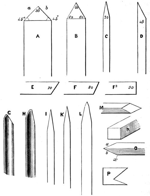
Fig. 45.
The third tool (which we may suppose a turner’s chisel held edgewise) is shown to have an angle of 30°, and I have added one more which has an angle of 45°. Now all tools, if well ground, are ground to a certain known angle, according to the material which they are intended to cut. Tools intended to cut soft woods, like deal, are ground to an angle of 20° to 30°, like the chisel seen edgewise. I shall have a word to say presently as to the direction in which such tools are to be held, in order to make them cut as well as possible. A tool for hard wood is given next at E. The angle is now at least 40°, and it ranges up to 80°, giving a stronger, thicker edge, but not so keen a one. We have, therefore, more of a scraping tool than a cutting one,—at least, in the way it is usually held. Then we come to the tools with which iron is turned and steel also. Fig. F is one of these, and the usual angle is 60°, and thence it ranges to 90°. Thus you see, advancing from soft wood tools to those for hard wood, and thence to a substance still harder, we have increased the angle of the edge, beginning at 30° and ending with 80° or 90°. But now we come to a material which is harder than wood and not so hard as iron, yet we use tools with an angle of 90°, which is still greater, and 70° is the least angle ever used for this metal.
Experience only has taught the proper angle for tools, and it is found, that if brass and gun-metal are turned with tools of a less angle than 70°, they only catch into the[148] material, and do not work at all satisfactorily. You can, however, scrape brass, as a finish, with the thin edge of a common chisel; but then the tool is held so as to scrape very lightly and polish; and its edge will not remain many minutes, unless the maker (intending it to be so used) has made it much harder than he would make it for soft wood cutting.
If you buy your tools at any good shop, you will find that they are already ground to nearly the angles named, and when you re-grind them, you must endeavour to keep them to the same. The bevel, as it is called, of many tools need not be ground at all, as they may be sharpened solely by rubbing the upper face on a hone, or grinding it, holding it so that the stone shall act equally on all parts of it. If, however, the tool should become notched, you must grind the bevel of it, and then you must try and keep the intended angle. One tool, however, or rather one pair of tools, viz., turning-gouges and chisels, are very seldom ground with a sufficiently long bevel when they first come from the maker. The usual shape of the edge is like G, whereas the angle should be much less, as seen at H. This you must correct when you first grind the tools for use, and keep the same long bevel and small angle of edge continually afterwards, for you will never make good work on soft wood if your chisels and gouges are ground with too short a bevel.
I must also guard you against another common error, which, however, is very difficult to avoid at first, and only long practice will enable you entirely to overcome it. I, is the chisel (held edgewise as before) ground as it ought to be; K is the same tool ground as it generally is by young hands, or, even if it is correctly formed at the grindstone, one or two applications to the oilstone almost invariably round it off as shown. The bevel of all tools must be kept quite flat and even, and when the tool is afterwards rubbed on the oilstone to give a finish to the edge, another flat, even bevel should be made. In the same figure at L is an exaggerated view of the chisel, with its first long bevel formed at the grindstone, and the second very small bright bevel seen at the extreme edge of all such tools when they have been set upon the oilstone. This second bevel, slight as it is, you will at once understand makes the angle of the edge a little larger, therefore you must allow for it, and grind a little keener edge than you really require.
Now, all this is very simple and easy to understand, and when you have mastered this much, you will be in a fair way to understand more. The second part of the subject, nevertheless, requires very close attention, and very likely may not become quite clear to you when explained. I shall therefore draw a line here, and make this lesson a special paragraph, which you can look back to some other day,[150] when you are grown from a boy-mechanic to a man, and have had more experience in cutting and turning wood and metal.
The tools above described have their cutting edges formed by the meeting of two planes at a given angle,—these planes being the flat bevels (or the flat top and one bevel) formed by the grindstone. But in some tools three planes meet to form an edge instead of two, and the angle of the cutting edge is not the same as that of either of these, although it depends upon them, and can be nicely calculated. This calculation, however, requires a knowledge of some higher branches of mathematics than the young mechanic is supposed to be acquainted with, and therefore a table is added instead, by which, when the angles of two of these planes are known, the third may be at once seen, which last determines, of course, the angle of the edge.
As an example, take the graver, of which you will find a drawing among the other tools, but which I give again in this place. M, Fig. 45, is the tool, looking at the face or bevel which has been ground upon it, making a lozenge-shape or diamond. But this face is a third plane, and the cutting[151] edges, a and b, depend for their angles upon all three of these. Now, for iron we want an angle of 60°. How are we to make the edges, a b, of that exact size? The bar is first of all square in section, like N, which would be its shape before the third face or bevel is ground, and all the angles are now right angles of 90° each. But instead of this, we want two of them 60°, the other two being of no importance. We simply proceed thus:—Determine which angle is to become the point of the tool (it is no matter in the present case, as all are alike), then grind away underneath till the new bevel forms an angle of 45° with the back (by which I mean the edge which runs along from the sharp point towards the handle—the edge x in fig. O). Trigonometry enables us to find out that an angle of 45° is the one required, but you will find it in the table annexed to this chapter, and an explanation of this table is also given to enable you to use it easily. Thus ground, the edges a b of fig. O will be each formed of two planes meeting at an angle of 60°. You can make a gauge of card or tin, P, to work by, of the required angle.
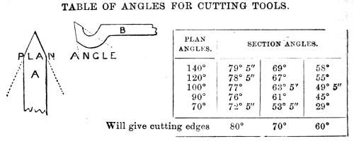
Fig. 46.
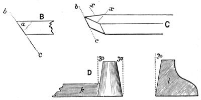
Fig. 47.
In order to understand the use of this table, it is necessary to give names to the several angles of a tool. That upon the front or face of the tool, as A of the point-tool, is called the plan-angle; that made by the upper surface and the front edge, as B (a, being the angle in question), is called the section angle, because, if you were to saw right[152] through the central line lengthwise, this is the angle that would appear at the point, viewing it sideways. Now, if we look at C, Fig. 47, we shall be able to understand how the front line, b c, is obtained, which constitutes one side of the section angle of a tool. It results from the meeting of the two diamond-shaped planes at the sides formed by the grindstone, but is dependent also on the plan-angle. These two side-planes are to be generally ground at an angle of[153] about 3° from the vertical, which is to give the clearance of the tool if held in a fixed position, as in the tool-holder of a slide-rest, the tool being supposed horizontal. This is in accordance with what I have before told you, viz., that the cutting edge should be presented to the work at the smallest possible angle, 3° being very small indeed. This angle is generally measured by placing the side ground in contact with a cone of wood or metal, turned to an angle of 3°, such as D,—k being a tool the front of which is evidently 3°; or a piece of tin, l, cut to the same angle, and stood on its edge, will answer the same purpose. By 3°, I mean an angle of 3° measured on the circumference of a circle, as I have already explained in a former page, such angle being of course at the centre of the circle where the lines drawn from the several degrees on the circumference meet.
Now, when you have ground these two surfaces, the line b c of B (or C) will have a certain slope or inclination depending on the plan-angle of the point. The exact inclination of it may be therefore said to be accidental; but, whatever it is, it becomes of great importance in the final result, being one side of the angle which will give any particular angle of cutting edge. And here the table comes into use:—Suppose I wish to have an edge of 60°, for cutting iron. Measure the plan-angle,—say it is 90°, which is that of the graver; then, on the table, under the[154] words “plan angle,” you will see 90°, and opposite, above 60° of “cutting edges,” you will see 45°. You have only to grind back the upper face of the tool, until it makes an angle of 45° (section angle) with the front edge or line, b c, and the edges x x will be angles of 60°. Or take the tool E, of which the plan angle is 120°, and suppose you want cutting edges of 80°, for brass, opposite 120°, and above 80°, is 78° 5″. Grind back the top face to an angle of 78° 5″ (or 78½) with the point line, and it is done.
Until you have practically proved it, you can have no idea of the vast importance of having correctly-formed cutting edges, and of placing them within a hair’s-breadth of the proper position. But it is in slide-rest work especially, and in cutting metal with tools held rigidly in one position, that this is of such paramount importance. It makes all the difference between cutting off a clean shaving, and tearing from the material by main force a quantity of disjointed particles, the latter process leaving a rough unfinished surface, the former producing one as smooth and polished as a sheet of glass; and the advantage of this short table is, that you can at any time shape your own tools for the particular work in hand.
After you have had some practice in turning, you should certainly learn to shape your tools from square bars of steel, worn files, and broken steel tools of various kinds; and before you have arrived at sufficient dexterity to do this[155] entirely by yourself, you will get them roughly shaped for you by the blacksmith, and then with grindstone and file you will further perfect the angles for use. Steel does not require, and must on no account be subjected to, a white heat, or you will spoil it hopelessly; and you can always heat it in a common fire, or in the little stove that I shall describe in a subsequent chapter, to a temperature that will allow you to bend it into any required form with the hammer and anvil—a bright red being the utmost heat it must be brought to.
We must now consider the mode of applying the edge of a tool to the work, so as to produce the best effect. First, we will consider the case of a gouge and chisel acting upon soft wood.
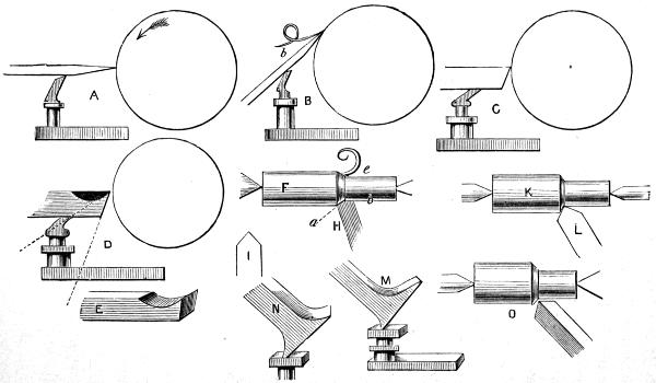
Fig. 48.
In Fig. 48, A represents a piece of wood in the lathe, as you would see it if you stood at one end of it, and a chisel is being held against it. The arrow shows the direction in which the wood is supposed to be revolving. Held thus, the chisel would scrape, and its edge would be carried off at once; it could not possibly cut. But, held as at B, it would cut off a clean and continuous shaving as the wood revolved against it, and this shaving would slide off along the upper face, b, of the tool, so that you can see that this face ought to offer the least possible resistance to it. The tool[157] acts, in fact, like a very thin, sharp wedge, which divides the material by pressure, which has to be great or slight according as the edge is sharp and thin or the contrary. Now, if you again look at A, you will see that this wedge-like action cannot take place, so that the tool is in its worst possible position.
Between the two positions, however, here shown, are several others at a greater or less angle to the surface of the wood; but the smallest possible angle it can make is the best, so long as the thickness of shaving removed will suffice for your purpose. This rule holds good with all tools, whether carpenters’ or turners’, which are made with sharp-cutting edges. Care must be taken, however, that the lower face of the tool does not rub against the work, which, again, it is evident, limits to a given degree the angle at which the cutting edge is to be applied to the work.
We now pass on to C, which represents the ordinary tool for turning iron, held flat upon the rest, the position it usually occupies. We see at once that in this case also we have a scraping tool only, and that, although the angle of the edge is far greater than that of the chisel, it must soon be ground off by the action of the metal to which it is applied, or of the hard wood, which is also cut in this way. But with this form of tool we shall find it impossible to apply it so as to cut in the best way; because if we lower[158] the handle, as we did that of the chisel, the part below the edge will rub against the work, while the edge itself will be moved out of contact with it. Thus we are obliged to hold the tool in the position first shown; but we may therefore conclude that the tool itself is a badly formed one for the intended purpose; and so it is, although you will see it in almost every workshop in the kingdom. Let us see what can be done to improve it. At D, I have represented the same tool, but the blackened part shows what has been filed away from the upper face, and the dotted lines show that, when this has been done, a tool is made very similar to the chisel for wood, and that it is also now in a good position for cutting (not scraping), although it is still held horizontally upon the rest. Shavings of iron curl off the upper face of this, as wood shavings curl off upon a chisel.
If the angle, however, is too small, the edge will soon be broken off, and the tool will dig into the work; hence the necessity of knowing at what angle a tool ought to be ground to cut any particular metal successfully.
Such a tool as the last named, which is intended only to cut with the front edge, and which is represented in E, is called a single-edged one, because it only cuts in one direction, but many others are double-edged, cutting the shaving at once on the flat and edge—that is, paring it off from the material below and also from the side. For[159] instance, F is a cylinder of iron, from which a shaving is supposed to be in process of being cut. It has to be removed from the shoulder to which it is represented as still adhering, and also from the flat surface, e b, around which it was, as it were, once coiled. But this requires two cutting edges, both acting at the same time, but in different directions; and good mechanics therefore so form the tools, and so use them, as to cut in both directions, which leaves the work beautifully smooth and even.
These tools are mostly used in the slide-rest, where their true position, once determined, can be accurately maintained; and it is, perhaps, only with the slide-rest that perfect work can be done. There is, however, no reason why you should not use tools of all kinds intelligently, and understand exactly how they should be formed, and how held. Suppose you have a tool correctly made by the aid of the table of tool angles already explained, still looking at fig. F, you can see that the smaller part of the roller is that which is to be left finished, and that it ought to be quite smooth, but the shoulder at a is not of the same degree of importance. A tool fit for such work would evidently be shaped on its plan-angle or face, like H in fig. C or I; and, if held as seen, both edges would be brought into action at the same time, as will be at once evident on inspection. In practice, however, the two edges would not be allowed to touch for their whole length, or the angle on the right[160] would leave a scratch upon the finished work; therefore it would be eased off a little, as at K, L. But this is evidently as nearly as possible the shape and position to be given to such a tool, and the edge which has to leave the finished surface should, as it were, follow the other; the right-hand angle being just and only just kept out of cut.
The hand-tools you will generally use are the heel-tool, M, held on the rest as shown, which, you see, brings the edge into cut at the least possible angle to the work, and the nail-head, which is in fact a heel-tool of four faces, or, if round, a heel-tool all edge, and which can be rolled over as it gets blunted. To these add the graver, of which I have already spoken. I have tried to show its position at O, with the bevel of the face pointed in the direction of the shoulder, and downwards; but it can be held face upwards also, and in one or two other positions. Always remember that the cutting edge is to be presented at a small angle with the work, and you cannot go wrong if the tool is well formed. The nail-head and heel-tools are single edged, and easily ground without the table of angles, but the graver is a double-edged tool, properly speaking, although only one edge may perhaps be used.
Having explained the principles upon which you have to work as regards grinding your tools and holding them when in use, I shall merely add a few remarks as to the[161] action of the grindstone and oilstone, and the proper way of using them.
Always let the stone revolve towards you, as if you had to turn it smooth with the tool you have to sharpen, except when you cannot possibly do so without cutting grooves in it. Chisels, knives, axes, planes, and all similar tools with flat edges, are to be ground with the stone running in that direction, by which means you will avoid giving them a wire edge, as it is called (i.e., a ragged-looking edge), and it will instead be even and sharp; the filament of metal being, as it were, driven back into the substance of the tool, instead of drawn away from it. Gouges may be ground in the same way, but must be rolled about to keep up the form of edge. It is indeed the easiest way with these to hold them across the stone, in the same direction as its axis, and then, by rolling them over backwards and forwards, you can give a very good shape to the edge, which should run slightly to a point, or rather tend to one. They are never to be ground square across, like that of the carpenter.
It is generally necessary to have some sort of rest upon which to lay the tools during the operation of grinding, but do not trust to special contrivances for holding them at the precise angle needed; rather trust to your own skill, which will increase more and more by being severely exercised. Always remember to grind your tools to a sharper angle than will be ultimately required, that the final angle[162] may be given by the oilstone. Of the latter there are many kinds. Nothing probably can surpass a Turkey stone, if good, but this varies considerably in hardness and other qualities. There is a very quick-cutting, slightly coarse stone from Nova Scotia, which is very serviceable, as it does this tedious work with great rapidity, not, however, putting on the tools a very fine edge, but one that admirably suits for such as are to be used on metal. With the rest, a rub or two on Turkey, or Arkansas, or Chorley Forest stone, will impart a finish. Arkansas stone, however, may be had coarse as well as fine; it is much liked by some, but I prefer the Nova Scotia, as it cuts more keenly, and even with the sharpest stone, setting tools is a most laborious process.
The young mechanic will find it very difficult at first to hold the tool steady, and to move it to and fro upon the oilstone so as not to give it any rolling movement, by which the edge and bevel would be rounded, as I before explained, which would in effect enlarge the angle of the cutting edge, besides preventing it from being held at a sufficiently small angle to the work to cut effectively. Nothing but practice will overcome this difficulty; I shall not therefore attempt to describe exactly how the tool should be held and the sharpening effected, such description being not only difficult, but, as experience has proved to me, impossible.

We now enter upon the actual work of the lathe, which should be comparatively easy to understand after the foregoing observations.
Your raw material having been chopped or shaved into a rough cylindrical form, you have to mount it in the lathe. I may suppose it a piece of beech for a tool-handle. If you have the cross-chuck, you should use it; if not, you may use the prong instead. In either case, centre the wood as truly as you can, so that, when the rest is fixed near it, the piece may not be much farther from it, as it revolves, in one place than another. Mind and screw down the back poppit tightly upon the lathe-bed, and also the rest, putting the latter as near the work as you can without touching it. Now set the lathe in motion,—this is tolerably easy, but to keep it in motion will probably not be easy at all. It is one of those operations which[164] require practice, because while your leg is at work upon the treadle, your body must be firm and still, so that you feel yourself free to use the tools without giving much attention to what your leg is doing. After a while you will do this with perfect ease. The wood is, of course, to rotate towards you, and the surface will come in contact with the edge of the tool as the latter is held tightly down on the rest. Now, this is, after all, the real difficulty, for every projection striking the tool tends to jerk it off the rest, and this has to be resisted with some force. There is, however, this advantage in hand-tools, viz., that they may be held rigidly yet be allowed some slight play, according to the peculiar exigencies of the work; and at first you will save the tool by allowing it to yield slightly until the roughest part has been cut away. Afterwards, there is to be no movement except that required to make it follow the curves or level parts of the work. Do your best first to produce a cylinder, i.e., a straight, even piece of wood, as long as the required handle, and as large round as the largest part proposed to be given it. It is the best plan at first to copy a well-shaped handle, and to turn as many as you want of that size exactly to the same pattern. This will give you such an amount of practice in copying form, as will stand you in good stead in after days; for it is not easy at first to turn even two things exactly to pattern and to size.
You must not expect to be able to run your tools along the work like a professional or old hand at the lathe; you must do the best you can. Hold the handle in the right hand, and with the left grasp both rest and tool together, and you will hold it firmly. Then you ought to run it along right or left at the right speed and the right angle, but you will be unable to do so yet;—never mind. Remember the principle I have laid down as to the position and angles of cutting tools, and trust to time and perseverance to make you a good workman.
The gouge is the easiest and best tool to use at first; and you can do a fair amount of smooth work with it if you know how, although smoothing and levelling is the special work of the chisel. The gouge, however, is used for all sorts of curves and hollows, and though the actual point will only turn a groove if held still, the side of the cutting part will, if the tool is steadily advanced, turn very fair surfaces indeed. I strongly advise practice with this tool before attempting to use any other. Your early work is of little importance, and you may make up your mind to cut several pieces into shavings and chips without very grand success, even though you use a chisel; so I repeat, stick to the gouge only for some time, until you can use it towards left or right, and with either hand grasping the handle.
With the chisel, far more care is required than with the last named. It is altogether a more difficult tool to use.[166] Its position may be described as follows, but practice alone will render its use easy. Lay it first flat on the rest as you would the gouge, and let it point upwards at a similar angle, until it also is in the position the gouge would take, ready to cut the piece of wood in the lathe, already turned to the cylindrical form by the latter tool. You will find one point or angle of the edge, the sharpest, reach the wood before the other, and will see at once that this would be liable to catch in, if the lathe were in motion—and so it would. I shall suppose that this sharpest angle is on the right-hand side as it lies flat on the rest, and against the wood. Raise that angle so that the tool lies a little edgewise on the rest instead of quite flat, when the angle of the tool that is highest on the wood will be also raised off it; the lower angle and remainder of the edge still being in contact with it. This is its proper position, with the upper angle out of contact with the work. You may turn it over so that the keenest angle is the lower one, but then you must raise the other, which is now the upper one, for under no circumstances must the one that is uppermost touch the wood. The chisel, therefore, never lies flat on the rest or on the work, but always slightly raised to clear the upper point, and in this position you have to keep it, making it descend into hollows, and rise over mouldings, and cut level places, almost without stopping an instant; and for wood, especially soft wood, the lathe is always itself to be[167] run at a very high speed, by putting the cord on the largest part of the fly-wheel and smallest part of the pulley.
To return to the supposed tool-handle. Having turned a cylinder, begin at the ferule, which you must cut off a brass or iron tube, or, which is easier, buy by the dozen or by the pound ready cut. You will want them three-quarters of an inch for your largest tools, and about three-eighths for the smallest, with some of half an inch, and you can then bore your tool-rack exactly true with centrebits of these sizes. Turn the place down for the ferule, and take care that you make a tight fit. Gauge with the callipers first of all, and turn almost to size, then try it on once or twice until it fits exactly.
If you use the cross-chuck, you have this one great advantage—you can take out your work to put on the ferule, and replace it exactly as it was before, and it will continue to run true. As, however, the piece in the present case is but partially turned, it can be replaced with sufficient accuracy upon the prong-chuck, especially if you mark the side of the chuck, and of the piece of wood, and take care to replace them in the same relative position. You must now try with gouge and chisel to imitate the pattern handle, remembering always to work downwards from right and left into the various hollows—(you cannot cut the fibres neatly if you try to go up-hill); and where the two cuts meet in the hollows, you must do your best not[168] to leave the least ridge or mark. You will be sure to need a little glasscloth to finish off your work, but do without it as much as possible, because it spoils the shape of mouldings, rubbing off the sharp angles, which in many cases add beauty to the work. If the piece of wood is longer than necessary, cut it off with the chisel. In any case, you must cut off a piece at the chuck end; and this being the end of the handle which you will hold in your hand, the ferule being at the end next to the back poppit, you will cut it off neatly with the chisel in finishing it to the required shape.
You would hardly suppose it possible to turn off the end of a piece squarely and accurately with the gouge, but it is a good tool for the purpose. You must lay it on its side upon the rest, so that its back or bevel rests flat against the end of the piece from which the superfluous wood is to be taken; the edge or point of the tool is then allowed to cut the work by a slight movement of the handle. You can only do it in this way, with the bevel against the piece from which the cut is to be taken. Turned over to its usual position, it will hitch in and spoil the work in a moment. In the same way you can face up a bread-platter or similar flat work; but such articles as these are not mounted between centres, but screwed upon the taper screw-chuck or the flat plate with the screw-holes, so that you can get to the face of them. At first, however, until the[169] work gets tolerably level, you may bring up the back-centre, which will prevent the taper screw of the chuck from being accidentally bent; and when all the rough part is cut away, and the rim turned down, you can remove the back-centre to finish the facing up. In this work, however, the back and face do not need much turning, because the platter is turned from plank wood, planed up truly on each side, and cut roughly into the form of a circle. If accurately planed, it will run true at once, and the small amount of facing may be done with the gouge held as directed. Afterwards it may be necessary to take a light scrape with a carpenter’s chisel, which answers well for this. Then finish up with glass or sand paper. Take care to make a neat moulding to the edge, which will be about an inch thick, and will therefore look very heavy unless turned off so as to thin it down. A platter is a very good and useful work for a beginner.
In turning a platter you will certainly learn one lesson in mechanics. You will find that it is very hard work to turn anything that is larger than the pulley of your lathe, and you will only be able to take a very light cut. Probably you will find it the easiest plan to set the lathe in rapid movement, and apply the turning-tool only for an instant, and then to remove it until the work has recovered its impetus, thus cutting it, as it were, by repeated brief applications of the tool, instead of by one continuous cut.[170] I do not mean that the tool is to be removed from the rest, but only eased off for a second from the work. If the latter is very large, and the pulley on the mandrel much less in size, you can only work in this way, finishing with a very light cut. There is a tool for the face of such flat works, called a broad. It is like a broad chisel with the end turned up at right angles to the side, only the edge is a bevelled one and thick. They work well in hands accustomed to them, but the gouge and chisel are sufficient for your present need.
I shall sketch here (Fig. 49) one or two articles not requiring to be much hollowed out, which will help you to decide upon such work as is suitable to a young mechanic desiring, by steady practice and application, to become a proficient at the lathe, and as soft-wood turning will teach you more than that in hard wood, I shall direct all the following to be made of it by gouge and chisel alone.
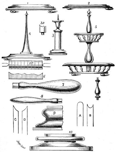
Fig. 49.
These examples are not given as specimens of the rich work which can be done in the lathe, but as easy examples of elementary turning. No. 1 is a stand for an urn or hot water jug, and a slight recess may be made in the upper surface, in which a piece of cloth, or carpet, or oilcloth can be glued, which will make a neat finish. No. 2 is a bread-platter, showing how a little neat moulding takes away the clumsy appearance of the thick board necessary for this[172] purpose. No. 3 is a candlestick. The lower part or stand is to be turned from a separate piece of thick board screwed upon the taper-screw chuck. While it is in the lathe, the hole must be made in the centre (or marked, if the piece is not very thick) by holding a pointed tool a little on one side of the centre, so as to describe a circle of the requisite size. Into this will be fitted a tenon, fig. 3 B, which is turned on the pedestal, and which is to be glued into its place. By and by you will learn how to cut a screw upon such a tenon, which is a far more satisfactory method of proceeding; at present glue will answer just as well. You can make the upper part separate, forming the junction at the line C (Fig. 49, No. 3), if you prefer it, or if your wood is not long enough; but as you will not hollow out the top, you may as well let it be cut out of one piece with the pedestal. Turn the top quite level, drive in a piece of stout wire, and point the end of it. Cut out a round piece of tin to fit, and make a hole in the middle of it to let the wire through; drop it over the point, and let it rest on the candlestick; a wax candle can be spiked upon the wire, and will stand firm.
Figs. 7 and 8 are drawings of tool-handles. These are the best shape to grasp in the hand, and they look neat in the tool-rack. Tool-handles with a number of mouldings, are not only absurd, but are uncomfortable to hold, and not at all suited to their intended purpose. 9 and 10[173] are other forms of mouldings, and are given merely to show how angular and rounded forms should be combined to produce a good effect. If these were to be made in hard wood, they might be turned with beading and moulding tools similar to those at A, B, C, D of this figure; such tools are bevelled only on one side, and being held flat upon the rest, cut the curves and hollows rapidly, and clean. Sometimes a number of these are arranged side by side, so as together to make up the outline of the intended moulding, and being held in position by a handle designed for the purpose, are presented all at once to the work as it revolves. In other cases, a flat plate of steel is filed into shape, and bevelled to form a compound moulding tool. Of course, such contrivances greatly help the turner, especially if he has to turn a number of articles of exactly the same pattern, such as the pawns of a set of chessmen, or a set of draughtsmen; but none of these tools answer upon soft wood, because, as already explained, tools which have to be held horizontally will cut and tear up the fibres of all woods that are not very hard and compact in grain.
Fig. 6 is a profile of a draughtsman, and fig. 6 B shows how they ought to be made, but for this you cannot use soft wood, and had better make them of box and ebony, or holly and ebony—(and, by and by, of black-wood and ivory). A cylinder is first turned, then marked off as shown with grooves cut by a parting-tool. The pieces are then[174] separated with a fine saw, and a chuck is hollowed out to fit them so that each can be readily turned upon the face. The desired mouldings having been made on one side, the disc is turned over in the chuck, and the other side operated upon in the same manner.
It is quite possible, you must understand, to cut these out of soft wood, even pine or deal. We often see boxes of toys, children’s wooden plates and cups, turned very neatly of this material; but it is not worth while to use it if you can obtain boxwood. Moreover, box can be stained black to imitate ebony, and is very often made to serve instead of it.
Figs. 4 and 5 are ring-stands for the toilette-table—very useful presents these to mothers, sisters, and, last but not least, lady cousins, and other young ladies too, perhaps, who are not cousins. These can be made in a variety of ways, and give great scope for the exercise of your powers of design. The first is a simple pedestal on a stand, turned quite smooth in an elegant and simple curve. The stand is also made without elaborate mouldings, giving altogether a chaste and elegant appearance to the design. The extremity is tipped with ivory, and an ivory ring surrounds the bottom of the pedestal. If this is made in plain deal, and thoroughly well finished and varnished, it will look very well. The nicest soft English wood, however, for this is certainly yew, some of which is beautifully fine in grain; and as it will take an excellent polish, it always looks[175] well; moreover, it can be turned entirely with gouge and chisel.
This ring-stand will be made in two parts; the pedestal being separately turned at one end, a tenon will have to be made as in the case of the candlestick, and just above it the wood is to be turned off a little as if you were going to make a larger tenon. Over this a ring of ivory may be slipped and glued on, and the two can then be turned together. A carpenter’s chisel will do for the ivory, which will be scraped into form by it. It may be polished with a little chalk on a moist rag or flannel. You can buy odds and ends of ivory from the turners in rings and solid pieces, which will come in for all sorts of decorations, and you should save all old handles of knives, tooth-brushes, and such like, for a similar purpose. Both ivory and bone smell very disagreeably when in process of being turned. To tip such articles with ivory, you can drill a small hole in the top of the pedestal with great care, and fit the ivory after being turned into it; or you can, if the work is larger, bore the ivory and slip it on the wood;—much depends upon the size and nature of the work.
The second ring-stand is of rather more elaborate construction. The baskets are made of little turned pedestals fitted into a round piece of wood to form the bottom, and into a ring which makes the rim. Baskets of this form (even apart from the ring-stand) are very neat and useful.
It is very easy to turn rings of any size. Mount a piece of board in the lathe on the taper screw chuck—it need not even be cut to a round form; then determine the size of the proposed ring, and, holding a parting-tool upon the rest turned round to face the work, mark two circles, and deepen the cuts, until the ring falls off. Take care that the outer one is cut through first. The ring thus cut may be afterwards placed upon a cylinder turned to fit it, and finished upon the outside, and then placed inside a chuck of wood bored out to suit the work, and neatly rounded off upon the interior surface. Of course, if you have to make rings of bone or ivory which are already hollow, you can at once run a mandrel or spindle of wood or metal through them and subject them to the various operations required.
Mandrels, or tapered cylinders of brass or iron, fitted as chucks to the mandrel of the lathe, are sold on purpose for this work, but a wooden rod answers just as well, and costs nothing. Turn such a rod a little tapering, and take care not to drive the work too far upon it, because, although at first you can safely drive it on very tightly, if it is of ivory or bone, you will frequently find your ring suddenly split and open when its thickness has been reduced to the required standard. If a number of equal rings are required, it is the best plan to turn a hollow cylinder and then saw off the rings as you are directed to saw off the draughtsmen.[177] They will, of course, have to be finished in a chuck.
If you look round any fancy warehouse in which Swiss carvings are sold, you will see how beautifully soft white pine can be worked in the lathe by keen tools and clever hands. In Tunbridge, too, many thousands of soft-wood articles are manufactured yearly, some plain and merely varnished, and some curiously inlaid with coloured woods, so that you need not despise such materials as willow and sycamore and the various pine woods, which are all capable of being made into pretty articles of one kind or another. The varnish, however, for these is such as to coat them with a glassy layer which does not sink into the wood. Common rosin dissolved in turpentine or in linseed oil, kept on the hob so as to get warm, answers well for these deal articles, and is extensively used where the slight tinge of yellow is not considered important. There are many other much paler varnishes for works of greater value, or where the white wood is to be carefully preserved. Any of these can be had at oil and colour shops.
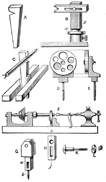
Fig. 50.
You will certainly find a difficulty in turning all exactly alike the little pillars of these baskets. You should turn several at once out of the same piece, separating them afterwards. Thus your pattern will always be close to the half-executed copy, which will somewhat assist you. Do your best in this respect, but be specially careful, at any[179] rate, to make all exactly the same length. One pillar is shown separate, but you can design a pattern for yourself.
Begin by turning a long cylinder; then set off the respective lengths of the pillars. Turn one complete as a pattern, and set the callipers to the largest part of it. Then go to work upon a second, using callipers freely at all parts of it. As these pillars will all be slender, you will be in great danger of breaking them; therefore use your tools lightly, taking only a very slight cut. But with all your care you will find it difficult to turn a row of more than two or three of the size wanted for such little baskets. I shall therefore show you how to make a support to fit at the back of the bar you are at work upon to support it against the pressure of the tool.
Fig. 50 gives a representation of one or two such supports, which are often required in turning. The first is the most simple, and is the one most generally in use, because easy to make and to apply, and it answers tolerably well. A is merely a piece of wood, about three-quarters of an inch thick, cut as shown. This is stood up between the lathe-beds, like C, and fastened with a wedge before and behind. It allows the work in the lathe to revolve in the notch which is cut in it, as is evident from the drawing. One, two, or more such may be used if necessary. They must be carefully adjusted, so as not to bend the piece which is to be turned, and which is to be just supported, but no more. Where[180] the back-stay, as this contrivance is called, comes in contact with the work, the latter is to be left of the size it was when this was adjusted to it as long as possible. It must then be shifted a little, and that part which formerly rested against it finished.
B is another simple form of back-stay, capable of nicer adjustment. The foot is that of a common rest, but if you have not a spare one, any wooden support is quite as good. Into this fits a turned part of the upright x y,—the upper part, y, of this being planed flat. Neither should be of deal; ash or elm is preferable. Thus the part x y can be raised and lowered at pleasure in the rest-socket. The top part is made of a half-inch board, about 2 or 2½ inches wide; a slit is cut in it, and it is fastened to x y by a short bolt and nut. Thus it is easy to raise and lower the end of this part, and to put it nearer to, or farther from, the work in the lathe, against which it can be adjusted with great nicety. Although there are several forms of back-stay, of more or less complicated construction, I know of none more generally serviceable than this last, which the young mechanic can make for himself. The notch should be lubricated with soap, or, if the blackness is not of importance (as when this part, which rotates in the notch, has finally to be cut away), with a mixture of soap and blacklead. This, remember, is always to be applied to wooden surfaces that are to work easily upon each other.
It will sometimes happen that you require to bore a hole through a long piece of wood, as would be the case in making a wooden pipe, flute, bodkin-case, and many similar articles. To hold these in a chuck only would be often impossible, because the hole in the chuck would have to be as deep at least as half the length of the piece to be bored.
For this kind of work, therefore, and for turning up a point on the end of a cylinder of iron or steel, like that of your back poppit, the following contrivance is used, which is called a boring-collar or cone-plate. It is represented in Fig. 50, D and E. This consists of a circular plate of metal, three-quarters of an inch thick, turning upon a large screw or pivot at its centre, by which pivot it is attached to a short poppit head, fitting between the bearers of the lathe as usual. There are six or eight conical holes bored round the circular plate, each of a different size; and these are so arranged as to height, or distance from the centre, that the top one (being in a perpendicular line passing through its centre and that of the bolt) is exactly as high as the axis of the mandrel. Thus, if it is clamped in that position, with the largest side of the conical holes next the mandrel, a piece of wood might be held at one end in a chuck, while the other might rest in such hole as was best suited to its size, not actually passing through it, but resting in the inside of the conical hole, in which it would rotate almost[182] as freely and as truly as if it were supported by the ordinary point of the back poppit.
Sometimes it may be preferred to allow the end of such a piece of work to project through the cone-plate, a collar being turned on it to prevent it from going too far. A tool-handle, for instance, of the pattern before given, may be beautifully bored in the lathe by allowing the ferule to rotate in one of the holes of the cone-plate, the shoulder behind preventing it from going too far. The rest is brought round in front of the end of the handle, and a hole bored by a drill for wood; or, the point of a drill is brought against it, while the other end (having had a slight hole made by a centre-punch for the purpose) is allowed to centre itself on the point of the back poppit. The screw of the latter is then advanced, and the drill being prevented from itself revolving either by being grasped by the hand or a vice, a beautifully straight and even hole is rapidly made.
Fig. 50, F, shows the position of the various pieces. The drill is here kept from rotating by a small spanner, the handle of which comes against the bed of the lathe. A great deal of work, both in wood and metal, is always drilled in this way.
For wood, a small nose-bit, or auger-bit, or one of the American twist-drills, can be used, and this may be succeeded by a larger, until the hole will allow of the introduction[183] of a finishing-tool of some kind, held in the hand. Of course the latter is not necessary in boring out handles for the tang of a tool, but only in turning boxes for pencils, needles, or other articles, which require to be neatly finished inside as well as out; all these are to be bored before the work is cut free from the superfluous wood out of which it was turned. You can even use the cross-chuck for this work.
It matters little, when using the cone-plate, whether you finish the turning of the outside before or after the boring is done. Very generally the box or other article is bored first, quite in its rough state, except that a short piece is turned down to fit into a hole of the cone-plate; and, keeping the latter in its place all the while, the wood is turned down and polished before removing it from the lathe. Sometimes, especially with metal, which is in no danger of splitting, the cone-plate is removed as soon as the hole has been made and replaced by the back-centre, the point of which, entering the hole, retains the work in its place while the outside is being fashioned. This of course insures the exterior surface being exactly concentric with the inside, which is often absolutely necessary in parts of machinery; but if wooden articles are finished in this way, there is great danger of their being split by the pressure of the back-centre as the work grows thinner and thinner under the action of the tools. Moreover, it must[184] be remembered that the back-centre, being itself of a conical form, will injure the form of the hole in metal by making it wider at the mouth if used in this way, and sometimes this may be of importance.
There is a fault in the cone-plate which boys will understand, and men, too, I imagine. It costs money! Therefore I shall now show you how to make a substitute, which will cost something under a shilling, if you do not mind a little trouble; but, if you do, you will never make a good workman, nor will you be good for much, I fear, in any way! A metal cone-plate for a 5-inch lathe costs £2 at least.
I shall suppose you want a cone-plate in which to bore your tool-handles, for it is not easy to do this with a gimlet, so that the tools, when inserted, shall stand straight in their handles. If you have a 5-inch centre lathe, i.e., a lathe in which the central line or axis of the mandrel is 5 inches from the lathe-bed (in which case you can turn anything nearly 10 inches in diameter), cut out of a piece of beech, 3 inches thick, a short poppit 3½ inches high, of some such shape as seen in the fig. G; and in the lower part (which must be cut to fit between the lathe-bearers, and must be made square at the sides and true, so that the whole will stand squarely across the lathe-bed), either cut a mortice, a, for a wedge, or bore a hole for a screw, which must have a plate and nut to fasten under the bed like other poppits. Near the top, and exactly[185] in the centre, bore a hole to receive the bolt K, similar to that in the metal cone-plate already described, and which will be tightened by a nut at the back. This supplies the place of the short iron poppit, and now you have to contrive something to replace the circular plate of holes. Cut two or three strips of any tolerably hard wood, H (beech will answer very well), 6 inches long, half an inch thick, and 2 inches wide. Cut in these a slot and a round hole, which must be carefully made with a centrebit. This hole is to be for one of those in the usual round plate, so be careful in making it. Work thus: Plane up the piece from wood rather more than the half inch required; draw a line exactly down the middle of it on both sides e, f; choose a centrebit of the size you require; put the point upon this line, about 1½ inches or more, according to the size of the required hole, and bore steadily a little way into the wood. Then turn it over, measure carefully so as to get the precise spot right, and finish from that side. If the centrebit is sharp, and the wood sound, you will now have a neat round hole. Let the slot be also cut from both sides of the piece of wood with a sharp chisel, taking care that the centre of it agrees with the line that you made for a guide.
Three or four of these should be made, each with a different sized hole, or more if required; but you can add new ones at any time. The bolt, K, is to be made with a large[186] head flat on the under side, and the upper part, above the screw, is to be square for three-eighths of an inch, and the slot in the pieces of wood must just fit this squared part. Now, as this is three-eighths only, and the thickness of the wood is four-eighths or half an inch, it is plain that the nut will draw, and the head of the screw clamp this tightly. You can, if you like, however, make the hole in the poppit square also, and then let the squared part of the screw be long enough to reach almost entirely through both pieces. Then slip a washer (an iron plate with a hole in it like L) over the end of the screw, and fix all with the nut. Thus you have a boring collar with one hole, and this you can raise or lower the length of the slot so as to get it exactly the right height, and when it is so arranged, one turn of the nut at the back will fix it.
This you will find a very simple form of boring-collar, easy to make, and of practical use. If you really take all the care you can, and follow the directions I have given, I do not see how you can possibly fail in constructing one. You should have a sliding-plate with a hole for each size of tool-handle ferule used, as you will frequently be making these.
As I have spoken of boring, I will go on to treat now of the general practice of hollowing out chucks and boxes, and such like. If this is to be done in soft wood, such as[187] willow, no tool will answer so well as the hook-tools, of which I have given drawings. But these are very difficult indeed to use, owing to their tendency to catch in, or take suddenly a deeper cut than was intended. Nothing but practice will teach exactly how to use these tools; but then, when the difficulty of so doing is once mastered, nothing can be more rapid or more satisfactory than the work which they will do. Small bowls are hollowed almost instantaneously by their means in skilled hands; whereas, with other tools, it becomes not only a tedious job, but if it is done at all, it is but roughly, the wood having to be rather scraped out than cut. Using, however, the back of the gouge as explained before, in the directions given for squaring up the end of a cylinder with this tool, it is possible to hollow out soft wood with it, but not very satisfactorily. In any case, other tools (generally a carpenter’s chisel) must be used to work into the angle which neither the gouge nor hook-tool can, of course, reach. Hence it is generally so much easier to cut out boxes and such like articles in box or hard wood, that this is nearly always used by amateurs.
The ordinary way to turn a box is as follows:—Prepare the wood as usual, turning it cylindrical, using any chuck you please for this work; cut off with the parting-tool rather more than the box and its cover together will require, and drive the piece thus separated into a cup-chuck. [You[188] may, if you prefer it, screw upon the nose of the mandrel, or upon the taper screw-chuck, the rough piece of the proper length, instead of first turning a cylinder to cut from. If you have several boxes to make of one size, the cylinder method is to be preferred.] Turn it up again quite true, for although it was correct before you cut it off, it will not be so now. Square up the end, and turning round the rest so as to stand across the face of the wood, begin to hollow out the cover. Use either the round end or pointed tool at first, and then a carpenter’s chisel or flat tool to finish. Be very careful that the sides (I must call it by this name, although a circle has not more sides than a plum-pudding) are turned square to the bottom, or else, when the cover is put on, it will perhaps fit just at the entry, and be quite loose when fairly on; or, it may be that it will be easy at first, and when you press it on, it will be tighter and become split,—a very common but unpleasant occurrence. Do not, moreover, turn down these sides as thin as they will ultimately be; because, after the box is hollowed and the cover fitted on, both will have to be slightly turned together to finish them nicely. Moreover, you may not wish your box to have plain sides, but may prefer to mould them into a more elegant form. All these little questions have to be duly considered in turning, for a mistake is often made, and the work spoiled, for want of a little timely consideration.
The next point on which you have to be on your guard is this,—having turned out the cover, you have to cut it off, not with a saw, but with your parting-tool. Now, be sure to leave thickness enough for the top of the cover; or, just as you think you have nearly severed the latter from the rest of the piece of wood, you will see a beautiful little ring tumble off,—sad relict of your box cover, which has come to an untimely end.
The sliding square of the turner, of which I gave a description among the list of tools, will always enable you to gauge both the depth to which the work is hollowed out, and also the squareness of the inside to the bottom. But if you have no turner’s square, you can easily gauge the depth inside, and thus see how much is necessary to be allowed for the thickness of the top. Keep the parting-tool edgewise on the rest, which should be raised to such a height that, when this tool is laid horizontally across it, it will point nearly to the centre of the work, i.e., the axis of it. After the parting-tool has cut into the wood a little way, widen the groove a little, and continue to give the tool a little play right and left, unless its end is so much wider than its blade generally that it will clear itself perfectly as it goes deeper and deeper into cut. If it should bind, it is almost certain to break, for it is a very thin tool; and it is better to waste a little more of your material than to have to replace a spoiled tool.
I shall suppose that you have now succeeded in cutting off the cover; pick it up and lay it near you. Directions are given generally to turn down next the flange upon which the cover of the box is to be fitted, but this is not to be wholly done yet, and you may proceed to hollow it out as soon as you have turned down just so much of this flange as will show you how much to leave in hollowing out the box. If you fit the cover before you have hollowed out the box, you will have the mortification of finding it a great deal too loose when the box is finished, because the latter will contract in size as soon as ever the solid core is removed from it. After you have hollowed it out, you must gauge the inside of the cover, and the outside of the place that it is to occupy, with the in-and-out callipers, or with a common pair, and turn the flange till it is almost correct to this gauge, and only a very little larger than it ought to be. When this is the case, do not trust any longer to the callipers, but try on the cover again and again until you get a nice fit. You must finish the flange with a chisel, held flat; and again I repeat the caution about keeping it truly square, so that the cover will hold equally tight in all positions. When this is the case, leave it on, and give a last touch to both box and cover together, when you ought barely to be able to see the joint.
You have now only to cut off the box as you did the cover, using the same precautions. Before it is quite[191] severed, however, you should give it a polish. Pick up a handful of shavings, and while the work is revolving as rapidly as possible, hold them with some pressure against it. Every fibre will be at once laid smooth, and it will look nice and bright at once. You can varnish it afterwards if you like, or French-polish it. Varnish is best for boxwood, and French-polishing requires special directions, which I shall give you separately in a future page.
To be able to make a box well, with its cover well fitted, is to be able to do all kinds of similar work. Yet in these may be special details deserving notice. Probably, therefore, when speaking in a future page of particular objects which have to be turned, such special details will be more fitting than if given here. I shall therefore pass on to another part of the subject, namely, screwed and twisted work.
Neither of these can be very accurately made without special and somewhat expensive apparatus; but both can with practice be done tolerably well by the young mechanic with ordinary simple means. I need not describe a screw, for all boys know what it is; and sporting boys, of which in these days there are many, know what sort of animal a screw is. Well, never mind. I am always riding a screw, I believe, for it is my hobby, and there is a great deal of[192] science in a screw; and as for the variety of the manufactured article, there is plenty of it. There is the corkscrew, which is, after all, not a screw, but a twist,—and this is often the means of making men screwed; and the miserly screw, who skins fleas for the sake of their fat; and there is the mythical, invisible, moral (and im-moral) screw, which hard-fisted men inflict upon their weaker brethren; and there is the gigantic screw of the Great Eastern steamship; and the minute, microscopic screw of the lady’s tiny jewelled watch.
There are several modes of cutting screws, in the lathe and out of it. The small ones required for holding together the different parts of machinery, as well as larger ones for the same purpose, are always cut with stock and dies. The very small ones used by watchmakers, and all below one-eighth of an inch diameter, are made by the screw-plate. But when either large or small screws are required of great accuracy, they are invariably cut in the lathe, and with the aid of mechanical appliances of the most delicately accurate description. These are all metal screws. But the young mechanic will often wish to put screwed covers to his boxes, and to join various parts of his work by screwed connections instead of glue; and all these may be cut in the lathe by simple hand-tools skilfully applied, although the operation is sufficiently fraught with difficulty to require a great deal of practice before it can be done with certainty[193] of success. At the same time, my young friends cannot possibly do better than practise this operation, for there are numberless cases in which screws cannot be conveniently cut in any other way, and it is, further, an accomplishment that will at once stamp them as skilful workmen.
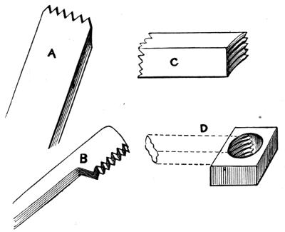
Fig. 51.
The tools required are represented at A, B, Fig. 51. A is an outside, and B an inside screw chasing-tool. These are always made in pairs, of exactly the same pitch, i.e., the outside tool being applied to the inside, the respective notches and points will exactly fit into each other. If you were to examine the under side of these tools, shown at C, you would notice that the notches do not run straight, but slanting. They are in fact parts of screw threads; and you[194] could make a tool of this kind out of a common screw nut, as I have shown you at D, only it would be too much hollowed out to make a good tool.
Now, supposing you were to hold the tool A flat on the rest, while a cylindrical piece of wood revolved in contact with it, you would cut a series of rings only; but if you were at the same time to slide the tool sideways upon the rest, so that by the time the wood had revolved once, the first point of the tool would have just reached the spot which was occupied by the second when you started, you would have traced a screw thread of that particular pitch. This is what you have to learn to do always, and with certainty, no matter what pitch of tool you may be using, and it is easy to understand how difficult the operation must be to a beginner. Indeed, there are numbers of otherwise good turners who have never succeeded in mastering this work. Nevertheless it can be done, and, although difficult, it is not so much so as might be supposed. Indeed, at first sight it would hardly be believed possible, because each different pitch of tool, and each different-sized piece of work, requires a different speed of traverse to be given to the tool. But a practised hand will strike thread after thread without failure, and those whose trade is to make all sorts of screw-covered boxes and similar articles, will execute the work with as much speed and apparent ease, as they would any ordinary operation of turning. I shall tell you[195] by and by, however, of several ways to escape this difficulty of screw-cutting,—lathes being fitted in various ways to insure good work, in some cases by carrying forward the tool at exactly the right rate of traverse, and at others by moving along the work itself at the proper speed, while the cutting tool is held immovably fixed in one position,—and I will give one tool of great service which will guide you in starting the ordinary chasing-tool; and a good start is here truly “half the battle.”
The chasing-tool must run from right to left for an ordinary right-handed screw (and a left-handed one is very seldom required), so that the young mechanic need not trouble himself about it. Precise directions cannot be given further than to have a rest with a very smooth and even edge, which will not in the least hinder the traverse of the chasing-tool, and to get the lathe into steady, equable motion. Then hold the tool lightly, but firmly, keeping it at right angles with the work. Allow it only just to touch until you find you have got into the right swing. It is all a matter of knack and practice; and if you succeed quickly, you may congratulate yourself.
The inside chasing-tool is used in precisely the same way, running it from the outer edge of the hole inwards. To some this is an easier tool to use than the outside chaser. I cannot say that I find it so; especially as one has to work more in the dark; unless the work is of large[196] diameter like the cover of a box, and even then the work is sufficiently difficult owing to the shallowness of the lid, which necessitates the instant stopping of the tool for a fresh cut. For you must understand that you have to deepen the screw-threads very gradually, and it will take several traverses of the tool to cut them to a sufficient depth.
The chasers require to be very sharp to cut wooden screws neatly, but observe you must only rub the upper flat face upon the oilstone, or, if a notch has been made by using the tools upon metal (they will cut brass well with care), grind them in the same way; the great secret being to hold the tool quite flat on the stone. You will thus, even by continual grinding, only thin the blade of the chaser, which will thus last for a long time. A practised hand will even cut a good thread with any flat piece of steel filed into equal notches, but a screw-chaser is the only tool really fit for the purpose.
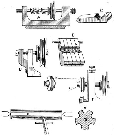
Fig. 52.
The most effectual remedy for the screw-cutting difficulty, is unfortunately rather expensive in its best form. But in another, it is by no means costly; and although it may not look so well as the first, it is equally effective, and extensively used by the turners at Tunbridge Wells, who make those beautiful little inlaid boxes and other articles. I shall explain this to you, therefore, first:—
A, is a lathe-head, something like the one I have already[197] described, but you will notice that the mandrel is a much longer one, and has several short screws cut upon it, each one being of a different “thread” or “pitch.”[1] This mandrel runs through two collars, so that, besides turning round, it can be pushed endwise. Now, supposing[198] I was to hold the point of a tool firmly against either of the screws, and at the same time was to turn the pulley and mandrel, you will understand that it would run backwards or forwards in its collars, at such a rate as the screw-thread compelled it to move. This is the plan of the traversing mandrel; and now supposing that you had a box held as usual in a chuck, and while the mandrel was compelled to move endwise as described, you were to hold a pointed tool against it, the tool would evidently cut a screw-thread of exactly the same pitch as that upon the mandrel against which the pointed tool first spoken of was applied. But in practice, a single-pointed tool held against the mandrel would not answer very well, and so the following plan is adopted instead, which answers perfectly.
Fig. 52, C, is called a half-nut. It has a set of screw-threads, cut where the semicircular hollow is, which threads fit one of the screws on the mandrel. A whole row of these half-nuts are fitted to turn at one end upon a long bar, so that either one can be raised up at pleasure to touch the screw upon the mandrel, which has threads of the same pitch as itself, B. These, then, are ranged under the mandrel, and when it is desired to make it traverse in its collars, one of these half-nuts is raised and kept up by a wedge placed underneath it. When no screw is required, a somewhat similar half-nut, but with merely a sharp edge instead of a thread, is raised, and this edge falls into a[199] notch or groove turned upon the mandrel, or sometimes a back centre-screw is added like D, and when no screw has to be cut, this is run up against the mandrel like an ordinary lathe.
In the more expensive traversing mandrels, although the principle is the same, there is a little difference in the arrangement of the different parts. The mandrel is not very much longer than usual; and it has no screw-threads cut upon it. But a number of ferules like K, are made each with a screw upon its edge, and one of these of the desired pitch is slid upon the end of the mandrel at b, fig. P, and is there held by a nut or otherwise, so that it cannot move out of its place. The half-nut is seen at a. It consists of a piece of brass or steel of the form shown with a hole in the middle, and a screw cut upon each hollow, so that it is a circle or set of half-nuts of different pitches. This slips over a pin at a, and when the screw b is turned, it draws up this pin and the nut attached, until the latter comes in contact with the ferule upon the end of the mandrel. This is very neat but expensive. Now, by far the cheapest and best way for the young mechanic, is to set boldly to work to conquer the difficulty of chasing screws by hand. There are even disadvantages in the expensive form of a traversing mandrel, which render it by no means a desirable mode of fitting up a lathe, and after all, the length of screw which it enables one to cut is very limited,[200] and in addition, it is not every day, nor probably once a month, that screw-cutting will be necessary at all. My advice, therefore, is, do not get a traversing mandrel until you can cut screws well with the chaser. When you can do this, you will be able to judge of the advantage or disadvantage of one.
By far the greater number of common screws are cut without the lathe, by screw-plates, or stocks and dies, and the nut, or hole into which such screws are to fit, is cut with a tap. A screw-plate is a simple affair,—a mere flat plate of steel, in which several holes are drilled, which are afterwards threaded by screwing into them taps, or hard cutting steel screws of the size required; the plate is then hardened by being heated red-hot and suddenly cooled, after which being much harder than brass, iron, or steel which has not gone through such process, it will in turn cut a thread upon any of these by simply screwing them into it. But although this will answer for small and common screws, it is not at all suitable for better ones, because the thread is burred up, not cut cleanly as it would be with a proper tool. A far better plan is a stock and dies; the latter being practically a hardened steel nut sawn in half, and fitted so that the two halves can be pressed nearer and nearer together as the screw thread becomes deeper. The dies are screwed up by means of a thumbscrew opposite to the handle.
To use it, a piece of iron is filed up or turned to the required size, which must be exactly that of the finished screw. The dies are then loosened and slipped on to the end of this screw-blank as it is called, and are then slightly tightened upon it. All that is now required is to keep turning the tool round and round upon the pin, which it will soon cut into a screw thread. When the stock is at the bottom or top, you may tighten the dies, and so work up or down; but never tighten them in any other part. If iron or steel is to be cut, use oil with the tool, but brass may be dry. If the screw is of steel, heat it red-hot and let it cool very gradually, to make it as soft as possible.
The hole or nut, into which the screw is to fit, is to be drilled so as just to allow the taper tap to enter about a couple of threads; a wrench, or, if small, a hand-vice is then applied to twist it forcibly into the hole, when the thread will be completed. Take great care to hold the tap upright, or else, if it is a screw with a flat head which has to fit into it, it will not lie correctly, but one side of the head will touch while the other is more or less raised.
There are other modes of screw cutting, but at present I need only mention one, which is used for wooden screws alone. It is called a screw-box, and is only made to cut one size, a tap being always sold to match. You can, however, purchase any size you like, from a quarter of an inch to 2 or 3 inches; but the latter are only intended for very[202] large screws, such as are used for carpenters’ benches and various kinds of presses. A screw-box looks like a small block of wood with a hole in it, but if you take out two screws you will find a blade of a peculiar shape, which forms the thread by cutting the wood as it is screwed into the hole in the box.
We now discard almost entirely the gouge and chisel used for soft woods, and fall back upon an entirely different set of tools, similar to those used for metal, but ground to rather more acute angles. These tools are held horizontally upon the rest, because depressing the handles causes the bevel below the edge to rub upon the work; and in addition, the grain of hard foreign woods is such that it cannot well be cut by placing the tool at a more acute angle, as would theoretically be required. Hence we can only regard these as scraping tools; but as such they will do excellent work in skilful hands. I have said that we discard the gouge, but there are some woods that will bear this tool, to take off the roughest parts of the work, before the application of others. The roughing-tool, however, may now be considered to be the point-tool, and the round-end tool, or “round” as it is[204] often called; a narrow one makes a good tool for this purpose.
Hard wood is easier on the whole to work than soft, because we have for the purpose a large stock of tools of all shapes, suitable to the various mouldings required. Hollows, round-beading tools, compound and simple moulding tools of various sizes, to say nothing of those which are made for use with ornamental apparatus, such as are required for fluting, beading, and eccentric work, spirals, and so forth. It is indeed in hard wood that most amateurs are accustomed to work; ebony and ivory, singly or in combination, being more extensively used than any other.
To turn a cylinder, or any work requiring to be held at both ends, you will invariably find the cross-chuck the best to use,—the fork or prong not taking hold in the hard material. Rough down to shape as before, using the gouge if it will work, but keeping the rest as close as possible, and only taking a light cut. Then finish roughing with a round-tool, and proceed generally as in soft wood turning, except inasmuch as you have to scrape instead of cutting the work into form.
In addition to the tools already described, you will have to obtain a few beading-tools, if you want to do very good work, for these give far more beautiful mouldings than you can cut in any other manner. Fig. 53, A to C, represent[205] these. The bevel is on the under side, and it is better to interfere with it as little as possible, by always sharpening the flat face only. If it should be necessary, however, to touch the bevel, it must be rubbed by a slip of oilstone, rounded on the edge, as used for sharpening gouges. Conical grinders, revolving in the lathe, are also used, especially for small beading-tools, to be fixed in the slide-rest. In the same figure, D and E represent another useful hard-wood and ivory tool. It is called the side-parting tool; and it is usual to have several of these, the hooks increasing in length. The edge is only on the extreme end of the hook. These tools are used for economy’s sake to cut solid blocks of ivory and hard-wood from the inside of boxes, instead of cutting the material into a heap of useless shavings. Similar tools, G, H, curved instead of rectangular, serve to cut out a solid piece from the inside of a bowl. In ivory work it is essential to use these tools, because such material is very costly; $2.50 a lb., and upwards, being a common price.
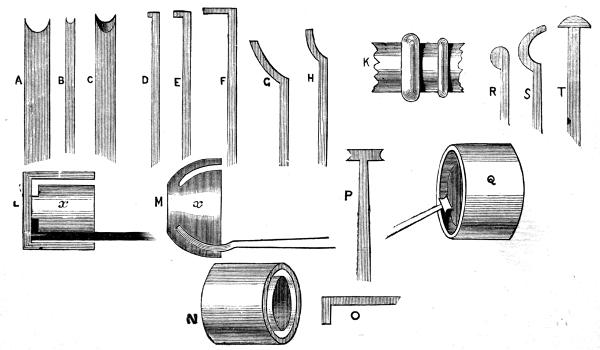
Fig. 53.
K is given to show what are meant by beadings. If these are exactly semicircular in section, they are far more beautiful in appearance than if of such curves as can be roughly cut by a chisel. The bead-tools are beautifully formed for this very purpose. To use the same side-parting tool, you must proceed as follows, which you will understand by the fig. L:—A common straight parting-tool or[207] narrow chisel is first applied to the face of the work to cut a deep circular groove or channel, as shown by the white space at N, and in section at L. This allows the narrowest of the hooked tools to be applied to under-cut the solid core x. This being withdrawn, a rather longer hook is applied, the hook being held downwards as at O, until it reaches the spot where it is to work, when it is gradually turned up (bevel below). Eventually, it is plain that the solid core or centre block x will fall out entire, which may be used for other purposes. M shows how a similar but curved block can be removed from the inside of a cup or bowl, the curved tool not requiring an entry to be made for it, as it cuts its own way entirely from first to last.
P and Q show a ring-tool and the method of using it. A recess is turned in the face of a piece of wood as if it was intended to hollow out a box. The ring-tool is then applied bevel downwards, and with the left cutting edge a bead is cut half-through from the inside. The right edge is then applied to the outside, and when the cuts meet the ring neatly finished, will fall off. With this tool you can turn them very rapidly, and they will require only a rub of sand-paper to finish them.
R, S, T are three more tools for hard wood. The first two cut on the outside of the curved part all round. These would be used to hollow out humming-tops and all similar[208] articles, and to finish the insides of bowls, for which T is also designed. Indeed, I might go on to describe all possible shapes of curved tools, each intended for some special work; but you will not do better than to go to Fenn, Buck, or any tool-maker in London, or elsewhere, and pick out at 7s., or so, per dozen, all shapes and sizes, or if you live at a distance and write to either of the above, they will select you the most useful; and you can trust these tradesmen and all first-class ones to send you no tools which are not of the best quality.
In finishing best work in hard wood, be very careful of all sharp edges of mouldings. Sand and glass paper round off these, and spoil the beauty of the work. If you are obliged to use such substances, touch off again the edges with very keen tools, which ought to leave brighter and more beautiful surfaces than any sand-paper can produce. Indeed, the secret of finished work in hard wood is to have tools whose edges and bevels are polished. In ornamental eccentric and rose-engine turning, where to use sand-paper would be to ruin the appearance of it, the little drills and cutters pass through three stages of sharpening, being ground on the oilstone, finished on a slab of brass, fed with oil and oilstone powder, and polished on a slab of iron with oil alone or oil and rouge. After this every cut that is made with them reflects the light; and as the surface is otherwise purposely grailed or dulled by cutting a series of fine light[209] rings with a point tool, the pattern itself shows out clearly and lustrously.
I shall now teach you how to turn iron and brass, which, though harder than wood, are not very difficult to cut, if you go to work in a proper manner and understand how to use your tools. What these are like I have already told you, and also how to mount a bar in the lathe by using the driver or point-chuck with a carrier. If the piece to be turned is not a bar, you will have to drive it into a chuck of wood, or clamp it upon a face-plate, or in a self-centring chuck if you have one.
I shall suppose, first of all, a mere straight bar of iron, centred at the ends, as I have shown you. Take off the lathe-cord that you use for wood, and fit one to go upon the largest part of the mandrel pulley, and the smallest upon the fly-wheel. When you now put your foot upon the treadle to work at your usual speed, you will find the mandrel turn quite slowly; but I may at once tell you, that what you lose in speed you gain in power. Set your rest for iron (which is not that used for wood, but one with a broad, flat top) so that it stands a little below the central line of the lathe mandrel and work, which will bring the edge of the tool exactly upon that line. This is always the position of the tool for metal-turning, at any rate for iron.
Begin by trimming the end of the bar next to the back centre. Use a graver, held as I directed you; that is, with the bevel flat upon the face of the iron, which is in this case the end of it. Only let the point cut, and a very little of the edge beyond it, and do not expect to take a deep cut so as to bring off a thick shaving. In metal work you will always have to proceed slowly, but nothing is more pleasant when once you can do it well.
You will at first have to experimentalise a little as to the exact angle at which to hold the tool, but you will soon find out this; and the advantage of hand-tools is, that you can always feel as well as see how they are working, and can ease them here and there to suit the material. It is rather difficult at first to hold the tool still in metal-working, but, like all else, it becomes easy by practice; so much so, that to hold the tool steadily in one hand is not only possible, but is the mode always followed by watchmakers. While you are about it, you should turn the graver over and try it in other positions; for although the two sides of the bevel nearest to the point are the only ones to be used, these may be applied in either direction, because they are both sharpened to angles of 60°, and so long as you present them at the correct angle (the smallest possible in respect of the work), it matters not which face of the tool lies uppermost. After squaring off one end, the approved plan is to remove the carrier, reverse the bar, and do the same to the other end. Then begin to[211] turn from the right hand. Place the graver as before, with the point overlapping the end very slightly (so as only to use the extremity of the cutting edge close to the point), and take off a light shaving along the bar for a distance of about half an inch, or even a quarter, keeping the edge of the graver which is on the rest in one position, and moving the tool, not by sliding it along the rest, but by using the point upon which it lies as a pivot. It is very difficult to describe this exactly, but Fig. 52, O, will help to explain it. The tool is to rest upon one spot, and the point to move in short curves like the dotted lines, being shifted to a new position as you feel it get out of cut. The left hand should grasp the blade and hold it tightly down upon the rest, while the right moves the handle to and fro as required. The curved dotted lines are necessarily exaggerated, but the principle of the work is this, whether you use a graver or a heel-tool. You should turn about half an inch quite round, and then go on to the next, by which you will always have a little shoulder upon the work for the tool to start upon, and this will be nice, clean, bright metal, and will not blunt the tool. But if you go to work differently, so that the edge of the tool comes continually in contact with the rough outside of the iron caused by the heat of the fire, and which is exceedingly hard, the point of the tool will be quickly ground down, while the iron will not be cut into at all.
I need tell you no more about turning a bar of iron in the lathe, because the above directions apply in all cases; but if you have to turn the face of a piece of metal that is carried in a chuck of some kind, you should always work from the middle towards the edge, and if the graver is used, its bevelled face will lie towards you during the process. Take care to chuck the metal very firmly, for it is most annoying to have it suddenly leave the chuck or shift its position after you have been at the trouble of turning part of it truly. In such case it is very difficult to replace it exactly as it was before, and all your work has in consequence to be gone over again. When taking the final cut, or before, if you like, dip the end of the tool into water, or soap and water, and see the effect. The surface turned in this way will be highly polished at once, and the tool will cut with much greater ease, so that a large, clean shaving will come off. When using a slide-rest, you will find it always better to keep water just dripping upon the work and point of the tool; but there is a drawback, nevertheless, to this plan, for, as might be expected, it makes a mess and rusts the lathe, and sometimes the work as well, so the water must be constantly wiped off it.
I shall now pass on to describe a mechanical arrangement called a slide-rest, of which there are two separate and distinct[213] forms, one for metal and one for ornamental turning in ivory and hard wood. The ornamental work that can be done I shall pass by for the present, because few boys are provided with the costly apparatus required, and I am rather addressing those young mechanics whose tastes incline them to model machinery and to practise the various operations of mechanical engineering on a small scale. To such a slide-rest is an almost necessary addition to the lathe, for there is a great deal of work which, I may say, cannot be done without it; for instance, boring the cylinders of engines (except small ones of brass), turning the piston-rods and various pieces which require to be accurately cylindrical and of equal size, perhaps for the length of a foot or more. Hand-work has accomplished something in this way in olden days, but the inability of workmen to advance beyond a certain standard of perfection with hand-tools alone, became such a hindrance to the manufacture of the steam-engine, as improved by Watt and others, that had not Maudsley, Naysmith, and others developed the principle of the slide-rest and planing machine, we should not yet have lived to see those gigantic engines which tear along like demon horses with breath of fire, at the rate of sixty miles or more in as many minutes. So likewise would various other machines, which now appear absolutely necessary to supply our various wants, have stood in their primitive and imperfectly developed forms; for it is necessary,[214] before constructing a machine, to have the means of turning cylindrical parts truly, and producing perfectly level plates where required.
The object of a slide-rest is to provide means for holding a tool firmly, and giving it a power to traverse to and fro and from side to side, so that by the first we may be able to cause such tool to approach or recede from the work, and by the second we may cause it to move in a perfectly straight line along its surface from end to end. This is accomplished in the following manner:—The drawing being a representation of one of the first machines constructed for the purpose. A rectangular frame, A, of iron is carried by a pair of strong uprights, B B, fixed to the sole-plate, C, by which it is attached by a bolt to the bed of the lathe. Lengthwise of this frame runs a screw, prevented by collars from moving endwise, but which can be turned round by the winch-handle, D. Thus a nut through which this screw passes, and which only has endwise motion, will, when the latter is turned by its handle, traverse it from end to end in either direction, according as the screw may be turned from right to left or the contrary. This nut is attached to the under part of a sliding-plate, E, which has a part projecting between the sides of the frame, and also two others on its outside, by which it grasps the same with great accuracy, and is prevented from any shake or play as the whole[215] with the nut is made to traverse to and fro along the frame.
Lengthwise of this sliding-plate, that is, in a direction the opposite to that of its own traverse, are two bars bevelled underneath, fixed exactly parallel to each other, which are so arranged to guide the cross traverse of another plate with chamfered edges to fit the bevels of the guide bars. This second plate has on its upper surface two clamps which secure the tool. It is plain, then, that by this arrangement the two required movements are attained, the lower plate sliding along in one direction parallel with the lathe-bed, and the other across it. In the original rests, this upper plate with the tool was moved by hand, and in the modern rest for ornamental turning (which this was also constructed for) the same is done, but a hand-lever is added for the purpose.
But although a similar arrangement is needed for metal, it is plain that the top plate should have a more easily regulated motion, and that we should be able to advance the tool as near the work as may be desired, and then to retain it securely at that distance while giving the necessary movement in the direction of the length of the object to be turned. The method of effecting this is at once suggested by the screw and nut of the lower part, and by merely adding to the top a similar arrangement, the desired end is at once attained.
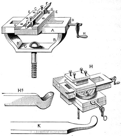
Fig. 54.
The actual construction of such rest varies somewhat, but Fig. 54, H, shows it in its most ordinary form. The lower part is, of course, to be clamped down securely to the lathe-bed, there being a projection below which is made to fit accurately between the bearers similar to that beneath the poppits. This projection secures the correct position of the rest, of which one frame or plate will travel lengthwise[217] of the bed, while the other will move exactly at right angles to it. But in the compound slide-rest, which is very general, there is also a third circular motion, by which the upper part can be set at any angle with the lower, instead of being permanently fixed at right angles to it. By this the tool can be made to approach the work more and more as it passes along it; and it will therefore cut deeper at one end of its traverse than at the other. The result will be that what is thus turned will not be a true cylinder, but a cone, i.e., it will be larger at one end than the other, although otherwise smooth and even.
We are thus provided with the most valuable addition to the lathe ever devised by mechanics, and it is no longer a question of the strength and skill of the workman whether we can produce a perfect piece of work, but simply of the accuracy with which the lathe and rest are constructed, and of the form and condition of the tools to be used. The latter are not exactly like those ordinarily used, although the principle of the cutting angles already laid down needs to be adhered to even with more unfailing attention than that required for the correct formation of hand-tools. Moreover, it is plain that—here we shall no longer feel whether the tool is working as it ought to do—we shall be unconscious of the precise amount of strain that is being brought to bear against its edge, and if it is by chance working in a bad position, at a wrong angle, we cannot re-adjust it in a[218] moment as we could a hand-tool by a slight movement of the fingers or wrist.
Hence you will see at once how very important it is that tools for the slide-rest should be shaped with the most rigid adherence to correct principles; and, further, that they should be so fixed in the slide-rest as to meet the work at the precise angle, and at the height exactly suited to the material of which it is composed. As regards the latter point, it may be taken as an almost invariable rule that the work should be attacked on its axial line (that is, a line that would run from end to end of it dividing it lengthwise into equal parts, or, as it would commonly be named, its middle line). If the tool meets it above this, it is most likely that it will rub against it, and the point will be out of cut. If it meets it below, there will be a tendency for the point to catch in, and the work to roll up upon the face of the tool, which, in fact, it very often does with careless workmen, and then there comes a smash of some kind—lathe centres snapped off, the tool broken, the bar bent beyond remedy, and possibly the operator’s toes made unpleasantly tender.
The most common slide-rest tool for outside work is that given at H². It is made straight, as shown, or bent sideways to right or left to cut shoulders on the work, or enter hollows, or creep sneakingly round corners, or any other of those crooked ways in which man delights; but[219] whether straight or not, these tools have all most commonly the cranked form shown here. This gives the tools a slight degree of elasticity—not very much, because that would only injure the perfection of the work; therefore they are not very considerably cranked. The angles are ground as directed in the table of tool-angles, and if the point is too low, slips of iron are placed below the shank upon the tool-plate of the slide-rest; if too high, the grindstone must be resorted to; and the advantage of these cranked tools is, that they can be ground down several times without being brought too low to be packed up with iron slips to the right level. Thus a cranked tool is by far more advantageous for the slide-rest than one made straight like those used for hand-turning. For inside work, however, or “holing,” the crank form is not possible, unless the hole is of large size, and so, for this purpose, straight side-tools are used, like K.
If the tool is well placed, as well as correctly made, nothing can be more easy and delightful than slide-rest work. You merely advance the tool to take the required cut (beginning generally at the right-hand end of the bar), and then gently turning the other handle, you will see it traverse along, as if work was a pleasure to it, as it ought to be to all young mechanics. Not infrequently, however, instead of this even, steady work, the tool jumps and catches, or rubs and shrieks: it is out of temper, I suppose;[220] at any rate, in some one or more particulars it needs correction.
Although with the slide-rest you can generally venture upon taking a deeper cut than you could with hand-tools, it is by no means well to hurry the work. At first, especially before it has become cylindrical, the tool will only cut partly round its surface, and the work is done in an uncomfortable, jerking, dissatisfied sort of way, and the deeper you drive the tool the worse it is; but as soon as the outer skin is off, and the work has become cylindrical, a long, clear, bright shaving curls off pleasantly from end to end, and the surface ought, if the tool is wetted, to become at once of a finished appearance.
You should always, with a slide-rest, take the whole run of the piece from end to end to a certain depth, and then, commencing again at the end, repeat the same process, and so on until the required size is almost attained. When it is, take out the tool with the pointed end which has been in use, and insert one freshly sharpened with a broad point, getting it so placed as to cut the shaving both from the surface below, and from the shoulder to which it is attached at the side, as I explained to you in the chapter on grinding and setting tools, and which must be well understood before you can hope to make good work with tools rigidly fixed in a slide-rest. With this tool, kept wet with soap and water (or soda water, which is better for this than for[221] your stomach), take a very light shaving from end to end, taking especial care to turn the handle which gives the traverse slowly and evenly. If you stop, or almost stop, the tool will be sure to draw a little deeper into cut, which will make a scratch upon the work, or, it may be, plough a groove, and so far spoil the appearance of it.
Whenever you finish turning any bar that has been centred at each end, be careful to leave the centre marks just as they were when the work was in the lathe. The ends will have been otherwise trimmed off at the very commencement, and it may happen that at some future day it may be desired to re-mount the piece for repair, when, if these marks are gone, and new centres have to be drilled, the whole will run so much out of truth that it will have to be entirely re-turned from the commencement. Do not, therefore, fancy that these centre marks are unsightly, and forthwith file them out, but be content to leave them.
Slide-rest tools, made in the ordinary way, are so far troublesome in use that if they get broken you must have them re-forged, and few country smiths know anything about such matters. I have a tool now lying by me made by a smith (true, it was a Welsh smith), and although I stood by and explained how it should be done, and cut one out of a piece of wood, it never arrived at a proper shape, and was never even placed upon the rest. I keep it as old Izaak Walton kept the Londoner’s artificial fly, viz., “to[222] laugh at,” and as a caution to all concerned, never to go to a country blacksmith for slide-rest tools. The following plan answers very well for many kinds of outside work, and is on the whole a plan that may be satisfactorily followed by the young mechanic.
Instead of having the tools constructed from a large bar of steel half an inch or so in the square, they are made of short pieces about an inch long, fitted into a peculiar holder.
The advantage of this arrangement consists in the ease with which you can make your own tools out of broken round, triangular, or square pillar files, small chisels and such like. These can be shaped by the grindstone alone, and the blacksmith will not have to be called into requisition. I shall give you two forms of tool-holders, more or less simple, because I may suppose my young mechanic to be fast growing into an old hand, and able to appreciate differences in these arrangements.
Fig. 55, A, B, represents two of such holders, one for round, the other for flat steel cutters. You can see at once that when these are upon the bed of the rest, they form a tool with cranked end, as previously described, and can therefore be used in precisely the same manner. I shall give no directions for making these tool-holders, which are, nevertheless, very simple affairs, and can be readily understood from the drawings here given.
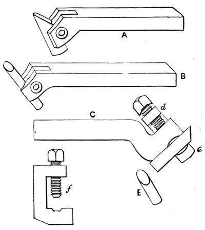
Fig. 55.
Another form is shown at C. The part d e is a clamp, which is separately drawn at f. This, like the last, enables one to use all sorts of odds and ends for tools. There are several other patterns of tool-holders, arranged either to use the little pieces of square, round, or triangular steel bars, so that one side, at least, of these may remain without grinding, and others in which two entirely new faces must be given to the tool by the grindstone. The latter are, perhaps, generally the best, because you can then, with the[224] aid of the table of tool-angles, shape your cutters very accurately to the work required of them.
Although such tool-holders and cutters are generally used for metals, there are others intended for wood; and constructed to hold miniature gouges and chisels, which perform their work admirably. A capital tool for outside work, Fig. 55, E, which was used extensively at Portsmouth dockyard for brass turning, is made simply by filing off at an angle of about 45° a round short bar of steel. This angle, however, is unusually small for brass and gun-metal, 80° being better. For iron it will answer better, because though filed, or rather ground at 45°, the cutting edge, a little way from what may be called the point of the tool, is nearer 60°.
Similar to these last are the tube gouges, short bits of steel tube ground off and sharpened. These fixed in a holder answer beautifully for soft wood, and do not “catch in.” If the holder is bent so as to bring the tool into proper position, inside work can be rapidly effected by these, such as hollowing out large bowls and similar heavy work. All this can, of course, be done rapidly with the slide-rest, so far as regards the removal of the greater part of the wood. But in the case of a bowl, in which a curve predominates over a straight line, hand-tools must be used to finish it (generally the inside hook-tool). This last is, in fact, almost identical with the tube gouge; for the[225] slide-rest, and that which makes it so difficult a tool to use, is that, being a hand-tool, and subject to slight unintentional changes of position upon the part of the workman, it catches in, and is either wrenched out of the hand, or a piece is chopped off the wood. Rigidly held in the slide-rest, the exact angle, once found, is of course maintained.
I now propose to assist the young mechanic in special work, instead of continuing general directions. This will enable me to explain to him various lathe appliances, and other details of mechanical work hitherto passed by.
Of all models which boys (and very big boys too) are desirous to construct, the steam-engine holds the chief place, and deservedly so; for every boy calling himself mechanical, ought to know how this is made, and the general principles of its construction as well. However, I am aware, from experience, that many a youngster, who is even in possession of a model engine, is utterly ignorant of the cause of its motion; although it is a great delight to them to see the steam puffing out, and the wheel revolving “nineteen to the dozen,” as schoolboys say. Now, an engine is a very simple affair, and can be easily explained; and, as I wish my readers to work rationally,[227] I shall show them what they have to do before I tell them how to do it.
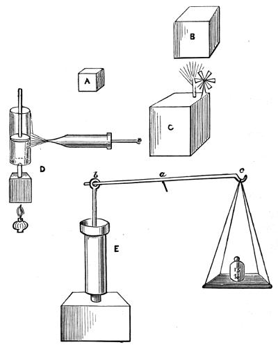
Fig. 56.
A, Fig. 56, represents a cubical vessel of tin or any[228] other substance. By cubical, I mean that all its sides are squares, and all exactly equal; each side in the present case is to be 1 inch wide and long, or a square inch. B is a similar vessel, 1 foot cube. It contains, therefore, 1728 cubic inches, or is 1728 times as large in capacity as the first. Now, if I were to fill the little vessel with water and tip it into the second, and put a lamp under it, the water would all soon boil away, as it is called. It would be converted into steam; and the quantity of steam it would produce would exactly fill the larger vessel, without exciting any particular pressure upon its sides.
Steam, thus allowed plenty of elbow room, is like a lazy boy; it will play and curl about very prettily, but will do no work. We must put some sort of pressure, therefore, upon it—confine it, and we shall soon see that, by struggling to escape, it will serve our purpose, and become a most obedient workman. We have, therefore, only to put double the quantity of water into our larger vessel, that is, two cubic inches. We will put on a cover tightly, adding a pipe through which to pour in the water. Soon we shall have the steam formed as before; but it has no longer room enough, and out it comes fizzing and roaring, very savage at having been shut up in so small a cage. And we can make it work too, for if we set up a little fan-wheel of tin right in its way, we shall see it spin round merrily enough; or if we cork the tube lightly, we shall find this cork soon[229] come out with a bang. We have, in fact, already constructed a steam-engine and a steam-gun on a small scale. The pressure in this case is, indeed, not great, but what it is I must now try to explain.
The air or atmosphere, which surrounds us on all sides, exercises a pressure upon everything of 15 lbs. on every square inch of surface. If our little cubical inch box of tin had no air inside it, and no steam, but was absolutely empty, each side, and top, and bottom would have 15 lbs. pressure upon it; which would be evident if it were not very strong, for it would sink in on all sides directly, just as much as if you were to add a weight of 15 lbs. when it was full of air, as it would ordinarily be.
When I spoke of the larger box being exactly filled with steam from the evaporation of the cubic inch of water poured from the smaller box, I supposed it empty of air. The steam from that quantity of water, occupying the place of the air, would also be of the same pressure, 15 lbs. per square inch of surface; and as this only balances the pressure of the atmosphere, which would be, in such a case, pressing in on all sides, the steam would not show any pressure; just as, if you put equal weights into each scale of a balance, the beam of it would remain horizontal, neither scale showing to the outward senses that it had any pressure upon it. But in the second case, we have doubled the quantity of steam, but compelled it to occupy the same[230] space; therefore we have now real, visible pressure of 15 lbs. upon each square inch; and if we again halve the space which the steam has to occupy, or double the quantity of water, we shall obtain a pressure of 30 lbs. beyond the pressure of the atmosphere.
Let us now disregard atmospheric pressure, and fit up such an apparatus as Fig. 56, D. Here we have first our small box, closed on all sides, and from it a small tube rising and entering into the bottom of a larger one, which is very smooth in the inside; in this is a round plate or disc, called a piston, which fits the tube nicely, but not so tight as to prevent it from moving up and down easily; and let a weight of 15 lbs. be laid upon it. Let us suppose this large tube or cylinder to be 1700 times larger than the cubic inch box, into which water is to be poured till full. Now we heat it as before, and when 212° of heat are attained by the water (which is its boiling-point) when it begins to be converted into steam, the piston will be seen to rise, and will gradually ascend, until quite at the top of the tube, because the steam required exactly that amount of room.
Now we have arrived at the same conclusion which we came to before; for you see that not only has the cubic inch of water become a cubic foot of steam (about 1700 to 1728 of its former volume), but it is supporting 15 lbs. weight, which represents that of the atmosphere, and if we could get rid[231] of the latter, a solid weight of 15 lbs. would be thus supported. Now, still neglecting the atmospheric pressure, suppose instead of 15 lbs. we add another 15 lbs., making the weight 30 lbs., down goes our piston again, and stands at about half the height it did before. We have thus, as we had previously, a cubic foot of steam made to occupy half a cubic foot of space, giving a pressure (which is the same as supporting a weight) of 30 lbs.
I ought, perhaps, to add in this place, however, that under 30 lbs. pressure, or atmospheric weight and 15 lbs. additional, the water would not become steam at a temperature of 212°, but it would have to be made much hotter, until a thermometer placed in it would show 252°.
So far we have seen what a cubic inch of water will do when heated to a certain degree, and at first sight it may not seem a great deal. Far from being light work, however, this is actually equal to the work of raising a weight of 1 ton a foot high. Let us prove the fact. Suppose the tube or cylinder to be square instead of round, and that its surface is exactly 1 square inch, how can we give 1700 times the room which is occupied by the water? It is plain that the piston must rise 1700 inches in the 1-inch cylinder or tube, carrying with it, as before, its weight of 15 lbs.—that is, it has raised 15 lbs. 1700 inches, or about 142 feet. But this is the same as 15 times 142 feet raised 1 foot, which is 2130 lbs. raised 1 foot, very nearly a ton, the latter[232] being 2240 lbs. So, after all, you see that our little cubic inch of water is a very good labourer, doing a great deal of work if we supply him with sufficient warmth.
Now this is exactly the principle of the ordinary steam-engine: we have a cylinder in which a piston is very nicely fitted, and we put this cylinder in connection with a boiler, the steam from which drives the piston from one end of the cylinder to the other. In the first engine that was made, the cylinder actually occupied the very position it does in our sketch; it was made to stand upon the top of the boiler, a tap being added in the short pipe below the cylinder, so that the steam could be admitted or shut off at pleasure. But it is plain that although our little engine has done some work, it has stopped at a certain point; there is the piston at the top, and it cannot go any farther; we must get it down again before it can repeat its labour.
How would you do this, boys? Push it down, eh? If you did, you would find it spring up again when you removed your hand, just as if there were underneath it a coiled steel spring; by which, however, you would learn practically what is meant by the elasticity of steam. Besides this, if you push it down, you become the workman, and the engine is only the passive recipient of your own labour. Try another plan; remove the lamp, and see the result—gradually, very gradually, the piston begins to descend.
Take a squirt or syringe, and squirt cold water against[233] the apparatus. Presto! down it goes, now very quickly indeed, and is soon at the bottom of the cylinder. But we may as well try to get useful work done by the descent of the piston as well as by its ascent.
Set it up like Fig. 56, E. Here is a rod or beam, b a c, the middle of which is supported like that of a pair of scales. From one end we hang a scale, and place in it 15 lbs.; and as the piston sinks the weight is raised, and exactly the same work is done as before. Thus was the first engine constructed; but instead of the scale-pan and weight, a pump-rod was attached, and as the piston descended in the cylinder this rod was raised, and the water drawn from the well. This, however, was not called a steam-engine, because the work is not really the effect of the steam, which is only used to produce what is called a vacuum (i.e., an empty space, devoid of air) under the piston. In fact, the up-stroke of the piston was only partly caused by steam, and the rod of the pump was weighted, which helped to draw it up.
I must get you to understand this clearly, so that the principle may become plain—“clear as mud,” as Paddy would say. I told you that the air pressed on every square inch of surface with a force of about 15 lbs. We do not feel it, because we are equally pressed on all sides—from within as well as from without—so that atmospheric pressure is balanced. Sometimes this is a very good thing. We should, I think, hardly like to carry about the huge[234] weight pressing upon our shoulders, if something did not counteract it for us, so that we cannot feel it. Indeed, if it were otherwise, we should become flat as pancakes in no time—“totally chawed up.”
But sometimes we should prefer to get rid of the air altogether—and I can tell you it is not easy to do so, unless we put something into its place; and we want perhaps simply to get rid of it, and make use of the room it occupied. We require to do this in the present instance, and in fact we have just done it. If the whole space below the piston, when we begin to work, is filled with water, it is plain there can be no air below it; and when the steam has raised it, there is still no air below it, but only steam. We then apply cold to the cylinder by removing the lamp and squirting cold water against it, which has the effect of reducing the steam to water again, which will occupy 1 inch of space only. We, therefore, now have a space of 1600 cubic inches with neither air nor water in it; and so, if the piston is 1 inch in size, there will be the 15 lb. pressure of the atmosphere upon it, and nothing below to balance it, for we have formed a vacuum below it, and of course this 15 lb. weight will press it rapidly down. It did so; and we therefore were enabled to raise 15 lb. in the scale-pan. You will know, therefore, henceforth, exactly what I mean by a vacuum and atmospheric pressure. It is, you see, the latter which does the work when a vacuum is[235] formed as above; but you can easily understand that it might be possible to use both the atmospheric pressure and the pressure of steam as well, which is done in the condensing steam-engine.
In the earliest engine, called the Atmospheric for the reason above stated, the top of the cylinder was left entirely open, as in our sketch; but the condensing water was not applied outside the cylinder, but descended from a cistern above, and formed a little jet or fountain in the bottom of the cylinder at the very moment that the piston reached its highest point. Down it, therefore, came, drawing up the pump-rod. When at the bottom the jet of water ceased. Steam was again formed below the piston, which raised it as before; and the process being repeated, the required work was done. A boy, to turn a couple of taps, to let on or off the water or steam, was all the attendance required.
For some time the atmospheric engine, the invention of Newcomen, was the only one in general use; and even this was, in those days (1705-1720), so difficult to construct that its great power was comparatively seldom resorted to, even for pumping, for which it was nevertheless admirably suited. The huge cylinder required to be accurately bored, while there were no adequate means of doing such work; and although the piston was “packed,” by being wound round with hemp, it was difficult to keep it sufficiently[236] tight, yet at the same time to give it adequate “play.” Then, another drawback appeared, which, though of less importance in some districts, absolutely prevented the introduction of this engine into many parts of the country. The consumption of coal was enormous in proportion to the power gained. We can easily understand the reason of this, when we consider the means used for producing a vacuum in the cylinder below the piston. The water introduced for the purpose, chilled, not only the steam, but cylinder and piston also; and therefore, before a second stroke could be made, these had to be again heated to the temperature of boiling water. The coal required for the latter purpose was therefore wasted, causing a dead loss to the proprietor.
So matters continued for some time, until a mathematical instrument-maker of Glasgow, named Watt, about the year 1760, began to turn his attention to the subject; and having to repair a model of Newcomen’s engine belonging to the University of Glasgow, the idea seems to have first struck him of condensing the steam in a separate vessel, so as to avoid cooling the cylinder after each upward stroke of the piston. This was the grand secret which gave the first impetus to the use of steam-engines; and from that day to this these mighty workmen, whose muscles and sinews never become weary, have been gradually attaining perfection. Yet it may be fairly stated that the most modern[237] form of condensing engine in use is but an improvement upon Watt’s in details of construction and accuracy of workmanship. For Watt did not stand still in his work; but after having devised a separate condenser, he further suggested the idea of closing the top of the cylinder, which had hitherto been left open to the influence of the atmosphere; and rejecting the latter as the means of giving motion to the piston, he made use of the expansive power of steam on each side of the piston alternately, while a vacuum was also alternately produced on either side of it by the condensation of the steam.
The atmospheric engine was thus wholly displaced. The saving of fuel in the working of the machine was so great, that the stipulation of the inventor, that one-third of the money so saved should be his, raised him from comparative poverty to affluence in a very short time. Watt, however, had still to contend with great difficulties in the actual construction of his engines. He was in the same “fix” as some of my young readers, who are very desirous to make some small model, but have little else than a pocket-knife and gimblet to do it with. For there were no large steam-lathes, slide-rests, planing and boring machines, procurable in those days, and even the heaviest work had to be done by hand, if indeed those can be called hand-tools which had frequently to be sat upon to keep them up to cut. It was therefore impossible for Watt to[238] carry out his designs with anything like accuracy of workmanship, else it is probable that he would have advanced the steam-engine even further towards perfection than he did. In spite of these drawbacks, however, this great inventor lived to see his merits universally acknowledged, and to witness the actual working of very many of these wonderful and useful machines.
The first necessity which occurred from closing the cylinder at both ends was the devising some means to allow the piston-rod to pass and repass through one end without permitting the steam to escape. This was effected by a stuffing-box, which is represented in Fig. 57, A, B,—the first being a sectional drawing, which you must learn to understand, as it is the only way to show the working details of any piece of machinery. We have here a cylinder cover, a, which bolts firmly to the top of the cylinder, there being a similar one (generally without any stuffing-box) at the other end or bottom of the same. On the top of this you will observe another piece, which is marked b, and which is indeed part of the first and cast in one piece with it. Through the cylinder cover, a, is bored a hole of the exact size of the rod attached to the piston, which has to pass through it, but which hole, however well made, would allow the steam to leak considerably during the working of the piston-rod.
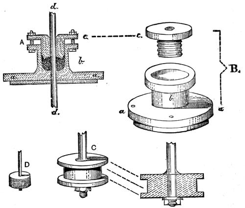
Fig. 57.
To obviate this, the part b is bored out larger, and has[239] a cup-shaped cavity formed in it, as you will see by inspecting the drawings. Into this cavity fits the gland, c, which also has a hole in it, to allow of the passage of the piston-rod. This gland is made to fit into the cavity in b as accurately as possible; and it can be held by bolts as in the fig. A, or be screwed on the surface as shown at B, in which latter case the greater part of the interior of b is screwed with a similar thread. The piston-rod being in place, hemp is wound round it (or india-rubber packing-rings[240] are fitted over it), and the gland is then fitted in upon it, and screwed down, thus squeezing the hemp or rubber tightly, and compelling it to embrace the piston-rod so closely, that leakage of steam is wholly prevented. Whenever you have, therefore, to prevent steam or water escaping round a similar moving-rod in modelling pumps or engines, you will have to effect it in this way. The piston was also packed with hemp or tow, either loosely-plaited or simply wound round the metal in a groove formed for the purpose. In Fig. 57, C and D, I have added drawings of a piston, so made, partly for the purpose of again explaining the nature of sectional drawings. In this one, C, you are shown the end of the piston-rod passing through the piston, and fastened by a screwed nut below, a shoulder preventing the rod from being drawn through by the action of this nut. The hemp packing is also shown in section, but in the drawing D the groove is left for the sake of clearness.
In all your smaller models you will have to pack your piston in this way, except in those where you entirely give up all idea of power. The little engines, for example, sold at $1 and upwards, with oscillating cylinders, have neither packed pistons nor stuffing-boxes; the friction of those would stop them, and escape of steam is of no great consequence. It will, however, be found advantageous to turn a few shallow grooves round these unpacked pistons[241] after they have been made to fit their cylinders as accurately as possible, like fig. C. These fill with water from the condensation of steam, which always occurs at first until the engine gets hot; and thus a kind of packing is made which is fairly effectual.
In Fig. 58 I have given a drawing of Newcomen’s engine, in case you would like to make a model of one; but I do not think it will repay you as well for your labour as some others. There is the difficulty of the cistern of cold water and the waste-well; and the condensation of the steam is a troublesome affair in a small model, so that, on the whole, I should not recommend you to begin your attempts at model-making with the construction of one of these. I shall, however, add a few directions for this work, because what I have to say about boring, screwing, and so forth, will apply to all other models you may desire to construct.
The cylinder, in this case, will be more easily made by obtaining a piece of brass tubing, which can be had of any size, from 3 or 4 inches diameter to the size of a small quill. The first you will often use for boilers, the latter for steam or water pipes. You can also obtain at the model makers—Bateman, for instance, of High Holborn—small taps and screws, and cocks for the admission of water and steam, and all kinds of little requisites which you would find great difficulty in making, and which would cost you more in spoiling and muddling than you would spend in buying them ready made.

Fig. 58.
The drawing is given on purpose to show the best and easiest arrangement for a model. It has all parts, therefore, arranged with a view to simplicity. A is the boiler made of a piece of 3-inch brass tubing, as far as a, b, c, d, the bottom being either of brass or copper at the level of a, b; the upper domed part may be made by hammering a piece of sheet brass, copper, or even tin, with a round-ended boxwood mallet upon a hollowed boxwood block, of which T, T is a section. You should make one of these if it is your intention to make models your hobby, as it will enable you to do several jobs of the same kind as the present. Probably you will not be able to make the dome semicircular, or rather hemispherical; but at all events, make it as deeply cupped as you can—after which, turn down the extreme edge one-sixteenth of an inch all round to fit the cupped part exactly. This requires a good deal of care and some skill. If you find that you cannot manage it, make your boiler with a flat top instead. Whichever way you make it, a very good joint to connect the parts is that shown in section at V.[2] The edge of the lower part is turned outwards all round; that of the upper part is also turned outwards, first of all to double the width of the other, and is then bent over again, first with a pair of pliers[244] and afterwards with a hammer, a block or support being placed underneath it. All this is done by the manufacturer with a stamping machine on purpose, and would be completed by the Birmingham brass-workers before I could write the description. It can, however, be done without any more tools than shown.
You will often need a tinman’s boxwood mallet with one rounded end and one flat one, which, of course, you can now turn for yourself, as it is an easy bit of work. With the rounded end you can cup any round piece of tin; but it requires gentle work; do it gradually by hammering the centre more than the edges. I will show you presently how to do similar work by spinning in the lathe, which is a curious but tolerably easy method of making hollow articles of many kinds from round discs of metal without any seam.
After you have hammered the joint of the upper and middle parts together, you must solder them all round with tinman’s solder. For this purpose you require a soldering-iron represented at W. This is a rod of iron, flattened and split at the end, holding between the forked part a piece of copper, which is secured to the iron by rivets. I should not recommend a heavy one, not so heavy nearly as what you may see at any blacksmith’s or tinman’s shop, because your work will be generally light, and such irons are all top heavy to use. The end, which may be curved over as shown, will require to be tinned, for without this it will not work at all[245] well. File the end bright, and heat it in the fire nearly red hot. Get a common brick, and with an old knife or anything else, make a hollow place in it—a kind of long-cupped recess like a mussel shell, if you know what that is, and put a little rosin into it. Take your iron from the fire, and holding it down close to the brick, touch it with a strip of solder, which will melt and run into the cavity. Now rub the iron well in the solder and rosin, rub it pretty hard upon the brick, and presently you will see it covered with bright solder, from which wipe what remains in drops with a piece of tow. The iron is now fit for immediate use; but remember, the first time you heat it red-hot, you will burn off the tinning, and you must file it bright again, and repeat the process. So when you want to solder, heat the iron in a clean fire, until, when you hold it a foot from your nose, you find it pretty warm; and avoid a red heat. You will now find, that when the soldering-iron is hot, it will not only melt but pick up the drop of solder; and as you draw it slowly along a joint (previously sprinkled with powdered rosin, or wetted with chloride of zinc, or with Baker’s soldering fluid), the solder will gradually leave the iron, and attach itself to the work in a thinly-spread, even coat.
The secret of soldering is to have the iron well-heated, and wiped clean with a bit of tow, and to apply it along the joint so slowly and steadily that the tin or other metal will become hot enough just to melt solder. Try to solder,[246] for instance, a thick lump of brass; file it bright if at all tarnished—for this must invariably be done with all metals. You will be unable to do it at first, for the moment the solder touches it, it will be chilled, and rest in lumps, which you can knock off directly when cold. Now place the brass on the fire for a few seconds until hot, and try again; the solder will flow readily as the iron passes along it, for it is kept up to the melting-point until it has fairly adhered. This is why in heavy work a large iron is required; it retains heat longer, and imparts more of it to the metal to be soldered. But you will find it often better to use a light soldering-iron, and to place the brass-casting upon the bar of the grate for a short time. You may, indeed, often work without any soldering-iron as follows:—
Heat the pieces to be soldered (suppose them castings and not thin sheets of metal) until they will melt solder. Take a stick of the latter, and just dip it in one of the soldering solutions named, and rub it upon the work previously brightened. The solder will adhere to both such pieces. Now, while still hot, put them together and screw in a vice, or keep them pinched in any way for a few minutes, and you will find them perfectly secured. In making chucks for the lathe, and in forming many parts of your models, you will find it advantageous to work in this way; but, notwithstanding, you will often require a light soldering-iron, and sometimes also a blowpipe, which I shall likewise[247] teach you to use, as also how to make a neat little fireplace or furnace to stand on your bench by which to heat the iron.
I must now suppose that you have carefully soldered the dome to the middle of your boiler; and as the solder will be underneath, the joint will be concealed even if (as is likely) you should not have made a very neat piece of work. Before you put on the bottom of the boiler, you will have to make two holes in the top—one for the steam-pipe three-eighths of an inch in diameter, the other for the safety-valve also three-eighths—because this will require a plug of brass to be soldered in, which plug will have a hole drilled through it of a quarter of an inch diameter. These may be punched through from the inside, or drilled; they are easily made, but should be as round and even as possible.
Take a piece of three-eighths-inch tubing, with a stop-cock soldered into the middle of it. I shall suppose you have bought this. It need not be over an inch in length altogether; and you must put it through the hole in the top of the boiler, and solder it round on the inside of the same. The nearer you can get the stop-cock to the bottom of the cylinder the better the engine will work, because the steam will have to rise through whatever water is left in this pipe from the jet used to cool the steam. You will see that it cannot run off by the pipe C into the pump well, like that which collects in the cylinder itself. In a real engine the steam-tap was a flat plate which slid to and fro sideways,[248] level with the bottom of the cylinder; but this you would not make easily at present.
The plug for the safety-valve you must turn out of a little lump of brass. It must be about three-eighths of an inch long; and you must drill a quarter-inch hole through it, and countersink one end of the hole (that is, make it wider and conical by turning a rosebit or larger drill round in it a few times), to make a nice seat, as it is called, for the valve itself, which need not be now attended to. Remember you can buy at Bateman’s, or any model-maker’s in London, beautiful safety-valves ready-made, as well as any part of a model engine that you cannot make yourself; and indeed it is so far a good plan at first that it saves you from becoming tired and disgusted with your work, owing to repeated failures. If you buy them, therefore, you must do so before you make the holes above alluded to, but in some respects it will be more to your advantage to try and make all the details for yourself. I cannot call it making an engine, if, like many, you buy all the parts and have little left to do but screw them, or solder them, together. Don’t do this, or you will never become a modeller.
Your boiler from c to a is, in height, maybe 2 inches, the dome 1½ or thereabout. This will slip inside the part that you see in the drawing, and which I here sketch again separately.[3]
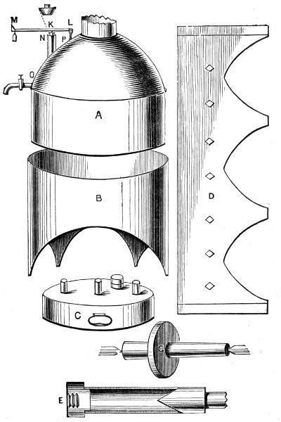
Fig. 59.
A is the boiler lifted out of B, the outer case or stand, which you can make out of tin, and paint to imitate bricks. It is almost a pity to waste sheet-brass upon it, because it is not very important, its object being only to carry the boiler. It is like D before being folded round and fastened (not with solder, which would soon melt, but) by a double fold of the joint, similar to that which you made round the boiler itself, but turned over once more and hammered down. The holes are punched with any round or square punch with a flat end, and are intended to give more air to the lamp C, which should have three wicks, or two at the least, to keep up a good supply of steam. I have shown the flat piece of tin with three legs only, which is as well as if it were made with four; but you can please yourself in this matter.
The lamp I need hardly tell you how to make, for it is easier than the boiler, being merely a round tin box, in the top of which are soldered three little bits of brass tube for the wicks, and a fourth for the oil to be poured in—the latter being stopped with a cork.
You should remember that no soldered work, like the inside of the boiler, must come in contact with the heat of the lamp, unless it has water about it, because if the water should at any time entirely boil away, the boiler will leak and be spoiled. A little care in this respect will insure the preservation of a model engine for a long time; but[251] boys generally destroy them quickly by careless treatment.
Let us now turn our attention to the cylinder. Cut off a piece of three-quarter-inch brass tube, 2½ inches in length—you can do this with a three-square file—mount it in the lathe by making a chuck like Fig. 59, E, of wood, the flange of which is just able to go tightly into one end of the tube. The other end will probably centre upon the conical point of the back poppit, over which it will go for only a certain distance. If your back centre will not answer on account of its small size, you must make a similar flange to go into the other end; but take care that when the back centre is placed against it, it runs truly. If the chuck is well made, it will do so. You can now with any pointed tool turn off the ends of the tube quite squarely to the side; but you should only waste one-quarter of an inch altogether, leaving it 2¼ inches long. When this is done, take it out of the lathe, and in place of it, mount a disc of brass rather more than one-eighth of an inch thick, or if you have none at hand, take an old half-penny or penny piece, which is of copper, and lay it upon the flat face of a wooden chuck, driving four nails round its edge to hold it, and with a point-tool cut out neatly the centre, of a size to fit inside your tube. You will scarcely, however, effect this perfectly without further turning; so take care to cut it too large; but before you cut it completely[252] through, make the hole for the tube which you soldered into the top of the boiler, which is three-eighths diameter. This you can do beautifully in the lathe with a pointed tool, or with a drill, centred against the point of the back poppit, as I showed you before.
Cut the disc quite out (too large, mind) and then turn a spindle like G, mount the disc upon it as shown, by its central hole, and turn the edge with a graver or flat tool, such as is used for brass, until it will exactly fit the brass tube. You can cut out round discs of one-eighth or one-fourth sheet-brass by mounting any square piece on a wooden face chuck, keeping it down by four nails or screws, and then with a point-tool cutting a circle in it until the disc falls out. You will often save time by so doing. You now have a disc of brass or copper with a hole three-eighths of an inch wide in it; and as the disc is three-fourths of an inch in diameter (i.e., six-eighths), you will have three-eighths remaining, or three-sixteenths, each way on the diameter between the edge of the hole and that of the disc. This will just give room for the two small holes required, one on each side of the central one, for the pipes from the cold-water cistern and to the well below the pump. These must both be of brass; and the first should be turned up and end in a jet, like a blowpipe, so as to make the water rise in a spray under the piston; the other should be as long as can be conveniently arranged.
The bottom of the cold-water cistern is drawn a little above the top of the cylinder, which is 2¼ inches high. A jet would theoretically rise in the cylinder to nearly the height of the level of water in the cistern; but with a small pipe, and other drawbacks inseparable from a model, you must not reckon on more than about half that height, which should be sufficient to condense the steam. The piston had better be nicely fitted, but not packed. You cut a disc of brass as before, drill the hole for the piston, make a spindle, or put in the piston-rod, and centre this as a spindle, which is the best plan, and then with a flat brass tool turn the piston accurately to fit the tube. Or, if you think it easier, or wish to fasten the piston with a nut, as drawn, you can, if you like, turn it on a separate spindle; and thirdly, you may tap the hole in the piston, and screw the end of the piston-rod. The great thing to attend to is, to turn the edge of the piston square to the sides.
For the piston-rod, a steel knitting needle or piece of straight iron wire will do very well; but it will have to be flattened at the upper end, or screwed into a little piece of brass, which must be sawn across to make a fork by which the chain can be attached which goes over the beam. Do not solder the cistern pipes in just yet, but go on to other parts.
The cistern itself can be made out of any tin box. A seidlitz-powder box will answer well, or you can make one[254] about that size, say 4 inches long, 2½ wide, and 2 deep. The cistern for the pump will, of course, require to be the same size or a little larger; it may stand on legs or be fastened to the bed-plate direct.
This bed-plate is shown below the picture of the engine. It is merely an oblong plate of iron one-sixteenth inch thick, or in this particular engine may be of tin neatly fastened to a half-inch mahogany board, which will keep all firm. The white places show the position of the boiler and of the pump cistern, the inner rounds indicating the lamp, and pump, and cylinder. The square is merely made to show a boiler of that shape, which some prefer;—it is not so good as a cylindrical one.
Whenever you have to make an engine, you should draw upon the bed-plate the position of each part, as I have done here, because it will serve you as a guide for measurement of the several pieces. The four small circles at S S show the positions of the legs of the support C, which carries the beam. In the drawing only two are given, but there would be a similar triangular frame upon this side. This may be made very well of stout brass wire, but in a bought engine it would be a casting of brass, painted or filed bright.
The beam itself should be of mahogany, 6 inches long, half an inch wide (on the side), and a quarter of an inch thick. The curved pieces you will turn as a ring 3 inches[255] diameter with a square groove cut in the edge for the chain. You can then saw into four, and use two of these, morticing the strip of mahogany neatly into them. Then finish with four brass wires, as shown, which will keep the curved ends stiff and give a finished appearance. The pin in the centre should be also of brass, as a few bright bars and studs of this metal upon the mahogany give a handsome look to the engine.
The pump will be of brass tube, made like the cylinder, but the bucket may be of boxwood, and so may the lower valve, each being merely a disc with a hole in it, and a leather flap to rise upwards. The bucket, however, should have a groove turned in its edge, to receive a ring of india-rubber, or a light packing of tow. The end of the pump-rod must be split to make a fork like Y, to allow the valve to rise. You can get just such a fork ready to hand out of an umbrella, if you can find an old one; if not, and you cannot split the wire, make the rod rather stouter, and bend it, as shown, so as to form only one side of a fork, which will probably answer the same purpose in so light a pump.
The valve in both of these may be made of a flap of leather—bookbinder’s calf, or something not too thick—and it may be fastened at one edge by any cement that will not be affected by water, or by a small pin,—cut off the head of a pin with half an inch of its shank, and point[256] it up to form a small tack. If the valve-box is of boxwood, you must drill a hole;—you may make it, if preferred, of softer wood.
There is no support shown in the drawing for the cold-water cistern; but you must stand it on four stout wires, or on a wooden (mahogany) frame, which can be attached to the bed-plate. As this last is always of some importance, I shall add it again in this place (Fig. 60), to a scale of three-quarters of an inch to the foot, showing the position of each part.
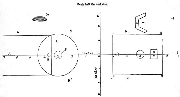
Fig. 60.
Always begin with a centre line and take each measure from it, and draw another across for the same purpose, at right angles to the first. You will quickly see the use of this. We draw two lines as described A, B, C, D, crossing in o. The longest is the centre line of beam, cylinder, and pump. The beam is to be 6 inches long to the outside of the middle of each arc, whence the chain is to hang. We, therefore, from the centre point, set off 3 inches each way. At the exact 3 inches will be the centres of the cylinder and pump;—set these off, therefore, on the plan. The end of the tank we must have near the cylinder, because we have to bring a pipe from it into the bottom of the cylinder. Set off, therefore, the end of the tank 2½ inches—i.e., 1¼ on each side of the central line, and draw it 4 inches in length. N shows the position of the pipe close to the end and on the line. The centre of the boiler is the[258] same as that of the cylinder, so we draw a circle round it with a radius of 1½ inches, which gives us the 3-inch circle of the boiler. Then we may set off equal distances, N, N, for the extremities of the legs of the frame which is to support the beam, and we complete our plan. M is the waste pipe, and K is the opening for the water to flow into the tank. We now find, therefore, that the bed-plate must be 13 inches long and 6 inches wide to take the engine of the proposed size, and we may, of course, extend this a little, if thought desirable. Mark off on the bed all the lines of the plan as here given, and always start any measurement from one of the two foundation lines, or else, if you make one false measure, you will carry it on, probably increasing the amount of error at every fresh measurement. Let this be with you a rule without exception. It is plain that if you work all parts of your engine to size, you can set it up on the marked bed-plate with perfect accuracy.
The description I have given will not only enable you to make a Newcomen engine with very little difficulty, but will give you an insight generally into this kind of work; and you will learn, too, a practical lesson in soldering, turning, and fitting. I must, nevertheless, help you a little in putting your work together.
You had better begin by soldering into the bottom of the cylinder the end of the steam-pipe, which you have already[259] fixed upright in the middle of the dome of the boiler, taking care that it stands squarely across the pipe, or your cylinder will not be upright. Then place the boiler in position, and you may fix it by turning out slightly the ends of the legs, and putting a tack through, or screwing, if the bed-plate is of iron,—or with help of Baker’s fluid you can solder; but this is hardly safe work, and you had better have a wooden plate, covered with tin, and tack down the legs. I have drawn you a circular lamp, and given three and four legs to the boiler-stand; but take care that you so arrange size of lamp and openings of the stand as to enable you to withdraw the former for trimming and filling. Now fit in the two small pipes, previously bent as required. To bend them, if hard soldered or brazed, fill with melted lead, and then bend; after which melt out the lead again. If soft soldered, you must fill with a more fusible metal. There is a composition called “fusible metal,” very convenient for this work, and well worth making, because you will often need to bend small pipes into various forms. Melt zinc, 1 oz.; bismuth and lead, of each the same quantity—this will melt in hot water; 8 parts bismuth, 5 lead, and 3 tin, will melt in boiling water. You can buy these at any operative chemist’s, either mixed, ready for use, or separately. Rosin and sand are also used for bending tin pipes, the sole object being so to fill them that they will become like a solid strip of metal, and[260] thus bend slowly and equally, with rounded and not sharp angles.
Pass the two pipes through from beneath the bottom of the cylinder, and solder them on the upper side of it, so that when the cylinder itself is added these two joints will not be visible. Then set up the cold-water cistern; block it up with anything you like so as to keep it in position, and, inserting the pipe from below, solder this also from above, i.e., on the inside of the cistern. Now, arrange the frame that is to support it, either stout wire or wood, and set it up so as finally to secure it in its place. Now, you had better set up the pump cistern, so as to secure the other small pipe in position, and prevent it from becoming displaced by any accidental blow. Fix this cistern therefore also, but leave the cover off for the present, that you may be able to solder the small pipe inside it.
You will now, at all events, have secured the position of the most important parts, and you may drop the cylinder into place, and solder this also round the bottom. This would be facilitated by turning a slight rebate, Fig. 60, S, round the disc which forms the bottom of the cylinder, so that the smaller part of it will just fit inside it; but you will be able to manage it without. Let the cylinder project a very little beyond the bottom, just to allow a kind of corner for the solder to run in; it will not show when all is fixed. Do this as quickly as you can, so as not to melt[261] off the solder round the small pipes. Now, make the pair of A-shaped supports for the beam. Measure the height of your cylinder top, above the bed-plate, and allow about another inch, and you will get the perpendicular height to the axis of the beam. Allow 3 inches more for each side, that is, in all for each side, 3 inches longer than if it was to be perpendicular instead of spreading. Take enough brass wire, about as thick as a small quill, to make two such legs. Bend it in the middle, like T, Fig. 60, and flatten the bent part by hammering, so as to allow you to drill a hole to take the pivot on which the beam is to oscillate. If you like to flatten all of it, and then touch it up with a file, so as to get quite straight edges, it will look much more handsome. Make two such pieces exactly alike, and, at distances alike in each, put cross-bars. File a little way into each, making square, flat notches, which will just take two flattened bars of the same wire; heat them, and solder very neatly, so that no solder appears on the outside; file all flat and true. In this way you can make almost as neat supports as if they were of cast brass, and you are saved all the trouble of making patterns. By and by, nevertheless, you must do better.
As I have directed you in this instance to put a wooden bed-plate to your engine, you may point the ends of the wires, and, making holes sloping at the same angle in the wooden stand, drive the wires into them. You have an[262] advantage here, inasmuch as you can raise or lower your stand until the position of the beam comes exactly right, and you find the ends drop over the centre of the cylinder and pump-barrel as it ought to do. When this is the case, you can cut off any wire that projects below the stand and file it level, for it will not be likely to need more secure fixing. The pump may now be soldered into the cover of the cistern (before the cover itself is fastened on), and a hole must be then cut to receive the water that will flow from the spout, and then the cover can be fitted on. There is no need to solder it, if it is made to fit over-tightly; and you may wish, perhaps, to get at the lower valve of the pump now and then.
The only thing left to do is to arrange the safety-valve of the boiler, which is in many cases the place through which the water is poured to charge it. In this engine it is, however, plain that you can fill the boiler by turning both the taps at the same time. A little will run off by the waste-pipe, but not enough to signify, because the tube below the cylinder is so much the larger of the two. The safety-valve is a little bit of brass turned conical to fit the “seat,” made by counter-sinking the hole. It is shown at K, Fig. 59, N being the seat, O P the dome of the boiler, and close to O is the gauge-tap for ascertaining the height of water in the boiler. L M is a lever of flattened wire, pivoted to turn on a pin at L,—L O being an upright wire[263] soldered to the boiler. A notch is filed across the top of the valve, on which the lever, L M, rests. The weight is at M. One, as large as a big pea, hung at the end of a lever 2 inches long, the valve at half an inch from the other end, will probably suffice for this engine.

I have already told you that Watt suggested the use of steam alternately on each side of the piston; and carried it out by closing the top of the cylinder, and allowing the rod of the piston to pass through a stuffing-box or gland. I now have to explain to you how this alternate admission of the steam may be effected.
You evidently require first an opening at the top and bottom of the cylinder, communicating with the boiler, one only being open at a time; but in this case, where is the steam to escape that was on one side of the piston when the opposite side was being acted upon? It must go somewhere, but evidently must not return to the boiler. Hence, some method has to be contrived by which, when one end of the cylinder is open to the boiler, the other may be open to the air or to the condenser (in which the steam is cooled under Watt’s plan). Fig. 61 will, I think, render clear one or two of these arrangements.
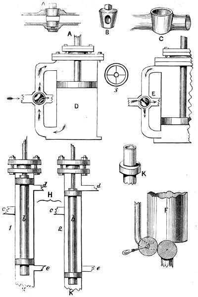
Fig. 61.
The first is the four-way cock, a very simple contrivance, easily and frequently used in models. You must first understand how a common water or beer tap is made. Fig. 61, A, represents one in section, turned so as to open the passage along the pipe to which it is attached; C is the pipe in which is the tap, a conical tube of brass set upright, and with a hole right and left made through it, fixed into a short horizontal tube (generally cast with it in one piece). Into this fits very exactly the conical plug B, also with a hole through it sideways. When this is put into place, no water or other liquid can pass, unless the hole in the plug is in the same direction with the hollow tube forming an open passage. If a key is put on the square part of the plug, and it is turned half round, the passage through the pipe will be closed. A steam tap would be made in a similar manner, if its only office were to open and close a passage in a tube. But we now want two passages closed and two opened, and then the alternate pair closed and opened. This is cleverly effected by a four-way cock.
At D is shown a section of the steam cylinder and piston, with the stuffing-box and all complete. A pipe enters this at the top and bottom, and another crosses it in the middle, making four passages. Shaded black is the four-way cock,[267] the white places showing the open channels through the plug. When this plug stands as at D, steam can pass from the boiler to the top of the cylinder only, above the piston, which it drives downward; the steam below the piston escapes through the other open-curved channel into the air, or to the condenser. Just as the piston reaches the bottom of the cylinder, the tap is turned, and the passage stands as seen at E. Steam now passes to the bottom below the piston, driving it upward, and the steam above it, which has done its work, passes outward through the other open channel of the tap.
You must understand that when Newcomen first set up his engine, a man had to turn the taps at the proper moment; and it is said that one Humphrey Potter, a boy, being left in charge, and getting tired of this work, first devised means to make the engine itself do this, by connecting strings tied to the handles of the taps to the beam that moved up and down above his head. Beighton and others improved on this, and very soon it became unnecessary for the attendant to do anything but keep up a good fire, and attend to the quantity of water in the boiler, and the pressure of the steam.
In the model I gave you of Newcomen’s engine, I purposely left the taps to be moved by hand; but F of the present figure shows how, by bringing them near together, and adding cogged wheels or pulleys, you would make one[268] handle answer for both; and I shall leave you to devise an easy method of making the engine work this one handle for itself. When Watt made his first engine, therefore, this work had been already done, and he only had to improve upon it, and to make it work more accurately to suit the engine designed by himself.
If you should chance to pay a visit to the Museum at South Kensington, you may see, I believe, Watt’s original engine, if not Newcomen’s. The cylinders are so large and cumbrous, that the wonder is they were ever bored by the inefficient means then in use; and the beam is a most unwieldy mass of timber and iron, that looks as if no power of steam could ever have made it oscillate. Yet it was in its day a successful engine, the wonder of the age; and did good work for its inventor and purchaser. I strongly advise my readers to try and visit Kensington, for there are many interesting models there, besides engines and appliances of older days. They will thus learn what rapid progress has been made since the days of Savery, Newcomen, and Watt; not only in the improvement of the arrangement of the parts, but in the workmanship, which last is mainly due to the invention of the slide-rest and planing-machine.
We must now return to the double-acting or real steam engine, and consider a second means whereby the steam can be alternately admitted and exhausted.
The four-way cock, already explained, was found to wear very considerably in practice, and hence work loose, and a new contrivance, called the slide-valve, soon took its place. Of this there are two patterns, the long D-valve and the short one, which latter is used for locomotives. There is also a form called a tappet-valve, often used for large stationary engines, but which is noisy and subject to rapid wear. I shall describe the long D first, in the form in which it would be most easily made for a model engine.
The two ports by which steam passes to the cylinder are shown at d, e, of H, Fig. 61. C is the passage to the boiler, K is that to the condenser. These are openings in a tube smoothly bored within, and having at the top a stuffing-box like that on the cylinder. Within this tube works an inner one, b, having rings or projections at the ends fitting perfectly, and which are packed with india-rubber, hemp (or, in modern days, with metal), to make a close fit. In a model, two bosses of brass, K, soldered on the tube and then turned, make the best packing. These packed portions of the inner tube form the stoppers to the steam ports, e e, alternately, at the top and bottom. The upper part of the inner tube has a cross arm, 3, affixed, from the centre of which rises the valve-rod by which it is moved up and down. In the position 1, the steam can pass from c round the tube to d, and thence to the top of the cylinder to which d is attached. The exhaust[270] steam passes from e below the piston by k to the condenser. In the second position, 2, the steam is evidently shut off from d, but can pass out at e e below the cylinder, while the communication is still open to the condenser from d, through the middle of the tube to K. This is a very good form of valve, because the exhaust is always open, and the motion is smooth and equal.
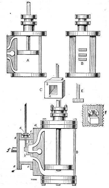
Fig. 62.
There are many modifications of the long D-valve, but the principle of all is the same; I shall therefore describe the short slide-valve which is nearly always used in the models which are purchased at the shops. This, too, is the usual form of valve in locomotives, traction-engines, and the majority of those in use for agricultural and similar purposes. A, Fig. 62, is the cylinder as before in section with piston. A thick piece is cast with the cylinder, on one side of it, having steam ports also cast in it, which are here left white. The two as before go to the top and bottom of the cylinder, and have no communication with the central one, which is bored straight into the boss, and generally is turned at right angles and connected with the condenser, or with a pipe opening into the chimney of the engine to increase the draught by means of the jets of steam, as is the case always in locomotives, or into the air, which is less usual. Seen from behind, these ports are like B, being cast and cut rectangular; and the face, B, is planed quite level, which is absolutely necessary to the[272] proper action of the slide-valve which has to work upon it. This valve is a box of iron, C, with a wide flange or rim, this flange being of sufficient width to close either port. If this valve is placed as it stands when the engine is at rest, b covers the upper steam port, and a the lower; while the exhaust or middle port is open to the hollow part of the box. Now, if we slide the valve downwards until the upper port is open, the other two will be in communication, being united by being both together in the inside of this box or valve. Suppose the valve then cased in, and that steam is admitted from the boiler into the case, it is evident that such steam could freely pass to the top of the cylinder above the piston to force it downwards, while that which was below would escape by the lower port into the box, and thence pass to the condenser. If, instead of pushing down the valve, we had drawn it upwards, the lower port would have been opened, and the upper and middle would have been brought into communication inside the valve, and the contrary effect would have been produced upon the piston.
This is the arrangement adopted, and which will be clearly understood from the following sectional drawing, D. a, a, is the thick casting upon the cylinder, with the upper and lower steam ports, which end towards the middle of the cylinder, with the third port lying between; then b is a section of the valve, in such a position that the flange[273] of it no longer covers the lower steam port, while the other two are open together on the inside of the valve. The latter is cased in by the valve-box, e e, in the back of which is the steam pipe f coming from the boiler. The valve-rod, which is moved by the engine, passes at o through a stuffing-box. It is evidently necessary that this slide-valve should fit, and work very smoothly and correctly against the face of the ports, so as not to allow any escape of the steam. It is not, however, packed in any way at the back (although springs have been sometimes added), because, as the back is subjected to the full pressure of the steam from the boiler, this keeps it quite close to its seat. The rod, however, by which it is worked, might prevent this close contact of the two surfaces if it was screwed into the valve; it is therefore made with a cross, E, at the end, which falls into a notch in a boss cast upon the back of the valve as seen at F. This allows a certain degree of play in one direction, and permits the steam to press it close even after it has become worn by use.
You will, I think, now clearly understand how steam can be admitted alternately to the top and bottom of a cylinder, and how the exhausted steam that has done its work escapes. I must therefore now tell you how the rod of the slide-valve is moved up and down by the engine, but to do this, I must draw such engine complete.
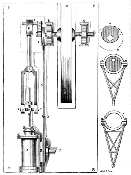
Fig. 63.
The cylinder, A, is screwed down on its side upon the bed-plate, R R, out of which are cut two holes, one for the fly-wheel, P, of which part only appears for want of space, the other for the crank, L, on the end of the axle, M M, running through bearings, N N. The slide-valve-box is at B, C being the steam-pipe from the boiler. The piston-rod has necessarily to move only in a straight line in the direction of its length, but the crank which it has to work to turn the fly-wheel must needs move round in a circle. Hence, a poker-and-tongs joint, F O F, is arranged. The connecting-rod, H, which is attached to the crank by brasses at K, divides or is attached to a forked piece, at the lower end of which are a pair of bearings or brasses, F F. The piston-rod carries the piece O, the cross-bar of which is turned, being, in fact, the pin which passes into these bearings at F F. This forms, therefore, a hinge-joint at this place, so that although the piston-rod cannot leave the right line, and can only slide in the guide, E, the rod, H, has an up-and-down motion upon this hinge, allowing the revolution of the crank-pin to take place. D is the valve-rod, in which is a hinge at S, which suffices for the slight movement required in the rod, as it rises and falls by the action of the eccentric, T, the motion and effect of which I now have to explain.
V is a round disc of metal with a recess on its edge, so that it is like an ordinary pulley, but large in proportion to[276] its thickness. A hole for the main crank axle, to which it has to be firmly keyed, is made through it, but not in its centre (hence its name, eccentric—out of the centre). As the axle revolves, it is evident that this disc revolving with it will carry any point, Y, of its surface round in a circle; the centre of which is on the central line or axis of the crank-shaft. I have drawn such circle as described by the point Y, farthest from the axis; but any and all points describe larger or lesser circles round the same centre. The point Y may, therefore, be considered as the centre of a crank-pin; and the eccentric might, so far as its effects are concerned, be replaced by a crank. Now, if you turn the fly-wheel of your lathe by hand, the crank will revolve, but the treadle will rise and fall only in a straight line; and you will presently see how the eccentric, in its revolution, gives just such a to-and-fro motion to the rod D, and consequently also to the slide-valve, which it has to move.
Round the disc V, closely encircling it, is a flat ring, shown separately at X, with a rod, W, attached to and part of it. This ring is generally made in separate halves, united by bolts passing through projecting lugs or ears. The ring also fits into the groove turned on the edge of the disc V, so that it cannot slip off sideways. This outer ring is turned quite smooth and true on the inside, so that the eccentric disc can revolve within it. In doing so, it is[277] plain that the whole ring will rise and fall, and that the rod W will move up and down, or to and fro, like the treadle of the lathe, thereby giving motion to the valve-rod, which is a continuation of the rod W. As the upper end, however, of this rod has an oscillating, or up-and-down motion, this is imparted, in a certain degree, to its other end, at the farthest distance from the eccentric; and hence the necessity for a hinged joint at S, to prevent the valve-rod from partaking of this movement. It is, however, very slight, so that the rod of the valve is not often made to pass through guides like the piston. The whole movement of the valve-rod is very limited, its traverse only being required to be sufficient to shift the valve the width of one of its ports at each stroke. The length of stroke or traverse which can be obtained by the eccentric is always equal to twice the distance between its real centre, and that on which it turns, which will always be a guide to you in making an engine.
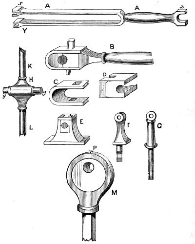
Fig. 64.
The drawing here described is a plan, i.e., a drawing viewed directly from above; therefore I cannot show you the perspective view of the parts, which are, indeed, in many cases only suggested by the shading. I have, therefore, added a second drawing of the several details. This engine is, in construction, the simplest that can be devised with a slide-valve, there being no additions beyond what are absolutely necessary to make it work; the exhaust-port[278] is below, opposite to the letter B on the valve-box. A, Fig. 64, is the forked connecting-rod, marked H in the previous drawing. This is cast with forked ends, x, and x[279] Y (the latter being F F of Fig. 63). These ends receive brasses in the following way, the end x being represented on a larger scale at B, with such brasses in place; of these there are two shaped like D. One of these lies in the fork of the connecting-rod end. A second similar one lies in the strap of iron C, which reaches beyond the first. A cotter or key, which is, in fact, a wedge of iron, is then passed through a slot in the strap, and a similar one in the rod; and being driven home, draws the two brasses tightly together, causing them to embrace the crank-pin, L, Fig. 63, or any similar bearing. All shafts that revolve in bearings are made to pass through brasses, and whenever these occur at the end of a rod, they are fitted as here described. E is another bearing of cast-iron, also fitted with brasses; but in a case like this, a plate lies on the upper one, and is screwed down by bolts and nuts as required. This bearing would do very well at E, Fig. 63, as a guide for the piston-rod; but in models such guide is commonly made without brasses, like F or G of the present drawing.
At H, I have shown the part F O F of the drawing 63. The middle is of brass or iron; if of the former, g g must be separate, as these gudgeons would not be substantial enough, unless of iron or steel. It is essential that K L, the piston-rod, should be in one right line; but, if this is attended to, they need not necessarily be one piece; and frequently the piston-rod, L, is fixed into one end of the[280] central casting, and another rod, K, is screwed into the other. In a model, the piston-rod should pass quite through, and g g should be two separate gudgeons screwed in, and then turned together in the lathe, to insure their being exactly in one line. These go into the brasses in the forked ends of the connecting-rod, to form a hinge at that part, as will be understood by a reference to Fig. 63.
At M, I have shown another simple eccentric and rod, which is less trouble to make in a model than the other. In this the ring is made in one piece, with a round rod screwing into it. The disc has a slight groove turned in its edge, and a small screw, P, passes through the ring and falls into this groove. This suffices to prevent the ring from falling off sideways, and of course is not screwed down so tight as to prevent the disc from revolving. This is a very easy way to fit the eccentric, and is generally followed in small engines. The lattice eccentric rod is nearly always used in large beam engines.
I do not think the reader will now have any difficulty in understanding the precise arrangement of the various parts in the simple horizontal engine of which I have given a sketch. It is a neat and convenient form, easily arranged as a model, and I shall proceed at once to the practical work of constructing this, and engines in general, presupposing a knowledge of the use of the lathe, and of the few tools required.
The very first mechanical work of difficulty, but of pre-eminent importance, in making an engine, is boring the cylinder, that is, if the same is a casting, and not a piece of tube ready made and smooth on the inside. This is, properly speaking, lathe work, yet may be done in a different way. Suppose you have bought your entire set of castings, which is the best way, and that the cylinder is half an inch diameter inside, which is a manageable size to work upon. Get a half-inch rosebit, which is very like the countersinks sold with the carpenter’s brace and bits. Mount it in the lathe in a chuck, A, Fig. 65. Unscrew the point of the back poppit, and slip over the spindle a boring-flange, B, which is merely a flat plate like a surface chuck, only the socket is not screwed but bored out, generally large enough to slip over the spindle. Sometimes there is, however, a screw at[282] the back, to screw into the spindle, the same as the points or centres. On the face of this lay a piece of board of equal thickness, but it is as well if not planed, as its object is partly to prevent the cylinder from slipping about during the operation, as it is sometimes inclined to do upon the smooth metal flange, and partly to prevent the borer or rosebit from coming in contact with the flange when it has passed through the cylinder. Grasp the latter in the left hand, and you can easily prevent it from revolving with the drill, which will go through rapidly, and leave the hole beautifully finished and quite true from end to end,—indeed, I have bored iron also, rapidly and with great ease, with this tool.
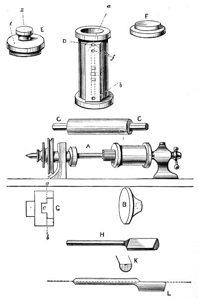
Fig. 65.
It is absolutely necessary, remember, that this hole bored in the cylinder should be at right angles to the ends of the same, and to secure this you must now make use of it to mount the cylinder in the lathe to turn these ends or flanges. I will show you a simple and easy way to do this. C is a bar of iron or steel, preferably of the latter, about 6 inches long, and three-eighths diameter, filed into six sides. It is a good plan to have three or four sizes of such bars, with centre holes drilled carefully into each end, so that you can mount them with a carrier-chuck, as you would if you were going to turn them. Taking one of about the size named, mount upon it a piece of wood, and turn this down until your cylinder will just go tightly upon it.[284] Being a six-sided bar, it is easy to mount the wood upon it by boring the latter with a gimlet and then driving the bar into it. It will hold tightly, and not turn round upon the metal. The cylinder being fixed in this way, you must turn the two flanges with a graver if the cylinder is of iron, but with a flat tool or the four-sided brass tool if of the latter metal; and also turn the edges of the flanges. The rest of the cylinder will be left in the rough, and may be painted green or black. I should advise you always to bore the cylinder first when possible, and then to mount it as described and turn it on the ends, which are thus sure to be correctly at right angles to the bore. Some cylinders, however, especially short ones, may be squared up first, and then mounted on a face-plate and bored. Unless, however, you have either a grip-chuck, which is self-centring, or some clamps properly constructed for this particular work, you will find the first method the easiest, especially for small light work.
You should now make the ports for steam and exhaust. Mark them upon the flat part of the casting, after you have filed this as level as you can, and do not mark them so long as not to leave you room beyond the ends of the ports for the steam-box or case which has to be placed here. The upper and lower ports are to be the same size, but the middle one may be a trifle larger with advantage. In larger engines these are cast in the metal, and have only[285] to be trimmed and faced; but in the small models you have to drill them out in the boss cast on the cylinder. Drill down from the top, as shown at D by the dotted lines, but take great care not to go farther than the outer ports, which are to be therefore first made, so that you can tell when the drill has gone far enough. If you pierce the middle port from either end, the cylinder is spoiled. To cut the middle one, you merely drill a hole straight in towards the cylinder, and meet it by another drilled from the side, into which the pipe for the exhaust is to be screwed. You also drill straight through into the cylinder at a b, and you then plug the end of f, and that at the other end of the cylinder. Your port faces, however, are generally oblong, and not round. Make a row of holes with the drill, and then, with a little narrow steel chisel and light hammer, chip out the superfluous metal, and finish with a small file. You can always make narrow channels with squared sides by thus drilling two or more holes, and throwing them into one with a file; but in reality, for these small engines, it is very little matter whether the ports are round in section or square.
The bottom and top of the cylinder demand our next attention. E and F show these. They are easily and instantly mounted in a self-centring chuck, but can be held very well in one of wood carefully bored with a recess of the right size and depth. You must here, nevertheless, be very[286] particular, else you will get your work untrue at this point, and then your piston-rod will stand awry, and all your subsequent fitting will be badly done. I therefore give you at G a section of the chuck bored to take the cover truly. Recess the part down to the line a b, to fit the cover exactly, taking care to level very carefully the bottom of the recess. Below this cut a deeper hole, to allow the flange in which the stuffing-box will be to go into it. It need not, however, fit the flange. The rough casting will hold very well in a chuck like this, even if it is of iron. You now carefully face the bottom of the cover, and turn the slight flange exactly to fit into the cylinder; then reverse it in the chuck, so as to get the stuffing-box outside; and in doing so, take the greatest care that it beds flat upon the bottom of the chuck. Turn off level the top of the flange first at x of fig. E, and then place a drill with its point against the middle of this, and its other end (with a little hole punched in it to keep it steady) against the back poppit centre, and carefully drill a hole down to the level of c, large enough to admit the gland of the stuffing-box or nearly so; but remember that you must not go too far, because the rest of the hole must only just allow the piston-rod to go through it. Therefore, after you have drilled about three-fourths of the distance, replace this drill by a smaller one, and with it bore quite through. The advantage of beginning in this way is, that you can now bring up the back[287] centre of your lathe to steady the cylinder cover while you finish turning it; and as you will have to make a chuck only to take hold of the flange b, while you turn the edge, you will need probably some extra support of this kind. I have, nevertheless, turned an iron cylinder cover 2½ inches diameter without any such support; the actual strain not being very severe, provided you understand how a tool should be made and held.
The above directions apply equally to the cylinder bottom, the great secret in this and all similar work being to take care to bed the work well and truly against the bottom of the recess, turned in the chuck; this being neglected, will result in the two faces not being parallel, which will terribly throw out of truth the rest of your work. Indeed, in all fitting of this kind, it is absolutely necessary to be exact in the squaring and truing of each several piece that has to be turned or filed; otherwise no planning or clumsy arrangement will make your mechanism work as it ought to do. Take a week, if necessary, over any part, and don’t be content until it is well done.
Your cylinder ought now to have a finished appearance when the cover and bottom are placed in position, but the latter have to be permanently attached by small screws, and these I strongly advise you to buy. They cost about 50 cents a dozen, including a tap with which to make a thread in the holes made to receive them; or, if you prefer[288] it, you can buy miniature bolts and nuts at almost as cheap a rate, which would cost you much time and trouble to make for yourself, if, indeed, you succeeded at all. You will want four of these for the top, and the same for the bottom, the holes for which you will make with a small archimedean or other drill.
The mention I have made of this reminds me that I am gradually adding considerably to your list of tools, and it is necessary to do so if you take up model-making. Set down, at any rate, the following:—
And for use in the lathe, either two or three sizes of rose-bits, or engineer’s half-round boring bits, of which I shall have to speak presently; and, unless you buy all screws and nuts, you will want screw-plate and taps, or small stock and dies. Files of square, round, and oblong section are matters of course. Remember, too, that after a file has been used on iron and steel, it is useless for brass; so use new ones on the latter metal first, and after such use they will answer for cast iron and then for wrought iron. You will find the cost of files rather heavy unless you attend to this. Have neat handles to all your smaller files, with ferules to prevent splitting.
When you purchase the castings of the engine, you will find a valve-box to enclose the slide and become a steam-chest, as explained. It is like a box with neither top nor bottom, but with a flange, or turned-out edge all round, for the screws by which it is to be attached to the valve-facings of the cylinder. This box must have its flanges filed up bright on their flat sides and edges—the rest may be painted. It will exercise your skill to get the two faces flat and true, to fit upon the cylinder; and at last you will find it expedient to put a brown paper rim or washer between the surfaces, or a bit of very thin sheet lead, to make a steam-tight joint. Do not solder it, if it is possible to use screws, because this is nearly certain to get melted off; and, if not, it is not nearly so neat and workmanlike a way of uniting the parts. You should, indeed, in all models, put them together in such a way as to be able at any time to separate the different pieces again, either for the purpose of cleaning or repair; and, if you solder, you cannot easily do this.
The valve-casing and its back are generally put on together; four screws at the corners passing through the back and both flanges into the flat side of the cylinder. This depends, however, upon the exact shape of these different pieces; and I can give you no special directions for a particular case unless I could see the castings which you have to fit together. The stuffing-box you will make[290] quite separate, both its outer and inner part, and screw or solder the former into place. It is seldom cast upon the valve-casing, because of the difficulty of chucking a cubical object safely so as to turn any part of it.
You are not to screw or solder the valve-box to the cylinder until you have carefully filed up the valve itself to slide upon the port face, without the possibility of any escape of steam taking place. This needs the greatest possible care; and probably, after doing what you can with a flat file, you will have to put a little emery and oil between the surfaces, and grind them to a perfect fit, by rubbing them together. This grinding with emery is an operation frequently required in mechanical engineering. Lathe-mandrels are fitted in this way into the collars; the cylinder is also ground into the back poppit-head. It is not a very long or difficult operation, but whenever you have had to use it, take care to wipe off the emery, or it will keep on grinding. It is indeed very difficult to do this perfectly; and for very fine work, such as fitting the mandrel of a screw-cutting lathe (i.e., a traversing mandrel), oilstone powder and crocus are used, in place of emery. These, however, cut very slowly, making the operation of grinding exceedingly tedious; and in the present instance, emery will answer quite well enough. In very small engines, a stroke or two of a file is all that is needed to fit the valve, which is so small as hardly to be worthy of the[291] name; but in an engine with cylinder of 1 or 2-inch bore, it will be impossible to do with file alone, as well as you can with grinding.
The piston and piston-rod should be turned at the same time, as already suggested in treating of the atmospheric engine of Newcomen. By this, you will avoid getting the piston “out of square” with its rod, as if you had bored the hole for the latter askew—a not unusual occurrence.
I do not mean to say that it is absolutely necessary for you to turn the piston-rod at all, for, in models, it is generally of round iron or steel-wire, which is as cylindrical as you can possibly make it. Knitting-needles are in general use for this, as being well finished and equalised from end to end. But these are rather hard, being tempered only to about the degree of steel-springs; therefore you must never attempt to cut a screw on them until you have first heated the end to be screwed red-hot, and allowed it to cool again very slowly. If you do this, a screw-plate will put a sufficiently good thread to allow you to attach either the piston, or the small piece of brass necessary to form the hinge, upon the other end of the rod—that is to say, the piece marked H in Fig. 64. Leave this for the present, however, not attempting at present to cut either the piston-rod or valve-rod to its intended length. You cannot do this until you have laid down the exact plan of the engine, and marked on the bed-plate the position of all the parts.
I shall now suppose that you have finished the cylinder, with its slide-valve, casing, stuffing-boxes, and piston, so that you have these in exactly the state in which you might buy them at Bateman’s and elsewhere, if you preferred, to spare yourself the trouble of boring the cylinder and fitting it. You can buy them just in this condition, with the rest of the castings in the rough; but I rather hope you may prefer to try and do for yourself the not very heavy or difficult work which I have described.
I suppose you, indeed, to have bought the forked connecting-rod, either arranged for brasses, or with holes drilled (or to be drilled) in the ends, which would probably be the case for a model of the size named, and also the various bearings, guides, and so forth required—some of which would have to be turned, and some filed, but which ought now to present little difficulty to our young mechanic.
Try to keep sharp edges to all your filed work, unless evidently intending to round them; for surfaces pretending to be flat, but partaking of a curved sectional form, characterise the workman as undeniably a bad hand with the file, and not worth his wages. Still I may tell you at once that nothing is so difficult as to use a file well. It has a knack of rounding off edges, which always get more than their proper share of its work. But this being the case, you will know what to try and avoid. Therefore, always endeavour[293] in filing a flat surface to make it slightly hollow in the middle, which it is scarcely possible, however, for you to do; but the endeavour to effect this by filing the middle more than the edges will help you wonderfully in keeping the latter sharp. Those, for instance, on the fork of the connecting-rod, especially the inside ones, should be as straight and sharp as possible; and if you round the outside edge, take care to do it so that it shall be evident you intended it; and so with all edges, whether turned or filed.
The disc of the eccentric can only be turned by letting it into a chuck to something less than half its thickness, and levelling one side and half the edge, and then reversing it; unless you prefer to drill and mount it on a spindle upon its centre. If you do this, you will of course eventually have two holes in it; because this first one is not that by which it will be mounted when in place. This second hole is not, however, of the least importance, and may be left without plugging, and, if preferred, may become in part ornamented by drilling additional holes, and filing them into some pattern; or if it is desired to conceal the one it was turned upon, this can be plugged and faced off, and will then not be the least apparent. If the outer ring, or strap, as it is called, is to be made in two pieces, with projecting lugs, it is evident the outside edge cannot well be turned; and, unless you have that most useful addition to[294] the lathe, a grip or jaw-chuck, you will have some little difficulty in letting the ring into a wooden chuck, so as to turn the inside. The solid ring is, therefore, preferable (if you use the first, however, you turn it up as a single ring, and then saw it across through the lugs), which can be let into a common chuck, with a place chiselled out to allow the boss to project, into which the eccentric rod has to be screwed. This boss also has to be drilled and turned on the outside. There are several modes of chucking it which can be applied, but the simplest is to use the carrier-chuck, and to let the ring become its own carrier by coming against the pin, as shown in Fig. 66, A.
When the ring is very small, I should first drill the hole for the wire rod, and then screw and mount it upon a little wire spindle, as in fig. B, aiding this, if necessary, by the back centre. But the smallest models require to be put into a watchmaker’s lathe or throw, and, except as curiosities, are scarcely worth making.
I have already told you never to undertake engine-making without first laying down a full-sized plan on paper, with centre lines through the principal parts, from which to take all measurements, and to mark these upon the base-plate, as a guide to the perfect adjustment of the various parts. Some of these are capable of a little extra adjustment after being put in place: the eccentric rod, for instance, can be lengthened or shortened by screwing into[295] or out of the eccentric ring; and the piston-rod, too, may be similarly lengthened or shortened slightly; but try to work as near as you can to precise measure without such adjustment.
To turn the fly-wheel, which is the last operation (including the crank-axle), it is better carefully to drill the boss, if not already done, marking the centre on each side, and working half through from each, so as to insure the squareness of the hole with the side of the wheel, which is very important. Then mount it at once upon its axle, previously turned slightly conical, where the wheel is to be placed, and run both together in the lathe. This will insure the wheel running true when the engine is put together.
In the horizontal engine which I have sketched, the crank is quite separate from the axle; and this is the easiest way to make it. The crank itself is filed up, like C of fig. 66, and drilled for the axle and the pin upon which the brasses on the connecting-rod work. Turn down the end of the crank-shaft very slightly conical, until the crank will almost go over it. Then heat the crank, which will expand it and enable you to slip it on the shaft. Dip it in cold water, and it will be as firm as if made in one piece with the axle. This is called shrinking it on, and the operation will often stand you in good stead, and save the trouble of filing key-ways and making the small wedges[296] called keys. The pin D can in this case be turned up separately, and screwed in, which will complete the work.
The eccentric must evidently be placed in position before the crank is added, and this, too, might be shrunk on, were it not that it cannot easily be fixed in a model until the engine is set up. The best way, therefore, is, in this case, to turn the eccentric with a little projecting boss to take a set screw, E, Fig. 66.
Where the axle has to pass through bearings, it must be turned down at these parts, so that the whole will be like F. First on the right is the journal, e, then the place for the fly-wheel, d, very slightly conical—the smallest part being towards e—then the second journal, and then another slightly conical part, the smallest end towards a, to take the eccentric and crank. The fly-wheel you will key on shaft, thus:—G represents the boss or centre of the wheel bored for the axle, and a key-way or slot filed on one side at a. There is a flat place filed on the axle, and the wheel is turned round to bring this opposite to the key-way. A wedge or key, b, is then driven in, which keeps the wheel secure, and prevents it from turning round or working loose on the axle. If inconvenient to turn a boss and add a set-screw to the eccentric, this also may be keyed in its place after its position has been found; but, for the latter purpose, it should fit rather tightly on the axle, so that it can be just moved round with the finger stiffly until its position with respect to the crank is ascertained.
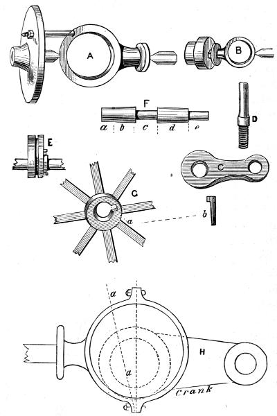
Fig. 66.
This position I shall now endeavour to explain, using a diagram from an American work, in which this generally supposed difficult point is thus ably and satisfactorily explained. First, put your engine together as if for work, and having cut the eccentric rod to about the length you seem to require, judging from your plan drawn upon the bed-plate, turn round the eccentric, with your fingers upon the crank-shaft, and, having removed the cover of the valve-box, so that you can see the action on the valve, watch the motion of the latter. Doubtless, the result will be that one of the steam-ports will be opened clear to the exhaust-port, while the other is nearly or entirely shut. The rod is then too long or too short. If in a horizontal engine the port nearest to the crank is wide open and the other shut, the rod is too long, and must be shortened half the difference only (you will do this by screwing it farther into the eccentric hoop). When the valve “runs square,” or opens and shuts the ports correctly, set the eccentric as in the diagram, H, in respect to the crank, i.e., with its widest part at right angles to it. By running square is meant that when the eccentric is turned round as described, the valve opens the ports equally, and does not affect one more than the other. The line a of the diagram shows that the position of the eccentric may advantageously be a[299] little beyond the right angle to the crank, to give what is called “lead,” i.e., to open the valve a little before the piston commences its return-stroke.
The boilers of model engines are made of tin, sheet-brass, or copper; seldom of the latter, which is, nevertheless, by far the best material, and one that you can braze, rivet, or solder satisfactorily, or bend into any shape with a hammer or wooden mallet. When polished, too, its rich red colour is very handsome. Brass is chiefly used from the facility of obtaining tubes of it ready brazed or soldered, from which any desired length can be cut. A brazed copper boiler will stand a great deal of pressure; will tear, and not fly into pieces when it bursts; and may be heated after the water has boiled away without suffering any injury. It would certainly not be worth while to make one for a model engine with a half-inch cylinder, but for one of 1 inch diameter and 2½ stroke; and for larger sizes, it will amply repay the trouble; and I will show you how to make one, with a tube or flue inside to add to the heating surface.
I shall endeavour presently to give the proper dimensions of boilers to work cylinders of given diameters, but the general directions here subjoined apply to all boilers of models, whether large or small. The main body of the boiler is generally cylindrical, and is, in fact, a tube of sheet-metal, with riveted, brazed, or soldered seams, the last greatly predominating in the toy engines; the result of[300] which is, that the first time the water gets too low, out drops the bottom, or, at the least, divers leaky places appear, and the boiler is obliged to go to the tinman’s for repair, its beauty being ever after a thing of the past. It is difficult to braze in an ordinary fire; because even if, by blowing it with a pair of bellows, you get sufficient heat, you cannot always manage to apply your work in a good position, as you can over the hot coals of a forge fire, where there are no bars, hobs, or other parts of the grate standing in the way. Moreover, you often want both hands free just as the solder commences to “run,” and forge-bellows will keep up the blast for a few seconds after your hand is taken from the staff or handle of them. Still, if you have no forge, which is probable, you should make a fire of cinders or coke (the latter if possible); and if you can contrive a grate by putting together a few bricks in some out-house, with a bar or two of hoop-iron below for the coke to rest upon, you will have a far more convenient fire to work at than can possibly be obtained in any ordinary household grate or stove. You will require a pair of light tongs, which ought to be something like A, Fig. 67; but it is quite possible to do without these if you can hold your work in any other way; as, for instance, with a loop of iron wire twisted round it and left long enough to form a handle.
The first thing to do is to cut a strip of copper large enough to make the required tube. A piece 6 inches wide[301] will roll up into a cylinder of about 2 inches diameter (the circumference of a circle being nearly equal in all cases to three times its diameter, or measure through the centre). If, therefore, you want one 6 inches across, which is the smallest size that can be advantageously fitted with a flue or internal tube, you must cut it out 18 inches wide, and if it is 8 in length to the bottom of the steam dome, it will be a large and serviceable boiler, fit to work an engine with a cylinder of 1½ bore by 2½ or 3 inch stroke, which would drive a small lathe. But observe that if you really have pluck and skill enough to try your hand upon an engine that will give you real power, you must take care to remember that “the strength of anything is the strength of its weakest part.” So don’t make the very common mistake of having a good boiler and ample cylinder, and then fit the engine with piston-rod, valve-rod, and such like, too small to bear the strain which you propose to put upon the engine. Remember that every screw and nut and pin upon which strain is liable to fall, must be of sufficient size and strength to bear it safely: if not, your engine will not only come to grief in the heavy trial, but it is quite possible that you also may become subjected to a bad scald or other disagreeable consequence of your error.
Whatever sized strips of copper you use for a boiler, the edges have to come together to form what is called a butt-joint; i.e., they do not overlap like the ordinary joints you[302] see made in tin. Before you coil up the strip into a tubular shape, you have to cut out holes for any boiler fittings you may wish to add, such as safety-valve, steam-dome, and gauges to ascertain the level of the water. These, however, do not all come into the cylindrical part of our present boiler; the gauge-taps and glass water-gauge alone having to be provided for. The man-hole, too, which is added to all large boilers, may be dispensed with, its object being to enable one to get at the inside, which will scarcely be necessary if our work is well done at first. A boiler of the proposed size should be heated with charcoal, as it would require a very large lamp; but where gas can be obtained, it may be preferably used, a ring gas-burner being placed below within the furnace. The object of a steam-dome, which, in a horizontal boiler, would have to be placed somewhere on the tube itself, is to prevent what is called priming, i.e., the carrying into the cylinder water as well as steam, which arises from the spurting caused by the violent boiling of the water. The dome merely provides a chamber for dry steam above the general level of the boiler, the steam-pipe passing from it direct to the cylinders. Our present boiler will be vertical like the last, but with a flue up the middle, and a grate fitted below. It is shown complete in Fig. 67, B, with all the fittings usually attached.
Having coiled up the tube by hammering it over a[303] cylinder of wood turned for the purpose, a little smaller than the intended size of the boiler (the edges having been previously filed up bright, and a width of a quarter of an inch of the upper being similarly cleaned on the inside all along the seam), a few loops of iron wire are tied round it, at intervals of 1 inch or 1½ inches; there being a short piece put round, and twisted together at the ends by a pair of pliers. The object of these is to prevent the seam from opening on the application of heat, which it is otherwise certain to do by the expansion of the metal. Some borax, pounded in a mortar, and heated to drive off the water of crystallisation, is next mixed with a little water to form a creamy paste, and smeared along the inside of the tube, upon the brightened part, the full length of the seam. It is generally better to heat this salt first sufficiently to dry it (or rather fuse it), because it swells prodigiously by the first application of heat, and if the spelter is laid on it, it often carries it off; after once fusing, it only melts quietly.
Before applying the little lumps of spelter, turn over the tube to heat the part opposite to the seam, so as to equalise the expansion. Then hold it in a pair of light tongs, lay the spelter all along upon the borax, and expose it without actually touching the coals to the heat of the fire, urged by a strong blast. Continue this until a blue flame arises, which shows that the spelter has melted; this blue[304] flame being, in fact, that caused by the burning of the zinc in the solder—spelter being copper and zinc fused together, or, if required softer, brass, tin, and zinc. The former is generally used, however, on copper. When the blue flame arises, the solder runs into the joint, and the work is done. With the hardest of these spelters, a red heat will not seriously affect the joint, and, therefore, if at any time the water should get below the line of this seam, so that it becomes exposed to the heat, no harm will be done. Nevertheless, this ought never to occur, as a gauge should be attached to every boiler to show the exact position of the water at any given time.
The inside tube of this boiler will be seen, from the section, to be conical up to the level of the lower part of the chimney. This is of copper, brazed like the cylindrical part, and is 2 inches wide below, and 1 inch above; consequently, the strips to make it must be 6 inches wide at one end, and taper to 3 inches at the other. If the dome rises 2 inches from the level of the top of the cylinder, it will be sufficient; and as this is a difficult piece of work for a boy to manage, a coppersmith should be asked to hammer the dome into the required form, as he will know from experience the best size of circular disc to use for the purpose. This part is so far removed from the action of the fire that it may safely be soldered, but it is, nevertheless, as well to rivet it, turning out both the edge of the[305] cylinder and that of the dome. Use copper rivets, and make the holes half an inch apart. If you find any leakage, you can run a little solder into the joint on the inside. The bottom of the boiler may be quite flat and brazed, a few rivets being first put in to hold the parts accurately together. The same may be said of the tube which passes through both this and the dome. There is nothing equal to riveting and brazing for this kind of work.
I may as well state however here, that as such a boiler as I have now described is worth very good work, it would be a great pity to spoil it; and it will be better to content yourself with smaller boilers and engines soldered, where necessary, until you have had some practice in brazing. This indeed is not difficult in reality, but, at the same time, requires great care, because sometimes the solder and the work melt at so nearly the same temperature, that, like a bad tinker, you will sometimes make two holes instead of mending one. The brass, for instance, used for beer-taps is very soft, and contains lead, and to a certainty would itself melt before ordinary spelter, and could not therefore be brazed; but the best Bristol brass, or yellow metal, will braze easily. A blacksmith, brazing a key or other iron article, will braze it in a different way, using brass wire, with which he will envelop the parts thickly which are to be united, after securing their position with iron binding-wire. He then sprinkles with borax, and heats the work until the wire runs into the joint; after which he files and cleans off level. This makes a very good medium.
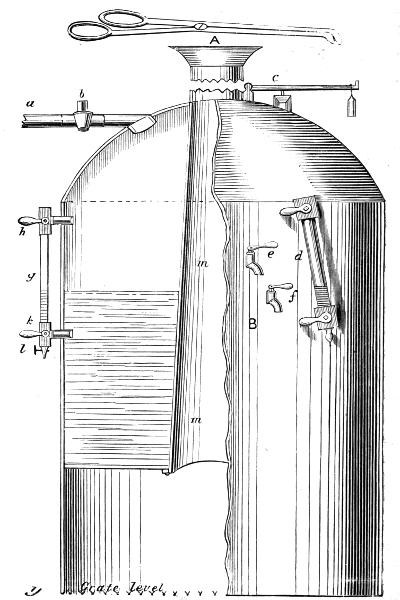
Fig. 67.
I have spoken of riveting in this place. There is no difficulty in this work. You can buy copper rivets of all sizes, and have only to punch holes, put a rivet in place, and hammer it so as to spread the metal to form a second head. If the rivets are heated before being applied, they will draw the parts closer together, because they shrink in cooling. All large boilers are made in this way, but smaller ones of iron are often welded, where such a mode of junction is possible. When you can rivet boilers water and steam tight, you will find no difficulty in constructing them, for you can make riveted joints where brazing would be difficult or impossible.
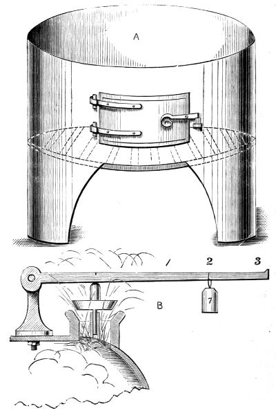
Fig. 68.
Fig. 67, B, is a half-section of such a boiler as I have just described. Fig. 68, A, is the lower part, which is separate, and forms the furnace in which the boiler stands, fitting it closely. This is drawn to scale, and is half the real size. a is the steam-pipe, fitted high up in the dome, the tap, b, serving to turn on or off the supply of steam for the cylinder; c is the safety-valve shown in section, and care must be always taken to make the conical part short and of a large angle, or it may stick fast, and cause an explosion; d is the glass gauge, to show the exact height of the water in the boiler. Its construction will be understood[309] from the other which is attached, where the boiler is seen in section. There is no need to have two, and this is added solely to explain the nature of glass-gauges. The top and bottom are of brass, being tubes screwing into the boiler, or fastened by a nut inside; a tube, g, of thick glass, connects these two, so as to form a continuous tube, one end of which opens into that part of the boiler which is full of steam, the other opening below the water-level. Thus the tube forms practically part of the boiler, and the level of the water is clearly seen. The lower tap is used for blowing off water, to insure the communication being kept open, as it might get stopped up with sediment.
Gauge-cocks, e, f, are generally added, even where the glass water-gauge is used. One of these should always give steam, the other water,—the level of the latter being between the two. If the upper one gives water, the boiler is too full; if both give steam, the boiler needs to have water added. With these fittings, even a soldered boiler ought never to get burnt, and will last a long time with care.
The lower part, Fig. 67, is made like that before described, except that, being intended for charcoal, a circular grate is used, which simply rests upon little brackets fixed by rivets for this purpose. The flame and heat play upon the bottom of the boiler, and also pass up the central tube—the latter adding greatly to the quantity of steam produced.[310] This furnace, when lighted, may be fed with bits of coke as well as charcoal, about the size of filberts, and will give plenty of heat. If the draught, however, is deficient, turn the waste steam into the tube, so as to form a jet at each stroke, and it will greatly increase it. It is in this way that the locomotive engines are always fitted, George Stephenson having first suggested the arrangement. Previously to this a fan had been fitted below the grate, which was put in rapid motion by the engine, and thus a sufficient draught was obtained.
To find out what pressure is exerted by the safety-valve, it must be clearly understood upon what principle it acts. I have in a previous chapter told you that the atmospheric pressure equals 15 lbs. on each square inch, so that if the surface of the valve which is exposed to the air is 1 inch in area or surface, it is pressed down with a force of 15 lbs. The steam, therefore, inside the boiler will not raise it until its elasticity exceeds this atmospheric pressure. If, therefore, we desire to have only just 15 lbs. per square inch pressing against the inside of the boiler (i.e., a pressure of “one atmosphere,” as it is called), we have only to load the valve so that, inclusive of its own weight, it shall equal 15 lbs. But it is plain that we must not load it at all in reality; for a flat plate, 1 inch square, of no weight,[311] is all that is needed, the atmosphere itself being the load. Suppose, then, that we do load it with 15 lbs. in addition to the 15 lbs. with which nature has loaded it, we shall not find the steam escape until it presses with a force of 30 lbs. on the square inch, or two atmospheres (which, however, is not 30 lbs. of useful pressure upon one side of the piston, if the cylinder is open as in an atmospheric engine, but only 15 lbs.) This is not the strain which the boiler has to stand, because the atmosphere is pressing upon it and counteracting it up to the 15 lbs., so that this strain tending to burst it is but 15 lbs. The number of pounds, therefore, which is straining the boiler can readily be seen; being always that with which the safety-valve is loaded, and this is also the useful pressure for doing any required work. Unfortunately, however, even in the best constructed engines, a pressure of 15 lbs. upon the boiler by no means represents that in the cylinder. Now it would be inconvenient to place weights upon the safety-valve itself, and therefore a lever is added, as seen in the sketch, with a weight hung at one end of it. This is shown at B, Fig. 68, where a section of the valve is given with its stem passing through a guide to insure the correct motion of the valve. The lever is hinged at one end; and the rule of the pressure or weight which is brought to bear upon the valve is, that it is multiplied by the distance at which the weight hangs from the valve, compared with its distance from the hinge[312] or fulcrum. If a weight of 7 lbs. is hung at 1, i.e., at a distance as far on that side of the valve as the fulcrum is on the other side of it, 7 lbs. will be the actual power exerted; at 2, where it is twice the distance, it will be doubled, and, as shown in the drawing, a pressure of 14 lbs. will be brought to bear upon the valve; while, if the weight is hung at 3, it will exercise a force of 21 lbs. This is very easy to understand and to remember. Sometimes (always in locomotives) the weight is removed and a spring balance is attached at the long end. Upon this is marked the actual pressure exerted; there being a nut to screw down, and thus bring any desired strain upon the spring. Mind, however, in case you should try this in any of your models, that the scale marked on the balance when you buy it must be multiplied, as before, according to the length of your lever. Thus, if I attach such a balance at 3 of the drawing, a real weight of 5 lbs. shown by the balance will be 3 × 5, or 15 lbs. upon the valve, and a balance made for such engine would be marked 15 lbs., to prevent the possibility of dangerous error.
Having been led on from the atmospheric engine to that of Watt’s, and to slide-valve engines generally, I am now going backward a little to a class easier to make, because they have no slide-valves, nor even four-way cocks; and[313] then I shall have done with engines. But I dare say some of my readers will wonder why I have said so little about condensers and condensing engines. I am sure they will wonder at it if they understood what I explained of the advantage of a vacuum under the piston; so that 15 lbs. pressure upon the piston means 15 lbs. of useful work, instead of 30 lbs. being required for that purpose. But condensing engines are utterly beyond a boy’s power. They require not only a vessel into which the steam is injected at each stroke, but there must be a pump to raise and inject cold water to condense the steam, and a pump to extract from the vessel again this water, after it has been used, and a cistern, and cold and hot wells; and all this is difficult to make so as to act; and I am sure no boy cares for a steam engine that will not work. Moreover, I have given you difficult work as it is—work that many of my readers will no doubt be afraid to try—yet I did it on purpose; because if small boys are unequal to some of it, their big brothers are not, or ought not to be; and mechanical boys must look at difficulties as a trained hunter looks at a hedge—viz., with a strong desire to go over it, or through it, or any how and some how to get to the other side of it. Indeed, you must ride your mechanical hobby very boldly and with great pluck, or you won’t half enjoy the ride. However, I am quite aware that I have led you into several difficulties, and therefore now I propose to set before you[314] some easy work as a kind of holiday task which will send you with fresh vigour to what is not so easy.
The engines without slide-valves have also no eccentrics and no connecting-rods. There is just a boiler, a cylinder, piston, piston-rod, and crank, and you have the sum total, save and except the fly-wheel. These are direct-action engines, the cylinders of which oscillate like a pendulum, and the piston-rod itself is connected to the crank, doing away with the necessity for guides.
Fig. 69, A, shows one of these engines, and you see that the cylinder leans to the left when the crank is turned to that side; and if you turn the wheel to the right, the crank will presently cause it to lean the other way; and thus, as it turns on a pin, or “trunnion,” as it is called, it keeps on swinging from side to side as the wheel goes round.
Now, when it is in its first position, the piston is at the bottom of the cylinder, and it then needs to have the steam admitted below it to drive up the piston; but when this has passed its highest position, and the cylinder is turned a little to the right, the piston must be allowed to descend, and, therefore, we must let out the steam below it. We ought, at the same time, to admit steam above the piston to force it down; but, in the simplest models, which are called single-action engines, this is not done. The fly-wheel, having been set in motion, keeps on revolving, and, by its impetus, sends down the piston quite powerfully[315] enough to overcome the slight resistance which is offered by the friction of the parts.
Now, you can, I daresay, easily understand that it is possible to make this to-and-fro motion of the oscillating cylinder open first a steam-port to allow steam to raise the piston, and then an exhaust-port to let it blow off into the air. This is exactly what is done in practice, and it is managed in the following manner:—
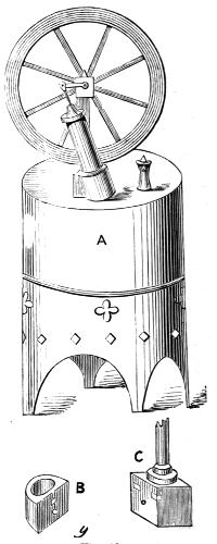
Fig. 69.
B, of Fig. 69, shows the bottom of the cylinder, which is a solid piece of brass filed quite flat on one side, and turned out to receive the end of the brass tube, which, generally speaking, is screwed into it to form the cylinder, this being the easiest way to make it. In the middle of the upper part of the flat side you see a white steam-port, and below it a round white spot, which is the position of the pin, or[316] trunnion, on which it oscillates. Fig. 69, C, is a similar piece of brass, which is fixed to the top of the boiler. In this, on the left of the upper part, is also a port, which is connected with the boiler by a hole drilled below it to admit steam. On the right is also a port, which is merely cut like a notch, or it may go a little way into the boss, and then be met by a hole drilled to meet it, so as to form the escape or exhaust port. Between and below these is the hole for the trunnion.
Now, you can, I think, see that if the cylinder stands upright against this block, as it does when the crank is vertical (or upright) and on its dead points, the port at the bottom of the cylinder would fall between the two on this block of brass, and, as they are both flat and fit closely, no steam from the boiler can enter the cylinder. Nor do we want it to do so, because, if the crank is on a dead point, no amount of steam can make the piston rise so as to move it. But now, if we move the cylinder to the left, which we can do by turning the wheel, we shall presently get the crank at right angles to its former position, and, also, we shall bring the steam-ports in the cylinder and block together, so that steam will enter below the piston. But, practically to get as long a stroke as possible, steam is not allowed to enter fully until the crank is further on than in a horizontal position, that is, approaching its lower dead point; and this is the position in which to put it to start[317] the engine. By altering the shape or the position of the port a little, we can so arrange matters as to let steam enter at any required moment.
Steam having entered, the piston will rise rapidly, forcing up the piston, and presently, by the consequent revolution of the fly-wheel, the cylinder will be found leaning to the left, and at this moment the piston must evidently begin to descend. At this very time the steam-ports will have ceased to correspond, but the port in the cylinder will come opposite the exhaust-port in the brass block, and this port is made of such size and shape that the two shall continue to be together all the time the piston is descending; but, the moment it has reached the end of its downward stroke, they cease to correspond in position, and the steam-port begins again to admit a fresh supply of steam.
The pillar attached to the brass boss has nothing to do with it, but is one of the supports of the axle of the fly-wheel, as you will understand by inspection of A of this same drawing.
Such is the single-action model engine, of no power, but a very interesting toy and real steam engine.
The double-action engine is very superior to the foregoing, which, I may remark, has no stuffing-box, and of which the piston is never packed. I may also add, that the crank is formed generally by merely bending the wire that forms the axle of the wheel, and putting the bent end through the hole[318] of a little boss or knob of brass, screwed to the end of the piston-rod. Here you have no boring of cylinders to accomplish, but the cylinder cover, piston, and wheel (often of lead or tin) require the lathe to make them neatly. Many an engine, however, has been made without a lathe, and I have seen one with a bit of gun-barrel for a cylinder, and a four-way cock of very rough construction, that was used to turn a coffee-mill, and did its work very well too.
But I must go at once to the double-action oscillating cylinder, in which, although a similar mode of admitting steam is used, it is arranged to admit it alternately above and below the piston, the exhaust also acting in a similar manner.
After the explanation I have given you, however, of the single-action engine, you will, some of you, I think, jump at a conclusion almost directly, and perhaps be able to plan for yourselves a very easy arrangement to accomplish the desired end. All boys, however, are not “wax to receive, and adamant to retain” an impression; for I have known some who need an idea to be driven into their brains with a good deal of hard hammering. Stupid?—No. Dull?—No, only slow in getting hold, and none the worse for that generally, if the master will but have a little patience; for when they do get hold, they are very like bulldogs, they won’t let go in a hurry, but store up in most retentive minds what they learned with such deliberation.
The cylinder of the double-action engine is of necessity made with ports very similar to those of the horizontal engine already described. There is a solid piece attached to the cylinder as before, which is drilled down to the upper and lower part respectively of a central boss, turned very flat upon the face, and which has to work against a similar flat surface as in the last engine. But the ports in the latter are four instead of two, and in an engine with upright cylinder would be cut as follows, and as shown in Fig. 70, C.
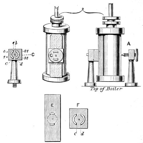
Fig. 70.
Those on the right marked st are steam-ports, which, being drilled into one behind, are connected with the boiler. The other two marked ex, are similarly exhaust-ports opening into the air. The spaces between a b and c d of fig. C must be wide enough to close the steam-ports in the cylinder, when the latter is perpendicular and the engine at rest. When the cylinder leans to the left, oscillating on the central pin between the ports in the middle of the circle, the lower port of it will evidently be in connection with the steam-port in C, while the upper port of the cylinder will be opposite to the exhaust. As the cylinder is carried over towards the right, the upper steam-ports will come into action in a similar way, while the lower exhaust-port is also carrying off in turn the waste steam. The impetus, therefore, of the[320] fly-wheel has here only to carry the ports over the spaces a b, c d, and to prevent the crank stopping on the two dead points. This, therefore, is a genuine double-action engine, and will answer, even on a large scale, very satisfactorily. If you do not quite understand the action of these ports, cut out two pieces of card, E F. Let E represent the cylinder. Draw circles, and cut two ports. Cut another piece of card[321] to represent the brass block, with ports, c d; pin them together through the centres of the circles, and they will easily turn on the pin. Mark the ports, so that you will see at a glance which are steam and which exhaust. Now cut out the ports with a penknife, and as you work the two cards together, swaying that which represents the cylinder to and fro upon the other, you will see when the ports in each card agree with one another, and which are opposite to which. This will teach you far better than any further written explanation. You will also see that, instead of making the steam and exhaust ports respectively with a division between, the two steam-ports may be in one curve united, and likewise the two exhausts; but take care not to unite the exhaust with the steam-ports. There is no way so easy as this of reversing the action of the steam; it is, in fact, a circular slide-valve, but wonderfully easy to make, because you have no steam-case to make, nor any attachments whatever.
The faces of the valve are kept in close contact in one of two ways—either the centre-pin is fixed into the cylinder face, and after passing through the brass boss with the ports, is screwed up with a nut at the back; or else there is fixed a small pillar or upright on the opposite side of the cylinder, and a little pointed screw passing through this presses against the cylinder, and makes a point of resistance, against which it centres, and on which it turns. This[322] is shown at fig. A. A small indentation is made where the point comes in contact with the cylinder.
In a locomotive engine there are two such cylinders, working against opposite faces of the same brass block containing the ports. The cranks are also two, on the shaft of the driving-wheels, and are at right angles to each other; so that when one piston is at the middle of its stroke, the other is nearly or quite at the end of it. Thus, between the two there is always some force being exerted by the steam; and the dead points of one crank agree with the greatest leverage of the other. In locomotives, too, the cylinders generally are made as in the present drawing, viz., to oscillate on a point at the middle of their length; but it is just as easy to have the two ports meet at the bottom instead, so that the point of oscillation may be low down, like the single-acting cylinders of the last sketch, and this is generally done when the cylinder is to stand upright.
There is no occasion for me to draw an engine with double-acting oscillating cylinders, because in appearance it would be like the single-acting one; but whereas the latter is of absolutely no use, seeing that the greater part of its motion depends on the impetus of the fly-wheel, the former can be made to do real work, and is the form to be used for marine and locomotive engines. For the former, oscillating cylinders with slide-valves are used in practice;[323] but for real locomotives fixed cylinders are always used. Of course either will answer in models, and it will be good practice to try both.
I have now given sufficient explanation of how engines work, and how they may be made, to enable my young mechanic to try his hand at such work. The double-action oscillating engines especially are well worthy of his attention, as he may with these fit up working models of steam-boats and railway trains, which are far more difficult to construct with fixed cylinders and slide-valves. I shall therefore close this part of my work with a description of one or two useful appliances to help him in the manipulative portion of his labour,—for here, as in most other matters, head and hand and heart must work together. The heart desires, the head plans, the hands execute. I think, indeed, I might without irreverence bring forward a quotation, written a very long time ago by a very clever and scientific man, in a very Holy Book: “Whatsoever thy hand findeth to do, do it with all thy might.” Depend upon it, success in life depends mainly upon carrying into practice this excellent advice. If you take up one piece of work, and carelessly and listlessly play at doing it, and then lay it down to begin with equal indifference something else, you will never become either a good mechanic or a useful man. If you read of those who have been great men—lights in their generation—you will find generally that[324] they became such simply by their observance of that ancient precept of the wise man. They were not so marvellously clever—they seldom had any unusual worldly advantages; but they worked “with all their might,” and success crowned their efforts, as it will crown yours if you do the same.
I promised in a previous page to describe a little stove for heating soldering-irons, and doing other light work. It is made as follows, and will be found very useful.
Fig. 71, A, is a tube of sheet-iron, which forms the body of the little stove. Four light iron rods stand out from it, which form handles, but these are forked at the ends, and thus become rests for the handles of soldering-irons, or any light bars that are to be heated at the ends. Below is a tray, also of sheet-iron, upon short legs to keep it off the table—for this is a little table-stove. C is the cast-iron grate. You can buy this for a few pence first of all, and then you fit your sheet-metal to it. It will rest on three or four little studs or projections riveted to the stove inside; or you can cut three or four little places like D, not cutting them at the bottom line, a b, but only on three sides, and then bend in the little piece so as to make a[326] shelf. If the stove is about 4 inches high above the grate, and 2 or 3 inches below it, and 6 inches diameter, it will be sufficiently large for many small operations; but that the fuel may keep falling downwards as it burns, the lower part should be larger than the upper, and, to admit plenty of air, should be cut into legs as shown. Round the top are cut semicircular hollows, in which the irons rest. To increase the heat, a chimney or blower, B, is fitted, which has also openings cut out to match those of the lower part, so that the soldering-irons can be inserted when this chimney is put on. If, however, this is not required, but only a strong draught, by turning the chimney a little, all the openings will be closed. A still longer chimney can be added at pleasure. A hole should be made at the level of the grate to admit the nozzle of an ordinary pair of bellows. This stove you would find of great service, and it may be fed with coke and charcoal in small lumps. Now you may make the above far more useful. It will make a regular little furnace, and not burn through, if you can line it with fireclay. In London and large towns you can obtain this; and it only needs to be mixed up with water, like mortar, when you can plaster your stove inside an inch thick or more, making it so much larger on purpose. There is no need to do this below the level of the grate; but if you cannot get fireclay, you may do almost as well by getting a blacklead-meltingpot from any ironfoundry,[327] and boring a few holes round the bottom for air, and fitting it inside your little iron stove. In this you can obtain heat enough to melt brass, and it will last a great deal longer than the iron alone, which will burn through if you blow the fire much; but for general soldering, tempering small tools, and so forth, you need not blow the fire, as the hood and chimney will sufficiently increase the heat. There is no danger in the use of this little fireplace, but of course you would not stand it near a heap of shavings, unless you are yourself a very careless young “shaver.”
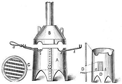
Fig. 71.
There is no reason why the young mechanic should not[328] be told how to make his own tools, and how to harden and temper them, because he ought to be a sort of jack-of-all-trades; and perhaps he may break a drill or other small tool just in the middle of some special bit of work, or his drill may be just a little too small or too large, and there he will be stuck fast as a pig in a gate, and unable to set himself right again any more than the noisy squeaker aforesaid. But to a workman a broken drill means just five minutes’ delay, and all goes on again as merrily as before; and as we wish to make our young readers workmen and not bunglers, we will teach them this useful art at once.
Drills are made of steel wire or rods of various sizes. In old times they were made square at one end, to fit lathe-chucks or braces, but now, for lathe-work, they are generally made of round steel, and fastened into the chuck with a set screw on one side. In this way they can be more easily made to run true. But there are so many kinds of drills that I suppose I had better go into the matter a little—only I have not room to say much more.
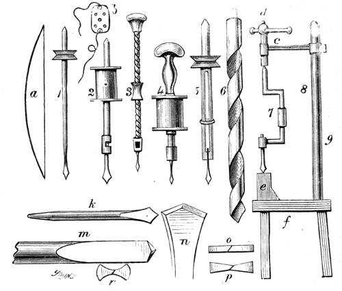
Fig. 72.
Look at Fig. 72, and you will see some of the more usual forms of drills used, but these are by no means all. You will not indeed require such a collection; and yet, if you should grow from a young mechanic into an old one, I daresay you will find yourself in possession of several of them. The first, labelled 1, is the little watchmaker’s drill, of[329] which, nevertheless, this would be considered a very large size. It is merely a bit of steel wire, with a brass pulley upon it, formed into a point at the largest end, and into a drill at the other. The way it is worked is this: At the side of the table-vice—that is, at the end of its jaws or chops or chaps—are drilled a few little shallow holes, in which the watchmaker places the point at the thickest end; the drill-point rests against the work, which he holds in his left hand. A bow of whalebone, a, has a string of fine gut such as is used for fishing, or, if the drill is very small, a horse-hair; and this is given one turn round the[330] brass pulley before the drill is placed in position. The bow is then moved to and fro, causing the drill to revolve first in one direction and then in the other. The general work is in thin brass, and therefore these little tools are sufficiently strong for the purpose. Some of the drills and broaches (four or five, or even six sided wires of steel) are so fine that they will bend about like a hair, and yet are so beautifully made and tempered as to cut steel.
No. 2 is a larger drill, even now much used. In principle it is exactly similar to the last, but the pulley is replaced by a bobbin or reel of wood, made to revolve by a steel bow with a gut string, or a strong wooden bow. The drills, too, are separate, and fit into a socket at the bottom of the drill-stock. The large end is pointed, as in the last, and is made to rest in one of the holes in a steel breast-plate, b, which is tied to the chest of the operator, who, by leaning against it, keeps the drill to its work, while both hands are free to hold the latter steady. There is a modification of this tool, invented by a Mr Freeman, intended to do away with the bow. The bobbin or reel is turned without raised ends, and is worked by a flat strip of wood covered with india-rubber, and turned at one end to form a convenient handle. The having to twist the bow-string round the drill, which is always a bother, is thus done away with.
No. 4 is a drill-stock similar to the last, but in place of[331] the breast-plate a revolving head or handle is put to the top, in which the point works. This is held in one hand, while the drill-bow is worked by the other. This is also generally held against the chest, as the hand alone does not give sufficient pressure. Heavy work, however, cannot well be done by these breast-drills, and they are liable to cause spitting of blood from the constant pressure in the region of the heart and lungs.
No. 3 is the Archimedean drill-stock, now very common, but originally invented by a workman of Messrs Holtzappffel’s, the eminent lathemakers of London. It now comes to us as an American drill-stock. It is a long screw of two or more threads, with a ferule or nut working upon it. The upper end revolves within the head, which is of wood; the lower end is formed into a socket to receive the drills, which revolve by sliding the ferule up and down. Some are 14 inches long, and others not more than 5. The first are used with the pressure of the chest, the latter with that of the left hand. For light work these are very useful, and you will seldom need any other in the models of small engines, &c.
No. 5 is another watchmaker’s drill, but serves also as a pin-vice to hold small pieces of wire while being turned or filed in the little lathes which are used in that trade, and which are worked by a bow with one hand, while the tool is held in the other. This is by no means a useless tool,[332] even without the pulley. It is made by taking a round (or better, an octagon, or five or six sided) piece of steel, drilling the end a little distance, and then sawing the whole up the middle. The slit thus made is then filed away to widen it, and leave two jaws at the end, which grasp the pin or drill; a ring slips over, and keeps the jaws together.
We now come to fig. 6, which represents the best of all drills for metal. It is really American this time, and does our Transatlantic cousins great credit, as does the machinery generally invented or made by them (the Wheeler and Wilson sewing-machines for instance). The steel of which this drill is made is accurately turned in a lathe, and the spiral groove is cut by machinery. This groove acts in two ways—first, as allowing the shavings (not powdery chips) to escape as the tool penetrates, but as forming the cutting edges where they (for there are two) meet at the point. These, however, require a lathe with a self-centring chuck made on purpose. They are sold in sets upon a stand, chuck and all complete, and each is one-thirty-second of an inch larger than the other. Some are as small as a darning-needle, or less, and they run up to an inch or so in diameter. There are large and small sets.
We now pass to the old-fashioned smith’s brace, fig. 7, shown in position, drilling the piece e. Pressure is kept up either by a weighted lever, or by a screw, as shown[333] here. The brace is moved round by the hand of the workman. Very often this tool is arranged on the vice-bench, so that the work can be retained in the jaws of the vice while being drilled. Sometimes it is mounted on a separate stand, having a stool below, and a special kind of vice or clamp is added. Well made, this is not so bad a tool as it looks, but those used ordinarily in smiths’ shops are very clumsy, and do not even run true, and the drills are badly made, although by sheer force they are driven through the work.
Whatever form of drill-stock is used, the main thing is to have the drills properly formed. You will recognise k and n as common forms, than which m is considerably better. For cast-iron n would not be a bad point, because the angle is great, much greater, you see, than k; and the bevels which form the cutting edges of a drill should also not be too sharp, as they are generally made, for, as they only scrape away the metal, their edges go directly.
The common way to make a drill is this: A piece of steel wire of the required size is heated until red hot (never to a white heat, or it would be spoiled). The end is then flattened out with a hammer, and the point trimmed with a file. It is then again heated red hot, and dipped into cold water for a second. Then held where the changes of colour, which ensue as it cools, can be seen plainly; and as soon as a deep yellow or first tinge of purple becomes[334] visible, it is entirely cooled in water. It is then finished, except as regards fitting it to the drill-stock, which may be done before or after it is hardened, because care is taken only to dip the extreme point. To get proper cutting edges the drill is taken to the grindstone, and each side of the point is slightly bevelled, but in opposite directions, so as to make it cut both ways. It is not, however, left of equal width, like o, but the flattened sides are ground away, so as to make more of a point, like p and n.
Now, this is all right enough as regards forging and hardening, and tempering, and for the smallest drills this is the only way to make them. (Only watchmakers heat them in the candle till red, and then cool and temper by running them into the tallow.) But if you want a good drill that will cut well and truly, you should file away the sides of a round bar like m, only spreading the point very slightly indeed, just to prevent the drill sticking fast in the work. Another drill, indeed, is spoken of very highly, which is also carefully made like m, but the places which are here flat are hollowed out or grooved lengthwise, the section of the point—i.e., the appearance of the end of the drill—becomes rather curious, like r. I am assured by those who have used them, that these cut quite as well as the twist drills which I have described already. These which I am now speaking of are also American; and I don’t know how it is, that somehow America is a far better place for[335] improvements in tools and machines than our own Old England. And if I had a wonderful invention—a new birch-rod-making and flogging-machine for very troublesome boys, for instance—I am afraid I should go to America to patent it; but I daresay English boys would not object to that.
If not, they had better not let me patent my flogging-machine. Luckily it is not invented yet.
The cutting edges of drills come under the same rules as other cutting edges. You might, for instance, hold a large drill flat on the rest, and use either edge as a turning-tool. You will see at once that these edges will not cut if made in the usual way, but only scrape. The bevel wants to be ground only to 3°, as before explained, to give the proper clearance, and the cutting edge requires to be then made by grinding back the upper surface, which is just the same in effect as is produced by twisting the metal[336] or cutting a spiral groove, which hollows out this upper surface and gives it cutting power. It is no use grinding a sharper-looking bevel, or making more of a point—you only weaken the edge; m or n is quite pointed enough, though the first is a right angle and the second greater; and, for cast-iron, a rounded point, showing no angle at all, will do just as well, or better, when once it has begun to penetrate. Do not be deceived, therefore, by making drills look pointed and keen, for, I repeat, they are scraping tools only, unless you file an edge by bevelling back the upper face of each side of the point. If you were to make a very thick, strong drill, you might begin by grinding back the two sides to 3°, to form the accidental front line of the point or section angle, and then grind back, at 45° from this line, the upper face, by which you would do just what you did to give the graver cutting edges of 60°—only a drill thus formed must have a point of 90°. It would cut in two directions, like one for a drill stock and bow.
I hope my bigger boys will not pass over the remarks on cutting edges interspersed in this book, for, once understood, they will be found to be most valuable. Indeed, they cannot work intelligently until they understand exactly the nature and principles of the tools which they have to use. In drilling iron, use water or oil, or soap and water, or soda-water—either will do; but the holes are drilled in the ships’ armour-plating with soap and water to cool the[337] drill; and very well it answers, for these plates are several inches thick, but the holes are soon made. When working in brass and gun-metal, use no water, but work the drill quite dry. The same rules, in short, apply to drilling as to turning or planing metal; and if you could see the action of a well-made American twist-drill, you would recognise this similarity, for you would see the metal come forth in long, bright curls, as pretty and shining as those of your favourite young lady or loving sister—one of which you have, I daresay.
To give you some idea of what a straight course a drill will take, if rightly made and skilfully used, I may tell you that a twist-drill has been run through a lucifer-match from end to end without splitting it; and as to the fineness possible, I have seen a human hair with an eye drilled through it, by which, needle-like, it was threaded with the other end of itself.
I told you how to bore a cylinder, which is but drilling on a larger scale, and in Fig. 65 I sketched the method of doing this in the lathe with a rosebit. But I did not explain another tool used just in the same way, but which will bore holes in solid iron wonderfully. Fig. 65, L, H, K, is one of these. This is an engineer’s boring-bit, and is made of all sizes, from that required to bore the stem of a tobacco-pipe—(don’t smoke, boys, it will dry up your brains)—to that which would bore a cannon. A rod of steel is forged[338] with a boss or larger part at one end. This is centred in the lathe, and the centre-marks are well drilled, and not merely punched, especially that at the small end. The boss is then turned quite cylindrical, after which it is filed[4] away exactly to the diametrical line, as you will see by inspection of L. The end is then ground off a little slanting, to give, as before, about 3° of clearance. The cutting edge thus obtained, and the end in which the centre hole still remains, are carefully hardened. You thus have a tool which will bore splendidly, but you must give it entrance by turning a recess first of all in the work, or drilling, with a drill of equal size, a little way into the material. Used like the rosebit, this tool will run beautifully straight, so that you can bore very deep, long holes with it, and cylinders can be most beautifully bored with it. I think you would be able to make these tools with a little care; but, when you harden them, only heat and dip the extremities, or it is ten to one your steel rod will bend and warp in cooling, and you will not be able to rectify it. If the ends are quite hard, it is as well that the rest should be soft, as the tool will not then be so liable to get broken.
There are many other tools used for boring iron and steel, but you need not trouble yourself at present to learn anything of them—they are no use to you now.
I have headed this chapter “Hardening and Tempering”[339] tools, but as yet I have only partially explained the process, which is a very curious one; and though the result is highly necessary in many cases, it is by no means well understood what really takes place in the process, or why this effect should occur in steel, but not in iron, or brass, or other metals.
If you heat a piece of bright steel over a clear gas jet or fire which will not smoke it, you will see several colours arise as the metal gets hotter and hotter, until finally it becomes red. These are due to oxidation, which is so long a word that I am not sure I can stop to explain it thoroughly. Let us see, however, what we can make of it. The air we breathe contains two gases, oxygen and nitrogen, with a small proportion of a third called carbonic acid. Neither of these alone will support life, or keep the fire burning, or enable vegetables to live and grow, but it is the first which is in this the chief support. The second is only used by Nature as we use water to brandy, viz., to dilute it and render it less strong. If we breathed oxygen alone, we should live too fast, and wear out our bodies in a few hours. If we breathed nitrogen only, we should die, and so of carbonic acid. Now this oxygen seizes upon everything in a wonderful and sometimes provoking manner. If you leave a bright tool out of doors to get damp, down comes our friend oxygen and rusts it. It combines with the iron and makes oxide of iron, which is what we call rust. I suppose,[340] however, this oxygen comes more from the water than the air, because water is made also of two gases, hydrogen and this same oxygen. It is certain that oxygen in this case always finds any bright tools that we leave about in the wet, and coats them with a red jacket very speedily. Then if you look at a blacksmith at work, you will see scales fall from the hot iron as he hammers it. These are black, but our old friend has been at work, and united with the red-hot metal and formed another oxide of iron, called black oxide. We can understand this. If a man eats a good deal, or drinks a good deal, he gets red in the face; if he eats till he chokes himself, he gets black in the face, and I suppose it is much the same when oxygen eats too much iron. Well, when we begin to heat the steel, down comes oxygen and begins his work; and first he looks very pale; then he gets more bilious and yellower; then he gets hotter and shows a tinge of red with the yellow forming orange; then he begins to get purple, then blue, then deeper blue; and finally black before he gets absolutely red and white hot.
Now to temper steel, we first heat it red-hot, not minding these colours, and then we cool it suddenly in cold water. This renders it very hard indeed. No file will cut it, or drill penetrate it; but if we strike it, behold it breaks like glass! This is too hard for general work, for the edge will break and chip if it meets with any hard spot in the metal, or chances to bite in too deep. Its teeth are too brittle, and[341] so get broken off. For this reason we have to “let down,” or temper, the tool, and we proceed as follows: The part to be tempered is ground quite bright. It is then laid upon a bar of iron heated red-hot, or if small, it is held over a gas jet or in a candle; heated, in short, in any way most suitable and convenient. And now, first, our friend oxygen puts on a pale yellow face as before. This will do for turning steel and iron, but is still too hard for general work. Then comes the orange, and this presently tends slightly to blue; at which point, if the tool is instantly cooled in water, it will be found to bear a good edge, hard, but sufficiently tough for work. Most tools for metal and drills are let down to something between the yellow and blue, and we know that the more they approach blue, the softer they will be. Thus we can easily manage our tools;—some to bear hard blows, like axes, which are tempered to a blue colour; some like files, which a blow will break, but which are famous for their own special work—these are let down only to a pale yellow; others, like springs and saws, are let down to a more thorough blue, because they are required to be elastic and tough, but are not needed to be so particularly hard. Then tools like turnscrews, and bradawls, and gimblets are left even softer, sometimes not tempered or hardened at all, but just forged and ground to the required shape.
Now, I fancy some of my sharp boys will say that the[342] first description I gave of the mode of hardening and tempering was not exactly like this; nor was it, yet in principle it is the same. For instance, if you give a drill to a smith to make, he will do as I then said. He will heat the extreme point red-hot, then dip the point in water, give a rub on the stone or bricks of the forge, and watch the colours. This can be done when the tool is of sufficient substance to retain heat enough after the edge has been dipped to re-heat that edge sufficiently. In this case there is no need to chill the whole tool and then heat it again. But in the case of small drills and tools, pen-knife-blades, and other articles of this nature, there will not be sufficient heat retained, after dipping, to bring up to the surface the desired colours; for oxygen likes a hot dinner as well as you do, and if the iron is not hot enough he will have nothing to do with it.
One great difficulty you would find if you had much tempering to do, viz., that the articles bend under the operation, some more than others. Try this: Take a thin knitting-needle when the owner is not looking, and run off with it;—it is all in the cause of science! Heat it red-hot, and with a pair of pliers take it up and drop it sidewise in a basin of water. It will bend like a bow. Heat again, straighten it, re-heat, and this time pop it in lengthwise—endwise, point first—I mean (don’t you see that a round needle has no sides, and puts me into a perfect quagmire[343] of difficulty). However, you will understand this, and will find the needle not bent nearly so much as before, but still it is not straight. As I explain most things as I go on, I may as well explain why this bending occurs before I tell you how to straighten your work again. All metals expand with heat, and contract with cold. I am sure I contract terribly in the winter until I have had plenty of hot soup, and hot roast-beef, and plum-pudding; and I know my temper improves, too, when I get expanded and warm. Well now, when you dropped your sister’s knitting-needle all hot on its side into the water, that side contracted before the other, and consequently the needle bent; but when you put it in the water, end on, it was cooled all round at once, and if you could but cool a piece of metal equally all over, inside and out, at once, all parts would shrink equally fast, and the article would remain straight.
But there is, unfortunately, another cause of this bending, which is, that all articles are not of such form that the same quantity of metal is on all sides of the axial line. Take a half-round file, for instance; one side is flat, the other curved, so that taking these two surfaces into consideration, one contains a great deal more metal than the other, and will not cool at the same rate. These articles are far more liable to bend than those whose sides are parallel. Another result of the hot mass being cooled most quickly on the outside is, that cracks are produced in[344] the latter, because, so to speak, the skin is contracted, and can no longer contain all the expanded metal within it. Hence, to make a mandrel for a lathe, it is common to bore it out first, before hardening, to remove this mass of metal, and to allow the water to touch it inside as well as out. Such mandrels seldom crack or bend.
The only way to straighten articles which have warped by hardening, is by what is called hacking or hack-hammering, which is nothing more than hammering the concave or hollow side with the edge of the steel pane of a hammer. This spreads the metal upon the hammered side, and, by expanding it, straightens the tool, for the hollow side, remember, is that which was too much shrunk or contracted. This is not an operation you will have to do, especially if you only harden the extreme points of the drills and little tools you make.
There is another way of hardening, not steel, but iron, called “case hardening,” because it puts a case of steel over the surface of the metal. Obtain a salt called prussiate of potash. It is yellow, like barley-sugar, but is poison. Heat the iron red-hot, and well rub it upon this salt, and then cool it in water. You will find that now a file will not touch it, its surface being as hard as glass. It is carbonised on its exterior, and made into hard steel. This can be done in another way, as gun-locks, snuffers, and many other things are case hardened. They are enclosed[345] in an iron box, with cuttings of leather and bone-dust, and the box is luted about with clay and put in the fire. All the pieces get red-hot, and the leather chars and blackens, and some of it combines as before with the hot iron, and makes it into steel. And our friend oxygen is considerably at a loss in this case to find his way in, or he would make black scales again and spoil the work; or combine with the carbon (or charcoal) and make it into gas. Probably, however, as we shut up a little oxygen with the contents of the box, this change DOES take place, but just as the gas rises the iron seizes it, and holds it fast.
And now, boys, I find it necessary to lay down the pen, which I see has almost run away with me, and written a good many more pages than I at first intended. Since I began to write I have visited the workshops at King’s College, and seen a sight to gladden my eyes. Boys carpentering, boys turning, boys filing; engines of real use, with single and double cylinders, finished, and in course of construction, and all these the work of schoolboys, whose hands and brains are alike engaged in this delightful branch of industry. Let no one, therefore, pretend that boys are not capable of executing good work of this kind in a masterly manner, or that what they do is always child’s-play, or I shall take up the cudgels in their behalf. I have also seen, in the Working-Men’s Exhibition, a very neat little engine, made by a boy only twelve years of age,[346] which makes me hope and believe that the few hints upon wood and metal work which I have here thrown together will neither be unacceptable nor useless to those whom I address in these pages. In this hope I take my leave, and sign myself, with gratification and pride—
The boy mechanic’s faithful friend,
THE AUTHOR.
[1] In the drawing, they are all accidentally drawn of the same pitch.
[2] The parts so jointed are highly exaggerated; when hammered down, the joint only forms a light beading.
[3] The bottom joint must therefore be hammered close; the upper one will become a ledge for the boiler to rest on.
[4] In large tools this is not done by the file.
Heroes of the Nations.
EDITED BY
EVELYN ABBOTT, M.A., Fellow of Balliol College, Oxford.
A series of biographical studies of the lives and work of a number of representative historical characters about whom have gathered the great traditions of the Nations to which they belonged, and who have been accepted, in many instances, as types of the several National ideals. With the life of each typical character will be presented a picture of the National conditions surrounding him during his career.
The narratives are the work of writers who are recognized authorities on their several subjects, and, while thoroughly trustworthy as history, will present picturesque and dramatic “stories” of the Men and of the events connected with them.
To the Life of each “Hero” will be given one duodecimo volume, handsomely printed in large type, provided with maps and adequately illustrated according to the special requirements of the several subjects. The volumes will be sold separately as follows:
| Cloth extra | $1 50 |
| Half morocco, uncut edges, gilt top | 1 75 |
| Large paper, limited to 250 numbered copies for subscribers to the series. These may be obtained in sheets folded, or in cloth, uncut edges | 3 50 |
The first group of the Series will comprise twelve volumes, as follows:
Nelson, and the Naval Supremacy of England. By W. Clark Russell, author of “The Wreck of the Grosvenor,” etc.
Gustavus Adolphus, and the Struggle of Protestantism for Existence. By C. R. L. Fletcher, M.A., late Fellow of All Souls College, Oxford.
Pericles, and the Golden Age of Athens. By Evelyn Abbott, M.A., Fellow of Balliol College, Oxford.
Theodoric the Goth, the Barbarian Champion of Civilization. By Thomas Hodgkin, author of “Italy and Her Invaders,” etc.
Sir Philip Sidney, and the Chivalry of England. By H. R. Fox-Bourne, author of “The Life of John Locke,” etc.
Julius Cæsar, and the Organization of the Roman Empire. By W. Warde Fowler, M.A., Fellow of Lincoln College, Oxford.
John Wyclif, Last of the Schoolmen and First of the English Reformers. By Lewis Sargeant, author of “New Greece,” etc.
Napoleon, Warrior and Ruler, and the Military Supremacy of Revolutionary France. By W. O’Connor Morris, sometime Scholar of Oriel College, Oxford.
Henry of Navarre, and the Huguenots in France. By P. F. Willert, M.A., Fellow of Exeter College, Oxford.
Alexander the Great, and the Extension of Greek Rule and of Greek Ideas. By Prof. Benjamin I. Wheeler, Cornell University.
Charlemagne, the Reorganizer of Europe. By Prof. George L. Burr, Cornell University.
Louis XIV., and the Zenith of the French Monarchy. By Arthur Hassall, M.A., Senior Student of Christ Church College, Oxford.
To be followed by:
Cicero, and the Fall of the Roman Republic. By J. L. Strachan Davidson, M.A., Fellow of Balliol College, Oxford.
Sir Walter Raleigh, and the Adventurers of England. By A. L. Smith, M.A., Fellow of Balliol College, Oxford.
Bismarck. The New German Empire: How It Arose; What It Replaced; and What It Stands For. By James Sime, author of “A Life of Lessing,” etc.
William of Orange, the Founder of the Dutch Republic. By Ruth Putnam.
Hannibal, and the Struggle between Carthage and Rome. By E. A. Freeman, D.C.L., LL.D., Regius Prof. of History in the University of Oxford.
Alfred the Great, and the First Kingdom in England. By F. York Powell, M.A., Senior Student of Christ Church College, Oxford.
Charles the Bold, and the Attempt to Found a Middle Kingdom. By R. Lodge, M.A., Fellow of Brasenose College, Oxford.
John Calvin, the Hero of the French Protestants. By Owen H. Edwards, Fellow of Lincoln College, Oxford.
Oliver Cromwell, and the Rule of the Puritans in England. By Charles Firth, Balliol College, Oxford.
Marlborough, and England as a Military Power. By C. W. V. Oman, A.M., Fellow of All Souls College, Oxford.
G. P. PUTNAM’S SONS
NEW YORK
27 WEST TWENTY-THIRD ST.
LONDON
24 BEDFORD ST., STRAND