*** START OF THE PROJECT GUTENBERG EBOOK 60043 ***
Please see the Transcriber’s Notes at the end of this text.
The cover image has been created for this e-text and is in the public domain.
TUNNELING:
A PRACTICAL TREATISE
BY
CHARLES PRELINI, C. E.
AUTHOR OF “EARTH AND ROCK EXCAVATION,” “DREDGES AND DREDGING,”
“EARTH SLOPES, RETAINING WALLS AND DAMS,” ETC. PROFESSOR
OF CIVIL ENGINEERING IN MANHATTAN COLLEGE,
NEW YORK
167 ILLUSTRATIONS
SIXTH EDITION, REVISED AND ENLARGED
NEW YORK
D. VAN NOSTRAND COMPANY
Twenty-five Park Place
1912
Copyright, 1912,
BY
D. VAN NOSTRAND COMPANY
NEW YORK
Stanhope Press
F. H. GILSON COMPANY
BOSTON, U.S.A.
[iii]
PREFACE TO THE SIXTH EDITION
During the few years that have elapsed since the publication
of the first edition of this work, the art of tunneling
through different soils and especially under large bodies of
water, has made considerable progress. During the last
ten years, no less than eight subaqueous tunnels involving
the construction of sixteen tubes have been constructed for
the service of the city of New York alone. The reader will,
no doubt, also recall the tunnels under the Boston Harbor,
the St. Clair, the Charles and Detroit Rivers in our own
country as well as the tunnels under the Thames and the
Seine in Europe. Engineers, contractors and workmen have
acquired such experience in these difficult underground and
under-river construction that the work is now undertaken
without any of the fear and hesitation that were associated
with the earlier enterprises.
As entirely new methods have been introduced by professional
men, it was found necessary to arrange the presentation
of the subject in this sixth edition so as to give
due prominence to these recent methods.
Besides this, other changes have been made in order to
give greater attention to American method of excavating
tunnels through rock and loose soil. This will explain the
treatment of the crown-bar and also the extensive illustration
of the heading and bench method as well as the drift
method of driving tunnels which is followed in the United
States.
Space has also been given to important tunnels recently
built mainly for the purpose of illustrating the various[iv]
methods discussed in the text and also to bring out more
clearly the characteristics of the different methods of tunnel
excavation.
The author hopes that these added features will meet the
present requirements of engineers and students.
Charles Prelini.
Manhattan College,
New York City.
[v]
CONTENTS
| |
PAGE |
| INTRODUCTORY—The Historical Development of Tunnel Building |
xiii |
| CHAPTER |
| I. |
Preliminary Considerations; Choice between a Tunnel and an Open Cut; Geological
Surveys |
1 |
| II. |
Methods of Determining the Center Line and Forms and Dimensions of Cross-Section |
9 |
| III. |
Excavating Machines and Rock Drills; Explosives and Blasting |
22 |
| IV. |
General Methods of Excavation; Shafts; Classification of Tunnels |
36 |
| V. |
Methods of Timbering or Strutting Tunnels |
47 |
| VI. |
Methods of Hauling in Tunnels |
59 |
| VII. |
Types of Centers and Molds Employed in Constructing Tunnel Linings of Masonry |
66 |
| VIII. |
Methods of Lining Tunnels |
72 |
| IX. |
Tunnels through Hard Rock; General Discussion; Representative Mechanical Installations for
Tunnel Work |
84 |
| X. |
Tunnels through Hard Rock (continued); Excavation by
Drifts; The Simplon and Murray Hill Tunnels |
102 |
| XI. |
Tunnels through Hard Rock (continued); Excavation by
Headings |
130 |
| XII. |
Excavating Tunnels through Soft Ground; General Discussion; The Belgian Method |
143 |
| XIII. |
The German Method—Excavating Tunnels through Soft Ground (continued);
Baltimore Belt Line Tunnel |
155 |
| XIV. |
The Full Section Method of Tunneling; English Method; American Method; Austrian
Method |
166 |
| XV. |
Special Treacherous Ground Method; Italian Method; Quicksand Tunneling; Pilot Method |
182 |
| XVI. |
Open-Cut Tunneling Methods; Tunnels under City Streets; Boston Subway and New York Rapid
Transit[vi] |
195 |
| XVII. |
Submarine Tunneling; General Discussion; The Severn Tunnel |
218 |
| XVIII. |
Submarine Tunneling (continued); The Compressed Air Method;
The Milwaukee Water-Works Tunnel |
225 |
| XIX. |
Submarine Tunneling (continued); The Shield System |
238 |
| XX. |
Submarine Tunneling (continued); The Shield and Compressed
Air Method; The Hudson River Tunnel of the Pennsylvania Railroad |
263 |
| XXI. |
Submarine Tunneling (continued); Tunnels at very Shallow
Depth; The Cofferdam Method; The Pneumatic Caisson Method; The Joining Together Sections of Tunnels Built on Land |
281 |
| XXII. |
Accidents and Repairs in Tunnels during and after Construction |
301 |
| XXIII. |
Relining Timber-Lined Tunnels with Masonry |
315 |
| XXIV. |
The Ventilation and Lighting of Tunnels during Construction |
325 |
| XXV. |
The Cost of Tunnel Excavation and the Time Required for Work |
336 |
[vii]
LIST OF ILLUSTRATIONS
| FIGURE |
PAGE |
| 1. |
Diagram Showing Manner of Lining in Rectilinear Tunnels |
10 |
| 2. |
B. R. Value’s Device for Locating the Center Line Inside of a Tunnel |
11 |
| 3. |
Triangulation System for Establishing the Center Line of the St. Gothard Tunnel |
12 |
| 4. |
Method of Transferring the Center Line down Center Shafts |
13 |
| 5. |
Method of Transferring the Center Line down the Side Shafts |
14 |
| 6. |
Method of Laying out the Center Line of Curvilinear Tunnels |
15 |
| 7. |
Diagram of Polycentric Sectional Profile |
19 |
| 8, 9 and 10.
Typical Sectional Profiles for Tunnel |
20 |
| 11. |
Soft Ground Bucket Excavating Machine; Central London Underground Railway |
22 |
| 12. |
Column Mounting for Percussion Drill; Ingersoll Sargent Drill Co. |
26 |
| 13. |
Sketch of Diamond Drill Bit |
27 |
| 14. |
Diagram Showing Sequence of Excavation for St. Gothard Tunnel |
36 |
| 15. |
Diagram Showing Manner of Determining Correspondence of Excavation to Sectional Profile |
38 |
| 16. |
Polar Protractor for Determining Profile of Excavated Cross-Section |
39 |
| 17. |
Joining Tunnel Struts by Halving |
48 |
| 18. |
Round Timber Post and Cap Bearing |
48 |
| 19. |
Ceiling Strutting for Tunnel Roofs |
49 |
| 20. |
Ceiling Strutting with Side Post Supports |
49 |
| 21. |
Sill, Side Post and Cap Cross Frame Strutting |
49 |
| 22. |
Reinforced Cross Frame Strutting for Treacherous Materials |
49 |
| 23. |
Longitudinal Poling-Board System of Roof Strutting |
50 |
| 24. |
Transverse Poling-Board System of Roof Strutting |
50 |
| 25. |
Shaft with Single Transverse Strutting |
52 |
| 26. |
Rectangular Frame Strutting for Shafts |
53 |
| 27. |
Reinforced Rectangular Frame Strutting for Shafts in Treacherous Materials |
53 |
| 28. |
Strutting of Timber Posts and Railway Rail Caps[viii] |
56 |
| 29. |
Strutting Made Entirely of Railway Rails |
56 |
| 30. |
Rziha’s Combined Strutting and Centering of Cast Iron |
57 |
| 31. |
Cast-Iron Segment of Rziha’s Strutting and Centering |
57 |
| 32. |
Cast-Iron Segmental Strutting for Shafts |
58 |
| 33. |
Platform Car for Tunnel Work |
59 |
| 34. |
Iron Dump-Car for Tunnel Work |
60 |
| 35. |
Wooden Dump-Car for Tunnel Work |
60 |
| 36. |
Box-Car for Tunnel Work |
61 |
| 37. |
Elevator Car for Tunnel Shafts |
65 |
| 38. |
Ground Mold for Constructing Tunnel Invert Masonry |
67 |
| 39. |
Combined Ground Mold and Leading Frame for Invert and Side Wall Masonry |
67 |
| 40. |
Leading Frame for Constructing Side Wall Masonry |
68 |
| 41. |
Plank Center for Constructing the Roof Arch |
69 |
| 42. |
Trussed Center for Constructing the Roof Arch |
70 |
| 43 and 44. A Typical Form of Timber
Lining for Tunnels |
73 |
| 45. |
Diagram Showing Forms adopted for Side-Wall Foundations |
76 |
| 46 and 47. Transverse Sections of
Tunnels Showing Methods for Increasing the Thickness of the Lining at Different Points |
79 |
| 48. |
Refuge Niche in St. Gothard Tunnel |
81 |
| 49. |
East Portal of Hoosac Tunnel |
82 |
| 50, 51 and 52.
Arrangement of Drill Holes in the Heading of Turchino Tunnel |
91 |
| 53 and 54. Arrangement of Drill Holes in
the Heading of the Fort George Tunnel |
91 |
| 55. |
Diagram Showing Sequence of Excavations in Drift Method of Tunneling Rock |
102 |
| 56. |
Sketches Showing Sequence of Work in Excavating and Lining the Simplon Tunnel |
111 |
| 57. |
General Details of the Brandt Rotary Drills Employed at the Simplon Tunnel |
112 |
| 58. |
Sequence of Excavation in the Murray Hill Tunnel |
124 |
| 59. |
Traveling Platform for the Excavation of the Upper Side of the Murray Hill Tunnel |
125 |
| 60. |
Timbering Used in the Murray Hill Tunnel |
126 |
| 61. |
Diagram Showing Sequence of Excavation in Heading Method of Tunneling Rock |
132 |
| 62. |
Method of Strutting Roof, St. Gothard Tunnel[ix] |
135 |
| 63. |
Sketch Showing Arrangement of Tracks, St. Gothard Tunnel |
135 |
| 64. |
Arrangement of Drill Holes in the Fort George Tunnel |
137 |
| 65. |
Longitudinal Section of the Heading and Bench Excavation at the Fort George Tunnel |
137 |
| 66. |
Diagram Showing the Arrangement of Drill Holes in the Heading and Bench of the Gallitsin Tunnel |
140 |
| 67. |
Diagram Showing Modification of the Heading and Bench Method |
140 |
| 68 and 68A. Diagrams Showing Sequence of
Excavation in the Belgian Method |
145 |
| 69. |
Sketch Showing Radial Roof Strutting, Belgian Method |
147 |
| 70. |
Sketch Showing Roof Arch Center, Belgian Method |
147 |
| 71. |
Sketch Showing Method of Underpinning Roof Arch with the Side Wall Masonry |
149 |
| 72. |
Longitudinal Section Showing Construction by the Belgian Method |
149 |
| 73. |
Diagram Showing Sequence of Excavation in Modified Belgian Method |
152 |
| 74. |
Sketch Showing Failure of Roof Arch by Opening at Crown |
153 |
| 75. |
Sketch Showing Methods of Repairing Roof Arch Failures |
154 |
| 76. |
Diagrams Showing Sequence of Excavation in German Method of Tunneling |
155 |
| 77. |
Diagram Showing Sequence of Excavation in Water Bearing Material, German Method |
156 |
| 78. |
Sketch Showing Work of Excavating and Timbering Drifts and Headings |
157 |
| 79. |
Sketch Showing Method of Roof Strutting |
157 |
| 80. |
Sketch Showing Roof Arch Centers and Arch Construction |
158 |
| 81. |
Sketch Showing Method of Excavating and Strutting Baltimore Belt Line Tunnel |
162 |
| 82. |
Roof Arch Construction with Timber Centers, Baltimore Belt Line Tunnel |
163 |
| 83. |
Roof Arch Construction with Iron Centers, Baltimore Belt Line Tunnel |
164 |
| 84. |
Diagram Showing Sequence of Excavation in English Method of Tunneling |
167 |
| 85. |
Sketches Showing Construction of Strutting, English Method |
168 |
| 86 and 87. Sketches of Typical Timber Roof-Arch
Centers, English Method |
169 |
| 88. |
Sequence of Excavation in the American Method[x] |
172 |
| 89. |
Strutting the Heading in the American Method |
172 |
| 90. |
Temporary Timbering of the Roof in the American Method |
173 |
| 91. |
Showing Crown Bars Supported by Segmental Arches |
173 |
| 92. |
Transversal and Longitudinal Section of a Tunnel Excavated and Strutted According to the American Method |
174 |
| 93 and 94. Diagrams Showing Sequence of
Excavation in Austrian Method of Tunneling |
177 |
| 95, 96 and 97. Sketches
Showing Construction of Strutting, Austrian Method |
178 |
| 98. |
Sketch Showing Manner of Constructing the Lining Masonry, Austrian Method |
179 |
| 99. |
Diagram Showing Sequence of Excavation in Italian Method of Tunneling |
183 |
| 100. |
Sketch Showing Strutting for Lower Part of Section |
183 |
| 101 and 101A. Sketches Showing Construction of
Centers, Italian Method |
184 |
| 102. |
Sketch Showing Invert and Foundation Masonry, Italian Method. |
185 |
| 103. |
Sketch Showing Longitudinal Section of a Tunnel under Construction, Italian Method |
186 |
| 104. |
Sketch Showing Sequence of Excavation, Stazza Tunnel |
186 |
| 105. |
Sketch Showing Method of Strutting First Drift, Stazza Tunnel |
187 |
| 106 and 107. Sketches Showing Temporary Strutting
Arch Construction, Stazza Tunnel |
187 |
| 108. |
Sketch Showing Preliminary Drainage Galleries, Quicksand Method |
190 |
| 109. |
Sketch Showing Construction of Roof Strutting, Quicksand Method |
190 |
| 110. |
Sketch Showing Construction of Masonry Lining, Quicksand Method |
191 |
| 111. |
Sketch Showing Pilot Method of Tunneling |
193 |
| 112. |
Diagram Showing Sequence of Construction in Open-Cut Tunnels |
197 |
| 113. |
Sketch Showing Method of Timbering Open-Cut Tunnels, Double Parallel Trench Method |
198 |
| 114. |
Side-Wall Foundation Construction Open-Cut Tunnels |
198 |
| 115. |
Wide-Arch Section, Boston Subway |
204 |
| 116. |
Double-Barrel Section, Boston Subway |
205 |
| 117. |
Four-Track Rectangular Section, Boston Subway |
206 |
| 118. |
Section Showing Slice Method of Construction, Boston Subway |
206 |
| 119. |
Double-Track Section, New York Rapid Transit Railway[xi] |
212 |
| 120. |
Park Avenue Deep Tunnel Construction, New York Rapid Transit Railway |
214 |
| 121. |
Harlem River Tunnel, New York Rapid Transit Railway |
215 |
| 122. |
Sketch Showing Underground Stream, Milwaukee Water-Works Tunnel |
229 |
| 123. |
Sketch Showing Methods of Lining, Milwaukee Water-Works Tunnel |
232 |
| 124. |
Longitudinal Section of Brunel’s Shield, First Thames Tunnel |
241 |
| 125. |
First Shield Invented by Barlow |
242 |
| 126. |
Second Shield Invented by Barlow |
243 |
| 127. |
Shield Suggested by Greathead for the Proposed North and South Woolwich Subway |
245 |
| 128. |
Beach’s Shield Used on Broadway Pneumatic Railway Tunnel |
245 |
| 129. |
Shield for City and South London Railway |
246 |
| 130. |
Shield for St. Clair River Tunnel |
247 |
| 131. |
Shield for Blackwall Tunnel |
248 |
| 132. |
Elliptical Shield for Clichy Sewer Tunnel, Paris |
249 |
| 133. |
Semi-Elliptical Shield for Clichy Sewer Tunnel |
250 |
| 134. |
Roof Shield for Boston Subway |
251 |
| 135. |
Transversal and Longitudinal Section of Prelini’s Shield |
252 |
| 136. |
Elevation and Section of Hydraulic Jack, East River Gas Tunnel |
260 |
| 137. |
Cast-Iron Lining, St. Clair River Tunnel |
262 |
| 138. |
General Elevations and Sections of Shields |
270 |
| 139. |
Plan and Elevation of First Bulkhead Wall in South Tube, Manhattan |
273 |
| 140. |
Typical Cross-Sections of One Tube of Pennsylvania Railroad Tunnel under the Hudson River |
278 |
| 141. |
Sections of Cofferdam, Van Buren St. Tunnel, Chicago |
283 |
| 142. |
Showing Working Platforms and Piles Sunk in Dredged Channel |
286 |
| 143. |
Showing Sheeting-Piles for the Sides of the Caisson and Trussed Beam for the Roof |
287 |
| 144. |
Showing the Caisson with the Working-Chamber |
287 |
| 145. |
Showing the Tunnel Constructed within the Caisson |
289 |
| 146. |
Showing Sides of the Caisson and Supports for the Roof |
290 |
| 147. |
Showing the Roof of the Caisson Formed by the Upper Half of the Tunnel |
291 |
| 148. |
Showing the Tunnel Completed by Building the Lower Half within the Caisson |
292 |
| 149. |
Transversal Section of the Caissons for the Tunnel under the Seine
River[xii] |
294 |
| 150. |
Showing the Joining of the Caissons at the Pont Mirabeau Tunnel under the Seine River |
295 |
| 151. |
Cross-Sections and Plans of the Detroit River Tunnel |
298 |
| 152. |
Tunneling through Caved Material by Heading |
306 |
| 153. |
Tunneling through Caved Material by Drifts |
307 |
| 154 and 155. Filling in Roof Cavity Formed
by Falling Material |
307 |
| 156. |
Timbering to Prevent Landslides at Portal |
308 |
| 157. |
Shortening Tunnel Crushed by Landslide at Portal |
308 |
| 158. |
Extending Tunnel through Landslide at Portal |
309 |
| 159 and 160. Relining Timber-Lined Tunnel |
316 |
| 161. |
Relining Timber-Lined Tunnel, Great Northern Ry |
317 |
| 162. |
Relining Timber-Lined Tunnel, Great Northern Ry |
318 |
| 163. |
Relining Timber-Lined Tunnel, Great Northern Ry |
319 |
| 164. |
Construction of Centering Mullan Tunnel |
320 |
| 165. |
Centering Mullan Tunnel |
321 |
| 166. |
Relining Timber-Lined Tunnel, Norfolk & Western Ry |
322 |
| 167. |
Relining Timber-Lined Tunnel, Norfolk & Western Ry |
323 |
[xiii]
INTRODUCTION
THE HISTORICAL DEVELOPMENT OF TUNNEL
BUILDING.
A tunnel, defined as an engineering structure, is an artificial
gallery, passage, or roadway beneath the ground, under the bed
of a stream, or through a hill or mountain. The art of tunneling
has been known to man since very ancient times. A Theban
king on ascending the throne began at once to drive the
long, narrow passage or tunnel leading to the inner chamber or
sepulcher of the rock-cut tomb which was to form his final
resting-place. Some of these rock-cut galleries of the ancient
Egyptian kings were over 750 ft. long. Similar rock-cut tunneling
work was performed by the Nubians and Indians in
building their temples, by the Aztecs in America, and in fact
by most of the ancient civilized peoples.
The first built-up tunnels of which there are any existing
records were those constructed by the Assyrians. The vaulted
drain or passage under the southeast palace of Nimrud, built by
Shalmaneser II. (860-824 B.C.), is in all essentials a true soft-ground
tunnel, with a masonry lining. A much better example,
however, is the tunnel under the Euphrates River, which
may quite accurately be claimed as the first submarine tunnel
of which there exists any record. It was, however, built under
the dry bed of the river, the waters of which were temporarily
diverted, and then turned back into their normal channel after
the tunnel work was completed, thus making it a true submarine
tunnel only when finished. The Euphrates River tunnel
was built through soft ground, and was lined with brick[xiv]
masonry, having interior dimensions of 12 ft. in width and 15
ft. in height.
Only hand labor was employed by these ancient peoples in
their tunnel work. In soft ground the tools used were the
pick and shovels, or scoops. For rock work they possessed a
greater range of appliances. Research has shown that among
the Egyptians, by whom the art of quarrying was highly developed,
use was made of tube drills and saws provided with
cutting edges of corundum or other hard, gritty material. The
usual tools for rock work were, however, the hammer, the chisel,
and wedges; and the excellence and magnitude of the works
accomplished by these limited appliances attest the unlimited
time and labor which must have been available for their accomplishment.
The Romans should doubtless rank as the greatest tunnel
builders of antiquity, in the number, magnitude, and useful
character of their works, and in the improvements which they
devised in the methods of tunnel building. They introduced
fire as an agent for hastening the breaking down of the rock,
and also developed the familiar principle of prosecuting the
work at several points at once by means of shafts. In their
use of fire the Romans simply took practical advantage of the
familiar fact that when a heated rock is suddenly cooled it
cracks and breaks so that its excavation becomes comparatively
easy. Their method of operation was simply to build large
fires in front of the rock to be broken down, and when it had
reached a high temperature to cool it suddenly by throwing
water upon the hot surface. The Romans were also aware
that vinegar affected calcareous rock, and in excavating tunnels
through this material it was a common practice with them to
substitute vinegar for water as the cooling agent, and thus to
attack the rock both chemically and mechanically. It is hardly
necessary to say that this method of excavation was very severe
on the workmen because of the heat and foul gases generated.
This was, however, a matter of small concern to the builders,[xv]
since the work was usually performed by slaves and prisoners
of war, who perished by thousands. To be sentenced to labor
on Roman tunnel works was thus one of the severest penalties
to which a slave or prisoner could be condemned. They were
places of suffering and death as are to-day the Spanish mercury
mines.
Besides their use of fire as an excavating agent, the Romans
possessed a very perfect knowledge of the use of vertical shafts
in order to prosecute the excavation at several different points
simultaneously. Pliny is authority[1] for the statement that in
the excavation of the tunnel for the drainage of Lake Fucino
forty shafts and a number of inclined galleries were sunk along
its length of 31⁄2 miles, some of the shafts being 400 ft. in
depth. The spoil was hoisted out of these shafts in copper
pails of about ten gallons’ capacity by windlasses.
The Roman tunnels were designed for public utility. Among
those which are most notable in this respect, as well as for
being fine examples of tunnel work, may be mentioned the numerous
conduits driven through the calcareous rock between
Subiaco and Tivoli to carry to Rome the pure water from the
mountains above Subiaco. This work was done under the
Consul Marcius. The longest of the Roman tunnels is the one
built to drain Lake Fucino, as mentioned above. This tunnel
was designed to have a section of 6 ft. × 10 ft.; but its actual
dimensions are not uniform. It was driven through calcareous
rock, and it is stated that 30,000 men were employed for eleven
years in its construction. The tunnels which have been mentioned,
being designed for conduits, were of small section; but
the Romans also built tunnels of larger sections at numerous
points along their magnificent roads. One of the most notable
of these is that which gives the road between Naples and Pozzuoli
passage through the Posilipo hills. It is excavated
through volcanic tufa, and is about 3000 ft. long and 25 ft.
wide, with a section of the form of a pointed arch. In order[xvi]
to facilitate the illumination of this tunnel, its floor and roof
were made gradually converging from the ends toward the
middle; at the entrances the section was 75 ft. high, while at
the center it was only 22 ft. high. This double funnel-like
construction caused the rays of light entering the tunnel to
concentrate as they approached the center, and thus to improve
the natural illumination. The tunnel is on a grade. It was
probably excavated during the time of Augustus, although
some authorities place its construction at an earlier date.
During the Middle Ages the art of tunnel building was
practiced for military purposes, but seldom for the public need
and comfort. Mention is made of the fact that in 1450 Anne
of Lusignan commenced the construction of a road tunnel
under the Col di Tenda in the Piedmontese Alps to afford
better communication between Nice and Genoa; but on account
of its many difficulties the work was never completed, although
it was several times abandoned and resumed. For the most
part, therefore, the tunnel work of the Middle Ages was intended
for the purposes and necessities of war. Every castle
had its private underground passage from the central tower or
keep to some distant concealed place to permit the escape of
the family and its retainers in case of the victory of the enemy,
and, during the defense, to allow of sorties and the entrance
of supplies.
The tunnel builders of the Middle Ages added little to the
knowledge of their art. Indeed, until the 17th century and
the invention of gunpowder no practical improvement was
made in the tunneling methods of the Romans. Engravings
of mining operations in that century show that underground
excavation was accomplished by the pick or the hammer and
chisel, and that wood fires were lighted at the ends of the
headings to split and soften the rocks in advance. Although
gunpowder had been previously employed in mining, the first
important use of it in tunnel work was at Malpas, France,
in 1679-81, in the tunnel for the Languedoc Canal. This[xvii]
tunnel was 510 ft. long, 22 ft. wide, and 29 ft. high, and was
excavated through tufa. It was left unlined for seven years,
and then was lined with masonry.
With the advent of gunpowder and canal building the first
strong impetus was given to tunnel building, in its modern
sense, as a commercial and public utilitarian construction, since
the days of the Roman Empire. Canal tunnels of notable
size were excavated in France and England during the last
half of the 17th century. These were all rock or hard-ground
tunnels. Indeed, previous to 1800 the soft-ground tunnel was
beyond the courage of engineer except in sections of such
small size that the work better deserves to be called a drift or
heading than a tunnel. In 1803, however, a tunnel 24 ft.
wide was excavated through soft soil for the St. Quentin Canal
in France. Timbering or strutting was employed to support
the walls and roof of the excavation as fast as the earth was
removed, and the masonry lining was built closely following it.
From the experience gained in this tunnel were developed the
various systems of soft-ground subterranean tunneling since
employed.
It was by the development of the steam railway, however,
that the art of tunneling was to be brought into its present
prominence. In 1820-26 two tunnels were built on the Liverpool
& Manchester Ry. in England. This was the beginning
of the rapid development which has made the tunnel one of
the most familiar of engineering structures. The first railway
tunnel in the United States was built on the Alleghany &
Portage R. R. in Pennsylvania in 1831-33; and the first canal
tunnel had been completed about 13 years previously (1818-21)
by the Schuylkill Navigation Co., near Auburn, Pa. It would
be interesting and instructive in many respects to follow the
rise and progress of tunnel construction in detail since the construction
of these earlier examples, but all that may be said
here is that it was identical with that of the railway.
The art of tunneling entered its last and greatest phase[xviii]
with the construction of the Mont Cenis tunnel in Europe and
the Hoosac tunnel in America, which works established the
utility of machine rock-drills and high explosives. The Mont
Cenis tunnel was built to facilitate railway communication
between Italy and France, or more properly between Piedmont
and Savoy, the two parts of the kingdom of Victor
Emmanuel II., separated by the Alps. It is 7.6 miles long,
and passes under the Col di Fréjus near Mont Cenis. Sommeiller,
Grattoni, and Grandis were the engineers of this great
undertaking, which was begun in 1857, and finished in 1872.
It was from the close study of the various difficulties, the great
length of the tunnel, and the desire of the engineers to finish
it quickly, that all the different improvements were developed
which marked this work as a notable step in the advance of
the art of tunneling. Thus the first power-drill ever used in
tunnel work was devised by Sommeiller. In addition, compressed
air as a motive power for drills, aspirators to suck the
foul air from the excavation, air compressors, turbines, etc.,
found at Mont Cenis their first application to tunnel construction.
This important rôle played by the Mont Cenis tunnel
in Europe in introducing modern methods had its counterpart
in America in the Hoosac tunnel completed in 1875. In this
work there were used for the first time in America power rock-drills,
air compressors, nitro-glycerine, electricity for firing
blasts, etc.
There remains now to be noted only the final development
in the art of soft-ground submarine tunneling, namely, the use
of the shield and metal lining. The shield was invented and
first used by Sir Isambard Brunel in excavating the tunnel
under the River Thames at London, which was begun in 1825,
and finished in 1841. In 1869 Peter William Barlow used an
iron lining in connection with a shield in driving the second
tunnel under the Thames at London. From these inventions
has grown up one of the most notable systems of tunneling
now practiced, which is commonly known as the shield system.
[xix]
In closing this brief review of the development of modern
methods of tunneling, to the presentation of which the remainder
of this book is devoted, mention should be made of
a form of motive power which promises many opportunities for
development in tunnel construction. Electricity has long been
employed for blasting and illuminating purposes in tunnel
work. It remains to be extended to other uses. For hauling
and for operating certain classes of hoisting and excavating
machinery it is one of the most convenient forms of power
available to the engineer. Its successful application to rock-drills
is another promising field. For operating ventilating
fans it promises unusual usefulness.
[1]
TUNNELING
CHAPTER I.
PRELIMINARY CONSIDERATIONS. CHOICE BETWEEN
A TUNNEL AND OPEN CUT.
GEOLOGICAL SURVEYS.
CHOICE BETWEEN A TUNNEL AND AN OPEN CUT.
When a railway line is to be carried across a range of
mountains or hills, the first question which arises is whether
it is better to construct a tunnel or to make such a détour as
will enable the obstruction to be passed with ordinary surface
construction. The answer to this question depends upon the
comparative cost of construction and maintenance, and upon
the relative commercial and structural advantages and disadvantages
of the two methods. In favor of the open road there
are its smaller cost and the decreased time required in its construction.
These mean that less capital will be required, and
that the road will sooner be able to earn something for its
builders. Against the open road there are: its greater length
and consequently its heavier running expenses; the greater
amount of rolling-stock required to operate it; the heavy expense
of maintaining a mountain road; and the necessity of
employing larger locomotives, with the increased expenses which
they entail. In favor of the tunnel there are: the shortening
of the road, with the consequent decrease in the operating
expenses and amount of rolling-stock required; the smaller cost[2]
of maintenance, owing to the protection of the track from snow
and rain and other natural influences causing deterioration;
and the decreased cost of hauling due to the lighter grades.
Against the tunnel, there are its enormous cost as compared
with an open road and the great length of time required to
construct it.
To determine in any particular case whether a tunnel or an
open road is best, requires a careful integration of all the factors
mentioned. It may be asserted in a general way, however, that
the enormous advance made in the art of tunnel building has
done much to lessen the strength of the principal objections to
tunnels, namely, their great cost and the length of time required
for their construction. Where the choice lies between a tunnel
or a long détour with heavy grades it is sooner or later almost
always decided in favor of a tunnel. When, however, the conditions
are such that the choice lies between a tunnel or a
heavy open cut with the same grades the problem of deciding
between the two solutions is a more difficult one.
It is generally assumed that when the cut required will have
a vertical depth exceeding 60 ft. it is less expensive to build
a tunnel unless the excavated material is needed for a nearby
embankment or fill. This rule is not absolute, but varies
according to local conditions. For instance, in materials of
rigid and unyielding character, such as rock, the practical limit
to the depth of a cut goes far beyond that point at which a
tunnel would be more economical according to the above rule.
In soils of a yielding character, on the other hand, the very
flat slope required for stability adds greatly to the cost of
making a cut.
It may be noted in closing that the same rule may be employed
in determining the location of the ends of the tunnel,
for assuming that it is more convenient to excavate a tunnel
than an open cut when the depth exceeds 60 ft., then
the open cut approaches should extend into the mountain- or
hill-sides only to the points where the surface is 60 ft. above[3]
grade, and there the tunnel should begin. If, therefore, we
draw on the longitudinal profile of the tunnel a line parallel to
the plane of the tracks, and 60 ft. above it, this line will cut
the surface at the points where the open-cut approaches should
cease and the tunnel begin. This is a rule-of-thumb determination
at the best, and requires judgment in its use. Should
the ground surface, for example, rise only a few feet above the
60 ft. line for any distance, it is obviously better to continue
the open cut than to tunnel.
THE METHOD AND PURPOSE OF GEOLOGICAL SURVEYS.
When it has been decided to build a tunnel, the first duty
of the engineer is to make an accurate geological survey of
the locality. From this survey the material penetrated, the
form of section and kind of strutting to be used, the best form
of lining to be adopted, the cost of excavation, and various
other facts, are to be deduced. In small tunnels the geological
knowledge of the engineer should enable him to construct a
geological map of the locality, or this knowledge may be had
in many cases by consulting the geological maps issued by the
State or general government surveys. When, however, the
tunnel is to be of great length, it may be necessary to call in
the assistance of a professional geologist in order to reconstruct
accurately the interior of the mountain and thereby to ascertain
beforehand the different strata and materials to be
excavated, thus obtaining the data for calculating both the
time and cost of excavating the tunnel.
The geological survey should enable the engineer to determine,
(1) the character of the material and its force of cohesion,
(2) the inclination of the different strata, and (3) the
presence of water.
Character of Material.
—The character of the material through
which the proposed tunnel will penetrate is best ascertained
by means of diamond rock-drills. These machines bore an[4]
annular hole, and take away a core for the whole depth of the
boring, thus giving a perfect geological section showing the
character, succession, and exact thickness of the strata. By
making such borings at different points along the center line
of the projected tunnel, and comparing the relative sequence
and thickness of the different strata shown by the cores, the
geological formation of the mountain may be determined quite
exactly. Where it is difficult or impracticable to make diamond
drill borings on account of the depth of the mountain
above the tunnel, or because of its inaccessibility, the engineer
must resort to other methods of observation.
The present forms of mountains or hills are due to
weathering, or the action of the destructive atmospheric influences
upon the original material. From the manner in which
the mountain or hill has resisted weathering, therefore, may be
deduced in a general way both the nature and consistency of
the materials of which it is composed. Thus we shall generally
find mountains or hills of rounded outlines to consist
of soft rocks or loose soils, while under very steep and crested
mountains hard rock usually exists. To the general knowledge
of the nature of its interior thus afforded by the exterior
form of the mountain, the engineer must add such
information as the surface outcroppings and other local evidences
permit.
For the purposes of the tunnel builder we may first classify
all materials as either, (1) hard rock, (2) soft rock, or (3)
soft soil.
Hard rocks are those having sufficient cohesion to stand
vertically when cut to any depth. Many of the primary rocks,
like granite, gneiss, feldspar, and basalt, belong to this class,
but others of the same group are affected by the atmosphere,
moisture, and frost, which gradually disintegrate them. They
are also often found interspersed with pyrites, whose well-known
tendency to disintegrate upon exposure to air introduces
another destructive agency. For these reasons we may[5]
divide hard rocks into two sub-classes; viz., hard rocks unaffected
by the atmosphere, and those affected by it. This
distinction is chiefly important in tunneling as determining
whether or not a lining will be required.
Soft rocks, as the term implies, are those in which the force
of cohesion is less than in hard rocks, and which in consequence
offer less resistance to attacks tending to break down their
original structure. They are always affected by the atmosphere.
Sandstones, laminated clay shales, mica-schists, and all schistose
stones, chalk and some volcanic rocks, can be classified in this
group. Soft rocks require to be supported by timbering during
excavation, and need to be protected by a strong lining to
exclude the air, and to support the vertical pressures, and
prevent the fall of fragments.
Soft soils are composed of detrital materials, having so little
cohesion that they may be excavated without the use of
explosives. Tunnels excavated through these soils must be
strongly timbered during excavation to support the vertical
pressure and prevent caving; and they also always require
a strong lining. Gravel, sand, shale, clay, quicksand, and peat
are the soft soils generally encountered in the excavation of
tunnels. Gravels and dry sand are the strongest and firmest;
shales are very firm, but they possess the great defect of being
liable to swell in the presence of water or merely by exposure
to the air, to such an extent that they have been known to
crush the timbering built to support them. Quicksand and
peat are proverbially treacherous materials. Clays are sometimes
firm and tenacious, but when laminated and in the
presence of water are among the most treacherous soils.
Laminated clays may be described as ordinary clays altered
by chemical and mechanical agencies, and several modifications
of the same structure are often found in the same locality.
They are composed of laminæ of lenticular form separated by
smooth surfaces and easily detached from each other. Laminated
clays generally have a dark color, red, ocher or greenish[6]
blue, and are very often found alternating with strata of
stiatites or calcareous material. For purposes of construction
they have been divided into three varieties.
Laminated clays of the first variety are those which alternate
with calcareous strata and are not so greatly altered as
to lose their original stratification. Laminated clays of the
second variety are those in which the calcareous strata are
broken and reduced to small pieces, but in which the former
structure is not completely destroyed; the clay is not reduced
to a humid state. Laminated clays of the third variety
are those in which the clay by the force of continued disturbance,
and in the presence of water, has become plastic.
Laminated clays are very treacherous soils; quicksand and
peat may be classed, as regards their treacherous nature,
among the laminated clays of the third variety.
Inclination of Strata.
—Knowing the inclination of the
strata, or the angle which they make with the horizon, it is
easy to determine where they intersect the vertical plane of the
tunnel passing through the center line, thus giving to a certain
extent a knowledge of the different strata which will be met
in the excavation. On the inclination of the strata depend:
(1) The cost of the excavation; the blasting, for instance, will
be more efficient if the rocks are attacked perpendicular to the
stratification; (2) The character of the timbering or strutting;
the tendency of the rock to fall is greater if the strata
are horizontal than if they are vertical; (3) The character and
thickness of the lining; horizontal strata are in the weakest
position to resist the vertical pressure from the load above
when deprived of the supporting rock below, while vertical
strata, when penetrated, act as a sort of arch to support the
pressure of the load above. The foregoing remarks apply
only to hard or soft rock materials.
In detrital formations the inclination of the strata is an
important consideration, because of the unsymmetrical pressures
developed. In excavating a tunnel through soft soil[7]
whose strata are inclined at 30° to the horizon, for instance,
the tunnel will cut these strata at an angle of 30°. By the
excavation the natural equilibrium of the soil is disturbed,
and while the earth tends to fall and settle on both sides
at an angle depending upon the friction and cohesion of the
material, this angle will be much greater on one side than on
the other because of the inclination of the strata; and hence
the prism of falling earth on one side is greater than on the
other, and consequently the pressures are different, or in
other words, they are unsymmetrical. These unsymmetrical
pressures are usually easily taken care of as far as the lining
is concerned, but they may cause serious cave-ins and badly
distort the strutting. Caving-in during excavation may be
prevented by cutting the materials according to their natural
slope; but the distortion of the strutting is a more serious
problem to handle, and one which oftentimes requires the
utmost vigilance and care to prevent serious trouble.
Presence of Water.
—An idea of the likelihood of finding
water in the tunnel may be obtained by studying the hydrographic
basin of the locality. From it the source and direction
of the springs, creeks, ravines, etc., can be traced, and from
the geological map it can be seen where the strata bearing
these waters meet the center line. Not only ought the surface
water to be attentively studied, but underground springs, which
are frequently encountered in the excavation of tunnels, require
careful attention. Both the surface and underground
waters follow the pervious strata, and are diverted by impervious
strata. Rocks generally may be classed as impervious;
but they contain crevices and faults, which often
allow water to pass through them; and it is, therefore, not
uncommon to encounter large quantities of water in excavating
tunnels through rock. As a rule, water will be found under
high mountains, which comes from the melted ice and snow
percolating through the rock crevices.
Some detrital soils, like gravel and sand, are pervious, and[8]
others, like clay and shale, are impervious. Detrital soils
lying above clay are almost certain to carry water just above
the clay stratum. In tunnel work, therefore, when the excavation
keeps well within the clay stratum, little trouble is
likely to be had from water; should, however, the excavation
cut the clay surface and enter the pervious material above,
water is quite certain to be encountered. The quantity of
water encountered in any case depends upon the presence of
high mountains near by, and upon other circumstances which
will attract the attention of the engineer.
A knowledge of the pressure of the water is desirable.
This may be obtained by observing closely its source and the
character of the strata through which it passes. Water
coming to the excavation through rock crevices will lose
little of its pressure by friction, while that which has passed
some distance through sand will have lost a great deal of its
pressure by friction. Water bearing sand, and, in fact, any
water bearing detrital material, has its fluidity increased by
water pressure; and when this reaches the point where flow
results, trouble ensues. The streams of water met in the
construction of the St. Gothard tunnel had sufficient pressure
to carry away timber and materials.
[9]
CHAPTER II.
METHODS OF DETERMINING THE CENTER
LINE AND FORMS AND DIMENSIONS OF
CROSS-SECTION.
DETERMINING THE CENTER LINE.
Tunnels may be either curvilinear or rectilinear, but the
latter form is the more common. In either case the first task
of the engineer, after the ends of the tunnel have been definitely
fixed, is to locate the center line exactly. This is done on the
surface of the ground; and its purpose is to find the exact
length of the tunnel, and to furnish a reference line by which
the excavation is directed.
Rectilinear Tunnels.
—In short tunnels the center line may be
accurately enough located for all practical purposes by means
of a common theodolite. The work is performed on a calm,
clear day, so as to have the instrument and observations subjected
to as little atmospheric disturbance as possible. Wooden
stakes are employed to mark the various located points of the
center line temporarily. The observations are usually repeated
once at least to check the errors, and the stakes are altered as
the corrections dictate; and after the line is finally decided to
be correctly fixed, they are replaced by permanent monuments
of stone accurately marked. The method of checking the
observations is described by Mr. W. D. Haskoll[2] as follows:
“Let the theodolite be carefully set up over one of the stakes, with the
nail driven into it, selecting one that will command the best position so as to
range backwards and forwards over the whole length of line, and also obtain a
view of the two distant points that range with the center line; this being done,[10]
let the centers of every stake ... be carefully verified. If this be carefully
done, and the centers be found correct, and thoroughly in one visual line as
seen through the telescope, there will be no fear but that a perfectly straight
line has been obtained.”
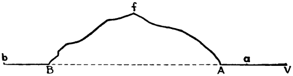
Fig. 1.—Diagram Showing Manner of Lining in Rectilinear Tunnels.
The center line which has thus been located on the ground
surface has to be transposed to the inside of the tunnel to
direct the excavation. To do this let A and B be the entrances
and a and b be the two distinct fixed points which have been
ranged in with the center line located on the ground surface
over the hill A f B, Fig. 1. The instrument is set up at V,
any point on the line A a produced, and a bearing secured by
observation on the center line marked on the surface. This
bearing is then carried into the tunnel by plunging the telescope,
and setting pegs in the roof of the heading. Lamps
hung from these pegs furnish the necessary sighting points.
This same operation is repeated on the opposite side of the
hill to direct the excavation from that end of the tunnel.
These operations serve to locate only the first few points inside
the tunnel. As the excavation penetrates farther into the hill,
it becomes impossible to continue to locate the line from the
outside point, and the line has to be run from the points
marked on the roof of the heading. Great accuracy is required
in all these observations, since a very small error at the beginning
becomes greater and greater as the excavation advances.
To facilitate the accurate location of points on the roof of the
tunnel, a simple device was designed by Mr. Beverley R. Value,
shown in Fig. 2. Two iron spikes, each having a small hole
in the flat end, are driven into the rock about 9 ins. apart. A
brass bar, 1 in. high, 1⁄4 in. thick and 10 ins. long, having a hole
near one end and a 1 in. slot at the other, is screwed tightly into[11]
the head of the spikes. The middle part of the bar is divided
into inches and tenths of an inch. A separate brass hanger is
fitted to the bar, having a vernier with its zero at the middle
of the hanger and corresponding
to a plumb line attached
below. The hanger
is moved back and forth until
it coincides with the line of
sight of the transit, and then
the readings of the vernier
are recorded. Any time that
the hanger is placed on the
bar and the vernier marks
the same reading, the plumb
line will indicate the center
line of the tunnel. When,
instead of one bar, two are inserted at a distance of 20 or 30 ft.
apart, the plumb lines suspended from the hangers will represent
the vertical plane passing through the axis of the tunnel
in coincidence with the one staked out on the surface ground.
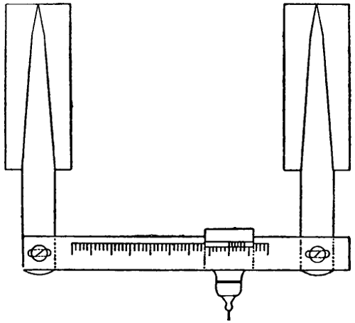
Fig. 2.—B. R. Value’s Device for Locating
the Center Line Inside of a Tunnel.
The location of the center line of a long tunnel, which is to be
excavated under high mountains, is a very difficult operation,
and the engineers usually leave this part of the work to astronomers,
who fix the stations from which the engineers direct the
work of construction. The center lines of all the great Alpine
tunnels were located by astronomers who used instruments
of large size. Thus, in ranging the center line of the St. Gothard
tunnel, the theodolite used had an object glass eight inches
in diameter.[3] Instead of the ordinary mounting a masonry
pedestal with a perfectly level top is employed to support the
instrument during the observations. The location is made by
means of triangulation. The various operations must be performed
with the greatest accuracy, and repeated several times
in such a way as to reduce the errors to a minimum, since[12]
the final meeting of the headings depends upon their elimination.
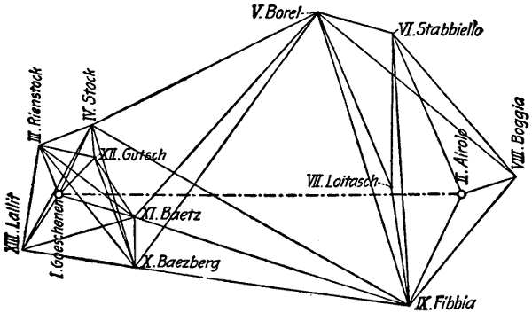
Fig. 3.—Triangulation System for Establishing the
Center Line of the St. Gothard Tunnel.
The St. Gothard tunnel furnishes perhaps the best illustration
of careful work in locating the center line of long rectilinear
tunnels of any tunnel ever built. The length of this
tunnel is 9.25 miles, and the height of the mountain above it
is very great. The center line was located by triangulation by
two different astronomers using different sets of triangles, and
working at different times. The set or system of triangles used
by Dr. Koppe, one of the observers, is shown by Fig. 3; it consists
of very large and quite small triangles combined, the latter
being required because the entrances both at Airolo and Goeschenen
were so low as to permit only of a short sight being
taken. The apices of the triangles were located by means
of the contour maps of the Swiss Alpine Club. Each angle
was read ten times, the instrument was collimated four times
for each reading, and was afterwards turned off 5° or 10° to
avoid errors of graduation. The average of the errors in reading
was about one second of arc. The triangulation was compensated
according to the method of least squares. The probable
error in the fixed direction was calculated to be 0.8″ of arc at
Goeschenen and 0.7″ of arc at Airolo. From this it was assumed
that the probable deviation from the true center would
be about two inches at the middle of the tunnel, but when the[13]
headings finally met this deviation was found to reach eleven
inches.
Comparatively few tunnels are driven by working from the
entrances alone, the excavation being usually prosecuted at
several points at once by means of shafts. In these cases, in
order to direct the excavation correctly, it is necessary to fix the
center line on the bottom of the shaft. This is accomplished in
two ways,—one being employed when the shaft is located directly
over the center line, and the other when the shaft is located to
one side of the center line.
When the shaft is located on the center line two small pillars
are placed on opposite edges of the shaft and collimating with
the center line as shown by Fig. 4. On these two pillars the
points corresponding to the center line are correctly marked,
and connected by a wire stretched between them. To this wire
two plumb bobs are fastened as far apart as possible. These
plumb bobs mark two points on the center line at the bottom of
the shaft, and from them the line is extended into the headings as
the work advances. In these operations,
heavy plumb bobs are
used. In the New York subway
plumb bobs of steel, weighing 25
lbs. each, were used, and to prevent
rotation they were made with
cross-sections, in the shape of a
Greek cross, and were sunk in
buckets filled with water. Owing
to the difference between the temperature
at the top and that at the
bottom of the shaft, strong currents
of air are produced, which keep in
constant oscillation the wires to
which the bobs are suspended.
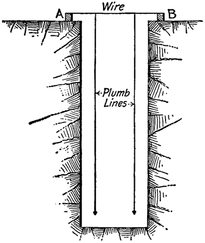
Fig. 4.—Method of Transferring the
Center Line down Center Shafts.
To determine the center line at the bottom of the shaft, the
headings are first driven from both sides of the shaft, after which[14]
a transit is set up on the same alignment with the two wires,
and this will indicate the vertical plane passing through the
axis of construction. Two points are then fixed on the roof
of the tunnel in continuation of this vertical plane. When the
plumb bobs are removed from the shaft and two small plumb
bobs are suspended to the two points mentioned, they will
always give the same vertical plane passing through the axis
of construction transferred from the surface.
Because of the continuous moving of the wires, the fixing of
the points on the roof of the tunnel is very troublesome, and
the operation should be repeated by different men at different
times before the points are permanently fixed.
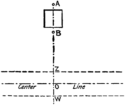
Fig. 5.—Method of Transferring the Center
Line down Side Shafts.
When the shaft is placed at one side of the tunnel the pillars
or bench marks are placed normal
to the center line on the
edges of the shaft as shown by
Fig. 5. Between the points A
and B a wire is stretched, and
from it two plumb bobs are
suspended, as described in the
preceding case; these plumb
bobs establish a vertical plane
normal to the axis of the tunnel.
The excavation of the side tunnel
is carried along the line BW
until it intersects the line of the main tunnel, whose center line
is determined by measuring off underground a distance equal
to the distance BO on the surface. By setting the instrument
over the underground point O, and turning off a right angle
from the line BO, the center line of the tunnel is extended into
the headings.
Curvilinear Tunnels.
—There are various methods of locating
the center lines of curvilinear tunnels, but the method of tangent
offsets is the one most commonly employed.
At the beginning the excavation is conducted as closely as[15]
may be to the line of the curve, and as soon as it has progressed
far enough the tangent AT, Fig. 6, is ranged out. At B a point
is located over which to set the instrument, and the distance
AB is measured for the purpose of finding the ordinate of
the right angle triangle OAB. Now OA = r, AB = d, and φ =
angle ABO. Then: Tang. φ =
rd.
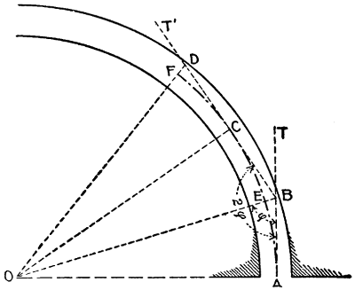
Fig. 6.—Method of Laying Out the Center Line of
Curvilinear Tunnels.
Doubling the value of φ and making the angle ABC = 2 φ,
the line BC will be fixed and the point C located by taking
AB = BC. On BC the ordinates are laid off to locate the curve.
Prolong CB so that CD = CB. Then the portion of the curve
CF is symmetrical with CE, and the ordinates used to locate
EC may be employed to locate CF, by laying them off in the
reverse order.
In curvilinear tunnels
several cases may
be considered.
(1) When the tunnel
for almost its entire
length is driven on a
tangent with a curve
at each end.
(2) When the tunnel
begins with a curve
and ends with a straight
line.
(3) When the whole
tunnel is in curve from portal to portal.
(4) The helicoidal or corkscrew tunnel.
(1) The axis of every one of the great Alpine tunnels is a
straight line, with a curve at each end. To range out the center
line of one of these long tunnels from a curve, no matter how
accurately laid out, will certainly cause an error, which, magnified
with the distance, may produce serious results. To avoid these[16]
inconveniences, the determination of the axis of the tunnel
should be made from a straight line. This means that the tunnel
is at first excavated on a straight line for its entire length and
after the headings driven from both portals have met, the two
portions of the tunnel or curve are excavated and constructed.
The portions of the tunnel excavated on straight lines for conveniences
of construction may then be abandoned or used in
cases of accidents or repairs.
When the axis of a short tunnel has a curve at each end and
a straight line in the middle, it is driven directly from the entrances;
first, however, excavating the curvilinear portions of
the tunnel. In such a case it would be advisable to proceed
in the following manner. Drive the headings on the curvilinear
portions of the tunnel, staking out the center line by means of
the offsets from the tangents. At the ends of the curves lay
out from both fronts the rectilineal portion of the tunnel. Only
very narrow headings should be excavated at first while the
whole section could be enlarged near the entrances. The excavation
of the headings at the front should advance very rapidly,
in order that the headings may meet in the shortest possible time.
When communication is established, it is comparatively easy to
correct an error resulting from driving the tunnel from the curves.
(2) When a tunnel begins with a curve and ends with a
straight line, the work of excavation should proceed from both
ends. From the straight end of the tunnel only the heading
should be driven, while from the curvilinear end the whole
section could be opened at once. By this arrangement the
excavation progresses slowly from the curvilinear end and
rapidly from the straight end of the tunnel. Once communication
has been established and any error corrected, the work of
enlarging the profile of the tunnel may be pushed with the same
activity from both ends.
(3) When the center line of the entire tunnel is a curve,
there is more probability of slight deviations from the true axis
of the proposed work. In such a case it would be advisable to[17]
first excavate a narrow heading and to concentrate all the efforts
in driving the headings as rapidly as possible in order that they
may meet in the shortest time. The center line of these headings
is staked out by the usual method of the offsets from the tangent.
The enlarging of the section of the tunnel could be commenced
at both portals and be driven slowly until the headings have
met and any errors corrected, when the work could be pushed
with the greatest activity all along the line.
(4) In corkscrew or helicoidal tunnels the entire center line
is on a curve. In these tunnels, as a rule, there is a great difference
of level between the two portals, one being much higher
than the other, so careful attention should be paid to the tunnel
grade. Working in the limited spaces afforded by narrow headings
it is very probable that errors may be made in fixing both
the alignment and the grade of the tunnel. To prevent these
almost unavoidable errors, it would be well to excavate at first
only the headings, to stake the center line in the roof of these
headings and then to lay the grade of the tunnel as accurately
as possible. The work on the headings should be pushed as
rapidly as possible in order that they may meet quickly, so that
the center line, as temporarily laid out, may be corrected and
permanently fixed for the direction of successive operations.
In these tunnels the headings should be excavated near the
center of the tunnel cross-section so that the sides and roof of
the heading would be at some distance from the sides and roof
of the proposed tunnel. This arrangement will easily permit
corrections to be made in case any slight difference from the
true line was erroneously made during the excavation of the
headings.
FORM AND DIMENSIONS OF CROSS-SECTION.
In deciding upon the sectional profile of a tunnel two factors
have to be taken into consideration: (1) The form of section
best suited to the conditions, and (2) the interior dimensions of
this section.
[18]
Form of Section.
—The form of the sectional profile of a tunnel
should be such that the lining is of the best form to resist
the pressures exerted by the unsupported walls of the tunnel
excavation, and these vary with the character of the material
penetrated. These pressures are both vertical and lateral in
direction; the roof, deprived of support by the excavation, tends
to fall, and the opposite sides for the same reason tend to slide
inward along a plane more or less inclined, depending upon the
friction and cohesion of the material. In some rocks the cohesion
is so great that they will stand vertically, while it may
be very small in loose earth which slides along a plane whose
inclination is directly proportional to the cohesion.
From the theory of resistance of profiles we know that the
resistance of a line to exterior normal forces is directly proportional
to its degree of curvature, and consequently inversely
proportional to the radius of the curve. Hence the sectional
profile of a tunnel excavated through hard rock, where there
are no lateral pressures owing to the great cohesion of the material,
and having to resist only the vertical pressure, should
be designed to offer the greatest resistance at its highest point,
and the curve must, therefore, be sharper there, and may decrease
toward the base. In quicksand, mud, or other material
practically without cohesion, the pressures will all be normal
to the line of the profile, and a circular section is the one best
suited to resist them. These theoretical considerations have
been proved correct by actual experience, and they may be
employed to determine in a general way the form of section to
be adopted. Applying them to very hard rock, they give us
a section with an arched roof and vertical side walls. In softer
materials they give us an elliptical section with its major axis
vertical, and in very soft quicksands and mud they give us the
circular section. These three forms of cross-section and their
modifications are the ones commonly employed for tunnels.
An important exception to this general practice, however, is
met with in some of the city underground rapid-transit railways[19]
built of late years, where a rectangular or box section is
employed. These tunnels are usually of small depth, so that
the vertical pressures are comparatively light, and the bending
strains, which they exert upon the flat roof, are provided for by
employing steel girders to form the roof lining.
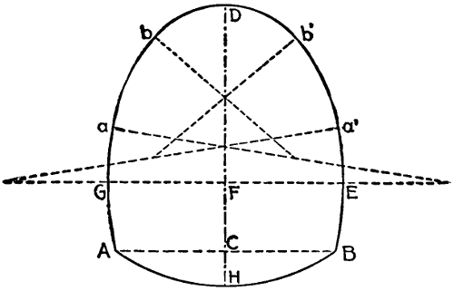
Fig. 7.—Diagram of Polycentric Sectional Profile.
From what has been said it will be seen that it is impossible
to establish a standard sectional profile to suit all conditions.
The best one for the majority of conditions, and the one most
commonly employed, is a polycentric figure in which the number
of centers and the length of the radii are fixed by the engineer
to meet the particular conditions which exist. In a general way
this form of center may be considered as composed of two parts
symmetrical in respect to the vertical axis. Fig. 7 shows such
a profile, in which DH
is the vertical axis. The
section is unsymmetrical
in respect to the
horizontal axis GE. The
upper part forming the
roof arch is usually a
semi-circle or semi-oval,
while the lower part,
comprising the side walls
and invert of floor, varies
greatly in outline. Sometimes the side walls are vertical and
the invert is omitted, as shown by Fig. 8; and sometimes the
side walls are inclined, with their bottoms braced apart by the
invert, as shown by Fig. 9. In more treacherous soils the side
walls are curved, and are connected by small curved sections
to the invert, as shown by Fig. 10. In the last example the
side walls are commonly called skewbacks, and the lower part
of the section is a polycentric figure like the upper part, but
dissimilar in form.
In a tunnel section whose profile is composed entirely of
arcs the following conditions are essential: The centers of the[20]
springer arcs Ga and Ea′, Fig. 7, must be located on the line
GE; the center of the roof arc bDb′ must be located on the axis
HD; the total number of centers must be an odd number; the
radii of the succeeding arcs from G toward D and E toward
D must decrease in length, and finally the sum of the angles
subtended by the several arcs must equal 180°.
Figs. 8 to 10.—Typical
Sectional Profiles
for Tunnel.
Dimensions of Section.
—The dimensions to be given to the
cross-section of a tunnel depend upon the purpose for which it
is to be used. Whatever the purpose of the tunnel, the following
three points have to be considered in determining the size
of its cross-section: (1) The size of clear opening required; (2)
the thickness of lining masonry necessary; and (3) the decrease
in the clear opening from the deformation of the lining.
Railway tunnels may be built either to accommodate one or
two, three and four tracks. In single-track tunnels a clear space
of at least 21⁄2 ft. on each side should be allowed for between the
tunnel wall and the side of the largest standard locomotive or
car, and a clear space of at least 3 ft. should be allowed for between
the roof and the top of the same locomotive or car. Since
the roof of the tunnel is arch-shaped, to secure a clearance of 3 ft.
at every point will necessitate making the clearance at the center
greater than this amount. In double-track tunnels the same
amounts of side and roof clearances have to be provided for,
and, in addition, there has to be a clearance of at least 2 ft.
between trains. On the three- and four-track tunnels only the
width varies while the height remains almost equal to the
two track. Referring to Fig. 7, and assuming the line AB[21]
to represent the level of the tracks, then the ordinary dimensions
in feet required for both single- and double-track tunnels are
as follows:—
| |
Height, D. F. |
Width, G. E. |
Height, C. F. |
Height, C. H. |
| |
Feet. |
Feet. |
Feet. |
Feet. |
| Single track |
17.6 to 18 |
16.5 to 18 |
6 to 7.4 |
1⁄4 to 1⁄8 AB |
| Double track |
26.6 to 28 |
26.6 to 28 |
6.3 to 6.9 |
1⁄4 to 1⁄8 AB |
The dimensions of tunnels built for aqueduct purposes are
determined so as to have an area of cross-section equal to the
required waterway. In the Croton Aqueduct two different types
of cross-sections were used, the circular one for tunnels through
rock and the horseshoe section for tunnels through loose materials.
In the Catskill aqueduct three different cross-sections
have been selected, the circular one for tunnels under pressure
and the horseshoe for tunnels at the hydraulic gradient. These,
however, through rock have a cross-section formed of a semi-circular
arch and vertical side walls, while through earth the semi-circular
arch is supported by skewback walls.
In tunnels built for railroad aqueduct sewer and any other
purpose the thickness of the masonry lining to be allowed for
varies with the material penetrated, as will be explained in a
succeeding chapter where the dimensions for various ordinary
conditions are given in tabular form. The lining masonry is
subject to deformation in three ways: by the sinking of the whole
masonry structure, by the squeezing together of the side walls
by the lateral pressures, and by the settling of the roof-arch.
The whole masonry structure never sinks more than three or
four inches, and merits little attention. The movement of the
side walls towards each other, which may amount to three or
four inches for each wall without endangering their stability,
has, however, to be allowed for; and similar allowance must be
made for the settling of the roof-arch, which may amount to
from nine inches to two feet, when the arch is built first as in
the Belgian system and rests for some time upon the loose soil.
[22]
CHAPTER III.
EXCAVATING MACHINES AND ROCK DRILLS:
EXPLOSIVES AND BLASTING.
Earth-Excavating Machines.
—Comparatively few of the labor-saving
machines employed for breaking up and removing loose
soil in ordinary surface excavation are used in tunnel excavation
through the same material. Several forms of tunnel
excavating machines have been tried at various times, but only
a few of them have attained any measure of success, and these
have seldom been employed in more than a single work. In
the Central London underground railway work through clay a
continuous bucket excavator (Fig. 11) was employed with
considerable saving in time and labor over hand work. In
some recent tunnel work in America the contractors made
quite successful use of a modified form of steam shovel. These
are the most recent attempts to use excavating machines in
soft ground, and they, like all previous attempts, must be
classed as experiments rather than as examples of common
practice. The Thomson machine,[4]
however, can be employed[23]
in any tunnel driven through loose soil. It occupies a comparatively
small space and may easily work when the timbering is
used to support the roof of the tunnel. Steam shovel instead
may give efficient result only in the case that the whole section
of the tunnel is open at once and there are no timbers to prevent
the free swinging of the dipper handle and boom. But in tunnels
through loose soils it is almost impossible to open the whole
section at once without the necessity of supporting the roof.
Consequently the use of steam shovel in loose tunnels is very
limited. The shovel, the spade, and the pick, wielded by hand,
are the standard tools now, as in the past, for excavating soft-ground
tunnels.
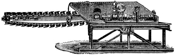
Fig. 11.—Soft Ground Bucket Excavating Machine:
Central London Underground Railway.
Rock-Excavating Machines.
—At one period during the work
of constructing the Hoosac tunnel considerable attention was
devoted to the development of a rock excavating, boring, or
tunneling machine. This device was designed to cut a groove
around the circumference of the tunnel thirteen inches wide
and twenty-four feet in diameter by means of revolving cutters.
It proved a failure, as did one of smaller size, eight feet in
diameter, tried subsequently. During and before the Hoosac
tunnel work a number of boring-machines of similar character
were experimented with at the Mont Cenis tunnel and elsewhere
in Europe; but, like the American devices, they were finally
abandoned as impracticable.
Hand Drills.
—Briefly described, a drill is a bar of steel
having a chisel-shaped end or cutting-edge. The simplest form
of hand drill is worked by one man, who holds the drill in one
hand, and drives it with a hammer wielded by his other hand.
A more efficient method of hand-drill work is, however, where
one man holds the drill, and another swings the hammer or
sledge. Another form of hand drill, called a churn drill, consists
of a long, heavy bar of steel, which is alternately raised
and dropped by the workman, thus cutting a hole by repeated
impacts.
In drilling by hand the workman holding the drill gives it a[24]
partial turn on its axis at every stroke in order to prevent wedging
and to offer a fresh surface to the cutting-edge. For
the same reason the chips and dust which accumulate in the
drill-hole are frequently removed. The instruments used for
this purpose are called scrapers or dippers, and are usually
very simple in construction. A common form is a strong wire
having its end bent at right angles, and flattened so as to
make a sort of scoop by which the drillings may be scraped
or hoisted out of the hole. It is generally advantageous to
pour water into the drill-hole while drilling to keep the drill
from heating.
Power Drills.
—When the conditions are such that use can
be made of them, it is nearly always preferable to use power
drills, on account of their greater speed of penetration and
greater economy of work. Power drills are worked by direct
steam pressure, or by compressed air generated by steam or
water power, and stored in receivers from which it is led to the
drills through iron pipes. A great variety of forms of power
drills are available for tunnel work in rock, but they can nearly
all be grouped in one of two classes: (1) Percussion drills, and
(2) Rotary drills.
Percussion Drills.
—The first American percussion drill
was patented by Mr. J. J. Couch of Philadelphia, Penn., in
March, 1849. In May of the same year, Mr. Joseph W. Fowle,
who had assisted Mr. Couch in developing his drill, patented a
percussion drill of his own invention. The Fowle drill was
taken up and improved by Mr. Charles Burleigh, and was first
used on the Hoosac tunnel. In Europe Mr. Cavé patented
a percussion drill in France in October, 1851. This invention
was soon followed by several others; but it was not until Sommeiller’s
drill, patented in 1857 and perfected in 1861, was used
on the Mont Cenis tunnel, that the problem of the percussion
drill was practically solved abroad. Since this time numerous
percussion drill patents have been taken out in both America
and Europe.
[25]
A percussion drill consists of a cylinder, in which works a
piston carrying a long piston rod, and which is supported in
such a manner that the drill clamped to the end of the piston
rod alternately strikes and is withdrawn from the rock as the
piston reciprocates back and forth in the cylinder. Means are
devised by which the piston rod and drill turn slightly on their
axis after each stroke, and also by which the drill is fed forward
or advanced as the depth of the drill-hole increases. The
drills of this type which are in most common use in America
are the Ingersoll-Sergeant and the Rand. There are various
other makes in common use, however, which differ from the
two named and from each other chiefly in the methods by
which the valve is operated. All of these drills work either
with direct steam pressure or with compressed air. Workable
percussion drills operated by electricity are built, but so far
they do not seem to have been able to compete commercially
with the older forms. No attempt will be made here to make
a selection between the various forms of percussion drills for
tunnel work, and for the differences in construction and the
merits claimed for each the reader is referred to the makers of
these machines. All of the leading makes will give efficient
service. It goes almost without saying that a good percussion
drill should operate with little waste of pressure, and should
be composed of but few parts, which can be easily removed and
changed.
Drill Mountings.
—For tunnel work the general European
practice is to mount power drills upon a carriage moving on
tracks in order that they be easily withdrawn during the firing
of blasts. Connection is made with the steam or compressed
air pipes by means of flexible hose which can easily be attached
or detached as the drill advances or when it is moved for repairs
or during blasts. Two, four, and sometimes more drills are
mounted and work simultaneously on a single carriage. In
America it has been found that column mountings have been
more successful for tunnel work than any other form. The[26]
column mounting made by the Ingersoll-Sergeant Drill Co.
is shown in Fig. 12. In using this form of mounting no tracks
or other special apparatus is required; it is not necessary, as
is the case with the carriage mounting, to remove the débris
before resuming operations, but as soon as the blasting has been
finished and the smoke has sufficiently disappeared the column
can be set up and drilling resumed.
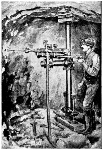
Fig. 12.—Column Mounting for Percussion Drill: Ingersoll-Sergeant Drill Co.
[27]
Rotary Drills.
—Rotary drilling machines, or more simply
rotary drills, were first used in 1857 in the Mont Cenis tunnel.
The advantages claimed for rotary drills in comparison with
percussion drills are: (1) That less power is required to drive
the drill, and the power is better utilized; (2) once the machines
work easily they do not require continual repairs, and (3) in
driving holes of large size the interior nucleus is taken away
intact, thus reducing work and increasing the speed of drilling.
Rotary drills are extensively used for geological, mining, well-driving,
and prospecting purposes; but they are very seldom
employed in tunnels in America, although successfully used for
this purpose in Europe. The reason they have not gained
more favor among American tunnel builders is due to some
extent perhaps to prejudice, but chiefly to the great cost of the
machine as compared with percussion drills, and to the expense
of diamonds for repairs. Those who advocate these machines
for tunnel work point out, however, that under ordinary usage
the diamonds have a very long life,—borings of 700 lin. ft.
being recorded without repairs to the diamonds.
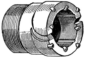
Fig. 13.—Sketch of Diamond
Drill Bit.
The form of rotary drill used chiefly for prospecting purposes
is the diamond drill. This machine consists of a hollow
cylindrical bit having a cutting-edge of diamonds, which is
revolved at the rate of from two hundred to four hundred revolutions
per minute by suitable machinery operated by steam
or compressed air. The diamonds are
set in the cutting-edge of the bit so as
to project outward from its annular
face and also slightly inside and outside
of its cylindrical sides (Fig. 13). When
the drill rod with the bit attached is
rotated and fed forward the bit cuts an
annular hole into the rock; the drillings
being removed from the hole by a constant stream of water
which is forced down through the hollow drill rod and emerges,
carrying the débris with it, up through the narrow space between[28]
the outside of the bit and the walls of the hole. There are
various makes of diamond drills, but they all operate in essentially
the same manner.
The rotary drill principally employed in Europe in tunneling
is the Brandt. The cutting-edge of the Brandt drill consists of
hardened steel teeth. The bit is pressed against the rock by
hydraulic pressure, and usually makes from seven to eight revolutions
per minute. Some of the water when freed goes through
the hollow bit, keeping it cool, and cleaning the hole of débris.
A water pressure of from 300 to 450 lbs. per square inch is
required to operate these drills. Rotary rock-drills may be
mounted either on carriages or on columns for tunnel work.
Several machines have recently been constructed for the purpose
of breaking the rock in tunnels without blasting, but they
did not meet the approval of tunnel engineers. One of these
machines is provided with numerous electric torches, which are
applied to the rock at the front. By suddenly chilling the rock
with a stream of cold water the stone will crumble away. Another
machine was tested, with little success, in the excavation
for the New Grand Central Depot in New York. On the face
of this machine there is a multitude of chipping drills revolving
on four arms and driven by air pressure. They attack the
rock and chip it into fragments, which are carried away by an
endless band.
EXPLOSIVES AND BLASTING.
When the holes are once drilled, either by hand or power
drills, they are charged with explosives. The principal explosives
employed in tunneling are gunpowder, nitroglycerine, and
dynamite.
Gunpowder.
—Gunpowder is composed of charcoal, sulphur,
and saltpeter in proportions varying according to the quality of
the powder. For mining purposes the composition employed
is 65% saltpeter, 15% sulphur, and 20% charcoal. It is a black
granulated powder having a specific gravity of 1.5; the black[29]
color is given by the charcoal; and the grains have an angular
form, and vary in size from 1⁄8 in. to 3⁄8 in. Good blasting powder
should contain no fine grains, which may be detected by pouring
some of the powder upon a sheet of white paper. The
force developed by the explosion of gunpowder is not accurately
known; it depends upon the space in which it is confined. Different
authorities estimate the pressure at from 15,000 lbs.
per sq. in. in loose blasts to 200,000 lbs. per sq. in. in gunnery.
Authorities also differ in opinion as to the character of the gases
developed by the explosion of gunpowder, a matter of vital
concern to the tunnel engineer, since they are likely to affect
the health and comfort of his workmen. It may be assumed
in a general way, however, that the oxygen of the saltpeter
converts nearly all of the carbon of the charcoal into carbon
dioxide, a portion of which combines with the potash of the
saltpeter to form carbonate of potash, the remainder continuing
in the form of gas. The sulphur is converted into
sulphuric acid, and forms a sulphate of potash, which by reaction
is decomposed into hyposulphite and sulphide. The nitrogen
of the saltpeter is almost entirely evolved in a free state; and
the carbon not having been wholly burnt into carbonic acid,
there is a proportion of carbonic oxide.
Nitroglycerine.
—Nitroglycerine is one of the modern explosives
used as a substitute for gunpowder. It is a fluid produced
by mixing glycerine with nitric and sulphuric acids; it
freezes at +41° F., and burns very quietly, developing carbonic
acid, nitrogen, oxygen, and water. By percussion or by the
explosion of some substances, such as capsules of gunpowder
or fulminate of mercury, nitroglycerine produces a sudden
explosion in which about 1250 volumes of gases are produced.
The pressure of these gases has been calculated at 26,000 atmospheres,
or 324,000 lbs. per sq. in. Nitroglycerine explodes
very easily by percussion in its normal state, but with great
difficulty when frozen; hence, in America, at the beginning
of its use, it was transported only in a frozen state. When[30]
dirty, nitroglycerine undergoes a spontaneous decomposition
accompanied by the development of gases and the evolution
of heat, which, reaching 388° F., causes it to explode. Notwithstanding
the enormous pressures which nitroglycerine develops,
it is very seldom used in its liquid state, but is mixed with
a granular absorbent earth composed of the shells of diatoms.
The fluid undergoes no chemical change by being absorbed,
and explodes, freezes, and burns under the same conditions as
in the fluid state.
Dynamite.
—The credit of rendering nitroglycerine available
for the purposes of the engineer by mixing it with a granular
absorbent is due to Albert Nobel of Stockholm, Sweden, who
named the new material dynamite. The nitroglycerine in
dynamite loses very little of its original explosive power, but
is very much less easily exploded by percussion, and can be
employed in horizontal as well as vertical holes, which was, of
course, not possible in its liquid state. Dynamite must contain
at least 50% of nitroglycerine. Some manufacturers, instead of
using diatomaceous earth, use other absorbents which develop
gases upon explosion and increase the force of the explosion.
These mixtures are classed under the general name of false dynamites.
A great many varieties of dynamite are manufactured,
and each manufacturer usually makes a number of grades to
which he gives special names. Dynamite for railway work,
tunneling, and mining contains about 50% of nitroglycerine; for
quarrying about 35%, and for blasting soft rocks about 30%.
It is sold in cylindrical cartridges covered with paper.
Storage of Explosives.
—In driving tunnels through rock
large quantities of explosives must be used, and it is necessary
to have some safe place for storing them. In many States
there are special laws governing the transportation and storage
of explosives; where there is no regulation by law the engineer
should take suitable precautions of his own devising. It is
best to build a special house or hut in one of the most concealed
portions of the work and away from the tunnel, and[31]
protect it with a lightning-rod and from fire. Strict orders
should be given to the watchman in charge not to allow persons
inside with lamps or fire in any form, and smoking should be
prohibited. The use of hammers for opening the boxes should
be prohibited; and dynamite, gunpowder, and fulminate of
mercury should not be stored together in the same room. A
quantity of dynamite for two or three days’ consumption may
be stored near the entrance of the tunnel in a locked box, the
keys of which are kept by the foreman of the work. When
dynamite has been frozen the engineer should provide some
arrangement by which it may be heated to a temperature not
exceeding 120° F., and absolutely forbid it being thawed out on
a stove or by an open fire.
Fuses.
—When gunpowder is used in tunneling it is ignited
by the Blickford match. This match, or fuse as it is more
commonly called, consists of a small rope of yarn or cotton
having as a core a small continuous thread of fine gunpowder.
To protect the outside of the fuse from moisture it is coated
with tar or some other impervious substance. These fuses are so
well made that they burn very uniformly at the rate of about
1 ft. in 20 seconds, hence the moment of explosion can be pretty
accurately fixed beforehand. Blickford matches have the objection
for tunnel work of burning with a bad odor, especially
when they are coated with tar, and to remedy this many others
have been invented. Those of Rzika and Franzl are the best
known of these. The former has many advantages, but it
burns too quickly, about 3 ft. per second, and is expensive;
the latter consists of a small hollow rope filled with dynamite.
Blickford matches cannot be used to explode dynamite, the
use of a cartridge being required. These cartridges are small
copper cylinders containing fulminate of mercury. They may
be attached to the end of the Blickford match, which being
ignited the spark travels along its length until it reaches the
copper cylinder, where it explodes the fulminate of mercury,
which in turn explodes the dynamite. Blasts may also be fired[32]
by electricity, which, in fact, is the most common and the
preferable method, because several blasts can be fired simultaneously,
and because the current is turned on at a great distance,
thus affording greater safety to the workmen.
The method of electric firing generally employed in America
is known as the connecting series method, and consists in firing
several mines simultaneously. The ends of the wires are scraped
bare, and the wire of the first hole of the series is twisted together
with the wire of the second hole, and so on; finally the
two odd wires of the first and last holes are connected to two
wires of a single cable or to two separate cables extending to
some safe place to which the men can retreat. Here the two
cable wires are connected by binding screws to the poles of a
battery, or sometimes to a frictional electric machine. The current
passes through the wires, making a spark at each break, and
so fires the fulminate of mercury, which explodes the dynamite.
Simultaneous firing by electricity by utilizing the united
strength of the blasts at the same instant secures about 10%
greater efficiency from the explosives. Another advantage of
electric firing is that in case of a missfire of any one of the
holes there is slight possibility of explosion afterwards, and the
place can be approached at once to discover the cause.
Tamping.
—Tamping is the material placed in the hole above
the explosive to prevent the gases of explosion from escaping
into the air. Tamping generally consists of clay. When gunpowder
is used the clay must be well rammed with a wooden
tool, and paper, cotton, or some other dry material must be
placed between the moist clay and the powder. When dynamite
is used it is not necessary to ram the tamping, since the
suddenness of the explosion shatters the rock before the clay
can be driven from the hole.
A few experienced men should be appointed to fire the blasts.
These men should give ample warning previous to the blast in
order that all machinery and tools which might be injured by flying
fragments may be removed out of danger, and so that the[33]
workmen may seek safety. When all is ready they should
fire the blasts, keeping accurate count of the explosions to
ensure that no holes have missed fire, and should call the workmen
back when all danger is over. In case any hole has missed
fire it should be marked by a red lamp or flag.
Nature of Explosions.
—When the explosives are ignited a
sudden development of gases results, producing a sudden and
violent increase of pressure, usually accompanied by a loud
report. The energy of the explosion is exerted in all directions
in the form of a sphere having its center at the point of explosion,
and the waves of energy lose their force as the distance
from this central point increases. The energy of the explosion
at any point in the sphere of energy is, therefore, inversely
proportional to the distance of this point from the center of
explosion. In the vicinity of the center of explosion the gases
have sufficient power to destroy the force of cohesion and
shatter the rock; further on, as they lose strength, they only
destroy the elasticity of the material and produce cracks; and
still further away they only produce a shock, and do not affect
the material. Within the sphere of energy there are, therefore,
three other concentric spheres: the first one being where
cohesion is destroyed, the second where elasticity is overcome,
and the third where the shock is transmitted by elasticity.
When the latter sphere comes below the surface, the gases
remain inside the rock; but when the surface intersects either
of the other two spheres, the gases blow up the rock, forming a
cone or crater, whose apex is at the point of explosion, and
which is called the blasting-cone. The larger the blasting-cone
is, the greater is the amount of rock broken up; and the object
of the engineer should, therefore, always be so to regulate the
depth of the hole and the quantity of explosive as to secure the
largest possible blasting cone in each case. Experiments are
required to determine the most efficient depth of hole, and
quantity of explosive to be employed, since these differ in
different kinds of rock, with the position of the rock strata,[34]
etc.; but in ordinary practice, the depths of the holes are made
from 2 to 3 ft. in the heading and upper portion of the tunnel,
when drilled by hand; and from 6 to 8 ft. when drilled by power
drills. In the lower portion of the profile, the holes are made
deeper, from 3 ft. to 4 ft. when drilled by hand, and exceeding 6
ft. when drilled by power. The distance of the holes apart should
be about equal to the diameter of the blasting-cone; as a general
rule it is assumed that the base of the blasting-cone has a diameter
equal to twice the depth of the hole. The following table
gives the average number of holes required in each part of the
excavation for the St. Gothard tunnel in which the heading
was excavated by machine drills while the other parts were
excavated by hand drills:
NO.
OF
PART.
[5] |
NAME OF PART. |
NO. OF
HOLES. |
| 1. |
Heading |
6 |
to |
9 |
| 2. |
Right wing of heading |
3 |
to |
5 |
| 3. |
Left wing of heading |
3 |
to |
5 |
| 4. |
Shallow trench with core |
2 |
|
| 5. |
Deepening of trench to floor |
6 |
to |
9 |
| 6. |
Narrow mass of core to left |
3 |
|
| 7. |
Greater mass of core to left |
6 |
to |
9 |
| 8. |
Culvert |
1 |
|
| |
Total section |
30 |
to |
43 |
The quantity of explosives required for blasting depends
upon the quality of the rock, since the force of the explosives
must overcome the cohesion of the rock, which varies with its
nature, and often differs greatly in rocks of the same kind and
composition. The quantity of explosives required to secure
the greatest efficiency in blasting any particular rock may be
determined experimentally, but in practice it is usually deduced
by the following rules: (1) The blasting force is directly proportional
to the weight of the explosives used, and (2) the bulk
of the blasted rock is proportional to the cube of the depth of
the holes. It is usually assumed, also, that the explosive should
fill at least one-fourth the depth of the hole.
[35]
The following table gives the depth of holes and amount of
dynamite used at each advance in the Fort George Tunnel
illustrated on page 135.
Order of
Firing. |
Kinds of
Holes. |
Depth. |
Charge. |
Kind of
Dynamite. |
| |
|
|
|
|
Bench
Holes |
- |
|
1st round
2nd round |
4 |
grading |
3′ to 5′ |
50 |
lbs. |
40% |
climax |
| 5 |
bench |
9′ 6″ |
45 |
„ |
40% |
„ |
| 6 |
trimming |
3′ to 9′ |
42 |
„ |
40% |
„ |
| |
|
|
|
|
Heading
Holes |
- |
|
3d round |
8 |
center cut |
9′ |
56 |
„ |
60% |
„ |
| 4th round |
8 |
side |
8′ |
48 |
„ |
40% |
„ |
| 5th round |
6 |
dry |
8′ |
36 |
„ |
40% |
„ |
| |
|
|
|
|
[36]
CHAPTER IV.
GENERAL METHODS OF EXCAVATION: SHAFTS:
CLASSIFICATION OF TUNNELS.
A number of different modes of procedure are followed in
excavating tunnels, and each of the more important of these
will be considered in a separate chapter. There are, however,
certain characteristics common to all of these methods, and
these will be noted briefly here.
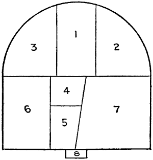
Fig. 14.—Diagram Showing Sequence
of Excavation for St. Gothard
Tunnel.
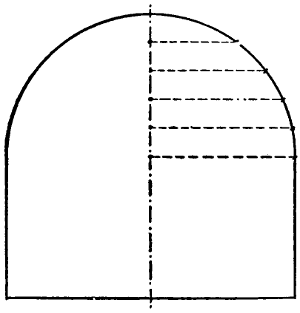
Fig. 15.—Diagram Showing Manner
of Determining Correspondence of
Excavation to Sectional Profile.
Division of Section.
—It may be asserted at the outset that
the whole area of the tunnel section is not ordinarily excavated
at one time, but that it is removed in sections, and as each
section is excavated it is thoroughly
timbered or strutted. The order in
which these different sections are
excavated varies with the method of
excavation, and it is clearly shown
for each method in succeeding chapters.
As a single example to illustrate
the proposition just made, the
division of the section and the sequence
of excavation adopted at the
St. Gothard tunnel is selected (Fig.
14). The different parts of the
section were excavated in the order numbered; the names given
to each part, and the number of holes employed in breaking it
down, are given by the table on page 35. Whatever method is
employed, the work always begins by driving a heading, which
is the most difficult and expensive part of the excavation. All
the other operations required in breaking down the remainder[37]
of the tunnel section are usually designated by the general
term of enlargement of the profile. The various operations of
excavation may, therefore, be classified either as excavation
of the heading or enlargement of the profile.
Excavation of the Heading.
—There is considerable confusion
among the different authorities regarding the exact definition
of the term “heading” as it is used in tunnel work. Some
authorities call a small passage driven at the top of the profile
a heading, and a similar passage driven at the bottom of the
profile a drift; others call any passage driven parallel to the
tunnel axis, whether at the top or at the bottom of the profile,
a drift; and still others give the name “heading” to all such
passages. For the sake of distinctness of terminology it seems
preferable to call the passage a heading when it is located at
the top of the profile, and a drift when it is located near the
bottom.
Headings and drifts are driven in advance of the general
excavation for the following purposes: (1) To fix correctly
the axis of the tunnel; (2) to allow the work to go on at
different points without the gangs of laborers interfering with
each other; (3) to detect the nature of material to be dealt with
and to be ready in any contingency to overcome any trouble
caused by a change in the soil; and (4) to collect the water.
The dimensions of headings in actual practice vary according
to the nature of the soil through which they are driven. As
a general rule they should not be less than 7 ft. in height, so as
to allow the men to work standing, and have room left for the
roof strutting. The width should not be less than 6 ft., to
allow two men to work at the front, and to give room for
the material cars without interfering with the wall strutting.
Usually headings are made 8 ft. wide. The length of headings
in practice varies according to circumstances. In very long
tunnels through hard rock the headings are sometimes excavated
from 1000 ft. to 2000 ft. in advance, in order that they
may meet as soon as possible and the ranging of the center line[38]
be verified, and so that as great an area of rock as possible may
be attacked at the same time in the work of enlarging the
profile. In short tunnels, where the ranging of the center line
is less liable to error, shorter headings are employed, and in soft
soils they are made shorter and shorter as the cohesion of the soil
decreases. When the material has too little cohesion to stand
alone, the tops and sides of the heading require to be supported
by strutting. To prevent caving at the front of the heading,
the face of the excavation is made inclined, the inclination
following as near as may be the natural slope of the material.
Enlargement of the Profile.
—The enlargement of the profile
is accomplished by excavating in succession several small
prisms parallel to the heading, and
its full length, which are so located
that as each one is taken out the
cross-section of the original heading
is enlarged. The number, location,
and sequence of these prisms vary
in different methods of excavation,
and are explained in succeeding
chapters where these methods are
described. To direct the excavation
so as to keep it always within
the boundaries of the adopted profile,
the engineer first marks the center line on the roof of the
heading by wooden or metal pegs, or by some other suitable
means by which a plumb line may be suspended. He next
draws to a large scale a profile of the proposed section; and
beginning at the top of the vertical axis he draws horizontal
lines at regular intervals, as shown by Fig. 15, until they intersect
the boundary lines of the profile, and designates on each
of these lines the distance between the vertical axis and the
point where it intersects the profile. It is evident that if the
foreman of excavation divides his plumb line in a manner corresponding
to the engineer’s drawing, and then measures horizontally[39]
and at right angles to the vertical center plane of the
tunnel the distance designated on the horizontal lines of the
drawing, he will have located points on the profile of the section,
or in other words have established the limits of excavation.
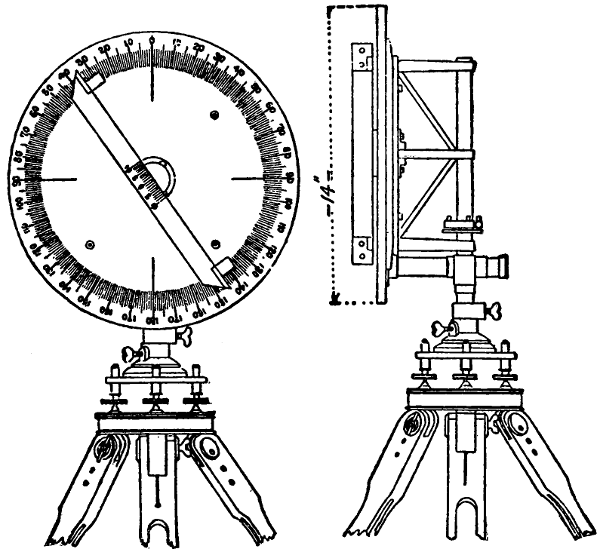
Fig. 16.—Polar Protractor for Determining Profile of Excavated Cross-Section.
In the excavation of the Croton Aqueduct for the water
supply of New York city, an instrument called a polar protractor
was used for determining the location of the sectional
profile. It was invented by Mr. Alfred Craven, division engineer
of the work. This instrument consists of a circular disk
graduated to degrees, and mounted on a tripod in such a manner
that it may be leveled up, and also have a vertical motion and a
motion about the vertical axis. The construction is shown
clearly by Fig. 16. In use the device is mounted with its
center at the axis of the tunnel. A light wooden measuring-rod
tapering to a point, shod with brass and graduated to feet
and hundredths of a foot, lies upon the wooden arm or rest,
which revolves upon the face of the disk, and slides out to[40]
a contact with the surface of the excavation at such points
as are to be determined. If the only information desired is
whether or not the excavation is sufficient or beyond the established
lines, the rod is set to the proper radius, and if it
swings clear the fact is determined. If a true copy of the
actual cross-section is desired, the rod is brought into contact
with the significant points in the cross-section, and the angles
and distances are recorded.
The general method of directing the excavation in enlarging
the profile by referring all points of the profile to the vertical
axis is the one usually employed in tunneling, and gives good
results. It is considered better in actual practice to have the
excavation exceed the profile somewhat than to have it fall
short of it, since the voids can be more easily filled in with
riprap than the encroaching rock can be excavated during the
building of the masonry. In tunnels where strutting is necessary
the excavation must be made enough larger than the
finished section to provide the space for it. In soft-ground
tunnels it is also usual to enlarge the excavation to allow for
the probable slight sinking of the masonry. The proper allowance
for strutting is usually left to the judgment of the foreman
of excavation, but the allowance for settlement must be
fixed by the engineer.
SHAFTS.
Shafts are vertical walls or passages sunk along the line of
the tunnel at one or more points between the entrances, to
permit the tunnel excavation to be attacked at several different
points at once, thus greatly reducing the time required for
excavation. Shafts may be located directly over the center
of the tunnel or to one side of it, and, while usually vertical,
are sometimes inclined. During the construction of the tunnel
the shafts serve the same purpose as the entrances; hence they
must afford a passageway for the excavated materials, which[41]
have to be hoisted out, and also for the construction tools and
materials which have to be lowered down them. They must
also afford a passageway for workmen, draft animals, and for
pipes for ventilation, water, compressed air, etc. The character
of this traffic indicates the dimensions required, but these depend
also upon the method of hoisting employed. Thus, when
a windlass or horse gin is used, and the materials are hoisted
in buckets of small dimensions, the dimensions of the shaft may
also be small; but when steam elevators are employed, and the
material is carried on cars run on to the platform of the elevator,
large dimensions must be given to the shaft. Generally the
parts of the shaft used for different purposes are separated by
partitions. The elevator for workmen and the various pipes
are placed in one compartment, while the elevator for hoisting
the excavated material and lowering construction material is
placed in another.
Shafts may be either temporary or permanent. They are
temporary when they are filled in after the tunnel is completed,
and permanent when they are left open to supply ventilation
to the tunnel. Permanent shafts are usually made circular, and
lined with brick, unless excavated in very hard and durable
rock. When sunk for temporary use only, shafts are usually
made rectangular with the greater dimension transverse to the
tunnel. They are strutted with timber. A pump is generally
located at the bottom of the shaft to collect the water which
seeps in from the sides of the shaft and from the tunnel
excavation. The dimensions of this pump will of course vary
with the amount of water encountered, as will also the capacity
of the pump for forcing it up and out of the shaft, which has
always to be kept dry.
The majority of engineers prefer to sink shafts directly
over the center line of the tunnel. Side shafts are employed
chiefly by French engineers. The chief advantage of the
former method is the great facility which it affords for hoisting
out the materials, while in favor of the latter method is the[42]
non-interference of the shaft with the operations inside the
tunnel. Were it not that the side shaft requires the introduction
of a transverse gallery connecting it with the tunnel,
it would be on the whole superior to the center shaft; but the
side gallery necessitates turning the cars at right angles, and
consequently the use of a very sharp curve or a turntable to
reach the shaft bottom, which is a disadvantage that may
outweigh its advantages in some other respects. It is impossible
to state absolutely which of these methods of locating
shafts is the best; both present advantages and disadvantages,
and the use of one or the other is usually determined more by
the local conditions than by any general superiority of either.
When side shafts are employed they are sometimes made
inclined instead of vertical. This form is used when the depth
of the shaft is small. By it the hauling is greatly simplified,
since the cars loaded at the front with excavated material can
be hauled directly out of the shaft and to the dumping-place,
surmounting the inclined shaft by means of continuous cables.
The short galleries connecting the side shafts with the tunnel
proper usually have a smaller section than the tunnel, but are
excavated in exactly the same manner. Another form of side
shaft sometimes used is one reaching to the surface when
the tunnel runs close to the side of cliff, as is the case with
some of the Alpine railway tunnels.
CLASSIFICATION OF TUNNELS.
Tunnels are classified in various ways, but the most logical
method would appear to be a grouping according to the quality
of the material through which they are driven; and this method
will be adopted here. By this method we have first the following
general classification: (1) Tunnels in hard rock; (2)
tunnels in ordinary loose soil; (3) tunnels in quicksand;
(4) open-cut tunnels; and (5) submarine tunnels. It is hardly
necessary to say that this classification, like all others, is simply[43]
an arbitrary arrangement adopted for the sake of order and
convenience in treating the subject.
Tunnels in Hard Rock.
—With the numerous labor-saving
methods and machines now available, hard rock is perhaps the
safest and easiest of all materials through which to drive a
tunnel. Tunnels through hard rock may be excavated, either
by a drift or by a heading. The difference depends upon
whether the advance gallery is located close to the floor or
near the soffit of the section.
Tunnels in Loose Soils.
—In driving tunnels through loose
soils many different methods have been devised, which may be
grouped as follows: (1) Tunnels excavated at the soffit—Belgian
method; (2) tunnels excavated along the perimeter—German
method; (3) tunnels excavated in the whole section—English,
Austrian and American methods; (4) tunnels excavated
in two halves independent of each other—Italian method.
(1) Excavating the tunnel by beginning at the soffit of
the section, or by the Belgian method, is the method of tunneling
in loose soils most commonly employed in Europe at the
present time. It consists in excavating the soffit of the
section first; then building the arch, which is supported upon
the unexcavated ground; and finally in excavating the lower
portion of the section, and building the side walls and
invert.
(2) In excavating tunnels along the perimeter an annular
excavation is made, following closely the outline of the sectional
profile in which the lining masonry is built, after which
the center core is excavated. In the German method two
drifts are opened at each side of the tunnel near the bottom.
Other drifts are excavated, one above the other, on each side
to extend or heighten the first two until all the perimeter is
open except across the bottom. The masonry lining is then
built from the bottom upwards on each side to the crown of
the arch, and then the center core is removed and the invert
is built.
[44]
(3) This method, as its name implies, consists in taking
out short lengths of the whole sectional profile before beginning
the building of the masonry. In the English method
the invert is built first, then the side walls, and finally the
arch. The excavators and masons work alternately. The
Austrian method differs in two particulars from the English:
the length of section opened is made great enough to allow the
excavators to continue work ahead of the masons, and the side
walls and roof are built before the invert. In the American
method the whole section of the tunnel is open at once: excavators
and masons work simultaneously, but a very large
quantity of timbering is required.
(4) The Italian method is very seldom employed on account
of its expensiveness, but it can often be used where the other
methods fail. It consists in excavating the lower half of the
section, and building the invert and side walls, and then filling
the space between the walls in again except for a narrow
passageway for the cars; next the upper part of the section is
excavated, as in the Belgian method, and the arch is built; and
finally the soil in the lower part is permanently removed.
Tunnels in Quicksand.
—Tunnels through quicksand are
driven by one of the ordinary soft-ground methods after draining
away the water, or else as submarine tunnels.
Open-Cut Tunnels.
—Open-cut tunnels are those driven at
such a small depth under the surface that it is more convenient
to excavate an open cut, build the tunnel masonry inside it,
and then refill the open spaces, than it is to carry on the work
entirely underground. In firm soils the usual mode of operation
is to excavate first two parallel trenches for the side walls,
then remove the core, and build the arch and the invert. In
unstable soils, since the invert must be built first, it is usual
to open up a single wide trench. In infrequent cases where
a tunnel is desired in a place which is to be filled in, the
masonry is built as a surface structure, which in due time is
covered.
[45]
Submarine Tunnels.
—The mode of procedure followed in
excavating submarine tunnels depends upon whether the material
penetrated is pervious or impervious to water. In impervious
material any of the ordinary methods of tunneling found
suitable may be employed. In pervious material the excavation
may be accomplished either by means of compressed air
to keep the water out of the excavation, or by means of a
shield closing the front of the excavation, or by a combination
of these two methods. Tunnels on the river bed are built by
means of coffer dams which inclose alternate portions of the
work, by sinking a continuous series of pneumatic caissons and
opening communication between them, and by sinking the tunnel
in sections constructed on land.
| Methods of Excavating Tunnels. |
- |
|
In hard rock. |
- |
|
By drifts. |
|
| By a heading. |
| |
| In loose soil. |
- |
|
By upper half:
the arch is built before the side walls. |
|
- |
Belgian method. |
| |
By the perimeter:
excavated and lined before the central nucleus is removed. |
|
- |
German method. |
| |
By whole section:
the lining begins after the whole section is excavated. |
- |
|
English method. |
| Austrian method. |
| American method. |
| |
By halves:
the lower half is excavated and lined, followed by the work of the upper half. |
|
- |
Italian method. |
| In quicksand. |
|
| Open-cut tunnels. |
- |
|
In resistant soils. |
- |
|
By two lateral narrow trenches. |
| |
| In loose soils. |
- |
|
By one very large trench. |
| |
| Built up. |
- |
|
By slices. |
| |
| Submarine tunnels. |
- |
|
At great depths under the river bed. |
|
- |
By any method. |
| |
| At small depths under the river bed. |
- |
|
By shield. |
| By compressed air. |
| By shield and compressed air. |
| |
| On the river bed. |
- |
|
By coffer dams. |
| By pneumatic caissons. |
| By built-up sections. |
[46]
The above diagram gives in compact form the classification
of tunnels according to materials penetrated and methods
of excavation adopted, which have been described more fully
in the succeeding paragraphs. It may be noted here again that
this is a purely arbitrary classification, and serves mostly as a
convenience in discussing the different classes of tunnels without
confusion.
[47]
CHAPTER V.
METHODS OF TIMBERING OR STRUTTING
TUNNELS.
The purpose of timbering or strutting in tunnel work is to
prevent the caving-in of the roof and side walls of the excavation
previous to the construction of the lining. As the
strutting has to resist all the pressures developed in the roof
and side walls, which may be exceedingly troublesome and
of great intensity in loose soils, its design and erection call
for particular care. The method of strutting adopted depends
upon the method of excavation employed; but in every case
the problem is not only to build it strong enough to withstand
the pressures developed, but to do this as economically as
possible, and with as little hindrance as may be to the work
which is going on simultaneously and which will come later.
Only the latter general problems of strutting peculiar to all
methods of tunnel work will be considered here. For this
consideration strutting may be classified according to the
material of which it is built, under the heads of timber structures
and iron structures.
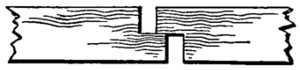
Fig. 17.—Joining Tunnel Struts
by Halving.
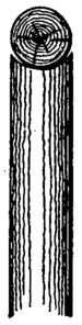
Fig. 18.—Round
Timber Post
and Cap Bearing.
TIMBER STRUTTING.
Timber is nearly always employed for strutting in tunnel
work. So long as it has the requisite strength, any kind of
timber is suitable for strutting, since, it being only temporarily
employed, its durability is a matter of slight importance.
Timber with good elastic properties, like pine or spruce, is
preferably chosen, since it yields gradually under stress, thus[48]
warning the engineer of the approach of danger; while oak and
other strong timbers resist until the last moment, and then
yield suddenly under the breaking load. Soft woods, moreover,
are usually lighter in weight than hard woods, which is a considerable
advantage where so much handling is required in
a restricted space. Round timbers are generally employed,
since they are less expensive, and quite as satisfactory in other
respects as sawed timbers. In the English and Austrian
methods of strutting, which are described further on, a few
of the principal struts are of sawed timbers.
The various timbers of the strutting are seldom
attached by framed joints, but wedges are used
to give them the necessary
bearing against each other.
Where framed joints are employed
they are made of the
simplest form usually by
halving the joining timbers, as shown by Fig. 17.
Fig. 18 shows a form of joint used where round
posts carry beams of similar shape. The reason why
it is possible to do away with jointed connections to such a
great extent, is that the strains which the timbers have to
resist are either compressive or bending strains, and because
the timbers are so short that they do not require to be spliced.
Strutting of Headings.
—The method of strutting the heading
that is employed depends upon the material through which
the heading is driven. In solid rock strutting may not be
required at all, or only for the purpose of preventing the
fall of loose blocks from the roof, then vertical props are
erected where required, or horizontal beams are inserted into
the side walls, as shown by Fig. 19. These horizontal beams
may be used singly at dangerous places, or they may be placed
from 2 ft. to 3 ft. apart all along the heading. In the latter
case they usually carry a lagging of planks, which may be
placed at intervals or close together, and filled above with[49]
stone in case the roof of the excavation is very unstable.
Planks used in this manner are usually called poling-boards.
Where the side walls as well as the roof require support,
vertical side posts are employed to carry the roof beams, as
shown by Fig. 20; and, when necessary, poling-boards are
inserted between these posts and the walls of the excavation.
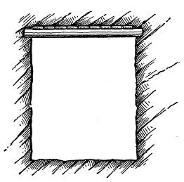
Fig. 19.—Ceiling Strutting for
Tunnel Roofs.
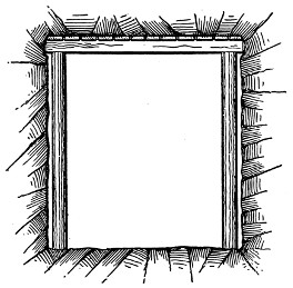
Fig. 20.—Ceiling Strutting with Side
Post Supports.
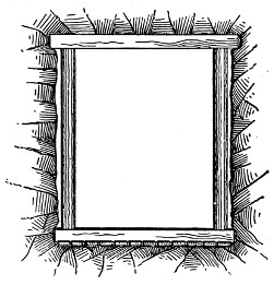
Fig. 21.—Sill, Side Post and Cap
Cross Frame Strutting.
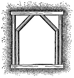
Fig. 22.—Reinforced Cross Frame
Strutting for Treacherous Materials.
Frame Strutting.
—In very loose soils not only the roof and
side walls, but also the floor of the heading require strutting.
In these cases frame strutting is employed, as shown by Fig.
21. It consists simply of a rectangular frame; at the top
there is a crown bar supported by two vertical side posts[50]
setting on a sill laid across the bottom of the heading. These
frames are spaced at close intervals, and carry longitudinal
planks or poling-boards. The sill of the frame is sometimes
omitted when the soil is stable enough to permit it, and in its
place wooden footing blocks are substituted to carry the side
posts. In soils where the pressures are great enough to bend
the crown bar, a secondary frame is employed, as shown by
Fig. 22, the two inclined roof members, or rafters, of which
support the crown bar at the center.
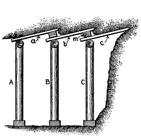
Fig. 23.—Longitudinal Poling-Board System
of Roof Strutting.
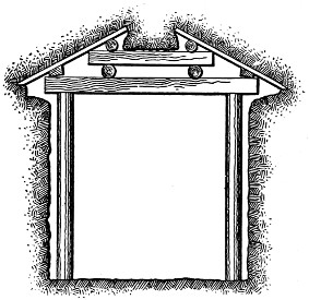
Fig. 24.—Transverse Poling-Board System
of Roof Strutting.
It is the more common practice in driving headings through
soft soils to use inclined poling-boards to support the roof.
Fig. 23 shows one method of doing this. The method of
operation is as follows: Assuming the poling-boards a and b
to be in place, and supported by the frames A, B, C, as shown,
the first step in continuation of the work is to insert the
poling-board c over the crown bar of frame C, and under the
block m. Excavation is then begun at the top, and as fast as
the soil is removed ahead of it the poling-board c is driven
ahead until its rear end only slightly overhangs the crown bar
of frame C. The remainder of the face of the heading is then
excavated nearly to the front end of the poling-board c, and
another frame is set up. By a succession of these operations[51]
the heading is advanced. The poling-boards at the sides of
the heading are placed in a similar manner to the roof poling-boards.
A second method of using inclined poling-boards is
shown by Fig. 24. Here the poling-boards run transversely,
and are supported by the arrangement of timbering shown.
The chief advantage of using these inclined poling-boards,
particularly in the manner shown by Fig. 23, is that the
excavators work under cover at all times, and are thus safe
from falling fragments or sudden cavings.
Box Strutting.
—In very treacherous soils, such as quicksand,
peat, and laminated clay, box strutting is commonly employed.
The method of building this strutting is to set up at
the face of the work a rectangular frame, and use it as a guide
in driving a lagging or boxing of horizontal planks into the
soft soil ahead. These planks have sharp edges, and are driven
to a distance of 2 ft. or 3 ft. into the face of the heading, so as
to inclose a rectangular body of earth. This earth is excavated
nearly to the ends of the planks, and then another frame is
inserted close up against the new face of the excavation, which
supports the planks so that the remainder of the earth included
by them may be removed. These two frames, with their plank
lagging, constitute a “box;” and a series of these boxes, one
succeeding another, form the strutting of the heading.
Strutting the Face.
—In some cases it is found necessary
to strut the face of the heading in order to prevent it from
caving in. This is generally done by setting plank vertically,
and bracing them up by means of inclined props whose feet
abut against the sill of the nearest cross frame. This strutting
is erected while the workmen are placing the side and roof
strutting, and is removed to permit excavation.
Full Section Timber Strutting.
—For strutting the full section
two forms of timbering are employed, known as the polygonal
system and the longitudinal system.
Longitudinal strutting consists of a timber structure so
arranged as to have all the principal members supporting the[52]
poling-boards parallel to the axis of the tunnel. This system
of strutting is peculiar to the English method of tunneling.
The longitudinal timbers rest on this finished masonry at one
end, and are carried on a cross frame or by props at the other
end. At intermediate points the longitudinals are braced
apart by struts in planes transverse to the tunnel axis. This
construction makes a very strong strutting framework, since
the transverse struts act as arch ribs to stiffen the longitudinals;
but the use of transverse poling-boards requires the
excavation of a larger cross-section than is necessary when longitudinal
poling-boards are employed, and this increases the
cost both for the amount of earth excavated and the greater
quantity of filling required.
In polygonal strutting the main members are in a plane
normal to the axis of the tunnel. They form a polygon whose
sides follow closely the sectional profile of the excavation.
These polygonal frames are placed at more or less short intervals
apart, and are braced together by short longitudinal struts
lying close to the sides of the excavation, and running from
one frame to the next, and also by longer longitudinal members
which extend over several frames. The polygonal system of
strutting is peculiar to the Austrian method of tunneling, and
is fully described in a succeeding chapter. One of its distinctive
characteristics is that
the poling-boards are inserted
parallel to the tunnel
axis. Polygonal strutting
is generally held to be
stronger than longitudinal
strutting under uniform
loads, but it is more liable
to distortion when the
loads are unsymmetrical.
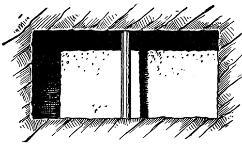
Fig. 25.—Shaft with Single Transverse
Strutting.
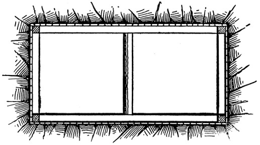
Fig. 26.—Rectangular Frame Strutting for Shafts.
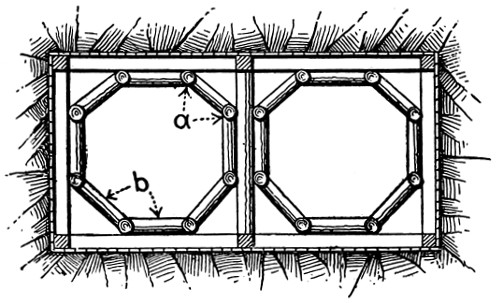
Fig. 27.—Reinforced Rectangular Frame Strutting
for Shafts in Treacherous Materials.
Strutting of Shafts.
—Tunnel shafts are strutted both to
prevent the caving-in of the sides and to divide them into[53]
compartments. When the material penetrated is very compact,
and caving is not likely, a single series of transverse struts, one
above the other, running from the top to the bottom of the
shaft, as shown by Fig. 25, is used to divide it into two compartments.
In softer material, where the sides of the shaft
require support, Fig. 26
shows a form of strutting
commonly employed. It
consists of vertical corner
posts braced apart at intervals
by four horizontal struts
placed close to the walls of
the shaft. The longer side
struts are also braced apart
at the center by a middle strut which divides the shaft into
two compartments. A lagging of vertical plank is placed
between the walls of the shaft and the horizontal side struts.
In very loose soils the form of strutting shown by Fig. 27 is
employed. This is practically the same construction as is
shown by Fig. 26, with the addition of an interior polygonal
horizontal bracing in each
half of the shaft. Referring
to Fig. 27, the timbers a, a,
etc., are vertical and continuous
from the top to the
bottom of the shaft; and
the horizontal timbers, b, b,
etc., are spaced at more or
less close intervals vertically.
The lagging planks
may be laid with spaces between them, or close together, or,
in case of very loose material, with their edges overlapping.
The manner of constructing the strutting is also governed by
the stability of the soil. In firm soils it is possible to sink the
shaft quite a depth without timbering, and the timbering can[54]
be erected in sections of considerable length, which is always
an advantage, but in loose soils the timbering has to follow
closely the excavation.
The solid wall shaft struttings which have been described
are discontinued at the point where the shaft intersects the
tunnel excavation; and from this point to the floor of the
tunnel an open timbering is employed, whose only duty is to
support the weight of the solid strutting above. This timbering
is made in various forms, but the most common is a timber
truss or arch construction which spans the tunnel section.
Quantity of Timber.
—The quantity of timber employed in
strutting a tunnel varies with the character of the material
through which the tunnel is excavated: it is small for solid-rock
tunnels, and large for soft-ground tunnels. In the Belgian
method of excavation a smaller quantity of timber is
used than in any of the other ordinary methods. For single-track
tunnels excavated by this method there will be needed
on an average about 3 to 31⁄3 cu. yds. of timber per lineal foot
of tunnel. Practical experience shows that about four-fifths of
the timber once used can be employed for the second time.
In any of the methods in which the whole tunnel section is
excavated at once, the average amount of timber required per
lineal foot is about 8.7 cu. yds. Of this amount about two-thirds
can be used a second time. In the Italian method, in
which the upper half and the lower half are excavated separately,
about 5 cu. yds. of timber are required per lineal foot of tunnel,
about one-half of which can be employed a second time. For
quicksand tunnels the amount of timbering required per lineal
foot varies from 3 to 5 cubic yds. Shaft strutting requires
from 1 to 11⁄2 cu. yds. of timber per lineal foot.
Dimensions of Timber.
—The dimensions of the principal members
composing the strutting of headings, full section, and
shafts, are given in Table I. The planks used for lagging
or the poling-boards are usually from 4 ins. to 6 ins. wide,
with a length depending upon the method of strutting employed.
[55]
TABLE I.
Showing Sizes of Various Timbers Used in Strutting Tunnels Driven
Through Different Materials.
| |
Rock. |
Soft Soils. |
| Hard. |
Soft. |
Com-
pact. |
Loose. |
Very
loose. |
| ins. |
ins. |
ins. |
ins. |
ins. |
| Headings: |
|
|
|
|
|
| Cap-pieces and vertical struts |
6 |
8 |
10 |
12 |
14 |
| Sills |
|
|
8 |
10 |
12 |
| Struts |
5 |
5 |
6 |
7 |
8 |
| Distance apart of the frames in feet |
6 |
4.5 |
3 |
2.6 |
2.6 |
| Strutting of the tunnel, longitudinal strutting: |
|
|
|
|
|
| Crown bars |
12 |
14 |
14 |
|
|
| Props vertical or inclined supporting the crown bars |
10 |
12 |
14 |
|
|
| Sills |
8 |
8 |
10 |
|
|
| Cap-pieces or saddles |
10 |
12 |
14 |
|
|
| Struts to stiffen the structure |
6 |
8 |
10 |
|
|
| Distance apart of the frames (in feet) |
4.5 |
4 |
3 |
|
|
| Polygonal strutting: |
|
|
|
|
|
| Cap-pieces and contour pieces |
8 |
10 |
12 |
14 |
16 |
| Vertical struts on top |
10 |
12 |
14 |
16 |
18 |
| Vertical struts below |
12 |
14 |
16 |
20 |
24 |
| Intermediate sills |
12 |
14 |
16 |
20 |
24 |
| Lower sills |
|
|
12 |
16 |
18 |
| Raking props |
10 |
10 |
10 |
12 |
12 |
| Distance apart of the frames (in feet) |
6 |
4.5 |
4 |
3 |
3 |
| Shafts: |
|
|
|
|
|
| Horizontal beams forming the frame |
8 |
8 |
10 |
12 |
14 |
| Transverse beams |
8 |
8 |
8 |
10 |
12 |
| Vertical struts between the frames |
8 |
8 |
10 |
12 |
12 |
| Struts to reënforce the frame |
|
6 |
8 |
8 |
8 |
| Distance apart of the strutting (in feet) |
6 |
4.5 |
4 |
3 |
2.6 |
IRON STRUTTING.
In 1862 Mr. Rziha employed old iron railway rails for
strutting the Naensen tunnel, and his example was successfully
followed in several tunnels built later where timber was scarce[56]
and expensive. The advantages which iron strutting is claimed
to possess over the more common wooden structure are: its
greater strength; the smaller amount of space which it takes
up; and the fact that it does not wear out, and may, therefore,
be used over and over again.
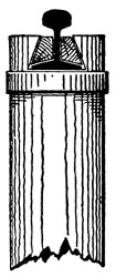
Fig. 28.—Strutting
of Timber
Posts and Railway
Rail Caps.
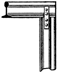
Fig. 29.—Strutting
made entirely of
Railway Rails.
Iron Strutting in Headings.
—In strutting the headings the
cross frames have a crown bar consisting of a section of old
railway rail carried either by wood or iron side posts. When
wooden side posts are used their
upper ends have a dovetail mortise,
and are bound with an iron
band, as shown by Fig. 28. The
base of the rail crown bar is set
into the dovetail mortise and
fastened by wedges. When iron
side posts are employed they
usually consist of sections of railway
rails, and the crown bar is
attached to them by fish-plate connections, as
shown by Fig. 29. The iron cross frames are set up as the
heading advances, and carry the plank lagging or poling-boards,
exactly in the same manner as the timber cross frames previously
described.
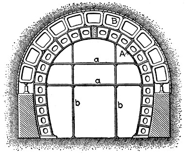
Fig. 30.—Rziha’s Combined Strutting and Centering
of Cast Iron.
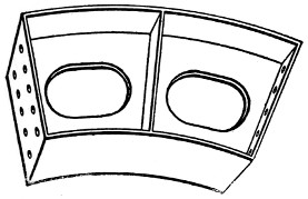
Fig. 31.—Cast-Iron Segment of Rziha’s
Strutting and Centering.
Full Section Iron Strutting.
—The iron strutting devised by
Mr. Rziha for full section work is shown by Fig. 30. Briefly
described, it consists of voussoir-shaped cast-iron segments,
which are built up in arch form. Fig. 31 shows the construction
of one of the segments, all of which are alike, with the
exception of the crown segment, which has a mortise and
tenon joint which is kept open by filling the mortise with sand.
The segments are bolted together by means of suitable bolt-holes
in the vertical flanges, and when fully connected form an
arch rib of cast iron. This arch rib, A, Fig. 30, carries a series
of angle or T-iron frames bent into approximately voussoir
shape, as shown at B, Fig. 30. Above these frames are inserted[57]
the poling-boards, running longitudinally, and spanning the
distance between consecutive arch ribs. By removing the bent
iron frames the cast-iron rib forms a center upon which to construct
the masonry. Finally,
to remove the cast-iron
rib itself, the sand
is drawn out of the mortise
and tenon joint in
the crown segment, which
allows the joint to close,
and loosen the segments
so that they are easily
unbutted.
The illustration, Fig.
30, shows longitudinal
poling-boards; more often
longitudinal crown bars
of railway rails span the space between connective arch ribs,
and support transverse poling-boards. In building the masonry,
work is begun at the bottom on each side, the bent iron frames
being removed one after another to give room for the masonry.
As each frame is removed, it is
replaced with a sort of screw-jack
to support the poling-boards
until the masonry is sufficiently
completed to allow their removal.
The interior bracing of the arch
rib shown at a a and b b consists
of railway rails carried by brackets
cast on to the segments. A
similar bracing of rails connects the successive arch ribs. These
lines of bracing serve to carry the scaffolding upon which the
masons work in building the lining.
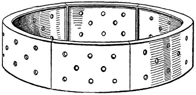
Fig. 32.—Cast-Iron Segmental Strutting for
Shafts.
Iron Shaft Strutting.
—In soft-ground shaft work, the use of
an iron strutting, consisting of consecutive cast-iron rings, has[58]
sometimes been employed to advantage. Fig. 32 shows the
construction of one of these rings, which, it will be seen, is composed
of four segments connected to each other by means of
bolted flanges. The holes shown in the circumferential web of
the ring are to allow for the seepage from the earth side walls.
The method of placing this
cylindrical strutting is to
start with a ring having a
cutting-edge. By means
of excavation inside the
ring, and by ramming,
the ring is sunk into the
ground a distance equal to
its height. Another ring
is then fastened by special hooks on top of the first one, and
the sinking continued until the second ring is down flush with
the surface. A third ring is then added, and so on until the
entire shaft is excavated and strutted. As in timber shaft
strutting, the solid iron ring strutting is carried down only to
the top of the tunnel section, and below this point there is an
open timber or iron supporting framework.
[59]
CHAPTER VI.
METHODS OF HAULING IN TUNNELS.
The transportation from one point to another within the
tunnel and its shafts of any material, whether it is excavated
spoil or construction material, is defined as hauling. In all
engineering construction, the transportation of excavated
materials, and materials for construction, constitutes a very
important part of the expense of the work; but hauling in
tunnels where the room is very limited, and where work is
constantly in progress over and at the sides of the track, is a
particularly expensive process. Hauling in tunnels may be
done either by way of the entrances, or by way of the shafts,
or by way of both the entrances and shafts.
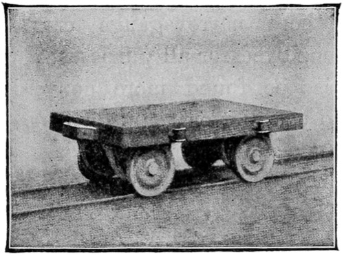
Fig. 33.—Platform Car for Tunnel Work.
Hauling by Way of Entrances.
—When the hauling is done
by the way of the entrances, the materials to be hauled are
taken directly from the point
of construction to the entrances,
or in the opposite direction,
by means of special
cars of different patterns. For
general purposes, these different
patterns of cars may be
grouped into three classes,—platform-cars,
dump-cars, and
box-cars. Representative examples
of these several classes
of cars are shown in Figs. 33 to
36[6] inclusive, but it will be
readily understood that there are many other forms.
Briefly described, platform-cars (Fig. 33) consist of a[60]
wooden platform mounted on tracks, and they are usually employed
for the transportation of timber, ties, etc. Dump-cars
are used in greater numbers in tunnel work than any other
form. Fig. 34 shows a dump-car of metal construction, and
Fig. 35 one constructed with a metal
under-frame and wooden box. These
cars are made to run on narrow-gauge
tracks, and usually have a capacity of
about one to one and one-half cubic
yards. Box-cars are more extensively
employed in Europe for tunnel work
than in America. Fig. 36 shows a
typical European box-car for tunnel
work. It is made either to run on narrow-gauge or standard-gauge
tracks.
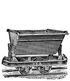
Fig. 34.—Iron Dump-Car for
Tunnel Work.
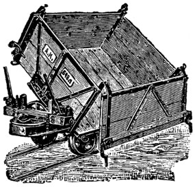
Fig. 35.—Wooden Dump-Car for Tunnel
Work.
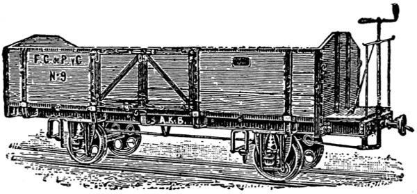
Fig. 36.—Box-Car for Tunnel Work.
It is usually desirable in tunnel work to employ cars of
different forms for different parts of the work. In rock
tunnels it is a common practice to use narrow-gauge cars of
small size in the headings, and
larger, broad-gauge cars for the
enlargement of the profile.
Where narrow-gauge cars are
employed for all purposes, it will
also be found more convenient
to use platform-cars for handling
the construction material, and
dump-cars for removing the spoil.
The extent to which it is desirable
to use cars of different forms
will depend upon the character
and conditions of the work, and particularly upon how far it is
possible to install the permanent track.
As a general ride, it is considered preferable to lay the
permanent tracks at once, and do all the hauling upon them,
so that as soon as the tunnel is completed, trains may pass[61]
through without delay. To what extent this may be done, or
whether it can be done at all or not, depends upon the method
of excavation and other local conditions. In soft-ground
tunnels excavated by the English or Austrian methods,
it is quite possible to lay the permanent tracks at first, since
the whole section is excavated at once, and the excavation is
kept but a little ahead of the completed tunnel. In rock
tunnels, where the heading is driven far ahead of the completed
section, it is, of course, impossible to keep the permanent
track close to the advance work, and narrow-gauge tracks
must be laid in the heading. The same thing is true in soft-ground
tunnels driven by successive headings and drifts. In
these cases, therefore,
where narrow-gauge
tracks have to be used
for some portions of
the work anyway, the
question comes up
whether it is preferable
to use temporary
narrow-gauge tracks throughout, or to lay the permanent track
as far ahead as possible, and then extend narrow-gauge tracks
to the advance excavation. In the latter case it will, of course,
be necessary to trans-ship each load from the narrow-gauge to
the standard-gauge cars, or vice versa, which means extra cost
and trouble. To avoid this, the method is sometimes adopted
of laying a third rail between the standard-gauge rails, so that
either standard- or narrow-gauge cars may be transported over
the line. Whatever form the local conditions may require the
system of construction tracks to assume, it may be set down as
a general rule that the permanent tracks should be kept as far
advanced as possible, and temporary tracks employed only
where the permanent tracks are impracticable.
The motive power employed for hauling in tunnels may be
furnished by animals or by mechanical motors. Animal power[62]
is generally employed in short tunnels and in the advance
headings and galleries. In long tunnels, or where the excavated
material has to be transported some distance away from
the tunnel, mechanical power is preferable, for obvious reasons.
The motors most used are small steam locomotives, special
compressed-air locomotives, and electric motors. Compressed
air and electric locomotives are built in various forms, and are
particularly well adapted for tunnel work because of their
small dimensions, and freedom from smoke and heat.
Hauling by Way of Shafts.
—When the excavated material
and materials of construction are handled through shafts, the
operation of hauling may be divided into three processes:
the transportation of the materials along the floor of the
tunnel, the hoisting of them through the shaft, and the surface
transportation from and to the mouth of the shaft. These
three operations should be arranged to work in harmony with
each other, so as to avoid waste of time and unnecessary handling
of the materials. An endeavor should be made to avoid,
if possible, breaking or trans-shipping the load from the time
it starts at the heading until it is dumped at the spoil bank.
This can be accomplished in two ways. One way is to hoist
the boxes of the cars from their trucks at the bottom of the
shaft, and place them on similar trucks running on the surface
tracks. The other way is to run the loaded cars on to the elevator
platform at the bottom, hoist them, and then run them
on to the surface tracks. If the first method is employed, the
car box is usually made of metal, and is provided at its top
edges with hooks or ears to which to attach the hoisting cables.
When the second method is used, the elevator platform has
tracks laid on it which connect with the tracks on the tunnel
floor, and also with those on the surface.
Hoisting Machinery.
—The machines most commonly employed
for hoisting purposes in tunnel shafts are steam hoisting
engines, horse gins, and windlasses operated by hand. Windlasses
and horse gins are rather crude machines for hoisting[63]
loads, and are used only in special circumstances, where the
shaft is of small depth, when the amount of material to be
hoisted is small, or where for any reason the use of hoisting
engines is precluded. The steam hoisting engine is the standard
machine for the rapid lifting of heavy vertical loads.
Recently oil engines and electric hoists have also come to be
used to some extent, and under certain conditions these machines
possess notable advantages.
The construction of hand windlasses is familiar to every one.
In tunnel work this device is located directly over the shaft,
with its axis a little more than half a man’s height, so that the
crank handle does not rise above the shoulder line. To develop
its greatest efficiency the hoisting rope is passed around the
windlass drum so that the two ends hang down the shaft, and
as one end descends the other ascends. A skip, or bucket, is
attached to each of the rope ends; and by loading the descending
skip with construction materials and the ascending skip
with spoil, the two skip loads tend to balance each other, thus
increasing the capacity of the windlass, and decreasing the
manual labor required to operate it. Skips varying from 0.3
cu. yd. to 0.5 cu. yd. are used. The horse gin consists of a
vertical cylinder or drum provided with radial arms to which
the horses are hitched, which revolve the cylinder by walking
around it in a circle. The hoisting rope is rove around the
drum so that the two ends extend down the shaft with skips
attached, as described in speaking of the hand windlass. The
power of the horse gin is, of course, much greater than that of a
windlass operated by hand, skips of 1 cu. yd. capacity being
commonly used. Horse gins are no longer economical hoisting
machines, according to one prominent authority, when V(H
+ 20) > 5000, where V equals the volume of material to
be hoisted, and H equals the height of the hoist, the weight of
the excavated material being 2100 lbs. per cu. yd. As a general
rule, however, it is assumed that it is not economical to
employ horse gins with a depth of shaft exceeding 150 ft.
[64]
As already stated, the most efficient and most commonly
used device for hoisting at tunnel shafts is the steam hoisting
engine. There are numerous builders of hoisting engines, each
of which manufactures several patterns and sizes of engines.
In each case, however, the apparatus consists of a boiler supplying
steam to a horizontal engine which operates one or more
rope drums. The engines are always reversible. They may
be employed to hoist the skips directly, or to operate elevators
upon which the skips or cars are loaded. In either case the
hoisting ropes pass from the engine drum to and around vertical
sheaves situated directly over the shaft so as to secure the
necessary vertical travel of the ropes down the shaft. Where
the shaft is divided into two compartments, each having an elevator
or hoist, double-drum engines are employed, one drum
being used for the operations in one compartment, and the other
for the operations in the other compartment. Where the work
is to be of considerable duration, or when it is done in cold
weather, more or less elaborate shelters or engine houses are
built to cover and protect the machinery.
Choice between the method of hoisting the skips directly,
and the method of using elevators, depends upon the extent and
character of the work. Where large quantities of material are
to be hoisted rapidly, it is generally considered preferable to
employ elevators instead of hoisting the skips directly. In
direct hoisting at high speed, oscillations are likely to be produced
which may dash the skips against the sides of the shaft
and cause accidents. The loads which can be carried in single
skips are also smaller than those possible where elevators are
used; and this, combined with the slower hoisting speed required,
reduces the capacity of this method, as compared with the use
of elevators. Where elevators are employed, however, the plant
required is much more extensive and costly; it comprising not
only the elevator cars with their safety devices, etc., but the
construction of a guiding framework for these cars in the tunnel
shaft. For these various reasons the elevator becomes the[65]
preferable hoisting device where the quantity of material to be
handled is large, where the shafts are deep, and where the work
will extend over a long period of time; but when the contrary
conditions are the case, direct hoisting of the skips is generally
the cheaper. The engineer has to integrate the various factors
in each individual case, and
determine which method will
best fulfill his purpose, which
is to handle the material at
the least cost within the
given time and conditions.
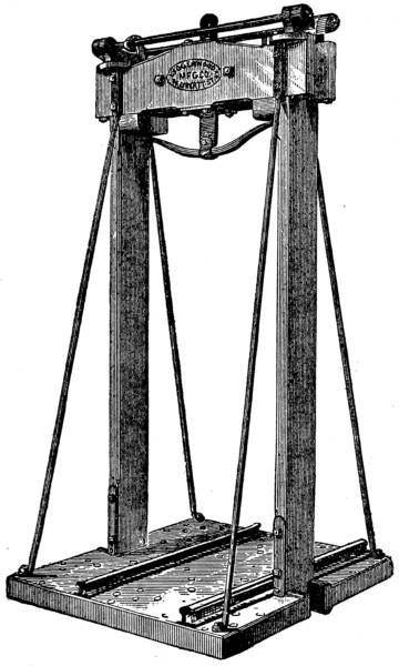
Fig. 37.—Elevator Car for Tunnel Shafts.
The construction of elevators
for tunnel work is
simple. The elevator car
consists usually of an open
framework box of timber and
iron, having a plank floor on
which car tracks are laid,
and its roof arranged for
connecting the hoisting cable
(Fig. 37[7]). Rigid construction
is necessary to resist the
hoisting strains. The sides
of the car are usually designed
to slide against timber
guides on the shaft walls.
Some form of safety device,
of which there are several kinds, should be employed to prevent
the fall of the elevator, in case the hoisting rope breaks,
or some mishap occurs to the hoisting machinery, which endangers
the fall of the car. Speaking tubes and electric-bell
signals should also be provided to secure communication between
the top and bottom of the shaft.
[66]
CHAPTER VII.
TYPES OF CENTERS AND MOLDS EMPLOYED
IN CONSTRUCTING TUNNEL LININGS
OF MASONRY.
The masonry lining of a tunnel may be described as consisting
of two or more segments of circular arches combined
so as to form a continuous solid ring of masonry. To direct
the operations of the masons in constructing this masonry
ring, templates or patterns are provided which show the exact
dimensions and form of the sectional profile which it is desired
to secure. These patterns or templates will vary in
number and construction with the form of lining and the
method of excavation adopted. Where the excavation is fully
lined on all four sides, the masonry work is usually divided
into three parts,—the invert or floor masonry, the side-wall
masonry, and the roof-arch masonry. At least one separate
pattern has to be employed in constructing each of these parts
of the lining; and they are known respectively as ground
molds, leading frames, and arch centers, or simply centers. In
the following paragraphs the form and construction usually
employed for each of these three kinds of patterns is described.
Ground Molds.
—Ground molds are employed in building the
tunnel invert. They are generally constructed of 3-inch plank
cut exactly to the form and dimensions of the invert masonry
as shown in Fig. 38. To permit of convenience of handling in
a restricted space, they are generally made in two parts, which
are joined at the middle by means of iron fish-plates and bolts.
Either one or two ground molds may be employed. Where two[67]
molds are used they are set up a short distance apart, and cords
are stretched from one to the other parallel to the axis of the
tunnel, by which the masons are guided in their work. Extreme
care has to be taken in
setting the molds to ensure that
they are fixed at the proper
grade, and are in a plane normal
to the axis of the tunnel. Where
only one ground mold is employed, the finished masonry is
depended upon to supply the place of the second mold, cords
being stretched from it to the single mold placed the requisite
distance ahead. The leveling and centering of the molds is accomplished
by means of transit and level.
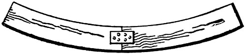
Fig. 38.—Ground Mold for Constructing
Tunnel Invert Masonry.
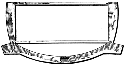
Fig. 39.—Combined Ground Mold and Leading Frame
for Invert and Side Wall Masonry.
Two modifications of the form of ground mold shown by
Fig. 39 are employed. The first modification is peculiar to
the English method of
excavation, and consists
in combining the ground
mold with the leading
frame for the lower part
of the side walls, as
shown by Fig. 39. The
second modification is
employed where the two
halves or sides of the
invert are built separately, and it consists simply in using one-half
of the mold shown by Fig. 38. When the last method of
constructing the invert masonry is resorted to, extreme care has
to be observed in setting the half-mold in order to avoid error.
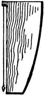
Fig. 40.—Leading
Frame for
Constructing
Side Wall Masonry.
Leading Frames.
—As already stated, leading frames are the
patterns, or molds, used in building the side walls of the lining.
Like the ground mold they are usually built of plank; one
side being cut to the curve of the profile, and the other being
made parallel to the vertical axis of the tunnel section. The
vertical side usually has some arrangement by which a plumb[68]
bob can be attached, as shown by Fig. 40, to guide the workmen
in erecting the frame. The combined leading frame and
ground mold shown in Fig. 39 has already been described.
The use of this frame is possible only where the
masonry is begun at the invert and carried up on
each side at the same time. This mode of construction
is peculiar to the English method of
tunneling; in all other methods the form of separate
ground frame shown by Fig. 40 is employed.
The ground frames are lined in and leveled up by
transit and level; and, as in setting the ground
frames, care must be taken to secure accuracy in
both direction and elevation.
Arch Centers.
—The template or form upon which the roof
arch is built is called a center. Unlike the ground molds and
leading frames, the arch centers have to support the weight of
the masonry and the roof pressures during the construction of
the lining, and they, therefore, require to be made strong.
Owing to the fact that the pressures are indeterminate, it is
impossible to design a rational center, and resort is had to those
constructions which past experience has shown to work satisfactorily
under similar conditions. In a general way it can
always be assumed that the construction should be as simple
as possible, that the center should be so designed that it can
be set up and removed with the least possible labor, and that
the different pieces of the framework and lagging should be as
short as possible, for convenience in handling.
Tunnel centers are usually composed of two parts,—a mold
or curved surface upon which the masonry rests, and a framework
which supports the mold. The curved surface or mold
consists of a lagging of narrow boards running parallel to the
tunnel axis, which rests upon the arched top members of two
or more consecutive supporting frames. The supporting frame
is built in the form of a truss, and must be made strong enough
to withstand the heavy superimposed loads, consisting of the[69]
arch masonry during construction, and of the roof pressures
which are transferred to the center when the strutting is
removed to allow the masonry to be placed. The framework
of the center is supported either by posts resting upon the floor
of the excavation, or upon the invert masonry when this is
built first, as in the English and Austrian methods, or it may
be supported directly upon the ground where the arch masonry
is built first, as in the Belgian method of tunneling.
In describing the various methods of tunneling in succeeding
chapters, the center construction and method of supporting
the center peculiar to each will be fully explained, and only a
few general remarks are necessary here. Centers may be classified
according to their construction and composition into plank
centers, truss centers, and iron centers.
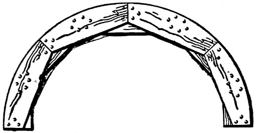
Fig. 41.—Plank Center for Constructing
the Roof Arch.
One of the most common forms of plank centers is shown
by Fig. 41. It consists of two
half-polygons whose sides consist
of 15 in. × 4 ft. planks having
radial end-joints. These two half-polygons
are laid one upon the
other so that they break joints, as
shown by the figure, and the extrados
of the frame is cut to the
true curve of the roof arch. The planks commonly used for
making these centers are 4 ins. thick, making the total thickness
of the center 8 ins. Plank centers of the construction
described are suitable only for work where the pressures to be
resisted are small, as in tunnels through a fairly firm rock, although
there have been instances of their successful use in soft-ground
tunnels.
Where heavy loads have to be carried, trussed centers are
generally employed, the trusses being composed of heavy square
beams with scarfed and tenoned joints, reinforced by iron plates.
Different forms of trusses are employed in each of the different
methods of tunneling, and each of these is described in succeeding[70]
chapters; but they are generally either of the king-post
or queen-post type, or some modification of them. The king-post
truss may be used alone, with
or without the tie-beam, as shown
by Fig. 42; but generally a queen-post
truss is made to form the
base of support for a smaller king-post
truss mounted on its top.
This arrangement gives a trapezoidal
form to the center, which approaches closely to the arch
profile. Owing to the character of the pressures transmitted to
the center, the usual tension members can be made very light.
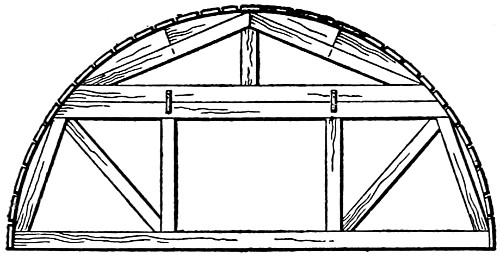
Fig. 42.—Trussed Center for Constructing
the Roof Arch.
The combined center and strutting system devised by Mr.
Rziha has already been described in a previous chapter. In
recent European tunnel work quite extensive use has also been
made of iron centers consisting of several segments of curved
I-beams, connected by fish-plate joints so as to form a semi-circular
arch rib. The ends or feet of these I-beam ribs have
bearing-plates or shoes made by riveting angles to the I-beams.
Centers constructed in a similar manner, but made of sections
of old railway rail, were used in carrying out the tunnel work
on the Rhine River Railroad in Germany. The advantages
claimed for iron centers are that they take up less room, and
that they can be used over and over again.
Setting Up Centers.
—According to the method of excavation
followed in building the tunnel, the centers for building
the roof arch may have to be supported by posts resting on the
tunnel floor; or where the arch is built first, as in the Belgian
and Italian methods, they may be carried on blocking resting
on the unexcavated earth below. Whichever method is employed,
an unyielding support is essential, and care must be
taken that the centers are erected and maintained in a plane
normal to the tunnel axis. To prevent deflection and twisting,
the consecutive centers are usually braced together by longitudinal
struts or by braces running to the adjacent strutting.[71]
Only skilled and experienced workmen should be employed in
erecting the centers; and they should work under the immediate
direction of the engineer, who must establish the axis and
level of each center by transit and level.
Lagging.
—By the lagging is meant the covering of narrow
longitudinal boards resting upon the upper curved chords of the
centers, and spanning the opening between consecutive centers.
This lagging forms the curved surface or mold upon which the
arch masonry is laid. When the roof arch is of ashlar masonry
the strips of lagging are seldom placed nearer together than
the joints of the consecutive ring stones, but in brick arches
they are laid close together. Besides the weight of the arch
masonry, the lagging timbers support the short props which
keep the poling-boards in place after the strutting is removed
and until the arch masonry is completed.
Striking the Centers.
—The centers are usually brought to
the proper elevation by means of wooden wedges inserted between
the sill of the center and its support, or between the
bottom of the posts carrying the center and the tunnel floor.
These wedges are usually made of hard wood, and are about
6 ins. wide by 4 ins. thick by 18 ins. long. To strike the center
after the arch masonry is completed, these wedges are withdrawn,
thus allowing the center to fall clear of the masonry.
Usually the center is not removed immediately after striking,
so that if the arch masonry fails the ruins will remain upon the
center. The method of striking the iron center devised by Mr.
Rziha has been described in the previous chapter on strutting.
[72]
CHAPTER VIII.
METHODS OF LINING TUNNELS.
Tunnels in soft soils and in loose rock, and rock liable to
disintegration, are always provided with a lining to hold the
walls and roof in place. This lining may cover the entire
sectional profile of the tunnel, or only a part of it, and it may
be constructed of timber, iron, iron and masonry, or, more
commonly, of masonry alone.
Timber Lining.
—Timber is seldom employed in lining
tunnels except as a temporary expedient, and is replaced by
masonry as soon as circumstances will permit. In the first
construction of many American railways, the necessity for
extreme economy in construction, and of getting the line open
for traffic as soon as possible, caused the engineers to line
many tunnels with timber, which was plentiful and cheap.
Except for their small cost and the ease and rapidity with
which they can be constructed, however, these timber linings
possess few advantages. It is only the matter of a few years
when the decay of the timber makes it necessary to rebuild
them, and there is always the serious danger of fire. In
several instances timber-lined tunnels in America have been
burned out, causing serious delays in traffic, and necessitating
complete reconstruction. Usually this reconstruction has consisted
in substituting masonry in place of the original timber
lining. In a succeeding chapter a description will be given of
some of the methods employed in replacing timber tunnel
linings with masonry. Various forms of timber lining are
employed, of which Fig. 44 and the illustrations in the
chapter[73]
discussing the methods of relining timber-lined tunnels with
masonry are typical examples.
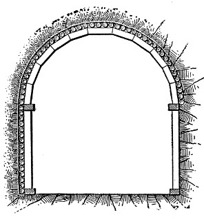
Cross Section.
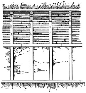
Longitudinal Section.
Figs. 43 and 44.—A
Typical Form of Timber Lining for Tunnels.
Iron Lining.
—The use of iron lining for tunnels was introduced
first on a large scale by Mr. Peter William Barlow in
1869, for the second tunnel under the River Thames at
London, England, and it has greatly extended since that time.
The lining of the second Thames tunnel consisted of cylindrical
cast-iron rings 8 ft. in diameter, the abutting edges of the
successive rings being flanged and provided with holes for
bolt fastenings. Each ring was made up of four segments,
three of which were longer than quadrants, and one much
smaller forming the “key-stone” or closing piece. These
segments were connected to each other by flanges and bolts.
To make the joints tight, strips of pine or cement and hemp
yarn were inserted between the flanges. Since the construction
of the second Thames tunnel, iron lining has been employed
for a great many submarine tunnels in England,
Continental Europe, and America, some of them having a
section over 28 ft. in diameter. Where circular iron lining is
employed, the bottom part of the section is leveled up with
concrete or brick masonry to carry the tracks, and the whole[74]
interior of the ring is covered with a cement plaster lining
deep enough thoroughly to embed the interior joint flanges.
In the succeeding chapter describing the methods of driving
tunnels by shields several forms of iron tunnel lining are fully
described.
Iron and Masonry Lining.
—During recent years a form of
combined masonry and iron lining has been extensively employed
in constructing city underground railways in both
Europe and America. Generally this form of lining is built
with a rectangular section. Two types of construction are
employed. In the first, masonry side walls carry a flat roof
of girders and beams, which carry a trough flooring filled with
concrete, or between which are sprung concrete or brick arches.
Sometimes the roof framing consists of a series of parallel
I-beams laid transversely across the tunnel, and in other cases
transverse plate girders carry longitudinal I-beams. In the
second type of construction the roof girders are supported by
columns embedded in the side walls. Where the tunnel provides
for two or four tracks, intermediate column supports are
in some cases introduced between the side columns. In this
construction the roofing consists of concrete filled troughs or of
concrete or brick arches, as in the construction first described.
Examples of combined masonry and iron tunnel lining are
illustrated in the succeeding chapter on tunneling under city
streets.
Masonry Lining.
—The form of tunnel lining most commonly
employed is brick or stone masonry. Concrete and reinforced
concrete masonry lining has been employed in several tunnels
built in recent years. The masonry lining may inclose the whole
section or only a part of it. The floor or invert is the part most
commonly omitted; but sometimes also the side walls and invert
are both omitted, and the lining is confined simply to an arch
supporting the roof. The roof arch, the side walls, and the invert
compose the tunnel lining; and all three may consist of stone or
brick alone, or stone side walls may be employed with brick invert[75]
and roof arch. Rubble-stone masonry is usually employed,
except at the entrances, where the masonry is exposed to view.
Here ashlar masonry is usually used. The stone selected for
tunnel lining should be of a durable quality which weathers
well. Where bricks are used they should be of good quality.
Owing to the comparative ease with which brick arches
can be built, they are generally used to form the roof arch, even
where the side walls are of stone masonry. Masonry lining
may be built in the form of a series of separate rings, or in the
form of a continuous structure extending from one end of the
tunnel to the other. The latter method of construction produces
a stronger structure; but in case of failure by crushing,
the damage done is likely to be more widespread than
where separate rings are employed, one or two of which
may fail without injury to the others adjacent to them. The
construction is also somewhat simpler where separate rings are
employed, since no provision has to be made for bonding the
whole lining into a continuous structure. Where a series of
separate rings is employed, the length of each ring runs from
5 ft. up to 20 ft., it depending upon the character of the
material penetrated, and the method of construction employed.
For the purpose of detailed discussion the construction of
masonry lining may be divided into four parts,—the side-wall
foundations, the side walls themselves, the roof arch, and the
invert.
Concrete and reinforced concrete linings are now extensively
used on account of cheapness and facility of handling, but they
have the great disadvantage of resisting pressure after they
become hard, which is some time after being placed. The
strutting should, therefore, be left to support the roof so as to
prevent direct pressure on the fresh material. The roof, as a
rule, is supported by longitudinal planks held in position by
five or seven segments of arched frames placed across the tunnel.
A large quantity of timber and carpenter work is thus entirely
wasted and these costly items, in many cases, make the concrete[76]
lining of a tunnel more expensive than the one built of brick
and stone. To avoid these inconveniences tunnels have been
successfully lined with concrete on the side walls and concrete
blocks in the arches. These blocks have been built by hand
and molded in the shape of the arch voussoirs.
Foundations.
—In tunnels through rock of a hard and durable
character the foundations for the side walls are usually
laid directly on the rock. In loose rock, or rock liable to disintegration,
this method of construction is not generally a safe
one, and the foundation excavation should be sunk to a depth
at which the atmospheric influences cannot affect the foundation
bed. In either case the foundation masonry is made
thicker than that of the side walls proper, so as to distribute
the pressure over a greater area, and to afford more room for
adjusting the side-wall masonry to the proper profile. In
yielding soils a special foundation bed has to be prepared for
the foundation masonry. In some instances it is found sufficient
to lay a course of planks upon which the masonry is constructed,
but a more solid construction is usually preferred.
This is obtained by placing a concrete footing
from 1 ft. to 2 ft. deep all along the
bottom of the foundation trench, or in some
cases by sinking wells at intervals along the
trench and filling them with concrete, so as
to form a series of supporting pillars.
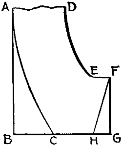
Fig. 45.—Diagram
Showing Forms
Adopted for Side-Wall
Foundations.
The form given to the foundation courses
and lower portions of the side walls varies.
Where a large bearing area is required, the
back of the wall is carried up vertically as
shown by the line AB, Fig. 45, otherwise the
rear face of the wall follows the line of excavation AC. For
similar reasons the front face of the wall may be made vertical,
as at FG, or inclined, as at FH. The line FE indicates the shelf
construction designed to support the feet of the posts used to
carry the arch centers during the construction of the roof arch.
[77]
Side Walls.
—The construction of the side walls above the
foundation courses is carried out as any similar piece of masonry
elsewhere would be built. To direct the work and insure
that the inner faces of the walls follow accurately the curve
of the chosen profile, leading frames previously described are
employed.
Roof Arch.
—For the construction of the roof arch, the
centers previously described are employed. Beginning at the
edges of the center on each side, the masonry is carried up a
course at a time, care being taken to have it progress at the
same rate on both sides, so that the load brought onto the
centering is symmetrical. As soon as the centers are erected,
the roof strutting is removed, and replaced by short props
which rest on the lagging of the centers and support the poling-boards.
These props are removed in succession as the arch
masonry rises along the curve of the center, and the space
between the top of the arch masonry and the ceiling of the
excavation is filled with small stones packed closely. The keystone
section of the arch is built last, by inserting the stones or
bricks from the front edge of the arch ring, there being no room
to set them in from the top, as is the practice in ordinary open-arch
construction. The keying of the arch is an especially
difficult operation, and only experienced men skilled in the
work should be employed to perform it. The task becomes
one of unusual difficulty when it becomes necessary to join the
arches coming from opposite directions.
Invert.
—In all but one or two methods of tunneling, the
invert is the last portion of the lining to be built. In the English
method of tunneling, the invert is the first portion of the lining
to be built, and the same practice is sometimes necessary in
soft soils where there is danger of the bottoms of the side walls
being squeezed together by the lateral pressures unless the
invert masonry is in place to hold them apart. The ground
molds previously described are employed to direct the construction
of the invert masonry.
[78]
General Observations.
—In describing the construction of the
roof arch, mention was made of the stone filling employed
between the back of the masonry ring and the ceiling of the
excavation. The spaces behind the side walls are filled in a
similar manner. The object of this stone filling, which should
be closely packed, is to distribute the vertical and lateral pressures
in the walls of the excavation uniformly over the lining
masonry. As the masonry work progresses, the strutting employed
previously to support the walls of the excavation has
to be removed. This work requires care to prevent accident,
and should be placed in charge of experienced mechanics who
are familiar with its construction, and can remove it with the
least damage to the timbers, so that they may be used again,
and without causing the fall of the roof or the caving of the
sides by removing too great a portion of the timbers at one
time.
Thickness of Lining Masonry.
—It is obvious, of course, that
the masonry lining must be thick enough to support the pressure
of the earth which it sustains; but, as it is impossible to
estimate these pressures at all accurately, it is difficult to say
definitely just what thickness is required in any individual case.
Rankine gives the following formulas for determining the depths
of keystone required in different soils:
For firm soils
and for soft soils,
where d = the depth of the crown in feet, r = the rise of the
arch in feet, and s = the span of the arch in feet. Other writers,
among them Professor Curioni, attempt to give rational methods
for calculating the thickness of tunnel lining; but they are
all open to objection because of the amount of hypothesis required[79]
concerning pressures which are of necessity indeterminate.
Therefore, to avoid tedious and uncertain calculations,
the engineer adopts dimensions which experience has proven to
be ample under similar conditions in the past. Thus we have
all gradations in thickness, from hard-rock tunnels requiring
no lining, and tunnels through rocks which simply require a
thin shell to protect them from the atmosphere, to soft-ground
tunnels where a masonry lining 3 ft. or more in thickness is
employed. Table II. shows the thickness of masonry lining
used in tunnels through soft soils of various kinds.
The thickness of the masonry lining is seldom uniform at
all points, as is indicated by Table II. Figs. 46 and 47 show
common methods of varying the thickness of lining at different
points, and are self-explanatory.
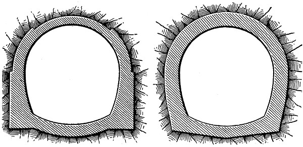
Figs. 46 and 47.—Transverse
Sections of Tunnels Showing Methods of Increasing the Thickness
of the Lining at Different Points.
Side Tunnels.
—When tunnels are excavated by shafts located
at one side of the center line, short side tunnels or galleries are
built to connect the bottoms of the shafts with the tunnel proper.
These side tunnels are usually from 30 ft. to 40 ft. long, and
are generally made from 12 ft. to 14 ft. high, and about 10 ft.
wide. The excavation, strutting, and lining of these side tunnels
are carried on exactly as they are in the main tunnel, with[80]
such exceptions as these short lengths make possible. Table
III. gives the thickness of lining used for side tunnels, the
figures being taken from European practice.
Culverts.
—The purpose of culverts in tunnels is to collect
the water which seeps into the tunnel from the walls and shafts.
The culvert is usually located along the center line of the tunnel
at the bottom. In soft-ground tunnels it is built of masonry,
and forms a part of the invert, but in rock tunnels it is the
common practice to cut a channel in the rock floor of the excavation.
Both box and arch sections are employed for culverts.
The dimensions of the section vary, of course, with the amount
of water which has to be carried away. The following are the
dimensions commonly employed:
Kind of
Culvert. |
Height
in Feet. |
Width
in Feet. |
Thickness
of Walls
in Feet. |
Thickness
of Covering
in Feet. |
| Box culvert |
1 to 1.5 |
1 to 1.5 |
0.8 to 1.2 |
0.3 |
| Arch culvert |
1 to 1.5 |
1 to 1.5 |
0.8 to 1.2 |
0.4 |
It should be understood that the dimensions given in the
table are those for ordinary conditions of leakage; where larger
quantities of water are met with, the size of the culverts has,
of course, to be enlarged. To permit the water to enter the
culvert, openings are provided at intervals along its side; and
these openings are usually provided with screens of loose stones
which check the current, and cause the suspended material to
be deposited before it enters the culvert. In cases where springs
are encountered in excavating the tunnel, it is necessary to
make special provisions for confining their outflow and conducting
it to the culvert. In all cases the culverts should be
provided with catch basins at intervals of from 150 ft. to 300
ft., in which such suspended matter as enters the culverts is
deposited, and removed through covered openings over each
basin. At the ends of the tunnel the culvert is usually divided[81]
into two branches, one running to the drain on each side of the
track.
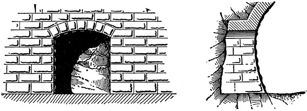
Fig. 48.—Refuge Niche in St. Gothard Tunnel.
Niches.
—In short tunnels niches are employed simply as
places of refuge for trackmen and others during the passing of
trains, and are of small size. In long tunnels they are made
larger, and are also employed as places for storing small tools
and supplies employed in the maintenance of the tunnel. Niches
are simply arched recesses built into the sides of the tunnel,
and lined with masonry; Fig. 48 shows this construction quite
clearly. Small refuge niches are usually built from 6 ft. to
9 ft. high, from 3 ft. to 6 ft. wide, and from 2 ft. to 3 ft. deep.
Large niches designed for storing tools and supplies are made
from 10 ft. to 12 ft. high, from 8 ft. to 10 ft. wide, and from
18 ft. to 24 ft. deep, and are provided with doors. Refuge
niches are usually spaced from 60 ft. to 100 ft. apart, while
the larger storage niches may be located as far as 3000 ft. apart.
The niche construction shown by Fig. 48 is that employed on
the St. Gothard tunnel.
Entrances.
—The entrances, or portals, of tunnels usually
consist of more or less elaborate masonry structures, depending
upon the nature of the material penetrated. In soft-ground
tunnels extensive wing walls are often required to support the
earth above and at the sides of the entrance; while in tunnels
through rock, only a masonry portal is required, to give a finish
to the work. Often the engineer indulges himself in an elaborate
architectural design for the portal masonry. There is[82]
danger of carrying such designs too far for good taste unless
care is employed; and on this matter the writer can do no better
than to quote the remarks of the late Mr. Frederick W. Simms
in his well-known “Practical Tunneling”:
“The designs for such constructions should be massive to be suitable as
approaches to works presenting the appearance of gloom, solidity, and
strength. A light and highly decorated structure, however elegant and well
adapted for other purposes, would be very unsuitable in such a situation; it
is plainness combined with boldness, and massiveness without heaviness,
that in a tunnel entrance constitutes elegance, and, at the same time, is the
most economical.”
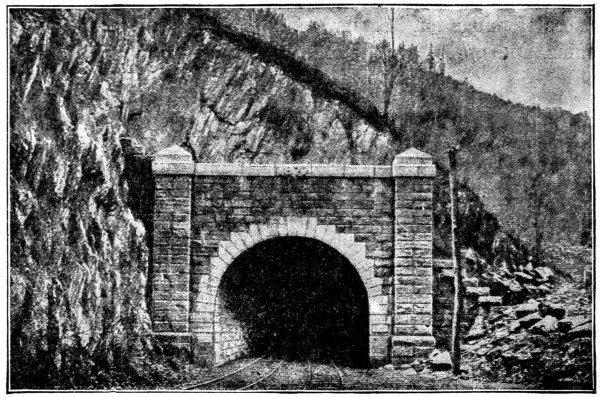
Fig. 49.—East Portal of Hoosac Tunnel.
Fig. 49 is an engraving from a photograph of the east portal
of the Hoosac tunnel, which is an especially good design. The
portals of the Mount Cenis tunnel were built of samples of
stone encountered all along the line of excavation. The stones
were cut and dressed and utilized for walls and voussoirs. The
only ornament that is usually allowed on the portals is the date
of the opening of the tunnel prominently cut in the stone above
the arch.
[83]
Table II.
Showing Thickness of Masonry Lining for Tunnels through Soft Ground.
| Character of Material. |
Keystone. |
Springers. |
Invert. |
| |
Ft. |
Ft. |
Ft. |
| Laminated clay, first variety |
2.15 to 3 |
2.75 to 3.5 |
1.6 to 2.5 |
| Laminated clay, second variety |
3 to 4.5 |
3.5 to 5.5 |
2.5 to 4 |
| Laminated clay, third variety |
4.5 to 6.5 |
5.5 to 8.1 |
4 to 4.5 |
| Quicksand |
2 to 3.28 |
2 to 4.1 |
1.33 to 2.5 |
TABLE III.
Showing Thickness of Masonry Lining for Side Tunnels through
Soft Ground.
| Character of Material. |
Keystone. |
Springers. |
Invert. |
| |
Ft. |
Ft. |
Ft. |
| Laminated clay, first variety |
1.6 to 2.3 |
1.8 to 3 |
1.5 to 2 |
| Laminated clay, second variety |
2.3 to 3 |
3 to 4.1 |
2 to 2.6 |
| Laminated clay, third variety |
3 to 4 |
4.1 to 5 |
2.6 to 3.29 |
| Quicksand |
1.6 to 2.5 |
1.3 to 2 |
1.3 to 2 |
[84]
CHAPTER IX.
TUNNELS THROUGH HARD ROCK; GENERAL
DISCUSSION; REPRESENTATIVE MECHANICAL
INSTALLATIONS FOR TUNNEL WORK.
The present high development of labor-saving machinery
for excavating rock makes this material one of the safest and
easiest to tunnel of any with which the engineer ordinarily has
to deal. To operate this machinery requires, however, the
development of a large amount of power, its transmission to
considerable distances, and, finally, its economical application
to the excavating tools. The standard rock excavating machine
is the power drill, which requires either air or hydraulic
pressure for its operation according to the special type employed.
Under present conditions, therefore, the engineer is
limited either to air or water under compression for the transmission
of his power. Steam-power may be employed directly
to operate percussion rock drills; but owing to the heat and
humidity which it generates in the confined space where the
drills work, and because of other reasons, it is seldom employed
directly. Electric transmission, which offers so many advantages
to the tunnel builder, in most respects is largely excluded
from use by the failure which has so far followed all attempts
to apply it to the operation of rock drills. As matters stand,
therefore, the tunnel engineer is practically limited to steam
and falling water for the generation of power, and to compressed
air and hydraulic pressure for its transmission.
Whether the engineer should adopt water-power or steam to
generate the power required for his excavating machinery depends
upon their relative availability, cost, and suitability to the[85]
conditions of work in each particular case. Where fuel is plentiful
and cheap, and where water-power is not available at a
comparatively reasonable cost, steam-power will nearly always
prove the more economical; where, however, the reverse conditions
exist, which is usually the case in a mountainous
country far from the coal regions, and inadequately supplied
with transportation facilities, but rich in mountain torrents,
water-power will generally be the more economical. In a succeeding
chapter the power generating and transmission plants
for a number of rock tunnels are described, and here only a
general consideration of the subject will be presented.
Steam-Power Plant.
—A steam-power plant for tunnel work
should be much the same as a similar plant elsewhere, except
that in designing it the temporary character of its work must
be taken into consideration. This circumstance of its temporary
employment prompts the omission of all construction
except that necessary to the economical working of the plant
during the period when its operation is required. The power-house,
the foundations for the machinery, and the general construction
and arrangement, should be the least expensive which
will satisfy the requirements of economical and safe operation
for the time required. It will often be found more economical
as a whole to operate the machinery with some loss of economy
during the short time that it is in use than to go to much
greater expense to secure better economy from the machinery
by design and construction, which will be of no further use
after the tunnel is completed. The longer the plant is to be
required, the nearer the construction may economically approach
that of a permanent plant. As regards the machinery itself,
whose further usefulness is not limited by the duration of any
single piece of work, true economy always dictates the purchase
of the best quality. Speaking in a general way, a steam-power
plant for tunnel work comprises a boiler plant, a plant of air
compressors with their receivers, and an electric light dynamo.
When hydraulic transmission of power is employed, the air[86]
compressors are replaced by high-pressure pumps; and when
electric hauling is employed, one or more dynamos may be required
to generate electricity for power purposes, as well as for
lighting. In addition to the power generating machines proper,
there must be the necessary piping and wiring for transmitting
this power, and, of course, the equipment of drills and other
machines for doing the actual excavating, hauling, etc.
Reservoirs.
—When water-power is employed, a reservoir
has to be formed by damming some near-by mountain stream at
a point as high as practicable above the tunnel. The provision
of a reservoir, instead of drawing the water directly from the
stream, serves two important purposes. It insures a continuous
supply and constant head of water in case of drought, and also
permits the water to deposit its sediment before it is delivered
to the turbines. The construction of these reservoirs may be
of a temporary character, or they may be made permanent
structures, and utilized after construction is completed to supply
power for ventilation and other necessary purposes. In the
first case they are usually destroyed after construction is finished.
In either case, it is almost unnecessary to say, they
should be built amply safe and strong according to good engineering
practice in such works, for the duration of time which
they are expected to exist.
Canals and Pipe Lines.
—For conveying the water from the
reservoirs to the turbines, canals or pipe lines are employed.
The latter form of conduit is generally preferable, it being
both less expensive and more easily constructed than the
former. It is advisable also to have duplicate lines of pipe to
reduce the possibility of delay by accident or while necessary
repairs are being made to one of the pipes. The pipe lines
terminate in a penstock leading into the turbine chamber, and
provided with the necessary valves for controlling the admission
of water to the turbines.
Turbines.
—There are numerous forms of turbines on the
market, but they may all be classed either as impulse turbines[87]
or as reaction turbines. Impulse turbines are those in which
the whole available energy of the water is converted into
kinetic energy before the water acts on the moving part of the
turbine. Reaction turbines are those in which only a part of
the available energy of the water is converted into kinetic
energy before the water acts on the moving vanes. Impulse
turbines give efficient results with any head and quantity of
water, but they give better results when the quantity of water
varies and the head remains constant. Reaction turbines, on
the contrary, give better results when the quantity of water
remains constant and the head varies. These observations
indicate in a general way the form of turbine which will best
meet the particular conditions in each case. The number of
turbines required, and their dimensions, will be determined in
each case by the number of horse-power required and the
quantity of water available. The power of the turbines is
transmitted to the air compressors or pumps by shafting and
gearing.
Air Compressors.
—An air compressor is a machine—usually
driven by steam, although any other power may be used—by
which air is compressed into a receiver from which it may be
piped for use. For a detailed description of the various forms
of air compressors the reader should consult the catalogues of
the several makers and the various text-books relating to air
compression and compressed air. Air compressors, like other
machines, suffer a loss of power by friction. The greatest loss
of power, however, results from the heat of compression.
When air is compressed, it is heated, and its relative volume
is increased. Therefore, a cubic foot of hot air in the compressor
cylinder, at say, 60 lbs. pressure, does not make a cubic
foot of air at 60 lbs. pressure after cooling in the receiver.
In other words, assuming pressure to be constant, a loss of
volume results due to the extraction of the heat of compression
after the air leaves the compressor cylinder. To reduce the
amount of this loss, air compressors are designed with means[88]
to extract the heat from the air before it leaves the compressor
cylinder. Air compressors may first be divided into
two classes, according to the means employed for cooling the
air, as follows: (1) Wet compressors, and (2) dry compressors.
A wet compressor is one which introduces water directly
into the cylinder during compression, and a dry compressor is
one which admits no water to the air during compression.
Wet compressors may be subdivided into two classes: (1)
Those which inject water in the form of spray into the cylinder
during compression, and (2) those which use a water piston
for forcing the air into confinement.
The following brief discussion of these various types of
compressors is based on the concise practical discussion of
Mr. W. L. Saunders, M. Am. Soc. C. E., in “Compressed Air
Production.” The highest isothermal results are obtained by
the injection of water into the cylinders, since it is plain that
the injection of cold water, in the shape of a finely divided
spray, directly into the air during compression will lower the
temperature to a greater degree than simply to surround the
cylinder and parts by water jackets which is the means of cooling
adopted with dry compressors. A serious obstacle to water
injection, and that which condemns this type of compressor, is
the influence of the injected water upon the air cylinder and
parts. Even when pure water is used, the cylinders wear to
such an extent as to produce leakage and to require reboring.
The limitation to the speed of a compressor is also an important
objection. The chief claim for the water piston compressor is
that its piston is also its cooling device, and that the heat of
compression is absorbed by the water. Water is so poor a
conductor of heat, however, that without the addition of sprays
it is safe to say that this compressor has scarcely any cooling
advantages at all so far as the cooling of the air during compression
is concerned. The water piston compressor operates
at slow speed and is expensive. Its only advantage is that it
has no dead spaces. In the dry compressor a sacrifice is made[89]
in the efficiency of the cooling device to obtain low first cost,
economy in space, light weight, higher speed, greater durability,
and greater general availability.
Air compressors are also distinguished as double acting and
simple acting. They are simple acting when the cylinder is
arranged to take in air at one stroke and force it out at the
next, and they are double acting when they take in and force
out air at each stroke. In form compressors may be simple or
duplex. They are simple when they have but one cylinder,
and duplex when they have two cylinders. A straight line or
direct acting compressor is one in which the steam and air
cylinders are set tandem. An indirect acting compressor is
one in which the power is applied indirectly to the piston rod
of the air cylinder through the medium of a crank. Mr. W. L.
Saunders writes in regard to direct and indirect compression
as follows:—
“The experience of American manufacturers, which has been more extensive
than that of others, has proved the value of direct compression as distinguished
from indirect. By direct compression is meant the application of
power to resistance through a single straight rod. The steam and air cylinders
are placed tandem. Such machines naturally show a low friction loss because
of the direct application of power to resistance. This friction loss has been
recorded as low as 5%, while the best practice is about 10% with the type which
conveys the power through the angle of a crank shaft to a cylinder connected
to the shaft through an additional rod.”
Receivers.
—Compressed air is stored in receivers which are
simply iron tanks capable of withstanding a high internal
pressure. The purpose of these tanks is to provide a reservoir
of compressed air, and also to allow the air to deposit its
moisture. From the receivers the air is conveyed to the workings
through iron pipes, which decrease gradually in diameter
from the receivers to the front.
Rock Drills.
—The various forms of rock drills used in tunneling
have been described in Chapter III., and need not be
considered in detail here except to say that American engineers[90]
usually employ percussion drills, while European
engineers also use rotary drills extensively. A comparison
between these two types of drills was made in excavating the
Aarlberg tunnel in Austria, where the Brandt hydraulic
rotary drill was used at one end, and the Ferroux percussion
drill was used at the other end. The rock was a mica-schist.
The average monthly progress was 412 ft., with a maximum
of 646 ft., with the rotary drills, and an average of 454 ft. with
the percussion drill.
Excavation.
—Since considerable time is required to get the
power plant established, the excavation of rock tunnels is often
begun by hand, but hand work is usually continued for no
longer a period than is necessary to get the power plant in
operation. Generally speaking, the greatest difficulty is
encountered in excavating the advanced drift or heading.
Based on the mode of blasting employed, there are two methods
of driving the advanced gallery, known as the circular cut
and the center cut methods. In the first method a set of holes
is first drilled near the center of the front in such a manner that
they inclose a cone of rock; the holes, starting at the perimeter
of the base of the cone, converge toward a junction at its
apex. Seldom more than four to six holes are comprised in
this first set. Around these first holes are driven a ring
of holes which inclose a cylinder of rock, and if necessary
succeeding rings of holes are driven outside of the first ring.
These holes are blasted in the order in which they are driven,
the first set taking out a cone of rock, the second set enlarging
this cone to a cylinder, and the other sets enlarging this
cylinder to the required dimensions of the heading. The number
of holes, however, varies with the quality of rock and they are
seldom driven deeper than 4 or 5 ft. This method of excavating
the heading, which is commonly followed by European engineers,
is illustrated in Figs. 50 to 52. In these figures are indicated
the number of holes in each round and the sequence of rounds
for the soft, medium and hard rock, as used in the Turchino[91]
tunnel of the Genova Ovada Asti line of the Mediterranean
Railway of Italy. The heading was about 9 ft. square, and five
sets of holes were used in blasting, the depths being 3.91, 4.26
and 4.6 ft. for soft, medium and hard rock, respectively, and the
amount of dynamite consumed was 2.38, 3.91 and 5.1 pounds
per cubic yard for the three classes of rock.
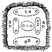
in Soft Rock
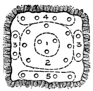
in Medium Rock
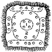
in Hard Rock
Figs. 50 to 52.—Arrangement
of Drill Holes in the Heading of Turchino Tunnel.
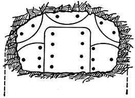
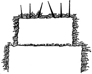
Figs. 53 and 54.—Arrangement of Drill Holes
in the Heading of the Fort George Tunnel.
In the center-cut method,
which is the one commonly
employed in America, the
holes are arranged in vertical
rows, and are driven from
8 to 10 ft. deep. Fig. 53
shows the arrangement of
the holes, and the method
of blasting them, as used in
the excavation of the heading
for the Fort George tunnel of
the New York rapid transit.
The two center rows of holes
converge toward each other
so as to take out a wedge
of rock; others are bored
straight, or parallel, with the
vertical plane of the tunnel.
Those bored around the perimeter
are driven either outward or upward, according as they
are located, close to the sides or roof of the tunnel. In this[92]
case, the holes of the center cut were driven 9 ft. deep, while
all the other holes were bored to a depth of 8 ft.
The width of the advanced gallery or heading depends upon
the quality of the rock. In hard rock American engineers
give it the full width of the tunnel section; but this cannot be
done in loose or fissured rock, which has to be supported, the
headings here being usually made about 8 × 8 ft. The wider
heading is always preferable, where it is possible, since more
room is available for removing the rock, and deeper holes can
be bored and blasted.
The important rôle played by the power plant and other
mechanical installations in constructing tunnels through rock
has already been mentioned. In some methods of soft-ground
tunneling, and particularly in soft-ground subaqueous tunneling,
it is also often necessary to employ a mechanical installation
but slightly inferior in size and cost to those used in tunneling
rock. It is proposed to describe very briefly here a few
typical individual plants of this character, which will in some
respects give a better idea of this phase of tunnel work than the
more general descriptions.
Rock Tunnels.
—The tunnels selected to illustrate the mechanical
installations employed in tunneling through rock are:
The Mont Cenis, Hoosac Tunnel, the Cascade Tunnel, the Niagara
Falls Power Tunnel, the Palisades Tunnel, the Croton Aqueduct
Tunnel, the Strickler Tunnel in America, and the Graveholz
Tunnel and the Sonnstein Tunnel in Europe. In addition
there will be found in another chapter of this book a description
of the mechanical installations at the St. Gothard, Pennsylvania
and other tunnels.
Mont Cenis Power Plant.
—The mechanical installation consisted
of the Sommeilier air compressors built near the portals.
The Sommeilier compressors, Mr. W. L. Saunders says, were
operated as a ram, utilizing a natural head of water to force air
at 80 lbs. pressure into a receiver. The column of water contained
in the long pipe on the side of the hill was started and[93]
stopped automatically by valves controlled by engines. The
weight and momentum of the water forced a volume of air with
such a shock against the discharge valve that it was opened,
and the air was discharged into the tank; the valve was then
closed, the water checked; a portion of it was allowed to discharge,
and the space was filled with air, which was in turn
forced into the tank. Only 73% of the power of the water was
available, 27% being lost by the friction of the water in the
pipes, valves, bends, etc. Of the 73% of net work, 49.4 was
consumed in the perforators, and 23.6 in a dummy engine for
working the valves of the compressors and for special ventilation.
The compressed air was conveyed from each end through a
cast-iron pipe 75⁄8 in. in diameter, up to the front of the excavation.
The joints of the pipes were made with turned faces,
grooved to receive a ring of oakum which was tightly screwed
and compressed into the joint. To ascertain the amount of
leakage of the pipes, they and the tanks were filled with air
compressed to 6 atmospheres, and the machines stopped; after
12 hours the pressure was reduced to 5.7 atmospheres, or to
95% of the original pressure.
Sommeilier’s percussion drilling machines were used in the
excavation of this tunnel. They were provided with 8 or 10
drills acting at the same time, and mounted on carriages running
on tracks. These were withdrawn to a safe place during the
blasting, and advanced again after the broken rock was removed
from the front and the new tracks laid.
Machine shops were built at both ends of the tunnel for building
and repairing the drilling machines, bits, tools, etc. A
gas factory was built at each end for lighting purpose.
Hoosac Tunnel.
—The Hoosac tunnel on the Fitchburg R.R.
in Massachusetts is 25,000 ft. long, and the longest tunnel in
America. The material through which the tunnel was driven
was chiefly hard granitic gneiss, conglomerate, and mica-schist
rock. The excavation was conducted from the entrances and[94]
one shaft, the wide heading and single-bench method being
employed, with the center-cut system of blasting which was
here used for the first time. The tunnel was begun in 1854,
and continued by hand until 1866, when the mechanical plant
was installed. Most of the particular machines employed have
now become obsolete, but as they were the first machines used
for rock tunneling in America they deserve mention. The
drills used were Burleigh percussion drills, operated by compressed
air. Six of these drills were mounted on a single carriage,
and two carriages were used at each front. The air to
operate these drills was supplied by air compressors operated
by water-power at the portals and steam-power at the shaft.
The air compressors consisted of four horizontal single-acting
air cylinders with poppet valves and water injection. The
compressors were designed by Mr. Thomas Deane, the chief
engineer of the tunnel.
Palisades Tunnel.
—The Palisades tunnel was constructed to
carry a double track railway line through the ridge of rocks
bordering the west bank of the Hudson River and known as
the Palisades. It was located about opposite 116th St. in New
York City. The material penetrated was a hard trap rock very
full of seams in places, which caused large fragments to fall
from the roof. The excavation was made by a single wide
heading and bench, employing the center-cut method of blasting
with eight center holes and 16 side holes for the 7 × 18 ft.
heading. Ingersoll-Sergeant 21⁄2 in. drills were used, four in
each heading and six on each bench, and 30 ft. per 10 hours
was considered good work for one drill.
The power-plant was situated at the west portal of the tunnel,
and the power was transmitted by electricity and compressed
air to the middle shaft and east portal workings. The
plant consisted of eight 100 H. P. boilers, furnishing steam to
four Rand duplex 18 × 22 in. air compressors, and an engine
running a 30 arc light dynamo. The compressed air was carried
over the ridge by pipes, varying from 10 ins. to 5 ins. in diameter,[95]
to the shaft and to the east portal, and was used for operating
the hoisting engines as well as the drills at these workings.
Inside the tunnel, specially designed derrick cars were employed
to handle large stones, they being also operated by compressed
air. This car ran on a center track, while the mucking cars ran
on side tracks, and it was employed to lift the bodies of the cars
from the trucks, place them close to the front, being worked
where large stone could be rolled into them, and return them
to the trucks for removal. In addition to handling the car
bodies the derrick was used to lift heavy stones. The hauling
was done first by horse-power, and later by dummy
locomotives.
Croton Aqueduct Tunnel.
—In the construction of the Croton
Aqueduct for the water supply of New York City, a tunnel 31
miles long was built, running from the Croton Dam to the Gate
House at 135th St. in New York City. The section of the tunnel
varies in form, but is generally either a circular or a horseshoe
section. In all cases the section was designed to have a
capacity for the flow of water equal to a cylinder 14 ft. in diameter.
To drive the tunnel, 40 shafts were employed. The material
penetrated was of almost every character, from quicksand
to granitic rock, but the bulk of the work was in rock of some
character. The excavation in rock was conducted by the wide
heading and bench method, employing the center-cut method
of blasting. Four air drills, mounted on two double-arm columns
were employed in the heading. The drills for the bench work
were mounted on tripods. Steam-power was used exclusively
for operating the compressors, hoisting engines, ventilating
fans and pumps; but the size and kind of boilers used, as well
as the kind and capacity of the machines which they operated,
varied greatly, since a separate power-plant was employed for
each shaft with a few exceptions. A description of the plant
at one of the shafts will give an indication of the size and character
of those at the other shafts, and for this purpose the plant at
shaft 10 has been selected.
[96]
At shaft 10 steam was provided by two Ingersoll boilers of
80 H. P. each, and by a small upright boiler of 8 H. P. There
were two 18 × 30 in. Ingersoll air compressors pumping into
two 42 in. × 10 ft. and two 42 in. × 12 ft. Ingersoll receivers.
In the excavation there were twelve 31⁄2 in. and six 31⁄8 in. Ingersoll
drills, four drills mounted on two double arm columns
being used on each heading, and the remainder mounted on
tripods being used on the bench. Two Dickson cages operated
by one 12 × 12 in. Dickson reversible double hoisting engine
provided transportation for material and supplies up and down
the shaft. A Thomson-Houston ten-light dynamo operated by
a Lidgerwood engine provided light. Drainage was effected by
means of two No. 9 and one No. 6 Cameron pumps. At this
particular shaft the air exhausted from the drills gave ample
ventilation, especially when after each blast the smoke was
cleared away by a jet of compressed air. In other workings,
however, where this means of ventilation was not sufficient,
Baker blowers were generally employed.
Strickler Tunnel.
—The Strickler tunnel for the water supply
of Colorado Springs, Col., is 6441 ft. long with a section of
4 ft. × 7 ft. It penetrates the ridge connecting Pike’s Peak
and the Big Horn Mountains, at an elevation of 11,540 ft. above
sea level. The material penetrated is a coarse porphyritic
granite and morainal débris, the portion through the latter
material being lined. The mechanical installation consisted
of a water-power electric plant operating air compressors.
The water from Buxton Creek having a fall of 2400 ft. was
utilized to operate a 36 in. 220 H. P. Pelton water-wheel, which
operated a 150 K. W. three-phase generator. From this generator
a 3500 volt current was transmitted to the east portal
of the tunnel, where a step-down transformer reduced it to a
220 volt current to the motor. The transmission line consisted
of three No. 5 wires carried on cross-arm poles and provided
with lightning arresters at intervals. The plant at the east
portal of the tunnel consisted of a 75 H. P. electric motor, driving[97]
a 75 H. P. air compressor, and of small motors to drive a Sturtevant
blower for ventilation, to run the blacksmith shop, and
to light the tunnel, shop, and yards. From the compressor
air was piped into the tunnel at the east end, and also over the
mountain to the west portal workings. Two drills were used at
each end, and the air was also used for operating derricks and
other machinery. For removing the spoil a trolley carrier
system was employed. A longitudinal timber was fastened to
the tunnel roof, directly in the apex of the roof arch. This
timber carried by means of hangers a steel bar trolley rail on
which the carriages ran. Outside of the portal this rail formed
a loop, so that the carriage could pass around the loop and be
taken back to the working face. Each carriage carried a steel
span of 11⁄2 cu. ft. capacity, so suspended that by means of a
tripping device it was automatically dumped when the proper
point on the loop was reached.
Niagara Falls Power Tunnel.
—The tail-race tunnel built
to carry away the water discharged from the turbines of the
Niagara Falls Power Co., has a horse-shoe section 19 × 21 ft.
and a length of 6700 ft. It was driven through rock from
three shafts by the center-cut method of blasting. In sinking
shaft No. 0 very little water was encountered, but at shafts
Nos. 1 and 2 an inflow of 800 gallons and 600 gallons per minute,
respectively, was encountered. The principal plant was located
at shaft No. 2, and consisted of eight 100 H.P. boilers, three
18 × 30 in. Rand duplex air compressors, a Thomson-Houston
electric-light plant, and a sawmill with a capacity of 20,000 ft.
B. M. per day. The shafts were fitted with Otis automatic
hoisting engines, with double cages at shafts Nos. 1 and 2, and
a single cage at shaft No. 0. The drills used were 25 Rand
drills and three Ingersoll-Sergeant drills. The pumping plant
at shaft No. 2 consisted of four No. 7 and one No. 9 Cameron
pumps, and that at shaft No. 2 consisted of two No. 7 and two
No. 9 Cameron pumps and three Snow pumps. An auxiliary
boiler plant consisting of two 60 H. P. boilers was located at[98]
shaft No. 1, and another, consisting of one 75 H. P. boiler, was
located at shaft No. 0.
Cascade Tunnel.
—The Cascade tunnel was built in 1886-88
to carry the double tracks of the Northern Pacific Ry. through
the Cascade Mountains in Washington. It is 9850 ft. long
with a cross-section 161⁄2 ft. wide and 22 ft. high, and is lined
with masonry. The material penetrated was a basaltic rock,
with a dip of the strata of about 5°. The rock was excavated
by a wide heading and one bench, using the center-cut system
of blasting. A strutting consisting of five-segment timber
arches carried on side posts, spaced from 2 ft. to 4 ft. apart,
and having a roof lagging of 4 × 6 in. timbers packed above
with cord-wood. The mechanical plant of the tunnel is of
particular interest, because of the fact that all the machinery
and supplies had to be hauled from 82 to 87 miles by teams,
over a road cut through the forests covering the mountain
slopes. This work required from Feb. 22 to July 15, 1886, to
perform. In many places the grades were so steep that the
wagons had to be hauled by block and tackle. The plant consisted
of five engines, two water-wheels, five air compressors,
eight 70 H. P. steam-boilers, four large exhaust fans, two complete
electric arc-lighting plants, two fully equipped machine-shop
outfits, 36 air drills, two locomotives, 60 dump cars, and
two sawmill outfits, with the necessary accessories for these various
machines. This plant was divided about equally between
the two ends of the tunnel. The cost of the plant and of the
work of getting it into position was $125,000.
Graveholz Tunnel.
—The Graveholz tunnel on the Bergen
Railway in Norway is notable as being the longest tunnel in
northern Europe, and also as being built for a single-track
narrow-gauge railway. This tunnel is 17,400 feet long, and
is located at an elevation of 2900 feet above sea-level. Only
about 3% of the length of the tunnel is lined. The mechanical
installation consists of a turbine plant operating the various
machines. There are two turbines of 100 H. P. and 120 H. P.[99]
taking water from a reservoir on the mountain slope, and furnishing
220 H. P., which is distributed about as follows: Boring-machines,
60 H. P.; ventilation, 30 to 40 H. P.; electric locomotives,
15 H. P.; machine shop, 15 H. P.; electric-lighting
dynamo, 25 H. P.; electric drills, the surplus, or some 40 H. P.
The boring-machines and electric drills will be operated by the
smaller 100 H. P. turbine.
Sonnstein Tunnel.
—The Sonnstein tunnel in Germany is
particularly interesting because of the exclusive use of Brandt
rotary drills. The tunnel was driven through dolomite and
hard limestone by means of a drift and two side galleries. The
dimensions of the drift were 71⁄2 × 71⁄2 ft. The power plant consisted
of two steam pressure pumps, one accumulator, and four
drills. The steam-boiler plant, in addition to operating the
pumps, also supplied power for operating a rotary pump for
drainage and a blower for ventilation. The hydraulic pressure
required was 75 atmospheres in the dolomite, and from 85 to
100 atmospheres in the limestone. The drift was excavated
with five 31⁄2 in. holes, one being placed at the center and driven
parallel to the axis of the tunnel, and four being placed at the
corners of a rectangle corresponding to the sides of the drift,
and driven at an angle diverging from the center hole. The
average depths of the holes were 4.3 ft., and the efficiency of
the drills was 1 in. per minute. One drill was employed at
each front, and was operated by a machinist and two helpers,
who worked eight-hour shifts, with a blast between shifts at
first, and later twelve-hour shifts, with a blast between shifts.
The 24 hours of the two shifts were divided as follows: boring
the holes, 10.7 hours; charging the holes, 1.1 hours; removing
the spoil, 11.7 hours; changing shifts, 0.5 hour. The average
progress per day for each machine was 6.7 ft. The total cost
of the plant was $17,450.
St. Clair River Tunnel.
—The submarine double-track railway
tunnel under the St. Clair River for the Grand Trunk Ry.
is 8500 ft. long, and was driven through clay by means of a[100]
shield, as described in the succeeding chapter on the shield
system of tunneling. The mechanical plant installed for prosecuting
the work was very complete. To furnish steam to the
air compressors, pumps, electric-light engines, hoisting-engines,
etc., a steam-plant was provided on each side of the river, consisting
of three 70 H. P. and four 80 H. P. Scotch portable
boilers. The air-compressor plant at each end consisted of
two 20 × 24 in. Ingersoll air compressors. To furnish light to
the workings, two 100 candle-power Edison dynamos were installed
on the American side, and two Ball dynamos of the same
size were installed on the Canadian side. The dynamos on
both sides were driven by Armington & Sims engines. These
dynamos furnished light to the tunnel workings and to the
machine-shops and power-plant at each end. Root blowers of
10,000 cu. ft. per minute capacity provided ventilation. The
pumping plant consisted of one set of pumps installed for permanent
drainage, and another set installed for drainage during
construction, and also to remain in place as a part of the permanent
plant. The latter set consisted of two 500 gallon Worthington
duplex pumps set first outside of each air lock, closing
the ends of the river portion of the tunnel. For permanent
drainage, a drainage shaft was sunk on the Canadian side of the
river, and connected with a pump at the bottom of the open-cut
approach. In this shaft were placed a vertical, direct-acting,
compound-condensing pumping engine with two 191⁄2 in. high-pressure
and two 333⁄8 in. low-pressure cylinders of 24 in. stroke,
connected to double-acting pumps with a capacity of 3000
gallons per minute, and also two duplex pumps of 500 gallons
capacity per minute. For permanent drainage on the American
side, four Worthington pumps of 3000 gallons’ capacity were
installed in a pump-house set back into the slope of the open-cut
approach. For the permanent drainage of the tunnel
proper two 400 gallon pumps were placed at the lowest point
of the tunnel grade. Spoil coming from the tunnel proper was
hoisted to the top of the open cut by derricks operated by two[101]
50 H. P. Lidgerwood hoisting-engines. The pressure pumping
plant for supplying water to the hydraulic shield-jacks at each
end of the tunnel consisted of duplex direct-acting engines
with 12 in. steam cylinders and 1 in. water cylinders, supplying
water at a pressure of 2000 lbs. per sq. in.
[102]
CHAPTER X.
TUNNELS THROUGH HARD ROCK (Continued).
EXCAVATION BY DRIFTS: THE SIMPLON AND MURRAY HILL
TUNNELS.
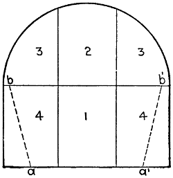
Fig. 55.—Diagram Showing Sequence
of Excavations in Drift
Method of Tunneling Rock.
General Description.
—The method of tunneling through hard
rock by drifts is preferred by European engineers. All the great
Alpine tunnels, from the Mont Cenis tunnel to the Simplon,
are examples of tunneling by drifts. In this method the sequence
of excavation is shown diagrammatically by Fig. 55.
The work begins by excavating a
drift close to the floor of the proposed
tunnel (as shown in the center
of the figure) and far in advance of
the excavation of any other part.
The section marked 2 is next removed
and still later the portions
marked 3. Then with the removal
of the parts marked 4 the whole
section of the tunnel will be open.
The drift is usually strutted by
means of side posts carrying a cap-piece
placed at intervals, and having
a ceiling of longitudinal planks resting on the successive caps.
In hard rock the roof of the section does not, as a rule, require
regular strutting, occasional supports being placed at intervals
to prevent the fall of isolated fragments: When the rock is disintegrated
or full of seams, a regular strutting may be necessary,
and this may be either longitudinal or polygonal in type. When
longitudinal strutting is employed, a sill is laid across the roof of[103]
the drift, and upon this are set up two struts converging toward
the top and supporting a cap-piece close to the roof. On this
cap-piece are placed the first longitudinal crown bars carrying
transverse poling-boards. Additional props standing on the sill
and radiating outward are inserted as parts No. 3 are excavated.
These radial props carry longitudinal bars which in turn support
transverse poling-boards. When polygonal strutting is used,
it may take the form of three or five segment arches of heavy
timbers.
In hard rock tunnels, as a rule, there is no danger of caving in
because of heavy pressures, and the whole section is left open
for some time before it is lined. The lining may be of concrete
masonry, but in many long tunnels, excavated through hard
rock, the side walls are lined with rubble masonry and the arch
with brick, and, in some instances, even the arch has been lined
with rubble masonry. With skilful laborers at hand the rubble
masonry lining has proved most efficient and economical, because
the rock is utilized as it is excavated without any further
operation. Concrete, however, is more extensively employed
for lining tunnels than any other material.
Tunnels excavated by drifts enable simple means of hauling
to be employed, and this is one of the reasons why the method
finds so much favor with European engineers. The tracks
are laid along the floor of the drift, and carry all the spoil from
parts Nos. 2, 3, and 4, as well as from the front of the drift
itself. As fast as the full section is completed, this single track
in the drift is replaced by two tracks running close to the sides
of the tunnel, or by a broad-gauge track with a third rail.
THE SIMPLON TUNNEL.[8]
Before entering upon a description of the constructive details
of this, the longest railway tunnel in the world, it may be
well to give a general idea of the undertaking. Many schemes[104]
for the connection of Italy and Switzerland by a railway near
the Simplon Road Pass have been devised, including one involving
no great length of underground work, the line mounting
by steep gradients and sharp curves. The present scheme,
put forward in 1881 by the Jura-Simplon Ry. Co., consists
broadly of piercing the Alps between Brigue, the present railway
terminus in the Rhone Valley, and Iselle, in the gorge of
the Diveria, on the Italian side, from which village the railway
will descend to the existing southern terminus at Domo d’Ossola,
a distance of about 11 miles.
In conjunction with this scheme a second tunnel is proposed,
to pierce the Bernese Alps under the Lötschen Pass
from Mittholz to a point near Turtman in the Rhone Valley;
and thus, instead of the long détour by Lausanne and the Lake
of Geneva, there will be an almost direct line from Berne to
Milan via Thun, Brigue, and Domo d’Ossola.
Starting from Brigue, the new line, running gently up the
valley for 11⁄4 miles, will, on account of the proximity of the
Rhone, which has already been slightly diverted, enter the
tunnels on a curve to the right of 1050 ft. radius. At a distance
of 153 yards from the entrance, the straight portion
of the tunnel commences, and extends for 12 miles. The line
then curves to the left with a radius of 1311 ft. before emerging
on the left bank of the Diveria. Commencing at the northern
entrance, a gradient of 1 in 500 (the minimum for efficient
drainage) rises for a length of 51⁄2 miles to a level length of 550
yards in the center, and then a gradient of 1 in 143 descends
to the Italian side. On the way to Domo d’Ossola one helical
tunnel will be necessary, as has been carried out on the St.
Gothard. There will be eventually two parallel tunnels having
their centers 56 ft. apart, each carrying one line of way; but
at the present time only one heading, that known as No. 1,
is being excavated to full size, No. 2 being left, masonry lined
where necessary, for future developments. By means of cross
headings every 220 yds. the problems of transport and ventilation[105]
are greatly facilitated, as will be seen later. As both
entrances are on curves, a small “gallery of direction” is necessary,
to allow corrections of alinement to be made direct from
the two observatories on the axis of the tunnel.
The outside installations are as nearly in duplicate as circumstances
will allow, and consist of the necessary offices,
workshops, engine-sheds, power-houses, smithies, and the numerous
buildings entailed by an important engineering scheme.
Great care is taken that the miners and men working in the
tunnel shall not suffer from the sudden change from the warm
headings to the cold Alpine air outside; and for this purpose
a large building is in course of erection, where they will be
able to take off their damp working clothes, have a hot and
cold douche, put on a warm dry suit, and obtain refreshments
at a moderate cost before returning to their homes. Instead
of each man having a locker in which to stow his clothes, a
perfect forest of cords hangs down from the wooden ceiling,
25 ft. above floor-level, each cord passing over its own pulleys
and down the wall to a numbered belaying-pin. Each cord
supports three hooks and a soap-dish, which, when loaded with
their owner’s property, are hauled up to the ceiling out of the
way. There are 2000 of these cords, spaced 1 ft. 6 ins. apart,
one to each man. The engineers and foremen are more privileged,
being provided with dressing-rooms and baths, partitioned
off from the two main halls. An extensive clothes washing
and drying plant has been laid down, and also a large restaurant
and canteen. At Iselle, a magazine holding 2200 lbs. of
dynamite is surrounded and divided into two separate parts by
earth-banks, 16 ft. high. The two wooden houses, in which
the explosive is stored, are warmed by hot-water pipes to a
temperature between 61° F. and 77° F., and are watched by
a military patrol; but at Brigue a dynamite manufactory,
started by an enterprising company at the time of the commencement
of the works, supplies this commodity at frequent
intervals, thereby avoiding the necessity of storing in such[106]
large quantities. This dynamite factory has been largely increased,
and supplies dynamite to nearly all the mining and
tunneling enterprises in Switzerland.
Geological Conditions.
—Before the Simplon tunnel was authorized,
expert evidence was taken as to the feasibility of
the project. The forecasts of the three engineers chosen, in
reference to the rock to be encountered and its probable temperature,
have, as far as the galleries have gone (an aggregate
distance of nearly 21⁄2 miles), generally been found correct.
At the north end, a dark argillaceous schist veined with quartz
was met with, and from time to time beds of gypsum and dolomite
have been traversed, the dip of the strata being on the whole
favorable to progress, though timbering is resorted to at dangerous
places. Water was plentiful at the commencement; in fact,
one inrush has not been stopped, and is still flowing down the
heading. The total quantity of water flowing from the tunnel
mouth is 16 gallons per second, of which 2 gallons per second
are accounted for by the drilling machines. At Iselle, however,
a very hard antigorio gneiss obtains, and is likely to
extend for 4 miles. Very dry and very compact, it requires
no timbering, and represents no great difficulty to the powerful
Brandt rock-drills, which work under a head of 3280 ft. of
water.
The temperature of the rock depends not only on the depth
from the surface, but largely upon the general form of that surface
combined with the conductivity of the rock. Taking
these points into consideration with the experience gained from
the construction of the St. Gothard tunnel, 95° F. was estimated
as the probable maximum temperature, owing to the
height of Monte Leone (11,660 ft.), which lies almost directly
over the tunnel axis.
Survey.
—After having determined upon the general position
of the tunnels, taking into consideration the necessary gradients,
the temperature of the rock, and a large bed of troublesome
gypsum on the north side, two fixed points on the proposed[107]
center line were taken, one at each entrance of tunnel
No. 1, and the bearings of these two points, with reference to
a triangulation survey made in 1876, were calculated sufficiently
accurately to determine, for the time being, the direction of
the tunnel. In 1898, a new triangulation survey was made,
taking in eleven summits, Monte Leone holding the central
position. This survey was tied into that of the Wasenhorn
and Faulhorn, made by the Swiss Government, and the accuracy
was such that the probable error in the meeting of the two
headings is only 6 cms. or 21⁄2 ins.
On the top of each summit is placed a signal, consisting of
a small pillar of masonry founded on rock, and capped with a
sharp pointed cone of zinc, 1 ft. 6 ins. high. An observatory
was built at each end of the tunnel in such a position that three
of the summits could be seen, a condition very difficult to fulfill
on the south side owing to the depth of the gorge, the mountains
on either side being over 7000 ft. high. Having taken
the angles to and from each visible signal, and therefrom having
calculated the direction of the tunnel, it was necessary to fix,
with extreme accuracy, sighting-points on the axis of the tunnel,
in order to avoid sighting on to the surrounding peaks for each
subsequent correction of the alinement of the galleries. To
do this, a theodolite 24 ins. long and 23⁄8 ins. in diameter, with
a magnifying power of 40 times, was set up in the observatory,
and about 100 readings were taken of the angles between the
surrounding signals and the required sighting-points. In this
manner the error likely to occur was diminished to less than 1′.
Thus at the north end two points were found about 550 yds.
before and behind the observatory, while on the south side,
owing to the narrowness of the gorge, the points could only be
placed at 82 yds. and 126 yds. in front. One of these sighting-points
consists of a fine scratch ruled on a piece of glass fixed
in an iron frame, behind which is placed an acetylene lamp,—corrections
of alinement are always done by night,—the whole
being rigidly fixed into a niche cut in the rock and protected[108]
from climatic and other disturbing agencies by an iron
plate.
Method of Checking Alinement.
—The direction of heading
No. 1 is checked by experts from the Government Survey Department
at Lausanne about three times a year, and for this
purpose a transit instrument is set up in the observatory. A
number of three-legged iron tables are placed at intervals of
1 mile or 2 miles along the axis of tunnel No. 1, and upon each
of these is placed a horizontal plane, movable by means of
an adjusting screw, in a direction at right angles to the axis,
along a graduated scale. On this plane are small sockets, into
which the legs of an acetylene lamp and screen, or of the transit
instrument, can be quickly and accurately placed. The screen
has a vertical slit, 3 ins. in height, and variable between 13⁄16 in.
and 3⁄16 in. in breadth, according to the state of the atmosphere,
and at a distance shows a fine thread of light. The instrument,
having first been sighted on to the illuminated scratch of the
sighting-point, is directed up the tunnel, where a thread of
light is shown from the first table. With the aid of a telephone
this light is adjusted so that its image is exactly coincident
with the cross hairs, and the reading on the graduated scale is
noted. This is done four or five times, the average of these
readings being taken as correct, and the plane is clamped to
that average. The instrument is then taken to the first table
and is placed quickly and accurately over the point just found
(by means of the sockets), and the lamp is carried to the observatory.
After first sighting back, a second point is given on the
second table, and so on. These points are marked either temporarily
in the roof of the heading by a short piece of cord hanging
down, or permanently by a brass point held by a small steel
cylinder, 8 ins. long and 3 ins. in diameter, embedded in concrete
in the rock floor, and protected by a circular casting, also sunk
in cement concrete, holding an iron cover resembling that of
a small manhole. From time to time the alinement is checked
from these points by the engineers, and after each blast the[109]
general direction is given by the hand from the temporary
points. To check the results of the triangulation survey, astronomical
observations have been taken simultaneously at each
end. With regard to the levels, those given on the excellent
Government surveys have been taken as correct, but they have
also been checked over the pass.
Details of Tunnels.
—In cross-section, tunnel No. 1 is 13 ft.
7 ins. wide at formation level, increasing to 16 ft. 5 ins., with
a total height of 18 ft. above rail-level, and a cross-sectional
area of about 250 sq. ft. This large section will allow of small
repairs being executed in the roof without interruption of the
traffic, and will also allow of strengthening the walls by additional
masonry on the inside. The thickness of the lining,
never wholly absent, and the material of which it is composed,
depend upon the pressure to be resisted, and only in the worst
case is an invert resorted to. The side drain, to which the rock
floor is made to slope, will be composed of half-pipes of
7 to 1 cement concrete. The roof is constructed of radial
stones.
Tunnel No. 2, being left as a heading, is driven on that side
nearest to No. 1, to minimize the length of the cross-headings,
and measures 10 ft. 2 ins. wide by 6 ft. 7 ins. high. Masonry
is used only where necessary, and in that case is so built as to
form part of the lining of the tunnel when eventually completed.
Concrete is put in to form a foundation for the side
wall, and a water channel. The cross-headings, connecting the
two parallel headings, occur every 220 yds., and are placed at
an angle of 56° to the axis of the tunnel, to avoid sharp curves
in the contractors’ railway lines. They will eventually be used
as much as possible for refuges, chambers for storing the tools
and equipment of the platelayers, and signal-cabins. The refuges,
6 ft. 7 ins. wide by 6 ft. 7 ins. high and 3 ft. 3 ins. deep,
occur every 110 yards, every tenth being enlarged to 9 ft. 10
ins. wide by 9 ft. 10 ins. deep and 10 ft. 2 ins. high, still larger
chambers being constructed at greater intervals.
[110]
Method of Excavation.
—The work at each end of the tunnel
is carried on quite independently, consequently, though similar
in principle, the methods vary in detail, apart from the fact that
different geological strata require different treatment. Broadly
speaking, the two parallel headings, each 59 sq. ft. in section,
are first driven by means of drilling-machines and the use of
dynamite, this work being carried on day and night, seven days
in the week; No. 1 heading is then enlarged to full size by hand-drilling
and dynamite. On the Italian side, where the rock
is hard and compact, breakups are made at intervals of 50 yds.,
and a top gallery is driven in both directions, but, for ventilation
reasons, is never allowed to get more than 4 yds. ahead
of the break-up, which is gradually lengthened and widened
to the required section. No timbering is required, except to
facilitate the excavation and the construction of the side walls.
Steel centers are employed for the arch; they entail fewer supports,
give more room, and are capable of being used over again
more frequently without damage. They consist of two I-beams
bent to a template and riveted together at the crown, resting
at either side on scaffolding at intervals of 6 ft.; longitudinals
12 ft. by 4 ins. by 4 ins. support the roof. Hand rock-drilling
is carried out in the ordinary way, one man holding the tool and
a second striking; measurements of excavation are taken every
2 or 3 yds., a plumb-line is suspended from the center of the
roof, and at every half-meter (20 ins.) of height horizontal
measurements are taken to each side.
At the Brigue end a softer rock is encountered, necessitating
at times heavy timbering in the heading, and especially in
the final excavation to full size, Fig. 56. The bottom heading,
6 ft. 6 in. high, is driven in the center, and the heading is then
widened to the full extent and timbered; the concrete forming
the water channel and the foundation for one side wall is put
in; the side walls are built to a height of 6 ft. 6 ins., and the tunnel
is fully excavated to a further height of 6 ft. 6 ins. from the
first staging. The side walls are then continued up for the[111]
second 6 ft. 6 ins., and
from the second floor
a third height of 6 ft.
6 ins. is excavated and
timbered. Finally the
crown is cleared out,
heavy wooden centers
are put in, the arch is
turned and all timbers
are withdrawn
except the top poling-boards,
supporting
the loose rock.
Fig. 56.—Sketches Showing Sequence of Work in
Excavating and Lining the Simplon Tunnel.
The masonry for
the side walls is obtained
either from the
tunnel itself or from
a neighboring quarry,
and varies in character
according to the
pressure; but the face
of the arch is always
of cut or artificial
stones, the latter being
7 to 1 cement
concrete. Where the
alinement heading, or
the “gallery of direction,”
joins the curving
portion of tunnel
No. 1, the section is
very much greater, and necessitates special timbering.
Transport (Italian Side).
—A small line of railway, 2 ft. 71⁄2
ins. gauge, with 40-lb. rails, enters all three portals; but since
the construction of a wooden bridge over the Diveria, the route[112]
through the “gallery of direction,” across heading No. 2, to
tunnel No. 1, is used exclusively; this railway leads to the face
in both headings, and, where convenient, from one heading to
the other by the cross-galleries. Different types of wagons are
in use; but in general they are four-wheeled, non-tipping box
wagons, supplied with brakes and holding 2 cu. yds. of débris.
A special type of locomotive is used, designed to pass round
curves of 50 ft. radius, and supplied with a specially large boiler
to avoid firing in the tunnel.
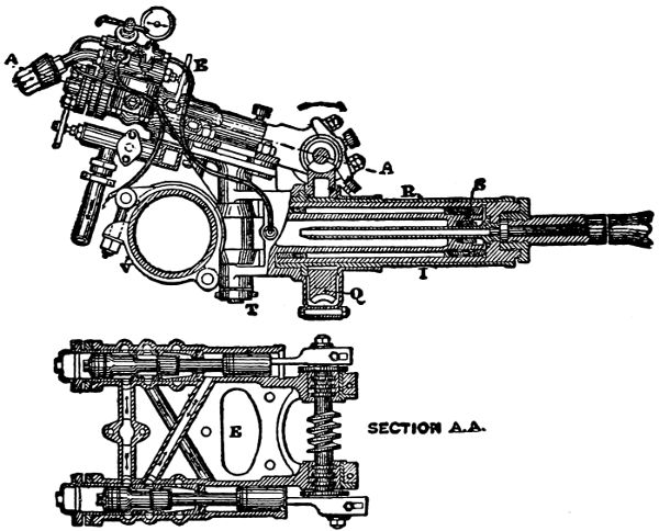
Fig. 57.—General Details of the Brandt Rotary Drills Employed at the Simplon Tunnel.
Larger illustration
Method of Working.
—The drilling-machines employed are of
the Brandt type, Fig. 57, and are mounted in the following
manner: A small four-wheeled carriage supports at its center
a beam, the shorter arm of which carries the boring mechanism
and the longer a counterpoise; near its center is the distributor.
In the short arm is a clamp holding the rack-bar or butting
column, which is a wrought-iron cylinder with a plunger constituting
a ram, and is jammed by hydraulic pressure between
the walls of the heading, thus forming a rigid support for the
boring-machine, and an efficient abutment against the reaction
of the drill. This rack-bar can be rotated on its clamp in a[113]
plane parallel to the axis of the beam. Three or four separate
boring-machines can be mounted on the rack-bar, and can be
adjusted in any reasonable position.
The boring-machine performs the double function of continually
pressing the drill into the rock by means of a hollow
ram (I) and of imparting to the drill and ram a uniform rotary
motion. This rotary motion is given by a twin cylinder single-acting
hydraulic motor (E), the two pistons, of 27⁄8 ins. stroke,
acting reciprocally as valves. The cranks are fixed at an angle
of 90° to each other on the shaft, which carries a worm, gearing
with a worm-wheel (Q) mounted upon the shell (R) of the
hollow ram (I), and this shell in turn engages the ram by a
long feather, leaving it free to slide axially to or from the face
of the rock. The average speed of the motor is 150 revolutions
to 200 revolutions per minute, the maximum speed being 300
revolutions per minute. The loss of power between the worm
and worm-wheel is only 15% at the most; the worm being of
hardened steel and the wheel of gun-metal, the two surfaces in
contact acquire a high degree of polish, resulting in little wearing
or heating. Taking into consideration all other sources of
loss, 70% of the total power is utilized. The pressure on the
drill is exerted by a cylinder and hollow ram (I), which revolves
about the differential piston (S), which is fixed to the envelope
holding the shell (R). This envelope is rigidly connected to
the bed-plate of the motor, and, by means of the vertical hinge
and pin (T), is held by the clamp (V) embracing the rack-bar.
When water is admitted to the space in front of the differential
piston the ram carrying the drilling-tool is thrust forward, and
when admitted to the annular space behind the piston, the ram
recedes, withdrawing the tool from the blast-hole. The drill
proper is a hollow tube of tough steel 23⁄4 ins. in external diameter,
armed with three or four sharp and hardened teeth, and
makes from five to ten revolutions per minute, according to the
nature of the rock. When the ram has reached the end of its
stroke of 2 ft. 21⁄2 ins., the tool
is quickly withdrawn from the[114]
hole and unscrewed from the ram; an extension rod is then
screwed into the tool and into the ram, and the boring is continued,
additional lengths being added as the tool grinds forward;
each change of tool or rod takes about 15 secs. to 25
secs. to perform. The extension rods are forged steel tubes,
fitted with four-threaded screws, and having the same external
diameter as the drill. They are made in standard lengths of
2 ft. 8 ins., 1 ft. 10 ins., and 113⁄4 ins. The total weight of the
drilling-machine is 264 lbs., and that of the rack-bar when full
of water is 308 lbs. The exhaust water from the two motor
cylinders escapes through a tube in the center of the ram and
along the bore of the extension rods and drill, thereby scouring
away the débris and keeping the drill cool; any superfluous
water finds an exit through a hose below the motors and thence
away down the heading. The distributor, already mentioned,
supplies each boring-machine and the rack-bar with hydraulic
pressure from the mains, with which connection is effected by
means of flexible or articulated pipe connections, allowing freedom
in all directions. The area of the piston for advancing
the tool is 151⁄2 sq. ins., which, under a pressure of 1470 lbs. per
sq. in., gives a pressure of over 10 tons on the tool, while for
withdrawing the tool 21⁄2 tons is available. In the rock found at
Iselle, namely, antigorio gneiss, a hole 23⁄4 ins. in diameter and
3 ft. 3 ins. in length is drilled, normally, in 12 mins. to 25 mins.;
a daily rate of advance of 18 ft. to 19 ft. 6 ins. is made in a heading
having a minimum cross-section of 59 sq. ft.; the time taken
to drill ten to twelve holes, 4 ft. 7 ins. deep, is 21⁄2 hrs.
When the débris resulting from one operation has been sufficiently
cleared away, a steel flooring, which is provided near
the face to enable shoveling to be more easily done, and to
give an even floor for the wheels of the drilling-carriage, is
laid bare at the head of the line of rails, and the drilling-machines
are brought up on their carriage by eight or ten men. When
advanced sufficiently close to the face, the rack-bar is slewed
round across the gallery and is wedged up against the rock[115]
sides; connection is made between the distributor and the
hydraulic main, by means of the flexible pipe, and pressure
is supplied by a small copper tube to the rack-bar ram, thereby
rigidly holding the machine. Next, connections are made between
the three drilling-machines and the distributor, and in
20 mins. from the time the machine was brought up all three
drills are hard at work, water pouring from the holes.
The noise of the motors and grinding-tools is sufficient to
drown all but shouts; and where the extension rods do not fit
tightly, small jets of water play in all directions, necessitating
the wearing of tarpaulins by the men directing the tools. Lighting
is done wholly by small oil-lamps, provided with a hook
to facilitate fixing in any crack in the rock; electricity will
probably be used to light that portion of the tunnel which is
completed.
Two men are allotted to each drill, one to drive the motor,
the other to direct and replenish the tool, one foreman and two
men in reserve completing the gang. A small hammer is freely
used to loosen the screw joints of the extension rods and drill.
A hole is usually commenced by a two-edged flat-pointed tool,
until a sufficient depth is reached to prevent the circular tool
from wandering over the face of the rock, but in many instances
the hole is commenced with a circular tool. The exhaust
water during this period flows away by the hose underneath
the motor. In the antigorio gneiss, ten to twelve holes are
drilled for each attack, three to four in the center to a depth of
3 ft. 3 ins., the remainder, disposed round the outside of the
face, having a depth of 4 ft. 7 ins. The average time taken to
complete the holes is 13⁄4 hr. to 21⁄2 hrs. Instead of pulverizing
the rock, as do the diamond drills, it is found that the rock is
crushed, and that headway is gained somewhat in the manner
of a circular saw through wood. The core of rock inside the
tool breaks up into small pieces, and can be taken out if necessary
when the drill requires lengthening.
The lowest holes, inclined downwards, are full of water;[116]
consequently two detonators and two fuses are inserted, but
apart from this, water has little effect on the charge. The
fuses of the central holes are brought together and cut off shorter
than those of the outer holes, in order that they may explode
first to increase the effect of the outer charges. All portable
objects, such as drills, pipe connections, tools, etc., have meanwhile
been carried back; the steel flooring is covered over with
a layer of débris to prevent injury from falling rock, and to
the end of the hydraulic main is screwed a brass plug pierced
by five holes; and immediately the explosions occur a valve is
opened in the tunnel, and five jets of water play upon the rock,
laying the dust and clearing the air. The necessity for this
was shown on one occasion when this nozzle was broken by the
explosion and the water had to be turned off immediately to
avoid useless waste; on reaching the face, the atmosphere was
found to be so highly charged with dust and smoke that it was
impossible to distinguish the stones at the feet, although a lamp
had been placed on the ground; and despite the fact that the
air tube was in full blast, the men experienced great difficulty
in breathing. A truck is now brought up, and four men clear
a passage in front, through the heap of débris, two with picks
and two with shovels, while on either side and behind are as many
men as space will permit. The stone is thrown either to the sides
of the heading or into the wagon, shoveling being greatly aided
by the steel flooring, which, before the explosion, had been laid
over the rails for nearly 10 yds. down the tunnel to receive the
falling rock. These steel plates are taken up when cleared, and
the wagon is pushed forward until the drilling-machine can be
brought up again, leaving the remaining débris at the sides to be
handled at leisure during the next attack. The roof and side
walls are, of course, carefully examined with the pick, to discover
and detach any loose or hanging rock. The times taken for each
portion of the attack in this particular antigorio gneiss are as
follows: Bringing up and adjustment of drills, 20 mins.; drilling,
between 13⁄4 hr. and 21⁄2
hrs.; charging and firing, 15 mins.;[117]
clearing away débris, 2 hrs.; or for one whole attack, between
41⁄2 hrs. and 51⁄2 hrs., resulting in an advance of 3 ft. 9 in., or a
daily advance of nearly 18 ft.
From this it appears that the time spent in clearing away
the débris equals that taken up in drilling, and it is in this clearing
that a saving of time is likely to be effected rather than in
the process of drilling. Many schemes have been tried, such as
a mechanical plow for making a passage; at Brigue, “marinage,”
or clearing by means of powerful high-pressure water-jets,
directed down the tunnel, was tried, but the idea is not yet
sufficiently developed.
Another series of experiments has been tried at Brigue with
regard to the utilization of liquid air as an explosive agent
instead of dynamite; and for this purpose a plant has been
laid down, consisting of one ammonia-compressor, two air-compressors,
and two refrigerators, furnishing 1⁄10 gallon of liquid
air per hour at an expenditure of 17 H. P. The system used is
that of Professor Linde, who himself directs the experiments.
The great difficulty experienced is that of shortening the interval
of time that must elapse between the manufacture of the cartridge
and its explosion. The liquid oxygen, with which the
cartridge, containing kieselguhr (silicious earth) and paraffin, is
saturated, evaporates very readily, losing power every moment;
hence the effect of each cartridge cannot be guaranteed, and
though it is an exceedingly powerful explosive when used immediately
after manufacture, no practical result has yet been
obtained.
Power Station.
—Water is abundant at either end, and therefore
hydraulic power is the motive force employed. On the
Italian side, a dam 5 ft. high has been thrown across the Diveria
at a point near the Swiss frontier, about 3 miles above the site
of the installations. A portion of the water thus held back
enters, through regulating doors and gratings, a masonry channel
leading to two parallel settling tanks, each 111 ft. by 16 ft.,
whence, after dropping all its sand and solid matter, the now[118]
pure water passes into the water-house, and, after flowing over
a dam, through a grating and past the admission doors, enters
a metallic conduit of 3-ft. pipes. Each of the settling tanks
and the approach canal are provided with doors at the lower
end leading direct to the river, through which all the sand and
solid matter deposited can be scoured naturally by allowing
the river-water to rush freely through. For this purpose the
floor of the basins is on an average gradient of 1 in 30. For
a similar reason the river-bed just outside the entrance to the
approach canal is lined with wooden planks, from which the
stones collecting behind the dam can be scoured by allowing
an iron flap, hinged at the bottom, to change its position from
the vertical to the horizontal in a gap left purposely in the
dam, so causing a rushing torrent to sweep it clean.
The chief levels are:
| Level |
of water at dam |
794.00 |
meters |
above |
sea |
level. |
| „ |
in water-house |
793.70 |
„ |
„ |
„ |
„ |
| „ |
at turbines |
618.50 |
„ |
„ |
„ |
„ |
giving a total fall of 175.20 ms. or 570 ft., and a pressure of
17.52 atmospheres.
The quantity of water capable of being taken from the Diveria
in winter, when the rivers which are dependent upon the mountain
snows for their supply are at their lowest, is calculated
to be 352 gallons per second. Thus, taking the fall to be
diminished by friction, etc., to 440 ft., and the useful effect at
70%, there is obtained 2000 H. P. on the turbine shaft.
The metallic conduit varies in material according to the
pressure; thus cast-iron pipes 3 ft. in diameter and 13⁄16 in. thick
are used up to a pressure of 2 atmospheres, from which point
they are of wrought-iron. The cast-iron portion has of late
caused a good deal of trouble, owing to settlement of the piers
causing occasional bursts, consequently a masonry pier has
been placed under each joint of this portion. The following
table gives the thicknesses and diameters, varying with the
pressure:
[119]
Water
Pressure. |
Thickness. |
Diameter. |
Weight
per Yard. |
Head
in Feet. |
Milli-
meters. |
Inch. |
Feet. |
Inches. |
Lbs. |
| 246 |
6 |
1⁄4 |
3 |
0 |
|
326 |
| 311 |
7 |
... |
3 |
0 |
|
383 |
| 360 |
8 |
... |
3 |
0 |
|
431 |
| 393 |
9 |
... |
3 |
0 |
|
483 |
| 426 |
10 |
... |
3 |
0 |
|
556 |
| 476 |
12 |
... |
3 |
0 |
|
651 |
| 590 |
16 |
5⁄8 |
3 |
3 |
1⁄3 |
977 |
This pipe is supported every 30 ft. on small masonry piers,
on the top of which is placed a block of wood hollowed out to
receive the pipe, thus allowing any movement due to the contraction
and expansion of the conduit. However, to prevent
this movement becoming excessive, the pipe is passed at intervals
of 300 yds. to 500 yds. through a cubical block of masonry of
13 ft. side, strengthened by longitudinal tie-bars. Five bands
of angle-bar riveted round the pipe, with their flanges embedded
in the masonry, constitute a rigid fixed point. Straw mats are
thrown over the pipe where it is exposed to the sun. The temperature
of the conduit is not, however, found to vary greatly,
since the pipe is kept full of water. To supply the rock-drills
with water at a maximum pressure of 100 atmospheres, or
1470 lbs. per sq. in., a plant of four pairs of high-pressure pumps
has been laid down, and a still larger addition is in course of
erection. At present, two Pelton turbines of 250 H.P. each,
running at 170 revolutions per minute, drive the pumps, by means
of toothed gearing, at 63 revolutions per minute. These pumps
are of very simple but strong construction, single suction and
double delivery, entailing one suction and one delivery-valve,
both heavy and both of small lift. The larger portion of the
plunger has exactly double the cross-sectional area of the smaller
portion, so that in the forward stroke half of the water taken in
at the last admission is pumped into the high-pressure mains, and
at the same time a fresh supply of water is sucked in. During the[120]
backward stroke half of this new supply is pumped into the
mains, and the remainder enters the second chamber, to be
pumped during the next forward stroke. Thus the work done
in the two strokes is practically the same. The pumps are in
pairs, and are set at an angle of 90°, to insure uniform pressure
and uniform delivery in the mains. Their size varies; but at
Iselle there are three pairs, with a stroke of 2 ft. 21⁄2 ins., and the
plungers of 211⁄16 in. and 17⁄8 ins. (approximately) in diameter,
supplying 1.32 gallons per second.
To avoid injury to the valves, the water to be pumped is
taken from a stream up the mountain side, and is passed through
filter screens. The high-pressure water, after passing an accumulator,
enters the tunnel in solid drawn wrought-iron tubes,
31⁄8 ins. in internal diameter, 3⁄16 in. thick, and in lengths of 26 ft.
The diameter of these mains varies with their length, so as to
avoid loss of pressure. With the 1250 yds. of tunnel now driven
10 atmospheres are lost.
At Brigue the installations are, as far as possible, identical.
The Rhone water, however, before reaching the water-house,
is carried from the filter basins, a distance of 2 miles, in an
armored canal built upon the Hennebique system,[9] the walls
and supporting beams, of cement concrete, being strengthened
by internal tie-bars of steel. The concrete struts, resembling
balks of timber at a distance, are occasionally 35 ft. high and
1 ft. 71⁄2 ins. square. The metallic conduit is 5 ft. in diameter,
with a minimum flow of 176 cu. ft. per second and a total fall
of 185 ft. In case water-power should be unavailable, three
semi-portable steam engines, two of 80 H.P. and one of 60 H.P.,
are always kept in readiness at each end of the tunnel, and are
geared by belts to the turbine shaft.
Ventilation.
—In tunneling, one of the most important problems
to be solved is that of ventilation, and it is for this reason
that the Simplon tunnel consists of two parallel headings with
cross cuts at intervals of 220 yds. At Brigue, a shaft 164 ft.[121]
deep was sunk through the overlying rock until the “gallery
of direction” was encountered. Up this chimney the foul air
is drawn by wood fires, the fresh air—a volume of 19,000,000
cu. ft. per day, or 13,200 cu. ft. per minute—entering by heading
No. 2, penetrating up to the last cross gallery, and returning
by tunnel No. 1. The entrances of No. 1 and the “gallery
of direction,” besides those of all the intermediate cross galleries,
are closed by doors. By this arrangement, however, fresh
air does not reach the working faces; therefore a pipe, 8 ins.
in diameter, is led from the fresh air in No. 2 to within 15 yds.
of the face of each heading, and up this pipe a draft of air is
induced by means of a jet of water, the volume to each face
being 800 cu. ft. per minute. One single jet of water from the
high-pressure mains, with a diameter of 1⁄16 in., is capable of
supplying over 1000 cu. ft. of air per minute at the end of
160 yds. of pipe, and during the attack the men at the drills
are in a constant breeze with the thermometer standing at
70° F. At Iselle, air is blown into the entrance of heading
No. 2 at the rate of 14,100 cu. ft. per minute by two fans driven
from the turbine shaft. This air travels from the fans along
a pipe 18 ins. in diameter, till a point 15 yds. up the tunnel is
reached, where beyond a door the pipe narrows to form a nozzle
10 ins. in diameter. This door is kept open to allow the outside
air to be induced up the tunnel, as the headings are at present
only 2500 yds. long, giving a resistance of not quite sufficient
power to cause the air to return. The fresh air then travels up
No. 2, crossing over the top of the “gallery of direction,” from
which it is shut off by doors, to the last cross gallery, returning
by No. 1, and finally leaving either by the “gallery of direction”
or by No. 1. A system of cooling the air and driving it on by
means of a large number of water-jets will be installed in No. 2
where that heading crosses over the “gallery of direction,” but
at present there is no need for it.
The average temperature at the face is 73° F. during the
drilling operation, 76° F. after firing the charges, and a maximum[122]
of 80° F., lately attaining to 86° F. on the south side,
with 80° F. and 85° F. before and after firing. The temperature
of the rock is taken at every 110 yds. in holes 5 ft. deep,
and shows a gradual increase according to the depth of over-laying
rock, to the conductivity of the rock, and to the form of
the mountain surface. The maximum hitherto reached on the
north side is 68° F., while on the south side, although a smaller
distance has been traversed, it attains to 79° F., due to the
more rapid increase in depth. Moreover, the temperature of
the rock is observed at the permanent stations, 550 yds. from
the entrances, in its relation to that of the tunnel and outside
air, and though on the north side that of the rock varies almost
as quickly as that of the tunnel air, on the south it is influenced
very much less.
A few statistics may be of interest with regard to the progress
of the last three months (taken from the trimestrial report
of January, 1900). At Brigue, where there are three drilling-machines
in No. 1 and two in the parallel heading, the total
length excavated was 995 yds. or 6409 cu. yds. in 89 working
days, the average cross-sectional area being 57 sq. ft. This required
507 attacks and 3066 holes, which had a total depth of
26,600 ft. and 14,700 re-sharpenings of the drilling-tool, with
44,000 lbs. of dynamite.
The average time occupied in drilling was 2 hrs. 45 mins.,
while charging, firing, and clearing away the débris took 6 hrs.,
35 mins. At Brigue 648 men and 29 horses were employed at
one time in the tunnel. At Iselle the numbers were 496 men
and 16 horses, working in shifts of 8 hrs. Outside the tunnel,
in the shops, forges, etc., the men work 8 hrs. to 11 hrs. per
day, the total being 541 men at Brigue and 346 men at Iselle.
On the Italian side, where the rock is very much harder, there
were three drilling-machines in each heading; the total length
excavated, with a cross-sectional area of 62 sq. ft., was 960 yds.
or 6700 cu. yds. in 91 working days. This required 61,293
re-sharpened tools, 758 attacks, 7940 holes with a total depth[123]
of 33,000 ft., and 56,000 lbs. of dynamite. The average time
spent in drilling was 2 hrs. 55 mins., and in charging and clearing
2 hrs. 36 mins. Thus, in the hard gneiss, to excavate 1 cu.
yd. of rock required 81⁄2 lbs. of dynamite, and each tool pierced
61⁄2 ins. of rock before it required re-sharpening.
THE MURRAY HILL TUNNEL.
The drift method of excavating tunnels was followed in
Section IV of the New York Subway, under Park Avenue
between 33rd and 41st Streets. At this point the four tracks
of the subway pass under a rocky elevation, known as Murray
Hill, in two double track parallel tunnels, 43 ft. apart, center to
center. Here already existed a double track tunnel which was
built many years ago by the New York Central and Hudson
River R.R., and is now used by the Madison Avenue surface
cars. The two subway tunnels were driven close below the
existing tunnel and also very near the foundations of expensive
residences along Park Avenue, particularly on Murray Hill, one
of the best residential sections of the city.
Material Penetrated.
—The material penetrated by the excavation
consisted chiefly of a surface outcrop of the mica-schist
rock which underlies Manhattan Island. The rock was for the
most part in compact strata, dipping at about 45° from East
to West, but at intervals an unstable stratum was encountered
which when free slid on the underlying stratum. Troubles
from such slides were experienced during the construction of
the tunnel.
Cross-Section.
—The cross-section selected for the tunnels
had vertical side walls and a three-centered roof arch with the
flattest curve at the crown. The interior dimensions were
25 ft. wide and 16 ft. high. The selected cross-section was not
the best suited for a tunnel to be driven through rock, where
the sharpest curve should be at the top, but in this case the
flattened curve was chosen because of local conditions; chiefly,
the presence of the existing tunnel and the consequent necessity[124]
of leaving a certain thickness of rock between it and the
new tunnel, without depressing very much the grade of the
subway.
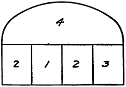
Fig. 58.—Sequence of Excavation in
the Murray Hill Tunnel.
Excavation.
—The two parallel tunnels were driven exclusively
from the ends reached by shafts; thus the tunnels were
attacked at four parts. It was in these tunnels that a comparative
test was made of the different methods of driving tunnels
through rock. The contractor applied the heading and drift
method at the southern ends of the tunnels, the eastern tunnel
being driven by means of a drift while in the western tunnel
the usual heading method was followed. This latter method
is illustrated in the chapter following and the eastern tunnel at
33rd Street, excavated by means of a drift, is here considered.
Fig. 58 shows the sequence of
cuts adopted for this tunnel. It
was begun by a bottom drift, about
10 ft. high, 8 ft. wide and 7 ft. deep,
which was located at one side of
the axis of the tunnel, as indicated
in the figure. This drift was immediately
widened by removing the
portions marked 2. About 50 ft.
in the rear the part marked 3 was
taken away, thus clearing the entire lower portion of the tunnel.
Section 4, about 50 ft. to the rear of section 3, was then
broken down and removed.
The methods of drilling and blasting were as follows: In
taking out the original drift, a wedge-shaped center cut was made
and then enlarged to the full size of the drift by drilling parallel
holes. The succeeding sections, 2 and 3, were removed by
driving parallel holes, while the top section, 4, was taken away
by a center cut and parallel holes. The drills were mounted
on columns, two drills to a column, and the holes were usually
drilled about 7 ft. deep, starting with a diameter of 23⁄4 in. and
ending with a diameter of 13⁄4 in. They were blasted with 40%[125]
dynamite in light charges, only a few holes being fired at a time,
usually not more than three or four.
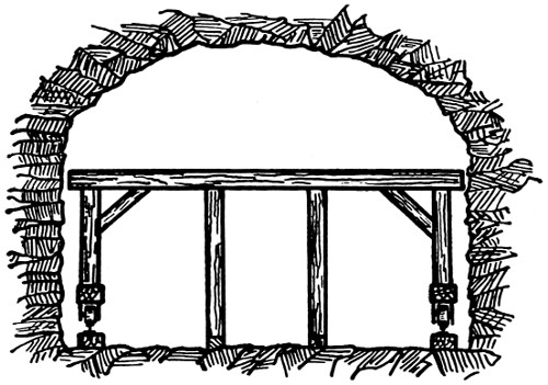
Fig. 59.—Traveling Platform for the Excavation of
the Upper Side of the Murray Hill Tunnel.
To remove section 4, a traveling platform 101⁄2 ft. long and
25 ft. wide was used. This platform, as shown in Fig. 59, consisted
of two longitudinal
beams mounted on four
double flanged wheels
which were running on
tracks laid 23 ft. apart.
Resting on top of these
beams were four 12 in. ×
12 in. uprights braced in
every direction against the
framework of the platform.
This frame was built of
12 in. × 12 in. beams laid
longitudinally, the transverse beams being 12 in. × 14 ins. The
platform proper was made of 3 in. planks, and was set 9 ft. above
the tunnel floor. The columns supporting the drills for the excavation
of the upper section 4, were set up above the platform
which was then reinforced by other vertical props, as indicated
by the dotted lines in the figure. These props, however, were
placed so as to leave a clearance beneath the platform for the
cars to carry away the débris from the front. During the
blasting the platform was moved back so that the blasted rock
fell to the floor of the tunnel, whence it was loaded into boxes
on the cars.
Strutting.
—When the rock was seamy and full of fissures,
running in every direction, it was necessary to support the
roof of the excavation. This was done in the following manner:
After part 4 was removed the timbers supporting the roof of
the excavation were set up. In this case, the polygonal strutting
was used. This consisted of heavy timber frames placed transversely
to the axis of the tunnel and supporting the planks or
poling-boards which ran longitudinally against the roof of the[126]
excavation. The seven-segment arch frame was used in the
Murray Hill tunnel. At the bottom of part 4 were placed
longitudinally 12 × 16 in. beams and upon them rested the
inclined segments which, with a horizontal one, formed the
arch frame as shown in Fig. 60.
When the pressures were too
heavy the crown segment was
reinforced by a 6 × 12 in. beam,
kept in place by two 12 × 12 in.
inclined props which rested on
the templates. As the tunnel
was lined with concrete, the timbering
was left in place and it
was built outside the line of the
extrados of the concrete lining.
Timbering was only used for a short distance but it necessitated
a larger amount of rock excavation when it was required.
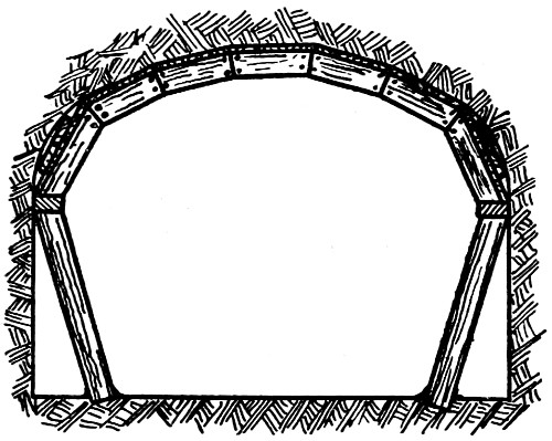
Fig. 60.—Timbering Used in the Murray
Hill Tunnel.
Hauling.
—Great efficiency was shown in the method of
hauling away the excavated materials. Three narrow-gauge
parallel tracks were laid on the floor of the tunnel and extended
to the faces of the advance drifts. Small flat cars were run on
these tracks. They carried steel boxes, 5 ft. square and 15 ins.
deep, fitted with three lifting rings and chains. When filled,
the cars were run to the bottom of the shaft, the boxes were
hoisted by a stiff-legged derrick placed at the shaft head, and
the débris was dumped into storage bins of 300 cu. yds. capacity.
These bins were elevated 8 ft. above the street so that the
wagons could be driven under it to take loads of spoil by
means of chutes. The broken rock was loaded into the boxes
by hand.
Concrete Lining.
—The tunnel was lined with concrete which
was manufactured by a quite elaborate plant. A stone crushing
plant, consisting of bins for raw and crushed stone, was erected
at the shaft head and a mixing plant was suspended from the
shaft. On the platform of the shaft head were two bins side[127]
by side, one for crushed stone, the other for sand; both of which
communicated, by means of trap doors, with a hopper chute.
The materials from the hopper were delivered into a measuring
box where cement was laid on top of the other ingredients by
hand. They were then conveyed through a canvas chute into
a cubical mixer operated by an engine. The mixer discharged
its contents into skips set on cars at the bottom of the
shaft and the concrete was hauled inside the tunnel ready for
use.
The construction of the lining was accomplished by means of
traveling platforms. The footing courses were laid first. Because
these projected inward about 18 ins. from the faces of the
finished sidewalks it was possible to lay a track rail on their top
inner edges on each side of the tunnel. These track rails carried
the traveling platforms. There were three of these platforms;
the forward one was used for building the side walls; the center
one, for carrying a derrick; the last one, for building the roof
arch. The side wall platform was mounted on six wheels. On
each side there was mounted an adjustable lagging which was
curved to conform to the inside profile of the side wall. In
operation this platform was run to the point where the side walls
were to be constructed and the lagging was adjusted to position
and fastened. Skips of concrete were then hoisted on its top,
their contents were shoveled into the space between the lagging
and the wall of the excavation and were there rammed into place
until the finished concrete had reached the top of the lagging.
When the concrete had set, the wedges holding the lagging in
place were loosened and the platform was moved ahead and
adjusted for building a new section of wall. The derrick platform
was 231⁄2 ft. wide and 18 ft. long. Transversely, it had
three bays, two of which were floored over and one was left
without flooring to allow passage for the concrete skips to and
from the cars, on the tunnel floor beneath. At the center of
the floored area was mounted a derrick to handle the skips. In
operation, the derrick platform came between the side wall[128]
platform ahead and the roof platform behind. The construction
of the roof platform was practically the same as the side wall
platform with the addition of roof arch centers at each bent
on which lagging could be placed. The mode of procedure was
to erect the form for a small space between the side walls already
built and the haunches of the center, to shovel concrete from the
skips and to run it into place. Then the roof lagging, a part at
a time, was placed upward from the haunches and the concrete
was filled and rammed behind it. The lining was built from the
haunches upward until the two sides approached within a distance
of about 5 ft. from each other at the crown. This 5 ft. crown
strip or key was built by working from the rear toward the front
end of the platform.
Plant.
—The plant used by the contractors for Section IV.
of the subway comprised a central power plant located about
4000 ft. from the work. This was on 42nd Street near the East
River and furnished power for the work on both Sections IV.
and V. The buildings consisted of an engine room 63 × 30 ft.
and a boiler room, 42 × 28 ft. In the former room was located
one Rand-Corliss air compressor, 22 × 40 × 48 ins., having a
capacity of 5000 cu. ft. of free air per minute; in the latter room
there were two 200 H.P. water tube boilers. There were also
the necessary equipment of feed water pump, air condenser
pump, etc. The compressors discharged into a 20 × 51⁄2 ft.
receiver of riveted steel through a 7 in. pipe. The air from the
receiver was carried by a 10 in. pipe 3.277 ft. to the corner of
Park Avenue and 41st Street, and was thence run south along
Park Avenue in an 8 in. pipe, from which 3 in. branches led to
the four headings of the work.
Ventilation.
—The ventilation of the tunnel caused very
little trouble. In cool weather the natural draft of the shafts
and the air discharged from the drills served to keep the atmosphere
wholesome. In warm weather, artificial means were
necessary to clear the workings of foul air, particularly after
blasting. They comprised at each end a 4 ft. American exhaust[129]
fan drawing air from a 12 in. riveted galvanized iron pipe, which
extended to the working faces.
Illumination.
—The tunnel was lighted by electric lamps which
extended even to the working face. During the blasting, however,
all the lamps and wires within 100 ft. from the front were
removed and gasoline torches were used; they were also employed
before the electric lamps and wires could be replaced, to
light the tunnel during the operation of clearing the débris.
[130]
CHAPTER XI.
TUNNELS THROUGH HARD ROCK (Continued).—EXCAVATION
BY HEADINGS.
EUROPEAN AND AMERICAN METHODS.
The more common method of tunneling through hard rock
is to begin the work by a heading, instead of by a drift. This
heading may be of small dimensions, and the remainder of the
section may also be removed in successive small parts, or it may
be the full width of the section, and the enlargement of the
section be made in one other cut.
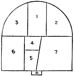
Fig. 61.—Diagram Showing Sequence
of Excavation in Heading
Method of Tunneling Rock.
General Discussion.
—When the tunnel is excavated by means
of several cuts, which is the method usually employed in
Europe, the sequence of work is as indicated by Fig. 61.
Work is begun by driving the center top heading No. 1, whose
floor is at the level of the bottom of the roof arch, and which is
usually excavated by the circular cut method. This heading is
widened by removing parts Nos. 2 and 3 until the top part of the
section is removed, then the roof arch is built with its feet resting
on the unexcavated rock below. The lower portion of the
section or bench is removed by first sinking the trench No. 4,
after which part No. 5 is taken out, and then parts Nos. 6 and 7,
and the side walls built. Part No. 8 for the culvert is finally
opened. The heading is, as a rule, driven far in advance, but
the excavation of each of the other parts follows the preceding
one at a distance behind of about 300 ft.
The strutting, when any is required, is usually the typical
radial strutting of the Belgian method of tunneling. The
masonry lining is constructed practically the same as in tunnels
excavated by a drift. The hauling is done on a single track
laid in the heading No. 1, which separates into double tracks[131]
where the full top section has been excavated by the removal
of parts No. 2. These two tracks are again combined and form
a single track along the top of part No. 5, which has been left
wider than part No. 4 for this particular purpose. When part
No. 3 is excavated a standard-gauge track is laid on its floor;
and as the full section of the tunnel is completed by taking out
parts Nos. 4 and 5, this single track is replaced by two standard-gauge
tracks, into which it switches. Spoil is transferred from
the narrow-gauge tracks on the upper level, to the standard-gauge
tracks on the tunnel floor, by means of chutes, and building
material is transferred in the opposite direction by means of
hoisting apparatus.
When the excavation is made by a single wide heading, and
a single other cut for removing the bench, which is the method
preferred by American engineers, it is called the Heading and
Bench method. The work begins by removing a top heading
the full width of the section; this heading is usually made 7 ft.
or 8 ft. high, and is excavated by the center cut method. The
method of strutting usually employed is to erect successive
three- or five-segment timber arches, whose feet rest on the
top of the bench; when the bench is removed, posts are inserted
under the feet of each arch. These arches are covered with a
lagging of plank. In America it has often been the practice to
let this strutting serve as a temporary lining, and to replace
it only after some time, often after years, with a permanent
lining of masonry. In a succeeding chapter, some of the methods
adopted in relining timber-lined arches with masonry are described.
The hauling is done by either narrow or broad gauge
tracks laid on the floor of the completed section below. A device
called a bench carriage is often employed to enable the cars
running on the heading tracks to dump their loads into the cars
below, without interfering with the work on the bench front.
This device consists of a wide platform carried on trucks, running
on rails at the sides of the tunnel floor, so that it is level with
the floor of the heading. The front of this platform carries a[132]
hinged leaf which may be raised and lowered, and which forms
a sort of gang-plank reaching to the floor of the heading. By
running the heading cars out on to this traveling platform, they
can be dumped into the cars below entirely clear of the work in
progress on the bench front.
For the purpose of illustrating the two methods of driving
tunnels by a heading, which have been briefly described, the St.
Gothard and the Fort George tunnels have been selected. The
St. Gothard tunnel is selected, as being one of the longest tunnels
in the world, and because it was excavated by a number of small
parts; and the Fort George tunnel, as being a double-track tunnel,
driven by a heading, and bench, and having a concrete lining.
ST. GOTHARD TUNNEL.
The St. Gothard tunnel penetrates the Alps between Italy
and France, and is 91⁄4 miles long. It was constructed in 1872-82.
Material Penetrated.
—The St. Gothard tunnel was excavated
through rock, consisting chiefly of gneiss, mica-schist, serpentine,
and hornblende, the strata having an inclination of from
45° to 90°. At many points the
rock was fissured, and disintegrated
easily, and water was encountered
in large quantities, causing much
trouble.
Excavation.
—The sequence of excavation
is shown by Fig. 14, p. 36.
First the top center heading, No. 1,
whose dimensions varied from 8.25 ×
8.6 ft. to 8.5 × 9 ft., according to the
quality of the rock, was driven
never less than 1000 ft. and sometimes
over 3000 ft. in advance of parts No. 2. The excavation
of parts No. 2 opened up the full top section, and parts
Nos. 3, 4, 5, 6, and 7, were removed in the order numbered.
Strutting.
—Where regular strutting was required, the construction
shown in Fig. 62 was adopted.
[133]
Masonry.
—The St. Gothard tunnel is lined throughout with
masonry. After the upper portion of the section was fully
excavated, the roof arch was built with its feet resting upon
short planks on the top of the bench. Plank centers were used
in constructing the arch. For the arch brick masonry was
employed, but the side walls were built of rubble masonry.
Shelter niches, about 3 ft. deep, were built into the side walls
at intervals, and about every 3,000 ft. storage niches about 10
ft. deep, and closed with a door, were constructed. The culvert
was of brick masonry.
Mechanical Installation.
—Water-power was used exclusively
in driving the St. Gothard tunnel. At the north end, the
Reuss, and at the south end, the Tessin and the Tremola, rivers
or torrents were dammed, and their waters conducted to turbine
plants at the opposite ends of the tunnel. The power thus
furnished by the Reuss was about 1,500 H.P., and the power
furnished by the combined supply of the Tessin and Tremola
was 1,220 H.P. The turbine plant at both ends at first consisted
of four horizontal impulse turbines, but later, two more
turbines were added at the south end. Each of the two sets of
four turbines first installed drove five groups of three compressors
each, and the two supplementary turbines drove two groups
of four compressors each. The compressors were of the Colladon
type with water injection, and four groups of three compressors
each were capable of furnishing 1,000 cu. yds. of air compressed
to between seven and eight atmospheres every hour, or about
100 H.P. per hour, delivered to the drills at the front. This
air when exhausted provided about 8,000 cu. yds. of fresh air
per hour for ventilation.
The compressors at each entrance discharged into a group
of four cylindrical receivers of wrought-iron each 5.3 ft. in
diameter by 29.5 ft. long, and having a capacity of 593 cu. ft.
The cylinders were placed horizontally, the first one receiving
the air at one end and discharging it at the other end into the
next cylinder, and so on. By this arrangement the air was[134]
drained of its moisture, and the discharge from the end receiver
into the tunnel delivery pipes was not affected by the pulsations
of the compressors. The delivery pipe decreased from 8 in.
in diameter at the receiver to 4 ins. in diameter, and finally to
21⁄2 ins. in diameter, at the front.
The drills employed were of various patterns. The first one
employed was the Dubois & François “perforator,” in which the
drill-bit was fed forward by hand. This was replaced by Ferroux
drills having an automatic feed. Jules McKean’s “perforator”
was employed at the north end of the tunnel. All of
these drills were of the percussion type, and were mounted on
carriages running on tracks. Their comparative efficiency was
officially tested in drilling granitic gneiss with an operating
air pressure of 5.5 atmospheres with the following results:
Name of
Drill. |
Penetration
Ins. per Min. |
| Ferroux |
1.6 |
| McKean |
1.4 |
| Dubois & François |
1.04 |
| Soummelier |
0.85 |
The heading was excavated by the circular cut method, the
holes being driven as follows: Near the center of the heading
three holes were first drilled, converging so as to inclose a
pyramid with a triangular base. Around these center holes
from 9 to 13 others were driven parallel to the tunnel axis.
The center holes were blasted first, and then the surrounding
holes. From 3 to 5 hours were required to drill the two sets
of holes, and from three to four hours were required to remove
the blasted rock. The number of holes drilled in removing
each of the various parts was as follows:
| Part No. 1 |
6 to 9 |
| Part No. 2 |
6 to 10 |
| Part No. 3 |
2 |
| Part No. 4 |
6 to 9 |
| Part No. 5 |
3 |
| Part No. 6 |
6 to 9 |
| Part No. 7 |
1 |
| Total for full section |
36 to 40 |
[135]
Hauling.
—Two different systems were employed for hauling
the spoil and construction material in the St. Gothard
tunnel. To remove the spoil from parts Nos. 1 and 2 a narrow-gauge
track was laid on the floor of the heading, and the cars
were hauled by horses, the grade being descending from the
fronts. These narrow-gauge cars were dumped into larger
broad-gauge cars running on the track laid on the floor of the
completed section and hauled by compressed air locomotives
(Fig. 63). To raise the incoming structural material from the
broad-gauge cars to the narrow-gauge cars running on the level
above, hoisting devices were employed.
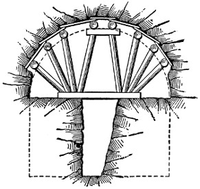
Fig. 62.—Method of Strutting Roof,
St. Gothard Tunnel.
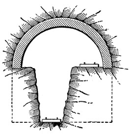
Fig. 63.—Sketch Showing Arrangement of
Car Tracks, St. Gothard Tunnel.
FORT GEORGE TUNNEL.[10]
From a point north of 157th Street and Broadway almost to
Dyckman Street, that is, a distance of nearly two miles, the New
York Subway passes under an elevation known as Fort Washington
Heights, which almost bounds Manhattan Island at its upper
end near the Harlem Ship Canal. Under this elevation the
rapid transit railroad was constructed in tunnel. The tunnel
was driven from two intermediate shafts over 110 ft. deep,
located one at 169th Street and the other at 181st Street and[136]
Broadway. Both shafts were sunk at one side of the center
line of the tunnel. After these shafts had been utilized for
working purposes during the construction of the tunnel, they
were equipped with electric elevators to carry passengers from
the streets to the deep station.
Material.
—The material encountered in the excavation of the
Fort George tunnel was the usual mica schist met everywhere
on Manhattan Island. It was full of seams with strata running
in every direction to such an extent that at many points the roof
of the tunnel had to be supported by timbers; at other parts
along the line the rock was so disintegrated that it was considered
a very loose and treacherous soil. Two serious accidents, each
accompanied by loss of life, occurred during the construction of
this tunnel. Both of them were caused by the sudden fall of
a large ledge of rock which, after the tunnel had been excavated
to the full section, remained hanging on the roof, deprived of
any support and held in place by the little cohesion of the material
packing the seams.
Excavation.
—The tunnel was excavated by the heading
method in only two cuts, viz., the heading and bench as indicated
in the Fig. 65. The heading, almost as wide as the upper portion
of the tunnel section, was excavated in the manner explained on
page 91. After the heading was removed, the enlargement of
the entire upper section of the tunnel was accomplished by
driving three inclined holes at each side of the heading. They
were driven at different depths and inclinations, as shown in
the figure and were called trimming holes. At the same time
the bench was removed by means of five holes—three vertical
and two inclined. The line of subgrade was reached by means
of five grading holes driven almost horizontal with a slight
inclination downward. The air drills for the heading were
mounted on columns, all the others on tripods. The blasting
was done in the following order: the grading holes were blasted
in the first round, the bench and trimming in the second, the
center cut of the heading in the third, the sides in the fourth[137]
and the dry holes in the last. Thus each advance of 7 ft. of
the whole tunnel section was made by means of forty holes fired
in five rounds which consumed 277 lbs. of dynamite with an
average additional quantity of 76 lbs., making a total of 353 lbs.
With the exception of the center cut, where 60% dynamite was
used, all the other holes were discharged with 40% dynamite.
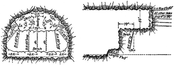
Cross Section.
Fig. 64.—Arrangement of Drill Holes in
the Fort George Tunnel.
Longitudinal Section.
Fig. 65.—Longitudinal Section of the Heading
and Bench Excavation at the Fort George
Tunnel.
Larger illustration
Strutting.
—When the rock was of such a character as to be
dangerous and required permanent timber support, until the
masonry lining was in place, the method employed was as follows:
a top heading was first excavated about 10 ft. deep and from 10 ft.
to 12 ft. wide for some distance, 100 ft. to 500 ft., the dangerous
rock being supported by 10 × 10 in. yellow pine plumb or raking
posts and sometimes by timber bents (“caps and legs”). The
next process was to widen the heading to the full width of 30 ft.
for a length of about 20 ft., placing timber supports under the
dangerous rock as the widening-out progressed. The excavation
was deepened a little at the sides to 9.5 ft. below the roof
grade (ordered line of excavation) or about 11 ft. below the
roof grade, which was necessary when segmental timbering was
to be used, to allow for placing a 12 × 12 in. “wall plate”
(timber sill) along each side. These wall plates, generally 20 ft.
long, were set to the correct elevation and were leveled by
blocking and wedging. As soon as the wall plates were set,[138]
the work of erecting the segmental timber sets, one set at a time,
was begun by starting from the wall plates and supporting the
timber on scaffolding until keyed in, then it was blocked up to
the rock at each joint and at other necessary points. When two
or more sets were erected, lagging, made of boards 2 ins. thick
by 6 to 10 ins. wide, was placed over the segmental timber “sets”
and the space above the timber dry packed with small stone
placed by hand. Sometimes there was enough room between the
timber and the rock to do all the dry packing after the full
number of sets, generally six, had been placed on the two wall
plates. The temporary timber posts and braces were taken out
as the segmental timber sets were erected.
The seven timbers that made up a timber set were of yellow
pine each 10 × 10 ins., 5 ft. 2 ins. long at the intrados and 5 ft.
6 ins. at the extrados. The sets were spaced from 3 ft. to 5 ft.
apart, but generally 3.5 ft. and braced to each other at each joint
of the segmental timbers by 6 × 8 in. spreaders which were
wedged against the joint splices.
When the timbers were all erected on a set of wall plates
(20 ft.) and the lagging and dry packing were completed the
work of taking out the bench, which had been partly drilled as
the timber sets were erected, was resumed. The face of the
bench, which had been left about 4 ft. from the end of the previous
set of wall plates, was brought forward slowly by placing
10 × 10 in. plumb posts which extended below subgrade under
the wall plates. These posts were generally spaced the same
as the timber sets above and directly under them.
When the face of the bench had been brought to within 3 or
4 ft. of the forward end of the wall plate, the process of widening
out and timbering another 20 ft. length of heading was begun.
In some places the rock, though needing permanent support,
was such that the work of taking out the bench and widening
the heading was carried on simultaneously without increasing
the danger; but the greater portion of the work, when strutting
was required, was done as has been described.
[139]
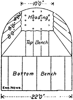
Fig. 66.—Diagram Showing
the Arrangement of Drill
Holes in the Heading and
Bench of the Gallitsin Tunnel.
Hauling.
—The excavated material was loaded at the foot
of the bench in dump cars which were run by mule power to the
portal or the shaft according to location, on 36 in. gauge-service
tracks. Inclines at 159th Street were graded from the portal at
158th Street to the street surface. The cars were formed at
this portal into a train and were taken up the incline to the dump
at 162nd Street and the North River by construction locomotives.
At the 168th Street and 181st Street shafts, the cars were hoisted
to the surface in cages (elevators). In the former case, they were
taken to the dump at 165th Street and the North River by mules
and gravity; in the latter case, to various dumps by teams.
At both shafts, stone crushers were located, therefore a great
part of the material did not have to be hauled to the dumps
or even taken to the surface as a great deal of stone was used in
dry packing over the concrete arch. The material from the
portal at Fort George was hauled by mules directly to the dump
near by.
Lining.
—The entire tunnel was lined with concrete, consisting
of a floor 4 ins. thick and vertical side walls 18 ins. thick and
25 ft. apart, which carried a semicircular arch 18 ins. thick
except in the timbered portions where the thickness was increased
to 21 ins. and to 24 and 27 ins. in some places. The
springing line of the arch is 6 ft. 2 ins. above the concrete floor
(5 ft. 6 ins. above the base of rail), hence the maximum clearance
above the base of rail is 18 ft. The side walls and arch were
built solid of rock to a height of 8 ft. above springing line and
the space above that point between the concrete and the rock
was packed by hand with small stones. The concrete of the
arch was laid on timber centers erected for that purpose.
The heading and bench method of excavating rock tunnels
is not always followed in the manner just described but is employed
with slight modifications. There is a large variety of
modifications but only the two most commonly used in practical
works are given here. The heading and bench method illustrated
in Fig. 66 was used, among others, on the Gallitsin[140]
tunnel along the Pennsylvania R.R. at the summit of the
Alleghenies near Altoona, Pa., and more recently in the tunnels
constructed by the same company under Bergen Hill, N. J., for
the entrance to New York City. The
shape of the cross-section of these tunnels
was semicircular arch on vertical side
walls. The excavation was made in three
consecutive cuts, viz., the heading marked
1 in the figure, the top bench 2, and the
lower bench 3. A heading 7 ft. high and
10 ft. wide was attached near the crown
of the arch and the rock was removed by
means of a center cut and parallel side
holes, the number of holes depending upon
the consistency of the rock. The part
No. 2 was excavated by drilling holes at
each side to different depths and at different
inclinations in order to reach the line of the profile as
well as the springing line of the proposed tunnel. The central
part of the top bench was excavated by means of holes driven
vertically from the floor of the heading. The bottom bench
No. 3, included between the springing
line of the arch and subgrade,
was removed by means of five vertical
holes driven from the floor of
the top bench. The three different
working parts were kept nearly
10 ft. apart. Blasting was effected
in reversed order to the figures
marked in the diagram, viz., the
bottom bench first and the heading
last.
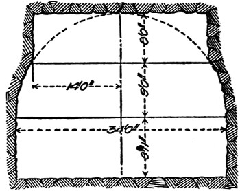
Fig. 67.—Diagram Showing a Modification
of the Heading and Bench
Method.
Still another modification of the heading and bench method,
commonly followed by American engineers, is the one shown in
Fig. 67. This consists in dividing the tunnel section in three[141]
parts by horizontal lines. The resultant parts are first the
heading excavated close to the roof, and as wide as the whole
section of the tunnel; second, the top bench in the middle, and
lastly the bottom bench excavated to the depth of the proposed
tunnel floor. The excavation proceeds in the numerical
order, beginning at the heading which was excavated, as usual,
by means of a center cut and side holes to the full width of the
proposed tunnel. First the top bench, then the bottom bench,
are removed by means of vertical holes driven from the floor
of the heading and the floor of the top bench, respectively.
COMPARISON OF METHODS.
The differences between the drift and heading methods of
excavating tunnels through rock, consist chiefly in the excavations,
strutting, and hauling. When the drift method is employed
an advanced gallery is opened along the floor of the
tunnel before the upper part of the section is removed, and
when the heading method is employed the upper part of the
section is completely excavated before any part of the section
below is excavated. When the drift method of driving is employed
polygonal strutting is usually used, and longitudinal
strutting is employed with the heading method of driving. In
the drift method the hauling is done by one system of tracks at
the same level, while in the heading method two systems of
tracks are employed at different levels.
It is, perhaps, impossible to state without qualification which
method is the better. European engineers who have been connected
with both the Mont Cenis and St. Gothard tunnels, driven
by the drift and heading methods respectively, had the opportunity
to practically observe the advantages and disadvantages
of these two methods. Their conclusion was that the drift
method was more convenient for tunnels driven through hard
and compact rock, and that the heading method was better for
tunnels of fissured and disintegrated rocks. To prove this
opinion, experiments were made in one of the tunnels approaching[142]
the great St. Gothard tunnel. On a short tunnel the excavation
was made by the drift method from one portal, while at
the other, the heading method was followed. Although the
general rule was fully confirmed still the conditions at the portals
were not identical. More conclusive experiments were made by
Mr. Ira A. Shaler, the contractor for Section IV., of New York
Rapid Transit Railway. He had the opportunity of driving two
parallel tunnels under Murray Hill only 17 ft. apart. The
eastern tunnel was driven by the drift method, the western one
by the heading method. After the work had proceeded for a
few months, Mr. Shaler stated that in his case the drift method
was more convenient. He could spare drilling several holes
at each advance, thus obtaining economy in time, labor and
material without considering the advantage of a simpler transportation
of the débris. He promised to publish his results
for the benefit of the profession, but, unfortunately, lost his
life in an accident in the tunnel before the completion of the
work.
An advantage that the drift method affords in long tunnels is,
that the water, which is usually found in large quantities under
high mountains, is easily collected in the drift and conveyed to
the culvert, while in the heading method the water from the
advance gallery, before being collected into the culvert built
on the floor of the tunnel, must pass through all the workings.
This may be a serious inconvenience when water is found in
large quantities, as, for instance, was the case in the St.
Gothard tunnel, where the stream amounted to 57 gallons per
second.
[143]
CHAPTER XII.
EXCAVATING TUNNELS THROUGH SOFT
GROUND; GENERAL DISCUSSION; THE
BELGIAN METHOD.
GENERAL DISCUSSION.
It may be set down as a general truth that the excavation
of tunnels through soft ground is the most difficult task which
confronts the tunnel engineer. Under the general term of soft
ground, however, a great variety of materials is included, beginning
with stratified soft rock and the most stable sands and
clays, and ending with laminated clay of the worst character.
From this it is evident that certain kinds of soft-ground
tunneling may be less difficult than the tunneling of rock,
and that other kinds may present almost insurmountable difficulties.
Classing both the easy and the difficult materials
together, however, the accuracy of the statement first made
holds good in a general way. Whatever the opinion may be
in regard to this point, however, there is no chance for dispute
in the statement that the difficulty of tunneling the softer and
more treacherous clays, peats, and sands is greater than that
of tunneling firm soils and rock; and if we describe the methods
which are used successfully in tunneling very unstable materials,
no difficulty need be experienced in modifying them to handle
stable materials.
Characteristics of Soft-Ground Tunneling.
—The principal characteristics
which distinguish soft-ground tunneling are, first,
that the material is excavated without the use of explosives,
and second, that the excavation has to be strutted practically[144]
as fast as it is completed. In treacherous soils the excavation
also presents other characteristic phenomena: The material
forming the walls of the excavation tends to cave and slide.
This tendency may develop immediately upon excavation, or it
may be of slower growth, due to weathering and other natural
causes. In either case the roof of the excavations tends
to fall, the sides tend to cave inward and squeeze together, and
the bottom tends to bulge or swell upward. In materials of
very unstable character these movements exert enormous pressures
upon the timbering or strutting, and in especially bad
cases may destroy and crush the strutting completely. Outside
the tunnel the surface of the ground above sinks for a considerable
distance on each side of the line of the tunnel.
Methods of Soft-Ground Tunneling.
—There are a variety of
methods of tunneling through soft ground. Some of these,
like the quicksand method and the shield method, differ in character
entirely, while in others, like the Belgian, German, English,
Austrian, and Italian methods, the difference consists
simply in the different order in which the drifts and headings
are driven, in the difference in the number and size of these
advance galleries, and in the different forms of strutting framework
employed. In this book the shield method is considered
individually; but the description of the Belgian, German, English,
Austrian, Italian, and quicksand methods are grouped
together in this and the three succeeding chapters to permit of
easy comparison.
THE BELGIAN METHOD OF TUNNELING THROUGH SOFT
GROUND.
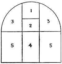
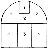
Figs. 68 and 68A.—Diagrams
Showing Sequence of Excavations in the
Belgian Method.
The Belgian method of tunneling through soft ground was
first employed in 1828 in excavating the Charleroy tunnel of
the Brussels-Charleroy Canal in Belgium, and it takes its name
from the country in which it originated. The distinctive characteristic
of the method is the construction of the roof arch[145]
before the side walls and invert are built. The excavation,
therefore, begins with the driving of a top center heading
which is enlarged until the whole of the section above the
springing lines of the arch is opened. Various modifications
of the method have been developed, and some of the more
important of these will be described farther on, but we shall
begin its consideration here by describing first the original and
usual mode of procedure.
Excavation.
—Fig. 68 is the excavation diagram of the Belgian
method of tunneling. The excavation is begun by opening
the center top heading No. 1, which is carried ahead a
greater or less distance, depending upon the nature of the soil,
and is immediately strutted. This heading is then deepened
by excavating part No. 2, to a depth corresponding to the
springing lines of the roof arch. The next step is to remove
the two side sections No. 3, by attacking them at the two fronts
and at the sides with four gangs of excavators. The regularity
and efficiency of the mode of procedure described consist in
adopting such dimensions for these several parts of the section
that each will be excavated at the same rate of speed. When
the upper part of the section has been excavated as described,
the roof arch is built, with its feet supported by the unexcavated
earth below. This portion of the section is excavated by
taking out first the central trench No. 4 to the depth of the
bottom of the tunnel, and then by removing the two side parts
No. 5. As these side parts No. 5 have to support the arch,[146]
they have to be excavated in such a way as not to endanger it.
At intervals along the central trench No. 4, transverse or side
trenches about 2 ft. wide are excavated on both sides, and
struts are inserted to support the masonry previously supported
by the earth which has been removed. The next step is to
widen these side trenches, and insert struts until all of the
material in parts No. 5 is taken out.
When the material penetrated is firm enough to permit, the
plan of excavation illustrated by the diagram, Fig. 68A, is substituted
for the more typical one just described. The only difference
in the two methods consists in the plan of excavating the
upper part of the profile, which in the second method consists
in driving first the center top heading No. 1, and then in taking
out the remainder of the section above the springing lines
of the arch in one operation, while in the first method it is done
in two operations. The distance ahead of the masonry to
which the various parts can be driven varies from 10 ft. to, in
some cases, 100 ft., being very short in treacherous ground, and
longer the more stable the material is.
Strutting.
—The longitudinal method of strutting, with the
poling-boards running transversely of the tunnel, is always
employed in the Belgian method of tunneling. In driving the
first center top heading, pairs of vertical posts carrying a transverse
cap-piece are erected at intervals. On these cap-pieces
are carried two longitudinal bars, which in turn support the
saddle planks. As fast as part No. 2, Fig. 68, is excavated,
the vertical posts are replaced by the batter posts A and B,
Fig. 69. The excavation of parts No. 3 is begun at the top,
the poling-boards a and b being inserted as the work progresses.
To support the outer ends of these poling-boards, the
longitudinals X and Y are inserted and supported by the batter
posts C and D. In exactly the same way the poling-boards c
and d, the longitudinals V and W, and the struts E and F, are
placed in position; and this procedure is repeated until the
whole top part of the section is strutted, as shown by Fig. 69,[147]
the cross struts x, y, z, etc., being inserted to hold the radial
struts firmly in position. The feet of the various radial
props rest on the sill M N. These fan-like timber structures
are set up at intervals of from 3 ft. to 6 ft., depending upon
the quality of the soil penetrated.
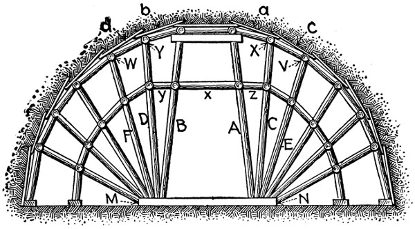
Fig. 69.—Sketch Showing Radial Roof Strutting, Belgian Method.
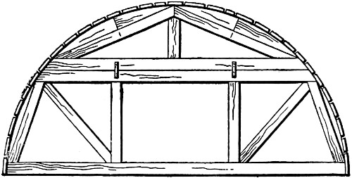
Fig. 70.—Sketch Showing Roof Arch
Center, Belgian Method.
Centers.
—Either plank or trussed centers may be employed
in laying the roof arch in the Belgian method, but the form of
center commonly employed is a trussed center constructed as
shown by Fig. 70. It may be said to consist of a king-post
truss carried on top of a modified form of queen-post truss.
The collar-beam and the tie-beam of the queen-post truss are
spaced about 7 ft. apart, and
the posts themselves are left far
enough apart to allow the passage
of workmen and cars between
them. The tie beam of
the king-post truss is clamped
to the collar-beam of the queen-post
truss by iron bands. On
the rafters of the two trusses are fastened timbers, with their
outer edges cut to the curve of the roof arch. These centers
are set up midway between the fan-like strutting frames previously
described. They are usually built of square timbers.
The tie beams are usually 6 × 6 in., and the struts and posts
4 × 4 in. timbers. The reason for giving the larger sectional[148]
dimensions to the tie beams, contrary to the usual practice in
constructing centers, is that it has to serve as a sill for distributing
the pressure to the foundation of unexcavated soil
which supports the center. Sometimes a sub-sill is used to
support the center upon the soil; and in any case wedges are
employed to carry it, which can be removed for the purpose of
striking the center. After the arch is completed, the centers
may be removed immediately, or may be left in position until
the masonry has thoroughly set. In either case the leading
center over which the arch masonry terminates temporarily is
left in position until the next section of the arch is built.
Masonry.
—The masonry of the roof arch, which is the first
part built, is of necessity begun at the springing lines, and the
first course rests on short lengths of heavy planks. These
planks, besides giving an even surface upon which to begin the
masonry, are essential in furnishing a bearing to the struts
inserted to support the arch while the earth below them, part
No. 5, Fig. 68, is being excavated. As the arch masonry
progresses from the springing lines upward, the radial posts
of the strutting are removed, and replaced by short struts resting
on the lagging of the centers, which support the crown
bars or longitudinals until the masonry is in place, when they
and the poling-boards are removed, and the space between the
arch masonry and walls of the excavation is filled with stone
or well-rammed earth.
Considering now the side wall masonry, it will be remembered
that in excavating the part No. 5, Fig. 68, of the
section, frequent side trenches were excavated, and struts
inserted to take the weight of the masonry. These struts are
inserted on a batter, with their feet near the center of the
tunnel floor, so that the side wall masonry may be carried up
behind them to a height as near as possible to the springing
lines of the arch. When this is done the struts are removed,
and the space remaining between the top of the partly finished
side wall and the arch is filled in. This leaves the arch[149]
supported by alternate lengths or pillars of unexcavated earth
and completed side wall. The next step is to remove the
remaining sections of earth between the sections of side wall,
and fill in the space with masonry.
Fig. 71 is a cross-section, showing
the masonry completed for one-half
and the inclined props in position
for the other half; and Fig. 72 is
a longitudinal section showing the
pillars of unexcavated earth between
the consecutive sets of inclined
struts and several other
details of the lining, strutting, and
excavating work.
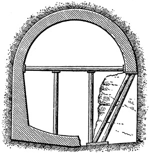
Fig. 71.—Sketch Showing Method of
Underpinning Roof Arch with the
Side Wall Masonry.
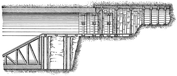
Fig. 72.—Longitudinal Section Showing
Construction by the Belgian Method.
The invert masonry is built after
the side walls are completed. This
is regarded as a defect of this method of tunneling, since the
lateral pressures may squeeze the side walls together and distort
the arch before the invert is in place to brace them apart.
To prevent as much as possible
the distortion of the arch after
the centers are removed, it is
considered good practice to
shore the masonry with horizontal
beams having their ends
abutting against plank, as shown by Fig. 71. These horizontal
beams should be placed at close intervals, and be
supported at intermediate points by vertical posts, as shown[150]
by the illustration. Since the roof arch rests are for some time
supported directly by the unexcavated earth below, settlement
is liable, particularly in working through soft ground.
This fact may not be very important so long as the settlement
is uniform, and is not enough to encroach on the space
necessary for the safe passage of travel. To prevent the
latter possibility the centers are placed from 9 ins. to 15 ins.
higher than their true positions, depending upon the nature of
the soil, so that considerable settlement is possible without any
danger of the necessary cross-section being infringed upon.
In conclusion it may be noted that the lining may be constructed
in a series of consecutive rings, or as a single cylindrical
mass.
Hauling.
—Since in this method of tunneling the upper part
of the section is excavated and lined before the excavation of
the lower part is begun, the upper portion is always more advanced
than the lower. To carry away the earth excavated at
the front, therefore, an elevation has to be surmounted; and
this is usually done by constructing an inclined plane rising
from the floor of the tunnel to the floor of the heading, as shown
by Fig. 72. This inclined plane has, of course, to be moved ahead
as the work advances, and to permit of this movement with as
little interruption of the other work as possible, two planes are
employed. One is erected at the right-hand side of the section,
and serves to carry the traffic while the left-hand side of the
lower section is being removed some distance ahead and the
other plane is being erected. The inclination given to these
planes depends upon the size of the loads to be hauled, but they
should always have as slight a grade as practicable. Narrow-gauge
tracks are laid on these planes and along the floor of the
upper part of the section passing through the center opening
mentioned before as being left in the centers and strutting.
In excavating the top center heading there is, of course, another
rise to its floor from the floor of the upper part of the
section. Where, as is usually the case in soft soils, this top[151]
heading is not driven very far in advance, the earth from the
front is usually conveyed to the rear in wheelbarrows, and
dumped into the cars standing on the tracks below. In firm
soils, where the heading is driven too far in advance to make
this method of conveyance adequate, tracks are also laid on
the floor of the heading, and an inclined plane is built connecting
it with the tracks on the next level below. In place of
these inclined planes, and also in place of those between the floor
of the tunnel and the level above, some form of hoisting device
is sometimes employed to lift the cars from one level to the
other. There are some advantages to this method in point of
economy, but the hoisting-machines are not easily worked in
the darkness, and accidents are likely to occur.
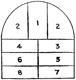
Fig. 73.—Diagram Showing
Sequence of Excavation
in Modified Belgian
Method.
In the advanced top heading and in the upper part of the
section narrow-gauge tracks are necessarily employed, and these
may be continued along the floor of the finished section, or the
permanent broad-gauge railway tracks may be laid as fast as
the full section is completed. In the former case the permanent
tracks are not laid until the entire tunnel is practically
completed; and in the latter case, unless a third rail is laid, the
loads have to be transshipped from the broad- to the narrow-gauge
tracks or vice versa. It is the more general practice to
use a third rail rather than to transship every load.
Modifications.
—Considering the extent to which the Belgian
method of tunneling has been employed, it is not surprising
that many modifications of the standard mode of procedure
have been developed. The modification which differs most
from the standard form is, perhaps, that adopted in excavating
the Roosebeck tunnel in Germany. This method preserves the
principal characteristic of the Belgian method, which is the
construction of the upper part of the section first; but instead
of building the side walls from the bottom upward, they are
built in small sections from the top downward. The excavation
begins by driving the center top heading No. 1, Fig. 73, whose
floor is at the level of the springing lines of the roof arch, and[152]
then the two side parts No. 2 are excavated, opening up the
entire upper portion of the section in which the roof arch is
built, as in the regular Belgian method. The next step is to
excavate part No. 3, shoring up the arch
at frequent intervals. Between these sets
of shoring the side walls are built, resting
on planks on the floor of part No. 3, and
then the sets of shores are removed and replaced
by masonry. Next part No. 4 is
excavated, shored, and filled with masonry
as was part No. 3. In exactly the same
way parts 5, 6, 7, and 8 are constructed
in the order numbered. To prevent the
distortion of the arch during the side-wall
construction it is braced by horizontal struts, as indicated
above in Fig. 71.
Advantages.
—The advantages of the Belgian method of
tunneling may be summarized as follows: (1) The excavation
progresses simultaneously at several points without the different
gangs of excavators interfering with each other, thus securing
rapidity and efficiency of work; (2) the excavation is done
by driving a number of drifts or parts of small section, which
are immediately strutted, thus causing the minimum disturbance
of the surrounding material; (3) the roof of the tunnel,
which is the part of the lining exposed to the greatest pressures,
is built first.
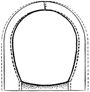
Fig. 74.—Sketch Showing
Failure of Roof Arch by
Opening at Crown.
Disadvantages.
—The disadvantages of the Belgian method
of tunneling may be summarized as follows: (1) The roof arch
which rests at first on compressible soil is liable to sink; (2)
before the invert is built there is danger of the arch and side
walls being distorted or sliding under the lateral pressures; (3)
the masonry of the side walls has to be underpinned to the arch
masonry.
Accidents and Repairs.
—One of the most frequent accidents
in the Belgian method of tunneling is the sinking of the roof[153]
arch owing to its unstable foundation on the unexcavated soil
of the lower portion of the section. The amount of settlement
may vary from a few inches in firm soil to over 2 ft. in loose
soils. To counteract the effect of this settlement it is the general
practice to build the arch some inches higher than its normal
position. When the settlement is great enough to infringe
seriously upon the tunnel section, repairs have to be made; and
the only way of accomplishing them is to demolish the arch and
rebuild it from the side walls. It is usually considered best not
to demolish the arch until the invert has been placed, so that
no further disturbance is likely to occur
once the lining is completed anew.
The rotation of the arch about its
keystone, or the opening of the arch at
the crown, by the squeezing inward of
the haunches by the lateral pressures,
is another characteristic accident. Fig.
74 shows the nature of the distortion
produced; the segments of the arch
move toward each other by revolving
on the intradosal edges of the keystone,
which are broken away and crushed together with the operation,
while the extradosal edges are opened. It is to prevent this
occurrence that the horizontal struts shown in Fig. 71 are employed.
The manner of repairing this accident differs, depending
upon the extent of the injury. When the intradosal edges
of the keystone are but slightly crushed, the repairing is done
as directed by Fig. 75. When the keystone is completely
crushed, however, the indications are that the material of the
keystone, usually brick, is not strong enough to resist the
pressures coming upon it, and it is advisable to substitute a
stronger material in the repairs, and a stone keystone is constructed
as shown by Fig. 75. The middle stone of this keystone
extends through the depth of the arch ring, and the two
side stones only half-way through, their purpose being merely[154]
to resist the crushing forces which are greatest at the intrados.
Sometimes, when the pressures are unsymmetrical, the arch
ring breaks at the haunches as well as the crown, as shown by
Fig. 75, which also indicates the mode of repairing. This
consists in demolishing the original arch, and rebuilding it
with stone voussoirs inserted in place of the brick in which the
rupture occurred.
[155]
CHAPTER XIII.
THE GERMAN METHOD—EXCAVATING TUNNELS
THROUGH SOFT GROUND (Continued);
BALTIMORE BELT LINE TUNNEL.
The German method of tunneling was first used in 1803
in constructing the St. Quentin Canal. In 1837 the Königsdorf
tunnel of the Cologne and Aix la Chapelle R.R. was
excavated by the same method. The success of the method in
these two difficult pieces of soft-ground tunneling led to its
extensive adoption throughout Germany, and for this reason
it gradually came to be designated as the German method.
Briefly explained the method consists in excavating first an
annular gallery in which the side walls and roof arch are built
complete before taking out the center core and building the
invert.
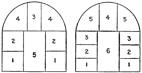
Fig. 76.—Diagrams Showing Sequence of Excavation in German Method
of Tunneling.
Excavation.
—The excavation of tunnels by the German
method is begun either by driving two bottom side drifts or
by driving a center top heading. Fig. 76 shows the mode of
procedure when bottom side drifts are used to start the work.
The two side drifts No. 1 are made from 7 ft. to 8 ft. wide,
and about one-third the total height of the full section; the[156]
width of each heading has to be sufficient for the construction
of the masonry and strutting, and for the passage of narrow
spoil cars alongside them. These drifts are increased in height
to the springing line of the arch by taking out the two drifts
No. 2. Next the top center heading No. 3 is driven, and
finally the two haunch headings No. 4 are excavated. The
center core No. 5 is utilized to support the strutting until
the side walls and roof arch are completed, when it is broken
down and removed. In case of very loose material, where the
first side drifts cannot be carried as high as one-third the
height of the section, it is the common practice to make them
about one-fourth the height, and to take out the side portions
of the annular gallery in three parts, as
shown by Fig. 76.
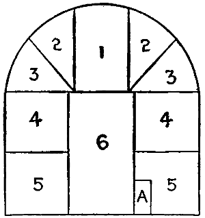
Fig. 77.—Diagram Showing
Sequence of Excavations
in Water Bearing
Material, German
Method.
The top center heading plan of commencing
the excavation is usually employed
in firm materials or when a vein
of water is encountered in the upper part
of the section. In the latter contingency
a small bottom drift A, Fig. 77, is first
driven to serve as a drain; but in any
case the excavation proper of the tunnel
consists in first driving the center top
heading No. 1, and then by working both
ways along the profile parts, Nos. 2, 3, 4, and 5 are removed.
Part No. 6 is left to support the strutting until the side walls
and roof arch are built, when it is also excavated.
Strutting.
—When the excavation is begun by bottom side
drifts these drifts are strutted by erecting vertical posts close
against the sides of the drift and placing a cap-piece transversely
across the roof of the drift. The side posts are
usually supported by sills placed across the bottom of the drift.
These frameworks of posts, cap, and sill are erected at short
intervals, and the roof, and, if necessary, the sides of the drift
between them, are sustained by means of longitudinal poling-boards[157]
extending from one frame to the next. The cap-pieces
of the strutting for the bottom drifts serve as sills for the
exactly similar strutting of the heading next above. To support
the additional weight, and to allow the construction of the
side walls, the strutting of the bottom drifts is strengthened by
inserting an intermediate post between the original side posts
of each frame. These intermediate posts are not inserted at
the center of the frames or bents, but close to the wall masonry
line as shown by Fig. 78. This eccentric position of the post
avoids any interference with the hauling, and also allows the
removal of the adjacent side post when the masonry is
constructed.
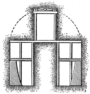
Fig. 78.—Sketch Showing Work of Excavating
and Timbering Drifts and
Headings.
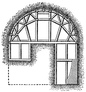
Fig. 79.—Sketch Showing Method of
Roof Strutting.
Two methods of strutting the soffit of the excavation are
employed, one being a modification of the longitudinal system
employed in the English method of tunneling described in a
succeeding chapter, and the other a modification of the Belgian
system previously described. Fig. 79 shows the method of
employing the radial strutting of the Belgian system. At the
beginning the center top heading is strutted with rectangular
bents such as are employed for strutting the drifts. As this
heading is enlarged by taking out the haunch sections, radial
posts are inserted, as shown by Fig. 79, which also indicates[158]
the method of strutting the side trenches when the excavation
is carried downward from the center top heading instead of
upward from bottom side drifts.
Masonry.
—Whatever plan of excavation or strutting is
employed, the construction of the masonry lining in the German
method of tunneling begins at the foundations of the side walls
and is carried upward to the roof arch. The invert, if one is
required, is built after the center core of earth is removed.
Centering.
—Tunnel centers are generally employed in the
German method of tunneling, a common construction being
shown by Fig. 80. It is essentially
a queen-post truss, the tie
beam of which rests on a transverse
sill as shown by the illustration.
The transverse sill is supported
along its central portion by the
unexcavated center core of earth,
and at its ends either directly on
the vertical posts or on longitudinal
beams resting on these posts.
The diagonal members of the
queen-post truss form the bottom
chords of small king-post trusses
which are employed to build out the exterior member of the
center to a closer approximation to the curve of the arch.
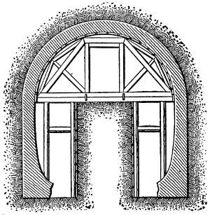
Fig. 80.—Sketch Showing Roof Arch
Centers and Arch Construction.
Hauling.
—When the bottom side drift plan of excavation
is employed, the spoil from the front of the drift is removed in
narrow-gauge cars running on a track laid as close as practicable
to the center core. These same cars are also employed to take
the spoil from the drifts above, through holes left in the ceiling
strutting of the bottom drifts. The spoil from the soffit sections
may be removed by the same car lines used in excavating
the drifts, or a narrow-gauge track may be laid on the top of the
center core for this special purpose. In the latter case the soffit
tracks are usually connected by means of inclined planes with[159]
the tracks on the bottoms of the side drifts. Generally, however,
the separate soffit car line is not used unless the material
is of such a firm character that the headings and drifts can be
carried a great distance ahead of the masonry work. With the
center top heading plan of beginning the excavation, the car
track has, of course, to be laid on the top of the center core.
The center core itself is removed by means of car tracks along
the floor of the completed tunnel.
Advantages and Disadvantages.
—Like the Belgian method
of tunneling, the German method has its advantages and disadvantages.
Since the excavation consists at first of a narrow
annular gallery only, the equilibrium of the earth is not greatly
disturbed, and the strutting does not need to be so heavy as in
methods where the opening is much larger. The undisturbed
center core also furnishes an excellent support for the strutting,
and for the centers upon which the roof arches are built.
Another important advantage of the method is that the construction
of the masonry lining is begun logically at the bottom,
and progresses upward, and a more homogeneous and stable
construction is possible. The great disadvantage of the method
is the small space in which the hauling has to be done. The
spoil cars practically fill the narrow drifts in passing to and from
the front, and interfere greatly with the work of the carpenters
and masons. Another objection to the method is that the
invert is the very last portion of the lining to be built. This
may not be a serious objection in reasonably compact and stable
materials, but in very loose soils there is always the danger of
the side walls being squeezed together before the invert masonry
is in position to hold them apart. Altogether the difficulties
are of a character which tend to increase the expense of the
method, and this is the reason why to-day it is seldom used
even in the country where it was first developed, and for some
time extensively employed. For repairing accidents, such as
the caving in of completed tunnels, the German method of tunneling
is frequently used, because of the ease with which the[160]
timbering is accomplished. In such cases the cost of the method
used cuts a small figure, so long as it is safe and expeditious.
BALTIMORE BELT LINE TUNNEL.
In the last few years a modification of the German method
was used in this country for the construction of several railroad
tunnels. The modification consists in excavating the two-side
drifts up to the springing line of the arch of the proposed tunnel.
Then a central heading, which is afterward enlarged to the whole
section of the tunnel, is excavated close to the crown. At the
same time the masonry is constructed from the foundation up
in the side drifts. From the floor of the upper section already
excavated and strutted, the top of the masonry of the drifts is
reached by means of small side cuts; thus the lining is made
continuous up to the keystone. The central nucleus or bench
is removed after the tunnel has been lined.
The most important tunnel excavated by this method was
the Baltimore Belt Line tunnel described as follows:
The Baltimore Belt Ry. Co. was organized in 1890 by officials
of the Baltimore & Ohio, and Western Maryland railways,
and Baltimore Capitalists, to build 7 miles of double track
railway, mostly within the city limits of Baltimore. This railway
was partly open cut and embankment, and partly tunnel,
and its object was to afford the companies named facilities for
reaching the center of the city with their passengers and freight.
To carry out the work the Maryland Construction Co. was
organized by the parties interested, and in September, 1890, this
company let the contract for construction to Ryan & McDonald
of Baltimore, Md. The chief difficulties of the work centered
in the construction of the Howard-street tunnel, 8350 ft.
long, running underneath the principal business section of
the city.
Material Penetrated.
—The soil penetrated by the tunnel was
of almost all kinds and consistencies, but was chiefly sand of
varying degrees of fineness penetrated by seams of loam, clay,[161]
and gravel. Some of the clay was so hard and tough that
it could not be removed except by blasting. Rock was also
found in a few places. For the most part, however, the work
was through soft ground, furnishing more or less water, which
necessitated unusual precautions to avoid the settling of the
street, and consequent damage to the buildings along the line.
A large quantity of water was encountered. Generally this
water could be removed by drainage and pumps, and the earth
be prevented from washing in by packing the space between the
timbering with hay or other materials. At points where the
inflow was greatest, and the earth was washed in despite the
hay packing, the method was adopted of driving 6-in. perforated
pipes into the sides of the excavation, and forcing cement
grout through them into the soil to solidify it. These pipes
penetrated the ground about 10 ft., and the method proved
very efficient in preventing the inflow of water.
Excavation.
—The excavation was carried out according to
the German method of tunneling. Bottom side drifts were
first driven, and then heightened to the springing line of the
roof arch. Next a center top heading was driven, and the
haunch sections taken out. The object of beginning the excavations
by bottom side drifts, was to drain the soil of the upper
part of the section. The center core was removed after the
side walls and roof arch were completed, its removal being kept
from 50 ft. to 75 ft. to the rear of the advanced heading. The
dimensions of the side drifts proper were about 8 × 8 ft., but
they were often carried down much below the floor level to secure
a solid foundation bed for the side walls.
Strutting.
—The side drifts were strutted by means of frames
composed of two batter posts resting on boards, and having a
cap-piece extending transversely across the roof of the drift.
These frames were spaced about 4 ft. apart. The excavation
was advanced in the usual way by driving poling-boards at the
top and sides, with a slight outward and upward inclination,
so that the next frame could be easily inserted leaving space[162]
enough between it and the sheeting to permit the next set of
poling-boards to be inserted. These poling-boards were driven
as close together as practicable so as to prevent as much as
possible the inflow of water and earth.

Fig. 81.—Sketch Showing Method of Excavating and Strutting Baltimore Belt
Line Tunnel.
Larger illustration
The center top heading was strutted in the same manner as
were the side drifts. The arrangement of the strutting employed
in enlarging the center top heading is shown clearly by
Fig. 81, which also shows the manner of strutting the side drifts
and face of the excavation, and of building the masonry.
Centers.
—Both wood and iron centers were employed in
building the roof arch. The timber centering was constructed
of square timbers, as shown by Fig. 82. This construction of
the iron centers is shown by Fig. 83. Each of the iron centers
consisted of two 6 × 6 in. angles butted together, and bent into
the form of an arch rib. Six of these ribs were set up 4 ft.[163]
apart. They were made of two half ribs butted together at the
crown, and were held erect and the proper distance apart by
spacing rods. The rearmost rib was held fast to the completed
arch masonry, and in turn supported the forward ribs while the
lagging was being placed.
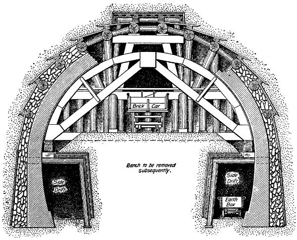
Fig. 82.—Roof Arch Construction with Timber Centers, Baltimore Belt Line Tunnel.
Masonry.
—The side walls of the lining were built first in
the bottom side drifts, as shown by Fig. 81. They were generally
placed on a foundation of concrete, from 1 ft. to 2 ft.
thick. As a rule the side walls were not built more than 20
ft. in advance of the arch, but occasionally this distance was
increased to as much as 90 ft. The roof arch consisted ordinarily
of five rings of brick, but at some places in especially unstable
soil eight rings of brick were employed. The arch was
built in concentric sections about 18 ft. in length. All the[164]
timber of the strutting above the arch and outside of the side
walls was left in place, and the voids were filled with rubble
masonry laid in cement mortar. It required about 125 mason
hours to build an 18-ft. arch section. Figs. 82 and 83 show
various details of the masonry arch work.
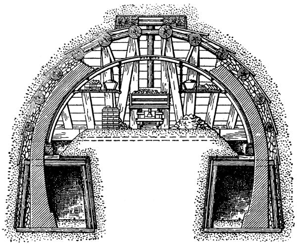
Fig. 83.—Roof Arch Construction with Iron Centers, Baltimore Belt Line Tunnel.
Owing to the very unstable character of the soil, considerable
difficulty was experienced in building the masonry invert.
The process adopted was as follows: Two parallel 12 × 12 in.
timbers were first placed transversely across the tunnel, abutting
against longitudinal timbers or wedges resting against the side
walls. Short sheet piles were then driven into the tunnel bottom
outside of these timbers, forming an inclosure similar to
a cofferdam, from which the earth could be excavated without
disturbing the surrounding ground. The earth being
excavated, a layer of concrete 8 ins. thick was placed, and the
brick masonry invert constructed on it. In less stable ground
each of the above described cofferdams was subdivided by
transverse timbers and sheet piling into three smaller cofferdams.
Here the masonry of the middle section was first constructed,[165]
and then the side sections built. Where the ground
was worst, still more care was necessary, and the bottom had
to be covered with a sheeting of 11⁄4-in. plank held down by
struts abutting against the large transverse timbers. The invert
masonry was constructed on this sheeting. Refuge niches
9 ft. high, 3 ft. wide, and 15 ins. deep were built in the side
walls.
Accidents.
—In this tunnel, owing to the quick striking of
the centers, it was found that the masonry lining flattened at
the crown and bulged at the sides. This was attributed to the
insufficient time allowed for the mortar to set in the rubble
filling. Earth packing was tried, but gave still worse results.
Finally dry rubble filling was adopted, with satisfactory results.
There was necessarily some sinking of the surface. This resulted
partly from the necessity of changing and removing of
the timbers, and from the compression and springing of the
timbers under the great pressures. The crown of the arch also
settled from 2 ins. to 6 ins., due to the compression of the mortar
in the joints. The maximum sinking of the surface of the
street over the tunnel was about 18 ins.; it usually ran from
1 to 12 ins. Some damage was done to the water and gas mains.
This damage was not usually serious, but it of course necessitated
immediate repairs, and in some instances it was found best to
reconstruct the mains for some distance. At one point along
the tunnel where very treacherous material was found, the
surface settlement caused the collapse of an adjacent building,
and necessitated its reconstruction.
[166]
CHAPTER XIV.
THE FULL SECTION METHOD OF TUNNELING:
ENGLISH METHOD; AMERICAN METHOD;
AUSTRIAN METHOD.
ENGLISH METHOD.
The English method of tunneling through soft ground, as
its name implies, originated in England, where, owing to the
general prevalence of comparatively firm chalks, clays, shales,
and sandstones, it has gained unusual popularity. The distinctive
characteristics of the method are the excavation of the
full section of the tunnel at once, the use of longitudinal strutting,
and the alternate execution of the masonry work and
excavation. In America the method is generally designated as
the longitudinal bar method, owing to the mode of strutting,
which has gained particular favor in America, and is commonly
employed here even when the mode of excavation is distinctively
German or Belgian in other respects.
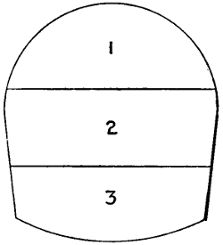
Fig. 84.—Diagram Showing
Sequence of Excavation
in English Method
of Tunneling.
Excavation.
—Although, as stated above, the distinctive
characteristic of the English method is the excavation of the
full section at once, the digging is usually started by driving
a small heading or drift to locate and establish the axis of the
tunnel, and to facilitate drainage in wet ground. These advance
galleries may be driven either in the upper or in the
lower part of the section, as the local conditions and choice
of the engineer dictate. Whether the advance gallery is located
at the top or at the bottom of the section makes no difference in
the mode of enlarging the profile. This work always begins
at the upper part of the section. A center top heading is
driven and strutted by erecting posts carrying longitudinal bars
supporting transverse poling-boards. This heading is immediately[167]
widened by digging away the earth at each side, and by
strutting the opening by temporary posts resting on blocking,
and carrying longitudinal bars supporting poling-boards. This
process of widening is continued in this manner until the full
roof section, No. 1, Fig. 84, is opened, when a heavy transverse
sill is laid, and permanent struts are
erected from it to the longitudinal bars,
the temporary posts and blocking being
removed. The excavation of part No. 2
then begins by opening a center trench
and widening it on each side, temporary
posts being erected to support the sill
above. As soon as part No. 2 is fully excavated,
a second transverse sill is placed
below the first, and struts are placed
between them. The excavation of part
No. 3 is carried out in exactly the same manner as was part
No. 2. The lengths of the various sections, Nos. 1, 2, and 3,
generally run from 12 ft. to 20 ft., depending upon the
character of the soil.
Strutting.
—The strutting in the English method of tunneling
consists of a transverse framework set close to the face of
the excavation, which supports one end of the longitudinal
crown bars, the other ends of which rest on the completed
lining. The transverse framework is composed of three horizontal
sills arranged and supported as shown by Fig. 85. The
bottom sill A is carried by vertical posts resting on blocking on
the floor of the excavation. From the bottom sill vertical
struts rise to support the middle sill B. The top sill, or miners’
sill C, is carried by vertical posts or struts rising from the
middle sill B. The vertical struts are usually round timbers
from 6 ins. to 8 ins. in diameter; and the sills are square timbers
of sufficient section to carry the vertical loads, and generally
made up of two posts scarf-jointed and butted to permit
them to be more easily handled. In firm soils the struts between[168]
the sills are all set vertically, but those at the extreme
sides of the roof section are inclined. In loose soils, however,
where the sides of the excavation must be shored, the V-bracing
shown by Fig. 85 is employed between one or more
pairs of sills as the conditions necessitate. The manner of
holding the transverse framework upright is explained quite
clearly by Fig. 85; inclined props extending from the completed
masonry to the sills of the framework being employed.
Two props are used to each sill. Sometimes, in addition to the
props shown, another nearly horizontal prop extends from the
crown of the arch masonry to the middle piece of the strutting.
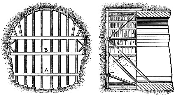
Fig. 85.—Sketches Showing Construction of Strutting, English Method.
Referring to Fig. 85, it will be observed that the longitudinal
crown bars are above the extrados of the roof arch. When,
therefore, the lining masonry has been completed close up to
the transverse framework, the latter is removed, leaving the
crown bars resting on the arch masonry; and excavation, which
has been stopped while the masonry was being laid, is continued
for another 12 ft. to 20 ft., and the transverse framework is
erected at the face, and braced or propped against the completed
lining as shown by Fig. 85. The next step is to place the[169]
crown bars, and this is done by pulling them ahead from their
original position over the masonry of the completed section of
the roof arch. It will be understood that the crown bars are
not pulled ahead their full length at one operation, but are
advanced by successive short movements as the excavation
progresses, their outer ends being supported by temporary
posts until the transverse framework is built at the face of the
excavation.
Centers.
—Two standard forms of centers are employed in
the English method of tunneling, as shown by Figs. 86 and 87.
Both consist of an outer portion, constructed much like a
typical plank center, which is strengthened against distortion
by an interior truss framework. The elemental members of
this truss framework take the form of a queen-post truss, as is
shown more particularly by Fig. 86. In Fig. 87 the queen-post
truss construction is less easily distinguished, owing to
the cutting of the bottom tie-beam and other modifications, but
it can still be observed. The possibility of cutting the tie-beam
as shown in Fig. 87, without danger, is due to the fact that
the lateral pressures on the haunches of the center counteract
the tendency of the center to flatten under load, which is
usually counteracted by the tie-beam alone. The object of
cutting the tie-beam is to afford room for the props running
from the completed masonry to the transverse framework of
the strutting as shown by Fig. 85.
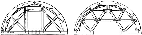
Figs. 86 and 87.—Sketches of Typical Timber Roof-Arch Centers, English Method.
Generally four or five centers are used for each length of
arch built. They are set up so that the tie-beams rest on[170]
double opposite wedges carried by a transverse beam below.
This transverse beam in turn rests on another transverse beam
which is supported by posts carried on blocking on the invert
masonry. It is usually made with a butted joint at the middle
to permit its removal, since it is so long that the masonry has
to be built around its extreme ends. The lagging is of the
usual form, and rests on the exterior edges of the curved upper
member of the centers.
Masonry.
—In the English method of tunneling, the masonry
begins with the construction of the invert, and proceeds to the
crown of the arch. The lining is built in lengths, or successive
rings, corresponding to the length of excavation, which, as previously
stated, is from 12 ft. to 20 ft. Each ring or length of
lining terminates close to the transverse strutting frame erected
at the face of the excavation. Work is first begun on the
invert at the point where the preceding ring of masonry ends,
and is continued to the transverse strutting frame at the front
of the excavation. As fast as the invert is completed, work is
begun on the side walls. In very loose soils the longitudinal
bars supporting the sides of the excavation are removed after
the side walls are built; but in firmer soils they may be taken
out one by one just ahead of the masonry, or in very firm soils
it may be possible to remove them entirely before beginning
the side walls. In all cases it is necessary to fill the space
between the masonry and the walls of the excavation with riprap
or earth. To build the roof arch the centers are first
erected as described above, and the crown bars are removed as
previously described by pulling them ahead after the arch ring
is completed. As with the side walls, the vacant space between
the arch ring and the roof of the excavation must
be filled in. Usually earth or small stones are used for filling;
but in very loose soils it is sometimes the practice not to
remove the poling-boards, but to support them by short brick
pillars resting on the arch ring and then to fill around these
pillars.
[171]
Hauling.
—To haul away the material and take in supplies,
tracks are laid on the invert masonry. Generally the permanent
tracks are laid as fast as the lining is completed. A short
section of temporary track is used to extend this permanent
track close to the work of the advanced drift.
Advantages and Disadvantages.
—The great advantage of the
English method of tunneling is that the masonry lining is
built in one piece from the foundations to the crown, making
possible a strong, homogeneous construction. It also possesses
a decided advantage because of the simple methods of
hauling which are possible: there being no differences of level
to surmount, no hoisting of cars nor trans-shipments of loads
are necessary. The chief disadvantage of the method is that
the excavators and masons work alternately, thus making the
progress of the work slower perhaps than in any other method
of tunneling commonly employed under similar conditions.
This disadvantage is overcome to a considerable extent when
the tunnel is excavated by shafts, and the work at the different
headings is so arranged that the masons or excavators when
freed from duty at one heading may be transferred to another
where excavation or lining is to be done as the case may be.
Another disadvantage of the English method arises from the
excavation of the full section at once, which in unstable soils
necessitates strong and careful strutting, and increases the
danger of caving. The fact also that the arch ring has to
carry the weight of the crown bars, and their loading at one
end while the masonry is green, increases the chances of the
arch being distorted.
Conclusion.
—The English method of tunneling in its entirety
is confined in actual practice pretty closely to the country from
which it receives its name. A possible extension of its use
more generally is considered by many as likely to follow the
development of a successful excavating machine for soft
material. The space afforded by the opening of the full section
at once, especially adapts the method to the use of excavators[172]
like, for example, the endless chain bucket excavator
used on the Central London Ry., and illustrated in Fig. 11.
The method also furnishes an excellent opportunity for electric
hauling and lighting during construction.
The English method of tunneling has been used in building
the Hoosac, Musconetcong, Allegheny, Baltimore and Potomac,
and other tunnels in America. The names of the European
tunnels built by this method are too numerous to mention here.
AMERICAN METHOD.
In this country tunnels through loose soils are excavated
according to the “Crown Bar” or American Method. This
consists in opening the whole section of
the tunnel before the construction of the
lining as in the English Method. It differs
from the English method, however, in that
many timber structures are erected for the
support of the roof, and that the excavation
and construction of the lining are far
apart, so allowing the miners and the masons
to work continuously and without interfering
with each other.
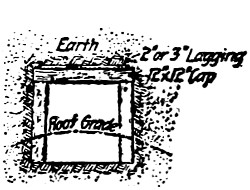
Section A-B.
Fig. 88.—Sequence of Excavation
in the American
Method.
Fig. 89.—Strutting
the Heading in the
American Method.
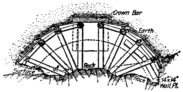
Section C-D.
Fig. 90.—Temporary Timbering of the
Roof in the American Method.
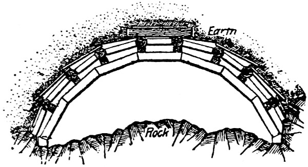
Section E-F.
Fig. 91.—Showing Crown Bars Supported
by Segmental Arches.
Excavation.
—The diagram in Fig. 88 shows the sequence of
excavation. The work begins by driving a central heading
usually 7 × 8 ft., strutted by means of vertical
or batter posts and cap-piece. Fig. 89,[11] the props
resting on foot blocks. Between the cap-pieces
of the consecutive frames are placed planks
driven upward at a slightly inclined angle.
After the heading has been excavated and
strutted, the floor is lowered by removing the
part marked 2 in the figure. The two batter
posts supporting the cap-piece are now substituted by two
longer ones resting on the floor of part 2 and abutting against[173]
longitudinal beams which are inserted underneath the cap-pieces.
These longitudinal beams are called crown bars. The new
batter posts are resting either on foot blocks or sills according
to the quality of soil and they are strongly wedged to the crown
bars. On each side of these crown bars are inserted poling-boards
or planks close to each other, which are driven downward.
The part marked 3 in the figure is removed by enlarging
the cut 1 × 2 on both sides. The plank, inserted above the
crown bar, is driven in either preceding or following the excavation
and another crown bar is inserted at the end of this plank.
This second crown bar is supported by a prop whose other end
abuts against the foot of the rafter strutting the heading. Between
this crown bar and the roof of the excavation, other
planks are placed transversally to the axis of the tunnel and
are driven in until they are supported by a new crown bar, etc.
The various props supporting the crown bars are placed radially
or in a fan-like manner, similar
to the characteristic arrangement
of the timbering in the Belgian
method. Bracers to strengthen
the timbering and the roof of the
excavation are inserted longitudinally
between the various posts
and transversally between the
crown bars, Fig. 90. As a rule,
only three or four of these radial structures are temporarily
erected. A trench is excavated at
the side of the part marked 3 in the
figure to receive the wall plate which
is a heavy timber laid on the floor
parallel to the longitudinal axis of
the tunnel. On the wall plates are
erected the arched timber sets composed
of five or seven segments of
hewn timbers so as to form a polygonal frame which is wedged[174]
to the crown bars and which will support the arch of the roof.
After one of these segmental timber sets is erected the temporary
radial structure is removed and the upper section of the
tunnel is cleared of any obstruction as the pressures are transferred
to the wall plates, Fig. 91. The bench marked 4 in the
figure is taken away and the vertical props inserted under the
wall plates, Fig. 92.
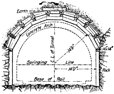
Section G-H.
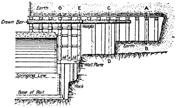
Longitudinal Section.
Fig. 92.—Transversal and Longitudinal Section of a Tunnel Excavated and Strutted
According to the American Method.
Strutting.
—The longitudinal strutting is used in connection
with the American method of tunneling. In fact, the strutting
consists of a series of longitudinal bars supporting planks laid
transversally to the axis of the tunnel and abutting against the
roof of the excavation. These crown bars during the excavations
and immediately after are temporarily supported by radial
timbers forming almost a fan-like structure, but this is soon
substituted by a permanent one composed of a polygonal timber
frame of five or seven segments which are cut to dimensions.
The batter posts of the heading, the radial posts of the temporary
timber structure and the crown bars are all round timbers from
10 to 12 ins. in diameter. All the other timbers are square
edged, the usual dimensions being 10 × 10 ins. or 12 × 12 ins.
with the exception of the wall plates which are 14 × 14 ins.
The dimensions of the various members of the strutting and the
distance apart of the different frames vary with the quality of[175]
the soil. For instance, in ordinary loose soils the frames are
placed between 4 to 6 ft., but in very soft soils they are erected
only 3 or 31⁄2 ft. apart.
Chiefly in the southwest, in tunnels excavated according to
the American method, the timbering has been left as regular
lining and it was only after many years when this temporary
structure had decayed or was burned down, that the tunnels
were lined with masonry. But in many instances the whole
timber structure was left in place even when the tunnel
was lined with masonry immediately after the excavation had
been made. This was usually done when the tunnel was lined
with concrete masonry. In such a case the timbering was left
to support the pressures of the roof while the concrete was
plastic and before it hardened.
Centers.
—In the American method the whole section of the
tunnel is open before the construction of the lining, thus the
masonry can be built from the foundations up. The centers are
designed so as to support only the weight of the masonry during
its construction and not the pressures of the tunnel as in the
other methods and consequently they are of light construction.
The centers described in the Murray Hill tunnel, page 123, may
be advantageously used in building the concrete lining in tunnels
through loose soils excavated by the American method.
Hauling.
—The excavation of the heading and the upper
section of the tunnel is usually far ahead of the bench, consequently
the hauling of both the débris and the building materials
is made at two different levels, viz., on the bench and on the
floor of the tunnel. When the face of the heading and the excavation
of the bench are not more than 50 ft. apart, the
hauling can be conveniently done on the tunnel floor, while
the materials and débris on the upper section of the tunnel are
hauled by wheelbarrows or light cars propelled by handpower.
For a greater distance, however, it is more convenient to use
light cars running on narrow-gauge tracks all through the tunnel.
In this case the tracks on the tunnel floor and on top of the[176]
bench are connected by means of an inclined platform where
the cars may ascend and descend without interfering with the
excavation of the bench. Here, as a rule, tunnels have been
excavated in soils considered good, generally through rock, while
loose soils have been encountered only in small sections. The
same method of excavation for whatever material is encountered
is certainly very convenient, as it affords a great regularity in
the work; hence its extensive use. A great disadvantage of this
method is the double strutting, viz., the polygonal and the
longitudinal strutting succeeding each other, whereas one of
them could be easily spared. Another defect is that it requires
a larger amount of excavation, in case the strutting
is left in place.
AUSTRIAN METHOD.
The Austrian full-section method of tunneling through soft
ground was first used in constructing the Oberau tunnel on the
Leipsic and Dresden R.R., in Austria in 1837. It consists in
excavating the full section and building up the lining masonry
from the foundations as in the English, but with the important
exception that the invert is built last instead of first in
all cases except where the presence of very loose soil requires
its construction first. A still more important difference in the
two methods is that the excavation is carried out in smaller
sections and is continuous in the Austrian method instead of
alternating with the mason work as it does in the English
method.
Excavation.
—The excavation in the Austrian method begins
by driving the bottom center drift No. 1, Fig. 93, rising from
the floor of the tunnel section nearly to the height of the springing
lines of the roof arch. When this drift has been driven
ahead a distance varying from 12 ft. to 20 ft. or sometimes more,
the excavation of the center top heading No. 2 is driven for the
same distance. The next operation is to remove part No. 3,
thus forming a central passage the full depth of the tunnel section[177]
at the center. This trench is enlarged by removing parts Nos. 4,
5, 6, 7, and 8 in the order named until the full section is opened.
A modification of this plan of excavation is shown by Fig. 94
which is used in firm soils.
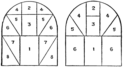
Figs. 93 and 94.—Diagrams Showing Sequence of Excavation in
Austrian Method of Tunneling.
Strutting.
—Each part of the section is strutted as fast as
it is excavated. The center bottom drift first excavated is
strutted by laying a transverse sill across the floor, raising
two side posts from it, and capping them with a transverse
timber having its ends projecting beyond the side posts and
halved as shown by Fig. 95. The top center heading No. 2,
which is next excavated, is strutted by means of two side posts
resting on blocking and carrying a transverse cap as also shown
by Fig. 95. Sometimes the side posts in the heading strutting-frames
are also carried on a transverse sill as are those of the
bottom drift. This construction is usually adopted in loose
soils. When the sill is employed, the middle part, No. 3, is
strutted by inserting side posts between the bottom of the top
sill and the cap of the frame in the drift below. When, however,
the posts of the top heading frame are carried on blocking,
it is the practice to replace them with long posts rising from
the cap of the bottom drift frame to the cap of the top heading
frame. Further, when the intermediate sill is employed at the
bottom level of the top heading it projects beyond the side
posts and has its ends halved.
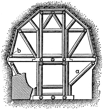
Figs. 95 to 97.—Sketches Showing Construction
of Strutting, Austrian Method.
After the completion of the center trench strutting the next[178]
task is to strut parts Nos. 4 and 5. This is done by continuing
the upper sill by means of a timber having one end halved
to join with the projecting end of the sill in position. This
extension timber is shown at a, Fig. 96. The next operation is
to place the timber b, having one end resting on the cap-piece
of the top heading frame and
the other beveled and resting
on the top of the sill a near
the end. The timber b is laid
tangent to the curve of the
roof arch, and to support it
against flexure the strut c is
inserted as shown. To support
the thrust of this strut
the additional post d is inserted
and the original bottom
heading frame is reinforced as
shown. The next step is to
insert the strut e, and when
this and the previous construction are duplicated on the opposite
side of the tunnel section we have the strutting of the parts
Nos. 1 to 5; inclusive, complete. Part No. 6 is then removed and[179]
strutted by extending the bottom drift cap-piece by a timber
similar to timber a above, and then by inserting a side strut
between the outer ends of these two timbers, as indicated by
Fig. 97. As the final parts. Nos. 7 and 8, are removed, the inclined
prop a, Fig. 97, is inserted as shown. When the soil is
loose some of the members of the framework are doubled and
additional bracing is introduced as shown by Fig. 97.
The frames just described are placed at intervals of about
4 ft. along the excavation, and are braced apart by horizontal
struts. Some of the longitudinal
bearing beams, as at b, Fig.
97, also extend through two or
three frames, and help to tie
them together. Finally, the
longitudinal poling-boards extending
from one frame to the
next along the walls of the excavation
serve to connect them
together. The short transverse
beam c, Fig. 90, located just
above the floor of the invert,
serves to carry the planking
upon which the train car tracks
are laid. Besides the timber
strutting peculiar to the Austrian
method, the Rziha iron strutting described in a previous
chapter is frequently used in tunneling by the Austrian
process.
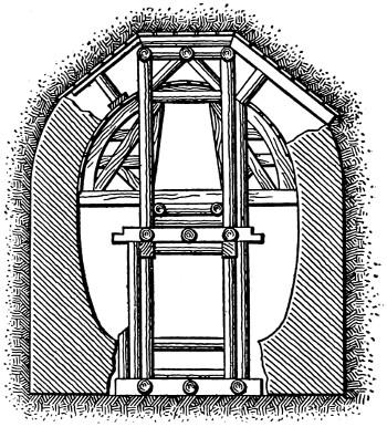
Fig. 98.—Sketch Showing Manner of
Constructing the Lining Masonry,
Austrian Method.
Centers.
—The two forms of centers used in the English
method of tunneling are also used in the Austrian method.
One of the methods of supporting these centers is shown by
Fig. 98. The tie-beam of the center rests on longitudinal timbers
carried by the strutting frames and intermediate props.
In single-track tunnels it is the frequent practice also to carry
the ends of the tie-beams in recesses left in the side wall[180]
masonry, with intermediate props inserted to prevent flexure
at the center. When the Rziha iron strutting is employed, it
also serves for the centering upon which the arch masonry is
built.
Masonry.
—In the Austrian system of tunneling, the lining
is built from the foundations of the side walls upward to the
crown of the roof arch in lengths in consecutive rings equal to
the lengths of the consecutive openings of the full section, or
from 12 ft. to 20 ft. long. Except in infrequent cases in very
loose materials the invert is the last part of the masonry to be
built, since to build it first requires the removal of the strutting
which cannot easily or safely be accomplished until the side walls
and roof arch are completed. As the side wall foundations are
built, however, their interior faces are left inclined, as shown
by Figs. 97 and 98, ready for the insertion of the invert, and
are meanwhile kept from sliding inward by the insertion of
blocking between them and the bottom of the strutting. Fig.
98 shows the nature of this blocking, and also the manner in
which the side wall and roof arch masonry is carried upward.
Finally when the roof arch is keyed and the centers are struck,
the strutting is taken down and the invert is built.
Advantages and Disadvantages.
—The principal advantages
claimed for the Austrian method of tunneling are: (1) The
excavation being conducted by driving a large number of consecutive
small galleries, which are immediately strutted, there
is little disturbance of the surrounding material; (2) the polygonal
type of strutting adopted is easily erected and of great
strength against symmetrical pressures; (3) the masonry, being
built from the foundations up, is a single homogeneous structure,
and is thus better able to withstand dangerous pressures; (4)
the excavation is so conducted that the masons and excavators
do not interfere, and both can work at the same time. The
disadvantages which the method possesses are: (1) The strutting
while very strong under symmetrical pressures, either vertical
or lateral, is distorted easily by unsymmetrical vertical or lateral[181]
pressures, and by pressure in the direction of the axis of the
tunnel; (2) the construction of the invert last exposes the side
walls to the danger of being squeezed together, causing a rotation
of the arch of the nature discussed in describing the Belgian
method of tunneling.
[182]
CHAPTER XV.
SPECIAL TREACHEROUS GROUND METHOD;
ITALIAN METHOD; QUICKSAND TUNNELING;
PILOT METHOD.
ITALIAN METHOD.
The Italian method of tunneling was first employed in constructing
the Cristina tunnel on the Foggia & Benevento R.R.
in Italy. This tunnel penetrated a laminated clay of the most
treacherous character, and after various other soft-ground
methods of tunneling had been tried and had failed, Mr. Procke,
the engineer, devised and used successfully the method which
is now known as the Italian or Cristina method. The Italian
method is essentially a treacherous soil method. It consists in
excavating the bottom half of the section by means of several
successive drifts, and building the invert and side walls; the
space is then refilled and the upper half of the section is excavated,
and the remainder of the side walls and the roof arch
are built; finally, the earth filling in the lower half of the
section is re-excavated and the tunnel completed. The method
is an expensive one, but it has proved remarkably successful in
treacherous soils such as those of the Apennine Mountains,
in which some of the most notable Italian tunnels are located.
It is, moreover, a single-track tunnel method, since any soil
which is so treacherous as to warrant its use is too treacherous
to permit an opening to be excavated of sufficient size for a
double-track railway, except by the use of shields.
Excavation.
—The plan of excavation in the Italian method
is shown by the diagram Fig. 99. Work is begun by driving[183]
the center bottom heading No. 1, and this is widened by taking
out parts No. 2. Finally part No. 3 is removed, and the lower
half of the section is open. As soon as the invert and side
wall masonry has been built in this excavation, parts No. 2
are filled in again with earth. The excavation
of the center top heading No. 4 is
then begun, and is enlarged by removing
the earth of part No. 5. The faces of this
last part are inclined so as to reduce their
tendency to slide, and to permit of a
greater number of radial struts to be
placed. Next, parts No. 6 are excavated,
and when this is done the entire section,
except for the thin strip No. 7, has been
opened. At the ends of part No. 7 narrow
trenches are sunk to reach the tops of the side walls
already constructed in the lower half of the section. The
masonry is then completed for the upper half of the section,
and part No. 7 and the filling in parts No. 2 are removed.
The various drifts and headings and
the parts excavated to enlarge them
are seldom excavated more than from
6 ft. to 10 ft. ahead of the lining.
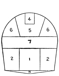
Fig. 99.—Diagram Showing
Sequence of Excavation
in Italian Method of
Tunneling.
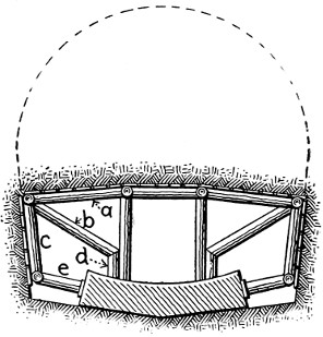
Fig. 100.—Sketch Showing Strutting
for Lower Part of Section.
Strutting.
—The bottom center
drift, which is first driven, is strutted
by means of frames consisting of side
posts resting on floor blocks and carrying
a cap-piece. Poling-boards are
placed around the walls, stretching
from one frame to the next. As
soon as the invert is sufficiently completed to permit it, the
side posts of the strutting frames are replaced by short struts
resting on the invert masonry as shown by Fig. 100. To permit
the old side posts to be removed and the new shorter ones to
be inserted, the cap-piece of the frame is temporarily supported[184]
by inclined props arranged as shown by Fig. 103. When parts
No. 2 are excavated the roof is strutted by inserting the transverse
caps a, Fig. 100, the outer ends of which are carried by the
system of struts b, c, d, and e. The longitudinal poling-boards
supporting the ceiling and walls are held in place by the cap
a and the side timber e. To stiffen the frames longitudinally
of the tunnel, horizontal longitudinal struts are inserted between
them.
The excavation of the upper half of the tunnel section is
strutted as in the Belgian method, with radial struts carrying
longitudinal roof bars and transverse poling-boards. On account
of the enormous pressures developed by the treacherous
soils in which only is the Italian method employed, the radial
strutting frames and crown bars must be of great strength,
while the successive frames must be placed at frequent intervals,
usually not more than 3 ft. After the masonry side walls have
been built in the lower part of the excavation, longitudinal
planks are laid against the side posts of the center bottom
drift frames, to form an enclosure for the filling-in of parts
No. 2. The object of this filling is principally to prevent
the squeezing-in of the side walls.
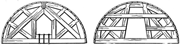
Figs. 101 and 101A.—Sketches Showing Construction of Centers, Italian Method.
Centers.
—Owing to the great pressures to be resisted in the
treacherous soils in which the Italian method is used, the construction
of the centers has to be very strong and rigid. Figs.
101 and 101A show two common types of center construction
used with this method. The construction shown in Fig. 101
is a strong one where only pressures normal to the axis of the
tunnel have to be withstood, but it is likely to twist under[185]
pressures parallel to the axis of the tunnel. In the construction
shown by Fig. 101A, special provision is made to resist
pressures normal to the plane of the center or twisting pressures,
by the strength of the transverse bracing extending horizontally
across the center.
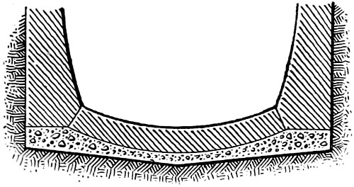
Fig. 102.—Sketch Showing Invert
and Foundation Masonry, Italian
Method.
Masonry.
—The construction of the masonry lining begins
with the invert, as indicated by Fig. 100, and is carried up to
the roof of parts No. 2, as already indicated, and is then discontinued
until the upper parts Nos. 4, 5, and 6 are excavated.
The next step is to sink side trenches at the ends of part No. 7,
which reach to the top of the completed side walls. This
operation leaves the way clear to finish the side walls and to
construct the roof arch in the ordinary manner of such work in
tunneling. Since this method of
tunneling is used only in very soft
ground which yields under load, the
usual practice is to construct the invert
and side walls on a continuous
foundation course of concrete as indicated
by Fig. 102. The lining is
usually built in successive rings, and
the usual precautions are taken with respect to filling in the
voids behind the lining. The thickness of the lining is based
upon the figures for laminated clay of the third variety given
in Table II.
Hauling.
—The system of hauling adopted with this method
of tunneling is very simple, since the excavation of the various
parts is driven only from 6 ft. to 10 ft. ahead, and the work progresses
slowly to allow for the construction of the heavy strutting
required. To take away the material from the center bottom
drift, narrow-gauge tracks carried by cross-beams between the
side posts above the floor line are employed. This same
narrow-gauge line is employed to take away a portion of parts
No. 2, the remaining portion being left and used for the refilling
after the bottom portion of the lining has been built, as[186]
previously described. The upper half of the section being excavated,
as in the Belgian method, the system of hauling with
inclined planes to the tunnel floor below, which is a characteristic
of that method, may be employed. It is the more usual
practice, however, since the excavation is carried so little a distance
ahead and progresses so slowly, to handle the spoil from
the upper part of the section by wheelbarrows which dump it
into the cars running on the tunnel floor below. Hand labor
is also used to raise the construction
materials used in building the upper section.
The tracks on the tunnel floor,
besides extending to the front of the advanced
bottom center drift, have right and
left switches to be employed in removing
the refilling in parts No. 2, the spoil from
the upper part of the section, and the
material of part No. 7. Fig. 103 is a longitudinal
section showing the plan of excavation
and strutting adopted with the Italian method.
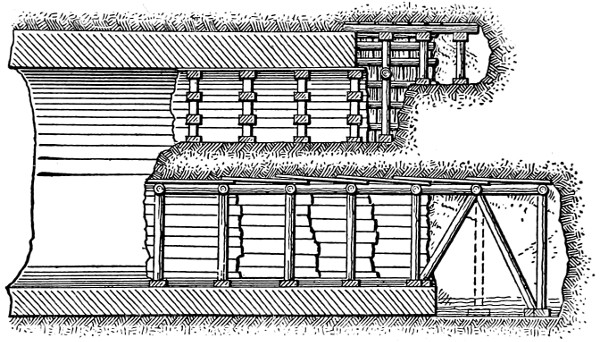
Fig. 103.—Sketch Showing Longitudinal Section of a Tunnel under Construction,
Italian Method.
Modifications.
—It often happens that the filling placed between
the side walls and the planking, which is practically the
space comprised by parts No. 2, is not sufficient to resist the
inward pressure of the walls, and they tip inward. In these
cases a common expedient is to substitute for the earth filling[187]
a temporary masonry arch sprung between the side walls
with its feet near the bottom of the walls, and its crown
just below the level of their tops, as shown by Fig. 107.
This construction was employed in the
Stazza tunnel in Italy. In this tunnel
the excavation was begun by driving the
center drift, No. 1, Fig. 104, and immediately
strutting it as shown by Fig. 105.
The other parts, Nos. 2 and 3, completing
the lower portion of the section, were then
taken out and strutted. While part No. 2
was being excavated at the bottom, and
the center part of the invert built, the
longitudinal crown bars carrying the roof
of the excavation were carried temporarily by the inclined
props shown by Fig. 106. After completing the invert and
the side walls to a height of 2 or 3 ft., a thick masonry arch
was sprung between the side walls, as shown in transverse
section by Fig. 107, and in longitudinal section by Fig. 106.
This arch braced the side walls against tipping inward, and
carried short struts to support the crown bars. The haunches
of the arch were also filled in with rammed earth. The upper
half of the section was excavated, strutted, and lined as in
the standard Italian method previously described. When the
lining was completed, the arch inserted between the side walls
was broken down and removed.
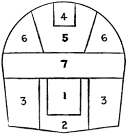
Fig. 104.—Sketch Showing
Sequence of Excavation,
Stazza Tunnel.
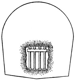
Fig. 105.—Sketch Showing
Method of Strutting First
Drift, Stazza Tunnel.
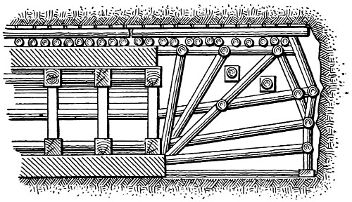
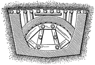
Figs. 106 and 107.—Sketches
Showing Temporary Strutting Arch Construction,
Stazza Tunnel.
[188]
Advantages and Disadvantages.
—The great advantage claimed
for the Italian method of tunneling is that it is built in two
separate parts, each of which is separately excavated, strutted,
and lined, and thus can be employed successfully in very
treacherous soils. Its chief disadvantage is its excessive cost,
which limits its use to tunnels through treacherous soils where
other methods of timbering cannot be used.
QUICKSAND TUNNELING.
When an underground stream of water passes with force
through a bed of sand it produces the phenomenon known as
quicksand. This phenomenon is due to the fineness of the
particles of sand and to the force of the water, and its activity
is directly proportional to them. When sand is confined it
furnishes a good foundation bed, since it is practically incompressible.
To work successfully in quicksand, therefore, it is
necessary to drain it and to confine the particles of sand so
that they cannot flow away with the water. This observation
suggests the mode of procedure adopted in excavating tunnels
through quicksand, which is to drain the tunnel section by
opening a gallery at its bottom to collect and carry away the
water, and to prevent the movement or flowing of the sand by
strutting the sides of the excavation with a tight planking.
The sand having to be drained and confined as described, the
ordinary methods of soft-ground tunneling must be employed,
with the following modifications:
(1) The first work to be performed is to open a bottom
gallery to drain the tunnel. This gallery should be lined with
boards laid close and braced sufficiently by interior frames to
prevent distortion of the lining. The interstices or seams between
the lining boards should be packed with straw so as to
permit the percolation of water and yet prevent the movement
of the sand.
(2) As fast as the excavation progresses its walls should[189]
be strutted by planks laid close, and held in position by interior
framework; the seams between the plank should be packed
with straw.
(3) The masonry lining should be built in successive rings,
and the work so arranged that the water seeping in at the sides
and roof is collected and removed from the tunnel immediately.
Excavation.
—The best and most commonly employed method
of driving tunnels through quicksand is a modification of the
Belgian method. At first sight it may appear a hazardous work
to support the roof arch, as is the characteristic of this method,
on the unexcavated soil below, when this soil is quicksand, but
if the sand is well confined and drained the risk is really not
very great. Next to the Belgian method the German method
is perhaps the best for tunneling quicksand. In these comparisons
the shield system of tunneling is for the time being left
out of consideration. This method will be described in succeeding
chapters. Whenever any of the systems of tunneling
previously described are employed, the first task is always to
open a drainage gallery at the bottom of the section.
Assuming the Belgian method is to be the one adopted, the
first work is to drive a center bottom drift, the floor of which
is at the level of the extrados of the invert. This drift is immediately
strutted by successive transverse frames made up of
a sill, side posts, and a cap which support a close plank strutting
or lining, with its joints packed with straw. Between the
side posts of each cross-frame, at about the height of the
intrados of the invert, a cross-beam is placed; and on these cross-beams
a plank flooring is laid, which divides the drift horizontally
into two sections, as shown by Fig. 108; the lower section
forming a covered drain for the seepage water, and the upper
providing a passageway for workmen and cars. The bottom
drift is driven as far ahead as practicable, in order to drain the
sand for as great a distance in advance of the work as possible.
After the construction of the bottom drainage drift the excavation
proper is begun, as it ordinarily is in the Belgian method[190]
by driving a top center heading, as shown by Fig. 108. This
heading is deepened and widened after the manner usual to the
Belgian method, until the top of the section
is open down to the springing lines
of the roof arch. To collect the seepage
water from the center top heading it is
provided with a center bottom drain constructed
like the drain in the bottom
drift, as shown by Fig. 108. When the
top heading is deepened to the level of
the springing lines of the roof arch, its
bottom drain is reconstructed at the new
level, and serves to drain the full top
section opened for the construction of the
roof arch. This top drain is usually constructed
to empty into the drain in the bottom drift.
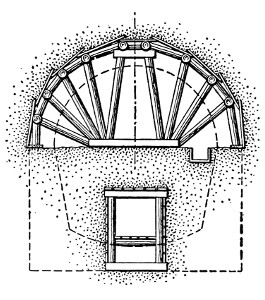
Fig. 108.—Sketch Showing
Preliminary Drainage Galleries,
Quicksand Method.
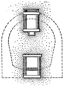
Fig. 109.—Sketch Showing Construction
of Roof Strutting,
Quicksand Method.
Strutting.
—The method of strutting the bottom drift has
already been described. For the remainder of the excavation
the regular Belgian method of radial roof strutting-frames is
employed, as shown by Fig. 109.
Contrary to what might be expected,
the number of radial struts required
is not usually greater than would be
used in many other soils besides
quicksand. Single-track railway tunnels
have been constructed through
quicksand in several instances where
the number of radial props required
on each side of the center did not
exceed four or five. It is necessary,
however, to place the poling-boards
very close together, and to pack the joints between them to
prevent the inflow of the fine sand. In strutting the lower
part of the section it is also necessary to support the sides with
tight planking. This is usually held in place by longitudinal[191]
bars braced by short struts against the inclined props employed
to carry the roof arch when the material on which they originally
rested is removed. This side
strutting is shown at the right
hand of Fig. 110.
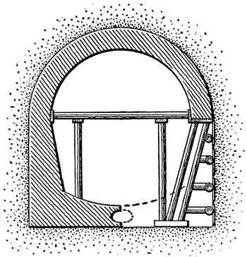
Fig. 110.—Sketch Showing Construction
of Masonry Lining, Quicksand
Method.
Masonry.
—As soon as the upper
part of the section has been opened
the roof arch is built with its feet
resting on planks laid on the unexcavated
material below. This arch
is built exactly as in the regular
Belgian method previously described,
using the same forms of
centers and the same methods
throughout, except that the poling-boards
of the strutting are usually left remaining above the
arch masonry. To prevent the possibility of water percolating
through the arch masonry, many engineers also advise the
plastering of the extrados of the arch with a layer of cement
mortar. This plastering is designed to lead the water along
the haunches of the arch and down behind the side walls. In
constructing the masonry below the roof arch the invert is
built first, contrary to the regular Belgian method, and the
side walls are carried up on each side from the invert masonry.
Seepage holes are left in the invert masonry, and also
in the side walls just above the intrados of the invert. At the
center of the invert a culvert or drain is constructed, as shown
by Fig. 110, inside the invert masonry. This culvert is commonly
made with an elliptical section with its major axis horizontal,
and having openings at frequent intervals at its top.
The thickness of the lining masonry required in quicksand is
shown by Table II.
Removing the Seepage Water.
—After the tunnel is completed
the water which seeps in through the weep-holes left in the masonry
passes out of the tunnel, following the direction of the[192]
descending grades. During construction, however, special
means will have to be provided for removing the water from
the excavation, their character depending upon the method of
excavation and upon the grades of the tunnel bottom. When
the excavation is carried on from the entrances only, unless the
tunnel has a descending grade from the center toward each end,
the tunnel floor in one heading will be below the level of the entrance,
or, in other words, the descending grade will be toward
the point where work is going on, while at the opposite entrance
the grade will be descending from the work. In the latter
case the removal of the seepage water is easily accomplished by
means of a drainage channel along the bottom of the excavation.
In the former case the water which drains toward the front is
collected in a sump, and if there is not too great a difference in
level between this sump and the entrance, a siphon may be used
to remove it. Where the siphon cannot be used, pumps are
installed to remove the water. When the tunnel is excavated
by shafts the condition of one high and one low front, as compared
with the level at the shaft, is had at each shaft. Generally,
therefore, a sump is constructed at the bottom of the
shaft; the culvert from the high front drains directly to the
shaft sump, while the water from the low-front sump is either
siphoned or pumped to the shaft sump. From the shaft sump
the water is forced up the shaft to the surface by pumps.
THE PILOT METHOD.
The pilot system of tunneling has been successfully employed
in constructing soft-ground sewer tunnels in America
by the firm of Anderson & Barr, which controls the patents.
The most important work on which the system has been employed
is the main relief sewer tunnel built in Brooklyn, N.Y.,
in 1892. This work comprised 800 ft. of circular tunnel 15 ft.
in diameter, 4400 ft. 14 ft. in diameter, 3200 ft. 12 ft. in
diameter, and 1000 ft. 10 ft. in diameter, or 9400 ft. of tunnel[193]
altogether. The method of construction by the pilot system is
as follows:
Shafts large enough for the proper conveyance of materials
from and into the tunnel are sunk at such places on the line of
work as are most convenient for the purpose. From these
shafts a small tunnel, technically a pilot, about 6 ft. in diameter,
composed of rolled boiler iron plates riveted to light angle irons on
four sides, perforated for bolts, and bent to the required radius
of the pilot, is built into the central part of the excavation on
the axis of the tunnel. This pilot is generally kept about 30 ft.
in advance of the completed excavation, as shown by Fig. 111.
The material around the exterior of the pilot is then excavated,
using the pilot as a support for braces which radiate from it and
secure in position the plates of the outside shell which holds
the sand, gravel, or other material in place until the concentric
rings of brick masonry are built. Ribs of T-iron bent to the
radius of the interior of the brick work, and supported by the
braces radiating from the pilot, are used as centering supports
for the masonry. On these ribs narrow lagging-boards are laid
as the construction of the arch proceeds, the braces holding the
shell plates and the superincumbent mass being removed as the
masonry progresses. The key bricks of the arches are placed
in position on ingeniously contrived key-boards, about 12 ins. in
width, which are fitted into rabbeted lagging-boards one after
another as the key bricks are laid in place. After the masonry
has been in place at least twenty-four hours, allowing the cement[194]
mortar time to set, the braces, ribs, and lagging which support
it are removed. In the meantime the excavation, bracing, pilot,
and exterior shell have been carried forward, preparing the way
for more masonry. The top plates of the shell are first placed
in position, the material being excavated in advance and supported
by light poling-boards; then the side-plates are butted
to the top and the adjoining side-plates. In the pilot the plates
are united continuously around the perimeter of the circle,
while in the exterior shell the plates are used for about one-third
of the perimeter on top, unless treacherous material is
encountered, when the plates are continued down to the springing
lines of the arch. This iron lining is left in place. The
bottom is excavated so as to conform to the exterior lines of
the masonry. The excavation follows so closely to the outer
lines of the normal section of the tunnel that very little loss
occurs, even in bad material; and there is no loss where sufficient
bond exists in the material to hold it in place until the
poling-boards are in position.
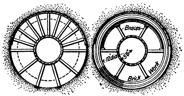
Longitudinal Section.
Fig. 111.—Sketch Showing Pilot Method of Tunneling.
In the Brooklyn sewer tunnel work, previously mentioned,
the pilot was built of steel plates 3⁄8 in. thick, 12 ins. wide, and
371⁄2 ins. long, rolled to a radius of 3 ft. Steel angles 4 × 41⁄2 ins.
were riveted along all four sides of each plate, and the plates
were bolted together by 3⁄4-in. machine-bolts. The plates weighed
136 lbs. each, and six of them were required to make one complete
ring 6 ft. in diameter. In bolting them together, iron
shims were placed between the horizontal joints to form a
footing for the wooden braces for the shell, which radiate from
the pilot. The shell plates of the 15-ft. section of the tunnel
were of No. 10 steel 12 ins. wide and 37 ins. long, with steel
angles 21⁄2 × 21⁄2 ×
3⁄8 ins., riveted around the edges the same as for
the pilot, and put together with 5⁄8-in. bolts. These plates
weighed 61 lbs. each, and eighteen of them were required to
make one complete ring 15 ft. in diameter. The plates for the
12-ft. section were No. 12 steel 12 ins. wide with 2 × 2 × 1⁄4-in.
angles. Seventeen plates were required to make a complete ring.
[195]
CHAPTER XVI.
OPEN-CUT TUNNELING METHODS; TUNNELS
UNDER CITY STREETS; BOSTON SUBWAY
AND NEW YORK RAPID TRANSIT.
OPEN-CUT TUNNELING.
When a tunnel or rapid-transit subway has to be constructed
at a small depth below the surface, the excavation is generally
performed more economically by making an open cut than by
subterranean tunneling proper. The necessary condition of
small depth which makes open-cut tunneling desirable is most
generally found in constructing rapid-transit subways or tunnels
under city streets. This fact introduces the chief difficulties
encountered in such work, since the surface traffic makes it
necessary to obstruct the streets as little as possible, and has
led to the development of the several special methods commonly
employed in performing it.
Subways are usually constructed under and along important
streets where electric cars are running. The engineers have
taken advantage of the presence of these lines to facilitate the
construction of subways. In New York, for instance, the tracks
of the electric lines were supported by cast-iron yokes 4 or 5 ft.
apart and were surrounded by concrete, leaving only a large
hollow space in the middle for the wires and trolleys. The rails
from 40 to 60 ft. long formed almost a solid concrete structure
for their entire length. The tracks and the street surface were
supported by horizontal beams inserted underneath the tracks.
These were the caps of bents constructed underground whose
rafters were finally resting on the subgrade of the proposed
subway.
[196]
The various methods for constructing the subways may be
classified as follows: (1) The single wide trench method; (2) the
single narrow longitudinal trench method; (3) the parallel longitudinal
trench method; (4) the slice method.
Single Longitudinal Trench.
—The simplest manner by which
to construct open-cut tunnels is to open a single cut or trench
the full width of the tunnel masonry. This trench is strutted
by means of side sheetings of vertical planks, held in place by
transverse braces extending across the trench and abutting
against longitudinal timbers laid against the sheeting plank.
The lining is built in this trench, and is then filled around and
above with well-rammed earth, after which the surface of the
ground is restored. An especial merit of the single longitudinal
trench method of open-cut tunneling is that it permits the
construction of the lining in a single piece from the bottom up,
thus enabling better workmanship and stronger construction
than when the separate parts are built at different times. The
great objection to the method when it is used for building subways
under city streets is, that it occupies so much room that the
street usually has to be closed to regular traffic. For this reason
the single longitudinal trench method is seldom employed, except
in those portions of city subways which pass under public squares
or parks where room is plenty.
This method was followed in the construction of the New
York subway, Section 2, along Elm St., a new street to be opened
to traffic after the subway had been completed, and at other
points where local conditions allowed it.
Fig. 112.—Diagram Showing Sequence
of Construction in Open-Cut
Tunnels.
A modification of this method was used in Contract Section 6,
on upper Broadway. The street at this point is very wide, so
by opening a trench as wide as the proposed four-track line of
the subway there still remained room enough for ordinary
traffic. The electric car tracks were supported by means of
trusses 60 or 70 ft. long, which were laid in couples parallel to
the tracks and which rested on firm soil. The soil under the
car tracks was removed, beginning with transversal cuts to[197]
receive the needles which were tied to the lower chord of the
trusses by means of iron stirrups. After the excavation had
reached the subgrade, posts were erected to support the needles
thus forming bents upon which the tracks rested. The trusses
were removed and advanced to another section of the tunnel,
and, in the clear space left, the subway was built from foundation
up.
The Single Narrow Longitudinal Trench.
—This method was
used on Contract Section 5, of the New York subway in order
to comply with the peculiar conditions of the traffic along 42nd
St. On this street, on account of the New York Central Station,
there is a constant heavy traffic, while pedestrians use the
northern sidewalks almost exclusively. A single longitudinal
trench was then opened along the south side, and from this
trench all the work of excavation and construction was carried
on. At first the steel structure of the subway was erected in the
trench and then a small heading was driven and strutted under
and across the surface-car tracks. Afterward heavy I-beams
were inserted, which rested with one end on top of the steel
bents and the other end blocked to
the floor of the excavation. These
I-beams were located 5 ft. apart
and they supported the surface of
the street by means of longitudinal
planks. The soil was removed
from the wide space underneath the
I-beams and the subway was constructed
from the foundation up.
When the structure had been completed,
the packing was placed between
the roof of the structure and
the surface of the street, the I-beams withdrawn and the voids
filled in.
Parallel Longitudinal Trenches.
—The parallel longitudinal
trench method of open-cut tunneling consists in excavating two[198]
narrow parallel trenches for the side walls, leaving the center
core to be removed after the side walls have been built. The
diagram, Fig. 112, shows the sequence of operations in this
method. The two
trenches No. 1 are
first excavated a little
wider than the side
wall masonry, and
strutted as shown by
Fig. 113. At the bottoms
of these trenches
a foundation course
of concrete is laid, as
shown by Fig. 114,
if the ground is soft;
or the masonry is
started directly on the natural material, if it is rock. From
the foundations the walls are carried up to the level of the
springing lines of the roof arch, if an arch is used; or to the
level of its ceiling, if a flat roof is used. After the completion
of the side walls, the portion of the excavation
shown at No. 2, Fig. 112, is removed
a sufficient depth to enable the roof arch
to be built. When the arch is completed,
it is filled above with well-rammed earth,
and the surface is restored. The excavation
of part No. 3 inclosed by the side walls
and roof arch is carried on from the entrances
and from shafts left at intervals
along the line.
Fig. 113.—Sketch Showing Method of Timbering Open-Cut
Tunnels, Double Parallel Trench Method.
Fig. 114.—Side-Wall
Foundation Construction
Open-Cut
Tunnels.
A modification of the method just described
was employed in constructing the Paris underground
railways. It consists in excavating a single longitudinal trench
along one side of the street, and building the side wall in it
as previously described. When this side wall is completed to[199]
the roof, the right half of part No. 2, Fig. 112, is excavated to
the line AB, and the right-hand half of the roof arch is built.
The space above the arch is then refilled and the surface of the
street restored, after which the left-hand trench is dug and
the side wall and roof-arch masonry is built just as in the
opposite half. Generally the work is prosecuted by opening up
lengths of trench at considerable intervals along the street and
alternately on the left-and right-hand sides. By this method
one-half of the street width is everywhere open to traffic, the
travel simply passing from one side of the street to the other
to avoid the excavation. When the lining has been completed,
the center core of earth inclosed by it is removed from the
entrances and shafts, leaving the tunnel finished except for the
invert and track construction, etc.
Another modification of the parallel longitudinal trenches
method was used in the construction of the New York subway.
A narrow longitudinal trench was excavated on one side of the
street near the sidewalk. Meanwhile the pavement of half of
the street was removed and a wooden platform of heavy planks,
supported by longitudinal beams which were buried in the
ground, was substituted. Then small cuts underneath the car
tracks were directed from the side trench and heavy beams or
needles were placed in these cuts, which also reached the longitudinal
beams of the wooden platform. The needles were
wedged and blocked to the car track structure and the beams.
They were temporarily supported by cribs built from underneath
as the excavation progressed. When the subgrade was
reached, vertical and batter posts were inserted to support the
needles, thus forming regular timber bents underground. In
the space thus left open the subway was constructed to the
middle of the street. While the work was going on as described,
another longitudinal narrow trench was excavated at some
distance on the other side of the street. From this trench, the
work of constructing the other half of the subway was carried
on in the manner just described. After the work had been[200]
completed, the timbers removed, the voids filled in and the
pavement of the street restored, another equal section was attacked
on both sides of the street.
Transverse Trenches.
—The transverse trench or “slice”
method of open-cut tunneling has been employed in one work,
the Boston Subway. This method is described in the specifications
for the work prepared by the chief engineer, Mr. H. A.
Carson, M. Am. Soc. C. E., as follows:—
“Trenches about 12 ft. wide shall be excavated across the
street to as great a distance and depth as is necessary for the
construction of the subway. The top of this excavation shall
be bridged during the night by strong beams and timbering,
whose upper surface is flush with the surface of the street.
These beams shall be used to support the railway tracks as well
as the ordinary traffic. In each trench a small portion or slice
of the subway shall be constructed. Each slice of the subway
thus built is to be properly joined in due time to the contiguous
slices. The contractor shall at all times have as many slice-trenches
in process of excavation, in process of being filled with
masonry, and in process of being back-filled with earth above
the completed masonry, as is necessary for the even and steady
progress of the work towards completion at the time named in
the contract.”
In regard to the success of this method Mr. Carson, in his
fourth annual report on the Boston Subway work, says:
“The method was such that the street railway tracks were
not disturbed at all, and the whole surface of the street, if desired,
was left in daytime wholly free for the normal traffic.”
Tunnels on the Surface.
—It occasionally happens when
filling-in is to take place in the future, or where landslides are
liable to bury the tracks, that a railway tunnel has to be built
on the surface of the ground. In such cases the construction
of the tunnel consists simply in building the lining of the
section on the ground surface with just enough excavation to
secure the proper grade and foundation. Generally the lining[201]
is finished on the outside with a waterproof coating, and is
sometimes banked and partly covered with earth to protect the
masonry from falling stones and similar shocks from other
causes. A recent example of tunnel construction of this character
was described in “Engineering News” of Sept. 8, 1898.
In constructing the Golden Circle Railroad, in the Cripple Creek
mining district of Colorado, the line had to be carried across a
valley used as a dumping-ground for the refuse of the surrounding
mines. To protect the line from this refuse, the engineer
constructed a tunnel lining consisting of successive steel ribs,
filled between with masonry.
Concluding Remarks.
—From the fact that the open-cut
method of tunneling consists first in excavating a cut, and second
in covering this cut to form an underground passageway,
it has been named the “cut-and-cover” method of tunneling.
The cut-and-cover method of tunneling is almost never employed
elsewhere than in cities, or where the surface of the ground has
to be restored for the accommodation of traffic and business.
When it is not necessary to restore the original surface, as is
usually the case with tunnels built in the ordinary course of
railway work, it would obviously be absurd to do so except in
extraordinary cases. In a general way, therefore, it may be said
that the cut-and-cover method of construction is confined to the
building of tunnels under city streets; and the discussion of
this kind of tunnels follows logically the general description of
the open-cut method of tunneling which has been given.
TUNNELS UNDER CITY STREETS.
The three most common purposes of tunnels under city streets
are: to provide for the removal of railway tracks from the street
surface, and separate the street railway traffic from the vehicular
and pedestrian traffic; to provide for rapid transit railways
from the business section to the outlying residence districts
of the city; and to provide conduits for sewage or subways for
water and gas mains, sewers, wires, etc. Within recent years[202]
the greatest works of tunneling under city streets have been
designed and carried out to furnish improved transit facilities.
Conditions of Work.
—The construction of tunnels under city
streets may be divided into two classes, which may be briefly
defined as shallow tunnels and deep tunnels. Shallow tunnels,
or those constructed at a small depth beneath the surface, are
usually built by one of the cut-and-cover methods; deep tunnels,
or those built at a great depth, beneath the surface are
constructed by any of the various methods of tunneling described
in this book, the choice of the method depending upon
the character of the material penetrated, and the local conditions.
In building tunnels under city streets the first duty of the
engineer is to disturb as little as possible the various existing
structures and the activities for which these structures and the
street are designed. The character of the difficulties encountered
in performing this duty will depend upon the depth at
which the tunnel is driven. In constructing shallow tunnels
by the cut-and-cover method care has to be taken first of all
not to disturb the street traffic any more than is absolutely
necessary. This condition precludes the single trench method
of open cut tunneling in all places where the street traffic is at
all dense, and compels the engineer to use the methods employed
in Paris and New York, as previously described, or else the
transverse trench or slice method employed in the Boston
Subway.
These methods have to be modified when the work is done
on streets having underground trolley and cable roads, and in
which are located gas and water pipes, conduits for wires, etc.
Where underground trolley or cable railways are encountered,
a common mode of procedure is to excavate parallel side trenches
for the side walls, and turn the roof arch until it reaches the
conduit carrying the cables or wires. The earth is then removed
from beneath the conduit structure in small sections, and the
arch completed as each section is opened. As fast as the arch
is completed the conduit structure is supported on it. Where[203]
pipes are encountered they may be supported by means of chains,
suspending them from heavy cross-beams, or by means of
strutting, or they may be removed and rebuilt at a new level.
Generally the conditions require a different solution of this
problem at different points.
Another serious difficulty of tunneling under city streets
arises from the danger of disturbing the foundations of the
adjacent buildings. This danger exists only where the depth
of the tunnel excavation extends below the depth of the building
foundations, and where the material penetrated is soft
ground. Where the tunnel penetrates rock there is no danger
of disturbing the building foundations. To prevent trouble of
this character requires simply that the excavation of the tunnel
be so conducted that there is no inflow of the surrounding material,
which may, by causing a settlement of the neighboring
material, allow the foundations resting on it to sink.
The Baltimore Belt tunnel, described in a preceding chapter,
is an example of the method of work adopted in constructing
a tunnel under city streets through very soft ground. This
may be classed as a deep tunnel. Another method of deep
tunneling under city streets is the shield method, examples of
which are given in a succeeding chapter. Two notable examples
of cut-and-cover methods of tunneling are the Boston Subway
and the New York Rapid Transit Ry., a description of which
follows.
Boston Subway.
—The Boston Subway may be defined as
the underground terminal system of the surface street railway
system of the city, and as such it comprises various branches,
loops, and stations. The subway begins at the Public Garden
on Boylston St., near Charles St., and passes with double tracks
under Boylston St. to its intersection with Tremont St., where
it meets the other double-track branch, passing under Tremont
St. and beginning at its intersection with Shawmut Ave. From
their intersection at Tremont and Boylston streets the two
double-track branches proceed under Tremont St. with four[204]
tracks to Scollay Square. At Scollay Square the subway
divides again into two double-track branches, one passing under
Hanover St., and the other under Washington St. At the
intersection of Hanover and Washington streets the two double-track
branches combine again into a four-track line, which runs
under Washington St. to its terminus at Haymarket Square,
where it comes to the surface by means of an incline. The subway,
therefore, has three portals or entrances, located respectively
at Boylston St., Shawmut Ave., and Haymarket Square.
It also has five stations and two loops, the former being located
at Boylston St., Park St., Scollay Square, Adams Square, and
Haymarket Square, and the latter at Park St. and Adams
Square. The total length of the subway is 10,810 ft.
Material Penetrated.
—The material met with in constructing
the subway was alluvial in character, the lower strata being
generally composed of blue clay and sand, and the upper strata
of more loose soil, such as loam, oyster shells, gravel, and peat.
At many points the material was so stable that the walls of
the excavation would stand vertical for some time after excavation.
Surface water was encountered, but generally in small
quantities, except near the Boylston St. portal, where it was
so plentiful as to cause some trouble.
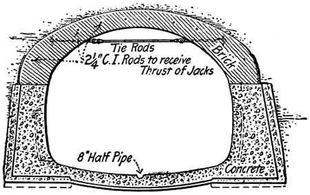
Fig. 115.—Wide Arch Section, Boston Subway.
Cross-Section.
—The subway being built for two tracks in
some places and for four
tracks in other places, it was
necessary to vary the form
and dimensions of the cross-section.
The cross-sections
actually adopted are of three
types. Fig. 115 shows the
section known as the wide-arch
type, in which the lining
is solid masonry. The second type was known as the double-barrel
section, and is shown by Fig. 116. The third type of
section is shown by Fig. 117. The lining consists of steel columns[205]
carrying transverse roof girders, the roof girders being
filled between with arches, and the wall columns having concrete
walls between them. The wide-arch type and the double-barrel
type of sections were employed in some portions of the Tremont
St. line, where the traffic was very dense, since it was possible
to construct them without opening the street. Much of the
wide-arch line was constructed by the use of the roof shield,
which is described in the succeeding chapter on the shield system
of tunneling.
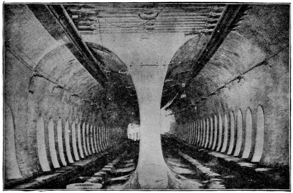
Fig. 116.—Double-Barrel Section, Boston Subway.
Methods of Construction.
—Several different methods were
employed in constructing the subway. Where ample space
was available, the single wide trench method of cut-and-cover
construction was employed, the earth being removed as fast as
excavated. In the streets, except where regular tunneling was
resorted to, the parallel trench or transverse trench cut-and-cover
methods were employed.
In the transverse trench method, trenches about 12 ft. wide[206]
were excavated across the street, their length being equal to
the extreme transverse width of the tunnel lining, and their
depth being equal to the depth of the tunnel floor. These
trenches were begun during the night, and immediately roofed
over with a timber platform flush with the street surface. Under
these platforms the excavation was completed and the lining
built. As each trench or “slice” was completed, the street
above it was restored and the platform reconstructed over
the succeeding trench or slice. During the construction of
each slice the street traffic, including the street cars, was carried
by the timber platform.
In the parallel trench method, short parallel trenches were
dug for the opposite side walls, and also for the intermediate
columns, and completely roofed over during the night. Under[207]
this roofing the masonry of the side walls and column foundations
and the columns themselves were erected. When the
side walls and columns had been erected, the surface of the
street between them was removed, the roof beams laid, and a
platform covering erected, as shown by Fig. 118. This roofing
work was also done at night. The subsequent work of building
the roof arches, removing the remainder of the earth, and
constructing the invert, was carried on underneath the platform
covering which carried the street traffic in the meantime.
The successive repetition of the processes described constructed
the subway.
Where the traffic was very dense on the street above, tunneling
was resorted to. For small portions of this work the excavation
was done in the ordinary way, using timber strutting,
but much the greater portion of the tunnel work was performed
by means of a roof shield. In the latter case, the side walls
were first built in small bottom side drifts and were fitted with
tracks on top to carry the roof shield. The construction and
operation of this shield are described fully in the succeeding
chapter on the shield system of tunneling.
Masonry.
—The masonry of the inclined approaches to the
subway consists simply of two parallel stone masonry retaining
walls. In the wide-arch and double-barrel tunnel sections, the
side walls are of concrete and the roof arches are of brick masonry.
In the other parts of the subway the masonry consists of brick
jack arches sprung between the roof beams and covered with
concrete, of concrete walls embedding the side columns, and
of the concrete invert and foundations for the columns. Figs.
115 to 118 inclusive show the general details of the masonry
work for each of the three sections. The inside of the lining
masonry is painted throughout with white paint.
Stations.
—The design and construction of the stations for
the Boston Subway were made the subjects of considerable
thought. All the stations consist of two island platforms of
artificial stone having stairways leading to the street above.[208]
The platforms are made 1 ft. higher than the rails. The station
structure itself is built of steel columns and roof beams with
brick roof arches and concrete side walls. Its interior is lined
with white enameled tiles. The intermediate columns are cased
with wood, and have circular wooden seats at their bottoms.
Each stairway is covered by a light housing, consisting of a
steel framework with a copper covering and an interior wood
and tile finish.
Ventilation.
—The subway is ventilated by means of exhaust
fans located in seven fan chambers, some of which contain
two fans, and others only one fan. Each of the fans has a
capacity of from 30,000 to 37,000 cu. ft. of air per minute, and
is driven by electric motor, taking current from the trolley
wires. This system of ventilation has worked satisfactorily.
Disposal of Rain Water.
—The rain water which enters the
subway from the inclined entrances, together with that from
leakage, is lifted from 12 ft. to 18 ft. by automatic electric pumps
to the city sewers. The subway has pump-wells at the Public
Garden, at Eliot St., Adams Square, and Haymarket Square.
In each of these wells are two vertical submerged centrifugal
pumps made entirely of composition metal. In each chamber
above, are two electric motors operating the pumps. Each
motor is started and stopped according to the height of water
by means of a float and an automatic release starting box.
The floats are so placed that only one pump is usually brought
into use. The other, however, comes into service in case the
first pump is out of order or the water enters more rapidly than
one pump can dispose of it. In the latter case, both motors
continue to run until the same low level has been reached.
Very little dampness except from atmospheric condensation
is to be found on the interior walls or roof of the subway, although
numerous discolored patches, caused by dampness and
dust, may be seen on some parts of the walls. Substantially all
of the leakage comes through the small drains in the invert
leading from hollows left in the side walls. Careful measurement[209]
was taken at the end of an unusually wet season to determine
the actual amount of leakage, and the total amount for
the entire subway was found to be about 81 gallons per minute.
Estimated Quantities.
—The estimated quantities of material
used in constructing the subway were as follows:
| Excavation |
369,450 |
cu. |
yds. |
| Concrete |
75,660 |
„ |
„ |
| Brick |
11,105 |
„ |
„ |
| Steel |
8,105 |
tons |
| Granite |
2,285 |
cu. |
yds. |
| Piles |
117,925 |
lin. |
ft. |
| Ribbed tiles |
12,440 |
sq. |
yds. |
| Plaster |
88,190 |
„ |
„ |
| Waterproofing (asphalt coating) |
117,980 |
„ |
„ |
| Artificial stone |
6,790 |
„ |
„ |
| Enameled brick |
2,210 |
„ |
„ |
| Enameled tiles |
2,855 |
„ |
„ |
Cost of the Subway.
—The estimated cost of the subway made
before the work was begun was approximately $4,000,000, and
the cost of construction did not exceed $3,700,000. This includes
ventilating and pump chambers, changes of water and
gas pipes, sewers and other structures, administration, engineering,
interest on bonds, and all cost whatsoever. Dividing this
number by the total length we obtain a cost per linear foot of
$342.30.
New York Rapid Transit Railway.
—The project of an underground
rapid transit railway to run the entire length of Manhattan
Island was originated some years previous to 1890. In
1894, however, a Rapid Transit Commission was appointed to
prepare plans for such a road, and after a large amount of trouble
and delay this commission awarded the contract for construction
to Mr. John B. McDonald of New York City, on Jan. 15, 1900.
Route.
—The road starts from a loop which encircles the
City Hall Park. Within this loop the tunnel construction is
two-track; but where the main line leaves the loop, all four tracks
come to the same level, and continue side by side thereafter[210]
except at the points which will be noted as the description
proceeds. Proceeding from the loop, the four-track line passes
under Center and Elm Streets. It continues under Lafayette
Place, across Astor Place and private property between Astor
Place and Ninth St. to Fourth Ave. The road then passes
under Fourth and Park Avenues until 42d St. is reached. At
this point the line turns west along 42d St., which it follows to
Broadway. It turns northward again under Broadway to the
boulevard, crossing the Circle at 59th St. The road then follows
the boulevard until 97th St. is reached, where the four-track
line is separated into two double-track lines.
At a suitable point north of 96th St. the outside tracks rise
so as to permit the inside tracks, on reaching a point near 103d St.,
to curve to the right, passing under the north-bound track,
and to continue thence across and under private property to
104th St. From there the two-track tunnel goes under 104th St.
and Central Park to 110th St., near Lenox Ave.; thence under
Lenox Ave to a point near 142d St.; thence across and under
private property and the intervening streets to the Harlem River.
The road passes under the Harlem River and across and under
private property to 149th St., which street it follows to Third
Ave., and then passes under Westchester Ave., where, at a convenient
point, the tracks emerge from the tunnel and are carried
on a viaduct along and over Westchester Ave., Southern Boulevard,
and Boston Road to Bronx Park. This portion of the line,
from 96th St. to Bronx Park, is known as the East Side Line.
From the northern side of 96th St. the outside tracks rise
and after crossing over the inside tracks they are brought together
on a location under the center line of the street and proceed
along under the boulevard to a point between 122d and
123d Streets. At this point the tracks commence to emerge
from the tunnel, and are carried on a viaduct along and over
the boulevard at a point between 134th and 135th Streets, where
they again pass into the tunnel under and along the boulevard
and Eleventh Ave. to a point about 1350 ft. north of the center[211]
line of 190th St. There the tracks again emerge from the tunnel,
and are carried on a viaduct across and over private property
to Elwood St., and over and along Elwood St. to Kingsbridge St.
to Kingsbridge Ave., private property, the Harlem Ship Canal
and Spuyten Duyvil Creek, private property, Riverdale Ave.,
and Broadway to a terminus near Van Cortland Park. That
portion of the line from 96th St. to the above-mentioned terminus
at Van Cortland Park is known as the West Side Line.
The total length of the rapid transit road, including the parts
above and below the surface ground of the streets, as well as
both the East and West Side Lines, is about 221⁄2 miles.
Material Penetrated.
—The soil through which the road was
excavated was a varied one. The lower portion of the road, or
the part including the loop up to nearly Fourth St., was excavated
through loose soil, but from Fourth St. to the ends it was excavated
in rock. The loose soil forming the southern part of
Manhattan Island is chiefly composed of clay, sand, and old
rubbish—a soil very easy to excavate. Water was met at
some points, but not in such quantities as to be a serious inconvenience.
From Fourth St. to the ends of both the east
and west side lines, the soil was chiefly composed of rock of
gneissoid and mica-schistose character, these rocks prevailing
nearly throughout the whole of Manhattan Island. The rock,
as a rule, was not compact, but full of seams and fissures, and
at many points it was found disintegrated and alternated with
strata of loose soils, and even pockets of quicksand were met
with along the line of the road.
Cross-Sections.
—The section of the underground road is of
three different types,—the rectangular, the barrel-vault, and
the circular. The rectangular section. Fig. 119, is used for the
greater part of the road, of which a portion is for four tracks and
a portion for two tracks. The dimensions adopted for the four
tracks are 50 × 13 ft., and for the double tracks 25 × 13 ft.
The barrel-vault section, composed of a polycentric arch, having
the flattest curve at the crown, has been adopted for the tunnels[212]
under Park Avenue—while the semicircular arch is used for
all the other portions of the road to be tunneled. The circular
section of 15-ft. diameter is used under the Harlem River, and
being for single track, two parallel tunnels were built side by side.
The main line from the City Hall loop to about 102d St. consists
of four tracks built side by side in one conduit, except for
that portion under the present Fourth Ave. tunnel where two
parallel double-track tunnels are employed. The West Side
Line will consist of double tracks laid in one conduit, except
across Manhattan St. and beyond 190th St., where it is carried
on an elevated structure. The East Side Line consists of a
double-track tunnel driven from 102d St., and the boulevard
under Central Park to 110th St. and Lenox Ave., and two
parallel circular tunnels excavated under the Harlem River,—the
other portions of the road being double-track, subway and
elevated structure.
Methods of Excavation.
—Both the double-and four-track
subway were built by using the different varieties of the cut-and-cover
method. The single wide-trench method was used for
the construction of the double-track line and also for the construction
of the four-track line where the local conditions allowed[213]
it. The single narrow-trench method was used for the construction
of the four-track subway at 42d St., to meet with the
peculiar conditions of the traffic. Almost the total length of
the four-track line of the subway was built by means of the two
parallel side trenches. The slice method, so successfully employed
in the Boston Subway, was used only on 42d St. west
of 6th Avenue.
Lining.
—The lining of the subway is of concrete, carried
by a framework of steel. The floor consists of a foundation
layer of concrete at least eight inches thick on good foundation,
but thicker, according to conditions, where the foundation
is bad. On top of this is placed another layer of concrete, with
a layer of waterproofing between the two. In this top layer
are set the stone pedestals for the steel columns, and the members
making up the tracks.
In the four-track subway, the steel framework consists of
transverse bents of columns, and I-beams spaced about five feet
apart along the tunnel. The three interior columns of each
bent are built-up bulb-angle and plate columns of H-section.
The wall columns are I-beams, as are also the roof beams; between
the I-beams, wall columns, and roof beams there is a
concrete filling, so that the roof of the subway will be made
up of concrete arches resting on the flanges of the I-beams of
the roof. The concrete used is of one part Portland cement,
two parts sand, and four parts broken stones. The double-track
subway is built in the same way, except that only one
column is placed between the tracks for the support of the
roof.
All the concrete masonry of the roof, foundations, and side
walls contains a layer of waterproofing, so as to keep perfectly
dry the underground road, and prevent the percolation of water.
This waterproofing is made up as follows: On the lowest stratum
of concrete, whose surface is made as smooth as possible, a layer
of hot asphalt is spread. On this asphalt are immediately laid
sheets or rolls of felt; another layer of hot asphalt is then spread[214]
over the felt, and then another layer of felt laid, and so on, until
no less than two, and no more than six, layers of felt are laid,
with the felt between layers of asphalt. On top of the upper
surface of asphalt the remainder of the concrete is put in place
so as to reach the required thickness of the concrete wall.
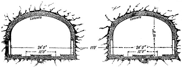
Fig. 120.—Park Avenue Deep Tunnel Construction, New York Rapid Transit Railway.
Tunnels.
—When the distance between the roof of the proposed
structure and the street was 20 ft. or over, the Standard
Subway construction was replaced by tunnels. Three important
tunnels have been constructed along the line of the New York
Rapid Transit and these are located between 33d and 42d Streets
on Park Ave., under Central Park northeast of 104th St. and
under Broadway north of 152d St. The Park Ave. construction
(Fig. 120) consists of two parallel double-track tunnels, located
on each side of the street, and about 10 ft. below the present
tunnel. The soil being composed of good rock, the tunnels were
driven by a wide heading, and one bench, since no strutting
was required, and the masonry lining, even of the roof, was left
far behind the front of the excavation. The masonry lining
consists of concrete walls and brick arches. The tunnels under
Central Park and under Broadway being driven through a similar
rock, the same method of excavation and the same manner of
lining was used.
The tunnel under the Harlem River was driven through soft
ground; and it was constructed as a submarine tunnel, according
to the caisson process. The tunnels were lined with iron made[215]
up of segments, with radial and circumferential flanges. Concrete
was placed inside and flush with the flanges.
The tracks, both in the subway and tunnels, are an intimate
part of the concrete flooring. The rail rests on a continuous
bearing of wooden blocks, laid with the grain running transversely
with respect to the line of the rail, and held in place by two
channel iron guard rails. The guard rails are bolted to metal
cross-ties embedded in the concrete.
Viaduct.
—A considerable portion of the double-track branch
lines north of 103d St. is viaduct, or elevated structure. The
viaduct construction on the West Side Line extends, including
approaches, from 122d St. to very near 135th St. Of this distance,
2018 ft. 8 ins. are viaduct proper, consisting of plate
girder spans carried by trestle bents at the ends, and by trestle
towers for the central portion. The columns of the bents and
towers are built-up bulb-angle and plate columns of H-section
of the same form as those used in the bents inside the subway.
The approaches proper are built of masonry. The elevated line
proper consists of plate girder spans, supported on plate cross
girders carried by columns.
[216]
Stations.
—Many stations are built along the line. These
are located on each side of the street. The entrances at the
stations consist of iron framework, with glass roofs covering the
descending stairways. The passageways leading down are walled
with white enameled bricks and wainscoted with slabs of marble.
The stations for the local trains are located on each side of the
road close to the walls, since the outside tracks are reserved for
the local trains, while the middle ones are reserved for the expresses.
The few stations for the express trains are located
between the middle and outside tracks. Stations are provided
with all the conveniences required, having toilet rooms, news
stands, benches, etc., and are lighted day and night by numerous
arc lamps.
General.
—The contractor completed the work in four years.
No difficulty was encountered in doing this, since the great
extension of the road and the great width of the avenues under
which it runs allowed work all along the line at the same time.
The work, briefly summarized, comprises the following items:—
| Length of all sections, ft. |
109,570 |
| Total excavation of earth, cu. yds. |
1,700,228 |
| Earth to be filled back, cu. yds. |
773,093 |
| Rock excavated, cu. yds. |
921,128 |
| Rock tunneled, cu. yds. |
368,606 |
| Steel used in structure, tons |
65,044 |
| Cast iron used, tons |
7,901 |
| Concrete, cu. yds. |
489,122 |
| Brick, cu. yds. |
18,519 |
| Waterproofing, sq. yds. |
775,795 |
| Vault lights, sq. yds. |
6,640 |
| Local stations, number |
43 |
| Express stations, number |
5 |
| Station elevators, number |
10 |
| Track |
total, lin. ft. |
305,380 |
| „ |
underground, lin. ft. |
245,514 |
| „ |
elevated, lin. ft. |
59,766 |
In addition to the construction of the railway itself, it was
necessary to construct or reconstruct certain sewers, and to[217]
adjust, readjust, and maintain street railway lines, water pipes,
subways, and other surface and subsurface structures, and to
relay street pavements.
The total cost of the work, according to the contract signed
by Mr. McDonald, was $35,000,000. Dividing this amount by
the total length of the road, which is 109,570 lineal feet, we have
the unit cost a lineal foot $315, or a little less than unit of cost
of the Boston Subway, which was $342 per lineal foot.
The road belongs to the city. The contractor acts as an
agent for the city in carrying out the work, and he is the leaser
of the road for fifty years. The work was paid for as soon as the
various parts of the road were completed, and the money was
obtained from an issue of city bonds. During the fifty years’
lease the contractor will pay the interest plus 1% of the face
value of the bonds. This 1% goes to the sinking-fund, which
within the fifty years at compound interest forms the total sum
required for the redemption of bonds.
This first New York Subway has been extended to Brooklyn,
and more lines will be built so as to form a complete underground
railway system to accommodate the ever-increasing traveling
crowd of the American metropolis. No new method of construction
has been devised yet. The only variation from the
illustrated methods has been where the subway is built underneath
the Elevated Road which had to be strongly supported
during the construction of the subway. This has been done
in two different ways, either by supporting the columns of
the Elevated Road by means of two wooden A-frames abutting
at the top and leaving a large space close to the foot of the
column where a pit was excavated to the required depth of
the subway, or by attaching the columns to long iron girders
placed longitudinally and resting with both ends in firm soil.
[218]
CHAPTER XVII.
SUBMARINE TUNNELING: GENERAL DISCUSSION.—THE
SEVERN TUNNEL.
GENERAL DISCUSSION.
Submarine tunnels, or tunnels excavated under the beds of
rivers, lakes, etc., have been constructed in large numbers
during the last quarter of a century, and the projects for such
tunnels, which have not yet been carried to completion, are
still more numerous. Among the more notable completed
works of this character may be noted the tunnel under the
River Severn and those under the River Thames in England,
the one under the River Seine in France, those under the
St. Clair, Detroit, Hudson, Harlem and East Rivers, and the
one under the Boston Harbor for railways, that under the East
River for gas mains, that under Dorchester Bay, Boston, for
sewage, and those under Lakes Michigan and Erie for the water
supply of Milwaukee, Chicago, Buffalo, and Cleveland in America.
For the details of the various projected submarine tunnels of
note, which include tunnels under the English and Irish Channels,
under the Straits of Gibraltar, under the sound between
Copenhagen in Denmark and Malmö in Sweden, under the
Messina Straits between Italy and Sicily, and under the Straits
of Northumberland between New Brunswick and Prince Edward
Island, and those connecting the various islands of the Straits
of Behring, the reader is referred to the periodical literature of
the last few years.
Previous to attempting the driving of a submarine tunnel
it is necessary to ascertain the character of the material it will[219]
penetrate. This fact is generally determined by making diamond-drill
borings along the line, and the object of ascertaining
it is to determine the method of excavation to be adopted. If
the material is permeable and the tunnel must pass at a small
depth below the river bed, a method will have to be adopted
which provides for handling the difficulty of inflowing water.
If, on the other hand, the tunnel passes through impermeable
material at a great depth, there will be no unusual trouble
from water, and almost any of the ordinary methods of tunneling
such materials may be employed. Shallow submarine
tunnels through permeable material are usually driven by the
shield method or by the compressed air method, or by a method
which is a combination of the first and second.
It is not an uncommon experience for a submarine tunnel
to start out in firm soil and unexpectedly to find that this
material becomes soft and treacherous as the work proceeds,
or that it is intersected by strata of soft material. The method
of dealing with this condition will vary with the circumstances,
but generally if any considerable amount of soft
material has to be penetrated, or if the inflow of water is very
large, the firm-ground system of work is changed to one
of the methods employed for excavating soft-ground submarine
tunnels. The Milwaukee water supply tunnel, described
elsewhere, is a notable example of submarine tunnels,
began in firm material which unexpectedly developed a treacherous
character after the work had proceeded some distance.
Occasionally the task of building a submarine tunnel in the
river bed arises. In such cases the tunnel is usually built by
means of cofferdams in shallow water, and by means of caissons
in deep water.
Submarine tunnels under rivers are usually built with a descending
grade from each end which terminates in a level middle
position, the longitudinal profile of the tunnel corresponding to
the transverse profile of the river bottom. Where, however,
such tunnels pass under the water with one end submerged, and[220]
the other end rising to land like the water supply tunnels of
Chicago, Milwaukee, and Cleveland, the longitudinal profile is
commonly level, or else descends from the shore to a level
position reaching out under the water.
The drainage of submarine tunnels during construction is
one of the most serious problems with which the engineer has
to deal in such works. This arises from the fact that, since the
entrances of the tunnel are higher than the other parts, all of
the seepage water remains in the tunnel unless pumped out, and
from the possibility of encountering faults or permeable strata,
which reach to the stream bed and give access to water in
greater or less quantities. Generally, therefore, the excavation
is conducted in such a manner that the inflowing water is led
directly to sumps. To drain these sumps pumping stations
are necessary at the shore shafts, and they should have ample
capacity to handle the ordinary amount of seepage, and enough
surplus capacity to meet probable increases in the inflow. For
extraordinary emergencies this plant may have to be greatly
enlarged, but it is not usual to provide for these at the outset
unless their likelihood is obvious from the start. The character
and size of the pumping plants used in constructing a number
of well-known tunnels are described in Chapter XII.
In this book submarine tunnels will be classified as follows:
(1) Tunnels in rock or very compact soils, which are driven by
any of the ordinary methods of tunneling similar materials on
land; (2) tunnels in loose soils, which may be driven, (a) by
compressed air, (b) by shields, or (c) by shields and compressed
air combined; (3) tunnels on the river bed, which are constructed,
(a) by cofferdams, or (b) by caissons. To illustrate
tunnels of the first class, the River Severn tunnel in England
has been selected; to illustrate those of the second class, the
several tunnels discussed in the chapter on the shield system of
tunneling and the Milwaukee tunnel is sufficient; to illustrate
those of the third class, the Van Buren Street tunnel in Chicago,
the Harlem, the Seine and the Detroit River tunnels are selected.
[221]
THE SEVERN TUNNEL.
The Severn tunnel, which carries the Great Western Railway
of England, beneath the estuary of a large river, is 4 miles
642 yards long. It penetrates strata of conglomerate, limestone,
carboniferous beds, marl, gravel, and sand at a minimum depth
of 443⁄4 ft. below the deepest portion of the estuary bed. The
following description of the work is abstracted from a paper by
Mr. L. F. Vernon-Harcourt.[12]
The first work was the sinking of a shaft, 15 ft. in diameter,
lined with brickwork, on the Monmouthshire bank of the Severn,
200 ft. deep. After the Monmouthshire shaft had been sunk, a
heading 7 ft. square was driven under the river, rising with a
gradient of 1 in 500 from the shaft on the Monmouthshire shore,
so as to drain the lowest part of the tunnel. Near to the first, a
second shaft was sunk and tubbed with iron, in which the pumps
were placed for removing the water from the tunnel works,
connection being made by a cross-heading with the heading
from the first shaft. There was also a shaft on the Gloucestershire
shore; and two shafts inland from the first on the Monmouthshire
side, to expedite the construction of the tunnel.
Headings were then driven in both directions along the line
of the tunnel, from the four shafts; and the drainage heading
from the old shaft was continued, in the line of the tunnel,
under the deep channel of the estuary, and up the ascending
gradient towards the Gloucestershire shore, till, in October,
1879, it had reached to within about 130 yards of the end of
the descending heading from the Gloucestershire shaft. During
this period, though the work had progressed slowly, no large
quantity of water had been met with in any of the headings, in
spite of their already extending under almost the whole width
of the estuary. On October 18, 1889, however, a great spring
was tapped by the heading which was being driven landwards
from the old shaft, about 40 ft. above the level of the drainage[222]
heading; and the water poured out from this land spring in
such quantity that, flowing along the heading, falling down the
old shaft, and thus finding its way into the drainage heading
and the long heading of the tunnel under the estuary in connection
with it, it flooded the whole of the workings in communication
with the old shaft, which it also filled within twenty-four
hours from the piercing of the spring.
To obtain increased security against any influx of water from
the deep channel of the estuary into the tunnel, the proposed
level portion of the tunnel, rather more than a furlong long under
this part, was lowered 15 ft. by increasing the descending gradient
on the Monmouthshire side from 1 in 100 to 1 in 90, and lowering
the proposed rail level on the Gloucestershire side 15 ft. throughout
the ascent, so as not to increase the gradient of 1 in 100 against
the load. A new shaft, 18 ft. in diameter, was sunk slightly
nearer the estuary on the Monmouthshire shore than the old one;
two shafts also were sunk on the land side of the great spring for
pumping purposes; and additional pumping machinery was
erected. The flow from the spring into the old shaft was arrested
by a shield of oak fixed across the heading; and at last,
after numerous failures and breakdowns of the pumps, the
headings were cleared of water, after a diver, supplied with
a knapsack of compressed oxygen, had closed a door in the
long heading under the estuary; and the works were resumed
nearly fourteen months after the flooding occurred. The great
spring was then shut off from the workings by a wall across
the heading leading to the old shaft; and, owing to the lowering
of the level of the tunnel, a new drainage heading had to
be driven from the bottom of the new shaft at a lower level,
which was made 5 ft. in diameter, and lined with brickwork,
whilst the old drainage heading was enlarged to 9 ft. in diameter,
and lined with brickwork, so as to aid in the permanent
ventilation of the tunnel. The lowering of the level, moreover,
converted the bottom tunnel headings into top headings, so
that along more than a mile of the tunnel the semicircular arch,[223]
26 ft. in diameter, was built first, and then, after lowering the
headings, the invert was laid and the side walls were built up.
Bottom headings were driven along the remainder of the tunnel,
and the work was expedited by means of break-ups. Ventilation
was effected in the works by a fan 18 inches in diameter
and 7 ft. wide, fixed at the top of the new deep shaft; the rock
was bored by drills worked by compressed air; the blasting was
eventually effected exclusively by tonite, owing to its being
freer from deleterious fumes than any other explosive; and the
workings were lighted by Swan and Brush electric lamps. The
tunnel is lined throughout with vitrified brickwork, between
21⁄4 ft. to 3 ft. thick, set in cement, and has an invert 11⁄2 ft. to
3 ft. in thickness; the lining was commenced towards the end
of 1880, the headings under the river were joined in September,
1881, and the last length of the tunnel, across the line of the great
spring, was completed in April, 1885.
Water came in from the river through a hole in a pool of
the estuary, close to the Gloucestershire shore, in April, 1881,
during the lining of a portion of the tunnel, but fortunately
before the headings were joined. This influx was stopped by
allowing the water to rise in the tunnel to tide-level, to prevent
the enlargement of the hole, which was then filled up at low
water with clay, weighted on the top with clay in bags. The
great spring broke out again in October, 1883, and flooded the
works a second time; but within four weeks the water had been
pumped out and the spring again imprisoned. During this period
an exceptionally high tide, raised still higher by a southwesterly
gale, inundated the low-lying land on the Monmouthshire side
of the estuary, and, flowing down one of the inland shafts, flooded
a section of the tunnel, but the pumps removed this water within
a week.
In order to construct the portion of tunnel traversing the
line of the great spring, the water was diverted into a side heading
below the level of the tunnel, leading to the old shaft, whence
it was pumped, and the fissure below the tunnel was filled with[224]
concrete, over which the invert was built. An attempt to
imprison the spring, on the completion of this length of tunnel,
having resulted in imposing an excessive pressure on the brickwork,
leading to fractures and leakage, a shaft, 29 ft. in diameter,
was sunk at the side of the tunnel at this point in 1886, and
pumps were erected powerful enough to deal with the entire
flow of the spring.
The tunnel was opened for traffic in December, 1886, and
gives access to a double line of railway, connecting the lines
converging to Bristol with the South Wales railway and the
western lines. The pumping power provided at the shaft connected
with the great spring, and at four other shafts, is capable
of raising 66,000,000 gallons of water per day, the maximum
amount pumped from the tunnel being 30,000,000 gallons a
day. The ventilation of the tunnel is effected by fans placed
in the two main shafts on each bank of the estuary, and the fan
in the Monmouthshire shaft is 40 ft. in diameter, and 12 ft. wide.
The tunnel gives passage to a large traffic, numerous through-trains
between the north and southwest of England making
use of it.
[225]
CHAPTER XVIII.
SUBMARINE TUNNELING (Continued); THE COMPRESSED
AIR METHOD.—THE MILWAUKEE
WATER-WORKS TUNNEL.
Tunnels excavated at shallow depth from the bed of the
river are liable to cave in under the great weight of the water
and material above the roof. Besides, the progress of the work
will be greatly interfered with by the water which may reach the
tunnel passing through the loose soil in large quantities. To
contend with these two sources of trouble, different methods of
constructing subaqueous tunnels have been devised; they are:
by compressed air, by shield, and finally by a combination of
these two methods, viz., by shield and compressed air.
The compressed air method was suggested by Mr. Haskin,
the promoter and the first builder of the Hudson River tunnel.
In 1874, when he began to sink the shaft for the construction of
his tunnel, several subaqueous tunnels had already been driven
by means of shields. Mr. Haskin had ideas of his own, and
thought he could dispense with the shield and could trust to
compressed air, since he was firmly convinced that compressed
air alone could expel the water and temporarily support the
roof of the excavation prior to the building of the lining masonry.
In other words, he expected to substitute a core of compressed
air for the core of earth removed. In the patent granted him for
this method of tunneling, he expresses himself as follows: “The
distinguishing feature of my system is that, instead of using
temporary facings of timber or other rigid material, I rely upon
the air pressure to resist the caving in of the wall and infiltration
of water until the masonry wall is completed. The pressure[226]
is, of course, to be regulated by the exigencies of the occasion.
The effect of such a pressure has been found to drive water in
from the surface of the excavation, so that the sand becomes dry.”
The compressed air method was soon found to be inefficient,
even in the construction of the Hudson tunnel where the roof
of the excavation was supported by timbering in the manner
indicated in the pilot system. Thus large subaqueous railway
tunnels cannot be driven exclusively by the compressed air
method; still it has been successfully employed in the construction
of small tunnels driven for aqueduct purposes. But the
use of compressed air marked a great progress in the art of
submarine tunneling.
THE MILWAUKEE WATER-WORKS TUNNEL.
The following description of the Milwaukee Water-Works
Tunnel is an example of subaqueous tunnels driven through
good soil in the usual manner employed in land tunnels; but
afterward when treacherous material was encountered, the work
was continued by means of compressed air.
The new water supply intake tunnel for the city of Milwaukee,
Wis., is one of the most difficult examples of tunnel construction
which American engineering practice has afforded. The difficulties
were in a large measure unexpected when the work was
decided upon and put under way. The tunnel began and ended
in a hard, impervious clay, practically a rock, and all the preliminary
investigations led to the conclusion that the same favorable
material would be encountered for its entire length. With
such material a brick-lined tunnel 71⁄2 ft. in diameter presented no
unusual problems; but after about 1640 ft. had been excavated
from the shore end the tunnel ran out of the hard clay, and for
the next 600 ft. or more a variety of water-bearing material was
encountered, which tried the skill and patience of the engineer
to their utmost. Other difficulties were indeed met with, but
these were of minor importance in comparison with that of safely
and successfully penetrating the water-bearing drift.
[227]
The work of sinking the shore shafts and excavating the
first 1600 ft. of tunnel did not prove especially difficult. A
hard, compact, and rock-like clay, bearing very little moisture,
was encountered all along, and was blasted and removed in the
ordinary manner. The only mishap which occurred with this
portion of the work was the destruction of the contractor’s
boiler plant by fire on Jan. 12, 1891, which allowed the tunnel
to fill with water, and delayed work about a month. By Oct. 21,
1891, 1640 ft. had been driven, averaging about 62⁄3 ft. per day,
all in the hard clay. No timbering had been necessary, and
except for the first 100 ft. of the tunnel there was very little
seepage. On the afternoon of Oct. 21 water was observed
coming out from one of the drill holes in the heading, but no
attention was paid to it. Shortly after a blast was fired, and
was immediately followed by a rush of water from the heading.
An unsuccessful attempt was made to check the flow, and the
pumps were started; but they were unable to keep the water
down, and after seven hours’ hard work the tunnel was abandoned.
By the next morning the tunnel and shaft were full of
water.
Several attempts were made to empty the tunnel; but the
limited pumping capacity was not equal to the task, and it was
finally decided to install larger pumps. The pumping had, however,
shown that about 1000 gallons of water a minute was
coming through the leak. With the increased pumping plant
the tunnel was finally laid dry Feb. 13, 1892. Upon examination
the head of the drift was found to be in the same undisturbed
condition in which it was left when the water broke in
three months before.
A brick bulkhead was built into the end of the brickwork
of the tunnel, and provided with a timber door for passage, and
two 10-in. pipes for the outlet of the water. With these openings
closed, the flow was checked sufficiently to allow the placing
of pumps at the bottom of the shore shaft. Meanwhile the
pressure of the water against the bulkhead caused dangerous[228]
leakage, and so after the pumps were in position the 10-in. pipes
were opened, relieving the pressure and allowing the water its
normal rate of flow. Trouble with the pumps now arose, and
after various stoppages and breaks the discharge pipe finally
fell, disabling the whole plant. It became necessary to close
the 10-in. pipes in the bulkhead and draw up the pumps. This
allowed the tunnel to again fill with water.
After thoroughly overhauling the pumping machinery, the
contractor again laid the tunnel dry on March 19; and after
the pumps had been permanently placed so as to take care of
the water, an examination of the work was made. It was found
that the water was coming from the north, and with the hope
of avoiding the difficulties of the old heading, it was decided to
make a détour of the south. On April 16 work was begun at
a point about 90 ft. back from the face, and deflecting the line
about 38° toward the south. About 38 ft. from the angle of
junction a brick bulkhead with two 8-in. openings was built
into the new bore. The work progressed successfully for about
75 ft., when water was again encountered; and upon pushing
forward the heading, gravel and sand came in such quantities
that it was found impracticable to continue the work further.
On June 1 the bulkhead was permanently closed, and the work
in this direction was abandoned.
A further and closer examination was now made of the heading
first abandoned. Upon breaking through the rock-like
clay it was found that the water came from an underground
stream flowing from the north through a well defined channel
in red clay. This channel was about 13 ft. above the grade of
the tunnel; and above it in every direction visible was a bed of
hard, dry, red clay, while immediately in front of the face of the
work was a bank of coarse gravel. Fig. 122 is a sketch of the
channel and stream where they entered the work. In this last
drawing the photograph has been followed exactly, no particular
being exaggerated in the slightest. The water from this
stream was clear and pure; and a chemical analysis showed[229]
that it was not lake water, but must come from some separate
source.
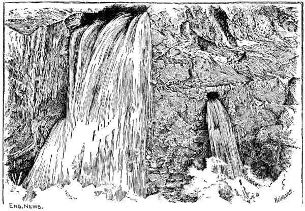
Fig. 122.—Sketch Showing Underground Stream, Milwaukee Water-Works Tunnel.
While the engineer did not consider the difficulty of proceeding
along the old line insurmountable, it was decided to be
less difficult on the whole to go back from 150 ft. to 175 ft. and
deflect the line to the north and upward, so as to pass over the
underground entrance. Instead of allowing the water to flow
at its normal rate and take care of it by pumping, the contractors
desired to reduce the pumping, and to this end they constructed
a bulkhead just west of the deflection toward the
south with a view of shutting off the water. The water, however,
accumulated with a pressure of some 50 lbs. per sq. in.
and penetrated the filling around the brick lining of the tunnel,
preventing the cutting through of the lining for the new line.
A second bulkhead was then built about 20 ft. west of the first,
but with not much better results, for upon closing it the water
was found to leak through the brickwork for a long distance[230]
west. Finally on Aug. 2, 1892, the contractors lifted their
pumps and allowed the tunnel to fill again with water.
No further work was done on the tunnel by the contractors,
although they continued work on the lake shaft for some months.
Difficulties had, however, arisen here, which will be described
further on; and finally a disagreement arose between the contractors
and the city over the delay in prosecuting the tunnel
work and over one or two other questions, which resulted in the
City Council suspending their contract and ordering the Board
of Public Works to go ahead with the work.
The first step to be taken by the engineer was to purchase
adequate pumping machinery and empty the tunnel. This was
effected Jan. 17, 1894; and as soon as practicable thereafter the
two bulkheads were removed and the tunnel cleaned, tram-car
tracks laid, and everything prepared for work. It was now
determined to go ahead on the original line of the tunnel if
possible, and the bulkhead here was removed and work begun.
Meanwhile, a safety bulkhead had been built to replace the first
one torn away. This was provided with a door and drainage
pipes. Work was begun on the original heading, but had
proceeded only a little way when the water broke in, driving
out the workmen. This was removed three or four times, when
the flow suddenly increased to 3000 gallons per minute. An
examination of the lake bottom above the break showed that it
had settled down, indicating that the new break connected with
the lake bottom, and making further work along the original
line out of the question.
The question now arose what it was best to do. It was
impracticable to use a shield, as the material ahead of the break
required blasting, and the pressure from above was enormous.
On account of its expense and difficulty of application the
freezing process did not seem advisable, and the plenum process
was likewise out of the question on account of the great pressure
which would be required at this depth. The détour to the
south which had been made by the contractor had been unsuccessful,[231]
and had left the ground in a treacherous condition.
To depress the tunnel was not advisable, for it was not by any
means certain that the bed of gravel could be avoided in that
way; and, moreover, it would be necessary to ascend again
further on, and thus leave a trap which would effectually cut
off escape to those at work on the face if water again broke into
the tunnel.
It was finally decided that the old plan of deflecting the
line toward the north and upward so as to pass over the underground
stream should be tried. A hole was therefore cut through
the tunnel lining 1433 ft. from the shore, and work was begun
on a détour of 20° toward the north and an upward grade of
10%. Fair progress was made on this new line, gradually
ascending into solid rock, until May 10, when the test borings,
which were constantly made in every direction from the face,
showed that sand was being approached. A brick bulkhead
was therefore built into the masonry as a safeguard, should it
happen that water was encountered in large quantities. As the
borings seemed to indicate that the top surface of the rock underlying
the sand was nearly level, the lower half of the tunnel was
first excavated, leaving about 18 ins. of the rock to serve as a
roof (Sketch a, Fig. 123), and the brick invert was built for
a distance of 52 ft. The rock roof was then carefully broken
through for short distances at a time, and short sheeting driven
ahead into the sand, which proved to be a very fine quicksand
flowing through the smallest openings. Extreme care had to be
taken in this work, but little by little the brickwork was pushed
ahead until at a distance of 90 ft. from the point where the sand
was first met, and 208 ft. from the old tunnel, the sand stopped
and the heading entered a hard clay.
All this work had been done on an ascending grade, and the
ascent was continued about 40 ft. farther in the clay. By this
time a sufficient elevation was gained to pass over the underground
stream, and the tunnel line was changed to head toward
the lake shaft, and the grade reduced to a level. The underground[232]
stream was passed without trouble and the tunnel continued
for a distance of 54 ft. without difficulty. On July
10 the clay in the heading suddenly softened, and before the
miners could secure it by bracing, the water rushed in, followed
by gravel, filling up solidly some 34 ft. of the tunnel before it
was stopped by a timber bulkhead hastily built.
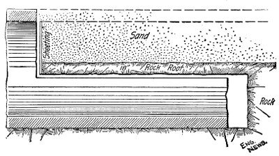
Longitudinal Section Showing Method of Construction in Rock Covered with
Quicksand.
Sketch “a”.
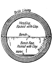
Section A-B-C-D.
Sketch “c”.
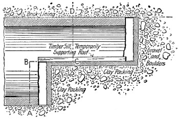
Longitudinal Section of Tunnel.
Sketch “b”.
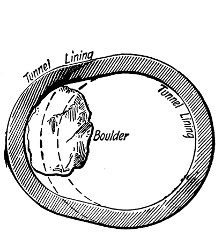
Cross Section Showing Manner of Constructing Lining around Boulder.
Sketch “d”.
Fig. 123.—Sketch Showing Methods of Lining, Milwaukee Water-Works Tunnel.
Larger illustration
Upon examining the lake bottom a cavity over 60 ft. deep and
10 ft. in diameter was found directly over the end of the tunnel,
which had been caused by the gravel breaking into the tunnel.
Having now reached an elevation where it was possible to use
compressed air, it was determined to put in double air-locks
and use the plenum process. The locks were built, and some[233]
670 cu. yds. of clay were dumped into the hole in the lake bottom.
On Aug. 4 the air-locks were tried with 26 lbs. air pressure;
but, upon a temporary release of the pressure, the water passed
around the locks and back of the tunnel lining for some distance,
and even forced through the lining, carrying considerable clay
and fine sand with it. Upon sounding the lake bottom it was
found that the cavity had again increased to a depth of 65 ft.,
whereupon an additional 600 cu. yds. of clay were dumped into it.
On account of the water leaking through the brickwork, the
only dry place to cut through the brickwork and build in an
air-lock was just ahead of the brick bulkhead. This lock was
completed Aug. 27, and to avoid encountering the danger of
the direct connection with the lake at the end of the drift, it
was decided to make another détour to the north. On Aug. 28,
therefore, the brick on the north side of the tunnel 12 ft. back
from the end of the brickwork was cut through under 25 lbs.
air pressure, and work proceeded in good, hard clay. The
original air-lock was cut out and a new lock built into this
clay about 34 ft. from the last détour, to be used in case of
further difficulties. After building the tunnel for about 80 ft.
from the détour, the soundings again indicated the approach to
gravel and water, and on Oct. 14 the water broke through from
the bottom in such volume and with such force that the men
ran out, closing every air-lock and the valves of every drain in
their haste to escape, until the brick bulkhead was reached.
It was with great difficulty that the portion of the tunnel up to
the last air-lock was recovered and cleaned out.
It was now recognized that a pressure of from 38 to 40 lbs.
of air would be needed to hold this water, and accordingly another
compressor was added to the plant. With a pressure of
36 lbs. the water was driven out and the work again started.
At this time also an additional 350 cu. yds. of clay were dumped
into the hole in the lake bottom. Altogether, 1620 cu. yds. of
clay had been put into this hole.
Loose gravel and boulders, some of immense size, were now[234]
encountered, and the work became exceedingly difficult on
account of the great escape of air. The interstices between the
gravel and boulders were not filled with silt or sand, but contained
water. Moreover, this material extended upward to the
lake bottom, as was shown by the escape of air at the surface of
the lake. For an area of several hundred square feet the surface
of the water resembled a pot of boiling water. At times the
air would escape very rapidly; and again only a few bubbles
would show.
It need hardly be said that the work in this gravel was very
slow. It was impossible to blast or to tear out the large boulders
whole, as so much surface would be exposed that an inrush of
water would take place despite the air pressure. The method
of procedure was to excavate a heading and build the brick roof
arch first, and then to take out the bench and build the invert.
Fig. 123 gives a number of sketches showing how the
work was done. A short piece of heading was taken out, the
top and face of the bench being meanwhile plastered with clay
(Sketches b and c, Fig. 123) to reduce the escape of air, and
then the roof arch was built and supported on side sills resting
on the bench. Bit by bit the roof arch was pushed forward
until some little distance had been completed, then the heading
was plastered with clay and the bench taken out little by little
and the invert built. All the gravel except the small area
upon which work was actually in progress was kept thoroughly
plastered with clay; and as the air escaped through the completed
brickwork very rapidly, water was allowed to cover a
portion of the invert (see Sketch c, Fig. 123), so as to reduce
the area of escape.
When a large boulder was reached, which lay partly within
and partly without the tunnel section, the lining was built out
and around it, as shown in Sketch d, Fig. 123. The boulder
was then broken and taken out. All through this gravel bed
the cross-section of the lining is made irregular by the construction
of these pockets in the lining to get around boulders.[235]
Sometimes they were on one side and sometimes on the other,
or on both, or at the top or bottom. In fact, there was no
regularity. Despite the hazard and danger of this work, continual
progress was made, though sometimes it was only 4 ft.
of completed tunnel per week, working night and day; and, if
some cases of caisson disease be excepted, the only mishap occurring
was a fire which got into the timber packing behind
the lining and caused some trouble. From the gravel the tunnel
ran into clay and quicksand, and then into hard, dry clay similar
to that encountered near the shore. Some difficulty was had
with the quicksand, but it was successfully overcome; and when
the hard clay was struck, the trouble, as far as the work from
the shore shaft was concerned, was virtually over.
Meanwhile, a different set of afflictions had come upon the
engineer and contractors in sinking the lake shaft and driving
the heading toward shore. This shaft was intended to be
built by sinking a cast-iron cylinder 10 ft. in diameter, made
up of sections bolted together. Work was begun July 5, 1892,
and the sinking was accomplished first by weighting the cylinder,
and afterwards by pumping out the sand and water within it
until the pressure from the outside broke through under the
cutting edge and forced the sand into the cylinder, allowing it
to sink a little. From 10 to 30 cu. yds. of sand were carried
into the cylinder each time, and finally it was feared that if
the process continued, the crib, which had been previously
erected, would be undermined. On Sept. 6, therefore, the
contractors were ordered to discontinue this method of work.
No change was made, however, until Oct. 1, when the cylinder
had reached a depth of 68 ft., and by this time there was quite
a large cavity underneath the crib. This was refilled, and the
cylinder pumped out, and excavation begun inside of it. On
Oct. 11 a 21⁄2-ft. deep ring of brickwork was laid underneath
the cutting edge; but in trying to put in another ring beneath
the first, two days later, the sand and water broke through the
bottom, driving the men out, and filling the cylinder to a depth[236]
of 16 ft. with sand. The pumps were started, but the water
could not be lowered to a greater depth than 60 ft.
At the request of the contractors, the city engineer had a
boring made at the center of the shaft to determine the character
of the material to be further penetrated. This boring
showed that sand mixed with loam and gravel would be found
for a depth of 26 ft., then would come 15 ft. of red clay, and
finally a layer of hard clay like that penetrated by the shore
end of the tunnel. About the middle of December the contractors
made another attempt to pump the shaft, but finding
that the water came in at the rate of 25 gallons a minute,
abandoned the attempt. In the latter part of February preparations
were made to put an air-lock in the shaft and use compressed
air. Hardly had the work been begun by this system
when, on April 20, 1893, a terrific easterly storm swept the top
of the crib bare of the buildings and machinery, and drowned
all but one of the 15 men at work there.
This disaster delayed the work for some time, but in June
the contractors erected a new building and new machinery, and
resumed work. Very little progress was made; and the air escaped
so rapidly that it loosened the sand surrounding the
shaft and reduced the friction to such an extent that on July
28 the entire cylinder lifted bodily about 6 ft., and sand rushed
in, filling the lower part of the cylinder to within 45 ft. of the
lake surface. No further work was done by the contractors
although they submitted a proposition to sink a steel cylinder
inside the cast-iron cylinder and extending from 5 ft. above
datum to 100 ft. below datum for $300 per ft. This proposition
was refused by the city; and since work on the tunnel
proper had been abandoned by the contractors some time before,
as had already been described, the city suspended their contract
on Oct. 19.
On Oct. 30 a contract was made with Mr. Thos. Murphy
of Milwaukee, Wis., to sink a steel cylinder inside the old iron
cylinder. The water was first pumped out of the old cylinder,[237]
and a timber bulkhead built at the bottom. On this the steel
cylinder was built, and then the bulkhead was removed. Air
pressure was put on, and the excavation proceeded successfully
until the bottom layer of clay was met with, when all chances
for trouble ceased.
The cylinder, as it was completed, penetrated 9 ft. into the
hard clay, and was underpinned with brickwork for a depth of
29 ft. or more, to a point 4 ft. below the grade line of the tunnel.
At the lower end, the section of the shaft was changed from a
circle to a square. Later the steel cylinder was lined with brick.
On March 28, 1894, an agreement was made with Mr. Thos.
Murphy to construct the tunnel from the lake shaft toward
the shore. Except that considerable water was encountered,
which, owing to inadequate pumping machinery, filled the
tunnel and shaft at two different times, and had to be removed,
no very great difficulty was had with this part of the work.
On July 28, 1895, the headings from the lake and shore shafts
met. Meanwhile the cast-iron pipe intake, the intake crib, etc.,
had been completed, and practically all that remained to be
done was to clean the tunnel and lift the pumping machinery
at the shore shaft. During the cleaning, the air pressure had
been kept up on account of the leakage through the brick lining,
and, indeed, the pressure was kept up until the last possible
moment, and everything made ready for removing the air-locks,
bulkheads, pumps, etc., in the least possible time. The pumps
were the last to come out.
[238]
CHAPTER XIX.
SUBMARINE TUNNELING (Continued).
THE SHIELD SYSTEM.
Historical Introduction.
—The invention of the shield system
of tunneling through soft ground is generally accredited to Sir
Isambard Brunel, a Frenchman born in 1769, who emigrated to
the United States in 1793, where he remained six years, and
then went to England, in which country his epoch-making invention
in tunneling was developed and successfully employed in
building the first Thames tunnel, and where he died in 1849, a
few years after the completion of this great work. Sir Isambard
is said to have obtained the idea of employing a shield to tunnel
soft ground from observing the work of ship-worms. He noticed
that this little animal had a head provided with a boring
apparatus with which it dug its way into the wood, and that its
body threw off a secretion which lined the hole behind it and
rendered it impervious to water. To duplicate this operation
by mechanical means on a large enough scale to make it applicable
to the construction of tunnels was the plan which
occurred to the engineer; and how closely he followed his animate
model may be seen by examining the drawings of his
first shield, for which he secured a patent in 1818. Briefly
described, this device consisted of an iron cylinder having at
its front end an auger-like cutter, whose revolution was intended
to shove away the material ahead and thus advance the
cylinder. As the cylinder advanced the perimeter of the hole
behind was to be lined with a spiral sheet-iron plating, which
was to be strengthened with an interior lining of masonry. It[239]
will be seen that the mechanical resemblance of this device to
the ship-worm, on which it is alleged to have been modeled, was
remarkably close.
In the same patent in which Sir Isambard secured protection
for his mechanical ship-worm he claimed equal rights of invention
for another shield, which is of far greater importance in
being the prototype of the shield actually employed by him in
constructing the first Thames tunnel. This alternative invention,
if it may be so termed, consisted of a group of separate
cells which could be advanced one or more at a time or all together.
The sides of these cells were to be provided with friction
rollers to enable them to slide easily upon each other; and it
was also specified that the preferable motive power for advancing
the cells was hydraulic jacks. To summarize briefly, therefore,
the two inventions of Brunel comprehended the protecting
cylinder or shield, the closure of the face of the excavation,
the cellular division, the hydraulic-jack propelling power, and
cylindrical iron lining, which are the essential characteristics
of the modern shield system of tunneling. The next step required
was the actual proof of the practicability of Brunel’s
inventions, and this soon came.
Those who have read the history of the first Thames tunnel
will recall the early unsuccessful attempts at construction which
had discouraged English engineers. Five years after Brunel’s
patent was secured a company was formed to undertake the
task again, the plan being to use the shield system, under the
personal direction of its inventor as chief engineer. For this
work Brunel selected the cellular shield mentioned as an alternative
construction in his original patent. He also chose to
make this shield rectangular in form. This choice is commonly
accounted for by the fact that the strata to be penetrated by the
tunnel were practically horizontal, and that it was assumed by
the engineer that a rectangular shield would for some reason
best resist the pressures which would be developed. Whatever
the reason may have been for the choice, the fact remains that[240]
a rectangular shield was adopted. The tunnel as designed consisted
of two parallel horseshoe tunnels, 13 ft. 9 ins. wide and
16 ft. 4 ins. high and 1200 ft. long, separated from each other
by a wall 4 ft. thick, pierced by 64 arched openings of 4 ft.
span, the whole being surrounded with massive brickwork built
to a rectangular section measuring over all 38 ft. wide and
22 ft. high.
The first shield designed by Brunel for the work proved inadequate
to resist the pressures, and it was replaced by another
somewhat larger shield of substantially the same design, but of
improved construction. This last shield was 22 ft. 3 ins. high
and 37 ft. 6 ins. wide. It was divided vertically into twelve
separate cast-iron frames placed close side by side, and each
frame was divided horizontally into three cells capable of separate
movement, but connected by a peculiar articulated construction,
which is indicated in a general way by Fig. 124. To
close or cover the face of the excavation, poling-boards held
in place by numerous small screw-jacks were employed. Each
cell or each frame could be advanced independently of the
others, the power for this operation being obtained by means
of screw-jacks abutting against the completed masonry lining.
Briefly described, the mode of procedure was to remove the
poling-boards in front of the top cell of one frame, and excavate
the material ahead for about 6 ins. This being done, the top
cell was advanced 6 ins. by means of the screw-jacks, and the
poling-boards were replaced. The middle cell of the frame was
then advanced 6 ins. by repeating the same process, and finally
the operation was duplicated for the bottom cell. With the
advance of the bottom cell one frame had been pushed ahead
6 ins., and by a succession of such operations the other eleven
frames were advanced a distance of 6 ins., one after the other,
until the whole shield occupied a position 6 ins. in advance of
that at which work was begun. The next step was to fill the
6-in. space behind the shield with a ring of brickwork.
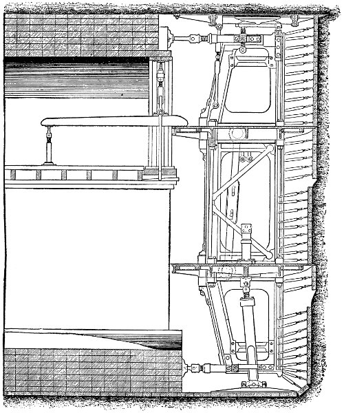
Fig. 124.—Longitudinal Section of Brunel’s Shield, First Thames Tunnel.
The illustration, Fig. 124, is the section
parallel to the vertical[241]
plane of the tunnel through the center of one of the frames,
and it shows quite clearly the complicated details of the shield
construction. Two features which are to be particularly noted
are the suspended staging and centering for constructing the
roof arch, and the top plate of the shield extending back and
overlapping the roof masonry so as to close completely the
roof of the excavation and prevent its falling. Notwithstanding[242]
its complicated construction and unwieldy weight of 120
tons, this shield worked successfully, and during several months
the construction proceeded at the rate of 2 ft. every 24 hours.
There were two irruptions of water and mud from the river
during the work, but the apertures were effectually stopped by
heaving bags of clay into the holes in the river bed, and covering
them over with tarpaulin, with a layer of gravel over all.
The tunnel was completed in 1843, at a cost of about $5600
per lineal yard, and 20 years from the time work was first commenced,
including all delays.
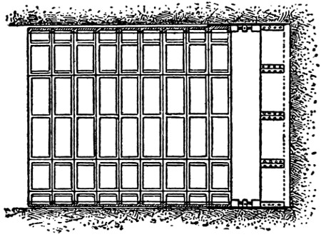
Fig. 125.—First Shield Invented by Barlow.
The next tunnel to be built by the shield system was the
tunnel under London Tower constructed by Barlow and Greathead
and begun in 1869. In
1863 Mr. Peter W. Barlow secured
a patent in England for
a system of tunnel construction
comprising the use of a circular
shield and a cylindrical cast-iron
lining. The shield, as
shown by Fig. 125, was simply
an iron or steel plate cylinder.
The cylinder plates were
thinned down in front to form a cutting edge, and they extended
far enough back at the rear to enable the advance ring of the
cast-iron lining to be set up within the cylinder. In simplicity
of form this shield was much superior to Brunel’s; but it seems
very doubtful, since it had no diametrical bracing of any sort,
whether it would ever have withstood the combined pressure of
the screw-jacks and of the surrounding earth in actual operation
without serious distortion, and, probably, total collapse.
It should also be noted that Barlow’s shield made no provision
for protecting the face of the excavation, although the inventor
did state that if the soil made it necessary such a protection
could be used. The patent provided for the injection of liquid
cement behind the cast-iron lining to fill the annular space left[243]
by the advancing tail-plates of the shield. Although Barlow
made vigorous efforts to get his shield used, it was not until
1868 that an opportunity presented itself. In the meantime
the inventor had been studying how to improve his original
device, and in 1868 he secured additional patents covering these
improvements. Briefly described, they consisted in partly closing
the shield with a diaphragm as shown by Fig. 126. The
uninclosed portion of the shield is here shown at the center, but
the patent specified that it might also be located below the
center in the bottom part of the shield. The idea of the construction
was that in case of an irruption of water the upper
portion of the shield could be kept open by air pressure, and
work prosecuted in
this open space until
the shield had been
driven ahead sufficiently
to close the
aperture, when the
normal condition of
affairs would be resumed.
This was obviously
an improvement
of real merit. The partial diaphragm also served to
stiffen the shield somewhat against collapse, but the thin plate
cutting-edges and most of the other structural weaknesses were
left unaltered. To summarize briefly the improvements due to
Barlow’s work, we have: the construction of the shield in a
single piece; the use of compressed air and a partial diaphragm
for keeping the upper part of the shield open in case of irruptions
of water; and the injection of liquid cement to fill the
voids behind the lining.
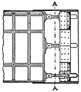
Longitudinal Section.
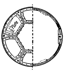
Cross Section.
Fig. 126.—Second Shield Invented by Barlow.
Turning now to the London Tower tunnel work, it may first
be noted that Barlow found some difficulty in finding a contractor
who was willing to undertake the job, so little confidence
had engineers generally in his shield system. One man, however,[244]
Mr. J. H. Greathead, perceived that Barlow’s device presented
merit, although its design and construction were defective, and he
finally undertook the work and carried it to a brilliant success.
The tunnel was 1350 ft. long and 7 ft. in diameter, and penetrated
compact clay. Work was begun on the first shore shaft on Feb.
12, 1869, and the tunnel was completed the following Christmas,
or in something short of eleven months, at a cost of £14,500.
The shield used was Barlow’s idea put into practical shape by
Greathead. It consisted of an iron cylinder, or, more properly, a
frustum of a cone whose circumferential sides were very slightly
inclined to the axis, the idea being that the friction would be less
if the front end of the shield were slightly larger than the rear
end. The shell of the cone was made of 1⁄2-in. plates. The thinned
plate cutting-edge of Barlow’s shield was replaced by Greathead
with a circular ring of cast iron. Greathead also altered the construction
of the diaphragm by arranging the angle stiffeners so
that they ran horizontally and vertically, and by fastening the
diaphragm plates to an interior cast-iron ring connected to the
shell plates. This was a decided structural improvement, but it
was accompanied with another modification which was quite as
decided a retrogression from Barlow’s design. Greathead made
the diaphragm opening rectangular and to extend very nearly
from the top to the bottom of the shield, thus abandoning the
element of safety provided by Barlow in case of an irruption
of water. Fortunately the material penetrated by the shield
for the Tower tunnel was so compact that no trouble was had
from water; but the dangerous character of the construction
was some years afterwards disastrously proven in driving the
Yarra River tunnel at Melbourne, Australia. To drive his
shield Greathead employed six 21⁄2-in. screw-jacks capable of
developing a total force of 60 tons. The tails of the jack bore
against the completed lining, which consisted of cast-iron rings
18 ins. wide and 7⁄8 in. thick, each ring being made up of a crown
piece and three segments. The different segments and rings
were provided with double (exterior and interior) flanges, by[245]
means of which they were bolted together. The soil behind
the lining was filled with liquid cement injected through small
holes by means of a hand
pump.
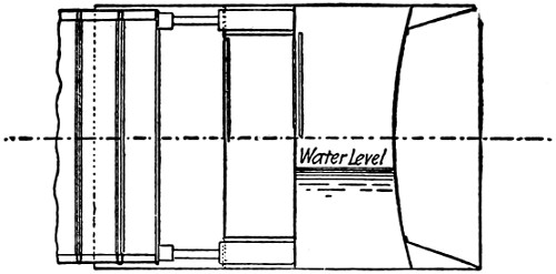
Fig. 127.—Shield Suggested by Greathead for the
Proposed North and South Woolwich Subway.
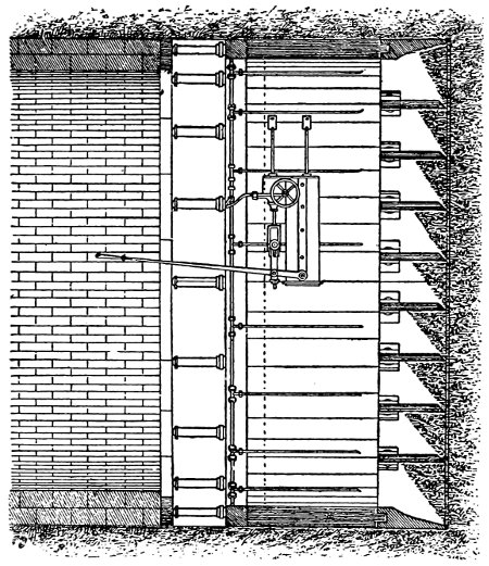
Fig. 128.—Beach’s Shield Used on Broadway
Pneumatic Railway Tunnel.
The remarkable success
of the London Tower
tunnel encouraged Barlow
to form in 1871 a
company to tunnel the
Thames between Southwark
and the City, and
Greathead, in 1876, to project a tunnel under the same waterway
known as the North and South Woolwich Subway. Barlow’s
concession was abrogated by Parliament in 1873, without
any work having been
done. Greathead progressed
far enough with
his enterprise to construct
a shield and a large
amount of the iron lining
when the contractors
abandoned the work.
From the brief description
of his shield given
by Greathead to the London
Society of Civil Engineers,
it contained several
important differences
from the shield built by
him for the London
Tower tunnel, as is shown
by Fig. 127. The changes
which deserve particular notice are the great extension of the
shield behind the diaphragm, the curved form of the diaphragm,
and the use of hydraulic jacks. Greathead had also designed[246]
for this work a special crane to be used in erecting the cast-iron
segments of the lining.
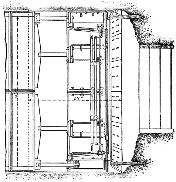
Fig. 129.—Shield for City and South London Railway.
While these works had been progressing in England, Mr.
Beach, an American, received a patent in the United States for
a tunnel shield of the construction shown by Fig. 128, which
was first tried practically in constructing a short length of
tunnel under Broadway for the nearly forgotten Broadway
Pneumatic Underground Railway. This shield, as is indicated by
the illustration, consisted of a cylinder of wood with an iron-cutting-edge
and an iron tail-ring. Extending transversely
across the shield at the front end were a number of horizontal
iron plates or shelves with cutting-edges, as shown clearly by
the drawing. The shield was moved ahead by means of a
number of hydraulic jacks supplied with power by a hand pump
attached to the shield. By means of suitable valves all or
any lesser number of these jacks could be operated, and by
thus regulating the action of the motive power the direction of[247]
[248]
the shield could be altered at will. Work was abandoned on
the Broadway tunnel in 1870. In 1871-2 Beach’s shield was
used in building a short circular tunnel 8 ft. in diameter in
Cincinnati, and a little later it was introduced into the Cleveland
water-works tunnel 8 ft. in diameter. In this latter work,
which was through a very treacherous soil, the shield gave a
great deal of trouble, and was finally so flattened by the pressures
that it was abandoned. The obviously defective features of
this shield were its want of vertical bracing and the lack of any
means of closing the front in soft soil.
With the foregoing brief review of the early development of
the shield system of tunneling, we have arrived at a point where
the methods of modern practice can be studied intelligently.
In the pages which follow we shall first illustrate fully the construction
of a number of shields of typical and special construction,
and follow these illustrations with a general discussion of
present practice in the various details of shield construction.
Mr. Raynald Légouez, in his excellent book upon the shield
system of tunneling, considers that tunnel shields may be divided[249]
into three classes structurally, according to the character
of the material which they are designed to penetrate. In the
first class he places shields designed to work in a stiff and comparatively[250]
stable soil, like the well-known London clay; in the
second class are placed those constructed to work in soft clays
and silts; and in the third class those intended for soils of an
unstable granular nature. This classification will, in a general
way, be kept by the writer. As a representative shield of
the first class, the one designed for the City and South London
Railway is illustrated in Fig. 129. The shields for the London
Tower tunnel, the Waterloo and City Railway, the Glasgow District
Subway, the Siphons of Clichy and Concorde in Paris, and
the Glasgow Port tunnel, are of the same general design and
construction. To represent shields of the second class, the St.[251]
Clair River and Blackwall shields are shown in Figs. 130 and
131. The shields for the Mersey River, the Hudson River,
and the East River tunnels also belong to this class. To represent
shields of the third class, the elliptical and semi-elliptical
shields of the Clichy tunnel work in Paris are shown by Figs. 132
and 133. The semi-circular shield of the Boston Subway is
illustrated by Fig. 134.
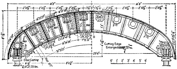
Half Transverse Section A-B.
Larger illustration
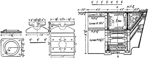
Details of Casting Supporting Ends of Jacks.
Details of Castings under Ends of Girders.
Longitudinal Section C-D.
Larger illustration
Fig. 134.—Roof Shield for Boston Subway.
Prelini’s Shield.
—In closing this short review mention will
be made of a new shield designed and patented by the Author
and shown in Fig. 135. It is an articulated shield composed of
two separated shields whose outer shells overlap each other.
The shields are connected together by means of hydraulic jacks
attached all around the two diaphragms. Between these diaphragms
is a large inclosed space called a safety chamber,
where the men can withdraw in case of accidents and where the
air can be immediately raised to the required pressure. This is[252]
an advantage in case of blow-outs, because the flooding of the
tunnel is prevented, while the accident is limited to only a few
feet from the front. On account of the shield being advanced
half at a time it is always under control and is thus better
directed through grade and alignment. Besides, this shield will
not rotate around its axis and consequently it can be built of
any shape, thus permitting the construction of subaqueous tunnels
of any cross-section and even with a wider foundation, which
is impossible to-day with the ordinary rotating shields of circular
cross-section.
SHIELD CONSTRUCTION.
General Form.
—Tunnel shields are usually cylindrical or
semi-cylindrical in cross-section. The cylinder may be circular,
elliptical, or oval in section. Far the greater number of shields
used in the past have been circular cylinders; but in one part
of the sewer tunnel of Clichy, in Paris, an elliptical shield with
its major axis horizontal, was used, and the German engineer,
Herr Mackensen, has designed an oval shield, with its major
axis vertical. A semi-elliptical shield was employed on the
Clichy tunnel, and semi-circular shields were used on the Baltimore
Belt Line tunnel and the Boston Subway in America.
Generally, also, tunnel shields are right cylinders; that is, the[253]
front and rear edges are in vertical planes perpendicular to the
axis of the cylinder. Occasionally, however, they are oblique
cylinders; that is, the front or rear edges, or both, are in planes
oblique to the axis of the cylinder. One of these visor-shaped
shields was employed on the Clichy tunnel.
The Shell.
—It is absolutely necessary that the exterior surface
of the shell should be smooth, and for this reason the exterior
rivet heads must be countersunk. It is generally admitted,
also, that the shell should be perfectly cylindrical, and not
conical. The conical form has some advantage in reducing the
frictional resistance to the advance of the shield; but this is
generally considered to be more than counterbalanced by the
danger of subsidence of the earth, caused by the excessive void
which it leaves behind the iron tunnel lining. For the same
reason the shell plate, which overlaps the forward ring of the
lining, should be as thin as practicable, but its thickness should
not be reduced so that it will deflect under the earth pressure
from above. Generally the shell is made of at least two thicknesses
of plating, the plates being arranged so as to break joints,
and, thus, to avoid the use of cover joints, to interrupt the
smooth surface which is so essential, particularly on the exterior.
The thickness of the shell required will vary with the diameter
of the shield, and the character and strength of the diametrical
bracing. Mr. Raynald Légouez suggests as a rule for determining
the thickness of the shell, that, to a minimum thickness of
2 mm., should be added 1 mm. for every meter of diameter
over 4 meters. Referring to the illustrations, Figs. 128 to 132
inclusive, it will be noted that the St. Clair tunnel shield, 211⁄2 ft.
in diameter, had a shell of 1-in. steel plates with cover-plate
joints and interior angle stiffeners; the shell of the East River
tunnel shield, 11 ft. in diameter, was made up of one 1⁄2-in. and
one 3⁄8-in. plate; the Blackwall tunnel shield, 27 ft. 9 ins. in diameter,
had a shell consisting of four thicknesses of 5⁄8-in. plates;
and the Clichy tunnel shield, with a diameter of 2.06 meters,
had a shell 2 millimeters thick.
[254]
Front-End Construction.
—By the front end is meant that
portion of the shield between the cutting-edge and the vertical
diaphragm. The length of this portion of the shield was formerly
made quite small, and where the material penetrated is very
soft, a short front-end construction yet has many advocates;
but the general tendency now is to extend the cutting-edge far
enough ahead of the diaphragm to form a fair-sized working
chamber. Excavation is far more easy and rapid when the
face can be attacked directly from in front of the diaphragm
than where the work has to be done from behind through the
apertures in the diaphragm. So long as the roof of the excavation
is supported from falling, experience has shown that it is
easily possible to extend the excavation safely some distance
ahead of the diaphragm. In reasonably stable material, like
compact-clay, the front face will usually stand alone for the
short time necessary to excavate the section and advance the
shield one stage. In softer material the face can usually be
sustained for the same short period by means of compressed air;
or the face of the excavation, instead of being made vertical, can
be allowed to assume its natural slope. In the latter case a
visor-shaped front-end construction, such as was used on some
portions of the Clichy tunnel, is particularly advantageous. The
following figures show the lengths of the front ends of a number
of representative tunnel shields.
| City and South London |
1 |
|
ft. |
| St. Clair River |
11 |
.25 |
„ |
| Hudson River |
5 |
2⁄3 |
„ |
| Mersey River |
3 |
|
„ |
| East River |
3 |
2⁄3 |
„ |
| Blackwall |
6 |
.5 |
„ |
Two general types of construction are employed for the
cutting-edge. The first type consists of a cast-iron or cast-steel
ring, beveled to form a chisel-like cutting-edge and bolted to
the ends of the forward shell plates. This construction was
first employed in the shield for the London Tower tunnel, and
has since been used on the City and South London, Waterloo
and City, and the Clichy tunnels. The second construction
consists in bracing the forward shell plates by means of right[255]
triangular brackets, whose perpendicular sides are riveted respectively
to the shell plates and the diaphragm, and whose
inclined sides slant backward and downward from the front
edge, and carry a conical ring of plating. The shields for the
St. Clair River, East River, and Blackwall tunnels show forms
of this type of cutting-edge construction. A modification of
the second type of construction, which consists in omitting the
conical plating, was employed on some of the shields for the
Clichy tunnel. This modification is generally considered to be
allowable only in materials which have little stability, and which
crumble down before the advance of the cutting-edge. Where
the material is of a sticky or compact nature, into which the
shield in advancing must actually cut, the beveled plating is
necessary to insure a clean cutting action without wedging or
jamming of the material.
Cellular Division.
—It is necessary in shields of large diameter
to brace the shell horizontally and vertically against distortion.
This bracing also serves to form stagings for the
workmen, and to divide the shield into cells. The following
table shows the arrangement of the vertical and transverse
bracing in several representative tunnel shields.
Name of
Tunnel. |
Diameter. |
Hori-
zontal. |
Plates,
Dist.
Apart. |
Vert.
Braces. |
| |
Ft. |
In. |
No. |
Ft. |
No. |
| Hudson River |
19 |
11 |
|
2 |
6.54 |
2 |
| Clichy |
19.4 |
0 |
|
2 |
6.54 |
None |
| St. Clair River |
21 |
6 |
|
2 |
6.98 |
3 |
| Waterloo (Station) |
24 |
10 |
1⁄2 |
2 |
7.12 |
None |
| Blackwall |
27 |
8 |
|
2 |
6.0 |
3 |
| East River |
11 |
|
3⁄4 |
None |
... |
1 |
Referring first to the horizontal divisions, it may be noted
that they serve different purposes in different instances. In
the Clichy tunnel shield the horizontal divisions formed simply
working platforms; in the Waterloo tunnel shield they were
designed to abut closely against the working face by means of
special jacks, and so to divide it into three separate divisions; in[256]
the St. Clair tunnel they served as working platforms, and also
had cutting-edges for penetrating the material ahead; and in
the Blackwall tunnel shield they served as working platforms,
and had cutting-edges as in the St. Clair tunnel shield, and in
addition the middle division was so devised that the two lower
chambers of the shield could be kept under a higher pressure of
air than the two upper chambers. Passing now to the vertical
divisions, they serve to brace the shell of the shield against vertical
pressures, and also to divide the horizontal chambers into
cells; but unlike the horizontal plates they are not provided
with cutting-edges. The St. Clair, Hudson River, and Blackwall
tunnel shields illustrate the use of the vertical bracing for
the double purpose of vertical bracing and of dividing the horizontal
chambers into cells. The Waterloo tunnel shield is an
example, of vertical bracing employed solely as bracing. The
vertical division of the East River tunnel shield was employed
in order to allow the shield to be dissembled in quadrants.
The Diaphragm.
—The purpose of the shield diaphragm is to
close the rear end of the shield and the tunnel behind from an
inrush of water and earth from the face of the excavation. It
also serves the secondary purpose of stiffening the shell diametrically.
Structurally the diaphragm separates the front-end construction
previously described from the rear-end construction,
which will be described farther on; and it is usually composed
of iron or steel plating reinforced by beams or girders, and
pierced with one or several openings by which access is had
to the working face. In stable material, where caving or an
inrush of water and earth is not likely, the diaphragm is omitted.
The shield of the Waterloo tunnel is an example of this construction.
In more treacherous materials, however, not only
is a diaphragm necessary, but it is also necessary to diminish
the size of the openings through it, and to provide means for
closing them entirely. Sometimes only one or two openings are
left near the bottom of the diaphragm, as in the St. Clair
and Mersey tunnel shields; and sometimes a number of smaller[257]
openings are provided, as in the East River and Hudson River
tunnel shields.
In highly treacherous materials subject to sudden and violent
irruptions of earth from the excavation face, it sometimes is
the case that openings, however small, closed in the ordinary
manner, are impracticable, and special construction has to be
adopted to deal with the difficulty. The shields for the Mersey
and for the Blackwall tunnels are examples of such special
devices. In the Mersey tunnel a second diaphragm was built
behind the first, extending from the bottom of the shield upward
to about half its total height. The aperture in the first diaphragm
being near the bottom, the space between the second and
first diaphragms formed a trap to hold the inflowing material.
The Blackwall tunnel shield, as previously indicated, had its
front end divided into cells. Ordinarily the face of the excavation
in front of each cell was left open, but where material was
encountered which irrupted into these cells a special means of
closing the face was necessary. This consisted of three poling-boards
or shutters of iron held one above the other against
the face of the excavation. These shutters were supported by
means of strong threaded rods passing through nuts fastened
to the vertical frames, which permitted each shutter to be advanced
against or withdrawn from the face of the excavation
independently of the others. Various other constructions have
been devised to retain the face of the excavation in highly
treacherous soils, but few of them have been subjected to
conclusive tests, and they do not therefore justify consideration.
Rear-end Construction.
—By the rear end of the shield is
meant that portion at the rear of the diaphragm. It may be
divided into two parts, called respectively the body and the
tail of the shield. The chief purpose of the body of the shield
is to furnish a place for the location of the jacks, pumps, motors,
etc., employed in manipulating the shield. It also serves a
purpose in distributing the weight of the shield over a large[258]
area. To facilitate the passage of the shield around curves,
or in changing from one grade to another, it is desirable to
make the body of the shield as short as possible. In the Mersey,
Clichy, and Waterloo tunnel shields, and, in fact, in most others
which have been employed, the shell plates of the body have
been reinforced by a heavy cast-iron ring, within and to which
are attached the jacks and other apparatus. The latest opinion,
however, seems to point to the use of brackets and beams for
strengthening the shell for the purpose named, rather than to
this heavy cast-iron construction. In the Hudson River, St.
Clair River, and East River tunnel shields, with their long and
strongly braced front-end construction to carry the jacks, the
body of the shield, so to speak, is omitted and the rear-end construction
consists simply of the tail plating. In the Blackwall
shield, the body of the shield shell provides the space necessary
for the double diaphragms and the cells which they inclose. In
a general way, it may be said that the present tendency of
engineers is to favor as short and as light a body construction as
can be secured.
The tail of the shield serves to support the earth while the
lining is being erected; and for this reason it overlaps the forward
ring of the lining, as shown clearly by most of the shields
illustrated. To fulfill this purpose, the tail-plates should be
perfectly smooth inside and outside, so as to slide easily between
the outside of the lining plates and the earth, and should also
be as thin as practicable, in order not to leave a large void behind
the lining to be filled in. In soils which are fairly stable, the tail
construction is often visor-shaped; that is, the tail-plates overlap
the lining only for, say, the roof from the springing lines up, as
in one of the shields for the Clichy tunnel. In unstable materials
the tail-plating extends entirely around the shield and excavation.
The length of the tail-plating is usually sufficient to overlap
two rings of the lining, but in one of the Clichy tunnel shields
it will be noticed that it extended over three rings of lining.
This seemingly considerable space for thin steel plates is made[259]
possible by the fact that the extreme rear end of the tail always
rests upon the last completed ring of lining.
In closing these remarks concerning the rear-end construction,
the accompanying table, prepared by Mr. Raynald Légouez,
will be of interest, as a general summary of principal dimensions
of most of the important tunnel shields which have been built.
The figures in this table have been converted from metric to
English measure, and some slight variation from the exact dimensions
necessarily exists. The different columns of the table
show the diameter, total length, and the length of each of the
three principal parts into which tunnel shields are ordinarily
divided in construction as previously described:
| Name of Shield. |
Length in Feet. |
| Diameter. |
Tail. |
Body. |
Front. |
Total. |
| Concorde Siphon |
6.75 |
2.51 |
2.55 |
1.16 |
6.67 |
| Clichy Siphon |
8.39 |
2.51 |
2.55 |
1.16 |
6.16 |
| Mersey |
9.97 |
5.61 |
2.98 |
2.98 |
11.58 |
| East River |
10.99 |
3.51 |
0.32 |
3.67 |
7.51 |
| City and South London |
10.99 |
2.65 |
2.82 |
1.01 |
6.49 |
| Glasgow District |
12.07 |
2.65 |
2.82 |
1.01 |
6.49 |
| Waterloo and City |
12.99 |
2.75 |
2.98 |
1.24 |
6.98 |
| Glasgow Harbor |
17.25 |
2.75 |
2.98 |
1.08 |
8.49 |
| Hudson River |
19.91 |
4.82 |
2.98 |
5.67 |
10.49 |
| St. Clair River |
21.52 |
4.00 |
2.98 |
11.25 |
15.25 |
| Clichy Tunnel |
23.7-19.8 |
4.00 |
2.98 |
6.88 |
17.22 |
| Clichy Tunnel |
23.8-19.4 |
7.44 |
11.90 |
4.46 |
23.65 |
| Blackwall |
27.00 |
6.98 |
5.90 |
6.59 |
19.48 |
| Waterloo Station |
24.86 |
3.34 |
5.51 |
1.14 |
10.00 |
A shield of 60 or 100 tons weight can hardly be directed along
the line of the proposed tunnel and also through curves and
grades, especially when driven through loose or muddy soils.
The tunnels of the New York and Hudson River Railroad under
the Hudson, and the tunnel of the New York Rapid Transit
Railway under the East River, show marked evidence of how
troublesome this work is. To avoid these and other inconveniences
encountered in every shield, the Author has designed
a new shield which was briefly described at page 251.
[260]
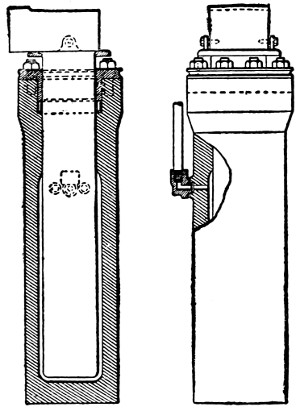
Fig. 136.—Elevation and Section
of Hydraulic Jack, East River
Gas Tunnel.
Jacks.
—The motive power usually employed in driving
modern tunnel shields is hydraulic jacks. In some of the earlier
shields screw-jacks were used, but these soon gave way to the
more powerful hydraulic device. The manner of attaching the
hydraulic jacks to the shield is always to fasten the cylinder
castings at regular intervals around the inside of the shell, with
the piston rods extending backward to a bearing against the
forward edge of the lining. In the older forms of shield, having
an interior cast-iron reinforcing ring construction, the jack
cylinder castings were always attached to this cast-iron ring;
but in many of the later shields constructed without this cast-iron
reinforcing ring, the cylinder castings are attached to the
shell by means of bracket and gusset connections. The number
and size of the jacks employed, and the distance apart at which
they are spaced, depend upon the size of the shield and the
character of the material in which it is designed to work. In
stiff and comparatively stable clays, the skin friction of the
shield is comparatively small, and an aggregate jack-power of
from 4 to 5 tons per square yard of
the exterior friction surface of the
shield has usually been found ample.
The cylinders are spaced about 53⁄4 ft.
apart, and have a working diameter
of from 5 to 6 ins., with a water
pressure of about 1000 lbs. per sq. in.
In soft, sticky material, giving a
high skin friction, the aggregate jack-power
required per square yard of
exterior shell surface rises to from 18
to 24 tons; the jacks are spaced about
3 ft. apart; and the working cylinder
diameter and water pressure are, respectively,
about 6 or 7 ins., and from
4000 lbs. to 6000 lbs. per sq. in. With these high pressures,
power pumps are necessary to give the required water pressure;[261]
but where the pressure required does not exceed 1000 lbs. per
sq. in., hand pumps may be, and usually are, employed. Fig.
136 shows the hydraulic jacks used in the East River Gas Tunnel
at New York. The number of jacks required depends upon
the diameter of the shield, and, of course, upon the distance
apart which they are placed. In the City and South London
tunnel shield six jacks were used, and in the Blackwall shield 24
were used. The mechanical construction of the jacks for tunnel
shields presents no features out of the usual lines of such
devices used elsewhere. The jacks used on the East River tunnel
shield are shown by Fig. 136.
Two general methods are employed for transmitting the
thrust of the piston rods against the tunnel lining. The object
sought in each is to distribute the thrust in such a manner that
there is no danger of bending the thin front flange of the forward
lining ring. In English practice the plan usually adopted is
to attach a shoe or bearing casting to the end of the piston rod,
which will distribute the pressure over a considerable area. An
example of this construction is the shield for the City and South
London tunnel. In the East River and St. Clair River tunnels
built in America, the tail of the piston rod is so constructed that
the thrust is carried directly to the shell of the lining.
LINING.
Either iron or masonry may be used for lining shield-driven
tunnels but present practice is almost universally in favor of
iron lining. As usually built, iron lining consists of a series of
successive cast-iron rings, the abutting edges of which are provided
with flanges. These flanges are connected by means of
butts, the joints being packed with thin strips of wood, oakum,
cement, or some other material to make them water-tight.
Each lining ring is made up of four or more segments, which
are provided with flanges for bolted connections similar to
those fastening the successive rings. Generally the crown segment
is made considerably shorter than those forming the sides[262]
and bottom of the ring. The erection of the iron segments
forming the successive rings of the lining may be done by hand
in tunnels of small diameter where the weights to be handled
are comparatively light, but in tunnels of large size special
cranes attached to the shield or carried by the finished lining
are employed. The construction of the iron lining for the Hudson
River tunnel is illustrated in Chapter XX., and that for the
St. Clair River tunnel is shown by Fig. 137.
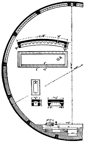
Part Transverse Section.
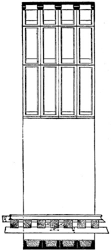
Longitudinal Section.
Fig. 137.—Cast-Iron Lining, St. Clair River Tunnel.
Larger illustration
[263]
CHAPTER XX.
SUBMARINE TUNNELING (Continued).
THE SHIELD AND COMPRESSED AIR METHOD. THE HUDSON
RIVER TUNNEL OF THE PENNSYLVANIA RAILROAD.
The shield and compressed air method of excavating subaqueous
tunnels is used when the distance is small between the
roof of the tunnel and the bed of the river. These tunnels are
usually driven from the shafts sunk from each shore. It is very
seldom they can be driven also by an intermediate shaft. This,
however, was done in the case of the Belmont tunnel under the
East River. Here the tunnels passed under the man-of-war
reef where a working shaft was sunk.
The plant is located at some convenient point near the head
shaft. It consists of a set of boilers to provide the power for
the different machines. They are low and high pressure compressors,
the former supply the air through the tunnel; the latter,
the air for working the drills, in case rock is encountered, and
power for hauling and hoisting purposes. The various pumps
force the water for the hydraulic rams that drive the shield and
work the erector. They also remove the water from the tunnel
which always collects in variable quantities at the bottom of
the excavation. Besides the machines for light and ventilation
purposes, the head shaft is provided with an overhead construction
where are housed the hoisting machines, the telephone
and other means of communication with the work at the front.
Usually a long trestle is built in connection with the head shaft,
leading to the dumping place and yard. On this inclined elevated
structure are located, also, the tracks upon which will run the
small cars used inside the tunnel for hauling purposes.
[264]
The shafts are excavated on a square, rectangular or circular
plan and are usually lined with masonry. It is only recently
that shafts excavated through loose soils have been lined with
the same cast-iron lining used in the tunnels, the only difference
being that the rings were laid flat on the ground and attached
to those already sunk.
After the shaft has been sunk to the required level, the tunnel
is driven toward the river by any one of the methods used for
land work. At some convenient distance from the shaft, the
dimensions of the tunnel are enlarged for a length of 20 or 30 ft.
In this larger space, called the shield chamber, the shield is
assembled, mounted, and, when completed, it is slowly pushed
toward the river. The tunnel is excavated from the shield
chamber on, with dimensions equal to the exterior shell of the
shield.
The construction of the shield and the hydraulic jacks used
for its advance are explained in a preceding chapter.
In very loose soils, a solid bulkhead of masonry is built across
the tunnel, after the shield has advanced to a certain distance
and some rings of the cast-iron lining have been erected. The
bulkhead is provided with three air locks—two near the floor of
the tunnel, for working purposes, and one near the roof, called
the emergency lock, which, as the name suggests, is used only in
case of danger. The air locks are steel cylinders from 10 to
15 ft. long and 6 ft. in diameter, made up of boiler plates. They
are provided with doors at each end, besides the pipes for the
admission and exit of compressed air. The working locks also
have narrow-gauge tracks for hauling purposes. In rock or
more consistent soil the bulkhead is constructed after the shield
is far ahead, since there is no immediate necessity, under these
conditions, to use the compressed air. In both the loose and
good soils, when the shield has been advanced over 500 ft. from
the bulkhead, a second bulkhead, with air locks, is erected in
the tunnel. The first is left in place but used only in case of
emergency.
[265]
To direct the shield along the center line and through curves
and grades, accurate measurements are taken, and the distance
between the shield and the last ring inserted in the iron lining
is regulated accordingly. The alignment inside the tunnel is
maintained in a very simple way. For this purpose, points
corresponding to the center line are marked on the roof at
distances of 100 ft. Nearly 100 ft. from the shield, a transit is
set up on a strong scaffold spanning the tunnel, and it is supported
by the flanges of the iron lining. A plumb-line is hung
from one of the points of the roof already determined, as indicating
the center line; and the transit man aligns his instrument
with this plumb-line; after this he “plunges” his telescope. A
rodman next places a horizontal rod of special construction
between the flanges of the last ring of the lining. This rod has
in the center an open slot which carries a glass with a black
vertical line. The slot is graduated, the zero of graduation
remains in the center while the vertical line is moved right and
left. The rodman places a lamp behind the slot and the transit-man
tells him how to move the dark line until it coincides with
the axis of the tunnel. If the ring, just erected, be a little out
of alignment, it is readjusted by pushing the shield a little more
on the side that has swerved from the axis of the tunnel. As the
shield is pushed forward, it is kept in place by four men with
graduated rods, one man on each side of the shield, one on top
and the other on the floor. As the shield progresses, they repeat
aloud in succession, the distance indicated on the rods, which
is the distance from the shield to the outer circumferential
flange of the last ring of the lining. When an advance of one
foot has been made, readings are taken at every inch; and when
very near the required distance, they are taken at every quarter
of an inch. In this way it is not difficult to bring the shield back
into line, in case it may have shifted a little to the right or left.
When curves are met, the rings are no longer cylindrical segments
but tores, so that the segments at one side are longer than
those on the other. In this case, the shield is advanced more[266]
on one side by a quantity equal to the difference of the two sides
of the ring to be erected. At each advance the shield is moved
2 ft. or 21⁄2 ft. ahead, the distance corresponding to the length of
the cast-iron rings of the lining. Within the space now open
between the shield and the lining another ring is inserted. The
ring is composed of different segments provided with flanges
and holes bored so they can be bolted together. The segments
of the lining are very heavy and difficult to handle but they are
easily set by means of the erector.
When the erector is not mounted on the shield, it is located
in the middle of a girder placed across the iron rings of the lining
and just at the rear end of the shield. The girder, at both
extremities, has flanged wheels resting on rails which are placed
on brackets. These brackets are attached temporarily to the
flanges of the iron lining. The erector is provided with an arm
capable to swing in a full circle. Its movements are regulated
by two hydraulic jacks, located horizontally on the spanning
girder. On the extreme end of the revolving arm are projections
with holes for the bolts. Each segmental plate of the lining
has a kind of plug in the center which is cast together with the
plate and is provided with holes for the bolt. In placing the
segmental plates of the lining, the arm of the erector is swung
over the plate to be lifted, then two bolts are passed through
the holes in the projection of the erector, and through those in
the plug. The arm of the erector is then moved upwards until the
plate, free from all obstacles, is swung very near its intended
position. There it is adjusted and held until bolts are inserted
to fix it to the plates of the preceding ring.
In connection with the method of excavating submarine
tunnels by means of shield and compressed air, the excavation
varies with the quality of soil encountered. In compact rock the
usual heading and bench method, so common in land tunnels, is
also employed in this case. The shield is left behind in presence
of good rock.
The men at the front attack the rock with air drilling machines[267]
and charges of dynamite. The holes are driven at a smaller
depth than in land work; very light charges of dynamite are
used and only a few holes fired at each round. Every precaution
is taken in order not to disturb the shield and the bed of the river
any more than is possible, because at a shallow depth the blast
would tend to widen the existing crevices in the rock and thus
permit an inflow of water. When the rock is fissured or disintegrated
and the roof of the excavation at the front requires
timbering, the shield should be kept closer to the front. In this
way the quantity of timber for strutting is greatly reduced, so
lessening the probabilities of fires. It is very difficult, in compressed
air, to extinguish fires and in almost every instance the
only way is to flood the tunnel. This was done at the Manhattan
end of the tunnel under the East River for the extension to
Brooklyn of the New York Subway.
The excavation is made by hand in loose but compact soils
such as clay. The men work on platforms located at the front
of the shield and they are protected from the caving-in of the
roof by a hood added for working through loose soils. The men
excavate the material which is shoveled inside the tunnel and
is carried away in small cars. The shield is very close to the
front of the excavation in loose soil. The East Boston tunnel,
under Boston Harbor, connecting with the Boston Subway, was
excavated through blue clay. The minimum distance between
the bottom of the water and the roof of the excavation was 18 ft.
The tunnel was excavated by means of compressed air and the
shield which was only used for the roof. It slid on top of concrete
side walls built in two drifts which were excavated nearly 100 ft.
ahead of the shield. The tunnel was lined with concrete, the
arch being reinforced by longitudinal steel rods which received
the thrust of jacks used for advancing the shield. The material
in the drifts under the shield and the bench was removed by
hand and carried away in small cars.
Subaqueous tunnels driven through very loose soils can be
excavated by simply leaving the doors open while the shield is[268]
pushed ahead. The material, dislodged by the cutting edge of
the shield, is forced through the doors and falls on the floor
whence it is removed in small cars. In very loose soils the
excavation has been made in a still more economic way; the shield
with closed doors is simply squeezed through the soil. This
method is financially convenient, because all the excavating and
hauling operations are eliminated and the tunnel progresses
from 40 to 50 ft. per day, but clearly indicates a lack of stability.
In this manner, the Hudson River tunnel of the New York and
New Jersey Railroad was constructed.
The pressure of the air in the tunnel depends upon the depth
and as a rule it varies between 20 and 40 or even more pounds
per square inch above atmospheric pressure. Working in compressed
air causes a peculiar disease commonly known as “bends”
or “caisson disease” often proving fatal. To prevent and
remedy the disease, the engineers should order a set of rules to
be strictly observed. The preventative measures should be, first,
to employ only sober, strong and healthy men, never one who
has not successfully passed the examination of the attending
physician; second, to order the lock tenders never to allow any
man in or out of the tunnel unless he has spent at least ten
minutes within the locks. Both compression and decompression
should be thorough and it cannot be in less than this time. A
stop of only a few minutes in the locks is not sufficient and this
incomplete compression or decompression is the real cause of the
bends. The men become careless after they have been in the
compressed air for some time, and they try to reduce this tiresome
operation to a minimum, hence the duty of the engineer
to strictly enforce this rule. The remedial measures should
consist of constant medical attendance near the shafts and the
erection of a compressed air hospital where the men affected
by bends for lack of decompression may be attended and
cured.
[269]
THE HUDSON RIVER TUNNELS OF THE PENNSYLVANIA
RAILROAD.[13]
The tunnels constructed under the Hudson River for the Pennsylvania
Railroad, consist of two parallel tubes driven side by
side 14 ft. apart. The tubes are of circular cross-section, 23 ft.
exterior diameter, and are lined with cast-iron rings. The tunnels
were driven from two shafts, one on the eastern shore of the
Hudson River near 32nd St. and 11th Ave., New York; the other
at Weehawken, New Jersey, near the piers of the Erie Railroad.
The horizontal distance between the shafts was 6550 ft. The
permanent one at Weehawken was built on a square plan, 130 ft.
to a side. It was lined with concrete masonry and the walls
were battered in such a way as to become the shape of an inverted
frustum of a pyramid. It was provided with five openings at the
bottom, four of these are used by trains that run in the open,
the fifth one leads to a power house near by. During the construction
of the tunnels one-third of this shaft was used for the
land portion of the tunnel under Bergen Hill, while the remaining
two-thirds were devoted to the construction of the tunnel under
the river. The working shaft on Manhattan Island was a side
shaft of rectangular plan 30 ft. by 22 ft., the tunnel proper being
connected by two drifts 10 ft. by 10 ft. each. The shield rooms
23 ft. long, were situated on both sides of the river just in front
of the shafts. On the New York side, the shields, one for each
tube, were built inside the iron lining of the shield chamber,
and the hoisting tackle was slung from the iron lining. The
erection on the Weehawken side was done in the bare rock
excavation where timber falsework was used. After the shields
were finished and in position, the first two rings of the lining
were erected in the tail of the shield. These rings were firmly
braced to the rock and the chamber lining; then the shields
were shoved ahead by their own jacks, another ring was built
and so on.
[270]
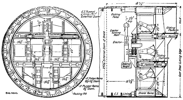
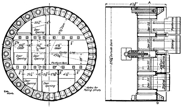
Fig. 138.—General Elevations and Sections of Shield.
Shield.
—The shields used in these tunnels were designed by
Mr. James Forgie, M. Inst. C. E. and M. Am. Soc. C. E., and
were provided with three innovations: the segmental doors, the
sliding platforms and the removable hood. The shields, Fig. 138,
were circular, 23 ft. 61⁄4 ins. in external diameter, and were 16 ft.
long, exclusive of the hood. The tail of the shield overlapped
the lining, the maximum being 6 ft. 41⁄2 ins. during ordinary
working; the minimum, 2 ft. during the operation of taking any[271]
ram out for repairing. The shields had only one transverse
bulkhead made up of two continuous horizontal platforms and
three vertical partitions stiffening angular web plates fore and
aft the ram chambers. They were connected by angles and skin
plates which formed a ring-shaped frame 25 ins. thick radially
and nearly 5 ft. long. Between the vertical and horizontal
partitions were left openings which either were partially or
entirely closed by segmental doors pivoted on an axis parallel
to the face of the shield bulkhead. There were nine of such
openings on each shield, the clear width being 2 ft. 7 ins., the
height varying from 2 ft. 2 ins. to 3 ft. 4 ins., according to the
location. The hood at the front of the shield was designed so
as to be detached underground and was made of complete
segments to permit easy erection or detachment. The hood
was extended as far as the upper platform, thus protecting only
the roof of the excavation. It was attached to the shield by
means of bolts, and, when removed, it was replaced by the cast-steel
cutting-edge, built in 24 sections and placed all around the
shield. The eight sliding platforms, another characteristic of
this shield, could be extended 2 ft. 9 ins. in front of the shield
by means of hydraulic rams, and, when so extended, were able
to stand a pressure of 7900 lbs. per sq. ft. These sliding platforms
were used as hoods for the protection of the men working
through loose soils, while in rock they enabled the drilling and
blasting to be carried on at three levels. A water trap or bird
fountain was constructed, at the rear of the bulkhead of the
shield, by means of angle irons to which steel plates were bolted.
The opening to the face was so spacious that in an emergency
the men could readily escape by getting over this trap into
safety. Besides, with the assistance of compressed air, it was
sufficient to perfectly trap the water-bearing ground, in case the
face collapsed. Including rams and erector, the total weight of
the shield was 193 tons.
Hydraulic Rams.
—The shield was operated by hydraulic
pressure. The machines were designed for a maximum pressure[272]
of 5000 lbs., to a minimum of 2000 lbs., while the average working
pressure was 3500 lbs. per sq. in. The forward movement
of the shield was obtained by means of 24 single-acting rams
81⁄2 in. in diameter and with 38 in. stroke. Each ram exerted a
pressure of nearly 100 tons, so that the combined action of the
24 rams was equal to 2400 tons. Each sliding platform was
operated by two single-acting rams 31⁄2 ins. in diameter and with
2 ft. 9 in. stroke. The rams were attached to the rear face of
the shield and the front ends of the cylinders to the front ends
of the sliding platforms, and since the cylinders were movable
and free-sliding so also were the platforms.
Erector.
—The erector, a box-shaped frame mounted on a
central shaft, revolved in bearings attached to the shield. Inside
this frame there was a differential hydraulic plunger of 4 in.
and 3 in. diameters and 48 in. stroke. To the plunger head
were attached two channels which slide inside the box frame and
to the projecting ends of which the grip was attached. At the
opposite end of the box frame was attached a counter-weight
which balances about 700 lbs. of the tunnel segment at 11 ft.
radius. The erector was revolved by two single-acting rams
fixed horizontally to the back of the shield, above the erector
pivot, through double chains and chain wheels which were
keyed to the erector shaft.
Air Locks.
—Two bulkhead walls, forming the rear closure
of the pneumatic sections, were built in each end of each tunnel,
one just ahead of the shield chamber, the other about 1200 ft.
ahead of the first. The walls were built of Portland concrete
10 ft. thick, and they were grouted with Portland cement, under
a pressure of nearly 100 lbs. per sq. in., to make them thoroughly
air-tight. Each wall had in it three locks; for man, material and
emergency. Each was equipped with hand valves arranged to
be operated from either outer end or from within. The floors
of the man and material locks were on a level with the working
platform of the tunnel, about 3 ft. 6 ins. above the invert; the
floor of the emergency lock was about 5 ft. above the horizontal[273]
axis of the tunnel. The
locks were made of steel
plates and shapes, with iron
fittings riveted and bolted
together. The man lock
was 11 ft. long of elliptical
cross-section, 6 ft.
vertical diameter and 5 ft.
horizontal; the material
lock was 25 ft. long, with
circular cross-section, 7 ft.
diameter, and the emergency
lock was 20 ft. long,
of elliptical cross-section,
4 ft. vertical and 3 ft. horizontal
diameters. Fig. 139
shows the elevation of the
air lock used in the Pennsylvania
tunnel.
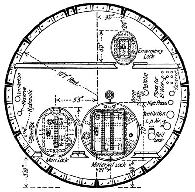
Sectional Elevation
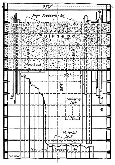
Horizontal Section
Fig. 139.—Plan and Elevation of First Bulkhead
Wall in South Tube Manhattan.
Larger illustration
Excavation.
—In driving
these tunnels almost
any kind of material was
encountered, viz., rock,
partly rock, and partly
loose soil, sand and gravel,
and finally silt.
Rock.
—Much of the
rock excavation was made
before the shields were
erected in order to avoid the
handling of rock through
the narrow openings of the
shield doors. Throughout the cross-section the shield traveled
on a cradle of concrete in which 2 or 3 steel rails were imbedded.
At the points where the excavation had been made for the full[274]
section of the tunnel, it was only necessary to trim off the
projecting corners of rock. Where only the bottom heading
had been driven the excavation was completed just in front of
the shield; the drilling below the axis level being done from
the heading itself, and above that from the front sliding platforms
of the shield. The holes were placed near together and
were drilled short; very light charges of powder were used in
order to lessen the chance of knocking the shield about too
much.
Mixed Face.
—When the rock dipped to such an extent that
the front of the tunnel was excavated partly in rock and partly
in loose soil, the compressed air was turned on, starting with a
pressure varying from 12 to 18 lbs. When the surface of the
rock was penetrated, the soft face was held up at first by horizontal
boards braced from the shield until the shield was shoved.
The braces were then taken out and, after the shield had been
shoved, were replaced by others. As the amount of soft ground
in the surface increased, the system of timbering was gradually
changed to one of 2-in. poling-boards. These rested on top of
the shield and were supported by vertical breast-boards which
in turn were held by 6-in. by 6-in. walings, braced through the
upper doors to the iron lining and from the sliding platforms of
the shield.
Sand and Gravel.
—Sand and gravel were only met at Weehawken,
where two different methods were used. The first
method was employed when the roof of the excavation was
through sand. It consisted of excavating the ground 2 ft. 6 ins.
ahead of the cutting-edge, the roof being held in place by longitudinal
poling-boards. These boards rested on the outside of
the skin at their back end, and at the forward end on vertical
breast-boards, braced from the sliding platforms and through
the shield doors to cross timbers in the tunnel.
The second method of timbering was used in the presence of
gravel at the upper part of the excavation. In such a case, the
excavation was only carried 1 ft. 3 ins. (half a shove) ahead of[275]
the cutting-edge, the roof being supported by transverse boards
held by pipes which rested in holes left in the shield. After a
small section of the ground had been excavated a board supported
by a pipe that was inserted underneath and wedged to it was
placed against the ground. These polings were kept below
the level of the hood, so that when the shield was shoved, they
would come inside of it; in addition they were braced with vertical
posts from the sliding platform. The upper part of the face was
held by longitudinal breast-boards braced from the sliding platform
by vertical pieces. The lower part of the face was supported
by vertical sheeted poling, braced to the tunnel through the
lower doors. Straw and clay were used in front of the boards to
prevent the escape of air which was very large, when the tunnel
was excavated through sand and gravel. The average rate of
progress in these materials was 5.1 ft. per day.
Silt.
—When silt was encountered, the shield was shoved into
the ground without any excavation being done by hand ahead
of the diaphragm. As the shield advanced the silt was forced
through the doors into the tunnel. Forcing the shield through
the silt resulted in raising the bed of the river, the amount that
the bed was raised depending on the quantity of material
brought into the shield. When the whole volume of the excavation
was brought in, the surface of the bed was not affected;
when about 50% was taken in, the surface was raised about 3 ft.;
if the shield was driven blind, the bed was raised about 7 ft.
When the shield was driven blind, the tunnel began to rise for
about 2 ins., and the iron lining was distorted, the vertical
diameter increasing and the horizontal one decreasing by about
11⁄4 ins. It was found, however, that the tunnel was not affected
when part of the excavation was taken, but if all of it was taken
in or the shield was shoved with open doors, the tunnel was
lowered. A powerful aid was thus found for the guidance of
the shield; for, if high, the shield could be brought down by
increasing the quantity of muck taken in, if low, by decreasing it.
The junction of the shields under the river was made as[276]
follows: When the two shields of one tunnel, which had been
driven from opposite sides of the river, approached within 10 ft.
of each other, they were stopped; a 10-in. pipe was driven between
them, and a final check of lines and levels was made
through the pipe. One shield was then started up with all doors
closed, while the doors of the stationary shield were opened for
the muck driven ahead by the moving shield. This was continued
until the cutting-edges came together. All doors in both
shields were then opened and the shield mucked out. The
cutting-edges were taken off and the shields moved together
again, edge of skin to edge of skin. As the sections of the
cutting-edges were taken off, the space between the skin edges
was poled with 3-in. stuff. When everything except the skin had
been removed, iron lining was built up inside the skins; the gap
at the junction was filled with concrete and long bolts were used
from ring to ring on the circumferential joint.
Lining.
—The tunnels were lined with cast-iron circular rings
of the segmental bolted type. In some special cases, cast steel
was used instead of cast iron. The rings were made 30 ins. long,
with an internal diameter of 21 ft. 2 ins. and an external one of
23 ft. The rings were composed of nine equal segments of 771⁄2
ins. external circumferential length each, except the two segments
adjoining the key which were equal to the other segments with
the difference, that one end joint was not radial but formed so as
to make an opening 12.25 ins. wide at the outside and 12.60 ins.
at the inside, which was closed by the key segment. Each segment
had six bolts in the circumferential joint, the key had one,
so that there were 67 bolts in one circumferential joint. Each of
the twelve longitudinal or radial joints had five bolts, in all
127 bolts per ring. The circumferential flanges of each plate
were strengthened by two transverse webs or feathers on each
flange. Each segment was provided with a 11⁄2 in. grout hole
closed with a screw plug. In order to pass around curves,
whether horizontal or vertical, or to correct deviation from the
line or grade, tapering was used; by this is meant the placing of[277]
rings in the tunnels which were wider than the standard rings,
either at one side (horizontal tapers or liners), or at the top
(depressors), or at the bottom (elevators). Tapers 1⁄2, 3⁄4 or even
1 in. were used. The taper rings were made by casting a ring
with one circumferential flange much thicker than usual and
then machining it off to the taper.
Grouting.
—From the exterior of the tunnel already lined
with cast-iron rings, grout was forced through the holes closed
by screw-plugs, at a pressure of 90 lbs. per sq. in. The grout was
composed of 1 Portland cement and 1 sand by volume and was
forced in by a specially constructed machine, so it formed a shell
of cement nearly 3 ins. thick around the exterior of the iron
lining. The grouting began at the lower segment; the cement
was forced in until it reached the hole above, then the hole was
plugged, and the grouting was carried on from the consecutive
hole and so on until all the tunnel was finally encased in grout,
as it filled every crevice between the outside of the lining and
the ground as excavated. The cast-iron rings of the tunnel were
covered with a concrete lining which was placed in the following
order: First, on the invert; second, on the duct benches; third,
on the arch; fourth, on the ducts; fifth, on the face of the bench.
Before any concrete was placed, the surface of the iron was
cleaned by scrapers and wire brushes and by washing it with
water. The invert was built in sections 30 ft. long and the duct
benches were constructed soon after. These duct benches were
built with several steps for the ducts to be laid later. They were
built by means of a traveling stage on wheels which ran on
tracks on the working platform of the tunnel. The arch was
constructed soon after. First the portion from the duct benches
to the haunches, then the arch proper, was built on traveling
centers on tracks laid on the steps of the duct benches. The
concrete was received in 3⁄4-cu.-yd. dumping buckets, from the flat
cars on which they were run; the buckets were hoisted to the
level of the lower platform of the arch by a small Lidgerwood
compressed air hoister. At this level the concrete was dumped[278]
on a traveling car or stage and moved in that to the point on the
form where it was to be placed. For the lower part of the arch
the concrete was thrown directly into the form from this traveling
part of the stage. Fig. 140 shows the cross-section of the
tunnel with the iron lining and concrete.
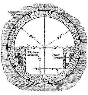
Section in Sand and Gravel or Rock
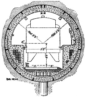
Section in Hudson River Silt, with foundations
Fig. 140.—Typical Cross-Sections of
One Tube of Pennsylvania Railroad Tunnel Under
the Hudson River.
Larger illustration
Hauling.
—A working platform, made up of 5-ft. sections,
was built inside the tunnel and kept close to the shield. On
this platform two lines of industrial railway tracks with switches
and sidings at the locks, and a heading, were laid for hauling
materials and spoils. These lines converged into a single track
in passing through the air locks. At the shaft elevators, they
terminated in a steel plate floor to avoid switches. Between the
locks of the bulkheads was installed an electrically driven cable
system, to haul the loaded muck up grade and to empty the flat
cars. From the first bulkhead to the shaft, the cars were hauled
up grade by a steam hauling engine. At the Manhattan end
there was one 10-H.P. engine for each tunnel, while at Weehawken
one 25-H.P. engine served for both tunnels. Each shaft
contained two elevators driven by a double-cable, reversible
single-drum steam-hoisting engine. A grouty frame was built[279]
over the shafts, and on the platforms over this frame were narrow-gauge
tracks, extending from the elevators to the muck-chutes
and to points where the lining segments were loaded on the cars.
The elevators were arranged to stop at both the ground and the
grouty platform levels. The rolling-stock at each of the tunnels
consisted of 75 flat cars for moving the tunnel segments, and of
about 50 muck cars, each of 11⁄4 cu. yd. capacity.
Plant.
—The plants located at each end of the tunnel near the
shafts were almost identical. Each consisted of three 500-H.P.
Stirtling boilers, which supplied steam at 150 lbs. pressure.
Feed water was supplied by three 131⁄2 metropolitan injectors, and
two Blake duplex pumps. Two Worthington surface condensers,
each of 2250 sq. ft. condensing surface, took care of the exhaust
from the engines and compressors. Condensing water was
pumped from the river through a 16-in. pipe. The high-pressure
air was supplied by a duplex Ingersoll-Sergeant compressor,
with cross-compound steam end 14 × 26 × 30 ins. and simple
water-jacket air cylinders 131⁄4 × 36 ins. Its capacity at 100 r.p.m.
was 1085 cu. ft. free air per minute. The maximum pressure
was 130 lbs. per sq. in. The air for the pneumatic working
was supplied by three 14 × 26 × 30 in. duplex Ingersoll-Sergeant
compressors. The maximum capacity of the three was 12,000
cu. ft. free air per minute at 125 r.p.m. and a discharge pressure
of 50 lbs. per sq. in. The suction air was taken from the outside
about 10 ft. above the roof of the engine house. Three aftercoolers,
321⁄2 ins. × 11 ft. 4 ins., each having 809 sq. ft. cooling
surface of tinned brass tubes, cooled the low-pressure discharge
to within 10° F. of the temperature of the cooling-water. From
the aftercoolers, the air passed into three steel receivers each
54 × 12 ft., placed outside the engine room and fitted with weighing
safety valves. The receivers were connected to two 10-in.
mains; one serving the north, the other the south tunnel. A
fourth receiver of the same size was built to receive the discharge
of the high-pressure compressor, through a 4-in. pipe. The
high-pressure water required for the shield was furnished by[280]
three Blake direct-acting, duplex pumps with outside packed
plungers. The steam end was 16 × 18 ins., the water end 21⁄16 × 18
ins. At 55 r.p.m. pumping against 5000 lbs. per sq. in., the
capacity of each pump was 57 gals. per minute. Two of them,
one on each tunnel, were sufficient to run the shields and the third
was held in reserve. The high-pressure water was conveyed to
the front by means of a 2-in. double, extra strong pipe which was
buried between the engine room and the shaft, in a trench, to
prevent freezing in cold weather. The electric current for light
and power was supplied by two 100-K.W. 250-volt G.E. direct-current
generators directly connected to Ball & Wood high-speed
engines running at 250 r.p.m. The switchboard had two machine
panels, two distributing panels and one panel carrying a circuit
breaker for the traction circuit.
Illumination.
—The tunnel was lighted by electricity, there
being two rows of lamps, one in the crown and one in the south
axial fine. The lamps were 16-c.p., 240-volt, two-wire system,
and were spaced 35 ft. apart in the crown and 121⁄2 ft. apart on
the axial line. In addition, five nests of 5 lamps each were
used at the front. Candles were supplied for miscellaneous and
emergency uses. The sockets for electric globes were fitted to a
wooden reflector, coated with white enamel paint on the inside.
[281]
CHAPTER XXI.
SUBMARINE TUNNELING (Continued); TUNNELS
AT VERY SHALLOW DEPTH. THE COFFERDAM
METHOD. THE PNEUMATIC CAISSON
METHOD. THE JOINING TOGETHER SECTIONS
OF TUNNELS BUILT ON LAND.
The tunnels on the river bed or at such a shallow depth that
only a few feet of material will remain between the bottom of the
river and the roof of the tunnel can be built in three different
ways, viz., (1) by a cofferdam; (2) by pneumatic caissons; (3)
by sinking and joining together whole sections of tunnels that
were built on land.
The Cofferdam Method.—The Van Buren Street Tunnel, Chicago
River.—
According to the cofferdam method, the work is attacked
at one of the shores, and the tunnel built in sections of
such length as not to interfere with the flow of water or the
navigation of the river. Round the entire exterior line of the
first section a double-walled cofferdam is built, and strongly
braced transversely, so as to withstand the pressure of the water.
When the water is pumped out, a single-walled cofferdam is
built within the first, leaving sufficient distance between the two
to allow of the construction of the masonry. The soil is then
removed within the inner cofferdam, and the tunnel constructed
from the foundation. When the end of the tunnel reaches the
channel end of the cofferdam, a crib-wall is erected over the end
of the completed tunnel. This crib, in turn, forms the end wall
of another cofferdam, built in continuation of the first, so as to
allow the second section to be proceeded with, and at the same
time to facilitate the removal of the cofferdams of the first[282]
section. The work goes on continuously in this way until the
distant shore is reached.
VAN BUREN STREET TUNNEL, CHICAGO.
The Van Buren Street tunnel, built to carry a double-track
street railway under the Chicago River, was completed in 1894
by the cofferdam method. The special features of the tunnel[14]
are: (1) the unusually large dimensions of the cross-section of
30 ft. × 15 ft. 9 ins.; (2) its construction inside of cofferdams
of great length and width; (3) the construction under some
very high buildings calling for great care and very strong temporary
and permanent supports.
The special feature of the work for our present purpose was
the construction of the tunnel across the river. To accomplish
this a cofferdam was built out from the west shore of the river
to its middle, and the tunnel constructed within it like the
building of any other structure within a cofferdam. Transverse
and longitudinal sections of this cofferdam are shown by
Fig. 141. As will be seen, it was a simple double-wall cofferdam,
with a clear width between the walls of 58 ft., and braced
transversely as shown. Inside of this a single-wall cofferdam
of piles was constructed, with a clear width just sufficient to
allow the construction of the masonry within it. When the
tunnel end reached the channel end of the cofferdam, a crib-wall
was built over the end of the completed tunnel, as shown by
the drawings. This crib-wall was intended to form the end wall
of another cofferdam, which was built out from the east shore,
and within which the remaining half of the tunnel was built
as the first half had been. The drawings show the character
of the tunnel masonry and of the centering upon which it was
built.
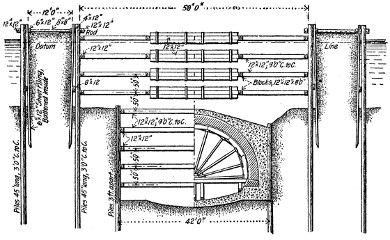
TRANSVERSE SECTION OF COFFERDAM AND TUNNEL
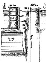
SECTION SHOWING METHOD OF CONSTRUCTING CRIB DAM.
Fig. 141.—Sections of Cofferdam, Van Buren St. Tunnel, Chicago.
Larger illustration
The Van Buren Street tunnel was the last of the three tunnels
under the Chicago River, constructed according to the cofferdam
method. At the time the tunnels were constructed the bed of[283]
[284]
the river was 17 ft. deep. In connection with the harbor and
river improvements, the Federal Government ordered the Chicago
River to be lowered so as to give a depth of 26 ft. of water. This
necessitated the lowering of the tunnel roof and the excavation
for a deeper floor which was a very difficult operation. This
work was described in “Eng. News,” Sept., 1906.
THE PNEUMATIC CAISSON METHOD.—THE TUNNEL UNDER
THE HARLEM RIVER.
In the early seventies Prof. Winkler proposed to construct
a tunnel under the River Danube to connect the various portions
of the Vienna, Austria, underground railway, and to use
caissons in the construction. Prof. Winkler proposed to build
caissons from 30 ft. to 45 ft. long, with a width depending upon
the lateral dimensions adopted for the tunnel masonry. The
caisson was to be made of metal plates and angle iron with
riveted connections on all sides except those running vertically
transverse to the tunnel axis, whose connections were to be
bolted. In the middle of the roof an opening was to be left;
this was for the shaft having the air-locks to allow the passage
of men, materials, and compressed air.
Across the river two parallel rows of piles were to be driven
into the river bed, to fix the place where the caisson was to be
sunk. Then the first caisson near the shore was to be lowered
in the ordinary way, and a second caisson was to be immediately
sunk very close to the first one. When both caissons had
reached the plane of the tunnel floor, the sides which were in
contact were to be unbolted and removed, and the small space
between made water-tight. The chambers of the two caissons
were to be opened into a single large one communicating above
by means of two shafts. At the same time that the masonry
was being built in the first two caissons, from the inverted arch
up, a third caisson was to be sunk; and when by excavation it
had reached the plane of the projected tunnel floor, the partitions
were to be removed so that the three caissons were in communication,[285]
forming a large single caisson. Then the outer partition
of the first caisson was to be removed, and the masonry of the
submarine tunnel connected with the portion of the tunnel built
on land. In a similar manner all the caissons were to be sunk;
and when the last one was placed, and the masonry lining constructed,
and connected with the portion of the tunnel built
on the other shore of the river, the partition walls were to be
battered down, and the submarine tunnel completely constructed
and open to traffic.
The Harlem River Tunnel.
—The pneumatic caissons method
was employed in the construction of the tunnel under the Harlem
River for the New York Rapid Transit Railway. The tunnel
proper consisted of two parallel tubes riveted to each other
and surrounded by a cradle of concrete as shown in Fig. 121,
page 216. The tunnel was built in three sections:—The first,
from the Manhattan shore well towards the middle of the river;
the second, from the shore of the Bronx towards the middle of
the river; and the last, the section uniting the other two and
completing the tunnel.
Each section was built within a specially constructed working-chamber,
consisting of timber side walls forming a wooden
caisson, so constructed that compressed air could be used. This
working-chamber of Mr. McBean presented some novel features,
inasmuch as the caisson was not built on land, but under water.
In building the tunnel, the Harlem River was dredged to a
certain depth, so as to leave only 6 ft. or 8 ft. of excavation to
be done before reaching the line of sub-grade of the proposed
structure. Two service platforms were built on piles 10 ft.
apart longitudinally, and cut off at a point above mean high-water
mark, braced in the usual manner, and covered with heavy
planks, to serve as the floor of the platform. On this platform
were placed rails for the trains used in the transportation of
materials. These platforms were also used in maintaining the
perfect alignment of the caissons.
Within the platforms and along the dredged channel four[286]
longitudinal rows of piles were sunk. These piles were accurately
brought to line by beams bolted together, and placed across and
above the water-level. A few beams were also added for the
purpose of bracing the piles transversely, after which they were
cut off under water and capped.
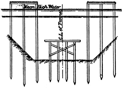
Fig. 142.—Showing Working Platforms
and Piles Sunk in the Dredged Channel.
Fig. 142 shows the manner in which the working platforms
were constructed, and also the rows of piles sunk in the dredged
channel. Between the piles a very
strong frame was placed, made up
of waling pieces and two transverse
beams 14 ins. by 14 ins. each,
placed one below the other at a
distance of 5 ft. 8 ins., and strongly
braced together. Guiding-beams
were fixed on each side of the
frame for the sheeting piles. The
frames were built in sections
of different lengths, and placed
directly above the cap-pieces of the pile-bents sunk in the
dredged channel.
The longitudinal sides of the caisson were constructed by
sinking two rows of sheeting piles, each row being close to a
service platform. The sheeting piles were made up of yellow-pine
timbers 12 ins. by 12 ins.; three piles bolted together formed
a section 3 ft. wide. Each section was grooved and tongued, so
as to be firmly connected with the adjacent sections to be sunk.
The lower ends of the piles were cut wedge-shaped, with a sharp
edge to offer a small resistance while penetrating the soil. The
sheeting-piles were then cut off under water, which operation was
successfully carried out by means of a circular saw operated
by a pile-driving machine. The sheeting was also extended
between two platforms to make a bulkhead, and in this way the
four sides of the caisson were built up. Particular attention
was always given to the alignment of the sheeting piles, which
was obtained by guiding the piles with the timbers placed longitudinally,[287]
one below the water-line in connection with the frames
located between the pile-bents, and the second along the inner
edge of the service platform, as
shown in Fig. 143.
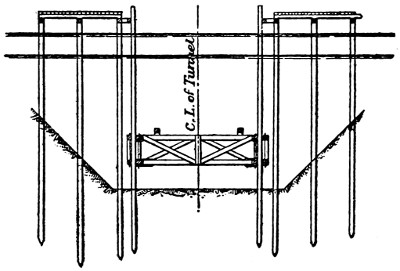
Fig. 143.—Showing Sheeting-Piles for the
Sides of the Caisson and Trussed Beam for
the Roof.
The caisson was completed
by placing a roof covering the
sides. This roof was 40 ins.
thick, made up of three layers
of 12-in. beams placed transversely
to the axis of the caisson,
while between the beams
planks 2 ins. thick were placed
lengthwise and bolted together,
so as to make a firm, solid structure. The roof was built ashore,
in sections each varying from 39 ft. to 130 ft. long. The edges of
the roof fitted the sides of the caisson perfectly; and when each
section was towed to the proper spot, it was sunk and made
secure. Under the roof were placed six longitudinal beams,
12 ins. by 14 ins., called
“rangers,” resting on the cap-pieces
of the pile-bents that
were laid across the space of
the proposed tunnel; while the
extreme rangers were used for
the purpose of fitting above
the sheeting-piles of the caisson,
in order to make the latter
water-tight. The two extreme
rangers were provided
with T-irons, the flat side being laid on the sheeting-piles, while
the web penetrated the ranger by reason of the weight of the load
resting on the roof, for the purpose of sinking it to the required
point. Earth was next heaped on the roof, and in this way a
large working-chamber was prepared, as shown in Fig. 144.
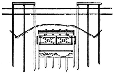
Fig. 144.—Showing the Caisson with the Working-Chamber.
The working-chamber built on the Manhattan side of the[288]
Harlem River was 216 ft. long, provided with two rectangular
shafts 7 ft. by 17 ft., rendered water-tight, and rising above the
high-water mark of the river. Within these shafts the air-locks
of the tunnel tubes were placed, so that the work could be carried
on by means of compressed air. The pressure of the air was used
to expel the water, being sufficiently intense to equilibrate a
column of water equal to the depth of the lowest point of the
roof of the caisson.
When the working-chamber was constructed, the tunnel
proper was begun by excavating the soil down to the required
level; the concrete was then laid on. It was just at this point,
when a large part of the roof was constructed and supported only
by the sheeting-piles of the sides of the caisson, that the writer
of this article feared that this novel method of tunneling would
prove a failure. The tendency of the timber to float, aided as
it was by the air pressure within the caisson, was counteracted
only by the weight of the earth heaped on the roof, and by the
friction of the soil against the feet of the sheeting-piles. This
friction was only a small quantity, as the soil was loose, so that
it was considered rather risky and dangerous to place reliance on
such a feeble quantity. This fear was, unfortunately, justified
on two occasions, when on cutting off a portion of the pile-bents
some of the sheeting-piles got loose and water flooded the whole
chamber, but, happily, without loss of life. As the chamber was
one of large dimensions, the workmen had time enough to effect
their escape. It may be remarked that during these troubles
only a few of the sheeting-piles were displaced, while the caisson
itself offered a stout and successful resistance, due to its being
strongly braced transversely. The accidents were, therefore,
limited to a few piles, instead of affecting the entire caisson. On
the occasion of the first, the repairs were effected by sinking the
piles to a greater depth, continuing down until rock was encountered.
After that, the water was pumped out and the work
resumed. In repairing the second accident, the sheeting-piles
were driven down to bed-rock, and the surrounding soil strengthened[289]
by cement forced through the loose soil around the piles.
This remedy proved effective, and no further trouble occurred
to delay the work on the Manhattan side of the Harlem River.
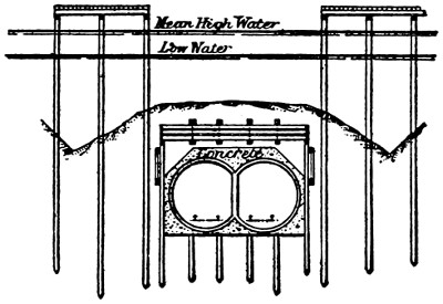
Fig. 145.—Showing the Tunnel Constructed
within the Caisson.
On the concrete bed of the tunnel the segments of the metal
lining were placed and surrounded
by concrete, as required
by the plans and specifications
(Fig. 145). The contractors
had planned to unbolt
the roof from its holdings, to
remove by means of dredgers
the earth which had been
heaped on it, and thus set the
roof afloat, after which it was
to be towed within the two
working platforms already erected on the Bronx shore. But
Mr. McBean devised a simpler and more economic, but at the
same time more dangerous, way of constructing this second
section of the tunnel. He thought that the upper half of the
tunnel proper could be used instead of the timber roof, thereby
reducing the capacity of the working chamber, and limiting the
use of compressed air. In this way he dispensed with the
removal of timber, and also of the earth heaped on the roof.
In building this Bronx section, a channel was dredged along
the line of the tunnel to a depth of 5 ft. from the foundation-bed
of the proposed tunnel. The working platforms were constructed
on both sides of this channel, quite similar to those erected on
the other half of the tunnel; and between them pile-bents were
sunk, capped with 12-in. by 12-in. beams. Over the cap-pieces
rangers were placed longitudinally, which also rested on the sides
of the wooden working caisson, Fig. 146. The sheeting-piles
were cut off at level, but much lower down than in the first half
of the tunnel.
The roof was built on floats made of 12-in. by 12-in. timber laid
transversely 4 ft. apart and supporting a floor of 3-in. by 12-in.[290]
planks rendered water-tight. The sides of the floats were made
by verticals, 4 ins. by 6 ins., and planks, 3 ins. by 12 ins., carefully
caulked. A temporary floor was built on the base of the
float, consisting of transverse
beams, 16 ins. by 16 ins.,
placed 8 ft. apart. A center
piece, 10 ins. by 16 ins., was
laid so as to correspond with
the axis of the tunnel; and
on each side of it, other
parallel beams, 16 ins. by
16 ins., corresponding to each
center of the circular metal
lining of the tunnel; the
beams, longitudinal and transversal, were strongly bolted together.
The temporary floor was completed by boarding the
spaces left between the various beams.
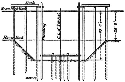
Fig. 146.—Showing Sides of the Caisson and
Supports for the Roof.
On this float, the upper half of the tunnel was constructed by
erecting the segments of the metal lining, which were strongly
supported, so as to prevent any settling or distortion; the concrete
was then built up in a large flange with vertical suspension
rods, four to each bar. The rings of the tunnel were 6 ft. each,
the weight of each lining being 41,000 lbs., the concrete covering
618 cubic feet. The second part of the tunnel was 300 ft. long,
with roof constructed in three sections—two of 90 ft. in length
each and the third of 84 ft. Each of these sections alternated
with a smaller section, 12 ft. long, provided with air-locks. The
shortest of the three sections was the first one set up, and was
constructed close to the Bronx side of the Harlem River. For
this purpose the two extreme ends of the section were closed by
means of steel plates forming diaphragms, built 6 ft. inward,
thus leaving one ring projecting out at each end. Openings were
left on the top of these projecting rings for access by divers. The
exterior of the upper half section of the permanent tunnel was
filled with water until it was lowered into position. It was[291]
directed by means of tackles attached to vertical eye-bars, which
were strongly fixed to the flanges of the springing line of the arch,
and bolted to the beams of the temporary floor. In this way the
roof was towed into place, and lowered by means of stone ballast,
until it rested on the cap-pieces and frames of the pile abutments,
the sides of the roof remaining just on top of the sheeting-piles
that formed the sides of the caisson, as shown in Fig. 147. Perfect
alignment was obtained by wires strung at each end and
along the side of the roof, corresponding to points fixed on
the working platforms and
sighted with transits. Such
accuracy was obtained that
the circumferential flanges
of the outer 6-ft. ring were
brought into contact with
those of the 12-ft. section
already constructed. A diver
then entered by the opening
left in the projecting ring,
and bolted this section of
the roof to the preceding one. By removing the iron diaphragm,
the consecutive sections were united into one. When the diver
completed his work, the opening was closed up, and compressed
air used to keep the water out of the box included between the
roof and the temporary flooring.
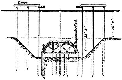
Fig. 147.—Showing the Roof of the Caisson
Formed by the Upper Half of the Tunnel.
The remaining sections of the tunnel roof were built in the
same way, until the last abutted against the part of the work
constructed within the caisson under the high wooden roof on
the Manhattan side of the river. The following method was
adopted for the purpose of connecting the few parts of the tunnel
which had been differently constructed. The diaphragm at the
end of the last section of the tunnel roof was constructed so as
to abut against the last circumferential flanges of the iron lining
without leaving a projecting ring. It was continued above the
metal and concrete lining of the roof in a rectangular form, and[292]
of the same height and width as the wooden bulkhead of the
working-chamber on the Manhattan side of the river. The
diaphragm was made of riveted plates and angles, with an opening
20 ins. by 30 ins., bolted so as to be removable at will. The
diaphragm was of the same height as the roof and was connected
with a roof-plate to the rangers supporting the thick wooden
roof. Other steel plates, placed vertically, were riveted to the
diaphragm and bolted to the caisson. All this work was carried
on by divers. The wooden bulkhead was cut to the springing-line
of the arch; and between the two parts of the tunnel, built
by different methods, a bulkhead was placed, made of steel
plates 14 ins. long, which prevented the entrance of water into
the working-chamber.
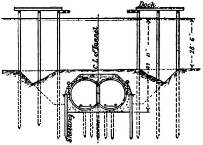
Fig. 148.—Showing the Tunnel Completed
by Building the Lower Half within the
Caisson.
When the different sections were joined together, and all
the openings closed and made water-tight, cement-grout was
poured on the roof, and earth was heaped up to a height of 5 ft.
The 300 ft. of the roof, resting
on sheeting-piles and provided
with diaphragms at the extreme
ends, formed a water-tight
working-chamber, or caisson,
communicating with the
exterior by means of the shafts
and air-locks. The lower portion
of the tunnel was built
under air-pressure. The pile-bents
were first cut off at the
plane of the tunnel sub-grade, after which the foundation-bed
of concrete was laid. The lower segments of the iron lining were
then placed in position, and the structure made continuous by
building up the lateral walls, consisting of concrete (Fig. 148).
No accidents occurred while building the second part of the
tunnel.
The Harlem River tunnel was completed in contract time,
although the opening of the subway was delayed by difficulties[293]
encountered in tunneling through rock in the borough of the
Bronx. The writer endeavored to obtain information regarding
the expense per linear foot, but all his efforts were rewarded with
a general assurance that it proved to be the cheapest method.
SINKING AND JOINING TOGETHER SECTIONS OF TUNNELS
BUILT ON LAND. THE SEINE. THE DETROIT
RIVER TUNNELS.
In the year 1896, Mr. Erastus Wyman secured a patent for
building subaqueous tunnels close to the river, by sinking and
joining together small sections of tunnels previously built on
land. Each section would have been provided with a long
vertical tube for the air-lock when compressed air was to be
admitted to expel the water and permit the construction of the
lining within the sunken shell. Thus each section of the tunnel
would have acted as a pneumatic caisson; being, however, an
improvement on Professor Winkler’s suggestion inasmuch as the
caisson was a portion of the tunnel itself, instead of a simple
inclosure for facilitating the construction of the shield. Mr.
Wyman proposed to use this method in the construction of a
tunnel between South Brooklyn and Stapleton, Staten Island; a
charter was granted him but the tunnel was never built.
The Tunnel under the Seine River.
—The caisson method of
building tunnels under water was used at Paris, France, in the
construction of the Metropolitan Railroad under the Seine River.
The caissons designed by Mr. L. Chagnaud were for a double
track line. They were sunk, ends to ends, and formed a portion
of the tunnel lining which was enveloped by a framework of
metal embedded in concrete. Built-up frames carried a shell of
steel plating on the sides, from toes to springing lines, and on
the sides and roof of the working-chamber. A temporary plate
diaphragm closed the open ends. This construction formed a
vessel capable of floating with a very light draft.
The method of sinking the caissons was as follows: The caisson
was erected on the river bank and when completed it was[294]
launched and towed into position between pile stagings which
served the double purpose of guiding the descent at the beginning
of the sinking and of forming a working platform. The caisson
when launched and, consequently, before the cast-iron lining
had been put in place within it, weighed 280 metric tons; but,
beyond some difficulty in taking it under the bridges in the way,
the towing was accomplished without serious trouble.
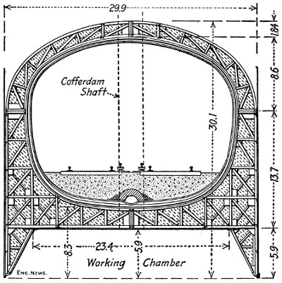
Fig. 149.—Transversal Section of the Caissons for the Tunnel under the Seine River.
Previous to placing the caisson in position between the
stagings, the portion of the river bed it was to rest upon had
been leveled by dredging. Once in position, the first work was
the erecting of the cast-iron lining segments within the framework.
Work was then begun by filling the annular space between
the lining and the shell with concrete; this additional weight
gradually sunk the caisson to the river bottom. The working
shafts, made up of steel cylinders, were placed as the sinking
progressed to this point.
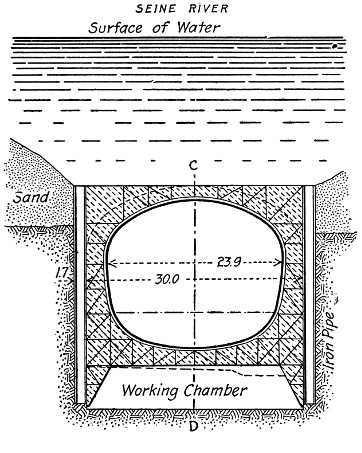
Section A-B.
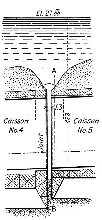
Section C-D.
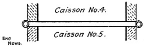
Plan at Joint.
Fig. 150.—Showing the Joining of the Caissons at the Pont Mirabeau Tunnel under the
Seine River.
After the caissons had been sunk to the required place and
in continuation of one another, a space of nearly 5 ft. was left
between them. The construction of the tunnel within the bank[295]
of earth separating the two caissons was as follows: A cofferdam
was built around this space. It was formed by two diaphragms
closing the ends of the tunnel, and by two longitudinal walls
sunk as temporary caissons, one on each side of the tunnel
and inclosing their ends. This cofferdam was covered with a
metal working-chamber whose lower edges rested on top of the
four walls of the cofferdam. The joints were made tight by
means of rubber or packed clay. The water in the cofferdam
was then pumped out, the earth excavated, and the masonry
built in continuation of the two ends of the tunnel sections.
The submerged sections of the tunnel which were allowed to[296]
remain full of water to render them more stable and to save effort
in pumping them, were now made dry; the diaphragms were
removed from the ends of the caisson tunnels and the work made
continuous. Fig. 149 shows the cross-section of the caissons.
At the Pont Mirabeau crossing of the Seine, a slightly different
method was used, described in “Eng. News,” May 18, 1911.
The caissons were sunk to the required line and grade with an
intervening longitudinal space of 153⁄4 ins. between two adjoining
caissons. At each end of this space, which was filled with the
river marl, was sunk against the edges of the caissons a hollow
cylinder 20 ins. outside diameter. The interior of these cylinders
was excavated and filled with concrete, thus forming a
continuous wall on both sides of the two adjoining caissons.
The earth from the intervening space was then removed and
concrete deposited from bottom opening tremies up to the level
of the top of the caisson. After nearly one month the tunnel
was entered from the shaft and an opening the shape and size
of the tunnel section cut through the diaphragms of the 153⁄4-in.
wall and the concrete tunnel lining made continuous between
the two sections. Fig. 150 shows the method of joining the
caissons.
The Detroit River Tunnel.
[15]—With some modifications which
permitted dispensing with compressed air, the tunnel under the
Detroit River was built for the Michigan Central Railroad, connecting
Detroit with Windsor, Canada. The tunnel is 6625 ft.
long; of this, however, only 2625 ft. are under the river, while
the approach on the American side is 2000 ft. long and that on
the Canadian side, 4000 ft. The tunnel consists of two parallel
circular tubes 23 ft. in diameter, built up of 3⁄8-in. steel plate.
They are placed 26 ft. apart, center to center, and are connected
by diaphragms at 12-foot intervals.
Each section of the subaqueous tunnel is approximately
262 ft. long. There are ten of these sections and an eleventh a
little over 60 ft. long. These tubes were built at the shipyards[297]
of the Great Lakes Engineering Works at St. Clair, about 30
miles from Detroit. After the assembling was completed, the
ends of each tube were closed by temporary wooden bulkheads
to make them float, and the outside sheathed horizontally with
heavy timbers bolted to the diaphragms. This sheathing running
lengthwise of the tube made a form or pocket, into which the
inclosing jacket of concrete was placed. The sections were then
launched and towed down to the tunnel site and sunk separately
in a trench on the river bottom that had been previously dredged
to receive them. This trench was dug to a width of 50 ft. and
depth varying from 25 to 50 ft. by clamshell buckets, swung
from a scow, working to a depth below the water level of 60 to
90 ft.
As a foundation for the sections, a grillage was constructed
on the surface and sunk in place in the trench by derricks swung
from a scow. The grillage was placed underneath each joint
between the sections and built up of I-beams imbedded in concrete.
This grillage is the width of the trench and about 30 ft.
long, with posts projecting downward from the four corners, and
these were seated into the river bottom, by means of pile drivers,
to the desired grade.
Then the eleven sections of the tunnel were lowered and connected,
one at a time. By the aid of air tanks placed on each
section the movement was controlled until the final sinking upon
the grillage in the trench. This operation called into play the
greatest engineering skill and ingenuity. When it is considered
that the current velocity at the river bed is about 2 ft. per second
and much higher along the surface, some idea can be gained of
the problems to be overcome. The movement of the enormous
sections must be absolutely under control. Thirty-five-ton
blocks of concrete were sunk in the river bottom up and down
stream to act as anchors, and through them cables were rigged
and connected back to the hoisting engines on the derrick scows.
These were prevented from moving by spuds at each corner,
securely driven into the river bottom at depths sometimes as[298]
great as 90 ft. Controlling cables were also run from the sections
to the tremie scow to pull one structure close to the adjoining
section previously sunk, and the divers made the necessary connection.
Fig. 151 shows cross-sections and plans of the tunnel
as given in “Eng. Record,” March 2, 1907.
Steel masts had been previously attached to each end of the
sections to enable the engineers on shore to determine the alignment
and locate the exact position during the sinking.
Concrete was then deposited in the pockets, completely surrounding[299]
the tubes, forming a solid monolithic structure from
end to end.
This was done by means of the tremie process.
A 32-ft. by 160-ft. scow was equipped with a concrete mixing
plant and the tremie pipes, three in number, through which the
concrete was deposited. Each pipe is 12 ins. in diameter, of
spiral riveted steel, 80 ft. long. These pipes could be raised or
lowered, reaching from the receiving hoppers on the scow to the
bottom of the trench. When the pipes were filled with concrete
and lowered into position, a continuous flow was maintained. As
fast as the concrete escaped at the bottom end of the pipe it was
replenished at the top; this process continuing until the entire
space surrounding the section was filled to the desired level, and
under the pressure produced not only by the depth of water
under which it was submerged, but also by the weight of the long
column of concrete contained in the tubes. It is interesting to
note that this is the first time a large amount of concrete has
been deposited at a depth of 70 ft. by this method, and upon the
accomplishment of this task in a measure depended the successful
building of the tunnel.
Inside the tubes was placed a lining of reinforced concrete
20 ins. thick. Side walls were built up from this ring to provide
ducts, which carry the electrical cables for the distribution of
power, lighting, signal and telegraph wires. They also serve to
provide a footwalk along the side of the tunnel.
There are cross passages in the tunnel every 200 ft., and
also various niches for the different equipment needed in connection
with the signaling, telephone and fire alarm system. The
tunnel is lighted with 800 16-candle-power incandescent lights.
The track construction is new. There is no ballast used,
the ties being laid in concrete. A ditch in the center of each
track carries the rainfall that will flow down from the summits
to sumps which are drained by centrifugal pumps.
One remarkable feature of its construction is that compressed
air was not used in the building of the subaqueous[300]
tunnel, but it was necessary in building the approach tunnels.
This is contrary to the usual program where compressed air is
required in subaqueous work, and not ordinarily used in approach
or land tunnel construction.
The trains are operated by very heavy electric locomotives,
operated by the third-rail system.
The tunnel was constructed under the supervision of W. S.
Kinnear, Chief Engineer of the Detroit River Tunnel Co.; Butler
Bros. of New York were the general contractors.
[301]
CHAPTER XXII.
ACCIDENTS AND REPAIRS IN TUNNELS DURING
AND AFTER CONSTRUCTION.
In the excavation of tunnels it often happens that the disturbance
of the equilibrium of the surrounding material by the
excavation develops forces of such intensity that the timbering
or lining is crushed and the tunnel destroyed. To provide
against accidents of this kind in a theoretically perfect manner
would require the engineer to have an accurate knowledge of
the character, direction and intensity of the forces developed,
and this is practically impossible, since all of these factors differ
with the nature and structure of the material penetrated. The
best that can be done, therefore, is to determine the general
character and structure of the material penetrated, as fully as
practicable, by means of borings and geological surveys, and
then to employ timbering and masonry of such dimensions and
character as have withstood successfully the pressures developed
in previous tunnels excavated through similar material.
If, despite these precautions, accidents occur, the engineer is
compelled to devise methods of checking and repairing them,
and it is the purpose of this chapter to point out briefly the
most common kinds of accidents, their causes, and the usual
methods of repairing them.
Accidents During Construction.
—Accidents may happen both
during or after construction, but it is during construction, when
the equilibrium of the surrounding material is first disturbed,
and when the only support of the pressures developed is the
timber strutting that they most commonly occur.
[302]
Causes of Collapse.
—Collapse in tunnels may be caused: (1)
by the weight of the earth overhead, which is left unsupported
by the excavation; (2) by defective or insufficient strutting;
and (3) by defective or weak masonry.
(1) The danger of collapse of the roof of the excavation is
influenced by several conditions. One of these is the method
of excavation adopted. It is obvious that the larger the
volume of the supporting earth is, which is removed, the
greater will be the tendency of the roof to fall, and the more
intense will be the pressures which the strutting will be called
upon to support. Thus the English and Austrian methods of
tunneling, where the full section is excavated before any of the
lining is placed, and where, as the consequence, the strutting
has to sustain all of the pressures, present more likelihood of
the roof caving in than any of the other common methods.
The character and structure of the material penetrated also
influence the danger of a collapse. A loose soil with little
cohesion is of course more likely to cave than one which is
more stable. Rock where strata are horizontal, or which is
seamy and fissured, is more likely to break down under the roof
pressures than one with vertical strata and of homogeneous
structure. Soft sod containing boulders whose weight develops
local stresses in the roof timbering is likely to be more dangerous
than one which is more homogeneous. A factor which
greatly increases the danger of collapse, especially in soft soils,
is the presence of water. This element often changes a soil
which is comparatively stable, when dry, into one which is
highly unstable and treacherous. The liability of the material
to disintegration by atmospheric influences and various other
conditions, which will occur to the reader, may influence its
stability to a dangerous extent, and result in collapse.
(2) Collapse is often the result of using defective or insufficient
strutting. Of course, in one sense, any strutting which
fails under the pressures developed, however enormous they
may be, can be said to be insufficient, but as used here the term[303]
means a strutting with an insufficient factor of safety to meet
probable increases or variations in pressure. Insufficient strutting
may be due to the use of too light timbers, to the spacing
of the roof timbers too far apart, to the yielding of the foundations,
to insufficient bearing surface at the joints, etc. Collapse
is often caused by the premature removal of the strutting during
the construction of the masonry. The masons, to secure
more free space in which to work, are very likely, unless
watched, to remove too many of the timbers and seriously
weaken the strutting.
(3) The third cause of collapse is badly built masonry.
Poor masonry may be due to the use of defective stone or brick,
to the thinness of the lining, to poor mortar, to weak centers
which allow the arch to become distorted during construction,
to poor bonding of the stone or bricks, to the premature
removal of the centers, to driving some of the roof timbers
inside it, etc.
Prevention of Collapse.
—Tunnels very seldom collapse without
giving some previous warning of the possible failure, and
also of the manner in which the failure is likely to occur.
From these indications the engineer is often able to foresee the
nature of the danger and take steps to check it. The danger
may occur either during excavation or after the lining is built.
During excavation the danger of collapse is indicated beforehand
by the partial crushing or deflection of the strutting timbers.
If the timbers are too light or the bearing surfaces are
too small, crushing takes place where the pressures are the
greatest, and the timbers bend, burst, or crack in places, and the
joints open in other places. The remedy in such cases is to insert
additional timbers to strengthen the weak points, or it may
be necessary to construct a double strutting throughout.
When the distance spanned by the roof timbers is too great,
failure is generally indicated by the excessive deflection of
these timbers, and this may often be remedied by inserting
intermediate struts or props. In some respects the best remedy[304]
under any of these conditions is to construct the masonry as
soon as possible.
When collapse is likely to occur after the masonry is completed,
its probability is generally indicated by the cracking
and distortion of the lining. A study of the cause is quite
likely to show that it is the percolation of water through the
material surrounding the lining which causes cavities behind
the lining in some places, and an increase of the pressures in
other places. When it is certain that this water comes from
the surface streams above, these streams may often be diverted
or have their beds lined with concrete to prevent further percolation.
When percolating water is not the cause of the trouble,
a usually efficient remedy is to sink a shaft over the weak point,
and refill it with material of more stable character. These,
and the remedies previously suggested, are designed to prevent
failure without resorting to reconstruction. When they or
similar means prove insufficient, reconstruction or repairs have
to be resorted to.
Repairing Failures.
—Tunnels may collapse in several ways:
(1) The front and sides of the excavation may cave in; (2)
the floor or bottom may bulge or sink; (3) the roof may fall
in; (4) the material above the entrances may slide and fill
them up.
(1) One of the most common accidents is the caving of the
front and sides of the excavation. This may often be prevented
by taking care that the face of the excavation follows the natural
slope of the material instead of being more or less nearly
vertical. When, however, caving does occur it may usually
be repaired by removing the fallen material, strongly shoring
the cavity, and filling in behind with stone, timber, or fascines.
(2) The bulging or rising of the bottom of the tunnel may
usually be considered as a consequence of the squeezing together
of the side walls. It usually occurs in very loose soils, and is
chiefly important from the fact that the reconstruction of the
side walls is made necessary. The sinking of the tunnel bottom[305]
is a more serious occurrence. It seldom happens unless
there is a cavity beneath the floor, due either to natural causes
or to the fact that mining operations have gone on in the hill
or mountain penetrated by the tunnel. When the bottom of
the tunnel sinks, three cases may be considered: (a) when the
sinking is limited to the middle of the tunnel floor; (b) when
only a portion of the foundation masonry is affected; and, (c)
when the entire lining is disturbed. In the first case repairs
are easily made by filling in the cavity with new material. In
the second case the unimpaired portion of the masonry is temporarily
supported by shoring while the injured portion is removed
and rebuilt on a firm foundation. The remaining cavity
is then filled. In the case of the complete failure of the lining,
the method of repairing employed when the roof falls, and
described below, is usually adopted.
(3) The most dangerous of all failures is the falling of the
tunnel roof. In such casualties two cases may be considered:
(a) When the falling mass completely fills the tunnel section,
and (b) when it fills only a portion of the section.
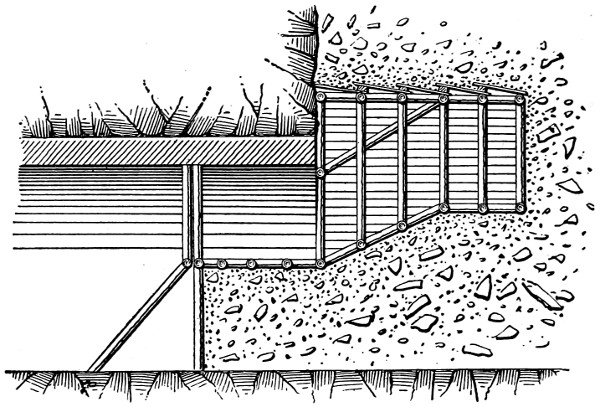
Fig. 152.—Tunneling through Caved Material by Heading.
When the whole section is filled by the fallen material, the
problem may be considered as the excavation of a new tunnel
of short length inside the old tunnel, and under rather more
difficult conditions. The first task, particularly if men have
been imprisoned behind the fallen material, is to open communication
through it between the two uninjured portions of
the tunnel. It is advisable to do this even when there is no
danger to life because of imprisoned workmen, since it enables
the work of repairing to be conducted from both directions.
The excavation of a passageway through the fallen material
is rendered difficult, both because the fallen material is of an
unstable character, and also because it is usually filled with the
lining masonry, timbering, etc. When, therefore, the accident
has happened before the full section of the original material
has been removed, the first heading or drift is driven through
this original material rather than through the fallen débris.[306]
Any of the regular soft-ground methods of tunneling may be
employed, but it is usually better to select one which allows
the masonry to be built with as little excavation as possible at
first. For this reason the German method of tunneling is particularly
suited to repair work of this nature. The Belgian
method may also be used to advantage, particularly when the
caving extends to the surface of the ground above, and the
upper portion of the débris is, therefore, practically the same
material as that through which the original tunnel was driven.
The greatest defect of the Belgian method for making repairs
is that the roof arch is supported by a rather unstable mass of
mingled earth, stone, and timber, which constitutes the bottom
layer of the fallen material. The method of strutting the work
when the German or Belgian method is used is shown by Fig.
152. It sometimes happens that the fallen débris is so unstable
that it will not carry safely the arch masonry in the
Belgian method or the strutting in the German method, and in
these cases one of the full-section methods of excavation is
usually adopted. The nature of the strutting employed is
shown by Fig. 153. When the section has been opened and
the new masonry built, great care should be taken to fill the
cavity behind the masonry with timber or stone; and should[307]
the disturbance reach to the ground surface it is often a good
plan to sink a shaft through the disturbed material, and fill it
with more stable material.
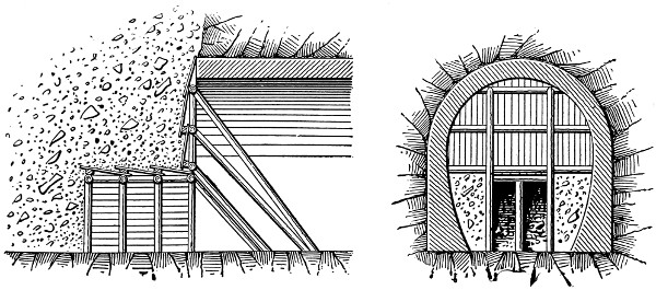
Fig. 153.—Tunneling through Caved Material by Drifts.
When the fallen débris fills only a part of the section, the
first thing to provide against is the occurrence of any further
caving; and this is usually done by building a protecting roof
above the line of the future roof masonry. Figs. 154 and 155
show two methods of constructing this temporary roof, which
it will be noticed is filled above with cordwood packing. As
soon as the temporary roof is completed, the lining masonry is
constructed.
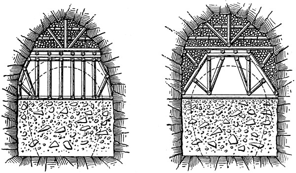
Figs. 154 and 155.—Filling
in Roof Cavity Formed by Falling Material.
[308]
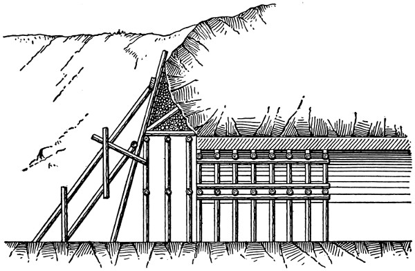
Fig. 156.—Timbering to Prevent Landslides at Portal.
(4) Landslides which close the tunnel entrance are repaired
in a variety of ways. Fig. 156 shows a common method of
preventing the extension of a landslide which has been started
by the excavation for the entrance masonry. Fig. 157 shows a
method often adopted when the slope is quite flat and the
amount of sliding material is small. It consists essentially of
removing the fallen material and building a new portal farther
back; that is, the open
cut is extended and the
tunnel is shortened.
When the amount of
the sliding material is
very large, the contrary
practice of lengthening
the tunnel and shortening
the open cut, as
shown by Fig. 158,
may be adopted.
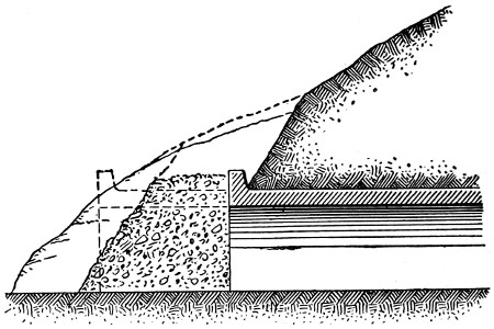
Fig. 157.—Shortening Tunnel Crushed by Landslide
at Portal.
Accidents After Construction.
—Accidents after the completion
of the tunnel may be divided into two classes: first,
those which entirely obstruct the passage of trains, of which the
collapse of the roof is the most common; and second, those which
allow traffic to be continued while the repairs are being made,[309]
such as the bulging inward of a portion of the lining without
total collapse. In the first case the first duty of the engineer
is to open communication through the fallen débris, so
that passengers at least may be transferred from one part of the
tunnel to the other and proceed on their way. This is done
by driving a heading, and strongly timbering it to serve as a
passageway. If the tunnel is single tracked this heading is
afterwards enlarged until the whole section is opened. In
double-track tunnels the method generally adopted is to open
first one side of the section and timber it strongly, so as to clear
one track for traffic. While the trains are running
through this temporary passageway the
other half of the section is opened and repaired;
the traffic is then shifted to the
new permanent track, and the temporary
structure first employed is replaced
with a permanent lining.
When the accident is such
that the repairs can be
made without obstructing
traffic entirely,
various
modes of procedure
are followed. In all cases great care has to be exercised to
prevent accident to the trains and to the tunnel workmen.
The work should be done in small sections so as to disturb as
little as possible the already troubled equilibrium of the soil;
the strutting should be placed so as to give ample clearing
space to passing trains, and the trains themselves should be run
at slow speeds past the site of the repairs. To illustrate the
two kinds of accidents and the methods of repairing them,
which have been mentioned, the accidents at the Giovi tunnel
in Italy and at the Chattanooga tunnel in America have been
selected.
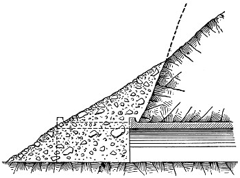
Fig. 158.—Extending Tunnel through Landslide at Portal.
Giovi Tunnel Accident.
—In September, 1869, at a point about[310]
220 ft. from the south portal of the Giovi tunnel, a disturbance
of the masonry lining for a length of about 52 ft. was observed.
Accurate measurements showed that the lining was not symmetrical
with respect to the vertical axis of the sectional profile.
It was concluded that owing to some disturbance of the surrounding
soil unsymmetrical vertical and lateral pressures were
acting on the masonry. Close watch was kept of the distorted
masonry, which for some time remained unchanged
in position. In 1872, however, new crevices were observed
to have developed, and shortly afterwards, in January, 1873,
the injured portion of the masonry caved in, obstructing
the whole tunnel section. The fallen material consisted
chiefly of clay in a nearly plastic state. The surface of the
ground above was observed to have settled. Investigation
showed also that the cause of the caving was the percolation of
water from a nearby creek. The water had soaked the ground,
and decreased its stability to such an extent that the masonry
lining was unable to withstand the increased vertical and lateral
pressures.
The mode of procedure decided upon for repairing the
damage was: (1) To open at least one track for the temporary
accommodation of traffic; (2) To remove permanently the causes
which had produced the collapse; (3) To build a new and
much stronger lining. Close to the western side wall, which
was still standing, the débris was removed, and the opening
strongly strutted in order to allow the laying of a single
track to reëstablish communication. At the same time a shaft
was sunk from the surface above the caved portion of the tunnel,
for the double purpose of facilitating the removal of the
fallen material and of affording ventilation. The depth of the
surface above the tunnel was 41.6 ft., which made the construction
of the shaft a comparatively easy matter. The shaft itself
was 61⁄2 ft. wide and 18 ft. long, with its longer dimensions parallel
to the tunnel, and it was lined with a rectangular horizontal
frame and vertical-poling board construction. After temporary[311]
communication had been opened on the western track of
the tunnel, the remainder of the fallen earth was removed and
the excavation strutted. The new masonry lining was then
built.
To remove permanently the cause of the cave-in, which was
the percolation of water from a close-by stream, this stream was
diverted to a new channel constructed with a concrete bed and
side walls.
The failure of the original lining occurred by cracks developing
at the crown, haunches, and springing lines. The new lining
was made considerably thicker than the original lining, and at
the points where failure had first occurred in the original arch
cut-stone voussoirs were inserted in the brickwork of the new
arch as described in Chapter XIII.
Chattanooga Tunnel.
—The Western & Atlantic Ry. passes
through the Chattanooga mountains by means of a single-track
tunnel 1,477 ft. long, constructed in 1848-49. The lining consisted
of a brickwork roof arch and stone masonry side walls.
After the tunnel had been opened to traffic, this lining bulged
inward at places, contracting the tunnel section to such an extent
that it was decided to reconstruct the distorted portions.
After careful surveys and calculations had been made, it was
decided to take down and reconstruct about 170 ft. of the
lining.
Owing to contracted space in the tunnel, it was necessary
to remove all men, tools, and material, whenever trains were
to pass through; and in order to do this a work-train of
three cars was fitted up with necessary scaffolds, and supplied
with gasoline torches for lighting purposes. Mortar was mixed
on the cars, and all material remained on them until used.
Débris torn out of the old wall was loaded on the cars, and
hauled to the waste dump. A siding was built near the West
end of the tunnel for the use of this train, and a telephone system
was installed between the entrances and the working-train.
On account of the contracted working-space and the greater[312]
ease with which brick could be handled, it was decided to rebuild
the walls out of brick instead of stone.
In tearing out the old wall a hole was first cut through the
three bottom courses of the arch and gradually widened. When
the opening became four or five feet long, a small jack was
placed near the center of it and brought to a bearing against
the arch to sustain it. After cutting the opening to a length
of from 7 to 10 ft. depending on the stability of the earth
backing, the jack was removed and a piece of 8×16 in. timber
placed under the arch and brought up to a bearing with jacks.
One end of the timber rested on the old wall, the other on a seat
built into the adjoining section of new wall. Wedges were
then driven under the ends of timber and the jacks removed.
With this timber in place, the old wall could be taken down
with ease, the only trouble being that small stones and earth
fell in from above and behind the arch. This was obviated
by placing a 2 in. plank across the opening and just back of
the 8×16 in. timber. At several points, however, the earth
backing was saturated with water, and it became necessary to
put in lagging as the old wall was removed. This timbering
would be taken out as the new work was built up.
A suitable foundation for the new wall was secured at a
depth from 2 to 4 ft., and a concrete footing was used. The
section of the new wall was then built up as near as possible to
the 8×16 in. timber; the timber was then removed and the
new wall built up and keyed under the arch.
The new wall had a minimum width of 21⁄2 ft. at the top,
and 4 ft. at the base of rail, and was provided with weep holes
at intervals. To facilitate matters, work was carried on simultaneously
at two or three different places, the intention being
to get one place torn out and ready for the bricklayers by the
time they completed a section of the new wall at another
place.
In rebuilding the arch, sections extending from the springing
line up as far as was necessary to obtain the desired clearance,[313]
and from 21⁄2 to 4 ft. in length, were removed. Near the
sides, the earth above the arch was a stiff clay, which was self-sustaining;
but near the center there occurred a stratum of
gravel and clay saturated with water. This gave considerable
trouble, falling through almost continuously until timbering
could be placed. One end of this timber rested on the old
arch, the other on the adjoining section of the new work. As
the new work was to be set 6 to 13 ins. back from the old, it
was necessary to block up this distance on top of the old arch,
to carry the end of the lagging timber, in order that the timber
should be clear of the new arch.
Owing to the small clearance between the car roof and the
arch, a special form of centering was required, one that would
occupy as small space as possible. Bar iron 1 in. thick, 4 ins.
wide, and 20 ft. long was curved to a radius of 61⁄2 ft., and on
the underside of this was riveted a 6-in. plate 1⁄4 in. thick. This
plate projected 1 in. on the sides of the centering, and carried
the ends of the 1 in. boards used for lagging. The rivets were
counter-sunk on the outside of the centering to present a smooth
surface next the arch.
In keying up a section of the new work, a space about 18 ins.
square had to be left open for the use of the workmen. As
soon as the next section had been torn out, this space was built
up. In building up the last section, this space had to be filled
from below, which proved to be a tedious undertaking. The
opening was gradually reduced to a size of 10 × 18 in., and the
top ring then completed and keyed up, the adhesion of mortar
holding the bricks in place until the key could be driven home.
The next ring was treated in a similar manner, and so on to the
face ring. Altogether 412 lin. ft. of the walls and 178 lin. ft.
of the arch were taken down and rebuilt, amounting in all to
607 cu. yds. of masonry at the total cost of $7,440, or about
$12.25 per cu. yds.
The regular trains arrived so frequently at the tunnel that
slightly over two hours was the longest working-time between[314]
any two trains, and usually less than one hour at a time was all
that it could be worked. In addition to the regular trains, a
large number of extra trains, moving troops, had to be accommodated.
Work was in progress eight months, and during that
time there was no delay to a passenger train. The repairs were
completed in August, 1899. The work was under the direction
of Mr. W. H. Whorley, engineer of the Western & Atlantic
R. R., and foreman of construction, A. H. Richards. A recent
examination failed to reveal any sign of settlement cracks at the
junction points of the new and old work.
[315]
CHAPTER XXIII.
RELINING TIMBER-LINED TUNNELS WITH
MASONRY.
The original construction of many American railway tunnels
with a timber lining to reduce the cost and hasten the work has
made it necessary to reline them, as time has passed, with some
more permanent material. In most cases the work of removing
the old lining and replacing it with the new masonry has had
to be done without interfering with the running of trains, and a
number of ingenious methods have been developed by engineers
for accomplishing this task. Three of these methods which
have been employed, respectively, in relining the Boulder
tunnel on the Montana Central Ry., in Montana, the Mullan
tunnel on the Northern Pacific Ry., in Montana, and the Little
Tom tunnel on the Norfolk & Western R. R., in Virginia, have
been selected as fairly representative of this class of tunnel
work.
Boulder Tunnel.
—This tunnel penetrates a spur of the main
range of the Rocky Mountains, at an elevation at the summit
of grade of 5,454 ft., and is 6,112 ft. in length. Its alignment is
a tangent, with the exception of 150 ft. of 30′ curve at the
north end. The material penetrated is blue trap-rock with
seams for 4,950 ft. from the north end, and syenitic boulders
with the intervening spaces filled with disintegrated material
for the remaining 1,160 ft. The dimensions and character of
the old timber lining and of the new masonry lining replacing
it are shown in Figs. 159 and 160.
The form of masonry adopted consisted of coarse rubble side
walls of granite, 13 ft. 8 ins. high, and generally 20 ins. thick,[316]
with a full center circular arch of four rings of brick laid in
rowlock form. When greater strength was needed the thickness
of the side walls was increased to 30 ins. and that of the
arch to six rings of brick.
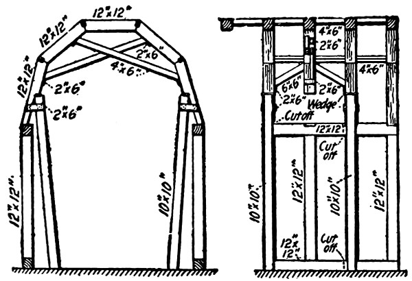
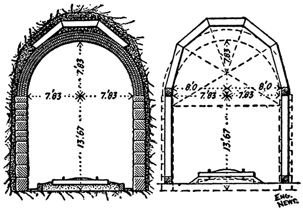
Figs. 159 and 160.—Relining Timber-Lined Tunnel.
The first plan adopted in putting in the masonry was to
remove all the timbering; but owing to the large number of
falls and slides this was abandoned, and the plan followed was to
leave in the three roof segments of the timbering with the overlying
cord-wood packing and débris. In carrying on the work
the first step was to remove the side timbers. This was done
by supporting the roof timbers, as shown in Fig. 159; that is,
the first and fourth arch rib of an 8-ft. section containing four
arch ribs were supported by temporary posts. The intermediate
arch ribs were supported against the downward pressure by
6 × 6 in. timbers, extending from the side ribs near the tops
of the temporary posts to the opposite sides of the intermediate
roof segments, as shown in the longitudinal section, Fig. 160.
To resist the pressure from the sides, 4 × 6 in. braces were
placed across the tunnel from near the center of the intermediate
segments to the upper ends of the hip segments, as shown
in the cross-section, Fig. 159. The hip segments were then
sawed off below the notch, and the side timbering removed and
the masonry built.
The stone was conveyed into the tunnel on flat cars, and laid
by means of small derricks located on the cars. Two derricks[317]
were used, one for each side wall, and the work on both walls
was carried on simultaneously.
The arch was built upon a centering, the ribs of which were
51⁄2 ins. less in diameter than the distance between the side
walls, so as to permit the use of 23⁄4 ins. lagging. Each center
had three ribs, made in 1-in. or 2-in. board segments, 10 ins. thick
and 14 ins. deep. These ribs were mounted on frames, which
followed the opposite walls, and were 4 ft. apart, making the
total length of the center out to out about 9 ft. The frames,
upon which the ribs were supported, are shown in Fig. 161.
As will be seen, they were mounted on dollys to enable the
center to be moved from one section to another. Jacks were
used to raise and lower
the center into its proper
position.
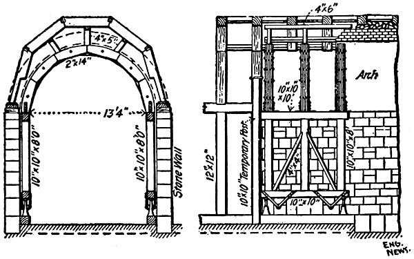
Fig. 161.—Relining Timber-Lined Tunnel,
Great Northern Ry.
The arch was built up
from the springing lines
on both sides at the same
time, four masons being
employed. The rings
were built beginning with
the intrados, which was
brought up, say, a distance
of about 2 ft. from the springing line. Then the back of
the ring was well plastered with from 3⁄8 in. to 1⁄2 in. of mortar,
and the second ring brought up to the same height and
plastered on the back, and so on until the last ring was laid.
After bringing the full width of the arch up some distance,
new laggings were placed on the ribs for an additional height
of 2 ft. and the same process was repeated. All the space
between the extrados of the masonry arch and the old lining
was compactly filled with dry rubble. When high enough
so that the hip segments had a foot or more bearing on the
masonry the segments were securely wedged and blocked up
against the brickwork, and the longitudinal 4 × 6 in. timbers[318]
removed. The remaining space was now clear for completion
of the arch, and both sides were brought up until there was
not sufficient space for four masons to work, when the keying
was completed by two masons beginning at the completed and
working back toward the toothed end. The brickwork was
built from the top of a staging-car.
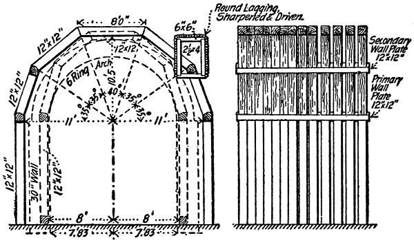
Fig. 162.—Relining Timber-Lined Tunnel,
Great Northern Ry.
In a few instances where slides occurred after the removal
of the slide timbering, the method of re timbering the tunnel
shown in Fig. 162 was adopted. Two side drifts were first
run 21⁄2 ft. wide by 4 ft. high, and the plate timbers placed in
position and blocked. Cross drifts were then run, and the roof
segments placed, and the core down to the level of the bottoms
of the side drifts taken
out. The lower wall
plates were then placed
and the hip segments
inserted. The bench
was then taken down
by degrees, the side
plates being held by
jacks, and the posts
placed one at a time.
As the masonry at the
points where slides occur consists of 30-in. walls and six-ring
arch, the timbering was 22 ft. wide in the clear, with other
dimensions as shown in Fig. 162.
Only a single crew of brick and stone masons was employed.
In order to prepare the sections for these masons it was
necessary to have timber and trimming crews at work throughout
the whole day of 24 hours, so that an engine and two train
crews were in constant attendance. The single mason crews
were able to complete 8 ft. of side wall and arch in 24 hours.
The number of men actually employed at the tunnel was 35.
This included electric-light maintenance, and all other labor
pertaining to the work. The tunnel was lighted by an Edison[319]
dynamo of 20 arc light capacity, one arc light being placed on
each side of the tunnel at all working-places. Each lamp
carried a coil of wire 20 or 30 ft. long to allow it to be shifted
from place to place without delay.
Mullan Tunnel.
—This tunnel is 3,850 ft. long, and crosses
the main range of the Rocky Mountains, about 20 miles
west of Helena, Mont. The tunnel is on a tangent throughout,
and has a grade of 20% falling toward the east. The summit
of the grade, west of the tunnel,
is 5,548 ft. above sea
level, and the mountain above
the line of the tunnel rises
to an elevation of 5,855 ft.
Owing to the treacherous
nature of the material through
which the tunnel passed, it
had been a constant menace
to traffic ever since its construction
in 1883, and numerous
delays to trains had been
caused by the falls of rock
and fires in the timber lining.
For these reasons it was
finally decided to build a permanent
masonry lining, and
work on this was begun in July, 1892.
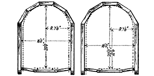
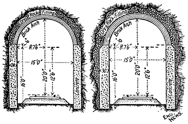
Permanent Work.
Fig. 163.—Relining Timber Lined Tunnel,
Great Northern Ry.
The original timbering consisted of sets spaced 4 ft. apart
c. to c., with 12 × 12 in. posts supporting wall plates, and a
five-segment arch of 12 × 12 in. timbers joined by 11⁄2-in.
dowels. The arch was covered with 4-in. lagging, and the
space between this and the roof was filled with cordwood.
Except where the width had been reduced by timbering placed
inside the original timbering to increase the strength, the clear
width was 16 ft., and the clear height 20 ft. above the top of
the rail. Fig. 163 shows the timbering and also the form[320]
of masonry lining adopted. The side walls are of concrete and
the arch of brick. This new masonry, of course, required the
removal of all the original timbering. The manner of doing
this work is as follows: A 7-ft. section, A B, Fig. 164, was first
prepared by removing one post and supporting the arch by
struts, S S. After clearing away any backing, and excavating for
the foundation of the side wall, two temporary posts, F F, were
set up, and fastened by hook bolts. Fig. 146, L, and a lagging
was built to form a mold for the concrete. Several of these
7-ft. sections were prepared at a time, each two being separated
by a 5-ft. section of timbering.
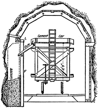
Section, with Concrete Car.
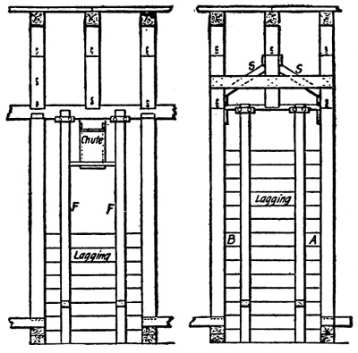
Longitudinal Section.
Fig. 164.—Construction of Centering Mullan Tunnel.
The mortar car was then run along, and enough mortar
(1 cement to 3 sand) was run by the chute into each section
to make an 8-in. layer of concrete. As the car passed along
to each section, broken stone was shoveled into the last preceding
section until all the mortar was taken up. The walls were
thus built up in 8-in. layers, and became hard enough to support
the arches in about 10 to 14 days. The arches were then
allowed to rest on the wall, and the posts of the remaining 5-ft.
sections were removed, and the concrete wall built up in the
same way as before.
[321]
The average progress per working-day was 30 ft. of side
wall, or about 45 cu. yds.; and the average cost, including all
work required in removing the timber work, train service, lights
and tools, engineering and superintendence, and interest on
plant, was $8 per cubic yard.
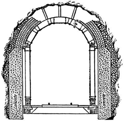
Fig. 165.—Centering Mullan Tunnel.
The centering used for putting in the brick arches is shown
in Fig. 165. From 3 ft. to 9 ft. of arch was put in at a time,
the length depending upon the nature of the ground. To remove
the old timber arch, one of the segments was partly sawed
through; and then a small charge of giant powder was exploded
in it, the resulting débris,
cordwood, rock, etc., being
caught by a platform car extending
underneath. From
this car the débris was removed
to another car, which
conveyed it out of the tunnel.
The center was then placed
and the brickwork begun, the
cement car shown in Fig. 164
being used for mixing the
mortar. The size of the
bricks used was 21⁄2 + 21⁄2 + 9
ins., four rings making a 20-in.
arch and giving 1.62 cu. yds. of masonry in the arch per
lin. ft. of tunnel. The bricks were laid in rowlock bond, two
gangs, of three bricklayers and six helpers each, laying about 12
lin. ft. per day. The brickwork cost about $17 per cu. yd.
The total cost of the new lining averaged about $50 per lin. ft.
Little Tom Tunnel.
—The tunnel has a total length of 1,902
ft., but only 1,410 ft. of it were originally lined with timber.
This old timber lining consists of bents spaced 3 ft. apart, and
located as shown by the dotted lines in the cross-section, Fig.
166. Instead of renewing this timber, it was decided to replace
it with a brick lining. Although the tunnel was constructed[322]
[323]
through rock, this rock is of a seamy character, and in some
portions of the tunnel it disintegrates on exposure to the air.
In removing the timber to make place for the new lining some
of the roof was found close to the lagging, but often also considerable
sections showed breakages in the roof extending to a
height varying from 1 ft. to 12 ft. above the upper side of the
timbering. This dangerous condition of the roof made it necessary
that only a small section of the timber lining should be
removed at one time. It made it necessary, also, that the brick
arch should be built quickly to close this opening, and finally
that all details of centers, etc., should be arranged so as to
furnish ample clearance to trains. The accompanying illustrations
show the solution of the problem which was arrived at.
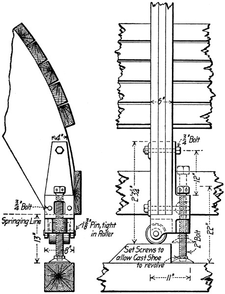
Fig. 167.—Relining Timber-Lined Tunnel, Norfolk and Western Ry.
Referring to the transverse and longitudinal sections shown[324]
by Fig. 166, it will be seen that two side trestles were built to
carry an adjustable centering for the roof arch. Two sections
of these trestles and centerings were used alternately, one being
carried ahead and set up to remove the timbering while the
masons were at work on the other. The manner of setting up
and adjusting the trestles and centerings is shown by Fig. 166
and also by Fig. 167, which is an enlarged detail drawing of
the set screw and rollers for the centering ribs. The following
is the bill of material required for one set of trestles and one
center:
| Trestles: |
| Caps and sills |
8 |
pieces |
8 × 8 |
ins. |
× 20 |
ft. |
| Posts |
18 |
„ |
8 × 8 |
„ |
× 11 |
„ |
| Braces |
16 |
„ |
6 × 4 |
„ |
× 7 |
„ |
| Centerings: |
| Ribs |
27 |
„ |
2 × 18 |
„ |
× 7 |
„ |
| Bracing |
12 |
„ |
2 × 8 |
„ |
× 7 |
„ |
| Support to crown lagging |
2 |
„ |
6 × 6 |
„ |
× 10 |
„ |
| Crown lagging |
20 |
„ |
3 × 6 |
„ |
× 2 |
„ |
| Side lagging |
30 |
„ |
3 × 6 |
„ |
× 10 |
„ |
| Side strips |
2 |
„ |
2 × 12 |
„ |
× 9 |
„ |
| Blocking for rollers |
1 |
„ |
5 × 8 |
„ |
× 12 |
„ |
| 6 screw and roller castings complete with bolts and lever; 114 bolts
3⁄4-ins. in diameter; 71⁄2 U. H. hexagonal nut and 2 cast washers each. |
With this arrangement the progress made per day varied
from 2 lin. ft. to 3 lin. ft. of lining complete. By work complete
is meant the entire lining, including stone packing between
the brickwork and the rock. On Feb. 23, 1900, 363 ft. of lining
had been completed, at a cost of $33.50 per lin. ft. This
cost includes the cost of removing the old timber, the loose rock
above it, and all other work whatsoever.
[325]
CHAPTER XXIV.
THE VENTILATION AND LIGHTING OF TUNNELS
DURING CONSTRUCTION.
VENTILATION.
In long tunnels, especially when excavated in hard rock,
proper ventilation is of great importance, because the air cannot
be easily renewed, and the amount of oxygen consumed by
miners horses and lamps during construction is very large.
The gases produced by blasting also tend to fill the head of excavation
with foul air. Pure atmospheric air contains about
21% of oxygen and only 0.04% of carbonic acid; when the
latter gas reaches 0.1% the fact is indicated by the bad odor;
at 0.3% the air is considered foul, and when it reaches 0.5% it
is dangerous. It is generally admitted that the standard of
purity of the air is when it contains 0.08% of carbonic acid.
A large quantity of carbonic acid in the air is easily detected
by observing the lamps, which then give out a dim red light
and smoke perceptibly; the workmen also suffer from headache
and pains in the eyes, and breathe with difficulty. Naturally,
miners cannot easily work in foul air and, therefore, make very
slow progress. It is, therefore, to the interest of the engineer to
afford good ventilation, not only because of his duty to care for
the safety and health of his men, but also for reasons of economy,
so that the men may work with the greatest possible ease,
thus assuring the rapid progress of the work.
It would be impossible to change completely the atmosphere
inside a tunnel, as the gases developed from blasting will penetrate
into all the cavities and gather there, but the fresh air[326]
carried inside by ventilation has a very small percentage of carbonic
acid, mixes with that which contains a greater quantity,
and dilutes it until the air reaches the standard of purity. We
have not here considered the gases developed from the decomposition
of carboniferous and sulphuric rocks, which may be
met with in some tunnels, and which render ventilation still
more necessary. Tunnels may be ventilated either by natural
or artificial means.
Natural Ventilation.
—It is well known that if two rooms of
different temperatures are put in communication with each
other, e.g., by opening a door, a draft from the colder room will
enter the other from the bottom, and a similar draft at the top,
but with a contrary direction, will carry the hot air into the
colder room, thus producing perfect ventilation, until the two
rooms have the same temperature. Now, during the construction
of tunnels the temperature inside may be considered as
constant, or independent of the outside atmospheric variations;
hence during summer and winter, there will always be a draft
affording ventilation, owing to the difference of temperature inside
and outside the tunnel. In winter time the cold air outside
will enter at the bottom of the entrances and headings, or
along the sides of the shafts, and the hot air will pass out near
the top of the headings or entrances or the center of the shafts;
in summer the air currents will take the contrary direction.
Natural ventilation in tunnels is improved when the excavation
of the heading reaches a shaft, because the interior air
can then communicate with the exterior at two points, at different
levels. In such cases a force equal to the difference in
weight between a column of air in the shaft and a similar one
of different density at the entrance of the tunnel, will act upon
the mass of air in the tunnel and keep it in movement, thus
producing ventilation. Consequently, during winter, when the
outside air has greater weight than that inside, the air will
come in by the headings and go out by the shaft, and in the
summer it will enter at the shaft and pass out at the entrance.[327]
Sometimes to afford better ventilation shafts 8 or 12 in. in diameter
are sunk exclusively for the purpose of changing the
air. When the inside temperature is equal to that outside,
as often happens during the spring and autumn, there are no
drafts, and consequently the air in the excavation is not renewed
and becomes foul; then fires are lighted under the
shaft and a draft is artificially produced. The hot air going
out through the shaft, as through a chimney, allows the fresh
air to come in as in ordinary ventilation.
When the head of the excavation is very far from the entrances,
or when the mountain is too high to allow excavation
by shafts, it is quite impossible to secure good natural ventilation,
especially during the spring and autumn months, and the
engineer has to resort to some artificial means by which to
supply fresh air to the workmen.
Artificial Ventilation.
—Artificial ventilation in tunnels may
be obtained in two different ways, known as the vacuum and
plenum methods. Their characteristic difference consists in
this, that in the vacuum method the air is drawn from the inside
and the vacuum thus produced causes the fresh air from
the outside to rush in, while the plenum method consists in
forcing in the fresh air which dilutes the carbonic air produced
inside the tunnel by workingmen and explosives. In the vacuum
method the pressure of the atmosphere inside the tunnel is
always less than the pressure outside, while in the plenum
method the pressure within is always greater than that outside.
Ventilation is the result of this difference of pressure, as the
tendency of the air toward equilibrium produces continuous
drafts. Both these methods have their advantages and disadvantages;
but in the presence of hard rock, when explosives are
continually required, the vacuum method is considered the best,
because the gases attracted to the exhaust pipes are expelled
without passing through the whole length of the tunnel, thus
avoiding the trouble that a draft of foul air will give to the
workmen who are within the tunnel. In both these methods it[328]
is necessary to separate the fresh air from the foul one; and this
is done by means of pipes which will exhaust and expel the
foul air in the vacuum method, or force to the front a current
of fresh air when the plenum method is used. Artificial ventilation
may also be obtained by compressed air which is set free
after it has driven the machines, especially in tunnels excavated
through rock, when rock drilling machines moved by compressed
air are employed.
Vacuum Method Contrivances.
—The most common of the vacuum
appliances consists in the simple arrangement of a pipe
leading from the head of the tunnel out through the fire of a
furnace. The air in the pipe is rarefied by the heat of the furnace
and then set free from the other end of the pipe, thus
creating a partial vacuum in the pipe, into which the foul air of
the head rushes, the fresh air from the entrance taking its place,
and thus ventilating the tunnel. A similar arrangement may
be used with shafts, and the foul air may be driven out by a
furnace which is placed either at the top or bottom of the shaft.
Such furnaces act the same as those commonly used for heating
purposes in the houses, with this difference, that, instead of fresh
air being forced in, foul air is expelled. Another simple
arrangement for producing a vacuum is by means of a steam
jet which is thrown into the pipe, and which helps the expulsion
of the air by heating it, thus producing a different density
which originates a draft besides that mechanically originated by
the force of the steam jet, which tends to carry out the foul air
of the pipes.
Foul air may also be expelled by means of exhaust fans
which are connected with pipes near the entrance of the tunnel.
The fan consists of a box containing a kind of a paddle wheel
turned by steam or water power and arranged so as to revolve
at a high speed. The air inside the pipe is forced out by
blades attached to the wheel, and thus the foul air of the front
is driven away and fresh air from the entrance rushes in to take
its place, and perfect ventilation is obtained.
[329]
The best manner of expelling foul air from tunnels, according
to the vacuum method, is by means of bell exhausters.
This consists of two sets of bells connected by an oscillating
beam and balancing each other. Each set consists of a movable
bell, which covers and surrounds a fixed bell with a water joint.
In the central part of the fixed bell there are valves which open
upwards, and on the bottom of each movable bell there are
valves which open from the outside. When one bell ascends,
the valves at the bottom are closed, the air beneath is then
rarefied, and a vacuum is produced; the valves in the central
part of the fixed bell filled with water are opened, and there is
an aspiratory action from the pipe leading to the headings, and
the foul air is thus carried away. The apparatus makes about
ten oscillations per minute, and the dimensions of the bells
depend upon the quantity of air to be exhausted in a minute.
In the St. Gothard tunnel, where these bell exhausters were
used, they exhausted 16,500 cu. ft. of air per minute.
Plenum Method Contrivances.
—Fresh air may be driven into
tunnels to dilute the carbonic acid by two different ways, viz.,
by water blast and by fans. Water when running at a great
velocity produces a movement in the air which may be sometimes
usefully and economically employed for ventilating
tunnels. Water falling vertically is let run into a large
horizontal zinc pipe having a funnel at the outer end; into this
the air attracted by the velocity of the water is forced. By an
opening at the bottom the water is afterward withdrawn from
the pipe, and there remains only the air which is pushed forward
by the air which is being continually sucked in by the
velocity of the water.
The best and most common means of ventilation by the
plenum method is by fans. There are numerous varieties of
these fans in the market, but they all consist of a kind of fan
wheel which by rapid revolution forces the fresh air into the
pipe leading to the headings of the tunnel or to the working
places. Instead of a large single fan, such as is used for mining[330]
purposes, it is better to have a number of small fans acting
independently of each other, conveying the fresh air where it is
needed through independent pipes.
Saccardo’s System.
—A new method of ventilating tunnels
was devised by Mr. Saccardo for the ventilation of the Pracchia
tunnel along the Bologna and Lucca Railway in Italy. At the
highest end of the tunnel the mouth was contracted inward in a
funnel shaped form so as to just admit a train. Immediately
at this contraction, a lateral tunnel, 50 feet long, branched off
from one side of the main tunnel. At the mouth of this lateral
tunnel was installed a fan which forced air into the tunnel and
with 70 revolutions per minute delivered 3.532 cu. ft. of air per
second at a water pressure of 1 in. This air current was directed
inward through a second contraction or funnel, parallel to the
one at the entrance and 23 ft. beyond it. In operation the
action of the artificial air current was to suck in a considerable
volume of outside air, while the air pressure was sufficient to
counterbalance the movement of air produced by a train moving
at a velocity of 16.1 ft. per second. Mr. Saccardo’s method
was employed in ventilating a tunnel on the Norfolk and Western
Railway with satisfactory results.
Compressed Air.
—In the excavation of tunnels in hard rock
a number of rock drilling machines are employed which are
moved by compressed air at a pressure of not less than five
atmospheres. At each stroke about 100 cu. ins. of compressed
air are set free, and at an average of 10 strokes per minute there
would be 5000 cu. ins. of air at five atmospheres or 25,000
cu. ins., or a little more than 175 cu. ft. of fresh air at normal
pressure set free every minute by each of the machines employed.
But the air exhausted from the drilling machine is foul.
Regarding ventilation by compressed air, Mr. Adolph Sutro,
in a lecture delivered to the mining students of the University
of California, said:
“I will note a curious fact which I have never seen explained, and which is
worthy of close investigation by means of experiments. In the Sutro tunnel[331]
we found that the compressed air used for driving the machine drills, after
having been compressed and expanded and discharged from the drills, was not
wholesome to breathe, and the men and mules would all crowd around the end
of the blower pipe to get fresh air. Whether the air in being compressed has
parted with some of its oxygen or because vitiated from some other cause, I do
not know, and I hope that this subject will at some future day be carefully
examined into.”
In the December, 1901, number of “Compressed Air,” a
magazine especially devoted to the useful application of compressed
air, is read:
Compressed air wasted from power drills is so contaminated with oil from
the cylinders that it cannot be taken into consideration as ventilation. It is as
important to displace it with pure air as it is to drive out or draw off other vitiated
air. The ventilation should be an independent supply provided by fan
or blower, delivering by pipe at the point where miners are working.
Quantity of Air.
—The quantity of air to be introduced into
tunnels must be in proportion to the oxygen consumed by the
men, the animals, and the explosions. It is allowed that the
quantity of air required for breathing purpose and explosions is
as follows:
| 1 |
workman with lamp |
needs |
240 |
cu. yds. |
of fresh |
air |
in 24 hours. |
| 1 |
horse |
„ |
850 |
„ |
„ |
„ |
„ |
| 1 |
lb. gunpowder |
|
100 |
„ |
„ |
„ |
|
| 1 |
lb. dynamite |
|
150 |
„ |
„ |
„ |
|
In a long tunnel excavated through hard rock the number
of workmen all together may be assumed at 400 at each end,
and each workman is supposed to be furnished with a lamp.
No less than ten horses are employed, and the average quantity
of dynamite consumed is 600 lbs. per day. From the data given
the consumption of air by workmen and lamps would be:
240 × 400 = 96,000 cu. yds.; the consumption of air by horses
would be 850 × 10 = 8500 cu. yds.; the consumption of air by
dynamite would be 150 × 600 = 90,000 cu. yds.; making a
total consumption of air per day of 194,500 cu. yds., or about
8000 cu. yds. per hour.
To obtain good ventilation, then, it will be necessary to
furnish every hour a quantity of fresh air amounting to not less[332]
than 8000 cu. yds. Since, however, a large quantity of pure
air is expelled with the foul air, it is necessary greatly to increase
this quantity.
It may be observed, in closing, that the water having its
particles divided, as in a fog or mist, rapidly precipitates the
gases produced by explosions. Now, when hydraulic machines
are used, there is a hollow ball pierced by holes that are almost
imperceptible, from which the compressed water spreads in very
subtile particles, and this causes the fall of the gases from
explosions. Such a method of precipitating gases is very good,
but does not have the advantage of supplying new oxygen to
replace that consumed by the men, animals, lamps, and explosions;
besides, it has the defect of increasing the quantity of
water to be removed. In tunnels the pipes used either for conveying
the fresh air or for carrying away the foul air, are of
iron, having a diameter of about 8 in.; they are fixed along the
side walls about 3 ft. above the inverted arch.
LIGHTING.
The object and necessity of a perfect lighting of the tunnel-workings
during construction are so obvious that they need not
be enlarged upon. Comparatively few tunnels require lighting
after completion; and these are generally tunnels for passenger
traffic under city streets, of which the Boston Subway is a representative
American example. Considering the methods of
lighting tunnels during construction, we may, for sake of convenience,
chiefly, divide the means of supplying light into (1)
lamps and lanterns usually burning oil; (2) coal-gas lighting;
(3) acetylene gas lighting; and (4) electric lighting.
Lamps and Lanterns.
—Lamps and lanterns are commonly
employed by engineers for making surveys inside the tunnel, and
to light the instrument. For ranging in the center line, a convenient
form of lamp consists of an oil light inclosed in glass
chimney covered with sheet metal, except for a slit at the front
and back through which the light shines, and on which the[333]
observer sights his instrument. To direct the operations of his
rodmen the engineer usually employs a lantern, either with
white or colored glass, much like the ordinary railway trainman’s
lantern, which he swings according to some prearranged
code of signals.
Lamps and lanterns are used by the workmen both for signaling
and for lighting the workings. For signaling purposes
red lanterns are usually placed to denote the presence of unexploded
blasts or other points of possible danger; and colored or
white lights are usually placed on the front and rear of spoil
and material trains. For lighting purposes, two forms of lamps
are employed, which may be somewhat crudely designated as
lamps for individual use and lamps for general lighting. Individual
lamps are usually of small size, and burn oil; they may
be carried in front of the miner’s helmet, or be fixed to standards,
which can be set up close to the work being done by each
man. Miners’ safety lamps should be employed where there is
danger from gas. A great variety of lamps for mining and
tunneling purposes are on the market, for descriptions of
which the reader is referred to the catalogues of their manufacturers.
Lamps for general lighting are always of larger size than
lamps for individual use. A common form consists of a cylinder
ten or twelve inches in diameter, provided with a hook or
bail for suspension, and filled with benzine, gasolene, or other
similar oil. Connected with this cylinder is a pipe of considerable
length and small diameter through which the benzine
or gasolene vapor runs, and burns when lighted with a brilliant
flame. Lamps of this type burning gasolene were extensively
employed in building the Croton Aqueduct tunnel. Various
patented forms of lamps for burning coal-oil products are on
the market, for descriptions of which the manufacturers’ catalogues
may be consulted.
Coal-gas Lighting.
—A common method of lighting tunnel
workings is by piping coal-gas into the headings and drifts from[334]
some nearby permanent gas plant, or from a special gas works
constructed especially for the work. Gas lighting has the great
advantage over lamps and lanterns of giving a light which is
more brilliant and steady. Its great objection is the danger of
explosion caused by leaks in the pipes, by breaks caused by
flying fragments of rock, and by the carelessness of workmen
who neglect to turn off completely the burners when they extinguish
the lights. In nearly every tunnel where gas has been
used for lighting, the records of the work show the occurrence
of accidents which have sometimes been very serious, particularly
when fire has been communicated to the tunnel timbering.
Acetylene Gas Lighting.
—The comparatively recent development
of acetylene gas manufactured from carbide of calcium
has given little opportunity for its use in tunnel lighting, and
the only instance of its use in the United States, so far as the
author knows, is the water-works tunnel conduit for the city of
Washington, D. C. Col. A. M. Miller, U. S. Engineer Corps,
who is in charge of this work, describes the method adopted in
his annual report for 1899 as follows:—
“It had been the practice to do all work underground by the light of
miners’ lamps and torches. This means of illumination is very poor for mechanical
work. The fumes and smoke from blasting, added to the smoke
from torches and lamps, render the atmosphere underground, especially when
the barometer conditions were unfavorable to ventilation, very offensive and
discomforting to the workmen. An investigation of the subject of lighting
the tunnel by other means, more especially at the locality where the mechanics
were at work,—brick and stone masons, and the workmen on the iron lining,—resulted
in the selection of acetylene gas as the most available and economical
in this special emergency. Accordingly, an acetylene gas plant for
300 burners was erected at Champlain-Avenue shaft, and one for 60 lights at
Foundry Branch. The engine-houses at the shafts, the head-houses, and localities
in the tunnel, when required, are lighted by these plants.
“Gas pipes were carried down the Champlain-Avenue shaft and along the
tunnel both in an easterly and westerly direction, with cocks for burners at
proper intervals every 30 feet; and this system sufficed for illumination from
Hock Creek to Harvard University, a distance of over two miles. The plant
erected at Foundry Branch was in like manner utilized for the illumination
from that point in both directions.
“By connecting with the stopcocks by means of a rubber hose, a movable[335]
light, chandelier, or ‘Christmas-tree’ of any required number of burners is
used, thus concentrating the light in the immediate vicinity of the work, and
also enabling the illumination to be carried into the cavities or ‘crow-nests,’ so
called, behind the defective old lining.
“This method of illuminating has proved very satisfactory and quite economical.
It is especially valuable as enabling good work to be done, and
facilitating a thorough inspection of the same.”
Electric Lighting.
—By far the most perfect, and at present
the most commonly employed means for lighting tunnel workings,
is electricity. The light furnished by electric lamps is
steady and brilliant, and does not consume oxygen or give off
offensive gases. The wires are easily removed and extended,
and the lamps are easily put in place and removed. About the
only objection to the method is the fragility of the lamps, which
are easily broken by the flying stones and the concussion produced
by blasting.
[336]
CHAPTER XXV.
THE COST OF TUNNEL EXCAVATION AND
THE TIME REQUIRED FOR THE WORK.
Cost.
—The cost of a tunnel will depend upon the cost of
the two principal operations required in its construction, viz.,
the excavation of the cross section and the lining of the excavation
with masonry, metal, or timber. These two operations
may in turn be subdivided, in respect to expense, into cost of
labor and cost of materials. It is a comparatively simple matter
to calculate the cost of the building materials required to
construct a tunnel; but it is very difficult to estimate with
accuracy what the cost of labor will be. The reason for this is
that it is impossible to foresee exactly what the conditions will
be; the character of the material may change greatly as the
work proceeds, increasing or decreasing the cost of excavation;
water may be encountered in quantities which will materially
increase the difficulties of the work, etc. Nevertheless, while
accurate preliminary estimates of cost are not practicable, it is
always desirable to attempt to obtain some idea of the probable
expense of the work before beginning it, and the more usual
means of getting at this point will be discussed here.
Two methods of estimating the cost of tunnel work are employed.
The first is to calculate the probable expense of the
various items of work, based upon the available data, per unit
of length, and then add to this a margin of at least 10% to allow
for contingencies; the second is to apply to the new work the
unit cost of some previous tunnel built under substantially the
same conditions. In the first method it is usual to consider
the strutting and hauling as constituting a part of the work of[337]
excavation. To estimate the cost of excavation involves the
consideration of three general items, viz., the excavation proper,
the strutting of the walls of the excavation, and the hauling of
the excavated materials and the materials of construction.
The cost of excavating the preliminary headings or drifts is
greater per unit of material removed than that of excavating
the enlargement of the section. The cost of bottom drifts is
also always greater than that of top headings, the material penetrated
remaining the same. Mr. Rziha gives the comparative
unit costs of excavating drifts, headings, and enlargement of
the profile as follows:—
| Bottom drifts |
$9.20 |
per |
cu. |
yd. |
| Top headings |
4.80 |
„ |
„ |
„ |
| Enlargement of profile |
2.84 |
„ |
„ |
„ |
The cost of hauling increases with the length of the tunnel.
This fact and amount of this increase are indicated by the
following actual prices for the Arlberg tunnel:—
| Top heading |
$6.76 |
per |
cu. |
yd., |
increasing |
37 |
cts. |
per |
mile |
| Bottom drift |
7.40 |
„ |
„ |
„ |
„ |
26 |
„ |
„ |
„ |
| Enlargement of profile |
2.70 |
„ |
„ |
„ |
„ |
10 |
„ |
„ |
„ |
In all the prices given above, the cost of strutting and hauling
is included in the cost of excavation.
The cost of excavation is not always the same for the same
character of materials in different tunnels. The following
figures show the prices paid for the excavation of calcareous
rock in four different German tunnels:—
| Berliner Nordhausen Wetzler R.R. |
$1.24 |
per |
cu. |
yd. |
| Ofen |
1.30 |
„ |
„ |
„ |
| Stafflach |
2.76 |
„ |
„ |
„ |
| Gries |
1.92 |
„ |
„ |
„ |
The method of tunneling has little influence upon the cost
of the work, as shown by the following figures from tunnels
excavated through calcareous rock by different methods:—
[338]
| Ofen tunnel |
Austrian method |
$93.19 |
per |
lin. |
ft. |
| Dorremberg tunnel |
Belgian method |
86.08 |
„ |
„ |
„ |
| Stafflach tunnel |
English method |
91.69 |
„ |
„ |
„ |
The Martha and Merten tunnels, excavated through soft
ground by the Austrian and German methods respectively,
cost $87.95 and $87.55 per lin. ft. respectively. In the excavation
of the various sections of the tunnel for the new Croton
Aqueduct in America, the following prices were paid:—
| Excavation of heading |
$8 |
to |
$10.00 |
per |
cu. |
yd. |
| Tunnel in soft ground |
8 |
to |
9.00 |
„ |
„ |
„ |
| Tunnel in rock |
7 |
to |
8.50 |
„ |
„ |
„ |
| Brick masonry |
10.00 |
„ |
„ |
„ |
| Timber in place |
$40 per M. ft. B. M. |
It is the practice in America to include the work of hauling
under excavation, but not to include the strutting, which is
paid for separately. In some cases only the market price of
the timber is paid for separately, the cost of setting up being
included in the price of excavation. The writer prefers the
European practice of including the total cost of timbering
under excavation, since the two operations are so closely connected,
and since the contractor employs the same timber over
and over again. Knowing the dimensions of the several members
of the strutting, it is a simple, although somewhat tedious,
process to calculate the total quantity required. An idea of
the quantity of timber required for strutting in soft ground
may be had from the data given on page 55. The quantity
will decrease as the cohesion of the material penetrated increases,
until it becomes so small in hard rock-tunnels as to cut
very little figure in the total cost.
The cost of hoisting excavated materials through shafts
depends upon the depth from which it is hoisted, and upon the
character of hoisting apparatus employed. The following table,
showing the cost of hoisting for different lifts and by different
methods, is given by Rziha, the cost being in francs per cubic
meter:—
[339]
Height
in Metres. |
Windlass. |
Horse Gins. |
Steam
Hoists. |
Francs
per Cu. M. |
One
Horse.
Francs
per Cu. M. |
Two
Horses.
Francs
per Cu. M. |
Francs
per Cu. M. |
| 15 |
0.172 |
0.077 |
0.062 |
0.035 |
| 30 |
0.212 |
0.087 |
0.070 |
0.045 |
| 45 |
0.257 |
0.100 |
0.080 |
0.050 |
| 60 |
0.305 |
0.112 |
0.092 |
0.082 |
| 90 |
0.410 |
0.152 |
0.110 |
0.087 |
| 120 |
0.535 |
0.195 |
0.135 |
0.092 |
| 150 |
0.722 |
0.240 |
0.157 |
0.112 |
Mr. Séjourné, a French engineer, who has been connected
with the construction of numerous tunnels by the Belgian
method where he was in position to secure comparative figures,
has given the following rules for calculating the cost of
tunnels. Assuming A to represent the cost of excavating a
cu. yd. in the open air, the cost of excavating the same
quantity underground in driving headings will be from 9 A to
11 A, and in enlarging the profile it will be about 5 A. The
cost of constructing single-track tunnels varies with the thickness
of the lining, and may be calculated by the following
formulas:
| Without lining, |
C = 5.5 A. |
| With roof arch only, |
C = 6.4 + 6.4 A. |
| With lining 18 in. thick, |
C = 9.4 + 7 A. |
| With lining 2 ft. thick, |
C = 11 + 8 A. |
In these formulas C is the cost per cu. yd. of excavation,
including the masonry. For double-track tunnels the amounts
given by the above formulas may be used by reducing them
about 71⁄2% or 8%.
The second method of estimating the cost of tunnel work
consists in assuming as a unit the unit cost of tunnels previously
excavated under similar conditions. Mr. La Dame
gives the following unit prices for a number of tunnels driven
through different materials:
[340]
| Nature of Soil. |
Tunnels,
No. of |
Excav.
per Cu. Yd. |
Cost per
Lin. Ft. |
Max. and Min.
per Lin. Ft. |
| Granite-gneiss |
56 |
$3.07 |
@ |
$3.85 |
$100. |
$61.46 |
@ |
$190.40 |
| Schist |
39 |
1.38 |
@ |
1.53 |
75.42 |
43.11 |
@ |
70.68 |
| Triassic |
3 |
... |
90.85 |
84.75 |
@ |
93.33 |
| Jurassic |
69 |
1.23 |
@ |
1.38 |
77.86 |
35.24 |
@ |
157.2 |
| Cretaceous |
34 |
0.61 |
@ |
0.77 |
59.60 |
27.37 |
@ |
92.25 |
| Tertiary and modern |
39 |
0.33 |
@ |
0.61 |
105.80 |
51.52 |
@ |
188.36 |
In the following table is given a list of tunnels excavated
through different soils, from the most compact to very loose
materials, and driven according to the various methods which
have been illustrated.
DOUBLE-TRACK TUNNELS.
| Name of Tunnels. |
Quality of Soil. |
Cost per
Lin. Ft. |
Method of
Tunneling. |
| Mt. Cenis |
Granitic, |
$273.73 |
|
Drift. |
| St. Gothard |
... |
193.63 |
|
Heading. |
| Stammerich |
Granitic, |
157.90 |
|
English. |
| Stalle |
Broken schist, |
290.58 |
|
Austrian. |
| Bothenfels |
Dolomite, |
115.64 |
|
English. |
| Dorremberg |
Calcareous, |
86.08 |
|
Belgian. |
| Stafflach |
Calcareous, |
91.69 |
|
English. |
| Ofen |
Calcareous, |
93.19 |
|
Austrian. |
| Wartha |
Grewack, |
87.95 |
|
Austrian. |
| Mertin |
Grewack, |
87.55 |
|
German. |
| Schloss Matrei |
Clay schist, |
94.25 |
|
English. |
| Trietbitte |
Clay and sand, |
229.0 |
|
German. |
| Canaan |
Clay-slate, |
69.50 |
|
Wide heading. |
| Church-Hill |
Clay with shells, |
178.0 |
|
... |
| Bergen No. 1 |
Trap rock, |
182.31 |
|
... |
SINGLE-TRACK TUNNELS.
| Name of Tunnels. |
Quality of Soil. |
Cost per
Lin. Ft. |
Method of
Tunneling. |
| Mt. Cenis |
Gneiss, |
$82.27 |
|
Heading. |
| Stalletti |
Granite and quartz, |
62.75 |
|
Austrian. |
| Marein |
Clay schist, |
64.36 |
|
English. |
| Welsberg |
Gravel, |
165.07 |
|
Austrian. |
| Sancina |
Clay of 1st variety, |
129.40 |
|
Belgian. |
| Starre |
Clay of 2d variety, |
191.61 |
|
Belgian. |
| Cristina |
Clay of 3d variety, |
307.42 |
|
Italian. |
| Burk |
... |
83.90 |
|
Wide heading. |
| Brafford Ridge |
... |
85.33 |
|
Wide heading. |
| Dunbeithe |
Limestone, |
70.47 |
|
Wide heading. |
| Fergusson |
Sandstone, |
37.46 |
[16] |
Wide heading. |
| Port Henry |
Limestone, |
80.00 |
[17] |
Wide heading. |
| Points |
Granite, |
72.00 |
[16] |
Wide heading. |
[341]
The Habas tunnel through quicksand, between Dax and
Ramoux, France, cost $118.50 per lin. ft. The cost of
the Boston subway was $342.40 per lin. ft. The Severn
and Mersey tunnels, constructed through rock under water,
cost respectively $208.38 and $263 per lin. ft. The First
Thames Tunnel, driven by Brunel’s shield, cost $1661.66 per
lin. ft. The Hudson River and St. Clair River tunnels, excavated
through soft ground by means of shields and compressed
air, cost respectively $305 and $315 per lin. ft. The Blackwall
double-track tunnel under the River Thames, which is
the largest tunnel ever built by the shield system, cost $600
per lin. ft.
In making estimates of the cost of projected tunnel work
based on the cost of tunnels previously constructed through
similar materials, it is important to keep in mind the date and
location of the work used as the basis for calculations. For
example, a tunnel excavated in Italy, where labor is very cheap,
will cost less than one excavated in America, where labor is
dear, all other conditions being the same. Other reasons for
variation in cost due to difference of date and location of construction
will suggest themselves, and should be taken into full
consideration in estimating the cost of the new work.
Time.
—The time required to excavate a tunnel depends
upon the character of the material penetrated and upon the
method of work adopted. Tunnels driven through soft ground
by hand require about the same time to construct as tunnels
driven through hard rock by the aid of machinery. Tunnels
can be driven through hard rock at about as great a speed as
through soft or fissured rock, chiefly because the work of
blasting is more efficient in hard rock, and because no time
is required in timbering. The following table shows the
average rate of progress in different parts of the tunnel excavation
through both hard and soft materials in feet per month:—
[342]
Quality
of Soil. |
Heading. |
Excavation
of Shafts. |
Enlargement
of Profile. |
By
hand. |
By
machine. |
By
hand. |
By
machine. |
By
hand. |
| Very loose soil |
16.7 |
- |
26.8 |
... |
6.6 |
- |
16.7 |
... |
6.6 |
- |
16.7 |
| Loose soil |
33.4 |
- |
100 |
... |
16.7 |
- |
33.4 |
... |
16.7 |
- |
33.4 |
| Soft rock |
66.8 |
|
233.8 |
- |
334 |
33.4 |
- |
66.8 |
66.8 |
- |
132.6 |
33.4 |
- |
50 |
| Hard rock |
50 |
- |
66.8 |
233.8 |
- |
334 |
33.4 |
- |
50 |
66.8 |
- |
132.6 |
66.8 |
- |
100 |
| Very hard rock |
33.4 |
|
233.8 |
- |
334 |
16.7 |
- |
33.4 |
66.8 |
- |
132.6 |
66.8 |
- |
100 |
The following tables showing the average rate of progress
have been compiled from the actual records made in the
tunnels named:
Name of
Tunnel. |
Dimensions
in Feet. |
Monthly
Progress
in Feet. |
Character
of Material. |
Observations. |
| Excavation of headings by hand: |
|
|
|
|
| Mount Cenis |
10 × 10 |
65.8 |
Schist, |
Bottom drift. |
| Sutro |
6.7 × 5.7 |
70.14 |
Quartzose, |
... |
| St. Gothard |
8.4 × 8.7 |
70.14 |
Granite, |
Top heading. |
| Excavation of headings by machine: |
|
|
|
|
| Mount Cenis |
10 × 10 |
188.7 |
Calcareous schist, |
Bottom drift. |
| Sutro |
8.15 × 10 |
227.45 |
Quartzose, |
... |
| St. Gothard |
8.4 × 8.7 |
339.45 |
Granite, |
Top heading. |
| Trari |
8 × 9.35 |
167 |
Gneiss, |
Top heading. |
| Arlberg |
8.35 × 9.35 |
474.2 |
Mica schist, |
Bottom drift. |
| Palisades |
16 × 7 |
160 |
Trap rock, |
Top heading. |
| Busk |
15 × 7 |
126 |
Granite, |
Top heading. |
| Cascade |
16 × 8 |
180 |
Basaltic rock, |
Top heading. |
| Franklin |
15 × 7 |
240 |
... |
Top heading. |
The following table shows the monthly progress of completed
tunnel in feet excavated through rock:
Name of
Tunnel. |
Progress
in Feet. |
Material. |
Method. |
| Cascade |
207 |
Basalt, |
Top heading. |
| Palisades |
186 |
Trap rock, |
Top heading. |
| Busk |
190 |
Granite, |
Top heading. |
| Tennessee Pass |
169.5 |
Granite, |
Top heading. |
[343]
The average monthly progress in feet of excavating tunnels
through treacherous ground may be quite generally assumed
to be for: (1) clay of the first variety from 43.4 ft. to 60 ft.;
for clay of the second variety from 33.4 ft. to 43.4 ft.; for clay
of the third variety from 23.3 ft. to 33.4 ft., and for quicksand
from 30 ft. to 50 ft. The monthly progress in feet made in
sinking the shafts of the Hoosac and Musconetcong tunnels in
America was as follows:—
Name of
Tunnel. |
Dimensions
in Feet. |
Depth
in Feet. |
Progress
in Feet. |
Character
of Material. |
| Hoosac: |
|
|
|
|
| East shaft |
15.4 × 27.7 |
1035 |
21.7 |
Mica schist. |
| West shaft |
8 × 16 |
267 |
16.7 |
Gneiss. |
| Musconetcong: |
|
|
|
|
| Vertical shaft |
8.35 × 16.7 |
113.5 |
100 |
Loose rock. |
| Inclined shaft |
8.35 × 26 |
304. |
32 |
Loose rock. |
The average monthly progress of sinking shafts in treacherous
soils may be assumed to be as follows: clay of first
variety, 50 ft. to 75 ft; clay of second variety, 36.75 to 50 ft;
clay of third variety, 23.4 ft. to 36.75 ft; quicksand, 16.7 ft.
to 33.4 ft.
For the reason that the details change with the various
conditions encountered in every work, all the tunnel operations
have been treated in a general way, purposely avoiding to give
any detail. Also the rate of progress and items of cost of tunnels
have been given in a broad manner because they greatly
vary in the different works. This information, however, can
be easily obtained by consulting the Engineering Magazines,
where are reported all the tunnel works of America and Europe,
and where are given so many details which are very valuable
to expert engineers in charge of similar works, but not to students
and people who are looking only for general knowledge.
[344]
[345]
INDEX
- Accidents and Repairs in the Belgian Method, 152
- Accidents in Tunnels:
- After Construction, 308
- Baltimore Belt Line, 165
- Chattanooga Tunnel, 311
- During Construction, 301
- General Discussion, 301
- Giovi Tunnel, 309
- Repairing of, 304
- Acetylene Gas Lighting, 334
- Air Compressors, Description of, 87
- Air Locks, 264-272
- Air Pressure, 268
- American Method:
- General Description, 172
- Excavation, 172
- Strutting, 174
- Hauling, 175
- Arrangement of Drill Holes, 90
- Artificial Ventilation, 327
- Austrian Method of Tunneling:
- Advantages and Disadvantages, 180
- Excavation, 176
- General Description, 176
- Lining, 180
- Strutting, 177
- Average Progress in Tunnels, 342
- Baltimore Belt Line Tunnel, General Description, 160
- Barlow’s Shield, 242
- Beach’s Shield, 246
- Belgian Method:
- Accidents and Repairs, 152
- Advantages and Disadvantages, 152
- Excavation, 145
- General Description, 144
- Lining, 148
- Hauling, 150
- Strutting, 146
- Bench, 131
- Bends, 268
- Blackwall’s Tunnel Shield, 248
- Blasting-cone, 33
- Blickford Match, 31
- Boston Subway:
- General Descriptions, 203
- Roof Shield, 251
- Boulder Tunnel Relined, 315
- Box-cars, 61
- Box Strutting, 51
- Brandt Drilling Machine, 28, 112
- Brown, W. L., 269
- Brunel’s Shield, 240
- Caissons, 293
- Canals and Pipe Lines, 86
- Cascade Tunnel, 98
- Center-cut, 91
- Center Line:
- Curvilinear Tunnels, 14
- Determination of, 9
- Rectilinear Tunnels, 9
- Simplon Tunnel, 106
- Submarine Tunnels, 265
- Triangulation, 12
- Transferred through Center Shafts, 13
- Transferred through Side Shafts, 14
- Value’s Device, 10
- Centers:
- For Arches, 68
- English Method, 169
- Ground Molds, 66
- Italian Method, 184
- Lagging, 71
- Leading Frames, 67
- Setting Up, 70
- Striking, 71
- Chattanooga Tunnel, Accident, 311
- City and South London Railway Shield, 250
- Classification of Tunnels, 42
- Coal-gas Lighting, 333
- Cofferdam Method of Tunneling, 281
- Van Buren Street Tunnel, Chicago, 282
- Collapse of Tunnels, 302
- Compressed Air:[346]
- For Power, 87
- For Ventilation, 330
- Concrete Lining, 75
- Fort George Tunnel, 139
- Murray Hill Tunnel, 126
- Cost of:
- Double-track Tunnels, 340
- Hauling, 338
- Headings, 337
- Hoisting, 338
- Single-track Tunnel, 340
- Submarine Tunnels, 341
- Subways, 209-217
- Tunnels, 336
- Craven, Alfred, 39
- Craven’s Sunflower, 39
- Cross-section:
- Dimensions of, 20
- Form of, 18
- Hudson River Tunnel Pennsylvania Railroad, 277
- Crown-bar (see American Method).
- Subways, 204-211
- Croton Aqueduct Tunnel, 95
- Culverts, 80
- Detroit River Tunnel, 296
- Diamond Drilling Machine, 27
- Directing the Shield, 265
- Drift, 37
- Drift Method:
- General Discussion, 102
- Murray Hill Tunnel, 123
- Simplon Tunnel, 103
- Drilling Machines:
- Brandt, 112
- Ingersoll, 26
- Drills:
- Diamond, 27
- Hand, 23
- Mountings for, 25
- Percussion, 24
- Power, 24
- Rotary, 27
- Dumping Cars, 60
- Electric Firing, 32
- Electric Lighting, 335
- English Method:
- Advantages and Disadvantages, 171
- Centers, 169
- Excavation, 166
- General Discussion, 166
- Lining, 170
- Strutting, 167
- Enlargement of the Profile, 38
- Entrances, 81
- Erector, 272
- Excavation:
- American Method, 172
- Arrangement of Drill Holes, 90
- Austrian Method, 176
- Belgian Method, 145
- Center-cut, 91
- Enlargement of Profile, 38
- English Method, 166
- Fort George Tunnel, 136
- German Method, 155
- Headings, 37, 91
- Hudson River Tunnel of Pennsylvania Railroad, 273
- Italian Method, 182
- Murray Hill Tunnel, 124
- Quicksand Method, 189
- Pilot Method, 193
- Shield and Compressed Air Method, 267
- Simplon Tunnel, 110
- Excavating Machines:
- For Earth, 22
- For Rock, 23
- Explosions, 33
- Dynamite, 30
- Gunpowder, 28
- Nitroglycerine, 29
- Quantity of, 34
- Storage of, 30
- Failure of Tunnel Roof, 305
- Forgie, James, 269
- Fort George Tunnel, 135
- Foundations for Lining, 76
- Fox, Charles B., 103
- Frame Strutting, 49
- Fuses, 31
- Geological Survey, 3
- German Method:
- Advantages and Disadvantages, 159
- Excavation, 155
- General Description, 155
- Hauling, 158
- Strutting, 156
- Giovi Tunnel Accident, 309
- Graveholz Tunnel, 98
- Greathead’s Shield, 245
- Hand Drills, 23
- Harlem River Tunnel, 285
- Hauling:
- American Method, 175
- Belgian Method, 150[347]
- Italian Method, 185
- German Method, 158
- Hudson River Tunnel of Pennsylvania Railroad, 278
- Motive Power, 61
- By Way of Entrances, 59
- Simplon Tunnel, 111
- By Way of Shafts, 62
- Heading and Bench Method:
- Fort George Tunnel, 135
- General Discussion, 130
- St. Gothard Tunnel, 1
- Headings, 37, 91
- Hewett, H. B., 269
- History of Tunnels, xiii
- Hoisting Machines:
- General Discussion, 62
- Elevators, 64
- Horse Gins, 63
- Windlass, 63
- Hoosac Tunnel, 93
- Hopkins, Stephen W., 135
- Hudson River Tunnel of Pennsylvania Railroad, 269
- Hydraulic Jacks, 260, 271
- Hydraulic Rams, 271
- Illumination:
- Acetylene Gas, 334
- Coal-gas, 333
- Electric, 335
- Hudson River Tunnel of Pennsylvania Railroad, 280
- Lamps and Lanterns, 330
- Inclination of Strata, 6
- Ingersoll Drilling Machine, 26
- Inverted Arch Lining, 77
- Iron and Masonry Lining, 74
- Iron Lining, 73, 261, 276
- Iron Strutting, 55
- Full Section, 56
- Headings, 56
- Shafts, 57
- Italian Method:
- Advantages and Disadvantages, 188
- Excavation, 182
- General Description, 182
- Modifications, 186
- Strutting, 183
- Jacks, 260, 271
- Joining the Caissons, 295
- Lagging, 71
- Lamps and Lanterns, 330
- Lighting (see Illumination).
- Lining:
- Austrian Method, 180
- Belgian Method, 148
- Concrete, 126, 139
- English Method, 170
- Foundations, 76
- General Observations, 78
- German Method, 158
- Hudson River Tunnel Pennsylvania Railroad, 276
- Invert, 77
- Iron, 73, 261, 276
- Iron and Masonry, 74
- Italian Method, 185
- Masonry, 74
- Quicksand Method, 191
- Roof Arch, 77
- Side Tunnels, 79, 83
- Side Walls, 77
- Subways, 207-213
- Timber, 72
- Thickness of Masonry, 78, 83
- Little Tom Tunnel Relined, 321
- Loose Soil (see Soft Ground).
- Masonry (see Centers).
- Masonry Culverts, 80
- Masonry (see Lining).
- Masonry Lining, 74
- Masonry Niches, 81
- McBean, Daniel, 285
- Mechanical Installations for Tunnel Work, 84
- Milwaukee Tunnel, 226
- Mont Cenis Tunnel, 92
- Monthly Progress of Tunnels, 342
- Mullan Tunnel Relined, 319
- Murray Hill Tunnel, 123
- Natural Ventilation, 326
- New York Rapid Transit Subway, 209
- Niagara Falls Power Tunnel, 97
- Niches, 81
- Open Cut or Tunnel, 1
- Open-cut Tunneling:
- General Discussion, 195
- Parallel Longitudinal Trenches, 197
- Single Trench, 196
- Single Narrow Trench, 197
- Transverse Trenches, 200
- Tunnels on the Surface, 200
- Palisade Tunnel, 94[348]
- Pennsylvania Railroad Shield, 270
- Percussion Drills, 24
- Pilot Method of Tunneling, 192
- Plank Centers, 69
- Platform Cars, 59
- Plenum Method of Ventilation, 329
- Pneumatic Caissons, 287
- Polar Protractor, 39
- Portals, 81
- Power Drills, 24
- Power Plants:
- Air Compressors, 87
- Canals and Pipe Lines, 86
- Cascade Tunnel, 98
- Croton Aqueduct Tunnel, 95
- General Description, 84
- Graveholz Tunnel, 98
- Hoosac Tunnel, 93
- Hudson River Tunnel Pennsylvania Railroad, 279
- Mont Cenis Tunnel, 92
- Murray Hill Tunnel, 128
- Niagara Falls Power Tunnel, 97
- Palisades Tunnel, 94
- Receivers, 89
- Reservoirs, 86
- Simplon Tunnel, 117
- Sonnstein Tunnel, 99
- St. Clair River Tunnel, 99
- St. Gothard Tunnel, 133
- Steam, 85
- Strickler Tunnel, 96
- Turbines, 86
- Prelini’s Shield, 251
- Presence of Water, 7
- Prevention of Collapse, 303
- Progress in Sinking Shafts, 343
- Progress of Excavation, 342
- Progress of the Work, 342
- Progress in Simplon Tunnel, 122
- Quantity of Air for Ventilation, 331
- Quicksand Tunneling:
- General Discussion, 188
- Removing the Seepage Water, 191
- Quantity of Timber in Strutting, 54
- Receivers, 89
- Relining Tunnels, 315
- Boulder Tunnel, 315
- Little Tom Tunnel, 321
- Mullan Tunnel, 319
- Repairing of Accidents in Tunnels, 308
- Reservoirs, 86
- Roof Arch Lining, 77
- Roof Shield for Boston Subway, 251
- Roof of Caissons, 287-291
- Rotary Drills, 27
- Ryder, B. H., 296
- Saccardo System of Ventilation, 330
- Saunders, W. L., 88
- Seepage Water, 191
- Seine River Tunnel, 293
- Setting up Centers, 70
- Severn Tunnel, 221
- Shafts, Description of, 40
- Shaler, Ira A., 142
- Shield and Compressed Air Method, 263
- Shield Construction:
- Diaphragm, 256
- Cellular Division, 255
- Dimensions of Shields, 259
- Front End, 254
- General Form, 252
- Rear End, 257
- Shell, 253
- Shield Method:
- Barlow Shield, 242
- Beach’s Shield, 245
- Blackwall Tunnel Shield, 248
- Brunel Shield, 240
- City and South London Railway Shield, 250
- Greathead’s Shield, 245
- History, 238
- Prelini’s Shield, 251
- St. Clair River Tunnel Shield, 247
- Side Shafts, 41
- Side Tunnels Lining, 79
- Side Walls Lining, 77
- Simplon Tunnel, 103
- Soils Encountered in Tunnels, 3
- Sonnstein Tunnel, 99
- Stations of Subways, 207-216
- St. Clair River Tunnel Shield, 247
- St. Gothard Tunnel, 132
- Steam Power Plant, 85
- Stratification of the Soils, 6
- Strickler Tunnel, 96
- Striking the Centers, 71
- Strutting:
- American Method, 174
- Austrian Method, 177
- Belgian Method, 146
- Dimensions of Timber, 54
- English Method, 167
- Fort George Tunnel, 137
- Full Section, 51
- German Method, 156
- Headings, 48
- Italian Method, 183
- Murray Hill Tunnel, 125[349]
- Pilot Method, 193
- Quantity of Timber, 54
- Shafts, 52
- Iron: Full Section, 56
- Headings, 56
- Shafts, 57
- Submarine Tunneling:
- Cofferdam Method, 281
- Compressed Air Method, 225
- Detroit River Tunnel, 296
- General Discussion, 218
- Harlem River Tunnel, 285
- Hudson River Tunnel Pennsylvania Railroad, 269
- Lining, 261
- Milwaukee Water-Works Tunnel, 226
- Pneumatic Caisson Method, 284
- Seine River Tunnel, 293
- Severn Tunnel, 221
- Shield and Compressed Air Method, 263
- Shield System, 238
- Sinking and Joining Sections Built on Land, 293
- Van Buren Street Tunnel, 282
- Subways:
- Boston, 203
- Cost of, 209-217
- Cross-sections, 204-211
- General Discussion, 195-202
- Lining, 207-213
- New York Rapid Transit Railway, 209
- Stations, 207-216
- Sutro, Adolph, 330
- Tamping, 32
- Thickness of Lining Masonry, 78, 83
- Thomson Excavating Machine, 22
- Timber Lining, 72
- Timbering (see Strutting).
- Tremies, 299
- Trussed Centers, 70
- Tunnel or Open Cut, 1
- Tunnels:
- Baltimore Belt Line, 160
- Classification of, 42
- Fort George, 135
- Murray Hill, 123
- Simplon, 103
- St. Gothard, 132
- Hard Rock, 84
- Drift Method, 102
- Comparison of Methods, 141
- Heading and Bench Method, 152
- Heading Method, 130
- Soft Ground:
- American Method, 172
- Austrian Method, 176
- Belgian Method, 144
- English Method, 166
- German Method, 155
- Italian Method, 182
- Pilot Method, 192
- Quicksand Method, 188
- Submarine:
- Detroit River Tunnel, 296
- Harlem River Tunnel, 285
- Hudson River Tunnel of Pennsylvania Railroad, 269
- Milwaukee Tunnel, 226
- Seine River Tunnel, 293
- Severn Tunnel, 221
- Van Buren Street Tunnel, Chicago, 282
- Under City Streets:
- General Description, 201
- Boston Subway, 203
- Turbines, 86
- Vacuum Method of Ventilation, 328
- Value, Beverley R., 10
- Van Buren Street Tunnel, 282
- Ventilation, 325
- Artificial, 327
- Compressed Air, 330
- Natural, 326
- Plenum Method, 329
- Quantity of Air, 331
- Saccardo’s System, 330
- Simplon Tunnel, 120
- Vacuum Method, 328
- Vernon-Harcourt, L. F., 221
- Working Platforms, 286
- Wyman, Erastus, 293
Transcriber’s Notes
Inconsistencies in spelling and hyphenation have been retained except as mentioned below; non-English words and phrases have not been corrected except as listed below. The (minor) differences between the Table of Contents and the chapter headings have not been rectified.
Where necessary to view all illustration details, illustrations are available in a larger form; hyperlinks are provided in the text (not available in all formats).
Page 36/132: Figs. 14 and 61 are identical.
Page 92/93, Sommeilier: possibly an error for Sommeiller.
Page 134, Soummelier: possibly an error for Sommeiller.
Page 174, Footnote 11: presumably Fig. 92, indicating the planes of the sections, is from the same publication.
Page 176, Austrian method: Dresden and Leipsic, and the Oberau Tunnel, are (and were in 1837) in Saxony, Germany (or Prussia).
Page 179, The short transverse beam c, Fig. 90: there is no short transverse beam visible in Fig. 90, nor is it clear which other figure might be intended; there is therefore no hyperlink to the illustration.
Page 279, Stirtling boiler: possibly an error for Stirling boiler.
Pages 337 and 342, Arlberg: possibly an error for Aarlberg.
Page 340, Wartha: possibly an error for Martha; Mertin: possibly an error for Merten.
Changes made
Footnotes, tables and illustrations have been moved out of text paragraphs; some table data have been re-arranged for better legibility. In some of the formulas brackets have been added for clarity.
Several obvious minor typographical and punctuation errors have been corrected silently.
Page 12, footnote 3: Chapter IX. changed to Chapter X.
Page 35: on page 155 changed to on page 135
Page 36: on page 34 changed to on page 35
Page 53: The lagging plank may be ... changed to The lagging planks may be ...
Page 113: (1) changed to (I) (2×)
Page 117: ... and it in this clearing ... changed to ... and it is in this clearing ...
Page 130: as indicated by Fig. 58 changed to as indicated by Fig. 61
Page 136: as indicated in the Fig. 63 changed to as indicated in the Fig. 65
Page 146: as shown by Fig. 63 changed to as shown by Fig. 69
Page 149: underpining changed to underpinning
Page 150: Since the roof arch rests for some time ... changed to Since the roof arch rests are for some time ...; as shown by Fig. 66 changed to as shown by Fig. 72
Page 172: illustrated in Fig. 12 changed to illustrated in Fig. 11
Page 175: page 127 changed to page 123
Page 179: as at b, Fig. 90 changed to as at b, Fig. 97
Page 204: The third type of section is shown by Fig. 116 changed to The third type of section is shown by Fig. 117
Page 218: Malinö changed to Malmö
Page 261: Fig. 118 shows the hydraulic jacks changed to Fig. 136 shows the hydraulic jacks
Page 282: shown by Fig. 119 changed to shown by Fig. 141
Page 297: towed down to the tunnel side changed to towed down to the tunnel site
Page 315: shown in Figs. 141 and 142 changed to shown in Figs. 159 and 160
Page 324: shown by Fig. 148 changed to shown by Fig. 166
Page 338: given on page 50 changed to given on page 55
Page 340: Scloss Matrei changed to Schloss Matrei
Page 341: Time. changed to Time.
Page 348, entry Ryder: page number 296 added; Sounstein changed to Sonnstein (2×).
*** END OF THE PROJECT GUTENBERG EBOOK 60043 ***

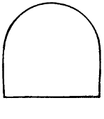
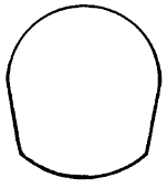
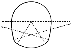
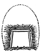
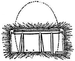
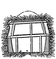
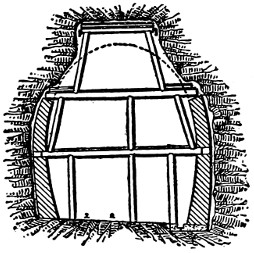
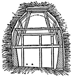
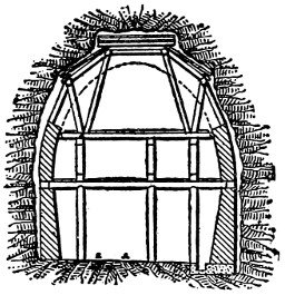
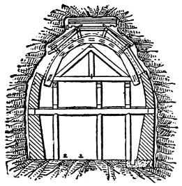
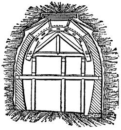
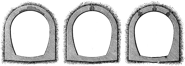
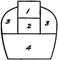
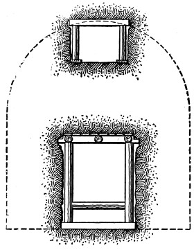
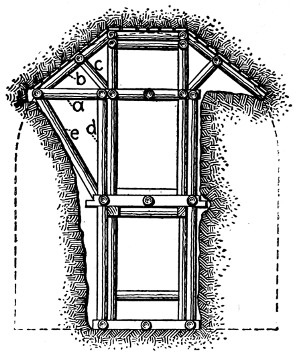
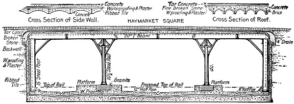
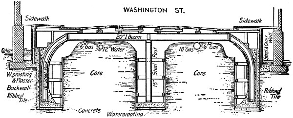
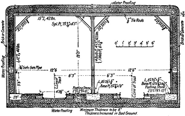


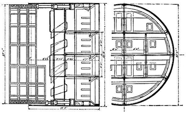
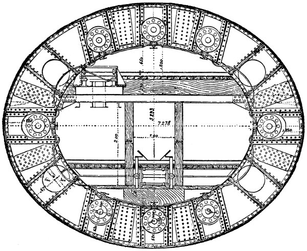
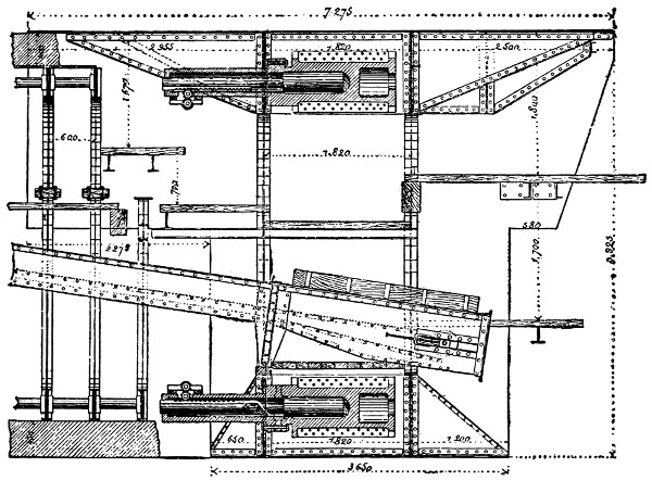
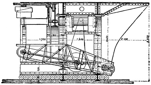

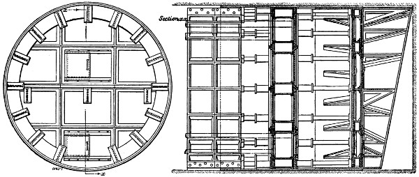
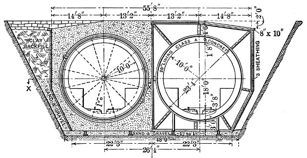
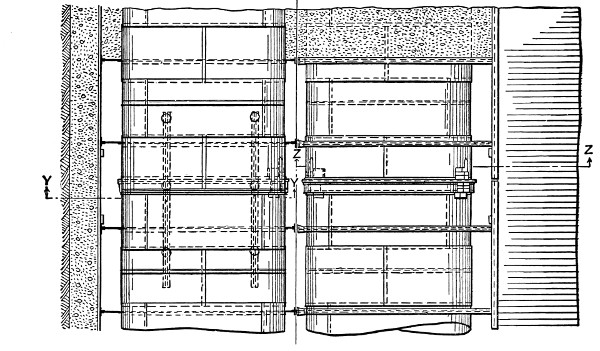
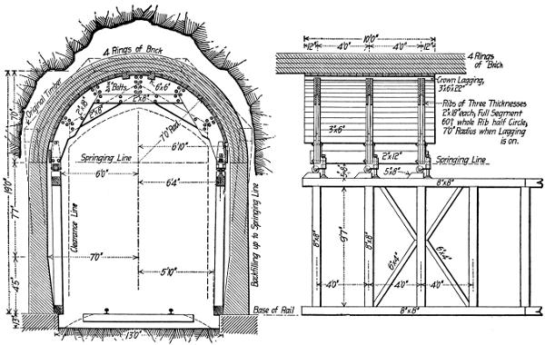
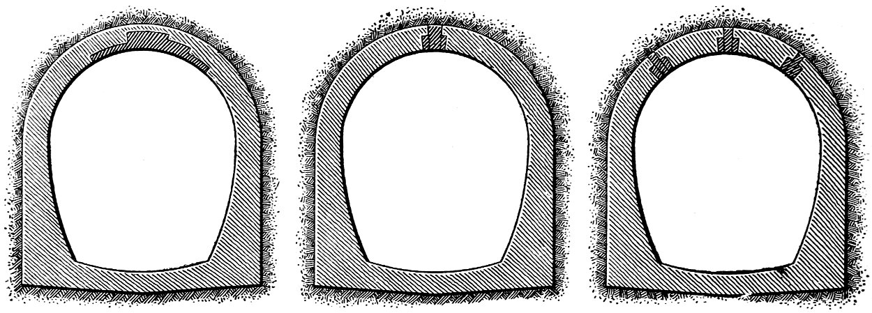
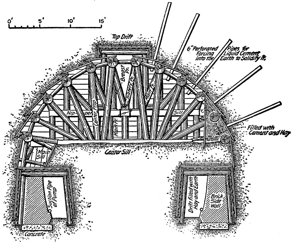
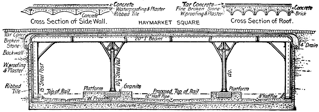
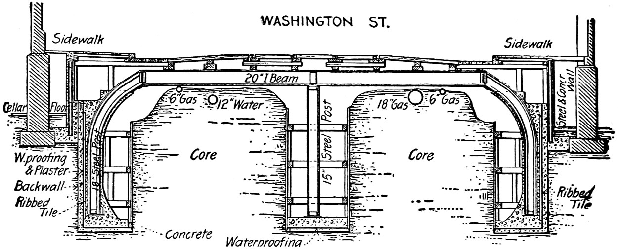
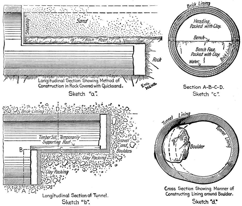
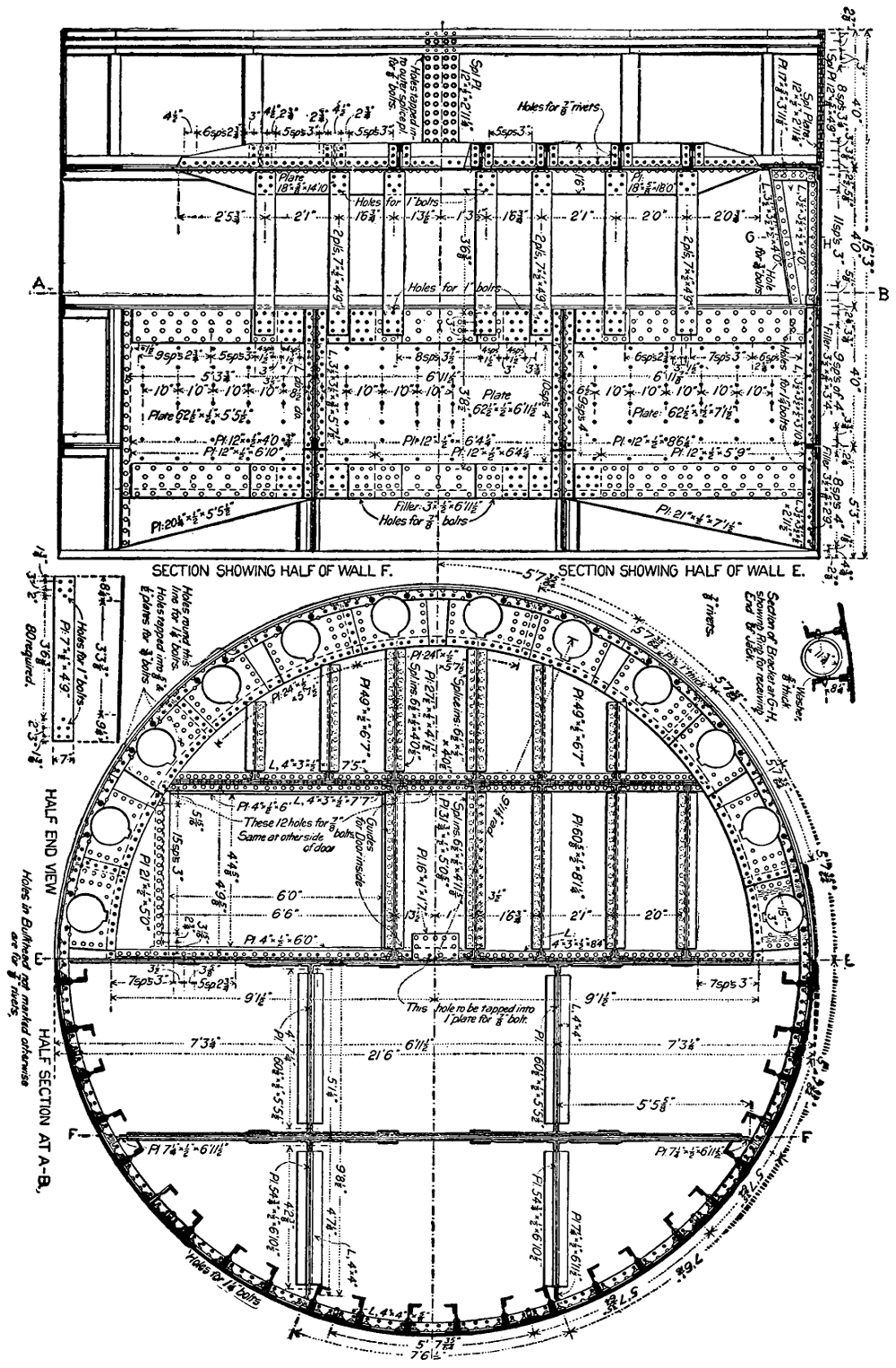
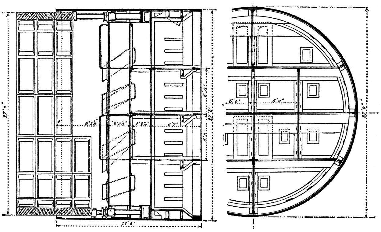
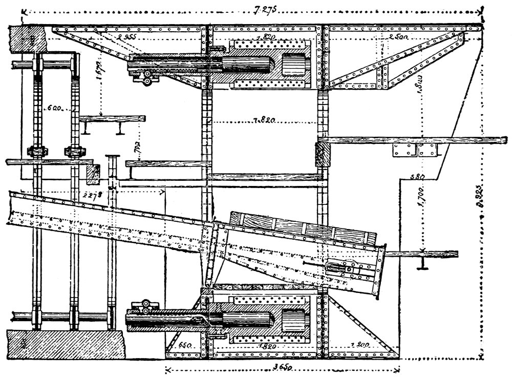
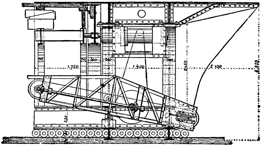
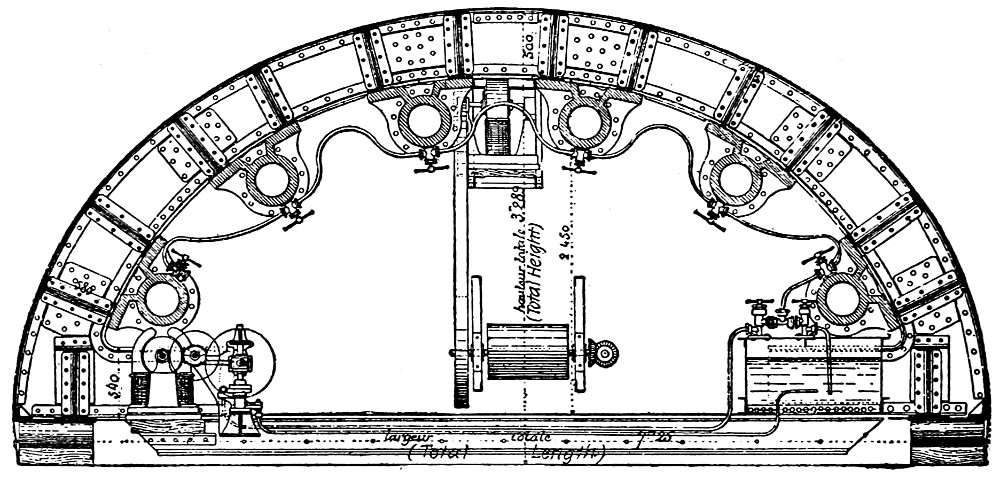
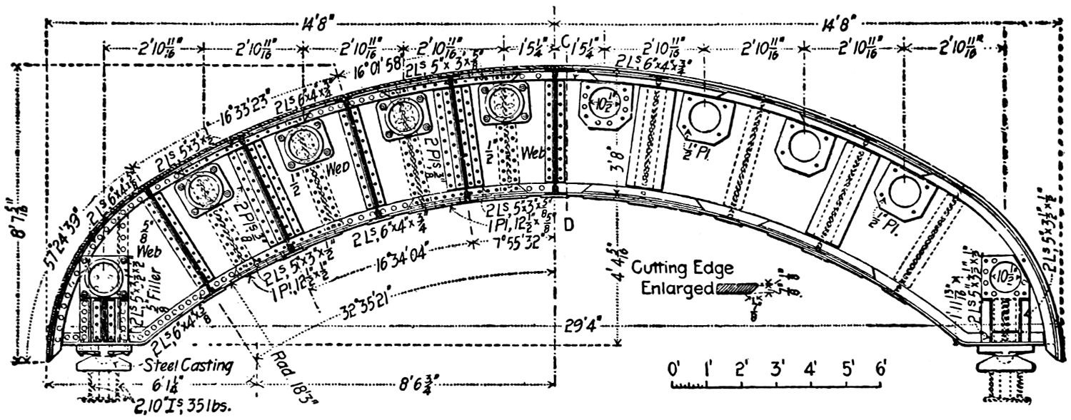
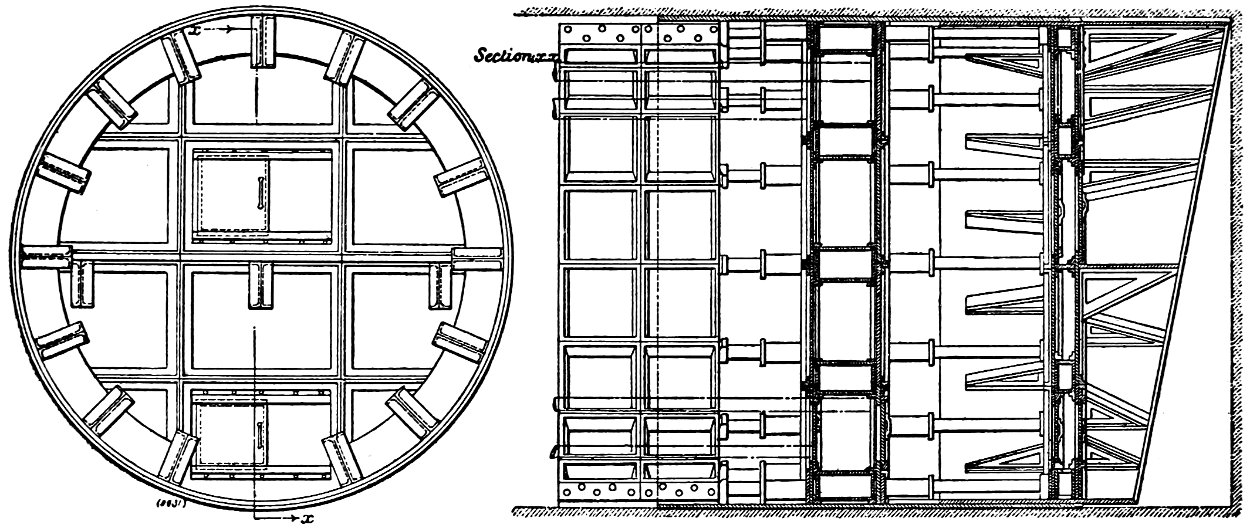
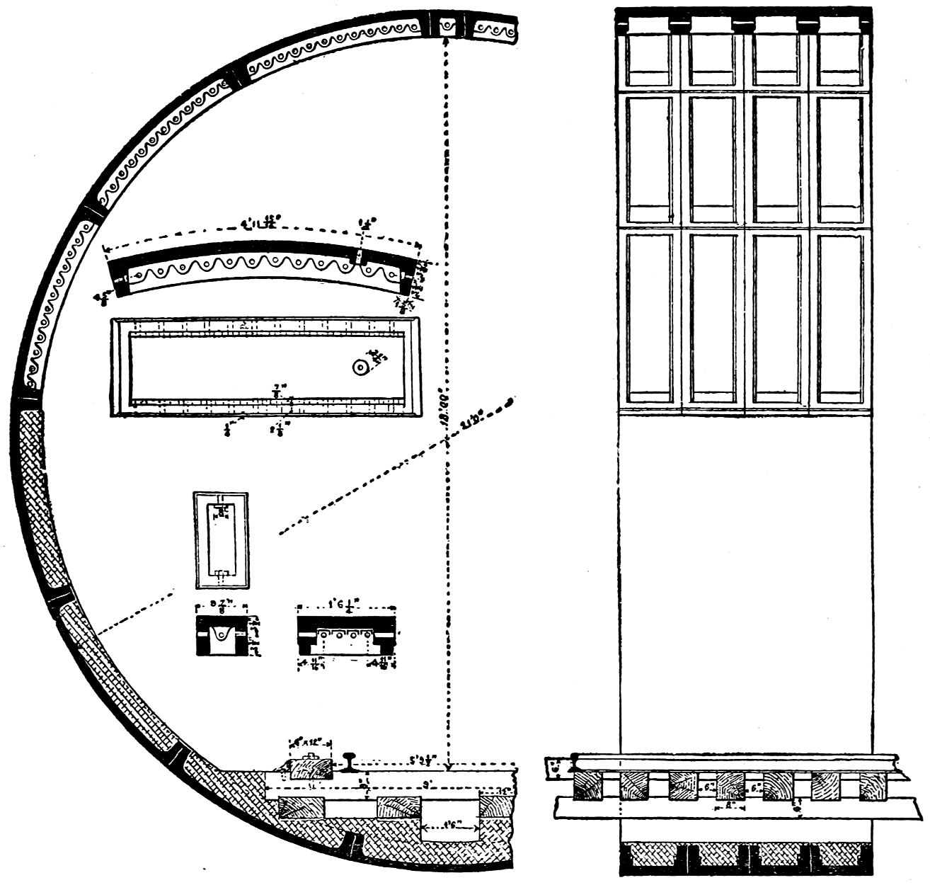
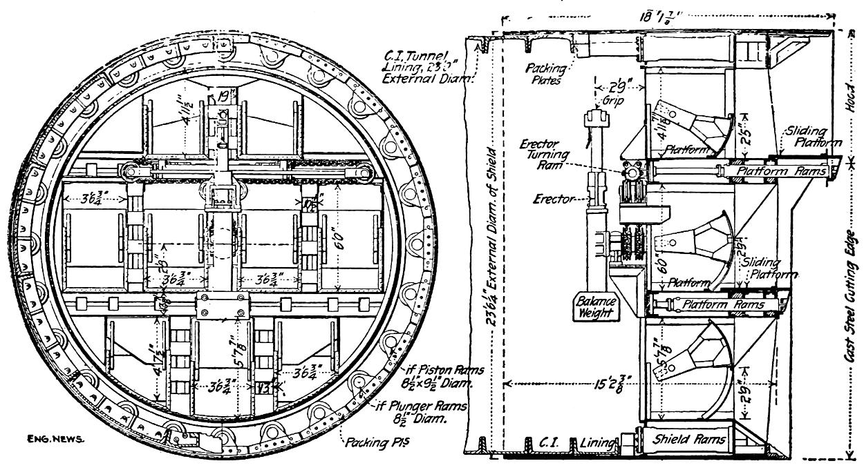
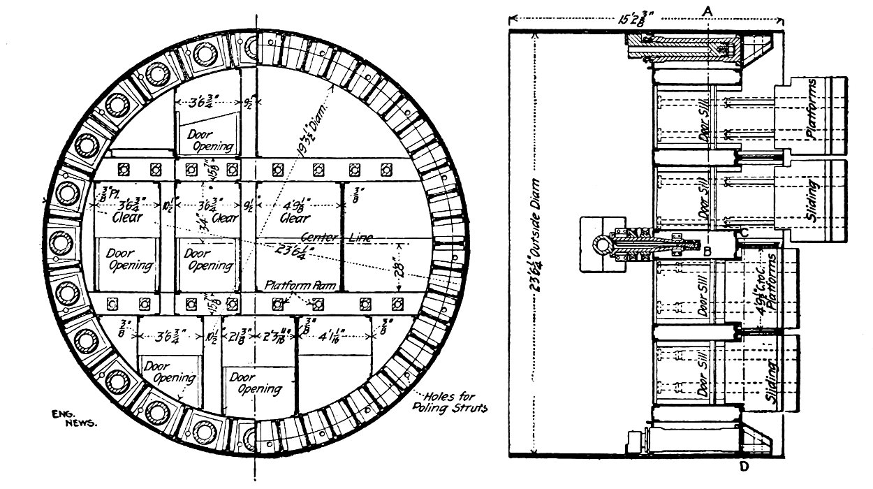
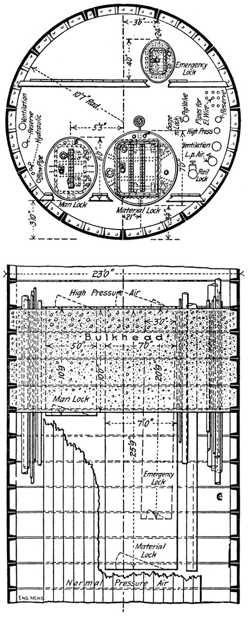
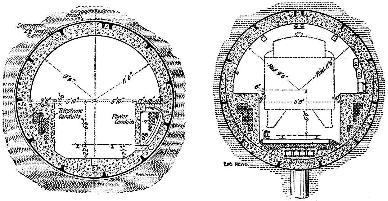
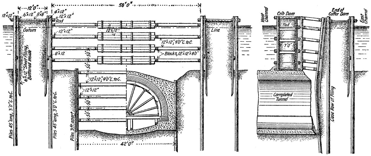
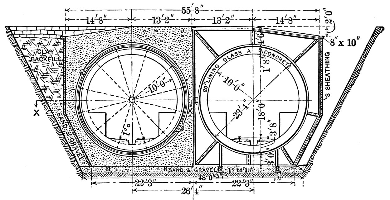
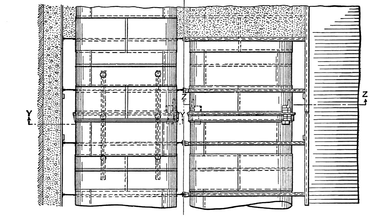