The Project Gutenberg EBook of The Aswân Obelisk, by R. (Reginald) Engelbach

This eBook is for the use of anyone anywhere in the United States and most
other parts of the world at no cost and with almost no restrictions
whatsoever.  You may copy it, give it away or re-use it under the terms of
the Project Gutenberg License included with this eBook or online at
www.gutenberg.org.  If you are not located in the United States, you'll have
to check the laws of the country where you are located before using this ebook.

Title: The Aswân Obelisk
       With some remarks on the Ancient Engineering

Author: R. (Reginald) Engelbach

Release Date: April 20, 2019 [EBook #59320]

Language: English

Character set encoding: UTF-8

*** START OF THIS PROJECT GUTENBERG EBOOK THE ASWÂN OBELISK ***


Produced by MFR, RichardW, and the Online Distributed
Proofreading Team at http://www.pgdp.net (This file was
produced from images generously made available by The
Internet Archive)

(1) The unfinished obelisk of Aswân lies in a quarry on the south-east side of the mediæval Arab cemetery, being about twenty minutes walk from the Cataract Hotel. It is approached by a small valley leading up south-eastwards from the track of the old Barrage railway.
Up to the time of the visit of King Fuad—then Sultan—in the winter of 1920–21, only about 22 metres of the obelisk were exposed to view, the remainder running down into a vast heap of blocks and chips. The curious trench, made round the obelisk for the purpose of detaching it from the rock, has long interested visitors, and His Majesty expressed a desire that the whole obelisk be cleared in order to obtain, if possible, new data as to ancient methods of quarrying, and to expose a unique monument.
I wish to tender my thanks to Mr. Somers Clarke for his kindness in putting his notes on the quarrying of granite at my disposal, and for reading and criticising my MS. before sending it to press; to Prof. Flinders Petrie for reading the proofs and giving many valuable suggestions; to Mr. W. Golénischeff for the references on the Anastasi papyrus and the Hammâmât inscriptions; to Mr. D. Watt, Resident Engineer of the Aswân Barrage, for the loan of books on the properties and working of granite and of surveying instruments from the Barrage works; to the Geological and Chemical Departments (sections 13 and 44) for their report on specimens submitted to them, and to the Survey Department for taking much trouble in preparing my plans for publication.
Mr. A. M. MacGillivray, of Aswân, took the photographs shewn on plate II and plate V, nos. 1 and 2, and has kindly permitted them to appear here.
(2) I began the work shortly after the departure of King Fuad, and soon found that the excavation would be more extensive than I had at first supposed; the length of the obelisk had reached 36 metres by April 1921, and the chip-heap, covering the butt end of the obelisk, began to shew signs of giving way. I had made arrangements, as regards the angle of the chip-heap, supposing that the obelisk was not larger than any of the known obelisks. Thirty-six metres was a surprise, so, as Ramadan was approaching, I abandoned the work for the season and applied for a further credit to make a complete clearance. This was done in the winter of 1921–22 by Mahmûd Eff. Mohammad, Inspector of Edfù, assisted by Mustafa Eff. Hasan, ‘chef de fouilles’ of the same district. I visited the site from time to time whenever my {2} other work permitted, but it was not till the end of the tourist season that I had sufficient time to study the obelisk.
During the removal of the chip-heap, we found some hundreds of large granite blocks thrown from a quarry above on to the obelisk; these had to be cut into two, and sometimes into four, before our workmen could handle them. At first we borrowed men from the Selugia quarries, but afterwards we employed local stonemasons, who proved more satisfactory, as they did not all want to be raises.
The total cost of the clearance was L. E. 75.
A word of explanation is, perhaps, needed on the system of weights and measures used in this volume. It has been the custom of my Department to insist on metric scales in all plans. In the text, however, I enter somewhat deeply into the stresses and strains set up in the granite, and since nearly all the English engineering text-books and tables use the ton-inch units, I have adhered to the English system, reducing the metric linear measures to inches in my calculations. The tonne and the kilogramme-per-square-centimetre still convey little to the average English-speaking engineer, who has to have recourse to his slide-rule before being able to realise the strains set up when they are given in metric units.
(3) The obelisk is 41.75 metres long, lying with its point 18.5 degrees north of east, and sloping down towards the butt at an angle of 11 degrees, making the base of the pyramidion 7.05 metres above the level of the butt. When complete, the obelisk would have weighed 1168 tons English.
It is curious that, during all the years that this obelisk has been known, those who were interested in the ancient methods of quarrying have not taken the trouble to clear it. Nearly every work in which it is mentioned dismisses it in a few sentences. Both Gorringe in his Egyptian Obelisks and Bædeker give its length as 95 feet and the width at the butt as 11 feet 1.5 inches. How they arrived at the latter figure passes my understanding, as it was buried under a chip-heap to a depth of 7 metres. Perhaps the measurements were given by the original writer, whoever he may have been, not as a fact, but as a prophecy.
The measurements of the obelisk are:
| Total length | 41.75 | metres. |
| Base | 4.20 | metres. |
| Base of pyramidion | 2.50 | metres. |
| Height of pyramidion | 4.50 | metres. |
| Weight when finished | 1168 | English tons. |
Round the obelisk, partly separating it from the surrounding rock, is a narrow trench, whose depth averages about 2/3 that required to disengage it to a square section.
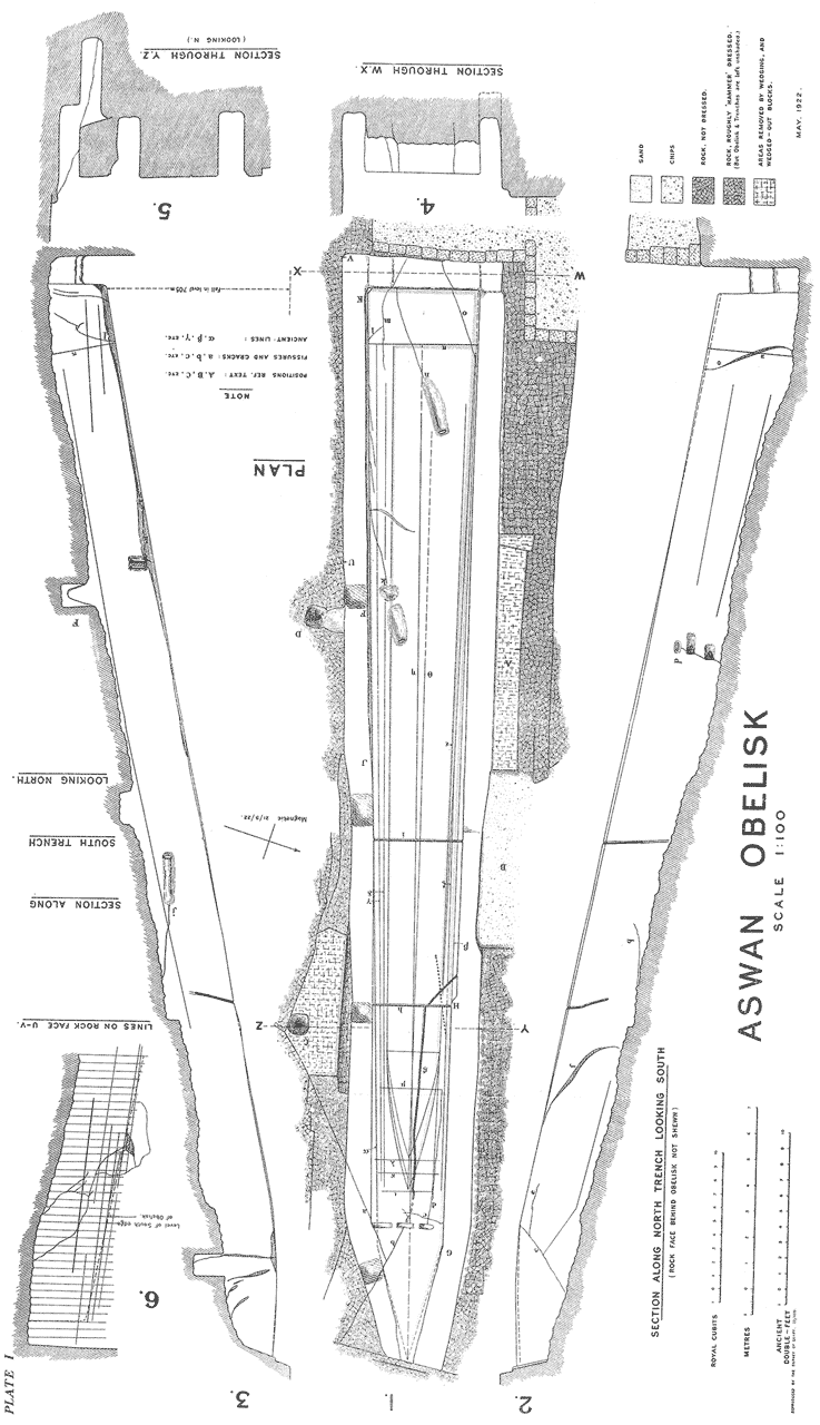
Plate I is a plan, with sections, of the obelisk to a scale of 1/100, and plate II, nos. 1 and 2, shews the obelisk viewed from the tip and butt respectively; the trench around the obelisk can be seen in plate II and in plate III, no. 1, and is discussed in chapter ii.
As to the date of this obelisk, I have found
nothing which gives any real clue to it. One
![]()
![]() utiy, in the reign
of
utiy, in the reign
of ![]() atshepsôwet, mentions an obelisk of
108 cubits (56.7 metres) long, which is longer than
that of Aswân, even if we allow for the pedestal as
having been included in the measurement (see BREASTED, Ancient Records,
II, p. 156, and section 43 of this volume). Neither can the Aswân obelisk
be an abortive attempt to extract the obelisk, a part of
which is now at Constantinople, as the thickness of what
is now the base is only 2.37 metres, whereas the Aswân
obelisk measures 2.50 metres at the base of the pyramidion.
Unfortunately we are compelled to leave the question of the
date open, until we get some definite evidence, which may
well appear when the whole quarry is completely cleared.
{4}
atshepsôwet, mentions an obelisk of
108 cubits (56.7 metres) long, which is longer than
that of Aswân, even if we allow for the pedestal as
having been included in the measurement (see BREASTED, Ancient Records,
II, p. 156, and section 43 of this volume). Neither can the Aswân obelisk
be an abortive attempt to extract the obelisk, a part of
which is now at Constantinople, as the thickness of what
is now the base is only 2.37 metres, whereas the Aswân
obelisk measures 2.50 metres at the base of the pyramidion.
Unfortunately we are compelled to leave the question of the
date open, until we get some definite evidence, which may
well appear when the whole quarry is completely cleared.
{4}
(4) There are abundant traces that the rock, from which the obelisk was to be extracted, was reduced to an approximately correct level by burning and wedging, the former being used wherever possible. In the excavations, a large quantity of burnt and semi-burnt mud bricks were noticed, while a considerable percentage of the chips round the obelisk and other quarries had the pinkish-brown colour and crumbling texture peculiar to burnt granite. Some large pieces of rock shew quite clearly how the burning was done; it appears that a stack of dried reeds was banked with brick, near a fissure if possible, and after firing, the rock was easily hammered away. It is very likely that water was poured on the hot stone to make it break up. This method of heating and chilling is used on the granite in India at the present day. Traces of burning are seen in the obelisk area at A and B on plate V, no. 1. Such a vast amount of stone has been removed in the neighbourhood which shews neither wedge nor chisel marks that, without the proof of the burnt brick and stone, we should have been driven to the conclusion that burning was the method employed [1].
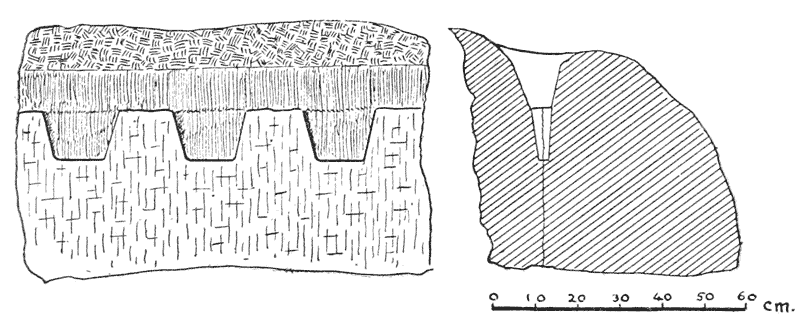
Wedge-marks may be seen on plate III, no. 3, on the left of the picture [2]. Typical examples are shewn on plate III, no. 2, and in figure 1. In nearly every case I observed, a small trench had been cut out by chisels along the proposed line of fracture, presumably to get below the surface, which is often decomposed by exposure, and which would crumble instead of tearing the stone apart. As to whether these wedges were of wood, and made to expand by wetting, I am not certain, but I believe that they were not, the reason being that the slots always taper inwards, and it appears to me that a wetted wedge would tend to spring out rather than exert a lateral force on the stone. In the only case where I have seen wetted wedges used (experimentally on limestone), the wedge-slots were cut with parallel walls.
[1] In some cases a ferruginous (?) stratum in the granite has decomposed the rock with an appearance of its having been burnt. Long exposure of the rock also rots it to a considerable depth, but in the majority of cases where the rock has been removed without wedges or chisels, neither of the above causes can have anything to do with it.
[2] An examination of the wedging-off of blocks in the quarries about Aswân shews that often the wedges have acted perfectly, but the block has not been removed. A crowbar acting in each slot would be ample to remove most of these. Can it be that the crowbar or jemmy of metal was not known?
Assuming, then, that hammered metal wedges were used and not wooden wedges made to expand by the action of water, it remains to be seen whether the plug-and-feather method, such as is used to-day, was employed, or whether the metal wedges engaged with the stone without the thin sheets of metal on either side which we now call ‘feathers’. The advantages of the plug-and-feather method are that it reduces the width of the slot at the top, leaving it wider below and hence to a large extent preventing the sharp edge of the wedge from touching the bottom of the wedge-slot, and that, since the faces of the feathers are smooth, it tends to {5} obtain the maximum advantage of the lateral force exerted by the wedge in the most evenly distributed way and with a minimum of friction. Now nearly all the ancient wedge-slots appear perfectly smooth inside—just as if they had been polished. This would be a disadvantage in using feathers, as there would be a greater tendency for them to jump out at the first blow. Nothing seems to be gained by polishing. Personally I favour the assumption that the Egyptians used the plug-and-feather, but the question is best left open for the present for lack of conclusive evidence. Photographs of two iron wedges from the Ramesseum are given in PETRIE, Tools and Weapons, plate XIII, B 16, 17. They appear to date to about 800 B. C. Feathers, of unknown date, but probably late, are given in the same volume on plate XIII, B 22, 23. It is a bare possibility that the smoothness of the sides of the wedge-slots is due to the fact that the slots were made without chisels, such as by scraping the granite with emery-stone, or that after they had been roughed-out by chisels they were finished by this means.
Sometimes, along a crack, enormous wedges were used, the largest I noticed being 0 m. 25 cent. long, spaced one metre apart. In any case the largeness of the wedges leads us to suppose that the Egyptians must have had large hammers. I do not think that the sledge-hammer, such as we use to-day, was known to the Egyptians, though mallets were common. I believe it likely that heavy rammers, used vertically by more than one man, must have been used to make these wedges act. Mr. C. Firth has pointed out to me a black granite hammer found at Saqqârah, now in the Cairo Museum. Though this example is of the Old Kingdom, it seems quite likely that a similar hammer was used for driving in the wedges. A photograph of the hammer is shewn in plate IV, no. 2. To-day the quarrymen use very small fat steel punches in conjunction with a sledge-hammer. Some large wedge-marks are seen in plate III, no. 2, at the top of the picture.
(5) It seems that the intention of the Egyptians was to leave the north wall of the north trench at a level slightly above that of the obelisk. The exceptions to this are the wedged-out block seen on plates I and II, no. 2 at A, and the (now) entrance to the bottom of the north trench at B. I believe these blocks to have been removed at a date later than that of the obelisk; the block A has been wedged out by a long channel instead of separate slots, while at B it is obvious that stone has been removed for building, since the inner face has been chisel-dressed. Near here, too, I found a block containing a ‘jumped’ hole blackened by gunpowder. Had the ancients wished to remove the trench wall at B, there is a crack running along it parallel to the ground, which would make its removal an easy matter by burning from the outside [3]. It seems, therefore, that the north wall of the north trench was intentionally left; the probable reasons are discussed in section 23. It will be noticed, in plate II, that the top of this wall has been roughly hammer-dressed near the butt, and to a certain extent near the pyramidion. How far it was intended to reduce the south wall of the south trench is not certain; it depends on the method to be used in getting the obelisk out of the quarry, and is dealt with in sections 21–23. There are indications that it was to be reduced to a considerable extent. {6}
[3] There is not a trace of burning within 6 feet of the obelisk.
(6) At intervals in the trench around the obelisk there are traces of squarish holes, generally going down to about the level at which the bottom of the obelisk was to be. These are seen more clearly in the south trench than in the north, and can in some cases be traced up the side of the obelisk itself. Besides these there are the deep holes seen at C and D on plate I. I believe that the holes C and D were made at the very commencement of the work to study the quality of the granite. The holes along the trench seem to have been made with the same purpose, and as a means of setting out the perimeter of the obelisk. There are indications that they were made when the removal of the top layers of rock were still in progress.
(7) From the beginning of the work on this obelisk, cracks and fissures seem to have given a great deal of trouble and anxiety. Though parting fairly evenly under the action of wedges, the natural fissures of granite are most erratic; a small crack at one level or position may, in a couple of metres, become a fissure into which one can insert the blade of a knife, and conversely, a fissure traceable for 5 metres will suddenly disappear. Hence every fissure or crack, as it appeared, had to be rigorously examined, to see its probable effect on the obelisk when completed. The examination seems to have been made in three ways, which I believe to have been of two dates. The original workers method was to hammer out a depression by means of a spherical ball of about 12 lbs. weight, of a very tough greenish-black stone (section 13), until the fissure either disappeared or became larger. These examination hammerings can be seen in plate I at j, k, n, and p, n being also seen in the photos on plate II no. 2 and plate III no. 1. In the depression, sometimes at one place and sometimes at two, a small fillet was left at the level of the face of the obelisk, and apparently polished; the object seems to have been to compare the state at the surface with that at the bottom of the depression. The second method was to chisel out a narrow channel right along the crack and to polish it. In some cases, as at the end of fissure i on plate I, the three red lines, drawn to guide the stone-cutter, can be clearly seen at the end of the channel. It seems likely that the channel method was that used by the later workers who examined the obelisk as to the possibility of extracting a smaller one from it, as the channels are only found in the parts within the area of the smaller obelisk (section 10). I think that the channels were cut over discolourations and superficial flaws, recognised as such and left by the original workmen. The statement made by Barber, in his The Mechanical Triumphs of the Ancient Egyptians, that the grooves are made at some later date with the intention of cutting up the obelisk, is impossible, as two (h and i, plate I) run transversely across the obelisk, where all the wedging and cutting in the world would not part the stone. The line of small punch-holes at H, however, was undoubtedly made in modern or mediæval times to extract a block from the side of the obelisk, and it is a marvel that the obelisk has not been used as a quarry throughout the ages. The third method was to cut with a chisel oblong holes, tapering sharply inwards, on the crack to be examined. It is possible that this was the work of the original party, done in haste on the occasion of an inspection. This method is seen at the base of the pyramidion on plate I.
The most serious flaws in the obelisk are those lettered a, b, c, d, k, m, o and p; any one of these would give one seriously to think as to the advisability of abandoning the work forthwith. {7} Fissure a meets fissure b and settles, once and for all, that the pyramidion must be set back at least half a metre. Fissure c is even more radical. Fissures d, e and f all seem to have connection with one another and make a considerable reduction in width necessary; those between k and m carry a similar warning on the south side, while m and o necessitate shortening the obelisk from the butt end. The last fissure completely separates the corner of the obelisk from the rest.
It might well be asked: Why was the work continued so long after such bad fissures had been discovered? The answer may be that none of these fissures appeared to be serious, even a short distance above the present level of the face of the obelisk. The north and south trenches do not give evidence that the granite was in a bad state, except at ab, l, o and p.
It is likely that the black line π, drawn across the base of the obelisk to shorten it by over 2 metres, was made by the original workers; this is indicated by the fact that, below this line, the hammer-dressing has been left in a rougher state than that on the remainder of the face of the obelisk; further, the trench, which was intended to separate the base of the obelisk, was abandoned earlier than those on the north and south sides, probably as soon as the fissures shewed themselves to be deep.
There is a curious fissure in the hole F on plate I which runs downwards and slightly inwards to the obelisk. Like fissures k to m, it would of itself necessitate a reduction in the original width. It appears, at first sight, that this is the beginning of undercutting the obelisk, but it is not at the level at which this would be commenced.
(8) It would not be out of place, perhaps, to speculate for a moment on the method of obtaining a flat surface along the upper face of the obelisk. I think the method used was by means of boning rods—the method used to-day. For the benefit of those not acquainted with their use, a brief description will suffice. Boning rods are a set of equal, usually T-shaped pieces of wood. One is held upright at each end of the surface which it required to straighten. A man standing at either end, if he sight along the top of these boning rods, can see if a third boning rod, placed anywhere between them, is above or below the line joining them. Thus the surface can be tested anywhere along the obelisk until it is made to slope evenly down along its whole length.
Boning rods for dressing moderately large blocks of stone are shewn in PETRIE, Tools and Weapons, plate XLIX, B 44–46. These measure only about 3 inches high and their tops were connected by a cord. In the case of an obelisk, the cord would be useless owing to the sag, so it seems probable that the sighting method described above was that employed by the ancient Egyptians.
In the setting out of the obelisk, no allowance is made for the slight convexity or entasis, in a longitudinal and transverse sense, which is to be observed in most of the known obelisks. If there was to be a convexity, it was made at a later stage [4]. {8}
[4] It will be noticed in plate I, nos. 2 and 3, that the slight convexity across the obelisk seen in some places, does not extend the whole length, neither is it even as regards either edge.
(9) When the face of the obelisk had been made fairly flat by hammer-dressing, lines were scratched on it with a chisel, and filled in with black paint. The remains of the lines for the original scheme are clearly traceable. These are shewn on plate I, α and β. How much reduction was allowed for as regards the final dressing and polishing, we do not know; it was probably only the matter of a couple of centimetres. At the west end of the south trench the reduction of the side of the obelisk to the guide line has been begun. This can be seen at J to K on plate I. It now forms a kind of bevel and, as far as it extends, obliterates the vertical markings on the wall of the trench. On the east end of the north trench the trench itself has been moved inwards, from G to H, to be nearer the guide-line. The reason may either be that the workers found themselves too far from the guide-line, or that the guide-line was changed during the progress of the work, perhaps through fear of a fissure.
Before the original workers abandoned their work they seem to have made several attempts to set out a slightly reduced obelisk, which would avoid all serious cracks by reducing the length and thickness of the original design. This is seen in the lines γ δ ε ζ and the transverse lines ι κ λ μ. The last four lines are so faint that they can only be seen just after sunrise or before sunset, and it is not clear with which of the longitudinal lines they connect. On the south side the lines are quite clear, but on the north side there seem to have been more lines even than those shewn on plate I. These lines γ δ ε ζ, do not lie at equal distances from either of the two centre lines η and θ.
There is no doubt in my mind that the original obelisk was to have had a straight-edged pyramidion, as the rough edge of the boundary trench lies evenly on either side of the centre line η.
(10) The outline for another, and most probably later, obelisk is set out on a new centre line θ, and keeps closely to the north edge of the original design, avoiding the series of fissures on the south. Just before sunset, the tentative outlines for the curved pyramidion can be traced; plate III, no. 3, taken at that time, shews these lines. In this, the right-hand curve appears to engage with a line to the north of that engaged by the curve next to it; this is only an effect of light and they really engage as shewn on plate I.
I have outlined the original design and the later scheme, in red. Though the lines setting out these obelisks are easily traceable, the colouring is mine, and is only intended to shew up the lines more clearly. Since there are some actual red lines on the obelisk, another colour would have been preferable; considerations of cost in printing have limited the plate to two colours. In outlining the later design in red, I have chosen the larger pyramidion, as the shape decided on. There is no proof of this, but the proportions are, to me, more effective, and there is no reason for abandoning the odd metre of difference, as the stone here is perfectly sound.
Taking the longer pyramidion, we have the following dimensions for the obelisk:
| metres. | |
|---|---|
| Total length | 32.10 |
| Pyramidion height | 5.31 |
| Pyramidion base | 2.02 |
| Obelisk base | 3.15 |
{9}
(11) I had intended to give a diagram of the better-known obelisks superimposed. I found it, however, almost impossible to get the sides of the obelisks distinct one from another without making the scale inconveniently large. I give, therefore, a table shewing the principal dimensions of ten examples. Those marked with an asterisk are scaled off photographs, making slight allowances for foreshortening.
| OBELISK. | BASE (METRES). | PYRA- MIDION BASE. |
PYRA- MIDION HEIGHT. |
TOTAL HEIGHT. | TAPER 1 IN | WEIGHT (IN TONS ENGLISH) |
|---|---|---|---|---|---|---|
| Aswân | 4.20 | 2.50 | 4.50 | 41.75 | 24.3 | 1168 |
| Aswân (later project) | 3.15 | 2.02 | 5.31 | 32.10 | 23.7 | 507 |
| Lateran | 2.87 | 1.90* | 4.50* | 32.15 | 30.7 | 455 [5] |
| 2.40 | 1.78 | 2.96 | 29.50 | 42.8 | 323 | |
| Vatican | 2.69 | 1.80 | 1.34 | 25.31 | 26.9 | 331 |
| Paris | 2.42 | 1.54 | 1.94 | 22.84 | 23.7 | 227 |
| London and New York | 2.37 | 1.63* | 1.65* | 21.18 | 30.5 | 193 [6] |
| Ma |
1.90 | 1.23* | 2.00* | 20.42 | 27.5 | 121 [5] |
| Tuthmôsis Ist | 2.15 | 1.40* | 2.39* | 19.60 | 24.2 | 143 |
It will be seen how close the measurements of the Aswân modified scheme are to those of the Lateran obelisk. Except for the height and base, I have had to scale the latter off a photograph, so the resemblance may be even closer.
It is also perhaps more than a coincidence that the base
of the later project is the same as that of the obelisk
fragment before Pylon VII at Karnak, namely 3.15 metres.
Legrain, writing in the Annales du Service, vol. V,
pp. 11 and 12, remarks, about this Pylon VII obelisk:
“L’obélisque d’Hatshopsitou mesure 29 m. 50 cent. de
hauteur et 2 m. 40 cent. à la base. Si nous admettons des
proportions semblables pour deux monuments contemporains,
la base de l’obélisque de Thoutmôsis III au VIIe pylône
étant 3 m. 15 cent.–3 m. 10 cent., nous arrivons au
chiffre approximatif de 37 m. 77 cent. comme hauteur de
l’obélisque de Thoutmôsis III dont nous avons retrouvé les
fragments cette année devant la face sud du VIIe pylône.
(Footnote): J’ai pris comme base de ce calcul hypothétique
(29.50 × 3.15)/2.46 en comptant sur la plus grande largeur
de la base, qui, dans l’antiquité, se voyait le mieux.”
This year, a fragment of the companion (or perhaps the
same) obelisk has been found, which just reaches up to the
wording of the Horus name of the king—that is to within a
couple of metres of the base of the pyramidion. Although
only one edge remains, I found that, by measuring from the
centre of the vertical lines flanking the inscription,
that the distance to the edge was 1.04 metre, making the
width here 2.08 metres, which is almost exactly that of the
outline on the Aswân obelisk. Legrain, in estimating the
height of the obelisk before Pylon VII, assumes that the
taper was the same as that of the obelisks of
![]() atshepsôwet,
but, from the table above, it will be seen that the taper
of her obelisks is exceptionally small, so his estimate is
likely to err on the large side. The outline on the Aswân
{10} obelisk may therefore be either for what is now
the Lateran obelisk, or those of Pylon VII; there is no
evidence to shew for which it was intended.
atshepsôwet,
but, from the table above, it will be seen that the taper
of her obelisks is exceptionally small, so his estimate is
likely to err on the large side. The outline on the Aswân
{10} obelisk may therefore be either for what is now
the Lateran obelisk, or those of Pylon VII; there is no
evidence to shew for which it was intended.
It is likely that the later scheme was, in its turn, abandoned from fear that the granite was not sound, especially near fissure p. In any case, the reduction of the large obelisk to obtain a smaller one would be a piece of work almost comparable to starting the work over again on a new site, where the rock was likely to be of better quality.
(12) The trench surrounding the obelisk, by means of which it was intended to separate it from the surrounding rock, is of most peculiar form, the effect being a series of parallel and equidistant vertical cuts, as if it had been made by a gigantic cheese-scoop. Plate III, no. 1, shews the structure of the sides and bottom of the trench. Its width averages 75 cent., and its depth about two-thirds that necessary to extract an obelisk of square section. Down the division between each concave “cut” a red line was drawn, it appears, by a plumb-bob with its string dipped in ochre (section 44). These lines are not continuous, but have been projected down from time to time as the level of the work became lower. The average distance between the vertical red lines is 29.9 cm., there being very little variation between examples. These appear to be feet, and the unit the double-foot. This is discussed in section 18.
It will be noticed in plate III, no. 1, that distinct horizontal marks are visible along the wall parallel to the bottom of the trench; these shew how uniformly the work was kept at the same level. The aspect of the bottom of the trench is so well shewn as not to need a description. When the whole trench is examined, the divisions across the bottom of the trench seem to run in pairs; it is difficult to define where the resemblance between each pair lies, but it is very clear, and I noticed it almost as soon as I began work. A clearer feature is the division between the depressions at the bottom of the trench separating each into a north and a south half, shewing that the work was done from each side of the trench alternately.
At irregular intervals, and not parallel either to the top of the obelisk or to each other, are red and black lines. They occur all over the walls of both trenches and on the sides of the obelisk itself. On plate I, no. 6, I give a diagram of the lines on the rock face U V, where they are clearest and most numerous. The only explanation I can give for them is that they are merely lines from which to measure from time to time the depth to which the trench had reached.
A feature of the surrounding trench is that there are no corners—everything is rounded; neither are there any traces of the marks of wedges, which are quite unmistakable (see plate III, no. 2); besides, it is not practicable to use a wedge unless one has to remove a part from the side of the parent rock. Chisels also leave sure traces; examples of fine pointing are seen in plate III, no. 2, and rough dressing on plate III, no. 4 (which was taken in the quarries of Shellâl). There are no traces of chisel-work in the trench at all, and not a trace of any copper implement was found during the clearance of the obelisk. We are therefore forced to the conclusion that the large balls of tough greenish-black stone, found in such profusion round the obelisk and all quarry work at Aswân, must have been the tools employed. {12}
(13) These stones, which I propose to call ‘pounders’, are nearly spherical, and vary between 8 and 13 inches in diameter, their weights ranging between 9 and 15 pounds. On assembling a large number of them and examining them closely, it is seen that nearly every one of them has one, and often several, brownish-red stains, which are never seen on the inside when a ball is broken. The balls are of almost natural formation, and shaped by the action of water during the ages, the stains being at the part where the block touched the parent rock before being washed out. The stains are caused by fissures in the original rock, which allowed the water to enter, decomposing the surfaces. They consist of ferric oxides from the ferrous silicates.
I have buried some hundreds of these pounders under the west retaining-wall and elsewhere, as even their weight did not prevent them from being carried off freely by souvenir-hunters.
Mr. C. Firth has given me some stone chisels from the district of Wady Alaqi, in Nubia, for comparison with the pounders used on the obelisk. He tells me that rounded stones of similar appearance to the pounders may be seen in large numbers in the wadys of the Eastern Desert both above and below Aswân.
I took some pieces of pounders, together with the chisels, to the Geological Museum, Cairo, where they were examined by Mr. W. F. Hume and Hassan Eff. Sadek, who have kindly furnished me with the following report:
‘It has been concluded (as the results of the examination supported by specific gravity determinations made in the Government Analytical Laboratory), that the stone from which the chisels were made was a diorite, the specific gravity varying from 2.75 to 2.87. The pounders, on the other hand, are composed of dolerite, which is a more basic rock than the diorite, with a specific gravity of 2.93 to 3.05. Though rocks of this nature are present in the Aswân Cataract region (see J. BALL, First or Aswan Cataract, pp. 79 and 86), it is quite conceivable that the material for these implements has come from other localities. Rocks of this type abound in the Second Cataract at Wady Halfa and have been used as pounders in many gold-mining localities of the Eastern Desert, such as the Baramia Mine where they are of wide distribution.’
My own examination of the Aswân quarries has not revealed stone of precisely the same quality as that of the pounders, and in so far tends to support the idea that the material for chisels and pounders is derived from some other region.
The wear on the pounders is not distributed evenly over the whole surface—which would be expected if they had been used entirely by hand—but appears in patches, shewing that the pounders were used in one position until the bruising surface in use had become flat, and therefore useless. When a pounder is newly used, the bruising surface nearly always is found at a point directly opposite to the stain, possibly as there is always a slight flattening there.
In very many cases the pounder had been broken by the great force of the blows delivered with it. I cannot believe that a man, using one of these by hand, could break it, as the only way I succeeded in doing so was by hurling one down from a height of about 30 feet on to a pile of others, and then only after repeated attempts.
It has long been known that the face of the granite was dressed by means of these pounders, but I have not heard of their use being suggested for excavating a trench in it.
There are many examples of monuments, partly pounded out, now lying in the quarries of {13} Aswân and Shellâl. Plate IV, no. 3, shews an example where, apparently, the lid of a sarcophagus is being shaped by this means.
To ascertain how much headway can be made by hand on this kind of work, I tried, on the bottom of the trench, to see how much I could remove by hand pounding. I found that, after an hour’s hard work, I had extracted about five millimetres off the surface of the foot × half-trench-width area. With practice I could perhaps have done more. I noticed that, if I threw the pounder down and caught it on the rebound, the granite broke up at a much greater rate; but to do this as a regular thing would certainly result in an accident, as occasionally the pounder rebounds at very unexpected angles. I am certain that they were not used entirely by hand in the regular work of cutting out the trench, as the work would go very slowly indeed, and, which is more to the point, it would not have the same regular appearance that it has. There is no doubt that very powerful blows were struck vertically downwards, sometimes with such force as to split the dolerite pounders into fragments.
The only conclusion I can come to is that the pounders were attached to rammers, and worked on the principle of the modern mindâlah, as the Egyptians call it, and with which they are very familiar. By this means two or more men could work from the top of the trench, while the third, working below, held the bottom of the rammer and directed the blows.
As to how the rammers were attached to the pounders—if such were indeed used—I am uncertain. It may have been done by having the base of the rammer made slightly concave, possibly bound with metal to prevent splaying, the pounder being held up in its place by a metal (iron?) ring, sufficiently large to expose enough bruising surface, but not large enough to let the pounder slip through or to scrape against the side of the trench. The ring would be held up by two metal bands or hide thongs attached to the body of the rammer. Another method of attaching the pounders would be by a leather strap, with a hole just small enough to keep the ball from slipping through.
(14) It might well be asked why they did not make flat surfaces for the rammer to bear on, and with some more convenient means of attachment. The explanation is that once the bruising part of the pounder had worn flat, it was of no further use, and a new part had to be selected; besides, the spherical pounders are of natural occurrence, and their great toughness would make any shaping a difficult process. There are signs that the local basalt, and even the granite, were sometimes used, apparently without much success, as they are far inferior to the dolerite in toughness. Since the pounders were imported, a certain economy was essential in making the maximum use of them before discarding [7].
[7] Hand pounding also must have been largely used for the face dressing, for examination of fissures, and possibly for undercutting. Some quite small hand-pounders were also found; these had no stain on them.
The pounding out of the trench has considerable advantages over other possible methods; these may be summed up as follows:
The bottom of the trench gives a certain amount of information as to how the labour was arranged. To work the maximum number of men, with the minimum chances of one interfering with the other, seems to me to be for each man to have two ‘feet’ marked out for him along the trench. Squatting with his back to the obelisk, he worked on, say, the right ‘foot’ of his task, putting his ‘spoil’ on to the left ‘foot’. (Handing it up would be a great waste of time, and not removing it constantly would reduce the bruising force of the blows almost to nil.) Each man during the spell, be it of days or weeks, sits with his back to the obelisk and works on his right ‘foot’. The next spell is on the same ‘foot’ but each man works facing the obelisk, and the process is repeated in exactly the same way for the two halves of the left ‘foot’ of their tasks. A glance at plate III, no. 1, will shew how likely this arrangement is, as there is just room for a man to squat comfortably, and there is always the space of a ‘foot’ between him and his neighbour. The men at the top of the trench, if rammers were used, would be rather crowded, but not impossibly so.
The average width of the trench is about 0 m. 75 cent.; the work may have been measured taking into account a minimum width, but this is not necessarily the case, as in certain places, the width of the trench gets smaller and smaller as it gets deeper, and then suddenly opens out again. In any case I imagine that the workmen would find it false economy to narrow the trench too much, as the cramped position would make the work go more slowly. I suggest that the reason for the occasional narrowings is that one party knew that their spell was coming to an end at a certain level, and finished it quickly, knowing that someone else had to continue the deepening.
It will be noticed that the top-dressing, as seen at the pyramidion, plate IV, no. 1, and the butt-end of the obelisk, is less regular than the pounding work in the trench; it seems that, with more space at their disposal, the workmen were given an area to pound, and left to arrange their method of doing it.
(15) As to the time which would have been taken to complete the trench, it is interesting to get a rough approximation.
Assuming that, with rammers, the men can extract 8 millimetres in an hour in each quarter of their double-foot task, then the time taken to complete the trench, with an extra metre for undercutting, will be that of working it at its deepest part, that is to a depth of 4.2 + 1.0 metre, and will equal (4 × 5.2)/(.008 × 12 × 30) months of twelve hours per diem = 7.22 months.
Before leaving the subject of time taken, we might apply
this calculation to the obelisk of
![]() atshepsôwet, assuming
that it was detached in much the same way. Here the deepest
part of the trench is 2.40 + .75 metre [8];
then the time
taken would have been: (4 × 3.15)/(.008 × 12 × 30) = 4.4
months. {15}
atshepsôwet, assuming
that it was detached in much the same way. Here the deepest
part of the trench is 2.40 + .75 metre [8];
then the time
taken would have been: (4 × 3.15)/(.008 × 12 × 30) = 4.4
months. {15}
[8] Since the obelisk is smaller.
It is recorded by the queen that “they are of one block of enduring granite, without seam or joining. My Majesty exacted work thereon from the year 15, the first of Machir (6th month), until the year 16, the last of Mesore (12th month), making seven months of exaction in the mountain.” Allowing for undercutting and a certain amount of top clearance, our calculation seems within the bounds of reason.
During the work of trench-pounding, the top-dressing, embankment preparing, and clearing for the exit of the obelisk would be carried on.
(16) At the south-west corner of the obelisk there is a kind of platform, sloping down southwards towards a vertical face of rock. Plate II, no. 2, shews the obelisk with the platform at the right, and plate V, nos. 1 and 2 shews the rock face viewed from below the north side of the obelisk, and from directly opposite it. A detailed drawing of the markings on the quarry-face is given on plate VI.
The rock face is crossed by three black lines, lettered a, b, and c, and one red line d. It will be seen that the structure of the face below the line c is similar to that of the side of the obelisk trench; the intervals, too, between the vertical markings are almost exactly the same, namely 29.8 cm. on the quarry-face against 29.9 on the trench.
It appears that, above the line c, the vertical markings made by the pounding have been hammered out to a certain extent, as if to use the upper half as a kind of blackboard.
There is no doubt that some monument has been removed from before this quarry-face, and it is rather tempting to see, in the lines a and c, the levels of the top and bottom faces of an obelisk, the line b being a centre line. If this is so, the taper is 1 in 17.5, which is sharper than the known large obelisks (see section 11). Unfortunately, the method of detaching the monument, whatever it may have been, is no longer traceable, as a large stratum of granite has been removed, almost certainly by burning, perhaps to make a control platform, destroying all traces of the original bed of the monument.
Line c is very nearly level, and both b and c are divided into ‘feet’ by short vertical black lines each in the middle of the pounded grooves. The reason for this is not clear to me.
The red line d is separated from the black line c by one double obelisk-foot; that is the distances between the lines varies between 59.7 and 60 centimetres. The vertical red lines are not very accurately drawn, but the average distance between successive lines is equal to the double-foot. The horizontal red lines above line d convey no meaning to me, neither do the eyes or the nefer on lines b and c.
Down the centres of the red squares, above the line c, run a series of curious chains in red—now very faint—all of which cut the line d, and some the line c. The horizontal lines on these chains are nearly the same distance apart. Those above the line d are much more irregular, and look like two different measures superimposed, the lower series being similar to the chains between c and d; they are, however, so faint that it is only at e that the beginning of the joining of the horizontal members can be determined.
I have numbered the spaces between the vertical divisions I–XIII; below is a table giving the levels in metres of each horizontal line in every chain, taking the level of line d as unity. {18} I have not taken any measurement nearer than half a centimetre, as the lines are thicker in some places than that, and I cannot be sure of a greater accuracy owing to the faintness of the lines.
(17)
| SPACE (Plate VI). | |||||||||||||
|---|---|---|---|---|---|---|---|---|---|---|---|---|---|
| I. | II. | III. | IV. | V. | VI. | VII. | VIII. | IX. | X. | XI. | XII. | XIII. | |
| Upper series | ″ | .05 | ″ | ″ | ″ | ″ | ″ | ″ | .02 | .02 | .05 | ″ | ″ |
| ″ | ″ | ″ | ″ | ″ | ″ | ″ | .13 | .12 | .12 | .15 | ″ | .12 | |
| ″ | .15 | ″ | ″ | .17 | .19 | ″ | ″ | ″ | ″ | ″ | .20 | .21 | |
| ″ | .27 | ″ | ″ | ″ | ″ | ″ | .28 | .27 | .26 | .30 | .31 | .30 | |
| ″ | ″ | ″ | ″ | .30 | .30 | ″ | .33 | .37 | ″ | .35 | .35 | .36 | |
| ″ | .41 | .44 | ″ | .48 | .45 | ″ | .40 | .44 | .40 | .42 | .38 | ″ | |
| ″ | .52 | ″ | ″ | ″ | ″ | ″ | .47 | .50 | .48 | .50 | .46 | ″ | |
| ″ | .58 | .55 | ″ | ″ | .59 | ″ | .55 | .56 | .55 | .58 | .53 | ″ | |
| ″ | ″ | ″ | ″ | .62 | ″ | ″ | .62 | ″ | .63 | ″ | .60 | ″ | |
| ″ | .67 | .655 | ″ | ″ | ″ | ″ | ″ | ″ | ″ | ″ | .68 | ″ | |
| ″ | ″ | ″ | ″ | ″ | ″ | ″ | .70 | .72 | ″ | ″ | ″ | ″ | |
| ″ | .74 | ″ | ″ | .73 | ″ | ″ | .77 | .74 | ″ | ″ | ″ | ″ | |
| ″ | .82 | ″ | ″ | ″ | ″ | ″ | .84 | ″ | ″ | ″ | ″ | ″ | |
| ″ | .89 | ″ | ″ | ″ | ″ | ″ | .92 | ″ | ″ | ″ | ″ | ″ | |
| Lower series | ″ | ″ | ″ | ″ | ″ | ″ | ″ | ″ | ″ | .71 | (?) | (?) | (?) |
| ″ | ″ | ″ | ″ | .78 | (?) | ″ | ″ | (?) | .78 | (?) | (?) | (?) | |
| ″ | ″ | ″ | .83 | .84 | .82 | ″ | (?) | (?) | .85 | (?) | (?) | .81 | |
| .88 | .895 | .83 | .89 | .91 | .89 | ″ | .91 | .86 | .92 | .87 | .89 | .88 | |
| .95 | (?) | .94 | .95 | .97 | .95 | (?) | .97 | (?) | .99 | .94 | .96 | .98 | |
| 1.03 | 1.045 | 1.02 | 1.01 | 1.03 | 1.00 | 1.03 | 1.03 | 1.02 | 1.04 | 1.00 | 1.03 | 1.03 | |
| 1.09 | 1.10 | 1.09 | 1.07 | 1.10 | 1.07 | 1.11 | 1.08 | 1.08 | 1.11 | 1.07 | 1.11 | 1.10 | |
| 1.15 | 1.16 | 1.13 | 1.15 | 1.17 | 1.14 | 1.18 | 1.15 | 1.15 | 1.17 | 1.14 | 1.17 | 1.17 | |
| 1.22 | 1.22 | 1.215 | 1.21 | 1.24 | 1.21 | 1.25 | 1.23 | 1.22 | 1.24 | 1.21 | 1.24 | 1.24 | |
| 1.275 | 1.29 | 1.28 | 1.28 | 1.30 | 1.28 | 1.32 | 1.30 | 1.29 | 1.31 | 1.28 | 1.32 | 1.31 | |
| 1.35 | 1.37 | 1.35 | 1.35 | 1.375 | 1.35 | 1.39 | 1.36 | 1.36 | 1.38 | 1.35 | 1.39 | 1.38 | |
| 1.42 | 1.425 | 1.42 | 1.42 | 1.45 | 1.42 | 1.47 | 1.44 | 1.43 | 1.45 | (?) | 1.46 | 1.47 | |
| 1.49 | 1.50 | 1.495 | 1.49 | 1.52 | 1.50 | (?) | ″ | ″ | ″ | ″ | ″ | ″ | |
| 1.57 | 1.57 | 1.565 | 1.56 | ″ | ″ | ″ | ″ | ″ | ″ | ″ | ″ | ″ | |
| 1.64 | 1.645 | 1.64 | ″ | ″ | ″ | ″ | ″ | ″ | ″ | ″ | ″ | ″ | |
| Sure intervals | 11 | 11 | 11 | 11 | 11 | 10 | 6 | 8 | 8 | 11 | 7 | 8 | 9 |
| Total length of intervals |
.76 | .75 | .76 | .73 | .74 | .68 | .44 | .53 | .57 | .74 | .48 | .57 | .66 |
| Unit | .069 | .068 | .069 | .066 | .067 | .068 | .073 | .066 | .071 | .067 | .069 | .071 | .073 |
| Average unit for lower series .0690 m. | |||||||||||||
(18) It is noteworthy, in the lower series, that the horizontal lines on the chains are stepped-up as we proceed towards the right; the upper series do not shew this peculiarity. Another point is that in only one case does one of the marks coincide with the red line c, and never at all with the black line b; had this not been so one would imagine that two sets of measures were being compared. {19}
If we multiply up the unit of .069 metre we get:
| .069 × .25 | = .01725 |
| .069 × .5 | = .0345 |
| .069 × 1 | = .069 |
| .069 × 2 | = .138 |
| .069 × 3 | = .207 |
| .069 × 4 | = .276 |
| .069 × 5 | = .345 |
| .069 × 6 | = .414 |
| .069 × 7 | = .483 |
| .069 × 8 | = .552 |
| .069 × 9 | = .621 |
| .069 × 10 | = .690 |
| .069 × 11 | = .759 |
| .069 × 12 | = .828 |
It will be seen from this that the unit, if it is a unit, is not a factor of the royal Egyptian cubit of .525 m., nor of the small cubit of .45 m., neither is it connected with the Egyptian finger of .0187 m. Further, it bears no relation to the obelisk single- or double-foot. Since we have no information as to whether this unit of .069 metre is a sixth, eighth, tenth or twelfth of a foot or cubit, it is rather unwise to try to reconcile it with the known Egyptian units, as, even during the same reign, the influx of foreign measures and the variations of the native measures would enable us to find an equivalent to almost any unit that could be imagined.
I am aware that DECOURDEMANCHE, in the Annales du Service, volume XII, page 215, gives the measure .06925 as a palm of the “lapidary” cubit of .4155 m., but I place very little reliance on this cubit, as it only explains the dimensions of one tomb measured by Amélineau at Abydos, and this tomb can be equally well rendered in the royal cubit system.
The relation of the obelisk foot to the royal Egyptian cubit is seen in the following table:
| metres. | ||
|---|---|---|
| Finger | (1) | .0187 |
| Palm (also = 3 inches) | (4) | .075 |
| Common foot | (16) | .300 |
| Common cubit | (24) | .450 |
| Royal cubit | (28) | .525 |
It will be noticed that the actual measurements of the obelisks, both the original and the later project, very largely depend on the royal Egyptian cubit of .525 metre. The height of the large obelisk does not. Probably the order was for as large an obelisk as possible. The dimensions of even royal cubits are:
| cubits. | |
|---|---|
| Base of large obelisk | 8 |
| Base to black line π | 4 |
| Base of later project | 6 |
| Height of pyramidion of later project | 10 |
Most of the remaining measurements, except the base of the pyramidion of the later project, depend on the rock rather than on the wish of the designers. Since the obelisk is still in a rough state I cannot give many accurate measurements from which the cubit can be found precisely. The two most accurate measurements are the base of the original obelisk and the base {20} of the later project. The former measures 4.20 or 8 cubits of .525 m., and the latter measures 3.15 or 6 cubits of .525 m.
As to the explanation of the scales on the quarry-face, though much is still obscure to me, I believe the lower series of vertical scales are the records of the work of the last shift employed in cutting out the trench by which the monument was removed, and the semi-effaced series on a higher level the records of preceding shifts. It seems likely that the red chains are fortuitous, and do not represent any particular unit, but marked the position of the tip of a 3‐cubit rod, when standing on the bottom of the trench, thus recording the depth reached by each party of workmen at definite intervals of time, possibly after every two days’ pounding.
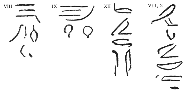
(19) At the top, and to the right of the upper series of scales, are very faint traces of script. They seem to have been placed against each scale, but very few can now be seen. I have tried to photograph them with special panchromatic plates, but without success; the most I have been able to do is to examine them in various lights, when dry and when wetted, and to make hand copies. These are shewn in figures 2 to 4, and are from divisions VIII, IX and XII respectively. Figure 5 is an extra group of signs to the left of the scale in division VIII. The inscriptions are all in red paint and are too fragmentary to translate.
| Fig. 2. | Fig. 3. | Fig. 4. | Fig. 5. |
It is within the bounds of possibility that the inscriptions originally gave some information as to the party who were working that particular double-foot division of the trench.
At the extreme left of the quarry-face, in the position indicated on plate VI, there is an inscription of two lines in the hieratic character. It is very faint indeed and I have not succeeded in deciphering it. The fact that it is in black paint on very dark red weathered granite has made it very difficult to photograph. It appears to begin with a date, and to have a number in the middle, but there is no name of a king.
(20) At the top of the upper quarry-face there is what seems to be the bed from which a monument, very probably a small obelisk, of 7 metres long has been extracted. The bottom of the trench can still be traced where the work has been divided up into grooves of similar width to those in the obelisk trench. Here the feet have become irregular, but the double-foot is of great regularity and measures 59.8 centimetres. Plate V, no. 2, shews the bed at the top of the rock face and no. 3 the same seen from above. It will be noticed that, in this case, the undercutting has been done by pounding, but with less regularity than in the obelisk trench, shewing that it was done by hand. The obelisk seems to have been snapped off, or more likely it broke off of itself. It is hardly justifiable to deduce how the large obelisks were extracted from such a small example. In all probability the principle was the same, but the details very different. This is discussed in sections 21–23. {21}
At the west end of the ridge from which the monument
has been removed, there is a short inscription in red
paint. A photograph of this is given in plate
V, no. 4.
It seems to begin with the words
![[glyphs]](images/i021.png) . . . . . “the work
(of) . . . . . ”. The
remainder is illegible to me, though the signs are quite
clear. They resemble some of the quarry-signs I have seen
at Maʿallah and elsewhere.
. . . . . “the work
(of) . . . . . ”. The
remainder is illegible to me, though the signs are quite
clear. They resemble some of the quarry-signs I have seen
at Maʿallah and elsewhere.
(21) Having examined, as far as possible, the methods by which the obelisk was separated from the surrounding rock, we will consider by what means the obelisk was detached from its bed and got into a position in which it could be handled and transported.
It might be remarked that this particular obelisk has not
been transported; there is no doubt, however, that the man
responsible for the work had quite definite ideas as to
how he was going to perform the feat. Although it is the
largest obelisk known (pace the phantom 108 cubit obelisk
of ![]() atshepsôwet), the old engineers have actually moved
even heavier and more unmanageable blocks: the colossus of
the Ramesseum and the colossi of Amenophis III at Thebes.
If we can solve the ancient method of dealing with this
particular obelisk, we can the more easily understand how
the others were dealt with.
atshepsôwet), the old engineers have actually moved
even heavier and more unmanageable blocks: the colossus of
the Ramesseum and the colossi of Amenophis III at Thebes.
If we can solve the ancient method of dealing with this
particular obelisk, we can the more easily understand how
the others were dealt with.
There seem to be two methods by which the obelisk could be detached from its bed; the snapping off of such an obelisk in the manner mentioned in section 19 being out of the question.
(1) By undercutting the obelisk from both sides to a certain extent, say a quarter of the breadth from each side, and either detaching it by a series of very large wedge-slots (as was done all over the quarries for medium-sized blocks), or, if the Egyptians used wooden wedges, expanded by the action of water, by one long wedge channel on each side of the obelisk. These could be wetted by flooding the trench with water, but before this could be done, the trench would have to be divided into compartments by, say, mud-brick walls to prevent the water running down to the deep end, leaving the pyramidion end dry. In this case a large allowance would have to be made in case the granite did not break evenly across between the wedge-channels. The great objection to this method is the risk of the obelisk breaking across owing to uneven strains set up by the wedges; it will be seen, in section 43, that the obelisk can only just support its own weight when in a horizontal position. If this method were employed, before the obelisk could be moved, it had to be raised off its bed to pass ropes round it. This could be effected by levering from both sides of the obelisk—using the outer trench wall as fulcra—and gradually rocking the obelisk higher by packing below it at each tilt. Assuming that only half a metre was undercut from both sides, it would require 30 12‐inch tree-trunks going down three feet into the trench (properly packed), and projecting 18 feet above the trench, being used vertically, with 70 men pulling on ropes attached to the top of each lever. The strain set up would be about 1000 pounds per square inch, which is well within the {24} powers of ordinary coniferous wood as cypress. (I assume that a man pulls 100 pounds.) The more undercutting performed, the less force would be required to rock the obelisk. Since the obelisk would have to be tilted from both sides, a good deal of rock would have to be removed from the south side of it before the levers could be used.
(22) (2) By completely undercutting the obelisk. In spite of the slowness of the work I am convinced that the obelisk was completely undercut, most likely by hand pounding, since the expenditure of copper chisels would be terrific, and the idea, in this kind of work, seems to be to economise as much as possible on copper. It would be packed by wooden blocks or stone as near the centre as is consistent with stability, and in as few places as possible. Ropes would then be passed round the obelisk, each going several times round and being brought forward from below to anchorages in front. It is here that the details of this method assume such great importance; it must be remembered that, if the obelisk weighs 1170 tons (allowing a margin for the roughness of the undercutting below), and lies on its side on a hard bed, then the horizontal pull by ropes necessary to turn it over on to a new face will be half the weight of the obelisk, i. e. 585 tons. This would need 13,000 men, if a man pulls 100 pounds. I do not see how such a number could possibly be put on to this work. Figure 6 shews the obelisk supported on its packing, the section here being at the centre of gravity, and the outer edge of the packing being 1 metre from the centre of the obelisk on each side. To pull it over by horizontal ropes would need 8000 men, which still seems more than is practicable. It is possible to reduce the number of men required to turn the obelisk over by means of levers working off the north wall of the north trench, which seems to have been deliberately left for that purpose (cf. section 5).
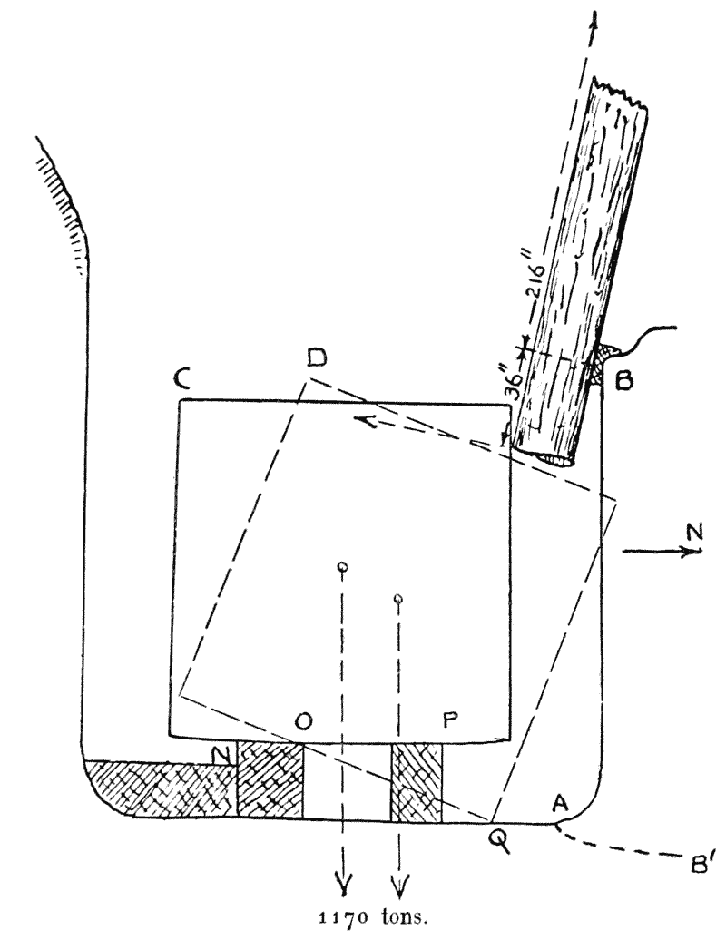
(23) By using, say, 30 21‐foot levers with a mechanical advantage of six to one, as described in the last section, the obelisk can be made to turn slightly about N (see fig. 6) so that the packing P can be removed and perhaps replaced by sand.
About N the moment of the force at the bottom of the lever is to that of the weight of the obelisk acting at its centre as 7 : 2 (by scaling off the figure), so that the moment at the top of the lever to that of the weight will be 42 : 2, or 21 : 1. Let the number of men per lever be n. {25}
Then 30 × 21 × 100 × n = 1170 × 2240, which gives the number of men as 42, or 1260 men in all [9].
I have taken the amount of undercutting in figure 2 as .75 m. at the centre of gravity; it would increase as far as 1.00 metre at the butt.
As soon as the sand had replaced the packing, the rock AB would be removed by burning and wedging until it sloped down as much as possible from the level of the bed of the obelisk. I had not sufficient funds at my disposal to examine the levels of the rock to the centre of the valley, so I have to be rather vague as to what distance the obelisk was rolled out [10]. The obelisk would then, when the sand flowed out or was removed, take up a position as shewn in the dotted section.
[9] The check the stress in the levers. Referring to figure 6, (Stress) (Section modulus) = Sum of moments on one side of fulchrum, i. e. (s × .0982 × (25)3) = (1170 × 2240 × 216)/(30 × 21) = 586 pounds per square inch, which is well within the powers of any wood.
[10] It will be seen that, if the obelisk lies at too low a level to be rolled downwards to the valley, it can be raised by tilting backwards and forwards by means of levers acting from the north and south trenches alternately, as mentioned in section 21. If the butt were raised even a metre above its present level, it would enormously reduce the quantity of rock to be removed before the obelisk could be rolled out.
Then, about Q, the moment of the horizontal force of the ropes round the obelisk to the moment of the weight will be, from the figure, as 9 to 2, so if n be the total number of men required to pull the obelisk over, then (n × 100) = (2 × 1170 × 2240)/9 which gives 5824 men as against the 8000 men which would be required if the levers were not used. It is an enormous number, but I do not see how they could manage with less.
A bank of sand just in front of the lower edge of the obelisk would make the second turn an easy matter, and if from thence the obelisk is rolled downwards on soft sand, I think that the 5824 men will still be ample, as the sand can be undercut in front of the edge and so make the rolling approximate to that of a cylinder.
(24) As to the size of the ropes required for the rolling out of the obelisk, all we can do is to obtain a very rough idea as to it. If they spread the men out slightly fanwise, I do not see how they could have used more than 40 ropes. The strain per rope will be, as we have seen, (2/9 × 1170/40) = 6.5 tons per rope.
The rope used was probably the very best palm-rope, newly made. The safe load which can be put on coir rope, which is of about the same strength, is given by the formula: Load in cwts = (Circumference in inches)2 divided by 4 (Military Engineering, 1913, Part III A, p. 49). Substituting, we have (6.5 × 20 × 4) = C2 which gives a circumference of 22.8 inches and a diameter of 7 ¼ inches. If such a rope were used it would require handling loops on it.
(25) Before leaving the work at the quarry, it remains to be seen how the chiselling of the wedge-slots was done. The apparent impossibility of cutting granite with a copper chisel has struck every student of this question. Many suggestions, some of them grotesque, have been put forward to explain how it might have been performed. Gorringe, in his Egyptian Obelisks, {26} boldly assumes the knowledge of steel. To my mind, the reasons against this are, first: the knowledge of steel would have soon resulted in its use being widespread for daggers, swords and, above all, razors; secondly, it would have had a special name, since its properties are so different from iron. Now all the ancient names for metals have been accounted for, none of which could be applied to mean steel. If we translate Benipet as ‘steel’, then we have no word for iron.
Gorringe’s assertion that iron and steel tools would have disappeared by oxydisation in a few centuries is not borne out by excavations. We know, from the scanty mentions of iron, that it was not very generally used, but quite a number of iron tools of late Egyptian date are now known, and I have myself taken out an iron bill-hook from the filling of a Roman or Ptolemaic grave which was hardly rusted at all, and in the Cairo Museum there is an iron fork of Coptic date from a depth of 5 metres in the sabâkh of Tell Edfù which is almost like new. If the ground is dry and free from certain chemicals, objects such as iron, wood, linen, papyrus, etc., will keep indefinitely, whereas, in unsuitable ground, even copper will disappear and leave no traces, except, perhaps, a blue stain. If steel had been in anything like common use, we should surely have found examples, either in graves or in town sites like Kahûn or Tell el-ʿAmarna. PETRIE, in Tools and Weapons, pl. VI, 187, cites a halberd of iron dated to Ramesses III; had steel been known, we should have expected it to be of that rather than iron. An examination of such broken iron tools as can be spared might give us definite information one way or the other, as steel, though it may lose its temper, will not turn into iron, however long it is left, and should be easily recognized by a micro-photograph.
On the rocks of the Wady Hammâmât, the following
inscription is to be seen, together with others having the
same title (GOLÉNISCHEFF,
Hammamat, II, no. 3, and
COUYAT et
MONTET, Les inscriptions
hiéroglyphiques et hiératiques du Ouâdi Hammâmât, in
Mémoires de l’Institut français du Caire, vol. XXXIV, p.
54) : (![[glyph]](images/i026a.png) )
)
![[glyphs]](images/i026c.png) , etc.
, etc.
The determinative ![]() , sometimes
written
, sometimes
written ![]() , seems to suggest iron tools in
general, and we are hardly justified in deducing from this
that the chisels for cutting granite were necessarily of
iron; it is very likely, however, that the wedges were of
iron.
, seems to suggest iron tools in
general, and we are hardly justified in deducing from this
that the chisels for cutting granite were necessarily of
iron; it is very likely, however, that the wedges were of
iron.
(26) The suggestion, put forward by Donaldson, that the Egyptians softened the granite by chemical means before using the chisels on it, is not worthy of serious notice, as a glance at the tool marks shews that the granite was quite hard, and behaved in exactly the same way as it does under modern tools. His other suggestion, that the granite was first pounded to render it more workable, cannot be accepted as the explanation, as how did they pound the bottom of the wedge-slots?
A far more reasonable suggestion is that the granite was cut by chisels of dolerite or similar {27} basic rocks. Mr. Firth tells me that, except for the grinding of the cutting-edge, they occur naturally in the Wady Alaqi. A series of trials with such a chisel left me entirely unconvinced, the more so since many of the old chisel-marks shew that a narrow-edged tool had been used.
From my own experiments, I can believe that the Egyptians could have cut granite with a copper chisel, but more time is spent sharpening the tool than in cutting the stone, and the expenditure of metal would be appalling in any but the smallest works, but I cannot admit that copper tools, as we know them, could have ever been used to cut hard quartzite, which gave the Egyptians no special trouble, if we judge by the huge chambers which they cut, polished and transported, as in the case of the burial chamber in the Hawara Pyramid.
It has also been suggested that the copper chisels were fed with emery, but anyone who has handled a chisel will appreciate the impossibility of feeding the tool with emery; on the other hand, emery may well have formed the basis of the polishing process, and have been regularly used in stone drilling and sawing.
(27) How, then are we to explain this problem? Much as I hate to admit it, I am driven to the conclusion that the ancient Egyptians possessed some simple method of tempering copper to the hardness of modern tool-steel [11]; even now copper with 2 % of alloy may, by heavy hammering, be brought to the hardness of mild steel. This has been suggested by many writers, and examples of tools are known—Wilkinson quotes one in volume II, p. 255—where the malletted end of the chisel was worn by the blows, but where the point was sharp; of course that might be explained by the fact that it had just been re-sharpened, but I have myself seen a chisel where the cutting-edge was chipped in the same manner as a modern steel tool instead of being burred. I was unable to purchase this specimen, but I tried the point with a knife, and was able to scratch it as I could any other piece of copper; the temper, therefore, must have been temporary (cf. WILKINSON, Manners and Customs, vol. II, p. 255, and PETRIE, Arts and Crafts, p. 100).
[11] There has lately been a rumour that a method has been discovered in America for tempering copper, and that a company is being formed for its exploitation; if this is true, it will relieve archæologists considerably, who have been at their wits’ end for a good explanation for the last 50 years.
If this is the true solution, it is probable that the knowledge died out when the use of iron and steel became general, as its value in not producing sparks could hardly have been foreseen. It is not surprising therefore that the knowledge died out when it was no longer a necessity.
It might be remarked that instead of having a method of greatly hardening copper, the Egyptians might have been able to temper iron. The experiments on iron and its properties during the last century have been innumerable and, had there been a method, apart from the introduction of carbon, of tempering iron to a very great hardness, I think that it would certainly have been discovered by now. In our present state of knowledge, it is best to leave the subject as an open question.
(28) Before entering into the question of the transport of obelisks, it may be as well to give extracts from ancient writers. They throw very little light on the problem, the Roman and Greek writers only giving what seems to be third-rate hearsay information, while the Ancient Egyptians usually confine themselves to statistics as to the numbers of men employed.
King Menthu![]() otpe IV sent an expedition of 10,000 men
to the Wady Hammâmât quarries to bring in a sarcophagus,
and records that it took 3,000 sailors from the Delta
nomes to remove the lid, measuring 4 by 8 by 2 cubits,
from there to Egypt. This seems to shew that a pressed
gang of the amphibious Delta inhabitants from the lakes
had been taken out to the quarries. At any rate we are
told that “not a man perished, not a troop was missing,
not an ass died and not a workman was enfeebled” (BREASTED, Ancient Records,
I, 215). This was more fortunate than the expedition of
Ramesses IV quoted below, but it gives no details of the
various kinds of artisan employed.
otpe IV sent an expedition of 10,000 men
to the Wady Hammâmât quarries to bring in a sarcophagus,
and records that it took 3,000 sailors from the Delta
nomes to remove the lid, measuring 4 by 8 by 2 cubits,
from there to Egypt. This seems to shew that a pressed
gang of the amphibious Delta inhabitants from the lakes
had been taken out to the quarries. At any rate we are
told that “not a man perished, not a troop was missing,
not an ass died and not a workman was enfeebled” (BREASTED, Ancient Records,
I, 215). This was more fortunate than the expedition of
Ramesses IV quoted below, but it gives no details of the
various kinds of artisan employed.
In the reign of Amenem![]() êt III, an official, also called
Amenem
êt III, an official, also called
Amenem![]() êt, was sent to the same place to obtain 10 statues
of 5 cubits high. The personnel consisted of (BREASTED, A. R., I, 313):
êt, was sent to the same place to obtain 10 statues
of 5 cubits high. The personnel consisted of (BREASTED, A. R., I, 313):
| Necropolis soldiers | 20 |
| Sailors | 30 |
| Quarrymen | 30 |
| Troops | 2000 |
Under Ramesses IV, a large expedition was again sent to the Wady Hammâmât for monumental stone. It numbered 8362 persons. Breasted sums up the personnel as follows (A. R., III, 224):
| High Priest of Amûn, Ramesses-nakhl, Director | 1 |
| Civil and military officers of rank | 9 |
| Subordinate officers | 362 |
| Trained artificers and artists | 10 |
| Quarrymen and stone-cutters | 130 |
| Gendarmes | 50 |
| Slaves | 2000 |
| Infantry | 5000 |
| Men from Ayan | 800 |
| Dead (excluded from total) | 900 |
| 8362 |
From this it will be seen that larger parties than our estimate of 5725 were sent much further afield than Aswân, which itself was a garrison town. It seems to have been the custom to use troops on this unpleasant kind of fatigue, if captives or pressed gangs were not available in sufficient numbers.
The only record that we have on the transport of an
obelisk is a passage from the Papyrus Anastasi I (GARDINER, Egyptian Hieratic
Texts, Part I, p. 17*, § XIII), in which one scribe called
![]() ori writes to another called Amenemope, accusing him of
being unable to calculate the number of men required to
transport an obelisk of given dimensions. He says: “An
obelisk has been newly made . . . . .
of 110 cubits in length of shaft; its pedestal 10
cubits square, the block of its base making 7 cubits
in every direction; it goes in a slope (?) towards the
summit (?), one cubit one finger, its pyramidion one
cubit in height its point measuring two fingers. Add
them together (?) so as to make them into a list (??),
so that thou mayest appoint every man needed to drag
it . . . ”
ori writes to another called Amenemope, accusing him of
being unable to calculate the number of men required to
transport an obelisk of given dimensions. He says: “An
obelisk has been newly made . . . . .
of 110 cubits in length of shaft; its pedestal 10
cubits square, the block of its base making 7 cubits
in every direction; it goes in a slope (?) towards the
summit (?), one cubit one finger, its pyramidion one
cubit in height its point measuring two fingers. Add
them together (?) so as to make them into a list (??),
so that thou mayest appoint every man needed to drag
it . . . ”
Here the obelisk is very long and thin and has an impossibly short pyramidion, but in any case such a problem can only be solved by one who has had previous experience, not only of the friction to be overcome in the transport of large blocks, but of the nature of the ground to be traversed. The figures given are only sufficient to determine the weight of the obelisk.
(29) The largest transportation on land, of which a scene has come down to us, is that of the winged bull of Nineveh. This is published in LAYARD, Discoveries, pls. X–XVII. The bull is drawn by men pulling on four cables, and a line of men keeps on placing rollers under the front of the sleds on which the colossus is attached. Behind it men assist the overcoming of the initial friction with large handspikes.
Another scene, this time from Egypt, is the transport
of a statue of one called D![]() ut
ut![]() otpe (LEPSIUS, Denkmäler, II, 134,
and BREASTED, Ancient
Records, I, 309–312). The method used here is that of
a sled, whose runners are wetted or greased, pulled on
sleepers. Though the statue was only about 22 feet high and
weighed some 60 tons, it appears to have required 172 men
to move it; we can therefore safely rule this method out as
applying to a 1170‐ton obelisk. If a sled was used, it must
have been in conjunction with rollers.
otpe (LEPSIUS, Denkmäler, II, 134,
and BREASTED, Ancient
Records, I, 309–312). The method used here is that of
a sled, whose runners are wetted or greased, pulled on
sleepers. Though the statue was only about 22 feet high and
weighed some 60 tons, it appears to have required 172 men
to move it; we can therefore safely rule this method out as
applying to a 1170‐ton obelisk. If a sled was used, it must
have been in conjunction with rollers.
Greek and Roman writers throw very little light on ancient methods of transportation. Herodotus, in book II, chap. 175, remarks: But of these, that which I not the least, rather the most admire, is this: he (King Amasis) brought a building of one stone from the city of Elephantine, and 2000 men, who were appointed to convey it, were occupied three whole years in its transport, and these men were all pilots. The length of this chamber, outside, is 21 cubits, the breadth 14, and the height 8. This is the measure of the outside of the one-stoned chamber. But inside the length is 18 cubits 20 digits, and the width 12 cubits, and the height 5 cubits.
Gorringe, in his Egyptian Obelisks, gives an almost complete collection of the accounts of transportation, erection, etc., by ancient authors. Many of these accounts are so vague or improbable as to be hardly worth including here. {31}
(30) Having discussed the possible methods of removing the obelisk from the quarry, the next thing to be considered is whether it was rolled over and over down to the river bank, or whether it was pulled along on rollers.
The first way is not without its advantages, as it is almost fool-proof. The width of the embankment or track, of which there are many about the quarries, need only be about one-third the length of the obelisk, and the tendency for the obelisk to roll in a circle would be to a large extent neutralized if it were of soft sand, where the heavy end would sink in to a greater depth than the point end. However, the turning would be a most laborious process, and the general progress very slow and requiring an enormous number of men. It is obvious that the obelisk was brought into the temple precincts lengthways, so if it was moved a little that way it is quite possible that the greater part of its journey on land was so made.
(31) Plate VII gives a rough plan of the quarry in which the obelisk lies. It is accurate as regards the obelisk, embankments and the rock faces A, B and C. It will be seen that the rock at B, which is also shewn on plate III, no. 2, has been partly cut away, presumably to let the point of the obelisk pass out of the quarry. It may be only a coincidence, but, strangely enough, the distance A C (from both ends of which rock has been removed), is almost exactly the length of the obelisk. My opinion is that the obelisk was only rolled sideways for a very short distance until it was very little higher than the level of the floor of the valley, and was then put on to rollers running on heavy baulks of limber, the process being:
It has been doubted that the Egyptians knew rollers, but without them I do not see how a thousand-ton block can be transported. After all, the Assyrians were familiar with them in the 8th century B. C. at latest (section 29), and there was extensive communication between them and the Egyptians for centuries before that. Are we to assume that the discovery was made between the probable 15th century of our obelisk and the 8th?
The Luxor obelisk, in the course of its removal to Paris, was dragged along a specially prepared wooden track after it had been mounted on a wooden ‘cradle’, the track being well greased. The pulling was done by capstans and blocks and tackles. It was found that a pull of 94 tons was required to pull the obelisk up the slope leading to the pedestal. This was with a 227‐ton obelisk. Since friction with average-sized blocks is about proportional to the weight, to pull the Aswân obelisk would need (1168/227 × 94) = 485 tons, which would require about 11,000 men. I cannot believe that all these could have been arranged so as to pull the obelisk up an embankment (see sections 35 and 37). {32}
The great advantage of rollers is that comparatively little space is required and a minimum of pulling force; its disadvantages are that there is always a risk of the rollers becoming jammed, and that, even on a slight incline, the obelisk is liable to get out of control.
As to the sizes of the rollers required, I can only say
that the top of the fallen obelisk of
![]() atshepsôwet now
rests on 20 cent. diameter pitch-pine rollers, spaced
one metre apart, and there is not the faintest sign of
crushing. The worst stress with the Aswân obelisk might
rise to 11 times as much as the example cited.
atshepsôwet now
rests on 20 cent. diameter pitch-pine rollers, spaced
one metre apart, and there is not the faintest sign of
crushing. The worst stress with the Aswân obelisk might
rise to 11 times as much as the example cited.
(32)
The obelisks of
![]() atshepsôwet were mounted on sleds, perhaps
to make an easier running surface; it would also serve to
damp any shocks and to distribute the upward pressure of
the rollers evenly along the under surface of the obelisk.
The method of attachment is shewn in figure 7 (from NAVILLE, The Temple of Deir el
Bahari, Part VI, pl. CLIV), but is rather vague. I cannot
say whether the Aswân obelisk was to have been mounted in
this way or not; if it were, then it would be put on its
sledge at the same time as it was put on the rollers, as
explained in the last section.
atshepsôwet were mounted on sleds, perhaps
to make an easier running surface; it would also serve to
damp any shocks and to distribute the upward pressure of
the rollers evenly along the under surface of the obelisk.
The method of attachment is shewn in figure 7 (from NAVILLE, The Temple of Deir el
Bahari, Part VI, pl. CLIV), but is rather vague. I cannot
say whether the Aswân obelisk was to have been mounted in
this way or not; if it were, then it would be put on its
sledge at the same time as it was put on the rollers, as
explained in the last section.
(33) Once on its rollers, there is a fairly level and straight track from the mouth of the valley running along the course of the old barrage railway (pl. VII), joining the two large embankments DE and FG, which feed the quarries on the south of the obelisk and on the high desert respectively. Plate IV, no. 4, gives a view of the embankment FG looking down to Aswân town. It joins the course the obelisk would take at A. The modern town north of the station prevents us determining exactly where these embankments gave on to the river bank.
(34) On the details of the boats, on which we know the obelisks were transported, I can offer no opinion of value, as I am not familiar with boat design, particularly that of the “queen-truss” type which seems to have been so popular with the Egyptians. I will content myself, therefore, with citing certain accounts and giving sundry references, which may prove of use to those who intend to pursue this matter further.
The only scene we have of water transportation is that
of the temple of Dêr el-Ba![]() ari, published by Naville and
entitled The Temple of Deir el Bahari, Part VI, plate
CLIV, where there is a picture of the boat containing
two 30‐metre obelisks placed butt to butt [12]. The
boat used here must have been at least 82 metres long. He
mentions also the boat used to carry the two obelisks of
Tuthmôsis I, which measured 63 metres by 21 wide (BREASTED, Ancient Records,
II, 105). Both this boat and that of
ari, published by Naville and
entitled The Temple of Deir el Bahari, Part VI, plate
CLIV, where there is a picture of the boat containing
two 30‐metre obelisks placed butt to butt [12]. The
boat used here must have been at least 82 metres long. He
mentions also the boat used to carry the two obelisks of
Tuthmôsis I, which measured 63 metres by 21 wide (BREASTED, Ancient Records,
II, 105). Both this boat and that of
![]() atshepsôwet are
spoken of as the “August” boat. {33}
atshepsôwet are
spoken of as the “August” boat. {33}
[12] It has been suggested that
the two obelisks shewn butt to butt in the Dêr
el-Ba![]() ari sculpture were not
the Karnak pair, but those erected before the Dêr
el-Ba
ari sculpture were not
the Karnak pair, but those erected before the Dêr
el-Ba![]() ari temple. Excavation has not confirmed
this. The subject is discussed by Breasted in Ancient
Records, II, p. 135, note e.
ari temple. Excavation has not confirmed
this. The subject is discussed by Breasted in Ancient
Records, II, p. 135, note e.
Another great boat was made by one Uni, in the VIth dynasty, for the transport of stone from Aswân. This measured 60 cubits (31 metres) in length by 30 in width, and took only 17 days to construct (Ancient Records, I, 322).
The construction of ancient boats is discussed in Ancient
Egypt, 1920, Part 1 ff. by Mr. Somers Clarke, and a
detailed description of
![]() atshepsôwet’s boat is given by
Naville, in his work cited above, on pages 2 to 4. Boats
are also described in
WILKINSON, Manners and
Customs, vol. I, p. 276, and vol. II, pp. 211, 212.
atshepsôwet’s boat is given by
Naville, in his work cited above, on pages 2 to 4. Boats
are also described in
WILKINSON, Manners and
Customs, vol. I, p. 276, and vol. II, pp. 211, 212.
To me, the only practicable way of loading such an obelisk on to a boat, would be by building an embankment round and over the boat, pulling the obelisk into a position above it, and then digging the boat and channel clear again. We can hardly believe that the obelisk was hauled in over the gunwale! In moving the Luxor obelisk to Paris, and the Alexandria obelisk to New York, in the one case the whole prow of the barge was removed, and in the other a port was cut in the bows of the steamer through which the obelisk was introduced (see sections 53 and 54).
Pliny, in his Natural History, book XXXVI, chap. 14, gives an account of how King Ptolemy Philadelphus had an obelisk transported to Alexandria. He tells us, apropos of the loading on to the boat: “A canal was dug from the River Nile to the spot where the obelisk lay; and two broad vessels, loaded with blocks of similar stone a foot square—the cargo of each amounting to double the size, and consequently double the weight of the obelisk—were put beneath it; the extremities of the obelisk remaining supported by the opposite sides of the canal. The blocks of stone were removed and the vessels, being thus gradually lightened, received their burden.” If this was so or not, it certainly was not the method by which the obelisks were brought from the Aswân quarries to the bank. No trace of a canal of this sort is to be seen, though there are plenty of traces of enormous embankments.
(35)
The only reference the Egyptians have left us actually
referring to the erection of a monument is that given in
the Papyrus Anastasi I (for publication, see section
28).
The monument to be erected is in this case a colossus.
The text gives (§ XIV): “It is said to thee: Empty the
magazine that has been loaded with sand under the monument
of thy Lord which has been brought from the Red Mountain.
It makes 30 cubits stretched on the ground, and 20 cubits
in breadth . . . . . -ed with 100
(??) chambers filled with sand from the river-bank. The
. . . . . of its (?) chambers have
a breadth of 44 (?) cubits and a height of 50 cubits,
all of them . . . . . in their
. . . . . . . . .
Thou art commanded to find out what is before the Pharaoh
(??). How many men will it take to demolish
(![]() m—also
“remove” or “overturn”) it in six hours—if (?) apt are
their (?) minds (?), but small their desire to demolish it
without there coming a pause when thou givest a rest to
the soldiers, that they may take their meal—so that the
monument may be established in its place?”
m—also
“remove” or “overturn”) it in six hours—if (?) apt are
their (?) minds (?), but small their desire to demolish it
without there coming a pause when thou givest a rest to
the soldiers, that they may take their meal—so that the
monument may be established in its place?”
Here the technical details are extremely obscure, as there are many unknown words in the text.
In the same papyrus (§ XII), there is a reference to
an embankment, which may well have been intended for
the erection of a monument, perhaps an obelisk, as the
problem immediately following concerns the transport of
an obelisk from the quarry. The scribe
![]() ori puts the
problem: “There is made a ramp of 730 cubits, with a
breadth of 55 cubits, consisting of 120 compartments (?)
filled with reeds and beams with a height of 60 cubits
at its summit, its middle of 30 cubits, its batter (?)
15 cubits, its base (?) of 5 cubits. The quantity of
bricks needed for it is asked of the commander of the army
. . . . . . . Answer us as to
the quantity of bricks needed. Behold its measurements (??)
are before thee; each one of its compartments (?) is of 30
cubits long and 7 cubits broad.”
ori puts the
problem: “There is made a ramp of 730 cubits, with a
breadth of 55 cubits, consisting of 120 compartments (?)
filled with reeds and beams with a height of 60 cubits
at its summit, its middle of 30 cubits, its batter (?)
15 cubits, its base (?) of 5 cubits. The quantity of
bricks needed for it is asked of the commander of the army
. . . . . . . Answer us as to
the quantity of bricks needed. Behold its measurements (??)
are before thee; each one of its compartments (?) is of 30
cubits long and 7 cubits broad.”
Since the words translated by “compartment” and “base” are very doubtful in meaning, it is difficult to obtain any definite idea as to the internal construction of the ramp. Borchardt supposes the words “the middle” to mean the space filled with rubbish in the inside of the embankment as a means of economising the bricks.
The ‘compartments’ may refer to the longitudinal divisions in the middle of the embankment, which can still be seen in the construction ramp inside the South Ptolemaic (?) pylon at Karnak. Choisy, in his L’Art de bâtir chez les Égyptiens, p. 86, gives rather a good little sketch of this, apparently made when the ramp was newly cleared. Borchardt, on the other hand, imagines the compartments to be transverse divisions. It is certain, however, that there is a mistake in the measurements given in the Anastasi papyrus, as it seems quite impossible to {36} divide up the embankment according to the data, even if we take ‘compartments’ to mean the sections or towers into which nearly all brick enclosure walls and embankments were divided (see SOMERS CLARKE, J. Eg. Arch., vol. VII, p. 77).
It seems to me that Borchardt is right as to the embankment being, as it were, a brick box filled with earth; otherwise there is a great redundance of data. Obviously, the only measurements necessary for an embankment (built of plain brickwork or in towers like the great temple walls), if solid, are: Horizontal length of ramp (L); highest part (H); width at top (W); and the batter (B). Then the number of bricks required will be, to a close approximation: ½LH(W + B) divided by the volume of one brick, plus a factor for waste bricks.
It may be remarked that if the Aswân obelisk were pulled up an embankment of the slope given here, it would need (neglecting friction) over 2000 men.
Classical authors tell us next to nothing; as an example I give Pliny’s account of an erection done by the Egyptians. In his Natural History, book XXXVI, chap. 14, he tells us: “Rhamsesis, who was reigning at the time of the capture of Troy, erected one 140 cubits high (73 metres). Having left the spot where the palace of Mnevis stood, this monarch erected another obelisk 120 cubits (63 metres) in height, but of prodigious thickness, the sides being no less than 11 cubits in breadth (5.77 metres). It is said that 120,000 men were employed upon this work, and that the king, when it was on the point of being elevated, being apprehensive that the machinery employed might not prove sufficiently strong for the weight, and with a view of increasing the peril that might be entailed by the want of precaution on the part of the workmen, had his own son fastened to the summit, in order that the safety of the prince might at the same time ensure the safety of the mass of stone . . . . . ”
(36) Mediæval and modern writers have speculated freely on the ancient method of erecting obelisks, their ideas ranging from fairly sound theories to the assertion constantly made to me by the less responsible spiritualists, that it was done by levitation!
Of modern theories two seem to be popular; the first suggests that the obelisk was laid flat, with one side of its base just above the notch, which in nearly all cases runs along one side of the pedestal, and that it was gradually levered up, and at the same time banked from below, being assisted when it had become sufficiently high by pulling with head-ropes, and similarly checked by ropes when on the point of tilting over on to its base. This with slight modifications, was the method used for the erection of the obelisk of Seringapatam, and is described by Gorringe in his Egyptian Obelisks (p. 157), and by Commander Barber, in The Mechanical Triumphs of the Ancient Egyptians on page 102. It must be remembered, however, that the whole obelisk weighs only about 35 tons. To assert that this method was that to be used for the Aswân obelisk is not justifiable. The reasons against this method may be summed up as follows:
(37) The more usual explanation as to how the erecting was performed is that the obelisk was pulled on rollers up a long inclined embankment until it was at a height well above the centre of gravity of the obelisk. Having been rolled up base foremost, it was tilted over the end of the embankment, and the earth gradually cut away from below it until it settled down on to its pedestal, leaning against the embankment; from thence it was pulled upright (see PETRIE, Arts and Crafts of Ancient Egypt, p. 77, quoted in section 55).
This seems a far more probable method than the last, but from a practical point of view it leaves a good deal unexplained. Anyone who has seen, in sabâkh work or elsewhere, earth being cut from under a stone, or even being itself undercut, knows the way it has of slipping sideways or any way but the expected—generally on the heads of one’s workmen. With, say, a 500‐ton obelisk, the undercutting would be a somewhat delicate business to make it settle down true on to the pedestal.
The tendency to rock and pivot when being finally pulled upright is not dealt with. Whatever method the Egyptians used, it was sure, and did not depend on the skill of the men with the hoe and basket.
Before describing the method which I believe was used, it would be well to consider what means the Egyptians had at their disposal.
(38) Levers must have surely been familiar to the Egyptians; the constant import of tree-trunks from Syria would furnish them with the material, and a hundred occurrences in every-day life, such as extracting a stone with the point of a hoe would suggest to them the application. The occurrence of a lever in the filling of a tomb at El-Bersheh is published by M. Daressy in Annales du Service, vol. I, p. 28, where he remarks: “On a retrouvé une branche d’acacia taillée en biseau à une extrémité qui avait dû servir de ciseau et de levier pour soulever le couvercle”.
In several of the temples in the Theban area and—Dr. Reisner informs me—in the temple of the third pyramid at Gizeh, one may see large blocks, undercut at various points along their length as if to take the point of a lever. {38}
Rollers, too they must have known, even if they did not
get the idea from the Assyrians. We know that they used
sleds running on sleepers—at Lahun pyramid the tracks have
actually been found—and it is incredible that the greater
ease in pulling, when a small sled ran over a stick, should
escape their notice. It might be asked why the statue of
D![]() ut
ut![]() otpe was not pulled along on rollers, instead of
on a sled only (cf. section
29). The reason seems to be
that, given a moderate sized block and plenty of men, the
progress would be quicker, as the sled does not need the
constant adjustment and attention which is required by
rollers. As we have already remarked, the friction renders
the use of sleds alone impossible for a large obelisk (cf.
section
31), so, since it appears that obelisks must have
been brought into the temple precincts endways, there is no
other means we know of other than rollers.
otpe was not pulled along on rollers, instead of
on a sled only (cf. section
29). The reason seems to be
that, given a moderate sized block and plenty of men, the
progress would be quicker, as the sled does not need the
constant adjustment and attention which is required by
rollers. As we have already remarked, the friction renders
the use of sleds alone impossible for a large obelisk (cf.
section
31), so, since it appears that obelisks must have
been brought into the temple precincts endways, there is no
other means we know of other than rollers.
Several pieces of wood, which were probably used as rollers, were found in the débris round the Lahûn Pyramid, and are published in BRUNTON, Lahun I, the Treasure, plate XX. They vary from a foot to about 8 inches in length, having diameters from 2 to 3 inches. The ends of all the examples are rounded. It is strange that, in the quarry and chip-heap cleared at El-Lahûn, so few workmen’s tools were found with the exception of wooden mallets and sleepers.
Dr. G. A. Reisner, in reply to my question as to whether any rollers had been found in the course of his excavations, has kindly sent me the following note. “At Nuri (Ethiopia) we found two short thick granite rollers in the chamber of Pyramid VIII, where there was a granite coffin, weighing 7–8 tons, which may have been used for moving the coffin from the foot of the stairs through rooms A and B to its place in C. We actually used these rollers in moving the coffin out.” He gives the date of these rollers as about 550 B. C.
(39)
On the other hand, it appears that the capstan and the
block and tackle, arranged to give a large mechanical
advantage, were quite unknown until quite late times.
No trace has been found of them in the town-sites
excavated in recent years, nor is there any trace of
their derivatives, such as the spoked well-drum in one
case or the application of the other for hauling up the
sails of ships. In the scene of the expedition to Punt in
the time of ![]() atshepsôwet, an examination of the sail
halliards reveal nothing in the nature of a block and
tackle.
atshepsôwet, an examination of the sail
halliards reveal nothing in the nature of a block and
tackle.
Sheers, gyns and derricks may well have been known in principle, but for moving weights like those of obelisks, these are of no use except in conjunction with the capstan and block and tackle. When the Luxor obelisk was being lowered for removal, in spite of the elaborate calculations of the stresses set up in the wooden sheers, and of the good modern carpentry used in their construction and the steady pull given by the capstans, the structure crushed and jammed, and it was only by the use of screw-jacks that the necessary repairs could be made. This was with a 227‐ton obelisk!
A method which may have been used, and which I should myself attempt if I were entrusted with such a piece of work, is as follows:
(40) A square funnel is first built round and above the pedestal on which the obelisk is to stand (see plate VIII), leaving a space about half a metre high, and one and a half metre wide, clear over the edge of the pedestal, to lead out to a tunnel. The sides of the funnel, which are {39} of smooth masonry, are set at a slope so that the obelisk on being lowered into it can lie against the wall of the slope without passing its dead-centre and coming of itself to an upright position. The sides of the funnel are continued upwards—perhaps in brick, for economy—until the height of the funnel is well above the centre of gravity of the obelisk; the higher, the better. Around the funnel the brickwork would be brought out to form a square tower, with the pylon wall for its revetement, perhaps, on one side. The tunnel mentioned above leads from the pedestal to the further wall of the tower.
A long sloping embankment (section
35) is made to lead up
to the top of the platform, and a gentle curve cut in the
brick (A) to lead down to the interior of the funnel. In
the case of the obelisk of
![]() atshepsôwet, the platform must
have been at a high enough level to clear any buildings in
the way.
atshepsôwet, the platform must
have been at a high enough level to clear any buildings in
the way.
The obelisk is then pulled up on rollers, base foremost, until it just overhangs the slope A. The funnel, previous to this, is filled with the finest Aswân sand, which has very little cohesion in its particles, banked high against the butt of the obelisk. The sand is then very gradually removed from the tunnel, thus letting the obelisk slowly down on to its pedestal. In this process, men would descend with the obelisk until the masonry portion of the tunnel was reached. Precautions would have to be taken, by banking the sand up before the butt of the obelisk and, if necessary, by inserting wooden struts between the butt and the wall B of the funnel, to prevent the obelisk jamming against it. After the masonry is reached, there would be little fear of a jam.
There is fairly good proof that blocks and statues were lowered on to their beds by emptying sand-bags which supported them. Choisy, in his L’Art de bâtir chez les Égyptiens, takes it for granted that this method must have been used for obelisks as well. His suggestion—or rather description, for he might well have been there—of how the Egyptians erected their obelisks, on page 124, is not to be taken seriously, except perhaps for the smallest obelisks (see section 50).
If the method I suggest, or a modification of it, was that used for the erection of the largest obelisks, sand-bags are not necessary at all.
As to the flow of fine blown sand, I can speak from personal experience on the matter, as I have several times approached a big tomb-shaft filled with blown sand from below, having entered by another tomb breaking into it. The sand always lay sloping from the roof of the chamber joining the shaft to the floor, at an angle of about 20 degrees. It can be easily and safely removed from below without bringing down an avalanche. I am very sure that, at the end of the tunnel, no constant flow will occur, even when the sand is being pressed down by a 1168‐ton obelisk; it is more likely that men would have to remove the sand from half-way along the tunnel.
The bottom of the funnel would have to be slightly larger than the base of the obelisk, so as to be able to remove the sand, stones and brick fragments which might have come down with it.
If all went well, the obelisk, when it touched the pedestal, would lie against the near wall of the funnel with its base engaging in the notch. Men would then enter through the tunnel, and clear out all particles of sand from the surface of the pedestal and, if necessary, from around the base of the obelisk. {40}
Before passing the proofs of the volume, but after plate VIII was printed, I made a wooden model of a funnel of almost exactly the same proportions as that shewn on the plate. The height of the end of the embankment was 30 centimetres. This I tried with a 1/100 scale model of the obelisk in limestone, using finely sifted Aswân sand.
The result was interesting, since it shews the great importance of unsuspected details in this kind of undertaking.
In the model, I did not use a tunnel, but allowed the sand to escape at any desired rate through an aperture in the stand on which the model was placed. Since the model was not fixed to the stand, the position of the aperture with regard to the bottom of the funnel could be varied.
I found that, if the aperture was on the side away from the embankment, there was a decided tendency for the obelisk to jam against the opposite wall of the funnel. If, on the other hand, the sand ran out from the near side, the obelisk came down resting against the embankment wall, with its edge where the slot should be. It seems most likely that the sand was removed, not from the tunnel shewn on plate VIII, but from one on the opposite side, leading out from under the embankment. The tunnel shewn in the plate seems necessary for the proper cleaning of the pedestal before the obelisk was pulled upright.
In a subsequent model, in which the side of the funnel was vertical and made of glass, I was enabled to examine the base of the obelisk and the levels of the sand during the descent. The results shewed no reason for modifying the diagram on plate VIII except in the manner mentioned above.
It is possible that the sand was removed from above until the obelisk was low enough for there to be no fear of a jam; after that point had been passed, it would not matter from which side of the pedestal the sand was removed.
I realise that if the model were enlarged up to full-size, the grains of sand would be at least one centimetre in diameter. It seems to me that, using ordinary sand with a full sized obelisk, the flow would be better than is the case in the model, as there would be less skin-friction with the sides of the funnel. On the other hand, there may well be factors, unforeseen by me, which might render the behaviour of the full-sized obelisk different from that of the model, so I give these results without insisting that they are a proof that such a method is possible for erecting obelisks.
Another point arises in connection with the funnel; this is the possibility of the side walls of the funnel having been constructed vertically, the width of the funnel being only slightly greater than the width of the base of the obelisk. The advantage of this modification would be that if sand were piled on to the obelisk in the initial stages of its descent, the weight of the sand would be a great help in forcing the base down the funnel past the point where it might be likely to jam. It would, however, make the examination of the obelisk during its descent a difficult matter owing to lack of space.
Mr. Somers Clarke points out that, if the obelisk came
down on to its pedestal supported on one edge, that the
strain would crush the granite. It seems that the slot
in the pedestal served a double purpose, one to keep the
obelisk from twisting, and the other to ensure that the
weight {41} is taken
on the edge of the slot and not on the edge of the obelisk
(see fig. 8).
Let us assume that the edge of the slot crushes until there
is 2 inches of supporting surface; then since the obelisk
is about 165 inches along its base, the bearing surface
will be 330 square inches and the resulting crushing
stress about 3 ½ tons per square inch, which is
not so very excessive. By putting moderately soft wood
in the slot, the weight could be borne both by the edge
of the obelisk and the edge of the slot, thus further
reducing the stress set up. In the case of the standing
obelisk of ![]() atshepsôwet, it has come down without
engaging in the slot, with the result that the corners have
crushed considerably.
atshepsôwet, it has come down without
engaging in the slot, with the result that the corners have
crushed considerably.
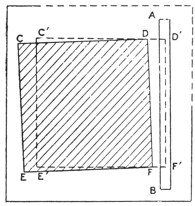
Figure 8 shews the position of this obelisk as it now stands on its pedestal, the position taken up being CDEF instead of C′D′E′F′. The corners E and F have split badly owing to the great weight and have been rounded to cover up the defect. In this case the inner side of the slot, AB, as far as can now be seen, is still sharp. In all the other pedestals I have examined, where the obelisks have apparently come down so as to bear on the inner edge of the slot, the edge is very distinctly crushed.
(41) Before the obelisk was pulled upright, the space in front of the obelisk, and between it and the wall B, might well be filled up with halfa and reeds, to make a kind of cushion, and to damp any tendency to rock backwards and forwards. The notch would prevent any twist before it engaged with the reed cushion. If the obelisk twisted, it was because the reed cushion was not sufficiently tightly packed, the twist taking place after it had rocked over to its further edge.
If the obelisk was on a sledge, I should think that it was removed before introducing it into the mouth of the funnel; the removal of the rollers would be automatic.
The raising of the obelisk without the aid of an embankment is proposed by Choisy in L’Art de bâtir chez les Égyptiens. He assumes that the obelisk was raised by a series of levers used horizontally on a fulcrum, and that it was heaved up simultaneously from both sides and packed from below after each heave, the obelisk and levers rising together till the obelisk was sufficiently high to lower on to the pedestal (cf. section 50 and fig. 11).
Let us assume that this method was to be used for the Aswân obelisk. I think that the largest levers practicable would be 15 metre tree-trunks used with a mechanical advantage of 10 to 1. Not more than 30 levers could be used on each side of the obelisk. The number of men required to raise the obelisk can be found to be about 56 per lever, assuming that they all heave at the end. I hardly see how such a number can be put on a horizontal lever unless we assume that a cross-baulk is attached along the ends of the levers and the whole loaded with stones. The levers would have to be dismounted at each heave and the time taken would be considerable. The method, however, is a possibility, so I include it as an alternative to the embankment. {42}
(42) Before leaving this subject, it is as well to ascertain if the obelisk is strong enough to bear the internal strain due to its own weight when it is supported at its centre of gravity.
The volume of a truncated cone is given by the formula V = H/3 (A2 + Aa + a2).
In the shaft of this obelisk, H is 37.25, A is 4.20 and a is 2.50 metres. Substituting, we have: V = 37.25/3 {(4.2)2 + 4.2 × 2.5 + (2.5)2} from which we find that the volume of the shaft is 426 cubic metres. Aswân granite weighs about 2.679 tons per cubic metre, which makes the shaft weigh 1143 tons.
The weight of the pyramidion is {(base)2 (height) (unit weight)}/3, or (2.50)2 (4.50) (2.679)/3 = 25 tons, so that the total weight of the obelisk would have been 1143 + 25 = 1168 tons.
The distance of the centre of gravity of a tapering square-sectioned solid from the butt is given by the formula: {¼ H (A2 + 2Aa + 3a2)}/(A2 + Aa + a2).
Here H is 37.25 m.; A = 4.2 m.; a = 2.5 m.
Substituting we get: (37.25/4) {[(4.20)2 + 2 (2.50 × 4.20) + 3 (2.50)2]/[(4.20)2 + (2.50 × 4.20) + (2.50)2]}.
That is, the distance of the C. G. from the butt, (LN on fig. 11), is 15.35 metres.
Taking the pyramidion by itself. Its height is 4.50 metres, so that its C. G. must be one-fourth that distance from the base, which makes 1.12 metres.
If x is the distance of the centre of gravity of the whole obelisk from the butt, by taking moments about the butt we have: (Total weight) × x = (weight of pyramidion) × (1.12 + length of shaft) + (weight of shaft) × 15.35, or 1168 x = 25 × 38.37 + 1143 × 15.35, from which x = 15.84. That is, the distance of the centre of gravity of the whole obelisk from the butt is 15.84 metres.
The breadth of the obelisk at its centre of gravity is 4.2 − (15.84/37.25) × (4.2 − 2.5) or 3.49 metres.
(43) Let us assume that the obelisk is balanced at its C. G., and find the stresses due to bending. The weight on each side will be equal. Taking the right hand half, its weight will act at its C. G. Using the formula for the C. G. of a tapering square-sectioned solid, quoted above, we get: (15.84/4) {[(4.20)2 + 2 (4.20) (3.49) + 3 (3.49)2]/[(4.20)2 + (4.20) (3.49) + (3.49)2]} = 7.43 metres, which means that the centre of gravity of the right-hand half of the obelisk will act at a distance of 7.43 metres from the butt, or 15.84 − 7.43 = 8.41 metres from the balancing point, or C. G. of the whole obelisk.
The sum of the moments to the right of the C. G. of the whole obelisk will be half the total weight multiplied by 8.41 = 584 × 8.41.
Then, if s is the internal stress set up due to the bending of the obelisk when supported at its C. G., we have:
(Section modulus) (stress) = sum of moments on one side of support.
The modulus of the square section is one sixth the cube of the depth, so we have: {(3.49 × 39.37)3/6} s = 584 × 8.41 × 39.37 × 2240.
From which s = 1001 pounds per square inch (39.37 being the reduction of metres to inches). {43}
The modulus of rupture for granite from Aswân is given as 1500 pounds per square inch, so it will be seen that the obelisk, if not converted into a live load (by a jerk, for instance) can be supported at its C. G. without breaking.
It is rather difficult to say how far the Egyptians were able to carry their calculations. The erection could well have been rehearsed by means of a scale-model, which could have been further used for obtaining the weight and the position of the centre of gravity. I do not think that they ever troubled about the bending-moment; at any rate, their mathematics were not sufficiently advanced for its determination. It may be that, since in all the obelisks we know of, whose taper does not vary to any great extent, can be supported anywhere, the Egyptians never had a case of such a monument breaking by its own weight.
Another interesting point arises in connection with this,
and that is, since in obelisks (and all beams) of the
same proportion, the bending stress due to their own
weight depends on the linear dimension, and therefore
the fact that a granite scale-model does not break will
be no indication that the monument itself will not break
when similarly supported. If the 108 cubit (56.70 metres)
obelisk of ![]() atshepsôwet, mentioned by
atshepsôwet, mentioned by
![]()
![]() utiy
(section
3),
does indeed apply to one and not to the two placed butt
to butt on the boat shewn in the Dêr el-Ba
utiy
(section
3),
does indeed apply to one and not to the two placed butt
to butt on the boat shewn in the Dêr el-Ba![]() ari sculpture,
then, if the proportions are about the same as the Aswân
obelisk, the stress set up when supported at its centre
of gravity (see section
40) would be in the nature of
56.70 × 1001/41.75 = 1360 pounds per square inch, which
is perilously near the breaking stress of 1500 pounds per
square inch.
ari sculpture,
then, if the proportions are about the same as the Aswân
obelisk, the stress set up when supported at its centre
of gravity (see section
40) would be in the nature of
56.70 × 1001/41.75 = 1360 pounds per square inch, which
is perilously near the breaking stress of 1500 pounds per
square inch.
It will be clearly seen that the obelisk, part of which is at Constantinople, cannot have been part of the 108‐cubit obelisk, as it would be much thinner than the one at Aswân and would certainly not support its own weight either at the centre of gravity or at its ends. When worked out, the internal stress set up in such an obelisk more than doubles the ultimate strength of granite.
(44) During the clearance of the west end of the north trench, a small pot was found, of the form shewn in figure 9, containing a small quantity of a substance which had the appearance of red brick dust. The pot appears to have had a neck, but it is now missing, and a section has been broken out of the side. On the other side of the pot there is a small hole. The shape of the pot is not characteristic, and it may well be of a date later than that of the obelisk. The glaze is of a dark reddish-brown colour, and is the coarsest I have ever seen, being very uneven and covered with bubble-craters. The Director of the Chemical Department kindly allowed analyses to be made of the glaze and also of the contents of the pot. As regards the glaze, Mr. W. B. Pollard of the Chemical Department staff, who has had experience in the analysis of glazes, has suggested that it is a natural one, perhaps due to the pot lying in a fire of burning vegetable matter. This seems very likely since there seems to have been a great deal of burning in removing the upper layers of granite during the extraction of monuments from the quarries (section 4).
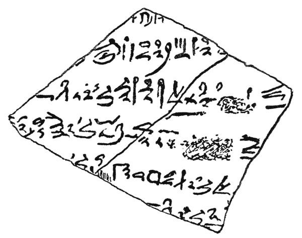
The contents of the pot are reported to be ochre and not burnt brick, though the ochre is of poor quality. It seems that we have here the material of the paint used in the quarries. It was probably mixed, before use, with acacia gum.
Ochre, of various colours, occurs within a mile of the obelisk in the rocks above the Luxor-Shellâl railway line.
(45) During the clearance of the west end of the north trench, we found part of an ostrakon in the hieratic character. It is written in black ink in a piece of pottery, measuring 16 × 12 cent., of the dull red with yellow slip common to the XVIIIth–XIXth dynasty. Mr. Battiscombe Gunn, who has lately been translating the recently discovered ostraka and graffiti for some of the excavators at Thebes, has kindly examined this ostrakon and reports that the writing is of characteristic XIXth dynasty type. This is shewn in figure 10. {46}
The hieroglyphic version of the ostrakon is:
()

[13]
![[glyph]](images/i046b.png) for
for ![]() r-f, as frequently
elsewhere.
r-f, as frequently
elsewhere.
This is hardly satisfactory, and I cannot see how we could have got a fragment of a letter telling us less than this. It is quite likely that it was thrown down from the quarry work above.
It is tempting to read, in the word
![[glyph]](images/i046c.png) qnqn, the pounding process
by which the trench was made.
qnqn, the pounding process
by which the trench was made.
(46) On the east face of the high rock shewn at C on plate VII, there are two short inscriptions in the Greek character. That on the right reads:
ΑΜ![[smudges]](images/i046d.png) |
Am . . . . . . . |
| ΣΑΒΙΝΙΑΝΟΣ | Sabinianos (and) |
| ΣΕΡΑΠΕΙΩΝ | Serapeum, (sons) |
| ΟΡΣΟΥ | of Ursus. |
The first name is doubtful as I am uncertain how many letters are missing. The remainder are Greek forms of Latin names.
On the left of the above is the Greek name ΕΡΜΕΙΝΟΣ. Ἕρμεινος is known in C. I. G., 3, nos. 5109; 4716.
The names have been fairly nearly cut in the granite with a fine pointed chisel. {47}
(47) There are over 25 obelisks known to-day whose weights exceed 50 tons, and all must have come from Aswân, since it is the only convenient outcrop of granite in Egypt. It might well be asked from which quarries they have been taken. I have examined most of the quarries about Aswân and Shellâl, but must admit that I have not found one from which I am sure that an obelisk has been extracted. I think that, at any rate, some must have been taken from the quarries in the near neighbourhood of the Aswân obelisk, as the stratum is good, and it is the most conveniently situated from the river bank. It would well repay the trouble taken to clear the quarry to the south, and the valley leading up to the obelisk, completely, exposing the floor, as it is there that we may expect to find the bed of one of the larger obelisks. It must be borne in mind however, that a quarry, good enough to furnish a large obelisk, would be worked as long as there was good stone to be extracted from it. The sand does not come in at any alarming rate, and a credit of L. E. 5 every year would be sufficient to keep the whole quarry clear. I estimate the cost of completely clearing the south quarry and the valley at L. E. 1500. It would leave a magnificent monument.
(48) I have endeavoured to confine this bibliography to references which, directly or indirectly, concern the quarrying, transport and erection of obelisks in Egyptian times, omitting certain mediæval accounts such as those of Peter Gyllius, and such stories of marvellous Egyptian engines as are put forward by certain irresponsible writers. I have, however, given a very brief précis of the removals of the Vatican, Paris and the London and New York obelisks, as these have a general interest.
ANTIQUITIES DEPARTMENT, Annales du Service.—Several references to obelisks are given in the index of parts I–X, chiefly dealing with those of Karnak. In volume V, pp. 11 and 12, there is a discussion by Legrain on those before Pylon VII (section 11).
(49) BARBER (Commander F. M., U. S. N., The Mechanical Triumphs of the Ancient Egyptians, published by Kegan Paul, 1900.—This is a popular description, in a portable size, of the best-known works undertaken by the Egyptians. In many ways it may be considered as a précis of Gorringe’s Egyptian Obelisks. It gives the details of removals of obelisks in modern times, shorn of elaborate technical details. He assumes that the large obelisks were raised in much the same manner as the Seringapatam obelisk (section 36).
BREASTED (Dr. J. H.), Ancient Records.—Translations of the inscriptions on most of the obelisks can be obtained from the general index under ‘obelisks’. Many of these translations are accompanied by interesting footnotes.
References to some large transportations are given in section 28 of this volume, to transport boats in section 34.
(50) CHOISY (Auguste), L’Art de bâtir chez les Égyptiens, published at 76 Rue de la Seine, Paris, 1904.—The author, in this work, gives what he considers to have been the ancient methods of building, together with his ideas as to those of the transportation and erection of monoliths. The chapters on construction do not come within the province of this volume. Obelisks are dealt with on pages 121 to 127. Under the heading of ‘extraction’, he gives some suggestions, or rather assertions, as to the manner in which the obelisk was given a curved surface, but none as to the quarry work. In his notes on transport by water, he favours the method described by Pliny (section 34 of this volume), which we know is not confirmed by an examination of the Aswân quarries. As to the method he proposes for the transport of obelisks, it is extremely laborious; the obelisk was heaved up by a series of levers acting on both sides simultaneously, {50} being packed from below after each heave. Figure 11, taken from his book, makes this clear. When the obelisk was sufficiently high, an embankment was constructed so as to make a ramp leading down in the direction in which it was desired to travel, and the obelisk was pulled, butt foremost, along the ramp until it reached ground-level again, the process being repeated for the whole journey. His method for erecting an obelisk is, to me, mechanically unsound. Figure 12 is taken from his book; referring to it, he says: “Soulevons le bloc (fig. 11), en ayant soin de maintenir le remblai d’appui par les bajoyers. Arrivés à une hauteur telle que a′, passons, par-dessous, des traverses c et un tourillon n. A ce moment rien n’empêche de déblayer les terres et d’établir en sous-œuvre une glissière g. La glissière faite, remplaçons par du sable les terres enlevées; retirons les traverses c et affouillons le sable. L’obélisque, pivotant autour du tourillon n, va s’incliner suivant a″ et arriver à l’aplomb de sa base b. Il suffira pour empêcher d’aller trop long, de réserver en d un arrêt qui le contre-bute du pied, et de retenir le sommet par des haubans.”
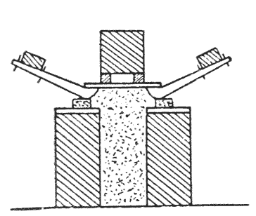
He does not tell us of what material the ‘tourillon’ n is to be made in order to stand the enormous strain, neither does he give any details as to the material of the ‘glissière’ which would allow the point of the sled to slide along it without burying itself.
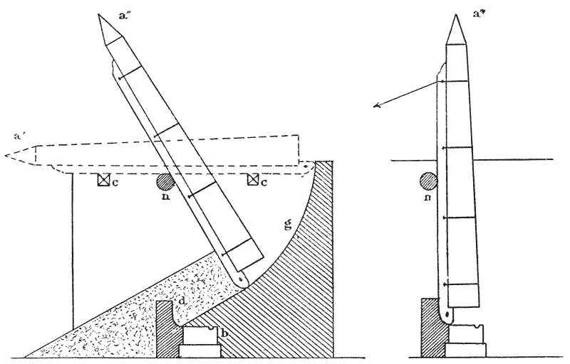
Choisy imagines the procedure after the obelisk had
attained a vertical position to have been to fill in the
space between the obelisk and the pedestal with filled
sand-bags, a long sausage-shaped bag having been placed
in the slot in the pedestal. The bags were then to be
perforated {51} one by one until the obelisk rested on
its edge and the long bag only. The empty bags were to be
withdrawn from under the obelisk and finally the long bag
opened and the material removed through the slot. This
may possibly have been the method used with medium-sized
blocks, such as sarcophagus-lids, but I very much doubt
whether any bag would stand half the weight of the Aswân
obelisk without bursting, besides, the crushing of the
inner edge of the slots in the pedestals of all the
obelisks at Karnak, except that of the standing obelisk
of ![]() atshepsôwet (cf. section
40), is not explainable by
Choisy’s ‘long-bag’ theory.
atshepsôwet (cf. section
40), is not explainable by
Choisy’s ‘long-bag’ theory.
The book would have been infinitely improved if it has contained a few references.
J. COUYAT et P. MONTET, Les inscriptions hiéroglyphiques et hiératiques du Ouâdi Hammâmât, in Mémoires publiés par les membres de l’Institut français du Caire, vol. XXXIV, p. 54 (Imprimerie de l’Institut français).—References to iron-workers from inscriptions on the rocks at Wady Hammâmât (section 25).
(51) DECOURDEMANCHE (J. A.), in Annales du Service, vol. XII, p. 215, gives details of various systems of lineal measures which he suggests are derived from an original talent, taken from measures on the Abydos monuments excavated by Amélineau in 1899 (see section 18).
DECOURDEMANCHE, Poids et Mesures, published at Paris by Gautier-Villars, 1909.—This gives a large number of systems of the divisions of the cubit and foot and shews clearly how cautious one must be in deducing anything from a single unit of measurement unless it is subdivided as in the case, for example, of a cubit rod. It is possible, in this book, to find an ancient example of almost any unit of length which could be imagined.
(52) FONTANA (Domenico), Della transportatione dell’obelisco Vaticano et delle fabriche di nostro signore papa Sisto V fatte dal cavaliere Domenico Fontana, architecto di sua Santità.—This is a rare book published in 1590, but a good précis is given by Lebas in his L’Obélisque de Louxor and in GORRINGE, Egyptian Obelisks. The obelisk was moved from the Circus of Nero at Rome to the Piazza di San Pietro in 1585, the method being the ‘heroic’ one of lifting it bodily by blocks and tackles. A gigantic tower of wood, known as ‘Fontana’s Castle’, was erected over the obelisk, being made of compound wooden struts of a metre square in section. From the cross-beams of the tower pairs of blocks and tackles were attached at four points along the obelisk, which was protected by matting and planks. The obelisk was first raised sufficiently high, being wedged as well from below, to enable a ‘cradle’, or platform on rollers, to be introduced underneath it. The obelisk was then lowered on to the cradle and pulled to its new site, first down an inclined plane and thence on level ground. The blocks and tackles were worked by a large number of capstans. The erection was done in exactly the reverse way to the lowering. The whole story as translated by Lebas, makes curious reading, and I cannot resist giving a few extracts. He says (L’Obélisque de Louxor, pp. 178 et seq.): “Public curiosity . . . . . attracted a large number of strangers to Rome. All roads leading to the square were barricaded, and a bando of the pope, published two days before, punished by death anybody who did not respect the barrier . . . . . On the 30th April, two hours before daylight, two masses were celebrated to {52} implore the light of the Holy Spirit. Fontana, with all his staff, communicated. On the eve of the lowering he had been blessed by the Holy Father. . . . . ” Before the work began, Fontana told his workmen: “The work we are about to undertake is consecrated to religion, the exaltation of the Holy Cross”; thereon everyone recited with Fontana a pater and an ave. Gorringe comments on this (Egyptian Obelisks, pp. 114 to 117) saying: “A striking scene it must have been and typical of that curious age”. If, however, one compares Fontana’s account with that of the erection of the New York obelisk, one is struck, not with the difference, but with the resemblance between the two ceremonies, the later one being undoubtedly more tedious to the spectators, as there were no inquisitors and familiars waiting in a corner, to mete out summary punishment to anyone misbehaving.
GARDINER (Dr. Alan), Egyptian Hieratic Texts, Part I.—On paragraphs XII, XIII and XIV, some details are given as to the removal of an obelisk from a quarry, the removal of sand from under a colossus during erection and the construction of an embankment of brickwork, set as problems by one scribe to another. The relevant passages are quoted in extenso in sections 28 and 35.
GARLAND (H.), in The Journal of the Institute of Metals, no. 2, 1913; article on Metallographical Researches on Egyptian Metal Antiquities.—The author gives a very technical account of his examination of Egyptian copper and bronze tools and weapons by means of micro-photographs. He proves that the shaping of the tools by hammering was done either cold or far below the annealing temperature; by this means a better cutting edge could be obtained. He does not speculate on how far hammer-tempering could be carried, confining himself to the actual results of his examination of the tools as they were found and after annealing.
GOLÉNISCHEFF (W.), Hammâmât, II, no. 3.—References to iron workers (section 25).
(53) GORRINGE (Lieut.-Commander H. H., U. S. N., Egyptian Obelisks, published in 1885 by Nimmo, 14, King William St., Strand.—The obelisk, which originally formed a pair with the London Obelisk, had already been once removed in Roman times from Heliopolis to Alexandria, where it was still standing. It was lowered by fitting it at its centre of gravity, with a pair of enormous steel trunnions supported by a steel tower on each side of the obelisk. The point was lowered (or rather it crashed) on to a tower made of wooden baulks laid alternately. A similar wooden tower was then built near the butt end of the obelisk and after raising the obelisk from each end with hydraulic rams, the trunnions were removed. The mass was then lowered from each side in turn by supporting the obelisk by the rams while a course of baulks were removed from the tower, and continuing the process until the obelisk lay on the ground. It was floated in a wooden caisson from the shore to the dock and introduced into a steamship called the Dessouk by opening a port in her bows. At the American end, it was placed on a railway line and pulled to Central Park, where the trunnion and towers were again used in the opposite order to the lowering. For the short moves, such as moving it into the hold of the ship, it was rolled on cannon-balls running in channel irons. {53}
In the publication there is a very good account of the history of the obelisk and an excellent collection of classical and mediæval records relating to the subject. In his ‘record of all Obelisks’ he gives poor photographs of one face of each, accompanied by ‘best translations’ of the inscriptions, where the roughest hand-copies of the text would have been infinitely more valuable. Nowhere in the book can I find a complete series of measurements of the New York obelisk; in a table on page 145 he gives the heights, width at the base and the estimated weight only. To make up for this, the analysis of the granite and of the copper ‘crabs’ is given with extraordinary detail, and we are given a complete list of the objects placed under the obelisk on re-erection, which range from sets of coinage and standard works (p. 33), to a small box, the contents of which were known only to himself (that is to a certain Mr. Henry Hurlbert). Cleopatra’s Needle, now rotting on the Thames Embankment, we are told, has beneath it among other things, a Mappin’s Shilling Razor, an Alexandra Feeding-bottle, a case of cigars and photographs of a dozen pretty English women for the benefit of posterity!
In Gorringe’s work, verbatim reports of pompous speeches, of which each stage of the proceedings seemed to provoke cataracts, total 18 pages of small type, while long dissertations are indulged in on the presence of ‘masonic emblems’ discovered in the base of the obelisk at Alexandria, and on their esoteric meaning; this in spite of the fact that their ‘most expert archæologist’ points out the obvious explanation that the signs commented on form part of an Egyptian word determined by the house-sign, and the ‘mysterious lines’, etc., are merely fragments of ordinary decoration from a re-used building.
HERODOTUS, H. Cary’s translation, 1861, Bohn edition. II, 125, iron tools used in the Great Pyramid; II, 155, transport of a monolithic chapel from Aswân to Buto. Mention of levers; II, 175, transport of an enormous monument under Amasis (section 29 of this volume).
LAYARD, Discoveries, p. 104; transport of a winged bull at Nineveh by means of a sled on rollers (section 29).
(54) LEBAS, L’Obélisque de Louxor, Paris, 1839.—A very interesting account of a gross act of vandalism, since the Luxor obelisks were the only pair still standing in their original position. The lowering and raising was performed by a huge compound derrick, consisting of five supporting members on each side of the obelisk, the power being supplied by capstans and blocks and tackles. The obelisk was lowered on to a wooden cradle on which it was dragged over a greased way, without rollers, to the water, and from the water to its present position in the Place de la Concorde. The water transport was effected by a pontoon-raft of peculiar design, the prow of which was removed for getting the obelisk in and out. Gorringe gives a good résumé of Lebas’ book, which is now very rare.
(55) PETRIE (Professor W. M. Flinders), Arts and Crafts of Ancient Egypt, published by T. M. Foulis, London, 1909.—Stone working is discussed in chapter vii. As regards granite, Prof. Petrie favours the suggestion that wetted wooden wedges were used (cf. section 4 of this volume). He gives valuable details as to the sawing and drilling of granite, the polishing of its surface and {54} the cutting of hieroglyphs. On the erection of obelisks he says (page 77), referring to the setting up of colossi under Ramesses IV: “A causeway of earth was made sloping up for the length of a quarter of a mile; it was 93 feet wide and 103 feet high on the slope, probably about 60 or 70 feet vertically, as the slopes were held up steeply with facings of timber and brushwood. The purpose of this evidently was to raise the great block by sliding it on its side up the slope and then to tilt it upright by gravity over the head of the slope. How the mass would be turned we have nothing to show, but probably the simplest way, by gradually removing earth, would be followed. By next ramming earth behind the obelisk as it lay on the slope, it would be quite practicable to force it forward into an upright position.”
PETRIE,
A History of Egypt, XVII–XVIIIth
dynasties, published by Methuen, 1904.—On pages 131 and
132 Prof. Petrie discusses the probable original height
of the Constantinople obelisk, and speculates on the
possibility that it is one mentioned by
![]() atshepsôwet as
having been 108 cubits high (see sections
3 and
43 of this
volume).
atshepsôwet as
having been 108 cubits high (see sections
3 and
43 of this
volume).
PETRIE, Tools and Weapons, published by Bernard Quaritch, 1917.—This gives photographs and drawings of each kind of Egyptian tool and weapon, compared with similar examples from other countries.
PLINY, Natural History, book XVI, chap. 76, and book XXXVI, chap. 14 and 15, transport of an obelisk to the Vaticanian Circus in Roman times, with details of an immense ship; book XXXVI, chap. 14, water transport of an obelisk under Augustus and the transport of an obelisk by canal under Ptolemy Philadelphus (see section 54); erection of an obelisk under king ‘Rhamsesis’ (section 35).
(56) WILKINSON (Sir G.), Manners and Customs of the Ancient Egyptians.—Although somewhat out of date, this is still the standard work on the subject, especially as regards arts and crafts. The portions directly concerning the subjects under discussion are as follows:
WILSON (Erasmus), Cleopatra’s Needle and Egyptian Obelisks.—The method of lowering and raising the London Obelisk was almost exactly the same as that of the New York Obelisk. The water transport, however, was effected by enclosing the obelisk in an iron shell in which it was towed to England.

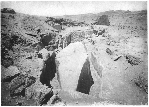
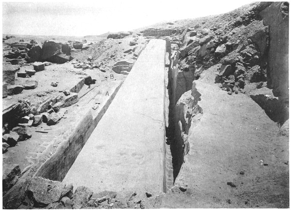
IMP. CATALA FRÈRES, PARIS
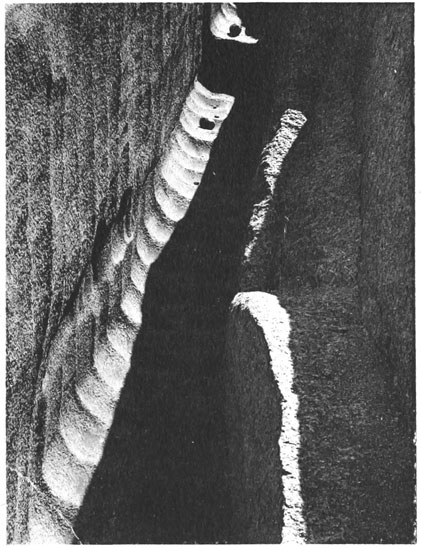
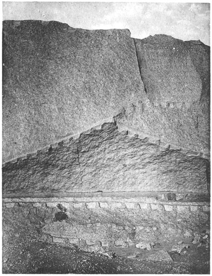
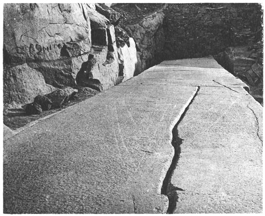
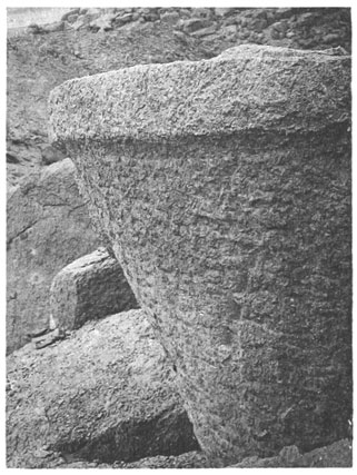
IMP. CATALA FRÈRES, PARIS
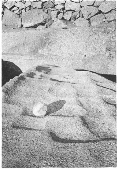
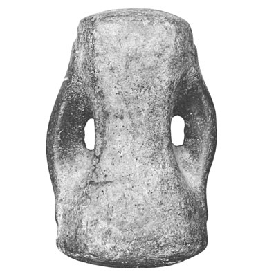
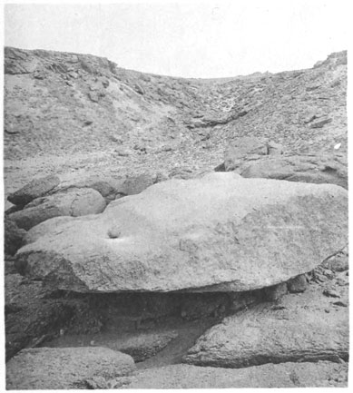
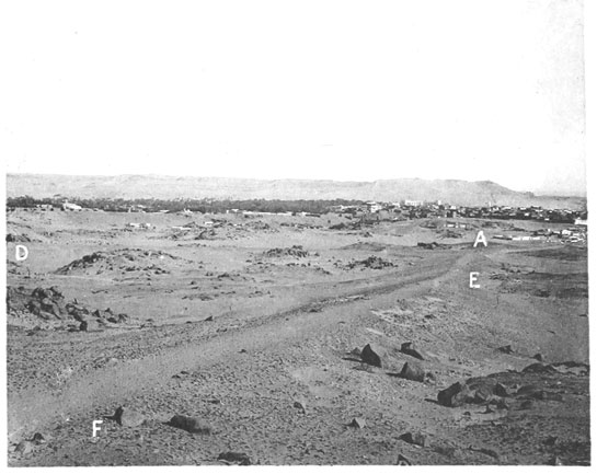
IMP. CATALA FRÈRES, PARIS
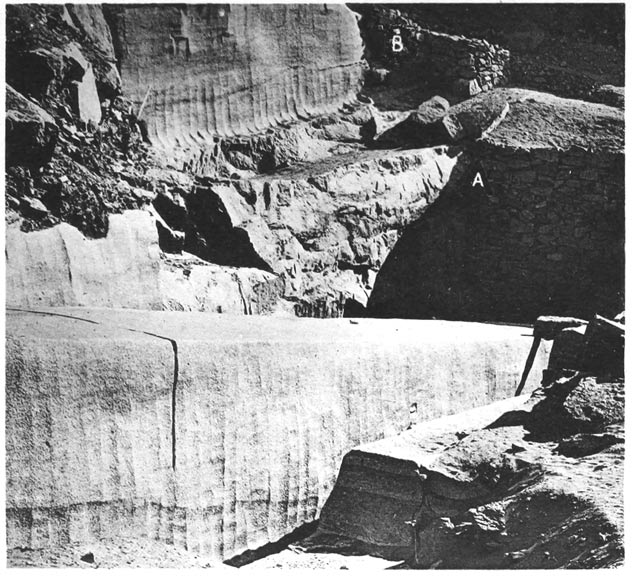
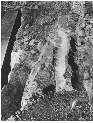
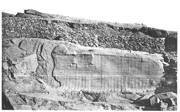
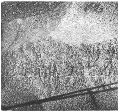
IMP. CATALA FRÈRES, PARIS
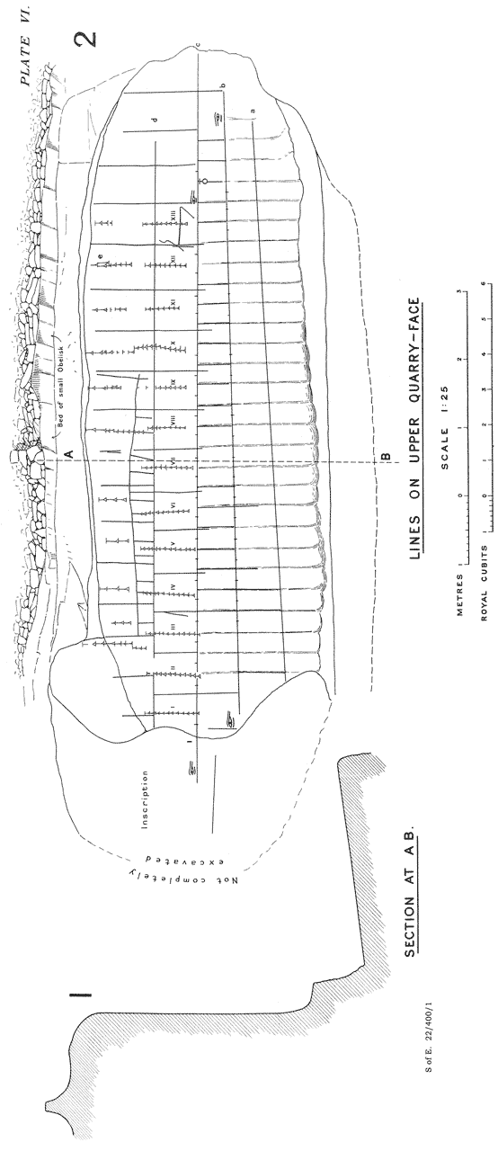
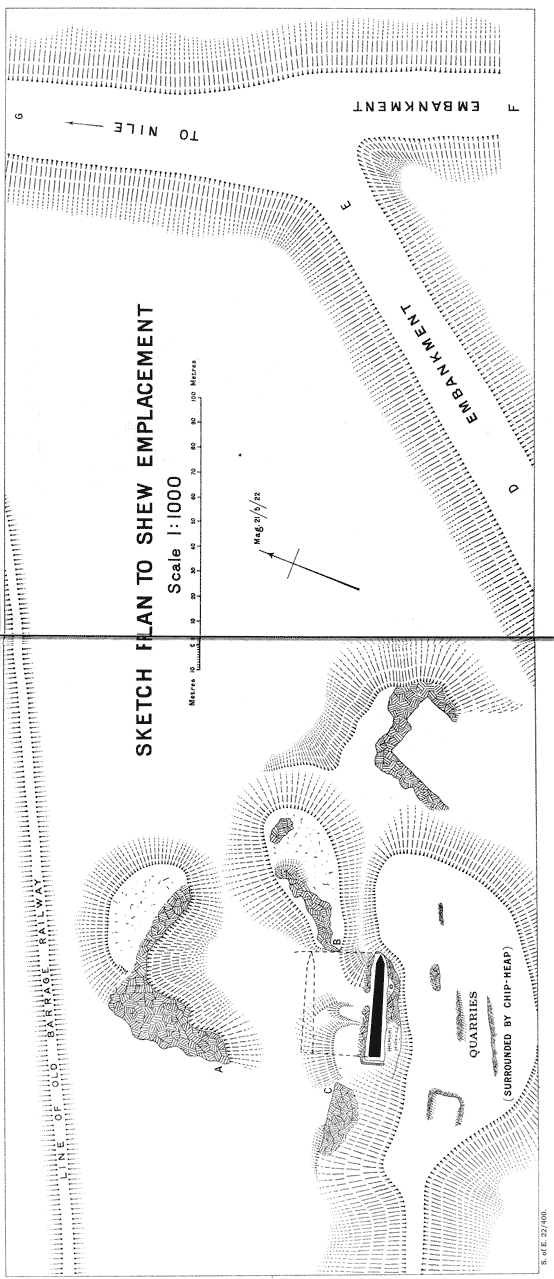
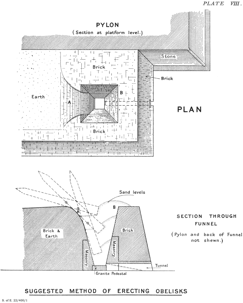
Original spelling and grammar have been generally retained, with some exceptions noted below. Original printed page numbers are shown like this: {52}. Anchored notes (e.g. footnotes) have been relabeled 1–13, and moved from within paragraphs to nearby locations between paragraphs. Large curly brackets { } that graphically indicate combination of information on two or more lines of text have been removed. Several Unicode characters that are poorly supported in current ebook browsers have been replaced with images: ‹Ḥ› U+1e24, ‹ḥ› U+1e25, ‹ḫ› U+1e2b, ‹Ṭ› U+1e6c, and ‹ṭ› U+1e6d. I produced the cover image and hereby assign it to the public domain. Original page images are available from archive.org—search for “aswnobeliskwiths00egyp”.
Chisels, copper, 24–27.
— stone, 26.
was changed to
Chisels,
— copper, 24–27.
— stone, 26.
End of Project Gutenberg's The Aswân Obelisk, by R. (Reginald) Engelbach

*** END OF THIS PROJECT GUTENBERG EBOOK THE ASWÂN OBELISK ***

***** This file should be named 59320-h.htm or 59320-h.zip *****
This and all associated files of various formats will be found in:
        http://www.gutenberg.org/5/9/3/2/59320/

Produced by MFR, RichardW, and the Online Distributed
Proofreading Team at http://www.pgdp.net (This file was
produced from images generously made available by The
Internet Archive)

Updated editions will replace the previous one--the old editions will
be renamed.

Creating the works from print editions not protected by U.S. copyright
law means that no one owns a United States copyright in these works,
so the Foundation (and you!) can copy and distribute it in the United
States without permission and without paying copyright
royalties. Special rules, set forth in the General Terms of Use part
of this license, apply to copying and distributing Project
Gutenberg-tm electronic works to protect the PROJECT GUTENBERG-tm
concept and trademark. Project Gutenberg is a registered trademark,
and may not be used if you charge for the eBooks, unless you receive
specific permission. If you do not charge anything for copies of this
eBook, complying with the rules is very easy. You may use this eBook
for nearly any purpose such as creation of derivative works, reports,
performances and research. They may be modified and printed and given
away--you may do practically ANYTHING in the United States with eBooks
not protected by U.S. copyright law. Redistribution is subject to the
trademark license, especially commercial redistribution.

START: FULL LICENSE

THE FULL PROJECT GUTENBERG LICENSE
PLEASE READ THIS BEFORE YOU DISTRIBUTE OR USE THIS WORK

To protect the Project Gutenberg-tm mission of promoting the free
distribution of electronic works, by using or distributing this work
(or any other work associated in any way with the phrase "Project
Gutenberg"), you agree to comply with all the terms of the Full
Project Gutenberg-tm License available with this file or online at
www.gutenberg.org/license.

Section 1. General Terms of Use and Redistributing Project
Gutenberg-tm electronic works

1.A. By reading or using any part of this Project Gutenberg-tm
electronic work, you indicate that you have read, understand, agree to
and accept all the terms of this license and intellectual property
(trademark/copyright) agreement. If you do not agree to abide by all
the terms of this agreement, you must cease using and return or
destroy all copies of Project Gutenberg-tm electronic works in your
possession. If you paid a fee for obtaining a copy of or access to a
Project Gutenberg-tm electronic work and you do not agree to be bound
by the terms of this agreement, you may obtain a refund from the
person or entity to whom you paid the fee as set forth in paragraph
1.E.8.

1.B. "Project Gutenberg" is a registered trademark. It may only be
used on or associated in any way with an electronic work by people who
agree to be bound by the terms of this agreement. There are a few
things that you can do with most Project Gutenberg-tm electronic works
even without complying with the full terms of this agreement. See
paragraph 1.C below. There are a lot of things you can do with Project
Gutenberg-tm electronic works if you follow the terms of this
agreement and help preserve free future access to Project Gutenberg-tm
electronic works. See paragraph 1.E below.

1.C. The Project Gutenberg Literary Archive Foundation ("the
Foundation" or PGLAF), owns a compilation copyright in the collection
of Project Gutenberg-tm electronic works. Nearly all the individual
works in the collection are in the public domain in the United
States. If an individual work is unprotected by copyright law in the
United States and you are located in the United States, we do not
claim a right to prevent you from copying, distributing, performing,
displaying or creating derivative works based on the work as long as
all references to Project Gutenberg are removed. Of course, we hope
that you will support the Project Gutenberg-tm mission of promoting
free access to electronic works by freely sharing Project Gutenberg-tm
works in compliance with the terms of this agreement for keeping the
Project Gutenberg-tm name associated with the work. You can easily
comply with the terms of this agreement by keeping this work in the
same format with its attached full Project Gutenberg-tm License when
you share it without charge with others.

1.D. The copyright laws of the place where you are located also govern
what you can do with this work. Copyright laws in most countries are
in a constant state of change. If you are outside the United States,
check the laws of your country in addition to the terms of this
agreement before downloading, copying, displaying, performing,
distributing or creating derivative works based on this work or any
other Project Gutenberg-tm work. The Foundation makes no
representations concerning the copyright status of any work in any
country outside the United States.

1.E. Unless you have removed all references to Project Gutenberg:

1.E.1. The following sentence, with active links to, or other
immediate access to, the full Project Gutenberg-tm License must appear
prominently whenever any copy of a Project Gutenberg-tm work (any work
on which the phrase "Project Gutenberg" appears, or with which the
phrase "Project Gutenberg" is associated) is accessed, displayed,
performed, viewed, copied or distributed:

  This eBook is for the use of anyone anywhere in the United States and
  most other parts of the world at no cost and with almost no
  restrictions whatsoever. You may copy it, give it away or re-use it
  under the terms of the Project Gutenberg License included with this
  eBook or online at www.gutenberg.org. If you are not located in the
  United States, you'll have to check the laws of the country where you
  are located before using this ebook.

1.E.2. If an individual Project Gutenberg-tm electronic work is
derived from texts not protected by U.S. copyright law (does not
contain a notice indicating that it is posted with permission of the
copyright holder), the work can be copied and distributed to anyone in
the United States without paying any fees or charges. If you are
redistributing or providing access to a work with the phrase "Project
Gutenberg" associated with or appearing on the work, you must comply
either with the requirements of paragraphs 1.E.1 through 1.E.7 or
obtain permission for the use of the work and the Project Gutenberg-tm
trademark as set forth in paragraphs 1.E.8 or 1.E.9.

1.E.3. If an individual Project Gutenberg-tm electronic work is posted
with the permission of the copyright holder, your use and distribution
must comply with both paragraphs 1.E.1 through 1.E.7 and any
additional terms imposed by the copyright holder. Additional terms
will be linked to the Project Gutenberg-tm License for all works
posted with the permission of the copyright holder found at the
beginning of this work.

1.E.4. Do not unlink or detach or remove the full Project Gutenberg-tm
License terms from this work, or any files containing a part of this
work or any other work associated with Project Gutenberg-tm.

1.E.5. Do not copy, display, perform, distribute or redistribute this
electronic work, or any part of this electronic work, without
prominently displaying the sentence set forth in paragraph 1.E.1 with
active links or immediate access to the full terms of the Project
Gutenberg-tm License.

1.E.6. You may convert to and distribute this work in any binary,
compressed, marked up, nonproprietary or proprietary form, including
any word processing or hypertext form. However, if you provide access
to or distribute copies of a Project Gutenberg-tm work in a format
other than "Plain Vanilla ASCII" or other format used in the official
version posted on the official Project Gutenberg-tm web site
(www.gutenberg.org), you must, at no additional cost, fee or expense
to the user, provide a copy, a means of exporting a copy, or a means
of obtaining a copy upon request, of the work in its original "Plain
Vanilla ASCII" or other form. Any alternate format must include the
full Project Gutenberg-tm License as specified in paragraph 1.E.1.

1.E.7. Do not charge a fee for access to, viewing, displaying,
performing, copying or distributing any Project Gutenberg-tm works
unless you comply with paragraph 1.E.8 or 1.E.9.

1.E.8. You may charge a reasonable fee for copies of or providing
access to or distributing Project Gutenberg-tm electronic works
provided that

* You pay a royalty fee of 20% of the gross profits you derive from
  the use of Project Gutenberg-tm works calculated using the method
  you already use to calculate your applicable taxes. The fee is owed
  to the owner of the Project Gutenberg-tm trademark, but he has
  agreed to donate royalties under this paragraph to the Project
  Gutenberg Literary Archive Foundation. Royalty payments must be paid
  within 60 days following each date on which you prepare (or are
  legally required to prepare) your periodic tax returns. Royalty
  payments should be clearly marked as such and sent to the Project
  Gutenberg Literary Archive Foundation at the address specified in
  Section 4, "Information about donations to the Project Gutenberg
  Literary Archive Foundation."

* You provide a full refund of any money paid by a user who notifies
  you in writing (or by e-mail) within 30 days of receipt that s/he
  does not agree to the terms of the full Project Gutenberg-tm
  License. You must require such a user to return or destroy all
  copies of the works possessed in a physical medium and discontinue
  all use of and all access to other copies of Project Gutenberg-tm
  works.

* You provide, in accordance with paragraph 1.F.3, a full refund of
  any money paid for a work or a replacement copy, if a defect in the
  electronic work is discovered and reported to you within 90 days of
  receipt of the work.

* You comply with all other terms of this agreement for free
  distribution of Project Gutenberg-tm works.

1.E.9. If you wish to charge a fee or distribute a Project
Gutenberg-tm electronic work or group of works on different terms than
are set forth in this agreement, you must obtain permission in writing
from both the Project Gutenberg Literary Archive Foundation and The
Project Gutenberg Trademark LLC, the owner of the Project Gutenberg-tm
trademark. Contact the Foundation as set forth in Section 3 below.

1.F.

1.F.1. Project Gutenberg volunteers and employees expend considerable
effort to identify, do copyright research on, transcribe and proofread
works not protected by U.S. copyright law in creating the Project
Gutenberg-tm collection. Despite these efforts, Project Gutenberg-tm
electronic works, and the medium on which they may be stored, may
contain "Defects," such as, but not limited to, incomplete, inaccurate
or corrupt data, transcription errors, a copyright or other
intellectual property infringement, a defective or damaged disk or
other medium, a computer virus, or computer codes that damage or
cannot be read by your equipment.

1.F.2. LIMITED WARRANTY, DISCLAIMER OF DAMAGES - Except for the "Right
of Replacement or Refund" described in paragraph 1.F.3, the Project
Gutenberg Literary Archive Foundation, the owner of the Project
Gutenberg-tm trademark, and any other party distributing a Project
Gutenberg-tm electronic work under this agreement, disclaim all
liability to you for damages, costs and expenses, including legal
fees. YOU AGREE THAT YOU HAVE NO REMEDIES FOR NEGLIGENCE, STRICT
LIABILITY, BREACH OF WARRANTY OR BREACH OF CONTRACT EXCEPT THOSE
PROVIDED IN PARAGRAPH 1.F.3. YOU AGREE THAT THE FOUNDATION, THE
TRADEMARK OWNER, AND ANY DISTRIBUTOR UNDER THIS AGREEMENT WILL NOT BE
LIABLE TO YOU FOR ACTUAL, DIRECT, INDIRECT, CONSEQUENTIAL, PUNITIVE OR
INCIDENTAL DAMAGES EVEN IF YOU GIVE NOTICE OF THE POSSIBILITY OF SUCH
DAMAGE.

1.F.3. LIMITED RIGHT OF REPLACEMENT OR REFUND - If you discover a
defect in this electronic work within 90 days of receiving it, you can
receive a refund of the money (if any) you paid for it by sending a
written explanation to the person you received the work from. If you
received the work on a physical medium, you must return the medium
with your written explanation. The person or entity that provided you
with the defective work may elect to provide a replacement copy in
lieu of a refund. If you received the work electronically, the person
or entity providing it to you may choose to give you a second
opportunity to receive the work electronically in lieu of a refund. If
the second copy is also defective, you may demand a refund in writing
without further opportunities to fix the problem.

1.F.4. Except for the limited right of replacement or refund set forth
in paragraph 1.F.3, this work is provided to you 'AS-IS', WITH NO
OTHER WARRANTIES OF ANY KIND, EXPRESS OR IMPLIED, INCLUDING BUT NOT
LIMITED TO WARRANTIES OF MERCHANTABILITY OR FITNESS FOR ANY PURPOSE.

1.F.5. Some states do not allow disclaimers of certain implied
warranties or the exclusion or limitation of certain types of
damages. If any disclaimer or limitation set forth in this agreement
violates the law of the state applicable to this agreement, the
agreement shall be interpreted to make the maximum disclaimer or
limitation permitted by the applicable state law. The invalidity or
unenforceability of any provision of this agreement shall not void the
remaining provisions.

1.F.6. INDEMNITY - You agree to indemnify and hold the Foundation, the
trademark owner, any agent or employee of the Foundation, anyone
providing copies of Project Gutenberg-tm electronic works in
accordance with this agreement, and any volunteers associated with the
production, promotion and distribution of Project Gutenberg-tm
electronic works, harmless from all liability, costs and expenses,
including legal fees, that arise directly or indirectly from any of
the following which you do or cause to occur: (a) distribution of this
or any Project Gutenberg-tm work, (b) alteration, modification, or
additions or deletions to any Project Gutenberg-tm work, and (c) any
Defect you cause.

Section 2. Information about the Mission of Project Gutenberg-tm

Project Gutenberg-tm is synonymous with the free distribution of
electronic works in formats readable by the widest variety of
computers including obsolete, old, middle-aged and new computers. It
exists because of the efforts of hundreds of volunteers and donations
from people in all walks of life.

Volunteers and financial support to provide volunteers with the
assistance they need are critical to reaching Project Gutenberg-tm's
goals and ensuring that the Project Gutenberg-tm collection will
remain freely available for generations to come. In 2001, the Project
Gutenberg Literary Archive Foundation was created to provide a secure
and permanent future for Project Gutenberg-tm and future
generations. To learn more about the Project Gutenberg Literary
Archive Foundation and how your efforts and donations can help, see
Sections 3 and 4 and the Foundation information page at
www.gutenberg.org


Section 3. Information about the Project Gutenberg Literary Archive Foundation

The Project Gutenberg Literary Archive Foundation is a non profit
501(c)(3) educational corporation organized under the laws of the
state of Mississippi and granted tax exempt status by the Internal
Revenue Service. The Foundation's EIN or federal tax identification
number is 64-6221541. Contributions to the Project Gutenberg Literary
Archive Foundation are tax deductible to the full extent permitted by
U.S. federal laws and your state's laws.

The Foundation's principal office is in Fairbanks, Alaska, with the
mailing address: PO Box 750175, Fairbanks, AK 99775, but its
volunteers and employees are scattered throughout numerous
locations. Its business office is located at 809 North 1500 West, Salt
Lake City, UT 84116, (801) 596-1887. Email contact links and up to
date contact information can be found at the Foundation's web site and
official page at www.gutenberg.org/contact

For additional contact information:

    Dr. Gregory B. Newby
    Chief Executive and Director
    gbnewby@pglaf.org

Section 4. Information about Donations to the Project Gutenberg
Literary Archive Foundation

Project Gutenberg-tm depends upon and cannot survive without wide
spread public support and donations to carry out its mission of
increasing the number of public domain and licensed works that can be
freely distributed in machine readable form accessible by the widest
array of equipment including outdated equipment. Many small donations
($1 to $5,000) are particularly important to maintaining tax exempt
status with the IRS.

The Foundation is committed to complying with the laws regulating
charities and charitable donations in all 50 states of the United
States. Compliance requirements are not uniform and it takes a
considerable effort, much paperwork and many fees to meet and keep up
with these requirements. We do not solicit donations in locations
where we have not received written confirmation of compliance. To SEND
DONATIONS or determine the status of compliance for any particular
state visit www.gutenberg.org/donate

While we cannot and do not solicit contributions from states where we
have not met the solicitation requirements, we know of no prohibition
against accepting unsolicited donations from donors in such states who
approach us with offers to donate.

International donations are gratefully accepted, but we cannot make
any statements concerning tax treatment of donations received from
outside the United States. U.S. laws alone swamp our small staff.

Please check the Project Gutenberg Web pages for current donation
methods and addresses. Donations are accepted in a number of other
ways including checks, online payments and credit card donations. To
donate, please visit: www.gutenberg.org/donate

Section 5. General Information About Project Gutenberg-tm electronic works.

Professor Michael S. Hart was the originator of the Project
Gutenberg-tm concept of a library of electronic works that could be
freely shared with anyone. For forty years, he produced and
distributed Project Gutenberg-tm eBooks with only a loose network of
volunteer support.

Project Gutenberg-tm eBooks are often created from several printed
editions, all of which are confirmed as not protected by copyright in
the U.S. unless a copyright notice is included. Thus, we do not
necessarily keep eBooks in compliance with any particular paper
edition.

Most people start at our Web site which has the main PG search
facility: www.gutenberg.org

This Web site includes information about Project Gutenberg-tm,
including how to make donations to the Project Gutenberg Literary
Archive Foundation, how to help produce our new eBooks, and how to
subscribe to our email newsletter to hear about new eBooks.
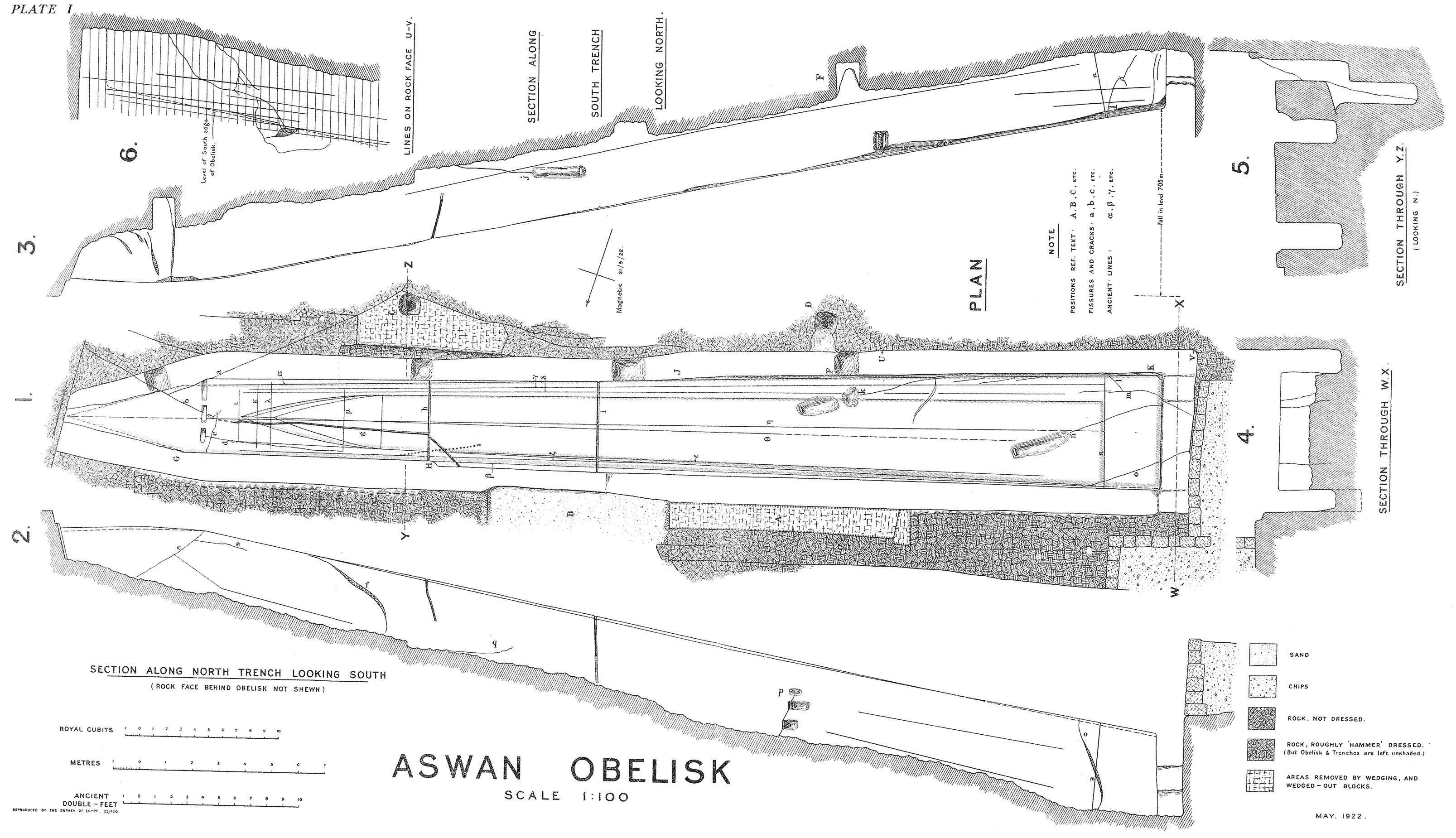
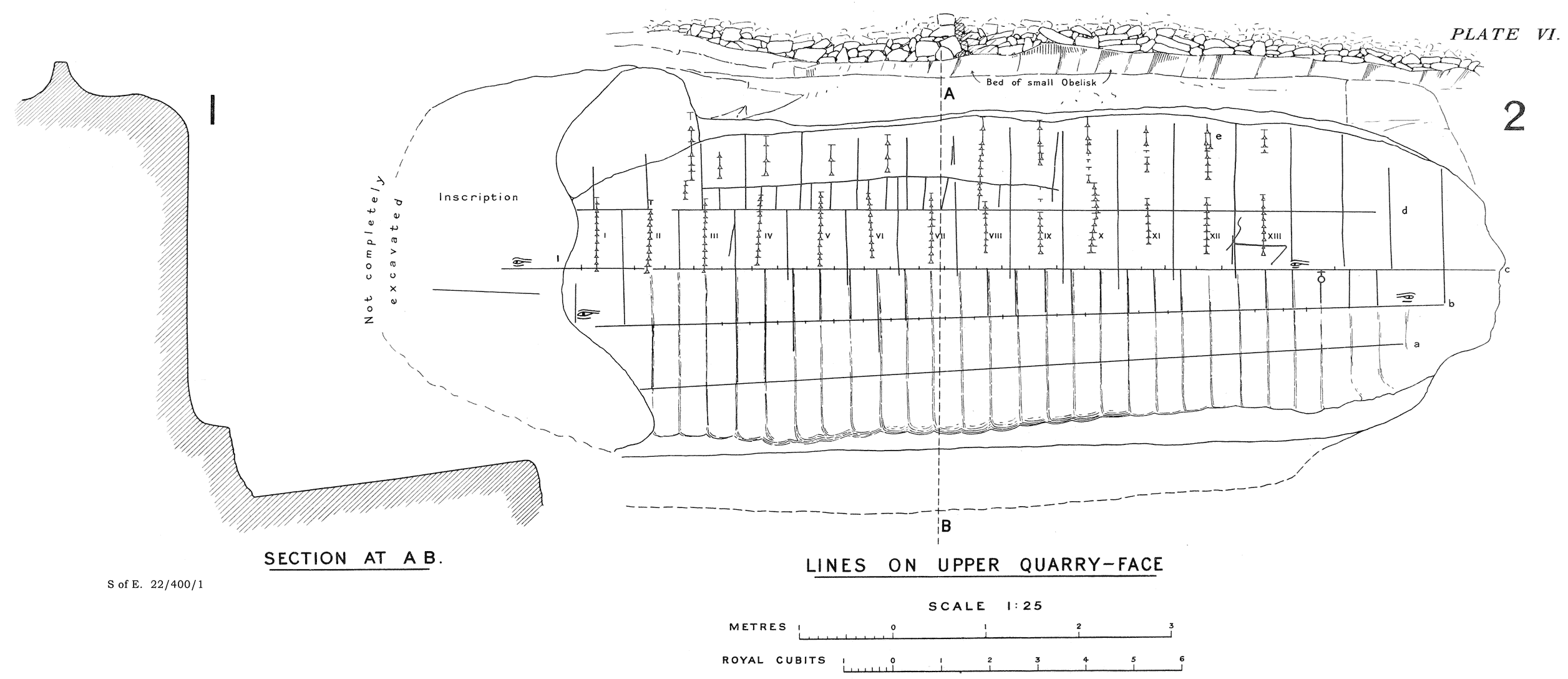
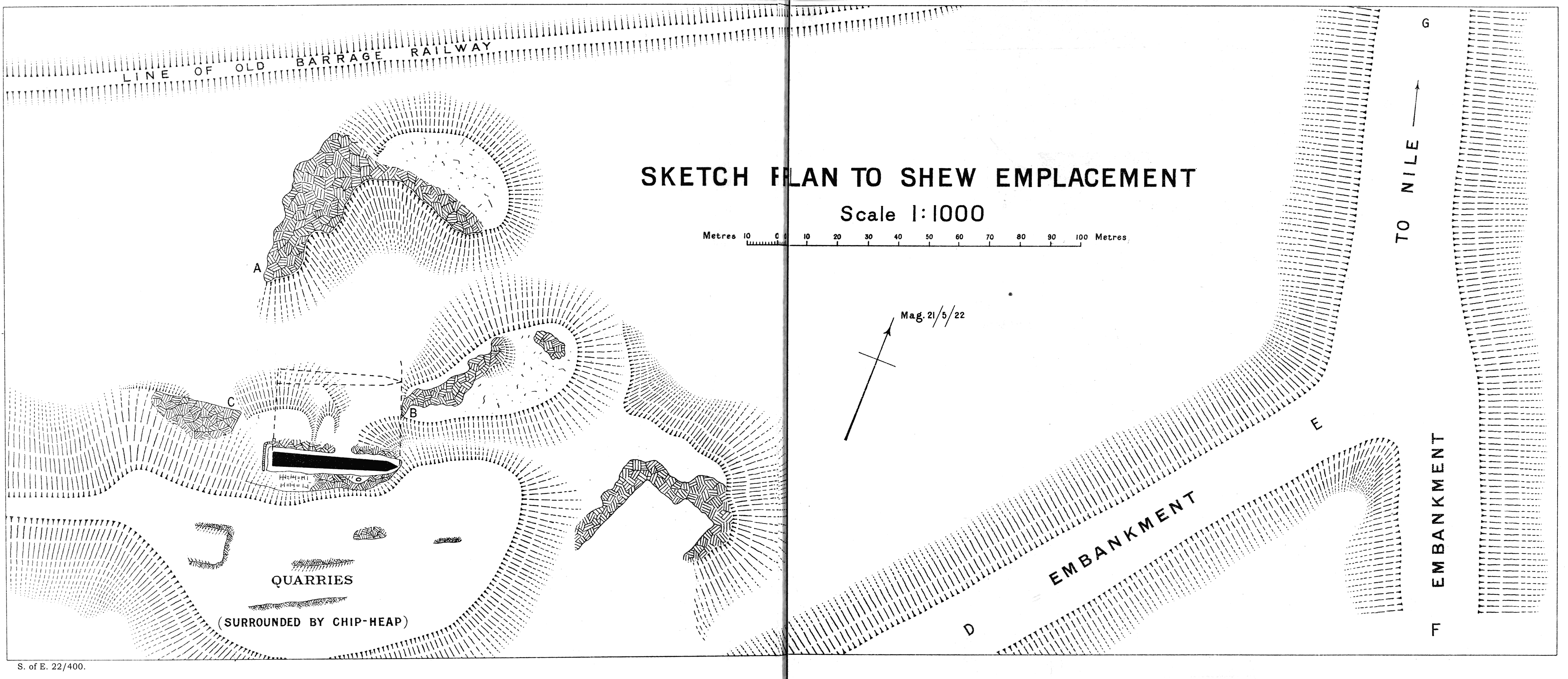