The great and increasing importance of internal combustion motors is perhaps scarcely realized by the general public. For industrial purposes they have for many years been steadily gaining favour, and now hold an assured position. It is only in the last few years, however, that we have begun to recognize the drawbacks of horse-drawn vehicles, and the immense advantage gained by propelling them mechanically.
The suitability of oil engines for the purpose has awakened a widespread interest in them. The Editor therefore hopes that this little volume will be especially welcome to non-technical readers who like to keep ahead of the times in matters of such universal importance.
One chapter deals exclusively with the theory of the gas engine, but the non-technical mind should have no fear, for mathematics have been as far as possible avoided. It may also serve to dispel wrongful notions concerning the practical limits of the efficiency of gas engines which, we are sorry to say, exist even among persons living in a scientific atmosphere.
vi
We have not spoken in the text of the extremely interesting results obtained from the oil engine invented by Herr Diesel of Berlin, because it has not yet been proved that this motor is strictly practicable. If, however, it turns out to be a commercial success, we hope to add a description of it at some future date.
May 1898.
CHAP. |
PAGE |
|
|---|---|---|
I. |
HISTORY OF THE GAS ENGINE | 1 |
II. |
THE WORKING PRINCIPLES OF THE GAS ENGINE | 13 |
III. |
DESCRIPTION OF EXISTING GAS ENGINES | 23 |
IV. |
CARBURETTED AIR ENGINE | 67 |
V. |
PETROLEUM ENGINES | 77 |
VI. |
GAS GENERATING PLANT | 103 |
VII. |
ENGINES FOR USE WITH POOR GASES | 121 |
VIII. |
MAINTENANCE OF GAS AND OIL ENGINES | 130 |
| INDEX | 139 |
The history of gas engines may be said to date from a time when coal gas and petroleum were unknown. This statement appears at first somewhat paradoxical, but it arises from the fact that the first gas engine, invented by the Abbé de Hautefeuille in 1678, used the explosive force of gunpowder as a motive power. The principle of this early gas engine, however, is exactly the same as that of its more modern brothers; that is, the work is done by the expansion and cooling of a volume of heated gas, the only difference being that gunpowder contains within its grains the oxygen necessary for its combustion, while coal gas or petroleum require admixture with the oxygen of the air before they can be made to explode.
Two years after the Abbé de Hautefeuille had made public his idea, in a memoir entitled A Method of Raising Water by means of Gunpowder, the Dutch savant Huyghens2 published a similar work, describing an apparatus consisting of a cylinder with two leather exhaust pipes, forming valves; to the bottom of the cylinder was screwed a small box in which gunpowder was to be ignited. The effect of the explosion was to drive out a large quantity of heated gas through the valves, which closed again when it had passed. The gas remaining in the cylinder soon cooled down, so that the pressure within it fell below that of the surrounding atmosphere, and caused the piston to be forced down by the excess of atmospheric pressure.
This operation was certainly very crude, and, as might have been expected, scarcely came up to the expectations of its inventor. The idea was, however, not allowed to rest here, and Papin set himself to find out some better agent to replace the gunpowder, whose action was uncertain and, to say the least of it, brutal. The result of his experiments pointed clearly to the condensation of steam as being the most suitable method of producing a space filled with a gas at a lower pressure than that of the atmosphere, and many inventors, following in his footsteps, adopted this process for working pumping engines. In consequence of the great success of the steam engine, which was due to the genius of Watt and his successors, the idea of using combustion to act directly as a motive power was lost sight of for a great number of years, and it was not till the year 1791 that any suggestion was made which was an improvement on the engines of De Hautefeuille and Huyghens. The inventor, this time an Englishman, by name John Barber, specified in his patent, in somewhat laconic language, the use of a mixture of a hydrocarbon 3 gas and air, and its explosion in a vessel which he termed an exploder. Several years later, in 1794, Robert Street, also an Englishman, took out a patent for the production of an explosive vapour by means of a liquid and air, ignited by a flame in a suitable cylinder so as to drive machinery and pumping engines. Petroleum or any other inflammable liquid was allowed to drip on to the heated bottom of a cylinder so as to be vaporized and drive up the piston.
Philip Lebon, of Brachay, the creator of the coal gas industry in France, took out a patent in 1799, setting forth very clearly the principle and construction of an engine using the explosion of coal gas as its motive power. Lebon, in fact, devised his gas-producing plant with the intention of only using the coal gas in his gas engine, lighting by its means being quite an afterthought. In a second patent two years afterwards he describes a more perfect apparatus, in which a pump is provided for compressing the mixture of coal gas air, and also an electric machine worked by the engine itself for igniting the compressed mixture. Unfortunately, the career of this fertile inventor came to an abrupt end by his assassination in 1804. It is highly probable, that if he had lived gas engines would have come into general use at the beginning of the century instead of nearly sixty years later.
From 1799 up till the year 1860, in which the first really practical gas engine made its appearance, several schemes were put forward, some of them not lacking in ingenuity, of which the most interesting were due to4 Welman, Wright, Johnston, and Barnett. Wright’s machine was particularly well thought out and constructed. The double-acting cylinder was placed in a vertical position and the gases were ignited by a gas-jet. A centrifugal governor regulated the pumps which compressed the explosive mixture in the cylinder, and at the same time varied the composition of the explosive mixture so as to always be proportional to the work which was required to be done. When we come to consider that this engine was brought out in the year 1833, it is wonderful that it did not meet with greater success, but this was probably due to the fact that the steam engine was at that period coming greatly into favour, and for the time being completely eclipsed all other forms of motive power.
About this time a double-acting gas engine was devised by Johnston, using pure hydrogen and oxygen as the explosive mixture, in the proportion of two volumes of hydrogen to one of oxygen. After the explosion and driving forward of the piston, the combined gases being cooled were precipitated as water, and a partial vacuum obtained which was used during the return stroke. This idea was a highly ingenious one, but failed owing to the high price of hydrogen and oxygen, but perhaps some day, when these obstacles have been removed, this idea may once more be taken up.
In 1838 William Barnett took out a patent for an engine based on the same principle as that of Lebon. Two pumps compressed separately the combustible gas and the air and forced the mixture under pressure into the cylinder. The explosion was caused by a small gas-jet, 5 communication between it and the cylinder being set up at the right moment by a revolving valve. The gas-jet was situated in the valve itself, and was so arranged that during half a revolution it was turned towards the outside, and was then lighted by a second jet, and during the remainder of the revolution it communicated with the interior of the cylinder and ignited the explosive mixture. This was the first gas motor in which the ignition was from the outside, and in which the explosive gases were at the same time under pressure. In most modern gases the same result is obtained, but the original and rather crude method of obtaining it has of course been much modified and improved. During the next few years several patents were taken out relating to the same subject. In 1844 John Reynolds suggested using a battery which should white-heat a platinum wire in order to ignite the gases, the ignition taking place at the required moment by means of an automatic switch closing the battery circuit.
In 1850 Stéphard recommended a magneto-electric machine driven by the engine itself instead of the primary battery.
Barsanti and Matteucci described in 1857 an atmospheric motor, their arrangement of the parts being afterwards adopted by Otto and Langen. A Bunsen cell supplied current to a De la Rive multiplier, causing a stream of sparks to pass between two fine points situated within the combustible mixture. In 1858 and 1859 Degrand explained in two patents a gas engine in which the gases were compressed in the cylinder itself. Owing to mechanical difficulties his machine was impracticable, but the6 idea forms an important step in the history of gas engines.
In 1860, when the Lenoir motor appeared, no other existed which was capable of regular and comparatively efficient work.
This machine, devised by Lenoir and constructed by Marinoni, had the appearance of a double-acting horizontal steam engine. The explosive mixture was ignited by an electric spark produced by a Ruhmkorff coil and a primary battery. The machine ran smoothly and regularly and its cost was moderate: among the advantages which it possessed at that time over other forms of motive power, were the absence of a cumbrous boiler and costly foundations, and the little care and attention necessary to keep it in working order. So great was its success at the time, that many people prophesied that the steam engine would soon become extinct.
In spite of this the Lenoir motor possessed many defects which engineers were not slow to recognize. The enthusiasm which it had aroused soon cooled down when it became known that for steam and gas engines of equivalent power, the steam engine was considerably cheaper. It required in fact 3000 litres of gas to produce one horse-power hour, and to cool the cylinder of such a motor a volume of water was necessary four times as great as that required to produce the steam of a steam engine of equal power. Besides this, the machine had to be kept flooded with lubricating oil. In consequence of these various defects the Lenoir motor disappeared almost as rapidly as it had arisen. In spite, however, of this 7 apparent failure, it did some good, for it once more directed the attention of inventors to the problem of a practical gas engine.
Among the numerous patents taken out in consequence of this reaction, the most important, filed in 1860 by M. Hugon, related to a gas motor with a flame ignition, and in which the cylinder was cooled by injecting into it a very fine spray of cold water. Experiments were made upon it in 1876 by M. Tresca, and it was found that the motor consumed 2445 litres of gas per horse-power hour. The temperature of the exhaust gases was 180° C., while in the Lenoir motor they were about 280° C. The diminution in temperature was probably due to the better method of cooling the cylinder, and was found to be a great improvement, the cylinder requiring much less lubrication. In 1861 Kinder and Kinsey somewhat modified the existing arrangements of the parts, but otherwise their motor embodied no new ideas. Another motor was devised about this time by Millon, once more bringing forward Lebon’s idea of compressing the gases in the cylinder itself.
We have now reached the year 1862, which may be considered a memorable one in the history of the gas engine, for it was in this year that a patent was taken out by M. Beau de Rochas, setting forth from a theoretical point of view the best working conditions for a gas engine. During the forward stroke of the piston the explosive mixture was to be drawn into the cylinder, during the return stroke this volume of gas being compressed; at the dead point at the beginning of the second forward stroke the explosion was to take place, driving the piston forward,8 the gases being expelled during the second return stroke. The whole principle will be seen to consist of four distinct operations, forming what is known as the Otto cycle, for reasons which we will presently explain.
The peculiar part of the patent was its purely theoretical explanation. Whilst giving all the honour due to the inventor, and recognizing that he fully understood what he was talking about, we must not forget that there was nothing whatever in the patent indicating how the ideas embodied therein might be carried into practice. No drawings were appended to the text, explaining how the gases were to be ignited, or how the exhausted gases were to escape; it contained nothing, in fact, but the plain statement of the most efficient cycle of operations.
M. de Rochas did not construct a machine on this principle, and as he omitted to pay his patent fee for the second year, the idea became public property. For these reasons no attention was drawn to it until ten years afterwards, when it came to light during some patent litigation undertaken by Dr. Otto in 1878.
In 1867 at the International Exhibition at Paris a vertical atmospheric motor was to be seen working, based on the primitive principle of the gunpowder pump of De Hautefeuille. This machine was constructed by two German engineers, Otto, and Langen of Deutz near Cologne, and was a perfected form of the Barsanti and Matteucci motor invented ten years previously. The explosion of the gases in the cylinder only served to obtain a partial vacuum underneath the piston, which was therefore forced down by the excess of atmospheric pressure above it. This9 arrangement had one great advantage over the Lenoir and Hugon motors, it only burnt 1350 litres of gas against their 2500 or 3000 per horse-power hour, and consequently it rapidly came into favour, and the lucky inventors were able to sell no less than 5000 motors in a few years.
The motor itself was very rough and had many defects: the gear-wheels rattled and made a furious noise, the igniting flame kept up a continuous roar, and above the noise of clanking machinery the explosion of the gases could be heard like a cannon going off; in fact, no one could say that the ideal of domestic motors had been attained; but as the motors constructed in 1872 only consumed 800 litres of gas per horse-power hour, rendering power produced by this means cheaper than steam, its success was assured in spite of the defects.
The success of these early attempts stimulated Dr. Otto to further efforts, and in 1878 he brought out his famous gas engine, which has earned a world-wide reputation by reason of its incontestable merits. It was based on the principle explained in the De Rochas patent which we have spoken of, but Otto undoubtedly knew nothing of this patent, and his invention was perfectly independent and fresh as far as the world was concerned. The enormous success to which the new motor attained naturally led to many unscrupulous imitations, and legal proceedings were instituted in England and France. In this country the validity of Otto’s patents were upheld, but in France the De Rochas patent was for the first time brought to light, and the verdict went against him. This verdict 10 has been attributed to malice on the part of the French judges, for at that time the French nation would have probably conceded as little as possible to a German; but whether that be so or not, we are indebted to Dr. Otto for having made the gas motor a really practical engine after many years of patient experiment and study. At the same time as the Otto engine three other motors appeared at the Exhibition of 1878: the Bisschop gas engine constructed by Mignon and Rouart, and two others by Simon and Ravel. The Simon motor, of which only a very small number were constructed, was very interesting from the economy point of view. The explosion of the mixed gas was not allowed to take place suddenly, but proceeded gradually as the piston moved forward, and the heat which in the Otto engine is carried off by the water jacket, was made use of, as in the old Hugon motor, to vaporize a spray of cold water, and thus adding to the total force behind the piston. This process was so effective, that on shutting off the supply of gas the motor continued to revolve for a considerable period by means of the vaporized water. About 800 litres of gas were consumed and four litres of water per horse-power hour, a very good result. The Ravel motor used even less, about 500 or 600 litres only, but owing to the bad arrangement of the parts the mechanical efficiency was very low.
Such was the position of the gas engine in 1878. A standard type had been adopted and worked excellently. It merely required to be perfected in detail and simplified in order to make it still more economic, and capable of holding its own against its powerful rival the steam engine.
11
Many modifications of the Otto gas engine have appeared since that date, among the most important being those by—Dugald-Clerk, in 1879, a motor which compressed and exploded the gases once in every revolution; Lenoir, in 1833, the cylinder being cooled by currents of air; and in the same year appeared the Griffin gas engine, with a complete cycle of operations every three revolutions.
At the Antwerp Exhibition of 1884 several new types appeared, among them the Stockport engine by Andrews, and others by Koerting, Bénier, and Benz. In the same year a very good motor appeared, called the Simplex, constructed by Powell of Rouen (now Matter et Cie.), according to the plans of MM. Delamare-Deboutteville and L. Malandin. This engine was the subject of some litigation, the Otto people considering it an infringement of their patents, but the improvements in the design of the working part and the novelty of several details being apparent, the Simplex gas engine gained the day. In 1885, after the appearance of the Simplex and the new Lenoir motors, most makers made use of the Otto cycle, and about this time appeared the first carburetted gas motors, that is to say, using volatile spirits and products of petroleum for their source of energy. Such motors have been devised by Tenting, Koerting-Boulet, Diedrichs, Gotendorf, Noël, Forest, Ragot, Rollason, Atkinson, etc.
At the International Exhibition in 1889 there were thirty-one exhibitors and fifty-three machines, with a total power of 1000 horse-power. All except four used the Otto 12 cycle, and for the first time a motor was to be seen using a gas other than coal gas, namely a poor gas produced at a very low cost in a special gas-producing plant. The motor itself was of the single-cylinder Simplex type of 100 horse-power, opening up a new horizon to inventors, and demonstrating the possibility of using large gas engines supplied with poor gas.
This short history of the gas engine will be seen to consist of three distinct periods—firstly, from 1700 up to 1860, during which time many inventors tried and failed to produce anything practical; secondly, from 1860 to 1889, during which the gas engine became something really practical; thirdly, from 1889 up to the present date. In this period gas engines have grown in size, and large units of 200 to 400 horse-power are now constructed, worked by poor gas produced from special gas plants, and enabling the gas engine to successfully hold its own against the steam engine, which it may one day entirely supplant.
Assuming that the earth once formed part of the sun, the whole of the energy at our command for commercial purposes can be traced back to the sun as source. This energy we have received from it in the form of heat, and under certain circumstances the heat is stored up in a latent form in chemical compounds such as coal, petroleum, etc. With our present knowledge it is exceedingly difficult to extract the latent energy from coal and petroleum in any other form but heat, and in order to do so to our greater benefit, it is necessary to study the laws of heat and heat engines. The law which states the relation between heat and other forms of energy such as electricity, mechanical work, is called the principle of the conservation of energy, and forms the first law of thermodynamics. It is enunciated as follows. Whenever a body does work or has work done upon it, there is a disappearance or an appearance of heat, and the amount of heat thus produced or used up is always exactly proportional to the work which is done. The ratio of the amount of work which a 14 certain quantity of heat can produce has been therefore termed the mechanical equivalent of heat.
It has been found by experiment, taking the calorie (C.G.S. unit) as the unit of heat and the kilogramme metre as the unit of work or energy, that the mechanical equivalent is 424. That is to say, the heat necessary to raise the temperature of one kilogramme of pure water at 0° Centigrade through 1° C. (the calorie) is equal to the work done in raising 424 kilogrammes to a height of one metre.
In nearly all commercial heat engines the heat is converted into the energy of movement (kinetic energy) by using some body such as water vapour, gas, or air as an intermediary agent. We do not, however, know at present how to transform heat into mechanical work without losing a greater part of it in the process. Even in the most perfect heat engines at least 70% of the heat is lost, only about 30% being converted into mechanical energy. This is as yet the most perfect result which engineers have obtained even with the most elaborate precautions. As a rule the loss is greater; for instance, many good machines which we consider efficient burn one kilogramme of coal, giving out 8000 calories, equivalent to 3,400,000 kilogramme-metres, and transform only about 400,000 kilogramme-metres into work, the rest, forming nearly 80%, is lost.
It has been the aim of engineers for many years past to reduce this extravagant waste by every means possible, and the very fact that such a waste exists, clearly shows that our vaunted engines are hopelessly wrong in their15 principle. There is reason, however, to hope that one day we may, by converting the chemical energy of coal direct into electricity, and thereby avoiding the wasteful heat altogether, reclaim at least 80% of the latent energy which nature has so bountifully supplied to us.
It can be shown mathematically that the ratio of the quantity of heat actually converted into work to the total heat used by an engine depends on the temperature at which the heat was absorbed and on the temperature at which the waste heat was discharged. For instance, in a gas engine the efficiency depends on the temperature of the gases directly after the explosion, and on the temperature of the exhaust gases after the work has been done. The exact relation is as follows: the above stated ratio, which is called the theoretical or thermal efficiency, is equal to the difference between the temperature of the hot gases immediately after explosion, and the temperature of the gases of the exhaust divided by the temperature of the hot gases after explosion. This somewhat cumbrous statement may be expressed more clearly in algebraic symbols—
where W is the amount of work done by an engine supplied with a quantity of heat, H, and T2 is the temperature of the heated gases which expand doing work, and are thereby cooled to the temperature T1, at which they are exhausted.
It is therefore evident, that to make an engine work perfectly efficiently we must obtain an amount of work from it exactly equivalent to the heat put in. That is to 16 say, W must equal H in the above equation. We therefore have the efficiency of such a perfect engine
It must not be forgotten that T2 and T1 are reckoned not in the ordinary scales of temperature such as Fahrenheit and Centigrade, but on the absolute scale, absolute zero being that temperature at which a body has no molecular motion.
Calculations based upon various considerations point to the fact that absolute zero corresponds to about -273° C.
We have just pointed out that in a perfectly efficient engine
In order that this may be so, we must have T1 = 0, the absolute zero.
In practice it is impossible to make the temperature of the exhausted gases as low as this, and so the only way to obtain more efficient engines is to make T2 as large as possible, that is to say, the initial temperature of the gases must be high.
It is, however, just as possible to turn all the heat supplied to a heat engine into work as it is to use up all the energy of a waterfall in a turbine, because the level from which the zero of the potential of the energy water is measured is the centre of earth, which is as inaccessible as absolute zero of temperature.
It therefore behoves us to make the ratio of the initial and final temperatures of the gas which does work in a 17 gas engine as large as possible, and it is for this reason that gas engines can be made more efficient than steam engines, for in the former a momentary initial temperature of 1500° C. may be obtained by the combustion, whilst steam at 200 lbs. on the square inch is at about 1/10th of that temperature. There are practical difficulties which prevent higher initial temperatures being used, residing chiefly in the fact that at 400° C. iron is red-hot, so that any lubricant coming into contact with it is decomposed and loses its lubricating properties. Even at 300° C. most lubricating oils in contact with the air become oxidized and destroyed.
This difficulty of lubrication, by limiting the temperature, at the same time limits the efficiency, and not till some new lubricant is discovered which defies heat will there be much improvement in this direction.
Even as it is, it is necessary to cool the sides of the vessel or cylinder in which the gases expand, and in doing so we lose a great deal of heat.
Hot-air engines using ordinary air as the expansible gas have been devised from time to time, but they have not met with much success owing to their weight and the large amount of space they take up, neither are they as efficient as a good modern gas engine. We will not, therefore, study the theory of hot-air engines, but further consider the details of gas engines, whose superiority over all other heat engines we think we have sufficiently pointed out.
It seems at the present date almost impossible to conceive anything fresh in the cycle of operation of a 18 motor using explosive gases, so numerous and varied are the already existing types. All possible combinations appear to have been considered, and even repeated, for in many recent patents old ideas have once more been brought forward which date back to the early attempts of Lebon, Barnett, Beau de Rochas. The greater number of existing types are based in principle on two or three fundamental ideas, and their improvement is rather to be found in their mechanical design than in the conception of a new cycle.
This fact enables us to classify gas engines very much more easily, because, apart from some perfection of detail, they fall naturally into several groups, which will prevent the reader from losing his way in what otherwise might be chaos. We shall therefore, in describing individual engines later on in this book, follow a systematic course, and arrange the different systems into four classes, which we shall consider in turn.
And in order to classify them according to the principles of their cycle of operations, irrespective of their fuel, M. Witz places them in four groups—
19
The first group of this second classification is formed by motors which have developed the idea conceived in 1860 by M. Lenoir. For the first half of the forward stroke the piston draws in a mixture of gas and air; the valves being then closed, and ignition taking place, the explosion drives the piston to the end of the stroke. The return stroke is made use of to expel the gases through the exhaust. Before igniting the gases which have been drawn in they may be compressed either by a separate pump, or in a chamber forming a continuation of the cylinder.
The arrangement is characteristic of the second group. This again can be modified to form the third group, by allowing the gases to burn under constant pressure throughout the stroke instead of violently exploding at the commencement. Engines using this sort of progressive combustion have been designed by Simon and Brayton.
Finally, in the fourth group the explosion is merely used for obtaining a partial vacuum under the piston, and the work is done by the excess of atmospheric pressure acting on its external surface. It is almost unnecessary to state that this method has been completely abandoned, and has been replaced by a sort of combination type, in which the explosion is used in the forward stroke and atmospheric pressure in the return stroke, such a motor as the Bisschop gas engine being therefore practically double-acting.
The table on page 20, which we have borrowed from M. Witz’s very complete work on gas engines, shows at a glance the cycle of operations in the cylinders of the different types: they are arranged in parallel columns, in order to make it more easy for the reader to compare the operations undergone by the gases before and after their combustion. It is necessary to subdivide the motors of the second group into three, according as the cycle of operations is completed in one, two, or three complete revolutions of the fly-wheel. Perhaps this subdivision is somewhat unnecessary, because the employment of a second cylinder for compressing the gases does not alter the character of the cycle, but we think that it will make the classification clearer if we proceed in this manner.
20
| Group I. Without compression. |
Group II. With compression. |
Group III. Combustion and compression. |
Group IV. Atmospheric. |
|---|---|---|---|
| 1. Explosive mixture enters the cylinder at atmospheric pressure | 1. Explosive gases enter the cylinder at atmospheric pressure | 1. Explosive mixture enters the cylinder at atmospheric pressure | 1. Explosive mixture enters the cylinder at atmospheric pressure |
| 2. Compression of the gaseous mixture | 2. Compression of the gaseous mixture | ||
| 2. Explosion at constant volume | 3. Explosion at constant volume | 3. Combustion at constant pressure | 3. Explosion at constant volume |
| 3. Expansion of gases in cylinder | 3. Expansion of gases | 3. Piston driven back by the pressure of the atmosphere | |
| 4. Products of combustion expelled from the cylinder | 5. Products of combustion expelled from the cylinder | 4. Products of combustion expelled from the cylinder | 4. Products of combustion expelled from the cylinder |
21
22
On page 21 we give a table embracing all the best known types of gas engines, which will also help to avoid the confusion arising from the fact that some motors exist which belong to neither one nor another, but are combinations of one or more groups. Such hybrid motors have been devised amongst others by Schweizer and Siemens. In the former the power of the explosion is used to compress a considerable volume of air, which is then used for working a compressed air engine. In the latter the gas heats a quantity of air which drives a hot-air motor. In this table we have also, specially grouped apart, engines using carburetted air (air which has been passed through a volatile spirit such as benzoline) and petroleum. The list may be found somewhat incomplete, as more than 250 gas engines have been devised and patented in the last twenty-five years; but on the other hand, many of these have been failures, and we have only included those motors which can undoubtedly be considered commercial successes. These we will now study.
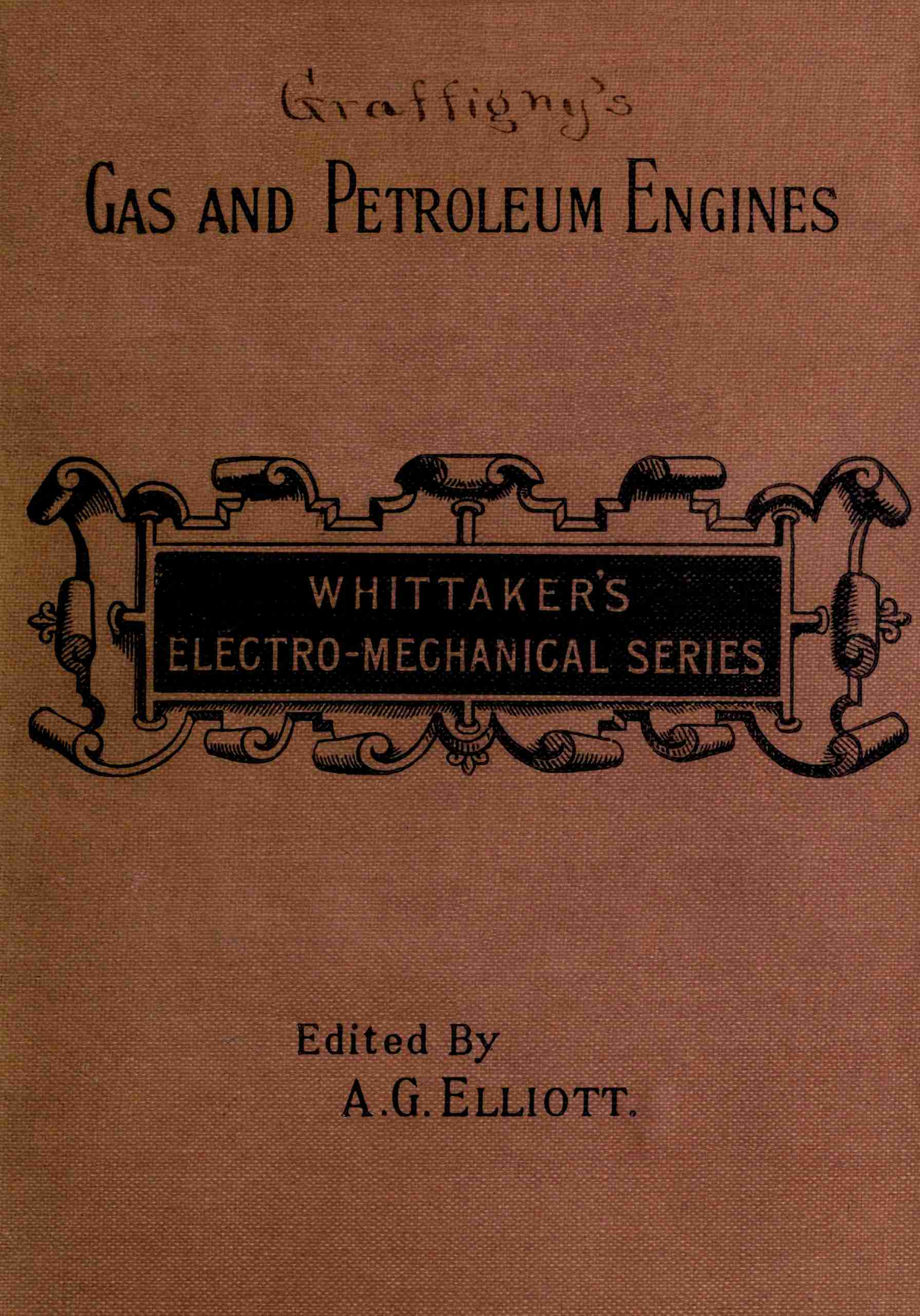
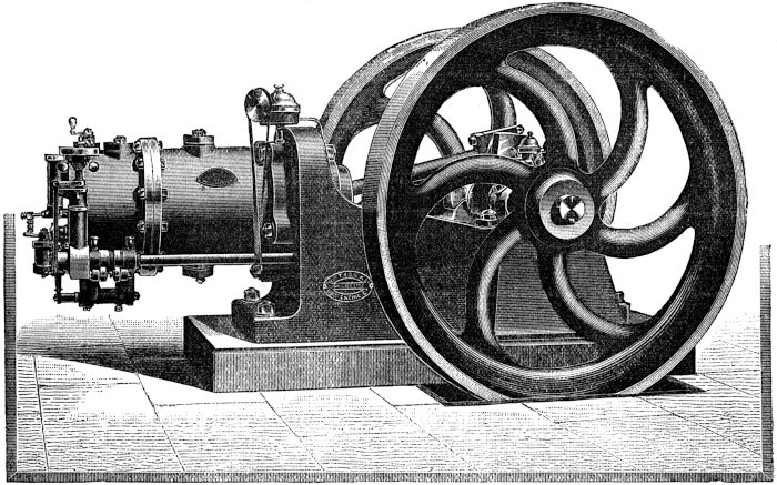
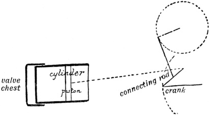
Early Lenoir engine (1860).—The motor (Fig. 1) resembled in external appearance a horizontal double-acting steam engine. This design was in great favour at that time, being copied from the steam engine, and was to a certain extent suitable for use with an explosive gas instead of steam. The valve chest is cylindrical and the valves themselves flat, and work off two eccentrics; ignition is effected by an electric spark from a Ruhmkorff coil, which passes through the gas in the cylinder when the piston is commencing the second half of the forward stroke. The exploded gases having done their work are driven out through the exhaust in the return stroke, during which work is being done by a similar explosion on the other side of the piston. A water jacket prevents the cylinder walls from becoming overheated. This arrangement is therefore double-acting, but a compression of the explosive gas is not possible without the use of a second cylinder. It has been abandoned because regularity of working is only obtained at the expense of economy, and by using both24 sides of the piston as explosive chambers it is found that the quantity of gas used is quite out of proportion to the power developed.
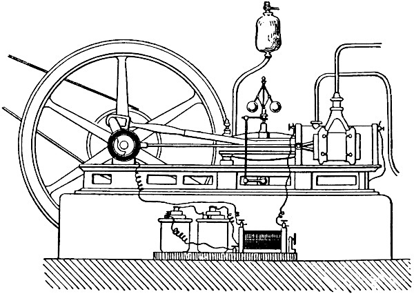
The Bisschop gas engine.—This motor (Fig. 2), based on a mixed principle, uses the explosion to do work during the forward stroke, and in the return the atmosphere exerts an excess of pressure on the other side of the piston, as in the Otto and Langen atmospheric engine which we have previously mentioned. In its time the Bisschop gas engine obtained a great measure of success, but it has now almost completely disappeared. It was, however, well thought out and constructed; the cylinder was vertical, and relied on longitudinal corrugations, and the air to keep it cool. Above the cylinder was placed a cylindrical guide; a connecting rod and cross-head formed 25 the attachment between the piston rod and crank. The machine was principally constructed for small workshops requiring small powers of from a quarter to one horse-power, the cost of fuel for the half horse-power size being about one penny per hour. The inventor received a prize of 1000 francs from the Société d’Encouragement for the best small motor applicable to home industries.
François motor.—This type, which is now quite obsolete, was somewhat similar in character to the last, but rather more complicated and perfect. The crank shaft was not in a line with the cylinder, and was connected by two connecting rods to the cross-head. Two fly-wheels were26 placed one on each side of the cylinder and connected by toothed wheels. The machine was on the whole too complicated, and although its consumption of fuel was comparatively small and its speed constant, it did not succeed in ousting the Bisschop motor from its position.
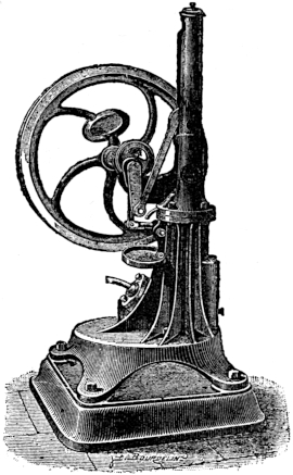
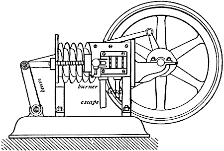
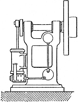
Bénier gas engine.—This motor was the first conceived by the inventors of the combined gas plant and engine which we will describe later, and is extremely simple. This piston rod is connected to the crank in a manner similar to a beam engine (Fig. 3). Both the admission of the gases and their ignition are accomplished by a single spring valve worked by a cam on the crank-shaft. The cylinder, which is vertical and inverted, draws in the gases for half the forward stroke, and then the valve, which has moved still further forward, brings a flame opposite the admission port and ignites the mixture; a small auxiliary27 gas-jet re-ignites the flame at each stroke. The gases escape from the cylinder by a second port with a special valve and cam. A water jacket for the cylinder is provided to carry off the surplus heat. The consumption is high, being about 1400 litres per horse-power hour, but owing to the extreme simplicity of the working parts this motor met with a certain amount of success about 1880.
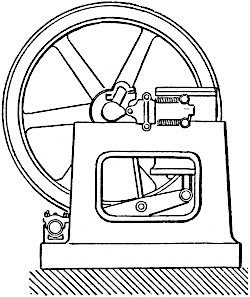
Forest gas engine (Fig. 4).—This motor, being of the single-acting type without compression, had at one time a considerable sale, being used where only a small power was required. The rectilinear motion is changed into a rotary one by means of an Oliver Evans beam, and a connecting rod which returned alongside of the cylinder to the crank-shaft and fly-wheel, which are placed at the back. Ignition is obtained by a burner which is re-lit by a smaller one at each stroke, and the cylinder is cooled28 not by a water jacket but by a helical groove, which increases the surface. This helix is formed by a thin plate cast on the cylinder. The fuel consumed was about 1400 litres of gas per horse-power hour, which may be considered good for such an engine.
Economic motor.—Constructed in New York. This engine is another example of the early attempts to obtain economy without compression. As a rule they were not constructed of more than half horse-power size, and the general arrangement is ingenious, but rather more complicated than those which we have so far spoken of. The piston rod is guided by being attached to one end of a lever, connected with crank by means of a vertical connecting rod. The cylinder is grooved, and cooled by the circulation of the air round it, and constancy of speed is obtained by a centrifugal governor, which cuts off the supply of gas when the speed is too high. The engine seems to have given some very fair results.
Lentz gas engine.—It is difficult to conceive a more simple mechanism than is to be found in this motor. The supply of gas is drawn into the cylinder by an open valve, and a gas flame situated in this admission port ignites the explosive gases. The force of the explosion closes the admission valve, and on the return stroke a cam opens an exhaust port situated underneath the cylinder. There is no water jacket, but the cylinder is formed of two parts connected together by a non-conducting joint. In order to smooth down the jerk of the explosion the head of the connecting rod slides in a groove, and is kept pressed against the crank-pin by a spring, the result being that29 the connecting rod is longitudinally elastic and deadens the shock of the explosion.
Dugald-Clerk gas engine.—In the ideal motor we should have at least one explosion per revolution of the fly-wheel, which is not the case in the Otto cycle. For this reason many inventors have tried to construct gas engines with one cycle per revolution, but experience has taught us that though they may be mechanically more simple, they lose in efficiency what they gain in simplicity, and in spite of many eminent inventors attempting to solve the problem. Even the best-designed motors of this type have been unable to hold their own against the Otto cycle because they are not as efficient.
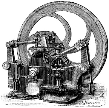
The first attempt was made by Dugald-Clerk in 1881. His engine is simple in the extreme, containing no gear-wheels, and working steadily and noiselessly at a fairly constant speed (Fig. 5).
There are two cylinders of equal diameter placed side by side, and projecting over the end of a cast-iron bed-plate. The first of these is the motive cylinder in which the explosion takes place; the other is used for compressing the explosive mixture, this compression taking place in the Otto cycle in the motive cylinder itself.
This secondary cylinder also serves for another purpose; it draws in a certain volume of air directly after the explosion, which is afterwards driven through the motive cylinder, effectively clearing out the waste gases. The30 advantage which this arrangement of double cylinders has over the Otto cycle, lies in the fact that one explosion can take place during each revolution of the crank, and consequently such very heavy fly-wheels as are used for the Otto type of engine are not necessary. The great disadvantage which the Dugald-Clerk motor possesses is the extreme suddenness of the explosion, which is practically complete before the piston begins to move. In spite of this defect the machines have a fairly high efficiency. The gases are ignited by a gas-jet situated in a sliding valve. A water jacket is used for cooling the cylinder, and in some of these motors a mechanism is attached for converting the engine from simple to compound. The compression cylinder then becomes double-acting, and the gases are further expanded in what was previously the motor cylinder only.
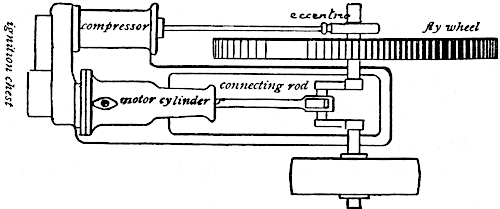
Owing to the fact that this motor was not as efficient as those of the Otto type it never became a commercial success, and it is doubtful if any are working at the present date.
31
Early Stockport gas engine.—The working of this motor affords a good example of British ingenuity. The compression cylinder is situated behind the motive cylinder, being a prolongation of it on the same axis; the two are firmly bolted together end on. The active piston is in front and connected to the crank, drawing behind it the piston of the compression chamber. Each cylinder has a separate sliding valve. The rear cylinder having aspirated and compressed a volume of the explosive gases, they are passed into the motive cylinder through a sliding valve which also serves to ignite them. The waste gas escapes into the air by a special valve. The aspiration and compression take place in the auxiliary cylinder once in every revolution of the crank, and besides, the motive piston also compresses the gases a trifle before the explosion takes place. The exhaust valve is made to open slightly before the piston reaches the end of its stroke. The motor was rather inefficient, and since its appearance a new type has been brought out with an Otto cycle which we will describe later on.
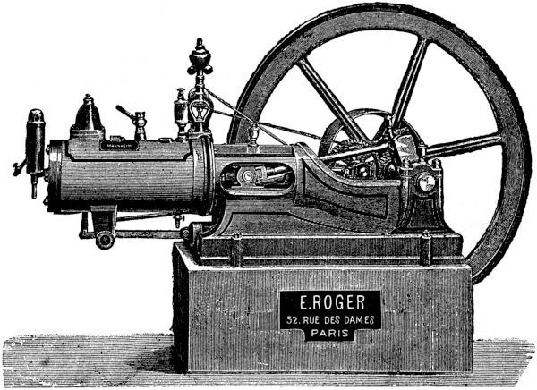
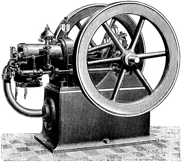
Benz motor (Fig. 6).—In this motor the inventor attempts to drive out the whole of the exhaust gases before the second half of the backward stroke of the piston is reached. To do this he injects a certain volume of air under pressure, driving out the burnt gases and substituting itself in their place. Before the end of this return stroke a small auxiliary pump introduces the requisite amount of coal gas, which is then compressed during the rest of the stroke. The ignition is effected by a small magneto machine driven by the engine itself, the sparks being32 generated between two fine metallic points in the cylinder. The jet of air required to drive out the product of the combustion is furnished from a reservoir, pressure in it being maintained by using the other side of the piston as an air-pump. This arrangement is an advantage, because cold air is being continually drawn into the cylinder which keeps it cool, and enables the lubrification to take place more effectively. There is also an external cooling apparatus in the form of a water jacket, which uses about 40 litres of water per horse-power hour, and keeps the cylinder at about 75° C. The Benz motor is very well known on the Continent, and much of its success is due to the fact that it seems to work as well with gasoline as with coal gas! It is constructed by M. Roger of Paris, and in consequence of the extreme constancy of its speed, it has been successfully applied to driving dynamos, and also to launches, motor cars, etc.
33
Baldwin gas engine.—The cycle of this engine is somewhat similar to that of the Benz motor, one side of the piston being used for expansion and the other side for compression. Part of the bed-plate casting is arranged so as to form a reservoir for the compressed gases. The coal gas is also admitted into this vessel, so that it contains an explosive mixture. As the vessel is only made of cast-iron this arrangement is rather dangerous. There are three valves, the admission valve being regulated by the governor. The power developed is, therefore, always kept proportional to the demand, and the constancy of speed is sufficient to warrant the use of these engines for running dynamos for electric light. The ignition is by an electric spark, and is generally obtained from some extra apparatus, such as accumulators or batteries, and an induction coil. The engine is constructed by Messrs. Otis Bros. of New York.
De Ravel motors.—The first motor constructed by M. de Ravel was exhibited in Paris in 1878, and was of the oscillating cylinder type, with a variable centre of gravity. The explosion drove up a heavy piston whose rod was directly connected to the crank-pin. The revolution of the crank-pin caused the whole cylinder to move in the same manner as that of the early oscillating steam engines. 34 This movement was used as a means of opening and closing the ports. The efficiency of the engine was low, using some 600 to 700 litres of gas per horse-power hour; and besides the motor had, owing to faulty mechanism, the unhappy knack of suddenly stopping dead. These defects caused M. de Ravel to abandon this type and to bring out a second motor in 1885, performing one cycle per revolution. This new motor only had one cylinder, whose rear half acted as a compression chamber during the backward stroke of the piston, whilst the explosion took place in the front end of the cylinder. The consumption of gas was slightly more than an Otto engine, and the motor ran exceedingly silently and evenly, but this advantage was not of much service in the struggle against the all-conquering Otto motor.
Midland motor (Taylor).—Constructed in Nottingham, this engine is of the horizontal double-cylinder type. One cylinder compresses the explosive mixture and passes it on to the other, where it is ignited and does work. The cranks connected to the two pistons are placed 65° apart, and a complete cycle in the cylinders is performed every revolution. The makers of this engine claim a consumption of only 600 litres of gas per horse-power hour.
Campbell gas engine.—The mechanism of this engine is very much like that of the Dugald-Clerk motor, two cylinders being placed side by side. The utilization of the heat is, however, far superior, and only about 500 litres of coal gas per horse-power hour are required. A result which the inventor of this type of cycle never succeeded in obtaining, but as far as we know the motor has never had 35 any official trial, and the above figures are only taken from the makers prospectus. However, there is only a hardly perceptible shock from the explosion, and the motor can be safely recommended to anybody requiring a silent gas engine. There still exist gas engines worked on this same cycle per revolution principle, such as the Conelly, Day, De Ravel motors, descriptions of which must be sought elsewhere. The limited space at our disposal prevents us from discussing all those types which have only obtained a very small measure of success. The only remaining engine based on this principle worth mentioning is the Bénier motor, which is exceedingly instructive, but we shall speak of it later under the head of poor-gas engines. We shall at present pass on to the consideration of engines based in principle on the patent of Beau de Rochas, and first practically realized in 1877 by Dr. Otto.
Otto gas engine (Fig. 7).—The principle on which this engine is based is known as the Otto cycle, named after Dr. Otto, but first suggested by Beau de Rochas. Since the patents have expired numerous copies and imitations have been brought out, but very few surpass or even equal some of the earlier types.
The explanation of the working of the Otto motor, which we are about to give, will save us from returning to it in the descriptions of analogous types brought out after this famous system. The cylinder is continued in a backward direction so as to form a compression chamber, into which the mixture of gas and air is drawn during the forward stroke of the piston. The mixture is compressed 36 during the return stroke in this chamber, the pressure rising at the end of the stroke to about 3 or 4 atmospheres. At this point in the cycle a flame is brought into contact with the compressed gases and they explode. This explosion raises the temperature of the gases to 1500° C., and drives forward the piston under a pressure of about 150 lbs. to the square inch. During the second return stroke, corresponding to the latter half of the second revolution of the crank, the piston drives out the products of the combustion into the air under a pressure of about an atmosphere. The heating of the cylinder is avoided by keeping water automatically circulating through a jacket surrounding it. This is necessary, because if the cylinder walls became heated, the oil upon them would become decomposed, and lose its lubricating properties. Dr. Otto paid special attention to the efficiency of the engine, and in order to increase it, he diluted the air and37 gas drawn into the cylinder with a portion of the gases already burnt in the previous stroke. Consequently the explosion at the beginning of the stroke is less violent, and the gases continue burning while the piston moves forward. The cause of this slow combustion has been wrongly attributed to stratification of superimposed layers of gas and air, but it is probably due to the action of the cylinder walls.
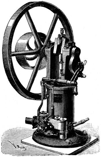
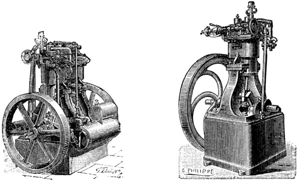
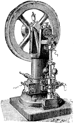
The Otto gas engine is a marvel of simplicity from a mechanical point of view, very much more so than a Corliss steam engine for instance. The admission and exhaust valves are worked by cams, and the ignition takes place under pressure. The governor is sometimes of the centrifugal type, and at others of the inertia type, but in both it is a case of all or nothing, the supply being completely shut off if the engine is going too fast. The connecting rod joins the crank to the piston rod by a cross-head running into a bored out-guide. It is necessary to have a heavy fly-wheel, because, as only one explosion takes place per two revolutions, the fly-wheel must store up enough energy during that explosion to carry it through the rest of the cycle. Many different types of Otto gas engines now exist, some having two cylinders and a single crank, and others two fly-wheels, in order to ensure constancy of speed for driving dynamos. Dr. Otto devised a compound gas engine, but it did not succeed, and also a cheaper vertical type (Fig. 8), which is very convenient for small workshops. Since the invention of carburetted air the creator of the Otto cycle has devised another motor for use with gasoline instead of coal gas.
38
Otto devised the first practical gas engine and opened up the path for others, who, following in his footsteps, have confined their attention to improvement of detail. Some have undoubtedly succeeded, and by avoiding waste of heat, and by raising the initial temperature of the gases, they have considerably reduced the consumption of fuel. We shall now discuss different types of motors which have appeared during the last fifteen years, confining ourselves to the really successful ones.
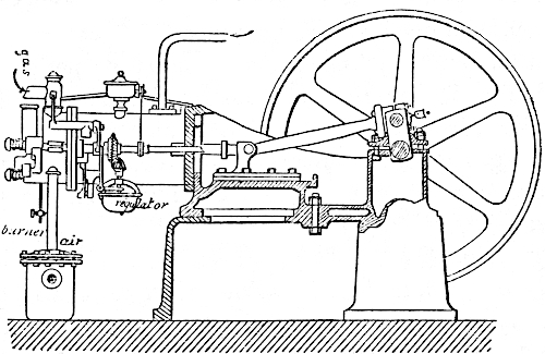
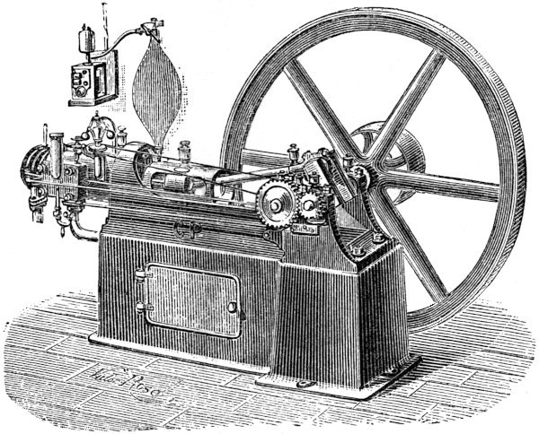
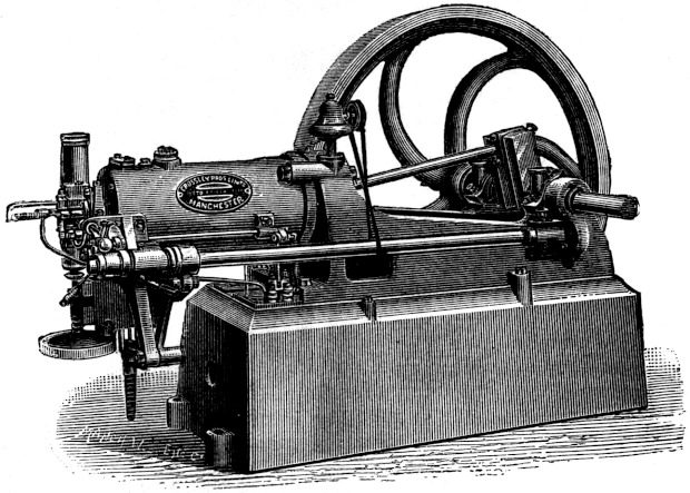
Second Lenoir motor.—Twenty-five years separated the appearances of the first and second Lenoir motors, and during this time M. Lenoir gained a great deal of practical experience, so that if reference be made to Figs. 1 and 9 they will be seen to have very little in common. In the later type the cylinder projects over the back of the bed-plate, and is provided with deep circular grooves on the 39 outside to increase the cooling surface. Ignition is obtained by the spark from a coil supplied by a battery as in the early form. The consumption of gas is about 800 litres per horse-power hour. Later on we shall discuss a petroleum motor for motor cars, and also a stationary petroleum engine by the same inventor. These engines were originally constructed by Mignon and Rouart, but later by the Compagnie Parisienne du Gaz, and are very well designed and constructed.
Koerting-Lieckfeld motor.—The first of these motors 40 was constructed in 1877, and was based on the Dugald-Clerk cycle. The original type has, however, been abandoned, and the firm of Brûlé et Cie. of Paris now construct these engines on the Otto system. All the moving parts are attached to a vertical frame of cast-iron (Fig. 10), the lower half containing the cylinder. The admission and exhaust valves are situated in front and near the base. The governor is of the centrifugal type and acts directly on the levers of the valves. The flame ignition makes it necessary to occasionally clean out the valves, but otherwise the motor has few drawbacks, and is very neat and compact. The consumption of coal gas for engines of 8 horse-power and upwards is about 800 litres per horse-power hour. The crank-shaft is placed horizontally across the top of the frame, and the cams acting upon the valves are rotated by a bevel gear enclosed in a case, driving a thin supplementary shaft on which they are placed. The motor is self-lubricating, and is also constructed as a horizontal gas engine.
41
Andrews’ motor.—The governing apparatus in this engine is exceedingly simple and ingenious, consisting of a weight fixed to an oscillating lever which controls the admission valve. The position which the weight takes up depends upon the rapidity with which the lever oscillates, and consequently upon the speed of the engine. If, therefore, the engine is running too fast or too slow the weight takes up a new position, and the effect upon the admission valve is to either slow down or quicken the speed. The gases are ignited by means of a tube kept red-hot by a gas flame. This engine possesses the special advantage of being self-starting, that is to say, it is not necessary, as in many other motors, to start the engine by giving the fly-wheel a few rapid turns by hand. The motor is stopped with the crank in a position slightly in advance of the point corresponding to ignition. The gas is allowed to enter by a small auxiliary valve, which closes after the first explosion. This volume of gas entering the cylinder mixes with the air already in it, forming an explosive mixture. This explosive mixture then begins to42 escape by similar automatic self-closing valves situated at the top of the red-hot ignition tube. Ignition takes place, and is communicated to the rest of the gas in the cylinder, closing the two small valves by the force of the explosion. The piston is therefore driven forward, and the energy of this combustion is sufficient to start the engine. It must be understood that this operation is only performed once at starting, for immediately afterwards the engine falls into its normal cycle of operations. Two fly-wheels are as a rule provided to ensure constancy of speed. The consumption of gas is as low as 580 litres per horse-power hour in the large units of 100 horse-power.
The Andrews gas engine is also constructed of a special type for consuming poor gas produced by the Dowson process, and gives very good results. As a rule, about 600 to 800 grammes of anthracite are necessary to produce one horse-power hour. In one particular plant generating electricity, the cost has been certified to be as low as one penny per kilowatt hour, including lubrication.
Fielding gas engine.—The characteristic point in these engines is the extreme simplicity of the valve gear, only one valve being ever subjected to pressure. Even in the small engines of this type all sliding valves are replaced by those of the spring pattern, in fact, the valve mechanism consists simply of two spring-valves, one of which fulfils two functions, controlling the admission and the escape of the gases. The two valves are moved by a double lever actuated by a single cam. The cycle is that of Dr. Otto. When the piston is starting on the return stroke after an explosion has taken place, the lever lifts43 one of the valves, and the products of the combustion escape into a circular space situated below. In the next forward stroke this valve is still further lifted, opening the admission port, while at the same moment the exhaust port is closed by the second valve; a new charge is therefore drawn into the cylinder. At the end of the admission stroke the valves are released by the lever, and the compression can now take place during the second return stroke. The movement causing the lifting of the valve continuously throughout one whole revolution is effected by means of a cam with two prominences on it, which act in succession on the lever. There is only one valve, therefore, which is subjected to pressure, and even this is well provided against risk of leakage by the second valve being placed behind it, acting as a double seating. A chamber is also provided in which the gases are first mixed, and this mixing is regulated by a second lever and a special valve. The governor is of the inertia type, and is attached to the upper side of the double lever. It consists of a straight rod with a ball at one end and a knife edge at the other, pivoted at its centre to the end of the valve lever. As this lever is thrown forward the knife edge strikes the end of the spring-valve admitting gas to the mixing chamber. If the speed is too great the sudden jerk on the ball at the other end of the knife edge causes it to miss the valve, and no gas is admitted till the speed is reduced to the normal number of revolutions per minute. This arrangement is very sensitive, and keeps the speed exceedingly constant. Mr. Fielding has constructed some large gas engines of 350 horse-power which are started by compressed 44 air, this air having been previously stored up under pressure when the motor was stopping.
Niel motor.—As will be seen from Fig. 11, the valves are actuated by cams rotating on a supplementary shaft placed parallel to the cylinder. A pair of toothed wheels transmit the rotation of the crank to this valve-shaft, and it is arranged so as to give one rotation to every two of the crank. The cycle of operations is somewhat similar to the Otto cycle; gas is only admitted to the cylinder for two-thirds of the forward stroke, so that the compression on the back stroke is somewhat lessened. It is doubtful whether there is much advantage in this method, but the Niel motors have had a large sale, which is a sufficient proof of their good qualities.
45
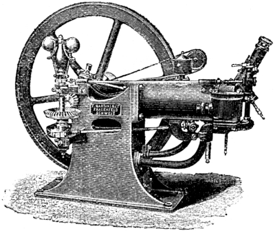
Lombart, Martini (Fig. 12), Adam, Le Parisien, and Le Kientzy motors.—All these motors, each of which is constructed by a different maker, are based in principle on the Otto engine, and except for slight modifications of the working parts, they do not call for any particular notice. The small amount of space at our disposal only admits of our mentioning them.
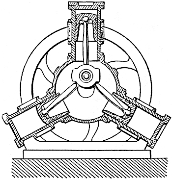
Lablin motor (Fig. 13).—M. Lablin of Nantes set himself to produce a motor which should correspond with the Brotherood and Westinghouse steam engine, that is to say,46 a motor developing the maximum of power for the minimum of space and weight. This might be termed the dynamic density of the motor, which M. Lablin sought to increase. He has succeeded in constructing gas motors of ½ horse-power weighing about 90 lbs., and of 8 horse-power weighing 7 cwt. Unfortunately they consume a rather large quantity of fuel—about 1000 litres of coal gas, or 500 grammes of gasoline per horse-power hour. There are three cylinders grouped at equal distances round the same shaft, and all attached to one single crank. By this arrangement a more constant torque or twisting movement on the shaft is obtained, and consequently the weight of the fly-wheel can be considerably reduced. Three explosions are produced during every revolution, that is to say, each cylinder performs a complete cycle of operations during every revolution, a fact which accounts for the low efficiency. Ignition is obtained by a platinum tube heated to incandescence when using coal gas, and by an electric spark when carburetted air is used. The governor is centrifugal, and controls the admission of gas.
47
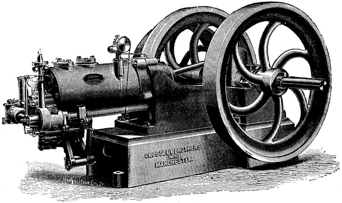
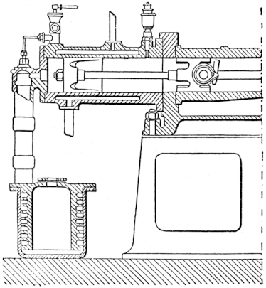
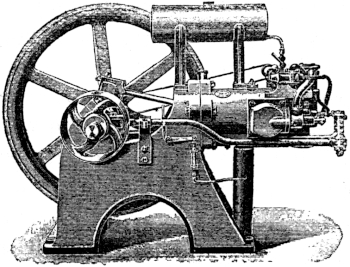
Crossley Bros. gas engine (Figs. 14, 15).—This engine is from the cycle point of view purely and simply an Otto gas engine. A light shaft runs parallel to the cylinder, being driven by a worm-gear of the crank-shaft. On it are situated the cams which force open the four spring-valves, controlling respectively the admission of air gas and the ignition and exhaust.
49
The pressure of the gases is raised during compression to about four atmospheres, and immediately after the explosion it rises to about 180 lbs. on the square inch; during the exhaust it averages about 10 lbs. per square inch. Ignition is obtained by a tube heated to a bright red incandescence by a Bunsen flame. At the right moment a valve is opened, placing the explosive mixture in contact with it and causing the explosion. When starting the machine the ignition is retarded or takes place a little after passing the dead point, so that the machine cannot start the wrong way by mistake. Two or three other features call for special notice, especially the device for lubricating the cylinder. In the illustration (Fig. 14) will be seen a small bell-shaped receptacle. This vessel contains oil, and also a small crank inside driven by a belt off the valve-shaft. As this crank rotates it dips into the oil at the bottom of the vessel, and at the top of its path it wipes off the oil which it has gathered on to a cup which allows it to flow into the cylinder.
The water jacket is cast separately from the cylinder, and not, as in many engines, in one piece with it. There is an advantage in this, because there is less likelihood of flaws or blow-holes in the cylinder wall passing unobserved when the engine is leaving the maker’s hands. The governor in some of the sizes is centrifugal, and in others of the inertia type similar to that described in the Fielding gas engine.
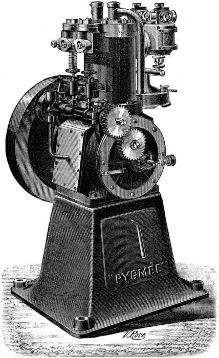
Pygmée motor (Lefebvre).—This motor, shown in Fig. 16, gives one the idea of solidity and compactness. It possesses the peculiar property of working equally well in any position, either horizontal or vertical. This is due to the fact that it is particularly well balanced, and when running does not vibrate at all. Easily started, these engines run at a very constant speed, and their power in relation to their size is truly remarkable, hence the name Pygmée. They have been especially designed for self-propelled vehicles, and are not affected by the worst running conditions, such as inclement weather or bad roads. In this type they are constructed with two cylinders in order to obtain a more constant torque, and also have an arrangement by which the speed can be changed. For stationary purposes the motor is mounted on a cast-iron stand (Fig. 16). In virtue of their exceedingly small dimensions and reduced weight they are specially suitable where small-power motors are required for home industries or small workshops, and also for driving private electric installations and pumping water. They have economically replaced steam engines in agricultural operations, both on a large and small scale. The working parts being entirely enclosed they stand a good deal of rough usage, and will work in positions in which other motors would be useless. Where it is necessary to bring the motor to the work it is required to perform they are bolted to a carriage instead of a cast-iron base.
51
The “National” gas engine.—As a gas engine this machine is constructed in all sizes, from one horse-power up to large units requiring a gas plant of their own. As petroleum motors they range from one to ten horse-power. They are all provided with two fly-wheels, which keep them well balanced and steadies their speed. They have besides been especially designed with a view to economy of coal gas or petroleum. An idea of the general arrangement of the parts will be obtained by glancing at Fig. 17. The petroleum motors are provided in addition with a vaporizer and a petroleum lamp placed at the front end of the machine, and the oil reservoir is situated immediately above the cylinder. M. Herckenrath has specially devoted himself to simplifying the mechanism and making it more self-contained and less unsightly. Up to 50 horse-power only one cylinder is found necessary, and for larger powers two are provided. The patent governor is centrifugal and rather novel in construction, and to it is partly due the high efficiency of these engines. The large sizes are as easily started as the smaller ones, and the lubrication is perfectly automatic. Besides these advantages they require a minimum of attention, in fact, a skilled attendant can be dispensed with, a few explanations and instructions being all that is necessary to enable a boy or labourer to take competent charge of them.
53
Forest motor (Figs. 18, 19, 20).—We have already described the earlier attempts of M. Forest to produce a practical gas engine. The idea embodied in the motor depicted in Fig. 20, if not particularly advantageous, is none the less highly original. The ends of the single cylinder are open, and within it are two pistons, between which the explosive mixture is introduced. The explosion drives these pistons out in different directions, but by means of a suitable mechanism they are each connected to one of two cranks on the same shaft. The whole forms a very neat and compact arrangement. In another type54 by the same inventor (Figs. 18, 19), also working on the Otto cycle, the cylinders are vertical, there being one, two, or four placed side by side. In the last case two explosions per revolution are obtained, ensuring a very constant torque throughout. M. Forest has, however, particularly applied himself in collaboration with M. Gallice to designing petroleum engines for small boats. These two inventors have conceived a highly ingenious arrangement for reversing the direction of rotation of the engine, which is absolutely necessary in the propulsion of boats. All the cams which actuate the valves are grouped together on a light shaft, and by a simple twisting of this shaft from one end by a handle the engine is reversed. The engines are self-starting, and are so especially suitable for the propulsion of boats that they have been adopted by the French navy, who at the present date have a number of small vessels propelled by this motive power.
55
Cuinat gas engines.—These engines are constructed in four types. The A type is vertical with the cylinder above and fly-wheel and shaft below. This is a more stable arrangement than placing them in the reversed order, as is more frequently done. For small engines the vertical type is undoubtedly the best, space, or rather lack of space, being very often an important consideration to the purchaser. The B type is similar to the previous one, except that two fly-wheels are provided so as to make it suitable for small electric light installations. The C type is horizontal, having all the valves placed vertically, which plan seems to work better for engines of power greater than 10 horse-power. The D type is also horizontal, but has two fly-wheels, having been specially designed for electric lighting purposes. In order to take up as little 56 space as possible the dynamo is situated underneath the projecting cylinder, both the engine and dynamo being bolted down on to a special bed-plate. This arrangement is more stable than placing them on separate foundations. In the petroleum engines an electric spark is used to ignite the gases, and in the gas engines both electricity and a gas flame.
It is best not to use animal or vegetable oils for lubricating the inside of the cylinder, because they decompose, forming fatty acids which have a corrosive action. Besides this, when they have fulfilled their function of lubrication they settle down to a thick paste, which has a most injurious effect on the working of the engine. It is best, therefore, to use nothing but perfectly pure mineral oils and to avoid all others. This does not only apply to the type of engine we have just been describing, but to all gas engines. The Cuinat gas and petroleum motors do not mix a portion of their exhausted gases with the fresh charge as is frequently done, but completely sweep away the products of the explosion before admitting a new charge. The result is, that combustion is more complete but at the same time rather more violent. An examination of an indicator diagram taken from one of these engines shows that the combustion takes place at once as an explosion, and that the final expanded pressure is as low as it is possible to get it. These being the conditions necessary for a high efficiency, it is needless to state that the consumption of fuel in these engines is as low as in any other engine.
Noël motor.—This type, constructed at Provins, has the 57 advantage of being exceedingly simple. The entries to the cylinder are controlled by spring-valves, and the gases are ignited by electricity. From the ¼ up to the 2 horse-power size the cylinder is not provided with a water jacket, and the general arrangement is either vertical or horizontal. These engines work equally well with coal gas or carburetted air; in the latter case the carburator is placed inside the cast-iron frame of the motor. The guaranteed consumption of fuel is about 900 litres of gas or 500 grammes of gasoline per horse-power hour, which is quite satisfactory.
Tenting motor.—This is a horizontal motor with the cylinder cooled atmospherically, and the gases ignited by electricity. The governor acts upon the exhaust valve; the products of the explosion remain in the cylinder if the speed is too great, and then the admission valve, which is automatic, no longer rises to admit a fresh charge until the speed has once more fallen to the normal. This little motor is one of the most practical small-power engines existing, partly because of the great simplicity of the mechanism. It works well with carburetted air, and the vertical type has been successfully applied to the propulsion of small pleasure-boats.
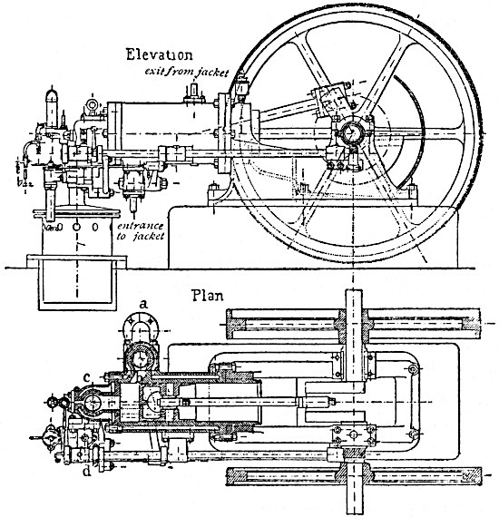
Atkinson motor (Figs. 21, 22).—This apparatus, constructed by the British Gas Engine Company, was until recently the most efficient heat engine in existence, its indicated efficiency being 22·8%. Mr. Atkinson, the inventor, has arrived at this result by making the gases burn gradually and by shortening the compression stroke. The discharge of the residual gases is complete, this being 58 directly opposite to Dr. Otto’s procedure, for he diluted his explosive mixture largely with the exhausted gases. In order, however, to make the piston execute two strokes relative to the cylinder of different lengths, the inventor has had to devise a rather complicated mechanism (Fig. 21). The result, however, quite neutralizes this slight disadvantage.
59
Charon motor (Fig. 23).—M. Charon has attempted to obtain a prolonged combustion without the complicated devices resorted to by Atkinson. He has obtained the same result by means of a regulator controlling a double cam, one half of which actuates the admission valve and the other half an auxiliary valve, which opens into a tube forming a sort of reservoir, into which part of the explosive mixture passes during the compression. After the explosion this stored-up mixture is gradually allowed to re-enter the cylinder and prolong the combustion. By this means a considerable gain in economy is obtained, so that engines of this type only use about 500 litres of coal gas per horse-power hour. In appearance the motor much resembles the Otto motor, the crank-shaft and valve-shaft and valves being placed in the same relative positions. Although these motors are rather more expensive than others working with the Otto cycle, they are nevertheless widely used. This is due to the fact that if cost of coal gas in a particular district is high it is cheaper in the end to pay a higher price for an efficient engine than to buy a less expensive and at the same time less economical machine.
60
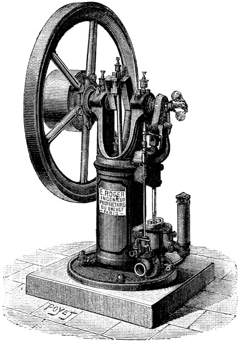
Roger motor.—This excellent little engine (Fig. 24) was especially designed for small workshops. The extreme simplicity of the working parts in no way lessens the efficiency, for the two horse-power only burns 700 litres of gas per horse-power hour. The simple design also keeps the cost of construction low, and the price averages about £30 per horse-power.
61
The governor controls the admission valve. Ignition is obtained by means of an incandescent tube; the cylinder is cooled by a water jacket; the mean speed is about 200 revolutions per minute, and this speed is constant enough to allow the engine to drive a dynamo for electric lighting. The motor has been very favourably received abroad, but is not much known in this country.
Motor of the Compagnie Parisienne du Gaz (Fig. 25).—Owing to its very large consumption of gas the engine can only be used if the price of gas is low, but it has several advantages which to a certain extent neutralize this defect. It runs at a high speed of 400 revolutions per minute, and the parts are arranged so as to be easily accessible.
62
Letombe motor.—Constructed by the firm of Mollet-Fontaine of Lille, this engine presents several interesting features which we will briefly enumerate. The cylinder is double-acting, giving one impulse to the piston during every revolution. The speed is therefore maintained fairly constant. The efficiency is high owing to the gases in the cylinder being made to burn slowly as in the Charon motor. The machine on the whole works exceedingly satisfactorily and reflects great credit on its inventors.
Robuste (Levasseur) motor.—The composition, admission, and ignition of explosive mixture are regulated by a sliding valve as in the Otto motor; in this case, however, it is a piston-valve and not a flat one. The valve-chest is at the back of the cylinder. The governor is of the inertia type,63 and suppresses the admission if the speed becomes higher than the normal. A double water jacket is provided for cooling the cylinder walls. Although not presenting any new features, this motor fully merits its name, and its solid construction enables it to withstand a surprising amount of bad handling.
Richardson and Norris gas engine.—Yet another high-speed engine, running at a speed of 230 revolutions per minute. Roby & Co. construct this machine especially for driving dynamos, and for this purpose two fly-wheels are provided in order to make it run smoothly without variation of speed. The gases are ignited through a valve with a double seating by means of a red-hot tube. The motor is reversible, which is an advantage under certain conditions. Poor gas can also be used instead of coal gas, consuming about 510 grammes of anthracite per horse-power hour for an 86 horse-power engine supplied with Dowson gas. This works out to a thermal efficiency of 21%, a result which places this engine above criticism.
H. C. motor.—This is an enclosed motor for use in mines or dusty places, the fly-wheel alone of the moving parts being visible. It works equally well with coal gas, carburetted air, or petroleum, and is constructed in sizes from ½ to 60 horse-power. In spite of its original features it has not met with much success up to the present time.
Le Marcel and Le Maurice motors (Cadiot) (Fig. 26).—The smallest types of the Marcel motors are of one man-power, and the largest of one horse-power, so that they are only suitable for small operations. One impulse is given to the piston every two revolutions, the cycle being that of64 Dr. Otto. The gas is compressed in a red-hot tube during half of the backward stroke. There are only two valves, one for the admission and the other for the escape of the gases, actuated by a single cam on the crank-shaft. The cylinder is cooled by a water jacket. The governor works on the all or nothing principle, the supply of gas being completely shut off if the speed rises above the normal of 350 revolutions per minute.
The Maurice motors are somewhat similar in construction, but are designed for operating dynamos. For this purpose two fly-wheels are provided. Many of these little motors are to be seen about the country working fans, lathes, pumps, etc.
Various.—We have described about thirty different sorts of motors, selected from the best-known and most original types. About one hundred other motors exist in Europe, which are similar in one way or another to those already described, such as the engines of Dürkopp, Forward,65 Brouhot, Debry de Soissons, Narjot, Archat, Wertenbruch, the “Acmé” motor, and many others. But we are obliged to limit our descriptions, and to conclude the chapter by a couple of examples of motors performing one cycle of operations per three revolutions.
Griffin motor.—In this engine we have only two explosions over three revolutions, but as it is double-acting this number is reduced to one explosion per revolution and a half. The different operations are as follows:—(1) gases drawn into the cylinder, (2) compression of gases, (3) ignition and expansion, (4) products of combustion driven out of the cylinder, (5) a volume drawn into it to completely sweep away any residue of the exhaust gases, (6) this volume of air drawn out.
Admission and ignition are obtained by the action of a sliding valve and eccentric. The governor causes the gas admission valve to remain open for a shorter or longer time, so as to ensure constancy of speed. The exhaust gases escape by two valves actuated by a pair of cams, opening them at every turn and a half, so that the gases are alternately discharged from the back and front parts of the cylinder. The consumption of fuel for a 12 horse-power motor was about 792 litres of coal gas per horse-power hour in an official trial. The speed is very constant in spite of the long cycle.
Rollason gas engine.—This is also an engine using a long cycle of operations, the arrangement of the parts being copied off the Otto motor. The governor is electric, and acts on the admission valve, varying the amount of gas admitted to the cylinder in proportion to the demand for66 power. In the larger size of from 20 to 100 horse-power a self-starting arrangement has been added. This engine, like the Griffin motor, has proved that it is possible, by completely getting rid of the products of combustion, to use a very dilute explosive mixture, which would be impossible in the Otto motor. The Rollason engine is constructed by Messrs. Beck and Co. of Newcastle-on-Tyne.
If cold air be saturated with the vapour of volatile spirits such as gasoline, or distillates of petroleum of about ·65 mean specific gravity, an explosive mixture is formed with similar properties to that produced by coal gas mixed with air. This carburetted air can be used as fuel for heat engines of the explosive type. About twenty different methods of carburating air are in existence, some of which are more practical than others. We shall proceed to describe the best known of these.
Mille carburetted gas.—In this system air is drawn into a reservoir containing a petroleum spirit by the volatilization and fall of the petroleum vapour, this vapour being heavier than air. The reservoir is placed on a higher level, and an indiarubber tube connected to its base leads the explosive mixture to the cylinder. The success of this arrangement encouraged inventors to perfect it. One of the earliest carburators by Lafroque was provided with a tiny hot-air engine, which helped to obtain a more perfect saturation of the air with the volatile spirit. In68 the Eclipse motors, and also in the Phœbus motors of Pluyer and Muller of Birmingham, the air and spirit vapour are mixed by an injector. The vapour is first obtained by heating the liquid spirit in a small still; it then passes by a fine nozzle across a space drawing air with it after the manner of the Giffard injector. The explosive mixture thus obtained passes into a reservoir.
Faignot apparatus.—The air is drawn in by a revolving pump and forced into a vessel, divided into several compartments, one above the other, separated by porous partitions and containing gasoline; several taps or valves cause the compartments to be alternately opened or closed, so that the mixture can always be drawn off rich in hydrocarbon vapour. This apparatus appeared in 1885 at the Antwerp Exhibition, and supplied a Bénier motor with carburetted air. It is suitable for lighting villages, country houses, etc., in fact, any places where coal gas is not laid on. The apparatus has been imitated by Polack of Hamburg and others.
Lenoir carburetted air motor.—Carburators for producing fuel for motive power have been carefully studied during the last ten years by reason of the rapidly extended use of gas motors. One of the most ingenious is due to M. Lenoir, constructed for a special motor designed by himself and constructed by Messrs. Rouart frères. This carburator consists of a horizontal cylinder rotated by a pinion wheel, and performing five or six revolutions a minute. Vertical perforated partitions divide the cylinder internally into several compartments, and the interior wall of the cylinder has attached to it a number of small69 buckets which draw up the spirit like a water-wheel, and pour it out again when they reach the summit of their path. The air and vapour are thus thoroughly mixed, and pass from thence into the cylinder. Motors supplied by such carburators have been used for agricultural operations, and also for driving small pleasure vessels, the cost of maintenance per horse-power hour being about 2½d.
Schrab carburator.—The idea of this apparatus is quite original. The jacket for cooling the motive cylinder is filled not with water but with the hydrocarbon to be vaporized. From thence it passes at a temperature of about 180° F. into a carburator containing several compartments, and through which pass part of the products of combustion; these gases passing through the already boiling liquid hydrocarbon become saturated with its vapour, but require admixture with air before they are capable of being exploded. The inventor states that the waste gases only take up 1/16th part of that which pure air would in passing through the hot liquid fuel, and thus explains the extraordinary economy of fuel which is obtained by these motors, only 1/16th of a litre of gasoline being necessary to produce one horse-power hour. This is a very remarkable result, and if it is correct places this combined plant in the foremost rank of carburetted air engines.
Meyer carburator.—This apparatus has the advantage of allowing heavier and cheaper oils to be used, at the same time completely volatilizing them. The heavy hydrocarbons are allowed to fall drop by drop into a steel chamber about eight centimetres diameter and four70 centimetres in height, heated by a flame. The vapour is produced at a high pressure, and escapes through a fine nozzle at high speed drawing the necessary air with it. Entering a reservoir this explosive mixture is prevented from returning by a check-valve. The apparatus is so arranged, that when the pressure in the reservoir has reached a certain point, the flame heating the vaporizer is turned down and prevents further explosive mixture being formed. The apparatus is therefore self-regulating, the supply of carburetted air being always proportional to the demand.
Delamare carburator.—M. Delamare-Deboutteville has devised a very compact carburator for use with his Simplex motor. Gasoline is contained in an upper vessel, from which it flows in a fine stream from a tap on to a horse-hair brush, and is there met by a similar stream of warm water coming from the water jacket of the cylinder. The heat obtained from this source tends to vaporize the hydrocarbon, and the two liquids fall together into a closed vessel. The gasoline rids itself of its impurities and floats on the surface of the water, which is withdrawn from underneath it by a siphon. The hydrocarbon vapour produced during the fall, and afterwards by the heat of the substratum of water, passes by a check-valve to the motor. It is found that the cleansing effect of the water renders the cylinder much less liable to become fouled by tarry products.
Lothhammer carburator.—Experience has shown that vapour of petroleum when mixed with air soon separates out; the vaporizer must therefore be placed as close to71 the engine as possible. In this motor it has been the aim of the inventor to obtain an exceedingly perfect mixture of the explosive gases. In order to do this the air enters the vaporizer near its base, and passes through it in a number of exceedingly fine streams of bubbles. The petroleum spirit is at the same time heated by a flame, and the result is a very close mixture of the gases. The inventor claims that he thereby obtains much more complete combustion.
Tenting motor.—M. Tenting has arranged his gas engine, which we have already described on page 57, for use also as an oil engine. The carburator is composed of three superposed vessels, through each of which the oil flows in turn. The upper vessel acts as a reservoir and will hold a day’s consumption of oil, and the lower one is traversed by the exhaust pipe, which supplies the heat necessary to obtain the change of state of the oil from liquid to gas. Although this carburator is rather crude it gives a very fair practical result.
Durand carburetted air engine (Fig. 27).—M. Durand has set himself to produce a motor which should work equally well with gas or petroleum, and which should require a minimum of attention at the same time, keeping in view such points as regularity of speed, rigidity, economy of space, and above all low price. This ideal he has, however, failed to reach, although his engine has many good points. He fails chiefly because the mechanism is too complicated. The motor works with an Otto cycle, and the ignition is by an electric spark generated by a small magneto machine. The regulation of the speed is72 obtained by throttling the admission, and the air is drawn through a tube heated by the waste gases; this arrangement allows a slight economy to be effected. The carburator is automatic, consisting of a closed cylinder placed vertically over the motor cylinder. Within it is placed the oil fuel, and also a spongy mass of cork which soaks up the heavier impurities found in the oil, and thereby allows cheaper oils to be used. Air is drawn through the spongy mass, becoming carburetted in the process; these gases are mixed with a further quantity of pure air in a distributing chamber before entering the cylinder.
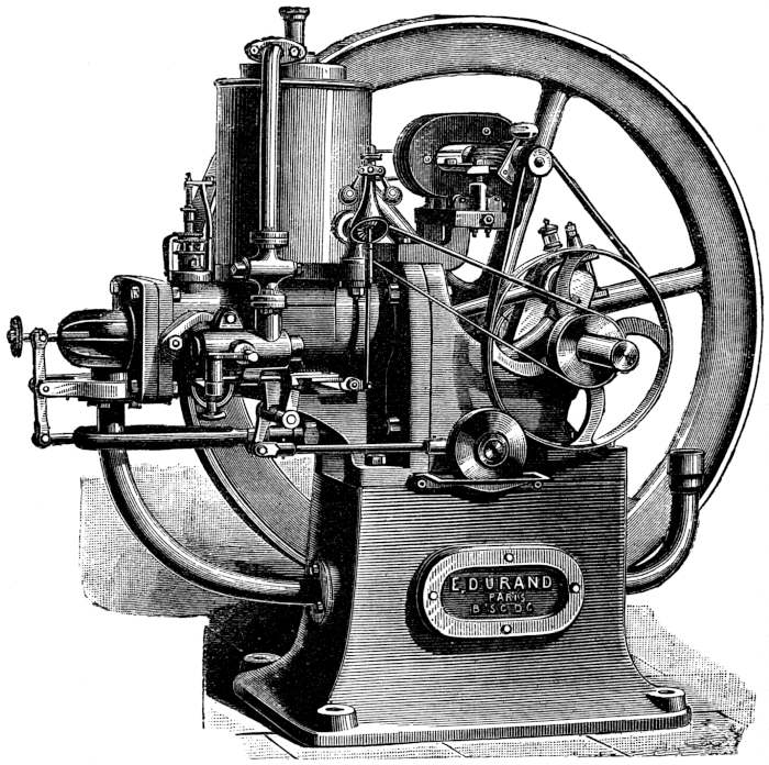
73
Such a Durand motor sins only by the number of its parts, the inconvenience of which is noticeable not only by the amount of lubrication they require, but also by their rapid deterioration.
Daimler motor.—This motor, constructed by Panhard and Levassor, has become especially famous for its application to power-driven road vehicles. It gained nearly all the best prizes in the automobile races organised in 1894 between Paris and Rouen, and again in 1895 between Paris and Bordeaux. MM. Panhard and Levassor also construct their motors as fixed engines, but except for slight modifications, the mechanism is the same in both; we shall therefore describe the automobile type.
There are two single-acting cylinders working on the same crank-shaft. A central valve allows compressed air to be admitted which completely drives out the products of combustion. The admission and exhaust valves are enclosed in a chest also containing the incandescent tube which ignites the mixture. The governor on the crank-shaft prevents the exhaust gases from escaping when the normal speed is exceeded. The gases remaining in the cylinder prevent a fresh charge from entering, and during 74 the next revolution no explosion takes place. The whole mechanism of the engine, together with the fly-wheels, are enclosed in an air-tight case communicating with the outside air by a valve opening inwards. The pistons during the backward stroke draw in air through this valve and compress it during the forward stroke; this forms the supply of compressed air for the explosive mixture. The carburetted air is obtained by the suction of heated air through oil placed in a vaporizing vessel. The motor cylinder is kept cool by a stream of water, which is itself cooled by travelling through a long annular pipe which runs completely round the carriage. The heat which it has absorbed from the cylinder is rapidly extracted from it by the circulation of the air on both the inside and outside of the tube.
Brouhot gas and carburetted air engine.—The firm of Brouhot of Vierzon construct an engine capable of working either by coal, gas, or petroleum, and which has been especially designed for agricultural operations. The general appearance of the engine is of the usual type; the cylinder projects over the bed-plate and is cooled by a water jacket. The explosive mixture is ignited by an electric spark produced from a battery of cells whose charge lasts from 120 to 130 hours, or by a small magneto machine driven by the motor itself. When working with petroleum a carburator is attached filled with a very volatile mineral spirit. The air is carburetted by being sucked through it directly into the cylinder. A second vessel is provided, which serves as a reservoir for oil feeding the carburator automatically, and keeping the oil in it 75 at a constant level. The whole machine, though not presenting any novel features, is strongly constructed and thoroughly suitable for the work it has to perform.
Carburetted air motors for horseless carriages.—Although not to such a great extent in England, self-propelled vehicles have within the last two years come rapidly into favour on the Continent, and the success which has attended them has caused inventors and makers to concentrate their efforts on building the motors as light and as practicable as possible, as much for purposes of locomotion as for a host of other uses. We have already spoken of the Daimler motor, which is used to drive several different types of motor cars; we will now speak of more recent developments in the same direction. Among many of the same character, the most noticeable is the high-speed motor of MM. de Dion and Bouton, who have applied them with great success to the propulsion of tricycles (Fig. 28).
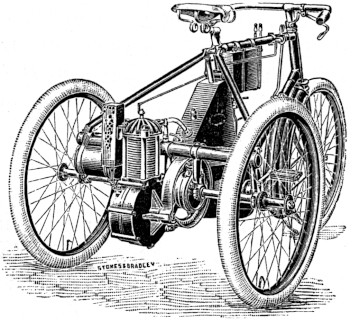
76
The cooling is effected by radiating cast-iron ribs offering a considerable surface to the air. The ignition is obtained by an induction coil and accumulator with a contact mechanism, invented by Captain de Place. The rotation of the crank-shaft is transmitted to the wheel-shaft of the tricycle by a reduction gear.
Among other motors we must mention the benzoline engines for self-propelled vehicles of Lepape, Gautier, the Gladiateur tricycles and quadricycles constructed by the Société des Voitures sans Chevaux; also the exceedingly light motors of the Kane-Pennington type; and lastly, the voiturette-tandem of M. Leon Bollée, some of whose vehicles have shown a remarkable speed with a very small consumption of fuel.
A few monstrosities have also appeared in the shape of a five-cylinder motor driving a bicycle called the “bicyclette Soleil Millet,” and a heavy and complicated mechanism by Wolfmüller, also driving a bicycle and using petroleum. These motors have not, however, obtained any success, nor will they at a future date, by reason of their complication and weight. It is almost unnecessary to state, that any of the above types may be equally well used for driving a dynamo and producing electric energy or light.
There is a great deal of difference, from an economic point of view, between spirit or carburetted air engines which we have just described and motors using ordinary commercial petroleum oil. As a rule such oil is much less dangerous, having a lower flashing-point, while at the same time it is cheaper than the more artificial products such as benzoline, naphtha, etc. We shall presently give a table comparing the cost of power produced by various systems of motors, and which will explain why the petroleum engine is gradually ousting the carburetted air motor from its place.
The first motor using ordinary petroleum was brought out twenty-six years ago by Brayton in 1872, and may be said to be the father of the large family of motors which consume oils varying from naphtha to others which have boiling-points as high as 150° C.
Ready motor (Brayton).—This motor belongs to the third group of the table on page 21 (combustion and compression). There are two cylinders, one motive the 78 other auxiliary, and used for compressing air. The compressed air passes through a space filled with some absorbent material such as felt, and kept saturated with petroleum injected into it by a special pump. The carburation of the air proceeds as follows: the high-pressure jet of air causes the petroleum to froth up, and in passing through it draws along a quantity of oil in the shape of finely-divided particles. This petroleum mist passes on to the cylinder. The advantage of this method of obtaining an explosive mixture is that it matters not what oil is used, in fact, the heavier oils are even to be preferred, as their partial condensation in the cylinder helps to lubricate it. One volume of petroleum will by this process produce 24,000 of explosive mixture.
The motor is constructed in both the horizontal and vertical form, the auxiliary being superposed upon the motor cylinder. The admission of the pulverized petroleum lasts for one-third of the forward stroke, and the return stroke expels the burnt gases. The engine is double-acting, using both sides of the piston.
A reservoir of compressed air is used for starting the engine, and saves the trouble of turning the heavy fly-wheel round by hand to give it the necessary impetus.
The Brayton motors are constructed by an American firm from 1 to 10 horse-power. The cost of maintenance and fuel is moderate, rendering them exceedingly practicable where coal gas or the lighter petroleum are unobtainable. A later type than the one we have just described appeared in 1890 which is slightly more economic, single-acting, and uses the Otto cycle. The process 79 for obtaining a spray of oil is also much improved. Both the auxiliary and the motor cylinders are connected by a beam and connecting rods to the shaft. A red-hot platinum tube ignites the explosive mixture.
Sécurité petroleum motor.—This engine was patented in 1887 by MM. Belmont Chabout and Diedrichs, and appeared at the Paris Exhibition of 1889. An Otto cycle is used, and ignition is obtained by a platinum capsule heated to incandescence by a jet of carburetted air which passes through a spiral coil warmed by the waste heat of the cylinder. This ignition tube is situated at the back of the cylinder, and is placed in communication with it by a port and valve, which determines the exact instant at which the explosion takes place. The petroleum is vaporized by passing through pipes coiled up in a vessel traversed by the heated products of combustion. The vapour thus formed has a high enough pressure to draw air along with it as it passes across an air space between two nozzles; an explosive mixture is therefore formed. The motor is started by carburating a small quantity of air by means of a reservoir containing a light oil, and this supplies sufficient energy to work the motor until the spiral coils are hot enough to vaporize the petroleum. The whole apparatus is rather complicated, especially as there are two separate vaporizers using different oils. This disadvantage, combined with only a moderate efficiency and a high prime cost, has severely handicapped the engine.
Priestman oil engine.—The first patent of this interesting engine was taken out in 1886 by Messrs. Dent and Priestman. The engine as a whole represents probably 80 the highest point of perfection which it is possible to attain to in this class of motor, and the general arrangement is somewhat similar to that of Dr. Otto’s engines, but in addition there is a very ingenious apparatus for working with heavy petroleum oils. A single-stroke pump, driven by an eccentric keyed to an auxiliary shaft turning half as fast as the main shaft, compresses the air to a standard pressure (depending in value, on the size of the engine) in a reservoir supplied with a governing valve and placed near the front of the engine. This reservoir contains petroleum, and the pressure of the air forces it up into a spray-maker, where it is pulverized. From thence the petroleum spray passes to a vaporizer heated by the waste gases, and becomes mixed with a certain volume of air forming an explosive mixture, which is admitted to the cylinder by an automatic valve. Compression and ignition take place in the cylinder, and the waste gases escape through a valve worked by the same eccentric which drives the air-pump. The number of parts of the mechanism is by this means reduced to a minimum, and it is found that this peculiar vaporizing process completely prevents the cylinder from being fouled, as is usual when petroleum is heated to such a high temperature, often decomposing it. The Priestman engine gave a fresh lease to the life of oil motors, which had at one time been almost abandoned by engineers. It is well adapted for all kinds of industrial operations requiring powers of from 1 to 50 horse-power, and large vertical engines have been constructed for marine purposes up to 100 horse-power, and have always given complete satisfaction to persons81 using them. A few minutes are required for the apparatus to become sufficiently heated to be able to start, after which the consumption of fuel is about 380 to 500 grammes of petroleum per horse-power hour, or about ·85 lb. The six-horse size weighs about 1½ tons. Ignition can be had either electric or by a flame, according to the wishes of the purchaser.
Campbell gas engine.—Fig. 29 shows a very compact engine, built by the Campbell Gas Engine Co. There are only three valves; the admission valve is regulated by a centrifugal governor. The petroleum is gasified in a vaporizer heated by a lamp. The speed is very constant and the motor easily started.
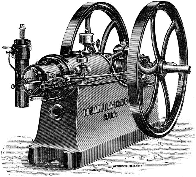
82
Grob motor.—This engine is constructed in Leipzig and uses the Otto cycle, and, like the motors already described, works well with ordinary petroleum. The arrangement (Fig. 30) is vertical; the cylinder and valve gear are supported on a hollow cast-iron column, which in turn is bolted to a circular bed-plate. The shaft has on one side a fly-wheel and on the other a pulley. The working valve parts are all situated on the outside so as to be easily got at. The oil-pump marked in the figure drives, the petroleum into a vaporizer, where it is broken up into very minute drops. This oil spray becomes mixed with air, and passes through a vaporizing tube heated by a flame. In the state of vapour the explosive mixture passes into the cylinder, where it is ignited at the right moment by a red-hot tube. In consequence of the compression during a quarter of the cycle, the combustion is very rapid, the power of these engines being very great for their size. Ignition, and therefore the explosion, only takes place when the speed falls below the normal. This regulation is obtained by a pendulum governor, and ensures a very constant speed. The cylinder walls are warm enough to make sure of ignition happening.
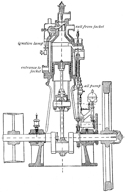
All heat engines based on the principle of the explosion of a volume of gas require an arrangement for drawing superfluous heat from the cylinder, otherwise it would soon become red-hot. This cooling is obtained in small engines by the circulation of air about a large surface especially attached to the cylinder walls, but in larger engines this means is insufficient, and it becomes necessary to use water as a cooling agent. If water is laid on there is no difficulty about this, but it occasionally happens that water is 84 too expensive, or that it is unobtainable; in such cases it is usual to erect a large cylindrical reservoir of galvanized iron holding about ten litres of water per horse-power of the engine. This reservoir is connected by two pipes from the top and bottom to the water jacket of the engine cylinder, and circulation takes place by the difference of density of hot and cold water. In the Grob motor a somewhat different device is resorted to. The water arriving from the jacket at a temperature of about 70° C. is divided into a number of fine streams, which pass up through a network inside the reservoir. At the same time a small centrifugal pump driven by the engine forces in addition a stream of air through the water; the effect is to cool the water before it returns to the jacket to a temperature of from 80° to 90° Fahrenheit. The Grob motor is built in the same manner as the Capitaine engine, which we shall describe next, but it does not work either as smoothly or efficiently as the latter engine. It possesses, in addition, other faults which are objectionable. The vaporizing apparatus is particularly troublesome, for the result of gasifying petroleum at such a high temperature is very often to decompose it, and thereby foul the cylinder and valve mechanism.
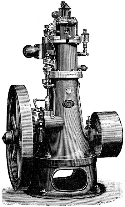
85
Capitaine petroleum motor (Figs. 32, 33, 34).—More than seventeen years have elapsed since Emile Capitaine, already well known for his experiments on gas engines, first tried his hand at oil motors. His first patent dates from the year 1879, and since that time he has continuously worked at the subject, expending much patience and money in order to produce a high-speed motor capable of using ordinary petroleum of ·88 specific gravity. The result of his labours is a machine which is excellent in all respects, requiring no igniting or heating apparatus. In the earlier type it was found that the motor would not work at less than three-quarters of its full load, because when it was doing less work the vaporizer became cooled in the intervals which occurred between the rarer explosions. This motor could only work under certain conditions, and after further trials and experiments Capitaine brought out a motor which worked at small loads as well as full loads, and which only consumed fuel in proportion to the power developed. This machine was considered too complicated, and a fresh type was brought out.
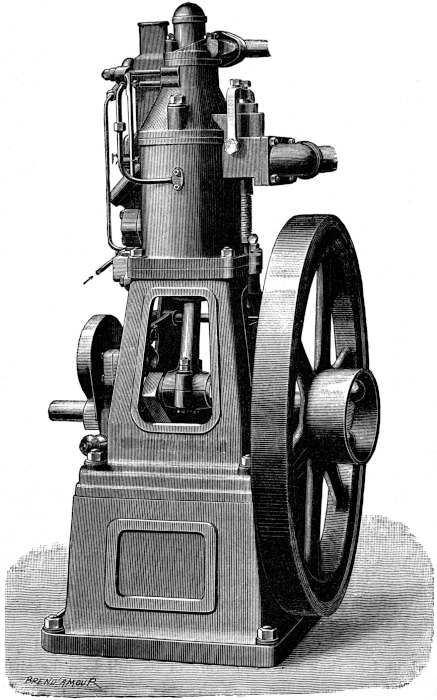
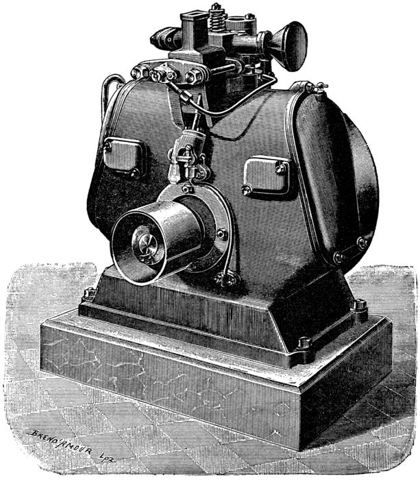
88
This third engine has a vaporizer which is in permanent communication with the cylinder, and is so constructed that even if it became red-hot there would be no risk of pre-ignition or the formation of tarry oils which would foul the cylinder. The vaporizer only draws in sufficient petroleum at a time for one explosion, and then only during the aspirating stroke of the piston. At the end of this stroke the whole of the petroleum in the vaporizer is gasified. The first motor on this plan was built by Capitaine in 1889, and many of them are still constructed at the present date by M. Louis Herlicq of Paris.
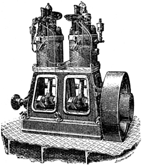
Capitaine came to an agreement with Grob et Cie. in 89 order to exploit his inventions in a wider field. Unfortunately differences arose, and in 1891 the agreement was cancelled. A lawsuit followed, lasting till March 26, 1893, when it was brought to an end by Grob et Cie. agreeing to pay Capitaine the sum of 125,000 francs in consideration for permission to use his name and patents in connection with their motors. After breaking up the partnership with Grob et Cie., Capitaine continued to build engines, and has since then taken out several patents, which have considerably enhanced the value of his previous inventions. In the 1892–93 type a lamp is used for starting which can afterwards be dispensed with, the heat of the compression being sufficient to maintain the temperature of the vaporizer. This is, however, only if the motor is developing more than three-quarters of its full power. When it was found that the same shaped indicator diagram could be obtained from these motors even when they were giving only 75% of their full power, it became obvious that it was only necessary to keep the vaporizer as warm as possible by covering it with non-conducting jackets, in order to get the engine to run at quite a small fraction of its full power. Capitaine has, by carefully observing this condition, obtained a motor which will run at all loads without any external heating apparatus.
The vaporizer forms part of the combustion chamber, and is carefully covered with non-conducting material. Only hot gases are allowed to pass through it. It must be started by heating for a few minutes with a small hand-lamp, and the engine is then ready for work.
Merlin motor.—This motor is of the vertical type, and 90 resembles the Capitaine motor in some respects. The oil is stored in a reservoir in the bed-plate; this receptacle is in communication with an air-pump driven by the motor, and also with an oil-pump. The pressure of air generated by the former forces the petroleum up into the oil-pump, which in its turn passes it drop by drop through a pulverizer, after which the spray of oil enters a vaporizer and becomes gasified. The vaporizer is heated by a special petroleum lamp. Ignition takes place when the explosive mixture comes into contact with the heated walls of the vaporizer, their temperature being always high enough to ensure ignition taking place. The consumption of fuel is regulated by a governor acting on the oil-pump, preventing it from supplying more oil than is absolutely necessary to keep up the speed. The governor regulates the exhaust valve as well, so that the speed, which is pretty high, is kept quite constant.
Hornsby-Akroyd oil engine (Figs. 35, 36).—This interesting machine was invented by Messrs. Akroyd, Stuart and Binney; it works with ordinary petroleum, and without the help of a carburator uses oils varying greatly in specific gravity. The reservoir of fuel is situated in the bed-plate. The ignition is automatic, and an electric spark is unnecessary, in fact, the whole engine is of the simplest construction, in order that there may be no inconvenience due to breakdowns. Referring to Fig. 35, L is a special petroleum lamp situated at the back of the cylinder A. When starting this lamp is supplied with air from a rotary fan turned by hand; in a short space of time, by the help of this stream of high-pressure air, the cartridge C becomes sufficiently 91 heated to ensure the ignition of the explosive mixture. This cartridge C is provided on its interior with radiating ribs, which greatly increase the surface. During the back-stroke of the piston it becomes filled with compressed air from the cylinder, and towards the end of this stroke a quantity of petroleum, exactly sufficient for the explosion, is squirted into it. To do this a small pump is provided, which is actuated by a cam driving the oil into the cartridge and brought back by a spring. The centrifugal governor G acts on the admission valve from this pump. The sudden injection of the oil into the middle of the heated chamber completely vaporizes it, forming with the air already present the necessary explosive charge, which immediately ignites in contact with the heated walls.
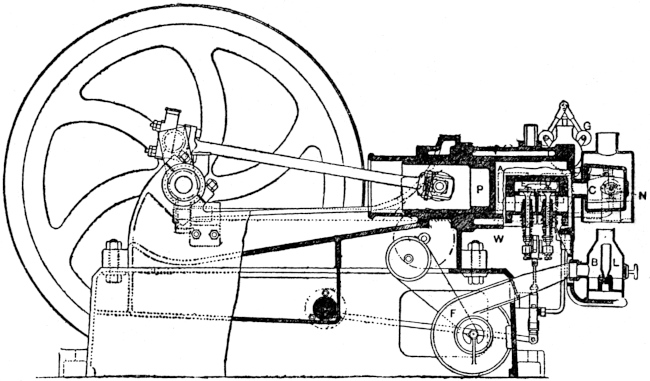
92
When the vaporizing cartridge has been sufficiently heated a rapid turn of the fly-wheel by hand, so as to produce the first explosion, is sufficient to start it, after which the vaporizer keeps itself warm. The pump which keeps up the supply of oil will be seen in the right-hand bottom corner of Fig. 35. It is of the plunger pattern, and at every stroke of the piston draws in the right quantity of oil and injects it into the vaporizer through a valve. The illustration on page 91 shows the other side of the engine with the valve-shaft, which revolves once for every two revolutions of the crank, also driving the centrifugal Porter governor. If the speed should happen to exceed the normal, a steel finger moved by the governor closes the valve admitting oil to the vaporizer, which then returns to the reservoir, having failed to accomplish its object. As the ordinary Otto cycle is used, a heavy fly-wheel is necessary to maintain the speed constant between the explosions. After being once started very little attention is necessary, everything working automatically. A water jacket W cools the cylinder.
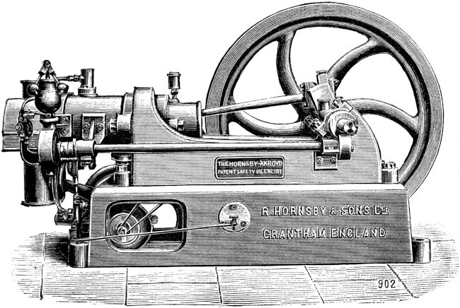
93
The specific gravity of the oil is usually about ·854, and of this the engine consumes about one pint per hour per B.H.-P., at a cost of 1½d. An additional advantage of the high speed is, that there is less chance of the cylinder becoming fouled by tarry products.
Vulcan motor.—This engine is in many respects a counterpart of the Akroyd motor. The cylinder is horizontal, and projects over the end of the bed-plate. Two fly-wheels are provided if very steady running is required. The lamp which vaporizes the petroleum at starting is removed when once the normal speed is attained. A water jacket prevents the cylinder from getting too hot. The most noticeable feature is the rather curious arrangement for governing by means of bent oscillating levers, which control both the admission and escape valves. The governor itself is situated inside the transmission pulley and keeps the speed within 1% of the normal; 600 grammes of petroleum per hour per horse-power is the usual consumption. The motor is rather too complicated, and can scarcely be said to have justified the expectations formed of it.
94
Ragot petroleum motor (Figs. 37, 38).—This engine, like the preceding ones, uses heavy petroleum and particularly schistic oil, which has a flashing-point above 77° Fahrenheit, and which may be bought very much more cheaply than naphtha, benzoline, or other artificial products of petroleum. Several different patterns of the engines are on the market, of which certain ones are of great value for electric lighting purposes, not only because of their steady running, but also because, by burning cheap oil, they allow the cost per horse-power to be reduced to a minimum. One high-speed pattern has been especially designed for coupling direct to dynamos, forming a very neat and compact plant. The latest developments in the construction of these engines tend to the simplification of the parts, and they are now so free from unnecessary mechanism, that persons with little or no knowledge of mechanics are quite capable of looking after them, and even taking them to pieces and putting them together again if a breakdown should occur, which is unlikely.
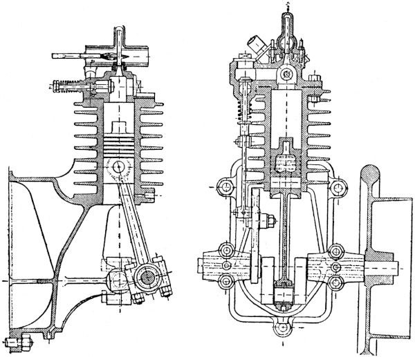
95
By a special arrangement in the carburator all constituents of the petroleum which might foul the cylinder are removed before the oil is allowed to enter the cylinder, and therefore it seldom requires cleaning out. The carburator (Fig. 39) is very ingeniously arranged; it consists of a cast-iron cylinder smooth on the inside, but provided with a spiral rib on its outer surface, and heated by an oil lamp. The spiral rib is itself enclosed by a covering, so that it forms a spiral tube. The petroleum is allowed to enter at the top, and gradually winds its way down, passing over a continually warmer and warmer surface as it approaches the lamp. The more volatile portions of the oil are therefore vaporized first, and the heavier oil passes on and is not vaporized till near the base, where the temperature is high enough to gasify the heavy residue. The air is heated in a jacket surrounding the base of the spiral, and is afterwards mixed with the oil vapour.
Root motor.—These engines work with the ordinary four-cycle, and are interesting because of the double-ignition apparatus. A lateral chamber is attached to the cylinder, communicating with it by an orifice situated at96 the back end, which is covered when the piston is at the beginning of its stroke. During the compression stroke a portion of the mixture is enclosed in this chamber and separated from the rest of the charge, which is compressed and ignited in the ordinary way. The explosion drives forward the piston, and when it has moved forward some distance it unmasks the above-mentioned orifice, igniting the gas contained in the lateral chamber, and helping to maintain the pressure behind the piston. This addition to the pressure is noticeable in a diagram taken from the cylinder, by sudden rise of pressure. We don’t quite see the utility of this arrangement, which seems to merely complicate matters. The first ignition is effected by a red-hot tube. The Root vaporizer utilizes the heat of the exhaust gases; the air is heated in a spiral coil wound round the tube through which the vaporized oil passes. The two become mixed in a small vessel, and the vaporizer is supplied by a chamber placed directly round the exit of the exhaust gases. Strictly speaking, there is no oil pump, but a plunger in a small auxiliary cylinder serves to direct the flow of oil into the right channels. Admission takes place through an automatic valve. The escape valve is actuated by the same mechanism which drives the piston governing the flow of oil.
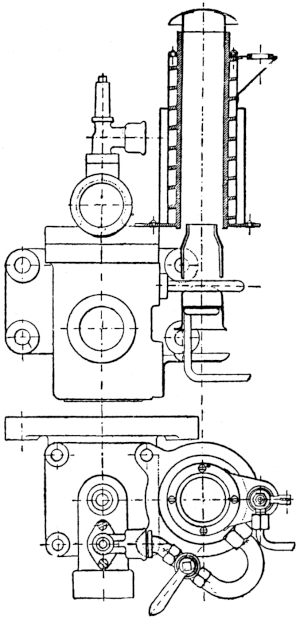
97
Koerting-Boulet motor.—In this four-cycle engine we shall only describe the vaporizer and spray-maker. The oil is stored in a reservoir placed about six feet from the ground, and a pipe conducts it into a space between two discs with a valve at the top. This circular space, about half a millimetre in thickness, is traversed by the air which pulverizes the oil; the spray thus formed is vaporized by the high temperature developed by a lamp situated underneath the tube which conducts the carburetted air to the cylinder. In addition, this lamp is used for igniting the gases through a porcelain tube kept at red heat by it. An auxiliary spirit-lamp is used for starting the engine, which takes about fifteen minutes to acquire a sufficiently high temperature.
98
Knight gas engine.—In his endeavour to completely drive out the products of combustion from the cylinder, Mr. Knight has had recourse to the Griffin cycle and to a double-acting cylinder: we have already discussed the relative merits of this system, and think it is sufficient to point out the greater constancy of speed obtained by it. The vaporizer is placed behind the motor-cylinder, and is separated from it by a steel plate, so that it is maintained at a high temperature; this vaporizer is made of bronze, and is provided with radiating ribs. A pump injects oil into it, and it is also supplied with compressed air by a special pump, which furnishes in addition a jet for producing a blow-pipe flame. This flame white-heats a platinum wire, which ignites the gases. The wire is situated in an opening in the ignition valve; the valve moves forward, and the white-hot wire is brought into contact with the explosive mixture at the right moment. The admission valve is automatic, and situated in the steel plate separating the vaporizer from the cylinder. The other organs of the motor are not of any special interest.
Crossley-Holt oil engine (Fig. 40).—This is practically the same engine which we described in the chapter on gas engines; a vaporizer is added in the oil motor to enable it to work with petroleum.
It consists of a chamber divided into four channels by vertical partitions, and heated by a lamp placed underneath. The flame traverses these channels before reaching the chimney placed at the top. The petroleum is converted into a spray, and drawn off by a jet of air warmed by passing it through a spiral coil placed round 99 the lamp chimney. This jet of air is supplied by a small pump worked by a lever. The oil lamp has no wick, which is rather a novel arrangement: it is supplied by a small pump similar to that which provides the air. Since its first appearance this engine has undergone certain changes which have considerably improved it. Messrs. Crossley Bros. have especially devoted themselves to shortening the length of time necessary to heat and start the engine. Besides this they have paid great attention to simplicity of the working parts.
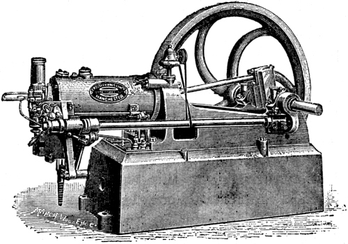
Trusty oil engine.—This motor was devised by Mr. Knight, and is constructed by Messrs. Weyman and Hitchcock. There is no spray-maker, the liquid oil being directly converted into vapour. The vaporizer is heated by the waste gas from the cylinder, and the oil falls drop 100 by drop on to the hot metal walls and becomes vaporized. The engine is of the ordinary four-cycle type, the most noticeable feature being the governing arrangement; a governor of the inertia pattern regulating the admission valve and the oil-pump. If the speed becomes too great the action of the governor on the valves ceases, and oil is no longer supplied to the vaporizer from the pump and the admission valve remains closed. Ignition is obtained by a red-hot tube heated by an oil lamp; a layer of asbestos on the outside prevents the tube from cooling, and keeps the tube at a high temperature. It takes twenty minutes before the vaporizer becomes sufficiently heated to enable a start to be made, and the cylinder is very liable to become fouled by tarry products from the oil. These serious disadvantages are scarcely neutralized by the variety and small quantity of oils which the engine will burn. An engine of this type with two cylinders consumed in certain trials only half-a-pint of oil, which speaks for itself.
Griffin oil engine (Figs. 41, 42).—Yet another Otto cycle engine provided with a pump reservoir and vaporizer. The latter is hidden in the bed-plate, and is heated by the gases from the exhaust. The pump is driven by an eccentric on the main shaft, and compresses the air to about 8 lbs. on the square inch in a reservoir also situated in the bed-plate. The compressed air passes from this chamber into a needle pulverizer, along with a quantity of oil which it has gathered in a small ante-chamber. This pulverized oil arrives in the vaporizer at the same moment as the air for the explosive mixture. A portion of the vaporized oil and101 air is used for the lamp, which red-heats the ignition tube. At starting, a small quantity of air is compressed in a hand pump, and in ten minutes the vaporizer is hot enough to gasify the oil. The Griffin engine is very economical, and only uses about a pint of petroleum per horse-power hour.

Niel petroleum engine.—In these motors, the general arrangement of whose parts is similar to that of the gas engines constructed by the same firm, the principal part is the vaporizer. It consists of a small cast-iron chamber, provided with radiating ribs in its interior so as to increase the surface; the petroleum, coming from a reservoir placed at a height of about six feet, passes through a regulating valve, and is dispersed in fine drops over the surface of the radiating ribs; the vaporization is consequently very steady. An automatic valve allows air to pass into this chamber from the outside, forming an explosive mixture 102 with the vaporized oil. A special tube coming from the reservoir supplies a lamp with oil for heating the ignition tube and also the vaporizer at the same time. A methylated spirit lamp is used for warming them up to the right temperature before starting the engine. The governor acts on both the admission and the exhaust, and the supply of oil is indirectly regulated by the closing of the exhaust valve. The whole mechanism is ingenious, giving excellent results; the speed is very constant, and the consumption of oil is within wide limits proportional to the demand for power. About a pound of oil is consumed per horse-power hour, including that necessary for the lamp.
Two patterns of this engine are built, one vertical and the other horizontal. In the latter, called the Atlas engine, the consumption per hour is slightly greater. The governor is also different. The compression in the cylinder rises to about two atmospheres, and the quantity of water necessary for the water jacket varies from seven to ten gallons per horse-power hour, according to the size of the motor.
We have so far followed, step by step, the various improvements undergone by internal furnace engines, from their first practical realization thirty-seven years ago by M. Lenoir. This improvement has continually tended, as one might naturally expect, to cheapen the cost of the motors themselves, and lessen the cost of the fuel consumption so that they might successfully compete against the steam engine, over which they have many advantages. As a rule, coal gas is pretty expensive, in some particular districts ruling as high as 4s. or 5s. per 1000 cubic feet. This price would be prohibitive were it not for the extreme economy which has been obtained in gas engines by such devices as compression and the lengthening out of the combustion. Inventors have sought to still further lessen the cost of power by replacing the expensive coal gas by other gases of lower illuminating power, produced by special gas plants attached to the engine, and which can be used in places where there is no coal gas laid on. Other engines have been devised, as we have already shown, which get104 over the difficulty by consuming petroleum oil or distillates of same, such as benzoline and other light hydrocarbons.
Gas companies are, as a rule, heavily taxed, and if it were not for a vast amount of idle capital buried in the streets in the form of gas mains, they would probably supply gas at a very low price, especially as the sale of bye-products practically covers the cost of production. Some companies have even reduced the price of gas if used for driving gas engines, and have therefore slightly decreased the cost of production of power by this means.
In France, the home of the oil motor, they are severely handicapped by having to pay double duties on all petroleum entering, first the country itself, afterwards the towns.
Inventors have therefore sought a method of getting round these difficulties by producing a cheap gas, which would answer the same purpose as coal gas. First of all many manufacturers tried to cut down the expense by erecting their own coal gas plants, so as to be independent of arbitrary taxation. The system, although fairly satisfactory, had many drawbacks, and further experiments were made with a view to simplifying the process of production. The result has been to give us water gas and also poor gases, whose great practical value we shall presently demonstrate.
In order to produce what is called water gas, the process essentially consists of placing in contact with one another red-hot carbon and superheated steam. The result is to form a mixture of gases according to the following chemical equation—
105
For those not understanding the above it will be as well to explain, that on the left-hand side of the equation are placed the compounds brought into contact, water (H2O) and carbon (C), and on the right the products of the chemical action, carbon monoxide (CO), carbonic acid gas (CO2), and hydrogen (H2).
The resulting water gas contains 60% of hydrogen and 20% of carbon monoxide, both of which are combustible gases. The proportions of the gases evolved can be varied at will by admitting more steam or using an excess of carbon; by this process a richer gas can be obtained—
and
With 18 parts of steam and 12 parts of carbon we can obtain by the former equation 28 parts of carbon monoxide and 2 parts of hydrogen. This forms an extremely calorific mixture.
There are several processes for preparing water gas which give good practical results, and the gas produced has been used in America and Germany for lighting towns on the incandescent gas-burner system.
The Strong and Lowe processes consist of a furnace lined with fire-bricks, and in which is placed coal or coke. When this mass of carbon has reached a state of bright incandescence by playing upon it a stream of air, steam is admitted at high temperature, and is decomposed by the carbon forming oxides and liberating hydrogen. The gaseous products pass from the furnace to a reservoir.
106
When the chemical action ceases, due to cooling of the carbon, the steam is shut off and the stream of air turned on till it becomes incandescent once more. The process of admitting steam is then repeated.
About 2½ lbs. of coke are necessary to produce 20 cubic feet of water gas.
Analysis of the gas reveals the following parts by volume of the constituents.
(1) Water gas produced by the Strong process:—
| Hydrogen | 53 |
volumes |
| Carbon monoxide | 35 |
” |
| Hydrocarbons | 4 |
” |
| Other gases | 8 |
” |
—— |
||
100 |
volumes |
(2) Lowe process:—
| Hydrogen | 30 |
volumes |
| Carbon monoxide | 28 |
” |
| Hydrocarbons | 34 |
” |
| Other gases | 8 |
” |
—— |
||
100 |
volumes |
It is possible to entirely get rid of the cooling effect of the steam, by using instead a jet of air which passes up through the carbon. First of all carbon dioxide (CO2) is formed near the bottom of the mass, but this gas passing upwards through it is reduced to carbon monoxide (CO) by the excess of carbon, and a mixture is obtained consisting of 34 parts by volume of carbon monoxide and 65 of nitrogen. This gas has been named after its inventor, Siemens gas.
107
By proceeding for ten minutes with this air process, and then stopping it and generating water gas, two different mixtures are obtained, which can be combined together forming a gaseous product containing 10 parts of hydrogen, 20 of carbon monoxide, and 50 of nitrogen. One kilogramme of coal produces 4·5 cubic metres of this mixture.
Instead of performing the operations of producing Siemens gas, or producer gas, as it is sometimes termed, and water gas alternately and separately, it is possible to so arrange the furnace and apparatus, that both are generated at the same time, and continuously instead of intermittently. The combination of the two is called poor gas.
The invention of gas-producing plant is due to two Frenchmen, Thomas and Laurens, who studied deeply the question of the economic generation of poor gas, and constructed the first working plant. These two inventors stood, however, in the same position relative to the production of poor gas that Beau de Rochas had held relative to the gas engine, and it was not till Siemens came forward, and showed how they might most economically be generated, that poor gases were generally adopted. Siemens adapted them especially to metallurgy and the manufacture of glass. We shall now describe the most interesting processes which have been brought out since the time of the appearance of the Siemens plant.
Dowson gas-producer (Fig. 43).—This process was the first to appear after the Siemens process, and the gas produced by it is used in a large number of manufacturing operations. It consists of a generator, a boiler for producing superheated steam, an hydraulic box, the108 scrubbers and the gasometer. The generator is simply a gas retort lined internally with fire-bricks, and placed vertically in position. It will be seen in front on the left-hand side of the illustration. The fuel is usually anthracite coal, and is supported on a grate. It is fed in through a hopper placed at the top of the generator. By an arrangement 109 of valves the anthracite enters without direct communication being ever established between the interior of the generator and the exterior atmosphere, which would result in explosions. The steam which is to be decomposed by the heated coal is generated in the small boiler, seen in front on the right, at a pressure of 50 lbs. per square inch, and superheated in a spiral coil inside. The steam passes into the retort through an injector, drawing a quantity of air along with it whilst passing from a nozzle across an air space. The air enters the generator along with the steam and causes the coal to burn, and the steam is decomposed, forming a mixture of producer gas and water gas. The quantity of gas produced is therefore regulated by the injector. The gases generated by the combustion of the anthracite are conveyed by a pipe into a flat hydraulic box seen behind the generator, and divided into two parts and half filled with water. The gases are washed by this water and then pass on to the scrubbers, where they are cooled and washed by passing through a mass of coke moistened by fine streams of water. To further cleanse them they are passed through saw-dust and thence pass to the gasometer. A number of analyses made by M. Witz show that Dowson gas consists on the average of 25% hydrogen, 16 to 25% carbon monoxide, and 50% of nitrogen. The heat of combustion of one litre varies according to the quality of coal used, but averages about 1400 calories. One kilogramme of anthracite will produce about four cubic metres of Dowson gas, the cost being one-tenth of a penny per cubic metre. It must not be forgotten that this gaseous mixture is only a quarter as rich as coal gas, but it costs 110 about one-tenth to produce, and is therefore cheaper on the whole. At some future date this type of apparatus may, to a great extent, replace the boiler of the steam engine. That Mr. Emerson Dowson’s process has succeeded beyond his most sanguine expectations goes without saying. His apparatus is in use in every corner of the globe, and, to quote his own words, “still better results can and will be obtained when an engine is really designed to give the best effect with this gas.”
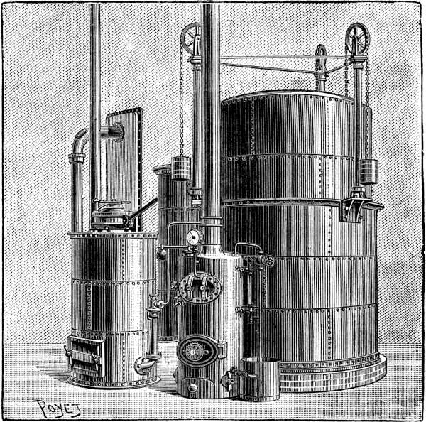
Buire-Lencauchez gasogene.—The analysis of the gas produced on this system shows that it contains 20 volumes of carbon dioxide, 115 of carbon monoxide, 66 of hydrogen, and 178 of nitrogen; its percentage composition is therefore the following:—
| Carbon monoxide | 29·4 |
| Carbon dioxide | 5·9 |
| Hydrogen | 17·6 |
| Nitrogen | 47·1 |
—— |
|
100 |
Theoretically one kilogramme of coal should develop 5·26 cubic metres of gas, having a heat of combustion at 0° C., and atmospheric pressure of 1360 calories. These figures enable us to calculate the efficiency of a gas-producing plant and the value of the gas obtained. Very good results have been obtained by gas generated by the latest Lencauchez process, with improvements added by the firm of Buire of Lyons, who construct the apparatus. The chief point to be noticed in these plants is the suppression of the steam boiler, which requires constant attention and 111 stoking. The hearth of the generator is made of refractory bricks surrounded by a layer of sand to keep in the heat. The fuel enters through a hopper, which by means of a bascule and counterpoise never allows any direct communication between the interior of the retort and the surrounding atmosphere. The fuel is either coke or anthracite, and is spread over a grate situated over an ash-pit. This ash-pit forms an important part of the apparatus, for it is fed with water which evaporates from the heat striking down on to it from the incandescent coke. The steam generated by this novel process passes together with air up through the heated mass of fuel, forming a mixture of producer and water gases in the generator above. The supply of air is regulated by a centrifugal fan driven by the gas engine which the plant is supplying. The necessity of having to use this fan very often more than destroys the advantage gained by the absence of a boiler. The gases produced pass by a pipe into the scrubbers after first surmounting the pressure of a water valve, which prevents them from returning to the generator. The scrubbers are filled with coke, with a continual stream of water flowing down over it. The gases in passing up are therefore thoroughly cleansed, so much so that they are fit to pass straight to the gasometer. When the gasometer is full and has reached its top position, it acts on a lever connected by a wire rope with a tap regulating the air supply of the generator. The centrifugal fan ceases to act, and the coke in the generator soon cools down, and the production of gas ceases. As the gasometer falls again the process is re-started, but not before the coke or anthracite in the112 generator has been re-lit automatically. The whole plant, therefore, only produces gas in proportion to the demand made on it, which is a necessary condition when driving gas engines. The coke is automatically re-lit by a small jet at the side of the generator, and fed by gas from the gasometer. A plant producing gas sufficient for 60 horse-power, or about 200 cubic metres per hour, uses up about 100 litres of water for vaporization, and about 500 for cooling the scrubbers. The water used for cooling the cylinder of the engine which the plant is supplying may be used for vaporizing purposes, and requires the addition of a small pump. Matter et Cie. of Rouen uses the Buire-Lencauchez gasogene for supplying their Simplex engine, which we have already described. Altogether about 3000 horse-power have been supplied by them on this system, and have given repeated proof of the value of this process of generating poor gas, especially in France, where poor French coal, which can be used, is cheaper than imported English anthracite.
Gardie gas-producing plant.—This apparatus is characterized by the use of high-pressure air at about 80 lbs. per square inch, mixed with steam at the same pressure; this arrangement being more concentrated only requires small plant. The generator is of peculiar construction, without any grate, the coke being held up on shelves. The air and steam enter the generator by a ring of twyers, and a small window is pierced at the side through which the attendant can see if the proper degree of incandescence is maintained. The fuel is poured in through a hopper in a similar manner to other generators already described. 113 The gas is produced at a high temperature, and is made to heat a coil through which the steam passes, which is thus economically superheated. After accomplishing this duty the gases pass on to a scrubber, formed by two concentric tubes of different heights, and travel on straight to the gasometer. The air is compressed in a reservoir by a special pump, and is heated by the waste gases from the cylinder of the motor. These various heating arrangements, therefore, prevent as much as possible any loss of waste heat.
Some of the operations described are novel and interesting, and the gas produced is very rich, having a heat of combustion of over 1400 calories, and very little ammonia is produced. The result of this is that only rudimentary scrubbers are required, other systems requiring elaborate methods of cleansing the gases. The only drawback to the apparatus is the reservoir of compressed air, which necessitates a pump using up power.
Taylor gas-producing plant (Fig. 44).—The future of gas engines, especially large units, is intimately connected with production of poor gases at low cost, for they would be far from economical if coal gas were used at the price at which it is usually sold. For this reason many inventors have attempted to devise apparatus which should produce gases suitable for being used in a gas engine, by the decomposition of steam by red-hot carbon. The Taylor system is one of the best of those which have appeared in the last few years. It has been thoroughly tested in practice. The plant consists of a generator and boiler, a series of cleansing and washing towers, and a114 gasometer. The most important feature is the automatic manner of getting rid of the coke ash from the generator by a moving hearth, which enables it to be cleaned out without stopping the production of gas. By this system cheap coal can be used instead of anthracite, which is more expensive. The steam boiler is placed on the generator, and is heated by the gases coming from it. The steam passes first of all through a superheater consisting of a number of tubes round which circulate the gases from the generator. The high temperature of the mixture of steam and air ensures a good efficiency. The gases produced in the generator pass through vertical tubes, exposing them to a large cooling surface, where they are chilled; they then pass through scrubbers lined with coke and so into the gasometer.
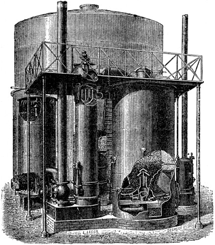
115
The gaseous mixture, consisting of hydrogen, carbon monoxide, etc., produced in the generator has a heat of combustion of from 1400 to 1500 calories. The relative heating power compared with coal gas is therefore two-sevenths. A motor consuming 700 litres of coal gas would require 2500 litres of the poor gas produced by this system to develop the same power, and 550 grammes of anthracite would be consumed in the process.
The cost per horse-power hour varies according to the price of materials. Supposing we have an eight horse-power motor consuming 25 cubic feet of coal gas per horse-power hour, at 2s. 6d. per 1000 cubic feet, and working for 10 hours, the cost per day would be
per horse-power hour.
If, on the other hand, it were supplied with poor gas generated from anthracite costing 25s. a ton, it would burn about 1¼ lbs. per horse-power hour, costing 16d., which is about one-fifth the cost, and using cheap coal this cost can be still further reduced. These figures clearly show how much cheaper it is to burn poor gases than coal gas.
Bénier gasogene.—Since the 1889 Exhibition, where a 116 Simplex engine was to be seen working with poor gas generated on the Dowson system, engineers and others have fully recognized the advantages of this cheap motive power. In the last few years a very large number of these plants have been erected, and the experience gained by practice has shown, that in spite of the extreme cheapness there are serious faults to be found with this class of apparatus.
The gases are produced under pressure and are of an exceedingly poisonous nature, carbon monoxide being the same gas which is principally evolved from burning charcoal. Great care has therefore to be taken that there are no leaks, which might have fatal results if inhaled by the persons attending to the plant. The chemical operation of the production of the gas is a very delicate one, and requires skilled attendants if constancy in the quality of the gas is required. The Bénier gasogene has been designed to eradicate or circumvent these grave drawbacks. It presents many novel features, the most interesting of which is the device for absolutely ensuring no leaks. This is done by generating the gas below the pressure of the atmosphere. This low pressure is maintained throughout the plant right up to the valve which admits the explosive mixture to the motor cylinder. The only places in which the pressure is raised are surrounded by vacuum jackets leading to the gas reservoir. The gas-producing plant can therefore be installed anywhere, even in dwelling-houses or cellars, without running any risk of poisoning the inmates.
The irregularity of the qualities of the gas produced by 117 other generators is due to the difficulty of always admitting the air and steam in the same proportions to the generator. This difficulty is got over in the Bénier gasogene, indirectly as the result of the low pressure in the interior: the air and steam enter under atmospheric and therefore constant pressure, and their proportions can be regulated to a fine degree of accuracy by varying the size of the orifices through which they are admitted. So regular is the production of the gas in quality that diagrams taken from an engine at intervals of several hours showed no appreciable difference. The functions of attendant can be thoroughly fulfilled by an unskilled labourer or boy, the operation of emptying a quantity of coke once every half-hour being sufficient to keep the plant working steadily. This apparatus is also an economic one, partly because of the invariable qualities of the gas produced, but chiefly owing to air and steam being heated before entering the hearth. A rotating grate is also provided, so that the generation of gas is in no way interfered with by the clearing out of ash and clinkers. A special engine is constructed for use with this plant, which we shall describe in the next chapter.
Taylor gas-producing plant modified by Wimand.—There exist a number of systems of gas-producers which are not so well known as those which we have already described, but which are none the less interesting. The most important of these is a modification by Wimand of the Taylor system, in which the boiler is discarded, and replaced by a jacket or vessel surrounding the generating plant and heated by the waste gases. The hot water 118 trickles down over a column of coke, and meets at the base the current of air passing towards the generator; the air is therefore heated, and becomes saturated with water vapour. This device can be applied to any generator.
Kitson gas-producer.—A rotating hearth is provided, as in other systems already described. The air is driven by a steam injector through holes in it, and the steam is supplied from a spiral coil situated in the fire-brick lining of the generator. A second tube through which the steam passes acts as a superheater. The steam enters a reservoir chamber at the side of the generator, from which it passes out again to fulfil its functions. There is therefore no fan needful, and the generating furnace is not liable to become fouled. The price of the plant is moderate.
Loomis gasogene.—This apparatus aspirates its air and draws it completely through a layer of carbon from top to bottom. The generator is open at the top, and instead of the usual grate at the bottom it is provided with a cone-shaped base instead. The air drawn in combines with the carbon during its downward journey, and then passes through a cooling tower surrounded by a water jacket which acts as a boiler. The heat extracted from the gas is therefore used to produce steam, which drives an engine working the pump which aspirates the air. The exhaust steam from this engine passes into the incandescent fuel and is decomposed, forming hydrogen and carbon monoxide. The valves which govern the supplies of air and steam are so arranged that producer gas or water gas, or both at once, may be generated at will. One particular plant is 119 known to have worked unceasingly for two years without stopping, but in this case it did not supply a gas engine, in fact, we believe that this system has not been applied for driving motors at all as yet.
Wilson gas-producer.—The generator is broader than it is high, and it is possible to use in it all sorts of cheap coal and coke. A window is provided, so that the attendant can see if the fuel is sticking and not settling down properly. The air is blown into the centre of the hearth by a steam injector at a low pressure of about two inches of water or less. Stoking is effected by turning spiral grate bars which rid the fire of clinkers and ashes. The air is heated by waste gases from the motor, a process which gives a slight gain in economy.
Longsden process.—We have mentioned that water gas generated by various processes has been used for lighting towns in America on the incandescent system. The drawback of the system is the exceedingly poisonous nature of carbon monoxide even when very dilute, and it is all the more dangerous because it is odourless. Many accidents have in consequence occurred, some of them terminating fatally. Mr. Longsden has attempted to produce a gas entirely free from carbon monoxide, so as to avoid this difficulty. He first attempted to rid water gas of the monoxide, but not being able to find a cheap enough solvent for it he tried other means. His present process consists of adding a sodium salt to the carbon in the generator. The gas produced has then the following composition:—
120
| Hydrogen | 62·2 |
volumes |
| Carbonic acid gas | 26·4 |
” |
| Carbon monoxide | 1·2 |
” |
| Hydrocarbons | 6·5 |
” |
| Nitrogen | 2·2 |
” |
| Oxygen | 1·5 |
” |
—— |
||
100 |
” |
This very rich gas, which might easily be ridded of its carbonic acid by passing it through lime, is very suitable for supplying motive power through the medium of the gas engine.
Gayon and Métais process.—This process, which, as far as we know, has not been put into practice, was intended by its inventors to diminish the price of coal gas. Instead of allowing coke to be deposited in the gas retorts, as it usually is, and selling it as a bye-product, their intention was to use it there and then for the production of water gas, which was to be mixed with the coal gas and increase its heat of combustion, while diminishing its cost of production. One ton of coal would produce 450 cubic metres of gas instead of 300; the idea has, however, never been put into practical shape.
Simplex motor (Fig. 45).—Although this motor works equally well with coal gas and oil, we have put off the description of it until now because it has become associated particularly with the production of poor gases, and by their help forms one of the most formidable rivals of the steam engine.
The Simplex was invented in 1884 by MM. Edouard Delamare-Deboutteville and Léon Malandin. In appearance it is of the usual four-cycle type. A lateral shaft transmits the rotation of the crank-shaft to a small crank which actuates the sliding valve. This sliding valve forms one of the principal features of the engine, and consists of a sliding iron plate pierced with two holes, one oblique regulating the ignition, and the other straight forming the admission valve. The piston having completed its first forward stroke comes back to compress the explosive mixture, and the sliding valve having advanced puts it in communication with a chamber containing two metallic points, between which a continuous stream of electric sparks122 is made to flow. After the explosion this cavity and the passage leading to it are filled with burnt gas, which must be driven out to prevent a miss-fire at the next stroke. This is effected by a small purging hole, through which they are driven by a fresh charge entering the cylinder.
In earlier patterns of this engine an ingenious air governor was used, but it has now been replaced by a fresh arrangement of a different pattern. This governor (Figs. 46 and 47) consists of a double pendulum, which takes up a vertical position because of the lower ball, seen in the illustration, being the heaviest. The whole pendulum is pivoted on a fixed bearing. The variation in the speed is obtained by a weighted knife blade acting on the gas-valve. The sliding valve is provided with a knife blade square at one end and pointed at the other, which catches in a notch on the pendulum, and is held by it in position so that the square end hits the end of the gas-valve and admits gas. If, however, the speed of the engine be too great the sliding valve carries its knife blade forward too soon and it does not catch in the notch, with the result that no gas is admitted as the square end is too low. The speed of the engine, therefore, tends to remain adjusted to the rate of vibration of the pendulum, which is a fixed quantity. A self-starting arrangement is provided by stopping the engine half-way back along the compression stroke, so that it is only necessary to pass an electric spark across for an explosion to occur and give it the necessary starting impetus.
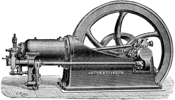
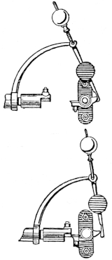
MM. Delamare-Deboutteville and Malandin were the first to construct units of very great power. At the 124 Havre Exhibition in 1889 they exhibited a Simplex engine using Dowson gas, and in 1889 they exhibited at the Paris Exhibition a 100 horse-power single-cylinder motor.
Their latest achievement in this direction is the erection of a 320 horse-power engine supplied by two Buire-Lencauchez gasogenes with poor gas. This is the largest single-cylinder gas engine in the world. The Simplex engine was the pioneer of motors using poor gas. The machine we described was for use with coal gas, and some modification has to be made in the parts when the motor is required to use gases of the Dowson type. The economy is very good, only 580 litres of coal gas or 550 grammes of anthracite being used per horse-power hour.
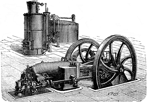
Gardie motor.—We have shown how poor gases are, beyond a shadow of a doubt, cheaper than coal gas for the 125 production of power. Many makers have therefore attempted to use it by simply adding a gas-producing plant to existing engines. Sometimes these motors were totally unsuited for these cheaply produced gases, and the result has been failure from miss-fire or irregular speed. The Crossley, Niel, and Andrews motors are exceptions, and a few others have also given fairly good results.
We described in the previous chapter the ingenious gasogene devised by M. Gardie of Nantes; the motor which is constructed for use with it is rather novel. It has two cylinders placed side by side, a compressing pump and reservoir for compressed air. The gaseous mixture arriving at a high temperature from the gasogene passes into the cylinders, and is mixed with a volume of air coming from the reservoir; these gases are compressed to about 100 lbs. on the square inch. At the entrance to the cylinders are placed two igniters of platinum heated to a white heat by an electric current at starting, but the temperature is afterwards maintained by the combustion. During the admission the gaseous mixture burns without any explosion and without raising the pressure, but considerably increasing in volume. At the commencement of the stroke the pressure in the cylinder is therefore the same as in the compressor, but it soon decreases by virtue of the expansion and driving forward of the piston.
After having exhausted themselves in doing work the gases pass out into a regenerator, which communicates their heat to the air for admission. The valves are actuated by a horizontal shaft placed above the cylinders; the cams are three in number corresponding to three valves, of126 which two regulate the admission of gas and air to a chamber in which they are mixed. The third valve opens the exhaust. This arrangement is not unlike that adopted by MM. Forest and Gallice for their marine oil engines.
The cylinders are surrounded by water jackets for cooling purposes, aided by air which can enter the front end when the piston is moving in its backward stroke. The hottest portion is therefore that situated at the valve end, and in which the explosion takes place. This portion is surrounded by a closed chamber forming a boiler, where steam is formed for use in the gas plant; the steam is superheated in a spiral coil placed on the top of the gasogene. As we have already stated, this system of gas production avoids the ammoniacal products, which are a constant source of trouble in other engines. The drawback lies in the compressor, which uses up about one-third of the indicated power, but the speed is exceedingly constant, and averages about 175 revolutions per minute. The consumption of gas is not very high, probably owing to the amount of heat which is absorbed from the waste gases, usually lost. A number of other engines exist of a similar type to the Gardie motor, such as the Shaw, Woodburg, Crowe, Buchett, and others, which cannot, however, consume poor gases, and which have not any distinguishing features worth mentioning.
Bénier motor gasogene (Figs. 49 and 50).—We have described the Bénier gasogene, and we will now complete the description by a short notice of the motor associated with it. This motor works on the Dugald-Clerk cycle,127 and in general arrangement is not unlike the Dugald-Clerk motors. A special compressing cylinder is provided cast in one with the motor cylinder, and the cranks are set at 90° degrees apart from one another. The pump is double, with two pistons coupled tandem-wise in the same cylinder. One of these draws in the air and the other forces the gas into the gasogene. The air and gas thus conducted by different paths reach the mixing chamber placed behind the motor cylinder and provided with a valve. The motor cylinder has exhaust ports perforating the walls, and which are uncovered by the piston when it has moved through five-sixths of the forward stroke. It remains open during the remaining sixth and the first sixth of the return stroke. At this moment the two piston pumps have forced into the cylinder the air and gas which they contain. The mixture enters through a valve and a perforated plate, which thoroughly mixes them in the cylinder. During the return stroke the piston, having closed the exhaust ports, compresses the explosive mixture till the end of the stroke. Ignition then takes place, and the explosion drives the piston forward, and the products of combustion escape to the air directly the exhaust ports are uncovered by the piston.
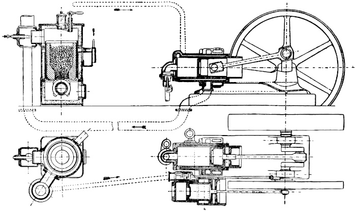
By this arrangement it might happen that the explosive mixture introduced into the cylinder might escape by the open exhaust valves. M. Bénier has obviated this difficulty by a novel device. Pure air is first admitted, driving out the products of combustion; the explosive mixture which follows is only admitted when the ports are closed. This result is obtained by properly regulating the supply 128 of air and gas from the pump. One explosion therefore occurs in every revolution.
The Bénier engine is constructed in sizes up to 100 horse-power, and also smaller ones of a few horse-power. A 5 horse-power motor consumes 800 grammes of anthracite per horse-power hour: this result is very remarkable, because great difficulty has been found in working these small engines at all with poor gas; the gas generator seems to work badly when its dimensions are so small. A 15 horse-power motor only consumes 600 grammes per horse-power hour. The Bénier combined plant shown in Figs. 49 and 50 has received a most flattering reception on the Continent, and there is good reason to believe that it will be very much more widely used in the future. We close this chapter with a table setting forth the relative merits and economy of a number of motors.
129
| Type of Engine. | Nature of Fuel. | Power of the Engine. |
Consumption of Fuel. | Consumption per horse-power hour. |
Cost per horse-power hour, pence. |
Trials conducted by |
|---|---|---|---|---|---|---|
| Lenoir (1860) | Coal gas |
·9 | 2400 litres | 2700 litres | 9 | Tresca |
| Hugon (1866) | ” |
2·07 | 5400 ” | 2600 ” | 8·5 | ” |
| Langen and Otto (1867) | ” |
·46 | 660 ” | 1380 ” | 4·5 | ” |
| Wittig and Hees (1881) | ” |
4 | 4960 ” | 1240 ” | 3·5 | Brauer |
| Koerting-Lieckfeld | ” |
2·18 | 2700 ” | 1275 ” | 3·7 | Schettler |
| Otto | ” |
8·34 | 9500 ” | 915 ” | 2·8 | Allard and Potier |
| Dugald-Clerk (1884) | ” |
11·6 | 9700 ” | 877 ” | 2·5 | Sterne |
| Lenoir (1885) | ” |
2 | 1320 ” | 655 ” | 1·9 | Tresca |
| Simplex (1885) | ” |
9·41 | 5580 ” | 593 ” | 1·1 | Witz |
| ” ” | Dowson gas |
3·66 | 6040 ” | 3300 ” | ·7 | ” |
| Lenoir (1885) | Carburetted air |
4·15 | 2·7 ” (petroleum) |
·65 ” | 4·5 | Tresca |
| Benz (1885) | Coal gas |
5·1 | 3600 litres | 707 ” | 1·4 | ” |
| Atkinson (1888) | ” |
9·48 | 6000 ” | 618 ” | 1·3 | Society of Arts |
| Crossley(1888) | ” |
14·74 | 10,800 ” | 765 ” | 1·5 | ” ” |
| Griffin (1888) | ” |
12·51 | 9500 ” | 786 ” | 1·5 | ” ” |
| Charon (1889) | ” |
4·17 | 2210 ” | 530 ” | 1·1 | Witz |
| Forest (1890) | Petroleum spirit |
16·67 | 7 kilg. 400 | 458 grms. | 3 | Martin |
| Niel (1891) | Coal gas |
3·75 | 1250 ” | 402 litres | ·8 | Witz |
| Simplex (1889) | Poor gas |
75 | 191 cub. met. | 2370 ” | ·7 | ” |
| ” (1893) | ” |
220 | 110 kilg. (anthracite) |
500 grms. | ·3 | Leblan |
| Lenoir (1891) | Coal gas |
6 | 4260 | 710 litres | 1·5 | Lencauchez |
| Charon (1892) | ” |
7·5 | 4380 | 586 ” | 1·2 | Chauveau |
| Priestman (1890) | Daylight oil |
7·7 | 3 kilg. | 385 grms. | 1·7 | Unwin |
| ” (1891) | Russoline |
6·7 | 2 kilg. 700 | 428 ” | 1·9 | ” |
| Crossley (1892) | Dowson gas |
148 | 415 kilg. (anthracite) |
280 ” | ·2 | Dowson |
| Atkinson (1892) | ” |
16·7 | 6·6 kilg. | 455 ” | ·3 | Tomlinson |
| Schleicher-Schum | Poor gas |
92 | 55 ” | 596 ” | ·32 | Spanglon |
| Trusty | Petroleum (ordinary) |
4·3 | 1·83 ” | 440 ” | 2·2 | Beaumont |
| Delamare-Deboutteville (1894) |
Lencauchez gas |
62 | 37 ” | 603 ” (cheap coal) |
·2 | Bourdon |
| Campbell (1895) | Petroleum (ordinary) |
6 | 2·4 ” | 400 grms. | 2·5 | ” |
Gas engines are in most cases mounted on a metal bed-plate, and for small engines the weight of the machine is very often sufficient to keep it in place; it is more satisfactory, however, to bolt it firmly down to a bed of concrete or stone. Plenty of room must be allowed round about to enable cleaning and repairs to be executed; space is also necessary for turning the fly-wheel round if no self-starting mechanism is provided.
Above two or three horse-power water must be used for cooling the cylinder, mere cooling by air circulation being insufficient for carrying off the waste heat except in very small motors. It occasionally happens that water is laid on, which can be used for the water jacket, the heated water being simply allowed to run to waste. Unless the water is exceedingly cheap this arrangement is far too expensive, and it becomes necessary to erect a separate circulating system, in which the water is used over and over again. Makers provide for this purpose galvanized iron tanks, which are connected by two pipes to the water131 jacket. The tank being filled with water, and the engines started, circulation takes place in a manner similar to the ordinary household hot-water systems. The lower opening of the water jacket is connected to the lower pipe from the tank, and the second pipe, starting from a point near the top of the tank, is connected to the upper opening of the cooling jacket. The difference of density between hot and cold water causes the former to rise and flow back to the reservoir along the upper pipe, and cold water rushes in to take its place.
About 400 to 500 litres of cold water are required per horse-power, but it largely depends on the rate at which the tank cools; in some cases only 200 litres being found quite sufficient. The temperature of the water leaving the jacket should be about 60° C. It is more economical to let it rise to 80° C., but in this case very good lubricating oil is required for the cylinder. A tap in the lower pipe, and a thermometer placed against the upper one, will enable the attendant to adjust this temperature.
Starting and stopping.—Starting is an operation requiring a little practice. First of all the igniting burner must be lit, and time allowed for it to red-heat the ignition-tube; if electricity is used this wait of a few minutes is obviated. The lubricating arrangements are then attended to, so as to make sure of them being in satisfactory working order. If no self-starting arrangement is provided, the supply of gas to the cylinder is partly turned on, and a few quick turns of the fly-wheel by hand are sufficient to set the engine in motion. Having attained the normal speed the gas can be turned full on. If the132 motor refuses to start, the tap regulating the gas supply should be examined as it may be too full on; the ignition apparatus must then be inspected. Sometimes the reason of the refusal to start lies in the exhaust-valve which leaks; in this case no compression takes place. This can easily be verified by turning the fly-wheel backwards, and seeing whether the piston tends to resist the motion, which it would do if the compression was taking place properly. When running it is a mistake to flood the engine with oil; a barely sufficient quantity of good mineral oil is all that is required. If the valves require cleaning, then of course plenty of oil should be used to wash away the deposit, but they should be well wiped before starting. Many persons have become erroneously imbued with the idea that a gas engine requires a skilled mechanic to attend to it. As a matter of fact any person without previous knowledge is, with a few days’ practice, competent to take charge of a motor provided that he is intelligent and careful. Under these conditions a gas engine will last as long as a steam engine, and will be generally found much more satisfactory.
To stop the machine, the self-starting mechanism must first be allowed to operate, and then the supply of gas is shut off. After this the burner or electric ignition must be cut off, and the cooling water too, if it is not a circulating system. If the machine is to remain stopped for some considerable period, turn the fly-wheel round till the piston is in its most forward position; this will prevent dust and grit from getting into the cylinder, and scoring the inside when the engine is re-started. These are the general 133 rules which must be obeyed in the maintenance of the gas engine. The attention they require is therefore small, and this quality has contributed not a little to their success. No stoker or engine-driver is required; any person can, with very little instruction, take charge of them. If the engine is properly erected by skilled workmen, and has been running sufficiently long to have arrived at a condition of regular lubrication, etc., a person in constant attendance can be dispensed with, and it is sufficient to look in occasionally and see that everything is all right, that there is a sufficient supply of oil, and that the cylinder is cool, because if it became overheated it might bind and destroy the interior.
Every month a complete cleaning should be undertaken, the valve mechanism and cylinder being washed with mineral oil to dissolve the deposit of carbon and tarry substances in them. Every six months the valves should be re-adjusted, and if necessary re-ground into their seatings. The time and trouble necessary for these periodical cleanings will be amply repaid by the satisfactory working of the engine; nothing is more annoying than a breakdown due to accumulation of dirt, and to the continual postponement of the cleaning out.
Maintenance of oil engines.—These machines require the same careful treatment as gas engines, but they have in addition a carburator or a vaporizer which require special attention, and render the cylinder particularly liable to become fouled by the heavier products of the vaporized oil. We have already described the principal systems of vaporizers and carburators, and we shall only 134 return to them to state, that for efficient working they should be cleaned out once a week. At the very outside not more than a month should elapse between the removals of incrustations and deposits of carbon. The lamps used for supplying heat to the vaporizer should also be attended to from time to time, and occasionally thoroughly cleaned out.
Ignition of the explosive mixture.—As we have already seen, several different methods exist of setting fire to the explosive gases, and each of them has its advantages and drawbacks. Ignition by an incandescent tube of iron or porcelain seems to be the most simple, and works as well as any other system; the sliding valve containing the igniting jet is somewhat more complicated.
Electric ignition, if effected by a magneto generator driven by the engine, is certain in its operation, but it is awkward at starting. For petroleum and carburetted air motors batteries both primary and secondary are better, especially when the motors are used for propelling vehicles.
Looked at from the economy point of view, it is very hard to decide which is the best system of ignition: red-hot tubes require gas, accumulators require electric energy to be put into them, magneto machines are expensive and use up power, in fact, they are all about the same as far as cost is concerned. In France electric ignition is in much greater vogue than in this country, where hot tubes reign supreme. The electric system requires a few words concerning batteries and induction coil.
If primary batteries are used the chromic acid type is 135 the best. These are manufactured in a large number of varieties; some of the French makers, Trouvé, Guérot, Radiguet, and others, have paid special attention to their application to gas and petroleum engines. The induction coil should have a rather thicker secondary winding than usual; it is necessary to have as hot a spark as possible to ignite the gas, and this is not obtained if the spark is of exaggerated length.
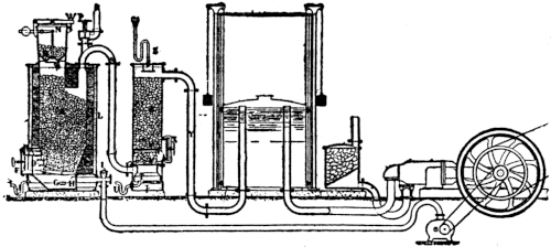
The spark-gap also requires occasional attending to. It consists usually of a porcelain rod with two points between which the sparks pass, either intermittently or governed by an automatic switch, or else continuously. In either case the points often become coated with a deposit of carbon, which decreases their efficiency. They must therefore be wiped clean about once a week.
Maintenance of engines using poor gas.—These engines differ very little from the ordinary coal-gas engine. The arrangement of valves which will do for the one is also suitable for the other. We shall therefore only give a few 136 hints on the management of the gas-producing plants which forms their only point of difference; to do this we shall consider a “Simplex” plant.
The firm of Matter et Cie. have received many letters from other firms to whom they have supplied their apparatus, replacing existing steam engines, in which they state that the whole management and maintenance of their new source of power is much more simple than the old. This is not to be wondered at, because the whole plant is perfectly automatic. There are no pressure or water gauges to attend to, because no more gas is ever produced than is absolutely wanted. A steam boiler may require to be stoked once every quarter of an hour, whilst a poor gas generator only requires charging about once every six hours, according to demand for power. The Simplex motor itself requires very little attention, and all bearing surfaces are made as large as possible to avoid the risk of heating.
Fig. 51 shows a complete plant in section. A is the generator filled with coke or anthracite; the opening of the hopper, N, and the door, D, of the hearth are closed. Air arrives from the centrifugal pump through a stop-valve, I, and water through W. The air passes through the mass of incandescent carbon forming carbonic acid gas, which is again reduced by the excess of carbon to carbon monoxide. The water becomes vaporized, and is dissociated by the action of the heated carbon forming hydrogen and oxygen, which combines with the carbon forming more carbon monoxide. The gas produced consists therefore of carbon monoxide, hydrogen, nitrogen, 137 and a small proportion of hydrocarbons and carbonic acid gas.
Passing by the pipe S to the base of the washing-tower the gases meet in their ascent water from the pipe Z, which cleanses them of all impurities, after which they pass by the pipe Y to the gasometer, and from there to the engine. We close this description of gas and oil engines, hoping that we have said enough to put before electrical engineers who are thinking of making use of this economic form of motive power, the exact state of affairs, what results have been obtained, and especially the considerations which govern the choice of an engine.
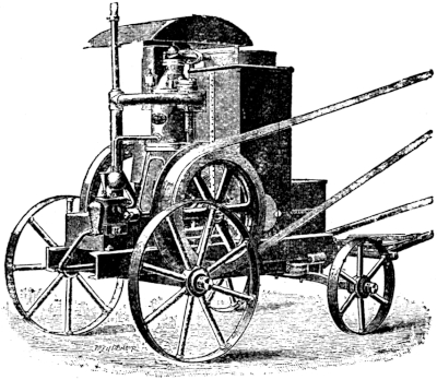
We further hope that this systematic examination of all engines which have received the sanction of practical 138 experience, will prove of some service to those who wish to become better acquainted with the numerous existing types, and to understand their relative advantages and faults, in order that they may select a gas engine which is suitable to the particular requirements of each individual case.
‘It contains information not often found in similar works.’—English Mechanic.
‘The book is evidently framed with a thorough appreciation of the most modern needs of the engineer.’—Marine Engineer.
‘There is little that any mechanical engineer is likely to require to be informed on—as to formulæ and data—that is not afforded in greater or lesser degree by the pages of this pocket-book.’—Electrician.
‘Literally packed with concrete data on all matters connected with practice of mechanical engineering, and every engineer will be much the better practical craftsman in having the work constantly at hand.’—Building Industries.
‘We welcome it as a valuable vade mecum to the engineer be he mechanical or civil.’—Indian and Eastern Engineer.
‘A handy little treatise, both practical and theoretical.’—Times.
‘A book of interest to those who require general information on the subject.’—Engineer.
‘This excellent book is simply full of every kind of information on motor-cars.’—Electrical Review.
‘Amongst works on motor-cars, that by Mr. Farman is in many respects the best.’—English Mechanic.
‘The neatness of mind with which all this technical matter is expounded makes the work unusually attractive, and the series has every prospect of success.’—Scotsman.
‘The arrangement of the work is excellent, the illustrations good, the explanations clear.’—Reynolds’ Newspaper.
‘The work is commendably free from mathematical language, and on that account should be welcome.’—Daily Telegraph.
‘As these works explain in clear and non-mathematical language many of the various applications of electricity, they undoubtedly meet the requirements of many readers who wish to grasp the principles underlying the applications of electricity now becoming so general.’—Engineers’ Gazette.
‘The author and compiler has given a useful and popular account of the present state of the knowledge in regard to electricity and of its application to the service of man.’—Marine Engineer.
FIRST BOOK OF ELECTRICITY AND MAGNETISM. Second Edition, Revised and Enlarged, with 107 Illustrations. 2s. 6d.
‘Students who purchase a copy, and carefully study it, will obtain an excellent groundwork of the science.’—Electrical Review.
ELECTRIC LIGHTING AND POWER DISTRIBUTION—An Elementary Manual of. For Students preparing for the Preliminary and Ordinary Grade Examination of the City and Guilds of London Institute, and general readers. Third Edition, Revised and Enlarged, in two volumes. Vol. I., 430 pp., with 231 Illustrations. Crown 8vo. 6s.
‘The work will no doubt become a standard text-book for schools and classes on this subject; as such, it has few equals.’—Electrical Review.
THE ALTERNATING CURRENT CIRCUIT. An Introductory and Non-Mathematical Book for Young Engineers and Students. By W. Perren Maycock, M.I.E.E. With 46 Illustrations. Small crown 8vo, cloth. 2s. 6d.
FITTING, THE PRINCIPLES OF. For Engineer Students. By J. Horner, M.I.M.E. Illustrated with about 250 Engravings, and containing an Appendix of Useful Shop Notes and Memoranda. 5s.
‘Calculated to aid and encourage the most useful set of handicraftsmen we have amongst us.’—Daily Chronicle.
THE PRINCIPLES OF PATTERN MAKING. Written specially for Apprentices, and for Students in Technical Schools. By J. Horner, M.I.M.E. Illustrated with 101 Engravings, and containing a Glossary of the Common Terms employed in Pattern Making and Moulding. 3s. 6d.
‘The book is well illustrated, and for its size will be found one of the best of its kind.’—Industries.
PRACTICAL IRONFOUNDING. By J. Horner, M.I.M.E., ‘a Foreman Pattern Maker.’ Illustrated with over 100 Engravings. Second Edition. 4s.
‘Every pupil and apprentice would find it, we think, an assistance to obtaining a thorough knowledge of his work. The book, however, is not intended merely for the student, but contains much useful information for practical men.’—Industries.
METAL TURNING. By J. Horner, M.I.M.E. With 81 Illustrations. 4s.
Contents:—The Lathe—Tools and Tool Angles—Chucks—Chucking—General Remarks on Turning—Hand Turning—Slide Rest Turning—Boring—Screw Cutting, etc.
‘An exceedingly useful publication to have at hand.’—Machinery.
ELECTRICAL EXPERIMENTS. With 144 Illustrations. Second Edition. 2s. 6d.
‘This is an excellent book for boys.’—Electrical Review.
INDUCTION COILS. A Practical Manual for Amateur Coil-makers. With a New Chapter on Coils for Radiography. With 101 Illustrations. 3s.
‘In Mr. Bonney’s useful book every part of the coil is described minutely in detail, and the methods and materials required in insulating and winding the wire are fully considered.’—Electrical Review.
THE ELECTRO-PLATER’S HANDBOOK. A Practical Manual for Amateurs and Young Students in Electro-Metallurgy. With Full Index and 61 Illustrations. Second Edition, Revised and Enlarged, with an Appendix on ELECTROTYPING. 3s.
‘An Amateur could not wish for a better exposition of the elements of the subject.’
Electrical Review.
LENS WORK FOR AMATEURS. With numerous Illustrations. Small crown 8vo. 3s.
‘The book is a trustworthy guide to the manufacturer of lenses, suitable alike for the amateur and the young workman.’—Nature.
MODERN OPTICAL INSTRUMENTS. By the same Author. 2s. 6d.
THE OPTICS OF PHOTOGRAPHY AND PHOTOGRAPHIC LENSES. With 68 Illustrations. 3s. 6d.
‘Personally we look upon this book as a most valuable labour-saving invention, for no questions are so frequent, or take so long to answer, as those about lenses.’
Practical Photographer.
THE PRACTICAL TELEPHONE HANDBOOK. With 228 Illustrations. Second Edition. Revised and considerably Enlarged. 5s.
‘This essentially practical book is published at an opportune moment. It contains readable accounts of all the best-known and most widely used instruments, together with a considerable amount of information not hitherto published in book form.’—Electrician.
ELECTRICITY IN OUR HOMES AND WORKSHOPS. A Practical Treatise on Auxiliary Electrical Apparatus. Third Edition. Revised and Enlarged. With 143 Illustrations. 6s.
‘It would be difficult to find a more painstaking writer when he is describing the conditions of practical success in a field which he has himself thoroughly explored.’
Electrician.
THE ART AND CRAFT OF CABINET MAKING. A Practical Handbook to the Construction of Cabinet Furniture, the Use of Tools, Formation of Joints, Hints on Designing and Setting Out Work, Veneering, etc. With 219 Illustrations. 5s.
‘A carefully-considered and well-written book.’—Work.
PRACTICAL ELECTRIC-LIGHT FITTING. A Treatise on the Wiring and Fitting-up of Buildings deriving current from Central Station Mains, and the Laying down of Private Installations, including the latest edition of the Phœnix Fire Office Rules. With 224 Illustrations. Second Edition, revised, 5s.
‘A book we have every confidence in recommending.’—Daily Chronicle.
DYNAMO MACHINERY, ORIGINAL PAPERS ON. With 98 Illustrations. 5s.
‘Must prove of great value to the student and young engineer.’—Electrical Review.
ELECTRICAL INSTRUMENT-MAKING FOR AMATEURS. A Practical Handbook. With 78 Illustrations. Sixth Edition, Revised and Enlarged. 3s.
‘To those about to study electricity and its application this book will form a very useful companion.’—Mechanical World.
ELECTRO-MOTORS: How Made and How Used. A Handbook for Amateurs and Practical Men. With 70 Illustrations. Third Edition, Revised and Enlarged. 3s.
‘We are certain that the knowledge gained in constructing machines such as described in this book will be of great value to the worker.’—Electrical Engineer.
ELECTRIC BELLS, AND ALL ABOUT THEM. A Practical Book for Practical Men. With more than 100 Illustrations. Fifth Edition, Revised and Enlarged. 3s.
‘Any one desirous of undertaking the practical work of electric bell-fitting will find everything, or nearly everything, he wants to know.’—Electrician.
THE DYNAMO: How Made and How Used. Tenth Edition, with additional matter and Illustrations. 2s. 6d.
HOW TO MANAGE A DYNAMO. By the same Author. Second Edition, Revised. Illustrated. Pott 8vo, cloth. Pocket size. 1s.
‘This little book will be very useful.’—Electrical Engineer.
ELECTRIC-LIGHT INSTALLATIONS, AND THE MANAGEMENT OF ACCUMULATORS. A Practical Handbook. Sixth Edition, Revised and Enlarged, with numerous Illustrations. 6s.
‘To say that this book is the best of its kind would be a poor compliment, as it is practically the only work on accumulators that has been written.’—Electrical Review.
ELECTRICAL INFLUENCE MACHINES: containing a Full Account of their Historical Development, their Modern Forms, and their Practical Construction. 4s. 6d.
‘This excellent book.’—Electrical Review.
ADVANCED PRIMERS OF ELECTRICITY.
THE METRIC SYSTEM OF WEIGHTS AND MEASURES COMPARED WITH THE IMPERIAL SYSTEM. By W. H. Wagstaff, M.A., Professor of Geometry at Gresham College. Crown 8vo, cloth. 1s. 6d.
ENGINEER DRAUGHTSMEN’S WORK. Hints for Beginners. By a Practical Draughtsman. With 80 Illustrations. Small cr. 8vo, cloth. 1s. 6d.
‘Will be found of practical value to the beginner in the drawing office.’—Engineer.
PRACTICAL ELECTRICAL MEASUREMENTS. An Introductory Manual in Practical Physics for Students and Engineers. By E. H. Crapper, Lecturer in Electrical Engineering at the Sheffield Technical School. With 56 Illustrations. Crown 8vo, 2s. 6d.
London: WHITTAKER & CO., 2 White Hart Street, Paternoster Sq.
Transcriber’s Notes:
Blank pages have been removed.
Silently corrected typographical errors.
Spelling and hyphenation variations made consistent.
Front advertisements moved to the back.