The Project Gutenberg EBook of Rockets, Missiles, and Spacecraft of the
National Air and Space Museum, by Lynne C. Murphy

This eBook is for the use of anyone anywhere in the United States and
most other parts of the world at no cost and with almost no restrictions
whatsoever.  You may copy it, give it away or re-use it under the terms
of the Project Gutenberg License included with this eBook or online at
www.gutenberg.org.  If you are not located in the United States, you'll
have to check the laws of the country where you are located before using
this ebook.


Title: Rockets, Missiles, and Spacecraft of the National Air and Space Museum
       Smithsonian Institution

Author: Lynne C. Murphy

Release Date: June 30, 2018 [EBook #57421]

Language: English

Character set encoding: UTF-8

*** START OF THIS PROJECT GUTENBERG EBOOK SPACE MUSEUM ***


Produced by Stephen Hutcheson and the Online Distributed
Proofreading Team at http://www.pgdp.net
SMITHSONIAN INSTITUTION
LYNNE C. MURPHY
Published by the Smithsonian Institution Press, Washington, D.C., 1976

Welcome to the National Air and Space Museum, part of the Smithsonian family. The flight of the Wrights in 1903 opened the door to ever more rapid and powerful ascents into the third dimension. This country, putting its scientific and technical talents to work, has produced an array of fascinating and complex machines. Fortunately, nearly all of the most significant ones have been preserved, and a sampling of them is included in this booklet. I hope that you will enjoy it, and that it will add to your understanding of what air and space progress has meant to all of us.

Michael Collins
Director, National Air and Space Museum
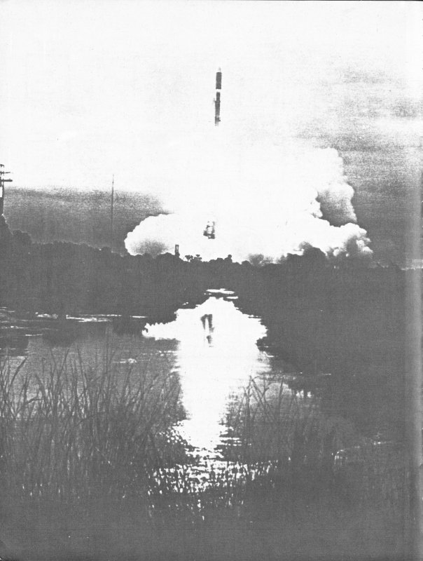
Viking 2—bound for Mars—is launched aboard Titan Centaur on September 9, 1975.
Printed in the U.S.A.
Designed by Elizabeth Sur
1, A-42103 (SI); 2, 74-H-1066 (NASA); 3, 74-H-1244 (NASA); 4, A-3757 (SI); 5, 72-8670 (SI); 6, 58-Explorer I-1 (NASA); 7, 62-Mariner II-34 (NASA); 8, 63-Mariner II-26 (NASA); 9, 62-MA 6-74 (NASA); 10, 62-MA6-111 (NASA); 11, 65-H-934 (NASA); 12, 65-H-937 (NASA); 13, 69-H-1199 (NASA); 14, 69-H-1367 (NASA); 15, 76-4880-81 (SI); 16, P-14054 (JPL, NASA, Pasadena, California); 17, 73-H-993 (NASA); 18, 74-H-239 (NASA); 19, 75-15926 (SI); 20, 74-H-1220 (NASA); 21, A-50483 (SI); 22, 65-H-817 (NASA); 23, 76-1706 (SI); 24, 76-1705 (SI); 25, 71-H-413 (NASA); 26, 62-NC-2 (NASA); 27, 63-ARCAS-1 (NASA); 28, 75-16094 (SI); 29, 75-16228 (SI); 30, 75-16276 (SI); 31, 61-DELTA-4-6 (NASA); 32, 66-H-223 (NASA); 33, VAN-11 (NASA); 34, 67-H-1008 (NASA); 35, 66-H-28 (NASA); 36, 60-TIROS-5 (NASA); 37, 69-H-1915 (NASA); 38, 68-H-111 (NASA); 39, 62-RELAY-17 (NASA); 40, 71-H-1414 (NASA); 41, 69-H-285 (NASA); 42, 66-H-871 (NASA); 43, 76-H-1182 (NASA); 44, 69-H-1986 (NASA); 45, 76-1704 (SI); 46, A-459994 (SI); 47, A-5293 (SI); 48, A-1085 (SI); 49, 75-11488 (SI); 50, A-4554 (SI); 51, 72-H-1240 (NASA); 52, 63-CENTAUR-15 (NASA); 53, 75-13753 (SI); 54, 76-2756 (SI); 55, 76-2687 (SI); 56, 75-H-461 (NASA); 57, 76-4479-6 (SI); 58, 62-MA6-109 (NASA); 59, 71-H-1380 (NASA); 60, 65-H-1021 (NASA); 61, A-5367 (SI); 62, 75-10232 (SI); 63, A-5073 (SI); 64, 75-16091 (SI); 65, 76-1625-11 (SI); 66, 73-733 (SI); 67, SPACE-12 (NASA); 68, 67-H-1609 (NASA); 69, 64-H-2795 (NASA); 70, 65-H-674 (NASA); 71, 76-1707 (SI); 72, 76-1708 (SI); 73, 73-H-928 (NASA); 74, 71-H-398 (NASA); 75, 68-H-423 (NASA); 76, 68-H-422 (NASA); 77, 75-H-248 (NASA); 78, 75-H-1081 (NASA); 79, 75-H-891 (NASA); 80, 75-H-1077 (NASA); 81, 71-H-525 (NASA); 82, 61-MR3-76 (NASA); 83, 65-H-2355 (NASA); 84, 72-H-734 (NASA); 85, 62-F1-2 (NASA); 86, 67-H-1205 (NASA); 87, 71-H-1416 (NASA); 88, 70-H-1392 (NASA); 89, 71-H-335 (NASA); 90, 74-H-63 (NASA); 91, S-71-45480 (NASA, Johnson Space Center); 92, 72-H-1571 (NASA).
There is an obvious relationship between aeronautics and astronautics since the same principles of physics apply and many materials and techniques of construction are common. Nevertheless, in the decades following World War II, rocketry, guided missiles, and space flights were rapidly developing a complex history and lore quite different from that of aviation. Accordingly, in 1965, the Museum established a Department of Astronautics parallel with a Department of Aeronautics.
At that time, artifacts in categories of rocket propulsion, guided missiles, and space-flight programs were placed under curatorial control of the Astronautics Department. In 1967 the Smithsonian Institution and the National Aeronautics and Space Administration signed an agreement which provided for transfer of title to and custody of significant space artifacts by the Museum after their technical need had passed. Through provisions of this instrument the preservation and exhibit of this country’s most important spacecraft, rocket engines, launch vehicles, and missiles has been assured for posterity.
With the construction of the new Museum building on the Mall literally dozens of exciting and fascinating astronautical artifacts have been acquired, some just a few months before our opening in July 1976. All major artifacts on exhibit at the opening are described herein with brief historical summaries.
F. C. Durant III
Assistant Director, Astronautics
January 13, 1976
1. Robert H. Goddard beside his liquid-fuel rocket prior to launch on March 16, 1926.
2. “It looked almost magical as it rose, without any appreciable greater noise or flame, as if it said, ‘I’ve been here long enough; I think I’ll be going somewhere else’....”—Robert H. Goddard.
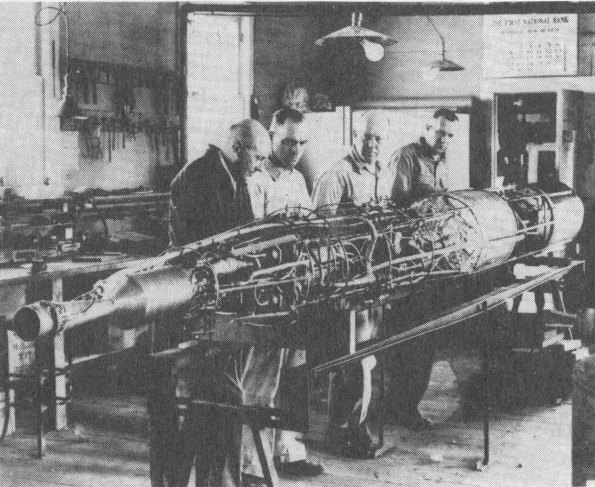
3. Rocket with turbopumps on its assembly frame in the Goddard shop at Roswell, New Mexico, 1940.
Robert H. Goddard contributed the first major astronautical breakthrough on our way to space exploration—a liquid-propellant rocket. A replica of the first successful rocket of this type is displayed in this hall as is Dr. Goddard’s last sounding rocket design.
The first of Dr. Goddard’s successful rockets was launched on March 16, 1926. It traveled to an altitude of 12.5 meters (41 feet) powered by liquid oxygen and gasoline. Its flight lasted 2.5 seconds with an average speed in flight of about 96.6 kilometers (60 miles) per hour. Part of the rocket’s nozzle was burned away during the flight, and other parts were damaged by ground impact; however, pieces of the original rocket were reassembled and flown again on April 3, 1926.
The last and most advanced of Dr. Goddard’s liquid-propellant rockets were those tested between 1939 and 1941. This series incorporated most of the basic principles and elements later used in all long-range rockets and space boosters. Design improvements for this series included a fuel system that used turbopumps to force propellants from the tanks to the combustion chamber. The rocket on display did not fly, because a malfunction in the umbilical cord caused the engine to shut down shortly after ignition.
The March 16 rocket replica is from the National Aeronautics and Space Administration. The 1941 rocket is from Mrs. Robert H. Goddard.
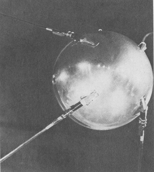
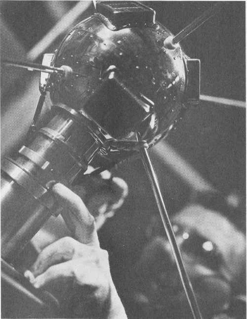
4. Model of Sputnik 1, the first man-made object to be placed in Earth-orbit.
Sputnik 1, the first man-made object to be placed in orbit around Earth, was launched by the USSR on October 4, 1957.
A 29-meter (96-foot) rocket with 510,037 kilograms (1,124,440 pounds) of thrust boosted Sputnik 1 into orbit. The satellite’s orbital and radio data provided scientists with information on atmospheric and electron densities. Sputnik 1 transmitted temperature data for 22 days before its batteries ran down.
The 83.5-kilogram (184-pound) satellite reentered the earth’s atmosphere and burned up on January 4, 1958.
This Sputnik model is from the USSR Academy of Sciences.
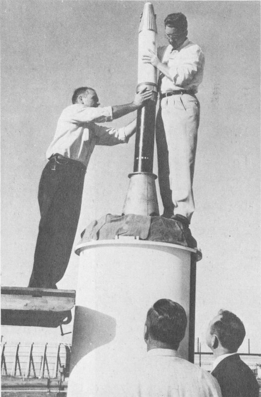
5. Trial firing of a full-size mockup of Explorer 1 on the third-stage assembly of the Jupiter-C launch vehicle.
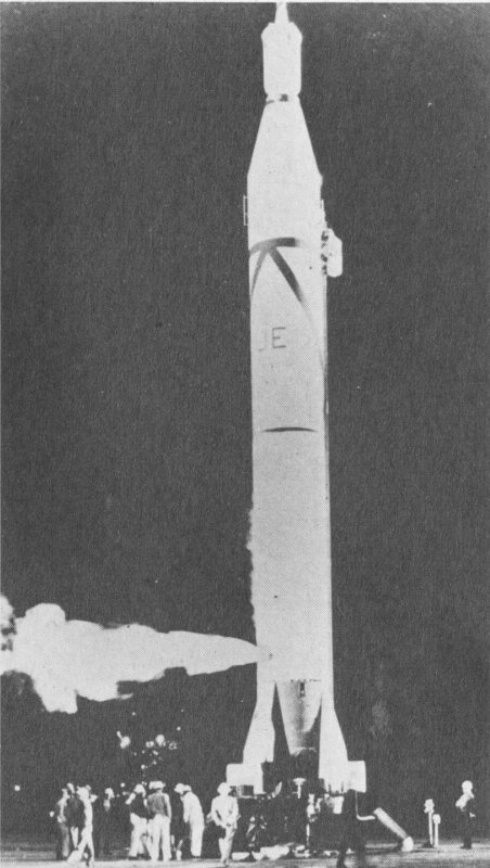
6. On the launch pad prior to sending the first American satellite into orbit. Explorer 1, launched January 31, 1958, discovered the first two circular radiation belts surrounding the Earth.
The International Geophysical Year (1957-58) provided the impetus for the first official American satellite effort, designated Project Vanguard in 1955. Vanguard was a civilian effort that relied on a launch vehicle built especially for the project’s purposes. The launch by the Soviet Union of Sputnik 1 on October 4, 1957, caused the work on Project Vanguard to go forward under great pressure. When Vanguard Test Vehicle 3, carrying the first American earth satellite, exploded on its launch pad on December 6, 1957, United States prestige reached a low point.
On January 31, 1958, Explorer 1 became the first successful American satellite. It originated in Project Orbiter, a joint study program of the U.S. Army and the Office of Naval Research—a project that lapsed after the 1955 decision to designate Vanguard as the official American satellite effort. Following the Sputnik success, the U.S. Army Ballistic Missile Agency was instructed to proceed with its satellite plans.
Explorer 1’s launch vehicle was a four-stage Jupiter-C rocket designed, built, and launched by the Army Ballistic Missile Agency team headed by Wernher von Braun. The satellite’s instrumentation was prepared by James Van Allen and George Ludwig of the State University of Iowa under project direction of the Jet Propulsion Laboratory, California Institute of Technology.
Explorer 1 measured three phenomena—cosmic ray and radiation levels (data that led to the discovery of the earth’s radiation belts), the temperature in the vehicle (important in the design of future spacecraft), and the frequency of collisions with micrometeorites. There was no provision for data storage, and therefore the satellite transmitted its information continually.
Explorer 1 was not the only orbiting American satellite for long. In spite of the early problems, Project Vanguard succeeded in launching the second American earth satellite on March 17, 1958.
The back-up Explorer 1 on exhibit is from the National Aeronautics and Space Administration, Jet Propulsion Laboratory. California Institute of Technology.
7. Artist’s conception of Mariner 2 as it flew by Venus.
The first successful interplanetary spacecraft probed the environment of Venus, Earth’s closest neighbor. Mariner 2, working flawlessly, swept by the hot and cloudy planet at a closest approach of 34,834 kilometers (21,645 miles) on December 14, 1962.
The journey began with lift-off on August 27 from Cape Canaveral atop an Atlas Agena-B launch vehicle. During the 109-day trip to the planet, Mariner’s on-board instruments sampled the environment of interplanetary space and telemetered information to Earth stations. Ground-based measurements of the Venerian surface temperature were confirmed by the probe to be around 425° C (800° F).
Mariner 2 detected no measurable magnetic field or radiation belts, indicating that Venus may have a very different history than has Earth.
Mariner 2 passed out of tracking range on January 4, 1963, when the spacecraft was about 87 million kilometers (54 million miles) from Earth. The probe is presently in orbit around the Sun.
The back-up craft on display would have been launched toward Venus if Mariner 2 had failed to reach the planet.
Prime contractor for Mariner 2 was the Jet Propulsion Laboratory, California Institute of Technology.
Mariner 2 is from the National Aeronautics and Space Administration.

8. Enlarged facsimile of coded Mariner 2 tape transmitted December 14, 1962, from the vicinity of Venus. Encircled portions show microwave and infrared coding.
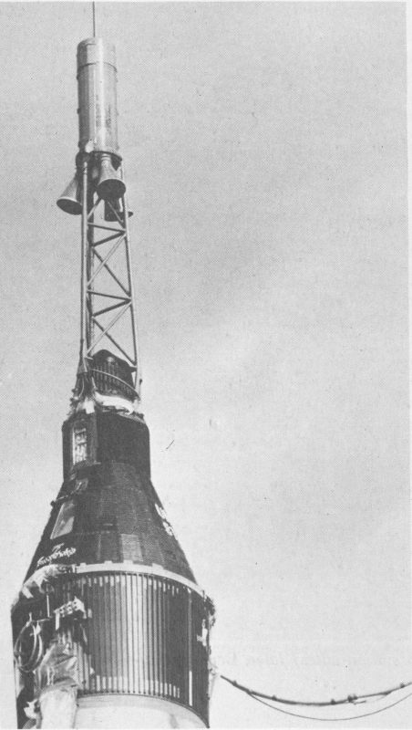
9. Close-up of Friendship 7 atop Atlas launch vehicle with escape tower.
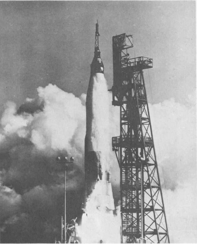
10. Launch of America’s first man in orbit on February 20, 1962, from Cape Canaveral, Florida.
On the morning of February 20, 1962, a 29-meter (95-foot) Mercury Atlas launch vehicle rose from Cape Canaveral carrying John H. Glenn, Jr., in his Mercury spacecraft, Friendship 7. This was the lift-off for the first U.S.-manned orbital space flight.
In slightly more than 5 minutes the Atlas accelerated Friendship 7 to its orbital velocity of 28,230 kilometers per hour (17,540 miles per hour). Astronaut Glenn completed three orbits in 4 hours, 55 minutes. From the orbital path, which varied between 160 and 260 kilometers (100 and 160 miles) above Earth, the first American in orbit described the four sunsets he saw and reported that he was able to distinguish a ship’s wake on the ocean below.
Mercury spacecraft had been used in two previous manned suborbital flights which proved that it was a safe vehicle for manned space flights. Later orbital Mercury missions demonstrated that man could live and work in space. Friendship 7’s flight tested the performance of the pilot in weightless conditions and the interaction of the human pilot with the various automatic systems in the spacecraft.
Friendship 7 reentered the earth’s atmosphere and splashed into the Atlantic Ocean only 64 kilometers (40 miles) from the planned site. Glenn and Friendship 7 were recovered by the U.S.S. Noa near Grand Turk Island in the Bahamas.
The Mercury spacecraft consists of a conical pressure section topped by a cylindrical recovery-system section.
During flight, the Mercury spacecraft was equipped with three 454-kilogram (1000-pound) thrust solid-propellant retro-rockets mounted in a package on the heat shield. After the three rockets were fired to slow the spacecraft, the retro-rocket package was jettisoned.
Prime contractor for Friendship 7 was McDonnell Aircraft Company.
Friendship 7 is from the National Aeronautics and Space Administration.
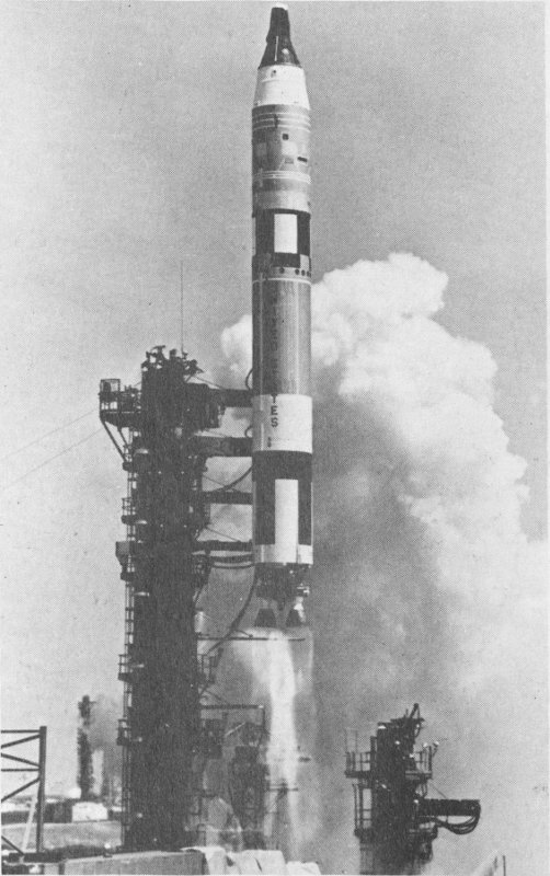
11. Gemini 4 lifts off, June 3, 1965.
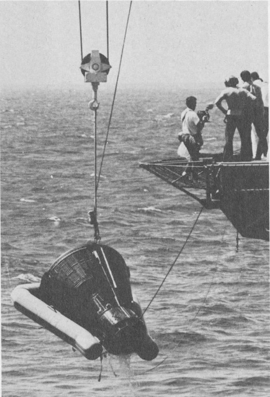
12. Well over 1.6 million kilometers (1 million miles) later, Gemini 4 is hoisted from the Atlantic Ocean.
Floating at the end of a gold “umbilical cord” attached to the Gemini 4 spacecraft, Edward H. White II became the first American to have only his space suit for protection from the space environment. White directed his movements during the historic 20-minute “walk” with a hand-held maneuvering device, while command pilot James A. McDivitt took pictures from within the craft.
Launched June 3, 1965 atop 3 Titan II booster, the Gemini 4 spacecraft made 62 revolutions during the four-day flight. Although Gemini 4 failed to rendezvous with the Titan II’s second stage as planned, because the stage fell away too rapidly to catch, astronauts McDivitt and White did demonstrate that the Spacecraft could be moved in and out of its orbital plane with ease.
The crew also photographed the Earth successfully. The pictures brought back from Gemini 4 enhanced interest in photographic surveys of Earth from space.
Gemini 4 splashed down in the Atlantic at 12:12 P.M. (EST) on June 7, 1965. McDivitt and White were on the deck of recovery carrier U.S.S. Wasp in less than one hour.
The spacecraft frame is titanium and it is covered with steel and beryllium shingles. Displayed here is the basic spacecraft which includes the pressurized cabin vessel, the heat shield at the base, and the cylindrical reentry attitude-control system section on the nose.
The heat shield is a curved section of fiberglass honeycomb filled with a phenolic-epoxy resin. During reentry, the craft’s kinetic energy was converted to heat by friction with the atmosphere. The heat-shield material melted and vaporized and was blown away from the craft, carrying the heat with it. This process is called ablation.
The Gemini was a true spacecraft, capable of maneuvering widely in space, changing its configuration for different phases of the flight, and allowing the two-man crew to work both inside and outside the craft.
Prime contractor for Gemini 4 was the McDonnell Aircraft Company.
Gemini 4 is from the National Aeronautics and Space Administration.
| Length | 5.6 m. (18 ft., 4 in.) in orbit; 2.3 m. (7 ft., 4 in.) at splashdown |
| Base diameter | Adapter, 3.1 m. (10 ft.); spacecraft, 2.3 m. (7 ft., 6 in.) |
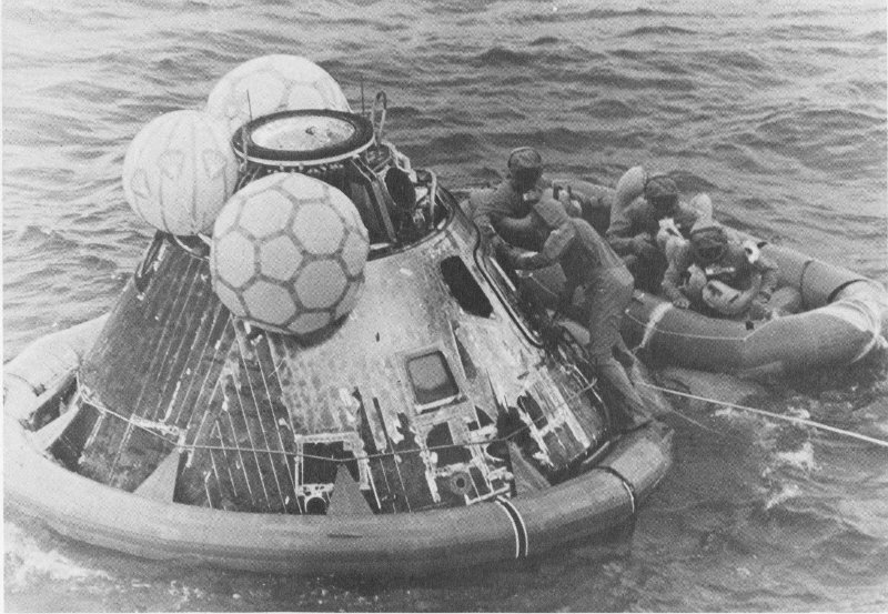
13. Three inflated bags repositioned the spacecraft following splashdown. The astronauts watch pararescue-man shut hatch during recovery.
“That’s one small step for a man, one giant leap for mankind,” Neil A. Armstrong radioed Houston from Tranquility Base on the Moon. The first footprint had been left on the lunar surface. It was 10:56 P.M. (EDT) on July 20, 1969.
Neil Armstrong was Apollo 11’s commander, Michael Collins was command-module pilot, and Edwin “Buzz” Aldrin was the lunar-module pilot. Their journey began at 9:30 A.M. (EDT) when their Saturn 5 lifted off under 3.4 million kilograms (7.5 million pounds) of thrust.
The three-man crew made the 383,000-kilometer (238,000-mile) journey to the Moon in three days, traveling in command-module Columbia.
At 1:46 P.M. (EDT), on July 20, Armstrong and Aldrin separated the lunar module from the Columbia and began the descent to the lunar plain.
During the 2 hours and 47 minutes that the astronauts were out on the surface of the Moon, they collected samples, deployed instruments, took photographs, and explored Tranquility Base around the lunar module.
After completing their tasks on the Moon, the astronauts rendezvoused with Collins in the command module. Jettisoning the ascent stage, they began the three-day journey back to Earth.
Splashdown occurred in the central Pacific Ocean on July 24. The astronauts climbed out of this command module and were recovered by helicopters that took them to the carrier U.S.S. Hornet.
Prime contractor for Apollo 11’s command module was North American Rockwell Corporation.
The Columbia is from the National Aeronautics and Space Administration.
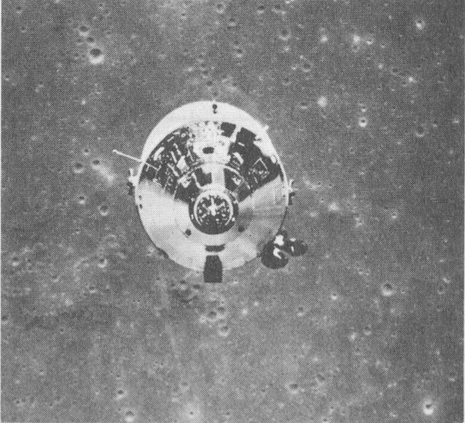
14. View of the Apollo 11 Command Module with Astronaut Collins aboard as seen from the Lunar Module. Terrain in background is the far side of the Moon.
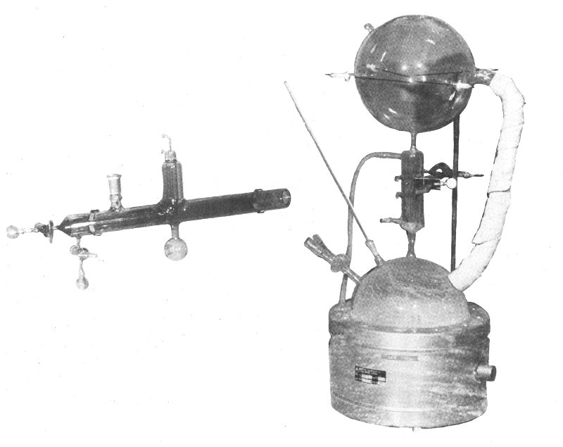
15. Equipment for Ponnamperuma Experiments.
These experimental devices were constructed by Cyril Ponnamperuma and his colleagues to show that various forms of energy may be used to produce organic molecules of the type found in living organisms.
In one experiment, electron beams were fired through a glass tube which contained a mixture of gases believed to resemble the atmosphere of primitive Earth. A number of organic molecules, including amino acids, the “building blocks” of life, were formed as a result.
In another experiment—the apparatus on display—electric spark discharges were used to add energy to a mixture of gases and water vapor contained in the device’s upper sphere. The lower sphere contained a solution of water and salts, a solution believed to resemble the slightly salty water of ancient seas. When heat and sparks were added to the gases and salty water, a number of complex organic molecules formed.
The results of these experiments supported the hypothesis that cosmic rays and other high-energy particles bombarding the primitive atmosphere could have been responsible for the origin of life on Earth.
The experimental devices were constructed and donated by Cyril Ponnamperuma and the Laboratory of Chemical Evolution, University of Maryland.
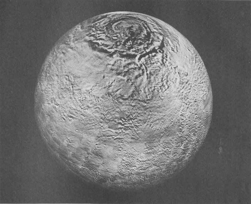
16. Photomosaic globe of Mars made of more than 1500 computer-corrected pictures taken by Mariner 9 in 1971 and 1972. The residual North Pole ice cap is at the top.
This 1.2-meter (4-foot) diameter globe of Mars was assembled from photographs taken by Mariner 9, an unmanned spacecraft that orbited the planet from November 14, 1971, until October 27, 1972. This globe is the first such photomosaic ever made of a planet.
Launched on May 30, 1971, Mariner 9 succeeded in photographing the entire surface of the planet. In its 349 days of orbit around Mars, Mariner 9 circled the planet 698 times and took more than 7300 photographs.
In its highly elliptical orbit, Mariner 9 obtained a sequence of overlapping wide-angle photographs. These were processed by a computer to remove the known variations in Mariner 9 camera response and geometric distortions, as well as to enhance surface detail. The mosaic made from the processed photographs is a pictorial presentation of the Martian surface which shows ridges and craters in the dark regions and on the bright polar caps with equal clarity. Surface features are in correct relationship and perspective, with only a minimum of shading difference between individual photographs.
In assembling the photomosaic, each picture was taped in place on the globe. Then, the match of adjacent pictures was assessed to determine where to trim the edges so that sharp features would not be intersected. The edges of each print were feathered so that when the prints were glued into place, the lines between pieces were almost indistinguishable. The complete globe received a thin protective coating.
This globe and copies of it enable scientists to study the geology and morphology of Mars from a perspective never before possible.
The photomosaic globe was designed and assembled at the Jet Propulsion Laboratory, California Institute of Technology, Pasadena, California.
The Mars Globe is on loan from the National Aeronautics and Space Administration.
17. Mariner 10 returned data and photographs from the vicinities of Venus and Mercury.
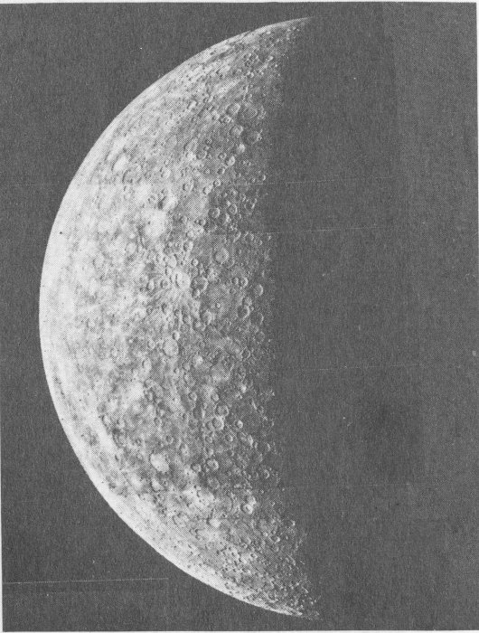
18. This computer-enhanced image of Mercury’s surface was returned by Mariner 10 from 200,000 kilometers (124,000 miles) and 6 hours away from closest approach to Mercury on March 29, 1974.
Mariner 10 returned closeup pictures of the cloud cover around Venus and of Mercury’s sunbaked surface. Mariner 10 was the first spacecraft to photograph Mercury, the innermost planet. The spacecraft’s instruments also measured particles, fields, and radiation from these planets.
Mariner 10 flew by Venus on February 5, 1974, after a three-month, 240-million-kilometer (150-million-mile) journey that took the Spacecraft halfway around the Sun. Mariner 10 swung around the planet, taking a variety of measurements and photographs of the clouds that obscure the planet’s face. Using the planet’s gravity to “bend” its flight path, Mariner 10 flew on toward encounter with Mercury.
On March 29, 1974. Mariner sped across the night side of the little planet closest to the Sun. Only 703 kilometers (436 miles) above the rugged surface, Mariner’s cameras captured the first closeup views of the planet’s daylight hemisphere. The pictures show craters, scarps—cliffs nearly 3 kilometers (2 miles) high and stretching as far as 500 kilometers (300 miles) across the surface—basins, and hilly furrowed terrain.
After providing our first glimpse of Mercury’s surface, Mariner raced on around the Sun and back out across Venus’ orbit. With some trajectory adjustments using on-board thrusters. Mariner returned to within 48,000 kilometers (30,000 miles) of Mercury on September 21, 176 days after the first encounter, again returning pictures and data. Mariner’s orbit brought it back to the planet for a third pass in another 176 days. On-board propellant exhausted, the spacecraft continues its orbit of the Sun and innermost planet.
Mariner 10 is the first complex spacecraft designed to travel to the inner reaches of the solar system. At closest approach to the Sun, the spacecraft received five times as much light and heat as it did on leaving Earth. Thus the solar panels, which collect and convert solar radiation into electrical energy for the spacecraft’s instruments and controls, were designed to tilt more and more away from the sunlight as Mariner approached the Sun.
Mariner could transmit much more information to Earth than earlier flyby spacecraft. This higher data rate enabled the craft to send back more live pictures of the planets as it flew by them. Some information was stored on magnetic tape for later transmission. This capability permitted Mariner to collect data when it was hidden from Earth behind a planet, and send the information when it emerged.
Prime contractor for Mariner 10 was Hughes Aircraft Company.
Mariner 10 is from the National Aeronautics and Space Administration.
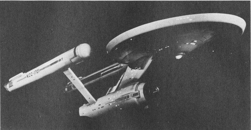
19. The starship Enterprise used in the filming of the “Star Trek” television series.
This studio model of an interstellar space ship was used in the filming of the science-fiction television series, “Star Trek.” Many of the series’ 78 episodes dealt speculatively with the problems and results of human contacts with extraterrestrial life forms and civilizations.
The model of U.S.S. Enterprise was designed by Walter M. Jeffries and Gene Roddenberry.
The model is from Paramount Television, a division of Paramount Pictures.
| Length | 3.4 m. (11 ft., 3 in.) |
| Diameter of disc | 1.5 m. (5 ft.) |
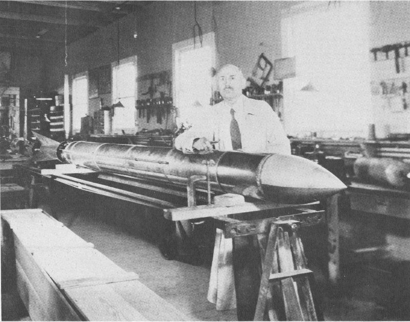
20. Dr. Goddard in his workshop at Roswell, New Mexico, October 1935.
Robert Hutchings Goddard, the American rocket pioneer, was one of the first to suggest the use of the rocket to gather scientific information from high altitudes. As seamen use sounding lines to measure the depth of unknown waters, so scientists use sounding rockets to investigate the nature of our atmosphere. As early as 1917, the Smithsonian Institution agreed to fund Dr. Goddard’s studies. In 1926, he built and flew the world’s first successful liquid-propellant rocket which rose to an altitude of 12.5 meters (41 feet) over a field in Massachusetts.
After the scientist received substantial grants from the Daniel and Florence Guggenheim Foundation, he established a facility near Roswell, New Mexico, where he built and tested a series of rockets and engines between 1930 and 1942.
A-Series rockets—one on exhibit—were flown during the summer of 1935, as part of Dr. Goddard’s program to develop methods of stabilizing his rockets in vertical flight. The principles he pioneered in this area were among his greatest contributions to the field of rocketry.
The greatest height reached by an A-Series rocket was about 2130 meters (7000 feet) and the greatest speed in flight was more than 1130 kilometers per hour (700 miles per hour).
The rocket on exhibit is from Robert H. Goddard.
| Length | 4.7 m. (15 ft., 6 in.) |
| Diameter | 15.2 cm. (6 in.) |
| Fuel | Gasoline |
| Oxidizer | Liquid oxygen |
| Thrust | about 90 kg. (200 lb.) |
| Velocity | 1130 km. (700 mi.) per hr. (+ or -) |
| Altitude | 2.3 km. (7600 ft.) (+ or -) |
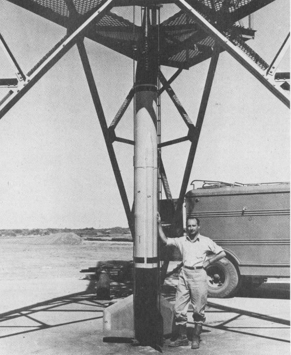
21. Frank Malina, project leader in the development of the WAC Corporal, stands beside the high-altitude sounding rocket.
The WAC Corporal was the first successful American sounding rocket to reach significant altitude. The first WAC Corporal, launched in 1944 from White Sands Proving Ground in New Mexico, reached a height of 71,600 meters (235,000 feet). The fin-stabilized rocket was powered by a liquid-propellant engine that burned a self-igniting fuel and oxidizer combination. Use of these propellants eliminated the need for an ignition system. By March 1946, these rockets had attained altitudes of over 72.4 kilometers (45 miles) with a booster. The WAC Corporal was later used as a second stage on a German V-2 rocket. This U.S. program, code-named “Bumper,” tested techniques for ignition and separation of stages at high altitudes.
The WAC Corporal was designed in 1944 by the staff of the Jet Propulsion Laboratory, California Institute of Technology.
The rocket on exhibit is from the California Institute of Technology.
| Length | 4.9 m. (16 ft., 2 in.) as exhibited |
| Diameter | 30.5 cm. (12 in.) |
| Fuel | Aniline-furfuryl alcohol |
| Oxidizer | Red-fuming nitric acid |
| Thrust | 680 kg. (1500 lb.) |
| Velocity | 4500 km. (2800 mi.) per hr. at burnout |
| Altitude | 72 km. (45 mi.) with a 11.3-kilogram (25-lb.) payload |
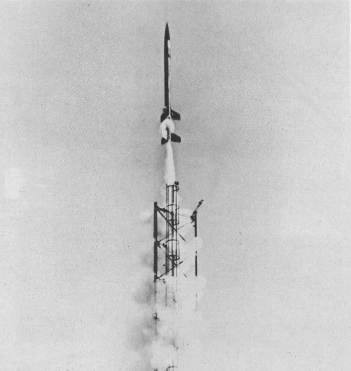
22. A booster lifts Aerobee 150 out of its launch rail.
The half-ton Aerobee could carry a 45.4-kilogram (100-pound) payload to an altitude of 120.6 kilometers (75 miles). For many years, the Aerobee was the standard American sounding rocket due to its reliability and relatively low cost. Several versions of the original Aerobee were produced. The Aerobee relied on a short-duration, solid-fuel booster for launching, after which the main-stage, liquid-propellant engine ignited.
On display at the NASM is an Aerobee 150, a more sophisticated version of the rocket. An Aerobee 150 can lift a 68.1-kilogram (150-pound) payload to an altitude of 274 kilometers (170 miles). Payloads consisted of a variety of scientific experiments.
The Aerobee concept originated early in 1946 when Dr. James Van Allen, then of the Applied Physics Laboratory at Johns Hopkins University, suggested that the Office of Naval Research contract for a rocket with these particular capabilities. The Aerojet General Corporation (then Aerojet, Inc.) was awarded the contract, with the Douglas Aircraft Corporation subcontracting for aerodynamic studies on the nose, fins, and tail cone, and for the final assembly of the rocket.
The Aerobee 150 is from the National Aeronautics and Space Administration, Goddard Space Flight Center.
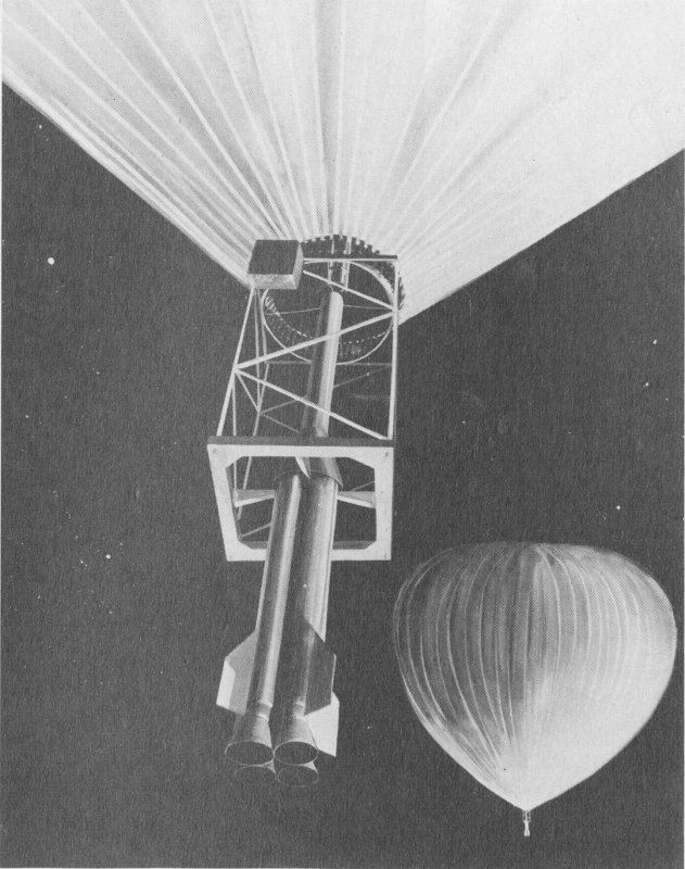
23. Artist’s rendering of four-stage Farside sounding rocket, in launcher below balloon.
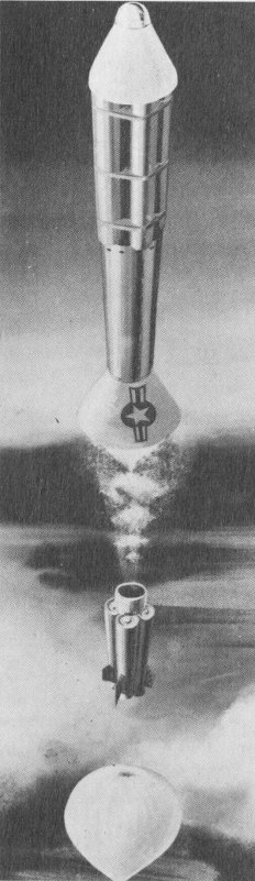
24. Rocket was fired directly through the apex of the balloon. Drawing shows the first stage falling away as second-stage rocket takes over.
Farside was a four-stage rocket launched from a balloon as an extremely high-altitude research vehicle. Achieving heights estimated at 6400 kilometers (4000 miles). Farside’s instrument payload was intended to study cosmic rays, earth’s magnetic field, certain forms of electromagnetic radiation in space, the presence of interplanetary gases, and the nature of meteoric dust.
The 908-kilogram (2000-pound) Farside was lifted to an altitude of 30.5 kilometers (19 miles) by a polyethylene balloon. An aluminum structure suspended from the balloon carried the 7.3-meter (24-foot) rocket to launch altitude. Positioned vertically in its casing, Farside was fired directly through the balloon.
Six Farsides were launched by the United States in 1957 from Eniwetok Atoll in the Pacific.
Farside’s first stage consisted of four solid-fuel Recruit rockets, manufactured by Thiokol Chemical Company. A single Recruit served as the second stage. Four Arrow II solid-fuel rockets by the Grand Central Rocket Company constituted the third stage. The final stage, a single Arrow II, carried the instrument payload provided by S. F. Singer of the University of Maryland.
Farside was developed by Aeronutronics Systems, Inc., for the U.S. Air Force Office of Scientific Research and Development.
The rocket on exhibit is from the Aeronutronics Division, Ford Motor Company.
| Length | 7.3 m. (24 ft.) |
| Propellants | Solid |
| Thrust | |
| First stage | 68,220 kg. (150,400 lb.) |
| Second stage | 17,055 kg. (37,600 lb.) |
| Third state | 4120 kg. (9080 lb.) |
| Fourth stage | 1030 kg. (2270 lb.) |
| Velocity | 29,000 km./hr. (18,000 mi./hr.) |
| Altitude | 3220-6440 km. (2000-4000 mi.) |
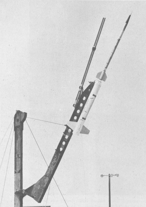
25. Nike-Cajun ready for launch.
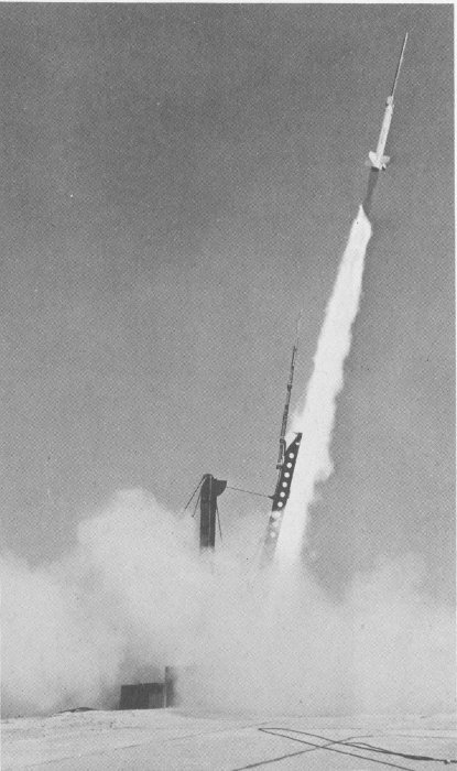
26. Nike-Cajun launch.
The Nike-Cajun was used extensively during International Geophysical Year (1957-58) to perform a variety of research tasks. These included weather photography, studies of water-vapor distribution in the upper atmosphere, and magnetic soundings in the ionosphere.
For photographic studies, the instrument package separated from the nose cone at about 80 kilometers (50 miles) and then coasted to a peak altitude of about 120 kilometers (75 miles), during which time data was collected. Then parachutes opened, lowering the cameras for recovery. Other data was radioed to Earth.
The Cajun rocket was developed by the Pilotless Aircraft Division of the National Advisory Committee for Aeronautics and the University of Michigan. The solid-fuel engine was designed and manufactured by Thiokol Chemical Company. The Nike booster was also solid fuel.
The rocket on exhibit is from the National Aeronautics and Space Administration.
| Length | 7.9 m. (26 ft.); Cajun, 4.1 m. (13.5 ft.) |
| Diameter | 41.9 cm. (16.5 in.) max; Cajun, 17.1 cm. (6.75 in.) |
| Propellant | Solid |
| Thrust | Sustainer, 4364 kg. (9620 lb.) |
| Velocity | 6760 km./ hr. (4200 mi./hr.) |
| Altitude | 161 km. (100 mi.) with a 23 kg. (50 lb.) instrument package; higher with a lighter payload |
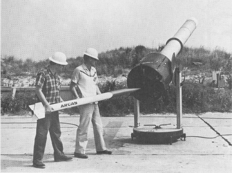
27. Loading ARCAS into launcher.
All-purpose Rocket for Collecting Atmospheric Sounding (ARCAS) gathers local meteorological data helpful to weather forecasters. Its 5.4-kilogram (12-pound) payload may include instruments which measure temperature, pressure, humidity, wind velocity and direction, and magnetic conditions. The single-stage ARCAS vehicle reaches an altitude of 64 kilometers (40 miles), propelled by a slow-burning solid-fuel engine which produces 141.4 kilograms (312 pounds) of thrust.
When the ARCAS is boosted by a Sparrow or Sidewinder missile engine, it can reach altitudes of 182,880 meters (600,000 feet).
The 32-kilogram (71-pound) ARCAS is far less expensive than the larger two-stage weather rockets it has replaced. It was developed and produced by the Atlantic Research Corporation.
The ARCAS is from the Atlantic Research Corporation.
| Length | 2.1 m. (7 ft.) |
| Diameter | 11.3 cm. (4.45 in.) |
| Propellant | Solid |
| Thrust | 159 kg. (350 lb.) |
| Velocity | 3590 km./hr. (2230 mi./hr.) |
| Altitude | 64 km. (40 mi.) with standard 5.4-kg. (12-lb.) payload; 91.7 km. (57 mi.) with a 2.3-kg. (5-lb.) instrument package |
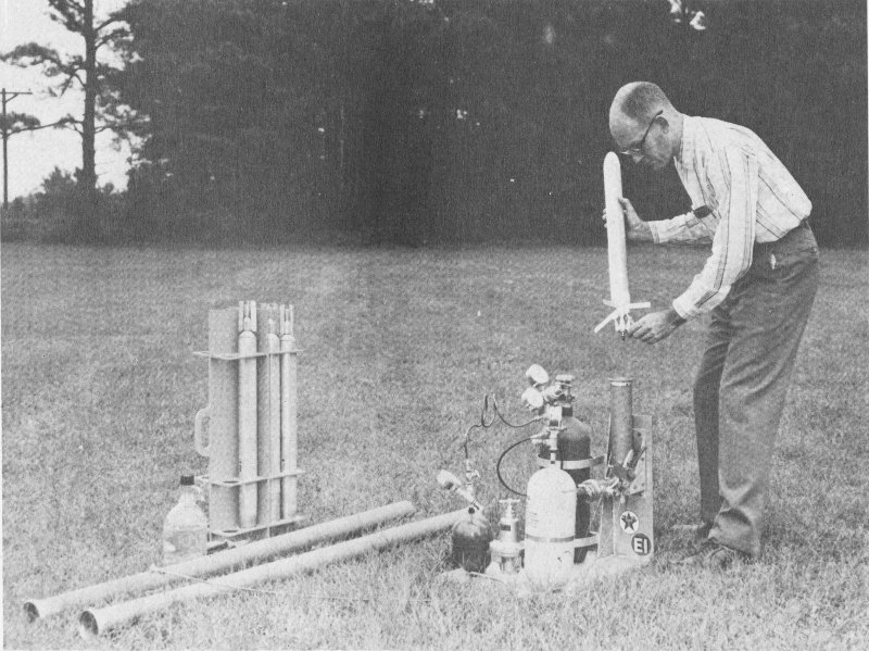
28. Preparing Cricket for launch.
The reusable Cricket, often called the “meteorologist’s handyman,” weighs only 2.5 kilograms (5½ pounds), 1.4 kilograms (3 pounds) of which is propellant. Recovered by parachute after each flight, Cricket costs less than $10 to refuel.
The Cricket’s .34-kilogram (three-fourth pound) instrument package zooms to 975 meters (3200 feet) in only 12 seconds, gathering data on air temperature, pressure and wind direction.
One of the rocket’s most noteworthy features is that it uses “cold” propellants. Compressed carbon dioxide to which acetone is added is pumped into a storage tank in the rocket at a pressure of 56.3 kilograms per square centimeter (800 pounds per square inch). Release of the pressurized mixture gives Cricket its thrust. Cricket is fired from its launcher by a separate charge of carbon dioxide in order to preserve the rocket’s fuel for flight.
This rocket was developed by Texaco Experiment, Inc., for the U.S. Air Force’s Cambridge Research Laboratory.
The Cricket is from Texaco, Inc.
| Length | 1.2 m. (3 ft., 10 in.) |
| Diameter | 11 cm. (4 in.) |
| Propellant | Pressurized carbon dioxide and acetone |
| Thrust | 23 kg. max. (50 lb.) |
| Velocity | 168 m./sec. max. (550 ft./sec.) |
| Altitude | 975 m. (3200 ft.) |
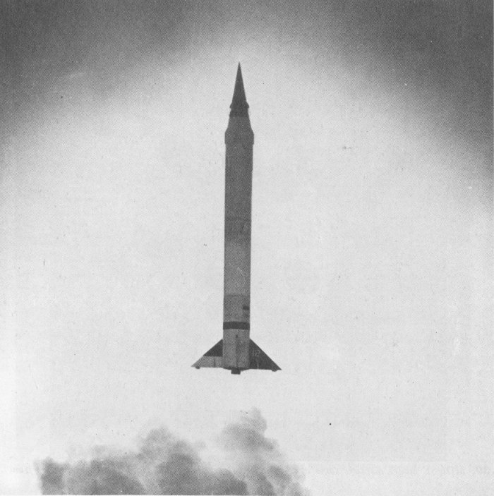
29. Viking 12 lift-off.
The Viking rocket family, numbering 14, grew out of the Navy’s efforts to develop an upper atmosphere research program. With enough time between launches to incorporate modifications suggested by experience with earlier Vikings, no two rockets of the series were exactly alike; however, there were two basic types of Vikings. The first seven rockets were taller, thinner, and had larger fins than those numbered 8-14; rockets in the second set were heavier, with fuel capacity greatly increased, and were designed either to go higher than the early Vikings or to carry heavier payloads to the same altitude.
Viking’s highest altitude was 254 kilometers (158 miles) following a launch from White Sands on May 24, 1954. Experiments flown on these rockets measured air temperature, density, pressure, and composition, as well as providing cosmic and solar radiation data.
One of the few failures in this program was Viking 8, the first rocket of the second set, which unexpectedly tore loose from the launch stand while being test-fired.
Viking was conceived at the Naval Research Laboratory, designed and produced by the Glenn L. Martin Company of Baltimore, Maryland, and powered by a liquid-propellant engine by Reaction Motors, Inc.
The rocket on exhibit is from the Hayden Planetarium and Martin Marietta Aerospace.
| Length | 13.7 m. (45 ft.) |
| Diameter | 1.1 m. (3 ft., 9 in.) |
| Propellant | Alcohol |
| Oxidizer | Liquid oxygen |
| Thrust | 9300 kg. (20,500 lb.) |
| Velocity | 6480 km. (4025 mi.) per hr. |
| Altitude | 193 km. (120 mi.) with a 402-kg. (887-lb.) payload |
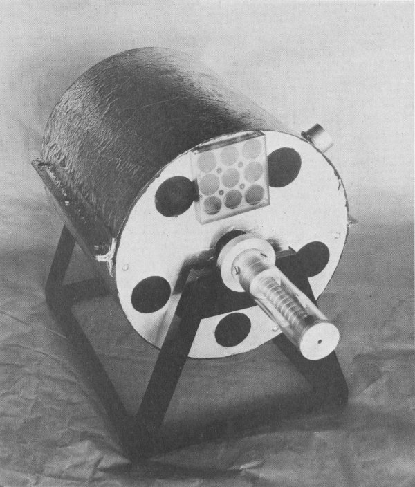
30. MOUSE model displays some of the earliest solar cells made (under square cover on front).
The concept of artificial earth satellites was a logical extension of existing sounding-rocket programs. The MOUSE, or Minimum Orbital Unmanned Satellite of Earth, was conceived in 1951 as the smallest possible orbital vehicle capable of performing scientific tasks. While the MOUSE was never built or flown, it demonstrated what could be accomplished by an orbiting vehicle of modest size and weight.
The MOUSE would have weighed 45.4 kilograms (100 pounds). It was designed to study cosmic rays, interplanetary dust, and solar ultraviolet and X rays, with the instruments attached to rods projecting from either end. The satellite was to be powered by solar cells.
MOUSE was conceived by Kenneth W. Gatland, Anthony Kunesch, and Alan Dixon of England. Dr. S. F. Singer of the University of Maryland designed the MOUSE and constructed the model on exhibit. The model displays some of the earliest solar cells produced by the Bell Telephone Laboratories.
The MOUSE is from S. F. Singer.
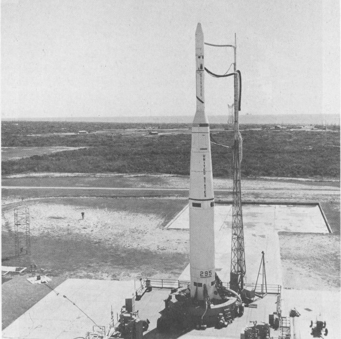
31. Thor-Agena launch vehicle and its satellite payload before launch.
The Agena launch vehicle has been an integral part of both unmanned and manned space programs. Flown as an upper stage on Thor and Atlas boosters, Agena orbited an impressive roster of spacecraft including the Echo communications satellites, the Ranger and Lunar Orbiter Moon probes, and the Mariner vehicles that traveled to Venus and Mars.
As the target for docking experiments during Project Gemini, Agena made substantial contributions to the eventual success of the Apollo program. The vehicle earned the distinction of being the first to place a payload in polar orbit, and was also the first to achieve circular orbit. The Agena engine was the first which could be stopped and restarted in space.
The Agena launch vehicle was developed and manufactured by the Lockheed Missiles and Space Company for the United States Air Force.
| Length | 7.1 m. (23.25 ft.) |
| Diameter | 1.5 m. (5 ft.) |
| Weight | Empty 674 kg. (1484 lb.) |
| Fuel | Unsymmetrical dimethylhydrazine |
| Oxidizer | Inhibited red-fuming nitric acid |
| Thrust | 7260 kg. (16,000 lb.) |
The Agena-B is from the United States Air Force and the Lockheed Missile and Space Company.
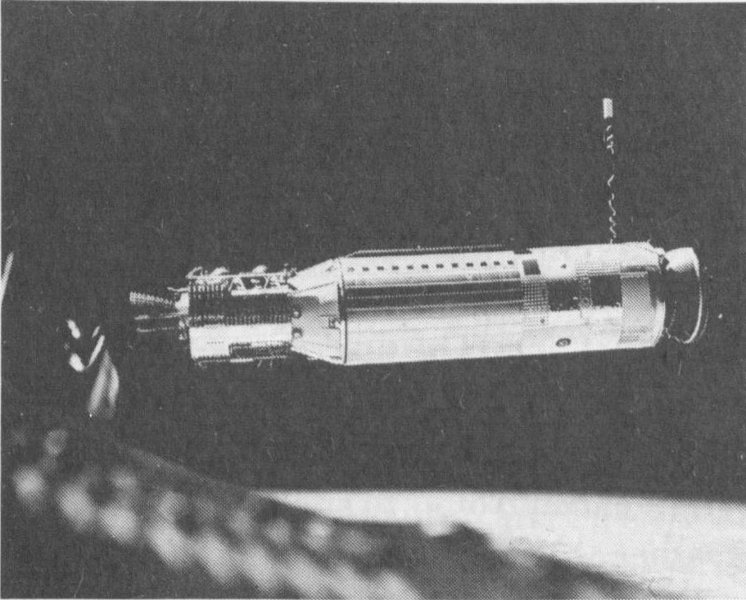
32. The Agena Target Docking Vehicle seen from the Gemini 8 spacecraft during rendezvous approach.
33. Vanguard 1, second American satellite launched. Information from Vanguard showed that the Earth is not quite round.
The first artificial earth satellites were sometimes called “long-playing rockets” because they carried the same instruments and investigated the same problems as had the sounding rockets. The great advantage of the satellite was its ability to provide a continuous flow of information for long periods of time. The first science satellites were the forerunners of later vehicles that would demonstrate the direct benefits that satellites could offer to such varied fields as weather observation and communication.
The advent of the earth satellite provided scientists with a new and valuable research tool. Science satellites have been used for such tasks as solar and astronomical observations, biology experiments, or atmospheric investigation. Explorer 1 (launched January 31, 1958) and Vanguard 1 (launched March 17, 1958), the first American earth satellites, carried scientific payloads into space.
Project Vanguard’s important contributions to America’s space program were the creation of the minitrack tracking system, the first use of silicon solar cells for electric power in a satellite, as well as the discovery that Earth is not quite round. The Vanguard program drew to a close with the 1959 launch of Vanguard 3. This satellite studied variations in solar and x-ray radiation and the earth’s magnetosphere. It also determined air density in the upper atmosphere.
The mysteries of the near-earth space environment drew Explorer 6, launched August 7, 1959. Explorer 6 instruments measured radiation levels in the Van Allen radiation belts, mapped the earth’s magnetic field, counted micrometeorites, and studied the behavior of radio waves in space. In addition, Explorer 6 carried a scanning device which returned the first complete television cloud-cover picture of the earth’s surface.
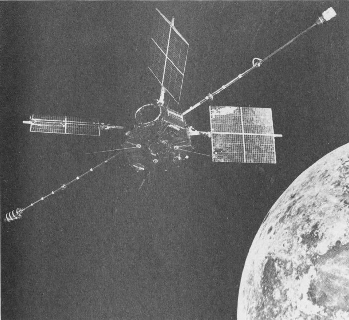
34. Artist’s concept of IMP-E. This satellite’s primary mission is to study solar wind and the interplanetary magnetic field at lunar distance and their interaction with the Moon.
Explorer 10, launched on board a Thor-Delta rocket on March 25, 1961, confirmed the existence of the solar wind—the stream of particles that carries the Sun’s magnetic field beyond the orbit of Earth. During the satellite’s planned 52 hours in orbit, it relayed information on the relationship between terrestrial and interplanetary magnetic fields and the solar wind.
To continue the study of solar wind and interplanetary magnetic fields, Explorer 12 was orbited by a Delta launch vehicle on August 16, 1961. It was the first in a series of satellites to study energetic particles in space. These electrons and protons constitute the earth’s radiation belts and they affect weather and other phenomena on Earth.
Atmosphere Explorer-A was the first of NASA’s aeronomy satellites. It was designed to remain in operation three months, studying the composition, density, pressure, and temperature of the upper atmosphere. This satellite discovered a belt of neutral helium atoms around the Earth.
Deriving its name from a spirit in Shakespeare’s play, The Tempest, Ariel 1 explored the ionosphere, a region of electrically charged air which begins about 40 kilometers (25 miles) above the surface of the Earth. Launched April 26, 1962, Ariel was a cooperative venture between Great Britain and the United States. It was both the first British satellite and NASA’s first international satellite. The Royal Society’s British National Committee on Space Research coordinated the experimental program; NASA scientists and technicians built the craft.
Two small scientific laboratories, called Interplanetary Monitoring Platforms, were launched in 1967 to study the solar wind and other phenomena. IMP-E investigated interplanetary magnetic fields in the vicinity of the Moon. IMP-F investigated the interplanetary magnetic field also, in addition to the earth’s magnetosphere and radiation levels in space.
Interplanetary space between the Earth and Venus was the subject area for Pioneer 5, launched March 11, 1960. The satellite tested long-range communications systems, developed methods for measuring astronomical distances, studied the effects of solar flares, and performed other tasks before it went into orbit around the Sun.
With increasing interest in the earth’s space environment, a satellite was launched on September 7, 1967, to investigate the impact of space on biological processes. Biosatellite 2 was the second satellite in the program of three such vehicles. Frog eggs, plants, micro-organisms and insects were placed in orbit to enable scientists to study the combined effects of weightlessness, artificially produced radiation, and the absence of the normal day-night cycle on these organisms. Following two days in space, the capsule containing the experimental package reentered the atmosphere and was caught in mid-air by an Air Force recovery aircraft.
Vanguard 1 is from John P. Hagan. Vanguard 3, Explorer 10, Explorer 12, AE-A, Ariel 1, IMP-E & F, and Biosatellite 2 are from the National Aeronautics and Space Administration. The models of Explorer 6 and Pioneer 5 are from Space Technology Laboratories.
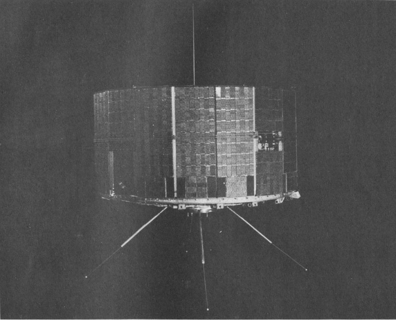
35. TOS satellite is covered with solar cells.
Weather forecasts are important to everyone—in planning whether or not to carry an umbrella, when to plant crops, when to evacuate riverbank areas. Nineteenth-century American meteorologists relied on local weather observations telegraphed to the Smithsonian Institution in Washington and then plotted on a large map of the nation from which forecasts were prepared.
When Tiros-1 returned the first global cloud-cover picture in 1960, meteorologists were on their way to more accurate forecasts. Since the satellite pictures offered more comprehensive weather data over a larger geographic area, the identification of weather patterns became more reliable.
While our knowledge of atmospheric conditions is still imperfect, we have learned to make reasonably accurate regional weather forecasts and to identify and track violent storms and hurricanes based on satellite information.
The TIROS series (Television Infrared Observations Satellites) were designed to test the feasibility of weather observation from orbit. The TIROS satellite on exhibit was the prototype for the entire series of vehicles. The prototype made eight trips to the launch stand at Cape Kennedy, where it was used to check communications and handling procedures prior to the launch of the scheduled TIROS. All 10 TIROS satellites were successful. Launched between April 1, 1960, and July 1, 1965, they carried a variety of camera systems for experimental purposes.
Nine TIROS Operational Satellites (TOS) followed TIROS 1-10. Except for the first TOS, these satellites flew in pairs with one craft storing pictures on board for 31 later transmission to major receiving centers, while the other broadcast its photographs continuously to any ground station within range. The satellite on display is of the latter type. These vehicles were launched between 1966 and 1969. They were placed in near-polar orbits by reliable Thor-Delta launch vehicles.
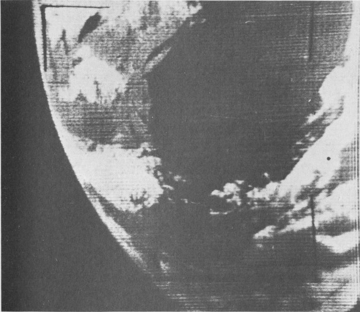
36. TIROS I photo showing a section of the East coast of the United States, including the Boston and New England area.
After launch, TOS vehicles were referred to as ESSA satellites. ESSA was an acronym both for Environmental Survey Satellite and for the Environmental Science Service Administration, the federal agency that operated the spacecraft. This organization became a part of the National Oceanic and Atmospheric Administration which currently has responsibility for operational meteorological satellite programs.
From about 1392 kilometers (865 miles) above Earth, two wide-angle television cameras mounted on either side of the spacecraft took in 10.4-million square kilometers (4-million square miles) per photo.
The Improved TIROS Operational Satellite (ITOS) opened the world of radiometric measurement to meteorologists—information about surface temperatures on the ground, at sea level, or at the cloud tops obtained by scanning devices sensitive to energy that is invisible to the naked eye. ITOS spacecraft could return accurate day or night surface and cloud-cover images. Seven of these satellites were launched between 1970 and 1973.
TIROS was presented to the National Air and Space Museum by the National Aeronautics and Space Administration; TOS is from the National Oceanic and Atmospheric Administration; ITOS is from the Astro-Electronics Division of RCA, Inc.
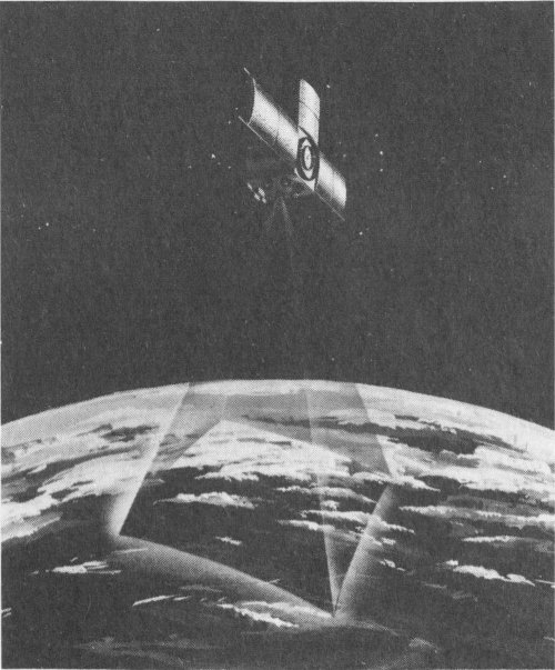
37. Artist’s concept of ITOS weather satellite illustrating how the weather eye takes night-time (infrared) cloud-cover pictures.
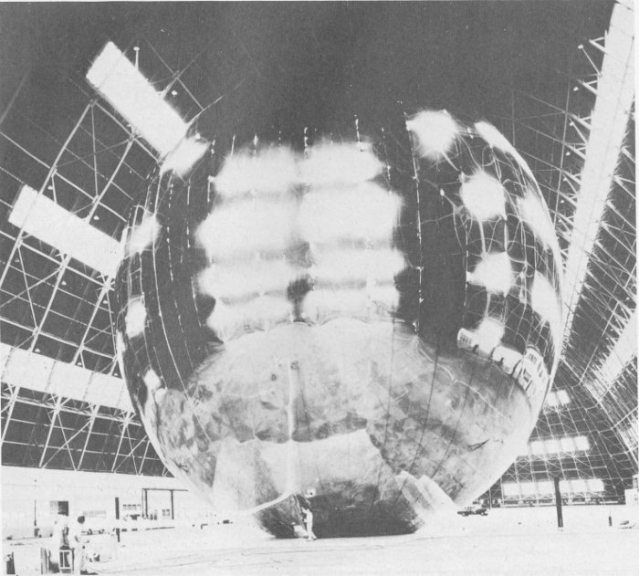
38. Ground inflation test on Echo 1, the world’s first passive communications satellite.
Communications satellites can be grouped into two broad categories. Passive vehicles reflect signals from one ground station to another. Active satellites accept ground signals and either amplify and rebroadcast them immediately or record messages for later transmission.
The Echo satellite balloons typified the passive category of communications spacecraft. These satellites “bounced” radio signals from one ground station to another. Uninflated Echo payloads were carried into orbit packed in special storage containers. When released in space, the balloon was inflated by chemicals packed inside which subliminated to produce inflating gas. The mylar plastic skin of the satellite was sandwiched between two layers of aluminum foil. Echo 2—on display—included a system for releasing gas over a long period of time to maintain the satellite’s spherical shape. Launched January 25, 1964, Echo 2 was the 33 first satellite used for communication experiments between the United States and the Soviet Union.
Project West Ford, launched May 9, 1963, was a unique experiment in passive satellite communications. It was not a solid vehicle, but a series of 400-million tiny individual copper filaments called dipoles. The dipoles formed a reflective layer some 64,300 kilometers (40,000 miles) long, 32 kilometers (20 miles) thick, and 32 kilometers (20 miles) wide. The distance between the individual dipoles averaged 536 meters (one-third mile). The West Ford experiment proved disappointing, and advances in the design of active communications satellites made further experiments of this nature unnecessary.
Oscar 1 (Orbital Satellite Carrying Amateur Radio) was conceived, designed, and constructed by American amateur radio “hams.” Launched as a “piggyback” satellite on December 12, 1963, Oscar transmitted a series of Morse code dots spelling “hi.” The message was picked up by 5000 operators in 28 nations during the 18 days of transmission. Oscar investigated radio propagation phenomena in space on that portion of the radio frequency spectrum allocated to amateur radio (144-146 megaherz).
Testing the use of a “delayed-repeater” satellite in global military communications, Courier 1-B was placed in a high-altitude orbit on October 4, 1960. The craft accepted and stored messages as it passed over one ground station, then replayed them on command.
Relay, another active repeater satellite, was placed in orbit on December 13, 1962. Relay carried communications experiments to test a variety of relay equipment—including that for photofacsimile, teleprinter, and data transmission. During its 25-month lifespan, Relay 1 introduced the nations of the world to satellite communication. A second, improved Relay was launched in 1964.
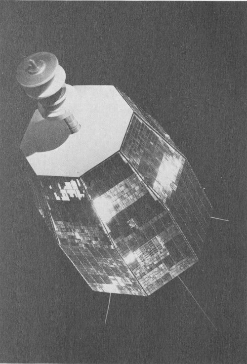
39. The exterior of eight-sided Relay is composed of honeycomb aluminum panels studded with 8215 solar cells.
The world’s first commercial communications satellite was called “Early Bird,” or INTELSAT 1. Built a decade ago by Hughes Aircraft Company for Communications Satellite Corporation (COMSAT), Early Bird could transmit simultaneously on 240 two-way channels for telephone, telegraph, or data transmission. Transatlantic telephone circuit capability increased by 50 percent once Early Bird went into orbit on April 6, 1965. Although the craft had a life expectancy of 18 months, it operated satisfactorily in full-time service for more than three and one-half years.
INTELSAT 2 introduced multipoint communications between earth stations in the Northern and Southern hemispheres. With almost twice the power of Early Bird, INTELSAT 2 proved particularly important as communications support for the Apollo missions to the Moon.
INTELSAT 2 established a global network of three satellites that was effective in linking two-thirds of the world’s people in one communications chain. The first of the series was launched on January 11, 1967. These spacecraft were designed and manufactured by the Hughes Aircraft Company for Intelsat, Inc., and had a design lifetime of three years.
INTELSAT 3 was a series of five communications satellites which provided global coverage for the first time. This INTELSAT had a capacity of 2400 voice, data, facsimile, and telegraph circuits, plus four television channels and had a design lifetime of five years.
The satellite featured a de-spun antenna which remained pointed at a particular area of the globe, while the body of the satellite spun around it. It was the first commercial satellite capable of transmitting voice and television broadcasts simultaneously.
INTELSAT 3 satellites were manufactured by TRW Systems, Inc., for Intelsat, Inc.
Echo 2, Courier 1-B, and Relay are from the National Aeronautics and Space Administration; OSCAR 1 is from Project Oscar, Inc.; INTELSAT 1, INTELSAT 2, and INTELSAT 3 are from the International Telecommunications Satellite Organization.
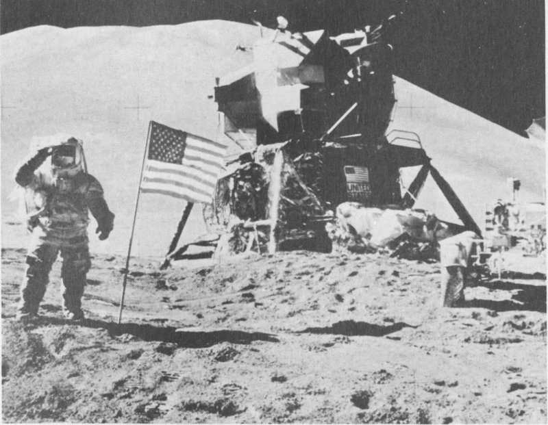
40. Apollo 15 Lunar Module, center, on the Moon. Astronaut Irwin on left and Lunar Roving Vehicle on right.
The lunar module is one of twelve built for the Apollo moon-landing program. Although this one never flew because an earlier test flight was completely successful, two-stage lunar modules like this one have been used for each manned moon landing.
Lunar modules do not have to be streamlined for flights through the vacuum of space or to withstand reentry. The lunar module (LM) lifts off from Earth enclosed in a compartment of the Saturn 5 launch vehicle, below the command-service module that houses the astronauts. The command module pulls the LM from its storage area once the spacecraft are on their way to the Moon, and the two travel together until they arrive in lunar orbit.
When the crew is ready to land, two of the three astronauts enter the LM and undock it, leaving the third to pilot the command module. After touchdown on the Moon, the astronauts exit through the door above the ladder.
The silver and black ascent stage, containing the astronauts’ pressurized compartment and the clusters of rockets that control the spacecraft, fits on top of the shiny gold descent stage that actually touches down on the Moon. The descent stage contains a main, centrally located rocket engine. This segment of the craft remains on the Moon as the crew lifts off in the ascent stage to rejoin the command module.
After the crew transfers to the command module, the ascent stage is also left behind as the three crew members start their return journey.
The LM is displayed just as it would look during a moon-landing mission. The gold and black materials insulate the spacecraft’s inner structure from temperature extremes and protect it from micrometeoroids. Thin sheets of both materials are used in “blankets” to accomplish the necessary protection in a foreign environment.
The black material is heat-resistant nickel-steel alloy. Each sheet is only .002 millimeters (1/12,000 of an inch) thick. These absorb heat and radiate it back into the blackness of space.
The shiny gold material on the descent stage is aluminum that is thinly coated over plastic film. The thin sheets of plastic and aluminum are used in blankets of up to 25 layers for protection and insulation of the spacecraft.
Prime contractor for the lunar module was Grumman Aerospace Corporation.
The lunar module on exhibit is from the National Aeronautics and Space Administration.
| Height | 7 m. (22 ft., 11 in.), legs extended |
| Diameter | 9.4 m. (31 ft.) diagonally across landing gear |
| Weight | |
| Earth launch | 14,700 kg. (32,400 lb.) |
| LM (dry) | 3900 kg. (8600 lb.) |
| Volume | |
| Pressurized | 6.7 cu. m. (235 cu. ft.) |
| Habitable | 4.5 cu. m. (160 cu. ft.) |
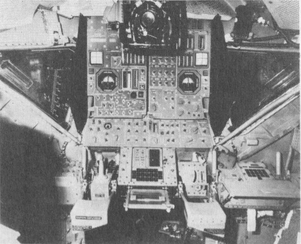
41. Lunar Module Center Instrument Panel in the ascent stage.
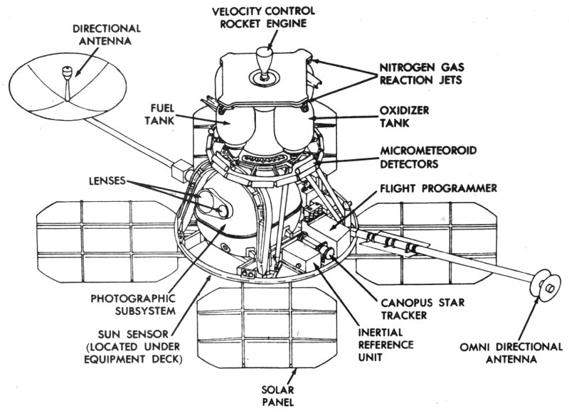
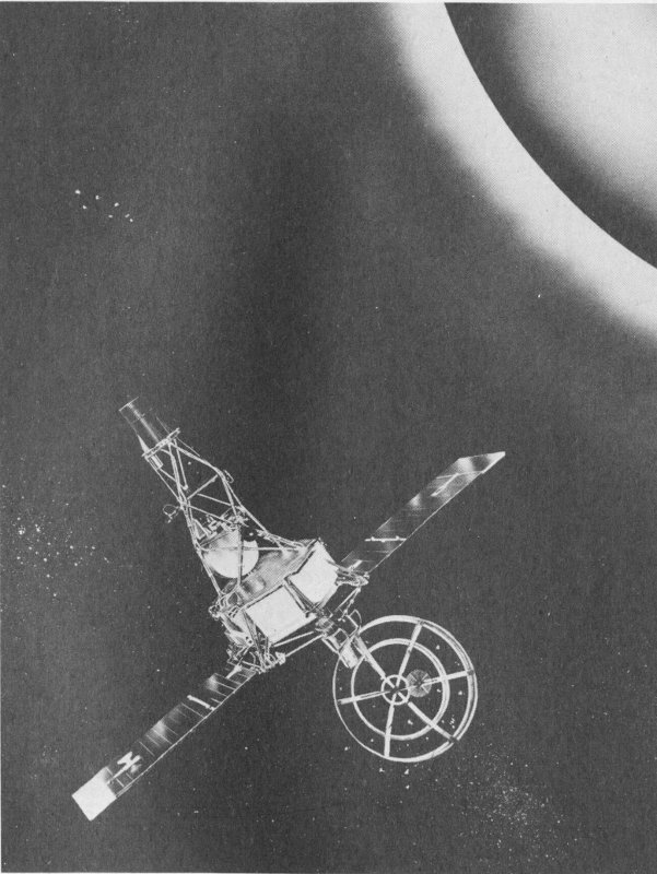
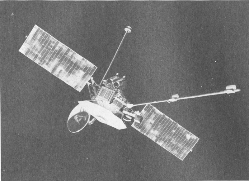
42. Lunar Orbiter.
The Lunar Orbiter project was initiated in 1963 as part of the U.S. Apollo program to land men on the Moon during the decade of the nineteen sixties.
Lunar Orbiter’s primary mission was to take and transmit both wide-angle and closeup images of the Moon. Lunar Orbiters photographed many areas of scientific interest and provided general photographic coverage of much of the moon’s surface. These pictures were then used to select the best landing sites for the first manned lunar landings. Orbiters also showed that the moon’s gravitational field permitted stable orbits.
Lunar Orbiter 1 was launched atop an Atlas-Agena D rocket on August 10, 1966. The last in the project, Lunar Orbiter 5, was launched on August 1, 1967. All five missions were successful.
The first three missions were similar. After each launch, the Agena stage’s booster engine was fired to send the spacecraft on a 90-hour coasting trajectory to the Moon, about 386,160 kilometers (240,000 miles) distant.
As the spacecraft neared the Moon, its on-board engine was fired as a retrorocket to slow the Orbiter and permit it to go into orbit around the Moon.
The closest approach to the Moon in each orbit was about 45 kilometers (28 miles), and the spacecraft swung out to about 1850 kilometers (1150 miles) from the Moon.
Photography was conducted while the Orbiter was near the lunar surface. Lunar photography for the Apollo Program landing-site selection was completed by the first three Lunar Orbiters. Each was then intentionally crashed into the Moon to prevent it from interfering with later missions.
The last two Lunar Orbiters were used for scientific photography of the Moon. Both were placed into polar orbits so that they could photograph all of the sunlit areas of the Moon.
Each Lunar Orbiter carried a camera with both a telephoto and a wide-angle lens. The telephoto lens was capable of resolving objects on the lunar surface as small as 91.4 centimeters (three feet) in diameter. The wide-angle lens could resolve objects as small as 7.6 meters (25 feet) in diameter. The photographic images were converted to electrical signals for transmission to Earth.
The Lunar Orbiter project was a complete success. All spacecraft operated properly, photographing a total of more than 36-million square kilometers (14-million square miles) of the moon’s surface.
Prime contractor for the Lunar Orbiter program was the Boeing Company. Principal subcontractors were Eastman Kodak Company and RCA.
The Lunar Orbiter in the National Air and Space Museum’s collection was used for thermal testing of spacecraft systems.
Lunar Orbiter is from the National Aeronautics and Space Administration.
| Maximum span | |
| Antenna booms | 5.6 m. (18 ft., 6 in.) |
| Solar panels | 3.7 m. (12 ft., 2 in.) |
| Height | 1.68 m. (5 ft., 6 in.) without panels |
| Weight | 385.6 kg. (850 lb.) |
| Power | Electrical; four solar panels with a total area of just over 4.8 sq. m. (58 sq. ft.) providing 375 w. to nickel-cadmium batteries |
| Velocity control system | A 45.4 kg (100 lb.) thrust engine burning a hydrazine mixture and nitrogen-tetroxide oxidizer |
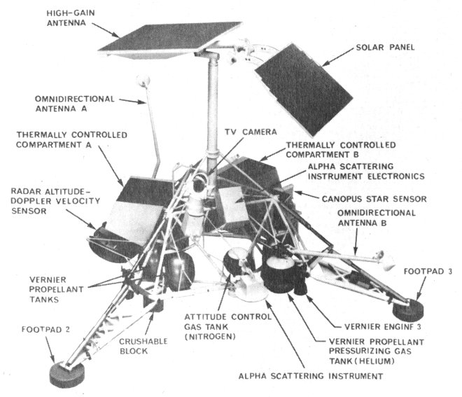
43. Surveyor.
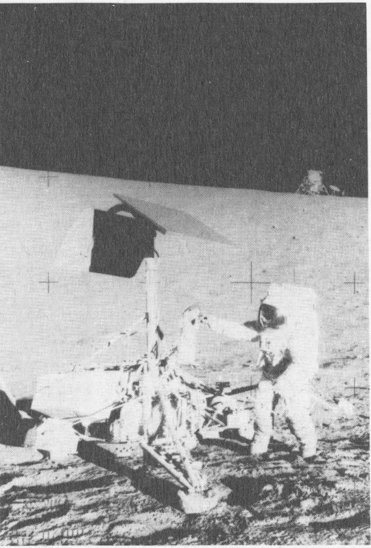
44. Apollo 12 crewman examines Surveyor 3, which soft-landed on the Moon on April 19, 1967. The Apollo 12 (1969) Lunar Module is in the background.
The Surveyor Project, begun in 1960, consisted of seven unmanned spacecraft which were launched between May 30, 1966, and January 6, 1968. The craft were used to develop lunar soft-landing techniques, to survey potential Apollo landing sites, and to improve scientific understanding of the Moon.
Five of the seven Surveyor spacecraft successfully landed on the Moon and performed their tasks well. They responded to 600,545 commands from Earth and returned 87,632 television images of their lunar surroundings. (Surveyors 2 and 4 crashed into the Moon and were destroyed.)
Besides returning TV images, Surveyors 3, 5, 6, and 7 carried a soil-sampling claw which could dig a trench, and test soil hardness and other characteristics. The soil-sampler tests showed that the lunar surface would bear the weight of an Apollo Lunar Module.
Surveyors 5, 6, and 7 carried instruments capable of making simple chemical analyses of the lunar soil near the spacecraft. This information told scientists that most lunar soil near the Surveyors was basalt, a common rock on Earth as well.
The Surveyor spacecraft on exhibit, designated S-10, was used in ground-based tests of on-board equipment, and was not used on a mission. S-10 is exhibited as it would have appeared just before landing on the Moon.
Prime contractor for the Surveyor spacecraft was the Hughes Aircraft Company. The project was managed by the National Aeronautics and Space Administration, Jet Propulsion Laboratory, California Institute of Technology, Pasadena, California.
The spacecraft on exhibit is from the National Aeronautics and Space Administration.
| Height | 3 m. (10 ft.) |
| Distance across footpads | 3.5 m. (11 ft., 6 in.) |
| Weight | 1000 kg. (2204 lb.) at launch; 292 kg. (644 lb.) as exhibited |
| Electrical power | One .83 sq. m. (9 sq. ft.) solar panel providing 89 w. to a silver-zinc battery |
| Landing vernier rocket system | Three throttleable liquid-propellant rockets each providing from 14.6 to 47.2 kg. thrust (30 to 104 lb. thrust). Fuel—Monomethylhydrazine monohydrate; oxidizer 90% nitrogen tetroxide and 10% nitric oxide. |
The American pioneer of astronautics, Robert H. Goddard (1882-1945) not only outlined the physical principles that would govern space flight, but he also constructed and tested many rocket engines, airframes, control devices, and guidance mechanisms between 1926 and 1942.
Goddard held a doctorate in physics, and was a professor at Clark University, Worcester, Massachusetts. The Smithsonian Institution began funding Goddard’s experiments as early as 1917 and published his first major work, A Method of Reaching Extreme Altitudes, in 1919.
Goddard was not only a trained scientist, but a talented and ingenious engineer as well. On March 16, 1926, he launched the world’s first liquid-propellant rocket. By 1930, he had established a rocket test facility at Mescalero Ranch, near Roswell, New Mexico. Here, he conducted research, funded by the Daniel and Florence Guggenheim Foundation, on rocket power plants, pumps and fuel systems, control mechanisms, and other vital elements of the modern rocket.
This vehicle is the oldest surviving liquid-propellant rocket in the world. Built of parts employed in the first liquid-propellant rocket launched on March 16, 1926, the engine was moved from the nose of the vehicle to the rear for the May 4 trial. Other changes were introduced to reduce the weight of the rocket to 2.5 kilograms (5.5 pounds). The motor burned gasoline and liquid oxygen.
The alcohol burner under the liquid oxygen tank was inadvertently not ignited, causing the May 4 attempted launch to fail. A second test on May 5 also proved unsuccessful. However, the rocket engine was fired on both occasions.
The May 4 rocket is from Mrs. Robert H. Goddard and the Daniel and Florence Guggenheim Foundation.
| May 1926 rocket | |
|---|---|
| Length | 1.95 m. (6 ft., 4 in.) |
| Weight | 2.5 kg. (5.5 lb.) |
| Fuel | Gasoline |
| Oxidizer | Liquid oxygen |
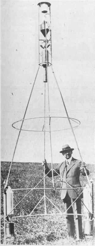
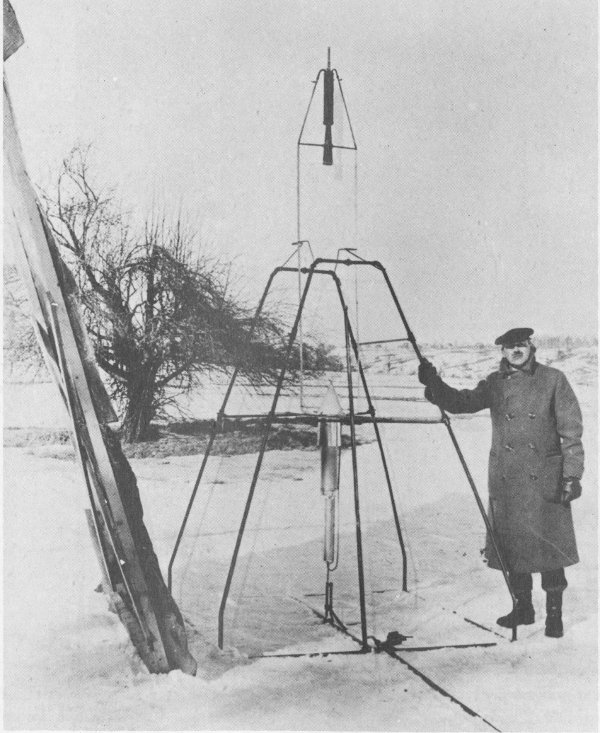
45. Dr. Goddard and the “Hoopskirt.” Propellant tanks are on legs of frame.
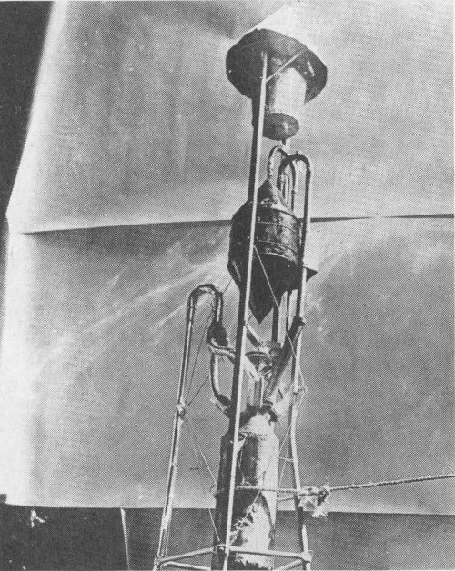
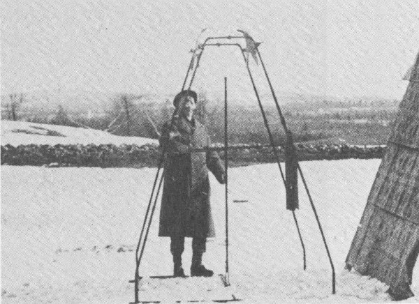
46. The upper section of the “Hoopskirt” rocket.
Developed by Dr. Goddard during the late summer and early fall of 1928, the “Hoopskirt” rocket featured a small rocket engine mounted in the nose and a system of tanks and alcohol burners—to maintain fuel pressure—mounted on two legs. On December 26, 1928, the rocket flew 62.33 meters (204.5 feet) in 3.2 seconds—its most successful flight. Like all Goddard rockets, the “Hoopskirt” burned gasoline and liquid oxygen.
The “Hoopskirt” rocket is from Mrs. Robert H. Goddard.
| “Hoopskirt” | |
|---|---|
| Height | 4.5 m. (14 ft., 8 in.) |
| Weight | 12.93 kg. (28.5 lb.) |
| Fuel | Gasoline |
| Oxidizer | Liquid oxygen |
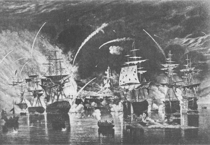
47. The Bombardment of Algiers, 1816. Congreve rockets in use.
The rebirth of European interest in military rocketry can be traced to the English conquest of India during the late 18th century. William Congreve, an artillery expert, was intrigued by the tactical success of the Indian war rockets. He began a research program in 1804 that led to the development of a metal-cased, stick-guided artillery rocket that could be fired in barrages against enemy troops. The rocket carried incendiary or explosive warheads.
The 14.5-kilogram (32-pound) Congreve war rocket models on display show the early side-mounting of the stabilizing guide stick and the later (1815) design in which the guide stick was center-mounted to give greater accuracy. Congreve rockets played an important role during the Napoleonic Wars and the War of 1812.
The experimental 45.4-kilogram (100-pound) Congreve incendiary rocket was developed as a siege weapon for use against fortresses or entrenched enemy positions, although it is not known to have been used in combat. The 6.7-meter (22-foot) guide stick screwed together and fitted to the side of the projectile before firing. Like the smaller Congreve rockets, it could be launched from a frame or earthen embankment.
William Hale was an English engineer and ordnance expert who made cumbersome guide sticks obsolete with the introduction of spin stabilization to rocketry. Hale’s first design of a stickless, or rotary, rocket was patented in 1844. Although the 5.4-kilogram (12-pound) rocket was used during the Mexican War (1846-1847) and the Civil War, Hale subsequently refined it because the rocket had a tendency to oscillate in the air following exhaustion of the propellant.
Hale’s intermediate pattern rocket of 1862—on display—was never produced, giving way in 1865 to a rocket weighing 11 kilograms (24 pounds) with a maximum range of 2012 meters (2200 yards) when fired from a 4.6-meter (15-foot) elevation. The propellant burned for 5 to 10 seconds, producing an estimated maximum thrust of 136 kilograms (300 pounds).
The American version of the Hale rocket has two sets of gas nozzles. The major aperture on the base of the case allowed the propellant gases to escape. The smaller holes above the rocket’s midpoint are angled; the exhaust gases spin the projectile, stabilizing it during flight. Hale rocket designs were employed by both sides during the Civil War.
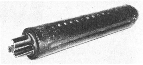
48. Hale rocket with canted nozzles for spin-stabilization.
The Congreve 14.5-kilogram (32-pound) war rocket model was copied from the original at the Royal Artillery Institution; the experimental Congreve incendiary rocket on display is a gift of that Institution. Hale’s 1844 design rocket, his 1862 experimental rocket, and the 1865 rocket are on loan from the Science Museum, London. The American Hale rocket is on loan from F. C. Durant III.
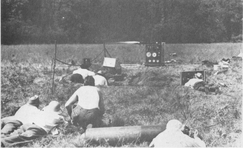
49. Static test of liquid-fuel rocket engine on American Rocket Society Test Stand No. 2.
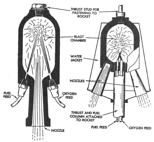
50. Two early types of liquid-fuel, rocket motors. Left, the original ARS motor; right, a four-nozzle motor for ARS No. 4 rocket.
The American Rocket Society (ARS) was the first organization in the United States dedicated to rocket research. The society was founded in New York City in March 1930 by G. E. Pendray and David Laser. The first successful ARS rocket was launched on May 13, 1933. The group continued to build and test rocket engines until the outbreak of World War II. After 1945, the ARS became a professional society for engineers involved in astronautics. The ARS joined with other aeronautical engineering groups to form the American Institute of Aeronautics and Astronautics in 1963.
The first liquid-propellant rocket engines built by the American Rocket Society were machined from blanks of heat-resistant, cast-aluminum alloy. Engine No. 1 powered the first two rockets designed and constructed by the ARS. It featured combustion chamber walls 12.7 millimeters (½ inch) thick and burned liquid oxygen and gasoline to produce a thrust of 27.22 kilograms (60 pounds). Liquid oxygen was pressurized by partial evaporation, while bottled nitrogen forced gasoline from the tank to the engine.
ARS Engine No. 4, like its predecessors, was mounted in the nose, rather than the tail, of the rocket. The engine featured a single combustion chamber and four nozzles. The nozzles directed the jet gases to the rear and slightly away from the top of the gasoline tank on which the engine was mounted. The rocket powered by this engine was tested on September 9, 1934. It rose several hundred feet, at which point one of the nozzles burned out, bringing the flight to a close. In 1938, ARS member James Wyld suggested a cooling system whereby propellants circulate through a jacket surrounding the combustion chamber. Engines using this system are termed “regeneratively cooled.” The first Wyld rocket motor tested developed 41 kilograms (90 pounds) of thrust for 13½ seconds. It proved so successful that Wyld and other members of the ARS founded Reaction Motors, Inc., to produce and sell rocket engines based on this design.
The performance of motors developed by the ARS prior to World War II was measured on a test stand with built-in fuel and oxidizer tanks and bottled nitrogen gas. The engine was mounted on a carriage, and connected to the stand’s propellant tanks by flexible metal hoses. Thrust was indicated on a pressure gauge. The stand was first used in 1938.
All American Rocket Society artifacts are from G. E. Pendray and the American Institute of Aeronautics and Astronautics.
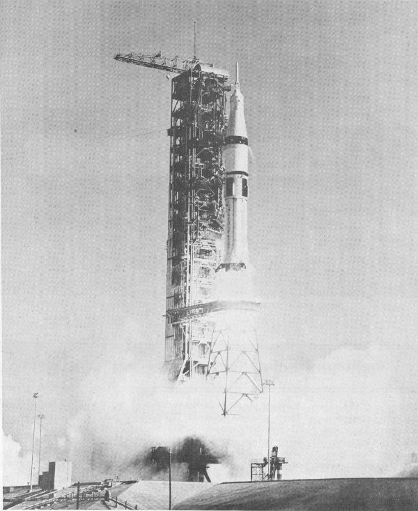
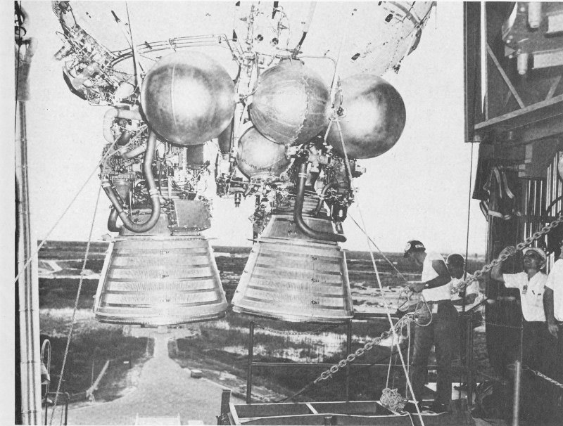
51. A two-stage Saturn 1B rocket powered by H-1 engine cluster lifts off carrying Skylab 4 astronauts, November 16, 1973.
The H-1 liquid-propellant rocket engine was an outgrowth of the LR-79 which served as the basic power plant for the USAF Thor missile. The H-1 was used in the 8-engine cluster of the first stage of the Saturn 1 and 1B launch vehicles.
The H-1 burns liquid oxygen and a grade of aviation kerosene to produce a total thrust of 92,986 kilograms (205,000 pounds). Each engine functions as an independent unit, with its own combustion chamber and turbopump, but fuel is drawn from common tanks.
The Saturn 1B was first launched on February 26, 1966, and most recently on July 15, 1975, in the launch of the U.S. crew of the Apollo-Soyuz Test Project.
It was developed by Rocketdyne, a division of North American Rockwell Corporation.
The engine on exhibit is from the National Aeronautics and Space Administration.
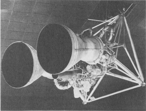
52. RL-10 engines used to power Centaur launch vehicle.
The RL-10 is an upper stage propulsion system that can be stopped and restarted in space. It is a regeneratively cooled engine which burns liquid hydrogen and liquid oxygen to produce 6800 kilograms (15,000 pounds) of thrust. RL-10s pioneered the use of liquid hydrogen as a rocket fuel. They powered the Centaur launch vehicles that boosted such craft as Surveyor and Viking into space. A six-engine cluster of RL-10s was also used to propel the S4 stage of the Saturn 1.
The RL-10 was developed by Pratt & Whitney Aircraft division of the United Aircraft Corporation.
The RL-10 engine is from the National Aeronautics and Space Administration.
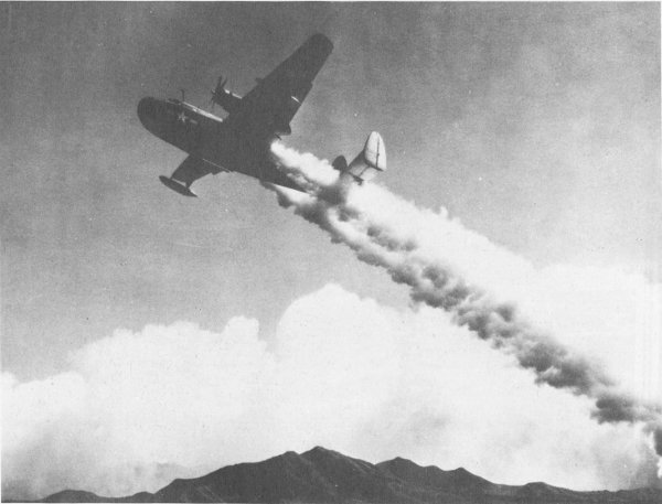
53. JATO-boosted Martin Mariner aircraft.
JATO (Jet Assisted Take-Off) rockets boost heavy aircraft from short runways or from high-altitude airports where long take-off runs are required. The development of more powerful airplane engines has reduced the use of JATOs in recent years.
The first American JATO units were tested at March Field, California, on August 12, 1941. Six solid-propellant engines, each developing 12.8 kilograms (28 pounds) of thrust, boosted a light plane piloted by Capt. Homer Boushey into the air on this occasion. These motors were designed and built by staff members of the Air Corps Jet Propulsion Research Project of the Guggenheim Aeronautical Laboratory of the California Institute of Technology.
During World War II, work continued on JATO prototypes: the M17G was developed by Reaction Motors, Inc., to provide 590 kilograms (1300 pounds) of thrust to assist the take-off of PBM flying boats; the M19G, also built by Reaction Motors, Inc., was fueled by gasoline with liquid oxygen as an oxidizer.
The liquid-propellant 25ALD1000, developed during World War II. produced 453 kilograms (1000 pounds) of thrust and burned red-fuming nitric acid as an oxidizer and aniline as a fuel. It was successfully used on a variety of aircraft, including the B-24, B-25, C-40, and P-38.
After the war ended, JATO engines were used on military aircraft such as the B-47 and F-84 in the United States, while in Britain the JATO Super Sprite became the first rocket engine to receive official type approval for quantity production.
The first U.S. JATO unit and the 25ALD1000 are gifts of the Aerojet General Division of the General Tire and Rubber Company. The M17G and M19G JATOs are from the Thiokol Chemical Corporation, and Rolls Royce, Ltd., provided the Super Sprite.
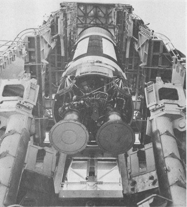
54. LR-87 engine in Titan on launch stand.
The LR-87 was a twin-chamber liquid-propellant rocket engine developed to power the Titan I intercontinental ballistic missile. The engine developed a total thrust of 136,078 kilograms (300,000 pounds) at sea level. It burned liquid oxygen and a grade of aviation kerosene. The combustion chambers were gimbal mounted to allow them to swivel, controlling the missile trajectory during the powered phase of flight. The engine was developed by Aerojet General Corporation.
55. LR-87 engine just after suspension in the museum.
The LR-87 on exhibit is from the U.S. Air Force.
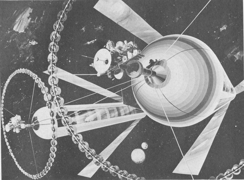
56. A 21st-century space colony in orbit between Earth and the Moon, as suggested by Dr. Gerard O’Neill of Princeton University. This colony could accommodate 200,000 persons, using solar energy for power and lunar or asteroid materials for construction. The teacup-shaped containers ringing the cylinder are agricultural stations, and the mirrors would direct sunlight into the interior, regulate the seasons, and control the day-night cycle.
During the first twenty years of the space age, all launch vehicles were propelled by solid or liquid chemical rockets; however, nuclear and electric rocket motors are needed to provide the higher thrusts and velocities required for possible future manned journeys to other planets. Robert H. Goddard, the American rocket pioneer, was the first to suggest the possibility of electric rocket motors, but it was not until 1964 that electric rockets were actually tested in space.
Two types of ion engines represent the most fully developed electric propulsion systems. In contact ion engines, a propellant gas (mercury or cesium, for example) is ionized, or given an electrical charge, by passage through a hot porous metal. The resulting ions are accelerated out of the engine by an electrical field. The charged ions are neutralized as they approach the nozzle to form an exhaust beam that imparts the thrust. Bombardment ion engines rely on the bombardment of the propellant gas by electrons from a cathode, or negative electrode, to create ions. The ions are accelerated from the engine in the same manner as in the contact ion engine.
This small contact ion engine produces .0009 kilogram (.002 pound) of thrust by passing vaporized cesium through hot tungsten. On Earth this amount of power is scarcely enough to lift a one-carat jewel an inch off a table, but in the frictionless vacuum of space, it is sufficient to provide attitude control for satellites. It can also accelerate a spacecraft to high interplanetary velocities by operating continuously for thousands of hours.
An ion engine of this type was first tested in space in 1964. On that occasion, it provided .0009 kilogram (.002 pound) of thrust for 2 hours, 10 minutes. It was able to control the attitude of the attached instrument package.
This ion engine is a gift from Electro-Optical Systems, Inc., the company that developed it.
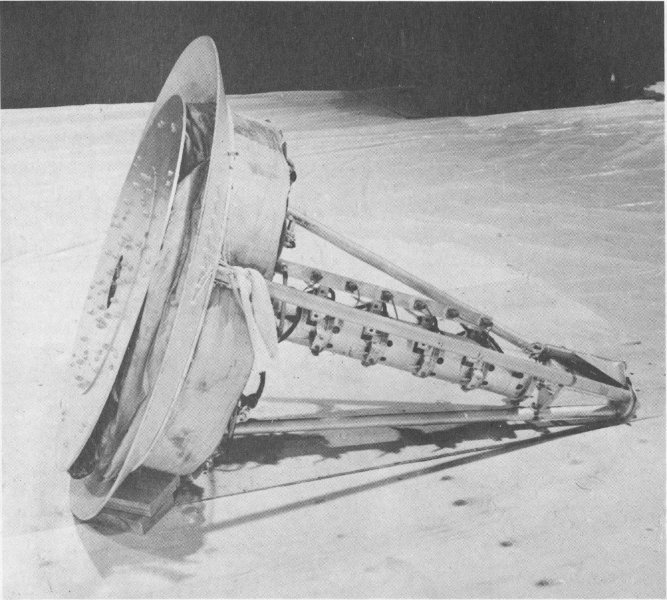
57. The Project Orion test vehicle was used to explore the feasibility of a unique type of propulsion which utilized successive nuclear explosions behind the rear pusher plate.
Project Orion was an attempt to solve the problems of propulsion for long-term manned journeys to other planets by creating an engine that would use successive nuclear explosions to propel very large space vehicles. The Orion spacecraft was designed to carry many small nuclear explosive systems which would be ejected sequentially from the rear of the vehicle. These units would explode some distance behind the spacecraft. The expanding debris, in the form of high-velocity, high-density plasma, would strike a pusher plate at the rear of the Orion vehicle.
Work on Project Orion was halted in 1963 when the Limited Nuclear Test Ban Treaty, which prohibited atmospheric tests of the propulsion system, was signed.
The Project Orion Test Vehicle—on display—demonstrated the basic principle of intermittent thrust from explosive charges. Test data provided by this model would have assisted engineers in developing the full-scale spacecraft.
The test vehicle carried five high-explosive plastic charges which were ejected from the rear of the craft. Compressed nitrogen powered the ejection system. Each charge was attached to the vehicle by a .9-meter (3-foot) cord. A microswitch exploded the individual packages. The Project Orion Test Vehicle was first flown successfully in October 1959.
From the Gulf Energy and Environmental Systems, Inc.
Although this engine is a liquid-propellant rocket, it substitutes a series of small combustion chambers and nozzles for the traditional single large chamber and nozzle to achieve additional thrust. This innovative combustion system features chambers and nozzles mounted on an annular ring at the base of the engine. Thrust is derived from the expansion of the exhaust gases against a large segmented plug in the center of the engine. Flight control is achieved by varying the amount of propellant introduced into the individual chamber sections. The engine on exhibit burned liquid oxygen and kerosene to provide a thrust of 22,680 kilograms (50,000 pounds).
The plug-nose rocket engine was developed at the General Electric Company’s Malta Test Station in 1961.
The engine on exhibit is from the New York State Atomic and Space Authority.
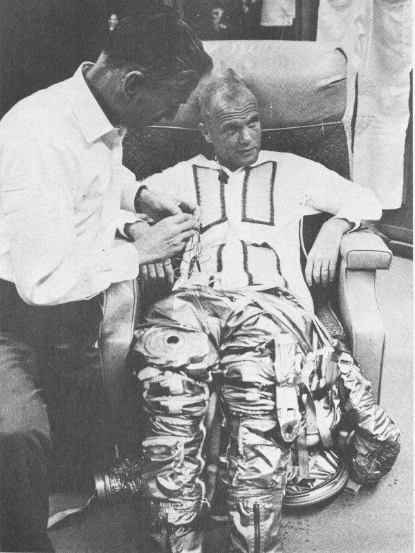
58. Astronaut John Glenn is assisted with his suiting-up.
Modern space suits are direct descendants of the simple “pressure suits” designed as early as 1907 for deep-sea divers. In 1911 an English respiratory physiologist, J. S. Haldane, proposed the use of an oxygen pressurized suit for ascent to high altitudes. The first U.S. patent was granted for a pressure suit in 1918.
Through the early 1960s, all such suits were pressure containers. Project Mercury astronauts wore suits adapted from the U.S. Navy MK-IV pressure suit. It consisted of an inner layer of neoprene-coated fabric and a restraint layer of aluminized nylon fabric. The garment design provided a fair degree of mobility, although the suit could not bend with the full hinge motion of the human elbow or knee because it folded in at the joints, reducing overall volume and increasing internal pressure. The Mercury suit would have been pressurized only if spacecraft cabin pressure had been lost.
Space suits require a great deal of sophistication. They must meet many vital criteria, 47 including low leakage, thermal control, comfort, stowage, and protection from micrometeoroid strikes.
Gemini 4 was the first American mission to explore the problems of man functioning outside his spacecraft, with only his space suit for protection. This extravehicular activity required the space suit to be a prime system rather than a precautionary measure.
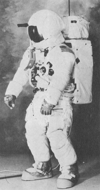
59. Apollo space suit.
Designed and created primarily for moon-walking, the 28.6-kilogram (63-pound) Apollo space suits, with backpack environmental and communication systems, enabled the lunar astronauts to dispense with the tether used on the Gemini “spacewalks.” The suit’s 21 layers are materials such as teflon fabric, nonwoven dacron, and aluminized mylar. These alternating layers of specialized materials protected the astronauts from the extreme temperatures of space and possibility of micrometeroids striking. Boots and gloves contain a stainless steel cloth to protect against abrasion. Suits had to fit the wearers so precisely that 67 anthropometric measurements were required of each astronaut.
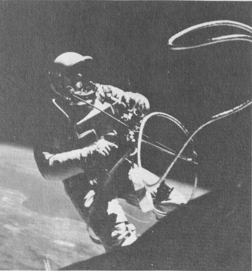
60. Astronaut White takes the first “spacewalk” with only his suit for protection from the space environment.
When the astronauts ventured outside the spacecraft and explored the lunar surface, the following equipment was worn under the suit: a fecal containment system for emergency containment of solid-waste material; a liquid-cooling garment; a bio-belt assembly, urine collection and transfer system. Together with a portable life-support system, this constituted the complete Environmental Mobility Unit (EMU).
The liquid-cooling garment consists of an outer layer of nylon spandex material, a network of polyvinyl-chloride tubing, and a nylon-chiffon comfort liner. Even spacing of the plastic tubing permitted the efficient transfer of body heat to the cooling liquid (water) as it circulated through the suit.
The bio-belt assembly, worn over the liquid-cooling garment, contains preamplifiers for sensors placed next to the skin. The sensors acquired electrical signals which determined respiration rate and electrocardiograms of the astronauts. The preamplifiers relayed the signals to the spacecraft telemetry system for transmission to Earth.
The urine collection and transfer assembly provided for emergency containment of liquid waste when spacecraft facilities were not available. Liquid waste was subsequently transferred from the collection assembly to the spacecraft waste-management system.
The portable life-support system (PLSS) created and maintained a livable atmosphere inside an astronaut’s space suit during activity on the lunar surface. Worn as a backpack, the PLSS could be used for as long as four hours at a time.
The PLSS supplied oxygen for breathing purposes, suit pressurization, and ventilation. It also removed contaminants from oxygen circulating through the suit and supplied water and oxygen for body cooling. Conversion of exhaled carbon dioxide into oxygen was accomplished through a lithium-hydroxide cartridge also contained in the PLSS. An emergency supply of oxygen was contained in the oxygen purge system mounted on top of the PLSS.
When fully charged, the pack weighs 38 kilograms (84 pounds) on Earth or 6.3 kilograms (14 pounds) on the Moon.
The space suit on exhibit is from the National Aeronautics and Space Administration.
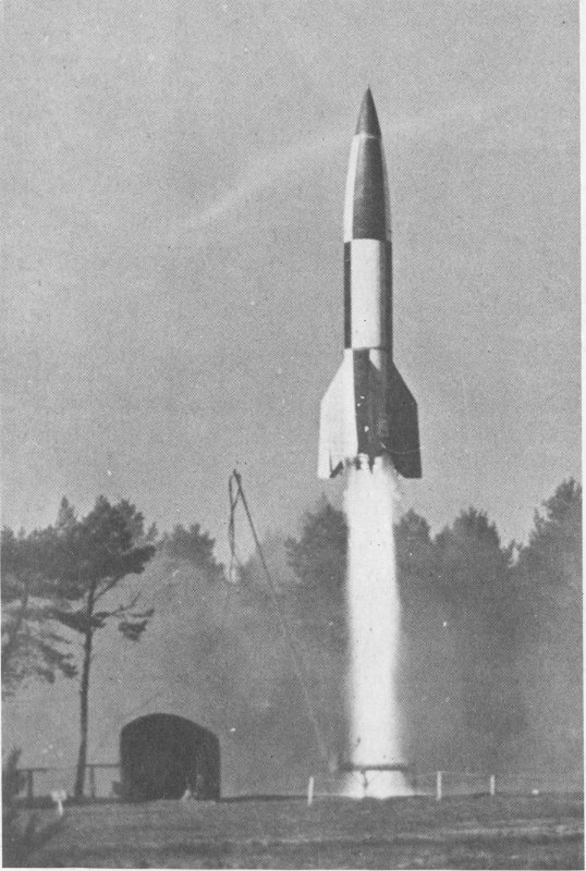
61. British-supervised postwar launch of V-2 in Germany.
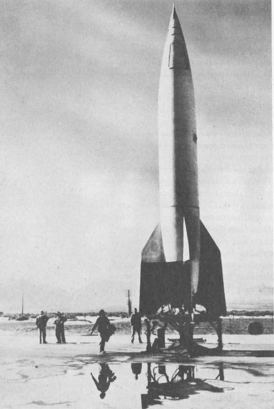
62. V-2.
The German V-2, originally designated A-4, represents the beginning of modern rocketry. The V-2 was the first proof that large rockets of the sort described by the space-flight pioneers of the early twentieth century could be successfully built and flown. It was also the forerunner of the intercontinental ballistic missile system.
Developed by a team of engineers working under the direction of Dr. Wernher von Braun at Peenemunde, Germany, the V-2 work laid the foundation for the Redstone missile through the Saturn series of space launch vehicles.
Four-thousand V-2s were fired against Allied targets in England and on the continent in 1944 and 1945. After World War II, captured V-2 rockets were used to train American technicians in missile launch procedures and to carry the first payloads of scientific instruments into the upper atmosphere in the United States.
The operational V-2 rocket structure consisted of three sections. The nose housed the warhead and control mechanisms. The fuel tanks carried liquid oxygen and alcohol propellants. The rocket engine, turbopumps, and control surfaces were contained in the tail section.
Jet deflector vanes positioned in the stream of exhaust gases and external vanes maintained attitude and directional control during the powered portion of flight.
| Length | 14 m. (46 ft., 1 in.) |
| Diameter | 1.6 m. (5 ft., 5 in.) |
| Propellants | Alcohol and liquid oxygen |
| Thrust | 25,400 kg. (56,000 lb.) |
| Velocity | 5633 km./hr. (3500 mi./hr.) |
| Altitude | Peak of operational trajectory, 89 km. (55 mi.) |
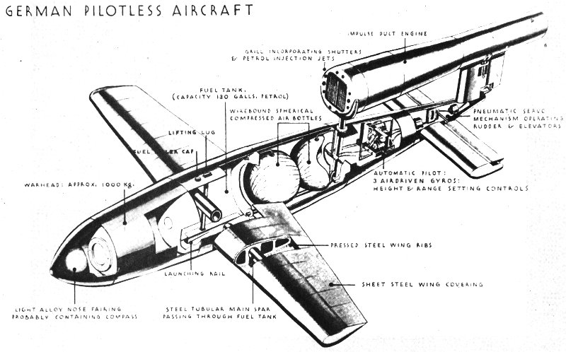
63. Illustration from World War II intelligence report.
The German-developed V-1 was an automatically controlled pilotless aircraft for use against Allied cities during World War II.
The missile was launched from ground ramps. Once in the air, automatic controls on board the craft took over. The V-1 climbed to a predetermined altitude, followed a compass course, and dove to the ground after a preset distance had been covered.
This mid-wing monoplane was powered by a unique pulsejet engine above the rear portion of the fuselage.
The relatively low speed of the missile made it easy prey for antiaircraft guns or fighters.
The V-1 on exhibit is from the U.S. Air Force, Park Ridge Depot.
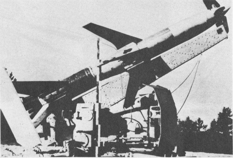
64. Rheintochter R-I (Rhine Maiden).
The Rheintochter I (Rhine Maiden) was intended for use against Allied bomber formations late in World War II. The German ground-to-air rocket was fin-stabilized, and controlled by radio. The flight of the two-stage vehicle was controlled by the four movable vanes on the nose of the craft.
The first stage carried the missile away from the launching rail, while the second stage brought the missile up to full speed and propelled it to the target.
Both the booster and sustainer engines used solid fuel. After a six-tenths of a second burn, the booster dropped off and the sustainer motor ignited. The missile warhead was housed at the rear of the sustainer stage. Exhaust gases were expelled through six nozzles located between the main fins.
The program was abandoned in December 1944, after 82 Rheintochter I rockets had been test fired. By then it had become apparent that the missile could not reach the operational altitude of modern bomber aircraft.
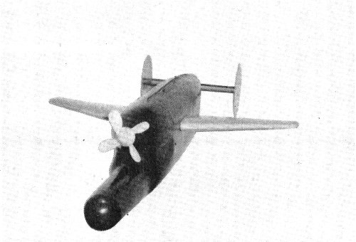
65. Hs-298.
The Hs-298 was designed to combat the Allied bomber threat to wartime Germany. This air-to-air missile could be launched from either fighter or bomber aircraft and was in quantity production early in 1945.
It carried 45.4 kilograms (100 pounds) of high explosives that were detonated by proximity fuse when the missile was within 9.1 meters (30 feet) of an enemy airplane.
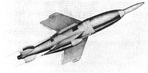
66. X-4.
The fin-stabilized X-4 air-to-air missile was guided to its target by means of electrical impulses which passed through two wires connecting the rocket to the launch aircraft until detonation. Once the missile was on its way to the target bomber, the fighter pilot directed its course with a separate small control stick in his cockpit. Because the control wires streamed out ahead of the launching aircraft, the pilot was prevented from evasive maneuvering.
Launched from German fighter aircraft, usually a FW-190, the X-4 was powered by either a solid-propellant engine or a bi-propellant liquid-rocket engine. It carried a 20-kilogram (44-pound) warhead.
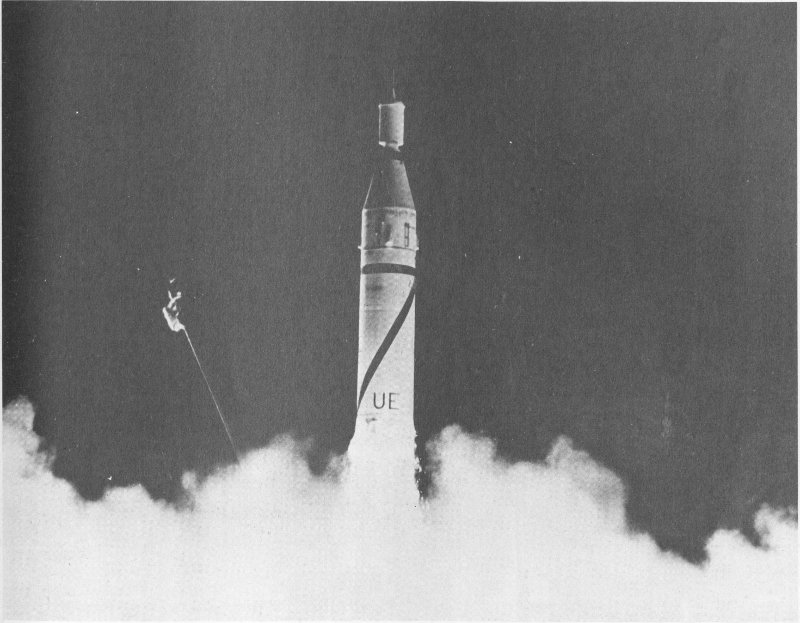
67. Jupiter-C launches the first American satellite, January 31, 1958.
Jupiter-C carried the first successful American artificial earth satellite, Explorer 1, into orbit on January 31, 1958. Jupiter-C launched additional Explorer satellites on March 26 and July 26, 1958.
Jupiter-C, or Juno 1, is a modified version of the Redstone Ballistic Missile and a direct descendant of the V-2 (A-4) rocket developed in Germany during the second World War.
The vehicle’s main stage is powered by a rocket engine burning liquid oxygen and a hydrazine mixture. The second and third stages are contained in the “tub” on the nose of the rocket. Both use scaled-down Sergeant solid-propellant rockets: eleven in the second stage and three in the third. A final Sergeant motor is attached to the base of the satellite to provide the velocity necessary to place the vehicle in orbit. An electric motor spun the entire “tub” prior to launch and during the climb into space in order to stabilize the satellite.
The Jupiter-C was built by the U.S. Army Ballistic Missile Agency.
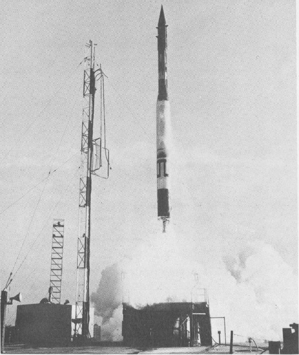
68. Three-stage Vanguard launch vehicle boosts the second American satellite into Earth-orbit, March 17, 1958.
Standing 21.6 meters (70.8 feet) high and weighing more than 10,000 kilograms (20,000 pounds), the Vanguard launch vehicle successfully orbited three satellites. The first was Vanguard 1, launched on March 17, 1958.
The rocket has three stages. The first-stage motor, burning kerosene and liquid oxygen, operated for 2 minutes and 20 seconds. The second stage carried the vehicle to an altitude of 210 kilometers (130 miles), propelled by white-fuming nitric acid and unsymmetrical dimethylhydrazine (UDMH). With propellants exhausted, the upper stages then coasted to 480 kilometers (300 miles) above the surface of the Earth where the solid-propellant third-stage motor fired to place the satellite into orbit.
The Vanguard was designed and built by the Martin Company for the U.S. Naval Research Laboratory.
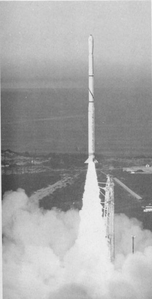
69. Four-stage Scout vehicle launches satellite from the Western Test Range, California.
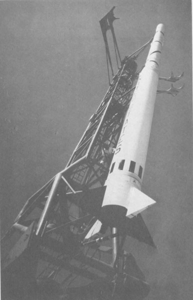
70. Scout in vertical position prior to the launch of an Explorer science satellite, April 29, 1965.
On February 16, 1961, Scout became the first solid-propellant vehicle to orbit a satellite (Explorer 9). It is a four-stage launch vehicle that can perform a variety of space and reentry research tasks. Its relatively low cost has made it a popular choice for many satellite programs, including Transit navigation satellites, the Small Astronomy and Small Scientific Satellites, the Beacon Explorer, Hawkeye, Micrometeoroid, Meteoroid Technology, and Solrad satellites. The rocket has also been used extensively to launch foreign satellites. ANS-A (Netherlands), GRP-A (Germany), UK-5 (England), Eole (France), San Marco 5 (Italy), and the ESRO satellites for the European Space Research Organization (now European Space Agency) have all gone aloft aboard Scout launch vehicles.
The satellite in the nose of the Scout on exhibit is an INJUN/Air Density Explorer identical to that launched from Wallops Island, Virginia, on August 8, 1968.
Scout was built by the LTV Aerospace Corporation for the National Aeronautics and Space Administration and the Department of Defense.
The Scout is from the National Aeronautics and Space Administration and LTV Aerospace Corporation.
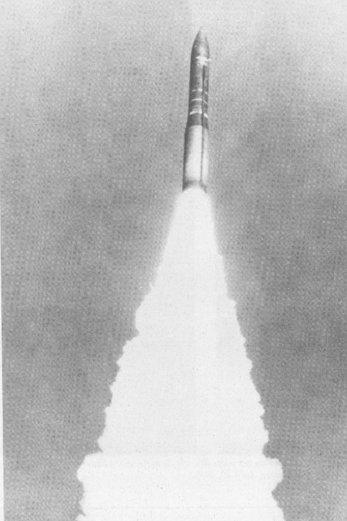
71. Minuteman III launch from Vandenberg AFB, California.
The Minuteman III is the standard U.S. land-based intercontinental ballistic missile. This three-stage solid-propellant missile is launched from underground silos that are 24.4 meters (80 feet) deep and 3.7 meters (12 feet) in diameter. These missiles can be launched either from underground control centers or by an airborne launch control center installed in KC-135 aircraft.
Minuteman III was first test-fired on August 16, 1968, and has since replaced earlier Minuteman series ICBMs in the operational system. This missile was designed by Boeing for the Air Force Strategic Air Command.
This missile is from the US. Air Force and Boeing Aerospace Corporation.
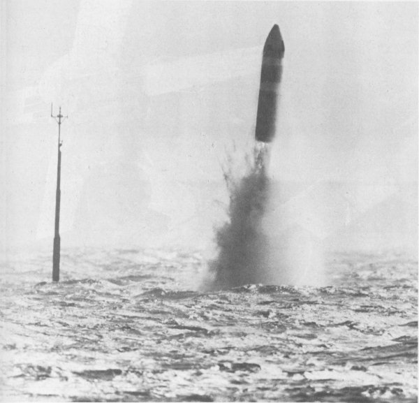
72. Launch of Poseidon from nuclear-powered submarine.
This two-stage solid-propellant Fleet Ballistic Missile is launched underwater from nuclear-powered submarines. The Poseidon is launched by compressed air, with first-stage ignition just after the missile is clear of the hull. Poseidon carried the Mk-3 Multiple Independently targeted Reentry Vehicles (MIRV)—thermonuclear weapons which enable a single missile to cover a number of targets.
The first successful test flight of Poseidon was from Cape Canaveral on August 16, 1968, and the first submarine launch was from the U.S.S. James Madison on August 3, 1970.
The Poseidon C-3 is from the U.S. Navy and Lockheed Aircraft Corporation.
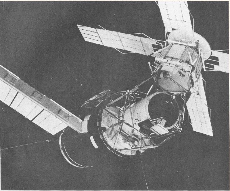
73. Closeup view of Skylab space-station cluster photographed against a black-sky background from the Skylab 3 Command Module during the “fly around” inspection prior to docking.
Launched into earth orbit on May 14, 1973, Skylab was a research center that housed three-man crews on three different visits to the space station. The longest mission lasted nearly three months.
Equipment and experiments on board the orbiting station were designed to accommodate four areas of research: earth observation to further knowledge of natural resources and the earth’s environment; solar observation to increase understanding of solar processes and influences on earth’s environment; study of the effects of long duration weightlessness on man, basic biological processes and adaptability to space flight conditions; and experiments in processing of materials under the unique conditions of weightlessness and vacuum environment of space. All missions were highly successful in obtaining data and photographs.
Skylab consisted of four major components: the Orbital Work Shop (OWS), Airlock Module (AM). Multiple Docking Adapter (MDA), and the Apollo Telescope Mount (ATM).
The cylindrical Orbital Work Shop is 15 meters (48 feet) in length and 6.5 meters (22 feet) in diameter. The workshop is divided into two major areas by an open-grid partition. By wearing special shoes, 57 the astronauts can use this grid to anchor themselves in the weightlessness of space. The lower portion contains the crew quarters, food preparation and dining areas, washroom, and waste processing and disposal facilities.
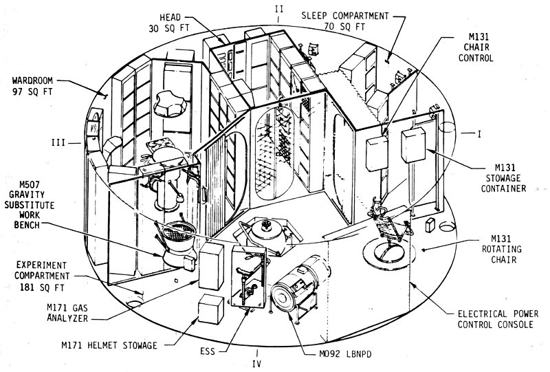
74. Orbital Workshop crew-quarters installations.
The upper portion contains a large work-activity area, water-storage tanks, food freezers, film vaults, and experiment equipment.
The Airlock Module enabled spacesuited crew members to make excursions outside the Skylab to replace or adjust equipment, change film, or carry out other extra-vehicular activities. This capability was vital to emergency repairs by the astronauts on the first mission. The Airlock Module was attached to the OWS and passage to the module was accomplished through a hatch which connected the module to the interior of the workshop. When an astronaut entered the module, he would vent the atmosphere of the module into space. When the pressure in the airlock reached zero, the crew member could open the outer hatch and float out into space.
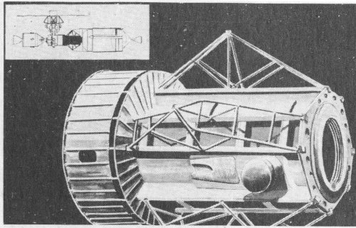
75. Airlock Module.
The Multiple Docking Adapter (MDA) was used by crews arriving or departing from the Skylab workshop. The Apollo command/service modules delivered crews to the MDA from which the astronauts could enter Skylab through the hatch in the docking port. In an emergency, two command/service modules could dock at the MDA. The MDA also held equipment for earth resources multispectral photography, materials processing, and astronomy. The Apollo Telescope Mount (ATM) was on top of and controlled by the MDA. It contained six astronomical instruments to obtain information about the Sun.
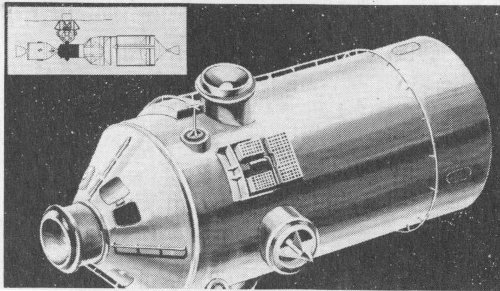
76. Multiple Docking Adapter.
Solar energy is the prime source of electric power on Skylab. Two systems of solar electric-cell arrays—one wing on the OWS and four panels on the ATM—deployed after the Skylab reached orbit. Principal contractors: OWS—McDonnell Douglas Astronautics Company; AM—McDonnell Douglas Astronautics Company; MDA—Martin Marietta Aerospace.
The Skylab components on display were presented to the museum by the National Aeronautics and Space Administration.
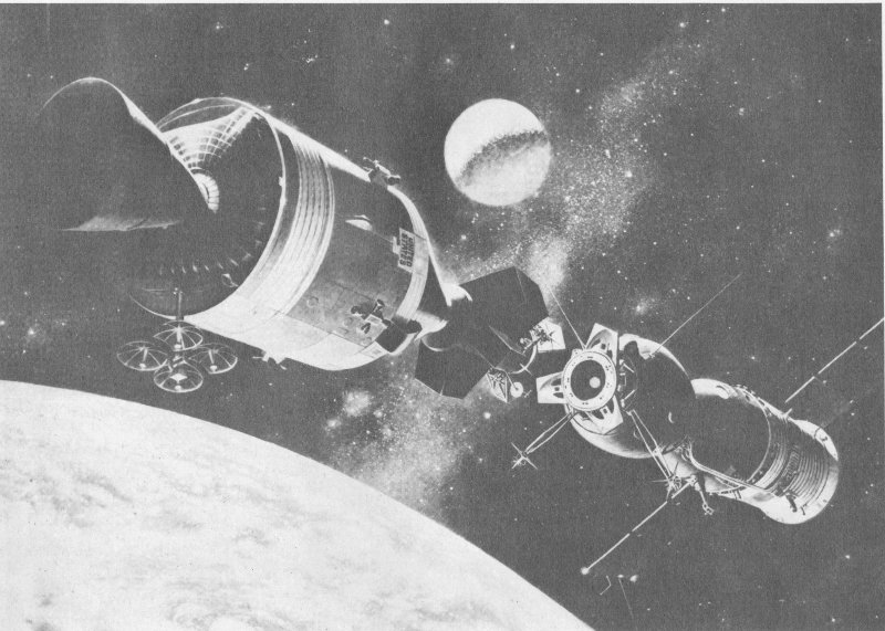
77. Artist conception of the Apollo-Soyuz Test Project rendezvous.
On May 24, 1972, President Richard Nixon and Aleksey Kosygin, Chairman of the USSR Council of Ministers, signed an agreement “concerning cooperation in the exploration and use of outer space for peaceful purposes.” The signing represented a formal endorsement of negotiations that had been held between the two nations over several years. The agreement established the Apollo-Soyuz Test Project (ASTP) to develop and fly a standardized docking system “to enhance the safety of manned flight in space and to provide the opportunity for conducting joint scientific missions in the future.”
On July 15, 1975, the afternoon countdown for the Soviet launch was completed and Soyuz lifted off from the Baykonur complex near Tyuratum in Central Asia, some 3200 kilometers (2000 miles) southeast of Moscow. Soyuz carried cosmonauts Alexey Leonov and Valeriy Kubasov.
Taking advantage of Apollo’s larger fuel supply for maneuvering, Apollo followed Soyuz into orbit 7½ hours later. Apollo was launched atop a Saturn 1B from Kennedy Space Center, Florida.
After careful maneuvering, the two craft linked up around noon on July 18. Some 225 kilometers (140 miles) above Earth, the astronauts and cosmonauts visited each other’s craft, performed joint experiments, and made further tests of the new docking system.
Following the undocking Saturday, Apollo fired its engines briefly and moved away from Soyuz. Soyuz descended from orbit and landed in the south-central USSR early Monday morning, July 21.
Astronauts Stafford, Slayton, and Brand remained in orbit conducting research and making science demonstrations. Splashdown into the Pacific Ocean occurred in late afternoon on Thursday, July 24.
The historic ASTP mission was accomplished by using existing systems and a new docking module. The Apollo spacecraft was made available when the lunar-landing program was curtailed. Since the command module was built with a docking system designed to work only with U.S. spacecraft, a method of incorporating the new docking system had to be devised.
A second important problem was the difference between the spacecraft atmospheres. The Apollo used a pure oxygen atmosphere at about one-third of the atmospheric pressure on earth’s surface; Soyuz used a nitrogen-oxygen mixture at normal atmospheric pressure. To permit 59 crews to pass from Soyuz to Apollo without suffering from the “bends” (a painful condition experienced when nitrogen gas bubbles form in the body fluids), engineers had to design an airlock to equalize the pressure.
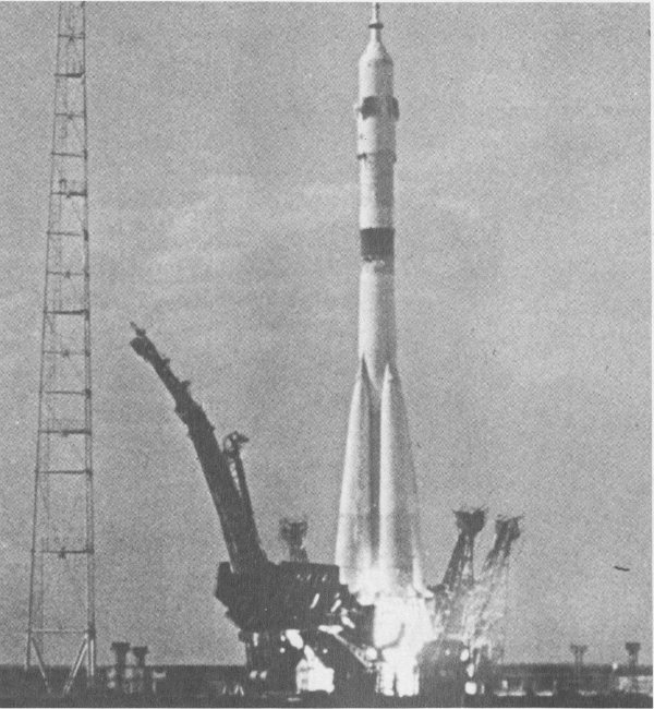
78. The Soviet Soyuz atop a three-stage launch vehicle lifts off July 15, 1975, to begin the joint US-USSR space mission.
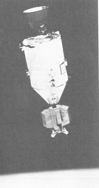
79. Overhead view of Soyuz in orbit, photographed from the Apollo spacecraft during the joint mission. The three major components of the Soyuz are the spherical Orbital Module, the bell-shaped Descent Vehicle, and the cylindrical Instrument-Assembly Module from which two solar panels protrude.
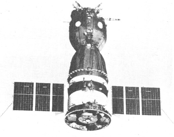
80. View of Apollo spacecraft as seen in Earth-orbit from Soyuz. The Command/Service Module and Docking Module are contrasted against a black-sky background and the horizon of the Earth is below.
The docking module, 3 meters long and 1.5 meters in diameter (10 feet long and 5 feet in diameter), also solved the problem of incompatible docking mechanisms by carrying the new docking system on one end and a system compatible with Apollo on the other.
Prime contractor for Apollo Command Module, Service Module, and Docking Module was Rockwell International.
The Apollo hardware is from the National Aeronautics and Space Administration, and the Soyuz spacecraft is on loan from the USSR Academy of Sciences.
| Apollo | |
|---|---|
| Command module | |
| Base diameter | 3.90 m. (12.8 ft.) |
| Length | 3.66 m. (12 ft.) |
| Weight | 5896 kg. (13,000 lb.) |
| Service module | |
| Diameter | 3.9 m. (12.8 ft.) |
| Length | 6.71 m. (22 ft.) |
| Weight at launch | 24,947 kg. (55,000 lb.) |
| Docking module | |
| Diameter | 1.52 m. (5 ft.) |
| Length | 3.05 m. (10 ft.) |
| Weight | 1882 kg. (4155 lb.) |
| Soyuz | |
| Orbital module | |
| Diameter | 2.29 m. (7.5 ft.) |
| Length | 2.65 m. (8.7 ft.) |
| Weight | 1224 kg. (2700 lb.) |
| Descent module | |
| Diameter | 2.29 m. (7.5 ft.) |
| Length | 2.20 m. (7.2 ft.) |
| Weight | 2802 kg. (6200 lb.) |
| Instrument module | |
| Diameter | 2.77 m. (9.75 ft.) |
| Length | 2.29 m. (7.5 ft.) |
| Weight | 2654 kg. (5850 lb.) |
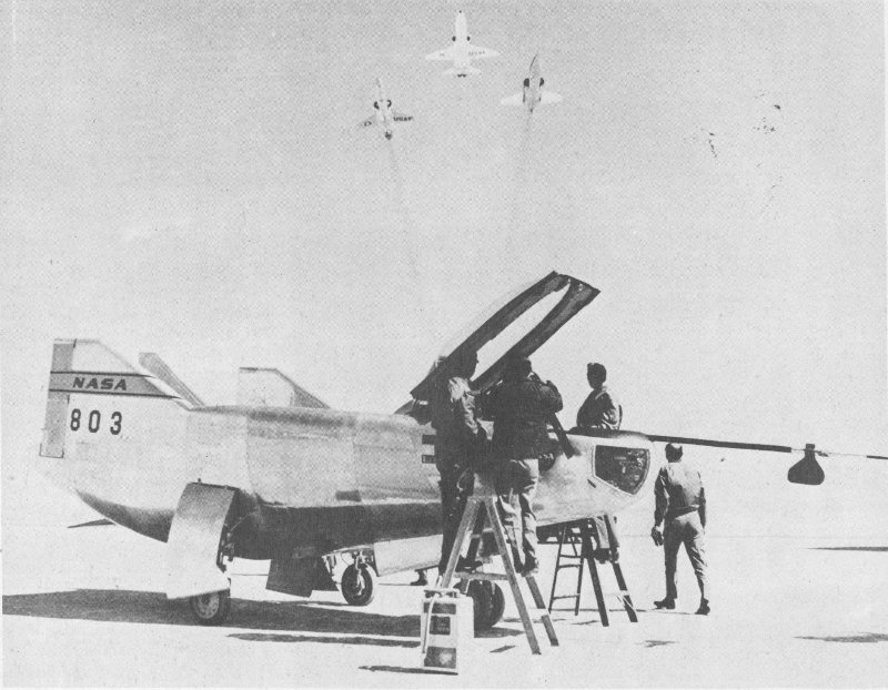
81. Three chase planes salute the M2-F3 wingless lifting body following one of its rocket-powered flights. The blunt-nosed M2-F3 achieves its aerodynamic lift from the shape of its body.
This wingless craft is called a lifting body, because it derives its lift from the fuselage rather than from wings. Removing the wings reduces the weight of the craft, but adds significant control problems. The lifting body concept was developed early in the last decade to explore the problems of aerodynamic heating and vehicle control during reentry from earth orbit. These are the problems that will be especially critical in the space shuttle of the 1980s.
The M2-F3 tested flight behavior of wingless craft over a wide range of speeds.
The M2-F3’s forerunner, the M2-F2, made 16 flights—all unpowered—between July 1966 and May 1967. On May 10, it crashed on landing, partly due to control instability. The craft was rebuilt, and the center fin was added. This modification effectively solved the control problem, and the new craft, designated M2-F3, logged 27 more flights by December 1972. Some of the M2-F3’s flights were powered by a 3630-kilogram (8000-pound) thrust rocket which boosted the craft to a higher altitude.
The M2-F3 was launched from a B-52 bomber at a height of about 13,300 meters (45,000 feet) and a usual speed of 730 kilometers (450 miles) per hour. The maximum altitude achieved was 21,800 meters (71,500 feet). The M2-F3’s record speed was 1718 kilometers (1066 miles) per hour. The M2-F3 was built by Northrop.
The craft on exhibit is from the National Aeronautics and Space Administration.
| Length | 6.8 m. (22 ft., 2 in.) |
| Span | 2.9 m. (9 ft., 7 in.) |
| Height | 2.5 m. (8 ft., 10 in.) |
| Weight | 2720 kg. (6000 lb.) empty; 4540 kg. (10,000 lb.) fueled |
| Speed | 1718 km. per hr. (1066 m. per hr.) max. achieved |
| Altitude | 21,800 m. (71,500 ft.) max. achieved |
| Mach number | 1.5 max. achieved |
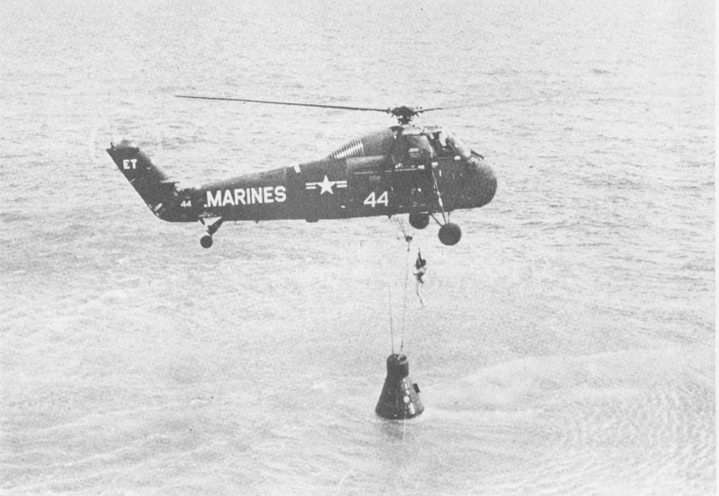
82. Marine helicopter hovers over Freedom 7 after the spacecraft carried the first American into space. Astronaut Shepard dangles in body harness as he is hoisted to helicopter.
On May 5, 1961, Alan B. Shepard, Jr., became the first American in space. He flew this Mercury spacecraft, Freedom 7, through a 15-minute, 22-second sub-orbital, or ballistic, space flight.
A Redstone booster, burning liquid oxygen and hydrazine-base fuel, lifted Freedom 7 from the launch pad at Cape Canaveral. The vehicle’s single engine developed 35,380 kilograms (78,000 pounds) of thrust.
The structure of the Mercury is titanium, covered with steel and beryllium shingles. The heat shield at the base of the spacecraft is of beryllium.
The heat shield served as a “heat sink” by storing the heat created by the spacecraft’s reentry into the earth’s atmosphere. The spacecraft reached the ocean before the heat could penetrate the interior of the craft. (Later flights used ablative heat shields, which protected the spacecraft by vaporizing and burning away during reentry.)
Freedom 7 traveled at a maximum speed of 8335 kilometers (5180 miles) per hour, going 485 kilometers (302 miles) downrange. The maximum altitude was 187 kilometers (116 miles).
Prime contractor for Mercury was the McDonnell Aircraft Company.
The Freedom 7 is from the National Aeronautics and Space Administration.
| Diameter | 2 m. (6 ft., 6 in.) max. |
| Length | 2.8 m. (9 ft., 2 in.) at launch |
| Weight | 1660 kg. (3650 lb.) at launch; 1100 kg. (2422 lb.) as exhibited |
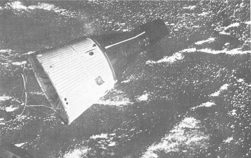
83. This photo of Gemini 7 was taken through the hatch window of the Gemini 6 spacecraft during rendezvous maneuvers 260 kilometers (160 miles) above Earth.
Gemini 7 was launched on December 4, 1965, carrying astronauts Frank Borman and James Lovell, Jr., into a two-week flight. Gemini 6 and 7 accomplished the first manned rendezvous in space. It was an historic flight for the United States’ manned space program and an important step in the preparation for the Apollo lunar flights.
The story of the Gemini 7/6 mission had begun two months earlier. The October launch of Gemini 6 had to be delayed when Gemini 6’s Agena target vehicle failed to reach orbit. It was then decided that Gemini 6 would attempt to rendezvous with Gemini 7. Eight days after the launch of Gemini 7, Gemini 6 was ready. But once again, the launch had to be delayed—this time an electrical plug became detached from the Titan booster prematurely, shutting down the engines. Finally, on December 15, Gemini 6’s Titan II launch vehicle lifted off. Gemini 6 began a 6-hour chase to catch Gemini 7, which was in a near-circular orbit 300 kilometers (186 miles) high.
Gemini 6’s launch put it 1175 kilometers (730 miles) behind Gemini 7 in an orbit which varied from 161 to 272 kilometers (100 to 169 miles) in height. By flying in a lower altitude orbit, Gemini 6 astronauts Wally Schirra and Thomas Stafford circled the Earth at a higher velocity, slowing down as they moved to match speed with Gemini 7 at the higher orbit. Finally, Schirra jockeyed the Gemini 6 spacecraft to within 30 centimeters (1 foot) from Gemini 7.
They stayed in formation for four revolutions while all four pilots practiced maneuvering. Then Gemini 6 broke off and reentered, splashing down on December 16, 1965.
Gemini 7 went on to complete its 14-day mission which set a record for the longest U.S.-manned space flight which stood until the first Skylab mission. Gemini 7 splashed down on December 18.
Prime contractor for Gemini was the McDonnell Aircraft Company.
Gemini 7 is from the National Aeronautics and Space Administration.
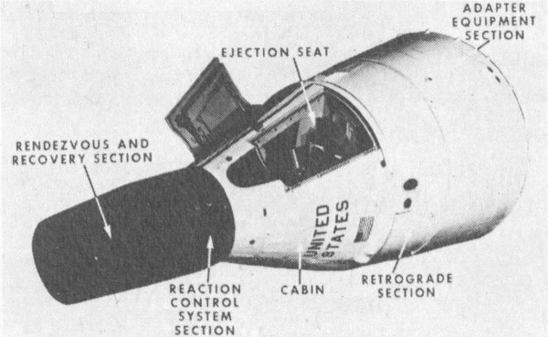
84. The Gemini spacecraft.
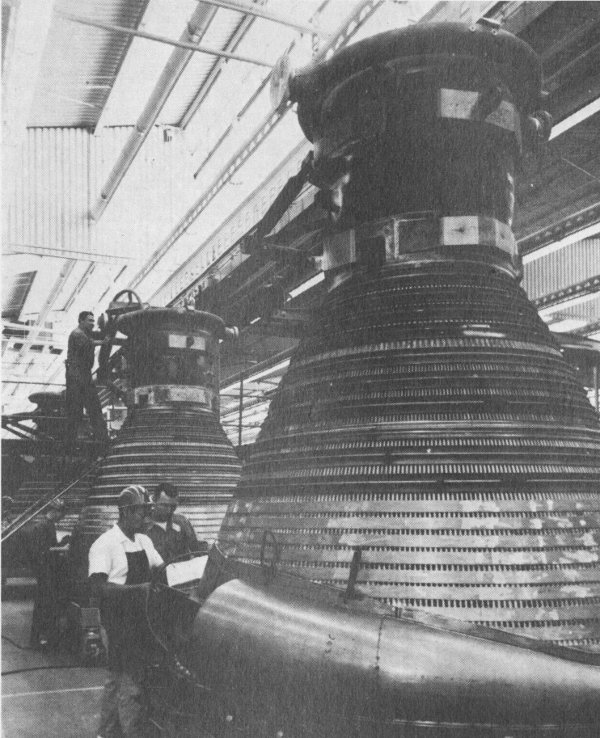
85. Thrust chambers of the F-1 rocket engine on the manufacturing line.
Five F-1 engines powered the first stage of the Saturn 5 launch vehicle that launched the manned Apollo spacecraft to the Moon. These engines developed a total thrust of 3.5 million kilograms (7.6 million pounds). They burn liquid oxygen and a form of kerosene at a rate of 13,475 liters (3560 gallons) per second.
The propellants are supplied to the thrust chambers by turbopumps driven by gas generators that use a fuel-rich mixture ratio of the same propellants used in the engine.
The F-l was developed and produced by Rocketdyne, a division of Rockwell International, under the technical direction of the National Aeronautics and Space Administration, Marshall Space Flight Center, Huntsville. Alabama.
The engine on exhibit is from the National Aeronautics and Space Administration.
| Function | Cluster of five providing 3.4 million kg. (7.5 million lb.) of thrust for Saturn 5 first stage |
| Thrust | 690,000 kg. (1,522,000 lb.) |
| Propellants | Kerosene (fuel) and liquid oxygen (oxidizer) |
| Length | 5.8 m. (19 ft.) with nozzle extension |
| Diameter | 3.8 m. (12 ft., 4. in.) with nozzle extension |
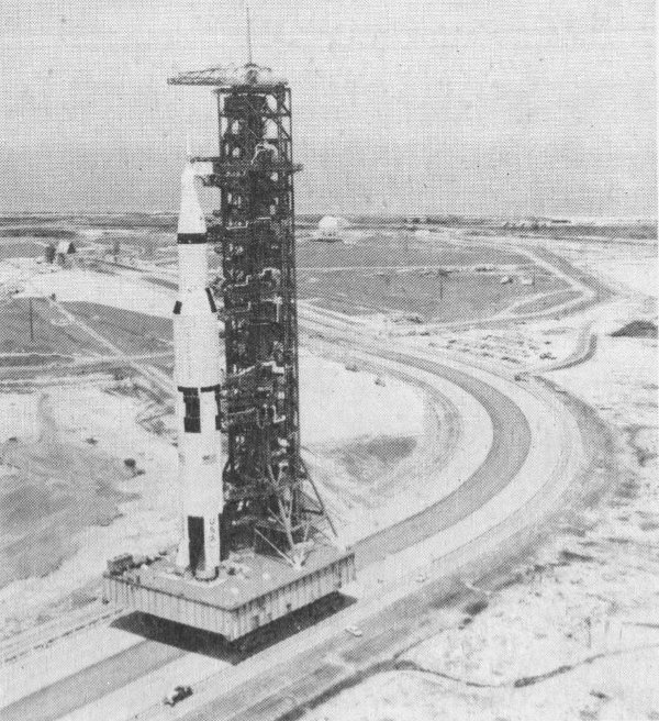
86. The first Apollo/Saturn 5 space vehicle on its way to the launch pad.
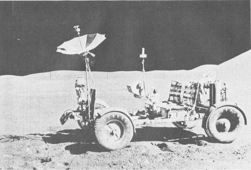
87. The Apollo 15 Lunar Roving Vehicle was the first motor vehicle on the Moon.
The Lunar Roving Vehicle (LRV) is a spacecraft designed to carry two astronauts, their life-support systems, scientific equipment, and lunar samples on the airless, low-gravity surface of the Moon.
Lunar Roving Vehicles were used on Apollo missions 15, 16, and 17 and were driven a total of 90 kilometers (56 miles) on the Moon.
The crew of Apollo 15, the first to use an LRV, drove their vehicle 27.9 kilometers (17.3 miles) at speeds up to 19-21 kilometers (12-13 miles) per hour. In comparison the Apollo 14 astronauts traveled only 4.2 kilometers (2.6 miles) on foot.
LRVs enabled the astronauts to carry heavy, bulky equipment and to place scientific instruments at considerable distances from the lunar module.
An LRV could carry two astronauts as far as 91.5 kilometers (57 miles) across the lunar surface or operate for up to 78 hours.
Each LRV was transported to the Moon in a compartment of the descent stage of a lunar module.
Four LRVs were built by the Boeing Company. Three were used on the Moon; the LRV on display was used in tests.
The LRV on exhibit is from the National Aeronautics and Space Administration.
| Weight | |
| On Earth | 210 kg. (462 lb.) |
| On Moon | 34 kg. (76 lb.) |
| Payload | |
| On Earth | 490 kg. (1080 lb.) |
| On Moon | 80 kg. (178 lb.) |
| Length | 3.1 m. (10 ft., 2 in.) |
| Width | 1.8 m. (6 ft.) |
| Wheel base | 2.3 m. (7 ft., 6 in.) |
| Turning radius | 3 m. (10 ft.) |
| Drive | One ¼ h.p. motor in each wheel; total 1 h.p. |
| Power source | Two 36-v. silver-zinc batteries |
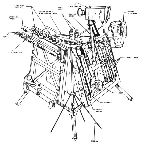
88. The Apollo Lunar Hand Tool Carrier holds 32 kilograms (70 pounds) of equipment, including a trenching tool, two geology scoops, four rock bags, a portable magnetometer, and five cameras.
Most tools and other pieces of equipment used by Apollo astronauts on the Moon were left behind as the astronauts departed to return to the Earth. This was done to conserve weight in the lunar module ascent stage so that the maximum quantity of samples of lunar soil and rocks could be brought back to the Earth.
Some tools and pieces of equipment, however, were returned to the Earth. These include such items as a lunar hammer, a 16-mm camera, film cassettes, lunar sample return containers, parts of a lunar roving vehicle fender, and parts of the unmanned spacecraft Surveyor 3 visited by Apollo 12 astronauts.
In addition, astronauts carried small mementos with them when they landed on the Moon.
Other lunar tools and instruments on exhibit were backup, prototype, or used by the astronauts in pre-flight training.
The lunar hammer is on loan from Alan L. Bean; other tools and instruments are from the National Aeronautics and Space Administration.
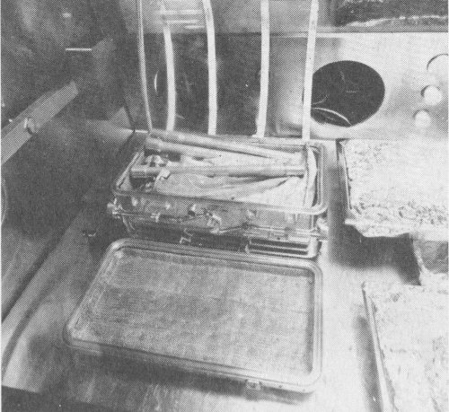
89. An Apollo lunar sample return container. In this view, the rock box contains sample material and core tubes.
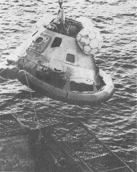
90. Skylab 4 Command Module is hoisted aboard the U.S.S. New Orleans after completing 1214 orbits.
The Skylab 4 command module ferried the crew of the last Skylab mission—astronauts Gerald P. Carr, Edward G. Gibson, and William R. Pogue. The Skylab 4 crew lived in the Skylab for 84 days, from November 16, 1973, to February 8, 1974.
In flight, the Apollo command module operated with a service module—an equipment section, 7.4 meters (24 feet) long and 4 meters (13 feet) in diameter—attached to the command module. The service module provided electrical power, oxygen, and water for the command module for most of a typical flight.
In addition, the service module contained the 9300-kilogram (20,500-pound) thrust Service Propulsion System, an engine capable of being throttled and restarted. During Apollo lunar flights, the engine provided thrust for mid-course trajectory changes and boosted the command/service module combination out of lunar orbit and back to Earth. The service module was jettisoned just before reentry into the earth’s atmosphere.
During reentry, the command module’s exterior was subjected to temperatures of around 2800°C (5000°F). The command module is covered with an ablative heat shield composed of a phenolic epoxy resin in a fiberglass honeycomb structure. As friction with the earth’s atmosphere caused the heat shield to char and vaporize, the heat was carried away from the spacecraft. The heat shield varies in thickness from 7 centimeters (2.75 inches) at the base to .6 centimeter (.25 inch) at the forward section. Total weight of the heat shield is about 1400 kilograms (3000 pounds).
The prime contractor for the Apollo Command Module was North American Rockwell Corporation.
The command module is from the National Aeronautics and Space Administration.
| Diameter | 3.9 m. (12 ft., 10 in.) max. |
| Length | 3.2 m. (10 ft., 7 in.) |
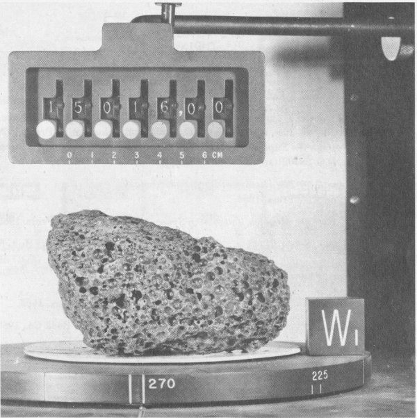
91. A sample of vesicular basalt, produced by lunar volcanism 3.7 billion years ago, in the Lunar Receiving Laboratory. Devices record size and orientation of the rock. The cavities in this sample were formed by gases escaping from the still-molten rock. This sample is 13.5 centimeters (5.5 inches) long. A fragment of this lunar rock is on display in the “Apollo to the Moon” gallery.
During the six Apollo program moon landings, astronauts collected and returned to Earth samples of the lunar surface. The samples were collected both from the flat maria regions—great basins created by ancient meteoric impacts and later filled with lava from the moon’s interior—and from the highland regions.
Subsequent analysis of the samples has indicated that the moon’s surface is largely composed of three kinds of rock.
Basalt, the rock of the maria regions, was formed as lavas from the interior of the Moon welled to the surface, filled the great meteoric impact basins, and then cooled.
Anorthosite, the highland rock, is believed by many scientists to have formed when the original crust of the Moon cooled and solidified. According to this theory, a light mineral, plagioclase, floated to the surface of the Moon and formed the anorthosite.
Breccia, the shocked rock, is composed of large and small fragments of rocks which were shattered and redistributed on the lunar surface by meteoric impacts. Subsequently, the fragments were recombined into new rocks by heat and pressure.
Lunar soils are largely composed of fragments of the three types of rocks and their minerals, and glass produced by meteoric impacts and volcanic eruptions.
Lunar rock samples are on loan from the National Aeronautics and Space Administration.
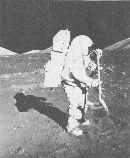
92. Astronaut Schmitt collects samples with the lunar rake, a hand tool used to collect rocks and rock chips ranging in size from 1.3 centimeter (½ inch) to 2.5 centimeters (1 inch).
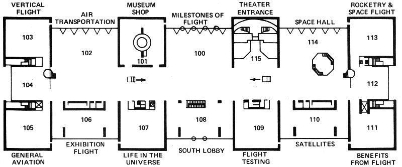
FIRST FLOOR PLAN
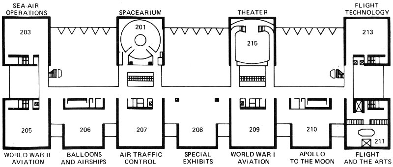
SECOND FLOOR PLAN
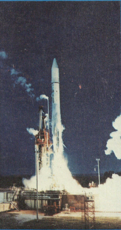
Lift-off of an Atlas Centaur carrying INTELSAT payload, August 23, 1973.
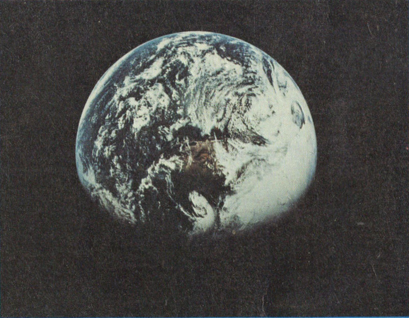
Earth from space photographed by the Apollo 16 crew.
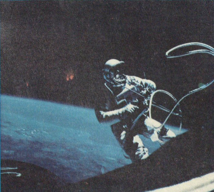
Astronaut White performs first spacewalk from Gemini 4.
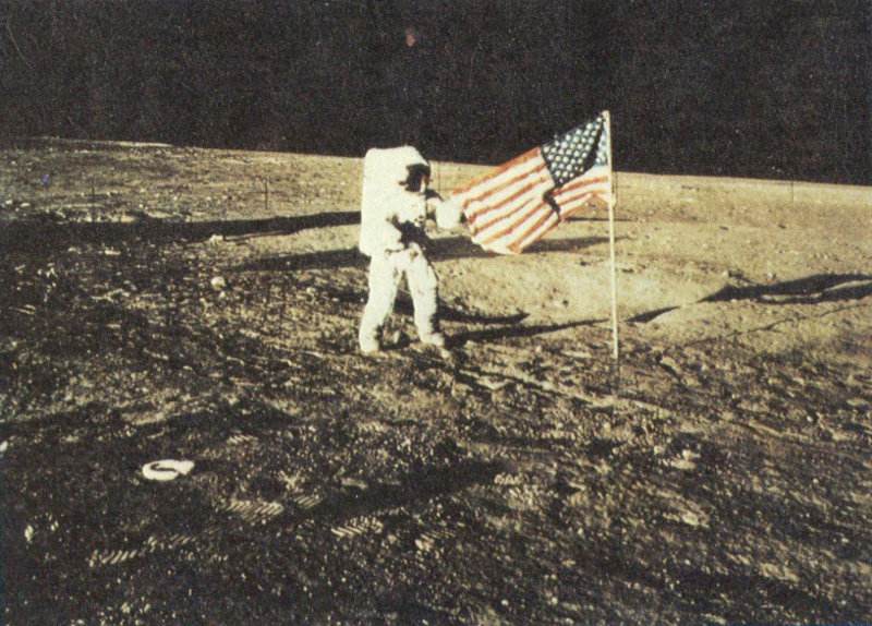
Apollo 12 astronaut with United States flag on lunar surface.
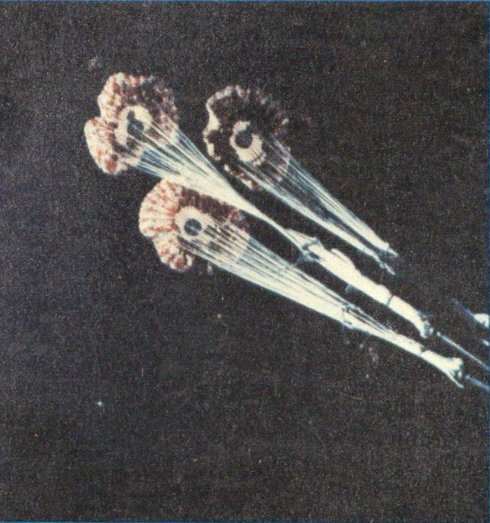
Main parachutes lower the Skylab 3 command module to the Pacific Ocean.
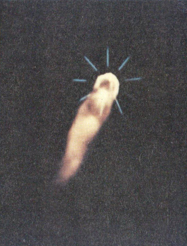
Solid rocket motors being jettisoned during launch of Geostationary Operational Environmental Satellite-1.
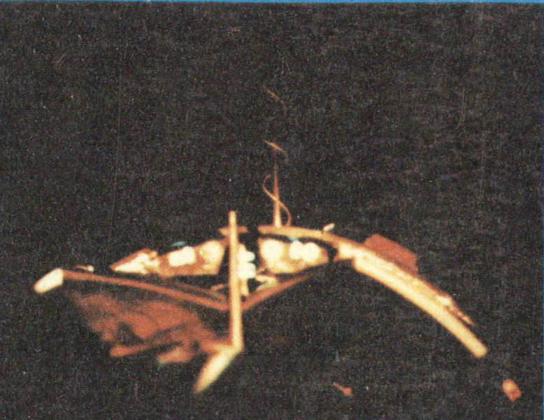
View from right-hand seat of Gemini 8 spacecraft when docked with Agena target vehicle.
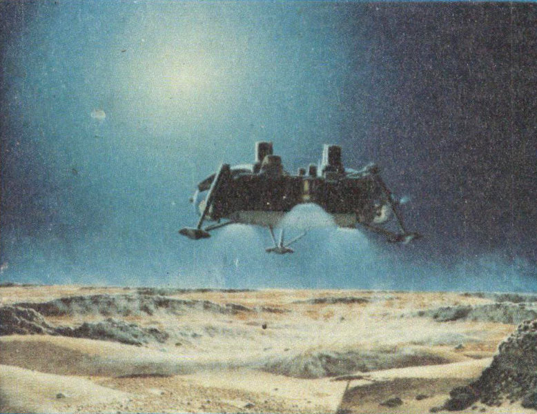
Artist’s conception of Viking Mars lander as it heads for touch down.
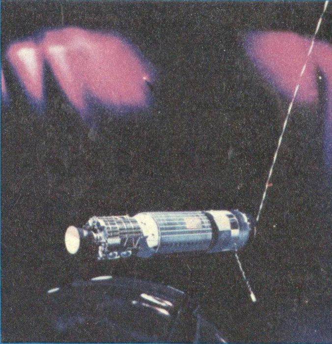
Agena target vehicle seen from Gemini 11 after tether drop.
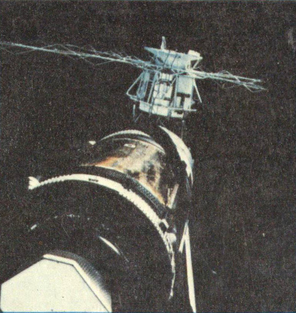
View of Skylab Orbital Workshop photographed by Skylab 2 crew.
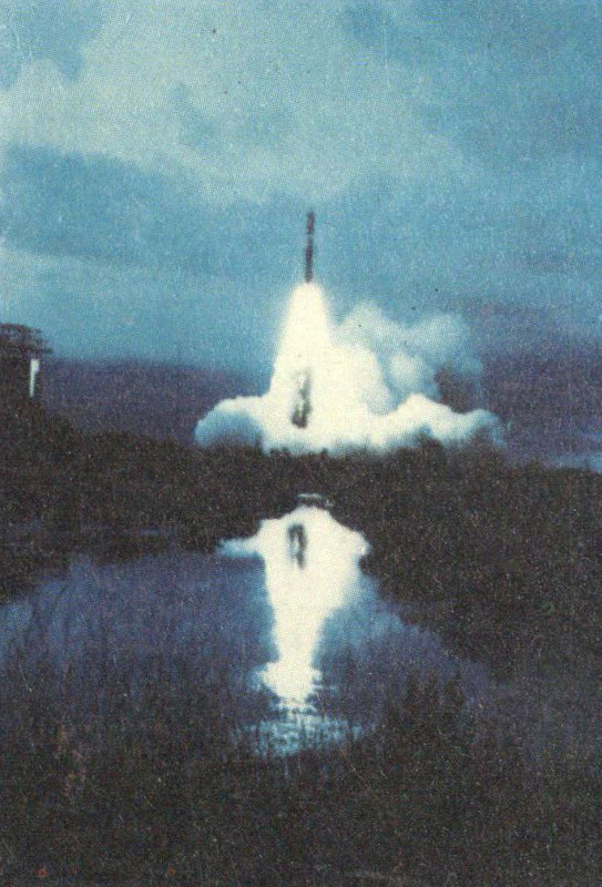
Viking 2—bound for Mars—is launched aboard Titan Centaur on September 9, 1975.
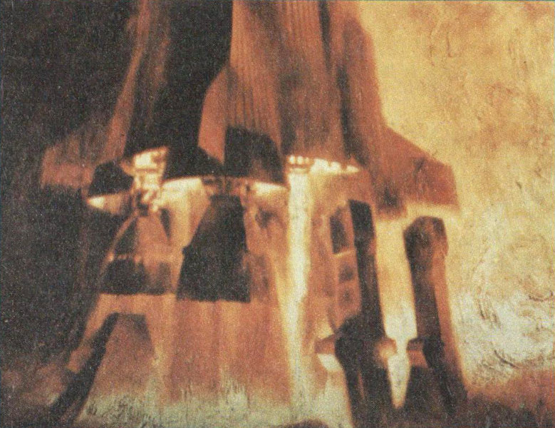
Paul Calle’s interpretation of Saturn 5 launch.

New York to Norfolk composite photo from the Earth Resources Technology Satellite-1.

Photomicrograph of thin section of lunar rock.
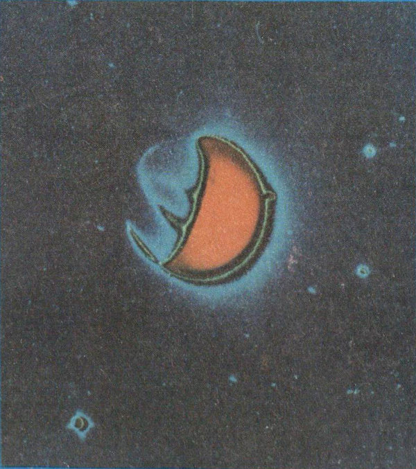
Color enhancement of far ultraviolet photo of the Earth taken from space.
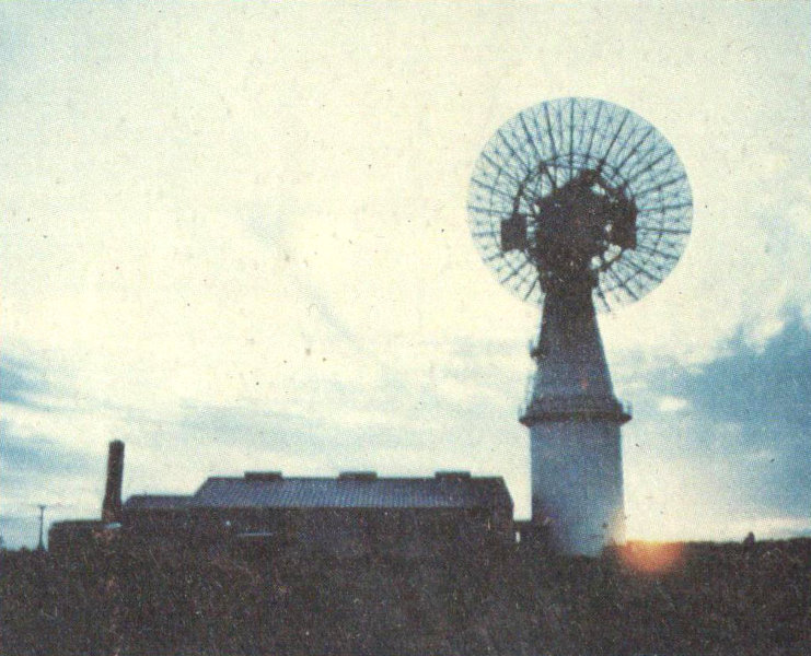
NASA’s Wallops Island Test Station in Virginia.
(All photographs from the National Aeronautics and Space Administration.)
End of the Project Gutenberg EBook of Rockets, Missiles, and Spacecraft of
the National Air and Space Museum, by Lynne C. Murphy

*** END OF THIS PROJECT GUTENBERG EBOOK SPACE MUSEUM ***

***** This file should be named 57421-h.htm or 57421-h.zip *****
This and all associated files of various formats will be found in:
        http://www.gutenberg.org/5/7/4/2/57421/

Produced by Stephen Hutcheson and the Online Distributed
Proofreading Team at http://www.pgdp.net


Updated editions will replace the previous one--the old editions will
be renamed.

Creating the works from print editions not protected by U.S. copyright
law means that no one owns a United States copyright in these works,
so the Foundation (and you!) can copy and distribute it in the United
States without permission and without paying copyright
royalties. Special rules, set forth in the General Terms of Use part
of this license, apply to copying and distributing Project
Gutenberg-tm electronic works to protect the PROJECT GUTENBERG-tm
concept and trademark. Project Gutenberg is a registered trademark,
and may not be used if you charge for the eBooks, unless you receive
specific permission. If you do not charge anything for copies of this
eBook, complying with the rules is very easy. You may use this eBook
for nearly any purpose such as creation of derivative works, reports,
performances and research. They may be modified and printed and given
away--you may do practically ANYTHING in the United States with eBooks
not protected by U.S. copyright law. Redistribution is subject to the
trademark license, especially commercial redistribution.

START: FULL LICENSE

THE FULL PROJECT GUTENBERG LICENSE
PLEASE READ THIS BEFORE YOU DISTRIBUTE OR USE THIS WORK

To protect the Project Gutenberg-tm mission of promoting the free
distribution of electronic works, by using or distributing this work
(or any other work associated in any way with the phrase "Project
Gutenberg"), you agree to comply with all the terms of the Full
Project Gutenberg-tm License available with this file or online at
www.gutenberg.org/license.

Section 1. General Terms of Use and Redistributing Project
Gutenberg-tm electronic works

1.A. By reading or using any part of this Project Gutenberg-tm
electronic work, you indicate that you have read, understand, agree to
and accept all the terms of this license and intellectual property
(trademark/copyright) agreement. If you do not agree to abide by all
the terms of this agreement, you must cease using and return or
destroy all copies of Project Gutenberg-tm electronic works in your
possession. If you paid a fee for obtaining a copy of or access to a
Project Gutenberg-tm electronic work and you do not agree to be bound
by the terms of this agreement, you may obtain a refund from the
person or entity to whom you paid the fee as set forth in paragraph
1.E.8.

1.B. "Project Gutenberg" is a registered trademark. It may only be
used on or associated in any way with an electronic work by people who
agree to be bound by the terms of this agreement. There are a few
things that you can do with most Project Gutenberg-tm electronic works
even without complying with the full terms of this agreement. See
paragraph 1.C below. There are a lot of things you can do with Project
Gutenberg-tm electronic works if you follow the terms of this
agreement and help preserve free future access to Project Gutenberg-tm
electronic works. See paragraph 1.E below.

1.C. The Project Gutenberg Literary Archive Foundation ("the
Foundation" or PGLAF), owns a compilation copyright in the collection
of Project Gutenberg-tm electronic works. Nearly all the individual
works in the collection are in the public domain in the United
States. If an individual work is unprotected by copyright law in the
United States and you are located in the United States, we do not
claim a right to prevent you from copying, distributing, performing,
displaying or creating derivative works based on the work as long as
all references to Project Gutenberg are removed. Of course, we hope
that you will support the Project Gutenberg-tm mission of promoting
free access to electronic works by freely sharing Project Gutenberg-tm
works in compliance with the terms of this agreement for keeping the
Project Gutenberg-tm name associated with the work. You can easily
comply with the terms of this agreement by keeping this work in the
same format with its attached full Project Gutenberg-tm License when
you share it without charge with others.

1.D. The copyright laws of the place where you are located also govern
what you can do with this work. Copyright laws in most countries are
in a constant state of change. If you are outside the United States,
check the laws of your country in addition to the terms of this
agreement before downloading, copying, displaying, performing,
distributing or creating derivative works based on this work or any
other Project Gutenberg-tm work. The Foundation makes no
representations concerning the copyright status of any work in any
country outside the United States.

1.E. Unless you have removed all references to Project Gutenberg:

1.E.1. The following sentence, with active links to, or other
immediate access to, the full Project Gutenberg-tm License must appear
prominently whenever any copy of a Project Gutenberg-tm work (any work
on which the phrase "Project Gutenberg" appears, or with which the
phrase "Project Gutenberg" is associated) is accessed, displayed,
performed, viewed, copied or distributed:

  This eBook is for the use of anyone anywhere in the United States and
  most other parts of the world at no cost and with almost no
  restrictions whatsoever. You may copy it, give it away or re-use it
  under the terms of the Project Gutenberg License included with this
  eBook or online at www.gutenberg.org. If you are not located in the
  United States, you'll have to check the laws of the country where you
  are located before using this ebook.

1.E.2. If an individual Project Gutenberg-tm electronic work is
derived from texts not protected by U.S. copyright law (does not
contain a notice indicating that it is posted with permission of the
copyright holder), the work can be copied and distributed to anyone in
the United States without paying any fees or charges. If you are
redistributing or providing access to a work with the phrase "Project
Gutenberg" associated with or appearing on the work, you must comply
either with the requirements of paragraphs 1.E.1 through 1.E.7 or
obtain permission for the use of the work and the Project Gutenberg-tm
trademark as set forth in paragraphs 1.E.8 or 1.E.9.

1.E.3. If an individual Project Gutenberg-tm electronic work is posted
with the permission of the copyright holder, your use and distribution
must comply with both paragraphs 1.E.1 through 1.E.7 and any
additional terms imposed by the copyright holder. Additional terms
will be linked to the Project Gutenberg-tm License for all works
posted with the permission of the copyright holder found at the
beginning of this work.

1.E.4. Do not unlink or detach or remove the full Project Gutenberg-tm
License terms from this work, or any files containing a part of this
work or any other work associated with Project Gutenberg-tm.

1.E.5. Do not copy, display, perform, distribute or redistribute this
electronic work, or any part of this electronic work, without
prominently displaying the sentence set forth in paragraph 1.E.1 with
active links or immediate access to the full terms of the Project
Gutenberg-tm License.

1.E.6. You may convert to and distribute this work in any binary,
compressed, marked up, nonproprietary or proprietary form, including
any word processing or hypertext form. However, if you provide access
to or distribute copies of a Project Gutenberg-tm work in a format
other than "Plain Vanilla ASCII" or other format used in the official
version posted on the official Project Gutenberg-tm web site
(www.gutenberg.org), you must, at no additional cost, fee or expense
to the user, provide a copy, a means of exporting a copy, or a means
of obtaining a copy upon request, of the work in its original "Plain
Vanilla ASCII" or other form. Any alternate format must include the
full Project Gutenberg-tm License as specified in paragraph 1.E.1.

1.E.7. Do not charge a fee for access to, viewing, displaying,
performing, copying or distributing any Project Gutenberg-tm works
unless you comply with paragraph 1.E.8 or 1.E.9.

1.E.8. You may charge a reasonable fee for copies of or providing
access to or distributing Project Gutenberg-tm electronic works
provided that

* You pay a royalty fee of 20% of the gross profits you derive from
  the use of Project Gutenberg-tm works calculated using the method
  you already use to calculate your applicable taxes. The fee is owed
  to the owner of the Project Gutenberg-tm trademark, but he has
  agreed to donate royalties under this paragraph to the Project
  Gutenberg Literary Archive Foundation. Royalty payments must be paid
  within 60 days following each date on which you prepare (or are
  legally required to prepare) your periodic tax returns. Royalty
  payments should be clearly marked as such and sent to the Project
  Gutenberg Literary Archive Foundation at the address specified in
  Section 4, "Information about donations to the Project Gutenberg
  Literary Archive Foundation."

* You provide a full refund of any money paid by a user who notifies
  you in writing (or by e-mail) within 30 days of receipt that s/he
  does not agree to the terms of the full Project Gutenberg-tm
  License. You must require such a user to return or destroy all
  copies of the works possessed in a physical medium and discontinue
  all use of and all access to other copies of Project Gutenberg-tm
  works.

* You provide, in accordance with paragraph 1.F.3, a full refund of
  any money paid for a work or a replacement copy, if a defect in the
  electronic work is discovered and reported to you within 90 days of
  receipt of the work.

* You comply with all other terms of this agreement for free
  distribution of Project Gutenberg-tm works.

1.E.9. If you wish to charge a fee or distribute a Project
Gutenberg-tm electronic work or group of works on different terms than
are set forth in this agreement, you must obtain permission in writing
from both the Project Gutenberg Literary Archive Foundation and The
Project Gutenberg Trademark LLC, the owner of the Project Gutenberg-tm
trademark. Contact the Foundation as set forth in Section 3 below.

1.F.

1.F.1. Project Gutenberg volunteers and employees expend considerable
effort to identify, do copyright research on, transcribe and proofread
works not protected by U.S. copyright law in creating the Project
Gutenberg-tm collection. Despite these efforts, Project Gutenberg-tm
electronic works, and the medium on which they may be stored, may
contain "Defects," such as, but not limited to, incomplete, inaccurate
or corrupt data, transcription errors, a copyright or other
intellectual property infringement, a defective or damaged disk or
other medium, a computer virus, or computer codes that damage or
cannot be read by your equipment.

1.F.2. LIMITED WARRANTY, DISCLAIMER OF DAMAGES - Except for the "Right
of Replacement or Refund" described in paragraph 1.F.3, the Project
Gutenberg Literary Archive Foundation, the owner of the Project
Gutenberg-tm trademark, and any other party distributing a Project
Gutenberg-tm electronic work under this agreement, disclaim all
liability to you for damages, costs and expenses, including legal
fees. YOU AGREE THAT YOU HAVE NO REMEDIES FOR NEGLIGENCE, STRICT
LIABILITY, BREACH OF WARRANTY OR BREACH OF CONTRACT EXCEPT THOSE
PROVIDED IN PARAGRAPH 1.F.3. YOU AGREE THAT THE FOUNDATION, THE
TRADEMARK OWNER, AND ANY DISTRIBUTOR UNDER THIS AGREEMENT WILL NOT BE
LIABLE TO YOU FOR ACTUAL, DIRECT, INDIRECT, CONSEQUENTIAL, PUNITIVE OR
INCIDENTAL DAMAGES EVEN IF YOU GIVE NOTICE OF THE POSSIBILITY OF SUCH
DAMAGE.

1.F.3. LIMITED RIGHT OF REPLACEMENT OR REFUND - If you discover a
defect in this electronic work within 90 days of receiving it, you can
receive a refund of the money (if any) you paid for it by sending a
written explanation to the person you received the work from. If you
received the work on a physical medium, you must return the medium
with your written explanation. The person or entity that provided you
with the defective work may elect to provide a replacement copy in
lieu of a refund. If you received the work electronically, the person
or entity providing it to you may choose to give you a second
opportunity to receive the work electronically in lieu of a refund. If
the second copy is also defective, you may demand a refund in writing
without further opportunities to fix the problem.

1.F.4. Except for the limited right of replacement or refund set forth
in paragraph 1.F.3, this work is provided to you 'AS-IS', WITH NO
OTHER WARRANTIES OF ANY KIND, EXPRESS OR IMPLIED, INCLUDING BUT NOT
LIMITED TO WARRANTIES OF MERCHANTABILITY OR FITNESS FOR ANY PURPOSE.

1.F.5. Some states do not allow disclaimers of certain implied
warranties or the exclusion or limitation of certain types of
damages. If any disclaimer or limitation set forth in this agreement
violates the law of the state applicable to this agreement, the
agreement shall be interpreted to make the maximum disclaimer or
limitation permitted by the applicable state law. The invalidity or
unenforceability of any provision of this agreement shall not void the
remaining provisions.

1.F.6. INDEMNITY - You agree to indemnify and hold the Foundation, the
trademark owner, any agent or employee of the Foundation, anyone
providing copies of Project Gutenberg-tm electronic works in
accordance with this agreement, and any volunteers associated with the
production, promotion and distribution of Project Gutenberg-tm
electronic works, harmless from all liability, costs and expenses,
including legal fees, that arise directly or indirectly from any of
the following which you do or cause to occur: (a) distribution of this
or any Project Gutenberg-tm work, (b) alteration, modification, or
additions or deletions to any Project Gutenberg-tm work, and (c) any
Defect you cause.

Section 2. Information about the Mission of Project Gutenberg-tm

Project Gutenberg-tm is synonymous with the free distribution of
electronic works in formats readable by the widest variety of
computers including obsolete, old, middle-aged and new computers. It
exists because of the efforts of hundreds of volunteers and donations
from people in all walks of life.

Volunteers and financial support to provide volunteers with the
assistance they need are critical to reaching Project Gutenberg-tm's
goals and ensuring that the Project Gutenberg-tm collection will
remain freely available for generations to come. In 2001, the Project
Gutenberg Literary Archive Foundation was created to provide a secure
and permanent future for Project Gutenberg-tm and future
generations. To learn more about the Project Gutenberg Literary
Archive Foundation and how your efforts and donations can help, see
Sections 3 and 4 and the Foundation information page at
www.gutenberg.org Section 3. Information about the Project Gutenberg
Literary Archive Foundation

The Project Gutenberg Literary Archive Foundation is a non profit
501(c)(3) educational corporation organized under the laws of the
state of Mississippi and granted tax exempt status by the Internal
Revenue Service. The Foundation's EIN or federal tax identification
number is 64-6221541. Contributions to the Project Gutenberg Literary
Archive Foundation are tax deductible to the full extent permitted by
U.S. federal laws and your state's laws.

The Foundation's principal office is in Fairbanks, Alaska, with the
mailing address: PO Box 750175, Fairbanks, AK 99775, but its
volunteers and employees are scattered throughout numerous
locations. Its business office is located at 809 North 1500 West, Salt
Lake City, UT 84116, (801) 596-1887. Email contact links and up to
date contact information can be found at the Foundation's web site and
official page at www.gutenberg.org/contact

For additional contact information:

    Dr. Gregory B. Newby
    Chief Executive and Director
    gbnewby@pglaf.org

Section 4. Information about Donations to the Project Gutenberg
Literary Archive Foundation

Project Gutenberg-tm depends upon and cannot survive without wide
spread public support and donations to carry out its mission of
increasing the number of public domain and licensed works that can be
freely distributed in machine readable form accessible by the widest
array of equipment including outdated equipment. Many small donations
($1 to $5,000) are particularly important to maintaining tax exempt
status with the IRS.

The Foundation is committed to complying with the laws regulating
charities and charitable donations in all 50 states of the United
States. Compliance requirements are not uniform and it takes a
considerable effort, much paperwork and many fees to meet and keep up
with these requirements. We do not solicit donations in locations
where we have not received written confirmation of compliance. To SEND
DONATIONS or determine the status of compliance for any particular
state visit www.gutenberg.org/donate

While we cannot and do not solicit contributions from states where we
have not met the solicitation requirements, we know of no prohibition
against accepting unsolicited donations from donors in such states who
approach us with offers to donate.

International donations are gratefully accepted, but we cannot make
any statements concerning tax treatment of donations received from
outside the United States. U.S. laws alone swamp our small staff.

Please check the Project Gutenberg Web pages for current donation
methods and addresses. Donations are accepted in a number of other
ways including checks, online payments and credit card donations. To
donate, please visit: www.gutenberg.org/donate

Section 5. General Information About Project Gutenberg-tm electronic works.

Professor Michael S. Hart was the originator of the Project
Gutenberg-tm concept of a library of electronic works that could be
freely shared with anyone. For forty years, he produced and
distributed Project Gutenberg-tm eBooks with only a loose network of
volunteer support.

Project Gutenberg-tm eBooks are often created from several printed
editions, all of which are confirmed as not protected by copyright in
the U.S. unless a copyright notice is included. Thus, we do not
necessarily keep eBooks in compliance with any particular paper
edition.

Most people start at our Web site which has the main PG search
facility: www.gutenberg.org

This Web site includes information about Project Gutenberg-tm,
including how to make donations to the Project Gutenberg Literary
Archive Foundation, how to help produce our new eBooks, and how to
subscribe to our email newsletter to hear about new eBooks.