Project Gutenberg's Practical Stair Building and Handrailing, by W. H. Wood

This eBook is for the use of anyone anywhere in the United States and most
other parts of the world at no cost and with almost no restrictions
whatsoever.  You may copy it, give it away or re-use it under the terms of
the Project Gutenberg License included with this eBook or online at
www.gutenberg.org.  If you are not located in the United States, you'll have
to check the laws of the country where you are located before using this ebook.

Title: Practical Stair Building and Handrailing
       By the square section and falling line system.

Author: W. H. Wood

Release Date: June 18, 2018 [EBook #57348]

Language: English

Character set encoding: UTF-8

*** START OF THIS PROJECT GUTENBERG EBOOK PRACTICAL STAIR BUILDING, HANDRAILING ***


Produced by Chris Curnow, Charlie Howard, and the Online
Distributed Proofreading Team at http://www.pgdp.net (This
file was produced from images generously made available
by The Internet Archive)
Transcriber’s Note
In the Table of Contents, the Plate numbers (left-hand column) are hyperlinked to the Plate illustrations, and the Page numbers (right-hand column) are hyperlinked to the descriptive text that follows them.
PRACTICAL
STAIR BUILDING AND HANDRAILING
BY THE
SQUARE SECTION AND FALLING LINE SYSTEM
BY
W. H. WOOD
London:
E. & F. N. SPON, 125 STRAND
New York:
SPON & CHAMBERLAIN, 12 CORTLANDT STREET
1894
The following book has been written to assist those who wish to acquire a knowledge of the most practical and systematic methods adopted in the execution of stair building and handrailing.
In compiling this work the author has kept steadily in view the absolute necessity of treating most fully the elementary parts. Therefore, if to some the details should appear tedious, he begs to say they have been written to assist those who, being unable to obtain a correct knowledge of the methods adopted, seldom advance beyond a certain and very unsatisfactory stage.
The plates on stairs will be found to contain much useful and valuable information, all of which the author has practically tested, some of them many times over, and can therefore vouch for the accuracy of the various methods shown.
The Plates 12 and 13 should be thoroughly understood before proceeding with the handrailing, as the diagrams showing problems in solid geometry have been carefully selected, bearing directly on the subject, and it should not be left until the “why” and “wherefore” has been reasoned out.
The system of handrailing is somewhat new, but the author has continually put it to practical test for the last five years, and he is convinced that it is only required to be known to be appreciated.
W. H. WOOD.
vii
| STAIR BUILDING. | ||
| PLATE | PAGE | |
| 1 | Elementary Problems | 3 |
| 2 | Close Newelled or Dog-legged Stairs, the Setting Out of Rods, &c. | 5 |
| 3 | The Construction of Various Parts of Stairs, showing the application of the Steel Square for Setting Out Strings, &c. | 7 |
| 4 | Plan and Elevation of Open Newel Staircase, with Spandril under Bottom Flight | 11 |
| 5 | Details of Construction | 13 |
| 6 | Details of a Newel Stairs, Starting and Landing with Winders | 15 |
| 7 | Half-space Landing, with a Straight Flight above and below, and a continued Rail, starting with a Side Wreath from a Newel | 17 |
| 8 | Details of Construction | 19 |
| 9 | Details of Construction | 23 |
| 10 | Details of Construction showing an Apparatus for marking the Length and Cuts of Balusters around the Circular Parts | 25 |
| 11 | Details of Construction | 29 |
| HANDRAILING. | ||
| 12 | On Oblique Planes and their Traces | 37 |
| 13 | On Projection of Oblique Planes, &c. | 41 |
| 14 | Level Landing Wreath, or Half Twist | 43 |
| 15 | Level Landing Wreath, or Half Twist | 45 |
| 16 | Level Landing Wreath, or Half Twist | 47 |
| 17 | Half-space Landing, with Straight Flight above and below | 49 |
| 18 | From the Level to the Rake | 53viii |
| 19 | From the Level to the Rake | 55 |
| 20 | Half-space Landing with the Risers in the Springing | 57 |
| 21 | Winders in the Half-space and Level Landing at top | 59 |
| 22 | Winders in the Half-space, with a Straight Flight above and below, Wreath to form its own Easing | 61 |
| 23 | Quarter-space Landing, Wreath in one Piece | 65 |
| 24 | Quarter-space Landing, Wreath in two Pieces | 67 |
| 25 | Quarter-space Landing, Wreath in one Piece, to form its own Easing into the Straight Rail | 69 |
| 26 | Winders in the Quarter-space, Wreath in one Piece, to form its own Easing into Straight Rail | 71 |
| 27 | Landing in an Obtuse Angle, the Wreath to form its own Easing into the Straight Rail | 73 |
| 28 | Half Twist starting from a Scroll, and a Side Wreath starting from a Newel | 75 |
| 29 | Winders starting from a Curtail Step | 77 |
| 30 | Winders in the Quarter-space, starting from a Newel | 79 |
| 31 | The Plan of Rail forming Part of an Ellipse, starting from a Newel over Winders | 81 |
| 32 | Showing the Moulding of Rails, and a Method of proportionately Increasing or Decreasing the Size of them | 83 |
1
Stairs are a succession of steps leading from one landing to another in a building. Each step comprises tread and riser, the tread being horizontal and the riser vertical. The side pieces supporting the ends of steps are called strings: that next to the wall, the wall string; the other, the front, outside, well, cut, open, or close string. When the steps are narrower one end than the other they are called winders. The landing is a platform between the floors, and it is sometimes arranged to give access to a door. A succession of steps between each landing is called a flight. It is not often that the stair builder is called upon to say how and where the stairs are to go, that being the work of the architect; but the former must do his best to carry out the wishes of the latter, who will leave to him the placing of risers, and all details necessarily belonging to the stair builder, who will make the best possible job, having all easings and falling lines as graceful as it is possible to make them. An easing that is too long is almost as objectionable as one that is too short.
He will take the dimensions off on to his rods, and from them set out the whole stairs, showing all doorways, landings, headroom, &c., to 1½ inch scale if possible. All winders must be set out full size.
3
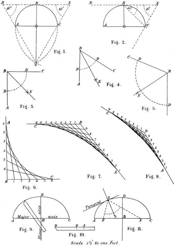
Fig. 1. Draw a straight line, equal in length to the semicircle A B C. With A and C as centres, and for radius A C, strike the two arcs to intersect each other in S. Join S A and S C extended, to cut the line through B in D and E. Then, D E is the length of the required line, and if this was bent around the semicircle it would reach from A to C. This line throughout this work is termed the stretch-out of the semicircle.
Fig. 2. Given the length D E, find the radius to strike a semi-*circle equal in length to it. Draw a line from E at 60°, and from B at 45° to D E, to cross each other at C. Draw from B square to D E, and from C parallel to D E to meet in O; then O B will be the required radius.
Figs. 3, 4 and 5 show how to bisect any given angle. Let A B C be the given angle. With B as centre, strike the arc D D to any radius. With D D as centres, and for radius more than half the distance D D, describe arcs intersecting in E. Then, a line from B to E will bisect the angle.
Figs. 6, 7 and 8 show how to ease any given angle, that is to form a curve that will connect the two straight lines, from any two given points, on those lines. Let A B and B C be the two lines forming the given angle, and it is required to connect those lines from A to C. Divide A B and B C into any number of equal parts, connect those parts, and the curve will be formed if A B and B C has been divided into a sufficient number of parts.
4 Fig. 9 shows a semi-ellipse, A B being the semi-major axis, and B D the semi-minor axis. Let A B and D B, Fig. 10, equal A B and D B, Fig. 9. To strike the curve, move this rod around, keeping D on the major axis, and A on the minor axis, and mark off points at the end of the rod all round.
Fig. 11. Given a semi-ellipse, draw a normal tangent. Determine the foci of the ellipse F F. With D as centre, and for radius A B strike arcs of circles at F F. At any point on the curve, say at S, draw lines to F F and bisect the angle. Now draw through S, square to this line that bisects the angle for the required normal tangent.
5
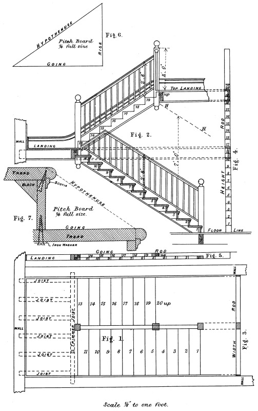
Fig. 1 shows the plan of a dog-legged stair. The first thing to be done is to take off the sizes on a rod. First take the rod, marked Fig. 3. Cut this rod in between the brick walls, taking care to try it between the walls where the two flights come together at risers 12 and 13. Set off on each end of this rod the thickness of plaster; now set off the face of wall strings so that they will be flush with the face of the skirting. Then set back from face of the string half an inch, the depth of the housing, this will be the end of the treads and risers. Next set off the centre of the rod, draw the newel and string on the rod, half their thicknesses on each side of the centre line. Then set back towards the centre from each face of the centre string, half an inch, the depth of the housing. This gives the length of the treads and risers; and if ordinary care is taken in setting out this rod, and working to it, no mistake can be made.
The height rod is seen at Fig. 4. Set off on this rod the height from the top of the bottom floor to the top of the top floor. Now divide this height into as many parts as there are to be risers, and the distance from one division to another represents the height from the top of one tread to the top of the next. The number of risers and the height of them must be regulated by circumstances. A few hints only can be thrown out here. The rise should not be less than 6 inches or more than 7¼ inches, while the going and the rise added together should not be less than 16½ inches or more than 18 inches. Thus, it will be seen, the going should be regulated by the rise. For instance, say the rise is 7¼ inches, then the going should not exceed 10¾ inches; this would make the going and rise added together 18 inches. Now, the6 stairs would be easier if the going was only 9¾, as this would make the two 17 inches, which is a better average than 18 inches. These remarks are not laid down as a fixed and unaltered rule, but are intended as a guide in the setting out of stairs of any description. Mark off on the height rod the floors, joist and ceiling of both landings, as shown at Fig. 4. In putting in the landing, use the height rod to get the height of the joist, but care must be taken to take the height from the proper floor level, in case the floor is not down.
Fig. 5 shows the going rod. Put one end of this rod against the back wall, and mark on to it all doorways, trimmer joists, &c. The width of landing and the going must be regulated by circumstances, but the risers, newels and all joists must be marked on to the rod as shown. In putting in these trimmers it is always as well to square them, that is, put them in square to the side walls, then should the back wall be out of square the difference will be in the landing.
Fig. 6 shows the pitch board. These are best made of zinc. Make the rise equal the height of one rise on the height rod, and the going equal the going of one step on the going rod.
Fig. 7 shows the construction of one step. A plan and elevation of the stairs should always be made to a scale of, say, ¾ of an inch to the foot, or, if possible, to 1½ inch to the foot, and all openings, headroom, &c., should be shown. The line H H, Fig. 2, is drawn parallel to the line of nosings on the bottom flight, and at a height above them of 7 feet. Then the bottom edge of the top landing must be kept above this line to give sufficient headroom. The setting out of the strings and glueing up of the steps, &c., will be seen on Plate III.
7
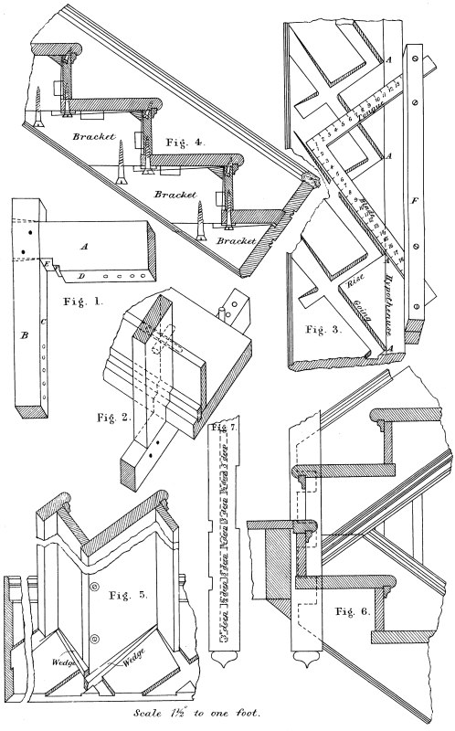
Fig. 1 shows a cradle for glueing up the steps. Let A be a piece of wood about 18 inches long by 6 inches wide by 2 inches thick, and B should be a piece about 2 feet 6 inches long by 3 inches wide by 2 inches thick. Put a ¾-inch mortise through B and tenon A into it. Well glue and wedge, and pin as shown. Two of these should be made. It will be noticed that E is cut out for the projection of the front edge of the tread past D, which is the face of the riser, and the mortise in B is kept back to E. F is cut out to fit over the scotia. The holes in the edges C and D are for pins to go in, to wedge against when glueing up the steps. The process of glueing up the steps is as follows: first cut off treads, risers, and scotia about 1 inch or 1½ inch longer than their proper length. Now plane up the treads, and shoot the front edges straight and square; then plough the under side for the scotia to go in about ¼ inch deep; then plane up the scotia and gauge them to a width and thickness so as to fit tight into the groove. These scotias should next be glued into the grooves and allowed to dry while the risers are being planed up. Plane up the face of the risers, and shoot the edge to go against the tread straight and square. Now fix the two cradles on the bench, by screwing them through B into the top of the bench. In fixing these, try them with one of the treads so as to get them square; keep them about 6 inches from each end.
Fig. 2 shows one of these cradles with a part of a step glued up. Lay the step on the cradle and stick a pin in one of the holes in B, and put in a wedge between the pin and the back edge of the step to8 keep the step in its place. Now glue the tread for the edge of the riser, also the back of the scotia; well rub the riser to get the glue rubbed out, and put in the wedge to keep the riser down, as shown. Then put in two screws and three blocks as shown at Fig. 7, Plate II. In putting on the blocks take care to well rub the glue out.
Fig. 3 shows a part of the outer string housed out for the treads and risers. The steel square is used to get the lines on the strings for the treads and risers, as shown. Get a piece of stuff long enough, marked F, and let it be about 2 inches square; put a good thick saw cut in each end and slip the square in the cuts as shown. Hold the hypothenuse of the pitch board against the fence F and set the blade to the going, and the tongue of the square to the rise of the pitch board. Now to mark the string. Gauge the hypothenuse line about 2½ inches from the top edge of string, and make the distance between A A on this line equal the hypothenuse of the pitch board. Slide the square along from A to A and mark both treads and risers. To mark the housing on the back side of the treads and risers, get two pieces of thin stuff and cut wedge-shaped, allowing them the wedge wider than the thickness of treads to mark the housing for the treads, and the wedge wider than the thickness of the risers for the housing for the risers. Fig. 4 shows a section of the steps with bracketed carriages showing. These carriages are only used in this description of stairs; they average from 2 inches to 3 inches thick; they are put on with the grain running in the same direction as the strings, they are screwed to the under side of the steps and to each other, as shown, and well blocked to treads and risers. They are placed according to the width of the stairs, three under each flight.
Fig. 5 shows a part of the wall string, moulded to match the skirting, and housed out for treads and risers. In putting stairs of this sort together, lay the wall string on the ground, as shown, taking care to get it straight and solid. Then place one end of the steps in the grooves of the wall string, after all the steps have been placed in position, then lay the outer string on the ends of steps, and after the9 steps have been got into the grooves. Well strut from the ceiling or any convenient place on to the outer string, forcing the steps into all the grooves. Then put in the wedges, glueing them before they are driven in. After they have been screwed up and blocked the struts can be removed.
The nosing and scotia are worked after the steps have been glued up; this is the best method of working in either a machine or a hand shop.
Fit the nosing and scotia into the strings on the bench before putting together, also get the rises to a width and number each step where it is to go.
Fig. 6 shows how the strings are tenoned into the newel; the dotted lines show the tenons and the haunching, the tenon being 3 inches deep and the haunching ½ inch deep; this is shown at Fig. 7. The housing out of the newels is described later on where there are winders.
The thickness of treads, &c., varies according to the class of work, but the following may be taken as a good example.
Treads, 1¼ inch thick. Project over risers, 1¼ inch.
Risers, 1 inch thick.
Scotia, 1¼ inch by ⅝ inch.
Strings, 1½ inch.
11
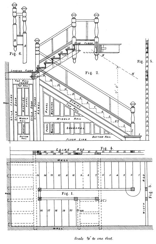
Fig. 1 shows the plan of an open newelled stairs, starting from a bull-nose step at bottom, and having a short piece of rail along the top to give sufficient headroom. The dotted lines show the joist.
Fig. 2 shows the elevation, with spandril and newels. After having taken the width, height and going or run on to the rods, set up an elevation to 1½ scale, when the size of strings can be taken off; newels, length of rails and spandril can all be set out. Draw the line H H parallel to the line of nosing and 7 feet above. Keep the bottom of facia crossing over the bottom flight above this line. After having set out the stairs to this scale mark off the rods full size.
Fig. 3 shows the width rod, with the two newels marked on it.
Fig. 4 is the going rod, with newels, face of risers, joist, &c., all marked on it.
Fig. 5 shows the height rod. Mark on to this rod the two landings.
Fig. 6 shows the newels on the half-space landing. The newel A being the bottom one, runs right down to the floor, the bottom square on it being to receive the bottom handrail, while the short level rail is above this. The newel B, the top square, is to receive the top handrail, and the short rail is below it. Thus it will be seen the twining on the top newel is shorter than on the bottom one marked A.
The details will be found on the following plate.
13
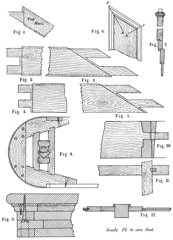
Fig. 1 shows the top rail of spandril, with the tenon cut ready to go together.
Fig. 2 is the middle rail tenoned and haunched ready to go together to fit into the stile.
Fig. 3 shows the other end of the same rail ready to go into the top rail.
Fig. 4 shows the bottom rail tenoned ready to go into the stile against the newel.
Fig. 5 is the same rail tenoned ready to go into the top rail under the string.
Fig. 6 shows a part of one panel with the moulding. To cut the moulding in, bisect the two angles as A B and C D; this was shown on Plate I. Make cuts in the mitre, cut to A B and C D, and cut the mitres to it. In putting the spandril together, put all muntings, rails, panels, top rail, bottom and middle rails first, and the stile against the newel last.
Fig. 7 shows a part section enlarged of the top rail of spandril, string of stairs and capping.
Fig. 8 shows a round-ended step. This is got out in three thicknesses, as shown at Fig. 9. This block is prepared as shown; the riser is cut to the thickness of a veneer, it is glued and screwed at the back, is well glued, brought around and well wedged and screwed as shown; the scotia is glued and screwed to the block, and the tread is well glued and screwed from the bottom. The newel is mortised into the step diagonally, as shown.
14 Fig. 10 shows the elevation of the trimmer at the top.
Fig. 11 shows the plans of the trimmer, with wedge and method of jointing.
Fig. 12 shows the section of newel and a part of door, frame and spandril.
15

In planning stairs of this description several things have to be considered. First take off the height and going on a rod. Then decide how many steps there are to be. Draw a plan and elevation, as shown at Figs. 1 and 2. Set off the width of the stairs and draw the two newels. Now draw the line of travel 15 inches from the centre of rail. Take the centre of newels for centre, and strike the quarter of circle top and bottom in continuation of this line, which divide into as many divisions as there are to be steps. In drawing the winders keep the narrow ends as wide as possible, and for this purpose they can be brought past the newels into the strings; as we can have no sympathy with the system that crowds all the narrow ends of winders into the newels, by that means making the stairs unnecessarily dangerous. The dotted lines show the trimmers and joist; care must be taken to have sufficient headroom. It will be noticed that the wall string is jointed at both ends, so as to get sufficient width. When these strings are set out like this to a scale, it is seen at once what there is to joint on. Fig. 3 shows the short string at the bottom, and Fig. 4 that at the top. These short strings must be made to ease into the long wall string at the same height, also to ease into the skirting. To fix these stairs proceed as follows: set the steps 1, 2 and 3 at the bottom, and 12, 13 and 14 at the top, out full size on a board, with the wall strings and newels. Tongue and groove the strings together in the corners, having the tongue on the long string at the bottom. Mark the treads off the board to cut and not try to fit on the job. If the rods have been set out correct in the first place, and as correct can be worked to, they can be cut in the shop for the bottom winders, but for the top ones the16 lines should be taken off the board out to them, and cut when fixed. Put the flight together, including step No. 12 at the top and 3 at the bottom, then fix on the bottom newel, after which step No. 2 can be fixed in position. Then put the short string in its place, also step No. 1. Now let the stairs go down into their place and do all necessary blocking and screwing. It will be understood that everything has been fitted before this, also that these bottom winders are glued up. Next put on the long newel and glue and pin it; slip the short string at top into its place, then fix in the risers 13, 14 and 15, and treads 13 and 14 and the nosing at top. Glue, screw and block these after they are in. Before cutting the treads and risers at the top, try with a rod to see if the lines on them taken off the board are correct, and if there is any difference allow for it when cutting them in.
Fig. 5 shows the plan and Fig. 7 the elevation of the newel for the bottom, with part of winders to 1½ inch scale. In setting out the newels mark the position of risers on to them, thus, make 1, 2, Fig. 7, equal to 1, 2, Fig. 5, and set up the height of a rise, and square out a line and make 2, 3 equal 2, 3, Fig. 5; this riser, it will be seen, comes on the edge; again set up a rise, as shown by 3, 3. From 3 square out a line and make 3, 4 equal 3, 4, Fig. 5, and set up the height of a rise. The same process would be repeated as long as there were any risers striking the newel on plan. Of course the newel would be set out full size on the board that the winders were set out on.
Fig. 6 shows the plan of newel, and Fig. 8 the elevation of a part of it. Repeat the process described at Figs. 5 and 7.
17
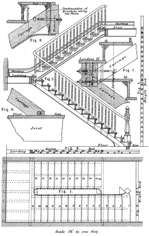
Fig. 1 shows the plan, and Fig. 2 the sectional elevation. The previous plates have shown stairs with close strings—that is, the outside strings are housed out for the treads and risers, in the same way as the wall string, and the top of the string is kept above the nosings, and a capping is fixed on the top of it, and the balusters are cut on, or let into this capping, according to the class of work. But in this case is shown a cut or open string. The treads and risers are housed into the wall string as before, but the outside strings are cut so as to allow the treads and risers to pass right through, and the balusters are dovetailed into the ends of treads, details of which are shown on Plate VIII. The carriages and the landing joist are shown by dotted lines on plan. The carriages fit close up under the bottom edge of treads, and rough brackets are nailed to the side of them, and fit close up to the under side of treads, and glued and blocked. In this description of stairs it is usual to have four iron balusters, placed as follows, one each on steps 7, 13, 18 and 24. There should be a joist, or good solid block let into them, immediately under the newel, so that a bolt can be let up into the centre of newel, and through this block, or joist, and screwed tight from the bottom. The wall string should be well plugged and nailed to the wall. If there is no spandril under the bottom flight, the carriages should be stiffened by cutting pieces of the same stuff in between each carriage and let into the wall. Get a long bolt made to go through all the carriages, and the pieces between them and into the wall, with a screw on the outside end to screw them all up tight together. To bore them for the bolts:18 After the carriages have been fitted in their place, before they are fixed, lay them together and bore them; then bore the short pieces before putting them into their place.
Fig. 3 shows the width rod. Care should always be taken to try this rod at the landing, where the two flights are connected, and allow for the stairs to fit in between the walls, just slack enough to go in their place without any trouble. They want, in fact, to drop into their place. Mark on each end of the rod the face of the skirting on the landings, and let this be the face of the wall string. Mark the centre, and set off on each side the centre line of rail, also the string and brackets. The face brackets will be the outside face of balusters.
Fig. 4 is the going rod. Of course, the going must be regulated by circumstances, but this rod must have the face of all the risers marked on it, also each springing, as shown by S S S, and the landings, doorways, &c.
Fig. 5 is the height rod, which must have landings, &c., marked on it as shown. These rods should be used to put in the landing by. The pitch board will be taken off the rods, as was before explained. Remember, a little care in setting out and working to these rods is true economy.
Fig. 6 shows how the carriages may be fastened to the floor. Let A be a fillet nailed well through the floor into the joist.
Fig. 7 shows the top and bottom carriages bolted to the trimmers at the landing. The short trimmer is sufficiently long to take the top carriages. The dotted lines show how the bottom end of the top carriages is let into the short trimmer, and bolted through. The bottom carriages cut against the long trimmer, and bolted through, as shown. It sometimes happens the short trimmer has to be blocked out from the long one, so as to receive the top carriages. In that case it is packed out sufficiently and bolted together.
Fig. 8 shows the carriages bolted to the trimmer on the top landing.
19
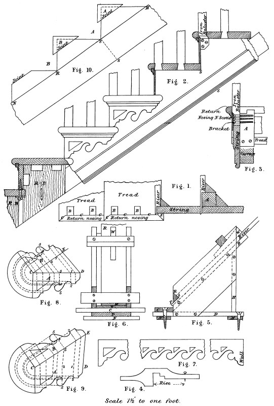
Fig. 1 shows the plan, and Fig. 2 the elevation of a part of an open or cut string. It will be seen the risers are cut like a bare face tenon 5/16 inch thick, the same thickness as the ornamental brackets, and shouldered to fit against the inside of the string. These brackets are glued and bradded to the outside face of the string, and mitred to the ends of the risers. That part of the string where the shoulder of the risers fits against, should be gauged to an exact thickness. The brackets fit close up under the ends of the treads, which project the thickness of the brackets past the strings, and mitred on the front edge to receive the return nosing and scotia, which is mitred and returned into the string, as shown at E, Fig. 1. The best method to adopt is as follows:—Get the risers shouldered and mitred, then plough the treads for the scotia; now cut off the ends of the treads as far as the mitre, which mark and cut in a little way, finishing the cut after the nosing has been worked and the stairs are together. Cut in the dovetails for the balusters, but not chop them out before the stairs are fixed. Now glue in the scotia, and, when dry, put the steps together, the same as was explained in Plate III. Then get the length of steps from the width rod, and cut them off. Gauge the risers to a width with a gauge as seen at Fig. 4. Fit the steps in the wall string, and cut out for nosing and scotia. To put them together, lay the wall string on the floor, having it straight and solid; put the steps into it, and lay the outer string on, and, with struts from the ceiling or any convenient place, force the cut string on to the shoulders of the risers, and the steps into the housing of the wall string. See that the stairs are square before doing all necessary wedging, blocking, screwing, &c. Then remove the struts and put on the brackets and return nosing,20 glueing and bradding the former, while the latter should only have two brads into the steps, so that they can be easily removed to fix the balusters when the handrail is fixed, after which they can be permanently nailed. The iron balusters are screwed to a block fixed for the purpose. This block is marked A, Figs. 1 and 3. The riser is reduced to allow the block to come forward, so as to get the screws well into it; it is stub-tenoned into the under side of the tread, as shown by the dotted lines, Fig. 3; it is also screwed into the back of the next tread below, and well glued and blocked. There will have to be a special baluster turned, out of pine, for a pattern, and turned a little longer to allow for shrinkage in the casting, which is about ⅛ inch to each foot. The square parts must be made to draw out of the sand when cast—that is, they must be a trifle thicker in the middle on the sides shown at Fig. 3 than they are at the edges, as they are cast in two halves. They will be drilled and countersunk for the screws after they are cast.
Fig. 5 shows the side and Fig. 6 the front elevation of a mitre shoot for shooting the mitres of the ends of risers. The sides are two 9-inch boards, set up at 45°, and screwed to the bottom, marked D, and to the back, marked H. Two ledges are screwed on the bottom, marked N. Also a longer piece on the top, in front, marked C, for the trying plane to slide on when shooting the mitres. A false bottom is put in, and set up at 45°, marked B, this is screwed or nailed through the sides, and kept ½ inch above C, as shown. The triangular piece is put in, and the bottom side S P is kept the thickness of a bracket above B, and S P must be the exact size of the thickness of the string where the risers fit against it. The risers are put in with the shoulders against S R and shot off. The brackets can be mitred in the same way. This box will do for any job by having different triangular pieces.
Fig. 7 shows how to get out the continuation of the brackets along the top landing, and finish against the wall. It often happens that the brackets require to be reduced in length for unders or21 diminished flyers, or increased for a large well, or where the risers are farther apart than on the straight flights. Figs. 8 and 9 show methods of reducing or increasing the length of the brackets, and each member proportionately. It is only necessary to describe one, as the method for both is the same. Let A be the given, and B the required bracket. Having drawn the bracket A, set off C E at any angle, the required length. Join D E, draw any number of lines on the bracket A, square to C D, draw these lines parallel to D E, and from where they cut C E square outline, and make them equal corresponding lines on the bracket A, as 3, 4 and 5 on B will equal 3, 4 and 5 on A. These brackets for the circular parts may be got out of wood; in that case the grain should be vertical, as the brackets are fixed. But for painted work the best are two pieces of linoleum glued together.
Fig. 10 shows how the cut string, which is 12 inches wide, may be got out of a 9-inch board. Shoot the bottom edge, then gauge a line on its face to equal S S, Fig. 2. Then with the compasses set off on this line, the hypothenuse of the pitch board as many times as is required, as shown by N R S H. Then with the steel square mark each going and rise, which cut, it will be found the board is not wide enough, but the pieces cut out of the corners can be glued on to make it out as shown by A and B.
In some cases, where there are no ornamental brackets, the ends of treads are cut off flush with the outside face of string, except the mitre for the return nosing, and the risers are mitred to the string.
23
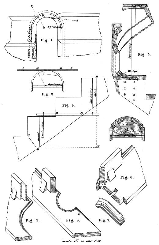
Fig. 1 is the plan of the well and the steps, landing and starting, at the half-space landing. The lines marked C S are the direction of the cuts to be made through the circular or well string for the risers to mitre to.
Fig. 2 shows a piece of thin stuff cut to a semicircle to fit the inside of the string. This piece is laid on the plan, and the position and direction of the cuts for risers is marked on it as seen by C C.
Fig. 3 shows a section of a staved well, the joints being ploughed out and cross tongues put in as shown. Each joint must be well glued and rubbed and screwed through the back. It will be noticed it is carried past the springing into the straight on both sides; this makes a better job, as a joint made in the springing always has a crippled appearance, no matter how well the job may be done.
Fig. 4 shows a falling mould for marking the treads and risers, also the bottom edge of the well in a continuous line with the bottom edge of the two straight strings. Take a thin lath and bend it around Fig. 2, and mark on it the springing and risers, as shown by S S and R R. Lay this lath on the piece of stuff the falling mould is to be cut out of, in a horizontal position, as shown, and mark the risers and springing. Set up a step above and below the springings, and set off S S to equal S S, Fig. 2, Plate VIII. Then draw the under side of straight strings and continue it across the well, taking care to have the best possible falling line. H H shows the length the pieces forming the well will require to be. This falling mould may be made out of good stiff brown paper, or any other suitable stuff. Now bend it around on the inside of the well, and mark the treads and risers24 and the bottom edge. Keep the springing lines on the mould to the springing marked on the well. To mark the springing on the well take Fig. 2 and hold in the well, and mark the springing top and bottom and finish it with a straight edge. Also mark the direction of the cuts as shown by the lines marked C.
Fig. 5 shows how the well is fixed to the straight strings. This must be all fitted in the shop ready to slide up in its place when the stairs are fixed, when it should be well glued, wedged and screwed. The circular string for the starting and top landing of Fig. 1, Plate VII., may be got out and fixed in the same way. These kind of wells answer the purpose for which they are used, but they are not so strong as a veneered well, which is shown on Plate XI.
Fig. 6 shows the step starting from the half-space landing. This step is slightly curved at the end to make it the same width on the end as the rest. The risers, starting and landing are laid down to suit the rail, as shown in Plate XVII.
Fig. 7 shows the return nosing for this step.
Fig. 8 shows the landing step. This is got out long enough to reach from wall to wall. This step is glued up in the shop with the rest; the nosing is worked on the solid and returned as far as E, about 2 or 3 inches on. The scotia is fixed around the circular part after all is fixed.
Fig. 9 shows the top landing step. This too goes from wall to wall, and is treated in the same way as Fig. 8, only the nosing is worked from end to end.
25
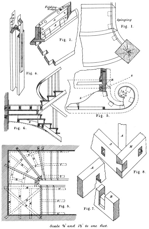
Fig. 1 shows part plan of stairs for a side wreath starting from a newel. The farther out the newel stands, within reason, the better will be the appearance, provided it does not obstruct the passage in any way.
Fig. 2 shows the construction of the curved steps. Let the pieces marked A be in two pieces, as shown, glued and screwed together, with the grain crossing each other as much as possible. The riser is reduced, as shown, as far as the work goes, to within about 3 inches of the end, as shown by B. The little piece of straight on the face of riser at B can be cleaned off in continuation of the curve after it is glued up. Screw through the blocks into the end of riser at B, then bend the veneer around, put on hand-screws to hold the riser and block together while wedging, and before removing the hand-screws put in the screws as shown. The scotia is screwed to the under side of the tread, and holes bored in the bottom edge of riser so as to get a screw-*driver in, and screw the riser on from the bottom, the screws going through the scotia into the tread.
Fig. 3 shows the block for a curtail step. The step is struck from the same centres as the handrail, which is explained on plate. The block is got out in three thicknesses; the grain of two pieces can run in the same direction as the riser, and the middle pieces in the direction of S S. The balusters will regulate the size of the block, as shown. This step is constructed on the same principle as Fig. 2, the scotia being in the solid. The nosing will be worked on the tread in the solid and returned at R through the string. The piece marked H26 is a piece of ¼-inch iron twisted so as to screw to the under side of the tread and to the inside of the string. The last baluster on the step should be iron, shouldered to fit on the top of the tread, and a ¾ pin on it to go through the step, with a thread for a nut to screw it up tight from the bottom. They are sometimes run in with sulphur instead of the nut; in that case it can be fixed after the step is fixed, but the nut makes the best job.
Fig. 4 shows an apparatus for cutting up the balusters around the wreaths. It is a very simple affair, easily made and easily applied; it makes a perfect fit, and the saving of time is very great. The box is made the size of the baluster on the inside, the back C is 1½ inch thick, and the sides ¾ inch. The pieces marked A are cut as shown, and slotted, a couple of screws are screwed into the sides with washers on, for A to slide up and down. B is a piece of zinc screwed on to A, as shown, with the head countersunk flush. B must be about ⅛ inch narrower than the balusters, so as to go into the groove of the under side of handrail. The screws in B must be so that they can be turned either way with the fingers, while those in the sides must be so that A will slide up and down easy. The box will be about 2 feet long, cut off perfectly square at the bottom end. To mark the balusters, stand the box on the tread so that the inside of it will be immediately over where the baluster has to go. Slide up A on either side so that B will go into the groove of the under side of the handrail, then turn B on both sides to fit the rail. Take it away and lay it down, and lay the baluster in it, and mark it top and bottom. The dovetail has of course to be added. The distance between the two pieces of zinc must be the same as the balusters and inside of the box, and the centre of B must be in a line with the centre of the side of inside of box.
Fig. 5 shows the plan, and Fig. 6 the sectional elevation, of a part of stairs, with winders in the quarter space, and a quarter space landing to give access to a doorway. The dotted lines show the carriages and landing. The back edges of the treads are kept ½ inch beyond the back of risers to form a ledge. The cross piece G is fixed to receive27 the carriages, as shown. The pieces F are fixed, as shown, let into the wall one end, and fixed to the back of the well the other. These pieces are fixed under each tread flush with the back edge, the width depends upon the well string; they are kept so that the plaster will finish flush with the bottom of the well. The short carriages C are cut tight in between F and F, and they must be wide enough to notch over the projection of the back edge of the treads, as shown by E, Fig. 6. If these short carriages are cut in tight it makes a good sound job, and rough brackets can be nailed on them, and blocked and glued as for the straight parts. The laths will go from F to F. D is put in to take the laths, as the distance here from F to F is too much without them, and E is to take the ends of laths along the wall. The landing will be understood. The joists K are put in to receive the floor and laths.
Fig. 7 shows the joint of the two diagonal joists.
Fig. 8 shows the joints at the external angle of the landing, the bolt going through the three, J A H, as shown.
29
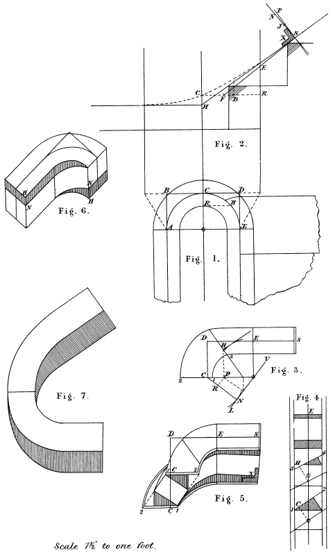
Fig. 1 is an enlarged plan of Fig. 1, Plate X. The face of risers must be set off on the centre line of rail to suit the falling line of handrail, which should be ascertained first. The line of travel is 15 inches from the centre line of rail, and the winders are divided on this line.
Fig. 2 shows the development. Cut a piece of thin board to fit the face of string around the zinc circle on plan, as shown by Fig. 3. Bend a thin lath around it, and mark the springing on to it and all risers between. Lay this lath on Fig. 2, and mark the springing and position of risers, as shown. The position of risers outside of the springing can of course be taken off the plan. Draw one or two full size steps top and bottom, and a part of the straight strings as shown. Continue the bottom edge of string to form a nice easy falling line connecting the straight parts, as shown by the curved parts, Fig. 2.
Fig. 4 shows a cylinder made to fit the inside face of the circular string. Before the veneer is put on, glue some paper all over the outside of this cylinder and let it dry. Then, should any glue get between the veneer and cylinder, it will pull the paper off instead of sticking to the wood, and perhaps break the veneer; the paper can be washed off. Bend the lath around the cylinder on top of the paper, and mark the springing, as shown, on both sides. Do this at both ends, and mark the springing down the sides with a straight-edge. Now get a piece of veneer a full 1/16 inch thick, the size shown by the straight dotted lines, Fig. 2. Cut the bottom edge to the curve S S.30 Mark the springing and each step on the veneer. It is as well to mark these on both sides. In putting this on the cylinder take care to have it the right hand. Fix on one side first with a hand-screw, so that the springing on the veneer is on the springing on the cylinder, then bend it around and fasten the other side temporarily. Then get two pieces of veneer, ⅛ inch thick and about 1 inch wide, cut to the shape of the curves S S and N N. Now bend the two pieces around on the top of the first piece, keeping the edge S S flush with the bottom edge of the large veneer. It will be seen that the three thicknesses of veneer will form the sinking in the string 5/16 inch deep. Next get a piece the exact thickness of the sinking 5/16 inch, and cut it to the shape of the sinking, as seen at Fig. 5. Put plenty of saw kerfs in the direction shown, that is, parallel to the springing. Let the kerfs go past the springing a bit on both ends. Now bend this around the cylinder with the kerfs next to it, and the edge close up to the veneers. Now get the staves about 2 inches by 2 inches, and bevel the edges to fit each other around the circle and hollow the under side to fit in the veneer, also cut the ends out to fit over the sinking. Start one side first with straight pieces as far as the springing and screw it down, then work from this piece and go right around, screwing each piece as it is fitted, until they are all on. Next start in the centre and take off one side, numbering each piece as it is taken off, lift up each of the three pieces of veneer and glue between them, screw the staves on again except the centre one, take them off on the other side and glue in the same way, after which screw on all the staves again. To glue the staves, again start in the centre and take off one, well glue the bottom next to the veneer and screw it down tight. Take off the next one to it and glue the bottom and side going against the one already glued. Repeat this process until all are fixed, but never glue more than one at a time. It may be found necessary to steam the veneer. This is sometimes done in a box made for the purpose, where there is steam to be had, but failing that, boiling in the glue-pot is used. But this is not a good thing to do if it can be avoided, as the dryer it is put on the better for the job.
31 Fig. 6 shows an enlarged section through the joint A B, Fig. 4. F is a section of Fig. 5.
Fig. 7 shows the well in position. If a ⅝-inch bead is used for the bottom edge, a piece of ⅝-inch cane can be bent around the well in continuation of the bead. This work must be all fitted before it leaves the bench, ready to go into its place when fixed.
33
The handrail is that portion of the fence carried up on the outside of the stairs and supported by the balusters, which are let into the ends of the treads. While these balusters form protection, the rail is to assist in the ascent and descent of the stairs. It is very evident the rail should be a uniform height over the line of nosings. This height should be 2 feet 8 inches, measured vertically over the face of risers, from the top side of tread to the top side of rail. And it will be seen that the risers around the circular parts should be placed so as to have the best possible falling line of rail, while the balusters should be, if anything, a trifle longer than on the straight parts.
The method adopted in this work is as follows:—The plan of centre line of rail is first laid down, and the tangents and face of risers drawn. Next the centre line of rail is unfolded, or developed, on a board, with position of risers thereon. Then the centre falling line of rail is drawn, resting on the corners of the full-size steps and continued across the well. And here it is where good taste and judgment is required, so as to get a good falling. After the falling line has been drawn it will be seen at once if any improvement can be made in the position of the risers. The development of tangents is next drawn to suit the falling line of rail.
The face moulds are next got out of some thin stuff. The tangents on the moulds will equal the tangents developed in the elevation. This will be better understood by referring to the succeeding drawings. Two face moulds are used, one for each side of the plank. The tangents and sections are the same on each mould, but as the width is on the inside of one mould and on the outside of the other, this gives the wreath the necessary twist. The wreath having been cut out square through the plank and the joints made, and the34 tangents squared across the joints, the face moulds are then tacked on, with the ends of both moulds flush with the joints, and the tangents on both face moulds are put to the tangents squared across the joints of wreath, there being no pushing or sliding the mould in any shape or form. The inside and outside is now sawn off, the saw always being held in the same direction as the section lines on the face moulds. A bevel is obtained for each section and set off on a board. The width of rail is also drawn on the same board, and where the bevel cuts the centre of width of rail, is the centre of plank. Now as the face mould gives the height of the centre of plank at each section, these heights are transferred to the elevation, which shows at once if the falling line is any, and how much, out of the centre of plank. Then the sections of rail are drawn on the board above, or below, where the bevel cuts the centre of width of rail, according to what the falling line is out of the centre of plank at each section. This shows what superfluous stuff there is to come off the top side of the wreath at each section, which is marked on to the wreath before the face moulds are removed. This superfluous stuff is then sawn off, keeping the saw in the direction of the section lines, after which the wreath is gauged to a thickness and the superfluous stuff sawn off the bottom.
I may say that this system has been put to practical test, and some of the very best examples of handrailing have been done by it with the very best results. But it was found to be a great advantage to use a machine gig-saw: they can be bought the same as any other saw, and if it is fixed into a bow-saw frame, or a frame made for it, no difficulty will be experienced in sawing out any wreath shown in this book.
The advantages of this system are:—
1. The tangents are made to conform to the falling line of rail, instead of the falling line having to conform to the tangents, as is the case in most systems.
2. The wreath being sawn out to the section lines instead of vertical, as is the case with cylindrical wreaths, saves more than half the time in squaring.
35 3. The wreath being straight across on the inside and outside in the direction of the section line, instead of concave on the inside and convex on the outside, as is the case with a cylindrical wreath, is much easier to mould, and has a much better appearance by far when finished.
4. It has all the advantages of falling moulds without the trouble of getting them out, and it can always be ascertained what any part of the falling line is out of the centre of the plank.
5. It takes the minimum thickness of stuff, as it can always be seen exactly what thickness will be required.
6. The system of bevelled joints does away with the short ramps, and thereby saves both labour and material; besides there is only one joint instead of three.
It will be seen that in no case in this book is extra thickness of stuff required.
37
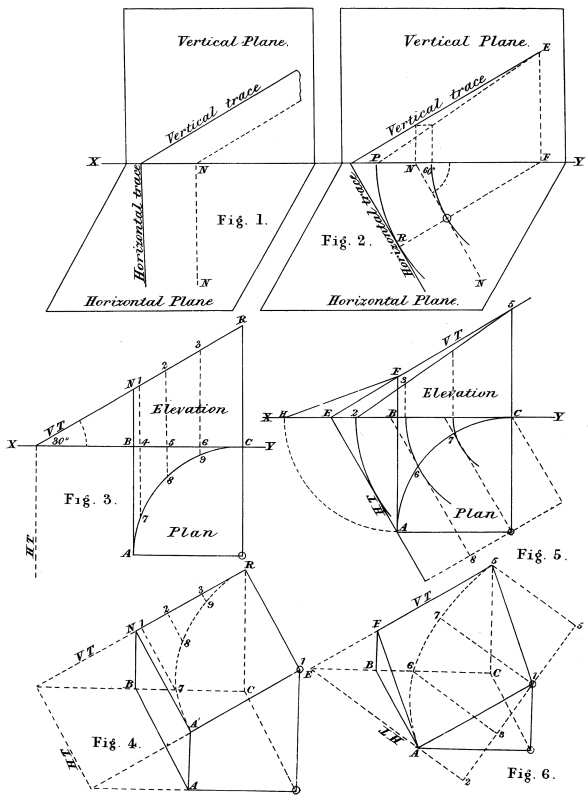
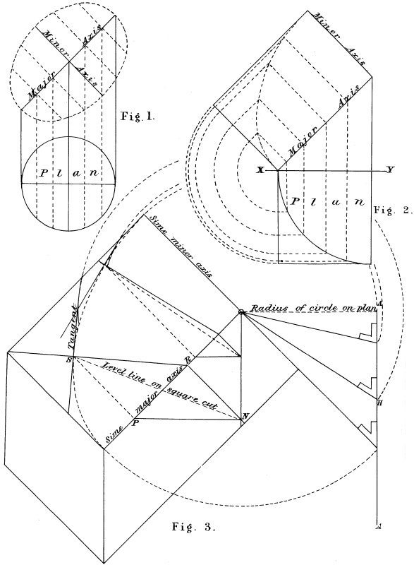
If the surface of a solid is neither horizontal or perpendicular it is oblique.
Thus, if we place a box on the table, the top of the table represents the horizontal plane and the side of the box the vertical plane, and the intersection of the box and the table is the ground line, or X Y. Draw a line out square from the box on the table, marked N N, Fig. 1. Hold the end of a book on this line, with its edge against the side of the box in an inclined position; mark a line on the side of the box: this line is the vertical trace, because the oblique plane has cut the vertical plane on this line. Before moving the book mark a line on the table: this is the horizontal trace, for the same reason that the oblique plane has cut the horizontal plane on this line.
Fig. 2 shows the horizontal trace inclined 60° to the vertical plane. Draw the dotted line N N on the table, making an angle of 60° with the box. Place the end of a book on this line, and while in an inclined position mark the vertical and horizontal traces the same as in Fig. 1. To find the true inclination of the oblique plane take F for centre, and for radius F R, strike the arc to cut X Y in P; join E P, which is the true length and inclination of a line on the oblique plane, to stand vertically over F R. All lines on the oblique plane parallel to the horizontal trace will be level, and all lines square to it will be the true inclination of the surface of the oblique plane.
Fig. 3. It is required to cut a block of wood the size of the square A B C O, its side A B to be 5 inches high, and its top surface inclined 30° to the horizontal plane. On the oblique surface project an ellipse that will stand vertically over the quarter of circle on plan.38 Let A B C O be the plan and B C R N the elevation. Project 7, 8, 9 on to the oblique surface, as shown by 1, 2, 3.
Fig. 4 shows a cuneiform sketch of the block. Make B N and C R equal corresponding letters, Fig. 3; join R N; square out lines from N R; make N A´, R O´ equal A B, Fig. 3. To complete the figure, make A A´ equal B N, and O O´ equal C R. To draw the ellipse, make N 1 2 3 R equal N 1 2 3 R, Fig. 3. Make 1 7 and 2 8 and 3 9 equal 4 7 and 5 8 and 6 9, Fig. 3. Trace the curve through A´ 7 8 9 R as shown. If this block is cut out in a vertical direction to the ellipse on its surface it will stand correctly over the quarter of circle, its plan.
Fig. 5. Cut a block of wood so that its edge will stand vertically over A B C O. The top of the block to be hard down at A. From A to B rise 3 inches, and from B to C 4 inches more. Make B F equal 3 inches and C 5, 7 inches. Join 5, F extended to cut X Y in E. Join E A, which is the horizontal trace, and E F 5, the vertical trace. F 5 will be the inclination of the edge of the block over B C. To get the length and inclination of the edge over A B, take B for centre and B A for radius, strike an arc to cut X Y in H. Join F H for the required edge.
The process of getting the lines on the oblique surface of this block, as shown at Fig. 6, is the same as most of the face moulds as laid down in this book, and let it be understood that if the problems on this and the following Plate are properly mastered, the foundation upon which this system depends has been laid, and all the plates that follow are purely a matter of detail. Let the instructions given here be carried out, and cut the blocks of wood as described, when the meaning and intention of every line will be clearly illustrated, and the way cleared for further progress.
Make E F 5 equal E F 5, Fig. 5. Take the distance F H, Fig. 5, in the compasses, with F, Fig. 6, as centre, strike an arc at A. With E A, Fig. 5, as a radius, and E, Fig. 6, as centre, strike an arc to intersect the first one at A. Join E A for horizontal trace and F A39 for the top edge of the block over A B. Draw from 5 parallel to F A, and from A parallel to F 5. Then O will be the centre of the ellipse, as it will be vertical over the centre on plan. A line drawn on an oblique plane square to the horizontal trace and passing through its centre is the major axis, and a line drawn parallel to the H T and passing through its centre is the minor axis. Make 2 3 0 5 equal 2 3 0 5, Fig. 5. Make 3 6 and 0 7 equal 8 6 and 0 7, Fig. 5, and trace the curve through A 6 7 5.
41
Should any part of a plan be a circle, it will when projected on to an oblique plane be an ellipse.
Thus, take any one round piece of wood, cut one end off square to its side, this end will be a true circle. Cut the other end to any angle, which will then be an ellipse, and when the piece is stood on end will be vertical over the circle, its plan. Fig. 1 shows this. And it will be seen, no matter what angle the oblique plane may be, the minor axis never changes, it is always the same length as on plan, as are all lines parallel to it; but not so with the major axis, which always lengthens as the angle increases.
Fig. 2 shows a quarter of a circle projected on to an oblique plane, inclined 45° to the horizontal plane.
Fig. 3 shows a plank inclined 45° to the horizontal plane, with a quarter of an ellipse traced on its oblique surface. At any point on the curve draw a section line and a normal tangent. Cut the plank square through to the section line. Draw a level line on the square cut, and produce a bevel that will, when the stock is held to the section line on the oblique surface, produce with its blade a line across the cut that will be perpendicular to the level line on the square cut.
At any point on the curve, say at S, draw a line square to, and to cut the major axis in P; draw the level line on the edge to cut the vertical line from the centre O in N; draw R N square to the major axis. Join R S, which is the section line; draw the tangent square to it through S. Cut the plank through to the lines S R and R N; join N S after the cut is made. To get the bevel, draw A A parallel42 to, and at a distance away from O N, equal to minor axis or radius of circle on plan. Take the compasses, and for centre put one foot at O, and for radius strike an arc just touching the tangent through S, bring it around to cut A A in H, join O H for the required bevel. This bevel, when applied across the cut, will be square to the level line S N.
43
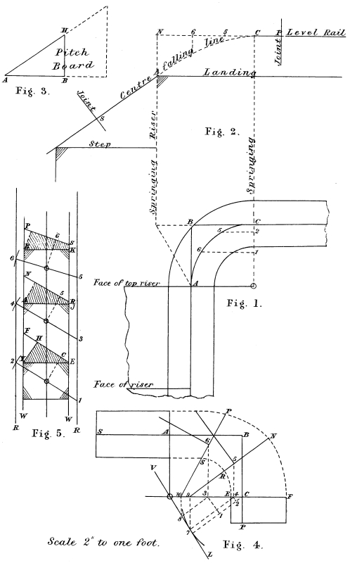
Fig. 1 shows the plan of the rail, with the top riser placed in the springing and the level rail 4 inches above the landing, so that when the rail is raised to its proper height, 2 feet 8 inches above the treads, measured vertically over the face of the risers to the top of rail, it will be 3 feet from the landing to top of level rail. To get the radius of the centre line of rail, make B H, Fig. 3, equal 4 inches; then A B will be the required radius. At Fig. 2 set up one step and landing. Draw the centre falling line resting on the corners, also draw the level rail 4 inches above the landing. Make N C equal the stretch-out of the centre line of rail, Fig. 1, and complete the falling line from A to C, as shown.
Fig. 4 shows the face mould. Draw A B C at right angles. Make A S equal A S, Fig. 2, and A B equal A H, Fig. 3, and B C equal B C, Fig. 1, and C P equal C P, Fig. 2. From A draw A O parallel to B C, and from C draw C O parallel to A B. Then O will be the centre, A O the semi-minor axis, and O C the semi-major axis. To get points in the curve and draw section lines, take O C, Fig. 1, for radius and C, Fig. 4, for centre; strike an arc on the left; draw V L through the centre, and tangent to this arc; draw from C square to V L. Say there are to be two sections marked 5 and 6, Fig. 1. Make C 2 1 equal C 2 1, Fig. 1. Draw from 1 and 2 parallel to V L to cut O C in 3 and 4. From 3 and 4 draw parallel to A O, and make 4 5 and 3 6 equal 1 6 and 2 5, Fig. 1; then 5 and 6 will be points in the curve. From 3 and 4 draw square to and cut V L in 7 and 8; from 7 and 8 draw square to and cut O C in 9 and 10; join 9 5 and 6 10 for section lines. To get bevels, width of mould, &c:—On a piece of board draw two parallel lines, at a distance apart equal to radius of44 centre line of rail, as shown by the lines R R, Fig. 5; also draw the width of rail, as shown by W W. For the section at C, make 1 2, Fig. 5, equal O C, Fig. 4; draw section of rail; draw E F parallel to 1 2, to cut the top corner of section of rail. Then O C will be half thickness of plank and E C F the width of mould. For section 5, with O, Fig. 4, as centre, strike an arc to just touch the tangent from 5; make 3, 4, Fig. 5, equal this distance. Make O 5 equal half thickness of plank and draw R N parallel to 3 4, then R 5 N will be width of mould on this section. The process of getting bevel and width of mould for section 6 is the same, always squaring out the line from the centre of section of rail and setting off half thickness of plank, and drawing the top or bottom side of plank parallel to the bevel line through the centre of section. To complete the face mould make C E and C F equal C E and C F, Fig. 5. For section 5 make 5 R and 5 N equal 5 R and 5 N, Fig. 5. For section 6 make 6 S and 6 P equal 6 S and 6 P, Fig. 5. The section on the minor axis requires no bevel, as was explained in Plates XII. and XIII. This line never exceeds its plan, therefore on this line the face mould never exceeds the width of rail. Complete the face mould as shown.
45
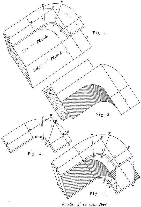
Fig. 1 shows the plank from which the wreath is to be cut out. Lay the face mould on, and transfer the tangents on the face of the stuff. Mark off each side of the tangent at P, O H to equal C H, Fig. 5, Plate XIV., and cut the wreath out square through the plank, as shown by dotted lines, taking care to have the wreath cut full on the minor axis at A, and along the shank to S, as this part does not exceed the width of the rail.
Fig. 2 shows the wreath after being cut out square through the plank. Plane one side perfectly true, then get it to its required thickness. It is very important that the stuff should be got to the same thickness as drawn at the sections, that is, twice the thickness of O C, Fig. 5, Plate XIV. Now make the joints square to the face of stuff and square to the tangents, applying the square as shown. So much depends upon the trueness of the joints that too much care cannot be taken with them.
Fig. 3 shows the face mould for the other side of the stuff. Lay the face mould, Fig. 4, Plate XIV., on a thin piece of stuff, and mark off on to it the tangents S A B C P and the section lines, stick a bradawl through 5 and 6, and mark off on the section lines, on each side of C 5 and 6, the width as shown opposite to the first face mould. Fig. 4 shows the application of moulds.
47
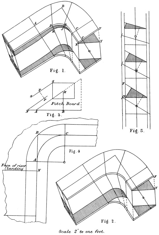
Fig. 1 shows the same wreath after the inside and outside has been cut off, so that a straightedge will touch both face moulds all round when held in the direction of the section lines, as shown marked across the inside.
To cut the wreath out get a machine gig-saw and either make a frame for it or fit it into a bow-saw frame: this saw will be found to be much better than the ordinary bow-saw, as it is much stiffer and will not bend in the cut, and being thick on the teeth and thin on its back edge, works free.
Every wreath shown in this book can be squared with this saw, and if care is taken in cutting the superfluous stuff off, very little cleaning up is required. The saw must always be held in the same direction as the section lines. After the inside and outside has been cut off and cleaned up, before taking the face moulds off mark down from the top on each section, inside and out, the distances as shown by the shaded parts on each section at Fig. 5, Plate XIV., and marked F Y, R J, S K, &c. The shaded part at Fig. 1 shows this; the moulds can now be removed and the superfluous stuff cut off to the lines traced through E J K on the inside and Y A B on the outside. The bottom can be gauged from the top with an ordinary gauge, but should be sawn full and jointed to the straight rails before being cleaned up.
Fig. 2 shows the same wreath, only the rail is cut out of the top of the plank all round, instead of the centre, as at Fig. 1. And this wreath has a much better appearance on the inside when finished.48 The face moulds and their application are the same, but as the rail is to come out of the top of the plank, it will throw the level rail too high on the landing. To obviate this the rising landing must be brought out from the springing. Make A B, Fig. 3, equal A B, Fig. 4, draw section of rail at H as shown, draw S S parallel to A H, make P P equal half thickness of rail, make B A N, Fig. 4, equal B A N, Fig. 3, and draw riser as shown.
49
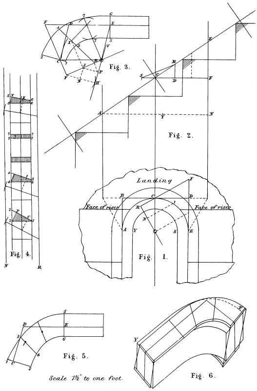
Fig. 1 shows the plan of rail with the risers landing and starting, placed half a tread from C on each side along the centre line of rail. By this arrangement we get two balusters on the landing the same distance apart as on the steps, and the centre falling line straight.
Draw plan of rail and enclose the centre line with tangents A B C D E. Mark off from C along centre line of rail on each side half a tread, and draw face of risers landing and starting.
Fig. 2 shows the elevation. Make A N equal stretch-out of centre line of rail. Set up two steps and landing, taking care to draw the face of risers as they occur on the centre line of rail, Fig. 1. Draw the falling line resting on the corners as shown. For development of tangents make F D S equal E D C, Fig. 1. From D, square up a line to cut the falling line in R, then E R will be the pitch of the tangent over E D, Fig. 1; join R S for pitch of tangent over D C, Fig. 1. Make E D F, Fig. 1, equal F D C, Fig. 2, join F C, which is the horizontal trace.
Fig. 3 shows the face mould. Make E D S equal E R C, Fig. 2, with D for centre, and R S, Fig. 2, as radius; strike an arc at C with S as a centre, and F C, Fig. 1, as radius; strike an arc to intersect the first one at C, join D C. From C draw parallel to D E, and from E draw parallel to D C; these lines will meet at the centre O. Join S C, which is the horizontal trace. Draw the semi-major axis square to it through the centre and the semi-minor axis parallel. With F as centre, and O N, Fig. 1, as radius, strike an arc at H; draw V L through the centre and tangent to the arc. Say we have one section50 between the minor axis and C marked 1. Make H N equal O N, Fig. 1. Draw N J parallel to V L. Make J I equal N I, Fig. 1. Draw J P square to V L and P R square to F O; join R I for section line. For bevels, width of moulds, &c., take O for centre and for radius open the compasses to touch each tangent; transfer these distances to Fig. 4, always making the distance between the lines N R, Fig. 4, equal the radius of centre line of rail on plan. Draw the section of rail on each bevel and set off half thickness of plank, and complete the sections as shown. For width of mould make C I P and 1 3 4 and E 6 5 on section lines Fig. 3 equal C I P and 1 3 4 and E 6 5 at sections Fig. 4. It will be noticed that, while at sections C and I the face mould has less stuff on the inside, at section E, on the other side of the minor axis, it has more.
Fig. 5 shows the face mould for the other side of the plank. To cut the wreath out, lay either mould on and transfer the tangents on to the stuff, and mark off on each side of face mould on the minor axis. The stuff should be cut full on this line. Mark off on each side of the tangents at the joint C the distance C P as seen at the section, and on each side of E, E Y as seen at Fig. 4. Draw around roughly from P to the minor axis to Y. The stuff is cut square through the plank to this line inside and out. Plane the stuff true and gauge it to its proper thickness and make the joints square to face of stuff and to the tangents. The application of the face moulds is seen at Fig. 6; the tangents on both face moulds must lie on the tangents marked across both joints of the wreath. Now saw the inside and outside off as shown by the shaded parts at Fig. 6, keeping the saw in the direction of the section lines. Clean up the wreath both inside and out, always keeping the straight edge in the direction of the section lines. Before removing the moulds mark from the top side 22, 33, 44, 55, 66 and 77, as shown by the shaded parts of sections at Fig. 4. Cut the superfluous stuff off the top to these lines, after which, gauge to a thickness, set the gauge full so as to allow the wreaths being cleaned up after the pair are bolted51 together. Before they are bolted and dowelled together at the centre joint them to the straight rails, and clean off any superfluous stuff there may be on the shanks in a line with the straight rails, and mark the section of rail on the ends of shanks before removing the straight rail; now joint the two together.
But before cleaning the pair off it would be well to test the correctness of the centre joint. Make N Y, Fig. 2, equal S Y, Fig. 1, and join E Y; now if the distance from the centre of the thickness of one wreath to the centre of the thickness of the other on the inside at the sections, at the springing, equals E Y, Fig. 2, the joint will be correct. Having proved the joint in this way, clean them off while together, then take them apart before glueing up. Mark the pattern of rail on the joint and mould them; use a handrail screw to bolt the joints together with and keep them as near as possible the centre of section of rail. There should be two dowels in each joint to keep them from twisting, placed according to pattern of rail.
In taking the length of straight rails, take the length of strings from springing to springing and allow for length of shanks of wreaths, as measured from the joint to springing, in a line with straight rails.
53

The principal thing to consider in planning stairs of this kind is to place the riser starting, so as to get a good falling line. Fig. 1 shows the plan with the centre line enclosed with tangents A B C D E.
Fig. 2 shows the elevation with the centre falling line and development of tangents. Make R N S equal stretch-out of centre line of rail, Fig. 1. Draw the landing and the level part of falling line 4 inches above it to cut the centre line at H. Draw H E to pitch of pitch-board and complete the falling line from E to J; set up the height of a riser above the landing on the right, and draw the top of step to cut the line H E for position of riser. Make E P, Fig. 1, equal S P and draw face of riser starting on plan. This riser must be slightly curved, so as to get it the same width on the end as the others. For development of tangents, make 1 2 3 4 E equal A B C D E, Fig. 1. From 4 square down a line to cut H E in D; from where the falling line cuts the centre line, square out a level line to cut 3 in C; join D C extended to cut the line 2 in B; draw A B level. Then A B and B C will be the tangents for the bottom mould, and C D and D E for the top mould; make E F, Fig. 1, equal W F, Fig. 2, and join F C for H trace.
Fig. 3 shows the face mould for the upper wreath. Make E D F equal E D F, Fig. 2, and F C equal F C, Fig. 1, and D C equal D C, Fig. 2. Draw the major axis through the centre square to F C. With S as centre and O N, Fig. 1, as radius, strike an arc at N; draw V L through the centre and tangent to the arc. For section marked 3, make N H equal O H, Fig. 1, draw H J parallel to V L, make J 3 equal54 H 3, Fig. 1. Draw J P parallel to S N, and P L square to major axis, join L 3 for section line.
Fig. 4 shows the sections, width of mould, &c. The process of getting the bevels being the same in every case, it would be useless repetition to describe it every time. The shaded parts of sections show the superfluous stuff to come off the top side of wreath at each section.
Fig. 5 shows the face mould for the other side of the wreath. In applying these moulds care must be taken to get the twist the right way.
Fig. 6 shows the face mould for the lower wreath. As this one has only one pitch, draw A B C at right angles and make A B and B C equal A B and B C, Fig. 2. With A as centre and A O, Fig. 1, as radius, strike an arc, draw V L through the centre and tangent to the arc; make H S equal O S, Fig. 1; draw S 4 parallel to V L, make 4 2 equal S 2, Fig. 1. Draw 4 5 parallel to A H, and 5 6 square to major axis A O; join 6 2 for section line.
Fig. 7 shows the sections for this wreath. The section at the joint C will be in the centre of plank, but that at A and 2 will be below the centre. The difference between O H, Fig. 6, and Y J, Fig. 2, is what the section on shank will be below the centre; and that between O 5, Fig. 6, and 5 6, Fig. 2, for section 2. Draw the sections below the centre as shown at Fig. 7.
Fig. 8 shows a sketch of the bottom wreath with the inside and outside worked. The shaded parts show the superfluous stuff to come off top and bottom.
55
The plan, elevation and falling line, and position of risers in this case are the same as in Plate XVII., but show a different way of getting out the wreaths. This may not be such a correct method as the former one, as the centre joint will be vertical instead of square to the tangent across the well as was the case there, but nothing could be more simple than the method here described. Having the plan and elevation drawn, square out a bevel line from C, to cut the springing in R. Make R F equal E D, Fig. 1; say the joint is to be at S on the right, join S F, draw the joint S P square to the straight rail, and draw S N square to the tangent F E S.
Fig. 3 shows the face mould. Draw S E D C at right angles, make S E D equal S E F, Fig. 2, and C D equal C D, Fig. 1. To complete the mould, make O N and C N equal E R and F R, Fig. 2. Draw V L through O N; make C R and P H equal C R and R H, Fig. 1. As will be seen, the straight rail is not in a line with the tangent, and as the joint must be square to the straight rail it cannot be square to the face of the plank. Therefore, the face mould for the top side will require to be a trifle longer, while the mould for the bottom side must be the same distance shorter. To find out how much the joint will require to be bevelled, mark off along S N, Fig. 2, S J to equal half thickness of plank; then the distance between the two lines S P and S N at J is what the joint will be out of square to face of plank through half its thickness. The shank of top face mould must be increased, and that of the bottom reduced to this amount as shown by the shaded parts. The face mould shown at Fig. 3, being for the under side, is reduced.
56 Fig. 5 shows the application of the face moulds; as there is no bevel on the shank E S the joint will only be out of square to face of plank and not to the tangent. Fig. 6 shows the bottom half; this having no twist can be struck with the compasses, the same as the plan. It must be the distance C H, Fig. 2, thicker than the rail. The shaded part shows how the superfluous stuff must be taken off top and bottom.
Fig. 7 shows the pair in position after being squared.
57
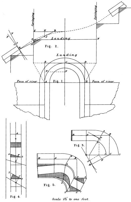
Fig. 1 shows the plan of a half-space landing with the centre line of rail struck with a 9-inch radius, and the risers starting and landing placed in the springing. As the steps are only 10 inches it is very evident that if the tangents A B and D E were the same pitch as the straight rail the tangent across the well would pitch the wrong way, which of course would not do. To obviate this the tangent A B must only rise half a riser over B, and the tangent D E only fall half a riser over D, and the tangent across the well level and the joint on the end of shanks must be bevelled so as to joint square to the straight rail.
Fig. 1 shows the plan with the risers in the springing.
Fig. 2 shows the elevation. Make S N equal stretch-out of centre line of rail. Set up one step above and below and draw landing; also draw the centre falling as shown, this line must pass through the centre at the height of half a riser above the landing, and make a good easing into the straight rail above and below the springing. For development of tangents make F B equal A B, Fig. 1, and draw from B to the joint below the springing; draw R P square to the straight rail, which will be the joint, and R N square to the tangent A B.
Fig. 3 shows the face moulds. As the tangent B C is level draw A B C at right angles; make R A B equal R A B, Fig. 2, and B C equal B C, Fig. 1, and complete the mould as usual. It will be seen that the sections will be in the centre of the plank at both joints. For section P, make F H, Fig. 2, equal A P, Fig. 1, and H J, Fig. 2, equal H J, Fig. 3. The difference between J and the falling line is58 what the section is out of the centre of plank as shown at Fig. 4. The difference between the tangent A B and the falling line at the springing shows that the section A is out of the centre. The stuff must be thick enough to get this section out as required. Make R Y, Fig. 2, equal half thickness of plank. Add Y C to the end of shank of one face mould and reduce the other to the same amount, as shown by the shaded parts.
59
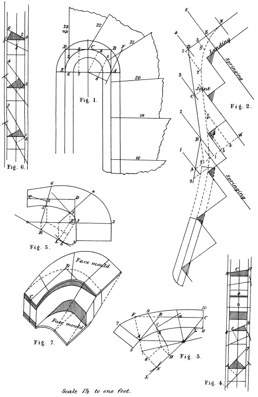
Fig. 1 shows the plan with the centre line enclosed with tangents. Having laid down the risers on plan, keeping the narrow ends of winders as near as possible half a step, then with one baluster on each they will be the same distance apart as on the square steps which have two. This is not intended as a fixed rule but merely as a guide. The risers must be placed so as to get a good falling line, and this can only be ascertained by developing or unfolding the centre line and tangents on a board.
Fig. 2 shows the development of centre line and tangents. Set up all the treads and risers as they occur on the centre line of rail, Fig. 1. Draw the springing through A and E. Draw the centre falling line resting on the corners of square step at bottom and 4 inches above the landing at top. It is better for the falling line to be a little higher over the winders, especially near the top. To develop the tangents make the distance between the lines 1 2 3 D E equal A B C D E, Fig. 1. Draw D E level. From the centre joint on the falling line square out a line to cut the line 3 at C, join D C extended to cut the line 2 in B. From where the falling line cut the lower springing, square out a line to cut the line 1 in A; join A B; then A B C will be the tangents for the lower wreath and C D E for the top. Decide where the joint is to be below the springing, and draw a line parallel to the tangent A B, and tangent to the curve of the falling line where the joint is to be. The joint must be square to this line. It will be necessary to have a ramp here to ease into the straight rail, this is shown by the dotted lines. In the next plate is shown a method of easing the wreath into the straight rail without the aid of a ramp.
60 Fig. 3 shows the bottom face mould. Make C B F and B A equal C B A and B A, Fig. 2, and F A equal F A, Fig. 1, and complete the mould as usual. To find what each section is out of the centre of the plank, make W 4 5, Fig. 2, equal C 4 5 on the centre line of rail, Fig. 1; make 4 4 and 5 5, Fig. 2, equal N O and N H, Fig. 3. The difference between the falling line and 4 is what the section 4 on the minor axis is above the centre; and that between 5 and the falling line is what the section 5 is out of the centre. The section at both joints is in the centre, but at the springing A the falling line is a little above the centre, as it cut the springing above the level line A W, which is the height of the centre of the plank there. Get out the mould for the opposite side of the plank in the usual way, by laying Fig. 3 on a thin piece of stuff, and transfer the tangents and section lines on to it. Stick a bradawl through A 5 4 C and mark off out to it A 7 5 8 and 5 9, and C 10 and C 11, only on the opposite side. Work the inside and outside off first with a gig-saw, as before described. The shaded parts of sections at Fig. 4 show the superfluous stuff there is to come off the top side.
Fig. 5 shows the face mould for the top half. Draw C D E at right angles, and to equal C D E, Fig. 2. To see what the sections are out of the centre, make E 3 2, Fig. 2, equal E 3 2 on centre line of rail, Fig. 1. Make 2 2 and 3 3, Fig. 2, equal S R and S L. The difference between 2 and the falling line is what the section 2 is below the centre of plank, and that between 3 and the falling line is what the section 3 is below the centre. And that between E and the falling line is what it is below there.
Fig. 6 shows the sections, and the shaded part shows the superfluous stuff there is to come off the top at each section, after the inside and outside have been cut off.
Fig. 7 shows the wreath after the inside and outside have been cut off; the dotted lines show the wreath cut square through the plank.
61
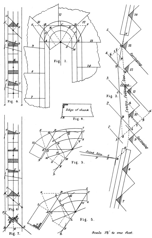
Fig. 1 shows the plan with face of risers laid down. It will be noticed that the winders commence at the springing at the top, while they are brought past the springing at the bottom; this causes the rail to be high at E and, therefore, safer for any one coming down the stairs with their hand on the rail; and by bringing the winders below the springing it makes a better easing into the straight rail. This will be understood by referring to Fig. 2, where the centre line and tangents are developed. Set up the treads and risers as they occur on the centre line of rail, Fig. 1; also draw the springing and the centre line W. Draw the centre falling line resting on the corners of square steps top and bottom, and continue it up over the winders as shown by the dotted line. To develop the tangents make the distance between 1 2 3 4 5 equal A B C D E, Fig. 1. From where the falling line cuts the centre line square out a level line to cut the line 3 at C. Continue the top tangent down in a line with the straight rail to cut the line 4 in D. Join D C extended to cut the line 2 in B. Now make the joint below the springing, as near to it as possible, so that it will be clear of the easing. There being no ramp on the straight rail, the joint should be well clear of the easing and into the straight so as to avoid any signs of a cripple when the wreath is jointed to the straight rail, which there would be if the joint was made in the easing. Square out a level line from the joint P, and make P R equal the distance between the line 1 and the springing. Join R B, this has cut the line 1 at A. From A draw A W level.62 From R draw the joint square to the straight rail, and R P square to the tangent A B R. Make D F, Fig. 1, equal 4 F, Fig. 2, and join F E for the horizontal trace of the top wreath. Make B S, Fig. 1, equal 6 S, Fig. 2, and join S A for the horizontal trace of the bottom wreath.
Fig. 3 shows the face mould for the top wreath. Make C D F equal C D F and D E equal D E, Fig. 2, and F E equal F E, Fig. 1. Draw from E parallel to D C and from C parallel to D E to meet at the centre O. Draw the major axis square to the horizontal trace F E. With M as centre and O M, Fig. 1, as radius strike an arc at N; draw V L through the centre and tangent to the arc, and complete the mould as usual; M S will equal M S, and T J will equal S J, Fig. 1.
Fig. 4 shows the sections. S S will equal the radius of centre line of rail, Fig. 1, and for bevels place one foot of the compasses on the centre O, Fig. 3, and open out to touch each tangent, then transfer these distances to each section, Fig. 4. To find what each section is out of the centre of the plank, make E J K, Fig. 2, equal E J K on the centre line of rail, Fig. 1. Make J J and K K, Fig. 2, equal N H and N O, Fig. 3. Now the difference between E and the falling line is what the section is below the centre at the springing, and that between J and the falling line is what the section is below the centre, and that between K and the falling line is what the section on the minor axis K is above the centre; the sections at both joints are in the centre of the plank.
Fig. 5 shows the bottom face mould. R A B will equal R A B, and S B C will equal S B C, Fig. 2, and A S will equal A S, Fig. 1. Proceed as usual to get bevels, sections and width of mould. Now, as the tangent A B is not in a line with the straight rail, and the joint being square to the latter, the end of shank must be bevelled so as to joint correctly to the straight rail. Draw P P, Fig. 7, to the same bevel as that for the shank marked O O, Fig. 6. Draw C D, Fig. 7, square to P P, make C N equal 2 2 at section A, Fig. 6, draw63 the level line through N to cut P P in E and C D in D. Now, at Fig. 2 mark off along R P, R S to equal 2 2 or 1 1, Fig. 6. Make C S and C S, Fig. 7, equal S S, Fig. 2, and join S E and S D for bevels T and S. Apply the bevel T as shown and S as shown at Fig. 8. The face mould for the under side will be S S, Fig. 2, longer, and that for the top side the same amount shorter.
65
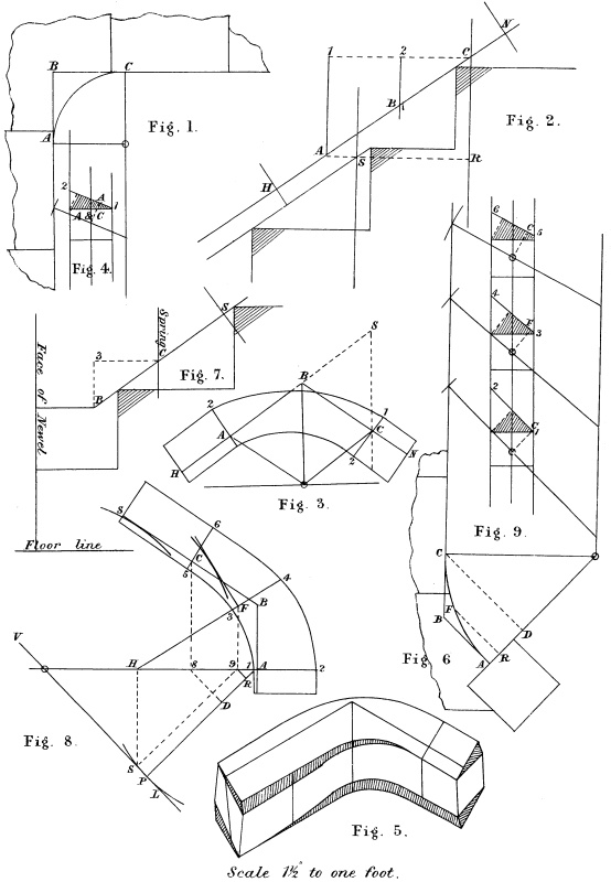
Fig. 1 shows plan of centre line of rail enclosed with tangent A B C. Draw risers, landing, and starting half a tread from B. This will cause the tangents on face moulds to be the same pitch as the straight rail. This arrangement answers very well if the rail is small, but if the rail is a wide one, say 4 inches or more, the inside has a crippled and awkward appearance.
Fig. 2. Make R S equal stretch-out of the quadrant, Fig. 1. Set up one tread and riser above and below, as they occur on the centre line of rail, Fig. 1. For development of tangents make C 2 1 equal A B C, Fig. 1. Square out a level line from the springing at S to cut the line 1 at A. Join A C for tangents, which will be the same pitch as the straight rail.
Fig. 3 shows face mould. Make C B S equal C B A and B C equal B C, Fig. 2, and S C equal the diagonal of the square on plan. Draw C O and B O parallel to A B and B C. Draw sine major axis and sine minor through O. Notice the major axis is parallel to the diagonal from A to C, and the minor axis is the other diagonal. Both pitches being the same throws the horizontal trace parallel to the diagonal from the centre to B. One bevel will do for both shanks, as the pitches are the same. The falling line will be in the centre of plank at both ends and at the minor axis.
Fig. 4 shows the section, which is the same for both ends, only of course the reverse hand.
Fig. 6 shows the plan of centre line of rail of a side wreath66 starting from a newel. Lay down the tangents A B and B C equal in length and to the required angle, according to circumstances, the size of the hall, &c. The farther it stands out into the hall the better it will look, but it must not obstruct the passage or be out of proportion to the size of the stairs. B should be in front of the second riser, or it will make the rail too high at the newel. A will be the face of the newel. Draw from A square to A B, and from C square to C B to meet in O. Then O A will be the radius of the centre line of rail, which draw. Then A B being level will be the horizontal trace.
Fig. 7 shows the elevation. Set up a tread and risers and draw the springing C as it occurs on the plan. Make C 3 equal C B, Fig. 6, and draw B C S resting on the corners.
Fig. 8 shows the face mould. Draw the line A P, and make A D P equal A D O, Fig. 6. Draw V L through P at right angles to A P. Draw D 8 parallel to V L, make D 8 equal B 3, Fig. 7; join A 8 extended to cut V L in O; then O will be the centre. Make A B and 8 C equal A B and D C, Fig. 6. The completion of the mould will be understood. The tangent C B will equal C B, Fig. 7, if the drawing is correct.
Fig. 9 shows the sections which will be in the centre of plank all round.
67
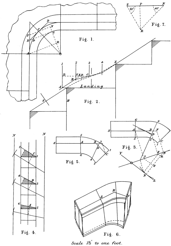
It was said in a previous case that with a wide rail and the tangents on the same pitch as the straight rail, the inside of rail has a crippled appearance. This can be remedied by having the wreath in two pieces.
Fig. 1 shows the plan laid down so as to make the inside falling line of rail a straight line; and the risers landing and starting placed in the springing. To find the radius of centre line of rail, Fig. 1. Make S N, Fig. 7, equal one step. From N draw N R at 45° with S N, and from S draw a line at 60° with S N to meet the line from N in R, from R draw square to and cut S N in P; then R P will be the radius for the inside of the rail on plan.
Fig. 2 shows the development. Make H R equal stretch-out of centre line of rail on plan. Set up one tread and risers above and below, with the risers in the springing. Draw the centre falling line, resting on the corners and passing through the centre, at the height of half a riser above the landing. To develop tangents, make C S R Fig. 2, equal C B A, Fig. 1, and complete tangents as shown. To draw the horizontal trace at Fig. 1, make A B F, Fig. 1, equal R S F, Fig. 2. Join F C for the required trace. Draw N O square to it.
Fig. 3 shows the face mould. Make A B F equal A B F and B C equal B C, Fig. 2, and F C equal F C, Fig. 1. Make C P equal C N, Fig. 1. Draw the major axis from N square to N C F. Draw from A parallel to F C P to cut major axis in 7. Now if the drawing is correct A 7 will equal A R, Fig. 1. With P as centre and N R, Fig. 1, as radius, strike an arc at S; again, with 7 as centre and68 A R, Fig. 2, as radius, strike an arc to intersect the first one in S. Join 7 S and P S extended, and P N equal O N, Fig. 1. Draw from N parallel to 7 S to cut the major axis in O, then O will be the centre.
Fig. 4 shows the sections and bevels. Make N N equal radius of centre line of rail, Fig. 1, with O as centre, and for radius just touching each tangent, which distances transfer to Fig. 4. All the sections in this case will be in the centre of the plank.
Fig. 5 shows the face mould for the other side of the plank.
Fig. 6 shows the application of the face moulds to the stuff.
Both joints are square to tangents and face of plank in this case.
69
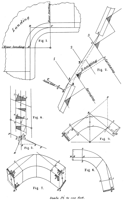
Fig. 1 shows the plan laid down exactly the same as in Plate XXIII.
Fig. 2 shows the elevation. Make Y Y equal the stretch-out of centre line of rail, Fig. 1, and set up one step above and below as shown. Draw the centre falling line resting on the corners and passing through the centre at the height of half a riser above the landing. For development of tangents, make 1, 2, 3 equal A B C, Fig. 1. Square out a level line from the lower joint H, and make H R equal the distance between the line 1 and the springing; join R N; then A B C will be the tangents of face mould. From R draw the joint line square to the straight rail, and R P square to the tangents.
Fig. 3 shows the face mould. Make R A B S equal R A B C, Fig. 2, and S C equal the diagonal on plan, and B C equal B C, Fig. 2. Draw C O and A O parallel to A B and B C, make C N equal C N, Fig. 2. The bevel A and C will be the same, as both pitches are the same.
Fig. 4 shows the sections at the two joints, and the section on the minor axis will be in the centre of the plank. But section A will be above, and that at C below the centre. The distance between C and the falling line is what the section at C will be below, and A above the centre. It will be seen one corner of the rail is cut off at these sections; this makes no difference so long as the moulding of the rail will work it out.
70 Fig. 5 shows the bevels for the joints to be worked off to, so as to make them joint to the straight rail. Draw P P to the same pitch as O O, Fig. 4; draw C H square to P P; make C N equal 4 4, Fig. 4. At Fig. 2 mark along R P, R S to equal 4 4, Fig. 4; make C S and C S equal S S, Fig. 2, and draw S E for the bevel T to be applied across the end of shank and along the tangent. Join S D for the bevel S, to be applied through the end of shank and along the surface of the stuff; this bevel must be held parallel to the tangent across the joint, that is, square through the plank. Notice that in all these bevel joints if the tangent is steeper than the straight rail, the bevel T is applied so that the ends of shank diminish towards the inside, while if the tangent is flatter, the end of shank will diminish towards the outside. This will be understood by referring to Fig. 3 in this plate, and Fig. 5, Plate XXI.
Fig. 6 shows the face mould for the under side; the shaded part N S shows the extra length required; this will equal S S, Fig. 2, the other end R S will be the same amount shorter. This mould is reverse to Fig. 3.
Fig. 7 shows the wreath cut out square through the plank, before the moulds are put on. The application of the bevels is seen here.
71

Fig. 1 shows plan with face of risers laid, and centre line of rail enclosed with tangents A B C.
Fig. 2 shows the development. Make Y Y equal stretch-out of centre of rail, Fig. 1. Set up treads and risers, placing the risers as they occur on the centre line of rail, Fig. 1; draw the centre falling line as shown. To development tangents make 1 2 C equal A B C, Fig. 1. Continue the tangent C B in a line with straight rail; make H R equal the distance between the line 1 and springing; join R B extended to cut the level line in F. Draw the joint line square to the straight rail, and R P square to the tangent; mark off along R P, R S to equal half thickness of plank.
Fig. 3 shows the face mould for the top side of the plank. Make R A B F and B C equal corresponding letters, Fig. 2, and F C equal F C, Fig. 1; draw C O and A O parallel to A B and B C; draw the major axis O M square to F C through the centre, with M as centre and M O, Fig. 1, as radius strike an arc at P; draw V L through the centre and tangent to the arc. Make M H equal M H, Fig. 1; draw Y J parallel to V L; make Y E equal H E, Fig. 1. Draw Y J parallel to M P, and J K square to major axis; join K E for section line; draw the short tangent from E square to K E.
Fig. 4 shows bevels, width of mould, thickness of plank. Get the levels by taking O, Fig. 3, as centre, and for radius open out to touch each tangent; transfer these distances to Fig. 4 for each bevel as shown, and complete the sections as usual; the section at each72 joint will be in the centre, but each of the others will be below. Make C E D, Fig. 2, equal C E D, Fig. 1. Make E E and D D equal P J and P O, Fig. 3. Then the difference between K D E and C and the falling line, is what each section will be out of the centre of plank.
Fig. 5 shows the bevels for the bevelled joint at R. Draw P P to the same bevel as the bevel for the shank, marked O O, Fig. 4; draw C H square to P P. Make C N equal 1 1, Fig. 4, make C S and C S equal S S, Fig. 2, and join S E and S P for bevels T and S. Cut the wreath out square through the plank as usual, except at this joint, which is worked across the top and bottom to the bevel T, the bevel S being for the sides. If the joint is worked true to these bevels, it will joint correctly to the straight rail. S S, Fig. 2, is what the face mould will require to be longer for the under side; this is shown by the shaded part on end of shank, Fig. 6, while R S on the shank of the top face mould, Fig. 3, shows the same amount shorter. It is presumed that the method of squaring the wreath is fully understood, and needs no further explaining here, as it can only be a repetition of what was described in the first few plates.
73
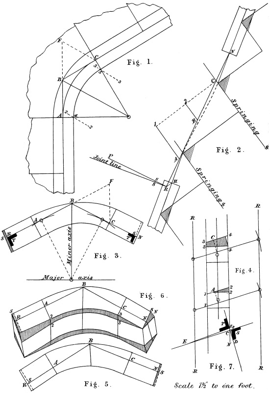
Fig. 1 is the plan with the risers placed in the springing, and the rail drawn with a radius so as to make the inside falling line nearly a straight line. Draw the centre line of rail to the angle, and bisect it from B. Set off on each side half a tread marked 2 2 and 3 3. Now draw the inside of rail to cut these two lines in 4 and 5; draw through 4 and 5 square to the centre line of rail to meet in O, then O will be the centre and A O the radius. Complete the plan as shown. The elevation is shown at Fig. 2. Make S S equal the centre line of rail, Fig. 1, from A to C. Set up one step above and below and draw the falling line. To develop tangents, make 1 2 C equal A B C, Fig. 1. Make the joints at N and H. Make H R equal the distance between the line 1 and the springing. Join R N for development of tangents. Draw the joint line square to the straight rail, and R P square to the tangents. Mark off along R P, R S to equal 1 1 or 4 4, Fig. 4. Make B F, Fig. 1, equal 2 C, Fig. 2, and join F C. Fig. 3 is the face mould. Make R A B F equal R A B C, Fig. 2, and B C equal B C, Fig. 2, and F C equal F C, Fig. 1. Draw the minor axis from B parallel to F C, and make B O equal B O, Fig. 1. Draw the major axis square to it. The sections are seen at Fig. 4. Make R R equal radius of centre line of rail on plan; make O O equal O O, Fig. 3, and complete sections as usual. The difference between C and the falling line at Fig. 2 is what the section at C will be below the centre, and that at A above; the sections at the joints and at the minor axis will be in the centre of plank.
74 Fig. 5 shows the face mould for the under side of the plank.
Fig. 6 shows the wreath worked inside and out ready for squaring.
Fig. 7 shows the bevels for the bevelled joints on both ends of wreath. They will be applied the same as in Plate XXV.
75
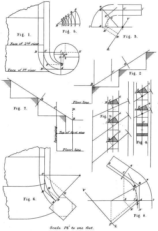
Fig. 1 shows the plan of a stair starting with a scroll. Make D E equal about 4 times the width of rail, which divide into 9 equal parts; make D I equal 5 of these parts; this will be the radius for the largest quadrant of the rail. To find the radius for each of the remaining quadrants, make D 1, Fig. 5, equal D 1, Fig. 1; make 1 2 equal one of the 9 parts, with D as centre and D 1 as radius; strike an arc from 2; square up a line to cut the arc in A; join A D with D as centre and D 2 as radius; strike an arc to cut A D in B; from B draw B 3 square to D 1. Continue the process as far as required to complete the scroll, D 2 will strike the second quadrant and D 3 the third, and so on. The face mould is seen at Fig. 3. Draw C B A at right angles and make C B equal C B, Fig. 2, and A B equal A B, Fig. 1. Make A R equal radius of centre line of rail C 1, Fig. 1, and complete the mould as usual. The scroll itself will only require to be the thickness of the rail, as it is level. All the sections in the wreath will be in the centre of the plank.
Fig. 6 shows the plan, and Fig. 7 the elevation of a side wreath starting from a newel. Make A P, Fig. 8, equal the radius of centre line of rail, Fig. 6, and draw V L through P square to A P. Make A E equal A E, Fig. 6, draw E 8 square to A E, and make E 8 equal B D, Fig. 7. Join A 8 extended to cut V L in O; then O will be the centre and A O the major axis. Make A B and 8 C equal A B and E C, Fig. 6. Join C B, which is the tangent, and if the drawing is correct, this will equal C B, Fig. 7. The tangent A B being level is of course the same length as on plan. All the sections will be in the centre of the plank; these are seen at Fig. 9. The short shank A N is to let into the newel; A being the face of newel.
77
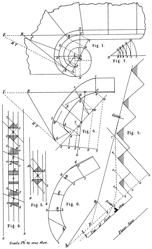
Fig. 1 shows the plan of a scroll, and wreath to stand over the curtail step and winders. Divide N N into 9 equal parts. Make N 1 equal 5 of these parts and draw the largest quadrant. To draw the remainder make N 1, Fig. 7, equal N 1, Fig. 1; with N as centre and N 1 as radius, strike the arc. Make 1 2 equal 1 of the 9 parts; from 2 erect a perpendicular to cut the arc in 7. Join 7 N. Now with N as centre and N 2 as radius, strike the second arc to cut N 7 in 8; draw 8 3 parallel to 7 2. Again, with N as centre and N 3 as radius, strike the arc to cut N 7 in 9; draw 9 4 parallel to 8 3. This process can be continued as far as required. N 1 will strike the largest quadrant, N 2 the next, and N 3 the next, and so on until the scroll is completed. The centre and inside lines of rail will be struck from the same centres. Make the joint at A, and draw the radius line from 2, which is the centre of this part of the scroll; draw the tangent A B square to it.
Fig. 2 shows the elevation. Set up the treads and risers as they occur on the centre line of rail, Fig. 1, and draw the centre falling line so that it will finish level, about on the line N N, and at a height of about 1 or 2 inches above the top of the first step. Make 3 7 equal the stretch-out of the centre line of rail, Fig. 1 from A to C. Draw the level line through the falling line at 7, and make 3 8 and 8 A equal C B and B A, Fig. 1, and complete the development of tangents as shown. Draw the joint at 7 square to the tangent A B. The scroll must be the distance S S thicker than the thickness of rail, and the joint worked to the bevel as shown.
Fig. 3 is the face mould for the top side of the plank. Make78 B F, Fig. 1, equal 8 F, Fig. 2, and at Fig. 3 make C B F equal C B F and B A equal B A, Fig. 2, and F A equal F A, Fig. 1. Draw C 11 and A 5 parallel to the horizontal trace F A, and make A 5 and C 11 equal A 5 and C 7, Fig. 1, and draw the major axis through 5 and 11. With 5 as centre and 5 7, Fig. 1, as radius, strike an arc at 7; draw a line through 11 and tangent to the arc. Now, if the drawing is correct, 7 11 will equal the height 3 C, Fig. 2. Make 5 4 3 1 6 7 equal corresponding figures, Fig. 1, and complete the mould as usual. Notice O will be the centre for sections D E R and C, and S S, Fig. 4, will equal the radius 1 D, Fig. 1. But for the section at the joint A, 2 will be the centre and S S, Fig. 5, will equal the radius 2 A, Fig. 1. The bevels, &c., are got as usual. Make 3 4 5 6 7, Fig. 2, equal C R E D A, Fig. 1. Make 4 4 and 5 5 and 6 6, Fig. 2, equal 1 S and 1 O and 1 W, Fig. 3. Now, the difference between 4 5 and 6 and the falling line is what each section is out of the centre of plank.
Fig. 6 is the face mould for the under side of the plank.
79
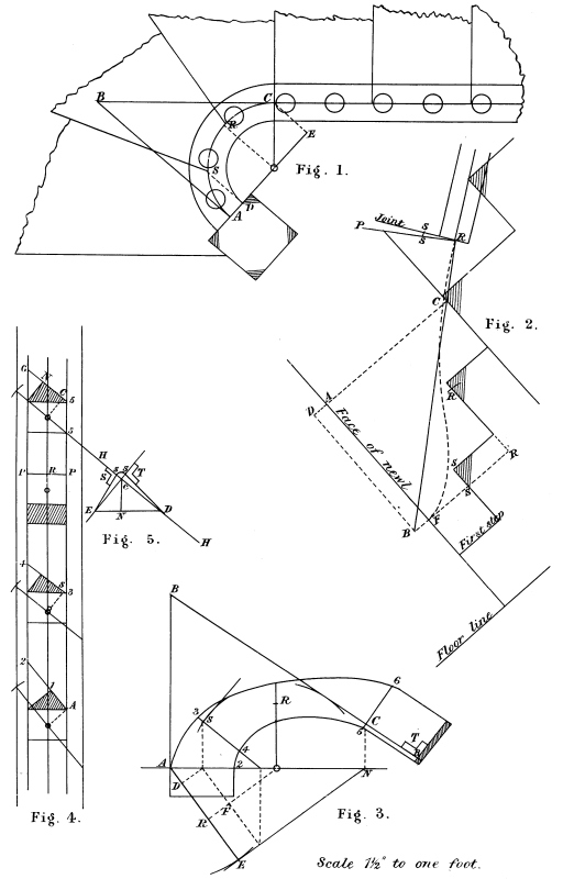
Fig. 1 shows the plan. There will be one baluster on the bottom step, and the remainder placed as shown. In planning stairs of this kind care must be taken not to let the newel obstruct the passage. No fixed rule can be laid down for the position of the newel; circumstances alone must regulate that; but the further the newel is brought round the more graceful will be the falling line of rail.
Fig. 2 is the elevation. Make C A equal the stretch-out of centre line of rail from C to A, Fig. 1, and C D equal C B, Fig. 1. Let B be 12 inches above the floor line; now draw the centre falling line from the joint at R at the top, and to strike the face of the newel level at the height of B, as shown by the dotted lines. Join R B for pitch of tangent B C. The tangent A B will be level, therefore the same length as on plan. Draw the joint at R square to the straight rail, and R P square to the tangent. Mark off along R P, R S to equal 5 5, Fig. 4.
Fig. 3 is the face mould for the top side of the plank. Draw the lines A E and N E at right angles, and make A E equal A E, Fig. 1, and N E equal B D, Fig. 2; join A N, which is the major axis; make C R equal C R above the springing at Fig. 2; add S S, Fig. 2, on to the end of shank, as shown by shaded part. The completion of the face mould will be understood.
Fig. 4 shows the sections. It will be noticed that the sections S and R are above the centre of plank. Make F S R, Fig. 2, equal A S R on the centre line of rail, Fig. 1, and make S S and R R below80 the falling at Fig. 2 equal R F and R O, Fig. 3. The difference between S and the falling line is what the section at S is above the centre of plank, while that between R and the falling line is what the section at R on the minor axis is above the centre of plank.
Fig. 5 shows the bevels for the bevelled joint at R. Draw H H to the same pitch as the bevel for the section C and draw C E square to H H and C N vertical; draw E D level through N; make C S and C S equal S S, Fig. 2, and join S D and S E for bevels T and S. To cut out the wreath, lay the face mould on the stuff, transfer the tangents on to it, mark off on each side of the tangent at A A 1, and on each side of the tangent at C C N, and on each side of R on the minor axis, ¼ of an inch more than half width of rail, marked P P, Fig. 4. Trace around through I P N inside and outside. Cut the wreath out square through the plank. Before bevelling the wreath, work the joint to the bevels T and S. The bevel T to be applied across the top and bottom, while the bevel S will be applied on the sides. S S is the extra length of stuff required on end of shank, as shown by shaded part on end of face mould. To get out the face mould for the under side, lay Fig. 3 on a thin piece of stuff and transfer the tangents and section lines on to it, and stick a bradawl through A S R C and mark off on each section the width of mould on the opposite side to Fig. 3. The shank will be the same amount shorter that Fig. 3 is longer.
81
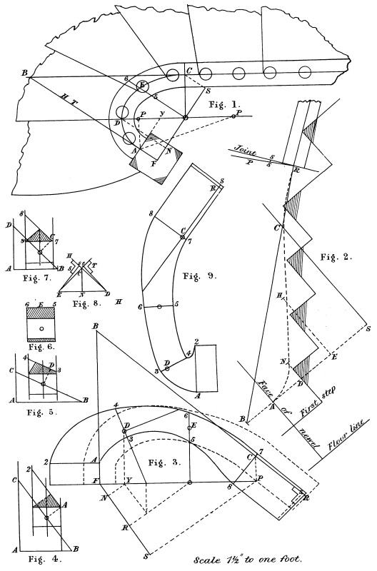
Fig. 1 shows the plan of rail with the risers in position. The line O C is the minor axis, and O D the major axis of the ellipse on plan; and as the tangent A B is level, it is of course the H T. From the foci P P draw to A, and bisect the angle, as shown by A Y; this will be the face of the newel on plan. Draw the tangent A B square to it. Draw F S through the centre O V square to A B. Draw O E parallel to A B; this line will be the minor axis on the face mould.
Fig. 2 shows the elevation. A S will equal the stretch-out of the centre line of rail from A to C, Fig. 1; and S B will equal C B, Fig. 1. Draw the falling line as shown so as to strike the face of newel level, at a height of 12 inches above the floor. Square out A B from A and join B R for pitch of tangent. Draw the joint line square to the straight rail and R P square to the tangent.
Fig. 3 shows the face mould for the under side. Draw F S and S P at right angles, and make F S equal F S, Fig. 1; and S P equal the height S C, Fig. 2. Join F P for the major axis of face mould. Make F R equal F O, Fig. 1. Draw R O parallel to S P. Draw O E square to the major axis F P; then O E is the minor axis, and O R is the same line as is marked V L in previous plates. Make O 5 E 6 equal O 5 E 6, Fig. 1. Make F N equal F N, Fig. 1, and draw N Y parallel to R O, and Y D square to major axis. Make Y D equal N D, Fig. 1, and complete the section as usual. Also make P C equal S C, and F A B equal F A B, Fig. 1. Join C B extended, and make C R equal C R, Fig. 2. Now if the drawing is correct C B will equal C B, Fig. 2.
82 Fig. 4 shows the bevel and section A. Make A B equal O F, Fig. 1; and B C equal O F, Fig. 3. Draw the section of rail, and draw A 2 to cut the top corner parallel to B C. Then A O will be half thickness of plank and A 2 width of mould here.
Fig. 5 shows bevel and section D. Make A B equal O D, Fig. 1. With O as centre for radius, open out the compasses to touch the tangent from D; transfer this distance to Fig. 5, as shown by B C. Now make A D E S, Fig. 2, equal A D E S on the centre line of rail, Fig. 1. Make D N and E H, Fig. 2, equal N Y and R O, Fig. 3. The difference between N and the falling line shows that the latter is nearly in the centre of plank at the section D. Make D 3 and D 4, Fig. 3, equal D 3 and D 4 at the section.
Fig. 6 shows the section on the minor axis, which of course requires no bevel. The difference between 4 and the falling line at Fig. 2 shows what this section is out of the centre of the plank.
Fig. 7 shows bevel and section C. Make A B equal O C, Fig. 1, and with O as centre, and for radius a distance to just touch the tangent, C B, Fig. 3. Transfer this to Fig. 7 as shown by B D, and complete the section as usual.
Fig. 8 shows the bevels for the bevelled joint at R. The method of getting them and their application will be understood.
Fig. 9 shows the face mould for the top side. The difference between this mould and Fig. 3 is that A 2 and D 4 and C 7 is on the inside of A D and C, instead of the outside, as at Fig. 3. In sawing around on the inside, leave the stuff full on the section D, and gauge to a width after the moulds have been removed.
83
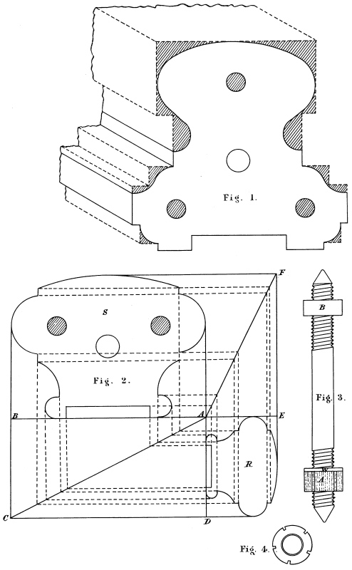
Figs. 1 and 2 show pattern of rails full size, both of which look well when finished, and nice to handle. The shaded parts at Fig. 1 show how the rail should be worked out before it is moulded. It will be seen that Fig. 1 has three dowels, while Fig. 2 has two.
At Fig. 2 is seen a method by which a rail may be proportionately increased or decreased to any size. Let S be the given rail and R the required one. Make A B equal the width of S, and A E the thickness of R; from E draw square to A B, and make E F equal the thickness of S; join A B. From A square out a line and make A D equal the width of the required rail R. From B and D square out lines to meet in C; join A C. From each member in S draw ordinates to cut A C and A F, and where these meet again in R will be the same member in the required rail.
Fig. 3 shows a handrail screw, A being a round nut, a section of which is seen at Fig. 4, and B a square one; W is a round washer. These screws are let into about the centre of the section of rail at the joints. A hole is cut in the under side of each piece for the nuts to go in, and a small bent chisel, made for the purpose, is used to turn the nut A.
LONDON:
PRINTED BY WILLIAM CLOWES AND SONS, LIMITED, STAMFORD STREET
AND CHARING CROSS.
Punctuation and spelling were made consistent when a predominant preference was found in this book; otherwise they were not changed.
Simple typographical errors were corrected; occasional unbalanced quotation marks retained.
Ambiguous hyphens at the ends of lines were retained; occurrences of inconsistent hyphenation have not been changed.
Each “Figure” reference is to a portion of the Plate illustration immediately preceding the text.
The captions of all illustrations included this credit line:
Thos. Kell & Son, Lith.
which have been omitted in this eBook.
The right-side edges of several illustrations were missing or illegible.
Page 43: Two occurrences of “sime” were changed to “semi-” to conform with the rest of the book.
End of the Project Gutenberg EBook of Practical Stair Building and
Handrailing, by W. H. Wood

*** END OF THIS PROJECT GUTENBERG EBOOK PRACTICAL STAIR BUILDING, HANDRAILING ***

***** This file should be named 57348-h.htm or 57348-h.zip *****
This and all associated files of various formats will be found in:
        http://www.gutenberg.org/5/7/3/4/57348/

Produced by Chris Curnow, Charlie Howard, and the Online
Distributed Proofreading Team at http://www.pgdp.net (This
file was produced from images generously made available
by The Internet Archive)

Updated editions will replace the previous one--the old editions will
be renamed.

Creating the works from print editions not protected by U.S. copyright
law means that no one owns a United States copyright in these works,
so the Foundation (and you!) can copy and distribute it in the United
States without permission and without paying copyright
royalties. Special rules, set forth in the General Terms of Use part
of this license, apply to copying and distributing Project
Gutenberg-tm electronic works to protect the PROJECT GUTENBERG-tm
concept and trademark. Project Gutenberg is a registered trademark,
and may not be used if you charge for the eBooks, unless you receive
specific permission. If you do not charge anything for copies of this
eBook, complying with the rules is very easy. You may use this eBook
for nearly any purpose such as creation of derivative works, reports,
performances and research. They may be modified and printed and given
away--you may do practically ANYTHING in the United States with eBooks
not protected by U.S. copyright law. Redistribution is subject to the
trademark license, especially commercial redistribution.

START: FULL LICENSE

THE FULL PROJECT GUTENBERG LICENSE
PLEASE READ THIS BEFORE YOU DISTRIBUTE OR USE THIS WORK

To protect the Project Gutenberg-tm mission of promoting the free
distribution of electronic works, by using or distributing this work
(or any other work associated in any way with the phrase "Project
Gutenberg"), you agree to comply with all the terms of the Full
Project Gutenberg-tm License available with this file or online at
www.gutenberg.org/license.

Section 1. General Terms of Use and Redistributing Project
Gutenberg-tm electronic works

1.A. By reading or using any part of this Project Gutenberg-tm
electronic work, you indicate that you have read, understand, agree to
and accept all the terms of this license and intellectual property
(trademark/copyright) agreement. If you do not agree to abide by all
the terms of this agreement, you must cease using and return or
destroy all copies of Project Gutenberg-tm electronic works in your
possession. If you paid a fee for obtaining a copy of or access to a
Project Gutenberg-tm electronic work and you do not agree to be bound
by the terms of this agreement, you may obtain a refund from the
person or entity to whom you paid the fee as set forth in paragraph
1.E.8.

1.B. "Project Gutenberg" is a registered trademark. It may only be
used on or associated in any way with an electronic work by people who
agree to be bound by the terms of this agreement. There are a few
things that you can do with most Project Gutenberg-tm electronic works
even without complying with the full terms of this agreement. See
paragraph 1.C below. There are a lot of things you can do with Project
Gutenberg-tm electronic works if you follow the terms of this
agreement and help preserve free future access to Project Gutenberg-tm
electronic works. See paragraph 1.E below.

1.C. The Project Gutenberg Literary Archive Foundation ("the
Foundation" or PGLAF), owns a compilation copyright in the collection
of Project Gutenberg-tm electronic works. Nearly all the individual
works in the collection are in the public domain in the United
States. If an individual work is unprotected by copyright law in the
United States and you are located in the United States, we do not
claim a right to prevent you from copying, distributing, performing,
displaying or creating derivative works based on the work as long as
all references to Project Gutenberg are removed. Of course, we hope
that you will support the Project Gutenberg-tm mission of promoting
free access to electronic works by freely sharing Project Gutenberg-tm
works in compliance with the terms of this agreement for keeping the
Project Gutenberg-tm name associated with the work. You can easily
comply with the terms of this agreement by keeping this work in the
same format with its attached full Project Gutenberg-tm License when
you share it without charge with others.

1.D. The copyright laws of the place where you are located also govern
what you can do with this work. Copyright laws in most countries are
in a constant state of change. If you are outside the United States,
check the laws of your country in addition to the terms of this
agreement before downloading, copying, displaying, performing,
distributing or creating derivative works based on this work or any
other Project Gutenberg-tm work. The Foundation makes no
representations concerning the copyright status of any work in any
country outside the United States.

1.E. Unless you have removed all references to Project Gutenberg:

1.E.1. The following sentence, with active links to, or other
immediate access to, the full Project Gutenberg-tm License must appear
prominently whenever any copy of a Project Gutenberg-tm work (any work
on which the phrase "Project Gutenberg" appears, or with which the
phrase "Project Gutenberg" is associated) is accessed, displayed,
performed, viewed, copied or distributed:

  This eBook is for the use of anyone anywhere in the United States and
  most other parts of the world at no cost and with almost no
  restrictions whatsoever. You may copy it, give it away or re-use it
  under the terms of the Project Gutenberg License included with this
  eBook or online at www.gutenberg.org. If you are not located in the
  United States, you'll have to check the laws of the country where you
  are located before using this ebook.

1.E.2. If an individual Project Gutenberg-tm electronic work is
derived from texts not protected by U.S. copyright law (does not
contain a notice indicating that it is posted with permission of the
copyright holder), the work can be copied and distributed to anyone in
the United States without paying any fees or charges. If you are
redistributing or providing access to a work with the phrase "Project
Gutenberg" associated with or appearing on the work, you must comply
either with the requirements of paragraphs 1.E.1 through 1.E.7 or
obtain permission for the use of the work and the Project Gutenberg-tm
trademark as set forth in paragraphs 1.E.8 or 1.E.9.

1.E.3. If an individual Project Gutenberg-tm electronic work is posted
with the permission of the copyright holder, your use and distribution
must comply with both paragraphs 1.E.1 through 1.E.7 and any
additional terms imposed by the copyright holder. Additional terms
will be linked to the Project Gutenberg-tm License for all works
posted with the permission of the copyright holder found at the
beginning of this work.

1.E.4. Do not unlink or detach or remove the full Project Gutenberg-tm
License terms from this work, or any files containing a part of this
work or any other work associated with Project Gutenberg-tm.

1.E.5. Do not copy, display, perform, distribute or redistribute this
electronic work, or any part of this electronic work, without
prominently displaying the sentence set forth in paragraph 1.E.1 with
active links or immediate access to the full terms of the Project
Gutenberg-tm License.

1.E.6. You may convert to and distribute this work in any binary,
compressed, marked up, nonproprietary or proprietary form, including
any word processing or hypertext form. However, if you provide access
to or distribute copies of a Project Gutenberg-tm work in a format
other than "Plain Vanilla ASCII" or other format used in the official
version posted on the official Project Gutenberg-tm web site
(www.gutenberg.org), you must, at no additional cost, fee or expense
to the user, provide a copy, a means of exporting a copy, or a means
of obtaining a copy upon request, of the work in its original "Plain
Vanilla ASCII" or other form. Any alternate format must include the
full Project Gutenberg-tm License as specified in paragraph 1.E.1.

1.E.7. Do not charge a fee for access to, viewing, displaying,
performing, copying or distributing any Project Gutenberg-tm works
unless you comply with paragraph 1.E.8 or 1.E.9.

1.E.8. You may charge a reasonable fee for copies of or providing
access to or distributing Project Gutenberg-tm electronic works
provided that

* You pay a royalty fee of 20% of the gross profits you derive from
  the use of Project Gutenberg-tm works calculated using the method
  you already use to calculate your applicable taxes. The fee is owed
  to the owner of the Project Gutenberg-tm trademark, but he has
  agreed to donate royalties under this paragraph to the Project
  Gutenberg Literary Archive Foundation. Royalty payments must be paid
  within 60 days following each date on which you prepare (or are
  legally required to prepare) your periodic tax returns. Royalty
  payments should be clearly marked as such and sent to the Project
  Gutenberg Literary Archive Foundation at the address specified in
  Section 4, "Information about donations to the Project Gutenberg
  Literary Archive Foundation."

* You provide a full refund of any money paid by a user who notifies
  you in writing (or by e-mail) within 30 days of receipt that s/he
  does not agree to the terms of the full Project Gutenberg-tm
  License. You must require such a user to return or destroy all
  copies of the works possessed in a physical medium and discontinue
  all use of and all access to other copies of Project Gutenberg-tm
  works.

* You provide, in accordance with paragraph 1.F.3, a full refund of
  any money paid for a work or a replacement copy, if a defect in the
  electronic work is discovered and reported to you within 90 days of
  receipt of the work.

* You comply with all other terms of this agreement for free
  distribution of Project Gutenberg-tm works.

1.E.9. If you wish to charge a fee or distribute a Project
Gutenberg-tm electronic work or group of works on different terms than
are set forth in this agreement, you must obtain permission in writing
from both the Project Gutenberg Literary Archive Foundation and The
Project Gutenberg Trademark LLC, the owner of the Project Gutenberg-tm
trademark. Contact the Foundation as set forth in Section 3 below.

1.F.

1.F.1. Project Gutenberg volunteers and employees expend considerable
effort to identify, do copyright research on, transcribe and proofread
works not protected by U.S. copyright law in creating the Project
Gutenberg-tm collection. Despite these efforts, Project Gutenberg-tm
electronic works, and the medium on which they may be stored, may
contain "Defects," such as, but not limited to, incomplete, inaccurate
or corrupt data, transcription errors, a copyright or other
intellectual property infringement, a defective or damaged disk or
other medium, a computer virus, or computer codes that damage or
cannot be read by your equipment.

1.F.2. LIMITED WARRANTY, DISCLAIMER OF DAMAGES - Except for the "Right
of Replacement or Refund" described in paragraph 1.F.3, the Project
Gutenberg Literary Archive Foundation, the owner of the Project
Gutenberg-tm trademark, and any other party distributing a Project
Gutenberg-tm electronic work under this agreement, disclaim all
liability to you for damages, costs and expenses, including legal
fees. YOU AGREE THAT YOU HAVE NO REMEDIES FOR NEGLIGENCE, STRICT
LIABILITY, BREACH OF WARRANTY OR BREACH OF CONTRACT EXCEPT THOSE
PROVIDED IN PARAGRAPH 1.F.3. YOU AGREE THAT THE FOUNDATION, THE
TRADEMARK OWNER, AND ANY DISTRIBUTOR UNDER THIS AGREEMENT WILL NOT BE
LIABLE TO YOU FOR ACTUAL, DIRECT, INDIRECT, CONSEQUENTIAL, PUNITIVE OR
INCIDENTAL DAMAGES EVEN IF YOU GIVE NOTICE OF THE POSSIBILITY OF SUCH
DAMAGE.

1.F.3. LIMITED RIGHT OF REPLACEMENT OR REFUND - If you discover a
defect in this electronic work within 90 days of receiving it, you can
receive a refund of the money (if any) you paid for it by sending a
written explanation to the person you received the work from. If you
received the work on a physical medium, you must return the medium
with your written explanation. The person or entity that provided you
with the defective work may elect to provide a replacement copy in
lieu of a refund. If you received the work electronically, the person
or entity providing it to you may choose to give you a second
opportunity to receive the work electronically in lieu of a refund. If
the second copy is also defective, you may demand a refund in writing
without further opportunities to fix the problem.

1.F.4. Except for the limited right of replacement or refund set forth
in paragraph 1.F.3, this work is provided to you 'AS-IS', WITH NO
OTHER WARRANTIES OF ANY KIND, EXPRESS OR IMPLIED, INCLUDING BUT NOT
LIMITED TO WARRANTIES OF MERCHANTABILITY OR FITNESS FOR ANY PURPOSE.

1.F.5. Some states do not allow disclaimers of certain implied
warranties or the exclusion or limitation of certain types of
damages. If any disclaimer or limitation set forth in this agreement
violates the law of the state applicable to this agreement, the
agreement shall be interpreted to make the maximum disclaimer or
limitation permitted by the applicable state law. The invalidity or
unenforceability of any provision of this agreement shall not void the
remaining provisions.

1.F.6. INDEMNITY - You agree to indemnify and hold the Foundation, the
trademark owner, any agent or employee of the Foundation, anyone
providing copies of Project Gutenberg-tm electronic works in
accordance with this agreement, and any volunteers associated with the
production, promotion and distribution of Project Gutenberg-tm
electronic works, harmless from all liability, costs and expenses,
including legal fees, that arise directly or indirectly from any of
the following which you do or cause to occur: (a) distribution of this
or any Project Gutenberg-tm work, (b) alteration, modification, or
additions or deletions to any Project Gutenberg-tm work, and (c) any
Defect you cause.

Section 2. Information about the Mission of Project Gutenberg-tm

Project Gutenberg-tm is synonymous with the free distribution of
electronic works in formats readable by the widest variety of
computers including obsolete, old, middle-aged and new computers. It
exists because of the efforts of hundreds of volunteers and donations
from people in all walks of life.

Volunteers and financial support to provide volunteers with the
assistance they need are critical to reaching Project Gutenberg-tm's
goals and ensuring that the Project Gutenberg-tm collection will
remain freely available for generations to come. In 2001, the Project
Gutenberg Literary Archive Foundation was created to provide a secure
and permanent future for Project Gutenberg-tm and future
generations. To learn more about the Project Gutenberg Literary
Archive Foundation and how your efforts and donations can help, see
Sections 3 and 4 and the Foundation information page at
www.gutenberg.org


Section 3. Information about the Project Gutenberg Literary Archive Foundation

The Project Gutenberg Literary Archive Foundation is a non profit
501(c)(3) educational corporation organized under the laws of the
state of Mississippi and granted tax exempt status by the Internal
Revenue Service. The Foundation's EIN or federal tax identification
number is 64-6221541. Contributions to the Project Gutenberg Literary
Archive Foundation are tax deductible to the full extent permitted by
U.S. federal laws and your state's laws.

The Foundation's principal office is in Fairbanks, Alaska, with the
mailing address: PO Box 750175, Fairbanks, AK 99775, but its
volunteers and employees are scattered throughout numerous
locations. Its business office is located at 809 North 1500 West, Salt
Lake City, UT 84116, (801) 596-1887. Email contact links and up to
date contact information can be found at the Foundation's web site and
official page at www.gutenberg.org/contact

For additional contact information:

    Dr. Gregory B. Newby
    Chief Executive and Director
    gbnewby@pglaf.org

Section 4. Information about Donations to the Project Gutenberg
Literary Archive Foundation

Project Gutenberg-tm depends upon and cannot survive without wide
spread public support and donations to carry out its mission of
increasing the number of public domain and licensed works that can be
freely distributed in machine readable form accessible by the widest
array of equipment including outdated equipment. Many small donations
($1 to $5,000) are particularly important to maintaining tax exempt
status with the IRS.

The Foundation is committed to complying with the laws regulating
charities and charitable donations in all 50 states of the United
States. Compliance requirements are not uniform and it takes a
considerable effort, much paperwork and many fees to meet and keep up
with these requirements. We do not solicit donations in locations
where we have not received written confirmation of compliance. To SEND
DONATIONS or determine the status of compliance for any particular
state visit www.gutenberg.org/donate

While we cannot and do not solicit contributions from states where we
have not met the solicitation requirements, we know of no prohibition
against accepting unsolicited donations from donors in such states who
approach us with offers to donate.

International donations are gratefully accepted, but we cannot make
any statements concerning tax treatment of donations received from
outside the United States. U.S. laws alone swamp our small staff.

Please check the Project Gutenberg Web pages for current donation
methods and addresses. Donations are accepted in a number of other
ways including checks, online payments and credit card donations. To
donate, please visit: www.gutenberg.org/donate

Section 5. General Information About Project Gutenberg-tm electronic works.

Professor Michael S. Hart was the originator of the Project
Gutenberg-tm concept of a library of electronic works that could be
freely shared with anyone. For forty years, he produced and
distributed Project Gutenberg-tm eBooks with only a loose network of
volunteer support.

Project Gutenberg-tm eBooks are often created from several printed
editions, all of which are confirmed as not protected by copyright in
the U.S. unless a copyright notice is included. Thus, we do not
necessarily keep eBooks in compliance with any particular paper
edition.

Most people start at our Web site which has the main PG search
facility: www.gutenberg.org

This Web site includes information about Project Gutenberg-tm,
including how to make donations to the Project Gutenberg Literary
Archive Foundation, how to help produce our new eBooks, and how to
subscribe to our email newsletter to hear about new eBooks.