The Project Gutenberg EBook of The Draughtsman's Handbook of Plan and Map
Drawing, by George G. André

This eBook is for the use of anyone anywhere in the United States and most
other parts of the world at no cost and with almost no restrictions
whatsoever.  You may copy it, give it away or re-use it under the terms of
the Project Gutenberg License included with this eBook or online at
www.gutenberg.org.  If you are not located in the United States, you'll have
to check the laws of the country where you are located before using this ebook.

Title: The Draughtsman's Handbook of Plan and Map Drawing
       Including instructions for the preparation of engineering,
              archictural, and mechanical drawings.

Author: George G. André

Release Date: June 8, 2018 [EBook #57290]

Language: English

Character set encoding: ISO-8859-1

*** START OF THIS PROJECT GUTENBERG EBOOK THE DRAUGHTSMAN'S HANDBOOK ***


Produced by Chris Curnow, Harry Lamé and the Online
Distributed Proofreading Team at http://www.pgdp.net (This
file was produced from images generously made available
by The Internet Archive, with additional images from Hathi
Trust)
Please see the Transcriber’s Notes at the end of this text.
PLATE 1.

E. & F. N. Spon. London & New York.
Plan shewing Principal Characters of work used in Mapping.
Large illustration (500 kB)
THE
DRAUGHTSMAN’S HANDBOOK
OF
PLAN AND MAP DRAWING,
INCLUDING INSTRUCTIONS FOR THE PREPARATION OF
ENGINEERING, ARCHITECTURAL, AND MECHANICAL DRAWINGS.
With Numerous Illustrations and Coloured Examples.
BY
GEORGE G. ANDRÉ, C.E., M.S.E.

LONDON:
E. & F. N. SPON, 48, CHARING CROSS.
NEW YORK:
446, BROOME STREET.
1874.
[v]
The main purpose of the present work is to be a handy book of reference for draughtsmen engaged chiefly in Topographical Drawings. But to have limited its use to one class of draughtsmen, and especially to the skilled members of that class, would have necessitated the discovery of more cogent reasons for its publication than its author has yet been able to adduce. Works of such a character exist already, and though their imperfections are numerous, they fulfil their purpose in a fairly satisfactory manner. But had the field been clear in this direction, it is so restricted in extent that to have entered upon it would have been to undertake a labour that promised little fruit, for such a work could be only of small utility even to those for whom it was specially intended. It was, therefore, determined to make the present handbook generally useful by giving it a much wider scope. And hence, if the intention has been efficiently carried out, it may claim a place in every drawing office, be it that of the Topographer, the Hydrographer, the Surveyor, the Military, Civil, or Mechanical Engineer, or the Architect. Whether or not this degree of success has been achieved, is not for the author to judge. But should he have failed to reach the high mark at which he has aimed, he hopes, with some degree of confidence, that he has at least succeeded in producing a book which the experienced draughtsman will find valuable as a book of reference, and which the pupil may constantly consult with profit. A want has long been felt by draughtsmen for some work of this kind to which they might refer their pupils in the office, and it may not be presumptive to suppose that the present work has supplied that want. To render it convenient for this twofold purpose, it has[vi] been divided into two parts. In the first part the principles and practices of the art have been clearly but briefly explained and illustrated; while in the second part, the application of the principles previously learned has been treated of, and such information given as relates directly to the duties of the practitioner.
Of course, in a work of the present character, originality in the matter is neither to be expected nor desired; enough if the manner shows some novelty, and is such as to add value to the matter.
Although the preparation of maps and plans has received the chief share of attention, engineering, architectural, and mechanical drawings have been largely treated of. Projection, orthographic, isometric and perspective, has been altogether omitted as beyond the scope of the work; but Colouring and Shading have been fully considered and profusely illustrated.
The Plates appended as examples for reference are numerous and varied in character; they have been specially prepared by B. Alexander, to whom the author offers his warmest thanks for the truly admirable manner in which he has executed the work entrusted to him.
16, Craven Street, Charing Cross,
September 7th, 1874.
[vii]
| PART I.—THE ESSENTIAL ELEMENTS. | |||||
| Section I.—The Drawing Office and its Furnishings. | |||||
| PAGE | |||||
| The Drawing Office | 1 | ||||
| Instruments | 2 | ||||
| Materials | 5 | ||||
| Precautions and Remarks | 9 | ||||
| Section II.—Geometrical Problems. | 15 | ||||
| Section III.—Lines, Dots, and their Combinations. | |||||
| Straight and Curved Lines | 27 | ||||
| Lines of uneven thickness | 30 | ||||
| The Broken Line | 30 | ||||
| The Dotted Line | 31 | ||||
| Combinations of Straight, Broken, and Dotted Lines | 31 | ||||
| The Wavy Line | 33 | ||||
| Grass-land | 34 | ||||
| Swamps and Marshy Ground | 35 | ||||
| Sand and Gravel | 35 | ||||
| Woodland | 36 | ||||
| Uncultivated Land | 37 | ||||
| Contour Lines | 37 | ||||
| Section IV.—Colours. | |||||
| Flat-tints | 40 | ||||
| Conventional Colours | 44 | ||||
| Water | 45 | ||||
| Grass-land | 45 | ||||
| Marsh | 45 | ||||
| Sand and Gravel | 46 | ||||
| Mud[viii] | 46 | ||||
| Woodland | 46 | ||||
| Cultivated Land | 47 | ||||
| Uncultivated Land | 47 | ||||
| Buildings | 47 | ||||
| Roads and Streets | 47 | ||||
| Fences | 47 | ||||
| Section V.—Shading. | |||||
| Application of Shade Lines | 48 | ||||
| Cylindrical Surfaces | 50 | ||||
| Shading Lines | 50 | ||||
| Shading Lines on Cylindrical Surfaces | 51 | ||||
| Shading Lines in Topographical Drawings | 52 | ||||
| The Vertical System of Shading | 57 | ||||
| Shading in Colours | 63 | ||||
| Hill Slopes | 63 | ||||
| Cylindrical Surfaces in Mechanical Drawings | 64 | ||||
| PART II.—APPLICATIONS. | |||||
| Section I.—Lettering, Bordering, and North Points. | |||||
| Lettering | 66 | ||||
| Borders | 69 | ||||
| North Points | 69 | ||||
| Section II.—Scales. | |||||
| Scales of Distances | 70 | ||||
| Scales of Construction | 74 | ||||
| Section III.—Plotting. | |||||
| Reference Lines and Points | 78 | ||||
| Plotted Points | 78 | ||||
| To Plot Reference Lines and Points | 78 | ||||
| To Plot Traverse Reference Lines | 84 | ||||
| To Plot Detail[ix] | 89 | ||||
| To Plot Contours | 90 | ||||
| To Plot Sounded Points in Submerged Districts | 90 | ||||
| Errors and Error-sheets | 91 | ||||
| To Plot Vertical Sections | 92 | ||||
| To lay down Gradients | 95 | ||||
| To Plot a Section from a Contour Map | 96 | ||||
| Section IV.—Civil Engineers’ and Surveyors’ Plans. | |||||
| Standing | Orders of | Parliament | 98 | ||
| „ | „ | „ | Documents required | 99 | |
| „ | „ | „ | Plans | 100 | |
| „ | „ | „ | Book of Reference | 101 | |
| „ | „ | „ | Sections | 101 | |
| Working Sections | 103 | ||||
| Regulations of Local Government Board:— | |||||
| Boundary Maps | 104 | ||||
| Maps for Division into Wards | 104 | ||||
| Plans of Proposed Works | 105 | ||||
| General Plan | 105 | ||||
| Detailed Plan | 106 | ||||
| Mining Plans | 106 | ||||
| Estate and Town Plans | 107 | ||||
| Section V.—Map Drawing. | |||||
| Single Stroke Streams | 109 | ||||
| Double Line Streams and Rivers | 110 | ||||
| Colouring Streams or Rivers | 110 | ||||
| Islands and Sand-banks, Sandy and Pebbly Beds of Rivers | 110 | ||||
| Roads and Pathways | 111 | ||||
| Mountain Passes | 111 | ||||
| Fords and Ferries, Toll-gates | 111 | ||||
| Telegraph Lines and Stations | 112 | ||||
| Railways, Stations, and Termini | 112 | ||||
| Size of Cities, Towns, and Villages | 112 | ||||
| Sketching, Shading, and Copying Hills | 113 | ||||
| Field Sketching | 114 | ||||
| Examination of Maps in the Field | 118 | ||||
| Section VI.—Mechanical and Architectural Drawings.[x] | 121 | ||||
| Section VII.—Copying and Reducing. | |||||
| Drawing from Copy | 127 | ||||
| Copying by Tracing | 128 | ||||
| Copying by Transfer | 129 | ||||
| Reducing and Enlarging | 130 | ||||
| The Pantograph | 131 | ||||
| The Eidograph | 136 | ||||
| Drawings for Lithographers and Engravers | 141 | ||||
| Trigonometrical Formulæ | 142 | ||||
| Inclined Measure | 143 | ||||
| Curvature and Refraction | 143 | ||||
| Index | 144 | ||||
[xi]
| Page. | Plate. | |
|---|---|---|
| Alphabets, examples of | .. | 4, 5, 6 |
| Angle, to bisect | 16 | .. |
| Angles, to construct | 16, 17 | .. |
| Arch, equilateral | 23 | .. |
| ——, horse-shoe | 24 | .. |
| ——, lancet | 24 | .. |
| ——, obtuse | 24 | .. |
| ——, ogee | 25 | .. |
| ——, semi-elliptical | 23 | .. |
| ——, Tudor | 24 | .. |
| Architectural drawings, colouring of. | .. | 24 |
| Borders | .. | 1, 3, 8, 9, 13 |
| Boundaries, parish, &c. | .. | 3, 15 |
| Canal locks | .. | 1, 11 |
| Chart, example of | .. | 18 |
| Cinquefoil, Gothic | 26 | .. |
| Circle, to describe through given points. | 17 | .. |
| ——, to find the centre of | 18 | .. |
| Cliffs | .. | 1, 11, 14 |
| Colouring architectural drawings. | .. | 24 |
| —— maps and plans | .. | 1, 3, 13, 17, 28, 33 |
| —— mechanical drawings | .. | 22, 23, 27 |
| Copse | .. | 1, 10 |
| Corners | .. | 1, 3, 8, 9, 13 |
| Cylinders shaded | 51, 52 | .. |
| Cyma recta | 25 | .. |
| —— reversa | 25 | .. |
| Docks | .. | 1, 11 |
| Drawings, architectural, colouring of. | .. | 24 |
| ——, isometrical | .. | 27 |
| ——, mechanical, colouring of. | .. | 22, 23, 27 |
| Eidograph | .. | 26 |
| Ellipse, to draw | 22 | .. |
| Equilateral triangle, to construct. | 16 | .. |
| Flourishes | .. | 25 |
| Fortifications, plans | .. | 32 |
| ——, sections | .. | 31 |
| Geological maps | .. | 28 |
| —— sections, coloured | .. | 20, 21 |
| Grass | 34 | 1, 17 |
| Gravel | 35 | 1 |
| Harbours | .. | 11 |
| Hexagon, to describe | 21 | .. |
| Hill shading | 53, 55, 56, 58, 61, 62, 63 | .. |
| Hills | .. | 1, 12, 14, 17 |
| —— in colour | .. | 12, 14 |
| Isometrical drawings | .. | 27 |
| Lakes | .. | 1, 3, 11, |
| Land, cultivated | 32 | 1, 13 |
| ——, uncultivated | 37 | .. |
| Lettering, examples of | .. | 4, 5, 6, 7, 8, 25 |
| Line, to divide into equal parts. | 15 | .. |
| Lines, broken | 30 | .. |
| ——, contour | 37 | .. |
| ——, dotted | 31 | .. |
| ——, section | 29 | .. |
| ——, shade | 49 | .. |
| ——, to bisect | 15 | .. |
| Maps, geological[xii] | .. | 28 |
| ——, Ordnance, example of. | .. | 18 |
| —— and plans, colouring of. | .. | 1, 3, 13, 17, 28 |
| Marsh | 35 | 1, 10, 11 |
| Mechanical drawings, colouring of. | .. | 22, 23, 27 |
| Mining plans | .. | 33 |
| North points | .. | 9 |
| Oval, to construct | 18 | .. |
| Pantograph | .. | 26 |
| Parabola, to draw | 21 | .. |
| Pentagon, to describe | 20 | .. |
| Perpendicular, to erect | 15 | .. |
| Plans, estate | .. | 3, 17 |
| ——, fortifications | .. | 32 |
| ——, mining | .. | 33 |
| ——, office | .. | 2 |
| ——, parliamentary | .. | 13, 19 |
| ——, reducing or enlarging | .. | 26 |
| ——, town improvements | .. | 13 |
| —— and maps, colouring of. | .. | 1, 3, 13, 17, 28, 33 |
| Plotting, examples of | 82, 85, 86, 88, 93 | .. |
| Quarries | .. | 1 |
| Quatrefoil, Gothic | 26 | .. |
| Radii of circle, to draw | 18 | .. |
| Railways | .. | 1, 3 |
| Rectangles, similar, to construct | 20 | .. |
| Rivers | .. | 1, 11, 12, 17 |
| ——, outlines of | 30 | .. |
| Roads | .. | 1, 3, 12, 17 |
| Rocks | .. | 1, 11 |
| Roofs | 30 | .. |
| Sand | 35 | 1 |
| —— banks | .. | 1, 11 |
| Scales | 71, 75, 76 | 2, 3, 8, 9, 13 |
| Section plotting, example of | 93 | .. |
| Sections, fortifications | .. | 31 |
| ——, parliamentary | .. | 19, 21 |
| —— of strata, examples of colouring. | .. | 20, 21 |
| Shade, scales of, for hills | 53, 58 | .. |
| Signs, various, used in Indian and Colonial maps. | .. | 29, 30 |
| ——, ——, used in maps, plans, &c. | .. | 15, 16 |
| ——, ——, used in military maps and fortifications. | .. | 31, 32 |
| Soundings | .. | 11, 18 |
| Square, to construct | 19 | .. |
| ——, multiple of, to construct. | 19 | .. |
| Squares, proportional, to construct. | 19, 20 | .. |
| Swamps and marshy ground. | 35 | 1, 10 |
| Tangent, to draw | 18 | .. |
| Titles, examples of | .. | 3, 7, 8 |
| Towns | .. | 1, 3, 11, 13 |
| Traverse plotting, example of. | 85,86,88 | .. |
| Trees | 36 | 1, 3, 10, 13, 17 |
| Trefoil, Gothic | 25 | .. |
| Triangles, to construct | 16, 17 | .. |
| Villages | .. | 1 |
| Water, flowing | 33 | 11 |
| ——, standing | 29 | 1, 11 |
| —— in section | 30 | .. |
| Wood-graining | 32 | .. |
| Wood in section | 32 | .. |
| Woods | 36 | 1, 3, 10, 17 |
[1]
PLAN AND MAP DRAWING.
There are few occupations so dependent for their correct performance upon minute matters of detail as that of the draughtsman. Things apparently the most trivial are sufficient to render inaccurate or to mar the appearance of the otherwise most carefully and skilfully executed design, and as the value of a drawing depends wholly upon its accuracy and its appearance, it is obvious that such matters of detail, however trivial they may be in themselves, demand careful attention. We have, therefore, deemed it desirable to preface our remarks on Plan and Map Drawing with a brief description of the instruments and materials required, and of the mode of using them which experience has shown to be the best.
—The first essentials of a room for drawing in are—that it shall be quite free from damp and be well lighted. The position of the windows is a matter of some importance, and though persons have largely to accommodate themselves to circumstances in this respect, it is desirable to know what are the most suitable conditions, in order that they may be complied with as far as circumstances permit. Skylights are unsuitable, because the light entering from above is liable to be intercepted by the body, and especially by the hands of the draughtsman; besides which, the light from a skylight is seldom sufficient. For the same reasons, a window[2] placed very high in the room is objectionable. When possible, a western aspect is to be preferred, as the light from this direction is less variable and lasts later in the day than from other directions. Blinds of some kind are necessary to modify the light when the sun shines directly upon the window. Gaslights should be situate about 3 feet above the drawing table, and there should be two burners, placed not less than 2 feet apart, as otherwise the hands and the instruments will cast shadows which will prevent fine lines and points from being seen.
The drawing table should be placed under the window; it should have a breadth of about 2 feet 6 inches, and its height should be 3 feet 8 inches at the back and 3 feet 6 inches at the front. The front edge should be rounded over.
Dusters and means for washing the hands must also be provided, as it is requisite to frequently dust the paper and the instruments, and to keep the hands perfectly clean.
—All drawing instruments should be of the best workmanship, for it is impossible to obtain accuracy with imperfect tools, and they must be kept in order by careful handling. For all kinds of drawing, compasses of three sizes are required, the ordinary compass, the bows, and the spring bows. The best compasses are those which are sector-jointed. The points should be kept sufficiently sharp not to slip on the paper, but not so sharp as to readily penetrate it. It is also important that the points be thin and round, as otherwise, when several arcs have to be struck from the same centre, the compass leg is apt to make a large hole, which is utterly destructive of accuracy. The pencil leg should be kept exactly equal in length to the steel leg, for true circles cannot be drawn when one leg is shorter than the other. In removing the movable leg, care should be taken to draw it straight out, as nothing spoils the instrument so soon as wrenching the leg from side to side. In using the compasses, the instrument should be held lightly between the thumb and the forefinger only. It should not be pressed upon the paper; but it should rest equally upon both points. If the weight of the[3] hand be thrown upon the instrument the points will penetrate the paper. Care should also be taken to bend the joints so as to keep both legs perpendicular to the paper. If attention be not given to this matter, the steel leg will make a large hole in the paper, and the ink leg will make a ragged line, because only one of the nibs will touch.
Next in importance to the compass, and of more frequent use, is the drawing pen. The draughtsman should possess at least two of these instruments, one for fine, and another for medium lines. When the proper opening of the nibs for fine lines has once been obtained, it is desirable not to change it; the pen can always be cleaned by passing a piece of drawing paper between the nibs. The cleaning of the pen should be carefully attended to; it should never be put away without having every particle of dried ink removed from it; and frequently, while in use, it should be wiped out to remove the dust, which is constantly settling in it, as well as the particles of lead that are taken up from the paper. The ink is supplied by breathing between the nibs and dipping them in the liquid, or by means of a camel’s hair brush. When the latter method is adopted, care should be taken to protect the brush from the dust floating in the atmosphere of the room.
After considerable wear, the drawing pen will require setting. The operation of setting requires some judgment and considerable practice, and is one of those mechanical niceties which it is difficult to describe. Generally it will be found advantageous to have the pen set by an instrument maker. As, however, this resource is not always at hand, it is desirable that the draughtsman should be able to set his own pen. The following description of the operation given by W. Binns, in his admirable work on Projection, is the best we have seen. “The nibs must be precisely of the same length, rounded in two directions, and as sharp as it is possible to make them without producing to the touch a sensation of cutting, and without scratching the surface of the paper when drawing a line, which is generally the case when one nib is longer than the other. This irregularity may be[4] detected by placing alternately the sides of the pen at an acute angle with the forefinger, and slipping the edge of the nail over the point, when the difference in length will be at once perceived; and it may be reduced by drawing a few lines, as it were, on a turkey stone, with the pen applied to the edge of a set square in the same manner as if drawing lines upon paper, but with this difference, that during the longitudinal motion of the pen the handle must be turned over in a circular manner, so as to give a rounded form to the point of the pen. If the pen be now held with the point directed towards the eye, and gently moved about so as to catch the angle of reflexion, a bright speck on one or both nibs will be observed, which must be reduced by rubbing the pen to and fro upon the stone, giving at the same time a slight rotary motion to the handle, which must be held at an angle of about 20° with the face of the stone: the point of the pen being examined from time to time, and the process of reducing the bright specks continued until the point is as fine as can be used without cutting or scratching the paper. If at this stage the two nibs are of the same length, a perfectly solid and fine line can be drawn. The beginner, however, must not be disappointed if sixty minutes are thus expended before he can produce a satisfactory result; whereas two minutes in the hands of a practitioner would suffice.”
The instrument most frequently in the hands of the draughtsman is the lead pencil. These are required of various degrees of hardness, but for lines that are to be ruled an H H is the best. The most suitable qualities of lead are those which are the most easily rubbed out; these qualities are sometimes gritty, but this defect is more than compensated by the facility with which a line may be removed from the paper. There is some art in cutting a pencil properly. If the point is intended for sketching, it should be cut equally from all sides, so as to produce a perfectly acute cone. But for line-drawing a flat or chisel point should always be used. This point is much stronger, and will last much longer than the cone point. To produce the chisel point, first cut the pencil from two sides only with a long slope, and afterwards cut the other sides away only just sufficiently to round the[5] first edge a little. This side wood is needed both to afford a support to the lead, and to show in what direction the point stands. To avoid breaking the lead, the knife should be held at an acute angle with it. A point cut in this manner may be kept in order for some time by rubbing it upon a fine file or upon a piece of glass-paper or fine sandstone.
Of the other instruments used in drawing, nothing need be said in this work, as their use presents no difficulties. It may, however, be well to remark that no straight-edge employed for ruling lines should be less than a fourteenth of an inch thick, for if the edge be very thin, it will be impossible to prevent the ink from escaping from the pen on to it.
—The drawing papers known as Whatman’s are the best prepared of any obtainable, and they are almost universally employed. Of these there are two kinds, the smooth and the rough; the former is technically called not paper, and is the more suitable for mechanical and architectural drawings; the rough is more effective for perspectives and Gothic elevations. A third kind is known as the hot-pressed, but as it does not take colour so well as the not and the rough, it is not often used. The various sizes are indicated by their names, which are the following:—
| Antiquarian | 53 | × | 31 | inches. | ||
| Atlas | 34 | × | 26 | „ | ||
| Columbier | 34 | 1⁄2 | × | 23 | 1⁄2 | „ |
| Demy | 20 | × | 15 | „ | ||
| Double Elephant | 40 | × | 26 | 3⁄4 | „ | |
| Elephant | 28 | × | 23 | „ | ||
| Emperor | 68 | × | 48 | „ | ||
| Imperial | 30 | × | 22 | „ | ||
| Medium | 22 | 3⁄4 | × | 17 | „ | |
| Royal | 24 | × | 19 | 1⁄4 | „ | |
| Super Royal | 27 | 1⁄2 | × | 19 | 1⁄4 | „ |
The sizes considered best, and almost universally used for engineering and architectural drawings, are the elephant, the double elephant, and the imperial. If smaller sizes are required, the half or quarter sheet is used. Antiquarian has generally a good surface to draw upon, and it is preferred by some architects. The atlas is also a[6] very good paper. Besides the foregoing, there is the machine-made or cartridge paper, which is very commonly employed for detail drawings. It has not so good a surface as the other kinds, nor is it so white; its chief advantage is found in its dimensions, it being made uniformly 53 inches wide and continuous. Hence the exact length required may be obtained. For large plans and competition drawings, either cartridge or emperor paper is used.
Paper that is to receive an elaborate drawing must be stretched and glued to the board. This operation is one requiring a little skill and some practice to perform successfully. The following is the best manner of proceeding. The sheet to be strained is laid face upward upon the board, and a wet sponge is passed rapidly along the margins, and then across the face, including the margins, until the whole surface is sufficiently and uniformly wetted. The object of wetting the margins first is to prevent cockling by allowing them a longer time to expand in than the middle of the paper. The sheet must now be left for about ten minutes, or until the wet gloss has entirely disappeared. The process of glueing to the board is as follows. A straight-edge is laid along one end of the sheet, and about 3⁄8 of an inch of the margin is turned up against it, and glued by means of a brush. The margin is then turned down and rubbed quickly with a knife-handle or, still better, a paper-knife. The opposite end of the sheet is next pulled outwards and glued in the same way, and the same method is afterwards applied to the top and bottom margins. Some draughtsmen prefer to glue down the adjoining edges, but generally it will be found that laying down successively opposite edges will give more satisfactory results. The contraction of the paper in drying should leave the face quite flat and solid. During the process of drying, it is important to keep the board in a perfectly horizontal position, as otherwise the water will gravitate towards the lower side and soften the glue, and as the sheet will dry unequally, the lower edge will break away.
The thinner the glue used the better, and for this reason the best quality should be obtained, and care should be taken to keep the[7] water supplied that is lost by evaporation. When it becomes necessary to replenish the glue-pot, the cake should be soaked in cold water for at least eight hours.
The removal of a drawing from the board presents no difficulty. A pencil line is drawn along the margin at a sufficient distance from the edge to be clear of the glue, and a pen-knife is guided along this line by a straight-edge not used for drawing.
As duplicates of drawings, especially if they be working drawings, are usually tracings, tracing paper is an important material in every drawing office. It is too well known to need a description. It is sold in various sizes, and of various prices, but the most usual sizes are 30 × 20 inches, and 40 × 30 inches, the price of the former being 3d. and that of the latter 6d. a sheet. It may also be purchased in continuous lengths of 24 yards, 42 inches wide, for about 8s., or if extra stout, 16s. A much less expensive mode of obtaining tracing paper is to make it one’s self. Common silk or tissue paper may be purchased in quantities at less than a halfpenny a sheet of the ordinary size. This may be prepared by placing a single sheet at a time flat upon a board or other smooth horizontal surface, and applying a mixture of boiled linseed oil and turpentine. This mixture should be composed of one part of oil to five of turpentine, and it should be applied with a small sponge. One coating is sufficient, and it should not be put on too thickly. Each sheet as prepared should be hung over a string stretched across the room to dry, and when all the clear oily marks have entirely disappeared, it will be ready for use. Five gills of turpentine and one of oil is enough for two quires of double-crown tissue paper. That tracing paper is best which is toughest, most transparent, and most free from greasiness. The continuous papers are more economical than those in sheets, because just the quantity required can always be taken from the roll. For durability, tracing cloth is to be recommended; it is sold in continuous lengths of 24 yards, and it may be had from 18 inches to 41 inches in width. That known as “Sager’s vellum cloth” is of excellent quality, both for transparency and strength.
[8]
Some kinds of drawings, such as specifications for Letters Patent, plans upon deeds, &c., have frequently to be made upon parchment. Special kinds of parchment can be obtained for these purposes. There is a kind made which is quite transparent, and which can be purchased cut to the Patent Office regulation size. As parchment has always a more or less greasy surface, before commencing to ink or to colour, it should be pounced over with pouncet of finely-powdered French chalk. Besides this precaution, it will be necessary to add a little ox-gall to the ink or colour.
Blacklead and carbonic paper are used to transfer a drawing. The former is prepared by rubbing thin paper over with a soft block of Cumberland lead; the latter by painting one side of the paper with lamp-black ground to perfect fineness in slow drying oil. Carbonic paper is used for coarser work than blacklead paper. Both may be purchased, properly prepared, at a trifling cost. The drawing to be copied is laid over the sheet of paper which is to receive the copy, with a sheet of the blacklead or carbonic paper interposed, and a tracer is passed with a light pressure over the lines. This method is mostly used to reproduce a drawing from a tracing, to obtain a finished copy from a rough draught that has become soiled and marked in designing, or to avoid errors or small alterations in the first drawing.
A very convenient kind of paper for small working drawings, or for sketching to scale, is that known as sectional paper. This is paper ruled into small squares to a given scale with pale ink. The spaces in ordinary use are 1⁄10, 1⁄8, 1⁄6, 1⁄5, and 1⁄4 inch. Thicker lines are drawn either to mark off the inches or to count the spaces in tens. With this paper, the scale may be dispensed with, as the eye is capable of subdividing the spaces with sufficient accuracy for practical purposes. Sectional paper is much used for sections of railway cuttings and embankments, as it affords a ready means of calculating the contents. It is also made up into sketching books and architects’ pocket-books, for which purposes it is peculiarly convenient.
Indian ink is used for all kinds of geometrical drawings. Being[9] free from acid, it does not corrode the steel points of the instruments, and it preserves its colour unchanged. It is difficult to get the genuine ink, but even that, as it is imported from China, varies considerably in quality. For line-drawing, that is the best quality which will wash up least when other colours are passed over it. This quality is ascertained in the trade, though not with absolute certainty, by breaking off a small portion. If it be of the right quality, it will show a very bright and almost prismatic-coloured fracture.
The ink is prepared for use by rubbing it with water on a slab or in a saucer. The saucer should be quite smooth inside, so as not to abrade the ink. When mixed to the requisite thickness, which may be ascertained by drawing a line with a common pen, it should be covered to protect it from the particles of dust floating about the room. Ink should be rubbed up perfectly black, for pale ink makes the boldest drawing look weak. But after it has become black, any further mixing will only injure it by rendering it viscid. It is best to use it immediately after it is mixed, for if re-dissolved, it becomes cloudy and irregular in tone. The addition of a little ox-gall will make it flow more freely from the pen.
For erasing Cumberland lead-pencil marks, native or bottle indiarubber is sufficient; but for other kinds of pencils, fine vulcanized indiarubber is better. This, besides being a more powerful eraser, possesses the important quality of keeping clean, as it frets away with the friction of rubbing, and thus presents a continually renewed surface. Vulcanized rubber is also very useful for cleaning off drawings.
—It is essential to the good appearance of a drawing that the paper be preserved perfectly clean. The hands especially should be kept as much as possible from resting on it, as the perspiration makes it greasy, and when once it has acquired this defect, clear, sharp lines become impossible. A sheet of clean paper should be constantly interposed between the draughtsman’s hands and the drawing upon which he is working. Brown or printed paper is unfit for this purpose, as the former is either greasy or tarry, and the latter is apt to soil from the printed matter. White paper can be[10] had of large size, or, if necessary, several sheets may be pasted together.
To prevent risk of smearing the lines when inking in, it is well to begin at the top of the drawing and to work downwards, also from the right to the left for vertical lines. The ink slab or saucer should be kept on one side and never in front of the drawing. Should a drawing get a grease spot, it may be removed by the application of a hot smoothing iron to a piece of clean blotting-paper laid over the spot, but not sufficiently to be coloured over.
Great care should be taken to correctly place the centre lines of a drawing; these lines should be drawn very fine and distinct. In working drawings the centre lines are of great importance, as the dimensions are always measured from them; in such cases it is customary to draw them in red or blue colour. In all cases where a plane figure is symmetrical with respect to a given line, whether the line exists in the figure or may be considered as existing in it, that line should be drawn first, and such a line is known as a centre line.
The centres of all arcs should be marked for the ink compasses at the time the arc is struck by the pencil, by placing a small hand-drawn circle around it. It is also necessary to mark distinctly by short intersecting straight lines the exact points at which the arc begins and ends. When a number of concentric circles have to be struck, the smaller ones should be struck first, as it is more difficult when the hole in the paper becomes enlarged to draw a small circle than a large one.
Whenever it is practicable, lines should be drawn from a given point rather than to it; and if there are several points in one of which two or more lines meet, the lines should be drawn from that one to the others; thus, for example, radii should be drawn from the centre to the points in the circumference of a circle. When a point has to be determined by the intersection of circular arcs or straight lines, these should not meet at an angle less than 30°. In dividing a line into a number of parts, instead of setting off the part repeatedly[11] along the line, it is better to set off a convenient multiple of the given part, and subdivide it; that is, to work from the whole to the parts, rather than from the parts to the whole. This is an important principle in surveying as well as in plan drawing, and in the construction of scales it ought always to be observed.
Ink lines should never be erased with a knife, nor should an ink-eraser be used, especially if the drawing is to be coloured. A needle point will take out a short line in a way that leaves little trace of the error. A very good means of taking out a line is furnished by a piece of Oakey’s No. 1 glass-paper folded several times until it presents a round edge; the application of this leaves the surface of the paper in a much better condition for drawing upon than it is left in by the knife. When the drawing is to be coloured, it is best to wash out a wrong line with a small hard brush, and to slightly sponge over the place through a hole of the requisite size cut in a scrap of drawing paper, to save the other parts of the drawing. When a line has been drawn a little beyond the point at which it should terminate, it will generally be found better to avoid erasure by laying a little Chinese white over the line with a fine sable-brush. Sometimes, when erasures are unavoidable upon a drawing that is to be coloured, it will be found expedient to take the surface off the whole of the paper with glass-paper, the colour will then flow equally.
In copying from a tracing, it is well to put a sheet of drawing paper underneath the tracing, for it not only shows up the lines more distinctly, but it prevents the dividers from tearing the drawing while taking off measurements.
Before commencing a drawing, a cutting-off line should be drawn all round the sheet clear of the glued portion. The portions outside of this line are useful to try the drawing pen upon before drawing a line, or for trying a tint when colouring. Care should be taken not to leave too narrow a margin, for nothing detracts more from the appearance of a good drawing. For a drawing occupying a space of 1 foot or 15 inches square over all, there should be a margin of at least 5 inches all round, with the border line from 11⁄2 to[12] 2 inches from the cut-off line. Other sizes should be in proportion. This rule is given by Maxton in his ‘Engineering Drawing,’ who also has the following remarks on cutting off and preserving drawings. “The opposite side should never be cut first, for if so cut, upon nearly completing the cutting of the third side the paper undergoes contraction, and the fourth side pulling against it, is apt to snap off the remaining inch or so, and generally in towards the sheet, seldom in the margin on the outside of the cutting-off line. The sheet should be cut off all round, taking care, by applying the knife-blade under the edge of the sheet, that it is free from the board before proceeding to cut off the side or end adjoining. When the sheet has been removed, the strips of drawing paper left on the board should be simply sponged over two or three times, and they will peel off easily.
“For preserving a rolled drawing, a common substitute for string, and one less likely to crease the drawing, is made as follows:—Take a strip of drawing paper from 11⁄2 to 2 inches wide and an inch longer than the circumference of the rolled drawing. About half an inch from each end make incisions, at one end in the middle and one-third of the breadth across, and at the other end at the sides, each one-third of the breadth across. Fold in these sides, so that they may pass through the incision in the opposite end of the strip; on being opened again after they have passed through, the whole will form a hoop, which, when slipped over the drawing, will keep it secure.”
As cartridge paper is not always suitable, it sometimes becomes necessary to join the smaller sizes end to end. To do this neatly the edges should be cut straight, and a straight-edge laid upon the paper, allowing 3⁄8 inch to project beneath it. This portion of the paper should then be rubbed down with sand or glass-paper until the outer edge is quite thin. The edges of both sheets to be joined must be treated in this way, and covered with a thin coating of gum. Having placed these edges in contact, a strip of paper 11⁄2 or 2 inches wide should be laid upon the joint, and well rubbed with the handle of a paper-knife. If the paper thus joined has afterwards to be stretched[13] on a board, it should be done while the joint is damp. In sponging the paper, care must be taken not to go over the joint.
In joining sheets of tracing paper, the joint should never be made more than 1⁄4 inch broad. The gum used for this purpose should be very thin, and a strip of drawing paper should be placed upon each side of the joint until it is quite dry. It is a good plan to roll the joined sheet upon a roller with the joint in a line with the roller and the strips infolded over the joint. When left to dry in this position, the joint will be perfectly smooth.
Drawings have frequently to be mounted on stretchers, and the operation of mounting is one requiring some care and practice. Generally it will be found more convenient to purchase the stretcher ready made complete; but when this is not done, care must be taken to have the frame made of sufficient strength to resist the tension of the paper when dry. The sides and the ends of a stretcher, 8 or 9 feet long, should be 4 inches broad and not less than 7⁄8 inch thick, and for any length above 18 inches there should be one or more bars across. A frame 6 feet long should have two cross-bars dividing the length into three equal parts, and they should be of such a thickness as not to come up flush with the sides and ends by about 1⁄8 inch. The inner edges on the face of the latter should be rounded down to the level of the cross-bars, and the same degree of rounding should be given to the edges of the cross-bars themselves. This is necessary to prevent the edges from showing a soiled mark on the paper. When the frame has been thus prepared, the linen or calico should be spread out on some flat surface and the frame laid upon it face downwards. The ends of the linen should then be pulled over and nailed to the back; next, the middle of the sides should be pulled over and fixed in the same way. The intermediate spaces are afterwards tacked down by placing a tack alternately on opposite sides, care being taken to pull the linen tight and smooth before inserting the tack. It is a good plan to fold the edge, as the double thickness will hold the tacking better than if single.
To mount the paper on the stretcher, it should be laid face downwards[14] upon a clean flat surface, which will be all the better if covered with a clean cloth, and sponged with clean water. When the water has soaked in, apply with a flat brush some cold flour paste, and, if necessary, remove all knots or particles of gritty matter, as these would prevent the paper from lying close to the linen. The addition of a little alum to the paste improves its adhesive property, and also tends to make the drawing less stiff when dry. When a good coating of paste has been well distributed over the paper, place the stretcher upon the paper and rub the back of the linen well; then turn the stretcher over and rub down the edges of the paper. Air-bubbles between the linen and the paper may be got rid of by puncturing the spot with a fine needle and rubbing it down. Paper thus mounted may be drawn upon nearly as well as when stretched on a board. To give an edge for the T-square, a strip of wood with parallel edges may be temporarily nailed on.
Some drawings, such as large plans of estates, have frequently to be varnished. This operation requires some skill, and can be satisfactorily accomplished only by a practised hand. The process generally adopted is to stretch the drawing upon a frame, and to give it three or four coats of isinglass size with a flat broad brush, taking care to well cover it each time, and to allow it time to dry between each coat. The best varnish is Canada balsam, diluted in oil of turpentine. This requires to be put on evenly in a flowing coat with a fine flat brush, and to be left in a warm room free from dust until it is thoroughly dry. The drawing must be in a perfectly horizontal position while the size and the varnish are being applied. In drawings to be varnished, thick lines, such as shade lines, and chalky colours should never be put on before sizing, as they are apt to blot during the process.
Should a fir drawing-board get accidentally dented, an application of water to the part will, within certain limits, bring it up to its proper level.
[15]
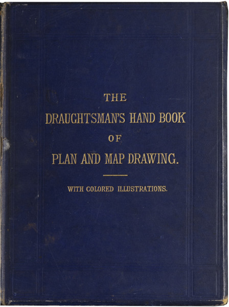
—Let A B (Fig. 1) be the given line. From A and B, with any radius greater than 1⁄2 A B, draw arcs cutting each other in C and D; then the line joining C D will bisect the line A B as at E.
Fig. 1.
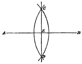
Fig. 2.
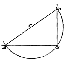
Fig. 1.
Fig. 2.
—Let it be required to erect a line perpendicular to the point B (Fig. 2) in the line A B. From any point C above the line, with radius B C, describe an arc as A B D; join A C and produce the line until it cuts the arc in D, and join D B; then will D B be perpendicular to A B.
Fig. 3.
—Let it be required to divide the line A B (Fig. 3) into five equal parts. From B, at any angle, draw B C, and on the line B C lay off five equal parts, 1, 2, 3, 4, 5; then take a set square E, and make one of the sides containing the right angle coincide with the points A and 5, and to the other side apply a straight-edge D; then by passing the set square along the edge of the straight-edge and drawing lines from the points 4, 3, 2, 1, through the line A B, we shall have the line A B divided into five equal parts through the points 1′, 2′, 3′, 4′.
—Let it be required to draw a line making with the line A B (Fig. 4) an[16] angle of 35°. From a scale of chords, which will be found on most scales supplied with a set of instruments, take off 60°; from the point A, with this distance for radius, describe an arc C D; lay off on this arc the distance of 35° taken from the same scale of chords; from A draw a line through this point. Then will the line A E make with the line A B an angle of 35°. The same result may be more readily arrived at by means of a protractor. If the centre point of the protractor be placed on the point A and its base made to coincide with the line A B, we can from its circumference prick off the distance of 35°, and a line drawn from A through the point thus found will make, with the line A B, the required angle of 35°.
Fig. 4.
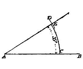
Fig. 5.
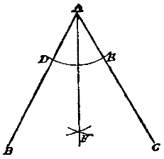
Fig. 4.
Fig. 5.
—Let B A C (Fig. 5) be the angle which it is required to bisect. From A, with any radius, describe an arc cutting the lines A B and A C in D and E; from D and E, with the same or any other radius, describe arcs cutting each other in F, and from A draw a line through F; this line will bisect the angle as required.
Fig. 6.
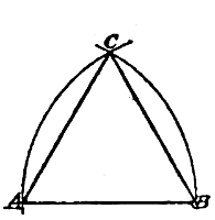
Fig. 7.
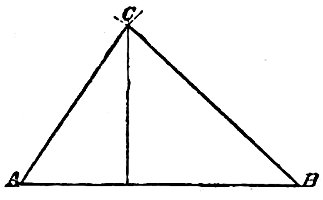
Fig. 6.
Fig. 7.
—Let A B (Fig. 6) be the given base. From A and B, with radius A B, describe arcs cutting each other in C; join A C and C B, which will complete the required triangle.
—Let it be required to construct a triangle whose sides shall be equal respectively to 6, 5, and 4. Lay down the base A B (Fig. 7), making it equal to 6 divisions of the scale; from A with radius equal to 4 divisions, and from B with radius of 5 divisions of the scale[17] describe arcs cutting each other in C; join A C and C B, which will complete the required triangle.
Fig. 8.
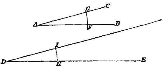
—It is required to draw a line making with the line D E (Fig. 8) an angle equal to that contained by the lines B A C. From A, with any radius, draw an arc F G, and from D, with the same radius, draw the arc H I, and make H I equal F G; then a line drawn from D through I will make, with the line D E, an angle equal to the angle B A C.
Fig. 9.
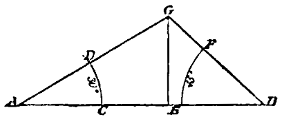
—It is required to construct a triangle whose base shall equal 1 inch, and the angles at the base be 30° and 45° respectively. Having made the base A B (Fig. 9) of the required length, make the angles at A and B of the required magnitude in the manner already described (see Fig. 4), and the continuation of these lines meeting in the point G will complete the construction of the required triangle.
Fig. 10.
—Let A B C (Fig. 10) be the points through which it is required to draw the circle. From each of these points, with any radius, describe arcs cutting each other in D and E; join the points D and E, and the point where these lines intersect will be the centre from which to describe the circle which will pass through the points A B C as required.
Fig. 11.
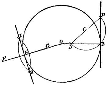
—I. Let B (Fig. 11) be the point from which it is required to draw the tangent. Draw the radius O B,[18] and at B erect a perpendicular (see Fig. 2); then will the line B D be a tangent to the circle. II. It is required to draw a tangent from the point E in the same circle. Draw the radius O E extending beyond the circumference to F, and make E G equal to E F. From F and G, with any radius, describe arcs cutting each other in H and I; then a line drawn through these points will be a tangent to the circumference at E.
Fig. 12.
—From any point in the circumference, as B, (Fig. 12), describe an arc cutting the circumference in A and C, and from A and C, with the same radius, describe arcs cutting the first arc in two points; through the points of intersection draw lines to the interior of the circle, and the point O where these lines intersect will be the centre of the circle.
Fig. 13.
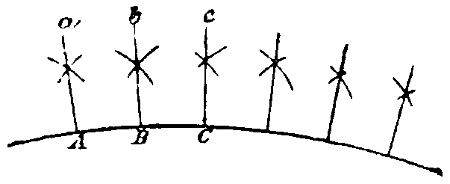
—Having laid off on the circumference of the arc, the distances apart of the radii, as A, B, C, &c. (Fig. 13), from each of these points, with radius greater than a division, describe arcs cutting each other as at a, b, c, &c., join A a, B b, C c, &c., and the lines so drawn will be radii of the circle as required.
Fig. 14.
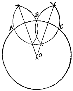
—Draw the line A B (Fig. 14) equal to the width, and bisect A B by C D (see Fig. 1). From the point of intersection E, with radius E A or E B, describe the circle A C B F, and from A and B through F, draw the lines A G[19] and B H. From A, with radius A B, describe the arc B G, and from B, with the same radius, describe the arc A H; also from F, with radius F G or F H, describe the arc G D H, which will complete the required oval.
Fig. 15.
—Let A B (Fig. 15) be the given line. At A erect a perpendicular (see Fig. 2), and from A, with radius A B, describe an arc cutting the perpendicular in C; also from B and C, with the same radius, describe arcs cutting each other in D; join C D and B D, which will complete the required square.
Fig. 16.
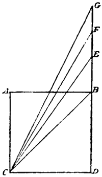
—Let A B C D (Fig. 16) be the given square, and let it be required to construct a square that shall contain 2, 3, 4, &c., times its surface. Draw the diagonal B C, then the square described on B C will be double the square A B C D. Lay off D E, equal to B C, and draw C E; then the square described on C E will be three times the square A B C D. In the same manner lay off D F, equal to C E, and the square described on C F will be four times the square A B C D; and so for any multiple of the square A B C D.
Fig. 17.
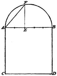
—Let A B C D (Fig. 17) be the given square. On A B, as a diameter, describe the semicircle A G B, and erect at the centre E the perpendicular E G. Draw G B, which will be the side of a square equal to one-half of A B C D. Lay off B F, equal to one-fourth of A B, and erect the perpendicular F H; then the square described[20] upon H B will be equal to one-fourth of A B C D. In the same manner a square may be constructed equal to any part of A B C D.
Fig. 18.
—Let A B C D (Fig. 18) be the given square. It is required to construct a square which shall be to A B C D as 2 is to 5. Upon the side A B as a diameter describe the semicircle A F B, and divide the line A B into five equal parts. At the second point of division erect the perpendicular E F and join A F; the square described upon A F will be to the given square A B C D as 2 is to 5.
Fig. 19.
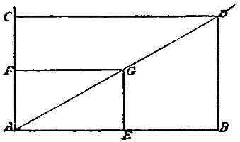
—Let A E F G (Fig. 19) be the given rectangle. It is required to construct upon the base A B, one that shall be similar to A E F G. Produce A E and lay off the given base from A to B; draw the diagonal A G and produce it indefinitely. Erect a perpendicular to A B at B, and from the point D where it intersects the diagonal produced, draw D C perpendicular to A F produced. Then A B C D will be similar to A E F G. All rectangles having their diagonals in the same line are similar.
Fig. 20.
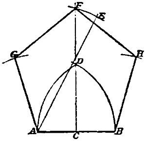
—Let A B (Fig. 20) be the given line. Bisect A B at C, draw C F perpendicular to A B, and make C D equal to A B. Draw A D and produce it[21] indefinitely; make D E equal to half A B. From A as a centre, with A E as a radius, describe an arc cutting the perpendicular C D in F; and from A F and B as centres, with radius A B, describe arcs cutting each other in G and H; join A G, B H, F G and F H; then A G F H B will be the pentagon required.
Fig. 21.
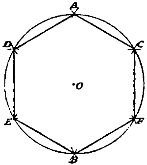
—With a radius equal to the length of one side of the required hexagon, describe a circle (Fig. 21), and set off the same radius round the circumference of the circle, which will be thus divided into six equal parts. Join the points thus found, and the required hexagon will be completed as A B C D E F.
Fig. 22.
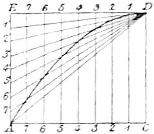
—Let C A (Fig. 22) equal half the base, and C D the height. From the point D draw D E parallel and equal to A C, and from the point A draw A E parallel and equal to C D. Divide D E and A E similarly, making the end E of A E correspond to the end D of E D. Through 1, 2, &c., in DE draw 1, 1; 2, 2, &c., parallel to D C. Join D to the several points 1′, 2′, &c., in A E. The parabola will pass through the points of intersections of these lines with the verticals drawn from D E to C A.
Fig. 23.
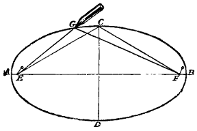
Fig. 24.
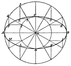
Fig. 25 a.
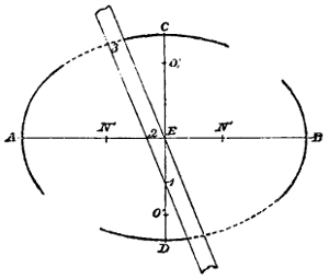
Fig. 25 b.
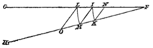
Fig. 23.
Fig. 24.
Fig. 25 a.
Fig. 25 b.
—I. By means of a piece of string and pins. Place the diameters A B and C D (Fig. 23) at right angles to each other, and set off from C half the major axis at E and F; then will E and F be the two foci in the ellipse. Fix a pin at E and another at F; take an endless string equal in length to the three sides of the triangle E F C and pass it round the pins, stretch the string with[22] a pencil G, which will then describe the required ellipse. II. From the centre O (Fig. 24) describe a circle of the diameter of the minor axis of the required ellipse. From the same centre, describe another circle with a diameter equal to its major axis. Divide the inner circle into any number of equal parts as 1, 2, &c., and through these points draw radii cutting the outer circle in 4, 3, &c. From 1, 2, &c., draw horizontals, and from 3, 4, &c., draw perpendiculars cutting each other in E F, &c.; the curve traced from C through the points C E F A, &c., will complete the curve of the required ellipse. III. Let A B (Fig. 25 a) be the major and C D the minor axis of the required ellipse. On any convenient part of the paper draw two lines F G, F H (Fig. 25 b) at any angle with each other. From F with the distance E C or E D, the semi-axis minor, describe an arc cutting the lines F G, F H, in I and K; and from F with the distance E A or E B, the semi-axis major, describe the arc L M. Join I M, and from L and K draw lines parallel to I M, cutting F G, F H, in N and O. From A and B (Fig. 25 a) set off the distance F N (Fig. 25 b) in points N′, and from these points as centres, with F N as radius, describe an arc of about 15° on each side of the major axis. From C and D[23] (Fig. 25 a) set off on the minor axial line the distance FO (Fig. 25 b) in points O′, and from these points as centres, with radius FO, describe arcs of about 15° on each side of the axis C D. To obtain any number of intermediate points take a slip of paper (Fig. 25 a) and mark upon one edge, with a sharp-pointed pencil, 1, 3, equal to the semi-axis major, and 2, 3, equal to the semi-axis minor. If the slip of paper be now applied to the figure and moved over it in such a manner that the point 2 is always in contact with the major axis, and the point 1 in contact with the minor axis, the outer point 3 will describe a perfect ellipse, any number of points in which can be marked off as the “trammel” is moved into successive positions.
For this last method, which in practice is by far the best, we are indebted to Binns’ ‘Orthographic Projection.’
Fig. 26.
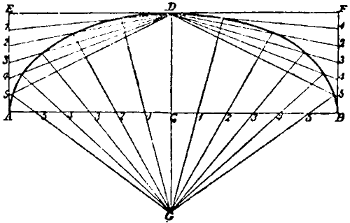
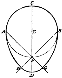
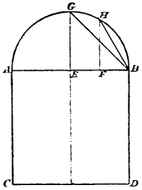
—The span A B (Fig. 26) and rise C D being given, divide C A and C B into any number of equal parts. Through the point D, draw E F parallel to A B, and from the points A and B erect the perpendiculars A E and B F. Divide A E and B F similarly to C A and C B. Produce C D and make C G equal C D. From D draw lines to the points 1, 2, 3, &c., in the lines A E and B F; also from G draw lines through the points 1, 2, 3, &c., in the line A B, and produce these lines until they cut those drawn from D to the corresponding numbers in A E and B F. Through the points thus obtained draw the curve of the ellipse.
Fig. 27.
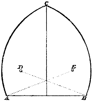
—From the points A and B (Fig. 27), with radius A B equal to the span, describe the arcs B C and A C. By joining C to A and B we obtain an equilateral triangle from which this arch derives its name.
[24]
Fig. 28.
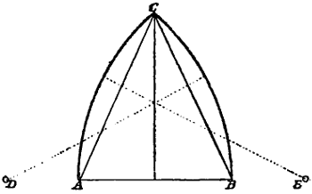
—In this arch, the centres E and D (Fig. 28) from which the arcs are struck, are situate outside of and in a line with the points of springing A and B; thus it is constructed on an acute-angled triangle, as will be seen by joining C to A and B.
Fig. 29.
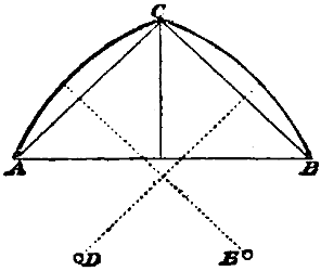
—This arch, called sometimes the Drop-Arch, is constructed on an obtuse-angled triangle; the centres E and D (Fig. 29) being situate below and within the points of springing A and B.
Fig. 30.
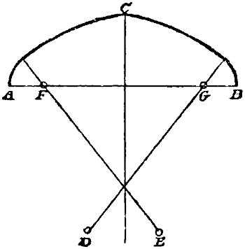
—On the line of springing A B (Fig. 30), take any two points as F and G, so that A F is equal to G B. Draw F E and G D cutting each other on the bisecting line through C; from F and G, with radius F A or G B, describe the short arcs, and from E and D, with radius E C or D C, describe the arcs meeting in C.
Fig. 31.
—The centres E and D (Fig. 31) from which the arcs forming this arch are struck, are situate above and within the points of springing A and B. One of[25] the most graceful forms of this arch is obtained when the height of the points E and D above the line of springing and their distance from the bisecting line through C are equal to one-third of the span A B.
Fig. 32.
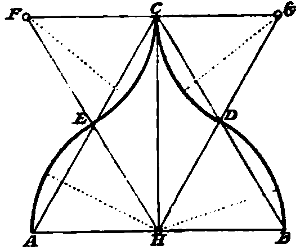
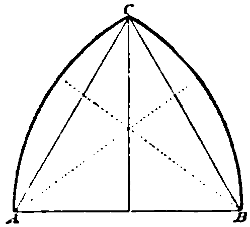
—The most pleasing form of this arch is that constructed on an equilateral triangle, in the following manner. Having drawn the equilateral triangle A B C (Fig. 32), draw F G parallel to A B. Bisect the sides A C and C B and produce the bisecting lines to F G and H, which will complete the triangle F G H similar and equal to the triangle A B C. From H, with radius H A or H B, describe the arcs A E and B D, and from F and G, with the same radius, describe the arcs E C and C D.
Fig. 33.
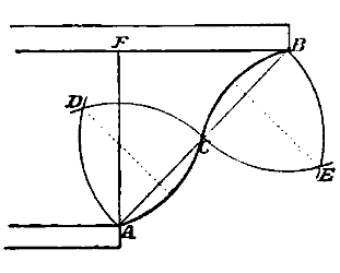
Fig. 34.
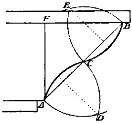
Fig. 33.
Fig. 34.
—Join A B (Fig. 33) and bisect A B in C. From the points C and B, with the distance B C, describe arcs cutting each other in E; and from A and C, with the same radius, describe arcs cutting each other in D; from D, with the same radius, describe the arc A C, and from E describe the arc C B. The projection of the upper end of the curve over the under, as F B, is generally equal to the height, A F, of the moulding. The same description applies to the Cyma Reversa (Fig. 34) letter for letter.
Fig. 35.
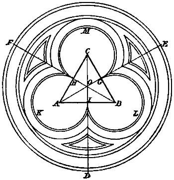
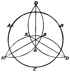
—Having drawn the equilateral triangle A B C (Fig. 35), bisect the angles and produce the bisecting[26] lines D E F which will bisect the sides of the triangle in G H I. From A B and C as centres, with radius A H or A I, equal to half the side of the triangle, describe the arcs K L M, and those concentric with them, and from the centre O of the triangle describe the outer circles and concentric arcs, which will complete the figure.
Fig. 36.
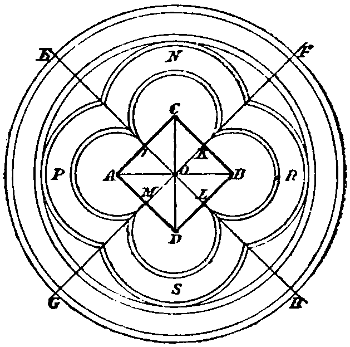
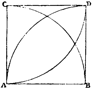
—Draw the square A B C D (Fig. 36); bisect the sides of the square at I K L M and produce the bisecting lines to E F G H. From the angles A B C D of the square as centres, with radius A I or A M equal to half the side of the square, describe the arcs P N R S, and draw the outer concentric arcs. The circles, completing the figure, are drawn from the centre O of the square.
Fig. 37.
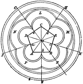
—Having drawn the regular pentagon A B C D E (Fig. 37), bisect the angles and produce the bisecting lines to F G H I K, which will cut the sides of the pentagon in a, b, c, d, e. From A B C D and E as centres, with radius A a or A b, equal to one-half of the side of the pentagon, describe the arcs L M N P R, and draw the outer concentric arcs and those concentric with them. The circles are drawn from the centre O of the pentagon, as in the preceding example.
[27]
All kinds of drawings are made up of lines and dots; these are the constituent parts, the materials which the draughtsman has to employ. It is therefore essential that he should make himself acquainted with their various forms and uses, and familiar with those means of producing them which experience has shown to be the best, before commencing the study of the principles by which the representation of an object is delineated. And moreover, it is desirable that he should acquire a familiarity with the operations required in the delineation of isolated objects, previously to making any attempt to place them in combination for the purpose of producing a complete drawing. The student will, therefore, do well to study carefully and to practise diligently the forms and examples given in this Section.
—All straight lines, however short, should be ruled, whether they be drawn with the pencil or the pen. Pencil lines, which are intended to serve merely as guides to the pen, should be drawn lightly, as otherwise it will be difficult to rub them out without injuring the ink. They should also be drawn a little beyond the point at which the line is required to terminate, because the intersection of the lines at that point makes it more distinctly visible, and there is, consequently, less danger of passing beyond that point or of stopping short of it when inking in. It is very important not to stop short of the required length when ruling a straight line with a pen, for it is extremely difficult to lengthen the line subsequently without leaving the join visible. An accurate line cannot be drawn unless the point of the pencil or the pen be kept close up to the rule, and to do this the top should be inclined a little outward. Before inking in a line that has been drawn in pencil, the indiarubber should be passed lightly over it, to remove the particles of lead adhering to the paper, for if these particles are allowed to remain, they get between the nibs of the pen and prevent the ink from flowing freely. The chief difficulties in ruling a straight line with[28] the pen are, to keep it of a regular thickness throughout, and, when numerous parallel lines have to be drawn, to keep them at equal distances apart. To draw an even line, a first requisite is that the pen be in good condition. Frequently it will be found when drawing fine lines that the pen ceases to mark before the end of the line is reached, and as we have already said, it is very difficult to join a line without leaving visible traces of the operation. To remedy this defect, the pen must be reset as described in Section I. If a very hard pencil has been used, or if the pencil has been pressed heavily upon the paper, the pencil line will lie in a groove in the paper, and as the nib of the pen will not touch the bottom of this groove, the line drawn will be ragged. Another cause of unevenness is unduly pressing the pen against the rule; this pressure closes the nibs, and besides producing an irregularity in the thickness of the line, is very apt to cause a blot by forcing out the ink, which adheres to the rule when brought into contact with it. To prevent this, care should be taken to press the pen very lightly against the edge of the rule. A pen is manufactured by Stanley, of Holborn, London, which has the back nib much stiffer than the other, so that all danger of defect from this cause is removed by the construction of the instrument. To ensure a good line, the pen should rest lightly upon the paper, and the handle of the pen should make the same angle with the paper from the beginning to the end of the line. A considerable amount of practice is required to accomplish this, and to acquire the habit, the same attention should be given to the pencil as to the pen. The ability to draw a number of parallel lines at equal distances apart without measuring requires considerable training of the eye, and this training can be obtained from practice alone. This ability must be acquired before anything further is attempted, and the student who spends a good deal of time in its acquisition may have the satisfaction of knowing that while he is going through this somewhat monotonous practice, besides exercising himself in drawing accurate lines, he is acquiring a correctness of eye and a power of hand that will be of incalculable service to him later.
[29]
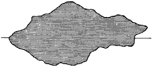
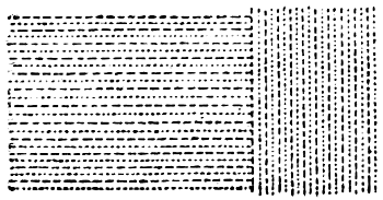
The straight line, besides being used for the outlines of regular objects, is employed conventionally for various purposes. When it is required to show an object in section, the part in section is covered with straight and parallel lines drawn at an angle of 45° and at equal distances apart, as in Fig. 38. To represent standing water, as ponds and lakes, horizontal straight lines are drawn parallel to each other and at equal distances apart over the surface, as shown in Fig. 39.
Fig. 38.
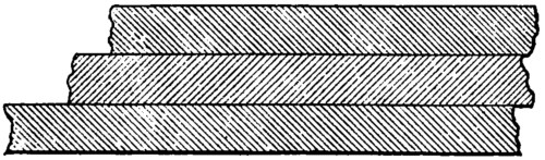
Fig. 39.
Curved lines, when arcs of circles, are drawn by the compasses. Other curves are drawn by hand through points previously found. To draw the curve correctly through these points, unless they be very numerous, a knowledge of the nature of the curve is necessary, which the draughtsman should in all cases endeavour to obtain. When the curved line is long, it is usually inked in with the drawing pen, with the aid of an instrument called the French curve, or cardboard moulds cut for the purpose; but for short lines an ordinary fine-pointed steel-pen point, or better, a good quill is used. In general, all lines drawn by hand should be drawn towards the body, as a better command of the pen can be obtained in that direction than in any other. In inking in curves by this means, the draughtsman should proceed continuously along the pencil-drawn line by partly repeated touches with the pen point, so held that the divided points of the pen may follow partly in the same track. Each touch should be made about one-thirtieth of an inch in length, and it should begin and end fine. Each succeeding touch must begin half its length back, so that the line is advanced by one-sixtieth of an inch. In map drawing all irregular lines are drawn in this way. Tracing maps[30] will afford the student excellent practice in this mode of using the pen.
Fig. 40.
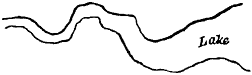
—Though generally a line is required to be of even thickness throughout, cases sometimes occur in which a variation in the thickness may be made to express some feature or quality of the landscape. The usual application of this kind of line is to mark the outline of rivers, lakes, and ponds, as shown in Fig. 40. The drawing of such a line presents no difficulty; the increased thickness is produced by going over those parts of the line again with the pen. Care must, however, be taken not to make a sudden increase in the breadth of the line, but to begin and end imperceptibly.
Fig. 41.

Fig. 42.
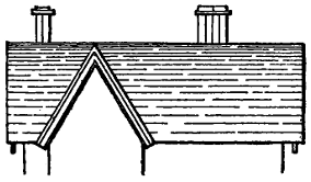
Fig. 41.
Fig. 42.
Fig. 43.
—The broken line, shown in Fig. 41, is of frequent occurrence in all kinds of drawings. In architectural and engineering drawings it is usually employed in roofs, as in Fig. 42, and for water in sections, as in Fig. 43. It is also used in combination with other lines for various purposes. In drawing a succession of broken lines, care must be taken not to allow the break in one line to be immediately over that in another. The effect may be varied considerably by increasing or diminishing the extent of the break. As in section lining, the lines should be at regular intervals apart, and be all of the same degree of fineness. Broken lines are sometimes used upon the face of stone buildings, instead of marking in the joints and[31] etching or colouring. In such a case the breaks are long, and the lines widely spaced.
Fig. 44.
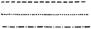
—Of still more frequent occurrence is the dotted line. There are two kinds of dotted lines, distinguished by the shape of the dot, and known as the long and the round dotted line. These are shown in Fig. 44, as well as a combination of the two.
The round dotted line is of very general application. In architectural and mechanical drawings, it is used to distinguish hidden parts, and to mark the path of a moving piece in a machine. In plans, it is used to show the position of proposed works, to denote the walks through pleasure grounds and gardens, to indicate lines chained over in surveying, and frequently for other purposes, at the pleasure of the draughtsman. The long dotted line is employed to mark the boundaries of a township, the navigable channel of a river or creek, and in large-scale maps to show farm and bridle roads, footpaths, and the divisions of land among different tenants. The combination of the long and round dotted lines is used for the boundaries of a parish. Another combination of two round and one long dots, or sometimes of three round and one long, is used to denote proposed railways, canals, roads, and other similar works.
To draw a good dotted line requires some care. The difficulty lies in keeping the dots at equal distances apart, and in making them equal in size; and unless both these conditions are fulfilled, the line will not present a pleasing appearance. To obviate this difficulty, an instrument is sold by mathematical instrument makers, called the dotting or wheel pen. But it requires very great care in using, as otherwise it frequently happens that the ink escapes from it and spoils the drawing. For this reason, its use has been generally abandoned by draughtsmen. But if the instrument were better constructed and carefully handled, it might be made to do good service.
Fig. 45.
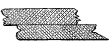
Fig. 46.
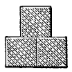
Fig. 45.
Fig. 46.
Fig. 47.
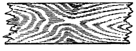
Fig. 48.
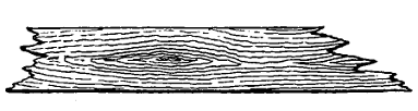
Fig. 49.
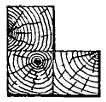
Fig. 48.
Fig. 49.
—Combinations of the foregoing lines are used for various purposes. Some[32] draughtsmen employ alternate, full, and dotted lines, to denote wood in section, as in Figs. 45 and 46; when wood is used in combination with iron or other metal, this is a very good way of distinguishing it. Wood-graining, though not made up of straight, broken, or dotted lines, yet partakes somewhat of the nature of all three kinds, and may therefore be introduced here. Oak-graining is shown in Fig. 47, and fir-graining in Fig. 48. The former is executed with the drawing pen, and requires some care and practice; the latter is most readily done with a common pen or a crow-quill. End wood is grained as shown in Fig. 49. The spring bows are very suitable for drawing in the circles, as a certain degree of turn to the nut will open the ink leg to the required distance after drawing each circle. A few broken wavy lines, called shakes, radiating from the centre, produce a good effect. When several pieces of end wood come together, the centres in each should not be in the same relative position.
Fig. 50.
Cultivated land is represented by alternate broken and dotted lines, suggesting furrows, as shown in Fig. 50. For the sake of variety, these lines are put in in sets, and in different directions, one set being usually parallel to one side of the enclosure. The lines are first ruled in continuously with the pencil, and the broken and dotted lines afterwards drawn in over them by hand. The portions of the broken lines must in this case be short, and the breaks still shorter. The dots must be[33] fine and close together; they are made by touching the paper with the point of the pen, and immediately lifting it off without dragging it over the paper. All round dots must be made in this way.
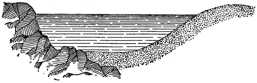
—The wavy line is very important in topographical drawings, as it is employed to represent running water, and frequently large bodies of standing water to which motion is communicated by the wind, as lakes and the sea. These rippled lines are intended to represent the ripples in the water, a purpose which they fulfil in a very pleasing manner. They must, however, be well executed, or the pleasing effect will not be produced. The operation of drawing these lines is usually regarded by the draughtsman as a tedious and an uninteresting one. But such ought not to be the case, for there is ample scope in it for the exercise of the taste and the judgment, and in proportion to the taste displayed and the judgment exercised, will be the effect of the work when executed.
Fig. 51.
Fig. 51 shows the manner of employing these lines. In representing water by this means, the lines should be drawn from the shores towards the middle of the stream or lake, and never from the middle outwards, for if the latter mode of proceeding be adopted, the proper graduation of the spaces between the lines becomes impossible. The shore line, or outline of the water, should be a moderately thick line, and of uniform thickness throughout. The first shading line may be of nearly the same thickness as the shore line, and it must be drawn as near to it as possible. Also this shade line, as well as all subsequent ones, must follow exactly all the windings of the shore line; this is essential to a correct expression. To effect this with accuracy, care should be taken to make the space between the shore and the shade line a fine white line. The second shade line must be drawn a little finer than the first, and at a slightly increased distance from it. This gradual diminution of the thickness of the lines, and increase of the spaces, must be continued to the middle of the[34] current. The last line in the middle of a piece of water must always return to itself. When the shading lines meet the margin of the drawing, they should terminate in it, that is, they should be drawn out to the margin as though they had been continued beyond and cut off.
These lines require to be drawn clean, and to do this the hand must be kept steady. This steadiness may be obtained by taking a very short hold of the pen, and resting the middle finger upon the paper. The lines, as we have already said, should be drawn towards the body, the drawing being turned about as required to facilitate this, and the last line drawn must be always kept on the left of the one being drawn. By this means the last line and the point of the pen are kept constantly in sight. It is also important that the lines should be completed successively, rather than that several should be carried on at once, because if the latter mode of working be adopted, the eye is apt to become confused by the different intervals, and an uneven distribution of the lines is the result. A principle to be attended to is that every line shall return to itself, spirals being altogether inadmissible. The distance of the lines apart and their thickness are expressive of the character of the object; thus, in a small pond, for example, they will be fine and close together; in a large pond or a lake they will be thicker and more widely spaced; and in the open sea they will be made to present a bold appearance by increasing still more their thickness and the distance between them.
Fig. 52.
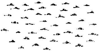
—Various combinations of lines and dots are used, conventionally, to represent certain natural features of common occurrence. As far as convenient execution will allow, these signs are made to resemble the objects denoted. Thus the sign for grass-land consists of groups of short lines, arranged like tufts of herbage, as shown in Fig. 52. Each tuft is composed of five or seven lines converging towards a point situate below the base, the middle line being the longest, and the outside ones mere dots. In drawing these groups, the base must be kept quite straight,[35] and parallel to the base of the drawing whatever the shape of the enclosure may be. Beginners usually experience considerable difficulty in keeping the base straight, the tendency being to make it curved. Great care is needed to distribute the groups evenly over the paper, and to avoid the appearance of being in rows, for the latter arrangement is destructive of that natural aspect which this sign otherwise possesses.
Fig. 53.
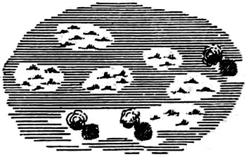
—As the surface of marshy ground consists of water and grass, a combination of the signs for these objects is employed to represent it. An illustration of this is given in Fig. 53. The lines representing the water should always be ruled parallel to the base of the drawing, and they should be grouped in an irregular manner so as to leave small islands interspersed throughout the locality. These islands should be covered with grass, and to show them out more distinctly, there should be nothing but water immediately around them. The division between the land and the water should be sketched in lightly before proceeding to rule in the lines. Sometimes dotted lines are used for the water, but full lines are to be preferred. The addition of a tree here and there improves the appearance of a drawing. A distinction is frequently made between a swamp and a marsh by watering the former more extensively than the latter. In drawing in marsh land, care should be taken to make the fineness of the lines in accordance with the scale of the map, as otherwise an offensive appearance will be produced. This caution applies equally to all signs.
Fig. 54.
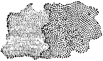
—Sand and gravel are represented by dots, the dots being made larger for the latter than for the former, as shown in Fig. 54. Simple as the operation of filling in these dots is, it is one that requires some degree of care. Beginners are apt to mar the[36] appearance of their drawings by inattention in this respect. The dots should be made in the manner already described when speaking of the dotted line, that is, the point of the pen should be brought slowly down upon the paper, and lifted without dragging it; and no dot should be made without a deliberate intention respecting its position. All arrangement in rows must be carefully avoided. In sand-hills, the slopes should be made darker than the level parts by placing the dots closer together. Mud in tidal rivers may be represented by very fine dots placed close together.
Fig. 55.
Fig. 56.
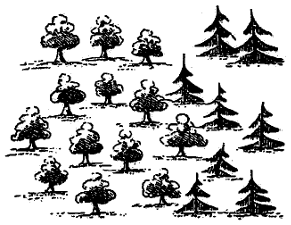
Fig. 55.
Fig. 56.
—Trees are generally shown in plan (as in Fig. 55). The outline is circular in character, and, to have a good effect, it should be made up of simple curves firmly drawn; small indentations should be avoided as bad. A few touches of the pen are given on the interior and towards the shadow. The latter is cast by parallel rays of light inclined 45° to the horizon, and is detached from the outline of the tree. When the scale is large, the shadow will be elliptical in form, but in small scales it will become a simple circle. In representing woodland, the trees and masses of trees should be disposed in every possible variety of position, care being taken, however, to avoid all regular figures and arrangements in lines. In parks and gardens, where the arrangement of the trees is artificial, it is usual to represent a grove in a rectangular form. Orchards are shown by placing single trees with their shadows at the points of intersection of two sets of equidistant parallel lines drawn at right angles to each other. These lines are drawn in pencil and afterwards erased. Some draughtsmen prefer to draw trees in elevation, as shown in Fig. 56. This method allows the various[37] kinds of trees to be distinguished on the plan, and gives scope to artistic skill.
Fig. 57.
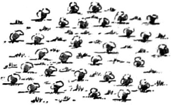
—Uncultivated land, other than woodland, is represented by drawing bushes in plan, similar to trees, but of smaller dimensions, and mixing tufts of grass with them, as shown in Fig. 57.
Fig. 58.
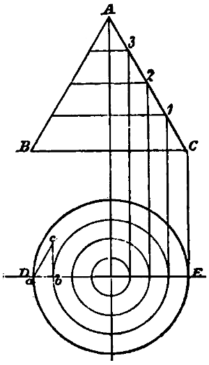
—Suppose a cone A B C (Fig. 58) cut at regular vertical intervals apart by a series of horizontal planes 1, 2, 3. The intersections of these planes with the surface of the cone will give lines upon that surface; and it is obvious that the cone may be represented in plan by the projection of these lines, as shown in the figure. To obtain this projection, draw the horizontal line D E, and from the apex of the cone and from the intersections of the cutting planes let fall vertical lines. From the point where the line from the apex meets the line D E as a centre, with radii equal to the distances from this point to those where the lines from the sections meet D E, describe circles. These circles will be the horizontal projections of the lines on the surface of the cone produced by the cutting planes; and these lines are called contour lines. Also it is obvious that, from the plan of the cone so obtained, we may as readily project the elevation, provided we know the vertical distance apart of the sections denoted by the contour lines. To obtain the elevation, we have only to draw horizontal lines at the given distance apart, and from the points in D E erect perpendiculars to meet them. Lines drawn through the points of intersection will give the elevation of the cone. To find the inclination of the surface of the cone, upon a b, a portion of the normal D E, as a base, erect a perpendicular b c, equal in height to the distance of the sections apart, and join a c. The hypothenuse a c then represents that portion of the surface of the cone which is included between the two contour lines, and of which[38] the angle of inclination is b a c. The space between two contour lines is called a horizontal zone.
The cone being a regular figure, its contour lines are circles. For irregular figures, the contour lines will be irregular curves. The regular inclination of the surface of the cone causes the projections of the contour lines to be at equal horizontal distances apart. But when the inclination varies, the horizontal distance between the contour lines also varies, the distance decreasing as the inclination increases. Thus the method of representing objects in plan by contour lines, not only gives the correct form of the object, but shows the relative inclination of every portion of its surface. This may be clearly seen in Figs. 59 and 60, the former of which is a representation in plan by contour lines of an irregularly shaped object, and the latter an elevation of the same object projected from the plan.
Fig. 59.
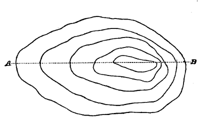
Fig. 60.
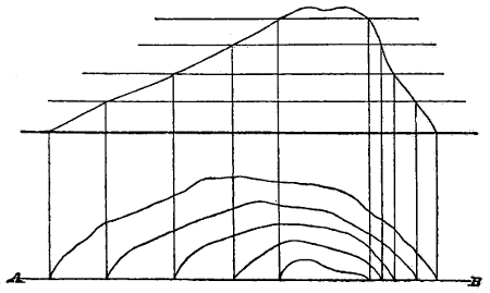
The system of representation by contour lines is generally adopted by topographers to distinguish and define the variation of the surface of the ground in regard to hill, valley, and plain. By intersecting a mountain, for example, by a sufficient number of horizontal planes, its correct form may be delineated, and the declivity of its surface accurately shown. The relative declivity of any portion of its surface is indicated by the difference in the horizontal distance of the curves apart; and by constructing a triangle upon a normal to the upper curve in the manner already described for the cone, the absolute slope at any point between any[39] two curves may be readily determined. The ground is supposed to slope uniformly from one curve or contour line to the next. Such, however, is rarely the case; but provided the curves are taken at frequent intervals, the error is of no practical importance. Hollows are represented in the same way; and whether the representation is that of a hill or a hollow, is known from the other parts of the map. Thus, if Fig. 59 represent a hill, the vertical projection will be as shown in Fig. 60; but if it denote a hollow, the outer curve must be projected highest, and the vertical section will be Fig. 60 inverted. In practice the contour lines are numbered, the number of any contour indicating its height above a plane of reference called a datum plane. The vertical distance of the contour lines apart varies with the character of the ground and the object of the survey; but it is seldom less than 25 feet. The lines are obtained by the surveyor by fixing a number of points on the same level by means of instruments.
The preceding Section treats exclusively of representation by lines and dots, or that mode of delineating objects and natural features known as line or pen drawing. There is, however, another mode of representation by means of colours that is fast coming into general use. This latter mode is far more expressive than the former, and, besides affording a wider scope for artistic effect, shows with greater distinctness and precision the character of the object represented. For these reasons it is almost always adopted for plans of estates and geological sections, and also very frequently for other kinds of topographical as well as for engineering and mechanical drawings. The colours used for this purpose are not applied in the way the artist applies them; but they are laid on in thin washes to produce a faint tint rather than a body of colour. The process is called tinting or[40] flat-washing, and though it cannot be described as a work of art, considerable practice and skill are requisite to execute it properly.
—A drawing to be coloured must be previously stretched and gummed to the board, in the manner described in Section I. Unless the paper be prepared in this way, it will remain blistered after being wetted by the laying on of the tints. The lines of the drawing must be very fine, and the ink, though black, should not be thick. Great care should be exercised in drawing in the outlines, that there be always a piece of clean paper between the hand and the drawing, for the least degree of greasiness will prevent the colours from working freely. Should the surface of the paper, however, from inattention to this matter, or from accident, become slightly greasy, the defect may be partially remedied by adding a little prepared ox-gall to the water with which the colours are mixed. When all the outlines have been drawn in and the pencil lines erased, the drawing is prepared for the colouring by being washed. The washing is effected by passing a soft sponge well saturated with clean water gently and rapidly over the surface. The purpose of this washing is twofold; first, to remove those portions of the ink which a wet brush would detach from the paper in laying on the colours, and which, by becoming mixed with the tint, would injure its purity; and second, to damp the surface of the paper in order to prevent the colour from drying too rapidly. The latter is an important matter, for if the tint which is being applied dries quickly, it is impossible to unite the edges properly, and the tint, especially if the surface be large, will have a cloudy and blotchy appearance. As the operation of washing renders the paper too wet to immediately receive the colour, it must be allowed to remain in a perfectly horizontal position for a short time to dry, and during this time any tendency to dry unequally must be corrected by means of blotting-paper. While the paper is drying, the tints may be prepared.
To ensure satisfactory results, care must be taken in the preparation and preservation of the tints. They should never be made by artificial light, and a sufficient quantity should be made at first to cover all the portions required, as it is very difficult to match a tint[41] exactly. When a drawing is several days in hand, it is best to prepare a fresh tint for every coat, for the colours will change in the course of a day or two, even if protected from the light. A few drops of water should be added now and then, to make up for the loss by evaporation, especially in warm weather. Tints left to dry upon the palette should never be wet up again for use, but they should be washed clean out and a fresh tint made; if this precaution be not attended to, the colour will not be pure. When a tint is to be mixed, the end of the cake of colour should be moistened and allowed to soften for a minute or two, as this will cause it to rub smooth and free from fragments. The palette should then be moistened and the end of the cake rubbed gently and evenly upon it till a sufficient quantity of colour has been obtained, which may be added to the requisite quantity of water by means of a brush. A precaution necessary to be observed is never to rub one colour down upon another, as it will probably be laid aside to dry with the other colour on it. The brush used should be as large as the nature of the work will allow, and it should be of the best sable hair; the quality is judged by the length of the hair, the longest and stiffest being the best. Draughtsmen frequently do all their work with a couple of sable brushes attached to one holder, one being for colour and the other for water; in this case the brushes should be of different colours to prevent mistakes.
The art of laying on a flat-tint consists in allowing the coloured water to flow equally over the paper, which thus becomes uniformly tinged. To facilitate this, the surface of the drawing should be inclined towards the draughtsman at an angle of about five degrees during the process of laying on the colour. Having taken as much colour on the brush as it will safely carry without dropping, the operation of applying it should be begun in the upper left-hand corner, the brush being carried along towards the right, so as to make the colour lie neatly along the upper outline. The brush should then be struck unhesitatingly from right to left and from left to right alternately, so as to bring the colour down in horizontal bands or stripes, taking care not to pass the brush a second time over the same[42] surface during the same wash, and to control it neatly within the proper limits. If the surface of the paper be in this way kept well wetted with the colour, or if, in other words, a flow of colour be kept in motion with the point of the brush, the tint can be carried on with perfect continuity. It is important to keep as nearly as possible the same quantity of colour in the brush until the lower outline is nearly reached, when the quantity must be diminished so as to finish at the lower outline without a great excess of tint, for the excess must be taken up by a damp brush. No accumulations should be allowed to take place anywhere, as on drying, these places would show a darker tint. When the colour has once flowed over the surface, the tint is finished, and must not, as we have said, be touched a second time, for any attempt to remedy defects while the colour is drying will only make them worse. Generally it will be found that the more quickly a tint is laid on, the better is its appearance. A little practice will enable the student to lay on a wash in the proper manner, but to keep within the outlines is a matter of greater difficulty and one that requires some dexterity in the handling of the brush. If the boundary should be exceeded, a finger of the left hand should be instantly applied to brush the colour back. Though the foregoing directions can be followed strictly only on large surfaces, the principles involved in them must in every case be observed.
The alternate or double tint consists of two colours applied alternately, their edges being made to blend into each other. The application of the double tint involves no particular difficulty. Having prepared two tints of equal intensity and provided a brush for each, lay on one of the colours at the upper outline of the figure, and before this dries, take the brush charged with the other colour, and run round its edge, allowing them to blend together. Repeat the first tint in the same manner, and continue the tints alternately till the surface is covered. The forms of the masses of each colour should be varied, and not made in stripes or spots, but irregularly clouded.
All flat-tints should be made very light, and intensity of colour should be produced by repeating the wash. As every surface looks[43] better with two washes than with only one, the strength of the tint should be such as to allow two coats to be laid over the lightest parts. If the colours have been laid on too dark, or the general effect be uneven and disagreeable, the defect may be remedied by sponging. This operation should be performed with a close-grained 6-inch sponge, and be commenced at the upper end of the inclined board. A basin of clean water having been provided, and an empty basin to receive the dirty water from the sponge, first moisten all the white surface of the paper to prevent the tint taken off by the sponge from adhering to it; then, having filled the sponge with water, pass it gently to and fro across the sheet. Press out the dirty water into the basin, refill the sponge, and repeat the operation until hardly any tint comes off. Sponging after five or six coats have been laid on generally improves the appearance of a drawing; it softens down asperities, and makes the tints blend into each other; the surface of the paper also takes the tints more readily after sponging.
Small defects may frequently be remedied by a process called stippling. This consists in making a number of dots with the point of a brush containing an almost imperceptible quantity of colour. The process, though a tedious one, produces a very beautiful effect, similar to that of dotted engravings. Excesses beyond the boundary lines may be washed out with the water-brush, and the stains removed by a piece of clean blotting-paper. White spots left in a tint may be filled up, after the tint is dry, with the point of the brush; but care must be taken not to touch beyond the edges of the tint, as that would double the intensity at the edges and produce a ring.
All flat surfaces in a drawing should be lighter or darker, in accordance with their distance from the eye. In laying on flat-tints when the surface is not in shade, it must be borne in mind (1) that all surfaces which are parallel to the plane of the picture, and therefore equally distant from the eye, should receive a tint of uniform intensity; (2) that those surfaces which are farthest from the eye should receive the darkest tint; and (3) that surfaces which are inclined to the plane of the drawing should receive a tint of varying intensity, the[44] depth of the tint increasing as the surface recedes from the eye. When the surfaces are in shade, the converse of these rules holds good.
—In representing objects by means of colours, the natural colours of the objects are in some cases adhered to; and in others, for the sake of greater distinctness, a conventional colour is adopted. In engineering, architectural, and mechanical drawings, the latter mode is nearly always resorted to, while in plans of estates the former is very frequently employed. Unfortunately, practice is not uniform among draughtsmen in the conventional use of colours; but the following Table shows the colours mostly employed, and represents the general practice.
| Carmine or crimson lake | For brickwork in plan or section to be executed. |
| Prussian blue | Flintwork, lead, or parts of brickwork to be removed by alterations. |
| Venetian red | Brickwork in elevation. |
| Violet carmine | Granite. |
| Raw sienna | English timber, not oak. |
| Burnt sienna | Oak, teak. |
| Indian yellow | Fir timber. |
| Indian red | Mahogany. |
| Sepia | Concrete works, stone. |
| Burnt umber | Clay, earth. |
| Payne’s grey | Cast iron, rough wrought iron. |
| Dark cadmium or orange | Gun metal. |
| Gamboge | Brass. |
| Indigo | Wrought iron—bright. |
| Indigo, with a little lake | Steel—bright. |
| Hooker’s green | Meadow land. |
| Cobalt blue | Sky effects. |
| And some few others occasionally for special purpose. | |
Sections are represented either by lines of the colour drawn with the pen or the point of the brush, or by a darker shade of the colour. In mechanical drawings, sections are frequently shown by ink lines drawn over the colour.
In plans and maps, as we have said, some attempt is made to give the true appearance of things. As this—which may be called the natural mode of representation—allows more scope for artistic skill than the conventional, a great deal must be left to the judgment and the taste of the draughtsman. But there are general principles and[45] features that may be laid down and described, and such are the following:—
—For water, a flat-tint of pure indigo is used. To produce the clear, transparent effect of water, there should be two coats of the tint, which, to allow of this, must be very light coloured.
—For grass or cleared land, a flat-tint of green is employed. This tint is composed of indigo and gamboge, and should be of a lively hue, which may be produced by giving predominance to the gamboge. Care must always be taken in preparing greens for maps and plans, that the blue be kept subordinate to the yellow; for a predominance of the former colour produces a cold quality, which is utterly destructive of that natural appearance it is intended to give. The intensity of the tint for this and for other purposes should be such as to distinguish it clearly from others, and to allow somewhat for fading, without masking any of the details of the drawing; and it must be clear and transparent. We may here remark that all tints which are much extended should be balanced, that is, no one should obtrude itself upon the eye by its relatively too great intensity.
—Marsh and swamp are represented, as in line drawing, by a combination of the signs for water and grass-land. The tints are laid on horizontally, that is, parallel to the base of the drawing. They are not, however, laid on in bands or strips across the drawing, but are made to project in irregular points from each side, with here and there a long and narrow patch to represent an island. The land should cover a larger portion of the space than the water, and it should be washed in first, care being taken to make the white spaces left for the blue colour resemble the green in form, which spaces should project their horizontal points into the green as the latter projects its points into the white. The outer limits of a marsh should consist of an outline of projecting green points. The land portion of the marsh is finished by drawing a light shading line of indigo and burnt sienna along the lower edge of the green. This line must be drawn upon the edge and not against it upon the white space. In washing in the water, care must be taken not to overlay the edges of the green. A good[46] effect is produced by introducing a tree here and there upon the land.
—Sand is shown by a flat-tint of yellow ochre. Sand and gravel are represented by dotting the flat-tint with burnt sienna by means of the point of the brush held in a vertical position. Stones and rocks in sand should be first outlined with the pen in burnt sienna and sepia in equal proportions, and afterwards filled in with the brush with the same colour.
—In the survey of rivers, creeks, and coasts, it frequently becomes necessary to show tracts of mud between the lines of high and low water. For this purpose a flat-wash of sepia or Indian ink may be used dotted with Indian ink of greater intensity. The dots in this case must be very minute and thinly placed, and they should be evenly distributed. A fine-pointed pen will be found more effective in putting in these dots than the point of the brush.
—To represent woodland, a flat-tint of green is first laid over the ground, as for grass-land. The groups and masses of trees are next drawn in outline, in the manner described in the last Section, with a hard and sharp lead pencil, or with a pen and pale ink. To fill in these outlines, a colour made up of indigo and gamboge in the same proportions as the ground tint, but of greater intensity, is laid on the lower and right-hand portion of each tree and mass of foliage, so as to occupy about two-thirds of the figure. The remaining portion, which will be the side towards the light, is then touched with an orange tint composed of gamboge and burnt sienna. It only remains to add the shadow. As the light is supposed to enter the drawing in parallel rays from the upper left-hand corner, the shadow of every object will surround its lower and right-hand outlines. It is laid close up to the outline in masses of foliage; but for single trees, as in orchards, it is detached. The form of the shadow was described in the last Section. To produce the shadow, the same tint is used as for the ground, two or three successive applications being sufficient to increase the intensity to the requisite degree; or a neutral tint may be used, composed of indigo, burnt sienna, and a little lake. After[47] the shadow has been put in, the outlines on that side should be strengthened by going over them again with the pen. By drawing the trees in elevation, an opportunity is afforded for the display of artistic skill far greater than the foregoing method admits of. When drawn in this way, the work partakes somewhat of the nature of landscape painting.
—Cultivated land is represented by a flat-tint of burnt sienna.
—Uncultivated land or brushwood is represented by a double tint of green, as for grass-land, and burnt sienna, as for cultivated land, laid on in the manner already described for the double tint. As this is the only double tint used, it may be made, if thought desirable, with alternate green and crimson lake.
—Buildings, including all structures of masonry, as bridges, locks, walls, and such like, are coloured with crimson lake, and shadowed with a neutral tint composed of indigo, burnt sienna, and a little lake, as given above for forest land.
—Roads and streets, and generally all those portions of a drawing not particularly described, are tinted with yellow ochre.
—Hedges are represented by green dots, varied in size for bushes; stone or brick walls, by a line ruled in red; and wooden fences by lines of neutral tint, either ruled or drawn in by hand, according as the line is to be straight or otherwise. In every case the shadow must be put in.
In determining the intensity of the various tints employed on a topographical drawing, care must be taken that everything be “in keeping.” A cardinal rule of art is that nothing shall unduly obtrude itself; and in a coloured plan, spottiness, as it is called, should be studiously avoided. Forest, brushwood, and cultivated land, should be represented by tints of about equal intensity, and the same equality may be observed for grass-land, marsh, water, and sand, but the intensity should be less than in the former case. Tints that are of small extent may be a little exaggerated in intensity for the purpose[48] of giving them greater distinctness, especially when the object represented is a building. Gardens and orchards require a little exaggeration in depth of tint, to distinguish them from the surrounding country; but care must be taken not to make the distinction too marked. It will generally be found conducive to a maintenance of “keeping,” to lay the lightest tints on first.
In mechanical and architectural drawings, shade lines must be considered rather as embellishments than constituent parts of the drawing. They are, however, frequently employed; and as their incorrect use may deceive the eye with respect to the intention of the designer, it becomes an important matter to know when to apply them with propriety.
Fig. 61.
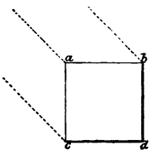
Fig. 62.
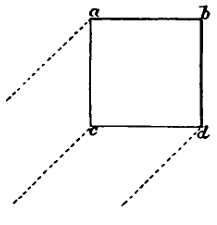
Fig. 61.
Fig. 62.
—As we have already explained, the light is supposed to fall upon the objects in a drawing in parallel rays from the upper left-hand corner for elevations, and from the lower left-hand corner for plans. To determine whether or not a given line should be a shade line, we have only to ascertain whether or not the light, introduced in such a manner, falls upon that edge of the object which the line represents. All those parts of a body upon which the rays of light fall directly, are said to be in light; all those parts upon which the rays of light do not fall directly, are said to be in shade; and those parts of a surface which are deprived of light by another body intercepting the rays, are said to be in shadow. These definitions should be borne in mind. Lines representing the boundaries of surfaces in light should be fine lines, and lines representing the boundaries of surfaces in shade should be thick or shade lines. Let it be required, for example, to determine the shade lines of the cube shown in elevation in Fig. 61. The extreme rays of light falling[49] upon the cube meet the edges in b and c; hence the surfaces a b, a c, are in light, and the surfaces d b, d c, are in shade. The foregoing rule will thus make a b and a c fine lines, and d b and d c shade lines. If the cube were turned so that a b should be at right angles to the rays of light, the extreme rays would fall on the edges a and b, and the middle ray which now falls on a would fall on the middle of the line a b. The rays immediately beyond those which are arrested by the edges a and b, may be considered to pass along in contact with the surfaces a c and b d; and these surfaces must, therefore, be regarded as in light. Thus we shall have in this case the lines a b, a c, and b d, fine lines, and the line c d a shade line. It is the practice of some draughtsmen to make a c and b d in such cases a medium line, and the practice has propriety to recommend it. The foregoing explanations of the shade lines in the elevation of the cube, render any further remarks concerning those in the plan, Fig. 62, unnecessary. In practice, whether or not a surface is in light may be determined by placing the set square of 45° against it.
Fig. 63.
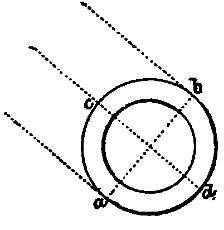
Fig. 64.
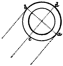
Fig. 63.
Fig. 64.
The same principles are observed in the end elevation of the hollow cylinder, shown in Fig. 63. The extreme rays meet the circumference in the points a and b; consequently the surface a c b is in light, and the surface a d b is in shade. The middle ray meets the surface perpendicularly at the point c, which will be the lightest part of that surface; similarly, d will be the darkest part. To show this, the shade line must be gradually increased in thickness towards the point d. The shading of the inner circle will be the converse of the outer. Fig. 64 shows a plan of the same object.
[50]
Fig. 65.
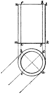
—Let a b c d, Fig. 65, be a plan, and k l n m an elevation of a cylinder. The portion a c b is in light, and the portion a d b is in shade, of which latter portion a and b are the edges. From the points a and c draw vertical lines e f, g h. Then will e f be that part of the cylinder upon which the light falls perpendicularly, or the lightest part, and g h the edge of the surface in shade, or that portion of the surface of the cylinder that would cast a shadow upon the plane of projection. Hence this will be the darkest part, and consequently it is obviously improper to make the line k l a shade line. This demonstration, which is given by Binns, shows that shade lines must never be applied to cylindrical surfaces. If this principle be observed, cylindrical may be readily distinguished from flat surfaces.
Fig. 66.
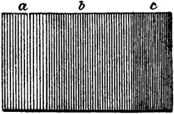
—Shade lines are applied only to the edges or boundaries of surfaces; when lines are put upon a surface to show the effects of light and shade, they are called shading lines. The use of the latter is determined by the same principles as that of the former; indeed, a shade line may be practically considered as an end view of a number of shading lines. In Fig. 66, which is an elevation of a hexagon, the surface c is in shade, and to represent this surface correctly, it must be made darker than the others. This darkening of the surface is effected by drawing the shading lines heavier or closer together, or by both of these means combined. The surface b is in light, but the rays fall upon it obliquely; the shading lines on this surface will therefore be lighter and more widely spaced than on c. The surface a is also in light, and receives the rays normally, that is, the[51] direction of the rays is normal to the surface. Hence this surface will reflect most, or, in other words, will be the lightest. This is shown by making the shading lines still lighter, and spacing them still more widely than those on b. The greatest care is needed in applying shading lines to keep their thickness and the spacing regular, as an error in these respects will frequently produce an effect quite opposed to what is intended.
Fig. 67.
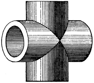
—If the demonstration previously given concerning shade lines on cylindrical surfaces be understood, the application of shading lines to these surfaces will present no difficulty. The darkest and the lightest part of the cylinder having been determined, and in practice this can be accomplished with sufficient exactness by the eye, the shading lines are applied according to the principles explained above with respect to the hexagon. The first shading line is drawn upon the darkest part; and each successive line on each side of this first line is drawn lighter and spaced more widely than the preceding. At the lightest part, a clear space is left to represent the reflexion of the rays that occurs strongly there, and beyond this part the shading is made equal to that of the corresponding part on the other side. The thickening of the lines is effected by going over them a sufficient number of times. Fig. 67 shows a vertical and a horizontal cylinder shaded in this manner. In outline drawings of machinery, this mode of shading with parallel lines is frequently resorted to.
Fig. 68.
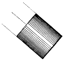
Fig. 69.
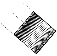
Fig. 70.
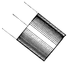
Fig. 71.
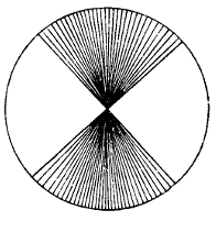
Fig. 68.
Fig. 69.
Fig. 70.
Fig. 71.
It will be evident, on reflection, that when the cylindrical body stands parallel with the direction of the rays of light, as shown in Fig. 68, the lightest part will be in the middle, and the shade will increase in intensity as it approaches the edges. The shading of the interior of a cylinder is, as we have already remarked when treating[52] of shade lines, the converse of that of the exterior. This is shown in the sectional elevation, Fig. 69. When parallel with the direction of the rays of light, as in Fig. 70, the internal shading is the same as the external. On bright circular surfaces, such as that of a circular saw, or the polished end of a shaft, the light is radiated from the centre, as shown in Fig. 71. This mode of shading is strictly in accordance with the appearance presented by such surfaces. It may be remarked here, that if, through inadvertence, any part should be made too dark, the error may be corrected by darkening all the other parts in a corresponding degree.
Fig. 72.
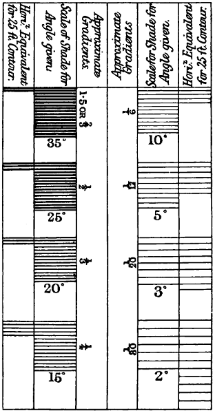
—The shading lines put upon mechanical drawings are merely accessories used for purposes of embellishment. But in topographical drawings, shading lines are applied to give expression, and they constitute an essential element in the representation. We have shown how undulations of the ground, constituting hill and valley, are represented by contour lines. But it is obvious that these lines furnish information respecting[53] the character of the surface only at those points through which they pass. Thus we are necessarily left in ignorance of the irregularities existing between any two successive contours. To supply this information which the contours fail to give, shading is resorted to. Another important object of hill shading is to represent the surface of the ground conventionally in a manner that will immediately afford an idea of its character without the aid of regular contours. The method adopted consists in employing lines varying in their thickness and in their intervals apart according to the slope of the ground to be represented. This method is based upon the principle of the horizontal contours, which is to give to the same vertical interval the same absolute amount of shade, whatever the inclination of the ground may be. The shading lines are used, as we have said, to fill in the features of the ground between contours already fixed; and to ensure accuracy and uniformity in the representation, a “scale of shade” is employed. The accompanying Fig. 72 shows the standard scale of shade adopted by the Council of Military Education, and made use of for all the Government surveys. The second and the fifth columns of this scale show the spacing of the hachures and their thickness for different angles of slope, while the first and the last columns show the number of hachures to be interpolated between contours at every 25 feet vertical intervals, supposing the slope to be uniform. The slope is denoted both by the number of degrees in the angle it makes with the horizontal,[54] and by a fraction showing the ratio of the vertical height to the base in a right-angled triangle, the hypothenuse of which is the slope in question.
The scale of shade is constructed for a horizontal scale of six inches to the mile, and the amount of shade has been chosen with a view of producing the best possible artistic effect. Of course, the most satisfactory results, both artistically and practically, will be obtained when the ground is delineated to this scale, but it can be readily applied to any other scale. For example, the horizontal interval for a slope of 1⁄20, corresponding to a vertical interval of 25 feet, will be 20 × 25 = 500 feet, which, on a scale of six inches to a mile, will be represented by a length equal to 500⁄5280 × 6 = 0·566 inches. In this case, therefore, supposing the slope of the ground to be uniform between two given contours 25 feet apart, we should represent it by means of the hachures shown opposite a slope of 1⁄20, continued over a space of 0·566 inch.
Fig. 73.

In topographical drawings, the light is supposed to fall vertically upon the surface; hence a level surface will reflect all the light that falls upon it, while one of 45° will not reflect any.
The drawing of the hachures presents certain difficulties of execution that can be overcome only by continued practice and careful attention to the modes of proceeding which experience has proved to be the most effectual. Thus an important rule is always to draw “from left to right and downwards.” To allow this to be done, the drawing must be placed with the summit of the hill to the left hand, and be turned round as the work progresses. The hachures should always be commenced at the crest of the hill, working outwards towards the foot of the slope. They should be drawn firmly, and of a length varying from 1⁄4 inch to 3⁄4 inch, according to the width of the zone, that is, according to the greater or less degree of the slope, as shown in Fig. 73, at a, b, c, d. When the hill is steep, the lines are made short and thick, and when the declivity is less, they are made longer and lighter, becoming fine and clean as the level is approximated[55] to. A difficulty with beginners is to press upon the pen equally from the beginning to the end of the stroke, the tendency being to press more heavily towards the end, thus producing a whip-like appearance quite opposed to artistic effect, and conveying a false impression of the character of the ground. A good effect is produced by imparting a slightly tremulous motion to the pen when drawing the hachures. The form of the hill being accurately defined by the pencil contour lines, it is not necessary that the accessory curves formed by the shading lines should be rigorously continuous, and indeed a much better effect, artistically, is gained by avoiding such a manner of drawing them. The various sets of lines must be placed together, end to end, in such a way that the groups or sets shall not be separated by a vacant space, nor overlap each other. Care must be taken that the junctions of sets in two contiguous zones do not form a continuous line from one zone to the other, but everywhere “break joint.” Each zone must be filled in before the next lower one is commenced, the drawing being turned as the work progresses to allow the rule enunciated above of “from left to right and downwards” to be complied with. The distance between the shading lines must be increased or diminished according as the width of the zone varies, so as to divide the space equally; and on reaching the part where the lines were begun, the ends must be brought neatly together. As this can be most satisfactorily accomplished where the lines come close together, it is best to begin at the steepest part of the slope.
In taking a set of hachures round a sharp bend, as in the case of a spur or a ravine, a practical difficulty occurs, which difficulty is increased as the angle becomes more acute. The most effective way of overcoming this difficulty is to draw a pencil line down the spur or[56] re-entering angle, as shown at A B and C D in Fig. 74, and to mark off on this line, at the proper intervals, small arcs of the same radius, as near as can be judged by the eye, as the curve of the contour line. The sets of hachures on each side may then be drawn to these arcs. Guiding lines, as a b, c d, e f, and g h, should be drawn at right angles to the general direction of the contours to ensure the hachures being correctly placed before and after rounding the angle. For this method of carrying a set of hachures round a sharp curve, we are mainly indebted to Lieut. R. Pulford’s ‘Theory and Practice of Drawing.’ When this method is not employed, the hachures must be drawn on each side of the angle first, and those for the angle filled in separately.
Fig. 74.
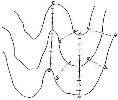
Great care must be taken in filling in the zones formed by the contour lines, that the drawing when finished do not present the appearance of separate layers or bands; for such an appearance is not only quite opposed to artistic effect, but it conveys a false notion of the character of the ground. The successive zones are not separate portions of the surface, but each is a continuation of the one adjoining it. The great principle to be observed in this, as in all matters of hill shading, is that changes of slope are gradual. When the contours are only pencilled in as guide lines to be afterwards erased, the above-mentioned defect may be avoided by drawing the hachures over them, without reference to exact spacing. But when, as is usually the case in regular surveys, the contours are inked in in dotted lines, the only means of avoiding it is to space the hachures on each side of a contour line at the same distance apart.
The student of map drawing should practise assiduously this[57] system of shading in detached portions before undertaking the delineation of a complete hill. For such exercises, either a soft, medium-pointed steel pen, or a quill may be used.
—The foregoing system of shading is known as the Horizontal, and is now generally employed in this country for all kinds of surveys. There is, however, another system much used abroad, and frequently adopted here for engraved maps. In this system, which is known as the vertical, the shading lines are made to radiate from or converge into the curved parts of a hill, according as they project or re-enter. Such lines are called lines of greatest descent; they are supposed to describe the same course that water would describe if allowed to trickle in streams down the slopes, and hence they exhibit both the direction and the degree of the slope. Having the horizontal sections given, we may obtain a complete knowledge of the direction in which the ground slopes by drawing perpendicular to them any number of lines of greatest descent; the degree of declivity is expressed by purely conventional means. The means adopted for this purpose are of two kinds. One depends upon the principle of vertical illumination, in which the maximum quantity of light is reflected upwards to the eye by a horizontal surface, and a minimum by a surface inclined 45° to the horizon. This is the English and German convention, and it lays more stress upon the proportions of black to white in indicating the degree of slope, than upon the distance between the shading lines. The other convention, which is the French, on the contrary, makes its expression depend more upon the distance between the lines of greatest descent than upon the shade of colour produced, though in this also the tint is graduated from dark to light, according to the degree of declivity.
A scale of shade is used for this system, founded upon the same principles as that already given for the horizontal system. The scale adopted is due originally to Major Lehmann, of the Saxon Infantry; but it has received some modification to adapt it to the requirements of practice. Fig. 75 shows Lehmann’s scale. It is constructed for every 5°, from a level up to a slope of 45°, which is the steepest[58] slope at which earth will stand. Each division of the scale corresponding to a given slope is subdivided into nine parts, to show the proportions of black to white. For a level, the whole of these spaces are left white; for a slope of 5°, the proportion is one black to eight white; for a slope of 10°, two black to seven white; and so on up to 45°, for which slope we have all black. The longitudinal divisions of the scale below that against the outer edge A B contain the same proportions of black to white, but equally distributed to show the mode of applying it. Thus, in the division o p r s, corresponding to a slope of 5°, the single black space is, in E F G H, divided into two equal parts and distributed; in G H I K, these two parts are again equally divided and distributed; and so on throughout the other longitudinal divisions. If now the scale be cut off along the line L M, the part L M C D will constitute a scale, the graduated edge L M of which will furnish us with a means of marking off the distance between the centres of the shading lines.
To find the proportion of black to white in the foregoing scale for any given slope:—Subtract the given inclination from 45° for a denominator, and put the given inclination for a numerator. In the scale, as drawn in the figure, the variations are by 5°; but it is obvious that a scale may be drawn in the same manner to mark smaller variations, if thought desirable.
[59]
In applying this method in the United States’ Coast Survey, it was remarked that “this scale of shade does not represent slopes greater than 45°, thereby limiting the graphic capabilities and effect of the map. It also makes the slopes too dark as they approach the inclination of 45°, and does not well represent slopes of less than 5°, which latter it is often desirable and necessary to express distinctly.” The following modification was therefore made:—
| Slope. | Proportion of | |||||||
|---|---|---|---|---|---|---|---|---|
| Black. | White. | |||||||
| 2 | 1⁄2° | or | 2 | 3⁄4° | 1 | 10 | ||
| 5 | ° | „ | 6 | ° | 2 | 9 | ||
| 10 | ° | „ | 11 | ° | 3 | 8 | ||
| 15 | ° | „ | 16 | ° | 4 | 7 | ||
| 25 | ° | „ | 26 | ° | 5 | 6 | ||
| 35° | 6 | 5 | ||||||
| 45° | 7 | 4 | ||||||
| 60° | 8 | 3 | ||||||
| 75° | 9 | 2 | ||||||
By this scale, the slighter slopes are represented distinctly. For slopes less than 16°, the shades are darker than in Lehmann’s scale; this makes their difference more noticeable. Above 25° the shades are lighter.
A further modification, which for ordinary purposes possesses the advantages of simplicity and facility of application, has been made in England, and very generally adopted. This modification consists in fixing with accuracy only three proportions of black to white for three medium slopes, as follows:—
| Slope. | Proportion of | ||||
|---|---|---|---|---|---|
| Black. | White. | ||||
| Level | .. | all | |||
| 15 | ° | 1 | 2 | ||
| 22 | 1⁄2° | 1 | 1 | ||
| 30 | ° | 2 | 1 | ||
| 45 | ° | all | .. | ||
A scale of shade may at once be constructed from this Table, by assuming the thickness of the shading line for the medium slope of 221⁄2°, which thickness must be suited to the scale, and to the degree of fineness and finish it is intended to give the drawing. Generally,[60] if the lines have such a relation to the scale of the drawing as to present a well-connected appearance, it will be found that fewer shading lines and a rather coarse texture will conduce more to clearness of expression than a finer texture, which tends to produce a dryness of style. In shading to this scale, it should be applied to the drawing wherever the slope corresponds to one of the three on the scale. Intermediate slopes are indicated by graduating the thickness of the shading lines. In all cases a good deal must be left to correctness of eye and skill of hand.
In the French method, as we have said, the inclination is expressed by the distances between the centres of the lines of greatest descent. The limits of the slopes that can be represented by this method are, 1⁄1 or 45° for the greatest and 1⁄64 or 0° 53′ 43″ for the smallest. The largest scale that will admit of conveniently drawing the lines of greatest descent is 1⁄600 full size, or about 83⁄4 feet to a mile. The vertical distance between the horizontal sections is generally taken as 1 yard. Hence to a scale of 1⁄600 the least width of zone will be 6⁄100 inch, and the greatest 6⁄100 × 64 = 384⁄100 inches.
The distance between the shading lines is reckoned from centre to centre, and is determined by the rule:—To the distance between the upper and the lower curves of any zone add 3⁄10 of an inch; a sixteenth part of this sum will be the proper interval for the shading lines. The distance is measured along the line of greatest descent. Thus, if the inclination be 1⁄60 and the scale 1⁄600, the width of zone will be ·06 × 60 = 3·60 inches, and by the rule we have 3·60 + ·316 = 3·916 = 0·244 inch. Another rule is:—To a fourth of the distance between the upper and the lower curves of any zone, add 75⁄1000 of an inch; a fourth part of the sum will be equal to the interval.
The thickness or breadth of the lines is made to vary directly as the inclination to assist in expressing the declivity. This thickness is determined by the following rule. For a slope of 1⁄1 the thickness of the shading lines is equal to 2⁄3 of the distance between their centres,[61] and this thickness will diminish with the inclination down to 1⁄64, where the lines will be as fine as they can be drawn. In a slope of 1⁄1 this rule will always make the breadth of the shading lines twice that of the white space contained between them.
To represent declivities by the vertical system of shading a considerable amount of practice is required. This practice should be commenced by drawing repeatedly the scale of shade, and gradually applied, as proficiency is attained, to the varying inclinations of a hillside. Having the horizontal sections of the hill given, the degree of slope should be written upon it in pencil in as many places as is necessary. The distances between the centres of the shading lines may then be marked off upon the upper curve of the zone from the scale of shade, and the lines of greatest descent drawn through the points thus determined. The exact proportion of black to white being then adopted, the colour will express the degree of the slope, and the line of greatest descent will show its direction.
The principle of making the shading lines longer on a gentle slope than on a steep one should be adhered to generally; but in this matter much must be left to the judgment and the skill of the draughtsman. Frequently on slight inclinations it will be desirable to divide and subdivide the zone by medial lines, as shown in Fig. 76, and on very steep slopes the shading lines may be drawn over two or more zones. For ordinary scales the extremes of length may be fixed at 1⁄6 of an inch on the steepest slopes, and 3⁄4 of an inch on the gentlest.
Fig. 76.
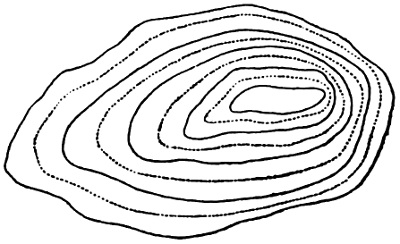
It is not necessary to repeat the process of construction for every line, such a mode of proceeding would be too laborious and slow. It will be sufficient to determine the lines in this exact manner at those parts where the greatest changes of slope occur. Thus a group should be constructed in each zone where the slope is greatest and another[62] where it is least, after which a few intermediate ones may be put in. The vacancies may then be filled in, taking care to graduate the changes in passing from group to group. By this means we do not, of course, get a mathematically exact representation of the surface, but it is sufficiently accurate for practical purposes.
When the preparatory pencil lines have been drawn in and the spaces for the shading lines laid off by dots, the shading should be commenced at the steepest part of the upper zone. The lines should be drawn firmly from curve to curve, taking care to make each row terminate evenly at the lower edge; they must always be drawn downwards and from left to right, proceeding in this direction round the zone till the point of setting out is reached, where the joining must be carefully effected. This can always be done most neatly where the lines are thickest, as we have previously pointed out. The succeeding zones should be filled up in the same manner. As changes must be gradual in every direction, care must be taken to make the contiguous zones blend into each other. When it is required to pass from a light zone to a darker one beneath it, the lower ends of the lines in the light zone should be thickened a little, so as to meet the upper ends of the lines in the dark zone with nearly the same colour. The upper ends of these latter lines should also be slightly lightened. The lines of one zone must not be continued into those of the next. Even on a uniform slope such a prolongation of the lines would produce a hard appearance, which should be avoided. But in the case of a conical hill, like that shown in Fig. 77, it would give rise to an error in principle; for soon after leaving the summit we should have too few lines of descent. When the hill has been covered with shading lines, the base and the summit must be softened off by tapering the lower end of each line at the base, and the upper end of each line at the summit. To give the taper to the latter, the drawing should be turned upside down.
Fig. 77.
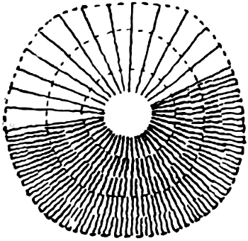
When the curves are parallel or nearly so, the shading lines are[63] straight, and also nearly parallel. But when the curves depart widely from each other, the shading lines will themselves have a slight curvature, for being lines of greatest descent, they must be normal to the curves. In such cases, a number of normals should be put in at short distances with the pencil, as shown in Fig. 78, to serve as guides to the shading lines. The foregoing directions for shading a hill apply equally to the shading of a hollow, the shading lines in which are converging.
Fig. 78.
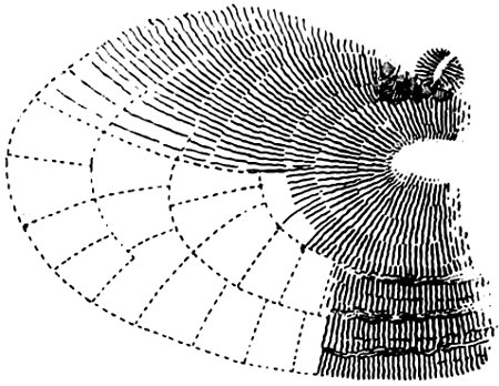
Occasionally short slopes steeper than the “natural slope” of 45° will be met with. Such being exceptions to the law of slopes, are marked in an exceptional manner. When the surfaces of these slopes are of earth, they are shown by black lines drawn parallel to the horizontal curves, and when of rock, by black lines drawn in all directions, not intersecting, but abutting abruptly upon each other in short heavy masses, as shown in Fig. 78.
—Frequently in topographical drawings, and still more frequently in mechanical drawings, colour is resorted to to produce the effect of shading lines. As the principles according to which colour is applied for this purpose are the same as those which determine the use of shading lines, there remains little to be said on this matter beyond describing the modes of applying the colour.
—In representing slopes, the tint employed to give the effect of that produced by the ink lines already described is composed of indigo and burnt sienna, and is applied as a flat-wash. A little lake is added to neutralize the greenish hue of this tint when it is to be laid over sand or cultivated ground. The different degrees of intensity required to express the inclination are produced by repeating the wash over those parts which are darker than the rest. To accomplish[64] this neatly, the darker portions must be washed in first, so that the final washings may cover the whole surface, and the edges of each successive wash must be softened off or blended into the next with a brush and clean water. In shading hills, the paper along the crest of the slope should be first moistened with the water-brush, and before it dries, the laying on of the colour should be begun on the moistened part, and proceeded with down the slope. The effect of representing hills by this method, which is a very expeditious one, is much improved by adding light shading lines with the pen, either in pale ink, or a mixture of indigo and burnt sienna. The ground is always covered with its appropriate sign before the shading tint is laid on.
—In shading cylindrical surfaces and drawings generally, three methods are employed. One of these is known as softening off, and is employed on finished drawings of machinery. For shading by this method, a brush called a softener is required; this has a brush at each end of the handle, one being larger than the other. Having moistened the paper, and filled the smaller brush with colour and the larger one with water, a narrow strip of colour is laid along the darkest part of the cylinder, and immediately after, while the colour is quite moist, the water-brush is drawn along one edge of the strip and then in like manner along the other, so as to cause the colour to flow over that portion of the surface which has been damped. The brush is then wiped upon a cloth and drawn lightly down the edge to take up the superfluous water. The colour should be light to begin with, and the quantity to be taken in the brush must be determined by experience. The same remark applies to the water-brush, for if too little be used the colour will not spread sufficiently, and if too much, the colour will be diluted and rendered uneven. These operations of laying on the colour and softening off are continued until the cylindrical appearance has been produced. Each succeeding coat should be laid on before the preceding one is quite dry, as the colour will spread more evenly over a damp surface. The previously applied coat must, however, have been[65] sufficiently absorbed not to wash up, or a clouded appearance will be the result.
Another method, known as the French, consists in applying a narrow strip of colour to the darkest part, and overlaying this with other strips, each wider than the one previously laid on. To regulate the breadth of the strips, a number of meridian lines are drawn upon the cylinder. When shaded in this manner, the cylinder presents the appearance of a polygon rather than that of a cylinder.
The third method, by reason of the facility it affords of producing effect, is very suitable for large drawings and diagrams for illustrating papers and lectures. In shading according to this method, a thick line or a narrow strip of very thick and black Indian ink is laid on the darkest part of the cylinder with the point of the brush. The breadth of the strip will be regulated by the diameter of the object, and it should be previously lined out in pencil. When dry, a damp brush is passed over it so as to remove the sharp edges of the strip, and to cause the ink to run slightly over the moistened surface of the paper. The flat colour washes are then applied as required, the washes being carried over the black strips, which will be further reduced in tone by a portion of the ink mixing with the colour.
In shading, it will be found convenient to keep the light side of the object next to the operator, as it is easier to wash towards the body than from it with the water-brush. The brush should be held in as nearly a vertical position as possible, as it is more easy, when that position is observed, to keep within the boundary lines.
[66]
—The lettering of a plan, map, or drawing of any kind, occupies a prominent and conspicuous position, and may be considered as forming an essential part of the drawing. It is, therefore, obvious that the character of the lettering, and the degree of finish introduced into its execution, will have an important influence on the general appearance of the drawing. Nothing detracts more from the value of a map, considered as a work of art, than a bad style of lettering, while, on the other hand, a well-chosen and well-executed style is both pleasing to the eye, and produces on the mind an impression of accuracy in the more important features of the work. Hence it is not merely desirable, but necessary, that the draughtsman should acquire the ability to form letters correctly and neatly, especially if he be engaged on topographical drawings, into which lettering enters very largely.
The formation of letters requires great attention and long practice. It is not a matter in which much assistance is to be derived from descriptions or written instructions of any kind; practice alone from good models will give the requisite skill. The difficulty of forming the letters correctly and of uniform dimensions may, however, be considerably lessened by using guide lines drawn in pencil, to be afterwards erased. Such lines are called construction lines, and the mode of employing them is shown in Plate 4. A careful study of this Plate will give the student a clear understanding of the use of these lines, which could not be imparted by pages of description. A reference to the letters B, E, and T, in connection with the construction lines will[67] show most readily the nature and the degree of assistance afforded by the latter.
In making capitals, each letter must be sketched in pencil; the outline must then be drawn in ink with a firm and steady line, and afterwards filled up with the pen. In forming the small roman and italic letters, three construction lines are drawn, the lower two to limit the height of the ordinary letters, and the upper one to limit the height of such letters as d and l, and the capitals. The heavy parts of these letters are made at once by a bold pressure of the pen. The curved portions should be carefully distinguished from the straight. The letters a, c, g, o, s, &c., for example, are composed wholly of curved lines. They should be drawn symmetrically, and their width should be only a little less than their height. The round portion of the g should not quite reach to the lower line. A perfect regularity should be maintained throughout the letters, as the beauty of their appearance depends greatly on this. Care must also be taken, in italic writing, to keep the inclination the same everywhere. Manuscript lettering should be more extended than the clear roman or italic type, for crowding greatly mars its appearance.
The character of the letters employed should be in accordance with that of the drawing upon which they are to appear. Thus for engineering and mechanical drawings, there is nothing more suitable generally than the plain block letter. But on drawings of a more artistic and ornamental character, a more elaborate form of letter may and should be used. And of these elaborate forms, there will always be one more suitable than the rest to the particular character of the drawing. The choice of this form is a matter to be left entirely to the judgment and the taste of the draughtsman.
Another matter on which the draughtsman will have to exercise his judgment is the size of the letters employed. This must manifestly be in accordance, first, with the character of the object denoted, and, second, with the scale of the drawing. With regard to the former of these conditions, it is obvious that propriety will demand a larger letter for the city than the town, for the town than the village, for[68] the village than the farm, and for the mansion than the gate-lodge. This propriety of relative importance must be everywhere observed. The different types of lettering are arranged in the order of importance as follows:—1, The upright capital; 2, the inclined capital; 3, the upright roman, or ordinary small type; and 4, the small italic. The draughtsman will have to exercise his judgment in suiting the size to the scale of the map, but the following Table may be taken as a general guide:—
| Scale. | Height of Upright Capitals. |
Height of Small Roman. |
|||
|---|---|---|---|---|---|
| 1⁄600, | or one inch to fifty feet. | Six-tenths of an inch. | Twelve-hundredths of an inch. | ||
| 1⁄2640, | or two feet to a mile. | Four | „„ | Eight | „„ |
| 1⁄5280, | or one foot to a mile. | Three | „„ | Six | „„ |
| 1⁄10560, | or four inches to a mile. | Two | „„ | Four | „„ |
The thickness of the capital should be one-seventh of the height.
As far as practicable, the lines of lettering should be parallel to the base of the drawing. Frequently, however, cases will occur in which it will be desirable to letter in other directions and in curved lines. In writing along a curved or very irregular outline, the course of a river or the boundary of an estate, for example, an agreeable effect is produced by making the lines of lettering conform in some degree with the outlines against which they are written.
The arrangement of the letters in titles and the effective disposition of the words are also matters requiring great care and some taste. The design and the execution of the title afford another opportunity of enhancing the beauty of a drawing by a display of striking arrangement and appropriate ornamentation. Plates 7 and 8 show some useful models for plans, and Plate 25 contains some specimens of flourishes which may frequently be introduced with pleasing effect. The form which the title shall assume and the space which it shall occupy must be determined before beginning to put it upon the drawing. To avoid erasures, it is well to sketch roughly upon a piece of paper, a trial title, emendations in which can be easily made. When found satisfactory, draw a vertical centre line, which[69] should pass through the middle letter of each line. Apply this centre line to the centre line of the title on the drawing, and lightly mark in with the pencil the position of each letter. When this method is not adopted, the middle letters should be put in first upon the centre line, and the others afterwards inserted from left to right, and from right to left.
In maps, the title may be placed outside the border if it consist of one line only, but if it occupy more than one line, it should be placed within the border. Generally, it should be placed in one of the corners of the map, and its size should bear some proportion to that of the map. The letters composing the name of the locality, which is usually the most important word, should not exceed in height three-hundredths of the length of the short side of the border. The letters of the other words will vary in size according to their relative importance.
—Plain borders usually consist of two lines, the outer one heavy, and the inner one light. The heavy line should be equal in breadth to the blank space between it and the light line, and the total breadth of the border, that is, of the two lines and the space between them, should be one hundredth part of the length of the shorter side. Ornamental corners may be made to embellish a drawing considerably, and they afford some scope to the fancy and the taste of the draughtsman. Several examples of borders and ornamental corners will be found in the accompanying Plates.
—The meridian or north and south line is an indispensable adjunct to every topographical drawing. When the extent of country represented is considerable, it is usual to make the top of the map the north, and in such a case the side border lines are meridian lines. Frequently, however, in plans, the shape of the ground does not admit of this arrangement, and then it becomes necessary to mark a meridian on some part of the map. This line is usually made a conspicuous one, and its north extremity is often ornamented with some fanciful device. The ornamentation of the meridian line should be in keeping with the rest of the map. Plate 9 contains several examples which may be adopted or modified as deemed desirable.
[70]
To all drawings which do not show the full size of the objects represented, it is necessary to affix the scale according to which the objects are drawn. Such a scale is called a scale of lengths or distances, because, by means of it, the distance from one point to another is ascertained. The scale of distances does not contain very minute subdivisions, and consequently is not suitable for use in constructing the drawing. For the latter purpose, another scale, similarly but more minutely divided, is employed, and is known as the scale of construction. A familiarity with the modes of constructing both of these scales should be early acquired by the young draughtsman.
—One means of denoting the scale of a drawing is furnished by what is called its representative fraction, the denominator of which shows how many times greater the actual length is than that in the drawing. Thus a scale of 1⁄24 shows that 1 inch on the drawing represents 24 inches on the object; in other words, that the object is twenty-four times larger than the drawing. But in addition to this representative fraction, it is usual to affix a graduated straight line, termed a scale, for the purpose of conveniently measuring distances upon it. It is manifest that the unit of length in this scale must bear the same ratio to the real unit of length that a line in the drawing bears to the line which it represents. Thus if the representative fraction be 1⁄24, 1 inch on the scale will represent 2 feet.
Scales of distances are usually of such a length as to be a multiple of 10 linear units of some kind, as 100 miles, 50 chains, 20 feet; and this length should also be such as to allow of long lines being taken off at one measurement. To construct the scale, two light lines should be drawn at a suitable distance apart, and below the lower of these lines and at a distance from it equal to one-third of the space between them, a third and heavy line should be drawn. The primary divisions may then be made with the compasses in the following manner. Supposing the number of divisions to be five, open the[71] dividers to what appears to be the fifth part of the line, and step this distance along the line; if the fifth step exceed or fall short of the end of the line, close or open the dividers 1⁄5 of the distance, and repeat the trial. This is the quickest and, for large divisions, the most accurate method of dividing a line. To render the divisions more distinct, draw a heavy line between the two light lines in alternate divisions. The left-hand division must be subdivided into the units or lesser measures of which it is made up. For example, if the primary divisions are each of 10 feet, the subdivisions will be feet; if they represent feet, the subdivisions will be inches, and so on. The subdividing should be performed in the following manner. Having erected a perpendicular of indefinite length from the left-hand extremity of the scale, take with the compasses from any scale the number of divisions into which it is required to divide the part. With this distance in the compasses, strike, from the first primary or zero division, an arc cutting the perpendicular, and join the point of intersection to the centre from which the arc is struck. Thus we shall have a right-angled triangle formed of the first primary division of the scale, the perpendicular and the radius, the latter being the hypothenuse (see Fig. 79). Mark on the hypothenuse the divisions to which it was made equal, and from the points of division let fall perpendicular lines upon the scale. These will divide the latter into the required number of equal parts. The length of the hypothenuse should be so chosen as to make an angle not greater than 50° with the base.
The total length of the scale will be determined by the greatest length which it is required to read off at once, and in the following manner. Thus, let it be required to construct a scale of 1⁄24, = 1⁄2 inch to[72] the foot, to show 12 feet. Here ·5 inch : x inches :: 1 inch : 12 inches; whence x = 12 × ·5 = 6 inches. This distance of 6 inches must, therefore, be set off upon the lines intended for the scale, and divided in the manner described above. Again, to construct a scale of 1⁄10560, = 6 inches to a mile, to show 100 chains. Since 6 inches represents 5280 feet or 5280⁄60 = 80 chains, the proportion becomes 6 : x :: 80 : 100; whence x = 600⁄80 = 71⁄2 inches. If the scale is 1⁄3960 = 16 inches to a mile, = 5 chains to an inch, and the distance to be shown is 30 chains, we have 1 : x :: 5 : 30; or x = 30⁄5 = 6 inches. In a scale of 10 yards to the inch, for example, the representative fraction is 10 × 3 × 12 = 1⁄360. So, on the contrary, 1⁄360 = 360⁄36 = 10 yards to the inch. Sometimes it is required to construct a comparative scale, that is, a scale having the same representative fraction, but containing other units. Thus suppose, for example, we have a Russian plan on which is marked a scale of archines measuring a length of 50 archines. It is required to draw upon this plan a comparative scale of yards, upon which a distance of 50 yards may be measured. The Russian archine = ·777 yard. Hence we have the proportion 50 : x :: ·777 : 1, whence x = 50⁄777 = 64·35 archines. Measure off this length from the Russian scale, and upon it construct the English scale in the manner already described. This scale may then be used to measure distances on the plan.
Amongst Continental nations, decimal scales are usually employed, which are far more convenient in practice than those involving the awkward ratios of miles, furlongs, chains, yards, feet, and inches. The decimal scale has also been adopted for the United States’ Coast Survey, the smallest publication scale of which is 1⁄30000; this is also the scale of the new map of France.
In choosing a scale, regard must be had alike to the purposes for which the drawing is intended, and to the nature and the amount of detail required to be shown. Thus a larger scale is required in plans of towns than in those of the open country; and the smaller and more intricate the buildings, the larger should the scale be. Also a plan to be used for the setting out of works should be to a larger scale than one made for parliamentary purposes.
[73]
The following Tables, given by Rankine in his ‘Civil Engineering,’ enumerate some of the scales for plans most commonly used in Britain, together with a statement of the purposes to which they are best adapted.
| Horizontal Scales. | ||||||
|---|---|---|---|---|---|---|
| Ordinary Designation of Scale. | Fraction of real Dimensions. |
Use. | ||||
| 1.— | 1 inch to a mile | 1⁄63360 | Scale of the smaller Ordnance maps of Britain. This scale is well adapted for maps to be used in exploring the country. | |||
| 2.— | 4 inches to a mile | 1⁄15840 | Smallest scale permitted by the Standing Orders of Parliament for the deposited plans of proposed works. | |||
| 3.— | 6 inches to a mile | 1⁄10560 | Scale of the larger Ordnance maps of Great Britain and Ireland. This scale, being just large enough to show buildings, roads, and other important objects distinctly in their true forms and proportions, and at the same time small enough to enable the eye of the engineer to embrace the plan of a considerable extent of country at one view, is on the whole the best adapted for the selection of lines for engineering works, and for parliamentary plans and preliminary estimates. | |||
| 4.— | 6·366 inches to a mile | 1⁄10000 | Decimal scale possessing the same advantages. | |||
| 5.— | 400 feet to an inch | 1⁄4800 | Smallest scale permitted by the Standing Orders of Parliament for “enlarged plans” of buildings and of land within the curtilage. | |||
| 6.— | 6 chains to an inch | 1⁄4752 | - | Scale answering the same purpose. | ||
| 7.— | 15·84 inches to a mile | 1⁄4000 | Scales well suited for the working surveys and land plans of great engineering works, and for enlarged parliamentary plans. | |||
| 8.— | 5 chains to an inch, or 16 inches to a mile. | 1⁄3060 | ||||
| (Scale 8 is that prescribed in the Standing Orders of Parliament for “cross sections” of proposed railways, showing alterations of roads.) | ||||||
| 9.— | 25·344 inches to a mile | 1⁄2500 | Scale of plans of part of the Ordnance survey of Britain, from which the maps before mentioned are reduced. Well adapted for land plans of engineering works and plans of estates. | |||
| 10.— | 200 feet to an inch | 1⁄2400 | Scale suited for similar purposes. Smallest scale prescribed by law for land or contract plans in Ireland. | |||
| 11.— | 3 chains to an inch | 1⁄2376 | Scale of the Tithe Commissioners’ plans. Suited for the same purposes as the above. | |||
| 12.— | 100 feet to an inch | 1⁄1200 | Scale suited for plans of towns, when not very intricate. | |||
| 13.— | 88 feet to an inch, or 60 inches to a mile. | 1⁄1080 | Scale of the Ordnance plans of the less intricately built towns. | |||
| 14.— | 63·36 inches to a mile | 1⁄1000 | Decimal scale having the same properties. | |||
| 15.— | 44 feet to an inch, or 120 inches to a mile. | 1⁄528 | Scale of the Ordnance plans of the more intricately built towns. | |||
| 16.— | 126·72 inches to a mile | 1⁄500 | Decimal scale having the same properties. | |||
| 17.— | 30 feet to an inch | 1⁄360 | - | Scales for special purposes. | ||
| 18.— | 20 feet to an inch | 1⁄240 | ||||
| 19.— | 10 feet to an inch | 1⁄120 | ||||
[74]
| Vertical Scales. | ||||||||||||
|---|---|---|---|---|---|---|---|---|---|---|---|---|
| Ordinary Designation of Vertical Scale. | Fraction of real Height. | Horizontal Scales with which the Vertical Scale is usually combined. | Exaggeration. | Use. | ||||||||
| from | ||||||||||||
| 1.— | 100 feet to an inch | 1⁄1200 | 1⁄15840 | to | 1⁄10560 | 13·2 | to | 8·8 | Smallest scale permitted by the Standing Orders of Parliament for sections of proposed works. | |||
| 2.— | 40 feet to an inch | 1⁄4800 | 1⁄4800 | to | 1⁄3960 | 10 | to | 8·25 | Smallest scale permitted by the Standing Orders of Parliament for cross sections showing alterations of roads. | |||
| 3.— | 30 feet to an inch | 1⁄360 | 1⁄3960 | to | 1⁄2376 | 11 | to | 6·6 | - | Scales suitable for working sections. | ||
| 4.— | 20 feet to an inch | 1⁄240 | 1⁄3960 | to | 1⁄2376 | 16·5 | to | 9·9 | ||||
The vertical scale, or scale of heights, is always much greater than the horizontal scale or scale of distances, and the proportion in which the vertical scale is greater than the horizontal, is called the exaggeration of the scale. This exaggeration is necessary, because the differences of elevation between points on the ground are in general much smaller than their distances apart, and would therefore, without exaggeration, be unapparent, and also because, in the execution of engineering works, accuracy in levels is of more importance than accuracy in horizontal positions.
—Scales of construction are intended to afford means of measuring more minute quantities than scales of distances. Of the former there are two kinds, known respectively as the Diagonal and the Vernier scale. The diagonal is the more frequently employed. Its construction involves no peculiar difficulty, as it consists simply of an ordinary scale of distances, with the addition of a number of parallel lines crossed by other parallel lines drawn diagonally from the smaller points of division. An example will best show the construction and mode of using this scale. Suppose it to be required to construct a scale of 10 miles to the inch, showing furlongs diagonally; the scale to measure 50 miles. Here 1 : 10 :: x : 50, whence x = 5 inches. Divide this length of 5 inches into five equal parts, and the first part into tenths to show miles, in the manner already described for scales of distances. Then, since it is required to[75] show furlongs or eighths of a mile, eight equidistant parallel lines must be drawn above the scale, at a convenient interval apart, as shown in Fig. 80. Produce the primary points of division to meet the top parallel; and from the last secondary point of division draw a line to the point in which the extreme primary division meets the top parallel. Draw from the other points of division, lines parallel to this one, and the scale will be complete. It will be seen that the inclined lines are the diagonals of the rectangular figures formed by the top and bottom parallels and vertical lines drawn from the smaller points of division.
To use this scale, suppose a length of 24 miles 5 furlongs is required. Place one leg of the dividers upon the point in which the fourth diagonal intersects the fifth parallel, and extend the other to the point in which the primary division marked 20 intersects the same parallel. In like manner, if the distance required be 33 miles 3 furlongs, it must be taken from the intersection of the third diagonal with the third parallel, to the intersection of the primary division marked 30 with the same parallel.
It is obvious that if a scale of feet showing inches diagonally be required, twelve equidistant parallel lines must be drawn instead of eight as in the foregoing example where furlongs are required. The diagonal scale possesses the important advantages of accuracy and distinctness of division which render it very suitable as a scale of construction. Another practical advantage is that it is less rapidly defaced by use than the other kinds, in consequence of the measurements being taken on so many different lines.
The construction of the vernier scale is similar to that of the[76] graduated arcs of surveying and astronomical instruments. The principle of the vernier is as follows. If a line containing n units of measurement be divided into n equal parts, each part will, of course, represent one unit; and if a line containing n + 1 of these units be also divided into n parts, each part will be equal to n + 1n units; and the difference between one division of the latter and one of the former will be x + 1n - 1 = 1⁄n of the original unit. Similarly, the difference between two divisions of the one and two of the other will be 2⁄n of a unit, between three of the one and three of the other, 3⁄n, and so on. Hence, to obtain a length of x⁄n of a unit, we have only to make a division on one scale coincide with one on the other scale; the space between the two corresponding xth divisions from this on both scales will be the required length of 2⁄n of a unit. The same reasoning will evidently hold good if a length equal to n - 1 be taken.
To show how the foregoing principle is applied in practice, we will take an example. It is required to construct a scale of 1⁄100 to show feet and tenths of a foot. Construct a scale in the ordinary way, and subdivide it throughout its whole length, as shown in Fig. 81; then each division will show one foot. Above the first primary division, draw a line parallel to the scale and terminating at the zero point. From the zero point, set off on this line towards the left a distance equal to eleven subdivisions, and divide this distance into ten equal parts. Now, as eleven divisions of the plain scale have been divided into ten equal parts on the vernier, each division on the latter will represent 11⁄10 = 1·1 of that on the former; and as the divisions of the plain scale represent feet, those of the vernier will represent 1·1 foot. Consequently, the distances from the zero of the scale to the successive divisions[77] on the vernier are 1·1, 2·2, 3·3, 4·4, 5·5, 6·6, 7·7, 8·8, 9·9, and 11 feet. It will be seen that the divisions of the two scales are made to coincide at the zero point.
The mode of using this scale will be seen from the following example. Let it be required to take off a distance of 26·7 feet. From zero to the 7th division of the vernier is, as we have seen, 7·7 feet. Therefore, to ascertain how far to the right of zero we must go to obtain the distance of 26·7 feet, we must subtract 7·7 from that distance, which gives 19. Thus to take off the distance, one leg of the dividers must be placed on the 7th division of the vernier, and the other on the 19th division of the plain scale. If the distance to be taken were 27·6 feet, one leg of the dividers would have to be placed on the 6th division of the vernier, and the other on the (27·6) - (6·6) = 21st division of the plain scale.
To construct a scale to show feet and inches, make the vernier equal to thirteen divisions of the plain scale and divide it into twelve equal parts. Each of these divisions will then represent 13⁄12 = 11⁄12 of a foot.
Scales of construction may be purchased upon box-wood or ivory, but where great accuracy is important, it is best to lay down the scale upon some part of the drawing, as in such a case it expands and contracts with the drawing under the influence of moisture.
Examples of scales of distances will be found on Plates 8 and 9.
The transference of the measurements determined by the survey from the field-book to the paper is termed plotting. The operations of plotting are very simple, and the ability to perform them properly may be acquired with a little practice. But their due performance demands the same extreme care and attention as that of the operations in the field, for it is obvious that the precautions taken to ensure accuracy in the latter may be rendered nugatory by inaccurate[78] plotting. The angular instrument used in plotting is the protractor, and to ensure correct results this instrument must be accurately divided. When, however, the survey has been made without the aid of an angular instrument, the protractor is not required in laying down the results. In such a case, which frequently occurs in surveys of small extent, the lines, having all been chained and registered in the field-book, are laid down directly from the scale by means of an ordinary straight-edge and a pair of compasses. The several methods of plotting and the various operations involved have now to be considered.
—The lines chained over in a survey and recorded in the field-book are not usually the actual lines existing on the ground, but imaginary straight lines chosen for the purpose of referring other lines and points to them. They are, therefore, appropriately termed reference lines, and all points situate in them to which other lines are referred, in other words, all points in a reference line in which other reference lines intersect it, are termed reference points. Reference lines are generally made to form triangles for facility of computation, and these triangles enclose the area to be surveyed. But to determine the details included within them, it is necessary to form other and smaller triangles within the larger ones first laid down. The latter are, therefore, distinguished as Primary and the former as Secondary triangles, and the lines of which they are composed are called primary and secondary reference lines.
—In laying down a line of definite length upon paper, the positions of its extremities are determined and marked by pencil dots; such dots, or rather the points indicated by such dots, are termed plotted points. The line is drawn by joining the plotted points.
—To plot a reference line of a given length when the position of neither of its extremities is given, a light dot must be made upon the paper in a convenient part to indicate the position of one extremity. The pencil-point mark should be as light and well defined as possible, and hence it is essential that the pencil used should be hard, and always kept pared to a fine[79] conical point. The scale must then be applied, in the direction of the line to be drawn, with its zero point coincident with the plotted point. The scale should be lightly but firmly held in this position with the left hand. The distance of the other extremity of the line must then be found upon the scale, and the eye placed directly over the line of the graduation; this is necessary to the correct placing of the point, and it is well to train the eye to trace accurately the prolongation of the line of graduation upon the paper. A dot must be placed in the prolongation of this line and close to the edge of the scale, to mark the position of the other extremity. The reference line is then to be drawn between these two plotted points with a sharp chisel-pointed pencil. Reference lines, like reference points, should be well defined, but drawn as fine and light as possible. The degree of fineness and lightness should be such that when the detail is finely but firmly outlined, the reference lines and points may not be visible, except on a close inspection of the surface.
To plot secondary reference lines, as, for example, a number of offset lines, apply the scale so that its edge may be parallel to and almost over the pencil trace of the primary line and its zero point coincident with the point at which the line begins. Care must always be taken to place the zero of the scale at the beginning of the line, and not at the end of it. At the distances recorded in the field-book as those at which the offsets were taken, plot upon the line, in the manner described above, the points indicating the extremities of the offset lines. All other points, such as stations and intersection of fences, roads, and streams, should be plotted at the same time. Around all stations, a light, hand-drawn circle should be placed, and intersections marked by small cross lines. This being done, place the offset scale so that the zero may coincide with the plotted point in the reference line and the edge be perpendicular to the line. To bring the edge into this position, the end of the scale should be placed parallel to the reference line; this is, of course, assuming the scale to be perfectly rectangular, as it ought to be. The other extremities of the lines may then be plotted in the same manner as those of the primary lines.
[80]
To illustrate the foregoing remarks, let it be required to plot the following portion of a field-book.
| 00 | 1346 | or 000 Line 1. | ||||
| 75 | 1170 | |||||
| 96 | 1000 | |||||
| 05 | 650 | |||||
| 66 | 400 | |||||
| 00 | 000 | |||||
| Line 3. | From | 1946 | last. | |||
| 1946 | 00 | |||||
| 1420 | 88 | |||||
| 1200 | 144 | |||||
| 1000 | 110 | |||||
| 600 | 75 | |||||
| 520 | 50 | |||||
| 000 | 00 | |||||
| Line 2. | From | 2504 | last. | |||
| 2504 | 00 | |||||
| 2000 | 65 | |||||
| 1790 | 95 | |||||
| 1610 | 115 | |||||
| 1440 | 87 | |||||
| 1220 | 110 | |||||
| 1000 | ||||||
| 850 | 28 | |||||
| 420 | 100 | |||||
| Line 1. | 000 | 00 | or 1346 Line 3. |
|||
| Begin at south corner and range N. | ||||||
Having laid down in a convenient part of the paper the beginning of Line 1, place the edge of the scale so that the zero may coincide with the plotted point and the edge be parallel to one of the meridians. Holding the scale firmly in this position, plot the distance 2504 links, and join the plotted points. Then, without removing the scale, plot upon this reference line the distances at which the secondary or offset lines were taken, that is at 420, 850, 1220, 1440, 1610, 1790, and 2000 links. In this case we have nothing but offsets; had there been stations or intersections of fences, roads, or streams, these would have had to be plotted at the same time, and distinguished by an appropriate mark. Line 2 begins at the end of Line 1, and returns on the left at an acute angle, as indicated by the arrow in the field-book. But as the magnitude of this angle is not known, the survey having been taken with the chain alone, the exact direction of Line 2 must be ascertained in the following manner. Take the length of the line in the compasses, and with this distance as a radius, strike an arc from the end of Line 1. Also with the length of Line 3 as a radius, strike an arc from the beginning of Line 1, at which point Line 3 closes, intersecting the former. The point of intersection will be the end of[81] Line 2. Join this point to the end of Line 1, and plot the offset reference points upon this line in the manner already described for Line 1. Line 3 begins at the end of Line 2, and terminates at the beginning of Line 1; hence both extremities being determined, we have only to join these points, and to plot the offset reference points as before. Had a split line been taken for the sake of accuracy from the angle A C B to the base Line 1, the intersection of this line should have been plotted upon Line 1, and the position of the end of Line 2 found by striking an arc from this point also with a radius equal to the length of the split line. If the distances have been correctly measured in the field and correctly taken from the scale, the three arcs will intersect at the same point. If they do not so intersect, the error must be noted in an error-sheet, and corrected in the field before proceeding further. It may be remarked here that on account of the irregularities of the surface chained over, all measured lines are liable to be recorded a little too long. One link in ten chains may be allowed for this source of error. Assuming, however, that the primary reference lines “close” properly, the offset lines may be plotted in the manner already described, and the detail or boundary lines drawn in, which in the present instance are hedges. Fig. 82 shows the survey as laid down in the foregoing notes.
When the survey has been made with the aid of an angular instrument, the method of plotting the primary reference lines differs somewhat from the foregoing. In this case, the paper should be first covered with a number of parallel straight lines ruled about an inch and a half apart to represent magnetic meridians. The first station may then be marked upon one of these meridians in a convenient part of the paper. To lay down the first reference line, apply the protractor to this meridian with its centre point coincident with the plotted point, and from the bearing recorded in the field-book, lay off the given angle. Join the two plotted points and produce the line indefinitely; and upon this line lay off a distance equal to the length of the measured line. The second reference line must be drawn in the same manner, from the end of the first, by laying off from that point[82] the recorded angle. But as the end of the first line will probably not fall upon a meridian, the protractor will have to be moved up to the point by means of a parallel ruler adjusted to the nearest meridian. A more convenient and a more accurate method, however, is to make the left of the drawing represent the north while plotting, and to use the T-square instead of the parallel ruler. All subsequent lines are plotted in the same way. Instead of covering the paper with meridians before commencing to plot, it may, in some cases, be found more convenient to draw with the set and T squares a short meridian through the point as required.
Fig. 82.
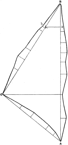
To lay down Fig. 82 in this manner, having fixed the first station A, the length of the first primary reference line A B may be laid off upon the meridian, because in this case the bearing being due north, the reference line will[83] be coincident with the meridian. This done, the protractor is to be placed over the plotted point B and the second bearing laid down. Having plotted the length of this line in the point C, the third reference line C A will be determined both in length and direction by the plotted points C A, which should be joined and the line measured to ascertain whether its length corresponds with the measured distance. If these do not correspond, the angle must be replotted and the lengths laid off anew to discover the source of the error. Assuming, however, that the lines close properly, the offsets and other secondary points may be next plotted in the manner previously described.
Angles may be more accurately laid down by means of a table of natural sines and cosines and a linear scale than by means of a protractor. This is especially true when the angles are subtended by long lines, as, for example, lines of 3, 4, and even 6 feet. In such cases, a protractor is of little use. This mode of laying down angles is also convenient in some cases where angles have been taken, but some of the sides not measured. In using the table, it must be remembered that the radius of the sines and cosines is taken as unity; therefore, to find the sine and cosine for any other radius, the sine and cosine in the tables must be multiplied by that radius. To lay down the angle A B C in Fig. 82, the reduced cosine of the angle should be plotted from B in the point a, according to some scale. The scale length of the reduced sine should then be scribed from a, and the scale length of the radius scribed from B. A line drawn from B through the point of intersection of the scribes will lay down the angle corresponding to the sine and cosine in the table. Suppose the radius chosen to be 5 chains, the angle being 32° 30′. The cosine of 32° 30′ is ·8434, which multiplied by 5, the assumed radius, = 4·2170. Lay off this distance from B on the base A B. The sine of 32° 30′ is ·5373, which multiplied by 5, = 2·6865. From the point a, which is distant 4·2170 chains from B, with a radius equal to 2·6865 chains, describe an arc; and from the point B, with a radius equal to 5 chains, describe another arc. From B draw a line through the intersection of these arcs, and lay off upon it the measured length of 1946 links as recorded in the field-book.
[84]
If only the length of the base A B and the magnitudes of the angles A B C and B A C were given, the lengths of the sides B C and A C would have to be calculated by trigonometrical formulæ. This method of calculating the lengths of the sides of triangles and plotting them with the beam compasses, like chained triangles, is the most accurate for laying down the great or primary triangles of a survey.
When it is required to plot according to this principle a solitary angle, as, for example, that between a station line and the meridian, a circle should be drawn with as large a radius as practicable round the station at which the angle is to be laid down. The distance between the points at which the two lines enclosing the angle cut that circle is then found by multiplying the radius by the chord of the angle, that is, by twice the sine of half the angle.
It sometimes happens, particularly in extensive surveys, that all the angular points of some triangles cannot be plotted upon the same sheet of paper. In such cases, the plot of the outlying points and the sides of the triangles may be laid down in the following manner. Plot the intersected triangles independently and trace them on tracing paper. Then, having drawn a fine line upon both sheets to represent the sheet edge, lay the points on the trace corresponding to those already plotted on the first sheet down upon, and make them to coincide with, the latter. Secure the trace in this position and trace the sheet edge line upon it. The intersected lines may now be plotted on the fair sheet with a pricker at points outside the sheet edge line. Next apply the trace to the second sheet and make the sheet edge lines coincide. Having secured the trace in this position, the points and the intersected lines on this second sheet may be plotted upon the fair paper by means of the pricker.
—In plotting a traverse survey in which the angles have been measured from a fixed line of direction, the magnetic meridian, the direction of the lines may be all laid down at the first angular point. An example will best show the method employed in this case. It is required to lay down the traverse shown in Fig. 83.
[85]
In a convenient part of the paper draw the straight line N S to represent the magnetic meridian, and plot upon it the first station A. Set the protractor with its centre accurately placed over this point and its 360th and 180th divisions coinciding with the meridian. Holding the instrument securely in this position, lay off around it all the bearings as entered in the field-book, numbering them in the order in which they were taken. Against each of these numbers it is well to place the page of the field-book on which the measurement of the angle and the survey of the line are entered. The plotting must now be commenced by laying down the first line through the first bearing[86] and determining its length from the recorded measurements. The direction of the second line has next to be transferred from the first station A to the extremity of the first line, or the second station B. This is accomplished by means of the parallel ruler, by placing the edge of the ruler through the plotted point and the point marked as bearing 2, and extending it till the same edge intersects the point B. A line is then to be drawn from this point and its length laid off from the field-book as before. The direction of the third line will then be transferred from the first angular point to the end of the second line, or station C, in the same manner. This will be continued for all the lines in the traverse, and if all the measurements have been correctly laid down, not only will the last line pass through the point A, but it will be of the same length as the chained line. Also the bearings taken from A to E and H will pass through these latter stations. These proof line bearings should be laid down at the same time as the reference line bearings, from which they should be distinguished by some sign. The directions of the reference lines should be consecutively transferred, and the length of each line should be plotted in its proper place before the direction of the next is transferred. To ensure the work closing properly, great care must be taken to plot the points accurately and to draw the pencil lines fine.
Fig. 84.
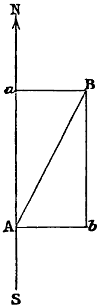
The degree of accuracy to be attained will depend in a great measure upon the extent of the traverse. With long lines the difficulties increase, and with a great number of angles the chances of error are multiplied. If the angles are carefully taken, it is probable that seconds have been read off in several instances, and these if neglected, especially upon long chain lines, may lead to an error of some importance. Also when the lines are long, the parallel ruler becomes practically useless, and some other system has to be adopted. One way of overcoming these difficulties is to draw a parallel to the first meridian through every third or fourth angle; in such a case, great care must be observed in drawing the parallels. A more easily practicable method, however, is to use the T-square in the manner already described. If the left-hand edge of the drawing board be made the north, the blade will determine meridional lines, and by[87] laying the straight side of a semicircular protractor against the edge of the blade, its zero will be adjusted to the fixed line of direction. The first bearing having been laid down, the line is drawn and made the scale length of the chain line; the blade of the square is then pushed to the station thus found, and the next bearing set off. This operation is repeated until all the lines have been laid down. If the work closes properly, the plotting of the secondary lines may be proceeded with.
The most accurate method of plotting a traverse is by rectangular co-ordinates, or, as it is usually termed, Northings, Southings, Eastings, and Westings, because the position of each station is plotted independently, and is not affected by the errors committed in plotting previous stations. This method consists in assuming two fixed lines or axes crossing each other at right angles at a fixed point, computing the perpendicular distances or co-ordinates of each station from those two axes, and plotting the position of each station by means of the T and set squares and a linear scale. The meridian is usually made to represent one of the axes, and in this case the co-ordinates parallel to one axis will be the distances of the stations to the north or south of the fixed point, and those parallel to the other axis will be their distances to the east or west of the same point. Let N S, Fig. 84, represent the meridian, and A B the first bearing taken, and the first line measured. The angle in this case is N A B = θ. If θ is an acute angle, the second station B is to the north of the first station A; if it is an obtuse angle, B is to the south of A. If the angle θ lies to the right of the meridian, B is to the east of A; if to the left, to the west. Thus it will be seen that if the northernly and easternly directions are considered positive, the southernly and westernly directions will be negative. From the foregoing it is manifest that the co-ordinates of B are as follows:—
Northing A a = b B (or if negative, southing) = A B × cos. θ.
Easting A b = a B (or if negative, westing) = A B × sin. θ.
[88]
To plot the point B, draw through the point A, with the aid of the T-square, a horizontal line. Multiply the chained length of the line A B by the sine of the angle N A B as entered in the field-book, and set off this distance along the horizontal line. From the point thus determined, erect, with the aid of the set square, a perpendicular, which will be parallel to the meridian. Multiply the chained length of A B by the cosine of the angle N A B, and set off this distance along the perpendicular line. The point thus determined will be the position of the second station B, which may then be joined to A by a straight line.
Fig. 85.
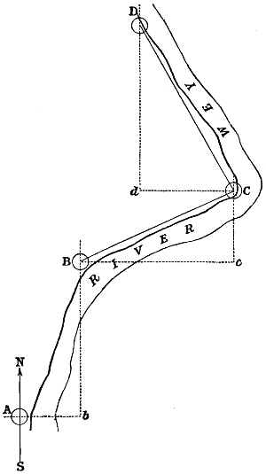
The mode of laying down the survey in Fig. 85 will now be obvious. Having determined the position of the second station B in the manner just described, draw a horizontal line through B and determine the third station C in the same way. The fourth station D being to the left of the meridian passing through C, c d is a westing and is to be considered as negative. Therefore the horizontal line through C must be drawn to the left of that station, and the station D determined in the same manner as the preceding stations.
The results of all these calculations should be entered in a book,[89] in four columns, for northings, southings, eastings and westings respectively. Also in four other columns should be entered the total northing or southing, and easting or westing, of each station from the first station, computed by adding all the successive northings and subtracting the southings made in traversing to the station, the result being a northing if positive, and a southing if negative. The same treatment is applied to the eastings and westings. This affords a means of testing the accuracy of the work. It is also obvious that the position of the last or any station may be determined by this means without plotting the intermediate stations.
Let it be observed that both θ and sin. θ are positive or negative according as that angle lies to the east or to the west of the meridian; and that the cosines of obtuse angles are negative.
—By “detail” is meant outlines or objects whether natural or artificial, such as fences, walls, rivers, canals, roads, lakes, water margins, beach marks, seas, or imaginary boundary lines. In plotting from the entries of measurements for detail, these measurements should be laid down upon the paper in the order and manner indicated in the field-book. The mode of plotting the perpendicular reference lines by means of which the position of the detail is fixed has already been fully described and illustrated. The proper connections for detail, as shown by the field-book, should be made by drawing a firm pencil line through the detail points with the aid of an offset scale adjusted successively to the adjacent points. All such connections should be clearly and elegantly made. When all boundaries, roads, and streams have been drawn and inked in, tracings should be taken in small portions of all that has been laid down for the use of the “examiner.” The duties of the examiner are to make on the ground the necessary corrections for omissions and detail in error; to give, in position and character, woods, water, marsh, commons, vegetable and geological features, and permanent artificial structures; and to furnish the descriptive names of places and things, or any other desirable information. The topographical character of mountains, marshes, bogs, rough pasture, woods and water, should be drawn in character[90] on trace and tinted. If required, hill sketching should also be supplied on the examiner’s trace. On being returned to the office, the plotter should replot from the field notes the detail corrected, and transfer the details from the trace to the map.
—The student who has made himself familiar with the methods of laying down angles, and plotting reference lines and points, will find no difficulty in laying down contour traces. When the contour points have been surveyed with the chain, the contour is obtained by drawing a free line of feature through the plotted points. But when the contour points have been surveyed by measuring magnetic angles to known points, such angles must be laid down at these points, and produced to meet in the contour point. The drawing of contours differs from the drawing of ordinary detail insomuch as each contour point is shown by a small dot, and each carrying point by a similar dot surrounded by a small hand-drawn circle to distinguish it. The former should be so plotted as to be distinguishable in the trace or contour line, which should be readily traceable, but not conspicuous. The line joining adjacent points should be true lines of feature. Colour is usually employed for these lines, and it is well to give them a broken or somewhat undefined character. When the French system is adopted, contour lines are drawn continuous, a broad but faint line of colour.
—When the angles have been measured on dry land with the theodolite, these angles should be laid down at the dry-land points, and the lines produced to meet in the sounded point. But when the angles have been measured on the water with a sextant, a station pointer is required. The arcs of the pointer should be adjusted to read the measured angles, and the instrument applied to the plotted points of the observed objects so as to bring the hair lines accurately to their respective object points. The sounded point may then be correctly plotted through the centre of the pointer. If the angles have been measured by the magnetic compass, that is, if the angles are those made with the magnetic meridian, the angles should be laid down at the plotted points of the[91] observed land objects, and the lines produced to meet in the sounded point. Instead of the station pointer, a piece of tracing paper may be used in the following manner. Draw three straight lines radiating from one point so as to make with each other angles equal to the measured angles. Lay the paper on the plan and move it about till the three lines traverse the observed objects. The point from which they diverge will then mark the position of the sounded point, which may be plotted by being pricked off.
The sounded point determined by angles measured with the sextant may also be plotted by describing circles on the land-object lines as chords, to contain segmental angles equal to the measured angles. Such circles will intersect in the common land-object point and the sounded point. To plot the sounded point in this manner, requires the solution by construction of the problem, “to describe on a given line a segment of a circle that shall contain a given angle.” But this method is generally found too tedious in practice.
—There is a tendency, as we have previously remarked, for the measured lengths of lines to be a little too long, by reason of the irregularities of the surface. It is usual to allow for this source of error 1 in 1000 in fair open country, and 11⁄2 in 1000 in close country. When the measurements differ by an amount exceeding these limits, the pencil trace should not be drawn between the reference points, but the line should be entered on an “office error-sheet.” The error-sheet should show the number of the plot-sheet, the triangle, the book and page in which the measurements are entered, and the scale and measured lengths of the line. To ascertain the source of the error, other lines referenced to the reference point or points of the line in error should be plotted, and the apparent source should be entered on the error-sheet. If the lines referred to the same point be found to plot to another point in the reference line, the scale measurement of this point should also be entered. And if the reference point in error be not directly surveyed in the survey of their respective lines, the measurements for reference and the arithmetical reductions will have to be examined. Besides the office error-sheet, there should[92] be a field error-sheet for each book and triangle, upon which should be entered the book, the page, and the line in error, and some indication of the source of the error. This sheet will be forwarded with the field-book to the surveyor for correction. The following are examples of a common and very good form of error-sheet, but it may be varied in many ways if thought desirable:—
Office Error-sheet.
| Plotter’s Name | Date | ||||||
| Book. | Lines. | Scale Measurement. |
Reference Points of Lines. |
Apparent Corrections. |
Triangles. | Observations. | |
|---|---|---|---|---|---|---|---|
| Page. | |||||||
| 200 | 1953 | 1907 | 1118 | 1551 | 1651 | 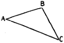 |
Examine reference point and line. |
| 23 | 2094 | 4020 | 4020 | ||||
| 200 | 3000 | 3056 | 2814 | 1308 | 3056 | Examine line. | |
| 28 | 4020 | 3082 | |||||
| 200 | 1314 | 1323 | 1551 | 85 | 1651 | Examine reference point and line. | |
| 42 | 4020 | 3028 | 4020 | ||||
Field Error-sheet.
| To A. B., Surveyor. | Date | |||
| Book. | Lines. | Triangles. | Observations. | |
|---|---|---|---|---|
| Page. | ||||
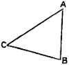 |
Examine reference points and line. | |||
| 200 | 1953 | 1651 | Reference point (August 10th, 1874). | |
| 23 | 4020 | |||
| 200 | 3000 | Examine line. Line 3056 (August 10th, 1874). | ||
| 28 | ||||
| Examine reference points and line. | ||||
| 200 | 1314 | 1651 | (August 12th, 1874). | |
| 42 | 4020 | |||
| Corrected in the field, A. B. | ||||
—In plotting a vertical section, a fine and firm horizontal line is first drawn to represent the datum line. The reference points are then plotted upon this line from the level-book by[93] means of a linear scale, in the manner already described for plotting such points. The reference points to be plotted upon the datum line are the chain lengths entered in the field-book in the column headed Distances. These distances are the points at which the levels were taken, and between them, unless otherwise stated in the field-book, the ground is supposed to slope uniformly. Moreover, these distances are assumed to be measured horizontally, and therefore care must be taken to ascertain whether or not they were so measured in the field; if not, they must be reduced before plotting, or the section will be too long. Having plotted the reference points on the datum line, a perpendicular must be erected from each of them, and a length laid off upon this perpendicular equal to the vertical height above the datum line indicated by the entry in the column of the level-book headed Reduced Levels against the distance to which the perpendicular corresponds. To render the differences of altitude more apparent, these vertical distances are plotted to a much larger scale than the horizontal, as explained in a preceding Section. To erect the perpendiculars, the T and set square furnish the most convenient means. The detail points thus determined upon the perpendiculars represent[94] the points in the surface of the ground at which the levels were taken, and by joining these points we obtain the surface line. An example will clearly show the method pursued. Let it be required to lay down the section from the following level-book:—
| Back Sights. |
Fore Sights. |
Rise. | Fall. | Re- duced Levels. |
Dis- tances. |
Remarks. |
|---|---|---|---|---|---|---|
| feet. | feet. | feet. | feet. | feet. | chains. | |
| 100·00 | .. | B.M. north-west corner of church tower. | ||||
| 16·41 | 9·37 | 7·04 | .. | 107·04 | 230 | |
| 19·36 | 10·43 | 8·93 | .. | 115·97 | 465 | |
| 16·42 | 19·36 | .. | 2·94 | 113·03 | 640 | |
| 8·36 | 14·36 | .. | 6·00 | 107·03 | 794 | |
| 9·37 | 12·49 | .. | 3·12 | 103·91 | 1030 | |
| 11·64 | 19·76 | .. | 8·12 | 95·79 | 1200 | |
| 19·46 | 9·32 | 10·14 | .. | 105·93 | 1564 | |
| 17·64 | 13·62 | 4·02 | .. | 109·95 | .. | Centre of road at 123 links. |
| 18·76 | 12·64 | 6·12 | .. | 116·07 | 1823 | |
| 19·84 | 16·92 | 2·92 | .. | 118·99 | 1964 | |
| 19·76 | 11·64 | 8·12 | .. | 127·11 | 2100 | Forward station ☉ at corner of wood. |
| 17·64 | 19·72 | .. | 2·08 | 125·03 | 2250 | |
| 9·73 | 18·64 | .. | 8·91 | 116·12 | 2376 | |
| 8·64 | 17·64 | .. | 9·00 | 107·12 | 2590 | |
| 18·76 | 16·24 | 2·52 | .. | 109·64 | 2700 | |
| 231·79 | 222·15 | 49·81 | 40·17 | |||
| 222·15 | 40·17 | 100·00 | ||||
| 9·64 | 9·64 | 9·64 | Difference between datum and last reduced level, or height of B above A. | |||
Draw the datum line D L, Fig. 86, and set off along it the distances 230, 465, 640, 794, &c., links; these points will be the reference points for the perpendiculars. Erect a perpendicular from each of these points, and lay off, to a suitable scale, upon these lines successively the vertical heights 100, 107·04, 115·97, 113·03, 107·03, &c. The points thus determined will be the surface detail points, and by joining these we shall obtain the surface line. Then will A D L B represent a section of the ground between A and B. A description of objects on the surface worthy of notice should be written over such objects.
In working sections, where great accuracy is required, larger scales are employed, and the levels are taken at more frequent intervals.[95] Thus, in a railway working section, for example, the levels are taken at every chain’s length, and also over every little undulation in the surface of the ground. In preparing such sections, vertical lines are drawn in blue at every chain’s length up to the surface of the ground from the datum line, and on each vertical is written the reduced height above datum from the column of reduced levels in the level-book.
Sections, especially working sections, are usually drawn upon ruled, or, as it is called, “section” paper, the nature of which we have already described. This method, which was introduced by Mr. Brunel, possesses many practical advantages, inasmuch as it obviates the necessity of plotting the “distances” and erecting perpendiculars, the latter already existing. It also greatly facilitates the computation of the contents of a given section. Its chief defect lies in the difficulty of making the horizontal lines coincide when joining the sheets end to end. Of course scales are not required upon section paper.
—The method of laying down the gradients of railways and roads usually adopted in practice consists in applying one end of an extended silken thread to the section at the point in which the road commences, and the other end in such a position that the thread may cut the profile of the earth’s surface so as to leave equal portions of space above and below the thread, as nearly as can be judged by the eye. The cuttings from the parts above the thread will then furnish sufficient materials to form the embankments in the spaces below. This is called “balancing” the cuttings and embankments. When the first gradient has been determined in this way, it may be found unfavourable to the second in respect to the extent of cuttings and embankments; in such a case it must be modified to suit the requirements of the latter. In this way the gradients must be modified successively until the compound result evidently gives a minimum of cuttings and embankments, due regard, of course, being had to the limits imposed by the nature of the case, both with respect to the ruling gradient and the proper heights for bridges.
[96]
—The mode of plotting a section from a contoured plan was explained when treating of contour lines. The contour map used for this purpose should give the features of the surface configuration in sufficient detail without serious error. Having drawn a line of section on the map and a datum line upon the fair paper for the vertical section, the points in which the section line intersects the contours should be measured on the scale of the map from a zero point in that line, and the measurements plotted upon the datum line. Perpendiculars should then be drawn through these plotted points, and on these perpendiculars the reduced altitudes of their respective contour points should be plotted. A line drawn through these surface plotted points will be the surface line. When the horizontal scales of the map and the section are the same, the contour plane lines may be drawn on the paper for the section parallel to the section line on the map, and perpendiculars raised to intersect them from the points on the map in which the section line intersects the contours, in the manner previously described. The points of intersection with the parallel lines will be the surface contour points in the vertical section. For practical purposes, the parallel lines and the perpendiculars are only temporarily drawn in pencil until the surface trace shall have been obtained and drawn in ink, with the datum line.
In the preceding Sections the manner of laying down plans has been fully described and the principles involved in the operations minutely explained. It now only remains, therefore, to direct attention to certain matters relating to the preparation of plans, which are necessitated by the circumstances of particular cases.
Civil engineers’ plans usually consist, if we except harbour surveys, of a representation, to a rather large scale, of long and[97] narrow tracts of country through which it is proposed to construct a means of communication, such as a railway, a road, or a canal. They do not differ essentially from other plans, the survey being taken in the ordinary way, and the plan laid down according to one or other of the methods described in the preceding Section. The width of railway surveys varies from five to twenty chains, at the option of the engineer. An important matter demanding careful attention is to survey, plot, and number all fields and other enclosures, houses and other buildings situate within the limits of deviation, that is, the boundaries of the space beyond which it is not proposed to deviate the line of railway. The object of numbering every separate enclosure, road, building, or other object on the plan, is that they may be the more readily described in a book prepared for that purpose and called the Reference Book. Parish and county boundaries are shown by dotted lines, as explained in a former Section. Frequently it is necessary, in consequence of the smallness of the scale adopted for the plan, to give enlarged drawings of certain portions. In these cases, whenever practicable, the enlarged plan should be placed directly under or over the small plan to which it refers, as such an arrangement is not only more pleasing to the eye, but is far more convenient for reference than one in which there is no relation of position between the two plans. The proposed railway should be represented by a full and heavy line, and the limits of deviation shown by strong dotted lines. The names of the different parishes through which the line passes should be conspicuously written, and the name of the county placed at the top of each sheet; the sheets also should be distinctly numbered. It is not usual to distinguish different kinds of fences on plans of engineering projects, as on estate plans to a large scale; on the former it is sufficient to distinguish between fenced and unfenced lines of division of land, marking the former by plain, and the latter by dotted lines. It is almost needless to remark that a scale of distances should accompany every plan.
The section should be drawn to the same horizontal scale as the plan, and the exaggeration of the vertical scale should be such as to[98] show distinctly the irregularities of the surface. The horizontal datum line of the section should have marked on it a scale of distances corresponding with those marked along the centre line of the plan, in order that corresponding points on the plan and the section may be readily found, and great care should be taken that horizontal distances on the plan and on the section exactly agree. Cross sections are longitudinal sections of existing lines of communication which the proposed work will cross; they may cross the centre line of the proposed work either at right angles or obliquely. Cross sections may also be required where the ground slopes sideways; in general they should be ranged accurately at right angles to the centre line, and they should be plotted without exaggeration, that is, their vertical and horizontal scales should be the same as the vertical scale of the longitudinal section. All cross sections should be plotted as seen by looking forward towards them along the centre line.
To distinguish the nature of the soils passed through, sections are frequently coloured, as shown in Plate 21. The information given by this means concerning the character of the strata is of very great value to the engineer or to the contractor, inasmuch as it enables them to predicate with some degree of certainty the amount of labour that will be required in executing the proposed work. It is, therefore, highly important that the draughtsman correctly represent the character of the strata. The conventional modes of representing these features are shown on Plate 20, which should be carefully studied and copied.
It is necessary that the engineering draughtsman should be acquainted with the “Standing Orders” of Parliament relating to the preparation of plans and sections, in order that he may fulfil the conditions therein laid down. And as most of the important details involved by the exigencies of practice in the preparation of such plans and sections are prescribed by these Standing Orders, we will give so much of them as relates directly to the matters under consideration; by so doing, the details will be clearly and fully described, and the requirements of the law concerning them authoritatively made known.
[99]
—“In cases of bills relating to engineering works, a plan and also a duplicate thereof, together with a book of reference thereto, and a section and also a duplicate thereof, as hereinafter described, shall be deposited for public inspection at the office of the clerk of the peace for every county, riding or division in England or Ireland, or in the office of the principal sheriff clerk of every county in Scotland, and where any county in Scotland is divided into districts or divisions, then also in the office of the principal sheriff clerk in or for each district or division in or through which the work is proposed to be made, maintained, varied, extended or enlarged, or in which such lands or houses are situate, on or before the 30th day of November immediately preceding the application for the bill.”
“In the case of railway bills, the ordnance map, on the scale of one inch to a mile, or where there is no ordnance map, a published map, to a scale of not less than half an inch to a mile, or in Ireland, to a scale of not less than a quarter of an inch to a mile, with the line of railway delineated thereon, so as to show its general course and direction, shall, on or before the 30th day of November, be deposited at the office of the clerk of the peace, or sheriff clerk, together with the plans, sections, and book of reference.”
“In cases where the work shall be situate on tidal lands within the ordinary spring tides, a copy of the plans and sections shall, on or before the 30th day of November, be deposited at the office of the Harbour Department, Board of Trade, marked ‘Tidal Waters,’ and on such copy all tidal waters shall be coloured blue, and if the plans include any bridge across tidal waters the dimensions as regards span and headway of the nearest bridge, if any, above and below the proposed new bridge, shall be marked thereon, and in all such cases such plans and sections shall be accompanied by a published map or ordnance sheet of the country, over which the works are proposed to extend, or are to be carried, with their position and extent, or route accurately laid down thereon.”
“In the case of railway bills, a copy of all plans, sections, and books of reference, and the aforementioned published map with the line[100] of railway delineated thereon so as to show its general course and direction, is required to be deposited at the office of the Board of Trade, and at the Private Bill Office of the Houses of Parliament; and in cases where any portion of the work is situate within the limits of the Metropolis, a copy of so much of the plans and sections as relates to such portion of the work is required to be deposited at the office of the Metropolitan Board of Works. Also a copy of so much of the plans and sections as relates to each parish in or through which the work is intended to be made, or in which any lands or houses intended to be taken are situate, together with a copy of so much of the book of reference as relates to such parish, is required to be deposited with the parish clerk of each such parish in England, with the school-master of each such parish in Scotland, and with the clerk of the union within which such parish is included in Ireland.”
—“Every plan required to be deposited shall be drawn to a scale of not less than four inches to a mile, and shall describe the line or situation of the whole of the work (no alternative line or work being in any case permitted), and the lands in or through which it is to be made, maintained, varied, extended or enlarged, or through which every communication to or from the work shall be made; and where it is the intention of the parties to apply for powers to make any lateral deviation from the line of the proposed work, the limits of such deviation shall be defined upon the plan, and all lands included within such limits shall be marked thereon; and unless the whole of such plan shall be upon a scale of not less than a quarter of an inch to every one hundred feet, an enlarged plan shall be added of any buildings, yard, courtyard or land within the curtilage of any building, or of any ground cultivated as a garden, either in the line of the proposed work or included within the limits of the said deviation, upon a scale of not less than a quarter of an inch to every one hundred feet.”
“In all cases where it is proposed to make, vary, extend or enlarge any cut, canal, reservoir, aqueduct or navigation, the plan shall describe the brooks and streams to be directly diverted into such intended cut, canal, reservoir, aqueduct or navigation, or into any[101] variation, extension or enlargement thereof respectively, for supplying the same with water.”
“In all cases where it is proposed to make, vary, extend or enlarge any railway, the plan shall exhibit thereon the distances in miles and furlongs from one of the termini; and a memorandum of the radius of every curve not exceeding one mile in length shall be noted on the plan in furlongs and chains; and where tunnelling as a substitute for open cutting is intended, such tunnelling shall be marked by a dotted line on the plan.”
“If it is intended to divert, widen or narrow any turnpike road, public carriage road, navigable river, canal or railway, the course of such diversion, and the extent of such widening or narrowing shall be marked upon the plan.”
“When a railway is intended to form a junction with an existing or authorized line of railway, the course of such existing or authorized line of railway shall be shown on the deposited plan for a distance of eight hundred yards on either side of the proposed junction, on a scale of not less than four inches to a mile.”
—“The book of reference to every such plan shall contain the names of the owners or reputed owners, lessees or reputed lessees, and occupiers of all lands and houses in the line of the proposed work, or within the limits of deviation as defined upon the plan, and shall describe such lands and houses respectively.”
—“The section shall be drawn to the same horizontal scale as the plan, and to a vertical scale of not less than one inch to every one hundred feet, and shall show the surface of the ground marked on the plan, the intended level of the proposed work, the height of every embankment and the depth of every cutting, and a datum horizontal line, which shall be the same throughout the whole length of the work, or any branch thereof respectively, and shall be referred to some fixed point (stated in writing on the section), near some portion of such work, and in the case of a canal, cut, navigation, turnpike or other carriage road or railway, near either of the termini.”
“In cases of bills for improving the navigation of any river,[102] there shall be a section which shall specify the levels of both banks of such river; and where any alteration is intended to be made therein, it shall describe the same by feet and inches, or decimal parts of a foot.”
“In every section of a railway, the line of the railway marked thereon shall correspond with the upper surface of the rails.”
“Distances on the datum line shall be marked in miles and furlongs, to correspond with those on the plan; a vertical measure from the datum line to the line of the railway shall be marked in feet and inches, or decimal parts of a foot, at each change of the gradient or inclination; and the proportion or rate of inclination between each such change shall also be marked.”
“Wherever the line of the railway is intended to cross any turnpike road, public carriage road, navigable river, canal or railway, the height of the railway over or depth under the surface thereof, and the height and span of every arch of all bridges and viaducts by which the railway will be carried over the same, shall be marked in figures at every crossing thereof; and where the roadway will be carried across any such turnpike road, public carriage road or railway, on the level thereof, such crossing shall be so described on the section; and it shall also be stated if such level will be unaltered.”
“If any alterations be intended in the water level of any canal, or in the level or rate of inclination of any turnpike road, public carriage road or railway, which will be crossed by the line of railway, then the same shall be stated on the said section, and each alteration shall be numbered; and cross sections in reference to the said numbers, on a horizontal scale of not less than one inch to every three hundred and thirty feet, and on a vertical scale of not less than one inch to every forty feet, shall be added, which shall show the present surface of such canal, road or railway, and the intended surface thereof when altered; and the greatest of the present and intended rates of inclination of such road or railway shall also be marked in figures thereon; and where any public carriage road is crossed on the level, a cross section of such road shall also be added; and all such[103] cross sections shall extend for two hundred yards on each side of the centre line of the railway.”
“Wherever the extreme height of any embankment, or the extreme depth of any cutting, shall exceed five feet, the extreme height over or depth under the surface of the ground shall be marked in figures upon the section; and if any bridge or viaduct of more than three arches shall intervene in any embankment, or if any tunnel shall intervene in any cutting, the extreme height or depth shall be marked in figures on each of the parts into which such embankment or cutting shall be divided by such bridge, viaduct or tunnel.”
“Where tunnelling, as a substitute for open cutting, or a viaduct as a substitute for solid embankment, is intended, the same shall be marked on the section.”
“When a railway is intended to form a junction with an existing or authorized line of railway, the gradient of such existing or authorized line of railway shall be shown on the deposited section, and in connection therewith, and on the same scale as the general section, for a distance of eight hundred yards on either side of the point of junction.”
Besides the information thus written on the plan, it is useful to the engineer, though not prescribed, to have the levels of important points either written or shown by means of contour lines, especially when the plan is to be used in selecting a line of railway. The results of trial pits and borings may also be written on the plan, and the estimated cost of each part of the work placed opposite to its position on the paper.
—For working sections the horizontal scale adopted is usually three or four chains to the inch, and the vertical scale 30 or 40 feet to the inch. A working section should show the level of the ground, the level of the proposed work, and the height of embankment or depth of cutting at every point of the ground where the level has been taken, these quantities being found by calculation, not by measurement on the paper. The position and levels of all “bench marks” should also be clearly indicated. At every crossing[104] of road, river or stream of any kind, should be inserted some remark respecting the work to be constructed, with a reference to the number of the working drawing prepared. The latter may be a special drawing, as for a bridge, or a general drawing, as for a level crossing and gates. The results of boring should also be shown on the working section. As soon as the works of construction have been determined upon, notes should be inserted from the working drawings, or other sources, of the angles of skew at which the line crosses roads or streams, the spans of arches on the square and on the skew, the rise of the arch, the depth of the arch stones, and of the puddle, if any be used, and, if the works be on an inclined plane, the rise or fall from centre to centre of the piers. Similar memoranda should also be made of girder bridges, culverts, and other works occurring along the line. To all working drawings the acting engineer always affixes his signature.
Besides an acquaintance with the “Standing Orders,” the engineering and surveyor’s draughtsman should possess a knowledge of the Regulations of the Local Government Board, for these have to be complied with in the preparation of plans relative to main sewerage, drainage, and water-supply. These Regulations are as follows.
—In cases in which a special district is proposed to be formed for the adoption of the Local Government Act, a map must be submitted, accompanied by a written description of the proposed boundary, designated by letters from point to point, commencing from a fully and clearly defined point on the north side of the map marked by the letter A and a written description, then proceeding eastward by natural or other well-defined features, until the description closes upon the point started from. The name of the proposed district must be printed on the map, with the area in acres. The population and the number of houses, with the rate of increase as ascertained at the two last decennial periods upon which the census was taken, must be given, and a duplicate or tracing of the map furnished.
—A map of the entire district must, in this case, be submitted, with the main boundary distinctly defined,[105] and the name of the district clearly printed thereon. The proposed division into wards must be by lines, clearly defined on the map of the district; brooks, roads, footwalks, streets, fences, or other easily recognizable lines of division may be adopted. Such lines must be defined on the map by a margin of colour. The proposed boundary-lines must be described in the same manner as in the boundary map, and the name or number of the ward, with the relative areas, population, and rateable value must be given. A duplicate map or a tracing must be deposited at the Local Government Act Office for future reference.
—It is in all cases necessary, upon application being made by Local Boards for the Secretary of State’s sanction to a loan for the execution of works, that plans, sections, detailed estimates, and specifications be submitted with the application, accompanied with the information relative to area, population, number of houses, and rateable value of the district required for boundary maps. Tracings of such plans and sections, and copies of the estimates and specifications must be sent in for filing at the Local Government Act Office.
—A general plan exhibiting the area which will be affected by the proposed works must be laid down to a scale of not less than two feet to a mile. It should have figured upon it the levels of the centres of all the streets and roads at their intersections and angles, and at every change of inclination; also, where a district is near the sea, it should show the high and the low tide level of the sea, and where there is a river, the summer and the flood-water levels should be recorded. Permanent bench marks having reference to the surface levels should be cut on public buildings, or other permanent and suitable objects, throughout the district, and clearly marked on the plan. Sections should accompany this plan, upon which the levels of the cellars should be shown. Such a plan may be used for showing the lines of main-sewers and drains, lines of water-pipes, and gas-mains. The lines of main-sewers and drains should have the cross-sectional dimensions and the gradients distinctly marked upon them.[106] The dimensions of water and gas pipes should also be shown in figures or in writing.
—A detailed plan for the purposes of house-drainage, paving, the sale and purchase of property, or other purposes of a like character, must be constructed to a scale of not less than ten feet to a mile. Upon this plan must be exhibited all houses and other buildings, bench marks, the levels of streets and roads, of cellars, of the sea at high and low tide level, and the summer and the flood level of rivers. Three feet by two feet will be a convenient size for the sheets of this plan, and by representing the marginal lines of the sheets upon the general plan, and numbering the sheets to correspond, the general plan will become a very useful index.
As it may occasionally be desired to carry out works piecemeal, with a view to save the time which would be occupied in the preparation of a complete plan from actual survey, it is sufficient in the first instance to furnish a general plan of streets and roads only, with the surface levels and those of the deepest cellars, and the proposed scheme of works shown thereon, after which the works can proceed in sections. But with each separate application for sanction to a loan, a correct plan and section or sections should be submitted, accompanied by detailed estimates and specifications. It must, however, be understood that the complete plan of the entire district must be proceeded with, so that, when the works are finished, the Local Board and the office of the Local Government Act may possess a proper record.
—The plotting of mining surveys is performed in the same manner as the surface traverse surveys already described. Before proceeding to lay down the plan, it is well to divide the paper into squares of 10 chains side, or 10 acres area, by two sets of lines crossing each other at right angles, one of which sets should represent meridians. This operation should be performed with scrupulous care; and to ensure accuracy, beam compasses should be used to lay off the divisions. The lines should be finely drawn in colour to distinguish them from other lines to be put upon the drawing. Care must be taken to get the plan fairly upon the paper, so that the conformation[107] of the outline or boundary to the edges of the paper may have a pleasing effect to the eye; and the direction of the meridians must be determined according to this condition. By having the plan thus divided into squares of 10 acres each, the quantity of ground worked out may be approximatively estimated at any time by inspection, and the total quantity may be readily computed in the same manner. Besides dividing the plan itself in this way, it will be found extremely useful to have a sheet of tracing paper, or better, tracing cloth, divided into squares of 316·228 links side, or 1 acre area, in black lines; each of such squares being subdivided into 4 by lines in colour, to show quarters of an acre. To find the area of any portion of exhausted or of unworked ground, it is only necessary to lay this divided sheet over such portion and to count the squares and quarters included in it.
By reason of the variations of the magnetic meridian, the date of a survey should always be written on the plan; and as the plan of underground workings is laid down piecemeal as the workings progress, often extending over a period of many years, care must be taken to reduce all bearings to the original meridian. Unless these matters are strictly observed, serious errors may result.
When two or more veins of mineral are being worked one above the other, and are placed upon the same plan, they are distinguished by means of colour. It matters not what colours are employed for the several separate workings so long as they are distinct from each other. Also the mode of applying the colour, whether with the brush or with the pen, is entirely a question of taste. It may, however, be observed that as mining plans are constantly being added to, it is very difficult to avoid a patchy appearance when the colour is laid on with the brush. Plate 33 shows the manner in which mining plans are got up.
—Plans of estates and towns, including as they do only a limited area and requiring great distinctness of detail, are laid down to a large scale; for the form and character of the detail are, on such plans, of equal importance with its position. With such a scale as is required in these cases, it is possible, not only to clearly distinguish natural and artificial features, but to introduce means of[108] producing pictorial effect into their representation. The nature of these means may be seen in the examples of plans appended to this work.
The manner of showing the various kinds of fences has been already described. Trees are usually shown in elevation for the sake of artistic effect; but care must be taken to give them such dimensions as will accord with the scale of the drawing. Houses and other buildings are shown in plan of the correct form, and washed for distinction in light red for dwelling-houses, dark grey for outhouses, and light grey for public buildings. Dark grey is also used for all wooden and iron buildings to distinguish them from those constructed of the ordinary materials, brick and stone. But besides such distinctions, others are needed to indicate the character of natural features and artificial constructions. These are obtained either by showing the object roughly in elevation, or by some purely conventional means. The signs of this character that are likely to be frequently required on estate plans are shown on Plate 15. The manner of representing water, which has been described in a preceding Section, will be found illustrated in detail on Plate 11. Plates 10 and 14 show various kinds of trees; in this form they may be introduced very effectively into plans of estates.
The several stages which a plan passes through in the office are shown on Plate 2. If the plan is to be coloured, the colouring must be done before the lettering is put on. Plate 3 shows a plan lightly coloured, as used by surveyors, solicitors, and others; and Plate 17 shows a finished plan in colour. The methods of laying on the colours and the principles involved in the operations have been fully described and explained in a former Section. In Plate 13 is given a town plan showing a proposed street improvement. Such a plan must be laid down to a large scale, and the details in and near the part affected must be drawn in clearly and accurately. The uncoloured portion represents the plan as prepared for lithographing. When pink colour is used to show the proposed street, the buildings should be coloured in black by a light wash of Indian ink. Yellow or[109] any other bright tint may be used for the proposed street, the object being merely to distinguish it clearly. Existing streets should be coloured in yellow ochre, except when that colour is used for the proposed street, in which case burnt sienna may be used.
The Plates relating to this Section are Nos. 2, 3, 10, 11, 13, 14, 15, 17, 19, 20, 21, and 33.
The principles and practice of map drawing, being in the main identical with those of ordinary plan drawing, have been generally explained and described in the preceding Sections. In the present Section, therefore, we have only to direct attention to such details as belong especially to the former class of topographical representations. These details relate chiefly to the selecting of objects and features on the surface of the ground whose character entitles them to special notice, and therefore to distinct delineation; to the practical methods of sketching such objects and features in the field, and to the means and the manner of reproducing them on the finished map. The first and the last of these questions have been treated by Mr. James in his Handbook of Topography, and the second by Lieut. R. S. Smith of the United States’ Army, in so concise and yet so complete a manner that we have not hesitated to avail ourselves of their labours rather than attempt to offer any instructions of our own. The following is, therefore, worthy of respectful attention.
—In inking in streams, begin at the source and draw downwards towards yourself, increasing the pressure on the pen as you descend. The use of the steel pen in drawing single stroke streams is very objectionable. Even soft steel pens are apt to cut the surface of the paper, and in sharp bends it is quite impossible to ensure an even width of line with the best yet made; by re-inking, much time is lost, and frequently a rough jagged line is the result. The common quill pen finely pointed will work well on any sort of paper.
[110]
—In maps of a small scale from 8 to 32 miles to the inch, it is usual to darken the north-western bank, supposing the light to fall from the N.W. corner of the map; but on maps of a large scale it is usual to attend strictly to the height of the banks, and the draughtsman should carefully represent the exact nature of each bank on his field-sketch or plane-table sheet.
—Single stroke streams may be inked in with either a dark line of Prussian blue, or a light line in Indian ink may first be drawn and a streak of Prussian blue or cobalt run neatly along it. Cobalt is much used both in single and double stroke streams—it is certainly the prettiest and most lasting blue we have, and the preference should be given it, as it imparts a high finish to MS. maps.
In maps which contain much hilly ground, the streams should be drawn in with light ink and a very fine pen at first, and be re-drawn with dark ink or dark blue after the shading of the hills. Large rivers on all maps published in England are now coloured with a flat-wash of cobalt or Prussian blue. Some draughtsmen prefer shading rivers according to bends, and keeping the shade as falling from the N.W., but this system cannot be carried out on maps of a large scale, where the height of the bank is correctly represented.
—Islands which are only visible at low water, on well-coloured maps, are usually first washed over with a light shade of burnt or raw sienna, or a mixture of raw sienna and light red; the last-mentioned colour does not easily mix with water, and should not be used if any other can be substituted. After the tint is dry, dot finely with light Indian ink or dark burnt sienna. Sand-banks are coloured in the same way. Sandy beds may be similarly treated, omitting the dotting if pressed for time. Pebbly beds should first be tinted with a mixture of burnt or raw sienna, then dip into a dark shade of burnt sienna any coarse camel-hair brush, and splitting the brush by drawing it between the forefinger and thumb, dot in the tinted portions. Care must be taken to avoid having[111] too much colour in the brush, or the dots will run into each other and make ugly daubs.
Another very easy and successful method of dotting in sand or pebbly beds is with a tooth-brush. First, on tracing or any other thin paper, trace out exactly the limit of the tinted portion requiring dotting, cut out these portions from the trace and place it correctly over the original, dip a tooth-brush lightly into a saucer of colour of the required depth of tint, and holding it in the left hand over the uncovered portions, with the forefinger of the right hand or the blade of a pen-knife, gently splutter the colour from the brush; when it is necessary to cover a large space with dots, this will be found the simplest and most speedy way of doing it.
—The main or trunk roads in any country should be very distinctly represented by double and perfectly parallel ink lines, coloured between the lines with lake or carmine. District roads metalled, or those made between chief towns, should be shown by a single line coloured with lake or carmine. Unmetalled roads and paths by only a single line in burnt sienna.
The same system should be carried out in roads in a mountainous country, and the draughtsman should give, either on the map or in the column of remarks, such information regarding roads as is likely to be useful to travellers or military authorities.
—On large scale maps these should be distinctly marked, and the windings of the road correctly shown. Along the Pass, write the name in small lettering, and state whether it is practicable for horses, or fit only for men on foot. On maps of a small scale, it will be sufficient to show the pass by a zigzag line across the hollow, with a note as above.
—Fords should be carefully noted and the name and depth of water during the rainy and dry seasons given, if possible. The number of boats at every ferry should be correctly ascertained, and noted on the map. Toll-gates may be shown on roads with a light line drawn across the road, and the words “Toll-gate” be clearly written on the side of the road.
[112]
, should be correctly shown and named on all maps.
must be shown on all maps drawn to a scale of four miles to an inch and upwards, by the usual symbol. On maps of a small scale, show by dots or a thin line of yellow, giving a reference under the title. The Stations are of the first importance, and should be represented by the symbol.
—Railways are represented by a strong black line, with or without thin lines drawn at right angles to the main line. They should of course be very carefully and accurately laid down, as they form the chief feature in any country.
Stations are shown by well-defined circles, and the name given in plain lettering. Termini are best shown by blocks representing the size of the buildings according to the scale of the map.
Except on maps of a very large scale, jungle should not be shown over hilly ground. Representing such objects as trees, jungle or brushwood, over plains or flat lands, on all ordinary scale maps, is very necessary, and the exact limits of the jungle or waste should be surveyed and correctly given by a dotted line, but over hilly ground it would be impossible to do so without impairing the beauty and hiding the features of the hill drawing. If it is actually necessary to make it known that the hills have jungle on them, let a foot-note to the effect be inserted amongst the remarks or under the title of the map. Under the head of remarks or notes, it is always very necessary to state the kind of jungle which exists in the surveyed tracts, for the information of speculators and timber merchants, and for the guidance of the lithographer or engraver. Notes on maps, whether statistical or geographical, can never be too full; they are useful in supplying at once information which could be obtained only from reading reports, and frequently they render topographical details intelligible where there might otherwise be doubt or misconception. They can be recorded in any spare corner or blank space on the map.
—It is of the utmost importance that all maps of a large[113] scale should show the size accurately of cities, towns and villages. If the scale admits of it, the several blocks or groups of houses with the roads between them should be correctly drawn.
—In sketching hills, always begin by fixing—1st. The drainage; 2nd. Those features which are most prominent, such as peaks, rocks, ledges of rock running with the strata of the hills, trees remarkable for some peculiarity in shape or size so as to be recognized from various positions, and any other objects likely to help the eye in filling in the details; and lastly, sketch the details, beginning always with the ground nearest yourself.
Endeavour to portray your ground faithfully—1st. By preserving the direction and bend of streams as in nature; 2nd. By giving the run of the ridges correctly; 3rd. By fixing the peaks, ledges of rock, precipitous falls and flats carefully; 4th. By showing the saddles or depressions between peaks, which can only be done by giving the peaks on either side sufficient relief in shading; 5th. By attending strictly to the true breadth of valleys; 6th. By suppressing all hollows with a suitable depth of tint; 7th. By careful representation of the banks of streams in the valleys; and lastly, by finishing shades and touches, in which is comprehended the retouching with brush or pen work the entire piece, strengthening the shade of the higher ridges and peaks to show their relative heights, and suppressing the white tint along the ridges.
Many excellent draughtsmen are in the habit of leaving the ridge of mountain ranges quite white; this is evidently a mistake, for, unless the ridge of any range of hills is of one uniform height from end to end, it cannot correctly be left white. Thus a wrong impression is conveyed of the surface of the ridge, the white streaks look harsh and are displeasing to the eye, and a stiff and unartistic look is given to the finish of the drawing.
The means of communication, whether by roads or minor tracks, are important, both for civil and military purposes, and should be carefully inserted in the map. This can generally be done with facility in a hilly country, as the fixed marks will be visible in sufficient[114] number along the road, so that the latter may be drawn in at once by plane-table operations along the line of communication to be surveyed. In flat countries, or where the view is circumscribed, it may be necessary to resort to measurements and plotting; but should any case occur where the fixed points of reference are far apart, the traverse system must be resorted to, and the road should be plotted from computed co-ordinates.
—Field sketches are made with the lead pencil, and may be drawn upon every page of the compass-book, or upon the alternate pages, at the option of the topographer. In the former case, the bearings and distances are recorded upon the drawing; in the latter, the record occupies the left-hand page, and the sketch the opposite one. The page for sketching should be ruled in squares, with blue or red ink, forming thus an indeterminate scale, the length of the sides of the squares being assumed at pleasure, according to the nature of the ground. Both the record and the sketch are read from the bottom of the page upward. Suppose the stations of the survey to be 100 feet apart; then, assuming the side of the square to be 100 feet, commence the sketch at the bottom of the page—in the centre, if the survey promises to be tolerably straight; if otherwise, at some point to the right or left of the centre, the reason for which will be explained directly. Let the bearing from the first station, the starting point or zero, be N. 10° E. Draw a line from the bottom of the page upward; the side of the square being assumed 100 feet, number the stations upon the squares as far as the line is run, say 325 feet, and write the compass angle down along this line. Let the bearing from the second station, or No. 1, be N. 1° W.; draw a line, making, as nearly as can be judged by the eye, the proper angle with the last bearing, and proceed as before. When the page is exhausted, commence with a vertical line at the bottom of the next one, marking upon it the remainder of the old bearing, and making, by the eye, a new series of approximate protractions as before. If it can be foreseen, as in most cases it can, that the line of survey will be very crooked, bending, for example, from left to right, then commence the bearing at[115] the bottom of the page accordingly, beginning at a point on the extreme right, and running it diagonally to the left, so as to make due allowance for the great deflection anticipated in the next bearing. Such cases may be foreseen in running around an inclosure, or in following a curving stream or ridge. The advantages of the system of squares in sketch books completely overbalance the one disadvantage, which is, that the diagonal bearings will not make exact distances upon the squares, while the vertical and horizontal ones will. It will be remembered that the surveying book is designed to be exact only in its record and the general features of the ground, and that a slight change of scale is not material, as it can be made exact when the survey is protracted upon the map. By these approximate protractions, any page of the book of survey conveys a very just notion of the bearings and distances, and of the relative positions of the general features of the ground. The first station being at the bottom of the page, note down, in the space between it and the second one, all the features of the ground passed over by the line of survey; as to whether it is cultivated, forest, marsh, &c.; whether it is crossed by streams, ditches, &c., and their width; if it rises or falls; about what degree of slope, &c. On both sides of the line introduce, according to the scale, and their distances, as judged by the eye, all topographical objects within sight, such as buildings, roads, streams, hills, &c., &c., drawing them to the scale if possible, and if they cannot be got upon the page, describing briefly their nature and position. In sketching hills endeavour to project as many horizontal curves as possible, which should be lightly put in, and then the shading lines may be drawn over them. The degree of slope should be frequently written down in numbers upon the sketch. The names of localities, streams, hills, farms, &c., should also be entered.
Thus far we have supposed a measured line upon the ground, to which the situation and dimensions of objects might be referred. It is much more difficult to embody the relative positions and dimensions, where all is left to the eye. Here a cultivated judgment is of the greatest value. Practice alone can make a good sketcher under such[116] circumstances. Rules must, from the nature of the case, be few and general. In the first place, all objects within the field of vision are presented to the eye in perspective, whereas the sketch is to be a plan. The apparent diminution of dimensions in distant objects must therefore be corrected on the plan. For example, the windings of a crooked stream, or a road, in perspective, are much exaggerated in retiring into the distance; they must therefore be straightened out in the sketch more and more, as they are more removed. 2nd. In looking at variously placed hills from a somewhat elevated station, the eye will in some cases look directly, or perpendicularly, at the face of some slopes, while in others, the surface of the slope, if prolonged, will pass through the eye, and will not be seen in its true dimensions, though its inclination may be judged. In sketching the shapes of hills, bodies of water, masses of forest, &c., these facts must be taken into consideration, and to ensure skill, eye sketches of a small portion of ground having well-marked features must be frequently made, and compared with measurements of the same features. In sketching a single hill, the best station is at the summit. First endeavour to represent the lowest horizontal curve of its surface; then a medial one; then the form of the level space at the summit, or the highest horizontal curve. Others may then be introduced between these, until the ground is sufficiently expressed. The angles of inclination should be frequently noted down in numbers; all accidents of ground, such as ravines, rocks, &c., should be carefully placed, and all other objects, such as houses, fences, trees, &c., should be put down in their proper relative positions and dimensions. Having thus prepared a skeleton of horizontal curves, numbered as to inclination and heights, the sketch will always serve a useful purpose without any lines of greatest descent. After sufficient practice in this method, the eye will become so cultivated as to enable the draughtsman to express the form of ground by lines of descent at once, the mind conceiving the position of the horizontal curves, and thus supplying the necessary data for the shading lines, the relative thickness and length of which for the different slopes is a matter very easy of acquirement. But this should[117] not be attempted until the method by horizontal sections is thoroughly mastered.
It is easy thus to make a sketch of a single hill, but when there are many, and the general face of the country is sloping also, the difficulties of representing the connection of the different hills at their bases are considerable. In such cases the direction and lengths of the valleys, or water-courses if there are any, must first be noted, bearing in mind the illusions of perspective in both its effects, previously mentioned. Then establish the positions of the different summits, marking down their relative heights, after which put in the other objects to be represented, such as roads, trees, buildings, &c., referring their positions to each other, and correcting them where they are found to disagree. Horizontal curves present the readiest means to the beginner in sketching declivities. When, after some practice, the form of a body suggests, as it always will, its horizontal sections, then it will be time to resort at once to the lines of greatest descent. The greatest difficulties to be overcome in the practice of eye-sketching are, 1st, that of converting a perspective view into a plan, in all its true proportions; and 2nd, in forming a just conception of the intersections of different slopes at their bases. Hence the rule, to project first upon the sketch, all the lowest lines, or water-courses, and then the highest parts or summits. Then the middle lines and objects may be placed, and the sketch filled up by referring all others to those three groups which may be regarded as determined.
The lead pencil for field drawing should be moderately hard, and the general tone of the drawing should be rather light. The shading of slopes ought not to overpower by its depth the distinctness of other objects, and the pencil should be so used and of such a quality as not to be easily defaced by rubbing.
We have already described some of the duties of the “examiner” in verifying and supplying detail in the field. The following fuller exposition of those duties and the methods of performing them is taken from an excellent little treatise on Land Surveying, by John A. Smith, C.E.
[118]
—For the purpose of the examination, the “examiner” should be furnished with an elegant and accurate trace, ink copy, of the plotted detail of the district, and he should be provided with a suitable sketch case, lined with prepared ass skin, pencil, linear scale, chain, &c., and labourers. The trace copy, in one sheet, should be in extent not more than can be conveniently secured in the sketch case. It is desirable that the marginal detail on the trace copy shall be common to the adjoining sheets for examination. If the district be extensive, and if there be no more than one examiner engaged on the examination, adjoining sheets should not be given to the same examiner, that the character of the examiner’s work may be ascertained by independent examinations of the same marginal detail. In the examination of the detail representation on a map the “examiner” should be mainly guided by a few leading considerations; these are:—
1. The position of a straight line, or detail, on the map will be correct when its actual and plotted position on the ground and map makes equal angles with another known line and intersects it in a known point, the position of which line and point on the ground has been previously ascertained to be correctly represented on the map.
2. The line, or detail, will be correctly laid down—given in magnitude and position—when its position and length on the ground and map are ascertained to correspond accurately.
From 1 and 2 it will be seen—
a. That the point of intersection of two given straight lines on the ground, and the corresponding point on the map, will be a given point on the map, if the corresponding lines on the map be ascertained to be correctly laid down in position. And,
b. That any two points being given or correctly determined, the straight line terminating in them will be a given line. Further,
c. That a straight line traced or drawn through given points, is given in position. It should be kept in view that lines may be more accurately traced, and to a greater distance, with the naked eye, when the party tracing is rather above than below the level of the field on which the trace shall be made.
[119]
It may be also seen that a point on the map which is the common point of intersection of three straight lines drawn through well-defined points in the detail will be a given point, if lines traced through the corresponding detail points on the ground be found to have a common point of intersection. And further, that the correct determination of two such points on the map determines, as already stated, the position of a straight line through these points. The determination, in the above manner, of three such common points of intersection correctly determines the representation of a given triangle. In the examination the sides of the triangle determined by intersections, as above, should be measured on the ground, to ascertain and verify the accuracy of the determinations of the angular points on the trace or map. The production of detail lines, and lines traced through plotted points, should be taken up in the chain measurements of the sides of this triangle. Through these verified points straight lines should be traced, and drawn in pencil, to well-defined points in the detail, such as the buttals of fences, the corners of houses and walls, gate piers, &c. On these lines the intersected and neighbouring detail should be examined by chain and scale measurements. In the measurement of the lines the internal and adjacent external detail should be very carefully examined, and corrected on the map where found in error. The examination of the detail should be carried forward by the production and intersection of given lines, and also by chain measurements from given points, to verify the position of the detail or other points on the map. This examination should be continued to the limits of the trace sheet. In remote parts of the trace and district, lines of verification should be drawn, traced on the ground and measured with the chain to verify the scale measurements by the examination. These lines should be long, and in situations affording few facilities for the accurate determination on the map of the position of the plotted detail by other modes of examination.
The straight line passing through the extremities, or other well-defined points in curved detail, should be regarded as a detail line, and the position of the intermediate curved detail verified by ordinates[120] or tangents. Buildings and adjacent detail should be carefully examined by productions, &c., because of the greater difficulties these details usually present to the surveyor and plotter, and the consequent liability to small errors in the position of some of the plotted points, which affect the direction of lines determined on them.
Among the Plates appended to this work will be found several examples of map drawing suitable for reference. Plate 16 shows the signs used on ordinary maps and charts. Plates 29 and 30 contain signs used chiefly upon Indian and colonial maps; and Plates 31 and 32 give the signs employed upon military maps, with a section and a plan of fortifications. These signs should be neatly drawn and their dimensions suited to the scale of the map, the same remark applying to these as to trees in elevation. Plate 1 is a plan showing the principal characters of work used in mapping. This plan has been very carefully compiled and drawn to render it suitable as a plan of reference. Plate 12 illustrates the construction and colouring of hills according to the several methods described in the preceding Sections. Other examples, with rocky cliffs, will be found on Plate 14. Plate 18 contains a piece of the Ordnance map drawn to a scale of one inch to the mile, and furnishes an example of finished work. Upon the same Plate will be found a piece of chart showing soundings, intended as a reference for hydrographers and others engaged in marine surveys. And Plate 28 shows the manner in which geological maps are prepared. The whole of these examples will be found worthy of careful study as specimens of the draughtsman’s art.
The Plates relating to this Section are Nos. 1, 10, 12, 14, 18, 28, 29, 30, 31, and 32.
[121]
It is not within the scope of the present work to explain and to illustrate the principles according to which mechanical drawings are executed. These must be studied in special treatises on Projection. The several methods of giving expression and embellishment to this class of drawings have, however, been fully described, and the principles upon which these methods are founded carefully explained. It now remains for us to add a few general remarks and some detailed instructions on the practical application of these principles and methods.
Before commencing the delineation of any machine, the draughtsman
should make himself thoroughly acquainted with its character;
that is, he should ascertain the nature of the work it is designed to
perform, the means by which it performs that work, and the manner
of its construction. This preliminary study is necessary to enable
him to obtain a good general idea of the more important parts, which
he will have to give prominence to in the drawing, and to understand
the nature of the various connections between the numerous pieces of
which the machine is composed. The dimensions of the several parts
must be carefully taken, and when drawing from actual machinery,
rough sketches should be made to serve as a guide in getting out
the complete drawing. The dimensions should be clearly marked
upon such sketches. As a general rule, it is best to begin with the
ground line and position of main driving shafts, from which dimensions
may be taken in every direction. The manner of writing the
dimensions, whether upon the rough sketch or upon the complete
drawing, should always be thus
![]() for lateral, and thus
for lateral, and thus
![]() for vertical dimensions. To enable the draughtsman to take
these with accuracy, he should be provided with a pair of
callipers for measuring the diameters of shafts, a plumb-line
for obtaining lateral distances when the objects are not in the
same horizontal plane, and a two-foot rule.
for vertical dimensions. To enable the draughtsman to take
these with accuracy, he should be provided with a pair of
callipers for measuring the diameters of shafts, a plumb-line
for obtaining lateral distances when the objects are not in the
same horizontal plane, and a two-foot rule.
[122]
The chief point to be attended to in commencing the drawing of a machine is to obtain the correct positions of the centre lines of its principal component parts, especial regard being had to the centres of motion. These centre lines have been explained in a former Section. Having laid down these lines accurately in their relative positions, separate sketches may be made on a large scale of each part of the machine, and the details of each part constructed upon each corresponding centre line in succession, until the whole machine is built up. The centre lines should be drawn in red, and the dimensions should be laid off on each side of them. It will frequently be necessary to take a careful section, to obtain sufficient information from which to draw the plan and the elevation.
With respect to the written dimensions on a drawing, it may be remarked that they cannot be too full or too numerous. Indeed, without complete written dimensions a drawing is almost useless; for though a scale may and should in all cases be attached, great labour would be required to make use of the drawing by means of the scale only. Every dimension which an engineer is likely to require to know should, therefore, be plainly written. Nor is it sufficient to give a dimension once only, as on the plan, for example, and to omit it on the elevation or on the section. It should never be necessary to refer to another drawing to find a dimension. The lettering should be clearly executed, and the direction of the lettering should be the same as that of the figuring, an example of which has been given; that is, it should read from the front or from the right-hand side of the drawing.
If a drawing is to be coloured, the lettering, and all dark lines, such as shade lines, must be left till after the colour has been applied. On all coloured drawings the draughtsman should endeavour to obtain a bright, clear tint by repeating the washes a sufficient number of times. In preparing a flat-wash the tint should be mixed up slightly darker than is required, and the solid colouring matter allowed to settle before using. The solution, being poured off without disturbing the sediment, will give a perfectly clear and pure tint. Tints for colouring perspective drawings should always be prepared in this[123] manner. The methods of laying on flat-washes and of shading by colours have been described in former Sections. The following additional remarks on colour shading are taken from Worthen’s ‘Cyclopædia of Drawing.’
A means of adding considerably to the definiteness of a coloured mechanical drawing, and of promoting, in a remarkable degree, its effective appearance, is obtained by leaving a very narrow margin of light on the edges of all surfaces, no matter what may be the angles they form with the surfaces that join them. This should be done invariably; we do not even except those edges which happen to have shadows falling upon them. In such cases, however, this margin, instead of being left quite white, should be slightly subdued. The difficulty of achieving this effect of imparting a clear, regular, unbroken appearance to these lines of light seems very formidable, and, indeed, almost insuperable. The hand of the colourist may be as steady and confident as a hand can be, and yet fail to guide the brush, at an almost inappreciable distance from a straight or a circular line, with that precision and sharpness so requisite for the production of this beautiful effect. We shall, however, explain a novel and an effective method of arriving at this most desirable result.
Suppose the object about to receive the colour to be the elevation of a long flat rod or lever, on the edge of which a line of light is to be left. Fill the drawing pen, as full as it will conveniently hold, with tint, and draw a broad line just within, but not touching, the edge of the lever exposed to the light. As it is essential to the successful accomplishment of the operation that this line of colour should not dry, even partially, before the tint on the whole side of the lever has been laid on, it will be well to draw the pen a second time very lightly along the line, so as to deposit as much tint as possible. Immediately this has been done, the brush, filled with the same tint, should be passed along so as to join the inner edge of this line of colour and the whole surface of the lever to be filled in. By this means a distinct and regular line of light is obtained without sacrifice of time. A still more expeditious way of colouring such[124] surfaces is to draw a second line of colour along and in contact with the opposite edge of the lever or other object, and to fill in the intermediate space between the two wet lines with the brush. In this way a clear, uniform outline to the tint is obtained. The blades of the drawing pen must not be sharp, and care must be taken not to press heavily upon it, as otherwise the blades will leave their course visible—an unsightly betrayal of mechanical means to obtain such regularity in the colouring. Flat circular surfaces may be treated in the same way, by using the pen compass instead of the drawing pen. When such surfaces are large it will be judicious to colour them in halves or in quadrantal spaces, but great care must be taken to join the parts neatly. The lines of junction may be obliterated by slightly washing them, or by laying a very light tint over the whole surface, taking care in crossing the lines of junction to rub them lightly with the brush.
The line of light upon cylindrical objects may be beautifully produced by the same means. To indicate this line with perfect regularity is highly important, for if strict uniformity be not maintained throughout its length, the object will appear crooked or distorted. Having marked in pencil the position of the light, and filled the drawing pen with a just perceptible tint, draw a line of colour on one side of the line of light. Then, with the brush filled with the same tint, fill up the space unoccupied by the shade tint, within which the very light colour in the brush will disappear. The portion of the surface on the other side of the line of light being treated in the same way, the desired effect, of a stream of light, clear and mathematically regular, will be obtained. The effectiveness and expeditiousness of this method will be most noticeable on long circular rods of small diameter, where a want of accuracy is more immediately perceptible. The extreme depth of shade, as well as the line of light, may, on such rods, be marked by filling the pen with dark shade tint, and drawing it exactly over the line representing the deepest part of the shade. On either side, and joining this strip of dark colour, another, composed of lighter tint, is to be drawn. Others successively[125] lighter should follow, until, on one side, the line of the rod is joined, and, on the other, the lightest part of the rod is nearly reached. The line of light is then to be shown, and the faint tint used at this part of the operation spread with the brush lightly over the whole of that portion of the rod situate on either side of this line, thus blending into smooth rotundity the graduated strips of tint drawn with the pen.
For the correct representation of a building, plans, sections, and elevations are required. The plan is usually a horizontal section of the building close above the ground floor. The position and the dimensions of the walls and the rooms of a house are shown by this means. As the walls are shown in section in the plan, sections of the various walls must, of course, be supplied before the plan can be drawn. It is usual to colour the section of the walls in a ground plan; but not unfrequently a dark wash of Indian ink is preferred to colour. The number of sections required will depend upon the regularity of the building; but generally it will be found that two half-sections are sufficient. These two half-sections are usually placed side by side, separated by a single line. The lines on which they are constructed must be drawn distinctly on the plan, and lettered. The section is then described as “Section” or “Half-section” on A B, &c. Usually the line of section is broken in plan, and the section is then said to be on A B, C D, one half being on A B and the other half on C D. Separate sections to larger scales are required for the details of construction, such as joints of rafters, mouldings to windows, and other parts needing distinct representation. Elevations generally represent the whole of one side of the building, and every side that differs from the rest must have its own elevation. Such elevations are termed Front, Back, and End Elevations, or North, South, East, and West Elevations. In order to show the foundations, a section of the ground is sometimes given with an elevation; in such a case the level of the ground should be shown by a distinct line. Sometimes the portions of the structure below the ground are shown by dotted lines. Such portions should not be coloured. In getting out the drawings the plan should first be drawn, then the sections, and finally[126] the elevations. The colouring of elevations will afford the student an opportunity of applying the knowledge he may have acquired from a former Section of this work, and of displaying his artistic taste.
In the accompanying Plates will be found examples of colouring mechanical and architectural drawings. These should be studied in conjunction with the Section on colouring in the first part of this work. Plate 22 shows a piece of marine engine carefully coloured to indicate the material of which the several parts are made, and Plate 23 contains a piece of permanent way, consisting of wrought-iron rail and bolt, cast-iron chair and wooden sleeper and block, and an elevation of a skew bridge, accurately coloured and shaded in accordance with the principles already explained. It is not within the scope of this work to treat the subject of projection, whether orthographic, isometrical, or perspective; but we have given examples of each of these for the purpose of illustrating the remarks and instructions on colouring given in the Section referred to above. Thus Plate 24 is a perspective drawing, such as are frequently made by architects, requiring a high degree of skill and taste on the part of the colourist. And Plate 27 contains two isometrical views of a building. These examples are intended to serve as models of finished colouring.
The Plates relating to this Section are Nos. 22, 23, 24, and 27.
Duplicates of drawings are very frequently required; so frequently, indeed, and in such numbers, that their production constitutes a large portion of the work executed in every drawing office. Generally, these duplicates are required to the same scale as the original drawing; but often it becomes necessary to reduce or to enlarge the scale to render the drawing suitable to the purpose for which it is intended. The various means and methods by which such duplicates are produced are, therefore, important matters to the draughtsman,[127] and especially to the young draughtsman, whose labours in the drawing office will for a long time be confined almost exclusively to their employment. These means and methods will now be described.
—Drawing from copy is rarely resorted to for the purpose of obtaining duplicates, the process being too slow for practical requirements. But it constitutes the principal means, after the study of projection, by which pupils in the office are initiated into the art of producing drawings. A few hints concerning the best modes of proceeding in these operations will, therefore, be serviceable, both to the instructor and the instructed.
First draw a horizontal and a vertical line through the middle, each way, of the sheet upon which the copy is to be made; draw also similar lines upon the copy. As these lines divide the paper equally, they may, for the sake of distinction, be called “divisional lines.” If the centre lines are not shown on the copy, these must next be drawn in lightly with the pencil, great care being taken to place them correctly. The position of these centre lines relatively to the divisional lines may then be transferred by means of the dividers from the copy to the fair sheet, upon which they must be drawn finely but distinctly. Sometimes it will be necessary to draw other lines upon the copy, and to transfer them in like manner to the fair sheet. The details may then be drawn in upon these centre lines, by transferring to them the measurements taken from the centre lines of the copy. In taking measurements from a centre line through an object that has both sides alike, the dividers should be turned over to ascertain whether the distance on the other side of the centre line is the same, so as to prove the accuracy of the drawing with respect to the centre line. All measurements must be taken in the exact direction of the distance to be measured, and be transferred in the same direction, or an obviously incorrect distance will be the result. In making the mark, the point of the dividers should not be pushed into the paper, a just visible mark being all that is required; care must also be taken, when using the compasses, not to press the leg into the paper, as the holes thus made render circles and arcs inaccurate, are unsightly at all times, and[128] completely destroy the unbroken appearance of a tint on a coloured drawing by retaining the colour. When drawing in circular details with the pencil, it will be well to place a small hand-drawn circle around the centre for reference when inking in; also, when a curve is struck from several centres, a temporary pencil line to represent the radii should be drawn from the centres to their respective arcs.
When two or more views of the same objects are given, they should be worked upon simultaneously; because, having once drawn in the centre lines, one measurement may be applied to the corresponding part in each view, and so time and trouble saved.
In copying maps and plans by this method of drawing from copy, both the copy and the fair sheets are divided up into small squares, by drawing a number of other lines parallel to the divisional lines described above. The intersection of detail with these lines may then be readily and correctly transferred from the copy to the fair sheet.
—Tracing furnishes the most expeditious means of multiplying drawings. When a tracing is required in outline only, the usual way is to fasten the sheet of tracing paper with ordinary drawing pins over the drawing to be traced; the sheet of tracing paper should be sufficiently large to allow the pins to be clear of the drawing. If the sheet is not large enough for this, strips of thin paper, with one edge gummed to the tracing paper and the other to the board, may be used. When this method is not practicable, the pin holes may be effaced to some extent by turning the drawing upside down, and pressing back the edges of the holes with the flat end of a pencil, after the tracing has been removed. If the tracing is to be coloured, it must be stretched on the board, or it will never lie flat after being moistened; and if the colouring is to be applied before the tracing is removed from the drawing, it is essential that the tracing paper be larger than the drawing, so that it may be cut off without injury to the latter. When there is not sufficient time to stretch the tracing paper, the tendency to buckle up when drying may be greatly lessened by placing weights around any part immediately after the colouring has been laid on. If the tracing is to be mounted, the[129] colouring should be applied after mounting. When tracing cloth is used, a much better appearance will be produced by applying the colour to the back of the tracing.
In performing the stretching process, the sponge must not be applied directly to the tracing paper, but to a piece of clean white paper laid over it; sufficient moisture will pass through to the tracing paper in a few seconds. Sometimes, when the sheet is small, merely breathing upon it will be found sufficiently effective. As tracing paper is thus greatly affected by the breath, it has been recommended to entirely finish both circles and lines within a small area at a time, when copying a drawing, as if all the circles were put in first, as on a drawing, many of them might be out of position before the lines could be drawn. This recommendation is, however, of doubtful value. When tracing from another tracing, a piece of white paper should be placed beneath the copy to render the lines distinct.
A tracing may be made upon ordinary drawing paper by means of the glass drawing board. This consists of a sheet of plate glass let into a wooden frame about 3 inches wide flush with the face, the inner edges of the frame being rebated for this purpose. This copying board is placed on a table in front of a window, and supported at an angle of about 25°, so as to get a strong light beneath, which light may be increased by placing a sheet of white paper upon the table to reflect upwards. The original drawing being pinned down to this board with a sheet of drawing paper or parchment over it, the finest lines will be plainly visible, and the drawing may be traced in the same manner as upon tracing paper. To alter the light, the angle of the board may be changed. This method, which is coming extensively into use, is a very convenient one for copying plans and maps.
—Copying by transfer has superseded the method already described as “drawing from copy.” Transfer paper, as employed for this purpose, may be made in the following manner. Take half an imperial sheet of very thin paper, such as tissue paper, and having stretched it upon a board, rub some common blacklead[130] powder well into it. Then, having removed the dust and superfluous blacklead, well rub the sheet with a cotton rag to prevent its soiling the paper when used for transferring a drawing. A sheet of transferring paper prepared in this way will last for years. Red transfer paper, which is principally used by lithographers, is prepared in the same manner with red ochre.
To transfer a drawing, the sheet of transfer paper is laid with its prepared face upon the paper which is to receive the drawing, and over this is placed a tracing of the drawing to be copied, carefully pinned down. The straight lines of the tracing may then be transferred to the drawing paper below by going over them with a style or other pointed instrument that will not cut the tracing. For the regular curves and circles, it will be sufficient to mark the centres by a small cross, thus, ×, and the radii by short lines. Other curves may be transferred by means of the French curve. By this means a copy of the original drawing is obtained in black or red lines, which may be afterwards inked in. Though three distinct operations are required in this process, making the tracing, transferring, and inking in, a drawing can be much more rapidly copied by means of it, than by measuring off with the dividers, as in drawing from copy.
—It is evident that in drawing from copy, the drawing may be reduced or enlarged at pleasure, since it is only necessary to take half or twice the dimensions as required. Usually proportional compasses are employed for this purpose. When reducing by scales, it is obviously not essential to use the same scale as that to which the original is made; the dimensions on one scale may be readily transferred to any other, and the student will do well to make himself familiar with the operation.
For reducing or enlarging plans, several means are employed: one of these is known as the method of squares, and is illustrated on Plate 26. In the preceding remarks on drawing from copy, it was shown how in copying to the same scale, both the copy and the fair sheet were divided into squares of equal size, and how the intersections of the detail with the lines forming these squares on the copy were[131] transferred by measurement to corresponding points on the fair sheet. It is obvious, therefore, that if the squares on the latter be larger or smaller than those on the former, as the intersections will be transferred to the same relative positions on the fair sheet as they occupy on the copy, the plan, or other drawing, will be enlarged or reduced accordingly. This is the principle upon which drawings are reduced by this method. Proportional compasses are required in the operations.
Drawings may also be rapidly reduced or enlarged by means of instruments called the Pantograph and the Eidograph. Both of these instruments are shown on Plate 26. The following very complete description of the pantograph and the eidograph is given in an excellent work on ‘Mathematical Drawing Instruments,’ by W. F. Stouley, of Holborn, London.
“The pantograph, as represented on the plate, consists of four rules of stout brass, which are jointed together in pairs, one pair of rules being about double the length of the other. The free ends of the shorter pair are again jointed to the longer in about the centre. It is important that the distance of the joints on each of the short rules should exactly correspond with the distance of the joints on the opposite longer rules, so that the inscribed space should be a true parallelogram. To enable the instrument to work freely and correctly, all the joints should be perfectly vertical, and with double axes. Under the joints casters are placed to support the instrument, and to allow it to move lightly over the paper. One of the long rules has a socket fixed near the end, which carries a tracing point when the instrument is used for reducing. The other long rule, and one of the shorter rules, have each a sliding head fitted upon it, which is similar to one of the heads of a pair of beam compasses. Each head has a screw to clamp it in any part of the rule, and carries a perpendicular socket, which is placed over the edge of the rule in a true line with the joints. Each socket is adapted to hold either a pencil holder, tracing point, or fulcrum pin, as may be required. The rules upon which the heads slide are divided with a scale of proportions:[132] 1—2, 11—12, 9—10, &c., which indicate as one is to two, as eleven are to twelve, as nine are to ten, &c.
“A loaded brass weight, which firmly supports a pin that fits exactly into either of the sockets, forms the fulcrum upon which the whole instrument moves when in use.
“The pencil holder is constructed with a small cup at the top, which may be loaded with coin or shot to cause the pencil to mark with the required distinctness.
“Arrangement is made to raise the pencil holder off the drawing. This is effected by a groove down one side of the pencil holder, in which a cord is fixed, passing from the pencil along the rules, turning the angles over small pulleys, and reaching the tracing point, where it may be readily pulled by the hand to raise the pencil. This will be found especially convenient when the pencil is required to pass over any part of the copy not intended to be reproduced.
“The pantograph is set to reduce drawings in two ways, termed technically the erect manner and the reverse manner. It will be necessary to give full details of each manner, particularly in relation to the scales engraved upon the instrument, which are not very intelligible; indeed comparatively few professional men are sufficiently acquainted with them to avail themselves of their full value.
“By the erect manner of setting the pantograph, the reduced copy will appear erect; that is, the same way as in the original. The general position of the parts of the instrument set in this manner is shown in the plate, where it will be seen that the fulcrum pin is placed in the socket of the sliding head upon the outside long rule, and the pencil holder in the socket upon the short central rule. By this method of setting the instrument, it will reduce in any of the given proportions not exceeding half-size, technically from 1—2. The scales engraved upon the rules that accord with the erect manner of setting are those which have 1 for the first proportion; as 1—2,[133] 1—3, 1—4, &c. The other scales may be used, but will not accord with the reading, except through arithmetical deductions, the results of which may be given more clearly by the following complete Table than by rules with exceptions.
Table of Reductions by the Pantograph in the Erect Manner, the Fulcrum being placed in the Socket upon the Outside Rule, and the Pencil upon the Central Rule.
| Reading given upon the Scales. |
Reduces in the Proportion of |
||||||
|---|---|---|---|---|---|---|---|
| 1 | — | 2 | 1 | to | 2 | ||
| 1 | — | 3 | 1 | „ | 3 | ||
| 1 | — | 4 | 1 | „ | 4 | ||
| 1 | — | 5 | 1 | „ | 5 | ||
| 1 | — | 6 | 1 | „ | 6 | ||
| 1 | — | 7 | 1 | „ | 7 | ||
| 1 | — | 8 | 1 | „ | 8 | ||
| 1 | — | 9 | 1 | „ | 9 | ||
| 1 | — | 10 | 1 | „ | 10 | ||
| 1 | — | 11 | 1 | „ | 11 | ||
| 2 | — | 3 | 2 | „ | 5 | ||
| 3 | — | 4 | 3 | „ | 7 | ||
| 4 | — | 5 | 4 | „ | 9 | ||
| 5 | — | 6 | 5 | „ | 11 | ||
| 6 | — | 7 | 6 | „ | 13 | ||
| 7 | — | 8 | 7 | „ | 15 | ||
| 8 | — | 9 | 8 | „ | 17 | ||
| 9 | — | 10 | 9 | „ | 19 | ||
| 10 | — | 11 | 10 | „ | 21 | ||
| 11 | — | 12 | 11 | „ | 23 | ||
“In the above Table the readings which are given with the proportions are given to show clearly which proportions agree with the erect scales; many of those that do not agree with the reading are very useful, as 2—3, which is often required to reduce a drawing from a scale of 20 to one of 50.
“In the reverse manner of setting the pantograph, the reduced copy appears reversed, or upside down, to the original. The fulcrum pin is placed in the socket upon the short central rule, and the pencil holder is placed in the socket upon the outside rule. This is generally the most convenient way of using the pantograph for large drawings, as the original and copy come edge to edge, and need not overlap each other, which is often compulsory in the erect manner; the range of scale is also much greater, as the proportions include the unit proportions of the erect scale, and continue in ratios up to full size.
“The following Table will give the readings of the instrument[134] which accord with the reverse setting, and those which may be used to this setting, obtained by calculation.
Table of Reductions by the Pantograph in the Reverse manner, the Fulcrum being placed in the Socket on the Central Rule, and the Pencil in the Socket upon the Outside Rule.
| Reading given upon the Scales. |
Reduces in the Proportion of |
||||||
|---|---|---|---|---|---|---|---|
| 1 | — | 2 | 1 | to | 1 full size | ||
| 1 | — | 3 | 1 | „ | 2 | ||
| 1 | — | 4 | 1 | „ | 3 | ||
| 1 | — | 5 | 1 | „ | 4 | ||
| 1 | — | 6 | 1 | „ | 5 | ||
| 1 | — | 7 | 1 | „ | 6 | ||
| 1 | — | 8 | 1 | „ | 7 | ||
| 1 | — | 9 | 1 | „ | 8 | ||
| 1 | — | 10 | 1 | „ | 9 | ||
| 1 | — | 11 | 1 | „ | 10 | ||
| 2 | — | 3 | 2 | „ | 3 | ||
| 3 | — | 4 | 3 | „ | 4 | ||
| 4 | — | 5 | 4 | „ | 5 | ||
| 5 | — | 6 | 5 | „ | 6 | ||
| 6 | — | 7 | 6 | „ | 7 | ||
| 7 | — | 8 | 7 | „ | 8 | ||
| 8 | — | 9 | 8 | „ | 9 | ||
| 9 | — | 10 | 9 | „ | 10 | ||
| 10 | — | 11 | 10 | „ | 11 | ||
| 11 | — | 12 | 11 | „ | 12 | ||
“The above Table and the previous one give the proportions for reductions, the tracing point being in every instance considered upon the outside rule. If it were required to produce an enlarged copy, which the pantograph will do but very imperfectly, the pencil and tracer would have to change places; the proportions of course would read the same.
“In using the pantograph some care is required in setting the fulcrum weight in the best position to allow easy action of the instrument over the space required. It should always be roughly tried over the boundary before commencing the copy.
“The ordinary pantograph will in no instance work over a large drawing at one operation, but it may be shifted about as required, using care, and testing the copy after the fulcrum is moved, to see that the tracer and pencil correspond in those parts already produced, that the pantograph will reach in its shifted position. The fulcrum weight being generally made with needle points to attach it to the drawing will be found very difficult to shift so short a distance as is frequently required. This may be easily remedied by attaching with gum a piece of indiarubber over each of the sharp points, when it is[135] required to be used for large drawings. The rubber will hold the paper sufficiently if the pantograph work freely in the joints and casters, as it should do.
“In copying the buildings which frequently occur in plans of estates, &c., a straight slip of transparent horn will be found very convenient to guide the tracing point. Some draughtsmen have the horn cut with an internal angle, by which one side and one end of a building may be traced without shifting the horn.
“Architects and mechanical engineers seldom use the pantograph; however, it may perhaps be sometimes used with advantage for tracing in the most difficult and tedious parts of a drawing with a precision impossible by hand. This applies particularly to such parts as are frequently repeated, as capitals, trusses, bosses, tracery, &c., upon drawings to very small scales. In these instances it is only necessary to make a detail sketch, say six times the size required, and to place the fulcrum weight in such position that the pencil will pass over the parts required to be filled in, the tracer at the same time resting on a corresponding part of the detail sketch, which may be placed in position under the tracing point, and be held sufficiently by two lead weights. For a second ornament on the same drawing, the detail may be shifted without moving the fulcrum.
“To follow the outline of any object of the ornamental class, or for the reduction of mechanical drawings to a size suitable for wood or other engravings, the strip of horn will be found particularly useful; indeed, to obtain any degree of precision, it will be better, generally, to let the tracer follow a guiding edge placed over the original for that purpose. French curves are particularly useful, although perhaps only a small piece may be available at once. The tracer may rest on the surface until another part of the curve is found to correspond with the continuation of the line.
“In some old pantographs a guide is fixed to the tracing point. The guide is a kind of handle similar to a drawing pencil, the point of which is hinged to the point of the tracer. This gives a convenient and firm hold of the point, and appears to the author a useful appendage.
[136]
“Pantographs have been made in many shapes unnecessary to describe, as they are all of one principle—that of a parallelogram jointed at the four corners; the principal difference being in the position of the points and fulcrum in relation to the parallelogram. One thing is essential in every construction,—that is, that the fulcrum, tracer, and pencil should always be in a true line when the instrument is set for use. The parallelogram may be in any position on the instrument, to the fancy of the maker.
“The Eidograph was invented by Professor Willis in 1821. It is a most ingenious and exact instrument, for many purposes superior to the pantograph, within the range of its working powers, which, however, may be considered to be limited to reducing or copying off, between the full size of the original and one-third of the size; for greater reductions, the balance of the various parts is thrown so far out that it appears clumsy to use, and is really inferior to the pantograph. The great merit of the eidograph is, that within its range it reduces conveniently and exactly in all proportions; for instance, we may reduce in the proportion of 9 to 25 as readily as 1 to 2. It is also in every way superior to the pantograph in freedom of action, there being no sensible friction on the single fulcrum of support, and in its movement it covers a greater surface of reduction.
“It is somewhat curious that an instrument of such great merit should be little known in the profession, where its uses would be so constantly convenient. This may partly be attributed to the very few published descriptions which are to be found in works treating on mathematical instruments. It is not intended, however, to infer that there are not many eidographs in use, but that the writer presumes they are comparatively little known, from his personal acquaintance with professional men, and from the number of large pantographs that are made and sold to perform work that could be done so much more exactly and conveniently by the eidograph. This remark will not apply to the small pantograph, which is less expensive than a small eidograph, and answers perfectly for the reduction of small plans—as, for instance, those frequently attached to leases and conveyances.
[137]
“The details of the construction of the eidograph are as follows:—The point of support is a heavy, solid, leaden weight, which is entirely covered with brass; from the under side of the weight three or four needle points project, to keep it in firm contact with the drawing. Upon the upper side of the weight a pin, termed a fulcrum, is erected, upon which the whole instrument moves. A socket is ground accurately to fit the fulcrum, and attached to a sliding box, which fits and slides upon the centre beam of the instrument. The sliding box may be clamped to any part of the beam by a clamping screw attached. Under the ends of the beam are placed a pair of pulley wheels, which should be of exactly equal diameter; the centre pins of these revolve in deep socket fittings upon the ends of the beam. The action of the two wheels is so connected as to give them exact and simultaneous motion. This is effected by means of two steel bands, which are attached to the wheels. The bands have screw adjustment to shorten or lengthen them, or to bring them to any degree of tension. Upon the under side of each of the pulley wheels is fixed a box, through which one of the arms of the instrument slides, and is clamped where required. At the end of one of the arms a socket is fixed to carry a tracing point, at the end of the other arm a similar socket is fixed for a pencil. The pencil socket may be raised by a lever attached to a cord, which passes over the centres of the instrument to the tracing point. The two arms and beam are generally made of square brass tubes, and are divided exactly alike into 200 equal parts, which are figured so as to read 100 each way from the centre, or by the vernier cut in the boxes through which the arms and beam slide they may be read to 1000.
“There is a loose leaden weight which fits upon any part of the centre beam, packed in the box with the instrument. The weight is used to keep the instrument in pleasant balance when it is set to proportions which would otherwise tend to overbalance the fulcrum weight.
“In the above details it will be particularly observed that the pulley wheels must be of exactly equal diameters. It is upon this that[138] chiefly depends the accuracy of the instrument, the periphery of these wheels being the equivalent to the parallelogram, which has been already described as the essential feature of the pantograph. The adjustment of the wheels to size, by turning in the lathe, is, perhaps, the reason the results of the eidograph are more exact than those of the pantograph, which has no equivalent compensation for the always possible inaccuracy of workmanship.
“From the details just given, the general principle of the eidograph may be easily comprehended. Thus, the wheels at each end of the beam being of equal size, the steel bands connecting them being adjustable, so as to bring the wheels into any required relative position, it follows, that if the arms fixed to the wheels be brought into exact parallelism, they will remain parallel through all the evolutions or movements of the wheels upon their centres; consequently, if the ends of the arms be set at similar distances from the centres of the wheels, any motion or figure traced by the end of one arm will be communicated to the end of the other, provided the fulcrum of support be placed also at a similar distance from the centre of one of the wheels.
“To adjust, or ascertain if the eidograph is in adjustment, is very simple, from the reason that when the arms are parallel the adjustment is perfect for all proportions. The manner of ascertaining this is as follows: place all the verniers at zero, which will bring them to the exact centres of the arms and the beam, place the arms at about right angles with the beam, then mark simultaneously with the tracer and pencil point, turn the instrument round upon its fulcrum, so that the pencil point be brought into the mark made by the tracer; then, if the tracer fall into the mark made by the pencil the instrument is in adjustment. If it should not fall into the same mark, the difference should be bisected, and the adjusting screws on the bands should be moved until the tracer fall exactly into the bisection, which will be perfect adjustment.
“When the eidograph is in adjustment, if the three verniers be set to the same reading on any part of their scale, the pencil point,[139] fulcrum, and tracer will be in a true line. If it should not be so, it will show the dividing of the instrument to be inaccurate. Thus we have a simple way of testing the eidograph in every important particular.
“The divisions upon the eidograph do not positively indicate the reductions required to be performed by the instrument, but merely give a scale, which, with the assistance of the vernier, divides the beam and arms into 1000 parts. To obtain the quantity to which the verniers are to be set, it is necessary either to apply to a table of proportions relative to divisions, or to simple arithmetic, as will be shown. A printed table is very generally placed inside the lid of the box in which the instrument is packed, which contains part of the following proportions:
Table for Reducing or Enlarging Proportions.
| Proportions. | Divisions on Bars. |
||||||||
|---|---|---|---|---|---|---|---|---|---|
| As | 1 | is to | 2 | 33 | ·333 | ||||
| „ | 1 | „ | 3 | 50 | |||||
| „ | 1 | „ | 4 | 60 | |||||
| „ | 1 | „ | 5 | 66 | ·666 | ||||
| „ | 1 | „ | 6 | 71 | ·428 | ||||
| „ | 1 | „ | 7 | 75 | |||||
| „ | 1 | „ | 8 | 77 | ·777 | ||||
| „ | 1 | „ | 9 | 80 | |||||
| „ | 1 | „ | 10 | 81 | ·818 | ||||
| „ | 2 | „ | 3 | 20 | |||||
| „ | 2 | „ | 5 | 42 | ·857 | ||||
| „ | 3 | „ | 4 | 14 | ·285 | ||||
| „ | 3 | „ | 5 | 25 | |||||
| „ | 4 | „ | 5 | 11 | ·111 | ||||
| „ | 5 | „ | 6 | 9 | ·09 | ||||
“The table here given answers for the general purposes of reducing, such as the bringing of a plan from one chain scale to another, the quantities of which are found by the following rule:
—Subtract one sum of the proportion from the other, and multiply this difference by 100 for a dividend; add the two sums of the proportion together for a divisor: the quotient from the working of this will give the number to which the arms and beam are to be set.
[140]
“For instance, let it be required to reduce a drawing in the proportion of 3 to 5.
| 5 - 3 | = | 2 | ||
| × | 100 | |||
| 5 + 3 = 8 | ) | 200 | ( | 25 |
“The centre beam is to be set to 25 on the side nearest the pencil point, the pencil arm is also set to the 25 nearest the pencil point, and the tracer arm is set to the 25 farthest from the trace. If it were required to enlarge in the same proportion, each side would have to be set at the opposite 25.
“To clearly illustrate the subject, it may be well to give another example. Let it be required to reduce an ordnance plan of five feet to the mile to a scale of three chains to the inch. First, we must have like terms, therefore to reduce both proportions to feet to the inch will, in this instance, be the most simple way; thus:
| 5 feet to the mile | = | 88 | feet to the inch. |
| 3 chains to the inch | = | 198 | „ |
| 198 - 88 | = | 110 | |
| 100 | |||
| 198 + 88 = 286 ) | 11000 | ( 38·461 | |
“If the slides of the instrument be set to 38·46, it will be, practically, sufficiently near.”
Photography is also frequently resorted to for the purpose of reducing and enlarging drawings. The results are satisfactory within certain limits of size; for it is obvious that when the drawing is large, the parallel lines will converge in the photograph, for reasons which will be understood from the laws of perspective. For enlarging small and intricate drawings, photography is very useful. In preparing drawings for reduction by this process, all lines and shadows should be put in in Indian ink only. For optical reasons, colour cannot be reproduced by photography, and as certain colours produce an effect which might not be anticipated by the inexperienced, it will be well to warn such against these effects, to prevent disappointment at the results obtained. Thus blue, for instance, shows[141] very indistinctly, and yellow surfaces in coloured drawings come out very dark.
—The drawings required by the lithographic draughtsman are simply outline drawings or tracings, with the shaded drawing for reference when such is required. The shaded drawing should be traced when in outline only with a fine-pointed pencil, not too hard. The engraver prefers such a tracing to the drawing itself, unless he can have the latter before it is shaded. He will, however, require the shaded drawing as a guide in copying in the shadows. As the drawing always gets soiled under such circumstances, unless protected, it is prudent to place it upon a board of the exact size, with a glass over it to fit, the glass being kept in its place by a strip of paper pasted round the edge. The drawing will not be required at all if only an outline engraving is to be made. In that case, the lines that are to be shade lines must be indicated on the pencil tracing; a dot in red ink on each of such lines will be sufficient.
A scale should always be put upon lithographs and engravings, instead of merely stating that it is drawn to some particular scale, because the paper just before receiving the impression is damped, and consequently expands. For this reason, no engraving is of the same size as the original drawing; and as the degree of moisture varies, no two engravings from the same plate ever are exactly equal in size. Hence the necessity for drawing the scale is obvious.
The Plate relating to this Section is No. 26.
[142]
To compute the Sides of Triangles.—Let A B C be the angles of a plane triangle, and a b c the sides opposite. Then, for right-angled triangles, we have
| b = a sin. B | or | |
| b = c tan. B | b = c cot. C | |
| c = a cos. B | c = b cot. B | |
| c = b tan. C |
and for oblique-angled triangles we have
b = a sin. Bsin. A,
c = a sin. Csin. A.
To compute the Areas of Triangles.—When two sides and the included angle are known, a and b representing the two sides and θ the included angle,
A = a b sin. θ2.
To find by logarithms the area in acres and decimals of an acre,
Log. A = log. a + log. b + log. sin. θ - 15·30103.
When two angles and the included side are known, β and θ being the angles and a the included side,
A = a2 sin. β sin. θ2 sin. (β + θ).
To find by logarithms the area in acres and decimals of an acre,
Log. A = 2 log. a + log. sin. β + log. sin. θ - log. sin. (β + θ) - 15·30103.
When the three sides are known, a b c being the three sides and s their half sum,
A = √s(s - a)(s - b)(s - c).
To find by logarithms the area in acres and decimals of an acre,
Log. A = log. s + log. (s - a) + log. (s - b) + log. (s - c)2 - 5.
[143]
Table showing the Reduction in Links and Decimals of a Link to be made per Chain for every Half Degree of Inclination from 3° to 30°.
| (100 × versed sine of the inclination.) |
||
|---|---|---|
| Angle. | Reduc- tion. |
|
| ° | ′ | |
| 3 | 0 | 0·15 |
| 3 | 30 | 0·19 |
| 4 | 0 | 0·24 |
| 4 | 30 | 0·31 |
| 5 | 0 | 0·38 |
| 5 | 30 | 0·46 |
| 6 | 0 | 0·55 |
| 6 | 30 | 0·64 |
| 7 | 0 | 0·75 |
| 7 | 30 | 0·86 |
| 8 | 0 | 0·97 |
| 8 | 30 | 1·10 |
| 9 | 0 | 1·23 |
| 9 | 30 | 1·37 |
| 10 | 0 | 1·53 |
| 10 | 30 | 1·67 |
| 11 | 0 | 1·84 |
| 11 | 30 | 2·01 |
| 12 | 0 | 2·19 |
| 12 | 30 | 2·37 |
| 13 | 0 | 2·56 |
| 13 | 30 | 2·76 |
| 14 | 0 | 2·97 |
| 14 | 30 | 3·19 |
| 15 | 0 | 3·41 |
| 15 | 30 | 3·64 |
| 16 | 0 | 3·87 |
| 16 | 30 | 4·12 |
| 17 | 0 | 4·37 |
| 17 | 30 | 4·63 |
| 18 | 0 | 4·89 |
| 18 | 30 | 5·17 |
| 19 | 0 | 5·45 |
| 19 | 30 | 5·74 |
| 20 | 0 | 6·03 |
| 20 | 30 | 6·33 |
| 21 | 0 | 6·64 |
| 21 | 30 | 6·96 |
| 22 | 0 | 7·28 |
| 22 | 30 | 7·61 |
| 23 | 0 | 7·95 |
| 23 | 30 | 8·29 |
| 24 | 0 | 8·65 |
| 24 | 30 | 9·01 |
| 25 | 0 | 9·37 |
| 25 | 30 | 9·74 |
| 26 | 0 | 10·13 |
| 26 | 30 | 10·51 |
| 27 | 0 | 10·90 |
| 27 | 30 | 11·30 |
| 28 | 0 | 11·71 |
| 28 | 30 | 12·11 |
| 29 | 0 | 12·53 |
| 29 | 30 | 12·96 |
| 30 | 0 | 13·40 |
Table of Corrections in Feet and Decimals of a Foot.
| Distance In Miles. |
Curvature. | Refraction. | Correction for Curvature and Refraction. |
||||
|---|---|---|---|---|---|---|---|
| 1⁄4 | ·04 | ·01 | ·03 | ||||
| 1⁄2 | ·17 | ·02 | ·15 | ||||
| 3⁄4 | ·37 | ·05 | ·32 | ||||
| 1 | ·67 | ·09 | ·58 | ||||
| 1 | 1⁄2 | 1 | ·50 | ·21 | 1 | ·29 | |
| 2 | 2 | ·67 | ·38 | 2 | ·29 | ||
| 2 | 1⁄2 | 4 | ·17 | ·60 | 3 | ·57 | |
| 3 | 6 | ·00 | ·86 | 5 | ·14 | ||
| 3 | 1⁄2 | 8 | ·17 | 1 | ·17 | 7 | ·00 |
| 4 | 10 | ·67 | 1 | ·52 | 9 | ·15 | |
| 4 | 1⁄2 | 13 | ·55 | 1 | ·93 | 11 | ·62 |
| 5 | 16 | ·67 | 2 | ·38 | 14 | ·29 | |
| 5 | 1⁄2 | 20 | ·18 | 2 | ·88 | 17 | ·30 |
| 6 | 24 | ·01 | 3 | ·43 | 20 | ·58 | |
| 6 | 1⁄2 | 28 | ·18 | 4 | ·03 | 24 | ·15 |
| 7 | 32 | ·68 | 4 | ·67 | 28 | ·01 | |
| 7 | 1⁄2 | 37 | ·52 | 5 | ·36 | 32 | ·16 |
| 8 | 42 | ·69 | 6 | ·10 | 36 | ·59 | |
| 8 | 1⁄2 | 48 | ·19 | 6 | ·88 | 41 | ·31 |
| 9 | 54 | ·02 | 7 | ·72 | 46 | ·30 | |
| 9 | 1⁄2 | 60 | ·20 | 8 | ·60 | 51 | ·60 |
| 10 | 66 | ·70 | 9 | ·53 | 57 | ·17 | |
[144]
THE END.
LONDON: PRINTED BY WILLIAM CLOWES AND SONS, STAMFORD STREET AND CHARING CROSS.
PLATE 2.
PLAN SENT TO BE COPIED
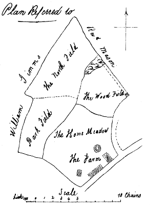
PLAN TRACED BY JUNIOR HAND
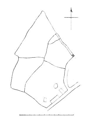
PLAN SHEWING WRITING GAUGED
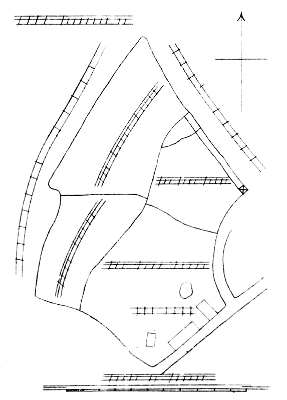
PLAN FINISHED
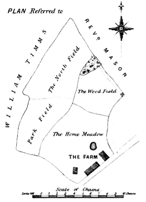
B. Alexander, Lith.
E & F. N. Spon. London & New York.
PLATE 2.
PLAN SENT TO BE COPIED
PLAN TRACED BY JUNIOR HAND
PLAN SHEWING WRITING GAUGED
PLAN FINISHED
B. Alexander, Lith.
E & F. N. Spon. London & New York.
Page as large illustration (215 kB)
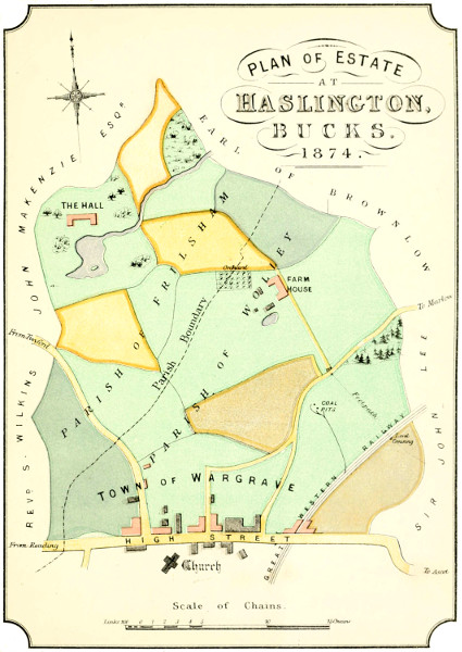
B. Alexander, Lith.
E & F. N. Spon. London & New York.
PLAN OF ESTATE
AT
Haslington,
BUCKS.
1874.
Larger illustration (370 kB)
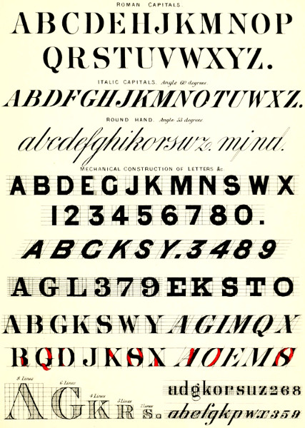
B. Alexander, Lith.
E & F. N. Spon. London & New York.
Roman Capitals
ITALIC CAPITALS Angle 60 degrees
ROUND HAND Angle 53 degrees
MECHANICAL CONSTRUCTION OF LETTERS &c.
8 Lines 6 Lines 4 Lines 3 Lines 2 Lines
Larger illustration (380 kB)
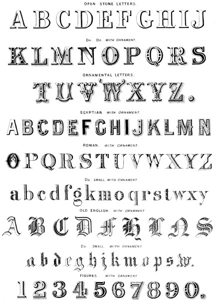
B. Alexander, Lith.
E & F. N. Spon. London & New York.
Open Stone Letters
Do. Do. with Ornament
Ornamental Letters.
Egyptian with Ornament
Roman with Ornament
Do. small with Ornament
Old English with Ornament
Do. Small with Ornament
FIGURES with Ornament
Larger illustration (260 kB)
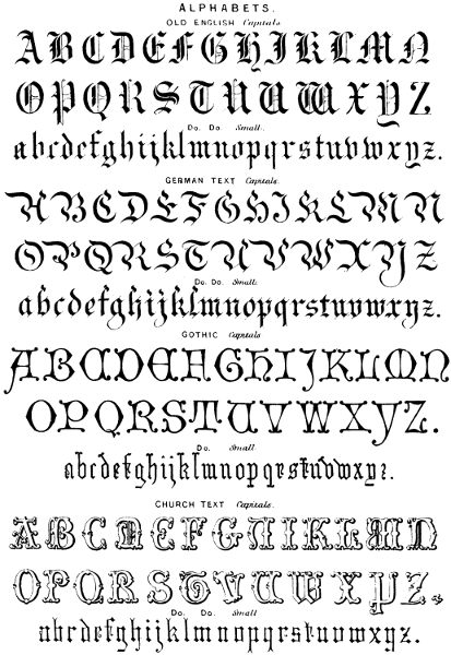
B. Alexander, Lith.
E. & F. N. Spon. London & New York.
ALPHABETS.
Old English Capitals.
Do. Do. Small.
German Text Capitals.
Do. Do. Small.
Gothic Capitals.
Do. Small.
Church Text Capitals.
Do. Do. Small.
Larger illustration (280 kB)

B. Alexander, Lith.
E. & F. N. Spon. London & New York.
PLAN of an ESTATE
CALLED
The Lower Cedars
NEAR the TOWN of
BIRMINGHAM
1874.
Plan of Property
Situate in the Parish of
Hammersmith,
Middlesex.
Plan of a Valuable Freehold Estate
known as
Frognal
NEAR
Hampstead Heath.
Larger illustration (240 kB)
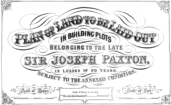
B. Alexander, Lith.
E. & F. N. Spon. London & New York.
PLAN of LAND to be LAID OUT
IN BUILDING PLOTS
BELONGING TO THE LATE
Sir Joseph Paxton,
IN LEASES OF 99 YEARS,
SUBJECT TO THE ANNEXED CONDITION.
Scale of Chains.Scale 6 Chains to an Inch.Scale of Feet.
Larger illustration (270 kB)

B. Alexander, Lith.
E. & F. N. Spon. London & New York.
Scale of Chains.
Scale of Feet.
Larger illustration (160 kB)
PLATE 10.
ORDINARY BEECH.
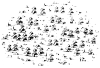
WOOD.
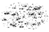
FIRS.

LIGHT BRUSHWOOD.
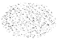
FIRS & OTHER TREES.
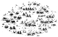
COCOA & PALM TREES
For Colonial Plans.
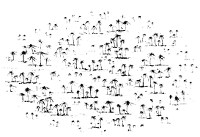
SWAMP.
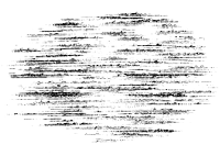
MARSH.
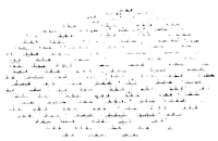
B. Alexander, Lith.
E. & F. N. Spon. London & New York.
Plate 10.
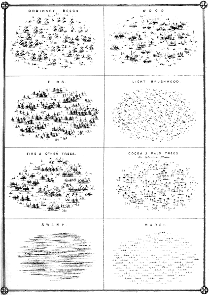
B. Alexander, Lith.
E. & F. N. Spon. London & New York.
Larger illustrations: ORDINARY BEECH. (60 kB)
WOOD. (60 kB)
FIRS. (70 kB)
LIGHT BRUSHWOOD. (40 kB)
FIRS & OTHER TREES. (60 kB)
COCOA & PALM TREES. (50 kB)
SWAMP. (60 kB)
MARSH. (40 kB)
PLATE 11.
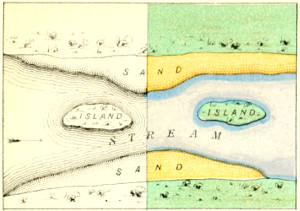
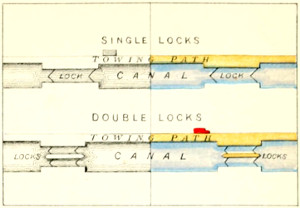
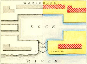
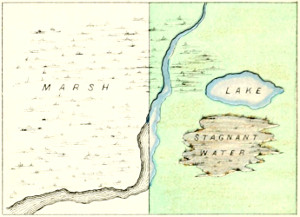
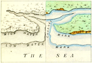
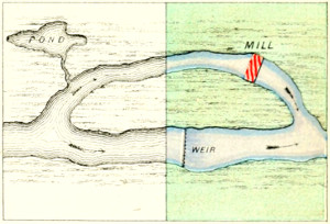
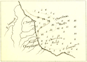

B. Alexander, Lith.
E. & F. N. Spon. London & New York.
A B
C D
E F
G H
Larger illustration: A (100 kB)
B (100 kB)
C (60 kB)
D (80 kB)
E (115 kB)
F (105 kB)
G (60 kB)
H (90 kB)
PLATE 11.
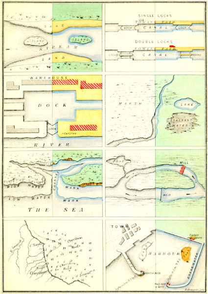
B. Alexander, Lith.
E. & F. N. Spon. London & New York.
PLATE 12.
CONSTRUCTION OF HILLS.
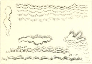
FINISHED HILLS.
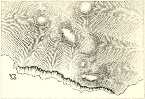
CONTOUR HILLS.
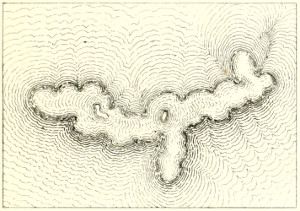
FINISHED HILLS IN COLOR.
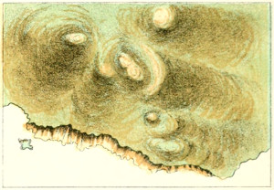
CONTOUR HILLS IN COLOR.
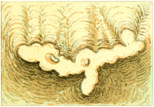
HILLS IN CHALK.
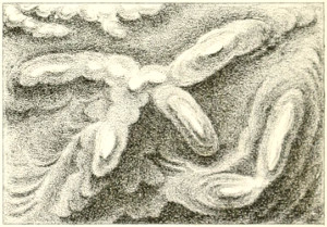
BROKEN HILLY COUNTRY.
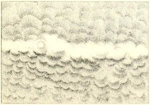
HILLS IN COLOR.
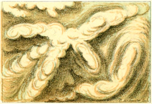
B. Alexander, Lith.
E. & F. N. Spon. London & New York.
Larger illustrations:
CONSTRUCTION OF HILLS. (80 kB)
FINISHED HILLS. (120 kB)
CONTOUR HILLS. (1400 kB)
FINISHED HILLS IN COLOR. (120 kB)
CONTOUR HILLS IN COLOR. (140 kB)
HILLS IN CHALK. (130 kB)
BROKEN HILLY COUNTRY. (130 kB)
HILLS IN COLOR. (130 kB)
PLATE 12.
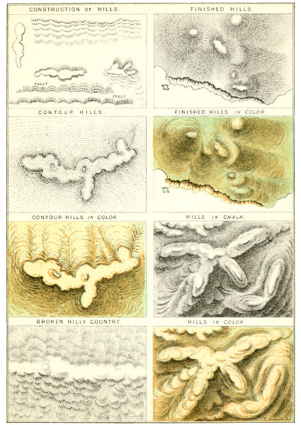
B. Alexander, Lith.
E. & F. N. Spon. London & New York.

B. Alexander, Lith.
E. & F. N. Spon. London & New York.
PLAN SHEWING PROPOSED NEW STREET.
Half Black for Lithography
Half Color for Paper.
Larger illustration (470 kB).
PLATE 14.
ASH
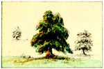
BEECH

BIRCH
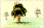
CEDAR
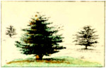
CYPRESS

ELM

FIR
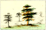
MOUNTAIN ASH

OAK
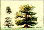
PLANTATION FOREST

PINE
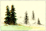
POPLAR
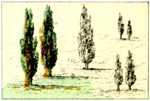
SYCAMORE
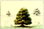
THORN
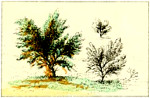
WEEPING WILLOW
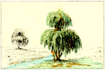
YEW
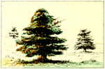
MOUNTAINS
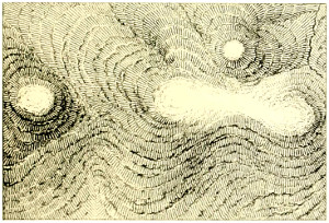
ROCKY CLIFF
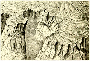
Do. IN COLOR
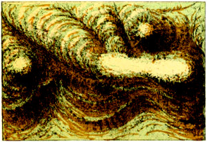
Do. IN COLOR

B. Alexander, Lith.
E. & F. N. Spon. London & New York.
Larger illustrations:
ASH,
BEECH,
BIRCH,
CEDAR
CYPRESS,
ELM,
FIR,
MOUNTAIN ASH
OAK,
PLANTATION FOREST,
PINE,
POPLAR
SYCAMORE,
THORN,
WEEPING WILLOW,
YEW
MOUNTAINS,
ROCKY CLIFF
MOUNTAINS IN COLOR,
ROCKY CLIFF IN COLOR
PLATE 14.
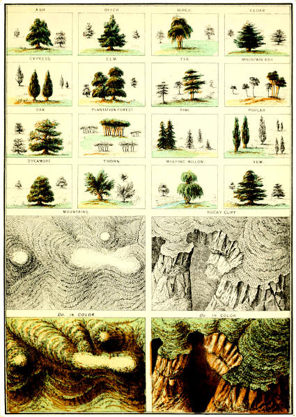
B. Alexander, Lith.
E. & F. N. Spon. London & New York.
SIGNS USED IN PLANS.
| Fence | Farm Buildings |  |
|
| Fence with Bank | Churches | ||
| Fence with Hedge | Windmills | ||
| Footpath | Water Mills | ||
| Bridle Paths | Lime Kiln | ||
| Occupation Road | Sunk Road | ||
| Public Road | Raised Road | ||
| Wall | Quarry | ||
| Parish Boundary | Inn | ||
| Hamlet Boundary | Sand Pits |  |
|
| County Boundary | Rocks |  |
|
| Parish & County Boundary | Mud | ||
| Railway | Gas Works | ||
| Tramway | Glass Works | ||
| Stream | Iron Works | ||
| Brook | Column |  |
|
| Ditch | Old Castle |  |
|
| Mineral Waters | Covered Passage |  |
|
| Canal | Saw Mill | ||
| River | Stone Windmill | ||
| Ponds | Wooden Windmill | ||
| Lake | 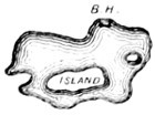 |
Cotton factory | |
| Wooden Fence | Woollen Factory | ||
| Post and Rail or thus |
Well | ||
| Chains & Post | Dry Well | ||
| Hurdle Fence | Salt Works | ||
| Gates | Field Wall |
B. Alexander, Lith.
E. & F. N. Spon. London & New York.
Page as large illustration (190 kB)
SIGNS USED IN MAPS AND CHARTS.
| Fortress | Rocks | { | alwayscovered | ||||
| Citadel | Reef of Rocks | ||||||
| Fortified Castle | Sand | { | nevercovered | ||||
| Walled Town | Sand | { | sometimescovered | ||||
| Open Town | Shoals | { | alwayscovered | ||||
| Country Town | Mud Bank & Beach dry at Low Water |
||||||
| Little Town | Rocky Ledges which cover and uncover |
 |
|||||
| City | Sandy Beach dry at Low Water |
||||||
| Episcopal City | Lighthouses (position of) |
 |
|||||
| Borough or Corporation | Can Buoys | ||||||
| Light Ship |  |
Nun Buoys | |||||
| Light House |  |
Mooring Buoy | |||||
| Anchorage for Ships | Buoys with Beacons | ||||||
| Do for Coasters | Coral Reefs |  |
|||||
| Wreck | Kelp | ||||||
| Stopping Places | Fish Weir |  |
|||||
| Head of Navigation | Swampy Land | 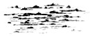 |
|||||
| Floating Light Vessel | Rocks | ||||||
| Harbour | Rocks dry at Low Water | ||||||
| Telegraph | Viaduct | 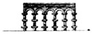 |
|||||
| Signal House | Tunnel | ||||||
| Buoys | Railway Bridge | ||||||
| Channel Marks | Bridge over Stream | 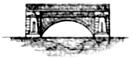 |
|||||
| No Current | Pontoon Bridge | ||||||
| Direction of Current | Bridge (Brick or Stone) |  |
|||||
| Rocks | { | sometimescovered | Foot Bridge | ||||
| Rocks | { | nevercovered |  |
Towns |  |
||
B. Alexander, Lith.
E. & F. N. Spon. London & New York.
Page as large illustration (190 kB)
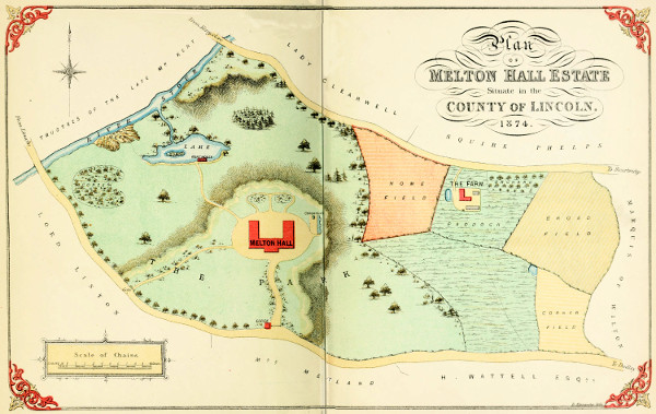
B. Alexander, Lith.
E. & F. N. Spon. London & New York.
Plan
OF
Melton Hall Estate
Situate in the
COUNTY of LINCOLN,
1874.
Large plan (450 kB)
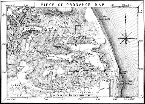

B. Alexander, Lith.
E. & F. N. Spon. London & New York.
PIECE OF ORDNANCE MAP.
PIECE OF CHART SHEWING SOUNDINGS, &c.
Larger illustrations: Ordnance map (540 kB)
Soundings chart (430 kB)
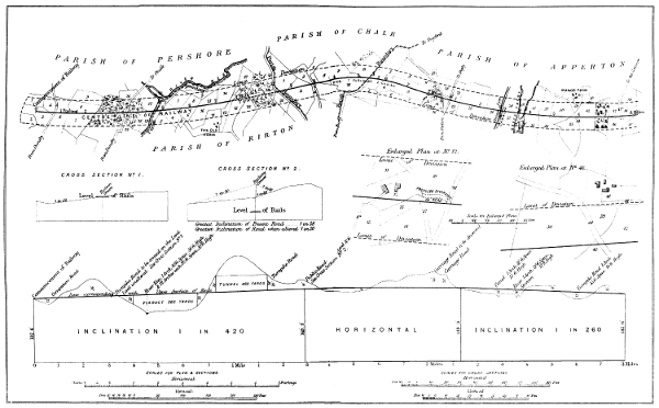
B. Alexander, Lith.
E. & F. N. Spon. London & New York.
Large illustration 170 kB)
| SAND & GRAVEL. | RED SANDSTONE. | CLAY & GRAVEL. |
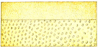 |
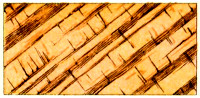 |
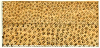 |
| LIMESTONE. | BOG. | CLAY SLATE. |
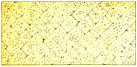 |
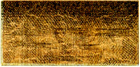 |
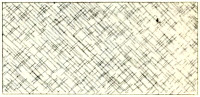 |
| MILLSTONE. | GRANITE. | SANDSTONE & COAL. |
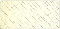 |
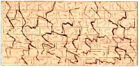 |
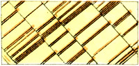 |
| SPOIL BANK. | PURE GRAVEL. | CLAY CALCAREOUS. |
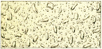 |
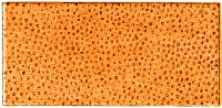 |
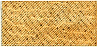 |
| PEAT & CLAY. | SANDSTONE. | SHELL MARL. |
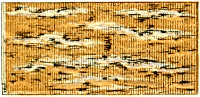 |
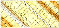 |
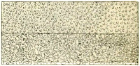 |
| LIMESTONE WITH MINERAL VEINS. | BOG WITH TIMBER. | SANDSTONE WITH GYPSUM. |
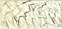 |
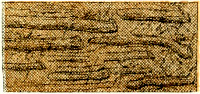 |
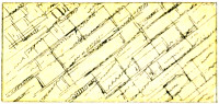 |
| MUD. | SANDSTONE COARSE & FINE. | CLAY SLATE WITH MINERAL VEINS. |
 |
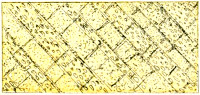 |
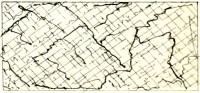 |
| COMBINATION OF THE ABOVE. | ||
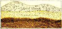 |
 |
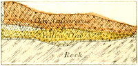 |
| Spoil Bank Limestone Bog |
Clay Sand Gravel Red Sandstone |
Clay Calcareous Yellow Clay Rock |
B. Alexander, Lith.
E. & F. N. Spon. London & New York.
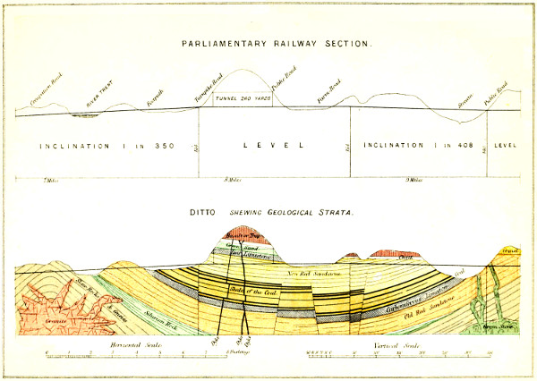
B. Alexander, Lith.
E. & F. N. Spon. London & New York.
PARLIAMENTARY RAILWAY SECTION.
DITTO, shewing Geological Strata.
Larger illustration (350 kB)

B. Alexander, Lith.
E. & F. N. Spon. London & New York.
PIECE OF MARINE ENGINE OF H. M. S. S. “RESEARCH”.
Larger illustration (450 kB)
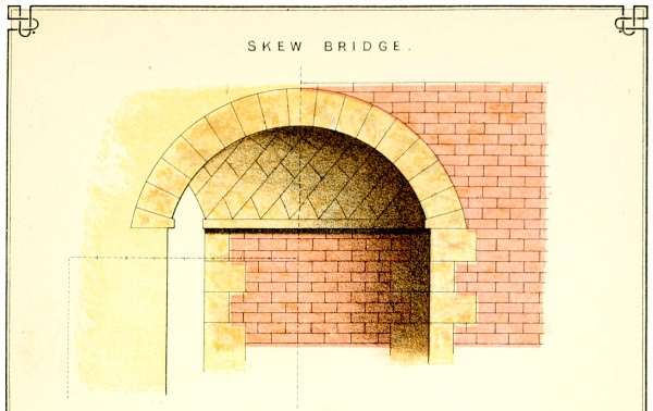
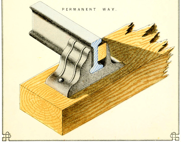
B. Alexander, Lith.
E. & F. N. Spon. London & New York.
SKEW BRIDGE.
PERMANENT WAY.
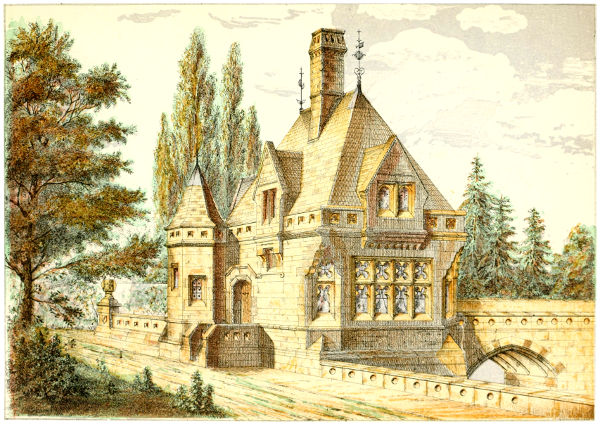
B. Alexander, Lith.
E. & F. N. Spon. London & New York.
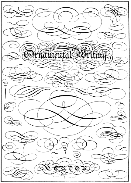
B. Alexander, Lith.
E. & F. N. Spon. London & New York.
Ornamental Writing.
London
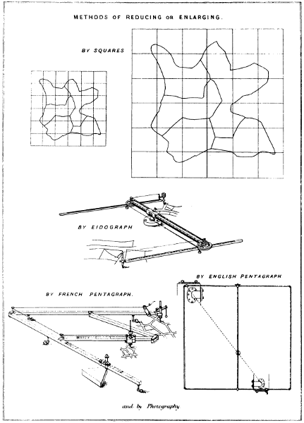
B. Alexander, Lith.
E. & F. N. Spon. London & New York.
METHODS of REDUCING or ENLARGING.
by SQUARES
by EIDOGRAPH
by ENGLISH PENTAGRAPH
by FRENCH PENTAGRAPH
and by Photography.
Larger illustration (150 kB)

B. Alexander, Lith.
E. & F. N. Spon. London & New York.
ISOMETRICAL view of building.
EXTERIOR.
INTERIOR.
Larger illustration (390 kB)
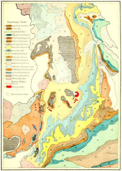
B. Alexander, Lith.
E. & F. N. Spon. London & New York.
Depositary Rocks. 1-18
Igneous Rocks. a-b
Larger map (560 kB)
Signs used in Indian & Colonial Plans.
| Telegraph | Hills with Peaks | 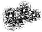 |
|
| Trunk Road (Metalled) | |||
| District Do. | |||
| Do. Unmetalled | Do. in Contour | 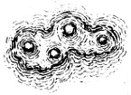 |
|
| Ford | 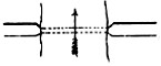 |
||
| Nullah or Khall | |||
| Bund or Embankment | Scarped Face of Hill |  |
|
| Old Bank of River | |||
| Hedges with Trees | Ravine | 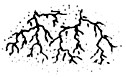 |
|
| River with Islands | 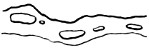 |
||
| River with Sand Bank | Garden | 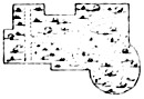 |
|
| Stone Sluice Gate | |||
| Lake or Tank | Paun Garden | ||
| Salt Pans | 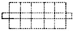 |
Village |  |
| Cultivated Ground | 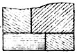 |
Ferry | |
| Flying Bridge | |||
| Burial Ground | 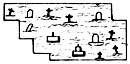 |
Haut or Bazar | |
| Mud Fort | |||
| Sand Hills | 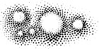 |
Pucka Fort | |
| Deserted Village | |||
| Ridge of Hills | 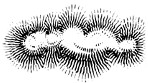 |
Principal Survey Stations | |
| Secondary Do. | |||
| High Ground | 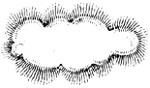 |
Flag for Surveying |  |
B. Alexander, Lith.
E. & F. N. Spon. London & New York.
Page as large illustration (200 kB)
Signs used in Indian & Colonial Plans.
| Salt Golah | Jhow Jungle | 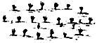 |
|
| Salt Chowkey | |||
| Silk Factory | Jheel | 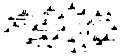 |
|
| Indigo Factory | Tamarind Trees | 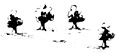 |
|
| Sugar Factory | Bamboo Jungle | 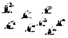 |
|
| Post Office | Salt Waste | 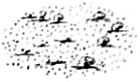 |
|
| Dak Bungalow | |||
| Police or Thana Stan. | Salt Waste with Jungle |  |
|
| Magistrate’s Kutcherry | Mangoe Tope | 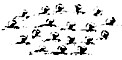 |
|
| Stone or Pucka Houses | |||
| Mahomedan Mosque | Cocoa Nut Trees | 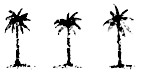 |
|
| Hindoo Temple | |||
| Telegraph Tower | Betel Nut Trees | 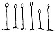 |
|
| Signal Staff |  |
Trees generally | 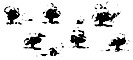 |
| Boundary Pillar | Date Trees | 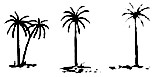 |
|
| Wooden Boundary Post | |||
| Pucka Well | Palm or Tar Trees | 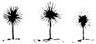 |
|
| Kucha Well | |||
| Forest Jungles | 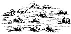 |
Mangrove | 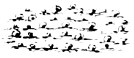 |
| Low Jungles | 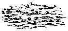 |
Brides | 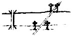 |
| Grass Jungles | 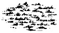 |
Rail Road |
B. Alexander, Lith.
E. & F. N. Spon. London & New York.
Page as large illustration (180 kB)
Military Signs and Fortifications.
| Tête du Pont |  |
Passable for Troops | |
| Infantry Engaged | |||
| Vedettes |  |
Cavalry Encamped | |
| Village Inundated | 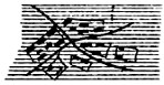 |
||
| Military Pits | |||
| Mines |  |
Sand Bags | 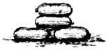 |
| Infantry Encamped | Intrenchment | ||
| Village Burnt | 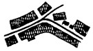 |
Cannon | |
| Cavalry Engaged | |||
| Caltrop or Crows Feet |  |
Park | |
| Trenches | 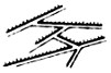 |
Palisades |  |
| Barrier | 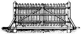 |
||
| Mortar & Shells | 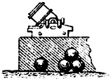 |
||
| Block House | 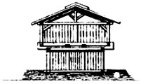 |
||
| Field Piece and Limber |  |
||
| Ammunition Waggon and Limber |  |
||
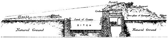 |
|||
| SECTION of GLACIS, DITCH, RAMPART, &c. | |||
B. Alexander, Lith.
E. & F. N. Spon. London & New York.
Page as large illustration (180 kB)
Military Signs and Fortifications.
| Infantry Column | Impassible for Artillery | ||
| Cavalry Line | Abatis | 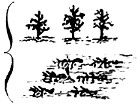 |
|
| Chevaux de frise | 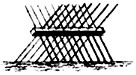 |
||
| Redoubt |  |
||
| Mortar Battery | |||
| Impassible for Cavalry | Cavalry Column | ||
| Gained | 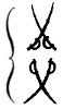 |
Guns on March | |
| Field of Battle | Gun Battery | ||
| Lost | Impassible for Infantry | ||
| Sentinel | Baggage Waggons |  |
|
| Infantry Line | |||
| Guns in Position | Fortified Castles Closed |
 |
|
| Palisades | 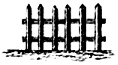 |
||
| Rifle Pits | Redan or Fleche | 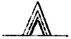 |
 |
 |
| Gabions | Fascines |
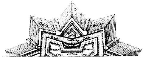 |
|
| PLAN of BASTIONED FORT with LUNETTES. | |
B. Alexander, Lith.
E & F. N. Spon. London & New York.
Page as large illustration (240 kB)

B. Alexander, Lith.
E. & F. N. Spon. London & New York.
PORTION of MINING PLAN shewing PILLAR WORKINGS.
as SHEWN by HAND on PAPER.
as SHEWN by ENGRAVING or LITHOGRAPHY.
Larger plan (530 kB)
Inconsistencies in spelling, hyphenation, lay-out, the use of quote marks, diacriticals and accents, etc. have been retained.
Depending on the hard- and software used to read this document, some elements may not display as intended. The browser version of this document (available from www.gutenberg.org) gives best results, and contains larger versions of several illustrations.
The minor differences between the Table of Contents and the headings in the text have not been standardised.
Several plates have been printed with poor colour overlays, this has not been remedied.
Some double-page plates have been re-combined, but the area between the pages may not be exactly as printed in the original work.
Page 136, Professor Willis: should be Professor (William) Wallace; Professor (Robert) Willis invented other drawing tools.
Plate 26, pentagraph (2×): as printed in the source document.
Changes made:
Some missing punctuation has been added silently, some minor typographical errors have been corrected silently.
Some tables, calculations, formulas, etc. have been re-arranged for better readability.
Some of the illustrations and their captions have been rotated.
Page 15: apply a straight-edge F changed to apply a straight-edge D
Page 75, Fig. 75: Lehman’s Scale changed to Lehmann’s Scale
Page 83: the third reference line C D changed to the third reference line C A
Page 132: the erect manner and the reverse manner changed to the erect manner and the reverse manner.
Heading PLATES added after Index.
End of the Project Gutenberg EBook of The Draughtsman's Handbook of Plan and
Map Drawing, by George G. André

*** END OF THIS PROJECT GUTENBERG EBOOK THE DRAUGHTSMAN'S HANDBOOK ***

***** This file should be named 57290-h.htm or 57290-h.zip *****
This and all associated files of various formats will be found in:
        http://www.gutenberg.org/5/7/2/9/57290/

Produced by Chris Curnow, Harry Lamé and the Online
Distributed Proofreading Team at http://www.pgdp.net (This
file was produced from images generously made available
by The Internet Archive, with additional images from Hathi
Trust)

Updated editions will replace the previous one--the old editions will
be renamed.

Creating the works from print editions not protected by U.S. copyright
law means that no one owns a United States copyright in these works,
so the Foundation (and you!) can copy and distribute it in the United
States without permission and without paying copyright
royalties. Special rules, set forth in the General Terms of Use part
of this license, apply to copying and distributing Project
Gutenberg-tm electronic works to protect the PROJECT GUTENBERG-tm
concept and trademark. Project Gutenberg is a registered trademark,
and may not be used if you charge for the eBooks, unless you receive
specific permission. If you do not charge anything for copies of this
eBook, complying with the rules is very easy. You may use this eBook
for nearly any purpose such as creation of derivative works, reports,
performances and research. They may be modified and printed and given
away--you may do practically ANYTHING in the United States with eBooks
not protected by U.S. copyright law. Redistribution is subject to the
trademark license, especially commercial redistribution.

START: FULL LICENSE

THE FULL PROJECT GUTENBERG LICENSE
PLEASE READ THIS BEFORE YOU DISTRIBUTE OR USE THIS WORK

To protect the Project Gutenberg-tm mission of promoting the free
distribution of electronic works, by using or distributing this work
(or any other work associated in any way with the phrase "Project
Gutenberg"), you agree to comply with all the terms of the Full
Project Gutenberg-tm License available with this file or online at
www.gutenberg.org/license.

Section 1. General Terms of Use and Redistributing Project
Gutenberg-tm electronic works

1.A. By reading or using any part of this Project Gutenberg-tm
electronic work, you indicate that you have read, understand, agree to
and accept all the terms of this license and intellectual property
(trademark/copyright) agreement. If you do not agree to abide by all
the terms of this agreement, you must cease using and return or
destroy all copies of Project Gutenberg-tm electronic works in your
possession. If you paid a fee for obtaining a copy of or access to a
Project Gutenberg-tm electronic work and you do not agree to be bound
by the terms of this agreement, you may obtain a refund from the
person or entity to whom you paid the fee as set forth in paragraph
1.E.8.

1.B. "Project Gutenberg" is a registered trademark. It may only be
used on or associated in any way with an electronic work by people who
agree to be bound by the terms of this agreement. There are a few
things that you can do with most Project Gutenberg-tm electronic works
even without complying with the full terms of this agreement. See
paragraph 1.C below. There are a lot of things you can do with Project
Gutenberg-tm electronic works if you follow the terms of this
agreement and help preserve free future access to Project Gutenberg-tm
electronic works. See paragraph 1.E below.

1.C. The Project Gutenberg Literary Archive Foundation ("the
Foundation" or PGLAF), owns a compilation copyright in the collection
of Project Gutenberg-tm electronic works. Nearly all the individual
works in the collection are in the public domain in the United
States. If an individual work is unprotected by copyright law in the
United States and you are located in the United States, we do not
claim a right to prevent you from copying, distributing, performing,
displaying or creating derivative works based on the work as long as
all references to Project Gutenberg are removed. Of course, we hope
that you will support the Project Gutenberg-tm mission of promoting
free access to electronic works by freely sharing Project Gutenberg-tm
works in compliance with the terms of this agreement for keeping the
Project Gutenberg-tm name associated with the work. You can easily
comply with the terms of this agreement by keeping this work in the
same format with its attached full Project Gutenberg-tm License when
you share it without charge with others.

1.D. The copyright laws of the place where you are located also govern
what you can do with this work. Copyright laws in most countries are
in a constant state of change. If you are outside the United States,
check the laws of your country in addition to the terms of this
agreement before downloading, copying, displaying, performing,
distributing or creating derivative works based on this work or any
other Project Gutenberg-tm work. The Foundation makes no
representations concerning the copyright status of any work in any
country outside the United States.

1.E. Unless you have removed all references to Project Gutenberg:

1.E.1. The following sentence, with active links to, or other
immediate access to, the full Project Gutenberg-tm License must appear
prominently whenever any copy of a Project Gutenberg-tm work (any work
on which the phrase "Project Gutenberg" appears, or with which the
phrase "Project Gutenberg" is associated) is accessed, displayed,
performed, viewed, copied or distributed:

  This eBook is for the use of anyone anywhere in the United States and
  most other parts of the world at no cost and with almost no
  restrictions whatsoever. You may copy it, give it away or re-use it
  under the terms of the Project Gutenberg License included with this
  eBook or online at www.gutenberg.org. If you are not located in the
  United States, you'll have to check the laws of the country where you
  are located before using this ebook.

1.E.2. If an individual Project Gutenberg-tm electronic work is
derived from texts not protected by U.S. copyright law (does not
contain a notice indicating that it is posted with permission of the
copyright holder), the work can be copied and distributed to anyone in
the United States without paying any fees or charges. If you are
redistributing or providing access to a work with the phrase "Project
Gutenberg" associated with or appearing on the work, you must comply
either with the requirements of paragraphs 1.E.1 through 1.E.7 or
obtain permission for the use of the work and the Project Gutenberg-tm
trademark as set forth in paragraphs 1.E.8 or 1.E.9.

1.E.3. If an individual Project Gutenberg-tm electronic work is posted
with the permission of the copyright holder, your use and distribution
must comply with both paragraphs 1.E.1 through 1.E.7 and any
additional terms imposed by the copyright holder. Additional terms
will be linked to the Project Gutenberg-tm License for all works
posted with the permission of the copyright holder found at the
beginning of this work.

1.E.4. Do not unlink or detach or remove the full Project Gutenberg-tm
License terms from this work, or any files containing a part of this
work or any other work associated with Project Gutenberg-tm.

1.E.5. Do not copy, display, perform, distribute or redistribute this
electronic work, or any part of this electronic work, without
prominently displaying the sentence set forth in paragraph 1.E.1 with
active links or immediate access to the full terms of the Project
Gutenberg-tm License.

1.E.6. You may convert to and distribute this work in any binary,
compressed, marked up, nonproprietary or proprietary form, including
any word processing or hypertext form. However, if you provide access
to or distribute copies of a Project Gutenberg-tm work in a format
other than "Plain Vanilla ASCII" or other format used in the official
version posted on the official Project Gutenberg-tm web site
(www.gutenberg.org), you must, at no additional cost, fee or expense
to the user, provide a copy, a means of exporting a copy, or a means
of obtaining a copy upon request, of the work in its original "Plain
Vanilla ASCII" or other form. Any alternate format must include the
full Project Gutenberg-tm License as specified in paragraph 1.E.1.

1.E.7. Do not charge a fee for access to, viewing, displaying,
performing, copying or distributing any Project Gutenberg-tm works
unless you comply with paragraph 1.E.8 or 1.E.9.

1.E.8. You may charge a reasonable fee for copies of or providing
access to or distributing Project Gutenberg-tm electronic works
provided that

* You pay a royalty fee of 20% of the gross profits you derive from
  the use of Project Gutenberg-tm works calculated using the method
  you already use to calculate your applicable taxes. The fee is owed
  to the owner of the Project Gutenberg-tm trademark, but he has
  agreed to donate royalties under this paragraph to the Project
  Gutenberg Literary Archive Foundation. Royalty payments must be paid
  within 60 days following each date on which you prepare (or are
  legally required to prepare) your periodic tax returns. Royalty
  payments should be clearly marked as such and sent to the Project
  Gutenberg Literary Archive Foundation at the address specified in
  Section 4, "Information about donations to the Project Gutenberg
  Literary Archive Foundation."

* You provide a full refund of any money paid by a user who notifies
  you in writing (or by e-mail) within 30 days of receipt that s/he
  does not agree to the terms of the full Project Gutenberg-tm
  License. You must require such a user to return or destroy all
  copies of the works possessed in a physical medium and discontinue
  all use of and all access to other copies of Project Gutenberg-tm
  works.

* You provide, in accordance with paragraph 1.F.3, a full refund of
  any money paid for a work or a replacement copy, if a defect in the
  electronic work is discovered and reported to you within 90 days of
  receipt of the work.

* You comply with all other terms of this agreement for free
  distribution of Project Gutenberg-tm works.

1.E.9. If you wish to charge a fee or distribute a Project
Gutenberg-tm electronic work or group of works on different terms than
are set forth in this agreement, you must obtain permission in writing
from both the Project Gutenberg Literary Archive Foundation and The
Project Gutenberg Trademark LLC, the owner of the Project Gutenberg-tm
trademark. Contact the Foundation as set forth in Section 3 below.

1.F.

1.F.1. Project Gutenberg volunteers and employees expend considerable
effort to identify, do copyright research on, transcribe and proofread
works not protected by U.S. copyright law in creating the Project
Gutenberg-tm collection. Despite these efforts, Project Gutenberg-tm
electronic works, and the medium on which they may be stored, may
contain "Defects," such as, but not limited to, incomplete, inaccurate
or corrupt data, transcription errors, a copyright or other
intellectual property infringement, a defective or damaged disk or
other medium, a computer virus, or computer codes that damage or
cannot be read by your equipment.

1.F.2. LIMITED WARRANTY, DISCLAIMER OF DAMAGES - Except for the "Right
of Replacement or Refund" described in paragraph 1.F.3, the Project
Gutenberg Literary Archive Foundation, the owner of the Project
Gutenberg-tm trademark, and any other party distributing a Project
Gutenberg-tm electronic work under this agreement, disclaim all
liability to you for damages, costs and expenses, including legal
fees. YOU AGREE THAT YOU HAVE NO REMEDIES FOR NEGLIGENCE, STRICT
LIABILITY, BREACH OF WARRANTY OR BREACH OF CONTRACT EXCEPT THOSE
PROVIDED IN PARAGRAPH 1.F.3. YOU AGREE THAT THE FOUNDATION, THE
TRADEMARK OWNER, AND ANY DISTRIBUTOR UNDER THIS AGREEMENT WILL NOT BE
LIABLE TO YOU FOR ACTUAL, DIRECT, INDIRECT, CONSEQUENTIAL, PUNITIVE OR
INCIDENTAL DAMAGES EVEN IF YOU GIVE NOTICE OF THE POSSIBILITY OF SUCH
DAMAGE.

1.F.3. LIMITED RIGHT OF REPLACEMENT OR REFUND - If you discover a
defect in this electronic work within 90 days of receiving it, you can
receive a refund of the money (if any) you paid for it by sending a
written explanation to the person you received the work from. If you
received the work on a physical medium, you must return the medium
with your written explanation. The person or entity that provided you
with the defective work may elect to provide a replacement copy in
lieu of a refund. If you received the work electronically, the person
or entity providing it to you may choose to give you a second
opportunity to receive the work electronically in lieu of a refund. If
the second copy is also defective, you may demand a refund in writing
without further opportunities to fix the problem.

1.F.4. Except for the limited right of replacement or refund set forth
in paragraph 1.F.3, this work is provided to you 'AS-IS', WITH NO
OTHER WARRANTIES OF ANY KIND, EXPRESS OR IMPLIED, INCLUDING BUT NOT
LIMITED TO WARRANTIES OF MERCHANTABILITY OR FITNESS FOR ANY PURPOSE.

1.F.5. Some states do not allow disclaimers of certain implied
warranties or the exclusion or limitation of certain types of
damages. If any disclaimer or limitation set forth in this agreement
violates the law of the state applicable to this agreement, the
agreement shall be interpreted to make the maximum disclaimer or
limitation permitted by the applicable state law. The invalidity or
unenforceability of any provision of this agreement shall not void the
remaining provisions.

1.F.6. INDEMNITY - You agree to indemnify and hold the Foundation, the
trademark owner, any agent or employee of the Foundation, anyone
providing copies of Project Gutenberg-tm electronic works in
accordance with this agreement, and any volunteers associated with the
production, promotion and distribution of Project Gutenberg-tm
electronic works, harmless from all liability, costs and expenses,
including legal fees, that arise directly or indirectly from any of
the following which you do or cause to occur: (a) distribution of this
or any Project Gutenberg-tm work, (b) alteration, modification, or
additions or deletions to any Project Gutenberg-tm work, and (c) any
Defect you cause.

Section 2. Information about the Mission of Project Gutenberg-tm

Project Gutenberg-tm is synonymous with the free distribution of
electronic works in formats readable by the widest variety of
computers including obsolete, old, middle-aged and new computers. It
exists because of the efforts of hundreds of volunteers and donations
from people in all walks of life.

Volunteers and financial support to provide volunteers with the
assistance they need are critical to reaching Project Gutenberg-tm's
goals and ensuring that the Project Gutenberg-tm collection will
remain freely available for generations to come. In 2001, the Project
Gutenberg Literary Archive Foundation was created to provide a secure
and permanent future for Project Gutenberg-tm and future
generations. To learn more about the Project Gutenberg Literary
Archive Foundation and how your efforts and donations can help, see
Sections 3 and 4 and the Foundation information page at
www.gutenberg.org


Section 3. Information about the Project Gutenberg Literary Archive Foundation

The Project Gutenberg Literary Archive Foundation is a non profit
501(c)(3) educational corporation organized under the laws of the
state of Mississippi and granted tax exempt status by the Internal
Revenue Service. The Foundation's EIN or federal tax identification
number is 64-6221541. Contributions to the Project Gutenberg Literary
Archive Foundation are tax deductible to the full extent permitted by
U.S. federal laws and your state's laws.

The Foundation's principal office is in Fairbanks, Alaska, with the
mailing address: PO Box 750175, Fairbanks, AK 99775, but its
volunteers and employees are scattered throughout numerous
locations. Its business office is located at 809 North 1500 West, Salt
Lake City, UT 84116, (801) 596-1887. Email contact links and up to
date contact information can be found at the Foundation's web site and
official page at www.gutenberg.org/contact

For additional contact information:

    Dr. Gregory B. Newby
    Chief Executive and Director
    gbnewby@pglaf.org

Section 4. Information about Donations to the Project Gutenberg
Literary Archive Foundation

Project Gutenberg-tm depends upon and cannot survive without wide
spread public support and donations to carry out its mission of
increasing the number of public domain and licensed works that can be
freely distributed in machine readable form accessible by the widest
array of equipment including outdated equipment. Many small donations
($1 to $5,000) are particularly important to maintaining tax exempt
status with the IRS.

The Foundation is committed to complying with the laws regulating
charities and charitable donations in all 50 states of the United
States. Compliance requirements are not uniform and it takes a
considerable effort, much paperwork and many fees to meet and keep up
with these requirements. We do not solicit donations in locations
where we have not received written confirmation of compliance. To SEND
DONATIONS or determine the status of compliance for any particular
state visit www.gutenberg.org/donate

While we cannot and do not solicit contributions from states where we
have not met the solicitation requirements, we know of no prohibition
against accepting unsolicited donations from donors in such states who
approach us with offers to donate.

International donations are gratefully accepted, but we cannot make
any statements concerning tax treatment of donations received from
outside the United States. U.S. laws alone swamp our small staff.

Please check the Project Gutenberg Web pages for current donation
methods and addresses. Donations are accepted in a number of other
ways including checks, online payments and credit card donations. To
donate, please visit: www.gutenberg.org/donate

Section 5. General Information About Project Gutenberg-tm electronic works.

Professor Michael S. Hart was the originator of the Project
Gutenberg-tm concept of a library of electronic works that could be
freely shared with anyone. For forty years, he produced and
distributed Project Gutenberg-tm eBooks with only a loose network of
volunteer support.

Project Gutenberg-tm eBooks are often created from several printed
editions, all of which are confirmed as not protected by copyright in
the U.S. unless a copyright notice is included. Thus, we do not
necessarily keep eBooks in compliance with any particular paper
edition.

Most people start at our Web site which has the main PG search
facility: www.gutenberg.org

This Web site includes information about Project Gutenberg-tm,
including how to make donations to the Project Gutenberg Literary
Archive Foundation, how to help produce our new eBooks, and how to
subscribe to our email newsletter to hear about new eBooks.

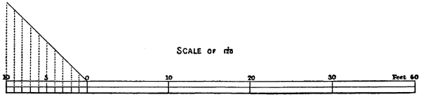
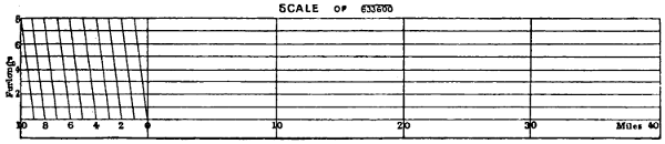
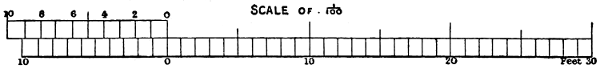

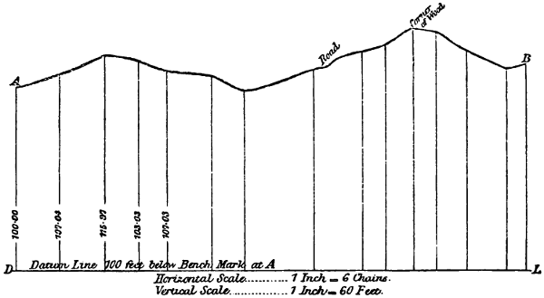
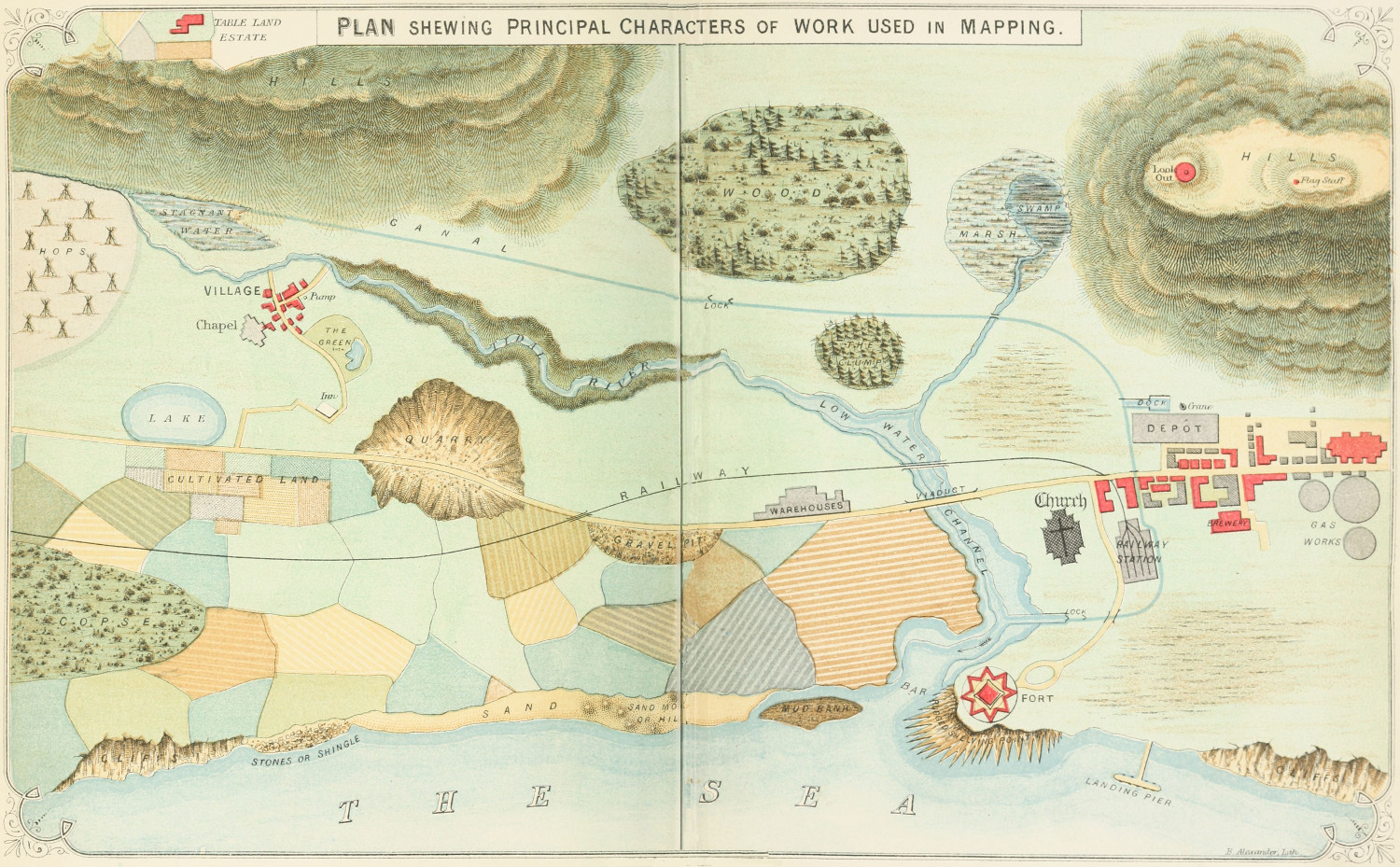
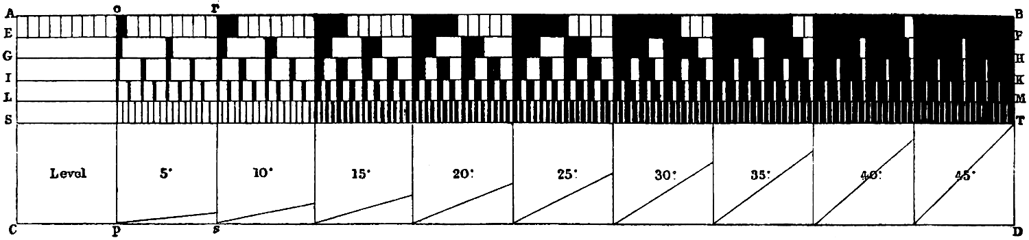
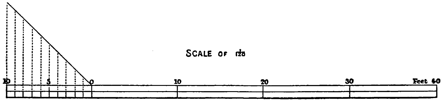
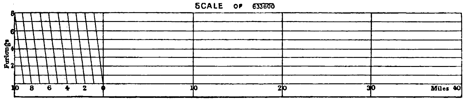
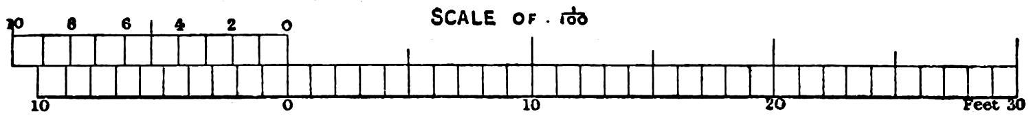
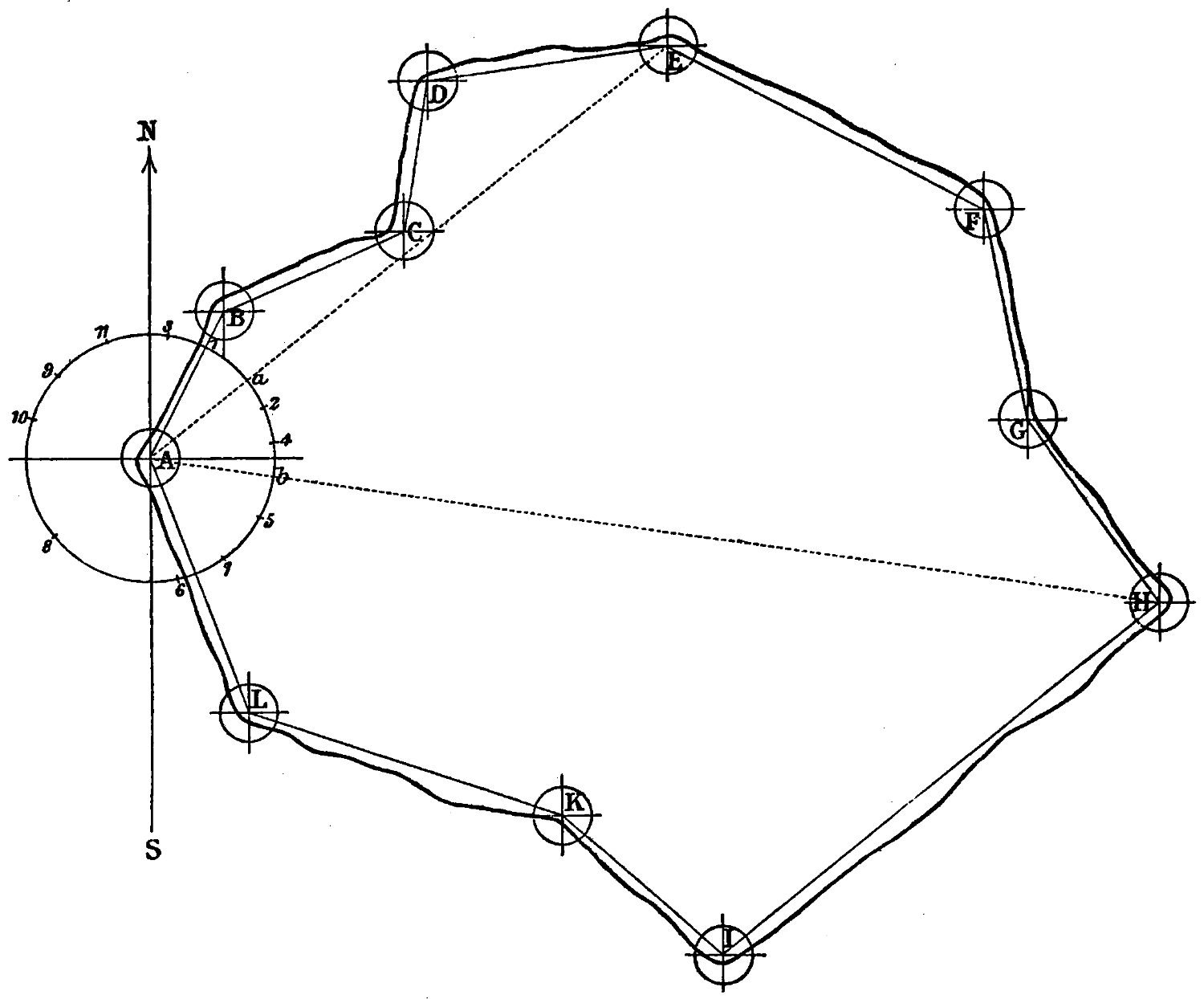
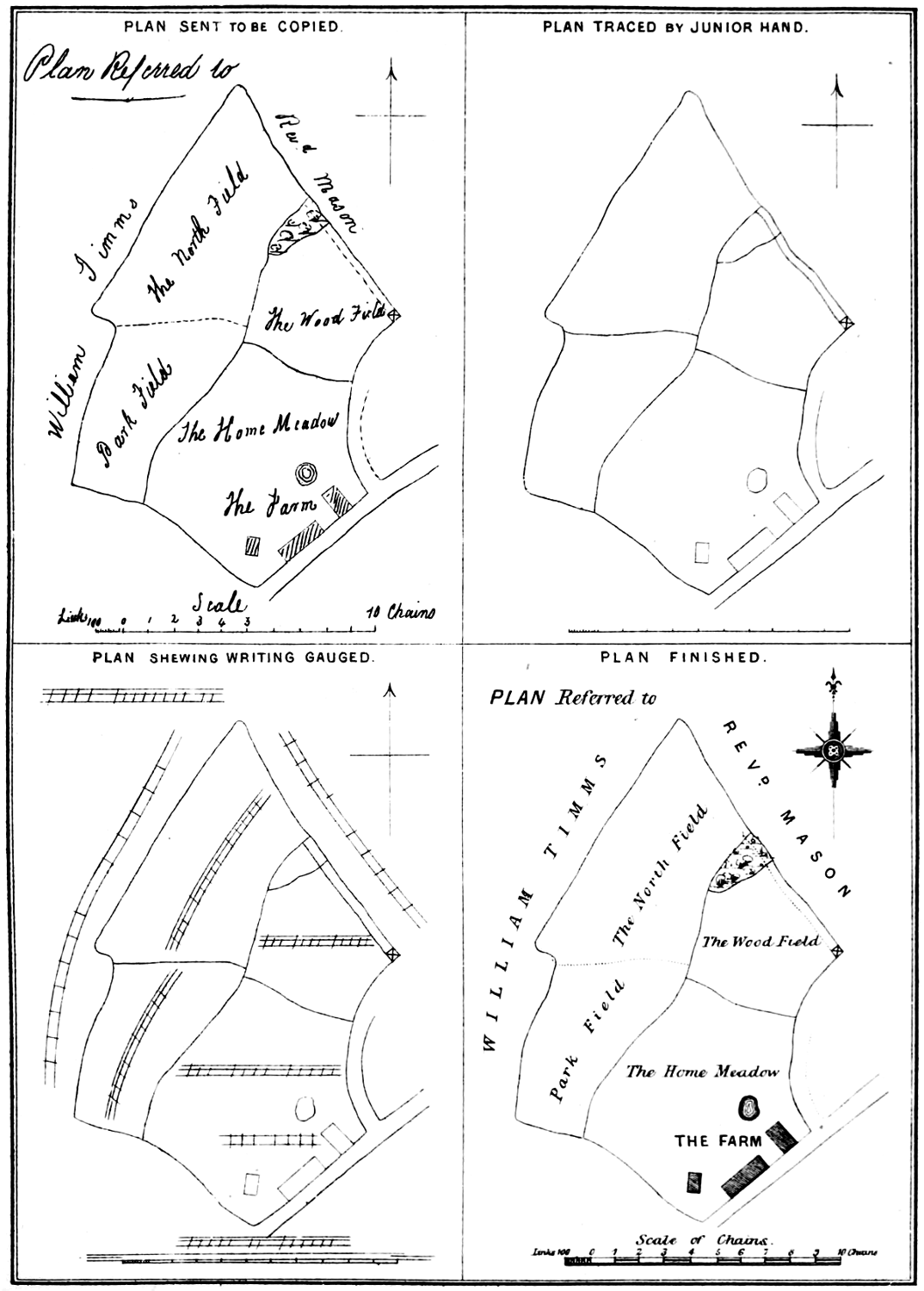
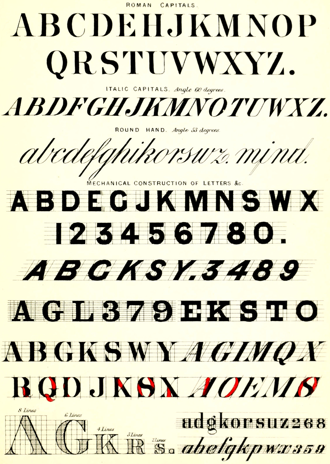
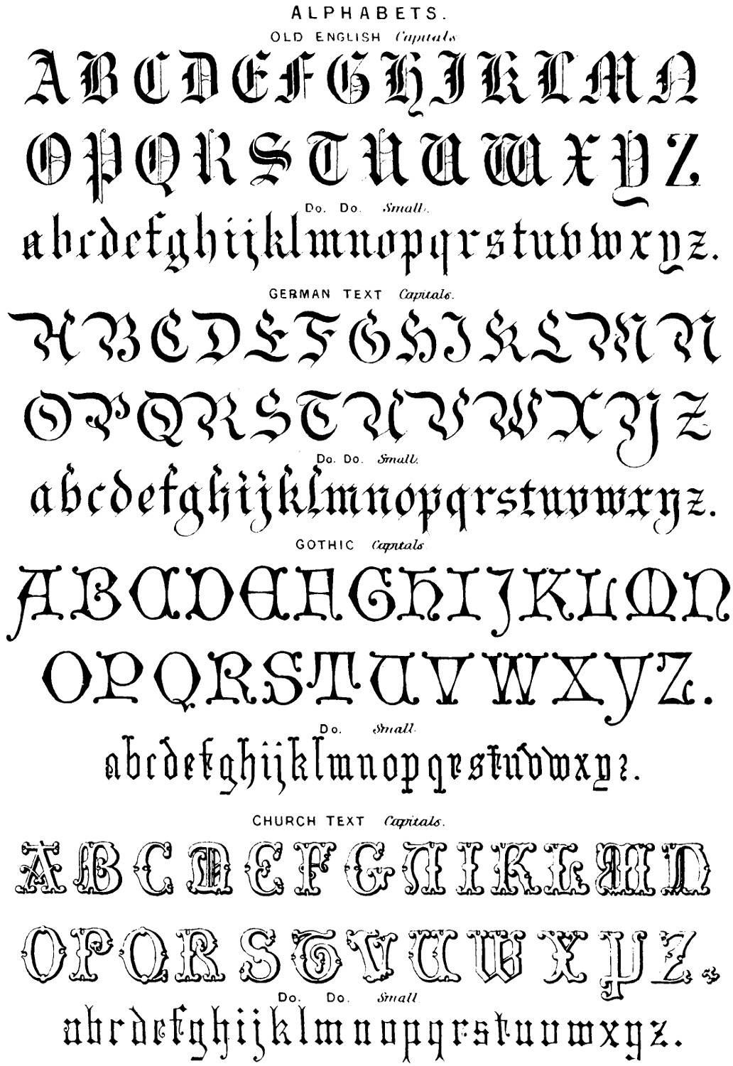
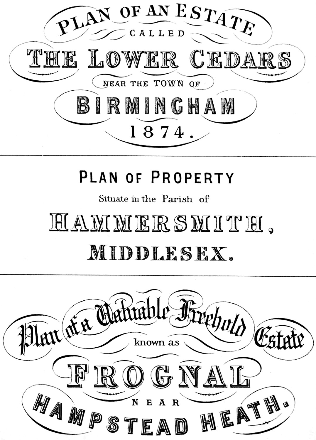
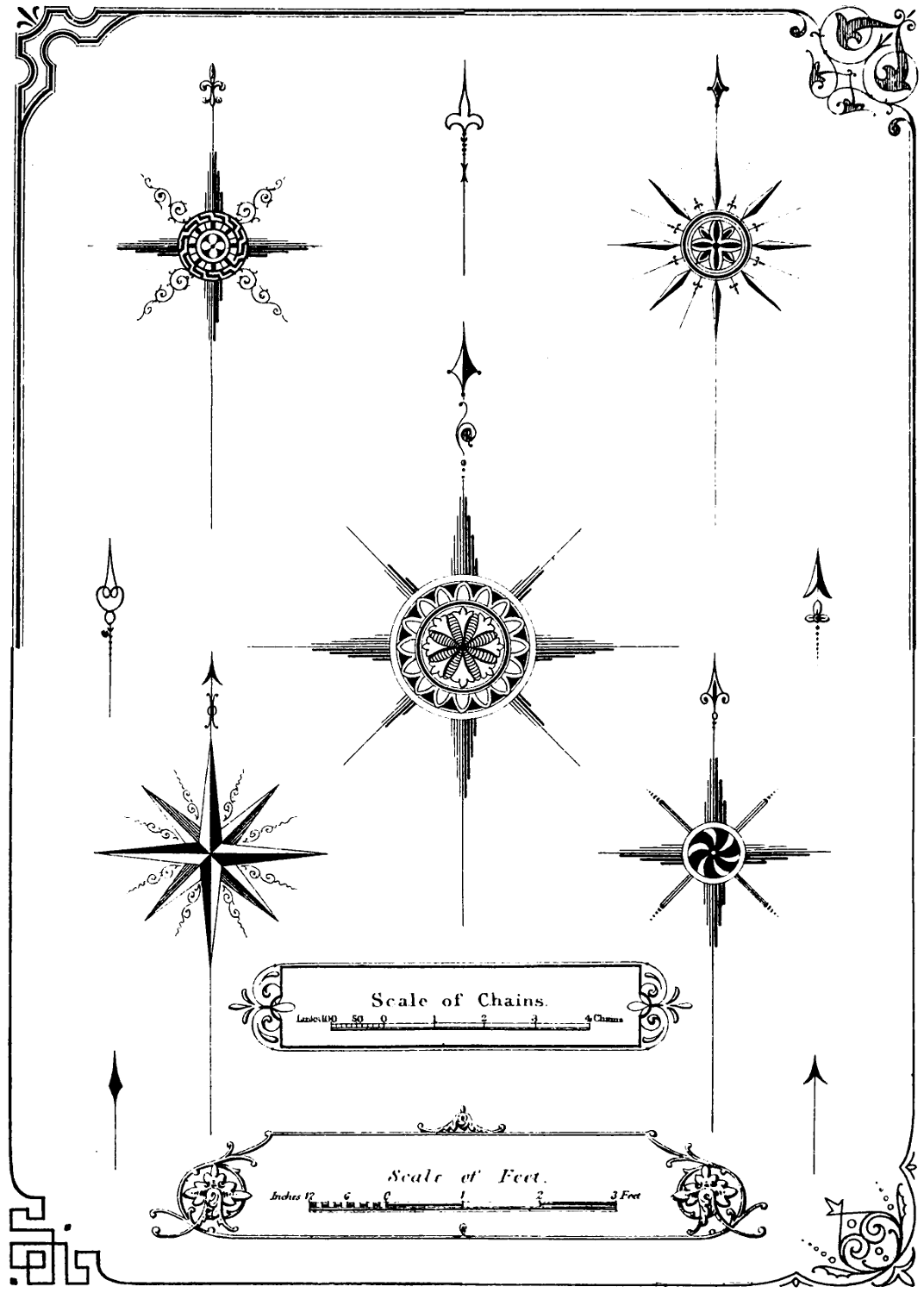
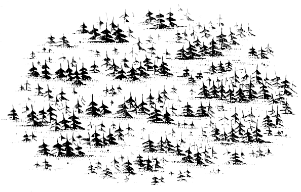
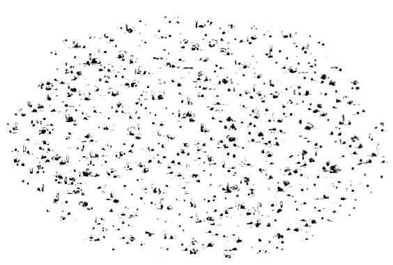
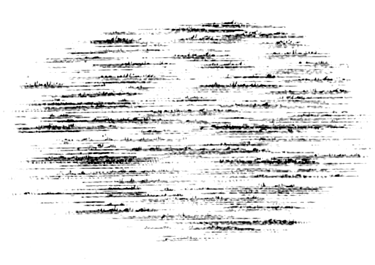
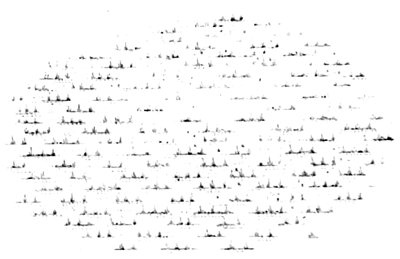
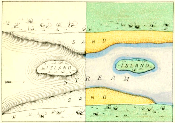
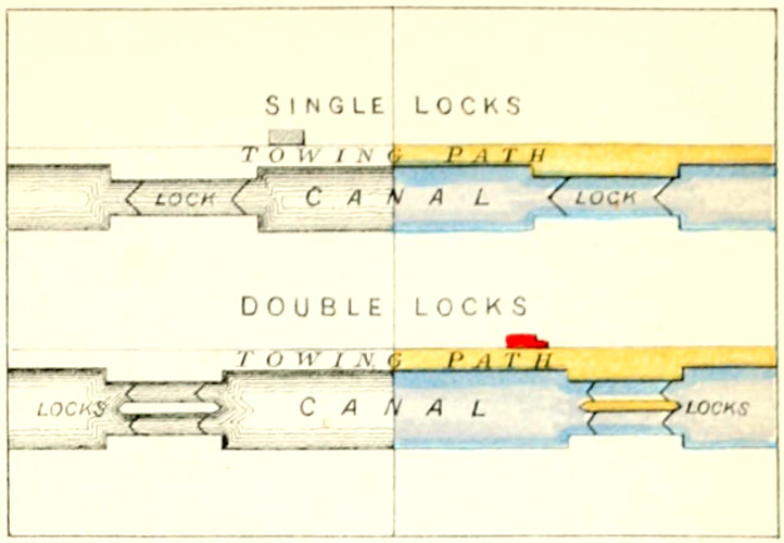
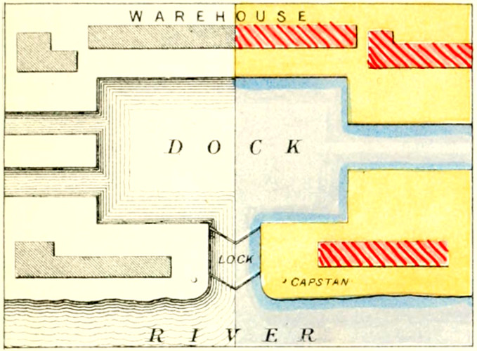
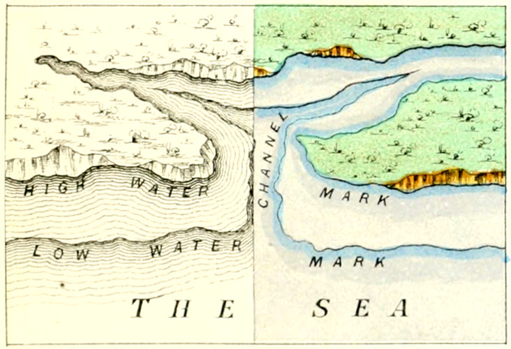
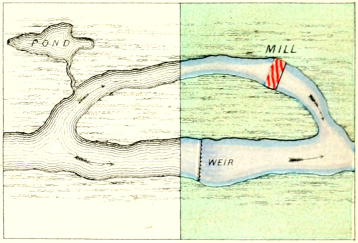
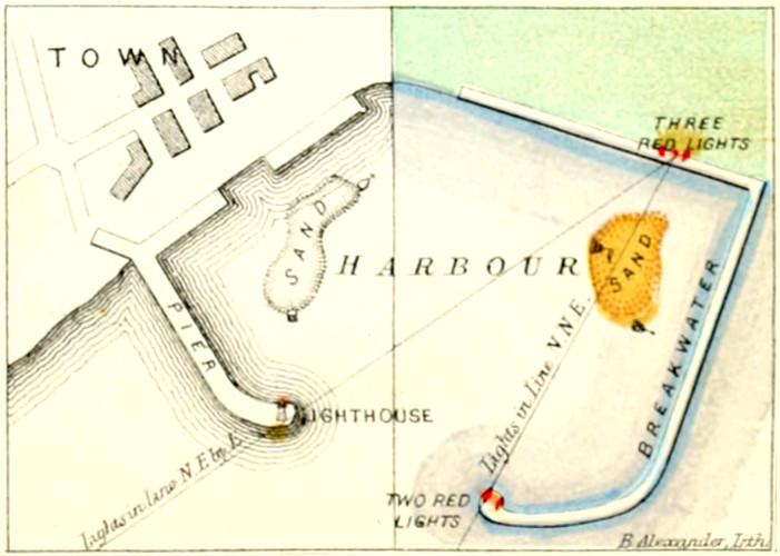
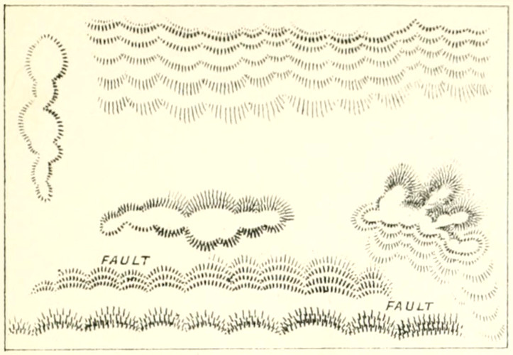
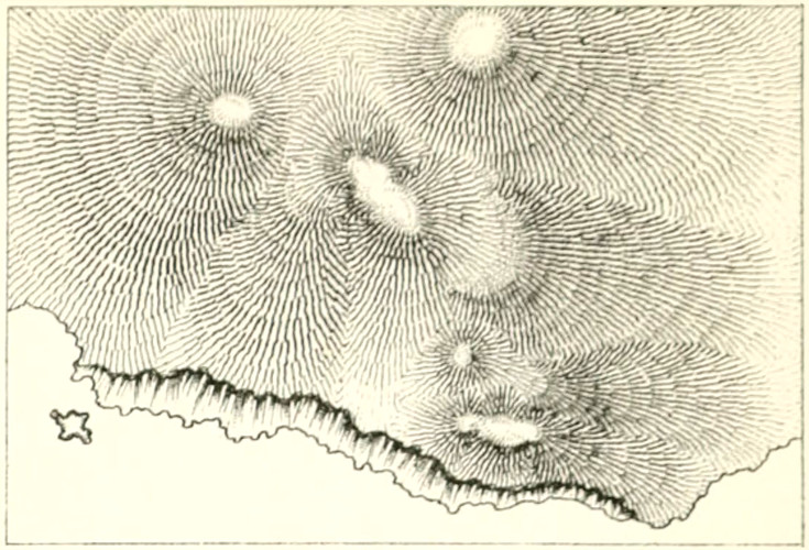
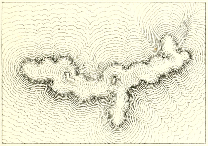
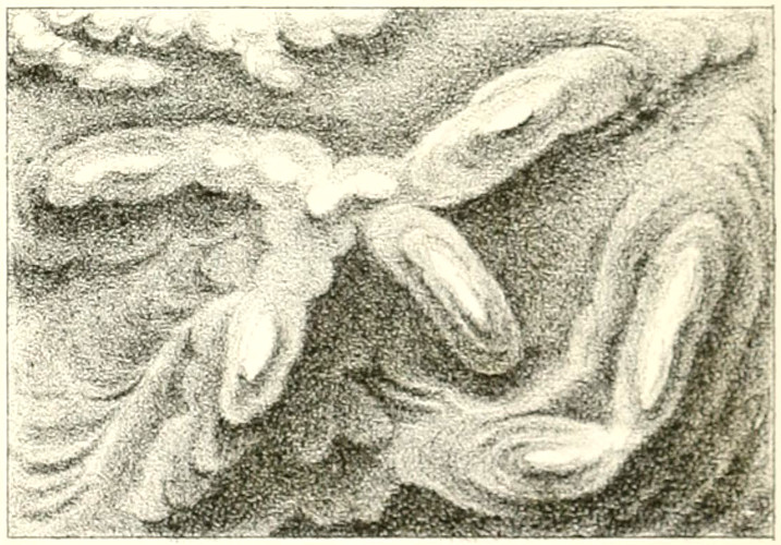
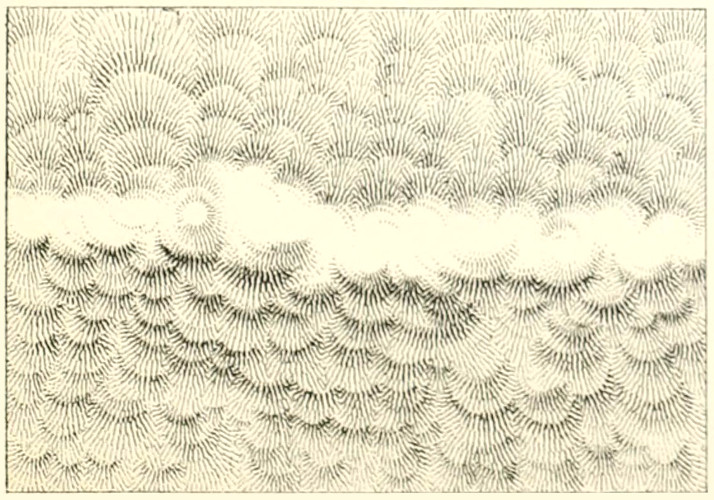
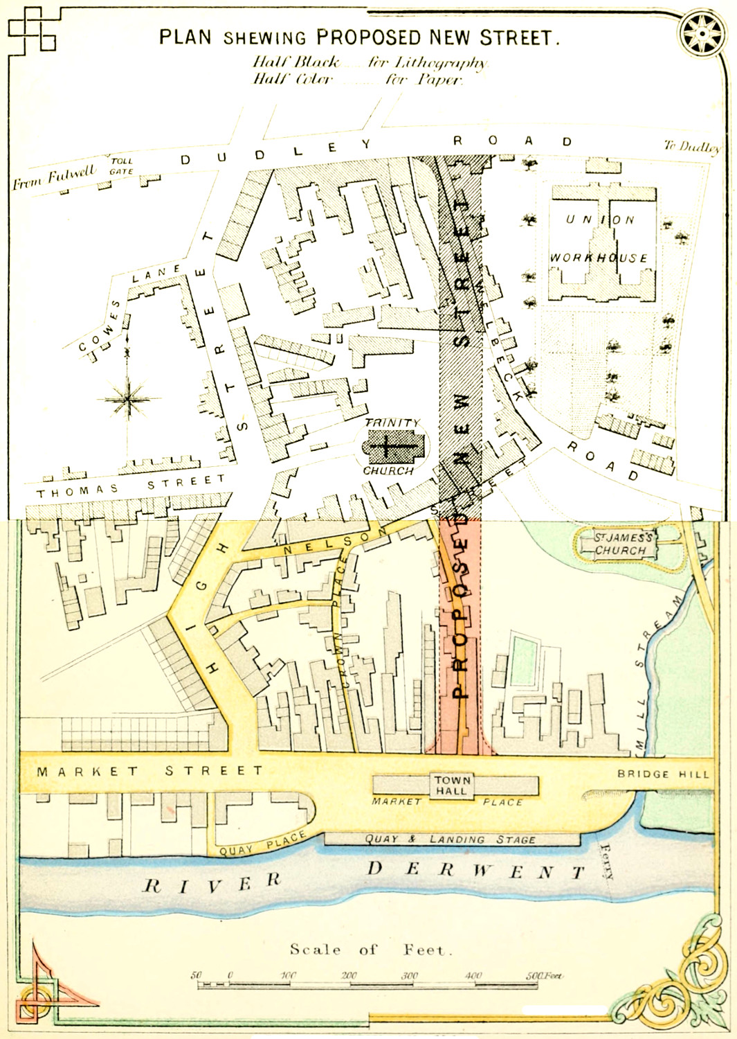
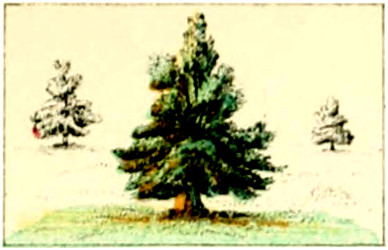
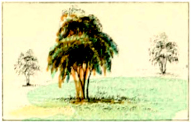
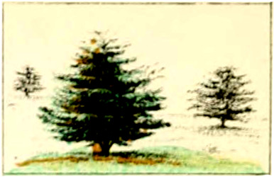
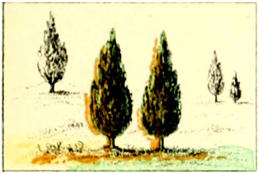
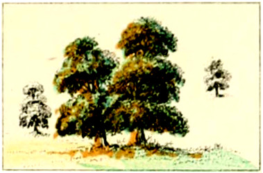
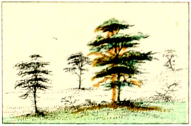
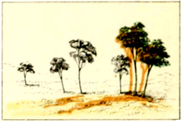
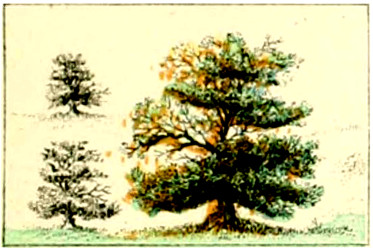
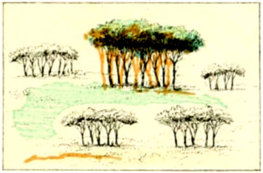
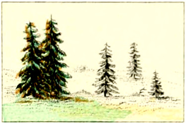
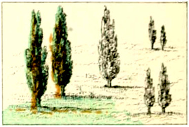
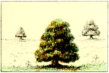
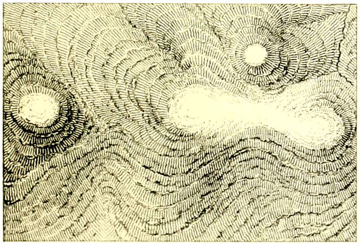
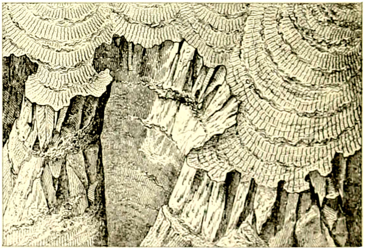
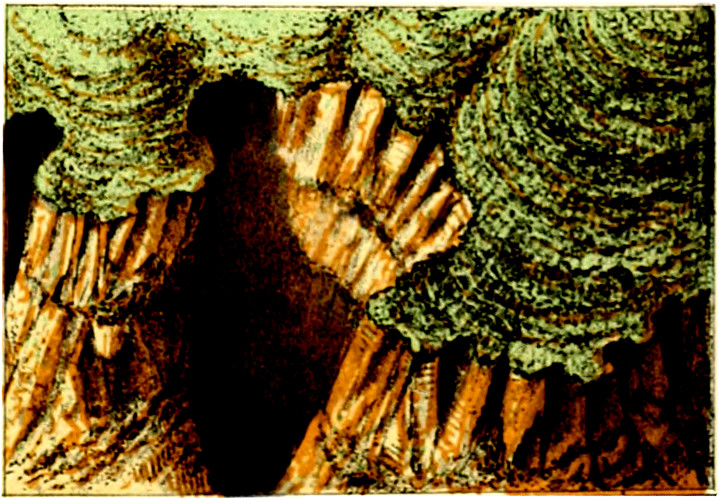
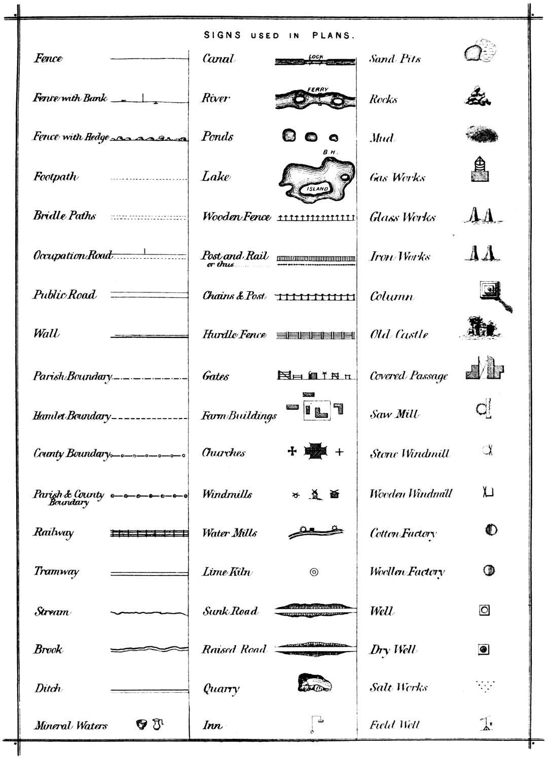
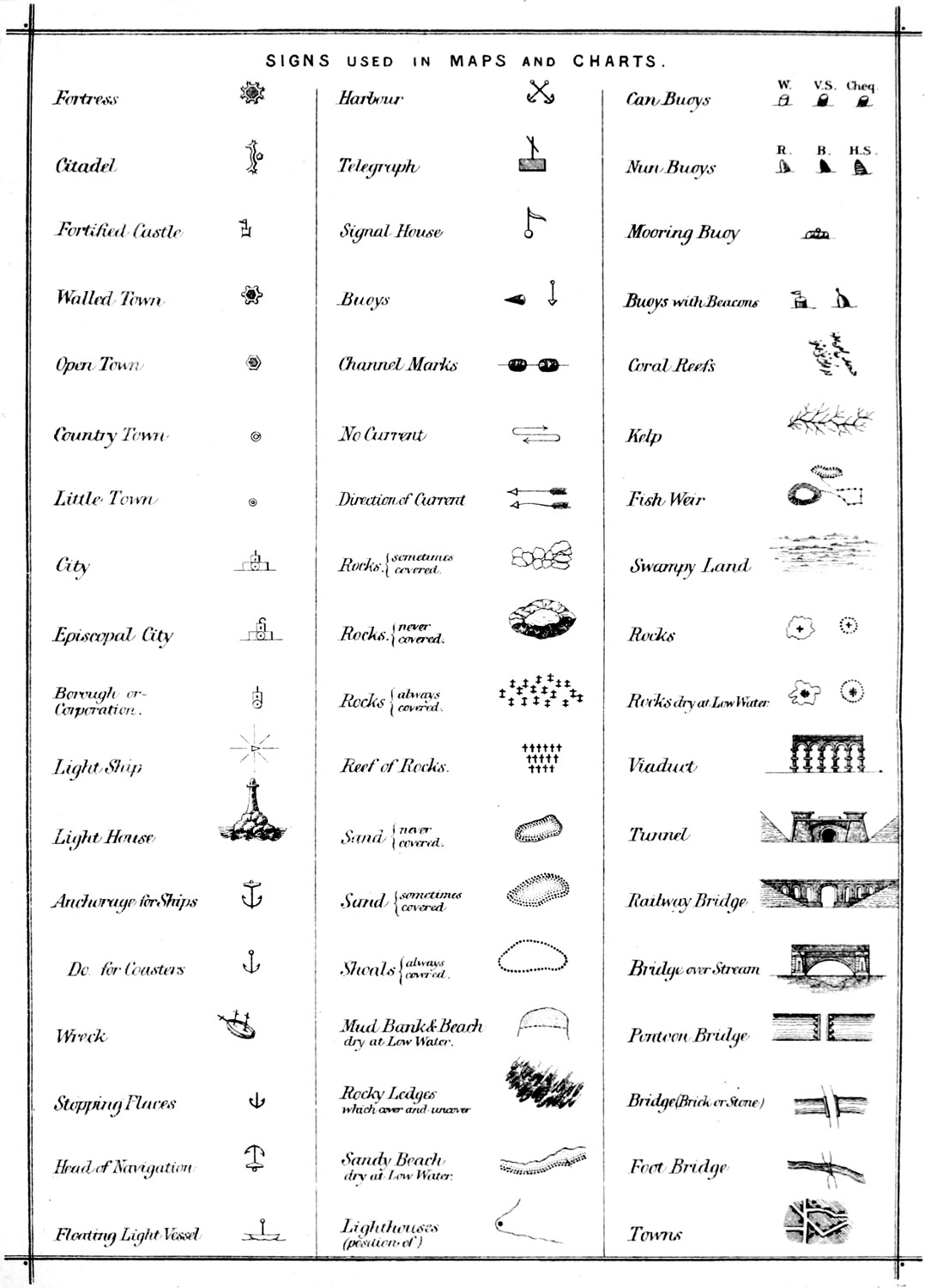
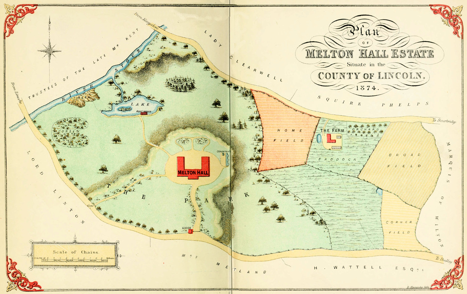
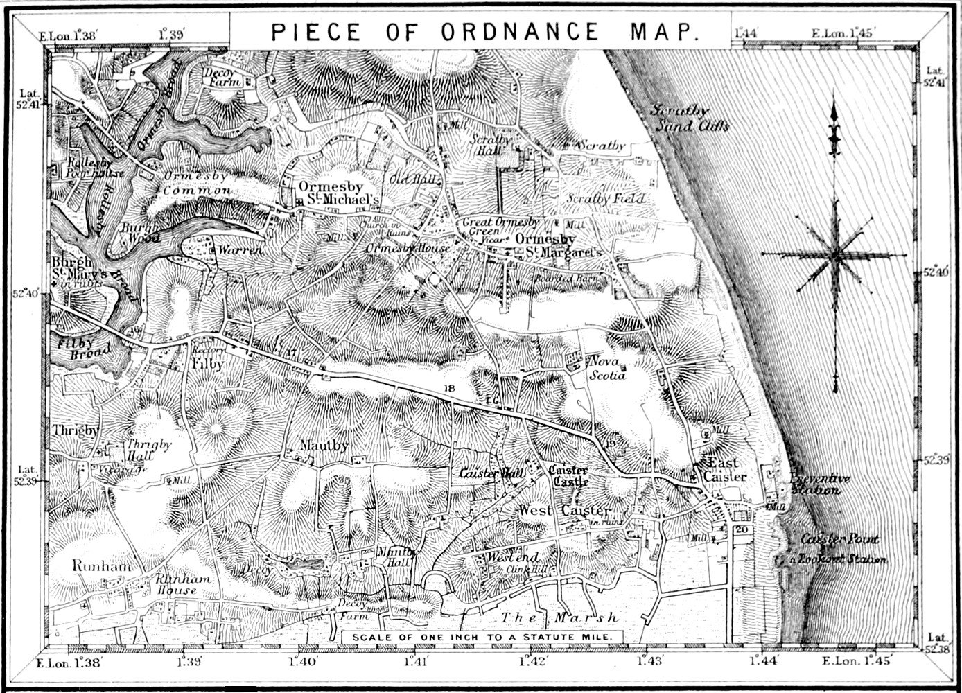
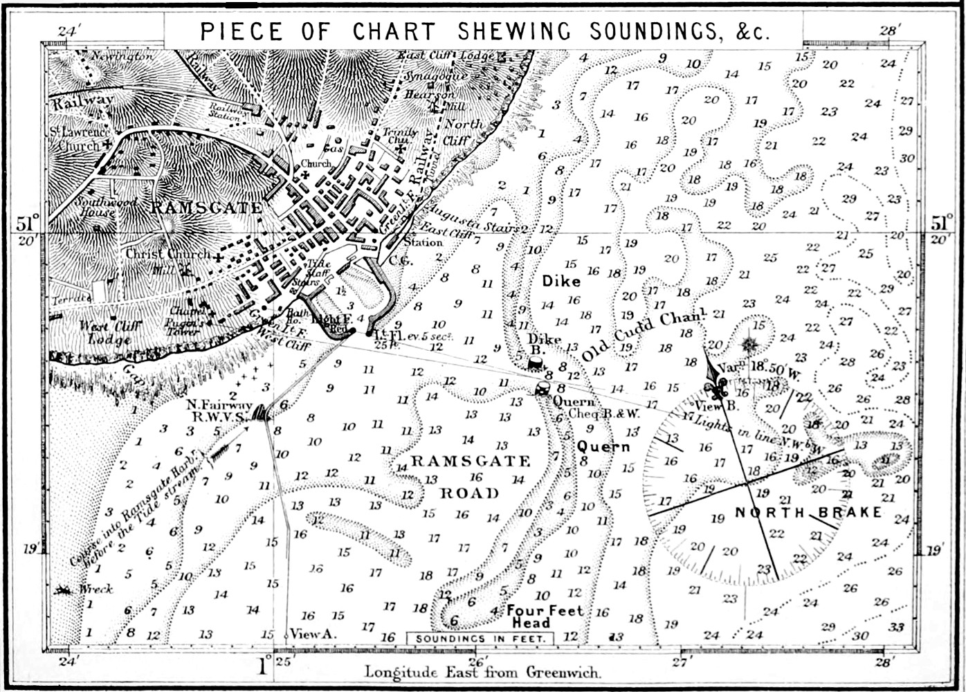
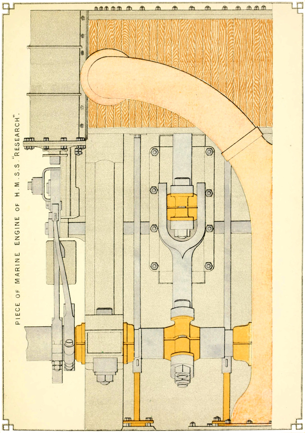
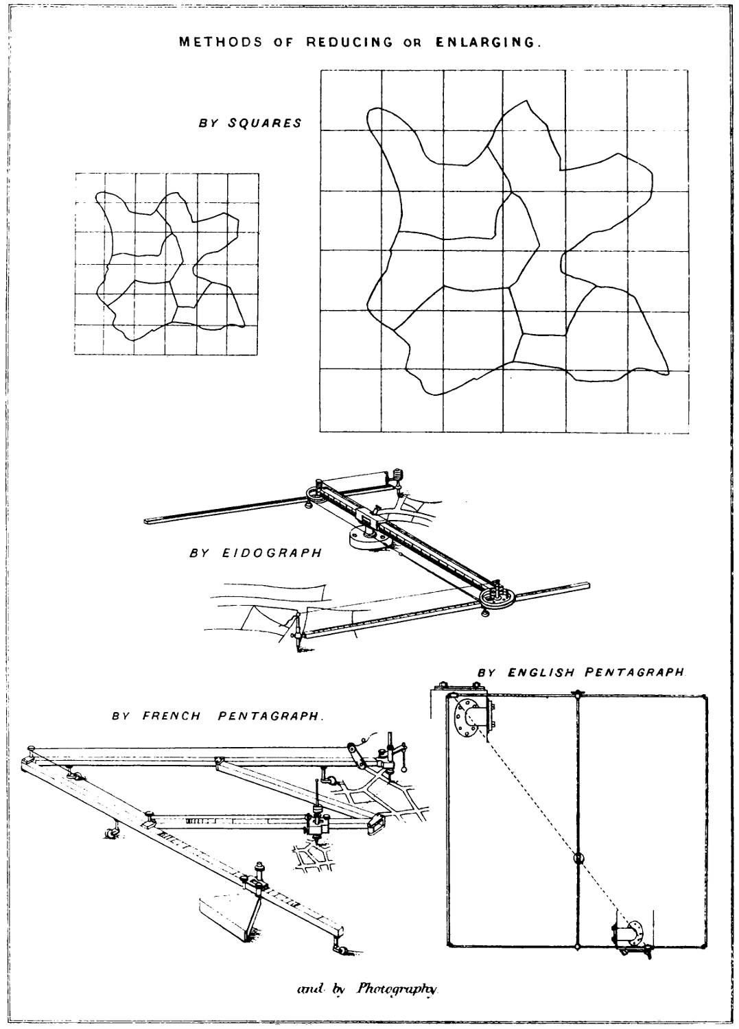
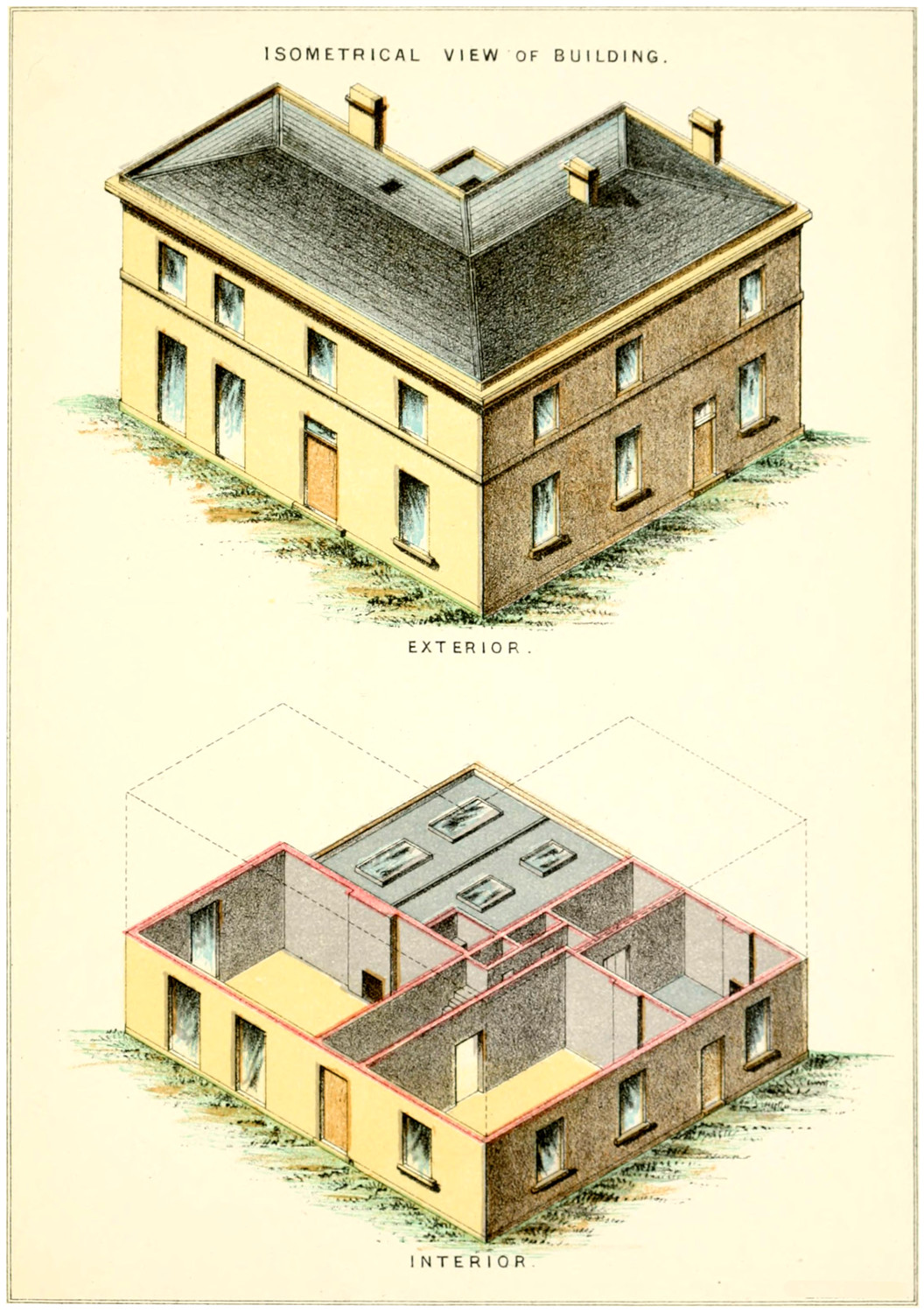
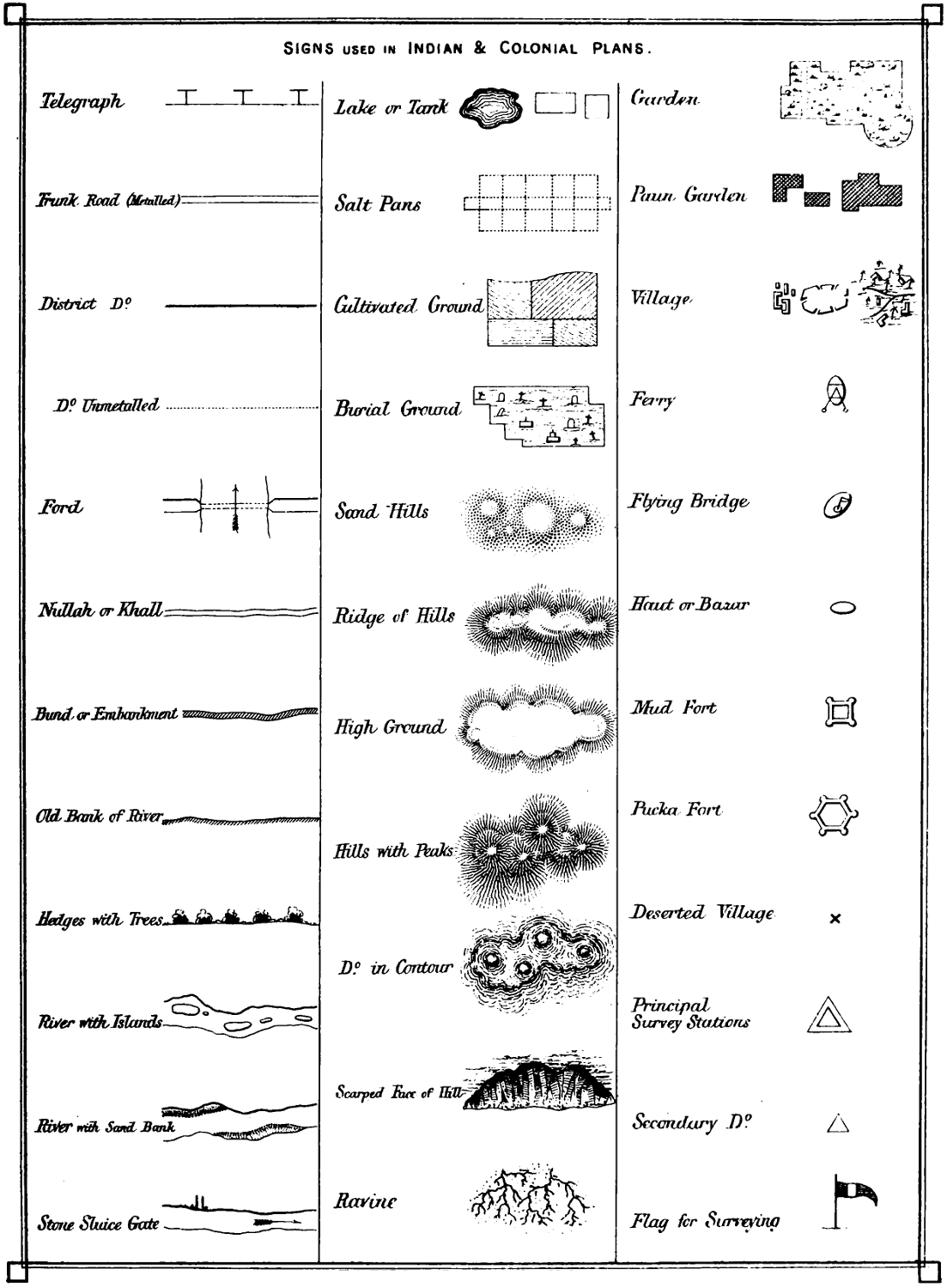
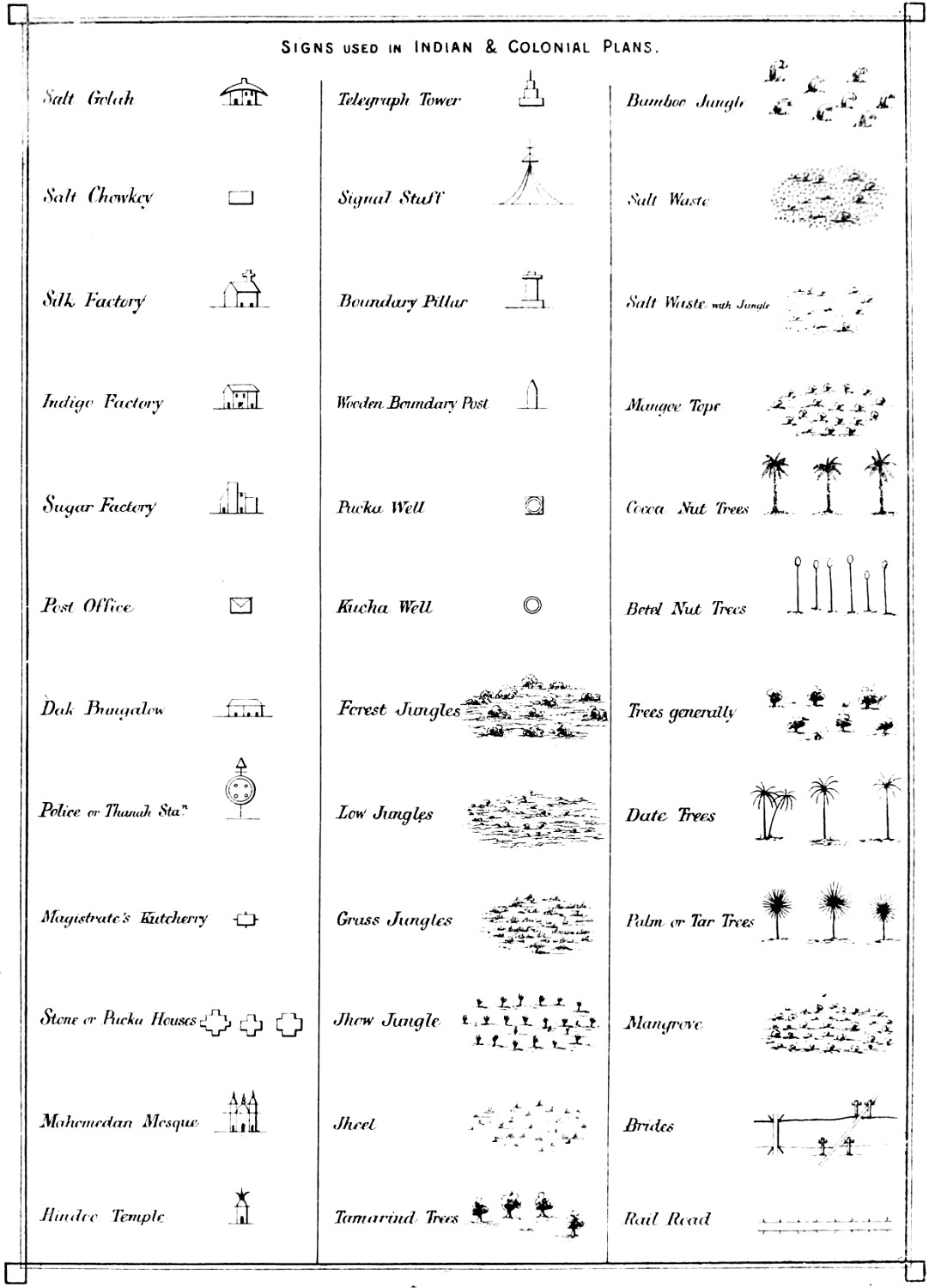
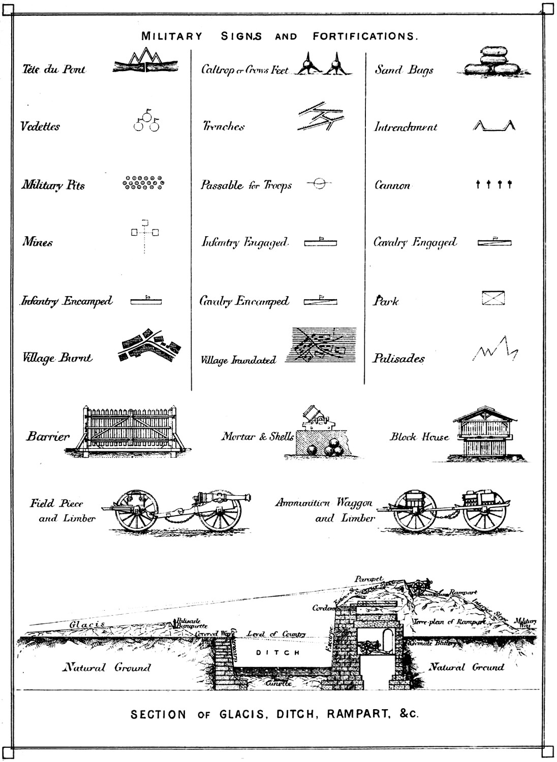
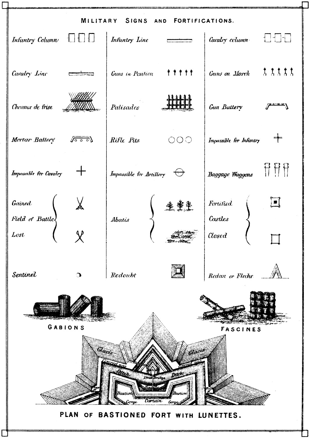
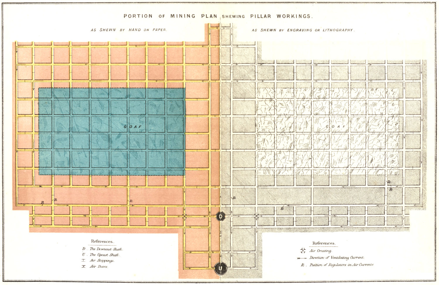