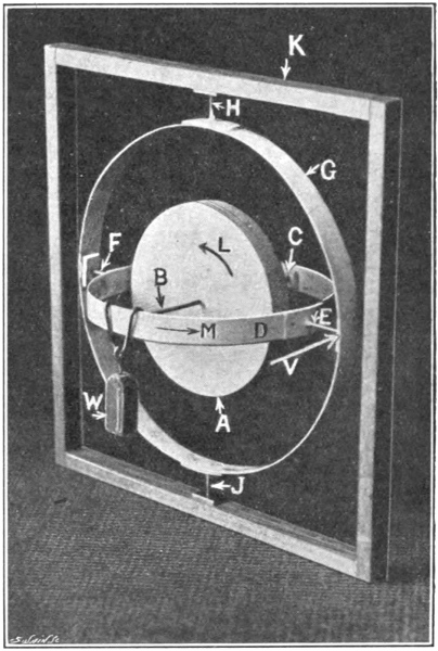
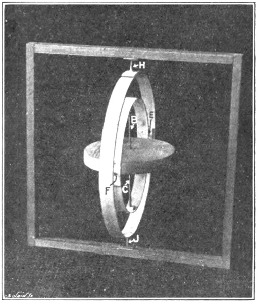
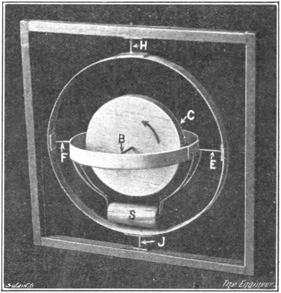
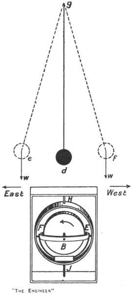
Fig. 1. Model Gyroscope, with Three Degrees of Freedom.
The Project Gutenberg EBook of The Gyroscopic Compass, by T. W. Chalmers

This eBook is for the use of anyone anywhere in the United States and most
other parts of the world at no cost and with almost no restrictions
whatsoever.  You may copy it, give it away or re-use it under the terms of
the Project Gutenberg License included with this eBook or online at
www.gutenberg.org.  If you are not located in the United States, you'll have
to check the laws of the country where you are located before using this ebook.


Title: The Gyroscopic Compass

Author: T. W. Chalmers

Release Date: May 22, 2018 [EBook #57200]

Language: English

Character set encoding: UTF-8

*** START OF THIS PROJECT GUTENBERG EBOOK THE GYROSCOPIC COMPASS ***


Produced by deaurider, Charlie Howard, and the Online
Distributed Proofreading Team at http://www.pgdp.net (This
file was produced from images generously made available
by The Internet Archive)
THE ENGINEER SERIES
THE ENGINEER SERIES
THE
GYROSCOPIC COMPASS
A NON-MATHEMATICAL TREATMENT
BY
T. W. CHALMERS, B.Sc., A.M.I.Mech.E.
(On the Editorial Staff of “The Engineer”)
ILLUSTRATED
LONDON
CONSTABLE & COMPANY, LTD.
10 ORANGE STREET, LEICESTER SQUARE. W.C.
1920
v
Printed in Great Britain
The chapters composing this book originally appeared as a series of articles in The Engineer during January, February, and March of the current year. The articles were written in the belief that many readers would welcome a clear and full, non-mathematical exposition of the gyroscopic compass, its theory and practical construction. The gyro-compass represents at once the most involved and abstruse and the most important and valuable of all the practical applications to which the gyroscope, so far, has been put. As a navigational instrument it is now in practically universal use in all the chief war navies of the world, and is to-day being adopted by several important representatives of the mercantile marine. Remarkable figures were shown to the author recently which demonstrated that not only was navigation by the gyro-compass much more accurate than by the magnetic compass, but that the increased accuracy reduced the length of the voyage of a mercantile vessel to an extent that resulted in saving a quantity of fuel the value of which on a single trip would go a considerable way towards meeting the extra first cost of the gyro-compass. Bearing these facts in mind the author from the outset endeavoured not only to dispense with mathematics but to avoid introducing anything except the most familiar physical principles and conceptions, for his object was to explain the mode of action of the gyrovi-compass for the benefit primarily of the navigating officer—naval and mercantile. If some readers should find the treatment in places unduly prolix, the author trusts they will exercise leniency and regard the fault as being caused by the author’s unwillingness to take any risks in expounding a subject, no part of which can be understood incompletely without grave hurt to the understanding of the whole.
T. W. C.
London, May, 1920.
vii
| CHAP. | PAGE | |
| I. | Introduction | 1 |
| II. | Elementary Gyroscopic Phenomena | 4 |
| III. | The Gyroscope and the Rotation of the Earth | 15 |
| IV. | Damping the Vibrations of the Gyro-Compass | 29 |
| V. | The Damping System of the Anschütz (1910) Compass | 42 |
| VI. | The Damping System of the Sperry Compass | 52 |
| VII. | The Damping System of the Brown Compass | 59 |
| VIII. | The Latitude Error | 65 |
| IX. | The North Steaming Error | 71 |
| X. | The Ballistic Deflection | 81 |
| XI. | The Quadrantal Error | 91 |
| XII. | The Elimination of the Quadrantal Error | 107 |
| XIII. | Centrifugal Forces during Quadrantal Rolling | 130 |
| XIV. | The Anschütz (1910) Compass | 138 |
| XV. | The Sperry Compass | 142 |
| XVI. | The Brown Compass | 148 |
| XVII. | The Anschütz (1912) Compass | 154 |
| Index | 165 |
ix
| FIG. | PAGE | |
| 1. | Model gyroscope with three degrees of freedom | 4 |
| 2. | Model gyroscope with three degrees of freedom | 7 |
| 3. | Model gyroscope, frictional transmission of turning moment | 9 |
| 4. | Model gyroscope, one degree of freedom lost | 11 |
| 5. | Model gyroscope, second degree of freedom lost | 12 |
| 6. | Model gyroscope, lost degrees of freedom restored | 13 |
| 7. | Elementary gyroscope at equator | 15 |
| 8. | Gyroscopic clock | 16 |
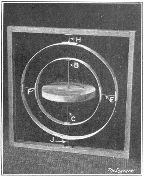
| 9. | Elementary gyro-compass | 18 |
| 10. | Elementary compass at equator | 20 |
| 11. | Elementary compass at 55 deg. N. Lat. | 24 |
| 12. | Compass at equator and near North Pole | 26 |
| 13. | Pendulum and compass | 32 |
| 14. | Damped and undamped vibrations | 35 |
| 15. | Damped pendulum | 37 |
| 16. | Air-blast damping system of Anschütz (1910) compass | 43 |
| 17. | Free and damped motion of axle | 49 |
| 18. | Damping curve from Anschütz (1910) compass | 50 |
| 19. | Damping system of Sperry compass | 53 |
| 20. | Action of excentric pin in Sperry compass | 55 |
| 21. | Action of excentric pin in Sperry compass | 57 |
| 22. | Gyro-pendulum with axle tilted | 60 |
| 23. | Damping system of Brown compass | 62 |
| 24. | The north steaming error at 0 deg. and 60 deg. N. | 72 |
| 25. | Sperry correction mechanism for latitude and north steaming errors | 76 |
| 26. | Ballistic force on compass when ship’s speed changes | 83x |
| 27. | Ballistic force on compass when ship’s speed changes | 84 |
| 28. | Ballistic deflection | 86 |
| 29. | Effect of rolling on due north course | 93 |
| 30. | Effect of rolling on due west course | 94 |
| 31. | External gimbal mounting | 97 |
| 32. | Effect of rolling on a due north course (simple mounting) | 98 |
| 33. | Effect of rolling on a due north course (external gimbal mounting) | 99 |
| 34. | Ship rolling on N.W. course | 101 |
| 35. | Sperry compass on N.W. course | 108 |
| 36. | Sperry ballistic gyro | 111 |
| 37. | Stabilised excentric pin (Sperry compass) | 112 |
| 38. | Diagram of Brown compass | 113 |
| 39. | Oil control bottles (Brown compass) | 115 |
| 40. | Brown compass on west course | 117 |
| 41. | Diagram of Anschütz (1912) compass | 121 |
| 42. | Plans of gyros (Anschütz compass) | 122 |
| 43. | Centrifugal forces on a pendulum | 131 |
| 44. | The Anschütz (1910) compass | 139 |
| 45. | The Sperry compass removed from binnacle | 143 |
| 46. | The Sperry compass | 144 |
| 47. | The Brown compass removed from binnacle | 148 |
| 48. | The Brown compass removed from binnacle | 149 |
| 49. | The Brown compass | 150 |
| 50. | Plan of Anschütz (1912) compass | 155 |
| 51. | Sectional elevation of Anschütz (1912) compass | 159 |
1
At this date it is, or should be, unnecessary to open an account of the gyroscopic compass with a discussion of the defects of the ordinary magnetic compass. These defects are too well known to require mention. Recent advances in naval architecture, particularly in warship construction, and very especially the building of submarines, have resulted in the magnetic compass becoming less and less useful for accurate navigation, primarily because of the upsetting influence exercised upon it by masses of steel or iron in its neighbourhood. It may still serve, perhaps, for the surface navigation of submarines, but for submerged runs the use of a gyro-compass is all but essential. In warships the weight of the guns and turrets is now so heavy that the magnetic compass can hardly remain unaffected by them and is materially influenced when the guns are trained to different directions. The shells themselves as they are discharged are also said to be a cause of error in the reading of the magnetic compass, for they tend in most positions of the ship to drag the needle after them by magnetic attraction as they pass along the bore of the gun.
The value of the gyro-compass is not, however, recognised2 only in the world’s war navies. It is becoming increasingly appreciated in the mercantile marine, and there can be but little doubt that the device will soon be extensively employed on passenger liners and merchantmen generally. In the following pages we attempt to give an account of the working of the gyro-compass and to describe the forms assumed by the device in practice—sufficiently fully to illustrate the theory without going into any great detail on the constructional side—and to do so without depending upon the reader’s possessing mathematical knowledge.
It is to be remarked that it is much easier to treat the gyroscope and all its practical applications mathematically than non-mathematically, and that the avoidance of mathematics generally leads to a discussion of this essentially mathematical device which is unscientific, unsound, and of very little practical value. We trust that our account will be found to avoid these defects and that it will prove useful and enlightening to those who have so far failed to understand the behaviour of the gyroscope and its applications by reason of the fact that hitherto all trustworthy descriptions have been couched in a highly mathematical form or have been mere mathematics thinly disguised in written words. It is admittedly not easy to understand gyroscopic phenomena either with or without the aid of mathematics, but on the other hand many of the difficulties of the subject are largely artificial. Thus the mathematician, when dealing with it, seems to be much more concerned with his equations than in creating a mental picture of what they represent; yet every one of his equations can be or should be capable of being represented physically. Those who set out to avoid mathematics do not usually succeed in giving a discussion sufficiently complete to be of any practical service afterwards to their readers. Thus in dealing with3 the gyro-compass the so-called “popular” description in most cases begins and ends with an explanation of why the device possesses directive force when it is set up at the equator. It is quite easy to demonstrate the existence of such force at the equator. It is not so easy to show non-mathematically how the directive force is generated and applied when the compass is situated north or south of the equator. The necessity for damping the horizontal vibrations of the gyro-axle and how the required damping force is applied in practice are still more difficult to explain, while the errors to which the gyro-compass is open—such as the latitude and the quadrantal errors—are even more trying to make clear. The latter subjects are usually neglected in the “popular” account of the compass. Yet without some means of damping the vibrations referred to or of eliminating or allowing for the various errors, the compass, even though it can be shown to possess directive force in all latitudes, would be utterly useless—especially on board ship—as a direction indicator.
Finally, it may be remarked that while the gyro-compass represents to-day probably the most intricate and involved practical application of the gyroscope, it is not the only one of importance. This fact is to our advantage, for if we succeed in explaining the theory and working of the gyro-compass we shall have succeeded in placing the reader in a position enabling him readily to understand all other devices in which a gyroscope is employed or in which gyroscopic phenomena are developed.
4
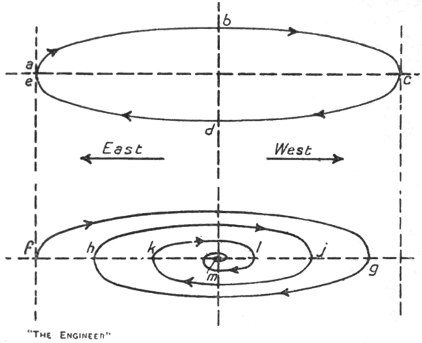
Let a wheel A (Fig. 1) be mounted on an axle B C journalled within a horizontal ring D. Let this ring in turn be mounted on journals E F within a vertical ring G and,5 further, let this vertical ring be carried on journals H J within a vertical frame K. This arrangement constitutes a gyroscopic system having three degrees of freedom, because relatively to the frame K the wheel may turn about three axes B C, E F, and H J mutually at right angles to each other and because, if the wheel is set spinning on its axle, gyroscopic properties will be manifested.
The following is a brief statement of the gyroscopic properties manifested when the wheel is spun on its axle:
(a) Let the wheel be spinning in the direction of the arrow L and let a weight W be hung on the horizontal ring at the end B of the axle. The movement produced by this weight is not a rotation of the horizontal ring, and the wheel within it, about the axis E F. Instead, the horizontal ring remains horizontal and the whole system inside the square frame sets off rotating at a uniform speed about the axis H J in the direction of the arrow marked M on the horizontal ring. This rotation or precession, as it is called, will be maintained so long as the weight W remains in action. There is here no question of perpetual motion. The work expended in overcoming the friction at the vertical journals is derived from the energy of the spinning wheel, and when this energy is exhausted the phenomenon ceases. The phenomenon can, in fact, only be maintained indefinitely by expending power to drive the wheel against the leakage of energy through friction at the journals of the axle and the vertical axis H J. A closer examination of the phenomenon would show that there is a slight rocking motion of the horizontal ring on its axis E F, and therefore an additional leakage of energy at the journals of this axis. This rocking motion can be neglected for our present purposes. It is sufficiently accurate to say that the horizontal ring remains horizontal.
(b) The speed of the precession is proportional to the6 weight W and to the speed of rotation of the wheel on its axle. For instance, doubling the weight doubles the speed of precession.
(c) If the direction of spin of the wheel is reversed the direction of the precession is also reversed.
(d) If the spin of the wheel is in the direction L, and if instead of attaching a weight at the end B of the axle we exert an upward force at this point the precession developed will be opposed to the direction of the arrow M.
(e) If instead of trying to rotate the wheel about the axis E F by means of a weight or force applied at B we attempt to turn it about the vertical axis H J by applying a horizontal force V to the outer ring, the wheel will not turn about the vertical axis H J, but about the horizontal axis E F, the end B of the axle rising up towards H.
(f) As before, the direction of this movement is reversed by reversing either the direction of spin of the wheel or action of the force V. If both are reversed simultaneously the direction of the movement produced by the applied force is not altered.
The behaviour set forth above can be summarised in a general rule as follows:—If to a spinning wheel possessing three degrees of freedom a force be applied tending to turn the wheel about some axis X X, the actual motion produced will not be about X X but about some other axis Y Y; this axis Y Y will be such that rotation about it will tend to bring the axle of the spinning wheel into coincidence with or parallel with the axis X X; the direction of the rotation produced about Y Y will be such that when the condition of coincidence or parallelism is reached the spin of the wheel will coincide in direction with the rotation we are attempting to produce about the axis X X.
Taking case (a) (Fig. 1), it will be seen that the axis E F about which we are attempting to produce rotation by7 means of the weight W, together with the weight W itself, is of necessity carried round by the precession in the direction M at the same rate as the axle of the spinning wheel. The axle in this case cannot therefore place itself in coincidence with the axis of the applied force. But it does its best to do so. The precession persists and is an expression of the fruitless chase of the axis E F by the axle B C.
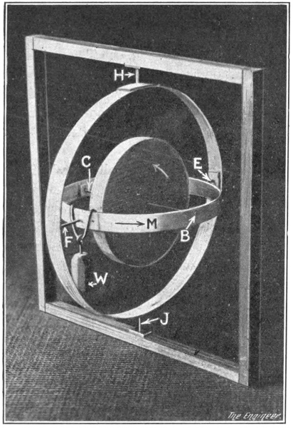
If, however, the weight is attached by some kind of sliding connection on the horizontal ring in such a way8 that its line of action remains stationary in space, then the axis about which we are attempting to produce rotation will also remain stationary in the position occupied by the axis E F before precession commences. In this case it is quite possible for the axle of the wheel to place itself in coincidence with the axis of the applied force. Precession about H J through 90 deg. will accomplish this result, as indicated in Fig. 2. The weight W is now acting at a point on the horizontal ring where it ceases to have any tendency to turn the wheel about the axis E F. When, therefore, the position of coincidence is reached precession ceases and the system comes to rest in this position.
If the experiment were actually made it would be found that the momentum acquired by the system during the 90 deg. turn would carry the axle through the position of coincidence with the axis of the applied force. But immediately the axle passes to the opposite side the force W is exerted on a point of the horizontal ring between F and C. The action of the force passing on to this, the opposite, segment of the ring reverses the conditions under which the system started its movement and as a result precession in the direction opposed to the arrow M is set up. The axle thus tends to recover its position of coincidence and in the end settles down to a vibratory motion from side to side of the axis of the applied weight. Friction at the vertical journals will “damp” this vibratory motion, the amplitudes of the swings will decrease, and the axle will ultimately settle in steady coincidence with the axis of the applied force. In this condition the force will have no further effect on the system beyond throwing a bending moment on to the vertical axis.
9
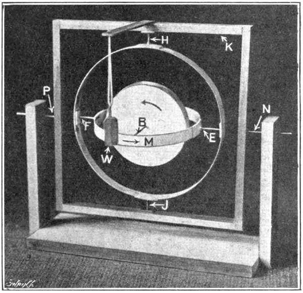
Instead of trying to make the wheel rotate about the axis E F by applying a weight to the inner ring as in Fig. 1, let us, as shown in Fig. 3, mount the square frame K on a horizontal axis N P and attach the weight W to an arm fixed on the frame. The axes N P and E F being—at least initially—collinear, the effect of this arrangement is to throw a turning moment on to the wheel about the axis E F just as does the weight W in Fig. 1. It is to be noticed, however, that the moment of the weight W in Fig. 3 about the axis N P is transmitted to the inner ring as a moment about the axis E F solely because of the friction existing at the journals of the axis E F. This friction may be very small, so that the turning moment received by the wheel is only a very small fraction of the turning moment exerted by the weight W about N P. The effect of the arrangement is thus exactly the same as would be produced in the arrangement10 Fig. 1 if we reduced the weight W to a hundredth or a thousandth of its value. In other words, precession about the vertical axis H J will set in in the direction of the arrow M just as before, but the speed of this precession will be only a hundredth or a thousandth of the previous value.
It is not very important to trace out the behaviour of the system shown in Fig. 3 beyond a very brief period immediately after the weight W is applied. The point of importance is that the precession produced by the weight is very slow, and therefore that in a given interval of time the amount precessed is very small. Further, the rate of the precession depends solely upon the friction at the journals of the axis E F and not upon the weight W or the movement of the frame K except in so far as these factors affect the friction. The less the friction the less will be the rate of precession and the amount precessed in a given time. Thus by mounting the axis E F on knife edges the friction can be made so small that the precession produced by the weight W becomes immeasurable. Hence we deduce that if friction is substantially absent at the axis E F the frame K might be violently rocked on the axis N P or even set into continuous rotation without causing the axle of the wheel either to dip or to precess.
Continuing the argument, we might mount the square frame on a vertical axis and attempt to produce rotation of the wheel about the axis H J by applying a horizontal force to one side of the square frame instead of a force V on the outer ring as shown in Fig. 1. A similar result would be obtained. Granted an all but total absence of friction at the journals of the vertical axis H J, the precession produced about the horizontal axis E F would be immeasurably small. Thus the frame might be set into violent motion about its vertical axis11 without causing the axle either to rotate in a horizontal plane or to precess in a vertical one.
Finally, if the square frame were mounted on a horizontal axis collinear with the axle B C it might obviously be rotated about this axis without affecting the system otherwise than by increasing or reducing the rubbing speed of the axle B C in its bearings.
Since pure translation of the frame in any direction cannot apply a turning moment to the system about any axis, and as rotation of the frame about any one of the three principal axes has no effect which is measurable on the orientation of the axle, it follows that, given substantial absence of friction at the axes E F and H J, the axle of the wheel will remain constantly pointing12 parallel with its original position, no matter how the frame K may be moved or turned about.
The gyroscopic system shown in Fig. 1 has, as we have said, “three degrees of freedom,” because its wheel is free to spin about three different axes mutually at right angles. It is to be carefully noted that it can only truly be said to have three degrees of freedom so long as the inner ring and the parts inside it are not rotated on the axis E F away from the position which in Fig. 1 they are shown as occupying relatively to the outer ring. Thus rotation of the wheel on its axle or of the whole system inside the square frame on the axis H J leaves the three axes B C, E F, H J undisturbed at right angles to each other. But rotation of the inner ring and the parts inside it on13 the axis E F tends to destroy one of the degrees of freedom. If, for instance, the inner ring is rotated through 90 deg., as shown in Fig. 4, the axle B C and the axis H J will coincide in direction. In this position the wheel cannot be rotated about a horizontal axis at right angles to E F and has therefore virtually only two degrees of freedom, namely, about the axis E F and about the axis H B C J. Again, if with the inner ring in the position shown in Fig. 4 the outer ring is turned through 90 deg. relatively to the square frame, the system assumes the configuration shown in Fig. 5 and the wheel loses the power of rotating about a horizontal axis in the plane of the square frame.
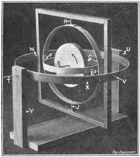
If, then, in any application of the gyroscope it is necessary to guarantee that the system shall have three14 degrees of freedom in all possible configurations, the simple mounting shown in Fig. 1 will not serve the purpose. It can be made to do so in the manner shown in Fig. 6, namely, by mounting the square frame inside a gimbal ring X, which in turn is supported by a frame Y, the two new axes T U and V W being at right angles to each other. In the position shown in Fig. 4 the new axis T U would restore the lost third degree of freedom, while the second new axis V W would restore the degree of freedom lost when the system assumed the configuration shown in Fig. 5.
In the gyro-compass it is necessary to guarantee that the spinning wheel in all possible configurations shall have three degrees of freedom, and accordingly we find the wheel mounted in a manner reproducing the features of Fig. 6. On the other hand, the majority of the movements which the compass system is called upon to make do not entail anything except very small degrees of rotation of the inner ring and wheel about the axis E F (Fig. 1), and therefore for most purposes the simple mounting there shown reproduces the required three degrees of freedom sufficiently closely to permit us to use it for demonstration purposes. In one very important portion of our subsequent discussion, however—namely, that dealing with the effect on a marine gyro-compass produced by rolling and pitching of the vessel—it will be necessary for us to take cognisance of the fact that the square frame shown in Fig. 1 is not fixed directly to the ship’s deck, but is really carried in gimbals as shown in Fig. 6.
15
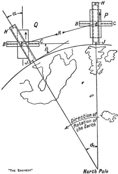
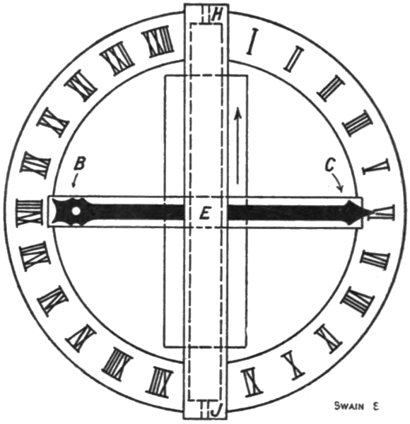
Let us now suppose that the gyroscopic system shown in Fig. 1—without the weight W—is placed on the equator as represented at P (Fig. 7), and that the axle is set pointing16 due east and west as at B C. At the end of an interval of time, say two hours, the earth will have rotated through some angle α, say 30 deg., and will have carried the gyroscope with it to the position Q. The square frame has thus clearly been inclined relatively to its original position. It has, in fact, suffered the exact equivalent of a direct translation R together with a pure rotation about a horizontal axis through E of amount α. The translation leaves the system unaffected, but the rotation of the frame results in the frame moving relatively to the axle, wheel, and inner ring. The axle, in fact, remains parallel with its original position at P. It is still pointing east and west, but the frame is now inclined to it and, relatively to the horizontal surface of the earth at Q, the axle is dipping at an angle β which is equal to α—17or 30 deg. Actually, if we fixed a disc to the square frame and a hand to the inner ring, as indicated in Fig. 8, the system as erected at the equator would form a twenty-four hour clock indicating strictly accurate sidereal time as distinct from mean solar time. To an observer on the earth the hand would appear to travel clockwise round the disc once in twenty-four hours. Actually, however, the hand would not rotate, but would remain constantly parallel with its original position, while the disc would travel anti-clockwise relatively to the hand and would make one complete turn in twenty-four hours. The hand would remain parallel with its original position by virtue of the fact already stated, namely, that the force applied to the inner ring through its all-but-frictionless supports is very small, and in any event does not turn the hand clockwise, but causes the wheel, inner ring, and hand to precess about the vertical axis H J. The rate at which this precession took place would be a measure of the success with which we had eliminated friction at the horizontal axis E F.
It might be thought that the system would without further addition serve as a compass, for if it maintains its axle constantly pointing in one direction it is just as good as a compass which always points its needle towards the magnetic north. In the magnetic compass, however, the needle has a directive force applied to it which enables it to recover its standard direction if it should be accidentally deflected from it. In the gyroscopic system we have been considering there is no such directive force. The axle will remain pointing in one direction, it is true, but the system is indifferent as to what that direction may be. If the axle is accidentally deflected it will remain pointing in the new direction as consistently as it did before in the originally set direction. As a substitute for the18 ordinary compass, then, the success of the device would depend upon the success with which accidental deflecting forces were prevented from acting on the axle after it had been set in a known direction. In practice, as Dr. Anschütz found in his early investigations, it is excessively difficult, if not quite impossible, to construct a gyroscopic system in which the centre of gravity and the centre of suspension are absolutely coincident. As a result a very minute gravity torque is thrown on the system, and in consequence the axle very slowly precesses away from the original set direction. This fact and the complication of parts required to give practical effect to the idea led Dr. Anschütz to abandon his early attempts at providing a compass substitute of the apparently simple nature described above.
An addition to the system of a very simple kind in19 itself not only endows the axle with directive force, but makes the direction which it seeks the north and south one, and thus converts the system into a device possessing the familiar property of the compass. This addition consists of a pendulum-like weight S (Fig. 9), attached below the wheel by a stirrup fixed to the inner ring so that the weight, stirrup, inner ring, axle, and wheel may swing as a whole on the horizontal axis E F.
Let us suppose that the system with this addition is set up at the equator and that the axle this time is aligned at right angles to the equator so that the end B, as shown at I (Fig. 10), points due north. In this condition the inner ring is horizontal and the weight S is vertically below the pendulum axis E F. No turning moment is therefore being applied by gravity to the wheel. If through imperfection of workmanship the centre of suspension of the system is not absolutely coincident with the centre of gravity before the weight S and its stirrup are attached, then the minute gravity torque arising from the lack of coincidence will be balanced automatically by the weight, the inner ring taking up some position minutely inclined to the horizontal. There will thus under all conditions be no resultant turning moment applied by gravity to the system as thus set up. In addition, the axle, lying north and south as it does, is aligned parallel with the earth’s polar diameter. Consequently the rotation of the earth can only move it parallel with its original position, and therefore does not tend to cause relative motion between it and the square frame. We conclude, then, that in this north and south position of the axle the system is not acted upon by any force or influence tending to cause the axle to depart from the north and south position.
20
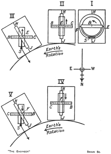
Now let us suppose that the axle by some agency is forced into parallelism with the equator so that the end B points due east as indicated at II (Fig. 10). Immediately after it takes up this position the tendency of the axle to remain parallel with this, its new original, direction becomes manifested in attempted relative motion between the axle, wheel, and inner ring on the one hand and the square frame on the other. Thus as the earth rotates the axle, etc., tend to set themselves relatively to the frame in the position shown at III. In this position, however, the weight S being rigidly suspended from the inner ring, is no longer vertically below the pendulum axis E F. Gravity acting upon the weight therefore21 applies a turning force to the wheel, etc., about the axis E F. The system is thus under the same conditions as those represented in Fig. 1, when the weight W is hung on the inner ring at B. Precession about the vertical axis therefore sets in, in the direction M (Fig. 1), so that the end B of the axle swings round from the east towards the north.
Let us reset the system in position I, and then by some agency cause the axle again to align itself parallel with the equator, this time, however, with the end B pointing due west as shown at IV (Fig. 10). As before, the rotation of the earth combined with the tendency of the axle to remain parallel with the new west and east position results in attempted relative motion between the axle, etc., and the square frame, so that in a little time the system would adopt the configuration shown at V. In this configuration, however, gravity as before applies through the weight S a turning force about the pendulum axis E F. Now, comparing the two configurations III and V, it will be seen that, mere reference letters or similar distinguishing marks being washed out, they are indistinguishable except for one fact: the wheel is rotating in opposite directions. If with the system as arranged in Fig. 1 we reverse the direction of spin of the wheel without reversing the direction of the applied force W, then, as we know already, the direction of the precession will be reversed. Precession about the vertical axis will take place in the direction opposed to the arrow M. Hence in the configuration shown at V (Fig. 10), the precession induced by the action of gravity on the weight S causes the end B of the axle to swing up from due west towards the north.
We are thus led to identify the end B of the axle as the north-seeking end and the end C as the south-seeking. With B pointing due north as at I, there is no force acting22 on the system tending to make the axle depart from the north and south direction. If B is swung over to the east or west—or intermediately, as may be taken for granted—a force is called into play tending to move the end B back towards the north. It follows, therefore, that the resting position of the axle is the north and south one with the end B pointing north.
It may be said, perhaps, that we have neglected to discuss what happens if from the position I the wheel is turned by some agency right round until the end B of the axle points due south. In this condition there is no resultant gravity torque on the pendulum axis, and the axle is lying parallel with the earth’s polar axis, so that the rotation of the earth does not cause relative motion between the wheel, etc., and the frame. Just as in the original configuration I, there is thus in this condition no force applied to the system tending to make the end B swing away from the pole. But as the reader may readily establish for himself by reversing the arrows and reference letters in the five diagrams of Fig. 10, the slightest departure of the end B of the axle from the south-pointing direction towards either side of the meridian will call into play a force which will cause the end B to precess up towards the north. With the wheel spinning in the direction we have shown throughout our illustrations the only stable position of equilibrium for the axle is the north and south with the end B pointing north. It may be pointed out that the magnetic needle can, like the gyro-compass axle, assume a position of unstable equilibrium with the north-seeking end pointing south.
A point of very great practical importance into which to inquire is the magnitude of the directive force, the existence of which, when the axle is deflected from the north and south position, we have just demonstrated.23 This directive force or restoring moment, as will have been gathered from our explanation, increases with the deflection from the north, being a maximum when the axle is lying east and west or west and east. Its magnitude in any position of the axle depends upon (a) the speed of rotation of the earth on its polar axis, (b) the speed of the spinning wheel on its axle, and (c) the mass, or, more correctly, the moment of inertia, of the wheel. The first item is small—0.0007 of a revolution per minute—and is quite beyond our control. The second factor is consequently made as large as possible, while the third is also made large, but a limit is placed to our choice by questions of safety and temperature rise at the high speeds adopted for the spin of the wheel. In the following table we give the values of these factors for three of the types of gyro-compass to be described later.
| Compass | Wheel diam. in. |
Wheel weight lbs. |
Speed r.p.m. |
| Anschütz1 | 6 | 10 | 20,000 |
| Sperry | 12 | 45 | 8,600 |
| Brown | 4 | 4¼ | 15,000 |
The value of the directive force for the same three gyro-compasses and for an ordinary magnetic compass is given in the next table, (1) for the axle—or needle—lying due east and west, and (2) for the axle—or needle—deflected 1 deg. east or west of north—true or magnetic.
Directive Force at Equator.
| Axle (or needle) E. and W. |
Axle (or needle) 1 deg. E. or W. of N. | |||
| Force Grains |
Leverage in. |
Force Grains |
Leverage in. | |
| Anschütz | 145 | 1 | 2 | 1 |
| Sperry. | 1140 | 1 | 20 | 1 |
| Brown | 12 | 1 | ⅕ | 1 |
| Magnetic2 | 40 | 1 | ⅔ | 1 |
24
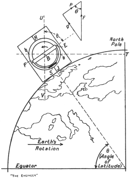
We have now to explain how the gyro-pendulum system manifests its compass-like property when it is transferred from the equator to some degree of latitude north or south. In Fig. 11 we represent the system as set up in the latitude of the British Isles. The axle is horizontal and the end B is pointing due east. In this configuration the earth’s rotation is, through the action of gravity on the pendulum bob S, trying to make the wheel turn round the earth’s polar axis once every twenty-four hours. As before, in accordance with the fundamental property of the gyroscope, the wheel will try to set its axle into coincidence with or parallel with the axis about which it is being forced to rotate. In other25 words, the wheel will endeavour to turn in such a way as to align its axle along V U with the end B towards U. This movement can be effected by a rotation about the vertical axis H J through a right angle combined with a rotation about the horizontal axis E F through an angle θ equal to the latitude of the station at which the system is set up. The rotation about the vertical axis H J does not result in deflecting the weight S away from the plumb line, and therefore can be completely fulfilled. The rotation about the horizontal axis does, however, affect the bob. The axle, having executed the horizontal portion of its movement, is pointing its end B due north, but this end, unlike its behaviour at the equator, manifests a desire to rise vertically so as to align the axle along V U. Its desire to do so is resisted by the bob S, and the axle therefore fails to complete the full movement.
The axle is thus held substantially horizontal with its end B pointing to the north. As the earth rotates the desire of the axle to align itself parallel with the polar axis persists. In attempting continuously to fulfil this desire it acquires a slight upward tilt, which is sufficient to bring the pendulum weight into action. With the weight thus slightly deflected towards the north a moment is applied to the wheel which tends to turn the wheel about the horizontal axis E F in such a way as to bring the end B down again to the horizontal plane. Such a moment, as we know from the fundamental rule of the gyroscope, will actually produce precession about the vertical axis H J, the direction of this precession being such as to cause the end B to move away from the north towards the west.
The fact, then, that the axle is prevented from aligning itself completely parallel with the earth’s polar axis thus apparently results, once it has found the north, in making it wander, in northern latitudes, towards the west. This26 is not so. Once the axle has found the north a steady uniform precession towards the west is required to maintain it on the north. Thus in Fig. 12 let A be the wheel and axle of the compass when it finds the north. If the axle maintained this alignment then some time later it would assume the position shown dotted at D; that is to say, it would be pointing towards east of north. To maintain it on the north it must rotate westwardly through the angle ϕ in the interval between A and D. As this angle ϕ grows with the interval the required rotation is really equivalent to a steady uniform precession towards the west.
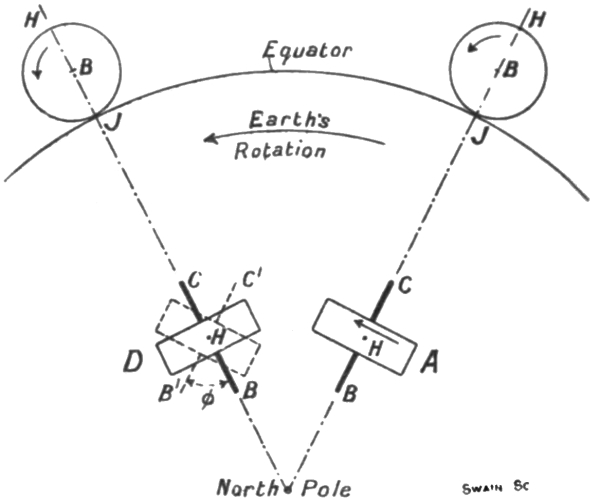
If the compass in Fig. 12 is practically at the north pole it is clear that to hold the end B of the axle on the north the axle has to precess about the vertical axis H J of the compass mounting at the rate of practically one complete revolution per twenty-four hours—that is, 0.0007 revolution per minute. At the equator the27 required rate of precession about H J is zero, for any movement about this axis will carry the axle away from the north. At intermediate latitudes the precession required to hold the axle on the north has an intermediate value. Its value for any latitude θ is, in fact, 0.0007 × sin θ in revolutions per minute.
Thus as the latitude is changed the required rate of precession also changes. So, too, does the angle θ (Fig. 11), by which the axle fails to reach parallelism with the earth’s polar axis, and consequently so does the strength with which the axle desires to reach this alignment. As the equator is left farther and farther behind, then, the axle comes to rest pointing north with a greater and greater upward tilt from the horizontal. The applied moment of the weight S thus increases. It increases just at the rate necessary to give the required rate of westerly precession for the particular latitude in which the compass is at any moment stationed. Should anything prevent the axle from acquiring the tilt appropriate to the latitude, or should the westerly precession on the vertical axis caused by this tilt be opposed and reduced in any way, the axle will fail to keep on the north and will lag behind the meridian with an easterly deviation. We shall see later on that the precession about the vertical axis is in some designs of gyro-compass unavoidably opposed, and that as a consequence these compasses exhibit a latitude error.
We have thus shown that the effort of the compass to set its axle parallel with the earth’s polar axis, combined with the action of gravity on the pendulum weight, is necessary to the compass if the axle once having found the north is to remain on it, and that this effort of the axle increases in strength the farther north—or south—the compass is moved from the equator. What, however, this effort gains in strength as the angle of latitude28 increases the effective directive force on the compass loses. Thus in Fig. 11 the directive force may be represented as at f by a line parallel with the earth’s polar axis. This line represents the magnitude of the compass’s effort to set its axle parallel with the polar axis. The speed of the spinning wheel and its moment of inertia have not been altered by moving the compass away from the equator, nor has the angular speed of the compass round the earth’s axis, for although the compass is moving in a circle of reduced radius T B, and therefore is travelling with less linear velocity than at the equator, it is still making one turn per twenty-four hours round the polar axis of the earth. Thus the three factors fixing the magnitude of the “directive force” are unaltered. The force f is thus the same as that exerted on the compass at the equator. It does not, however, act as before, purely about the vertical axis H J, but partly about H J and partly about the horizontal axis E F. It may be regarded as a force applied at the end B of the axle and therefore as tending to turn the wheel about an imaginary axis a b. We may resolve it into two components p and q, p being at right angles to the axis H J and q at right angles to E F. The component q represents the magnitude of the upwardly tilting effect applied to the axle by the rotation of the earth. The component p represents the effective directive force tending to restore the axle from the deflected position represented towards the north in the horizontal plane. The angle between this effective component and the full force f is θ, the angle of latitude of the station at which the compass is set up. The effective directive force is thus f cos θ, and therefore diminishes from the value f at the equator towards zero as the north—or south—pole is approached.
29
Reviewing what we have already established, we see that a gyroscopic system possessing “three degrees of freedom” and having a pendulum weight fixed below the wheel manifests a tendency in all latitudes to preserve its axle pointing in the north and south direction, a “directive force” or restoring moment being developed and applied to the axle if the north and south position is departed from. The magnitude of the directive force in any given latitude increases with the deflection, from zero when the axle is pointing north and south up to a maximum when it is aligned east and west. At any given angle of deflection of the axle the magnitude of the directive force varies with the latitude in which the system is stationed, being zero at the north or south (true) pole and a maximum at the equator. Finally, at any given angle of deflection of the axle and in any given latitude the magnitude of the directive force is determined by (a) the speed of rotation of the earth on its polar axis, (b) the speed of rotation of the spinning wheel on its axle, and (c) the mass or moment of inertia of the spinning wheel.
We have now to consider several important matters affecting the practical application of the gyroscope-pendulum combination as a substitute for the magnetic compass. The first practical consideration which arises naturally in our minds is the question: Can a system be30 devised and constructed sufficiently robust to withstand the trials and knocks of every-day use and yet be sufficiently delicate to respond to the feeble directive forces on the effect of which its action as a compass depends? From the table given previously it will have been noted that in the three chief types of gyro-compass so far developed the directive forces developed are in two examples greater than the corresponding directive force applied to the card of a magnetic compass, while in the third the directive force is materially lower. Even though they were all considerably greater than the force applied to the needle of a magnetic compass, some doubt as to their sufficiency to effect their work would remain, for they have to control sensitive elements, comprising a spinning wheel, axle, supporting rings, etc., weighing anything from 7 lb. to about a hundredweight, whereas in the ordinary compass the sensitive element consisting of the card and its attached magnetic needles weighs round about ¼ oz. The actual weights of the sensitive elements are given in the following table.
Weight of Sensitive Element.
| Anschütz compass | 15 lb. |
| Sperry compass | 100 lb. |
| Brown compass | 7¼ lb. |
| Thomson magnetic compass | 178 grains |
Whether or not the directive force developed will be sufficient to control the movement of the sensitive element in a gyro-compass must clearly depend very largely upon the degree of success reached in banishing friction from the vertical axis about which the sensitive element moves. Without for the present describing the means actually adopted to secure virtually frictionless support in the three types of gyro-compass, we may say31 that were they other than very refined no compass action whatever would be manifested. In the early theoretical days of the gyro-compass before sufficiently refined practical constructive methods had been developed, the experimental verification of the mathematical results arrived at could not be attempted.
Granted the attainment in practice of a satisfactory frictionless method of supporting the sensitive element, we have next to note that the simple gyro-pendulum system which we have been considering would be quite useless as a direction-finding device either at sea or on land by virtue of the fact that the very absence of friction at the vertical axis would encourage the sensitive element to oscillate from side to side of the meridian under the least provocation. The period of oscillation would be a prolonged one, much too prolonged, in fact, to permit the true north to be determined by taking the mean of the extreme positions reached by the gyro-axle in the course of its oscillation.
We have seen that the simple gyro-pendulum system which we have so far been considering, when placed on the equator, manifests a tendency to set its axle north and south, that if the axle is deflected towards the east a westerly turning directive force is developed, and that if the axle is deflected towards the west an easterly turning directive force is developed.
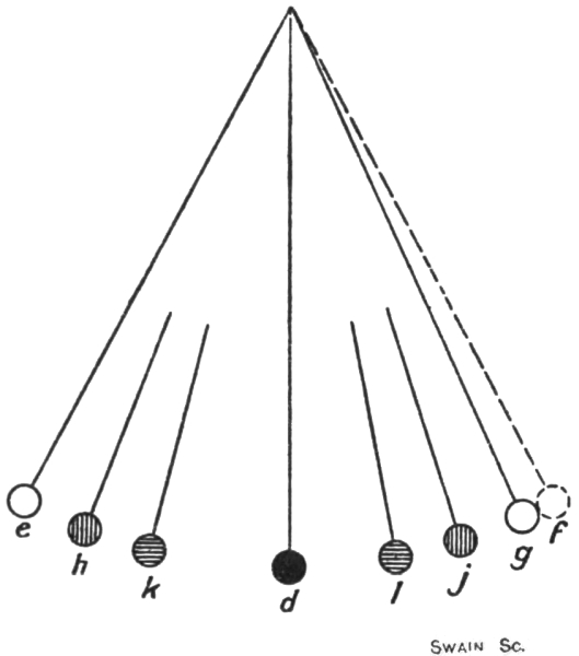
In an ordinary vertical pendulum (Fig. 13), the resting position of the bob is at d. If it is swung to the position e—towards the east, let us say—the weight w of the bob supplies a moment about the axis at g, tending to restore the pendulum to its resting position; while if it is swung towards the position f—towards the west, we may suppose—the moment is reversed and again acts to restore the pendulum to its resting position.
32
The gyro-pendulum system as set up at the equator is, it will be seen, subjected to an exactly analogous set of forces when its axle is deflected east or west. The system, in fact, constitutes virtually a horizontal pendulum, the vertical axis H J being identified with the axis at g in the ordinary pendulum. Now we know that if we deflect an ordinary pendulum to some such position as e and let it go it will swing through the resting position d to a position f equidistant on the other side, and will continue to vibrate until friction at the axis g, air resistance, etc., sap its original stock of energy communicated33 to it by the initial deflection. The period of vibration—the time elapsing between two successive passages of the bob in the same direction through the resting position—is determined by the length of the pendulum and remains constant throughout, even when the amplitude of the swing has fallen off virtually to nothing.
An exactly analogous state of affairs exists with the gyro-pendulum system. If the axle is deflected towards the east and then let go it will swing back under the action of the directive or restoring force through the north and south position over to an equal angle on the western side, and will thereafter vibrate back and forth with a constant period, until frictional and other losses cause the motion to die away. The period of vibration is determined by a complication of factors, among which are the speed at which the wheel is spinning on its axle, the speed of rotation of the earth, and the mass of the sensitive element. If the sensitive element can be regarded as consisting solely of the wheel, then, no matter what may be the size of the wheel, so long as it is in the form of a circular disc, the period of vibration is determined solely by the speed of the wheel and the speed of rotation of the earth. For a wheel at the equator running at 20,000 revolutions per minute the period of vibration would be about eleven seconds. In practice, however, the weight of the axle, the inner and outer supporting rings—or their equivalents—the pendulum bob and various other fittings and adjuncts of a secondary nature have to be added to the weight of the wheel in assessing the influence of the sensitive element upon the period of vibration. The greater the mass—or more correctly, the moment of inertia—of the sensitive element the longer will be the period of vibration. In the early—1910—Anschütz gyro-compass the sensitive element had a moment of inertia such that the period of vibration at34 the equator was just over 61 minutes; that is to say, 334 times as long as it would have been if the sensitive element had consisted of nothing but the spinning wheel.
This very prolonged period, were nothing done to rectify matters, would be a very serious objection in practice to the use of the gyro-compass. The axle, if deflected, would take about half an hour to reach an equal position on the opposite side of the meridian. Hence, if, when a compass reading was desired, the axle were found to be vibrating, at least half an hour would be required to determine the north and south direction by observing the two extreme positions of the axle and taking the mean. The alternative would be to wait until the vibration died away. This course would involve, however, a very much greater delay, for the virtual absence of friction at the vertical axis of the system—an essential, as we have seen, if the directive force is to be allowed to come into play at all—results in the vibration being practically unchecked, so that, once started, it would continue almost indefinitely.
Some means of damping the vibration analogous to the damping action of the liquid in a magnetic compass must clearly then be provided. Ideally the means should be such that if the axle is deflected through any angle it will return to the north and south position in a “dead-beat” manner and not swing across the meridian over to the opposite side. This ideal cannot be realised in practice.
Returning to the simple pendulum illustrated in Fig. 13 we have to notice that the influence at work causing the vibration is the weight of the bob acting about the axis at g. This influence is a maximum when the bob is at the extreme positions e f and is zero when the bob is at d. On the other hand, the velocity of the bob is zero at the two extreme positions e f and is a maximum at d. During the swing from e to d the vibrating influence is helping the35 motion of the bob and the velocity consequently increases. At d the vibrating influence disappears, while during the swing from d to f it reappears and this time opposes the motion of the bob, the velocity of which consequently becomes less and less. The movement of the bob from d to f in opposition to the vibrating influence is achieved by the momentum of the bob arising from the velocity which it gathers during its swing from e to d. For the angle d g f to be equal to the angle d g e the velocity of the bob as it passes through the position d must just be a certain amount, no more and no less, namely, the velocity which a body would acquire in falling from rest at the level of the bob at e vertically downwards to the level of the bob at d. If the velocity of the bob when it swings through d is greater than this amount the bob will swing beyond the position f. If it is less the bob will fail to reach f.
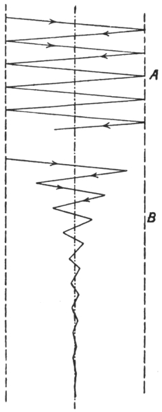
The analogue of the problem to be solved in connection with the gyro-compass is to devise some means that will rob the pendulum bob on each successive swing of some percentage of the velocity with which it passed through the resting position d during the preceding swing. By so doing we shall obviously decrease continuously the angle to which the pendulum swings on each side of the position d. Thus instead of the swings as traced out on a piece of paper moving below the bob being as shown at A (Fig. 14),36 they will be of the form represented at B. The amplitudes, instead of remaining of uniform amount practically indefinitely, will diminish with each swing until they become so small as to be invisible. It is to be noted that theoretically the vibrations cannot be completely suppressed even after an indefinite number of swings, for if the velocity at the resting position is at each swing, say, 50 per cent. less than at the previous passage, it will always be something and never become zero. It will, however, in quite a small number of swings become so low that the motion of the pendulum will be practically undiscernible. Thus with a 50 per cent. decrement the velocity at the eighth passage of the bob through the resting position will be less than 1 per cent. of what it was at the first passage.
It is also to be noted that while the amplitudes are decreased in the manner indicated the periods of the swings are not being made less. In an ordinary pendulum the period, as we have said, depends solely upon the length and—within quite wide limits at least—remains the same whatever be the angle to which we originally deflect the bob. We should therefore expect that if the swings are “damped” in the way shown at B (Fig. 14), the period of each swing would be the same and equal to that of the undamped swings represented at A. Actually the period of a damped vibration is always somewhat greater than that of the same system vibrating freely, for by robbing the pendulum of some of its velocity at each swing we are virtually causing the bob to pass through the resting position with the velocity of a free swinging pendulum of greater length and therefore of increased period. The increase in the period of the damped pendulum over the same pendulum when undamped is determined by the strength of the damping means employed, or, in other words, by the percentage37 by which we reduce the velocity at each swing.
In the early (1910) Anschütz compass the period of vibration at the equator without damping was, as we have stated already, about 61 minutes. With its damping device in action the period of the compass at the equator became approximately 70 minutes. In later designs of gyro-compasses the period of the damped vibration is deliberately made 85 minutes or thereabouts. A practical advantage—to be explained later—is secured by adopting this particular value. It is the period which a simple pendulum would have if its length were equal to the radius of the earth—4000 miles or so.
A vibrating pendulum (Fig. 15) will be satisfactorily damped if we can apply to the bob in all positions of its swing a force proportional to the velocity with which the bob is moving at each given instant and directed always so as to oppose the motion. At e, the position of release after deflection, the bob has no velocity; the38 damping force should therefore be zero. As it travels from e to d the bob is gaining velocity; the damping force should therefore grow from zero to a maximum at d and be directed at each instant tangentially to the curve of swing and act from d towards e. During this portion of its swing the bob is thus robbed of some of its velocity, so that it fails to rise to the position f and comes to rest at some point g. In travelling from d to g the velocity of the bob is decreasing naturally, and is still further decreased by the damping force which, acting in the same direction as before, falls from a maximum at d to zero at g. As it moves from g to d on the return stroke the bob gains velocity; the damping force should therefore increase from zero at g to a maximum at d—of a lower value than the maximum at the same point during the first stroke—and should be directed along the curve in the reversed sense, namely, from d towards g. During the swing from d to h the damping force, still reversed, should decrease from the second maximum value once more to zero. At the start of the second swing the damping force should again act from d towards e and should rise from zero to a third maximum value at d—less than either the second or first maximum value, and so on until the amplitude of the swing is reduced to the required degree. It will be noticed that in a damped vibration the mean position of the bob on any one swing is not coincident with the resting position d, but lies somewhere between the resting position and the position from which the bob commences the swing.
With each passage of the bob through the resting position d the value of the damping force rises to a maximum, the value of which becomes less and less on each successive swing. Ultimately, when the bob settles in the resting position, the maximum value becomes zero. In other words, the damping force, having completed its39 work by bringing the bob to rest, entirely disappears and leaves the pendulum exactly in the same condition as it would be under in the resting position if no damping force had ever been in action. The pendulum is thus as free as formerly to respond, in the resting position, to a vibrating influence, but as soon as it acquires motion the damping force is again called into existence to a degree directly dependent on the strength of the vibrating influence, with the result that the motion is first checked, and then finally stopped.
The damping force required is, as we have said, one which at all times is proportional in magnitude to the velocity of the bob—or what is the same thing, to the angular velocity of the pendulum as a whole—and which at all times acts to oppose the motion of the bob. Metallic friction—say, at the supporting axis of the pendulum—it would bring the motion to rest sooner or later, would not provide a satisfactory damping force, for solid friction is independent of the rubbing velocity, at least at low speeds such as we are here concerned with. The damping force provided by it being constant, would not be automatically adjusted to the velocity of the bob. It would vanish, it is true, when the bob was at rest, but as soon as the slightest vibration set in it would spring up to its full value straight away and would preserve the same value throughout a large swing as throughout a small one. In any event the presence of metallic or other solid friction at the point in the gyro-compass corresponding to the axis of the pendulum—namely, at the bearings of the vertical axis H J—cannot be permitted, and must be eliminated to the utmost possible degree if the directive force is to be sufficient to control the movement of the sensitive element.
Fluid friction, on the other hand, would provide a satisfactory damping force, for fluid friction is proportional40 to the velocity, at least at low speeds. A pendulum vibrating with its bob in a vessel of water or the floating card of an ordinary magnetic compass is satisfactorily damped by fluid friction. In the gyro-compass, however, the motion to be damped is, as we have seen, an exceedingly slow one, slower in fact than the small hand of a watch if the deflection of the axle from the meridian is initially less than 11½ deg. east or west. A fluid damping force would be proportionately low, so that without making the damping elements of enormous size the force derived would be insignificant and next to useless for practical purposes. As an illustration of this statement it may be remarked that in the early Anschütz compass the sensitive element was virtually floated in a bowl of mercury. Yet the drag of the mercury, the velocity of the vibration being so small, did not measurably reduce the amplitudes of the vibration during observation extending over several hours. This example is not quite a good one, however, for the friction at the surface of a body immersed in mercury would appear to be not of the fluid description, but of the solid type.
Solid and fluid friction being thus ruled out, at least as direct means of providing the required damping force, we have to find some other method of applying it. It is, or should be, clear that in whatever way the damping force is applied it should originate within the sensitive element itself. If it originates outside, then its transmission to the sensitive element cannot, in view of the fact that its origination, growth, and decay are to be controlled by the motion of the element, be effected in any conceivable way without the introduction of some material connection between the element and the outside source of the force. Such a connection can only be made frictionless if the outside source moves in exact unison with the sensitive41 element. If it does so move it clearly ceases to be an outside source and becomes really part of the sensitive element itself. This consideration suggests generating and applying the damping force gyroscopically by the exertion of some suitable action on the spinning wheel itself.
42
In the preceding chapter we demonstrated the necessity for damping the horizontal oscillatory movement of the gyro-compass axle and discussed the nature of damped vibrations in general. We now turn to describe the damping means provided in each of the practical forms of gyro-compass so far evolved.
Turning to the early (1910) form of Anschütz compass, we find that, as shown in the purely diagrammatic sketch given in Fig. 16, the spinning wheel is enclosed within a metallic case formed with tubular journals B C for the axle, and provided with trunnions E F, whereby it is supported within the vertical ring, which, as before, is free to turn on a vertical axis H J. The casing, it will be seen is, so far as the support of the wheel is concerned, exactly equivalent to the horizontal inner ring of our preceding illustrations. In the actual instrument the method of supporting the casing so as to permit it to turn about a horizontal and a vertical axis is not in the least like that shown in our sketch.
The wheel, running at 20,000 revolutions per minute, although it is quite plain, has a powerful blower-like action. On one side of the casing an orifice D is formed for the inlet of air, and on the periphery below an outlet duct K, directing the air blast tangentially away from the casing, is provided. The exact value of the pressure of the blast in the early Anschütz compass is not known43 to us, but in the Brown compass, wherein a similar blast is developed, the wheel, running at 15,000 revolutions per minute, gives an air pressure equal to some 3 in. of water.
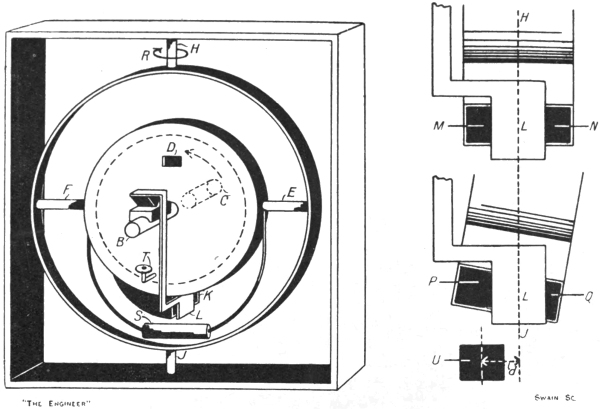
The mouth of the outlet duct K is partially closed by a plate L fixed at the end of a pendulum arm suspended44 frictionlessly, or practically so, from some convenient point on the casing, so that when the casing turns on the vertical axis H J the arm and plate turn with it. The pendulum arm is carefully balanced in such a way that when the axle of the spinning wheel is horizontal the plate L exactly divides the orifice K, leaving equal passages for the air blast on each side. In this condition the two passages M N being equal in area, the air blast is divided by the plate into two streams of equal volume and momentum, so that if their free discharge is not influenced by surrounding objects their reactions on the casing, one on the one side of the vertical axis H J, the other on the opposite side, will be equal.
Let the compass be deflected until its axle points east and west, the end B being towards the east. Then, as we have seen, the tendency of the axle to remain parallel with its original position, combined with the rotation of the earth, will cause the axle to assume an inclined position relatively to the earth’s horizontal surface. Gravity acting on the pendulous weight S as thus displaced from the plumb line will, as we know, set up a precession about the vertical axis H J, so as to cause the end B of the axle to move towards the north. When, however, the axle tilts in this manner about the horizontal axis E F, the pendulum plate L, hanging freely, remains in the plumb line. Consequently the equal areas M N become unequal, as at P Q, the larger P being towards that end of the axle which has tilted upwards, namely, the north-seeking end B. The reaction on the casing of the portion of the air blast issuing from P is now greater than that of the portion emitted through Q. This inequality results in the application to the sensitive element of a force acting about the vertical axis H J. The reaction of a jet of air or water or other fluid being opposed to the direction in which the jet is issuing, the45 force applied to the casing is such as to drive P into the plane of the paper and to bring Q out of it—that is to say, to tend to rotate the casing on the vertical axis in the direction of the arrow R.
The force thus applied clearly tends to oppose the return of the axle from the east towards the north. On the other hand, if the axle succeeds in turning round until the end B points to the west, the rotation of the earth will result in the axle tilting as before, but with the end B downwards. Consequently the area M diminishes and the area N increases, and the reaction applied to the casing is such as to tend to turn it in the reverse direction to R. The applied force in this case therefore opposes the return of the axle from the west towards the north. The exact manner in which the opposition acts is to be noted. A force applied to a simple gyroscope, so as to tend to make it turn about the vertical axis H J in the direction R (Fig. 16) will, as was stated in our second chapter, cause the wheel to precess about the horizontal axis E F, the end B of the axle going down and the end C up. If the force about H J is reversed, the movement produced will be a precession of the wheel on E F such that the end B of the axle rises and the end C falls. The opposition between the moment applied to the sensitive element by the air blast and the moment applied to it by the directive force is therefore not quite direct. When the end B of the axle is deflected towards the east a directive force is called into being by virtue of the tendency of this end to rise. The air blast reaction about H J induces precession on the axis E F, causing the end B to fall. By the amount by which the air blast reaction succeeds in lowering the end B of the axle, by that amount will it reduce the normal magnitude of the directive force. When the axle swings through the meridian towards the west a reversed directive force is called into play by46 virtue of the tendency of the end B to fall. The opposition of the air blast reaction arises from the fact that its tendency now is to make the end B rise. Thus on both sides of the meridian the opposition of the air blast reaction is effective because it tends to precess the wheel on the axis E F in the direction opposed to that in which the rotation of the earth is trying to tilt the axle. The tilt moves the pendulous weight S away from the vertical, so producing the directive force; the air blast reaction reduces the tilt and so opposes the directive force.
The reaction applied to the sensitive element by the air blast thus fulfils one requirement of a satisfactory damping force; its effect at all times is opposed in direction to the direction in which the axle is moving. The second requirement is that the magnitude of its effect should always be proportional to the velocity with which the axle is moving.
In connection with this second requirement it is assumed that the momenta of the air jets issuing from the openings P Q (Fig. 16) are at all angles of tilt equivalent to the momentum of a single jet issuing from an imaginary orifice U situated at some distance d from the axis H J on the side of the larger opening P, the area of the imaginary orifice R and the velocity of the air through it being constant at all angles of tilt. If this assumption is correct, then the moment about H J applied by the reaction of the air blast is proportional to the distance d—that is to say, to the angle of the tilt.
The assumption here made is, we believe, substantially justified if the angle of tilt is never very great. In actual practice it is always small. Various considerations, however, suggest that the reactions of the two jets P Q are not equivalent strictly to the reaction of a single jet through an orifice R of constant area. Thus from geometrical considerations we can show that the sum47 of the areas P Q is not equal to the sum of the areas M N. Again, the total weight of air drawn in per minute through the orifice D may be constant, and therefore the total weight of air delivered per minute through the combined openings P Q may be unaffected by the tilt. But the ratio in which the total volume divides itself between the two openings P Q and the velocity through each certainly vary with the tilt. A peculiar practical phenomenon also has to be considered in this connection. In the 1910 form of Anschütz compass the peripheral speed of the spinning wheel was 500 ft. per second, or 340 miles an hour. The air friction at this speed was so very great that after the wheel had been run a few thousand hours its surface was found to be noticeably smoother than it was when the wheel left the grinding machine on which it was finished. As a result of this polishing effect, we should expect that even though the speed of the wheel remained perfectly constant, its blower-like action would decrease somewhat until the compass had been in use for a certain length of time. If the blower action does so decrease the magnitude of the air blast reaction on the sensitive element at any given angle of tilt must diminish with time. We do not know whether the diminution would be sufficiently great to introduce a serious error in the reading of the compass.
Taking the assumption to be correct, at least for small angles of tilt, we have next to study how the angle of tilt varies as the axle swings from the east side of the meridian over to the west and back again.
When the axle is pointed due east the rotation of the earth, as we have seen, tends to make the end B rise. If it is pointed due west, the end B tends to fall. If it is lying dead on the meridian, the earth’s rotation has no tilting effect at all on the axle. If the axle is pointed in some direction between due east and due north, the tilting48 effect is less than it would be if it were pointed due east, but it is in the same direction; the end B tends to rise. Similarly, in any position in the north-west quadrant the end B tends to tilt downwards under a tilting influence which is somewhat less than that experienced in the due west position. Let, then, the axle be turned to point due east. The end B begins at once to rise, but immediately the axle thus leaves the horizontal position it begins to feel the directive force, and it commences to turn towards the north. Until it reaches the north the tilting influence of the earth’s rotation continues so that during the whole time the axle is swinging through the north-east quadrant the tilt is increasing and the end B is rising, higher and higher. When the north direction is reached the tilting influence vanishes and the end B of the axle tends to travel horizontally in its elevated position over into the north-west quadrant under the influence of the momentum acquired in that direction during its movement through the north-east quadrant. But on passing to the west side of the meridian it again comes under the tilting influence of the earth’s rotation, which this time tends to make the end B fall. When the axle reaches the due west position, the tilting influence being equal to that acting over the north-east quadrant and reversed in direction, and having acted for the same length of time, will just have wiped out the elevation of the end B, and the axle will again be horizontal. On the return journey through the north-west quadrant the tilting influence is still reversed, so that on reaching the north position again the end B is as far below the horizontal as it was above it on the swing from east to west. Passing to the east side of the meridian, the tilting action assumes its former direction, the end B begins to rise, and when the due east position is reached again the axle is once more horizontal. The path traced out by the end B49 during a complete vibration from east to west and back again is thus in the nature of an ellipse—or, in extreme cases, a circle—such as that shown at a b c d e in Fig. 17.
On an east-to-west swing, then, the end B of the axle in Fig. 16, if the air blast is out of action, tilts upwards from zero to a maximum in the mid position and then again falls to zero. If the air blast is brought into play, the reaction, being, as we have seen—at least for all small angles of tilt—proportional to the angle of tilt of the axle, will correspondingly increase from zero to a maximum and again fall to zero. On the west-to-east swing the reaction will similarly rise and fall in the reversed direction. The unrestrained movement of the sensitive element under the influence of the directive force is, as we know, analogous to that of a simple pendulum, so that the velocity with which the axle moves is zero in the extreme positions and a maximum in the mid position. Thus we see that the air blast reaction not only constantly opposes the movement of the axle,50 with the variation in the velocity with which the axle moves. The air blast reaction therefore completely fulfils the requirements of a satisfactory damping force. When51 it is brought into play the end B of the axle, instead of vibrating indefinitely in a closed elliptical path a b ... e (Fig. 17) moves spirally, as indicated at f g h ..., until in a relatively short period of time it comes virtually to rest at m pointing towards the north.
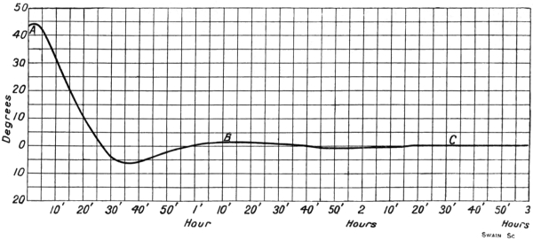
An actual curve taken from an Anschütz (1910) compass while it was settling down on the meridian after the gyro-axle had been deflected nearly 45 deg. to one side is given in Fig. 18. The crests A B C occur at 70-minute intervals—the period of vibration of the system when damped, as we have already stated. The oscillations are, it will be seen, damped down very effectively, being entirely eliminated in less than three hours in the course of the third complete vibration. It follows that if the wheel of a gyro-compass is started spinning with the axle pointing elsewhere than due north, several hours must be allowed to elapse before readings are taken from the card. During the period of settling down, and especially during the later portions, the movement of the axle towards its resting position is extremely slow, and cannot be detected by direct observation. It can, however, be inferred from the readings of a spirit level placed on the card, for, as we have seen, the oscillations are accompanied by a tilting of the wheel case on its horizontal axis.
52
In the Sperry gyro-compass the damping system adopted is mechanically of a very different nature from that used in the early Anschütz, although the theoretical principle of action in both cases is the same. The Sperry method rules out the employment of air or other fluid in any shape or form as a means of generating, applying, or transmitting the damping force, the reason being that if air or other fluid is relied upon, the damping force—or so the Sperry Company holds—will not act in strict unison with the oscillations, but will invariably lag behind.
The details of the Sperry method are indicated in a diagrammatic manner in Fig. 19. As in the Anschütz compass, the spinning wheel revolves in a casing which, being provided with trunnions E F, takes the place of the inner horizontal supporting ring of our elementary gyroscope. Since no blowing action is required of the wheel in this compass the casing, in order to reduce the expenditure of power required to drive the wheel, is exhausted of air until a vacuum of not less than 26 in. is registered on a gauge which forms a permanent fixture on the casing. The exhaustion is effected by attaching a hand-operated vacuum pump to a nipple on the casing. The vacuum produced at one exhaustion remains effective for at least a month under proper treatment. That it is very well worth while exhausting the casing, if the general design of the compass permits it, is shown by the fact53 that in the 1910 Anschütz compass over 95 per cent. of the work done by the motor driving the spinning wheel was spent against windage and air friction.
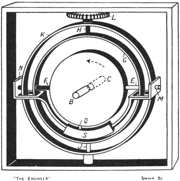
The outer ring G (Fig. 19) within which the casing is carried is, as before, mounted on a vertical axis H J. A second outer ring K—or “phantom ring,” as it is called—surrounds the ring G, and is mounted co-axially with it. While the ring G, as before, moves along with the wheel and its casing relatively to the square frame under the influence of the directive force, the ring K is caused to follow it up in exact agreement by means of a small electric motor, the pinion of which engages with a gear wheel L on the upper trunnion, the current to the motor being automatically controlled by the movement of the ring G. The compass card may be regarded as attached directly to the top face of the gear wheel. A second pinion gearing with the wheel L can be arranged54 to transmit the reading of the card to any number of repeater compasses stationed elsewhere.
In all our preceding illustrations we have shown the pendulous weight S as being attached by a stirrup directly on to the inner horizontal ring or its equivalent, the wheel casing, so as to move in rigid connection therewith. In the early Anschütz compass the design definitely reproduces this arrangement, but in the Sperry compass matters are otherwise. The pendulous weight S (Fig. 19) is carried on a stirrup, which is forked at each end so as to span the rings G K, and which is free to swing on pivots M N fixed on the phantom ring K. The pivots M N are exactly in line with the pivots E F, and as the phantom ring K and the ring G always move in unison, the two sets of pivots remain at all times collinear.
So far the arrangement of parts is exactly similar to that which would be obtained in our simple gyro-pendulum system if the stirrup of the pendulous weight were not fixed rigidly to the inner horizontal ring, but were swung freely on the pivots E F. It can be brought into complete identity with the arrangement of our simple system if the pendulous weight S (Fig. 19) or “bail,” as it is called by the makers, be provided with a pin at its mid point to engage with a hole in the periphery of the casing. The system, as thus arranged, would merely be a distinctly complicated mechanical variation of our simple gyro-pendulum arrangement, and, as a compass, would be open to the same practical objection, namely, the persistence with which any oscillation of the axle, once set up, would continue. The vibrations would, in fact, be quite undamped.
The generation and application of a satisfactory damping force is accomplished in a very simple, yet beautiful and really ingenious, manner by displacing the pin connecting the bail and the casing from the55 mid position to some position lying eastwards of the vertical axis H J, as shown at Q.
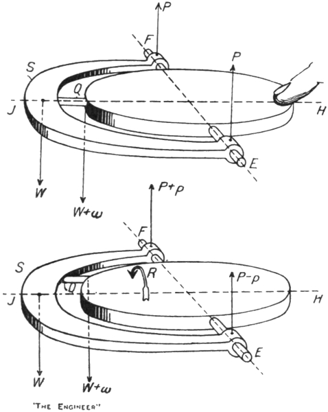
In order to follow the action of this arrangement, let us consider a disc (Fig. 20) swung on a horizontal axis E F on which there is also swung a weighted stirrup S, the stirrup and disc being connected by a pin Q. Let this system of parts be held horizontal, and in the first instance let the pin, as shown in the upper view, be arranged on the centre line of the disc. Then the weight W of the stirrup applies to the disc three forces, namely, a force W + w acting downwards at the end of the pin, and two upward forces P equal to each other at the pivots E F, as will readily be seen by considering the stirrup as a lever fulcrumed at the disc end of the pin.56 The only force tending to turn the disc is the force W + w acting about the axis E F.
Let, now, the pin be situated excentrically relatively to the axis H J of the disc, as shown in the lower view. The forces applied to the disc by the weight W of the stirrup are again three in number. The force applied at the end of the pin is, as before, W + w, but at the pivot E the force applied falls to P - p, while the force at the pivot F rises to P + p. These forces apply turning moments to the disc. About the axis E F the turning moment, as before, is that of the force W + w. This force, owing to the displacement of the pin, has now, in addition, a turning moment about the axis H J in the direction of the arrow R. The upward force P - p on the pivot E tends to turn the disc in the same direction, while the force P + p on the pivot F tends to turn it in the opposed direction. These three turning moments about the axis H J exactly balance each other, as can be confirmed by working out their values. Thus there is no net alteration produced by shifting the pin from its central position, for in all positions of the pin the only effective moment applied by the weight W to the disc is that of the force W + w about the axis E F.
Now, in the Sperry system the forces P - p and P + p are not allowed to act on the trunnions E F of the wheel casing, but are borne by the phantom ring K (Fig. 19) whence they are transmitted back to form part of the load on the follow-up motor. Acting on the casing, therefore, there remains only the force W + w. This force exerts a turning moment about the axis E F strictly equal to that produced by a directly attached pendulous weight. In addition, it exerts a turning moment about the axis H J.
57
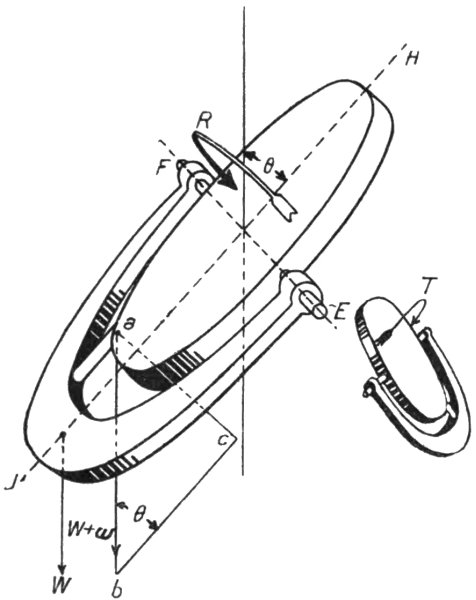
As actually constructed, the wheel casing and bail in the Sperry compass cannot be placed in the position shown in Fig. 20, for the forks at the end of the bail permit the bail, and therefore the casing, to swing only through a small angle from the vertical position. It is clear, however, that if the parts could be moved into the horizontal position the moment of the force W + w about the axis H J would be a maximum, just as in this position the moment of the same force about the axis E F is a maximum. It is also clear that when the parts are in the vertical position the force W + w has no turning moment about either axis. In an intermediate position (Fig. 21) the moment of the force W + w about the axis E F is proportional to a c—that is, to the component of a b perpendicular to the plane of the casing or disc—just as it would be if the pin were central or if the bail formed a rigid part of the casing. The moment of W + w about the axis H J is likewise proportional to the component a c. As the value of the component58 a c, at least for small angles of swing, is proportional to the angle of swing θ, the net result of making the pin excentric and introducing a phantom ring is to apply to the casing when it is deflected (1) the ordinary moment of the weight W about the axis E F, and (2) an additional moment about the axis H J. This latter moment is proportional to the angle of swing θ, and in the position shown in Fig. 21 tends to turn the casing in the direction of the arrow R. If the deflection is towards the other side of the axis E F, the moment applied about H J will clearly tend to rotate the casing in the opposite direction, as shown at T. Comparing Figs. 21 and 16, it will be seen that the excentricity of the pin in the Sperry compass secures exactly the same result as the air blast reaction produces in the Anschütz compass.
It is to be noted that the excentric pin in the Sperry compass is displaced towards the east when the axle is resting on the meridian. If it were displaced towards the west the force applied about the vertical axis would be reversed in its effect, and would tend to increase the oscillations of the sensitive element and not to damp them, as is the intention.
59
In both the Sperry and the early Anschütz compass the natural oscillation of the sensitive element about the vertical axis is damped by applying a retarding moment to the element about this same axis, the strength of the retarding moment being at all times proportional to the velocity with which the element is moving in the course of its vibration. The opposition exercised by the retarding force is not, however, a direct one. The motion of the sensitive element arises from the fact that the spinning wheel, the axle, and the pendulous weight are tilted about the horizontal axis E F. The retarding force is applied about the vertical axis, not because that is the axis on which the sensitive element is oscillating, but because a force so applied produces a movement about the horizontal axis tending to wipe out the tilt and so eliminate the cause of the oscillation.
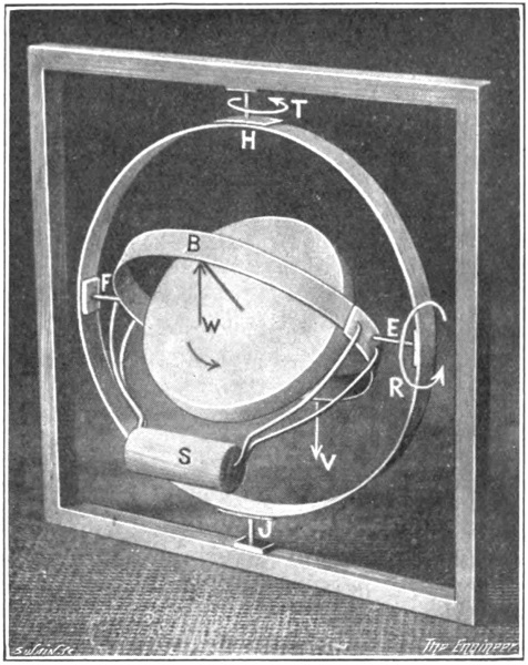
An alternative method of damping the oscillation is possible. The effectiveness of the pendulous weight may be damped by virtually reducing the weight of the pendulum bob instead of reducing the tilt at which it is acting. In Fig. 22 the wheel of a gyro-pendulum system is shown tilted. The weight S is trying to turn the wheel on the horizontal axis E F in the direction R, and as a consequence is causing precession about the vertical axis H J in the direction T. Instead of attempting to damp this precession by applying a force about the vertical axis60 so as to reduce the tilt, we might virtually reduce the weight S by applying an upward force W at the end B of the axle, or, what is the same thing, a downward force V at the other end. Such a force, if it were acting alone, would tend to turn the wheel in the direction opposed to that of the arrow R, and would consequently cause the wheel to process on the vertical axis in the direction opposed to that of the arrow T. Acting in conjunction with the weight S, the force W would thus damp the natural motion by endeavouring to produce a counter precession of the wheel about the vertical axis.
61 This alternative method of damping the oscillations is adopted in the Brown gyro-compass. The mechanism of the Brown method is shown diagrammatically in Fig. 23. The wheel, as in the early Anschütz compass, runs in an enclosing case, and acts as a blower, developing a pressure of about 3 in. of water. At each side of the casing a bottle L, M is attached to the housing of the axle. A pipe N connects the bottoms of the bottles, while a second pipe P joins their upper ends. At its mid point the pipe P is interrupted, and a box Q is inserted in the gap. This box, as shown separately, is open on the underside, and is provided with a central partition. The air from the casing is delivered through the hollow trunnion F, and passes upwards into the box Q from the orifice R.
When the axle is horizontal the air blast entering the box Q is divided into two equal portions by the central partition, and exerts an equal pressure inside the bottles. These two bottles are half-filled with oil, which under the equal air pressures and the horizontal configuration of the system lies at an equal level in each bottle, and does not therefore unbalance the sensitive element on the axis E F. If, however, the axle tilts the balance is disturbed. Thus if the end B rises the box tilting with the wheel will assume some such position relatively to the nipple R—which is free of the trunnion F—as that shown at T. The central partition will divide the air jet unequally, and a greater pressure will therefore be exerted inside the bottle L than in the bottle M. Thus the oil level in L falls, while the oil level in M rises. The difference in the weights of the two bodies of oil acts as a turning moment tending to rotate the casing about the horizontal axis E F in the direction U—that is to say, in the direction opposed to that in which the pendulum weight S is trying to turn the casing. Since the pendulum weight causes precession about H J in the direction V, the weight of the62 unbalanced oil will cause or tend to cause precession about H J in the reverse direction.
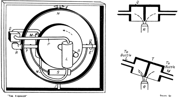
Should the end B of the axle fall, the air jet will exercise excess of pressure in the bottle M, the oil level will rise in the bottle L, and as a consequence will tend63 to make the system precess about H J in the direction of the arrow V. Thus in both cases the precession which would be produced by the unbalanced weight of oil if it acted alone is in the reverse direction to that produced by pendulum weight when the axle tilts under the rotation of the earth.
As the excess of pressure in either bottle varies with the ratio in which the central partition of the box Q divides the air blast, and as that ratio varies with the angle of tilt, it follows that the opposition of the applied precession increases with the angle of tilt, and therefore with the rate at which the sensitive element is turning on H J under the influence of the pendulum weight S. The system therefore fulfils the requirements of a satisfactory damping method.
It may be noted that were the air blast and the box Q suppressed and the pipe P made continuous, a tilt of the axle would cause oil to flow from one bottle to the other in the endeavour of the liquid to preserve its surface horizontal. This flow might be constricted by means of a valve in the pipe N, and would then serve to damp the oscillations, for the arrangement would constitute virtually an oil dashpot. This plan would not prove satisfactory in practice, because the tilts which are attained are so small that the amount of oil flowing between the bottles would be insignificant. Further, the flow would almost certainly lag behind the movement to be damped. The application of the air blast to the surface of the oil greatly increases the rate of flow of the oil and correctly synchronises it with the tilt. The extent to which the damping effect is allowed to act on the system can be regulated by means of a needle valve in one of the bottles, which valve is made to control the orifice in the bottom of the bottle through which the pipe N enters.
The damping system adopted in the latest form of64 Anschütz compass cannot very conveniently be described at this point. It will be dealt with later on in Chapter XVII. For the present it is sufficient to say that the system used is in principle very similar to that found in the Brown compass.
65
Having explained the necessity for damping the horizontal vibrations of the gyro-compass axle and how the damping force is generated and applied in the Anschütz, Sperry, and Brown compasses, we are now in a position to discuss the various errors to which the gyro-compass is open and how those errors are in practice eliminated, reduced, or allowed for.
The first error to which we shall turn our attention is that known as the latitude error. This error is a direct consequence of the necessity we are under of damping the horizontal vibrations of the compass axle.
It will be recalled that in any latitude other than the equator the compass rests on the north with a slight tilt up or down of the axle, the tilt increasing progressively as the poles are approached and being upwards in northern latitudes and downwards in southern. The tilt acquired in any latitude is perforce and automatically just sufficient to precess the axle westwardly or eastwardly at the rate required at that latitude to keep the axle on the north once it has found it.
Let us suppose, then, that a compass of the early Anschütz type is stationed in some degree of northern latitude. The axle in acquiring the appropriate tilt will clearly disturb the equilibrium between the two sections of the air blast. As the axle tilts its north end B upwards the north section of the air blast will enlarge and the southern diminish in area. Thus the tilting of the axle66 brings into play an air blast reaction which is applied as a moment tending to turn the sensitive element about the vertical axis H J in such a way as to make the north end move eastwardly. The actual movement produced will, in accordance with the fundamental rule, be a precession of the axle about the horizontal axis, the end B going down. Thus the tilt upwards of the axle required for the correct working of the compass is opposed. It is not allowed to acquire the full value which it should have, but instead stops at the point at which a balance is struck between the upward moving tendency of the axle resulting from the earth’s rotation and the downward moving tendency caused by the uneven air blast reaction. The westerly precession of the axle about the vertical axis is now that arising from the reduced angle of tilt, and is less than the rate required to keep the end B pointing to the north. The resulting deviation is known as the latitude error. Its magnitude depends upon the latitude and upon such factors as the speed of the wheel, its efficiency as a blower and other items incidental to the particular design of the compass.
In the Sperry compass the latitude error arises from an exactly similar cause. Thus the tilt of the axle is transmitted through the excentric pin to the casing as a moment about the vertical axis H J, tending to make the north end of the axle move over to the east, and therefore causing the axle to precess vertically downwards until the position of balance is reached.
In the Brown compass, on the other hand, it is claimed that there is no latitude error. Thus when in northern latitudes the north end of the axle tilts upwards under its unsatisfied desire to set itself parallel with the earth’s polar axis, the air blast is divided unequally between the two partitions of the box. Excess pressure is exerted inside the damping bottle attached to the northern face of the wheel casing, and as a result an excess of oil67 accumulates in the damping bottle on the south side. The weight of the excess oil applies a turning moment to the spinning wheel about the horizontal axis, and tends to lift the north end of the axle upwards in opposition to the pendulum weight, which tends to turn it downwards about the same axis. Thus in this compass the natural tilt of the axle is not interfered with by the action of the damping arrangement, for that action is applied about the horizontal axis E F, and not, as in the Anschütz and Sperry compasses, about the vertical axis H J. The damping action in the Brown compass is virtually equivalent to a subtraction from the weight of the pendulum bob, and is not applied, as in the other compasses, to the reduction of the tilt of the axle. It tends, therefore, to reduce the natural rate of westerly precession required at the given latitude to keep the axle on the north. Actually, however, the tilt acquired by the axle will take cognisance of the reduction in the weight of the bob caused by the weight of the excess oil. The north end of the axle will rise until the effective moment of the bob—that is, the moment due to its own actual weight less the moment due to the excess oil in the southern damping bottle—is such as will automatically generate the required rate of westerly precession for the given latitude.
In the Anschütz and Sperry compasses the latitude error can be allowed for by shifting the position of the lubber line relatively to the ship’s longitudinal centre line in accordance with calculated tables of the error. The exact value of the error depends upon the design of the compass, but in both types it increases with the latitude. Analysis shows that—at least in the early Anschütz compass—the latitude error may be neglected if the change of latitude is less than 10 deg. In the Sperry compass, as we shall see presently, the movement of the lubber line to correct the latitude error is effected by a very pretty piece of mechanism, which also can control68 the position of the lubber line to allow for a second error to which the compass is open, to wit, the so-called “north steaming error.”
In some respects as an alternative to moving the lubber line, the latitude error may be completely eliminated for a particular latitude—the latitude of most frequent use would naturally be chosen—by attaching a small weight to the north side of the wheel casing. In the early Anschütz compass such a weight was provided as indicated at T in Fig. 16. This weight and its position were so chosen that at 50 deg. north of the equator its moment about the horizontal axis E F, when the axle of the compass was horizontal, was just sufficient to supply to the wheel the amount of westerly precession required to keep the axle pointing to the north. The axle being horizontal in that latitude, the air blast was equally divided by the pendulum shutter, and as a result the rate of westerly precession produced by the weight T was not affected by the existence of the damping system. At other latitudes, of course, the latitude error arose, and at the equator—where ordinarily there should be no latitude error—and south of the equator, the error became worse than it would have been without the addition of the weight, unless the weight and its position were adjusted. With the compass corrected for 50 deg. N. latitude the error had the following values:
| Latitude | Error |
| 60° N. | .6° E. |
| 50° N. | Zero |
| 40° N. | .5° W. |
| 20° N. | 1.1° W. |
| 0° | 1.6° W. |
| 20° S. | 2.1° W. |
| 40° S. | 2.7° W. |
| 60° S. | 3.8° W. |
69 In the Sperry compass no attempt is made to eliminate the latitude error at any particular latitude, the correction applied to the lubber line being solely relied upon to allow for it. In this compass, therefore, the latitude error is zero at the equator. At 50 deg. north or south it amounts to 2 deg., easterly and westerly respectively. A feature found in this type of gyro-compass of a connected nature calls, however, for mention at this point. This feature consists of mounting the pivots M N (Fig. 19), on which the bail swings, within excentric housings and graduating the edge of the housings with a scale of latitudes. In this way the pivots can be displaced to one side or the other of the vertical plane containing the axis H J by an amount proportional to the latitude. When the spinning wheel is at rest, this displacement makes the angle between the axle of the wheel and the plumb line through the centre of gravity of the bail a little less or a little more than a right angle, and in northern latitudes makes the north end of the axle dip below the horizontal and in southern latitudes rise above it. The scale is so graduated that the dip of the axle or its rise when the wheel is not running is just equal to the natural rise or dip which the axle would acquire at any given latitude with the wheel running and with the bail pivots in the mean position. As a result, when the compass is in service and the bail pivots are adjusted for the latitude of the station, the natural rise or dip of the axle leaves the axle horizontal, but deflects the bail weight from the vertical by the amount required to generate the correct degree of easterly or westerly precession.
Thus in the Sperry compass the axle, if the latitude bail correction is applied, is at all latitudes horizontal when resting on the north. Several advantages are thus secured, the chief being that the effect of any change in the speed of the spinning wheel or of a complete failure of70 the electric supply driving the wheel is greatly reduced or spread over a longer interval. Were the axle as well as the bail allowed to acquire the rise or dip proper to the latitude, the axle during a change of speed of the wheel would tend to deviate and develop an error which might prove misleading. If, however, the axle is not allowed to acquire the rise or dip appropriate to the latitude, the error introduced by a change in the speed of the wheel takes longer to manifest itself, and is reduced in magnitude. As it is difficult to guarantee that the voltage of the current supplied to the compass will not vary, this feature of the Sperry compass is undoubtedly of practical advantage.
71
The source of error which we have just discussed affects the gyro-compass whether it is on land or on a ship. We have now to discuss certain errors which are only met with when the compass is mounted on board a moving ship.
The first of these errors to which we will refer is sometimes called the “north steaming error,” although it is equally associated with a due south course. Imagine the vessel on which the gyro-compass is fitted to be sailing due east along the equator. If its speed is, say, 20 knots it would, if it could, circumnavigate the globe in 45 days. Its velocity round the earth’s axis apart from the rotation of the earth is thus 0.000015 revolution per minute. As the speed of the earth on its polar axis is 0.0007 revolution per minute, the actual rate at which the gyro-axle is being carried round in space is 0.000715 revolution per minute. If the vessel is sailing due west its speed opposes that of the earth, so that the actual rate at which the gyro-axle is being carried round in space is 0.000685 revolution per minute. As compared with the same gyro-compass on land, the only effect of the ship’s speed on these courses is in the one case to increase the magnitude of the directive force and in the other case to reduce it, the increase and reduction both being quite small—about 2 per cent. actually. Sailing due east or west in latitude 60 deg. north or south, its speed would cause the vessel to circumnavigate72 the globe in 22½ days. On these courses in either of these latitudes, therefore, the directive force would be increased or diminished respectively by about 4 per cent.
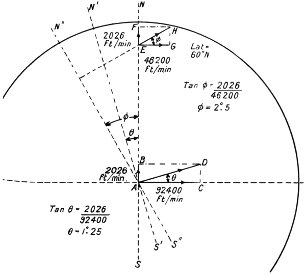
If, now, the vessel starts at the equator and sails due north, its speed is at right angles to the speed with which the rotation of the earth is carrying the gyro-compass round in space. The speed of the ship—2026 ft. per minute—may be represented by A B (Fig. 24) and the speed of rotation of the earth—92,400 ft. per minute—by A C. The actual speed and direction in which the gyro-compass is being carried round in space is A D, and the actual axis about which it is being carried round is not73 the earth’s polar axis N S, but an axis N´ S´ at right angles to A D. The gyro-axle will settle, therefore, on the line N´ S´, and not on the true north and south meridian. The true north will be to the east of the indicated north by the angle N´ A N, which for the ship speed in question—20 knots—will be 1.25 deg. If the ship starting from the equator sails due south, the deviation will be towards the opposite side, the true north lying 1.25 deg. to the west of that indicated by the compass. If the course is neither due north or south nor due east or west, the deviation will have some intermediate value between zero and 1.25 deg., the true north lying to the east of the indicated on all courses with a northern component and to the west on all courses with a southern component.
If the ship is in latitude 60 deg. north, and is steaming north, its speed will carry it, as before, 2026 ft. northward per minute, as at E F, but, as its distance from the earth’s polar axis is now only half what it was at the equator, the earth’s rotation is carrying it round at only half the equatorial speed, namely, with a velocity E G of 46,200 ft. per minute. The compass is therefore being carried round in space with a velocity represented in magnitude and direction by E H—that is to say, it is being rotated not actually about the earth’s polar axis N S, but about an axis N´´ S´´ at right angles to the resultant velocity E H. The axle will therefore align itself parallel with N´´ S´´, and not with N´ S´. Thus in that latitude at the given speed the true north will lie 2.5 deg. eastward of that indicated by the compass. On north-easterly or north-westerly courses at 60 deg. north latitude the deviation will lie between zero and 2.5 deg., while on all courses with a southerly component the true north will be to the west of the indicated north by some amount between the same two limits. Our demonstration is not strictly accurate, for, arising from the rotundity of the earth, the74 speed E F of the ship is not really in the plane of the paper, but should be drawn inclined with the end F below the level of E. Accurate analysis, however, shows that the deviation arrived at by neglecting this fact is substantially correct. In the tables issued in connection with the early Anschütz compass the deviation at 20 knots due north or south in latitude 60 deg. N. is given as 2.5 deg., while those issued by the Sperry Company give it, by interpolation, as 2.41 deg.
It will be seen that this error is a natural one—that is to say, it is not caused by any peculiarity in the design of the compass in use. The table of deviations on various courses, at various speeds, in various latitudes, compiled for one type of compass would be equally applicable to any other design. In the case of the early type of Anschütz compass the “north steaming error” was corrected solely by means of such tables—that is to say, to find the exact bearing on which the ship was sailing the compass was read, and from its reading there was subtracted, or to it there was added, arithmetically, the appropriate figure taken from the tables, the uncorrected reading being a sufficiently accurate indication of the true course to permit it to be assumed as the true course for the purpose of extracting the correction from the tables.
In the Sperry design the use of similar tables in a similar way is permissible and is provided for. In addition, however, provision is made whereby the tables may be entirely dispensed with and the correction applied by moving the lubber line relatively to the ship’s fore and aft direction. In the case of the early Anschütz compass the lubber line could be moved through 4 deg. on each side of the position in which it was parallel with the ship’s fore and aft centre line. This movement was, however, for the purpose of correcting the latitude error, and not the north steaming error. In the Sperry compass75 provision is made for moving the lubber line so as to correct for both errors. The latitude error depends upon the design of the compass and the latitude. The north steaming error is independent of the design of the compass, and is determined by the speed of the ship, the latitude in which it is sailing, and the course which it is following. Latitude thus comes into both errors, being the sole variable causing one, and one of the three variables causing the other. It is eliminated simultaneously for both errors, by operating one dial. A second dial is set to suit the speed of the ship, while the third factor in the north steaming error, the bearing of the ship’s course, is automatically brought into the movement of the lubber line by means of an inclined ring carried round with the compass card.
A diagram of the Sperry correction mechanism is given in Fig. 25. The lubber ring on which the lubber line is engraved is shown at A. The latitude corrector dial B is mounted to rotate about its centre and to read against a fixed scale. It is slotted radially to engage a pin C on a rod D E, one end of which can slide in a fixed guide F, while the other is pivoted to a link E G pinned at H to the lubber ring. If the end G of this link be imagined pivoted to some fixed point it is clear that rotation of the dial B will communicate a corresponding rotation to the lubber ring. The proportions of the parts and the positions of the pivots and pins are such that by setting the dial to the latitude in which the vessel is sailing the lubber ring is rotated through the angle by which the local latitude error causes the gyro-axle to deviate in its resting position from the true north and south direction.3
76
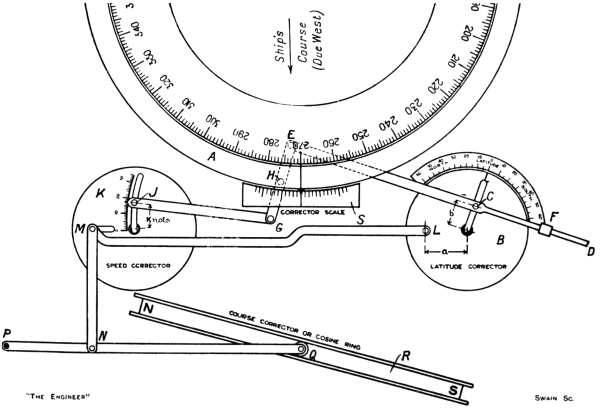
If the end G of the link E G were pivoted, as we have supposed it to be, to some fixed point, then the latitude Error could be applied by itself to the lubber ring. It is not, however, so fixed, but is pivoted to a link, the end J of which carries a pin working in a curved slot extending77 from the centre of the speed corrector dial K to its edge. The radius of this curved slot is struck from the point G as centre. It follows, therefore, that with the speed corrector dial in the position shown the end J of the link G J may be fixed at any point in the curved slot without affecting the position of the point G. If, however, the speed corrector dial be rotated about its centre, the movement of the point G will vary in magnitude with the position at which the pin J is fixed in the curved slot. This position is set against the scale of speed in knots on the edge of the slot, but the setting is without effect until the speed corrector dial is rotated from the position shown in the diagram. When it is so rotated a corresponding movement is communicated to the lubber ring through the link G E, the end E of which is now to be regarded as the fixed fulcrum.
The two dials B K are connected by means of a link L M of length equal to the distance between the dial centres. The end L of this link is pivoted to a fixed point on the dial B, but the end M is provided with a pin which works within a slot in the dial K. Thus the setting of the dial B to any latitude will not produce rotation of the dial K, but will merely cause the pin M to slide in its slot. If, however, the link M N is moved upwards, the angle through which such movement will rotate the dial K will depend upon the exact position of the pin M in its slot—that is to say, upon the setting of the latitude dial. Thus a movement of the link M N will rotate the lubber ring by an amount proportional to the movement of M N, to the setting of the pin J in the curved slot of the speed dial, and to the setting of the latitude dial.
The link M N is pinned to a lever P Q, the end P of which is pivoted to a fixed point. The end Q carries a roller, which engages within the flanges of a ring R permanently fixed in an inclined position on the phantom78 ring of the compass. The higher end of this ring is situated directly above the north-seeking end of the gyro-axle, and the lower end directly above the south-seeking end, its east and west diameter being aligned horizontally.
In the position shown in the diagram the ship is supposed to be sailing due west. Under this condition, as we know, no north steaming error is involved, the latitude error only applying. The dial B can therefore be set to the latitude in which the vessel is sailing so as to apply the latitude correction by itself to the lubber ring. At the same time the pin J can be set to read the ship’s speed—17 knots in the case shown. The movement of the link J G involved in this setting will, as we have seen, not alter the setting of the lubber ring, nor will the setting of the dial B rotate the dial K from the position shown. The two settings are, however, ready to modify the adjustment of the lubber ring as soon as any movement of the link M N occurs. Such a movement arises if the vessel alters course towards the north or south or intermediately, for when the course is altered the links, dials, and lubber ring move with the ship, while the compass card and the course corrector ring R remain stationary. The roller at Q therefore rises or falls towards the north or south end of the ring, and produces a rotation of the dial K. The amount of the modification thus produced in the setting of the lubber ring relatively to the ship’s centre line will depend upon (1) the setting of the pin M—that is to say, the setting of the latitude dial; (2) the setting of the pin J on the speed dial; and (3) the extent of the turn towards the north or south. In this way the correction for the north steaming error is automatically added to or subtracted from the correction for the latitude error to the correct amount on all occasions when the ship’s course is altered so as to have a northerly or southerly component, the adjustment for the error79 being automatically wiped out in all latitudes when the ship’s course is again brought east and west. The mechanism, it will be seen, merely by the setting of two dials, takes cognisance of three independent variables, of which one enters into the required adjustment in a twofold way.4 The total correction is indicated on the corrector scale S attached to the binnacle independently of the lubber ring.
It will be seen, then, that neither the latitude error nor the north steaming error is in the strict sense of the word eliminated, but is only allowed for, automatically or arithmetically, when the compass is read—that is to say, no attempt is made to force the gyro-axle to rest in the true north and south position in all latitudes at all speeds on all courses. The crucial angle by which the ship is navigated is the angle between its longitudinal centre line and the true meridian. A constant straight course will be held if this angle is maintained constant. If the indicated meridian on the compass is open to error, the constancy of the navigating angle may be preserved by introducing a similar error into the degree of coincidence between the lubber line and the longitudinal centre line of the ship. The readings of the master compass may therefore be used for the purpose of maintaining the ship on a given course or for setting it on a new one. But for taking the bearing of some passing object, the fact that it may not be indicating true north may render the observation somewhat more troublesome than it need be. To overcome the difficulty here involved the repeaters served by the master compass are arranged80 to indicate true north under all conditions, provided the latitude and speed dials on the master compass are correctly set. The repeaters are operated electrically, the first element in the transmission system between them and the master compass being a pinion meshing with the gear wheel attached to the phantom ring beneath the master compass card. This pinion is mounted on the lubber ring, and therefore rotates with the ship round the card when the course is altered. But, as it is mounted on the lubber ring, it also partakes of the movement of this ring relatively to the ship produced by the correction mechanism. Thus the net indication transmitted to the repeaters when the ship changes course or latitude or speed is compounded of the relative motion of the master compass card and of the lubber ring. The reading of the repeaters thus shows the true north. A pelorus or dummy compass may be combined with the repeaters to facilitate the taking of bearings. In war vessels the actual navigation of the ship is preferably conducted from a repeater, the master compass for safety in action being disposed below the armoured deck.
The Sperry compass is peculiarly complete in the provision made for taking account of the latitude and north steaming errors. The Brown compass, as we have seen, is free from latitude error, so that the north steaming error alone has to be dealt with. This error may be allowed for arithmetically in the usual way by means of tables of corrections to be applied to the readings of the master compass. As regards the repeaters, the error is eliminated by a method involving the mounting of the repeater cards excentrically, the excentricity being varied to suit the latitude, speed, and course.
81
Having considered the effect of the ship’s speed upon the readings of the gyro-compass, we have next to discuss the effect of the conditions which arise when the speed is changed. It is clear, of course, that if the ship’s speed is changed, say from 20 to 10 knots, the north steaming error appropriate to the course and latitude will fall to half its value when the new speed has been attained. Two questions, however, may be asked. What happens in the period during which the speed is changing, and what time elapses between the attainment of the new speed and the attainment by the compass of the new north steaming error proper to the new speed?
If an ordinary simple pendulum were hung from the roof of a railway carriage it would be found that so long as the train was travelling smoothly at uniform speed the pendulum would hang vertically without oscillating just as it would do if the train were at rest. If the train increased its speed the inertia of the pendulum—that is to say, its tendency to go on moving with the old velocity—would cause the pendulum to assume an inclined position behind the vertical, the deflection being proportional to the rate at which the train was gathering speed. At the instant at which the train ceased to gather speed, and again assumed a uniform velocity, the tendency for the pendulum to remain inclined to the vertical would vanish, but the deflection it possessed at that instant would result in its acquiring an oscillation which82 would persist until friction, etc., damped it out. If when the pendulum were again steady and hanging vertically, the train began to slow down, a similar series of events would occur, only on that occasion the inertia of the bob would cause the pendulum while the train was losing speed to assume a forwardly inclined position, the angle of which would be a measure of the rate at which the speed was being reduced. On the attainment of the new uniform speed the pendulum would oscillate for a time, as before.
The gyro-compass is in part a pendulous body, and on a ship changing speed or acquiring speed from rest or coming to a stop it is open to the action of inertia forces just as is our railway carriage pendulum. As a result the compass during the change of speed may exhibit an error—the ballistic error, as it is called—on top of the existing north steaming error. Since the speed of a ship, at least of a merchant ship, cannot be changed very quickly, and since, further, the speed of a ship, at least on long voyages, is not liable to be changed very often, it might be thought that this transient ballistic error could be neglected. It probably could be safely neglected if its effect were strictly confined to the actual period of the change in the speed, but it is not so confined. We have to bear in mind the subsequent vibration of the railway carriage pendulum. A similar oscillation is set up in the gyro-compass after the new speed is attained. Since the period of oscillation of the compass is about 85 minutes, and as two or three complete swings have to be made before the damping arrangements can suppress the vibration, it follows that the compass will not settle in its resting position again until two or three hours after the new speed has been attained, although the actual change of speed may have been effected inside five minutes or less.
83
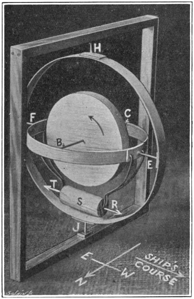
If the ship is sailing on an east-west course, as represented in Fig. 26, any change of speed will tend to cause the pendulum weight S to move in the direction R or T, according as the change of speed is a decrease or an increase. Such a tendency will merely throw stresses on to the journals at E F and H J, or, if the equivalent of the square outer frame is carried on gimbals, as it actually is in practice, then the tendency to rotate will be translated into an actual movement of the sensitive element on the axis of the outer mounting coincident or parallel with the axle B C of the wheel. Such a movement will have no gyroscopic effect on the compass, for the axle84 is not subjected by it to any non-parallel displacement. No ballistic deflection will therefore occur on that course.
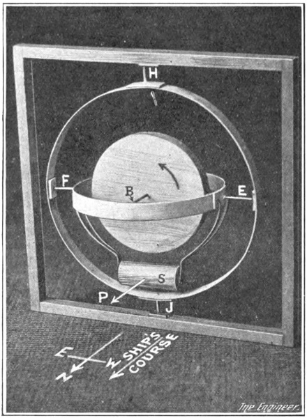
If the ship changes speed while on a west to east course, the change is similarly without effect on the compass. Strictly speaking, we ought to say that the change of speed will have no effect on the compass if the ship’s course is at right angles to the direction in which the axle of the wheel is pointing. Only at the equator would this course be due east or west. In other latitudes the latitude error has to be reckoned with, so that the particular course on which changes of speed are without effect on85 the compass must be slightly south or north of due east or west.
If, now, the ship is steaming due north, as indicated in Fig. 27, a reduction of its speed will tend to make the pendulum weight swing forward about the east and west axis E F in the direction P. This tendency is clearly equivalent to the application of an upward force to the end B of the axle, and hence, as we know, will cause the wheel to precess, the end B of the axle going eastwards. As this precession continues it is opposed by the ever-increasing restoring moment of the directive force, so that in the end the axle assumes a position in which the directive force just balances the ballistic deflective force. This ballistic deflection remains constant all the time the ship’s speed is falling. When the speed reaches the new steady value the axle slowly oscillates back to the true resting position.
It is clear that a reduction of speed on a northerly course and an increase of speed on a southerly produce ballistic deflections in a like direction, the north end of the axle moving towards the east. An increase of speed on a northerly course or a decrease of speed on a southerly produces a westerly ballistic deflection. On intermediate courses deflections of a like kind, but of intermediate value, are caused, for the north and south component of the change of speed is alone effective in tilting the wheel about the east and west axis E F.
Imagine a ship steaming due north at 20 knots and changing its speed to 10 knots during a period of five minutes. As it is steaming north there will be a north steaming error, the axle pointing westwards of true north by an amount dependent upon the speed of the ship and the latitude in which it is sailing. Let O N (Fig. 28) be the direction of true north, and let O A be the direction in which the axle of the gyro-compass aligns itself when the86 speed is 20 knots, the angle N O A being the combined latitude and north steaming errors. Let O B be the resting position for the axle when the ship’s speed is 10 knots, the angle N O B being the latitude error—which has not altered—plus the north steaming error—which is now less because of the reduced speed. As the speed is being reduced, the ballistic action of the pendulum weight causes the axle temporarily to turn eastwards from the true resting position and to align itself in some direction O C. When the ship has settled down to 10 knots, the axle leaving the position O C vibrates about O B with amplitudes which are being continually reduced by the action of the damping system.
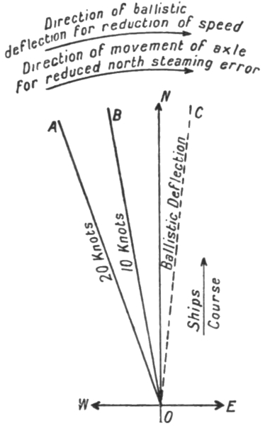
The point of importance to notice is that the temporary87 ballistic deflection O C is eastward of O A, just as is O B the new resting position for the axle. This result is a general one. Had the speed been increased instead of decreased, the ballistic deflection would have been westward of O A, just as would be the new resting position for the axle at the increased speed. Similarly, on due southerly courses or on quadrantal courses the ballistic deflection produced by any change of speed is always in the same direction as that in which the axle moves in passing from the old to the new north steaming error. This being so, it is conceivable that at least, under certain conditions, the ballistic deflection position O C may coincide with the new position O B for the axle under the new north steaming error. Should such a result be obtained, the ballistic action will, on a change of speed occurring, swing the axle straight away into the new resting position. Thus O C and O B being coincident, there will be no tendency for the axle to oscillate about O B when the speed assumes the new steady value, so that the axle will swing into the new resting position in a “dead-beat” manner. The effect of the ballistic action will thus be confined to the period during which the speed is being changed—five minutes in our example—and will not influence the readings of the compass for a period of anything up to two or three hours after the new speed is reached.
The ballistic deflection of a pendulum hung from the roof of a railway carriage is dependent upon the length of the pendulum, and therefore upon its period of natural vibration. So, too, the ballistic deflection of the gyro-compass is dependent upon the period of its vibration about the north and south direction. Once the characteristics of the compass are determined, therefore, the angle A O C (Fig. 28) of the ballistic deflection is settled by (1) the direction of the ship’s course, and (2) by the rate88 at which the ship’s speed towards the north or south is being changed. It is not affected by the latitude in which the ship is sailing, the deflection produced by a change of 10 knots in five minutes being the same at the equator as in 60 deg. or any other latitude.
Coming to the difference between the old and the new north steaming errors, it will be seen from our previous explanation of the errors themselves that the magnitude of the angle A O B is independent of the design of the compass in use. It will vary with (1) the direction of the ship’s course, and (2) the extent by which the ship’s speed is changed. In addition, it will also vary with (3) the latitude in which the ship is sailing.
From these considerations it is argued that by suitably selecting the period of vibration the ballistic deflection can be made for one particular latitude just equal to the difference between the north steaming errors for any initial and any new speed on any course. In practice the latitude selected is 40 deg. north or south. It is found by calculation that the period of vibration which must be given to the compass to secure this dead-beat ballistic deflection is such that in this latitude the compass should oscillate in the same period as would a simple pendulum, the length of which was equal to the radius of the earth. It is for this reason that all modern gyro-compasses have a period of vibration of approximately 85 minutes.5
89 In latitudes other than 40 deg. north or south the ballistic deflection will not be dead-beat, but by taking this latitude as the mean the subsequent oscillation after a change of speed is—in mercantile vessels at least—sufficiently small to introduce no error of great importance, except for purposes of very accurate observation, in which case the observation, if possible, would not be made until the vessel had been running for two or three hours after the last considerable change of speed.
It is to be noticed that the ballistic error may arise when the ship is altering course without altering its speed. Thus, if it is sailing north and makes a sharp turn eastwards or westwards, the speed northwards during the turn falls progressively from a maximum at the beginning to zero at the end of the turn, even although the actual linear speed of the ship remains constant throughout. Turning in either direction is thus equivalent to a deceleration of the ship’s northerly speed, so that an easterly ballistic deflection may be expected in both cases. On the other hand, a turn towards the north from a due east or west course is equivalent to an acceleration of the ship’s northerly speed, and, as a result, a westerly ballistic deflection is produced. In latitude 40 deg. north or south both these ballistic deflections would be dead-beat in a modern gyro-compass, being just sufficient90 in the one case to eliminate and in the other to apply the appropriate north steaming error.
In a very recent improvement, it is understood, it has been found possible to provide means whereby the ballistic deflection is made dead-beat in all latitudes.
91
Let a stone be tied to the end of a string and be flung forward while the free end of the string is held in the hand. Let the hand holding the free end be moved forward at first with the same speed as the stone in its flight, and then let the hand be drawn back. We know that as soon as the string becomes taut—if it were not already fully extended—the hand would feel a pull exerted on it in the direction in which the stone was initially projected. This pull arises from the fact that the stone has been given momentum in the direction of its flight, and while this momentum is being taken out of it by the backward pull of the hand and new momentum in the backward direction is being communicated to it the stone reacts forcibly on the string and therefore on the hand.
In the gyro-compass the pendulum weight may be likened to the stone, the stirrup carrying the weight to the string, and the spinning wheel to the hand. While the ship is steaming at a uniform speed, the system is in the condition existing just after the stone has been projected from the hand, and while the hand is following it with equal speed. A change in the ship’s speed—a reduction of its speed to be quite correct in our analogy—is comparable with the drawing back of the hand. The pull of the stone exerted on the hand at this instant is represented by the tendency of the weight to continue92 moving at the former speed, and the resultant “kick” which by its attempt to do so it applies to the spinning wheel. This kick is communicated to the spinning wheel through stiff members and rigid connections, and not through a flexible string. It really acts at the centre of gravity of the pendulum weight, and is therefore felt by the spinning wheel, not as a straight pull, but as a force tending to turn the wheel about the horizontal axis E F.
The kick of the weight when the ship changes speed on any course having a north or south component produces, as we have seen, a transient ballistic error which may influence the correctness of the compass readings for some hours after the change of speed has been completed. We have now to show that similar kicks occur under other conditions, and may similarly affect the accuracy of the readings.
The subject which we are about to discuss is the so-called quadrantal error which, unless steps are taken to eliminate it, appears in the compass readings when the ship is sailing in a rough sea on any course other than due north, south, east, or west. It is caused by the rolling and pitching of the ship. The efforts made to eliminate it have influenced the evolution of the gyro-compass to a greater extent than probably those directed towards overcoming or allowing for all the other errors combined to which the device is open.
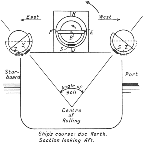
The gyro-compass on board ship is usually, although in no way necessarily, mounted above the vessel’s metacentres—transverse and longitudinal—about which rolling and pitching take place. In Fig. 29 we show a section, looking aft, of a vessel steaming due north with a gyro-compass mounted on its deck. It is clear that, so far as the weight S is concerned, it may be regarded when the ship rolls as the bob of an inverted pendulum vibrating in an east and west plane, through an angle equal to93 the angle of the ship’s roll. From what we have already said, it will be seen that at the end of a roll to port the hand holding the string attached to the flying stone, hitherto following it, begins its withdrawal to the east. The weight checked in its movement to the west communicates a kick to the sensitive element. This kick, a westward force, is applied at the centre of gravity of the weight, and clearly does nothing more than throw a stress on to the journals at E F and H J, and through the square frame on to the deck. It does not therefore affect the direction in which the gyro-axle is pointing. If, as is actually the case in practice, the equivalent of the square frame is not fixed directly to the deck, but is mounted inside the binnacle on athwartship and longitudinal gimbals, the square frame will swing on the longitudinal gimbal axis. The weight S will, however, still act during94 the ship’s roll as an inverted pendulum, as at Z Z, in which the bob remains more or less parallel with its original direction. Under these conditions the kick of the weight at the end of a roll to port will rotate the frame in the direction of the curved arrow about the longitudinal gimbal axis. As this axis is coincident or parallel with the gyro-axle, the gyro-axle is not moved otherwise than parallel with itself either by the actual roll of the ship or by the kick of the weight at either out position. Thus a ship steaming north may roll with impunity without affecting the accuracy of the direction in which the gyro-axle is pointing.
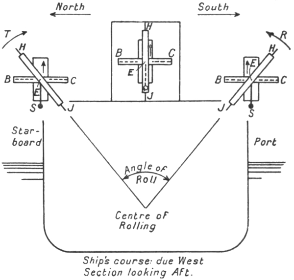
It is clear that rolling on a due south course or pitching on a due east or west course is similarly without effect on the gyro-compass.
Now consider the case of the ship rolling when on a due95 west course (Fig. 30). It is clear that here again the weight S may by itself be considered as the bob of an inverted pendulum vibrating through the angle of the ship’s roll, this time in a north and south plane. The weight S has, in addition, its own pendulum action on the horizontal axis E F, and tends to keep the gyro-axle horizontal throughout the roll.
At the end of a roll to port the kick of the weight S, a southerly force acting at the centre of gravity of the weight, tends to turn the spinning wheel in the direction R about the horizontal east and west axis E F. This kick is clearly equivalent to the application of an upward force at the end C of the axle or a downward force at the end B, and therefore, as we know, will cause the axle not to turn about E F, but to precess the north end B towards the west about the axis H J.
The roll to starboard now takes place, and at its end the kick of the weight occurs in the northerly direction. This kick will tend to turn the spinning wheel about the east and west axis E F in the direction T, and is clearly equivalent to the application of an upward force at the end B of the axle. Such a force, as we know, will cause the end B of the axle to precess towards the east.
It will thus be seen that the western deflection of the axle produced by the precession which occurs at the end of the roll to port is counterbalanced and automatically eliminated by the eastern deflection produced by the precession occurring at the end of the roll to starboard. The only effect on the compass caused by the rolling of the ship is therefore a vibration of the axle about the north and south direction. We should really say that the only effect is the application to the sensitive element of a vibratory influence in tune with the rolling of the ship. As the ship’s period is very small compared with that of the compass about the axis H J—about 5 to 12 seconds96 as compared with about 85 minutes—this vibratory influence practically fails to disturb the steadiness with which the axle points to the north.
It is clear that pitching of the ship when on a due west course has the same effect—or lack of effect—on the compass as rolling on a due north course, and that pitching on a due north course has the same effect as rolling on a due west course. It is further clear that due south and due east courses are similar in this respect to due north and due west courses. Thus when the ship is on a cardinal course neither pitching nor rolling disturbs the axle of the spinning wheel from its north resting position.
Matters are quite otherwise, however, when the course is an inter-cardinal, or quadrantal, one. The discovery of this unlikely fact was in large part due to the investigations of the Compass Department of the British Admiralty. It does not appear to have been known, or at least its full significance does not seem to have been appreciated, in the earlier days of gyro-compass construction. At least one early design of compass—the Anschütz of 1910—did not include means of eliminating or allowing for the “quadrantal error,” and soon became obsolete as a result primarily of the omission. That the later design of Anschütz compass successfully overcomes the difficulties introduced by this error is shown by the admitted excellence of the navigation of the German submarines, which vessels were universally fitted with compasses of this design, and which, like all their class, suffer much from rolling and pitching.
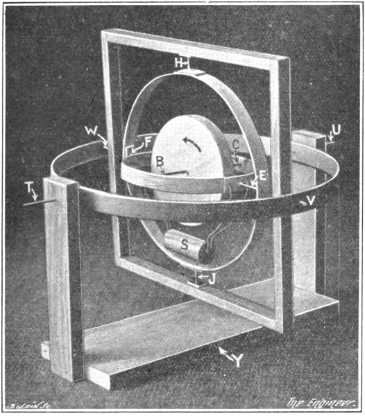
So far we have been able to use a very simple model to demonstrate the properties and errors of the gyro-compass. We have now reached a subject which, if it is to be explained correctly, requires us to adopt a model of a more elaborate nature, one in which the outer square frame of our simple model is itself mounted on a97 pair of gimbal axes. We have already referred to this type of mounting in our second chapter and above in connection with Fig. 29. In Fig. 31 we show it with the pendulous weight added to the sensitive element. We may take it that the axis T U, about which the entire compass system may swing, is parallel with the longitudinal centre line of the ship, and that the frame Y is fixed to the deck.
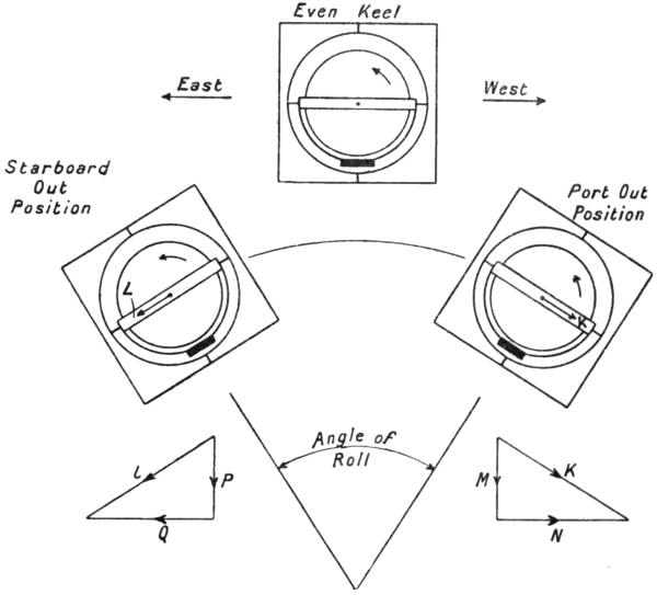
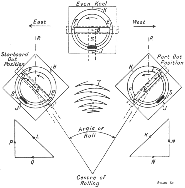
In order to make quite clear the difference between the two forms of mounting, we give in Figs. 32 and 33 two corresponding sets of views showing the compass system on a ship while steaming due north and rolling. With the simple mounting (Fig. 32) the weight S constantly remains radially below the centre of the spinning98 wheel, and the kicks which it applies at the out port and out starboard positions merely stress the compass mountings. With the more elaborate mounting (Fig. 33) the weight tends to remain constantly in the vertical below the centre of the spinning wheel, but the kicks occurring at the out positions, if the rolling is continued for any length of time, cause it to swing beyond the vertical, so that as the ship rolls the whole compass system acquires an oscillation on the axis T U (Fig. 31) in tune with the rolls. It is to be noted that the period of vibration of the compass system about the axis T U is very much less than that of the sensitive element about the axis H J. The latter, as we have seen, is about99 85 minutes, and is determined, in part at least, by the high speed of the spinning wheel. About T U the vibration, however, does not call any gyroscopic force into play, for it takes place without causing the axle of the spinning wheel to alter its direction. The period of this vibration is therefore not affected by the speed of the spinning wheel. It may be quite small—from one to two seconds—and therefore comparable with the ship’s rolling period. If, then, no steps are taken to prevent it, the compass system as a whole will acquire a swing on the axis T U (Fig. 31) when the ship is steaming north—or south—and rolling. Its period of vibration on this axis is not strictly100 that which it would have were it set oscillating about the axis T U with this axis mounted on a fixed frame, for the vibration is not a free one, but is a forced vibration under the impulses communicated by the rolling of the ship. Whatever may be the exact free period of swing of the compass system on the axis T U, so long as it is somewhere near that of the ship’s roll or a small sub-multiple of the rolling period, the tendency is for the compass swings to settle down in such a way that, as represented in Fig. 33, the pendulum weight S reaches its extreme out positions simultaneously with the ship’s arrival at its extreme port and starboard heels. In the course of one complete roll of the ship, however, the compass system may make more than one complete vibration about T U.
It is clear that whether the bob S remains radially below the centre of the wheel, as in Fig. 32, or remains vertically below it, or swings past the vertical, as in Fig. 33, the effect of rolling when the ship is on a due north course is as established in connection with Fig. 29. Either a tendency to rotate the wheel about an axis coincident with its axle or an actual rotation of the wheel about this axis results from the kicks of the weight S at the out positions. Whichever it is, there is no gyroscopic effect called into play, and the axle is not subjected to any influence causing it to move away from the due north direction.
We have now to discuss what happens if the vessel rolls or pitches when sailing on an inter-cardinal or quadrantal course.
In Fig. 34 we show in plan a vessel steaming on a north-west course. When the ship rolls the compass oscillates in the path A D, a path, that is to say, at right angles to the ship’s centre line and curved upwardly by reason of the fact that the compass is mounted above the rolling centre of the ship. The axle of the compass during this101 movement tends to point steadily towards the north under the action of the directive force. The wheel therefore oscillates from A to D with its axle askew relatively to the path of oscillation, and not at right angles to it, as in Fig. 29, or parallel with it, as in Fig. 30. The oscillation A D can, however, be resolved into two components, namely, a north and south oscillation D K, in which the axle is parallel with the path, and an east and west oscillation K A, in which it is at right angles to the path, both paths being curved upwardly.

The oscillation D K, taken by itself, is clearly exactly equivalent to that shown in Fig. 30. The southward kick of the weight at the “out position” D (Fig. 34) just neutralises the disturbing effect of the northward kick at the “out position” K.
102 Similarly, the oscillation K A, taken by itself, is exactly equivalent to that shown in Fig. 29 or its modification, Fig. 33. The eastward kick of the weight at A and the westward kick at K cannot do more than turn the mounting round the axle of the spinning wheel. They do not tend to change the direction of the axle.
Hence, taken separately, each component oscillation D K and K A is without disturbing effect upon the direction in which the axle is pointing. Taken together, however, their united effect is not the sum of their separate effects, as we might hastily assume. We must not suppose that the north and south kicks proper to the north and south component of the oscillation are without effect upon the east and west component or vice versa. At the out position D of the component oscillation K D the weight is not only kicked southwards, but also receives a westward kick from the other component oscillation A K. At K it receives both a northward kick and an eastward kick. Similarly, at the out position K of the component oscillation A K the weight is kicked not only to the west but also to the south, by virtue of the oscillation from K to D. At the other out position A of this component the weight is kicked eastwardly, and also to the north. If we take cognisance of these additional kicks, we may treat the component oscillations separately and add the separate results to get the true effect of the actual oscillation A D.
Returning, then, to Fig. 30, let us suppose that in the oscillation there shown, the equivalent of the component K D, we apply a westward kick to the weight S when the ship reaches its port out position—that is to say, a kick out of the paper—and that at the starboard out position it receives an eastward kick into the plane of the paper. It is clear that these additional kicks do nothing more than tend to rotate the wheel about its103 axle or an axis coincident or parallel with its axle. They cannot therefore call any gyroscopic effect into action, and as a result do not disturb the direction in which the axle is pointing. The component oscillation D K, even with the extra kicks added, is thus harmless.
Taking Fig. 33 rather than Fig. 29 as the equivalent of the component oscillation A K, let us suppose that at the port out position the weight is subjected to an additional kick to the south—that is, into the plane of the paper—and that at the starboard out position it receives an extra kick to the north, or out of the plane of the paper. The southward kick on the weight at the port out position will tend to cause the end B of the axle to turn down towards J, but, in accordance with the fundamental gyroscopic rule, the actual motion of the sensitive element will not be a rotation about the axis E F, but a precession about the axis H J, the end B of the axle moving in the direction K. Similarly, the northward kick at the starboard out position will tend to cause the end B of the axle to rise towards H, and will therefore produce precession in the direction L. Now these two precessional movements, K and L, can be resolved into horizontal and vertical components N M and Q P respectively, as shown separately, and of these components it is clear that the movement N cancels the movement Q. On the other hand, the two components M and P are in the same direction, and therefore do not cancel each other. Their effect is cumulative, and with each succeeding roll the end B of the axle tends to rise higher and higher in the true vertical plane B R. It may be explained, perhaps, that this motion is possible, in spite of the fact that there is no actual axis in the mounting of the compass at right angles to the true vertical plane, except at the instant when the compass is passing through the even keel position in the course of its swing104 from side to side. As the rolling of the ship starting from zero increases up to a more or less steady value, the end B of the axle rises slowly at first and then at a constant rate, as exaggerated at T. Such of this upward movement as occurs while the compass is passing through the even keel position can be effected by means of a rotary motion purely about the axis E F. Elsewhere in the swing of the compass from side to side it is accommodated by a partial rotation on E F and a partial rotation about H J. These two axes between them permit the end B of the axle to rise in a vertical plane at any point of the compass swing just as effectively as would an axis which was at right angles to the vertical plane B R.
To appreciate the significance of this vertical rise of the north end B of the axle, let us consider the condition of the compass as it is passing through the even keel position. The elevation of the end B out of the horizontal plane causes the weight S to swing forward towards the north, and therefore to apply a turning moment to the spinning wheel about the axis E F. This turning moment will tend to bring the end B down again to the horizontal, but, as we know, the actual motion produced will be a precession about the axis H J, the end B moving westwards. Looking at Fig. 34, it will thus be seen that the net effect of the rolling of the ship is to deviate the axle of the compass in the direction shown at V—that is to say, in the direction required to set the plane of the spinning wheel parallel with the plane of the rolling by the shortest possible course—in our example by a rotation westward through 45 deg. With the axle so deflected the earth’s rotation, of course, calls a directive force into play, tending to restore the axle to the north and south line, but if the ship is rolling violently the deviating force will be much stronger than the directive force until a very considerable angle of deflection is reached.105 When the balance is struck, the axle settles down with a steady deviation towards the west, which will remain constant as long as the rolling is maintained. In practice the violence of the rolling varies almost from roll to roll, for it represents a conflict between the natural period of rolling of the ship and the period of the waves. As a consequence, the deviation of the compass varies somewhat during the rolling, but it is always westwardly if the course is in the north-west quadrant.
A little consideration will show that if the ship is steaming towards the north-east the additional kick on the weight S (Fig. 33) at the port out position will be towards the north and at the starboard out position towards the south. The end B of the axle is therefore precessed vertically downwards instead of upwards, and as a result the deviation of the axle is eastwardly. In general, if the ship is steaming on any course in the north-west or south-east quadrant, the deviation caused by her rolling will be towards the west. It will be towards the east if the course is in the north-east or south-west quadrant. The effect of pitching on a quadrantal course is to cause a deviation of the axle in the direction opposed to that of the deviation caused by rolling, so that if the vessel be both rolling and pitching, the deviation is somewhat less than it would be if rolling only had to be considered.
It may perhaps be thought that the quadrantal error is an effect produced by the double gimbal mounting of the compass, and that had we adhered to our simple model, as shown in Fig. 32, it would not arise. This is not so. If Fig. 32 be taken as representing, after the manner of Fig. 33, the north view of the compass on a ship steaming due north-west, it will be seen that the southern kick at the port out position causes the axle to precess in the direction K and the northern kick at the106 starboard out position in the direction L. Resolving these movements as before, we see that, while the horizontal components N Q again cancel, the vertical components M P are, as in Fig. 33, cumulative in effect, but this time they result in the end B of the axle moving downwards, and therefore finally cause it to precess eastwards instead of westwards, as before. The quadrantal error is therefore not eliminated, but merely reversed in direction by adopting the simpler mounting for the compass.
107
From our description of the cause of the quadrantal error it should be clear that it is of a variable erratic nature, or at least that, unlike the latitude and north steaming errors, its magnitude cannot be forecast from a knowledge of the ship’s speed, course, latitude, or other factors. Its direction is determined by the direction of the ship’s course, but its amount is settled by the violence of the rolling and pitching, and cannot therefore be calculated and tabulated in a practically useful way. It follows, therefore, that to get rid of the upsetting influence of the quadrantal error we cannot resort to “correcting” the compass readings for it, but must entirely eliminate it.
In the early (1910) Anschütz compass there were no means of eliminating the quadrantal error, for the existence of the error, or at least the importance to be attached to it, was not at first recognised. The compass, we believe, showed errors from this cause of as much as 20 deg. to 40 deg. As a result, within a very short time the design was discarded, and what amounted to an entirely different compass was substituted for it. The 1912 Anschütz compass will be briefly described later on, but here it may be said that the quadrantal error in it is eliminated by adding two more gyro-wheels to the sensitive element. The theory of this compass is not very easy to understand, so that it will be best if we explain first how the quadrantal error is eliminated in the Sperry and the Brown compasses.
108 The early Sperry, like the early Anschütz compass, was open to the full action of the quadrantal error. In the form now in use, however, it is prevented from taking effect by controlling automatically the position of the excentric pin connecting the weight or “bail” to the gyro casing. In the Sperry compass, as we know, the weight S (Fig. 35) is not hung from the inner supporting ring or its equivalent, but from the follow-up or phantom ring, its pendulous effect being communicated to the casing and thence to the spinning wheel through the excentric pin A. The kicks of the weight at the out positions during the rolling of the ship are also transmitted through the pin to the casing and wheel inside it.
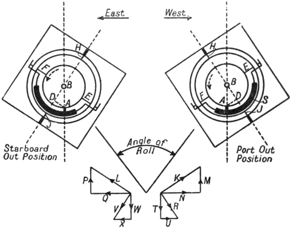
Let us suppose, as shown in Fig. 35, that at the port out position of the compass swing the excentric pin is east of the axis H J by the amount required just to bring it vertically below the centre of the spinning wheel. Then the southward kick of the weight when the vessel109 rolls on a north-west course is transmitted to the casing as a southward force applied at the point A. This force, acting about the axis E F as before, produces precession in the direction K, and, as before, we may resolve this movement into the components N M. The force at A has, however, in addition, a turning moment about the axis H J, for it is applied to the casing at a point lying at a distance A D from this axis, and not, as in Fig. 33, at a point virtually on it. This moment about H J would tend to make the end B of the axle turn in the direction of F, and therefore results, in accordance with the rule of the gyroscope, in an actual movement about the axis E F, the end B of the axle precessing downwards towards J, that is, in the direction R. We may resolve the precession R into two components T U.
Similarly, at the starboard out position, let us suppose that the excentric pin is this time westwards of the axis H J by exactly the amount required again to bring it vertically below the centre of the wheel. As before, in the case shown in Fig. 33, the northward kick of the weight acting about E F results in a precession L, which may be resolved into the components P Q. The kick, however, as at the port out position, also has a moment about the axis H J. The kick is reversed in direction, but the point of its application to the casing is now on the other side of H J. Consequently the kick tends to rotate the casing about H J—and therefore produces precession about E F—in the same direction as does the kick at the port out position. The precession produced is represented by V, and can be resolved into the components W X.
Considering now the four pairs of component precessions, we see that they cancel out in pairs. Thus N and Q cancel, U cancels X, T wipes out M, and W does the same to P. The two components M P, which110 were the cause of the quadrantal error, are just balanced by the two additional components T W. The axle therefore does not rise vertically, but remains horizontal, and as a result no quadrantal error can arise.
It will be seen that the Sperry method of eliminating the quadrantal error requires the excentric pin to be movable relatively to the bail and casing. To be more precise, while the casing, the bail, the phantom ring, and all the other parts of the compass may swing round the axle of the spinning wheel, or the external gimbal axis coincident or parallel with the axle, matters have to be arranged in such a way that when the ship rolls the excentric pin shall not partake of this motion, but remain constantly in the vertical below the centre of the spinning wheel. We have to remember, however, that the Sperry method of damping the horizontal vibrations of the axle hangs upon the pin being displaced towards the east of the axis H J when the compass is in the even keel position. The two requirements are met by so controlling the position of the pin relatively to the bail and casing that when the bail, casing, etc., swing sideways under the influence of the rolling of the ship, the pin is maintained at a fixed distance eastwards of the true vertical through the centre of the spinning wheel at all points in the oscillation of the bail, casing, etc.
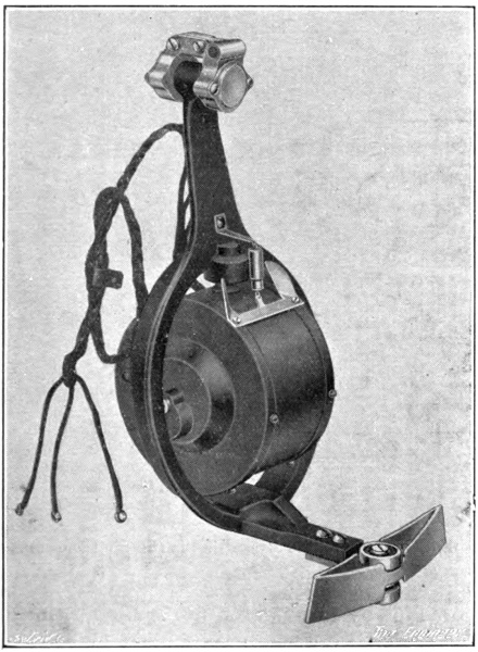
The stabilisation of the excentric pin in this manner is effected gyroscopically by means of the attachment shown in Fig. 36. This device consists of a small high-speed electrically driven gyroscope running inside a casing which is mounted rotatably on a vertical axis inside a stirrup frame. This frame, as shown in Fig. 37, is hung pendulum-wise on the north side of the main gyro casing, the axis of its suspension being collinear with the axle of the main gyro-wheel. The axle of the small gyro-wheel is thus aligned in the east and west direction.111 The stirrup bracket is turned up horizontally below the casing of the small gyro, and at its end is fitted with guides, carrying a pair of rollers. These rollers constitute the excentric pin and, as shown in Fig. 37, engage within two curved channel-sectioned tracks attached one to the bail and one to the main gyro casing. If when the bail, casing, etc., swing under the influence of the ship’s rolling the excentric pin should attempt to follow suit—either by reason of friction at the axis of suspension of the stirrup bracket or at the track rollers—the wheel112 and casing of the small gyro will start processing round the vertical axis inside the stirrup, for the attempt is equivalent to an endeavour to tilt the small gyro-axle in an east and west vertical plane, and therefore calls forth the usual gyroscopic reaction. The precession of the small gyro on its vertical axis is made to react on the stirrup bracket by means of a spring connection between the bracket and the casing, as shown in Fig. 36. The direction of spin of the small gyro-wheel is such that the force thus applied to the stirrup bracket opposes and just balances the frictional or other force trying to make it swing with the bail, casing, etc., of the main gyro. In this way the excentric pin as the vessel rolls is caused to maintain its original distance from the vertical line through the centre of the spinning wheel.
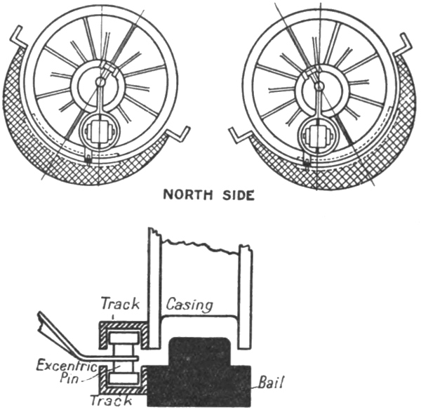
The suppression, or rather the avoidance of the quadrantal113 error in the Brown compass, is achieved in a manner which is mechanically very distinct from that adopted for the same purpose in the Sperry compass.
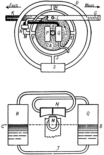
An elementary diagram of the Brown compass is given in Fig. 38. In this sketch A is the casing, inside which the gyro-wheel mounted on the axle B (C) rotates in the direction of the dotted arrow—B, as before, representing the north-seeking end of the axle. The casing is supported on an east and west horizontal axis E F inside a vertical ring, this ring being journalled at H J inside a frame D, the equivalent of the square frame in our simple model. To obtain complete freedom for the gyro the frame D114 is mounted on an athwartship axis G K, which is itself carried inside a ring journalled within the binnacle on an axis L parallel with the ship’s longitudinal centre line. The pendulum weight S is fixed to the lowest point of the frame D. If the weight S and frame D be set swinging on the axis G K, the swinging movement will, of course, be directly communicated through the journals H J to the vertical supporting ring, but, as the trunnions E F of the casing are really supported on knife edges, the swinging movement of the frame D cannot be communicated from the vertical ring through the trunnions E F to the casing A, and thence to the wheel. Yet it is essential that the weight S should be able to act pendulum-wise on the casing and wheel, for otherwise, as we know, the system would be without directive force.
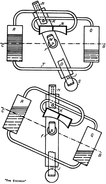
The connection between the weight and the casing is not a mechanical one, but is effected by making use of the air blast created by the fan-like action of the wheel inside the casing. As we have explained in connection with the damping system adopted in this compass, the trunnion F is hollow, and delivers the air blast through a nozzle M, fixed relatively to the vertical supporting ring, into a divided box N. From this box pipes are led to two oil bottles—one of which is shown at P—fixed to the casing on the east side of the axle, one bottle being on the north face of the casing and the other on the south. The pressure of the air blast acting unequally upon the oil in these two bottles when the casing tilts about the axis E F results, as we have already explained, in any horizontal oscillation of the sensitive element about the axis H J being damped. In a similar way two bottles Q R half-filled with oil are fixed to the north and south faces of the casing on the west side of the axle of the spinning wheel. These bottles are also connected to the box N, but the connecting pipes are crossed so as to join each bottle Q R115 to the division of the box remote from it, and not to the adjacent division, as in the case of the damping bottles P. When, therefore, the weight S and frame D are swung slowly pendulum-wise on the axis G K, as shown in the first view in Fig. 39, the nozzle M, being fixed to the vertical ring, delivers more air into one division of the116 box N than the other, and therefore a greater air pressure is exerted inside one bottle than inside the other. Consequently oil flows through the connecting pipe T from the former bottle to the latter until the columns of oil are sufficiently unequal to balance the difference of pressure of the air inside the bottles. It will be noticed that the crossing of the pipes connecting the bottles with the box N results in the oil being accumulated in that bottle, which lies away from the side to which the weight S has been swung. Hence, although there is no mechanical connection between the weight and the casing of the spinning wheel, the effect when the weight S is swung slowly is thus substantially the same as it would be if there were, for the weight of the extra oil forced into the bottle R exerts a turning moment on the casing about the axis E F, and tends therefore to make the casing follow the deflection of the weight S and frame D.
Similarly, should the axle B C dip, as shown in the second view in Fig. 39, extra oil will accumulate in the bottle which has been elevated by the dipping, and as a result a restoring moment about the axis E F will be applied to the casing, just as it would be if the weight S had been directly connected to the casing and had been deflected by the dipping movement.
The second view in Fig. 39 illustrates the generation of the directive force in the Brown compass. Let us suppose that the compass is at the equator, and that by some agency the axle is turned so that its end B points due west. The rotation of the earth will cause the axle to dip slowly into some such position as that shown. During this slow dipping movement oil will flow slowly from the bottle Q into the bottle R. The unbalanced weight of oil will apply a turning moment to the sensitive element about the axis E F and will therefore produce actual motion about the axis H J, which will precess the117 end B of the axle towards the north. Any tendency for the axle to vibrate about the north and south line as a result of the momentum acquired by the sensitive element while coming up from the west will be damped by the air blast acting upon the oil in the two other bottles P fixed, as shown in Fig. 38, on the east side of the axle.
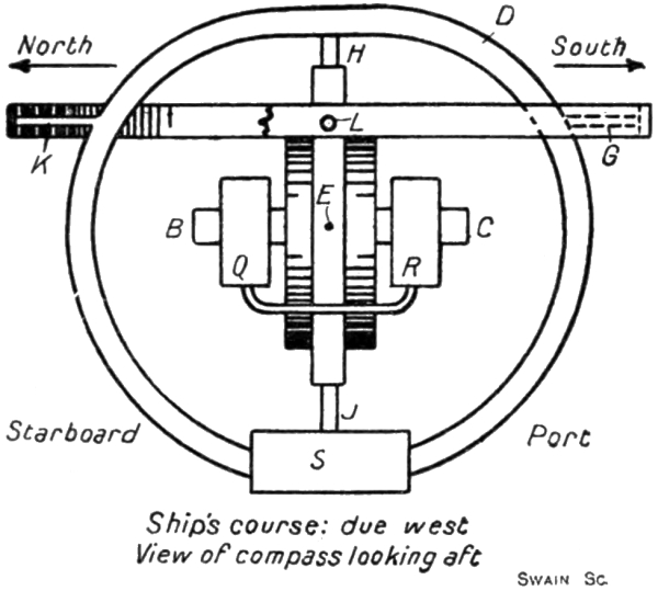
The point we require here to notice especially about this action is that, as the tilting of the axle produced by the rotation of the earth takes place very slowly—it cannot exceed the speed of rotation of the earth on its polar axis, namely, 0.0007 of a revolution per minute—the flow of oil from the bottle Q to the bottle R takes place very slowly also. The oil therefore acquires practically no momentum, and rises in the bottle R in strict accordance with the tilt acquired by the axle. If the tilting motion be stopped or reversed, the oil would remain in the bottle R at just the level it had reached, or would immediately begin to flow back again, for its momentum being negligible, it has not sufficient kinetic118 energy to rise higher in the bottle R after the upward motion of the bottle has ceased.
On the other hand, when the ship rolls, say, on a due west course, as represented in Fig. 40, the outer gimbal ring supporting the athwartship axis G K, the frame D carrying the weight S, and the vertical supporting ring will acquire an oscillation about the fore and aft axis L in tune with the rolls of the ship. The air blast will thus be directed into the two divisions of the box alternately, and therefore oil will flow from one bottle to the other. It is to be noticed, however, that the rolling motion of the ship induces in this manner a flow of oil from one bottle to the other at a very much greater rate than does the tilting action of the earth’s rotation dealt with above.
A ship rolling through 45 deg., out to out, in a complete period of 10 seconds rotates about its rolling centre with an average velocity equivalent to 1.5 revolutions per minute—or over 2000 times as fast as the speed of rotation of the earth on its polar axis—and at the mid point of its roll it will move with an actual velocity of about twice the average. The momentum acquired by the oil in flowing from bottle to bottle is therefore in this case not negligible. In fact, when the ship reaches one of its out positions and starts to return, the oil does not immediately begin to flow back into the other bottle, but is carried by its kinetic energy to a still higher level in the bottle in which it has been rising. As a result, the oscillation of the oil between the two bottles lags behind the oscillation of the pendulum weight S, and therefore that of the ship itself. The lag acquired is such that the oil is just level in the two bottles when the ship is at either of its out positions, and when the ship is at the mid point, or even keel position of its roll, although the air blast is for the moment evenly distributed between the two compartments of the divided box, the oil is standing at its119 maximum level in the bottle on that side of the wheel from which the ship is recovering herself. The action of the oil in the bottles during a rapid oscillation of the compass system is, in fact, quite analogous to that of the water in the Frahm system of anti-rolling tanks.
It will thus be seen that the net effect of transmitting the “kicks” derived during rolling from the pendulous weight of the wheel through the Brown oil bottle arrangement is simply to delay the application of the kicks to the gyro-wheel by a constant amount, namely, by the time taken for the ship to roll from either out position to the mid position or a quarter of a complete period. Thus as the ship sailing due west rolls through the mid position from starboard to port the compass system experiences the turning moment about the axis E F, which with a rigidly fixed pendulum it would receive at the starboard out position from the northwards kick of the weight. Similarly, the equivalent of the southwards kick of the weight at the port out position is felt by the wheel when the compass is passing through the even keel condition on the subsequent roll from port to starboard. It is clear that with the ship sailing due west—or east—this delaying of the kick does not affect the result established previously for a rigidly connected pendulous weight. Any tendency for the axle to precess towards the west when the compass is passing through the even keel position in one direction is completely annulled by the tendency to precess towards the east at the succeeding passage through the even keel position in the opposite direction.
On quadrantal courses, however, the delay in the application of the kick is most important, for when the ship rolls it results in the elimination of the quadrantal error. That it does so can easily be understood by reference to Fig. 33. The kicks, being received when the compass is passing through the even keel position, and not120 at the out positions, precess the wheel about the axis H J at a time when this axis is truly vertical, and not when it is inclined. The precessional movements have therefore no vertical components M P. They are represented completely by the horizontal components N Q. The axle thus does not depart from the horizontal plane, and any movements in this plane arising from the tendency to precess in the directions N Q cancel each other at successive passages of the compass through the mid position.
The early form of Anschütz compass was followed by the 1912 pattern in which the quadrantal error was successfully eliminated. An example of the 1910 form was obtained by Messrs. Elliott Brothers, of Lewisham, from Anschütz and Co., of Kiel, and was, we believe, fitted on board H.M.S. New Zealand. Its defects becoming apparent, its manufacture in this country was not proceeded with, but upon the appearance of the improved type in 1912, Messrs. Elliott took up its construction and supplied several to the Admiralty. The Sperry compass, however, secured the preference in the British Navy, and with the outbreak of the war Messrs. Elliott ceased practically to make Anschütz compasses. On the other hand, the German Navy continued to use the 1912 type of Anschütz compass, with very little alteration or addition, right throughout the war. In view of the fact that every German submarine was fitted with a compass of this form, and bearing in mind the high degree of excellence attained in the navigation of the enemy’s underwater craft, there can be no doubt that the modern Anschütz compass is a very satisfactory device.
In Fig. 41 we give a purely diagrammatic representation of the compass. The outer square frame may, as usual, be regarded as mounted within external gimbal rings, providing a fore-and-aft axis and an athwartship axis. The square frame contains a vertical ring free to turn121 about the axis H J and itself containing a horizontal ring mounted on an east and west axis F E. The pendulum weight S is attached, as usual, to the inner horizontal ring. The essential difference between the 1912 and the 1910 forms of Anschütz compass lies in the fact that, as shown in our diagram, the inner ring, or its equivalent, does not surround a single gyro-wheel, but has attached to it the casings of three distinct gyros.

As shown in the first plan—in Fig. 42—the three gyros are situated at the corners of an equilateral triangle. One gyro K is placed at the south end of the meridional diameter of the horizontal ring, with its axle pointing towards the centre of the ring. The two other gyros L M are placed at 60 deg. east and 60 deg. west of north, with their axes pointing towards the centre of the gyro K—not towards the centre of the ring. The wheels of all three122 gyros rotate anti-clockwise, as seen from the north, looking south—that is, they rotate in the same direction as do the wheels of all single-gyro compasses as seen from the same standpoint.
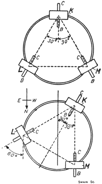
If we neglect the two gyros L M for the moment, imagining them to be replaced by simple deadweights to counterbalance the weight of the gyro K, it will be seen that this system differs from that of the early Anschütz compass only in the fact that the gyro-wheel has been reduced in size, and has been displaced from the centre of the horizontal ring to the southern edge.123 The displacement of the wheel in this manner in no way affects the essential working of the compass. In a single-gyro compass we might with some advantage similarly displace the spinning wheel, for by so doing and by counterbalancing the displaced weight we should, at least partially, get rid of the concentration of mass about the east-west axis, which, as we shall see, introduces, if not corrected, an additional source of error into the compass readings when the ship rolls on quadrantal courses.
The reduction in the size of the gyro-wheel would, of course, reduce the magnitude of the directive force. In the 1912 design the wheels of all three gyros run at 20,000 revolutions per minute—that is, at the same speed as the wheel in the 1910 design. But each wheel is only 5 in. in diameter instead of 6 in., and weighs, with its axle, 5 lb. 2 oz., or only half as much as the wheel in the earlier form. The gyro K considered alone would therefore supply a directive force of but half the former amount.6
It follows, obviously, that if a second gyro of the same speed and size as that at K be fixed in accurate alignment at the north end of the meridional diameter of the horizontal ring the directive force at any angle of horizontal deflection away from the north will be doubled, that is, will be made equal to that developed in the 1910 design. Such a compass might be constructed, but it would exhibit the quadrantal error—or at least the inertia force portion of that error—just as badly as did the early Anschütz.
The essence of the 1912 design lies in the fact that not124 one but two gyros are attached to the north side of the horizontal ring, and in the additional fact that the axles of these two gyros are not parallel with but are inclined to the axle of the south gyro K.
When the sensitive element of this compass is in the north resting position, the axle of the gyro K is aligned with the meridian and therefore the rotation of the earth—the compass being supposed at the equator—merely moves the axle parallel with itself. On the other hand, with the sensitive element in the north resting position, the axles of the gyros L M are inclined to the meridian at 30 deg. The gyro L is virtually in the condition of a single-gyro compass, with the north end of its axle partially turned towards the east. Under this condition, as we know, the rotation of the earth will tend to make the north end B of the axle rise above the horizontal plane. Conversely, the gyro M is in the condition of a single-gyro compass, with the north end of its axle partially turned towards the west. The earth’s rotation in this case tends to make the north end of the axle dip below the horizontal plane. Thus, in the 1912 Anschütz compass, when the sensitive element is in the north resting position, the gyro K under the rotation of the earth is without effect on the pendulous weight S, the gyro L is striving to swing it towards the north, and the gyro M is trying with an equal effort to swing it towards the south. The weight, therefore, remains in the plumb line and applies no turning moment to any of the gyros. As there is no turning moment, there is no precessional tendency. The sensitive element remains directed towards the north. This alignment, as in a single-gyro system, is the true resting position, and under it no directive force is applied to the sensitive element.
To study how the three gyros act together to restore the sensitive element to the north resting position should125 it be deflected therefrom, let us suppose that the deflection suffered is one of 30 deg. towards the east. As shown in the second plan in Fig. 42, the effect of such a deflection is to place the three gyros K L M in the condition respectively of a single-gyro system when the axle is (k) deflected 30 deg. to the east, (l) deflected 60 deg. to the east, and (m) aligned on the north. At this deflection, then, the gyro M contributes no restoring force. The directive force contributed by the gyro K is half that contributed by the single gyro of the 1910 design when the deflection is 30 deg., for the mass—or moment of inertia—of the wheel is half the earlier value. The directive force contributed by the gyro L is something greater than that contributed by the gyro K, for the virtual deflection eastwards is 60 deg. instead of 30 deg., and, as we know, the directive force increases with the deflection. Thus, the three gyros taken together supply a directive force, when the sensitive element is deflected through 30 deg., which is somewhat greater than that supplied by the single double-sized wheel of the 1910 design.7 This result is a general one. Whatever the deflection may be, the directive force supplied by the three-gyro compass is always about one-third greater than the directive force of the 1910 design at the same deflection. This increased force is developed even if the deflection be less than 30 deg. In such cases the gyro M will, of course, supply a force, a non-restoring force, to the sensitive element. Only when the deflection exceeds 30 deg. eastwards does the gyro M assist the gyros K and L to restore the sensitive126 element to the north resting position. If the deflection be to the west, however, the gyro M is the chief assistant of the gyro K, a laggard’s part being played by the gyro L until 30 deg. of westerly deflection is reached.
The manner in which this three-gyro system avoids the quadrantal error can now be discussed. The quadrantal error, it may be recalled, arises when the ship rolls on an intercardinal course, and is primarily caused by the fact that the whole compass system can swing on its external gimbal axis in tune with the rolls of the ship. If we could so arrange matters that during the roll of the ship from side to side the compass system would swing on the external gimbals, no more and no less than the amount required just to keep the axis H J truly vertical at all points of the roll, then the north and south “kicks” received on the weight S at the out positions of the roll would cause the sensitive element to precess first one way, then the other, but always in a horizontal plane. There would be no vertical component in the precession, the cumulative effect of which, as we have seen, produces the quadrantal error.
In the Brown compass, the quadrantal error is eliminated by delaying the effect of the “kicks” on the weight S until the axis H J is truly vertical—that is to say, the “kicks” on the weight are not transmitted to the spinning wheel until the compass system is passing through the even keel position. In the Sperry compass the weight S is virtually shifted back and forth from east to west of the axis H J in tune with the rolling of the ship in such a way as to introduce a second component of vertical precession, which in amount and direction is just sufficient to nullify the vertical component causing the quadrantal error. In the 1912 Anschütz compass, the object aimed at is the maintenance of the axis H J truly vertical at all times during the rolling condition.
127 This object is achieved, as we shall now show, by setting the axles of the gyros L M—Fig. 41—inclined to the axle of the gyro K. In a single-gyro compass, or in the 1912 Anschütz compass with the gyros L M suppressed, the system is very stiff against vibrations on the east-west axis E F, but is quite easily set vibrating about the north-south axis provided by the external gimbal mounting. The reason is, of course, that any vibration about the axis E F is met by the resistance of the gyro-wheel, for the vibration causes the axle to alter its direction, whereas no gyroscopic resistance is called into play by the vibration on the north and south axis, for this axis is coincident or parallel with the gyro-axle. Thus, in the 1910 Anschütz compass the period of vibration about the east-west axis was something like 70 min., whereas the period about the north and south axis was only one or two seconds. The smallness of the latter period readily resulted in the compass system getting into a swing in tune with the period of rolling of the ship—from five to twelve seconds or so. Were the axles of the gyros L M in the 1912 form set parallel with that of the gyro K, there would still be no gyroscopic resistance exerted against vibration on the north-south axis. As it is, the inclination of the axles of these two gyros, taken together, has virtually the same effect as would be obtained by the addition to the sensitive element of a separate single gyro, with its axle aligned at right angles to the axle of the gyro K.
The gyroscopic stiffness against vibration about the east-west axis E F is hardly affected by the inclination of the gyros L M at the angle chosen by the designers. The resistance, instead of being that contributed by three gyros, is equivalent to that supplied by about 2¾ gyros. The period of vibration on this axis E F is arranged to be the standard 85 min. About the north and south axis we128 have virtually the resistance of one gyro. The period of vibration about this axis, instead of being only one or two seconds, is about 80 sec. With this lengthened period of vibration there is practically no chance of the compass system getting into a swing in tune with the rolling of the ship, for every 2½ to 6 seconds the vibrating influence is reversed in direction, and in this interval of time the system cannot acquire any substantial degree of swinging motion. Thus, as the compass, following the rolls of the ship, moves from side to side, it suffers a pure translational movement. The axis H J remains truly vertical at all instants during the roll, and therefore the north and south kicks of the pendulous weight at the out positions of the roll precess the gyro-axle about H J in purely a horizontal plane, the precessional tendency at one out position cancelling that at the other. There is no vertical component in the precession, and therefore there can be no quadrantal error.
It is of interest and of some amusement to note that during the war the Germans applied a fourth gyro to the Anschütz compass, and that this additional gyro was carefully removed from every compass before they surrendered their submarines to us. The deceit was, however, of no avail, for the application of the fourth gyro was known to us long before the war ended, a complete compass so fitted having been recovered from a sunken submarine and repaired and carefully studied. The fourth gyro was applied to the external gimbal rings. These rings, when the submarine rolled, were found to acquire at times a violent oscillation of their own, for, of course, they received no stabilisation from the gyroscopic elements of the compass. On board submarines the violence with which the rings vibrated would occasionally threaten to wreck the compass. By adding a gyroscope to the gimbal rings, the period of vibration of the rings129 was lengthened to about 16 sec., so that little or no opportunity to swing was left to them. With the exception of this addition, the Anschütz 1912 compass was used by the Germans throughout the war practically without alteration.
130
In addition to the “kicks” of the pendulous weight, which during quadrantal rolling, as we have seen, react gyroscopically upon the compass and tend to make the axle deviate from the north, there is a second influence at work on the compass, which, when the vessel rolls on an intercardinal course, likewise tends to deviate the axle. The two deviations are always in the same direction, so that we cannot arrange the one to reduce or eliminate the other. The second deviation arises from the centrifugal forces developed in the compass parts during quadrantal rolling. These forces, like the kicks of the pendulous weight, react gyroscopically upon the spinning wheel, and if not checked will deviate the axle away from the north.
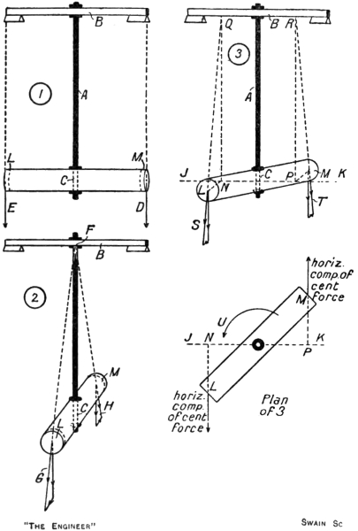
Let us consider the somewhat unusual type of pendulum shown in Fig. 43, a pendulum the rod A of which is fixed rigidly to the bar B carried on knife edges, and of which the “bob” is in the form of a cylinder suspended at its mid point from the rod A in such a way as to permit the bob to turn horizontally on the bearing at C, substantially without friction. In the first instance, let the pendulum be set swinging about the knife edges with the cylindrical bob set parallel with the axis B. Each portion of the bob is thus caused to swing about that point on the axis B which is vertically over the portion when the bob is at rest. The centrifugal force developed on each portion is at all positions of the swing directed radially from such131 point. The centrifugal force on each portion is a maximum when the bob is passing through the mid position, and falls, with the velocity, to zero at each of the out positions. At the mid position the centrifugal force on the two extreme portions L M of the bob may be represented by D E. These two forces are equal and are directed vertically downwards. On all other similar portions the centrifugal force at the same instant is similar in magnitude and direction. The net effect of the132 centrifugal forces on all the portions is thus simply a tendency to bend the bob ends downwards about the central line at C. They have clearly no tendency either at the mid position of the swing or at any other to turn the bob round the axis C at the foot of the rod.
Let us now set the pendulum swinging with the bob arranged at right angles to the knife-edge axis, as shown in the second view of Fig. 43. Each and every portion of the bob is now swinging about the one point F on the axis. At any instant in the swing the centrifugal force on any portion is directed along the line joining the point F to the centre of that portion. Taking the two extreme end portions L M as the bob passes through the mid position, the centrifugal forces are as indicated at G H. They are not now vertical nor parallel with each other, but, again, they have no tendency to turn the bob horizontally about the axis at C. Resolving them into vertical and horizontal components, we see that the net effect of all the centrifugal forces is to try to bend the ends of the bob downwards—the effect of the vertical components—combined with the application to the bob of a horizontal stretching force—the effect of the horizontal components.
Let us, however, rotate the bob about the axis at C through something less than 90 deg. from the first position—say, through 45 deg., as indicated in the third sketch. Consider again the two extreme end portions as the bob is passing through the mid position of its swing. Let J K be a line through the centre of the bob parallel with the knife-edge axis. From the centres of the end portions, let lines L N and M P be drawn at right angles to J K. From N and P draw lines upwards parallel with the rod A to meet the knife-edge axis at Q and R. Then Q and R are the points about which the two extreme portions of the bob are swinging. The centrifugal forces on these portions are directed along the lines Q L and133 R M, and are indicated at S and T. These forces may, as shown, be resolved into vertical components—parallel with Q N and R P—and horizontal components—parallel with N L and P M. Treating the other portions of the bob similarly, it will be seen that while the vertical components of the centrifugal forces, as before, merely tend to bend the ends of the bob downwards, the horizontal components are no longer parallel with the length of the bob, as in the second sketch. They are inclined to the bob and clearly apply to it a moment which will turn it about the axis at C in the direction of the arrow U until the bob reaches the position shown in the second sketch.
It is obvious that any rotation of the bob on the axis at C away from the position shown in the first sketch, even a slight one, will call into action horizontal components of centrifugal force after the manner shown in the third sketch. The equilibrium of the bob in the position shown in the first sketch is therefore unstable. With the bob in the second position a movement of the end L to the left will, as we know, call into action horizontal components of centrifugal force, tending to turn the bob about C in the direction of the arrow U. If the end L is moved to the right the horizontal components, as can easily be verified by repeating the argument, will tend to turn the bob about C in the direction opposed to the arrow U. Thus deflection to either side of the second position calls forth forces which lead the bob to recover that position. We conclude, therefore, that the second position is one of stable equilibrium.
It may further be shown by repeating the argument that if the bob is rotated about C from the first position in such a way as to send the end L to the rear the horizontal components called into action tend to set the bob into the second position with the end L pointing backwards, and that when the bob is so aligned relatively to134 the knife-edge axis the equilibrium is again stable. Thus, altogether, if the bob is parallel with the knife-edge axis, the equilibrium is unstable. If it is at right angles the equilibrium is stable. If it is set into any intermediate position, forces are called into play which endeavour to align it at right angles to the knife-edge axis.
Let a second cylindrical bob of the same size and weight be attached to the first at right angles to it and in the same plane. Then in all positions of the bobs relatively to the knife-edge axis the equilibrium will be stable, for at any setting of the bobs the rotary force about C developed by the one bob will be equal and opposed in direction to that developed by the other bob.
The above discussion covers a principle of considerable general importance in mathematical physics. Briefly put, it shows us that a body suspended pendulum-wise in the manner sketched will develop a tendency when swung to set its longer axis parallel with the plane of the swing, and that to avoid this tendency in a swinging body mounted in the manner we have indicated, the mass of the body must be distributed symmetrically and equally about the pendulum rod, so that there shall be no “longer axis.”8 So far as the gyro-compass is concerned, the circumstances described necessitate—at least in the Sperry and Brown compasses—the addition of compensator weights to represent the second cylindrical bob to which we have referred above.
The masses composing the gyro-compass are not disposed symmetrically and equally about the vertical axis—the axis which we have throughout called H J. As seen in plan, the masses are concentrated towards the east and west plane containing the spinning wheel, and are deficient towards the north and south. By135 virtue of the presence of the pendulous weight, or its equivalent, below the spinning wheel, the whole mass of the compass is capable of swinging pendulum-wise, the axis of this swing being one or other of the axes of the external gimbal mounting. Further, the swinging mass is free—if the wheel is not spinning—to turn about the vertical axis which we have called H J. Reference to Fig. 31 will make these statements quite clear.
Thus the compass and its system of mounting inevitably reproduce the essential features of the pendulum shown in Fig. 43. Taking the second sketch in that engraving, the bob represents the masses of the compass concentrated in the east and west plane. The gyro-axle being at right angles to this plane is parallel with the knife-edge axis B. This axis B may be regarded as representing the longitudinal axis of the external gimbal mounting, so that in the conditions imagined the ship is supposed to be sailing due north or south. It is clear that when the ship rolls on either of these courses, the fact that the mass of the compass is concentrated in the east and west plane will not tend to deviate the axle, for the “pendulum bob” is in its position of stable equilibrium.
The first sketch similarly represents the condition of matters existing when the ship rolls on an east or west course, the knife-edge axis B again being identified with the longitudinal axis of the external gimbal mounting. The pendulum bob is now in its position of unstable equilibrium, so that if the mass distribution of the compass is not corrected by the addition of compensator weights, a tendency for the axle to deviate away from the north may occur.
If we identify the knife-edge axis B with the athwartship axis of the external gimbal mounting, the second sketch in Fig. 43 illustrates the condition of matters existing when the ship pitches on an east or west course,136 while the first will represent pitching on a due north or south course.
On quadrantal courses, failure to correct the inequality of the mass distribution, if that distribution is not uniform, will inevitably result in the axle deviating when the ship rolls. Thus, the third view in Fig. 43 represents the conditions prevailing when the ship rolls on a due north-west—or south-east—course. Looking at the plan, the line J K represents the direction of the longitudinal axis of the external gimbal mounting and therefore the direction of the ship’s course, while a line at right angles to the pendulum bob would represent the gyro-axle, and therefore the north and south direction. When the ship rolls the compass masses oscillate pendulum-wise about the external longitudinal gimbal axis—represented by the bar B—but the directive force of the compass tends to preserve the general plane of the oscillating masses inclined at 45 deg. to the direction of the bar B. As a result, the horizontal components of the centrifugal forces developed in the compass masses apply to the wheel, casing, etc., a turning moment in the direction of the arrow U. This moment, it will be seen, tends to turn the sensitive element in the same direction as that in which the “kicks” of the weight at the out positions of the swing endeavour to deviate the axle on the same course. The centrifugal moment would, however, cause an actual deviation in the direction U in a direct manner only if the gyro-wheel were not spinning. As it is, the centrifugal moment causes the north end of the gyro-axle to precess upwards and therefore leads to a deflection of the pendulous weight of the north. This deflection throws a turning moment on to the wheel about the horizontal axis—the axis we have called E F throughout—and, finally, this turning moment precesses the axle horizontally in the direction of the arrow U. Thus, with the wheel spinning,137 the centrifugal moment actually does produce rotation in the direction U, but its action is not direct.
As we have said, the tendency of the axle to deviate during rolling on quadrantal courses as a result of the action of centrifugal forces, is corrected in those compasses requiring it by the addition to the compass masses of compensator weights on the north and south sides of the sensitive element. These weights are adjusted for mass and position in such a way as to make the mass distribution of the sensitive element substantially the same in the north and south direction as in the east and west. In this way the centrifugal forces tending to cause deviation are neutralised on all courses, both during rolling and pitching.
138
Some few words of description fall to be made regarding certain mechanical and electrical features of the principal types of gyro-compass—features, that is, which, not being primarily connected with the gyroscopic behaviour of the compass, have not so far been mentioned in our discussion of the general theory of the device.
A sectional diagrammatic view of the early form of Anschütz compass is given in Fig. 44. This compass, although it is now obsolete by reason of the fact that no provision was made in its design for the quadrantal error, is still, we think, of interest from other than the historical point of view.
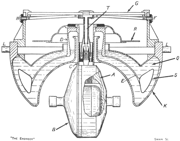
The gyro-wheel is shown at A. The axle is carried in bearings inside the casing B. This casing is attached to a tubular stalk C, which is fixed to a head D carrying the compass card R. This system of parts as a whole is floated in mercury Q contained inside a circular steel bowl K, the flotation being secured by means of a hollow steel ring S joined to the head D by a dome-shaped member E, which is perforated all over for the sake of lightness. As the float S is completely immersed in the mercury, the exact level to which it will sink can be delicately settled by controlling the form of the bore inside the head D. The central position of the float inside the bowl is controlled by means of a steel stem T fixed at its upper end to the centre of the glass G covering the card and pointed at its lower end to dip into a cup139 containing mercury which is fixed centrally inside the stalk C. The stem T is insulated, and is enclosed within a tube, the upper end of which is also attached to the glass G and the lower end of which is splayed out to dip into a second mercury cup surrounding but insulated from the first. Through this tube and its mercury cup one phase of a three-phase current is led to the motor driving the gyro-wheel from the terminal F. The second phase reaches the motor from the terminal H by way of the stem T, while the third phase is transmitted through the bowl, the mercury Q, and the float. The bowl is provided with knife-edge bearings at L, whereby the whole system shown is mounted within two gimbal rings providing the external longitudinal and athwartship axes. The outer140 gimbal ring is supported inside the binnacle by means of springs, the attachments of these springs, as well as the gimbal supports, being insulated on account of the method adopted for transmitting the third phase of the current to the gyro-motor. The gyro-axle runs on ball bearings. The driving motor comprises a stator carrying the windings and fixed inside the casing B and a rotor forming a rigid part of the gyro-wheel itself.
It will be seen that this design of compass does not explicitly reproduce the horizontal axis E F, nor the pendulous weight S of our simple model. The float is, however, free to tilt within the bowl in any direction, so that the system of suspension is practically equivalent to the provision of an infinite number of horizontal axes E F. As regards the apparent absence of the pendulous weight, it is to be noted that the centre of gravity of the floating system is below its metacentre, and therefore that the pendulum effect is exactly reproduced. The damping details are not shown in the engraving, but they are substantially as we have described them previously.
In view of the high speed, 20,000 revolutions per minute, at which the gyro-wheel runs, giving a stress in the rim of about 10 tons per square inch and a peripheral velocity of 340 miles an hour, it is of interest to note that during a test to destruction the wheel did not fail until it was being driven at a speed involving the supply to it of five times the normal driving power. A special motor generator had to be built to enable this test to be carried out. Even the normal motor driving the gyro-wheel had to be specially designed, for no motor capable of running at 20,000 revolutions was at the time commercially available, while the small space within which it had to be accommodated rendered the question of temperature rise a very serious one. It was found, it may be added, that in designing the motor the usually accepted magnetic141 constants for the iron in the motor did not hold good with a periodicity as high as 333 cycles per second.
The flotation of the sensitive element in mercury is a simple and convenient method of obtaining a practically frictionless support for the vertical axis—the axis H J of our elementary model. The absence of friction arises from the facts that the drag of the mercury on the parts of the sensitive element with which it is in contact is proportional to the velocity with which the parts move through it, and that this velocity is always extremely slow. If the mercury is freshly distilled, there is, it would appear, substantial absence of frictional drag. But in course of time dust, oil, etc., may collect on the surface of the mercury, and may introduce a drag on the sensitive element of sufficient amount to interfere with the accuracy of the compass readings. The suspension of the vertical axis by flotation has, however, the advantage that no external gimbal rings need be provided to give the sensitive element three degrees of freedom in all configurations. The sensitive element, as we have said, is virtually provided with an infinite number of horizontal axes, so that within the bowl itself there is always a longitudinal and an athwartship axis about which the sensitive element may turn. The external gimbal axes provided in this compass permit the bowl to remain horizontal when the ship rolls or pitches; they are not essential gyroscopically. A similar remark applies to the later form of Anschütz compass in which the sensitive element is also floated in mercury.
142
A general view of the Sperry compass as removed from the binnacle is given in Fig. 45. This view depicts the compass as it would be seen looking forward on a vessel steaming towards the south-west. At A is shown the compensator weight on the north side of the sensitive element, and at B the ballistic gyro is to be seen. The ring C is the inner of the two external gimbal rings, and carries on an athwartship axis D the spider E, from which the sensitive element is suspended. At F may be seen one of the bearings whereon this ring is swung on a longitudinal axis within the outer gimbal ring. The outer ring, in turn, is hung on springs attached to the inside of the binnacle. The speed and latitude corrector dials are to be seen directly above the bearing F, while behind them the inclined cosine ring or course corrector ring is visible. The phantom ring is shown at G. This ring in section is channel-shaped, and in the view hides the vertical ring within which the casing of the gyro-wheel is journalled on the horizontal east and west axis. It is to be carefully noted that the lugs H, by which the compensator weights are attached to the sensitive element, are not fixed to the phantom ring, but pass through easy-fitting holes therein, and are directly secured to the vertical ring inside. The bail weight lies within the phantom and vertical rings, and can be seen at J, the tracks for the excentric pin, one on the bail and the other on the wheel casing, being shown143 at K. The stirrups L are fixed to the ends of the bail, and carry the pins whereon the bail is swung from the phantom ring. The bail latitude corrector dial, whereby the bail is allowed to assume the tilt appropriate to each latitude without disturbing the horizontality of the gyro-axle, is144 visible behind the stirrup. The horizontality of the axle is indicated on a level attached at this point to two brackets springing from the wheel casing.
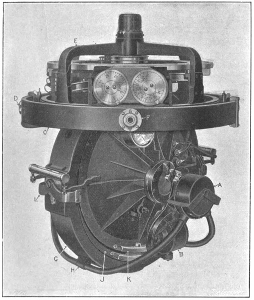
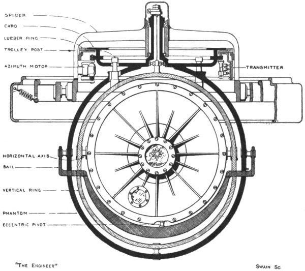
Of the non-gyroscopic mechanical details of this compass, chief interest probably centres in the method of providing the vertical axis about which the sensitive element may turn relatively to the spider E in a substantially frictionless manner. In Fig. 46 we give a diagram of the compass as we would see it looking aft on a ship steaming due south. It will be seen from this diagram that the phantom ring, shown in black section, is extended at the top to form a horizontal flange. On this flange the angular divisions of the compass card are engraved. The145 phantom ring is also formed with a central hollow stalk whereby it is hung on ball bearings within the central boss of the spider. A torsionless wire composed of several strands of steel is secured at one end to a cap fixed over the top of the stalk, and at the lower end is secured to a ball-borne pin forming part of the vertical ring. Diametrically below, the vertical ring and the phantom are united by a pivot pin. The gyro case, as we have explained before, is carried on a horizontal axis within the vertical ring, while the bail is swung on the phantom. The phantom and all within it may be regarded as the sensitive element, the constant alignment of which in the north and south direction gives the device its utility as a compass. The spider carrying the lubber ring and all outside it move round the wire-and-pivot-pin vertical axis with the ship when the course is altered. When such a movement occurs the absence of any direct mechanical connection of a rigid nature between the phantom ring on the one hand and the rest of the sensitive element on the other would tend to result in the phantom ring following the movement of the spider, binnacle, and ship rather than in its remaining stationary with the wheel, casing, and vertical ring. The suspension wire would thus be twisted. As we have previously explained, however, the phantom ring is formed just below the card with a circular rack with which there meshes a pinion driven through reduction gearing by a small electric motor—the azimuth motor—attached to the spider. The starting and stopping of this motor and the direction of its rotation are controlled automatically by means of gold-rimmed wheels on two trolley heads fixed to the vertical ring and certain gold-faced contactors on the phantom. Thus when the ship’s course is altered the azimuth motor is started up in the direction required to take the twist out of the suspension wire and bring the phantom into alignment146 with the rest of the sensitive element. When this alignment is reached the motor is automatically cut out. In actual use the phantom overshoots the exact position of alignment by a very small amount, bringing the reverse contactors into action and starting the motor in the reverse direction. The phantom, in fact, oscillates about the position of alignment with the sensitive element through, roughly, a quarter of a degree. This small vibration is transmitted to the repeater compasses elsewhere in the ship, and is of practical value in that its visibility is some assurance that the master compass is working correctly.
It will be seen, then, that the absence of friction about the vertical axis of the Sperry compass is secured by suspending the sensitive element within a member—the phantom ring—the frictional drag on which is eliminated by driving it by power in such a way that it follows all the movements of the sensitive element relatively to the supporting spider in an automatic and substantially instantaneous and dead-beat manner.
The repeater compasses are operated electrically from the master compass through a transmitter and a pinion meshing with the circular rack on the phantom. The pinion is journalled on a pin depending from the lubber ring, and therefore transmits to the repeaters not only the relative movement between the phantom and the binnacle, but, as we have before explained, any movement of the lubber ring relatively to the binnacle which may be made to correct the reading of the master compass for the latitude and north steaming errors. In this way the repeater compasses always indicate true north both for course-setting purposes and for the purpose of taking bearings on passing objects. It is regarded as outside the scope of this discussion to describe the mechanical features of the repeater compasses. It may, however, be147 remarked that the fact that they may be fitted in any number and in any position, and that automatic course recorders and similar devices may also readily be linked up with the gyro-compass, forms a very strong reason in itself for recommending the adoption of the gyroscopic rather than the magnetic compass on board ship.
148
The Brown compass is the invention of Mr. S. G. Brown, F.R.S., of North Acton, with Professor John Perry, F.R.S., in association as technical adviser and co-patentee. It has been evolved after five years of laborious experimental work, and is claimed to be the only British gyroscopic compass so far constructed and applied on board ship.
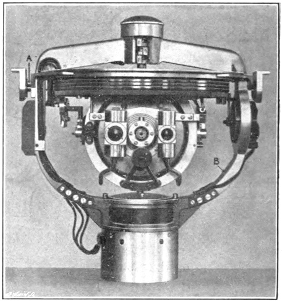
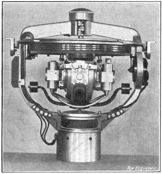
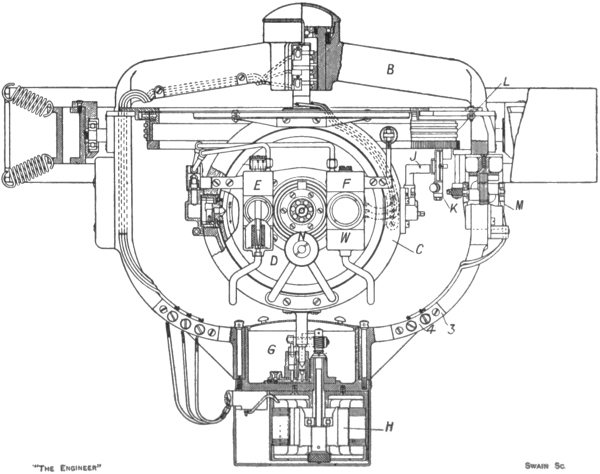
In Fig. 47 we show the Brown compass as seen looking forward on a vessel steaming due north. The south end of the gyro-axle is pointing towards the reader. In Fig. 48 it is shown as it would be seen when looking forward on a vessel steaming due west. The north end of the axle is pointing to the right in this view. In the line engraving (Fig. 49) we are supposed to be looking forward on a vessel steaming due south. The north end of the axle is therefore pointing toward us. In the half-tone engravings the compass is shown removed from its external gimbal rings. The axis A (Fig. 47), it will be understood, is the athwartship axis of the external mounting. It is mounted on ball bearings within a couple of small brackets which by means of four screws are attached to the inner gimbal ring, as shown in Fig. 49.150 This inner ring, in turn, is carried on a longitudinal axis inside an outer gimbal ring, which, finally, is hung on springs from the binnacle. The frame B, within which the sensitive element proper is mounted, is very much as we have represented it to be in our previous diagrams, except that it swings pendulum-wise on the axis A—or151 the other axis of the external mounting—not because of the attachment to it at its lowest point of an actual bob weight, but because its centre of gravity is designedly below the axis of suspension, and because at its lowest point it carries a casing containing an electric motor and other adjuncts possessing a degree of weight.
As shown best in Fig. 49, the frame B supports a vertical ring C carrying the compass card, and within which the casing D containing the gyro-wheel is mounted on a horizontal, east and west, knife-edge axis. The easterly end of this knife-edged axis—towards the left in the engraving—has associated with it the nozzle and divided air box, whereby, as we have explained, the pressure of the air blast generated inside the casing by the spinning wheel is transmitted by open and crossed pipes respectively to the oil-damping bottles E and the oil control bottles F.
What we regard as the most interesting non-gyroscopic feature of the Brown compass is the manner in which the vertical ring C is supported within the frame B. The ring at its highest point is formed with a vertical trunnion, which at its top is guided within a ball bearing fixed in the central boss of the frame B. Three slip rings lower down on the trunnion acting in conjunction with three mercury contact rings attached to the frame serve to conduct three-phase current to the sensitive element. At the lower side the vertical ring is also provided with a trunnion, which is of the nature of a foot-step bearing. In reality, however, the trunnion is never allowed to touch the bottom of its bearing, for it—and with it the vertical ring, the compass card, and the whole of the sensitive element—is forced, by means of a supply of oil delivered below it, to vibrate up and down through about an eighth of an inch at the rate of some 180 times a minute. Before the trunnion can fall to the foot of its bearing it gets a152 fresh kick up by the oil, so that no actual metal-to-metal contact is established. The oil supply is drawn from and returned to the reservoir G by a pump driven from an electric motor H. The slight rapid vibratory motion thus communicated to the sensitive element has no appreciable effect upon the ease or accuracy with which the compass card may be read. On the other hand, it is sufficient to relieve the frictional resistance to turning at the upper and lower trunnions of the vertical ring in accordance with the well-known fact that if we overcome friction in one direction we overcome it also in the direction at right angles to the first.
A second mechanical feature of the Brown compass of outstanding interest is the method adopted for transmitting the indications of the master compass card to the repeater compasses. The problem to be solved in this matter is to establish connection with the master compass card in a manner which shall impose no frictional or other drag on that card. To this end in the Brown compass the air blast generated by the spinning wheel is called upon to fulfil a function additional to those to which we have already referred. The air blast is delivered not only from the eastern, but also from the western end of the horizontal axis of the casing. It is thus directed through a nozzle J against the face of a contact maker K containing a pair of disc-like plungers working in balanced connection within two cylinders. Opposite each plunger is a slot, and when no movement has to be transmitted to the repeater compasses the air blast is directed against the blank wall between these two slots or enters each slot in equal proportion. Thus the plungers being balanced, neither makes contact. If, however, the ship’s course is altered, the contact maker K, being attached to a ring L beneath the lubber ring, moves with the ship, while the nozzle J remains stationary with the sensitive153 element. Thus the air blast exerts unequal pressures on the plungers, and one of them is forced back to make contact. As a result, a step-by-step electric motor M carried on the frame B and in mesh through reduction gearing with a rack on the ring L is started up and turns the ring in the direction required to make the two slots again divide the air blast equally. When this neutral position is reached the motor is cut out. As in the Sperry compass, the follow-up motion is open to a little hunting movement as a result of the momentum acquired by the parts. Ignoring this hunting movement, the ring L and the contact maker K are thus driven to remain stationary in fixed relationship with the sensitive element no matter to what extent the frame B may move with the ship when the course is altered. The relative movement between the ring L and the frame B is communicated to the repeater compasses in an electrical manner. The details of the electrical transmission are outside the ambit of this discussion, but we may say that the movements communicated to the repeater compasses are derived from a distributor on the compass switchboard, this distributor being arranged to operate in exact synchronism with the follow-up ring L. It is claimed for the Brown system of transmission between the master and the repeater compasses that even should the whole repeater system break down the correct action of the master compass will not thereby be affected.
154
A plan and sectional elevation of the modern form of Anschütz compass are given in Figs. 50 and 51. The casings of the three gyros K L M hang by vertical stalks below a triangular spider A at the centre of which is affixed a float B immersed in a bowl C containing mercury. After the manner followed in the 1910 form, the float and all attached to it are centralised relatively to the bowl by means of a rod D fixed centrally to the cover of the compass. As before, this rod D is composed of a central core and a liner insulated from the core. The ends of the core and liner dip into two concentric mercury cups carried within the float in order that two phases of the three-phase current driving the gyro-motors may be transmitted through the core and liner of the rod D. The third phase is transmitted through the mercury and float by earthing the bowl C.
Matters are so arranged that the centre of flotation of the float B and its attached parts is above the centre of gravity of the floating parts. These floating parts—the spider A, the float B, the three gyros, and other items not yet mentioned—constitute the sensitive element, so that this element, as in the 1910 form, does not need the addition of a separate weight to provide the required pendulum action about a horizontal axis through the centre of flotation. Instead of there being but one such horizontal axis—the east and west axis E F of our models and diagrams—it is clear that the support of the sensitive155 element by means of a float provides the element with an east and west horizontal axis and an infinite number of other horizontal axes.
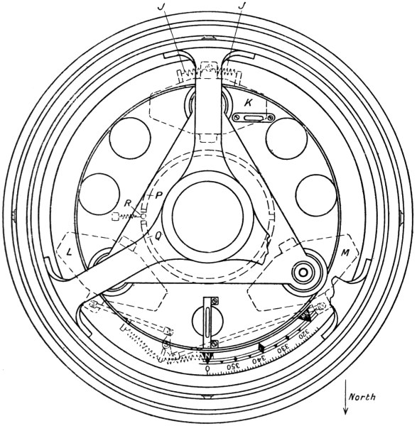
Attached to the spider A—and therefore forming a portion of the sensitive element—is a sheet metal annular casing of the section shown at E E or F F. The gyros are enclosed within this casing. Ventilating tubes and baffles G are provided at points on the casing between each pair of gyros. The compass card—in the form really of a ring—is attached to the casing at H. Regarding the casing156 and the spider A as the equivalent of the horizontal ring shown in our diagram (Fig. 41), it will be noticed that the gyro casings are not fixed rigidly to it, but are really mounted on ball bearings surrounding their stalks, so that they may rotate about a vertical axis relatively to the rest of the sensitive element. As shown in the plan view, however, the casing of the gyro K is connected by two springs J to the rest of the sensitive element, so that in whichever way the gyro turns on the ball bearings it applies through one or other of the springs a force in the same direction to the annular casing, etc. The gyro is therefore substantially, though not actually, rigidly connected to the rest of the sensitive element, the springs being introduced to provide a yielding connection which will prevent the full force of a sudden turn of the ship from being thrown all at once on to the gyro. The gyros L M are similarly connected to the rest of the sensitive element, but in their case one pair of springs is made to serve both gyros by employing links and a bell-crank lever. The springs, it may be remarked, undoubtedly do play a part in the transmission of the directive force from the gyros to the card and in the avoidance of the quadrantal error. But their presence is not essential to the fundamental principle of action of the compass.
The damping system of the 1912 design is of a very simple nature, and represents a great improvement over the air blast method previously used. Although the wheels are not required to act as blowers, their casings are not exhausted of air. The casings, in fact, are perforated with four large holes on each side, the cooling effect of the circulating air being regarded as of more value in practice than the saving of power which would result if the wheels were run in an exhausted atmosphere.
The damping force is supplied by the weight of a body of oil contained within a trough N extending right round157 the foot of the annular casing containing the gyros. This trough, a circle as seen in plan, is blocked by eight bulkheads, one each below the north and south points of the compass card, and the others equally spaced round the trough. Through each bulkhead a short pipe passes, so that the oil in the trough may flow from one compartment to another. With the exception, however, of the north and south bulkhead pipes, which are quite free in the bore, the passage of the oil is restricted by means of a wire partially filling the bores of the pipes. By varying the size of wire used, the restriction to the flow of the oil from one compartment to the others, and therefore the rate at which the oil will flow when the sensitive element tilts, can be regulated to give the degree of damping required or to suit any change of viscosity in a fresh supply of oil.
The system in principle has much in common with the Brown method of damping. Should the compass card suffer an easterly deflection, the north point of the card will, as we know, tend to rise under the influence of the earth’s rotation, and will continue to rise until the turning moment applied by the deflected pendulum weight precesses the card back to the meridian, whereafter the north point of the card passing over towards the west will begin to fall towards the horizontal plane, and then, descending still farther, it will once more come back to the meridian. During this compound motion the oil in the trough flows backwards and forwards, accumulating below the south point of the card when the north point of the card is rising and gathering below the north point when the north point is falling. In other words, there is an excess weight of oil below the southern point of the card throughout the complete half-swing from east to west, the maximum excess occurring when the card is crossing the meridian. On the half-swing from west to158 east the excess weight of oil is below the northern point of the card, the maximum excess occurring, as before, when the card is crossing the meridian. The excess weight of oil at all times thus tends to increase the rise or dip of the north point of the card above or below the horizontal plane, whereas the pendulum weight at all times tends to diminish such rise or dip. Hence the excess weight of oil tries to precess the card in the direction opposed to that in which the pendulum weight is precessing it. The vibration of the card in this compass, as in the Brown design, is therefore damped by the generation of a counter-precessional tendency, and not, as in the early Anschütz and the Sperry designs, by precessing the sensitive element in the direction required to reduce the angle by which the pendulum weight is tilted away from the plumb line.
From what we have already said regarding the Brown system of damping, it will readily be inferred that there is no latitude error in the Anschütz 1912 compass. The damping force is equivalent to a reduction in the weight of the pendulum “bob,” and is not applied directly to reduce the tilt of the bob. The tilt of the pendulum weight required in north or south latitudes to provide the appropriate rate of westerly or easterly precession is not opposed by the damping force called into play by such tilt. Instead, the damping force merely makes the bob lighter, so that the tilt has to be carried farther before the effective weight of the bob can balance the tilting action of the earth’s rotation. The balance will be automatically struck when the moment of the effective weight of the bob is just sufficient to generate the required rate of westerly or easterly precession appropriate to the latitude.
The arrangement of the three gyros at the corners of an equilateral triangle and the general form given to the159 annular casing and the rest of the sensitive element results in the distribution of the mass of the sensitive element in a very uniform manner around the vertical axis. There is no excessive concentration of the mass towards the east and west plane, and as a result it is unnecessary to add compensator weights to this compass in order to avoid the effects of centrifugal force during quadrantal rolling.
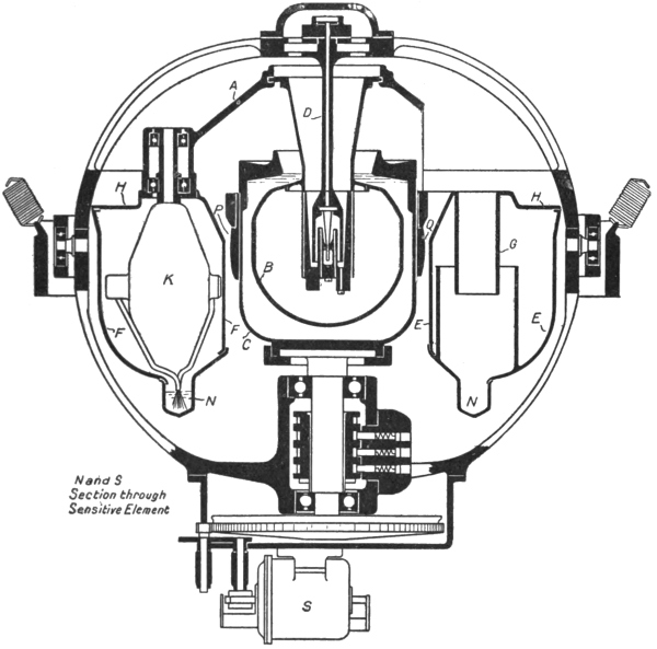
The gyro-wheels are made of a special quality of nickel steel, and are mounted on axles of the de Laval type—160that is to say, they are tapered and made of very small diameter (about 0.15 in. at the parallel ends)—in order that they may yield a little should the centre of gravity of the wheel not be truly coincident with the centre line of the shaft. The wheels are 5 in. in diameter, weigh 5 lb. 2 oz., and run at 20,000 revolutions per minute. The motors are of the squirrel-cage type with the rotor windings fixed to the wheels inside a recess concentric with the axle. The field coils are fixed relatively to the gyro casing. It is of interest to note that when the gyro-wheel is being run up to its full speed—an operation taking about five minutes to complete—the axle passes through three critical speeds. These speeds are approximately 7000, 11,000, and 14,000 revolutions, and are believed to be associated, the first with one end of the axle, the second with the other end, and the third with a combined action at both ends. During the period of running up the gyros the starting current is, of course, heavier than the current taken to drive the wheels at the top speed, and as a result a considerable temperature is developed in the wheels and their casings. When, however, the gyros have been running for some time at the top speed the temperature drops, and throughout the compass remains fairly constant at about 150 deg. Fahr. The viscosity of the damping oil, on the constancy of which the constancy of the damping force depends, is therefore less affected by external atmospheric changes of temperature than might be expected. The oil used is a mineral one. It serves not only to damp the vibrations of the card, but also to lubricate the gyro-axles. To this end, as shown in Fig. 51, pipes are led down from each end of each axle to dip into the oil trough, the flow of oil being induced by means of wicks inside the pipes.
The method adopted for the transmission of the readings from the master compass to the repeaters is of161 considerable interest. The bowl C containing the mercury and the float is surrounded by two semi-cylindrical strips P Q of silver-plated brass. At one of the gaps between these strips the two abutting edges are faced with platinum. The gap between these platinum faces is 0.11 in. in width, and into it there is inserted, as shown in the plan view, a platinum-iridium ball R, measuring 0.095 in. in diameter.
On the switchboard serving the compass there is a reversible motor, two of the windings of which are constantly connected to a generator—the same generator as serves the gyro-motors. The contact ball R is connected to the third phase of the generator, while the two strips P Q are connected to the third winding of the reversible motor, this winding being duplicated in such a way that the motor revolves in one direction or the other, according as the circuit is completed at the ball R through the strip P or the strip Q. A commutator is mounted on the axle of the reversible motor, and from it current is distributed to the motors operating the repeaters and to the “follow-up” motor S (Fig. 51). The latter motor is geared to the shaft carrying the bowl C, and when started up by the reversible motor turns the bowl in the direction required to restore the ball R to the middle of its slot, and so break the connection with the strip P or Q. Thus when the ship’s course is altered the bowl tends to rotate with the ship, but the ball R is mounted on the sensitive element, and therefore maintains its position. Contact is thus established between the ball and one of the strips P Q, the reversible motor is set rotating in the appropriate direction, and current is distributed to the “follow-up” motor S to rotate the bowl relatively to the ship until the ball R is once more lying midway in the gap. The tendency of the bowl to rotate with the ship is thus counteracted; the action of162 the “follow-up” motor practically results in the bowl being held in constant relationship to the sensitive element substantially as though it were part thereof. Simultaneously the cards of the repeaters are prevented from rotating with the ship, so that virtually they, too, act as if rigidly connected to the sensitive element, without, however, any frictional drag being thrown from them on to the sensitive element.
As illustrating the refined construction of the entire compass, the design of the ball contact may be noticed. The ball is carried at the end of a tapered spiral spring. It is free to rotate on the spring end, but is prevented from moving axially thereon. The spring end is provided with a button. The ball is drilled out and beaded over the button. To ensure good electrical contact at all times between the ball and the spring a drop of mercury is carried inside the ball between it and the button. Should the ship turn very suddenly the ball may spring out of the gap and be dragged across the face of one or other of the strips P Q. It is for this reason that these strips are silver-plated.
The repeater compasses are provided not only with an ordinary card graduated from 0 deg. to 160 deg., but also with an inner dial which makes one revolution for an alteration of 10 deg. in the ship’s course. This dial is graduated to 1/10 deg., and permits very small departures from the set course to be immediately noticed and corrected. An elaboration of the same idea is provided in the multiple repeater of the Brown compass. In this repeater the inner dial is the ordinary 360 deg. card. The outer annular dial makes four revolutions for every complete turn of the ship. With the ship sailing due north the graduations on the outer dial are numbered from 0 to 45 round the east half of the dial, and from 360 to 315 round the west half. The numbers,163 however, are not marked on the dial itself, but on the edges of discs seen through slots in the dial. As the ship turns from the north towards the east, the discs on the west side of the dial are successively rotated one stage as the south end of the lubber line passes over them, so as to exhibit numbers forming a continuation of the numbers on the east side of the dial. The outer magnified dial is thus of itself sufficient for navigational purposes.
In the Anschütz equipment arrangements are made for attaching an azimuth mirror to the repeater dial for the purpose of providing an artificial horizon during the taking of bearings. A separate gyroscopically stabilised artificial horizon device, such as is sometimes to be found on board ships, is thus rendered unnecessary.
165
Printed in Great Britain at
The Mayflower Press, Plymouth. William Brendon & Son, Ltd.
1 Earlier form as in use in 1910.
2 Approximate. Differs in different compasses.
3 The value of the latitude error is b tan L, where L is the angle of latitude and b a constant dependent upon the design of the compass. In the Sperry correction mechanism the value of the quantity b is represented by the distance between the centre of the dial B and the centre of the pin C when the radial slot in the dial is lying at right angles to the bar D E.
4 The value of the north steaming error is numerically equal to (a K cos C)/cos L, where K is the ship’s speed, L the angle of latitude, C the angle between the course and the north and south direction, and a a constant involving the speed of rotation of the earth. In the Sperry correction mechanism the value of the quantity a is represented by the radius at which the pin L lies from the centre of the latitude dial.
5 The ballistic deflection is dependent upon the rate at which the northerly component of the ship’s speed is being changed. The difference in the north steaming errors is dependent upon the initial and final values of the speed towards the north, and would not appear to be affected by the length of time occupied in changing the speed. It would seem, therefore, that the ballistic deflection can only be dead-beat in the chosen latitude if the speed towards the north is reduced or increased at one particular rate. Thus if the ship is steaming due north at 20 knots and changes its speed to 10 knots in (a) 10 minutes or (b) 5 minutes, the initial and final values of the north steaming error will be the same in both cases, since the initial and final speeds are the same, but the ballistic deflection will be greater in the second case than in the first, since the rate at which the speed is changed is greater. If, then, the ballistic deflection is dead-beat in the first case it cannot be so in the second. The statement that the ballistic deflection in the chosen latitude is dead-beat thus appears, it may be suggested, to require qualification. On the other hand, the British Admiralty in connection with the use of gyro-compasses on destroyers and similar fast-manœuvring vessels wherein the ballistic deflection is a factor of very great importance has carried out lengthy experiments on the matter, and, although the results have not been divulged, it is understood that the ballistic deflection was found to be dead-beat independently of the rate at which the speed was changed.
6 The wheels in the two designs being similar in form, their moments of inertia—the real factors determining the magnitude of the directive forces—are proportional to the fourth powers of their diameters. The fourth power of 5 is to the fourth power of 6 as 1 is to 2 approximately.
7 The directive force is proportional to the sine of the angle of deflection. The gyros K L M therefore supply at 30 deg. deflection a total directive force of D sin 30 deg. + D sin 60 deg. + D sin 0 deg., or 1.366 D. For a single-gyro compass, having a wheel of twice the inertia of K L or M separately, the directive force at 30 deg. deflection would be 2 D sin 30 deg. or D.
Simple typographical errors were corrected.
When necessary, illustrations have been moved between paragraphs, so some of the page references in the List of Illustrations are off by a page or two. Links to those illustrations are correct.
Index not checked for proper alphabetization or correct page references.
End of Project Gutenberg's The Gyroscopic Compass, by T. W. Chalmers

*** END OF THIS PROJECT GUTENBERG EBOOK THE GYROSCOPIC COMPASS ***

***** This file should be named 57200-h.htm or 57200-h.zip *****
This and all associated files of various formats will be found in:
        http://www.gutenberg.org/5/7/2/0/57200/

Produced by deaurider, Charlie Howard, and the Online
Distributed Proofreading Team at http://www.pgdp.net (This
file was produced from images generously made available
by The Internet Archive)


Updated editions will replace the previous one--the old editions will
be renamed.

Creating the works from print editions not protected by U.S. copyright
law means that no one owns a United States copyright in these works,
so the Foundation (and you!) can copy and distribute it in the United
States without permission and without paying copyright
royalties. Special rules, set forth in the General Terms of Use part
of this license, apply to copying and distributing Project
Gutenberg-tm electronic works to protect the PROJECT GUTENBERG-tm
concept and trademark. Project Gutenberg is a registered trademark,
and may not be used if you charge for the eBooks, unless you receive
specific permission. If you do not charge anything for copies of this
eBook, complying with the rules is very easy. You may use this eBook
for nearly any purpose such as creation of derivative works, reports,
performances and research. They may be modified and printed and given
away--you may do practically ANYTHING in the United States with eBooks
not protected by U.S. copyright law. Redistribution is subject to the
trademark license, especially commercial redistribution.

START: FULL LICENSE

THE FULL PROJECT GUTENBERG LICENSE
PLEASE READ THIS BEFORE YOU DISTRIBUTE OR USE THIS WORK

To protect the Project Gutenberg-tm mission of promoting the free
distribution of electronic works, by using or distributing this work
(or any other work associated in any way with the phrase "Project
Gutenberg"), you agree to comply with all the terms of the Full
Project Gutenberg-tm License available with this file or online at
www.gutenberg.org/license.

Section 1. General Terms of Use and Redistributing Project
Gutenberg-tm electronic works

1.A. By reading or using any part of this Project Gutenberg-tm
electronic work, you indicate that you have read, understand, agree to
and accept all the terms of this license and intellectual property
(trademark/copyright) agreement. If you do not agree to abide by all
the terms of this agreement, you must cease using and return or
destroy all copies of Project Gutenberg-tm electronic works in your
possession. If you paid a fee for obtaining a copy of or access to a
Project Gutenberg-tm electronic work and you do not agree to be bound
by the terms of this agreement, you may obtain a refund from the
person or entity to whom you paid the fee as set forth in paragraph
1.E.8.

1.B. "Project Gutenberg" is a registered trademark. It may only be
used on or associated in any way with an electronic work by people who
agree to be bound by the terms of this agreement. There are a few
things that you can do with most Project Gutenberg-tm electronic works
even without complying with the full terms of this agreement. See
paragraph 1.C below. There are a lot of things you can do with Project
Gutenberg-tm electronic works if you follow the terms of this
agreement and help preserve free future access to Project Gutenberg-tm
electronic works. See paragraph 1.E below.

1.C. The Project Gutenberg Literary Archive Foundation ("the
Foundation" or PGLAF), owns a compilation copyright in the collection
of Project Gutenberg-tm electronic works. Nearly all the individual
works in the collection are in the public domain in the United
States. If an individual work is unprotected by copyright law in the
United States and you are located in the United States, we do not
claim a right to prevent you from copying, distributing, performing,
displaying or creating derivative works based on the work as long as
all references to Project Gutenberg are removed. Of course, we hope
that you will support the Project Gutenberg-tm mission of promoting
free access to electronic works by freely sharing Project Gutenberg-tm
works in compliance with the terms of this agreement for keeping the
Project Gutenberg-tm name associated with the work. You can easily
comply with the terms of this agreement by keeping this work in the
same format with its attached full Project Gutenberg-tm License when
you share it without charge with others.

1.D. The copyright laws of the place where you are located also govern
what you can do with this work. Copyright laws in most countries are
in a constant state of change. If you are outside the United States,
check the laws of your country in addition to the terms of this
agreement before downloading, copying, displaying, performing,
distributing or creating derivative works based on this work or any
other Project Gutenberg-tm work. The Foundation makes no
representations concerning the copyright status of any work in any
country outside the United States.

1.E. Unless you have removed all references to Project Gutenberg:

1.E.1. The following sentence, with active links to, or other
immediate access to, the full Project Gutenberg-tm License must appear
prominently whenever any copy of a Project Gutenberg-tm work (any work
on which the phrase "Project Gutenberg" appears, or with which the
phrase "Project Gutenberg" is associated) is accessed, displayed,
performed, viewed, copied or distributed:

  This eBook is for the use of anyone anywhere in the United States and
  most other parts of the world at no cost and with almost no
  restrictions whatsoever. You may copy it, give it away or re-use it
  under the terms of the Project Gutenberg License included with this
  eBook or online at www.gutenberg.org. If you are not located in the
  United States, you'll have to check the laws of the country where you
  are located before using this ebook.

1.E.2. If an individual Project Gutenberg-tm electronic work is
derived from texts not protected by U.S. copyright law (does not
contain a notice indicating that it is posted with permission of the
copyright holder), the work can be copied and distributed to anyone in
the United States without paying any fees or charges. If you are
redistributing or providing access to a work with the phrase "Project
Gutenberg" associated with or appearing on the work, you must comply
either with the requirements of paragraphs 1.E.1 through 1.E.7 or
obtain permission for the use of the work and the Project Gutenberg-tm
trademark as set forth in paragraphs 1.E.8 or 1.E.9.

1.E.3. If an individual Project Gutenberg-tm electronic work is posted
with the permission of the copyright holder, your use and distribution
must comply with both paragraphs 1.E.1 through 1.E.7 and any
additional terms imposed by the copyright holder. Additional terms
will be linked to the Project Gutenberg-tm License for all works
posted with the permission of the copyright holder found at the
beginning of this work.

1.E.4. Do not unlink or detach or remove the full Project Gutenberg-tm
License terms from this work, or any files containing a part of this
work or any other work associated with Project Gutenberg-tm.

1.E.5. Do not copy, display, perform, distribute or redistribute this
electronic work, or any part of this electronic work, without
prominently displaying the sentence set forth in paragraph 1.E.1 with
active links or immediate access to the full terms of the Project
Gutenberg-tm License.

1.E.6. You may convert to and distribute this work in any binary,
compressed, marked up, nonproprietary or proprietary form, including
any word processing or hypertext form. However, if you provide access
to or distribute copies of a Project Gutenberg-tm work in a format
other than "Plain Vanilla ASCII" or other format used in the official
version posted on the official Project Gutenberg-tm web site
(www.gutenberg.org), you must, at no additional cost, fee or expense
to the user, provide a copy, a means of exporting a copy, or a means
of obtaining a copy upon request, of the work in its original "Plain
Vanilla ASCII" or other form. Any alternate format must include the
full Project Gutenberg-tm License as specified in paragraph 1.E.1.

1.E.7. Do not charge a fee for access to, viewing, displaying,
performing, copying or distributing any Project Gutenberg-tm works
unless you comply with paragraph 1.E.8 or 1.E.9.

1.E.8. You may charge a reasonable fee for copies of or providing
access to or distributing Project Gutenberg-tm electronic works
provided that

* You pay a royalty fee of 20% of the gross profits you derive from
  the use of Project Gutenberg-tm works calculated using the method
  you already use to calculate your applicable taxes. The fee is owed
  to the owner of the Project Gutenberg-tm trademark, but he has
  agreed to donate royalties under this paragraph to the Project
  Gutenberg Literary Archive Foundation. Royalty payments must be paid
  within 60 days following each date on which you prepare (or are
  legally required to prepare) your periodic tax returns. Royalty
  payments should be clearly marked as such and sent to the Project
  Gutenberg Literary Archive Foundation at the address specified in
  Section 4, "Information about donations to the Project Gutenberg
  Literary Archive Foundation."

* You provide a full refund of any money paid by a user who notifies
  you in writing (or by e-mail) within 30 days of receipt that s/he
  does not agree to the terms of the full Project Gutenberg-tm
  License. You must require such a user to return or destroy all
  copies of the works possessed in a physical medium and discontinue
  all use of and all access to other copies of Project Gutenberg-tm
  works.

* You provide, in accordance with paragraph 1.F.3, a full refund of
  any money paid for a work or a replacement copy, if a defect in the
  electronic work is discovered and reported to you within 90 days of
  receipt of the work.

* You comply with all other terms of this agreement for free
  distribution of Project Gutenberg-tm works.

1.E.9. If you wish to charge a fee or distribute a Project
Gutenberg-tm electronic work or group of works on different terms than
are set forth in this agreement, you must obtain permission in writing
from both the Project Gutenberg Literary Archive Foundation and The
Project Gutenberg Trademark LLC, the owner of the Project Gutenberg-tm
trademark. Contact the Foundation as set forth in Section 3 below.

1.F.

1.F.1. Project Gutenberg volunteers and employees expend considerable
effort to identify, do copyright research on, transcribe and proofread
works not protected by U.S. copyright law in creating the Project
Gutenberg-tm collection. Despite these efforts, Project Gutenberg-tm
electronic works, and the medium on which they may be stored, may
contain "Defects," such as, but not limited to, incomplete, inaccurate
or corrupt data, transcription errors, a copyright or other
intellectual property infringement, a defective or damaged disk or
other medium, a computer virus, or computer codes that damage or
cannot be read by your equipment.

1.F.2. LIMITED WARRANTY, DISCLAIMER OF DAMAGES - Except for the "Right
of Replacement or Refund" described in paragraph 1.F.3, the Project
Gutenberg Literary Archive Foundation, the owner of the Project
Gutenberg-tm trademark, and any other party distributing a Project
Gutenberg-tm electronic work under this agreement, disclaim all
liability to you for damages, costs and expenses, including legal
fees. YOU AGREE THAT YOU HAVE NO REMEDIES FOR NEGLIGENCE, STRICT
LIABILITY, BREACH OF WARRANTY OR BREACH OF CONTRACT EXCEPT THOSE
PROVIDED IN PARAGRAPH 1.F.3. YOU AGREE THAT THE FOUNDATION, THE
TRADEMARK OWNER, AND ANY DISTRIBUTOR UNDER THIS AGREEMENT WILL NOT BE
LIABLE TO YOU FOR ACTUAL, DIRECT, INDIRECT, CONSEQUENTIAL, PUNITIVE OR
INCIDENTAL DAMAGES EVEN IF YOU GIVE NOTICE OF THE POSSIBILITY OF SUCH
DAMAGE.

1.F.3. LIMITED RIGHT OF REPLACEMENT OR REFUND - If you discover a
defect in this electronic work within 90 days of receiving it, you can
receive a refund of the money (if any) you paid for it by sending a
written explanation to the person you received the work from. If you
received the work on a physical medium, you must return the medium
with your written explanation. The person or entity that provided you
with the defective work may elect to provide a replacement copy in
lieu of a refund. If you received the work electronically, the person
or entity providing it to you may choose to give you a second
opportunity to receive the work electronically in lieu of a refund. If
the second copy is also defective, you may demand a refund in writing
without further opportunities to fix the problem.

1.F.4. Except for the limited right of replacement or refund set forth
in paragraph 1.F.3, this work is provided to you 'AS-IS', WITH NO
OTHER WARRANTIES OF ANY KIND, EXPRESS OR IMPLIED, INCLUDING BUT NOT
LIMITED TO WARRANTIES OF MERCHANTABILITY OR FITNESS FOR ANY PURPOSE.

1.F.5. Some states do not allow disclaimers of certain implied
warranties or the exclusion or limitation of certain types of
damages. If any disclaimer or limitation set forth in this agreement
violates the law of the state applicable to this agreement, the
agreement shall be interpreted to make the maximum disclaimer or
limitation permitted by the applicable state law. The invalidity or
unenforceability of any provision of this agreement shall not void the
remaining provisions.

1.F.6. INDEMNITY - You agree to indemnify and hold the Foundation, the
trademark owner, any agent or employee of the Foundation, anyone
providing copies of Project Gutenberg-tm electronic works in
accordance with this agreement, and any volunteers associated with the
production, promotion and distribution of Project Gutenberg-tm
electronic works, harmless from all liability, costs and expenses,
including legal fees, that arise directly or indirectly from any of
the following which you do or cause to occur: (a) distribution of this
or any Project Gutenberg-tm work, (b) alteration, modification, or
additions or deletions to any Project Gutenberg-tm work, and (c) any
Defect you cause.

Section 2. Information about the Mission of Project Gutenberg-tm

Project Gutenberg-tm is synonymous with the free distribution of
electronic works in formats readable by the widest variety of
computers including obsolete, old, middle-aged and new computers. It
exists because of the efforts of hundreds of volunteers and donations
from people in all walks of life.

Volunteers and financial support to provide volunteers with the
assistance they need are critical to reaching Project Gutenberg-tm's
goals and ensuring that the Project Gutenberg-tm collection will
remain freely available for generations to come. In 2001, the Project
Gutenberg Literary Archive Foundation was created to provide a secure
and permanent future for Project Gutenberg-tm and future
generations. To learn more about the Project Gutenberg Literary
Archive Foundation and how your efforts and donations can help, see
Sections 3 and 4 and the Foundation information page at
www.gutenberg.org Section 3. Information about the Project Gutenberg
Literary Archive Foundation

The Project Gutenberg Literary Archive Foundation is a non profit
501(c)(3) educational corporation organized under the laws of the
state of Mississippi and granted tax exempt status by the Internal
Revenue Service. The Foundation's EIN or federal tax identification
number is 64-6221541. Contributions to the Project Gutenberg Literary
Archive Foundation are tax deductible to the full extent permitted by
U.S. federal laws and your state's laws.

The Foundation's principal office is in Fairbanks, Alaska, with the
mailing address: PO Box 750175, Fairbanks, AK 99775, but its
volunteers and employees are scattered throughout numerous
locations. Its business office is located at 809 North 1500 West, Salt
Lake City, UT 84116, (801) 596-1887. Email contact links and up to
date contact information can be found at the Foundation's web site and
official page at www.gutenberg.org/contact

For additional contact information:

    Dr. Gregory B. Newby
    Chief Executive and Director
    gbnewby@pglaf.org

Section 4. Information about Donations to the Project Gutenberg
Literary Archive Foundation

Project Gutenberg-tm depends upon and cannot survive without wide
spread public support and donations to carry out its mission of
increasing the number of public domain and licensed works that can be
freely distributed in machine readable form accessible by the widest
array of equipment including outdated equipment. Many small donations
($1 to $5,000) are particularly important to maintaining tax exempt
status with the IRS.

The Foundation is committed to complying with the laws regulating
charities and charitable donations in all 50 states of the United
States. Compliance requirements are not uniform and it takes a
considerable effort, much paperwork and many fees to meet and keep up
with these requirements. We do not solicit donations in locations
where we have not received written confirmation of compliance. To SEND
DONATIONS or determine the status of compliance for any particular
state visit www.gutenberg.org/donate

While we cannot and do not solicit contributions from states where we
have not met the solicitation requirements, we know of no prohibition
against accepting unsolicited donations from donors in such states who
approach us with offers to donate.

International donations are gratefully accepted, but we cannot make
any statements concerning tax treatment of donations received from
outside the United States. U.S. laws alone swamp our small staff.

Please check the Project Gutenberg Web pages for current donation
methods and addresses. Donations are accepted in a number of other
ways including checks, online payments and credit card donations. To
donate, please visit: www.gutenberg.org/donate

Section 5. General Information About Project Gutenberg-tm electronic works.

Professor Michael S. Hart was the originator of the Project
Gutenberg-tm concept of a library of electronic works that could be
freely shared with anyone. For forty years, he produced and
distributed Project Gutenberg-tm eBooks with only a loose network of
volunteer support.

Project Gutenberg-tm eBooks are often created from several printed
editions, all of which are confirmed as not protected by copyright in
the U.S. unless a copyright notice is included. Thus, we do not
necessarily keep eBooks in compliance with any particular paper
edition.

Most people start at our Web site which has the main PG search
facility: www.gutenberg.org

This Web site includes information about Project Gutenberg-tm,
including how to make donations to the Project Gutenberg Literary
Archive Foundation, how to help produce our new eBooks, and how to
subscribe to our email newsletter to hear about new eBooks.