Project Gutenberg's Flat Machine Knitting and Fabrics, by H. D. Buck

This eBook is for the use of anyone anywhere in the United States and most
other parts of the world at no cost and with almost no restrictions
whatsoever.  You may copy it, give it away or re-use it under the terms of
the Project Gutenberg License included with this eBook or online at
www.gutenberg.org.  If you are not located in the United States, you'll have
to check the laws of the country where you are located before using this ebook.


Title: Flat Machine Knitting and Fabrics

Author: H. D. Buck

Release Date: April 26, 2018 [EBook #57054]

Language: English

Character set encoding: UTF-8

*** START OF THIS PROJECT GUTENBERG EBOOK FLAT MACHINE KNITTING AND FABRICS ***


Produced by Chris Curnow, Barry Abrahamsen, and the Online
Distributed Proofreading Team at http://www.pgdp.net (This
file was produced from images generously made available
by The Internet Archive)
When the City of New York established a textile school in 1919 I was asked to take charge of the class in knitting. Although very busy in manufacturing lines, I decided to give up a part of my time to this educational work, believing it to be my duty to do my bit toward helping to fill a long felt want in the industry.
There being no suitable text book available, particularly on the elementary subjects, I was obliged to prepare my own material for the instruction of the students. The results of this work are contained in this volume, which is devoted to the various types of flat latch needle machines. It is my intention to follow this with other volumes covering circular latch needle machines, spring needle machines, etc., with their products.
The various chapters of this work have been published in the knitting technical section of TEXTILE WORLD but I believe their usefulness will be increased by this revision and publication in more convenient book form.
One of the greatest needs for the advancement of the knitting industry to the position it should occupy in the world of textiles is available technical information, and it is hoped that this volume with the ones to follow will supply, in some degree, this need.
| Chap. | Page | |
| I. | Development of the Industry How Cloth is Constructed—Study of Loop. | 9 |
| II. | Latch Needle Knitting Making Jersey Cloth on the Lamb Type of Machine. | 16 |
| III. | Rib Fabric Group How Stitch is Made for Different Cloths. | 26 |
| IV. | The Rack Stitch Making Shaped Collars—Opportunities in Designing Fabrics. | 35 |
| V. | The Double Lock Flat Machine How Different Stitches Are Formed. | 44 |
| VI. | Fashioned Goods | 51 |
| VII. | Automatic Flat Latch Needle Machines Single Lock. | 57 |
| VIII. | Automatic Widening Machine Explanation of Mechanism Used. | 78 |
| IX. | Purl Stitch, or Links and Links Machine For Hand or Manual Power. | 86 |
| X. | Designs on Plain Purl Stitch Machines Automatic Jacquard Type—Details of Jacquard-Designing on Jacquard Machine. | 97 |
| XI. | Flat Latch Needle Automatic Narrowing Machine | 113 |
| XII. | The Flat Jacquard Machine How It Differs From the Purl Stitch Jacquard Machine—Type of Fabric Produced—Methods of Needle Selection—Difference Between Single Jacquard and Double Jacquard—Explanation of Design and Pattern Cards. | 129 |
| INDEX | 143 |
Machine knitting is a much older industry than most people realize, the first knitting machine having been invented in England about the year 1590. In spite of this early start the knitting industry has not made as great progress as some other lines of manufacturing. The great obstacle to its progress, in comparison with that of its rival, the weaving industry, appears to have been the slow realization by people in general, and the producers of knitted goods in particular, of the possibilities of the looped fabric and the diversified uses to which it is suited.
For 250 years or more after the invention of the knitting machine, knitted fabrics were in a general way supposed to be fit only for hosiery. Then some enterprising knitter woke up to the fact that knitted fabric was the ideal fabric for underclothing to be worn next to the body, and there was developed a great industry in knitted underwear.
In very recent years, we have begun to realize that this fabric is suitable for outer garments of various kinds, making up into beautiful, comfortable and serviceable articles of apparel, and the industry is surging ahead by leaps and bounds on this line. The principal reasons for this are: first, the making of knit fabric does not require, in its present state of development, the technical skill required for the making of woven fabrics, notwithstanding the fact that many people not connected with the industry look upon machine knitting as a most mysterious operation; second, the initial investment for a given production is not nearly so great as for woven fabrics; third, knitted fabrics can be produced, yard for yard, or pound for pound, cheaper than woven fabrics.
Knitting is the art of constructing fabric or cloth with knitting needles by an interlocking of loops. The essential 10element of knitting is the loop, for the whole fabric is constructed from a succession of loops.
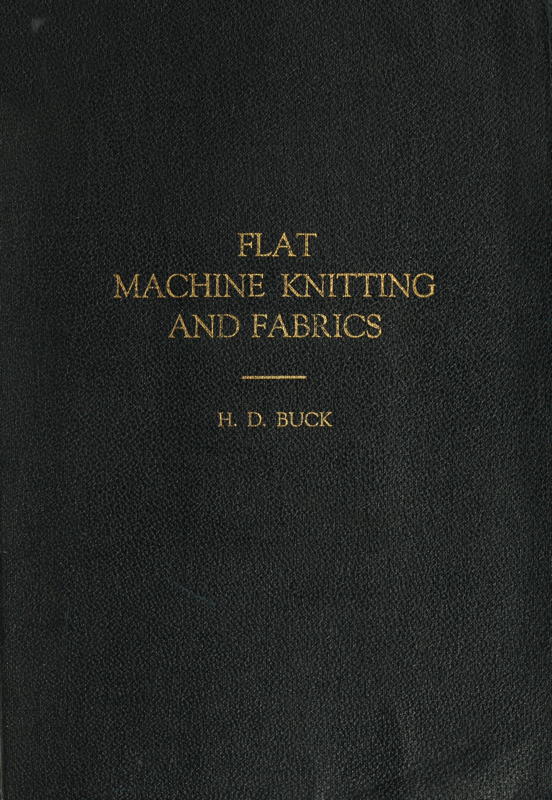
A loop is a very small length of thread, or yarn, taken at some point at a distance from the end and drawn through, or around, some object, usually another loop. Obviously this will result in two loops. One of these coils around the instrument or needle which draws it through and is called the needle loop, shown by the letter a in Fig. 1. The other loops around the object or previous loop through which it was drawn, and is called the sinker loop, indicated by b, b in Fig. 1. These two loops, not two complete loops, but rather one full needle loop and two halves of the sinker loop, make a stitch, as indicated by the shaded portion of Fig. 1 from c to c.
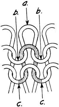
Fig. 1.
Sinker Loop, Needle
Loop and Stitch.
A course is any number of loops lying side by side in a line crosswise of the fabric, as indicated along dotted lines a, a, Figs. 2 and 3.
A wale is any number of loops in a line succeeding one another lengthwise of the fabric, as indicated along dotted lines b, b, Figs. 2 and 3.
Crosswise of the fabric is the direction in which the yarn feeds while the fabric is in the process of construction, forming loops adjoining one another, or the same direction as the course. Lengthwise of the fabric is the direction in which the fabric is built up by drawing one loop through another, or the same direction as the wale. Therefore the width of the fabric is restricted by the number of loops or needles used as a base, while the length of the fabric has no restrictions other than the supply of material or the will of the knitter. Rib is an alternative expression for wale, but is applicable more particularly where the fabric has a wale on both sides, in which case it is shown as a rib fabric. Where a cloth has a wale on one side only it is known as a jersey fabric, and is also sometimes called flat goods. Rib fabrics will be taken up later for it is my purpose to deal only with jersey or flat fabrics until the theory of knitting is thoroughly explained.
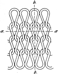
Fig. 2.
Wale and Course, Face.
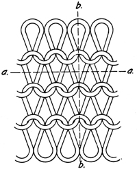
Fig. 3.
Wale and Course, Back.
A study of the loop is very important to those who wish to acquire a knowledge of knitting, for the whole construction of the knitted fabric is from loops. In fact, knitted fabric is commonly referred to as looped fabric.
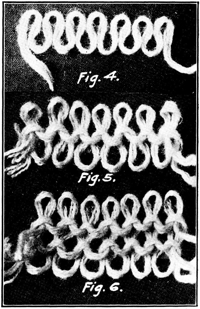
Fig. 4.
Fig. 5.
Fig. 6.
Formation of Loops.
Fig. 4 shows the position or form into which the yarn is drawn to form the loops of a plain jersey or flat fabric. Fig. 5 shows a second course of loops drawn through the first. Fig. 6 shows a third course. It is quite evident that in order to draw each of these courses of loops through the preceding one there must be something to sustain or hold the preceding course of loops as well as the new loops during the period in which the new ones are being drawn through. There must also be something on which to 12start the first row or course of loops for, as stated before, a loop cannot be made without something of stability to draw it through.
It is very important that the reader get firmly fixed in his mind the curves of the loops and the most simple methods of forming them, as he can then more readily understand the necessary movements made on a machine. For this reason I will first take up the most primitive method of knitting; i.e., hand knitting.
The needles used for hand knitting are straight rods of steel, wood, bone or celluloid. Not less than two of these needles must be used as indicated in Figs. 7, 8 and 9. To start we take the yarn and make a small slip knot or noose, with which we are all familiar, slip one needle through the loop thus made and draw the yarn up so that it fits around the needle loosely.
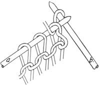
Fig. 7.
Forming Loops by Hand, First Step.
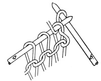
Fig. 8.
Forming Loops by Hand, Second Step.
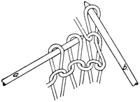
Fig. 9.
Forming Loops by Hand, Completed.
We now have the cornerstone laid. Holding this needle in the left hand with the fore-finger bearing lightly on the loop, we take the other needle in the right hand and slip it through the loop as in Fig. 7, next draw the yarn over the end of the right hand needle as shown, then draw this needle back to the point where it will pass the left side of the loop on 13the right hand needle, but not far enough to allow the yarn that was placed over the end to drop off. Then we draw this yarn through as indicated in Fig. 8, and we will have the second loop.
At this point in the building up of the fabric we would slip the previous loop off the left hand needle and let it hang on the newly formed loop on the right hand needle, as in Fig. 9, but as we are not as yet building, but only laying the foundation, we slip this new loop back on the left hand needle, where we now have two loops. The next step is to take the right hand needle, slip it through the second loop, and proceed as with the first, then slip the third loop back on the left hand needle. This procedure is repeated until there are sufficient loops to make the fabric the width wanted. We now have our foundation on which to build.
Figs, 7, 8 and 9 give a very clear illustration of the method of building up the knit fabric by hand knitting after the first course. It should be noted, however, that after the right hand needle has completed the new course, and the last loop has been dropped off the left hand needle, the right hand needle with its full number of loops is shifted to the left hand and the empty needle then becomes the working needle in the right hand.
This first course of stitches, it should be noted, has the needle loop only, the sinker loop being tied in to form a base or edge from which to start. Fig. 7 shows the first position to form the loops with two needles. One full course is on the needle lettered a, while needle b is thrust through the first loop of the last course and receiving yarn to draw through a new loop.
Fig. 8 shows the new loop drawn through, while Fig. 9 shows the old or preceding loop cast off from needle a and hanging from the new loop on needle b.
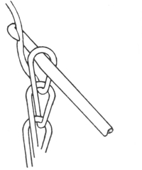
Fig. 10.
Crochet Stitch,
Catching Thread.
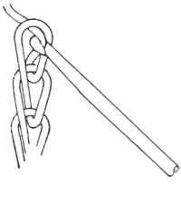
Fig. 11.
Crochet Stitch,
Drawing Stitch.
Figs. 10 and 11 show the crochet stitch, which is taken up at this point to show its similarity to the knitted loop and to 14explain the points of difference. The illustrations show very plainly the method of forming crochet loops and they also show that this stitch is simply a single chain or wale of loops succeeding one another.
When crochet work is to be made into a fabric, the hooked needle is pushed through the side of another loop at the point at which it is to be joined, and the new loop is drawn through this old loop as well as the one on the needle. There is never more than one loop used at a time in making this work.
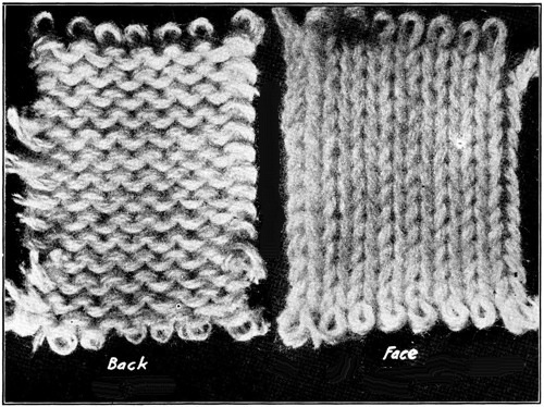
Fig. 12. – Back
Fig. 13. – Face
Jersey Fabric.
In the knitted fabric the loops are laid side by side and there are a sufficient number of loops being used at all times to make the width of fabric desired. The wales are bound together by the yarn passing from one loop to the next adjoining one, thereby forming the sinker loops which have already been explained.
Figs. 12 and 13 are photographic reproductions of a piece of closely knitted jersey or flat goods. The stitch formation in this cloth is exactly the same as shown in the line drawings at Figs. 2 and 3.
15It may be well to state here in passing, that all textile fibres have more or less flexibility or resiliency, and while this characteristic is infinitely small in any single fibre or hair, it is quite appreciable when there are hundreds of fibres grouped together and twisted into a yarn. This is the reason for the elasticity or stretch in knitted fabrics.
It will be noticed in Fig. 2 that in forming the loops the curvature or bend of the thread is gradual and uniform. When this yarn is knitted into fabric and both top or needle loop, and bottom or sinker loop are attached to or drawn through other and like loops, and we pull or stretch the fabric, we draw sharp curves or corners in the yarn where it passes around the preceding and succeeding loops. When we let go or take the strain off the fabric, the natural tendency of the fibre to straighten out or take an easier curve brings the fabric back into its original position.
I would suggest that the reader take any straight piece of yarn, worsted if available, form a loop, and hold it between the thumb and finger of one hand, then press the loop together with the thumb and finger of the other hand and demonstrate for himself this characteristic of textile fibres.
Although what is known as the spring beard needle was a part of the original invention of the knitting machine, and was in use more than 200 years before the latch needle was invented, I am taking up the latch needle machine first for two reasons. First, because the latch needle type of machine is most largely used and is more popular in this country today than any other type; and second, because I believe it can be more easily understood by a person who is not familiar with machine knitting.
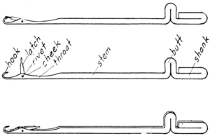
Fig. 14.
Latch Needles.
In machine knitting of every kind there must be a needle for every loop, and therein lies the fundamental difference between machine and hand knitting. Latch needles, however, are constructed entirely different from the straight plain hand needles. Fig. 14 shows the construction of the latch needle. It will be noted by looking at the latches on the three needles that they swing freely on a pin or rivet lengthwise of the needle, but have no movement sidewise.
The hook, latch, rivet, cheek, throat and stem are substantially the same except in size in all latch needles, but the balance of the needle may and does vary in shape to a marked degree in the various types and makes of machines. Fig. 15 shows many of the different types of butts and shanks made, as well as the variation in the sizes of the hooks and the thickness of the needles, but it should be understood that the type of the butt and shank has no bearing on the size of the hook and stem, as each type is made in the various sizes and is governed only by the size of the yarn to be used.
17Fig. 16 is a very important illustration and the reader should study it well and mentally digest every position of the needles, for here is shown a complete cycle of the movements necessary to make the knitted loop on a latch needle machine of the type in which the needles slide back and forth, lengthwise of the needle, in what are called tricks, or more commonly expressed, slots. Probably 95 per cent. or more of the latch needle machines in use today are of the type in which the needle slides back and forth in slots in the operation of forming the loops.
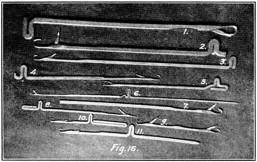
Fig. 15.
Some of the Various Types of Latch Needles.
A study of Fig. 16 should be made in connection with the photographic reproductions, Figs. 17 and 18. Fig. 18 shows substantially the whole knitting machine, while Fig. 17 is a close-up view of that part of the machine which actually does the knitting. Fig. 16 shows the principle used to operate the needles.
This type of machine was invented in 1863 by Isaac W. Lamb, a clergyman, and was made possible only by the invention of the latch needle in England about 1847. It is very simple in construction in the plain models and is the most versatile of all the knitting machines, it being possible to make on it a larger variety of stitches and articles of apparel than 18on any other machine. It is known as the flat or Lamb type of machine.
It has two flat or straight horizontal plates or beds about one-half inch thick by 6 inches wide, the length of which varies from 6 inches or less to 60 inches or more, according to the width of fabric it is designed to make. These plates are set in a frame, parallel to each other lengthwise, and at an angle of about 90 degrees to each other and 45 degrees to the horizontal. See Figs. 16, 17 and 20.
All flat machines of this type have two needle plates, but for our purpose of knitting jersey fabric we need but one, therefore we will imagine that there are two in Fig. 16 but the back one having no needles in it cannot do any knitting. The needles, as will be noted in Fig. 16, are placed in tricks or slots of which there may be any number from 2½ up to 18 in one inch, according to the size of the yarn to be used. The needles should fit in the slots close enough so that they will not have any chance to tip sidewise, yet they must move easily endwise. The gib c, c, is for holding the needles in the plate, and of course is removed by drawing out endwise when a needle is to be put in or taken out of the plate. The plate is secured in a frame indicated by the letter n in Fig. 16, and the frame is attached to a stationary stand or table.
The cams a-1, a-2 and a-3 are attached to the carriage b, b, b, b, Fig, 17, at a point just below a-1, a-2 and a-3 and the carriage, together with the cams, rests and slides freely back and forth on the ways c, c, while the plate and needles remain stationary. The cams are secured to the carriage in a position so that they come very close to the needle plates. They should be set as close as possible and not rub the plate as they are moved back and forth.
It may be well to explain here that a cam in any machine is a piece of hardened steel of the proper shape and construction to cause some other part of the machine to make the proper movements to perform its functions. In this instance they actuate the needles by coming in contact with the butts.
It will be noted that each one of the needles from e to e, Fig. 16, has a loop in the hook except from the point where they are rising over the cam a-3, and on these the loops rest on the shank. It should be understood that the fabric back of the needle plate has a weight on it, thereby giving to each loop a downward pull. The fabric and weights may be seen in Fig. 18.
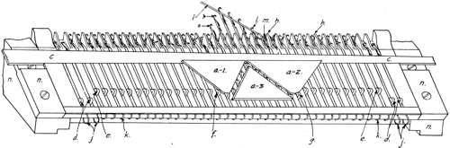
Fig. 16.
Principle Used to Form Loops on a Machine.
20Now bear in mind that the cams a-1, a-2 and a-3, Fig. 16, are attached to the carriage b, b, b, b, Fig. 17, at points underneath a-1, a-2 and a-3. These cams are moving from right to left and as the lower left hand corner of a-3 is below the line of the butts of the needles from e to e, they, the needles, must of necessity slide upward in the slots along the edge of this cam. When they get to the top it will be noted that the latches of the needles are above and clear of the loops. As the cams move farther along, the cam a-2 comes in contact with the butts and slides them down again. As the needles move downward the hooks catch the thread i which lies in their path, and as at l the stitch that is on the needle closes the latch as the needle slides downward. As the needle moves farther down the hook draws a new loop through the old one, while the latch closing up the hook allows the old loop to slip over the end (needle m), and the pull of the fabric draws it down on to the new loop.
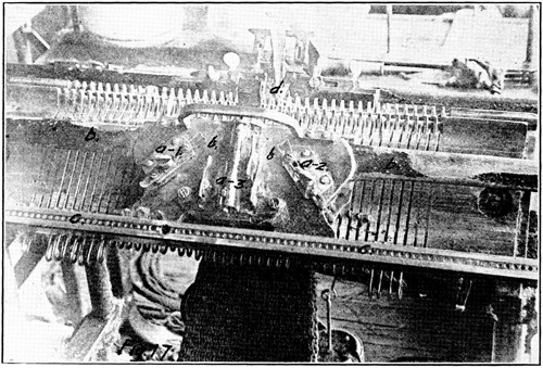
Fig. 17.
Top Side of Carriage, Over Cams.
The thin portions of the needle plate indicated by the letter h in Fig. 16, which extend upwards, are called jacks and these hold that part of the stitch called sinker loops while the needle is drawing through the new needle loop.
Below each needle is a U-shaped spring, j, j, and k, k, Fig. 16, which holds the needles up in the working position. 21They extend down to and around the bottom of the plate and up against the under side of the plate. The end that is under the plate is a little longer than the end that slides up in the slot below the needle. These U-springs are made so that before they are put in their places on the plate, the ends come together, so when they are spread and pushed on to the plate they act as a clamp to hold the needles in position. They are not attached to the needles, but simply clamp the plate with tension enough to hold them up or down, as the case may be, and the bottom end of the needles rests on them. This construction leaves the knitter in a position to pull d own out of working position as many needles as he may wish, therefore he may make his fabric any desired width by pulling needles down out of the working line or pushing them up into the working line, thereby adding to or taking away stitches.
The letter d in Fig. 17 designates the yarn carrier through which the yarn passes, and which guides the yarn along the path of the hooks of the needles. After having moved the carriage clear across the working needles, and finishing a course of loops, the carriage is moved back in the opposite direction and another course is put on. This is done in exactly the same way except that the cams must necessarily push or slide the needles up and down on the opposite sides of the cams: i.e., the butts slide up on the right hand side of the V-cam or cam a-3 in Fig. 16 and down the right hand side of cam a-1, or stitch cam. This operation is continued until the fabric is of the desired length.
Needles are operated at a rate of speed that would make 500 or more stitches per minute per needle if the machine would keep them in continuous operation, but in practical work they make from 50 to 200 stitches per minute according to the size of the machine as more time is consumed as a rule in the movements of the machine between the stitches than is used in the actual knitting operation. On account of this speed of operation the latches of the needles must be under control at all points in the cycle of knitting; that is, from f to g in Fig. 16.
It will be noted that needle o in Fig. 16 has just started to rise and the stitch that was in the hook has opened the latch and still has it under control. When this needle gets up to the position of needle p it has passed the point where the 22stitch can control the latch, therefore, other means must be provided or it would be very liable to fly up and close the hook, in which case it would be impossible for the hook to catch the yarn for the next stitch. When this happens we have what is called a drop stitch, and after the yarn had passed there would be no stitch on the needle.
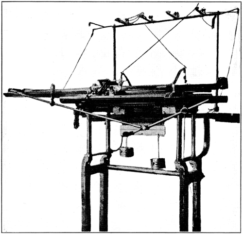
Fig. 18.
Flat Latch Needle Machine.
To provide against this there is used in this type of machine a long narrow thin bristle brush set over the needles and at the proper angle and distance to just clear the latches. This brush is shown in Fig. 19. The letter a indicates the brush alone, and at b is shown the brush in the fixture which carries it. The letter c indicates the brush carrier. Fig. 20 is a view looking down from above the machine and shows the brushes, a and b, set ready to operate in the machine. So as not to confuse the reader I will say here that all previous 23illustrations presenting this part of the machine have shown it with the brushes removed in order to make clear the operation of the needles.
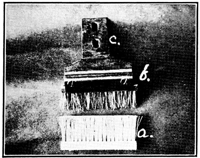
Fig. 19.
Latch Brushes.
One Mounted in its Holding Clamp, or Fixture.
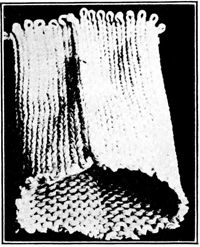
Fig. 21.
Tubular Fabric Made on a Flat Machine.
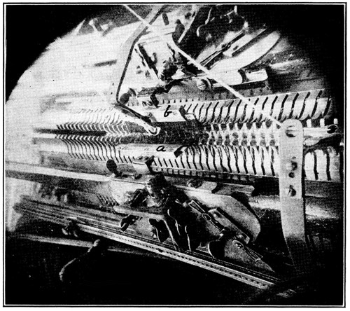
Fig. 20.
Position of Latch Brushes When on the Machine.
A fabric made according to the foregoing explanations would be what is known as a jersey fabric (see Figs. 12 and 13), but it would be a flat piece of fabric when finished. Perhaps 24to make it plainer I should say that if the fabric were laid out on a table it would be a single thickness, and if it were to be made into a garment it would be necessary to double it over and sew the edges together to make it tubular, or in the form of a bag. If we wish to make the fabric tubular on the machine to save the labor of seaming it, and also prevent the unsightly seam, it would be necessary to use the needles in both plates, front and back. The cams would then be set by means provided, which will be explained later, so that when the carriage is moved in one direction, say from left to right, the front cams will operate the front needles and the back cams will be put out of operation; and when the carriage is moved from right to left, the back cams will operate the back needles and the front cams will be put out of work.
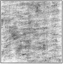
Fig. 22.
Jersey Fabric Made on
a Machine With 24 Needles
to One Inch.
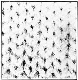
Fig. 23.
Jersey Fabric Made on
a Machine With 2½ Needles
to One Inch.
By continuing the operation of the machine in this manner of having only the front cams operate while moving the carriage in one direction, and only the back cams operate when the carriage is moved in the opposite direction, there would be produced a tubular fabric as shown in Fig. 21. The yarn must of a necessity go across from front needles to back ones, and from back ones to front ones each time the direction of the movement of the carriage is changed, thereby closing up both sides of the fabric.
The jersey type of fabric is very popular with the consuming public and is used for quite a wide range of garments in many different weights and materials. Milady may easily be dressed throughout, with the exception of shoes, in jersey cloth, and still be up to the minute with her clothes. She may have on silk stockings which are made with the jersey stitch. Her underwear, most surely is made of silk jersey fabric. Then she may wear a tricolet waist, which is silk jersey fabric, with a worsted jersey cloth suit. Also she might easily have her fall and winter coat made from the heavyweight fulled jersey cloth, and carry a heavy Shaker sweater, which is also the jersey stitch, on her motor trips into the country.
It is a far cry from the finest and lightest to the heaviest and coarsest in jersey cloth. Figs. 22 and 23 show two extremes. Fig. 22 is a sample of fine fabric and has 32 stitches to one inch; while Fig. 23 is used for what is known as the Shaker sweater and has 3½ stitches to one inch. Between these come men’s balbriggan underwear and the flat woolen underwear, the jersey bathing suits, tricolet, and the fulled jersey cloth for ladies’ suits and coats, etc. This stitch is also the basic one for medium priced knit neckties, as well as knit mittens and gloves, except the very lightest and thinnest.
There are numerous conflicting expressions or terms used in the knit goods industry, and one of the most common of these is the term “flat goods.” In the older underwear sections, where the circular machine was used exclusively and the flat machine was practically unknown, the term flat goods indicated underwear fabric made tubular in the jersey stitch on circular spring needle machines, as distinguished from tubular rib fabric made on latch needle machines. At present, in the localities where mills are using both the circular and flat straight needle bed machines, it is generally understood that a flat fabric is a fabric of single thickness made on a flat machine, regardless of the stitch, and any fabric made on a circular machine is known as a tubular fabric. If the stitch should be specified it is mentioned separately.
This latter custom appears to me to be the more logical; therefore, when these terms are used hereafter in this work it should be understood that flat fabric means cloth of a single thickness made on a flat machine, or a tubular fabric cut open so it will lie out flat. The “flat goods” of the old time knitters will be called jersey cloth or fabric.
We will now leave the jersey fabrics for a time, as the making of the tuck stitch and plated work in the jersey stitch are more or less complicated and had better be left until we take up fancy stitches and designs on circular latch needle machines. The tuck stitch is never used in the jersey fabrics on flat machines.
A rib fabric is one which has a rib or wale on both sides of the cloth. It has much more stretch or elasticity than cloth of the jersey group; about twice as much, generally speaking. The elasticity of either one, however, may be varied to a marked degree by changing the length of loop drawn.
27Rib fabric is peculiarly adapted for such garments or parts of garments as should be close fitting, such as ladies’ undergarments, cuffs for all kinds of knitted garments, tops of half hose, etc. Fig. 24 shows very clearly the course the yarn takes to form this stitch. It would be well to study this drawing in connection with Figs. 2 and 3 and note carefully the different course the yarn takes in order to form a wale on both sides of the fabric. A photographic reproduction of a plain rib fabric showing both sides is given at a, a, in Fig. 25.
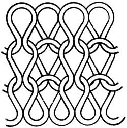
Fig. 24.
Construction of a Plain
Rib Fabric.
A properly constructed plain 1 and 1 rib fabric, such as is shown in Fig. 24, should be alike on both sides. Very often this is not the case. A little carelessness on the part of the adjuster in not drawing the stitch the same length on both sides will make a difference on the flat machines, while it is impossible to make them the same on an ordinary circular machine on account of the principles of construction of this machine.
Fig. 26 is a view of a flat machine making the rib stitch, looking down from above. It almost fully explains the method of making this stitch to those who have carefully read and understand the principles of making the jersey stitch. In this illustration the carriage is moving from right to left, and both front and back cams are in operation, therefore both front and back needles are working.
It should be noted that the back plate is set so that the needles of that plate come up at a point in the middle of the spaces between the needles of the front plate. The cams, front and back, being made exactly alike and set exactly opposite one another, must push the needles of both plates up at the same time and draw them down at the same time. When we feed the yarn, indicated by the letter a in Fig. 26, down through the guide, b, it is drawn into loops from both sides alternately, as shown at c, by the opposite sets of needles, thereby making stitches, or ribs, or wales, on both sides of the fabric. This is the plain 1 and 1 rib stitch.
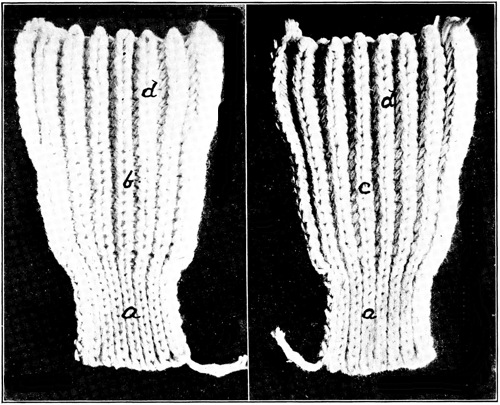
Fig. 25.
Face and Back of Fabric;
a, a, Plain Rib;
b, c, Half Cardigan;
d, d, Full Cardigan.
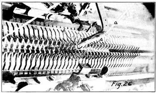
Fig. 26.
Flat Knitting Machine Making the Rib Stitch.
This stitch, by distortion, or by manipulation of the yarns or needles, or by a combination of two or all three of these things, can produce a number of fabrics different both in appearance and feel. To enumerate the principal ones, there are the half cardigan or tuck stitch, also sometimes called royal rib; the full cardigan, and the rack stitch with the rack on one side of the fabric and the double rack which shows the rack on both sides of the fabric. Then there is the zig-zag stitch, which is quite simple to make but is quite a puzzle to those not familiar with it. There is also the cotton back, which is a well known and popular fabric in the sweater trade.
Then there are many varieties of ribs made either in plain or in combination with one or more of the above by taking needles out of the machine at predetermined places, or by the Jacquard system of selecting needles. There is also the system of making designs by the cut pressers and pattern wheels, which is used on circular machines only.
The half cardigan or tuck stitch is used more than any other of the ribbed group, though it is generally used in combination with the plain rib. The body and sleeves of the ordinary rib sweater, and much of the rib underwear produced, are made in this stitch while the cuffs are plain rib. The reason for this is that the half cardigan rib will knit up considerably wider, with the same number of needles, than the plain rib, therefore it is possible to make a shaped garment without cutting and sewing up again. Also the plain rib comes out lighter and thinner so makes a more desirable cuff for sweaters and underwear. It also has more life or spring to it, which is another desirable feature.
The half cardigan or tuck stitch is the one that is almost invariably used in making the well known cotton back sweaters. It is believed by many people who are familiar with this fabric that the back stitch of cotton does not come through on the face, but in this they are mistaken. The face stitch does not go through on the back, but the back yarn does go through on the face.
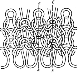
Fig. 27.
Construction of a Half Cardigan
Rib Fabric.
Fig. 27 is a line drawing showing the course the yarn takes in making this stitch and a careful examination of it will demonstrate to the reader that this is the case. The dotted line e, e, indicates the wale on the face and f, f, shows the wale on the back. It will be noted that the back stitches of yarn come through to the face of the fabric and connect the preceding and succeeding stitches, c, c, the same as in the plain rib, but there is this difference, in the plain rib these face stitches are, or should be, just the same length, while in the half cardigan, on account of the back stitch of this course holding over for one course, it necessarily draws a longer stitch in the back and the yarn for this long stitch must come from the face stitch, thereby making this face stitch very short.
In the drawing the stitches are not proportioned just as they lie in the actual fabric, for if they were it would be very difficult to trace their course. In the fabric the stitches b, b are so short that they are almost completely covered by the large, full, round stitches, c, c, c. These stitches are full and large from the fact that where they go through to the back they do not form a loop but simply cross over the back loop as at d, without being drawn through. These are completely covered by the loops a, a, in the back wale.
The diagram at Fig. 28 shows the method used to make the half cardigan or tuck stitch on a flat machine. The cams shown are what are known as the Lamb system and are called the automatic cardigan or drop locks. The word “locks,” as applied to the flat knitting machine, means a full set of cams attached to the cam plates ready to affix to the carriage. There are a number of different systems of constructing these locks, but the one selected is the most simple of all and for this 31reason is used for illustration first. The others will be taken up at the proper place.
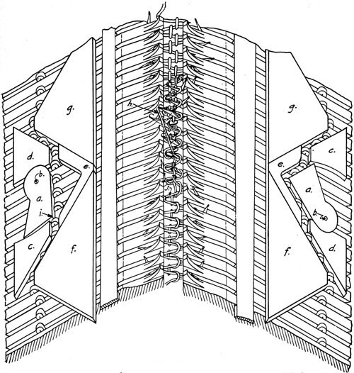
Fig. 28.
Automatic Locks for Making Half or Full Cardigan Fabrics.
In Fig. 28 only a part of the needle plates are shown. They are attached to a frame at an angle of 90° to each other and 45° to the horizontal as explained before. The cams are shown in working position with the carriage (to which they are attached when in use) removed. As indicated by the thread h, they are being moved toward the far end.
It should be noted that the automatic drop V-cams a, a, are in different positions. These cams are made so that they swing freely on the pivots b, b, and the swing is inside of the limits of the positions of the two cams in the drawing. It is controlled by pins on the top side of the swinging ends, the pins coming 32through a slot of the proper length in the cam plate to stop them at the right place.
When starting to move these locks from the near end toward the far end, the cam a, on the left, might be in any position within the limits of the before mentioned slot in the cam plate, but the instant it comes in contact with the butts of the needles it is automatically forced to the position shown.
In making the half cardigan stitch the right hand cam is held up to the top, as shown, at all times by means provided. This position forces the needles high enough so that the latches are above and clear of the loop that is on the needle, therefore when the needles are drawn down again by the cam f, they draw new loops and cast the old ones off over the latch and hook, and they drop down on the new loop, just as explained in describing how to make the plain rib. This refers only to the needles in the right plate.
The cam a, on the left side, however, having been swung down to its lowest position by contact with the needle butts, raises the needles only about one-half of the normal distance. Or to put it differently, the needles raise high enough to open the latches and catch the yarn when being drawn down again, but not high enough to permit the loop that is on the needle to slide down below the latch. Therefore, after the completion of the course we have the right side with the new loop drawn through the old one as in plain rib, but the left side still retains the old or previous loop and also the new one as at j. This leaves two loops on every needle on the left side and one on the right when the course is completed.
On the return course, from the far end to the near end, when the point i of the left cam, a, comes in contact with the first needle it must swing up in the same position as the right cam, a, therefore all the needles will draw the new loop through the two preceding ones and clear themselves, leaving only one loop on each needle as in the plain rib.
On the next course, from the near end to the far end, the left hand needles again hold the old loop and take on a new one as just explained, while the right hand needles cast off the old ones and hold only the new ones.
To condense the operation into a few words let us say that the left hand needles always must hold the two stitches while moving in one direction, and clear them off and hold only one on the return course; while the right hand needles always cast 33off the old stitch and hold the new ones only. The right hand needles would make the face side of the fabric.
The writer has made a special effort to explain the formation of this particular stitch, and the reader should make the same effort to get this formation clear in his mind, for this stitch is the base of almost all of the fancy stitches or design work which will be taken up later. The system used in design work is of course entirely different from the one just described, being what might be called a selective system, that is, a method whereby the designer may select the proper needles at the proper time and place to make the tuck stitches block out the design wanted.
Fig. 25, at band c, shows the tuck or half cardigan stitch; b is the face and c is the back. If studied carefully the reader will notice that the face side, b, has a full round stitch, while c, or the back of the fabric, has a small narrow stitch.
The full cardigan stitch is not nearly so generally used as the half cardigan and plain rib stitches. It is seldom if ever used in making underwear or any fine fabrics. When it is made it is usually used for sweater fabrics or other novelty wearing apparel of this character.
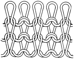
Fig. 29.
Construction of a Full Cardigan Fabric.
A line drawing of the full cardigan stitch is shown in Fig. 29. This stitch, as its name would indicate, is made in the same way as the half cardigan only the stitches are held alternately on both rows of needles on alternate courses. Referring again to Fig. 28, in making the full cardigan stitch the cams would operate exactly the same while moving toward the far end as shown and explained for the half cardigan. But the means provided to hold the right hand cam, a, at the top position would have been removed, so that on the return from the far to the near end this cam would be thrown down 34to the same position as the left hand cam, a, is shown, while this left hand cam would be forced up into the position in which the right hand cam is now shown. In other words, the stitch would be the same with the carriage or cams moving in either direction, only it would alternate on each course from one row of needles to the other.
We will refer back to Fig. 25, which shows both sides of a piece of fabric with the three stitches we have just discussed in one piece. This shows quite plainly the individual characteristics of each. All have the same number of needles or wales, the same yarn was used, on the same machine; yet how different the results!
The most marked difference is in the width. There is proportionately the same difference in the thickness, but this cannot very well be shown. It should be observed that the stitch or loops of the plain rib a, a, and the full cardigan d, d, are the same on both sides of the fabric, while the stitches in the half cardigan, b and c, are not. It will be noted also that the stitch of the plain rib is much smaller than that of the two cardigans, also that the wales or ribs hug very close together in the plain rib, while they are separated more or less in the cardigans.
The rack stitch is used on many sweaters for a border on the bottom, also for a narrow strip on both sides of the shoulder seam, and a strip at the place the stitch changes from half cardigan to plain for the cuff. Many sweaters have the collar and the border down the front made separately in the rack stitch and sewed on. Most of the designs in the knitted neckties made on flat machines are based on the rack stitch. Another very important use for this stitch is in making a smooth sightly edge on the bottom of sweaters, the ends of cuffs, etc.
The rack stitch is always made on one of the cardigans. From this statement the reader will realize that this stitch is not made in place of the half or full cardigan, or any other stitch but is an addition to, or a further development of these stitches.
Fig. 30.
Half Cardigan Stitch Ready to Rack.

Fig. 31.
Stitch After Plate Has Been Racked Over One Needle.
Fig. 30 shows a half cardigan stitch ready to rack, as it is customary to make the one needle rack on this stitch. It should be noticed that the racking is done on the course that holds, or does not cast the previous stitch off on one side. Fig. 31 shows the stitch after the plate has been racked over one needle. This illustration practically explains the whole principle of the rack stitch. The rack will show on the side that casts the stitches off the needles. It is customary to hold 36the stitch or tuck on the back plate, therefore the rack shows on the front side of the fabric, or the side toward the operator of the machine.
It is understood, of course, that on a flat machine there must always be an end needle on one plate or the other. Usually the knitter sets up his machine with one plate carrying the end needle on one side of the work and the other plate carrying the other end needle. Which end of the respective plates carries this needle depends on the position of the racking cam. In the illustration, Fig. 30, the front plate has the end needle on the right and back plate has the end needle on the left. After racking as in Fig. 31, these positions are reversed. It will be noted that the front plate has been racked or moved over one needle so the front needles will come up through and operate between the next two needles to the left of their previous positions.
Or to explain it in a different way, in Fig. 30, before racking, the front plate has the end needle on the right and operates outside of the last needle in the back plate, but after racking, as in Fig. 31, this end needle on the front plate has been shifted over so it comes up inside the last needle in the back plate.
After racking over one needle there must be one full round or two courses put on before racking again; that is while racking on the half cardigan stitch, and then the plate is racked back to the first position. This operation of racking first one way and then the other with a round between each rack is continued until the necessary number of racks are finished and then the operator proceeds with the plain half cardigan.
This procedure would make a plain rack on one side of the fabric only. We have assumed in this explanation that the back is stationary and the front plate is the one that moves, but I wish to have it understood here that it makes no difference which plate is stationary and which one racks or is movable; the results are the same.
Some writers use the words shog or shogged in place of rack or racked, but the writer of this work has avoided the use of these words as they are seldom or never used by the practical knitter, at least not in this country.
In most of the modern flat machines the plate that racks has enough end clearance to rack over at least two needles, and some of them as many as four, though racking two needles is sufficient for all ordinary work. Fig. 32 shows the method of racking or moving the plate to make the rack stitch, or at least this is the principle used as a rule on the imported machines, with some modifications by some makers. This also applies to the method shown of attaching the plates to the frame.
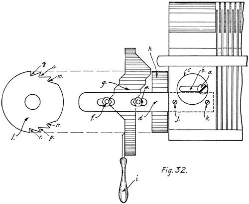
Fig. 32.
The Racking Cam, Ratchet and Studs.
There is a large flat bottom hole, c, bored about half way through the plate; through the bottom of this hole there is made an elongated hole, b, through which the plate is attached to the frame by the shouldered screw, a, the head of which is flush with the top of the plate. It will readily be seen that with this method the plate cannot be moved in any direction except lengthwise of the plate, or crosswise of the needles. To secure this movement at will there is a steel strap, d, attached 38to the under side of the plate by the screws j and k, and through the outside end of this strap there are two elongated holes through which are attached two shouldered studs with nuts e and f. These studs extend down on both sides of the steps of the racking cam, g, and together with the plate are moved back and forth by the steps on the racking cam. The cam is moved by the handle, i, in the hand machines, or by the ratchet, h, being operated by pawls or dogs in power machines.
The letter h shows a front elevation of the ratchet, while i is a side view. It will be noted that there are only three teeth on each side, and these two groups are opposed one to the other. If the reader will examine the racking cam, g, with due thought the reason for this will be obvious. There are three steps on the cam and the cam must have an oscillating movement and not a rotary one. The ratchet, h, and the racking cam, g, are both attached securely to one hub, therefore must move together on a stud which projects from the end of the frame.
The plate as illustrated in Fig. 32, sets at the limit of its movement to the left, consequently any racking that is to be done must move the plate to the right, therefore the pawl at the top of the ratchet would engage the uppermost tooth, q, and turning the ratchet one tooth would move the racking cam one step, thus moving the plate over one needle through its contact with the studs, e and f. There are two pawls, upper and lower, arranged to engage the teeth on the ratchet either at the top or the bottom as required. If we wanted a one-needle rack only, after putting on one round of stitches we would have the lower pawl engage the tooth, n, of the ratchet and move the racking cam back to its first position. If, however, we wanted a two-needle rack, the upper pawl would engage the second tooth, o, of the ratchet. For three racks it would then engage the next tooth, m, after which it would be necessary to start on the return to the first position, remembering to put on one course or one round, as the case may be, of stitches between each rack. If racking on the half cardigan stitch there should be one full round between the racks, but if on the full cardigan the racking may be done every half round or every course, as will be explained hereafter.
Fig. 33 is a photographic reproduction of a piece of fabric, face and back, of a one-needle rack which shows on one side 39of the fabric only. A fabric with the two-needle rack which would show on both sides of the fabric is not illustrated, for it would be the same on both sides as the face side of Fig. 33. A line drawing of the rack stitch is shown at Fig. 34. This is drawn out of proportion and is very loose and not like the fabric, but by making it this way the direction the yarn takes may be easily located.
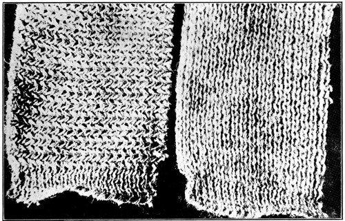
Fig. 33.
Face and Back of One-Needle Rack.
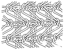
Fig. 34.
Position of Stitch After Racking.
Fig. 35 is an example of a fabric that may be made with a one-needle rack. It is called the zig-zag stitch. To make this the machine should be set to make the full cardigan stitch. After setting up the machine and putting on one round, the needle plate is racked over one needle, put on a course or half round and rack back one needle. Continue this racking back and forth on each course for five rounds, then skip one rack or put on one full round without racking and continue as before. 40Repeat this operation of racking every course for five rounds and then skip one rack and we have a zig-zag stitch.
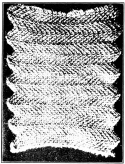
Fig. 35.
Zig-Zag Stitch.
The points come where the rack is skipped, or in other words the direction of the diagonal stitch will continue in the same direction as long as the needle plate is racked every course without skipping, but immediately one rack is missed the stitch starts diagonally in the other direction. It is obvious from the foregoing explanation that the knitter is not obliged to use any set number of courses between the change, but may use any number at his discretion to get the distance desired between the points.
The peculiar characteristic of this stitch is utilized in making a shaped collar for sweaters, as shown in Figs. 38 and 39. First let the reader remember that the direction the diagonal 41stitch takes all depends on which end of the machine the carriage is at when the racking operation begins. It should be understood that the collars are made in a long string and the three parts, as shown in Fig. 38, are duplicated one after another. On either end, where this piece has been cut off, there was a duplicate of the plain racked piece shown at the middle, and at the end of these there was another diagonal piece, and so on from the beginning to the end.
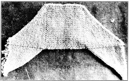
Fig. 38.
Shaped Collar for Sweaters as Knit.
It should be clear to the reader that if the piece shown (Fig. 38) were cut through on the broken lines we would have one complete collar and we would have left the diagonal stitch that belongs on one end of each of the two adjoining center pieces, therefore by cutting all the collars apart at the point indicated by the line we would have our collars shaped without any waste and would have a selvage or finished edge on the outside.
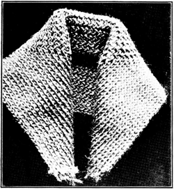
Fig. 39.
Shaped Collar Folded.
The collar is stitched or sewed on the neck opening of the sweater along the cut edge and across the bottom of the racked center piece, and after it is finished and the sweater coat buttoned up it folds over and looks as shown in Fig. 39. As stated before this collar can be made on a machine that racks over only one needle, but in that case the center piece would be racked on one side only, therefore it is customary to make these collars on a two needle rack machine with the middle portion racked on both sides as will be noted in Fig. 39.
Making a rack on both sides of the fabric is very much like making the diagonal stitch in the operation of the machine, even though the resultant fabric is so radically different. It should be made with a full cardigan stitch same as the zig-zag or diagonal, and the needle plate must be racked every course or half round, but with this difference: When making the diagonal stitch the needle plate is racked over one needle and back again, while to rack both sides of the fabric the needle plate is racked over two needles. This does not mean that the knitter should rack over two needles at once, for this should 42never be done, but rack over one needle, let us say to the right, then put on one course and rack over the second needle to the right, put on one course and rack one needle to the left, put on one course and rack the second needle to the left. Or in other words, rack alternately two needles to the right and left and put on one course or half round each time the needle plate is racked one needle.
There is one other point that should be remembered in making this collar and that is the manner of starting the diagonal stitch in the proper direction after finishing in the middle portion. Each time this part is finished the diagonal stitch should go in the opposite way from the previous time, therefore when the one needle half round rack starts to make this stitch the first rack should be made with the carriage on the opposite side of the machine from which the previous one was started.
Fig. 37 is an interesting example of what may be done with the two-needle rack. Designs of this character require the removal or pulling down out of operation of every other needle, therefore a machine of any given cut, or needles per inch, would be in reality only half as fine as cut and would necessitate the use of a heavier or larger yarn.
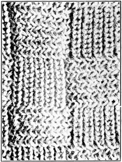
Fig. 37.
Basket Weave Design Made With the Rack.
To make the fabric shown in Fig. 37 pull down or remove every other needle in the front plate. Then pull down or remove every other needle in the back plate for five needles, then leave two needles together and remove every other needle for five more, leave two needles together and continue as before until the full width of needles in working position are as follows: Every other needle down out of working position in the front plate, and every other one down in groups of five with two needles together between these groups in the back plate.
43We will find by this arrangement that when we rack the plate over one needle, every second group of five needles in the back plate will rack across a needle of the front plate, but the other groups will simply move between the needles in the front plate, therefore will make a plain half cardigan stitch only, while the other groups will make a rack stitch. If this operation were continued in this way, racking one needle only back and forth, we would get a fabric with vertical stripes of alternating plain half cardigan and rack stitch. But if we rack back and forth one needle each round for ten rounds, then rack over the second needle and rack back and forth one needle in this position, we will find that the groups of five needles that were racking in the first instance are now making the plain half cardigan stitch, and the groups that were at first making the plain are now racking.
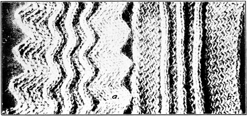
Fig. 36.
Designs Made with Rack Stitch.
An ingenious knitter can make an almost unlimited number of designs of this character by different arrangements of his needles and a variation of the timing of his racks. One thing which should be remembered is that all racking should be done on the course that tucks or holds two stitches when racking on the half cardigan. On the full cardigan both courses are tucked, therefore it does not matter which one is racked, only the side of the fabric on which the rack shows is dependent upon which course the plate is racked.
The design shown in Fig. 36 at a is simply a zig-zag stitch with three needles taken out of the back plate at short intervals, giving these places a piping effect. The fabric at b is a plain one-needle rack with the piping made in the same manner.
Our study of flat machines up to this point has dealt entirely with the class known as the single lock machines, or those that have but one set or pair of locks to do the knitting. There is another very popular type, commonly known as the double-lock machine, which is, it might be said, in a class by itself. This machine, as the name would indicate, has two sets or pairs of locks mounted on the same carriage, and set as closely together as they can be and work properly.
The double-lock machine has many advantages over the single-lock type, the most important being that there can be made upon it a two-faced fabric, that is, a fabric with each side faced with a different yarn, either in color, quality or both. The popular “cotton back” sweater is in this class. In making this class of fabric it is essential that the two different yarns, to show out on the two faces of the fabric, go into the fabric in alternate courses. Therefore, it is obvious that it would not be practical to make this fabric on a single lock machine, for when a course was finished the second yarn would be on the opposite end of the machine from the locks and yarn carrier, and it would be necessary to put on a full round, or two courses, in order to get back to that end to exchange yarn carriers.
The double-lock machine overcomes this difficulty by taking both yarn carriers across, one following the other, each on a pair of locks, each time the carriage moves across the machine. It is evident from this that every time the carriage is moved across the machine there are two courses put on the fabric, instead of one as with the single-lock machine.
This point leads up to another advantage of the double-lock machine, that is, increased production on account of putting on two courses with each movement of the carriage across, as against one course with the single-lock machine. The production would not be twice as much, as might be supposed at first 45thought, for comparing two machines of the same size, the single lock could be operated at a greater speed than the double lock, but not approaching twice the speed. The reason for this is that the locks of the double-lock machine must, of course, be practically twice the length of the locks of the single-lock machine, and inasmuch as the locks must move far enough at each end to be clear of or past the needles, it is quite obvious that the double-lock carriage must have a longer travel. Therefore, it takes longer to complete one round of the carriage than the single-lock machine, to maintain the same needle speed.
This brings us to another point that may as well be disposed of here, and that is the speed of latch needle machines. Generally speaking, the maximum speed of a latch needle machine, either flat or circular, is governed by the needle speed; that is, the speed at which the cams raise and lower the needles, and the thread velocity, which is of course dependent on the needle speed.
As a general rule, where the machine is in good condition and the yarn of fairly good quality, a flat machine with a crank drive should be operated at from 100 to 125 lineal feet per minute, and a chain drive may be operated at from 125 to 150 lineal feet per minute. The reason for this difference between the chain drive and the crank drive is that with the crank drive the movement of the carriage across the machine is not uniform throughout, its movement being faster in the center than at either end, therefore we must regulate our speed so it will not be too high at this point. On the other hand, the chain drive carries uniformly throughout the movement of the carriage except for two or three inches at the ends.
To explain what is meant by lineal feet per minute, let us assume that we have a 20-inch machine, that is, there are 20 inches of needles. In this case the carriage would have to travel about 30 inches on account of the locks having to clear the needles at both ends, therefore a movement of the carriage across and back, or one complete round, would cover twice 30 inches or 60 inches, or 5 feet. Now if we intend to run this machine at a speed of 120 lineal feet per minute, we would divide 120 feet by 5 feet, which would give us 24 rounds per minute, the speed the machine should run.
46I do not wish to be understood as giving this as a hard and fast rule for the speed of machines, for there are many factors which enter into the operation of knitting machinery which might make it desirable to vary this speed. Some of these factors are the condition of the machine, the experience of the operator, the character of the yarn, the class of fabric, and sometimes the skill of the mechanic in charge of the machines.
Going back to the two-faced fabric, this must be made on one of the two cardigans. The “cotton backs” are usually made on the half cardigan, while the fabrics with two different colored faces are made on the full cardigan as a rule.
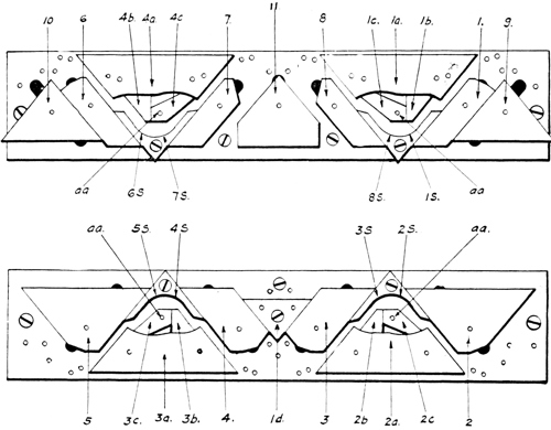
Fig. 40.
Dubied System of Double Locks.
Fig. 40 shows a type of double lock used in a Dubied machine made in Switzerland. The reader will understand from what has gone before that this illustration shows the locks turned upside down, that is, if they were in operation on a machine they would be turned over with the cams close to the needle plates. It will be noted that the fundamentals 47are the same as in the Lamb system previously described, but the method used to change from the plain rib to the full or half cardigan, or vice versa, is different.
In making a plain rib fabric the needle butts would follow the camway as in the Lamb system, that is, if the carriage were being moved from left to right the needle butts would follow the course up with cams 1a, 1b and 1c below, and 1, 1s, 8s and 8 above. This explanation would of course apply to all four sets of cams. The cams 1b, 2b, 3b and 4b have studs which project through the cam plate and there are means provided to draw any one or all of these cams back through the cam plate by these studs far enough so that the faces of the cams are flush with the cam plate, and entirely out of operation.
The cams 1c, 2c, 3c and 4c are made to swing on the pivots, aa, and are held down on cams, 1a to 4a, in the position shown, by springs. It should be particularly noticed that the cams just mentioned, 1b to 4b, and 1c to 4c, are exactly alike in the four sets of locks, but their positions are reversed in the sets opposite. They are placed in this way in order to facilitate the making of the cardigan stitches.
In the study of what follows it should be remembered that the illustration at Fig. 40 shows the locks bottom up, therefore in actual operation the lower set in the illustrations would be the back ones, and the upper set the front ones.
In making the half cardigan stitch it is customary to have the tuck or holdover stitch on the back plate; on the double-lock machine, where we have two feeds, it is on the back feed, and the plain course is on the locks that are leading. Therefore, to make a half cardigan stitch with these locks we would simply raise cams 2b and 3b up through the cam plate out of working position.
Now remembering that the cams 2c and 3c are free to swing up and down on the pivots, aa, and are held down in their present position by a small spring, it should be readily understood that in moving the carriage from, let us say, left to right, the butts of the needles would follow up the right side of cam 2a, and on up over 2c, therefore would knit out on this course. But when these butts came to the second set of locks 48they would move up the right side of cam 3a until they came to the upper right hand corner of this cam, and at this point, on account of cam 3b being up out of operation, they would move across and raise up cam 3c and pass under it. Cam 3a not being high enough to raise the needles to the point where the stitch would drop off the latches, obviously the needles must hold the two stitches on this side of these locks.
On the return of the carriage from right to left the operation of the needles would be reversed, that is, they would pass up over cam 3c and knit out on the locks in the lead and pass under cam 2c.
To sum up the whole operation in a few words, to make a half cardigan stitch we must alternate with the plain rib course and a course that tucks or holds the previous stitch, as well as the new one on one side. This half cardigan is the stitch used in making what is known as the “cotton back” sweater and other such fabrics.
By having one yarn carrier threaded with cotton and one threaded with wool or worsted, as the case may be, and changing these carriers at the end of every course so as to keep the cotton always knitting at the cams that are leading or making the plain stitch, the cotton alone will draw through on the back of the fabric while the worsted or wool will practically cover the face stitch of the cotton. This exchange of the yarn carriers at the end of each course is done automatically by the machine, therefore requires no attention by the operator.
To make the full cardigan stitch the procedure would be practically the same as explained on the single-lock machine, as both pairs of these locks would be tucking or holding on one side (opposite sides) on one course, and each would reverse itself on the return course. The cams 1b, 2b, 3b and 4b would be lifted up out of operation. When this is done the cams 1c, 2c, 3c and 4c would operate automatically to give us this result. This is the stitch used as a rule to make the two-faced fabrics, that is, to make the two sides of different colors.
In connection with this explanation the question may arise as to why the half cardigan stitch is used in making a fabric with one side cotton and the other side wool or worsted, and 49the full cardigan stitch used when making the two sides of different colors. The answer to this is that the half cardigan stitch makes the better fabric of the two for most purposes on account of the face stitch being full and round, thereby filling up the space between the wales. Inasmuch as the cotton stitch on the face is very short, and the wool or worsted quite long, and both are the same color, the cotton will show but very little, if any. On the other hand, if two widely divergent colors were used, the face would not show a solid color but would have more of a salt and pepper effect.
To go back to Fig. 40 it will be noted, as stated before, that while the principle of these locks is the same as the Lamb system previously explained, the construction is somewhat different. The stitch cams, 1, 8, 7, 6, 3 and 4 are shaped along the lines of a parallelogram, while all the stitch cams in the Lamb system were triangular. Cams 3 and 4 are made this shape to allow placing the triangular cam, 1d, in position to act as a guard cam to prevent the butts of the needles from flying up between after dropping off the ends of the stitch cams 3 and 4. Yet it allows these stitch cams to be moved freely up and down through the angular slot in the cam plate, which shows at the ends, in order to make the stitch longer or shorter as the need may be. Cams 1 and 6 are made this shape to allow placing back of them the triangular cams 9 and 10, but these are for another purpose.
It sometimes happens that it is desirable to make a fabric with the stitch so short that it would not cast the old stitch off over the end of the needles with all the cams set high enough to make this short stitch. When this is the case, cams 1 and 6 only would be moved up to a point where they would not draw the new stitch through the previous one on their respective courses, therefore would not use any yarn, while the opposite cams 2 and 5 would draw a full stitch.
After the needles had passed these cams (2 and 5) the cams 9 and 10 on their respective courses, having been set down to the proper position, would draw the needles in this plate down to the point where the old stitch would cast off, thereby completing that stitch without undue strain on the yarn on account of the needles on the opposite side being free to raise far enough to prevent it. Cam 11 acts as a guard cam for 7 and 8 and also is used on a short stitch to cast off for these two cams, the same as 9 and 10 cast off for 1 and 6.
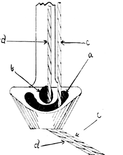
Fig. 41.
Plating Yarn Carrier.
51Fig. 41 shows a yarn carrier used for plating on a flat machine. By plating is meant where two threads of different quality, say worsted and cotton, are used in the same course, and the worsted is laid in the fabric so as to show on the outside and the cotton is in the middle. To do this the worsted yarn, d, d, would pass through the center hole, b, and the yarn c, c, passing through the crescent-shaped hole, a, would be the cotton. It will be noted that the angular draw of the yarn from the bottom of the guide into the needles will always keep the yarns in the positions shown. When the end of the course is reached, and the movement of the carriage is reversed, the cotton yarn c, c, will swing around to the opposite end of the crescent-shaped hole, a, and in this way will always be in the same relative position to the worsted yarn d.
Fashioned goods are garments which, while being knit on the machine, are made the proper shape to fit the wearer.
If the garment to be fashioned is a sweater, the fashioning or shaping to be done is the sleeve, the neck opening, the collar, and at times in the better class of sweaters, the arm holes are narrowed back from the lower part to the shoulder in order to shorten the shoulder length, thereby insuring a better fit. When making underwear not only the sleeves have to be shaped but the legs of the drawers are shaped also. In the ladies’ high class fashioned underwear and tights the bust and hips are shaped. Much of this class of work, with the exception of hosiery, is made on the hand machines and involves much more labor, time and skill, than where the work is knit in a straight piece and made the proper shape by other means after being taken off the machine.
There are three advantages in fashioning the garments in the knitting operation. First, there is a saving in material as there is no material cut off in order to get the shape. This saving, however, would pay but a small part of the extra labor involved. Second, fashioned goods make up into better looking and as a rule better fitting garments than cut goods. Third, on account of the edges being selvage, not cut and raw, it is possible to join two edges so the place of joining will look much like a wale in the fabric, thereby avoiding the unsightly seams of the cut garment.
In fashioning of this character it is customary to set the machine up and start at the widest part of the garment, if possible, so that in getting the required shape the fabric will be made narrower instead of wider, though this is not essential, as it is practical to widen the fabric as well as to make it narrower.
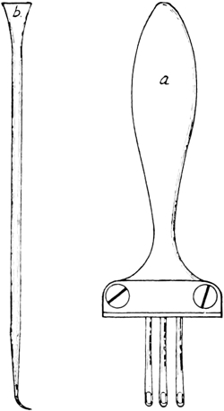
Fig. 42.
Narrowing Comb or Decker
and Work Hook.
The letter a in Fig. 42 shows the instrument used for narrowing by hand. It is called a decker or narrowing comb. It 52will be noted that it consists of long slim points clamped in a handle, with an eye in the free end of each point. There may be any desired number of points clamped in the handle, the limit being only the width of the clamp, but the usual number for this work is from three to five. These points must be set at a distance from one another to correspond to the cut of the machine on which they are to be used; that is, if the needle plates are cut for six needles to one inch the spacing of the decker points must be the same. I might add that these deckers are sometimes made by stamping the whole decker, points and all, out of sheet steel, and sometimes by soldering the round points on to a handle.
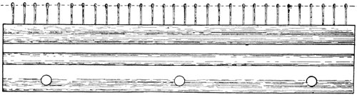
Fig. 43.
Set Up Comb.
Perhaps the best way to explain the use of this decker is to give directions for making a sleeve. First we must have a set up comb, shown in Fig. 43, the use of which will be understood as we proceed. Then we must have weights with which to hold the work down on the needles, for, as stated before, in the operation of knitting there must always be means provided to pull the fabric onto and away from the needles. These weights are simply a stand made from a short iron rod about three-sixteenths inch in diameter and about seven to eight inches long, with a hook turned on one end, a small round iron disc attached to the other, and a number of round iron weights slotted to the center to allow the operator to slip them on or off the stand to secure the desired pull. In fact, 53the stand and weights are a duplicate of the stand and weights we see hanging on the end of the beam of a common platform scale.
To make the sleeve we would put up the required number of needles for the full width of the sleeve, let us say 100, and set the locks for half cardigan stitch. We would then draw the yarn through the yarn guide and down through the throat between the needle plates. Then we would move the carriage across the machine to the opposite side, and we should find that each needle had caught the yarn and drawn it back and forth across the throat. We would now take our set up comb, illustrated in Fig. 43, and push the points which project at the top up through the throat, from underneath, until the upper ends are above the yarn, which has been drawn back and forth across the throat, after which we push the wire, shown just above the comb, through the eyes in the end of the points, as indicated by the dotted line. Now we can pull the comb down on to the yarn and the wire will rest on it. We then hang a weight in the center hole at the bottom and are ready to proceed with the knitting.
The first thing we would do after hanging on our weights would be to rack over one needle to give that end of the sleeve a smooth selvage finish. We would now put on five rounds, after which we would begin to narrow. Stopping the carriage on the left side of the machine, we would take the decker and place the hooks of the three end needles, in the back plate on the right, in the eyes of the three points of the decker, draw the needles up until the stitch dropped down below the latch, then push them down to their first position. We find that the stitches have dropped off over the end and free of the needle on to our decker. We now carry the stitches in toward the center one needle, hook on to these three needles and pull them up through the stitches, being careful not to pull them up so far that the stitches will drop down below the latches. After this has been done we have the end needle without a stitch and therefore pull it down where it is out of operation.
We go through this same performance on the front needle plate, right side, then move the carriage over to the right and 54do the same with the left side. It is obvious that when we have finished we shall have put four needles out of operation, or what would count as two in the width of the garment. We would repeat this after every five rounds for twenty-five rounds, so at this point our sleeve would be ten needles narrower than when we started, although we would have put out of operation twenty needles in narrowing. It is customary to reckon only with the needles of one plate, as the wales of one side only are counted in the width of a rib fabric.
Shaping a garment in this manner leaves a selvage edge for joining, consequently when the garment is finished the seams, when properly put together, are small with an appearance much like a wale in the fabric. They also have the same stretch or elasticity as the fabric.
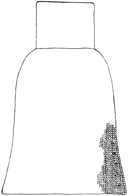
Fig. 44.
Outline of Fashioned Sleeve.
Fig. 44 is an outline of approximately the shape the sleeve should be when finished and shows the direction of the wales and the places where the ones doubled up terminate. This is shown on one side and edge only, although the other side and edge would be the same.
It is understood, of course, that the sleeve is shown opened up flat, and in being put on a garment would be doubled over and the edges joined on the underside of the arm. To reduce the size from the forearm to the wrist or cuff it is usual, in sweaters, to depend on the change to the plain rib stitch, for as explained previously the plain rib will come out much narrower than the half or full cardigan with the same number of needles and the same yarn. In underwear and theatrical tights it is customary to fashion down the forearm to the cuff.
Many knitters consider it good practice to reverse this formula in fashioning; that is, to start at the cuff in order to have the rack stitch on the end of the cuff to save the hand 55finishing. In this event the narrowing operation as described would be reversed, or a widening operation.
This is done by pulling up the three end needles and pushing them down until the stitches drop off on to the decker, as in narrowing, but instead of setting these stitches in towards the center we would push up another needle and set them out one. This would leave the fourth needle without a stitch, so we would pick up the previous stitch, which had been cast off of what is now the fifth needle and raise it up and hook it over the fourth. This is done with one point of the decker. After having done this on both plates and on both sides of the sleeve, while we would have pushed four needles up into operation, we would have widened only two.
Where it is not considered an advantage to have the widening stitches show, this operation may be expedited quite a little by using the hook shown at b in Fig. 42, which is a convenient size to handle, about one-eighth inch in diameter by 6 inches long. By this method we push up into operation the new needle and simply catch with the hook the previous stitch cast off of the end needle and hook it on to the new needle on the four corners as before described. It is best to do this one needle at a time with a course between, taking the one on the plate that contains the inside needle.
The term “automatic” as applied to this class of machine means that all the changes are made automatically, as from plain stitch to half cardigan or full cardigan, or vice versa, changing colors to make striped work, making the rack stitch and back to plain rib, changing from rib to tubular or jersey stitch, making the French rack, etc. All these changes may be made at any predetermined place in the work without any attention from the operator. The machines discussed up to this point may be presumed to have been hand machines, that is, operated by manual power. Therefore, all changes of the stitch, yarn, racking, etc., may be done to advantage at the proper time and place by the operator as the machine requires his whole attention anyway.
A prerequisite of an automatic machine is the operating of the machine by other than manual power, therefore automatic machines are first of all what are called power machines. This does not imply by any means that all power machines are automatic, but rather that all automatic machines are power machines.
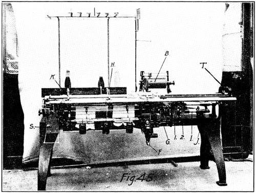
Fig. 45.
Dubied Automatic Single Lock Machine.
Fig. 45 shows an automatic single-lock machine built by Dubied & Co. in Switzerland, designated as Type VD, which is a very good example of the automatic machine. It is operated by the belt A, Fig. 46, which runs it by a pulley of the clutch type which is located back of the machine. The proper movement is conveyed to the carriage through a pair of sprockets and chain as shown in Fig. 46, at m. The carriage is connected to the driving chain at point m, by the connection rod n, which obviously must follow the chain back and forth around the sprockets. This arrangement gives the carriage a uniform movement during the time it is operating the needles and is generally conceded as superior to the crank system of driving.
The letter G, Fig. 45, indicates the lever for throwing in the clutch to start the machine, and F is the crank for turning the machine by hand. This crank does not turn when the machine is run by power but hangs in the position shown. The letter S shows the main or controlling chain and 1 and 2 59indicate the racking chains. These will be taken up in more detail later. Letter B indicates an ingenious counter arrangement for counting the rounds, which permits the use of very short chains and will be explained in due course. H and K are yarn carriers, of which there are five altogether. The others are on the back and cannot be seen plainly. T is the yoke or bridge which holds the two sides of the carriage together. There is no physical connection between the two sides of the carriage at the point where the locks are attached, but the connection is made through extensions which can be seen, and through this yoke.
On these machines the fabric is not held down by weights, hanging thereon, as in the hand machines, but by what is called a take-up roller which has means provided for adjustment to keep the desired strain on the fabric at all times. The weights which are in plain view are to hold the fabric up to and in close contact with the take-up roller through a frame with a small roller on the fabric side of the frame and the weights on the outside, which work on the lever and fulcrum principle.
An automatic machine must have a pattern chain of some kind or character to operate its automatic functions. Means provided which will be explained in what follows cause the desired change to be made at the proper time and place. The machine under discussion has a main or controlling chain made up from wire links which may be taken out or added to at will, each link measuring about 6 inches crosswise of the chain and about one-half inch lengthwise of the chain. This chain is carried by a sprocket roller at the top and is held down on this roller by its own weight, though there are guards over each end to keep it from jumping off in case of emergency. This sprocket roller is turned the distance of one full link by the carriage depressing the lever J, and through this medium acting on the rocker shaft I (Fig. 45) which extends the length of the machine to the sprocket roller. The latter is in turn moved the distance of one link by a pawl and ratchet.
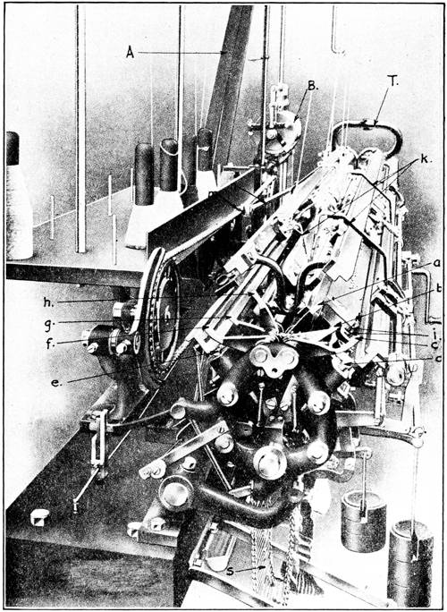
Fig. 46.
Automatic Mechanism, Dubied Machine.
In Fig. 46 we have a view of this main chain at S, with the levers on which it acts shown at a to h. These levers swing on a small shaft, at the point where they appear to end, near the center of the machine. Instead of ending there, each has an extension on the other side of this shaft which extends at an angle and reaches quite close to the chain. These levers, 60though only about three-eighths of an inch wide, are arranged so the angular extensions underneath come in line laterally with each other and crosswise of the chain, or lengthwise of the machine, and they, together with the space between, cover practically the whole width of the chain. These levers swing freely crosswise of the machine, but are fixed lengthwise, therefore the positions of the upper ends can be very easily moved toward the front or back of the machine, but are stationary in the direction in which the carriage moves.
Keeping this in our mind, we will now refer to the main chain shown in Fig. 46 at S. It will be noted that there are a number of studs affixed to the chain which project up above the chain proper. These studs may be put on at any desired spot and taken off at will. It is quite obvious that if we fix a stud on this chain at a spot in line with one of the levers, let us say at lever a, when the chain has moved forward to the point where this stud comes under the angular extension of the lever the position of the top of the lever would be changed. And this new position would be fixed until the carriage has been moved to the other end of the machine and turned the chain one more link. Then the lower end of the lever will drop off the stud and be returned to its former position by a spring.
It is essential that the reader get these explanations of the different parts and their functions well fixed in his mind in order to understand intelligently the relation of one to the other.
Fig. 47 is a drawing of the cams and cam plates, and Fig. 48 shows the top of the carriage with the cams or locks mounted underneath. In the Dubied machine this part of the carriage on which the locks are fixed is detachable, and either side may be taken off separately, which arrangement is very convenient at times. At the left of Fig. 48 will be seen several slides, designated by small letters, which extend through the locks at different points between the cam plate and the carriage proper, and some on the top of the carriage. These are the essence of the automatic control of the stitch forming mechanism. This principle is followed in all automatic machines of this type, although the different builders vary in the details of construction and in the methods of moving these slides, as well as the manner of operating on the cams and yarn carriers.
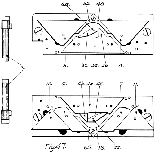
Fig. 47.
Cam Arrangement of Dubied Single Lock Machine.
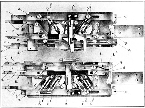
Fig. 48.
Top Side of Carriage Directly Over Locks or Cams, Dubied Single
Lock Machine.
62These slides make the proper cam or yarn guide changes by being pushed in or pulled out, as the case may be, and this is done by the levers indicated by the letters a to i, Fig. 46. Each slide is provided with a flat spot or shoulder, as indicated at m and o, Fig. 48, which pushes them in upon coming in contact with the proper lever as the carriage reaches the extreme left end and is clear of the needles. In order to have these slides moved in just the proper distance there are projections from the carriage underneath the slides with beveled ends, part of which may be seen in Fig. 48 at k and i, which push the levers off the before-mentioned shoulders and release the slides at just the proper time. To explain the drawing out of these slides, it will be noted that each slide has an enlarged part or head and all have at least one right angled shoulder on the inside of the head; some have two.
It will also be noted that each one has under it a guard or extension from the carriage, which is fixed to the carriage and is stationary, as e and p. This extension also has an enlarged part or head on the outer end, but it is different from the heads on the levers in one respect, this head has sloping shoulders on both ends instead of the right angled shoulders that are on the inside head of the slides. Where a fixed guard or extension has a sloping shoulder on both sides (not ends) they will be found to be at different distances from the carriage.
The right angled shouldered heads on the slides are made in this way so that when the proper lever (Fig. 46) is placed in its path, which is done by the studs attached to the main chain S, it will slide over the head and drop in back of the shoulder as the carriage moves to the left, and when the carriage moves to the right the lever catches on the shoulder and draws it out until the lever is released by being pushed out by the sloping shoulder of the extension underneath. When the fixed extension has a sloping shoulder on both sides at different distances from the carriage proper it will be found that the slide also has a right angled shoulder on both sides. This indicates that this slide may be moved to any one of three different positions, therefore has a choice of three different functions it may perform in the automatic changes.
To make the changes from plain rib to half or full cardigan, or to plain jersey, etc., the slides have inclined planes under the cam plates and these engage notches or pins on studs extending through from the cams and by this means raise the cams up into the cam plate out of action, or let them down into action as the case may be. The illustration, Fig. 47, shows them all down in the proper position to make the plain rib or cuff stitch.
To change to half cardigan stitch it would be necessary to raise cam 3b up out of operation, which is done by slide n. Fig. 48, which in turn is moved to the proper position to accomplish this by the lever h, Fig. 46. This slide has three different positions, therefore three different functions to perform in the automatic changes, which are accomplished as follows: To make a half cardigan stitch a low stud (there are three heights, low, medium and high) should be placed so it will come under lever h. When this takes place the top end of this lever is moved to the position where it would engage the upper shoulder of slide n, and on the return of the carriage it would draw this slide out to its farthest point, or until it is pushed off the shoulder by the taper on that side of the guard or extension p. When the slide is moved to this position it raises up and holds out of operation cam 3b, thus causing the machine to make the half cardigan stitch. This should be readily understood from what has gone before.
To change to plain rib stitch place a medium stud under the same lever (h) and its top position will be changed to where it will push the slide clear in as the carriage moves to the left. On the return movement the lever will engage the shoulder on the opposite side and draw it out until released by the guard as before. This releases cam 3b, which drops down into working position. The fact that the sloping shoulders on each side of the stationary guards are at different distances from the carriage causes this slide, n, to be left in different positions according to which side the lever h engages it.
In the third change, which makes the French rack or false knop stitches, it is necessary to raise up out of operation the cams 3b and 3c. To do this a high stud should be placed to come under the same lever (h), which would then be moved to a position where it would come in contact with the shoulder v 64(which is a part of the slide n) and would push the slide in until disengaged by another sloping guard which cannot be seen. When the lever drops back on to the chain without any studs under it it is clear of all slides; therefore will make no changes. The other slides are moved in the same way as the one just explained, but each one has the part, which make? the changes, constructed in such a manner that it will operate that particular member of the locks for which it is intended.
There is one other change that is made by these levers and slides besides the changes in the stitch, and that is changing the yarn carriers to make stripes of different colors. This is done, not by changing the yarn in the yarn carriers as one might imagine, but by providing a carrier for each yarn needed and then changing the carriers. These carriers are shown at letter k, in Fig. 46. They are not fixed to the carriage but are attached to a block which slides back and forth on ways or gibs which are shown at 1, 2, 3 and 4, and reach the length of the machine. The gibs are undercut on a bevel on both edges and the block is undercut in the same way, so they dovetail together to keep the block from lifting off, yet are free to slide back and forth on the gib. These blocks have a depression or are cut out on the upper edge with a square shoulder at each end of the cut out, and the carrier is moved back and forth by a plunger which is attached to the carriage and engages these shoulders.
In Fig. 47, at letter x, are shown the plungers, and Fig. 48, letter x, shows them placed in the block and attached to the carriage. These plungers are set to pick up the desired yarn carrier by the slide, i, on the front, and slide, z, on the back. (Fig. 48.)
We will leave the slides and levers for the present and give our attention to the two racking chains shown in Fig. 49 at figures 1 and 2. Inasmuch as the rack stitch is made by a part of the machine entirely separate and distinct from the locks and carriage, that is, the needle plate, obviously it 65is necessary to arrange means other than the levers and slides on the top of the machine to do this automatically. The mechanism used to do the actual racking is illustrated in Fig. 32. The illustration is accompanied by an explanation of the required movements. This racking cam may be seen in Fig. 49 at letter R. Having in mind the former explanation it is evident that to control the racking it is necessary to control the pawls only which actuate the ratchet. This is done by the racking chains shown in Fig. 49. They of themselves do no actual racking, but simply put the pawls into action or out of action, as the case may be, at the proper time. These chains hang on a sprocket roller and are moved two links at each round of the machine by the same means as the main chain, and are started and stopped automatically by studs on the main chain at any predetermined time. There are also two levers over the top of each, and it is by means of these levers that they control the pawls which actuate the racking cam ratchet through small rocker shafts.
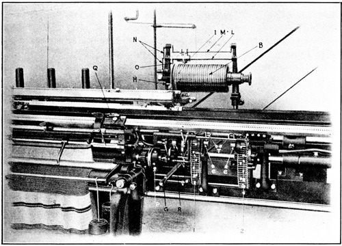
Fig. 49.
Racking Chains and Cam, Dubied Automatic Single Lock Machine.
It will be noted that the chains have studs attached, similar to the main chain, which are staggered or attached alternately 66near both sides of the chain. As these studs pass under and raise a lever at the top of the chain they cause a pawl to act on the racking cam ratchet, thereby making one rack.
When the carriage makes the next round the chain would have moved forward so the lever just mentioned would have dropped off its stud and the stud on the other side of the chain would move up to and under the second lever, which would cause the other pawl to act in the opposite way and therefore would rack the plate back to its starting point. If two or more racks in the same direction are desired, it would only be necessary to put two or more studs in line on the same side, but remembering that where this is done it is imperative that later the same number be placed on the other side so as to return the racking plate to its original position.
Both of these chains do the same work and in the same manner, and either one may be selected to do the racking at any time or place, but both should not and cannot be operated at the same time for there is a very ingenious arrangement which will stop the one automatically, if working, immediately when the other one starts.
The reason for providing two chains instead of one is to enable the operator to make two different kinds of rack in one garment by setting the studs on one chain for let us say a one-needle rack, and on the other for a two-needle rack. This arrangement permits the use of very short chains, as the racked pattern may repeat itself on the chain any number of times, where if a single chain were used it would be necessary to have a chain long enough to have a stud for each time the plate racked, when two patterns are required, and this would necessitate the use of a very long chain at times.
Some few years ago, when automatic machines were first brought out, all automatic functions were operated from a single chain. This meant the use of very long and unwieldy chains many times, as it was necessary to have a link in the chain for each round. It was soon realized that by stopping the chain during the time the machine was making one kind of fabric without a change, which on most work is by far the greater part, and operating it only when needed, not only much time and material in making up the chain would be saved, but also much annoyance and trouble in providing means to keep the chain from getting twisted or out of place while running would be eliminated.
Most of the builders have devised means to do this and one of the best methods is the cylinder or drum idea devised by Dubied & Co., which is shown in Fig. 50. To more easily master the explanation of how this cylinder operates, it should be understood that its only function is to count the rounds and start the main chain at the proper point, the chain stopping itself after having caused the automatic changes necessary at that point.
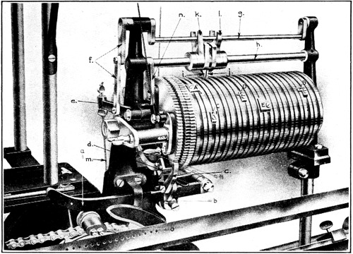
Fig. 50.
Counting Drum for Short Chain Arrangement, Dubied Machines.
The device consists of a cylinder about 10 to 12 inches long by about 6 inches in diameter, around which are cut two spiral grooves, the larger of which is used to attach stops and the smaller to act as a guide for the fingers i and j, which extend down into and run in the narrow groove and carry the whole block, including the forks k and l, forward or backward on the rods g and h, according to which way the cylinder is turning.
68The cylinder is divided in its circumference by the lines into 1,000 divisions, and is turned the distance of one division each round of the machine by means of the roller on the lug o, which raises the lever a, which in its turn raises the pawl c, and its duplicate on the back, which cannot be seen. It can very easily be noted how the pawl c engages the outside ratchet and on being raised it would obviously turn the drum one tooth of the ratchet wheel. The back pawl operates on the center ratchet wheel and inasmuch as this ratchet wheel is cut the opposite way from the outside one, and the pawl is on the opposite side, it is plain that when the back pawl is in operation the cylinder will turn backward.
Both pawls raise each time the lever is raised, but only one at a time can engage the ratchets and the one which engages is governed by the stops A or E on the cylinder. This is done by two guards, one of which may be seen at d, while the other would be between the back pawl and its ratchet, therefore this back pawl could not operate.
These guards are mounted on a triangular or three-cornered frame which is pivoted at the center on the cylinder shaft with the guards mounted on the two lower corners, while the third corner is engaged by the lever n, which in turn is secured to the rod h. Now it is plain that if the bottom or base of this triangle is moved forward or toward the machine, the front guard would move under and disengage the front pawl while the back guard would move down and free the back pawl and allow it to operate on its ratchet wheel.
Keeping this triangular arrangement in mind we will turn our attention to the block, of which the fingers i and j, and the forks k and l, form a part. As noted before there are three fingers extending down to the cylinder from the block, two of which (i and j) reach down to but do not touch the cylinder, while the third one, which is between these two, engages in the smaller of the two grooves.
The block is constructed so it must move lengthwise of the rod as one piece, but each part is free to move laterally independent of another. The block is not fixed in any manner to the top rod and the only positive connection it has with the lower rod h is with a key in the center finger which engages in a keyway which is cut the full length of the rod. It should now be clear to the reader that so long as there is no 69obstruction placed in the path of the center finger it will simply follow the small groove and gradually move over toward the right (if the front pawl is operating and the top of the cylinder is turning away from you) until it comes to the Stop, E, which it will be noted lies across its path.
On account of the key in this center finger engaging the keyway in the rod h, it naturally follows that when the finger comes up to the stop E, the next movement of the cylinder will swing it away from you and this turn of the rod h, will swing the lever n, and through this will swing the triangle on which the guards d, are mounted, bringing the front guard d up under the front pawl and at the same time will free the back pawl on the center ratchet, thereby reversing the movement of the cylinder.
Upon the return of the block to its starting point at the left end of the cylinder, its direction of movement is again reversed in the same way by the stop A. Stop A is set at division O and is never moved, but stop E may be placed at any number of the divisions corresponding to the number of rounds in the garment. This point will be taken up again further along.
Now to give our attention to the side fingers i and j. These are constructed so that the left one, or i, will swing freely toward you but an attempt to swing it away from you will engage the fork k, which by contact would swing the rod g, which through the connection f would raise the lever e, and this by a pull on the cord m would start the main chain in motion. The right finger j works in precisely the same manner, only that it swings freely when moved away from you and starts the main chain in motion when moved toward you, by contact of the fork l with rod g.
With the foregoing in mind it should hardly be necessary to explain that the stops C and D are for the purpose of putting the main chain in motion by coming in contact with the fingers i or j; C to operate when the cylinder is turning the top away from you by tripping finger i, and D when it turns toward you by tripping finger j. It will be noted that the stops A and E have short extensions which extend forward along the side of the small groove. These cause the side fingers, i or j, to start the main chain at the same time that the direction of the movement of the cylinder changes. If for any reason this is not 70desired, a stop like B may be used instead of these, and then the cylinder will reverse without starting the main chain.
Going back to the setting of stop E, where the garment to be made has less than 1,000 rounds, it is customary to set this stop as well as the intermediate stops, like C and D, to make a complete garment on its forward movement and a second one on its return. But if the garment should have more than 1,000 rounds, let us say 1,500, then stop E would be set on division 750 and the small stops like C, which are for tripping the finger i, would be placed at the proper place to start the main chain for the automatic changes in the first half of the garment. The stops like D, which are for tripping the finger j, would do the same for the last half of the garment.
If there is no change to be made in the middle of the garment the knitter may avoid it by either one of two means; either by using a stop like B, which will reverse the movement of the cylinder without starting the main chain, or by using a stop like E, which starts the main chain at the same time it reverses the movement of the cylinder, but in this event he must put in the main chain two extra links with a stud attached for stopping the chain immediately after starting without acting upon any of its automatic mechanism.
If the fabric being made does not require the use of the cylinder all that it is necessary to do to stop it is to raise up the lever a, and draw the roller b out against the head of its stud.
Up to this point the yarn guides and carriers have been mentioned only incidentally so we will now take them up in more detail. Where there is only one thread and guide on a machine it is a very simple matter to control it but in the modern full automatic machines, where there are several threads and guides, and they must be arranged so that any one on a single lock machine, or any two on a double lock, may be selected at will, it becomes more of a problem. There is another point that must be taken into consideration in connection with this. That is, in the automatic machines the carriage must travel the full length of the machine but much of the fabric made on these machines does not take the whole width. Therefore if the yarn carrier was carried the full 71length with the locks there would be at the end of each course a considerable length of yarn, reaching from the edge of the fabric to the yarn carrier, which it would be very difficult, if not impossible, to draw back through the yarn guide. There must be no slack yarn between the edge of the fabric and the yarn guide when starting to knit across on a course.
To obviate these difficulties the yarn carriers are attached to blocks which in turn are mounted on ways or bars which reach the full length of the machine and may be seen in Fig. 46, and are indicated by the figures 1, 2, 3 and 4 in white. This has been explained in part before, together with the manner of operating the carriers with plungers, but I wish to call the reader’s attention to it again as it has a direct connection with what follows.
To prevent the yarn carrier from following the locks to the end of their travel, and thereby accumulating yarn between the guide and the edge of the fabric, there is a stop placed at each end of the fabric to stop the carrier at the proper point. One of these stops may be seen in Fig. 49, at Q. This may be placed in any desired spot and is held in place by a pin which engages in one of the holes in the way or bar, which holes may be plainly seen.
This stop consists of a base or block which slides on to the way on the dovetail principle. On the top edge of this base there is a thin strip about 4 inches long by about one-half inch wide, which is beveled down from the top to the bottom edge on both ends. When the carriage with the yarn carrier approaches this stop the carrier comes just under this top strip and the point of the strip comes just under the end of the plunger X, Fig. 48, also Fig. 52, which as explained before moves the yarn carrier. As the carriage moves farther along, the plunger slides up the incline or bevel of the strip and is raised out of engagement with the shoulder on the yarn carrier block, and the carrier stops while the carriage completes the length of its travel.
Upon the return of the carriage the plunger will slide over the strip on the stop, drop into the opening of the yarn carrier block, and engage the opposite shoulder and take the yarn carrier back with it on the return course, where it will be released on the other side in the same manner as just explained.
No matter how close to the edge of the fabric the yarn guide may be stopped, unless the yarn is kept taut the selvage will not be perfect, therefore a very insignificant appearing but quite important adjunct called the yarn take-up spring is provided to do this. There is one provided for each yarn guide and their position in relation to the machine may be seen at the top of the yarn stand in Fig. 45, while one is shown in detail in Fig. 51. The spring is a coil spring turned around the stud, f, and attached at the inner end. The outer end is a part of this spring straightened out as at b, with an eye turned in the end at d.
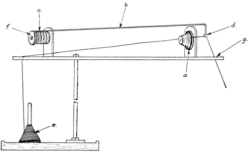
Fig. 51.
Yarn Stand and Take Up Spring.
By turning the top of the stud f away from you it will put more pull or tension on the spring, and by turning toward you less. The yarn is drawn from the bobbin, e, through an eye directly over the bobbin, then through a hole in the tension stud at a, then through an eye of the spring, then down through another eye in the stand at g, and directly to the yarn guide of the machine. The tension a prevents the spring from drawing any yarn from the bobbin, therefore it will always draw the slack yarn from the yarn guide and keep it taut at all times. There must be a take-up spring for each thread in use and 73that means that there are sometimes as many as eight or ten on one stand.
We have had a drawing of the double lock in Fig. 40, showing the cam side with an explanation of how it works and its advantages, so now we will show only the top carriage side in Fig. 52, with its appurtenances for the automatic changes. Bear in mind that when slides or plungers are mentioned in the following explanation reference is made to Fig. 52, and when cams are mentioned reference is had to Fig. 40.
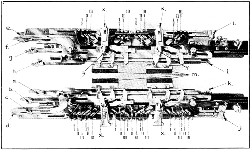
Fig. 52.
Top Side of Carriage Directly Over Locks, Dubied Automatic
Double Lock Machine.
Slide a operates on cams 1b and 4b to change from plain to cardigan, or vice versa, and is used in making the full cardigan stitch. Slide b and g, working in conjunction with d and e, are for changing the length of stitch, which will be explained more fully later. Slides c and f are for changing the yarn carriers to change colors. The exchange of carriers at the end of each course in order to keep the cotton carrier feeding into the cams that are leading (where cotton and worsted or wool is used) is another matter and should not be confused with this. Slide h operates on cams 2b and 3b to 74change from plain to half cardigan, or vice versa, also on these cams together with cams 2c and 3c to make the French rack or false knop. Slides i and j operate cams 1a, 2a, 3a and 4a to make tubular work, or to be more explicit, they raise one pair of these cams up out of operation while the other pair knit only on one side alternately and in this way knit jersey fabric in tubular form.
To go back to slides b and g, in order to understand this explanation it will be necessary to return again to Fig. 40. What are called the stitch cams, or cams 1 to 10, are attached to the cam plates through elongated slots, the ends of which may be seen at the top and bottom of the cams. The cams, though attached to the plate, may be easily moved lengthwise of these slots. On the under side of the plate is a coil spring with one end attached to a stud in the cams, while the other end is attached to the bottom edge of the plate. These springs will always draw the cams to the lowest end of the slots if nothing is placed in the way. Bear in mind that the bottom of the lower plate is the lower edge and the bottom of the top plate is the top edge, in the drawing.
To change the length of the stitch it is necessary to raise or lower these cams. To draw a longer stitch they would be moved toward the bottom of the plate and for a shorter one toward the top. Now it is clear that in order to change the length of the stitch automatically it is only necessary to provide stops of the proper height for them to rest on when pulled down by the before-mentioned springs. The cam studs to which the springs are attached are long enough to reach up through the carriage proper and may be seen resting on the end of the pins II, Fig. 52.
The reader of a mechanical turn of mind should be able to grasp the modus operandi of the automatic changing of the length of the stitch from the explanation up to this point, but to continue we will refer again to the pins indicated by the Roman numerals I, II, and III, Fig. 52.
It will be noted that there are a set of three of these pins for each stitch or draw cam, therefore the knitter may change to any one of three different lengths of stitch at his option by raising or lowering these pins. The pins must of course be set individually at the proper height, each one for its own length of stitch, before starting the machine.
75Inasmuch as all the pins on the front side are attached to one slide, and the pins on the back are attached to another, all that it is necessary to do to change the length of the stitch is to change the pins on which the before-mentioned cam studs rest, they being held down on the pins by the coil spring between the carriage proper and the cam plate. This is done with slides b and g, in conjunction with slides e and d, which raise the cams and studs up so they will not catch between the pins while the change is being made. In the meantime slides b and g move the desired pins to the position where the studs can drop on them when the slides e and d are returned to their running position, which position allows studs to drop on their respective pins, with the exception of the pair of cams at the extreme right, which are held up for one course.
This is another ingenious and practical arrangement which deserves an explanation, but this leads us to another point which should be gone into first. That is, when the cams are changed to make a short stitch after having made a long one, the holding up of the right pair of stitch cams for one course is of no benefit. But in changing from a short stitch to a long one, inasmuch as the right pair of stitch cams pass over the needle butts before the new course is made, if they were allowed, preparatory to drawing a longer stitch in the next course, to drop down to a point below where the previous stitch was drawn, they would ride on the butts of the needles and cause undue strain on the stitches of that course and would be very liable to break them, thereby making holes in the fabric. This is prevented by holding up these two cams one course. This is done by providing two catches to receive and hold them when they are raised at the left of the machine, but when the carriage is moved to the extreme right of the machine the two small levers, l and k, come in contact with two studs and release the catches, and allow the two cams to drop down on their respective pins.
It has been explained that in making what are known as cotton backs and like fabrics the cotton yarn, or yarn that must show on one side only, must at all times be fed in the locks that are in the lead, on a double lock machine, while the worsted or wool yarn which shows on the other side must feed into the following pair. To do this the yarn carriers must be exchanged at the end of each course. To explain how this is done we will refer to Fig. 52, where the plungers that engage 76the yarn carrier blocks and moves them back and forth with the locks, are shown at x and y.
These plungers never take more than two carriers at one time. In these machines there may be four or more bars or ways for yarn carriers, and in the preceding explanation of how the yarn carriers are stopped we assumed that the carriers in question were being operated on the lower ways by the outside end of the plungers x. For this present explanation we will assume that we are using the carriers on the top bar or way, and they would be operated by the end of the plungers towards the center of the carriage.
It will be recalled that when the yarn carrier block comes to the stop at the edge of the fabric, the plunger is raised out of engagement with its shoulder, and the block stops while the plunger passes on. When the carrier block that is being moved across by the plunger in the lead stops, the one that follows will also pass over the block without moving it, as the outside end of the block is beveled off to compel this.
It will be noticed that the inside ends of the back plungers at y are flattened, and the flat sides are at right angles to the travel of the carriage. Now we will assume the carriage is traveling from right to left, and the cotton carrier is being moved along by the plunger in the lead, or y on the left. When this carrier comes to the stop on the left this plunger leaves it there and passes on, also the plunger on the right will pass on over the carrier block. But upon the return of the carriage moving toward the right the first plunger coming in contact with the yarn carrier block, which would be y on the right and which would now be in the lead, would engage the shoulder of the block and take it across.
It will be noted that the two front plungers are also flattened at x, but are different from the back ones in this respect; the inside flat is at right angles to the travel of the carriage while the outside flats are at an angle of about 45 degrees. The yarn carrier operated on this side is stopped at the edge of the fabric with the plungers passing over and beyond it the same as the back one. But upon the return of the carriage the first plunger cannot pick up the carrier block as the side of the plunger coming in contact with the shoulder of the block is beveled off and cannot catch, but when the second plunger comes along with its flat side at right 77angles to its movement, it will engage the shoulder of the carrier block and take it along.
It may have been noticed in Fig. 45 that the machine illustrated has two separate fabrics on it. This is done very often when a knitter has a large machine and has no wide work to make. He simply utilizes the greater part of the machine by making two narrow fabrics.
When this is done both fabrics must be the same vertically or lengthwise of the fabric, but they may be of different widths and of different colors. This is made possible by the system of carriers and blocks mounted on ways together with the stops, as just described.
There are two carriers mounted on each way or bar, instead of one as previously explained, and stops are placed at each side of both fabrics so the plungers, either y or x or both, according to how many carriers are in use, will drop one carrier at the edge of one of the fabrics and pick up the other carrier to knit the course on the second fabric.
We have explained what fashioned work is and how it is done by hand. Fig. 53 shows a machine built by Dubied & Co., which does this work by widening the fabric automatically in the knitting operation. It is called an automatic widening machine, and is particularly adapted to making sleeves. It overcomes the principal objection knitters have to making shaped work—that is, the extra labor involved, and has the advantages before-mentioned—namely, no material to be cut away to get the shape, a selvedge edge which means a small neat seam, and the proper shape for a proper fit.
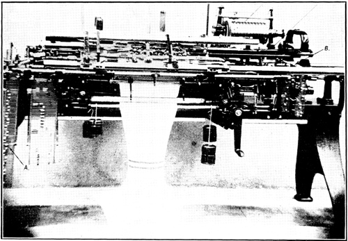
Fig. 53.
Automatic Widening Machine, Dubied.
To the casual observer, the widening machine would look to be a very complicated piece of mechanism, but as a matter of fact the widening device is surprising in its simplicity.
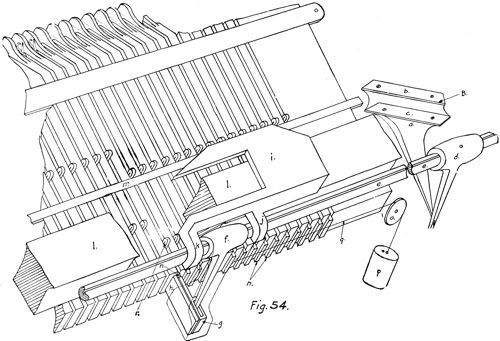
Fig. 54.
Widening Mechanism, Dubied Automatic Widening Machine.
80Fig. 54 shows the principle of the method used. The drawing does not by any means reproduce the parts as made, but only shows the principle employed to secure these results, with all superfluous parts eliminated.
The machine proper is a full automatic machine, practically the same as we have just finished with in the last article, with the exception of the needle plates and the needles that are used, and the addition of the widening mechanism. The needle plates are made almost twice as wide as the regular plates, with a gib running through the middle of the lower part as shown. The needles used for the narrowest part of the fabric, and which are never used in the widening operation, are shown by the letter a in Fig. 56, and have one butt only as indicated at b. The needles used in widening have one butt at the same distance from the hook as the regular needles, as at c, and in addition to this they have a second butt at the lower end of the shank extension which reaches down under the narrow gib to the lower half of the plate, as indicated at d.
The slot in the needle plate, at the lower edge, is cut all the way through the plate up to a point which would about equal the distance between the needles up in working position and the needles down. There are needle springs, shown at n in Fig. 54, below each needle which, when the needles are down, project just below the bottom edge of the plate, and when pushed up to hold the needles in working position would have their lower ends about where the lower butts of the widening needles are when down, as shown. The needle spring is shown in Fig. 56, at e, in its position relative to the needle, the upper portion at e fitting in the needle slot below the needle, while the lower part acts as a clamp on the under side of the plate.
The lever shown at f in Fig. 54, together with the slide g and the stop h, is enclosed in a cast block and they, together with the yarn carrier stop i, move freely lengthwise of the small shaft e. There is attached to this block a cord q, which runs over the small pulley o with a weight attached as at p.
It naturally follows that this weight would pull the block, lever, carrier stop and all, over to the extreme right if there were nothing in the way to stop it. The stop h is for this purpose. It is stationary in the block and extends up to the plate, while the slide g is cut back far enough to clear the lower ends of the springs n which are below the needles.
Inasmuch as these springs extend a trifle below the plate when the long needles are down and the stop h comes up in close proximity to the bottom edge of the plate, this stop will engage the left side of the spring and prevent the block, together with the lever f and slide g, from moving toward the right. Now in order to widen the fabric one stitch or wale it is simply necessary to push the needle r up into working position. This is done by moving the cam block, a, longitudinally, which would necessarily raise the lever d, which, through the rocker shaft e and lever f, would push the slide g, together with the spring n and needle r, up high enough to put this needle into working position.
It should be understood that there are four of these widening mechanisms as shown in Fig. 54, one on each end of both front and back needle plates, but as they are all operated in the same manner it will be necessary to describe and explain but one.
Now to explain how this is done automatically we will refer to Fig. 55, which shows the cam side of the carriage of the automatic widening machine. It will be noted that on the ends of the four fixed extensions b1, b2, b3 and b4, there are rollers a1 to a4, attached with shouldered screws whose heads are flush with the end of the rollers. As we are dealing with only one we will select a1, which is the one that would operate on the block a, Fig. 54, when turned over and placed on the machine.
This roller is in the proper position to engage the cam b (Fig. 54) when the carriage is at the right end of the machine, and when the carriage is at the end of its travel the roller would be at about the point B.
It naturally follows that inasmuch as cam b is attached to the block a on an inclined plane, and the block a is attached to the frame of the machine in such a manner that it cannot move lengthwise of the machine, but may be moved freely in an up-and-down direction, when the roller moves through the camway between cam b and cam c the block must move upward, thereby pushing up one needle. Upon the return of the carriage 82the roller coming in contact with cam c will return the block to its first position.
When the block a is moved down by the roller, after pushing up the needle, it must necessarily draw the slide g back to the position shown, and inasmuch as the lever f slides freely lengthwise on the shaft e, and there is nothing to prevent, the weight p will draw all of this part of the mechanism over one needle or until the stop h comes in contact with the next needle spring n.
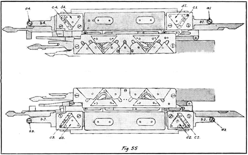
Fig. 55.
Under or Cam Side of Carriage, Dubied Automatic Widening Machine.
Now, it should be understood that, as a rule, a fabric is not widened a needle each round, therefore the block a (Fig. 54) is arranged so it will drop below the plane of travel of the roller a1 (Fig. 55) when widening is not desired. Perhaps it would be more correct to say that the normal position of block a is below the plane of travel of the roller a1, therefore out of operation and is raised up in the path of this roller by a stud on the widening chain A, Fig. 53, at the proper time to push the needle up into operation. Upon the return of the carriage it drops down to its normal position until another needle is to be added to the fabric. The position of the block a in Fig. 54, in relation to the rest of the machine, may be seen at B in Fig. 53.
As stated before, a fabric to be shaped on this machine must be started at its narrowest part, therefore when the garment or part of a garment is finished, these needles which have been pushed up to widen it must be returned to their lowest position where they are out of operation, in order to start a new piece. This is where the second and lower butts of the needles come into use. They are operated on by the cams c1 to c4, and d1 to d4, Fig. 55.
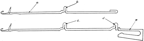
Fig. 56.
Needles and Needle Springs Used in Automatic Widening Machine.
These cams are arranged so that normally they are raised up in the cam plate and pass over the lower butts of the needles, but they may be lowered to operate the needles and raised again, all automatically, at the proper time and place by slides and levers similar to those described in a previous article on the automatic machine. The manner of returning the widening needles to their lowest position so they will be out of operation should be obvious to the reader after the foregoing explanations and a study of the illustrations.
When the time comes to cast off these added stitches in order to start a new sleeve or fabric, the plate on which cams c1 and d1 are attached is automatically lowered when the carriage is over to the extreme right. Then upon its return the lower needle butts of the widening needles will come in contact with the left side of cam d1, and moving up over the top of this will, of course, raise the needles to a point where the latches are above the stitches. As the carriage moves farther along, and the butts come in contact with the left side of cam c1, they will slide down and cast the stitches off over the latch and hook, and at the same time be drawn down to a 84point so low that the knitting or upper cams cannot operate on the upper butts.
At the same time that the cams c1 and d1 are lowered to cast off and draw out of operation the widening needles, a plunger, which is attached to the carriage, drops down and engages a recess on the under side of the yarn carrier stop i, Fig. 54, and through the lug j moves the lever f, together with the slide g and stop h, back to its first position where the plunger is disengaged by an inclined stop. The stop h will hold this part of the mechanism in this place by contact with the first needle spring as explained before.
It should be understood that while this explanation covers only one of the four corners that must have the needles pushed up to widen the fabric, the method applies to all of them. Also in the manner of casting off the widening needles and returning them to their lowest positions preparatory to starting a new fabric, we have confined ourselves to the right end of the front plate only in order to present the matter in the simplest possible manner. In actual practice the pair of cams on the left, indicated by c3 and d3, together with c4 and d4, are put into operation first by a medium stud on the widening chain while the carriage is at the extreme left end. Upon the return movement of the carriage these cams would cast off and return the widening needles to their lowest point on the left end of both front and back plates. Immediately this is done the cams are released by means provided, and they again rise up into the plate out of the working position, thus passing over the right side widening needles without effect.
After putting on one full round the cams d1 and c1, together with cams d2 and c2, are put into operation at the extreme right end of the machine by a high stud on the widening chain, and these cast off and draw down out of operation the front and back widening needles on the right in the same manner as heretofore explained.
The reader will realize from what has gone before that when there are needles added to or taken from the edge of a fabric, while in the process of knitting on a machine, it would be necessary to arrange to change the stopping position 85of the yarn carrier in order to prevent it from stopping too far away from or too close in to the fabric as the widening operation progresses. This is done by the simple expedient of having the yarn carrier stop mounted on its bar or way so it will slide freely, and providing the lugs j and k, Fig. 54, on both sides of the lever f, so that it, with the lever f, and slide g, with stop h, will at all times move together. Therefore the needle on the edge of the fabric and the yarn carrier stops are always in the same relative position.
If the reader has stopped to ponder on the working of this machine, with the resultant fabric, he may realize that there should be more pull or tension on the fabric during the last part of it than when it is started. As there have been needles added it is wider. This has been provided for so that by placing high studs on the main chain at the proper point they will increase the tension on the take-up rollers where and as much as needed. When the widening needles are cast off, and the width of the fabric is reduced to its narrowest portion, this extra tension may be automatically released and the pull reduced to the proper strain for the narrower fabric.
These machines are made only in the double lock type, but there are means provided through the before described levers and slides to change automatically to single lock by raising one pair of the locks up out of operation. This is quite an advantage where one wishes to make some style of garment with a rack showing on both sides of the fabric such as the turned-up cuff on ladies’ sweaters, etc.
The purl stitch or links and links machine is a type which may be termed unique in the class of machinery built to make knitted fabrics. It is entirely a European development; in fact, to my knowledge there had been none of these machines built in this country until some time after the war started, when it was impossible to import them.
The chief individual characteristic of purl stitch machines lies in the fact that they have two needle plates, but only one set of needles, and the cams do not act directly on the needles, but act indirectly through what are called jacks. First we will try to get a thorough knowledge of the fabric this machine was primarily designed to make, and the stitch formation required to produce this fabric; then the mechanism and movements of the different parts of the machine will be more readily understood as we proceed with the explanation.
Fig. 57 shows a photographic reproduction of the fabric with the top turned over to show both sides, which it will be noted are exactly the same. Fig. 58 is a line drawing showing the formation of the stitch; the course that the yarn takes may easily be followed. This is called the purl stitch and is very popular with milady when making hand knit sweaters, children’s suits, etc.
If the reader will refer back to Fig. 12, he may be surprised to note how near this fabric is like the back of the jersey fabric, while the face of the jersey fabric is so different. I do not think that I should go very far wrong if I put this in the same class as the jersey fabric, the same as the half and full cardigan are classed as rib fabrics. It is made the same as the jersey on one set of needles, but with this difference: In making the jersey fabric the loop is always drawn through the previous loop in the same direction. That is, we will suppose we were making this jersey fabric on an ordinary flat machine, on the front plate only. In this case the loops would 87always be drawn toward you through the previous loops. Now if we should reverse every course the direction in which we draw these loops, or in other words, if we should draw them towards you when moving the carriage from right to left, and away from you when moving the carriage from left to right, and continued this reversal, we would make a purl stitch fabric.
But, you say, how are we going to do this? The solution is the purl stitch or links and links machine, with its double ended needle, or a needle with a hook and latch on both ends to permit the whole needle to be pushed through the loop every course, thereby casting the previous loops off one end on one course, and off the opposite end on the next course. This system of knitting is such that there can be no obstruction to the free movement of the stitch over any part of the needle, therefore this fact precludes the use of a butt projecting up from any part for the cams to operate on, even if there were no other reason, which there is as the reader will understand after a study of the subject.
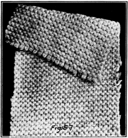
Fig 57.
Plain Purl Stitch Fabric.
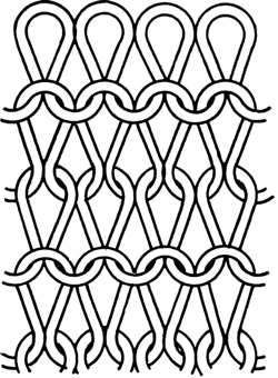
Fig. 58.
Construction of the Plain Purl
Stitch Fabric.
This machine is constructed somewhat along the lines of the ordinary flat machine, which we have been studying. Its points of similarity are that the table or stand is the same, it has two straight, flat needle plates, it has a carriage which is moved backward and forward over the needle plates to operate the needles, and the cams or locks are practically the same as in the ordinary single lock flat machine. The main 88points of difference are that on the purl stitch machine the needle plates are set so that they are flat, or both are on a horizontal plane, and the needle slots of both plates are directly in alignment with one another so a needle may move freely from the front to the back plate, or vice versa. The ordinary flat machine has the needle plates set at an angle of about 90 degrees to one another, and 45 degrees to the horizontal, and they are set lengthwise so the needle slots of one plate are opposite the space between the needle slots of the opposite plate, or in a position so the needles of one plate will come up between the needles of the opposite plate.
Another point of difference is that the purl stitch machine has one set of needles for both plates, with a hook and latch on both ends of each needle and no butts to operate them, while the ordinary machine has a set of needles for each plate with a hook and latch on one end only with a butt on the other end to operate it. It naturally follows that inasmuch as the needle plates are set flat, instead of at an angle to one another, and the needles are operated indirectly through what are called jacks instead of directly on butts on the needles, the construction of the purl stitch machine must be somewhat different from the ordinary flat machine.
Fig. 59 shows a general view of a purl stitch machine built by Dubied & Co. The letter a indicates the carriage, b the handle used to operate the carriage, and c is an auxiliary handle which some knitters like and use, while others take it off, preferring the use of handle b only. The letter i indicates the connection rod for the auxiliary handle; d is the racking handle for racking the back plate, which plate is made to rack over usually about 12 needles. The letter e is a sector of a circle attached to the frame of the machine and acts as a guide and a stop for the racking handle. This may be studied to better advantage in Fig. 60, at e. It has V-shaped notches cut at the proper intervals to correspond to the needle spacing with a V-shaped plunger attached to the handle so that when this plunger springs into one of the notches it brings the needle slots of the back plate into alignment with the needle slots of the front plate.
89The secondary handle d-1 is for releasing this plunger to permit the handle to be moved. It will be noted that there are holes in this sector, one back of each notch in the edge, and in two of these holes there are pins. These pins may be placed in any desired hole and act as stops for the racking handle and in this way save the operator the trouble of stopping to count the number of notches every time he racks, as on this class of work racking over anywhere from two to twelve needles at one time is common practice.
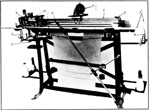
Fig. 59.
Dubied Purl Stitch or Links and Links Machine. Hand Power.
To go back to Fig. 59, letter f is a counter for counting the rounds, g indicates two yarn carrier stops, one on each side of the bar or gib, while h and h are the yarn take-up frames and springs. Letter j indicates the two gibs or ways on which the carriage slides, and k is the bar for carrying the yarn carriers.
Now to get an insight into the principle of the method of making this purl stitch we will first give our attention to Fig. 63, which is a line drawing of a needle and the two jacks which are required for each needle in their proper relative positions.
As will be surmised after looking at the drawing, the jacks are moved forward and backward by cams operating on the butts a and a, which project above the surface of the needle plate in the same manner as the cams operate on the needle butts in the ordinary flat machine. The jacks operate the needles by catching the hook of the needles in the clutches b and b of the jacks. These needles are simply passed, so to speak, back and forth across the throat, between the needle plates, from one jack to the opposite one on each course, and in that way they reverse the direction of the draw of the loop on each course.
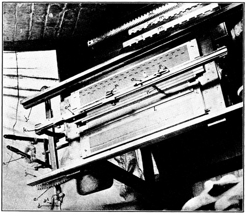
Fig. 60.
Looking Down at Top of Purl Stitch Machine.
We will now give our attention to Fig. 62, which shows the under or cam side of the carriage. It is understood, of course, that lengthwise of the carriage, or the direction of movement, would be what is crosswise or right and left in the 91illustration. It will be noted that the locks or stitch cam arrangement are, on the whole, practically the same as in the ordinary flat machine. This would apply to the cams and locks including a, h, k and g, also b, i, l and j. The bridges c and d are for another purpose.
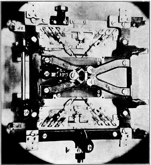
Fig. 61.
Top of Carriage. Dubied Purl Stitch Machine.
It will be noted that while the stitch cams h and i, also g and j, are exactly opposite one another, the cams a and b are not. The bridges c and d have perfectly flat smooth surfaces except at points e and f, and here they have a concave portion about one-eighth of an inch deep. The space between bridge c 92and cam k, also between bridge d and cam 1, is filled by the needle gib 1, Fig. 60, and its mate on the back, which cannot be seen, when the carriage is on the machine. The reader should carefully study the points just gone over, that is, the location of the cams a and b in relation to each other, and the bridges c and d with their concave spots e and f, in order to fully grasp their relation to the jacks and needles in the operation of the machine.
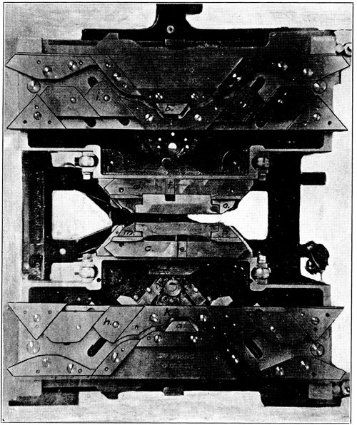
Fig. 62.
Under Side of Carriage With Cam System. Dubied Purl Stitch Machine.
93We will now give our attention to Fig. 60, where it will be noted that the front gib 1 is abnormally wide. The back gib is the same, and inasmuch as it cannot be seen we will assume that it is also marked 1 and hereafter call it back gib 1. Just below the center, laterally, of the front needle plate we see a row of jack butts which are in working position. In the back plate we see jack butts in every slot but they alternate with three up in working position, and three down out of working position. It should be understood clearly that any jacks that are moved to the outer edge of either plate will not operate as they are out of range of the cam system, the same as in the ordinary flat machine.
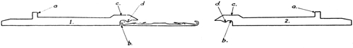
Fig. 63.
Jacks and Needles Used in the Dubied Purl Stitch Machine.
Let us now bring together the needles and jacks in Fig. 63, and the needle plates in Fig. 60. The butts of the jacks a (Fig. 63) are what we see projecting above the needle plates in Fig. 60. The hump c (Fig. 63) lies under the gib 1 (Fig. 60). The reason for having this gib extra wide is to cover this hump during most of the knitting operation in order to keep the needle captive. The depth of the needle slot is just sufficient to allow this part of the jack to slide under the gib freely without any up and down play, therefore it follows that when the hook of a needle is caught in the clutch b, as in jack number 1 in Fig. 63, that needle must move backward and forward with the jack. When the jacks are moved forward to the point where the butts would be near or against the gib 1 (Fig. 60) the hump c (Fig. 63) would be inside and clear of the gib 1, toward the center of the machine, therefore the shank of the jack being narrower than at 94the hump, a slight draw on the needle would free it from the jack as the clutch d, which holds the needle, is beveled off for this purpose. This being the case it follows that when the jacks are in this position the hooks of the needles may be easily pushed under and into the clutch b of the jacks. This is how the machine is filled with needles to begin with, or imperfect ones replaced with new.
It will now be necessary to study Fig. 62 in connection with Figs. 60 and 63. Referring to Fig. 62, the space between the cam k and bridge c, also cam 1 and bridge d, as noted before, is occupied by the two gibs 1 (Fig. 60) when the carriage is on the machine. The bridges c and d (Fig. 62) come down to the needle plates and the surface we see is on the same plane as the under side of the gibs 1, Fig. 60. We have just had the statement that when the butts of the jacks a (Fig. 63) were moved up to the outside and close to the gibs 1 (Fig. 60), the hump c of the jacks would be just inside and clear of the gibs 1, therefore could be raised sufficiently to slip the hook of a needle in or out of the clutch b of the jack. This is true only at a time when the carriage is not over and operating the jacks.
When these are moved up to this point by the cams the hump c of the jacks would come under the bridges c and d (Fig. 62), therefore could not raise up to release the needles except at the narrow concaves marked e and f in the bridges. These concaves, it should be noted again, are not opposite one another. The distance between the top or narrow part of cam a and cam b is such that when the butts of the jacks have moved up to this point the clutch b of both of the opposed jacks cover a hook of the needle. In looking at Fig. 62, the top half of the carriage would be the part covering the front needle plate and operating upon the front jacks, and the bottom half would do likewise on the back plate. When the carriage is at the left end of the machine, when making the purl stitch the needles should be in the front plate, and when the carriage is at the right end of the machine the needles would be in the back plate. This relative position is always the same when making the purl stitch.
I have assumed that the reader understands that a jack and a needle together would, when in a normal position as shown by the butts in the front needle plate in Fig. 60, reach just to the throat between the needle plates. Having the different parts and their relative positions in our mind we will 95now proceed with the modus operandi. We will assume that the carriage is at the left end of the machine, therefore the needles would be in the front needle plate and under the control of the front jacks, as the hooks would be in the clutch b (Fig. 63) of these jacks, while the hump c being under the gib of the needle plate will not allow the needles to escape. To obviate some of the difficulties the reader may have in understanding this explanation we will assume that the carriage as shown in Fig. 62 is stationary, and the plates with their jacks and needles are the parts that are moved.
The outline of the camway may be easily traced as it is practically the same as the ordinary flat machine with which the reader should be familiar and the action on the needles, through the jacks, is the same until they reach the first inside corner of the cam b. If the reader will take a straight edge and lay it on the illustration, he will find that this corner of cam b is just in line with the concave e in the bridge c, and also with the center of the flat portion of the cam a. This being the case, it follows that the center of the flat portion of the cam b must be in line with the left inside corner of cam a and the concave f in the bridge d.
It should be understood that as the needles are moving across the throat between the needle plates, the stitch or loop opens the latches, and guards are provided to keep them open until the needles are ready to draw the new loop through the previous one.
Now to return to where we left the needles and jacks at the right inside corner of cam b. The jacks of the back plate have reached their innermost position, and the heads or humps c (Fig. 63) lie under the bridge c (Fig. 62). At the point where the front jacks opposite are reaching their innermost position, the heads or humps c of the back jacks come under the concave e, which allows the hook of the needles, just coming forward from the opposite plate, to raise up the head and enter the clutch b of the jack. As they move farther to the left, the heads of these back jacks are under the plane surface of the bridge c, which secures the needles to these jacks. As the jacks start to move back toward their outermost position, the heads of the jacks of the front plate are under the concave f of bridge d. This allows the needle hooks of this end to draw out and release themselves from the jacks of this side, and be drawn through the loop to the back plate, and by this 96means to cast the previous loop off from the back plate toward the front one.
Upon the return from left to right, the needles are exchanged from the back plate to the front one in the same manner, only of course, the action is just opposite to that just explained. Therefore, the needles would pass through the loop from the back to the front plate, and cast off the previous loop from the front plate toward the back one. This would make the purl stitch.
While the machine was designed primarily to make this purl stitch, there can be made on it a larger variety of stitches than on any other machine, but in general practice the stitches made are limited as a rule to the purl, jersey and plain rib, 1 and 1, 2 and 2, etc. The term 1 and 1 rib means one needle in each plate alternately. The term 2 and 2 rib means two needles together alternating in each plate without a needle working between the two from the opposite plate. It is also possible to make the half or full cardigan stitch.
The jersey stitch may be made by one of two methods. First, when the needles are all in one plate move the jacks in the other plate to their outermost position, where the cams of that side cannot operate on them and the needles will stay on one side as there are no jacks operating on the other side to take them across. Second, by moving the handle b, Fig. 61, to the left. By doing this we would draw the cams a and b (Fig. 62) up into the cam plate out of working position, therefore the jacks would not move to their innermost position so the needles would not move far enough forward to meet the opposite jacks and could not be taken over into the opposite plate. This system of being able to operate any number of selected needles, or all of them, on either the purl or jersey stitch, either alone or in combination with the rack, is the base or principle used to make practically all the designed or pattern work produced on the ordinary purl stitch machine.
Fig. 61 shows the top side of the carriage. The letter a indicates the handle for operating the carriage; b is the lever for changing the stitch from purl to jersey, or vice versa, by raising out or putting into operation the cams a and b, Fig. 62. The letter c shows the lever for changing yarn carriers while d1 and d2 are the slides for changing the length of stitch. This change is made the same as has been explained for the ordinary flat machine; that is, by shifting the stops, of which there are three for each stitch cam or six on each of the slides d1 and d2.
Figures 64, 65 and 66 show some of the design effects which may be made on the links and links system of knitting. Fig. 64 is a basket weave design. To make this we will assume that the machine is set up, that is, has work on it, with the carriage at the left end of the machine. Then all the needles would be in the front plate. The back plate should be racked to its last position to the right. The last working jack in the back plate, left end, should be opposite the last needle in the front plate, but in the right end of the back plate there should be 8 jacks more than needles in the front plate. Now starting at the right, count eight jacks, which leave in operating position; then draw five back out of operating position; leave eleven in operation, and drawn five out. Alternate in this way with eleven in work and five out for the length of the work.
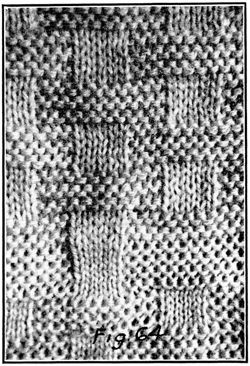
Fig. 64.
Basket Weave Design Made on Purl Stitch Hand Machine.
After doing this the position of the jacks would be similar to those shown in the back plate in Fig. 60, except that that illustration showed three in and three out, while we would have eleven in work and five out in the present instance. The three rules marked m, shown in Fig. 60, are used for this purpose. They save the time of counting the jacks and drawing them back one or two at a time. By the use of one of these rules, properly cut, all of the jacks to be put out of operation may be moved back in one sweep.
98To go back to our design, set the pin shown in the arc e, Fig. 60, to stop the racking handle at eight needles, put on six courses or three rounds, stopping with the carriage on the left, which will leave all the needles in the front plate, and rack the back plate to eight needles to the left. Put on three more rounds and rack the eight needles to the right, and continue doing this.
It should be understood that the back plate should never be racked over more than two needles except when all the needles are in the front plate. I have previously explained that when the cams are set for purl stitch, if the jacks are in the operating position in both plates we would make the purl stitch, but in any place where the jacks were drawn back out of operating position in one plate, in that place the needles would at all times stay in the opposite plate and knit the plain jersey stitch.
Now in this basket design we have in the back plate, disregarding the first eight jacks, five jacks that are not operating alternating with eleven that are. Therefore, the first three rounds would make purl stitch on eleven needles alternating with five making plain jersey stitch.
When we rack the plate over eight needles we find that the five slots with the non-working jacks of the back plate are just opposite the middle five needles of the eleven that have been making purl stitch, and are, of course, at the time of racking in the front plate. We also find that the five needles that have been making the jersey stitch in consequence of having been opposite the five non-working jacks in the back plate, are now opposite the middle five of the eleven working jacks of the back plate. Therefore it is plain that these five needles would make purl stitch for the next three rounds, while the middle five needles of the eleven that were making purl stitch would make jersey in the next three rounds. There are always three needles on each side of the five that are racked over that purl stitch all the time.
Fig. 65 shows two designs the lower one being very simple. With the carriage on the left end of the machine arrange the jacks in the back plate two and two, or two in working position 99and two out. Then move the carriage across to the right end of the machine and we will find that the needles have arranged themselves to conform to the arrangement of the back jacks, alternating two and two in both needle plates. Now move the handle b, Fig. 61, to the left and this will raise cams a and b, Fig. 62, up into the cam plate out of operation, thus preventing the jacks from moving to their innermost position. Therefore, they cannot exchange needles and so would make a two and two rib fabric, knitting this continuously without any further change.
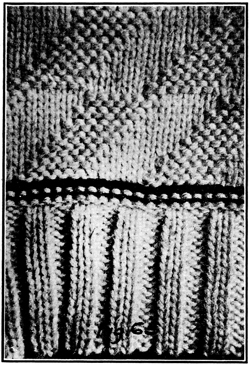
Fig. 65.
Diagonal Diamond Design
and Two and Two Rib Made on
Hand Purl Stitch Machine.
The upper half of Fig. 65 is made by arranging the jacks in the back needle plate so that five will be in working position, alternating with five out. With this arrangement of the jacks, and without any further manipulation, the machine would knit a straight vertical stripe of five needles purl stitch and five needles plain jersey stitch. If, however, we rack the back needle over one needle every round when the carriage is at the left end of the machine, and all the needles are in the front plate, for five rounds we would have these stripes running diagonally instead of vertically, and the distance they would run to the right or left, depending on which way we racked, would depend on how many times we racked in one direction. In this instance it would be for seven rounds, or rather we would rack over in the one direction every round for six rounds, and on the seventh we would rack the plate back the five needles at once. Then start over racking the other way one needle each round as before to make the second row of diagonal blocks. This racking back of five needles at one time would of course bring the non-working jacks to the position where the working jacks were, and the working jacks to the position where the non-working jacks were. Therefore, 100the needles that were knitting the purl stitch would begin making plain jersey, while the needles that were making plain jersey would now make purl stitch.
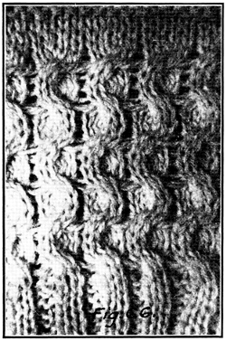
Fig. 66.
Two and Two Rib Racked, Made on Purl Stitch Machine.
Fig. 66 is simply a two and two rib stitch racked over two needles every four rounds. This racking over two needles with needles in both plates may be done successfully if the stitch is drawn fairly long.
The automatic links and links or purl stitch machine is what the name would imply; that is, a machine which makes the changes in the stitch and yarn carriers automatically. The word jacquard added to this would convey to the mind of a person familiar with textile processes the fact that the machine automatically makes designs or patterns in the process of knitting.
Fig. 67 shows a Dubied machine of this type which in general appearance resembles their automatic power flat machine. It has the same drum device for counting the rounds, indicated at d, with a chain drive somewhat similar to the flat machine, though with this difference: The carriage is connected directly to the chain through a cross head which slides on two rods, instead of through a connection rod. We have the main chain, at e, on this machine as on the flat machine, but it is placed on the right end instead of the left. The racking chains which are on the flat machine are not needed on this machine, therefore are dispensed with.
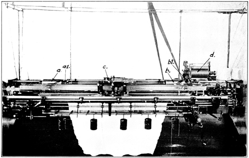
Fig. 67.
Dubied Power Automatic Jacquard Purl Stitch or Links and Links Machine.
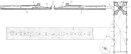
Fig. 68.
Cross Section of Pair Purl Stitch Machine Plates With Card Cylinder and Their Relative Positions.
On the ordinary purl stitch machine a large part of the designing is done by a combination of selected jacks in conjunction with the rack; therefore it is desirable to have such a machine built to rack over quite a number of needles. With this machine the designs are made on the jacquard system, 103therefore this extreme racking is not required and the machine is built to rack but two needles. At a and b in Fig. 67 will be noted two cylinders with grooves cut on a long spiral. They are mounted on a small shaft which acts as a bearing upon which they turn. These operate the jacquard system and should be kept well in mind as they will be referred to later. The letter c indicates the carriage, which is shown, top and bottom, in detail in Figs. 69 and 70.
Fig. 69, it will be noted, is the same in the general layout of the cam system as shown for the hand machines in Fig. 62, in the last article. The upper locks would operate on the front plate and the lower ones on the back one. There are two main points of difference: The cam x, which must be used in connection with the cards of the jacquard system and which will be taken up in detail in due course, and the levers s and t which raise the stitch cams that are in the lead and lower the ones that follow and form the stitch at the end of each course. This is done to take all undue strain off the stitch.
It will be noted in the illustration that the left stitch cams are raised and the right ones lowered preparatory to putting on a course by moving the carriage from right to left. At the left end of the machine the position of these cams is reversed for the return course. This is done by a pin set at both ends of the two plates which act on the levers s and t. Then we have the extensions of the slides. Numbers 1 and 3 are for changing the length of the stitch. Slides 2 and 5 are for raising and lowering cams a and b to change from purl to plain jersey stitch, or vice versa. The manner of doing this and the action of these cams on the needles and jacks have been explained.
Slide 4 puts the plunger y into and out of operation. This plunger operates the jacquard system by entering the spiral grooves of and turning the cylinders a and b, Fig. 67. The four slides marked 6, Figs. 69 and 70, are for changing the yarn carriers, of which there are four. The four small parts indicated by the letter m, Fig. 69, are latch openers, which are essential as the machine cannot be operated when the latches are closed. We would be unable to move the carriage across the machine when there was no fabric on the needles to open the latches, without these latch openers.
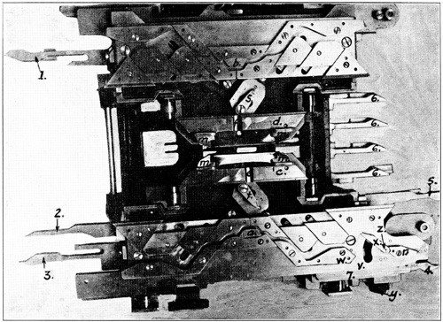
Fig. 69.
Under Side of Carriage of Automatic Jacquard Purl Stitch Machine.
The small slide indicated at 7 is for changing the position of the cam x, swinging on a pivot screw at z, which may be 105moved to any one of three positions. These are the position shown, or horizontal with the lower edge of, and on a line with the lower edge of cams w and r, or it may be swung down to a point where the end will be at the lower edge of the cam plate at v. The three positions of this cam should be firmly fixed in mind, as they have an important part to play in the jacquard work.
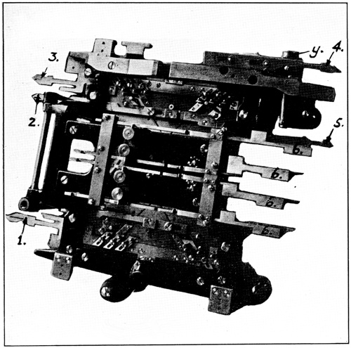
Fig. 70.
Top Side of Carriage of Automatic Jacquard Purl Stitch Machine.
We will now give our attention to Fig. 68, which represents a cross section of the needle plates, showing a pair of jacks and a needle in their respective slots or tricks. Letter a indicates the back plate and b the front one. 106The back jack c is shown in its outermost position, therefore would be out of operation, while the dotted lines at h show its innermost position ready to receive the needle from the opposite jack. Letters e and f indicate the gibs which cover and hold down the heads of the jacks at all times except when they are at their innermost position; when they are in this position they are under and held down by the bridges or winkles c and d, Fig. 69, and are permitted to rise only at the concaves e and f where the exchange of needles takes place. Letter g, Fig. 68, indicates the needle, and i is a vertical projection, called teeth, which are between the needles and act as sinkers for the needles to draw the loops over.
The jacquard system of designing is simply a method of providing means to select and put into operation any desired needle or needles at any predetermined place in the fabric. The mechanism to do this is shown in Fig. 68. The letter l indicates a four cornered star shaped bar called the card cylinder, which is the length of the needle plate. The letter j indicates what are called cards and are also the same length as the needle plate and as wide as one side of the card cylinder. These are made from either thin sheets of steel or from stiff strong paper board, and are attached to one another by rings or other means so as to form a continuous band around the card cylinder. The illustration shows ten of these cards, but the number used depends on the design being made, for there is one card for each round in the design.
To return to the card cylinder l, this is mounted on a shaft which is supported by two uprights or arms, one at each end, shown by the broken lines at n, which in turn are attached securely to the rocker shaft m. This arrangement permits the card cylinder to be swung forward to the needle plate and back to the position shown at any predetermined time or place. As noted before, the back jack c is out of working position, therefore as long as it stays in this position the needle would operate in the front plate only and make a plain jersey fabric.
If, when the carriage is at the left end of the machine, we should swing the card cylinder with the blank card j, No. 1 (which is a card without any openings in it) up to the needle 107plate, it would push these back jacks up into working position and on the next course the needles would cross over into the back plate and make the purl stitch. Now bear in mind that the basic principle of designing of this character is in making the design of one stitch and the ground of the other. It is quite obvious that if we provide means to sweep all the back jacks to their outermost positions and out of operation every time the carriage is moved from the right to the left end of the machine after having passed the needles across to the front plate, then swing a card with holes cut through at certain intervals up to the needle plate, those jacks that come into contact with that part of the card that is intact would be pushed into working position, while those that were in front of the openings or holes would pass through and not be affected. Therefore, on the next round the needles opposite these would make the jersey stitch, while all the others would make purl stitch. On the last course of the round from right to left the jacks would be swept back out of operation, the card cylinder l would be turned a quarter turn, bringing another card opposite the needle plate, and another and perhaps different lot of jacks selected for the next round.
The card cylinder is turned the quarter turn when the carriage is approaching the right end of the machine by the plunger y, Fig. 70, engaging the spiral in the cylinder b, Fig. 67, and the cards are moved up to the needle plate when the carriage approaches the left end of the machine by this same plunger engaging the spiral in cylinder a.
At k in Fig. 68, is shown the face of a portion of a card as it might be cut. Beginning at the opening at the left, the heels of three jacks would pass through this. The space next to the right, being intact, would push six jacks into operation; and so on throughout the length of the fragment of the card shown as indicated by the figures. This drawing was made to represent a card to be used on a needle plate cut eight needles to one inch, and while the scale is cut down somewhat in the reproduction the proportions would remain the same.
Now as to the means provided to make the changes shown as necessary we will refer again to Fig. 69, and to the cam marked x. As stated before, this cam may be swung on the pivot screw z, automatically, to any one of three positions. When it is in alignment with cams w and r it has no effect, as when the jacks are in their normal knitting position the 108butts will pass just above and when they are out of working position they will pass just under these three cams. Now it will be noted that cam x is placed at the extreme right end of this lock or set of cams, in consequence of which it must always be put into operation when the carriage is at the right end of the machine, and it performs its functions as the carriage is moved to the left and after the stitch formation of this course is completed.
The cam is moved into the desired position by the slide 7, which comes in contact with movable stops at either end of the machine. When the jacquard system is in operation this cam would be moved to the position shown in the illustration while the carriage was on the right, consequently as the carriage is moved to the left end of the machine the needles in the back plate would be passed to the front plate and immediately after this the back jacks would be swept out of the operating position by this cam.
When the carriage reached the left end of the machine this cam would be moved down in alignment with cams w and r, so would be in the position that would not make any change in the position of the jacks.
In making some kinds of work it is desirable to put all the back jacks in and out of operation at certain times. We have just explained about putting them out of operation. To put all of them in the working position without using the jacquard the before mentioned movable stop comes in contact with another slide just under slide 7, when the carriage is moved to the right end of the machine, and this slide will swing the point of cam x to its lowest position at v, and in this position, as the carriage is moved to the left, it will sweep all the back jacks into working position ready for the next course. As the carriage finishes its travel to the left, the stop at that end would of course move this cam to its neutral point.
I assume that the reader understands that the stops and levers that cause all these automatic changes are controlled by studs attached in their proper places on the chain e, Fig. 67, which in turn is controlled by the drum d.
We will now take up in more detail the action of the cards and the mechanism provided to actuate them. As stated before, when making a design by this system the card cylinder, together with the cards, is moved up to the edge of the needle plate each round. Referring to Fig. 67, at a-1 there is an eccentric 109attached to the movable cylinder a, and there is a connection rod from this eccentric to the small shaft o, Fig. 68. Therefore, when the plunger y, Fig. 70, enters the spiral groove and moves the length of the cylinder a, Fig. 67, the cylinder turns about half way round, which of course turns the eccentric a-1, and this moves the card j, No. 1, Fig. 68, up to the needle plate. As noted before, any part of this card that has holes in it could not push those, jacks opposite into working position, while that part of the card which remained intact would put the jacks opposed to it in work. Upon the return of the carriage it turns the cylinder a, Fig. 67, back to its first position, which movement would of course move the cards away from the needle plate again. The cylinder b is actuated in the same manner as cylinder a as the carriage reaches the right end of the machine, but its function is to turn the card cylinder a quarter turn each time in order to bring a new card into position for the next round and make that part of the design.
Having explained the theory of making designs on the jacquard system we will now show in detail how it is done in actual practice. With the jacquard system there is no limit or end to the designs that may be made, as there is with the other systems used on knitting machines.
Fig. 71 is a photographic reproduction of a design made on this machine. The reader who has studied well and thoroughly digested what has gone before will realize that this design could not be made in any other way, on a machine of this type, without an expenditure of time and labor which would be far beyond the bounds of practicability.
The designer will first sketch out his design on a piece of plain paper, then take a piece of cross section paper and lay it down as illustrated in Fig. 72. This is the layout of the design shown in Fig. 71. Each of the crosswise rows of squares represents one round or two courses, and each of the vertical rows represents a wale or needle. In other words each one of the squares in a crosswise row represents a needle or the loops in one round, and each one of the succeeding squares represents that same needle in the succeeding rounds.
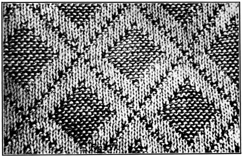
Fig. 71.
Design Made on Automatic Jacquard Purl Stitch Machine.
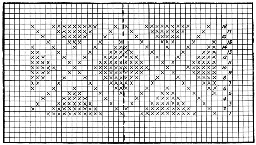
Fig. 72.
Layout of Design Shown in Fig. 71.
Now to cut the cards we would start with No. 1 and cut them consecutively. Referring to Fig. 72, the blank squares, or the spaces in the cards these represent, should be cut out, and the squares marked with an x would remain intact. Starting at the right side, one needle space is not cut out; then sufficient space to cover three needles or jacks is cut out; 111then the space of eleven jacks is left intact, then three cut out. This is the full width of the first round of the design, therefore this cutting would be repeated until it covers the desired width of fabric. Card No. 2 would be cut as follows: One space cut, one left intact, three cut out, nine left intact, three cut out, and one left intact. This should be repeated as with No. 1 card. Each card thereafter should be cut according to the marking of the cross section paper, and numbered as cut, so as to avoid trouble in assembling them in their proper order when finished.
It should be understood that the part of this layout from the right side to the dotted line is the complete design, and all to the left as well as above and below, would be a duplicate of this.
After these cards are put on the card cylinder, attached like an endless belt, and the machine is in operation, when card No. 18 has finished the last part of the design, card No. 1 will start immediately in the next round on its part of the design. When it comes to card No. 6, that square will have been completed, and a new square in the center section will have been started.
The two-tone color effect is made by using two different colored yarns and using a plating yarn carrier. This throws one color on the face in the jersey stitch and the other color on the face in the purl stitch.
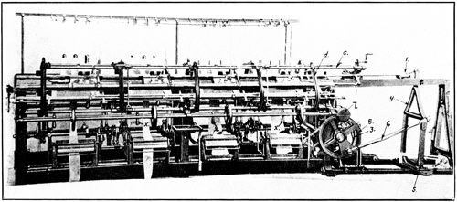
Fig. 73.
Claes and Flentje Automatic Narrowing Machine.
The flat latch needle automatic narrowing machine as built by Messrs. Claes & Flentje is shown in Fig. 73, and a piece of fabric from this machine narrowed down fourteen needles is shown in Fig. 74. This machine is quite complicated when compared with any that have been taken up before, but those who have studied what has gone before carefully, especially that part treating on fashioned garments and how they are made by hand, should have no trouble in understanding the principles and movements necessary to do this work automatically.
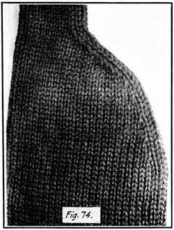
Fig. 74.
Fabric Narrowed Down on Automatic
Narrowing Machine.
The machine shown is really four separate and complete units mounted upon one frame or stand and driven by one belt, with the automatic movements operated from one control. It is evident from this that the garments or parts of garments made on each one of these four units must be the same, or rather they must have the same number of rounds with the same number of needles narrowed down, but they may be made from different yarns both in kind and color.
There are four points that should be understood to begin with: First, the machine is operated by power. Second, the power is transmitted to the driving pulley on the machine at all times when the machine is being operated. Third, the knitting mechanism must be stopped while the narrowing mechanism is in operation. Fourth, the narrowing mechanism must be at rest during the time the knitting mechanism is in operation.
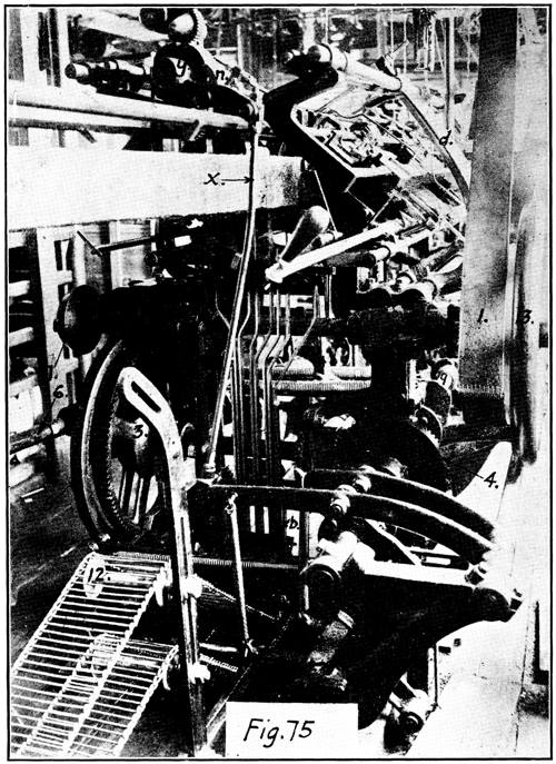
Fig. 75.
Changing Mechanism on Right End of Automatic Narrowing Machine.
115We will first show how it is arranged to automatically stop one part of the machine, say the knitting operation, and put the narrowing mechanism in work, and after this part has performed its functions or narrowed down one needle on each needle plate, front and back, how it is stopped until time to narrow again, and the knitting parts set in operation.
Fig. 75 is a view of the right end of the machine, and it is here that the driving mechanism is located, also the automatic controls. The number 1 indicates the belt and pulley which drive the machine. The pulley is mounted loose upon the shaft and operates the machine through a clutch which is thrown in or out, as the case may be, by the handles marked x in Fig. 73. The number 13 (Fig. 75) indicates a plain balance wheel on the outside end of the shaft.
When the clutch is in, the driving wheel on which the belt 1 runs will of course turn the shaft 2, on the other end of which there is a small spur gear which drives the large gear 3. This large gear is automatically connected with, and disconnected from the crank wheel 5, which wheel drives the knitting mechanism through the connecting rod 6 and lever y, Fig. 73, whose fulcrum is at s, and is connected to an extension of the carriage at r. The lever y comes up between two ways or slides, on which is mounted a crosshead at the end of this extension, and where the lever connects at r, to keep the extension in alignment with the carriages.
Referring to Fig. 75, when the machine is being operated the following parts are always in motion: The driving wheel 1 with the shaft 2, together with the small spur gear on the end of the shaft 2, which cannot be seen but drives the large gear 3, also the large gear 3 with the shaft upon which it is mounted, which may be seen running behind the vertical connecting straps toward the right of the illustration and terminates back of the large bevel gear 4. Upon this end of the shaft there is mounted a small bevel or pinion gear to drive the large bevel gear 4.
Now then let us understand that the crank wheel 5 operates the knitting mechanism of the machine, and the bevel gear 4, through a shaft which runs the entire length of the machine with a series of cams mounted on it, operates the narrowing mechanism. We have seen that the driving parts from the driving pulley 1 on the back of the machine, over to and 116including the large gear 3, and back to and including the small bevel gear which drives the large bevel gear 4 are in motion at all times while the machine is in operation. The gear 4 is engaged with the small gear only at the time the narrowing is done; while the crank wheel is connected with the large spur gear 3 and turning only while the knitting parts are in operation. The connection between the crank wheel 5 and the gear 3 is simply a key-like lever which may be disconnected by lifting out of place and connected again by dropping back, though there is only one place on the circumference of the wheel where it can connect the two together.
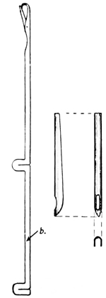
Fig. 76.
Needles and Decker
Points Used on the
Automatic Narrowing
Machine.
The method of starting and stopping the narrowing or fashioning mechanism is quite a novel and ingenious arrangement. To explain it we will refer to Fig. 81. The number 4 indicates the bevel gear shown at 4 in Fig. 75, and 4-a is the small pinion a part of which may be seen in Fig. 75. The larger bevel gear 4 has a small space (three or four teeth) cut away so it acts somewhat on the principle of an intermittent gear. When the small pinion 4-a comes to this spot the large gear 4 will of course stop. This gear is mounted on the shaft 9, which may be seen under the same designation in Figs. 79 and 80, which is a continuation of this shaft. It (the gear 4) is shown in Fig. 81 in the position where it would be at rest as the small pinion 4-a would be turning free and clear on account of the teeth of the large gear being cut away at this point.
It will be noted that there is a pin extending from one side of the hub of the small pinion gear 4-a. On the back of gear 4 there is attached a box-like arrangement with the lever 4-b passing through it, which is pivoted at p and is held out in the position shown by a spring. Outside and near the outer end of this lever 4-b is another L-shaped lever 4-d, which is pivoted at m to the frame of the machine.
117It is plain that when the lever 4-b is moved in the path of the pin 4-c, which is turning at all times with the pinion 4-a, by the right-angled lever 4-d, the gear 4 will be moved forward far enough for the teeth of the pinion to engage with the teeth of the large gear. Consequently, the gear 4 would turn one complete revolution, or until the place which has the teeth cut out is again adjacent to the pinion, and it would stop at this point. This one revolution of the gear 4 completes the execution of one narrowing operation or the narrowing down of one needle on each needle plate.
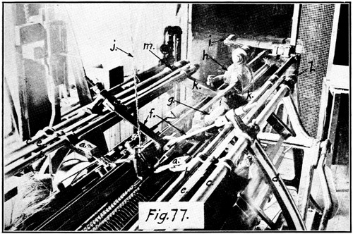
Fig. 77.
Top of Automatic Narrowing Machine.
Referring to Fig. 75, number 11 indicates the lever or slide which is the means provided to make the shift from fashioning to knitting, and vice versa. When this slide is at its furthermost position toward the back of the machine it is held there by a catch, and the knitting mechanism would be in operation while the fashioning mechanism would be at rest. But immediately the slide is released from the catch, which is done by a stud on the chain 12, a spring brings it forward and a release bar, by means of an inclined plane, is set to disconnect the large gear 3 (Fig. 75) from the crank wheel 5, when it gets to the point where the carriages are at the extreme right end of the needle plates as shown in Figs. 77 and 78. At the 118same time it raises up the right-angled lever 4-d (Fig. 81) which throws in the lever 4-b, and this of course starts the fashioning mechanism to work. Just as the gear 4 with the cam shaft 9 completes its one revolution the slide is set back again, which permits the gear 3 to connect with the crank shaft and the gear 4 stops as the cut out teeth come opposite the small pinion.
The several vertical straps which may be seen at or near the center of Fig. 75 are the mediums through which the automatic changes are made by studs coming under and raising them. These studs are attached in their several positions on the chain 12. We will not go into these further, for while the construction is somewhat different from what we have had, the principle is the same. As the studs on the chain come under the straps, they raise them up and this moves a stop in the path of the different slides which changes the locks, yarn carriers, etc.
It will be remembered that in narrowing by hand there were three lines of movement of the decker or narrowing comb. But lines of movement should not be confused with direction of movement. An object may be moved in one line, but if moved back and forth on that line it would move in two directions.
The three lines of movement are as follows: First, it is moved in a line parallel with an extension of the line of a needle lengthwise, or same as the arrows 1 and 2 in Fig. 82. We would move it on this line, and in the direction of arrow 1 to bring the openings in the point of the decker directly over or above the hooks of the needles. Second, it would be moved up and down at right angles to its first movement, and in the direction indicated by arrow 4 to place the openings in the decker points on the hooks of the needles. With the hooks of the needles caught in these openings the decker would move again on its first line, and in the direction indicated by arrow 2 to the point where the latches are above the loops. Then the deckers push the needles down on the same line, but in the direction indicated by arrow 1 to the point where the loops on the needles will close the latches and drop over the hooks on to the decker points. Then the points raise up with the 119loops on them, on the second line again, but in the direction indicated by arrow 3, to clear the needle hooks.
Now we have the third line of movement, which is in toward the other end of the needle plate, as indicated by arrow 5, the distance of one needle space carrying the loops on the decker points. Then they move down on the second line in the direction indicated by arrow 4, catch the needle hooks in the openings of the decker points, draw back on first line, direction of arrow 2 to the point where the loops will slip off the decker points on to the needles again. The decker then raises up and retires to its point of rest. This will leave one empty needle at the end, which is drawn down out of working position by means which will be explained later.
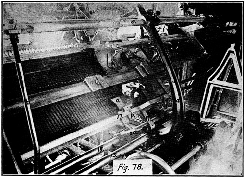
Fig. 78.
Front of Automatic Narrowing Machine.
The knitting mechanism is now started in operation, and after putting on the proper number of rounds it stops and the narrowing proceeds as before. If this explanation of the movements of the decker has been followed carefully by the reader, he will see that there are but three lines of movement in the whole narrowing operation proper, though on two of 120these lines the movement is in opposite directions at different times. To do this automatically only three sources must be provided for the several movements, as the opposite direction of movements on the same lines come as a matter of course, otherwise there could be but one movement in any direction on one line.
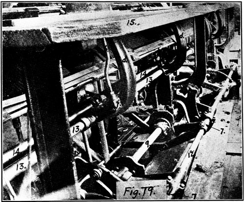
Fig. 79.
Back of Automatic Narrowing Machine Showing Shaft Carrying Cams for
Automatic Movements. View from Right End of Machine.
The source of all of these movements is the shaft upon which the bevel gear (Figs. 75 and 81) is mounted and is designated by the number 9 in Figs. 75, 79 and 80. It may be plainly seen in the illustrations with its irregular surfaced cams which perform this work.
Figs. 79 and 80 are views of the back of the machine, both showing the same parts, but Fig. 79 is a view looking from the right end, or end upon which the driving mechanism is mounted, while Fig. 80 is a view from the other or left end looking toward the driving wheel.
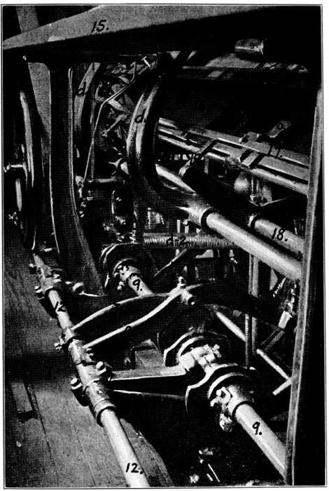
Fig. 80.
Showing the Same Cam Shaft as Shown in Fig. 79 but from Left
End of the Machine.
We will take up the manner of mounting the deckers and the auxiliary parts through the medium of which the narrowing is done. Referring to Fig. 77, the decker points may be seen at a, a, mounted in a clamp in much the same manner as the hand deckers were mounted. The decker points, however, are somewhat different from those used in the hand decker, these latter being solid, either flat or round, while those on the automatic machine are half-round or U-shaped, as shown in Fig. 76, to facilitate placing them on the hooks of the needles.
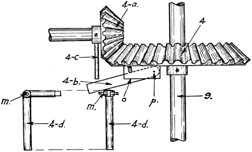
Fig. 81.
Gear Arrangement for Starting and Stopping the Narrowing Mechanism.
Before proceeding any further, it should be understood that the narrowing is done on both sets of needles, front and back, by two separate deckers, therefore most of the parts connected with this operation that are shown and described, except the cam shaft 9 and its appurtenances, are in duplicate on front and back of the machine. The decker point clamp is a part of a yoke which is clamped on the two rods b and c (Fig. 77) tight enough to permit no play, yet not so tight but that it will slide freely endwise on the two rods. There are four of these on each side, front and back, or two for each 123independent pair of plates and locks. The rods b and c run the whole length of the machine and have no end movement, but b is free to move up and down vertically, while c acts simply as a rocker shaft or pivot upon which to swing the rod b, together with the clamp and decker a. The rod c is mounted through and near the end of the arm d, which in its turn is mounted or pivoted on the rocker shaft 13, Fig. 78, where the whole arm may be noted. In Fig. 73 the whole five arms that are on the front of the machine may be seen. These arms are connected with a lever beneath the needle plates and frame by two flexible straps shown at f, Fig. 77. The lever to which the other end of these straps are attached may be seen at 1, Fig. 80, also the extension of the arm d, at d-1. The spring which is attached to this extension with the other end attached to a like extension on the opposite arm d, is shown at d-2. This spring provides the energy to return the arms to, and hold them in the position shown in Fig. 77, after the narrowing operation is completed.
To get the endwise movement of the decker, or the movement we have designated as 1 and 2 in Fig. 82, we will refer again to Fig. 80 and the lever 1. This lever is pivoted on the shaft 12 and passes under the shaft 9. At the point where it passes under to one side of the irregular cam d-3 there is a stud with a roller projecting from one side which comes under and in contact with the cam d-3. We have seen that there is always an upward pull on this lever 1 through the springs d-2, and the extension d-1, the arm proper d, and the straps f (Fig. 77), back down through the center of the machine to the inner end of lever 1, Fig. 80.
Now it follows, that if the periphery of this cam d-3 is irregular, and the spring d-2 always holds the pin with the roller on the side of lever 1, in close contact with the outside of this cam, then by having the periphery vary, or at different distances from the center at different points, the deckers may be moved to any point or held at any point in a line lengthwise with the decker points by making the irregularities at the proper place and at the proper distance from the center.
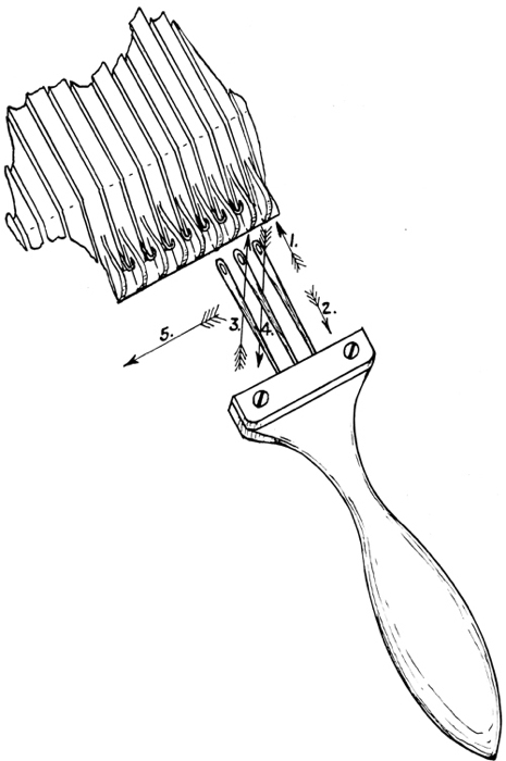
Fig. 82.
Lines of Movement Necessary for Narrowing.
The explanation of this movement applies to all of the automatic movements for narrowing or fashioning on this machine. Inasmuch as all these irregular cams for the different movements are mounted on this same shaft 9, after once being 125set right they must always be in synchronism unless the setting is disturbed by accident. We have seen how the first movement is secured to bring the openings in the decker points down to a point directly over the needle hooks. We have assumed that they were in a line sidewise to begin with. Now we will see how the second movement, or bringing the deckers down on to the hooks of the needles after being moved directly over them, and lifting them off again, is accomplished.
Referring to Fig. 77, it has been explained how the decker points with their clamp a and yoke are mounted on the rods b and c in such a manner that they will swing freely with the rod c acting as a pivot. Referring to Fig. 78, we find that the rods c and b have another yoke at i, which is attached securely to these rods, with a short extension toward the outside of the machine on which to attach the connection rod h.
If we now turn to Fig. 79, we will find that the connection rod h comes down and is attached at the other end to a lever at j. While, as the reader may surmise, the connection rod h, Fig. 78, is on the front of the machine, and the rod h, Fig. 79, is on the back, the connections and manner of moving are the same. The lever to which this connection rod h (Fig. 79) is attached at j is mounted on the shaft 13, so as to swing up and down freely, and has an extension on the other side of the shaft from which there is another rod connecting it with the inside end of lever 2.
This lever has the proper movements imparted to it through the pin and roller, which may be plainly seen, resting on the periphery of an irregular cam, just the same as has been explained for lever 1 for the first movement, except that the pin and roller rest on the top of the cam in this instance, while in the former case the pin and roller were held firmly up against the bottom of the cam by a coil spring.
The third movement to carry the loops in toward the center one needle, designated in Fig. 82 as 5, is a straight line movement and always in one direction. But the movement as to distance must be more exact than either of the others, therefore while the source of the movement is the same as the 126others, an irregular cam on the cam shaft 9, the transmission of it to the deckers is accomplished in an entirely different manner.
We will refer again to Fig. 77, where we will find two long flat steel straps, one on each side of the machine, marked e and e. It will be noted that these straps are attached securely to the yokes that carry the deckers, as well as to the crossheads or bridges marked l and m. Reaching across from one to the other and attached to these bridges is a yoke the two arms of which are indicated by k and k. These two arms come together at the center in a hub through which runs the worm or screw indicated by g.
On the outer end of this worm is a small spur gear which meshes into the gear h. Back of the gear h is a ratchet gear, and both are rigidly attached to the small shaft and turn together. Now it is quite evident that if the ratchet and gear marked h are turned in the right direction, which would be the top toward the right, this would turn the worm, which would move the yoke k and k, together with the bridges l and m, also the straps e and e, and they, of course, would move the deckers. The principle of the worm or screw used to make this movement permits an almost micrometer adjustment of the distance moved.
To find the method used to turn the ratchet gear and spur gear h, we will refer again to Fig. 75, where the ratchet gear is marked y and its pawl n. This will hardly need an explanation, as the method of working may be plainly seen by following out the pawl lever to the connection rod x, and down to the lever 8, which is raised the proper distance at just the proper time by the cam directly under it, and in this manner turns the ratchet.
In narrowing, when it comes to the point where the decker is to be placed on the needle hooks, it is imperative that the latches of those needles on which the transferring is to be done are all open, otherwise the decker will not catch the hook. Also after narrowing down one needle, the empty needle must be drawn down out of the operating position. The manner of doing this is as follows: The needles used in this machine 127have an extension of the shank, and on the lower end of this there is another butt as shown at b, Fig. 76. This extra butt is there solely for the manipulation of the needles for this purpose. Just before the decker is ready to drop on to the needle hooks, the needles are pushed up part way to meet it by the hoe-shaped part designated by the letter o in Fig. 78. This hoe is attached to the block p, which in its turn is attached to the long steel strap 17, then the whole is mounted on a slide directly beneath the strap upon which it may slide lengthwise of the machine.
The slide is attached to the connecting strap 19, the other end of which is attached to the lever 20, therefore the hoe o and the block p may be moved lengthwise of the machine by the strap 17, and the whole, including the slide beneath and the connecting strap 19, may be moved up and down on a line with the movement of the needles by swinging the lever 20, which is pivoted on the rod 18. As the deckers make their first movement down to align the openings over the needle hooks, the hoe o is moved upward by the lever 20, and, inasmuch as it is directly under and contiguous to the lower butts of the needles, it will push those needles up ahead of it to the point where the loops will open and lie across the latches, thus leaving the needle hooks free to receive the deckers. The hoe then retires while the deckers push the needles down, but is used a number of times in the same manner to assist the deckers in the manipulation of the needles during the narrowing operation. In the meantime it is moved over toward the center of the machine at the same time the deckers are, as it also is connected with the yoke k and k, Fig. 77.
As the deckers are finishing their part of the work, the hoe is moved upward again and a hooked finger, which lies just at the right and is almost wholly concealed by the hoe, hooks over the empty needle butt and draws the needle down out of the operating position as the hoe retires to the position shown.
The fabric photograph shown in Fig. 74 is part of a storm collar made for a Shaker sweater. The wide part is that part of the collar that covers from the top of the shoulder down to where the narrowing stops at the center of the breast. The narrow strip is a part of the border on the front opening upon which is placed the buttons and button-holes. It is narrowed down five needles, with four rounds between in the first part, 128while the last part has nine narrowings with one round between.
On this machine, while the narrowing is all automatic, after each garment or part is finished it is necessary to reset the machine by hand, that is, push up those needles that have been narrowed down, move the deckers and hoe back to the starting point by turning the crank i, Fig. 77, then move the carriages across and put in either a comb, or a hook made specially for this purpose, to hold down the stitches on the needles just pushed up into working position. Letter j indicates the yarn leading into the yarn carrier. The numbers 15 in Figs. 79 and 80 indicate the board or stand upon which the yarn is placed for use in the machine.
So far as the knitting mechanism is concerned, the flat jacquard machine is designed and constructed along the same lines as the ordinary flat machine, with the card cylinder for cards and the other necessary appurtenances added. Fig. 83 is a general view of a Dubied jacquard machine, which is semi-automatic but operated by hand. This illustration and the other photographs for this chapter were secured through the courtesy of D. Nusbaum & Co.
The card cylinder and cards are practically the same as used on the purl stitch machine and explained in a former chapter, but obviously the application must be somewhat different owing to the different construction and manner of operating the needles in this machine. Inasmuch as there are two sets of needles opposed one to the other, and each set forms the stitches which show on their respective sides of the fabric, it is possible and customary to make the designs in solid colors, differing in this respect from the links and links or purl stitch machine.
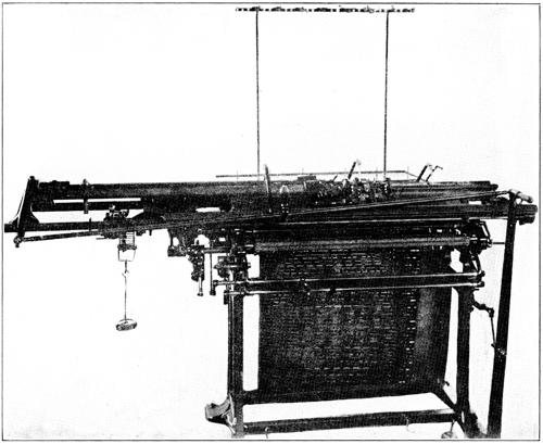
Fig. 83.
Dubied Automatic Jacquard Flat Bed Machine.
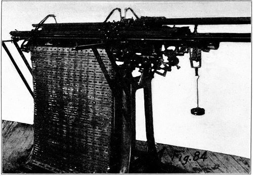
Fig. 84.
Back of Flat Jacquard Machine Showing a Set of Cards, Mounted.
The jacquard designed fabrics are usually made in what would, on an ordinary machine, be the one and one rib or plain stitch. The tuck or cardigan stitch is not resorted to to bring out the design as in some other systems. Strictly speaking, however, the stitch is not what could properly be called a rib stitch, but is a combination of a plain rib and jersey stitch when made on the single jacquard, and is almost wholly of the jersey stitch construction when made on the double jacquard where the design is brought out on both sides of the fabric. The single jacquard is so called when the jacquard arrangement 131is on one plate only, usually the back one. The double jacquard machine is one which has the jacquard attachment on both the front and back plates. With the single jacquard the design can be brought out on one side of the fabric only, while with the double jacquard the design may be brought out on both sides of the fabric, but the colors would be reversed.
Before going into the mechanical construction of the attachment we will to some extent analyze the fabric to find out what must be done to produce it. Referring to Fig. 87, which is a photographic reproduction of a fabric made on the machine under discussion, it will be noted that both the design and the ground are in solid colors. The rectangular figures which might be called the design are in solid black, while the squares, both the large ones and the small ones, which would be the ground, are solid white. It should be understood that there are two yarn carriers used in making this fabric, one for the white yarn and one for the black, and that these carriers are changed every round; that is, one round of white, and one round of black, alternating throughout the fabric.
Now inasmuch as we know that the fabric is made in the plain stitch, it is quite obvious that in order to make this design means must be provided to permit only those needles to knit which are making the white ground on any course in which the carrier with the white yarn is being used. Similarly only those needles making the black design must be permitted to knit on the course in which the carrier with the black yarn is used. The needles or wales, of course, run vertically in the fabric, while the rectangular design is diagonal, therefore it is plain that the number of needles or their relative positions must be changed each course.
In this fabric the design is brought out on one side only, the back plate, and the needles on the opposite side or front plate are knitting each time the carriage is moved across the machine as explained in detail later. This may be plainly seen in Fig. 87, where the corner is turned over to show the back of the fabric.
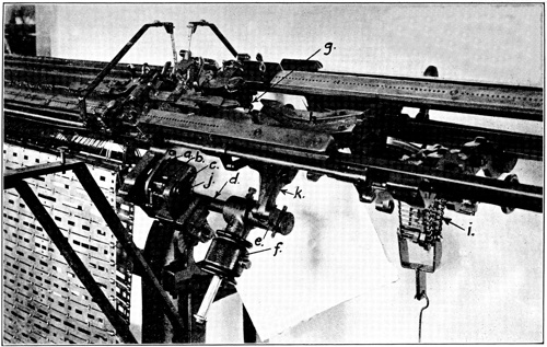
Fig. 85.
Back and End of Jacquard Machine Showing Details of Necessary Movements.
Now to find the method of selecting the proper needles at the proper time we will refer first to Fig. 86, which is a 134photographic reproduction of the cam system used in this machine; also to Fig. 90, which is a drawing of a cross section of the needle plates. It will be noted in Fig. 90 that there are two separate needle plates. The top one is for the needles proper, while the lower one is for the auxiliary needles.
These two plates are in perfect alignment, both as to the surface and the needle tricks or slots. In the double jacquard the front plate would be in two parts and a duplicate of the back plate, but in the single jacquard the front side would have what is the upper plate on the back side only, and would use the short needles as shown at b, Fig. 89.
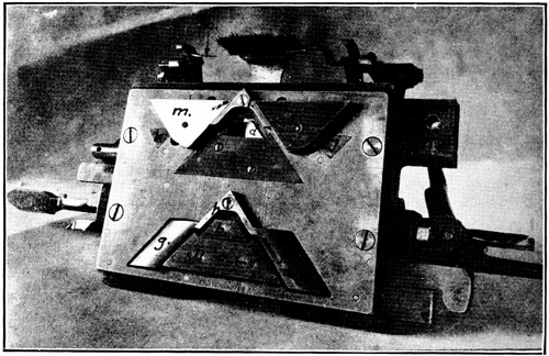
Fig. 86.
Construction and Arrangement of Cams and Locks in Dubied Jacquard
Machine.
Referring now to the cam system shown in Fig. 86, it will be noted that while in general appearance the upper and lower set of locks are similar, the wing or stitch cam l and m are not only different in shape from the lower wing cams f and g, but they are set differently in their relation to the V or rise cams a and c.
The cams as shown are set in the proper position to make jacquard or design work. The upper rise cams c, d and e are 135drawn up into the plate out of working position, therefore those needles selected to operate on any course must be raised by the lower rise cams a and b. The upper lock operates on the butts of the needles proper shown at b, Fig. 90, while the lower lock operates upon the auxiliary needles shown at a in the same illustration. Now, then it is plain that the needles proper will not be raised up, therefore cannot draw new loops or knit unless they are raised by the auxiliary needles a, Fig. 90, which in their turn are raised by the cams a and b, Fig. 86. But it should be noted that the auxiliary needles are drawn down below the point of the rise cams a on each course, as the wing cams f and g extend below these corners, therefore, on every course, unless one of the wing cams f or g is drawn up into the cam plate out of working position, all of the auxiliary needles are drawn down out of working position and will not operate on the next succeeding course unless put into working position by other means.
These wing cams f and g are chamfered off on the outside, so that any auxiliary needles pushed up above the lower end and into operating position will slide under and raise them up into the cam plate. The inner edge is a square corner consequently will, upon coming in contact with the needle butts, draw them down out of the working position. The auxiliary needles being a separate unit have no effect on the needles proper on their downward movement, but must, of course, raise them on the upward movement by coming in contact with the lower ends.
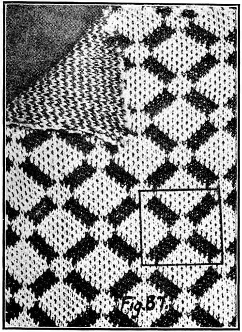
Fig. 87.
Fabric Design Made on a Jacquard
Machine.
Those of the needles proper that are moved up into work are brought down again and form new loops by the stitch cams l and m, Fig. 86. The small triangular cams j and k are for clearing the needles when a very short stitch is being drawn by the stitch cams l and m.
Now to show how the needles are selected we will first refer to Fig. 89, which shows the needle proper at b and the auxiliary needle at a. The auxiliary needle has a joint in it as shown at h to permit the lower end e to swing to the position shown by the dotted line i.
Fig. 90 shows the auxiliary needles in position with the card cylinder and cards in place ready to push them up into operation. Those needles which it is desired not to operate at all, such as the needles at the end of the plate that may not be needed, are drawn down and the ends are turned down to the point where they are at right angles to the plate, as shown by the dotted line at i. When they are in this position the cards cannot of course push them up into operating position. The short nib that looks like a part of a needle, indicated at f, and the card cylinder shown at g are not a part of the mechanism under consideration, but are another method of needle selection which will be explained later.
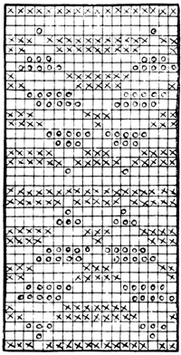
Fig. 88.
o-Black; x-White.
Designs Shown in Fig. 87 Layed Out
on Cross Section Paper for
Cutting Cards.
Fig. 84 is a general view of the back of the machine showing a set of cards on the card cylinder ready for work. Fig. 85 shows the mechanism used to bring the cylinder with the cards into action. The cards and cylinder need no distinguishing mark as they should be easily recognized from what has gone before. The same thing applies to the auxiliary needles just above, part of which are turned down to the point where they cannot be put into operation.
Letter j indicates the end of the shaft upon which the card cylinder is mounted, and c is the elongated opening in which it moves up and down. This opening is on the same diagonal plane as the needle plates and has its duplicate at the other end which carries the other end of the card cylinder. The rocker shaft d is mounted just under the card cylinder and 137has two levers securely attached, the other ends of which are connected to the card cylinder shaft, one at either end. On the outer end of the rocker shaft d is another lever indicated by the letter e. This is connected to the camway h through the extension k. This camway is mounted in such a manner that it can be moved only in one direction, and that direction is up and down diagonally or on the same plane as the back needle plates.
As the carriage reaches the extreme end of its travel the pin g, which is attached to the carriage, enters and follows the camway. Inasmuch as the cams are set on an incline this pin or plunger must raise the camway together with the end of the lever e. Through the rocker shaft d and the two levers before mentioned as connecting the rocker shaft with the card cylinder, this will bring the card cylinder up to the lower edge of the auxiliary needle plate. This action will of course push all those needles into action that come in contact with the particular card that may be on that side of the card cylinder at the time. Where the openings are cut in this card the needles will pass through and have no contact, therefore will not be pushed up into working position.
As the card cylinder returns to its lowest position it is turned a quarter turn by the stationary hooked dog a, which catches a tooth, of which there are four, of a ratchet wheel which is also securely attached to the card cylinder shaft. In this way the card cylinder is turned a quarter turn each time it is moved up to the auxiliary plate, which brings a new card into position to make another selection of needles for the next course.
Letter f indicates a counterweight which, as will be noted, is attached to the rocker shaft d to assist in returning the card cylinder to its lowest position and hold it there after its return. Letter i indicates an ordinary pattern chain on which the proper studs are attached to change the yarn carriers automatically.
In this type of jacquard machine there are three separate and distinct units which may be racked or moved at right angles to the movement of the needles. They are, first, the 138needle plate proper which racks the same as the ordinary flat machine; second, the auxiliary needle plate; and third, the card cylinder together with the cards. The racking of the needle plate proper is necessary to make those designs in which a rack in the fabric is required, but the other two are chiefly a matter of convenience to save making up cards. There are many designs that may be made with one or four cards, or even without any cards, by manipulation of these racking movements, where otherwise quite a string of cards would be required.
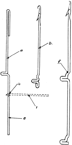
Fig. 89.
Needles Proper and Auxiliary Needles
Used in Jacquard Machine.
We will take for example any design consisting of a small block or check within the limits of the needles the auxiliary plate will rack over. Such a design may be made without cards in this way. Say we wish to make a black and white check four needles wide and four courses high. We would put up into operating position four auxiliary needles and draw four down, alternating in this way with four up and four down for the width of the fabric. Then, referring to Fig. 86, we would draw up out of operating position as shown the rise cams c, d and e, also the wing cams f and g. This would permit the alternating four auxiliary needles we have left in operating position to always stay in this position. Now, after putting on one round or two courses of, let us say, white we would rack the auxiliary plate over four needles and then put on a round of black; rack back the four needles and put on a round of white, rack the other way four needles and put on a round of black. If we could see the fabric made thus far we would find that we had a row of blocks or checks four needles wide and four courses high. For although we have put on four courses each of the black and white, which makes eight courses in all, each color has been put on its own group of 139four needles; therefore the whole will build up the fabric but four courses. If we continued to operate the machine in the same manner we would get alternate black and white stripes, each four needles wide.
To break them up into checks or squares we would at this point have to either skip racking once while continuing the change of carriers each round, or miss changing carriers once while continuing the rack of four needles each round. This change must of course be made every four rounds throughout the length of the fabric, or as long as it is desired to make the check. It should be remembered that it is the auxiliary plate that is racked in this case, and not the needles proper; therefore the rack does not show in the fabric. But the shifting of these alternate sets of four auxiliary needles each round causes alternate groups of four of the needles proper to knit, the set which knits depending on which way the auxiliary plate is racked.
This same check design may be made with one card properly cut by preventing the card cylinder from turning and racking, or moving the card cylinder back and forth four needles in the same manner as the auxiliary plate was moved. Or it may be made with four cards without moving either the plate or card cylinder. In this case it would be necessary to use all the auxiliary needles and lower the wing cams f and g, Fig. 86, into action.
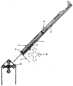
Fig. 90.
Cross Section of Needle Plates and Card Cylinder.
In making a fabric on a double jacquard machine which shows the design on one side only, it is good practice to put four cards on the front cylinder properly cut to put alternate needles into operation on alternate courses, in order to prevent putting more courses on the front plate than on the back. Or to explain it in another way, the needle in the back plate that makes the white part of the design knit only on the rounds on which the white thread carrier is used, and the needles that make the black parts operate only when the carrier with the black yarn is in use.
140Now it is plain that if all the needles in the front plate are permitted to knit each round we would have approximately twice as many courses on the front as on the back. This is obviated, as stated before, by using cards on the front card cylinder to push up into operation every alternate needle when moving the carriage say from left to right, and permitting these to remain idle and pushing those not operated on this course into operation on the return course from right to left. While this is desirable it is not essential, for it cannot be done on a single jacquard, though there are many nice designs and fabrics made on this machine.
Fig. 87 shows a fabric made on a double jacquard machine with both card cylinders in operation. Before going any further it should be understood that both the front and back card cylinders can be operated and make a new selection of needles at the end of each course, or when the carriage is at the end of its travel at both ends of the machine. This design is made by operating the card cylinders in this way. Fig. 88 is a layout of the design shown in Fig. 87. It is one complete repeat of the design as shown by the square box in Fig. 87. All the rest of the fabric is simply a repetition of this, but when grouped together on a large piece of fabric they appear entirely different.
As may be seen in Fig. 88, it would take 36 cards to make this design. In cutting the cards for this we would cut out the places shown blank and leave the card whole to push the needles into operation in the places marked by an x or an o. This cutting would of course have to be repeated the width of the fabric, or the length of each card.
The principle as explained is used on all makes of flat jacquard knitting machines, but the method used to put the needles into operation by the cards differs with the different builders. For example, one popular method is shown in Fig. 90, where the card cylinder is placed directly below the under surface of the auxiliary plate as shown at g, and acts on a short nib with the butt turned downward and extending through the plate as shown at f. With this method it is customary to use a long needle with two butts as shown in Fig. 89 at f, 141instead of the short one with an auxiliary needle. Also with this method the needle plate would be a single wide plate with the tricks or needle slots cut gradually deeper as they reached the lower edge, so that at the point where the lower butts of the needles come the trick is deep enough so that the needle may be depressed to bring the top of the lower butts flush, or just below, the top surface of the needle plate. When operating the machine these butts always remain in this position, therefore will not knit unless raised up and put into operation by the cards.
If we should cut a set of cards just the reverse of the set laid out in Fig. 88, that is, cut out where these are not, and leave uncut where these are cut, and put this set on the front card cylinder and operate them in conjunction with and opposite to the back set, we would have the same design on both sides of the fabric, but the colors would be reversed.
These machines are the most productive and durable made, and are successfully operated by nearly all the Full Fashioned Hosiery Manufacturers in the United States
End of Project Gutenberg's Flat Machine Knitting and Fabrics, by H. D. Buck

*** END OF THIS PROJECT GUTENBERG EBOOK FLAT MACHINE KNITTING AND FABRICS ***

***** This file should be named 57054-h.htm or 57054-h.zip *****
This and all associated files of various formats will be found in:
        http://www.gutenberg.org/5/7/0/5/57054/

Produced by Chris Curnow, Barry Abrahamsen, and the Online
Distributed Proofreading Team at http://www.pgdp.net (This
file was produced from images generously made available
by The Internet Archive)


Updated editions will replace the previous one--the old editions will
be renamed.

Creating the works from print editions not protected by U.S. copyright
law means that no one owns a United States copyright in these works,
so the Foundation (and you!) can copy and distribute it in the United
States without permission and without paying copyright
royalties. Special rules, set forth in the General Terms of Use part
of this license, apply to copying and distributing Project
Gutenberg-tm electronic works to protect the PROJECT GUTENBERG-tm
concept and trademark. Project Gutenberg is a registered trademark,
and may not be used if you charge for the eBooks, unless you receive
specific permission. If you do not charge anything for copies of this
eBook, complying with the rules is very easy. You may use this eBook
for nearly any purpose such as creation of derivative works, reports,
performances and research. They may be modified and printed and given
away--you may do practically ANYTHING in the United States with eBooks
not protected by U.S. copyright law. Redistribution is subject to the
trademark license, especially commercial redistribution.

START: FULL LICENSE

THE FULL PROJECT GUTENBERG LICENSE
PLEASE READ THIS BEFORE YOU DISTRIBUTE OR USE THIS WORK

To protect the Project Gutenberg-tm mission of promoting the free
distribution of electronic works, by using or distributing this work
(or any other work associated in any way with the phrase "Project
Gutenberg"), you agree to comply with all the terms of the Full
Project Gutenberg-tm License available with this file or online at
www.gutenberg.org/license.

Section 1. General Terms of Use and Redistributing Project
Gutenberg-tm electronic works

1.A. By reading or using any part of this Project Gutenberg-tm
electronic work, you indicate that you have read, understand, agree to
and accept all the terms of this license and intellectual property
(trademark/copyright) agreement. If you do not agree to abide by all
the terms of this agreement, you must cease using and return or
destroy all copies of Project Gutenberg-tm electronic works in your
possession. If you paid a fee for obtaining a copy of or access to a
Project Gutenberg-tm electronic work and you do not agree to be bound
by the terms of this agreement, you may obtain a refund from the
person or entity to whom you paid the fee as set forth in paragraph
1.E.8.

1.B. "Project Gutenberg" is a registered trademark. It may only be
used on or associated in any way with an electronic work by people who
agree to be bound by the terms of this agreement. There are a few
things that you can do with most Project Gutenberg-tm electronic works
even without complying with the full terms of this agreement. See
paragraph 1.C below. There are a lot of things you can do with Project
Gutenberg-tm electronic works if you follow the terms of this
agreement and help preserve free future access to Project Gutenberg-tm
electronic works. See paragraph 1.E below.

1.C. The Project Gutenberg Literary Archive Foundation ("the
Foundation" or PGLAF), owns a compilation copyright in the collection
of Project Gutenberg-tm electronic works. Nearly all the individual
works in the collection are in the public domain in the United
States. If an individual work is unprotected by copyright law in the
United States and you are located in the United States, we do not
claim a right to prevent you from copying, distributing, performing,
displaying or creating derivative works based on the work as long as
all references to Project Gutenberg are removed. Of course, we hope
that you will support the Project Gutenberg-tm mission of promoting
free access to electronic works by freely sharing Project Gutenberg-tm
works in compliance with the terms of this agreement for keeping the
Project Gutenberg-tm name associated with the work. You can easily
comply with the terms of this agreement by keeping this work in the
same format with its attached full Project Gutenberg-tm License when
you share it without charge with others.

1.D. The copyright laws of the place where you are located also govern
what you can do with this work. Copyright laws in most countries are
in a constant state of change. If you are outside the United States,
check the laws of your country in addition to the terms of this
agreement before downloading, copying, displaying, performing,
distributing or creating derivative works based on this work or any
other Project Gutenberg-tm work. The Foundation makes no
representations concerning the copyright status of any work in any
country outside the United States.

1.E. Unless you have removed all references to Project Gutenberg:

1.E.1. The following sentence, with active links to, or other
immediate access to, the full Project Gutenberg-tm License must appear
prominently whenever any copy of a Project Gutenberg-tm work (any work
on which the phrase "Project Gutenberg" appears, or with which the
phrase "Project Gutenberg" is associated) is accessed, displayed,
performed, viewed, copied or distributed:

  This eBook is for the use of anyone anywhere in the United States and
  most other parts of the world at no cost and with almost no
  restrictions whatsoever. You may copy it, give it away or re-use it
  under the terms of the Project Gutenberg License included with this
  eBook or online at www.gutenberg.org. If you are not located in the
  United States, you'll have to check the laws of the country where you
  are located before using this ebook.

1.E.2. If an individual Project Gutenberg-tm electronic work is
derived from texts not protected by U.S. copyright law (does not
contain a notice indicating that it is posted with permission of the
copyright holder), the work can be copied and distributed to anyone in
the United States without paying any fees or charges. If you are
redistributing or providing access to a work with the phrase "Project
Gutenberg" associated with or appearing on the work, you must comply
either with the requirements of paragraphs 1.E.1 through 1.E.7 or
obtain permission for the use of the work and the Project Gutenberg-tm
trademark as set forth in paragraphs 1.E.8 or 1.E.9.

1.E.3. If an individual Project Gutenberg-tm electronic work is posted
with the permission of the copyright holder, your use and distribution
must comply with both paragraphs 1.E.1 through 1.E.7 and any
additional terms imposed by the copyright holder. Additional terms
will be linked to the Project Gutenberg-tm License for all works
posted with the permission of the copyright holder found at the
beginning of this work.

1.E.4. Do not unlink or detach or remove the full Project Gutenberg-tm
License terms from this work, or any files containing a part of this
work or any other work associated with Project Gutenberg-tm.

1.E.5. Do not copy, display, perform, distribute or redistribute this
electronic work, or any part of this electronic work, without
prominently displaying the sentence set forth in paragraph 1.E.1 with
active links or immediate access to the full terms of the Project
Gutenberg-tm License.

1.E.6. You may convert to and distribute this work in any binary,
compressed, marked up, nonproprietary or proprietary form, including
any word processing or hypertext form. However, if you provide access
to or distribute copies of a Project Gutenberg-tm work in a format
other than "Plain Vanilla ASCII" or other format used in the official
version posted on the official Project Gutenberg-tm web site
(www.gutenberg.org), you must, at no additional cost, fee or expense
to the user, provide a copy, a means of exporting a copy, or a means
of obtaining a copy upon request, of the work in its original "Plain
Vanilla ASCII" or other form. Any alternate format must include the
full Project Gutenberg-tm License as specified in paragraph 1.E.1.

1.E.7. Do not charge a fee for access to, viewing, displaying,
performing, copying or distributing any Project Gutenberg-tm works
unless you comply with paragraph 1.E.8 or 1.E.9.

1.E.8. You may charge a reasonable fee for copies of or providing
access to or distributing Project Gutenberg-tm electronic works
provided that

* You pay a royalty fee of 20% of the gross profits you derive from
  the use of Project Gutenberg-tm works calculated using the method
  you already use to calculate your applicable taxes. The fee is owed
  to the owner of the Project Gutenberg-tm trademark, but he has
  agreed to donate royalties under this paragraph to the Project
  Gutenberg Literary Archive Foundation. Royalty payments must be paid
  within 60 days following each date on which you prepare (or are
  legally required to prepare) your periodic tax returns. Royalty
  payments should be clearly marked as such and sent to the Project
  Gutenberg Literary Archive Foundation at the address specified in
  Section 4, "Information about donations to the Project Gutenberg
  Literary Archive Foundation."

* You provide a full refund of any money paid by a user who notifies
  you in writing (or by e-mail) within 30 days of receipt that s/he
  does not agree to the terms of the full Project Gutenberg-tm
  License. You must require such a user to return or destroy all
  copies of the works possessed in a physical medium and discontinue
  all use of and all access to other copies of Project Gutenberg-tm
  works.

* You provide, in accordance with paragraph 1.F.3, a full refund of
  any money paid for a work or a replacement copy, if a defect in the
  electronic work is discovered and reported to you within 90 days of
  receipt of the work.

* You comply with all other terms of this agreement for free
  distribution of Project Gutenberg-tm works.

1.E.9. If you wish to charge a fee or distribute a Project
Gutenberg-tm electronic work or group of works on different terms than
are set forth in this agreement, you must obtain permission in writing
from both the Project Gutenberg Literary Archive Foundation and The
Project Gutenberg Trademark LLC, the owner of the Project Gutenberg-tm
trademark. Contact the Foundation as set forth in Section 3 below.

1.F.

1.F.1. Project Gutenberg volunteers and employees expend considerable
effort to identify, do copyright research on, transcribe and proofread
works not protected by U.S. copyright law in creating the Project
Gutenberg-tm collection. Despite these efforts, Project Gutenberg-tm
electronic works, and the medium on which they may be stored, may
contain "Defects," such as, but not limited to, incomplete, inaccurate
or corrupt data, transcription errors, a copyright or other
intellectual property infringement, a defective or damaged disk or
other medium, a computer virus, or computer codes that damage or
cannot be read by your equipment.

1.F.2. LIMITED WARRANTY, DISCLAIMER OF DAMAGES - Except for the "Right
of Replacement or Refund" described in paragraph 1.F.3, the Project
Gutenberg Literary Archive Foundation, the owner of the Project
Gutenberg-tm trademark, and any other party distributing a Project
Gutenberg-tm electronic work under this agreement, disclaim all
liability to you for damages, costs and expenses, including legal
fees. YOU AGREE THAT YOU HAVE NO REMEDIES FOR NEGLIGENCE, STRICT
LIABILITY, BREACH OF WARRANTY OR BREACH OF CONTRACT EXCEPT THOSE
PROVIDED IN PARAGRAPH 1.F.3. YOU AGREE THAT THE FOUNDATION, THE
TRADEMARK OWNER, AND ANY DISTRIBUTOR UNDER THIS AGREEMENT WILL NOT BE
LIABLE TO YOU FOR ACTUAL, DIRECT, INDIRECT, CONSEQUENTIAL, PUNITIVE OR
INCIDENTAL DAMAGES EVEN IF YOU GIVE NOTICE OF THE POSSIBILITY OF SUCH
DAMAGE.

1.F.3. LIMITED RIGHT OF REPLACEMENT OR REFUND - If you discover a
defect in this electronic work within 90 days of receiving it, you can
receive a refund of the money (if any) you paid for it by sending a
written explanation to the person you received the work from. If you
received the work on a physical medium, you must return the medium
with your written explanation. The person or entity that provided you
with the defective work may elect to provide a replacement copy in
lieu of a refund. If you received the work electronically, the person
or entity providing it to you may choose to give you a second
opportunity to receive the work electronically in lieu of a refund. If
the second copy is also defective, you may demand a refund in writing
without further opportunities to fix the problem.

1.F.4. Except for the limited right of replacement or refund set forth
in paragraph 1.F.3, this work is provided to you 'AS-IS', WITH NO
OTHER WARRANTIES OF ANY KIND, EXPRESS OR IMPLIED, INCLUDING BUT NOT
LIMITED TO WARRANTIES OF MERCHANTABILITY OR FITNESS FOR ANY PURPOSE.

1.F.5. Some states do not allow disclaimers of certain implied
warranties or the exclusion or limitation of certain types of
damages. If any disclaimer or limitation set forth in this agreement
violates the law of the state applicable to this agreement, the
agreement shall be interpreted to make the maximum disclaimer or
limitation permitted by the applicable state law. The invalidity or
unenforceability of any provision of this agreement shall not void the
remaining provisions.

1.F.6. INDEMNITY - You agree to indemnify and hold the Foundation, the
trademark owner, any agent or employee of the Foundation, anyone
providing copies of Project Gutenberg-tm electronic works in
accordance with this agreement, and any volunteers associated with the
production, promotion and distribution of Project Gutenberg-tm
electronic works, harmless from all liability, costs and expenses,
including legal fees, that arise directly or indirectly from any of
the following which you do or cause to occur: (a) distribution of this
or any Project Gutenberg-tm work, (b) alteration, modification, or
additions or deletions to any Project Gutenberg-tm work, and (c) any
Defect you cause.

Section 2. Information about the Mission of Project Gutenberg-tm

Project Gutenberg-tm is synonymous with the free distribution of
electronic works in formats readable by the widest variety of
computers including obsolete, old, middle-aged and new computers. It
exists because of the efforts of hundreds of volunteers and donations
from people in all walks of life.

Volunteers and financial support to provide volunteers with the
assistance they need are critical to reaching Project Gutenberg-tm's
goals and ensuring that the Project Gutenberg-tm collection will
remain freely available for generations to come. In 2001, the Project
Gutenberg Literary Archive Foundation was created to provide a secure
and permanent future for Project Gutenberg-tm and future
generations. To learn more about the Project Gutenberg Literary
Archive Foundation and how your efforts and donations can help, see
Sections 3 and 4 and the Foundation information page at
www.gutenberg.org Section 3. Information about the Project Gutenberg
Literary Archive Foundation

The Project Gutenberg Literary Archive Foundation is a non profit
501(c)(3) educational corporation organized under the laws of the
state of Mississippi and granted tax exempt status by the Internal
Revenue Service. The Foundation's EIN or federal tax identification
number is 64-6221541. Contributions to the Project Gutenberg Literary
Archive Foundation are tax deductible to the full extent permitted by
U.S. federal laws and your state's laws.

The Foundation's principal office is in Fairbanks, Alaska, with the
mailing address: PO Box 750175, Fairbanks, AK 99775, but its
volunteers and employees are scattered throughout numerous
locations. Its business office is located at 809 North 1500 West, Salt
Lake City, UT 84116, (801) 596-1887. Email contact links and up to
date contact information can be found at the Foundation's web site and
official page at www.gutenberg.org/contact

For additional contact information:

    Dr. Gregory B. Newby
    Chief Executive and Director
    gbnewby@pglaf.org

Section 4. Information about Donations to the Project Gutenberg
Literary Archive Foundation

Project Gutenberg-tm depends upon and cannot survive without wide
spread public support and donations to carry out its mission of
increasing the number of public domain and licensed works that can be
freely distributed in machine readable form accessible by the widest
array of equipment including outdated equipment. Many small donations
($1 to $5,000) are particularly important to maintaining tax exempt
status with the IRS.

The Foundation is committed to complying with the laws regulating
charities and charitable donations in all 50 states of the United
States. Compliance requirements are not uniform and it takes a
considerable effort, much paperwork and many fees to meet and keep up
with these requirements. We do not solicit donations in locations
where we have not received written confirmation of compliance. To SEND
DONATIONS or determine the status of compliance for any particular
state visit www.gutenberg.org/donate

While we cannot and do not solicit contributions from states where we
have not met the solicitation requirements, we know of no prohibition
against accepting unsolicited donations from donors in such states who
approach us with offers to donate.

International donations are gratefully accepted, but we cannot make
any statements concerning tax treatment of donations received from
outside the United States. U.S. laws alone swamp our small staff.

Please check the Project Gutenberg Web pages for current donation
methods and addresses. Donations are accepted in a number of other
ways including checks, online payments and credit card donations. To
donate, please visit: www.gutenberg.org/donate

Section 5. General Information About Project Gutenberg-tm electronic works.

Professor Michael S. Hart was the originator of the Project
Gutenberg-tm concept of a library of electronic works that could be
freely shared with anyone. For forty years, he produced and
distributed Project Gutenberg-tm eBooks with only a loose network of
volunteer support.

Project Gutenberg-tm eBooks are often created from several printed
editions, all of which are confirmed as not protected by copyright in
the U.S. unless a copyright notice is included. Thus, we do not
necessarily keep eBooks in compliance with any particular paper
edition.

Most people start at our Web site which has the main PG search
facility: www.gutenberg.org

This Web site includes information about Project Gutenberg-tm,
including how to make donations to the Project Gutenberg Literary
Archive Foundation, how to help produce our new eBooks, and how to
subscribe to our email newsletter to hear about new eBooks.