FIG. 1.
Project Gutenberg's Cotton Weaving and Designing, by John T. Taylor

This eBook is for the use of anyone anywhere at no cost and with
almost no restrictions whatsoever.  You may copy it, give it away or
re-use it under the terms of the Project Gutenberg License included
with this eBook or online at www.gutenberg.org/license


Title: Cotton Weaving and Designing
       6th Edition

Author: John T. Taylor

Release Date: April 23, 2018 [EBook #57031]

Language: English

Character set encoding: UTF-8

*** START OF THIS PROJECT GUTENBERG EBOOK COTTON WEAVING AND DESIGNING ***


Produced by Jane Robins, Reiner Ruf, and the Online
Distributed Proofreading Team at http://www.pgdp.net (This
file was produced from images generously made available
by The Internet Archive)
Transcriber’s Notes
This e-text is based on ‘Cotton Weaving and Designing,’ from 1909. Inconsistent spelling and hyphenation have been retained, but punctuation and typographical errors have been corrected. Example calculations have been maintained; some erroneous figures in the tables have been corrected.
The mid dot has been used as the decimal point (as in 3·0000). The ‘Mathematical Operators’ Unicode Block needs to be supported by the font installed in the reading device/software; special characters used in this book are ‘therefore’ (∴), ‘square root’ (√), and others.
COTTON WEAVING AND DESIGNING
THE ELEMENTS OF COTTON SPINNING. By JOHN MORRIS and F. WILKINSON. With a Preface by Sir B. A. DOBSON, C.E., M.I.M.E. With 169 Diagrams and Illustrations. Crown 8vo. 7s. 6d.
COTTON SPINNING CALCULATIONS AND YARN COSTS: A Practical and Comprehensive Manual of Calculations, Yarn Costs and other Data involved in adapting the Machinery in all Sections, and for all Grades of Spinning and Doubling. By JAMES WINTERBOTTOM, Lecturer in Cotton Spinning, Municipal School of Technology, Manchester. With Diagrams and other Illustrations. 8vo. 7s. 6d. net.
JACQUARD WEAVING AND DESIGNING. By F. T. BELL, Medallist in Honours and Certificated Teacher in Linen Manufacturing and in Weaving and Pattern Designing, City and Guilds of London Institute. With 199 Diagrams. 8vo. 12s. net.
PRINCIPLES OF WORSTED SPINNING. By HOWARD PRIESTMAN. With 118 Illustrations. 8vo. 7s. 6d. net.
PRINCIPLES OF WOOLLEN SPINNING.
By HOWARD PRIESTMAN.
With 111 Diagrams. 8vo. 9s. net.
LONGMANS, GREEN, AND CO.
LONDON, NEW YORK, BOMBAY, AND CALCUTTA
BY
JOHN T. TAYLOR
LATE LECTURER ON COTTON WEAVING AND DESIGNING IN THE PRESTON, ASHTON-UNDER-LYNE, CHORLEY, AND TODMORDEN TECHNICAL SCHOOLS AND ON SILK WEAVING AND DESIGNING IN THE MACCLESFIELD TECHNICAL SCHOOL AUTHOR OF DESIGNS FOR COTTON FABRICS, ETC., IN ‘THE TEXTILE MANUFACTURER’
REVISED UNDER THE DIRECTION
OF
F. WILKINSON
DIRECTOR OF THE TEXTILE AND ENGINEERING SCHOOL, BOLTON
AND
H. NISBET
WEAVING MASTER OF THE TEXTILE SCHOOL, BOLTON
SIXTH EDITION
WITH NUMEROUS DIAGRAMS
LONGMANS, GREEN, AND CO.
39 PATERNOSTER ROW, LONDON
NEW YORK, BOMBAY, AND CALCUTTA
1909
All rights reserved
TAYLOR’S “Cotton Weaving” has for many years enjoyed a reputation among Students who have attended Day and Evening Classes in Textile Weaving and Designing.
It has, however, been found wanting in some important features, and others have needed expansion so as to bring the work up to modern requirements.
A further Edition having been called for, has afforded the opportunity of having these deficiencies remedied by the addition of matters which will put the book in line with the latest improvements in this section of the Mechanical Arts. Chapter I., on preparatory processes, has been entirely rewritten and enlarged. My obligations are many to Mr. H. Nisbet, Weaving and Designing Master here, who has kindly carried out this work. Some chapters have had new and important features added, and many drawings are included for the first time, either as new illustrations, or in place of others which had become obsolete.[Pg vi] For these drawings I am indebted to the same gentleman, who has made this class of work a speciality.
Other chapters have been expanded, and partly rewritten. I should like to say, in conclusion, that while the book was passing through the press the assistance of Mr. Nisbet has been most helpful.
FRED. WILKINSON,
Director.
TEXTILE AND ENGINEERING SCHOOL,
BOLTON,
February, 1905.
PREFACE TO SIXTH EDITION
ANOTHER Edition having been called for has given opportunity for a revision of the work in several directions. The most notable addition is that of Chapter IX., which is quite new and deals with Automatic Weft-replenishing Devices. It is hoped this will be of considerable help in giving weaving students clear ideas on a phase of the subject which is growing rapidly, and will tend to still greater importance as increased production becomes more necessary. Quite a number of new illustrations have been substituted for old ones.
FRED. WILKINSON,
Director.
TEXTILE AND ENGINEERING SCHOOL,
BOLTON,
November, 1909.
YARN intended for manufacture into cloth requires to pass through various stages of preparation, the character of which depends upon the class of fabrics to be produced. Thus, some systems of treatment are better adapted for the preparation of yarn for grey cloths (i.e. of the native colour of cotton), some for mono-coloured, and others for multi-coloured, fabrics. The choice of a system is often arbitrary, and can only be made from a knowledge of local or special requirements.
The operations involved in the preparation of warps for most fabrics are comprised under not less than five chief divisions, namely—
1. Winding yarn from any of its earlier stages on to warpers’ bobbins.
2. Warping.
3. Sizing.
4. Beaming, or winding yarn on to a weaver’s beam.
5. Looming, i.e. either drawing-in or twisting-in.
Each of these operations may be performed by a variety of machines of distinctly different types that have been specially devised to meet specific requirements, and which are, therefore,[Pg 2] better adapted than others for their special purpose. Before introducing the reader to the details of the various types of machines in each division, it will be better to briefly enumerate the different systems of preparation usually adopted in the manufacture of the three classes of goods named above.
Grey warps are prepared by one or other of two systems, namely, (1) Beam warping, for slasher or tape sizing; and, (2) ball or mill warping, for ball or warp sizing; but by far the greater number are prepared by the first-named system.
1. Beam Warping and Slasher Sizing.
This system comprises the following operations, namely—
1. Winding yarn from cops, ring, or throstle bobbins on to warpers’ bobbins, by means of a “spindle” or “cop” winding machine.
2. Beam warping, whereby yarn is transferred, in the form of a wide sheet, from warpers’ bobbins on to a large flanged beam.
3. Slasher or tape sizing, whereby yarn is withdrawn from several beams, termed “back” or “slashers’” beams, to be sized, and subsequently re-wound by the same machine on to a weaver’s beam by simultaneous operations.
4. Looming, by which the threads of a new warp are placed in a loom ready for weaving.
2. Ball Warping and Sizing.
This system comprises the following operations, namely—
1. Winding yarn from cops or ring bobbins on to warpers’ bobbins.
2. Ball warping, in which a number of threads are withdrawn from warpers’ bobbins and condensed into the form of a rope of untwisted strands. This operation may be accomplished by several types of machines. The one usually employed is the old-fashioned warping mill, which coils warp-ends on to a large revolving reel or swift, from which they are subsequently withdrawn and formed into a large ball. Ball warps are also sometimes formed direct from warpers’ bobbins; also sometimes from sections formed by a sectional warper; and sometimes by means of a linking or chaining machine.
3. Ball-warp sizing.
4. Beaming, or winding a warp in an even sheet of threads on to a weaver’s beam for the loom.
5. Twisting-in or else drawing-in warp-ends in the loom.
If the threads of a new warp are similar in number and counts to those of the finished warp, and are to pass through the shedding harness and reed also in a similar manner, it is more economical to twist the threads of a new warp separately to the corresponding threads of the old warp, and then draw the twisted portion of the warp bodily forward through the healds and reed. If, however, the number of threads and counts are greatly dissimilar, or if a different drafting is required, then recourse must be had to drawing new warp-ends through the harness and reed.
Preparation of Mono-coloured Warps.
Warps of one colour may be prepared from either (1) warp-dyed and sized yarn, or (2) from hank-dyed and sized yarn.
1. (a) Warp-dyeing and Sizing.
The series of operations in this system are identical with those involved in the preparation of grey warps by means of[Pg 4] ball warping, but with the additional process of dyeing immediately following the operation of warping, and are as follows:—
1. Winding yarn on to warpers’ bobbins.
2. Mill or other system of ball warping.
3. Warp-dyeing and sizing.
4. Winding yarn on to a weaver’s beam.
5. Twisting-in or drawing-in.
1. (b) Warp-dyeing and Sizing.
A system by which warps of one colour may be prepared by means of sectional warping, from ball-dyed and sized yarn, has been recently introduced. It comprises the following operations, namely—
1. Winding yarn from cops or ring bobbins on to warpers’ bobbins.
2. Mill or other system of ball warping.
3. Warp-dyeing and sizing.
4. Winding yarn from ball warps on to warpers’ bobbins by means of a warp-winding machine.
5. Sectional warping and beaming.
6. Drawing-in or twisting-in.
2. Hank-dyeing and Sizing.
This system involves the following operations, namely—
1. Reeling yarn from cops or ring bobbins into single or multiple hanks. (A standard hank contains 840 yards.)
2. Hank-dyeing and sizing.
3. Winding yarn from hanks on to warpers’ bobbins by means of a drum-winding machine.
4. Beam warping.
5. Beaming, or winding yarn from back beams on to a weaver’s beam.
6. Drawing-in or twisting-in.
Sectional warping may be substituted in lieu of beam warping.
Preparation of Multi-coloured Warps.
Striped warps are usually prepared by one or other of two systems, namely, (1) Yorkshire dressing, from warp-dyed and sized yarn; and (2) sectional warping, from hank-dyed and sized yarn. Warp-dyeing yields a more uniform tone of colour than hank-dyeing, for which reason some manufacturers prefer to adopt the former system, although the latter system is less costly.
1. Yorkshire Dressing.
This system comprises the following operations, namely—
1. Winding yarn on to warpers’ bobbins.
2. Mill or other system of ball warping.
3. Warp-dyeing and sizing.
4. Yorkshire dressing, by which the required number of threads of each colour are split off reserve ball warps. The warp-ends thus split off are subsequently passed, in groups of two to four, through the dents of a reed in proper order, according to the required warp pattern, and wound on to a weaver’s beam.
5. Drawing-in or twisting-in.
2. Sectional Warping.
This system comprises the following operations, namely—
1. Reeling yarn into hanks.
2. Hank-dyeing and sizing.
3. Winding on to warpers’ bobbins by a drum-winding machine.
4. Sectional warping, by which a warp is wound in sections upon wooden or compressed paper blocks, with warp-ends in the same relative position that they are required to occupy in cloth. Each section forms a complete unit of the full warp, and when the required number of units are prepared, they are placed together side by side, and compressed upon a mandril; then the yarn is unwound from all sections simultaneously, and wound on to a weaver’s beam.
5. Twisting-in or drawing-in.
Preparation of Weft Yarn.
If weft yarn is to be woven in a grey state, it is rarely that it requires to undergo any operation after it leaves the spinner. Grey cops and ring bobbins of weft are usually placed in a shuttle and woven direct; but if they are too large for a shuttle, their yarn is transferred on to wooden or paper bobbins by means of pirn winding.
Cops intended for use as weft are frequently dyed and bleached in that form, and woven without any operation of winding. If, however, weft yarn is dyed or bleached in hanks, it requires to be subsequently wound on to pirn bobbins or paper tubes to fit on a shuttle tongue. Weft is also sometimes woven in a damp condition, with a view to inserting a greater number of picks per inch in cloth than is possible with dry weft.
Winding Machines for Warp Yarn.
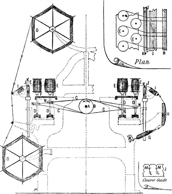
Fig. 1 is a diagram showing parts of a “spindle” or “cop” winding machine, which is chiefly employed to wind grey yarn from cops, G, or ring bobbins on to warpers’ bobbins, E. It is also sometimes incidentally employed to wind coloured yarn from hanks, O (as represented on the left-hand side of the[Pg 7] diagram), when the amount of work required of that kind would not justify the purchase of a “drum” winding machine, which latter is better adapted for that purpose, for reasons that will be explained later.
FIG. 1.
As usually made, a “cop” winding machine contains a tin driving drum, B, passing centrally down the machine, and carrying the driving pulleys at one end of the tin drum shaft A. By means of cotton bands, C, the tin drum drives four rows of[Pg 8] spindles, D, arranged in two zigzag rows, one on each side of the machine, as shown in part plan (detached). Warpers’ bobbins, E, fit loosely upon the spindles, and rest upon metal discs, F, secured to the spindle-shanks, by which bobbins are frictionally rotated. During winding, yarn passes from cops, G, or other source, over a drag-board, H, through a brush, I, and clearer guide, J, thence over a glass rod, K, surmounted on guide-rails, and on to warpers’ bobbins, E. The drag-board H is covered with flannel to impart frictional resistance to yarn, and thereby prevent its passing too freely and making soft bobbins. The clearer guide (of which a front view is shown, detached) is a thin metal plate containing a number of vertical slits, L, from near the top of which are two short slits, M, branching upwards at an angle of about 45°. The vertical slits serve to guide threads to their respective bobbins, and also to remove any irregularities, as “slubbings” (i.e. thick, soft places consisting of a mass of untwisted fibres). The short slits are intended to prevent operatives from raising threads out of the guides, and so save themselves the trouble and loss of time involved in piecing up broken threads.
Spindle-shanks, D, are furnished with tightly-fitting grooved pulleys, N, termed “wharves,” around which driving bands pass. Wharves on each back row of spindles are usually made one-quarter of an inch larger in diameter than those of front spindles, to cause them to revolve at a slower velocity. The object of this is to enable some compensation to be made for the constantly accelerating pace at which yarn is wound, in consequence of the gradually increasing girth of bobbins by additional layers of yarn. When bobbins become about half full on front spindles, a winder removes them to back spindles to be filled.
If bobbins were allowed to fill on front spindles, the velocity at which yarn would travel towards the completion[Pg 9] of winding would impart an abnormal degree of tension to it, and thereby make it more liable to break. It is in consequence of the excessive degree of friction to which yarn is subjected in a cop-winding machine that renders it unsuitable for winding yarn that has been previously dyed and sized.
FIG. 2.
One of the most important parts of a cop-winding machine is the traverse motion to guide yarn between the flanges of a bobbin during winding. These are constructed in great variety, but all belong to one of two distinct types, namely, those governed by cams, and those governed by what is termed a “mangle-wheel.” They are also constructed to guide yarn at either a uniform or variable pace between the bobbin flanges. If the traverse of yarn is uniform, bobbins will be wound with a uniform diameter; but if a barrel-shaped bobbin is required, the movement of guide-rails must be differential—quicker towards the extremities, and slower towards the centre of their[Pg 10] traverse, with the object of placing a greater quantity of yarn upon them. Traverse motions are usually designed on the compensating principle, so that guide-rails on either side move in opposite directions at the same time, and a falling rail helps a rising one to ascend, thereby requiring less motive power to drive a machine.
FIG. 3.
One of several modifications of a heart-cam traverse motion is shown in Fig. 2. In this motion two heart-cams, Q, are set in opposite direction upon a shaft, P, which is driven by a pinion, R, on the tin drum shaft, A, and a train of wheels, S, T, U, V. The cams operate treadles, W, whereby they fall and rise alternately. The free end of each treadle farthest from its fulcrum is connected by means of straps or chains, X, to pulleys; Y, secured to shafts; Z, extending one on each side of the machine, and carrying several pinion wheels, 1, at intervals. The latter engage with teeth in vertical racks, 2, which serve as supports to guide-rails, 3. Thus, as treadles are depressed, guide-rails are raised in a positive manner; but their return is effected by gravitation. The character of movement imparted to guide-rails depends upon the conformation of the cams, which may be constructed to give either a uniform or differential traverse to guide-rails, as desired.
Another modification of a heart-cam motion is illustrated in Fig. 3. In this motion a single cam, H, serves to operate[Pg 11] both guide-rails, B, by acting upon two treadle bowls, one of which, K, is placed above, and the other, L, below the cam. Treadle bowl K is carried at one end of a lever fulcrumed at O, whilst the other end, M, is connected to a lever, Q. Through the medium of chains and chain pulleys, lever Q operates the guide-rail on the left, whilst the lower treadle, T, operates that on the right.
FIG. 4.
A traverse motion constructed on the mangle-wheel principle, to wind barrel-shaped bobbins, is represented in Fig. 4, A pinion, B, on the tin drum shaft, A, drives wheel, C, which carries a small pinion, D. Wheel C and pinion D are carried by a bracket that permits of a slight concentric movement of those wheels to enable the pinion to engage alternately on the outside and then on the inside of the mangle-wheel E, with which it gears. On the same stud as the mangle-wheel is a pinion, F, which engages with the teeth of a horizontal rack, G, which is formed with a curved rack at each end. The curved racks gear with eccentric wheels, H, fastened to shafts, I, which carry chain pulleys, J, to wind up or let off the chains connected to the supports of guide-rails. When pinion D revolves[Pg 12] on the outside of the mangle-wheel, the latter revolves until the gap K arrives at the pinion, which immediately runs inside the mangle-wheel and reverses its direction, until the gap L arrives at the pinion, which then runs on the outside and again reverses the direction of the mangle-wheel. Thus, rack G is slowly moved from one side to the other, and by acting upon the eccentric wheels H at different distances from their axes, their rotation is quicker or slower, according as the racks are in gear with them at a point nearer to, or farther from, the centre of their shafts respectively. On the same shafts as the eccentric wheels are a number of chain pulleys on which are fastened chains, M, connected to the supports, 2, of guide-rails, whereby the latter are raised and lowered in a manner determined by the eccentric wheels.
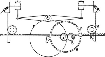
FIG. 5.
Another modification of a mangle-wheel motion is shown in Fig. 5. In this motion a wheel, E, on the drum shaft, drives the larger wheel F. The small pinion C turns the mangle-wheel H.
In order to obtain the unequal motion of the rack R, to give the barrel shape to the bobbin, a wheel, A, is fixed on the mangle-wheel shaft a short distance from the centre of the wheel. Another wheel, B, is fixed in a similar manner on[Pg 13] another shaft, which also carries a wheel which gears into the under side of the rack. The smaller side of the wheel A gears into the larger side of the wheel B, as shown in the diagram, and as the mangle-wheel shaft revolves, the larger part of A will gradually come in contact with the smaller part of B, and this, of course, will cause the rack to move quicker. When the smaller side of A is in contact with the larger side of B, the guide-plate will be guiding the yarn on to the middle of the bobbin; and when the larger side of A is in contact with the smaller side of B, the guide-plate will be putting the yarn on to either the top or bottom of the bobbin.
FIG. 6.
The small side of the wheel A must be set in gear with the larger side of the wheel B, and the traverse halfway of the bobbin. The pinion C will at the same time be in contact with the middle pin in the mangle-wheel, and the middle of the rack R driving the wheel M.
Fig. 6 is a part elevation, and Fig. 7 a plan, showing the[Pg 14] essential parts of a drum-winding machine to wind yarn from hanks, W, that have been previously dyed and sized, on to warpers’ bobbins, C. In this type of machine, warpers’ bobbins are held horizontally against the peripheries of a series of revolving drums, B, fixed at regular intervals upon a shaft, A, running centrally from end to end of the machine. Bobbins are held in position by spindles, D, contained in frames, E, which are fulcrumed at F to brackets, G, to permit of bobbins rising as they increase in size. Since bobbins are driven by surface contact with drums, the rate of winding is approximately uniform throughout. Projecting from each bobbin frame is a latch, H, to permit of a hook, I, holding a bobbin out of contact with its drum, whilst an operative replaces a full bobbin with an empty one, or pieces a broken thread.
FIG. 7.
FIG. 8.
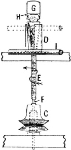
FIG. 9.
Yarn is guided between the flanges of bobbins at a uniform pace by means of guides, J, carried upon guide-rails, K, supported in brackets, L, and operated by a heart-cam, M. On the end of the driving shaft, A, is a worm, N, which gears with a worm wheel, O, with which is compounded a pinion, P, to drive wheel, Q, to which the cam M is secured. As the cam revolves, it acts alternately upon two runners, R and S, carried upon studs secured to the sliding base, T, of brackets, L, whereby the latter receive a reciprocal motion, as indicated by arrows, U and V.
Winding Machines for Weft.
When weft yarn is in an unsuitable form to be placed within a shuttle it is usually wound upon paper tubes, or wooden bobbins, by means of one of the many systems of “pirn” winding. The chief parts of the prevailing type of machine used for that purpose are represented in Figs. 8, 9, and 10, which are end[Pg 16] and front elevations and plan respectively. Passing centrally down the machine is a tin drum, B, on driving shaft, A, for the purpose of driving a number of wharves, C, arranged at regular intervals on each side of the machine. Fixed immediately above each wharve is a metal pirn cup, D, having a conical interior, for the reception of a pirn bobbin, E. When in position, a long spindle, F, having a heavy head-piece, G, passes through a bobbin tube and enters a rectangular hole in the wharve immediately below. The lower portion of a spindle which enters the wharve is also rectangular in cross-section, and therefore revolves with its wharve. At the same time, bobbins are driven by causing a projection, H, below spindle heads to enter a slot in each bobbin head.
FIG. 10.
Each thread passes from its source, over several stationary bars, to impart the required degree of tension to it, thence over guide-rail, I, by which it is guided up and down (as indicated by arrows, J) between the extremities of a pirn cup, as it passes through an opening, K, in the latter, and on to its bobbin. In consequence of yarn being built upon a bobbin within a conical chamber, a bobbin, with its spindle, rises automatically as it fills with yarn, and when filled it raises its spindle clear of its wharve, and thus stops automatically.
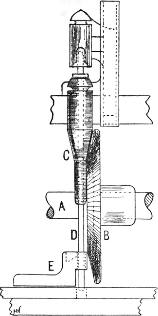
FIG. 11.
Guide-rails, I, are usually operated by means of a grooved cam, L, fixed on a side shaft, M, which carries a worm wheel, N, driven from a worm, O, on the end of a driving shaft, A. The cam acts upon a runner, P, fixed on a sliding rail, Q, in[Pg 18] which are formed vertical slots, R, one on each side of the machine. Each vertical slot acts upon a runner, S, secured to lever T, having shaft U for a fulcrum. At regular intervals on shaft U brackets are fixed to support guide-rail I, which rises and falls at a uniform pace in both directions.
In consequence of yarn rubbing against the stationary surface of a pirn cup, it is liable to become burnished, and sometimes injured. Many attempts have been made to overcome that objection by driving bobbins by surface contact with revolving discs, and also by supporting them against conical rollers. Fig. 11 shows one of several methods of driving bobbins by means of bevelled discs, B, fixed at regular intervals upon driving shafts, A, placed one on each side of the machine. In this machine, as in an ordinary pirn cup machine, a bobbin, C, rises automatically until filled, when its spindle, D, withdraws from a hole in the bolster, E, and slides down a short incline, thereby stopping a bobbin by carrying it from the disc.
The three methods of warping in use are mill warping, beam warping, and sectional warping. The oldest form is mill warping, but this has been largely superseded in almost all cases, except for coloured goods, by the beam warping machine.
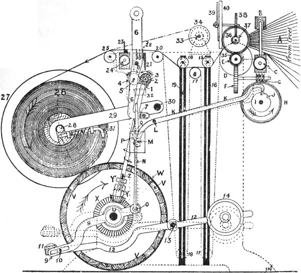
FIG. 12.
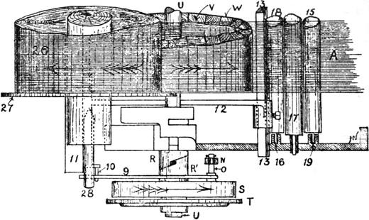
FIG. 13.
FIG. 14.
In beam warping bobbins are placed in a creel. This is a frame constructed to hold from 400 to 500 bobbins, and is the shape of the letter V, as this is the most convenient and easiest for unwinding. The 400 to 500 threads, A, are[Pg 19] taken through an expanding reed, B (Figs. 12, 13, and 14). The ends are then passed over a tin measuring roller, D, and under tension-rollers, 15 and 18, which keep the yarn taut, and also pull it back when it is required to turn backward to find a broken thread, or otherwise. Each thread is then passed separately underneath a small bent wire drop-pin, 22. Each thread bears the weight of one of these wires, and should the thread break when the machine is in motion, the wire falls between two rollers, 3 and 4, which latter is mounted so that a wire causes it to move forward and, by releasing a “trigger” motion at Q, as it is called, the machine is automatically stopped. This is the principle of Singleton’s stop-motion,[Pg 20] which is the one most commonly used. In front of the stop-motion wires the yarn is passed through an expanding comb, 23, which regulates the width of the slashers’ or “back” beam, 26. This beam is driven by friction; the beam rests on a drum, V, and as the drum revolves, the beam is driven in such a manner that yarn is wound at a uniform pace throughout, although the beam is gradually increasing in diameter. One of these machines will supply about 80 to 90 looms weaving medium counts of yarn. The creel is usually made to hold 504 bobbins, but any lesser number of ends may be put on a beam.
After leaving the warping machine the beams are taken to[Pg 21] the slashing frame, where a sufficient number of beams are put together to form the warp for the loom.
Mill warping.—This system of warping is still in use for warps used in the Bradford mixed goods trade, and for many classes of coloured cotton goods in Lancashire, although slashed warps are fast superseding the system for the former trade, and sectional warping is replacing the system for the coloured trade. Mill warping is also in general use in silk manufacture. Those spinners who supply warps to Yorkshire worsted manufacturers have usually supplied them in the ball, unsized. The warps are “mill” warped, and the manufacturer has them sized to his own orders by cotton warp sizers, who usually combine this business with dyeing and finishing in the Bradford district. Slashed warps are now being used in the Bradford trade to a considerable extent, the warps being in most cases slashed in Lancashire and sent on beams.
FIG. 15.
A warping mill consists of a large reel, Z (Figs. 15 and 16),[Pg 22] of from six to twenty yards circumference, which is made to revolve. This reel is fixed upright in suitable framework, and the warper’s bobbins, W, are placed in a creel, V, by the side of the reel. The ends are taken from the bobbins, and drawn separately through the eyes of a row of needles, T, which constitute what is termed a “heck.” This heck is so constructed that one-half of the eyes can be raised above the other half, to form a lease. The heck slides up and down the framework Y of the mill, and thus forms a traverse and distributes the warp as the reel revolves. At the commencement of a warp, the bunch of ends is taken from the “heck” and fastened to a peg, 6, at the bottom of the reel. As the reel revolves the heck slowly rises, and so causes the warp to be wound on the reel spirally, without overlapping. The heck is moved up and down a sufficient number of times to give the required number of ends in the warp, when the warp is cut off and unwound, and made up either in the form of a ball or a chain. The length of a warp is determined by the number of revolutions made by the mill from the commencement, until it is reversed at the other extremity.
FIG. 16.
Sectional warping is a system chiefly employed in the production of coloured striped warps, from yarn previously dyed and sized in the hank, and subsequently wound upon warpers’ bobbins by a drum-winding machine. It is also sometimes employed in the production of grey warps for ball sizing. As its name implies, the operation consists of preparing a warp in sections, termed “cheeses,” each of which is a complete unit, and virtually a transverse section, of the full warp. When the required number of sections for a warp have been made, they are compressed between flanges side by side upon a mandril of a running-off machine, and their yarn run from them simultaneously on to a weaver’s beam. Sometimes a sectional warper works in conjunction with an automatic stop-motion similar to that of a beam warping machine, in which case bobbins are contained in a V-shaped creel. They also sometimes work without a stop-motion. In that case bobbins are contained in a curved creel similar to that employed in conjunction with a warping mill, whereby the threads are better under the observation of the operative warper, and broken threads may be more readily detected. One of the most important considerations in sectional warping is the production of sections of uniform diameter and length of yarn; otherwise, warp-ends would be of varying degrees of tension; also, waste of material would result from irregular lengths of yarn on the sections.
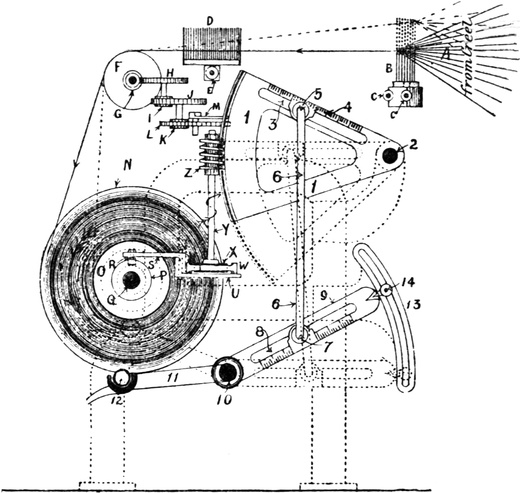
FIG. 17.
The principal parts of a well-known type of sectional warping machine are shown in Figs. 17, 18, and 19. Warp-ends, A, are withdrawn from a curved creel, and passed separately through needle eyes of a leasing heck, B, thence through a[Pg 24] V-reed, D, over a tin measuring roller, F, and on to a section block, O, which is compressed between two flanges, N, O, upon a shaft, Q, by which it is turned. Flange N is removable to permit of a full section being replaced by an empty one. Another flange, 24, is keyed upon the section shaft, Q, and driven by means of friction bowls, 20, 20’, placed one on each side, and turned by driving shafts 16, 16′, each of which contains a wide loose pulley, 17, 17′, a narrow fast pulley, 18, 18′, and a toothed wheel, 15, 15′, which are in gear. Thus, if driving strap 19 is placed in a central position (as indicated) it runs on both loose pulleys, without effect; but if placed upon the fast pulley 18, it will turn the section forward, and wind yarn on the front, as shown, and if placed on fast pulley 18′, it will turn a section backward, and wind yarn at the back.[Pg 25] This arrangement enables sections to be made with one-half of a full repeat of a warp pattern, either alone or in addition to several repeats (provided the pattern is a symmetrical one), so that when all sections are placed in their proper position for running their yarn on to a weaver’s beam, two halves of a pattern will join together without a break. A uniform rate of winding yarn is maintained by causing friction driving bowls, 20, 20′, to automatically recede from the section shaft at a pace exactly corresponding to that at which a section increases in diameter, thereby gradually retarding the velocity of the section shaft.
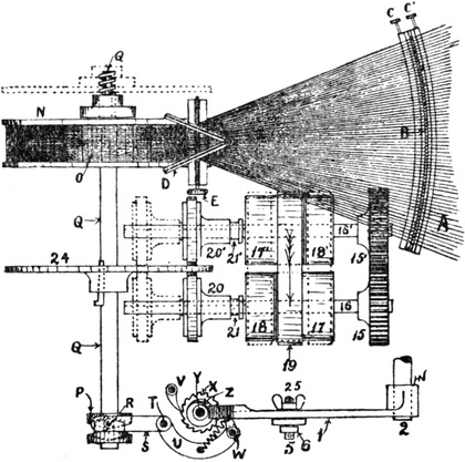
FIG. 18.
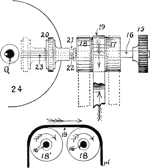
FIG. 19.
A presser roller, 12, carried at the end of a lever, 9, 11, fulcrumed on shaft 10, bears against yarn during winding, to wind it more compactly, and also to ensure uniformity of diameter of sections composing the same warp. During the winding of the first or “trial” section, the presser, which is suitably weighted, is free to recede at such pace as corresponds with[Pg 26] the increasing diameter of that section; but for subsequent sections, the presser is under mechanical control, and may only recede at a prescribed pace, which should, however, exactly coincide with its recession during the formation of the first section. The movement of the presser is governed by means of a toothed quadrant or sector, 1, communicating with presser lever, 9, by a connecting rod, 6. The position of rod 6, in relation to the fulcrum 2 of the sector and the fulcrum 10 of the presser lever, determines the velocity at which the presser recedes. A cam, P, on the end of section shaft Q, imparts an intermittent rotary motion to a short vertical shaft, Y, by means of lever S, U, and pawl W. Surmounting shaft Y is a[Pg 27] worm, Z, gearing with the teeth of sector 1 which slowly rises as a section revolves, thereby causing the presser to recede, at a prescribed pace. The number of revolutions of the section shaft is indicated upon a dial; also, the length of yarn wound is indicated upon a dial, by fingers operated by a train of wheels driven from worm G, on the end of tin measuring roller shaft F. The two indicators, therefore, serve as a check upon each other.
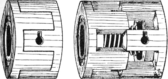
FIG. 20.
FIG. 21.
Section blocks are made in different widths from 3½ inches upwards. Some are constructed so as to permit of expansion and contraction, as shown in Fig. 20. Pressers are also constructed on a similar principle, as shown in Fig. 21.
The chief systems of sizing are slashing, dressing, ball-sizing, and hank-sizing.
The object of sizing is to strengthen the yarn by saturating it with a starchy substance, which lays the fibres, thus making it weave with less breakages. Other objects are to impart “feel” to the cloth, and to give it additional weight. For light sizing, in which the object is simply to strengthen the yarn, and not to increase its weight, only 10 to 15 per cent. is added to the weight. When 30 or 40 per cent. is added it is termed medium sizing, and for heavy sizing often 100 per cent. or more is added to the weight. The materials used for light sizing are: wheat flour, sago, farina or potato starch, rice flour or starch, maize.
Potato starch, or farina, is obtained from the tubers by reducing them to a pulp and mixing well with water. The water carries away the starch, and when allowed to stand the starch falls to the bottom of the vessel and the water can be drawn away. Farina is much used in all kinds of sizing, on account of its cheapness and the thickness of the paste it produces when boiled with water.
Sago is much used in light sizing, for which it is specially adapted. It is obtained from the pith of the sago palm, and made into flour by treating with water and drying on hot plates.
Maize is a starch obtained from the Indian corn, and is sometimes used for lightly sizing the finer counts of cotton yarns.
For light sizing it is not necessary to use anything but wheat flour, farina, or sago, and a small quantity of softening material, usually tallow or wax. Wheat flour is fermented before using by mixing it well with water (about equal weights of each) and leaving it for several weeks, occasionally stirring to keep the particles in suspension. When flour is fermented new bodies are formed, which have a powerful influence in preventing mildew. The fermenting cistern, 1 (Fig. 22), is usually a large vessel 8 feet by 4 feet by 4 feet, in which are two revolving “dashers,” C, to stir the flour and water when fermenting. Another similar cistern, 2, is used for storing called a “storage and diluting” cistern, into which the mixture is pumped after a few days, and left to further ferment. A force-pump, N, is used for pumping from this to the mixing cistern, 3, where the softening and weighting materials are added, after being boiled together in pan 4.
Softening materials are used to render the yarn more pliable. The articles mostly used for this purpose are tallow, wax, and soap, cocoanut and palm oil.
The following mixtures are suitable for light sizing. They can be made to give a greater or less percentage, according to the specific gravity of the mixture. For testing the specific gravity or density of the liquid, the Twaddell’s hydrometer is used. This instrument registers in degrees the density of the mixture, or the amount of matter in solution.
For light sizing—
Another mixture is—
For sizing with sago, cocoanut oil is often used as a softening material. A mixture of these two gives as good a size as anything for pure sizing.
Another mixture used for fine counts is—
Almost every manufacturer uses different proportions of ingredients. Many use wheat flour, farina, and sago mixed in various proportions, whilst a flour and farina mixture in the proportions of 2 : 1 is considered by some to give the best results. Farina and sago are also often mixed for light sizing in the proportion of two parts farina to one part sago. Wheat flour carries through better than farina or sago, and is therefore more generally used for the heavier kinds of sizing.
Any of these mixtures may be altered as regards strength, or otherwise, by increasing or diminishing their density. If a mixture twaddles 10 degrees at a given temperature, it may be strengthened for heavier cloths or higher picks by increasing the proportion of solid matter in the mixture until it twaddles 15 degrees at the same temperature.
For adding weight to the cloth china clay is the chief ingredient used. This material is found in deposits in Devonshire and Cornwall, and is used in large quantities for the purpose of weighting and filling cloth, more especially those manufactured for export to the Eastern markets.
For what is termed “medium” sizing, viz. adding about 30 to 50 per cent. to the weight of the cloth, the following materials are used in various proportions, the proportion given being an example—
It will be noticed here that chloride of magnesium and chloride of zinc are introduced along with the china clay. Chloride of magnesium is a very powerful softener as well as a weighting material, and one of its uses is to prevent the gritty feel which the addition of clay alone would give to the cloth. It has a great affinity for water, and has thus the power of attracting moisture to the cloth in which it is used. It is this which really constitutes its softening effect.
Chloride of zinc is used to prevent mildew, which is a species of vegetable growth which often occurs in sized cloth which has been left damp, or which attracts moisture.
As chloride of magnesium attracts moisture, it is necessary to use an antiseptic which will counteract the tendency of the cloth to mildew. Chloride of zinc possesses valuable properties as an antiseptic, and therefore it is often used where chloride of magnesium is used in the size as a softening and weighting material.
If china clay is used for medium sizing without using chloride of magnesium, it is necessary to greatly increase the proportion of tallow or other softeners in the mixture. Thus, for every 100 lbs. of flour, 40 lbs. clay, and perhaps 25 lbs. tallow would be used.
Chloride of calcium has a similar effect to chloride of magnesium, but is scarcely as powerful. It is used by many in light-sizing mixtures to prevent the yarn becoming too brittle.
For heavy sizing the proportions of clay and mineral ingredients are increased. In some classes of low shirtings, over 100 per cent. is added to the weight of the yarn. The adhesive material mostly used is wheat flour, as it carries the added materials better than farina or sago; but farina is sometimes used for sizing up to 100 per cent. Sometimes two parts clay to one of flour is used for very heavy sizing.[Pg 33] For 100 per cent. sizing about the following proportions may be used:—
Colouring matters are used in size to give the yarn any desired tinge. Blue is the most common, as it neutralizes the yellowness of the cloth given in heavy sizing. Only a very small quantity is required. Sometimes yellow is used to give a brownish appearance to American yarn, making it appear more like Egyptian. Numerous other materials are used for various purposes in sizing. “Gloy” has been found useful for strengthening warps for very heavily picked cloths.
Fig. 23 will show the principle of the slashing machine in its most usual form. The warpers’ beams are placed in the creel 1, at the back of the machine. In the diagram there are six beams, 1 to 6, so that if each one contains 500 ends there would be 3000 ends in the warp. The warp passes over roller A, and into the size-box. The small roller B in the size-box is of copper, and is called the immersion roller. The warp is passed under this, and its depth in the size mixture is regulated by it. The warp then passes between two pairs of rollers, C, D, and E, F (of which D and F are covered with flannel), to squeeze the surplus size from the yarn. The size is kept boiling in the size-box by the injection of steam. When the warp comes from the rollers E, F, it passes over a large drying cylinder, M, and, after passing almost completely round it, over a smaller cylinder, N, and then round the fan P and over guide-roller Q. The warp then passes through the dividing rods R (which divide the warp into the same portions that come from each warpers’ beam), thence over guide-roller S and tin measuring roller T, between drawing rollers U, V, and finally on to a weaver’s beam, Z. This end of the machine is called the “headstock,” and comprises the measuring mechanism, dividing rods, and winding-on arrangement.
The position of the immersion roller in the size has some effect upon the amount of size retained on the warp, as by sinking the roller lower in the box the yarn will remain longer in the size, and will therefore absorb more. This roller is also mounted so that it can be lifted out of the size altogether when the machine is stopped. The larger cylinder is usually 6 feet to 7 feet diameter, and the smaller one about 4 feet diameter, and both are heated with steam.
Some machines have a revolving brush between the size-box and the cylinder. This brush is usually driven from the fan shaft, and its object is to lay the projecting fibres, and so strengthen the yarn. Brushes are only used in some fine-weaving districts, and not always there. The brush gives the threads a round, smooth feel, and prevents them sticking together. Under the brush which brushes the yarn a smaller brush is placed, running at a slower speed than the one above it; the lower brush is placed a short distance into the upper one, and serves the purpose of cleaning it as it revolves.
The marking mechanism in the slashing frame usually consists of a tin roller wheel, B (Fig. 24), driving the wheel D, called the “stud wheel”; a screw or worm, E, on this stud drives the bell wheel F. The marking hammer L is situated immediately above a vessel containing colouring matter, and is lifted by a cam, P, driven from the tin roller, and dropped suddenly on the warp, marking it to the required lengths.
The length between each mark is regulated by the wheels used. The tin roller wheel being the driver, if this is divided into the product of the stud wheel and bell wheel, it will give the number of revolutions of the tin roller for each mark, and[Pg 36] this multiplied by the circumference of the roller will give the length of the mark. The formula will stand thus—
stud wheel × bell wheel × circumference of rollertin roller wheel = length of mark.
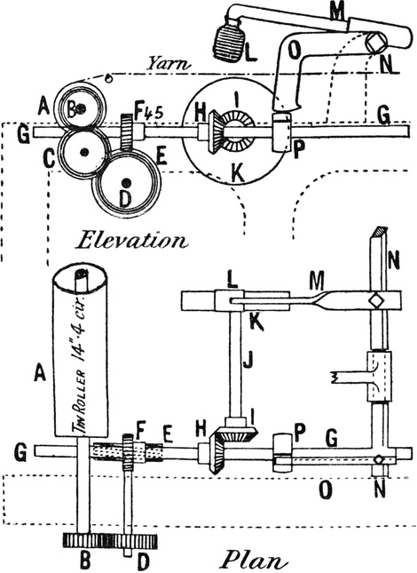
FIG. 24.
If the stud wheel contains 90 teeth, the bell wheel 45 teeth, the tin roller wheel 60, and the roller is 14·4 inches circumference, the length of the mark will be
90 × 45 × 14·460 = 972 inches
There are other marking motions in use for marking short lengths for dhooties and scarves of various kinds, some being constructed so as to mark scarves of two different lengths in succession—say one scarf is marked 2 yards long, and the next one 4, the two being repeated.
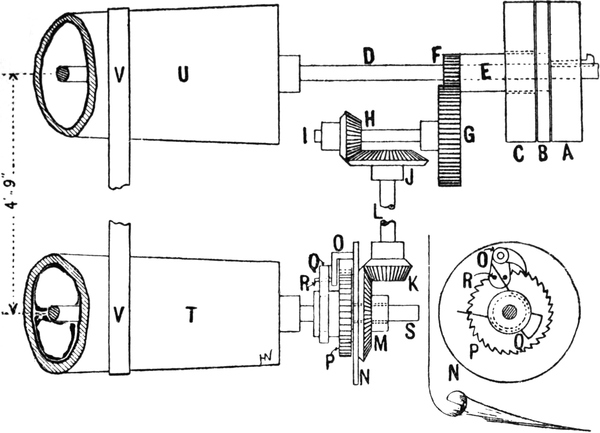
FIG. 25.
A “slow motion” arrangement is used for keeping the machine moving very slowly whilst the weaver’s beam is changed. If the machine is stopped completely, the warp becomes marked where it rests on the drying cylinders. Fig. 25 shows the principle of this arrangement. There are three pulleys, A, B, C, on the driving shaft D. Between the fast[Pg 38] and loose pulleys A, C, the slow motion pulley B is placed. When the belt is moved from the fast pulley to the slow motion, the wheel F is set in motion and drives another wheel, G, and this, through the bevel wheels H, J, K, M, causes the catch O to drive the ratchet wheel P on the driven cone shaft T. As the motion of the driving catch O is slower than the cone T when driven by the fast pulley, the catch O will begin to work when the strap is moved from the fast pulley to the slow motion pulley, and the speed of the machine is reduced to the point where the catch O overtakes the driven cone T.
Hot-air drying has been employed in place of cylinder drying, but is not much used. In this system of drying the warp passes from the size-box to hot-air chambers. The air is heated with steam pipes and driven through the chambers by fans. Combinations of cylinder and hot-air drying have also been used, but with little success.
In a slasher sizing machine, yarn is withdrawn from back beams and finally wound upon a weaver’s beam at a uniform pace, notwithstanding the gradually increasing diameter of the latter as it fills with yarn. It follows, therefore, that the velocity of a beam must gradually diminish from the commencement of winding. In order to meet such requirement a beam is driven negatively by means of a frictional driving motion, one of which is shown in sectional elevation in Fig. 26. This motion consists of a tooth wheel, A, whose sides are extended beyond its proper teeth to form inner flanges, which latter are turned at right angles to form an outer rim. Two outer flanges, B, interlock with the rims of wheel A, as shown at C, so that wheel A and flanges B always revolve at the same velocity. Enclosed within each chamber between the inner flanges of A and outer flanges B is a sheet steel disc, D, encased within two flannel washers, E, and secured to a hub which rotates on a hollow beam shaft, O, in which is cut a channel or key-bed, R. The hubs of steel discs D being furnished with a key that enters the channel R, are free to slide upon shaft O, which they rotate at the same velocity. The hub of wheel A revolves freely upon the hubs of discs D; also, the hubs of flanges B revolve freely upon shaft O; therefore, by compressing the flanges and discs together, any degree of friction, within certain limits, may be induced. Pressure is applied to the flanges by means of a vertical lever, F, fulcrumed at G, and elbow lever J fulcrumed at K. A stud, I, in lever J bears against lever F with a force that may be regulated by means of an adjustable weight, L, N. On the inner end of shaft O, which receives one of the beam gudgeons, is a disc, P, furnished with a stud or peg, Q, to which is attached a rope or strap that encircles and grips one end of the weaver’s beam, which is thereby turned. As a beam becomes filled and its velocity diminishes, the slippage between discs D and the driving flanges increases, because the velocity of the driving flanges remains undiminished.
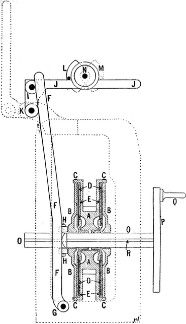
FIG. 26.
Automatic Supply of Size to a Sizing Machine.
There are numerous devices for the purpose of ensuring a continuous and automatic supply of size to the size-box of a slasher sizing machine. One of these is represented in Figs. 27 and 28. From the last mixing beck 3 (Fig. 22) size is pumped into a storage beck, 5, whence it is withdrawn and forced by a ram, N, along feed pipe Q, which is coiled within a steam-heated chamber, U. From the steam chamber it returns along pipe T, through regulating valve Z, and into the size-box, in a boiling state. Within a separate chamber of the size-box is a floating copper roller, X, connected at one end by means of rod Y to a tap which regulates the flow of size through valve Z, on the principle of a ball tap.
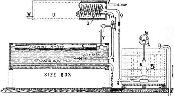
FIG. 27.
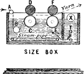
FIG. 28.
Scotch dressing is another system of applying size to the yarn. This is a much slower method than slashing, and is chiefly suitable for very fine yarns. In this machine the weaver’s beam is placed above an expanding reed, R (Fig. 29), and to prevent the ends being crowded the warper’s beams are divided, one-half the ends being placed at each end of the machine. The warp is passed through a pair of rollers, A E, the top one being very heavy. The lower roller of the pair is immersed some distance in the size, and takes the size up to the yarn. After emerging from the rollers or “squeezers,” the yarn passes through a revolving brush, B, and over a fan in a hot-air chamber, F, then through another brush, C, round a guide-roller through the expanding reed to the weaver’s beam. The opposite half of the machine is a duplicate of this. By this process the yarn is greatly strengthened. The brushing lays down all the projecting fibres, and makes the thread round, preventing any caking of the size on the threads. The production, of a machine of this kind, is much less than that of a slashing frame, as only about five beams a day can be dressed,[Pg 43] whilst about fifteen beams could be slashed in the same time. Instead of the circular brush B, sometimes flat brushes are used. These are made to work on both sides, as shown at Fig. 30. The dotted lines show the movement of the brushes. The warp is brushed in the opposite direction to that in which it is moving.
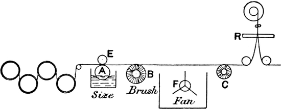
FIG. 29.
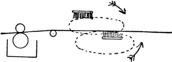
FIG. 30.
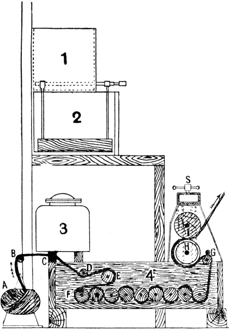
FIG. 31.
Ball-warp Sizing.
Fig. 31 is a sectional elevation of a sizing machine for ball-warps. One or more warps, A, are placed upon cones,[Pg 44] and their yarn guided over rollers, B, C, into a large size-box, 4, containing a series of rollers, between which yarn passes until it emerges at guide-roller G, when all excess of size is removed by rollers H, I. From the squeezing rollers, yarn is conducted to a drying machine (Fig. 32), consisting of a series of steam-heated cylinders arranged in two vertical zigzag rows, O, N, the outer rows of which are driven from vertical shafts containing a series of bevel wheels, Z, gearing with bevel wheels Y at one end of the cylinder shafts. By this means yarn is subjected to little tension, and its elasticity is better preserved. After drying, the warps are deposited in box crates, R, to be subsequently re-balled, ready for beaming or winding on to a weaver’s beam.
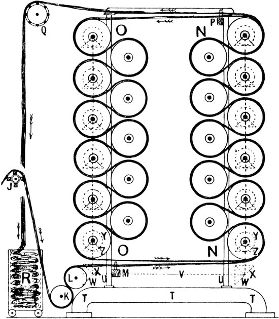
FIG. 32.
Beaming.
Beaming machines exist in great variety, but they may be classed under the heads of (1) press beaming, and (2) tension beaming machines. An example of the first-named type, as made by Butterworth and Dickinson, Ltd., is illustrated in Fig. 33. If beaming is accomplished from back beams prepared by a beam warping machine, a creel or stand capable of holding several beams is situated in the rear of the headstock of the beaming machine; but if beaming is from ball-warps, yarn from the latter is passed in a circuitous manner under and over tension and guide rollers A, B, for the purpose of tautening and separating warp-ends, which are finally passed through the dents of an expending comb, C, and on to a weaver’s beam. By causing weighted levers, D, to bear upon the beam-ends during winding, a hard and compact beam is made.
A tension beaming machine of the type known as a Yorkshire dressing machine, as made by Hattersley & Sons, is shown in Fig. 34. Yarn from a warp, A, or from several sections of warps, is conducted under and over the bars of a tension ladder, B, thence around dividing bars, C, between tension rollers, D, and finally through a wraith or coarse reed on to a weaver’s beam, E; but if Yorkshire dressing proper is adopted, warp-ends are passed through the dents of a reed in groups of two to four, and disposed according to pattern (if any) before passing on to a weaver’s beam ready for weaving in the loom. By means of stepped speed pulleys, F, G, the velocity of a beam may be retarded at intervals, to compensate for the gradually increasing diameter of a beam, and thereby maintain a uniform rate of winding.
THE three principal movements in weaving are shedding, picking, and beating up the weft. By shedding is meant opening the warp threads to allow the shuttle containing the weft to pass over certain ends and under others. In the common[Pg 49] hand loom the shed is made by the weaver operating treadles with his feet. Fig. 35 shows the method of connecting the shafts or staves with the treadles for weaving a plain cloth. There are two treadles, A and B, placed underneath the loom, and centred at C. The stave E is connected to the treadle A through the lever G. The stave F is connected to the same treadle through the “tumbler” T and the lever M. When the treadle A is pressed down it will take the stave E down, and the stave F up. For the second pick, the stave F is connected to the treadle B through the lever H, and the stave E is connected to the same treadle through the “tumbler” R and the lever N. Therefore, when the treadle B is pressed down, it will take the stave F down and stave E up. By alternately pressing first one treadle and then the other, we get each stave up for one pick and down for the next, alternately, as required for weaving plain cloth. The levers M and N are usually called “long lams,” the levers G, H “short lams,” and the top levers R, T “tumblers.” The cords PP connect the long lams and tumblers together at the side of the loom.
FIG. 35.
In mounting this loom for weaving a three-shaft twill, three treadles are required, one treadle for each pick in the pattern. Supposing one stave to be down and two up for each pick. The stave required to be taken down for the first pick must be connected to the first treadle through a short lam, and the two staves required to be taken up must be connected to the same treadle through their long lams and tumblers. Each pick in the pattern must be gone through in this manner. A separate treadle is required for every pick in the pattern, unless the same pick is repeated, in which case one treadle will do for more than one pick. It is not advisable to break the regularity in the order of treading in order to save a treadle; but in diaper patterns and similar weaves the[Pg 50] effect of a point draft is obtained by reversing the order of treading.
FIG. 36.
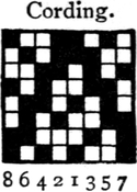
FIG. 37.
Figs. 36 and 37 show the design and cording plan respectively for a twill cloth requiring eight treadles.
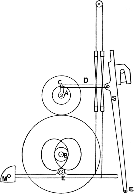
FIG. 38.
The hand loom is practically obsolete in the cotton trade, but it is still extensively used in silk manufacture, where power looms, as at present constructed, are not found advantageous for weaving the finer classes of goods.
The chief shedding motions in power looms are tappets, dobbies, and jacquards.
There are various kinds of tappets, the simplest and best for plain or twill weaving being those shown at Figs. 38 and 39. The former is the more general arrangement. In this the tappets are placed under the loom, inside the framework. In the arrangement shown at Fig. 39 the tappets are placed outside the loom, and thus a larger amount of floor space is taken up by the latter than the former.
Outside tappets are mostly used in the Yorkshire weaving districts, and are commonly made for weaving with about eight shafts. The top levers, with “half moons,” are centred at the cross rods EE (Fig. 39), and the heald is lifted from both sides of the loom. The top levers are very useful for equalizing the shed, as the connection with the upright rod can be altered without difficulty.
FIG. 39.
In a power loom there are two horizontal shafts, the top shaft A (Fig. 38) and the bottom shaft B. The former is used for working the slay, by means of the crank C, and the connecting rod or “crank arm” D (Fig. 38). The bottom shaft is used for “picking,” and for this purpose it is necessary that the shaft should revolve at one-half the speed of the top or crank shaft. The toothed wheel on the bottom shaft must therefore contain twice the number of teeth in the wheel on the crank[Pg 52] shaft which drives it. As a plain cloth contains two picks to the round, and the bottom shaft makes one revolution for two picks, the tappets are fixed to the bottom shaft. Each tappet acts upon treadle bowl E, and therefore the size of the bowl will require to be taken into consideration in shaping the tappets. For weaving plain cloth four staves are usually taken, in order to prevent overcrowding the healds on each stave, the ends being drawn through the staves in the order 1, 3, 2, 4. As the staves are fastened together in pairs, this is the same as two staves.
The kind of movement to be given to the staves is very important, especially in quick-running looms. The staves should be moving quickest when they are level, and their speed should gradually decrease as the shed opens. It is obvious that a movement of this kind will put as little strain as possible on the warp, and therefore cause the fewest breakages. The depth of the shed should only be sufficient to allow the shuttle to pass, therefore the “lift” or stroke of the heald is dependent upon the depth of the shuttle used. The shed when opened should remain open only long enough to allow the shuttle to pass through.
Example.—What lift should a tappet have to make a plain cloth, the other arrangements in the loom being as follows: Sweep of slay 5½ inches, distance of healds from cloth 8 inches, heald connected to treadle 24 inches from fulcrum, distance from fulcrum to centre of treadle bowl 16 inches, size of shuttle 1½ inch broad, 1¼ inch deep?
Assuming that the tappets are under the loom, as in Fig. 38,
the treadle bowl E is 16 inches from M, and the heald connected
24 inches from M. If slay moves back from cloth 5½″, and the
shuttle is 1½″ broad and 1¼″ deep, it follows that the shed
must be 1¼″ deep, or a little over, at a point 4″ from the cloth
(5½-1½ = 4). Then if the heald is 8″ from cloth, the stroke
of heald may be obtained—4 : 8  1¼ : 2½″ stroke of heald, and
as 24″ treadle : 16 2½ : 1⅔ lift of tappet required.
1¼ : 2½″ stroke of heald, and
as 24″ treadle : 16 2½ : 1⅔ lift of tappet required.
To obtain the proper shape of the tappets for a plain cloth, the lift or stroke of the tappets to give the required lift to the healds must be obtained. If the lift of the heald is required[Pg 53] to be 4 inches, and the centre of the treadle bowl E (Fig. 38) is situated 12 inches from the fulcrum of the treadle M, the heald being connected to the treadle at, say, 18 inches from the fulcrum, the lift or stroke of the tappet will be obtained as follows:—
4
In some makes of looms the staves are connected to the treadles at a point between the fulcrum and the treadle bowl, the fulcrum being at the front of the loom. This necessitates a larger lift of tappet than lift of heald. The tappets in this case are very large, and are preferred by some manufacturers.
FIG. 40.
To construct a tappet for a plain cloth from the following dimensions.—Lift of tappet, 4 inches. Distance from centre of shaft to nearest point of contact with treadle bowl, 2 inches; dwell one-third of a pick. Diameter of treadle bowl, 2 inches.
At a radius of 2 inches describe the circle A (Fig. 40).[Pg 54] This circle represents the distance from the centre of the shaft to the nearest point of contact with the treadle bowl.
At a radius of 3 inches describe the circle B. One inch added for radius of treadle bowl.
At a radius of 7 inches describe the circle C. Four inches added for lift.
The circle B represents the centre of the treadle bowl when the inner circle of the tappet is acting upon the bowl.
The circle C represents the centre of the bowl when pressed down by the tappet.
The pattern being a plain one, the circle must be divided into two equal parts, and each half-circle will then represent one pick. By the line DE divide the circle into two equal parts. Then, as the healds must have a pause or dwell equal to one-third pick when at the top and bottom of their stroke, divide each half-circle into three equal parts by the lines FK, GH. Divide FH and GK each into six equal parts, and divide the space between the circles B and C into the same number of unequal parts, the largest being in the middle, gradually decreasing towards the circles B and C.
From the corners of these unequal spaces, and with the radius of the treadle bowl in the compasses, describe circles representing the position of the treadle bowl at different parts of its movement.
Draw the curved line touching the extremities of the treadle bowl. This gives the outline of the tappet.
As previously stated, the movement of the heald must be quickest when the shed is nearly closed, and must gradually decrease in speed as the shed opens. The unequal spaces into which the lift of the tappet was divided give this eccentric movement to the heald. The curve of the tappet will approach nearer to a radial line as the shed closes, and the heald approaches the centre of its stroke. Referring to Fig. 40, it will[Pg 55] be seen that the treadle bowl is at rest from F to G and from H to K, or one-third of a pick at both the top and bottom of the stroke. Therefore the time allowed for change, or for moving the heald from top to bottom, or vice versâ, is equal to two-thirds of a pick. If a dwell equal to half a pick is required, it can be obtained by dividing the pick into four equal parts and taking the middle two parts for dwell. If two-thirds dwell is required, divide the pick into six parts and take four parts for dwell.
It is usual to give the tappet which operates the back heald a slightly larger lift than the tappet which operates the front heald. The difference required can be easily calculated. In looms with the fulcrum of the treadles at the front, and the healds connected to the treadles between the fulcrum and the treadle bowls, some of the required extra lift is obtained by connecting the back heald to the treadle at a point further from the fulcrum than the front heald is connected. In looms with the fulcrum of the treadles at the back of the loom, and the tappets acting between the heald and the fulcrum, there will be a greater difference between the size of tappets in proportion to the lift than in the former case.
Tappets for twills, and other simple weaves, having more than two picks to the round, are usually placed upon a counter-shaft, but outside tappets are usually worked loose upon the bottom shaft.
The following example will illustrate the principle of constructing twill tappets:—
Draw a tappet for a 3 up and 1 down twill. Distance from centre of shaft to nearest point of contact with treadle bowl 3 inches, lift 3 inches, bowl 2 inches diameter, dwell ½ pick.
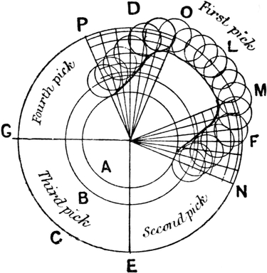
FIG. 41.
At a radius of 3 inches describe the circle A (Fig. 41). At a radius of 4 inches describe the circle B (one inch added for treadle bowl). At a radius of 7 inches describe the circle C[Pg 56] (3 inches added for lift). There being four picks in the pattern, divide the circles into four equal parts by the lines DE, FG. Then each quarter-circle represents one pick, and the tappets must be made to make one revolution for four revolutions of the crank shaft. As the dwell of the heald (when the shed is open) must be equal to half a pick, or half a revolution of the crank shaft, divide the first pick into four equal parts by the points O, L, M; make DP equal to DO, and FN equal to FM, and rule lines from P, O, M, N to the centre. The distance OM represents the half-pick dwell, and the distances OP and MN represent the half-pick which will be allowed for changing the heald from bottom to top of its stroke, and vice versâ. Divide OP and MN into six equal parts, and the lift of tappet, or the distance between the circles B and C, into six unequal parts, the largest in the middle and gradually decreasing towards the two circles. From the corners of the unequal spaces describe the small circles representing the[Pg 57] treadle bowl at different parts of its stroke, and draw the outline of the tappet touching the extremities of these circles.
A tappet of this shape acting upon a treadle bowl two inches in diameter will take the heald down for one pick and allow it to go up for three picks. The heald will be held stationary for exactly half a pick when at the bottom of its stroke, and will begin to rise slowly, and gradually increase in speed as it approaches the centre of its stroke, and will gradually decrease in speed as it approaches the top of its stroke. The downward movement will be an exact counterpart of this. In this kind of tappet it will be noticed that the heald, when it gets to the top (if it is required up for more than one pick), remains stationary until it is required to come down. Thus the heald remains at the top while the circles revolve from N to P.
For this twill there will be four treadles, each treadle being operated by a tappet of the same shape; but the tappet operating each succeeding treadle will be placed one quarter of a revolution later than the previous one.
The size of the treadle bowl has a very appreciable effect upon the shape of the tappet, more especially when there are several picks to the round. The movement imparted to the centre of the treadle bowl will be the exact movement given to the heald as far as regards dwell and eccentricity, and as the tappet acts on the treadle bowl at a distance of 1 or 2 inches from the centre, the required amount of dwell and eccentricity must be given to the centre of the bowl, and the shape of the tappet obtained accordingly. It will be noticed at Fig. 41, that to give a dwell of half a pick to the centre of the treadle bowl, a slightly longer dwell is on the tappet at the inner circle; and as the size of the treadle bowl increases, this hollowing out of the tappet must be increased in order to keep the dwell of the heald the same.
Fig. 42 is a drawing of a tappet for a 3 down, 1 up, 1 down, 1 up (six to the round) twill. Centre of tappet shaft to nearest point of contact with bowl 4 inches, lift of tappet 2 inches, bowl 1½ inch diameter, dwell one-third of a pick.
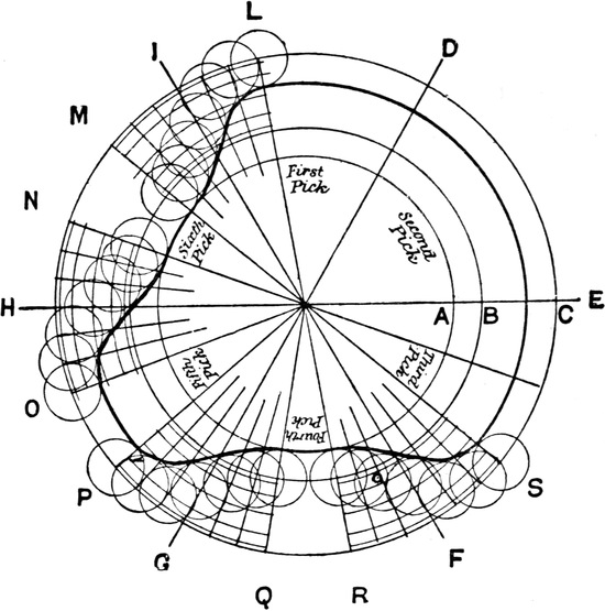
FIG. 42.
To construct this tappet:—At a radius of 4 inches describe the circle A. At a radius of 4¾ inches describe the circle B. At a radius of 6¾ inches describe the circle C. As there are six picks to the round, divide the circles into six equal parts by the lines D, E, F, G, H, I. As there is one-third pick dwell, divide each pick into three equal parts, and take the middle one for dwell. Rule the lines L, M, N, O, P, Q, R, S to the centre, and divide the spaces allowed for change into six equal parts, and the distance between the circles B and C into six unequal[Pg 59] parts, as in the previous examples. From the corners of the unequal spaces describe the circles representing the movement of the treadle bowl, and obtain the shape of the tappet accordingly. It will be noticed that at point L the treadle bowl begins to dwell, and remains stationary until it reaches the point S, when it begins to go up. The heald will thus be down for the first, second, and third picks, up for the fourth, down for the fifth, and up for the sixth.
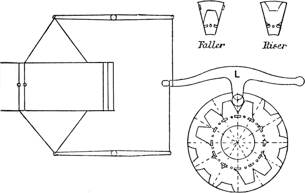
FIG. 43.—Woodcroft’s Tappet.
FIG. 44.
Woodcroft Section Tappet.—Sect. 1, riser (heald-up); sect. 2, faller (heald-down); sect. 3, left-hand riser; sect. 4, neutral riser; sect. 5, right-hand riser; sect. 6, left-hand faller; sect. 7, neutral faller; sect. 8, right-hand faller.
Woodcroft’s Section Tappets are much used in weaving heavy goods, such as velveteens and corduroys. They are made with various numbers of sections to the round. A single tappet plate of one twelve picks to the round is given at Fig. 43. Sections are sometimes made in two kinds only. These are termed “risers” and “fallers,” according as they[Pg 60] raise or depress a heald respectively. Each heald requires one plate and lever L, and as the tappets revolve, the lever L is moved up and down. When the lever L is lifted, the heald is moved downwards. A difference in the character of the shed produced by these tappets as compared with ordinary tappets will be noticed. When the lever L is lifted for two or more picks in succession, it comes down about half-way each pick. This is unavoidable in section tappets consisting only of “riser” and “faller” sections, which must join together[Pg 61] exactly wherever inserted, thereby causing all the healds to come towards the centre of the shed after every pick. If there are twelve sections to the round, any pattern repeating on three, four, six, or twelve picks may be woven.
It is sometimes considered an objectionable feature of section tappets (as represented in Fig. 43) that they cause all healds to be brought level after every pick, thereby producing jerky shedding. This objection, however, has been overcome by the construction of eight distinct varieties of sections, as shown in Fig. 44, whereby healds may remain either up or down for several picks in succession on the “open-shed” principle, as with ordinary box-plate tappets cast in one piece.
Another form of shedding device, which embodies certain features of ordinary rotary tappets and dobbies, is that known as the oscillating or rocking tappet, an example of which is shown in Fig. 45. This type of shedding motion consists of a series of plates, B, cast with upper and lower projecting ridges, C, D, and fulcrumed on shaft A, upon which they oscillate in a manner indicated by arrows, E. A movement in either direction represents one pick. On each side of the rocking shaft A, and oscillating with the tappets, is a pattern chain, F and F′, composed of bowls and bushes threaded upon spindles, G. Pattern chains, which represent odd and even picks respectively, are rotated alternately and intermittently, one spindle for each pick, thereby causing elbow-levers H to be raised or depressed, according to whether a bowl or a bush is presented underneath them respectively. The vertical arms of H act upon loose plates, I (termed “duck-bills”), which are fulcrumed upon short studs, J. Grooves may thus be formed[Pg 62] between either the upper or lower ridges of tappet plates, and the upper or lower edges of “duck-bills,” which grooves, by acting upon treadles K, governing healds, will operate the latter in a manner determined by the pattern chains.
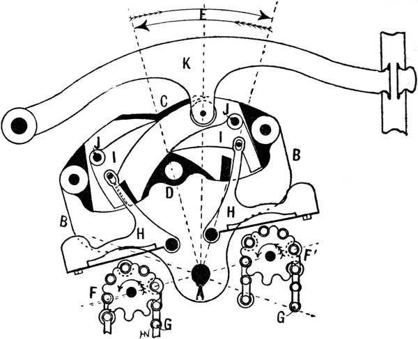
FIG. 45.
Oscillating tappets are situated at one end of a loom, above the crank shaft, from which they are driven by wheel gearing and suitable connecting arms. They are chiefly employed on looms weaving fustians and similar heavy and strong fabrics.
In plain looms with under tappets, the healds are generally connected round a top roller or cone, so that when the tappet is pressing one stave down, it is also taking the other stave up. The shedding is thus positive. For weaving twills, satins, and such weaves, either spring, roller, or pulley top motions are used.[Pg 63] Where spring tops are used, the tappet pulls the heald down, and the spring pulls it up again. Of course, the speed at which the heald moves upward will be controlled by the shape of the tappet exactly as it is in its downward stroke, but in the up stroke of the heald, the tappet is only acting negatively. With roller tops the movement is positive, as the rollers are so constructed that as one stave is taken down by the tappets another is taken up. If two staves are taken down, two will be taken up, and the tappets must be constructed so as to allow this. It is very important also that the tappets should be of the proper shape, and the exact counterpart of each other, so that any one stave is allowed to go up at exactly the same speed, and with the same amount of eccentricity in its movement, as any other stave which is being taken down by the tappets. Fig. 46 shows the top roller arrangement for plain cloth. Straps are connected to the staves over the rollers K, K1; so that when one stave is taken down by the tappet, the other is taken up.
FIG. 46.
For three staves the arrangement of rollers as shown at Fig. 47 is used. The diameter of B must be twice that of A. Sometimes a pulley is used at C, but when it is a roller, it is fitted into slots at the ends so as to allow of its being lifted. The diameter of C is immaterial, but the reason for B and A being as 2: 1 is that when the first heald is taken down, either the second or third must be taken up the same distance. Suppose the first stave is pulled down a distance of 4 inches, the strap E, being fastened to the roller A, which is half the size of B, will be taken up only two inches; and as the tappets are constructed so as to allow only one heald to go up each pick, if this heald is the second one, the third being immovable, the second will be taken up 4 inches, or the same distance that the first was taken down. If the strap E were fastened to B, the stave would be taken up eight inches instead of four. This arrangement of rollers is suitable for a 2 and 1 twill; either 2 down and 1 up, or 1 down and 2 up.
FIG. 47.
FIG. 48.
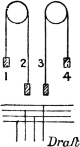
FIG. 49.
FIG. 50.
For four staves the arrangement shown at Fig. 48 is used. The relative size of the rollers in this case is immaterial. If the first stave is pulled down by the tappet 4 inches, and the second is the one allowed to go up, it will be taken up the same distance. If the first is being pulled down 4 inches, and the third is the one allowed to go up, the fourth being immovable, the strap A is pulled down 2 inches, and B lifted two inches, and the third[Pg 65] stave will be lifted 4 inches. If any one of the four healds is pulled down, another will be lifted the same distance. This motion can be used for either a 3 and 1 twill or a 2 and 2 twill, or any four-stave pattern with the same number of staves going up as are going down each pick. The arrangement shown at Fig. 49, in which the top roller is dispensed with, is sometimes used for a 2 and 2 twill. It will not work a 3 and 1 pattern. The principle of this will be understood by carefully following the movement of staves in weaving a 2 and 2 twill. The draft used with Fig. 49 must be 1, 3, 2, 4, or the first end must be drawn through the first stave, the second end through the third stave, the third end through the second stave, and the fourth through the fourth stave. If the pattern is the one shown at Fig. 50, in which the first and second ends are down for the first pick, it is obvious that to effect this the first and third staves will be down for that pick, and the second and fourth staves will be up. For the second[Pg 66] pick the second and third ends are down, and as these are drawn through the third and second staves respectively, these staves must be down for the second pick. As the third is already down, it is only necessary to take the second down, which will pull the first up as required. The changes in this pattern will be easily understood from the following:—
FIG. 51.
Fig. 51 shows a top-roller device for five healds, with bottom heald staves connected to treadles that are operated by tappets, J, fixed upon a shaft underneath, but a little in front of the healds, and driven by a train of wheels from a pinion, B, on the end of the crank shaft A. This top-roller motion is designed for a five-end weave in which either one heald only or else four healds, must be raised or depressed for every pick, uniformly. Therefore, four of the five healds must be suspended from one pair of rollers C, and one heald from another pair of rollers D, with both pairs of rollers firmly secured to the same shaft. Also, in order to obtain the proper leverage that will ensure the four healds that are suspended from rollers C, exactly counterbalancing the one heald suspended from rollers D, the diameters of the pairs of rollers C and D must be in the ratio of one to four, respectively.
All shedding motions of this type are based on the principle of equilibrium, whether they are designed as top-roller motions, to operate above the healds, or as stocks and bowls to operate below the healds. Therefore, in all top-roller motions, the diameters of the rollers on the same shaft must always be in inverse ratio to the number of healds suspended from them. Likewise with stocks and bowls, the leverage of the stocks[Pg 67] must be in inverse ratio to the number of healds to which the respective ends of the stocks or levers are connected.
FIG. 52.
An arrangement for seven staves is given at Fig. 52. The two pulleys A and B, on the same centre, are in the ratio of 3: 4, and the pulley D must be twice the diameter of C, the relative size of the remaining pulleys being immaterial. If the first stave is pulled down, say, 6 inches, and the seventh stave is the one allowed to go up; then the strap E will be pulled down 2 inches, and the strap F taken up 1½ inches, the strap G 3 inches, and the stave 6 inches, which is the same distance that the other stave was pulled down. It will be the same with any other healds in the set. If one stave is taken down, any other one left loose by the tappet will be taken up the same distance. Instead of the pulleys A and B, a lever may be used with its two arms in the ratio of 3 to 4, the four staves being connected to the shorter arm, and the three staves to the longer arm.
In some looms the positions of tappets and roller heald-motions are inverted: tappets being fixed above, and roller motions below, healds. In such cases the roller motions are known as “stocks and bowls,” which terms, however, more correctly describe those devices consisting of a combination of levers and bowls, or rollers, and not those consisting of rollers upon shafts. In either case, they are based upon the same principle of leverage, and act in an exactly similar manner to each other. These devices are very limited in their scope, as regards variety of weaves for which they are suitable, and may only be employed for weaves of a regular character, in which[Pg 68] the number of healds up and down is the same for every pick. Of course, any number of healds in a set may be up or down as required, but when once that number is selected, and healds are tied up accordingly, it may not be changed without re-tieing up.
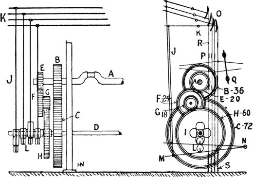
FIG. 53.
Fig. 53 shows a front and end elevation of what is known as the Yorkshire shedding motion, in which tappets are cast upon a sleeve slid upon one end of the second motion or picking shaft D, to operate treadles, M, fulcrumed at N. Connecting rods, J, connect treadles, M, with quadrant jacks, O, secured to cross-bars, K. These serve as fulcra for the jacks, which are connected to upper heald staves, P, by means of straps and cords, R, whilst bottom heald staves are attached by cords to springs, S, for the purpose of pulling healds down, after being raised by the tappets.
As soon as a warp-shed is sufficiently opened by the healds, the shuttle, containing weft, is propelled through it. That operation is termed “picking,” and may be accomplished by[Pg 69] either of two types of picking motions known as “over” and “under” picking motions. The “over-pick,” also known as the “cone” and Blackburn pick (Fig. 54), is in most general use, especially for narrow and quick-running looms weaving light and medium-weight fabrics; whilst the “under-pick” (Figs. 56 and 57), of which there are many modifications, is chiefly confined to medium and broad looms, which require a picking motion capable of developing greater force. A shuttle is propelled by a picker made of hide, which is connected by means of a leather strap to the picking stick A (Fig. 54). The upright shaft B is the fulcrum of the lever. The cone C is the short arm of the lever which receives the force from the picking tappet D. The tappet is so shaped that as it revolves it gives a sudden quick movement to the cone-shaped stud, and therefore to the shuttle. It is obvious that as the shuttle must move from one side of the loom to the other, and back again, for two revolutions of the crank shaft, the picking tappets must be placed on a shaft whose speed is one-half that of the crank shaft; therefore the bottom shaft in the loom on this account is made to move at the required speed, and the picking tappets are placed on this shaft at opposite sides of the loom.
FIG. 54.
The chief requirement in a good pick is that as little force as possible shall be wasted in the loom. The relative positions[Pg 70] of the tappet shaft and cone should be such that the force is exerted as nearly as possible in the direction of the dotted line E at right angles with the upright shaft B. It is impossible to effect this throughout the whole course of the stroke, but it is obvious that if this is approached as nearly as possible, the pick will be smooth, and the wear and tear reduced to a minimum. A very considerable amount of power is wasted if the direction of the force is too much downward.
The direction of the force is at right angles to a line drawn tangent from the cone at the point of connection with the picking tappet. Thus in Fig. 54 the direction of the force is indicated by the dotted line M, which is at right angles to the dotted line N, drawn tangent to the cone at the point of connection with the tappet.
FIG. 55.
The intensity of the force depends on the length of the stroke of the tappet and on the suddenness of the curve of the working face. If in two looms the length of tappet is the same, but in one the portion of a revolution occupied in making the stroke is less than in the other, there will be a greater intensity of force in the loom with the quicker stroke. In Fig. 55 the portion of a revolution occupied in making the stroke is indicated by the angle AB. If this angle is increased, the force of the pick will be lessened, and if the angle be decreased, the force of the pick will be augmented. It will be understood from this that if the picking tappets are short the pick is liable to be harsh. If a fair length of tappet is given, a smoother and better-timed pick can be made. The curve on the picking tappet gradually approaches a radial line as it nears the end of the stroke, but the combined influence of the change in the position of the cone and the backward[Pg 71] movement of the slay causes the shuttle to move quickest in the early part of its movement in the box.
There is a relation between the length of the shuttle-box and the length of the picking tappet. If the tappet is a short one, the shuttle-box must be short; and if a longer tappet is used—the leverage of the picking arm and other parts being the same—the shuttle-box will be longer.
It is obviously inadvisable to have too short a tappet, as the movement of the shuttle in the box must in that case be extremely sudden, in order to have the necessary force.
FIG. 56.
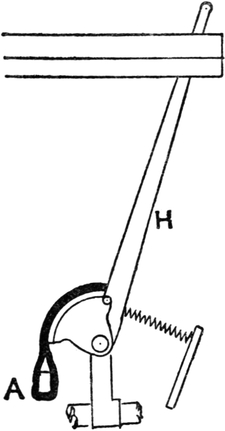
FIG. 57.
An underpick motion is given at Fig. 56. A picking treadle, A, centred at C, is pressed suddenly down by the picking bowl B, which is fastened on to the wheel on the bottom shaft in the loom. A strap, E, connects the treadle and the picking lever. In Fig. 57 this connection is shown. The strap from the treadle is fastened to the quadrant, and as the treadle is pressed suddenly down, the picking lever H is moved forward. The shape of the curve E, which the picking[Pg 72] bowl strikes, regulates the character of the movement given to the lever H, and it is well not to have the curve too small and sudden, or the pick will not be satisfactory. The curve on the treadle in Fig. 88 (p. 120) is perhaps better than the one in Fig. 56, as it is longer, and is therefore not liable to be so jerky.
There are numerous other picking motions, which chiefly differ in the mechanism for actuating the picking lever.
Beating up the Weft is the third primary movement in weaving. This movement is performed by a crank on the top shaft in the loom and a connecting rod or crank-arm which connects the crank and the slay together. This is shown at Fig. 38, where the crank C and crank-arm D give a reciprocating movement to the slay S. The slay moves upon a rocking shaft, E, as a fulcrum, and when the crank is at the front centre the slay-swords should be perpendicular, or nearly so. Sometimes the fulcrum is taken a little forward, but it is never advisable to have the slay over the perpendicular when in contact with the cloth.
The movement of the slay should be eccentric. It is obvious that when the slay is at the back of its stroke its movement should be sufficiently slow to allow time for the shuttle to pass through the shed; and that when beating up, the speed of the slay should be sufficient to knock the weft firmly into the cloth. A crank and crank-arm give the kind of movement required.
The eccentricity of the slay’s movement depends upon the length of the crank and crank-arm, and upon the position of the crank-shaft in relation to the point of connection of the crank-arm with the slay. The position of the crank-shaft in relation to the connecting pin varies in different makes and widths of looms. We shall see that the position of the shaft and the direction in which the loom runs have an important bearing on the force exerted by the slay in beating up the weft. For ordinary looms the usual position of the shaft is a little[Pg 73] below the level of the connecting pin when at the front centre, and when the shaft is in this position the movement of the slay is the most even and least eccentric. To obtain this position of the crank-shaft in a diagram, first draw the line SA (Fig. 58) to represent the slay-sword when the reed is in contact with the cloth; this we will assume is perpendicular. We will suppose SA to be 24 inches, S being the rocking shaft and A the connecting pin which connects the crank-arm with the slay. Suppose the loom we are dealing with to have a 3-inch crank and a 12-inch crank-arm. Describe the arc AN from the centre S, and mark off on the arc a distance from A equal to twice the length of the crank. As the crank is 3 inches long, mark off the point B, 6 inches from A. This point B represents the position of the connecting pin when the slay is at the back of its stroke.
FIG. 58.
From A, rule the line AX in such a position that the arc AB makes the least possible departure from it. It will be found that this necessitates AX cutting the arc AB at a point a little past the middle of the arc. With the length of the crank and crank-arm, viz. 15 inches, in the compasses, from A as the centre cut the line AX at E, and this gives the position for the crank-shaft which will give the least possible eccentricity to the slay. This will be obvious, as the nearer the connecting pin moves on the straight line AX, the less will be the eccentricity of the slay.
That the movement of the slay in the back half of its stroke is slower than in the front half can easily be proved by taking the length of the crank-arm in the compasses, and, after bisecting the arc AB at C, from C marking off the points D and H on the crank circle. It will be seen that both these points are somewhat inside the top and bottom centres of the crank indicated by the dotted line, and therefore the slay moves from C to A and back, the front half of its stroke, in less time than it moves from C to B and back to C. The reason for this eccentricity or unevenness in the movement of the slay is that when the crank is moving from the back centre to the top centre the crank-arm is oscillating and opening an angle with AX while the slay is moving forward, and therefore while the crank is making this quarter of a revolution, the connecting pin of the slay will move something less than from B to C; and while the crank is moving from the top centre to the front centre, the crank-arm is straightening or closing the angle while the slay is moving forward, and thus the connecting pin will move a greater distance than from C to A while the crank is making this quarter of a revolution. When the crank moves from front to bottom centre the angle is opening while the slay is moving backwards, and therefore the pin will move a little more than from A to C; and when the crank moves from bottom to back centre the angle is closing while the slay moves backwards, thus retarding the velocity of the slay.
FIG. 59.
This will be better understood from Fig. 59, where CD is[Pg 75] the crank-arm, and ED the crank at the top centre. A is the position of the connecting pin when at the front of its stroke, and B its position when at the back of its stroke. The dimensions are as in Fig. 58—viz. 12-inch arm, 3-inch crank—and for simplicity we will assume the connecting pin moves on the straight line AE. From A to B is 6 inches, and therefore it is obvious that AC is something over 3 inches, and that the connecting pin moves this distance whilst the crank is making the quarter of a revolution from top to front centre. The distance AC can be obtained as follows. It is obvious that CDE is a right-handed triangle, and therefore CD2 is equal to CE2 + ED2. Therefore CD2-ED2 = CE2, and having obtained the length of CE, we can subtract this from AE, which leaves the length of AC. The formula will stand thus—
The answer may be obtained in one calculation as follows:—
We thus see that the connecting pin moves 3 inches + 0·3811[Pg 76] inch while the crank is moving from the top to front centre. It will also move the same distance while the crank moves from front to bottom centre.
When the crank is moving from the bottom to the back centre, the connecting pin will move 3 inches − 0·3811.
and the same distance when the crank moves from back to top centre.
It is often necessary in comparing looms to obtain the distance travelled by the connecting pin for a smaller movement of the crank than a quarter of a revolution.
Suppose it is desired to find the distance travelled by the connecting pin while the crank moves through 30 degrees to the front centre.
Take a 4-inch crank and 12-inch crank-arm. In Fig. 60, ED is the crank, 4 inches, and DC the crank-arm, 12 inches, the angle O = 30 degrees. P is the position of the connecting pin when at front of its stroke.
FIG. 60.
To find the distance CP. From a table of natural sines we can obtain the sine of an angle of 30 degrees, viz, sin 30° = 0·5, and therefore, knowing the length of ED, viz. 4 inches, we can obtain the length of DN, it being 0·5, or half of ED, in an angle of 30 degrees.
Having two sides of a triangle, we can obtain the third side thus:
Having obtained the length of CN and EN, we can easily obtain CP by subtracting CF from the length of crank and crank-arm together. Working out the problem in figures we get—
Therefore CE = 15·2962 inches, and subtracting this from PE, which is 16 inches (12 + 4 = 16), we get 16 − 15·2962 = 0·7038 as the distance CP, which is the distance moved by the connecting pin for the 30 degrees movement of the crank.
The complete formula is as follows:—
PE − [√(ED2 − DN2) + √(DC2 − DN2)] = CP, or distance moved by the connecting pin for the given number of degrees through which the crank moves, ND being obtained from a table of sines.
To find the distance moved by the connecting pin while the crank moves through 5 degrees—say, from 30 degrees to 25 degrees in beating up.
To solve this it will only be necessary to subtract the[Pg 78] length of CE when the crank is forming an angle of 30 degrees from the length of CE when the crank forms an angle of 25 degrees. In the previous example we found that for 30 degrees, CE = 15·2962 inches, and therefore proceeding in the same manner for 25 degrees, we get from table of sines, sin 25° = 0·4226, and 0·4226 of 4 inches 1·69; therefore ND =1·69 inches, and
therefore CN = 11·88 inches, and CE will equal 11·88 + 2·626, or 15·506 inches, when the crank is forming an angle of 25 degrees.
In this manner it is easy to calculate the distance travelled by the pin for any number of degrees moved by the crank, and by comparing the velocity of the slay in different looms, the force of the beat up can be compared.
The force exerted by the slay varies as the square of its velocity.
Thus, if in two looms where the weight of the two slays and the
tension on the two warps are the same, the velocity of the slay in one
loom is twice that of the other[Pg 79] at a certain point in the beat up, the
force of the former slay at that particular point will be four times
the force of the latter, 12 : 22 1 : 4.
We can thus compare the force exerted by the slay in different looms at any point of the beat up.
The force of the beat up is chiefly exerted upon the pick when the crank is nearly at the front centre, and the force exerted will also depend considerably upon the tension on the warp; but the slay is doing some work in beating up from the moment the reed begins to move the pick forward.
Possibly the most reliable method of comparing the force of the beat up in different looms is to calculate the time occupied by the slay in moving through a specified distance at the front of its stroke in beating up. This necessitates a rather different calculation to the preceding examples, but is equally as simple.
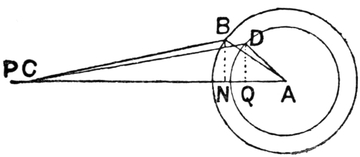
FIG. 61.
Suppose it is required to compare the force exerted by the slay in beating up (say the front 1 inch of its stroke) in two looms, one with a 12-inch crank-arm and 3-inch crank and the other with an 11-inch arm and 4-inch crank. The weight of the slays, the speed of the looms, the tension on the warps, and the timing of the primary movements, the same in each case.
In Fig. 61 the smaller circle represents the 3-inch crank and the larger one the 4-inch crank. CP = 1-inch, CB = 11-inch arm, and CD = the 12-inch arm. It is obvious that if we can obtain the two angles made by the cranks, viz. ∠ CAB and ∠ CAD, we shall be able to get the time, or fraction of a revolution, occupied in moving the slay from C to P. As we know the three sides of the triangle we can obtain the angle enclosed by any two sides, and what is required in[Pg 80] this case is to obtain the angles BAC and DAC. In triangles of this kind where there is no right angle, we can obtain the cosine of the angle as follows:—
| CA2 + AD2 − DC2 | = AQ, the cosine of angle DAC, | |
| 2CA.AD | ||
| and | CA2 + AB2 − BC2 | = AN, the cosine of angle BAC. |
| 2CA.AB |
The proof of this formula is given in Euclid, Book 2.
Having obtained the cosines of the two angles, we can find the angles themselves by referring to a table of sines and cosines.
Then as AP = 15 inches,
CA = 14, AD 3 inches, DC 12 inches, BA 4 inches, BC 11 inches; and reducing the formulæ to figures, we get:
| 142 + 32 − 122 | = | 196 + 16 − 144 | = | 0·7262 cosine, |
| 2 × (14 × 3) | 84 |
and by referring to a table of sines, we find that cosine 0·7262 = angle 43° 26´, therefore angle DAC = 43½°, about. Also
| 142 + 42 − 112 | = | 196 + 16 − 121 | = | 91 | = | 0·8125, |
| 2 × (14 × 3) | 112 | 112 |
and by referring to a table of sines and cosines, we find cosine 0·8125 = angle 35⅔°.
We thus find that to move the connecting pin 1 inch to the front of
the stroke, in the loom with 11-inch arm, the 4-inch crank will move
through 35⅔°, and in the loom with the 12-inch arm the 3-inch crank
will move through 43½° for the same movement of the slay. Assuming
the force exerted by the latter to be 1, the force of the former will
be as 35⅔ squared : 43½ squared 1 : Ans.
It may be as well here to give a short explanation of the system of obtaining angles by sines and cosines.
As the crank moves forward it is obvious that the line DQ will become shorter, and as the angle becomes larger the line DQ will increase in length. In trigonometry, the ratio between the length of the line DQ and the radius AD is called the sine of the angle, and if the radius is 1, the length of DQ will be the value of the sine. In an angle of 30° the sine is exactly ½ the radius, and the relation between the radius and the sine for every angle is known, and arranged in “tables of sines.” The length of AQ will also vary with the angle, and the length of this line is called the “cosine” of the angle QAD. The cosine of an angle of 30° is therefore the same as the sine of an angle of 60°. When the sine is known it is easy to obtain the cosine as follows:—
Cosine = √1 − sin2. Thus for an angle of 30°, cosine = √1 − 0·52, or cos2 = 1 − 0·52, therefore cos2 = 1 − 0·25, or cos2 = 0·75, ∴ cos = √0·75 = 0·866. By reversing, the sine may be obtained from the cosine.
The value given to the sines and cosines must not be taken for the actual length of the lines; they are simply the ratio to the radius. Thus in an angle of 30°, if the radius is 1 inch the length of the sine will be ½ inch and the cosine 0·866 inch. If the radius is 2 inches, the actual length of the sine will be 1 inch and of the cosine 1·732 inches.
TABLE OF SINES AND COSINES.
We see from Fig. 61 that in a loom with a 4-inch crank and 11-inch arm, the velocity of the slay is much greater when beating up than with the 3-inch crank and 12-inch arm.
The effect of the length of the crank-arm on the velocity of the slay can easily be shown by a diagram or by calculation. If the length of the crank-arm be altered without altering the length of the crank, there will be found a somewhat quicker movement of the slay at the beat up in the loom with the shorter arm. The difference is not so great when the crank-arm is a long one in proportion to the crank. The chief cause of the difference in the velocity of C in Fig. 61 is the difference in the length of the crank. It is obvious that the longer the crank the greater the angle which it will cause the arm to make, and therefore the greater will be the acceleration of the velocity of C when the angle is closing and the slay moving forward. Likewise, it is obvious that the shorter the arm the larger will be the angle to close, but the principal thing to notice is that an increase in the length of the crank causes an increase in the velocity of the slay owing to the extra distance which it has to travel in each revolution; so that even if the crank-arm were lengthened in exact proportion to the increase in the length of the crank, so as to keep the angle to be closed in beating up the same, there would still be a considerable increase in the velocity of the slay, caused by the extra distance it has to travel. This lengthening of the crank has obviously much more to do with the increase in velocity of the slay than the shortening of the arm has.
The longer the crank the further back from the cloth will the slay be taken, and assuming that the shed is open for the shuttle when the crank is at the bottom centre, a long crank is obviously more suitable for a wide loom, as, having to move further back, it will allow a longer time for the shuttle to pass through the shed than a short crank would; therefore the[Pg 83] wider the loom, the longer the crank is required to be to allow time for the shuttle to pass.
The time allowed for the passage of the shuttle may also be increased by using a short arm so as to increase the eccentricity of the slay.
The longer the crank, the greater the velocity of the slay, therefore a long crank is suitable for heavy work, as it stores up more force in the slay than a short one. The force may also be increased by shortening the crank-arm, thus increasing the eccentricity of the slay.
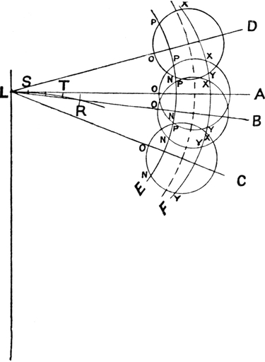
FIG. 62.
The position of the crank-shaft in relation to the connecting pin has some effect upon the eccentricity of the slay’s movement. Fig. 62 shows this, but to see clearly the effect it would be advisable to make an accurate drawing to a large scale.[Pg 84] Four positions of the crank-shaft are shown. The one on the line A is just a little below the level of the connecting pin, so that the pin moves as nearly as possible on the line A when making the front quarter of its stroke. The circle on the line B is the position where the pin moves as nearly as possible on line B when at the back quarter of its stroke; D is any higher plane, and C any lower one. Divide the stroke of the connecting pin LR into four equal parts, and from S, with the crank-arm in the compasses, cut the circles with the arc E, and from T cut the circles with the arc F. It will be found that in the circle A, OP is slightly longer than in any of the other circles; therefore this is the position where the beat up is slowest. It will also be found that in the circles B and C there is scarcely any difference in OP, therefore sinking the crank-shaft from within reasonable limits makes very little difference; if anything, there is a slight decrease in the size of OP as the plane is lowered, but it is very slight, and the increase in the velocity of slay would also be very slight. On the other hand, by raising the crank-shaft to D a considerable increase in the velocity of the slay in beating up takes place, as it will be found that in this circle OP is much less than in the others.
At the back of the stroke it will be found that in the plane B the distance XY is least; therefore there is here the least dwell of the slay at the back of its stroke with the shaft in this position. This is because the pin moves as nearly as possible on the line B whilst the crank is at the back part of its stroke. As the crank is raised or lowered the dwell at the back increases slightly.
Reversing the direction of the loom makes a difference in the beat-up.
It will be found that in the circle A, OP and ON are about equal, therefore there will be scarcely any change in the velocity of beat-up by reversing the loom; but as the shaft is[Pg 85] lowered ON will be found to become less than OP, and therefore a quicker blow is given by reversing the loom if the shaft is in this position. If the shaft is raised, as in the case of circle D, it will be found that ON becomes greater than OP; therefore with the crank above A, reversing the direction of the loom will cause a slower and weaker beat-up.
In the diagram, Fig. 62, the crank and crank-arm are the same length for each position, the centre of the shaft being indicated by the dotted arc.
Timing of the Primary Movements.
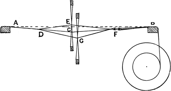
FIG. 63.
The primary movements, shedding, picking, and beating up, are timed differently in relation to each other in weaving different classes of fabrics. For plain cloths, or other cloths where a good cover is required—that is, where the warp has to be spread—the crank should be set about the top centre when the healds are crossing each other. At Fig. 38 the loom is timed in this manner. When so timed it is obvious that the shed will be considerably or altogether open when the reed is in contact with the cloth. By sinking the centres of the healds[Pg 86] below a line drawn from the temple to the back rest, the upper portion of the shed is always slack, and if the pick is beaten up in a crossed shed, the loose ends of the warp are spread between the taut ones. In Fig. 63 the straight line AB is drawn from the front carrier A to the back carrier B. The centres of the healds when level are on the line ACB, the point C being a little way below the line AB. When one stave is lifted a certain distance and the other goes down the same distance, it is obvious that the upper portion of the warp will be slacker than the lower portion, because the line ADEFB is shorter than ADGFB, and when the reed beats up with the warp in this position the slack ends are spread between the taut ones, thus giving a good cover to the cloth and preventing the reed marks from showing. Each set of ends alternately becomes slack.
Another advantage of beating up when the shed is crossed or partly open for the succeeding pick is that the pick is held more firmly in position than when the shed is not crossed, and therefore the picks can be got in better.
In twilled cloths the boldness of the twill is somewhat affected by the warp being spread, and these cloths are often preferred when made without the healds having been sunk.
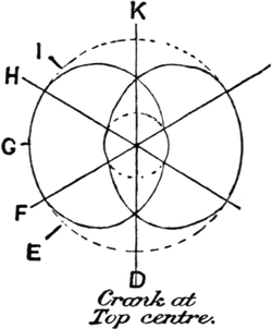
FIG. 64.
If the dwell on the tappet is equal to one-third of a pick, as in Fig. 64, the line D will mark the point of the tappet when the crank is at the top centre. When the crank has made one quarter of a revolution and is at the front centre with the reed in contact with the cloth, the point E will be acting on the treadle bowl. It will be seen that[Pg 87] here the shed is almost fully open. When the crank is at the bottom centre the point G will be acting on the bowl, and the shuttle should just be entering the shed. When the point H of the tappet is acting on the bowl the shed will be commencing to close, and the shuttle must be just leaving the shed. When the point I is acting on the bowl the crank will be at the back centre, and when the crank reaches the top centre the healds will be again level.
If the dwell on the tappet is more than one-third pick, and at the commencement the crank is set on the top centre with the healds level, the shed will keep open longer for the shuttle to pass through, and would be more open when the crank reached the front centre. It will be obvious that for a wide loom a longer dwell is required than for a narrow loom.
By having the shed fully open before the shuttle enters the shed, the warp is spread and a good cover put on the cloth, but all this dwell is taken off the time which would otherwise be allowed for opening and closing the shed, and therefore means extra strain on the warp.
If it is not necessary to spread the warp, the shed need not be fully open until the shuttle is entering the shed. In this case the greatest possible amount of time is allowed for opening and closing the shed, thus putting as little strain as possible on the warp.
Speed of Tappets.
As previously stated, the bottom shaft in the loom, being the one used for picking, revolves at one-half the speed of the crank-shaft, and therefore plain cloth tappets may be fastened on the bottom shaft. Tappets of more than two picks to the round are usually fixed on a counter-shaft, S (Fig. 65), in looms with inside tappets. Sometimes the wheel E is geared directly[Pg 88] into the wheel C on the bottom shaft, but usually a carrier-wheel, D, is used to convey the motion from the bottom shaft. The number of teeth in the carrier wheel has no effect on the speed of the tappets, as it is used simply to fill up the space between the bottom and counter-shafts.
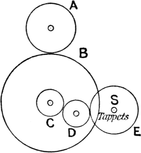
FIG. 65.
If the wheel on the crank-shaft A contains 45 teeth, and the wheel B 90 teeth, C 40 teeth, and E 60 teeth, the tappet-shaft S will be making one revolution for three revolutions of the crank-shaft; therefore these wheels will do for three-end twill tappets. This may be proved by multiplying the drivers together and the drivens together, and dividing one by the other, thus—
| 90 × 60 | = 3 |
| 45 × 40 |
It is usual to place two or three wheels on the bottom shaft of the loom, so that any one of them may be geared into the carrier wheel D, each giving the required speed for different tappets. If a 40 wheel, a 30 wheel, and a 24 wheel are placed on the bottom shaft in such a manner that they can be moved along the shaft and any one of them be geared into the carrier wheel, any 3, 4, or 5 pick tappets can be driven with these wheels. We have seen that a 40 wheel at C gives three picks to the round.
Suppose the 30 wheel at C is geared into the carrier wheel, we get—
| drivens | 90 × 60 | = 4 |
| drivers | 45 × 30 |
or the relative speed of the tappets and crank-shaft are as[Pg 89] 1:4; therefore these wheels may be used for any tappets with four picks to the round.
If the 24 wheel is at C, we get:
| drivens | 90 × 60 | = 5 |
| drivers | 45 × 24 |
and thus we get the proper rate of speed for tappets five pick to the round.
Some loom makers use the wheel E as a change wheel. With a 24 wheel C and a 36 wheel E we get three picks to the round, thus—
| drivens | 90 × 36 | = 3 |
| drivers | 45 × 24 |
With a 24 wheel C, a 48 wheel E gives 4 picks,
With a 24 wheel C, a 60 wheel E gives 5 picks,
With a 24 wheel C, a 72 wheel E gives 6 picks.
Example.—Find the number of teeth for the wheel C on the bottom shaft to drive tappets seven picks to the round, wheel on tappets 63 teeth.
| 90 × 63 | = 18 wheel. Ans. |
| 45 × 7 |
Woodcroft’s tappets, as a rule, are driven directly from the crank-shaft. As these tappets are usually of a large circumference, a large wheel on them is of no disadvantage, although sometimes intermediate wheels are used.
If the tappets are twelve to the round, and the wheel on the tappets contains 192 teeth, a driving wheel of 16 teeth will be required on the crank-shaft.
| 192 | = 12 picks to the round |
| 16 |
For driving outside tappets, as in Fig. 39, a driving wheel on the crank-shaft and two intermediate wheels are generally used.[Pg 90] The tappets are placed on the bottom shaft outside the loom, but they are loose upon the shaft, and can, of course, be made to revolve at a different speed to the shaft, either in the same or in the opposite direction. This system of driving the tappets is shown at Fig. 66. The wheel A, on the crank-shaft, drives the wheel B, on an intermediate stud; the wheel C, on the same centre, drives the tappet wheel D.
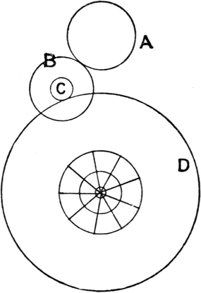
FIG. 66.
To find the wheel on the crank-shaft, or the first driver, the other wheels being as follows: first driven wheel, B, 36 teeth; second driver, C, 12 teeth; tappet wheel, D, 120 teeth.
Multiply the two driven wheels together, and divide by the given driver multiplied by the picks to the round, thus—
| 36 × 120 | = 40 first driver, A. |
| 12 × 9 |
To find the second driver for eight picks, the other wheels being: first driver, A, 20; first driven, B, 40; second driven, D, 60.
The given driver multiplied by the picks to the round, 20 × 8 = 160; the drivens multiplied together, 40 × 60 = 2400; 2400 ÷ 160 = 15 wheel required.
To find either of the driven wheels, multiply the two drivers and the picks together, and divide by the driven given wheel, thus—
Example.—Find the wheel for the tappets, D, for 10 picks to the round,[Pg 91] the other wheels being: first driver, 16 teeth; first driven, 32 teeth; second driver, 20 teeth.
| 16 × 20 × 10 | = 100 wheel required |
| 32 |
To find both intermediate wheels, multiply the given driver by the picks to the round, and as the product is to the teeth in the tappet wheel, so is the required driven to the required driver.
Example.—Find the two intermediates for 10-pick tappets, if the wheel on the crank-shaft has 18 teeth, and the wheel on the tappets 120 teeth. The 18 × 10 = 180, and therefore the two required wheels must be in the proportion of 180 to 120, the former being the driven wheel. Thus a 36 driven and a 24 driver will give the required speed to the tappets. That this is correct may be seen from the following:—
| 18 × 24 | = 10 picks |
| 36 × 120 |
That the required wheels must be in this proportion will be apparent from the fact that if the wheel B has ten times the number of teeth in A, then B is revolving at the speed at which the tappets are to move; therefore if the wheel C has the same number of teeth that D has, the speed of the tappets will remain the same.
One of the most important motions in the power loom is that by which the loom is stopped automatically when the shuttle is caught in the shed or for some reason does not enter the shuttle-box. A motion of this kind has always been considered necessary since the introduction of the power loom. If the shuttle be caught in the shed as the reed is beating up, it is obvious that great damage to the warp must result unless the loom is brought to a sudden stop or the reed thrown out.[Pg 92] The oldest form of protector is the “stop rod.” In this the reed is fast, and if the shuttle is caught in the shed or flies out, the loom is brought to a sudden stop before beating up. Fig. 67 will illustrate the principle of this motion. If the shuttle enters the box safely it presses back the swell S, which projects inside the box and is held there by a spring. As the swell is pressed back it raises the lever B above the frog F as the slay beats up. If the shuttle for any reason does not enter the box, the swell is not pressed back, and as the slay moves forward in beating up, the lever B catches the frog F, which is moved a little and applies the brake G, and also knocks off the loom handle H, which removes the belt on to the loose pulley. Before the application of the brake to this motion the frog was fixed to the framework of the loom, and it will easily be understood that the concussion caused many breakages. A stop rod protector was patented in 1791, but the brake was not applied until 1840 or thereabouts.
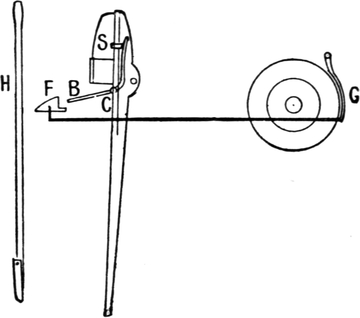
FIG. 67.
The loose reed is a better way of preventing damage to the warp by the shuttle being caught. If the shuttle is caught in the shed it throws out the reed and stops the loom. Its action will be understood from Fig. 68. A rod, C, runs underneath the shuttle-race at the back of the slay, and the finger B is fastened to it. The reed is held in position by a board, A, which is also connected to the rod C, as shown in the diagram. If the shuttle is caught in the shed, it presses back the reed and[Pg 93] the board A, and lifts the finger B to the upper side of the frog F, and as the slay moves forward it throws the board A further back and the reed out at the bottom, and the lever H is brought into contact with the loom handle, and the loom is stopped. If the shuttle passes safely through the shed, the reed is not pressed back, and the finger F comes under the frog as the slay gets to the front of its stroke, and holds the reed comparatively fast. The disadvantage of the loose reed is that the reed is not sufficiently firm to put a large amount of weft into the cloth, but improvement is being made in this respect, and loose-reed looms are to-day made for weaving fabrics for which it was formerly necessary to have fast reeds.
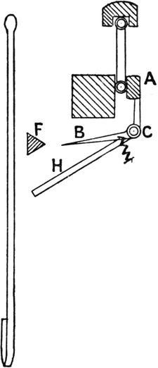
FIG. 68.
The invention of the loose reed is generally attributed to Mr. James Bullough. It was invented about 1842.
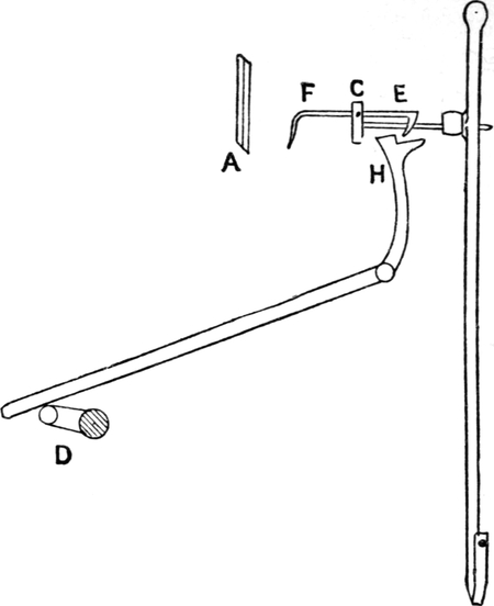
FIG. 69.
One of the most useful adjuncts to the power-loom is the motion for stopping the loom when the weft breaks or runs out. Fig. 69 will explain the principle of this useful contrivance. The grid A is placed at the side of the reed between the reed and the shuttle-box, and the fork is so placed that as the grid moves forward the prongs of the fork pass through it.[Pg 94] When the weft comes between the fork and the grid it raises the end of the fork E, out of the way of the hammer H, which is moved forward every two picks by a cam or lifter, D, on the bottom shaft of the loom. If the weft breaks or runs out the fork will of course pass through the grid, and it is so balanced that the hook E will be caught by the hammer and the loom handle knocked off. The invention of the Weft Fork Stopping Motion is claimed by several persons, but it was perfected about the year 1842, when the brake was applied to it. The action of this brake is illustrated at Fig. 70. When the handle is pushed sideways in starting the loom it lifts the rod R and the lever L, and thus takes the brake off. When the handle is knocked off by the weft fork being caught, the lever L drops[Pg 95] and the brake is applied. The brake power can be regulated by altering the position of the weight on the levers.
FIG. 70.
In looms with change boxes at both sides the weft fork is often placed in the middle of the loom. It is obvious that when several shuttles are used there will always be some weft threads opposite the grid in the ordinary weft fork motion, and this renders it inoperative in this class of looms. It is therefore necessary to have a fork to feel for each pick separately.
There are two distinct classes of taking-up motions—the positive, and the negative or drag motion. In the former the cloth is taken up a small but regular distance each pick, and the number of picks per inch can be regulated to a fraction. Fig. 71 is the common form of positive take-up motion. A ratchet wheel or “rack wheel,” A, is moved forward one tooth every pick by a click or catch, M, operated by a projection, G, on the slay sword. As the slay moves forward the rack wheel is moved one tooth, and the holding catch or detent N prevents it from going back. There are five wheels in the train, and the[Pg 96] names usually given to them are as follows: A, rack wheel; B, change wheel; C, stud wheel; D, stud pinion; E, beam wheel. The emery taking-up roller is marked F. The cloth, as it is woven, is drawn forward by the emery roller and is wound upon the cloth roller, which is pressed against the emery roller by weighted levers, and is turned by friction.
FIG. 71.
The speed at which the emery beam roller is turned regulates the number of picks per inch, and as changes are constantly required in most weaving mills, the wheel B is usually taken as a change wheel. As this wheel is a driver, a smaller wheel will make the emery roller move slower, and therefore more picks will be put in the cloth, and a larger wheel will drive the emery roller quicker, and as a consequence a smaller number of picks will be put in. If the rack wheel has 50 teeth,[Pg 97] the stud wheel 120 teeth, the stud pinion 15 teeth, and the beam-roller wheel 75 teeth, the beam roller being 15 inches in circumference, and if the change wheel used has 25 teeth, the number of picks per quarter-inch will be 20.
This may be proved by multiplying the drivers together and by the circumference of the emery beam roller in quarter-inches for a divisor, and multiplying the drivens together for a dividend: the quotient will be the number of picks per quarter-inch.
When the cloth is taken out of the loom, rather more than this number of picks will be counted, as there is not the same tension as when the cloth is being woven. It is usual to allow about 1½ per cent. for this shrinkage.
For the purpose of easy calculation the dividend of the loom is obtained; that is, the change wheel required to give one pick per quarter-inch. By using this as a dividend and dividing by the number of picks required in a quarter-inch, the quotient will be the change wheel required; and, vice versâ, by dividing by the change wheel, the number of picks given by that wheel can be obtained.
To find the dividend of a loom—
Multiply the rack, stud, and beam wheel together for a dividend, and the stud pinion and the number of quarter-inches in a circumference of the emery beam for a divisor, and the quotient will be the mathematical dividend. Add 1½ per cent. to this for the practical dividend.
With the wheels given in Fig. 71 the dividend will be as follows:—
| 15 | stud pinion | |
| 60 | quarter-inches in circumference of beam | |
| 900 | ||
| 50 | rack wheel | |
| 120 | stud wheel | |
| 6000 | ||
| 75 | beam wheel | |
| 900) | 450000 | (500 mathematical dividend |
| 4500 | ||
| 00 | ||
| 500 | ||
| 7 = 1½ per cent. for shrinkage | ||
| 507 practical dividend. | ||
Having the dividend, it is only necessary to divide by the picks to obtain the change wheel required, or to divide by the teeth in the change wheel to obtain the picks which it will give, thus—
| picks | 507 | = 39 change wheel change wheel | 507 | = 25⅓ picks. |
| 13 | 20 |
The following are the wheels used by various loom makers:
Example.—Find the dividend of a loom with a rack wheel 60 teeth, stud wheel 100 teeth, stud pinion 12 teeth, beam wheel 75 teeth, beam 15 inches circumference.
It is not possible by changing one wheel only to obtain any number of picks or fraction of a pick, as will be seen from the following examples:—
For the lower number of picks the motion does fairly well, but for the higher numbers of picks the changes cannot be made with sufficient exactitude by changing a single wheel. Even in the lower picks it is now required to make the smallest fractional changes.
An improved arrangement of wheels is now largely adopted. This is Pickles’ motion. Fig. 72 shows the train of wheels. The change wheel B is in this case a driven wheel, and therefore if a larger wheel is used it will give a larger number of picks in the cloth, and if a smaller wheel is used it will give a smaller number of picks; so that if the wheels are so proportioned that the change wheel B has the same number of teeth that there are picks per quarter-inch, it will always remain so, whatever size the wheel is. If a 20 driven wheel gives 20 picks, a 30 will give 30 picks, and so on.
The wheel A is also changed, and this is usually called the “standard” wheel. This is a driver wheel, and therefore a smaller wheel gives more picks, and vice versâ. The wheels are so proportioned that if A, the standard wheel, has nine teeth, each tooth in B, the change wheel, represents one pick,[Pg 100] and therefore, this wheel being a driven, the number of teeth in it will also represent the number of picks per quarter-inch. If an 18 standard wheel is used, it is obvious that the emery beam will be driven twice as fast, therefore each tooth in the change wheel B will then represent half a pick per quarter-inch. With a 27 standard each tooth in the change wheel B will represent one-third of a pick. With a 36 standard each tooth in B will represent a quarter of a pick per inch.
FIG. 72.
The wheels mostly used are those in the diagram, and supposing we have a 36 standard and a 45 change wheel, and taking the emery beam as 15·05 inches in circumference, we get—
| B | |
| 24 × 45 × 89 × 90 | = 11·088 |
| 36 × 24 × 15 × 60·20 | |
| A | ·166 = 1½ per cent. for shrinkage |
| 11·254 picks per quarter-inch. |
Thus with a 36 standard a 45 change wheel, B, gives 11¼ picks per quarter-inch, or each tooth in the change wheel gives a quarter of a pick per quarter-inch.
By changing these two wheels any fraction of a pick can be obtained. Thus if 13½ picks per quarter-inch are required, the wheels used would be an 18 standard and a 27 change wheel. For 13⅔ picks a 27 standard and a 41 change wheel would be used, and so on.
The following examples will fully illustrate the principle of this motion:—
It is not always customary to change the wheels in the above manner, as a different value is often given to each tooth in the change wheel by altering the standard wheel, otherwise than by multiples of nine.
Any number may be made the basis of a train of wheels of this kind; there is no reason why it should be nine more than any other number, and in adapting looms from the ordinary five-wheel motion to this principle, it is not necessary to get all new wheels, as sow of the old ones may be made to form part of the train.
There are several kinds of negative or drag take-up motions. One of the older forms is that given in Fig. 73. A lever, AB, centred at C is weighted on the arm B. A small cam, D, on the crank-shaft presses down A every pick and lifts the catch E, which operates the ratchet wheel F.[Pg 102] As the weights drop they act as a drag upon the ratchet wheel. A small pinion on the same centre as the ratchet wheel drives the wheel G on the cloth beam. The cloth in a negative motion is wound directly on to the cloth beam, and thus there is no risk of damaging the finer fabrics, as is the case when an emery beam is used, as in a positive motion. The number of picks put in the cloth is regulated by the weights on the lever B; the greater the weight the less the number of picks, and vice versâ.
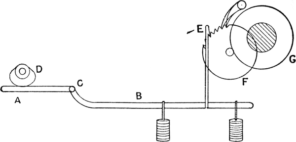
FIG. 73.
The action of a negative motion is as follows:—As the slay beats up, the cloth between the cloth beam and the reed is slackened a little, and the weights on the lever at that moment act as a drag upon the ratchet wheel F. The holding catch is usually a double one, and will hold the ratchet wheel when taken forward the space of half a tooth.
By increasing the drag upon the ratchet wheel, a slighter blow from the slay will enable the weights to act, and thus less weft is put into the cloth. If a loom is regulated so as to put a certain number of picks per inch into the cloth of a given count of weft, and weft of a finer count is then used, it is obvious that the number of picks per inch would be increased. If the weft varies in thickness[Pg 103] the negative motion compensates for this somewhat, by putting more picks in where it is thinner, and thus a more even thickness of cloth is produced than where a positive motion is used.
As the cloth is wound on the beam the circumference of the latter gradually increases, and consequently there would be a gradual alteration in the amount of weft put into the cloth, owing to the difference in leverage. It is necessary, therefore, to count the cloth and adjust the weights at intervals in order to keep the number of picks regular.
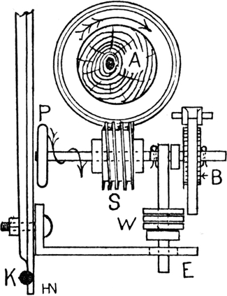
FIG. 74.
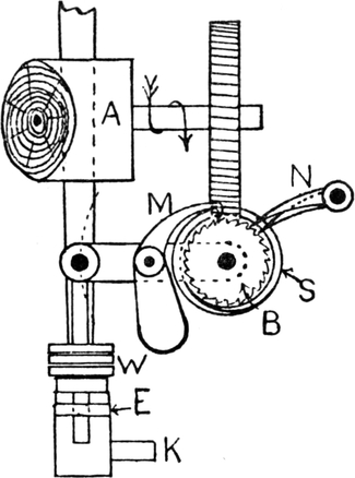
FIG. 75.
Another kind of negative take-up motion is shown at Figs. 74 and 75. This is now more generally used than the other kind. The cloth beam A is driven by a screw, S. The ratchet wheel B is fastened to the screw-shaft, and the method of operating the ratchet wheel will be seen from Fig. 75, which is another view of the mechanism. A short lever, E, is attached to the rocking shaft K, and as the slay moves backwards from the cloth the weights W are lifted a little, and when the slay moves forward, the weights, acting[Pg 104] through the catch M, will take the ratchet wheel forward a tooth, or half a tooth, as the case may be. There is usually a double-holding catch N, which will hold the wheel if taken forward half a tooth. When the ratchet wheel has made one revolution, the wheel on the cloth beam will only have been moved one tooth by the screw, so that the required slow movement of the cloth beam is obtained by very simple means. There is a hand wheel, P, for unwinding the cloth readily. The negative motion is used principally in weaving the heavier classes of cotton fabrics and those in which there is a large number of picks per inch, such as velvets, and similar fabrics. Its advantages are that the cloth is wound directly on to the cloth beam, and cannot therefore be injured by an emery beam, and that it makes the cloth of a more even thickness, as it compensates for any variation in the thickness of the weft; and its disadvantages as compared with a positive motion are that it requires frequently adjusting (less frequent, of course, when a very large number of picks are put in, as in velvets), and that it does not put a perfectly regular number of picks in the cloth, as a positive motion does. This latter is the chief objection to it, as even in the lighter makes of common velvets a positive motion is preferred on account of its giving a more evenly picked cloth. In silk looms, where it is absolutely necessary to dispense with an emery beam, a very large cloth beam is used, and the cloth is wound directly on to the cloth beam although the take-up is positive. The cloth beam is sometimes over a yard in circumference, so that it will hold a fair length of cloth without making much difference in the number of picks. The cloth is taken off the beam frequently, or the gradual change in the thickness of the cloth beam would cause the piece to get too thin. This would, of course, not do for cotton goods.
Another ready method of obtaining any required pick in[Pg 105] a positive motion is used in the East Lancashire districts. Seven wheels are used, as in Pickles’ arrangement, but the ordinary wheels of a 507 dividend (or other dividend) are used, and in addition the two wheels B and C, as in Pickles’ (Fig. 72), are introduced. The wheel B, the driven wheel, is called the standard in this arrangement; and suppose it is required to put 15 picks per quarter-inch in the cloth with the rack wheel 50 teeth, stud wheel 120, stud pinion 15, beam wheel 75, beam 15 inches circumference. The standard used is a 24—this, it must be borne in mind, is in this case a driven wheel. Then by multiplying the dividend of the five-wheel motion, viz. 507·5, by 24, the teeth in the standard, and dividing by the picks per quarter-inch required, we get the product of the two drivers, A and C, thus—
This 812, then, is the product of the two drivers, and any two convenient wheels which, multiplied together, give this number can be used—thus 81228 = 29. Therefore the two drivers may have 28 and 29 teeth respectively. The two wheels are found by experiment. If the dividend of the five wheels is 609 a 20 standard wheel is used, and the same drivers as in the preceding case will do. If it is required to change only one wheel, and to have the arrangement such as to give an exact number of picks, or half-picks, or quarter-picks, in the quarter-inch of cloth, by taking the two drivers A and C of such numbers that their product amounts to 507, the number of teeth in the driven wheel B will always equal the number of picks per quarter-inch exactly. Thus 507/13 = 39. Therefore if the drivers A and C have respectively 13 and 39 teeth, every tooth in the driven wheel B will represent one pick per quarter-inch.
Suppose half-picks are required exactly, the method of obtaining the wheels is as follows:—Multiply the 507·5 by 2, which equals 1015, then find two convenient wheels which, multiplied together, produce this number; 35 × 29 = 1015, and the two drivers A and C may be 35 and 29. This will cause every tooth in the driven wheel B to represent half a pick exactly.
Thus with a 35 wheel A, and a 29 wheel C, a 31 wheel B will give 15½ picks per quarter-inch, the other wheels being the same as in an ordinary 507 dividend motion.
The following examples will prove this:—
When quarter-picks are required exactly, by changing one wheel only—multiply 507·5 by 4, and the product of the two drivers A and C must equal this. Then every tooth in the driven wheel B will represent a quarter-pick per quarter-inch.
There are many methods of letting off the warp positively, but none are likely to succeed in displacing the older and quite satisfactory method of levers, ropes, and weights. The very fact of making the let-off positive, causes too great a rigidity in the hold of the warp, which is detrimental to the yarn. The frictional let-off is not likely to be replaced in cotton goods weaving unless it be in some of the heavier kinds of fabrics. Where it is a question of putting in as much weft as possible, the positive let-off has an advantage.
WHERE more than one kind or colour of weft is used in a fabric, it is, of course, necessary to change the shuttles automatically. Sometimes two or more different counts of weft of the same colour are used, and sometimes different colours of weft. Checks of all kinds, extra weft spots, and others are the chief classes of fabrics which require change boxes.
FIG. 76.
The oldest and commonest form is the Diggle’s chain motion illustrated at Fig. 76. The number of boxes used in this motion is either 2, 3, or 4. It would be possible to use more, but it is not usually done with this arrangement for operating them. A lever, AC, is centred at C (Fig. 76), and the friction bowl B on this lever is moved upwards by a chain, composed of links fastened together on pins, which work round a barrel, D. These links are of different sizes, according to the number of boxes used. The smallest link leaves the top box in a line with the shuttle-race, and the other links are of such a size as to raise either the second, third, or fourth boxes (assuming that there are four) into this position. The general[Pg 108] method is to raise the boxes one at a time, and drop them all together, but this is not compulsory. It will be seen that the motion of the boxes is not positive downwards—that is, the boxes drop by their own weight, and are not mechanically forced down, as in Wright Shaw’s or Whitesmith’s motions—and it will be well understood that there will thus be a limit to the speed at which the loom can be run. The method of turning the barrel D which carries the chain is as follows. A wheel, E, on the crank-shaft drives a larger wheel, F, above it. On the face of this wheel, F, is a rim and two projections, PP, or, it may be, only one projection. These projections or pins gear into the star wheel G, which is fastened to the barrel carrying the chain, and therefore when the star wheel is turned one tooth, or one-eighth of a revolution, it will move the chain a space of one link. The wheel E on the crank-shaft often has one-fourth the number of teeth contained in the wheel F; therefore, if there are two pins or projections, PP, in the circumference, the star wheel will be moved one tooth every two picks, and the boxes may be changed so often by making the chain accordingly. The lever M, which is centred at R, has the boxes attached to one end, and the other end may be pressed down by the foot when it is required to lift the boxes for any purpose when the loom is stopped. Supposing the wheel E to have 15 teeth and F 60 teeth, if there are two projections, PP, on the face of F, the shuttle may be changed every two picks, but if there is only one projection or pin, there may be a change every four, or a multiple of four picks.
The chief disadvantage of this motion in the form given at Fig. 76 is that the chain becomes very cumbersome if a long pattern is required. To obviate this, the projections PP are, in an improved motion, made so that they can be withdrawn from gear with the star wheel. This is effected by a clutch motion[Pg 109] which is subsequently described in connection with the “pick-and-pick loom.” With this improvement, each link in the chain may be made to represent any number of picks, the number being regulated by a small chain of metal cards, and thus larger patterns may be made without the long heavy chains which are required in the ordinary “Diggle.”
The Diggle’s chain principle, although suitable for some types of looms, is not an ideal motion, as the downward movement of the boxes is negative. The boxes have nothing to force them down but their own weight and the weight of the levers connected with them, and this necessitates the loom being run at a slower speed than is the case with some of the positive drop-box motions. Of this latter kind Wright Shaw’s motion is one of a great variety of different types, and has been in use for a long time.
The principle of this motion will be understood from the diagram, Fig. 77. The essential feature of this invention is a forked rack, G, suspended from the free end of a treadle lever, E, fulcrumed at F, and carrying a bowl or runner, D, near the centre. At one end of the second motion or picking shaft, A, of the loom, are two cams, B and C, either of which may be brought underneath the treadle bowl at will, so as to raise the treadle and forked rack once during each revolution of the picking shaft, corresponding to two picks. Passing midway between the two prongs, H, H′, of the fork is a short shaft, upon which are secured two toothed wheels, I and J. Wheel I is so placed that the teeth on either side of the rack may be put into engagement with its teeth just before the fork rises, so as to turn the wheel in either direction; or the rack may occupy a neutral position when rising, in which event the wheel remains stationary. In any case, the racks are always clear of the wheel when descending. Immediately in front of wheel I is another similar wheel J, whose teeth are in permanent engagement with those of a rack, K (an extension, L, of which supports the shuttle-boxes, M). Thus, if rack H′ is put into gear with wheel I, boxes will be depressed as the rack rises; but if rack H operates, the boxes will be raised. One box, or two boxes, only, may be either raised or dropped at one change, according to which rack and which cam is put into operation. The smaller cam moves one box, and the larger cam two boxes, either up or down.
The selection of racks and cams is made by pattern cards (detached) which pass over an octagonal prism, N. The cards are presented separately, once in two picks, to three selecting needles, 1, 2, 3. The two outer needles, 1, 3, are attached one at each end of a double arm secured at the top of a long vertical shaft, O, the bottom of which communicates with the forked rack G. Thus a depression of boxes is effected by a blank part of a card pressing against needle 1, and an elevation of boxes by pressing back needle 3. Shaft O is loosely contained within a long tube or sleeve, P, which carries a short arm, R, at the top, and a forked clutch, Q, which acts upon the boss of cams, B and C. If it is desired to move two boxes, needle 2 is pressed back, thereby causing an inclined piece, S, secured to it, to act upon arm R so as to slightly turn the sleeve P, and move the larger cam C under the treadle bowl at a time when the short side of the cam is uppermost, as indicated in the diagram, Fig. 77. At one point, the larger and outer cam is slightly lower than the smaller one, and can be readily moved under the bowl.
The various changes which can be made by this motion[Pg 112] may be seen by referring to the cards at Fig. 77. When there is a blank opposite the first needle only, the rack H′ is pushed to the left and the boxes are moved “down one.” When there is a blank opposite the third needle only, rack H is moved to the right and the boxes are forced “up one.” When there are blanks opposite the first and second needles, they are pushed backward, thus moving rack H′ to the left, and also forcing the larger cam under the treadle bowl, in which case the boxes will be moved “down two.” When there are blanks opposite the second and third needles, they are pushed backward, and the boxes are “raised two.” When there are three holes in the card, the racks, when lifted, miss the wheel, and there is “no change” in the boxes. It will be seen that the boxes may be moved either up or down, a space of one or two boxes only at a time. There may be more than three boxes, as many as five being regularly used; but if there were five, it would not be possible to change from the first box to the fourth or fifth. The greatest change which can be made is from the first to the third, fourth to second, and so on.
The principle of Whitesmith’s motion is probably the best for any number of boxes. It is usually made for four, and the change may be made with certainty from one box to any other. The arrangement for working four boxes in a loom is illustrated at Figs. 78, 79, 80. The principle will be best understood by referring first to Fig. 80. The four different positions of the boxes are here shown. The boxes are connected to the ring or strap of an eccentric at the point E, and at A the position[Pg 113] of the parts is shown when the boxes are at their lowest point. The eccentric, F, on the shaft has a lift of one box, and therefore by causing it to make half a revolution intermittently every two picks, the boxes would be alternately lifted and dropped a space of one box, as will be seen by referring to C (Fig. 80), where it has made half a revolution from its position at A. It will be seen that E is one box higher at C than at A. Starting again from the first position, as at A, by turning the outer ring halfway round and leaving the eccentric stationary, there will be a lift of two boxes. This is shown at B (Fig. 80). Again starting with the first position, as at A, if we turn the outer ring halfway round, and at the same time turn the eccentric F half-round, we lift a space of three boxes—that is, from the first to the fourth box.[Pg 114] The position of E in this case is shown at D (Fig. 80). We thus see how from the bottom box any other of the four can be reached. By turning the eccentric halfway we lift one box, by turning the ring halfway round we lift two boxes, and by turning both ring and eccentric halfway round we lift three boxes. If we are at the third box, as at B (Fig. 80), and we wish to reach the second box or one lower, by turning the eccentric half a revolution and the ring half a revolution we shall get the position required. It will thus be seen that any one of the four boxes may be reached at will. At Fig. 79 another view of the eccentrics and boxes is given. The wheel H is keyed to the shaft on which the eccentric is fixed, and riding loosely upon this shaft is another wheel, I, of the same size, to which a fork, K, is attached. This fork fits on to a pin at the back of the ring, and thus by turning the wheel I the ring can be moved independently of the eccentric. If the wheel H is moved it moves the cam, and if the wheel I is moved it moves the ring. Referring now to Fig. 78, the wheel H is shown. This wheel is driven by a wheel, I (Fig. 79), twice its size. On the face of the wheel L there are four pins, and by lifting the lever OP at O, the pulling hook M is dropped round one of the pins, and the hook being moved forward by the crank Q will cause the wheel L to make a quarter of a revolution and the wheel H to make half a revolution, and therefore the eccentric is moved half a revolution. On the same stud as the wheel L there is another wheel exactly the same size and with four pins; this wheel (which cannot well be shown in the diagram) gears into the wheel I shown in Fig. 79. There is also another pulling hook which works along with M. This second pulling hook is operated by another lever like OP. There are two levers, X, which are lifted by the cards, and by lifting X, either, or both, of the pulling hooks may be dropped, and either of the wheels I or H (Fig. 79) turned half a revolution, but always in the same direction.
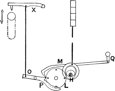
FIG. 78.
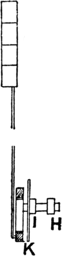
FIG. 79.
FIG. 80.
The wheel L and its companion are prevented from turning too far by a strong friction arrangement.
This motion may be adapted to work six boxes, or even more. For six boxes there is another eccentric inside the first eccentric, which can be worked independently; this will, of course, require a third pulling hook, and so on.
Many loom-makers have patented arrangements on the same principle, which do away with the pulling hooks M, and it is probably in this direction that the motion may be improved.
The Whitesmith principle is simple, and positive throughout, and it is difficult to see why it is not in more general use. It is generally admitted by those who have had practical experience of drop-box looms on this principle that it is the best. There are other drop-box motions, but the foregoing are the chief kinds.
These are not used in the cotton trade to anything like the extent they are in the woollen and worsted trades, especially in Yorkshire. It is remarkable that this should be the case, as it is claimed for circular boxes that they can be run at a higher speed than any other kind. Circular boxes are usually made for six shuttles, generally to move only one box at a time, but they are made to skip one box, although the arrangement is by no means so simple or satisfactory as in a well-made loom on Whitesmith’s principle, where the changes are made from one box to another almost noiselessly. At Fig. 81 the mechanism of a circular-box motion is shown. There are two hooks, A and B, which act upon pins outside the boxes. When the hook[Pg 116] A is pulled down the boxes will be turned one to the right, and when B is pulled down they are turned one to the left. A lever, EF, is connected with the lower part of each hook, and another lever, M, is lifted every two picks by means of a cam, C. The cards lift or drop the L lever QS at S, and so the hook H can either be lifted or left down by the lifter M, and the boxes can be turned one in either direction. A disadvantage of circular boxes is that they cannot be used in fast-reed looms on account of the difficulty of operating the stop rod from the back of the boxes. They are therefore only used for weaving the lighter classes of fabrics.
FIG. 81.
The majority of box looms are made with movable boxes at one side of the loom only, so that single picks of any colour cannot be put in the cloth at will. As it is very desirable in many fabrics to use single picks of a colour or count of weft, it is necessary to have movable boxes at both sides of the loom, and where this is the case it is usual to have picking mechanism which will allow of several picks being made in succession from either side of the loom. If the matter be carefully thought over, it will be easily apparent that even with drop boxes worked quite independently of each other at both sides of the loom, if the picking mechanism is of the ordinary kind—viz. to[Pg 117] pick once from each side alternately—it would be impossible to obtain that variety of changes in the shuttles which is in many cases necessary. In a loom with two boxes at each side worked independently, it would be impossible to obtain single picks alternately of two colours or counts. But by being able to pick twice in succession from each side this can be done. By going through all the changes possible with a given number of boxes, the advantage of this kind of picking arrangement will be very apparent, in the command it gives over any shuttle in the series for any pick. It is therefore necessary to have the picking mechanism aforementioned in order to allow of all the boxes being emptied at one side if required. A loom of this character is called a “pick-and-pick” loom; the picking motion is sometimes called a “pick at will” motion. The loom which we take as an example is one on the Diggle’s chain principle. There are two chains, placed at one side of the loom for convenience. Both chains are on one barrel, A (Fig. 82). The chain for working the boxes at the right-hand side of the loom operates the lever B, and the left-hand chain operates the lever C, the fulcrum of both levers being at D. When these levers are lifted they lift the levers E and F, and when E is lifted it lifts the boxes at the right-hand of the loom, and when F is lifted it lifts the left-hand boxes. The connection of the left-hand boxes with the lever F is shown at Fig. 83. The shaft G is placed under the loom, and the left-hand boxes are connected to the lever H, which is fast to the shaft G. The lever F is also fast to the shaft G, but the lever E rides[Pg 118] loosely upon this shaft, which merely serves as a fulcrum for E. From these two figures it will be clearly understood how the boxes may be worked independently at both sides of the loom by two chains placed side by side upon the barrel A.
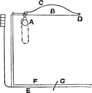
FIG. 82.
FIG. 83.
FIG. 84.
FIG. 85.
In order to make each link in these chains represent any number of picks, and thus prevent long cumbersome chains, the mechanism shown at Figs. 84 to 87 is employed. The barrel A in Fig. 84 is the same as barrel A in Fig. 82, and carries the chains for lifting the levers B and C. At the end of the barrel the star wheel I is fixed, and this star wheel is turned by the pins J. These pins are worked by a clutch motion shown at Fig. 86, by which they can be withdrawn from gear with the star wheel as desired. The pins KK are fixed, and turn one tooth of the star wheel Y every pick, the wheel M having twice the number of teeth contained in L, which is on the crank shaft of the loom. The star wheel Y is fast to the end of a small octagonal barrel,[Pg 119] which carries a pattern chain N composed of small metal cards, and we have seen how this barrel is turned one division every pick. Above this pattern chain N a finger, O (Fig. 86), is placed, and is lifted up against a spring every pick by the cam P on the face of the wheel M. When the finger is up, the pins JJ are taken inside the wheel M, as shown at Fig. 86. The cam P only raises the finger a sufficient length of time to allow the barrel Y to be turned round, and if there is a blank in the cards opposite the finger O when it is let down by the cam it will still keep the pins J inside the wheel, and will thus prevent either of them from engaging with the star wheel I, and will leave the boxes unchanged. This can be repeated any number of picks. If a change is required in the boxes, a hole is placed opposite the finger O, and when it is let down the pins J project through the wheel M (as indicated by the dotted lines in Fig. 86), and the star wheel I will thus be turned one tooth, and the chain can make the change required in the boxes.
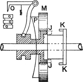
FIG. 86.
FIG. 87.
Fig. 87 is another view of the cam-shaped projection P, which raises the finger every pick, and Fig. 85 is another view of the chain barrel A. The letters in the six Figs. 82 to 87 inclusive refer to the same parts in each case.
In this way the chains on A are rarely required to be very long, as one link may be made to represent any number of picks from one upwards. Of course a separate card on Y is required for each pick, but these are very small, only about 1½ inch in length, and a large pattern can be made with very little trouble.
When a Jacquard is used on one of these looms it is sometimes necessary to work the pattern from the Jacquard cards. This can be done in a very simple manner by covering the hole in the barrel carrying the cards N with a metal plate, which is held over the hole by a spring. When a change is required in the boxes, a Jacquard hook pulls the plate from over the hole, and allows the finger O to drop, and thus causes the star wheel I to be engaged by the pins J.
The picking mechanism in a pick-and-pick loom may be either over or under pick. In the former the picking tappets are sometimes moved on the shaft by a clutch arrangement. In the latter the top of the picking treadle is movable. As the under pick is perhaps the best adapted for this loom, we will describe it.
FIG. 88.
Fig. 88 is a side view of the loom, and the top of the picking treadles consists of a metal plate with the “shoe” S of such a shape as to give the required force and character to the pick. This metal plate works round a pivot, P. The treadles at both sides of the loom are the same in this respect. At the back of the loom a rod, R, is connected to the extreme ends of the loose plates or the treadles, and when one plate is on[Pg 121] the treadle, the other is fixed off its treadle, as shown in Fig. 89. The consequence is that when the picking bowls come round (there are two bowls on the bottom shaft at each side of the loom) the loom will pick always from that side where the loose plate is on the treadle, and at the other side, where the plate is off, the bowls will pass over the treadle without touching it. By moving the rod R sideways, the plates may be moved alternately off and on their treadles.
FIG. 89.
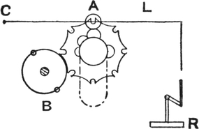
FIG. 90.
If the loom has four boxes at each side, it may be necessary to pick four times in succession from one side of the loom, and by a simple arrangement the picking can be regulated at will. The mechanism for moving the rod R sideways is shown at Fig. 90. Inside the loom framework a lever, L, is centred at C, and by a combination of levers is connected to the rod R, which is the rod referred to in the previous diagrams. A strong spring keeps the plates right for picking from one side, but when it is required to pick from the other the lever L is lifted, which moves the rod R sideways and moves the plate off one treadle and on the other. A chain is used for lifting the lever L, and the star wheel A is turned by two pins on the wheel B on the bottom shaft of the loom, or[Pg 122] by one pin if on the crank shaft, thus causing the star wheel to be turned one division every pick. The loom may thus be made to pick four times from the right side, three from the left, twice from the right, and so on, of course always taking care that the shuttles are there to be picked.
THE tappet shedding motion is the simplest and most perfect for a small number of shafts. They may be made to work an indefinite number of shafts, but it is seldom that above eight or ten are worked with ordinary tappets, and about sixteen with Woodcroft’s or other plate tappets.
With dobbies, a higher number of shafts may conveniently be worked, but it is not only for this reason that dobbies are so extensively used. They are extensively used for weaving twills, satins, and other simple weaves, on four or five shafts. The chief advantage they possess is that any number of shafts within their capacity may be used without extra trouble or cost; whereas ordinary tappets have to be made specially for each pattern; whilst section tappets, and oscillating tappets, are inconvenient.
Dobbies are made to weave up to 40 or more shafts, but 16 and 20 are the commonest numbers. Most dobbies now used are on the double-lift principle; indeed, the single-lift dobby or witch machine is almost obsolete in cotton weaving. The chief kind of double-lift dobby is the “Hattersley” or “Keighley” dobby. The principle of this machine was invented by Messrs. Hattersley & Hill, of Keighley, Yorkshire; hence its name. Since the original patent rights have expired, almost all loom makers have their own particular form of this[Pg 124] dobby, embodying many more or less minor improvements on the original. The principle of this dobby will be understood from the lecture diagram, Fig. 91. The dobby is placed at one side of the loom, and is therefore in a convenient position for being attended to. The upright rod R is connected to a crank on the bottom shaft of the loom, and therefore the rocking lever AB, centred at C, will make one complete movement to and fro, every two picks. The knives D and E slide along, always retaining a horizontal position, one going inward as the other comes outward.
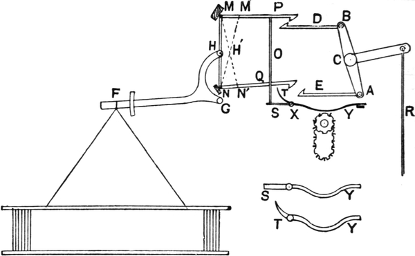
FIG. 91.
The shaft or stave is connected to the jack lever FGH at F, and the upright MN is fastened to this lever at H, the fulcrum being at G. The upright MN has two hooks, P and Q, connected to it at opposite ends, and suppose that when the knife D is in its innermost position, as in the diagram, the hook P is dropped on to the knife; when the knife begins to move it will take the top of the upright MN with it until MN assumes the position indicated by the dotted line M′N, and the[Pg 125] stave is lifted. If it is required to lift the same stave for the succeeding pick, the bottom hook is then dropped on to the knife E, which at that moment will be in its innermost position just commencing its outward movement, and is taken forward by it until the upright MN assumes the position indicated by the dotted line MN′; and it will easily be seen that as the top of the upright is moving back from M′ to M whilst the bottom of the upright is moving forward from N to N′, the centre of the upright H remains stationary at H′, with the exception of a slight movement caused by the knife going further back than the hooks, and thus the stave remains up all the time. The character of the shed is, therefore, what is termed “open shed”—that is, if a stave is required up for several picks in succession, when it is lifted it remains up until it is required to come down again. This is what is meant by “open shed” as compared with “centre shed,” the characteristic of which is that the lifted stave, instead of remaining up, is let down halfway every pick and taken up again if required.
The method of dropping the hooks is as follows:—Two levers, S, T, of different shapes are employed for each pair of hooks; these levers are centred on a rod, X. One of the levers, viz. T, is bent from the fulcrum to touch the bottom hook, and the lever S projects straight out from the fulcrum, and an upright needle O rests upon it, the top hook resting upon the upright needle. When the lever SY is lifted a little at Y it will drop the top hook, and when TY is lifted at Y it will drop the bottom hook.
In a 16 shaft dobby the parts shown in the diagram are duplicated sixteen times—that is, there are sixteen uprights MN, each with two hooks, sixteen levers SY, sixteen like TY, and sixteen of other parts. The levers SY and TY are operated by lags pegged so as to lift the staves to give the required[Pg 126] pattern. These lags work round a cylinder or barrel, which is turned round the space of one lag every two picks intermittently. Each lag operates the hooks for two picks, one row of pegs operates the top hooks P, and the other row of pegs the bottom hooks Q. The method of pegging the lags will be understood from Fig. 92, where two lags are shown with the pegging for a two and two twill. Of course care must always be taken that the pegs are put opposite the proper levers, as when only a portion of the jacks are used, say eight, it is often preferred that the staves be connected to eight jacks in the middle of the machine.
FIG. 92.
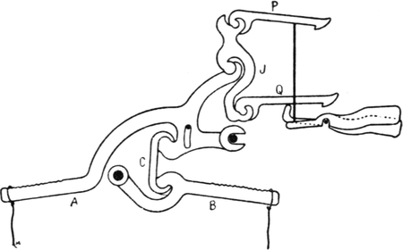
FIG. 93.
Dobbies constructed with single jacks, as indicated in Fig. 91, are only suitable for narrow looms. Those constructed with double jacks are preferable for wider looms, as they not only keep the healds under better command, but they also move them in a perfectly vertical plane without the tendency to a slight side movement such as occurs when the[Pg 127] healds are controlled by single jacks, in consequence of the ends of these describing an arc of a circle as they rise and fall. One of the best adaptations of double jacks to the Keighley type of dobby is that exemplified in the “Climax” dobby made by Lupton and Place, Burnley. This is represented in Fig. 93, in which A and B are complementary jack-levers operated from the same baulk-lever, J, controlled by hooks P and Q, to govern the same heald. The distinctive features of this dobby are the construction of the outer jack-lever A in one part, instead of two parts, and its attachment with the inner jack, B, by means of a link, C. This modification is a great improvement on double-jack dobbies in which the connections are made with streamer hooks or rods, or those in which the jacks are geared by means of toothed segments, as these increase the number of parts that are liable to wear and to get out of order.
The Keighley dobby is decidedly the most popular one at the present time, but what is known as the “Blackburn” dobby is preferred by some. This is a double-lift dobby, which gives a centre shed—that is, the staves which are required up for a number of picks in succession are let down halfway every pick and taken up again. The principle of this dobby is illustrated at Fig. 94. The staves are lifted by the two jacks A and B; when B is lifted it causes A to lift the same distance. There are two hooks, D and F, for each double jack, and the lags are divided into two parts, all the odd numbered picks being fastened together, and the even picks forming another chain. The pegs in the lags press back the hooks, the back part of each of which forms a spring, so that when the hook is pressed back it leaves the stave down.
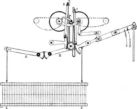
FIG. 94.
The knives lift alternately. When one is going up the other is going down, and when one hook of a pair is lifted, as in the diagram, a lag operates the other hook, and if the[Pg 128] same stave has to be lifted for the next pick, the hook is left over the knife, and the second hook will be taken up whilst the stave is being let down, and will catch it halfway and take it up to the top again. This is the advantage of all double-lift machines over single-lift. The staves which are required up for a certain pick are being taken up whilst those which were up for the previous are coming down. A saving of time is thus effected, and the looms can be run quicker than with single-lift machines. A crank L on the end of the bottom, or picking, shaft is connected by means of a lifting-rod E to the end of a horizontal arm M, mounted on a shaft G, which constitutes a fulcrum for the arm. On one end of shaft G, at the rear of the machine, there is fixed a toothed quadrant H, which, through the medium of a small wheel, transmits motion to a similar toothed quadrant H′ fixed on the end of a shaft G′; and each quadrant is connected, by means of rods K and K′ to the rear ends of the respective griffe-bars D and F. On the opposite ends of the shafts G and G′, there are fixed, one on each shaft, two short arms which are respectively connected to the fore ends of the griffe-bars. Therefore, as the crank L[Pg 129] revolves, the griffes are raised and depressed alternately, and in a contrary manner.
Another thing to be borne in mind is that in a single-lift machine all the staves come to the bottom every pick, and therefore the character of the shed is different from that of a double-lift. In double-lift machines there are the “open-shed” like the Keighley dobby, and the “centre shed” like the Blackburn dobby. It is important to remember these points, as the cover and appearance of the cloth is affected by the beating-up being done in different kinds of sheds.
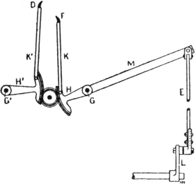
FIG. 95.
The loom crank is usually set at the top centre, or thereabouts, when the rising and falling staves are level, so that the shed will be partly open for the next pick by the time the loom crank gets to the front centre. In single-lift dobbies the beat-up is made when the shed is closed, and so the warp has not the same chance of being spread as with the timing of double-lift dobbies. This difference in the character of the shed when the beat-up is made is caused by the fact that in a double-lift machine the knives, being in the middle of their stroke, are moving at their quickest speed when the shed is closed, and in a single-lift the knife is almost stationary when the shed is closed. The same thing occurs in Jacquards, and the matter may be better understood by a reference to the chapter on Jacquards.
Dobbies can be made “positive” in various ways. Keighley dobbies are made with a pin fixed on the upright MN (Fig. 91) at the point H. A wire is hooked on to this pin and connected to an L lever at the side of the loom opposite the dobby;[Pg 130] this is connected to a lever at the bottom of the loom. By connecting the bottom of one stave to this lever the stave will be pulled down as the upright MN is taken forward, and so the knife whilst taken one stave up is pulling another down, rendering the dobby positive. This, of course, will only do for certain simple patterns, such as twills, satins, and similar weaves, and would not do for patterns where different numbers of staves are lifted every pick. Positive dobbies are not much used in the cotton trade.
The ordinary form of dobby is non-positive, the stave being kept down by springs in some form or other. One reason which may be urged against ordinary springs, or “jack boxes,” is that the pull on the heald increases as the stave is lifted and the spring opened. It is obvious that this is just the reverse of what is required, as the stave is lifted positively, and the pull on it may therefore conveniently be decreased as it is lifted, and the healds would last longer. The use of the spring is to keep the stave down, and therefore it should exert its greatest force when the stave is at the bottom. A simple method of accomplishing this has long been in use. Something on the same principle has been used on hand looms for generations, and very cheap and convenient undermotions of this kind have long been available for power looms; but, strange to say, cotton manufacturers have been very slow at adopting them. An undermotion of this kind is illustrated at Fig. 96. The spring is fixed at A, and a wire hook connects the spring with the quadrant at B. It will easily be seen that as the stave lifts, the direction of the pull of the spring is gradually moved over the centre of the quadrant at C. If the stave were lifted until the spring was in a direct line from A to C, the pull on the stave would be nil, as all the force would be exerted on the fulcrum. Each stave is connected at both sides in the same manner, the springs and other parts are[Pg 131] all arranged in a very compact manner, and the cost is very small.
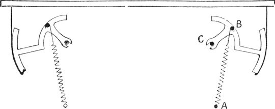
FIG. 96.
Another form of undermotion on the same principle is much used in Yorkshire in the woollen and worsted trades. This is illustrated at Fig. 97, and is known as Kenyon’s undermotion. In this the springs are arranged horizontally, and therefore longer springs can be used. The quadrant is centred at C, and a strap is fast to the quadrant at D. The spring is connected with the quadrant at F. The strap passes from the quadrant under the bowl B, and then to the stave. Another quadrant serves in the same manner for the opposite side. The spring is fastened to a bar at E, and as the stave is lifted, the pull of the spring is gradually moved over the centre C, and therefore the pull on the heald gradually decreases as it is lifted.
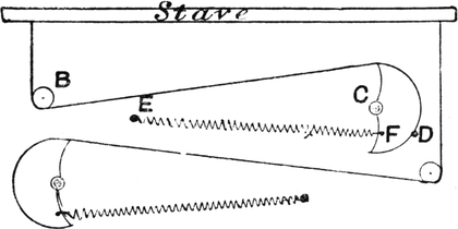
FIG. 97.
WHEN two or more pieces are woven in one width and afterwards cut or torn apart, if there are not a few leno ends to divide each piece the warp threads have nothing to stop them from coming out at the cut sides. In light fabrics this is a greater disadvantage than in heavy and finely picked ones, such as velvets, and therefore in the former it is usual to weave a few ends leno to keep the edge firm. There are various kinds of motions for effecting this object, one of the oldest being that illustrated at Figs. 98 and 99. This is for an ordinary plain loom, and the crossing end is taken through the back stave and through a loop from the top of the front stave. This loop is often formed of a small fine pliable chain, as it wears longer than worsted. Fig. 98 shows the back stave lifted, and Fig. 99,[Pg 133] the front stave up, when it will be seen that the crossing end is brought up on the opposite side from the previous pick.
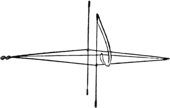
FIG. 98.
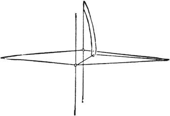
FIG. 99.
FIG. 100.
FIG. 101.
Another, and perhaps a better, method, is Shorrock and Taylor’s patent, shown at Figs. 100 and 101. For a plain loom the two straps A and B are fastened to a drum on the top roller of the loom. In these straps are the small eyes C and D, and through these eyes the crossing ends are taken. The “standard” ends, round which C and D are crossed, are drawn through the fixed eyes EF, immediately above the small bobbins MN. The straps pass round the bobbins and up to the elastics X, which are fastened to a hook, L, at the top of the loom. The top roller is rocked to and fro by the ordinary staves, and when rocked in the direction against the elastics the crossing threads are brought up inside as shown at Fig. 100, and as the roller rocks back the elastics pull the eyes C and D completely round the bobbins and take the crossing threads up the other side of the “dummy” or “standard” ends, EF. The selvedge formed is thus like that shown at Fig. 102.
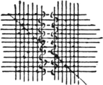
FIG. 102.
There are many patents taken out every year for split motions, but the simple old forms still keep their place.
Another invention of a totally different kind may be mentioned. In this, the weft is cut between the two cloths every pick as it is being woven, and the loose end is then[Pg 134] turned round and taken into the cloth at the next pick, thus forming a practically perfect selvedge; indeed, it would be impossible for any one to find out the difference without being told or making a very close examination. For about half an inch at the inner side of the cloth there are double picks, but this is scarcely noticeable. The practical utility of this invention is yet to be proved, and one thing to militate against its general adoption is its cost, which is several pounds per loom, whereas some of the ordinary split motions cost only a few shillings per loom. With Jacquards or dobbies it is an easy matter to arrange an ordinary doup heald to form a split, but the arrangements before mentioned are used for plain looms, where it is not so easy to get the required lift. The twist used must be very strong, as no slackener is used. Usually it is a three-or four-or six-fold cotton thread.
FIG. 103.
Another kind of selvedge motion is that used for producing a plain selvedge on a loom weaving satteens with tappets. The fact of the ordinary satteen being five picks to the round, and a plain selvedge being a necessity, causes either the tappets to be made ten to the round, working the plain selvedges by tappets on the same shaft, or the selvedge ends must be worked from another shaft. In what is known as Smalley’s satteen motion the former principle is acted upon: the tappets are ten to the round, and the plain is worked from the same shaft.
A more ordinary form is that shown at Fig. 103. A small tappet, A, is fitted on the bottom shaft (or picking shaft), and this acts upon a lever, B, to which the bottom of one set of[Pg 135] harness threads containing, say, the odd-numbered ends of the plain is connected, the other, or even-numbered, ends of the plain being connected to the elastic E, the bowl F at the top being used for working round. When the tappet presses down the lever B, it will take half the plain ends down and the other half up, and the elastic will pull back again as the tappet allows it. In this way a plain selvedge is obtained in a five-shaft satteen.
FIG. 104.
Another method of effecting the same purpose is shown at Fig. 104. A shaft A is placed under the loom, and this shaft is made to rock to and fro to work the mails B and C alternately up and down. The picking shaft of the loom has a crank M fastened to it, and a strap S is taken from this crank to the small drum H on the shaft A, and is wrapped round it. As the crank M revolves it will pull the shaft A in one direction until the crank gets to the top, and when the crank has passed the top of its stroke the spring X will pull the shaft back to its original position, and thus the required reciprocating motion is given to the shaft A and to the mails B and C.
Double-beat Slay.
A double beat is sometimes required to be given to each pick of weft. This is done in weaving some of the heaviest kinds of sackings, carpets, and similar fabrics. Fig. 105 shows how this is effected. AB is the slay, and is movable about B as a centre; EC is in two pieces, viz. ED and DC, and these are fitted loosely on a pin at D. It will be obvious that when[Pg 136] the crank occupies either position QP or QP′, the slay will be at the front of its stroke, and as the crank is moving from P to M it will pull the slay back a little, and in moving from M to P′ a second beat-up will be made. Whilst the crank is moving from P′ to P the shuttle is passed through the shed. It is obvious that a beat-up of this kind will enable the weft to be beaten well up into the cloth, and more to be put in than with a single beat. The force exerted is often so great that the looms have to be very firmly fastened into the floor on which they stand, or they would move.
FIG. 105.
THE Jacquard machine was the invention of a Frenchman of that name, who exhibited the machine about the year 1800. It was introduced into this country about twenty years later. The chief advantage of the machine is that a large number of warp threads can be operated separately, and a larger figure be produced than with a shaft harness. The chief ideas in the machine are that each mail is connected separately to its hook, and the use of perforated cards to leave any hook over the griffe if it is required to be lifted, or to push it away from it if the hook is required to be left down in the shed.
The original Jacquard machine was a single-lift, and although many minor improvements have been made in it, the main features are practically the same to-day as in the earliest machines introduced into this country. At the present day the single-lift is comparatively little used in cotton manufacture owing to the increased speed at which double-lifts can be worked, but it is still preferred in silk manufacture for several reasons. One reason is that the character of the shed when beating up in a double-lift machine is essentially different to that produced by a hand-loom, where of course a single-lift is always used, and as hand-loom fabrics have a finer touch and appearance than power-loom fabrics, the object is to imitate the hand-loom production as nearly as possible. The cause[Pg 138] of this difference in the character of the shed when beating up will be explained later in this chapter. Another reason is that silk-looms could never be run at any speed higher than that of which a single-lift machine is capable, and therefore the advantage of increased speed of the double-lift is of no use.
Double-lifts, owing to the counterpoise and the division of the work on to two knives, are undoubtedly steadier in working, and this is an argument decidedly in their favour. Single-lifts are still used in the manufacture of figured lenos, as no shaking motion has yet been successfully adapted to enable the crossing ends to cross with a double-lift machine.
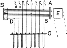
FIG. 106.
A single-lift Jacquard for weaving a pattern which occupies 400 ends in a repeat consists of 400 hooks and 400 needles, with an extra row of eight hooks for selvedges, or other auxiliary use. The hooks are arranged in eight rows with 51 hooks in a row. A cross section of this Jacquard is shown at Fig. 106, where the uprights are the hooks and the horizontal wires the “needles.” A is the “needle board,” and this is a perforated board through which the needles pass. The bottom needle B is twisted or looped round the back hook D, and the connection of the other needles and hooks is shown. At the back of each needle a small spring made of fine brass or steel wire is placed. These springs are held in position in the “spring-box” S. There are, therefore, 408 springs required for the 408 needles. The hooks rest on the grate G, but in some makes of machine the grate is not used and the hooks rest upon a “bottom board.” In this case the hooks are very liable to turn round, and thus cause[Pg 139] annoyance. To prevent this, flat hooks have been used, and the needle loop was shaped so as not to permit the hook to turn within it. The eight knives form the griffe. These knives are all fastened together, and are moved up and down from the crank-shaft of the loom. The illustration shows the knives at the bottom of their stroke, and at this point, or immediately after the griffe begins to move upwards, the card on the perforated cylinder E is pressed against the needles, and if there is a hole in the card, the needle directly opposite the hole will pass through it and into the perforation in the cylinder, and the knife will take up the hook to which this needle is connected. If the card is blank opposite any needle it will press back the hook, and as the knife lifts, the hook is left down. Thus it is possible to lift any of the 408 hooks in the machine for any pick. When the cylinder is taken away from the needles the hooks are forced back into their original position by the small springs in the spring-box S.
It will be noticed that the knives are leaning a little, and the reason for this will be apparent, as if they were not leaning they would catch the tops of the hooks in coming down, and would break or bend them. The sloping position enables the knives in coming down to press back the tops of the hooks and so get under them, ready for the next card to be pressed against the needles. The knives should come down low enough to be quite clear of the hooks, and therefore in this machine there is a considerable dwell when the shed is closed.
The harness for a straight-over pattern is mounted as shown at Fig. 107. In order to prevent confusion the connection of the cords to the machine is not shown, but the numbers on the line A represent the hooks in the machine to which the cords are to be attached. The “comber-board” or “cumber-board” B is a frame into which perforated slips are fitted. These slips are perforated to different degrees of fineness, the fineness being[Pg 140] regulated by the number of ends per inch required in the cloth to be woven. The lingoes, L, are metal weights, and serve the purpose of keeping the mails down. MM are the mails, through which the warp threads are drawn in the order shown by the numbers, beginning at the back left-hand corner. The draft in straight-over patterns is always taken in this way in Jacquard weaving, although it is not compulsory. The harness is built with linen thread, and the method of tieing the lingoes to the hooks will be understood from the diagram.
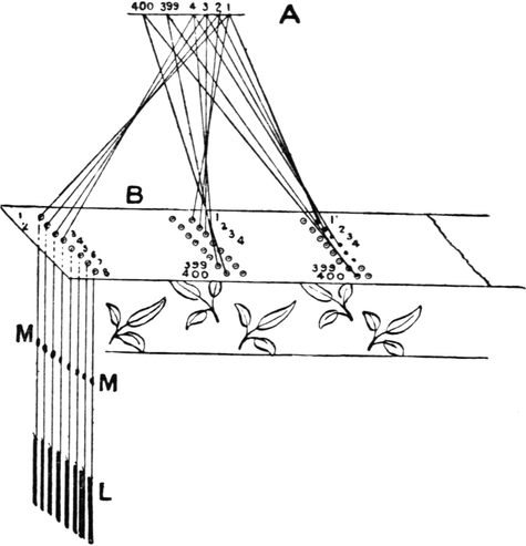
FIG. 107.
When one lingoe has been connected to each of (say) 400 hooks, the first pattern is complete. Supposing there are 100 ends per inch, the pattern will occupy 4 inches, and therefore if cloth is required 28 inches wide in the harness, there must be seven lingoes attached to each hook, making seven patterns, or seven repeats of the pattern, in the width of cloth. Thus[Pg 141] when one lingoe has been tied to each hook, beginning with the first and ending with the 400th, another is connected to each hook, beginning again with the first; and when this is done other patterns are formed in the same manner until the required number is complete.
FIG. 108.
It is important to have a clear understanding as to which is the hook which lifts the first end in the draft. This hook is the one connected with the bottom needle in the last row on the 25-side of the machine. As we stated previously, a 400s machine has 400 hooks arranged in 50 rows of 8, or 8 rows of 50 hooks, and in addition there is always a spare row of hooks, making 51 rows in all. As it is necessary to lace the cards in the middle as well as at the sides, a space has to be allowed for the lace holes, and therefore the machine is divided into two parts by a space between the 26th and 27th rows.
A plan of a card is given at Fig. 108. The length of the card between the two peg holes A and B is nearly 14½ inches, and the distance between the centre of the top needles and the bottom needles is 1⅞ inch exactly. This holds good for all English-made machines, but the American index is different.
It will be seen that there are 26 rows on the right of the machine and 25 rows on the left, and one is called the “26-side” and the other the “25-side.” The cards are always numbered at the “26-side,” and the cutting is commenced at this end. It may be as well to explain here the order in which the holes are cut from the design, as it will assist in following the point paper design to the loom. The cutting is usually done in a “piano” cutting machine, which will be explained more fully later on. By this machine one row of eight holes can be cut by operating eight punches and pressing down the right-foot treadle of the machine.
The number end of the card is gripped by the machine, and at the first stroke of the right foot, the lace holes EF and the peg hole A are cut, then one stroke of the treadle is made without cutting, and the pointer of the machine arrives at the 1st or spare row. If the selvedges are worked from this row, holes are cut accordingly. Then the pointer comes to the 2nd row, and in this row the cutting from the design is commenced.
At Fig. 109 the design is made on point paper, as it is required to appear in the cloth right side up, with the twill in the ground running in the same direction as shown on the design. When cutting, the design is usually turned round, as shown at Fig. 110, and the cutting commences from the top right-hand corner A. To show the matter clearly, the first row of holes cut are numbered, both in the design and the card, in consecutive order.
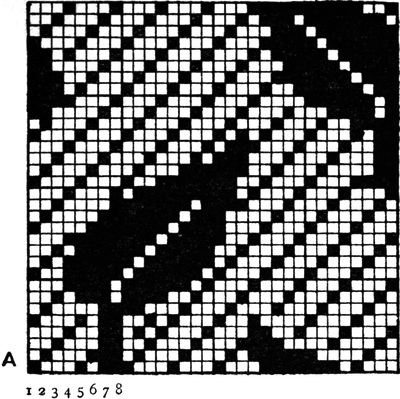
FIG. 109.
FIG. 110.
The first hole cut in the card is operated with the little finger of the right hand. Following this hole to the loom, we find it operates the last or 400th end in the draft, and that the hole cut last on the card (numbered 400) operates the first[Pg 144] end in the draft. This is the hole which operates the bottom needle in the last row on the “25-side” of the Jacquard machine, which, as was previously stated, is the hook from which the draft begins.
Following out the operation of cutting the card. When the 26th row has been cut, the lace holes MN (Fig. 108) are cut, and then the cutting is again straight-forward to the 50th row. The piano machine is so constructed that with the same stroke of the treadle which cuts the 51st row the peg hole D is also cut, and then follows a stroke without cutting, after which the two lace holes T and Y are cut. This makes 56 strokes of the foot for each card.
It is usual, in order to economise space, for the Jacquards with straight, or “Norwich,” harnesses to be placed on the loom, so that on one loom the cards hang over the weaver’s head, and on the next the cards are at the back of the loom. In both cases the harnesses are built the same way, but in one case (cards over weaver’s head) the thread operated by the bottom needle on the “25-side” will be at the back of the comber-board, at the left hand; and in the other case (cards behind loom) the same thread will be at the front of the comber-board at the right-hand side.
As previously stated, the single-lift Jacquard for cotton weaving is not often employed except for special purposes, such as figured leno weaving. The advantage possessed by the double-lift Jacquard as regards speed is so very considerable that its adoption for ordinary forms of cotton weaving has become universal; and the advantage of speed is not the only advantage it possesses, as will be pointed out shortly.
A double-lift machine with one cylinder for a 400 end pattern consists of 800 hooks and 400 needles. Each needle is twisted or bent round two hooks, as shown at Fig. 111. The hooks are connected together in twos by neck cords,[Pg 145] which are usually strong whipcord, as will be seen from the illustration. It will be seen that the bottom needle is bent round the back pair of hooks, the next needle round another pair, and so on. Each needle has a spring behind it, as in a single-lift machine.
FIG. 111.
There are two griffes, which work oppositely—that is, as one goes up the other comes down. The griffes (or knives) are worked by a double crank on the bottom shaft of the loom, so that each griffe moves from the bottom to top of its stroke in one pick, and from top to bottom in another pick.
The principle of the double-lift will be understood from Fig. 112. One knife, A, is at the top, and the other knife, B, is down. One hook of the pair is lifted, and therefore the ends in the mails connected to the neck cord at C will be lifted. Suppose now it is required to lift the same ends of warp for the next pick: a card is pressed against the needles, and if there is a hole in the card opposite the needle E, it will leave the needle and the hook N where they are, and as the knife B is lifted, the hook N will be taken up as the hook M is coming down. The hooks will cross at about the middle of their stroke, and the weight of the ends and lingoes on the cord C will at that moment pass from the hook M to the hook N. In the diagram the cord attached to the hook N is slack, but when this hook[Pg 146] is lifted the cord will gradually tauten until it bears all the weight, when the cord from the hook M becomes slack. We thus have the ends for the second pick lifted whilst the ends which were up for the previous pick are coming down. This is where the advantage of the double lift lies. In a single lift the knife must lift the hooks up and then come down to the bottom before another card can operate the needles, whereas in a double lift the card for a second pick can be brought against the needles as soon as the ends which were up for the previous pick are ready to come down.
FIG. 112.
It is obvious that in the position shown in Fig. 112, when one knife is up and the other down and the needle pressed back by the card, that the hook M will also be pressed back, as shown by the dotted line. The bend of the hook over the knife, therefore, must be sufficient to prevent the hook being pushed off the knife, and it will be noticed that the hooks in this class of machine are bent more than the hooks in a single-lift machine. The hooks rest on the grate G, Fig. 111, and the shape of the hook at this point acts as a spring to straighten the lifted hooks after the pressure of the card has been taken off the needles. A machine of this kind can be run at a speed of about 160 or 170 picks a minute, as compared with the 130 or 140 picks of a single-lift.
A double-lift machine on another principle is illustrated at Fig. 113. This is a two-cylinder machine, and to weave a pattern repeating on 400 ends this machine requires 800 hooks and 800 needles. The cylinders work at opposite sides. The[Pg 147] hooks are placed as shown in the diagram, the hooked parts facing each other in pairs, and by following carefully the manner in which the needles are twisted round the hooks it will be seen that there are really two single-lift machines placed together, alternate rows of hooks representing each machine. There are two griffes, as in the double-lift single-cylinder machine, and the griffes are worked in the same manner.

FIG. 113.
The cylinders work alternately, the cards being laced in two sets, all the odd numbers being together in one set and the even numbers forming another set. Immediately one knife is at the top and the other at the bottom, one cylinder is pressed against the needles, and it will be noticed that the hooks which each cylinder operates have the hooked parts in the direction of the cylinder. When the hooks operated by one cylinder are at the top the other cylinder is pressed against the needles, and thus the work done by one cylinder in Fig. 111 is divided between two in this machine. The advantage of this machine is in the lessened speed of the cylinders. The vibration caused by the cylinder working at a high speed in a single-cylinder machine is so great that the limit is reached at about 170 picks per minute, whereas a double-cylinder machine can be run up to 200 or sometimes even more picks per minute, though perhaps 180 is a more advantageous speed. The top set of[Pg 148] needles project a little further through the needle board to compensate for the difference in leverage on the hooks.
Besides the advantage of speed, double-lifts have an advantage in the counterpoise obtained by one set of hooks going up as the other comes down. This causes a more even motion and steadier working. Another advantage possessed by double-lifts is that the beating up of the weft is effected in a crossed shed, thus enabling more weft to be put in than in a single-lift, where the beat-up is done with a closed shed. This beating up in a crossed shed also spreads the warp better, and prevents the reed marks from showing, for the same reason as was given when referring to the spreading of the warp in the tappet loom.
In silk weaving a single-lift machine has an advantage in imitating more closely hand-woven goods, as hand-loom weavers usually beat up in a closed shed. This causes the weft to be put in straighter—that is, less wavy, which is very desirable in silk fabrics.
The cause of this difference in the shed when beating up in the two kinds of looms will be understood by following the relative positions of the griffes and the loom crank throughout its revolution.
In a single lift the time allowed for opening and closing the shed must be used to the best advantage; that is, as much time as possible must be given for this purpose. On this account it is necessary to pick the moment the slay is sufficiently far back to allow the shuttle to enter the shed—that is, when the slay is half-way back, or the crank at the bottom centre. The griffe is worked by a crank on the top shaft of the loom, and there is no actual dwell of the griffe or of the ends when the shed is open; therefore the shed must be opened a little wider than would otherwise be necessary for allowing the shuttle to pass through.
The shed must be sufficiently open to allow the shuttle to[Pg 149] enter when the loom crank is at the bottom centre. This regulates the timing of the other parts. Fig. 114 will make this quite plain. The shed must be nearly fully open when the crank is at the bottom centre to allow the shuttle to enter; and when the loom crank is at A the griffe must be nearly at the top. When the crank is at B the griffe will be at the extreme top, and when the crank is at the top centre, or C, the griffe will be as near the bottom as it was to the top when the loom crank was at A. As was previously pointed out, the griffe must go further down than the hooks to allow another card to operate the needles, and therefore it is when the loom crank has arrived at C that the knife is leaving the hooks resting on the grate, or bottom board. The griffe will be at the extreme bottom when the loom crank is at D, and when the griffe is up at the hooks again the crank is at the front centre, or E. Thus the shed has the fraction of a revolution between B and C to close in, and between E and B for opening. The shed remains closed for the quarter of a revolution, C to E.
FIG. 114.
FIG. 115.
In a double-lift the warp is much more leniently dealt with. As we have said, the shed must be open for the shuttle to enter when the loom crank is at the bottom centre. Therefore the griffes should be in their extreme position—one up and one down—when the crank is at the bottom centre.
The timing of the parts in a double-lift will be seen at Fig. 115. The cranks that work the griffes are on the bottom[Pg 150] shaft, which of course makes a revolution every two picks. These cranks will be perpendicular when the shed is fully open; therefore when the loom cranks are at the bottom centre the cranks which drive the griffes must be in the position AB. If they are so set they will be in the position CD when the loom crank reaches the back centre, and in the position EF, or horizontal, when the loom crank arrives at the top centre, when the shed will be closed. We have thus a closed shed when the crank is at the top centre, as in a single-lift; but in this case when the shed is closed the griffes are moving quickly, whereas we have a quarter of a revolution dwell after the loom crank reaches the top centre in a single-lift. This causes, as we shall see, a difference in the shed when the slay beats-up, or is at the front centre. When the griffe cranks are in the position GH, the loom crank will be at the front centre, and thus the shed will be partly opened for the next pick when the reed comes in contact with the cloth.
Jacquards are made in various sizes. 100s, 200s, 300s, 400s, and 600s, are the most common. 100s are arranged in rows of four; 200s and 400s are in rows of eight; 300s and 600s in rows of twelve.
There are two distinct kind of harness mounting, the London and Norwich systems. In the former the Jacquard is placed with the narrow end towards the front of the loom, thus causing the cards to fall at the side. In the Norwich system, or “tie,” the machine is placed with the broad side facing the front of the loom, thus causing the cards to hang either over the weaver’s head or at the back of the loom. On this system, as there are eight rows in a machine, by taking the comber board eight rows deep the harness becomes what is called a straight neck. With the London system, the end of the machine facing the weaver, there must be a twist in each pattern in the harness. There is not much to choose between[Pg 151] the two systems. Some prefer the London tie, as they say the twist in the harness causes the harness threads to support each other, and so last longer. The Norwich system is the more common, especially in the cotton trade.
FIG. 116.
Fig. 116 shows the method of tying up the harness on the Norwich system for a bordered fabric, such as handkerchiefs. In these goods it is usually preferred that both borders should point inwards, as in the sketches Figs. 116 and 117.
FIG. 117.
The hooks to which the harness threads are attached are numbered on the line A, and it will be seen that the draft begins in the left-hand corner at the back of the comber-board, the lingoes being numbered in the order of the draft. The cords are tied up just as for an ordinary straight-over harness for the first 400, or one full pattern of the machine, but then, instead of commencing with the first hook again, the 201st lingoe is tied to the 201st hook, and the second half of the pattern is repeated. This forms the middle of the handkerchief, and it must be repeated over a sufficient number of times to give the required width of cloth after allowing for the trimming and border. In[Pg 152] Figs. 116 and 117 nothing but a border and middle are shown, but sometimes a trimming of another small weave is required outside the border, and this, which is usually on a small number of hooks, is repeated over in the same way as the middle. In Fig. 118 only two repeats of the middle are shown; but supposing that the harness had 100 ends per inch, and that the handkerchief was required to be twenty-four inches wide excluding the border, there would be twelve repeats of the middle required. When the middle has been repeated over a sufficient number of times, the other border must be tied up, and to obtain the reverse position of the figure the draft must be reversed. By tying the next lingoe to the 200th hook, and going backwards with the draft, it can easily be seen that the same figure will be woven at this side of the harness as at the[Pg 153] opposite side; the only difference will be that the figure will point to the left, as will also the twill in the ground, if it is a twill. This system of tying up is compulsory in the Norwich system, as it is usual to keep the harness straight—that is, the harness threads from each of the eight rows in the Jacquard each form a separate row in the comber-board. We have thus eight rows in the machine and eight rows deep in the comber-board, and it would not do to have a thread taken from the front of the comber-board at one border and from the back of the comber-board at the other border to the same hook.
FIG. 118.
If the harness is a “London tie” it necessitates a half-turn in each pattern, as the machine is at right angles to the comber-board. Therefore the draft may be continuous, as shown at Fig. 117, where, after the middle has been repeated a sufficient number of times, finishing with a thread from the 400th hook at the front of the comber-board, the next one is[Pg 154] taken from the 200th hook through the back of the comber-board, and the border will finish with a thread from the first hook going through a hole at the front of the board—just the reverse to the other side.
Bordered goods are often made with two borders at each side, and sometimes the borders are repeated a few times. The number of hooks taken for the border and middle respectively vary according to requirements. Sometimes, in a 400 machine, 300 will be taken for the border and 100 for the middle, and so on. The cross-border must of course be designed, and the cards cut. The number of cards in a set in these goods is often very large, as the middle must be repeated over the required number of times, and there will be as many cards used in the set as there are picks in the handkerchief.
In designing for the mounting given at Fig. 117, the design would be made on 400 ends: 200 for the border and 200 for the middle, and the cards would be cut just in the ordinary manner. The cross-border would also be designed in such a manner as to harmonize with the side borders. The portion to be designed is enclosed by the dotted lines.
Centre ties or point ties are another class of harness in regular use. This is really the two borders of a bordered harness joined together. Fig. 118 shows how the tying up is done for a pattern of this kind. The first 400 threads are connected as usual, the draft being from back to front. When the 400th has been reached, the draft is reversed until No. 1 is arrived at again. The same effect is obtained as in a point of V draft in a shaft harness. The pattern must be of such a character that one half is the exact reverse of the other. This kind of harness is used for weaving large damask figures, and it is obvious that the effect produced is really that of a figure[Pg 155] on 800 ends, or twice the size of the machine. Designs of this character are of course rather stiff, but are suitable for damasks, and similar fabrics.

FIG. 119.
The object of a cross-border Jacquard is to save the expense of cards in handkerchiefs and other bordered goods. As pointed out previously, the portion of the handkerchief between the two cross-borders is usually repeated over for a considerable number of times, often from twelve to twenty times. This often means using a few thousand cards, which might be saved if the border and middle cards could be laced separately and changed automatically. On the hand-loom it is usual for the weaver to change the cards by hand when required, substituting the border for the middle cards and vice versâ, but in the power-loom this is of course out of the question, and usually the total number of picks in the handkerchief have each a separate card. The cross-border machine illustrated at Figs. 119 and 120 is the invention of Messrs. Crossley and Davenport.[Pg 156] The machine is double-lift, as will be seen from the connection of the neck-cords. The border cards are put on one cylinder, B, and the middle cards on another, A. When the cylinder A presses back a needle, say the top needle C, it will press back the pair of hooks EF, as in an ordinary double-lift single-cylinder machine, and as long as this cylinder is worked every pick the machine is to all intents and purposes a double-lift single-cylinder machine. When this cylinder is stopped and the cylinder B is worked every pick, the cards on the cylinder B have exactly the same effect on the ends as those on cylinder A; for when the top needle in this set of needles is pressed back, it will force backward the pair of hooks EF, exactly as operating needle C by the other cylinder did. Only one spring-box is used, as the upright wires MM pass through loops, P, in the long needles, and small iron bars, HH, act as fulcra for the wires MM. The tops of these wires are fastened to the short needles N, as indicated in the diagram, and thus when the needle N is pressed back it moves the needle C in the opposite direction and operates the hooks EF.
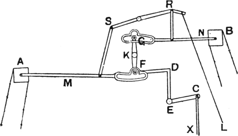
FIG. 120.
The cylinders can be changed by pulling the cord L in Fig. 120. When the parts are in the position shown in this[Pg 157] illustration, the cylinder A will be pressed against the needles every pick. The cylinders are driven from the crank shaft, the rod X goes to the crank shaft, and a reciprocating motion is given to the L lever CD centred at E. The rocking lever FG is centred at K, and the reciprocating motion is transferred from CD to FG. It will be seen that one end of the lever FG is in the diagram inside the bend in the slot on M, and the other end of the lever FG is in a position to move about its centre, K, without moving the cylinder B. Thus as the crank shaft of the loom revolves it will give motion to the cylinder A, but not to B. By pulling the cord L, however, the bend on the slot on N takes hold of the top of the rocking lever G, and at the same time, through the lever SR, M is lifted, and the end F of the rocking lever moves freely in the slot without moving the cylinder A. The disadvantage of this motion is that the change is not made from the cards automatically, certainly not an impossible piece of mechanism to contrive. There are other cross-border motions, but this is only given as an example.
Double-shed Jacquards are used chiefly in weaving heavy goods where a very large and deep shuttle is required to hold a reasonable quantity of weft. The principle of this machine will be easily understood from Fig. 121. A is connected to the crank shaft of the loom and moves the end of the lever BC up and down, the fulcrum of the lever being at E. The bottom board or plate F is therefore moved up and down, and in doing so the griffe G is made to move oppositely, the bottom plate coming down as the griffe goes up, and vice versâ.[Pg 158] This is effected by the top levers PR and QS, which are centred at O. One end of the griffe is connected to Q, the other end of the griffe is connected to P. This gives firmness and strength to the machine. These Jacquards are usually made very heavy, as they are chiefly for heavy work.
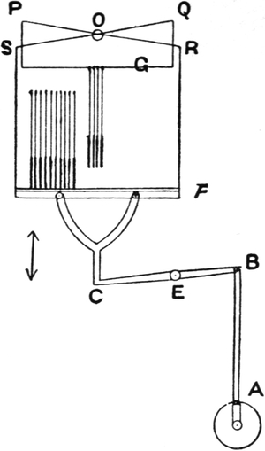
FIG. 121.
Only a few hooks are shown as an example, but the machines can be made any size. When all the hooks are resting on the bottom board, which will be when the bottom plate is at the top of its stroke, the card is pressed against the needles and selects the hooks to be lifted in the usual manner, after which the griffe rises as the bottom board sinks. Thus an extra deep shed is produced without the griffe having so far to lift as would otherwise be the case. The shed produced is a centre shed, all the ends coming to the centre every pick.
Several open-shed Jacquards have been patented. That of Wilkinson’s is illustrated at Figs. 122 and 123. A and B are a pair of hooks, which are connected by a cord passing round a pulley, W. This pulley works on a pin at one end of the thin plate C, and at the other end of the plate[Pg 159] is another pulley, X. The neck cord E passes round this pulley to the bar D, to which it is fastened. It is obvious that when one hook of the pair is lifted, say, 4 inches, and the other is at the bottom, the pulley W will be lifted 2 inches; and as the cord E is fast to D, the harness threads will be lifted 4 inches, the same as the hook.
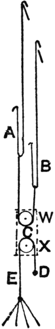
FIG. 122.
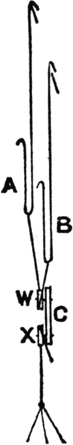
FIG. 123.
If one hook of the pair is lifted and it is required to keep the same ends of warp up for the next picks, the hooks being connected round the pulley W, one hook going up as the other comes down will keep the harness cords stationary, and the hooks A and B can be lifted alternately one up, one down, without moving the cord E, which will all the time be keeping the warp ends up. The shed thus obtained is similar to that in a Keighley dobby; the ends, when once they are lifted, stay in that position until they are required to come down. The principle can be applied to either double-lift single-cylinder or double-lift double-cylinder machines.
Another view of the pulleys is shown at Fig. 123, where the pulleys and other parts are lettered as in the previous figure. Each pair of hooks in the machine has these pulleys attached, and therefore it will be understood that the pulleys must be rather thin in order to enable them to be placed in a space equal to the size of the Jacquard machine. The advantage which a satisfactory machine on this principle would possess lies in the fact that the jerk which occurs in ordinary double-lifts when the weight is passing from one hook to another in each[Pg 160] pair is done away with. This jerk causes breakage of the neck cords, and many efforts to overcome the annoyance have been made. This principle of open shed may be applied to dobbies such as the Blackburn dobby.
The split harness is an ingenious method of increasing the size of pattern which can be woven on a given Jacquard. What is termed a “double-scale” split harness consists of two adjacent lingoes being connected to each hook in the machine. Thus with a 400s machine there are 800 mails in a pattern. A few lingoes are shown at Fig. 124 tied up in the manner of a double-scale harness. The connections to four hooks are shown. Underneath the comber-board a loop is made in the harness thread, and shafts SS, either wood or metal, are inserted through the loops in each row in the harness. These shafts are worked by the spare hooks in the machine, and in the places where the ends are left down by the Jacquard, the shafts, being lifted to a given ground pattern, will weave the ends singly. In Fig. 124 the shafts are shown lifted to weave a plain or tabby ground, every alternate one being lifted. Hooks No. 1 and No. 2 are lifted by the Jacquard, and hooks 3 and 4 are left down, and it will be seen that where the hooks are down, half the ends will be lifted by the shafts. The ends, when lifted by the Jacquard, cannot be woven separately with this harness, and[Pg 161] therefore the bindings in the figure will show in twos, which, unless the harness is a fine one, has a tendency to make the cloth appear coarse. Satin or twill grounds may be woven. In fact, the ends left down by the Jacquard may be woven singly to any pattern which repeats on the number of shafts used, or into the number of rows which the harness is deep in the comber-board. Of course either the figure or the ground may be woven singly, according to the way the pattern is designed, but not both.
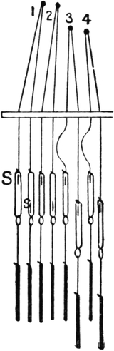
FIG. 124.
In silk weaving, harnesses are built on this principle to a threefold scale—that is, with three mails attached to each hook—and as in the double-scale a figure repeating on 800 ends can be woven on a 400s machine, so with a threefold scale a 1200 figure can be woven on a 400s machine. In this case the bindings in the figure will be in threes, but the ground ends may be woven quite singly by the shafts.
This principle is only adapted for very fine reeds in cotton goods, but is often used in silk manufacture, where 300 or 400 threads per inch are not uncommon.
The pressure harness was invented with the object of enabling very large figures to be woven on ordinary sized Jacquard machines. In very fine silk damasks—say, with about 400 threads per inch—a very large machine (or machines) is necessary to obtain a figure suitable for damask on the ordinary principle. The pressure harness overcomes this difficulty in a most ingenious manner.
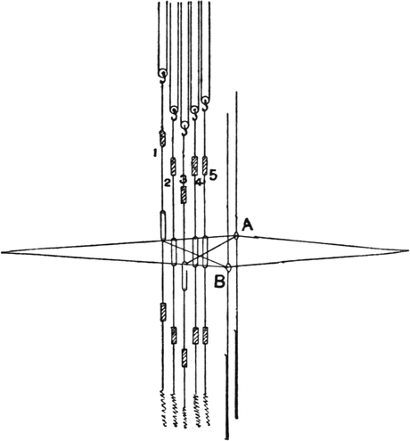
FIG. 125.
The method originally used consisted in drawing a number of ends in each mail, and then drawing each end separately[Pg 162] through a shaft in front of the harness. These shafts had long eyes, as shown in Fig. 125; in fact, the eyes are large enough to permit of the shed being opened without their interfering with it. In Fig. 125 two of the Jacquard lingoes are shown, A, representing those lifted by the Jacquard, and B, those left down. There may be any number of ends in each mail, say five. After being drawn through the Jacquard harness in fives, the ends are drawn singly through the shaft harness in front. These shafts are either worked by treadles or by a Jacquard. In the diagram they are shown worked in the latter manner. A small pulley is placed between the hooks and the shafts, and each shaft is connected to two hooks, a cord from one hook passing round the pulley to the other[Pg 163] hook. When both hooks are lifted, the shaft will be lifted to the top, like the shaft 1; when only one hook of the pair is lifted, the shaft will be taken up half way, like the shafts Nos. 2, 4, and 5; and when both hooks are left down, the shaft is left at the bottom, like the shaft No. 3 in the diagram. These shafts require to be worked by a machine with double the lift of the Jacquard machine behind them, as from bottom to top the lift is twice the size of the shed. They may also be worked on the centre shed principle, one shaft going up and another one going down from the centre each pick.
If one of these shafts is lifted to the top, like shaft No. 1, it is obvious that it will take up one end out of every mail left down, and by lifting the shafts in satin order the ends left down by the Jacquard in fives would be woven singly five shaft satin. By leaving one shaft down every pick, the ends lifted by the Jacquard will be split up in the same manner. So that with one shaft at the top, one at the bottom, and the other three lifted half way, a figure repeating on 2000 ends can be woven on a 400s Jacquard, every end being woven singly in both the ground and the figure. Of course only simple weaves can be used, and the figure will move in steps round the edges. If it is required to weave an eight shaft weft satin figure on an eight shaft warp satin ground, eight shafts must be used instead of five. The ends may still remain five in a mail, as it is not necessary that the number of ends in each mail should be the same as the number of shafts used. These shafts are called pressure healds; hence the name given to the harness.
In designing for this class of harness the figure is put on point paper in simple colour, no binding dots being used, as the binding is all done by the pressure healds. The method of putting down the plan for lifting the healds, and of devising a variety of weaves for pressure harness weaving, will be found fully explained in Chapter X.
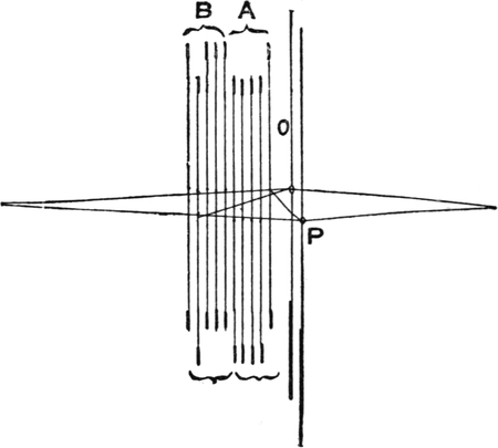
FIG. 126.
Another and better kind of pressure harness is illustrated at Fig. 126. Instead of healds with long eyes, two sets without eyes are used, but with a simple clasp in the middle. Fig. 126 shows the mounting for a five end satin figure on a five end satin ground, and two lingoes only of the Jacquard are shown, O representing the lifted hooks, and P the hooks left down.
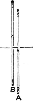
FIG. 127.
There may be five, six, eight, or more ends in each mail, and they are drawn singly into the pressure healds in front in the following manner:—There are two sets of healds with clasps, as shown at Fig. 127. Each end is drawn singly over a clasp in the set A, and under a clasp in the set B. The clasps in the set A are fixed at the bottom of the shed, and the clasps in B are fixed at the top of the shed. By pulling one of the set B down and lifting one of the set A every pick in satin order, the ends lifted in fives or sixes are[Pg 165] woven singly in warp satin, and the ends left down in fives or sixes are woven singly in weft satin.
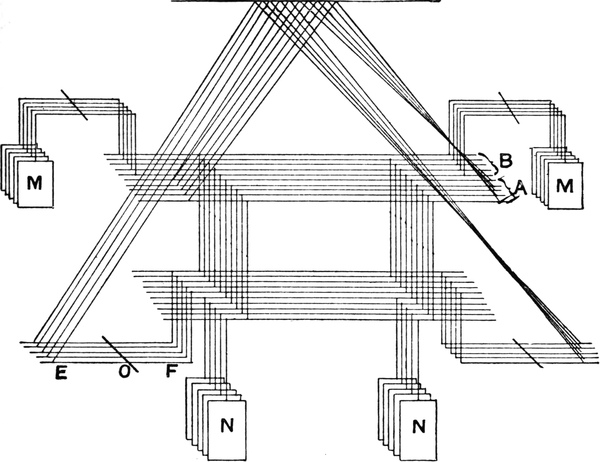
FIG. 128.
The method of operating the pressure healds in a hand loom is shown at Fig. 128. The shafts in set B are pulled down by lifting the end E of the levers EF, and the same on the other side. The shafts in the set A are lifted directly by the hooks. The shafts are lifted by a few spare hooks in the Jacquard. Sometimes the Jacquards have three or four rows of extra hooks for this purpose, and these hooks are placed a little to one end of the machine, and a small separate cylinder is used. The cards for lifting or pulling the pressure healds are put on this cylinder, and the large cylinder carrying the figure cards is only turned round once every few picks by[Pg 166] arranging the catches to do this. The same card is thus brought against the needles several times in succession, and the smaller cylinder being turned every pick, interweaves the threads in satin or the required order. This will form steps at the edges of the figure in the weft way as well as warp way, and is a considerable saving of cards. The weights M are to pull the healds B up, and the weights N to keep the healds A down. Springs may be used in their place, but weights are preferred in the hand loom.
The mails used in the Jacquard harness are made with a separate hole for each end. Sometimes as many as twelve or sixteen ends are drawn in each mail, thus giving in the latter case a 6400 end figure from a 400s machine, so that with 300 ends per inch the figure would measure over 20 inches wide.
A method of weaving an 800 figure on a 400 double-lift machine has been patented by James Edleston, of Preston. This is a very useful and ingenious idea, as a floated figure can be formed, and the machine remains a double-lift, with all its advantages as regards speed. Certain limits are placed upon the weaves, which can be employed for the ground or for developing the figure, but sufficient scope is afforded for all practical purposes to make the invention a success. An illustration is given of this harness at Fig. 129. The inventor gives no drawing in his specification, but presumably the illustration (Fig. 129) will represent his method; at least, it will effect the same object. One row of hooks of a 400s double-lift single-cylinder machine are shown, and it will be noticed that the hooks are not joined together by a[Pg 167] neck cord as in the ordinary machine, but the harness threads are taken singly from each hook as in a single-lift machine. The knives work as in a double-lift, one up, one down. By cutting the cards in a certain manner the whole of the 800 hooks may be operated by the 400 needles so as to produce ordinary brocade or damask figures with a repeat of 800 ends. The same end cannot be lifted for two picks in succession, as the knives have to move up and down and work oppositely; but an end can be left down any odd number of picks, and a figure can thus be formed. At Fig. 130 the design for eight-end satin ground is given. It must be remembered that for eight ends there are only four needles, and therefore the lifting dots must be put on four ends on the point paper. By carefully comparing this design with the mounting of the harness, the principle will be quite clear. The design shows a dot on the first and fifth ends on the first pick, and therefore a hole will be cut in the card opposite the first and fifth needles.
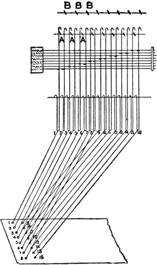
FIG. 129.
Suppose the griffe A to be lifted for the first pick, it will lift the first and ninth ends. The second card has holes opposite the second and sixth needles, and when the griffe B is lifted for the second pick, it will lift the fourth and twelfth ends in the warp or lingoes in the comber-board. The third[Pg 168] card has holes opposite the fourth and eighth needles, and as on the odd picks the griffe A lifts, it will lift the seventh and fifteenth ends in the warp. If this is followed out it will be found that the ends are lifted in the order 1 4, 7 2, 5 8, 3 6, or eight end satin is woven. Fig. 131 shows the method of putting the dots on point paper for four end twill (one and three). The principle is the same as in the preceding case, and is very simple when understood. A hole opposite the first needle on the first pick causes the first end to be lifted, and a hole opposite the same needle for the second pick causes the second end to be lifted. Any figure can be put upon the cloth, with the following limits as regards the bindings: firstly, an end cannot be lifted for two successive picks; secondly, every end must be left down an odd number of picks.

FIG. 130.

FIG. 131.
From this it will be seen that a five end satin cannot be woven, nor can a weft figure be put on a warp ground. Plain grounds can be woven, and cord grounds of various kinds are also suitable for the harness.
These Jacquards are now extensively used for weaving linen, damasks, and similar fabrics, and are used where pressure harnesses were formerly used. The pressure harness puts a great strain on the warp, and requires a longer distance between the cloth and the warp beam than is usually allowed for in power looms; therefore much ingenuity has been expended on these Jacquards with the view of obtaining a large design without using several ordinary Jacquards above[Pg 169] each loom, with the accompanying great expense in cards and other attachments.
The principle of damask attachments and twilling Jacquards is entirely different to the principle of the pressure harness, and for fine silk fabrics which require a very large extent of pattern and woven on the hand loom, the pressure harness on the principle shown at Fig. 126 is not likely to be replaced.
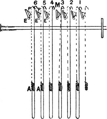
FIG. 132.
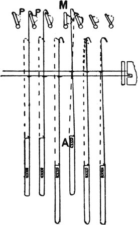
FIG. 133.
In the pressure harness a number of warp threads are placed in each mail, the number of threads varying from five to sixteen; but in the twilling Jacquard only one end is drawn in each mail, and a separate hook is required for every end. The advantage comes in making each needle serve for several hooks and in making one card serve for several picks. One of the first inventors of this kind of Jacquard was Mr. Barcroft, of Newry, Ireland, and it has been improved since by him and others. The principle is illustrated at Figs. 132 and 133. There may be any number of hooks to each[Pg 170] needle. In the illustration there are three. The machine is necessarily a single-lift, the griffe goes up and down every pick. Only two needles are shown, operating six hooks. When the top needle is pressed back it will press back the hooks 1, 2, and 3, and when the bottom needle is pressed back it will press back the hooks 4, 5, and 6. These hooks are bent at the bottom as in the diagram, and a bar or rod A is passed through each row of hooks the full length of the machine. These bars A are lifted by the twilling hooks, shown in the diagram in dotted line. These hooks are placed at the sides of the machine: two hooks for each long row of the ordinary hooks, or one for each end of every bar, A. The blades of the griffe are movable about the centres EE, and at each end of the blades and immediately behind each twilling hook (dotted) there is a projecting piece, P, also shown in a dotted line in the diagram.
Now, when the griffe is at the bottom, the blades are operated by a pegged barrel, and by turning the blades one at a time out of the way of the hooks as the blade M is turned, it is obvious that a whole row of hooks can be left down which would otherwise be lifted.
Turning the blade has also another effect. On the front of the blade at each end, as previously pointed out, is a projecting piece, P, and when the blade is turned, this projection pushes the twilling hook in front of it (dotted) on to the next blade of the griffe, and the twilling hook is lifted. The bottom of the twilling hook is fastened to the end of a bar, A, and the bar is lifted, thus lifting a whole row of hooks which would otherwise be left down. In this manner it is obvious that by operating the blades of the griffe in regular order, the figure can be woven warp twill and the ground weft twill, or vice versâ. At Fig. 133 the position of the six hooks is shown after the griffe is lifted. It will be seen that the blank opposite the top needle pressed[Pg 171] the first, second, and third hooks back, and they would all three have been left down but for the bar A being lifted. The hole opposite the bottom needle leaves the fourth, fifth, and sixth hooks over the griffe, and they would all have been lifted but for the blade M being turned, which also caused the bar A to be lifted. It will be obvious that the twill must repeat on the number of bars A, or on the number of rows of hooks, in the machine, exactly as in a split harness the ground weave must repeat on the number of shafts or rods used under the comber board. In these machines, as in the pressure harness, the same card is pressed against the needles two, three, or more times in succession, so as to give a great extent of pattern with a small number of cards. The number of times a card is pressed against the needles depends on the number of hooks there are to each needle, and on the relative amount of warp and weft in the fabric. If there are three hooks to a needle and the same number of picks as ends per inch, the card should be used three times in succession, but sometimes there are more picks per inch than ends, in which case each card should be used oftener; and sometimes, as in silk damasks, there are 400 or more warp threads per inch and 100 picks, and supposing there were eight threads in a mail, it would make a step of eight ends in the warp; therefore, to make the steps in the weft balance it would be necessary to bring the same card against the needles only twice in succession.
Fig. 134 is another arrangement for weaving damask. It is called a damask attachment, and was patented by Tschorner and Wein. Its construction differs from ordinary twilling Jacquards, but the principle is much the same.
Each needle is twisted round several hooks, and the knives are operated separately by cams at the side of the machine. The illustration shows one of the knives left down, leaving down[Pg 172] a row of hooks which would in the ordinary course have been lifted, and one of the bottom lifters is taking up a row of hooks which would in the ordinary course have been left down.
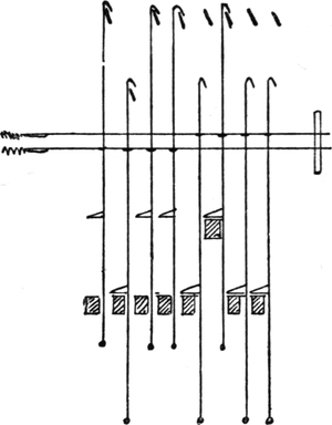
FIG. 134.
The foregoing are the chief kinds of Jacquards and harnesses (except lenos) attached thereto, but there are many combinations of shaft and Jacquard or mail harness which need not be mentioned in a book of this size. We may mention a system, sometimes called half harness, in which only half the ends are drawn through the Jacquard harness, and the other half through shafts in front or behind. A double-sized figure may thus be formed.
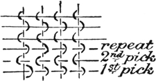
FIG. 135.
THE word “leno” has latterly become a general term given to all classes of cross weaving. Originally it had a different meaning to gauze, but the word is now often applied to gauze as well as other fabrics woven with doups. A pure gauze fabric is one in which the crossing thread is brought up on one side of a standard end, and up the other side of the standard end on the next pick. Fig. 135 shows how the threads are interlaced in gauze weaving. It will be seen that the weave repeats every two picks. The crossing end, and the end round which it crosses, must be placed in one dent, and if an end is made to cross round a number of ends they must all be in the same dent or split in the reed, as it is very obvious that an end cannot be made to cross into another dent with the ordinary doup heald.
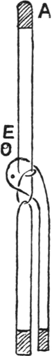
FIG. 136.
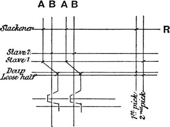
FIG. 137.
The end is made to cross from one side to the other by means of a doup heald. These healds consist of an ordinary heald with an extra half, generally called a “loose half” or slip. The method of knitting the doup heald will be understood from Fig. 136. It is obvious that when the doup is lifted at A, the end contained in the doup will be lifted up on the right-hand side of the end E. In order to bring the same[Pg 174] end up on the left-hand side of E, the ends are drawn through the healds, as shown at Fig. 137. There are two ordinary staves, and the ends are drawn through them as for plain cloth with two staves. Then the end which is drawn through the first stave is crossed under the end which is drawn through the second stave, and is then drawn through the doup in the manner shown at Fig. 136. When the doup is lifted it will lift the crossing end A up on the right-hand side of the standard end B; but in order to do this easily the end must be slackened. This is done by taking all the crossing ends A from the warp beam over a slackening rod or vibrator, R; the other ends of the warp B are taken over the back rest in the ordinary manner. The slackener is usually in the form of a lever, one end of which can be lifted by the dobby or whatever shedding motion is used, and when the dobby lifts one end of the lever the rod is moved downward, thus slackening the warp which is drawn over the rod. Whenever the doup is lifted the crossing warp must be slackened, or it would cause the standard end B to be lifted, as it is crossed under it. In this manner when the[Pg 175] doup is lifted the doup end is brought up on the right of the end B. In order to bring the same end up on the left of B, it is necessary to lift the first stave and the loose half of the doup. The first stave naturally takes the end up on the left-hand side of B, but it is necessary to lift the loose half in order to let the end go up on that side. It is usual to show the doup by a double line in the draft, the front line always representing the loose half. The pegging plan or lifting plan for the healds is for leno fabrics not usually shown on point paper, although it may be, just as easily as any other way. The usual way is to rule horizontal lines representing the staves and perpendicular lines representing the picks, and to put a / on the shafts to be lifted for each pick. It is easy to do this by continuing the lines which represent the shaft in the draft, and to make the pegging plan on the same lines by the side of the draft, as in Fig. 137. The two perpendicular lines one and two represent the picks, and the marks on the first pick are on the loose half, the doup, and the slackener; therefore all these will have to be lifted. (It is usual to peg the dobby to lift the loose half along with the doup to take the strain off the healds.) On the second pick the marks are on the loose half and the first stave, therefore these must be lifted for the second pick.
With the same draft as in Fig. 137, a considerable variety of patterns can be made of a style known as crossover lenos. This style consists in weaving a number of picks plain, and then making a cross with the end. At Fig. 138 the design draft and pegging plan are given for a “five and one” crossover leno. From the design it will be seen that the doup is required to be lifted for the first pick, and the first stave and loose half for the second pick, the second stave for the third pick, and so on. This lifting is shown in the pegging plan at the right of the draft, where on the first pick marks are put on the doup and loose half the slackener, and on the second pick on the loose[Pg 176] half and first stave, and so on. There are in this pattern six picks to the round. The appearance of the cloth will be a bar of five picks plain, and then a crank or open space, in the middle of which is a single pick; the crack is caused by the crossing of the ends.
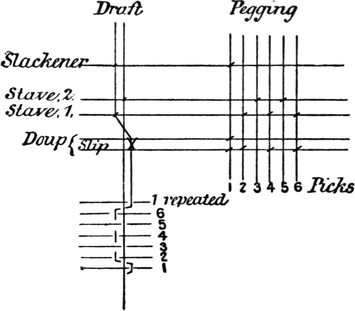
FIG. 138.
In gauzes and fabrics of this description, a thin open fabric in which the ends will not fray or slide is the object. The nature of the weave enables a firmer fabric to be obtained with a smaller number of ends and picks per inch than in ordinary weaving where the threads are not crossed.
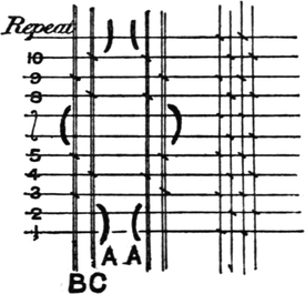
FIG. 139.
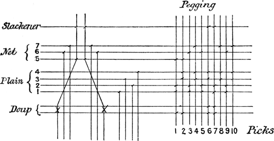
FIG. 140.
Another and quite distinct effect is produced with doups. This is commonly called “lace” or net, and is often combined with gauze or other “open” leno effect in stripes known as “lace and leno stripes.” This lace effect is produced by making a thick end form a zigzag on the plain ground. The interlacing of the threads in a simple lace or net stripe is shown at Fig. 139. A thick end, A, is brought up first on one side and then on the other side of two plain or nearly plain ends, B and C. There are ten picks to the round, and by the side of this dent there is another thick end twisting in the opposite direction, first up one side, and then up the other of two more[Pg 177] plain or nearly plain ends. Each thick end comes up for two picks at one side and then crosses under and comes up on the other side after an interval of three picks, and vice versâ. The marks represent the ends lifted. By the side of the lace there are two plain ends shown, which represent the unlimited number of ends used for the ground of the fabric. In weaving this pattern the draft and pegging given at Fig. 140 would be used. By carefully following the design with the draft and pegging plan the principle will be easily mastered. The arrangement of the shafts is rather important. The doup is placed in front, the ground staves next, and the leno or net staves next. It is immaterial whether the crossing ends be taken through the first stave of the three used for the leno, or the back one—some prefer one way, some another—but it is necessary to get the leno staves as far back as possible to give the thread a better chance of crossing. Four staves are taken for the plain, as in ordinary weaving, to prevent overcrowding. The lifting marks on the pegging plan will be easily followed if the one in Fig. 138 was understood. Where the fifth stave is lifted the loose half is lifted also, and both thick threads come up on the[Pg 178] inside. Where the doup is lifted the slackener is lifted also, and the ends are brought up on the outside as on the sixth and seventh picks. More will be said on the arrangement of shafts in the chapter dealing with designs for leno. The explanations on the structure of the fabrics at this point are only for the purpose of enabling the requirements of the looms for weaving them to be understood. Some manufacturers prefer to work with the doups at the top of the loom, especially in weaving net lenos. In this case the crossing end is crossed over the others and slipped downwards.
It used to be considered that gauze and lenos could not be woven on double-lift machines. In other places than Lancashire this idea prevails to-day to a great extent, but of course this is a great mistake. The simpler kinds of lenos, such as pure gauze and crossovers, are sometimes woven on tappets, which are, of course, double-lift. The tappets are of the ordinary kind, drawn on the same principle as described earlier in this book; but the tappet which operates the standard ends is made to lift the staves halfway when the doup end is crossing. Tappets of this kind have been used for some time past, and it is not surprising that the same principle should be applied to double-lift dobbies. Instead of drawing the tappets to lift the standard ends half way or a little way to enable the ends to cross easier, the easing motion usually employed for dobbies is often used, and the tappets are of the ordinary kind.
In a double-lift dobby the healds begin to lift for one pick when the healds which are up for the previous pick begin to come down. In the case of Fig. 137, when the doup is lifted for the first pick and begins to come down, the same end is being taken up the other side of B by the stave No. 1 being lifted. If the end B were not moved it would very soon be broken by the crossing end being made to act in this saw-like[Pg 179] manner upon it. It is necessary, therefore, to lift the end B about halfway up at the moment the crossing end begins to come down and to pass to the other side of B. If the end A has not to cross for the next pick, it would not be necessary to lift the end B at all. In a single-lift machine the doup will get to the bottom before the first stave begins to rise, and therefore there would be no difficulty in the end crossing. In a double-lift dobby the staves containing the ends round which the doup thread crosses are lifted partly up every pick by a lever worked from the crank arm of the loom. This easing motion or “shaker” is shown at Fig. 141. AB is the crank-arm, and the upright CD is connected to the crank-arm at C, and to a lever ED at D. EG is another lever on the rod E, and the healds which are to be lifted half way are connected to this lever at G, as well as to the jacks in the dobby. As the crank revolves the oscillation of the crank arm imparts a similar movement to the lever ED, and to the staves which are connected to EG. This motion commences just at the proper time. Of course, when the crank-arm is lifting the healds, the cords connecting these healds to the dobby will be slack, as indicated at Fig. 141. By thus lifting the standard healds, the crossing is greatly facilitated.
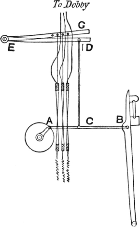
FIG. 141.
This easing motion is not required where there is no crossing of the end immediately, as, for instance, in Fig. 139, the doup end after being brought up on one side is never required[Pg 180] up on the other side on the pick immediately succeeding, therefore the end has time to get down before being lifted on the other side and an easing motion is not required.
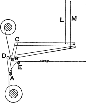
FIG. 142.
The method of slackening the warp when the doup lifts is shown at Fig. 142. This diagram shows a two-doup arrangement. For gauze and similar weaves it is not necessary to have a separate beam for the crossing warp, as one end pulls the other and the take-up is about the same; but for net lenos or laces after the manner of the fabric in Fig. 139 it is necessary to have the crossing ends on a separate beam, as a great deal more in length of this warp is required than for the plain. Sometimes several beams are used, the only limit being the number which can be placed in a given space.
At Fig. 142 the crossing warp from the bottom beam is taken over the slackening rod A, and over the carrier E. The crossing warp from the top beam is taken under the slackening rod B. A moves about a centre D, and B moves about a centre C.
The slackener B is connected to a jack in the dobby by the cord L, and the slackener A is connected to another jack by the cord M. When either L or M is lifted, the warp over its rod will be slackened.
FIG. 143.
A full cross may be made by taking the doup completely round the standard end, as in Fig. 143, and alternately lifting the doup and the other end. This is a much more difficult weave than ordinary leno, and is not much used, although it gives a very pleasing effect when woven with thick yarns. The weave repeats on two picks as in gauze, but it is necessary to use very strong twist in order to bear the strain and friction unavoidable in this crossing.
FIG. 144.
Where figures are required to be thrown up on a leno ground a Jacquard mounting is required. It is possible to weave a plain figure on a gauze ground with an ordinary Jacquard harness and an ordinary doup stave in front, but this can only be done on a pure gauze ground—that is, one end crossing one. A plain figure on a ground of this kind does not afford a sufficiently powerful contrast to the ground. It is necessary in order to produce a really efficient contrast to have two ends crossing two and weaving separately in the plain. A fabric of this kind is one of the most beautiful of all fabrics, and is remarkably cheap and[Pg 182] serviceable in wear. The method of producing a plain figure on a gauze ground with one doup in front of any ordinary Jacquard harness is illustrated at Fig. 144. The ends are drawn through the Jacquard as usual, and are then taken in pairs and one crossed under the other, the crossing end being taken through the doup, as shown in the diagram. The crossing end in each pair is marked A. We can now see how either plain or gauze can be woven at will. The doup is lifted for the first pick, and this brings all the ends A up at the right hand side of ends B (see first pick). In the first two dents the ends A are lifted again by the harness, and the loose half of the doup being lifted will enable the ends A to cross to the left side of the ends B. The doup is lifted for the third pick, and it is obvious that this will weave gauze with the first two dents. After the doup is lifted, if the end B is lifted on the next pick, it will cause plain to be woven, as will be seen from the diagram, where the third and fourth dents are weaving plain when the first and second dents are weaving gauze, and vice versâ.
FIG. 145.
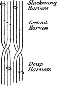
FIG. 146.
A proper leno harness is illustrated at Fig. 145. It is obviously impossible with the arrangement given at Fig. 144 to weave a leno with two ends crossing two in conjunction with plain, as there would require to be two ends in each eye in the doup, and as the doup is lifted every other pick, it is impossible to change to plain from the leno. To obtain a figured leno of this description, each dent must have a doup to itself, and the doups must be lifted by the hooks. At Fig. 145 the arrangement of the harness is shown. The machine is a single lift, and in order to obtain a 400 end figure 600 hooks are required. These are arranged in twelve rows, the two front rows being used for the doup harness, the two back rows for the slackening harness, and the eight middle rows for the ground or figure harness. For the 600 hooks only 500 needles are used, the doup hook and its slackening hook being connected with the same needle. The top and bottom needles are used for the doups and slackeners, as shown in the diagram, and the eight middle rows of needles for the ground or figure harness. The method of drawing the warp through the harness is shown at Fig. 146. The two crossing ends are drawn through the slackening harness, and all the ends are drawn through the ground harness. It is immaterial whether the draft is from back to front or front to back; some manufacturers of these goods draw the ends from front to back. Of course, this must be borne in mind in designing and cutting the cards. After being drawn through the ground harness the two crossing ends are crossed under the other two and drawn through a doup. The mails in the doup lingoes are specially made to allow the thread from the slip to pass through and[Pg 184] back again. The shaft A (Fig. 145) is the slip or loose half, and serves for all the doups. The mails in the slackening harness are placed, lower down than the other warp, and these mails hang between two rods, B and C, which are called the “bridge.” Sometimes only one rod is used, and this serves equally well.
A better shed is formed by only lifting the slackening hooks half as much as the other hooks, and therefore a special device is required for giving only half the lift to these hooks. In the illustration, Fig. 145, there are two griffes, E and H, and the griffe E is connected to the lever GK at a point, O, about midway between the fulcrum G and the point where the griffe H is connected to the lever. The fulcrum G is movable in a slot made for that purpose, so that the lift of E can be altered a little if desired. When the griffe H is lifted in the ordinary manner, it is obvious that the griffe E will only be lifted about half way.
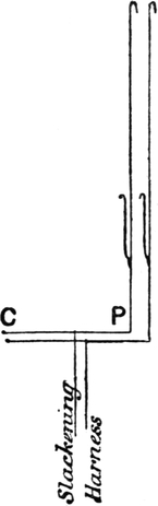
FIG. 147.
The usual method of obtaining the half-lift, which this invention is intended to supplant, is illustrated at Fig. 147. This method was invented by the late Mr. Tootal Broadhurst, and has been in regular use a long time. Each of the slackening hooks lifts a lever CP, centred at C, the slackening harness is tied to these levers about midway between C and P, and thus the mails are lifted only about half as much as the hooks. Of course, in this case all the hooks in the machine are lifted by one griffe, and therefore the slackening hooks are lifted as far as the others.
This method serves its purpose very well, but if any alteration is required in the lift of the slackening harness all the[Pg 185] levers have to be gone through and altered separately, whereas in the Devoge machine the lift can be regulated to a nicety by moving the fulcrum G and the point O. The slackening harness should be placed from nine inches to a foot behind the ground harness.
The wire M, in Fig. 145, is for lifting the shaft A, which is required to be lifted every pick. The advantage of using only one needle for the doup and slackening hooks is that it prevents the possibility of the slackener being missed when the doup lifts, as well as being a saving in cards.
By lifting the crossing ends with the ground harness for two or more picks, followed by lifting the same ends in the doup harness for a similar number of picks, an open leno fabric is produced, and a plain figure can be woven by lifting the ground harness plain, or a floated figure can be formed exactly as with an ordinary Jacquard.
FIG. 148.
FIG. 149.
The usual method of putting the design on point paper for these Jacquards is illustrated at Fig. 148. In the plan eight ends of leno are shown with four picks in a shed; and eight ends of plain, of which the figure is usually formed, are shown. The design on point paper for this would be as given in Fig. 149. Ordinary 8 × 8 paper is used, although there are ten rows of needles. The card-cutter cuts the black squares opposite the ground harness needle, and where the circles come, he cuts so as to lift the doup in the next dent. Thus in the first four cards for Fig. 149, the card-cutter would cut opposite[Pg 186] the third and fourth needles in the ground harness, and opposite the doup needle for the next four ends. The plain would be cut in the ordinary manner opposite the ground harness needles. A larger design for this harness will be found in Chapter X.
Double-lift Jacquards are not yet used beyond the experimental form, as the shaking cannot be done as easily as in a dobby with shafts, but we have heard of the thing being done by knotting the harness above the comber board and lifting the board a little when the cross is being made. Messrs. Eccles, of Preston, some years ago obtained a patent for lifting the standard ends by means of a third knife or griffe. The additional knife was given half the lift of the other two, and its function was to lift the standard ends half way when the doup ends were crossing to the other side. This would, no doubt, enable the cross to be made with ease in a double-lift Jacquard, but the principle is not likely to be a great success.
The doups in leno Jacquards are very liable to wear out unless made of very good material, and some experience is necessary before the harnesses are worked satisfactorily.
An imitation of the fabric usually woven on this harness is sometimes made by making one end cross three ends in the leno, and weave plain in the figure. This can be done with an ordinary harness with a doup heald in front lifted every other pick, on the same principle as in Fig. 144.

FIG. 150.
TERRY looms are extensively used in the cotton trade, chiefly for weaving towels, but often for striped dress and similar fabrics where terry or loop pile is combined with other weaves. The loops can be formed either on one side or both sides of the fabric, but the loop formed in these looms is not to be compared with real loop pile woven over wires, as the loops cannot be formed with the same regularity. There are numerous terry motions, as they are called, most loom makers having their own speciality. Fig. 150 is the design for a good terry cloth. It will be noticed that the second and fourth ends are the reverse of each other: one is up for four picks and down for one, and the other is down for four picks and up for one, whilst the other two ends are nearly plain. The first and third ends form the ground, and the second and fourth ends the pile or loops. There are five picks to the round.
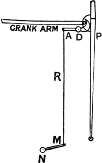
FIG. 151.
FIG. 152.
The ground warp is on a separate beam to the pile warp, the latter having a special tension to let off the required quantity to form the pile. At the second pick in the pattern, just where the pile warp is bound, the reed is made to beat further up than on the two preceding picks, thus forming a pile by sending one half the pile ends to the face and the other half to the back. The reed beats up to the front for the[Pg 188] second, third, and fourth picks in the pattern, as given at Fig. 150, following which the reed is held back for two picks. Fig. 151 is a good motion for making the reed occupy the two positions when beating up. P represents the slay, and a lever, A, centred at D, is so constructed that when A is pulled down the reed is pushed forward. The rod R is connected to a lever, M, on a shaft, N, placed under the loom. A rocking motion is given to this shaft by a box cam, P, five to the round (Fig. 152), so shaped as to lift and depress the lever QS for the required number of picks. This cam is driven from the picking shaft. By pulling the rod R downwards the reed is moved forwards, and the rod will have to be kept down for three picks and moved up for two picks, so as to keep the reed in its front position for three picks and a little way back for two. The effect required is really to lengthen the crank-arm at will, and the principle of the knuckle joint may be used in its simplest form—that is, by having the crank-arm jointed in the middle and fixed a little out of a straight line, and by straightening the arm when the front position of the slay is required.
The real loop pile is woven over wires. The wires can be inserted and pulled out automatically by a power-loom, but the richest kind of pile is woven on the hand-loom. The structure of the fabric is shown at Fig. 153. The pile end is brought up over a wire every two picks, and when the wire is pulled out the loops form a springy pile, which can be made to give beautiful effects in dress[Pg 189] goods. The principle is also used in Brussels carpets, and similar goods. Where figured fabrics are required on this principle, it is necessary to have each pile end on a separate bobbin and weighted separately at the back of the loom, as the take-up of each end would vary so much in the figure.
FIG. 153.

FIG. 154.
With cut pile the wires are either grooved, as at Fig. 154, or each wire has a knife at the end, as at Fig. 155, and when the wire is pulled out it cuts the pile. The best pile is formed by the grooved wires, as the cutting wires are apt to drag the pile. When cut pile is being made, about four or five wires are constantly in the cloth, for, if the wire were pulled out immediately, the pile ends would fall away from the cloth.

FIG. 155.
FIG. 156.
Looms are made to weave two pieces of plush (which is a long cut pile, rather longer than velvet pile) in one loom simultaneously, one piece above the other, after the manner shown at Fig. 156. The principle is not used in cotton manufactures, although it has been tried. It is chiefly used for silk plush.
The cards are usually cut from the design on a machine called a “piano” card-cutter. This machine consists of a punch-box (Fig. 157), containing thirteen punches, twelve for cutting the smaller holes and one for cutting the peg holes in the cards. There are eight “keys” behind the punch-box, each of which has a small spring round it to spring it back to its original position when the finger is taken off it. These eight keys are used for cutting the eight rows of holes in a 400’s card, and for 600’s cards, with twelve rows of holes, the four punches in front are used. The two punches in front at the right hand are operated by the thumb on that hand, and the eleventh and twelfth are operated by the thumb on the left hand. The eight keys behind are governed by the four fingers on each hand. Fig. 158 shows the effect of pushing in one of the keys. The key is pushed over the punch K, and as an up-and-down motion is given to the whole punch-box by means of two treadles operated by the card-cutter’s feet, the punches that are locked will cut holes in the[Pg 191] card. Where the keys are not pressed (see Fig. 159) they do not act upon the punches, and the card is left blank accordingly.
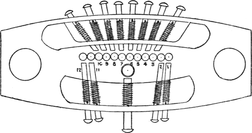
FIG. 157.
The card is clipped at the numbered end by a clip on the “carriage.” This carriage recedes with the card for a space of one row of holes every time the left treadle is pressed down. The method of cutting the cards has already been explained with Figs. 108–110.
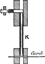
FIG. 158.
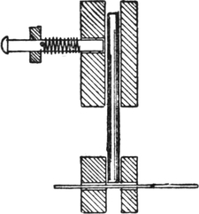
FIG. 159.
If several sets of cards of the same pattern are required, a repeating machine is used. In the hand repeater the cards are made to leave punches in a plate where there are holes in the card, and the plate is then taken to a repeating press, where any number of cards can be cut like the first by applying pressure to the plate, which is done by passing it under a roller or wheel.
Some repeating machines are capable of repeating direct from one set of cards to the other, at the rate of thirty or forty cards per minute. The cards may be laced blank, and kept in stock ready for use when required, which is a great advantage. The machine is built on the Jacquard principle, and the punches required to cut are fastened, whilst those which are not required to cut are taken out of the way of the card.
These machines are rather costly, but in large fancy weaving establishments they soon repay their cost.
Lappet figures are formed by giving a horizontal motion to a thick end, and making it interweave in the manner shown at Fig. 160. The system has long been used in hand-looms, and it is now extensively used in power-looms, especially in Scotland. The figures are usually produced with a very thick end upon a fine muslin ground, and the advantage it possesses over figuring with extra weft is that the figuring material does not require cutting off every pick, and therefore there is not the same amount of waste, and in addition the figures are more firmly bound into the cloth.
FIG. 160.
Only small solid spot figures can be woven, as the figuring thread cannot be bound between the extreme edges of the figure. This is the chief disadvantage of the principle, and it is not to be compared with swivels for the purpose of producing intricate designs. In swivel weaving each figuring thread is placed in a small shuttle, which receives a horizontal motion by means of a rack. The small shuttles can be lifted out of, and dropped into, the warp, so as to allow the figuring thread to be passed through the shed where the spot is formed, and therefore twill or satin, and shaded effects, can be formed in the spot. In lappet weaving the floats cannot be bound in the middle.
The chief advantage of lappet weaving is that it can easily and satisfactorily be applied to a power-loom. Swivels have been applied to power-looms, but not yet with entirely satisfactory results, taking into consideration the question of cost.
The principle of the lappet power-loom will be understood from Fig. 161. In front of the slay cap the needle rack A is placed, the ends resting in the slots BB, and this is moved downwards by the hook C being lifted by the treadle F at the side of the loom. The figuring threads are taken from a separate beam through the needles in the rack, and it will thus be seen that when the rack is pulled down the figuring threads will be at the bottom of the shed. When the treadle F is forced down, the springs PP pull the rack back to its topmost position, and when in this position the rack is pulled to the left by pressing down the treadle D, the distance which the rack can be moved being regulated by the size of the groove in the lappet wheel at that point.
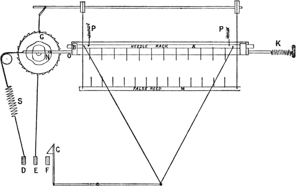
FIG. 161.
The lappet wheel G is a wheel with ratchet teeth, and is turned one tooth at a time. The groove in the wheel is so shaped that the rack can be pulled sideways a greater or a less[Pg 194] distance as desired, to form a spot or figure. The pin N fits in the groove, and when the treadle D is pressed down the rack is pulled to the left as far as the groove will allow, when the spring S gives way until the treadle reaches the bottom of its stroke. When the treadle is released the spring K pulls back the rack and treadle as far as the groove in the wheel will allow it. The spring K is much weaker than S, so that when the treadle D is pressed down the spring K gives way the first.
The needle rack being in front of the ordinary reed, a “false” reed is required to guide the shuttle across the shed. This false reed M is placed immediately behind the shuttle race, and it is lifted every pick when the shuttle is going across, and dropped to make room for the proper reed to beat up. The treadle E is used for operating the false reed; the connection is shown in the diagram, and when the treadle is pressed down the reed is lifted.
At Fig. 162 a section is given showing how the needle rack receives a lateral as well as a perpendicular motion. The slay-cap is cut square, and the cover C works loosely upon it. The needle rack A is pulled down against the spring S, and the cover is pulled sideways by the bar attached to the cover at O, carrying the needle rack along with it.

FIG. 162.

FIG. 163.
The treadles are operated by tappets, and those operating treadles E and F must do so every pick, whilst the treadle D only requires to be pressed down once every two picks, because the spring K pulls the needle rack to the right. The tappets are shown at Fig. 163, where it will be seen that when the treadle E is down, F is up, and the rack will be dropped and the false reed lifted; and when the treadle F is pressed down—letting the rack be pulled up by the springs, the treadle D[Pg 195] is pressed down, which pulls the rack to the left as far as the groove in the wheel will allow it to move.
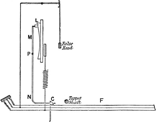
FIG. 164.
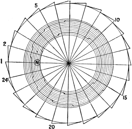
FIG. 165.
At the back of the lappet wheel a face cam L (Fig. 164)[Pg 196] acts upon a lever, MN, centred at P, and the bent arm of the lever N pushes the hook C on to the treadle F when the spot figure is being formed, and when there is no figuring going on the hook is pulled out of the way of the treadle, and so the motion of the rack is stopped.
The pattern is formed by the groove in the lappet wheel (Fig. 165), and in drawing this the wheel is divided into as many teeth as there are picks in the pattern. The wheel is usually made of hard wood, and after being smoothed off a number of circles are described, the distance between each being equal to one dent in the reed. Suppose the pattern is a continuous one, as at Fig. 166, the picks shown on paper being in addition to the ground picks. In drawing a wheel for this pattern the number of teeth required will be twenty-four, as there are this number of picks in the pattern.
FIG. 166.
The pattern extends to seven dents, and as the pin N (Fig. 165) occupies four dents, it will be necessary to have eleven spaces, each equal to a dent, in the groove. The first pick in the pattern floats over two dents or four ends, and therefore the groove at this point must be six spaces wide—four for the pin, and two for the space it has to move through. Before the next movement of the rack, the wheel will have been turned one tooth, and at this point the groove moves one space further to the left. For the third pick both sides of the groove are moved one space to the left, and the size of the float will remain the same as in the second pick, but it will[Pg 197] float over different ends. The groove gradually gets wider until the tenth pick is reached, when it narrows down again until it repeats on the twenty-fourth pick.
If there are two spots set “one and one” in the pattern, the wheel requires one tooth more than the picks in a repeat, in consequence of changing from one spot to the other.
THE history of the development of the power-loom, from its inception by Dr. Cartwright, has been written on many occasions. That story relates how old methods have been improved or else displaced by new ones of greater efficiency, and how the modern power-loom has, by the effort and skill of the pioneers of industry, been brought gradually to its present state of mechanical perfection. This march of progress goes on steadily, continuously, and almost imperceptibly to those who are not immediately interested in or affected by the changes that are thus wrought; until by some special circumstance they suddenly and unexpectedly arrest attention, and it is realized for the first time that a new era has dawned and promises changes of great magnitude.
The advent, now fifteen years ago, of what are popularly described as “automatic looms” marked the beginning of events of considerable importance to the weaving industry in particular, and to the textile industry in general. The essential element which distinguishes these looms from those of ordinary construction consists of special apparatus attached to, and forming an integral part of, the looms, which are thereby enabled to replenish weft automatically from a reserved supply conveniently held in readiness. This briefly constitutes the automatic element of the looms. There are, of course, many auxiliary attachments that are incidental to the weft-replenishing devices, and which increase their efficiency and productiveness.
Notwithstanding the comparatively short period that has elapsed since the adoption, on a commercial scale, of these looms, such has been the activity of inventors and loom-makers both at home and abroad, that looms of this class have already been designed in an almost endless variety of forms, some of which differ essentially in construction and operation, whilst many others differ only in minor details of construction. Most of these, however, have never matured to practical forms. Many have never escaped the secret confines of the experimenting room. Others have been doomed to premature failure, whilst some three or four types of real merit are struggling hard for supremacy. Which of the competing types will win, ultimately, is at the present time matter for conjecture. This will depend entirely on the type that will best meet the requirements of manufacturers, and the one that will endure the test of experience and time, which alone can be the deciding factors. But, for certain classes of fabrics for which they are suitable, it is safe to predict that automatic looms of some approved type are permanently established in the trade.
Whatever particular character these weft-replenishing devices assume, they may be broadly classified under one or other of two distinct types, namely, (1) that in which the same common shuttle is replenished with cops or bobbins of weft; and (2) that in which a fresh shuttle replaces the previous one. Each of these two broad divisions comprises numerous modifications in both their construction and also in the manner in which they operate.
Of the cop-or bobbin-changing type of loom, the “Northrop” loom, invented in Hopedale, Mass., U.S.A., by James H. Northrop (a native of Keighley, Yorks.), has gained a greater measure of success than that of any other automatic loom; and of the shuttle-changing type, the “Hattersley” loom, invented by Simeon Jackson, of Geo. Hattersley and[Pg 200] Sons, Limited, Keighley, Yorks., has probably found greater favour than others of that type. Looms of the Northrop type require essentially the use of shuttles of special construction that are capable of self-threading the weft; whereas looms of the Hattersley type may weave with the same kind of shuttles as those employed in ordinary power-looms. Looms of both types are constructed so that the change of weft is effected instantaneously whilst they are running at full speed, without any loss of time; but when a change of weft takes place in the Hattersley modification of the shuttle-changing type, the looms stop running automatically for a few picks to allow more time for the changing of shuttles, after which the looms re-start automatically and continue running at full speed.
In addition to the essential elements constituting a successful weft-replenishing device, this requires to be supplemented by numerous appliances of a special character to ensure the general efficiency of the loom. For example, at that side of the loom on which the replenishment of weft is made, there is fixed a weft-cutting device to sever the superfluous trail of weft close to the selvedge of cloth after the insertion of each fresh supply of weft. In some looms the weft is replenished only when the previous supply fails either by breaking or becoming exhausted; and some are furnished with “weft-feeler” motions to put the weft-changing mechanism into operation and thus replenish the weft just before the previous supply is entirely depleted, thereby preventing broken or missing picks of weft which would produce faulty cloth. A warp-stop motion, which is sometimes applied to ordinary looms, is an almost indispensable accessory to an automatic loom. Its function is to detect the breakage of warp-ends, and to stop the loom automatically whenever that occurs. These remarks apply also to the controlling of the tension and delivery of the warp, which are sometimes effected automatically in looms of any description.
Up to the present time weft-replenishing devices are almost exclusively restricted to single-box looms employed in the production of standard varieties of fabrics of comparatively simple construction, and containing but one kind of weft requiring the use of only one shuttle. These devices have, however, been employed on check-looms weaving with more than one kind of weft, and therefore requiring the use of a corresponding number of shuttles at the same time; but automatic check-looms have not yet passed the experimental stage and become established on a commercial basis, although there are prospects of this taking effect in the near future.
Having thus far introduced the reader to what constitutes the chief elements of an automatic or self-acting loom, it will, at this stage, and before examining the details of their special mechanism, be both instructive and profitable to briefly survey the work of pioneers in this sphere of invention, as revealed in the records of the numerous Letters Patent that have from time to time been granted for inventions of devices for the automatic replenishing of weft in looms, and to trace the origin and development of such devices from the earliest authentically recorded date of their inception down to the present time.
From a research of the earliest published records of patents relating to weaving, which records date from 15th July, 1620, it would appear that the credit for the first patent for an automatic weft-replenishing device for looms is due to Messrs. John Paterson Reid and Thomas Johnson, both of Glasgow, who are the joint patentees of an invention of such a device described in the Patent Specification, dated 20th March, 1834, No. 6579. This is a large document of 69 pages of text comprising over 35,000 words and 12 sheets of diagrams. It describes in a very lucid manner several improvements in power-looms, of which that relating to the automatic replenishing of weft is treated almost as if it were regarded, by the[Pg 202] inventors, as of only secondary importance to the other improvements which they describe.
In view of the great progress which has been made within recent years in the development of these looms, and also in consideration of the fact that a patent, which was granted to Charles Parker nearly seven years subsequently, and is described in the Specification dated 22nd October, 1840, No. 8664, has been frequently cited as the first patent relating to the automatic supply of weft in looms, the first-named document acquires a special interest, not only as a record of what is probably the first attempt in that direction, but also because it establishes, beyond refutation, the date and rightful title to the first patent granted for such an invention.
In the former specification, the patentees state that their improvements are applicable to what were then known as Johnson’s vertical power-looms, in which the warps were extended vertically from the warp-beam at the bottom to the cloth-roller at the top of the loom; and the reed, which served as the shuttle-race during the flight of the shuttle through the warp-shed, moved in a vertical plane when beating up the weft. These vertical looms were made double, to permit of two pieces of cloth being woven in them at the same time; but they had evidently been discarded, and were not then in use amongst manufacturers. The looms made according to Reid and Johnson’s specification were so very different from Johnson’s looms as to have very little in common with them excepting that they also were vertical power-looms in which the warps extended vertically. The specification states that the “great object” of their improvements is to enable four webs or pieces of cloth to be woven simultaneously and at one operation in the same loom, with only one slay which has a vertical motion, and also that the warps for the four webs are to be wound on two separate warp-beams. After describing[Pg 203] in minute detail the construction of the improved loom, the patentees proceed to describe their invention of a device for the automatic supply of weft to their looms whilst these continue running. This part of their invention is introduced as if it were quite incidental and of little consequence, and is described as the “accessories and new improvements” which they apply to their vertical power-looms, as follows:—
“In order to avoid stopping the motion of the loom when any one of the four weft threads break, twice or three times as many shuttles as are required for constant use are to be lodged in suitable receptacles or shuttle boxes, which are so arranged that the breaking of a weft thread will cause a change of shuttles, and a substitution of spare shuttles, which have been provided and placed in the said receptacles ready for such changing; for instance, the breaking or failure of a weft thread from either of the two shuttles, which work on the same reed as one pair, will cause the pair to be removed, and a pair of spare shuttles to be brought into their place instantaneously, without any act of the person who attends the loom, and who will therefore have no occasion to stop the motion thereof when a weft thread breaks or runs off, but will only have to take care to keep the loom at all times provided with a sufficient number of spare shuttles ready filled and inserted into their proper places in the receptacles, leaving it to the machinery of the loom to remove those shuttles which have been working, and to substitute others the instant that a change becomes necessary in consequence of the breakage or failure of weft thread. But if, by neglect of the attendant, the loom is not so provided with a pair of spare shuttles ready filled and placed in preparation for changing as aforesaid by the machinery on the breakage or failure of any weft thread, then the loom will stop its own motion, wherefore the weaving cannot be continued unless all the four webs have their several wefts duly inserted in a proper manner for working cloth.” From this description it is of interest to note that what probably constituted the first automatic loom was of the shuttle-changing type, to which nearly all subsequent inventors in this particular field have chiefly devoted their attention.
It was not until an interval of nearly seven years had elapsed after Reid and Johnson’s patent that a patent was granted to Charles Parker, of Darlington, for the second invention of an automatic weft-replenishing device, which, like its predecessor, was also one of the shuttle-changing type. This device, along with other improvements in power-looms, is described and illustrated in the specification dated 22nd October, 1840, No. 8664, in which the fourth claim made by the patentee is in respect of “means of changing the shuttle when the weft is broken or the shuttle is empty of weft” without the necessity of stopping the loom for that purpose.
The next and third patent for an automatic weft-replenishing device, which, like the two previous devices, was a shuttle-changer, was that granted to an agent, William Newton, to whom the invention was communicated from a foreign country not named in the specification which is dated 28th April, 1852, No. 14,092. This document states that the invention relates to improvements in looms for weaving plain, figured, or fancy fabrics, and that it consists in the employment of several shuttles arranged in the loom in such a manner that if the weft failed, or the shuttle missed or flew out of the shuttle-box, a second shuttle would always be in readiness to take its place, without it being necessary to stop the loom in order to replace it with a fresh shuttle. In carrying out the improvement, several shuttles where placed one above the other in a box, or in guides fixed immediately above the shuttle-race or box, and[Pg 205] held in their place by means of a stud, plate, or catch, which, when required, was removed so as to allow a second shuttle to enter the shuttle-box in place of the spent shuttle, which, by the same motion, was pushed out. In the event of a shuttle flying out or missing the shuttle-box, the same mechanism caused a fresh shuttle to supply its place. The special mechanism which affected the changing of shuttles was put into operation by means of a weft-stopping device which detected the absence of weft whenever this failed to pass along the shuttle-race in front of the reed.
After an interval of five years from the granting of the previous patent, Patrick McFarlane, of Perth, patented an automatic weft-replenishing device which marks a distinctly new departure from the previous inventions for the same object, and one, moreover, which has the distinction of constituting the prototype of cop-or bobbin-changing devices, of which type a modification has been so successfully adopted in the construction of Northrop automatic looms. McFarlane’s invention is described in the Patent Specification dated 13th April, 1857, No. 1046, which states that “the first part of the invention consists in means or arrangements by which a loom is made to supply its shuttle or shuttles with fresh weft when the weft last placed in the shuttle or shuttles has become broken or exhausted.” The cop or bobbin of weft was placed in a case which fitted inside the shuttle in which it was held securely during weaving, but from which it could be easily ejected and replaced by another weft-case containing a fresh supply of weft whilst the loom continued weaving. Any practicable number of these weft-cases were conveniently stored and retained in a suitable receptacle or hopper, so that the successive weft-cases could take the place of those removed, as they were each in turn inserted in the shuttle. The chamber containing the reserve supply of weft-cases was attached to the[Pg 206] framing of the loom opposite the shuttle-box or boxes, so that when the absence of weft was detected by the weft-fork, this put into operation the weft-changing mechanism which forced a weft-case from the hopper into the shuttle, and thereby displaced the previous weft-case which fell into a box or basket.
An interval of only three years elapsed before the next patent was granted for a weft-replenishing device patented by Thomas Ingram, of Bradford, for which the specification is dated 4th April, 1860, No. 861. In this specification, the patentee describes a device which combines the elements of both a shuttle-changing and also a cop-or bobbin-changing loom. The invention relates to mechanism for effecting a continuous action in looms without stopping them to change the bobbins or cops, or for an additional supply of weft, whether that is all used up or only broken. This was effected by forming an opening or aperture in the front, back, top or bottom of the shuttle-box “large enough to admit a shuttle, or a case containing a spool or spools of weft, to pass through to be inserted within the box.” Also, “when the weft is broken or used up, or a change of weft is required, the shuttle, or the case within the shuttle containing the weft, is immediately expelled through one of the openings in the shuttle-box, and supplied through another of the openings with another shuttle or a case containing a further supply of weft.” The patentee states later that he is aware of a patent for a previous device “to exchange the cop of weft by means of a portable case, whilst the loom was in action,” and does not claim that device as a part of his own invention; but what he claims “is the combination and the general arrangement of apparatus or mechanism for producing or effecting continuous action in looms for weaving.”
A device of a different character from any of those[Pg 207] previously described was one that formed the subject of a communication from Julius Boeddinghaus, of Elberfeld, Prussia, to an agent, William Brookes, and is described in the specification dated 14th November, 1860, No. 2787. The function of this device was merely that of ejecting the shuttle automatically when the weft failed; but the replenishing of weft required to be performed by hand in the usual manner. The ejecting of the shuttle was effected by causing it to shoot downward through an opening in the base of the shuttle-box at one end of the slay, and on the occurrence of which the loom would stop.
A patent for the next device which, although not strictly belonging to the present category of inventions, is, nevertheless, closely allied to them, was that granted to John Leeming, Bradford, and described in the specification dated 5th February, 1861, No. 301. The specific object of this device was to effect changes of weft of different kinds or colours for the production of check fabrics. Weft-cases, as introduced by Patrick McFarlane in 1857, were employed to contain the weft, and the weft-cases were exchanged automatically in the same shuttle according to a prearranged scheme of decoration, but not on the failure of weft, in which event the loom would stop as usual. The device was, therefore, a checking motion to effect changes of different kinds of weft by changing cops or bobbins, instead of employing a number of separate chambers, each containing a shuttle with a different kind of weft, and bringing these in line with the race-board, as required. In this respect, therefore, the present device may be regarded as the first recorded attempt to adapt the automatic weft-replenishing element to perform the function of a checking motion.
The next following patent for a weft-replenishing device was that granted to three Crawfords and Robert Templeton,[Pg 208] of Beith, Ayr, and described in the specification dated 17th February, 1862, No. 419. This invention, which is of the shuttle-changing type, introduces two distinctly novel departures from any previous invention of the same class, namely, the employment of a six-chambered revolving shuttle-box to bring fresh shuttles into working position, and also what corresponds to a weft-feeling motion to effect the replenishing of weft before the supply in use is quite depleted. The chambers of the multiple shuttle-box are charged with reserve shuttles contained in a hopper. At each change of shuttles the boxes revolved on their common axis for one-sixth of a revolution to receive a fresh shuttle in readiness for the next change. On arriving at the bottom of its circuit, the discarded shuttle fell out of its chamber into a receptacle. The weft-feeling motion operated the weft-changing mechanism when the weft was nearly depleted. This was effected by constructing the weft pirns or bobbins with a longitudinal slot to receive a curved blade-spring fitting inside the shuttle so that it entered the slot in the bobbin and passed underneath the weft. On the weft becoming exhausted to a certain fixed point on the bobbin, the blade-spring was automatically released, on which it projected through a slot formed in the shuttle side. Thus, on the shuttle arriving in its chamber of the rotary boxes, the blade-spring came into contact with a part of the weft-changing mechanism which was thereby put into operation to change the shuttles.
The foregoing brief descriptions of the first eight patented devices for the automatic replenishing of weft in looms will serve to indicate the general character which those devices assumed down to February, 1862. Although since that date to the present time the number of patents for devices of that class of inventions number many hundreds, yet it is significant that none of these later devices differ in any essential element from those of earlier inventions. The table on page 209 gives a list of weft-replenishing devices for which Letters Patent have been granted, down to 1894, with the date and number of specification, the names of patentees, and type of device.
LIST OF PATENTS FOR AUTOMATIC WEFT-REPLENISHING DEVICES.
| Date of Patent. |
No of Specification. |
Name of Patentee. | Type of Device. | ||||||
| (1) | 1834, Mar. 20 | 6,579 | J. P. Reid and T. Johnson | Shuttle-changing | |||||
| (2) | 1840, Oct. 22 | 8,664 | Charles Parker | Shuttle-changing | |||||
| (3) | 1852, Apr. 28 | 14,092 | William Newton | Shuttle-changing | |||||
| (4) | 1857, Apr. 13 | 1,046 | Patrick McFarlane | Cop- or Bobbin-changing | |||||
| (5) | 1860, Apr. 4 | 861 | Thomas Ingram |
Shuttle-changing or Cop- or Bobbin-changing |
 * *
|
||||
| (6) | 1860, Nov. 14 | 2,787 | Julius Boeddinghaus | Shuttle-ejecting | |||||
| (7) | 1861, Feb. 5 | 301 | John Leeming |
Bobbin-changing for Check Fabrics |
|||||
| (8) | 1862, Feb. 17 | 419 |
H., J., and R. Crawford and R. Templeton |
Shuttle-changing | |||||
| (9) | 1863, Jan. 27 | 239 |
J. Edmondson and T. Ingram |
Cop- or Bobbin-changing | |||||
| (10) | 1864, Mar. 17 | 688 |
J. Edmondson and T. Ingram |
Cop- or Bobbin-changing | |||||
| (11) | 1864, July 19 | 1,803 | John Maynes | Cop- or Bobbin-changing | |||||
| (12) | 1865, Feb. 2 | 293 | John Maynes | Cop- or Bobbin-changing | |||||
| (13) | 1865, Sept. 20 | 2,395 | Joseph Edmondson | Shuttle-changing | |||||
| (14) | 1866, Jan. 1 | 1 |
J. Bullough and W. Rossetter |
Shuttle-changing | |||||
| (15) | 1866, Apr. 16 | 1,069 | Alf. Vincent Newton | Shuttle-changing | |||||
| (16) | 1866, Sept. 6 | 2,292 | John Bullough | Shuttle-changing | |||||
| (17) | 1866, Oct. 13 | 2,654 | Wm. Rossetter | Shuttle-changing | |||||
| (18) | 1868, July 28 | 2,366 | John Bullough | Shuttle-changing | |||||
| (19) | 1868, Sept. 10 | 2,788 | John Maynes | Shuttle-changing | |||||
| (20) | 1869, Sept. 28 | 2,820 | John Bullough | Shuttle-changing | |||||
| (21) | 1870, May 26 | 1,530 | Benjamin Cooper | Shuttle-changing | |||||
| (22) | 1872, Mar. 12 | 757 |
A. M. Clark, from Paul Heilmann |
Shuttle-changing | |||||
| (23) | 1874, May 1 | 1,542 |
J. H. Johnson, from Arthur Villeminot |
Shuttle-changing | |||||
| (24) | 1877, Jan. 27 | 356 | J. S. and B. A. Raworth |
Semi-automatic Shuttle-changing |
|||||
| (25) | 1888, Mar. 31 | 4,850 | Jacob Jucker |
Shuttle-changing |
|||||
| (26) |
|
1891, June 23 |

|
10,633 |
|
A. G. Brookes, from W. F. Draper |

|
Cop- or Bobbin-changing |
|
| (27) | 10,634 | Shuttle-changing | |||||||
| (28) | 10,635 |
Cop- or Bobbin-changing |
|||||||
| (29) | 1894, Apr. 26 | 8,251 | H. Bourgeois |
Shuttle-changing |
|||||
| (30) | 1894, Oct. 2 | 18,611 | G. O. Draper | Cop- or Bobbin-changing | |||||
| (31) | 1894, Nov. 27 | 22,939 |
A. G. Brookes, from W. F. Draper |
Northrop Device for Cop- or Bobbin-changing |
|||||
During the periods of four years ending December, 1900 and 1904, there were 34 and 163 British patents respectively granted for inventions relating to devices for the replenishing of weft automatically in looms, which figures bear striking evidence of the amount of energy and inventive talent which have been expended in this direction during the past few years. And how forceful are these figures when contrasted with the number of patents (31) extending over the first period of 61 years. It was, however, not until after the advent, in 1894, of the Northrop automatic loom, which received such favourable reception by American manufacturers, that the adoption of automatic looms was taken into earnest consideration by British manufacturers, many of whom now recognize that in one form or another such looms have a definite sphere of usefulness in the manufacture of a great variety of different classes of fabrics of simple construction and embodying one series each of warp and weft threads.
The Northrop Weft-replenishing Device.
The most characteristic features and essential elements of this device, and also those which distinguish it from all previous inventions of this class, consist of the removal of cops or bobbins of weft that are conveniently retained in a circular rotary hopper or magazine, and of their insertion into a self-threading shuttle, by mechanical means operated automatically either on the breakage or depletion of weft, or else when the weft is depleted to a predetermined amount, as may be[Pg 211] elected. The magazine containing the reserve supply of weft is always mounted above the shuttle-box situated on the right-hand side of the loom, as represented perspectively in Fig. 167, which shows a bobbin-hopper A from which a pusher B is in the act of removing a full bobbin of weft and inserting it into the shuttle, thereby ejecting the previous bobbin C which falls down a chute into a box D.
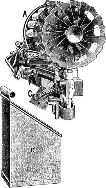
FIG. 167.
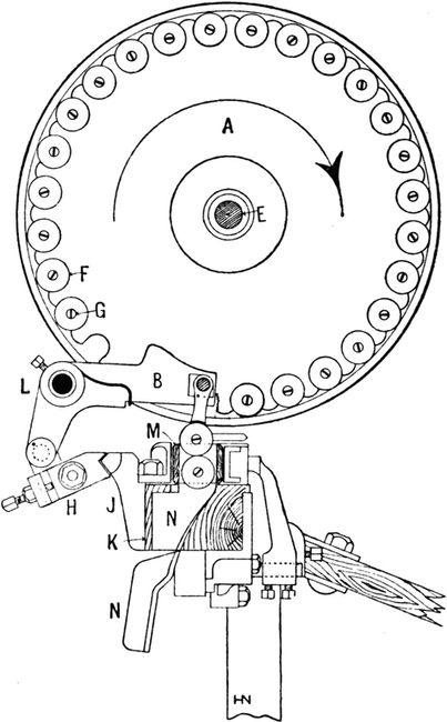
FIG. 168.
The parts of this device are better represented by the[Pg 212] sectional view shown in Fig. 168, which illustrates a cop-hopper A freely mounted on a stud E to permit of its partial rotation, intermittently, immediately after each successive change of weft, so as to bring into position another cop to be in readiness for the next change of weft. The hopper here shown is one constructed with sockets for 28 cops, F; but the space occupied by the pusher reduces its actual capacity to 25 cops. These are previously placed upon skewers, G,[Pg 213] of special construction, after which they are disposed in a horizontal position around and between the rims of two discs or plates that are formed with notches for the reception of the skewers, as represented in the diagram.
The conditions under which a change of weft is effected depends entirely on the equipment of the loom, which may be adapted so that a change will take place only when the weft either breaks or otherwise fails in its supply; or else the loom may be furnished with an attachment known as a “weft-feeling” device which effects a change of weft immediately before the previous supply is completely consumed, albeit, in this case, if the weft should break, the loom will stop automatically, as under ordinary conditions. The object of this device is to avoid such defects as are liable to be caused in cloth in consequence of broken and missing picks of weft, and so produce cloth of superior merit. If, however, such a device is not employed, the weft-changing mechanism is put into action, on the failure of weft, by the weft-fork hammer pulling backward the weft-fork, as usual. But whether the operation of the weft-changing device is controlled by the weft-fork or by the weft-feeler, the object in either case is to cause the notched and free end of a trip-finger H to tilt upward from its normal position, as shown in the diagram, so that on the forward stroke of the slay K the finger will be struck by a bunter J fixed on the front of the slay-baulk. The trip-finger is loosely mounted on a stud fixed at the bottom of a short arm of an L-lever which constitutes the pusher B, fulcrumed freely on a stud L. Thus, in the event of the trip-finger being tilted on the forward stroke of the slay, the free end of the pusher, which reaches over the ready-positioned cop in the hopper, is suddenly depressed when the slay is at its extreme forward position, thereby removing that cop from the hopper, and forcing it into the shuttle M, through the[Pg 214] bottom of which the previous cop-skewer is expelled and passed down a chute N. The next flight of the shuttle causes the weft thread to pass through a slit formed in a brass casting fixed in the upper side of the shuttle, and then to enter the shuttle eye automatically. At the same time, the remnants of both weft threads are severed near to the selvedge of cloth and also at a point near to the hopper, so that they shall not become obstructive or involve the risk of being carried along accidentally into the warp-shed. All these operations occur in proper rhythmical sequence whilst the loom continues to run at full speed, which, for a loom of 36 inches reed-space, may be up to 150 picks per minute.
The Hattersley Weft-replenishing Device.
(Patent No. 22,523, 11th December, 1900.)
The chief characteristic element which distinguishes this device—which is one of the most successful modifications of the shuttle-changing type—from other weft-changing devices, is the stopping of the loom to effect the change of shuttles, and then the restarting of it, automatically. The object of that course is to allow more time to accomplish the change, and so avert the straining and breaking of the mechanical parts, which are more liable to occur when the changing of weft is effected whilst the loom continues to run at full speed, as in all other automatic looms. It is also claimed that this arrangement enables a loom to be run at the same speed as an ordinary loom of the same width and construction, whereas continuous-acting looms require to be worked at a slower velocity.
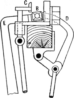
FIG. 169.
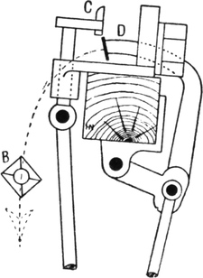
FIG. 170.
In the Hattersley loom, the reserve supply of shuttles that have been previously furnished with weft are retained in a hopper or magazine which is mounted on the breast-beam and[Pg 215] facing the shuttle-box on either the right-or left-hand side of the loom. The changing of shuttles may be effected either by the action of the weft-fork only when the weft actually fails from any cause, or else by the operation of a weft-feeler, before the weft completely fails, as desired. In either case a change of shuttles involves a series of six distinct operations which occur in the following sequence, namely: (1) stopping the loom, (2) raising the shuttle-box fender, (3) ejecting the failing shuttle from its box, (4) removing from the magazine another shuttle and placing it in the emptied shuttle-box, (5) lowering the shuttle-box fender back into its normal position, and (6) restarting the loom. These operations, of which the second, third, and fourth are represented by diagrams in Figs. 169, 170, and 171, are accomplished by means of a series of four tappets governed by an indented clutch-wheel, all of which are loosely mounted together on the second-motion or picking-shaft, at the same side of the loom as that on which the driving-pulleys are situated. The clutch-wheel is driven by means of a pinion carried by the loose driving-pulley, and revolves continuously, so that when a change of shuttles is called for, an indent or notch in the clutch-wheel becomes[Pg 216] engaged by a lug which, being secured to the tappets, turns these for one revolution, and thereby performs the series of operations just enumerated. Thus, in the event of weft either failing or becoming nearly depleted, either the weft-fork hammer or else the weft-feeler motion, according to the equipment of the loom, first disengages the starting-handle to pass the driving-belt from the fast or driving-pulley to the loose pulley, thereby stopping all the primary movements of the loom, and at the same time putting into operation the series of four tappets which effect the changing of shuttles. Then one of the four tappets raises the shuttle-box front, C, above the shuttle B, as shown in Fig. 169, to permit of the removal of the shuttle. A second tappet then operates the pusher D, which advances to eject the discarded shuttle from its box, whence it falls into a receptacle, as shown in Fig. 170. A[Pg 217] third tappet next operates the feeder E, which removes the bottom shuttle from the hopper A and places it in the same shuttle-box as that previously occupied by the ejected shuttle, as represented in Fig. 171. The shuttle-box fender now falls sufficiently to prevent the withdrawal of the newly inserted shuttle from the box as the feeder withdraws and returns to the magazine to receive another shuttle in readiness for the next change, after which the shuttle-box front falls to its normal position, and finally the fourth tappet replaces the starting-handle into its operative position to transfer the driving-belt back again from the loose to the fast driving-pulley and thereby re-start the loom.
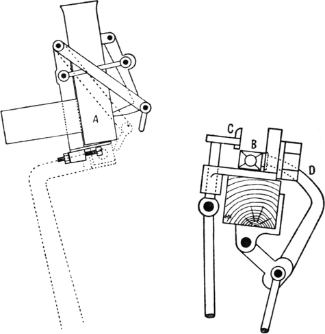
FIG. 171.
All the movements just described are performed during one complete revolution of the tappets, and involve a stoppage for six picks, corresponding to six revolutions of the crank-shaft. Therefore, in a loom running at a speed of 180 picks per minute, the changing of shuttles would involve a stoppage of the loom for only two seconds.
THE simplest form of interlacing the threads is the plain or tabby weave. In this weave the threads intersect as often as possible, and thus the greatest possible amount of firmness and strength is obtained from a given quantity of material by this weave, with the exception of leno or cross weaving, where additional firmness and strength is obtained by the warp threads being partly twisted round each other in weaving. Plain cloths may be ornamented by using threads of different colours and of different thicknesses, as, for instance, if four picks of blue and four picks of white are alternately put into a cloth, the warp of which is composed of four ends blue and four ends white alternately, a check is formed although the weave is quite plain. A check may also be formed on a plain cloth by using one or more thick threads at intervals in both warp and weft.
There is, of course, a limit to the number of threads of a certain count which can be put into a plain cloth. Assuming that the counts of warp and weft are equal, and that the number of picks per inch required is the same as the ends, the number of threads per inch which can be satisfactorily put into the cloth would not much exceed half the number which could be placed side by side in one inch. Some allowance must be made for the threads being bent out of a straight line[Pg 219] and for compression. This branch of design will be treated of more fully in a subsequent chapter, but it will be obvious that this limit to the number of threads of a given count which can be used in a plain cloth renders the weave unsuitable for heavy fabrics. If a plain cloth is very heavy and thick, it must of necessity be coarse.
FIG. 172.

FIG. 173.
Plain cloth can be made by using two shafts, but four are usually taken with the draft, as shown at Fig. 172. This prevents overcrowding the healds. By tying the first and second together and the third and fourth together, the effect is the same as by using only two staves, only two lifts being required.

FIG. 174.
FIG. 175.
Twills.—The simplest twill is the “2 and 1” twill, which is woven with three shafts. A section through this twill is given at Fig. 173, where it will be seen the weft passes under one end and over two. The structure of the fabric is better shown on “point paper,” as at Fig. 174. The spaces between the perpendicular lines represent the warp threads or “ends,” and the spaces between the horizontal lines represent the weft threads or “picks.” By filling in the first square on the first pick, it is shown that the first end is lifted for that pick;[Pg 220] and by filling in the second end on the second pick, it is shown that the second end is lifted on the second pick, and so on. It is not always advisable to take a filled-in square as representing a lifted end, as it is often more convenient to fill in the weft squares or those which are left down in weaving. If necessary, it can be stated along with the design whether the marks represent warp or weft up.
Twilled weaves enable a larger number of threads of a given count to be put into a fabric than in a plain cloth, and therefore these weaves are employed in the production of the heavier kinds of cloths where closeness of the threads is also desired.

FIG. 176.
With three staves the twill given at Fig. 174 is the only one which can be woven. The same twill may be woven with the warp predominating on the face, and this would be represented on paper as at Fig. 176, where two ends are shown to be lifted on each of the three picks.
In weaving this pattern three staves would be taken with the draft, as given for Fig. 174 (see Fig. 175). The first stave will be lifted for the first pick, the second stave for the second pick, and the third stave for the third pick. These three lifts being repeated over an indefinite number of times will produce small diagonal lines running at an angle of 45 degrees across the piece, if the number of warp and weft threads in a given space are equal. This twill is sometimes called a “Jean,” and is used in the production of a fabric of that name, as well as in “Jeannettes,” the latter with warp predominating on the face of the cloth. In all these fabrics a large range of qualities is made.
With four staves the following twills can be made:—
1. One up, three down;
2. Two up, two down;
3. Three up, one down.
These are shown on point paper at Figs. 177, 178, and 179 respectively. The third pattern is really the same as the first, being the reverse of that pattern. It is advisable, however, to consider them as two distinct patterns, since they give different effects when used for purposes of combination, as will be seen later.

FIG. 177.

FIG. 178.
FIG. 179.
Five-shaft Twills.—With five shafts of staves the possible twills are—
1. One up, four down;
2. Two up, three down;
3. Three up, two down;
4. Four up, one down;
5. Two up, one down, one up, one down;
6. Two down, one up, one down, one up.

FIG. 180.

FIG. 181.

FIG. 182.

FIG. 183.

FIG. 184.

FIG. 185.
These are shown on point paper at Figs. 180 to 185 inclusive. There are really only three different methods of interlacing the threads in these six patterns; but, as stated previously, different effects are produced in combination twills by all of them.
Six-shaft Twills.—With the increase in the number of shafts the number of twills increases very quickly, as with a[Pg 222] “repeat” of six ends the following simple twill can be woven:—
1. One up, five down;
2. Two up, four down;
3. Three up, three down;
4. Four up, two down;
5. Five up, one down;
6. Three up, one down, one up, one down;
7. Three down, one up, one down, one up;
8. Two up, two down, one up, one down;
9. Two down, two up, one down, one up.
There are here five distinct methods of intersection, the remaining four patterns being reverses. The patterns are shown on point paper at Figs. 186 to 194.

FIG. 186.

FIG. 187.

FIG. 188.

FIG. 189.

FIG. 190.

FIG. 191.

FIG. 192.

FIG. 193.

FIG. 194.
Eight-shaft Twills.—With a “repeat” of eight ends and picks the number of changes which can be made in the basis of the twill is much larger, and as the size of the repeat increases the possible twills increase enormously. A selection of eight-end twills is given at Figs. 195 to 204 inclusive.
Satin Weaves.—In simple twills every pick is interlaced with the warp in the same manner, but each successive pick commences, as it were, one end further to the right or to the left, thus enabling every end to be bound into the cloth in[Pg 223] regular order. In satins the picks are arranged differently. The object in a satin cloth is to obtain an even surface, free from the bold lines of a twill; and thus it is necessary to distribute the points of intersection of the warp and weft as evenly over the surface of the fabric as possible.

FIG. 195.

FIG. 196.
FIG. 197.
FIG. 198.
FIG. 199.
FIG. 200.
FIG. 201.
FIG. 202.
FIG. 203.
FIG. 204.
FIG. 205.
The commonest form of satin is the five shaft, and this can be woven with five shafts with a straight draft lifted in the order 1, 3, 5, 2, 4. The relation between this satin and a five-end twill is shown at Fig. 180, where it will be seen that on the second pick of the satin the third end is lifted, on the third pick the fifth end is lifted, then the second is lifted, and lastly the fourth. This distribution of the points of intersection produces a satin. A slight twill effect is given by most of these weaves, but it is nothing like so decided as where the adjacent ends are lifted on successive picks, as in twilled cloths.
The direction of the twill in the satin at Fig. 205 is from right to left.
This five-shaft satin weave is used with weft preponderating over warp, and also the reverse. Immense quantities of cloth[Pg 224] are made on both principles, and in all qualities. A regular make with weft predominating is made with about 72 ends per inch of 32’s twist, and picks ranging from 100 to 200 per inch of 40’s weft. A finer make is used in large quantities for printing upon. This cloth counts about 26 ends × 45 picks per quarter-inch, and the yarns used are 60’s twist, 70’s weft. These are two of the standard makes of satins, but for special purposes all qualities are made in cotton.
With the warp predominating a cheaper fabric is produced, as less time is required to weave a given length. “Drills” are woven on this principle, the proportion of warp to weft being about two to one.

FIG. 206.
Satins may be produced on any number of shafts from five upwards. Fig. 206 is commonly called a four-shaft satin, but this is better classed as a broken twill. The principle of its structure is essentially different to that of a true satin.
A simple method of making a satin weave on any number of ends is to find the first number which is not a measure of the number of staves used, and take this as the basis of constructing the satin, as follows: The first number which is not a measure of five is 2. Then, taking this as the basis of the satin, assuming that the first stave is lifted for the first pick, the third stave must be lifted for the second pick. This gives the number of ends to be “skipped” over, and thus we can obtain the satin by skipping over one each time, viz. 1, 3, 5, 2, 4.
It is advisable to put the numbers in a line or in a circle, and re-arrange them underneath.
The order of lifting the staves for an eight-end satin can be obtained as follows:—The first number which is not a measure of eight is 3. Then, taking this as the basis, we lift the first stave for the first pick and the fourth stave for the second pick,[Pg 225] and “skipping” over two each time we get the order, 1, 4, 7, 2, 5, 8, 3, 6. This is shown on point paper at Fig. 207.

FIG. 207.

FIG. 208.

FIG. 209.
A six-stave satin is irregular. It is impossible to form a satin with six staves by “skipping” over a regular number of staves each pick, but the points of intersection can be separated and a satisfactory satin formed by lifting the staves in the order, 1, 3, 5, 2, 6, 4, or 1, 4, 2, 6, 3, 5. These are shown on point paper at Figs. 208 and 209.
A six-end satin weave is extremely useful, as it takes rather more material than a five, and its irregular appearance is an advantage for some purposes.
Fig. 210 is a seven-end satin.
FIG. 210.
FIG. 211.
Fig. 211 is a ten-end satin. Three is the first number which is not a measure of ten, therefore three is taken as a basis in constructing the satin, and the fourth stave is lifted for the second pick, and the others in regular order.
Fig. 212 is a twelve-end satin. The basis in this case is five, as five is the first number which is not a measure of twelve.
FIG. 212.
FIG. 213.
Combined Twills.—A useful class of pattern is obtained by combining pick and pick two simple twills. If two eight-end twills are combined in this manner, a pattern repeating on eight ends and sixteen picks is produced. At Fig. 213 a “three and five plain” twill is combined with a “three, two, one, two,” twill, and different effects may be obtained by combining the same twills in all the possible positions.
Figs. 214 to 220 show the effect produced by all the changes in the relative position of the two twills. An immense number of patterns can be made on this principle, as all the simple twills may be combined in every position, and in each case a different pattern results.
On six ends we have seen that nine simple twills can be made, and as each may be combined with the others in six different positions, the number of patterns which can be obtained from this system of combination is as follows:—Fig. 186 combined with each of the others in one position each gives eight patterns, and as there are six positions in which they can be combined, this gives forty-eight patterns. Fig. 187 combined with Figs. 188 to 194 gives seven patterns, and these in six positions give forty-two patterns. Fig. 188 combined with Figs. 189 to 194 gives six patterns, and in the six positions give thirty-six patterns. By going through all the changes in[Pg 227] this manner we get successively 48, 42, 36, 30, 24, 18, 12, and 6, or a total of 216 patterns. In addition to these, each twill may be combined pick and pick with itself in four different positions without giving double picks.
FIG. 214.
FIG. 215.
FIG. 216.
FIG. 217.
FIG. 218.
FIG. 219.
FIG. 220.
Drafting.—The arrangement of the draft is a very important matter in connection with dobby or tappet weaving. In the case of simple twills, satins, and other regular weaves, as each end, or warp thread, in the design is required to be lifted differently, a separate stave is required for each end in the design, but in some patterns this is not the case.
Fig. 221 is a stripe design composed of twenty ends of five-shaft satin and sixteen ends plain. The least number of shafts on which this could be woven is seven, five for the satin and two for the plain. The number of picks to the round, or the[Pg 228] number of picks on which the pattern repeats is ten, ten being the least common multiple of two and five. The draft may be shown either by ruling lines to represent the staves as at Fig. 222, or on point paper as at Fig. 223. The latter is the readier way, and is the way usually practised. The order of lifting the staves is shown in the “pegging plan” (Fig. 224). The term “pegging” refers, of course, to the dobby loom; if the design is woven on a tappet loom, “tappet plan” would be a more correct term to use.
FIG. 221.
FIG. 222.
FIG. 223.
FIG. 224.
FIG. 225.
FIG. 226.
FIG. 227.
When two weaves which consist of different arrangements of the same ends are combined in stripe form, the same shafts will do for both weaves. Fig. 225 illustrates this principle. In the design there are sixteen ends of an eight-end twill, “2 up 2 down, 1 up 1 down, 1 up 1 down,” and sixteen ends of a mixed effect, which is simply a re-arrangement of the ends of the twill. Each of the ends in the crape or mixed weave can be drawn through the same stave as one of the ends in the twill, as will be seen from the draft (Fig. 226) given with this design, and thus the whole design can be woven with eight staves. If the staves are lifted to form the twill with the first sixteen ends, the different order of drawing the ends in the second part of the draft causes the desired change in the pattern. The pegging or lifting plan (Fig. 227) will therefore be the first eight ends of the twill.
FIG. 228.
FIG. 229.
FIG. 230.
FIG. 231.
FIG. 232.
FIG. 233.
One of the most useful principles of drafting is the V draft, or point draft. Fig. 228 is a design based upon this principle; the design is repeated twice over in order to show the effect better, and it will be seen that the basis of the pattern is a “four and four” twill. The first eight ends are drawn from right to left, and by reversing the draft, as in Fig. 229, the pattern is made to repeat on fourteen ends. The pegging plan (Fig. 230) will be the first eight ends and picks of the design. The first and eighth staves have each only one end out of the fourteen drawn through them, whilst all the other staves have two ends in each pattern. The number on each stave could be made equal by making the pattern repeat on sixteen ends and reversing the draft from the ninth stave, with an eight-end twill basis.
FIG. 234.
FIG. 235.
FIG. 236.
The V draft is used in a great variety of forms. It is not only in stripes that it is used. It is very often employed in weaving all-over spot effects and diamond patterns.
FIG. 237.
Fig. 231 shows the principle applied to an all-over design. The draft (Fig. 232) is given, showing how the ends are drawn through the thirteen staves required to weave the pattern, and[Pg 233] the “pegging plan” (Fig. 233) shows the order of lifting the staves.
FIG. 238.
A very effective method of employing this draft is illustrated at Fig. 234. This is a stripe design, and the general appearance would lead one to suppose that a larger number of staves are required to weave it than the eighteen actually required. Fig. 235 is the draft and Fig. 236 the pegging plan for this design.
FIG. 239.
FIG. 240.
Another class of pattern produced by the V draft is the “diaper” style. Fig. 237 is a small design of this kind, and it[Pg 234] will be noticed that the draft (Fig. 238) plays a very important part in increasing the size of the pattern. The draft given shows how the pattern would be made on nineteen staves.
It is not always advisable to draft a pattern to its lowest number of staves, as it is not worth while saving one or two staves at the expense of an irregular draft.
FIG. 241.
Dice Checks.—Fig. 239 is a simple dice check pattern. Alternate squares of warp and weft twill form the check effect,[Pg 235] and it is necessary to arrange the bindings so as to cross each other at the edges of the squares, as otherwise the ends would “slip.” Fancy dice patterns are produced by employing squares of different dimensions. Fig. 240 is a pattern of this description. The bindings are here those of an eight-end satin. To obtain the crossing of the binding dots at the edges of the squares it is necessary to run the satin in opposite directions in the warp and weft squares.
A still more fancy dice effect is given at Fig. 241. The bindings are on the five-end satin basis, and the blocks of warp and weft satin are arranged so that the design repeats on fifty ends and picks. It is necessary in this class of binding to commence the satin in the position indicated in the design. By a judicious arrangement of the warp and weft blocks a large variety of patterns can be produced. The principle is extensively employed in the production of fabrics for both the home and shipping trades.
FIG. 242.
FIG. 243.
“Barley corn” patterns are a related style. The structure of these cloths is shown at Figs. 242 and 243. The former pattern is manufactured on an extensive scale, as it is a fabric in regular use for making-up purposes. Fig. 243 has the weft square rather larger than the warp, and is usually made in rather a better quality than Fig. 242. In fine makes the size of the squares is often increased.

FIG. 244.
FIG. 245.
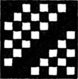
FIG. 246.
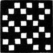
FIG. 247.
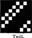
FIG. 248.
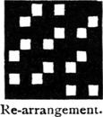
FIG. 249.
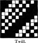
FIG. 250.
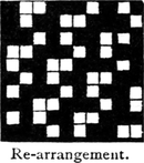
FIG. 251.
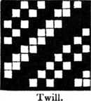
FIG. 252.
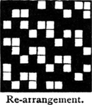
FIG. 253.
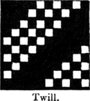
FIG. 254.
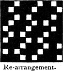
FIG. 255.
Patterns produced by Re-arrangements of Twills.—If the ends of any twill be re-arranged in some regular order, another pattern of a different character is produced. For example, by re-arranging the eight-end twill given at Fig. 244 in “satin order” the effect at Fig. 245 is produced. The method of re-arrangement is to take the first end of the twill design and place it in the first place in the re-arrangement. The fourth end of the twill is then placed in the second end of the re-arrangement, the seventh end of the twill in the third place, and so on, the satin order used being 1 4, 7 2, 5 8, 3 6. Fig. 246 re-arranged in this manner gives the effect at Fig. 247, and, as will be seen from the remaining figures (Figs. 248–255),[Pg 237] the effects produced by the re-arrangement are all good serviceable effects which are useful for a great many purposes. With larger twills the effects produced are more elaborate and varied, and the principle is distinctly useful for the production of new woven effects.
FIG. 256.
FIG. 257.
FIG. 258.
FIG. 259.
FIG. 260.
FIG. 261.
FIG. 262.
FIG. 263.
Combined twills may also be re-arranged in this manner for the production of new effects. Figs. 256 and 258 are two five-end combined twills, and the effect produced by re-arranging the ends in five-end satin order is shown at Figs. 257 and 259, respectively.
FIG. 264.
FIG. 265.
Fig. 260 is an eight-end combined twill, and Fig. 261 shows the effect produced by its re-arrangement in eight-end satin order.

FIG. 266.
FIG. 267.
Fig. 262 is a twelve-end combined twill, and when re-arranged in twelve-end satin order Fig. 263 is produced.
The effects produced by re-arrangement in satin order are, as a rule, mixed effects of a less decided character than the original twill. There are many other useful systems of drafting or re-arranging patterns.
FIG. 268.
FIG. 269.
FIG. 270.
Fig. 265 is the re-arrangement of Fig. 264 in the order 1 2,[Pg 239] 6 7, 3 4, 8 1, 5 6, 2 3, 7 8, 4 5. This is a regular draft obtained by skipping three shafts between each two ends. Another draft is obtained by skipping one end between each two ends drawn through the healds.
Fig. 267 is obtained by re-arranging Fig. 266 in the order of the draft 1 2, 4 5, 7 8, 2 3, and so on, the draft repeating on sixteen ends.
Another useful draft (Fig. 270) as a basis for re-arrangement is the one employed in producing Fig. 269 from Fig. 268. The order of the draft is shown along with the design; the order runs, 2 1, 3 2, 4 3, and so on, repeating on sixteen ends.
FIG. 271.
FIG. 272.
Some novel effects are obtained by re-arranging the ends of a sixteen-end twill in the order 1 4, 7 2, 5 8, 3 6, 9 12, 15 10, 13 16, 11 14. The effect of this system is shown at Fig. 272, which is the result of re-arranging Fig. 271 in the above order. The system is of course applicable to other twills than those on sixteen ends.
Twills combined to form Square Patterns.—Simple twills may be combined to form “square” patterns by taking alternate picks of each. If two eight-end twills are combined in this manner only four picks of each twill will be used in the combination. The principle will be understood from Fig. 273.
This is a pattern composed of alternate picks of two ten-end twills making an effect repeating on ten ends and ten picks. The effect given by re-arranging this in satin order is shown at Fig. 274.
FIG. 273.
FIG. 274.
FIG. 275.
Fig. 275 is a twelve-end pattern made on the same principle, and if this is re-arranged in satin order, another effect is obtained.
Fig. 276 is a sixteen-thread pattern, and when re-arranged this produces the rather peculiar pattern Fig. 277.
FIG. 276.
FIG. 277.
An immense variety of useful weaves may be obtained on this system of combination, the effects being perhaps more useful than when the patterns occupy twice as many picks as ends.
Unequal Twills combined.—Some useful fancy effects are obtained by combining two unequal twills[Pg 241] “end and end,” or “pick and pick.” Fig. 278 shows the effect produced by combining “end and end,” a “three and two” twill, and “two and two” twill. As one twill repeats on five picks and the other on four, the combined pattern will occupy twenty picks—twenty being the L.C.M. of five and four. There will require to be twenty ends of each twill used to make up a complete pattern, therefore the combined design will repeat on forty ends and twenty picks. If a four-end twill is combined with a three-end twill in this manner, the complete pattern would occupy twenty-four ends and twelve picks, as twelve is the least number of picks on which both the four-end and three-end twills repeat.
FIG. 278.
Check Patterns produced by Re-arrangement of Twills.—If an eight-end twill “three and five plain” is re-arranged in the order 1 4, 7 2, 5 8, 3 6, the effect shown in the square A (Fig. 279), and if this be again re-arranged in the same order, the original twill results. It follows, therefore, that by placing the pattern A above the twill and drawing the ends through eight staves as indicated in the draft (Fig. 280), a check pattern will be formed. The draft which produces the crape from the twill also produces the twill from the crape. The[Pg 242] first eight ends and sixteen picks of the design is the pegging plan. By the addition of two extra staves the floats may be prevented from passing from one square to another. To produce the check effect properly, the satin draft must be such a one that if the fourth end is drawn on the second stave, the second end must be drawn on the fourth stave. If a sixteen-end satin draft is used for making a check pattern on this principle from a sixteen-end twill, the satin draft must be selected from those which can be made on sixteen shafts, and must be such a one that exactly the same pattern will be produced in the opposite squares of the check. The sixteen-end satin which gives this effect is the one made by skipping eight ends between each lift.
FIG. 279.
FIG. 280.
Honeycomb Cloth.—In this style of cloth the threads are interlaced so as to form squares, the centres of which are lower than the ridges which form the sides. Fig. 281 is a honeycomb pattern on ten ends and ten picks. It will be noticed that the ridges or raised portions of the honeycomb are formed by the gradually increasing floats of the weft and warp threads. The hollows are formed by the threads weaving plain for a few ends and picks. Any size of pattern, within reasonable limits, may be formed on this principle. Fig. 282 is a 16 × 16 honeycomb on the same principle.
For smaller sizes the principle requires a little alteration. Fig. 283 is a good 8 × 8 honeycomb, and gives a fairly good[Pg 243] effect even in low makes of cloth. These honeycomb weaves are used for quiltings, towellings, and for fancy goods of all kinds. Some excellent effects can be produced by combining honeycomb with satin or other weaves for striped dress goods, and similar fabrics. A good effect is given by the pattern, Fig. 284. The weave requires very thick yarns for giving the best effect. The pattern is reversible, both sides of the cloth being exactly alike.
FIG. 281.
FIG. 282.
FIG. 283.
FIG. 284.
Mock Lenos, or Lace Weaves.—These weaves are very extensively used in cotton manufacture. The imitation of leno fabrics can be made extremely close, often so close as to deceive even experienced buyers. The simplest kind is the pattern at Fig. 285, a “three and three” pattern. The threads are interlaced in such a manner that the first ends are pulled together by the second and fifth picks, and the picks are pulled together in threes by the second and fifth ends, and as the shed is crossed between the third and fourth picks, the crack in the cloth appears there. The open effect is greatly increased if the ends are reeded “three in a dent,” the first[Pg 244] three ends in the pattern being together in one dent, so that the reed assists in forming the open effect. Sometimes the ends are reeded in threes with a dent “skipped” between each full one, and this greatly augments the open effect. A “four and four” mock leno is the weave shown at Fig. 286. To produce the best effect this requires to be reeded four ends in a dent, commencing with the first four ends in the pattern. In this weave the crack is made between the fourth and fifth ends and fourth and fifth picks. The principle of the weave is exactly the same as in the “three and three” pattern, but a slightly more open effect can be obtained with the “four and four” pattern. It is also suitable for a finer make of cloth, as the open effect can be made with a larger number of threads per inch.

FIG. 285.
FIG. 286.
FIG. 287.
FIG. 288.
A “five and five” pattern is given at Fig. 287. The second, fourth, seventh, and ninth ends serve to pull the picks together in fives, and to make a decided crack in the cloth between the fifth and sixth picks in the pattern. The same thing takes place with the ends, they are pulled together in fives, by the second, fourth, seventh, and ninth picks.
Probably the best open effect is produced by Fig. 288. This is called a “five and one” mock leno or lace. To[Pg 245] produce the best effect, the pattern should be reeded as follows:—
Two repeats of the pattern are shown at Fig. 288, only six ends and six picks being required to weave it. The first five picks are pulled together by the second and fourth ends, and as the shed is crossed between the fifth and sixth picks and between the sixth and the succeeding pick, the single pick No. 6 is shown in the middle of the crack between the bars of five picks. The same thing takes place with the ends.
It is not absolutely necessary to reed the pattern other than two in a dent; an open effect is produced with the ordinary reeding, but the special reeding greatly increases it.
Cords.—Cords can be formed in cloth by simply making a number of threads lift together, as in Fig. 289. The cord may be made across the piece by putting a number of picks in a shed, as shown at Fig. 290. This principle of forming cords has its disadvantages. If the cord is going lengthwise of the piece a large number of picks per inch is required to give a good and fine effect, and there is always a tendency to show a perforated appearance in cords made on this principle, owing to the threads being pulled together in threes or fours, or whatever number of threads go to form a cord.
FIG. 289.
FIG. 290.
A good cord up the piece may be made by taking six or eight ends of six-end satin and two plain ends. Fig. 291 is a pattern of this kind. The six-end satin is used because the plain ends would make wrong bindings with a five-end satin and the ends would slip. This principle of making cords is very useful, as the effect being produced from the warp, the cost is less than if produced from the weft.
FIG. 291.
FIG. 292.
FIG. 293.
FIG. 294.
FIG. 295.
FIG. 296.
For dobby patterns it is necessary to keep the number of shafts as low as possible, and cords requiring only two shafts above the plain are made as in Figs. 292 and 293. Fig. 294 gives a cord across the piece, and is of rather a firmer character than an ordinary four and four cord. Fig. 295 shows a useful principle of making cords across the piece. Two picks are taken together, and three double picks from a cord. The three plain picks serve to define the cord. A better effect is[Pg 247] obtained from Fig. 296, in which the double picks have a float of five ends. This cord is very suitable for stripes, as it combines extremely well with warp satin.
FIG. 297.
FIG. 298.
Fig. 297 gives a cord up the piece. The back of the cloth is plain, each pick taking an equal part in forming the back. The plain also serves to spread the ends, and so produces a firmer cloth than would be obtained if the cord were formed on the principle of Fig. 299. Sometimes the back of the cord is required to be rather looser, and is woven to a small twill. At Fig. 298 a twelve-end cord is shown on this principle, with a 2 and 1 twill pattern at the back.
FIG. 299.
FIG. 300.
Another form of cord is illustrated at Fig. 299. This shows a cord up the piece caused by every pick interweaving with the first and second ends, and only half the picks interweaving with the remaining six ends. The ends interweaving with half the picks are looser than the other two ends, and therefore have a raised appearance. The face of the cloth is plain, with the lines formed by the two ends running up the piece. A smaller cord is[Pg 248] shown at Fig. 300, which repeats on six ends and four picks. Fig. 301 is a pattern composed of crossed cords. Excellent effects are obtained by combining larger cords in the same manner.
FIG. 301.
FIG. 302.

FIG. 303.
FIG. 304.
Crapes.—This is a name given to weaves of a small “seedy” effect. Good effects of this kind are produced by Figs. 302 and 303, which repeat on ten ends and six picks, and six ends and six picks, respectively. Another very largely used pattern is that at Fig. 304. This is a pattern of rather peculiar construction, as both sides of the cloth are alike, and the small floats of three are bent somewhat out of a straight line. The reason for this can be seen by a careful examination of the pattern. Patterns of the same character,[Pg 249] but with very large repeats, are often used. In many of these there is no regularity in the construction of the pattern. The chief object is to get a perfect all-over effect free from lines or rows. This can be accomplished by keeping about the same amount of float on every pick and distributing the floats as evenly as possible. A pattern of this kind, on forty picks and sixteen ends, is given at Fig. 305. It will be seen that each pick has two floats on it.
FIG. 305.
FIG. 306.
Fancy Effects.—Some novel effects can be produced on the principle of Fig. 306. Two picks are floated on the top of a plain cloth every ten picks, and these loose picks are bound only by two ends out of every twelve. The loose picks are pulled in opposite directions by the loose ends, and the result is that small hexagonal figures are formed after the manner shown at Fig. 307. By using coloured ends and picks for the loose ones a still better effect is obtained.
FIG. 307.
FIG. 308.
Crimp Stripes.—These are usually produced by having two warps at different tensions. The warp to weave the crimp is lightly weighted as compared with the warp of the other stripe, which may be plain or satin as desired, and is let off intermittently. If the crimp warp is very hard twisted the effect is[Pg 250] increased. Fig. 308 is the design of a crimp stripe of rather a novel character. The ends woven entirely plain are on a beam lightly weighted, whilst the other ends are heavily weighted. The first two picks are of ordinarily twisted weft, and the third and fourth picks are very hard twisted. These picks are thrown to the back, and take no part in forming the cloth in one portion of it. The consequence is that these picks, loose at the back of the cloth, and being very hard twisted, pull the two edges of the stripe closer together, and thus form a crimp or “tuck” the length of the piece. The plain ends form a crimp in the ordinary manner, owing to being lightly weighted.
Huck Patterns.—This is the name given to a class of patterns used for towellings. The object is to get a firm cloth with a rough surface. Fig. 309 is a weave of this description, but there are many others in use. The pattern repeats on ten ends and eight picks, and can be drafted down to be woven on five shafts.
FIG. 309.
Extra Warp.—When some warp ends are used for figuring without taking any part in forming the ground or body of the fabric, they are termed “extra warp” threads. The principle is much used for putting coloured spots or figures on grounds of a different colour or material. In Fig. 310 the ends on which the black squares occur are “extra ends,” as they take no part in forming the ground of the fabric. In this figure the black squares represent the warp lifted. Where[Pg 251] the extra warp is not forming the figure it is thrown to the back of the cloth, where it hangs loosely unless it can be bound into[Pg 252] the ground cloth or cut off. Two or three differently coloured spots may be formed one above the other. Fig. 311 will show the principle of this. The ground of the cloth is plain, and these ends are distinguished by the small dots in the design. The first and second ends in the design are supposed to be of different colours. This design will repeat on forty picks, and any desired number of ends may be used between each stripe for the ground. The extra warp must be put “extra” in the reed, so that, supposing there are two ends in a dent in the ground, there would be six in a dent where the two extra warps occur. The principle is useful for obtaining a large width of pattern.
FIG. 310.
FIG. 311.
FIG. 312.
The extra ends may be of the same colour as the ground, but of thicker material, and may be used with the object of increasing the width of the pattern. Fig. 312 is a small striped design illustrating this principle. The ground is plain, and the extra warp threads, if of sufficient thickness, give a bold well-covered figure, which enables the design to be woven on nine shafts.
Extra Weft.—Extra weft spots may be woven on exactly the same principle by taking the weft “extra” instead of the warp. Fig. 313 is a small spot design on the “extra weft” principle. The cloth would require to have twice as many picks per inch as there are ends per inch.
FIG. 313.
The ground may be either plain, twill, or satin, but if it is required to bind the extra material a twill is preferable.
Fig. 314 is the commencement of a small design for an extra weft figure on a “two and two” twill ground, showing how the extra weft may be bound to the ground of the fabric[Pg 253] without showing through to the face. The extra weft may be brought up under the weft floats of the twill, and if a fair quantity of material is used the binding will not be visible on the face of the cloth.
FIG. 314.
FIG. 315.
It is impossible to bind extra weft to a plain ground or to a warp satin ground in the ordinary manner, as there is no float to hide the binding under. It may, however, be bound to a warp satin ground by means of stitching threads, after the manner shown in Fig. 315. This is an extra weft spot on a warp twill ground, and the loose picks at the back of the cloth are bound by the stitching thread A. This thread is really an extra warp thread, and it is lifted in such a position that the binding is hidden under the warp floats of the twill ground. One of these threads may be used at intervals of an eighth to a quarter of an inch.
In binding extra warp the same principle applies. Extra warp may be bound to a warp ground by lifting it between two warp floats, or it may be bound to a weft ground by using an extra stitching pick on the principle illustrated in Fig. 315.
FIG. 316.
Extra warp or weft is often used to produce a solid figure on a light or open ground. Fig. 316 is a small design of this kind, in which one half the picks are thrown out of the cloth in the ground of the pattern. The design gives a very close imitation of a figured leno cloth, if woven with suitable yarns. To obtain a good effect there should be at least twice the number of picks per inch that there are ends or warp threads. When the cloth is taken out of the loom the loose threads are clipped and passed through a shearing machine, where the loose threads are cut off close to the figure.
The extra picks should be bound round the figure by weaving[Pg 255] plain for a few ends, to prevent the extra material being pulled out of the figure in clipping or shearing.
Extra Warp and Extra Weft combined.—Where extra warp and extra weft are used together in the same part of the design, the structure is a little more complicated.
A small check pattern of this description is given at Fig. 317. Every alternate end and every alternate pick are extra, and all the even numbered ends and picks belong to the ground cloth, which in this case is woven plain.
In making designs employing both extra warp and weft, it is advisable to put the dots of the ground weave on the point paper first. Then dots may be put on to lift the extra warp where it is required to form the figure, and if it is required to throw the extra weft to the back of the ground cloth when the extra warp is on the face, the ground ends must be lifted on the extra weft picks where required.
FIG. 317.
In Fig. 317 the ground weave is shown in solid squares; the extra warp is lifted by the small circles, and the extra weft is thrown to the back of the plain cloth by the small dots, which lift all the ground ends on the extra picks where the extra warp is lifted. This design is made for single picks, but in the majority of looms there are only change boxes at one side, and so the design must be arranged for two picks alternately of ground and extra weft.
Double Weft Face.—Double weft-faced cloths are made on the principle shown at Fig. 318. There is a face weft and a backing weft, and both sides of the cloth may be made alike by using only one count of weft.
FIG. 318.
The pattern is a four and one twill for both face and back, and it is important that the binding should take place under the floats of the twill, after the manner described in binding extra weft.
The face pattern may be different from the back, but it is not possible to back a cloth with every pattern on this principle, as the binding must not show through to the face, and therefore the back pattern must be selected so as to give this result.
Fig. 319 is an eight-end twill backed with weft, the back pattern in this case being a “seven and one” twill.
FIG. 319.
FIG. 320.
FIG. 321.
FIG. 322.
Suppose it is desired to put a weft back to the pattern, Fig. 320, and to have two face picks to one back pick. The face pattern must be put on the face picks as in Fig. 321, and the back pattern must then be put on in such a manner that[Pg 257] where the backing weft is passing over one of the warp threads there must be at least one weft dot above and below it, as in Fig. 321.
Two wefts of different colours may be made to form reversible figures by making them change places, first one being on the face, and then the other. The principle is shown at Fig. 322, where the alternate picks are of different colours. The two wefts should be thick enough to cover well, and a fine warp should be used.
Double Warp Face.—This is the same as “double weft face” weaving, with the exception that two warps are used instead of two wefts. A four and one twill backed with warp is shown at Fig. 323. It is necessary to have the warp threads close enough together to hide the bindings. Fancy patterns may be backed with warp by binding the backing warp under warp floats in the face cloth.
FIG. 323.
FIG. 324.
FIG. 325.
Corkscrew twills are those which have a warp face on both sides of the cloth. The weave is chiefly used in the manufacture of worsted coatings, and similar goods, but is often employed in cotton designs. An eleven-thread corkscrew is given at Fig. 324, and a fifteen-thread pattern is given at Fig. 325. The weave requires a large number of warp threads per inch to give a good effect.
Padded Cloths.—To obtain a raised effect on cords or figures, thick weft may be inserted between the face and back cloth, or between the face cloth and backing ends when there is no backing weft used. This thick weft takes no part in forming either the face or back cloth, and is simply held in position by the binding of the backing material to the face cloth.
FIG. 326.
A simple example of this principle of weaving is given at Fig. 326. This pattern may be woven with one shuttle, and a fine raised cord across the piece is formed. The backing warp threads, on which the solid squares are placed, should be on a separate beam, and should be heavily weighted as compared with the other ends. All the marks in the design represent the warp lifted, so that the empty squares represent warp left down. It will be noticed that the heavily-weighted ends are only lifted for two picks in every ten, and this forms a cord effect. There are three picks in each cord which do not interweave with either the face or backing ends, but they serve to increase the boldness of the cord by giving it a raised appearance. The three picks which form the padding are the second, fourth, and sixth in the design.
The section at Fig. 327 will better explain the principle of the pattern. There are five plain picks in the cord, two plain picks between the cords, and three padding picks, making altogether ten to the round. These cloths are known as Piqués.

FIG. 327.
FIG. 328.
Another padded effect is given at Fig. 328. The double pick is the padding weft, and should be of thick material. The plain face cloth is developed in small dots, and the backing ends in solid squares. The padding picks in this pattern are pulled out of a straight line, and a diamond effect is produced on the cloth.
Double Cloths.—Double-warp-face and double-weft-face cloths are usually classed as double cloths, but they are essentially different from double cloths made from two warps and two wefts.
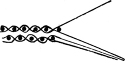
FIG. 329.
FIG. 330.
Figs. 329 and 330 will show how two separate cloths, one above the other, can be woven in one loom. The first figure shows one of the face ends only lifted, and a pick being put in the face or top cloth. It will be noticed that both back ends are in this case down along with one of the face ends. The second figure shows both face ends lifted and one of the back ends, whilst a pick is being put in the back cloth.
Two separate cloths of any pattern may be woven by simply lifting the face ends out of the way when a pick is being put in the back cloth.
If a pick is put in the face and back cloth alternately, the cloths will be bound together at both selvedges; but if two picks are put in each cloth alternately, they are only bound at one side. This will be seen from Figs. 331 and 332. In the former the pick passes from the face cloth to the back cloth at one side, and from the back cloth to the face cloth at the[Pg 260] other side of the loom. In Fig. 332 two picks are put in each cloth in succession, and the cloth will open out to double the width of the loom. The former principle is used for weaving sacks, meat-bags, and seamless pillow-cases. In putting double cloths on point paper it is usual to use different colours or marks for the face and back cloths respectively, and also for lifting the face cloth when weaving in the back one. It is also advisable to always take the dotted squares as warp lifted.

FIGS. 331, 332.
The following directions for double cloth designing will be found useful.
First mark off the face and back ends and picks respectively. Then on the face ends and face picks put the face pattern, and on the back ends and back picks put the back pattern. On every back pick lift every face end. This will make the two cloths separate.
FIG. 333.
FIG. 334.
FIG. 335.
Fig. 333 is the design for two separate plain cloths bound at both sides of the loom, and Fig. 334 is the pattern for the[Pg 261] cloths bound only at one side. The face and back cloths may be of different patterns, and bound together to form one thick fabric.
Fig. 335 is a design for a double cloth with a two and two twill face and a plain back. The design is end and end, and pick and pick.

FIG. 336.
The binding of the two cloths together is a very important matter. It must be done in such a manner that the bindings are not visible on the face of the fabric. To find the best position for binding the two cloths together it is generally advisable to make a section showing the first two picks in the pattern, as at Fig. 336. A position can then be found for passing a back pick over a face end where the floats of weft in the face pattern will hide the binding. It will be seen that this can be done effectually by passing the back pick over the fourth face end, and so in the design the fourth face end is not lifted when the first back pick is being put in.
Sometimes the face cloth is required to be much finer than the back, and so there may be two face ends and two face picks to one back end and one back pick.
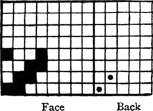
FIG. 337.

FIG. 338.
Figs. 337 and 338 show a design for a fabric of this description, the face pattern being a two and two twill, and the back plain. Before commencing to put the design on paper, it is best[Pg 262] to make a section showing in what relative positions it is proposed to start the two patterns, and so enable the weaves to be placed in such positions that a satisfactory binding is possible.

FIG. 339.
Fig. 339 shows how the binding may be effected by placing the two patterns in a certain position in relation to each other. The binding in this, as in the previous case, is made by passing a back pick over a face end.
The binding may also be made by lifting a back end over a face pick where the warp floats in the face cloth would cover it. A design illustrating this kind of binding is given at Fig. 340. The face pattern is a “four and four” twill and the back a two and two twill, and there are two threads of face to one of back. The two cloths are bound together by lifting the first back end on the first face pick where the binding dot comes between two warp floats. The full squares in the figure represent the face ends lifted; the small dots represent the back ends lifted; and the circles show all the face ends lifted on the back picks, which keep the two cloths quite separate. The cross on the first pick effects the binding.
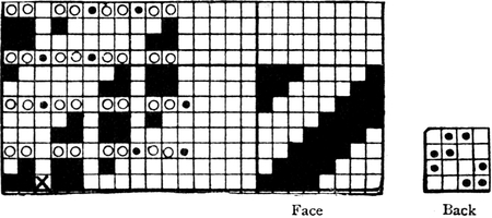
FIG. 340.
The question as to which is the better system of binding depends upon the character of the two cloths. If the face[Pg 263] weft covers better than the warp, it is the better way to bind by passing the back pick over a face end, whereas if the face warp covers better than the weft, a back end lifted over a face pick is preferable.
Three-, and more ply Cloths.—Any number of cloths may be woven separately, one above the other, or several may be bound together to form a very thick fabric. Fig. 341 is a design for weaving four plain cloths, one above the other, and if the picks are woven in the order given in the design it will weave a cloth four times the width of the loom when opened out. The passage of the weft from one cloth to the other is shown at Fig. 342.
FIG. 341.
FIG. 342.
Figured Double Plain Cloths.—If the warp be taken with alternate ends of two colours and picked in the same manner, figures, checks, or stripes can be formed by weaving two separate cloths of the different coloured yarns, making both cloths solid colour, and making them change places so as to form the desired figure. Fig. 343 is a design for a small check pattern on this principle. The odd ends and picks are, we will suppose, black; and the even numbered ends and picks white. It will be seen that in the bottom left-hand square[Pg 264] of eight ends and picks, the lifting marks for lifting the face cloth out of the way when weaving in the back cloth are put on the black ends and white picks, and therefore the black cloth is lifted to the face in this square. On the opposite square of eight ends and picks, the lifting marks for separating the two cloths are put upon the white ends and black picks, and therefore the white cloth is here made the face cloth. By bringing either the black or white cloth to the face, any figure may be formed, and the surface of the fabric is quite plain, which for some purposes is much preferable to floated figures. The weave used may be a twill or satin instead of plain, if desired, or the two cloths may be of different weaves, and one brought through the other to form a figure. Fig. 344 is a design for a small spot pattern on the double plain principle. The threads should be “end and end” and “pick and pick” of different colours, the first end and first pick being, we will suppose, black, and the threads for the second cloth being white. The lifting marks for[Pg 265] bringing the back cloth to the face are the solid squares, whilst the white cloth is brought to the top by the circles.
FIG. 343.
FIG. 344.
If all the black ends and picks are brought together and all the white ends and picks brought together, the pattern of both sides of the cloth can plainly be seen as well as the ground weave. Fig. 345 will show this. The face pattern is shown on the first sixteen ends and picks, and the back pattern on the second sixteen ends and picks, whilst the ground weave is shown for both cloths in the opposite corner squares. The patterns may be designed in this manner, and the full effect produced by arranging the draft so as to give the required effect in the cloth.
FIG. 345.
Some fine effects may be obtained by inserting a thick end in the form of padding between two plain cloths, and binding the cloths together so as to make the thick end form a cord. The cords may run either lengthwise or across the piece.[Pg 266] Fig. 346 is a section showing how the cord is formed by the thick end coming between the two cloths without interweaving with either of them, and Fig. 347 shows how the point paper design is made. The end on which the crosses are placed is the thick thread which is used for padding, and the four ends at each side of this are the two separate plain cloths. At each side of this there are two ends showing where the two cloths change places, and so bind the thick end between the cloths and form the cord.

FIG. 346.
FIG. 347.
Double plain cloths may be bound together by using sufficient material to cover well, but the binding is difficult to make without being visible. This principle of binding is shown at Figs. 398 and 399.
Leno Fabrics.—In a previous chapter the method of interlacing the threads in simple gauze has been shown. With the two staves and one doup required to weave gauze a considerable variety of patterns can be woven. A “five and one cross-over” has already been given, but it will be obvious that the number of plain picks in each bar of the cross-over may be any odd number. A “seven and one,” “eleven and one,” and so on, are regular weaves.
Where the crossing thread weaves plain first at one side and then the other of the standard end, a simple crack is made in the cloth between the bars of plain, and there is no single pick in the middle of the crack. The most common pattern of this[Pg 267] description is a “five and five cross-over;” a plan, draft, and pegging-plan of this pattern is shown at Fig. 348.
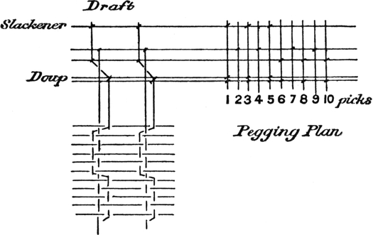
FIG. 348.
In all these fabrics the effect is decidedly of an open or transparent nature.
In some leno fabrics the object is not to get an open effect but to get zigzag effects by crossing a thick end over a few plain ends. A simple pattern of this kind was given at Fig. 139 in dealing with leno weaving, but the effect may be varied by making the crossings at irregular intervals.
FIG. 349.
Fig. 349 is a fancy crossing in which the thick doup end is crossing over three double plain ends.
Fig. 350 is another fancy effect on the same principle. The marks on the plain ends show when these ends are lifted.
When the thick crossing ends all work in the same direction a “wave” effect is produced, which is often employed in conjunction with the “diamond” or[Pg 268] “eye” effect, obtained from the opposite working of the two thick ends.
FIG. 350.
FIG. 351.
By using two doups a great variety of effect can be obtained. Fig. 351 shows a method much practised of making the picks bend out of a straight line. It is obvious that this will require two doups, because one doup thread has to be lifted for the first six picks, and the other doup thread does not lift until the fourth pick in the pattern.
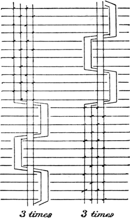
FIG. 352.
Check Lenos.—Where alternate squares of leno and plain are required to be woven, it is necessary to have two doups if the leno is required to be woven four ends in a dent, with two ends crossing two, as in Fig. 352. It has been shown how a check leno or gauze can be woven with only one doup at[Pg 269] Fig. 144, but the principle only applies to pure gauze, or one end crossing one. The draft and pegging plan for weaving a small check on the principle of Fig. 352 is given at Fig. 353, where it will be seen that eight shafts or staves are required with two doups and two slackeners.
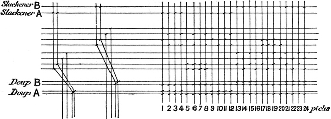
FIG. 353.
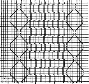
FIG. 354.
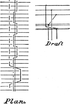
FIG. 355.
For dobby weaving, the leno principle is chiefly used in the production of striped fabrics. One of the most popular[Pg 270] classes of fabrics is a combination of the thick zigzag effect with an open leno effect of any kind. Fig. 354 is an example of this combined style, the stripe can either be woven with a satin or plain ground fabric.
With three doups some very elaborate effects can be obtained, but the increased cost is rather prohibitive.
A thick end can be crossed round a pair of ends weaving leno, as in Fig. 355. It is necessary to bring the end from the back stave round the doup B before crossing under the pair of leno ends, as this would make the crossing easier.
Weft Pile Fabrics, Velvets, and Corduroys.—Practically all cotton velvets are woven on the weft pile principle. The intricate nature of the loom required for weaving warp cut-pile prevents its adoption for cotton pile fabrics. There is no doubt that a warp pile woven over wires is superior to any weft pile fabric, all the pile being perfectly even. The principle upon which weft pile is formed is illustrated at Figs. 356 and 357, the former showing the pile uncut, and the latter cut.

FIG. 356.

FIG. 357.
In weft pile fabrics the pile weft is usually “extra weft” issuing out of the ground fabric only between every pair of ends. This forms grooves or “races” in the fabric, which allow of the insertion of a “knife and guide” which cuts the pile about the middle of the float. At Fig. 356 the ground fabric[Pg 271] is plain, and between each ground pick there are three pile picks. The first pile pick passes under the first end, the second pick under the third end, and the third pick under the fifth end, and if these are repeated there are formed small grooves for the cutter’s knife every two ends. The pattern is given on point paper at Fig. 358, extended a little in each direction as the pattern repeats on only six ends and eight picks. The ground picks (plain) are put on in circles. A large number of picks per inch are required; in a common make about 260 picks per inch of 60’s weft are used, and about 74 warp threads per inch, the counts of warp being usually 2-70’s.
FIG. 358.
If there are 260 picks per inch, and one pick out of every four belongs to the plain ground fabric or “back,” as it is sometimes called, there will be sixty-five picks per inch in the plain, and the pile weft is “extra” material forming grooves for the cutter’s knife on the face of the cloth.

FIG. 359.
After the cloth is woven it is stiffened, and stretched in a frame for cutting. Fig. 359 shows the kind of knife used for this purpose. The guide A is selected so as to fit under the float easily and lift the centre of the float to the cutting edge B. The cutter inserts the knife and guide every two ends or “race,” and thus in a common velvet, as at Fig. 358, one-third of the pile picks are cut each time the knife is run up the piece. The arrows show the ends where the knife is inserted.
Machine cutting is now adopted to some extent[Pg 272] for velvets. The piece is moved backwards and forwards automatically, and so the cutter does not require to walk the length of the frame every time the knife is run up the piece.
The term velvet is used by retailers and the general public as referring to silk velvet, and by them all cotton pile fabrics are termed velveteens; but in the trade the lighter and finer classes of cotton weft pile fabrics are velvets, and the heavier kinds, such as those used for clothing purposes, are called “velveteens.” There is no very definite line drawn between the two classes.
Velvets are usually sold by weight when in the grey state. The pattern given at Fig. 329 is made to weigh from 18 lbs. to 30 lbs. for 100 or 110 yards, 24 inches wide, the yarns being as previously stated, and the various weights obtained by altering the number of picks per inch. About 25 lbs. per 110 yards is a medium weight.
The usual width for home trade velvets is 24 inches (grey), but for shipping 22½ inches is a very common width. The pieces are usually woven two or three in a width of the loom, and afterwards torn asunder.
FIG. 360.
The length of the pile may be increased by increasing the length of the float. Fig. 360 is a pattern with a seven float, and four pile picks to each backing, or ground pick. This is usually called an E1 velvet, a term probably handed down from the origination of the pattern.
Until well into the last century the pattern Fig. 358 was the only weave used in the production of cotton velvets, and a patent was obtained for this E1 velvet, and the term “Patent” is still regularly used when referring to velvets with a longer pile than a five float.
An E1 velvet requires considerably more picks per inch than a “common velvet.” A good make will contain 400 or more picks per inch of 60’s or 70’s weft, woven in a 74 Stockport reed with 2-70’s twist.
Sometimes the points where the pile weft intersects are distributed in satin order as in Fig. 361, but this makes no appreciable difference, as the picks are so piled up on the top of each other that the bindings of the four pile picks are practically in a horizontal line in either of the methods given.
FIG. 361.
FIG. 362.
Fig. 362 is a design for a velvet with a nine float, and five pile picks to one back pick or “binder,” as they are sometimes termed. This would require a still larger number of picks, and would easily take 500 picks per inch of 70’s weft.
FIG. 363.
A cloth is made with the same length of pile as the above, but with only four picks of pile to each back pick. This pattern requires fifty picks to complete it, as will be seen from Fig. 363. The pile in this case will be much more firmly bound into the ground cloth than is the case in Fig. 362.
Fast Pile Velvets.—When the pile weft is only bound under one end it is rather liable to wear out, especially by rubbing at the back. To obviate this, the pile weft is bound in the manner shown at Fig. 364, by which it is rendered much faster.[Pg 274] When bound to the ground fabric in this manner it is known as “fast pile.”
The method of binding detracts from the richness of the pile obtained from a given quantity of material, but the fabric possesses much better wearing qualities.
Fig. 365 shows the structure of an ordinary fast pile velvet with a plain ground, and four pile picks to each back pick.

FIG. 364.
FIG. 365.

FIG. 366.
A regular make of this fabric is as follows:
Width 26 inches, length 104 yards, weight 30 to 34 lbs. 76 reed, 420 picks per inch, 2-70’s twist, 50’s weft.
Twill Backed Velvets.—Some of the finest kinds of velvet are made with a twill back. The chief advantage of a twill back over a plain is that the bindings of the pile weft into the ground are hidden by the twill floats at the back. This renders the pile much faster than a common velvet; in fact, twill backs are usually sold as fast pile velvets.
FIG. 367.
Fig. 366 is a section showing the structure of the fabric, and it will be easily understood that the pile cannot be so easily pulled out at the back, owing to the weft covering the bindings. Fig. 367 is the design for a good make of this kind of velvet, the back is a two and one twill, and the pile weft floats over eleven ends.
An important thing to remember about twill backs is, that[Pg 275] the pile pick following a back pick must have the dot opposite a blank square in the back pick. If this were not so, the picks would slip about and form an irregular surface.
In the weave under notice, five pile picks are taken between the first two back picks, two between the second and third, and five between the third and first. This enables the proper bindings to be made.
This weave gives one of the best cloths that are made. It is usually woven with about 600 picks per inch of 60’s weft, in a 76 reed with a 2-70’s twist.
FIG. 368.
Another pattern of the same kind which will take still more weft is given at Fig. 368. In this there are five pile picks to each backing pick, and the pattern repeats on thirty-six picks.
Plushes.—When much longer piles are required the fabric is called “plush.” These can be made on exactly the same principles as the foregoing, or the principle embodied in Fig. 369 may be used. In this weave the pile is bound in much oftener than in the shorter piled cloths, as a long pile is much easier to pull out than a short one, and therefore requires more firmly binding. The ground picks also in this weave are all alike, i.e. they all pass under the same ends, and this does not hold the pile weft as firmly as a proper plain back, although it utilizes the binding of the pile weft as forming part of the back pattern. The bindings of the four pile picks together form a plain pick, and the back of the cloth thus appears perfectly plain. To preserve an even surface of pile it is necessary to distribute the points, where the first pick in each four commences, in satin order. As there are in Fig. 369[Pg 276] twelve ends on which the pile picks are bound, the basis upon which the bindings must be distributed is a twelve-end satin, which runs 1, 6, 11, 4, 9, 2, 7, 12, 5, 10, 3, 8. The first pile pick commences to bind on the second warp thread, and therefore the first pile pick in the second set of four (the seventh pick) must commence to bind on the sixth of the ends available for the purpose (the twelfth end). The whole design will be complete on sixty picks.
FIG. 369.
For a longer pile the weft would require to be bound under more ends, especially if the backing picks are not crossed.
Cord Velvets.—A simple cord velvet can be made on the principle of Fig. 370. The two plain ends on every six bind all the pile picks in the form of a cord up the piece, and there is one ground pick to four pile picks. The cutter’s knife is only run up every cord, and so the cutting operation is much cheaper and more easily done than in the case of velvets. After cutting, the pile is brushed, and the fibres spread out so as to cover the space between the two binding ends as much as possible.
An eight-end cord on the same principle is given at Fig. 371.
FIG. 370.
FIG. 371.
Round cords are made by employing floats of two lengths. In the previous cords all the floats are equal, but in Fig. 372 one float is a “thirteen” and the other a “fifteen.” When these are cut in the middle, the short float forms the outside of a cord, and the long float the inside, which gives the cord a round appearance. Fig. 373 shows the appearance of the two pile picks when cut.
FIG. 372.

FIG. 373.
As a rule, these cords are used for very heavy fabrics, and twill and satin backs are chiefly used, and as the pile weft is usually much thicker than velvet weft, there are not so many pile picks between the ground picks. A smaller cord on the same principle is given at Fig. 374.
FIG. 374.
IN figured fabrics it is most important that the distribution of the parts of the figure should be such that the eye is not attracted by lines formed by the unequal distribution of the figure. The objectionable feature is most likely to occur in designs of an all-over character, as it is almost impossible to tell if the distribution is perfect without extending the design to cover a considerable space.
FIG. 375.
In designs which consist of set or detached figures, it is a comparatively easy matter to cover the surface of the fabric equally by distributing the figures in some pre-arranged order. The simplest method of arranging detached figures is to arrange them “one and one,” as in Fig. 375. This is a small spot arranged from two points on twelve ends and twelve picks, and the same principle will apply whatever the size of the figure. The space to be covered, twelve ends and twelve picks, is divided into two, both in warp and weft, and it will be noticed that the central dot in each spot is in the same position in each square of 6 × 6.
In designs of a floral character the two figures are generally turned in different directions, and if the centres of the figures be properly placed they may be turned in any direction, and[Pg 279] still preserve the equal distribution. Detached figures may be arranged in the order of any satin, but the regular satins show the figures too much in lines, and the system is not much practised on that account. Irregular satins give much better effects. Fig. 376 is a design consisting of six spots arranged in six-end satin order, on thirty ends and thirty picks; the ground being five-end satin. In making the design the space to be covered is divided into six parts, both in warp and weft, by the crosses at the corners of the squares.
FIG. 376.
The squares are numbered at the side in the order of the satin, viz. 1, 3, 5, 2, 6, 4, and the first spot is placed in the left-hand bottom corner, the central dot of the spot being placed in the centre of its square. The next figure is placed in the third square, on the second five picks, the central dot again being placed in the middle of the square. The third spot is placed in the fifth square, on the third division of the picks; and so on, until the six figures have been placed on the thirty ends and picks.
If the central dot is always placed in the correct position[Pg 280] in each division, the figures may be turned round or placed in any direction.
The ground weave is a five-end satin, and care must always be taken, in designing, that the ends and picks in the pattern are a multiple of the ends and picks in the ground weave, or there will occur a broken pattern at the joining of each “repeat.”
FIG. 377.
Fig. 377 is a small spot arranged in the order of a regular eight-end satin on sixteen ends and sixteen picks. In making this design the sixteen ends and picks divided into eight will give only two ends and picks for each division, so that if the central dot of the first spot is placed on the third pick, the centre of the next spot will come on the fifth pick, and so on.
FIG. 378.
FIG. 379.
As previously stated, when set figures are distributed in regular satin order a stiff appearance is given to the design by the figures showing in lines. It is therefore necessary to get some irregular order as a basis to work upon, which will distribute the parts of the figure equally, and give a mixed up appearance. A design based upon an irregular eight-end plan is given at Fig. 378. The irregular satin upon which it is based is given at Fig. 379. The method of constructing the design is precisely the same as in the previous examples; the space to be covered is divided into eight parts in each direction, and the figures are arranged in the same order as the dots in Fig. 379. If ten spots or figures are to be arranged in a design, an irregular ten-end satin may be used. In arranging the order care must be taken to have the dots evenly distributed.
Transferring from Sketch to Point Paper.—In transferring a design from the sketch to point paper, it is usual to rule the sketch into small squares, each square to represent sixteen or twenty-four ends and picks, and to mark the point paper into squares of this number of ends and picks. The outline of the sketch is then drawn on the point paper; the squares into which the sketch and point paper have been divided render it a simple matter to enlarge the sketch and preserve the proportions of the various parts of the design. If the sketch measures four inches for one repeat of the pattern, and the design is to be made on 400 ends, and say 500 picks, on 8 × 8 point paper, the sketch may be ruled with lead pencil into twenty-five parts in the warp, and the same number of parts in the direction of the weft. The point paper would then require to be divided into spaces of sixteen ends and twenty picks.
40025 = 16 ends 50025 = 20 picks
Development of the Pattern.—When the outline of the figure has been drawn on the point paper, it may be coloured in. This is done by going over the line carefully and filling in all the squares that the outline passes through. If the ground of the fabric is to be plain, the outline of the figure must be kept plain—that is, it must move an odd number of threads each time, so that the plain ground may be carried up to the figure without spoiling it.
FIG. 380.
If a solid weft figure is required on a warp satin ground[Pg 283] the figure may be coloured all over with, say, red paint, and the developing dots be put on in blue or other colour; but if much shading or fancy treatment is required, it is more convenient to develop the figure in one colour, as in Fig. 380. Some designers colour the ground with red, and put the satin or other dots over this in another colour, leaving the figure white, and then develop the figure by putting on the required red dots to lift the warp for shading or binding.
This method is advantageous where there is more figure than ground, which is often the case; but, as a general rule, the figure is coloured with red, and the binding dots of the ground in the same colour, another colour being used for the binding of the figure when required.
FIG. 381.
Fig. 380 illustrates the principle of developing a weft figure on a warp satin ground by shading from warp to weft.
The outline of the figure is first sketched on the point paper, and then the whole is covered with the satin dots. By adding single dots where required any degree of light and shade can be obtained. It is best to add the dots all to the same side of the float, and, as a rule, it is most convenient to add them singly. The effect is obtained by gradually increasing the float from one to seven, and thus there are seven degrees of light and shade between the two opposite eight-thread satins.
Fig. 381 will illustrate the principle of shading more perfectly. This is a small stripe of shaded eight-end satin.[Pg 284] The space to be shaded is divided into seven equal parts of five threads each, as there are seven changes to be made. The first five ends are left as they are, and a dot is added to each one in the second division, two dots are added to each in the third division, and so on, until the float of seven is reached at the right-hand side of the stripe.
In a five-shaft satin there are only four possible changes, and therefore this is not of much use for figured design in cotton goods. The larger satins, such as eight, ten, and twelve-shaft satins, are most useful for this purpose.
Twills may be shaded in the same manner as satins by gradually adding to the float of a warp twill until a weft twill is reached.
Satin figures are somewhat flat and indistinct when woven with grey warp and weft, and therefore in cotton fabrics the figures are more often developed in twill or fancy weaves of a bold character, unless coloured yarns are used. The best effect is obtained when a number of different weaves are employed in developing a design; the variety in itself prevents any appearance of flatness, which a design developed entirely in satin or twill possesses, and the weaves may be selected so as to suggest the beauties of the flower, leaf, or other object which forms the basis of the design.
The object of the designer need not be to render a direct imitation of nature; but there is no reason why a textile designer should not use the power at his disposal of suggesting the surface appearance, or the beauties, or characteristics of the object which forms the subject of the design.
A portion of a design developed in a variety of weaves is given at Fig. 382. The combination of the solid weft mixed fancy weaves gives a good effect.
In designs of the more conventional kind the outline of[Pg 285] the figure may be solid weft float, and the inside any other weave that fancy may suggest.
FIG. 382.
If the figures are formed from extra warp or weft, the same principles of development will apply. Any variety of light and shade can be obtained, and bold effects may be produced by twilling, or subdued effects by interweaving the threads more closely and in satin order.
Sizes of Patterns, and Casting Out.—The Jacquard machine most generally used in the cotton trade is a 400’s,[Pg 286] which weaves a design made on 400 ends or warp threads in a “repeat.” If the harness is tied up to the 400 neck cords, and the warp drawn through every mail in the harness, the designs made for this loom must either be on 400 ends or on a number of ends which is a measure of 400. Thus a 400’s harness will weave the following sizes of patterns:—
If it is required to make a design with three patterns to the four hundred ends, the design must be made three times over, two patterns occupying 133 ends each, and the other pattern occupying 134 ends to make up the 400 ends.
A design six patterns to the four hundred may be made by designing four patterns on sixty-seven ends each and two patterns on sixty-six ends each, and other sizes not exactly divisible into the four hundred may be made to come in on the same principle.
In designing for Jacquard weaving care must be taken that the ground weave will divide exactly into the number of ends in the harness, otherwise the pattern will be broken. Sometimes the figure will allow of the ground being broken at some point or other without the break being visible. Such opportunity occurs where the ground narrows down to a fine point; but in ordinary cases, where it is necessary to make a design with a ground weave repeating on a number not a measure of 400, some of the mails must be “cast-out.”
For example, if the ground weave is required to be a 12 × 12 honeycomb, as it will not divide equally into 400, but[Pg 287] will divide into 396, the design may be made on this number, and four mails in the harness left empty.
Casting out is also resorted to when it is required to reduce the fineness of the reed. For instance, if one-eighth of a 400’s harness be cast out, there will be 50 ends less per pattern, and if the pattern measures four inches, the reed would be reduced from a 100’s to an 87’s.
FIG. 383.
If several rows are cast out, it is best to leave them out in two places; usually one-half is left out in the first half of the machine, and the remainder in the second half.
In designing for a machine which is “cast out,” it is necessary to know in which part of the machine the ends are cast out, so that the design may be made to tie up properly, and that proper instructions may be given to the card-cutter.
Striped Designs.—Striped fabrics are always largely made for dress goods and other purposes. An endless variety of styles may be made by combining stripes of any two contrasting weaves. If the weaves are combined for dobby weaving, care must be taken that too many shafts are not required for the value of the effect obtained, but if intended for Jacquard weaving, the stripes may be figured as desired.
Some of the most effective combined styles are made of satin and leno in various forms and proportions. If for dobby weaving, the designs may be spotted to come in on a reasonable number of shafts, but if for the Jacquard, the satin is figured. The satin stripes are usually crammed—that is, there are more ends in each dent of the reed in the satin than in the other part of the fabric. Fig. 383 is a stripe design, composed of alternate stripes of figured satin and “5 and 1” lace or mock leno. The reeding plan for this fabric will be as follows:—
Reeding Plan for Fig. 383.
| 48 ends satin, 4 in a dent | = | 12 | dents | |||
| 5 ends | 1 dent |

|
three times | = | 12 | dents |
| Skip | 1 dent | |||||
| 1 end | 1 dent | |||||
| Skip | 1 dent | |||||
| 5 ends | 1 dent | = | 1 | dent | ||
| 25 | dents in pattern. | |||||
This system of reeding the open work is the best for obtaining an open effect, as pointed out in a previous chapter. Twenty-five dents are occupied in reeding each pattern of seventy-one ends, and assuming the harness to have one hundred threads per inch, the reed required to keep the cloth the same width in the reed as in the harness will be—
71 : 100 25 : 35·2 dents per inch.
The reed required is one with 35·2 dents per inch, or a 70’s “Stockport” reed would be used. This calculation is for a complete number of patterns, and does not allow anything for balancing the piece by having a satin stripe at both sides, as is often the case.
In figured stripe designs the general effect is much improved by placing the figure in different positions on each stripe in the 400 ends. If there are four figured stripes in the 400 ends, and the figure repeats on 100 picks, the figure may be placed in four different positions, moving twenty-five picks each time, in which case it would have to be designed on 400 ends; or in two different positions, in which case it would be designed on 200 ends. The object of this distribution is to prevent the figure appearing in rows across the piece.
Figured Diagonals.—As previously explained, striped designs are complete on the lowest number of picks into which[Pg 290] all different weaves in the design will divide without remainder. In figured diagonals the design is complete on the first number that the diagonal and figure or figures counted diagonally will divide into without remainder. Thus, in Fig. 384 the design is complete on 48 picks, because the diagonal repeats on 24 picks and the figure repeats on 16 picks, and the L.C.M. of 24 and 16 is 48; therefore this is the number of picks to which the design must be carried before it is complete.
FIG. 384.
Selection of Point Paper.—Point paper is divided into small squares to represent the ends and picks, and if the designs are for a 300’s or 400’s Jacquard a thick line is required every eight in the warp direction to mark off the number of rows of eight needles in the machine. In 100’s Jacquards the needles are placed in 25 rows of four needles in a row; in 200’s the needles are in 25 rows of eight needles, in 400’s there are 50 rows of eight needles, and in 600’s there are twelve needles in a row. The design on point paper must be divided by a thick line to mark off the number of needles in a row; in a 400’s machine this is always eight, in 600’s machines it is always twelve.
If the paper has a thick line every eight in the picks as well as in the warp it is called “8 × 8,” and a design made on this paper will be proportionately the same if woven into cloth with the same number of ends as picks per inch.
If it is desired to make a design for a fabric with 96 ends per inch and 60 picks per inch for a machine with eight needles in a row, the paper required to keep the figure of the same proportions as it will appear in the cloth will be 8 × 5.
96 : 60 8 : 5
If the design is intended for a 600’s machine, the paper must be 12 × (x). If the cloth is to have 96 ends per[Pg 291] inch and 120 picks per inch in a 600’s machine, the paper required would be 12 × 15.
96 : 120 12 : 15
In selecting paper for a figured crammed stripe design, a rather more complicated calculation is necessary. It is necessary to obtain the number of ends per inch in the figured stripe, thus:—If the satin is figured in a stripe
|
|
96 ends, 4 in a dent, satin |
|
| 50 ends, 2 in a dent, plain |
woven in a harness 100 ends per inch, and the same width in the reed as in the harness, the ends per inch can be obtained as follows:—
If 49 dents are required for 146 ends, the number of dents per inch in the reed will be—
146 : 100 49 : 3382146 dents per inch, or a 67 reed.
If the reed used is one with 33½ dents per inch and the satin is
four ends in a dent, there will be 33½ × 4 = 134 ends per inch in
the satin; and if there are to be 100 picks per inch in the cloth, the
paper required to keep the figure proportionate would be for a 400’s
machine, 134 : 100 8 : 6 (nearly).
Therefore the paper required is 8 × 6.
It is not at all necessary to use point paper ruled exactly in proportion to the warp and weft, as the design can easily be elongated or otherwise. It is only necessary to rule the[Pg 292] sketch into squares, representing a certain number of ends and picks, and to mark off the point paper accordingly.
Designs for Split Harness.—In designing for the split harness, Fig. 124, no ground dots are required on the design, as the shafts under the comber-board which are lifted by the spare hooks weave the ground pattern. The design is simply coloured in, and the binding dots put on the figure only.
In a double-scale split harness every hook lifted takes up two ends, and thus the bindings in the figure will appear in twos, and will therefore appear rather coarse. In the ground every end is woven separately by the shafts, and these will require to be lifted to give the required ground weave. All that is required, therefore, is to put the lifting dots on the point paper in the position required to operate the hooks which lift the shafts. Except for the limit with regard to the ground weave, designs for the split harness are prepared in the same manner as for an ordinary harness.
Pressure Harness Designs.—In designs for the pressure harness no binding dots are required on the point paper in either the figure or ground, as the shafts or “pressure healds” in front of the harness do all the binding.
This harness is chiefly used in fine goods. Several warp threads are drawn through each mail in the harness, and afterwards woven singly by the pressure healds in front.
The edges of the figure are stepped according to the number of ends in each mail.
The structure of a pressure harness damask fabric, woven six ends in a mail with eight shaft satin bindings, is shown at Fig. 385. Of course it is not necessary to make the design on point paper in this manner; all that is necessary is to sketch the figure and colour it in where the warp satin is required.[Pg 293] All the binding is done by the pressure healds, as explained with Fig. 125.
FIG. 385.
Designs woven with this harness have always a flat appearance, but this is suitable for hangings, for which the harness is chiefly used.
A considerable number of weaves may be employed in binding the ground or figure. Any two weaves can be used in conjunction for the ground and figure which do not interfere with each other in the working.
FIG. 386.
FIG. 387.
FIG. 388.
In addition to simple satin and twill weaves, Figs. 386 and 387 can be used in conjunction, the figure being woven to either pattern. Fig. 388 will show that the two weaves do not interfere with each other—that is, an end is never required to be lifted and left down at the same time.
Figs. 389 and 390 can be used together, one forming the figure and the other the ground.
The best way of compiling weaves to give variety to pressure harness fabrics is to put the satin clots on paper first, and then to arrange a pattern to fit in the empty squares.
FIG. 389.
FIG. 390.

FIG. 391.
Designing for Edleston’s Harness.—When designing for the patent harness, illustrated at Fig. 129, the sketch is put on point paper in the ordinary manner, but it must be remembered in doing so that the figure when woven will be on double the number of ends which it apparently occupies on point paper.
FIG. 392.
If the spot shown at Fig. 391 is put on point paper and woven in this harness the effect shown at Fig. 392 will be obtained in the cloth. The number of ends between the spots would only be nine on paper to give the eighteen in the cloth.
It was pointed out in explaining the structure of this harness that a weft figure could not be put upon a warp ground, as it is obvious that not more than half the warp can be lifted at once, and the figure must therefore be obtained by leaving the warp down. The designs are confined to plain grounds, or[Pg 295] weft figures may be thrown on weft satin grounds, and twill or cord grounds may with advantage be used. The method of putting eight-end satin on point paper is given at Fig. 130. The principle of putting on paper any weave possible on this harness will be understood by referring to the explanation given with the illustration of the harness.
Figured Lenos.—Some of the most beautiful of all fabrics are made with the leno harness, the combination of plain or floated figures with the open and firm leno ground giving a fabric which is both serviceable and effective. The structure of the harness has already been explained with Fig. 145, and it has been shown how “four and four” leno and a plain or floated weave can be combined.
FIG. 393.
The method of putting the design on point paper for a figured leno harness with 500 needles and 600 hooks (see Fig. 145) will be understood from Fig. 393. This is a small portion[Pg 296] of a design which includes “four and four” leno, plain, and floated weft or warp. The solid squares show the crossing threads lifted by the ground harness, and the circles show the same ends lifted by the doup. There will thus be four ends in a dent and four picks in a shed in the leno, and when these are woven plain the contrast is very effective.
Two colours are necessary for putting the design on paper, and in cutting the cards from the design the solid squares in the leno portion will be cut opposite the third and fourth or seventh and eighth needles in the ground set, whilst the circles in the design which show where the doups are to be lifted will be cut opposite either the first or tenth row of needles. In a ground weave of this kind both doups are never lifted together, as the weave is easier when they are lifted separately.
Some beautiful striped designs are made by using thick whip threads to give a lace effect, and various fancy leno weaves can be made and employed for giving variety to the effect.
If there are more than four picks in a shed on the leno it is often necessary to lift one of the crossing ends when the standard ends are lifting in order to prevent the threads from “slipping” or “fraying.”
FIG. 394.
Fig. 394 will give a well-known two-doup effect, and other patterns may be devised quite easily, the power of the harness being practically unlimited.
Sometimes leno figures are woven on plain grounds, but the opposite is the general rule. Floated figures are not much[Pg 297] used, as the contrast of the plain and leno is very effective, and is more serviceable than a loose figure.
A very fair imitation of a four in a dent figured leno can be made by using one doup stave in front of an ordinary Jacquard harness, and crossing one end under three. By lifting the doup every other pick a plain figure can be woven on the leno ground, one crossing three, on the principle explained with Fig. 144.
FIG. 395.
Toiletings.—In toilet quilts a raised plain figure is formed by an extra warp from a separate beam interweaving with the plain cloth where the ground of the design is required. Fig. 395 is a portion of a design for a cloth of this kind. Every third end is an “extra” end, and where the raised figure is required these ends are left down, but where the ground of the design is required the extra ends interweave[Pg 298] with the plain cloth and bind it down. The tension of the extra warp causes the figure to stick up more than would otherwise be the case. The principle can be made to give innumerable effects by different methods of introducing the extra warp, but the ends must not be left out of the cloth for too long together, or they would be too loose at the back and would be likely to catch. Fig. 396 is a section showing the binding of the extra warp into the plain figuring cloth.

FIG. 396.
The principle is well adapted for the production of large figures such as are required on quilts and similar fabrics, owing to the fact that only one-third of the warp threads are required to pass through the Jacquard harness; the plain ends can be lifted by shafts.
In the better classes of toiletings two shuttles are used, and the extra ends are woven plain at the back instead of hanging loose. The principle is otherwise the same as in a one-shuttle toileting.
FIG. 397.
In some quilts a padding weft is inserted between the face and back cloth on the principle explained in Figs. 326–328. “Marseilles” quilts are made in this manner. Fig. 397 will show how a padded figure is formed, the dots represent the weft, and the principle of forming the figure is the same as in Figs. 326 and 328.
When the padding picks are being put in, the face cloth is all lifted, and the back cloth left down.
There are various other makes of quilts, of which the “Mitcheline” type is extensively manufactured. These fabrics are characterized by a raised figure of coarse texture upon a ground of comparatively fine texture. Fig. 398 shows how this is effected.
FIG. 398.
Two systems each of warp and weft are used, the warp being drawn in the harness and reed as follows:—
The order of picking is—
Two plain cloths are woven, one being white and the other brown, and these are made to change places so as to form the desired figure in the manner shown in Fig. 398.
The two cloths are bound together in both the figure and the ground. When the white cloth is at the top, as in the first part of Fig. 398, a ground pick is passed over a white face end under the float which follows, and the binding is perfectly hidden. When the brown cloth is at the top a white end is lifted, and as this is of a fine count and the brown warp threads are rather closely set to the reed, the binding is obscured.
A portion of a design of this weave is given at Fig. 399, the structure of which will repay careful study along with the section at Fig. 398.
Twilled cloths are sometimes used for figuring on this double cloth principle, and the binding can be much more easily effected, although the weave is more expensive than double plain, if the same firmness is desired. Fig. 400 is a section showing how the figure can be formed from two twill cloths, and how the binding can be best effected. The cloths in this example are of equal fineness.
REFERENCE.


FIG. 399.

FIG. 400.
Fig. 401 is a design for this fabric, showing a small portion[Pg 301] of both ground and figure. The cloths are bound together once in every eight threads.
FIG. 401.
Figured Weft Pile Velvets.—When figuring with weft and pile, the chief difficulty is the cutting of the fabric after weaving, owing to the difficulty of keeping the knife-guide in the race when passing from one portion of the figure to another across the ground.
A considerable quantity of fabrics had been made with velvet cord figures—which are easy enough to cut—before it was found possible to cut the real velvet figure. This was rendered possible by throwing the short floats of pile weft to the back of the cloth at the edges of the figure, and always moving in steps or races at the edges of the figure, and in[Pg 302] addition to this always keeping the end upon which the knife runs, to the inside of each step. By throwing out the short floats the chief difficulty was overcome, as the obstruction caused by these was the chief cause of the knife and guide being thrown out when cutting. These improvements were simultaneously devised by the writer and Mr. T. Anderson, of Wyke, and a large quantity of cloth was turned out a few years ago, but owing to the cottony appearance of the ground the demand quickly fell away.
FIG. 402.
Two large manufacturers took out a patent to include all figured weft pile fabrics, but a thorough search could not have been made, as the writer recently came across a heap of patterns woven on the same principle, including the stepping in races, and also with a coloured extra warp ground, which had been made at least before the year 1870.
The method of putting the designs on point paper is shown at Fig. 402. The weave generally used is an ordinary E1 velvet[Pg 303] with about 400 picks per inch, woven in an 80 reed 2-60’s twist, 70’s weft. It will be seen that the figure steps in twos at the edges, and that all floats less than five are thrown to the back of the cloth by the small dots in the design. The blanks represent the weft on the face, and the inside of the step or race is arranged to come on the third, fifth, seventh ends, and so on, these being the ends along which the knife runs. Where a turn is made in the figure it must be on an odd number of ends in order to keep the race in this position.
Other systems of making figured weft pile fabrics have been tried. One of these was to use an extra warp at the back for binding the pile picks where the ground is required, and binding the picks where the figure is required, to the ordinary warp. When the pile is cut the extra warp is torn away, pulling the pile with it where the ground of the pattern occurs.
Another method is to weave the figure fast pile, and the ground loose pile, and to brush the loose pile away at the back.
Velvet and leno stripes have been woven. As velvet requires a large number of picks and leno a small number, there is a difficulty in cutting the picks at the back of the leno stripe away. This can be overcome by interweaving the picks to be taken away at the back of the leno with some extra ends, and when the velvet stripe is cut, the back cloth can be torn away quite easily.
Solid Coloured Borders.—In some fabrics, such as dhooties, the borders are sometimes made with coloured warp and weft, and the middle of the piece with white or grey yarns. The method of obtaining the solid border is rather ingenious, and is as follows.
A coloured end is placed at each side of the warp, and this thread hangs loose from the bobbin, so that not much force is required to pull the thread into the border. The[Pg 304] warp ends forming the border are on separate staves from the ground ends, and lift so as to allow two picks to go through each shed while the middle weaves ordinary plain cloth.
The coloured end A (Fig. 403) is lifted every other pick, and the shuttle containing the white weft will pass round it, and as the shed is not changed in the border ends, the coloured thread is taken into the border, thus forming a solid coloured border on an ordinary grey or white cloth. In the border, there will be two picks in a shed.
FIG. 403.
FIG. 404.
The point paper plan showing the difference in the shedding between the border and the middle is given at Fig. 404. The coloured thread from the bottom may be lifted by the plain staves.
Direction of the Twist in Yarns.—Warp yarns are usually twisted so as to show the lines of the twist from right to left, and weft yarns are twisted in the opposite direction. The reason for this is that when the yarns are woven into cloth the lines of both warp and weft run in the same direction, and the threads become embedded together as closely as possible through the strands falling into each other. This is shown at Fig. 405, where at A and B the warp and weft yarns are shown laid side by side. At C the same yarns are shown as laid in the cloth, when it will be seen that the lines of twist[Pg 305] appear in the same direction, and the threads have thus a chance of getting together as closely as possible.
If the weft is spun in the same direction as the warp, or “twist way,” as it is termed, when woven the lines or strands appear in opposite directions, and each thread has a tendency to be kept apart from the others, and appears separately. This, if anything, makes the cloth feel slightly thicker, and is preferred by many for certain purposes, including some classes of printing cloths. The finer appearance is obtained by the yarns spun in opposite directions.
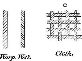
FIG. 405.
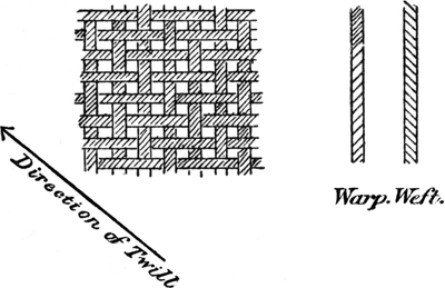
FIG. 406.
In twill and satin cloths, and similar fabrics, the direction of the twist has a very important bearing upon the appearance of the fabric.
The finest and closest effect is obtained by using warp and weft yarns spun in opposite directions, so that when woven the lines appear in the same direction, and the direction of the twill should be opposite to both. This is why one side of a twill cloth has a finer appearance than the other, as the twill[Pg 306] runs against the lines on one side, and with the lines on the other side of the cloth, the former having the finer appearance. Fig. 406 shows the yarns spun oppositely, and the twill running in a direction opposite to the lines.
In sateen cloths there is a kind of twill in one direction, as shown in Fig. 407, and the above principle applies to this as well as regular twills.
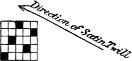
FIG. 407.
It often occurs that for printing and dyeing purposes the weft is preferred spun “twist way,” and as the weft greatly predominates over the warp, the direction of the twill should be contrary to the lines of the weft. Not much difference is noticeable in the better makes of cloth, but when there are few picks, a frayed appearance is often produced if the direction of the twill is not reversed.
To keep the twill in a given direction, the twist may be spun “weft way” to give the desired effect.
In very small twills, such as Jeannettes, a more decided twill is obtained by using weft spun in the same way as the twist or warp yarns, but in larger twills the best effect is obtained in the opposite manner.
THE numbers of cotton yarns are based upon the hank of 840 yards, the number of hanks in 1 lb. being the “counts.”
It follows that if 840—the yards in one hank—be multiplied by the counts, the result will be the yards in 1 lb. of that count.
Thus in 1 lb. of 30’s yarn there will be 840 × 30 = 25,200 yards, and the yards in a pound of any count may be found in the same manner.
The counts of worsted yarns are based upon a hank of 560 yards, and the number of hanks in 1 lb. Avoirdupois is the count of the yarn.
Linen yarns are based on a hank or lea of 300 yards, and the number of these in 1 lb. is the count of the yarn.
Spun silk, which is the silk chiefly used in cotton fabrics for stripes and headings, is numbered on the same system as cotton yarns. The number of hanks of 840 yards in 1 lb. is the count of the yarn.
Net silks or thrown silks are numbered on an altogether different system. The “skein” or hank is 520 yards, and the number of deniers—533⅓ deniers = 1 oz.—which a skein weighs indicates the number of the yarn. In silk manufacture the number of the yarn is called the “size,” the word “count” being used to denote the closeness of the reed.
Another system is used for silk yarns called the Manchester scale. This is based upon the hank of 1,000 yards.
The number of drams which one such hank weighs is the “size” or number of the yarn or thread.
In the former scale the yards per ounce may be found by multiplying the yards in a hank by the deniers in one ounce, and dividing by the number of deniers which a hank weighs.
The yards in an ounce of 40 denier silk will be—
In the Manchester silk scale the yards per ounce of a 4 dram silk may be found by multiplying 1,000, the yards in a hank, by 16, the drams in an ounce, and dividing by the number of drams which the hank weighs, viz. 4; thus—
1000 × 164 = 4000 yards per oz.
Twofold Yarns in cotton, worsted, and linen are numbered according to the count of the single yarn, with the number of folds put before it. Thus a 2-40’s yarn means that the yarn is composed of two threads of 40’s single, making a twofold yarn of 20 hanks to the pound.
In spun silk the yarns are nearly always two or more fold, and the number of the yarn always indicates the number of hanks in 1 lb. The number of folds is usually written after the hanks per pound. Thus, 40’s-2 spun silk indicates that the yarn is 40 hanks to the pound, made up of two threads of 80’s single.
It sometimes occurs in fancy yarns that threads of unequal thickness are twisted together. If a 60’s thread and a 40’s thread are twisted together, the count of the doubled thread will not be the same as if two threads of 50 hanks to the pound, but will be something less than this.
It is obvious that when the two threads are twisted together[Pg 309] the weight of a hank of the doubled thread will be 1/60 + 1/40 of a pound, and by adding these fractions together the counts of the twofold yarn may be obtained. Thus—
140 + 160 = 3 + 2120 = 5120 = 24’s counts.
Another method of obtaining the same result is to multiply the two numbers together, and add them together, and divide one result by the other. Thus—
If three or more unequal threads are twisted together the counts of the resulting thread may be found by adding the fractions of a pound which a hank of each count represents.
Example.—Find the counts of a threefold thread composed of one thread each of 10’s, 20’s and 60’s cotton.
110 + 120 + 160 = 6 + 3 +160 = 1060 = 16 or 6’s counts.
Some allowance must be made for the twisting of the threads, but this will vary with the number of turns per inch in the yarn, and so is not taken into account in the example.
If it is required to obtain the weight of each count in 100 lbs. of the threefold yarn, the following is the method.
As one count is to the resulting count, so is the total weight to the weight required of that yarn—
100 :
100 :
100 :
Reeds and Setts.—The system of numbering reeds, now almost universal in the cotton trade, is known as the Stockport or Manchester count. The number of dents or splits per inch in the reed with two ends in each dent is the basis of the system. If the reed has 30 dents per inch, it is called a 60 reed, because if there are two ends in a dent in the 30 dents there will be 60 ends per inch. The number of the reed is always the same as the ends per inch in the reed, if the ends are all two in a dent.
A 60 reed Stockport counts, if reeded three ends in a dent, will have 90 ends per inch, because a 60 reed has 30 dents per inch, and if there are three in a dent, there will be 30 × 3 = 90 ends per inch.
Various other systems have been used, but are gradually giving way to the simpler Stockport or Manchester system. Some of these are—
The Bolton count, in which the number of “beers” of 40 ends, or 20 dents, in 24¼ inches is the basis of the system.
The Blackburn count, in which the number of beers in 45 inches was the basis. The beer, as above, being 20 dents, representing 40 ends in a beer.
The Preston count was based on the number of beers in different widths.
The 6-4 count was based on the number of beers of 20 dents—representing 40 ends—in 58 inches.
The 9-8’s count was based on the number of beers in 44 inches.
The 4-4’s count was based on the beers in 39 inches.
The 7-8’s count was based on the beers in 34 inches.
The Scotch system is based on the number of dents in 37 inches. Thus in a 2000 reed there will be 2000 dents in 37 inches, representing 4000 ends in that space.
The Bradford system is based on the number of beers of[Pg 311] 40 ends in 36 inches. If there are 50 times 40 ends in 36 inches, it is a “50 sett.”
To find the number of ends per inch in a given sett, it is necessary to multiply the sett by 40 and divide by 36, thus—
50 sett × 4036 = 552036 ends per inch.
Quantity of Material in a Piece.—To find the weight of warp and weft of given counts in a piece, the total length of yarn in the piece may be found, and divided by the yards in 1 lb. of the counts of yarn used. This will give the weight in pounds. The following example will make the principle quite clear:—
Example.—Find the weight of warp and weft in a piece woven 30 inches wide in a 70 reed (Stockport) cloth 90 yards long, from 95 yards of warp, 80 picks per inch, the counts of twist or warp being 30’s, and counts of weft 40’s.
If the piece is 90 yards long, the length of warp used will be somewhat in excess of this, as the warp in interlacing with the weft is bent out of a straight line. The amount of “milling up,” as it is called, varies according to the number of intersections in the pattern or weave of the cloth, and with the counts of yarn used. It will also vary considerably according to the elasticity of the yarn. Twofold yarns are more elastic than single, and therefore will require a shorter length of yarn for a given length of cloth.
In this example 95 yards of warp are used to weave a 90-yards piece, an allowance of a little over 5 per cent.
In making the calculation for the weft it is necessary to take the width in the reed, as this length of weft is used every pick. The cloth will contract a little owing to the pull of the threads when woven, and when calculating for a given width of cloth care must be taken to calculate for the reed width and not the cloth width only.
In the present example the width in the reed is given, and so the cloth will be somewhat narrower than this when woven.
TO FIND WEIGHT OF WARP.
TO FIND WEIGHT OF WEFT.
Therefore, weight of weft = 21600033600 = 6 lbs. 66⁄7 oz.
Weight of weft = 6 lbs. 66⁄7 oz.
Weight of warp = 7 lbs. 14⅔ oz.
In the weft calculation, the picks per inch multiplied by the width in the reed in inches gives the inches of weft in one inch of cloth. This multiplied by 36 will give the inches of weft in one yard of cloth, and divided by 36, this gives the yards of weft in one yard of cloth. The two 36’s may be left out, as it is obvious that the yards of weft in a yard of cloth are the same as the inches of weft in an inch of cloth. The formula to calculate the weight of warp in a piece is as follows:—
Inches
in reed × length of warp in yards × ends per inch in reed840 × counts
= weight of warp.
The formula for the weft is—
Inches
in reed × length of piece in yards × picks per inch840 × counts
= weight of weft.
Working out the previous calculation in this manner, we get—
30 × 95 × 70840 × 30 = 7 lbs. 14⅔ oz. of warp.
30 × 90 × 80840 × 40 = 6 lbs. 66⁄7 oz. of weft.
If it is required to find the number of hanks, it is only necessary to leave out the counts in the above formulæ. Thus we get—
Inches wide × length × ends per inch840 = hanks,
and using the figures in the previous example—
30 × 95 × 70840 = 237½ hanks of warp.
Before the actual cost of a piece of cloth can be calculated, it is necessary to know the price to be paid the weaver. In Lancashire the payment is made according to the list agreed[Pg 314] upon by both employers and employed. For plain cloths and twills a new uniform list has been agreed upon, and this is now generally accepted. The following is the new list:—
1. The Standard.—The standard upon which this list is based is an ordinary loom, 45 inches reed space, measured from the fork grate on one side to the back board on the other, weaving cloth as follows:—
Width: 39, 40, 41 inches.
Reed: 60 reed, 2 ends in a dent, or 60 ends per inch.
Picks: 15 picks per quarter-inch, ascertained by arithmetical calculation, with 1½ per cent. added for contraction.
Length: 100 yards, 36 inches to the yard, measured on the counter. Any length of lap other than 36 inches to be paid in proportion.
Twist: 28’s, or any finer numbers.
Weft: 31’s to 100’s inclusive.
Price 2s. 6d., or 2d. per pick, per quarter-inch.
2. Width of Looms.—A 45-inch reed space loom being taken as the standard, 1½ per cent. shall be added for each inch up to and including 51 inches; 2 per cent. from 51 to 56 inches; 2½ per cent. from 56 to 64 inches; and 3 per cent. from 64 to 72 inches.
1¼ per cent. shall be deducted for each inch from 45 to 37 inches inclusive, and 1 per cent. from 37 to 24 inches, below which no further deduction shall be made. For any fraction of an inch up to the half no addition or deduction shall be made; but if over the half, the same shall be paid as if it were a full inch.
All additions or deductions under this clause to be added to, or taken from, the price of the standard loom 45 inches.
DEDUCTED FROM STANDARD.
ADDED TO STANDARD.
3. Broader Cloth than admitted by Rule.—All looms shall be allowed to weave to within 4 inches of the reed space; but whenever the difference between the width of cloth and the reed space is less than 4 inches, it shall be paid as if the loom were 1 inch broader: and if less than 3 inches, as if it were 2½ inches broader.
4. Allowance for Cloth 7 to 15 inches narrower than the Reed Space.—When the cloth is from 7 to 15[Pg 316] inches narrower than the reed space of the loom in which it is woven, a deduction in accordance with the following table shall be made:—
DEDUCTIONS FOR NARROW CLOTH.
No further deduction shall be made when cloth is more than 15 inches narrower than the reed space, or when cloth is narrower than 18 inches. Fractions of an inch not to be recognized under this clause.
5. Reeds.—A 60 reed being taken as the standard, ¾ per cent. shall be deducted for every two ends or counts of reed from 60 to 50, but no deduction shall be made below 50. ¾ per cent. shall be added for every two ends or counts of reed from 60 to 68, 1 per cent. from 68 to 100; 1½ per cent. from 100 to 110; and 2 per cent. from 110 to 132. All additions or deductions under this clause to be added to or deducted from the price of the standard 60 reed.
|
Deductions from standard.
|
Additions to standard.
|
||||
|
Count of
reed. |
Percentage.
|
Count of
reed. |
Percentage.
|
Count of
reed. |
Percentage.
|
|
50
|
3¾
|
62
|
¾
|
98
|
18
|
|
52
|
3
|
64
|
1½
|
100
|
19
|
|
54
|
2¼
|
66
|
2¼
|
102
|
20½
|
|
56
|
1½
|
68
|
3
|
104
|
22
|
|
58
|
¾
|
70
|
4
|
106
|
23½
|
|
60
|
standard
|
72
|
5
|
108
|
25
|
|
|
|
74
|
6
|
110
|
26½
|
|
|
|
76
|
7
|
112
|
28½
|
|
|
|
78
|
8
|
114
|
30½
|
|
|
|
80
|
9
|
116
|
32½
|
|
|
|
82
|
10
|
118
|
34½
|
|
|
|
84
|
11
|
120
|
36½
|
|
|
|
86
|
12
|
122
|
38½
|
|
|
|
88
|
13
|
124
|
40½
|
|
|
|
90
|
14
|
126
|
42½
|
|
|
|
92
|
15
|
128
|
44½
|
|
|
|
94
|
16
|
130
|
46½
|
|
|
|
96
|
17
|
132
|
48½
|
6. Picks.—Low Picks.—An addition of 1 per cent. shall be made for each pick or fraction of a pick below 11, thus:—
and so on, adding 1 per cent. for each pick or fraction of a pick.
High Picks.—An addition of 1 per cent. shall be made for each pick whenever they exceed the following:—
In making additions for high picks, any fraction of a pick less than the half shall not have any allowance; exactly the half-pick shall have ½ per cent. added; and any fraction over the half-pick shall have 1 per cent. added.
7. Twist.—The standard being 28’s or finer, the following additions shall be made when coarser twist is woven in the following reeds:—
and so on at the same rate.
When twist is woven in coarser reeds no addition shall be made.
8. Weft.—Ordinary Pin Cops.—The standard being 31’s to 100’s, both inclusive, shall be reckoned equal. Above 100’s 1 per cent. shall be added for every 10 hanks or fraction thereof.
In lower numbers than 31’s the following additions shall be made:—
Large Cops.—When weft of the following counts is spun into large cops, so that there are not more than nineteen cops to the lb., the following additions shall be made in place of the allowance provided for pin cops in the preceding table:—
9. Four-stave Twills.—Low Picks.—In four-stave twills an addition of 1 per cent. for each pick or fraction thereof below the picks mentioned in the following table shall be made when using weft as follows:—
High Picks.—When using weft—
In making additions for high picks any fraction of a pick less than the half shall not have any allowance; exactly the half-pick shall have ½ per cent. added, and any fraction over the half shall have the full 1 per cent. added.
10. Splits.—The following additions shall be made for splits:—
Empty dents shall not be considered splits.
11. All the foregoing additions and deductions shall be made separately.
This list is subject to a deduction of 10 per cent.
For fancy cloths the CHORLEY LIST, 1886, is the one most commonly used. This is as follows:—
Double-Lift Jacquards.—To be paid the following over plain cloth prices:—
Brocades, damasks, and crammed stripes with three or more ends in a dent, to be paid for by the number of ends per inch.
Picks 18 to 30 per quarter inch, 1 per cent. per pick;[Pg 323] from 30 to 40 picks, ¾ per cent.; all above 40 picks, ½ per cent. instead of 1 per cent.
Lace brocades, 5 per cent. extra.
Single-lift jacquards to be paid 10 per cent. about double-lift machines.
The above applies to Jacquards only.
Dobby and Tappet Looms (except Satins).—To be paid the following above plain cloth prices—
Up to and including—
Stripes and other cloths with three or more ends in a dent to be paid for by the number of ends per inch.
In single-shuttle checks, handkerchiefs, and all special classes of goods in which more than one pick is put in one shed, all lost picks shall be counted.
Plain handkerchiefs, 72 reeds and below, to be paid 5 per cent. extra.
Single-shuttle cord checks with more than two picks in one shed to be paid 2½ per cent. less.
Lace stripes and other special classes of goods shall be paid extra as per special arrangement to be agreed upon by Employers’ and Operatives’ Associations.
The following example will show the method of calculating the price to be paid for weaving under the Uniform List:—
Example.—Find the weaving of a 44-inch cloth, 40 yards long, woven in a loom 48-inch reed space, 92 reed, 30 picks per quarter-inch, 40’s twist, 60’s weft.
From this must be deducted 10 per cent., as per agreement, which will give 28·5535 pence as the actual price to be paid for weaving this piece of cloth.
The following example includes the allowance for narrow cloth woven in broad looms:—
Example.—Find the weaving price for 38-inch cloth woven in a 48-inch reed space loom, 50 reed, 507 dividend, 50 change wheel, 75 yards long, 32’s twist, 36’s weft.
50750 = 10·14 picks per quarter inch.
2·0116 × 10·14 picks × 75 yards100 yards
In making the additions and deductions it is important that they should be made in the above order.
The Cost of a Piece of Cloth.—Besides the cost of material and the weaving wage, the expenses of the manufacturer must be taken into account. When a manufacturer makes only one kind of cloth, his expenses will obviously not be so proportionately great as another manufacturer’s who only takes a single order of a particular make. The expenses also vary with the district and distance from the market, and with other circumstances.
A manufacturer knows from experience exactly what amount of expenses to allow in different classes of fabrics in his own case, and in quoting prices for plain or fancy cloths he usually includes under the term “expenses” all the items of cost from the carriage of the yarn to the delivery of the cloth, including winding, warping, sizing, waste, and other fixed expenses in the mill.
The expenses are usually calculated in proportion to the weaving wage, and a manufacturer quotes “double weaving” or “three times weaving,” according to the class of fabric in question.
The following example will illustrate the principle of estimating the cost of a piece.
Find the cost of a piece, 34 inches full, 75 yards s.s. (short stick), 19 × 18, 32’s/40’s. Twist at 7d. per lb., weft at 7½d. per lb.
Weaving 2s. Expenses equal to weaving.
The 34-inch cloth would stand, say, 36 inches in the reed. The 75-yards cloth, “short stick,” or 36 inches to the yard, will require, say, 78 yards of warp.
A cloth counting 19 × 18, nominal, is usually woven in a 68 or 70 reed, and the picks per inch will be about 66 or 67 actually.
Assuming that the cloth stands 36 inches in a 70 reed, and the picks per inch are 67, we get—
36 inches × 78 yards × 70 reed × 7d.840 × 32’s = 51.188d., cost of twist,
and
36 inches × 75 yards × 67 picks × 7½d.840 × 40’s = 40.38d., cost of weft.
The amount allowed for expenses in the preceding example is perhaps sufficient for most cloths woven on dobbies, but more is required for jacquard-woven fabrics.
If 11s. 7½d. is quoted for the above cloth, the price is said to be based on “double weaving.”
For jacquard fabrics the price is usually based on 2½ to 3 times weaving, and in special cases, such as new styles, an extra profit is put upon the 3-times weaving.
Sometimes the expenses are said to be 5 or 10 per cent. more than weaving. If the weaving wage were 2s. 6d., and the expenses 10 per cent. more than weaving, the expenses would be 2s. 9d.
Contraction.—The length of warp required to weave a piece of a given length will vary with the pattern or weave of the cloth, and depends also on the elasticity of the yarn and the counts of both warp and weft. Owing to this difference in the elasticity of various classes of yarns, and the variation in the elasticity of the same yarn at different degrees of tension, it is impossible to lay down rules for the calculation of the[Pg 327] exact warp length for a given length of piece, or for the exact width in the reed for a required width of piece. The length of warp required can only be obtained with exactness from experience, especially in fancy cloths.
As previously stated, twofold yarns are more elastic than single; indeed, with some kinds of twofold American yarns, such as are used in velvets, the percentage of contraction becomes less with an increase in the number of picks, owing to the increase of tension upon the yarn, which causes it to stretch more.
Roughly, the amount of contraction to allow in the warp can be obtained by taking into account the counts of weft and the number of intersections which the warp makes with the weft. The thicker the counts of weft the more the warp will be bent out of a straight line, also with an increase in the number of picks the amount of take-up or contraction will increase. This does not vary in a regular manner, as the angle which the warp makes in bending over the weft changes with any variation in the picks. Furthermore, the greater the tension on the warp yarn the more it will stretch, and also the more it will compress the weft at the point of intersection.
A rough estimate only can therefore be made if there is no previous experience in the same class of goods to guide the manufacturer.
A method of roughly estimating the percentage of milling-up of the warp is to multiply the intersections of the warp per inch by a number found by experience to give the right result, and to divide this product by the counts of weft used.
For rather heavily picked cloths the multiplier 4 gives a fairly accurate result, and in cloths with a medium number of picks and medium counts the multiplier 3 will be used. In some classes of goods the multiplier requires to be 5; but when[Pg 328] a correct multiplier is found for a certain class of goods, it will serve for changes in that class. The system is certainly not accurate in all cases, but it embraces roughly the different causes which alter the percentage of contraction or milling-up in the warp, and is therefore of some use in practice.
Example.—Find the length of warp required to weave a piece of 5-stave satin 94 yards long (36 inches to the yard), 94 reed, 180 picks per inch, 60’s twist, 70’s weft.
The number of intersections per inch will be two-fifths of the number of picks, as the warp intersects twice every five picks or pattern.
The length of warp required to weave the 94 yards piece would therefore, roughly, be 98 yards.
In a plain cloth the contraction is much more than in a satin, and the percentage is greater in heavily picked cloths than light ones.
In a plain cloth of, say, 120 picks per inch, 60’s twist, 70’s weft, the percentage of take-up will roughly be as follows:—
In a plain cloth the warp intersects every pick, and so the intersections per inch are the same as the ends per inch. In a “two and two” twill the warp intersects twice in four picks, and the intersections per inch will be one-half the picks.
In more medium cloths the multiplier 3 is used; as, for example:—
Find percentage of contraction in a piece of plain cloth woven with 60 picks per inch, 32’s twist, 40’s weft.
60 × 340’s counts = 4½ per cent.
In fancy cloths experience is the only guide as to the warp length required, but in striped cloths and similar fabrics woven from one beam the contraction of the whole will be that of the tightest weave in the pattern.
In a fabric in which there are only a few plain ends in the pattern, the other ends being loosely interwoven, it does not follow that the take-up will be as much as in a plain cloth, as the plain ends will compress the weft more at the point of intersection than could occur if all the ends were weaving plain.
Testing Yarn.—It often occurs that only a short length of yarn is available for being weighted when it is required to test it for the counts. If it is required to test the weft in a piece of grey cloth it is usual to take out of the cloth 120 yards, or one “lea.” This is one-seventh of a hank, and therefore if the weight of 120 yards is divided into 1,000 grains—the one-seventh part of a pound—the quotient will be the counts of the yarn. The reason of this will be obvious when it is remembered that if the weight of one hank is divided into 7000 grains, or 1 lb., the result is the number of hanks in 1 lb., or the counts.
The counts are based upon the number of hanks in 1 lb. avoirdupois, and as this weight is not suitable for weighing small quantities, it is necessary to weigh them in Troy weight. As nearly as possible 7000 grains Troy = 1 lb. avoirdupois.
Example.—If 120 yards of cotton weft weighs 20 grains, what counts is it?
100020 grains = 50’s counts.
If it is required to know the number of grains which 120[Pg 330] yards of any count should weigh, the method of procedure is the reverse of the foregoing.
Example.—How many grains should 120 yards of 40’s yarn weigh?
1000 grains40’s counts = 25 grains.
When testing the counts of cops, it is usual to wrap two, three, or four cops, in order to arrive at a more satisfactory test.
If two leas, or two-sevenths of a hank, are weighed, the counts can be obtained by dividing the weight into 2000 grains, or two-sevenths of 1 lb. If three leas, or 360 yards, are weighed, divide the weight into 3000 grains, and the result is the counts. If 480 yards are weighed, the dividend is 4000; if 600 yards, or five leas, are weighed, the dividend will be 5000; if six leas, or 720 yards, are weighed, the dividend is 6000; and when seven leas, or one hank, is weighed, the dividend will be 7000 grains, or 1 lb.
As it takes a considerable time to take 120 yards of weft out of a piece, a shorter length is often weighed and the counts found therefrom. A balance is extensively used which registers the counts when twenty yards of yarn are put upon the pointer. This is a very useful, though not always accurate, method.
When any odd length of yarn is weighed, the counts may be obtained by proportion, thus—
If 34 yards of yarn have been found to weigh 8 grains, what count is it?
The yards in 1 lb. can first be found as follows:—
34
and this divided by 840 will give the counts, thus:—
29750840 = 35·41 counts.
From this we get the formula:—
7000 × yards weighed840 × counts = counts.
This is a very useful formula, as when only a small piece of cloth is available to be tested it is necessary to get as near as possible to the counts from weighing sometimes only 10 or 15 yards, or any odd length.
A calculation may occur in the following form:—
How many grains should 16 yards of 20’s cotton weigh?
There are 840 × 20 = 16,800 yards of 20’s in 1 lb., or 7000 grains.
Then if 16,800 yards weigh 7000 grains, how many grains will 16 yards weigh?
This may be stated in a formula as follows:—
7000 × yards weighed840 × counts = weight in grains.
Staub’s Yarn Balance is a small balance which is made to test the counts of very small quantities of yarn. A template is given with the balance, and the yarn is cut into lengths the size of the template, about two inches. One end of the balance is slightly heavier than the other, and the number of threads the size of the template which are required to draw the balance indicate the counts of the yarn. If twenty threads or about 40 inches balance the small weight, the count of the yarn is 20’s, and so on.
The principle is the same as if a 1 lb. weight were put on one end of a balance, in which case the number of hanks required to draw the weight would indicate the counts, because if 20 hanks = 1 lb. the counts are 20’s, and if 21 hanks[Pg 332] = 1 lb. the counts are 21’s. The balance may be made to weigh any length, according to the weight on one end of the balance.
The form in which it is usually made makes it specially suitable for testing the counts in small patterns of a few inches.
The test is, of course, only approximate, as could only be expected from weighing so short a length.
If the foregoing examples are thoroughly understood, the following will not be found difficult.
If a warp has 2000 ends, and is 500 yards long, and weighs 60 lbs., what counts is it?
The ends multiplied by the length will give the total length of yarn in the warp, and this divided by 840 will give the hanks. If the hanks are divided by the weight, the result will be the counts. The result may be obtained at once as follows:—
2000 × 500840 × 60 = 19·84 counts.
If a beam has 2200 ends, the counts being 40’s, and the weight 50 lbs., find the length.
By multiplying 40 by 840 the yards in 1 lb. are obtained, and multiplying this by 50, the yards of yarn on the beam are arrived at. If this is divided by the ends in the warp, the result will be the length of warp thus:—
40 × 840 × 502200 = 763·6 yards.
A simple method of mentally calculating the number of hanks in a piece is as follows:—
A warp 84 yards long will contain just one-tenth as many hanks as ends. Thus a warp of 2000 ends, 84 yards long, contains 200 hanks. This can be proved as follows:—
2000 × 84840 = 200 hanks.
The number of hanks in a warp 84 yards long can thus be seen at once, and it is a very simple matter to mentally calculate the difference for any other length.
The hanks of weft can also be calculated mentally in a similar manner.
If the piece is 84 yards, the counts multiplied by the width and divided by 10 will give the number of hanks required for 84 yards. Thus, find the hanks of weft in a piece 34 inches wide, 84 yards long, 60 picks per inch.
60 × 3410 = 204 hanks.
The calculation is really simpler than it looks in the above form, as the dividing by 10 can be done by simply pointing off the last figure in the product of the picks and width. The formula may be proved correct by working out fully as follows:—
34 × 84 × 60840 = 204 hanks.
This system of mentally calculating the hanks is very useful, as it serves as a check upon a full calculation.
The Firmness of Cloth.—The number of ends and picks per inch which can advantageously be put into a fabric depends upon the number of intersections per inch in the pattern or weave, and on the counts or diameters of the yarns used. In a plain cloth woven with 32’s twist and 32’s weft, the number of threads per inch which could be put into the cloth without undue compression would be a little more than one-half the number which could be laid side by side touching each other. The reason for this is that the warp and weft threads interlace with each other every pick, and therefore, supposing that 156 threads of 32’s occupy one inch when laid[Pg 334] side by side, one-half of these threads would have to be left out to allow of the intersection of the weft between every end.
In a “two and two” twill the weft intersects once for every two ends, or twice in the pattern; therefore there are four threads and two intersections in the pattern. It is obvious, therefore, that to keep the same firmness in the twill as in the plain cloth with the same yarns, a larger number of threads per inch both in warp and weft will be required.
To keep the same “firmness” the threads must be kept as close together in one cloth as in the other, and as in a plain cloth one-half the threads which occupy one inch are dropped out, so in a twill with two intersections for four ends there must be one-third of the ends occupying one inch left out. Thus with 32’s yarn, of which the diameter is 1/156 of an inch, there will require to be about 102 threads per inch in a “two and two” twill.
A perfectly balanced plain cloth may be defined as a cloth in which the warp and weft yarns are equal in diameter, and the spaces between the threads are equal to the diameter of the yarn.
If the diameters of yarns of various counts are known, it is an easy matter to find the number of threads per inch which will produce the desired firmness in any simple weave.
The diameters of yarns of cotton, woollen, worsted, and other threads are given by the late Mr. T. R. Ashenhurst in an excellent little work on “Textile Calculations and the Structure of Fabrics,” which has done much to promote this branch of the art of weaving.
Mr. Ashenhurst estimates the diameter of a 32’s cotton yarn at the 1148th part of an inch; but this is probably somewhat under the mark, and in the following table I have taken 1156th inch as the diameter of 32’s.
The variation in the thickness of any yarn, and the fact that they are not strictly cylindrical, renders measurements of little avail, but taken in conjunction with an examination of a range of woven cloths, the approximate or practical diameter can be estimated.
TABLE OF DIAMETERS OF COTTON YARNS.
The preceding is a table of the diameters of cotton yarns from 1’s counts to 200’s. The number given as the diameter is the number of threads which occupy the space of one inch when laid as close together as possible without compression.
A perfectly balanced plain cloth will require one-half this[Pg 336] number of threads per inch, plus, perhaps, 5 per cent. for the threads being forced somewhat out of the same plane in weaving.
Relative Diameters of Yarns.—The “counts” of yarns indicate the number of hanks in 1 lb., and therefore a given length of 30’s is twice as heavy as the same length of 60’s; but the diameter of the 30’s will not be twice that of the 60’s, as the yarns are cylindrical, and the diameters will vary as the square roots of the areas, which in this case are as 1: 2.
If one thread is four times as heavy as another, and if it is of the same density—which in these calculations is assumed, although it is not strictly correct—the diameters of the two threads will be as 2: 1. For example, looking at the tables, the diameter of a 60’s is seen to be the 1/213 of an inch, whilst the diameter of a thread four times the weight, viz. 15’s, is seen to be 1/106½ of an inch, or exactly twice the diameter of the 60’s thread.
The diameter of one yarn being known, the diameter of any other may be obtained by the following rule:—
Rule.—As the square root of one count is to the square root of another count, so is the diameter of one to the diameter of the other.
Example.—If the diameter of a 16’s yarn is the 1/110th part of an inch, find the diameter of a 36’s.
In this form the calculation necessitates the extraction of two square roots, and with most numbers would require the use of two fractions in the calculation. By squaring all the three terms the calculation is much simpler, as in the following example:—
Example.—If the diameter of a 32’s is the 1/156 of an inch, what is the diameter of a 50’s?
and √38025 = 195 Ans.
As the diameters of yarns vary as the square root of their counts, it follows that the diameters will always bear a certain relation to the yards in 1 lb. If this relation is once obtained, it becomes easy to calculate the diameter of any yarn on this principle.
Taking the diameter of a 32’s yarn from the table, viz. 156, it will be found that this is equal to the square root of the yards in 1 lb., less 5 per cent.
Example.
The number of ends and picks per inch required to make plain cloths of equal firmness from different counts may be at once seen from the table of diameters, as one-half the number given as the diameter is required.
Thus if a plain cloth with 78 threads per inch of 32’s is taken as the standard, and it is required to make a cloth of equal firmness, with 60’s yarns, the number of threads per inch required would be 106½. In 20’s yarns about 62 threads would be required. In 16’s yarns 55 threads per inch, and so on.
In twills, or other regular weaves, the following rule will give the number of threads per inch required of any count:—
Rule.—As the sum of the ends and intersections in the pattern is to the ends, so is the diameter to the number of threads required.
Example 1.—How many threads per inch are required to make a perfectly balanced “2 and 1” twill cloth, with 24 yarns, warp and weft?
There are 3 ends and 2 intersections in the pattern; therefore
3 ends + 2 intersections = 5;
Example 2.—How many threads per inch are required to make a perfectly balanced “3 up, 2 down, 2 up, 2 down twill” with 44’s yarns?
In this pattern there are 9 ends and 4 intersections; therefore
One of the most useful purposes to which a knowledge of this principle can be put is in changing the weave of a fabric, to find the threads per inch of a given count of yarn required to keep the same firmness as in a sample cloth.
It must be remembered that the word “firmness” is here used as implying that the space between the threads bears the same relation to the diameters of the threads in both cases, or, if the given cloth is perfect, the proposed one will also be perfect.
Suppose it is desired to make a “two and two” twill of the same “firmness” as a plain cloth made with 103 threads per inch.
The yarns being the same, the number of threads per inch required will be as the ends plus intersections in a given number of ends in both patterns.
In the above question the given cloth is plain, with 103 threads per inch, and the proposed cloth is a “two and two” twill. Taking the same number of threads in each case, we get—
|
Ends + Intersections in
proposed twill cloth. |
Ends + Intersections
in given plain cloth. |
||||||
|
4+2
|
: |
4+4
|
|
103 | : | x | |
| or |
6
|
: |
8
|
|
103 | ||
| 8 | |||||||
| 6)824 | |||||||
|
Ends required in twill cloth =
|
137⅓ | ||||||
It must not be forgotten that it is necessary to take an equal number of ends of each pattern in this class of calculation. In more complex patterns it is often advisable to take the number of ends which is the L.C.M. of the ends in the two patterns in order to get a complete number of intersections in each case.
Another Example.—If a “two and two” twill cloth is made with 137 threads per inch, and it is proposed to make a cloth with the same counts of yarns in a “5 up, 2 down, 1 up, 2 down” twill, how many threads per inch are required to keep the same firmness?
In 40 ends of the proposed cloth there are 16 intersections, and in 40 ends of the sample cloth there are 20 intersections.
If it is required to make a cloth with the same number of threads as a sample cloth, and to change the pattern and keep the same firmness, it is necessary to change the counts on the following principle:—
Rule.—As the sum of the ends and intersections in the sample cloth is to the sum of the ends and intersections in the proposed cloth, so is the square root of the counts in the sample to the square root of the counts in the proposed cloth.
Example.—If a plain cloth has been made with 36’s yarns, and it is proposed to make a “two and two” twill with the same number of threads per inch, find the counts required to keep the same “firmness.”
And 4½2 = 20·25 counts required.
This may be proved correct by referring to the table of diameters on page 335, where it will be seen that a plain cloth with 82½ threads per inch of 36’s is “perfect,” and a “two and two” twill with 82½ threads of 20¼’s counts is equally perfect.
To change the Counts, the pattern and threads per inch remaining the same.
If a sample cloth has 78 threads per inch of 32’s yarn, and it is proposed to make a cloth of the same weave with 55 threads per inch, what counts of yarn are required to keep the same “firmness”?
This is simple enough. The diameters of yarns vary as the square root of their counts, and therefore as the threads in one cloth are to the threads in another, so will the square root of the counts in one be to the square root of the counts in the other.
|
Threads in
sample. |
Threads in
proposed cloth. |
Counts in
sample. |
|||||
| 78 | : |
55
|
|
√32
|
: |
√x
|
|
| or as | 782 | : |
552
|
|
32
|
||
| 6084 | : |
3025
|
|
32
|
|||
|
32
|
|||||||
|
6050
|
|||||||
|
9075
|
|||||||
|
6084)
|
96800
|
(15·91, or 16’s nearly = counts required
|
|||||
|
6084
|
|||||||
|
35960
|
|||||||
On referring to the table of diameters (p. 335), it will be found that a plain cloth with 78 threads of 32’s is “perfect,” and that a plain cloth with 55 threads of 16’s is also perfect. Therefore the above calculation is correct.
To change the Threads per Inch, the counts and pattern remaining the same.
If a sample has 78 threads per inch of 32’s, and it is proposed to weave a cloth of the same pattern, but with 60’s yarns, find the number of threads per inch required to keep the same firmness.
This is simply a continuation of the previous statement.
If the two counts are known, the number of threads will vary as the square roots of the counts; thus—
√11407 = 106.8 threads required.
The above may be proved correct by referring to the table of diameters. A plain cloth with 78 threads per inch of 32’s is “perfect,” and so is a plain cloth with 106½ threads per inch of 60’s.
The same principle must be employed if the warp and weft are of different counts, or if the threads per inch are not equal in warp and weft.
Example.—A sample cloth is made with 78 ends per inch of 32’s and 91 picks per inch of 44’s. How many picks will be required to keep the same firmness, if the weft only is changed to 60’s?
and √11292 = 106½ ∴ picks per inch required = 106½
One advantage gained by a knowledge of the principle of[Pg 343] cloth “balance” is that the number of picks per inch which a given pattern or weave will take can easily be obtained by calculation. This is of great advantage to designers for Jacquard weaving, as it often occurs that a design is made and the cards cut for a pattern which will not admit of the required number of picks of the given counts being put in the cloth, which a slight alteration in the ground weave would have rendered possible.
To alter the Weight.—If the weight of a cloth is required to be altered, and the same firmness kept, the threads per inch and counts can be found on the same principle.
If a cloth is made heavier it must be done by using coarser yarns and fewer threads; it cannot be done by using more threads, and preserve the same “firmness” or “perfection.”
Suppose a sample piece of cloth weighing 10 lbs. is made with 93 threads of 45’s, and it is proposed to make a piece of the same length and width, but weighing 15 lbs. To find the threads per inch and counts of yarn to keep the same firmness.
The weights of two cloths will vary as the square roots of the counts if they are of the same perfection.
Therefore—
To find the threads per inch required of the above counts—
Then to make a piece of the same perfection or firmness as the sample piece, and to alter the weight from 10 lbs. to 15 lbs., the counts must be changed from 45’s to 20’s, and the threads per inch from 93 to 62.
To prove this is correct take a piece 20 inches wide, 102 yards long, 93 threads per inch both in warp and weft of 45’s yarns.
The weight of this sample piece will be—
20 × 102 × 93840 × 45 = 5 lbs. of twist;
and as there is the same weight of weft, the total weight of the piece will be 10 lbs.
Now calculate the weight of a piece of the same length and width with 62 threads per inch of 20’s yarns:—
20 × 102 × 62840 × 20 = 7½ lbs. of twist;
and with the same quantity of weft, the total weight of the piece will be 15 lbs.
This proves the calculation to be correct so far as altering the weight goes.
To see if both cloths are of the same firmness, the table of[Pg 345] diameters may be referred to. It will there be seen that a plain cloth with 93 threads per inch of 45’s yarn is “perfect,” and also that the altered cloth with 62 threads of 20’s is equally perfect.
It thus proves the principle of the calculation to be correct.
A lighter cloth may be made, and the same firmness kept. The formula is the same in both cases. If a cloth is made lighter it must be done by using finer counts and more threads. It cannot be done by using fewer threads, as the firmness could not be kept and the required weight obtained.
In altering the weights of cloths some allowance would have to be made for the difference in milling-up with different counts of yarns and numbers of threads. If a cloth is made heavier, thicker yarns would be used, and the warp length to give a certain length of piece would be different in the sample to the altered cloth. But this is a comparatively small matter, which can be adjusted with a slight alteration in the basis of the structure.
THE END
PRINTED BY
WILLIAM CLOWES AND SONS, LIMITED
LONDON AND BECCLES
End of Project Gutenberg's Cotton Weaving and Designing, by John T. Taylor

*** END OF THIS PROJECT GUTENBERG EBOOK COTTON WEAVING AND DESIGNING ***

***** This file should be named 57031-h.htm or 57031-h.zip *****
This and all associated files of various formats will be found in:
        http://www.gutenberg.org/5/7/0/3/57031/

Produced by Jane Robins, Reiner Ruf, and the Online
Distributed Proofreading Team at http://www.pgdp.net (This
file was produced from images generously made available
by The Internet Archive)


Updated editions will replace the previous one--the old editions
will be renamed.

Creating the works from public domain print editions means that no
one owns a United States copyright in these works, so the Foundation
(and you!) can copy and distribute it in the United States without
permission and without paying copyright royalties.  Special rules,
set forth in the General Terms of Use part of this license, apply to
copying and distributing Project Gutenberg-tm electronic works to
protect the PROJECT GUTENBERG-tm concept and trademark.  Project
Gutenberg is a registered trademark, and may not be used if you
charge for the eBooks, unless you receive specific permission.  If you
do not charge anything for copies of this eBook, complying with the
rules is very easy.  You may use this eBook for nearly any purpose
such as creation of derivative works, reports, performances and
research.  They may be modified and printed and given away--you may do
practically ANYTHING with public domain eBooks.  Redistribution is
subject to the trademark license, especially commercial
redistribution.


*** START: FULL LICENSE ***

THE FULL PROJECT GUTENBERG LICENSE
PLEASE READ THIS BEFORE YOU DISTRIBUTE OR USE THIS WORK

To protect the Project Gutenberg-tm mission of promoting the free
distribution of electronic works, by using or distributing this work
(or any other work associated in any way with the phrase "Project
Gutenberg"), you agree to comply with all the terms of the Full Project
Gutenberg-tm License (available with this file or online at
http://gutenberg.org/license).


Section 1.  General Terms of Use and Redistributing Project Gutenberg-tm
electronic works

1.A.  By reading or using any part of this Project Gutenberg-tm
electronic work, you indicate that you have read, understand, agree to
and accept all the terms of this license and intellectual property
(trademark/copyright) agreement.  If you do not agree to abide by all
the terms of this agreement, you must cease using and return or destroy
all copies of Project Gutenberg-tm electronic works in your possession.
If you paid a fee for obtaining a copy of or access to a Project
Gutenberg-tm electronic work and you do not agree to be bound by the
terms of this agreement, you may obtain a refund from the person or
entity to whom you paid the fee as set forth in paragraph 1.E.8.

1.B.  "Project Gutenberg" is a registered trademark.  It may only be
used on or associated in any way with an electronic work by people who
agree to be bound by the terms of this agreement.  There are a few
things that you can do with most Project Gutenberg-tm electronic works
even without complying with the full terms of this agreement.  See
paragraph 1.C below.  There are a lot of things you can do with Project
Gutenberg-tm electronic works if you follow the terms of this agreement
and help preserve free future access to Project Gutenberg-tm electronic
works.  See paragraph 1.E below.

1.C.  The Project Gutenberg Literary Archive Foundation ("the Foundation"
or PGLAF), owns a compilation copyright in the collection of Project
Gutenberg-tm electronic works.  Nearly all the individual works in the
collection are in the public domain in the United States.  If an
individual work is in the public domain in the United States and you are
located in the United States, we do not claim a right to prevent you from
copying, distributing, performing, displaying or creating derivative
works based on the work as long as all references to Project Gutenberg
are removed.  Of course, we hope that you will support the Project
Gutenberg-tm mission of promoting free access to electronic works by
freely sharing Project Gutenberg-tm works in compliance with the terms of
this agreement for keeping the Project Gutenberg-tm name associated with
the work.  You can easily comply with the terms of this agreement by
keeping this work in the same format with its attached full Project
Gutenberg-tm License when you share it without charge with others.

1.D.  The copyright laws of the place where you are located also govern
what you can do with this work.  Copyright laws in most countries are in
a constant state of change.  If you are outside the United States, check
the laws of your country in addition to the terms of this agreement
before downloading, copying, displaying, performing, distributing or
creating derivative works based on this work or any other Project
Gutenberg-tm work.  The Foundation makes no representations concerning
the copyright status of any work in any country outside the United
States.

1.E.  Unless you have removed all references to Project Gutenberg:

1.E.1.  The following sentence, with active links to, or other immediate
access to, the full Project Gutenberg-tm License must appear prominently
whenever any copy of a Project Gutenberg-tm work (any work on which the
phrase "Project Gutenberg" appears, or with which the phrase "Project
Gutenberg" is associated) is accessed, displayed, performed, viewed,
copied or distributed:

This eBook is for the use of anyone anywhere at no cost and with
almost no restrictions whatsoever.  You may copy it, give it away or
re-use it under the terms of the Project Gutenberg License included
with this eBook or online at www.gutenberg.org/license

1.E.2.  If an individual Project Gutenberg-tm electronic work is derived
from the public domain (does not contain a notice indicating that it is
posted with permission of the copyright holder), the work can be copied
and distributed to anyone in the United States without paying any fees
or charges.  If you are redistributing or providing access to a work
with the phrase "Project Gutenberg" associated with or appearing on the
work, you must comply either with the requirements of paragraphs 1.E.1
through 1.E.7 or obtain permission for the use of the work and the
Project Gutenberg-tm trademark as set forth in paragraphs 1.E.8 or
1.E.9.

1.E.3.  If an individual Project Gutenberg-tm electronic work is posted
with the permission of the copyright holder, your use and distribution
must comply with both paragraphs 1.E.1 through 1.E.7 and any additional
terms imposed by the copyright holder.  Additional terms will be linked
to the Project Gutenberg-tm License for all works posted with the
permission of the copyright holder found at the beginning of this work.

1.E.4.  Do not unlink or detach or remove the full Project Gutenberg-tm
License terms from this work, or any files containing a part of this
work or any other work associated with Project Gutenberg-tm.

1.E.5.  Do not copy, display, perform, distribute or redistribute this
electronic work, or any part of this electronic work, without
prominently displaying the sentence set forth in paragraph 1.E.1 with
active links or immediate access to the full terms of the Project
Gutenberg-tm License.

1.E.6.  You may convert to and distribute this work in any binary,
compressed, marked up, nonproprietary or proprietary form, including any
word processing or hypertext form.  However, if you provide access to or
distribute copies of a Project Gutenberg-tm work in a format other than
"Plain Vanilla ASCII" or other format used in the official version
posted on the official Project Gutenberg-tm web site (www.gutenberg.org),
you must, at no additional cost, fee or expense to the user, provide a
copy, a means of exporting a copy, or a means of obtaining a copy upon
request, of the work in its original "Plain Vanilla ASCII" or other
form.  Any alternate format must include the full Project Gutenberg-tm
License as specified in paragraph 1.E.1.

1.E.7.  Do not charge a fee for access to, viewing, displaying,
performing, copying or distributing any Project Gutenberg-tm works
unless you comply with paragraph 1.E.8 or 1.E.9.

1.E.8.  You may charge a reasonable fee for copies of or providing
access to or distributing Project Gutenberg-tm electronic works provided
that

- You pay a royalty fee of 20% of the gross profits you derive from
     the use of Project Gutenberg-tm works calculated using the method
     you already use to calculate your applicable taxes.  The fee is
     owed to the owner of the Project Gutenberg-tm trademark, but he
     has agreed to donate royalties under this paragraph to the
     Project Gutenberg Literary Archive Foundation.  Royalty payments
     must be paid within 60 days following each date on which you
     prepare (or are legally required to prepare) your periodic tax
     returns.  Royalty payments should be clearly marked as such and
     sent to the Project Gutenberg Literary Archive Foundation at the
     address specified in Section 4, "Information about donations to
     the Project Gutenberg Literary Archive Foundation."

- You provide a full refund of any money paid by a user who notifies
     you in writing (or by e-mail) within 30 days of receipt that s/he
     does not agree to the terms of the full Project Gutenberg-tm
     License.  You must require such a user to return or
     destroy all copies of the works possessed in a physical medium
     and discontinue all use of and all access to other copies of
     Project Gutenberg-tm works.

- You provide, in accordance with paragraph 1.F.3, a full refund of any
     money paid for a work or a replacement copy, if a defect in the
     electronic work is discovered and reported to you within 90 days
     of receipt of the work.

- You comply with all other terms of this agreement for free
     distribution of Project Gutenberg-tm works.

1.E.9.  If you wish to charge a fee or distribute a Project Gutenberg-tm
electronic work or group of works on different terms than are set
forth in this agreement, you must obtain permission in writing from
both the Project Gutenberg Literary Archive Foundation and Michael
Hart, the owner of the Project Gutenberg-tm trademark.  Contact the
Foundation as set forth in Section 3 below.

1.F.

1.F.1.  Project Gutenberg volunteers and employees expend considerable
effort to identify, do copyright research on, transcribe and proofread
public domain works in creating the Project Gutenberg-tm
collection.  Despite these efforts, Project Gutenberg-tm electronic
works, and the medium on which they may be stored, may contain
"Defects," such as, but not limited to, incomplete, inaccurate or
corrupt data, transcription errors, a copyright or other intellectual
property infringement, a defective or damaged disk or other medium, a
computer virus, or computer codes that damage or cannot be read by
your equipment.

1.F.2.  LIMITED WARRANTY, DISCLAIMER OF DAMAGES - Except for the "Right
of Replacement or Refund" described in paragraph 1.F.3, the Project
Gutenberg Literary Archive Foundation, the owner of the Project
Gutenberg-tm trademark, and any other party distributing a Project
Gutenberg-tm electronic work under this agreement, disclaim all
liability to you for damages, costs and expenses, including legal
fees.  YOU AGREE THAT YOU HAVE NO REMEDIES FOR NEGLIGENCE, STRICT
LIABILITY, BREACH OF WARRANTY OR BREACH OF CONTRACT EXCEPT THOSE
PROVIDED IN PARAGRAPH 1.F.3.  YOU AGREE THAT THE FOUNDATION, THE
TRADEMARK OWNER, AND ANY DISTRIBUTOR UNDER THIS AGREEMENT WILL NOT BE
LIABLE TO YOU FOR ACTUAL, DIRECT, INDIRECT, CONSEQUENTIAL, PUNITIVE OR
INCIDENTAL DAMAGES EVEN IF YOU GIVE NOTICE OF THE POSSIBILITY OF SUCH
DAMAGE.

1.F.3.  LIMITED RIGHT OF REPLACEMENT OR REFUND - If you discover a
defect in this electronic work within 90 days of receiving it, you can
receive a refund of the money (if any) you paid for it by sending a
written explanation to the person you received the work from.  If you
received the work on a physical medium, you must return the medium with
your written explanation.  The person or entity that provided you with
the defective work may elect to provide a replacement copy in lieu of a
refund.  If you received the work electronically, the person or entity
providing it to you may choose to give you a second opportunity to
receive the work electronically in lieu of a refund.  If the second copy
is also defective, you may demand a refund in writing without further
opportunities to fix the problem.

1.F.4.  Except for the limited right of replacement or refund set forth
in paragraph 1.F.3, this work is provided to you 'AS-IS' WITH NO OTHER
WARRANTIES OF ANY KIND, EXPRESS OR IMPLIED, INCLUDING BUT NOT LIMITED TO
WARRANTIES OF MERCHANTABILITY OR FITNESS FOR ANY PURPOSE.

1.F.5.  Some states do not allow disclaimers of certain implied
warranties or the exclusion or limitation of certain types of damages.
If any disclaimer or limitation set forth in this agreement violates the
law of the state applicable to this agreement, the agreement shall be
interpreted to make the maximum disclaimer or limitation permitted by
the applicable state law.  The invalidity or unenforceability of any
provision of this agreement shall not void the remaining provisions.

1.F.6.  INDEMNITY - You agree to indemnify and hold the Foundation, the
trademark owner, any agent or employee of the Foundation, anyone
providing copies of Project Gutenberg-tm electronic works in accordance
with this agreement, and any volunteers associated with the production,
promotion and distribution of Project Gutenberg-tm electronic works,
harmless from all liability, costs and expenses, including legal fees,
that arise directly or indirectly from any of the following which you do
or cause to occur: (a) distribution of this or any Project Gutenberg-tm
work, (b) alteration, modification, or additions or deletions to any
Project Gutenberg-tm work, and (c) any Defect you cause.


Section  2.  Information about the Mission of Project Gutenberg-tm

Project Gutenberg-tm is synonymous with the free distribution of
electronic works in formats readable by the widest variety of computers
including obsolete, old, middle-aged and new computers.  It exists
because of the efforts of hundreds of volunteers and donations from
people in all walks of life.

Volunteers and financial support to provide volunteers with the
assistance they need, are critical to reaching Project Gutenberg-tm's
goals and ensuring that the Project Gutenberg-tm collection will
remain freely available for generations to come.  In 2001, the Project
Gutenberg Literary Archive Foundation was created to provide a secure
and permanent future for Project Gutenberg-tm and future generations.
To learn more about the Project Gutenberg Literary Archive Foundation
and how your efforts and donations can help, see Sections 3 and 4
and the Foundation web page at http://www.pglaf.org.


Section 3.  Information about the Project Gutenberg Literary Archive
Foundation

The Project Gutenberg Literary Archive Foundation is a non profit
501(c)(3) educational corporation organized under the laws of the
state of Mississippi and granted tax exempt status by the Internal
Revenue Service.  The Foundation's EIN or federal tax identification
number is 64-6221541.  Its 501(c)(3) letter is posted at
http://pglaf.org/fundraising.  Contributions to the Project Gutenberg
Literary Archive Foundation are tax deductible to the full extent
permitted by U.S. federal laws and your state's laws.

The Foundation's principal office is located at 4557 Melan Dr. S.
Fairbanks, AK, 99712., but its volunteers and employees are scattered
throughout numerous locations.  Its business office is located at
809 North 1500 West, Salt Lake City, UT 84116, (801) 596-1887, email
business@pglaf.org.  Email contact links and up to date contact
information can be found at the Foundation's web site and official
page at http://pglaf.org

For additional contact information:
     Dr. Gregory B. Newby
     Chief Executive and Director
     gbnewby@pglaf.org


Section 4.  Information about Donations to the Project Gutenberg
Literary Archive Foundation

Project Gutenberg-tm depends upon and cannot survive without wide
spread public support and donations to carry out its mission of
increasing the number of public domain and licensed works that can be
freely distributed in machine readable form accessible by the widest
array of equipment including outdated equipment.  Many small donations
($1 to $5,000) are particularly important to maintaining tax exempt
status with the IRS.

The Foundation is committed to complying with the laws regulating
charities and charitable donations in all 50 states of the United
States.  Compliance requirements are not uniform and it takes a
considerable effort, much paperwork and many fees to meet and keep up
with these requirements.  We do not solicit donations in locations
where we have not received written confirmation of compliance.  To
SEND DONATIONS or determine the status of compliance for any
particular state visit http://pglaf.org

While we cannot and do not solicit contributions from states where we
have not met the solicitation requirements, we know of no prohibition
against accepting unsolicited donations from donors in such states who
approach us with offers to donate.

International donations are gratefully accepted, but we cannot make
any statements concerning tax treatment of donations received from
outside the United States.  U.S. laws alone swamp our small staff.

Please check the Project Gutenberg Web pages for current donation
methods and addresses.  Donations are accepted in a number of other
ways including checks, online payments and credit card donations.
To donate, please visit: http://pglaf.org/donate


Section 5.  General Information About Project Gutenberg-tm electronic
works.

Professor Michael S. Hart is the originator of the Project Gutenberg-tm
concept of a library of electronic works that could be freely shared
with anyone.  For thirty years, he produced and distributed Project
Gutenberg-tm eBooks with only a loose network of volunteer support.


Project Gutenberg-tm eBooks are often created from several printed
editions, all of which are confirmed as Public Domain in the U.S.
unless a copyright notice is included.  Thus, we do not necessarily
keep eBooks in compliance with any particular paper edition.


Most people start at our Web site which has the main PG search facility:

     http://www.gutenberg.org

This Web site includes information about Project Gutenberg-tm,
including how to make donations to the Project Gutenberg Literary
Archive Foundation, how to help produce our new eBooks, and how to
subscribe to our email newsletter to hear about new eBooks.
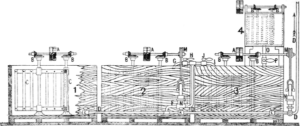


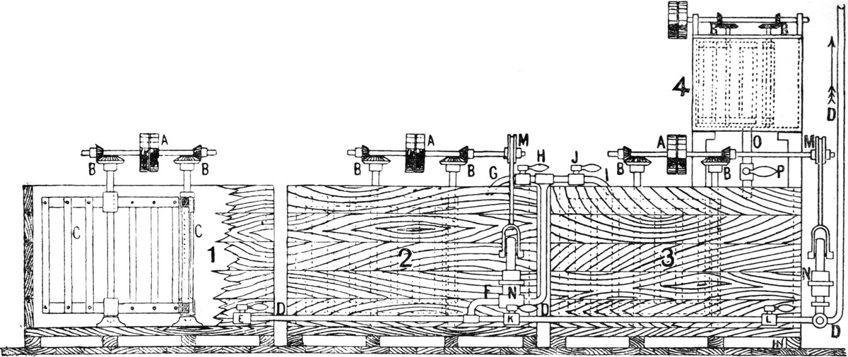
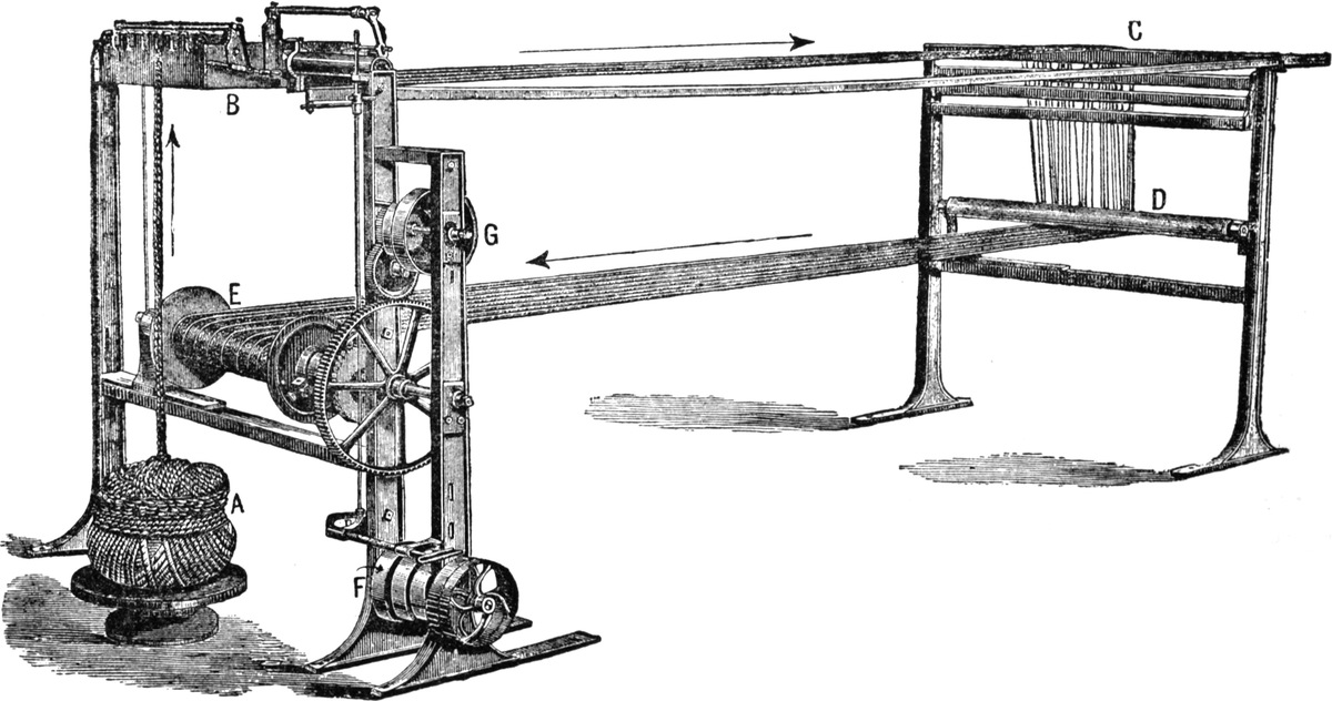