The Project Gutenberg EBook of Pumps and Hydraulics, by William Rogers

This eBook is for the use of anyone anywhere in the United States and most
other parts of the world at no cost and with almost no restrictions
whatsoever.  You may copy it, give it away or re-use it under the terms of
the Project Gutenberg License included with this eBook or online at
www.gutenberg.org.  If you are not located in the United States, you'll have
to check the laws of the country where you are located before using this ebook.


Title: Pumps and Hydraulics, Part 1 (of 2)

Author: William Rogers

Release Date: January 8, 2018 [EBook #56339]

Language: English

Character set encoding: UTF-8

*** START OF THIS PROJECT GUTENBERG EBOOK PUMPS AND HYDRAULICS ***


Produced by deaurider, Brian Wilcox and the Online
Distributed Proofreading Team at http://www.pgdp.net (This
file was produced from images generously made available
by The Internet Archive)
Transcriber’s Note:
The cover image was created by the transcriber and is placed in the public domain.
PUMPS
AND
HYDRAULICS.
IN TWO PARTS.
Part One.
“There are many fingers pointing to the value of a training in science, as the one thing needful to make the man, who shall rise above his fellows.”—Frank Allen.
“The motto marked upon our foreheads, written upon our door-posts, channeled in the earth, and wafted upon the waves is and must be, ‘Labour is honorable and Idleness is dishonorable.’”—Carlyle.
This work is respectfully dedicated to
Maj. ABRAM B. GARNER,
of Newark, N. J.,
—AND—
ALBERTO H. CAFFEE, Esq.,
of New York City.
‘Gentlemen without fear and without reproach.’
“Thought is the principal factor in all mechanical work; the mechanical effort is an incident rather than the principal equipment in any trade or occupation.”
“Any trade is easily learned by an apt scholar who uses his reasoning faculties and makes a study of cause and effect.”—CHAS. J. MASON.
Author of “Drawing and Design,” etc.
RELATING TO
HAND PUMPS; POWER PUMPS; PARTS OF PUMPS; ELECTRICALLY DRIVEN PUMPS; STEAM PUMPS, SINGLE, DUPLEX AND COMPOUND; PUMPING ENGINES, HIGH DUTY AND TRIPLE EXPANSION; THE STEAM FIRE ENGINE; UNDERWRITERS’ PUMPS; MINING PUMPS; AIR AND VACUUM PUMPS; COMPRESSORS; CENTRIFUGAL AND ROTARY PUMPS; THE PULSOMETER; JET PUMPS AND THE INJECTOR; UTILITIES AND ACCESSORIES; VALVE SETTING; MANAGEMENT; CALCULATIONS, RULES AND TABLES.
WITH ILLUSTRATIONS.
ALSO
GENERAL CONSIDERATIONS; GLOSSARY OF PUMP TERMS; HISTORICAL INTRODUCTION, WITH ILLUSTRATIONS; THE ELEMENTS OF HYDRO-MECHANICS, HYDROSTATICS AND PNEUMATICS; GRAVITY AND FRICTION; HYDRAULIC MEMORANDA; LAWS GOVERNING FLUIDS; WATER PRESSURE MACHINES; PUMPS AS HYDRAULIC MACHINES, ETC.
PART ONE.
PUBLISHED BY
THEO. AUDEL & COMPANY
72 FIFTH AVE.,
NEW YORK, U.S.A.
7, IMPERIAL ARCADE,
LUDGATE CIRCUS, E.C.,
LONDON, ENG.
Copyrighted, 1905, by
THEO. AUDEL & CO., NEW YORK.
Entered at Stationers Hall, London, England.
Protected by International Copyright in Great Britain and all
her Colonies, and, under the provisions of the
Berne Convention, in
Belgium, France, Germany, Italy, Spain, Switzerland, Tunis,
Hayti, Luxembourg, Monaco, Montinegro
and Norway.
Printed in the United States.
The divisions of Part One are represented by the following headings: each subject is fully treated and illustrated on the pages shown:
| PAGES | |
|---|---|
Introductory Considerations |
1-16 |
Glossary of Pump and Hydraulic Terms |
17-34 |
Historical Introduction |
35-70 |
Elementary Hydraulics |
70-104 |
Flow of Water Under Pressure |
105-116 |
Water Pressure Machines |
117-154 |
Water Wheels |
119-125 |
Turbine Water Wheels |
126-135, 141-144 |
Turbine Pumps |
136-139 |
Water Pressure Engines |
145-147 |
Hydraulic Motors |
147-154 |
Hydraulic Apparatus |
155-184 |
Hydraulic Jack |
159-168 |
Hydraulic Press |
169-170 |
Hydraulic Accumulator |
171-173 |
Hydraulic Ram |
175-180 |
Pumps as Hydraulic Apparatus |
181-184 |
Classification of Pumps |
185-345 |
Hand Pumps |
189-204 |
Power Pumps |
205-224 |
Belted Pumps |
225-240 |
The Electric Pump |
241-276 |
The Steam Pump |
227-330 |
The Duplex Pump |
331-343 |
Underwriter Fire Pumps |
344 |
Specifications of the National Board of Fire Underwriters Relating to the Duplex Fire Pumps |
347-398 |
Ready Reference Index to Part One |
“Among the first things a practical engineer should know, and among the last things he will, after becoming such, forget, is that in handling water within pipes he has a fluid which, while it is flexible to the greatest extent and is susceptible of the influence of power, or force, of greater or less intensity, and while it may be drawn from below and raised to the heights above, can be turned to the right or to the left at will, and while, with a seeming docility which is as flattering as it is deceptive, it bends itself to the will of the engineer, still there are some things it will not do, and which all the complicated appliances of the engineer have as yet failed to compel it to do. When inclosed within chambers and pipes, to an extent that fills them, it will not permit the introduction of an added atom without bursting its bounds. While inclosed within long lines of pipes it will not suddenly start into motion, or when in motion suddenly come to a rest, without shocks or strains more or less disastrous; and so, while it seems to be handled with the greatest ease, it is only in the manner it chooses to go, and all mechanical appliances not designed with reference to following these imperative laws are sure to meet trouble, if not disaster. In other words, when an unyielding force meets an unyielding resistance, their coming together means a shock to all about.”
“Whenever a full mind meets an empty one, it is a call to teach, not to scoff.”—Anon.
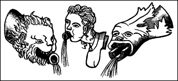
Orifices of Pipes, etc., Symbolical of Irrigation.
“He who sedulously attends, pointedly asks, calmly speaks, coolly answers and ceases when he has no more to say, is in possession of some of the best requisites of man.”—Levater.
It should be a matter of thankfulness to author and reader, or rather to both instructor and student, for this is designed to be an educational work, that the Laws of Nature are unchangeable.
From age to age and co-extensive with the globe the immutable principles underlying and actuating the physical states of all matter remain steadfast; gaseous bodies expand by unchanging laws which are obeyed down to the merest atom, fluids flow by law and the earth to the smallest particle remains firm, all things at all times responsive to the mandates of the Author of Creation.
The silent, mighty, unanswering physical characteristics of Gravity, Cohesion, Tenacity, furnish an agreeable contrast to the din, discord and frequent argument, to the verge of hatred, that have too often accompanied the efforts of mankind to co-operate with the forces of Nature. But now, between author and reader, let it be hoped, that in the unfolding of the subject-matter of this work that kind consideration will be extended and that some of that peacefulness and trust which existed on the earth, when flints were the weapons and the gourds the only goblets, may prevail from beginning to the “finis” of the volumes.
The author in planning the outlines of this work has aimed to keep close to real things belonging to the practical side of hydraulics, pumps, pumping-engines, and to the simple explanation of the Natural Laws pertaining to their industrial application. A knowledge of the real things in the objective world about us and the laws that govern them in their inter-relations is of practical value to every man; all branches of science are simply branches of one great science and all phases of human activity are touched by it; man is so constituted that he must have something to be interested in, and if he has no resources within himself he looks elsewhere, and often to his own disadvantage.
And so, the author has aimed to make the subjects of this book interesting as well as useful; 1, by their self-help arrangement; 2, by the illustrations, and 3, by leaving very much to the further research and investigation of the reader, as, in a well-told story, many things are left to the imagination of the listeners.
It should be borne in mind by the reader, that the work is designed to be seriously Educational in its plan and scope, and Progressive in the presentation of its subject-matter; nothing has been withheld that might add to its lasting value.
This is said in the way of an introduction to the Table of Contents to which the student is referred as showing the method of treatment, in the wide range of the theory and practice, of this important branch of Industrial Science.
In the back of the volume may be found a Ready Reference Index which by its admirable method of arrangement affords a speedy key to the contents of the book when occasion requires.
The well-known pump expert, Mr. F. Meriam Wheeler, writes us saying that if the manufacturers of steam pumps would send out with their pumps a card reading something like the following, it would probably impress the men who run the pumps more forcibly than anything that could be said or written in the ordinary way of giving instructions:
“Please do not gorge me with oil, as it will give my steam chest indigestion. What I like is a steady diet and thus enable my valves to work smoothly and with durability. A very small amount of oil fed to me steadily is the thing—it saves oil and repair bills.
“Two or three times a year give me a good dose of kerosene, to clean out any obstructions that may have accumulated in the passageways of my steam chest, or on the face or working parts of the valve and valve-seat, or on the chest piston.
“Do all you can to help me make a full length of stroke, as it means that I will use less steam and do better work. The adjustable collars on the valve rod will allow you to regulate the length of my stroke to a nicety.
“By allowing me to make short strokes, you prevent my steam piston from getting in its proper cushion, which it would do if it could complete its full stroke. My steam piston is supposed to run up to the end of the cylinder and pass across the exhaust port, cushioning on the confined steam between said port and the cylinder cover.
“The hand wheels on the side of my steam cylinder are for controlling the amount of this cushion. For slow speeds these cushion valves should be shut tight. When running at ordinary speed or a high rate of speed, these cushion valves should be slightly opened.
“Once in a while take a look at my water cylinder. See that the packing of the water piston is not set up so tight that it makes me grunt, producing unnecessary friction and wear. Or, perhaps the packing is too loose a fit, or is worn out and needs renewing.
“Please see that my water valves are seating properly, because if they are not tight I cannot pump as much water as I ought to do for a given speed. Sometimes the springs on the backs of my water valves need renewing or looking after.
“If you have not already provided a good suction air chamber for my water cylinder, you ought to do it, because it will prevent the water column in the suction pipe from slapping the face of my water piston at the end of each stroke in a harsh manner and so produce ‘water hammer.’ A good suction air chamber, properly located, saves wear and tear, and makes a pump quiet running.
“Please keep me nice and clean. I may not be of as much importance as your big engine, but there is no reason why I should not be kept free from dirt and grease. I hate to have oil slobbered all over my steam chest, or my stuffing-boxes left leaking.
“You will find it pays to keep me in good condition, like a well-groomed horse. Treat me well and I’ll serve you well and long!!!”—The Engineer.
Air-bound. This word applies to both pump and piping and expresses the confinement of air between the discharge valve of the pump and the check-valve or the point of delivery.
Air-cock. Is the same as a pet-cock and is used to relieve pipes that are air-bound.
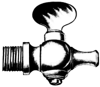
Air Cock.
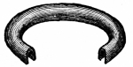
Annular Valve. From annular—a ring—i.e., a round valve with a hole in the middle.
Area. The extent of surface, as the area of a piston.
Assembling. Putting together the parts of a machine.
Atmospheric Pressure. The pressure of atmospheric air, not only downward but in every direction, this amounts to about 14.7 lbs. per square inch at the sea level. Usually taken at 15 lbs. to facilitate calculations.
Auxiliary. Something to “help out,” as an auxiliary cylinder or an auxiliary piston.
Ball Check-valve. One in which a metal ball is used in place of a poppet-valve.
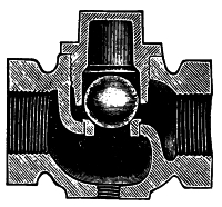
Ball Check-Valve.
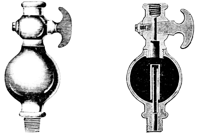
Balanced Valve. A valve having an equal pressure on all sides. See equilibrium valve.
Basket. The outer casing or netting of a foot valve which forms a strainer on a pump suction pipe.
Bends. In pipe, the turns in lines of pipe may be angle bends (called “elbows“) or offset bends.
Bibb-cock. This is a plug cock having an elbow or curved outlet directing the outflow downward.
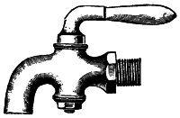
Bibb-Cock.
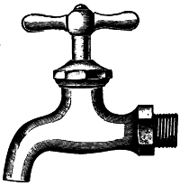
Bibb Compression.
Bibb Compression. A bibb-cock having in place of the plug a stem with thread and handle to open by unscrewing; the valve contains fibrous packing and is made tight by compression.
Bonnets. These are covers for the opening into valve chambers of pumps.
Boss. Any round protuberance on a casting to support a stud or to strengthen a steam chest cover, etc.
Bushing. A nut used in pipe fitting, threaded inside and outside to accommodate two sizes of pipe.
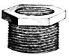
Bushing.
Check Valve. A valve through which fluid can pass only in one direction; used between pump and reservoir or boiler. See swing-check.
Check-Nut. A second nut screwed against the first to hold it firmly in place; also called a lock-nut.
Circulating Pump. A pump arranged to force water through the tubes of a surface condenser. Frequently a centrifugal pump is used as a circulating pump.
Clack Valve. This takes its name from the noise it makes in seating; it is made of leather with a metal weight on top, the leather forming a hinge on one side. In the cut the lifted valve is the “clack.”
Clack Valve.
Clearance. The space or distance by which one piece clears another. The space between piston and cylinder head.
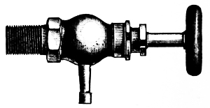
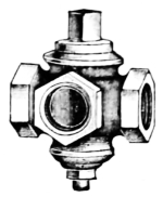
Cock. A faucet or device for opening or closing a passage. The illustration shows a straight-way cock.
Plain Cock.
Column Pipe. A column may be considered as a beam set on end and a column pipe may, similarly, be defined as a pipe set on end. The pipes leading from a water column to boiler.
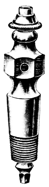
Compression Gauge Cock. A device having a threaded steam spindle and made tight by compression. The figure exhibits an outside view of a locomotive compression gauge cock.
Compression Gauge Cock.
Corrosion. Rusting or wasting away of the surfaces of metals.
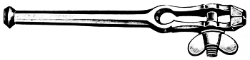
Crow. A claw with a screw attached to support and feed a drill brace for drilling holes in pipes.
Cup Leather Packing. The leather packing used around the ram of a press. In section it resembles a cup—hence the name.
Cup Leather Packing.
Cushioning. This term applied to the operation of pumps, etc., is the imprisoning of steam, water or air between the piston and cylinder head to prevent the piston from impact with the head.
Cylinder Head or Cylinder Cover. A plate which encloses or covers the end of a cylinder.
Dead end of a pipe. The closed end of a pipe or system of pipes.
Disk or Disc. A cylinder, whose length is very short in proportion to its diameter; a round plate with a hole in its center.
Double-eye or Knuckle Joint. A joint formed of two forks or jaws with a cube of iron between them, with a bolt or pin through each jaw and the cube at right angles. Will work freely in all positions from a straight line up to 45°.
Double seated poppet valve. A poppet valve having two valves on one stem, with two seats in the same shell.
Double-Seated Poppet Valve.
Drafting water. Another term for “raising“ water by suction, in distinction to “forcing water.”
Drip-pipe. A device used to draw off the water of condensation from systems of piping, steam cylinders, heaters, etc. Drain-cocks are used for similar purposes.
“Dutchman.” A piece “fitted in” to restore a worn part or to hide a defect.
Duct. A passage or conduit.
“Duty” of pumps. This indicates the measurement of the work performed by pumps. “Duty trials” are careful tests of the work done by the larger pumping-engines.
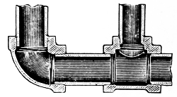
Elbow. This fitting is used for uniting two pipes together at right angles. The illustration shows a malleable-iron gas-pipe elbow.
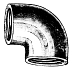
Elbow.
Equilibrium Valve. A valve balanced by an equal pressure on both ends.
Expansion Joint. A telescopic slip joint having a packed stuffing box, permitting the parts it connects to expand and contract under variations of temperature.
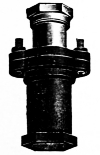
Expansion Joint.
Face. The broadest flat surface of a piece of work, or the one having the greatest area.
Factor of Safety. When a calculation of the ultimate strength of a machine is to be made it is necessary to provide for contingencies—this takes the form of a multiplier, and is called the factor of safety, or the margin of safety.
Feather, or sunk key. A key that is fast in one piece of work, and an easy fit in the other, as a feather in a shaft.
Flow. Motion of a fluid or liquid in one direction. “Flow-gate“ is a term sometimes applied to a riser.
Flume. An open trough for conveying water.
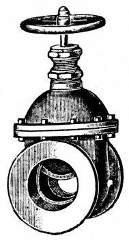
Gate Valve.
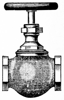
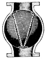
Globe Valve.
Gate Valve. A valve which opens the full area of the pipe, on the principle of a gate in a water flume.
Globe Valve. A valve having a round ball-like shell as shown in the engraving.
Gland. The sliding bushing for holding packing into a stuffing box, adjusted by studs and nuts.
Goose neck. A pipe fitting having two bends in opposite directions which resemble the neck of a goose.
Gridiron Valve. A type of slide valve familiarly called a “grid,” which may be circular or rectangular, consisting of alternate bars and spaces, sliding over a similarly formed seat, the object being to obtain the necessary steam way with a diminished amount of valve travel.
Hand-Nut. A nut having wings or projections so that it may be screwed up by hand without the aid of a wrench.
Hand-Nut.
Head of water. In hydraulics “head“ means pressure due to height of column of water.
Heat Units. The unit of heat is the amount of heat required to raise one pound of water one degree, usually from 32° to 33° Fahr.
“Hesitates.” A pump is said to “hesitate” when the motion becomes uncertain.
Horse-power of a pump. Is the same as is used to designate that of a steam engine, with this exception: the initial pressure in the pump remains constant throughout the stroke. Formula is the same as for a steam engine.
“Hump.” This is an arch or bend which causes an “air pocket” in a water-pipe line.
Hydrant. A valve and spout connecting with a street main.
Hydraulic Belt. An endless woolen band for raising water. The lower bight is immersed in water, and the upper bight passes over a roller. The belt travels about 1,000 feet per minute, and discharges at its upper turn.
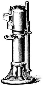
Hydraulic Jack.
Hydraulic Jack. A lifting device in which a ram, a pump, and liquid is used instead of a screw.
Hydraulic Pivot. A “slippery liquid support” for an upright shaft, a film of water being introduced beneath it by pressure to support the weight thereof and prevent the usual friction of the shaft on its step.
Hydraulic Shears. A machine for shearing or cutting metals, etc., by the force of water pressure operating cutters.
Hydraulic Valve. A valve for regulating the distribution of water in the cylinders of hydraulic elevators, cranes and other water pressure machines and devices.
Hydraulic Wheel. One for raising water by applied power, as the Noria Scoop wheel, tympanum, etc. See illustrations in section relating to the history of the pump.
Impact. The single instantaneous shock of a body in motion when it strikes against another body either in motion or at rest.
Leakage. The loss of water from any cause.
“Lift and drop of a valve.” This term indicates the amount of “play” up and down, designed to be given to a valve by its designer.
Liner. A piece of iron or other metal put behind or on a piece to take up its wear.
Mississippi River
Gauge Cock.
Lost Motion. Motion that is not transmitted on account of the looseness of the parts, hence it is lost.
“Losing water.” A term used when the pump stops, caused by air leaking into the suction pipe, or foreign matter clogging the strainer at the end of the suction pipe.
Low pressure steam. Steam which is either below 30 lbs., or but a few pounds in excess of the atmospheric pressure.
Lug. That which projects like an ear, especially that by which anything is supported, or against which anything bears, or through which a belt passes.
Main. A principal pipe or duct as distinguished from lesser ones, especially a principal pipe leading to or from a reservoir or a fire-main; a “forcing main” is the delivery pipe of a pump.
Mean gradient. The grade of a pipe-line which should be made as nearly straight as possible to avoid air pockets.
Miner’s Inch. The amount of water that will flow per minute through an opening one inch square in a plank two inches thick, under a head of four inches of water above the upper edge of the opening, and is equal to nine United States gallons.
Mississippi River gauge cock. A cock without a handle or thread upon the stem and designed to be opened by pressure upon the top end of the stem as shown.
“Modulus” of a steam pump. The measure or multiplier of power used in operating pumps. Modulus has nearly the same meaning as measure.
Nipple. A short connecting piece of pipe threaded upon both ends.
Outboard delivery pipe. The pipe which leads, in steam vessels, from the condenser through the side of the ship.
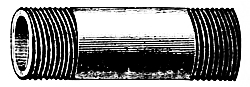
Nipple.
Pipette. A small tube used to withdraw and transfer fluids or gases from one vessel to another. The shape differs with the special use to which it is adapted: some are graduated to measure fluids accurately as well as to transfer them.
Penstock. The barrel of a pump in which the piston plays and through which the water presses up; also the conduit or trough from the source of supply to a water wheel.
Pet-cock. This is an air-cock. See air-cock.
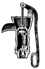
Pitcher Pump.
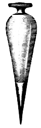
Plumb Bob.
Pipe-clamp. A device for connecting one pipe to another without cutting the pipe and inserting a tee; a pipe-saddle performs the same office as the above, but for larger pipes.
Pitcher Pump. A hand pump which takes its name from the shape of its discharge.
Plug-valve. This is a tapering plug which turns in a shell, example, the plug of a faucet. See Cock. A fire-plug is a street hydrant to which a hose may be attached.
Plumb-bob. This is a device for testing whether anything stands exactly vertical; a plumb-rule contains a plumb-bob.
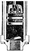
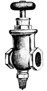
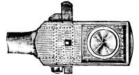
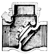
Pressure-reducing Valve. A valve for reducing high boiler pressure to low pressure, for steam heating, etc.
Priming. To fill a pump with water when it refuses to lift of its own action, is called “priming the pump.”
Pump-brake. The handle or lever by which a pump is worked.
Pump-box. A cap or case covering the top of a pump; the casings of the upper and lower valves are the upper and lower pump boxes.
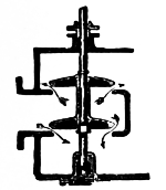
Pressure Reducing Valve.
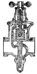
Section.
Pump-chain. An endless chain with discs forming valves at proper distances, working on two wheels, one above and one below, and passing down outside and returning upward through a wooden tube like a belt.
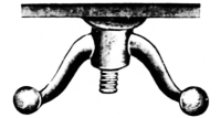
Pump-cheeks. A forked piece serving as a fulcrum for the handle of a pump.
Pump-well. A compartment extending from a ship’s bottom to the lower or the upper deck, as the case may be, to contain the pump stocks, etc. The bilge water collects in the limbers and is discharged through a spout called the pump-dale.
Rain-gauge. A vessel graduated to measure the fall of rain in a given period.
Reducing-coupling. A fitting for connecting two sizes of threaded pipe.
Resistance. The force that a pump has to work against, caused by gravity, friction, head of water, etc.
Reducing Coupling.
Right-hand Thread. A screw thread in which, with the threaded end of the bolt towards you, the top of the nut must revolve from left to right like the hands of a watch, in order to cause the nut to screw upon the bolt.
Rope-socket. A device fastened to the end of a rope by means of which the rope may be attached to its load. The socket may be open or closed.
Rust-joint. A joint which is made by being filled with sifted cast-iron borings, mixed with sal ammoniac, sulphur and water; this causes the cuttings to rust and form a solid cement.
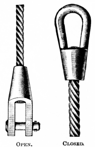
Rope Sockets.
Sea Injection. The pipe and valve through which sea water is injected into the condenser of a marine engine.
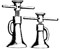
Screw Jacks.
Screw jack or lifting jack. A screw working in a threaded base or stationary nut and turned by a lever inserted into holes near the top, of which there are usually four. A loose plate or swivel is placed on top of screw.
“Slams” and “Shocks.” Banging, clanking and jarring noises indicating a derangement of the action of a pump.
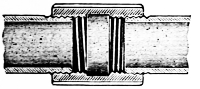
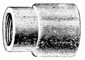
Sleeve Coupling.
Sleeve-coupling. A threaded connection for uniting the two ends of pipes of equal size.
“Slippage.” The difference between the calculated and actual work performed by a pump.
Sluice. A water-gate; a channel to run off waste water.
Slurry pump. A special pump for handling a mixture of earth water.
Socket-wrench. A wrench for turning nuts, having a socket in the end made to a special size and shape of the nut to be turned.
Spanner. Is a wrench for turning round nuts having holes or slots.
Spanner.
Spline or feather. A key made fast in a shaft.
Split-pin or cutter. An iron pin divided at the end which is to be spread apart after inserting in the hole.
“Spread.” A term used to indicate the distance from center to center of the cylinders of a duplex pump.
Spring-seat. An elastic seat for a valve.
Steam thrown valves. Valves moved by steam only.
Steam end of a pump. The end operated by steam.
“Sticking of valves.” Inability to work caused by the introduction into the valves of sand, soil, etc.; or it may be caused by too tight a fit of the moving parts, rust or corrosion.
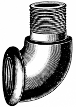
Street Elbow.
Street elbow. An elbow having an extension piece at one end.
“Stroke” of pump. The distance traveled by the piston in one motion.
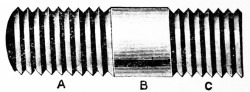
Stud-Bolt.
Stud-bolt. A piece of round bar metal with a thread upon each end. A represents thread for nut; B body of bolt and C thread to fit in casting.
Stub-end. Either end of a connecting rod.
Strainer. A device for separating solid particles from the liquid which contains them.
Stuffing box. A recess to receive the packing around piston rods, plungers and valve stems.
Submerged pump. A pump which works under water.
Stub-End.
Strainer.
“Sucking wind.” A leakage of air into the suction part of a pump.
Supplemental piston. The piston which operates the main valve in the steam pump.
Swing check valve. One which swings upon a pivot or hinge in opening and closing.
Switch cock or valve. A device for conducting exhaust steam into the smoke stack or atmosphere. A three-way cock.
Syphon Cock. A cock having a combined chamber which is partially filled with water of condensation, attached to a steam gauge to keep steam from entering and damaging the works of the instrument.
Swing Check Valve.
Switch Cock.
Syphon Cock.
Thumb-Nut.
Thumb-nut. The same as a wing-nut, but a smaller size of the two, shown above, applied to hand-vice.
Tobin-bronze. An alloy of copper, tin and zinc treated in a special manner; it is non-corrosive, has great tensile strength and can be forged at a cherry red heat.
“Trailing Water.” Water can be trailed, i.e., carried through pipes to pumps a very great distance so long as “the lift” is not over 25 to 33 feet.
“Trompe.” The term used to designate a water-blast—a form of pump.
Turbine. A water wheel driven by the impact or reaction of streams of water flowing through it or by the impact and reaction combined; it is also distinguished by the manner in which it discharges the water, as outward, vertical or central discharge turbine wheels.
Turbine-pump. A pump in which water is raised by the action of a turbine wheel driven by exterior power in the opposite direction from that in which it is turned when used as a motor.
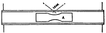
Tube-Plug.
Tube-plug. A tube stopper to be used in case of a leak in a boiler tube; it consists of two wood pistons joined together so that the leak will come between them. Tube plugs are frequently made of turned tapered cast iron, one of which is to be driven into each end of a leaking tube.
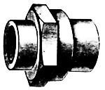
Union.
Union. A fitting designed to unite the two screwed ends of a pipe, with a single nut to secure them.
Vacuum. A void space; an inclosed chamber from which the air (or other gas) has been very nearly removed, as by an air pump.
Valve. Any device or appliance used to control the flow of a liquid, vapor, or gas, or loose material, through a pipe, outlet or inlet; the term includes air, gas, steam and water-cocks of all kinds; water-gates, air-gates, etc. One hundred and fifty of such devices are named by Knight in his “Mechanical Dictionary.”
Viscosity. Glutinous, adhering, or sticky, as tar, gums, molasses. Internal friction or resistance to change of shape.
V thread. A thread on a rod or bolt cut in the form of a letter V.
Washer. A circular piece of leather, rubber, metal, or other material with a hole in its center, through which a rod or bolt may pass.
Water Arch. A chamber of plates or of pipes over the furnace door of brick set boilers to take the place of the usual cast iron or fire brick arch, and connected with the boiler to supply it with water. The feed water is often introduced through the water arch.
Water-bellows. A form of pump, like a bellows—of great antiquity.
Water-cap. The cover for discharge valves on a steam pump.
Water-end. The pump end of a steam-pump; in distinction from the steam end.
Water-hammer. A noise caused by the pulsative motion of water inside a steam pipe, resembling the blows of a hammer.
Water Ram. A hydraulic ram.
Working Barrel. The water end of a pump.
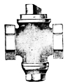
Yoke.
Whirlpool-chamber. A chamber attached to the discharge end of the centrifugal pump in which the whirling water gradually loses its rotation, thereby reducing friction.
Wing-nut. An iron nut having a wing at each side. Sometimes called a “butterfly nut.”
Yoke. A branch pipe, or a two-way coupling for pipes, particularly twin hot and cold-water pipes that unite in their discharge.
Y.—A pipe fitting for uniting two pipes at an angle of 45°.

Gourd, Cauldron and Pipkin.
The very small degree of antiquity to which machine tools can lay claim appears forcibly in the sparse records of the state of the mechanic arts a century ago.
A few tools of a rude kind, such as trip-hammers (worked by water wheels), and a few special ones, which aimed at accuracy but were of limited application, such as “mills” for boring cannon, or “engines” for cutting the teeth of clock wheels, were almost their only representatives.
The transmission of power was unthought of, except for the very limited distances which were possible with the ill-fitted “gudgeons” and “lanterns and trundles” of the old millwrights.
The steam-engine, however, changed all this; on the one hand the hitherto unheard of accuracy of fit required by its working parts created a demand for tools of increased power and precision, and on the other it rendered the use of such tools possible in almost any situation.
Thus, acting and re-acting on each other, machine tools and steam engines have grown side by side, although the first steps were costly and difficult to a degree which is not now easy to realize. James Watt, for instance, in 1779 was fain to be content with a cylinder for his “fire-engine,” of which, though it was but 18 inches in the bore, the diameter in one place exceeded that at another by about 3⁄8 of an inch; its piston was not unnaturally leaky; though he packed it with “paper, cork, putty, pasteboard and old hat.”
The early history of the pumping-engine is the history of the steam-engine, for originally and for many years the only way in which the steam-engine was utilized was for pumping water out of the coal mines of England and from the low lands of the Netherlands.
In 1698 Capt. Thomas Savery secured Letters Patent for a machine for raising water by steam. It consisted of two boilers and two receivers for the steam, with valves and the needful pipes. One of the receivers being filled with steam, its communication with the boiler was then cut off and the steam condensed with cold water outside of it; into the vacuum thus formed the atmosphere forced the water from below, when the steam was again caused to press upon the water and drive it still higher.
This engine was used extensively for draining mines and the water was, in some instances, made to turn a water wheel, by which lathes and other machinery were driven.
In 1705 Thomas Newcomen, with his associates, patented an engine which combined, for the first time, the cylinder and piston and separate boiler. This soon became extensively introduced for draining mines and collieries, and the engines grew to be of gigantic size, with cylinders 60 inches in diameter and other parts in proportion.
This engine was, in course of years, used in connection with the Cornish pump, whose performance in raising water from mines came to be a matter of the nicest scientific investigation, and adopted as the standard for the duty or work, by which to compare the multitudinous experimental machines very soon introduced by many inventors.
But there is an earlier history which long antedates the achievements of Savery, Newcomen and Watt, which belongs, however, principally to the domain of hydraulics. Before proceeding to discuss the advancements made within the memory of men now living, it may be well to take a glance backward and occupy a few pages with their appropriate illustrations, with the facts recorded in history.
It were vain to even try, to trace the advances made toward the mammoth city pumping stations, from the early beginning hereafter described, which have inspired the words recorded by J. F. Holloway, M. E.:
“In looking upon the ponderous pumping engines which lift a volume of water equal to the flow of a river, sending it with each throbbing beat of their pulsating plungers through the arteries and veins that now reach out in every direction in our great cities, bringing health, comfort, cleanliness and protection to every home therein, we cannot but wonder what is the history of their beginning, what the process of their evolution out from the crude appliances of long ago.
Just who the first man was, and by what stream he sat gazing on his parched fields, on which the cloudless skies of the Orient shed no rain, and where the early rising sun with eager haste lapped up the dew drops which the more kindly night in pity over his hard lot had shed, and who, looking on his withering grain stalks on the one side and the life-giving waters which flowed by on the other, first caught the inspiring thought that if one could only be brought to the other, how great would be the harvest, we shall never know. Knowing, as we do, that such still is the problem that confronts the toiler on the plains of that far-off Eastern land where man’s necessities first prompted man’s invention, it does not require a great stretch of the imagination to conceive of such a situation, and to believe that, acting on the impulse of the moment, he called his mate, and tying thongs to the feet of a sheep-skin and standing on either side of the brook, with alternate swingings of the suspended skin they lifted the waters of the stream to the thirsty field, making its blanched furrows to bloom with vegetation, and at the same time introducing to the world the first hydraulic apparatus ever invented, and certainly the first hydraulic ram ever used.”
The figures shown on the opening page of this section of the work represent the very first utensils used for collecting and containing water. The gourd or calabash was undoubtedly the very first; it was common among the ancient Romans, Mexicans and Egyptians, and in the most modern times continues to be in use in Africa, South America and other warm countries. The New Zealanders possessed no other vessels for holding liquids, and the same remark is applicable to numerous other savage tribes.
Although not strictly connected with the subject, it may be observed that the gourd is probably the original vessel for heating water, cooking, etc. In these and other applications the neck is sometimes used as a handle and an opening made into the body by removing a portion of it, as shown in the engraving, its exterior being kept moistened by water while on the fire, while others apply a coating of clay to protect it from the effects of the flame. When in process of time vessels for heating water were formed wholly of clay, they were fashioned after the cauldron as shown.
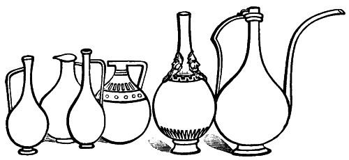
Figs. 47-52.
The above illustrations are representations of ancient vases; it is curious to note their conformation to the figure of the gourd. The first three on the left are from Thebes. Golden ewers of a similar form were used by rich Egyptians for containing water to wash the hands and feet of their guests.
Similar shaped vessels of the Greeks, Romans and other people might be easily produced.
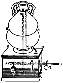
Fig. 53.—Water-Clock.
In Egypt, India, Chaldea and China the clepsydra or water-clocks date back beyond all records. Plutarch mentions them in his life of Alcibiades who flourished in the Fifth Century B. C. when they were employed in the tribunals at Athens to measure the time to which the orators were limited in their addresses to the judges. Julius Cæsar found the Britons in possession of them.
The clepsydra is a device for measuring time by the amount of water discharged from a vessel through a small aperture, the quantity discharged in a given unit of time, as an hour being first determined. In the earlier clepsydras the hours were measured by the sinking of the surface of the water in the vessel containing it. In others the water ran from one vessel to another, there being in the lower a cork or piece of light wood which as the vessel filled, rose and thus indicated the hour. In later clepsydras the hour has been indicated by a dial.
Fig. 53 shows a water-clock described by Hero of Alexandria, Egypt, made to govern the quantities of fluids flowing from a vessel. The note below gives the exact wording of the description which has come down to us.
“A vessel containing wine, and provided with an open spout, stands upon a pedestal: it is required by shifting a weight to cause the spout to pour forth a given quantity,—sometimes, for instance, a half cotyle (1⁄4 pint), sometimes a cotyle (1⁄2 pint), and in short, whatever quantity we please. A B (fig. 53), is the vessel into which wine is to be poured: near the bottom is a spout D: the neck is closed by the partition E F, and through E F is inserted a tube, G H, reaching nearly to the bottom of the vessel, but so as to allow of the passage of water. K L M N is the pedestal on which the vessel stands, and O X another tube reaching40 within a little of the partition and extending into the pedestal in which water is placed so as to cover the orifice O, of the tube. Fix a rod, P R, one-half within, and the other without the pedestal, moving like the beam of a lever about the point S; and from the extremity P of the rod suspend a water-clock, T, having a hole in the bottom. The spout D having been first closed, the vessel should be filled through the tube G H before water is poured into the pedestal, that the air may escape through the tube X O; then pour water into the pedestal, through a hole, until the orifice O is closed, and set the spout D free. It is evident that the wine will not flow, as there is no opening through which air can be introduced: but if we depress the extremity R of the rod, a portion of the water-clock will be raised from the water, and, the vent O being uncovered, the spout D will run until the water suspended in the water-clock has flowed back and closed the vent O. If, when the water-clock is filled again, we depress the extremity R still further, the liquid suspended in the water-clock will take a longer time to flow out, and there will be a longer discharge from D: and if the water-clock be entirely raised above the water, the discharge will last considerably longer. To avoid the necessity of depressing the extremity R of the rod with the hand, take a weight Q, sliding along the outer portion of the rod, R W, and able, if placed at R, to lift the whole water-clock; if at a distance from R, some smaller portion of it. Then, having obtained by trial the quantities which we wish to flow from D, we must make notches in the rod R W and register the quantities; so that, when we wish a given quantity to flow out, we have only to bring the weight to the corresponding notch and leave the discharge to take place.”
The Syphon is a bent pipe or tube with legs of unequal length, used for drawing liquid out of a vessel by causing it to rise in the tube over the rim or top. For this purpose the shorter leg is inserted in the liquid, and the air is exhausted by being drawn through the longer leg. The liquid then rises by the pressure of the atmosphere and fills the tube and the flow begins from the lower end.
The general method of use is to fill the tube in the first place with the liquid, and then, stopping the mouth of the longer leg, to insert the shorter leg in the vessel; upon removal of the stop, the liquid will immediately begin to run. The flow depends upon the difference in vertical height of the two columns of the liquids, measured respectively from the41 bend of the tube, to the level of the water in the vessel and to the open end of the tube. The flow ceases as soon as, by the lowering of the level in the vessel, these columns become of equal height or when this level descends to the end of the shorter leg.
The atmospheric pressure is essential to the support of the column of liquid from the vessel up to the top of the bend of the tube, and this height is consequently limited; at sea height the maximum height is a little less than 34 feet for water, but this varies according to the density of the fluid.
Syphons are necessary in numerous manipulations of the laboratory, and modern researches in chemistry have given rise to several beautiful devices for charging them, and also for interrupting and renewing their action. When corrosive liquids or those of high temperatures are to be transferred by syphons, it is often inconvenient, and sometimes dangerous to put them in operation by the lungs. Moreover cocks and valves of metal are acted on by acids, and in some cases would affect or destroy the properties of the fluids themselves.
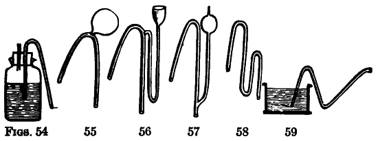
Fig. 54 shows how hot or corrosive liquids may be drawn off from a wide mouthed bottle or jar. The short leg of a syphon is inserted through the cork, and also a small tube, through which the operator blows, and by the pressure of his breath forces the liquid through the syphon.
Fig. 55 represents a syphon sometimes employed by chemists. When used, the short leg is first placed in the fluid to be decanted, the flame of a lamp or candle is then applied to the underside of the bulb; the heat rarefies the air, and consequently42 drives out the greater part of it through the discharging orifice. The finger is applied to this orifice, and as the bulb becomes cool the atmosphere drives up the liquid into the void and puts the instrument in operation.
Fig. 56 is a syphon charged by pouring a quantity of the fluid to be decanted into the funnel, the bent pipe attached to which terminates near the top of the discharging leg. The fluid in descending through this leg bears down the air within it, on the principle of the trompe, and the atmosphere drives up the liquid in the reservoir through the short leg.
Fig. 57 is a glass syphon for decanting acids, &c. It is charged by sucking, and to guard against the contents entering the mouth, a bulb is blown on the sucking tube. The accumulation of a liquid in this bulb being visible, the operator can always withdraw his lips in time to prevent his tasting it.
Fig. 58 is designed to retain its contents when not in use, so that on plunging the short leg deep into a liquid the instrument will operate. This effect however will not follow if the end of the discharging leg descend below the bend near it, and if its orifice be not contracted nearly to that of a capillary tube.
Fig. 59 is a syphon by which liquids may be drawn at intervals, viz., by raising and lowering the end of the discharging leg according to the surface of the liquid in the cistern.
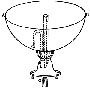
Fig. 60.
Figs. 60, 61, 62 are syphons described by Hero of Alexandria who lived 120 B. C.; the descriptions of the figures are the translation of the original.
Let A B C D (Fig. 60) be a vessel open at the top, and through its bottom pass a tube, either an inclosed pipe as E F G, or a bent syphon G H K. When the vessel A B C D43 is filled, and the water runs over, a discharge will begin and continue till the vessel is empty, if the interior opening is so near the bottom of the vessel as only to leave a passage for the water.
As before, let there be a vessel, A B (Fig. 61), containing water. Through its bottom insert a tube, C D, soldered into the bottom and projecting below. Let the aperture C of the syphon approach to the mouth of the vessel A B, and let another tube, E F, inclose the tube C D, the distance between the tubes being everywhere equal, and the mouth of the outer tube being closed by a plate, E G, a little above the mouth C. If we exhaust, by suction through the mouth D, the air in the tube C D, we shall draw into it the water in the vessel A B, so that it will flow out through the projection of the syphon until the water is exhausted. For the air contained between the liquid and the tube E F, being but little, can pass into the tube C D, and the water can then be drawn after it. And the water will not cease flowing because of the projection of the syphon below:—if, indeed, the tube E F were removed, the discharge would cease on the surface of the water arriving at C, in spite of the projection below; but when E F is entirely immersed no air can enter the syphon in place of that drawn off, since the air which enters the vessel takes the place of the water as it passes out.
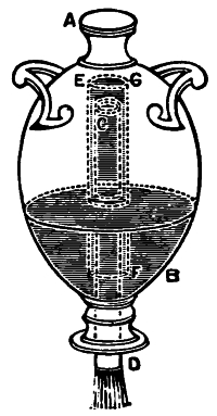
Fig. 61.
Let A B C (Fig. 62), be a bent syphon, or tube, of which the leg A B is plunged into a vessel D E containing water. If the surface of the water is in F G, the leg of the syphon, A B, will be filled with water as high as the surface, that is, up to H, the portion H B C remaining full of air. If, then we draw off the air by suction through the aperture C, the liquid also will follow. And if the aperture C be level with the surface of the44 water, the syphon, though full, will not discharge the water, but will remain full: so that, although it is contrary to nature for water to rise, it has risen so as to fill the tube A B C; and the water will remain in equilibrium, like the beams of a balance, the portion H B being raised on high, and the portion B C suspended. But if the outer mouth of the syphon be lower than the surface F G, as at K, the water flows out, for the liquid in K B, being heavier, overpowers and draws toward it the liquid B H. The discharge, however, continues only until the surface of the water is on a level with the mouth K, when, for the same reason as before, the efflux ceases. But if the outer mouth of the tube be lower than K, as at L, the discharge continues until the surface of the water reaches the mouth A.
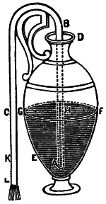
Fig. 62.
The Syringe is an instrument of very high antiquity and was probably the first machine consisting of a cylinder and piston that was especially designed to force liquids. In the closed end a short conical pipe is attached whose dimensions are adapted to the particular purpose for which the instrument is to be used. The piston is solid and covered with a piece of soft leather, hemp, woolen listing, or any similar substance that readily imbibes moisture, in order to prevent air or water from passing between it and the sides of the cylinder. When the end of the pipe is placed in a liquid and the piston drawn back, the atmosphere drives the liquid into the cylinder; whence it is expelled through the same orifice by pushing the piston down: in the former case the syringe acts as a sucking pump: in the latter as a forcing one. They are formed of silver, brass, pewter, glass, and sometimes of wood. For some purposes the small pipe is dispensed with, the end of the cylinder being closed by a perforated plate, as in those instruments with which gardeners syringe their plants.
Joseph’s Well.
Long before pumping devices were conceived, wells existed as the invention of prehistoric man. Herewith is a sectional view of Joseph’s Well to be seen at the present time at Cairo, Egypt. Scientists think it the production of the same people that built the pyramids and the unrivaled monuments of Thebes, Dendaroh and Ebsambone. The magnitude of the well and the skill displayed in its construction is perfectly unique.
This stupendous well is an oblong square, twenty four feet by eighteen, being sufficiently capacious to admit within its mouth a moderate sized house. It is excavated (of these dimensions) through solid rock to the depth of one hundred and sixty-five feet, where it is enlarged into a capacious chamber, in the bottom of which is formed a basin or reservoir, to receive the water raised from below (for this chamber is not the bottom of the well). On one side of the reservoir another shaft is continued, one hundred and thirty feet lower,46 where it emerges through the rock into a bed of gravel, in which the water is found, the whole depth being two hundred and ninety-seven feet; the lower shaft is not in the same vertical line with the upper one, nor is it so large, being fifteen feet by nine.
As the water is first raised into the basin, by means of machinery propelled by horses or oxen within the chamber, it may be asked, how are these animals conveyed to that depth in this tremendous pit, and by what means do they ascend? A spiral passage-way is cut through the rock, from the surface of the ground to the chamber, independent of the well, round which it winds with so gentle a descent, that persons sometimes ride up or down upon asses or mules. It is six feet four inches wide, and seven feet two inches high. Between it and the interior of the well, a wall of rock is left, to prevent persons falling into, or even looking down it (which in some cases would be equally fatal), except through certain openings or windows, by means of which it is faintly lighted from the interior of the well. The animals descend by this passage to drive the machinery that raises the water from the lower shaft into the reservoir or basin, from which it is again elevated by similar machinery and other oxen on the surface of47 the ground. In the lower shaft a path is also cut down to the water, but as no partition is left between it and the well, it is extremely perilous for strangers to descend.
Twelfth Century.
Asiatic Pulley and Bucket.
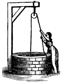
Note.—However old and numerous wells with stairs in them may be, most of the ancient ones were constructed without them; hence the necessity of some mode of raising the water. From the earliest ages, a vessel suspended by a cord, has been used by all nations—a device more simple and more extensively employed than any other, and one which was undoubtedly the germ of the most useful hydraulic machine of the ancients. The figures shown on this and a few succeeding pages are from the collection made by Ewbank—to whom reference has been made in another portion of this work.
Pulley and Two Buckets.
(ANCIENT.)
The square openings represented on each side of the upper shaft are sections of the spiral passage, and the zig-zag lines indicate its direction. The wheels at the top carry endless ropes, the lower parts of which reach down into the water; to these, earthenware vases are secured by ligatures (see A A) at equal distances through the whole of their length, so that when the machinery moves these vessels ascend full of water on one side of the wheels, discharge it into troughs as they pass over them and descend in an inverted position on the other side.
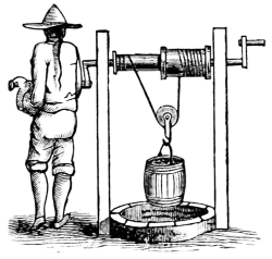
Chinese Windlass.
This celebrated production of former times, as will be perceived, resembles an enormous hollow screw, the center of which forms the well and the threads a winding stair-case around it. To erect of granite, a flight of “geometrical” or “well stairs,” two or three hundred feet high, on the surface of the ground, would require extraordinary skill, although in its execution every aid from rules, measures, and the light of day, would guide the workmen at every step; but to begin such a work at the top, and construct it downwards by excavation alone, in the dark bowels of the earth, is a more arduous undertaking, especially as deviations from the correct lines could not be remedied; yet in Joseph’s well, the partition of rock between the pit and the passage-way, and the uniform inclination of the latter, seem to have been ascertained with equal precision, as if the48 whole had been constructed of cut stone on the surface. Was the pit, or the passage, formed first; or were they simultaneously carried on, and the excavated masses from both borne up the passage, are unanswered questions.
Anglo-Saxon Crane.
The extreme thinness of the partition wall, excited the astonishment of M. Jomard, whose account of the well is inserted in the second volume of Memoirs in Napoleon’s great work on Egypt. It is, according to him, but sixteen centimetres thick, [about six inches!] He justly remarks that it must have required singular care to leave and preserve so small a portion while excavating the rock from both sides of it. It would seem no stronger in proportion, than sheets of paste-board placed on edge, to support one end of the stairs of a modern built house, for it should be borne in mind, that the massive roof of the spiral passage next the well, has nothing but this film of rock to support it, or to prevent from falling, such portions as are loosened by fissures, or such, as from changes in the direction of the strata, are not firmly united to the general mass. But this is not all: thin and insufficient as it may seem, the bold designer has pierced it through its whole extent with semi-circular openings, to admit light from the well: those on one side are shown in the engraving.
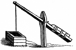
Swape or Sweep, A. D. 1493.
Aqueducts, fountains, cisterns and wells, are in numerous instances the only remains49 of some of the most celebrated cities of the ancient world. Of Heliopolis, Syene and Babylon in Egypt; of Tyre, Sidon, Palmyra, Nineveh, Carthage, Utica, Barca, and many others. “The features of nature,” says Dr. Clarke, “continue the same, though works of art may be done away: the ‘beautiful gate’ of the Jerusalem temple is no more, but Siloah’s fountain still flows, and Kedron still murmurs in the valley of Jehoshaphat.” According to Chateaubriand, the Pool of Bethesda, a reservoir, one hundred and fifty feet by forty, constructed of large stones cramped with iron, and lined with flints embedded in cement, is the only specimen remaining of the ancient architecture of that city.
Note.—Roman wells are found in every country which that people conquered. Their armies had constant recourse to them when other sources of water failed. Pompey and Cæsar often preserved their troops from destruction by having provided them. It was Pompey’s superior knowledge in thus obtaining water, which enabled him to overthrow Mithridates, by retaining possession of an important post.
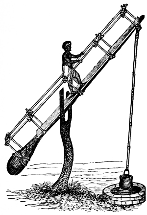
Picotah of Hindostan.
Note.—The operation of this primitive device may be thus described—Near the well or tank, a piece of wood is fixed, forked at the top; in this fork another piece of wood is fixed to form a swape, which is formed by a peg, and steps cut out at the bottom, that the person who works the machine may easily get up and down. Commonly, the lower part of the swape is the trunk of a tree; to the upper end is fixed a pole, at the end of which hangs a leather bucket. A man gets up the steps to the top of the swape, and supports himself by a bamboo screen erected by the sides of the machine. He plunges the bucket into the water, and draws it up by his weight; while another person stands ready to empty it.
Ephesus, too, is no more; and the temple of Diana, that according to Pliny was 220 years in building, and upon which was lavished the talent and treasure of the east; the pride of all Asia, also one of the wonders of the world, has vanished, while the fountains which furnished the citizens with water, remain as fresh and perfect as ever. Cisterns have been discovered in the oldest citadels in Greece. The fountains of Bounarbashi are perhaps the only objects remaining that can be relied on, in locating the palace of Priam and the site of ancient Troy. And the well near the outer walls of the temple of the sun at Palmyra, will, in all probability, furnish men with water, when other relics of Tadmor in the wilderness have disappeared; a great number of the wells of the ancient world still supply man with water, although their history generally, is lost in the night of time.
We are now to examine the modes practised by the ancients, in obtaining water from wells. In all cases of moderate depth, the most simple and efficient, was to form an inclined plane or passage, from the surface of the ground to the water; a method by which the principal advantages of an open spring on the surface were retained, and one by which domestic animals could procure water for themselves without the aid or attendance of man.
But when in process of time, these became too deep for exterior passages of this kind to be convenient or practicable, the wells themselves were enlarged, and stairs for descending to the water, constructed within them.
Historical Note.—One of the most appalling facts that is recorded of suffering from thirst occurred in 1805. A caravan proceeding from Timbuctoo to Talifet, was disappointed in not finding water at the usual watering places; when, horrible to relate, all the persons belonging to it, two thousand in number, besides eighteen hundred camels perished by thirst! Occurrences like this, account for the vast quantities of human and other bones, which are found heaped together in various parts of the desert. While the crusaders besieged Jerusalem, great numbers perished of thirst, for the Turks had filled the wells in the vicinity. Memorials of their sufferings may yet be found in the heraldic bearings of their descendants. The charge of a foraging party “for water,” we are told, “was an office of distinction;” hence, some of the commanders on these occasions, subsequently adopted water buckets in their coats of arms, as emblems of their labors in Palestine.
Wells with stairs by which to descend to the water, are still common. The inhabitants of Arkeko in Abyssinia, are supplied with water from six wells, which are twenty feet deep and fifteen in diameter. The water is collected and carried up a broken ascent by men, women and children. Fryer in his Travels in India speaks of “deep wells many fathoms underground, with stately stone stairs.” Near the village of Futtehpore, is a large well, ninety feet in circumference, with a broad stone staircase which is about thirty feet deep to descend to the water. The fountain of Siloam is reached by a descent of thirty steps cut in the solid rock, and the inhabitants of Libya, where the wells often contain little water, “draw it out in little buckets, made of the shank bones of camels.”
Wells with stairs are not only of very remote origin, but they appear to have been used by all the nations of antiquity. They were common chiefly, among the Greeks and Romans.
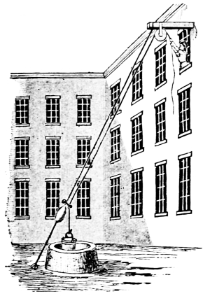
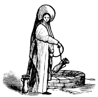
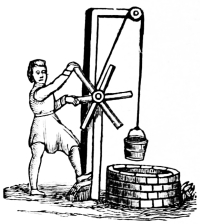
Italian Mode of Raising Water to the Upper Floors of a House.
As a matter of interest some six or eight representations of the early forms of wells, have been introduced; but little need to be written relating to them—the cuts with the titles speak for themselves and also indicate their manner of use. (See note.)
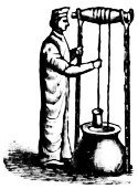
In Syria and Palestine at the present time the antique bucket and rope, in modified form, is still used in raising water from wells for irrigation. The buckets are attached to the ropes at regular intervals and pass over large drums going down empty and rising full. They discharge at the top into a large open trough, which conveys the water to the irrigating ditches.
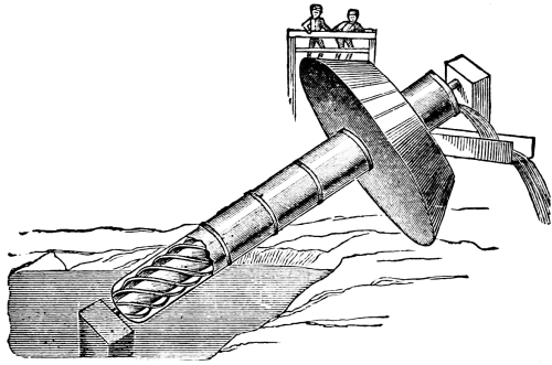
Roman Screw.—Fig. 72.
A method much used where rivers are available is the wheel and bucket, in which the buckets are mounted on the rim of a large wheel which is of a diameter equal to the height to which the water is to be raised. The processes although extremely crude are well adapted to countries where labor is inexpensive as the running expense of the devices is very small.
Note.—The source from which many of these have been derived is “Eubank’s Hydraulics,” to which work credit is gladly given for nearly all the historical data so far used in this volume. The author of the book named gave many years of research into the early records of all relating to hydraulics and water machines and kindred subjects.
The raising of water is one of the early arts; beginning in ancient times with devices of the crudest form it has followed the progress of civilization with ever-increasing importance. In the present era, it demands engineering ability of the highest order and the finest of machinery.
Important epochs in the gradual inventions relating to pumps and hydraulics are: (1) The “force pump,” due to Ctesibius 200 B. C.; (2) the “double-acting pump,” invented by La Hire in 1718; (3) the “hydraulic ram,” by Whitehurst in 1772; (4) the “hydraulic press,” introduced by Joseph Bramah in 1802.
Most of the machines hitherto noticed, raise water by means of flexible cords or chains, and are generally applicable to wells of great depth. We now enter upon the examination of another variety, which, with one exception (the chain of pots), are composed of inflexible materials, and raise water to limited heights only.
In preceding machines, the “mechanical powers” are distinct from the hydraulic apparatus, i.e., the wheels, pulleys, windlass, capstan, etc., form no essential part of the machines proper for raising the water, but are merely employed to transmit motion to them; whereas those we are now about to describe, are made in the form of levers, wheels, etc., and are propelled as such.
The Roman Screw delineated upon the opposite page, if not the earliest hydraulic engine that was composed of tubes, or in the construction of which they were introduced, is certainly the oldest one known of that description; in its mode of operation it differs essentially from all other ancient tube machines; in the latter the tubes merely serve as conduits for the ascending water, and as such are at rest; while in the screw it is the tubes themselves in motion that raises the liquid.
Fig. 73 represents one of the earliest forms of a double gutter, placed across a trough or reservoir designed to receive the water. A partition is formed in the center, and two openings made through the bottom on each of its sides, through which the water that is raised escapes. The machine is worked by one or more men, who alternately plunge the ends into the water, and thus produce a continuous discharge.
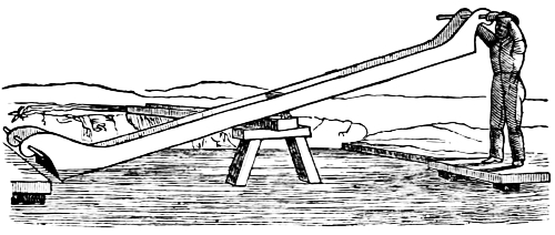
Fig. 73.
Sometimes, openings are made in the bottom next the laborers, and covered by flaps, to admit the water without the necessity of wholly immersing those ends; machines of this kind probably date from remote antiquity; they are obviously modifications of the Jantu of Hindostan and other parts of Asia. The jantu is a machine extensively used in parts of India, to raise water for the irrigation of land, and is thus described: “It consists of a hollow trough of wood, about fifteen feet long, six inches wide, and ten inches deep, and is placed on a horizontal beam lying on bamboos fixed in the bank of a pond or river.
One end of the trough as shown in the figure rests upon the bank where a gutter is prepared to carry off the water, and the other end is dipped in the water, by a man standing on a stage, plunging it in with his foot. A long bamboo with a large weight of earth at the farther end of it, is fastened to the end of the jantu near the river, and passing over the gallows, poises up the jantu full of water, and causes it to empty itself55 into the gutter. This machine raises water three feet, but by placing a series of them one above another, it may be raised to any height, the water being discharged into small reservoirs, sufficiently deep to admit the jantu above, to be plunged low enough to fill it;” water is thus conveyed over rising ground to the distance of a mile and more. In some parts of Bengal, they have different methods of raising water, but the principle is the same.
The Tympanum. This is a water raising current wheel originally made in the form of a drum, hence the name. It is now a circular open frame wheel, fitted with radial partitions as shown in Fig. 74, so curved as to point upward on the rising side of the wheel and downward on the descending side. The wheel is so suspended that its lower edge is just submerged and is turned by the current (or by other power), the partitions scooping up a quantity of water which, as the wheel revolves, runs back to the axis of the wheel where it is discharged; or it may discharge at some point of the periphery; while one of the most ancient forms of water lifting machines it is still used in drawing works.
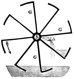
Fig. 74.
A little study of the figure (74) will explain its operation.
S, is the shaft; G G, the gutters; A, a trough to take away the water. The arrow indicates the direction in which the wheel turns; each gutter, as it revolves scoops up a portion of water and elevates it, till by the inclination to the axle, it flows towards the latter, and is discharged through one end of it.
The prominent defect of the tympanum arises from the water being always at the extremity of a radius of the wheel, by which its resistance increases as it ascends to a level with56 the axis, being raised at the end of levers which virtually lengthen till the water is discharged from them; this has been remedied by making the arms curving as shown in the Scoop Wheel (Fig. 75.) As this revolves in the direction of the arrow the extremities of the partitions dip into the water and scoop it up and as they ascend discharge it into a trough placed under one end of the shaft which is hollowed into as many compartments as there are partitions or scoops.
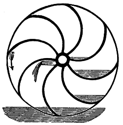
Fig. 75.
Fig. 76 represents a sectional view of an improved tympanum; this was invented by De La Faye; the illustration will be readily understood. As shown in Figs. 74 and 75 the wheel is driven by the current of a stream impinging upon what in later times came to be known as boards or floats on the circumference of the wheel.
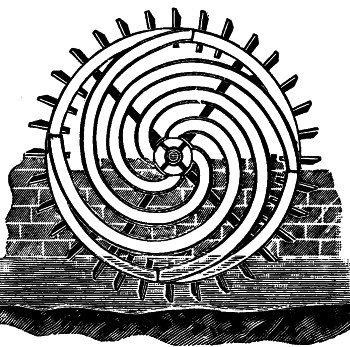
Fig. 76.
Within the enclosure are arranged four scrolls of suitable proportions, dipping the water, at one end, and emptying it out at the center of the wheel as more clearly shown in Figs. 74 and 75.
The Noria or Egyptian Wheel. The tympanum has been described as an assemblage of gutters, and the Noria may be considered as a number of revolving swapes. It consists of a series of poles united like the arms of a wheel to a horizontal shaft. To the extremity of each, a vessel is attached which fills as it dips into the water, and is discharged into a reservoir or gutter at the upper part of the circle which it describes. Hence, the former raises water only through half a diameter, while this elevates it through a whole one. (Fig. 77.)
The Chinese make the noria, in what would seem to have been its primitive form, and with an admirable degree of economy, simplicity, and skill. With the exception of the axle and two posts to support it, the whole is of bamboo, and not a nail used in its construction. Even the vessels, are often joints of the same, being generally about four feet long and two or three inches in diameter. They are attached to the poles by ligatures at such an angle, as to fill nearly when in the water, and to discharge their contents when at, or near the top.
The periphery of the wheel is composed of three rings of unequal diameter and so arranged as to form a frustrum of a cone. The smallest one, to which the open ends of the tubes are attached, being next the bank over which the water is conveyed. By this arrangement their contents are necessarily discharged into the gutter as they pass the end of it. When employed to raise water from running streams they are propelled by the current in the usual way—the paddles being58 formed of woven bamboo. The sizes of these wheels, vary from twenty to seventy feet in diameter; some raise over three hundred tons of water in twenty-four hours. A writer mentions others which raise a hundred and fifty tons to the height of forty feet during the same time.
Note.—The mode of constructing and moving the noria by the Romans, is thus described by Vitruvius, who lived about the beginning of the Christian Era. “When water is to be raised higher than by the tympanum, a wheel is made round on axis of such a magnitude as the height to which the water is to be raised requires. Around the extremity of the side of the wheel, square buckets cemented with pitch and wax are fixed; so that when the wheel is turned by the walking of men, the filled buckets being raised to the top and turning again toward the bottom, discharge of themselves what they have brought into the reservoir.”
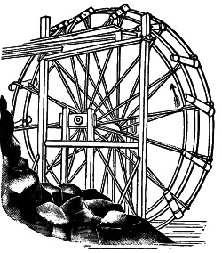
Fig. 77.
The Persian Wheel. Two prominent defects exist in the noria. First, part of the water escapes after being raised nearly to the required elevation. Second, a large portion is raised higher than the reservoir placed to receive it, into which it is discharged after the vessels begin to descend; to obviate this the Persian wheel was devised.
The vessels in which the water is raised, instead of being fastened to the rim, or forming part of it, as in the preceding figures, are suspended from pins, on which they turn, and thereby retain a vertical position through their entire ascent; and when at the top are inverted by their lower part coming in contact with a pin or roller attached to the edge of the gutter or reservoir, as represented in the figure. By this arrangement no water escapes in rising, nor is it elevated any higher than the edge of the reservoir; hence, the defects in the noria are avoided. It is believed, to have been used in Europe ever since the time of the Romans.

Fig. 78.
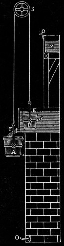
In the latter part of the Sixteenth, or beginning of the Seventeenth Century a machine which is entitled to particular notice on account of its being, as claimed, the first one of the kind to be self-acting, for raising water was in use in Italy. It is ascribed to Gironimo Finugio who put one in operation at Rome in 1616.
Between the illustration and the following description its operation may be clearly understood. On a pulley S, are suspended by a rope two buckets A and B, of unequal dimensions. The smaller one B, is made heavier than A when both are empty, but lighter when they are filled. It is required to raise by them part of the water from the spring or reservoir E, into the cistern Z. As the smaller Bucket B, by its superior gravity, descends into E, (a flap valve in its bottom admitting the water), it consequently raises A into the position represented in the figure. A pipe F, then conveys water from the reservoir into A, the orifice or bore of which pipe is so proportioned, that both vessels are filled simultaneously. The larger bucket then preponderates, descending to O, and B at the same time rising to the upper edge of Z, when the projecting pins O O, catch against others on the lower sides of the buckets, and overturn them at the same moment. The bails or handles are attached by swivels to the sides, a little above their center of gravity. As soon60 as both buckets are emptied, B again preponderates, and the operation is repeated without any attendance, so long as there is water in E and the apparatus continues in order.
In Moxon’s machine, the buckets were filled by two separate tubes of unequal bore; the orifices being covered by valves to prevent the escape of water while the buckets were in motion; these valves were opened and closed by means of cords attached to the buckets. The efflux through F in the figure, may easily be stopped as soon as A begins to descend, by the action of either bucket on the end of a lever attached to a valve, or by other obvious contrivances. The water discharged from A, runs to waste through a channel provided for that purpose. These machines are of limited application, since they require a fall for the descent of A, equal to the elevation to which the liquid is raised in B. They may however be modified to suit locations where a less descent only can be obtained. Thus, by connecting the rope of B to the periphery of a large wheel, while that of A is united to a smaller one on the same axis, water may be raised higher than the larger bucket falls, but the quantity raised will of course be proportionally diminished. In the face of these securing advantages it has fallen into disuse; it was much too complex and cumbersome, and of too limited application.
The principle of self-action in all these machines is no modern discovery, for it was described by Hero of Alexandria, who applied it to the opening and closing the doors of a temple, and to other purposes.
In those vast periods preceding the dawn of history, water was as heavy and as necessary for the use of mankind and animals as it is to-day; the toil and labor in securing it must indeed have been hard. Doubtless, the first inventions of the primitive man were first made—perhaps, after weapons of defence—to relieve himself of the painful endeavor of supplying the precious liquid.
There are reasons which render it probable that the single pulley was devised to raise water and earth from wells; the latter are not only of the highest antiquity but they are the only known works of man in early times in which the pulley could have been required or applied. That it preceded the invention of ships and the erection of lofty buildings of stone, is all but certain; but for what purpose, save for raising of water, the pulley could have been previously required it would be difficult to divine; it seems to have been the first addition made to those primitive implements, the cord and the bucket.
By it the friction of the rope in rubbing against the curb and the consequent loss of a portion of the power expended in raising the water, were avoided, and by it also a beneficial change in the direction of the power was attained; instead of being exerted in an ascending direction, it is applied more conveniently and efficiently in a descending motion as shown in the various figures and illustrations in the preceding pages.
But the grand advantage of the pulley in the early ages was this:—by it the vertical direction in which men exerted their strength, could be directly changed into a horizontal line, by which change animals could be employed.
The wells of Asia, frequently varying from two to three, and even four hundred feet in depth, obviously required more than one person to raise the contents of an ordinary sized vessel; and where numbers of people depended on such wells, not merely to supply their domestic wants, but for the purposes of irrigation, the substitution of animals in place of men to raise water, became a matter almost of necessity, and was certainly adopted at a very early period. In employing an ox for this purpose, the simplest way and one which deviated the least from their accustomed method, was merely to attach the end of the rope to the yoke, after passing it over a pulley fixed sufficiently high above the mouth of the well, and then driving the animal a distance equal to its depth, in a direct line from it, when the bucket charged with the liquid would be raised from the bottom.
Although it may never be known to whom the world is indebted for the windlass, there are circumstances which point to the construction of wells and raising of water from them, as among the first uses to which it as well as the pulley, was applied. The windlass possesses an important advantage over the single pulley in lifting weights, or overcoming any resistance since the intensity of the force transmitted through it can be modified, either by varying the length of the crank, or the circumference of the roller on which the rope is coiled. Sometimes a single vessel and rope, but frequently two, are employed as shown in several of the preceding illustrations; one of these is the Chinese Windlass. This furnishes the means of increasing mechanical energy to almost any extent, and as it is used to raise water from some of those prodigiously deep wells already noticed, a figure of it, page 47, has been inserted. The roller consists of two parts of unequal diameters, to the extremities of which the ends of the rope are fastened on opposite sides, so as to wind round both parts in different directions. As the load to be raised is suspended to a pulley, every turn of the roller raises a portion of the rope equal to the circumference of the thicker part, but at the same time lets down a portion equal to that of the smaller; consequently the weight is raised at each turn, through a space equal only to half the difference between the circumferences of the two parts of the roller. The action of this machine is therefore slow, but the mechanical advantages are proportionately great.
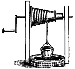
Fig. 79.
The fusee windlass is shown in Fig. 79. This is an early invention designed to overcome in a mechanical method the greater weight which the rope hung at its extremity has, as compared to what it is when nearly wound up. At the bottom of the well the rope then being at its heaviest period is wound upon the small end of the fusee; and as the length diminishes63 it coils round the larger part. (See Fig. 79), which is however inaccurately drawn—as the bucket is at the top of the well; it should have been represented as suspended from the large end of the fusee.
The value of a device like this will be appreciated when the great depth of some wells is considered and the consequent additional weight of the chains. In the fortress of Dresden is a well eighteen hundred feet deep; at Augustburgh is a well in which half an hour is required to raise the bucket; and at Nuremburgh another, sixteen hundred feet deep. In all these, the water is raised by chains, and the weight of the one used in the latter is stated to be upwards of a ton.
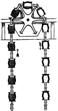
Fig. 80.
The tympanum and noria in all their modifications have been considered as originating in the gutter or jantu, and the swape; while the machine we are now to examine is evidently derived from the primitive cord and bucket. The first improvement of the latter was the introduction of a pulley or sheave over which the cord was directed—the next was the addition of another vessel, so as to have one at each end of the rope, and the last and most important consisted in uniting the ends of the rope, and securing to it a number of vessels at equal distances through the whole of its length—and the chain of pots was the result. (See Fig. 80.)
The general construction of this machine will appear from an examination of those which are employed to raise water from Joseph’s well at Cairo, represented on page 45. Above the mouth of each shaft a vertical wheel is placed, over which two endless ropes pass64 and are suspended from it. These are kept parallel to, and at a short distance from each other, by rungs secured to them at regular intervals, so that when thus united, they form an endless ladder of ropes. The rungs are sometimes of wood, but more frequently of cord like the shrouds of a ship, and the whole is of such a length that the lowest part hangs two or three feet below the surface of the water that is to be raised. Between the rungs, earthenware vases (of the design shown at A A) are secured by cords round the neck, and also round a knob formed on the bottom for that purpose.
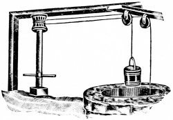
Fig. 81.
In all the preceding machines the roller is used in a horizontal position; but at some unknown period of past ages, another modification was devised, one by which the power could be applied at any distance from the center. Instead of placing the roller as before, over the well’s mouth, it was removed a short distance from it, and secured in a vertical position, by which it was converted into the wheel or capstan. One or more horizontal bars were attached to it, of a length adapted to the power employed, whether of men or animals; and an alternating rotary movement imparted to it, as in the common wheel or capstan, represented in the figure. It appears that machines of this kind, and worked by men were common in Europe previous to, and at the time he wrote. Sometimes the shaft was placed in the edge of the well, so that the person who moved it walked round the latter, and thus occupied less space.
With the wide acceptance in practical use of the Duplex steam pump, may be dated the beginning of the modern inventive period of pumping machinery; this introduction of the Duplex pump was only one of five successive advances which it were well for the student to memorize:
1. The Cornish,
2. The Rotative,
3. The Direct Acting,
4. The Duplex, and
5. The Compounded Steam Pump.
The Cornish engines have been alluded to in connection with the Newcomen engine. Probably no large pumping engines in the past have held, and deservedly so, as high repute as have the Cornish engines when used for deep mine pumping. Their construction, with the rude appliances at hand, is not only a marvel but as well a high tribute to the ingenuity of those who designed them and to the skill of the workmen who built them. A rather full illustrated description of this almost unexcelled machine will be found later on in the book.
The next class of large steam pumping-engines which have played an important part in the history of hydraulic engineering may be grouped together as “rotative engines.” What is here meant by the term “rotative” is engines in which there are parts which make complete and continuous rotary motion and in which are used, in some way or another, shafts, cranks and fly-wheels.
These engines vary greatly in their design and in the details of their construction. They are of varying sizes, including some of the largest and most expensive in the world. As a general thing they are employed in supplying towns and cities with water, and in some cases freeing shallow mines of water. The application of the power of the steam used in the66 steam cylinders in this class of engines to drive the plungers or pistons in the pumps, varies greatly, both as to the general design upon which they are built, and in the detail of their construction. In some instances it is through the use of long or short beams or bell cranks, sometimes through gearing, and occasionally through the plunger or piston of the pump direct; but in all cases the limit of the stroke of the steam piston, and of the pump plunger, is governed by a crank on a revolving shaft.
Attached to the revolving shaft is a fly-wheel of greater or less diameter and weight, which, in addition to assisting the crank to pass the center at each end of its stroke, is employed to store up at the beginning of each stroke of the steam piston, whatever excess of power or impulse there may be imparted to it, beyond that required to steadily move the water column, and to give out again, toward the latter part of the stroke, when the power of the steam is of itself below that required to move the water column, the power previously stored in it. In this respect the function of a revolving fly-wheel on a rotative engine is the same as is the weighted plunger in the Cornish engine; both being used for the purpose of permitting the steam to be cut off at a portion of its stroke in the steam cylinder, and expanded during the rest of the stroke.
In short, these devices, as employed in both the classes of pumping engines described, were used in order that the best economy in the consumption of steam by means of early cutoff and a high grade of expansion, might be attained.
The succeeding class of pumps to be described, driven by steam are direct acting steam-pumps.
What is here meant as “direct-acting,” is a steam-driven pump in which there are no revolving parts, such as shafts, cranks and fly-wheels; pumps in which the power of the steam in the steam cylinder is transferred to the piston or plunger in the pump in a direct line, and through the use of a continuous rod or connection. (Fig. 82.)
The introduction of the direct-acting steam-pump marked a point of deviation, and it entered the field almost without a rival, and at a time when economy was overshadowed by its convenience.
In the brief description given of these three most prominent classes of pumping engines, no attempt has been made to describe any of the peculiarities of their general construction, beyond what was necessary to describe their action and the principles upon which they operate.
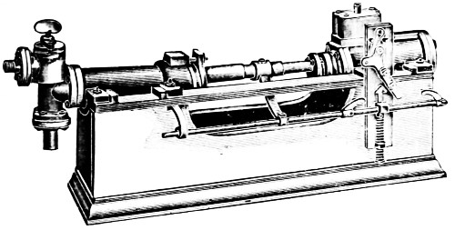
Fig. 82.
In pumps of this construction there are no weights in the moving parts other than that required to produce sufficient strength in such part for the work they are expected to perform, and, as there is consequently no opportunity to store up power in one part of the stroke, to be given out at another, it is impossible to cut off the steam in the steam cylinder during any part of its stroke. The uniform and steady action of the68 direct-acting steam-pump is dependent alone on the use of a steady uniform pressure of steam through the entire stroke of the piston against a steady, uniform resistance of water pressure in the pump; the difference between the power exerted in the steam cylinders over the resistance in the pump governing the rate of speed at which the piston or plunger of the pump will move. The length of the stroke of the steam piston, within the steam cylinders of this class of pumps, is limited and controlled alone by the admission, suppression and release of the steam used in the cylinders.
Note.—Up to the introduction of the direct-acting steam pump, all the other pumping machinery of the world then in use was the outcome of evolution. It had been developed by slow stages, in which one engineer after another aided by the experience of others and of his own, supplemented by his inventive faculties, added here and there slight improvements to which other engineers, with increased experience, were enabled to add still other improvements, so that each new engine constructed under more favorable circumstances, and with increasing expenditures, was supposed to excel all previously built; until at this time we have, as it is fair to suppose, pumping engines which combine all the wisdom of the past, and which leave little or no room for further improvements in their respective classes.
The history of the Direct-Acting Steam Pump differs from all others from the fact that it was the invention of one man, and was in the main perfected during his lifetime. It was so strikingly different from all that had preceded it, that there was nothing in the way of precedent, either in ancient or modern practice, of which the inventor could avail himself by which to aid or guide him to success.
The date of the first patent on these pumps was September 7, 1841. It was issued on a small pump used for supplying feed water to a steam boiler, and consisted of one steam cylinder connected to a force pump, and so arranged that by the use of levers, trips, springs, and other connections between the piston rod and the slide valve, the movement of the piston rod controlled the movements of the slide valve to an extent that not only regulated the length of the stroke of the piston, but reversed its motion. This pump was placed alongside of the steam boiler, and was so connected by means of pipes and levers and floats within the boiler, that when the water fell below the proper level in the boiler, it would start the pump, and stop it when the water rose too high.
Note.—At the head of a list consisting of two names only, who, on the foremost pages of “The American Society of Mechanical Engineers,” are recorded as the “Honorary Members in Perpetuity” of that large society, and standing as well at the head of that long and increasing list of members who have accomplished their work on earth, may be seen the name of Henry Rossiter Worthington, the inventor and original builder of the “direct-acting steam pump.”
Feeling how incomplete was an invention which did not provide against the intermittent action of the pump, Mr. Worthington devoted much time and study to correct this trouble, and a few years later he brought out an improved pump which, in its simplicity of parts, certainty of action, and cheapness of construction more than rivaled the original invention itself. This pump is now universally known as the “Direct-Acting Duplex Steam Pump.”
In the main, the construction of the steam ends and the water ends of the duplex pump differs but slightly from those of the single-acting pump, but the mechanism which operates the steam valves is different, and the effect on the water column was marvelously different; the principle upon which it operates is this:
Two pumps of similar construction are placed side by side, a lever attached to the piston rod of each pump connects to the slide valve of the opposite steam cylinder; thus the movement of each piston, instead of operating its own slide valve as in the single pump, operates the slide valve of the opposite cylinder. The effect of this arrangement is, that as the piston or plunger of one pump arrives near the end of its stroke, the plunger or piston of the other begins its movement, thus alternately taking up the load of the water column, producing a regular, steady, onward flow of water, without the unusual strains induced by such a column when suddenly arrested or started in motion.
While the “duplex steam pump” overcame one of the greatest objections to the former single pump, there still remained in this class of pumping machinery one other difficulty. It did not use steam expansively.
This not only debarred it from competing with other engines where a large quantity of water was required to be raised, and where the cost of fuel was an item of importance, but as well prevented the pump from taking rank among the hydraulic appliances required in supplying towns and cities.
This objection was one which seemed insurmountable, steam in them could not be used economically. Applied to the propulsion of the plunger or piston of this pump it must be of sufficient quantity, and pressure, to overcome the height of the column of water on the pump, together with its friction through the pump and its connections, at the very beginning of the stroke; and it must be maintained, both as to its volume, and its pressure up to the very last part of the stroke. Any diminution, either of volume or pressure, during any part of the stroke would simply bring the pump to a stop. This apparent inability to cut off the steam in the steam cylinder, and to complete the stroke of the pump by the aid of the steam remaining in the cylinder, and by its expansive force, had debarred this pump from coming into general use for large water works. How this, the only remaining objection to their use for such purposes, was overcome, forms an interesting chapter in the history of the “Direct-Acting Steam Pump.”
It was when this question had assumed a most formidable, importance, that the principle of using steam in compound steam engines had engaged the careful consideration of the most eminent engineers of this and other countries; its adjustment to the Duplex pumps was made, and while it was easily done, owing to their peculiar construction, its application produced a most wonderful result in their working, and their speedy introduction for water works use.
Note.—At this time the man who had invented and built the little steam pump for the canal boat, who had watched its growth and development, supplemented one device after another to help it on through the trial period of its existence, had merged it at last into the dual or duplex stage of its advancement, had added to it the compound feature, had seen it expanding in size and importance until, growing up and out of the day of small things, it had come to take its well-earned place alongside those old and massive machines whose invention and origin was lost amid the musty records of the past—it was, at this time, and of which any man might well have been proud, that his lifelong labors came to an end Dec. 18., 1880, at the Everett House, New York City.
ELEMENTARY
HYDRAULICS
There are three physical states or conditions of matter, which are the solid, liquid and gaseous, which in this connection apply to Ice, Water and Steam. A solid offers resistance both to change of shape and to change of bulk.
A Fluid offers no resistance to change of shape. Again fluids can be divided into liquids and vapors or gases. Water is the most familiar example of a liquid. A liquid can be poured out in drops while a gas or vapor flows in a stream or streams.
Gas is a term at first used as meaning the same as the name air, but is now restricted to fluids supposed to be permanently elastic, as oxygen, hydrogen, etc., in distinction from vapor such as steam which become liquid upon a reduction of temperature.
It is important to note that experiment proves that every vapor becomes a gas at a sufficiently high temperature or low pressure, while, on the other hand, every gas becomes a vapor at sufficiently low and high pressures. In present popular usage the term gas applies to any substance in the aeriform elastic condition.
Hydraulics is that branch of science or of engineering which treats of the motion of liquids, especially of water and of the laws by which it is regulated.
As a science, hydraulics includes hydrodynamics or the principles of mechanics applicable to the motion of water.
As a branch of engineering, hydraulics consists in the practical application of the mechanics of fluids, to the control74 and management of water, with reference to the wants of man, including water works, hydraulic machines, pumps, water wheels, etc.
The term hydraulics, so familiar in daily use, is formed from two Greek words meaning: 1, water; 2, a pipe; hence, it will be observed with interest how close the original meaning follows the development of the science in its practical adaptation; there is always the “pipe” or holding vessel and the “water” or its equivalent.
From the same elementary word meaning water, in the Greek language, has been formed very many other words in common use, for example hydrophobia, hydrogen, hydrant, hygrometer, etc., as well as the following:
Hydromechanics is that branch of natural philosophy which treats of the mechanics of liquid bodies, or in other words, of their laws of equilibrium and motion. Hydromechanics comprises properly those phenomena of liquids by which these bodies differ from solids or from bodies at large; hence, its foundation is laid in the properties that distinguish the liquid from other states of bodies, viz.: the presence of cohesion, with great mobility of parts, and perfect elasticity.
Hydrostatics is that branch of science which relates to the pressure and equilibrium of non-elastic fluids, as water, mercury, etc.; thus, the hydrostatic press is a machine in which great force with slow motion is action communicated to a large plunger by means of water forced into the cylinder in which it moves, by a forcing pump. Statics treats of forces that keep bodies at rest or in equilibrium, the water through which the force operates in the hydrostatic press always remaining at rest serves as a good illustration.
Pneumatics is that branch of science, which relates to air, or gases in general or their properties; also of employing (compressed) air or other gas as a motive power. The use of pneumatic pumping machinery is constantly increasing, especially of the direct pressure types; under the section of75 this work relating to Air Pumps additional data will be presented.
Hydropneumatics is defined as involving the combined action of water and air, or gas, as shown, for example, in the hydropneumatic accumulator. The word is a compound formed of the Greek words meaning water and air.
Semi-liquids. All the results stated in reference to water are further modified in those semi-liquids which have greater or less viscidity, as pitch, syrup, fixed oils, etc. Viscosity may be defined as the quality of flowing slowly, thus the viscosity of such liquids as have been named is very great as compared with that of a mobile liquid like alcohol.
Water, considered from a chemical standpoint, is a compound substance consisting of hydrogen and oxygen, in the proportion of two volumes of the former gas to one volume of the latter; or by weight it is composed of two parts of hydrogen united with sixteen parts of oxygen. It should be noted that the union of these two gases is effected by chemical action and not by mechanical mixture. Pure water is transparent, inodorous and tasteless.
Under ordinary conditions water passes the liquid form only at temperatures lying between 32° F. and 212° F.; it assumes a solid form, that of ice or snow at 32° F., and it takes the form of vapor or steam at 212° F.
There are four notable temperatures for water, namely:
| 32° F., | or | 0° C. | = the freezing point under one atmosphere. |
| 39°·1 | or | 4° | = the point of maximum density. |
| 62° | or | 16°·66 | = the standard temperature. |
| 212° | or | 100° | = the boiling point, under one atmosphere. |
The temperature 62° F. is the temperature of water used in calculating the specific gravity of bodies, with respect to the gravity or density of water as a basis, or as unity.
Weight of one cubic foot of Pure Water.
| At 32° F. | = 62·418 | pounds. | |
| At 39°·1. | = 62·425 | „ | |
| At 62° | (Standard temperature) | = 62·355 | „ |
| At 212° | = 59·640 | „ |
The weight of a cubic foot of water is, it may be added, about 1000 ounces (exactly 998·8 ounces), at the temperature of maximum density.
The weight of a cylindrical foot of water at 62° F. is 48·973 pounds.
Weight of one cubic inch of Pure Water.
| At 32° F. | = ·03612 | pound, | or | 0·5779 | ounce. | |
| At 37°·1 | = ·036125 | „ | „ | 0·5780 | „ | |
| At 62° | = ·03608 | „ | „ | 0·5773 | „ | or 252·595 grains. |
| At 212° | = ·03451 | „ | „ | 0·5522 | „ |
The weight of one cylindrical inch of pure water at 62° F. is ·02833 pounds, or 0·4533 ounce.
Volume of one pound of Pure Water.
| At 32° F. | = ·016021 | cubic foot, | or | 27·684 | cubic inches. |
| At 39°·1 | = ·016019 | „ | „ | 27·680 | „ |
| At 62° | = ·016037 | „ | „ | 27·712 | „ |
| At 212° | = ·016770 | „ | „ | 28·978 | „ |
The volume of one ounce of pure water at 62° F. is 1·732 cubic inches.
The weight of water is usually taken in round numbers, for ordinary calculations, at 62·4 lbs. per cubic foot, which is the weight at 52°·3 F.; or it is taken at 621⁄2 lbs. per cubic foot.
Salt water boils at a higher temperature than fresh water owing to its greater density, and because the boiling point of water is increased by any substance that enters into chemical combination with it. The density of water decreases as the temperature increases, since heat destroys cohesion and expands the particles, causing them to occupy greater space,77 where precision is not required; the pressure on a square foot at different ocean depths are approximate, in the following
TABLE.
| Depth in feet. | Pressure on sq. foot. | |
|---|---|---|
| 8 | 500 | lbs. |
| 16 | 1000 | „ |
| 24 | 1500 | „ |
| 32 | 2000 | „ |
| 40 | 2500 | „ |
| 48 | 3000 | „ |
| 56 | 3500 | „ |
| 64 | 4000 | „ |
| 72 | 4500 | „ |
| 80 | 5000 | „ |
| 88 | 5500 | „ |
| 96 | 6000 | „ |
| 1 mile, or 5,280 feet, | 330,000 lbs. | |
| 5 miles, | 1,650,000 „ | |
This table is based upon an allowance of 621⁄2 lbs. of water to the cubic foot, thus 8 feet × 621⁄2 = 500, etc.
Water is practically non-elastic. A pressure of 30,000 lbs. to the square inch has been applied and its contraction has been found to be less than one-twelfth. Experiment appears to show that for each atmosphere of pressure it is condensed 471⁄2 millionth of its bulk.
The mechanical properties of liquids are determined on the hypothesis that liquids are incompressible; according to known general principles this is found to be for all practical purposes true, yet liquids are more compressible than solids. If water be confined in a perfectly rigid cylindrical vessel, its compression would equal 1⁄300000 of its length for every pound per unit of area of the end pressure.
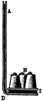
Fig. 84.
Water is nearly 100 times as compressible as steel, yet for almost all practical purposes, liquids may be considered as non-elastic bodies without involving sensible error.
The pressure upon the horizontal base of any vessel containing a fluid, is equal to the weight of a column of the fluid, found by multiplying the area of the base into the perpendicular height of the column, whatever be the shape of the vessel.
This follows, since here the distance of the center of gravity of the base from the surface of the fluid, is the same as the perpendicular height of the column. With a given base and height, therefore, the pressure is the same whether the vessel is larger or smaller above, whether its figure is regular or irregular, whether it rises to the given height in a broad open funnel, or is carried up in a slender tube.
Hence, any quantity of water, however small, may be made to balance any quantity, however great. This is called the hydrostatic paradox. The experiment is usually performed by means of a water-bellows, as represented in Fig. 84. When the pipe AD is filled with water, the pressure upon the surface of the bellows, and consequently the force with which it raises the weights laid on it, will be equal to the weight of a cylinder of water, whose base is the surface of the bellows, and height that of the column AD. Therefore, by making the tube small, and the bellows large, the power of a given quantity of water, however small, may be increased indefinitely. The pressure of the column of water in this case corresponds to the force applied by the piston in the hydrostatic press.
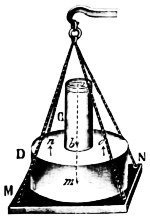
Fig. 85.
We have already seen that the pressure on the bottom of a vessel depends neither on the form of the vessel nor on the quantity of the liquid, but simply on the height of the liquid above the bottom. But the pressure thus exerted must not be confounded with the pressure which the vessel itself exerts on the body which supports it. The latter is always equal to the combined weight of the liquid and the vessel in which it is contained, while the former may be either smaller or greater than this weight, according to the form of the vessel. This fact is often termed the hydrostatic paradox, because at first sight it appears paradoxical.
CD (Fig. 85) is a vessel composed of two cylindrical parts of unequal diameters, and filled with water to a. From what has been said before, the bottom of the vessel CD supports the same pressure as if its diameter were everywhere the same as that of its lower part; and it would at first sight seem that the scale MN of the balance, in which the vessel CD is placed, ought to show the same weight as if there had been placed in it a cylindrical vessel having the same weight of water, and having the diameter of the part D. But the pressure exerted on the bottom of the vessel is not all transmitted to the scale MN; for the upward pressure upon the surface n o of the vessel is precisely equal to the weight of the extra quantity of water which a cylindrical vessel would contain, and balances an equal portion of the downward pressure on m. Consequently the pressure on the plate MN is simply equal to the weight of the vessel CD and of the water which it contains.
Pressure exerted anywhere upon a mass of liquid is transmitted undiminished in all directions, and acts with the same force on all equal surfaces, and in a direction at right angles to those surfaces.
To get a clearer idea of the truth of this principle, let us conceive a vessel of any given form in the sides of which are placed various cylindrical apertures, all of equal size, and closed by movable pistons. Let us, further, imagine this vessel to be filled with liquid and unaffected by the action of gravity; the pistons will, obviously, have no tendency to move. If now a weight of P pounds be placed upon the piston A (Fig. 86), which has a surface A, it will be pressed inwards, and the pressure will be transmitted to the internal faces of each of the pistons B, C, D, and E, which will each be forced outwards by a pressure P, their surfaces being equal to that of the first piston. Since each of the pistons undergoes a pressure, P,80 equal to that on A, let us suppose two of the pistons united so as to constitute a surface 2a; it will have to support a pressure 2P. Similarly, if the piston were equal to 3a, it would experience a pressure of 3P; and if its area were 100 or 1,000 times that of a, it would sustain a pressure of 100 or 1,000 times P. In other words, the pressure on any part of the internal walls of the vessel would be proportional to the surface.
The principle of the equality of pressure is assumed as a consequence of the constitution of fluids.
By the following experiment it can be shown that pressure is transmitted in all directions; a cylinder provided with a piston is fitted into a hollow sphere (Fig. 87). in which small cylindrical jets are placed perpendicular to the sides. The sphere and the cylinder being both filled with water, when the piston is moved the liquid spouts forth from all the orifices, and not merely from that which is opposite to the piston.
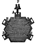
Fig. 86.
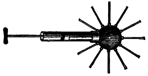
Fig. 87.
The reason why a satisfactory quantitative experimental demonstration of the principle of the equality of pressure cannot be given is that the influence of the weight of the liquid and of the friction of the pistons cannot be altogether eliminated.
Note.—The influence of the weight (or gravity) of water and its fractional resistance in practical use is so great upon all the processes of numbers and of the application of the natural laws governing the operation of fluids, as stated under the heading of Hydraulic Data, that separate pages will hereafter be found devoted to a more extended explanation of this subject of gravity and friction of water.
Yet an approximate verification may be effected by the experiment represented in Fig. 88. Two cylinders of different diameters are joined by a tube and filled with water. On the surface of the liquid are two pistons, P and p, which hermetically close the cylinders, but move without friction. Let the area of the large piston, P, be, for instance, thirty times that of the smaller one, p. That being assumed, let a weight, say of two pounds, be placed upon the small piston; this pressure will be transmitted to the water and to the large piston, and as this pressure amounts to two pounds on each portion of its surface equal to that of the small piston, the large piston must be exposed to an upward pressure thirty times as much, or of sixty pounds. If now, this weight be placed upon the large piston, both will remain in equilibrium; but if the weight is greater or less, this is no longer the case.
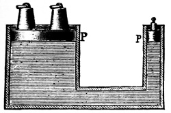
Fig. 88.
It is important to observe that in speaking of the transmission of pressure to the sides of the containing vessel, these pressures must always be supposed to be perpendicular to the sides.
Equilibrium or state of rest of superposed liquids. In order that there should be equilibrium when several heterogeneous liquids are superposed in the same vessel, each of them must satisfy the conditions necessary for a single liquid, and further there will be a stable state of rest only when the liquids are arranged in the order of their decreasing densities from the bottom upwards.
The last condition is experimentally demonstrated by means of the phial of four elements. This consists of a long narrow bottle containing mercury, water, colored red, saturated with carbonate of potash, alcohol, and petroleum. When the phial is shaken the liquids mix, but when it is allowed to82 rest they separate; the mercury sinks to the bottom, then comes the water, then the alcohol, and then the petroleum. This is the order of the decreasing densities of the bodies. The water is saturated with carbonate of potash to prevent its mixing with the alcohol.
This separation of the liquids is due to the same cause as that which enables solid bodies to float on the surface of a liquid of greater density than their own. It is also on this account that fresh water, at the mouths of rivers, floats for a long time on the denser salt water of the sea; and it is for the same reason that cream, which is lighter than milk, rises to the surface.
The pressure upon any particle of a fluid of uniform density is proportioned to its depth below the surface.
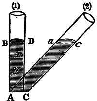
Fig. 89.
Example 1. Let the column of fluid ABCD Fig. (1) be perpendicular to the horizon. Take any points, x and y, at different depths, and conceive the column to be divided into a number of equal spaces by horizontal planes. Then, since the density of the fluid is uniform throughout, the pressure upon x and y, respectively, must be in proportion to the number of equal spaces above them, and consequently in proportion to their depths.
Example 2. Let the column be of the same perpendicular height as before, but inclined as is Fig. (2); then its quantity, and of course its weight, is increased in the same ratio as its length exceeds its height; but since the column is partly supported by the plane, like any other heavy body, the force of gravity acting upon it is diminished on this account in the same ratio as its length exceeds its height; therefore as much as the pressure on the base would be augmented by the increased length of the column, just so much it is lessened by the action83 of the inclined plane; and the pressure on any part of Cc will be, as before, proportioned to its perpendicular depth; and the pressure of the inclined column ACac will be the same as that of the perpendicular column ABCD.
Fluids rise to the same level in the opposite arms of a recurved tube.
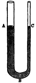
Fig. 90.
Let ABC, (Fig. 90) be a recurved tube: if water be poured into one arm of the tube, it will rise to the same height in the other arm. For, the pressure acting upon the lowest part at B, in opposite directions, is proportioned to its depth below the surface of the fluid. Therefore, these depths must be equal, that is, the height of the two columns must be equal, in order that the fluid at B may be at rest; and unless this part is at rest, the other parts of the column cannot be at rest. Moreover, since the equilibrium depends on nothing else than the heights of the respective columns, therefore, the opposite columns may differ to any degree in quantity, shape, or inclination to the horizon. Thus, if vessels and tubes very diverse in shape and capacity, as in Fig. p. 84 be connected with a reservoir, and water be poured into any one of them, it will rise to the same level in them all.
The reason of this fact will be further understood from the application of the principle of equal momenta, for it will be seen that the velocity of the columns, when in motion, will be as much greater in the smaller than in the larger columns, as the quantity of matter is less; and hence the opposite momenta will be constantly equal.
Hence, water conveyed in aqueducts or running in natural channels, will rise just as high as its source. Between the place where the water of an aqueduct is delivered and the spring, the ground may rise into hills and descend into valleys, and the pipes which convey the water may follow all the undulations84 of the country, and the water will run freely, provided no pipe is laid higher than the spring.
Pressure of water due to its weight. The pressure on any particle of water is proportioned to its depth below the surface. The pressure of still water in pounds per square inch against the sides of any pipe, channel, or vessel of any shape whatever, is due solely to the “head” or height of the level surface of the water above the point at which the pressure is considered and is equal to ·43302 lbs. per square foot, every foot of head or 62·355 lbs. per square foot for every foot of head at 62° F.
The pressure per square inch is equal in all directions downwards, upwards or sideways and is independent of the shape or size of the containing vessel; for example, the pressure on a plug forced inward on a square inch of the surface of water is suddenly communicated to every square inch of the vessel’s surface, however great and to every inch of the surface of any body immersed in it.
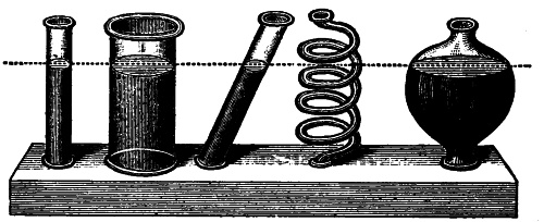
It is this principle which operates with such astonishing effect in hydrostatic presses, of which familiar examples are found in the hydraulic pumps, by the use of which boilers are tested. By the mere weight of a man’s body when leaning on the extremity of a lever, a pressure may be produced of upwards of 20 tons; it is the simplest and most easily applicable of all contrivances for increasing human power, and it is only limited by want of materials of sufficient strength to utilize it.
Gravity or Gravitation is that species of attraction, or force by which, all bodies or particles of matter in the universe tend towards each other; it is also called attraction of gravitation and universal gravity; gravity, in a more limited, sense is the tendency of a mass of matter toward a center of attraction especially the tendency of a body toward the center of the earth.
This influence is conveyed from one body to another without any perceptible interval of time. If the action of gravitation is not instantaneous, it comes very nearly to it by moving more than fifty millions of times faster than light.
Gravity extends to all known bodies in the universe, from the smallest to the greatest; by it all bodies are drawn toward the center of the earth, not because there is any peculiar property or power in the center, but because the earth being a sphere, the aggregate effect of the attractions exerted by all its parts upon any body exterior to it, is such as to influence that body toward the center.
This property manifests itself, not only in the motion of falling bodies, but in the pressure exerted by one portion of matter upon another which sustains it; and bodies descending freely under its influence, whatever be their figure, dimensions or texture, all are equally accelerated in right lines perpendicular to the plane of the horizon. The apparent inequality of the action of gravity upon different species of matter near the surface of the earth arises entirely from the resistance which they meet with in their passage through the air. When this resistance is removed (as in the exhausted receiver of an air-pump), the inequality likewise disappears.
The law of gravity, discovered by Sir Isaac Newton, toward the end of the seventeenth century, may be stated as follows:
Every particle of matter in the universe attracts every other particle with a force whose direction is that of a line joining the two particles considered, and whose magnitude is directly as the product of the masses and inversely as the square of the distance between them.
As a groundwork for this great generalization, Newton employed the results of two of the greatest astronomers who preceded him, Copernicus and Kepler. About 1500 A. D. Copernicus perceived and announced that the apparent rotation of the heavens about the earth could be explained by supposing the earth to rotate on an axis once in twenty-four hours. Previous to this time the earth had been regarded as the center of the universe. He also showed that nearly all the motions of the planets, including the earth, could be explained on the assumption that these revolved in circular orbits about the sun, whose position in the circle, however, was slightly eccentric.
Thus, building somewhat upon the labors of the two parties named, Newton was the first to prove the law of the forces which would account for the motions of all the bodies in the solar system.
Since a body falls to the ground in consequence of the earth’s attraction on each of its molecules, it follows that, all other things being equal, all bodies, great and small, light and heavy, ought to fall with equal rapidity, and a lump of sand without cohesion should during its fall retain its original form as perfectly as if it were compact stone. The fact that a stone falls more rapidly than a feather is due solely to the unequal resistances opposed by the air to the descent of these bodies; in a vacuum all bodies fall with equal velocity.
In a vacuum, however, liquids fall like solids without separation of their molecules. The water-hammer, a model used in scientific schools, illustrates this: the instrument consists of a87 thick glass tube about a foot long, half filled with water, the air having been expelled by ebullition previous to closing one extremity with the blow-pipe. When such a tube is suddenly inverted, the water falls in one undivided mass against the other extremity of the tube, and produces a sharp metallic sound, resembling that which accompanies the shock of two solid bodies coming suddenly together.
Note.—The resistance opposed by the air to falling bodies is especially remarkable in the case of liquids. The Staubbach in Switzerland is a good illustration; an immense mass of water is seen falling over a high precipice, but before reaching the bottom it is shattered by the air into the finest mist. See Parker’s Philosophy, pp. 69-70.
It has been ascertained, by experiment, that from rest, a body falling freely will descend 161⁄12 feet in the first second of time, and will then have acquired a velocity, which being continued uniformly, will carry it through 321⁄6 feet in the next second. Therefore if the first series of numbers be expressed in seconds, 1″, 2″, 3″, &c., the velocities in feet will be 321⁄6, 641⁄3, 961⁄2, &c.; the spaces passed through as 161⁄12, 641⁄3, 1443⁄4, &c., and the spaces for each second, 161⁄2, 481⁄4, 805⁄12, &c.
TABLE.
Showing the Relation of Time, Space and Velocity.
| Time in seconds of the body’s fall. |
Velocity acquired at the end of that time. |
Squares. | Space fallen through in that time. |
Space. | Whole Space fallen through in the last second of the fall. |
|---|---|---|---|---|---|
| 1 | 32·16 | 1 | 16·08 | 1 | 16·08 |
| 2 | 64·33 | 4 | 64·33 | 3 | 48·25 |
| 3 | 96·5 | 9 | 144·75 | 5 | 80·41 |
| 4 | 128·66 | 16 | 257·33 | 7 | 112·58 |
| 5 | 160·83 | 25 | 402·08 | 9 | 144·75 |
| 6 | 193· | 36 | 579· | 11 | 176·91 |
| 7 | 225·17 | 49 | 788·08 | 13 | 209·08 |
| 8 | 257·33 | 64 | 1029·33 | 15 | 241·25 |
| 9 | 289·5 | 81 | 1302·75 | 17 | 273·42 |
| 10 | 321·66 | 100 | 1946·08 | 19 | 305·58 |
Experience has shown that the measurement of all physical quantities may be expressed in terms of three fundamental magnitudes. Those commonly chosen for this purpose are time, length and mass or quantity of matter. It may be assumed that our ideas of time and space are sufficiently exact for all practical purposes. The subject of matter, however, requires88 more particular consideration. Of the three magnitudes named, matter alone is directly cognizable by the senses, and invested with a variety of interesting properties.
For present purposes matter may be defined as anything that can be weighed, and the quantity of matter as proportional to its weight; i.e., its attraction towards the earth. The weight of a body is the force it exerts in consequence of its gravity, and is measured by its mechanical effects, such as bending a spring. We weigh a body by ascertaining the force required to hold it up, or to keep it from descending. Hence, weights are nothing more than measures of the force of gravity in different bodies.
Again, Gravitation, the most feeble of physical actions between small masses, is almost imperceptible; yet it is an energy abundant in proportion to the quantity of matter in the universe, and fully competent, by its gradual condensing agency, to account for the origination of planetary systems and their movements. It is not strange, therefore, that by some physicists this energy is supposed to be the beginning of that of which all other forms of force are residues or metamorphoses. Gravity is the name especially given to its terrestrial manifestations. A particle or body without a sphere or spheroid, solid or hollow, is attracted to the center of the mass of such body; within a hollow sphere, it will remain at rest at any point. At different depths below the earth’s surface, a body will be attracted with a force diminishing as the distance from its center decreases. The slight variation in the gravitating force of the same falling body at different heights is in practice usually disregarded. The weight of a body, as the measure of its gravitating tendency, must vary both with mass and with the force acting on it; hence, from the form of the earth, the same body at the sea level will weigh less and less as it is removed from either pole toward the equator. An elevation above the sea level gives a like result. A stone falls through a less distance in a given time on a mountain than in the valley below, less at the equator than at either pole. The loss of weight in these cases cannot be tested by lever scales, in which this loss is equal on both sides; but it may be by the spring balance, in which bodies are weighed by the pull they exert against the elasticity of a coiled wire. The effect of centrifugal force, increasing from the pole to the equator, co-operates with increasing removal from the earth’s center to lessen weight; the result of the combined action of these two causes is, that a body weighing 195 lbs. at either pole will weigh but 194 over the equator. The line of a falling body, called also the line of direction, is interesting as being that direction in space at any point of the earth’s surface with reference to which all other directions are named, and by which they are to be determined.
A few points remain to be named. The flow of water is the result of the force of gravity; the importance of this fact and its wide influence cannot be over stated; the gently falling dew, the mighty currents in the unfathomable depths of the ocean, as well as the rivulet merrily falling over the rocks to a lower level are all subject to the laws of terrestrial gravity.
The upper surface of a liquid in a vessel exposed to the atmosphere is called the free surface and is pressed downwards by the air under about 15 lbs. pressure per square inch. The free surface of a small body of a perfect liquid, at rest, is horizontal and perpendicular to the action of gravity although in large bodies of liquid, as lakes and ponds, the free surface is spherical, assuming the curvature of the earth’s surface.
1.—To find the Velocity a falling Body will acquire in any given time.
Multiply the time, in seconds, by 321⁄6, and it will give the velocity acquired in feet, per second.
Example. Required the velocity in seven seconds.
321⁄6 × 7 = 2251⁄6 feet. Ans.
2.—To find the Velocity a Body will acquire by falling from any given height.
Multiply the space, in feet, by 641⁄3, the square root of the product will be the velocity acquired, in feet, per second.
Example. Required the velocity which a ball has acquired in descending through 201 feet.
641⁄3 × 201 = 12931; √12931 = 113·7 feet. Ans.
3.—To find the Space through which a Body will fall in any given time.
Multiply the square of the time, in seconds, by 161⁄12, and it will give the space in feet.
Example. Required the space fallen through in seven seconds.
161⁄12 × 7² = 7881⁄12 feet. Ans.
4.—To find the Time which a Body will occupy in falling through a given space.
Divide the square root of the space fallen through by 4, and the quotient will be the time in which it was falling.
Example. Required the time a body will take in falling through 402.08 feet of space.
√402·08 = 20·049, and 20·049 ÷ 4 = 5·012. Ans.
5.—The Velocity being given, to find the Space fallen through.
Divide the velocity by 8, and the square of the quotient will be the distance fallen through to acquire that velocity.
Example. If the velocity of a cannon ball be 660 feet per second, from what height must a body fall to acquire the same velocity?
660 ÷ 8 = 82·5² = 6806·25 feet. Ans.
6.—To find the Time, the Velocity per second being given.
Divide the given velocity by 8, and one-fourth part of the quotient will be the answer.
Example. How long must a bullet be falling, to acquire a velocity of 480 feet per second?
480 ÷ 8 = 60 ÷ 4 = 15 seconds. Ans.
Specific Gravity is the proportion of the weight of a body to that of an equal volume of some other substance adopted as a standard of reference. For solids and liquids the standard is pure water, at a temperature of 60° F., the barometer being at 30 inches.
Aëriform bodies are referred to the air as their standard. A cubic foot of water weighs 1,000 ounces; if the same bulk of another substance, as for instance cast iron, is found to weigh 7,200 ounces, its proportional weight or specific gravity is 7·2. It is convenient to know the figures representing this proportion for every substance in common use, that the weight of any given bulk may be readily determined. For all substances the specific gravity is used in various tests for the purpose of distinguishing bodies from each other, the same substance being found, under the equal conditions of temperature, &c., to retain its peculiar proportional weight or density.
Hence tables of specific gravities of bodies are prepared for reference, and in every scientific description of substances the specific gravity is mentioned. In practical use, the weight of a cubic foot is obtained from the figures representing the density by moving the decimal point three figures to the right, which obviously from the example above, gives the ounces, and these divided by 16 gives the pounds avoirdupois, in the cubic foot.
Different methods may be employed to ascertain the specific gravity of solids. That by measuring the bulk and weighing, is rarely practicable; as a body immersed in water must displace its own bulk of the fluid, the specific gravity may be ascertained by introducing a body, after weighing it, into a suitable vessel exactly filled with water, and then weighing the fluid which overflows. The proportional weight is thus at once obtained. Wax will cause its own weight of water to overflow; its specific gravity is then 1. Platinum, according to the condition it is in, will cause only from 1⁄21 to 1⁄21·5 of its92 weight of water to overflow, showing its specific gravity to be from 21 to 21·5. But a more exact method than this is commonly employed. The difference of weight of the same substance weighed in air and when immersed in water, is exactly that of the water it displaces, and may consequently be taken as the weight of its own bulk of water. See Fig. 93 and rule and example on page 95.
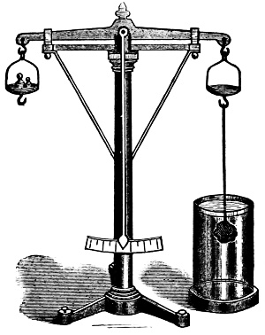
Fig. 91.
The specific gravity is then obtained by weighing the body first in air, and then, suspended by a fibre of silk or a hair, in water, and dividing the weight in air by the difference. It is hardly necessary to say that the substance examined must be free from mixture of foreign matters, and especially from cavities that may contain air.
Note.—Hydrometers are instruments for determining the relative density of fluids; distilled water is usually referred to as the standard of comparison. They consist usually of a bulb or float weighted at bottom so as to float upright, and having an elongated stem graduated to indicate the density of the liquid by the depth to which they sink therein.
Every body immersed in a liquid is submitted to the action of two forces: gravity which tends to lower it, and the buoyancy of the liquid which tends to raise it with a force equal to the weight of the liquid displaced. The weight of the body is either totally or partially overcome by its buoyancy, by which it is concluded that a body immersed in a liquid loses a part of its weight equal to the weight of the displaced liquid.
This principle, which is the basis of the theory of immersed and floating bodies, is called the principle of Archimedes, after the discoverer. It may be shown experimentally by means of the hydrostatic balance (Fig. 92). This is an ordinary balance, each pan of which is provided with a hook; the beam being raised, a hollow brass cylinder is suspended from one of the pans, and below this a solid cylinder whose volume is exactly equal to the capacity of the first cylinder; lastly, an equipoise is placed in the other pan. If now the hollow cylinder be filled with water, the equilibrium is disturbed; but if at the same time the beam is lowered so that the solid cylinder becomes immersed in a vessel of water placed beneath it, the equilibrium will be restored. By being immersed in water the solid cylinder loses a portion of its weight equal to that of the water in the hollow cylinder. Now, as the capacity of the hollow cylinder is exactly equal to the volume of the solid cylinder the principle which has been before laid down is proved.

Fig. 92.
Minerals, if suspected of containing spaces, should be coarsely pulverized, and then the second method may be conveniently applied to determine their density—thus prepared, a higher result will be obtained, and even metals when pulverized were found to give a greater specific gravity than when this is determined from samples in their ordinary state. Very fine powders may also be examined by the method in use for ascertaining the specific gravity of fluids, viz.: by comparing the weight of a measured quantity with that of the same quantity of water.
A glass vessel called a specific gravity bottle is commonly employed, which is furnished with a slender neck, upon which is a mark indicating the height reached by 1,000 grains of water. The substance to be examined is introduced till it reaches the same mark, and, the weight of the bottle being known, only one weighing is required to obtain the result.
The specific gravity of fluids is also taken by the instrument called a hydrometer or alcometer. Such instruments are much used for ascertaining the specific gravity of spirituous and other liquors, as an indication of their strength. If the solid body to be tested is lighter than water, it must be attached to some heavy substance to cause it to sink. Its specific gravity is then calculated by dividing its weight in the air by the sum of the weights of the attached body both in air and in water, first subtracting from this sum the weight of the two bodies together in the water.
Bodies soluble in water may be weighed in some other fluid, as alcohol, ether, olive oil, &c., and their proportional weight to that of this fluid being thus ascertained, their density compared with that of water is readily calculated or they may be enveloped in wax or other suitable substance to protect them, and then treated by the method just given for substances lighter than water. Gaseous bodies are weighed in a thin glass flask or other vessel made for the purpose, and provided with a stop-cock. The vessel is exhausted of air before the introduction of the gas.
Rule for finding the Specific Gravity of a Solid Body.
Weigh the solid in air and then in pure water.
The difference is the weight of water displaced, whose specific gravity is 1.000.
Then, as the difference of weight is to 1·000, so is the weight in air to the specific gravity; or divide the weight of the body in air by the difference between the weights in air and in water.
Example.
A lump of glass is found to weigh in air 577 grains; it is then suspended by a horse hair from the bottom of the scale pan, and immersed in a vessel of pure water, when it is found to weigh 399.4 grains. What is its specific gravity?
577.0Then, as 177.6 : 1 :: 577.0 : sp. gravity.
399.4 1
————
177·6 the difference177·6)577·0(3·248, Ans.
532·8
——–
4420
3552
——–
8680
7104
——–
15760
14208
——–
1552
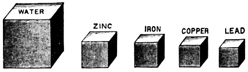
Fig. 93.
Note.—The above figures are introduced to show more vividly the comparison between bulk and weight, the size of the different substances, of course, being merely approximate. A study of the Table of Specific Gravities to be found in the next page is worthy of the time and attention.
| Metals. | |||
|---|---|---|---|
| Iron, | (cast) | 7·207 | |
| „ | (wrought) | 7·688 | |
| Steel | (soft) | 7·780 | |
| „ | (tempered) | 7·840 | |
| Lead | (cast) | 11·400 | |
| „ | (sheet) | 11·407 | |
| Brass | (cast) | 8·384 | |
| „ | (wire drawn) | 8·544 | |
| Copper | (sheet) | 8·767 | |
| „ | (cast) | 8·607 | |
| Gold | (cast) | 19·238 | |
| „ | (hammered) | 19·361 | |
| Gold | (22 carats) | 17·481 | |
| „ | (20 „ ) | 15·709 | |
| Silver | (pure, cast) | 10·474 | |
| „ | (hammered) | 10·511 | |
| Mercury | (60°) | 13·580 | |
| Pewter | 7·248 | ||
| Tin | 7·293 | ||
| Zinc | (cast) | 7·215 | |
| Platinum | 21·500 | ||
| Antimony | 6·712 | ||
| Arsenic | 5·763 | ||
| Bronze | (gun metal) | 8·700 | |
| Stones and Earth. | |||
| Coal | (Bituminous) | 1·256 | |
| „ | (Anthracite) | { | 1·436 |
| 1·640 | |||
| Charcoal | ·441 | ||
| Brick | 1·900 | ||
| Clay | 1·930 | ||
| Common | Soil | 1·984 | |
| Emery | 4·000 | ||
| Glass | (plalte) | 3·248 | |
| Ivory | 1·822 | ||
| Grindstone | 2·143 | ||
| Diamond | 3·521 | ||
| Gypsum | 2·168 | ||
| Lime | 2·720 | ||
| Granite | 2·625 | ||
| Marble | 2·708 | ||
| Mica | 2·800 | ||
| Millstone | 2·484 | ||
| Nitre | 1·900 | ||
| Porcelain | 2·385 | ||
| Phosphorus | 1·770 | ||
| Pumice Stone | ·915 | ||
| Salt | 2·130 | ||
| Sand | 1·800 | ||
| Slate | 2·672 | ||
| Sulphur | 2·033 | ||
| Woods. | |||
| Ash | ·845 | ||
| Beech | ·852 | ||
| Birch | ·720 | ||
| Oak | 1·120 | ||
| Pine | (yellow) | ·660 | |
| „ | (white) | ·554 | |
| Cherry | ·715 | ||
| Cork | ·240 | ||
| Elm | ·671 | ||
| Poplar | ·383 | ||
| Walnut | ·671 | ||
| Willow | ·585 | ||
| Liquids. | |||
| Acid | Sulphuric | 1·851 | |
| „ | Muriatic | 1·200 | |
| Spirits | of Wine | ·917 | |
| Alcohol | ·790 | ||
| Oil | (turpentine) | ·870 | |
| „ | (olive) | ·915 | |
| Oil | (linseed) | ·932 | |
| „ | (castor) | ·961 | |
| Pure | water | 1·000 | |
| Vinegar | 1·080 | ||
| Milk | 1·032 | ||
| Sea water | 1·029 | ||
To Find the Weight of a Cubic Foot of Anything Contained in these Tables.
Rule. Multiply 62·5 lbs. (the weight of a cubic foot of pure water) by the specific gravity of the given body.
Example. What is the weight of a cubic foot of sea water?
62·5 lbs.
1·029 sp. gravity.
——–
5625
1250
625
———–
Answer, 64·3125 lbs. is the actual weight: but 64
lbs. is taken in practice as the weight of a cubic foot of sea water.
Example. How many cubic feet of sea water will weigh a ton?
Divide 2240 lbs. (1 ton) by 64 lbs.
{ _8)2240
64 { ——
{ 8) 280
——
Ans. 35
Example. What is the weight of a cubic foot of wrought iron?
62·5 lbs.
7·69 sp. gravity.
——–
5625
3750
4375
———-
Answer, 480·625 lbs.
480 lbs. in practice is the weight of 1 cubic foot of wrought iron.
Note.—35 cubic feet of sea water is accounted to be a ton, as in sea water ballast for steamers, and in calculating displacement of ships.
Example. What is the average weight of a cubic foot of Bituminous coal?
1·256 sp. gravity.
62·5 lbs.
——–
6280
2512
7536
———–
Answer, 78·5000 lbs.
This 78·5 lbs. is the weight of a cubic foot in a solid block, but loose, as used for fuel, a cubic foot weighs about 49.7 lbs. which is the average of 13 kinds.
Example. What is the weight of a solid cast cylinder of copper, 4 inches diameter and 6 inches high?
8·607 sp. gravity.
62·5 lbs.
——-
43035
17214
51642
————
537·9375 lbs. per cub. ft.
————
Say 538 lbs.
·7854
16 diam. squared.
——–
47124
7854
——–
12·5664 area of base.
6 high
———–
75·3984 cu. in. in volume
———–
Say 75·4 cubic inches.
cub. in.cub. in.lbs.
Then, as 1728 : 75·4 :: 538 : Answer.
538
——
6032
2262
3770
————
{ 12)40565·2
{ ————–
1728 { 12)3380·433
{————–
{ 12) 281·702
———–
23·475 lbs.
Answer, 231⁄2 lbs. nearly.
Frictional Resistance.—The resistance with which bodies oppose the movement of one surface on another is termed friction. It depends on the nature, and the roughness of the surfaces in contact; at the commencement of the sliding, it is greater than when the motion is continued.
Friction is in effect an equivalent force exerted in a direction opposite to that in which the sliding occurs. Its whole amount is the product of two factors: the first of these, which sums up the effect of the nature and condition of the surfaces, is called the coefficient of friction; the second, which is the sum of all pressures, as weight strain, and the adhesion due to magnetism (when employed), which act to urge the two bodies together, i.e., perpendicularly to the surface of contact, is called the normal pressure. But this law holds only where, with dry surfaces, the pressure is not enough to indent or abrade either; or, with wet surfaces, not enough to force out the unguent. In either of these cases, the friction increases more rapidly than the ratio of normal pressure.
No surfaces can be made absolutely hard or smooth; when one surface is made to slide over another, the slight roughness of the one interlock with those of the other, so that the surfaces must be separated or the points abraded to allow of the motion; but if one surface roll upon another, the prominent points are successively raised, without the need of complete lifting of the body or wearing off those points. Hence, there are two kinds of friction, the sliding and the rolling. The former of these in amount greatly exceeds the latter; it is a leading element in the stability of structures and fabrics of all lands, and the most important resistance and source of waste in all machinery, and is therefore a chief object of regard in the arts of construction and the science of engineering.
Sliding friction increases with the roughness of the surfaces in contact; hence, it is in practice diminished as these surfaces become worn, also by polishing, and by the use of lubricants, which smooth the rubbing surfaces by filling their depressions. It increases, almost universally, in exact proportion with the entire pressure, owing to weight or other causes, with which the two surfaces are held together; but at very great pressures, somewhat less rapidly. Consequently, in all ordinary cases, so long as the entire weight or pressure remains the same, the friction is, in general, entirely independent of the extent of the surfaces in contact.
The exceptions are, some increase when the rubbing surfaces under the same total pressure are very greatly extended, or when either surface is comparatively soft; and considerable lessening of friction when the bodies are very small, as in the runners of skates upon ice. For ordinary rates of motion, the total friction within a given space or distance is in like manner entirely independent of the velocity with which one surface is caused to move over the other; but in very slow motions it is increased, and in very rapid motions perceptibly diminished.
Friction is also increased in proportion to the tendency of the surfaces to adhere; hence, it is usually found greater between bodies of the same kind (steel on steel proving almost an exception) than between those of different kinds; it is usually greater when the surfaces have been long in contact, and at the beginning of motion, and always so, unless corrected by lubricants, between metallic surfaces so highly polished that air may be excluded from between them.
The frictional resistance retarding the flow of water is subject to three laws:
1. It is proportioned to the amount of surface in contact.
2. It is independent of the pressure.
3. It is proportional to the square of the velocity.
It should be remembered that the laws relating to friction, between solid bodies operate quite differently from what they do when applied to liquids; hence, the large mass of data relating to the general subject of friction must be disregarded in the consideration of hydromechanics and allied subjects.
For all fluids, whether liquids or gaseous, the resistance is independent of the pressure between the masses in contact. This is in accordance with the second law as stated.
The friction for all fluids (liquid or gaseous) is in proportion to the area of the rubbing surface; this follows from the first law and as the sectional area of a circle is the least, pipes from their circular form present the smallest resistance to the flow of water.
From the third law, in practice we desire the making of pipes as large as possible; experiment having proved that low speeds are preferable to moderate and still more so, as compared to high speeds in proportioning the piping of hydraulic apparatus.
Friction of fluids is also independent of the nature of the solid against which the stream may flow, but dependent to some extent upon their degree of roughness.
Friction for all fluids is also proportional to the density of the fluid, and related in some way to its adhesiveness.
Water flowing through a pipe tends to drag the pipe along with it on account of friction; in all actual fluids there is viscosity or internal friction, but if the relative motion is only slow enough it makes little difference whether the fluid is viscous or not.
Ordinary fluids will change in shape under the action of a force, however small, if enough time is given for the change to take place, and the rate of change of shape is a measure of its viscosity.
The laws of friction, both for solids and liquids, have been established from experiments endlessly varied. In investigating these principles we first proceed on the supposition that the forces in question act without any impediments. Great simplicity is attained by first bringing the subject to this ideal102 standard of perfection, and afterwards making suitable allowances for all these causes which operate in any given case to prevent the perfect application of the law.
Several tables and other data relating to the friction of water will be found in the other sections of this work, reference to which is made in the Index.
The term viscosity has been described in the Glossary at the beginning of this work; a perfect fluid is incapable of resisting—except by its weight or inertia—a change of shape. Such a substance does not actually exist for all fluids have viscosity or internal friction.
This is defined as a resistance to a change of shape depending on the rate at which the change is effected, but, as the fluids which engineers have to deal with are water and vapors and gases, it simplifies nearly all the calculations to assume that they have no internal viscosity or friction.
A slow continuous change of the shape of solids or semi-solids under the action of gravity, or external force, is also by the extension of the term called viscosity, as the viscosity of ice, as observed in the slow movement of those rivers of ice, the glaciers.
The viscosity of liquids arises from the mutual attractions of the molecules and is diminished by the effect of the wandering molecules (C. D.). The viscosity of gases increases while that of liquids diminishes as the temperature is raised.
The viscosity of fluids presents a certain analogy with the malleability of solids.
Vis Viva is equivalent to active or living force; temperature is the Vis Viva of the smallest particles of a body; in bodies of the same temperature the atoms have the same vis viva, the smaller mass of the lighter atoms being compensated by their greater velocity.
This term, which is often met with in scientific treatises, was invented by Leibnitz. It is well known that water in rapid circulation will absorb more heat than when stagnant or moving slowly; this is caused by Vis Viva of the atoms.
Capillary attraction is the attraction which causes the ascent of fluids in small tubes. This word is derived from the Latin capillus—a hair.
The tubes must be less than one-tenth of an inch in diameter in order to produce the most satisfactory results, and tubes whose bores are no larger than a hair present the phenomenon the most strikingly. But though the rise of water above its natural level, is most manifest in small tubes, it appears, in a degree, in vessels of all sizes and shapes, by a ring of water formed around the sides with a concavity upward.
The following are the leading facts respecting capillary attraction.
(1.) When small tubes, open at both ends, are immersed perpendicularly in any liquid, the liquid rises in them, to a height which is inversely as the diameter of the bore. Though tubes of glass are usually employed in experiments on this subject, yet tubes made of any other material exhibit the same property. Nor does the thickness of the solid part of the tube, or its quantity of matter, make the least difference, the effect depending solely on the attraction of the surface, and consequently extending only to a very small distance.
(2.) Different fluids are raised to unequal heights by the same tube. Thus, according to experiment, a tube which will raise water 23 inches will raise alcohol only 9 inches.
(3.) A tube 1⁄100 of an inch in diameter raises water 5.3 inches; and since the height is reciprocally as the diameter, the product of the diameter into the height is a constant quantity, namely, the .053th part of an inch square.
(4.) Fluids rise in a similar manner between plates of glass, metal, &c., placed perpendicularly in the fluids, and near to one another. If the plates are parallel, the height to which a fluid will rise, is inversely as the distance between the plates; and the whole ascent is just half that which takes place in a tube of the same diameter. If the plates be placed edge to edge, so as to form an angle, and they be immersed in water, with the104 line of their intersection vertical, the water will ascend between them in a curve having its vertex at the angle of intersection. This curve is found to have the properties and form of the hyperbola.
In the adjustment of the stems of barometers and the thermometer an allowance is made to compensate for the influence of capillary attraction.
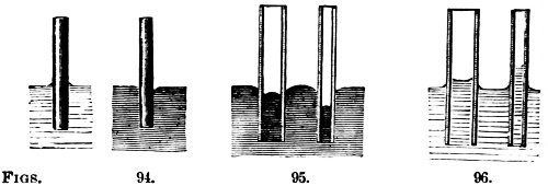
Figs. 94-96.
Such are the leading facts ascertained respecting capillary attraction. Various explanations of them have been attempted but that of La Place is most generally received. According to this high authority, the action of the sides of the tube draws up the film of fluid nearest to it, and that film draws along with it the film immediately below it, and so each film drags along with it the next below, until the weight of the volume of fluid raised exactly balances all the forces which act upon it. The fact that the elevation of the water between the parallel plates is exactly half that in a tube of the same diameter, clearly indicates that the force resides in the surrounding body; and the additional fact that the thickness or quantity of that body makes no difference, proves that the force resides in the surface, and that the action extends only to a very small distance.
Note.—Several familiar examples of capillary attraction may be added. A piece of sponge, or a lump of sugar, touching water at its lowest corner, soon becomes moistened throughout. The wick of a lamp lifts the oil to supply the flame, to the height of several inches. A capillary glass tube, bent in the form of a syphon, and having its shorter end inserted in a vessel of water, will fill itself and deliver over the water in drops. A lock of thread or of candle-wick, inserted in a vessel of water in a similar manner, with one end hanging over the vessel, will exhibit the same result. An immense weight or mass may be raised through a small space, by first stretching a dry rope between it and a support, and then wetting the rope.
The several figures above need no explanation to the attentive reader.
Under this head three general cases are to be considered: 1, that of liquids issuing from orifices; 2, their flow through tubes, or in streams; and, 3, the effects of the momentum and impact of liquids. The principles governing the action of the two last will be introduced, 2, under that portion of the work relating to “piping,” and, 3, under the sections pertaining to the jet pump. Throughout the different portions of the book will the three cases be still further elucidated.
Now, as to the laws governing the escape of liquids under pressure through an opening, it may be understood that when the liquid escapes from a vessel, owing to the excess of the internal pressure, the volume which escapes depends on the section of the orifice and the velocity with which the liquid molecules move at the moment of their escape from it.
This velocity depends upon the density of the liquid, the excess of pressure at the opening, and the friction of the liquid, both at the opening and against the walls. When the aperture is made in a very thin wall of a large vessel, so as to remove, as much as possible, the causes tending to modify the motion of the escaping fluid, the laws of the escape are comprised in the following theorem, discovered by Torricelli, in 1643, as a consequence of the law of the fall of bodies discovered by Galileo: “Liquid molecules, flowing from an orifice, have the same velocity, as if they fell freely in vacuo from a height equal to the vertical distance from the surface to the center of the orifice.”
Deductions from the above:—1, the velocity depends on the depth of the orifice from the surface, and is independent of the density of the liquid. Water and mercury in vacuo would fall106 from the same height in the same time; and so escaping from an orifice at the same depth, below the surface, would pass out with equal velocity; but mercury, being 13·5 times as heavy as water, the pressure exerted at the aperture of a vessel filled with mercury, will be 13·5 times as great as the pressure exerted at the aperture of a vessel filled with water; 2, the velocity of liquids is as the square roots of the depths of the orifices below the surfaces of the liquids.
Note.—Torricelli discovered, in the early part of the 17th century, the remarkable fact that a fluid issues from a small orifice with the same velocity (friction and atmospheric resistance excluded) which it would have acquired in falling through the depth from its surface. This was one of a long series of discoveries leading toward the now almost exact science of hydro-mechanics.
Thus stating, the velocity of a liquid escaping from an orifice one foot below the surface to be one; from a similar orifice four feet below the surface, it will be two, and at nine feet three, at sixteen feet four, and so on.
From comparative experiments made by a great number of observers, it is learned that the actual flow is only about two-thirds of the theoretical flow. See note.
The form and constitution of liquid veins have been studied and found to be:
1.—That the fluid issuing vertically from an orifice made in a plane and thin horizontal wall, is always composed of two distinct parts, Fig. 97, the portion nearest the orifice is calm and transparent, like a rod of glass, gradually decreasing in diameter. The lower part, on the contrary, is always agitated, and takes an irregular form, in which are regularly distributed elongated swellings, called ventres, whose maximum diameter is greater than that of the orifice.
Note.—Theoretical and actual flow.—The actual flow from an orifice, is the volume of liquid which escapes from it in a given time. The theoretical flow, is a volume equal to that of a cylinder which has for its base the orifice, and for its height the velocity, furnished by the discovery of Torricelli. That is, the theoretical flow is the product of the area of the orifice multiplied by the theoretical velocity. It is observed that the vein escaping from an orifice, contracts quite rapidly, so that its diameter is soon only about two-thirds of the diameter of the orifice. If there was no contraction of the vein after leaving the orifice, and its velocity was the theoretical velocity, the actual flow would be the same as that indicated by theory. But its section is much less than at the orifice, and its velocity is not so great as the theoretical velocity, so that the actual flow is much less than the theoretical flow; and in order to reduce this to the first, it is necessary to multiply it by a fraction.
2.—In the lower part of the vein, the liquid is not continuous; for if we employ an opaque liquid, as mercury, we can see through the vein, Fig. 98. The apparent continuity in a vein of water is owing to the fact that the globules which constitute it succeed each other at a distance inappreciable to the eye.
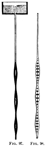
Figs. 97, 98.
The time it takes by a vessel to empty itself is to the time required, when it is kept constantly full, to discharge the same quantity of water, as 2 to 1, and the spaces described by the surface in its descent in a column of equal size throughout, are as the odd numbers, 9, 7, 5, 3, 1. Thus these spaces measure equal times. Since liquids are not perfectly mobile, and their exit at an orifice must be retarded by cohesion and friction, the results thus far given are much modified in practice.
When a liquid flows through an orifice in a vessel, eddies are formed about the sides of the orifice, preventing the escape of a jet equivalent to its full size; and owing to these, and to acceleration of velocity, if the jet be downward, it rapidly contracts in its diameter. At a distance outside about equal to diameter of the opening, it is contracted to 2⁄3 or 5⁄7 its original area; and this part has been called the “contracted vein.” It has been shown, that below this the stream still contracts, though less rapidly.
These swellings separate more widely as they descend with increased rapidity; but falling through great heights, the whole may finally be dissipated in a mist.
Note.—The annular swellings contain air and arise from a periodical succession of pulsations near the orifice, which must be produced by very small oscillations of the entire mass of the liquid, so that the velocity of the flow is periodically variable. The sucking, whistling noise which is often heard in the descent of water through an orifice is caused by air drawn in by the whirling motion. See Fig. 103.
If an orifice in a vessel looks downward, and the column of liquid over it be short, this will simply drop out by its own weight, starting at a velocity of o. But if a considerable depth of liquid be above, its gravity produces a corresponding pressure on its base, or on that liquid which is near it; so that, if a plug be removed from an orifice in or close to the base, the liquid starts at once into rapid motion.
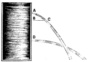
Fig. 99.
Each particle of a jet A issuing from the side of a vessel moves horizontally with the velocity above mentioned, but it is at once drawn downward by the force of gravity in the same manner as a bullet fired from a gun, with its axis horizontal. It is well known that the bullet describes a parabola with a vertical axis, the vertex being the muzzle of the gun. Now, since each particle of the jet moves in the same curve, this jet C takes the parabolic form. In every parabola there is a certain point called the focus, and the distance from the vertex to the focus fixes the magnitude of a parabola in much the same manner as the distance from the center to the circumference fixes the magnitude of a circle.
Now it can be proved that the focus B is as much below as the surface of the water is above the orifice. Accordingly, if water issues through orifices which are small in comparison with the contents of the vessel, the jets from orifices at different depths below the surface take different forms, as shown at D. If these curves are traced on paper held behind the jet, then, knowing the horizontal distance and the vertical height, it is easy to demonstrate that the jet forms a parabola.
Quantity of Efflux.—If we suppose the bottom of a vessel containing water to be thin, and the orifice to be a small circle whose area is A (see Fig. 100) where A B represents an orifice in the bottom of a vessel.
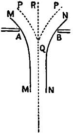
Fig. 100.
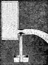
Fig. 101.
Every particle above A B tries to pass out of the vessel, at once and in so doing exerts a pressure on those nearest. Those that issue near A and B exert pressures in the directions M M and N N; those near the center of the orifice in the direction R Q, those in the intermediate parts in the directions P Q, P Q. In consequence, the water within the space P Q P is unable to escape, and that which does escape, instead of assuming a cylindrical form, at first contracts, and takes the form of a truncated cone.
It is found that the escaping jet continues to contract until at a distance from the orifice about equal to the diameter of the orifice; this part of the jet is called the vena contracta or contracted vein, as explained on a previous page.
Influence of tubes on the quantity of efflux.—The result before given has reference to an aperture in a thin wall. If a cylindrical or conical efflux tube is fitted to the aperture, the amount of the flow is considerably increased. A short tube, whose length is from two to three times its diameter, has been found to increase the actual efflux per second to about 82 per cent. of the theoretical. In this case the water on entering110 the tube forms a contracted vein, Fig. 101. just as it would do on issuing freely into the air; but afterwards it expands, and, in consequence of the adhesion of the water to the interior surface of the tube, has, on leaving the tube, a section greater than that of the contracted vein. The contraction of the jet within the tube causes a partial vacuum shown in black in the figure.
Now, if an aperture is made in the tube, near the point of greatest contraction, and is carefully fitted with a vertical tube, the lower end of which dips into water, Fig. 101, it is found that water rises in the vertical tube, thereby proving conclusively the formation of a partial vacuum.
If the nozzle has the form of a conic frustum whose larger end is at the aperture, the efflux in a second may be raised to 92 per cent., provided the dimensions are properly chosen. If the smaller end of a frustum of a cone of suitable dimensions be fitted to the orifice, the efflux may be still further increased, which will fall very little short of the theoretical amount.
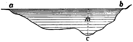
Fig. 102.
Velocities of streams.—The velocity of streams varies greatly. The slower flow of rivers has a velocity of less than three feet per second, and the more rapid, as much as six feet per second, which gives respectively about two and four miles per hour. The velocities vary in different parts of the same transverse section of a stream, for the air upon the surface of the water, as well also as the solid bottom of the stream, has a certain effect in retarding the current. The velocity is found to be greatest in the middle, where the water is deepest, Fig. 102, somewhere in m, below the surface; then it decreases with the depth towards the sides, being least at a and b.
Fig. 103.
Appearance of the surface during a discharge.—A vessel containing a liquid, discharging itself through an orifice, does not always preserve a horizontal surface. When the vein issues from an orifice in the bottom of a vessel, and the level of the liquid is near the orifice, the liquid forms a whirlpool, Fig. 103. If the liquid has a rotary movement, the funnel is formed sooner; if the orifice is at the side of the vessel, there is a depression of the surface upon that side, above the orifice, Fig. 104. These movements depend upon the form of the vessel, the height of the liquid in it, and the dimensions and form of the orifice.
Fig. 104.
In order to verify many of the laws of hydraulics in an accurate manner, it is necessary to maintain a uniform pressure on the escaping liquid, thereby obtaining a constant velocity at the orifice. This may be done in various ways, as by allowing the water to flow into the vessel in a little larger quantity than can escape from the orifice, the excess being discharged over the upper edge of the vessel; also by means of the syphon.
By suspending solid particles, such as charred paper, pulverized in the water, we render the currents that are formed visible. These solid particles arrange themselves, in curved lines, towards and into the orifice, as a center of attraction, Fig. 105. The particles in immediate contact with the orifice, not moving so easily as those within, must cause contraction; so, also, we can see that gravity in accelerating the velocity, must cause continual decrease in the section of the jet.
Fig. 105.
Upward jets of water.—As the velocity of a liquid escaping from an orifice is the same as that which a body acquires, falling from a height equal to the distance from the level of the liquid to the orifice, a jet of water escaping from a horizontal opening upwards, should theoretically reach the level of the liquid in the112 vessel. But this never takes place, Fig. 106, because of—1st, the friction in the conducting tubes destroying the velocity. 2nd, the resistance of the air. 3rd, the returning water falling upon that which is rising. The height of the jet is increased by having the orifices very small, in comparison with the conducting tube; piercing them in a very thin wall, and inclining the jet a little, thus avoiding the effect of the returning water.
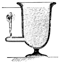
Fig. 106.
Height of the jet.—If a jet issuing from an orifice in a vertical direction has the same velocity as a body would have which fell from the surface of the liquid to that orifice, the jet ought to rise to the level of the liquid. It does not, however, reach this; for the particles which fall hinder it. But by inclining the jet at a small angle with the vertical it reaches about 9⁄10 of the theoretical height, the difference being due to friction and to the resistance of the air.
The quantities of water which issue from orifices of different areas are very nearly proportional to the size of the orifice, provided the level remains constant, and this is true irrespective of the form of the opening which may be round, square, or any other shape.
Escape of liquids through short tubes.—We often place in an orifice, to increase the flow, a short tube (called an adjutage) either cylindrical or conical. If the vein pass through the tube without adhering to it, the flow is not modified; if the vein adhere (the liquid wetting the interior walls) the contracted part is dilated, and the flow is increased.
In the last case, and with a cylindrical adjutage, its length not being more than four times its diameter, the flow is augmented about one-third. Conical pipes, converging towards the exterior, increase the flow still more than the preceding, the flow and velocity of the vein varying with the angle.
Escape of liquids through long tubes.—When a liquid passes through a long straight tube, the flow soon diminishes greatly in velocity, because of the friction which takes place between the liquid particles and the walls. If there be any bends or curves in the tube, it is still further diminished by the same cause. The discharge is then much less than it would be from an orifice in a thin wall, and therefore the tube is generally inclined; the liquid then passes down this inclined plane, or it is forced through by pressure, applied at the opposite end.
Direction of the jet from lateral orifices.—From the principle of the equal transmission of pressure, water issues from an orifice in the side of a vessel with the same velocity as from an aperture in the bottom of a vessel at the same depth.
In reference to the table on the next page, it may be well to say that it has two uses; by it when the “head” is known the pressure can be ascertained to a fraction, thus, Ex. 1, If the head is 140 feet, then the pressure is 60·64 pounds per square inch. Again, Ex. 2, If the pressure is 15·16 per square inch, then the head is 35 feet.
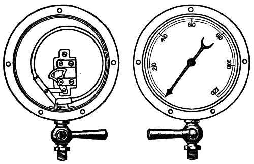
Inside. (See Page 115.) Outside.
PRESSURE OF WATER.
The pressure of water in pounds per square inch for every foot in height to 300 feet; and then by intervals, to 1000 feet head· By this table, from the pounds pressure per square inch, the feet head is readily obtained; and vice versa.
| Feet Head. | Pressure per square inch. |
|---|---|
| 1 | 0·43 |
| 2 | 0·86 |
| 3 | 1·30 |
| 4 | 1·73 |
| 5 | 2·16 |
| 6 | 2·59 |
| 7 | 3·03 |
| 8 | 3·46 |
| 9 | 3·89 |
| 10 | 4·33 |
| 11 | 4·76 |
| 12 | 5·20 |
| 13 | 5·63 |
| 14 | 6·06 |
| 15 | 6·49 |
| 16 | 6·93 |
| 17 | 7·36 |
| 18 | 7·79 |
| 19 | 8·22 |
| 20 | 8·66 |
| 21 | 9·09 |
| 22 | 9·53 |
| 23 | 9·96 |
| 24 | 10·39 |
| 25 | 10·82 |
| 26 | 11·26 |
| 27 | 11·69 |
| 28 | 12·12 |
| 29 | 12·55 |
| 30 | 12·99 |
| 31 | 13·42 |
| 32 | 13·86 |
| 33 | 14·29 |
| 34 | 14·72 |
| 35 | 15·16 |
| 36 | 15·59 |
| 37 | 16·02 |
| 38 | 16·45 |
| 39 | 16·89 |
| 40 | 17·32 |
| 41 | 17·75 |
| 42 | 18·19 |
| 43 | 18·62 |
| 44 | 19·05 |
| 45 | 19·49 |
| 46 | 19·92 |
| 47 | 20·35 |
| 48 | 20·79 |
| 49 | 21·22 |
| 50 | 21·65 |
| 51 | 22·09 |
| 52 | 22·52 |
| 53 | 22·95 |
| 54 | 23·39 |
| 55 | 23·82 |
| 56 | 24·26 |
| 57 | 24·69 |
| 58 | 25·12 |
| 59 | 25·55 |
| 60 | 25·99 |
| 61 | 26·42 |
| 62 | 26·85 |
| 63 | 27·29 |
| 64 | 27·72 |
| 65 | 28·15 |
| 66 | 28·58 |
| 67 | 29·02 |
| 68 | 29·45 |
| 69 | 29·88 |
| 70 | 30·32 |
| 71 | 30·75 |
| 72 | 31·18 |
| 73 | 31·62 |
| 74 | 32·05 |
| 75 | 32·48 |
| 76 | 32·92 |
| 77 | 33·35 |
| 78 | 33·78 |
| 79 | 34·21 |
| 80 | 34·65 |
| 81 | 35·08 |
| 82 | 35·52 |
| 83 | 35·95 |
| 84 | 36·39 |
| 85 | 36·82 |
| 86 | 37·25 |
| 87 | 37·68 |
| 88 | 38·12 |
| 89 | 38·55 |
| 90 | 38·98 |
| 91 | 39·42 |
| 92 | 39·85 |
| 93 | 40·28 |
| 94 | 40·72 |
| 95 | 41·15 |
| 96 | 41·58 |
| 97 | 42·01 |
| 98 | 42·45 |
| 99 | 42·88 |
| 100 | 43·31 |
| 101 | 43·75 |
| 102 | 44·18 |
| 103 | 44·61 |
| 104 | 45·05 |
| 105 | 45·48 |
| 106 | 45·91 |
| 107 | 46·34 |
| 108 | 46·78 |
| 109 | 47·21 |
| 110 | 47·64 |
| 111 | 48·08 |
| 112 | 48·51 |
| 113 | 48·94 |
| 114 | 49·38 |
| 115 | 49·81 |
| 116 | 50·24 |
| 117 | 50·68 |
| 118 | 51·11 |
| 119 | 51·54 |
| 120 | 51·98 |
| 121 | 52·41 |
| 122 | 52·84 |
| 123 | 53·28 |
| 124 | 53·71 |
| 125 | 54·15 |
| 126 | 54·58 |
| 127 | 55·01 |
| 128 | 55·44 |
| 129 | 55·88 |
| 130 | 56·31 |
| 131 | 56·74 |
| 132 | 57·18 |
| 133 | 57·61 |
| 134 | 58·04 |
| 135 | 58·48 |
| 136 | 58·91 |
| 137 | 59·34 |
| 138 | 59·77 |
| 139 | 60·21 |
| 140 | 60·64 |
| 141 | 61·07 |
| 142 | 61·51 |
| 143 | 61·94 |
| 144 | 62·37 |
| 145 | 62·81 |
| 146 | 63·24 |
| 147 | 63·67 |
| 148 | 64·10 |
| 149 | 64·54 |
| 150 | 64·97 |
| 151 | 65·40 |
| 152 | 65·84 |
| 153 | 66·27 |
| 154 | 66·70 |
| 155 | 67·14 |
| 156 | 67·57 |
| 157 | 68·00 |
| 158 | 68·43 |
| 159 | 68·87 |
| 160 | 69·31 |
| 161 | 69·74 |
| 162 | 70·17 |
| 163 | 70·61 |
| 164 | 71·04 |
| 165 | 71·47 |
| 166 | 71·91 |
| 167 | 72·34 |
| 168 | 72·77 |
| 169 | 73·20 |
| 170 | 73·64 |
| 171 | 74·07 |
| 172 | 74·50 |
| 173 | 74·94 |
| 174 | 75·37 |
| 175 | 75·80 |
| 176 | 76·23 |
| 177 | 76·67 |
| 178 | 77·10 |
| 179 | 77·53 |
| 180 | 77·97 |
| 181 | 78·40 |
| 182 | 78·84 |
| 183 | 79·27 |
| 184 | 79·70 |
| 185 | 80·14 |
| 186 | 80·57 |
| 187 | 81·00 |
| 188 | 81·43 |
| 189 | 81·87 |
| 190 | 82·30 |
| 191 | 82·73 |
| 192 | 83·17 |
| 193 | 83·60 |
| 194 | 84·03 |
| 195 | 84·47 |
| 196 | 84·90 |
| 197 | 85·33 |
| 198 | 85·76 |
| 199 | 86·20 |
| 200 | 86·63 |
| 201 | 87·07 |
| 202 | 87·50 |
| 203 | 87·93 |
| 204 | 88·36 |
| 205 | 88·80 |
| 206 | 89·23 |
| 207 | 89·66 |
| 208 | 90·10 |
| 209 | 90·53 |
| 210 | 90·96 |
| 211 | 91·39 |
| 212 | 91·83 |
| 213 | 92·26 |
| 214 | 92·69 |
| 215 | 93·13 |
| 216 | 93·56 |
| 217 | 93·99 |
| 218 | 94·43 |
| 219 | 94·86 |
| 220 | 95·30 |
| 221 | 95·73 |
| 222 | 96·16 |
| 223 | 96·60 |
| 224 | 97·03 |
| 225 | 97·46 |
| 226 | 97·90 |
| 227 | 98·33 |
| 228 | 98·76 |
| 229 | 99·20 |
| 230 | 99·63 |
| 231 | 100·06 |
| 232 | 100·49 |
| 233 | 100·93 |
| 234 | 101·36 |
| 235 | 101·79 |
| 236 | 102·23 |
| 237 | 102·66 |
| 238 | 103·09 |
| 239 | 103·53 |
| 240 | 103·96 |
| 241 | 104·39 |
| 242 | 104·83 |
| 243 | 105·26 |
| 244 | 105·69 |
| 245 | 106·13 |
| 246 | 106·56 |
| 247 | 106·99 |
| 248 | 107·43 |
| 249 | 107·86 |
| 250 | 108·29 |
| 251 | 108·73 |
| 252 | 109·16 |
| 253 | 109·59 |
| 254 | 110·03 |
| 255 | 110·46 |
| 256 | 110·89 |
| 257 | 111·32 |
| 258 | 111·76 |
| 259 | 112·19 |
| 260 | 112·62 |
| 261 | 113·06 |
| 262 | 113·49 |
| 263 | 113·92 |
| 264 | 114·36 |
| 265 | 114·79 |
| 266 | 115·22 |
| 267 | 115·66 |
| 268 | 116·09 |
| 269 | 116·52 |
| 270 | 116·96 |
| 271 | 117·39 |
| 272 | 117·82 |
| 273 | 118·26 |
| 274 | 118·69 |
| 275 | 119·12 |
| 276 | 119·56 |
| 277 | 119·99 |
| 278 | 120·42 |
| 279 | 120·85 |
| 280 | 121·29 |
| 281 | 121·72 |
| 282 | 122·15 |
| 283 | 122·59 |
| 284 | 123·02 |
| 285 | 123·45 |
| 286 | 123·89 |
| 287 | 124·32 |
| 288 | 124·75 |
| 289 | 125·18 |
| 290 | 125·62 |
| 291 | 126·05 |
| 292 | 126·48 |
| 293 | 126·92 |
| 294 | 127·35 |
| 295 | 127·78 |
| 296 | 128·22 |
| 297 | 128·65 |
| 298 | 129·08 |
| 299 | 129·51 |
| 300 | 129·95 |
| 310 | 134·28 |
| 320 | 138·62 |
| 330 | 142·95 |
| 340 | 147·28 |
| 350 | 151·61 |
| 360 | 155·94 |
| 370 | 160·27 |
| 380 | 164·61 |
| 390 | 168·94 |
| 400 | 173·27 |
| 500 | 216·58 |
| 600 | 259·90 |
| 700 | 303·22 |
| 800 | 346·54 |
| 900 | 389·86 |
| 1000 | 433·18 |
The Piezometer, or pressure gauge, is an instrument for measuring the pressure of water in a pipe.
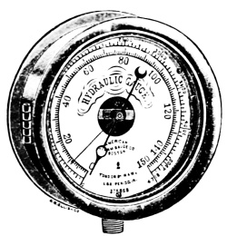
Fig. 107.
It may be broadly stated that all pressures and weights relating to water, steam, gases, etc., are now recorded by gauges.
The principle of construction of the dial gauge is that the pressure may be indicated by means of a spring and pointer upon a divided dial similar to a clock face, but marked in divisions, indicating pounds, hundreds, etc., pressure instead of hours and minutes. The more approved forms of gauges are now constructed upon the principle of the Bourdon spring or metallic barometer invented in 1849. (See page 113 for illus.)
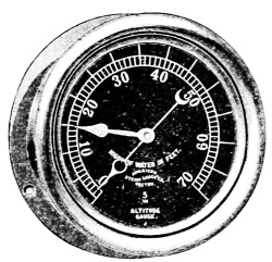
Fig. 108.
The essential principle—or discovery—is this: that a metal curved tube—oval cross section, under pressure, tends to straighten itself according to the force exerted by the pressure inside. Figs. 107 and 108 show the ordinary style of gauge which consists of an elliptical tube, connected at one end to a pipe in communication with the pressure, and at the other end with toothed arc and pinion to a pointer spindle as shown in cuts.
Note.—Hydraulic gauges are indispensable as it is often necessary to stop the pressure at points below that at which the safety valve has been set.
Within the gauges—or cases, is a small coiled tube closed at one end, while the other end is attached to the socket through which the water is admitted; this tube has a tendency to straighten when under pressure, and thus its free closed end moves, and this motion is communicated to the pointer; when the pressure is relieved the tube assumes its original position and the pointer returns to zero. There are many modifications and special adaptations of the Bourdon discovery, but the principle remains, and the same useful results are obtained with both single and double tubes, the latter being the most resensitive.
Fig. 107 shows the dial of a hydraulic gauge which is graduated to suit the work to which it is related. These gauges are made for pressures from 1,000 to 20,000 pounds per square inch. The springs are formed of heavy solid bar steel turned and bored to size and are of the Bourdon style. They are in use in large railroad shops, sugar refineries and cotton-seed oil mills. These gauges are also made with connections through the back of the case.
The gauge illustrated in Fig. 108 is used in connection with hot water heaters, denoting the height of column of water in the tank or reservoir, one hand being painted red and the other black. As it is necessary to have at all times in the tank or reservoir a certain height of water, the red hand is set at the point on the dial which denotes this height. The black hand is connected with the working parts of the gauge and indicates on the dial the actual height of water in the tank or reservoir.
The dial of this gauge is graduated in feet, instead of pounds.
A check valve is almost indispensable in using a hydraulic gauge, as the pressure is often suddenly removed and the momentum of the hand will throw the pinion out of gear with the toothed arc, and is liable to break the hair-spring. A check valve prevents any trouble of this kind and should always be used.
Hydraulic machinery may be broadly divided into
1. Motor machines, and,
2. Pumps.
Water motors may be divided into
1. Water wheels,
2. Turbines, and,
3. Water pressure engines.
In hydraulic motor machines a quantity of water descending from a higher to a lower level, or from a higher to a lower pressure, drives a machine which receives energy from the water and applies it to overcoming the resistances of other machines doing work.
In the next general class, work done on the machine by a steam engine or other source of energy is employed in lifting water from a lower to a higher level. A few machines such as the ram and jet pump combine the functions of both motors and pumps.
The subject of water wheels is but a continuation of much that has been illustrated and defined in the historical introduction to which is now added the following summary.
In every system of machinery deriving energy from a natural water-fall there exist the following parts:
(1) A supply channel, leading the water from the highest accessible level, to the site of the machine; this may be an open channel of earth, masonry, or wood, or it may be a closed cast or wrought-iron pipe; in some cases part of the head race is an open channel, part a closed pipe.
(2) Leading from the motor there is a tail race, culvert, or discharge pipe delivering the water after it has done its work.
(3) A waste channel placed on or at the origin of the head race by which surplus water, in floods, escapes.
(4) The motor itself, which either overcomes a useful resistance directly, as in the case of a ram acting on a lift or120 crane chain, or indirectly by actuating transmissive machinery, as when a turbine drives the shafting, belting, and gearing of a mill. With the motor is usually combined regulating machinery for adjusting the power and speed, to the work done.
The great convenience and simplicity of water motors has led to their adoption in certain cases, where no natural source of water power is available. In these cases, an artificial source of water power is created by using a steam engine to pump water to a reservoir at a great elevation, or to pump water into a closed reservoir in which there is great pressure.
Water flowing from the reservoir through hydraulic engines gives back the energy expended, less so much as has been wasted in friction. Where a continuously acting steam engine stores up energy by pumping the water, while the work done by the hydraulic engines is done intermittently,—this arrangement is considered the most useful.
Note.—“Wherever a stream flows from a higher to a lower level it is possible to erect a water motor. The amount of power obtainable depends on the available head and the supply of water. In choosing a site the engineer will select a portion of the stream where there is an abrupt natural fall, or at least a considerable slope of the bed. He will have regard to the facility of constructing the channels which are to convey the water, and will take advantage of any bend in the river which enables him to shorten them. He will have accurate measurements made of the quantity of water flowing in the stream, and he will endeavor to ascertain the average quantity available throughout the year, the minimum quantity in dry seasons, and the maximum for which bye-wash channels must be provided. In many cases the natural fall can be increased by a dam or weir thrown across the stream. The engineer will also examine to what extent the head may vary in different seasons, and whether it is necessary to sacrifice part of the fall and give a steep slope to the tail race to prevent the motor being flooded by backwater in freshet time.
In designing or selecting a water motor it is sufficient to consider only its efficiency in normal working conditions. It is generally quite as important to know how it will act with a scanty water supply or a diminished head. The greatest difference in water motors is in their adaptability to varying working conditions.”—Encyc. Brit.
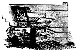
Fig. 110.
Water wheels are large vertical wheels driven by water falling from a higher to a lower level: they are motors on which the water acts, partly by weight, partly by impulse. Turbines are wheels, generally of small size compared with water wheels, driven chiefly by the impulse of the water. Before entering the moving part of the turbine, the water is allowed to acquire a considerable velocity; during its action on the wheel this velocity is diminished, and the impulse due to the change of momentum drives the turbine. Roughly speaking, the fluid acts in a water-pressure engine directly by its pressure, in a water wheel chiefly by its weight causing a pressure.
A flutter-wheel is shown in Fig. 110. This is a water wheel of moderate diameter placed at the bottom of a chute so as to receive the impact of the head of water in the chute and penstock. Its name is derived from its rapid motion, the effect of which is to cause a commotion of the water like “the fluttering” of a fowl.
Impact Wheels.—The simplest and most imperfect of the horizontal wheels are the so-called impact wheels or impact turbines, such as shown in Fig. 111.
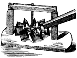
Fig. 111.
They consist of 16 or 20 rectangular blades fastened to the wheel at an inclination of 50° to 70° with the horizon. The water is brought on through a race of 40° to 20° inclination, so that it strikes at about right angles upon the blades.
These wheels are used in falls from 10 to 20 ft., where a large number of revolutions is necessary, as in grain mills, where the moving millstone is hung on the vertical shaft of the wheel, hence intermediate gearing is unnecessary. These crude machines are found in Southern Europe, North Africa, in the Alps, Pyrenees, and in Algiers. They are about 5 ft. in diameter, and the blades are 15 inches high and 8 to 10 inches long (measured radially).
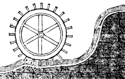
Fig. 112.
Fig. 112 shows an “undershot water wheel.” In this style of wheel, the work is done by impact alone, as the running water acts only on a few immersed buckets on the under side of the wheel.
In the breast wheel, Fig. 113, the water is admitted on a level or slightly above the center of the shaft, so that the water acts by impact and weight.
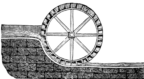
Fig. 113.
Note.—“A weir is a dam erected across a river to stop and raise the water, as for the purpose of taking fish, of conveying a stream to a mill, of maintaining the water at a level required for navigating it, or for the purposes of irrigation.”
For facilitating the computation of the quantity of water flowing over weirs, Weir Tables, are used, based upon approved formulas, of which “Francis’ Formula” is perhaps the most reliable. These tables are applicable to the subject of water wheels but cannot be printed in this work.
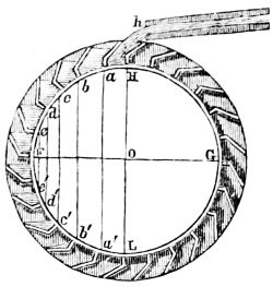
Fig. 114.
Fig 114 represents an over-shot water wheel (F G H L, with axis at O) in which the water flows upon the top of the wheel at h, in the same direction in which it revolves, therefore the impact of the water is utilized upon the upper buckets H, a, b, after which the weight of the water acts in the buckets c, d, e, F, e´, d´ and c´. At b´ the buckets begin to overflow and empty themselves as shown at a´. It will be seen that the water acts upon almost one-half the circumference of this wheel, thus realizing the greatest mechanical effect with the smallest quantity of water.
The current-wheel is perhaps the first application of the force of water in motion, to drive machinery. In the first century B. C., water-wheels for driving mills were used in Asia Minor and on the Tiber. In the former case we suppose, but in the latter case we know, that these were current-wheels.
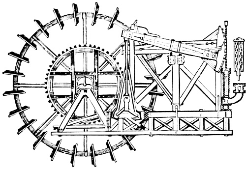
Fig. 115.
The tide or current wheel, (Fig. 115) erected in the vicinity of the north end of London Bridge, and subsequently under its124 northern arch, was erected by Peter Morice, a Dutchman, in 1582, and operated force-pumps which supplied a part of London with water. The stand-pipe from the pump was 120 feet high, and conducted the water to a cistern at that height. The amount raised was about 216 gallons per minute. The wheel worked sixteen pumps, each 7 inches in diameter, and having a uniform stroke of 30 inches.
During the seventeenth and eighteenth centuries the works were extended from time to time, and occupied one after another of the arches. In the first arch of the bridge was one wheel working sixteen force-pumps. In the third arch were three wheels, working fifty-two pumps. The united effect was 2,052 gallons per minute, raised 120 feet high.
In 1767 Smeaton added wheels in the fifth arch. Steam-engines were added about this time to assist at low water and at neap-tides. Thus the matter remained till 1821. Stow, the antiquarian and historian, describes the works in 1600; and Beighton in 1731 gives an account of them at that date.
The water-wheels at that time were placed under several of the arches. The axis of these wheels was 19 feet long 3 feet diameter. The radial arms supported the rings and twenty-six floats, 14 feet long by 18 inches wide. The axis turned on brass gudgeons supported by counterpoised levers, which permitted the vertical adjustment of the wheel as the tide rose and fell. On the axis of the wheel was a cog-wheel 8 feet in diameter and having forty-four cogs; meshing into a trundle-wheel 41⁄2 feet in diameter and having 20 rounds, or pins and whose iron axle revolved in brasses.
The axis of the trundle was prolonged at each end, and had quadruple cranks which connected by rods to the ends of four walking beams 24 feet long, whose other ends worked the piston-rods of the pumps. The axis of oscillation of the lever supporting the wheel, and by which it was adjusted to the height of the tide, was coincident with the axis of the trundle, so that the latter engaged the 8-feet cog-wheel in all conditions of vertical adjustment. Cranks operated one end of the beams while pumps were attached to the other end.
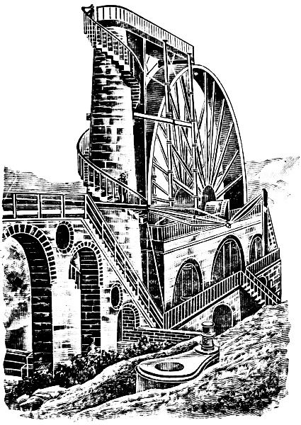
Fig. 116.
Fig. 116 exhibits an overshot water wheel employed at Laxey, Isle of Man, for driving the pumps which drain the mines at that village; these have an extreme depth of 1,380 feet. The wheel is 72 feet 6 inches in diameter, 6 feet in breadth, exerts a force of about 200 horse-power and is capable of pumping 250 gallons per min. from a depth of 1,200 feet. Its crank-stroke is 10 feet. The water for driving it is conducted by pipes from a reservoir on a neighboring hill, and ascends in the column of masonry shown to the left of the wheel. (Knight Vol. III.) An extra crank appears to be shown in the foreground of this reproduction of an old drawing.
The word turbine is derived from the Latin, “turbo”—that which spins or whirls around—a whirlwind.
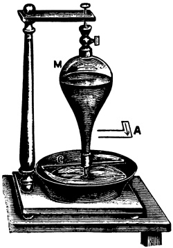
Fig. 117.
The turbine is a horizontal water wheel, and is similar to the hydraulic tourniquet or reaction wheel shown in Fig. 117. This consists of a glass vessel, M, containing water and capable of moving about its vertical axis. At the lower part there is a tube, C, bent horizontally in opposite direction at the two ends. If the vessel were full of water and the tubes closed, the pressure of the sides of C would balance each other, being equal and acting in contrary direction: but, being open, the water runs out and the pressure is not exerted on the open part but only on the opposite side, as shown in the figure A.
And this pressure, not being neutralized by an opposite pressure, imparts a rotary motion in the direction of the arrow, the velocity of which increases with the height of the liquid and the size of the aperture. This description and the illustration gives an idea of the crude reaction wheel invented by Barker about 1740; again a turbine is simply a centrifugal pump reversed, but the turbine is usually furnished with curved guide vanes to guide the water as it enters the wheel.
Note.—The steam turbine has come into common use and competes in its economical performance with the simpler and less economical types of the steam engine; it is impelled by steam jets, the steam impinging upon vanes or buckets on the circumference of a rotating disc or cylinder.
In those turbines which are without guide blades—i. e., which have a high fall—the discharged water still possesses a great velocity and the wheel is thereby deprived of a considerable part of mechanical power. This loss can, however, be obviated or lessened by using the energy of this discharged water to drive a second wheel.
A construction of this sort has been carried out by Ober-Bergrath Althaus in the tanning mill at Vallendar near Ehrenbreitstein. The essential parts of the arrangement can be seen in Fig. 118. A E A is an ordinary reaction wheel with four curved revolving pipes and a fall of 124 ft., and B B is a larger wheel with floats which is set in rotation by the water issuing from A. A. Since the two wheels turn in opposite directions, they must be connected together by a special form of wheel-work. The outer wheel affords the additional advantage of serving at the same time as a fly-wheel, thereby giving a more uniform rate of motion to the whole machinery.
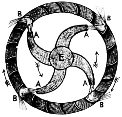
Fig. 118.
Turbines are variously constructed, but all have curved floats or buckets against which the water acts by its impulse or reaction in flowing either outward from a 1 central chamber, 2 inward from an external casing, 3 from above downward, and, 4 from below; these constructions are either divided into outward, vertical or central discharge wheels.
Turbines may also be divided into reaction turbines, or those actuated substantially by the water passing through them (their buckets moving in a direction opposite to that of the flow); impulse turbines or those principally driven by impact against their blades or buckets (the buckets moving with the flow); and combined reaction and impulse wheels which include the best modern types of turbines. In reaction turbines the128 wheel passages are designed to be always full and therefore the water under pressure; in the impulse turbine the passages are not usually full.
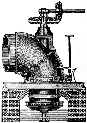
Fig. 119.
Turbines in which the water flows in a direction parallel to the axis are called parallel flow turbines—or journal turbines.
The turbine-dynamometer is a device used for measurings or testing the power delivered by turbines (whence its name).
Fourneyron’s Turbine. This is, in its latest form, when properly constructed, the nearest perfect of the horizontal water-wheels. It revolves either in the air or under water, and may be either high or low pressure. For the low-pressure wheel, the water enters the flume from the open reservoir, with free surface, as in Fig. 119. For high pressure, the reservoir is boxed up and the water brought in at the side through a pipe, as shown in Fig. 124, page 136. The first is for low and the second for high falls.
Note.—The early history of the turbine is one of considerable interest especially in view of the development of the steam, from the water turbine.
“M. Fourneyron, who began his experiments in 1823, erected his first turbine in 1827, at Pont sur l’Ognon, in France. The result far exceeded his expectations, but he had much prejudice to contend with, and it was not until 1834 that he constructed another, in Franche Comté at the iron-works of M. Caron, to blow a furnace. It was of 7 or 8 horse-power, and worked at times with a fall of only 9 inches. Its performance was so satisfactory that the same proprietor had afterwards another of 50 horse-power erected, to replace 2 water-wheels, which together, were equal to 30 horse-power. The fall of water was 4 feet 3 inches, and the useful effect, varied with the head and the immersion of the turbine, 65 to 80 per cent. Several others were now erected: 2 for falls of seven feet; 1 at Inval, near Gisors, for a fall of 6 feet 6 inches, the power being nearly 40-horse, on the river Epté, expending 35 cubic feet of water per second, the useful effect being 71 per cent. of the force employed.”
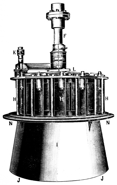
Fig. 120.
The Leffel-Samson turbine wheel is shown in the engraving, Fig. 120, page 129, where N.N. represents the bottom casting of the case flanged to support the wheel by resting upon the bottom of the penstock.
The draft tube I is of conical shape as represented at J. J. to reduce the friction of discharge water which after performing its work in the wheel escapes at the bottom of the draft tube. This tube must always project into the tail water at least two or three inches. The gates H.H.H. are pivoted at the center so that they are balanced and are opened and closed with the least possible friction. These gates are operated by rods L. L., connecting with a rack and pinion which are manipulated by the operator as occasion requires, by an extension shaft from the coupling K, having a hand-wheel on top.
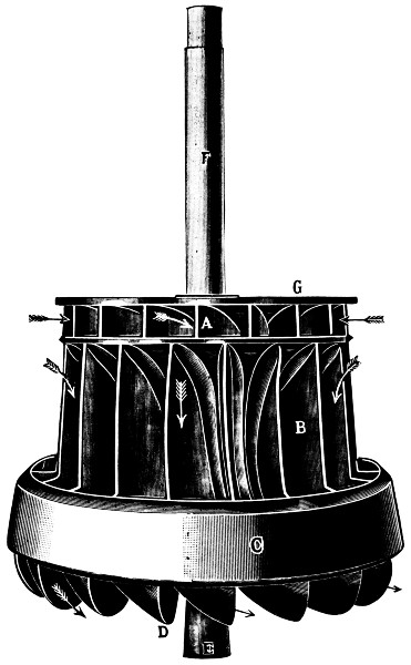
Fig. 121.
Power is transmitted from the wheel shaft F to the gears and pulleys connected with the coupling above; the manner of setting turbine wheels in openstocks is shown a few pages further on.
From the construction of gates and guides upon turbine wheels one may readily see the absolute necessity of carefully guarding the flume against the admission of sticks and other solid materials that might wreck the wheel or jam the gates so that they could not be operated; this is best accomplished by placing a water rack in front of the head gate at the entrance to the flume.
These water racks are best made of flat bars of wrought iron placed edgewise in a vertical position, or what is better, let the top incline say one foot or two (depending upon the size of flume) towards the head gates. When placed in an inclined position it is very much easier to clean the rack from drift wood and the like than when placed in a vertical position as by means of a hoe or scraper these obstructions may be hauled up over the top of the inclined rack.
The racks should be made very strong and substantial to guard against being broken by ice in the winter, for should the rack give way at any inopportune time the admission of sticks and other rubbish might wreck the wheel.
The “runner” which is the revolving part, as shown in Fig. 121, is composed of two separate and distinct types of wheels, and has two diameters, as shown. Each wheel or set of buckets receives its separate quantity of water from one and the same set of guides but each set acts only once and independently upon the water used, hence the water does not act twice upon the combined wheel as might be supposed, as in the compound steam engine.
The upper wheel G receives the water as shown by the arrows at A, and has a central and downward discharge, while the lower wheel C receives the water as shown by the arrows at B and has an inward, downward and outward discharge as shown by the arrows at D.
These two sets of buckets need to be exceedingly strong. The lower set B are made of heavy flanged steel plate and are cast into their places by being placed in the sand mould, and the cast iron flows around them forming the heavy ring C, surrounding the outer and lower edges. This ring is a part of the diaphragm which separates the two wheels. The upper edge of the ring C is beveled to form a neat joint which prevents any unnecessary loss of water.
This runner is balanced and secured to a hammered iron or steel shaft F. It is supported usually by a step of the best specially selected hard wood thoroughly soaked in oil for months before use. The lower end of the shaft is dished out at E, forming a true arc of a circle—concave—while the wooden step is made spherical—convex—to fit into the end of the shaft. The step is formed in this way so that no sand can lodge between the bearing surfaces, and cut them out. The resident oil in the wood combined with the water make a most durable means of lubrication, and these steps last for many months where the water is clear.

Fig. 122.
To get at the exact quantity of water consumed by a turbine wheel, one cannot make an accurate calculation from the openings through the wheels but the water is measured after it133 has passed through the wheel, as it flows away into the tail race. Any slight variation in the form of buckets or admission apertures will make an appreciable variation in the quantity of water discharged by a turbine wheel.
These wheels are made either for vertical or horizontal shafts and are also made single or double. The engraving, Fig. 122, shows a Hercules turbine within the case and gate ready to set in the penstock.
Up to the year 1876 this make of wheel tested at the flume of the Holyoke Water Works showed the highest efficiency at all stages of gate, namely 87 per cent. (page 97, Emerson’s tests).
The design of case will naturally lead the reader to conclude that this wheel has, 1, an inward, 2, downward and, 3, an outward discharge which is correct. The gate is simply a curb or hollow cylinder which forms a sleeve outside the case and is raised and lowered by the gearing and rack shewn in the engraving. As this sleeve rises it gradually uncovers the openings shown which admits water into the wheel.
Horizontal Turbine—The turbine of 10,500 horse power installed in the Shawinigan plant, Canada, see IV Pt. 2. is of the horizontal type, the water entering at, A, the lowest part of the turbine and flows around and fills the outer special tube, passes through an annular gate, flows radially through the wheel thence out through two draft tubes, B, one on each side. The weight of the water wheel is 182 tons, the shaft weighing 10 tons and the bronze runner 5 tons. It is 30 feet from base to top and 32 feet 21⁄2 inches wide over all. The shaft, C, is of solid forged steel, 22 inches diameter in the middle, tapering down to 10 inches diameter on one end and 16 inches diameter on the other, the distance between bearings being 27 feet. The intake is 10 feet in diameter and the quantity of water going through the turbine when developing full power is 395,000 gallons a minute. The speed of the wheel is 180 revolutions per minute with a head of water acting on the turbine of 125 to 135 feet.
Fig 123 is designed to show The Setting of a turbine wheel in a wooden penstock.
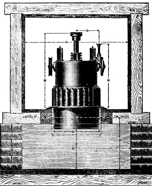
Fig. 123.
The principal and most essential dimensions necessary to be considered in setting turbines are indicated by letters, each size having its own particular dimensions.
In setting the wheel in the ordinary penstock it is necessary in the first place, to have the floor exactly level, and it is generally more convenient to lay down a ring of soft wood around the135 hole in the floor, as it will be much easier to dress off with a plane than the plank floor. The floor should be supported by posts under the timbers around the hole, so that there will be no settling of the floor after being once made level. As the flange on which the wheel rests is turned true, the wheel will, when placed on this level floor, stand in the exact position required, i.e., the shaft will be exactly vertical.
If the wheel is a large one and was taken apart for shipment, the draft tube is first erected in position, then the wheel is placed on its step, the other parts being put on in their order. The step and other bearings are adjusted before leaving the shop, but it will sometimes happen that they will in some way get shifted, and as the wheel is being put together, they should be inspected and readjusted, if necessary. The only change that can occur in the step is its vertical adjustment, which is regulated by screws. When the right height is found, the broad flange around the lower part of the wheel should stand about one-sixteenth of an inch below the under side of the base of the guide rim where it rests upon the draft tube. The adjustable bearing on the top of the cover plate should be fitted up closely around the shaft, but not screwed so tightly as to bind it.
All these wheels above fifteen inches in diameter are provided with chains and weights to counterbalance the weight of the gate, so that it will move easily. It is best, when it can be done without much trouble, to carry the weights outside of the flume, but they can be used inside where the height is sufficient, although it will require a little more weight to be as effective. When the wheel is not likely to be started up at once, it is a good plan, when putting it together, to smear the step and the shaft at the bearing with tallow, as a protection against rust while it remains idle.
It is sometimes necessary to use a draft tube longer than is ordinarily attached to the wheel. If properly constructed and applied there will be no sensible loss of power, but it must be air tight, and when of considerable length it is better enlarged gradually toward the lower end, especially in cases where it may be necessary to carry this tube near the pit bottom.
Iron cases for Turbines. Fig. 124 shows the setting of a Hercules wheel within an iron case.
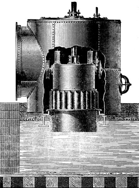
Fig 124.
Although the expense of iron is as a rule considerably greater than wood, the results obtained by the use of iron137 cases and penstocks are much better than could be possible with wood, on account of their durability and freedom from leakage.
It is generally conceded that there is a great risk of the step becoming heated and burning out when placed in a draft tube above the tail-water, and a jet of water is required to counteract this tendency to overheat. As all such fixtures are liable to derangement and often fail to operate, we are in favor of setting the wheel with the step immersed, whenever it can be done without too great expense.
This case consists of two cast iron heads with boiler iron sides and is provided with a cover, so that the wheel may be taken out entire. This cover is fitted with stuffing boxes for both wheel and gate shafts, and a manhole affords easy access to the wheel. The bearing surfaces of the heads are nicely turned, insuring tight joints, and all holes for rivets are accurately spaced and drilled. The heads of the larger cases are made to clamp, the two halves being planed together; the cases are fitted with mouthpieces having cast iron flanges for feeder connections, to secure by bolts to either iron or wooden feeders.
Where two wheels of the same or different diameters are to be used, corresponding cases connected in the centre with one common feeder connection, or are placed in cases provided with separate feeders. In connection with these cases an iron draft tube of any desired length may be used. The wheel is usually fitted to the case before leaving the works, and in erecting the smaller wheels, all that remains to be done is to set the case on the foundations provided for it and make the necessary connections as stated in explanation previously made for Figs. 122 and 123.
The general arrangements required for the proper erection of turbines are well understood by competent millwrights and do not in ordinary cases present any serious difficulties. It may be of interest to many, and to the advantage of some who138 may consider the use of water power, if a few general remarks on this subject are added.
In practice there is almost always a little loss of head due to the velocity with which the water passes through the channels leading to and away from the wheel, and it should be the aim in constructing flumes to bring the loss to a minimum. When the size of the wheel and the quantity of water to be used have been determined, 1, the size of the conduit for carrying the water to the wheel, 2, the width and depth of the wheel-pit and tail-race, and 3, the dimensions and location of the flume for the wheel are to be considered and properly arranged.
All of these should be of such dimensions as to insure the flow of water through them at a moderate velocity, and with as little change of direction as may be practicable.
The larger the pipe or canal the better, but there must be a limit in practice, and it may be laid down as a general rule that a velocity of three feet per second is good practice in short tubes of uniform section of not more than fifty feet in length; but the velocity should be reduced as the distance increases, until in a length of 200 feet, it should not exceed two feet per second.
The same rule applies to the tail-race, except that the velocity should be somewhat lower in ditches cut through rock or earth and having the naturally resulting roughness of sides and bottom.
The width and depth of the pit below the wheel may, for a given wheel, vary somewhat as the water discharged into it is greater or less; therefore, the dimensions should increase with a greater head for the same wheel. The following is an approximate rule for the dimensions of the pit, say for a head of twenty feet: width of pit equal to four times the diameter of wheel, depth below the level of tail-water one and a half times the diameter of wheel. The flume for the wheel should be about three times the diameter of the wheel in its width or diameter, and if it is decked over at the top it should be high enough inside to clear the coupling on the wheel shaft.
The Watertight Turbine is a special machine designed to keep the case tight by the pressure of the water against the gates at the sides, no matter how much these gates wear.
Fig. 125 shows the plan of chutes, gate-seats, gates, and buckets of the wheel. Part of the gates are shown open, and others are closed. The gates make a quarter of a turn in opening, and the same in shutting, and to open all the gates, the gate wheel makes half a revolution. The upper half of case shows the gate-wheel and pinion for operating its parts.
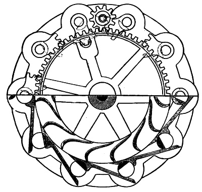
Fig. 125.
The small illustration is a perspective view of the gate and gate segment used on the watertight turbine. The part cut away forms part of the chute when the gate is open as shown in the lower left-hand side of the figure. The sharp edge of the gate cuts off sticks and rubbish which are liable to get in the wheel, which is an obvious advantage. Another desirable feature claimed for this wheel is the plan of operating the gates in opposite pairs; by this means 2, 4, 6, 8 or 10 full gates may be opened at will, according to the power required.
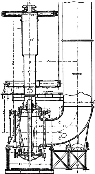
The Niagara Falls Turbine.—Fig. 126.
Turbines at Niagara Falls. A number of turbines installed at Niagara Falls, N. Y., are here briefly described; they are about 5,000 horse-power each; a canal leads water from the river to the wheel pit. The water is carried down the pit through steel penstocks to the turbines, which are placed 136 feet below the water level in the canal. After passing through the wheels the waste water is conveyed to the river below by a tunnel 7,000 feet long. The “plan” Fig. 126 shows a cross-section of the wheel pit, with an end view of a penstock, wheel case and shaft. Fig. 126 exhibits part of a vertical section of the wheel pit and a side view of this penstock, with the enclosing case and shaft of the turbine.
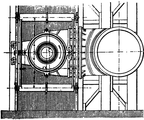
Top View or Plan of Fig. 126.
This turbine has a rock-surface wheel pit, but this surface is protected by a brick lining having a thickness of about 15 inches. The width of the wheel pit is 20 feet at the top and 16 feet at the bottom, and the cylindrical penstock is 71⁄2 feet in diameter. The shaft of the turbine is a steel tube 38 inches in diameter, built in three sections, and connected by short142 solid steel shafts 11 inches in diameter, which revolve in bearings. On the top of each shaft is a dynamo for generating the electric power.
In Fig. 126 is shown a vertical section of the lower part of the penstock, shaft, and twin wheels. The water fills the casing around the shaft, passes both upward and downward to the guide passages, through which it enters the two wheels, causes them to revolve, and then drops down to the tail race at the entrance to the tunnel, which carries it away to the river. The gate for regulating the supply is seen upon the outside of these wheels, both at the top and bottom, Fig. 126.
Fig. 128 gives a larger vertical section of the lower wheel with the guides, shaft, and connecting members. The guide passages, and the wheel passages, are triple as shown so that the latter may be filled not only at full gate, but also when it is one-third or two-thirds open, thus avoiding the loss of energy due to sudden enlargement of the flowing stream. The two horizontal partitions in the wheel are also advantageous in strengthening it. The inner radius of the wheel is 311⁄2 inches and the outer radius is 371⁄2 inches, while the depth is about 12 inches. In this figure the gate is represented closed and to open, it moves downward uncovering the guide passages as shown in Fig. 126, the position it occupies loaded.
In Fig. 127 is shown a half-plan of one of the wheels, in a part of which are seen the guides and vanes, there being 36 of the former and 32 of the latter. Although the water on leaving the wheel is discharged into the air, the very small annular space between the guides and vanes, together with the decreasing area between the vanes from the entrance to the exit orifices, ensures that the wheels move like reaction turbines for the three positions of the gates correspond to the three horizontal stages or openings through the guides as shown in Fig. 128, i.e., three stages of gate.
Note.—A test of one of these wheels, made in 1895, developed 5,498 electrical horse-power, generated by an expenditure of 447·2 cubic feet of water per second under a head of 135·1 feet. The efficiency of the dynamo being 97 per cent., the efficiency of the wheel and approaches was 821⁄2 per cent.
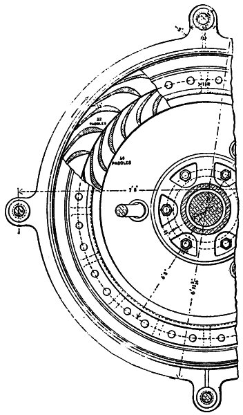
Fig. 127.
The average discharge through one of these twin turbines is about 430 cubic feet per second, and the theoretic power due to this discharge is 6,645 horse-power. Hence if 5,000 horse-power be utilized the efficiency is 75.2 per cent. Under this discharge the mean velocity of water in the penstock is nearly 10 feet per second, but the loss of head due to friction in the penstock will be but a small fraction of a foot. The pressure-head in the wheel case is then practically that due to the actual static head, or closely 1411⁄2 feet upon the lower and 130 feet upon the upper wheel.
The absolute velocity of the water when entering the wheel is about 66 feet per second, so that the pressure-head in the guide passages of the upper wheel is nearly 66 feet. The mean absolute velocity of the water when leaving the wheels is about 19 feet per second, so that the loss due to this is only about 4 per cent. of the total head.
Note.—The above description refers to the ten turbines in wheel pit No. 1. The illustrations are those of the wheels called units 1, 2, and 3 which were installed in 1894 and 1895. Units 4 to 10, inclusive, installed in 1898-1900, are of the same type except that both the penstock and wheel case have cast-iron ribs on their sides which rest on massive castings built into the masonry of the side walls. This arrangement dispenses with the supporting girders shown in Fig. 126 and gives much greater rigidity to both penstocks and wheels.
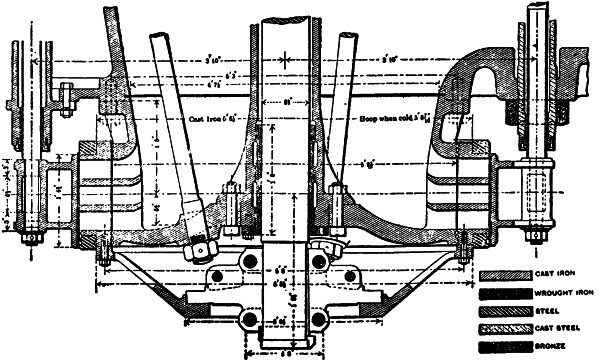
Fig. 128.—Enlarged Vertical Section of Lower Wheel, Showing Gates.
The weight of the dynamo, shaft, and turbine is balanced, when the wheels are in motion, by the upward pressure of the water in the wheel case on a piston placed above the upper wheel. The upper disc containing the guides is, for this purpose, perforated, so that the water pressure can be equalized.
Water pressure engines are machines with a cylinder and piston or ram, in principle identical with the corresponding part of a steam engine; the water is alternately admitted to and discharged from the cylinder, causing a reciprocating action of the piston or ram. It is admitted at a high pressure and after doing its work on the piston is discharged.
The water in some of these machines acquires a high velocity; the useful work is due to the difference in the pressure of admission and discharge, whether that pressure is due to the weight of a column of water of more or less considerable height, or is artificially produced.
When an incompressible fluid such as water, is used to actuate piston engines, two special difficulties arise. One is that the lost work in friction is very great, if the water attains a considerable velocity; another is that there is over-straining action on the machinery. The violent straining action due to the more or less sudden arrest of the motion of water in machinery is termed hydraulic shock. For these reasons the maximum velocity of flow of water in reciprocating hydraulic machines should generally not exceed 5 to 10 feet per second.
Under high pressure, where there is less object in saving and it is very important to keep the dimensions of the machinery small, Mr. Anderson gives 24 feet per second as the limit of velocity. In large water-pressure engines used for pumping mines the average piston speed does not exceed 1⁄2 to 2 feet per second.
The suitability of water for the transmission of power has been fully recognized in recent years; the facility with which water under pressure is capable of being utilized, and the advantages that attend its use in motors have resulted in many practical difficulties being overcome, which were at first considered insurmountable.
At the outset of the employment of water pressure it was feared that the water in the pipes and machinery might freeze. This, however, has been found not to be a difficulty where well-known precautions are taken. The working parts should, where possible, be placed under ground, or should be cased in, if they are above ground. The water should be run out of all valves and cylinders which cannot be cased in, and protected as soon as the working of the machine ceases.
A very small gas jet or lamp placed near the unprotected parts will prevent freezing.
Experiments have also shown that a mixture of glycerine and water prevents the effects of frost at a temperature as low as 16° Fahr., provided the glycerine has a specific gravity of 1.125, and that it is mixed in the proportion of one part of glycerine by weight to four parts of water.
Where water is used over again in the machines (by returning the exhaust water from the machines to a reservoir), such addition of glycerine is more easily resorted to. Where moderate risks of frost have to be dealt with, the proportion of one gallon of glycerine to 300 gallons of water proves effectual. If the water is at a high pressure, such as 1,500 lbs. to the square inch, it is less liable to freeze than when used at a low pressure.
Again, it was at first feared that accidents might be frequent from the bursting of hydraulic pipes and cylinders under high pressure. Such, however, has been proved not to be the case in practice, and even where pipes or cylinders do burst, the pressure is at once dissipated, as the body of water which can escape at the opening is but slight.
It is desirable to use water which is as free as possible either from suspended matter or from chemical impurity. The former increases the wear and tear of the packing, and is otherwise inconvenient, and the latter acts injuriously on the seats and fittings of valves. Sea-water can be used for hydraulic machinery, but on account of its corrosion, fresh-water is better.
Water-pressure has sometimes been applied to operate machines which are worked continuously and not intermittently, and to continuous working rotary machines. This is unwise, for in applying hydraulic power to the continuous working of shafting or shop tools, the amount of power developed by the hydraulic engine cannot be varied to suit the work to be done, neither can the speed be regulated with sufficient nicety.
Pressure or Hydraulic Motors form an interesting variety of hydraulic devices; they consist of working cylinders with valves and pistons, and resemble forcing pumps in their construction, but differ from them in their operation; the pistons not being moved by any external force applied to them through cranks, levers, etc., but by the weight or pressure of a column of water acting directly upon or against the pistons. Pressure engines or motors are applicable to locations—such as afford a suitable supply of water for the motive column; but where-ever refuse, impure, salt or other water can be obtained from a sufficient elevation, such may be used to raise a quantity of fresh water by these machines.
The stress considered in hydro-mechanics is always a pressure, as liquids are in general capable of sustaining only a slight tension without disruption: the intensity of the pressure is measured by the number of units of force per unit of area. Thus we say, one thousand pounds of pressure per square inch of piston—the pounds and the square inches are the units used in these calculations.
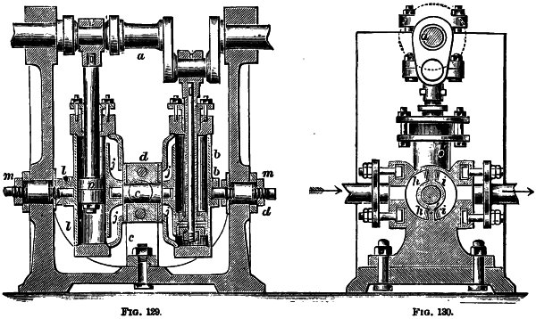
Figs. 129, 130.
For description see page 151.
The invention of pressure engines brought to light a new mode of employing water as a motive agent: and also the means of applying it in locations where it could not otherwise be used; with pressure engines the motive agent may be taken to the machine itself. In valleys or lowlands, having no natural fall of water, but where that liquid can be conveyed in tubes from a sufficient elevation (no matter how distant the source may be), such water, by these machines, may be made149 to propel others; unlike the steam engine, a pressure engine is inexpensive, and simple in construction—it requires neither chimneys, furnaces nor fuel; neither firemen nor engineers, nor is there any danger of explosions. It may be placed in the comer of a room, or be concealed under a counter or a table. It may be set in operation in a moment, by opening a cock, and the instant the work is done, it may be stopped by shutting the same, and thus prevent waste of power.
Pressure engines afford an illustration of the variety of purposes to which a piston and cylinder may be applied. These were probably first used in piston bellows; next in the syringe; subsequently in pumps of every variety; and then in water-pressure and steam engines. The moving piston is the nucleus or elemental part that gives efficiency to them all; and the apparatus that surround it in some of them, are but its parts.
The history of machines composed of pistons and cylinders also illustrates the process by which some simple inventions have become applied to purposes, foreign to those for which they were originally designed—each application opening the way for a different one.
In another form hydraulic motors have been adopted, in favorable locations, as first movers of machinery, and when thus used, they exhibit a very striking resemblance to high pressure steam engines. Indeed, the elemental features of steam and pressure engines are the same, and the modes of employing the motive agents in both are identical—it is the different properties of the agents that induces a slight variation in the machines—one being an elastic fluid, the other a non-elastic liquid.
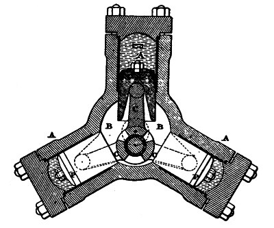
Fig. 131.
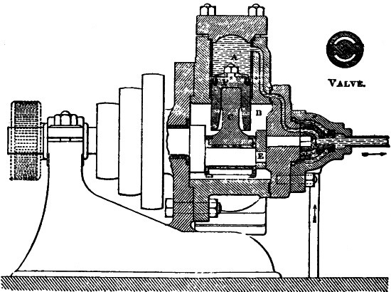
Fig. 132.
In steam engines a piston is alternately pushed forward and back in its cylinder by steam; and by means of the rod to151 which the piston is secured, motion is communicated to a crank and fly-wheel, and through these to the machinery to be driven: it is the same with pressure engines when used to move other machines, except that instead of the elastic vapor of water, a column of that liquid drives the pistons to and fro.
Note.—“The hydraulic engine of Huelgoat, in Brittany, is used to drain a mine; is single-acting, and acts directly to lift the piston of the pump. It makes five and a half strokes per minute, the stroke being a little more than eight feet in length. The piston-rod is 767 feet long, and it weighs 16 tons. The power of the engine is derived from a source at a height 370 feet above its own level.”—Knight.
In default of a natural head of sufficient pressure, the head is sometimes established in an accumulator of power; this is a body of water driven into a reservoir under heavy pressure, by forcing pumps worked by power. In cities where the water distribution is from elevated reservoirs, and in which the water supply is sufficiently abundant to justify the application of a portion of it to industrial uses, the water-engine or motor is recommended.
The following description of a water engine of world-wide adaptation will, if attentively studied, show the working of an approved type of this machine:
Ramsbottom’s hydraulic engine (Figs. 129 and 130), is oscillating, and employs two cylinders b, l, operating one crank-shaft, a, by means of two cranks at right angles to each other. In one of the accompanying figures the channels of induction are marked j and are cast on the cylinders; the dotted circle c shows the position of the supply and discharge pipes; in the other figure these pipes are indicated by arrows. The two views are vertical cross-sections at right angles to each other, one being through the axis of the cylinders and the other through the middle post in which the inner trunnions of the cylinders are journaled. The apertures of induction are seen at h and those of eduction at i, and have the form of truncated circular sectors, whose center is the center of motion.
The induction and eduction spaces are divided by a sectoral partition; the apertures of admission and discharge on the sides of the cylinders are of similar construction. The surfaces of contact between the cylinders b, l and the support d are planed and polished and are made water-tight by the adjusting screws m m of the pivots. When the piston p is at the end of its course in either direction the cylinder and crank are vertical,152 and the valves all momentarily closed, the openings by which the channels j j communicate with the discharge and supply pipes presenting themselves exactly opposite the solid sectors which separate h from i.
In the next moment the flow of water will recommence, the cylinder discharging itself from the full side of the piston, and filling anew from the opposite side. Air chambers and relief-valves are used as a provision against counter-pressure and hydraulic shocks.
The Brotherhood three-cylinder reciprocating engine is an appliance for producing rotary motion by water-pressure.
The working parts of the Brotherhood three-cylinder hydraulic engine consist only of the three pistons and connecting rods, one crank and one rotating balanced valve and spindle which fits into the driver and is turned direct from the crank-pin; there are no glands, stuffing boxes, or oscillating joints.
It is shown by Figs. 131, 132. The three cylinders, A (made in one casting) are always open at their inner ends, and are attached to a central chamber, B. They contain three pistons, P, which transmit motion to the crank-pin through the rods, C. The water is admitted and exhausted by means of the circular disc valve, V, having a lignum-vitæ seat. The valve is rotated by the eccentric pin, E. A face view of this valve is shown above the steam chest. It has segmental ports which, in rotating, pass over apertures in the valve seat. There being no dead centers, the engine will start from all positions of the crank-pin, and a uniform motion of the shaft is produced without a flywheel.
The pressure is always on the outer end of the piston, so that the rods, C, are in compression, and take up their own wear. This engine is well adapted for transmitting pressure to appliances which are worked intermittently, as, owing to the great speed at which it can be run, it will not only save the loss from friction (where gearing is employed), but will also reduce the friction in the machine itself by enabling the gearing153 for increasing speed to be dispensed with. The production of this simple hydraulic rotary engine led to its wide application to capstans.
Fig. 133 represents a small hydraulic engine—The Compton Hydraulic Motor—attached to and operating a gas-compressor. It shows a style of water motor in large use in connection with city water-mains. A pressure of 15 to 20 lbs. per square inch is sufficient to operate it; the motor here illustrated occupies a floor space of 9 x 23 inches; it will supply gas burners to the extent of 6,000 candle-power.
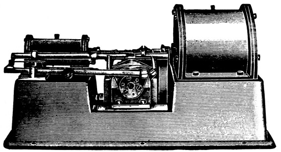
Fig. 133.
The valve motion on the motor is unique in this, the outlets and inlets have a positive motion by which they are simultaneously opened and closed by the motion of the piston; this valve motion is designed to overcome the back pressure; it has a governor, incorporated in the valve-motion for the purpose of maintaining uniform pressure on the main pipes.
Generally speaking a packing is a contrivance or a material to close a joint. Various greasy materials with gaskets, flax, hemp, etc., are used in joints which are screwed down, also collars of rubber, red lead, luting, graphite, etc.
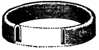
“U” Packing—Fig. 134.
A most important part in the practical working of nearly all water-pressure machines is the leather collar, the invention154 of which by Bramah removed the difficulties which had been experienced in making the large ram work water-tight when submitted to great pressure.
It consists of a circular piece of stout leather (see cut page 20), in the center of which a circular hole is cut. This piece of leather is thoroughly soaked in water and is pressed into a metallic mould and so that a section of it represents a reversed U, and is fitted into a groove made in the neck of the cylinder. This collar being concave downwards, then in proportion as the pressure increases, the edge nearest the ram being trimmed down, it fits the more tightly against the ram plunger on one side and the neck of the cylinder on the other. It should be saturated with Neatsfoot or Castor oil so as to be impervious to water.
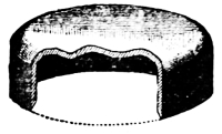
Cup Packing—Fig. 135.
When the least amount of friction possible is desired in the operating of a hydraulic plunger, there is no form of packing which can surpass a properly prepared and applied Leather “U” Packing (Fig. 134), and in practice its position is according to conditions, either in a groove near the upper end of the cylinder, or at the lower end of the ram.
When for any reason it is not desired to use the outer lip of the packing, the resulting form is known as a Cup Packing, (Fig. 135), and when the inner lip is used then we have the Hat or Flange Packing. Fig. 136.
Flange Packing. Fig. 136.
When the water pressure is not over 2,000 lbs. to the square inch, and a greater allowance for friction is not important, a fibrous packing can be used, which is easier of application than these for large sized cylinders.
The loss of power by the best of leather packings is 1 per cent. on 4 in. ram, 1⁄2 per cent. with 8 in. ram and 1⁄4 per cent. with 16 in. ram.
HYDRAULIC
APPARATUS
Apparatus is another name for machinery but it also carries the particular meaning of a complete collection of instruments or devices prepared for a particular use, hence, hydraulic apparatus may be said to include very many combinations of machines to utilize the pressure or weight of water.
A number of these devices are illustrated in the succeeding pages. It were vain to attempt to describe all.
Knight in his Mechanical Dictionary has grouped some six hundred and seventy five terms and names under the heading of “Hydraulic Engineering and Devices.” In the note are given some terms, the definition of which the student may, perhaps, look up; thus: Gyle (the first term given) is a large cistern or vat. The liquor gyle in a brewery is the water-vat or gyle-tun.
Hydraulic apparatus has been developed mainly from two sources. The “cut and try” method, which of course was the first and second from scientific calculations, based upon both the experiments and upon the mathematics of hydraulics.
It is difficult at this date to say to which procedure the world is the most indebted, but it is plainly discernable that the two methods have been necessary as a check upon each other. Untold thousands of practical experiments and an almost equal number of tables, rules and calculations have been made. The result has been that out of many failures the point of economy and efficiency, aimed at, of hydraulic apparatus is well defined.
Note.—Terms relating to hydraulics named by Edward H. Knight, Civil and Mechanical Engineer, as above. Gyle; Sluice Valve; The Sough; Stade; Worm-safe; Weel; Water-twist; Water-lute; Water-gilding; Vineficatur; Tun; Tide-lock; Tail-bag; Swash-bank; Sump; Stop-plank; Sterhydraulic apparatus; Staith; Rip-rap; Quay; Puffer; Psychrometer; Levee; Leam; Leach; Land tank; Kiddle; Kimelin; Keir; Jetty; Invert Burette; Hydraulic Blower, etc. Some of these terms go “way back,” and the above are a specimen only of the 675 headings.
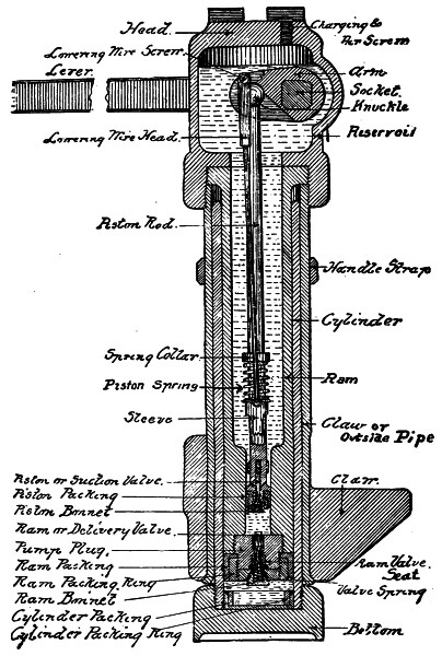
Fig. 137.
Section of Claw Type Hydraulic Jack.
A Lifting-Jack is a contrivance for raising great weights by force from below; also called a jack-screw. From its derivation from Jack, equivalent to lad or boy, has arisen its modern use as denoting a contrivance which is subject to rough usage. It is operated by a screw, whereas—a hydraulic jack is a jack or lifting apparatus operated by some liquid, usually oil, acting against a piston or plunger, the pressure on the liquid being produced by a force pump. The hydraulic jack consists of, 1, a cylinder; 2, a ram or plunger; and 3, a pump. One of these machines is shown and described in the Glossary, page 24, another is illustrated by Fig. 138. The Fig. 137 on the opposite page shows the inside view of Fig. 138 but on a different scale. The names of the parts are particularly to be noted.
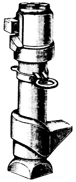
Fig. 138.
Movable hydraulic, or screw, jacks serve on numerous occasions most effectively for lifting or propping-up of less accessible parts. Eye-bolts and jack-bolts are arranged for, in all parts that are likely to be handled, to facilitate and accelerate the work in necessarily crowded quarters.
The base or foot is usually made of cast iron or cast steel and may be either round or square to suit requirements. The cylinder is bored from a seamless steel ingot and having a thread upon its lower end is screwed into the base.
The ram is also a tube of seamless steel having a thread at the top and is screwed into the head or cap which is made either of cast iron or cast steel. The lower end of the ram has a thread inside to receive the pump plug which contains the delivery valve, while upon its outside is placed the cup leather packing and the ram packing ring. The pump for operating the ram is from five-eighths to three-quarters of an inch in diameter depending upon the capacity of the jack, and has a plunger packed with a cup leather.
A suction valve is contained within the plunger. A short arm is fitted upon a socket which enters through the side of the head or reservoir. This arm is connected by a pin to the pump inside the ram while the outer end of the socket has a tapered rectangular hole through it to receive the jack-lever. A leather collar packing makes the socket tight where it enters the side of the reservoir.
To properly use a hydraulic jack. Place the head under the weight to be raised, be careful to set the jack plumb with a good solid footing; put the lever into the socket with its projection on the bottom side; work the lever until the weight has been raised to the desired height or an escape of liquid blows out of the safety vent. Hold the lever up or raise it to its highest position and remove it from the socket to prevent the valve from opening. In lowering insert the lever in the socket with the projection underneath and then cautiously press it slowly down until it brings up against the stop; remove the lever and turn it over with the projection on top; insert the lever in the socket and gently but firmly press it on the end with the right hand clasping the ram with the fore finger, and thumb of the left hand: thus the workman has full control of the jack and can lower and stop as frequently as may be found necessary.
If from any cause the valves stick a few sharp quick strokes of the lever will usually release it and cause it to work, if not, it should be thoroughly cleaned.
Before shipping the brass filling screw should always be screwed down tight, and before using this screw should always be loosened to let the air out and in.
Note.—A prominent firm making these tools says: “In our Jacks, rams are cut and cylinders bored from solid high carbon steel. We have nearly 300 styles for pushing, pulling or lifting.” This shows the wide use to which hydraulic jacks are put; the style shown in the Glossary with its broad base is to be used when the jack stands upon a light board on the ground and can be placed under the work, or where steadiness is required. Fig. 139 shows a style to be used when there is not room enough to get the head of the jack under the work, and is the style generally used for moving engines, boilers, machinery, etc.
In repairing hydraulic jacks the following points should be carefully observed; before attempting to repair a hydraulic jack the trouble should be definitely located, next:
Put the jack under a weight and attempt to raise it, carefully watching its action. Should the liquid leak out around the lever socket, the gland should be tightened slightly until this leak disappears. If the packing is worn out unscrew the set screw at the back of the head about one-quarter inch, then withdraw the socket not more than one inch, unscrew the gland and put in a new packing of lamp wick braided and well oiled with mineral oil, which is free from gum. Afterwards put the socket back to its former place and tighten the set screw.
When the pump valve leaks the lever can be worked up and down without raising the ram. This is also true when the plunger packing becomes worn. If the trouble is found with the valve it can be ground by taking out the pump plug and unscrewing the brass bonnet which covers the valve.
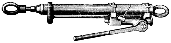
Fig. 139.
Sometimes the jack will become air bound by reason of the accumulation of dirt around the filling plug; this must be removed before the jack will work. Sometimes the liquid will all have been displaced before the ram is half way up, in this emergency the reservoir must be refilled. It often happens that when the workman stops working the lever it will persist in rising to its highest position. This indicates the presence of dirt under the lower or delivery valve. One or two sharp quick strokes of the lever will generally dislodge such obstructions; if this does not bring relief the valve is probably worn so as to need regrinding. When a jack has been taken apart each part should be thoroughly washed in clean water.
While using, if the liquid escapes over the top of the cylinder the ram packing is too loose, and may be set out by inserting a strip or strips of tin or any sheet metal between the leather and the ram packing ring; all leathers should be kept soft and pliable by saturating with a proper leather dressing such as Frank Miller’s Leather Preservative or Shoemakers’ Dubbing. Castor Oil is excellent as well.
One man can exert upon the lever all the pressure that the jack is capable of raising and this pressure should not exceed 150 lbs. Beyond this the jack will be strained.
To repack the pump remove the pump plug, and unscrew the set screw in the head, then withdraw the socket far enough to permit it to revolve clear of the lug, on the head, which brings the piston head out of the pump.
After the new packing is in place the piston should be worked in and out a few strokes to see if it is right, then replace the plug.
To fill the reservoir remove the filling screw in the top of the head, and fill with a mixture of proof alcohol (95 per cent.), two parts and water three parts for winter use, or for summer use one part alcohol to four parts water.
When not in use the ram in a hydraulic jack should be kept in its lowest position, that is to say, all the way down, or in, as the case may be.
Important.—Jacks should never be filled with kerosene oil, water or wood alcohol, for the following reasons: Kerosene oil destroys the leather packing, water will rust the parts and make them rough, while wood alcohol attacks the smooth steel surfaces, and thus destroys both the cylinder and ram. All liquids should be well strained before putting them into the reservoir and great care should be exercised to prevent any dirt from getting into this reservoir.
The Pulling Jack.—The pulling jack, Fig. 139, is used in connection with travelling cranes over wheel presses, quartering machines, planers, drill presses and lathes. Its operation is the reverse of lifting jacks.
This Jack has an improved force-pump on the outside, worked by a lever, which draws the liquid from the upper end and forces it into the space on the opposite side of the piston. The piston rod has one of the rings attached at the end.
By this operation the rings are drawn together and with them the body to be lifted or moved, for it will be understood that this style of jack works either in a horizontal or vertical position. Hooks are furnished instead of rings when desired.
The liquid is introduced into a hole in the side of cylinder, care, being observed to push the piston into the cylinder. The proportions of filling liquid are proof alcohol two parts and water three parts.
To use this jack extend it as far as it can be pulled apart, first opening the valve in the side of force-pump. Now close this valve and work the pump lever.
This jack appeals particularly to the marine engineer, to be attached to the trolley over the engine for the purpose of raising pistons, rods and lifting various parts of the machinery.
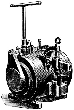
Fig. 140.
Horizontal Jack.—The accompanying engraving, Fig. 140, shows a horizontal type for pulling armatures on to shafts, putting in cranks pins, and marine work. The directions given for the care and handling of the regular hydraulic jack apply also to this as well as other devices of the same description.
This pump has two plungers of different diameters, the small one inside of the large, so that by throwing a clutch, both plungers may work together as one, or they may be separated, and the smaller one used; as for example, in starting, the larger pump is used as far as possible, i.e., until the pressure becomes too great for the large plunger, then the clutch is thrown and the smaller one finishes the work.
The speed of this appliance may be changed to three times greater, and its power reduced to one-third of the maximum by throwing the clutch which brings the large plunger into operation. A rack and pinion with handle is connected with the main ram to cause its return when forced out to its full length. The size shown in Fig. 140 represents a capacity of 200 tons and its approximate weight is 1,200 lbs.
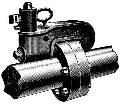
Fig. 141.
The Hydraulic Bolt Extractor.—Much harm is done to coupling bolts in driving them out with a hammer or sledge. The hydraulic bolt extractor shown in Fig. 141 is an admirable device to do this work without injuring the bolts or threads. This same apparatus may be used for other purposes as well as that for which it was designed, as will appear from time to time.
The Hydraulic Punch.—The hydraulic punch has been found of greatest utility in the erection of steel structures, such as buildings, bridges and ship building. It consists of a hydraulic jack attached to a “punching bear” instead of the usual screw to operate the punch. By an ingenious device the punch can be shoved down close upon the work without pumping all the way, as in the earlier styles of hydraulic punches; this means a considerable saving of time and muscle.
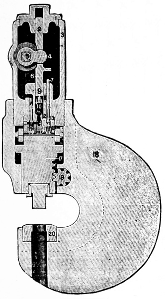
Fig. 142.
The construction and operation of working parts of this punch will be easily understood by referring to the engraving, Fig. 142 where 18 represents the body or “punching bear,” 17 the ram, 19 the raising and lowering pinion to move the ram quickly to its work; 20 shows the die with punch in place above it, secured by its gland; 3 the punch head cistern, the screwed cover having a hole in its center to guide the end 2 of pump plunger 9, having cup leather packing 10, at its lower end; 5 represents the lower socket which carries the arm 4 to operate the piston 6. The suction valve 11 is supported by the spring underneath; 12 is the safety vent; 13 the release or lowering valve operated by the stem 7 which is pushed downward by the projection of the piston 6 whenever the lever is turned and pressed downwards as described166 in lowering the lifting jacks. The relief valve is kept seated by the spring 14. 8 represents the body of the pump 16 its packing and 15 the ram packing ring. No. 16 does not move, but the ram 17 does, having a cup leather reversed at its upper end applied in the same way and manner as 16, with screwed packing ring. The discharge valve is located behind the pump plunger 9 and is, therefore, invisible.
A hydraulic punch mounted upon three legs or supports is shown in Fig. 143, and it also has a shackle at its back to suspend the punch in mid air as occasion requires.
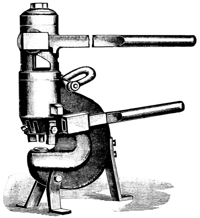
Fig. 143.
The details of this punch are like Fig. 142. It has two guards, one each side of the punch to pull the material operated upon off the punch as it is raised by the lower lever. Another very convenient style of hydraulic punch is shown in Fig. 144 where A represents the body of punch, B the operating lever with the lowering or adjusting lever shown broken off. The167 punch proper is shown at C. The center of gravity of this punch has been so nicely located that by suspending from the handle the ram hangs plumb.
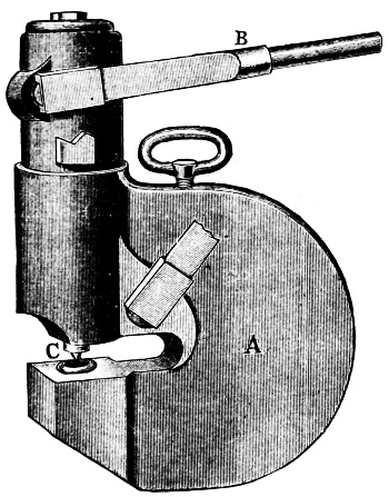
Fig. 144.
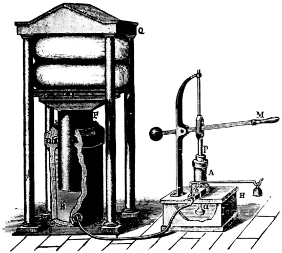
Fig. 145.
The hydraulic press consists of
1. A Lever,
2. A Pump,
3. and a Ram working in a
4. Cylinder.
Bramah in the year 1796 brought out a very interesting apparatus which illustrates the law of the equality of pressure which has been widely adopted in the practical use of the hydraulic press. The principle upon which this press works is due to Pascal but it remained for Bramah to put it to practical use. Enormous pressures are developed by operating the hand lever shown at M in Fig. 145, which is connected with pump plunger P. The pump barrel A is very thick and receives its supply from the cistern H through the suction pipe a.
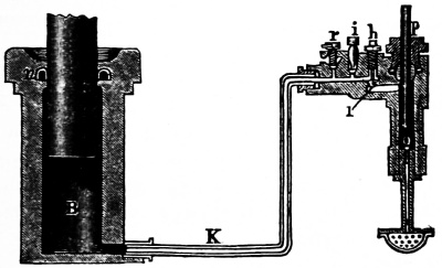
Fig. 146.
Water is delivered from the pump A through a heavy lead pipe into the cylinder B of the hydraulic press. The ram P is made tight by the leather packing n and has a table or platform attached to its upper end as shown. The stationary part Q consists of a heavy cast-iron plate supported by four wrought-iron or machinery steel columns. By operating the handle M of the pump any substances placed between the table on the ram P and the plate Q may be compressed to any reasonable extent.
The pressure which can be obtained by this press depends on the relation of the ram P to that of the plunger P. If the former has a transverse section fifty or a hundred times as large as the latter, the upward pressure on the ram will be fifty or a hundred times that exerted upon the pump plunger. By means of the lever M an additional advantage is obtained.
If the distance from the fulcrum to the point where the power is applied is five times the distance from the fulcrum to the plunger P the pressure on it will be five times the power. Thus, if a man acts on M with a force of sixty pounds, the force transmitted by the plunger P will be 300 pounds, and the force which tends to raise the ram will be 3,000, supposing the section of ram is a hundred times that of the pump plunger.
Over-pressure, is prevented by safety-valve shown in front of the pump A. Fig. 146 shows an enlarged section of the pump used in connection with this press. When the plunger P rises a partial vacuum is formed below it and the suction valve O rises allowing the pump barrel to fill with water through the strainer and suction pipe in the cistern.
When the plunger descends the valve O closes and the water passes through the discharge valve h into the pipe K, thence into the cylinder B of the press where it acts upon the ram. When the press has done its work the ram may be lowered by opening the relief valve r. The safety valve is shown at i. By removing the plug h the discharge valve can be reached to grind it in when necessary.
Note.—Hydraulic Pressure Transmission. Water under high pressure—500 to 3000 lbs. per square inch and upwards—affords a very satisfactory method of transmitting power to a distance, especially for the movement of heavy loads at small velocities, as by cranes and elevators. The system consists usually of one or more pumps capable of developing the required pressure; 2, accumulators, described on the next page; 3, the distributing pipes, and 4, the presses, cranes, or other machinery to be operated. This property of fluids invests us with a power of increasing the intensity of a pressure exerted by a comparatively small force, without any other limit than that of the strength of the materials of which the engine itself is constructed. It also enables us with great facility to transmit the motion and force of one machine to another, in cases where local circumstances preclude the possibility of instituting any ordinary mechanical connection between the two machines. Thus, merely by means of water-pipes, the force of a machine may be transmitted to any distance, and over inequalities of ground, or through any other obstructions.
This useful and indispensable apparatus was designed by Sir William Armstrong. Its use was to secure a uniform pressure of water in a reservoir by weight so that however much or little of this water was used the pressure would remain constant.
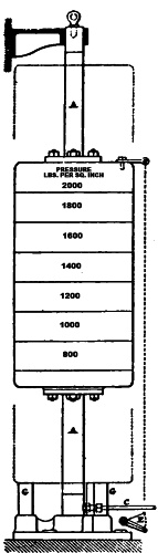
ELEVATION.
Fig. 147.
In the first accumulator which is still in use the ram was attached to the foundation while the cylinder rose and fell as the pressure was utilized. The weights were annular in shape and were hung upon the outside of cylinder. In the modern types of accumulators the cylinder is stationary and the ram supporting the weights is made to rise and fall.
By means of a hydraulic accumulator a uniform pressure can be established and maintained on all parts of a hydraulic main or system.
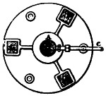
PLAN AT BOTTOM.
Fig. 148.
The volume of water which is used intermittently for the purpose of operating presses—draw-benches for brass and copper tubing and the like is replaced by a pump or pumps which are started and stopped automatically by a connection between the accumulator and the throttle or belt shifter of the pump. The accumulator is used for a double purpose of maintaining a constant pressure and to store up any surplus force of the pumps. The friction loss in the transmission of power by water through mains is very small, as for example: It has been found that water under a pressure of 700 lbs. per square inch may be transmitted through well proportioned mains, one mile with a loss of only two per cent.
The useful work stored in an accumulator may be calculated by the following rule: Multiply the area of ram in square inches by the length of the stroke in inches by the pressure m pounds per square inch divided by 33,000 lbs. the equivalent of one H. P.
This represents the work done by one full stroke of the accumulator ram in descending from its highest position to its lowest.
Example. Required the work done by one stroke of a ram twelve inches in
diameter, and a stroke of twenty-two feet, under a pressure of 750 lbs.
to the square inch. Area of 12 ram = 113·097 square inches. No. of ins.
in 22 ft. = 264. Then
113·097 × 264 × 750
————————– = 678·582 H.P.
33,000
Mr. Tweddel designed the accumulator shown in Figs. 147 and 148 to furnish the varying demand for water where only one appliance of this kind is used in connection with a hydraulic system of shop tools more especially where these tools are numerous.
The ram or spindle A is fixed top and bottom and acts as a guide for the cylinder B which slides up and down upon it.
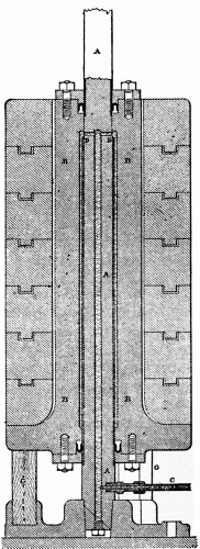
VERTICAL SECTION.
Fig. 149.
This cylinder is loaded with weights marked to indicate the pressure which the accumulator will balance with those weights in use. The water is pumped into the bottom through the pipe C, and fills the annular space173 around the spindle. The entire weight of cylinder is raised by the pressure of water acting only on the area of the end of brass sleeve D D, which is only 1⁄2 inch thick all around the center spindle, and extends down through the bottom packing in cylinder, as shown in sectional view. Fig. 149.
A compact arrangement is thus gained and any reasonable, required cubical capacity may be reached by lengthening the stroke.
The accumulator is supplied by two pumps having plungers 13⁄8″ diam. by 31⁄2″ stroke, speed 100 to 120 rev. per minute.
When the loaded cylinder B reaches the top of its stroke, by means of a small chain it closes the suction cock E, which shuts off the water supply of the pumps.
To put in a new bottom packing, the cylinder is let down to rest on the wooden blocks G, and the spindle is lifted out of its tapered seat at the bottom by a tackle hooked into the eye-bolt at the top. To renew the top leather the bracket holding the top end of spindle A, has to be removed.
This accumulator (having only a small area) falls quickly when the water is withdrawn, thus producing a combined blow and squeeze, which is of great advantage in hydraulic riveting.
The Hydraulic Intensifier is a cylinder having two diameters, in principle very like the tandem compound engine. It is used for increasing the pressure of water in hydraulic mains, pipes, or machines, using only the energy of the pressure water to effect the change. But for this distinction a steam pump would be an intensifier. An intensifier worked the reverse way is a “diminisher” as a hydraulic pump usually is, giving a reduced pressure.
The intensifier is in some respects analogous to the electric transformer.
The intensifier as used in connection with hydraulic apparatus was patented in the year 1869 by Mr. Aschroft, but the principle upon which it works is very much older. Intensifiers are made both single and double acting.
PERCENTAGE OF THE TOTAL AMOUNT OF WATER TAKEN FROM THE RESERVOIR.
| Height of fall in feet. |
Elevation of discharge above delivery valve of ram in feet. |
||||
|---|---|---|---|---|---|
| 15 | 18 | 21 | 24 | 27 | |
| Percentage. | |||||
| 2 | ·0724 | ·0583 | ·0402 | ·0307 | ·0255 |
| 3 | ·1327 | ·1020 | ·0807 | ·0651 | ·0532 |
| 4 | ·1960 | ·1535 | ·1234 | ·1020 | ·0854 |
| 5 | ·2614 | ·2068 | ·1686 | ·1404 | ·1189 |
| 6 | ·3282 | ·2614 | ·2146 | ·1800 | ·1535 |
| 7 | ·3960 | ·3170 | ·2614 | ·2203 | ·1885 |
| 8 | ·4647 | ·3733 | ·3090 | ·2614 | ·2248 |
| 9 | ·5341 | ·4303 | ·3572 | ·3030 | ·2614 |
| 10 | ·6040 | ·4877 | ·4058 | ·3450 | ·2984 |
| 11 | ·6745 | ·5459 | ·4549 | ·3874 | ·3357 |
| 12 | ·7453 | ·6040 | ·5043 | ·4302 | ·3733 |
| 13 | ·8166 | ·6627 | ·5540 | ·4732 | ·4112 |
| 14 | ·8881 | ·7217 | ·6040 | ·5166 | ·4494 |
| 15 | ·9600 | ·7809 | ·6543 | ·5601 | ·4877 |
| 16 | — | ·8404 | ·7048 | ·6040 | ·5263 |
| 17 | — | ·9001 | ·7555 | ·6480 | ·5650 |
| 18 | — | ·9600 | ·8064 | ·6921 | ·6040 |
| 19 | — | — | ·8574 | ·7364 | ·6430 |
| 20 | — | — | ·9086 | ·7800 | ·6823 |
| 21 | — | — | ·9600 | ·8254 | ·7217 |
| 22 | — | — | — | ·8701 | ·7612 |
| 23 | — | — | — | ·9150 | ·8007 |
| 24 | — | — | — | ·9600 | ·8404 |
| Height of fall in feet. |
Elevation of discharge above delivery valve of ram in feet. |
||||
| 30 | 35 | 40 | 45 | 50 | |
| Percentage. | |||||
| 2 | ·0181 | ·0112 | ·0063 | ·0027 | — |
| 3 | ·0441 | ·0326 | ·0243 | ·0181 | ·0132 |
| 4 | ·0724 | ·0560 | ·0441 | ·0348 | ·0281 |
| 5 | ·1020 | ·0807 | ·0652 | ·0533 | ·0441 |
| 6 | ·1327 | ·1063 | ·0870 | ·0724 | ·0608 |
| 7 | ·1640 | ·1327 | ·1096 | ·0920 | ·0782 |
| 8 | ·1960 | ·1595 | ·1327 | ·1121 | ·0960 |
| 9 | ·2285 | ·1868 | ·1561 | ·1327 | ·1142 |
| 10 | ·2614 | ·2145 | ·1800 | ·1535 | ·1327 |
| 11 | ·2947 | ·2425 | ·2041 | ·1746 | ·1514 |
| 12 | ·3282 | ·2708 | ·2285 | ·1960 | ·1704 |
| 13 | ·3620 | ·2994 | ·2532 | ·2177 | ·1896 |
| 14 | ·3960 | ·3282 | ·2780 | ·2395 | ·2090 |
| 15 | ·4303 | ·3572 | ·3030 | ·2614 | ·2285 |
| 16 | ·4647 | ·3863 | ·3282 | ·2835 | ·2482 |
| 17 | ·4993 | ·4157 | ·3535 | ·3058 | ·2680 |
| 18 | ·5341 | ·4451 | ·3790 | ·3232 | ·2380 |
| 19 | ·5690 | ·4746 | ·4046 | ·3507 | ·3081 |
| 20 | ·6040 | ·5042 | ·4303 | ·3733 | ·3282 |
| 21 | ·6392 | ·5340 | ·4561 | ·3960 | ·3486 |
| 22 | ·6745 | ·5640 | ·4820 | ·4188 | ·3688 |
| 23 | ·7098 | ·5940 | ·5080 | ·4417 | ·3892 |
| 24 | ·7433 | ·6241 | ·5341 | ·4657 | ·4097 |
| Height of fall in feet. |
Elevation of discharge above delivery valve of ram in feet. |
||||
| 60 | 70 | 80 | 90 | 100 | |
| Percentage. | |||||
| 2 | — | — | — | — | — |
| 3 | ·0063 | ·0017 | — | — | — |
| 4 | ·0180 | ·0112 | ·0063 | ·0027 | — |
| 5 | ·0307 | ·0217 | ·0150 | ·0099 | ·0063 |
| 6 | ·0441 | ·0325 | ·0243 | ·0180 | ·0132 |
| 7 | ·0580 | ·0441 | ·0340 | ·0264 | ·0205 |
| 8 | ·0724 | ·0560 | ·0441 | ·0351 | ·0281 |
| 9 | ·0870 | ·0682 | ·0545 | ·0441 | ·0360 |
| 10 | ·1020 | ·0807 | ·0651 | ·0533 | ·0441 |
| 11 | ·1172 | ·0934 | ·0760 | ·0627 | ·0524 |
| 12 | ·1327 | ·1063 | ·0870 | ·0723 | ·0608 |
| 13 | ·1483 | ·1194 | ·0983 | ·0821 | ·0694 |
| 14 | ·1640 | ·1327 | ·1096 | ·0920 | ·0782 |
| 15 | ·1800 | ·1460 | ·1211 | ·1020 | ·0870 |
| 16 | ·1960 | ·1595 | ·1327 | ·1121 | ·0960 |
| 17 | ·2123 | ·1731 | ·1444 | ·1223 | ·1050 |
| 18 | ·2286 | ·1868 | ·1561 | ·1327 | ·1142 |
| 19 | ·2449 | ·2006 | ·1680 | ·1430 | ·1262 |
| 20 | ·2614 | ·2145 | ·1800 | ·1535 | ·1327 |
| 21 | ·2780 | ·2286 | ·1920 | ·1640 | ·1420 |
| 22 | ·2947 | ·2425 | ·2041 | ·1746 | ·1514 |
| 23 | ·3114 | ·2567 | ·2163 | ·1853 | ·1609 |
| 24 | ·3282 | ·2708 | ·2185 | ·1960 | ·1704 |
For explanation of these tables see page 177.
A hydraulic ram or water-ram is a substitute for a pump for raising water by means of the energy of the moving water, of which a portion is to be raised. It was considered a notable discovery when it was demonstrated by Daniel Bernovilli, in the beginning of the 18th century, that water flowing through a pipe, and arriving at a part in which the pipe is suddenly contracted, would have its velocity at first very greatly increased.
The hydraulic ram owes its efficacy to the fact that when a flow of water in a pipe is suddenly stopped, a considerable force is generated by the momentum of the water, by its change from a state of motion to a state of rest. In practice, the pipe conveying water from the reservoir or head, connects with a chamber which has a valve opening downward, or outlet valve, allowing the current of water to pass on or escape when the valve is open; but on flowing the current in the pipe acquires sufficient force to close this valve, which checks the flow in the pipe.
The current is thus suddenly stopped; this causes a reaction, which produces pressure sufficient to open another valve (inlet valve) between the current-pipe and an air chamber, and a portion of water enters by means of the force of the current, but by so doing the current has spent its force; the outlet valve at the end of the chamber falls by its own weight, and the pressure in the pipe ceasing, the inlet valve in the air-chamber falls and closes the opening. The condition of things is then restored; the water then acquires a momentum which closes the outlet valve and forces more water again into the chamber. A very slight descending column is capable of raising one ascending very high. In all cases the drive-pipe176 or inlet pipe must be sufficiently long to prevent water being forced back into the reservoir. The air-chamber serves to keep up a steady supply from the reservoir, preventing spasmodic action. To prevent admixture of air with the water in the air chamber, which is caused by pressure of water when raised to a great height, a small hole should be made on the upper side of the inlet pipe, immediately in front of the same. By the action of the ram at each stroke, a partial vacuum is formed below the air chamber, and the air rushing through the small hole in the inlet pipe, passes into the air chamber, making good that which the water absorbs.
Note.—In 1797 Matthew Boulton (manufacturer and practical engineer, and in later life a partner of Jas. Watt, the Father of the steam engine) obtained a patent for a mode of raising water by impulse. The apparatus had excited much attention in France, under the name of Montgolfier’s hydraulic ram, and Boulton added to it a number of ingenious modifications, which were the basis of his patent.
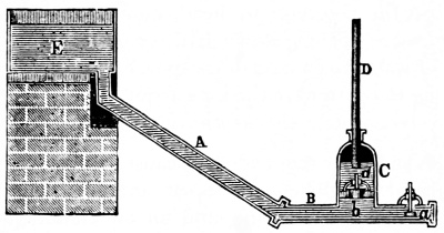
Fig. 150.
Fig. 150 shows in section the construction of the ram in its simplest form in which E is the reservoir, A the pipe in which the water falls, B the channel, a and b the valves, C the air-chamber, and D the discharge. Water first flows out in quantity through the valve a, and as soon as it has acquired a certain velocity it raises that valve, closing the aperture. The impact thus produced, acting on the sides of the pipe and the valve b, raises this valve, and a quantity of water passes into the air-chamber shutting off air and compressing it in the space above the mouth d of the discharge D. This air by its electric force closes the valve b, and the water which has entered is raised in the discharge D.
As soon as the impulsive action is over, and the water in the channel A comes to rest, the valve a again falls by its own weight, the flow begins afresh, and when it has acquired sufficient velocity the valve b again closes, and the whole process is repeated.
The efficiency of hydraulic rams has been much discussed; exhaustive practical tests have been made and the results have been reduced to formulas. Whittaker’s Mechanical Engineer’s Pocket Book gives the following:
G × H
E = ——–
g × h
where E = the efficiency;
G = gallons of drive water used;
g = gallons of water raised;
H = height of fall, in feet;
h = height to which the water is raised, in feet.
The Table given on page 174 is from the American Engineer. Its use is apparent, thus: when the height of fall in feet is, say 12 feet, and the elevation of discharge above the delivery valve of ram, in feet, is 30 feet, the efficiency or per cent., is ·3282. (Example) of 100 gallons 3282⁄100 gallons would be delivered.
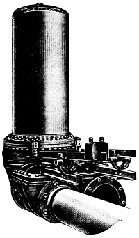
Fig. 151.
The double hydraulic ram is shown in Fig. 151. A sectional view of the same device is shown in Fig. 152, the cuts represent the Rife hydraulic engine, or ram,—a so-called double acting or double supply type of the water ram. It is more clearly described by considering it, first, as a single machine by disregarding its double supply feature.
First, suppose the opening at H, Fig. 152, to be closed, the valve B being open, the water from the source of supply from more or less elevation above the machine flows down the drive pipe, A, and escapes through the opening at B until the pressure due to the increasing velocity of the water is sufficient to close the valve, B. When the flow through this valve ceases, the inertia of the moving column of water produces a reaction, called the ramming stroke, which opens the valve at C, and compresses the air in the air chamber, D, until the pressure of the air plus the pressure due to the head of the water in the main, is sufficient to overcome the inertia of the moving column of water in the drive pipe. This motion may be likened to the oscillation of water in a U shaped tube. The instant the column of water in the drive pipe comes to rest, and the air pressure178 being greater than the static head alone, the motion of the moving column is reversed, and the valve, C, closes. The water in the drive pipe then moves backward, and with the closing of valve C a partial vacuum is formed at the base of the drive pipe. This negative pressure causes the valve, B, to open again, and completes the cycle of operations. At the moment negative pressure appears the little snifting valve, E, admits a small quantity of air, and at the following stroke this air rises into the air chamber D, which would otherwise gradually fill with water, or the air is gradually absorbed by the water.
In this machine the valve, B, is made as light as is consistent with the necessary strength, and the negative pressure at the completion of the stroke opens the valve. In the largest size of these machines this valve is 18 inches in diameter, with a head of 8 feet, which is a common head for use with hydraulic rams; the static pressure on the under side of this valve is 883 pounds; it is seen that so great a shock in a valve of this weight would rapidly destroy both valve and seat.
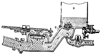
Fig. 152.
The waste in a mechanism of the Rife engine consists of a large port with ample opening and a large rubber valve or overflow with a balance counterweight and spring seat, which removes almost entirely the jar of closing. The valve, C, in the air chamber consists of a rubber disc with gridiron ports179 and convex seats fastened at the center and lips around its circumference. The object of this arrangement is to transfer the shock from the power of the driving water to the air cushion with the smallest possible friction and vibration.
After the valve, C, closes, the pressure in the air chamber forces the water in the air chamber out into the delivery pipes. The Rife engine is claimed to elevate water 30 feet for each foot of fall in the driving head; the machine is built in sizes to elevate as much as 150,000 gallons per day, the efficiency being about 82 per cent.
When a water supply pipe is attached to H, the engine is called double acting; spring water, or that which is purer than the water used to drive the engine, may then be supplied through the supplemental drive pipe I, and by a proper adjustment of the relative flow of the impure driving water, and that of the pure supply, the engine may be made to deliver only the pure water into the mains. This method is employed where the supply of pure water is limited.
The most important detail in which the Rife engine differs from the ordinary hydraulic ram is the waste valve. It will be seen in the engraving that the counterweight on the projecting arm of this valve permits the adjustment of this valve to suit varying heads and lengths of drive pipe. By adjusting the counterweight so that the valve is nearly balanced, the valve comes to its seat very quickly after the flow past it begins. The result is that the ram makes a great number of short, quick strokes, which are much easier on the valves and seats than slower and heavier strokes. The stroke must be sufficiently powerful to act efficiently in overcoming the head in the delivery pipe. The adjustable weight permits this to be effected with great nicety.
Note.—The engine illustrated weighs approximately 2,800 pounds; the capacity of the air chamber is 203⁄4 cubic feet; diameter of drive pipe, 8 inches; diameter of the waste valve, 18 inches; weight of waste valve, 50 pounds; diameter of delivery pipe, 4 inches; height to top of air chamber, 71⁄2 feet.
Lifts and Cranes. These, as hydraulic machines, are adapted to very many places where other power apparatus is too slow; they operate on the same principle as the hydraulic press; having a cylinder and a ram: they have chain wheels attached to the outer end of the ram, as shown in the illustration.
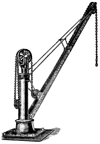
As the ram advances the chain is shortened and when it recedes the chain is lengthened, thus, the weight attached to the end of the chain is raised and lowered. The hydraulic “lift” in passenger elevators operates upon the same principle and this gives an idea of the rapid motion capable of being imparted to the load. It is by the adaptation of hydraulic lifts and cranes in steel mills that such economical results have been attained.
In Figs. 153 and 154 are shown representations of certain apparatus, long used in schools, to explain the rather obscure operation, of even the simplest of pumps; these models are made of glass so that all the movements of the valves, etc., may be clearly noted. Credit is due to Monsieur Ganot, author of Elements of Physics, for the following.
Fig. 153 represents a model of a suction-pump such as is used in lectures, but which has essentially the same arrangement as the pumps in common use. It consists, 1st, of a glass cylinder, B, at the bottom of which is a valve, S, opening upwards; 2nd, of a suction-tube, A, which dips into the reservoir from which water is to be raised; 3rd, of a piston, which is moved up and down by a rod worked by a handle, P. The piston has a hole in its center; this upper aperture is closed by a valve, O opening upwards.
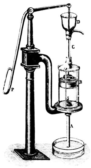
Fig. 153.
When the piston rises from the bottom of the cylinder B, a vacuum is produced below, and the valve O is kept closed by the atmospheric pressure, while the air in the pipe A, in consequence of its elasticity, raises the valve S, and part of it passes into the cylinder. The air being thus rarefied, water rises in the pipe until the pressure of the liquid column, together with the pressure of the rarefied air which remains in the tube, counterbalances the pressure of the atmosphere on the water in the reservoir.
When the piston descends, the valve S closes by its own weight, and prevents the return of the air from the cylinder into the tube A. The air compressed by the piston opens the valve O, and escapes into the atmosphere by the pipe C. With a second stroke, the same series of phenomena is produced, until after a few strokes the water reaches the cylinder. The effect is now somewhat modified; during the descent of the piston the valve S closes, and the water raises the valve O, and passes above the piston by which it is lifted into the upper reservoir D. There is now no more air in the pump, and the water forced by the atmospheric pressure rises with the piston, provided that when it is at the summit of its course it is not more than 34 feet above the level of the water into which the tube A dips.
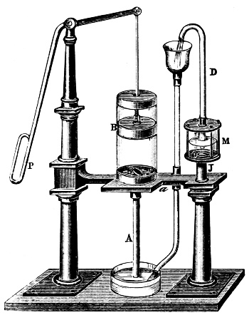
Fig. 154.
In practice the height of the tube A does not exceed 26 to 28 feet; for although the atmospheric pressure can support a higher column, the vacuum produced in the barrel is not perfect, owing to the fact that the piston does not fit exactly on the bottom of the barrel. But when the water has passed the piston, it is the ascending force of the latter which raises it, and the height to which it can be brought depends on the power which works the piston.
The action of this pump, a model of which is represented in Fig. 154, depends both on exhaustion and on pressure. At the base of the barrel, where it is connected with the tube A, there is a valve, S, which opens upwards. Another valve, O, opening in the same direction, closes the aperture of a conduit, which discharges from a hole, o, near the valve S, into a vessel, M, which is called the air-chamber. From this chamber there is another tube, D, up which the water is forced.
At each ascent of the piston B, which is solid, the water rises through the tube A into the barrel. When the piston sinks the valve S closes, the water is forced through the valve O into the reservoir M, and thence into the tube D. The height to which it can be elevated in this tube depends solely on the motive power which works the pump.
If the tube D were a prolongation of the tube Jao, the flow would be intermittent; it would take place when the piston descended, and would cease as soon as it ascended. But between these motions there is an interval, which, by means of the air in the reservoir M, ensures a continuous flow. The water forced into the reservoir M separates into two parts, one of which, rising in D, presses on the water in the reservoir by its weight; while the other, by virtue of this pressure, rises in the reservoir above the lower orifice of the tube D, compressing the air above. Consequently, when the piston ascends, it no longer forces the water into M, the air of the reservoir, by the pressure it has received, reacts on the liquid, and raises it in the tube D, until the piston again descends, so that the jet is continuous.
Hydraulic Machine Tools. Probably in no department of engineering has the use of hydraulic power met with more success than in its application to certain machine tools. This success is owing to the peculiar suitability of pressure—water as the motive agent for the performance of a certain class of operations requiring the exertion of a great force with comparative slow motion, as in punching, riveting, forging and the like.
The wide spread and successful use of hydraulic machines—of which a few only have been described and illustrated upon the pages of this book—is due to the necessity for such tools and the inventive ability of our tool designers.
A large fixed hydraulic riveter is shown in Fig. below; it is capable of exerting on the rivet a pressure of 40 tons or more; the machine has a working pressure of 1,500 pounds per square inch. Working pressures of 5,000 to 10,000 pounds per square inch are used in hydraulic forging presses, but in the riveter much less pressure is required.
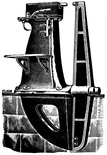
Note.—The proportions of this machine are immense. The platform weighs 22,500 lbs. and is operated by a single lever shown in the side view. The “gap” is 8 feet across. The machine has a large steel “stake” carrying the stationary die; this is held in tension strain by the two steel bolts shown, one upon each side of the machine. The other part of the jaw is cast iron.
CLASSIFICATION
OF PUMPS
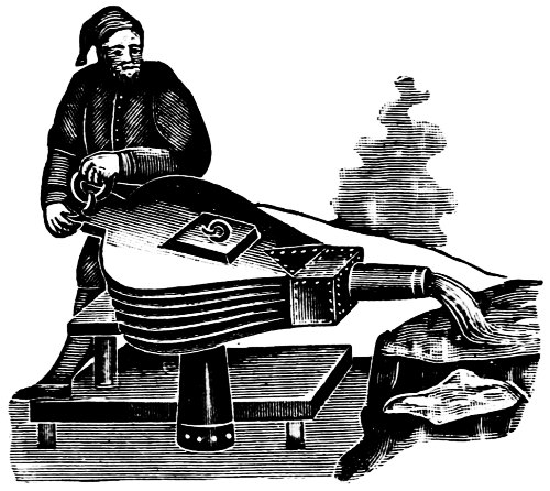
Fig. 155.—The Bellows Pump.
The simplest division of the subject matter relating to this branch of practical mechanics is that which goes back to the very earliest of times; it is thus:
1. Hand Pumps.
2. Power Pumps.
The names indicate the dividing line between the two. The following are more modern divisions, indicating the method of action distinguishing each:
1. Suction or Lift Pumps.
2. Force Pumps.
3. Suction and Force Pumps.
These again may be reciprocating or rotary. The powers actuating pumps are, in the main, as follows:
1. Manual.
2. Animal.
3. Belts.
4. Water.
5. Wind.
6. Steam.
7. Gas.
8. Electricity.
These various motors give distinct names to general classes, thus, electric pumps, belt pumps, elevator pumps, etc. A sub-division of titles indicating differences in construction are these:
1. Vertical Pumps.
2. Horizontal Pumps, or again
1. Single Acting Pumps.
2. Double Acting Pumps.
The list is still further extended, as pumps vary in design to suit their several uses, and are defined as rope, chain, diaphragm,188 jet, centrifugal, rotary, oscillating, cylinder. It is with the last named with which this volume has principally to deal; cylinder pumps cause the last given classification, as they are either single or double acting.
A single acting pump does its work through one end of the cylinder or barrel of the pump.
In double acting pumps the motion of the piston in one direction causes an inflow of water, and a discharge at the same time, in the other; and on the return stroke this action is renewed as the discharge end alternately becomes the suction end; the pump is thus double acting.
Finally pumps may be classified with reference to particular uses to which they are specifically adapted by their form and the materials they are required to handle.
Pumps now raise, convey and deliver beer, molasses, acids, oils, and melted asphalt. They also handle such gases as air, ammonia, lighting gas and even oxygen.
In the orderly progress of the contents of the volume, it will be seen that the main subject, occupying many pages with illustrations, is that relating to “Steam pumps;” those having a steam-end and a water-end and which consist of pump and steam-motor combined. An interesting class under Vacuum-pumps will be found, 1, the combined vacuum and feed; 2, the combined vacuum and circulating and, 3, the combined vacuum and refrigerating pumps.
Under Pumping Engines and the Steam Fire Engine will be found a description of the most brilliant and fascinating of modern scientific and mechanical achievements; these two sections relate to hydraulic engineering in its highest development.
The theoretical action of a pump has already been described and illustrated;—the practical operation is described in the note below. The subject is important enough to justify the space it takes to present these two descriptions of the action of a pump.
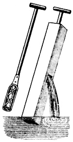
Fig. 156.
The parts of which a pump is composed are: 1, the barrel or cylinder; 2, the plunger or piston; 3, the valves; 4, the pipes.
The barrel of a modern pump is a tube of metal having a water tight plunger or piston which moves freely up and down at the pleasure of the operator. This plunger is in its simplest form made of cast iron in two parts. The upper part consists of an arched part having a hole in its center to receive a bolt which passes through it and a jaw on the lower end of the pitman or connecting rod. The upper end of this pitman is attached to the pump handle by means of a bolt. The inside of the upper part of the plunger is threaded to receive the lower part with a cup leather packing and contains a valve of metal having a conical seat. Fig. 156 shows a design of a pump in common use in the 14th century.
Note.—The action of a pump is as follows: The piston or plunger by moving to one end, or out of the pump cylinder, leaves the space it occupied, or passed through, to be filled by something. As there is little or no air therein a partial vacuum is formed unless the supply to the pump is of sufficient force to follow the piston or plunger of its own accord. If this is not the case, however, as it is when the water level from which the pump obtains its supply is below the pump itself, there being a partial vacuum produced, the atmospheric pressure forces the water into the space displaced by the plunger or piston, continuing its flow until the end of stroke is reached.
The water then ceases to flow in, and the suction valve of the pump closes, forbidding the water flowing back the route it came. The piston or plunger then begins to return into the space it has just vacated, and which has become filled with water, and immediately meets with a resistance which would be insurmountable were the water not allowed to go somewhere. (See next page.)
Its only egress is by raising the discharge valve by its own pressure, and passing out through it. This discharge valve is in a pipe leading to the boiler, and in going out of the cylinder by that route the water must overcome boiler pressure and its own friction along the passages. Water is inert and cannot act of itself; so it must derive this power to flow into the feed pipe and boiler from the steam acting upon the steam piston of the pump. The steam piston and pump piston are at the two ends of the same rod. Therefore the steam pressure exerted upon the steam piston will be exerted upon the pump piston direct.
Between the upper and lower parts of the plunger a cup leather is introduced before these parts are screwed together. This cup leather, while it allows the plunger to move freely, also makes a water-tight joint.
The lower valve consists of a piece of cast-iron flat on the bottom and circular in shape about three-eighths inch thick with a curved toe at one side. This iron disc is secured to the flat leather valve by a screw that passes through the valve and is threaded in the disc.
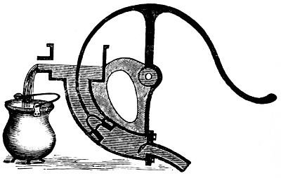
Fig. 157.
The object of this toe upon the disc is to open the lower valve by means of raising the pump handle as far as it will go which lowers the plunger upon the toe and tips the lower valve upon its seat. This same operation also lifts the valve in the plunger off its seat, so that all the water in the barrel drains back into the well so the pump is kept from freezing up in winter.
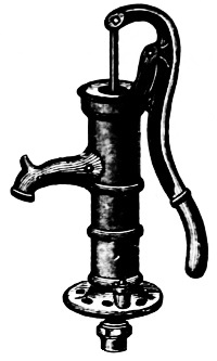
Fig. 158.
The leather which forms the lower valve is held in place by clamping the pump barrel upon it, so that it is held between the barrel and the base plate.
Hand pumps are primarily divided into: 1, suction or lift pumps; 2, force pumps, and 3, suction and forcing pumps; 4, also pumps for exhausting air from vessels.
Of the first class, the common single-acting house-pumps shown in Figs. 157 and 158 are examples; the pumps are simply modifications of the suction-pump; a common form of lift-pump has a pitman-rod which pushes the water up instead of lifting it through a spout at or near the top of the cylinder.
The details of the suction-pump are as follows—at the bottom of the cylinder is a pipe communicating with the liquid to be raised, and a valve which opens from beneath. A similar valve is placed in the piston.
A force-pump is shown in Fig. 159; from the two figures the difference between the lift and the force-pump may be understood; while the former raises the liquid above its piston from which it flows under no pressure, the latter forces it out of the barrel under a varying pressure which depends upon circumstances. When the piston rises the suction valve opens, and the valve in the piston closes by the air-pressure. The liquid then enters the barrel beneath the piston. On the descending stroke the suction valve closes, and the liquid flows upward into the discharge pipe.
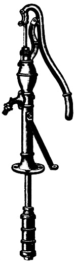
Fig. 159.
In Fig. 160 is shown an air-chamber attached to a force-pump for the purpose of preventing shocks in the discharge, and for producing a steady flow; air-chambers are also frequently attached to suction pipes for a similar purpose.
According to the underlying principles of action thus far explained hundreds of thousands of pumps have been constructed and operated. It is beyond the limits of this volume—or any single book to give the names and details of these so-called “hand-pumps,” however, three approved styles are shown in Figs. 161, 162, 163.
Fig. 161 represents a double acting force pump used extensively on ship-board, wharves, around factories, mills, etc., and in residences, for tank pumping. On ships these pumps perform the three-fold purpose of filling boilers when cold, washing down decks and to satisfy government inspection as to fire protection; in service in mines they are unaffected by mine water, the working parts being made non-corrosive. It is claimed that a three-inch diameter cylinder with a stroke of four and a half inches with a 11⁄4-inch suction pipe and 1-inch discharge pipe will lift and force water 150 ft. high and has a capacity of ·28 gallons for each stroke, with the water not more than twenty-five feet below the pump.
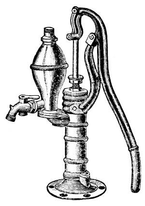
Fig. 160.
Fig. 162 represents a two cylinder force pump; this has vertical single acting pistons actuated by one lever, producing the same results as a double-acting pump. It is claimed that the total lift and force, from supply to point of delivery, with193 the pump not more than twenty-five feet above water will attain one hundred feet; that a 3-inch × 4 inch cylinder, 11⁄2-inch suction and 11⁄4-inch discharge will deliver ·24 gallons of water for each stroke.
Fig. 163 represents a widely used type of suction pump, it is designed for vessels of not more than fifteen to twenty feet deep; for contractors who wish to pump large quantities of water from excavations, etc.; for irrigation or any other purpose where a compact and capacious pump is desired.
The lever may be worked from three different points as shown by lugs on the illustration. The lever socket is made at such an angle that the bent wrought iron lever when put in one side up, is right for ordinary pumping and by simply changing it the other side up, it becomes a vertical lever. The valves are accessible and removable by hand from above. It is claimed that with 81⁄2-in. diameter cylinder and 6-in. stroke that the capacity is 147⁄100 gallons for each stroke, with 20 feet lift—the suction pipe being 3-in. in diameter.
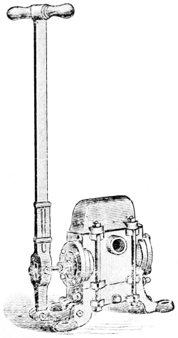
Fig. 161.
In the illustrations (Figs. 161 and 162) it will be noticed that the discharge is conveniently arranged to receive either fire hose, or iron pipe connections for other uses, as in mines and on ship-board.
Being made in large factories, there are immense numbers in world-wide use; every detail of these pumps is carefully considered; the sizes manufactured range from 2 inches to 6 inches diameter of cylinders, with strokes 4, 41⁄2 and 5 inches.
The capacity of each pump is also given in the published lists by the makers; this is given under the heading “Capacity per Revolution” with the added information as to the best sizes to be used for the suction and discharge pipes.
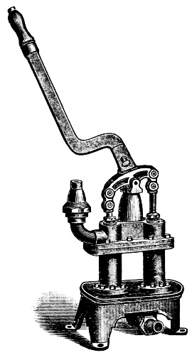
Fig. 162.
Note.—It were well for the student to know that in case of breakage or worn out parts of an otherwise serviceable apparatus that the makers have provided for their repairs as will be indicated by the following taken from the catalogue of a well known manufacturer. “In the following lists will be found descriptions of pieces for all the staple pumps, which will prove of decided convenience. In this connection we desire to impress most emphatically on the minds of dealers that the threads are cut to exact and accurate gauges; all holes in flanges, etc., drilled to templets; all castings made from exact metal patterns, similar parts being always the same. Therefore, repairs will invariably take the place of the broken parts.”
Fig. 163 represents a Pitcher Spout Pump, of large size for contractors, and Fig. 164 the parts of a common house pump. The two figures show pumps substantially the same.
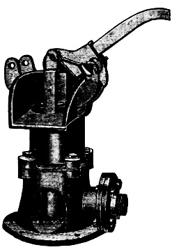
Fig. 163.
The smallest size “listed” of this pump has a cylinder diameter of 21⁄2 inches, fitted with 11⁄4 in. pipe and it has a capacity of ·09 gal. per stroke and it takes more than eleven strokes to pump a single gallon. With a cylinder 41⁄2 inches, with pipe 11⁄2 in. diam., the pump has a capacity of ·34 gal. per stroke.
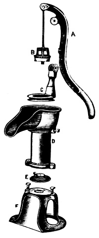
Fig. 164.
The engraving 164 shows a pitcher pump dissected, in which A represents the lever or handle, B the plunger which contains the discharge valve and is made tight by a cup leather packing, C is the fulcrum for the lever, D the barrel or cylinder, E the lower or suction valve, F the base which supports the pump. The leather which forms the valve E also makes the joint between the cylinder and the base.
Fig. 165 represents a Two-Cylinder Suction and Force Pump arranged with extension levers. When these levers are put in place, they afford room for a large force of men to work, renders this pump a most powerful engine for throwing water on fires, or supplying it for many uses about factories, warehouses, wharves, etc.
The discharge hose can be fitted both ends for wrought-iron pipe or either end for hose. The Table below gives the makers’ numbers, the diameter of the cylinders, etc., and also distance to which the water can be lifted or forced.

Fig. 165.
TABLE OF SIZES, CAPACITIES, ETC.
| No. | Diameter Cylinder |
Stroke | Capacity per Rev. |
Discharge | Suction | *Lift and Force |
||||||
|---|---|---|---|---|---|---|---|---|---|---|---|---|
| 4 | 3 | in. | 61⁄2 | in. | ·40 | gal. | 11⁄4 | hose in. | 11⁄2 | pipe in. | 100 | ft. |
| 6 | 31⁄2 | „ | 61⁄2 | „ | ·54 | „ | 11⁄2 | „ | 2 | „ | 75 | „ |
| 8 | 4 | „ | 8 | „ | ·87 | „ | 2 | „ | 21⁄2 | „ | 75 | „ |
| 10 | 41⁄2 | „ | 8 | „ | 1·10 | „ | 2 | „ | 21⁄2 | „ | 75 | „ |
| 12 | 5 | „ | 8 | „ | 1·36 | „ | 2 | „ | 21⁄2 | „ | 75 | „ |
| 16 | 6 | „ | 7 | „ | 1·96 | „ | 21⁄2 | „ | 4 | „ | 50 | „ |
* Total lift and force from supply to point of delivery, Pump not more than 25 feet above water.
Fig. 166 represents a hand, rotary force pump provided with a balance wheel. A sectional view of this pump is given in Fig. 167; these pumps are adapted for almost any place or purpose where lift or force pumps can be used, they can be moved to any place where water is within suction distance and immediately operated.
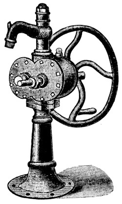
Fig. 166.
The provision of a foot valve at the end of the suction pipe will keep it always filled.
In the rotary pump there are no pistons. As will be seen in the Fig. 167, there are two pinions of extremely coarse pitch meshing into one another with neat fit in the case; the joints become practically air-tight by the water which surrounds them and passes through the case.
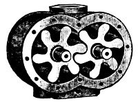
Fig. 167.
Both pinions are supported by a journal at each end, the shaft of one being extended to receive a pulley or hand wheel as shown in Fig. 166, hence, one pinion causes the other to revolve. The teeth on the bottom side of the pinions move away from each other and form a partial vacuum which the water fills and is carried around between the teeth of the pinions on opposite sides and is discharged through a central opening in the case at the top, thence through the discharge pipe into the tank or reservoir.
In the small sizes of the rotary pump there is no trouble from leakage, until the parts become much worn.
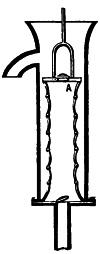
Fig. 168.
Bag Pump. This is a form of bellows-pump in which the valve disc A, which takes the place of the bucket, is connected with the base of the barrel by an elastic bag distended at intervals by rings. This bag may be made of leather or of double canvas. The upper end of the bag should be firmly tied with a cord in a groove gouged out of the rim of the board at A. Into this board is fixed the fork of the piston rod, and the bag is kept distended by a number of wooden hoops or rings of wire, fixed to it at a few inches distance from one another, and kept at equal distances by three or four cords binding them together and stretching from the top to the bottom of the bag. Now let this trunk be immersed in the water: it is evident that if the bag be stretched from the compressed form which its own weight will give it by drawing up the piston rod, its capacity will be enlarged, the valve A will be shut by its own weight, the air in the bag will be rarefied, and the atmosphere will press the water into the bag. When the rod is thrust down again, the water will come out at the valve A, and fill part of the trunk. A repetition of the operation will have a similar effect; the trunk will be filled, and the water will at last be discharged at the spout.
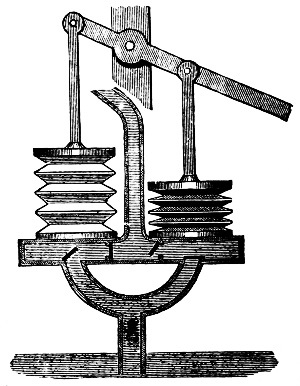
Fig. 169.
Bellows-pump (Page 186). This is an atmospheric pump in which the part of the piston is played by the top leaf of the bellows. A very199 simple method of describing an invention, from which great good in drainage of waste lands in Europe, was realized. “There was of course a valve covering the interior orifice of the nozzle and opening outwards, to prevent the air from entering when the upper board was raised. This valve is not shown because the art of representing the interior of machines by section, was not then understood, or not practiced. The lower board is fastened to the ground by a platform while the suction pipe dips into the water. A weight is placed on the upper board to assist in expelling the water.”
Fig. 169 represents a Double Lantern Bellows-Pump as used in the 16th century. This engraving is plain and requires no description. Fig. 170 shows a diaphragm pump in which a sheet of rubber or its equivalent is used as a substitute for a piston in a cylinder.
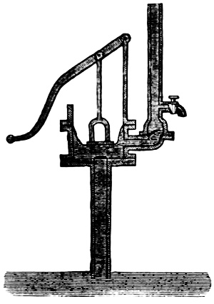
Fig. 170.
Note.—When an ox or a horse plunges his mouth into a stream, he dilates his chest and the atmosphere forces the liquid up into his stomach precisely as up the pipe of a pump. It is indeed in imitation of these natural pumps that water is raised in artificial ones. The thorax is the pump; the muscular energy of the animal, the power that works it; the throat is the pipe, the lower orifice of which is the mouth, and which he must necessarily insert into the liquid he thus pumps into his stomach. The capacious chest of the tall camel, or of the still taller cameleopard or giraffe, whose head sometimes moves twenty feet from the ground, is a large bellows-pump which raises water through the long channel or pipe in his neck. The elephant by a similar pneumatic apparatus, elevates the liquid through that flexible “suction pipe,” his proboscis; and those nimble engineers, the common house-flies, raise it through their minikin trunks in the manner of the gigantic animals which in remote ages roamed over this planet, and which quenched their thirst as the ox does. There could have been none which stood so high as to have their stomachs thirty feet above the water they thus raised into them.
Rope Pump. This machine consists of one or more endless ropes, all stretched on two pulleys as shown in Figs. 171 and 172. These pulleys have grooves formed in their surfaces for the reception of the ropes. A rapid rotary motion is communicated to the upper pulley, by a multiplying wheel, and the ascending side of each rope carries up the water absorbed by it, and which is separated from it while passing over the upper pulley, partly by centrifugal force, and partly by being squeezed in the deep groove.
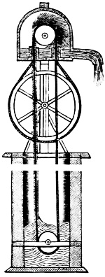
Fig. 171.
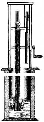
Fig. 172.
In the beginning of the motion, the column of water adhering to the rope, is always less than when it has been worked for some time, and continues to increase till the surrounding air partakes of its motion. By the utmost efforts of a man, nine gallons of water were raised by one of these machines from a well, ninety-five feet deep, in one minute. (Adam’s Philos.)
The hydraulic belt is a similar contrivance. It is an endless double band of woolen cloth, passing over two rollers, not here shown. It is driven with a velocity of not less than a thousand feet per minute; when the water contained between the two surfaces is carried up and discharged as it passes over the upper roller, by the pressure of the band. Some machines of this kind are stated to have produced an effect equal to seventy-five per cent. of the power expended, while that of ordinary pumps seldom exceeds sixty per cent. (Lon. Mechan. Mag.)
Spray Pump. Fig. 173 exhibits a carefully designed pump made to spray trees, plants, etc. All the working parts are of brass, the valves are metal; the air chamber is made of galvanized iron or copper and has large capacity. It will hold sufficient compressed air to keep the spray going from six to ten minutes after the pumping stops. The “agitators” are placed so that they keep the liquid thoroughly stirred. The plungers can be easily removed and packed without the necessity of taking the pump to a shop.

Fig. 173.
The pump is fastened to the bottom of the barrel by a bolt passing through the barrel and secured by a nut underneath, with packing to prevent leakage, and by an iron plate at the top covering the opening through which the pump is placed in the barrel. This pump is arranged with one, or two levers, and for one or two lines of discharge hose. The cylinders are 21⁄2 inches diameter with stroke 3 inches; its capacity per stroke is 0·13 gal.
Combined Pump and Horse Power. The “horse power” (apparatus) with its “pole” for one horse and two poles for two horses and its wrought iron “tumbling shaft” has been so modified that a horse operates the pump, by means of a “sweep,” direct connected to the pump crank shaft.
The animal will make three to four circuits per minute, giving the pump crank shaft a speed of 40 to 50 revolutions per minute. The capacity of a 4 in. plunger and 8 in. stroke is given as 3·120 gallons per hour; the suction pipe is given as 31⁄2 in. diam. and the discharge as 3 in. pipe.
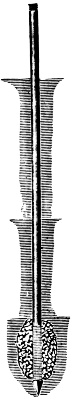
Fig. 175.
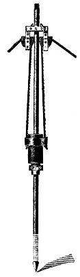
Fig. 175-A.
Aside from the wells described on page 45 and those following it, there are wells made by forcing iron tubing down into the earth until a water supply is reached. Within reasonable distances and in a remarkably large proportion, these pipe wells are directly connected with the suction part of hand pumps.
Note.—“When a well fails to yield a fair amount of oil or water, an increase in the flow is often effected by means of the Roberts torpedo. This is a thin water-tight cylinder of metal or paper, 4 to 6 ft. long and 2 or 3 in. in diameter, charged with powder, gun-cotton or nitro-glycerine. It is lowered to the bottom of the well, or to a depth that will bring it opposite the desired stratum, and the well is then flooded. The charge is exploded by a cap or electric spark, and the explosion often clears away the obstruction from the oil or water vein. This applies particularly to deep wells.”
To this class also belong the famous oil and artesian wells which penetrate through earth and rock thousands of feet, many of them operated by power pumping machines.

Fig. 176.

Fig. 177.
The process of driving tube-wells resembles pile-driving, but with this distinction, that while piles receive the blows of the “monkey” on their heads, the tubes are not struck at all, the blow being communicated by the clamp, which receives the blow near the ground. The tube-well, as in ordinary use, is not intended for piercing rock or solid formations, but is quite capable of penetrating very hard and compact soils, and can be also successfully driven through chalk, breaking through the flints which may obstruct its passage downward. When solid masses of rock or stone are reached, special means of drilling have to be provided for it. When coming upon rock or stone, the best plan is to pull up the tube and try in another spot. This applies also when deep beds of clay are driven into; for, by going a little distance off, and testing again, in many cases water will be found.
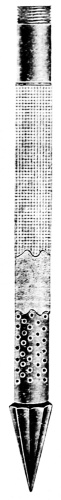
Fig. 178.
The operation is as follows: The first or pioneer tube, shown in Fig. 175 is furnished with a steel point of bulbous form, and perforated with holes varying from one-eighth to an inch, extending from 15 in. to 3 ft. from the point, Fig. 178. The enlargement of the point serves to clear a passage for the couplings by which the tubes are screwed together. On this tube the clamp Fig. 176 is held about 3 ft. from the point by two bolts; the clamp is of wrought iron with steel bushing screwed internally so as to form teeth to grip the tube. Next, the cast-iron driving-weight or monkey is slipped on to the tube above the clamp. The monkey is operated with ropes.
Sucker-Rod Couplings. These couplings are usually made of iron galvanized and are used to connect the ends of wooden sucker rods for deep well pumps. Each half of coupling is secured to the end of wooden rods by three bolts; the ends of the couplings are joined by male and female threads in the usual way.
Either bolts or rivets may be used to attach the rods to the couplings. (See Fig. 179.)
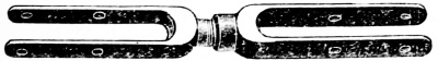
Fig. 179.
Foundation—For the smaller sizes a foundation is not necessary, other than a good floor. With the large sizes it is advisable to have a substantial foundation. Concrete, well rammed into place, surmounted by a capstone, is as good as any. The foundation allows the pump to be run at a higher speed; a plan showing location of bolt-holes, position of flanges, and general dimensions, so that there may be no delay in setting the pump upon arrival at its destination.
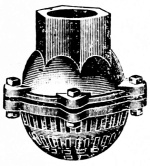
Fig. 180.
Suction Pipe—The suction pipe should be as short and direct as possible, avoiding all turns not necessary. Place a strainer and foot-valve, Fig. 180, on the suction pipe. It is better for the pump to have a slight suction except when hot water is pumped, than to supply the water to the pump under a slight head.
Discharge Pipe—Make the discharge piping as straight as possible, using long bends.
Packing—The stuffing boxes should be carefully packed and the gland brought up firmly against the packing; screwing up the gland by hand should be sufficient.
Large sizes of suction and discharge pipe are desirable, because the friction of the water in the pipes thus reduced makes the pump work easier.
By a power-driven pump is meant one actuated by Belt, Rope-transmission, Gear, Shafting, Electric-motor, Water-wheel, Friction, or by direct connection to a power shaft. It thus becomes very frequently a question which apparatus is most desirable.
These are classified, thus—
1. Single power pumps,
2. Duplex power pumps,
3. Triplex (triple) power pumps,
4. Quadruplex, etc. Where the sizes still
further increase they are named from the number of barrels or water
cylinders, but when of much larger size than the Triplex they come
under the classification of pumping engines.
Where power can be had from a shaft in motion there is no pump so economical as the power or belt driven pump. This fact is shown by the rapid increase in the number of applications of this type of pump: the reduced cost of manufacture in making the teeth of the gear wheels, the use of automatic machinery, the production of interchangeable parts have tended to produce a high grade of machine at an attractive price.
The energy expended in operating the power driven pump is obtained at the same economy as that required by the machinery in the mill or factory, and as a modern automatic cutoff engine will develop a horse power with considerable less steam than the direct acting steam pump the cost of the power required by the power driven pump is correspondingly less; it participates in the economy of the steam engine using from one and a half pounds of coal to five or six pounds per H. P. per hour.
For this reason the power driven pump is oftentimes the more economical, and especially where shafting is adjacent to the location of the pump, or can be conveniently arranged by simply adding another length of shafting with the necessary pulleys, or even by cutting suitable openings through the walls for the belts.
Single, duplex and triplex power pumps are described and illustrated upon the succeeding pages; power pumps are built with one, two, three, four or five cylinders and for either high or low pressure or general service, and their sizes, capacities, and the materials they handle are no more numerous than their combinations in erection.
The portion of this work devoted to power pumps should be especially interesting and instructive to the attendants operating steam, compressed air and power driven pumps. Particular attention has been given to single-cylinder steam pumps because of the great variety of steam-actuated valves to be found in practice, each differing from the other in one or more essential features.
It is due very largely to the numerous designs of steam valves, that difficulty has been encountered in managing single-cylinder pumps as successfully as those of the duplex type, the similarity of construction in the latter type, even in minor details, being much more marked.
The successful operation of a pump depends to a great extent upon the intelligence displayed in its management, and an engineer can scarcely hope to obtain quiet and smooth running pumps and freedom from breakdowns and perplexing delays except by a thorough knowledge of the details of construction and operation.
It must be remembered that power pumps are to be illustrated and explained in a class entirely excluding steam pumps; the latter are pumps in which the moving force is steam.
Electric Pumps are properly power pumps in which the moving force is electricity which is conducted to the pumps by wires.
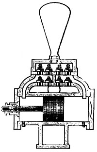
Fig. 181.
Water Ends. There are properly speaking four kinds of water ends to steam and power pumps:
1, A solid plunger, with a stuffing box used for heavy pressings in hydraulic apparatus, or as shown in Fig. 182, for larger plungers.
2, A piston packed with fibrous material within the cylinder. See Fig. 181. The letter P in Fig. 182 and the following cuts indicates the plunger.
3, A plunger packed with a metal ring around the outside, as illustrated in Fig. 183.
4, Two plungers, Fig. 184, connected outside of the cylinder with a stuffing box in two cylinder heads, through which the plungers work. These are more fully explained and illustrated as they occur in many examples as they are referred to in the oncoming chapters of this work.
The construction of the water ends of single cylinder and duplex pumps is practically the same; any slight differences which may be found are confined to minor details, which in no way affect the general design or operation of the pump.
The steam or power ends of numerous and varied makes of pumps are also as shown in the following pages of this work; all pumps actuated by power—steam, electric, etc.—are possessed of these two distinguishing features—1, a steam or power end, and 2, the water end.
Note.—This statement has exception in the cases of large pumping engines having a fly wheel or supplemental cylinders attached to an accumulator, in which case the steam is worked expansively.
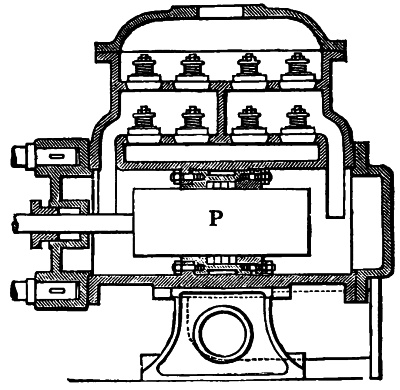
Fig. 182.
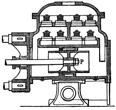
Fig. 183.
The steam end of the ordinary single steam pump, and also of the duplex pump, differs from the steam cylinder of the steam engine in that the former has four ports to each cylinder, i. e., two steam ports and two cushioning ports as shown hereafter in figures.
Under the division of the work allotted to the “Steam Pump” will be found all necessary further notice of the steam ends of Pumps.
Pump Valves. The valve apparatus is perhaps the most important part of any form of pump and its design has a material bearing upon its efficiency.
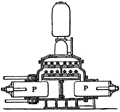
Fig. 184.
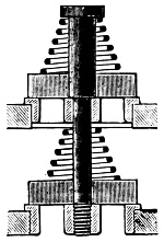
Fig. 185.
The valves shown in Fig. 181 are carried by two plates or decks, the suction valves being attached to the lower plate and the delivery valves to the upper one. The upper deck, and sometimes both decks, are removable. The valves are secured to the plates by means of bolts or long machine screws, which, in turn, are screwed into the bridge across the board in the plate, as shown in Figs. 185 and 186 or capped as in Fig. 187. The valves in all pumps except the large sizes, which may properly be classed with pumping engines, are of the flat rubber disc type212, with a hole in the center to enable the valve to rise easily on the bolt, the latter serving as a guide. A conical spring is employed to hold the valve firmly to its seat, the spring being held in position by the head of the bolt, or cap, as shown.
Certain improvements in pump-valves have been made which tend to increase the durability and to prevent the liability of sticking, which is not an uncommon occurrence after the valves have become badly worn. The improved forms of pump valves are shown in Figs. 186 and 187.
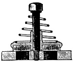
Fig. 186.
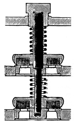
Fig. 187.
When these valves leak through wear the disc may be reversed, using the upper side of the disc next to the valve seat. This can be done with ordinary valves also, provided the spring has not injured the upper surface of the disc. Valve seats are generally pressed into the plates, although instances may be found where they are screwed. When pressed in they may be withdrawn by substituting a bolt having longer screw threads than the regular bolt, and provided with a nut, as shown in Fig. 188. The bolt is slipped through a yoke and screwed into the bridge. By turning the nut the seat can generally be started without difficulty.
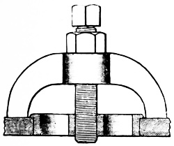
Fig. 188.
Fig. 189 represents the customary gland and stuffing-box in which the gland is adjusted by the nuts C and D upon two studs. After the adjustment has been properly made lock-nuts are tightened which leaves the gland free yet preserves the alignment.
It has been proven by practice—after long and costly experiments—that a number of small valves instead of one large one are far the most durable; durability being the question. Corliss, Leavitt, Holly and other leading pump builders had occasion to find the truth of this statement early in their careers. The “slamming” of large valves under moderate speeds proved itself an almost insurmountable difficulty until the principle of keeping the valve area as low as possible within reasonable limits had been fully demonstrated.
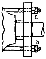
Fig. 189.
To illustrate the advantage of having a number of comparatively small valves instead of one large one, suppose a pump to be fitted with four 31⁄2-inch delivery valves at each end, the valves covering ports 21⁄2 inches in diameter. The area of each port is 4·9 square inches. In order to provide an equal area between the valve and the seat the valve must rise a distance equal to one-fourth the diameter of the port.
The combined area of the four ports is 19·6 square inches, which corresponds to the area of a circular opening 5 inches in diameter, one-fourth of which is 11⁄4 inches. It will be understood that the smaller valves can seat much more quickly and with less jar than the larger one, hence a larger number of small valves is not only better because of the great reduction in slippage, but they are also more economical, being subjected to less wear and tear.
The lift of valves for moderate or low speed pumps is seen in Fig. 190 and those for higher speeds in Fig. 191. These engravings clearly show the relative position of the suction and discharge valves during the movements of the piston.
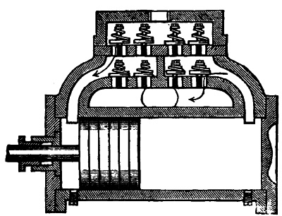
Fig. 190.
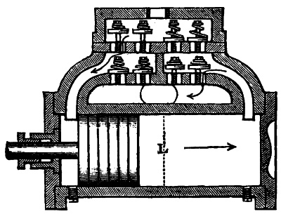
Fig. 191.
Pump slip or slippage is a term used to denote the difference between the calculated and the actual discharge of a pump, and is generally expressed as a percentage of the calculated discharge. Thus, when the slippage is given as 15 per cent. it indicates that the loss due to slip amounts to 15215 per cent. of the calculated discharge. Slippage is due to two causes, the time required for the suction and discharge valves to seat.
When pumps run very fast the piston speed is so high that the water cannot enter the pump fast enough to completely fill the cylinder and consequently a partial cylinder full of water is delivered at each stroke. High speeds also increase slippage, due to the seating of the valves. Fig. 191 represents a sectional view of the water end of a pump, showing the position of the valves during a quick reversal in the direction of the arrows, which illustrates the position of the valves corresponding to high speed. The valves in a pump, like almost every other detail in the operation of machinery, do not act instantaneously, but require time to reach the seats.
When pumps run at high speed the piston will move a considerable distance, while the valves are descending to their seats, and water flows back into the pump cylinder until the valves are tightly closed. The valves will remain in the raised position shown in Fig. 191 until the piston stops at the end of the stroke, and under high speed the piston will reach the position on the return stroke indicated by the dotted line L by the time the valves are closed. The cylinder will be filled up to this point with water from the delivery chamber so that no vacuum can be formed until after the piston reaches this position. The volume of water that can be drawn into the cylinder must necessarily be represented by the cubic inches cf space, minus the quantity which flows back during the time the valves are closing. It will thus be seen that the actual volume of water discharged is considerably less than a cylinderful, and the difference, whatever it may prove to be, is called, and is due to slippage.
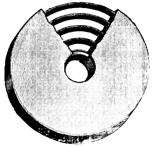
Fig. 192.
Fig. 190 represents the same pump running at a comparatively low speed. It will be noticed that the valves have not been raised as high as in Fig. 191, because a longer time being allowed for the discharge of the water, a smaller orifice is sufficient. It will be seen also that the piston, moving at a lower velocity, cannot travel as far in Fig. 190 before the valves216 seat, and consequently a vacuum can be created in the cylinder earlier in the stroke, and a larger volume of water can therefore be drawn in during the return stroke. In the latter case it is evident that the volume of water drawn into the cylinder will be nearly equal to a cylinderful and consequently the loss by slippage must be correspondingly less.
In order to reduce the loss by slippage several valves are used instead of a single valve of equal area. A flat disc valve will rise a distance equal to one-fourth the diameter of the port or of the opening in the seat to discharge the same volume of water that can flow through the port in the same time. In practice the rise exceeds this proportion of one-fourth a trifle, owing to the friction of the water, and this is especially true at high speeds.
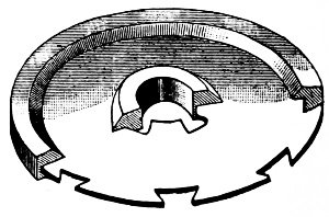
Fig. 193.
Reinforced pump valves. Where pure gum has been used for pump valves it has always proved too soft and when it has been compounded with other substances it has been found too hard to withstand the severe duty to which it is subjected as a material for pump valves.
In the accompanying Fig. 192 is shown the Braden pump valve, which is made of composition of rubber having wire rings embedded in the center of the disc. The composition has been removed from a section to show these rings. A ferrule of217 composition metal forms a hub around the center through which the bolt or stud passes to guide the valve and to prevent excessive wear of the hole.
Its wire coil frame work clothed with rubber maintains a due amount of stiffness, with a degree of flexibility which prevents its bulging into the holes in the seats, or sticking therein, and thus impairing the suction and discharge. Both sides, the upper as well as the lower, are made available for service. These qualities of stiffness and flexibility combined, permit this valve to adjust itself to form a water-tight seat.
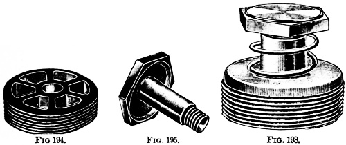
Figs. 194, 195, 198.
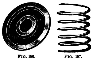
Figs. 196, 197.
Armored pump valves. As represented in Fig. 193 this is a valve made by stamping a metal disc out of steel which is then plated with copper to protect the surface and secure the adhesion of the rubber. Marginal notches are left on the inside and outside edges of the plate and rubber is moulded around these, and vulcanized to the required hardness; a brass or copper plate may be used instead of steel and the plates may be corrugated radially to increase their stiffness when the area of the valve is large.
Experience proves that the water valve adopted together with its location, has a material bearing upon the efficiency218 of any pump; easy seating valves are subject to more or less slippage, owing to tardy seating; the location of water valves should be above the pump cylinder, inasmuch as in operation the pump is always primed, while if suction valves are placed below, any wear on the valves or valve seats, or obstruction under the valves, will cause the water to leak entirely out of the water cylinder, making it necessary to prime the pump before it can be started.
Note.—The screwed seat is shown in Fig. 194, Stud Fig. 195, Metal Valve Fig. 196, Spring Fig. 197, and all put together in Fig. 198.
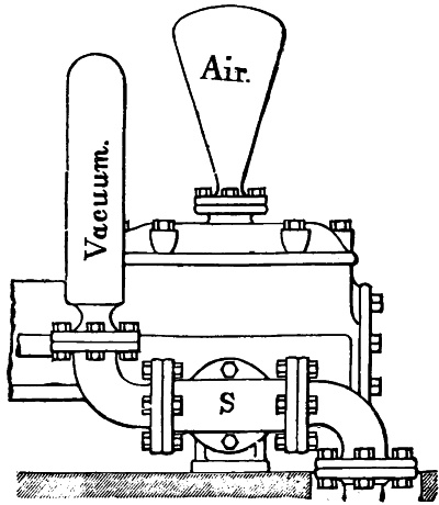
Fig. 199.
Valve seats, bolts and springs should be of the best composition or gun-metal; and valves of composition, or hard or soft rubber, to suit the duty such pump is required to perform. These valve seats are screwed into the valve plate, and valves may be changed from composition to rubber by merely removing bolt, and substituting one for the other without removing the seat. This is of great advantage where a pump is to be used for hot water after being used for cold water.
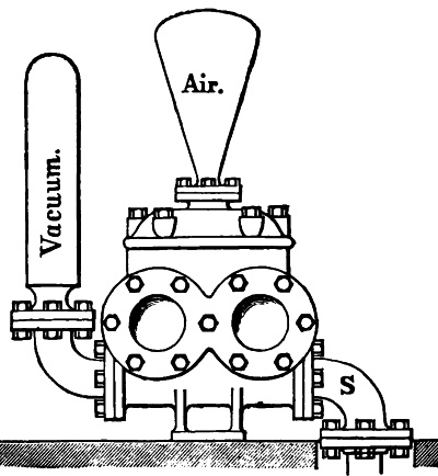
Fig. 200.
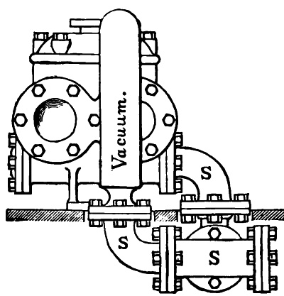
Fig. 201.
Air chambers are placed upon the top of a pump, see Figs. 199 and 200, and contain air for the purpose of introducing an air cushion to counteract the solidity of the water, thus preventing shocks as the water flows through the valves; and also for the purpose of securing a steady discharge of water.
The water being under pressure in the discharge chamber, compresses the air in the air chamber during each stroke of the water piston and, when the piston stops momentarily at the end of the stroke, the air expands to a certain extent and tends to produce a gradual stopping of the flow of water, thus permitting the valves to seat easily and without shock or jar.
The capacity of the air chamber varies in different makes of pumps from 2 to 31⁄2 times the volume of the water cylinder in single cylinder pumps, and from 1 to 21⁄2 times the volume of the water cylinder in the duplex type. The volume of the water cylinder is represented by the area of the water piston multiplied by the length of stroke.
For single-cylinder, boiler-feed pumps and those employed for elevator and similar service the volume of the air chamber should be 3 times the volume of the water cylinder, and for duplex pumps, not less than twice the volume of the water cylinder. High speed pumps, such as fire pumps, should be provided with air chambers containing from 5 to 6 times the volume of the water cylinder.
The diameter of the neck should not exceed one-third the diameter of the chamber. When the pumps work under pressure exceeding 85 or 90 pounds per square inch, it is frequently found that the air gradually disappears from the air chamber, the air passing off with the water by absorption. In this case air should be supplied to the air chamber unless the pump runs at very low speeds, say, from 10 to 20 strokes for the smaller sizes and from 3 to 5 strokes per minute for pumping engines. At higher speed and with no air in the air chamber the valves221 are apt to seat heavily and cause more or less jar and noise, and the flow of water will not be uniform. The water level in the air chamber should be kept down to from one-fourth to one-third the height of the air chamber for smooth running at medium and high speeds.
Note.—In large pumping plants small air pumps are employed for keeping the air chambers properly charged. In smaller plants an ordinary bicycle pump and a piece of rubber tubing are used to good advantage.
Vacuum chambers are shown in Figs. 199, 200 and 201. These devices are attached to the suction pipe. When the column of water in the suction pipe of a pump is once set in motion, it is quite important, especially under high speeds, to keep the water in full motion, and when it is stopped, to stop it gradually and easily. This is accomplished by placing a vacuum chamber on the suction pipe, as shown in the figures.
The location of the vacuum chamber may be varied to suit the convenience of the engine room arrangements. Fig. 199 represents the vacuum chamber at the side of the pump, Fig. 200 shows it opposite the suction and Fig. 201 represents its position at the end of the pump.
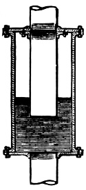
Fig. 202.
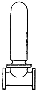
Fig. 203.
Vacuum chambers are practically of two designs, as shown in Figs. 202 and 203. The one shown in Fig. 203 should be placed in such position as to receive the impact of the column of water in the suction pipe. In order to do this effectively it should be placed in the position shown in Figs. 199, 200 or 201. The chamber illustrated in Fig. 202 is placed in the suction pipe below, but close to the pump.
The action of the vacuum chamber is practically the reverse of that of the air chamber. The object of the vacuum chamber is to facilitate changing continuous into intermittent motion. The moving column of water compresses the air in the vacuum chamber at the ends of the stroke of the piston, and when the piston starts the air expands (thus creating a partial vacuum222 above the water) and aids the piston in setting the column of water in motion again.
Thus the flow of water into the suction chamber of the pump is much more uniform during each stroke of the piston than without the vacuum chamber, and consequently the pump can be run at higher speeds without increasing the loss due to slippage and without “slamming” of the valves. Vacuum chambers should be slightly larger than the suction pipe and of considerable length rather than of large diameter and short. The size of the neck is substantially the same as in the air chamber.
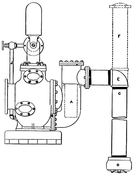
Fig. 204.
Fig. 204 on the opposite page represents the pipe connections, etc., of a pump with the delivery opening on the opposite side. D represents the foot valve and strainer placed on the lower end of the suction, which should be not less than a foot from the bottom of the well; the distance named provides for the gradual filling of the well. C is the suction pipe proper, screwed into the elbow, E, which changes its direction into the suction chamber, which contains the strainer, A. This strainer can be removed for cleaning by lifting the bonnet secured by stud bolts on top. In connecting large pumps it is customary to attach a vacuum chamber, F, which in the absence of any regular pattern, may be made of a piece of pipe of the same diameter as the suction and screwed into a T, instead of the elbow, E, with a regulation screwed cap on top as shown in the dotted lines.
A priming pipe is shown by the letter J, often used to fill the pump on starting. The discharge pipe connection is shown at G with the air chamber attached.
This figure is introduced for the purpose of showing an approved method of piping a pump. It may be observed that the flange joints in this design are so arranged that they may be disconnected without unscrewing any part of the suction pipe; this feature is almost essential in view of needed repairs.
The foregoing description of the parts of a pump relate to the water end solely; there remain the more complex and widely differing parts of the steam-end which constitute the distinguishing characteristics of the pumps built by the different makers. There remain also the particular parts belonging to the large pumping engines, air-pumps, etc.
These will be described under their respective chapters with much added and essential matter. Particular details as to the conditions of service under which it is proposed to operate pumps are to be found on the next page.
It is especially important that the makers and also the sellers of pumps and pumping machinery should be informed regarding the proper type, size, pattern and proportion of parts for any peculiar service, as well as to the plan of their connections and the kind of material to be used in their construction.
This information regarding the conditions of the service under which the pump is to be worked is quite pertinent to the foregoing pages regarding the parts of pumps. The following questions are extracted from the catalogue of an extensive manufacturer.
First—To what service is it to be applied?
Second—The quality of the liquid to be pumped, whether salt, fresh, acid, clear or gritty, and whether cold or hot?
Third—To what height is the water to be lifted by suction, and what are the length and diameter of the suction and discharge pipes?
Fourth—Of what material is the suction pipe, and what is its general arrangement as regards other pipes leading into it, etc.?
Fifth—Will the supply be taken from a driven well? If not, from what source?
Sixth—To what height, or against what pressure, is the water to be pumped?
Seventh—What is the greatest quantity of water to be delivered per hour?
Eighth—What boiler pressure of steam is carried?
Ninth—Will the pump exhaust into the atmosphere, into a condenser, or against a back pressure? If the latter, how much?
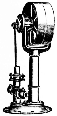
Fig. 205.
Fig. 205 represents an approved form of steam boiler feed pump, single acting. It has a crank shaft and a tight and loose pulley. It may be driven direct from any line shaft, a countershaft being unnecessary.
This is a compact form of a boiler feed pump; formerly the pump crank shaft was attached to floor beams or timbers above and connected by a long pitman to the pump which stood upon the floor; the objections to the older system of apparatus were found to be the vibration of the long pitman and the springing of the floors.
To obviate these two difficulties the pump and countershaft were attached to a post bringing them nearer together but finally resulting in the design of pump here shown. The broad base insures great stability in the operation of the pump especially when fixed to a rigid floor or timber foundation.
In the Table below are given some details furnished by the makers relating to six sizes of this style of pump, to which may be added that the speed ordinarily used varies from 100 revolutions per minute for the small sizes, to 20 revolutions for the larger sizes.
Table.
| No. | Size piston. | Suction fitted for. | Discharge fitted for. | Stroke. | Size pulleys, in. | ||||
|---|---|---|---|---|---|---|---|---|---|
| 1 | 2 | in. | 1 | in. pipe | 1 | in. pipe | 3 | in. | 16 × 4 |
| 2 | 21⁄2 | „ | 1 | „ „ | 1 | „ „ | 3 | „ | 16 × 4 |
| 3 | 3 | „ | 11⁄4 | „ „ | 11⁄4 | „ „ | 3 | „ | 16 × 4 |
| 4 | 2 | „ | 11⁄4 | „ „ | 11⁄4 | „ „ | 6 | „ | 18 × 4 |
| 5 | 21⁄2 | „ | 11⁄4 | „ „ | 11⁄4 | „ „ | 6 | „ | 18 × 4 |
| 6 | 3 | „ | 11⁄2 | „ „ | 11⁄2 | „ „ | 6 | „ | 18 × 4 |
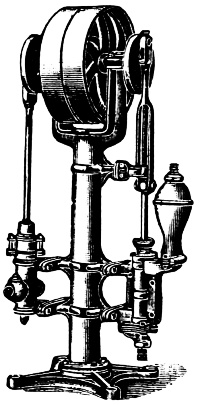
Fig. 206.
Fig. 206 exhibits two independent pumps. The description of the pump shown in Fig. 205 will apply to the left-hand pump which is a boiler feed pump. The improvement consists in the addition of another pump at the right-hand side; this is a suction force pump with an air chamber and is used to draw water from a well and discharge it into a tank from which it is taken by the other pump and forced into the boiler, as occasion requires.
These two pumps work simultaneously, being driven from the same shaft with cranks set opposite each other. Like the pump previously described this has a tight and loose pulley. The larger sizes are geared, having a pinion on the pulley shaft and a spur wheel on the crank shaft.
These two pumps represent a high service and a low service, the left-hand pump working under high pressure, against that in the boiler and the right one against the head of water in the tank. Each pump has its own separate connections—one or more—to suit the required conditions.
The right-hand pump is double acting; the plunger-rod is guided by a steadiment which holds it in line and preserves this alignment and the power is transmitted through a forked connecting rod. The Table below refers to both these pumps.
Table.
| BOILER PUMP. | DBLE.-ACTING FORCE PUMP. | ||||
|---|---|---|---|---|---|
| Diam. cyl. |
Suc. and dis. |
Gal. per stroke |
Diam. cyl. |
Suc. and dis. |
Gal. per rev. |
| 21⁄2 in. | 11⁄4 in. | 1—8 | 3 in. | 11⁄2 in. | 2—5 |
| 21⁄2 „ | 11⁄4 „ | 1—8 | 4 „ | 2 „ | 4—5 |
In Fig. 207 is shown a double acting power pump used principally for feeding boilers but may be employed for any purpose in forcing water or other liquids against pressure. This pump is double acting, is made with four check valves, as shown in engraving, and will draw water through 25 feet of suction pipe. On a high lift like the foregoing a foot valve (as shown at D in Fig. 204) should be used.
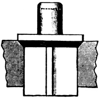
Straight Wings.
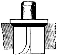
Spiral Wings.
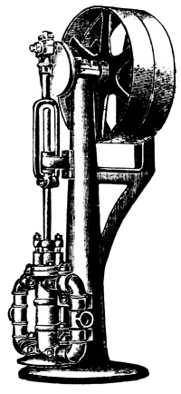
Fig. 207.
The form of valves used in this type of pump are the regular commercial check valves, made of steam-metal, extra heavy; the valve proper is of the wing pattern as shown in the small cuts. There are four of these wings on each valve, at right angles to one another forming a cross with arms of equal lengths.
The seat of the valve has an angle of 45° to which the valve is adjusted. A part of this valve projects above the top and has a slot, shown by the dotted line in it to receive the edge of a screw-driver, held in a bit stock to grind the valve seat in refitting. The lift of the valve is regulated by the distance between the top of the stem and the bottom of the covering nut or cap.
In hydraulic pumps it is found to be good practice to give the wings of these valves a twist, or pitch, so that the water in passing through will cause the valve to rotate and fall in a new position every time it comes in contact with the seat.
Fig. 208 represents a very compact design of double acting low service belt driven pump. The water cylinder is bored and has a piston fitted to it; both ends of this cylinder are covered with “heads,” one of which has a stuffing box through which the piston operates; the outer end of this piston rod is fitted to a slotted yoke which slides upon a guide at the bottom.
This mechanism, just described, takes the place of a pitman connection and occupies very much less space. The crank shaft is supported at each end in pillow blocks and is driven by a belt having a tight and loose pulley; larger sizes are geared. Access to the two sets of valves can be had by slacking up four nuts upon the long belts, two of which are shown in the engraving. The broad base secures great stability for this size pump.
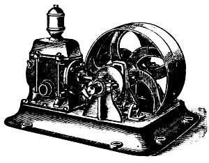
Fig. 208.
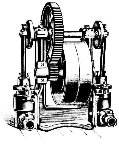
Fig. 209.
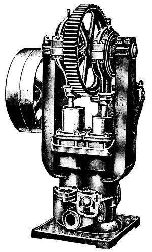
Fig. 210.
Fig. 209 exhibits two single acting plunger pumps actuated by one shaft having a crank upon each end with crank pins opposite to one another. This shaft is supported on the top of two pillars which form a part of the solid cast iron frame. The boxes are babbited. The crank shaft has a cast iron spur gear keyed to it and meshes into a pinion upon the pulley shaft. The teeth are cut to insure smooth and quiet running. The power is transmitted through a belt upon a tight and loose pulley. Each pump is secured to the frame by four bolts. The lower end of the pitman has an arrangement to take up the wear by means of two set screws with lock-nuts as shown in the figure230 on the top of each plunger. This pump is largely used as a boiler feed pump. These pumps can be used separately or together and with single or compound connections.
Duplex Power Pump. This engraving, Fig. 210, shows a special boiler feed pump having ball valves, as shown in section, and which is also intended for use in pulp mills and in other places where it is necessary to pump sandy or muddy water, or chemicals, soap and other heavy bodied liquids. These pumps have composition ball valves, composition plungers and composition lined cylinders and glands.
The two barrels or cylinders of this pump are brought together so as to occupy as little space as possible. Instead of cranks eccentrics are used having very large wearing surfaces. Each pitman has a ball at its lower extremity forming a “ball and socket” joint, which is adjustable to compensate for wear. All the bearings are Babbitted and like the last pump described the gears have cut teeth. It is belt driven.
If there are two cranks as in the duplex power pump they are placed opposite to one another or 180° apart, the circle described by the crank-pin containing 360 degrees. In the triplex pump this circle is divided into three equal parts of 120° each which is represented by the position of the cranks; a quadruplex or two duplex pumps attached to the same shaft the cranks will be 90° apart. This arrangement effects a uniform distribution of load on the crank shaft and one of the pumps is continuously discharging at its maximum capacity.
This duplex power pump should not be confounded with the “Duplex Pump” so called. The latter has two steam cylinders and two water cylinders and is double acting while the former is single acting.
The successful operation and durability of these, as of all power pumps, depends largely upon the judicious selection and application of a proper packing to the stuffing boxes. As for example, plaited flax dipped in a mixture of warm graphite and tallow, braided rawhide, Selden’s packing, etc., have proved by long service to have a low co-efficient of friction and are not liable to cut the plungers.
The triplex power gang pump is shown in Fig. 211. The engraving represents two triplex pumps bolted to one bed, and having an extended pulley shaft with pinions near each end to drive all of the pumps.
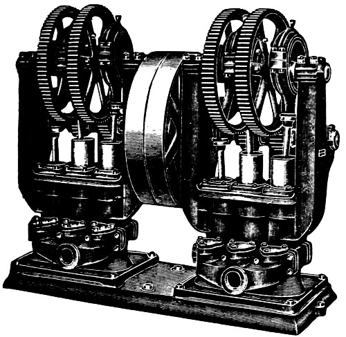
Fig. 211.
Table.
| No. | 1 | 2 | 3 | 4 | 5 |
| Size of Plunger in inches |
21⁄4 | 3 | 41⁄2 | 6 | 8 |
| Length of Stroke in Inches |
23⁄4 | 31⁄4 | 43⁄4 | 61⁄2 | 81⁄2 |
| Gallons per Stroke or 1 Rev. |
.28 | .58 | 1.96 | 4·76 | 11.08 |
| Revolutions per Minute |
20 to 50 | 10 to 40 | 10 to 40 | 10 to 30 | 10 to 25 |
| Size of Suction in Inches |
11⁄4 | 11⁄2 | 21⁄2 | 4 | 5 |
| Size of Discharge in Inches |
11⁄4 | 11⁄2 | 2 | 31⁄2 | 4 |
| Size of Pulleys |
ACCORDING TO DUTY REQUIRED | ||||
| Geared | { *16 } { 72# } |
{ *16 } { 80# } |
{ *13 } { 71# } |
{ *20 } { 89# } |
{ *20 } { 80# } |
| Pressure Pounds |
175 | 175 | 170 | 165 | 160 |
* Teeth in Pinion.# Teeth in Spur Gear.
The description of the duplex power pump just given, applies to this type also. The exception is that the triplex has three plungers and barrels instead of two. There are two spur wheels and two pinions on each pump to equalize the power to better advantage, as by this arrangement one eccentric is placed between each pair of spur wheels and two eccentrics outside. The pinion shaft is in one piece having tight and loose pulleys.
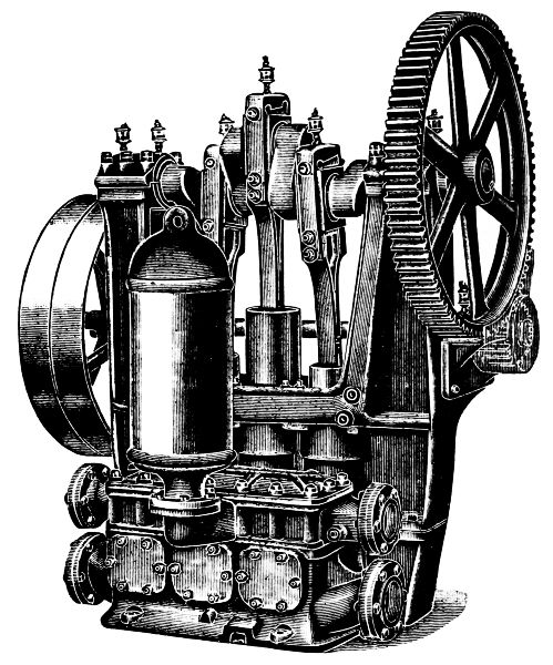
Fig. 212.
The eccentrics—six in number—are set at 60°, and an even strain on the belt at all points of the stroke is thus obtained, and connecting both discharges together insures a steady flow without shock. Where light duty only is required, these pumps are made without gears to run with the belt over pulleys.
Fig. 212 represents a single acting triplex plunger pump actuated by a belt over a tight and loose pulley.
The principal characteristic of this pump is the long connecting rods. These have at their upper ends regular connecting rod straps with brasses fitted to them and adjusted by wedges and set screws. At the plunger or lower ends of these rods bronze bushings and steel pins are used.
These pumps are largely employed for pumping semi-liquids such as tar, soap, mud, tan-liquor, oils, chemicals, sewage, etc.
The teeth of the pinion and the meshing part of the two gears are protected by a shield to prevent clothing being caught or parts of the body from being injured.
For these various materials different valves are necessary to be used each suited to the substance to be elevated or conveyed.
The removal of one cover, in this pump, exposes all the discharge valves and a plate uncovers each of the three groups of suction valves, as shown. The suction pipe may be attached at either end of the suction chamber while the discharge pipe may be connected with one or both ends of the discharge chamber.
The pump here represented has barrels 8-inch in diameter by 10-inch stroke. The air chamber is very large in proportion to the pump.
Table.
| Plungers | Capacity one Revolution of Crank Shaft |
Sizes of Pipe | Geared | Tight and Loose Pulleys |
||
|---|---|---|---|---|---|---|
| Diameter | Stroke | Suction | Discharge | |||
| 4 in. | 4 in. | 0·65 gals. | 3 in. | 3 in. | 5 to 1 | 20 × 3 in. |
| 4 „ | 6 „ | 1· „ | 3 „ | 3 „ | 5 to 1 | 20 × 3 „ |
| 5 „ | 6 „ | 1·5 „ | 4 „ | 4 „ | 4 to 1 | 20 × 4 „ |
| 5 „ | 8 „ | 2· „ | 4 „ | 4 „ | 4 to 1 | 20 × 4 „ |
| 7 „ | 8 „ | 4· „ | 5 „ | 5 „ | 4 to 1 | 30 × 5 „ |
| 8 „ | 10 „ | 6·5 „ | 6 „ | 6 „ | 5 to 1 | 36 × 6 „ |
| 8 „ | 12 „ | 7·8 „ | 6 „ | 6 „ | 5 to 1 | 36 × 6 „ |
The Deane single acting triplex power pump is shown in Fig. 213. Pumps of this type are used for general service in places where a large quantity of water is to be obtained in a short time and delivered under high pressure; they are adapted for tank service, water works, boiler feed, etc.
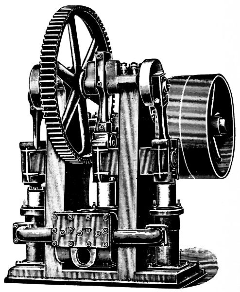
Fig. 213.
The pillar, or column design of frame is employed in this pump which secures great strength with the least weight of material, and at the same time is accessible for adjustment or repairs. The bearings for both the steel shafts are unusually long, which reduces the pressure per square inch below the factor of235 safety and increases the durability. The crankpins are set 120 degrees with one another so that the strokes successively overlap, which promotes an easy flow of water through the delivery pipe. The crank shaft is of the composite design, the center crank pin is of equal diameter and forming a part of the shaft, with discs and crank pins attached to each end by shrinking fits and keys. Either disc, crank, or their crank pins, can be duplicated without sacrificing any other part, which in itself is a great advantage.
The connecting rods have solid ends with adjustable boxes, with adjustment by means of wedge and screws. The brasses are lined with a special anti-friction metal bored to exact size.
The crossheads are of the box design with adjustable shoes having large wearing surfaces in bored guides. These guides are secured to the frame by studs and nuts.
The plungers are outside packed, the cylinders are submerged, thus keeping the pump primed at all times. The plungers are bolted to the crossheads and are readily removed when necessary. The cylinders are single acting and are cast separate from the base and other parts of the machine, so that repairs can be made at small cost, and, furthermore, should it be desirable to use the pump for moving liquids which would be injurious to cast iron, cylinders of other metals are substituted. The water chest is cast separate from the cylinders and is provided with large handholes, affording easy access to the interior and to the valves for inspection and cleaning. The handholes are located so that one valve may be removed independent of the others.
Improved grease cups are placed on all the bearings. This pump is very popular with the users of power driven pumps and is generally selected for high pressures and for hot or gritty water. Its simplicity of design and construction, together with the convenient arrangement of working parts, renders it desirable in isolated places where little attention is given to any kind of pumps.
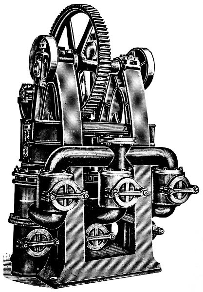
Fig. 214.
Fig. 214 represents the Gould triplex single acting power pump and is one of many designs of this class of power pumps. The frame consists of two standards, which contain the two end cylinders, and the seats to which the outside crosshead guides are bolted. These are held together by two castings, one containing the center crosshead guide, and the other237 the center cylinder. The crankshaft is a solid steel forging, while the bearings are of phosphor bronze, and the pinion shaft bearings Babbitted.
The gear wheels are machine cut, the pinion and the adjacent teeth of the large gear are covered by suitable guards.
The crossheads are provided with adjustable shoes or gibs, which work in bored guides. The connecting rods are fitted with straps and bronze boxes, which are adjustable for wear by means of wedge and set screws, the wristpin brasses being of the marine type. The cylinders are provided with bronze liners, which are readily removable when necessary for repairs, the plungers being ground to size, present a smooth polished surface to resist the wear.
The valve boxes are separate castings, and each contains a set of suction and discharge valves. These valves are rubber discs, held firmly against the bronze seats by cylindrically wound springs. All of these pumps are furnished with air chambers, and vacuum chambers are provided when the nature of the service demands it. All valves and other working parts of the pump are accessible for inspection, cleaning and repairs, all internal parts being arranged within easy reach through the large handholes.
The pumps here shown are intended for moderately light pressures as for example not to exceed 150 lbs. per square inch, but they are also made in heavier proportions for very high pressures (5,000 lbs. to 15,000 lbs.) such as is necessary to operate hydraulic presses, draw benches for brass and copper tubing and that class of work.
A very simple automatic regulator and by-pass connection (shown in the chapter on accessories) can be attached to these pumps in situations where a constant pressure is to be maintained and allow the pump to run continuously at its maximum speed. This regulator is adjusted to open the by-pass valve whenever the pressure in the compression tank or pipe system exceeds the limit pressure, and so fills the office of a safety valve by allowing the surplus water to return to the tank.
The Riedler belt driven pump is shown in Fig. 215.
The principal feature of this pump is its valve; there is but one valve for the suction and one for the discharge, which greatly simplifies the pump end. When working against high pressures, the ordinary rubber or leather faced valves are oftentimes pounded to pieces, but in this pump, on account of the mechanical control, the valves work well under all pressures.
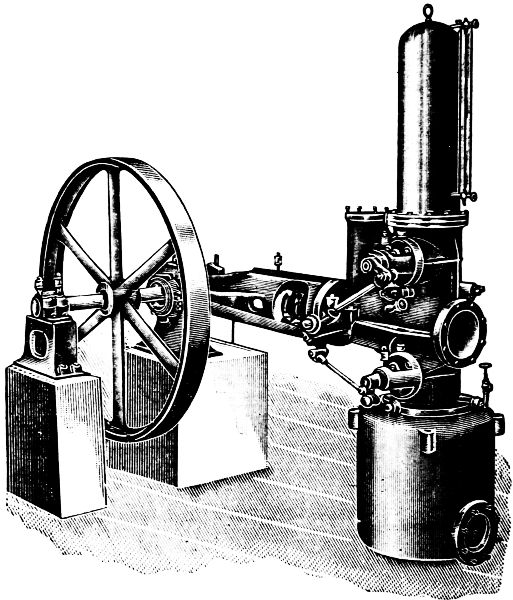
Fig. 215.
This valve and valve seat are circular in form, and made of bronze, as shown in Fig. 216. The valve has a lift of from 1 to 2 inches, and an area sufficiently large to reduce the velocity of the water flowing through it to a few feet per second.
At the beginning of the stroke the valve opens automatically, controlled, however, by a very simple and effective mechanical device, and it remains open practically during the entire stroke. When near the end, it is positively closed at the proper moment by the controller.
This valve, see Fig. 216, may be briefly described as follows. The seat, A, is turned to slip into its place in the pump and is made tight by a round rubber hydraulic packing, B, in a groove near the bottom. A spindle or stud, C, in the center of this seat supports and guides the valve, D, which is made tight by a leather seal, E. The rubber collar or buffer spring holds the valve above its seat, and this valve unlike ordinary pump valves, always remains open except when pressure is brought to bear to close it. The valve bonnet, G, also forms the bearing for the valve stem with fork, which spans the spindle, C, at one end and having the valve lever and pin, H, for operating at the other end. The valve stem is made tight by a stuffing-box and gland as shown. The operation of this valve is substantially as follows.
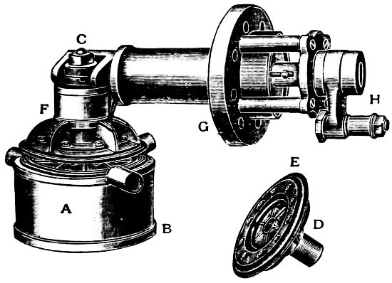
Fig. 216.
At the beginning of the suction stroke the valve is opened by the rubber spring, F, the pressure upon the collar being relieved by lifting of the valve fork arms through motion of the eccentric.
It will be observed from an inspection of Fig. 215 that both the suction valve and the discharge valve are controlled by an eccentric—rock arm—and valve levers similar to the motion of Corliss valves.
As the plunger nears the end of its stroke and before it starts on the return stroke, the valve fork closes the valve, and thus prevents slip and avoids pounding, so common in pumps having valves that close by their own weight. In case of any obstruction between the valve and its seat the rubber buffer spring will be compressed thus preventing all injury to mechanism.
The lost work expended in closing the valves is hardly worth any consideration as it is practically the friction only of the eccentric and the members of the valve gearing, the bearings of which are all small.
The motion for these valve gears is usually taken from an eccentric on the main shaft.
The standard speed of the Riedler pumps is about 150 revolutions per minute. Smaller pumps run even faster than this.
It may be desired to connect a pump directly to a high speed electric motor or water wheel already installed. To meet these conditions, a special design known as the Riedler Express pump, is built.
The chief feature of this pump, is its suction valve. This valve is concentric with, and outside of the plunger, and lifts in the opposite direction to that of the plunger when on its suction stroke. At the end of the suction stroke, the plunger presses the valve to its seat, thus making it certain that the valve is seated when the plunger starts on its delivery stroke, allowing practically no slip. A high air suction chamber containing a column of water is placed immediately before the suction valve, so it is certain that the pump will fill as the plunger moves. Ordinarily the pump would not completely fill, owing to the high speed of the plunger.
These pumps are also built with steam cylinders both of the plain slide valve and Corliss designs.
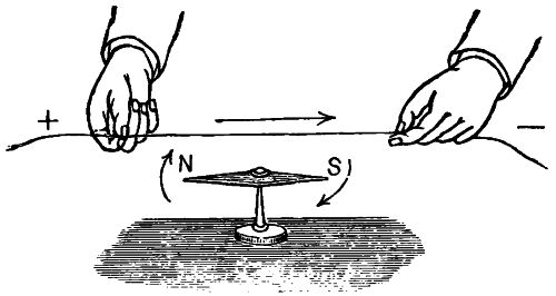
Compass Needle—See Page 266.
Each kind of power requires its own special machinery so constructed and adapted as to utilize it; hence, to be serviceable to mankind, electricity demands machinery suited to its nature; what that is, will be indicated in the following few paragraphs.
Electricity is a name derived from the Greek word electron—amber. It was discovered more than 2,000 years ago that amber when rubbed with a Fox’s tail possessed the curious property of attracting light bodies. It was discovered afterwards that this property could be produced in a dry steam jet by friction, and in A. D. 1600 or thereabouts, that glass, sealing-wax, etc., were also affected by rubbing, producing electricity.
Whatever electricity is, it is impossible to say, but for the present it is convenient to consider it as a kind of invisible something which pervades all bodies. While the nature and source of electricity are a mystery, and a constant challenge to the inquirer, many things about it have become known—thus, it is positively assured that electricity never manifests itself except when there is some mechanical disturbance in ordinary matter, and every exhibition of electricity in any of its multitudinous ways may always be traced back to a mass of matter.
Note.—The great forces of the world are invisible and impalpable; we cannot grasp or handle them; and though they are real enough, they have the appearance of being very unreal. Electricity and gravity are as subtle as they are mighty; they elude the eye and hand of the most skillful philosopher. In view of this, it is well for the average man not to try to fathom, too deeply, the science of either. To take the machines and appliances as they are “on the market,” and to acquire the skill to operate them, is the longest step toward the reason for doing it, and why the desired results follow.
Electricity, it is also conceded, is without weight, and, while electricity is, without doubt, one and the same, it is for convenience sometimes classified according to its motion, as—
1. Static electricity, or electricity at rest.
2. Current electricity, or electricity in motion.
3. Magnetism, or electricity in rotation.
4. Electricity in vibration.
Other useful divisions are into—
1. Frictional and
2. Dynamical,
And into—
1. Static, as the opposite of
2. Dynamic electricity.
There are still other definitions or divisions which are in every-day use, such as “vitreous” electricity, “atmospheric” electricity, “resinous” electricity, etc.
Static Electricity.—This is a term employed to define electricity produced by friction. It is properly employed in the sense of a static charge which shows itself by the attraction or repulsion between charged bodies. When static electricity is discharged, it causes more or less of a current, which shows itself by the passage of sparks or a brush discharge; by a peculiar prickling sensation; by an unusual smell due to its chemical effects; by heating the air or other substances in its path; and sometimes in other ways.
Current Electricity.—This may be defined as the quantity of electricity which passes through a conductor in a given time—or, electricity in the act of being discharged, or electricity in motion.
An electric current manifests itself by heating the wire or conductor, by causing a magnetic field around the conductor245 and by causing chemical changes in a liquid through which it may pass.
Note.—Statics is that branch of mechanics which treats of the forces which keep bodies at rest or in equilibrium. Dynamics treats of bodies in motion. Hence static electricity is electricity at rest. The earth’s great store of electricity is at rest or in equilibrium.
Radiated electricity is electricity in vibration. Where the current oscillates or vibrates back and forth with extreme rapidity, it takes the form of waves which are similar to waves of light.
Positive Electricity.—This term expresses the condition of the point of an electrified body having the higher energy from which it flows to a lower level. The sign which denotes this phase of electric excitement is +; all electricity is either positive or,-, negative.
Negative Electricity.—This is the reverse condition to the above and is expressed by the sign or symbol-. These two terms are used in the same sense as hot and cold.
Atmospheric electricity is the free electricity of the air which is almost always present in the atmosphere. Its exact cause is unknown. The phenomena of atmospheric electricity are of two kinds; there are the well-known manifestations of thunderstorms; and there are the phenomena of continual slight electrification in the air, best observed when the weather is fine; the aurora constitutes a third branch of the subject.
Dynamic Electricity.—This term is used to define current electricity to distinguish it from static electricity. This is the electricity produced by the dynamo.
Frictional electricity is that produced by the friction of one substance against another.
Resinous Electricity.—This is a term formerly used, in place of negative electricity. The phrase originated in the well known fact that a certain (negative) kind of electricity was produced by rubbing rosin.
Vitreous electricity is a term, formerly used, to describe that kind of electricity (positive) produced by rubbing glass.
Magneto-electricity is electricity in the form of currents flowing along wires; it is electricity derived from the motion of magnets—hence the name.
Voltaic Electricity.—This is electricity produced by the action of the voltaic cell or battery.
Electricity itself is the same thing, or phase of energy, by whatever source it is produced, and the foregoing definitions are given only as a matter of convenience.
The term is employed to denote that which moves or tends to move electricity from one place to another. For brevity it is written E. M. F.; it is the result of the difference of potential, and proportional to it. Just as in water pipes, a difference of level produces a pressure, and the pressure produces a flow so soon as the tap is turned on, so difference of potential produces electro-motive force, and electro-motive force sets up a current so soon as a circuit is completed for the electricity to flow through. Electro-motive force, therefore, may often be conveniently expressed as a difference of potential, and vice versa; but the reader must not forget this distinction.
In ordinary acceptance among engineers and practical working electricians, electro-motive force is considered as pressure and it is measured in units called volts. The usual standard for testing and comparison is a special form voltaic cell, called the Clark cell. This is made with great care and composed of pure chemicals.
The term positive expresses the condition of the point having the higher electric energy or pressure, and, negative, the lower relative condition of the other point, and the current is forced through the circuit by the (E. M. F.) electric pressure at the generator, just as a current of steam is impelled through pipes by the generating pressure at the steam-boiler.
Care must be taken not to confuse electro-motive force with electric force or electric energy, when matter is moved by a magnet, we speak rightly of magnetic force; when electricity moves matter, we may speak of electric force. But, E. M. F. is quite a different thing, not “force” at all, for it acts not on matter but on electricity, and tends to move it.
The word dynamo, meaning power, is one transferred from the Greek to the English language, hence the primary meaning of the term signifying the electric generator is, the electric power machine.
The word generator is derived from a word meaning birth giving, hence also the dynamo is the machine generating or giving birth to electricity.
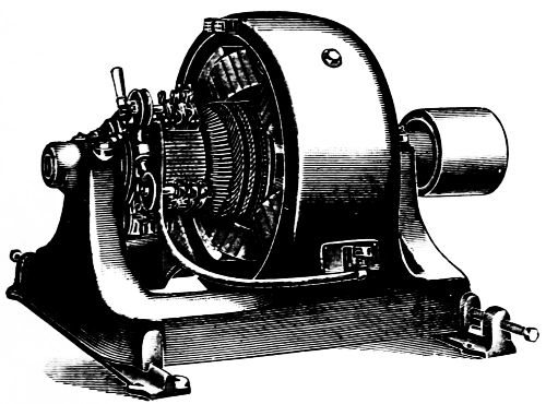
Fig. 217.—See page 251.
Again, the dynamo is a machine driven by power, generally steam or water power, and converting the mechanical energy expended in driving it, into electrical energy of the current form.
To summarize, the dynamo-electric generator or the dynamo-electric machine, proper, consists of five principal parts, viz:
1. The armature or revolving portion.
2. The field magnets, which produce the magnetic field in which the armature turns.
3. The pole-pieces.
4. The commutator or collector.
5. The collecting-brushes that rest on the commutator cylinder and take off the current of electricity generated by the machine.
Fig. 218 shows a dynamo of the early Edison type—the names of the principal parts are given in the note below, as well as those of the other parts of the machine.
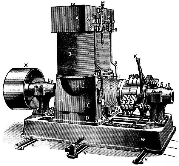
Fig. 218.
This is a two-pole machine, direct current; the figure is introduced to show the “parts” only—as this dynamo has been largely superseded by others of the four pole type.
Note.—A, Magnet yoke; B, Magnet and field piece; C, Pole piece; D, Zinc field piece; E, Armature; F, Commutator; I, Quadrant; JJ, Brushes; K, Adjusting handle for the brushes; L, Switch pivot; M, Pilot lamp receptacle; N, Negative lug; O, Switch lever; P, Positive lug; Q, Positive terminal; R, Negative terminal; S, Negative rod; T, Pole piece; UU, Bearings; X, Slides for belt tightener; VVV, Driving pulley; Y, Connecting blocks, one on each side of machine.
An electric motor is a machine for converting electrical energy into mechanical energy; in other words it produces mechanical power when supplied with an electric current; a certain amount of energy must be expended in driving it; the intake of the machine is the term used in defining the energy expended in driving it; the amount of power it delivers to the machinery is denominated its out-put.
The difference between the out-put to the intake is the real efficiency of the machine; it is well known that the total efficiency of an electric distribution system, which may include several machines, usually ranges from 75 to 80 per cent., at full load, and should not under ordinary circumstances fall off more than say 5 per cent. at one-third to half load; the efficiency of motors varies with their size, while a one horse-power motor will, perhaps, have an efficiency of 60 per cent., a 100 horse-power may easily have an efficiency of 90 per cent. and the larger sizes even more.
The general and growing application of electric power to the driving of all kinds of machinery including pumps makes the question of motor driving one of the most important in the power field. For many purposes, a single speed is sufficient, but for others, it is imperative that the speed should be variable; and for still others, though not absolutely necessary, a speed adjustment is very desirable.
While the direct-current motor has been in this field so long that its properties are well known and its possibilities fully developed, in the operation of motors located in the immediate neighborhood of the generator the alternating-current motor has marked advantages where a large area of territory has to be covered and the conditions are nearly uniform, that is to say—
Where the current has to be transmitted a long distance and the load is approximately constant, the alternating system is preferred, as it can be operated with small main lines or conductors. This effects a saving in copper, over the direct system which requires larger conductors.
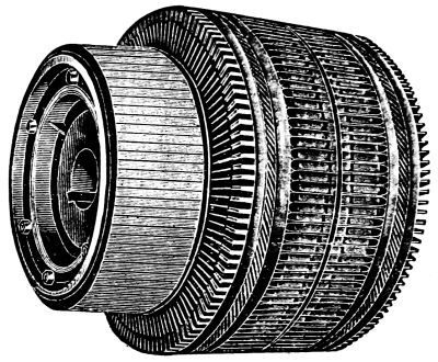
Fig. 219.
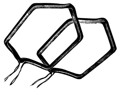
Fig. 220.
Fig. 217, on page 247, shows a four-pole generator designed to run by a belt or directly connected to an engine. The five parts named, as the principal parts of a dynamo, are all shown in the figure. The machine is arranged ready to be bolted to the floor.
Fig. 219 on the opposite page is the armature which is made up of coils of insulated wire, the free ends of which, see Fig. 220, are united to the arms of the commutator bars. When the armature is finished, as shown, the wire forms an unbroken circuit.
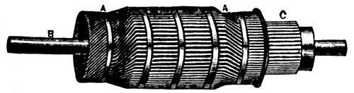
Fig. 221.
Fig. 221 is intended to represent another form of armature, but the principle upon which it operates, is the same, as the other shown. A A, represents the wire coils of the armature, B, is the shaft with its journals, C, is the commutator. All commutators both for generators and for motor armatures are insulated by mica between the bars.
Fig. 222.
Fig. 222 shows a woven wire brush. The brushes on the dynamo, page 247, are made of carbon.
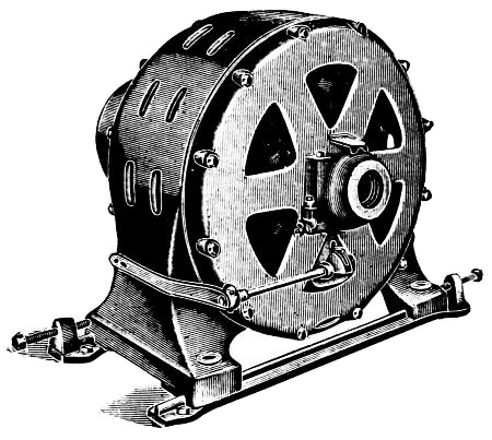
Fig. 223.
Fig. 223 shows an alternating induction motor. Induction is a property by virtue of which an electric current is transferred from one conducting line to another without any metallic connection; it is that influence by which a strong current flowing through a conductor controls or affects a weaker current flowing through another conductor in its immediate neighborhood,—the strong current remaining unaffected.
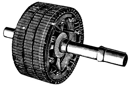
Fig. 224.
Fig. 224 exhibits the armature for the above alternator; it253 is familiarly called a “squirrel cage armature” on account of its resemblance to the wheel in a squirrel’s cage.
Its peculiar construction enables it to run without producing any sparks; this feature renders it safe to run where there are explosive gases which might be ignited by an electric spark. In the machine the bearings are cast solid with the end shields, thus assuring perfect alignment when properly turned. Another feature is the automatic self adjusting bearings which are lubricated mechanically by rings resting upon the shaft. These rings were formerly a failure, but by the use of mineral oils are now a success.
This machine is one of the simplest designs of alternating motors, the example, Fig. 223, is one developing one hundred horse-power.
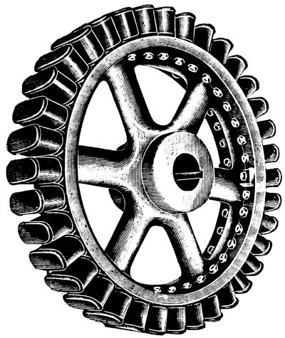
Fig. 225.
Fig. 225 shows a revolving field with “spider.” In this construction of generators or motors the field revolves in place of the armatures, the first object of this design is to reduce the high rotative speed; it is also claimed to have a better electrical efficiency.
The field spider consists of an extra heavy cast iron pulley which is keyed to the shaft; the low speed at which it runs permits the employment of bolts to secure the field coils and laminated pole pieces to the rim of the spider, as shown in the engraving. With this construction each individual pole piece can be removed and replaced independent of the others.
The laminated pole piece, one of which is shown in detail in Figs. 226-229, takes its name from the fact that it is built up of a large number of layers of soft sheet iron, which it has been demonstrated give a better electrical efficiency than a solid iron. Soft iron is the most magnetic of all metals and is better suited for pole pieces than steel.
It should be understood that each individual pole piece is insulated from the others as well as from the spider. The pieces of sheet iron are stamped out—like washers and are cut apart and the ends united so as to form a continuous coil, like a coil of wire and each coil is isolated; mica is used between the layers.
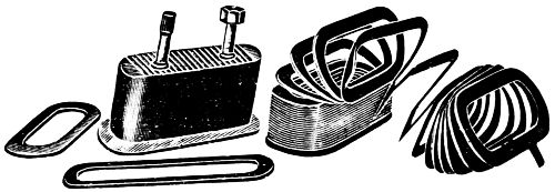
Figs. 226-229.
Fig. 230 is designed to illustrate the front of a continuous current two wire switchboard with circuit breakers; these are made up usually of marble or slate so that they will not burn; the Insurance Underwriters require a non-combustible material at this place, as well as hangers, and insulators used for conductors.
The Switches shown in the middle of the board, are enlarged in Fig. 232, and are used for closing the connections with the generators and lines running to various parts of the field to be lighted or furnished with power.
The switch handles are made usually of wood or hard rubber; the blades are of copper. The connections are soldered into the sockets shown upon the ends of the screws which project beyond the back of the switch-board.
The upper row of figures as shown in Fig. 230 and enlarged in the engraving, 231, are circuit-breakers. The use of these is analogous to that of the safety-valve upon a steam boiler, so that when the pressure in the circuit exceeds that at which it is set the “breaker” opens the circuit and thus prevents damage.
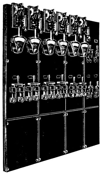
Fig. 230.
In this case, the main contact is formed by means of a laminated brush while the final stroke is made on carbon, the motion of this breaker is by means of a toggle-joint which so multiplies the power applied that it does not require much of an effort to close it; this device maintains the same speed in operating the breakers when the circuit-breaker is tripped.
A Rheostat is a device for controlling the amount of electricity in a conductor—by the insertion of coils of wire in a box—which may be successively switched in or out of the main circuit by means of a lever and button-switch. The best place to install a rheostat is on a wall or post, as the resistance transforms a portion of the electric energy into heat, which heat must be dispersed into the atmosphere.
A transformer is an induction coil employed usually for lowering electric pressure, but it may also be used for raising the same, in which case it is sometimes called a booster. A compensator is a transformer which works automatically.
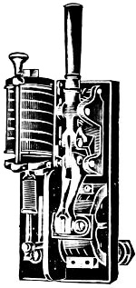
Fig. 231.
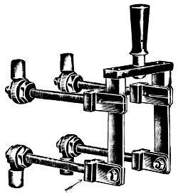
Fig. 232.
Ammeters record the quantity of current flowing through the circuit, in amperes. Voltmeters record the pressure or strength of the current in volts.
An Ampere is an electric current which would pass through a circuit whose resistance is one ohm under an electro-motive force of one volt. A Volt is an electro-motive force of sufficient strength to cause a current of one ampere to flow against a resistance of one ohm.
The ampere is the unit for calculations relating to the quantity or volume of a current; the volt is the unit for calculating the pressure or strength of the current.
The action of the electric current in producing rotation in an electric motor is really quite simple. While many electrical problems are comparatively complicated, the principal elements in the operation of electric motors may be readily understood. The fundamental fact in this connection is the relation between an electric current and a magnet.
If a piece of round bar iron be surrounded by a coil through which an electric current passes, it becomes a magnet. In Fig. 233 the passage of a current through the coil of wire around the iron bar in either direction, renders the iron a magnet, with all its well-known properties. It will attract iron, and the space surrounding it becomes magnetic. Iron filings will arrange themselves in the direction shown by the dotted lines in the figure. One end of the magnet is the North or positive + pole and the other the South or negative - pole.
If a wire, such as CD, be moved past either pole of the magnet, there will be a tendency for current to flow in the wire either from C to D or D to C, according to the character of the pole past which it is moved, and to the direction of the movement. If the ends of the wire CD are joined by a conductor, so that there is a complete circuit, a current of electricity will flow through this circuit.
This circuit may be a simple wire, as shown by the line CEFD, or it may be the wire coils on machines enabling the current to produce mechanical work, or it may be electric lamps producing light. The indispensable feature is that there shall be a complete unbroken circuit from C to D for the current to flow, no matter how complicated or how long this circuit may be.
This description of a dynamo and motor carries with it all of the elementary theory of electric generators and motors that is necessary for an attendant to know in order to take reasonably intelligent care of electric machines. Further useful knowledge must be acquired by studying the different types of electric motors and dynamos. All these other types of direct current machines have the same elementary theory, although their construction may be quite different.
By suitable illustrations the operation of the electric motor as applied to pumps will be easily understood; its application to other machines is the same in theory and practice.
“Why an electric motor revolves” is a question well worth careful, and, if necessary, long study.
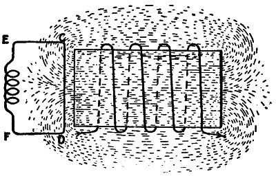
Fig. 233.
The reason why there is a tendency for an electric current to flow in the wire CD when it is moved in the vicinity of a magnet is not fully known. There are several theories, all more or less complicated, and depending upon pure assumptions as to the nature of an electric current. For practical purposes it matters little what the reason is, the fact that current flows when there ts an electric pressure in a closed circuit, is the important thing, and it serves all useful purposes to know that current does flow, and that its direction and amount are always the same under similar circumstances. There are many facts in mechanics that are accepted and used practically, about which little is known as to their fundamental and primary causes, and this fact about motors and dynamos is, therefore, only one of many which all must accept without a full and complete explanation.
The intensity of the electric pressure, or electro-motive force, depends upon the velocity of revolution of the wire sections in the armature and upon the strength of the magnets, and the quantity of current depends upon the electro-motive force and upon the amount of the resistance in the circuit. Other things being equal, the current, flowing through a long small wire, or greater resistance, will be less than through a short, thick wire, or a less resistance.
Having seen that when a wire is moved in the vicinity of a magnet an electric pressure is produced which will cause a current to flow in a closed circuit, one can easily conceive of many ways in which, by combining magnets and wires so that there will be a relative motion between them, a current of electricity may be generated. In order to cause a continuous flow the relative motion must be continuous; and if the current is to be uniform the motion must be uniform.
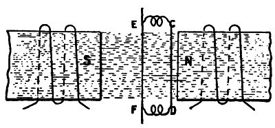
Fig. 234.
Two electro-magnets are shown in Fig. 234, in which the North pole of one magnet is near the South pole of the other, and the magnetic field between the two lies in the approximately straight lines between the two magnets, as indicated by the dotted lines. If the wire CD be moved across this field and its ends be joined, as by the metallic circuit CEFD, a current will flow in this circuit. The wire CD may be made to revolve around the wire EF, passing in front of one pole and then in front of the other pole, as in Fig. 235. The current in the circuit will pass in one direction when the wire is passing one pole, and in the other direction when it is passing the other260 pole. The connection between this elementary arrangement and the dynamo is easily recognized. In the dynamo a magnetic field is produced by electric magnets, called “pole pieces,” and a considerable number of wires similar to the wire CD are placed upon an armature so that they revolve in front of these poles. Each individual wire produces current first in one direction and then in another direction, as explained above; but if there be many wires there will always be the same number in front of the North, or positive pole, and the same number in front of the South, or negative pole, so that the total or resultant action is practically uniform, and may be made to produce a continuous current. Such a machine is the common direct current dynamo, or motor.
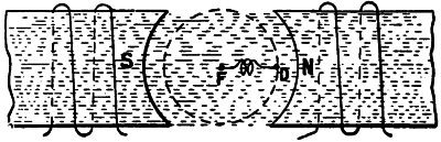
Fig. 235.
A dynamo transforms mechanical into electrical energy, and a motor transforms electrical into mechanical energy. The two operations are reversible, and may be effected in the same machine; a dynamo may be used as a motor, or a motor may become a dynamo.
A dynamo is a motor when it is driven by a current of electricity, and it is a dynamo when it is driven by mechanical power and produces an electric current. If a motor be driven by an engine, it can deliver a current of electricity which is able to operate other motors or electrical apparatus or lights. A simple form of electric machine is shown in Fig. 236, which is a general form of the electric motor. In this there are two projections of steel, H and G, which are made electro-magnets by the current flowing through the wires wound around261 them from any source of electricity, such as a battery at I and J. These magnets have poles facing toward an armature, K, on a shaft. The poles G and H are called the “salient” poles; the poles M and P are called the “consequent” poles. The magnetic flow or field is shown by the dotted lines. On the periphery of the armature are wires in the slots shown. As this armature revolves, there will be a tendency for electricity to flow through the wires.
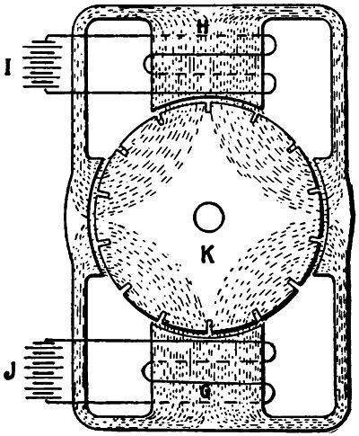
Fig. 236.
In order to distribute a current of electricity through these wires it is necessary to make a complete circuit. As each of the wires in the slots passes in front of a pole, a pressure or electro-motive force will be generated, and its direction will depend upon whether the pole is a North or a South pole, i.e., + or -.
Note.—In the above illustrations I and J represent the ordinary electric battery; in electrical literature such marks always indicate a battery.
The pressure or electro-motive force generated in the wires moving in front of the North, or positive field poles, will be in one direction, while that of those in front of the South, or negative field poles, will be in the opposite direction. Therefore, if two such wires be connected together at one end of the armature, the free terminals of the wires at the other end of the armature will have the sum of the electro-motive forces generated in the two wires. The wires so connected can be considered as a turn of a single wire instead of two separate wires, and this turn may be connected in series with other turns, so that the resulting electro-motive force is the sum of that in all the turns and all the wires so connected. It is customary to connect the coils of an armature so that the electro motive force given is that obtained from half the coils in series. The other half of the coils is connected in parallel with the first half, so that the currents flowing in the two halves will unite to give a current in the external circuit equal to twice the current in the two armature circuits or paths.
It is evident that, as the armature revolves, wires which were in front of the positive pole will pass in front of the negative, and that in order to maintain the electro-motive force it will be necessary to change the connections from the armature winding to the external circuit in such a way that all the wires between the two points of connection will have their electro-motive forces in the proper direction. The connection to the armature must therefore be made not at a definite point in the armature itself, but at a definite point with reference to the field magnets, so that all the wires between two points or contacts shall always sustain the same relation to the field magnets.
For this purpose a device known as a “commutator” is provided. The commutator is made up of a number of segments, as shown at A, in Fig. 237, which are connected to the armature winding. On the commutator, rest sliding contacts, or brushes, which bear on the segments and are joined to an external circuit, making a continuous path through which current may flow. As the commutator revolves, the different segments263 come under the brushes, so that the relative position of the armature wires between the brushes is dependent on the position of the brushes. The armature wires which connect the brushes are those sustaining the desired definite position to the field magnets, so that the currents from the armature at all times flow properly into the external circuit, although individual armature wires carry currents first in one direction and then in the other direction, depending on the character of the pole in front of which they may be moving.
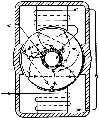
Fig. 237.
On two-pole machines there are two brush-holders, each containing one or more brushes. On the four-pole machine there may be either two or four brush-holders, and on a six-pole machine, either two, four, or six brush-holders.
A single path of the current through the commutator and armature winding is shown by the arrows on Fig. 237. The264 brushes B and C are placed on the top side of the commutator to make them more accessible, and this shows a peculiar but simple armature winding.
For the sake of simplicity, the batteries I and J, of Fig. 236, are not used on common forms of generators or motors, but the current that flows from the armature through the commutator is made to flow through the electro-magnets either in whole or in part. If all of the armature current flows around the electro-magnets or fields of the machine, it is a “series” machine; if only a part of the current is used in this way, it is a “shunt” machine; that is, some of the current is “shunted” through the fields. Sometimes both the shunt and series windings are used, and in that case the machine is called a “compound wound” machine. Such a machine has a large wire through which the main current passes, and a fine wire through which the shunted current flows. Fig. 237 shows how the commutator and the fields are connected, and how the current flows from the wires in the armature through the commutator in a series machine.
If the current delivered by a dynamo does not flow in the desired direction, it can be reversed by shifting the wires in the binding posts or by throwing a switch. If the motor does not revolve in the desired direction, it can be made to do so by reversing the connections to the armature or field-coils; so that, without knowing which way a current of electricity is to be generated, any practical man can make a motor revolve in a proper direction by simply changing its connections.
It is natural that a machine which gives out electric energy when driven by an external power, should, when electric energy is delivered to it, reverse its action and give out mechanical power and do work.
Perhaps the simplest way to explain the cause of the movement of an electric motor, when supplied with a current, is to compare its action to the well-known attraction of unlike poles or magnets and the repulsion of like poles. Unlike poles are North and South; like poles are two North or two South. In265 all motors a current through the field causes a North or South pole to be maintained, and a current through the armature and brushes causes an opposite polarity. These constantly-maintained unlike poles attract each other and pull the armature around on its axis.
It has been explained that if a motor be driven by a belt an electro-motive force is produced and the machine acts as a dynamo. It is also a fact that an electro-motive force is produced whether the power for driving the machine is received from a belt or from the electric current,—that is, whether the machine be driven as a dynamo or as a motor. In a dynamo, however, the current follows the direction in which the electro-motive force is acting. In a motor, the electro-motive force produced has a direction opposed to that of the flow of current. This may be illustrated by the following experiment.
Two similar machines are driven independently at 600 revolutions and give an electro-motive force of 100 volts. Similar terminals of the two machines are connected together; no current flows between the machines, because the two pressures are the same and are in opposite directions. If now the belt be thrown off from one machine, its speed will begin to fall; this will lower its electro-motive force below that of the other machine or dynamo, but will not change the direction of the force. There will now be a difference of pressure in favor of the machine which is driven, and it will deliver a current through the other machine and run it as a motor. The speed of the motor will continue to fall until the difference in pressure or electro-motive force between the two machines is only sufficient to cause the flow of enough current to keep the motor running against whatever frictional resistance, and other resistance there may be. The electro-motive force generated in the motor, which is against, or counter to that of the current in the circuit, is called the “counter electro-motive force.”
In order to determine how fast a motor will run without doing work under any given pressure, it is not necessary to know anything about the dynamo that furnishes the pressure.266 The pressure alone is sufficient to determine the speed of the motor. For instance, if a motor will give a pressure of 500 volts when running free at 100 revolutions, it will always run at about 100 revolutions when not doing work on an electric circuit where the pressure is 500 volts.
The figure on page 242 shows a magnetic compass needle. This is used to test the direction of an electric current flowing through a wire or cable conductor. The plus sign, +, is the positive and the minus, -, sign is the negative end or pole. A continuous current always flows from the positive to the negative end or pole, hence the north end or pole, N, is the positive end of the needle and the south pole, S, is the south pole of the needle.
When one of these devices is held in close proximity to a conductor of electricity it immediately assumes a parallel position to the conductor and indicates the direction in which the current is flowing. The long, upper arrow, as shown in the figure, tells the direction of the flow. A small pocket compass may be used in place of this device and is often carried in the pocket of electricians for the purpose of indicating the direction of the current.
It should be understood that an electric dynamo or battery does not generate electricity, for if it were only the quantity of electricity that is desired, there would be no use for machines, as the earth may be regarded as a vast reservoir of electricity, of infinite quantity. But electricity in quantity without pressure is useless, as in the case of air or water, we can get no power without pressure, a flow of current.
As much air or water must flow into the pump or blower at one end, as flows out at the other. So it is with the dynamo; for proof that the current is not generated in the machine, we can measure the current flowing out through one wire, and in through the other—it will be found to be precisely the same. As in mechanics a pressure is necessary to produce a current of air, so in electrical phenomena an electro-motive force is necessary to produce a current of electricity. A current in either case can not exist without a pressure to produce it.
Since the conditions surrounding pumping plants are so widely different, it is impossible to treat every practical application in detail, hence, the space allotted to this subject has been used in the preceding succinct and plain discussion of the principles upon which electric power is applied to the operation of pumps.
The following are some of the advantages claimed for electric pumping machinery:
“Economy in operation and maintenance is the first and most vital consideration that demands the attention in the installation of pumping machinery. In respect to economy, the electric system has many important advantages. It is saving in the transmission of power, and thus enables a pumping installation to be situated at a considerable distance from the source of power where the first cost and maintenance expense of other systems would be almost prohibitive.
“The economy in space required is also worthy of consideration. The driving mechanism of a modern electric pumping outfit occupies a small amount of room and the space required for wiring is negligible. In case of accident, any mechanical injury to wires can be quickly and easily repaired—thus the economy in time and expenditure for repairs. There is no large loss by condensation. The only loss sustained with the electric system in the transmission of power is a small loss due268 to line resistance, increasing directly with the amount of water being pumped and ceasing entirely when the pump is not in operation.”
A well designed electric pump will give an efficiency of from 75 to 80 per cent.; and, as the transmission loss depends upon the weight of copper in the transmission line it can be made as low as the cost of power, and, 2, the investment in copper will warrant.
1. It is important to locate the electric pump where it will be dry and clean and where it will be thoroughly accessible for proper care.
2. No pipes should be allowed to pass above the electric motor where liquids are likely to drip upon it.
3. The suction or supply pipe must be as short and straight as possible and must be air tight, as air entering the pump through the suction reduces its capacity or prevents it from working altogether.
4. A tight foot valve and a strainer should invariably be used on the bottom end of the suction pipe when the water is to be lifted from 8 ft. to 10 ft. below the pump. Where the lift is excessive or for any reason the supply be limited, an air chamber placed on the suction pipe near the pump will prove beneficial in preventing slamming of the valves.
5. Provision should be made for draining both pumps and pipes in cold weather by a proper application of frost cocks.
6. If the electric pump is kept dry, clean and well oiled, it will prove the most desirable and least expensive apparatus to be had for the service.
7. Ascertain the nature of electric current to be used. Direct or alternating? Voltage? (If alternating, note phase and number of alternations.)
8. Also record any unusual or peculiar circumstances connected with the installation or operation of the apparatus; and if so, what?
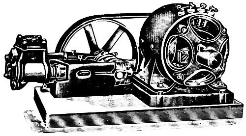
Fig. 238.
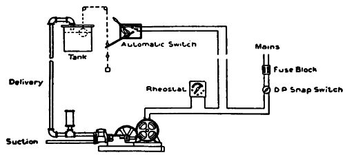
Fig. 239.
In many places the pressure on the mains is insufficient to raise the water to the upper floors or through improperly designed systems of piping the pressure may be so diminished as to make the flow extremely weak or the difficulty in securing proper water supply may be due to inconvenient location with reference to water mains. The automatic electric house tank pumping plant has been designed and perfected to meet these conditions; the electric plant is connected to some power or lighting circuit and provided with an automatic attachment requiring no more care than can be given by any casual attendant. Such an installation avoids the smoke, ashes, dust and objectionable odors that accompany steam or gas plants.
The accompanying diagram shows the general arrangement of the automatic electric house system used with a tank in the upper part of the building and the pump in the basement or cellar. The operation is as follows:
When water is being delivered to the tank, the float rises until the upper knob makes forcible contact with the switch lever, opening the switch and stopping the pump. When water is withdrawn from the tank, the float falls until the lower knob makes contact with the switch lever, which again closes the switch and starts the pump. The supply of water is thus maintained within the tank without the aid of an attendant. The accompanying illustration, Fig. 238, shows a Worthington house tank pump of 500 gallons per hour capacity belted to a General Electric direct current motor, the pump and motor being mounted on the same base.
Table of Capacity.
| Diameter of Plungers |
Length of Stroke |
Revolutions per Minute |
Gallons per Minute |
Maximum Water Pressure in Lbs. |
Gallons per Hour |
Feet 1 H.P. Will Pump Against |
Feet 2 H.P. Will Pump Against |
|---|---|---|---|---|---|---|---|
| 2 | 4 | 45 | 9.8 | 150 | 500 | 175 | 300 |
| 23⁄4 | 4 | 45 | 18.5 | 75 | 1,000 | 80 | 175 |
| 3 | 4 | 45 | 21.8 | 60 | 1,200 | 70 | 140 |
| 33⁄4 | 4 | 45 | 34.4 | 40 | 1,800 | 50 | 100 |
The above useful table is inserted to show the capacities, revolutions, size of plungers, etc., in these electrically driven pumps, the automatic feature of which is truly admirable.
It must be remembered that the number of combinations between small electric motors and proportionate pumps for water, gas, air, etc., afford an endless field for the exercise of engineering skill.
Fig. 240 is intended to show the application of the electric motor to a triplex pump of small size, the plungers being 31⁄8 inches in diameter. The Stroke is 47⁄8 inches which gives a capacity of 108 cubic inches per revolution, with a pressure of 50 lbs. to the square inch. The pumps require about one-half horse power applied at the motor.
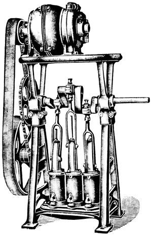
Fig. 240.
The high speed of the motor is reduced by two belt pulleys and two chain wheels. These pumps may be worked independently to produce pressure or vacuum as desired by a separate pipe for each pump.
Fig. 241 is intended to show the application of the electric motor to a centrifugal pump; these two machines are mounted on one bed plate, directly connected by a flange coupling between them. The motor shown, is almost identical with the machine illustrated, Fig. 217, and described on page 251. The pump is so arranged that the discharge can be turned in any direction desired. Wherever electric power is available and the centrifugal pump is the form best adapted to the work, this combination presents advantages over a steam engine operated by a plain slide valve such as is generally used.
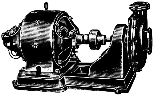
Fig. 241.
Fig. 242 shows a double pump driven directly, without gears or belt, from the shaft of an electric motor. The pump crossheads are connected directly to cranks at each end of the motor shaft. The cranks are set at right angles and each pump is double acting, or has two plungers connected by outside rods and with outside packed stuffing-boxes, so that this portion of the pump is always accessible.
The plungers are 31⁄2 inches diameter and 51⁄2 inches stroke. The pump and motor are mounted upon a rigid box girder frame: this unit is self-contained and occupies a relatively small floor space.
Electric Drive for Fire Pumps. The importance of instantly operating fire extinguishing apparatus can scarcely be exaggerated. The largest conflagrations are but little flames at the beginning, and if caught at the critical moment they make no record of destruction; for such service the electric current is the ideal agent. A notable installation of electric-driven pumps for fire service is in the Marshall Field store, Chicago, a building occupying an entire city block. The outfit consists of a Laidlaw-Dunn-Gordon duplex Underwriter pump connected by single reduction gearing to a waterproof electric motor.
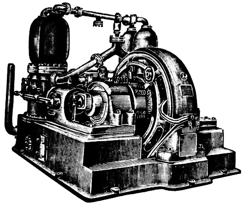
Fig. 242.
The pump cylinders, 8 × 12 inches, have a computed capacity of 700 gallons per minute at 140 pounds water pressure. The pump, besides its other special features, is claimed to be rust proof throughout so that it will not get out of ready running condition.
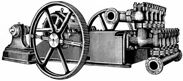
Fig. 243.
The electric system has especial conveniences for mine pumping because of its adaptability to long transmissions of power; electric power can be transmitted to almost any distance, and the pumps can be supplied with either direct or alternating current motors. A mining outfit can be easily divided into a number of parts, to facilitate lowering into a mine, after which the assembling of the parts is a simple operation.
Stationary pumps for mine use are made in two classes: first, vertical pumps having cylinders in a vertical position in which the over all height is comparatively great and the horizontal dimensions as small as possible; second, horizontal pumps with cylinders in a horizontal position and having for cross dimensions the over all length. The class of pump to be selected, of course, depends upon the limitations of the location. In either case, the motor used for driving the pump is mounted on an extension of the pump base, making a self-contained and compact outfit.
Engraving, Fig. 243, represents a Quintuplex pump used principally in mining operations, or wherever large quantities of water are to be delivered under high pressure in the shortest possible space of time. The pump here shown was designed to deliver 225 gallons of water per minute under a head of 1,200 feet. It has five plungers 4 inches in diameter each and having a uniform stroke of 12 inches.
These pumps driven by electric motors it is said represent the most economical method of transmitting power, as compared with the best designs of steam pumps. An efficiency of 80 per cent. is claimed for these pumps.
Note.—It is interesting to know that in one of the largest electric pumping installations which has ever been made for mining work, the power is carried 2,500 feet underground at a potential of 3,500 volts and then transformed into 220 volts at the motors. No trouble has thus far resulted from the high voltage or any other cause; in regard to danger from underground electric pumps, it can be stated that accidents due to the use of electricity in such installations are almost unknown. Induction motors are arranged to operate without moving contacts. They are therefore free from sparks and can be used in mines where the presence of gases compels the use of safety lamps.
Fig. 244 exhibits an electric induction motor operating a 51⁄2 × 8 portable track pump.
Portability is an important feature in all pumps for mine use; and, as track pumps may be put into service immediately at any point on a system of tracks, they meet this requirement better than pumps of any other form.
Such an outfit can be hauled to any point in the mine and there operated from some convenient circuit such, for instance, as the circuit supplying power to mine locomotives.
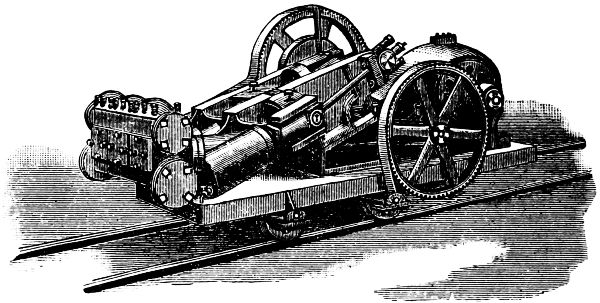
Fig. 244.
The pump and motor shown in Fig. 244 are mounted on an iron truck, no wood whatever being used in construction, so that adjustment cannot be affected by moisture and an easy running and durable pump is assured. The pumps are made as compact and strong as possible for mine service, which is usually exceptionally rough and continuous. They are of the horizontal type which is best adapted for low passageways and are designed so as to afford easy access to all parts. The pumps are single acting and the plungers are provided with outside stuffing-boxes, which can be packed, and being in sight, any leakage can be quickly detected. Access to all valves is made easy by the removal of one large hand-hole cover on the valve chest.
THE STEAM
PUMP
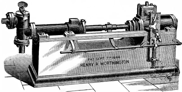
Fig. 245.
G.KIRKHAM
The illustration, Fig. 245, on the opposite page represents the first practical steam pump ever made; on pages 67-69 will be found an interesting account of it. The water end is single acting; the steam end is, of necessity, double acting to produce the reciprocating motion. From this original design has been evolved the piston valve as well as many other designs of valve motion for pumps.
Having already taken up in some detail the construction of “the parts of the pump” and the necessary appliances connected with its use, it now remains to consider the means by which the steam power generated is made available and the mechanism by which the energy is transformed from pressure into pumping power.
It may be well to consider at some length the “Steam end” of the pump. This consists primarily of cylinders, together with their connections; these constitute the muscular system of the pump. The muscular or operating end is separate and distinct from the water end so far as construction is concerned but in operation the two are closely allied. It is therefore necessary as well as convenient to unite them in one equipment and thus enable the propelling mechanism to furnish a constant source of power.
So far as the elastic force of steam itself is concerned its history dates back to a period two hundred years B. C., when, as described by Hero, the force generated by steam was utilized for actuating certain devices constructed rather for curiosity than for any benefit which might be derived from their use. Very little advance was made in the construction of practical devices until the latter part of the eighteenth century when James Watt by his improvements placed the stationary engine on an operative basis and gave to the world what has proved to be the greatest invention of all time.
The first stationary steam engines were used for pumping water and were of the single acting type, in which the steam was admitted at one end of the cylinder, the opposite end being open to the atmosphere. The steam acting on the piston forced it to the limit of its stroke when the supply was cut off. The steam then condensed in the cylinder, forming a partial vacuum, and the force of the atmosphere upon the opposite side of the piston forced it back, causing it to complete its stroke before another supply of steam was admitted. This was a slow process, wasteful of steam and attended with many other inconveniences.
An improvement on this device was made in an engine built by Watt in 1774. This was a single acting engine but the condenser was separated from the cylinder. The valves were so arranged as to admit live steam into the upper end of the cylinder on the top of the piston and at the same time open the lower end of the cylinder to the condenser. The steam followed the piston in its downward stroke in which action it was aided by the partial vacuum formed in the condenser. At the completion of the downward stroke the valves were changed so as to close the ports to the steam supply and the condenser, and at the same time open a communication between the two ends of the cylinder equalizing the pressure above and below the piston. The weight of the pump rod on the beam or lever connection overbalanced the weight of the piston and caused it to complete the return stroke.
In 1782 the double acting steam engine was patented by Watt. This was a device in which the live steam acted on each side of the piston alternately, the opposite side of the281 cylinder being in communication with the condenser. The same patent covered the method of applying the principle of expansion of steam in the cylinder; a non-condensing engine was also described.
Note.—This invention was of great historical importance as it covered all the essential detail of modern practice in steam engine building and constituted the fundamental principle of all steam engines.
Improvements have been made in form and construction, necessitated by new adaptations which have been constantly developed. The requirements for higher speed, increased pressure which implies greater power, and the constant desire for greater economy in fuel have produced a variety of changes in detail but have not altered the fundamental idea.
When the steam after being utilized in the cylinder makes its exit directly to the open air, the engine is called single expansion for the reason that the action of the steam takes place in one cylinder during a single stroke, and what expansion takes place must be during one half of a revolution. When the steam from one cylinder instead of exhausting into the open air, is passed to a second cylinder, of larger area, and by expanding exerts a pressure on a second piston to aid in the completion of the revolution, the engine is called double expansion or compound, because the steam instead of completing its work in a single operation is afforded a double opportunity for expansion and an increased range of action. In the single cylinder the temperature of the walls is reduced in each revolution to correspond with that of the steam at the exhaust pressure.
This temperature must be restored by incoming steam at the beginning of a new stroke which means a reduction of power. With a double cylinder owing to the greater range of expansion, a higher temperature can be maintained in the first cylinder and a large amount of initial condensation is prevented. A still greater use of expansion may be obtained by the introduction of a condenser which allows the final exhaust to be carried below the atmospheric pressure to the extent of the vacuum formed. In stationary and marine practice triple and quadruple expansion engines are common. These are used in large units to give the greatest possible economy in fuel.
Properties of Steam.—Before taking up in detail the valve and other mechanism of the steam pump it may not be out of place to consider briefly the action of steam and its expansive properties. Heat is identical with mechanical force and the one can be converted into the other. Aside from the means used in converting or developing the action a certain quantity of heat always produces a certain quantity of work.
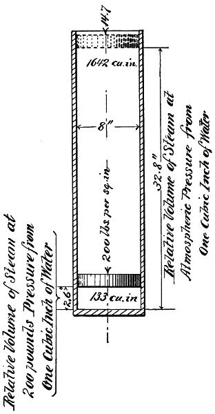
Fig. 246.
The temperature of steam at atmospheric pressure (14.7 lbs. absolute) is 212° Fahr. As the pressure increases the temperature rises, but is always the same for a given pressure. The sensible heat required to raise the temperature of water from 32° to 212° is 180° and the heat absorbed by the water or latent heat at 212° is 996° making the total amount of heat expended 1176°. As the temperature rises the latent heat decreases in nearly the same proportion as the sensible heat increases. This number may therefore be taken as a constant to express the unit of heat in one pound of steam from 32° up to the temperature at which evaporation takes place. Then 1176 × 772 = 907,872 pounds raised one foot which represents the mechanical equivalent or maximum theoretical duty of the quantity of heat contained in one pound of steam.
One cubic inch of water if converted into steam at the pressure of the atmosphere (14.7 pounds) will occupy the space of 1642 cubic inches or nearly one cubic foot. As the pressure increases the volume is relatively diminished and if the same quantity of water is converted into steam say at 200 pounds pressure it will occupy a space of only 133 cubic inches. Assuming that no loss occurred by condensation, if released at this pressure it would expand and again occupy its relative volume at atmospheric pressure.
This is illustrated by the accompanying diagram, Fig. 246, showing a cylinder with an internal capacity of 1642 cubic inches provided with a movable piston. A quantity of steam representing that formed from one cubic inch of water is forced into it, supposing the weight on the piston to be 200 lbs. per square inch, this weight will be raised until the space under the piston occupied by the steam will be 133 cubic inches. If the supply is now cut off (assuming that no condensation takes place) the piston will remain at this place supporting its load. If the load on the piston is diminished the volume of steam will expand and the piston will be correspondingly raised in the cylinder. This action will be continued until all the load is removed and only the weight of the284 atmosphere remains. The volume of steam under the piston will then be 1642 cubic inches. It will therefore be seen that the same quantity of steam has exerted a lifting pressure upon the piston due to its relative volume commencing at 200 pounds per square inch and gradually decreasing until the pressure of the atmosphere is reached.
The English unit of heat is that which is required to raise the temperature of one pound of water one degree Fahrenheit and is known as the British Thermal Unit, or B. T. U. Dr. Joule demonstrated by an ingenious device, Fig. 247, in which a weight operated a paddle wheel agitating water in a closed vessel, that it required 772 foot pounds to raise the temperature of one cubic foot of water one degree, or, on the other hand, it was deduced that one unit of heat was capable of raising 772 pounds one foot high. The mechanical equivalent of heat is therefore accepted as 772 foot pounds for one B. T. U. based on Joule’s experiment.A
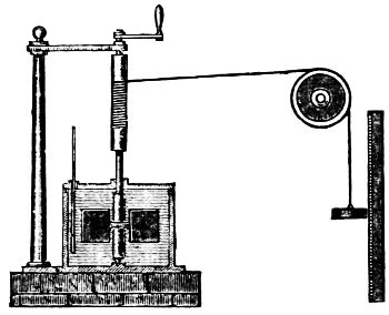
Fig. 247.
The theoretical efficiency of the use of steam by expansion can never be realized, owing to losses occasioned by condensation, caused by contact with the cooler walls of the cylinder, the unavoidable friction of the working parts, and from the fact that a certain portion of the pressure must be utilized to create a draft for the fire. All these losses must be taken into consideration in calculating the work actually done.
From the foregoing it will be readily understood that if the steam is allowed to exhaust from the cylinders at or near the pressure at which it is admitted the work which it might have285 accomplished by expansion will be lost. This means not only a loss of the steam but of a part of the fuel used to generate it.
It is therefore advisable to get all the work out of the steam that is possible and the nearer to atmospheric pressure the exhaust can be brought the greater will be the economy.
A Note.—This unit has been recently changed to 778.
Steam is water in a gaseous state; the gas or vapor of water; it liquifies under a pressure of 14·7 and temperature of 212° F.
Steam is a joint production of the intermingling of water and heat. Water is composed of two gases which have neither color nor taste, and steam is made up of the same two gases with the addition only of that mysterious property called heat by which the water becomes greatly expanded and is rendered invisible. The French have a term for steam which seems appropriate when they call it water-dust.
This is what takes place in the formation of steam in a vessel containing water in free communication with the atmosphere. At first, a vapor is seen to rise that seems to come from the surface of the liquid, getting more and more dense as the water becomes hotter. Then a tremor of the surface is produced, accompanied by a peculiar noise which has been called the singing of the liquid; and, finally, bubbles, similar to air bubbles, form in that part of the vessel which is nearest to the fire, then rise to the surface where they burst, giving forth fresh vapor.
The curious fact must be here noted that if water be introduced into a space entirely void of air, like a vacuum, it vaporizes instantaneously, no matter how hot or cold, so that of an apparent and fluid body there only remains an invisible gas like air.
That steam is dry at high pressure is proved by an experiment which is very interesting. If a common match head is held in the invisible portion of the steam jet close to the286 nozzle, it at once lights, and the fact seems convincing as to complete dryness, as the faintest moisture would prevent ignition even at the highest temperature. This experiment proves dryness of the steam at the point of contact, but if throttling exists behind the jet, the steam supplied by the boiler may be in itself wet and dried by wire drawing.
Dead steam is the same as exhaust steam.
Live steam is steam which has done no work.
Dry steam is saturated steam without any admixture of mechanically suspended water.
High-pressure steam is commonly understood to be steam used in high pressure engines.
Low-pressure steam is that used at low pressure in condensing engines, heating apparatus, etc., at 15 lbs. to the inch or under.
Saturated steam is that in contact with water at the same temperature; saturated steam is always at its condensing point, which is always the boiling point of the water, with which it is in contact; in this it differs from superheated steam.
Superheated steam, also called steam-gas, is steam dried with heat applied after it has left the boiler.
Total heat of steam is the same as steam heat.
Wet steam, steam holding water mechanically suspended, the water being in the form of spray.
Specific gravity of steam is ·625 as compared to air under the same pressure.
The properties which make it so valuable are:
1. The ease with which we can condense it.
2. Its great expansive power.
3. The small space in which it shrinks when it is condensed either in a vacuum chamber or the air.
A cubic inch of water turned into steam at the pressure of the atmosphere will expand into 1,669 cubic inches.
The Davidson pump is shown complete in Fig. 248; the valve motion consists principally of a valve, valve pistons, valve pin and cam. The main valve is operated by a positive mechanical connection between it and the main piston rod, also by the action of steam on the valve pistons. The engraving, Fig. 249, shows the details of valve gear and steam cylinder. The steam end consists of the cylinder, M, valve, A, and valve pistons, B and B. These pistons are connected with sufficient space between them for the valve, A, covering the steam ports, F and F1, Fig. 250.
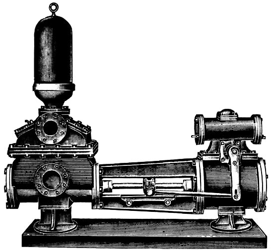
Fig. 248.
The valve is operated by the steel cam, C, acting on a steel pin, D, which passes through the valve into the exhaust port, N, in which the cam is located. In addition to this positive motion steam is alternately admitted to and exhausted from the ends of the valve piston through the ports, E and E1, which moves the pistons, B and B1.
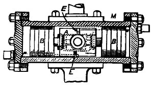
Fig. 249.
Assumed that this pump is at rest with the valve, A, covering the 288main steam ports, F and F1, in which position the cam C, holds the main valve by means of the valve pin, D, so that ports, E and E1, admit steam to one end of the valve piston at the same time connects the other end with the exhaust port. The steam, acting on the valve pistons, moves both, opening the main ports, F and F1, admitting steam to one end of the steam cylinder and opening the other end to the exhaust. If the valve occupies any other position than the one described, the main ports, F and F1, will be opened for the admission and exhaust of steam; consequently it is evident that this pump will start from all points of the stroke.
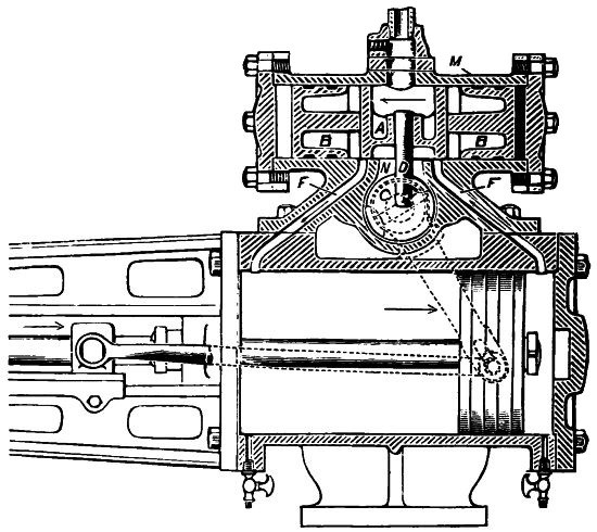
Fig. 250.
On the admission of steam to the cylinder the main port, F, the main piston, cam and valve will move in the direction indicated by the arrows. The first movement of the cam oscillates the valve, preparatory to bringing it into a proper position for the opening of the auxiliary steam ports, E, to live289 steam, and E, to exhaust also to close the valve mechanically just before the main piston reaches the end of its stroke. This causes a slight cut-off and compression, and fully opens the auxiliary ports, E, to steam, and E1, to exhaust. By the admission of steam to one end, the other being open to the exhaust, the valve pistons move the valve to allow the admission and exhaust of steam from the cylinder for the return stroke.
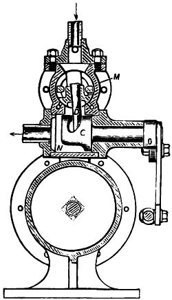
Fig. 251.
This main valve is as much under the control of the piston rod as is the valve of an ordinary steam engine worked by an eccentric which insures a positive action, the pump being capable of starting from all positions and maintaining a uniform and full stroke.
To set the valve piston, push the main pistons to the end of the stroke until the inner edge of the port and the piston coincide, then loosen the side lever, turn the cam, C, until the valve piston uncovers the auxiliary steam port, E, leading to the same end of the steam chest occupied by the main piston.
After setting, secure the cam and then connect the side lever to the connecting rod. The side lever and cam occupy correct relative positions, therefore, the lever should be secured to the cam shaft while in this position. The stroke may be regulated by raising or lowering the end of the connecting rod in the slotted end of the slide lever. Raising the connecting rod shortens the stroke and lowering it lengthens the stroke. When making the foregoing adjustments it is well to have the connecting rod at or near the bottom of the slot as shown in the engravings.
The single cylinder pumps of this make are equipped with the gear illustrated in Fig. 252, in sizes varying from 4 inches in diameter by 5 inches stroke to 28 inches in diameter by 24 inches stroke.
The arrangement of valves and ports is shown in the engravings, Figs. 253 and 254.
The admission of live steam to the cylinder and of exhaust steam to the atmosphere is controlled by a valve piston, A, shown in Fig. 252.
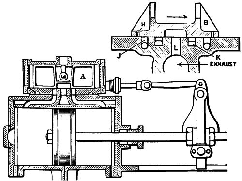
Fig. 252.
Assume that the piston is in position shown, Fig. 253, and that both the main and auxiliary valves cover their respective steam ports. By means of a starting bar, operating through a stuffing-box in the valve chest, the piston valve, A, is moved toward the head of the steam chest, D, thus opening the ports, E and L, and admitting live steam through L, from the cavities, S, of the valve piston to the housing end of the main steam cylinder, through the port, F, Fig. 255, forcing the main piston, P, toward the opposite end of the stroke, or toward the left in the figure. The port, E, Fig. 253, being open, the exhaust291 steam escapes from front of the main piston through the port, F, Fig. 255, into the main exhaust port, G, through the port, E. The piston, P, travels to its extreme left position and the auxiliary slide valve has been drawn to such a position in the direction indicated by the arrow in the smaller drawing in Fig. 252, as to bring valve piston, A, toward the opposite end; the exhaust steam from the steam chest escapes from before it, through the exhaust port, K, the opening of which into the chest is at such a distance from the head as will permit sufficient exhaust steam to remain to afford a cushion to the valve piston.
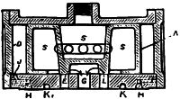
Fig. 253.
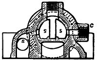
Fig. 254.
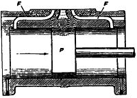
Fig. 255.
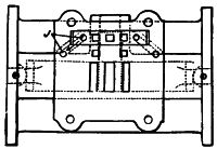
Fig. 256.
With the auxiliary slide valve in position to bring the hole, H, over the port, J, Fig. 256, it is plain that the exhaust through the port, K, will pass into the main exhaust through the port, L. With the main piston at its extreme travel toward the right, the ports, E and L, which correspond to F and F, respectively, in Fig. 255, are opened in such a manner as to exhaust steam to the atmosphere from the housing end of the steam cylinder through the port, F, and live steam292 from the chest to the head end of the main cylinder, through the port, F, thus driving the main piston, P, toward the housing end of the cylinder, or toward the right. The piston and reciprocating parts traveling in this direction move the auxiliary slide valve to its maximum point of travel in the opposite direction, thus opening the opposite auxiliary steam and exhaust ports and again driving the valve piston toward the head, D, of the steam chest, whence a new stroke begins.
Lost motion in the valve gear is taken up by adjustable links, on all sizes above 7 inches diameter by 10 inches stroke and on some smaller sizes.
Cushioning of the steam pistons in the larger sizes and upwards is accomplished by means of suitable valves called cushion valves. In the smaller sizes sufficient cushioning is done by exhaust steam passing from the clearance space next the head through a small hole drilled into the main steam port.
To set the valve of this pump it is only necessary to place the piston in its central position and adjust the lever so that the valve will occupy its central position. By this proceeding the travel of the valve is equalized.
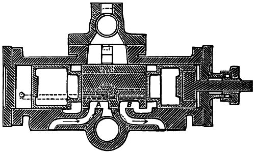
Fig. 257.
The Foster single cylinder pump valve motion is a compound valve piston and slide valve in one piece and performs the office293 of both a main and auxiliary valve. It seats over the main steam cylinder on the web or casting connecting together the valve pistons, and is provided at the bottom with vents or openings, A and B, Fig. 257, for opening and closing the main steam ports to the main steam cylinder. The sides of this valve are cut to form the recesses, C and D, which are for the purpose of opening and closing the small steam ports, which admit steam to the valve pistons; it is also provided with L shape slots for the purpose of alternately exhausting steam from the valve pistons through the steam ports.

Fig. 258.
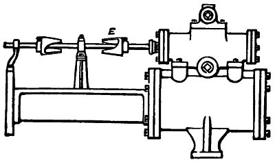
Fig. 259.
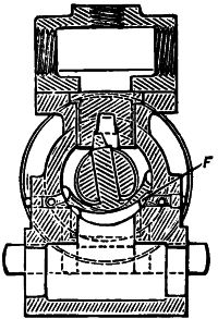
Fig. 260.
In operation the main piston rod commences its forward stroke, motion is communicated to the vertical arm, which moves forward on the rod until it engages with one of the cams, E, Fig. 259, adjusted on the valve stem. The arm coming in contact with the inclined faces of the cam imparts a rolling or oscillating movement to the stem and valve, opens294 one of the recesses, C or D, cut in the side of the valve and admits steam through a port to one of the valve pistons. At the same time this oscillating movement of the valve opens the slot, F, Fig. 260, opposite the first, and exhausts steam through the alternate port from the other piston. Steam thus admitted to one of the pistons (while exhausts from the other piston), carries the valve over its seat, and by means of the vents, A and B, steam is admitted through one of the main ports and exhausts through the other. When the main piston has completed one stroke, it moves backward on its return; the arm strikes against the other cam on the valve stem and communicates a reverse motion to the valve which closes and opens the alternate ports to admit and exhaust steam to and from the pistons. It also cushions the piston at the end of each stroke which prevents the piston from striking the heads.
To set the valves. This can best be done by starting the pump slowly and adjusting the cams, E, so as to open the valve at the proper time to compel the piston to make a full stroke. A little experimenting combined with good judgment is all that is necessary, unless the piston valve be badly worn, in which case a new valve must be substituted and fitted to the valve chest.
The plunger in the Cameron pump is reversed by means of two plain tappet valves, shown in the accompanying engraving, Fig. 261, and the entire valve mechanism consists of four pieces, all of which work in a direct line with the main piston. This pump is simple and has no delicate parts.
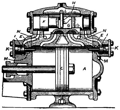
Fig. 261.
As here represented—A is the steam cylinder; C, the main piston; L, the steam chest; F, the valve piston, the right-hand end of which is shown in section; G, the slide valve; H, a lever, by means of which the valve piston, F, may be moved by hand when expedient; I, I are reversing valves; K, K are the reversing valve chamber bonnets, and E, E are exhaust ports leading from the ends of steam chest direct to the main exhaust. The passages, M, M, lead directly into the exhaust (although the connection is not shown, being cut away in the sectional view), and closed by the reversing valves, I, I.
The piston, C, is driven by steam admitted under the B slide valve, G, which, as it travels backward and forward, alternately supplies steam to opposite ends of the cylinder, A. The slide valve, G, is operated by the valve piston, F; F hollow at the ends, which are filled with steam, which, issuing through a hole in each end, fills the spaces between it and the heads of the steam chest in which it works.
The pressure being equal at each end, the valve piston, F, under ordinary conditions, is balanced and motionless; but when the main piston, C, has traveled far enough to the left to strike and open the reverse valve, I, the steam exhausts from behind the valve piston through the port, E. The pressure being now unequal behind the two ends, the valve piston immediately shifts accordingly and carries with it the slide valve, G, reversing the piston. No matter how fast the piston may be traveling, it must instantly reverse when it touches the valve, I.
In its movement the valve piston, F, acts as a slide valve to close the port, E, and is cushioned on the confined steam between the ports and steam chest cover. The reverse valves, I, I, as soon as the piston, C, leaves them, close by the constant pressure of steam behind supplied direct from the steam chest through the ports, N, N, shown by dotted lines.
To set the valve, it is only necessary to keep valves tight by occasional grinding. The piston as it nears the end of each stroke strikes the stem and lifts the valve off its seat; this allows the exhaust steam behind the piston valve to escape. The live steam pushes the piston towards the exhausted end carrying the main slide valve along with it.
The Mason pump has a valve piston, a main valve, a preliminary valve and a yoke connected directly to the valve stem, as shown in Fig. 262. The valve piston is contained in a cylinder above the steam chest, and moves the main valve by means of a pin, which projects into a pocket in the top.
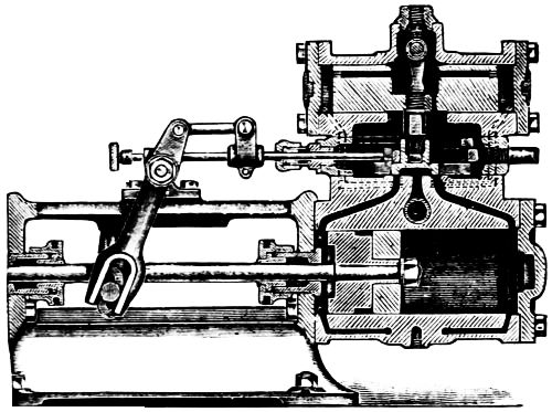
Fig. 262.
The main valve and preliminary valve travel on the same seat, and receive their motion from the yoke, E, Fig. 263, which surrounds them. This yoke fits the preliminary valve neatly, allowing an independent movement of the main valve and valve piston.
The preliminary valve is the ordinary D type and controls three ports, as shown in Fig. 263, the two steam ports are connected with either end of the auxiliary cylinder and the exhaust, with the small port, A, in the main valve seat. The duty of the preliminary valve is to alternately connect each end of the auxiliary cylinder with this port. The main valve controls four ports, and is also of the D type, having an extended cavity connecting the exhaust from the preliminary valve with the main exhaust. The main valve also controls the main steam and exhaust ports of the pump cylinder.
Steam enters the chest through the steam pipe, passes around the central portion of the valve piston and through the passages in the piston to both ends of the valve cylinder, thus balancing the valve piston.
Suppose that the yoke and preliminary valve have been carried to the back end of the chest, and have moved the main valve to bring its auxiliary cavity over the auxiliary port, A, Fig. 263, in the main valve seat, which connects the back end of the auxiliary cylinder with the main exhaust. The steam from the end of the chest passes up through port, B, down through port, C, and up through port, A, into the exhaust port, D, in the main valve. This unbalances the auxiliary piston, which is driven back by pressure on the opposite end, and carries the main valve independently of the yoke. The travel of the main valve causes it to cut off the exhaust from the auxiliary cylinder, and the remaining steam cushions the valve piston.
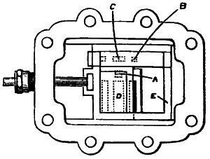
Fig. 263.
The travel of the main valve also opens the main steam port to the forward end of the pump cylinder, and connects the back end of the cylinder with the main exhaust, thus reversing the motion of the piston.
This action is repeated at the end of each stroke. Whatever position of the piston, the pump will start when steam is turned on, as there is always a connection either directly from the steam inlet to one of the steam ports, or, if the main valve has covered both steam ports, it is in a position to connect the auxiliary cavity in the main valve seat with the main exhaust, which at once releases the steam from one end of the valve piston, and the pressure on the other end drives the piston, thus moving the main valve and giving direct communication between the steam inlet and one of the main steam ports.
Thus it is seen that the piston cannot get into a position where it is impossible for it to respond to the steam pressure.
To set the valve place the piston in the mid-stroke position and set the auxiliary valve with rocker arm plumb, and the preliminary valve covering all its ports equally. These positions may be secured by adjusting the position of the clamp on the valve stem and move the main piston sufficiently so that the auxiliary valve will open one of its ports.
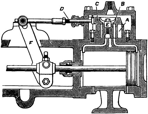
Fig. 264.
The accompanying engraving, Fig. 264, shows a section of the slide valve chamber, which is fitted to the top of cylinder. The slide valve, B, is fitted in the valve chamber, A, the cut-off valve, C, works on top of the slide valve and is operated by the valve stem, D. The lever, F, which moves the valve, is attached to the crosshead on the piston rod. While the crosshead moves the length of the stroke, the cut-off valve, C, moves twice the300 width of the steam ports in the cylinder. The opening in the cut-off valve, C, is equal to the length of the dog, E, plus the throw of the slide valve, B, plus one-sixteenth inch. The length of the valve chamber on the inside is equal to the length of the cut-off valve minus the throw of the cut-off valve. The valve stem, D, is connected to the cut-off valve, C, so that it moves the latter valve a distance proportional to the movement of the steam piston. The opening through the cut-off valve is equal in width to the distance from inside to inside of the ports on top of the slide valve. As the piston moves to the right, as shown in the drawing, the cut-off valve moves to the left, so as to open the right-hand end of the valve box and admits steam, which acts upon the slide valve and moves it to the left-hand end of the valve box. This opens the port wide in the slide valve, which corresponds with the port leading to the cylinder while in the upper side of the slide valve the port is nearly closed by the cut-off valve, so that little steam is admitted to the cylinder; consequently, the piston is gradually started on its return stroke. On the return stroke the cut-off valve begins to move and opens one of the ports on top of slide valve, which stands still until the piston has made a half stroke.
By this time the valve is wide open “full port” to the cylinder. The cut-off valve, C, coming in contact with the dog, E, both the slide valve and cut-off valve move together to the end of the stroke. Notice that as soon as the cut-off valve, C, engages the slide valve and it begins to move, the port to the cylinder closes so that at the end of the stroke but little steam can get to the piston. The cut-off valve opens the valve box, A, to admit steam to complete the stroke of slide valve, and should the steam fail to throw the slide valve, the piston, by means of the cut-off valve, C, coming in contact with the dog, E, moves the slide valve, thereby opening the opposite port and preventing the piston from striking the cylinder head.
The lower corner of the slide valve, B, is removed and a slot cut to the exhaust port, the slot being of sufficient size to release the steam from the ends of the valve box and exhaust pressure of it into the pocket of the slide valve.
The movement of this valve very much resembles that produced by means of an eccentric. The movements of the valves are so timed that as the main piston nears the end of the stroke its movement is sufficiently retarded to permit the water valves to seat quietly and without jar, also on the return stroke, the steam is so gradually admitted that the piston starts with ease and gradually increases its speed to the middle of the stroke, from which point it gradually decreases toward the opposite end. A proper adjustment of the cut-off valve allows the piston to stop momentarily at the ends of the stroke without any possibility of striking the cylinder heads.
To Set the Valve. Adjust all joints so that there will be no lost motion in the valve gear. Then move the crosshead to the end of its stroke, and see that the cut-off valve opens the valve chamber one-sixteenth of an inch, and that the steam valve closes the port leading to the cylinder to within one-sixteenth of an inch. Next move the crosshead to the other end of its stroke and note that the valves are in the same relative position. If, from any cause the cut-off valve does not open correctly to admit steam to the valve chamber at the ends of the stroke of the piston, the valve can be shortened by filing off the ends. This should not be done, however, until all lost motion has been taken up in the valve gear.
In this pump (see Figs. 266, 267) the steam is admitted to the center of the valve chamber which contains the main valve, A, and the supplemental slide valve, B. The recess in the center of the valve piston, C, receives the main valve and moves it when steam is supplied to or exhausted from either end of the valve piston.
In operation live steam passes through the left-hand ports, D and E, drives the main piston to the right and the exhaust passes out of the right-hand port, F, into the cavity in the main valve, A, thence through the exhaust port, G, into the atmosphere.

Fig. 265.
As the main piston nears the right-hand port, the valve lever H, attached to and moving with piston rod brings the dog, I, on plate, J, in contact with the valve arm, K. This moves the supplemental valve, B, to the right and supplies live steam to the right of the valve piston, C, and exhausts the steam from the left-hand end through the ports, L. The main valve, being enclosed by the valve piston, moves with it to the left. As the steam enters the right hand main port and exhausts from the left hand port, the main piston commences its return stroke and the operation just described becomes practically continuous. As the main piston closes the main port, F, to the right, it cushions on compressed exhaust steam, because the main valve, A, has then closed the auxiliary port, M, leading to that end of the main cylinder. The steam in this case is supplied through the main and auxiliary ports, but exhausts through the main port only.
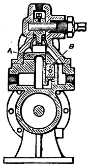
Fig. 266.
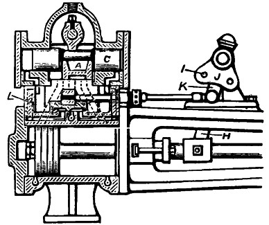
Fig. 267.
The slow movement of the main piston near the ends of the stroke allows the pump valves to seat quietly, and gives the pump cylinder time to fill with water, thus effectually preventing shock and noise. The valve piston, C, is cushioned by303 cushion valves, which are simply loose valves inserted near the ends in the valve piston. By removing the steam valve chamber, the main and supplemental valves may be readily examined or repaired. These valves are the ordinary plain flat slide with which all engineers are familiar.
To set the valve of this pump. Place the piston in the center of its travel with the valve lever, H, plumb and also valve arm, K, plumb; adjust the supplemental valve so as to cover equally all the posts, which is done by lengthening or shortening its valve stem.
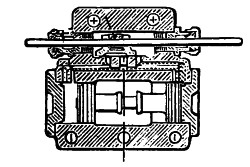
Fig. 268.
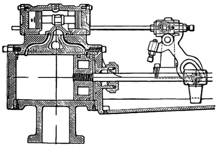
Fig. 269.
The main valve in this pump is moved by steam acting upon a valve piston. The steam admitted to and released from the auxiliary cylinder is controlled by a small slide valve operated by the valve gear. This small slide valve is in every essential feature identical with the slide valve of a steam engine, admitting and releasing the steam in precisely the same manner. In this pump the usual collars and tappets on the valve stem are dispensed with, the stem receiving motion304 by means of a roller carried by a slide block to which the valve stem is attached.
The roller is given a lateral motion by set screws in the forked ends of the rocker arm, as shown in the engraving, Fig. 269. By adjusting these set screws the travel of the small slide valve is made to suit the speed of the pump, thus preventing the main piston from striking the cylinder heads.
A sectional elevation of the cylinder and main valve is also shown; the connection of the valve piston to the main valve, also the construction of the small slide valve. The valve gear is provided with roller bearings to reduce the friction.
To set the valve. The main piston must be moved to the end of the stroke, so that the face of the piston and the edge of the steam port are flush, as a preliminary step to set the small slide valve, then the set screw in the rocker arm nearest the roller on the valve stem should be adjusted so that when the roller is in contact with the set screw the small slide valve will have opened the steam port corresponding to the position of the main piston.
Now push the main piston to a corresponding position at the opposite end of the stroke and adjust the other set screw nearest the roller on the valve stem in the same manner as the first one.
Mark the striking points of piston on the piston rod close to the stuffing-boxes. Start the pump slowly, and if the parts work smoothly, gradually increase the speed, keeping close watch of the striking points to see that the piston has ample clearance.
If the stroke is too short, the set screws should be backed out until the stroke is found to be right. Screwing the set screws in shortens the stroke and increases the clearance at the ends of the stroke. A full stroke should always be required of every pump.
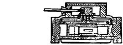
Fig. 270.
This pump is for deep wells; it has a valve piston and two slide valves operated by valve stem, also supplemental port valves to regulate and control the up and down strokes of the main piston. The main and auxiliary valves are both flat slides, each covering five ports, as shown in Fig. 271. The main valve is actuated by means of a valve piston, the steam being admitted to and exhausted from the ends of the valve piston in precisely the same manner that the main valve controls the admission and release of steam in the main pump cylinder.
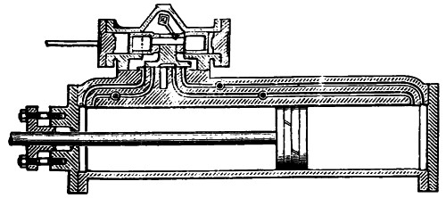
Fig. 271.
One of the auxiliary ports enters the end of the main steam chest, and the other enters at a point nearer the middle of the chest. The end ports are admission only and the inner ones exhaust. When the auxiliary valve reaches the upper end of its travel, as shown in the engraving, the admission port opens at the bottom of the steam chest, while the one at the top closes.
At the same time, the upper end of the main cylinder is open to the exhaust. The admission of steam drives the valve piston upward, but before reaching the end of its stroke it closes the exhaust port, thus entrapping a portion of the exhaust steam, which cushions the valve piston at the ends of the stroke.
The auxiliary slide valve is operated by means of a double-cone tappet on the piston rod, which strikes a rocker bar pivoted to the frame of the pump. The rocker bar carries an arm or lever at right angles to it and to this arm the valve rod is connected.
A short shaft runs across and through the upper part of the steam chest and is provided with a toe, as shown, by means of which the valve piston may be moved by hand when necessary and without disconnecting any part of the pump or valve gear.
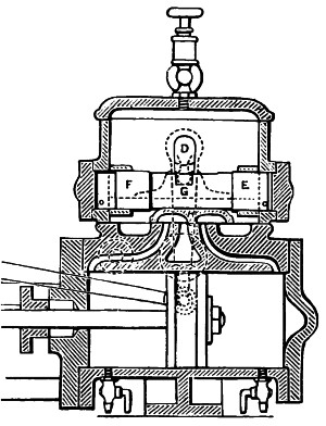
Fig. 272.
The port valves provide a simple means of contracting these passages and regulating the velocity of the up and down strokes to meet the requirements of the water ends of the pump so that uniform strokes are obtained regardless of the resistance against the main piston.
When adjusting the auxiliary valve, place the rocker bar parallel to the piston rod and so that the arm to which the valve rod is connected will stand at right angles to the piston rod. The auxiliary valve must then cover all the ports equally. The upper or outer end of the arm on the rocker bar is slotted, hence moving the valve rod pin toward the end of the arm lengthens the stroke and moving it toward the piston rod shortens it.
To set the valve of this pump it is necessary only to square the levers and equalize the travel.
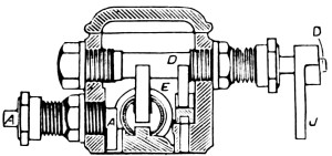
Fig. 273.
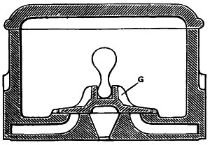
Fig. 274.
The steam chest of this pump differs somewhat from other pumps in which valve pistons are employed to operate the main valve. See accompanying engraving, Fig. 272. This pump has a steam chest with a cover for inspection and repairs. This chest is bored at each end to form suitable cylinders to receive the valve piston, E. By the side of the valve piston, E, in the steam chest is an auxiliary slide valve, G, Figs. 273 and 274, which admits and releases the steam from the ends of the valve piston. The valve piston, E, has two slots at the center, the lower one receiving the lug on the back of the main valve and the upper one the toe on the rocker shaft, D. The rocker shaft has two toes, the larger one, F, engaging with the valve piston, and the smaller one with the auxiliary slide valve, G, as shown in Fig. 274. The auxiliary, as well as the main, valves are plain slides designed to take up the wear automatically. The pendulum lever, J, Fig. 273, is connected with the piston rod as shown and rotates the shaft, D, and by means of the toes the valves move together.
The auxiliary slide valve, G, admits and exhausts the steam to and from the ends of the valve piston. Steam being admitted, the piston moves toward one end. The two valves also move in the same direction by means of the rocker shaft and the toes. This movement continues until the piston has nearly completed its stroke, when the auxiliary valve opens one of the small ports leading to the end of the valve piston, thus admitting steam at one end and exhausting it from the other. The valve piston moving from one end of the steam chest to the other, shifts the position of the main valve and reverses the motion of the main piston. The valve piston is moved the greater part of its travel by the toe on the rocker shaft, thus reversing the steam distribution, by steam pressure, which brings the opposite end of the slot in the driver to a second engagement by the toe on the rocker shaft which begins the return stroke.
The steam acts to throw the main valve only near the ends of the valve travel, and being already in motion the valve requires but very slight help to complete its stroke quickly without shock.
The motion of the auxiliary valve is synonymous with the main piston so there can be no practical dead center. The valves are very durable under such easy motion.
With this arrangement of valves no setting is necessary because when assembling the parts the centers of the pendulum lever and the toes on the rocker shaft are adjusted parallel with one another.
The McGowan single cylinder steam pump and section is shown in Fig. 275. Its main valve is of the B form and is driven by a valve piston. Steam enters the central port in valve seat and into the cylinder through one of the cavities in the valve and exhausts through the opposite. The two tappet valves cover the auxiliary ports, shown by dotted lines, leading to the ends of the steam chest and connect with the main exhaust ports. These tappet valves are raised by means of309 levers, the ends of which project downward and into the cylinder so that when the piston nears the end of a stroke it comes in contact with the lever and raises it sufficiently to lift the tappet valves.
Each tappet valve lever is pivoted on a pin which fits into a recess near the main ports, as indicated by the dotted lines.
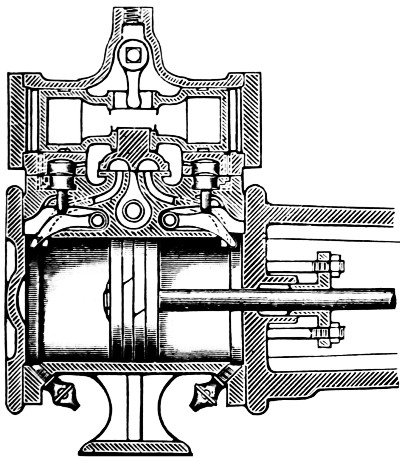
Fig. 275.
When the piston reaches the end of its stroke it lifts one of the tappet levers and with it the corresponding valve is raised from its seat, opening the port leading from the end of the steam chest to the main exhaust port. The pressure is thus relieved on one end of the valve piston and the steam pressing on the opposite end forces the valve piston to the opposite end of its stroke, thus reversing the distribution of steam to the cylinder and starting the piston on its return stroke. The valve piston thus moves back and forth, the ends of the steam chest being filled with steam at initial pressure. Steam escaping from one end of the steam chest causes a difference of pressure on the two ends of the valve piston, from which we realize the power to move the main valve. The tappet valves, having a very slight lift, operate without shock or noise. The main valve is connected with the valve piston so that all lost motion is taken up automatically.
A rocker shaft, extending through the steam chest carries a toe moving in a slot in the top of the valve piston, so that the valve can be moved by hand.
To set the valves of this pump. Simply keep the valves in order. The motion of the piston as it nears the end of the stroke opens and closes the valves.
In the Knowles pump a valve piston, G, Fig. 277, in the steam chest moves the main valve. This valve piston is driven alternately backward and forward by the pressure of steam, carrying with it the main valve, which admits steam to the main steam piston that operates the pump. The main valve is a plain slide whose section is of B form, working on a flat seat.
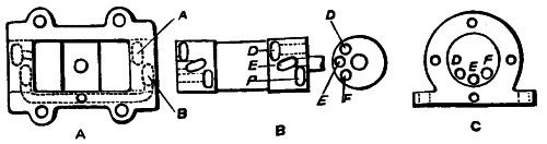
Fig. 276.
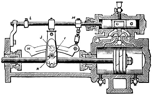
Fig. 277.
The valve piston is slightly rotated back and forth by the rocker bar, H; this rotative movement places the small steam ports, D E F, Fig. 276, which are located in the under side of the valve piston in proper position with reference to the corresponding ports, A B, cut in the steam chest. Steam enters through the port at one end and fills the space between311 the valve piston and the head, drives the valve piston to the end of its stroke and carries the main slide valve with it. When the valve piston has traveled a certain distance, a corresponding port in the opposite end is uncovered and steam enters, stopping its progress by giving it the necessary cushion. In other words, when the reciprocating rotative motion is given to the valve piston through the outside mechanism, it opens the port to steam admission on one end, and at the same time opens the port on the other end to the exhaust. There is no point in the stroke at which either the valve piston or the main piston is not open to direct steam pressure, hence the immunity from any dead position or dead center.
The operation of the pump is as follows: The piston rod with its tappet arm, J, Fig. 277, moves backward and forward with the piston. At the lower part of this tappet arm is attached a stud or bolt, K, on which is a friction roller, I. This friction roller, lowered or raised, adjusts the pump for a longer or shorter stroke. This roller coming in contact with the rocker bar at the end of each stroke, and this motion is transmitted to the valve stem, causing the valve to roll slightly. This action opens the ports, admits steam and moves the valve piston, which carries with it the main slide valve which admits steam to the main piston. The upper end of the tappet arm does not come in contact with the tappets, L M, on the valve rod, unless the steam pressure from any cause should fail to move the valve piston, in which case the tappet arm moves it mechanically.
To set the valve, loosen the set screws in the tappets on the valve stem. Then place the piston at mid-stroke, and have the rocker bar, H, in a horizontal position, as shown in the engraving. The valve piston should then occupy the position shown at C, Fig. 276. The valve piston may be rotated slightly in order to obtain this position by adjusting the length of connection between the rocker bar, H, and the valve stem. Then turn the valve piston, G, one way or the other to its extreme position, put on the chest cover, and start the pump slowly.
If the pump should make a longer stroke on one end than on the other, simply lengthen or shorten the rocker connection so that the rocker bar, H, will touch the rocker roller, I, equally distant from the center pin, J.
In case the pump hesitates in making its return stroke, it is because the rocker roller, I, is too low and does not come in contact with the rocker bar, H, soon enough. To raise it, take out the rocker roller stud, K, give the set screw in this stud a sufficient downward turn, and the stud with its roller may at once be raised to its proper height.
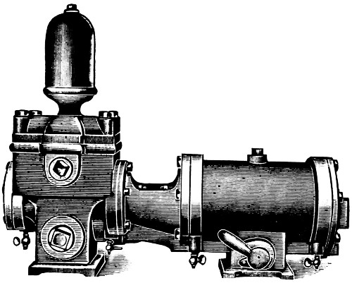
Fig. 278.
When the valve rod has a tendency to tremble, slightly tighten the valve rod stuffing-box nut. When the valve motion is properly adjusted, the vertical arm should not quite touch the collar, L, and the clamp, M. Rocker roller, I, coming in contact with the rocker bar, H, reverses the stroke.
The water piston is packed by means of segments that will be seen by taking off the follower. The packing may be quickly set out to insure a good vacuum and at the same time not to be so tight as to bind. All wearing parts are made adjustable.
The valve for admitting steam to and exhausting it from the cylinder of this pump is contained within the cylinder and moves simultaneously with the steam piston, having no outside mechanism. See Fig. 278.
The piston, and also the valve, are of the form of spools, each representing a hollow sleeve with a ring packed piston head at either end. The piston is secured to the piston rod and the sleeve connecting the two heads serves as the valve seat for the cylindrical valve. The sleeve of the piston contains two longitudinal ports, one port communicating with one end of the cylinder, and the other port communicating with the opposite end. Suitable holes drilled through the walls of the sleeve and communicating with the longitudinal ports, act as admission and exhaust ports, with which the holes and cavities in the sleeve coincide at proper positions in the stroke.
Referring to the accompanying engraving, Fig. 279, which represents the valve and piston in the position occupied when ready to commence a stroke from left to right, the reader will easily understand the action of these parts. When the piston reaches the end of the stroke steam enters through the steam pipe at A, between the pistons, and forces the valve to the left as shown. This movement opens the port, B, and also brings the cavity, C, in communication with port, D, steam being admitted through ports, B and D, into the longitudinal port, F, thence into the clearance, G, of the cylinder. This causes the piston to move toward the right. When the piston has moved a short distance to the right steam is admitted into the space, H, surrounding the valve, and passing into the cavity, C, and through the port, D, furnishes steam to complete the stroke.
Should the piston stop at mid-stroke it will start again as soon as steam is turned on, because the port, D, remains open until the valve is reversed at the opposite end of the stroke.
When the piston reaches the latter position, Fig. 280, the valve is reversed, due to steam entering at A, and again forcing the pistons apart, as shown. The steam, which drove the314 piston from left to right, now escapes through the port, I, into the cavity, J, and around the sleeve to the holes, K, Fig. 279, where it enters the hollow piston, and finally escapes through the hollow rod, L, and the port, M. The live steam for the next stroke from right to left, now enters through ports, N and O, Fig. 280, and flows through the longitudinal port, P, into the end, Q, of the cylinder.
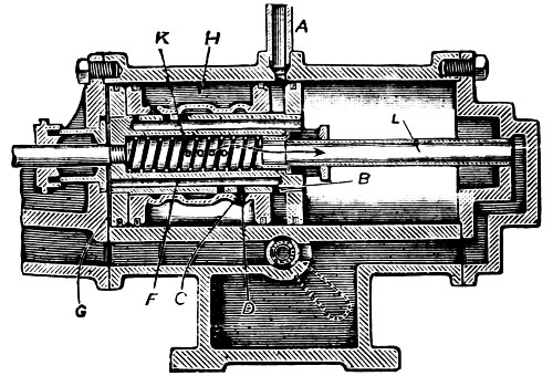
Fig. 279.
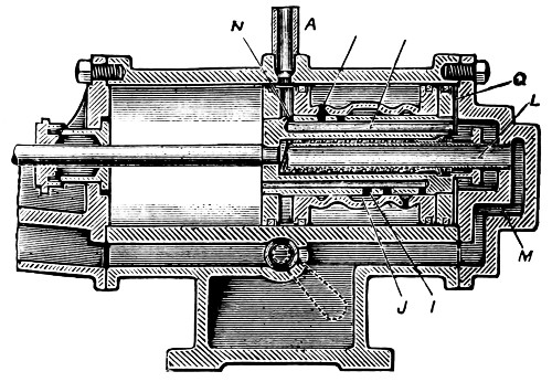
Fig. 280.
The exhaust steam may be allowed to flow into the atmosphere or into the suction chamber as desired. A valve is315 located in the base of the pump, which changes the course of the steam from the atmospheric discharge to the suction chamber. The valve is operated by a lever shown by dotted lines. When the lever is turned down toward the steam end, the steam is directed into the atmospheric exhaust, and when turned in the opposite direction the steam will enter the pump suction and be condensed.
There is no valve setting to be done on this pump. Should the pump fail to work properly, due to the failure of the steam end, all that is necessary is to take out the valve and piston and clean them thoroughly and after replacing them and starting the pump to see that these parts are properly lubricated. The remainder of the pump requires the same care and attention that is, or should be, given all pumps.
The auxiliary valve of this pump is a plain flat slide operated by a valve stem, the latter being moved back and forth by means of a rocker shaft, as shown in the engraving, the upper end of which alternately comes in contact with the collars on the stem.
The outer end of the valve stem passes through a sleeve attached to a pin in the upper end of the rocker arm, as shown. A knuckle joint near the stuffing-box permits the rod to vibrate without causing any derangement in the alignment of valve stem through the stuffing-boxes.
On the valve stem at either end of the auxiliary valve is a spring, which tends to keep the valve in a central position, so that when the rocker arm engages one of the collars, the valve is drawn against the spring toward that end of the stroke. The result is that the stem and valve follow the rocker arm on the return stroke to its mid-position, and are started on the latter half of the stroke by the stem, but without shock or lost motion. This arrangement is particularly valuable in the case of condensers, and in pumps where the first part of the stroke is made quickly, and the piston is then suddenly stopped by316 coming in contact with a solid body of water, the latter part of the stroke being made much more slowly. The springs on either side of the auxiliary valve take up lost motion and keep the parts in absolute contact, thus preventing shocks and unnecessary wear.
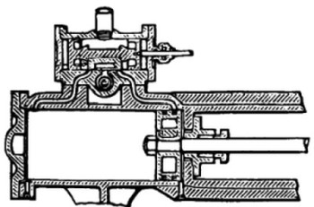
Fig. 281.
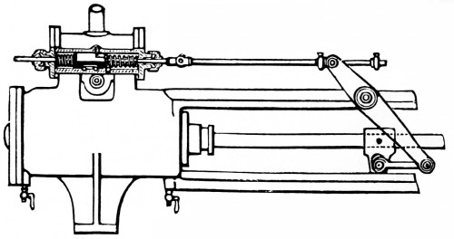
Fig. 282.
The auxiliary valve controls the admission and exhaust of steam for the steam chest and valve piston in the manner common to all slide valve engines. The valve piston is connected to the main valve, which allows the valve to find its own bearings on the seat and not only takes up the wear automatically, but produces even wear.
To set the auxiliary valve, see that the valve is in its central position when the rocker arm is plumb, and that the collars on the valve stem are located at equal distances from each end of the sleeve. When the piston moves to one end of the stroke, the auxiliary valve will open the small port at the opposite end,317 provided the collars on the valve stem have been properly placed. Setting the collars closer together shortens the stroke of the piston, and moving them farther apart lengthens the stroke. The piston should always make a full stroke without danger of striking the cylinder heads.
The details of the valve gear used on the Deane single cylinder steam pumps are shown in the accompanying engraving. The main valve is operated by a small piston called the valve piston, shown in Fig. 286. The ears on the main valve fit freely but without lost motion into a slot cut in the valve piston, so that when the valve piston moves in either direction it carries the main valve with it.
The valve piston is fitted to the valve chest and is operated by steam admitted alternately to the opposite ends of the chest. The movements of this valve piston are controlled by a secondary valve, which admits and exhausts the steam to the valve piston through the small ports at the sides of the steam chest. The secondary valve derives its motion from the valve stem, tappets, links and the piston rod as shown.
The valve piston is steam jacketed which insures equal expansion of the parts in starting the pump and prevents the seats from pinching the valve piston before these parts have acquired a uniform temperature.
The action of this pump is as follows: Suppose the piston moving in the direction of the arrow nears the end of the stroke; the tappet block comes in contact with the left-hand tappet and throws the secondary valve to the left until it’s edge, A, Fig. 284, uncovers the small port, S, Fig. 283, admitting steam to the valve piston.
The port, E, and chamber, F, in the secondary valve provide for the exhaust of steam from the left-hand end of valve piston in the same manner and at the same time that steam is admitted behind the right-hand end. The exhaust ports in the chest allow for properly cushioning the valve piston. The318 small ports on the other side of the steam cylinder, Fig. 283, control the motion of the valve in the other direction and act in exactly the same manner as those just described. In case the steam pressure should for any reason fail to start the valve piston in time there is a lug, B, Fig. 286, which forms a part of the valve stem and comes in contact with the valve piston and the entire power of the steam cylinder starts it. The correct timing of the valve movements is controlled by the position of the tappets. If they are too near together, the valve will be thrown too soon and thus the stroke of the pump will be shortened, while on the other hand if too far apart, the pump will complete its stroke without moving the valves. The tappets are set and keyed securely before leaving the factory.
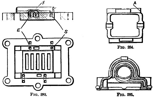
Figs. 283-285.
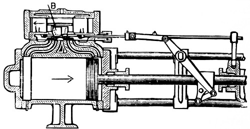
Fig. 286.
The exhaust from the cylinder is cut off when the piston covers the inner port, and forms a steam cushion for the piston to prevent it striking the heads.
To set the valve. Place the steam piston at the end of stroke nearest stuffing-box and the secondary valve so that it will uncover the steam port, S, Fig. 283. Set the tappet next to the steam cylinder on the valve stem against the tappet block and secure it in this position.
Slide the secondary valve forward until the opposite steam port is uncovered and place the steam piston in its extreme outward position, then set the other tappet against the tappet block. Now set the valve so that the inside main steam port is open and the valve piston in position to engage the main steam valve, put the valve chest on the cylinder and secure it in place. The pump will then be ready to start on the admission of steam to the steam chest.
If when steam is turned on the pump refuses to start, simply move the valve rod by hand to the end of its stroke and the pump will move without trouble.
In renewing the packing between the steam chest and cylinder extreme caution should be observed to cut out openings for the small ports.
The engravings, Figs. 287, 288, show the valve gear, also section of steam cylinder and steam chest. The piston and valves are in their central position, which condition never occurs in the operation of this pump; if it did the pump would stop. The valves and pistons being at one end or the other of the stroke uncovers the ports, and the moment steam is admitted the pump will start. Referring to the engravings, A, is the main steam pipe, and B, the auxiliary steam pipe. These pipes are one, inside the casting, so that one pipe supplies both. Assume the valve, C, moved to the left so that the port, D, is uncovered.
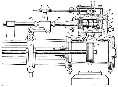
Fig. 287.
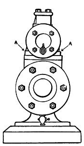
Fig. 288.
Live steam then flows through the port, D, and pushes the balanced piston valve, E, to the left, carrying the slide valve, F,321 with it to the left, so that the port, G, is opened to the steam cylinder. The steam enters through the port, G, pushes the main piston, H, to the left, completing one stroke of the piston. As the piston travels to the left the lever, J, pushes the crosshead, I, to the right, which opens corresponding ports in the left-hand end of the cylinder, and the piston valve, E, is pushed to the right, which admits steam on the left-hand side of the main piston through the port, K, pushing the piston to the right, completing the second stroke of the piston. The auxiliary slide valve, C, is operated by the crosshead, I, coming in contact with the tappets, L L.
The auxiliary tappets and stem, M M, theoretically could be dispensed with, but they are put in place for the reason that occasionally the valve, E, might stick, due to the pump standing for some time unused or from some other cause. In such a contingency the crosshead, I, is pushed to the right by the action of the main piston and comes in contact with the tappets, M M, which causes the piston valve to start, after which steam will complete the work. When the pump is running, the crosshead, I, never quite touches the tappets, M M, because it engages the tappets, L L, admitting steam to the piston valve and shifts it before the tappets, M M, are touched.
The reason of the double ports in the auxiliary steam chest is to have one port, D, for steam, and one port, N, for the exhaust. Steam being imprisoned between these two ports forms a cushion, preventing the piston valve from striking the heads of the chest. The tappets, L L, set closer together or farther apart control the stroke of the main piston, H. When the pump is running very fast the momentum of the moving parts increases and the tappets will have to be set closer together for high speed than for slow. The tappets, M M, are adjustable to their right relation with the tappets, L L. The general design and easy means of adjustment make a reliable single cylinder valve motion.
To set the valves. There are no complicated internal parts requiring adjustment, and almost all parts requiring manipulation can be handled while the pump is running.
The accompanying engraving, Fig. 289, represents the Weinman pump and the sectional engraving, Fig. 291, the valve motion.
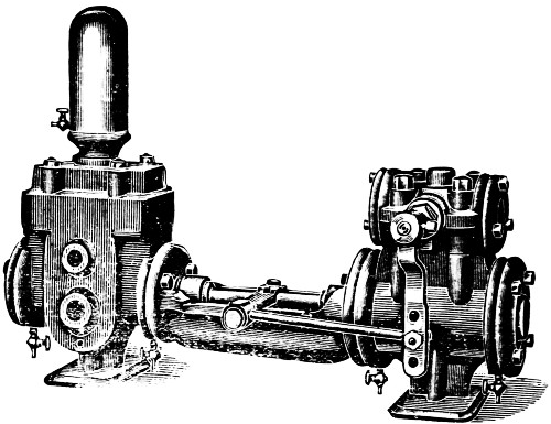
Fig. 289.
The motion of the main piston is controlled by steam valve, A, which is a hollow cylinder combining a valve piston and slide valve in one and the same casting and sliding horizontally in steam chest, D. This valve is prevented from revolving by a cap screw, B. Small drilled openings, C, C, permit the steam to pass from the steam valve to each end of the steam chest, D. This valve, A, is moved horizontally in either direction by steam pressure, and the movement is controlled by an auxiliary valve, E. The openings, F, F (Fig. 290), conduct the steam from the ends of the steam chest to the auxiliary valve, which is connected to the piston rod by a tappet rod and the side arm, X.
Steam being admitted to steam chest, it passes through steam valve, A, to ports, H, H. As the construction permits but one of the ports, H, H, to be in communication at a time with one of the passages, I, I, leading to the opposite ends of the steam cylinder a dead center becomes an impossibility.323 While one of the ports, H, H, is in communication with one of the passages, I, I, the opposite passage, I, is in communication with the exhaust, J.
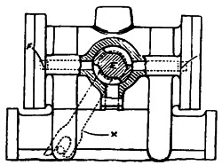
Fig. 290.
Suppose that the steam piston has moved to the end of its stroke, the auxiliary valve, which, as stated above, is connected to the piston rod, is shifted. This releases the steam from one end of the steam chest, D, through port, K, to exhaust, L. The steam pressure at the opposite end of the steam chest causes the steam valve to slide to opposite end of the steam chest, thus reversing the motion of the main steam piston.
To set the auxiliary valve, remove the pendulum or tappet lever, X, and the cap or bonnet, O, and take out the auxiliary valve, E. With a straight edge and scriber indicate the working edges on the end of the valve, and mark the edge of the port on the valve seat so that it can be seen when the auxiliary valve is in its proper place. Replace the valve, and the pendulum lever, omitting the bonnet.
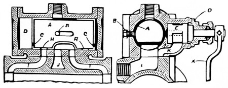
Fig. 291.
Push the steam piston to one end of the stroke, then swing the pendulum lever toward the end of the cylinder corresponding to the piston, and until the auxiliary valve uncovers the324 port leading to the end of the valve chest farthest from the piston. Connect the horizontal rod to the bottom of the pendulum lever. Then remove the lever from the auxiliary valve stem and replace the bonnet and pendulum lever, shown by dotted lines. The length of the stroke may be regulated by raising or lowering the end of the horizontal rod in the slotted lower end of the pendulum lever. Lowering the rod produces a longer stroke, and raising it shortens the stroke.
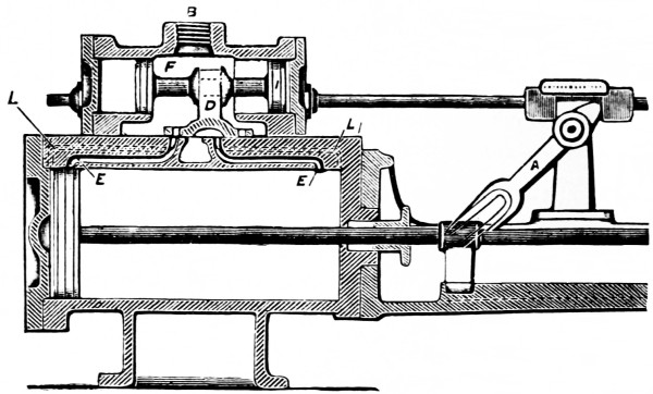
Fig. 292.
The accompanying engravings illustrate the cylinder valves and valve motion of the Burnham single cylinder pump. Fig. 294 is a plan of the main cylinder valve face, having the same arrangement of ports as the cylinder shown in Fig. 293.
A longitudinal section of the steam cylinder is shown in Fig. 292. Motion is imparted to the slotted arm and cam, A, by means of a crosshead and a roller on the piston rod.
The cam works between and in contact with two blocks on the valve stem, and by adjusting these two blocks the stroke may be shortened or lengthened, as the case may require. The valve stem of the auxiliary valve, H, Fig. 293, always moves in a direction opposite to that of the piston.
The action of this valve alternately admits steam through the double ports, J J, and K K, to each end of the valve cylinder, causing the valve piston, I, to move the main slide valve, D, which, in turn, admits steam to the main cylinder through the double ports, E E, and L L. As the travel of the cam is only one-fifth that of the piston travel, the valve moves slowly, and without jar or noise which is often caused by long travel and rapid motion.
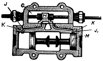
Fig. 293.
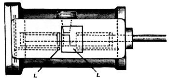
Fig. 294.
Steam enters the steam chest at B, and fills the space, F, between the valve piston heads and the auxiliary valve chest, G, shown in Fig. 292. With the auxiliary valve, H, in the position shown, Fig. 293, steam passes into both ports, J and K, but as the port, J1, is closed by the valve piston, I, no steam can enter the valve cylinder through it, but the other port, K (extending to the extreme end of the valve cylinder), never being covered by the piston, is open, and admits steam into the space, M.
As this port is quite small the space fills slowly and the piston moves gradually until it uncovers the last port, J1, when the full volume of steam is admitted, which quickly moves the piston to the opposite end of the valve cylinder. During this movement of the valve piston, the large port, J, remains open to the exhaust until it is covered by the valve piston. When the port, J, is covered by the valve as at J1, it has no connection with the exhaust, consequently, there being no outlet for326 the exhaust vapor, it is compressed and forms a cushion for the valve piston, I. The valve piston carries with it the main valve, D, which admits steam to the main steam cylinder through the double ports, E, E1, and L, L1, Fig. 294. The same cushioning and slow starting of the piston occurs in the main as in the valve cylinder, each having double ports.
This arrangement insures a uniform travel of piston under varying degrees of load. A momentary pause of the piston at each end of the stroke permits the water valves to seat quietly, without shock or jar, and the slow initial movement of the piston (whereby the water columns are started gradually) relieves the pump and piping of excessive strains.
To set the valve. Set the lever, A, plumb and the valve to cover all the ports equally.
The Dean Bros. pump is shown in Figs. 295, 296 and 297.
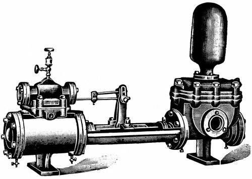
Fig. 295.
The auxiliary valve, A, Fig. 297, has in its face two diagonal exhaust cavities, B B1. The ports, C C1, and the exhaust port, D, are placed in a triangular position with one another, the diagonal cavities diverging so that the cavity B, when the valve is in place, connects the ports, C1 and D. Cavity B1 connects the ports C and D, when the valve, A, is at the end of the stroke. The three small cuts show relation of auxiliary valve to ports.
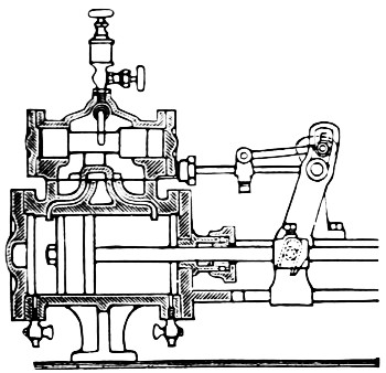
Fig. 296.
The piston starts from left to right when the valve, A, moves in an opposite direction, opens the port, C, admitting steam to the auxiliary cylinder at the moment the main piston has reached the end of its stroke. The auxiliary piston, E, is forced to the left, opening the main port and admitting steam to the main cylinder, reversing the movement of the main piston the return stroke of the main piston reverses the movement of the auxiliary valve, whereby the port, C, is closed, at the moment the main piston reaches the end of its outer stroke. The port, C1, is opened by the valve, A, and reverses the valve piston, E, opens the main port and reverses the motion of the main piston.
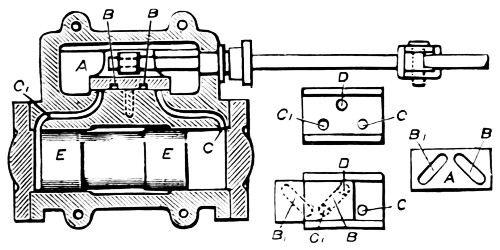
Fig. 297.
This port arrangement admits of a short valve with a long travel. The stroke of the pump can be regulated by moving the stud up or down in the segmental slot, Fig. 296, which varies the travel of the auxiliary valve and reverses the stroke of the main piston as desired. By raising the stud the pump will make shorter strokes, and by lowering it will make longer strokes.
The motion of the auxiliary steam slide valve is like that derived from an eccentric. The ports leading to the valve piston, E, Fig. 297, remain closed, except at the moment the main piston is reversed; hence, there can be no waste of steam from leaks when the valve piston becomes worn.
Having a long stroke and a rapid motion, the auxiliary valve insures a certain reversal of the piston at the proper time.
To set the valve, turn the steam chest upside down. Put valve stem through the stuffing-box and secure in place the clamp for small slide valve. The diameter of valve stem is smaller where the clamp is attached.
Now screw up the stuffing-box nut (having previously removed the packing), then move the valve and stem so that the small port at right of valve will be open 1⁄16 inch and make a scratch upon the stem close to stuffing-box nut. The valve should then be moved in the opposite direction to open the other small port 1⁄16 inch and make a second scratch upon the valve stem next to stuffing-box nut. Prepare joint and replace steam chest on cylinder. To square the valve, slacken the screw in crosshead and move the latter to the end of stroke with edge of crosshead flush with the end of guide, then set the valve stem so that the first scratch is flush with the face of nut, same as when the scratch was made. Tighten screw in set screw under valve rod dog and move the crosshead to the opposite end of stroke, and note the position of second scratch. If it does not come to the position in which it was made, split the difference by slackening the set screw under valve rod dog and move the valve rod to equalize the travel of valve.
In replacing steam chest on cylinder, cover the opening with a thin board, or piece of sheet iron, before turning it over to prevent the valve from dropping out of place.
This slide valve has a fixed travel and the process of setting is precisely the same as for that upon a steam engine with a plain slide valve.
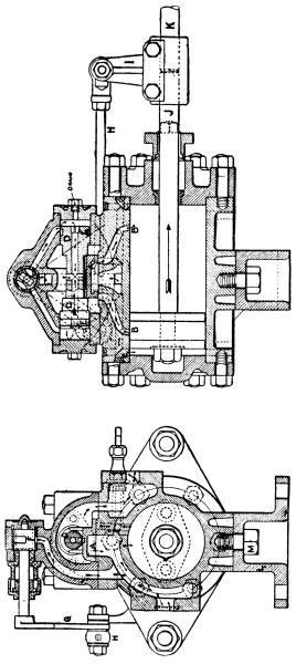
Figs. 298, 299.
The accompanying sectional view of steam end of the “Smith-Vaile” exhibits some very novel features. So far as the piston and cylinder in this pump are concerned they are not unlike the average first class pump, but with this difference. It has only one set of cored ports, B, B. The supplemental ports, C, C, are drilled.
The main valve, A, is a slide and is moved by a valve piston, D. Almost all the valve pistons as now made are simply plugs turned accurately to fit the holes in the chest and without any means of adjustment to compensate for wear. After these valve pistons become worn they have to be replaced with new ones, but there is a period between the time when330 the valve piston becomes so leaky as to render the action of the pump uncertain and the time when the worn valve is replaced by a new one that the pump is very wasteful of steam.
The valve piston in this pump is provided with packing rings, E, E, which compensate for wear of these parts so that this valve is expected to do efficient service long after a slow valve. The supplemental valve, F, has a reciprocating rotary motion which is communicated to it by the rock arm, G, and pitman, H, connecting with the crosshead, I, secured to the piston rod. It will be observed that the piston rod, J, and the rod, K, of the water end are separated so that should either one give out through wear or accident it can be replaced without sacrificing both, as would be the case if they were solid in one piece. This supplemental valve, F, in general appearance very closely resembles the “Corliss” valve, and its action is somewhat similar, in controlling the action of the valve piston, which will be understood from the engraving without further description. These pumps all have removable water ends and can be rebored or otherwise manipulated without disturbing the steam end of pump. The cylinder can be separated from the foot by removing the bolt, M.
The duplex pump is also shown in the accompanying engraving, where, A, A, represents the steam cylinders, secured to the foot, B, by bolts, as previously described.
The usual slide valves have been replaced by piston valves, C, in this instance and are provided with removable seats, D, D.
These piston valves have packing rings, E, E, also to compensate for wear and the valves are cast hollow to reduce their weight as much as possible consistent with good workmanship, also to serve as ports for steam admission. When these valve seats become worn they may be easily removed and rebored or replaced by new ones, as desired. It will be observed that these ports are very short to reduce the clearance as much as possible, and to secure a more satisfactory cushion. Each valve is operated by the rock arm connected with the opposite engine in the usual way.
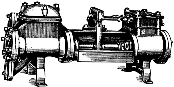
Fig. 300.
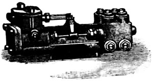
Fig. 301.
The word duplex means two fold, or double, and has a wide application, as the duplex lathe, the duplex watch, etc., hence, the well-known duplex-pump is one in which two direct acting pumps are placed side by side and so connected that the steam piston of one operates the valve of the other. See Fig. 300.
Fig. 301 shows one of the smallest manufactured patterns of this type of pumps. Its dimensions are as follows: 2-inch diam. steam cylinder; 11⁄8-inch water cylinder; 22⁄3-inch stroke. Its capacity is .044 gallons per revolution; rev. per minute, 80; gallons per minute, 3.5. Steam pipe, 3⁄8-inch; exhaust pipe, 1⁄2-inch; suction pipe, 1-inch; discharge, 3⁄4-inch. Floor space occupied, 1´ 9″ × 7″ wide; requires 1⁄2 H.P.
The valve motion (see Figs. 302, 303) of one cylinder is communicated or produced by the piston of the other through the medium of rocker arms and links. By means of the small lost motion of the levers the pistons have a slight pause at the end of each stroke, which allows the water valves to seat quietly, thus preventing any slam or jar.
With this arrangement, as one of the steam valves must always be open, there can be no dead point, thus removing the liability of the pump to stick. The simplicity of the duplex movement is at once evident, each valve is dependent upon its counter part, and both directly control the action of the steam, which is supplied through one simple throttle valve.
Note.—Of the effect produced by the steam-moved direct-acting pump of much greater capacity it may be said there are now in use pumps of this class, exerting over 250 horse-power, delivering five million gallons of water in twenty-four hours through main pipes, say thirty inches diameter and fourteen miles long, without the use of an air chamber, and which do their work so quietly, steadily, and gently, that a nickel coin set on edge on the extreme end of the pump would not be overthrown by any jar or motion of the pump while it was doing this work.
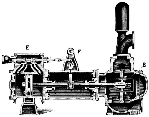
Fig. 302.
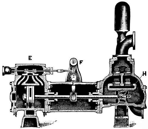
Fig. 303.
The adoption of the Worthington design of duplex pumps, has been well nigh universal, especially so since the expiration of the earlier patents. Nearly all leading manufacturers now make “duplex pumps.” Single, compound and triple expansion.
Compounding consists of adding a second steam cylinder on the end of the high pressure in use, both using the same piston rod, the steam from the boiler being first used in the smaller cylinder, and at the end of the stroke of the piston being exhausted behind the piston of the larger cylinder on its return stroke. In this way the measure of the expansion of the steam used, was the relation of one cylinder to the other.
By this arrangement a much smaller steam cylinder, for using the high pressure steam, could be adapted to do the same work, for in addition to the pressure of steam working full stroke in the small cylinder, was to be added the pressure of the steam being expanded in the large cylinder.
In addition to this, for large compound and triple expansion engines was added the further economy realized by attaching a condenser to form a vacuum in the large steam cylinders.
Adapting these newer improvements in the marine engine coupled with what had previously been accomplished in the direct-acting steam pump, they were at once brought up in size, capacity, and economy alongside the previously constructed rotative pumping engines.
The history of the invention of this pump is given on pages 69 and 70; to these pages a careful attention is advised, as they briefly describe also the fundamental principles of its operation. This form of steam pump has been so long and generally in use that the valve mechanism is already familiar to most engineers.
The simplicity of both its theory and its practical application obviates the necessity of devoting very much space to its consideration. The final improvement made by Worthington in connection with the steam duplex pump was in the adaptation of triple expansion in its steam ends.
The illustrations, Figs. 302 and 303, are sectional views of one side, or half, of the Worthington steam pump, showing two different designs. They illustrate the interior arrangement of the pump. The valve, as may be seen at, E, is an ordinary slide valve; the motion of this valve is controlled by a vibrating arm, F, which swings through the whole length of the stroke. The moving parts are always in contact, which ensures smooth and even motion.
This valve motion is the prominent and distinguishing characteristic of the Worthington duplex pump. Two steam pumps are placed side by side and so combined that one piston acts to give steam to the other, after which it finishes its own stroke and waits for its valve to be acted upon by the other pump before it can renew its motion. This pause allows the water valves to seat quietly, and removes any harshness of motion. As one or the other of the steam valves is always open, there is no dead point, and therefore the pump is always ready to start when the steam is admitted.
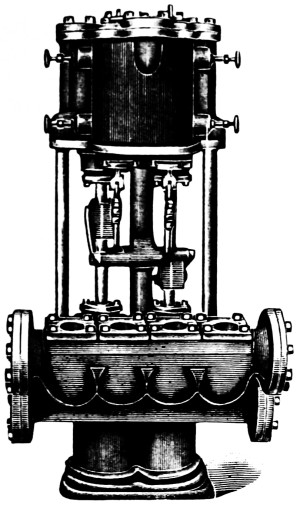
Fig. 304.
In the plunger and ring pattern, Fig. 302, there is a double-acting plunger, B, working through a deep metallic ring bored to fit the plunger. The plunger is located some inches above the suction valves, leaving a settling chamber, into which any foreign substance may fall out of the way of the wearing surfaces. Both the plunger and ring can be taken out and either refitted or, when necessary, renewed. The valves consist of small discs of rubber, or other suitable material, and are easily accessible through convenient handholes. This pattern is recommended where the liquid to be pumped contains small quantities of grit or foreign material, or where there is an unusually long or high suction lift.
In the piston-pattern pump, Fig. 303, there is a packed water piston, G, working in a brass-lined cylinder, H. Both the suction and the discharge valves are located above the water pistons, so that the pistons may be at all times submerged. This pattern is recommended where the liquid to be pumped contains no grit or foreign material.
Fig. 304 shows the Worthington Admiralty pattern boiler feed pump which is designed to meet the requirements of the United States Bureau of Steam Engineering for steam boiler pressure up to 250 lbs. to the square inch. The ordinary slide valves are replaced by piston valves with outside, adjustable, lost-motion links, making it possible to readily adjust the stroke. The water end is made of composition, gun metal, or cast-iron, as desired. When made of cast iron the water end is brass-fitted throughout.
Table of Sizes, Capacities, Etc.
| Diameter of Steam Cylinders |
Diameter of Water Pistons |
Length of Stroke |
Horse-power of Boiler based on 45 pounds of water per hour, which this pump will supply at slow speed. |
|||
|---|---|---|---|---|---|---|
| 41⁄2 | 23⁄4 | 4 | 170 | |||
| 51⁄4 | 31⁄2 | 5 | 280 | |||
| 6 | 4 | 6 | 470 | |||
| 6 | 41⁄2 | 6 | 590 | |||
| 71⁄2 | 5 | 6 | 670 | |||
| 9 | 6 | 6 | 960 | |||
| 71⁄2 | 41⁄2 | 10 | 800 | |||
| 9 | 6 | 10 | 1400 | |||
| 10 | 7 | 10 | 2200 | |||
| 12 | 81⁄2 | 10 | 3200 | |||
| 12 | 91⁄4 | 10 | 3800 | |||
| 14 | 10 | 15 | 4800 | |||
| Diameter of Steam Cylinders |
Diameter of Water Pistons |
Length of Stroke |
Sizes of Pipes for Short Lengths To be enlarged as length increases. |
|||
| Steam Pipe |
Exhaust Pipe |
Suction Pipe |
Delivery Pipe |
|||
| 41⁄2 | 23⁄4 | 4 | 3⁄4 | 11⁄4 | 2 | 2 |
| 51⁄4 | 31⁄2 | 5 | 1 | 11⁄2 | 21⁄2 | 21⁄2 |
| 6 | 4 | 6 | 11⁄2 | 2 | 4 | 3 |
| 6 | 41⁄2 | 6 | 11⁄2 | 2 | 4 | 3 |
| 71⁄2 | 5 | 6 | 11⁄2 | 2 | 5 | 4 |
| 9 | 6 | 6 | 2 | 21⁄2 | 5 | 4 |
| 71⁄2 | 41⁄2 | 10 | 11⁄2 | 2 | 4 | 3 |
| 9 | 6 | 10 | 2 | 21⁄2 | 5 | 4 |
| 10 | 7 | 10 | 2 | 21⁄2 | 6 | 5 |
| 12 | 81⁄2 | 10 | 21⁄2 | 3 | 6 | 5 |
| 12 | 91⁄4 | 10 | 21⁄2 | 3 | 6 | 6 |
| 14 | 10 | 15 | 21⁄2 | 3 | 8 | 6 |
| Diameter of Steam Cylinders |
Diameter of Water Pistons |
Length of Stroke |
Approximate Space Occupied Inches |
|||
| Height | Depth | Width | ||||
| 41⁄2 | 23⁄4 | 4 | 38 | 18 | 23 | |
| 51⁄4 | 31⁄2 | 5 | 46 | 22 | 29 | |
| 6 | 4 | 6 | 50 | 23 | 32 | |
| 6 | 41⁄2 | 6 | 50 | 23 | 32 | |
| 71⁄2 | 5 | 6 | 54 | 28 | 33 | |
| 9 | 6 | 6 | 57 | 27 | 36 | |
| 71⁄2 | 41⁄2 | 10 | 66 | 28 | 33 | |
| 9 | 6 | 10 | 68 | 27 | 36 | |
| 10 | 7 | 10 | 77 | 34 | 40 | |
| 12 | 81⁄2 | 10 | 86 | 39 | 44 | |
| 12 | 91⁄4 | 10 | 86 | 39 | 44 | |
| 14 | 10 | 15 | 110 | 36 | 50 | |
A notable feature in this pump is the location of the exhaust passage; this opening is underneath the cradle—or the part that the pump rests upon—just forward of the steam cylinders. The flanges of the steam end and cylinders and the steam chest cover have been made heavier than the regular and strengthened to withstand the higher pressures.
Fig. 305 is a sectional view of a larger size duplex pump than the one shown in Fig. 302. The plunger, B, packing is identical, but the number of water valves is double; access for cleaning the suction chamber, C, is had by removing the hand hold plate at the side and in the center. The discharge valves are reached through the hand hold at D.
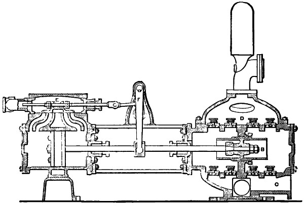
Fig. 305.
The following rule applies to nearly all duplex pumps of the Worthington type. The valves are usually of the common “D” valve type, working on the cylinder iron, or bronze seats, and suitably “set.” Sufficient cushion at the end of each stroke is provided by separate valves in the ports.
Rule.—1, Locate the steam piston in the center of the cylinder, Fig. 305. This is accomplished by pushing the piston to one end of its stroke against the cylinder head and marking the rod with a scriber at the face of the stuffing-box, and then bringing the piston in contact with the opposite head; 2, divide exactly the length of this contact stroke. Shove the piston back to this half mark, which brings the piston directly in the center of the steam cylinder, F; 3, perform the same operation with the other side; 4, place the slide valves, which have no lap, to cover all the ports, E; 5, pass the valve stem through the stuffing-box and gland. The operation of placing the pistons in the center of their cylinders will bring the levers and rock shafts in a vertical position; 6, screw the valve stem through the nuts until the hole in the eye of the valve stem head comes in a line with the hole in the links, connecting the rocker shaft; then put the pins in their places; 7, adjust the nuts on both sides of the lugs of the valves to leave about 1⁄4″ or 1⁄8″ loss motion on each side.
This process of adjustment being performed with both cylinders, the steam valves are set. In short the travel of the two valves is simply equalized.
The pattern of pump shown in Fig. 306, is especially designed for use in connection with hydraulic lifts and cranes, cotton presses, testing machines, hydraulic riveting and punching machines, and hydraulic presses of all kinds. Also for oil pipe lines (see Table, page 341), mining purposes, and such services as require the delivery of liquids under heavy pressures.
There are four single acting outside packed plungers, which work into the ends of the water cylinders, the latter having central partitions; each individual valve has its own cover or bonnet. The arrangement of compound steam cylinders is shown. The water valves are easily accessible, and are contained in small chambers, capable of resisting very heavy pressures. The general arrangement shown in the engraving is subject to numerous alterations, according to various requirements, but the general characteristic of four outside packed plungers is in all cases preserved.
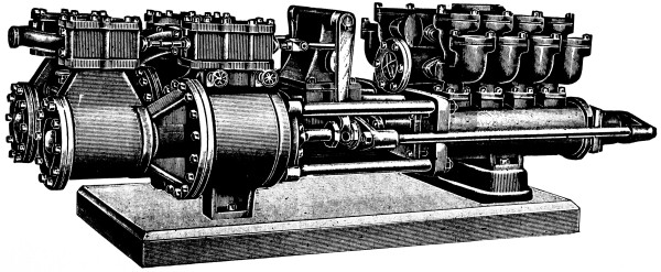
Fig. 306.
Table.
| Steam Cylinders. |
Water Plungers. |
Stroke. | Capacity in Gallons, per Stroke each Plunger. |
Strokes per Minute, each Plunger. |
|---|---|---|---|---|
| Ins. | Ins. | Ins. | ||
| 16 | 5 | 12 | 1.02 | 50 to 100 |
| 16 | 6 | 12 | 1.47 | 50 „ 100 |
| 16 | 7 | 10 | 1.66 | 50 „ 100 |
| 16 | 7 | 18 | 3.00 | 40 „ 80 |
| 16 | 8 | 12 | 2.61 | 50 „ 100 |
| 16 | 8 | 18 | 3.91 | 40 „ 80 |
| 16 | 9 | 12 | 3.30 | 50 „ 100 |
| 181⁄2 | 7 | 12 | 2.00 | 50 „ 100 |
| 181⁄2 | 71⁄2 | 12 | 2.30 | 50 „ 100 |
| 181⁄2 | 8 | 18 | 3.91 | 40 „ 80 |
| 181⁄2 | 9 | 18 | 4.95 | 40 „ 80 |
| 181⁄2 | 10 | 12 | 4.08 | 50 „ 100 |
| 181⁄2 | 10 | 18 | 6.12 | 40 „ 80 |
| 20 | 8 | 12 | 2.61 | 50 „ 100 |
| 20 | 8 | 18 | 3.91 | 40 „ 80 |
| 20 | 9 | 12 | 3.30 | 50 „ 100 |
| 20 | 9 | 18 | 4.95 | 40 „ 80 |
| 20 | 10 | 12 | 4.08 | 50 „ 100 |
| 20 | 10 | 18 | 6.12 | 40 „ 80 |
| Steam Cylinders. |
Water Plungers. |
Stroke. | Capacity of Both Cylinders, in Gallons, per Minute. |
Steam Pipe. |
| Ins. | Ins. | Ins. | Ins. | |
| 16 | 5 | 12 | 102 to 204 | 21⁄2 |
| 16 | 6 | 12 | 147 „ 294 | 21⁄2 |
| 16 | 7 | 10 | 166 „ 332 | 21⁄2 |
| 16 | 7 | 18 | 240 „ 480 | 21⁄2 |
| 16 | 8 | 12 | 261 „ 522 | 21⁄2 |
| 16 | 8 | 18 | 312 „ 625 | 21⁄2 |
| 16 | 9 | 12 | 330 „ 660 | 21⁄2 |
| 181⁄2 | 7 | 12 | 200 „ 400 | 3 |
| 181⁄2 | 71⁄2 | 12 | 230 „ 460 | 3 |
| 181⁄2 | 8 | 18 | 312 „ 625 | 3 |
| 181⁄2 | 9 | 18 | 396 „ 702 | 3 |
| 181⁄2 | 10 | 12 | 408 „ 816 | 3 |
| 181⁄2 | 10 | 18 | 490 „ 980 | 3 |
| 20 | 8 | 12 | 261 „ 522 | 4 |
| 20 | 8 | 18 | 312 „ 625 | 4 |
| 20 | 9 | 12 | 330 „ 660 | 4 |
| 20 | 9 | 18 | 396 „ 792 | 4 |
| 20 | 10 | 12 | 408 „ 816 | 4 |
| 20 | 10 | 18 | 490 „ 980 | 4 |
| Steam Cylinders. |
Water Plungers. |
Stroke. | Exhaust Pipe. | Suction Pipe. |
| Ins. | Ins. | Ins. | Ins. | Ins. |
| 16 | 5 | 12 | 3 | 4 |
| 16 | 6 | 12 | 3 | 5 |
| 16 | 7 | 10 | 3 | 6 |
| 16 | 7 | 18 | 3 | 7 |
| 16 | 8 | 12 | 3 | 7 |
| 16 | 8 | 18 | 3 | 8 |
| 16 | 9 | 12 | 3 | 8 |
| 181⁄2 | 7 | 12 | 31⁄2 | 6 |
| 181⁄2 | 71⁄2 | 12 | 31⁄2 | 6 |
| 181⁄2 | 8 | 18 | 31⁄2 | 8 |
| 181⁄2 | 9 | 18 | 31⁄2 | 8 |
| 181⁄2 | 10 | 12 | 31⁄2 | 10 |
| 181⁄2 | 10 | 18 | 31⁄2 | 10 |
| 20 | 8 | 12 | 5 | 7 |
| 20 | 8 | 18 | 5 | 8 |
| 20 | 9 | 12 | 5 | 8 |
| 20 | 9 | 18 | 5 | 8 |
| 20 | 10 | 12 | 5 | 10 |
| 20 | 10 | 18 | 5 | 10 |
| Steam Cylinders. |
Water Plungers. |
Stroke. | Discharge Pipe. | Water Press. Pump End will stand, in lbs., per square inch. |
| Ins. | Ins. | Ins. | Ins. | |
| 16 | 5 | 12 | 3 | 450 |
| 16 | 6 | 12 | 4 | 450 |
| 16 | 7 | 10 | 5 | 300 |
| 16 | 7 | 18 | 6 | 450 |
| 16 | 8 | 12 | 6 | 300 |
| 16 | 8 | 18 | 7 | 450 |
| 16 | 9 | 12 | 7 | 250 |
| 181⁄2 | 7 | 12 | 5 | 250 |
| 181⁄2 | 71⁄2 | 12 | 5 | 300 |
| 181⁄2 | 8 | 18 | 7 | 450 |
| 181⁄2 | 9 | 18 | 7 | 250 |
| 181⁄2 | 10 | 12 | 8 | 250 |
| 181⁄2 | 10 | 18 | 8 | 250 |
| 20 | 8 | 12 | 6 | 450 |
| 20 | 8 | 18 | 7 | 450 |
| 20 | 9 | 12 | 7 | 250 |
| 20 | 9 | 18 | 7 | 250 |
| 20 | 10 | 12 | 8 | 250 |
| 20 | 10 | 18 | 8 | 250 |
A test of the superiority of this method of moving, and controlling long columns of fluids under extreme heavy pressures was made at the time of the introduction of long pipe lines for conveying oil from the wells to the seaboard.
Note.—After trying various kinds of pumps for forcing the oil through these long pipes, and after having a succession of disasters in the way of burst pipes, and leaking joints, it was decided to test the efficiency of the direct-acting duplex steam pump. These pumps were placed in the various stations along the pipe lines, and after a continued service of many years, have shown their perfect adaptation to that exceptionally hard service. These pumps convey the oil over mountains where at times the coupled lines have been over one hundred miles long between the pumps, and where the pressure on the plunger of the pump sometimes rises to 1,500 lbs. per square inch.
J. F. Holloway.
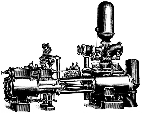
Fig. 307.
The application of this valve is shown in Fig. 307, on the opposite page. It can be attached to any regular Compound or Triple Expansion Pump, and if not in use does not in any way impede the regular running of the machine.
The Deane switch valve is a device by which compound low service pumps may be converted into powerful fire pumps. This appliance consists of a valve of such construction that steam may be allowed to enter the cylinders as usual for compounding, or may be diverted by simply moving a lever, when all four cylinders receive steam at boiler pressure, each exhausting independently to the atmosphere. The change makes each steam cylinder available for its maximum power, all four cylinders develop their full power, and its effect can be utilized in powerful fire streams.
It should be borne in mind in justice to the manufacturers that the Deane switch valve is not to be classed with the ordinary two or four-valve arrangement, which, while admitting initial steam to the second cylinders, develops no power in the first, or, as it is sometimes arranged, uses initial steam in all four cylinders and develops less power than if the second cylinders were used independently.
This valve is recommended by the Insurance companies, and compound duplex pumps fitted with the Deane switch valve will be accepted in place of the Underwriter pump of similar capacity. This valve is also frequently used where two widely differing water pressures are required for other purposes than for fire protection.
Every machine is subject to rigorous tests before leaving the factory, including a 300-pound test of the water cylinders. Every pump is guaranteed to be in full accordance with the specifications.
The Insurance Companies have issued detailed specifications for the construction of fire pumps to be known as Underwriter Fire Pumps. They have agreed that such pumps with their specified attachments be recognized as the approved type, and that pumps built and fitted up less perfectly be not approved in future installments.
The wide experience and systematic methods of the Insurance Companies place them in position to give valuable suggestions as a result of their observation and experiment, and these are embodied in carefully drawn regulations issued by their Engineering Department.
The specifications are very exacting in every particular, entering into the design, material, and workmanship in minute detail. They call for a number of fittings and attachments not usually furnished, and a most rigid test at the factory before shipping, and by the Inspecting Engineers of the Insurance Companies after the pump is installed, which secures for the purchaser the certainty of having a machine which beyond any reasonable doubt can be relied upon to do its full duty when emergency arises calling for its use.
There are a few quite important features not found in pumps of usual construction. The pumps are composition fitted throughout, the water cylinder bushings and plungers and linings to stuffing-boxes are of composition, the piston and valve rods, made unusually heavy, are of Tobin bronze. The mixture of the copper and tin composing the plungers and bushings varies for the two so as to prevent their cutting. Owing to the very high speed at which these pumps are liable to be run during a fire, all the working parts are made excessively strong, and the valve area and water passages are larger than usual. The interior of each Underwriter pump is treated with a rust-proof coating, and every precaution taken so that the pump will start instantly after an indefinite period of disuse.
Figs. 307 and 308 exhibit two somewhat varying but acceptable forms of the duplex steam pump.
Among the attachments included in an outfit for the underwriter pump may be mentioned: an elbow or tee for the suction connection with a large suction air chamber, a set of brass priming pipes with special gate and check valves for the same, an automatic water pressure relief valve fitted to a cone and overflow pipe, a steam gauge and a special water gauge with duplex spring, each of which in the Underwriter Pump is mounted on an ornamental plate rigidly attached to the machine.
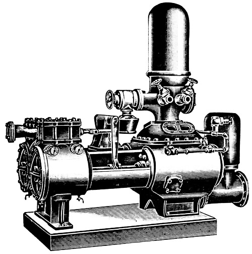
Fig. 308.
Straightway hose valves for the proper number of streams are placed in the neck to a very large discharge chamber, and there is also a large discharge opening for connection to the system of hydrants and sprinklers.
A stroke pointer is attached which travels between graduations marked on the yoke, indicating the length of stroke which pump travels, a one-point sight feed cylinder lubricator, a capacity plate with enamelled face giving instructions for operating, etc., is attached to each machine.
EDITION OF 1904
This pump is merely a pump of the well-known “duplex” type, built in a very substantial manner, and with certain improvements suggested by the experience of inspectors with Fire Pumps.
The principal points of difference between the National Standard Pump and the ordinary commercial pump are:
1st. Its steam ports and water passages and air chamber are made much larger than in common trade pumps, so that a larger volume of water can be delivered in an emergency without water hammer.
2nd. It is “rust proofed” that it may start instantly after disuse, by making its piston rods and valve rods of Tobin Bronze, instead of steel; its water pistons, stuffing boxes and rock-shaft bearings of brass, instead of cast iron. Its valve levers are made of steel or wrought-iron forgings, or of steel castings.
3d. The following necessary attachments are all included in the price of the “National Standard Pump,” viz.:—a vacuum chamber, two pressure gauges, a relief valve, a set of brass priming pipes, 2 to 6 hose valves, a stroke gauge, a capacity plate, an oil pump, a sight feed lubricator and a cast-iron relief-valve discharge-cone.
By reason of the larger ports, passageways and pipes, its larger number of valves, and the added attachments, and general superior construction a “National Standard” pump costs more than a common trade fire pump, but the cost per gallon which these pumps can deliver in an emergency by reason of their large passageways, etc., is no greater than for the old style of fire pump and is well worth this extra cost.
Finally it should be remembered that these specifications cover only the outlines of the design, and that all pumps built under them are not of equal merit, for certain of the pump factories possess a broader experience and better shop facilities than others, and that the responsibility for first-class workmanship and strength of materials rests on the pump manufacturers, and not on the insurance companies.
We advise that all contracts call for strict conformity to the National Standard Steam Fire Pump specifications of the National Board of Fire Underwriters.
The following specifications for the manufacture of Steam Fire Pumps, developed from those originally drawn by Mr. John R. Freeman, are now used throughout the whole country, having been agreed upon in joint conference by representatives of the different organizations interested in this class of work. They will be known as “The National Standard,” and have been up to this time adopted by the following associations: Associated Factory Mutual Fire Insurance Companies, National Board of Fire Underwriters, National Fire Protection Association.
a. The general character and accuracy of foundry and machine work must throughout equal that of the best steam-engine practice of the times, as illustrated in commercial engines of similar horse-power.
This refers to strength of details, accuracy of foundry work, accuracy of alignment, accuracy of fits, quality of steam joints and flanges, construction of steam pistons and slide-valves, etc., and does not apply particularly to exterior finish.
a. Only “Standard Duplex pumps” are acceptable.
So-called “Duplex” pumps consisting of a pair of pumps with “steam-thrown valves” actuated by supplemental pistons are not acceptable.
Experience shows that duplex pumps are more certain of starting after long disuse. The whole power of the main cylinder is available for moving a corroded valve or valve rod, whereas on a single pump with a “steam-thrown” valve no such surplus of power is available.
Further, the direct acting duplex has the great advantage over a fly-wheel pump of not suffering breakage if water gets into steam cylinder.
a. Only the four different sizes given on the next page will be recognized for “National Standard” pumps.
The multiplicity of odd sizes of “Trade Pumps” is confusing, and different makers have, in the past, estimated the capacity in gallons according to different arbitrary standards.
| Pump Sizes. | Ratio of Piston Areas. |
Capacity At 100 lbs. at Pump. |
||||
|---|---|---|---|---|---|---|
| Steam. | Water. | Stroke. | About | Number of 11⁄8 in. Streams. |
Nominal Gals. per Minute. |
Actual Gals. per Min. as per Art. 4. |
| 14 × 7 × 12 | 4 to 1 | Two | 500 | 4830 | ||
| 14 × 71⁄4 × 12 | 520 | |||||
| 16 × 9 × 12 | 3 to 1 | Three | 750 | 8060 | ||
| 18 × 20 × 12 | 3 to 1 | Four | 1000 | 9990 | ||
| 181⁄2 × 101⁄4 × 12 | 1050 | |||||
| 20 × 12 × 16 | 23⁄4 to 1 | Six | 1500 | 1655 | ||
NATIONAL STANDARD PUMP SIZES.(continuation)
| Pump Sizes. |
B Boiler Power Required |
Full Speed. | ||||
|---|---|---|---|---|---|---|
| Steam. | Water. | Stroke. | Horse Power. |
Steam Pres. at Pump, lbs. |
Rev. Per Minute. |
Piston Travel Feet Per Minute. |
| 14 × 7 × 12 | 100 | 40 | 70 | 140 | ||
| 14 × 71⁄4 × 12 | ||||||
| 16 × 9 × 12 | 115 | 45 | 70 | 140 | ||
| 18 × 20 × 12 | 150 | 45 | 70 | 140 | ||
| 181⁄2 × 101⁄4 × 12 | ||||||
| 20 × 12 × 16 | 200 | 50 | 60 | 160 | ||
B This boiler power is required for continuous running at full speed and pressure. It is, however, often best to put in a larger pump than the existing boilers could drive at full capacity, as a small boiler will drive a 750-gallon pump at the 500-gallon speed with very nearly as good economy as it can drive a 500-gallon pump at full speed. The pump then does not have to be changed when the plant is enlarged and the boiler power increased.
A steam piston relatively larger than necessary is a source of weakness. It takes more volume of steam, and gives more power with which to burst the pipes if the throttle is opened wide suddenly during excitement.
It has been common to make all fire-pumps with water plunger of only one-fourth the area of steam piston, with the idea that pump could thereby be more readily run at night, when steam was low. The capacity in gallons is thus reduced 25 per cent. as compared with a 3 to 1 plunger on the same steam cylinders.
b. The above sizes of steam and water cylinders and length of stroke have given general satisfaction and will now be considered as standard.
Often, especially with large pumps, “4 to 1” construction is a mistake, and gives no additional security, although the pump might start and give a few puffs with 30 lbs. of steam on banked fires; because, if any pump of whatever cylinder ratio draws 50 or 100 horse-power of steam from boilers with dead fires, it can run effectively only a very short time (ordinarily, perhaps, 3 to 5 minutes), unless fires are first aroused to make fresh steam to replace that withdrawn.
Steam pressures stated above must be maintained at the pump, to give full speed and 100 lbs. water pressure. Pressure at boilers must be a little more, to allow for loss of steam pressure between boiler and pump. Pumps in poor order, or too tightly packed, will require more steam.
The boiler horse-powers above are reckoned on the A. S. M. E. basis of 341⁄2 lbs. of water evaporated from and at 212 degrees Fahrenheit as the unit of boiler horse-power. From 12 to 15 square feet of water-heating surface in the boiler is commonly assumed necessary for the generation of one horse-power.
Smaller boilers than called for above, if favorably set, and having excellent chimney draft, can sometimes be forced to nearly double their nominal capacity for a short run, as for fire service.
c. 250 gallons per minute is the standard allowance for a good 11⁄8-inch (smooth nozzle) fire stream.
A so-called “Ring Nozzle” discharges only three-fourths as much water as a smooth nozzle of the same bore, and is not recommended.
From fifteen to twenty automatic sprinklers may be reckoned as discharging about the same quantity as a 11⁄8-inch hose stream under the ordinary practical conditions as to pipes supplying sprinkler and hose systems respectively.
a. Plunger diameter alone will not tell how many gallons per minute a pump can deliver, and it is not reasonable to continue the old time notion of estimating capacity on the basis of 100 feet per minute piston travel.
b. The capacity of a pump depends on the speed at which it can be run, and the speed depends largely on the arrangement of valves and passageways for water and steam.
c. It is all right to run fire-pumps at the highest speed that is possible without causing violent jar, or hammering within the354 cylinders. Considerations of wear do not affect the brief periods of fire services or test, hence these speeds are greater than those allowable for constant daily duty.
d. Careful experiments on a large number of pumps of various makes at full speed, show that in a new pump with clean valves, and an air-tight suction pipe, and less than 15 feet lift, the actual delivery is only from 11⁄2 to 5 per cent. less than plunger displacement. This slip will increase with wear, and for a good average pump in practical use, probably 10 per cent. is a fair allowance to cover slip, valve leakage, slight short-stroke, etc.
e. Largely from tests, but partly from “average judgment,” and recognizing that a long stroke pump can run at a higher rate of piston travel in lineal feet per minute than a short stroke pump, and that a small pump can make more strokes per minute than a very large one, the speeds given in the preceding table have been adopted as standards in fire service for direct acting (non-fly-wheel) steam pumps, which have the large steam and water passages herein specified.
f. Rated capacity is to be based on the speed in the preceding table, correcting the plunger displacement for one-half the rod area and deducting 10 per cent. for slip, short-stroke, etc.
Men sometimes ask why, (if they can run a pump smoothly so as to get a delivery of 1,000 gals. per minute,) we should not accept as “a thousand gallon pump,” irrespective of its suction valve area or its exhaust port area or the size of its cylinders.
To this we reply that when new and favorably set almost any pump built according to these specifications can run at a much greater delivery than here rated, but when lift is unusually high or suction pipe long, or when the pump takes its suction under a head, no pump can be run so fast as on, for instance, a 5-foot lift. A solid foundation is also a great and indispensable aid in running a pump fast.
Standard 500-gallon pumps have often delivered 800 gallons, and 1,500-gallon pumps have delivered 2,000 gallons; but some margin must be allowed for unfavorable conditions and for deterioration as a pump grows old, or for the absence of an expert to get its utmost duty.
a. Every steam fire-pump must bear a conspicuous statement of its capacity securely attached to the inboard side of air chamber, thus:—
NATIONAL STANDARD FIRE PUMP
16 × 9 × 12
CAPACITY
750 GALLONS PER MINUTE, OR
3 GOOD 11⁄8-IN. SMOOTH NOZZLE
FIRE STREAMS
FULL SPEED
70 REVOLUTIONS PER MINUTE
NEVER LET STEAM GET BELOW
50 POUNDS, NIGHTS, SUNDAYS
OR AT ANY OTHER TIME
The name “Underwriter” has been largely used for a considerable time to designate the type of pump covered by the principal features of these specifications. While our preferences are against the use of this word as designating any piece of apparatus objections will not be raised at the present time to its being continued on name plates in place of the words “National Standard,” if manufacturers so desire.
b. This plate must have an area of not less than one square foot, and must be made of an alloy at least two-thirds aluminum and the remainder zinc. The letters must be at least one-half inch in height, plain and distinct, with their surfaces raised on a black background and buffed off to a dead smooth finish.
The name of pump manufacturer may also be placed on this plate, if desired.
c. A smaller plate of composition must be attached to steam chest bearing the size of pump, the shop number, and the name of shop in which the pump was built.
a. The maker must warrant each pump built under these specifications to be at time of delivery, in all its parts, strong enough to admit of closing all valves on water outlet pipes while steam valve is wide open and steam pressure eighty pounds, and agree to so test it before shipment from his works.
b. The pump must be warranted so designed and with such arrangement of thickness of metal that it shall be safe to instantly turn a full head of steam on to a cold pump without cracking or breaking the same by unequal expansion.
A systematic shop inspection must be given to each pump to ensure completed workmanship, and to prevent the use of defective parts, improper materials, or the careless leaving of foreign matter in any part of the cylinders or chests.
Several instances have occurred in which chisels, bolts, or core irons have been found in steam chests or steam cylinders. This has resulted in a serious crippling of the pump and in some cases requiring repairs to be made before the pump could be used for fire purposes.
a. These must be of hard close iron with metal so distributed as to ensure sound castings and freedom of shrink cracks. The following are the minimum thicknesses acceptable:
| 14″ | Diam. | 7⁄8″ | thick |
| 16″ | „ | 15⁄16″ | „ |
| 18″ | „ | 1″ | „ |
| 20″ | „ | 11⁄8″ | „ |
b. The inside face of the steam cylinder heads and the two faces of the piston must be smooth surfaces, fair and true so that if the piston should hit the heads it will strike uniformly all around, thus reducing to a minimum the chances of cramping the piston rod or injuring the pump.
c. All flanged joints for steam must be fair and true and must be steam tight under 80 lbs. pressure if only a packing of oiled paper 1⁄100 inch thick covered with graphite were used. Jenkins, “Rainbow” or equivalent packing of not exceeding 1⁄32 inch original thickness is acceptable. Oiled paper is not acceptable as a final packing, as it burns out.
For size of steam and exhaust pipes, standard flanges and bolting, see Art. 39.
The specifications originally required machine facing for all these surfaces. The art of machine molding from metal patterns with draw plates, etc., has, however, attained such excellence in certain shops, that in regular practice “foundry faced” cylinder heads and piston faces can be made true and fair, and steam joints can be made, tight under 80 lbs. pressure with a packing of oiled paper only 1⁄100 inch thick.
Under proper assurance that this precision can be obtained in regular practice at the shop in question, foundry finish may be accepted on cylinder heads and piston faces, steam chests and steam-chest covers.
In the case of built-up pistons, of separable form, it must be conclusively shown that the boring and finishing are carried on by such methods as will ensure the faces of pistons being exactly square to the piston rod and exactly parallel to the cylinder head.
In the case of solid pistons the two faces must be machine faced, as proper parallelism cannot well be obtained by foundry methods.
Ordinary foundry finish secured by the old methods and wooden patterns is not acceptable and acceptance of any foundry-finish can only be secured after a special investigation of shop practices.
d. Heads at both ends of cylinder must be beveled off very slightly over a ring about one inch wide, or equivalent means provided to give steam a quick push at piston, should it stand at contact stroke.
a. The stress on bolts or studs in connection with steam cylinders must not exceed 7,500 lbs. per square inch under a test pressure of 80 lbs. steam, disregarding such initial strain as may be due to setting up. (Compute pressure area out to center line of bolts.)
No stud or bolt smaller than 3⁄4 inch should be used to assemble parts subject to the strain of steam pressure as smaller bolts are likely to be twisted off.
a. The steam cylinders and water cylinders must be connected by such a form of yoke as requires no packing, a metal to metal joint at this connection being considered necessary. The piston-rod stuffing box heads should concentrically fit the counter-bore of the yoke.
If packing is put into these joints, there is a chance of the steam and water ends getting out of alignment and leaking at the joint between cylinders and yoke.
a. The area of each exhaust steam passage, at its smallest section, must not be less than 4 per cent. of the area of the piston from which it leads.
This is a large increase over the size heretofore common, but indicator cards which we have taken from pumps of several different makes indicate this to be one of the points in which improvement is most needed to accommodate the high speeds at which fire pumps are always supposed to run, and this unrestricted exhaust aids very materially in giving steadiness to the jet of water.
b. Each admission port must be not less than 21⁄2 per cent. of area of its piston, and to avoid wasteful excess of clearance, these passages should not be bored out larger in interior of casting than at ends or passage.
c. The edges of the steam-valve ports must be accurately milled, or chipped and exactly filed to templets, true to line, and the valve seat must be accurately fitted to a plane surface, all in a most thorough and workmanlike manner and equal to high-grade steam-engine work.
d. To guard against a piston ring catching in the large exhaust ports, these ports must have a center rib cast with cylinder at cylinder wall. See also Art. 13 d.
a. Clearance (including nut-recess, counter-bore, and valve passages) must not exceed 5 per cent. for contact stroke or about 8 per cent. for nominal stroke (i.e., contact stroke should overrun nominal stroke not more than one-half inch or not less than one-fourth inch, at each end).
b. The clearance space between face of piston and cylinder head must be reduced to smallest possible amount, and these contacting surfaces be flat, without projections or recesses other than the piston rod nut and its recess.
Some makers, with the idea that a fire pump need not be economical, have not taken pains to keep these waste spaces small.
Securing small clearance costs almost nothing but care in design, and is often of value, since at many factories boiler capacity is scant for the large quantity of steam taken by a fire pump of proper size.
a. May be either built up or solid, as maker thinks best.
It is believed that “solid” (cored) pistons with rings “sprung in,” are for fire-pumps much preferable to built-up pistons, since follower bolts do sometimes get loose.
b. Piston must not be less than four inches thick between faces. If solid, walls should be not less than 1⁄2 inch thick, and special care should be given to shop inspection to determine uniformity of thickness.
c. If built up pistons are used, involving follower bolts, such bolts must be of best machinery steel, with screw thread cut for about twice the diameter of the bolt and fitting tightly its whole length.
d. The width of each piston ring must exceed the length of the large exhaust port by at least 1⁄4 inch.
This is to avoid the possibility of piston ring catching in the port.
a. Slide valves must be machine fitted on all four of the outer edges, the exhaust port edges, and the surfaces in contact with rod connections.
b. The slide valve itself must have its steam and exhaust edges fitted up “line and line” with their respective steam and exhaust ports.
The adding of lap to these edges in lieu of lost motion is not acceptable further than a possible 1⁄32 of an inch to cover inaccuracies of edges.
c. The valves must be guided laterally by guide strips cast in steam chest, and these strips must be machine fitted. The lateral play at these surfaces should not exceed 1⁄16 inch. The height of these guide strips should not be less than 1⁄2 inch, measuring from valve seat.
The construction must be such as to absolutely preclude the possibility of the valve riding up on top of this guide strip.
d. The valves must be guided vertically by the valve-rod itself, the inside end of which must be kept in alignment by the usual form of tail-rod guide.
The vertical play at these parts should not exceed 1⁄8 of an inch.
e. The surface of valves must be machine faced and accurately fitted to a plane surface, and be steam tight when in contact with the seat of steam valve.
a. The lost motion at the valves and the setting of them must be determined by a solid hub on the rod, finished in the pump shop to standard dimensions, so that no adjustment is possible after the pump is once set up.
This hub may be forged on the rod and then lathe-finished to standard dimensions, or it may be made by turning down a rod of the size of the hub. It is believed that Tobin bronze can be safely forged after a little experience, if care is taken to maintain the proper heat.
It is recognized that the practice of making adjustable valve tappets located outside of the steam chest is a good thing in a large pump in constant service and operated by a skilled engineer, but for the infrequently used ordinary fire-pump, the utmost simplicity is desirable, and it is best not to tempt the ordinary man to readjust the valve gear.
The common form of lost motion adjustment consisting of nut and check nut at each end of the slide valve is not acceptable, as these nuts are liable to become loose and may be incorrectly reset by incompetent persons. A long rectangular nut in the center of the valve is also not acceptable, as it can be moved out of adjustment. A solid hub made as a part of the rod is required, as it absolutely avoids the possibility of the hub becoming loose, an accident possible with a separate hub attached to the rod.
The amount of lost motion should generally be such that admission takes place at about 5⁄8 of the stroke of the piston, i.e., for 12-inch stroke R. H. valve will be about to open when L. H. piston has moved 71⁄2 inches to 8 inches from the beginning of stroke. When piston is at end of stroke the ports should be full open.
a. Rock shafts must be either forged iron, forged steel, or cold rolled steel. Cast iron is not acceptable. The following are the minimum diameters acceptable:
| 500 gallon pump | 11⁄2 in. |
| 750 gallon pump | 13⁄4 in. |
| 1000 gallon pump | 2 in. |
| 1500 gallon pump | 2 to 21⁄4 in. |
b. The rock shaft bearings must be bushed with bronze and the bushings pinned firmly in place. The length of each of these non-corrosive bearings must be not less than 4 inches.
c. Rock shaft cranks, valve rod heads, valve rod links, and piston rod spools or crossheads may be wrought iron or steel forgings, or steel castings. If of a heavy, strong pattern, these parts, with the exception of valve rod links, may be of semi-steel or cast iron.
d. The sectional area of all connections between rock shaft cranks and valve rod must be such as to give a tensile or compressive strength substantially equal to that of the valve rod.
a. The valve motion levers must be steel, wrought iron, or steel castings. Cast iron is not acceptable. Steel castings, if used, must be deeply stamped with the name of the makers, with letters one-eighth inch high, near the upper end of each lever, where it can easily be seen,—thus “.....Steel Castings.”
Cast-iron arms, if bulky enough to be safe against external blows, are awkward in shape. The sectional area necessary for any arm depends upon the means provided for preventing a sidewise strain on the lever, due to rotation of piston or friction of its connection to piston rod. The spool or crosshead on the piston rod should be so designed that no sidewise strain can be thus produced on the lever.
b. The levers must have a double or bifurcated end at crosshead.
The double end is less likely than a single end to put an undue strain on the lever as the rod turns, and is also likely to give trouble from lack of lubrication or from a loosening of any small parts, and has proved to be the most satisfactory arrangement.
a. The valve motion stand must be securely dowel-pinned to the yoke castings, to prevent any movement after being once adjusted.
a. Cushion-release valves regulating the amount of cushion steam retained at ends of stroke must be provided.
b. The cushion release must be through an independent port as shown in Figs. 2 and 3, so located as to positively retain a certain amount of cushion steam.
The old form of cushion release through bridge between ports is not acceptable. This form while leading into the exhaust passage as formerly, differs by starting from a small independent port (about 1⁄2-inch wide × 21⁄2 inches long) through the cylinder wall, located about 3⁄8 or 1⁄2 inch back from the cylinder head. (The exact position for affording the best action has to be determined by experiment with each different make of pump, as it depends somewhat on the extent of clearance space and on the363 point of closure of exhaust by piston and somewhat on the weight of reciprocating parts.)
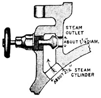
Fig. 2.
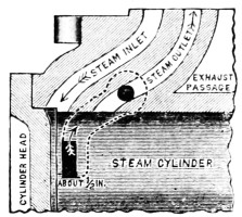
Fig. 3.
This style of cushion port makes the pump safer in case cushion valves are unskillfully left open too wide and tends to prevent a pump from pounding itself to pieces in case of a sudden release of load, as by a break in suction or delivery mains, or by a temporary admission of air to suction pipe.
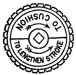
Fig. 4.
Pumps made with this form of cushion release, have given very satisfactory results, and if the ports are properly located, there will be no re-bound of piston.
c. Cushion valves must be always provided with hand-wheels marked as per sketch, for the reason that very few men in charge of fire-pumps are found to clearly understand or to remember their use.
The lettering must be very open, clear and distinct, not liable to be obscured by grease and dirt, and of a permanent character.
It is desirable that spindle or wheel be so formed that a monkey wrench can get a grip to open a jammed valve. Fig. 5 shows the stem flattened for this purpose.
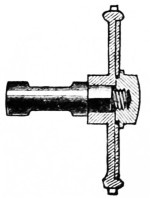
Fig. 5.
d. The valve and stem of cushion valve must be in one piece without any swivel joint.
Swivel joints are apt to come apart and make it impossible to operate the valve.
a. Piston rods for their entire length must be of solid Tobin Bronze, and the distinguishing brand of the manufacturers of this metal must be visible on at least one end of each rod.
b. The sizes must be not less than in table below.
| Size of Pump. | 500 gal. | 750 gal. | 1,000 gal. | 1,500 gal. |
|---|---|---|---|---|
| Diameter of rod | 2 inch. | 21⁄4 inch. | 23⁄8 inch. | 21⁄2 inch. |
c. The size and form of connection of rod to piston plunger and cross-head must be such that the stress in pounds per square inch at bottom of screw thread, or at such other point of reduced area as receives the highest tensile strain, shall not exceed 8,000 lbs. per square inch, when the steam pressure acting on the piston is 80 lbs. per square inch.
d. Piston rod nuts, in both steam and water ends, must be tightly fitted, and preferably of a finer thread than the United States Standard. This is to avoid as much as possible the unnecessary weakening of the rod at the bottom of the thread, and to reduce the tendency of the nut to work loose.
In practice 8 threads per inch has been found to give good satisfaction.
e. In addition to a tightly fitting nut, some reliable device must be provided, in both steam and water ends, for absolutely preventing these nuts from working off.
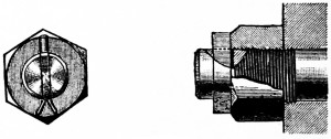
Fig. 6.
Fig. 6 shows one form of such a locking device and illustrates the kind of security desired.
This device combines the advantage of a taper key and a split pin, and the elongated key-slot gives sufficient leeway to always insure that the key can be driven up tight against the nut and thus prevent it from even starting to work off. Other methods will be approved in writing, if found satisfactory.
a. Valve Rods for their entire length must be of solid Tobin Bronze, with sizes not less than in table below.
| Size of Pump. | 500 gal. | 750 gal. | 1,000 gal. | 1,500 gal. |
|---|---|---|---|---|
| Diameter of rod | 1 inch. | 11⁄8 inch. | 11⁄8 inch. | 11⁄4 inch. |
b. The net area of valve-rod at its smallest section subject to tensile stress, must not be smaller than at bottom of U. S. standard screw thread on rod of diameter given above.
The construction of this rod as affecting lost motion at slide valve is specified under Article 15.
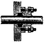
Fig. 7.
a. All six stuffing boxes must be bushed at the bottom with a brass ring with suitable neck and flange, and the follower or gland must be either of solid brass, or be lined with a brass shell 3⁄16-inch thick, having a flange next the packing, as shown in the sketch.
The bottom of stuffing boxes and the end of glands should taper slightly towards the center as per sketch.
b. These glands should be strong enough to withstand considerable abuse, so as not to break from the unfair treatment of unskilled men.
a. A pressure gauge of the Lane double tube spring pattern with 5 inch case must be provided and attached to the steam chest inside the throttle valve.
The dial of gauge should be scaled to indicate pressures up to 120 lbs. and be marked “STEAM.”
This kind of gauge is used on locomotives and is the best for withstanding the vibration which causes fire-pump gauges to be often unreliable. Moreover, this double spring is safer against freezing.
a. Four brass drain cocks, each with lever handle and of one-half inch bore, are to be provided, and located one on each end of each steam cylinder.
Care should be taken to select a pattern of cock whose passageway is the full equivalent of a 1⁄2-inch hole. Some patterns of 1⁄2-inch commercial cocks although threaded for 1⁄2-inch pipe thread have but a 1⁄4-inch hole through them. Such are not acceptable.
a. A one-pint hand oil pump, to be connected below the throttle, and a one-pint sight feed lubricator, to be connected above the throttle, must be furnished with each pump.
b. Oiling holes must be provided for all valve motion pins, and for each end of both rock shafts.
a. A length-of-stroke-index must be provided for each side of pump. These must be of simple form for at all times rendering obvious the exact length of stroke which each piston is making, and thus calling attention to improper adjustments of cushion valves or stuffing boxes.
b. The gauge piece over which the index slides must have deep, conspicuous marks at ends of nominal stroke, and also light marks at extreme positions; it need contain no other graduations.
c. This stroke index must be rigidly secured to cross-head in such a way that it cannot get loose or out of adjustment.
a. These must be of hard close iron with metal so distributed as to ensure sound castings, and freedom from shrink cracks.
b. The design should be along lines best calculated to resist internal pressure so as to avoid as much as possible the need of ribs for stiffening.
c. They must be capable of withstanding, without showing signs of weakness, the pressures and shocks due to running under the conditions mentioned in Chapter “Tests for Acceptance,” Art. 48-54.
The suction chamber should be able to withstand a water pressure of 100 lbs.
Although suction chambers are not regularly subject to a pressure, it is sometimes desired to connect them to public water supplies, and where foot valves are used there is a chance of getting pressure on the suction, so that ample strength is necessary.
Foundry finish may be permitted on the joints at water cylinder heads and at hand-hole plates, provided surfaces are so true that a rubber packing not over 1⁄16 of an inch in thickness is sufficient to secure perfect tightness.
d. Conveniently placed hand-holes of liberal size must be provided for the ready examination and renewal of valve parts at the yoke end of water cylinders and in the delivery chamber.
This will necessitate holes not less than 6 × 8 inches, or its equivalent, for the two largest-size pumps, and holes proportionately as large for the 500 and 750-gallon pumps. The easy access to the valve parts is of vital importance, and must receive careful attention.
e. The thickness of metal for cylinder shell, valve decks, partitions, ribs, etc., will depend largely upon the form of construction, but, in a general way, to establish safe minimums for368 the average water cylinder, of nearly cylindrical form, whose flat surfaces are stiffly ribbed, we submit the table below:
| Size of Pump. | 500 gal. | 750 gal. | 1,000 gal. | 1,500 gal. |
|---|---|---|---|---|
Thickness of cylinder shell when of nearly cylindrical form |
Inches. | Inches. | Inches. | Inches. |
| 7⁄8 | 1 | 11⁄8 | 11⁄4 | |
Thickness of valve decks when well ribbed |
11⁄4 | 11⁄4 | 11⁄4 | 11⁄4 |
Thickness of transverse partition, depending on ribbing |
11⁄4 to 11⁄2 | 11⁄4 to 11⁄2 | 11⁄2 to 2 | 11⁄2 to 2 |
Thickness of longitudinal partition, depending on ribbing |
11⁄4 to 11⁄2 | 11⁄4 to 11⁄2 | 11⁄4 to 2 | 11⁄2 to 2 |
Thickness of ribs |
3⁄4 | 7⁄8 | 1 | 1 |
Thickness of suction chamber |
5⁄8 | 3⁄4 | 3⁄4 | 7⁄8 |
Thickness of delivery chamber |
7⁄8 | 1 | 11⁄8 | 11⁄4 |
Lighter construction than herein specified will not be regarded as satisfactory, and any construction will be finally passed upon on examination of drawings.
f. The bolting of all parts of the water end is to be of such strength that the maximum stress at bottom of screw thread will not exceed 10,000 lbs. per square inch (disregarding for the moment the initial stress due setting up nuts) for a water pressure of 200 lbs. per square inch, computed on an area out to centre line of bolts.
No stud or bolt smaller than 3⁄4-inch should be used to assemble parts subject to the strain of water pressure, as smaller bolts are likely to be twisted off.
Although these pumps are not expected to be designed for a regular working water-pressure of 240 or 320 lbs., it is expected that bolts, shells, rods, etc., will be figured to stand this comparatively quiet, temporary, high pressure, exclusive of further allowance for initial strain due setting up of bolts, with a factor of safety of at least four.
This high test pressure is analogous to the custom of proving all common cast-iron water pipes to 300 lbs. and all common lap-welded steam pipes369 to 500 lbs. per square inch, and common water-works gate valves to 400 lbs., even though these are to be regularly used at much less pressure.
We are assured that castings no heavier than at present used by the best makers will stand this test, if properly shaped and liberally bolted.
g. For requirements for stuffing boxes, see Art. 22.
a. The “inside plunger and bushing” is preferred for all situations where the water is free from grit or mud.
b. Water-plungers must be of solid brass or bronze, and the bushing in which they slide must also be of brass or bronze. The composition of the plunger and its bushing should be of very hard, though dissimilar alloys, to ensure good wearing qualities.
For material and size of piston rods and lock for nuts, see Art. 20.
With poor alignment or bad workmanship or lack of skill in mixing the alloys, brass plungers are liable to score and give trouble; but with proper selection of alloys and true cylinders accurately aligned, they can be made to run all right wherever iron ones can. It is quite a fine point to get these wearing surfaces just right; and this is wherein the experience, skill and shop practice of one maker is likely to be much superior to that of another working under the same specification.
c. The length of machined cylindrical bearing within the partition must be not less then 2 inches. The plunger bushing must have a faced seat transverse to its axis against partition, forming a water-tight ground joint not less than one-half inch wide.
Any rubber gasket or other compressible packing for making this joint water-tight is not acceptable.
d. The construction of bushing and hole in partition must be such that a cylindrical shell for use with a packed piston can be interchangeably inserted in its place and secured by the same bolts.
This can readily be arranged and enables a packed piston to be inserted in place of a plunger subsequent to the installation of the pump with a minimum of expense, should this become desirable from change of conditions at any future time.
e. Small transverse grooves cut within the sliding surface of the plunger bushing, with a view to lessen the leakage, are not acceptable.
Although a slight advantage in this respect for clean water, they are a disadvantage on the whole, as dirt catches in them in the ordinary situation and cuts the plungers.
a. To bring all these expensive parts to the same standard of weight and bearing surface, the following dimensions are specified as the least that will be acceptable. These are based on a length of plunger which uncovers the bushings one inch at end of nominal stroke.
SOLID BRONZE PLUNGERS AND BUSHINGS.
| Size of Pump. | 500 gal. | 750 gal. | 1000 gal. | 1500 gal. |
|---|---|---|---|---|
Plunger. |
||||
Diameter |
7 or 71⁄4-in. | 9-in. | 10 or 101⁄4-in. | 12-in. |
Length |
17-in. | 17 „ | 18-in. | 24 „ |
Thickness of transverse partition |
5⁄8 „ | 5⁄8 „ | 3⁄4 „ | 3⁄4 „ |
Thickness next to partition |
1⁄2 „ | 1⁄2 „ | 5⁄8 „ | 3⁄4 „ |
Thickness next to end |
5⁄16 „ | 3⁄8 „ | 3⁄8 „ | 1⁄2 „ |
Number of ribs |
4 | 4 | 6 | 6 |
Thickness of ribs |
5⁄16 „ | 5⁄16 „ | 3⁄8 „ | 3⁄8 „ |
Bushing. |
||||
Length |
7 „ | 7 „ | 8 „ | 10 „ |
Thickness at end |
5⁄16 „ | 3⁄8 „ | 3⁄8 „ | 1⁄2 „ |
Thence tapered evenly to a |
1⁄2 „ | 5⁄8 „ | 5⁄8 „ | 3⁄4 „ |
Thickness at the |
3⁄4 „ | 3⁄4 „ | 3⁄4 „ | 13⁄16 „ |
a. The “water piston with fibrous packing” is preferred for many situations in the West or South, or for water containing371 grit or mud, like that of the Ohio River; and, for the comparatively few cases where pump pressure governors are used, the packed piston will give better service and longer wear.
b. The removable bushing or cylinder in which this piston works must be of solid bronze.
c. As stated in Art. 28 d, this bushing should be so constructed as to be readily interchangeable with the bushing of the inside plunger type.
d. The length of bushing must be such that the ends of piston will barely come short of the edges of cylinder at contact stroke and not uncover.
e. The thickness of the cylindrical bushings must be not less than is given in the following table:
BUSHINGS FOR PACKED WATER PISTONS.
| Size of Pump. | 500 gal. | 750 gal. | 1000 gal. | 1500 gal. |
|---|---|---|---|---|
Solid Bronze. |
||||
Thickness at extreme end |
7⁄16-in. | 1⁄2-in. | 1⁄2-in. | 9⁄16-in. |
Tapered evenly from end to a thickness |
9⁄16 „ | 5⁄8 „ | 11⁄16 „ | 3⁄4 „ |
Thickness at center bearing at least |
3⁄4 „ | 3⁄4 „ | 3⁄4 „ | 13⁄16 „ |
f. In other respects, the specifications for plunger bushings, already given in Art. 28, will apply to the above.
g. The water piston used in the shell described above must expose not less than 2 inches in width of fibrous packing, and must be of bronze, with disc and follower accurately turned to a sliding fit, so that the leakage past it will be a minimum, even when no fibrous packing is in place. There must be at least 2 inches in length of metallic bearing on both disc and follower.
The follower must be accurately centered and fitted to hub of piston, so that alignment will not be disturbed if taken apart.
h. The water piston must be of simple and strong construction, with follower bolts tightly fitted, and with fibrous packing so cut as to prevent by-passing.
i. All materials used in construction of piston, except packing, must be brass, bronze, or other non-corrosive metal.
j. Bushing studs must be of Tobin Bronze, and of such size and number, that the maximum stress at the bottom of the screw thread shall not exceed 10,000 lbs. per square inch, in the event of plunger becoming fast in the bushing with 80 lbs. of steam in the steam cylinders.
k. For each bushing stud there must be provided a composition nut and check nut.
l. All minor parts exposed to the action of water in water cylinder, that are not herein specified, must be of brass, bronze, or other non-corrosive material.
a. All the suction and discharge valves in any one pump must be of the same size and interchangeable.
b. There must be a clear space around each rubber valve, between it and the nearest valve, equal to at least one-fourth of the diameter of the valve, or between it and the wall of the chamber of at least one-eighth of the diameter of the valve.
c. These valves must be of the very best quality of rubber, of medium temper, with a face as soft as good wearing quality will permit.
They must be double-faced, so they can be reversed when one face is worn.
The quality of rubber is almost impossible of determination by brief inspection or by chemical analysis. The relative amount of pure gum and of cheaper composition may vary, or good material may be injured by defective vulcanization. The only safe way to secure excellence and uniformity is for the pump manufacturer to test samples of each new lot under severe duty (as by a week’s run in a small special pump, with say 150 pounds pressure and heavy water hammer, or by some equivalent means) and to furthermore require the rubber manufacturer to mould a date mark as “(Name of pump manufacturer, lot 201—April 3, 1904.)” on the edge of every valve, by which the pump manufacturer can keep track of those which prove defective.
a. The diameter of the disc of rubber forming the valve must not be greater than 4 inches or less than 3 inches. Three and a half inches diameter is probably the most favorable size, but is not insisted upon.
There is some confusion between different shops about designating size of valves. The practice is here adopted, which is much the most widely used, of naming the diameter of the disc of rubber which covers the ports, and it is hereby specified that this shall be about 1⁄2-inch greater than the diameter of the valve-port circle which it covers, thus affording about 1⁄4-inch overlap or bearing for the rubber disc all around its edge.
If valves are larger than 4-inch there is an increased tendency to valve-slam at the very high speed at which the pump is designed to run, and if valves are smaller than 3 inches diameter the greater number tends to unnecessary multiplication of parts, and the ports being so small are a little more liable to become obstructed by rubbish.
b. The thickness of the rubber valve must in no cases be less than 5⁄8-inch.
a. The total lift of suction valves must not exceed 1⁄2-inch.
b. The net suction valve port area and the total suction valve outlet area under valves lifted 1⁄2 inch high must not be smaller than the figures given in the table below.
(1) Length of Stroke (in inches) |
12 | 16 | |
(2) Greatest No. revolutions per minute. |
70 | 60 | |
(3) Corresponding Piston travel per minute. |
140 | 160 ft. | |
Approx. actual max. Piston velocity |
(4) Feet per minute. |
308 | 352 |
(5) Feet per second. |
5.1 | 5.9 | |
(6) Net Suction Valve-port area speed regarded |
56% | 64% | |
(7) Total Suction Valve Outlet Area under Valves |
56% | 64% | |
(8) Discharge Valve Area. |
2/3 of Suction Valve Area. | ||
By “valve-outlet area,” we mean the vertical cylindrical surface over the outer edge of the valve ports, i.e., the distance L multiplied by the circumference at the outer edge of the valve ports C, Fig. 8. Thus for a 4-inch valve, with ports inscribed in a 31⁄2-inch circle, whose circumference is 3·5 × 3·1416 = 11 inches; the valve “outlet area” for 1⁄2-inch lift would be 51⁄2 inches.
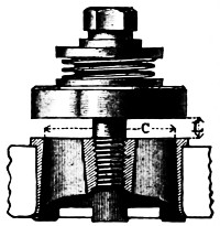
Fig. 8.
The actual velocity of piston during the middle portion of stroke is from 2.0 to 2.4 (average 2.2) times as great as the piston travel per minute (as determined in experiments by Mr. J. R. Freeman on several duplex pumps of different manufacture). This is because each piston stands still nearly half the time, or while its mate is working, and, moreover, moves more slowly near start and finish of stroke. The words “piston speed” are commonly incorrectly used and refer to “piston travel.” A clear understanding that the actual piston speed is more than twice as great leads to more generous valve design.
Large aggregate valve areas are necessary for pumps designed to run as fast as these, and experience has shown that to prevent valve slam at high speed and to accommodate high suction lifts, it is just as important to have a large “valve outlet area” as to have a large area of valve port.
It is valve slam or water hammer which commonly limits the highest speed at which a pump can be run. This water hammer may originate from the pulsations in a long or small suction pipe. The vacuum chamber lessens it, but there is commonly some point of high water in the vacuum chamber that will give much smoother action than any other.
Valve slam in this style of pump is caused chiefly by the short rebound of the steam piston against the elastic steam cushion at the end of the stroke. This in turn snaps the valves down with a jump when the speed is high. Dividing this impact or slam on numerous valves of low lift, tends to break up and lessen the shock, therefore with valves of the size and style used in fire-pumps, other things being equal, the less they have to rise and drop to let the water through them, the less will be the valve slam. This height of rise and drop is governed by the circumference rather than the port area. Experience and practice has shown that a 1⁄2-inch limit of lift is reasonable and does ensure a smooth working pump under all ordinary conditions.
c. The following table gives minimums for aggregate valve port area and aggregate valve outlet area, for the different size plungers, figured on a basis of 56% of plunger area for a 12-inch stroke, and 64% for a 16-inch stroke.
| Size of Pump. | 500 gal. | 750 gal. | 1000 gal. | 1500 gal. | |
|---|---|---|---|---|---|
| 1 | Diameter of plunger. Inches |
71⁄4″ | 9″ | 10″ | 12″ |
| 2 | Area of plunger in sq. inches |
41·28 | 63·62 | 8·54 | 113·10 |
| 3 | 56% of plunger area,or Minimum aggregate valve port area allowed per section. Square inches |
23·11 | 35·63 | 43·98 | 64% = 72·38 |
| 4 | Minimum aggregate valve port circumference, allowed per section. Inches |
46·22 | 71·26 | 87·96 | 144·76 |
| 5 | Minimum aggregate valve outlet area allowed per section for valves lifted 1⁄2 inch high. Square inches |
23·11 | 35·63 | 43·98 | 72·38 |
d. If we consider using any one of the three sizes of valves below, whose port areas may be assumed approximately as
| Diam. Valve. |
Diam. of Valve Port. Circ. |
Circ. of V. C. Circle. |
Valve Port Area (Net). Square inches. |
|---|---|---|---|
| 3″ | 21⁄2″ | 7·85″ | 3·5 |
| 31⁄2″ | 3″ | 9·42″ | 4·7 |
| 4″ | 31⁄2″ | 10·99″ | 6·3 |
given, then the necessary number of valves per section will be as in the table following:
| Size of Pump. | 500 gal. | 750 gal. | 1000 gal. | 1500 gal. | ||||||||
|---|---|---|---|---|---|---|---|---|---|---|---|---|
| Size of Valves. | 3″ | 31⁄2″ | 4″ | 3″ | 31⁄2″ | 4″ | 3″ | 31⁄2″ | 4″ | 3″ | 31⁄2″ | 4″ |
Necessary number of valves to satisfy (4) under c |
6 | 5 | 5 | 9 | 8 | 7 | 11 | 10 | 8 | 19 | 16 | 14 |
Necessary number of valves to satisfy (3) under c |
7 | 5 | 4 | 10 | 8 | 6 | 13 | 10 | 7 | 21 | 16 | 12 |
The exact number and size of valves will, however, not be insisted upon provided the aggregate valve area and the aggregate valve outlet area for each section is not less than that given in the table under c for the limiting lift of 1⁄2 inch.
Manufacturers will note that with the established lift of 1⁄2 inch, the 31⁄2-inch valve will permit a valve outlet area more nearly equal to its port area than will either the 3-inch or 4-inch valves, and a relatively less number of valves will satisfy the specifications.
a. The total lift of delivery valves must not exceed one-half inch.
This is to avoid valve slam, as explained in Art. 33.
b. The aggregate valve-port area should be restricted to about two-thirds the suction-valve area.
A small restriction of water-way through the delivery valves steadies the action of the pump and tends to prevent undue pulsations of pressure in the delivery pipe or fire hose. Fewer delivery valves than suction valves are, therefore, preferred, and if extra holes in the delivery deck are cast for shop purposes these had better be plugged than fitted with valves.
The suction valves require more generous port-circumference and port-area than delivery valves because when a pump has to suck its supply through a considerable height or through a long pipe there should be the least practicable waste of the atmospheric pressure in getting the water into the plunger chamber, or in retarding it from following the plunger in full contact. With the water once into the plunger chamber there is plenty of steam pressure available to force it out through the delivery valves.
a. All valve springs must be of the best spring brass wire, and must be coiled on a cylindrical arbor.
Conical valve springs are not approved because the strain is not uniform throughout spring, thereby increasing the liability to breakage and the chance of their getting out of center and becoming “hooked up.”
b. The valve spring must be held centrally at its top by resting in a groove in valve guard, substantially as shown in Fig. 9.
c. A light, rustless metallic plate must be interposed between the bottom of the spring and the rubber valve, and must be the full area of the valve. This plate must also be formed with a raised bead to guide the spring at the bottom.
The weight of this plate should be small, for the inertia of the lifting parts of the valves should be the least possible, to permit quick action and to avoid pounding.
d. For the average condition of a 10 or 15-foot lift, the stiffness of suction valve springs should be such that a force of about one pound per square inch of net port area will lift valve 1⁄4 inch off its seat.
The springs on the delivery valves should ordinarily be from two to three times as stiff as just specified, but any other reasonable degree of stiffness which is proved to work well in practice will not be objected to.
For suction under a head, the greater snap with which water enters the plunger chamber when thus pushed in by say twice the atmospheric pressure renders it difficult to avoid water hammer at high speed. Extra stiff suction valve springs will commonly aid in controlling this and should be used wherever pumps are to work under a head.
An approved type of indicator water gate on the suction pipe near the pump, which can be partly closed, will enable the pump to run quietly at high speed. Such a gate is an extra not included in price of the pump.
a. Steam fire-pumps should be started, to limber them up, at least once a week.
Although vulcanized India-rubber is much the best material yet used for fire-pump valves, unfortunately the brass is sometimes corroded by the free sulphur contained in the rubber, so that if the pump is left standing for several weeks the rubber valve discs may become stuck to their brass seats, and, if suction has a high lift, there may not be vacuum enough to tear all the suction valves open when pump is started.
a. All water valve seats must be of bronze composition. They may be either screwed into the deck on a taper or forced in on a smooth taper fit. With either arrangement, the seat must be either flanged out on the under side all the way round378 or be provided with a substantial lug opposite each rib, these lugs being expanded out after the valve is inserted.
If the valve seats are not expanded after being put in place, there is a possibility that now and then a valve seat will work loose and come out, thus crippling the pump.
b. The under side of the valve deck must be rounded over to give good bearing for the expanded part of the seat.
c. Three-inch valves must have four or five ribs, three and a half inch valves five or six ribs, and four inch-valves six ribs.
Enough ribs must be provided to give proper support to the rubber valve, but too many are objectionable, as small ports would be liable to obstruction by refuse.
d. The edges of the valve-seat ports must be moderately rounded over, to remove such sharp edges and points, as would be liable to cut, or damage the rubber valve when under pressure.
a. All valve stems must be of 3⁄4-inch Tobin bronze and of the fixed type, and must have the guard fastened on by one of the methods shown in Figs. 9 and 10.
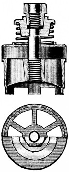
Fig. 9.
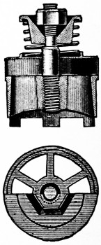
Fig. 10.
Other methods may be approved, in writing, if found by test and experience to have especial merit.
b. These stems must be screwed into the seats on a straight, tightly fitting thread, and the lower end then well headed over into a countersink. The valve guard and nut must be of composition.
In Fig. 9 the upper part of the stem is slabbed off on two opposite sides and fits a corresponding hole in the guard.
The guard, therefore, cannot turn. The outside of the special nut is fitted on a taper to the inside of the guard, and the nut tapped out to fit the 5⁄8 U. S. thread on the stem.
The action of the valve, whether with the spring or without, tends to drive these taper fits together, producing a frictional lock similar to that of a friction clutch; and although the nut may be loose on the thread, it cannot possibly work off.
It will be apparent that the taper fit on the nut must be so made as to always bear on the taper fit in the guard, and not bottom in the guard.
It is believed that with the present screw machine practice in shops of to-day these small parts can readily be turned out accurately and cheaply in large quantities. The nuts and guards made in any one shop must be exactly of standard dimensions, so that the product of different periods will be interchangeable.
The taper should be about one inch to one foot. With this taper the nut can be readily turned in or out, but there is friction enough to hold the guard and nut together even if the spring is off.
In Fig. 10, the top of the guard is recessed in the form of a hollow inverted pyramid of six sides, to correspond to a hexagonal nut. The angle of two opposite sides of this recess, which should be about 75 degrees, will both surely lock the nut and still permit of its being turned with a wrench.
The guard is kept from turning by slabbing off the stem, in the same manner as described and shown in Fig. 9.
To facilitate the removal of the nut, the edges should be slightly chamfered. An unfinished nut simply drilled and tapped is all that is desired. Any hexagonal or square nut within the size of the tapered recess will be locked.
With this construction, the nut cannot turn in either direction without compressing the spring and is therefore locked, and, in the event of the spring breaking or being left off, the nut is well protected in its recess380 from the possible turning effects of water currents, and experiments have shown that it will still stay in place.
With machine molding it will be possible to make these guards complete in foundry, requiring no machine work further than a possible broaching out of hole to fit the stem, as a fairly good fit is necessary.
While both of these devices are effective even though not tightened down to a shoulder, they should be so tightened for greater safety and to fix the lift at the half-inch limit.
a. Water and steam pipe connections must have standard flanges to connect with pipes of the sizes given below.
| Size of Pump. Gal. Per Min. |
Diameter of Suction Pipe. Inches. |
Diameter Discharge Pipe. Inches. |
Steam Pipe. |
Exhaust Pipe. |
|---|---|---|---|---|
| 500 | 8 | 6 | 3 | 4 |
| 750 | 10 | 7 or 8 C | 31⁄2 | 4 |
| 1,000 | 12 | 8 | 4 | 5 |
| 1,500 | 14 | 10 | 5 | 6 |
C Eight-inch preferred, this being the more common size for valves, fittings, and pipes.
These suction pipe sizes, although larger than common for trade pumps of the same size, are believed to be amply justified by experience, and exert a powerful influence toward enabling the pump to run smoothly at high speed with water cylinders filling perfectly at each stroke. No defect is more common than restricted suction pipes.
b. A single suction entrance at the end of the pump is to be provided unless otherwise specified by the purchaser.
Some situations render desirable side suction entrances, for permitting drafting water from two different sources of supply. These additional openings are to be considered as extras. Ordinarily, the purchaser can provide for such situations by proper piping at the single end suction entrance.
If there is to be but one suction opening on casting, this had best be at center, for the reason that, if suction pipe ever gets to leaking air, this air stands a better chance of being distributed equally to the two plungers, and has less tendency to make the pump run unevenly.
c. Standard flanges and standard bolt layouts as adopted by the Master Steam Fitters, July 18, 1894, must be used on all the above pipe connections, as per table given below.
SCHEDULE OF STANDARD FLANGES.
| Size of Pipe × Diam. of Flange. |
Diameter of Bolt Circle. |
Number of Bolts. |
Size of Bolts. |
Flange Thickness at Edge. |
||||
|---|---|---|---|---|---|---|---|---|
| Inches. | Inches. | Inches. | Inches. | |||||
| 3 | × | 71⁄2 | 6 | 4 | 5⁄8 | × | 21⁄2 | 13⁄16 |
| 31⁄2 | × | 81⁄2 | 7 | 4 | 5⁄8 | × | 21⁄2 | 7⁄8 |
| 4 | × | 9 | 71⁄2 | 4 | 3⁄4 | × | 23⁄4 | 15⁄16 |
| 41⁄2 | × | 91⁄4 | 73⁄4 | 8 | 3⁄4 | × | 3 | 15⁄16 |
| 5 | × | 10 | 81⁄2 | 8 | 3⁄4 | × | 3 | 15⁄16 |
| 6 | × | 11 | 91⁄2 | 8 | 3⁄4 | × | 3 | 1 |
| 7 | × | 121⁄2 | 103⁄4 | 8 | 3⁄4 | × | 31⁄4 | 11⁄16 |
| 8 | × | 131⁄2 | 113⁄4 | 8 | 3⁄4 | × | 31⁄2 | 1⁄8 |
| 9 | × | 15 | 131⁄4 | 12 | 3⁄4 | × | 31⁄2 | 11⁄8 |
| 10 | × | 16 | 141⁄4 | 12 | 7⁄8 | × | 35⁄8 | 13⁄16 |
| 12 | × | 19 | 17 | 12 | 7⁄8 | × | 33⁄4 | 11⁄4 |
| 14 | × | 21 | 183⁄4 | 12 | 1 | × | 41⁄4 | 13⁄8 |
Do not drill bolt holes on center line, but symmetrically each side of it.
On steam and exhaust openings loose flanges threaded for wrought-iron pipe must be provided.
Where the situation will not permit of a standard flange on exhaust opening for lack of room, a special flange threaded to fit the proper size wrought-iron pipe may be used.
a. Air and vacuum chambers in accordance with the sizes given in the following table must be provided with all pumps. If the air chamber is cast iron, the pump manufacturers must warrant that it has been subjected to a hydraulic test of 400 lbs. per square inch before it is connected to pump.
It is to be thoroughly painted inside and out to diminish its porosity.
SIZE OF VACUUM AND AIR CHAMBERS.
| Vacuum Chamber is to contain:— |
Air Chamber is to contain:— |
|
|---|---|---|
| 500-gallon pump. | 13 gallons. | 17 gallons. |
| 750 „ „ | 18 „ | 25 „ |
| 1,000 „ „ | 24 „ | 30 „ |
| 1,500 „ „ | 30 „ | 40 „ |
The air chamber, combined with connections for discharge pipe, relief valve, and hose valves, should be carefully designed to make the whole weight as small as possible. Keeping this weight down makes the pump run steadier and brings less strain on the flanges at high speeds.
An air chamber of hammered copper and warranted tested under a hydraulic pressure not less than 300 lbs. per square inch is a little better than cast iron as it holds air better, and being lighter it wrenches and strains the pump less when running fast and shaking, but because it costs from $25 to $50 more than cast iron, it is not often adopted.
b. The vacuum chamber must be attached to the pump in the most direct way practicable, but provision must be made for attaching it in such manner as not to prevent readily taking off the cylinder heads.
c. Every vacuum chamber should be provided on one side near the top with a 1⁄4-inch pipe hole plugged. This to be used for attaching a vacuum gauge if desired.
a. A pressure gauge of the Lane double tube spring pattern with 5-inch case, must be provided with the pump, and connected near to inboard side of air chamber, as shown in Fig. 12, by a 1⁄4-inch cock, with lever handle.
The dial of this gauge should be scaled to indicate pressures up to 240 lbs. and be marked “WATER.”
This kind of gauge is used on locomotives and is the best for withstanding the vibration which causes fire-pump gauges to be often unreliable. Moreover, this double spring form is safer against freezing.
a. Hose valves must be attached to the pump (and included in its price) as follows:—
For the 2 stream or 500-gal. pump, 2 hose valves.
For the 3 stream or 750-gal. pump, 3 hose valves.
For the 4 stream or 1,000-gal. pump, 4 hose valves.
For the 6 stream or 1,500-gal. pump, 6 hose valves.
These are to be 21⁄2-inch straightway brass valves, without cap, and similar and equal in quality to those made by the Chapman Valve Company, the Ludlow Valve Company, or the Lunkenheimer Company.
The hose-screw at end of these valves is to be fitted to a hose coupling furnished by the customer, or where this cannot be procured may be left with the thread uncut.
To accommodate locations where all the lines of hose must lead off from one side of the pump—makers can furnish a spool piece or special casting to which the hose valves can be attached—but this is an extra not included in the regular price.

Fig. 11.
a. A safety or relief valve of the Ashton, Crosby, American, or other make agreed upon in writing with this office, is to be regularly included in the price, and is to be attached to each pump; preferably extending horizontally inboard from base of air chamber, as shown in Fig. 12, so that its hand-wheel for regulating pressure is within easy reach. This hand-wheel must be marked very conspicuously as shown in Fig. 11.
b. This valve is to be set ordinarily at a working pressure of 100 pounds to the square inch, and is to be of such capacity, that when set at 100 pounds it can pass all the water discharged by the pump at full speed, at a pump pressure not exceeding 125 pounds per square inch.
For 500-gallon pump a 3 inch valve.
For 750-gallon pump 31⁄2 inch valve.
For 1,000-gallon pump 4 inch valve.
For 1,500-gallon pump 5 inch valve.
The relief valve must discharge in a vertical downward direction into a cone or funnel secured to the outlet of the valve. (See Art. 44.)
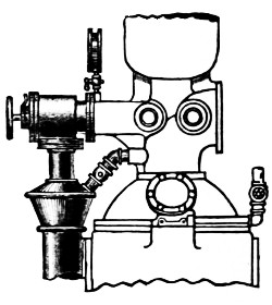
Fig. 12.
The valve must be so attached to the delivery elbow and discharge cone by flange connections as to permit of its ready removal for repairs without disturbing the waste piping.
a. This cone should be so constructed that the pump operator can easily see any water wasting through the relief valve, and its passages should be of such design and size as to avoid splashing water over into the pump room.
b. The cone must also have a one-inch tapped connection for the air-vent pipe required by Art. 45, and the arrangement must be such that the pump operator can easily tell whether water is coming from the air pipe or is wasting through the relief valve.
c. The cone should be piped to some point outside of the pump house where water can be wasted freely, the waste pipes being as below.
| SIZE OF PUMP. |
DIAMETER OF WASTE PIPE FROM CONE. |
|---|---|
| 500-gallon. | 5 inches. |
| 750 „ | 6 „ |
| 1,000 „ | 7 „ |
| 1,500 „ | 8 „ |
The waste pipe can pass down to floor between the yokes at middle of pump. It should be piped in such a way that steam and gases from other drains or waste pipes will not work back through it, and, by being troublesome385 in the pump room, suggest the covering of the cone in any way, as it is desirable that the pump operator should always be able to see instantly any waste from the relief valve or air vent.
This cast-iron cone, connected to the safety valve and air vent, is included in price of pump, but the waste pipe beyond it is not.

Fig. 13.
a. An air vent with a brass gate valve and brass pipe for connecting up, must be provided and connected with delivery elbow and discharge cone.
b. The size of this air vent should be one inch for 500-gallon and 750-gallon pumps, and one and one-fourth inches for the 1000-gallon and 1500-gallon sizes.
c. The hand wheel of this valve must be marked as per Fig. 13. The lettering must be very open, clear and distinct, not liable to be obstructed by grease and dirt, and of a permanent character.
The object of this valve is to reduce the pressure above force valves and secure a prompt riddance of all air that may come through the water cylinders when first starting up.
This valve, of course, should be closed when once pump is under way, to prevent waste of water.
a. Each pump must be fitted with a set of brass priming pipes and valves, according to either one or the other of the following methods:
b. For 1,000 and 1,500 gallon pumps, the priming pipes must be 11⁄4 inches. For the 500 and 750 gallon pumps, the pipes must be 1 inch. Pump-makers are to furnish these pipes and the fittings called for below, and are to connect them up providing a 2-inch outlet, looking upwards, ready for the supply from the priming tank.
The pipe from the priming tank to this outlet should be at least 2-inch, and may be of iron, and is to be furnished by the purchaser. All parts furnished by the pump-maker are to be of brass, and are to be included in the price of the pump.
Controllable Valve Arrangement.
c. Four 2-seat controllable valves, one for each pulsation chamber, and of the general type illustrated in Fig. 14, must be provided. In these the inlet of water and outlet of air are simultaneously opened and closed by the pump operator.
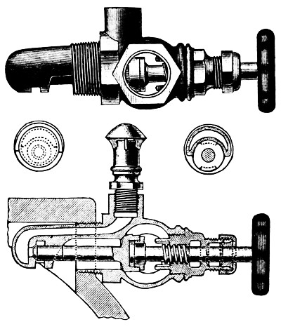
Fig. 14.
Objection has been raised to this double-seated valve from the possible difficulty of keeping both seats tight. If desired, the valve may be fitted with a flange instead of a screw connection, and the stem between the two seats somewhat enlarged and provided with a suitable spring, thus giving flexibility between the two seats and preventing all trouble from uneven wear.
d. The hand-wheel of each of these valves must be marked as per Fig. 15, so that the pump operator I may clearly understand their use. The lettering must be very open, clear and distinct, not liable to be obscured by grease and dirt, and of a permanent character.
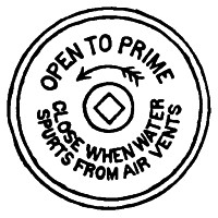
Fig. 15.
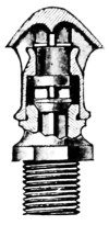
Fig. 16.
e. There must be provided and fitted to each combined valve a check and umbrella-top air vent, as shown in Fig. 16. This fitting must have a clear passageway through it, the full equivalent of a 1⁄2-inch bore.
The check-valve is to permit the outflow of air, but to prevent the influx when the plunger is sucking.
This method is preferred to the one using rubber priming checks, as now and then a rubber valve will stick on its seat and thus prevent priming of one of the chambers. In this arrangement the pump operator has absolute control over the priming water into each chamber.
Another advantage is that the connection of the air-vent with the priming valve ensures that the air-vents will be opened; and further, by the vigorous spurting out of water as soon as the pump is primed, the pump operator is reminded that the priming valve should be closed.
Should the pump operator, however, through a mistaken idea of the proper method of operation, think that the priming should be continued until all air was exhausted from the suction pipe and the pump running in normal condition, there would be some by-passing between chambers, but as there is a free vent for the air, the main result would be simply to limit the amount of air exhausted per stroke, from the main suction, by the amount of water which entered a chamber in this way. The amount of water thus entering, however, would not be appreciably greater than that which would enter from the priming-tank with the check-valve arrangement.
If, even in spite of the warning given by the spurting air-vents, the pump operator should neglect to close the priming-valves when the pump was running normally, the priming-tank would eventually be overflowed; but this would not be as serious as the drawing in of air from an exhausted priming-tank, which would result with the check-valve method, were the main 2-inch valve similarly neglected.
Rubber Check Valves.
f. Four rubber check valves, one for each pulsation chamber, and similar to ordinary pump valves, must be provided. The chambers for these should preferably be made as a part of the pump cylinder, thus securing a compact arrangement.
Figure 12 shows this arrangement in outline.
g. The valve seat should have three ribs to the central hub, supporting the rubber valve. The net port area through the valve should be not less than 11⁄2 square inches.
This valve seat should rest in an inverted position, and can be so fitted up as to be readily removed. The valve stems can be of the removable type screwing into the seat, but must be made long enough to receive a check nut on the opposite side of seat. This will effectually lock the stem in place.
h. Care must be taken to arrange the water passages through and about these priming checks, so as to avoid all air pockets and so as to reduce to a minimum the possibility of the valves becoming choked up by refuse.
i. The valve seats, stems and all parts must be of composition and of strong rugged design, so fitted up that there is the least chance for the rubber valves to stick, and with all parts securely put together the valves must be readily accessible.
j. The valve springs must have only sufficient strength to keep the valves on their seats, so that they will freely open even with the low head of priming water often existing.
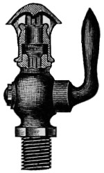
Fig. 17.
k. There must be provided, and attached to the top of each plunger chamber, a brass check valve and air cock with umbrella top, as shown in Fig. 17. This cock and valve must have a clear passageway through them—the full equivalent of a 1⁄2-inch bore.
The check valve is to permit the outflow of air, but to prevent the influx when the plunger is sucking. Cocks with lever handles are used, as these show clearly whether they are open or shut.
l. There must also be provided a 2-inch brass gate valve for the general control of389 the water to the four-check valves. The hand wheel of this valve must be marked as per Fig. 15. The lettering must be very clear, open, and distinct, not liable to be obscured by grease, and of a permanent character.
It is essential for a properly working pump that the main 2-inch priming-valve should be closed as soon as the pump is primed. Otherwise, water will be drawn from the priming tank, lessening the lifting power of the pump through the main suction, and if this is continued the priming tank will often be exhausted and air drawn into the pump, interfering with its proper action. It is for this reason that the marking on the priming valve is required.
For all average situations, either method of priming permits of getting the pump under way in a very few minutes, but, for cases where the suction pipe is over 300 or 400 feet in length, or sometimes where the lift is over 18 feet, or where there is a combination of long length and lift within these limits, so much time is consumed in exhausting the air from the suction pipe that it becomes desirable to supplement this method.
For such situations, a steam ejector connected to the suction pipe near the pump is advised, and may be required in addition to the regular priming pipes and tank. The size of the ejector should be sufficient to exhaust the suction pipe within about three minutes. Such ejectors will be considered as extras not included in the ordinary pump fittings.
For cases where pump can only take its suction under a head, if absolutely certain that the level of the suction water will never fall below level of center of pump, these priming pipes may be omitted, but openings for them into the pump shell must be provided and capped or plugged.
A foot valve on a fire-pump suction is not advised except in very rare cases, as with a lift of 18 feet or a suction pipe 500 feet or more long. A foot valve is not needed when there is a good efficient set of priming arrangements as described above and it is commonly found this gives a false sense of security, and that with a fire-pump left standing several days the water will often be found to have leaked back, so that it is no better than if no foot valve had been used.
A foot valve must of necessity generally be located where it is inaccessible for quick repairs, and as they grow old, foot valves are often a source of trouble. Where a suction pipe is exposed even slightly to frost, a foot valve is specially objectionable.
A priming tank is provided for the purchaser in all cases where there is ever to be any lift on the suction. It is generally advised that this tank have a capacity of one-half of what the pump can throw at full speed in a minute. This means 250 gallons for a 500-gallon pump and 500 gallons for a 1,000-gallon pump, etc. It is the intention to make the pump a truly “independent source” of supply, therefore the need of a special priming tank.
Older Priming Arrangements.
The form of priming arrangement heretofore used, with metal check valves, one main 2-inch priming valve, and 1-inch priming pipes, separate controllable air cocks, may be retained on all pumps at present in service, and will be considered satisfactory, if kept in good order.
If in any case such checks give trouble the priming arrangement may be changed and valves like Fig. 14 or rubber checks as described in sections f-j, made up in detachable form,D may be put on if desired, where the connections on the pump permit them.
Where neither method is desired or where neither is feasible the faulty checks may be replaced by a special type such as are now made for this use, by the Locke Regulator Company, of Salem, Mass. These are 1-inch check valves, adapted to use a small disc of medium hard rubber, similar to a pump valve.
These fittings are very near the dimensions of the commercial check valve, so that with slight shortening of piping connections they will fit into the present arrangements, and give satisfaction.
a. Five brass drain cocks, each with a lever handle and of 1⁄2-inch bore, are to be provided, and located one on each end of each water cylinder, and one above the upper valve deck.
Care should be taken to select a pattern of cock whose passageway is the practical equivalent of a 1⁄2-inch hole. Some patterns of 1⁄2-inch commercial cocks although threaded for 1⁄2-inch pipe thread have but a 1⁄4-inch hole through them. Such are not acceptable.
D Such detachable rubber check valves are now made up in regular form by the George F. Blake Mfg. Co., East Cambridge, Mass.
a. Provide outlets for the water; start the pump slowly, gradually open steam-throttle to bring the pump to full speed.
The pump should run smoothly at the rated full speed of 70 revolutions per minute (or 60 revolutions if a 1,500-gallon pump) with full length of stroke, and meanwhile maintain a water pressure of 100 lbs. per square inch.
If the hose lines are short, or discharge is too free, partly close the water outlet valves, thus throwing an extra back pressure on the pump equivalent to that which would be produced through a greater length of hose.
During this trial it is preferable to discharge the water through lines of 21⁄2-inch cotton rubber-lined hose, preferably each 150 feet long, each connected directly to the hose outlets on the pump, and each line having a 11⁄8-inch smooth nozzle at its outer end. Two lines should be connected for a 500-gallon pump, three for a 750, and so on, having as many lines as rating of pump requires.
A hose line 150 feet long, with an inside surface of average smoothness, and with a 11⁄8-inch nozzle attached, will require about 80 pounds pressure at the pump to discharge 250 gallons per minute, and the nozzle pressure will be about 45 pounds. Therefore, with lines attached as above, a pressure at the pump of about 80 pounds should represent a discharge about equal to the rated capacity of the pump, and would ordinarily correspond with the rated full speed revolutions.
If the pump runs smoothly under these conditions, it is well to open the throttle somewhat further, and bring the pressure at the pump up to 100 pounds. This will give a discharge of about 280 gallons per stream, or about 12 per cent. in excess of the rated capacity. The revolutions will, of course, correspondingly increase, and under all ordinary conditions a pump should run smoothly at this higher capacity though a little more vibration and pounding would be expected than when running simply at its rated speed.
After cushion valves are adjusted there should be no noteworthy water hammer or valve-slam. Sometimes valve-slam is not the fault of the pump, but arises from an obstructed suction pipe. It is objectionable to doctor water hammer in a pump by “snifting” air into the suction, as this cuts down the efficiency and is a poor expedient.
The quietness of that part of the hose near the pump, or its freedom from rubbing back and forth crosswise an inch or more with each pulsation of the pump, is a good index of the pump maker’s skill in securing uniform delivery. Bad pulsation quickly wears holes in the hose, and to reveal this is the object of testing with hose connected directly to the pump.
a. This is shown by the reading of steam gauge compared with water pressure gauge at air chamber.
Tests have generally run about as follows, for pumps running at full rated speed:
Size Gallons Per Minute Capacity. |
500 | 750 | 1,000 | 1,500 |
Ratio of Steam Piston Area to Water Piston Area. |
4 Times | 3 Times | 3 Times | 23⁄4 Times |
Water Pressure lbs. Per Sq. in. |
100 | 100 | 100 | 100 |
Steam Pressure Theoretically Necessary, Disregarding Friction. |
25 | 33 | 33 | 36·5 |
Excess of Steam Pressure Needed to Overcome Friction, Back Pressure, Etc. |
15 | 12 | 12 | 13·5 |
Actual Steam Pressure Found Necessary at the Pump. |
40 | 45 | 45 | 50 |
b. The steam pressure needed will vary slightly with the freedom of the exhaust pipe and with the tightness of the packings, etc., but a steam pressure of 45 pounds at the steam chest should suffice for 100 pounds water pressure on pump in proper adjustment.
a. First, shut the main valve between the pump and the fire system lest a sprinkler head be burst, then shut all water outlets nearly, but not quite tight, so pump will move very slowly. Screw safety valve down hard. Slowly and carefully admit steam pressure sufficient to give 240 pounds per square inch water pressure.
b. With this extreme pressure all joints should remain substantially tight, and the slow motion of the pump should be tolerably smooth and uniform. (The leakage of a few drops here and there and a little unsteadiness of motion are to be expected.)
c. If boiler pressure is above 85 pounds, the safety valve on pump should be attached and screwed down only enough to hold the required pressure. For with 100 pounds or more of steam the water pressure might be carried too high.
After completing the above test slack off on safety valve, setting it so that it will begin to open at about 100 pounds pressure.
a. The relief valve may next be tested by first adjusting it to “pop” at 100 pounds, then shut the main outlet to pump, and then shut the hose gates one by one, and thus force all the discharge through the relief valve, meanwhile opening steam throttle, so as to run pump first at two-thirds speed or about 50 revolutions per minute, and finally at full speed (70 revolutions). The safety valve (relief valve) should carry all this and not let the pressure rise above 125 pounds.
The pressure in a quick-moving fire-pump necessarily fluctuates 5 to 15 pounds at different points in stroke, and an air chamber of reasonable size cannot wholly remove this. Therefore the safety valve must be set at about 15 pounds higher than the intended average working pressure; otherwise it will get to jumping with almost every stroke.
a. Set safety-valves at 115 lbs., shut all water outlets, admit steam enough to give 100 pounds water pressure, then pump will move very slowly under the influence of the leakage past plungers. About one revolution of pump per minute shows a proper accuracy of fit. Anywhere from 1⁄3 to 2 revolutions per minute is satisfactory.
Too tight a fit is bad, as if not exceedingly uniform it induces scoring or cutting of the metals. Moreover, should the pump happen to be run dry for a few minutes before catching its suction a slight warming and expansion of the plunger may cause it to stick and cut.
a. For this, alternately shut down the main outlet gate and adjust the hand-wheel of the safety valve, and open up on the394 throttle as may be required, running pump at say one-half speed (or, in experienced hands, at full rated speed), and note the greatest water pressure which the full boiler pressure (unless boiler pressure is above 85 lbs.) will yield with pump at full speed.
Sometimes it may be necessary to force water through very long lines of hose, or to an unusual height.
Steam fire engines are not infrequently called on to give 200 pounds per square inch water pressure.
To test short hose lines with anywhere near so high a pump-pressure is dangerous, lest nozzle kick and pull itself away from the man holding it and thrash around; but the ability of the pump may be tested by putting this high pressure-delivery mainly through the safety valve, or in part through the partially closed main outlet gate.
It is not advisable to carry this water pressure above 200 pounds in this test at the factory, (although in the shop test the water pressure is carried to 240 pounds) and engine driver should stand with his hand on the throttle.
a. This can best be tried by adding one or, in some cases, two more streams than the pump is rated to deliver by attaching the extra lines of hose to some hydrant near, and then speed up the pump gradually, to see how fast it may be run before violent pounding or slamming of valves begins.
Sometimes the increased delivery can be drawn off through an open hydrant-butt meanwhile holding sufficient back pressure to show 100 pounds on the water gauge by partly closing the discharge valve.
The engine driver should stand with his hand on or near the throttle when thus speeding the pump.
It is all right to run a fire-pump up to the utmost speed possible before water hammer begins, and very often a pump, while new and if favorably set up, can deliver 25 to 50 per cent. more than rated capacity; nevertheless, although expert treatment can force 1,000 gallons from a 16 × 9 × 12 pump we can rate it as only a 750-gallon pump. There must be some margin to allow for wear and for the possible absence of the expert at time of fire.
The main points of Difference between the “National Standard” and the “Trade Pump” are:
Brass Plungers instead of cast-iron plungers.
Wrought iron side levers instead of cast iron.
Bronze piston rods and valve rods instead of iron or steel.
Pump has brass-lined stuffing boxes instead of cast iron.
Rock shafts are brass bushed.
Area of water valves is 25 to 50 per cent. greater.
Steam and exhaust passages 20 to 50 per cent. greater.
Suction pipe connections two to four inches greater diameter.
Cushion valves better arranged.
Air chamber is made much larger.
Shells and bolting are warranted especially strong.
The following necessary fittings are included in the price, and regularly furnished as a part of this pump, viz.:
A capacity plate.
A stroke gauge.
A vacuum chamber.
Two best quality pressure gauges.
A water relief valve of large capacity.
A cast iron relief valve discharge cone.
A set of brass priming pipes and special priming valves.
From two to six hose valves.
A sight feed cylinder lubricator connected above throttle.
A one-pint hand oil pump connected below throttle.
Information regarding tests made under these specifications can be obtained by addressing Underwriters’ Laboratories, Chicago, Ill.
| Article No. and section. |
|
|---|---|
Acceptance, tests for, |
48 to 54 |
Air chamber, |
40 |
Air valve, |
45 |
Automatic sprinklers, discharge of, |
3 c |
Boiler power required for driving pumps, |
3 a |
Bolts, allowable stress and size, |
9, 27 f |
Bolting standards required, |
39 c |
Bushings for packed water pistons, |
30 |
Bushings for plungers, |
28, 29 |
Capacity of pumps, method of computing, |
4 |
Capacity plate, |
5 |
Chambers, air and vacuum, |
40 |
Clearance in steam cylinders, |
12 |
Cone, discharge, |
44 |
Cover plates for water valves, |
35 |
Cranks, |
16 |
Crossheads, |
16 c |
Cushion valves, |
19 |
Cylinders, steam, |
8 |
Cylinders, water, |
27 |
Delivery, test of maximum, |
54 |
Discharge cone, |
44 |
Drain cocks, |
24, 47 |
Duplex pumps required, |
2 |
Fire stream, standard, |
3 c |
Flanges, standards required, |
39 c |
Friction, internal, tests for, |
49 |
Guards for valves, |
35 |
Gauges, pressure, |
23, 41 |
Gauges, stroke, |
26 |
Hose valves, |
42 |
Inspection at shop, |
7 |
Leakage, test of internal, |
52 |
Levers, valve motion, |
17 |
Links, |
16 |
Name plates, |
5 |
Oiling devices, |
25 |
Pipe, sizes, steam and water, |
39 |
397 Piston areas, ratio, |
3 a |
Pistons, packed water, |
30 |
Piston rods and nuts, |
20 |
Pistons, steam, |
13 |
Plunger bushings, |
28, 29 |
Plunger, water, |
28, 29 |
Pressure, maximum, working tests for, |
53 |
Priming, methods required, |
46 |
Rock shafts, |
16 |
Rods, piston, |
20 |
Rods, valve, |
21 |
Safety valves, |
43 |
Safety valve, test of capacity, |
51 |
Shop inspection, |
7 |
Single pumps not acceptable, |
2 |
Sizes of pumps, standards, |
3 a |
Slip, |
4 f |
Slip, test of internal, |
52 |
Smoothness of action, test for, |
48 |
Speed of pumps, |
3 a, 33 b |
Speed of pumps, revolutions per minute, |
3 and 4 |
Springs, valve, |
35 |
Steam cylinders, |
8 |
Steam, clearance space, |
12 |
Steam joints, |
8 c |
Steam pistons, |
13 |
Steam ports, |
11 |
Steam slide valves, |
14, 15 |
Strength of parts, |
6 |
Strength, tests for, |
50 |
Stuffing box, |
22 |
Tests for acceptance, |
48 to 54 |
Tightness, tests for, |
50 |
Vacuum chamber, |
40 |
Valves, water valve areas, |
33-34 |
Valve, air, |
45 |
Valve, cover plates, |
35 |
Valves, delivery, |
34 |
Valve guards, |
35 |
Valves, hose, |
42 |
Valve motion stand, |
18 |
Valves, pump, general requirements, |
31 |
Valves, pump, size and number, |
32 |
Valve rods, |
21 |
398 Valve rod heads, |
16 c |
Valves, safety, |
43 |
Valve seats, water, construction of, |
37 |
Valve springs, |
35 |
Valve, steam slide, |
14 |
Valves, steam slide adjustment, |
15 |
Valve stems, types required, |
38 |
Valves, sticking of water valves, |
36 |
Valve, suction valve area, |
33 |
Water cylinders, |
27 |
Workmanship, character of, |
1 |
Yoke, |
10 |
INDEX
TO PART ONE
Any one, and more especially the attentive student, can with the least trouble avail himself of the subject matter contained in this work by doing as indicated in the following old English couplet quoted by Chas. Reade.
“For index-reading turns no student pale,
Yet takes the eel of science by the tail.”
| Page | |
|---|---|
Accumulator, an, des., |
151 |
hydraulic, ills. and des., |
171-173 |
rule for calculating capacity of, |
172 |
Acid, muriatic, specific gravity of, |
96 |
sulphuric, specific gravity of, |
96 |
Adjustment of the slide valves of the underwriter steam fire pumps, |
360 |
Advantages of a duplex pump as a fire pump, |
351 |
Aëriform fluids, des., |
15 |
Air, des., composition of, |
15, 16 |
and vacuum chambers for the underwriter pump, |
381 |
Practically the reverse of each other, |
221 |
Air-bound, def., |
17 |
Air chamber of pump, ills., |
223 |
chambers, ills. and des., |
220 |
Air-cock, def., |
17 |
Air, gravity and elasticity of, |
16 |
Air pump, |
13 |
and electric motor, ills. and des., |
271 |
valve, marking of, for the underwriter pump, |
385 |
Alcohol, specific gravity of, |
96 |
Alcometer, def., |
94 |
Allen, Frank, annotations, |
IV, VIII |
Alternating motor, des. and ills., |
252 |
Ammeters, des. and ills., |
256 |
Ampere, def., |
256 |
Angle for crank positions of duplex, triplex and quadruplex pumps, |
230 |
of check valve, ills. and des., |
227 |
Animal power, |
187 |
Animals, when drinking are natural bellows pumps, Note, |
199 |
Annular valve, def., |
17 |
Antimony, specific gravity of, |
96 |
Apparatus, hydraulic, def., |
157 |
Archimedes and the hydrostatic balance, |
93 |
Area, def., |
17402 |
Armature, des. and ills., |
247, 251 |
Armored pump valves, ills. and des., |
217 |
Armstrong, Sir William, designer of the hydraulic accumulator, |
171 |
Arsenic, specific gravity of, |
96 |
Asphalt, melted, raised by pumps, |
188 |
Assembling, def., |
17 |
Atmospheric electricity, |
245 |
pressure, def., |
17 |
Attraction, capillary, def., |
103 |
of gravitation, |
85 |
Auxiliary, def., |
17 |
Bag pump, ills. and des., |
198 |
Balanced valve, def., |
18 |
Ball check-valve, def., |
18 |
Barrel or cylinder of a pump, des., |
189 |
ills., |
195 |
Base of hand pump, ills., |
195 |
Basket, def., |
18 |
Battery, how indicated by the signs + and -, |
261 |
Bellows-pump, illustrated and des., |
186, 198, 199 |
Belted pumps, des. and ills., |
225 |
Belt-pumps, hydraulic, |
200 |
pumps, why so called, |
187 |
Bends, def., |
18 |
Bethesda, pool of, historical def., |
49 |
Bibb-cock, def., |
18 |
Blakeslee steam pump, ills. and des., |
299-301 |
Bodies soluble in water, how weighed, |
94 |
Boiler feed pump duplex power, ills. and des., |
230-231 |
pumps, ills. and des., |
225-234 |
table of capacity of, |
226 |
Boiling point of water, |
76 |
Bolt-extractor, des. and ills., |
164 |
Bolts and stubs to be used in the underwriter steam fire pump, |
356 |
Bonnets, def., |
18 |
ills., |
223 |
Boss, def., |
19 |
Boulton, Matthew, inventor of hydraulic ram note, |
175 |
Bourdon spring, of metallic barometer des., |
115-116 |
Bounarbashi fountains of, historical def., |
50 |
Braden pump valve, ills. and des., |
215-216 |
Bramah, time of his invention of the hydraulic press, |
169 |
Brass, specific gravity of, |
96 |
Breast, water wheel des. and ills., |
122 |
Brick, specific gravity of, |
96 |
Bronze, specific gravity of, |
96 |
Brotherhood three cylinder hydraulic engine, |
150-152 |
Brushes, dynamo, des. and ills., |
251, 262 |
Buckets, gaining and losing, historical, des. and ills., |
59, 60 |
part of water wheel, |
130 |
Buffalo single cylinder pump, ills. and des., |
319-321 |
Burnham steam pump, ills. and des., |
324-326 |
Bushing, def., |
19 |
Caffee, Alberto H., dedication of work to, |
V |
Calabash, des., |
38 |
Cameron steam pump, ills. and des., |
295, 296 |
Capacity of a pump, depends upon speed, etc., |
353-354 |
Capacity plate of the underwriter steam fire pump, |
355 |
Capillary attraction, def., |
103 |
facts and ills., |
103, 104 |
note, containing examples of, |
104 |
Care and management of electric pumps, |
268403 |
Carlyle, quotation, |
IV |
Cases for turbines, des. and ills., |
136 |
Castor oil, specific gravity of, |
96 |
Cauldron, ills., |
35 |
Centrifugal pump and electric motor, ills. and des., |
272 |
pumps, why so called, |
188 |
Chain of pots, des. and ills., |
63 |
pumps, why so called, |
187 |
Chambers, air and vacuum for the underwriter pump, |
381 |
Charcoal, specific gravity of, |
96 |
Check-nut, def., |
19 |
valve, def., |
19 |
office of, |
388 |
of the underwriter pump, method of use, |
387, 388 |
wing pattern, ills. and des., |
227 |
Chemicals, pump for handling, ills. and des., |
233 |
Chinese windlass, des. and ills., |
47, 62 |
“Chutes” of water wheel, ills., |
139 |
Circuit breakers, |
255 |
Circulating pump, def., |
19 |
Clack valve, def., |
19 |
Classification of pumps, |
185 |
Clay, specific gravity of, |
96 |
Clearance, def., |
19 |
space of the underwriter steam fire pump, |
356 |
Clepsydra, des. and ills., |
39 |
Coal, specific gravity of, |
96 |
Cock, def., |
19 |
Cocks, drain, for the underwriter pump, |
390 |
Coefficient of friction, def., |
99 |
Collecting-brushes, part of dynamo, |
248 |
Column pipe, def., |
19 |
Commutator, ills. and des., |
247, 262 |
bars, des. and ills., |
251 |
Compensator, |
256 |
Compound duplex pumps, with the Deane switch valves, |
343 |
steam pumps, |
65 |
Compounding, what it consists of, |
335 |
Compression gauge cock, def., |
20 |
Compton hydraulic motor, des. and ills., |
153 |
Computation of capacity of the underwriter fire pump, method of, |
353-354 |
Computation relating to specific gravity of various bodies, |
95-98 |
relating to the velocity of falling bodies, |
89, 90 |
Conditions of service required of a pump, |
224 |
Cone, discharge, of the underwriter pump, |
I, 384 |
Construction of the water ends of single cylinder and duplex pumps, |
209 |
Contents, Table of, part one, |
15 |
Controllable valve arrangement, des. and ills., for underwriter pump, |
386 |
Copper, specific gravity of, |
96 |
Copyright, page, |
VIII |
Cork, specific gravity of, |
96 |
Corliss valves applied to the Riedler belt driven pumps, |
240 |
Cornish (engine) pump, des., |
65 |
pumping engines, history of, |
65 |
Corrosion, def., |
20 |
Covers, valve springs and guards for the underwriter pump, |
376 |
Crane, Anglo-Saxon, historical ref. and ills., |
48 |
Cranes, lifts and hydraulic, |
180 |
Crow, def., |
20 |
Cup leather packing, |
20, 154, 190 |
Current delivered from a dynamo, how reversed, |
264 |
Current electricity, |
244 |
Current water wheel, des. and ills., |
123404 |
Cushioning, def., |
20 |
Cushion valves of the underwriter fire pump, |
362 |
Cylinder head or cylinder cover, def., |
20 |
of hydraulic jack, des. and ills., |
158, 159 |
or barrel of a pump, des., |
189 |
pumps, why so called, |
188 |
Cylinders for the water end of the underwriter steam fire pump, |
367 |
of the underwriter fire pump, thicknesses of, |
356 |
Davidson steam pump, ills. and des., |
287-289 |
Dead end of a pipe, def., |
20 |
Dean Bros. pump, ills. and des., |
326-328 |
Deane single acting triplex power pump, |
234 |
switch valve, special features of, |
34 |
steam pump, ills. and des., |
317-319 |
Dedication of work, |
V |
Delivery valves of the underwriter pump, |
376 |
Dial of pressure gauge of the underwriter pump, how marked, |
382 |
Diaphragm pumps, why so called, |
187 |
Direct acting duplex steam pump, des., |
69 |
pumps, des., |
66-68 |
Direct current motor, des., |
249 |
Discharge cone of the underwriter pump, |
384 |
pipe connection, ills., |
223 |
how made, |
204 |
Disk or disc, def., |
20 |
Domestic electric pumps, ills. and des., |
269 |
Double acting power pump, with 4 check valves, ills. and des., |
227 |
pumps, how they do their work, |
187, 188 |
pump, when invented, |
53 |
Double-eye or knuckle joint, def., |
20 |
seated poppet valve, def., |
21 |
Drafting water, des., |
21 |
Draft tube of a water wheel, des., |
135 |
Drain cocks for the underwriter pump, |
390 |
Drip-pipe, des., |
21 |
Driven or tube wells, |
202 |
Dry steam, def., |
286 |
Duct, def., |
21 |
Duplex fire pump, shop name and shop number required on plate attached to underwriters, |
355 |
underwriters steam end, |
356-366 |
oil pumps, ills. and des., |
339 |
power pump not to be confounded with “Duplex pumps”, |
230 |
pump, ills. and des., |
331-398 |
outside packed plunger pattern for high pressure, |
341 |
setting valves of, |
338 |
pumps, history of, |
65, 69 |
only acceptable for fire pumps, |
351 |
with Deane switch valve, |
343 |
Worthington admiralty pattern of, ills. and des., |
337 |
steam fire pump, underwriters, water end of, |
367-380 |
steam pump, important note, |
333 |
valve motion, |
333-334 |
underwriters steam, fire pump, |
343-398 |
“Dutchman,” def., |
21 |
“Duty” of pumps, def., |
20405 |
Dynamics, def., |
245 |
Dynamo, def., |
247 |
early Edison type, |
248 |
electric current from a, how reversed, |
264 |
five principal parts, |
247 |
when it becomes a motor, |
260 |
Dynamometer, turbine, des., |
128 |
Eccentrics of the triplex power pump, how set, |
232 |
Edison dynamo, early type, |
248 |
Efficiency of an electric pump, |
268 |
Efflux of water under pressure, |
105-113 |
Elbow, def., |
21 |
shown in piping, ills. and des., |
223 |
Electric circuit breakers, |
255 |
Electric current, action of, |
257 |
from a dynamo, how reversed, |
264 |
Electric drive for fire pumps, ills. and des., |
273 |
house tank pumping plant, ills. and des., |
269 |
Electricity and electrical machinery, |
243 |
how classified and defined, |
244 |
how measured, |
246 |
important note, |
243 |
in vibration, |
244 |
vitreous, negative, positive, etc., |
245 |
whence derived, |
243 |
Electric mining pumps, ills. and des., |
274-276 |
Electric motor and air pump, ills. and des., |
271 |
motor, des., |
249 |
operating a portable track pump, ills. and des., |
276 |
pump, ills. and des., |
272-273 |
pump, |
241-276 |
pumping installation, notable example, |
275 |
pumping machinery, |
267-276 |
pumps, care and management, |
268 |
properly power pumps, |
208 |
why so called, |
187 |
Electric-rheostat, transformer, compensator, |
256 |
Electric-switches and switchboards, |
254-255 |
Electro-magnets, ills. and des., |
259 |
Electro-motive force, def., |
246 |
Elementary hydraulics, |
71-73 |
Elements, phial of four, (mercury, water, alcohol and petroleum) des., |
81 |
Elevator pumps, why so called, |
187 |
Emery, specific gravity of, |
96 |
E. M. F., def., |
246 |
Energy, mechanical and electrical, how transformed, |
260 |
Engineering, as a branch of hydraulics, |
74 |
Engine, Rife hydraulic, |
177-179 |
English unit of heat, ills. and des., |
284 |
Equilibrium of superposed liquids, data, |
81 |
Equilibrium-valve, def., |
21 |
Ewbank, Thomas, author, ref. to, |
46 |
“Ewbank’s hydraulics,” credit given for use of, |
52 |
Ewers, golden, used by rich Egyptians, |
38 |
Expansion joint, des., |
21 |
Face, def., |
21 |
Factor of safety, def., |
22 |
Feather, or sunk key, def., |
22 |
Field magnets, |
247 |
Field, Marshall, reference to, |
273 |
Field spider, electrical, def., |
253 |
Fire-engine, historical reference, |
35 |
Fire-pumps, electric drive for, ills. and des., |
273 |
national standard specification for the manufacture of, |
351406 |
steam to be started once a week, |
377 |
underwriter, |
344 |
uniform requirements for the underwriter’s steam, |
350 |
Flange packing, hydraulic, ills. and des., |
154 |
Flanges, table of standard sizes for underwriter pump, |
381 |
Flax, plaited, recommended for packing power pumps, |
230 |
Flow, def., |
22 |
of water result of gravity, |
89 |
under pressure, 3 cases of, |
105 |
Fluid condition of matter, |
73 |
Fluids, aeriform, des., |
15 |
data relating to, |
77-84 |
division into liquids and vapors or gases, |
73 |
elastic, two classes of, |
73 |
friction of, des., |
99 |
Flume, def., |
22 |
for water wheel, size of, |
138 |
water, how to construct, |
138 |
Flutter-wheels, des., |
121 |
Foot valve and strainer, ills. and des., |
223 |
Force pumps, classification of, |
187 |
two-cylinder, |
192 |
when invented, |
53 |
Formula for obtaining the efficiency of hydraulic rams, |
177 |
Foster steam pump, ills. and des., |
292-294 |
Foundations for hand pumps, des., |
204 |
Fourneyron’s turbine, historical note, |
128 |
Francis Weir table formula, |
122 |
Frictional Electricity, |
244 |
resistance of water, three laws of, |
100 |
Friction and viscosity of fluids, def., |
99 |
sliding, def., |
100 |
two kinds of, |
99 |
Fulcrum of the lever of a hand pump, |
195 |
Fusee windlass, historical note, |
62 |
Gaining and losing buckets, historical, des. and ills., |
59-60 |
Gang pumps, triplex power, ills. and des., |
231 |
Garner, Maj. Abram B., dedication of work to, |
V |
Gas a condition or state of matter def., |
73 |
Gaseous condition of matter, |
73 |
Gases, permanent, des., |
73 |
Gas pumps, why so called, |
187 |
Gate valve, des., |
22 |
of the underwriter pump, how marked, |
389 |
Gate-wheel of turbine water wheel, ills., |
139 |
Gauge, pressure, for the underwriter pump, |
382 |
Gauges, hydraulic, des. and ills., |
115 |
Generator, electric, def., |
247 |
four-pole, des. and ills., |
251 |
Gland, def., |
22 |
and stuffing-box, ills. and des., |
211 |
Glass, specific gravity of, |
96 |
Globe valve, def., |
22 |
Glossary of pump and hydraulic terms, |
17-34 |
Gold, specific gravity of, |
96 |
Goose neck, def., |
22 |
Gould triplex single acting power pump, ills. and des., |
236, 237 |
Gourd, ills., |
35, 38 |
Granite, specific gravity of, |
96 |
Gravitation, important note, |
88 |
universal, |
85 |
Gravity, law of, |
85407 |
influence in weight of water, note, |
80 |
specific, |
91 |
Gridiron valve, def., |
23 |
“Guides” of water wheels, des., |
131 |
Guild and Garrison steam pump, ills. and des., |
307-308 |
Gutter, double, des. and ills., |
54 |
Gyle and gyle-tun, def., also note, |
157 |
Gypsum, specific gravity of, |
96 |
Hand-nut, def., |
23 |
Hand pumps, classification of, |
187 |
points for erecting and operating, |
204 |
Hand rotary force pump, ills. and des., |
197 |
Hand wheel for safety valve of the underwriter pump, ills., |
383 |
“Hat” or flange hydraulic packing, ills. and des., |
154 |
“Head of water,” def., |
23 |
Heat units, def., |
23 |
Hercules (turbine) wheel, des. and ills., |
132, 133 |
Hero, his first mention of steam, 200 years B. C., |
279 |
Hero’s water clock, des. and ills., |
39 |
“Hesitates,” def., |
23 |
High pressure steam, def., |
286 |
High speed in pumps, disadvantages of, |
215 |
Hill steam pump, ills. and des., |
305-306 |
History of hydraulic engines, |
149 |
invention of the duplex steam pump, |
335 |
Holloway, J. F., historical quotation, |
37 |
note relating to pumping oil, |
341 |
Hooker steam pump, with outside valve gear, |
301-303 |
Horizontal jack, ills. and des., |
163, 164 |
pumps, why so called, |
187 |
turbine wheel, des., |
133 |
Horse power apparatus, combined pump, |
201 |
theoretic, of Niagara Falls water wheels, |
143 |
of a pump, def., |
23 |
Hose valves, sizes for the underwriter pump, |
383 |
“Hump,” def., |
23 |
Hydrant, def., |
23 |
Hydraulic accumulator, ills. and des., |
171-173 |
Hydraulic apparatus, |
154-184 |
pumps as, |
181 |
Hydraulic belt, def., |
23 |
pump, |
200 |
Hydraulic bolt extractor, ills. and des., |
164 |
data, |
77-84 |
engine of Huelgoat, interesting note, |
149 |
Ramsbottom’s, des. and ills., |
148, 150-152 |
Brotherhood three-cylinder, |
150-152 |
gauges, des. and ills., |
115 |
Hydraulic intensifier, des., |
173 |
Hydraulic jack, des. and ills., |
158-162 |
Hydraulic jacks, pulling, horizontal, etc., |
163, 164 |
relating to repairs and use, |
161, 162 |
lifts and cranes, |
180 |
machinery, broadly divided, |
119 |
machine tools, |
183, 184 |
motors, |
147-153 |
motors, resemblance to high pressure steam engines, |
149 |
Hydraulic motor, the Compton, |
153 |
packings, |
153, 154 |
pivot, def., |
24 |
press, des. and ills., |
169, 170 |
when invented, |
53 |
punch, des. and ills., |
165-167 |
Hydraulic ram, double, |
177408 |
table of capacity, |
174 |
des. and ills., |
180 |
Hydraulics, as a branch of engineering, |
73, 74 |
as a term, how formed, |
74 |
def., |
73 |
Hydraulics, elementary, |
71, 73-116 |
Hydraulic shears, def., |
24 |
shock, def., |
145 |
tourniquet, des. and ills., |
126 |
valve, def., |
24 |
wheel, def., |
24 |
Hydro-dynamics, def., |
73, 74 |
Hydro-mechanics, def., |
74 |
as a branch of natural philosophy, |
74 |
stress considered in a pressure, is always, |
147 |
Hydro-meters, see note, |
92 |
Hydro-pneumatics, |
15, 75 |
Hydrostatics, def., |
74 |
Hydrostatic balance, des. and ills., |
93 |
paradox, data, ills., |
78 |
Impact, def., |
24 |
water wheels, |
121 |
India rubber best for fire pump valves, |
377 |
Induction motors, as used in mines, |
275 |
special electrical quality of, |
252 |
Inspection shop, required of the underwriters steam fire pump makers, |
356 |
Installation of electric pumps, |
268 |
Intensifier, hydraulic, des., |
173 |
Introduction, historical, |
35-70 |
Introductory Considerations, |
70 |
Invention of pressure engines, a new mode of employing water as a motive agent, |
147 |
Inventions, successive, |
65 |
water lifting, |
53 |
Iron cases for turbine water wheels, des. and ills., |
136 |
Iron draft tube, des., |
137 |
Iron, specific gravity of, |
96 |
Italian mode of raising water, des. and ills., |
51 |
Jantu, the historical, des. and ills., |
54 |
Jet pumps, why so called, |
188 |
Jets, direction of, from orifices, |
113 |
Joseph’s well, Cairo, ills., |
45 |
use of chain of pots in, |
63, 64 |
Joule’s experiment, |
284 |
Knowles steam pump, ills. and des., |
310-312 |
Knuckle-joint, def., |
20 |
Laidlaw-Dunn-Gordon duplex underwriter pump, ills. and des., |
273 |
steam pump, ills. and des., |
290-292 |
Laminated pole piece, def. and ills., |
254 |
Law of gravity, |
85 |
Laws of falling bodies, |
86 |
Table, |
87 |
Lead, specific gravity of, |
96 |
“Leakage,” def., |
24 |
Leather collar hydraulics, the invention of Bramah, |
153, 154 |
the, of a hand pump, how held in place, |
191 |
valve of hand pump, ills., |
195 |
Leffel-Samson turbine water wheel, des. and ills., |
130 |
Leffel water wheel, ills., |
128, 130, 132, 134, 136, 144 |
Levator, quotation from, |
X |
“Lift and drop of a valve,” def., |
24 |
Lifting-jack, def., |
29 |
Lifts and cranes, hydraulic, |
180409 |
Line of direction, or line of a falling body, |
88 |
“Liner,” def., |
24 |
Liquid, def., |
73 |
Liquids, as a condition or state of matter, |
73 |
equilibrium of superposed, data, |
81 |
three cases of flow under pressure, |
105 |
veins, form and constitution of, |
106, 107 |
Live steam, def., |
286 |
“Losing water,” def., |
25 |
“Lost motion,” def., |
25 |
Low pressure steam, def., |
286, 25 |
“Lug,” def., |
25 |
Magnetic current, pressure necessary to produce a, |
242 |
field of how produced, |
260 |
needle, des., |
266 |
ills., |
242 |
Magnetism, |
244 |
Magneto-electricity, |
245 |
Magnets, electro, ills. and des., |
259 |
Magnitudes, three-time, length and quality, |
87, 88 |
“Main,” def., |
25 |
Manual power, |
187 |
Marble, specific gravity of, |
96 |
Mason, Chas. J., quotation from, |
VII |
Mason steam pump, ills. and des., |
297-299 |
Matter, def., |
88 |
solid, liquid and gaseous, states of, |
73 |
three physical conditions, des., |
73 |
McGowan steam pump, ills. and des., |
308-310 |
Mean gradient, def., |
25 |
Measurement of water pressure, |
113 |
Mercury, specific gravity of, |
96 |
Mica, specific gravity of, |
96 |
Mica, where used, |
251 |
Millstone, specific gravity of, |
96 |
Miner’s inch, def., |
25 |
Mining outfit, how divided, |
275 |
Mississippi River gauge cock, def., |
25 |
Model of suctions and force pumps, glass, |
181 |
“Modulus” of a steam pump, def., |
25 |
Momenta, equal, principle of applied to fluids, |
83 |
Montgolfier’s hydraulic ram, note, |
175 |
Moore steam pump, ills. and des., |
313-315 |
Motor, alternating induction, des. and ills., |
252 |
and centrifugal pump, ills. and des., |
272 |
direct current, des., |
249 |
electric, and air pump, ills. and des., |
271 |
electric, des., |
249 |
electric, why revolves, explanation, |
258 |
Motors, division of water, des., |
119 |
giving names to pumps, |
187 |
hydraulic, |
147, 153 |
induction, as used in mines, |
275 |
Motor, water, simplicity of, |
120 |
note, |
120 |
when it becomes a dynamo, |
260 |
Mud, pump for handling, ills. and des., |
233 |
National standard duplex fire pump, ills. and des., |
343-398 |
points of difference between it and the trade pump, |
395 |
pump, |
349 |
specifications for the manufacture of steam fire pumps, |
349, 351 |
National steam pump, ills. and des., |
303, 304 |
Natural philosophy, hydro-mechanics as a branch of, |
74410 |
Needle, magnetic, des., |
266 |
ills., |
242 |
Negative electricity, |
245 |
Newcomen pumping engines, history of, |
65 |
Thomas, historical ref., |
36 |
Niagara Falls turbine wheels, notes, |
142, 143 |
des. and ills., |
140, 144 |
Nipple, def., |
26 |
Nitrogen, what part of air, |
15 |
Noria, the, or Egyptian wheel, des. and ills., |
57 |
Nozzles, kind of, to be used in connections with the national steam fire pump, |
353 |
Oak, specific gravity of, |
96 |
Oil pump, ills. and des., |
233 |
duplex, ills. and des., |
339 |
Olive oil, specific gravity of, |
96 |
Oscillating pumps, why so called, |
188 |
Outboard delivery pipe, def., |
26 |
“Outfit” of underwriter pump, |
273 |
“Out-put” of electric motor, |
249 |
Over-shot water wheel, des. and ills., |
123, 125 |
Oxygen, what part of air, |
15 |
Packings, hydraulic, |
153, 154 |
most suitable for power pumps, |
230 |
Packing of hand pumps, |
204 |
loss of power in use of hydraulic, |
154 |
Parts of a pump, |
209 |
Parts of pitcher pump, ills. and des., |
195 |
Penstock, ills., |
134, 135 |
def., |
26 |
Persian wheel, des. and ills., |
58 |
Pet-cock, def., |
26 |
Pewter, specific gravity of, |
96 |
Picotah of Hindostan, des. and ills., |
49 |
Pine, specific gravity of, |
96 |
Piston, actual velocity of, |
374 |
Piston and valve rods of the underwriter fire pump, ills. and des., |
364 |
Pistons, steam, of the underwriter steam fire pumps, |
359 |
Piston, the, is nucleus of power of pumps and engines, |
149 |
Pitcher pump, def., |
26 |
spout pump, des. and ills., |
195 |
“Pitman” of a pump, des., |
190 |
Pipe-clamp, def., |
26 |
Pipe sizes, table of, for underwriter pump, |
380 |
“Pipette,” def., |
26 |
Piping a pump, ills. and des., |
222, 223 |
Pipkin, ills., |
35 |
Phial of four elements (mercury, water, alcohol and petroleum), des., |
81 |
Phosphorus, specific gravity of, |
96 |
Plate, capacity, of underwriter steam fire pump, |
355 |
Platinum, specific gravity of, |
96 |
Plug-valve, def., |
26 |
Plumb-bob, def., |
26 |
Plunger of a pump, how indicated in Fig. 181 and succeeding ills., |
209 |
of hand pump, ills., |
195 |
pumps, single acting, ills. of two, |
228, 229 |
Plungers, proportion of water and steam, advised by the Underwriters Associat’n, |
352, 353 |
water, of the underwriter steam fire pump, |
368 |
Pneumatics, |
15 |
def., |
74 |
hydro, |
15 |
“Points” for erecting and operating hand pumps, |
204 |
Pole-piece, laminated, def. and ills., |
254 |
Pole-pieces, part of dynamo, |
247411 |
Poplar, specific gravity of, |
96 |
Porcelain, specific gravity of, |
96 |
Positive electricity, |
245 |
Pots, chain of, des. and ills., |
63 |
Power or steam ends of pumps, |
211 |
Power pump, double acting (4 check valves), |
227 |
duplex, ills. and des., |
230, 231 |
classification of, |
187, 207 |
Power transmission by water pressure engines, |
145 |
Preface, |
II |
Press, hydraulic, des. and ills., |
169, 170 |
Pressure gauge for the underwriter pump, |
382 |
necessary to produce a magnetic current, |
242 |
of electric currents, how measured, |
256 |
of water, table of, |
114 |
reducing valve, def., |
27 |
Priming, def., |
27 |
arrangement, des., |
390 |
pipe of pump connections, |
223 |
place for the underwriter pump, ills. and des., |
387 |
Prizometer or pressure guage, def., |
115 |
Properties of steam, explanation, |
281-285 |
Pulley and bucket, historical des. and ills., |
46, 48 |
and windlass, historical, des., |
60, 61 |
Pulling-jack, hydraulic, des. and ills., |
161, 163 |
Pump and combined horse power apparatus, |
201 |
bag, ills. and des., |
198 |
bellows, ills. and des., |
186, 198, 199 |
Pump-box, def., |
27 |
Pump-brake, def., |
27 |
Pump, Buffalo single cylinder, ills. and des., |
319-321 |
Pump, Burnham steam, ills. and des., |
324-326 |
Pump-chain, def., |
27 |
Pump-cheeks, def., |
27 |
Pump, conditions of service required of a, |
224 |
Pump, Dean Bros., ills. and des., |
326-328 |
Deane single acting triplex power pump, ills. and des., |
234, 235 |
Deane steam, ills. and des., |
317-319 |
double acting low service, belt driven, |
227 |
duplex, ills. and des., |
331-398 |
duplex, outside packed plunger pattern for high pressure, |
341 |
duplex power, ills. and des., |
230 |
duplex steam, explanation, |
333 |
electric, direct driven motor, ills. and des., |
272-273 |
electric induction motor, ills. and des., |
276 |
electric mining, ills. and des., |
274-276 |
Gould single acting triplex power pump, ills. and des., |
236, 237 |
Pump, Guild and Garrison steam, ills. and des., |
307-308 |
hand rotary force, ills. and des., |
197 |
hydraulic belt, |
200 |
Pumping engine, historical reference, |
36 |
Pumping machinery, electric, |
267-276 |
Pump, Knowles steam, ills. and des., |
310-312 |
Laidlaw-Dunn-Gordon, ills. and des., |
290-292 |
Laidlaw-Dunn-Gordon duplex underwriter, ills. and des., |
275 |
McGowan steam, ills. and des., |
308-310412 |
Moore steam, ills. and des., |
313-315 |
Pump parts, ills. and des., |
209 |
Pump, parts of a, |
189 |
pitcher spout, des. and ills., |
195 |
quintuplex, used for mining operations, |
275 |
rope, ills. and des., |
200 |
Pumps and Hydraulics, in two parts, Part One, |
I-III |
Pumps as hydraulic apparatus, |
181 |
Pumps, belted, des. and ills., |
225 |
boiler feed, ills. and des., |
225-234 |
duplex oil, ills. and des., |
339 |
for thick stuff, |
233 |
high speed in, a disadvantage, |
215 |
single acting triplex plunger, ills. and des., |
233 |
Pump sizes and capacities, standard of, given in underwriter table, |
352 |
Pump slip or slippage, |
214 |
Pump, Smith-Vaile single, ills. and des., |
329-330 |
Snow steam, ills, and des., |
315-317 |
Pumps, power driven, how classified, |
207 |
Pump, spray hand, ills. and des., |
201 |
Pumps, single acting, ills. of two, |
228, 229 |
stationary, for mine use, how classified, |
275 |
steam end of, explanation, |
279-285 |
steam, ills. and des., |
277-330 |
suction and force, models of, glass, |
181 |
suction, for vessels and irrigation, |
193 |
steam, the Mason, ills. and des., |
297-299 |
their operation and management, |
208 |
triplex power, gang, ills. and des., |
231 |
two-cylinder force, |
193 |
underwriter fire, |
344 |
water ends of, des. and ills., |
209 |
Pump, the air, |
13 |
the Blakeslee steam, ills. and des., |
299-301 |
the Cameron steam, ills. and des., |
295, 296 |
the Davidson steam, ills. and des., |
287-289 |
the Foster steam, ills. and des., |
292-294 |
the Hill steam, ills. and des., |
305-306 |
the Hooker steam, with outside gear, ills. and des., |
301-303 |
the National steam, ills. and des., |
303, 304 |
the practical operation of a, note, |
189 |
the Riedler belt driven, ills. and des., |
238-240 |
the Riedler express, |
240 |
the theoretical action of a, |
189 |
Pump valves, des. and ills., |
209 |
of the underwriter steam fire pump, |
372 |
reinforced, des. and ills., |
215 |
size and number of, for the underwriter pump, |
373 |
Pump, Weinman steam, ills. and des., |
322-324 |
Pump-well, def., |
27 |
Pump, Worthington duplex, |
336 |
Worthington house tank, ills. and des., |
269-270 |
Punch, hydraulic, des. and ills., |
165-166 |
Quintuplex pump, used in mining operations, |
275 |
Quotations, |
I, II |
Radiated electricity, |
245413 |
Rain-gauge, def., |
28 |
Ram, double hydraulic, |
177 |
hydraulic, table of capacity, |
174 |
des. and ills., |
180 |
of hydraulic jack, des. and ills., |
158, 159 |
Rife hydraulic, |
177 |
Ramsbottom hydraulic engine, des. and ills., |
148, 150-152 |
Reaction turbine water wheel, |
127 |
water wheel, des. and ills., |
126 |
Reducing-coupling, def., |
28 |
Riedler express pump, |
240 |
the belt driven pump, ills. and des., |
238-240 |
Reinforced pump valves, des. and ills., |
215 |
Relief valve of the underwriter pump, |
384 |
Resinous electricity, |
245 |
Resistance, def., |
28 |
three laws of, in flow of water, |
100 |
Rheostat, des., |
256 |
Rife hydraulic ram, or engine, |
177-179 |
Right-hand thread, def., |
28 |
Rock shafts, cranks, links, etc., of the underwriter fire pump, |
361 |
Racks, water, for water wheels, how best made, |
131 |
Roberts torpedo for clearing wells, note, |
202 |
Roman screw for raising water, des. and ills., |
52 |
wells, historical ref., |
48 |
Rope pump, ills. and des., |
200 |
pumps, why so called, |
187 |
socket, def., |
28 |
Rotary, hand, force pump, ills. and des., |
197 |
pumps, why so called, |
188 |
Rotative engine pumps, des., |
65 |
Rubber, how to determine quality of, |
372 |
Rule for calculating capacity of accumulator, |
172 |
for finding the specific gravity of a solid body, |
95 |
for velocity of water in flume, pipes and tail race, |
138 |
relating to the velocities of fluids flowing from orifices, |
105, 106 |
relating to velocity of falling bodies, |
89 |
to find weight of a cubic foot of anything in the table of specific gravities, |
97 |
“Runner” of turbine wheels, des., |
131 |
Rust-joint, def., |
28 |
Safety valve for the underwriter pump, des., |
383 |
Salt, specific gravity of, |
96 |
Sand, specific gravity of, |
96 |
Saturated steam, def., |
286 |
Savery, Capt. Thomas, historical ref., |
36 |
Scoop wheel, des. and ills., |
56 |
Screw jack or lifting jack, def., |
29 |
Roman, for raising water, des. and ills., |
52 |
Sea injection, def., |
29 |
Seats, valve, of the underwriter pump, |
377 |
Sea water, how many cubic feet to ton, |
97 |
specific gravity of, |
96 |
Selden’s packing, recommended for packing power pumps, |
230 |
Semi-liquids, def., |
75 |
pump for handling, ills. and des., |
233 |
Setting of a turbine wheel in penstock, des. and ills., |
134 |
Setting chamber of duplex pump, des., |
336 |
Sewage, pump for handling, ills. and des., |
232 |
Shawinigan turbine wheel, des., |
133414 |
ills., |
II, IV |
Shield for prevention of accident in gear pumps, |
233 |
Ship pumps, working, by ropes, ills., |
14 |
“Shocks,” def., |
29 |
Shop name, and shop number required on plate attached to the underwriter steam fire pump, |
355 |
Siloah’s fountain, historical ref., |
49 |
Silver, specific gravity of, |
96 |
Single acting pumps, how they do their work, |
188 |
why so called, |
187 |
“Slams,” def., |
29 |
Slate, specific gravity of, |
96 |
Sleeve-coupling, def., |
29 |
Sliding friction, def., |
100 |
“Slippage,” def., |
29 |
of water in pumps, |
214 |
Sluice, def., |
29 |
Slurry pump, def., |
29 |
Smith-Vaile single pump, ills. and des., |
329-330 |
Snow steam pump, ills. and des., |
315-317 |
Soap, pump for handling, ills. and des., |
233 |
Solid, def., |
73 |
Solids, a condition or state of matter, |
73 |
Socket-wrench, def., |
29 |
Spanner, def., |
29 |
Specific gravity of liquids, |
96 |
of steam, |
286 |
rule for finding the, of a solid body, |
95 |
standard for, |
91 |
tables, rule to find weight of anything in, |
97 |
Spline or feather, def., |
29 |
Split-pin or cutter, def., |
29 |
Spray pump, ills. and des., |
201 |
“Spread,” def., |
29 |
Spring, a conical, employed to hold the valve to its seat, |
209 |
Spring-seat, def., |
29 |
Springs, valve, guards and covers for the underwriter pump, |
376 |
Standard, National, specification for the manufacture of steam fire pumps, |
351 |
Statics, def., |
244 |
what it treats of, |
74 |
electricity, |
244 |
Steam end of a pump, def., |
30, 279-285 |
of the underwriter steam fire pump, details of, |
356-366 |
Steam engines, compound, adapted to pump, |
70 |
Steam fire pumps, to be started once a week, |
377 |
Steam gas, def., |
286 |
history of steam and the steam engine, |
280 |
how produced, |
285 |
or power ends of pumps, |
209 |
parts of the underwriter steam fire pump, |
356 |
properties of, explanation, |
281-285 |
properties which make it valuable, |
286 |
Steam pump, ills. and early patent of H. R. Worthington, |
278-330 |
how classified, |
188 |
why so called, |
187 |
Steam, relative volume of, diagram, |
282 |
specific gravity of, |
286 |
thrown valves, def., |
30 |
total heat of, |
286 |
useful definitions relating to, |
285-286 |
Steel, specific gravity of, |
96 |
Stems, valve, of the underwriter pump, |
379 |
Step for water wheel, danger of heating, |
137415 |
“Sticking of valves,” def., |
30 |
des., |
377 |
Strainer, def., |
30 |
foot valve, ills. and des., |
223 |
for suction pipe, ills., |
204 |
for tube wells, ills. and des., |
203 |
Streams, velocities of, ills., |
110 |
“Stroke” of pump, def., |
30 |
Stub-end, def., |
30 |
Stud-bolt, def., |
30 |
Stuffing-box, def., |
30 |
and gland, ills. and des., |
211 |
of the underwriter steam fire pump, |
365 |
Submerged pump, def., |
30 |
Sucker-rod, couplings, des. and ills., |
203, 204 |
“Sucking wind,” def., |
31 |
Suction and force pumps, classification of, |
187 |
glass models of, |
181 |
two-cylinder, arranged with extension levers, ills., |
196 |
Suction-force pump with air chamber, ills. and des., |
226 |
Suction or lift pumps, classification of, |
187 |
pump, for vessels, ills., |
193 |
pipe, how made and placed, |
204 |
pipe, proper, ills. and des., |
223 |
valve area of the underwriter pump, |
373 |
of the Riedler express pump, peculiarities of, |
240 |
Sulphur, specific gravity of, |
96 |
Superheated steam, def., |
286 |
Supplemental piston, def., |
31 |
Supply channel, leading water from falls, |
119 |
Swape or sweep, historical ref. and ills., |
48 |
Swing check valve, def., |
31 |
Switch, automatic, |
269 |
Switch-cock or valve, def., |
31 |
Switches and switch boards, des. and ills., |
254-255 |
Switch valve, Deane, with duplex pump, |
393 |
Syphon, des., |
40 |
ills., |
41-44 |
cock, def., |
31 |
Syringe, des., |
44 |
Table for underwriter pump, pipe sizes, |
380 |
of capacity, etc., of boiler feed pumps, |
226 |
etc., of triplex power pumps, |
231 |
for single acting triplex plunger pump, |
233 |
of hydraulic ram, |
174 |
of Worthington house tank pump, |
270 |
sizes, etc., of two-cylinder force and suction pump, |
196 |
Table of Contents of Part One, |
15 |
diameters of waste pipe of the underwriter pump, |
384 |
temperatures of water, |
75 |
National standard of sizes for duplex steam fire pumps, |
352 |
pressure of water, |
114 |
pressure of water at different depths, |
77 |
size, capacities, etc., Worthington admiralty pattern boiler feed pump, |
337 |
sizes, etc., of belted pumps, |
225 |
sizes of vacuum and air chambers for the underwriter pump, |
382 |
Table of specific gravities, |
96 |
standard flanges for the underwriter pump, |
381 |
suction valve area of the underwriter pump, |
373 |
test of the internal friction of the underwriter pump, |
392 |
valve port area and valve outlet area for underwriter pumps, |
375416 |
volume of one pound of water, |
76 |
weight of one cubic foot of water, |
76 |
inch of water, |
76 |
weight, volume and pressure of water, |
75-77 |
Table, showing relation of time, space and velocity, |
87 |
Tail race leading from water falls, |
119 |
water, des., |
131 |
level of, ills., |
134, 136 |
of turbine, des., |
135 |
Tank, electric house pumping plant, ills. and des., |
269 |
Tan-liquor, pump for handling, ills. and des., |
233 |
Tar, pump for handling, ills. and des., |
233 |
Test for acceptance of the underwriter pump, |
391-393 |
maximum delivery, |
394 |
Test of the quality of rubber, |
372 |
Thumb-nut, def., |
32 |
Tide water wheel, des. and ills., |
123 |
Tin, specific gravity of, |
96 |
Tobin-bronze, def., |
32 |
“Toe” upon a disc of pump, des., |
190 |
Tools, hydraulic machine, |
183 |
Torpedo, Robert’s, for clearing wells, note, |
202 |
Torricelli’s theorem, relating to flow of fluids flowing from an orifice, and note, |
105 |
Tourniquet, hydraulic, des. and ills., |
126 |
Trade pumps, underwriters criticism of, |
351 |
“Trailing water,” def., |
32 |
Transformer, des., |
256 |
Transmission of power by water pressure engines, |
145 |
Triplex power gang pump, table of capacity, etc., |
231 |
pump, how to set the 6 eccentric, |
232 |
“Trompe,” def., |
32 |
Tube, or driven wells, |
202 |
Tube-plug, def., |
32 |
wells, how driven, ills. and des., |
203 |
Turbine, def., |
32 |
Turbine-dynamometer, des. of, |
128 |
Fourneyron’s, des. and ills., |
128 |
pump, def., |
32 |
water-tight, des. and ills., |
139 |
water-wheels, des. and ills., |
126-144 |
outward, vertical and central discharge of, |
127 |
des. of parallel flow, |
128 |
the Hercules, des. and ills., |
132, 133 |
horizontal, des., |
133 |
Turbine wheels, Niagara Falls, des. and ills., |
140-144 |
Turbine wheel, setting of, in penstock, des. and ills., |
134 |
Turpentine oil, specific gravity of, |
96 |
Tweddel, design of the hydraulic accumulator, |
172 |
Two cylinder force pump, |
192 |
arranged with extension levers, |
196 |
Tympanum, The, des. and ills., |
55 |
Undershot water wheel, des. and ills., |
122 |
Underwriter fire pumps, |
344 |
list of attachments for, |
345 |
area for suction valve for the, |
373 |
test for acceptance of, |
391 |
Underwriter steam fire pump, des. and ills., |
343-398 |
Union, def., |
33 |
Unit of heat, English, ills. and des., |
384 |
V packing, hydraulic, ills. and des., |
154417 |
Vacuum, def., |
33 |
and air chambers practically the reverse of each other, |
221 |
for the underwriter pump, |
381 |
ills. and des., |
220 |
Vacuum pumps, how classified, |
188 |
Valve, def., |
33 |
air, def., and marking of, for the underwriter pump, |
385 |
areas, size necessary for, |
374 |
gate of the underwriter pump, how marked, |
389 |
motion of duplex pump, |
333, 334 |
of the Worthington duplex pump, |
336 |
of hand pump, lower or suction, ills., |
195 |
Valve of Riedler belt-driven pump, ills. and des., |
238-240 |
Valve port area and valve outlet area, table of, for underwriter pump, |
374, 375 |
relief of the underwriter pump, |
384 |
seats, bolts and springs should be of the best composition, metal, etc., |
218 |
Valve setting of the Blakeslee steam pump, |
301 |
Buffalo single cylinder pump, |
321 |
Burnham steam pump, |
326 |
Cameron steam pump, |
296 |
Davidson steam pump, |
287-289 |
Dean Bros’ steam pump, |
328 |
Deane steam pump, |
319 |
Duplex steam pump, |
338 |
Foster steam pump, |
292-294 |
Guild and Garrison steam pump, |
308 |
Hill steam pump, |
306 |
Hooker steam pump with outside valve gear, |
303 |
Knowles steam pump, |
311 |
Dunn-Gordon steam pump, |
290 |
Laidlaw, |
292 |
Mason steam pump, |
299 |
McGowan steam pump, |
310 |
Moore steam pump, |
315 |
National steam pump, |
304 |
Smith-Vaile single steam pump, |
330 |
Snow steam pump, |
316 |
Weinman steam pump, |
323 |
Valve slam, def., |
374 |
Valve springs, guards and covers for the underwriter pump, |
376 |
Valve stems of the underwriter pump, |
379 |
Valves, delivery, of the underwriter pump, |
376 |
hose, size for the underwriter pump, |
383 |
pump, des. and ills., |
309 |
Valves, pump, size and number of, for the underwriter pump, |
373 |
reinforced pump, des. and ills., |
215-216 |
small ones preferable, |
213 |
steam slide of the underwriter fire pump, |
360 |
Valves, sticking of, def., |
377 |
the lift of valves, |
214 |
Vapors, des., |
73 |
Vapor, when it becomes a gas, |
73 |
Velocity of falling bodies, valves to find, |
89 |
fluids flowing from an orifice, |
105, 106 |
streams, ills., |
110 |
water in flumes and pipes, |
138 |
in tail-race, Rule, |
138 |
in water pressure engines, |
145 |
Ventres, def., |
106 |
Vertical pumps, why so called, |
187 |
Vinegar, specific gravity of, |
96 |
Viscosity, def., |
33, 75 |
of fluids, des., |
99, 102 |
Vis viva, def., |
102 |
Vitreous electricity, |
245 |
Vitruvius, quotation from, |
57418 |
Volt, def., |
256 |
Voltaic electricity, |
246 |
Voltmeters, def., |
256 |
V thread, def., |
33 |
Washer, def., |
33 |
Waste channel of water-falls, |
119 |
Waste pipe, sizes for the underwriter pump, |
384 |
Water and steam, one an elastic and the other a non-elastic liquid, |
149 |
Water arch, def., |
33 |
Water as an example of a fluid, |
73 |
Water-bellows, def., |
33 |
Water, boiling point of, |
76 |
cap, def., |
33 |
chemical composition of, |
75 |
clocks, des. and ills., |
39 |
conditions of, |
75-77 |
considered from a chemical standpoint, |
75 |
data relating to, |
75 |
Water dust, French term for steam, |
285 |
end, def., |
33 |
of the underwriter steam fire pump, ills. and des., |
367-380 |
pumps, des. and ills., |
209 |
Waterfalls, des. of supply and waste channels, |
119 |
division of parts deriving energy, |
119 |
Water, flow of, result of gravity, |
89 |
four notable temperatures of, |
75 |
Water-hammer, def., |
34 |
or valve slam, def., |
374 |
influence of gravity on weight of, note, |
80 |
Water-lifting inventions, |
53-70 |
of what composed, |
285 |
practically non-elastic, data, |
75-77 |
pressure engines, care of, to prevent freezing, etc., |
145, 146 |
Water pressure machines, |
117-154 |
measurement of, |
113 |
due to its weight, data, |
83 |
pressure of, table, |
114 |
pressure on column of, data, |
77 |
how transmitted, data and ills., |
79 |
proportioned to its depth, data, |
83 |
table, |
77 |
Water pressure or hydraulic motors, des., |
147 |
Water pumps, why so called, |
187 |
racks for turbine wheels, how best made, |
131 |
Water ram, def., |
34 |
rises to same level in opposite arms of tube, data, |
83 |
salt, boiling point of, |
76 |
sea, how many cubic feet to ton, |
97 |
tables of weight and volume, etc., |
76 |
temperature of, for calculations, |
75 |
Water, theoretical and actual flow, note, |
106 |
three laws of frictional resistance of, |
100 |
Water-tight turbine, ills. and des., |
139 |
under pressure, efflux of, |
105-113 |
velocity of, in flumes and pipes, rule, |
138 |
tail race, rule, |
138 |
weight and volume of, tables, |
76, 77 |
in round numbers, |
76 |
one cubic foot of, |
76 |
Water wheel, |
132, 133 |
Water wheels, |
119-144 |
des. and ills. of “chutes,” gate-seats, “gates” and “buckets” of turbine, des. and ills., |
139 |
des. and ills. of flutter wheels, etc., |
121-125 |
des. of “runners,” “guides” and water racks, |
130419 |
des. of the “step” buckets, etc., |
130 |
des. “tail water” and “draft tube”, |
135 |
setting of, in penstock, |
134 |
Leffel, |
130 |
when the water is measured, |
130 |
Water will rise as high as its source, data, |
83 |
Watt, Jas., account of his discovery of the properties of steam, |
280, 281 |
Watt, Jas., historical, ref., |
35 |
Weinman steam pump, ills. and des., |
322-324 |
Weirs, def., |
122 |
Weir tables, allusion to in note, |
122 |
Wells, des. and ills., |
45-52 |
driven or tube, |
202 |
historical note, |
50 |
Roman, historical ref., |
48 |
tube, how driven, ills. and des., |
203 |
with stairs, historical des., |
51 |
Wet steam, def., |
286 |
Wheel and axle, use of, in wells, |
64 |
Wheel, scoop, des. and ills., |
56 |
Wheel, the Egyptian, des. and ills., |
57 |
Wheel, the Noria, des. and ills., |
57 |
the Persian, des. and ills., |
58 |
Whirlpool-chamber, def., |
35 |
Why an electric motor revolves, |
258 |
Willow, specific gravity of, |
96 |
Windlass, Chinese, historical ref. and ills., |
47, 62 |
Wind pumps, why so called, |
187 |
Wing-nut, def., |
35 |
pattern check valve, ills. and des., |
227 |
Working barrel, def., |
34 |
Work, useful, done in water pressure engines, |
145 |
Worthington, Henry Rossiter, historical notes, |
68-70 |
engraved portrait of, |
vi |
death of, |
70 |
ills. of first patented steam pump, |
278 |
Worthington duplex pump, |
336 |
Y, def., |
35 |
Yoke, def., |
35 |
of the underwriter steam fire pump, |
356 |
Zinc, specific gravity of, |
96 |
Transcriber’s notes:
The spelling, punctuation and hyphenation are as the original except for apparent typographical errors, which have been corrected.
Some page numbers printed in the original ‘Index to Part One’ do not appear in the body of the book. The transcriber has endeavoured to make assumptions as to the most appropriate anchor locations. The appearance of the original index has not been changed.
Examples (possibly relocated, by the author, into Part Two) are:
Air, des., composition of, 15, 16
Air pump, 13
Nitrogen, what part of air, 15
Oxygen, what part of air, 15
Value of Reidler belt-driven pump, ills. and des., 238-240
changed in the Index to:-
Valve of Riedler belt-driven pump, ills. and des., 238-240
All references to ‘Reidler’ pumps have been corrected to ‘Riedler’ (Alois Riedler, 1850-1936, Austrian professor of engineering).
End of the Project Gutenberg EBook of Pumps and Hydraulics, by William Rogers

*** END OF THIS PROJECT GUTENBERG EBOOK PUMPS AND HYDRAULICS ***

***** This file should be named 56339-h.htm or 56339-h.zip *****
This and all associated files of various formats will be found in:
        http://www.gutenberg.org/5/6/3/3/56339/

Produced by deaurider, Brian Wilcox and the Online
Distributed Proofreading Team at http://www.pgdp.net (This
file was produced from images generously made available
by The Internet Archive)


Updated editions will replace the previous one--the old editions will
be renamed.

Creating the works from print editions not protected by U.S. copyright
law means that no one owns a United States copyright in these works,
so the Foundation (and you!) can copy and distribute it in the United
States without permission and without paying copyright
royalties. Special rules, set forth in the General Terms of Use part
of this license, apply to copying and distributing Project
Gutenberg-tm electronic works to protect the PROJECT GUTENBERG-tm
concept and trademark. Project Gutenberg is a registered trademark,
and may not be used if you charge for the eBooks, unless you receive
specific permission. If you do not charge anything for copies of this
eBook, complying with the rules is very easy. You may use this eBook
for nearly any purpose such as creation of derivative works, reports,
performances and research. They may be modified and printed and given
away--you may do practically ANYTHING in the United States with eBooks
not protected by U.S. copyright law. Redistribution is subject to the
trademark license, especially commercial redistribution.

START: FULL LICENSE

THE FULL PROJECT GUTENBERG LICENSE
PLEASE READ THIS BEFORE YOU DISTRIBUTE OR USE THIS WORK

To protect the Project Gutenberg-tm mission of promoting the free
distribution of electronic works, by using or distributing this work
(or any other work associated in any way with the phrase "Project
Gutenberg"), you agree to comply with all the terms of the Full
Project Gutenberg-tm License available with this file or online at
www.gutenberg.org/license.

Section 1. General Terms of Use and Redistributing Project
Gutenberg-tm electronic works

1.A. By reading or using any part of this Project Gutenberg-tm
electronic work, you indicate that you have read, understand, agree to
and accept all the terms of this license and intellectual property
(trademark/copyright) agreement. If you do not agree to abide by all
the terms of this agreement, you must cease using and return or
destroy all copies of Project Gutenberg-tm electronic works in your
possession. If you paid a fee for obtaining a copy of or access to a
Project Gutenberg-tm electronic work and you do not agree to be bound
by the terms of this agreement, you may obtain a refund from the
person or entity to whom you paid the fee as set forth in paragraph
1.E.8.

1.B. "Project Gutenberg" is a registered trademark. It may only be
used on or associated in any way with an electronic work by people who
agree to be bound by the terms of this agreement. There are a few
things that you can do with most Project Gutenberg-tm electronic works
even without complying with the full terms of this agreement. See
paragraph 1.C below. There are a lot of things you can do with Project
Gutenberg-tm electronic works if you follow the terms of this
agreement and help preserve free future access to Project Gutenberg-tm
electronic works. See paragraph 1.E below.

1.C. The Project Gutenberg Literary Archive Foundation ("the
Foundation" or PGLAF), owns a compilation copyright in the collection
of Project Gutenberg-tm electronic works. Nearly all the individual
works in the collection are in the public domain in the United
States. If an individual work is unprotected by copyright law in the
United States and you are located in the United States, we do not
claim a right to prevent you from copying, distributing, performing,
displaying or creating derivative works based on the work as long as
all references to Project Gutenberg are removed. Of course, we hope
that you will support the Project Gutenberg-tm mission of promoting
free access to electronic works by freely sharing Project Gutenberg-tm
works in compliance with the terms of this agreement for keeping the
Project Gutenberg-tm name associated with the work. You can easily
comply with the terms of this agreement by keeping this work in the
same format with its attached full Project Gutenberg-tm License when
you share it without charge with others.

1.D. The copyright laws of the place where you are located also govern
what you can do with this work. Copyright laws in most countries are
in a constant state of change. If you are outside the United States,
check the laws of your country in addition to the terms of this
agreement before downloading, copying, displaying, performing,
distributing or creating derivative works based on this work or any
other Project Gutenberg-tm work. The Foundation makes no
representations concerning the copyright status of any work in any
country outside the United States.

1.E. Unless you have removed all references to Project Gutenberg:

1.E.1. The following sentence, with active links to, or other
immediate access to, the full Project Gutenberg-tm License must appear
prominently whenever any copy of a Project Gutenberg-tm work (any work
on which the phrase "Project Gutenberg" appears, or with which the
phrase "Project Gutenberg" is associated) is accessed, displayed,
performed, viewed, copied or distributed:

  This eBook is for the use of anyone anywhere in the United States and
  most other parts of the world at no cost and with almost no
  restrictions whatsoever. You may copy it, give it away or re-use it
  under the terms of the Project Gutenberg License included with this
  eBook or online at www.gutenberg.org. If you are not located in the
  United States, you'll have to check the laws of the country where you
  are located before using this ebook.

1.E.2. If an individual Project Gutenberg-tm electronic work is
derived from texts not protected by U.S. copyright law (does not
contain a notice indicating that it is posted with permission of the
copyright holder), the work can be copied and distributed to anyone in
the United States without paying any fees or charges. If you are
redistributing or providing access to a work with the phrase "Project
Gutenberg" associated with or appearing on the work, you must comply
either with the requirements of paragraphs 1.E.1 through 1.E.7 or
obtain permission for the use of the work and the Project Gutenberg-tm
trademark as set forth in paragraphs 1.E.8 or 1.E.9.

1.E.3. If an individual Project Gutenberg-tm electronic work is posted
with the permission of the copyright holder, your use and distribution
must comply with both paragraphs 1.E.1 through 1.E.7 and any
additional terms imposed by the copyright holder. Additional terms
will be linked to the Project Gutenberg-tm License for all works
posted with the permission of the copyright holder found at the
beginning of this work.

1.E.4. Do not unlink or detach or remove the full Project Gutenberg-tm
License terms from this work, or any files containing a part of this
work or any other work associated with Project Gutenberg-tm.

1.E.5. Do not copy, display, perform, distribute or redistribute this
electronic work, or any part of this electronic work, without
prominently displaying the sentence set forth in paragraph 1.E.1 with
active links or immediate access to the full terms of the Project
Gutenberg-tm License.

1.E.6. You may convert to and distribute this work in any binary,
compressed, marked up, nonproprietary or proprietary form, including
any word processing or hypertext form. However, if you provide access
to or distribute copies of a Project Gutenberg-tm work in a format
other than "Plain Vanilla ASCII" or other format used in the official
version posted on the official Project Gutenberg-tm web site
(www.gutenberg.org), you must, at no additional cost, fee or expense
to the user, provide a copy, a means of exporting a copy, or a means
of obtaining a copy upon request, of the work in its original "Plain
Vanilla ASCII" or other form. Any alternate format must include the
full Project Gutenberg-tm License as specified in paragraph 1.E.1.

1.E.7. Do not charge a fee for access to, viewing, displaying,
performing, copying or distributing any Project Gutenberg-tm works
unless you comply with paragraph 1.E.8 or 1.E.9.

1.E.8. You may charge a reasonable fee for copies of or providing
access to or distributing Project Gutenberg-tm electronic works
provided that

* You pay a royalty fee of 20% of the gross profits you derive from
  the use of Project Gutenberg-tm works calculated using the method
  you already use to calculate your applicable taxes. The fee is owed
  to the owner of the Project Gutenberg-tm trademark, but he has
  agreed to donate royalties under this paragraph to the Project
  Gutenberg Literary Archive Foundation. Royalty payments must be paid
  within 60 days following each date on which you prepare (or are
  legally required to prepare) your periodic tax returns. Royalty
  payments should be clearly marked as such and sent to the Project
  Gutenberg Literary Archive Foundation at the address specified in
  Section 4, "Information about donations to the Project Gutenberg
  Literary Archive Foundation."

* You provide a full refund of any money paid by a user who notifies
  you in writing (or by e-mail) within 30 days of receipt that s/he
  does not agree to the terms of the full Project Gutenberg-tm
  License. You must require such a user to return or destroy all
  copies of the works possessed in a physical medium and discontinue
  all use of and all access to other copies of Project Gutenberg-tm
  works.

* You provide, in accordance with paragraph 1.F.3, a full refund of
  any money paid for a work or a replacement copy, if a defect in the
  electronic work is discovered and reported to you within 90 days of
  receipt of the work.

* You comply with all other terms of this agreement for free
  distribution of Project Gutenberg-tm works.

1.E.9. If you wish to charge a fee or distribute a Project
Gutenberg-tm electronic work or group of works on different terms than
are set forth in this agreement, you must obtain permission in writing
from both the Project Gutenberg Literary Archive Foundation and The
Project Gutenberg Trademark LLC, the owner of the Project Gutenberg-tm
trademark. Contact the Foundation as set forth in Section 3 below.

1.F.

1.F.1. Project Gutenberg volunteers and employees expend considerable
effort to identify, do copyright research on, transcribe and proofread
works not protected by U.S. copyright law in creating the Project
Gutenberg-tm collection. Despite these efforts, Project Gutenberg-tm
electronic works, and the medium on which they may be stored, may
contain "Defects," such as, but not limited to, incomplete, inaccurate
or corrupt data, transcription errors, a copyright or other
intellectual property infringement, a defective or damaged disk or
other medium, a computer virus, or computer codes that damage or
cannot be read by your equipment.

1.F.2. LIMITED WARRANTY, DISCLAIMER OF DAMAGES - Except for the "Right
of Replacement or Refund" described in paragraph 1.F.3, the Project
Gutenberg Literary Archive Foundation, the owner of the Project
Gutenberg-tm trademark, and any other party distributing a Project
Gutenberg-tm electronic work under this agreement, disclaim all
liability to you for damages, costs and expenses, including legal
fees. YOU AGREE THAT YOU HAVE NO REMEDIES FOR NEGLIGENCE, STRICT
LIABILITY, BREACH OF WARRANTY OR BREACH OF CONTRACT EXCEPT THOSE
PROVIDED IN PARAGRAPH 1.F.3. YOU AGREE THAT THE FOUNDATION, THE
TRADEMARK OWNER, AND ANY DISTRIBUTOR UNDER THIS AGREEMENT WILL NOT BE
LIABLE TO YOU FOR ACTUAL, DIRECT, INDIRECT, CONSEQUENTIAL, PUNITIVE OR
INCIDENTAL DAMAGES EVEN IF YOU GIVE NOTICE OF THE POSSIBILITY OF SUCH
DAMAGE.

1.F.3. LIMITED RIGHT OF REPLACEMENT OR REFUND - If you discover a
defect in this electronic work within 90 days of receiving it, you can
receive a refund of the money (if any) you paid for it by sending a
written explanation to the person you received the work from. If you
received the work on a physical medium, you must return the medium
with your written explanation. The person or entity that provided you
with the defective work may elect to provide a replacement copy in
lieu of a refund. If you received the work electronically, the person
or entity providing it to you may choose to give you a second
opportunity to receive the work electronically in lieu of a refund. If
the second copy is also defective, you may demand a refund in writing
without further opportunities to fix the problem.

1.F.4. Except for the limited right of replacement or refund set forth
in paragraph 1.F.3, this work is provided to you 'AS-IS', WITH NO
OTHER WARRANTIES OF ANY KIND, EXPRESS OR IMPLIED, INCLUDING BUT NOT
LIMITED TO WARRANTIES OF MERCHANTABILITY OR FITNESS FOR ANY PURPOSE.

1.F.5. Some states do not allow disclaimers of certain implied
warranties or the exclusion or limitation of certain types of
damages. If any disclaimer or limitation set forth in this agreement
violates the law of the state applicable to this agreement, the
agreement shall be interpreted to make the maximum disclaimer or
limitation permitted by the applicable state law. The invalidity or
unenforceability of any provision of this agreement shall not void the
remaining provisions.

1.F.6. INDEMNITY - You agree to indemnify and hold the Foundation, the
trademark owner, any agent or employee of the Foundation, anyone
providing copies of Project Gutenberg-tm electronic works in
accordance with this agreement, and any volunteers associated with the
production, promotion and distribution of Project Gutenberg-tm
electronic works, harmless from all liability, costs and expenses,
including legal fees, that arise directly or indirectly from any of
the following which you do or cause to occur: (a) distribution of this
or any Project Gutenberg-tm work, (b) alteration, modification, or
additions or deletions to any Project Gutenberg-tm work, and (c) any
Defect you cause.

Section 2. Information about the Mission of Project Gutenberg-tm

Project Gutenberg-tm is synonymous with the free distribution of
electronic works in formats readable by the widest variety of
computers including obsolete, old, middle-aged and new computers. It
exists because of the efforts of hundreds of volunteers and donations
from people in all walks of life.

Volunteers and financial support to provide volunteers with the
assistance they need are critical to reaching Project Gutenberg-tm's
goals and ensuring that the Project Gutenberg-tm collection will
remain freely available for generations to come. In 2001, the Project
Gutenberg Literary Archive Foundation was created to provide a secure
and permanent future for Project Gutenberg-tm and future
generations. To learn more about the Project Gutenberg Literary
Archive Foundation and how your efforts and donations can help, see
Sections 3 and 4 and the Foundation information page at
www.gutenberg.org Section 3. Information about the Project Gutenberg
Literary Archive Foundation

The Project Gutenberg Literary Archive Foundation is a non profit
501(c)(3) educational corporation organized under the laws of the
state of Mississippi and granted tax exempt status by the Internal
Revenue Service. The Foundation's EIN or federal tax identification
number is 64-6221541. Contributions to the Project Gutenberg Literary
Archive Foundation are tax deductible to the full extent permitted by
U.S. federal laws and your state's laws.

The Foundation's principal office is in Fairbanks, Alaska, with the
mailing address: PO Box 750175, Fairbanks, AK 99775, but its
volunteers and employees are scattered throughout numerous
locations. Its business office is located at 809 North 1500 West, Salt
Lake City, UT 84116, (801) 596-1887. Email contact links and up to
date contact information can be found at the Foundation's web site and
official page at www.gutenberg.org/contact

For additional contact information:

    Dr. Gregory B. Newby
    Chief Executive and Director
    gbnewby@pglaf.org

Section 4. Information about Donations to the Project Gutenberg
Literary Archive Foundation

Project Gutenberg-tm depends upon and cannot survive without wide
spread public support and donations to carry out its mission of
increasing the number of public domain and licensed works that can be
freely distributed in machine readable form accessible by the widest
array of equipment including outdated equipment. Many small donations
($1 to $5,000) are particularly important to maintaining tax exempt
status with the IRS.

The Foundation is committed to complying with the laws regulating
charities and charitable donations in all 50 states of the United
States. Compliance requirements are not uniform and it takes a
considerable effort, much paperwork and many fees to meet and keep up
with these requirements. We do not solicit donations in locations
where we have not received written confirmation of compliance. To SEND
DONATIONS or determine the status of compliance for any particular
state visit www.gutenberg.org/donate

While we cannot and do not solicit contributions from states where we
have not met the solicitation requirements, we know of no prohibition
against accepting unsolicited donations from donors in such states who
approach us with offers to donate.

International donations are gratefully accepted, but we cannot make
any statements concerning tax treatment of donations received from
outside the United States. U.S. laws alone swamp our small staff.

Please check the Project Gutenberg Web pages for current donation
methods and addresses. Donations are accepted in a number of other
ways including checks, online payments and credit card donations. To
donate, please visit: www.gutenberg.org/donate

Section 5. General Information About Project Gutenberg-tm electronic works.

Professor Michael S. Hart was the originator of the Project
Gutenberg-tm concept of a library of electronic works that could be
freely shared with anyone. For forty years, he produced and
distributed Project Gutenberg-tm eBooks with only a loose network of
volunteer support.

Project Gutenberg-tm eBooks are often created from several printed
editions, all of which are confirmed as not protected by copyright in
the U.S. unless a copyright notice is included. Thus, we do not
necessarily keep eBooks in compliance with any particular paper
edition.

Most people start at our Web site which has the main PG search
facility: www.gutenberg.org

This Web site includes information about Project Gutenberg-tm,
including how to make donations to the Project Gutenberg Literary
Archive Foundation, how to help produce our new eBooks, and how to
subscribe to our email newsletter to hear about new eBooks.