Transcriber’s Note:
This text uses some Unicode characters that are not supported by all fonts and may not display correctly, for example ꝫ.
Most ‘figure’ illustrations have been moved from their position in the original book: each figure is placed by the passage that describes it, for ease of reference. The figures are large and detailed, and hence displayed only as a thumbnail image inline; if your device supports it, thumbnail images with a blue border can be clicked to display a larger version.
A list of changes made to the original text (to correct suspected printing errors) is given at the end.
Rules and Examples of
PERSPECTIVE
PROPER FOR
Painters and Architects, etc.
In English and Latin;
Containing a most easie and expeditious Method to
DELINEATE in PERSPECTIVE
All DESIGNS relating to ARCHITECTURE,
AFTER A NEW MANNER,
Wholly free from the Confusion of Occult Lines:
by that GREAT MASTER thereof,
ANDREA POZZO, Soc. Jes.
Engraven in 105 ample folio Plates, and adorn’d with 200 Initial Letters to
the Explanatory Discourses: Printed from Copper-Plates on ye best Paper
By John Sturt.
Done into English from the Original Printed at Rome 1693 in Lat. and Ital.
By Mr John James of Greenwich.
LONDON:
PRINTED by Benj. Motte, MDCCVII.
Sold by John Sturt in Golden-Lion-Court in
Aldersgate-Street.
PERSPECTIVA
PICTORUM
ET
ARCHITECTORUM,
ANDREÆ PUTEI,
E SOCIETATE JESU.
In quâ docetur Modus expeditissimus Delineandi
Opticè omnia quę pertinent ad Architecturam.
LONDINI:
Juxta Exemplar ROMÆ excusum, MDCXCIII.
Ex Sculpturâ Joannis Sturt, et ejusd. Curâ adornata:
TYPIS Benj. Motte, MDCCVII.
May it please your Majesty!
The Condescension of the late Emperor of Germany to patronize this Work in the Original, could not have incited me to the Presumption of laying the Translation at Your Royal Feet; had not the Art of Perspective, of which it treats, been so nearly ally’d to the Noble Arts of Painting and Architecture. The First of these Your Majesty has been pleas’d to honour, as well in expressing a Satisfaction with the Performances, as in extending Your Royal Munificence to that great Master thereof, Signor Verrio.
And although Affairs of higher Consequence have hitherto deferr’d Your Majesty’s Commands for Raising WHITE-HALL from its Ruins; yet has not Architecture been without Encouragement, under Your Majesty’s Most Auspicious Reign: Witness the great Dispatch lately given to those Noble Fabricks of S. PAUL’s, Greenwich-Hospital, and Blenheim.
These seem to presage, that a Time is coming, when, through the Blessing of Peace, and the Happy Influence of Your Majesty’s Government; WHITE-HALL shall become a Structure worthy its Great Restorer, and its Name as much Celebrated among Palaces, as Your Royal Vertues are Illustrious among Princes: When Your Majesty’s Subjects shall exert themselves as much to their Country’s Honour, in the Arts of Design, and Civil Architecture; as they have already done in the Art Military, and Personal Valour.
Preliminary to such Happy Season, I presume this Art of Perspective made Practicable, may not be improper; being One of the most Useful, though hitherto the most Obscure and Confus’d, of all the Lineary Arts. I therefore, with all Submission, beg Leave to supplicate Your Majesty’s Pardon for this Address, and Your Gracious Protection of this Specimen of English Graving; to which if Your Majesty vouchsafe Your Royal Patronage, it will effectually animate the future Endeavours of,
May it please Your Majesty!
Your Most Obedient Subject,
J. Sturt.

Notwithstanding the Art of PERSPECTIVE must be acknowledg’d so highly and indispensably requisite in the Practice of Painting, Architecture, and Sculpture; that in the First of these especially, nothing commendable can be perform’d without its Assistance: Yet such have been the Difficulties and Obscurities met with in the first Attempts, and so great the Perplexity and Confusion of Lines in the Practice thereof; that the best Instructions, hitherto made English, have invited very few to such a Prosecution of this Study, as might render their Performances of this kind, truly valuable.
’Tis something unaccountable, that, among so many learned Persons as have handled this Subject, Priests, Architects, and Painters; very few, if any of them, have given Directions proper for shunning that Disorder and Confusion of Lines, which, in most Instances, must necessarily attend the Execution of their Rules: In all or most of which, the whole Space for the Performance is confin’d between the Lines of the Plan and Horizon; which, where the Scale is small, and the Height of the Eye not very much advanc’d, renders the Work exceedingly confus’d; and where those Lines are coincident, (which frequently happens) the Method becomes utterly impracticable.
This Author’s great Experience in the Practice of Perspective, having furnish’d him with excellent RULES for Shortning the Work, and Obviating the foremention’d Difficulties; he has here very generously imparted them, and especially the latter, in the Tenth and Eleventh Figures. And tho’ on Perusal of the first three or four Plates, this Method may possibly seem the same that some others have before made use of; yet whoever shall diligently observe and copy the Rules and Examples of the succeeding Figures, must necessarily acknowledge the great Advantage this has in a Perspective-Plan and Upright, clear and distinct; whence the finish’d Piece is deduc’d, without the least Incumbrance of the Work. The Explanations of the Rules here given, are short and instructive; and the Architectonical Designs produc’d to exemplify them, Noble and Magnificent.
The Manner of Designing, where the Perspective is drawn on several Ranges of Frames one behind the other, and such Scenes of Theaters whose Grooves lie oblique to the middle Line, is also here laid down: And by our Author’s Method, Horizontal Perspective, or that of Ceilings, is render’d less difficult than the Vertical, or that against an upright Wall. Upon the whole, nothing seems wanting that may make a Work of this nature complete; unless what concerns Designs which are either Circular, or abound with many Columns: For the Performance whereof, the Author, as he promises in the Sixty-fifth Figure, has, in a SECOND Volume, given a Rule more proper for the purpose; which also may possibly be made English in due time, if this Part meet with Encouragement.
What the Author once intended should make a Part of that Second Volume, he afterwards inserted in the Ninety-third and following Figures of this Book: In the last of which, particular Notice should be taken of his Conclusion; That if Painters would not run into inextricable Errors, they ought as strictly to observe the Rules of Perspective, in designing the Figures of Men and Animals; as they do in painting Columns, Cornices, or other Parts of Architecture.
That none therefore be discourag’d in their first Attempts, through the Brevity or Silence of our Author; (who, writing in a Country where the Principles of this Art are more generally known than with Us, had no need to insist so long on some things, as might be thought necessary to Beginners) we shall endeavour to speak as plainly as we can to a point or two, most liable to be misunderstood, or to prove a Stumbling-Block at the Entrance; and then add a Word of Advice to such as shall attempt the putting these Rules in Execution.
The Author, in both his Explanations of the first Plate, has given some Account of what he would have his Reader understand, by Designing in Perspective; and a right Conception of this point being of great Use to facilitate the Work, we thought it not improper, to describe something more particularly, what is meant by the Art Perspective: but shall at present speak only of That, which, whether Vertical or Horizontal, is receiv’d on a Flat and Even Superficies; This being of much the more general Use, and, when rightly understood, renders the Difficulties of the Circular or Irregular Surfaces, easy and familiar.
PERSPECTIVE is the Art of Delineating, on a flat Superficies, as a Wall, Ceiling, Canvas, Paper, or the like, the Appearances of Objects, as seen from One determinate Point: For tho’ in Works of great Length, Two, Three, or more Points of Sight are sometimes made use of; yet such may more properly be said to be Several Views conjoin’d, than One Piece of Perspective: Of which see the Author’s Opinion, at the End of this Treatise.
In Perspective, the Eye of the Beholder is esteem’d a Point, from whence Rays are suppos’d to proceed to every Angle of the Object. The Wall or Canvas to be painted (which we shall here call the Section) is imagin’d to intervene at right Angles to the Axis of the said Rays, and, by dissecting them, to receive the Appearance of the Object, in greater or less Proportion, as the Section is more or less remote from the Point of Sight. Our Author’s Rule is, That the Distance of the Eye ought to be equal to the greatest Extent of the Object, whether in Length or Height: As, to view a Building that is a hundred Foot long, and fifty high; he would have the Distance a hundred Foot: To view a Tower sixty Foot wide, and a hundred and fifty Foot high; the Distance should be a hundred and fifty Foot. This Distance is not strictly to be understood of the Space between the Eye and the Object, but of the Space between that and the Section, the Plan of which our Author calls the Line of the Plan, or Ground-line; for it’s often requisite, that the Section be plac’d at some Distance before the Object, on account of Projectures of Cornices, and other Parts of the Work that advance, as in the Eighth Figure.
The Place of the Eye, with respect to its Height above the Ground, ought to be such, as is most natural and agreeable to the Object. Thus in Architecture, the Basements and inferior Parts of a Building are improper to be set above the Eye, and their Cornices and Entablatures have but an ill Effect when below it. General Perspectives indeed require the Sight to be taken at a Birds View; and on other Occasions the Place of the Eye may be vary’d: but the best and most general Rule is, not to exceed five or six Foot Height above the Ground. The Height of the Eye above the Ground, thro’ which a Line is drawn, call’d the horizontal Line, is set on by the same Scale of Proportion, as the Design bears to the real Work; and the Point of Sight so plac’d therein, as may render the Object most agreeable. From the Point of Sight, either on one or both sides in the horizontal Line, you are to set, by the same Scale, the Distance you stand from the Section. And by means of these Points of Sight and Distance, and the Measures of the Parts brought on the Lines of the Plan and Elevation of the Section, by the same Scale; all the Examples of this Volume are reduc’d into Perspective; as is manifest on Inspection of the Figures.
What we would add, by way of Advice, is,
I. That you very carefully observe, what the Author understands by Breadth, Length, and Height, in his Explanation of the Fifth Plate, before you proceed to practise on any Figure; otherwise you’ll certainly misunderstand him; especially in the Third Figure.
II. That the Rules of the Tenth and Eleventh Figures be particularly regarded, for avoiding Confusion in the Plans and Uprights.
III. That from the Disposition of the Perspective-Plans and Uprights, with respect to the finish’d Pieces in the Twelfth and many following Figures, you would observe, with what Dispatch the said Pieces may, without the Help of Compasses, be delineated by your Drawing-Square; viz. the Perpendiculars from the Perspective-Plan, and the level Lines from the Perspective-Upright, or Section.
IV. That you would accustom yourself in Works that have many Lines, to make the Perspective-Plans and Uprights for each Part distinct, so as to prevent all Danger of Confusion. Thus you may have one Plan and Upright for the Basement of a Building; and when that is drawn on your finish’d Piece, remove them, and place those of the Body of the House; and when that’s complete, do so by the Attick, &c. always observing so to place the Plan below, and the Upright on one side of your neat Draught, that your Drawing-Square may command each of them; which will mightily shorten your Work.
V. That the Author’s Advice of taking the Figures in Course, be strictly follow’d in the Practice; which will be a great means to render the Whole easy and pleasant.
This is the Sum of what we thought most proper to advertise you; and have only this farther to request, That if any Mistakes may have escap’d the Press undiscover’d, as we well hope there are few or none, you will favourably correct and pardon them.
Concinnitatem ac symmetriam opticæ delineationes ædificiorum habere nequeunt, nisi utramque mutuentur ab Architectura. Proinde necesse est, ut in istius graphide ac intelligentia te aliquandiu exerceas, donec uniuscujusque elevationis vestigium formare didiceris, ex eoque eruere sectionem totius longitudinis, ut in Opere toto videre est, præsertim figuris sexagesimaoctava & septuagesima. Siquidem ex vestigio & ex sectione derivatur in opticas imagines congrua rerum singularum profunditas.
Subjiciam his consilium summi momenti; videlicet, egregiè intelligas oportet figuram secundam, priusquam progrediaris ad tertiam, idemque de cæteris dictum velim; nam singulas eo disposuimus ordine, ut quæ præcedit, necessaria sit ad percipiendas eas quæ sequuntur. Si aliqua sint in explicatione, quæ initio non intelligas, ipsum schema sæpius diligenter inspicies; ac vicissim si aliqua desint in schematibus, ex declarationibus ea supplebis. Lapsus verò quos deprehenderis, facilè pro tua benignitate, mihi, ut spero, condonabis.
The Perspective of Structures here treated of, can have no Grace or Proportion, without the Help of Architecture. ’Tis therefore absolutely necessary, that you employ yourself for some time in Drawing, and the Study of that Art; till you can readily describe the Plan of any Upright, and from thence project the Section or Profile, as is shewn through the whole Course of this Work; and more particularly, in the Sixty-eighth and Seventieth Figures: Forasmuch as the proper Depth of each Part of the Perspective, is determin’d by the Plan and Profile thereof.
I shall add this one thing more, which is indeed of the last Importance; to wit, that you endeavour to understand the Second Figure throughly, before you proceed to the Third; and so of the rest: they being dispos’d in such Order, that the Knowledge of the preceding Figure is always necessary to a right Understanding of that which follows. If you meet with any thing which at first seems difficult in the Description, a diligent Inspection of the Figure may relieve you: And on the other hand, if you find not in the Figure every thing you desire, you may have Recourse to the Explanation. What Errours you discover in the Work, I hope you’ll generously overlook and pardon.
Ars Perspectiva, oculum, licet sagacissimum inter sensus nostros exteriores, mirabili cum voluptate decipit; eademque necessaria est iis, quibus in pingendo, tum singulis figuris positionem ac deformationem suam congruè tribuere, tum colores & umbras, magis vel minus intendere aut remittere, prout oportet, curæ est. Ad id autem sensim sine sensu illi perveniunt, qui solo studio Graphidis non contenti, singulis Architecturæ Ordinibus exactè deformandis assueverint. Nihilominus, inter multos qui opus hujusmodi magno impetu aggressi hucusque fuerunt, paucos numeramus, qui animum ipso statim initio non desponderint, ob magistrorum librorumque penuriam, ordinatè ac perspicuè docentium opticas projectiones, à principiis hujus artis, usque ad omnimodam perfectionis consummationem. Quum autem sentiam, longâ multorum annorum exercitatione, me non minimam facilitatem in hac disciplina mihi parasse: censeo Studiosorum voluntati me satisfacturum, eorumque profectui consulturum, si methodos expeditissimas in lucem proferam, ad singulorum Architecturæ Ordinum opticas delineationes perficiendas, adhibitâ communi regulâ, ex qua omnia linearum occultarum offendicula sustulimus. Deinde, si tempus & vires ad aliud Opus conscribendum Bonitas Divina dederit, projectiones quascunque absolvemus regulâ qua in præsentia uti soleo, ac multò facilior & universalior est regula communi & vulgata, quamvis hæc sit fundamentum alterius. Itaque, Lector studiose, constanti animo negotium tuum suscipe; ac lineas omnes tuarum operationum, ad verum oculi punctum ducere, ad gloriam scilicet DEI O.M. tecum omninò decerne. Sic votis honestissimis, ut auguror tibi ac spondeo, feliciter potieris.
The Art of PERSPECTIVE does, with wonderful Pleasure, deceive the Eye, the most subtle of all our outward Senses; and is very necessary to be known of all, who in Painting would give a due Place and Proportion to their Figures, and more or less Strength requisite to the Lights and Shades of the Picture. This might be insensibly attain’d, if Persons, not content with the Study of Drawing only, would accustom themselves exactly to delineate the several Orders of Architecture. Nevertheless, among many who have hitherto vigorously undertaken this Work, there have been but very few, who have not been in a manner quite discourag’d, through want of Masters and Books to teach them clearly and methodically the Rules of Perspective-Projections, from the first Principles of the Art, to the entire Perfection thereof. Wherefore, apprehending that by long and constant Practice in Works of this kind, I had acquir’d a Method to facilitate the same; I judg’d it might be for the Satisfaction and Advantage of the Studious, to publish the shortest way for designing in Perspective the several Orders of Architecture, by a common and easy Rule, free from the Incumbrances of occult Lines. But if it please God to give me Life and Health to compose another Book, I shall therein shew the Method of putting Works into Perspective by the Rule I make use of at present, which is more easy and general than the common way, though this be the Foundation of the other. Therefore, Reader, my Advice is, that you chearfully begin your Work, with a Resolution to draw all the Lines thereof to that true point, the Glory of GOD; and I durst predict, and promise you good Success in so honourable an Undertaking.
At the Request of the Engraver, We have perus’d this Volume of Perspective; and judge it a WORK that deserves Encouragement, and very proper for Instruction in that ART.
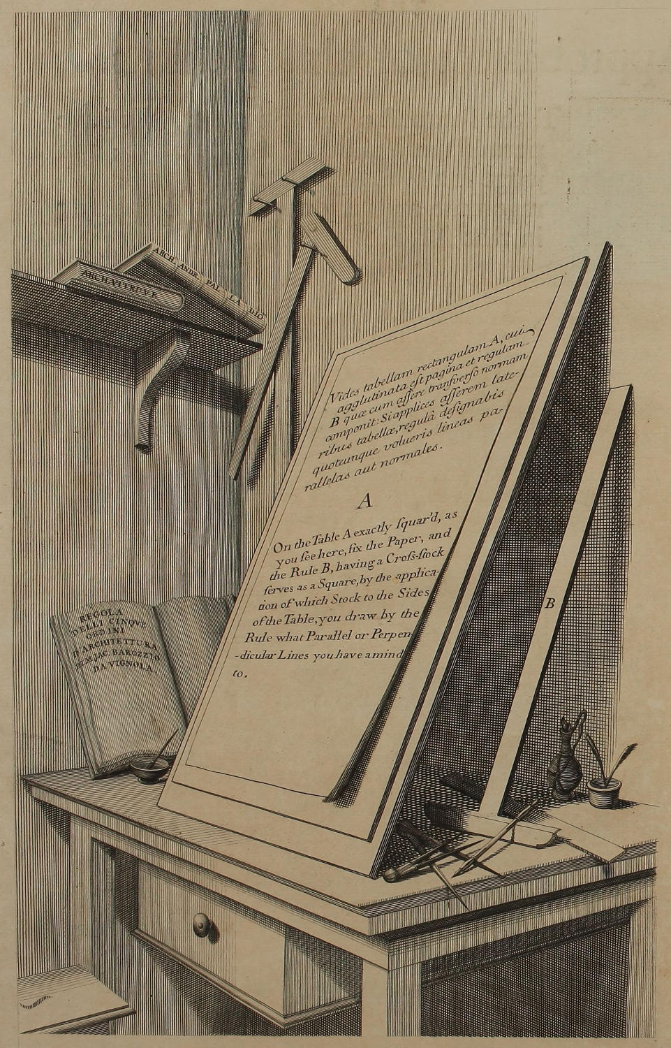
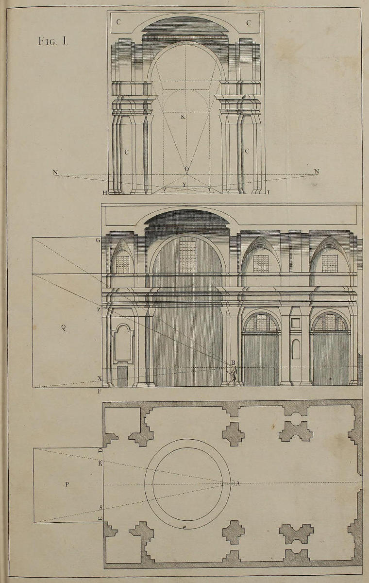
Fig. I.
Explicatio linearum Plani & Horizontis, ac Punctorum Oculi & Distantiæ.
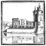
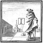
Ut principia Perspectivæ faciliùs intelligas, pono tibi ob oculos Templum, in cujus interiori facie, præter cætera, pingendum sit aliquid ad Perspectivam pertinens. Templi hujus vestigium geometricum est A, elevatio geometrica in longum est B, in latum est C. In A est locus Hominis aspicientis lineam DE, cui paries pingendus incumbit. In B idem Homo ex eâdem distantiâ intuetur lineam FG, quæ refert elevationem parietis. In figura C supponimus Hominem consistere è regione ipsius parietis: easdemque proportiones mensuratum translatas esse ex vero pariete in figuram C, quæ ipsum in parvo repræsentat.
Prima ergo linea HI dicitur linea terræ vel plani, ex quâ incipit, eidemque incumbit ædificium. Secunda linea NON priori parallela, dicitur horizontalis, in quâ ponitur O punctum oculi, & N punctum distantiæ. Duo autem puncta distantiæ à nobis posita sunt, ut unum adhibeas ex quâ parte volueris; nam ad figuras opticè contrahendas sufficit unum punctum distantiæ: nec fieri potest ulla optica delineatio, quin primo loco designentur duæ parallelæ, una plani seu terræ, altera horizontis, notando in lineâ horizontis, punctum oculi, seu opticum, & punctum distantiæ. Porrò unam eandemque rem triplici Schemate repræsentare oportuit, ut videas, locum ex quo aspicienda est figura C esse punctum N unius ex rectis NO, quam concipere debemus veluti normaliter infixam in O; ac distantiam inter O & N eandem esse debere cum distantiâ inter A & DE, inter B & GF.
In picturis multum spatii occupantibus, punctum oculi poni solet in medio lineæ horizontalis: atque ubi altitudo picturæ sit major latitudine, distantia NO fiet æqualis altitudini. Si latitudo picturæ sit major altitudine, distantia NO fiet æqualis latitudini; ita enim unico intuitu totum picturæ spatium comprehendi poterit. Porrò quamvis eadem distantia diverso modo adhibeatur in vestigio A, & in elevationibus B & C; nihilominus sectiones visualium cum pariete vestigii A, & elevationis B, omninò conspirant cum sectionibus visualium figuræ C.
Jam si velimus ut spectatori in A & B paries depictus videatur distare à lineis DE & GF, quanta est longitudo quadrati P, cujus elevatio est Q; ex punctis A & B fiant visuales ad puncta extrema quadrati, notando sectiones visualium cum pariete DE & GF, qui ab aliis vocatur velum, vitrum diaphanum, sectio, tela, vel tabula. Invenies autem, lineas RS ac TV esse æquales, ac similiter lineas XZ & YK; & sic de aliis.
Explication of the Lines of the Plan and Horizon, and of the Points of the Eye and of the Distance.
That you may the better understand the Principles of Perspective, here is presented to your View a Temple, on the inner Wall of which, amongst other things, one would paint something in Perspective. The Geometrical Plan of this Church is A, the Geometrical Elevation, or Upright, lengthwise is B, breadthwise is C. In A is the Place from whence a Man beholds the Line DE, which is the Plan of the Wall that is to be painted: In B the same Man, from the same Distance, looks upon the Line FG, that represents the Elevation of the Wall. In Fig. C, the Man is supposed to stand opposite to the said Wall; and this Figure contains, in Little, the very same Proportions of Measures transferr’d from the real Wall.
The first Line therefore HI is call’d the Ground-line, or Line of the Plan, at which the Edifice begins, and on which it stands. The second Line NON, parallel to the former, is call’d the Horizontal Line, wherein is plac’d O the Point of the Eye, and N the Point of the Distance. Two Points of Distance are here laid down, that you may make use of which you please; for that on one Side only is sufficient for the fore-short’ning Figures in Perspective: Neither can any Optick Delineation, or Perspective, be described, without first making two Parallels; one of the Plan, or Ground-line, the other of the Horizon; marking, in the Line of the Horizon, the Point of the Eye, or Sight, and the Point of Distance. It was thought besides expedient to put one and the same Thing into three Schemes or Designs, to let you see, that the Place, from which the Figure C is to be look’d upon, is the Point N, one of the right Lines NO, which must be conceived as fixt at right Angles into O; the Distance ON being the same as that between A and DE in the Plan, or between B and GF in the Upright.
In Pictures taking up a great deal of Room, the Point of Sight ought to be made in the middle of the Horizontal Line; and where the Height of the Picture happens to be greater than the Breadth, the Distance NO must be made equal to the Height. If the Breadth of the Picture exceed the Height, the Distance NO must be made equal to the Breadth: For so will the Extent of the Picture be the better comprehended, or receiv’d, at one View. And altho’ the same Distance may seem to be used in a different manner in the Plan A, and in the Elevation B, from what it is in C; nevertheless the Sections of the visual Rays, with the Wall of the Plan A, and of the Elevation B, have a perfect Correspondence with the Sections of those of the Figure C.
Now, if to the Spectator in A and B, we would have the farthest Part of the Work seem to recede from the Lines DE and GF, as much as the Square P does, whose Elevation is Q; draw from the Points A and B, the visual Rays to the extreme Points of the Square P and Q; noting the Sections they make with the Walls DE and GF; which by some is call’d the Veil, Transparent Medium, Section, Cloth, or Table: and you’ll find RS equal to TV, XZ equal to YK; and so of the rest.
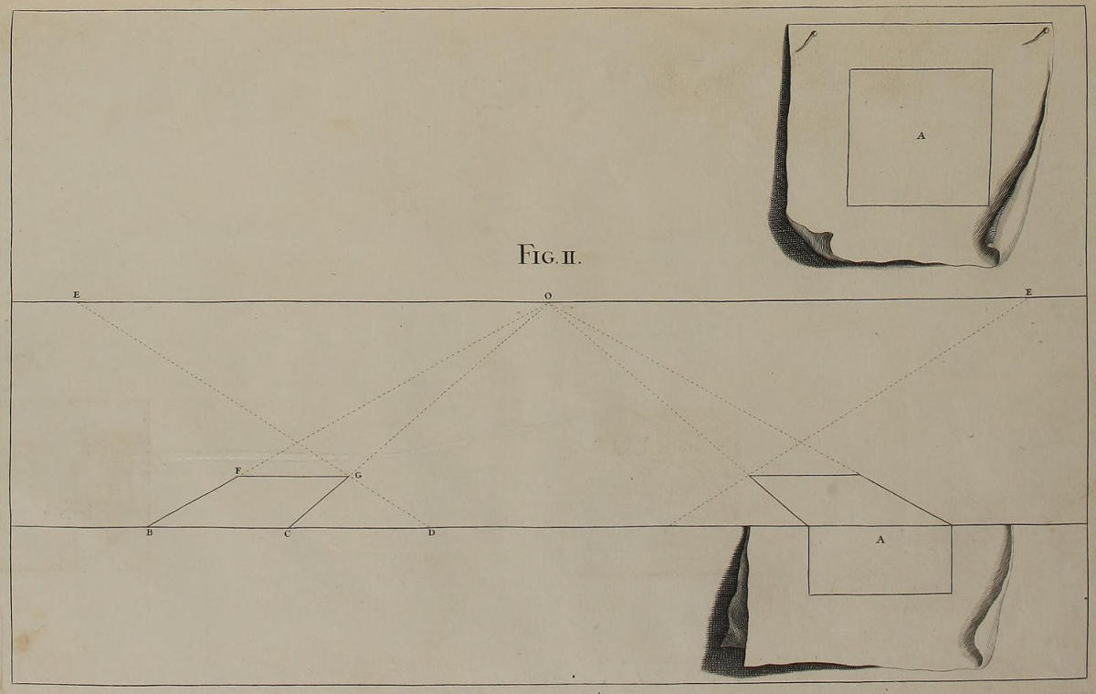
Fig. II.
Modus delineandi opticè Quadratum.
Ante descriptionem opticam quadrati A, quod fingimus delineatum esse in papyro separatâ, ducendæ sunt duæ lineæ parallelæ; altera plani, altera horizontis, ut jam docuimus; notando in linea horizontis punctum oculi O, & punctum distantiæ E. Tum translatâ in lineam plani latitudine ac longitudine ipsius quadrati A, ita ut linea CB sit æqualis latitudini, & DC sit æqualis longitudini. Ex punctis B & C fiunt visuales BO, CO ad punctum oculi; ex puncto D fit recta DE ad punctum distantiæ. Demum ubi visualem CO secat recta DE, fit GF parallela ad CB; habesque quadratum opticè contractum.
Compendium temporis & laboris facies, præsertim in schematibus quæ abundant lineis, si chartulam in medio complicaveris, eademque utaris, ut latitudinem ac longitudinem quadrati transferas in lineam plani.
Manner of delineating a Square in Perspective.
Before the Square A, which is supposed to be drawn on a separate Paper, can be laid down in Perspective, two parallel Lines must be drawn; one of the Plan, the other of the Horizon, as is already intimated; noting in the Horizontal Line the Point of Sight O, and the Point of Distance E. Then, when the Length and Breadth of the Square A shall be transferr’d into the Line of the Plan, so that the Line CB be equal to the Breadth, and DC be equal to the Length, let the visual Lines BO, CO be drawn from the Points B and C to the Point of Sight O, and the right Line DE from the Point D to the Point of Distance. Lastly, where the Line DE cuts the Visual CO, make GF parallel to CB: and you have the Square Optically contracted, or fore-shorten’d in Perspective.
To spare Time and Pains, especially in Figures that abound in Lines, fold your Paper in the middle, and make use of it to transfer the Breadth and Length of the Square, into the Line of the Plan.
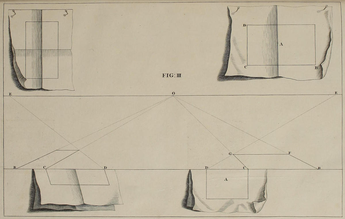
FIG. III.
Optica delineatio rectanguli, alterâ parte longioris.
Latitudo BC rectanguli A ponatur in linea plani, adhibito circino, vel chartulâ complicatâ; & ex punctis B & C fiant visuales ad O, punctum perspectivæ. Tum papyro ex altera parte iterum complicatâ, notetur longitudo CD rectanguli; ducendo tum rectam DE ad punctum distantiæ, tum rectam FG parallelam ad BC, quæ complebit opticam delineationem rectanguli.
Altera figura ostendit complicationem cruciformem papyri, quæ adhiberi potest in delineandis rectangulis, seu latitudo eorum sit major longitudine, aut vice versâ; seu latitudo & longitudo sint æquales.
The Delineation of an Oblong Square in Perspective.

Let the Breadth BC of the Square A, be plac’d in the Line of the Plan, by the Compass, or a folded Paper, and from the Points B and C, make the Visuals to the Point of Sight O. Then fold your Paper cross-wise, and mark CD the Length of the Square, drawing the Line DE to the Point of Distance, and the Line FG parallel to BC, which will complete the Optick Delineation of the oblong Square.
The other Figure shews the Folding of the Paper cross-wise, which is of ready use in delineating Squares, whose Breadth exceeds their Length, or vice versâ; or whose Length and Breadth are equal.
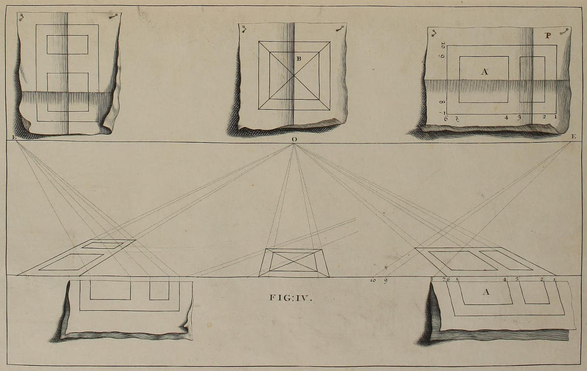
FIG. IV.
Optica descriptio quadrati duplicis.
Iam incipies frui compendio papyri complicatæ. Nam eam admovendo lineæ plani, nullo negotio notare poteris puncta 1, 2, 3, 4, 5, 6, linearum visualium, quæ ducentur ad O punctum perspectivæ. Exinde complicatâ rursum chartulâ in crucem ad P, notabuntur hæc puncta; 7, coincidens cum puncto 6, nisi quadratum distet à linea plani; 8, 9, 10. Ductis autem rectis ex 8, 9, 10, ad punctum E, ubi secant visualem 6, 7, O fient parallelæ, eritque completa delineatio.
In medio quadrati B, aliud quadratum facilè describetur, ducendo diagonales seu diametros ab angulo ad angulum, ut in figura.
The Optical Delineation of a double Square.
Here you’ll find the Advantage of your folded Paper; for, applying it to the Line of the Plan, you readily mark the Points 1, 2, 3, 4, 5, 6, of the visual Lines, which must be drawn to the Point of Sight O. Then folding the Paper cross-wise, as in P, you mark the Points 7, 8, 9, 10, placing the Point 7 on that of 6, unless you would have the Square removed within the Line of the Plan. Then from 8, 9, 10, drawing Lines to the Point of Distance E; where they intersect the Line 6, 7, O, draw Parallels to the Line of the Plan; and your Work is done.
Within the Square B, you may easily inscribe another Square, by help of the Diagonals; as may be seen in the Figure.
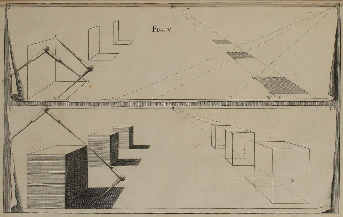
Fig. v.
Vestigia quadratorum, cum elevationibus.
Suppositis iis quæ jam diximus de Contractione optica Quadratorum, notandum est, vestigium primi Quadrati distare à linea plani spatio BA opticè contracto; quia linea BD habet à visuali AO, distantiam BA. Eodem modo Quadratum secundum distat à linea plani spatio EA, & sic deinceps.
Velim observes, in omnibus his Quadratis lineas longitudinis esse partes visualium, lineas vero latitudinis esse parallelas lineæ plani, & in primo Quadrato duci ex punctis, in quibus lineæ BD, CD, tendentes ad punctum distantiæ, secant visualem AO.
Sub singulis vestigiis Quadratorum, delineavimus alia omnino similia, per quæ parvo labore fient tres bases, erigendo ad libitum duas primas perpendiculares æquales; ac ducendo tum duas visuales ad punctum oculi O, tum reliquas, ut in figura. Supponendum est autem, geometricam altitudinem cujuslibet rei desumi ex lineis normalibus ad lineam plani; quemadmodum latitudo & longitudo geometrica desumuntur ex eadem linea plani.
Tres aliæ bases inferiores formantur sine lineis occultis ex vestigio & ex elevatione longitudinis opticè deformatis, adhibendo solas altitudines ac latitudines angulorum. Nomine altitudinis intelligimus distantiam cujuslibet anguli à linea plani; nomine latitudinis intelligimus distantiam anguli ab una aliqua linea normali ad lineam plani; dummodo hæ normales eandem habeant positionem respectu basium, & respectu vestigiorum & elevationum. Quemadmodum autem per concursum altitudinis FG, & latitudinis HI, ope duorum circinorum invenitur unus angulus in una basi; ita inveniuntur cæteri tum in ea, tum in reliquis.
Plans of Squares, with their Elevations.
Besides what has been already said of the fore-short’ning of Squares in Perspective, it is convenient to observe, That the Foot of the first Square is here set within the Line of the Plan, as much as the Space BA optically contracted; because the Line BD has the Distance BA from the Visual AO: And in like manner, the second Square is distant from the Line of the Plan the Space EA; and so for the rest.
I would have you observe in all these Squares, That by the Length I always understand part of the visual Lines, and by the Breadth those parallel to the Ground-line; which in the first Square are drawn from the Points in which the Lines BD, CD, tending to the Point of Distance, intersect the Visual AO.
Under the Plans of these Squares are described three others just like them, which are easily converted into three Bases, by erecting, at pleasure, the two first Perpendiculars of equal Height, and thence drawing two Visuals to the Point of Sight O, which also bound the rest, as in the Figure. Observe also, That the Geometrical Height of every thing is to be set perpendicularly from the Ground-line, or Line of the Plan, as the Geometrical Length and Breadth are also placed on the same Line.
The three other Bases below are form’d without the Help of Occult Lines, by making use only of the Heights and Breadths of the Angles, taken from the Perspective Plan and Upright. By Height I understand the Distance of each Angle, or Corner, from the Ground-Line; By Breadth, the Distance of an Angle, or Corner, from any Line perpendicular to the Ground-line; provided these Lines have always the same Place in respect of the Bases, as they have in respect of the Perspective Plan and Upright. And as, by the Help of two Compasses, the Height FG, and the Breadth HI determine the Corner of the first Base; so, in like manner, are found the Corners of the other Bases.
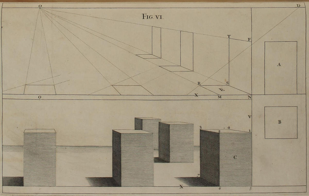
Fig. vi.
Modus opticæ delineationis, absque lineis occultis.
In hac figura sexta, vestigium geometricum B seorsim posui ab elevatione geometrica A, ut deinceps faciemus. Vestigium B opticè contractum in E est NMRS; elevatio contracta longitudinis vestigii est FTSN. Posito autem quòd altitudines FN, 1, 5, 2, 6, sint æquales; latitudines NM, 1, 2, 5, 6, sint æquales; & rectæ NM, 5,6, sint in linea X plani; rectæ FN, 1, 5, sint in perpendiculo V: anguli 3 & 4 basis C habent eandem elevationem seu distantiam à linea X plani, quam habet angulus T: anguli 1 & 2 habent elevationem, quam angulus F: anguli 3 & 7 habent eandem latitudinem seu distantiam à perpendiculo V, quam habet angulus R: anguli 2 & 6 habent eandem latitudinem, quam habet angulus M.
The Manner of designing in Perspective, without occult Lines.
In this sixth Figure, I have design’d the Geometrical Plan B separately from the Geometrical Elevation A, as I shall always do hereafter. The Plan B optically contracted, or put in Perspective, in E, is NMRS; the Elevation of its Length in Perspective is FTSN. Then supposing the Heights FN, 1,5, 2,6, equal; and the Breadths NM, 1,2, 5,6, equal; the Lines NM, 5,6, to be in the Line of the Plan X; and the Lines FN, 1,5, in the Perpendicular V: the Angles 3 and 4 of the Base C have the very same Elevation or Distance from the Line of the Plan X, as has the Angle T: the Angles 1 and 2 have the same Elevation with the Angle F: the Angles 3 and 7 have the same Breadth or Distance from the Perpendicular V, as the Angle R has: the Angles 2 and 6 have the same Breadth, as the Angle M has.
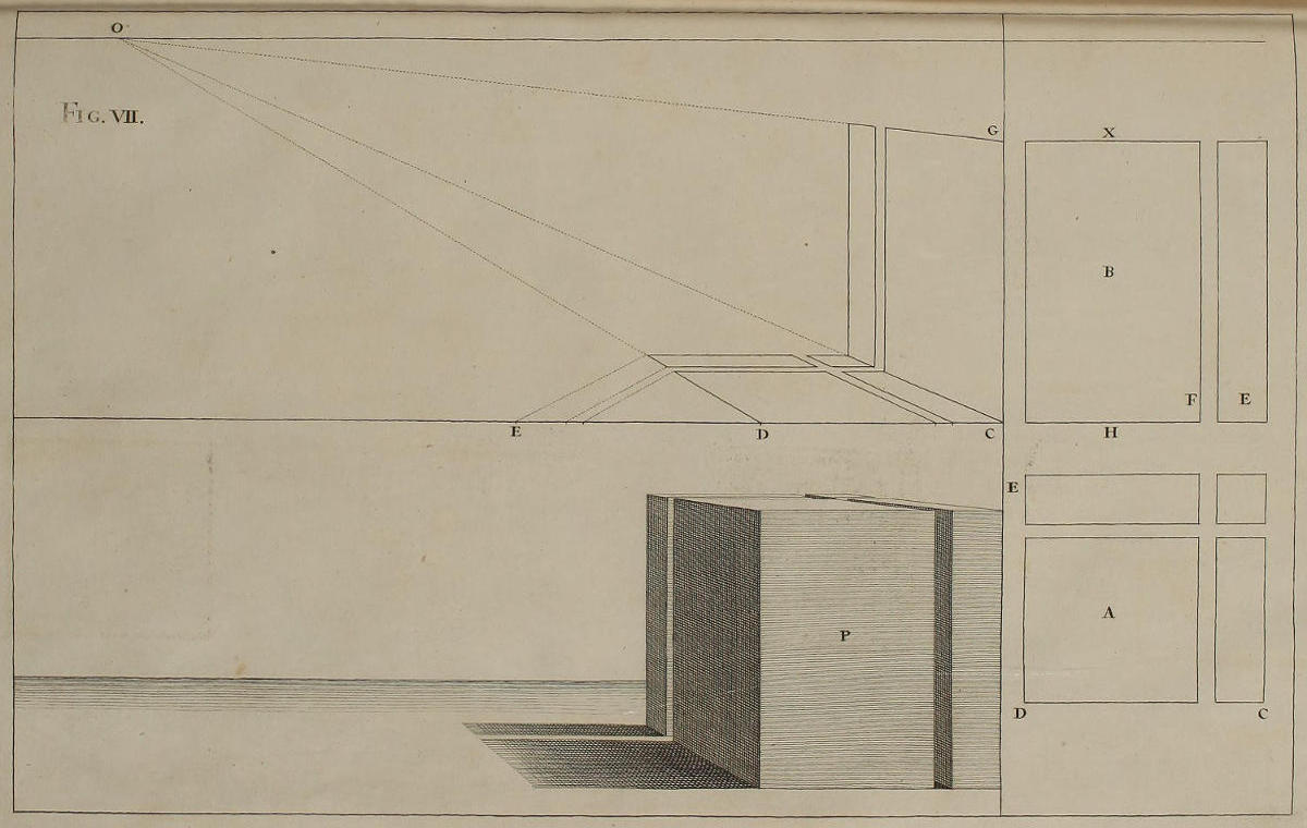
Fig. vii.
Aliud exemplum vestigii geometrici, cum elevatione longitudinis.
Si delineanda sit basis dissecta in quatuor partes, fiat vestigium A cum suis divisionibus longitudinis ED & latitudinis CD. Easdem vero divisiones latitudinis habebit in EF elevatio B quæ pertingit usque ad X. Porro ad contractionem opticam vestigii adhibebitur papyrus complicata in latum & in longum, transferendo in lineam plani latitudinem & longitudinem vestigii. Deinde nullo negotio fiet optica deformatio elevationis, ut clarè positum est in figura. Quomodo autem ex vestigio & ex elevatione longitudinis opticè imminutis eruatur basis nitida sine lineis occultis, ex præcedentibus manifestum est. Optarem ut per assiduam circini tractationem in hac methodo exercenda operam sedulò ponas; quum ex ea pendeat omnis facilitas delineationum opticarum.
Another Example of a Geometrical Plan and Upright, put in Perspective.
For drawing in Perspective a Pedestal, or Base, divided into four Parts, make the Plan A with its Divisions of Length ED, and of Breadth CD; and the same Divisions of Breadth EF, in the Elevation B, prolong’d to X. Then make the Perspective-Plan, by transferring the Breadth and Length into the Ground-line, by means of your Paper folded cross-wise. From which Plan the Perspective-Upright is very easily made, as may be plainly seen in the Figure. How the Base below, without occult Lines, is made from the Perspective-Plan and Upright, is manifest from what has been said before. I could wish you would be very diligent in the Practice of this Method by the Compass; because the Dispatch of Perspective-Delineations chiefly depends thereon.
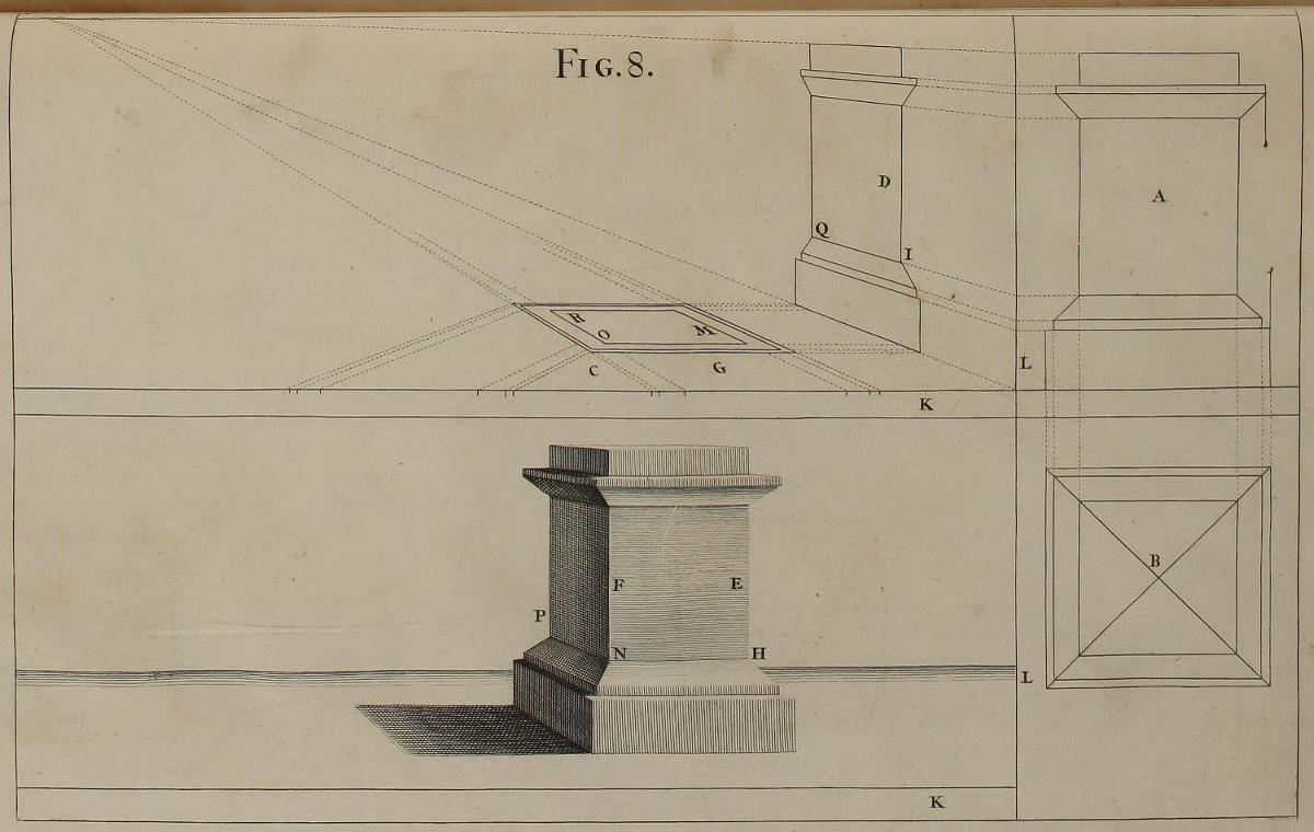
Fig. 8.
Optica projectio stylobatæ.
Si libitum fuerit delineare stylobatam, cum projecturis in summo & imo, incipies ab elevatione geometrica A, ducendo occultas ad id necessarias, tum versus perpendicularem L, tum deorsum pro vestigio geometrico B, cujus distantiæ transferentur in spatium G. Si mensuræ longitudinis distent spatio C à mensuris latitudinis, vestigium deformatum videbitur distare à linea K plani, quantum est idem spatium C. In construenda optica elevatione D, visuales ex punctis lineæ L dabunt lineas latitudinis; lineas vero altitudinis accipies ex lineis vestigii contracti, ut in figura. In formando stylobata nitido EF, locum anguli H dabit concursus latitudinis ex linea L usque ad M, & altitudinis ex linea K usque ad I. Concursus tum ejusdem altitudinis, tum latitudinis ex L usque ad O, dabit angulum N. Demum altitudinem anguli P accipies ex K usque ad Q; latitudinem ex L usque ad R.
The Projection of a Pedestal in Perspective.
If you would draw a Pedestal, with the Projecture of its Cap and Base, you must begin with the Geometrical Elevation A, by drawing such occult Lines as are necessary, as well sideways to the Perpendicular L, as downwards for making the Geometrical Plan B, whose Distances must be transferr’d, and carry’d into the Space G. If the Measures of the Length be placed the Distance of the Space C, from those of the Breadth, the Perspective-Plan will then appear removed within the Ground-line K, as much as the said Space C is. In the Construction of the Perspective Elevation D, the Visuals drawn from the Points of the Line L give the Lines of the Breadth; and those of the Height are taken from the Lines of the Perspective-Plan, as in the Figure. In delineating the clean or finish’d Pedestal EF, the Intersection of the Breadth from L to M, with the Height from K to I, gives the precise Place of the Corner H. The Intersection of the same Height with the Breadth LO gives the Angle N. Lastly, the Angle P is found by the Intersection of the Height KQ, with that of the Breadth LR.
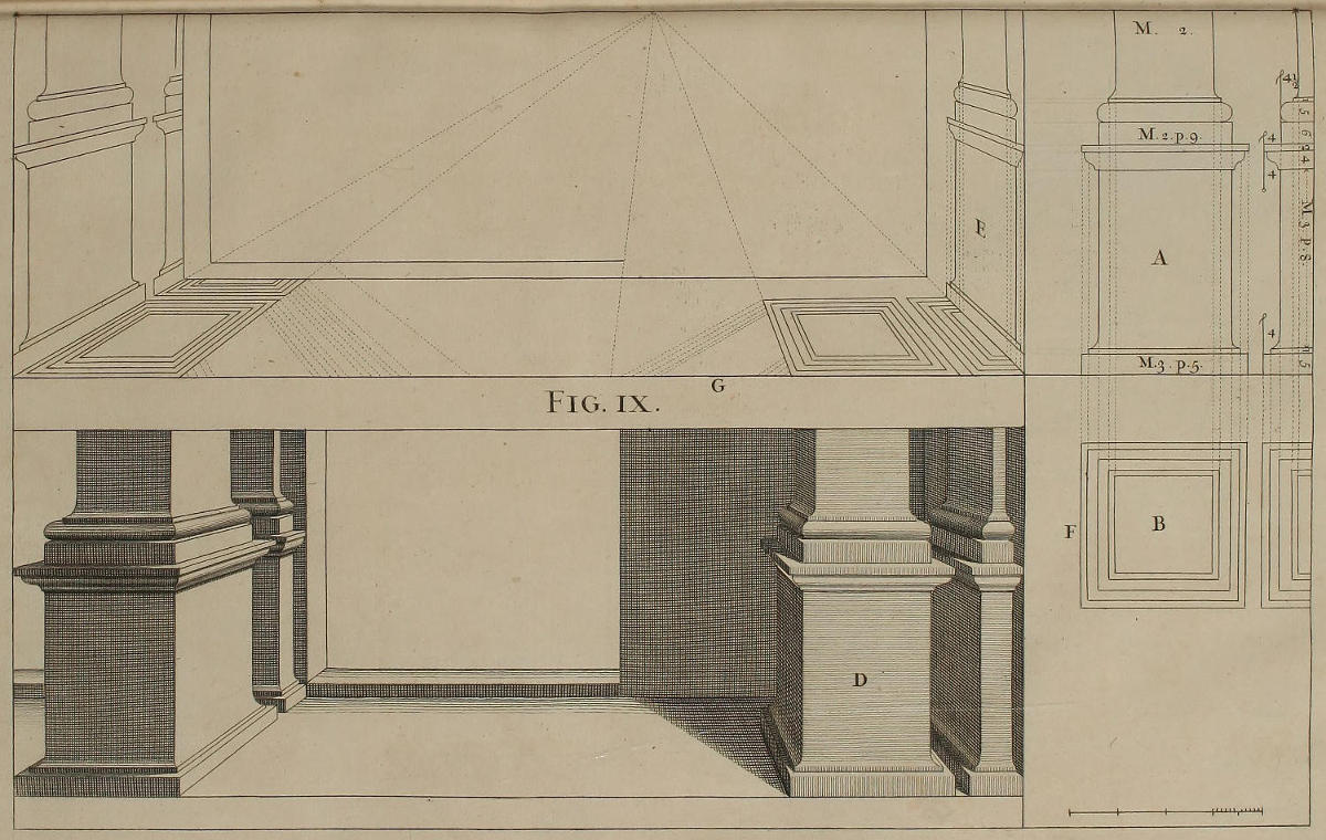
Fig. ix.
Optica delineatio Architecturæ Jacobi Barozzii; & primum, de Stylobata Ordinis Etrusci.

Perspectiva nusquam clariùs emicat, quàm in Architectura. Iccirco tibi ob oculos pono Architecturam Jacobi Barozzii, quem à patria nuncupant Il Vignola, reliquis fortasse usitatiorem; in eaque continetur elevatio geometrica singulorum quinque Ordinum, qui vocantur, Etruscus, Doricus, Ionicus, Corinthius, & Romanus, vel Compositus; delineando seorsim partes cujuscunque Ordinis in figuris grandioribus. Elevationi geometricæ suum vestigium nos addemus; ex vestigio autem & ex elevatione opticè deformatis, eliciemus apparentias solidorum juxta regulam traditam. Exempli gratia, si delineare velis stylobatam quadratum & pilam Ordinis Etrusci, præter elevationem geometricam A delineare oportet vestigium geometricum B; ex ambobus autem opticè contractis formatur stylobata nitidus D, cum anta & pila existente ad latus, accipiendo altitudines à linea plani, latitudines à linea perpendiculari ad ipsum planum. In alia delineatione posuimus pilam ex adverso, ut eis omni modo delineandis assuescas.
Ad vitandam confusionem linearum, proderit ut figuræ fiant his nostris multò grandiores: in quem finem singulis paginis apposita est scala modulorum. Hoc nomine intelliguntur partes æquales, in quas dividuntur lineæ latitudinis & altitudinis elevationum geometricarum; ac lineæ latitudinis & longitudinis vestigiorum geometricorum. Si moduli sint parvi, subdividuntur singuli in duodecim partes; ac prout fuerint grandiores, subdividuntur in partes triginta, vel sexaginta, vel centumviginti. Modulos Etruscum Doricúmque in partes duodecim; reliquos autem in octodecim partiti sunt.
The Architecture of Vignola in Perspective; and first, of his Pedestal of the Tuscan Order.
Perspective never appears more graceful, than in Architecture; for which Reason I present you with that of James Barozzi, from his Country generally call’d Vignola; which perhaps is more in use than any other; and contains the Geometrical Upright of each of the five Orders, viz. the Tuscan, Dorick, Ionick, Corinthian, and the Roman, or Composite; together with a separate Delineation of the Parts of each Order, in larger Figures. To this Geometrical Elevation we shall add the Plan, and, from both of them reduc’d into Perspective, shall draw the Appearances of Solids, according to the Rule before laid down. For Example: If you would draw the square Tuscan Pedestal, and its Pilaster, you must, from the Geometrical Elevation A, make the Geometrical Plan B; and from both of them reduc’d in Perspective, draw the finish’d Pedestal D, with that of its Pilaster on the Side, by taking the Heights from the Ground-line, and the Breadths from a Line perpendicular to the same. On the other Side we have placed the Pilaster on the Back-part, that you may practise the Drawing them in any manner.
For avoiding the Confusion of Lines, I advise you to make the Figures as much larger than ours as you can; for which purpose there is annex’d a Scale of Modules to each Figure. By this Name we understand the equal Parts, into which the Lines of the Breadth and Height of the Geometrical Uprights, and of the Breadth and Length of the Geometrical Plans, are divided. If the Modules are small, they are subdivided into twelve Parts; and according as they are larger, into thirty, sixty, or an hundred and twenty Parts. I have divided the Tuscan and Dorick Module into twelve Parts, and that of the other Orders into eighteen.
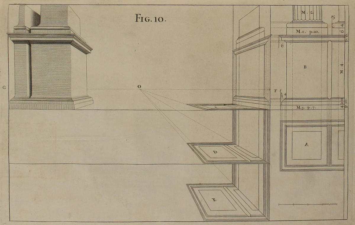
Fig. 10.
Optica deformatio stylobatæ Dorici; ubi de modo vitandi confusionem, in vestigiis delineandis.
Elevatio geometrica B stylobatæ Dorici continet eandem symmetriam partium quæ habetur apud Barozzium; ex eaque eruitur vestigium geometricum A per lineas occultas, quæ descendant ex punctis terminativis præcipuarum projecturarum. Earundem projecturarum distantiæ transferendæ sunt in lineam elevationis, notando puncta quæ necessaria sunt ad deformandam elevationem longitudinis stylobatæ.
Si ob propinquitatem lineæ plani ad lineam horizontis, vestigium evadat confusum, fiant in distantia congrua sub linea plani aliæ lineæ planorum ipsi parallelæ, cum suis vestigiis. Quid autem emolumenti afferat distantia major præ minori, ostendit vestigium E distinctiùs vestigio D. Singula hæc vestigia fiunt notando in linea cujuslibet plani mensuras latitudinis & longitudinis vestigii A, & ducendo lineas ad eadem puncta oculi ac distantiæ.
Stylobatam nitidum descripsimus ex parte G, tum ex necessitate, tum ut videas, pro distantia FO, usurpandam esse distantiam GO penitus æqualem.
A Dorick Pedestal in Perspective; with the Manner of avoiding Confusion, in designing the Plans.
The Geometrical Elevation B has the same Members and Proportions, as the Dorick Pedestal of Vignola; and the Geometrical Plan A is form’d, by letting fall occult Lines from the principal Projectures of the Upright. Occult Lines are also to be continued to the Perpendicular F, from the several Members requisite for elevating in Perspective the Length of the Pedestal.
When, by reason of the too near Approach of the Ground-line to that of the Horizon, the Plan becomes thereby confus’d; draw at a convenient Distance underneath, other Ground-lines parallel to the first; together with the Plans in Perspective. And of what Advantage the Removal of the Ground-line is, is evident from the Plan E, which is much more distinct than the Plan D. Each of these Plans is made, by marking upon its respective Ground-line the Measures of the Breadth and Length of the Plan A, and by drawing Lines to the same Points of Sight and Distance, which were first assign’d.
We have placed the finish’d Pedestal on the Side G, partly for want of Room, and partly to shew, that the Point of Distance G is there made use of, GO being equal to FO.
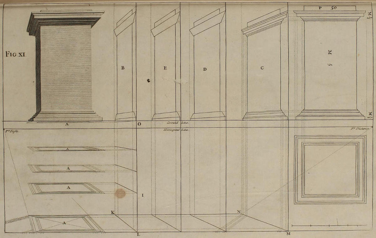
Fig. xi.
Stylobatæ Ionici deformatio; ubi de vitanda confusione in elevationibus.
Tum in figura præcedenti, tum rursus in hac, ostendimus quid agendum sit ubi vestigia AA nimium obliquentur, unde oritur confusio; præcipuè in lineis parallelis quæ exhibent latitudines. Non minor difficultas interdum occurret in elevationibus longitudinis opticè deformandis; quòd videlicet, ob nimiam earum obliquitatem, pervium non sit altitudines singularum projecturarum probè discernere ac designare. Ad scopulos istos declinandos, loco elevationis B adhibebitur elevatio C, quæ distinctior est, tum illâ, tum duabus intermediis D & E, ob majorem distantiam quam habet à puncto oculi.
In delineando stylobata nitido, latitudines accipientur ex ultimo vestigio, ponendo unam cuspidem circini in linea perpendiculari, quæ proxima est literæ O: altitudines accipientur ex elevatione C, ponendo unam cuspidem circini in linea plani, ut in præcedentibus ostensum est.
The Ionick Pedestal in Perspective; with the Manner of avoiding Confusion, in Elevations.
As in the foregoing Figure, so in this also is shewn what is to be done, where the Plans AA lie so oblique, as to cause Confusion; especially in the Parallel-lines which give the Breadths. The like Inconvenience often happens in elevating the Lengths in Perspective; when by their too near Approach to the Point of Sight, the Contour of the several Mouldings can’t be distinctly delineated: For avoiding which, instead of B you may make use of the Elevation C, which is not only more distinct than the former, but better than either of the two intermediate ones D or E, by so much as it is more remote from the Point of Sight.
In designing the finish’d Pedestal, the Breadths are taken from the lowest Plan, by setting one Point of the Compasses in the perpendicular Line OL: the Heights are taken from the Elevation C, by placing one Point of the Compasses in the Ground-line, as has been shewn before.
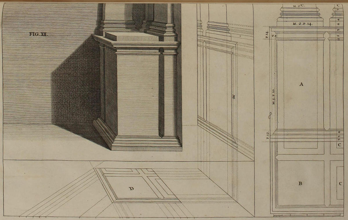
FIG. XII.
Deformatio stylobatæ Corinthii, cum duabus pilis.
Ornatus gratiâ, stylobatæ Corinthio additæ sunt pilæ, quæ pone columnas locari solent. Ut autem pilæ clariùs appareant, columna omissa est, cujus deformandæ rationem nondum tradidimus. Mensuras omnes ex Barozzio acceptas esse demonstrat ipsum schema, in quo elevatio geometrica stylobatæ est A; vestigium ejus geometricum est B: pilæ CC. Vestigium opticè contractum est D, elevatio longitudinis stylobatæ opticè contracta est E, ac methodo consuetâ ex iis eruetur stylobata nitidus cum suis pilis.
The Corinthian Pedestal, with its Pilasters, in Perspective.
For Ornaments sake, we have added to this Corinthian Pedestal the Pilasters, which are usually placed behind Columns: And that they may be the more perspicuous, have left out the Column, not having yet shewn the Manner of putting it in Perspective. The Scheme shews the Measures are taken from Vignola; in which the Geometrical Upright of the Pedestal is A; the Geometrical Plan of the same is B; that of the Pilasters CC. The Plan in Perspective is D, the Elevation in Perspective is E; from which the finish’d Pedestal and Pilasters are drawn by the usual Method.
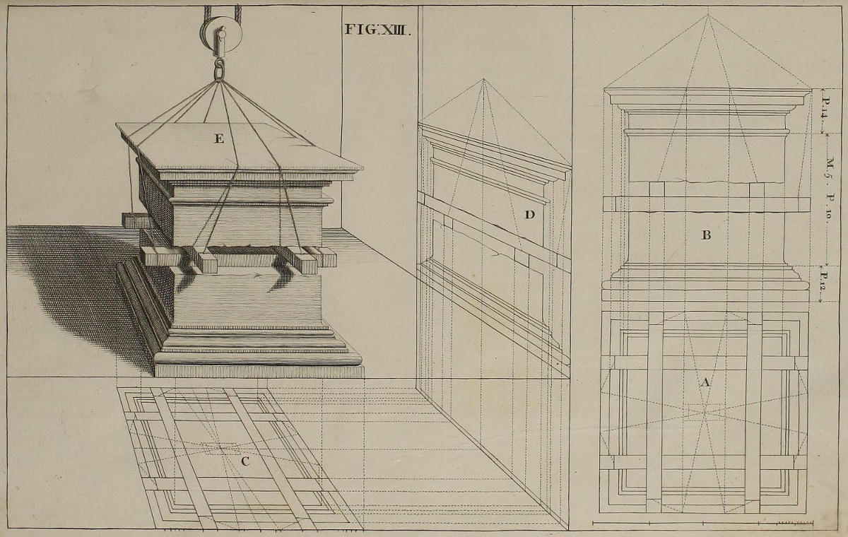
FIG. XIII.
Projectio stylobatæ, ordinis Compositi.
Quum pagina non caperet integrum stylobatam tantæ molis, fingere oportuit detractum illi esse aliquid de trunco; ac partem supremam stylobatæ sustentari ab infima, non immediatè, sed per quatuor asseres; eisque impositam fuisse adjumento funium suspensorum ex trochlea. Elevatio geometrica stylobatæ est B; vestigium geometricum est A. Ex his eruitur optica delineatio vestigii C & elevationis D. Ac postea formatur stylobata nitidus E, accipiendo latitudines ex vestigio C, altitudines ex elevatione D.
The Projection of a Pedestal, of the Composite Order, in Perspective.

Wanting Room in this Page to describe so large a Pedestal entire, we imagine it to have lost part of its Trunk, and the upper part to be set on the lower; not immediately, but on four Cross-pieces that intervene; and for placing it thereon, we suppose the Assistance of Ropes and a Pulley. The Geometrical Elevation of the Pedestal is B; its Plan A; from whence are found their Projections in Perspective D and C. Then taking the Breadths from the Plan C, and the Height from the Elevation D, you complete the finish’d Pedestal E.
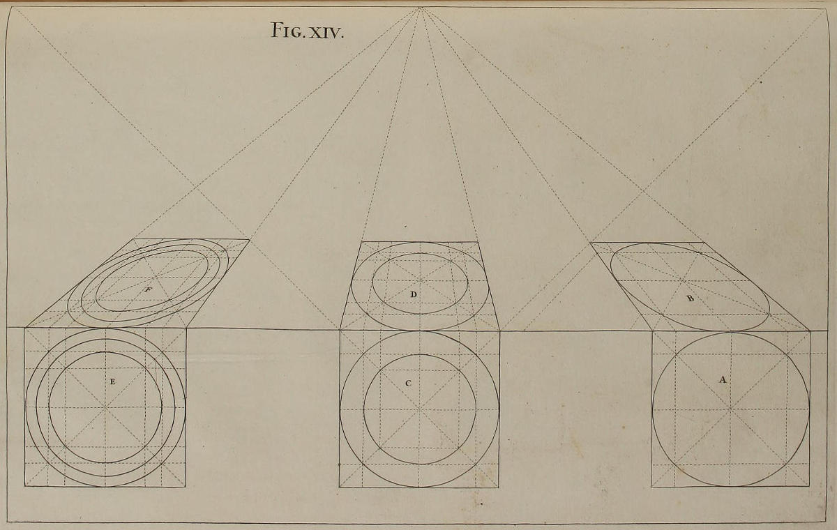
Fig. xiv.
Deformatio circulorum.
Ut stylobatis imponere liceat columnas cum suis basibus & capitellis, docendus est modus qui servandus est in projectione optica circulorum, tum singularium, tum duplicium aut multiplicium circa idem centrum.
Vestigium geometricum A constat quadrato in quatuor partes æquales diviso, cui circulus inscribitur, additis diagonalibus: & ubi hæ secant circulum, fiunt rectæ parallelæ ad singula latera ipsius quadrati. Deinde quadratum cum omnibus divisionibus opticè imminuitur; ac tum per quatuor puncta ubi tres lineæ rectæ se intersecant, tum per quatuor extrema reliquarum duarum diametrorum circuli, ducetur cum venustate circumferentia circuli B. Si addere velimus alium circulum, vestigio geometrico C inscribetur aliud quadratum; indeque habebitur optica delineatio duplicis circuli D. Inter hos duos quomodo liceat describere tertium, per octo sectiones quadratorum, ostendunt figuræ E & F. Uno verbo, circuli describuntur per quadrata, adhibendo sectiones visualium cum parallelis ad lineam plani; ac nullum est punctum in quadratis & circulis A, C, E, cui per sectiones illas nequeat inveniri punctum correspondens in quadratis & circulis B, D, F. Nihilominus ubi opus habeas pluribus circulis, autor tibi sum ne multiplices quadrata, plus confusionis allatura tibi quam adjumenti.
Circles in Perspective.
That upon Pedestals you may be able to place Columns with their Bases and Capitals, it is requisite you should know the Manner of putting Circles into Perspective; whether single, double, or many concentrick.
The Geometrical Plan A consists of a Square with a Circle inscrib’d, whose Diameters divide it into four equal Parts; and the Diagonals being drawn where they intersect the Circle, continue Lines parallel to each Side of the Square. The Square, with all its Divisions, being put in Perspective; by the four extreme Points of the Diameters, and by those of the Intersection of the Diagonals, you neatly trace by hand the Circumference B. If you would add another Circle, you must inscribe another Square, as in the Plan C; from whence you find in Perspective the double Circle D. Between these two Circles, you may, by the eight Intersections of the Squares, describe a third; as is evident by the Figures E and F. In a word, all Circles are described by the Help of Squares, tracing them by the Intersections of the visual Lines, with those parallel to the Ground-line: Nor is there any Point in either the Squares or Circles A, C, E, whose correspondent Point may not be readily found by such Sections, in the respective Squares and Circles B, D, F. Nevertheless, where your Work requires many Circles, I would advise you to use as few Squares as possible; lest they perplex, rather than assist you.
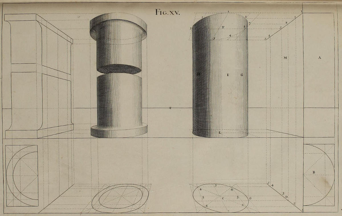
Fig. xv.
Optica delineatio Columnæ.
Descripturi frustum cylindricum I uniforme, fiet elevatio A, & vestigium geometricum B, saltem quoad medietatem. Ex hoc opticè deformato, ut vides in C, ducendæ sunt parallelæ tum latitudinis ad visualem D, tum elevationis ad visualem E; ex quibus describentur circuli opticè contracti F & L, accipiendo latitudines ex vestigio C, altitudines ex perpendiculari M; & juxta hanc methodum circuli F & L fiunt sine ope quadratorum. Demum ducendæ sunt perpendiculares G & H, quæ tangant circulos F & L in punctis terminativis maximæ latitudinis.
Nullum est punctum in vestigio C, cui per lineas latitudinis & elevationis nequeat inveniri locus correspondens in circulo F. Exempli gratia; locus puncti 7 est punctum 6. Hunc autem locum habemus per tres lineas, CD, DE, E7.
In delineandis duobus frustis cylindricis, cum summo & imo scapo, eandem regulam servare oportebit.
A Column in Perspective.
Being to describe Part of the Shaft of a Pillar without Projectures, make the Elevation A, and the Geometrical Plan B, at least to the middle: From this brought into Perspective, as you perceive in C, must be drawn Parallels both of Breadth to the Visual D, and of Elevation to the Visual E; from which are described the Circles in Perspective F and L, taking the Breadths from the Plan C, and the Heights from the Perpendicular M: And according to this Method the Circles F and L are made, without the Help of Squares. Lastly, draw the Perpendiculars G and H, by the Points which terminate the greatest Breadth of the Circles F and L.
There is not a Point in the Plan C, but what, by means of the Lines of Breadth and Elevation, may be found in the Circle F. For Instance; the Place of the Point 6 is 7, which is found by the three Lines CD, DE, E7.
In designing the two Pieces of a Pillar, with the Projecture of the Fillet at Head and Foot, you must observe the very same Rule.
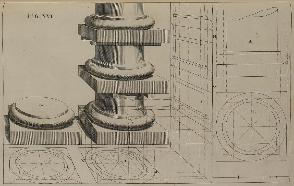
Fig. xvi.
Optica projectio basis Etruscæ.

Ex elevatione geometrica A eruitur vestigium B. Hoc autem deformato in C & D, ex circulis vestigii C habentur latitudines columnæ, quadræ, ac tori triplicis basis: & eodem modo ex vestigio D habentur latitudines quadræ ac tori ultimæ basis. Ex maximis latitudinibus circulorum vestigii C ereximus perpendiculares ad partes quæ ipsis respondent in basi; ut agnoscas quænam sint puncta maximæ latitudinis in eisdem partibus. Hæc puncta (quæ in circulo maximo vestigii C sunt M & N) invenientur tangendo circumferentiam uniuscujusque circuli regulâ parallelâ ad lineam perpendicularem E, nam si figura exactè delineata fuerit, regula tanget singulos toros trium basium in punctis maximæ hinc inde latitudinis.
Magis laborandum erit in reperiendis altitudinibus quatuor basium. Verum si sedulò inspiciatur deformatio elevationis F, aliarumque duarum, (quæ factæ sunt, notatis in linea perpendiculari E divisionibus desumptis ex elevatione geometrica A) constabit, nullum esse punctum in circulis vestigii C, cui nequeat inveniri punctum correspondens in toro & quadra ipsius basis, ut ostendunt lineæ occultæ, quæ incipiunt ex M & N. Earum quælibet ex vestigio C pervenit ad lineam visualem, & continuatur cum linea altitudinis ex visuali ad elevationem F, & cum alia linea latitudinis ex elevatione F ad basim. Porrò ex figura constat, superficiem superiorem quadræ subduci oculis à columna, & aliquid ex parte postica tori quod cæteroqui conspiceretur, abscondi à quadra. Proinde torus, qui ex punctis maximæ latitudinis retrorsum flectitur, eousque delineandus est, quoad hinc inde occurrat quadræ ipsum cooperienti. Præstaret autem singula membra ita exactè delineari, quasi essent diaphana; ut partes oculis imperviæ, omnino cohæreant cum partibus quæ ipsis conspicuæ sunt.
Completâ delineatione, si figuram tuam ex perpendiculo puncti oculi ex debita distantia contemplatus fueris, omnes defectus facilè deteges & statim corriges. Præcipuam diligentiam pones in formando & emendando toro, qui habet duas rotunditates; unam quatenus ambit columnam; alteram quatenus caret angulis, ut ostendit elevatio geometrica in I.
The Tuscan Base in Perspective.
From the Geometrical Elevation A, is drawn the Plan B; which being put into Perspective, as you see in C and D, from the Circles of the Plan C you have the Breadths of the Column, and of the List, and Torus of the three Bases: And after the same manner, by the Plan D, you have the Breadth of the List and Torus of the last Base. From the greatest Breadth of the Circles of the Plan C, we have erected Perpendiculars to the Parts that answer them in the Base, to the end that you may see where the Points fall, which terminate the greatest Breadth of those Parts. These Points (which in the biggest Circle of the Plan C are M and N) are found by touching the Extremity of the Circumference with a Line parallel to the Perpendicular E: for if the Figure were exact, that Line would touch every Torus of the three Bases in the extreme Points of their Breadth.
The Heights of the four Bases are something more difficult to be found. Nevertheless, if you consider well the Elevation F, and the other two G and H, (which are made by transporting the Divisions of the Elevation A upon the Perpendicular E) it will plainly appear that there is no Point in the Circles of the Plan C, to which there may not be a correspondent Point found in the Torus and List of the said Base; as the occult Lines shew, that arise from M and N; each of which is a Continuation of three Lines: The first of Breadth, from the Plan C to the Visual; the second of Height, from the Visual to the Elevation F; the third of Breadth, from the Elevation F to the Base. Now, tho’ it’s plain by the Figure, that the Body of the Column prevents the Sight of good part of the Fillet, and the same Fillet takes off from part of the Torus, which would otherwise be visible; for which Reason the Back-part of the Torus is continu’d only till it meet the same: Yet it’s certainly best to draw every Member complete, as tho’ the Work were transparent; that the Parts hidden from the Eye may the better agree with those that are expos’d to it.
When your Draught is finish’d, if you view it at the due Distance, and perpendicularly to the Point of Sight; you’ll readily discover and rectify what’s amiss. Your chief Care will be employ’d in shaping the Torus, difficult by reason of its Roundness both ways; namely, in the Contour of its Moulding, as in the Elevation I; and in the Circuit it makes about the Column.
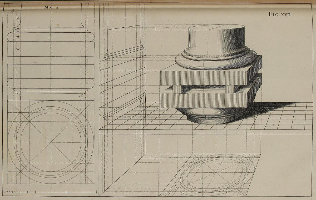
Fig. xvii.
Deformatio basis Doricæ.
Ad vitandam satietatem quam pareret nimia uniformitas, unam ex basibus invertimus. Utraque autem basis delineata est methodo quam tradidimus figurâ præcedenti. Eademque methodus adeò manifestè patet ex lineis occultis latitudinum & elevationum, ut superfluum futurum sit ipsam repetere.
The Dorick Base in Perspective.
That you may not be tir’d with practising one and the same thing, I have here, for Variety-sake, inverted one of the Bases. Both of ’em are drawn after the Manner explain’d in the foregoing Figure; which is so evident from the occult Lines of the Plan and Elevation here given, that I think it superfluous to say any more of it.
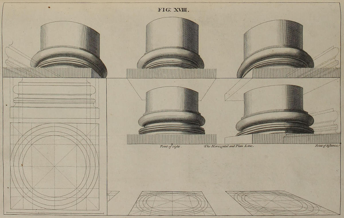
FIG. XVIII.
Optica delineatio basis Ionicæ.
Ex multitudine ac varietate figurarum hujus Operis, disces, mi Lector, modum deformandi res demissas & sublimes, magnas & parvas. In hac figura, linea cui bases duarum columnarum incumbunt, est conjunctim linea plani, & linea horizontalis; linea cui bases trium columnarum incumbunt, est altior linea horizontali. Quemadmodum autem, si linea plani sit inferior linea horizontali, lineæ quæ tendunt ad punctum oculi & ad punctum distantiæ, ascendunt sursum; ita si linea plani sit superior horizontali, lineæ quæ veniunt ad punctum oculi & ad punctum distantiæ, tendunt deorsum. Quòd si in eadem tabula sint plura plana, eorumque aliqua sint altiora, alia verò demissiora linea horizontali, lineæ omnes planorum, ac linea horizontalis, sunt invicem parallelæ; adeoque ex linea, quæ omnes eas normaliter secet, statim dignosci potest, in qua proportione, singula plana sint altiora vel profundiora linea horizontali. Velim quoque observes, latitudinem columnæ mediæ, minorem esse latitudine columnarum lateralium; & discrimen inter hujusmodi latitudines eò est majus, quò punctum distantiæ fuerit vicinius puncto oculi. Quæ dicta sunt de columnis, intelligere oportet de basibus, & de optica delineatione ambarum. Nihilominus, si figura ex debito puncto inspiciatur, columnæ pictæ habebunt eandem apparentiam, quam haberent columnæ solidæ, invicem æquales.
The Ionick Base in Perspective.
By the Multitude and Variety of Figures in this Work, the Reader will be instructed in delineating things, however different in Size or Situation. In this Figure, the Line on which the two Columns rest, is both the Horizontal and the Ground-line; that on which the three Columns are plac’d, is so much higher than the Horizontal Line. And as, where the Ground-line is beneath the Horizontal, the Lines drawn to the Points of Sight and Distance tend upwards; so, where the same is above the Horizontal, the Lines to the Points of Sight and Distance tend downwards. If in the same Picture there are different Grounds, some higher, others lower than the Horizontal Line; yet are all those Ground-lines, and the Horizontal, parallel one to another; and therefore, by a Line cutting them all perpendicularly, you presently know in what proportion each Plan or Ground is higher or lower than the Horizontal. I would have you observe, That the Breadth of the middle Column is, by the Perspective, render’d less than that of the Side-Columns; and that this Difference is the greater, as the Point of Distance approaches nearer to the Point of Sight. What has been said of the Columns, is also to be understood of the Bases, and the Projections of all their Parts in Perspective: Nevertheless, if the Picture be view’d from its due Place, the Columns will have the same Effect, as if solid; and all appear equal one to the other.
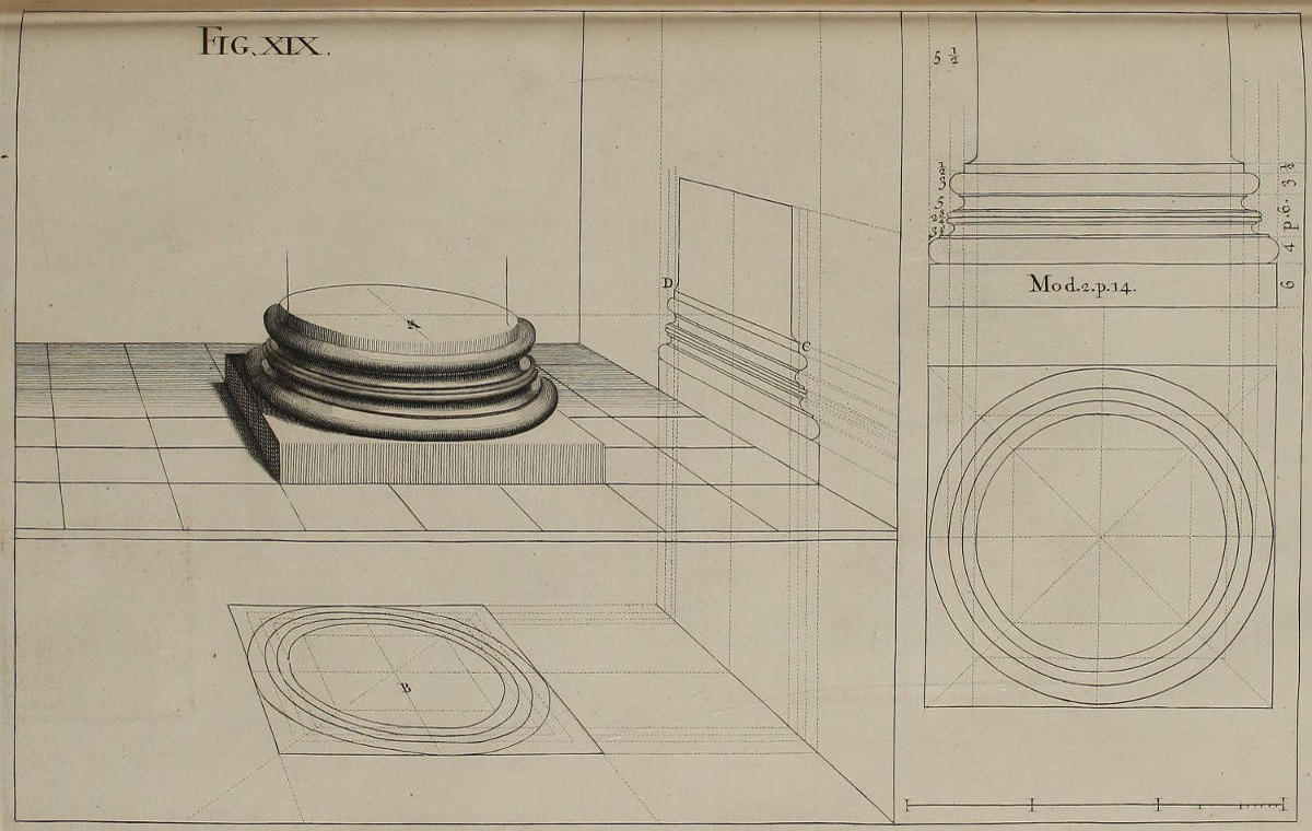
Fig. xix.
Optica imminutio basis Corinthiæ.
Hæc basis juxta regulas traditas opticè contracta est. Porrò altitudo superficiei A est eadem cum altitudine lineæ visualis CD; latitudo crucis A est eadem cum latitudine crucis secundi circuli vestigii B, incipiendo à minimo omnium. Duæ lineæ normaliter infixæ basi, ostendunt maximam latitudinem quam habere debet columna supra imum scapum. Maxima latitudo tori superioris & utriusque astragali, est eadem cum maxima latitudine tertii circuli. Maxima latitudo tori inferioris est eadem cum maxima latitudine ultimi circuli.
The Corinthian Base in Perspective.
This Base is put in Perspective by the Rules before laid down. The Height of the Superficies A is the same with that of the visual Line CD; the Breadth of the Cross A is the same with that of the second Circle of the Plan B, beginning with the least. The two Lines that stand perpendicularly on the Surface of the Base, shew the greatest Breadth of the Columns Shaft above the Fillet. The Extent of the upper Torus and the two Astragals, is the same with that of the third Circle; and the Extent of the lower Torus is the same with that of the outward Circle.
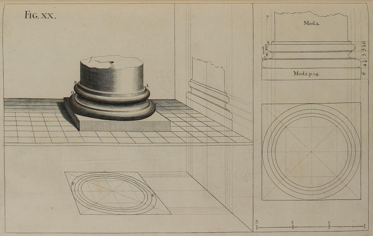
Fig. xx.
Basis Acticurga opticè imminuta.
Basis Acticurga Pictoribus præ reliquis familiaris est, quia cum omnibus ferè Ordinibus egregiè consentit. Porrò ex punctis E & F maximæ utrinque latitudinis extimi circuli vestigii, habetur maxima latitudo tori inferioris CD. Ac cætera quæ spectant ad ipsum & ad torum AB, petenda sunt ex dictis de basi Etrusca.
The Attick Base in Perspective.
The Attick Base is more frequently made use of by Painters, than any other; because it suits well with most of the Orders. The Points E and F, the greatest Breadth of the outward Circle of the Perspective-Plan, give the greatest Breadth of the lower Torus CD. And whatever else relates either to this or the upper Torus AB, is to be sought in the same Manner, as has been shewn in the Tuscan Base.
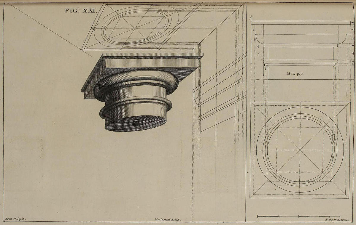
FIG. XXI.
Optica imminutio capitelli Etrusci.
Eâdem cum reliquis formâ, eâdemque methodo capitella delineanda sunt: quum habeant ipsa quoque suum cimatium quadratum, & sint rotunda. Linea plani solet in iis fieri altior lineâ horizontali: quia quum capitella imponenda sint columnis homine altioribus, plerumque apparent sublimiora nostris oculis.
The Tuscan Capital in Perspective.
The Manner before deliver’d concerning Bases, is of the same Use in delineating Capitals; forasmuch as these also have their square Abacus, and their round Members. The Ground-line in Capitals is usually plac’d above the Horizon; because when they are set upon Columns which exceed a Man’s Height, they are generally represented above the Eye.
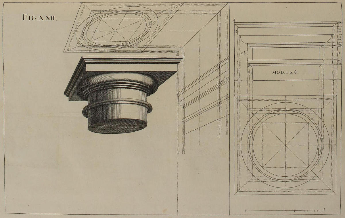
Fig. xxii.
Optica projectio capitelli Dorici.
Capitellum hoc pluribus membris constat, adeóque operosius est quàm præcedens. Nihilominus accurata delineatio vestigii geometrici omnes difficultates complanabit.
The Projection of a Dorick Capital, in Perspective.
This Capital consisting of more Members than the foregoing, will be more troublesom to put in Perspective; but an accurate Delineation of the Geometrical Plan will certainly remove many seeming Difficulties.
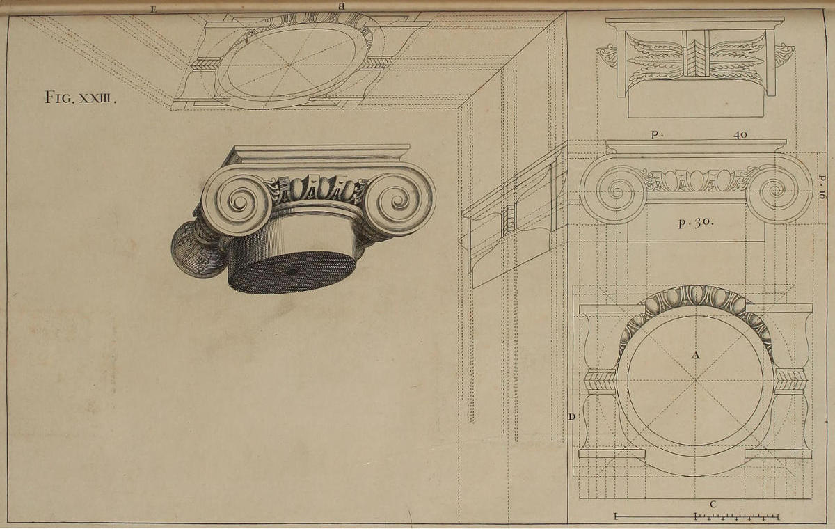
Fig. xxiii.
Deformatio capitelli Ionici.
Capitellum Ionicum poscit duas elevationes geometricas distinctas, alteram faciei, alteram lateris; ex iisque conflatur vestigium geometricum A, quod opticè contrahitur, translatis in B punctis latitudinis C, & in E punctis longitudinis D more consueto: ut ex punctis B latitudinis, lineæ tendant ad punctum oculi; ex punctis verò E longitudinis, lineæ tendant ad punctum distantiæ.
Ex vestigio capitelli opticè contracto eruenda est elevatio longitudinis ut in figura. Ex utrisque verò juxta morem fiet capitellum nitidum, acceptis latitudinibus ex vestigio, altitudinibus ex elevatione longitudinis. Hæc quoque dabit maximam latitudinem singularum volutarum.
Modum delineandi capitellum Ionicum, in quo helices volutarum obliquentur, dabimus infra figurâ trigesimâ.
The Ionick Capital in Perspective.
The Ionick Capital requires two distinct geometrical Elevations, one of the Front, the other of the Side; from both which is found the geometrical Plan A, which is put in Perspective by transferring into B the Points of Breadth C, and into E the Points of Length D, after the usual Manner; that from the Points of Breadth B, Lines may be drawn towards the Point of Sight; and from the Points of Length E, towards the Point of Distance.
From the Plan of the Capital in Perspective, is to be drawn the Upright of the Length, as in the Figure; and from both, as usual, the finish’d Capital is wrought, by taking the Breadths from the Plan, and the Heights from the Elevation; this giving the utmost Height, and that the utmost Breadth of each of the Volutes.
The Manner of describing the Ionick Capital, whose Volutes lie obliquely, we shall hereafter treat of in the Thirtieth Figure.
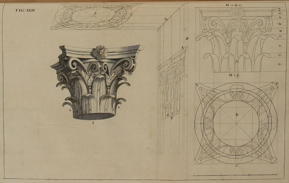
FIG. XXIV.
Optica projectio capitelli Corinthii.
Capitellum Corinthium absolvere non poteris, nisi elevatione geometrica ejusque vestigio exactissimè delineatis juxta regulas Barozzii.
Ad formandum ex vestigio B vestigium E, rectis occultis fient quadrata necessaria ad contractionem opticam quatuor vel trium saltem circulorum; translatis in lineam D divisionibus lineæ C, & aliis, more consueto. Contrahentur deinde lineis occultis vestigia foliorum, & absolventur cætera quæ posita sunt in vestigio E.
Ut fiat optica elevatio longitudinis F, in lineam perpendicularem H transferentur ex elevatione A omnes ejus divisiones. Complebitur autem per lineas rectas, quæ ex punctis divisionum ducantur ad punctum oculi, ac per rectas ex circulorum summitate ac profunditate, quæ rectæ sint parallelæ ad lineam D, ac perveniant ad visualem G; indeque descendant, ac sint parallelæ ad lineam perpendicularem H.
Capitellum nitidum exordieris ab infimo circulo I, ostendente ambitum columnæ. Succedent folia 1, 2, quorum latitudines accipientur ex vestigio E per circinum, positâ unâ ejus cuspide in linea H; altitudines verò accipientur ex elevatione F, posita una cuspide circini in linea D. Idipsum dico tum de foliis 3, 3, 4, 4, tum de folio 5, ac de aliis, & demum de cymatio. Descensus verò lineæ curvæ ipsius cymatii incipiet ex acie L.
The Corinthian Capital in Perspective.
There is no Completing the Corinthian Capital, unless you most accurately describe its Geometrical Elevation and Plan, according to the Rules of Vignola.
Being to form the Plan E from the Plan B, you must, with occult Lines, make the Squares necessary for bringing four, or at least three of the Circles into Perspective; transferring into the Line D the Divisions of the Line C, and the rest as usual. Then, with other occult Lines, contract the Plans of the Leaves, and finish what’s farther requisite in the Plan E.
To make the Optick Elevation of the Length F, you must transfer into the Perpendicular H all the Divisions of the Elevation A; and complete the same, by Lines drawn toward the Point of Sight, till they meet their respective Perpendiculars; which proceeding from all parts of the Circles parallel to the Line D, intersect the Visual G; from whence they descend, Parallels to the Perpendicular H.
In working the clean Capital, you should begin with the lowest Circle I, which denotes the Compass of the Column. Then make the Leaves 1, 2, by taking their Breadths from the Plan E, with the Compasses, and keeping one Point of them upon the Line H; and their Heights from the Elevation F, keeping one Point on the Line D. The same must be done, as well by the Leaves 3, 3, 4, 4, as by the Leaf 5, and the others; and last of all, by the Abacus also; the Sinking of the Horns whereof answers that of the visual Line L.
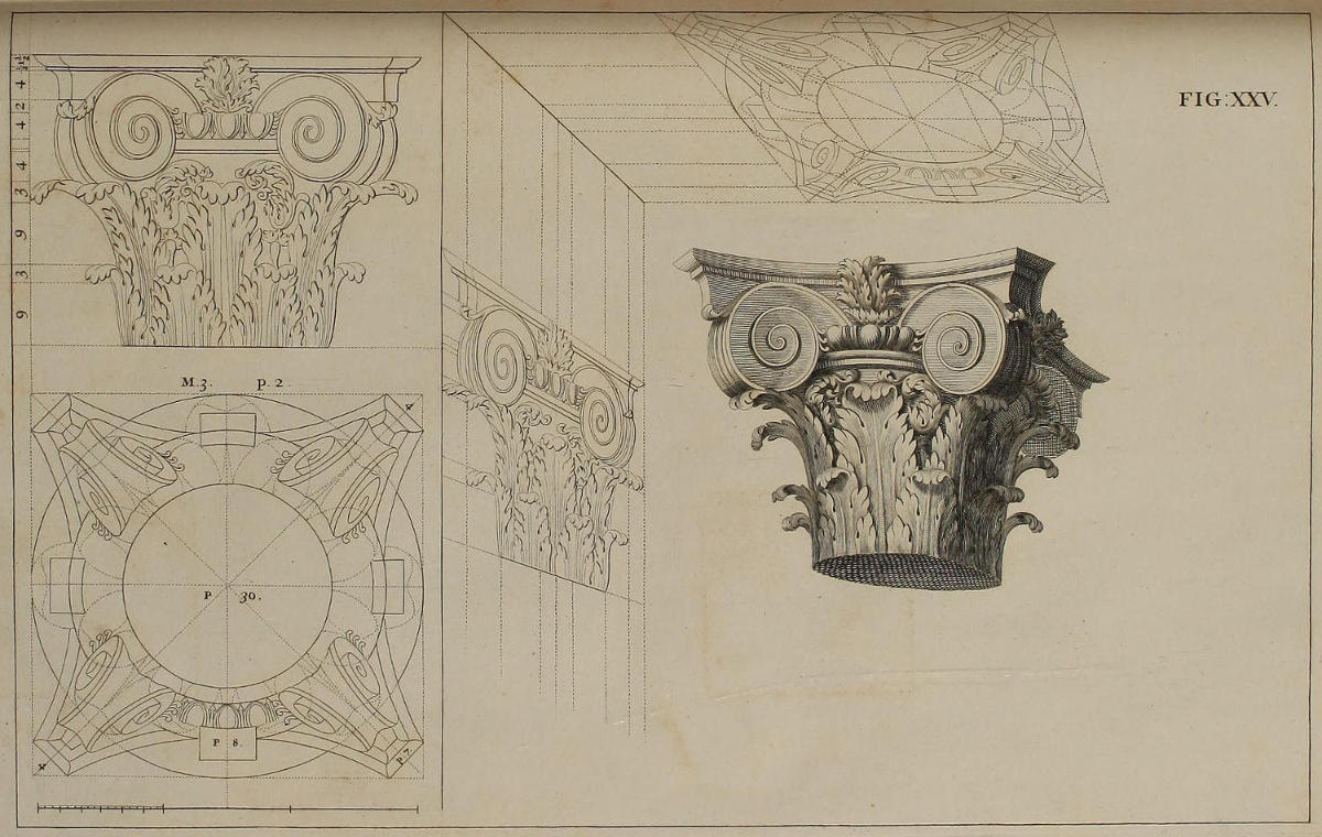
FIG. XXV.
Optica descriptio capitelli Compositi.
Ex iis quæ diximus de capitello Corinthio, didiceris modum faciendi capitellum Compositum. Velim autem tibi persuadeas, cum lectione harum regularum quæ sunt magistri inanimes, circini usum perpetuò conjungi oportere. Hic enim vivi magistri defectum unicè supplere potest.
The Composite Capital in Perspective.
From what has been said of the Corinthian Capital, may be learnt the Manner of putting the Composite also into Perspective. I wish I could prevail with you, that to the Reading of the Rules, which in themselves are but lifeless Masters, you would constantly add a diligent Practice of the Figures by the Compasses; this being the only way to supply the Want of a living Master.
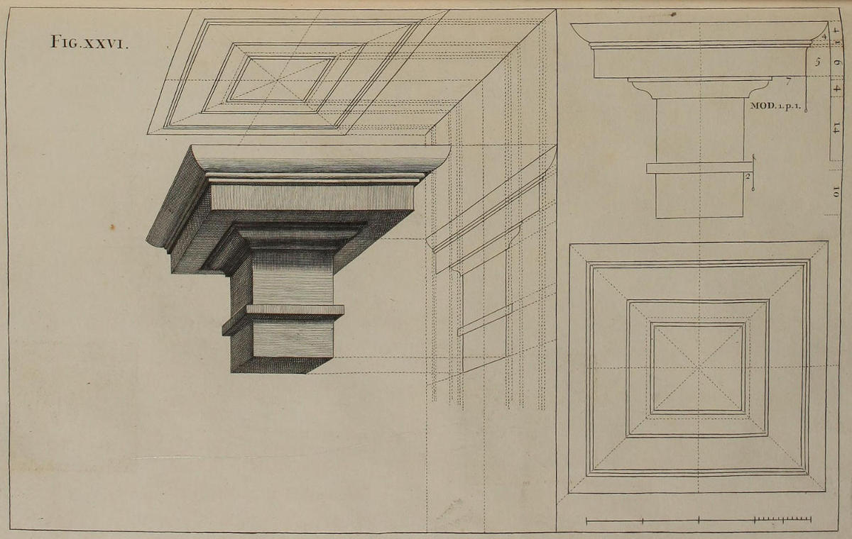
Fig. xxvi.
Deformatio coronicis Etruscæ.
Post capitella sequuntur coronices, quæ utpote quadratæ, minimam habent arduitatem. Inter coronices verò, nulla est Etruscâ simplicior ac facilior. Ex elevatione geometricâ, more solito, formatur vestigium geometricum; ex eoque opticè contracto eruitur similis elevatio longitudinis. Demùm ex elevatione & vestigio componitur coronix nitida. Memineris autem duas esse lineas, quæ hinc inde terminant latitudinem elevationis opticæ. Linea quæ altior est, dat altitudinem anterioris faciei coronicis, alia quæ est depressior, dat altitudinem faciei posterioris. Et ita erit in posterum.
The Tuscan Entablature in Perspective.
After Capitals we proceed to Entablatures, which because they are square, are less difficult than the former. And of all Entablatures, that of the Tuscan Order is the most simple and easie to be put in execution. From the Geometrical Upright is drawn, as usual, the Geometrical Plan; from the Plan put in Perspective is describ’d the Optick Elevation of the Length; and from both the latter is wrought the clean Entablature requir’d. You may observe, here are two Lines that terminate the Breadth of the Perspective on one side and the other. The Line which proceeds from the higher Corner of the Visual, gives the Height of the most advanc’d Part; that from the lower determines the Height of the Back-part. And so for the future.
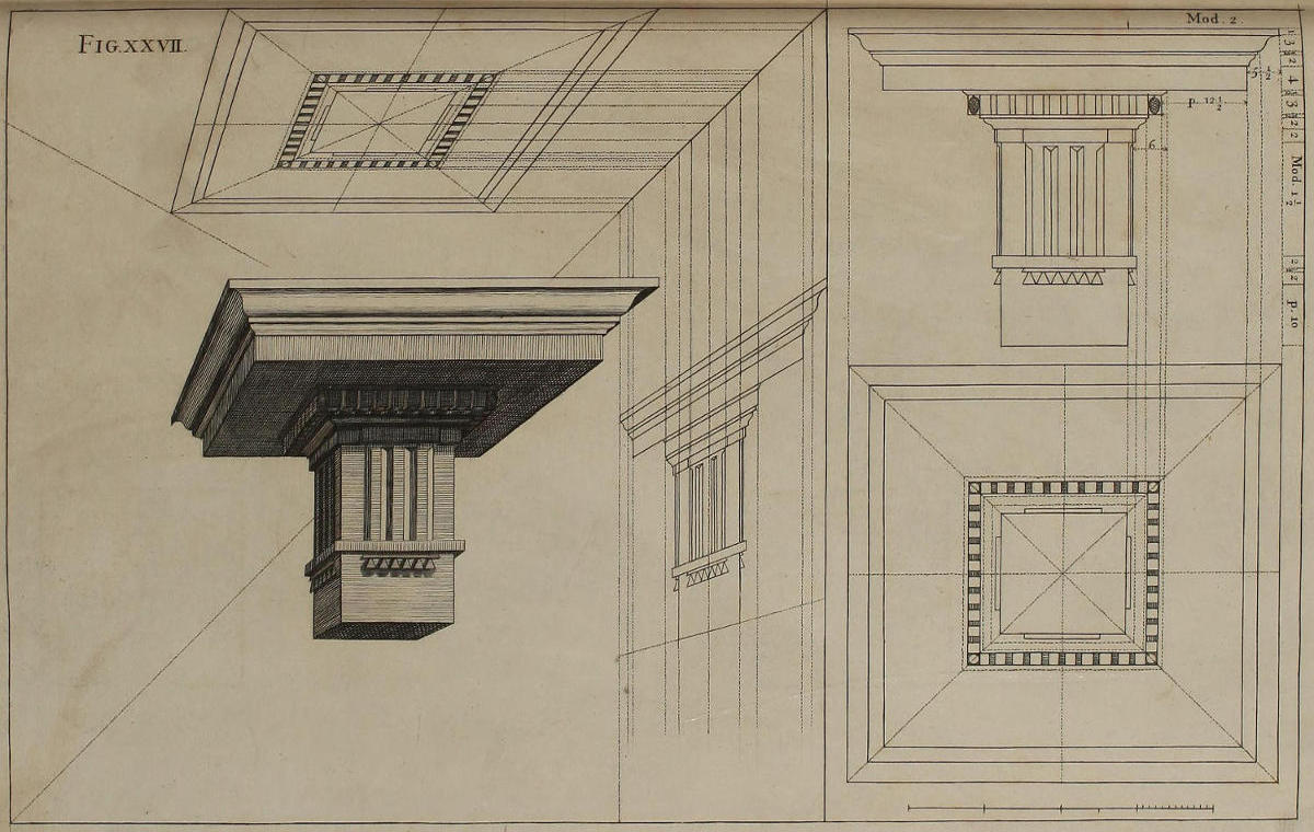
Fig. xxvii.
Optica delineatio coronicis Doricæ.
In faciendâ coronice Doricâ, quæ majorem operam poscit, ob denticulos & triglyphos; communis regula servanda est. Si autem libeat coronicem nitidam describere in papyro separatâ ab ejus præparationibus, id profectò licet, tum in hoc, tum in quocunque alio schemate.
The Dorick Entablature in Perspective.
In making the Dorick Entablature, which has something more Work in it than the former, on account of its Dentels and Triglyphs; the common Rule is to be observ’d. And if you would delineate the finish’d Entablature in a Paper distinct from that of its Preparations, you are at liberty so to do, either in this or any other Figure.
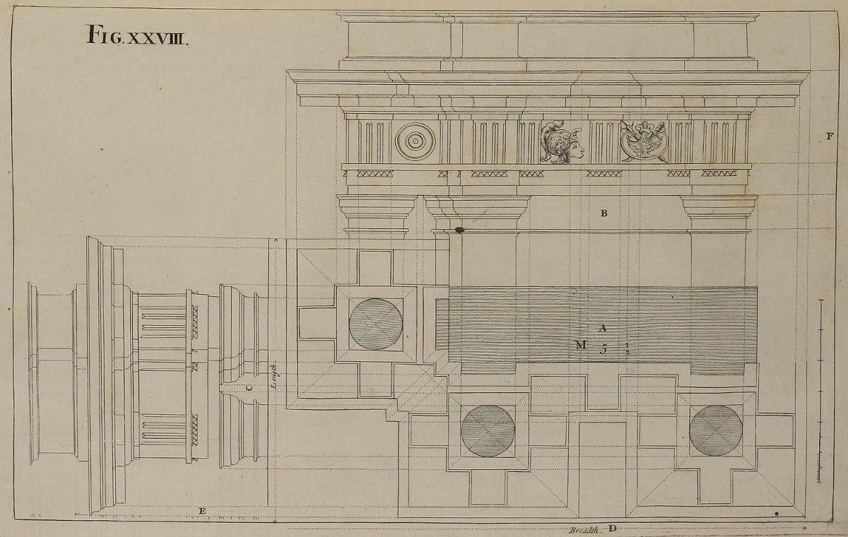
Fig. xxviii.
Præparatio figuræ sequentis.
In figurâ vigesimaoctavâ, quæ continet vestigium & elevationes geometricas figuræ vigesimænonæ, oportuit latus C delineare seorsim à facie B; quia facies exhibet latitudinem ædificii, latus verò exhibet longitudinem; atque una non est alteri æqualis. In vestigio geometrico solidus paries est A: circuli referunt summum scapum columnarum. Cætera dant projecturas coronicis, cum suis mutulis.
Preparatory to the following Figure.
In this Twenty-eighth Figure, which contains the Plan and Geometrical Elevations of the Twenty-ninth Figure, it was requisite to delineate the Side C separately from the Front B; because the Front, which signifies the Breadth of the Building, and the Side, which shews its Length, are not equal one to the other. In the Geometrical Plan the solid Wall is A: the Circles express the Nakeds of the Pillars Shafts at top. The rest is the Projecture of the Cornice, with its Mutules.
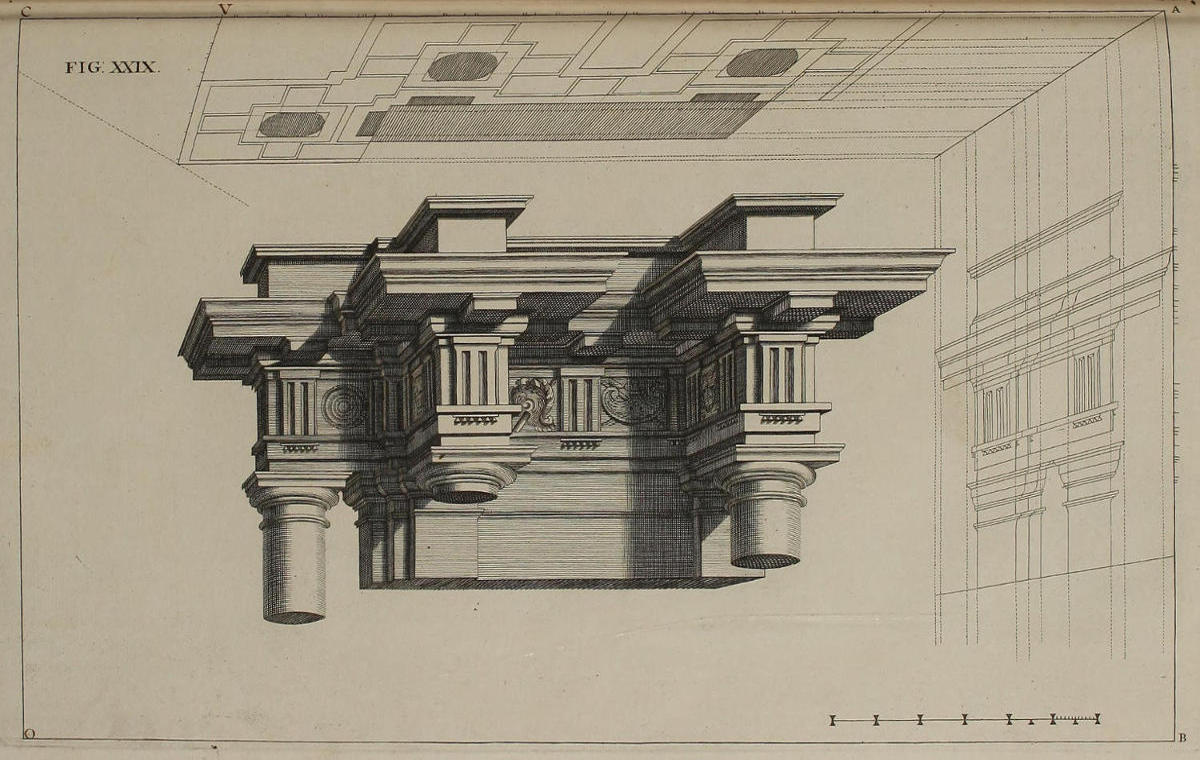
FIG. XXIX.
Optica projectio ædificii Dorici.
Habes in hac figura vigesimanona, opticam delineationem vestigii, & unius ex elevationibus figuræ vigesimæoctavæ; nimirum, elevationis longitudinis; ex quibus eruitur imago nitida ædificii Ordinis Dorici, cum summitatibus & capitellis trium columnarum; ejusque epistylium, zophorus, & corona.
BO est linea horizontis; AC est linea plani; in quam, ex lineis D & C figuræ vigesimæoctavæ, transferuntur puncta latitudinis & longitudinis duarum elevationum; prolongando versus C ipsam lineam plani, ut oportet. Operaberis autem, ut diximus figurâ vigesimatertia; nimirum, in puncto V desinet latitudo vestigii, incipiet longitudo; & ex punctis latitudinis lineæ tendent ad punctum oculi; ex punctis longitudinis lineæ occultæ tendent ad punctum distantiæ. Ubi verò hæ lineæ secant visualem VO, fient parallelæ ad lineam AC, cum cæteris quæ necessaria sunt ad complendam delineationem opticam vestigii.
Elevatio C figuræ vigesimæoctavæ opticè contrahetur more consueto, translatis in lineam AB divisionibus lineæ E vel F, ex quibus fient visuales ad punctum oculi; ac demissis ex linea visuali AO perpendicularibus ad lineam AC, ita ut lineæ parallelæ ad lineam plani AC continuentur cum aliis lineis parallelis ad lineam AB.
Hic quoque locum habet observatio illa, cujus meminimus figura vigesimasexta, de lineis quæ deorsum excurrunt, & hinc inde terminant membra elevationis opticæ. Ex iis autem desumuntur projecturæ omnes coronicis & capitellorum.
A Projection of the Dorick Order in Perspective.
In this Twenty-ninth Figure, you have in Perspective the Plan, and one of the Uprights of the Twenty-eighth Figure; namely, that of the Length; from whence is drawn this finish’d Piece of the Dorick Order, which has the upper Part and Caps of three Pillars, with their Architrave, Freeze, and Cornice.
BO is the Horizontal-line; AC that of the Plan; into which, from the Lines D and C of the Twenty-eighth Figure, are transferr’d the Points of Breadth and Length of the two Elevations; first prolonging the Line itself, as much as is needful, through C. The Work is then perform’d, as was shewn in the Twenty-third Figure; namely, the Divisions of the Breadth of the Plan end in the Point V, at which those of Length begin. From the first, Lines are drawn to the Point of Sight; and from the latter, occult Lines are directed to the Point of Distance: And where these cut the Visual VO, Lines are drawn parallel to AC; with those that are farther necessary for completing the Plan in Perspective.
The Elevation C of the Twenty-eighth Figure is put in Perspective, as usual, by transferring the Divisions of the Line E, or F, into that of AB in this Plate; from whence drawing Visuals to the Point of Sight, they are intersected by Perpendiculars let fall from those Divisions of AO made by the Parallels to the Ground-line AC, and again continu’d parallel to the Perpendicular AB.
The Observation, mention’d in the Twenty-sixth Figure, is also pertinent in this place; That the Lines, which, in the Perspective-Elevation, tend downward, give the Advance and Recess of the several Members of the Work; and from them are taken all the Projectures of the Entablature and Capitals.
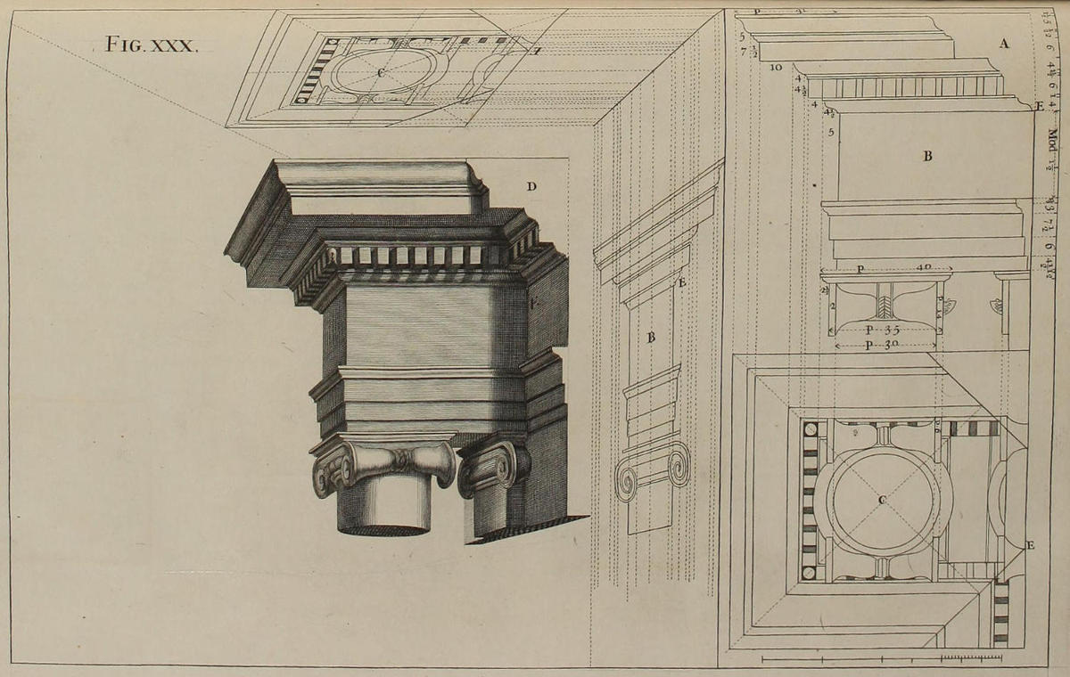
Fig. xxx.
Optica projectio ædificii Ionici; ubi de modo jungendi fictum cum vero.
Si tibi Pictor quum sis, occasione apparatûs quadraginta horarum, vel sepulcri Domini, mutare ad tempus libeat formam architecturæ alicujus Ecclesiæ jungendo fictum cum vero, ut mihi sæpius contigit Mediolani ac Romæ, cum ingenti spectatorum delectatione & admiratione; paucis ostendam tibi modum quem servare debeas in operando.
Sectio coronicis veræ, quæ, ut suppono, videri debet continua esse cum coronice picta in telario, est A; elevatio geometrica coronicis, & reliquorum quæ delineanda sunt, est B; vestigium geometricum est C. Porrò, tum vestigium tum elevatio longitudinis opticè contrahentur more consueto, ut vides in C & B: ex iisque formabitur in telario coronix nitida cum columna & anta; ipsumque telarium depictum, normaliter coagmentandum erit veræ coronici.
Ut fiat ea pars longitudinis, quæ coronicem pictam continuare videatur cum vera, & erui non potest ex elevatione deformata; oportet sectionem A transferre in D, ducendo visuales ex punctis terminativis membrorum sectionis D, usque dum occurrant lineis latitudinis eorundem membrorum. Quod si colores in telarium scitè inducantur, angulus in E, quamvis merè depictus, videbitur verus; & ex adverso, anguli quos telarium ipsum depictum facit cum diversis adeò crepidinibus coronicis veræ, nusquam apparebunt, præterquàm in quadra simæ dumtaxat; & unio architecturæ veræ cum ficta dignosci non poterit.
An Ionick Work in Perspective; with the Manner of reconciling the fictitious to the solid Architecture.
If, being a Painter, you were requir’d, against the Solemnity of the Holy-Week, to alter for a while the Architecture of some Altar-piece, by joining Painting to the real Work; as I have often done, both at Rome and Milan, to the great Satisfaction and Surprize of the Beholders: I shall briefly shew the Method to be observ’d in performing the same.
The Dissection of the solid Cornice, which I here suppose shall appear continu’d in that painted on the Canvass, is A; the Geometrical Elevation of the Cornice, and other Parts to be drawn, is B; the Geometrical Plan is C. The Plan and Elevation of the Length are put in Perspective after the usual manner, in C and B; from those the finish’d Cornice, with the Pillar and Pilaster, are delineated on the Canvass; and the Picture is then conjoin’d, at right Angles, to the true Cornice.
For adjusting the Members so, that the painted Cornice may seem to be the real one continu’d, (which can’t be done by the Perspective Upright) you must transfer the Section A to D; and from the terminating Points of the several Members thereof, draw visual Lines, till they meet those of their respective Members in the Perspective. And if the Colours are laid by a skilful Hand, the Angle at E, tho’ painted only, will appear as real; and on the contrary, the Angles which the Members of the painted Cornice make with the different Projectures of those of the true, will never be discern’d, unless in the very uppermost Fillet; but the Conjunction of the real with the painted Architecture, will be altogether imperceptible.
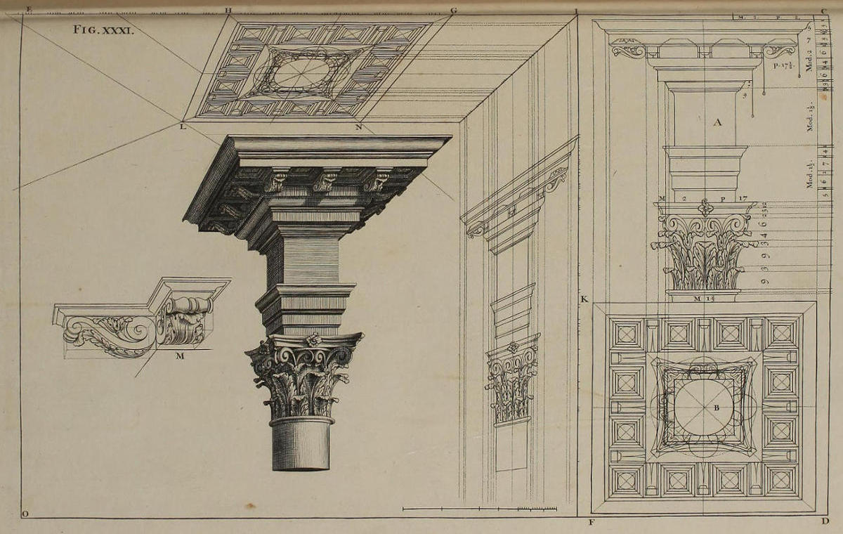
Fig. xxxi.
Optica projectio coronicis Corinthiæ, cum capitello & summitate columnæ.
In hoc schemate linea plani est CIE, horizontis est DFO; punctum oculi est O, distantiæ est D. Elevatio geometrica capitelli Corinthii cum sua coronice est A, quorum divisiones cernuntur in perpendiculari CD. Vestigium geometricum B habet longitudinem æqualem latitudini: opticè autem contrahitur methodo consueta. Nimirum, translatis divisionibus latitudinis & longitudinis in lineam plani CIE; ex punctis latitudinis fiunt visuales ad punctum oculi; ex punctis verò longitudinis fiunt occultæ ad punctum distantiæ: hoc modo habes quicquid necessarium est ad contractionem opticam vestigii. Nam lineæ longitudinum sunt partes visualium, ut patet in GN, HL: lineæ latitudinum, parallelæ ad lineam plani fiunt ex punctis in quibus lineæ tendentes ad punctum distantiæ secant visualem HO, ut vides in NL. Porro, si tantundem prolongaretur horizontalis DO, ita ut haberet duo puncta distantiæ remota æqualiter ab O, medietas diagonalium, quæ sunt in quadrato majori GNLH opticè deformato, & in quadratis ejus minoribus, tendent ad unum punctum distantiæ; altera medietas ad aliud punctum distantiæ.
Elevatio longitudinis opticè contrahitur ductis parallelis ad CE, quæ ubi pervenerint ad visualem IO, continuentur cum aliis parallelis ad IK. Præterea, translatis in lineam IK divisionibus lineæ perpendicularis CD, ex punctis divisionum fiunt visuales ad punctum oculi, ac ducuntur singula membra ipsius elevationis, cujus latitudines sunt partes visualium, altitudines verò sunt partes linearum parallelarum ad IK. Demùm ex vestigio & ex elevatione longitudinis, formatur coronix nitida cum capitello. Ut autem faciliùs delineentur mutuli, primùm fient quadratâ formâ, ut in M; deinde congruus flexus in singulos inducetur.
The Optick Projection of a Corinthian Cornice, with the Capital and PART of the Column.
In this Figure the Line of the Plan is CIE, that of the Horizon is DFO; the Point of Sight is O, the Point of Distance D; the Geometrical Elevation of the Corinthian Capital, with its Entablature, is A; whose Divisions are seen in the Perpendicular CD. The Length and Breadth of the Geometrical Plan B are equal, and the Plan is put into Perspective after the usual Method; to wit, by transferring the Divisions of Breadth and Length into the Line CIE; from the Points of Breadth drawing Visuals to the Point of Sight; and from those of Length occult Lines to the Point of Distance: by which Intersections you have all that’s necessary for putting the Plan into Perspective. For the Lines of Length are Parts of visual Rays, as is manifest by GN, HL; and the Lines of Breadth are made Parallels to the Ground-line, from the Intersections before-mention’d, as is seen in NL. Moreover, if the Horizontal-line DO were so prolong’d, as to receive another Point of Distance equidistant from O; half the diagonal Lines of the great Square GNLH, and of the lesser Squares contain’d therein, would tend to one Point of Distance, and the other half to the other.
The Elevation of the Length is put in Perspective, by continuing the Parallels to CE, till they cut the Visual IO; and from thence dropping Lines parallel to IK: Then transferring into IK the Divisions of the Perpendicular CD, from them make visual Lines to the Point of Sight, and draw the several Members of the Upright; whose Breadths are Parts of Visuals, and their Heights Parts of Perpendiculars, or Lines parallel to IK. Lastly, from the Plan and Elevation of the Length, you delineate the finish’d Cornice and Capital: But that you may more easily draw the Modillions, first make them in a square Form, as in M; and that will very much assist you to give the Scroll of each a more agreeable Turn.
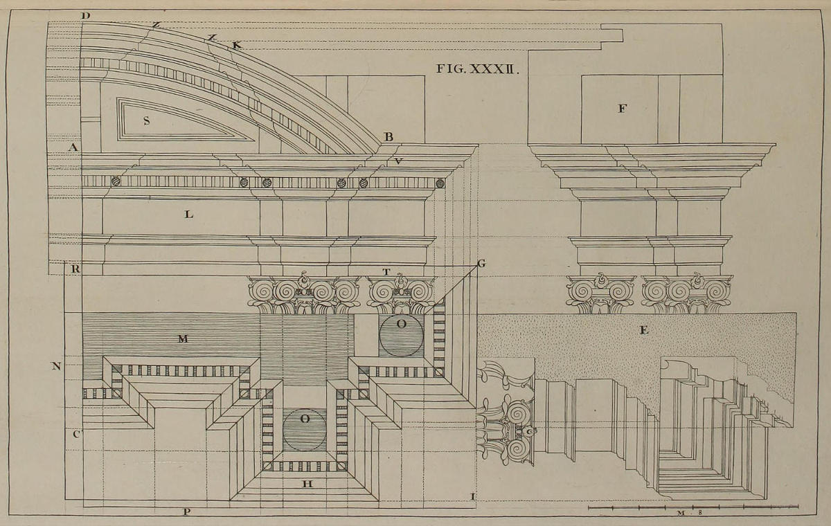
FIG. XXXII.
Delineatio geometrica coronicis, Ordinis Compositi.
Ut hoc schema grandius ac distinctius esset, ejus medietatem dumtaxat suscepi delineandam. PN est vestigium geometricum. M est solidus paries. OO spatia columnarum. In H sunt crepidines coronicis. Elevatio geometrica latitudinis ædificii constat epistylio T, zophoro L, & coronâ V, supra quam eminet fastigium S.
Jam ut inveniatur centrum arcuum, distantiæ AV fiat æqualis distantia AC. Positaque una cuspide circini in C, alia extendatur usque ad V: ita fient arcus, quorum ultimus est BD, omnesque sunt concentrici. Elevatio F ostendit longitudinem ædificii ex parte GI; elevatio E ostendit longitudinem ipsius ex parte DR.
The Geometrical Design of a Cornice, of the Composite Order.
That this Figure might be larger and more distinct, I have here describ’d only the Half of it. PN is the Geometrical Plan. M is the solid Wall. OO are the Places of the Columns. H shews the Projectures of the Cornice. The Geometrical Elevation of the Breadth of the Frontispiece, consists of the Architrave T, the Freeze L, and the Cornice V, over which is rais’d the Pedament S.
For finding the Center of the arch’d Lines of the Pedament, make the Distance AC equal to that of AV; and placing one Point of the Compasses in C, extend the other to V, and describe the Arch. The other Arches, of which BD is the utmost, have all the same Center. The Elevation F shews the Length of the Work on the Side GI. The Upright E shews the Length of the same on the Front DR.
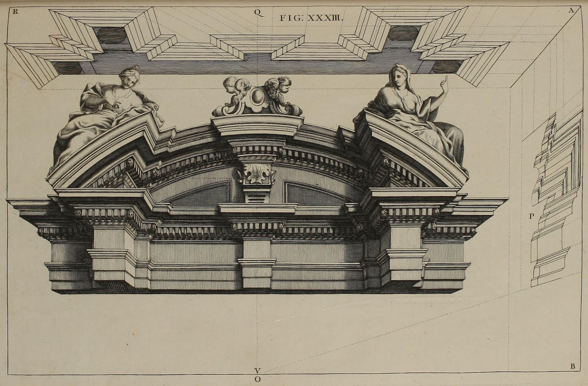
FIG. XXXIII.
Deformatio coronicis Compositæ.

Figura hæc trigesimatertia minus ardua tibi videbitur, si ex ea delineandam primùm suscipias medietatem quæ respondet vestigio PN & elevationi BR figuræ trigesimæsecundæ; rejecto in ultimum fastigio, postquàm cætera compleveris. Linea BV est horizontalis. Punctum oculi est V, punctum distantiæ remotum est ab V spatio BV, additis modulis quatuordecim cum dimidio. Linea plani est AR, in quam ex Q versus A transfertur latitudo P; ex Q versus R transfertur longitudo N, cum omnibus earum divisionibus; ut ex punctis latitudinis fiant visuales ad punctum oculi; & ex punctis longitudinis fiant occultæ ad punctum distantiæ. Ex his habes quicquid necessarium est ad projectionem opticam vestigii, ut ostendimus figurâ trigesimaprimâ. Eademque methodo, quam ibi servavimus, contrahes elevationem P longitudinis coronicis: ac tum ex illa, tum ex vestigio, eruetur coronix nitida more consueto.
Ut delineetur fastigium, transferendæ sunt in lineam AB divisiones ipsius ex elevatione F figuræ trigesimæsecundæ, ac ducendæ visuales ad punctum oculi, additis lineis terminativis uniuscujusque membri, quæ accipientur ex vestigio Q opticè deformato. Centrum O arcuum fastigii nitidi, remotum est à summitate coronicis, medietate distantiæ, quam habent ungues quadræ cui fastigium ipsum incumbit. Ac proinde, si accipias ex elevatione P diversas altitudines membrorum fastigii; latitudines verò accipias ex vestigio Q; opus tuum feliciter absolves.
A Composite Cornice in Perspective.
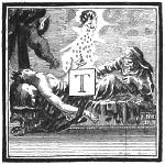
This Thirty-third Figure will be found the less difficult, if you first attempt that Half which answers to PN in the Plan, and BR in the Upright of the Thirty-second Figure; leaving the Pedament, till all the rest be finish’d. The Line BV is the Horizontal. V is the Point of Sight; the Point of Distance is fourteen Modules and a half without the Point B, more than the Interval BV. The Line of the Plan is AR, in which from Q toward A you have the Divisions of Breadth of the foregoing Plan P; and from Q to R those of the Length thereof N: From the former, Visuals are drawn to the Point of Sight; and from the latter, occult Lines to the Point of Distance. And from these you have all that’s necessary for putting the Plan in Perspective; as was shewn in the Thirty-first Figure. By the Method there observ’d, you may also describe the Perspective-Elevation of the Length P; and from this, and the Plan, delineate the finish’d Cornice after the usual Manner.
For making the Pedament, the Divisions of the Elevation F in the Thirty-second Figure, must be transferr’d into the Line AB, and Visuals drawn from them to the Point of Sight; giving to each Member its proper Out-line and Contour, as may be taken from the Perspective-Plan Q. The Center O of the Arches in the finish’d Pedament, is plac’d below the upper Member of the Cornice, as much as half the Extent of the upper Fillet from whence the Pedament springs. And by taking the several Heights of the Members thereof, from the Elevation P; and the Breadths from the Plan Q; you will successfully finish and complete your Work.
Fig. xxxiv.
Præparatio ad figuram trigesimamquintam.
Si placuerit conferre figuram trigesimamtertiam cum præsenti figura trigesimaquarta, dignosces vestigium & elevationem coronicis Compositæ alio modo hic deformari, mutando scilicet longitudinem in latitudinem, & latitudinem in longitudinem. Propterea hæc figura tantum spatii occupat, ut eam seorsim à coronice nitida delineare oportuerit.
Divisiones latitudinis in vestigio incipiunt ex V versus R, & sunt eædem cum divisionibus rectæ IG figuræ trigesimæsecundæ. Divisiones longitudinis incipiunt ex V versus S, & sunt eædem cum divisionibus rectæ IP duplicatis. Ex divisionibus latitudinis fiunt visuales ad punctum oculi; ex divisionibus longitudinis fiunt rectæ ad punctum distantiæ; cum reliquis quæ necessaria sunt ad complendum vestigium AVDC.
Elevatio longitudinis coronicis & fastigii, opticè contrahitur per lineas parallelas ad lineam plani AS; quæ ubi pervenerint ad visualem AC, continuentur cum aliis parallelis ad perpendiculum P, ut diximus figurâ trigesimaprimâ. In idem perpendiculum P transferuntur ex figurâ trigesimasecundâ divisiones rectæ DR; & insuper altitudines, quas puncta KXZ habent supra rectam VA; fientque visuales ad punctum oculi: sectiones autem visualium cum parallelis ad perpendiculum P, dabunt sex puncta simæ fastigii, respondentia punctis KXZ duplicatis, figuræ trigesimæsecundæ; earumque ductu formandus est supremus arcus. Eodem artificio fient reliqui omnes.
Faciliùs delineabitur coronix, cujus maximam partem occupant lineæ visuales ad punctum oculi: porrò, membra omnia, exceptâ simâ, communia sunt coronæ & fastigio. Adeoque puncta similia in lineis terminativis membrorum singulorum, ex quibus desumuntur crepidines & ungues figuræ nitidæ, sunt parallela ad perpendiculum P.
Preparatory to the Thirty-fifth.
If you please to compare the Thirty-third Figure with this Thirty-fourth Figure, you will perceive the Plan and Elevation of this Composite Cornice to be delineated differently from that; to wit, by making the Length of that the Breadth of this, and the Breadth of that the Length of this: On which account, this Figure takes up so much Room, that there was a necessity of drawing the finish’d Cornice on a separate Paper.
The Divisions of Breadth in the Plan begin from V toward R; and are the same with those of the Line IG in the Thirty-second Figure. The Divisions of Length are set from V toward S; and are the same with those of the Line IP in the Thirty-second Figure; which being the Half, is here doubl’d. From the Divisions of Breadth, Lines are drawn to the Point of Sight; and from those of the Length, Lines to the Point of Distance; with the farther Requisites for completing the Plan AVDC in Perspective.
The Upright of the Length of the Cornice and Pedament, is made by producing Parallels to the Ground-line AS; till they intersect the Visual AC; and thence continuing Lines parallel to the Perpendicular P, as was directed in the Thirty-first Figure. Into the same Perpendicular P are transferr’d the Divisions of the Line DR in the Thirty-second Figure; and also the Heights which the Points KXZ have above VA in the same Figure. From all which, Visuals are drawn to the Point of Sight; which being intersected by the Perpendiculars, give six Points on the Cima of the Pedament, which answer to the said Points KXZ of the Thirty-second Figure, doubl’d: By these the outward Arch is form’d. And by the same Rule, you find Points for all the others.
You will more easily draw the Cornice, the greatest Part of it consisting of visual Lines to the Point of Sight: Moreover, all the Members, except the upper Cima, are common both to the Cornice of the Entablature, and to the Pedament; so that the corresponding Points, in the Out-lines of their several Members, from whence the Breaks and Contours of the finish’d Piece are taken, are found in the same Parallels to the Perpendicular P.
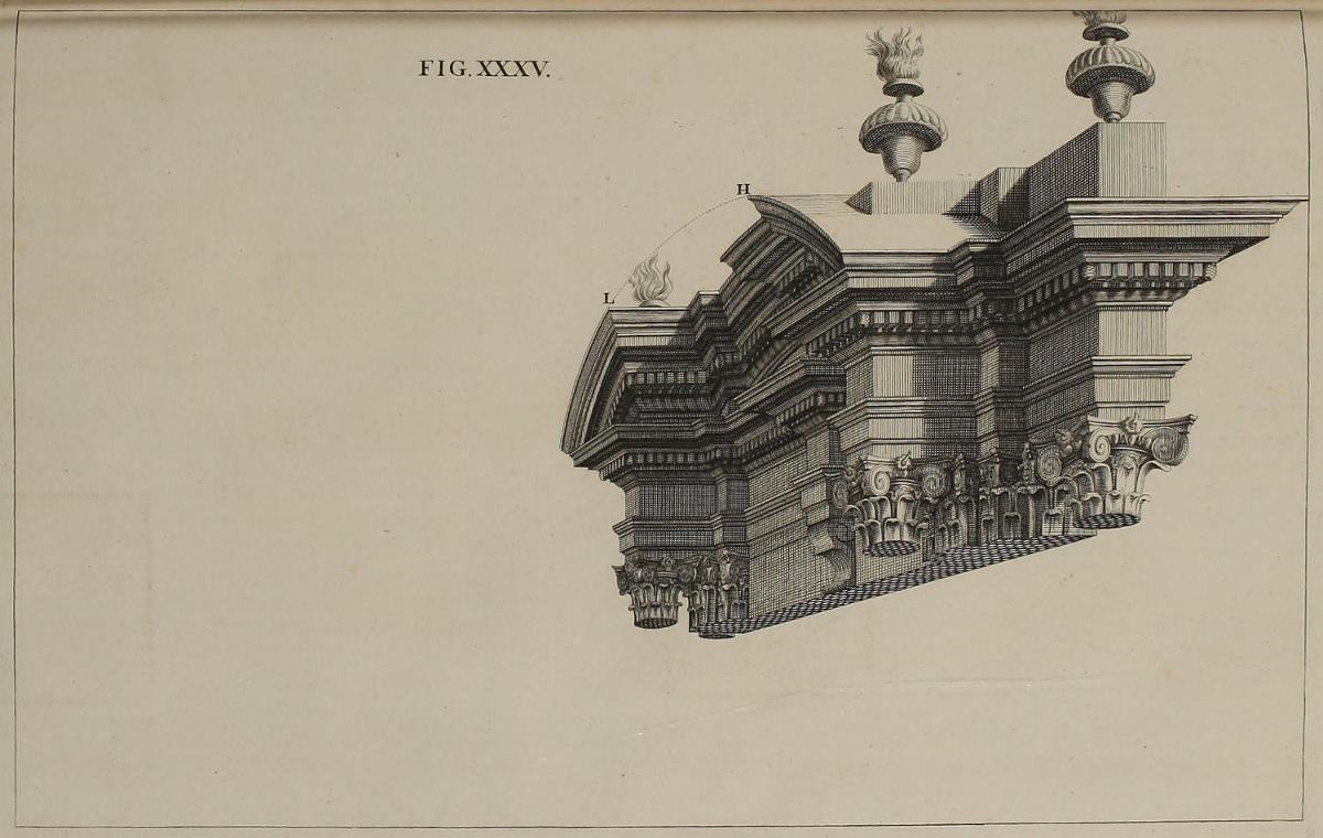
FIG. XXXV.
Deformatio coronicis Compositæ, ad latus inspectæ.
Artificium nitidæ coronicis, ex vestigio & elevatione figuræ trigesimæquartæ eruendæ, non differt ab eo quod sæpè traditum est. Itaque supposito, quòd linea plani & horizontis, ac puncta oculi ac distantiæ, habeant in hoc schemate situm omnino eundem, quem habent in præcedenti; ope duorum circinorum, invenientur distantiæ, quas anguli necessarii ad integram delineationem coronicis, habent à linea plani, & à linea normali ad ipsam lineam plani. Nam ducendo lineas visuales, aliasque lineas parallelas ad ipsum perpendiculum, cum terminis & flexibus qui conveniunt singulis membris, complebitur delineatio.
In fastigio visuales sunt penitus occultæ: puncta autem similia H & L, ex quibus fastigium incipit introrsum flecti, incidunt in unam eandemque visualem. Idipsum dico de aliis punctis similibus. Nam lineæ rectæ omnes, quæ in figura trigesimatertia sunt parallelæ ad lineam plani, in figuris trigesimaquarta & trigesimaquinta sunt partes linearum visualium.
A Side-View of the Composite Cornice, in Perspective.
The Manner of drawing this finish’d Cornice, from the preceding Plan and Elevation, is the same with that so often shewn you. Admitting therefore, that the Lines of the Plan and Horizon, and the Points of Sight and Distance, have the very same Position in this, that they had in the preceding Scheme; all the Angles necessary for delineating the entire Cornice, are readily found by the help of two pair of Compasses; taking their Distances one way from the Ground-line; and the other way from a Line perpendicular to the same: Then drawing the visual and perpendicular Lines, and keeping the Place and Contour of the several Mouldings, you complete your Design.
In the Pedament the visual Lines are wholly occult; and the Points H and L, where the Pedament begins to break back, being of like Height, are found in one and the same Visual: And the same may be said of all Points that are of equal Height from the Plan; for all the right Lines, which in the Thirty-third Figure are Parallels to the Ground-line, in the Thirty-fourth and Thirty-fifth Figures are Parts of the visual Lines.
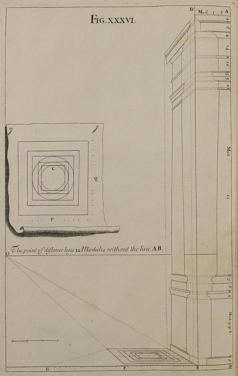
Fig. xxxvi.
Præparatio ad figuram trigesimamseptimam.
In vestigio geometrico C, & in ejus elevatione AB, præcipuas tantùm lineas adnotavi, ne figuram confunderem, & ut studiosorum industriæ aliquid relinquerem. Linea plani EG habet divisiones latitudinis P, & longitudinis Q, vestigii geometrici C. Ex punctis latitudinis ducentur more solito visuales ad O punctum oculi; ex punctis longitudinis fient occultæ ad punctum distantiæ, quod extra lineam AB protenditur modulis quatuordecim: & ubi occultæ ex divisionibus longitudinis secant visualem FO fiunt parallelæ ad lineam plani EF, adhibitis sectionibus talium parallelarum cum visualibus, ad complendam deformationem vestigii.
Eædem lineæ quæ in vestigio deformato sunt parallelæ ad EF, prolongantur usque ad visualem EO, & continuantur cum aliis parallelis ad perpendiculum DE. Fiunt quoque visuales ad punctum oculi ex divisionibus elevationis AB translatis in perpendiculum DE; adhibitis sectionibus talium parallelarum cum visualibus, ad complendam deformationem longitudinis elevationis.
Preparatory to the Thirty-seventh.
In the Geometrical Plan C, and in the Elevation thereof AB, I have only mark’d the principal Lines, as well for avoiding Confusion in the Figure, as that something might be left to the Industry of the Studious. The Line of the Plan EG has the Divisions of Breadth P, and of Length Q, of the Geometrical Plan C. From the Points of Breadth are drawn, as usual, Visuals to the Point of Sight O; From the Points of Length occult Lines are produc’d to the Point of Distance, which lies fourteen Modules without the Line AB: And where the occult Lines from the Divisions of Length cut the Visual FO, Parallels are made to the Ground-Line EF; and from the Intersections of those Parallels with the Visuals, you complete the Delineation of the Plan in Perspective.
The Lines which in the Plan are parallel to EF, being prolong’d to the Visual EO, are then continu’d parallel to the Perpendicular DE. And from the Divisions of AB, produc’d to DE, visual Lines are drawn to the Point of Sight; which intersecting the Perpendiculars aforesaid, you from thence find the Length of the Elevation in Perspective.
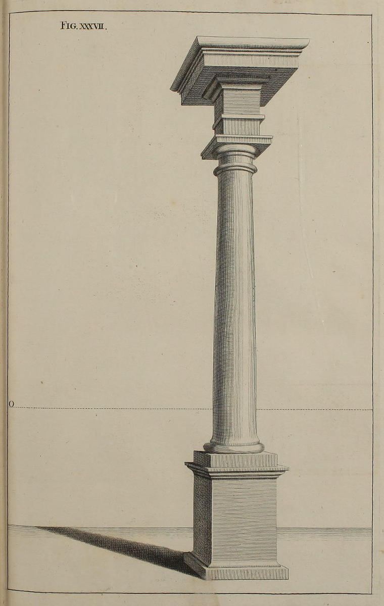
Fig. xxxvii.
Deformatio columnæ Etruscæ.
Ex præparatione quam exhibuimus figurâ trigesimasextâ, eruitur columna hæc nitida Ordinis Etrusci, opticè imminuta per latitudines & altitudines partium singularum; quæ accipiuntur ope duorum circinorum, ut sæpiùs dictum est.
A Tuscan Column in Perspective.
From the Preparation exhibited in the Thirty-sixth Figure, is drawn this complete Piece of the Tuscan Order, brought into Perspective by means of the Breadths and Heights of the several Parts, exactly taken off with the Compasses, as has been often said.
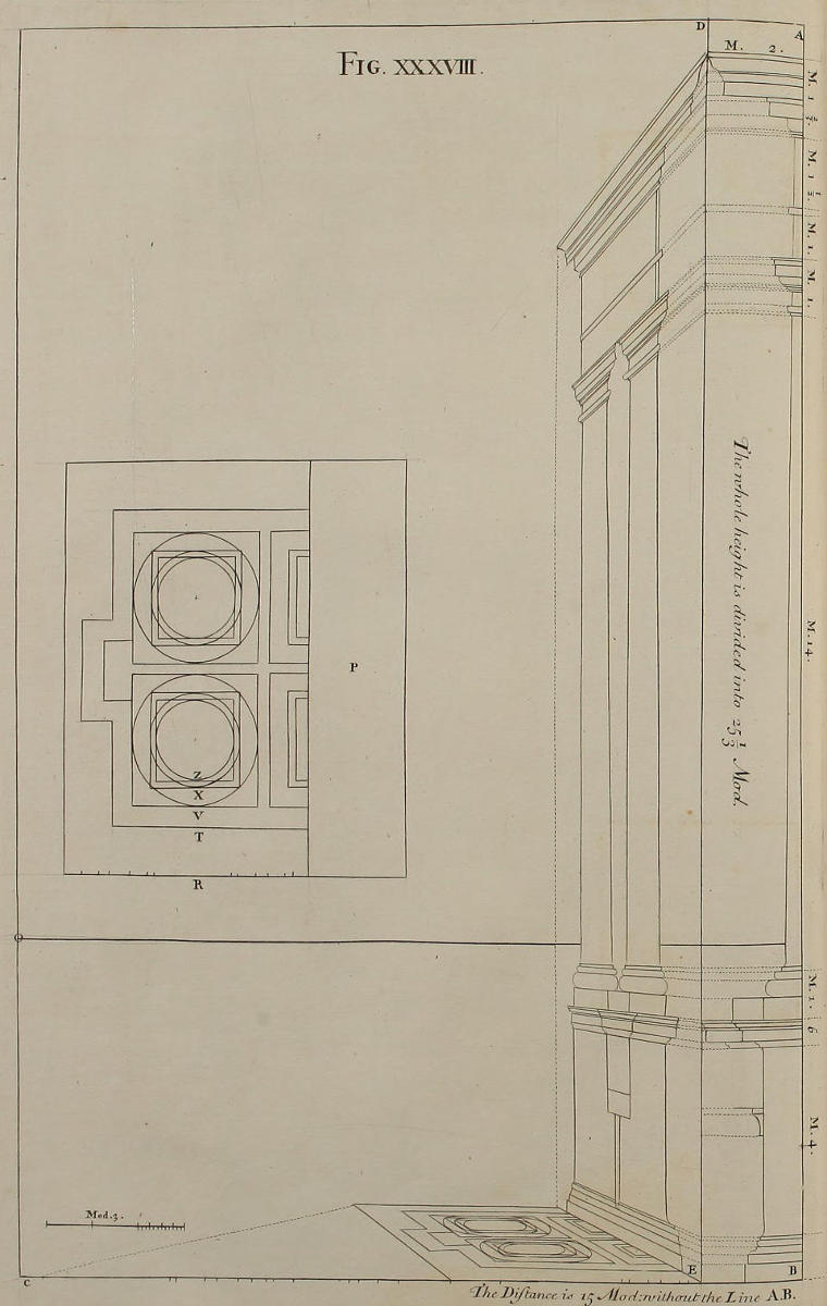
Fig. xxxviii.
Præparatio ad figuram trigesimamnonam.
Hæc figura est simillima figuræ trigesimæsextæ. In vestigio P limes prominentiæ coronicis est R; coronæ verò in stylobatâ est T. soliditas stylobatæ est V. ambitus columnæ in imo est X, in summo Z.
Preparatory to the Thirty-ninth.
This Figure is very much the same with the Thirty-sixth. In the Plan P, the utmost Projecture of the Cornice is R; that of the Cap of the Pedestal is T; the Trunk of the Pedestal is V; the naked Shaft of the Column at bottom is X, at top is Z.
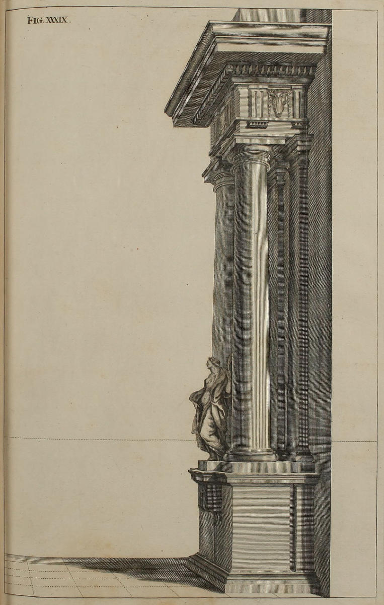
Fig. XXXIX.
Deformatio ædificii Dorici.
Habes hoc loco ædificium Doricum, addito statuæ unius ornamento. Velim autem, ut si figuram aliquam ex his desumptam, delineandam assumas, aliquid mutes saltem in loco punctorum oculi aut distantiæ. Hoc modo majores in hac arte progressus facies; & si alicubi cælator aberraverit, ex lapsu illius nullum senties detrimentum.
A Piece of Dorick Architecture in Perspective.
In this Plate you have a Dorick Composition, with the additional Ornament of a single Statue; but I would advise, when you undertake to work after any of these Designs, you would at least place the Points of Sight and Distance somewhat differing from those here given; which Practice will both greatly further your Progress in this Art, and prevent any Inconvenience, that may arise from a Mistake of the Engraver.
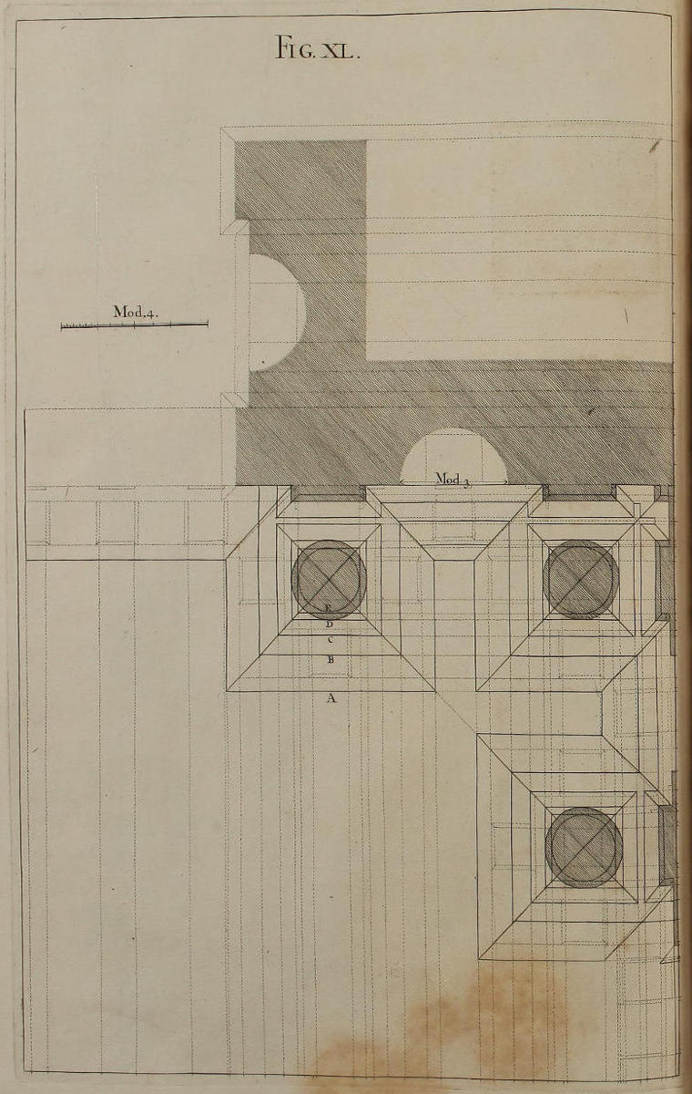
Fig. xl.
Vestigium geometricum ædificii Ordinis Dorici.
Vt studiosorum, qui sedulò se exercuerint in praxibus hucusque traditis, & ad majora inhient, utilitati serviam, delineandam suscepi medietatem arcûs cum tribus columnis, ac totidem statuarum loculamentis. Ad vitandam autem confusionem, ea dumtaxat membra in vestigio adumbrantur, quæ recensuimus figurâ trigesimaoctavâ, & ostendunt characteres A, B, C, D, E.
The Geometrical Plan of a Design, of the Dorick Order.
For the Benefit of the Studious, who, having reduc’d to Practice the Rules hitherto laid down, aim at yet greater Things; I have here undertaken to delineate half an Arch adorn’d with three Columns, and as many Niches for Statues. But to avoid Confusion, I have given full Lines to those Members only, which were mention’d in the Thirty-eighth Figure, and which are here denoted by the Characters A, B, C, D, E.
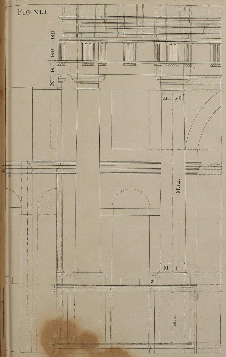
Fig. xli.
Elevatio geometrica ædificii Dorici.
Ex vestigio geometrico eruitur hæc elevatio geometrica longitudinis ædificii nostri. Et iccircò figura ista quadragesimaprima, cujus mensuræ omnes desumptæ sunt ex Barozzio, congruit longitudini figuræ quadragesimæ.
The Geometrical Elevation of the foregoing Design.
This Upright is drawn from the foregoing Geometrical Plan; and therefore all the Parts of this Design, whose Measures are taken from Vignola, exactly answer those of the Fortieth Figure.
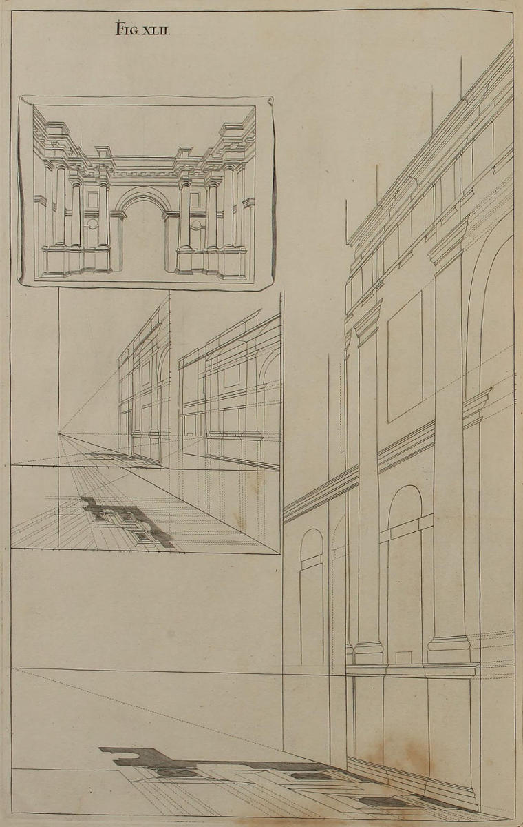
Fig. xlii.
Modus vitandi confusionem, in contractione vestigiorum, & elevationum.
Contractiones vestigii figuræ quadragesimæ, & elevationis figuræ quadragesimæprimæ, ob nimiam obliquitatem quam habent, valde confusæ sunt. Medebimur tamen incommodo isti, uti fecimus figuris decimâ & undecimâ. Et ostendit chartula, exhibens in parvo tum figuram hanc quadragesimamsecundam, tum quatuor sequentes.
The Manner of avoiding Confusion, in reducing Plans and Elevations into Perspective.
The Reducing into Perspective the Plan of the Fortieth Figure, and the Upright of the Forty-first Figure, would become very confus’d, through the great Obliquity of the Rays: We have therefore remedy’d the Inconveniences of both, by the Methods explain’d in the Tenth and Eleventh Figures. And this Plate contains in little, what is more at large describ’d in Parts, as well in this, as the four subsequent Figures.
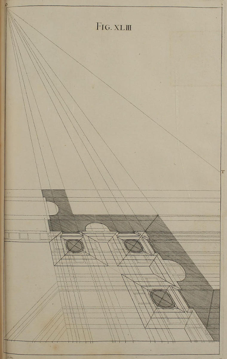
Fig. xliii.
Contractio vestigii figuræ quadragesimæ.
Linea plani multò remotior est à lineâ horizontali in hoc schemate, quàm in præcedenti. Ideo istud vestigium vacat omni confusione. Cætera patent ex iis quae sæpiùs dicta sunt, & ex figuræ hujus inspectione. Oportet autem, rectas parallelas ad lineam plani, prolongari usque ad visualem TO, (quæ cadit extra paginam) ut adminiculo parallelarum, fiat elevatio longitudinis nostri ædificii, de quâ dicemus figurâ quadragesimaquartâ.
The Plan of the Fortieth Figure in Perspective.

By placing the Ground-line in this, much more remote from the Horizontal, than it is in the foregoing Figure, all Confusion is here avoided. The rest is evident from what has been often said on this Head, and a bare Inspection of the Figure. Parallels to the Ground-line must nevertheless be continu’d to the Visual TO, which falls without this Page; that from them may be rais’d the Elevation of the Length of this Design, which we shall handle in the next Figure.
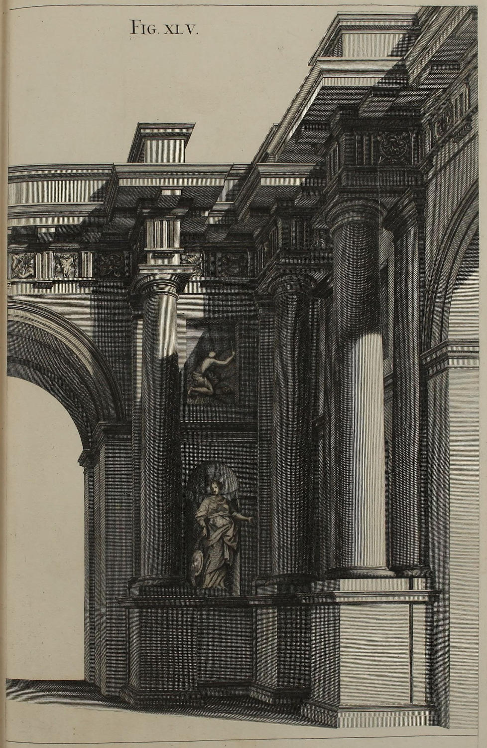
Fig. xliv.
Contractio elevationis figuræ quadragesimæprimæ.

Rectæ parallelæ ad lineam plani figuræ quadragesimætertiæ, ubi pervenerint ad visualem TO, continuandæ sunt, more solito, cum parallelis ad lineam perpendicularem. In hanc autem transferre oportet omnes divisiones, quas ex Barozzio habet elevatio hujus ordinis; ac ducere visuales. Quomodo autem, adminiculo visualium & parallelarum, compleatur elevatio, constat ex figura, & clarius ex chartula figuræ quadragesimæsecundæ. Numeri 1, 2, 3, 4, geminati, ostendunt centra & altitudines semicirculorum seu arcuum figuræ quadragesimæquintæ; videlicet, numerus inferior designat centrum, superior verò designat altitudinem semicirculi.
The Elevation of the Forty-first Figure in Perspective.

When the Parallels to the Ground-line in the Forty-third Figure, are prolong’d to the Visual TO, they are then, as usual, to be continu’d Parallels to the Perpendicular: On which Perpendicular, those Divisions given by Vignola, for the Proportions of this Order, are to be transferr’d; and Visuals drawn from them to the Point of Sight. How by these Visuals and Parallels the Elevation is rais’d in Perspective, is manifest in part from this Figure, but more clearly from the Forty-second Figure. The Numbers 1, 2, 3, 4, which you here see doubl’d, give the Centers and Heights of Semicircles of the Arches in the Forty-fifth Figure; the lower Numbers denoting the Centers, and the upper Numbers the Heights of the Semicircles of the same.
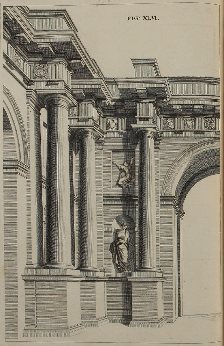
Fig. xlv.
Dimidium ædificii Dorici opticè deformati.
Huic figuræ delineandæ plures præiverunt, ejusdemque latitudines mutuati sumus ex figura quadragesimatertia, altitudines ex quadragesimaquarta. Superest autem, ut lumina & umbræ scitè inducantur in singulas partes ædificii.
One Half of the Dorick Design in Perspective.
The foregoing Figures being preparatory to this, the Breadths are taken from the Forty-third, and the Heights from the Forty-fourth Figure. It only remains, that the Lights and Shades be skilfully dispos’d to each Part of the Work.
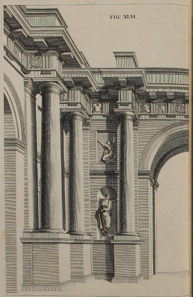
FIG. XLVI.
Alterum dimidium ejusdem ædificii.
Supersedere poteram delineatione alterius medietatis ædificii nostri. Verùm operæ non peperci, ut ostenderem diversitatem luminum & umbrarum, quæ conveniunt partibus cæteroqui omnino similibus.
The other Half of the same Design.
I might very well have omitted this Half of the Design, but that I spar’d no Pains, to shew the Diversity of the Lights and Shadows, that must be given to those Parts of the Work, which in other Respects are alike.
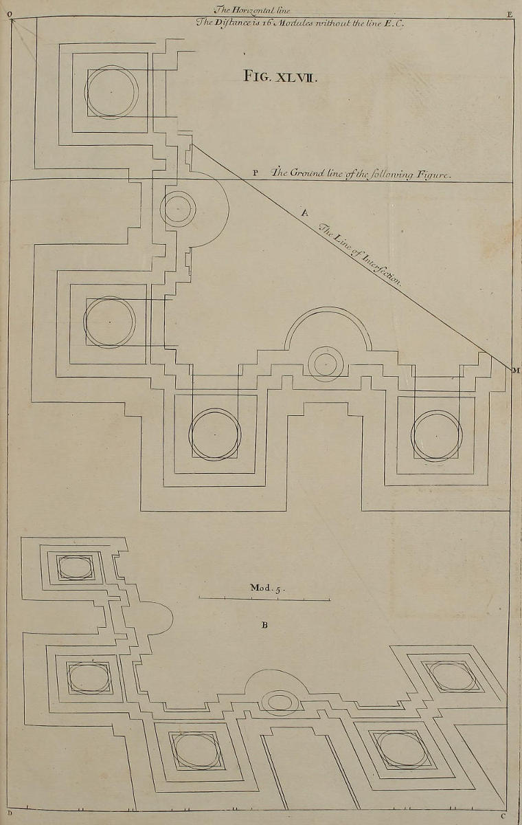
Fig. xlvii.
Vestigia ædificii Ionici.
Vestigium geometricum A ædificii Ionici, sub se habet suam deformationem B. Hæc autem ut evadat distinctior, lineam plani, quæ in sequentibus figuris habebit distantiam PE ab horizontali OE, deorsum protraximus in CD, ut etiam fecimus figurâ quadragesimasecundâ & quadragesimatertiâ. Linea visualis OM eundem habet usum, quem visualis OT figuræ quadragesimætertiæ; videlicet, ut in ea terminentur parallelæ ad lineam plani ex membris vestigii B, eademque continuentur cum aliis parallelis ad rectam EC, pro deformandâ elevatione quam apponemus figurâ quadragesimanonâ.
The Plan of an Ionick Building.
The Geometrical Plan of this Ionick Work is A, underneath is its Perspective B; to render which more distinct, the Ground-line that in the following Figures has only the Distance PE from the Horizontal EO, is here remov’d downward to CD, as was done in the Forty-second and Forty-third Figures foregoing. The visual Line OM is of the same use as that of OT in the Forty-third Figure; namely, to terminate the Lines which are drawn from the Members of the Plan B parallel to the Ground-line; from whence they are again continu’d parallel to the Perpendicular EC, for making in Perspective the Elevation inserted in the Forty-ninth Figure.
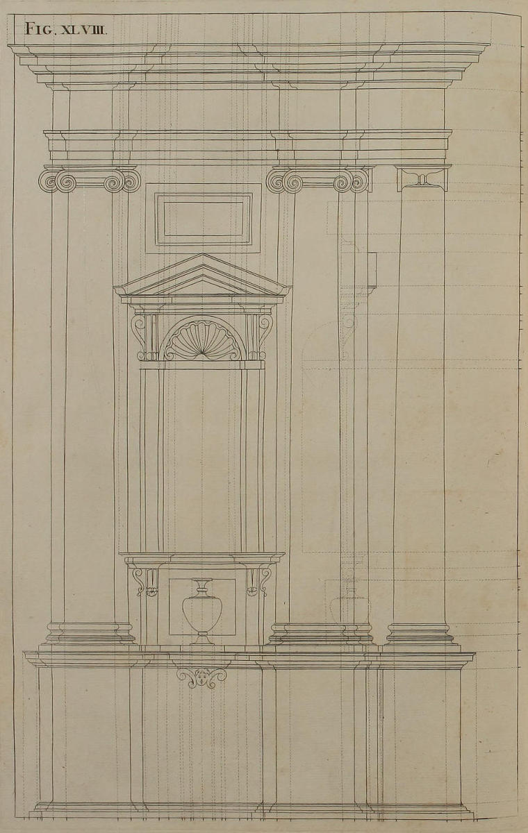
Fig. xlviii.
Elevatio geometrica ædificii Ionici.
Ex hac elevatione quæ clarè ostendit membra totius ædificii secundum longitudinem dissecti, desumuntur altitudines ac terminationes membrorum singulorum. Peritiores tamen hac figurâ delineandâ supersedere solent, quia terminationes haberi possunt ex vestigio A figuræ quadragesimæseptimæ, altitudines verò ponendæ iterum sunt figurâ sequenti.
The Geometrical Upright of the foregoing Ionick Design.
From this Figure (which distinctly shews the Composition of the whole Work, in respect of its Length) are taken the Heights and Terminations of the several Members thereof. But those that are skill’d in this Art, usually omit the delineating these Elevations; because the Terminations may be taken from the Plan A in the Forty-seventh Figure; and the Heights must be repeated in the following Figure.
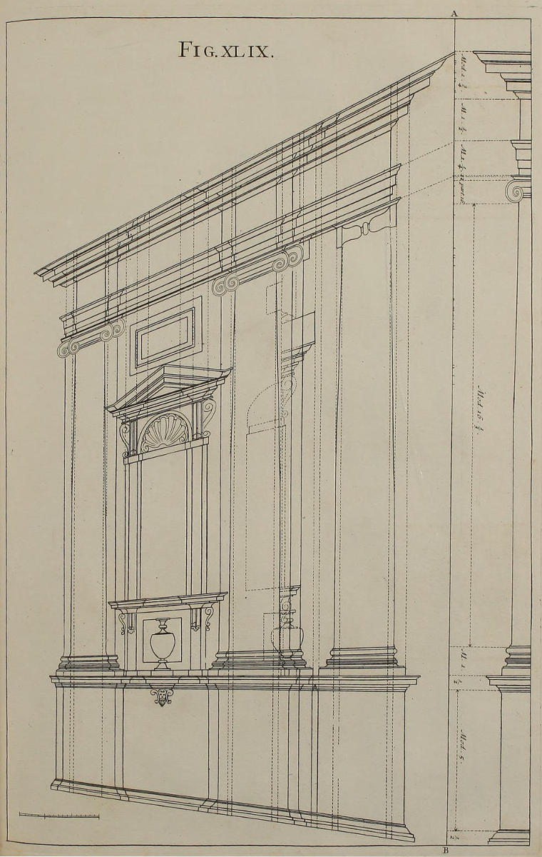
Fig. xlix.
Deformatio elevationis ædificii Ionici.
Hæc figura continens deformationem præcedentis elevationis, perficitur methodo illa, quam ostendimus figurâ quadragesimasecundâ; nimirum, ex vestigio B figuræ quadragesimæseptimæ, ducere oportet parallelas ad lineam plani CD, quæ ubi pervenerint ad visualem OM, continuandæ sunt cum aliis parallelis ad lineam EC. Easdem parallelas in hanc figuram translatas secant visuales ex linea recta AB, in qua positæ sunt altitudines ædificii Ionici, desumpta vel ex figura præcedenti, vel ex Barozzio. Nullum autem est punctum in membris hujus elevationis, quod non inveniatur per sectiones visualium ex linea AB, cum parallelis ad eandem lineam.
The Elevation of the Ionick Design in Perspective.
This Plate containing the Perspective of the foregoing Upright, is drawn by the Method laid down in the Forty-second Figure; to wit, from the Plan B of the Forty-seventh Figure, Parallels to the Ground-line CD are prolong’d to the Visual OM; and thence are continu’d Parallels to the Perpendicular EC. These being transferr’d into this Figure, are intersected by the visual Lines that proceed from AB, which contains the Heights of this Ionick Composition, agreeable to the foregoing Figure, and the Rules deliver’d by Vignola. Now there is no Point in any Member of this Upright, but may be found by the Intersection which the visual Line from AB makes with its respective Perpendicular.
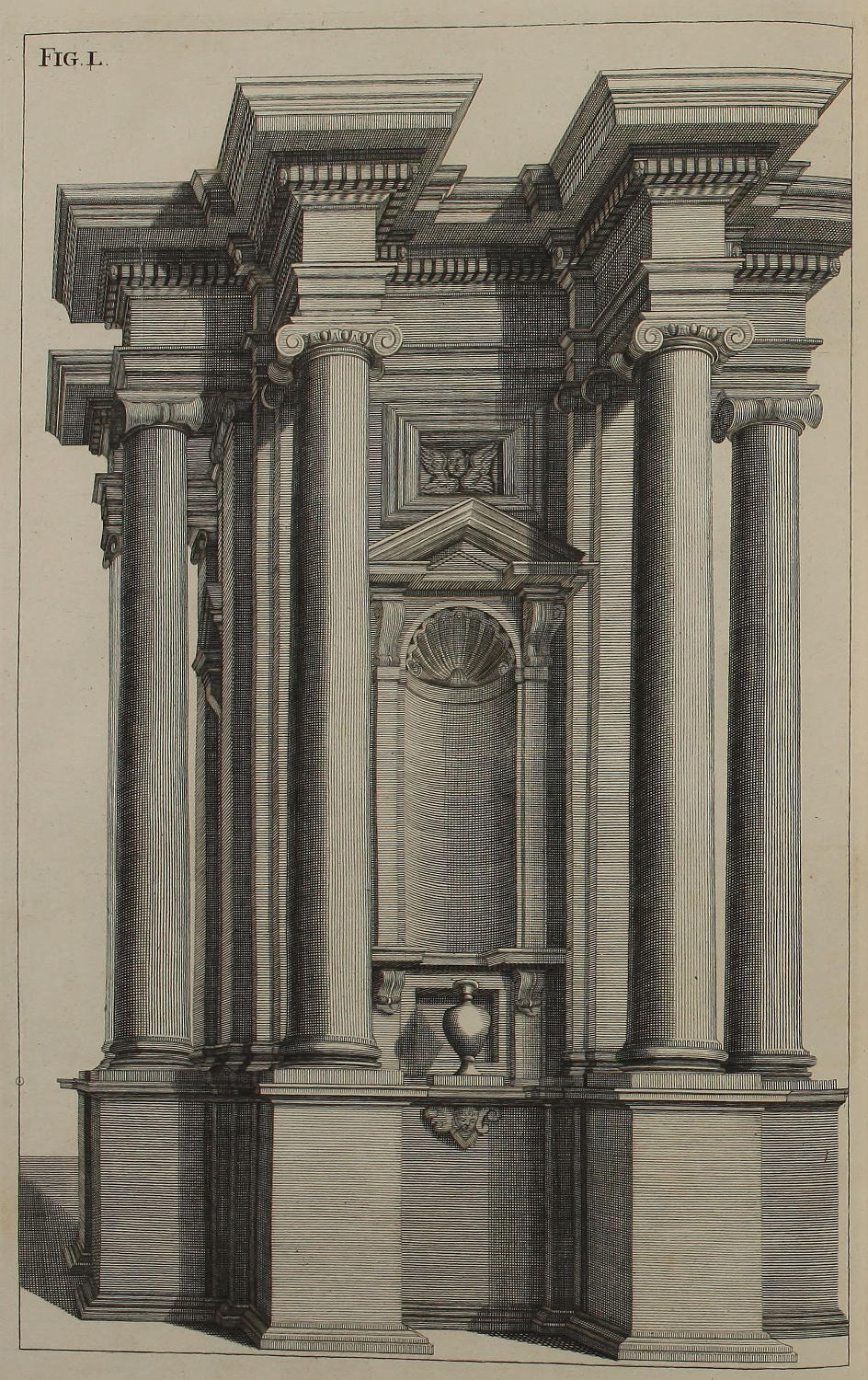
Fig. l.
Architectura Ionica.
Ex vestigio figuræ quadragesimæseptimæ, & ex elevatione figuræ quadragesimænonæ, eruitur hoc ædificium Ionicum, quod esse poterit vel principium alicujus turris campanariæ, aut basis cujuspiam arcûs triumphalis. Vereor ut cælator suam diligentiam in hoc schemate satis probaverit. Ejus tamen errata facilè ipse deteges, & omni studio cavebis.
A Design of Ionick Architecture.
From the Plan of the Forty-seventh Figure, and from the Upright of the Forty-ninth Figure, is drawn this Ionick Piece; which might well serve for the lower Order of a Turret, or for part of a Triumphal-Arch. I fear the Engraver has not been so exact in this Scheme, as he ought; but you will readily discover his Mistakes, and carefully beware of them.
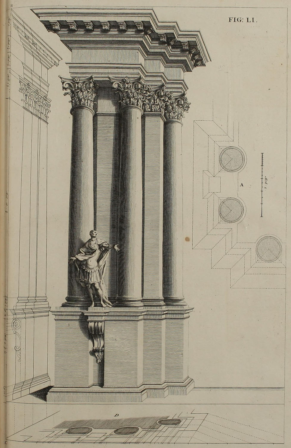
FIG. LI.
Ordo Corinthius.
Complectitur hæc pagina molem contractam Ordinis Corinthii, cum suis præparationibus. Vestigium A exhibet parietem pone columnas cavum instar canalis. Idem vestigium opticè deformatur in D: omissâque elevatione geometricâ, per ejus altitudines notatas in lineâ BC projicitur elevatio; ac methodo consuetâ, ex vestigio & elevatione componitur ædificium, addito statuæ unius ornamento.
A Corinthian Design in Perspective.
This Plate contains the Perspective of a Corinthian Work, with its Preparations. The Geometrical Plan A shews the Wall wrought hollow behind the Columns. The said Plan in Perspective is D: and leaving out the Geometrical Elevation, the Perspective thereof is describ’d, by transferring the Heights of the former into the Line BC. From the Perspective-Plan and Upright the Design is finish’d after the usual Manner; to which is added the Ornament of a single Statue.
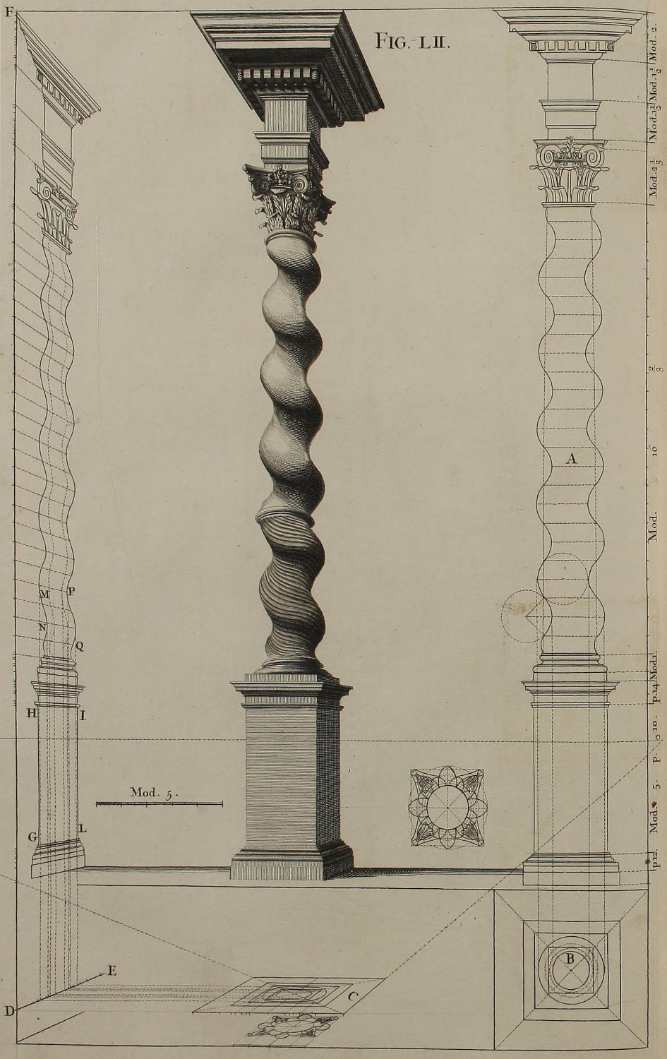
Fig. lii.
Delineatio columnæ spiralis, Ordinis Compositi.
Posita elevatione geometrica columnæ rectæ, ac divisione illius in vigintiquatuor partes æquales, columna spiralis absolvitur per partes circumferentiæ circulorum, quorum diametri sunt æquales diversis latitudinibus columnæ rectæ, ut ostendit figura in A. Ad projectionem opticam elevationis, notandæ sunt quatuor occultæ rectæ, quæ ex terminis convexitatis & concavitatis infimarum spirarum ejusdem elevationis A, descendunt ac desinunt in duos circulos vestigii geometrici B. Vestigium ipsum opticè imminutum habetur in C: eædem autem sunt maximæ hinc inde latitudines, tum in circulo majori, tum in convexitate infimarum columnæ spirarum; eædem sunt maximæ latitudines, tum in circulo minori, tum in concavitate ipsarum spirarum; ut dignosces applicando regulam spiris simul & circulis. Ex quatuor punctis maximæ latitudinis duorum circulorum, incipiunt quatuor lineæ parallelæ ad lineam plani, quæ ubi pervenerint ad visualem ED, continuandæ sunt cum parallelis ad perpendiculum DF. In eandem lineam DF, ex elevatione A transferre oportet vigintiquatuor partes æquales altitudinis columnæ, ac ducere visuales ad O punctum oculi. Per sectionem autem visualium cum prædictis quatuor parallelis ad lineam DF, ducuntur lineæ undulatæ MN, PQ, ex quibus eruuntur lineæ utrinque terminativæ columnæ spiralis nitidæ. Ex linea verò GH habetur facies anterior stylobatæ, columnæ & coronicis; ex linea IL habetur facies eorum posterior.
The Description of a wreath’d Column, of the Composite Order.
Having made the Geometrical Elevation of a streight Column, and divided the Height of its Shaft into Four and twenty equal Parts; the Wreathing is describ’d by Parts of the Circumference of Circles, whose Diameters are equal to the several Breadths, or Diameters, of the streight Column; as is shewn in the Figure A. For putting the Upright into Perspective, four streight occult Lines are of use, which descend from the Extent of the Swellings and Sinkings of the lower Wreaths of the Column A; and terminate in two Circles of the Geometrical Plan B. The said Plan laid down in Perspective is C. The utmost Extent of the greater Circle determines that of the Convex Parts of the lower Wreaths: The greatest Breadth of the lesser Circle gives that of the hollow Parts of the said Wreaths; as may be perceiv’d, by applying a Ruler from the Wreaths to the Circles of the Plan. From the four Points of greatest Breadth in those Circles, four Lines parallel to the Ground-line are continu’d to the Visual ED, and thence again continu’d parallel to the Perpendicular DF. From the Elevation A, the Four and twenty equal Parts of the Columns Height are transferr’d into the Line DF, and Visuals drawn from each to the Point of Sight O. By the Intersections of those Visuals with the four Perpendiculars aforesaid, are drawn the wav’d Lines MN, PQ; from which, both the Out-lines of the finish’d Column are describ’d. But the Fore-part of the Pedestal, Column, and Cornice, is taken from the Line GH; the Back-part of the same from the Line IL.
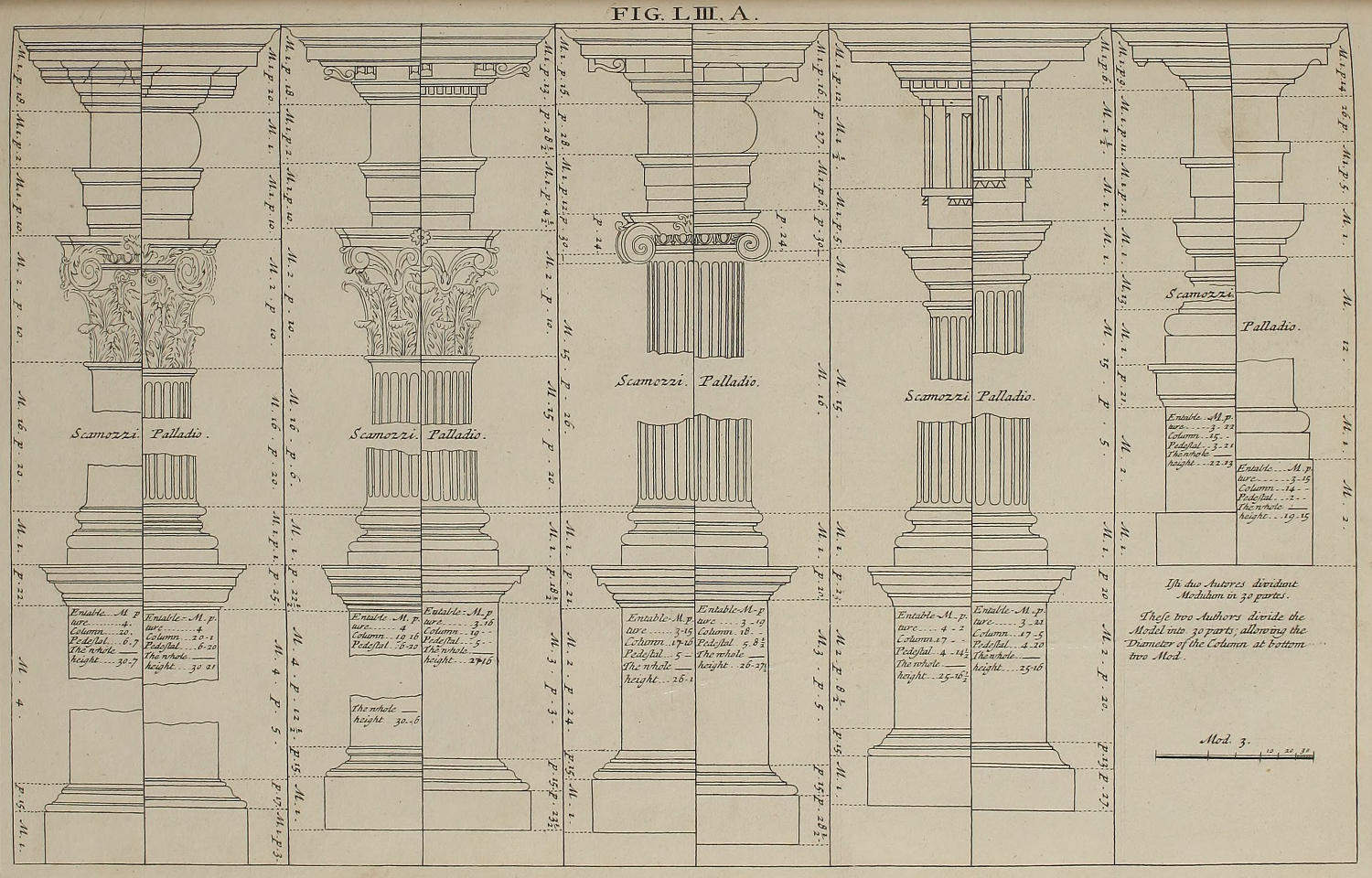
FIG. LIII. A.
Ordines Architecturæ, desumpti ex Palladio & Scamozzio.
De Ordinibus Architecturæ, præter Barozzium, egregiè scripserunt Palladius & Scamozzius; ac singuli, jure merito, suos habent asseclas & patronos. Ut ergò, etiam juxta laudatissimorum Autorum placita, opticas projectiones facere possis, omnes Ordines in hac paginâ exhibere volui, ut in eorum Libris inveniuntur.
The Orders of Architecture, taken from Palladio and Scamozzi.
Besides Vignola, Palladio and Scamozzi have also written excellently well of the Orders of Architecture; and each of ’em have deservedly their Followers and Admirers. That you might therefore be enabl’d to make Designs in Perspective, after the Proportions of the most celebrated Masters, I have in this Plate given you the Measures of all the Orders, as deliver’d by them in their Books.

Fig. liii. b.
Modus triplex delineandi columnas spirales.

Columnæ figuræ superioris carent ea concinnitate, qua præditæ sunt columnæ spirales æneæ celeberrimi Equitis Bernini ad sepulcrum S. Petri in Vaticano. Itaque methodum triplicem exhibeo ad minuenda spatia totius altitudinis columnæ.
1. Recta OA sit æqualis altitudini AB columnæ. Fiat autem recta OB, & arcus AP ex centro O, divisus in partes duodecim æquales, ducendo rectas, quæ per puncta divisionum desinant in columnam rectam; ac demum fiant parallelæ ad basim: Spatia inter has parallelas dabunt aperturam circini pro triangulis æquilateris & pro spiris, ut ostendit columna 1.
2. Translatâ in C tertiâ parte altitudinis columnæ ab ejus imo scapo, habeat circinus aperturam CD; ac posito uno ejus crure prius in D, postea in C, fiant duo parvi arcus ad E: sectio illorum arcuum erit centrum arcûs DC, quem oportet dividere in duodecim partes æquales, & ex punctis divisionum ducere parallelas ad basim. Tum spatiis inter parallelas divisis in quatuor partes æquales, tres ex illis partibus dabunt longitudinem crurum pro triangulis isoscelibus; vertices autem triangulorum erunt centra singularum spirarum, ut ostendit columna 2.
3. Ductâ ex medio summitatis G rectâ GF, spatium HF transferatur in I, & fiat recta IL parallela ad basim HF; spatium IL transferatur in N, ac fiat NM, & sic deinceps. In parvis columnis triangula sine sensibili errore duci possunt per diagonales: in columnis tamen grandioribus, alterutrum ex modis antea explicatis adhibere necesse est.
Three different Ways of delineating wreath’d Columns.
The wreath’d Columns describ’d in the Fifty-second Figure, being divided into Twenty-four equal Parts, want very much of that Elegancy of Contour, which is visible in those brass Pillars, made by the famous Cavalier Bernino, for S. Peter’s Sepulcher in the Vatican. Wherefore I here lay before you three several Ways of diminishing the Spaces through the whole Height of the Column.
1. Make the right Line OA equal to AB the Height of the Column; then draw the Line OB, and on the Center O describe at pleasure the Arch AP, which divide into twelve equal Parts, and by the Divisions draw streight Lines from the Center O to the Line of the Column; and lastly continue the same Parallels to the Base. The Spaces between these Parallels, shall be the Sides of equilateral Triangles, wherewith you are to describe the Wreath of the Column, as is seen in Column 1.
2. Having set the third Part of the Columns Height, from the Bottom of the Shaft to the Point C; with the Interval CD, from the Centers D and C, describe the Parts of Arches intersecting at E. On the Center E, with the same Interval, describe the Arch DC, which divide into twelve equal Parts; and from the Points of those Divisions, draw Parallels to the Base. Then dividing each Space between the Parallels into four equal Parts; three of those Parts shall be the Sides of the Isosceles Triangle; whose Vertex is the Center whereon to describe each Wreath of Column 2.
3. Having drawn from the midst of the Columns top G, the Line GF, make HI equal to HF, and draw IL parallel to the Base HF: Again, make IN equal to IL, and draw NM also parallel, and so on. In small Pillars, the Centers of the Diagonals of these Spaces may, without sensible Errour, serve for describing the Wreaths; but in greater Columns, either of the other two Methods is rather to be chosen.
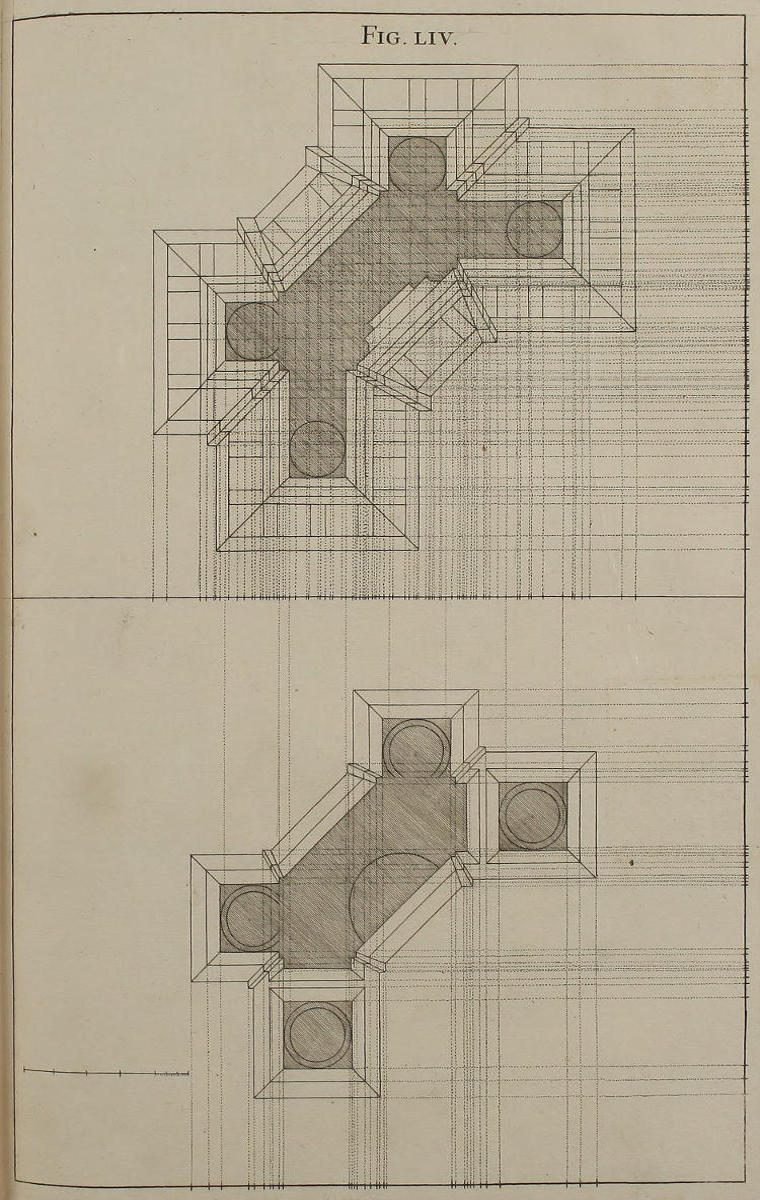
Fig. liv.
Vestigia ædificii Ordinis Corinthii.
Descripturi ædificium Corinthium octangulare, ponimus hic vestigia unius ex quatuor partibus pilarum, quibus imponetur fornix in modum tholi, ut constabit in figurâ quinquagesimaoctava. Ad faciliorem descriptionem, in parte inferiori paginæ posui vestigium geometricum stylobatæ, in superiori vestigium geometricum coronicis, cum latitudinibus & longitudinibus membrorum singulorum; ut eas transferendo in lineam plani more consueto, utrumque vestigium opticè deformetur. Ad vitandam confusionem, prius notare oportebit puncta quæ spectant ad membra propinquiora solido parieti, deinde alia.
The Plan of a Design of the Corinthian Order.
Being to describe an Octangular Corinthian Work, I have here inserted the Plan of one Quarter of the Composition; which is vaulted in Form of a Cupola, as is seen in the Fifty-eighth Figure. To render the Plan less confus’d, I have, in the lower part of the Plate, given the Geometrical Plan of the Pedestal; and in the upper part, that of the Cornice; with the Breadths and Lengths of each Member: so that by transferring the same into the Ground-line, after the usual Manner; you delineate each Plan in Perspective. For avoiding Confusion, ’twill be requisite first, to transfer the Points of those Members that are next the Solidity of the Wall; and then proceed to the others.
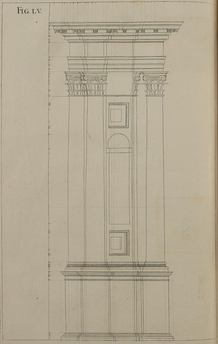
Fig. lv.
Elevatio ædificii Ordinis Corinthii.
Elevatio geometrica ædificii octangularis congruit cum duobus ejus vestigiis figuræ antecedentis. Quia verò elevatio parietis abscondit secundam ex quatuor columnis, eademque in ædificio deformato conspicua futura est; iccircò eam lineis occultis designare oportuit.
The Geometrical Elevation of a Corinthian Work.
The Geometrical Elevation of this Octangular Design, is wholly correspondent to the two Plans of the foregoing Figure: But because the Wall in this Upright takes off the Sight from the second of the four Columns, which is notwithstanding visible in the finish’d Perspective that follows; ’tis requisite to delineate the same with occult Lines, as in the Figure.
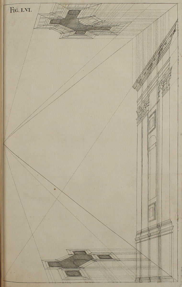
Fig. lvi.
Deformatio vestigiorum & elevationis ædificii Corinthii.
In hac figurâ, lineam plani coincidere volui cum linea horizontis. Itaque videri non posset vestigium inferius, nisi ut alias deorsum protraxi lineam plani, hic è converso sursum promovissem lineam horizontis, quam constitui mediam inter lineas plani utriusque vestigii, ut ambæ projectiones essent æquè distinctæ. In elevatione, columna secunda, quam, ut dixi, paries abscondit, lineis occultis designanda est.
The Perspective Plans and Upright of the Corinthian Design foregoing.
In this Figure, I have made the Ground-line coincident with that of the Horizon, in which case the lower Plan can’t be seen, unless the Ground-line be sunk lower, as before intimated; or contrariwise, the Point of Sight rais’d higher, as I have here done, keeping it in the midst between the Ground-lines of the two Plans, that the Perspective of both might be equally distinct. In the Elevation, the second Column, which I mention’d to be hidden by the Wall, should be design’d with occult Lines.
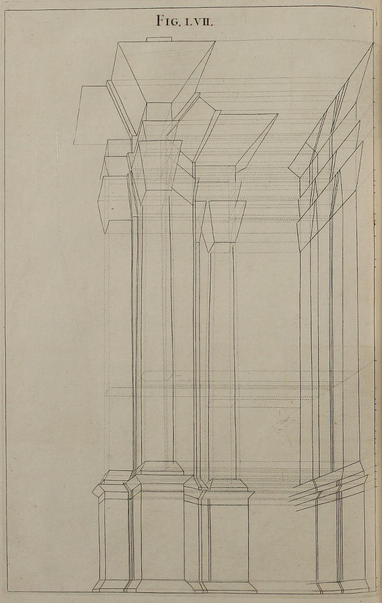
Fig. lvii.
Adumbratio figuræ sequentis.
Figuram hanc seorsim delineavi, ut videas quomodo facienda sit operis totius adumbratio, accipiendo altitudines membrorum singulorum ex elevatione; latitudines & longitudines ex vestigiis. Quæ omnia ex diagrammatis inspectione clarissimè apparent.
The rough Draught of the following Figure.
I have drawn this Figure apart, that you may see the Manner of describing the Out-line of the whole Work, by taking the Heights of the several Members from the Elevation, and their Breadths and Lengths from the Plans; all which is very plain, upon Inspection of the Figure.
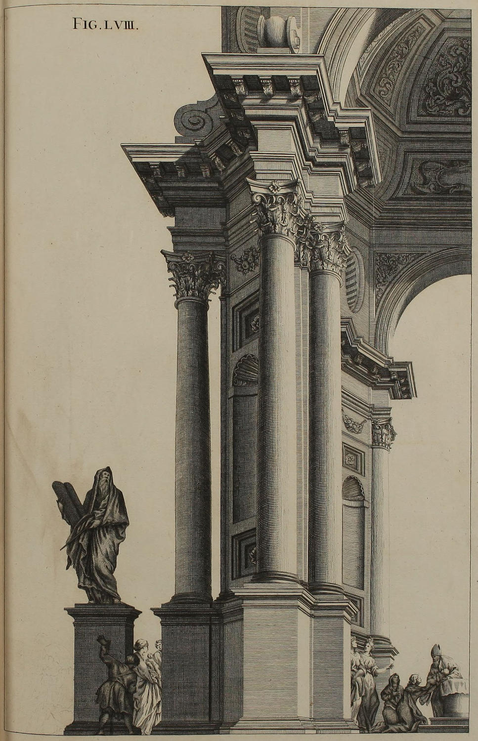
Fig. lviii.
Ædificium Ordinis Corinthii octangulare.
Hucusque descripsimus pilas anticas sinistras ædificii Corinthii. En hoc loco medietatem dexteram totius Operis. Integrum verò ædificium habebis figurâ sexagesimâ.
Part of an Octangular Work of the Corinthian Order.
Hitherto the nearest left-hand Quarter of this Corinthian Design has been describ’d. In this Plate you have the right-hand Half of the whole Work; and in the Sixtieth Figure, the entire Perspective compleat.
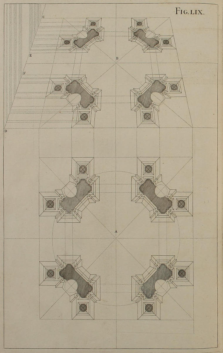
Fig. lix.
Vestigia tabernaculi octangularis.
Projectiones rerum octangularium sunt quadratis difficiliores: ideò in eis explicandis diligentiæ non peperci. Moles cujus vestigia vides in A & B, convenit in multis cum eâ quam ereximus figurâ quinquagesimaoctavâ. Visualis CD recipit sectiones perpendicularium, quæ deserviunt pro elevatione figuræ sequentis, ut sæpius dictum est. Si facies interior delineanda sit seorsim à facie anteriori, illam perficies ope linearum CE, istam ope linearum FD.
The Plans of an Octangular Tabernacle.
Octangular Figures being more difficult to be put in Perspective, than the Square; I shall use my best Endeavours to render the Method as plain as possible. The Composition whose Plans you see in A and B, has much Affinity with that describ’d in the Fifty-eighth Figure. The Visual CD receives the Sections, from which Perpendiculars are rais’d for the Elevation and Profile of the following Figure, as has been often said. If you would delineate the Back-part separate from the Fore-part, you may do the former by means of the Line CE, and the latter by that of FD.
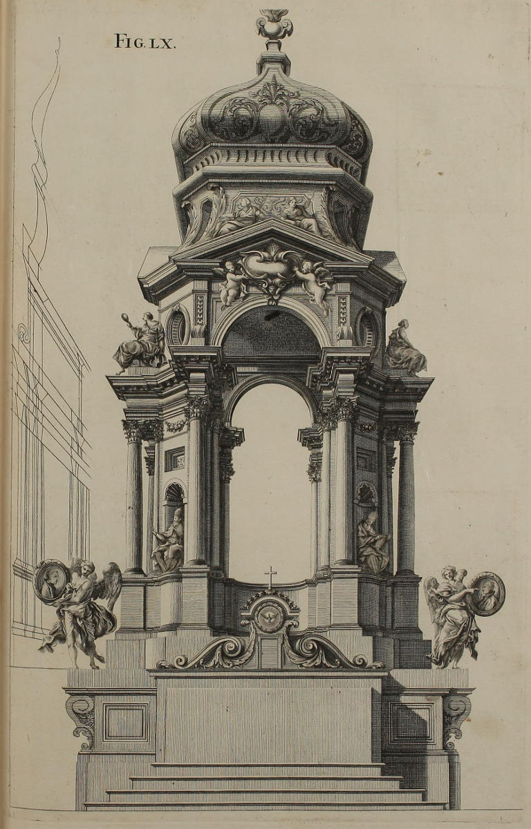
Fig. lx.
Tabernaculum octangulare.
Hoc tabernaculo aliquoties usus fui pro expositione quadraginta horarum. Si colores scitè inducti fuerint in duos ordines telariorum, resectis omnibus quæ ad molem ipsam non pertinent, spectatoribus imponet, & solida videbitur. Oportebit autem exemplar externæ faciei eruere ex parte DF vestigii & elevationis; exemplar interioris faciei eruere ex parte EC, servando in omnibus regulas quas hucusque tradidimus.
An Octangular Tabernacle in Perspective.
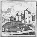
I have sometimes made use of this Tabernacle for the Exposition of the Forty Hours. If the Colours are laid by a skilful Hand, on two Ranges of Cloth, and the Frame cut away according to the Out-line of the Work, they will wonderfully deceive the Eye, and appear as solid; but then the outer Range must be drawn after the Plan and Elevation of the Part DF in the foregoing Figure; and the inner Range after that of EC; in all things observing the Rules hitherto deliver’d.
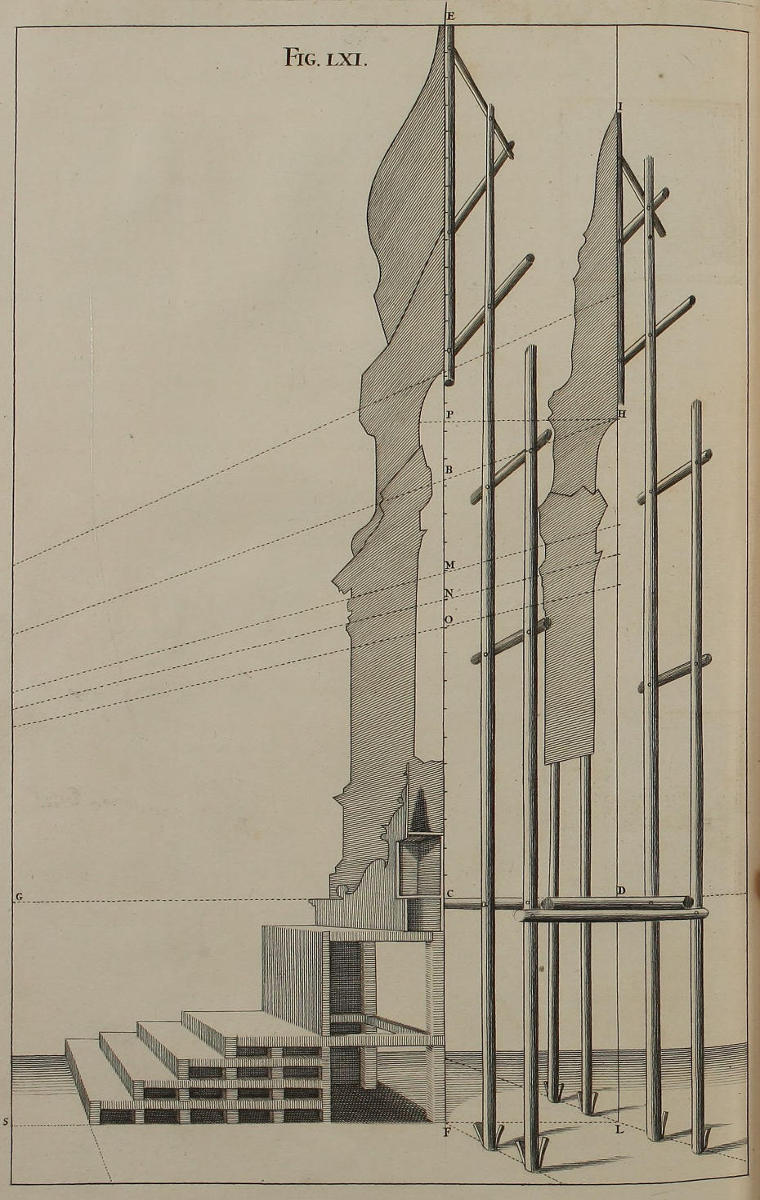
Fig. lxi.
Modus erigendi machinas, quæ constant pluribus ordinibus telariorum.
Ex figuræ inspectione addisces modum erigendi machinas quæ constant pluribus ordinibus telariorum. Tabernaculum hoc nostrum indiget duobus tantum ordinibus; nam telaria propinquiora oculo exprimunt faciem externam, remotiora exhibent faciem internam. Ne autem lateant stipites quibus telaria sustinentur, medietatem telariorum adumbrare omisimus. Recta LS est linea plani, recta DG est linea horizontalis; ac punctum distantiæ quod cadit extra paginam in recta CG prolongatâ, debet esse remotum à puncto C, quantum in superiori parte figuræ quinquagesimænonæ, punctum distantiæ est remotum à puncto oculi. Eadem horizontalis DG secatur normaliter in C à recta EF, quæ est sectio externæ faciei tabernaculi, & ex C incipiunt divisiones in partes æquales pro reticulatione anterioris faciei telariorum, ut dicemus figurâ sexagesimasecunda. Recta IL quæ est sectio internæ faciei tabernaculi, distat ad libitum à recta EF cui est parallela. Porrò, per divisiones rectæ EF (ut vides in M, N, O) ex puncto distantiæ ducendæ sunt visuales ad rectam IL pro reticulatione aliorum telariorum: distantia enim DC facit ut augere oporteat ea quæ in telariis pinguntur, alioquin justo minora viderentur. Atque hinc dignosces, cur arcus qui in telariis anterioribus pertingeret solum ad B, in posterioribus elevetur usque ad H.
Figura sequenti proponemus modum delineandi faciem internam telariorum, adhibita reticulatione externæ faciei: ad intelligentiam verò illius methodi, fiat in hac figurâ recta HP parallela ad DC, ac recta BC dividatur in totidem partes æquales, in quot partes divisa fuerit recta PC.
The Manner of erecting Machines, that consist of several Ranges of Frames.
By casting your Eye on the Figure, you’ll readily apprehend the Manner of erecting the several Ranges of Frames. This Tabernacle last describ’d needs only two of them; the Frame next the Eye represents the outer Face, and the hinder Frame the inner Face thereof. I have here describ’d but the Half-Breadth of the said Frames, that you might have a Sight of the Poles and Braces which support them. The Line LS is the Line of the Plan, or Ground-line; the Line DG is that of the Horizon; and the Point of Distance, which falls without the Page CG prolong’d, is as far from the Point C, as the Point of Distance is from the Point of Sight in the upper Part of the Fifty-ninth Figure. The Horizontal DG is cut perpendicularly in C by the Line EF, which is the Section of the outer Face of the Tabernacle; and from the Point C begin the equal Divisions for the Net-work of the foremost Frame, as is shewn in the Sixty-second Figure. The Line IL, which is the Section of the inner Face of the Tabernacle, may at pleasure be set nearer or farther from the Line EF, to which it is parallel. By the Divisions of the Line EF (as M, N, O) Lines are drawn from the Point of Distance to the Perpendicular IL, for the Net-work of that Frame; for the Distance DC obliges the Parts of D to be painted larger, otherwise they will appear less than they really ought. And from hence you may discern, why the Arch, which in the foremost Frame would reach only to B, does in the hindmost rise up to H.
In the following Figure is shewn the Manner of delineating the inner Frame, from the Net-work of the outer Face; for the better understanding of which, make the Line HP in this Figure parallel to DC, and let the Line BC be divided into as many equal Parts, as the Line PC was.
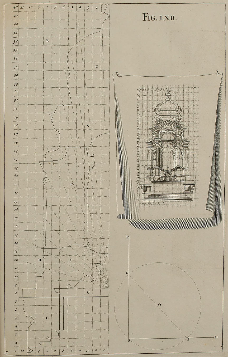
Fig. lxii.
De reticulandis telariis, quæ repræsentent ædificia solida.
Duo exemplaria tabernaculi quæ seorsim delineanda sunt, conjunctim habes in A. Utrisque deservit eadem reticulatio, quam suis numeris insignivimus. Postquam ergo designaveris amplitudinem totius ædificii, cum proportione ad ipsam reticulabis pavimentum B aulæ cujuspiam quod capiat rem totam, ascriptis eisdem numeris quos habet exemplar: ejusque retis ope, ducentur in pavimento lineæ terminativæ totidem membrorum, quot futura sunt telaria exprimentia faciem externam tabernaculi. Ubi hæc parata fuerint, singula disponentur exactè suis locis in ipsomet pavimento; ac funiculis colore nigro imbutis, repetetur in telariis eadem reticulatio, additis ad libitum pluribus visualibus; quarum adjumento dum seorsim pinguntur telaria, duci queant rectæ tendentes ad punctum oculi seu perspectivæ. Alia quoque reticulatio super pavimento necessaria est pro internâ facie tabernaculi: ac duæ reticulationes pavimenti eam inter se proportionem habebunt, quam habent divisiones rectarum IL, EF, figuræ sexagesimæprimæ. Hujus retis ductu fient lineæ terminativæ telariorum cum reliquis, ut jam indicavimus.
Juxta hanc methodum nequeunt duci lineæ terminativæ interioris faciei, nisi fiat in pavimento aliud rete deleto priori, quod esset valdè laboriosum. Postquam ergo ex vestigio figuræ quinquagesimænonæ eruta sint duo exemplaria, in exemplar faciei externæ transferatur recta PC figuræ sexagesimæprimæ, in exemplar faciei internæ transferatur recta BC. Si autem recta PC divisa fuerit in quindecim partes æquales, dividetur BC in quindecim partes æquales, atque ope harum divisionum reticulare oportebit utrumque exemplar. Porrò licet quadrata in reti exemplaris faciei externæ sint majora quadratis exemplaris internæ faciei, nihilominus idem rete pavimenti deserviet pro ducendis lineis terminativis utriusque faciei. Quæ dicta sunt de duobus exemplaribus, valent de aliis quotcunque. Exempli gratiâ; si construere placeat quinque ordines telariorum, fient quinque exemplaria in papyro. Si in omnibus exemplaribus usurpetur eadem reticulatio, in pavimento facere oportet quinque diversas reticulationes. Si autem in exemplaribus fiant quinque diversæ reticulationes, in pavimento sufficit una reticulatio.
Curandum est ut singula retis quadrata in telariis sint exacta, omnesque illorum anguli sint recti. Modus expeditissimus faciendi angulos rectos est hujusmodi. Posito uno crure circini in puncto F lineæ rectæ EF, alioque crure posito ubilibet in O, fiet circulus GFI, & ex puncto G diameter GI. Si recta HF transeat per puncta I & F, est normalis ad EF.
Of making the Net-work on Frames, for representing the Architecture as solid.
You have jointly in A, the two Designs of a Tabernacle, which are to be drawn separately; the same Net-work serving for both, which is also mark’d with Numbers. When you have therefore resolv’d on the Size of your Work, on the Pavement of some Room capacious enough make a Net-work answerable, and affix thereto the Numbers, as in your Copy: By the Help of which, you may on the Pavement describe the Out-line of all those Members that are requisite to the outer Frame of the Tabernacle. This being done, let the Frame be laid exactly in its place on the said Pavement, and with a black Line strike thereon the same Net-work; adding as many visual Lines as you please, which will be of Use for drawing Lines to the Point of Sight, when you come to paint the Frames asunder. Another Net-work on the Pavement is also necessary for the inner Face of the Tabernacle, which should bear such Proportion to this, as the Divisions of the Line IL do to those of EF in the Sixty-first Figure; and by this means the Out-lines of the inner Frame, &c. may be drawn, as has been shewn already.
Thus the Out-line of the inner Face can’t be describ’d, without rubbing out the first Net-work, and making a second on the Pavement; which would be very troublesom. Wherefore, from the Plan of the Fifty-ninth Figure, take the two Designs, and transfer the Line PC of the Sixty-first Figure on the outer Face, and the Line BC on the inner Face. Then if PC were divided into fifteen equal Parts, BC shall be divided in the same manner, and by these Divisions make the Net-work on each Design. And although the Squares of the outer Face be larger than those of the inner one, the same Net-work may nevertheless serve for giving the Out-line of both. What has been said of these two Designs, may be understood of many. For Instance; if five Ranges of Frames were requir’d, five Designs must be made in Paper. If in all the Designs the same Net-work be us’d, then five several Net-works must be made on the Pavement; but if the Designs have five different, then one Net-work on the Pavement will suffice.
You must be very careful that all the Squares of the Net-work be exactly divided, and at right Angles. The ready way of making a right Angle is thus: Placing one Foot of the Compasses in the Point F of the Line EF, and the other at pleasure in O, describe the Circle GFI; and from the Point G draw the Diameter GI. The Line FH drawn by the Points FI, shall be perpendicular to FE.
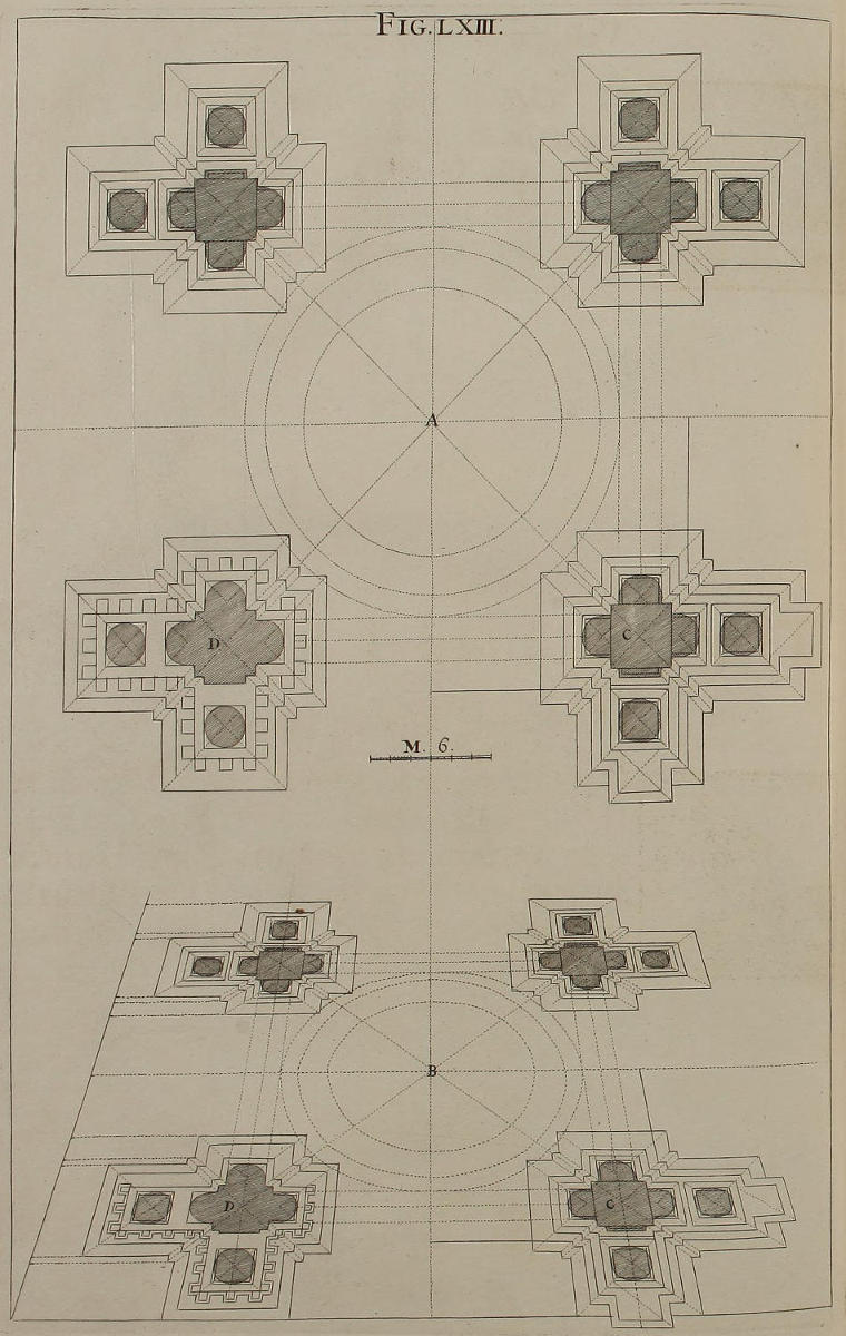
Fig. lxiii.
Vestigia ædificii quadrati.
Vestigium geometricum A hujus ædificii habet in B suam deformationem. Discrimen inter pilas C & D oritur ex eo, quòd in C posita sint vestigia stylobatarum, in D autem posita sint vestigia coronicum.
The Plan of a square Design.
The Geometrical Plan of this Design A, is brought into Perspective in B. The Difference between the Parts C and D arises from hence, that the Plan of the Pedestals is plac’d in C, and that of the Cornice in D.
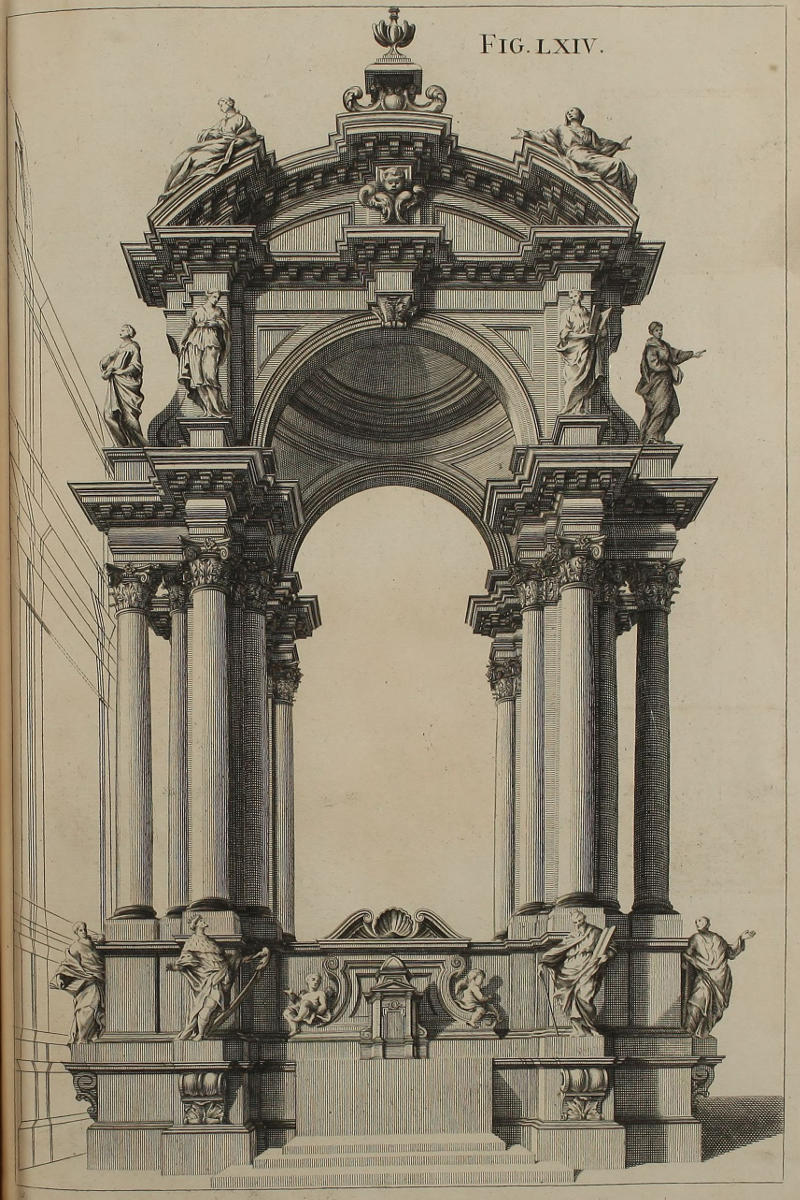
Fig. lxiv.
Ædificium quadratum.
Ex deformatione vestigii & elevationis, methodo consuetâ eruitur imago totius ædificii, quæ potest esse exemplar aræ maximæ alicujus Ecclesiæ. Hanc machinam, non sine communi approbatione, aliquoties adhibui, in apparatu quadraginta horarum; locum in medio vacuum occupantibus Angelis cum nubibus, additâ figurarum aliquot copiâ in parte inferiori. Modus faciendi in telariis remotioribus ab oculo partem tholi rotundi quam hic vides, deducitur ex iis quæ tradidimus in projectione circulorum.
A square Design in Perspective.
From the Plan and Upright in Perspective, this finish’d Piece of the whole Work is delineated after the usual Manner, and may serve for the Design of a great Altar in a Church. I have sometimes, for the Solemnity of the Forty Hours, expos’d this painted on a Machine, with an universal Satisfaction; Angels with Clouds possessing the higher part of the Hemisphere within, and Groups of Figures the lower part. The Manner of designing on the inner Frame, that part of the said Cupola which you here see, is deduc’d from what has been before said of putting Circles into Perspective.
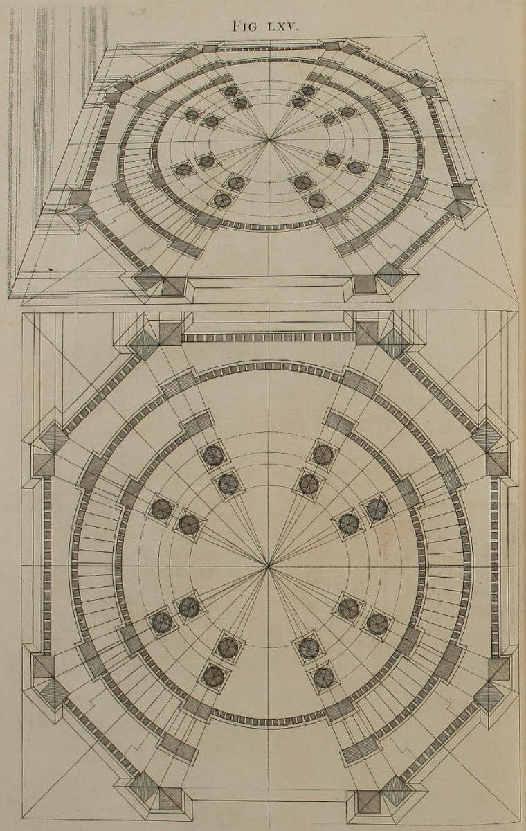
Fig. lxv.
Vestigium ædificii rotundi opticè imminutum.
Qui sedulam operam in circulis deformandis non posuerint, eosque minimo negotio ex usu describere nequiverint, frustra conabuntur projicere vestigia ædificiorum rotundorum. Ad vitandam confusionem, proderit in vestigio notare primùm lineas occultas membrorum præcipuorum; iisque translatis in elevationem, addere sensim reliquas. Hac industriâ ego ipse in hoc schemate usus sum. Quum autem experimento didicerim summam arduitatem harum descriptionum, aliam regulam adhibere jamdiu cœpi, quam, ut suprà diximus, in aliud Opus reservamus.
The Plan of a Circular Work in Perspective.
They that have not diligently apply’d themselves to the putting Circles into Perspective, and, by a constant Practice, render’d the Work familiar to them, will in vain attempt that of the Plans of round Buildings. To prevent Confusion, you’ll do well, first to mark the occult Lines of the principal Members; and after those are transferr’d into the Upright, then proceed to the rest, as I myself did in this Figure. But having found by Experience, the great Difficulty of describing these round things, I have long since made use of another Method, which, as I said before, is reserv’d for another Volume.
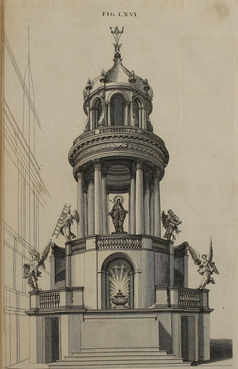
FIG. LXVI.
Projectio ædificii rotundi.
Mirifice oculis imponunt imagines rerum rotundarum, si omnibus resectis quæ ad eas non pertinent, exactè delineatæ ac depictæ fuerint. Hanc figuram ex vestigio eruere oportebit methodo consuetâ, eamque in Templo S. Ignatii Collegii Romani construxi pro feriâ V & VI Hebdomadæ sanctioris. Intra arcum, super altari, locus erat urnæ sepulcrali, cum Venerabili Sacramento. Sub altari visebatur simulacrum Christi Domini è Cruce depositi: in medio columnarum, imago Beatæ Virginis dolentis; super balaustiis Angeli lugentes, cum instrumentis cruciatuum Salvatoris.
A Circular Design in Perspective.
The Appearance of round things, if well design’d, masterly painted, and the Frame cut away to the Out-line of the Work, do wonderfully deceive the Eye. This Figure is drawn from the Plan, as usual; and was put in execution by me, in the Church of S. Ignatius of the Roman College, for the Thursday and Friday of the Holy Week. Within the Arch, on the Altar, was plac’d a sepulchral Urn containing the Holy Sacrament. Beneath the Altar was laid a Figure of our Saviour Christ taken down from the Cross. In the midst of the Tambour, was a Picture of the Blessed Virgin in extreme Sorrow; and on the Ballustrade, Angels mourning, bearing the Instruments of the Passion.
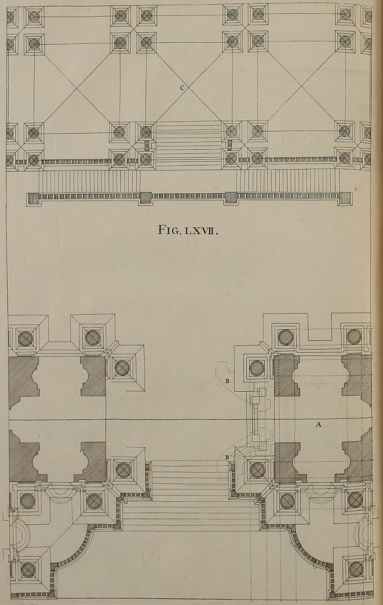
Fig. lxvii.
Vestigium geometricum, ac prima præparatio ad figuram septuagesimamprimam.
Egregiam adeò speciem præsetulit, atque oculis adeò imposuit machina quam construxi anno 1685, pro supplicatione quadraginta horarum, in Templo Urbis Farnesiano, ut decreverim satisfacere Studiosis, publici juris faciendo non modò imaginem totius ædificii, sed etiam illius vestigia & elevationes: quæ omnia eâ diligentiâ delineavimus, veluti Opus ipsum non pennicillo colorandum, sed lapidibus extruendum fuisset. Spatia nigrantia soliditatem designant parietum & columnarum. Cæteræ lineæ sunt crepidines stylobatarum & coronicum. Initium delineationis fiet ab iis membris, ex quibus oriuntur lineæ occultæ positæ in A, (quæ autem dicuntur de hac medietate, intelligi debent de aliâ) ne multitudo linearum confusionem pariat. In B lineæ curvæ occultæ sunt vestigium tholi qui complet summitatem ædificii. Vestigium C exhibet ambulacrum interius. Omisimus autem vestigium theatri, quia paginæ angustia illud non capit.
The Geometrical Plan, and first Preparation to the Seventy-first Figure.
The Machine which I erected in the Year 1685, in the Church Farneze, or Jesuits Church at Rome, for the Devotions of the Forty Hours; had so admirable an Effect, and so pleasantly deceiv’d the Eye, that I resolv’d to gratify the Studious, not only with a general View, but with the Plan and Elevation thereof; all which was perform’d with such Exactness, that the Work itself seem’d rather to consist of solid Stones, than to be wrought by the Painter’s Hand. The hatch’d Part denotes the Solidity of the Walls and Columns. The other shews the Breaks and Projectures of the Pedestals and Cornices. Lest many Lines should cause Confusion, begin with those Members, which produce the occult Lines on the Side A; understanding the same also of the other half. In B the occult curv’d Lines are the Plan of the Cupola which crowns this Structure. The Plan C is that of the inner Vestibule, but that of the Theater is here omitted, through Want of Room in the Page.
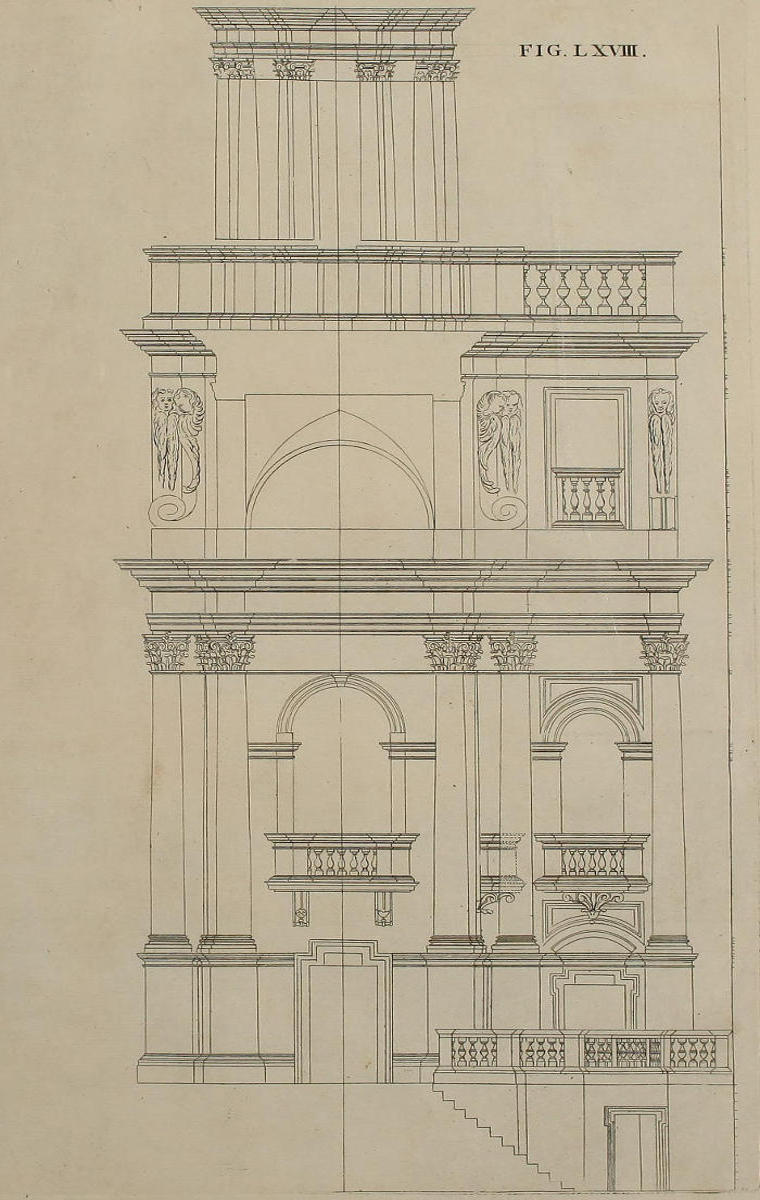
FIG. LXVIII.
Elevatio geometrica vestigii præcedentis, & secunda præparatio ad figuram septuagesimamprimam.
In hoc schemate habes elevationem ædificii sectam in longum, quam figurâ septuagesimâ opticè projiciemus: eisdemque membris constare videbis elevationem deformatam, quibus constat elevatio geometrica. Hinc disces ad excogitandas hujusmodi machinas, eandem Architecturæ scientiam in Pictore necessariam esse, quæ ad construenda solida ædificia exigitur in Architecto.
The Geometrical Elevation of the foregoing Plan, and second Preparation to the Seventy-first Figure.
In this Figure you have the Elevation of the aforesaid Structure dissected lengthwise; the Perspective thereof is describ’d in the Seventieth Figure; and you may observe that both of them consist of the same Members: whence you may perceive, that for designing things of this kind, the Painter ought to have no less Skill in Architecture, than is requir’d for the Execution of solid Works.
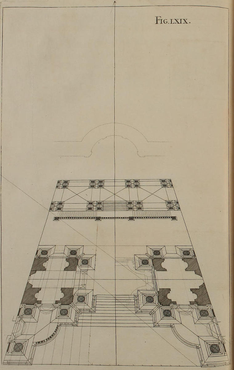
Fig. lxix.
Deformatio vestigii figuræ sexagesimæseptimæ, & præparatio tertia ad figuram septuagesimamprimam.
Artificium projectionis vestigii hujus, explicatum à nobis est figurâ quadragesimasecundâ. Nimirum, ut parallelæ sint invicem distantiores, lineam plani deorsum protraximus, ut ex intuitu figuræ statim cognosces.
The Plan of the Sixty-seventh Figure in Perspective, and third Preparation to the Seventy-first Figure.
The Artifice us’d in projecting the Perspective of this Plan, has been already shewn in the Forty-second Figure; namely, that for giving the greater Distance between the Parallels, the Ground-line is drawn much lower than its true Place; as is manifest on Inspection of the Figure.
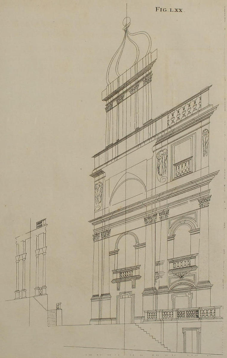
Fig. lxx.
Deformatio elevationis figuræ sexagesimæoctavæ, & præparatio quarta ad figuram septuagesimamprimam.
Quæ dicta sunt de projectione vestigii nostri ædificii, habent locum in elevatione. Nimirum, ut parallelæ invicem notabiliter distarent, usi sumus industriâ quam declaravimus figurâ quadragesimasecundâ.
The Perspective of the Elevation of the Sixty-eighth Figure, and the fourth Preparation to the Seventy-first Figure.
What has been said of the Perspective-Plan of this Structure, is also here practis’d in the Elevation; namely, that the Parallels might be sufficiently distinct, the Perpendiculars are drawn more remote from the Point of Sight, as was shewn in the Forty-second Figure.
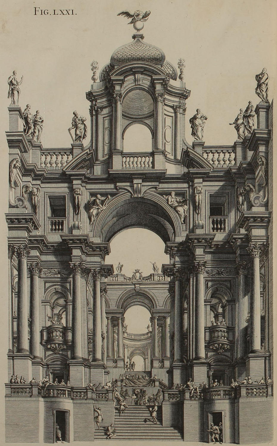
Fig. lxxi.
Theatrum repræsentans Nuptias Canæ Galilææ, constructum Romæ, anno 1685. in expositione Ven. Sacramenti in Templo Farnesiano Societatis JESU.
Ex antecedentibus præparationibus eruimus projectionem nobilis hujus Architecturæ, quæ oculos implebat tum ad lucem solis diurnam, tum præcipuè ad lumen candelarum; ex quibus multæ palam erant expositæ, aliæ omnino latebant, ut illuminarent sex diversos ordines telariorum quibus tota machina constabat, non computando in hoc numero telaria, quæ in medio arcûs maximi exprimebant nubes refertas Angelis adorantibus Venerabile Sacramentum. Nubes istas omisimus, ne absconderentur partes interiorum ædificiorum. In disponendis autem ordinibus telariorum, servatus est modus quem declaravi figurâ sexagesimaprima & sexagesimasecunda; ac præterea in eligenda eorum distantia curatum fuit, ut candelæ in parte postica telariorum collocatæ, illuminarent faciem telariorum interiorum. Porrò quot membra præcipua in duabus faciebus majoribus, totidem distincta telaria numerabantur, quorum proinde connexiones discerni vix poterant; eorumque aliquot paria ferreis hamulis copulata erant, ut explicari ac replicari possent, ad faciliorem tractationem diuturnioremque conservationem.
Qui hucusque sequuti me fuerint, nihil dubito quin suum iter felicissimè sint prosequuturi; atque Opera his nostris majora melioraque inventuri.
A Theater representing the Marriage of Cana in Galilee, erected in the Jesuits Church at Rome, in the Year 1685; for the Solemnity of exposing the Holy Sacrament.
From the foregoing Preparations, is drawn the Perspective of this noble Piece of Architecture; which struck the Eye when seen by Day-light, but was more especially surprizing by Candle-light; many of the Candles being expos’d to Sight, and others altogether hidden, to illuminate the six different Ranges of Scenes, of which the whole Work consisted, without reckoning that in the midst of the great Arch, representing Clouds fill’d with Angels adoring the blessed Sacrament. Those Clouds are here omitted, that the inner Parts of the Work might be the better seen. In disposing the several Ranges of Scenes, the same Method was observ’d, which was deliver’d in the Sixty-first and Sixty-second Figures; and great Care was also taken in their Distances, that the Candles plac’d on the Back of one of them might illuminate the Face of the other behind it. Moreover, each Scene consisted of as many parts, as there were principal Members in the two greater Façades; so that the Joints were scarcely discernible: and some Pairs of them being coupl’d with Hinges, folded and unfolded, for the more easy managing and preserving them.
I doubt not but those who have follow’d me thus far, will be encourag’d so to prosecute their Studies, as to be able to design even greater and more noble Works, than these of mine.
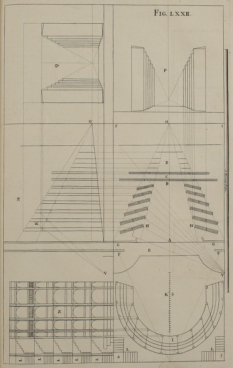
Fig. lxxii.
De theatris scenicis.
Theatris quæ jam delineavimus affinia sunt theatra scenica: in his tamen non adeò facilè reperitur punctum oculi seu perspectivæ. Præterea, quia ex obliquitate canalium intra quos moventur scenæ, oritur ut lineæ rectæ quæ videri debent parallelæ ad lineam plani, non debeant esse parallelæ sed obliquæ, harum delineatio difficultate non caret. Incommodum istud vitari posset adhibendo canales parallelos ad poscenium, ut alicubi fieri solet, præsertim in Germaniâ. Nihilominus usus Italicus affert hoc adjumentum, ut illi quibus incumbit suggerere actoribus, vel scenas movere, aliisque similibus præesse, facilius lateant & liberius fungantur munere suo.
Ut brevem summam habeas eorum quæ deinde latius declaraturi sumus, hanc figuram contemplare. 1, 2, 3, 4, est vestigium aulæ quæ habet in longitudine centumviginti palmos Romanos, in latitudine sexaginta palmos; ut ostendit scala S triginta palmorum. Medietatem loci occupat theatrum, medietatem obtinent podia & loca spectatorum. O punctum in quo uniuntur lineæ visuales, D locus pro apparentiis rerum magis ac magis distantium. BC locus poscenii. HH sunt canales obliqui, quorum latitudo est dupla latitudinis scenarum. FG frons & facies theatri. AO ejus profunditas aut longitudo. E locus pro psaltibus, tibicinibus, & fistulatoribus. K spatium pro spectatoribus. I vestigium podiorum. L scalæ podiorum. N ipsorum elevatio. M declivitas tabulati, cum sectione & elevatione theatri, & scenis ex latere inspectis, quæ cum suis canalibus congruunt, ut demonstrant lineæ occultæ. OO linea normalis ad lineam horizontalem. P & Q elevatio scenarum coram inspectarum, quæ introrsum flectuntur; & in latitudine congruunt cum canalibus vestigii B, in altitudine cum sectionibus elevationis M; ut constat ex lineis occultis. In eâdem elevatione M pars altitudinis tribuenda est scenis, pars laquearibus R, per quæ jungitur unumquodque par telariorum. VV lineæ ad explorandum an detur vacuum inter scenas & laquearia, vel inter scenas, vel inter laquearia. In quibusdam autem scenis, loco laquearium pinguntur nubes & aer.
Of Scenes for the Stage.
Scenes for the Stage have very much Affinity with those lately describ’d, but the Point of Sight is not so easily found in these; and from the Obliquity of the Grooves in which the Scenes run, it comes to pass, that the right Lines which ought to appear parallel to the Line of the Plan, must not be drawn parallel thereto, but oblique; which is a Work of some Difficulty. This indeed may be avoided, by fixing the Grooves parallel to the Poscene; as is usual in some Places, especially in Germany. Nevertheless, the Italian Manner has this Advantage; That those who are employ’d to prompt the Actors, and shift the Scenes, &c. are less expos’d to Sight, in the Performance of their Business.
In this Figure I have given you an Abridgment of those things, which shall hereafter be more enlarg’d on. The Numbers 1, 2, 3, 4, denote the Area of a Hall an hundred and twenty Roman Palms in Length, and sixty in Breadth; as is manifest from the Scale of thirty Palms mark’d S. Half this Space is taken up by the Stage, the other half by the Spectators. O is the Point in which the visual Lines concenter. D is the Place of those things that are to appear most remote. BC is the Place of the Poscene. HH are the oblique Grooves, whose Lengths are double the Breadth of the Scenes. FG is the Front of the Stage. AO is its Depth or Length. E is the Place for the Musick. K is the Room for Spectators. I is the Plan of the Galleries. L the Stairs to the same. N is the Elevation of the Galleries. M shews the Declivity of the Floor, with the Section and Elevation of the Stage and Scenes view’d on the Side; answering their respective Grooves, as the occult Lines demonstrate. OO is a Line perpendicular to that of the Horizon. P and Q are the Elevation of the Scenes view’d in Front, turning inwards, in Breadth agreeing with the Length of the Grooves of the Plan B; and in Height answering that of the Sections of the Elevation M; as is evident from the occult Lines. In this Profile M, part of the Height belongs to the Scenes, and part to their Soffites, or Ceilings, R; where each Pair of these Frames are join’d. VV are the Lines by which is espy’d what Vacancy there is either between the Scenes and their Ceilings, between the Scenes themselves, or between their respective Ceilings; though in some Scenes the Place of these last is supply’d by painting therein the Air with Clouds, &c.
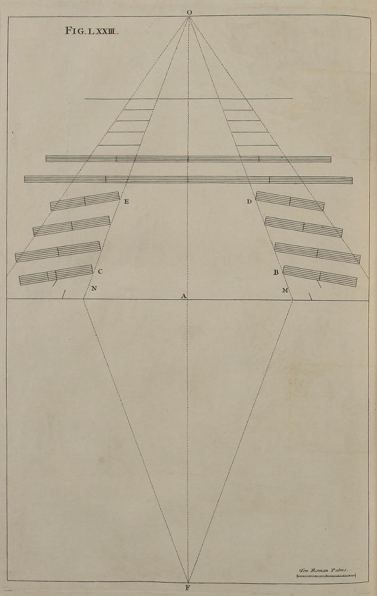
Fig. lxxiii.
Aliud vestigium theatri, ubi de modo inveniendi ejus punctum.
Si pingendæ sint scenæ theatri alicujus antea constructi, delineare oportebit vestigium geometricum ex ipso erutum, (ad formam vestigii quod cernis in hac paginâ) ut inveniatur longitudo theatri, seu distantia quam ejus punctum habet à puncto A: id autem nullo negotio fiet, accipiendo distantias BC inter primos canales, & DE inter ultimos, ac ducendo visuales MO, NO: nam theatrum habebit longitudinem AO, ac punctum perspectivæ in vestigio theatri erit O. Præterea scire oportebit longitudinem & latitudinem canalium, eorumque numerum, distantias, & flexus; ac præcipuè curandum est, ut licet sint obliqui ad lineam MN, sint invicem paralleli in unoquoque latere, ac singuli tangant lineas MO, NO. Jam si rectæ AO fiat æqualis recta FA, in F erit punctum distantiæ: adeoque si theatrum juxta methodum à nobis tradendam depictum fuerit, spectatori qui consistat in F apparebit veluti tabula picta juxta leges perspectivæ, posita in A.
Another Plan of a Theater, with the Method of finding the Point of Sight therein.
If it be requir’d to paint the Scenes of some Theater already built, the Geometrical Plan thereof must first be carefully drawn, (as you see, for Example, in this Plate) that the Length of the Theater may be found; or the Distance of its Point from that of A; which is easily done, by taking the Interval BC of the first Grooves, and DE of the latter; and drawing the Visuals MO, NO: for AO is the Length of the Theater, and the Point of Sight, or Perspective, therein, is O. Moreover the Length and Breadth of the Grooves must be known, as also their Numbers, Distance, and Obliquity; and especial Care must be taken, that though they be oblique to the Line MN, that on each Side they be Parallels between themselves, and that they all touch the Lines MO, NO. If you then make AO equal to FA, the Point of Distance will be F; and if the Theater be painted according to the Rules hereafter given, it will appear to him that views it from F, as a regular Piece of Perspective plac’d in A.
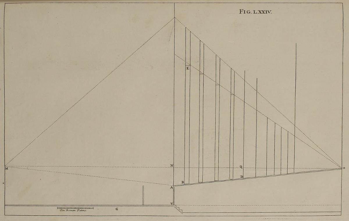
Fig. lxxiv.
Sectio Scenarum Theatri.
Præter vestigium Theatri delineanda est sectio scenarum. Itaque si acceptis mensuris altitudinis, quam punctum A unde incipit tabulatum, ac punctum D poscenii, habent supra planum horizontale FV, fiant ex perpendiculo NV tum recta ADO ex qua innotescit declivitas tabulati, tum recta NO, quæ sit parallela ad FV & æqualis rectæ AO figuræ septuagesimætertiæ; punctum theatri in elevatione est O; in poscenio verò punctum theatri est Q. Si maxima scenarum altitudo sit EB, recta OE dat altitudinem omnium reliquarum. Vera tamen altitudo cujuslibet scenæ est illa quam habet linea major, ex minori autem dignoscitur quantum obliquitas cujusque scenæ apparenter minuat altitudinem extremæ illius lineæ. Porro excessus quo linea major superat minorem tum in summo tum in imo, diligenter notandus est, hinc enim pendet intelligentia figuræ septuagesimæquintæ. Punctum M quod est remotum ab N quantum in figura septuagesimatertia punctum F est remotum ab A, designat locum unde Theatrum spectari oporteat, ut ibidem notavimus.
In construendo tabulato solet servari hæc regula, ut altitudo puncti O sit æqualis altitudini oculi, & elevatio ex A usque ad D sit nona circiter vel decima pars ipsius longitudinis AD. Expediret autem ad scenas facilius movendas, pavimentum F esse profundius pavimento G, ut erecto corpore sub tabulato ambulari possit.
The Section or Profile of Scenes for Theaters.
Besides the Plan of the Theater, the Section of the Scenes is also to be delineated, for finding the Point of the Theater in the Elevation. Wherefore, setting the Measures of the Heights which the Point A, where the Floor of the Stage begins, and the Point D of the Poscene, have above the Level of the Horizontal FV; from the Perpendicular NV draw the right Line ADO, which gives the Declivity of the Stage; then make NO parallel to FV, and equal to AO of the Seventy-third Figure: The Point of the Theater in Elevation is O; the Point of the same on the Poscene is Q. If EB be the greatest Height of the first Scene, the Line OE determines the Height of all the others. The longest of the two Lines gives the true Height of each Scene; and the shorter discovers how much of that Height the Sight loses on the Out-line, by the oblique Position of the Scenes. Moreover, the Excess of the longer Line above the shorter, as well at top as at bottom, is to be well observ’d; for on this depends the right Understanding of the Seventy-fifth Figure. The Point M, which is as far distant from N, as that of F is from A in the Seventy-third Figure, denotes the Place from whence the Stage ought to be view’d; as is there mention’d.
In laying the Floor of the Stage, this Rule is commonly observ’d, That the Height of the Point O be made equal to the Height of the Eye, and that the Rise of the Floor from A to D, be about a Ninth or Tenth Part of the Length AD. ’Tis also requisite, for the better shifting the Scenes, that the Pavement F be sunk lower than that of G, that a Man may walk upright under the Floor thereof.
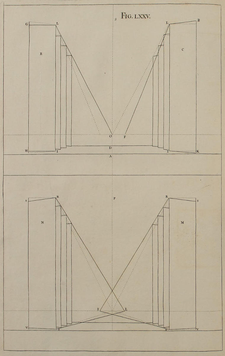
Fig. lxxv.
Elevatio scenarum coram inspectarum: ubi docetur artificium ut scenæ obliquæ appareant rectæ.
Scenæ quas vides in S, habent suam latitudinem à vestigio figuræ septuagesimætertiæ, altitudinem ab elevatione figuræ septuagesimæquartæ, ac censentur erectæ & canalibus insertæ, quæ omnia repræsentantur etiam figurâ septuagesimasecunda in P & Q. Velim observes quantum elevetur tabulatum in principio A, in poscenio D, & in puncto theatri O. Similiter notare oportet elevationem singularum scenarum, quæ propter obliquitatem canalium flectuntur introrsum: iccirco lineæ BL, KI, partis C, non videntur parallelæ ad lineam plani, ut reipsa sunt; ac visualis LF non tendit ad punctum oculi O, sed ad punctum F. Si autem excessus apparens, quem recta BK habet in summo & imo supra rectam LI transferatur in partem E scenarum, (iidem excessus desumi etiam possunt ex figura septuagesimaquarta) ac ducantur rectæ LG, IH, habebuntur lineæ apparenter parallelæ ad lineam plani. Si fiat recta LO, quæ cum LG faciat angulum GLO æqualem angulo BLF, eadem LO tendet exactissimè ad punctum O oculi, eâque utendum erit ut visuali.
In P supponimus scenas M & N jacere super pavimento unas super aliis, ac duas lineas RT habere distantiam eandem cum duabus LI, & ita in reliquis scenis. Ubi notandum est, lineas RS, TV, easdem esse cum lineis LG, IH, scenarum E: nihilominus lineas RS, TV, non esse parallelas, quum tamen LG, IH, videantur parallelæ. Proinde, si fiat recta RL, & anguli SRL, GLO, sint æquales, rectâ RL utendum erit tanquam visuali, in L erit punctum accidentale oculi pro pingendis scenis N, ac lineæ RS, TV, habebuntur ut parallelæ: id autem quod superest in telario ultra tales lineas, pro nihilo computabitur, ibique pingetur aer aut aliquid aliud. Punctum accidentale oculi pro pingendis scenis M erit in I.
The Elevation of Scenes in Front, and how the oblique Scenes are made to appear direct.
The Scenes in S have their Breadth from the Plan of the Seventy-third Figure, and their Height from the Elevation of the Seventy-fourth Figure; and are suppos’d to stand perpendicularly in their Grooves; all which is also represented in P and Q of the Seventy-second Figure. I would have you observe, how much the Floor rises, from its Edge A, to the Poscene D, and to the Point of the Theater O. You should also note the Elevation of each Scene, which, by reason of the Obliquity of the Grooves, turn inward: Wherefore the Lines BL, KI, of the Part C, do not seem Parallels to the Ground-line, as they really are; and the Visual LF tends not to the Point of Sight O, but to the Point F. But if the seeming Excess, which the Line BK has at top and at bottom, above the Line LI, be transferr’d on the Side of the Scenes E, (which Excess may also be taken from the Seventy-fourth Figure) and you draw the Lines LG, IH; these Lines will appear Parallels to the Line of the Plan. Then drawing the Line LO, so as to make the Angle GLO equal to the Angle BLF, the said LO shall tend directly to the Point of Sight O; and serve for a visual Line.
In P, I suppose the Scenes M and N to lie one upon another on the Floor, and the two Lines RT to have the same Distance as the Lines LI; and so of the others. Where you are to take Notice, that the Lines RS, TV, are the same with the Lines LG, IH, of the Scenes E: and that the Lines RS, TV, are not Parallels; altho’ LG, IH, seem to be so. Therefore, if you draw the Line RL, so that the Angles SRL, and GLO, be equal; the Line RL shall serve as a Visual, and L shall be the accidental Point of Sight, for painting the Scenes of the Side N; and the Lines RS, TV, shall be us’d as Parallels. What remains on the Frame, beyond those Lines, is to be reckon’d as nothing; but you may paint there Air, or what you please. The accidental Point of Sight for painting the Scenes of the Side M, is I.
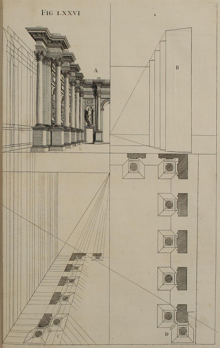
Fig. lxxvi.
Modus delineandi exemplar scenarum.
Iterum delineavimus scenas erectas super tabulato; in B nudas, in A depictas, additis projecturis coronicum & aliorum ornamentorum. Deformatio scenarum A eruitur methodo consuetâ ex vestigio C, in quo videbis lineam plani deorsum protractam. Vestigium autem geometricum est in D.
The Manner of delineating the Designs of Scenes.
In this Plate you have another Design of Scenes erected on the Floor; the naked Scenes are B; the painted ones A; with the additional Projectures of Cornices and other Ornaments. The Draught of the Scenes A is produc’d from the Plan C, after the usual Manner; in which you may observe the Ground-line to be lower than its true place, for the greater Distinction of the Parallels. The Geometrical Plan is D.
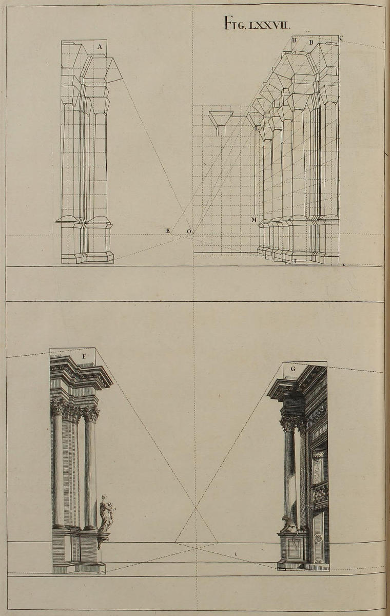
Fig. lxxvii.
Modus reticulandi & pingendi scenas theatri.
Postquam in pavimento exactissimè disposueris tum poscenium, tum ex ordine scenas reliquas, unam alteri incumbentem, ut figurâ septuagesimaquintâ declaravimus, fiet linea horizontalis, in qua notanda sunt tria puncta perspectivæ, unum in O usui futurum in pingendo poscenio, ac duo reliqua hinc inde, singula videlicet pro scenis partis oppositæ. Jam supponendo quòd in parvo exemplari A primæ scenæ facta fuerit reticulatio per quadrata perfecta; proportionalis divisio fiet tum in recta HI primæ scenæ B, tum in recta CD. Postea ex puncto E, per singula puncta divisionum rectæ HI, fient visuales, adhibendo funiculum colore nigro imbutum; earumque ope, ut figura ostendit, reticulare oportebit scenam B, tum remotâ ea scenam illi subjectam, & eodem modo aliam & aliam; ac demum per divisiones quas in recta LM faciunt visuales ex puncto E, absolvetur reticulatio poscenii, cujus quadrata esse debent perfecta, secus quadrata scenarum. In parte inferiori paginæ, duæ scenæ G & F ostendunt ornamenta quæ in scenis depingi possunt. Velim autem observes, tum lineas transversas coronicum, quæ non sunt invicem parallelæ, tum visuales, quæ tendunt ad puncta opposita. Nam ejusmodi lineæ continent duas peculiares difficultates projectionum theatralium; easque ut superes, exactè servandæ sunt regulæ quas declaravimus.
The Manner of making the Net-work or Squares, and painting the Scenes of Theaters.
After you have with great Exactness dispos’d the Poscene on the Pavement, and the others in order one upon another, as was mention’d in the Seventy-fifth Figure; draw the horizontal Line, and mark therein three Points of Sight: That in O, for the Use of the Poscene; and the Points on the Sides, for the Service of the opposite Scenes respectively. Then, supposing that the Net-work of the small Draught of the first Scene A, consists of perfect Squares; transport the same Divisions both on the Lines HI and CD of the first Scene B; and with a black Line strike the Visuals from the Point E, by the Points of the Divisions of HI; and by the Help of those Visuals make the Net-work of the Scene B, as is done in the Figure. When that’s done, lay it aside; and do the next in the same manner; and so of the others. Lastly, by the Divisions, which the Visuals from the Point E make on the Perpendicular LM, finish the Net-work on the Poscene, which consists of perfect Squares, though that of the Scenes does not. The two Scenes of the lower part of the Plate, G and F, shew what Diversity of Ornament the Painter may introduce. I would have you also take particular Notice, both of the transverse Lines of the Cornice, which are not Parallels to each other; and of the Visuals which are directed to their opposite Points: because in these two Particulars lies the greatest Difficulty of describing Theatrical Designs; for the surmounting which, it’s absolutely necessary, that you carefully regard the Rules hitherto deliver’d.
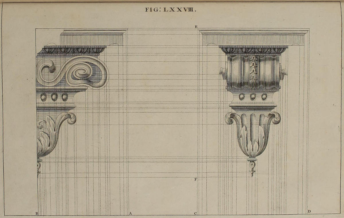
FIG. LXXVIII.
De projectionibus horizontalibus.
Quemadmodum facilior est deformatio columnarum jacentium, quàm columnarum erectarum; (nam lineæ quæ in istis sunt perpendiculares, in illis sunt visuales, ac nullus circulus amittit suam formam) ita projectiones horizontales, quas in laquearibus delineare necesse est, contra quàm Pictores imaginantur, expeditiores & faciliores sunt verticalibus, quas hucusque tractavimus. Nam ut stylobatæ & columnæ appareant erectæ, pingendæ sunt veluti jacentes.
Deformationes horizontales auspicamur à mutulis, quia columnæ ac stylobatæ identidem iis imponuntur, ut magis in prospectu sint. Ob diversitatem verò quam habet latus mutuli à sua facie, utriusque delineationem geometricam seorsim in hac figura exhibemus.
Of horizontal Perspective.
As it is easier to describe in Perspective Columns lying on the ground, than those that are erect, (the Lines in these last being Perpendiculars, which in the former are Visuals, wherein no Circle loses its Form) so the horizontal Projections of Perspective, proper for Ceilings, contrary to the Judgment Painters usually make, are perform’d with more Ease and Expedition, than the vertical, which we have hitherto treated of; forasmuch as the Pedestals and Columns that must appear erect, are painted as if lying on the ground.
I have usher’d in these horizontal Designs with those of Corbels, because, for setting the Pedestals and Columns more in View, they generally seem to be supported by them. And the Side of this Corbel being different from its Face, I have here inserted a Geometrical Description of each distinct.
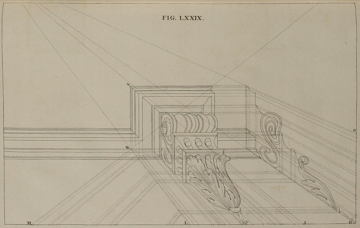
FIG. LXXIX.
Projectiones vestigii & elevationis mutuli.
Facies mutuli quam delineavimus figurâ septuagesimaoctavâ, gerit hic munus vestigii; latus verò gerit munus elevationis; ut ostendunt lineæ occultæ, quæ ex divisionibus faciei tendunt ad punctum oculi, ex divisionibus lateris tendunt ad punctum distantiæ (puncta oculi ac distantiæ in hac & sequentibus figuris cadunt extra paginam.) Per sectiones harum linearum ducuntur lineæ quæ terminant singulas partes vestigii deformati; hujusque adjumento ducitur elevatio lateris, ac methodo consuetâ latitudines & longitudines mutuli solidi eruuntur ex vestigio, altitudines ex elevatione. Hic & deinceps nomina longitudinis & altitudinis usurpamus, veluti planum cujuslibet perspectivæ esset verticale; in quâ suppositione, IL esset latitudo mutuli, SR altitudo, RL longitudo: quum SR reverà sit longitudo, RL altitudo. Ad faciliorem descriptionem hujus figuræ observandum est, rectis IL, LM, GH, hujus paginæ inesse divisiones rectarum DC, FE, AB, figuræ septuagesimæoctavæ.
The Plan and Elevation of a Corbel in Perspective.
The Face of the Corbel describ’d in the Seventy-eighth Figure, in this does the Office of a Plan; and the Side serves here for the Elevation; as is plain from the occult Lines, which from the Divisions of the Face tend to the Point of Sight, and from those of the Side tend to the Point of Distance; both which Points, in this and the succeeding Figure, fall without the Plate. From the Intersections of these Lines are drawn others, that determine each Part of the Perspective-Plan; by means of which, the Elevation of the Side being also form’d, the Breadths and Lengths of the solid Corbel are taken, as usual, from the Plan, and the Heights from the Elevation. Here and henceforward, the Terms of Length and Height are made use of, as though the Plan of each Perspective were vertical; according to which Supposition, IL is the Breadth of the Corbel, SR the Height, and RL the Length; whereas in reality SR is the Length, and RL the Height. For the more ready Description of this Figure you will do well to observe, that the Lines IL, LM, GH, of this Plate, bear the same Divisions as DC, FE, AB, of the Seventy-eighth Figure.
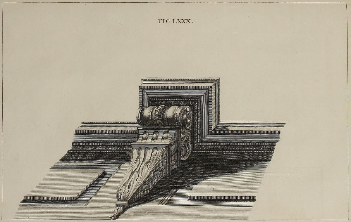
FIG. LXXX.
Horizontalis projectio mutuli inumbrati.
In hac figurâ suas umbras mutulo addidimus: eumque si in altum supra oculum elevaveris, & ex distantiâ quam ipsi dedimus suspexeris; miraberis profectò, in alium longè concinniorem subitò mutatum fuisse.
The Horizontal Projection of a shaded Corbel.
In this Figure you have the Corbel finish’d with its proper Shades; which, if plac’d above the Eye, and beheld from the Distance here assign’d it; you’ll be strangely surpriz’d at the sudden and most agreeable Alteration you’ll find therein.
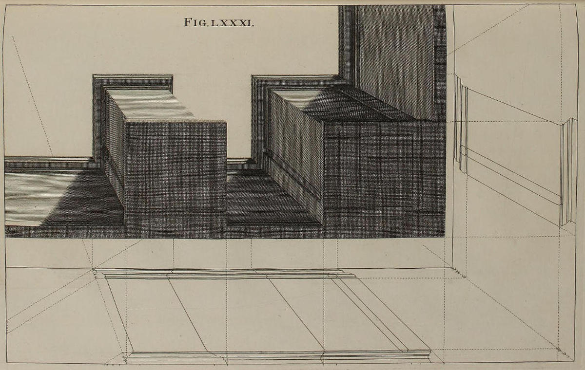
Fig. lxxxi.
Stylobatæ Corinthii horizontaliter contracti.
In deformandis hisce stylobatis, usi sumus projectione vestigii & elevationis, quam exhibet figura duodecima; ut figuram illam cum istâ conferenti manifestissimè constabit. Porrò stylobatas pingi solere incumbentes mutulis, diximus figurâ septuagesimaoctavâ.
Corinthian Pedestals in an Horizontal Perspective.
In delineating these Pedestals, I have made use of the Plan and Upright put into Perspective in the Twelfth Figure; as will evidently appear, by comparing that Figure with this. I have already mention’d, in the Seventy-eighth Figure, that in painting these Pedestals, they are generally suppos’d to be upheld by Corbels.
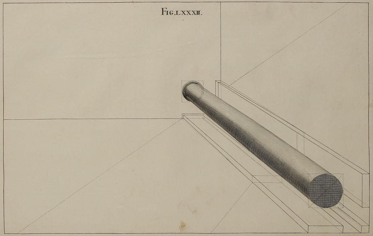
Fig. lxxxii.
Columna Corinthia horizontaliter deformata.
Vestigium & elevatio stylobatæ, quem delineavimus figurâ duodecimâ, suppeditat mensuras pilarum hoc loco deformandarum, ut ex iis eruatur contractio columnæ. Huic autem soli suas umbras addidimus, ut clariùs appareat modus & artificium totius operationis. Ex his vides, quadrata & circulos in perspectivâ horizontali omninò retinere suam figuram, eamque dumtaxat restringi paulatim & coarctari: quicquid in contrarium & verbis & pennicillo docuerint Pictores nonnulli.
A Corinthian Column in Horizontal Perspective.
The Plan and Elevation of the Pedestal delineated in the Twelfth Figure, gives also the Measures for reducing these Pilasters into Perspective; from which the Contraction of the Column is taken. I have shadow’d only this last, that the Manner of the whole Work might be the more conspicuous. By this you see the Squares and Circles in Horizontal Perspective always retain their Figures, without any Alteration, save that of being gradually diminish’d and made less; notwithstanding what some Painters have taught and practis’d to the contrary.
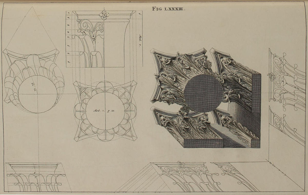
Fig. lxxxiii.
Capitella Corinthia horizontaliter contracta.
Habes in hac paginâ deformationes vestigii & elevationis capitelli Corinthii, quas desumpsimus ex delineationibus geometricis, transferendo mensuras earum in lineas plani AB, & elevationis AC, ita ut facillimè dignosci possit unde nascantur singulæ partes capitellorum nitidorum. Nihil dubito quin deformationes horizontales sis experturus faciliores verticalibus quas dedimus figurâ vigesimaquartâ. Nam in horizontalibus gyrus foliorum circulis clauditur, quorum centra mutuantur latitudines à suis vestigiis in punctis 1, 2, 3, 4; altitudines verò à capitellis elevationis in punctis 5, 6, 7, 8.
A Corinthian Capital horizontally contracted in Perspective.
You have in this Plate the Perspective both of the Plan and Elevation of the Corinthian Capital, drawn from the Geometrical Descriptions, by transferring their Measures into the Ground-line AB, and into that of the Elevation AC; so that you may readily discover from whence every part of the finish’d Capital is produc’d. I don’t doubt but you’ll experience these horizontal Perspectives to be much less difficult than the vertical propos’d in the Twenty-fourth Figure. For in these the Circuit of the Leaves is determin’d by perfect Circles, whose Centers take their Breadths from the Plan at the Points 1, 2, 3, 4; and their Heights from the Capitals of the Elevation, at the Points 5, 6, 7, 8.
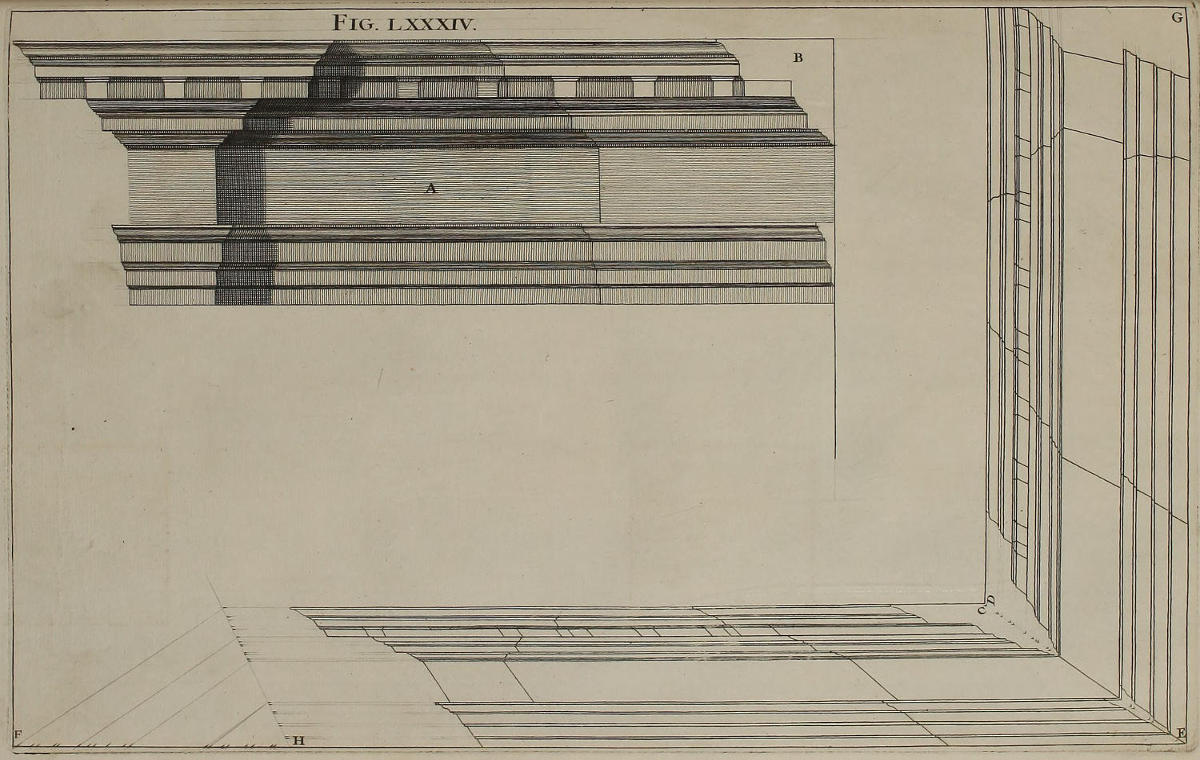
Fig. lxxxiv.
Coronix Corinthia.
Si faciendæ sint coronices quæ habeant angulos, elevatio geometrica A repræsentabit unum latus, alterum sectio B. Curandum est autem, ut crepidines partium, quas fingere volumus incumbere columnis, non obsint concinnæ distributioni mutulorum. Ad contractionem elevationis A & sectionis B, in lineam plani EF & elevationis EG transferre oportet puncta diversarum latitudinum, quas habent in elevatione A ungues epistylii, zophori, & coronæ, ducendo ex iis lineas ad punctum oculi; in partem verò FH lineæ FE transferre oportet puncta longitudinis, ducendo lineas ad punctum distantiæ. Hac industriâ perficies utramque deformationem, quarum una geret munus vestigii, altera elevationis. Utrobique autem designabis lineas terminativas partium coronicis, ac sectionum C & D.
A Corinthian Cornice.
If you are to describe Cornices having Angles, admit the Elevation A to represent one Side, and the Section B the other. But Care is to be taken, that the Breaks of those Parts which are suppos’d to be set directly over the Columns, do not obstruct the regular Distribution of the Modillions. For contracting into Perspective the Elevation A, and the Section B, you must transfer into the Ground-line EF, and into that of the Elevation EG, the Points of the several Breadths made by the Projectures of the Architrave, Freeze, and Cornice of the Elevation A; and from them draw Lines to the Point of Sight: Then on the Part FH of the Line FE, you must note the Points of Length, and draw Lines from them to the Point of Distance. By this Practice you complete these two Contractions, one of which does the Office of a Plan, the other that of an Elevation. It’s also requisite, that you draw the Out-line of the Members of the Cornice on each side the Angle, & the Sections C and D.
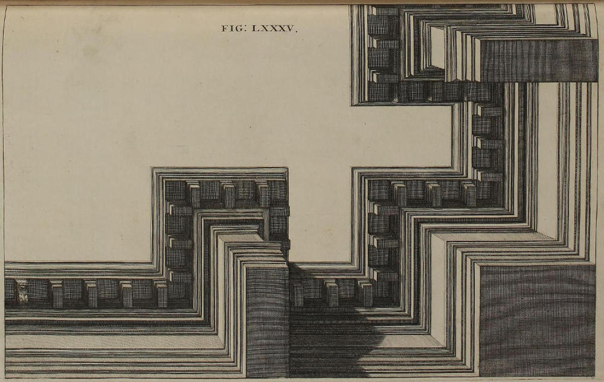
FIG. LXXXV.
Coronix Corinthia horizontaliter contracta.
Soliditas coronicis cum omnibus projecturis eruta est ex vestigio & elevatione figuræ octogesimæquartæ. Hic autem finem imponimus partibus rerum, ad integra ædificia gradum facturi.
A Corinthian Cornice in Horizontal Perspective.
The Solidity of this Cornice, with all its Projectures, is deduc’d from the Plan and Elevation of the foregoing Figure. With this therefore I shall conclude the Description of Parts of things, and proceed to that of entire Structures.
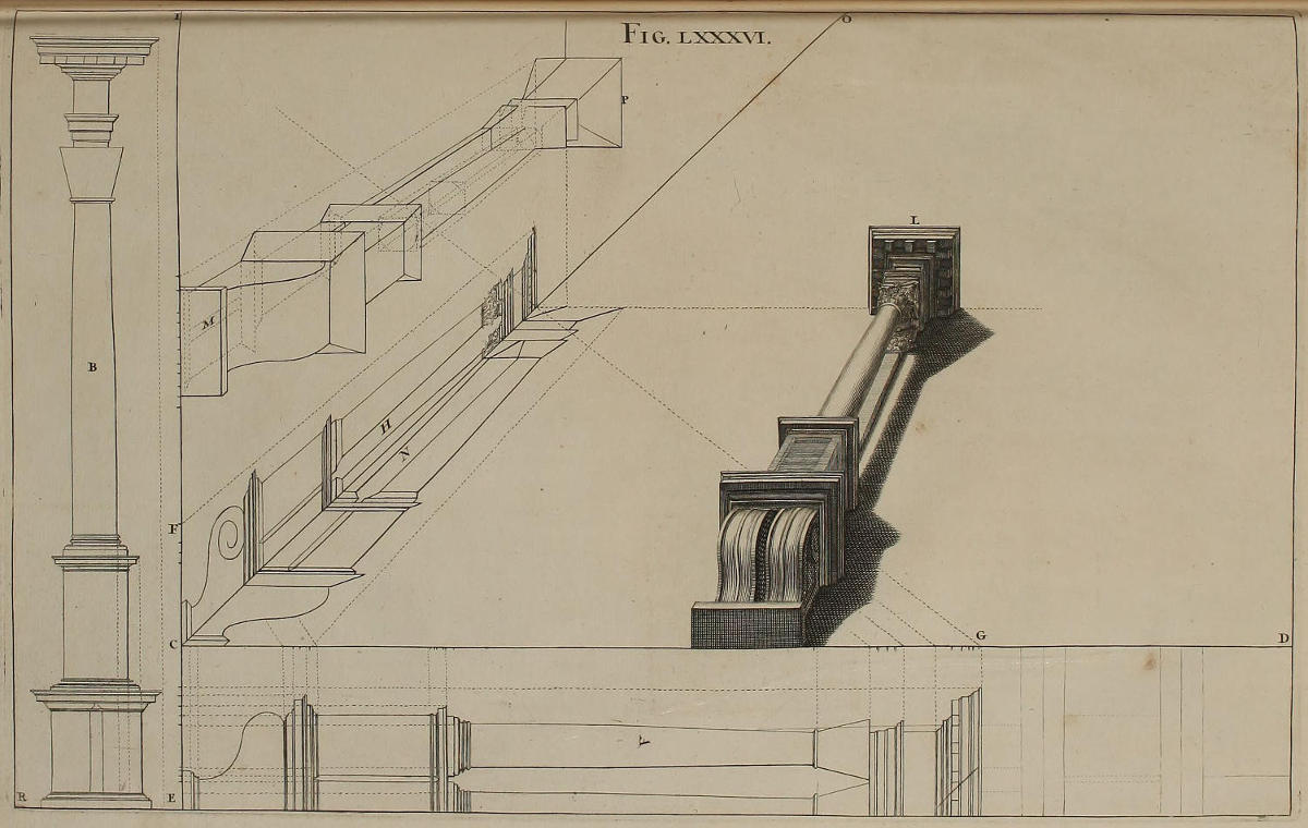
Fig. lxxxvi.
Horizontalis projectio columnæ.
Postquam sigillatim descripsimus mutulum, stylobatam, columnam & coronicem, omnia ista conjungere placuit: ita clariùs apparebit quomodo disponere oporteat delineationes geometricas, ut ex iis eruantur projectiones horizontales.
Linea plani est CD, perpendicularis CI. In A est elevatio geometrica longitudinis columnæ, (supponimus columnam delineari veluti jacentem humi.) In B ejus vestigium geometricum, cum divisionibus latitudinis in lineâ ER. Puncta longitudinis transferentur in lineam plani CG, puncta altitudinis EC transferentur in CF, ducendo rectas ex divisionibus CG ad punctum distantiæ, ex divisionibus CF ad punctum oculi. Per sectiones verò visualis CO erigentur perpendicula, & complebitur elevatio H, ex quâ eruetur columna nitida L.
Si super vestigio M formare placeat aliam columnam, ejus latitudines accipiendæ sunt ex columna B; ac sectio projicienda est in N, ut ex hac tamquam ex elevatione eruatur columna P. Si aliam columnam in angulo addere libitum fuerit, ope sectionum HN facilè illam complebis.
A Column in horizontal Perspective.
After the separate Description of a Corbel, Pedestal, Column, and Cornice; I have here conjoin’d them all, that you might the better perceive how to dispose Geometrical Elevations for the Business of horizontal Perspective.
The Line of the Plan is CD, the Perpendicular CI; the Geometrical Elevation of the Length of the Column, suppos’d to be lying on the Ground, is A. The Geometrical Plan thereof is B, with the Divisions of its Breadth on the Line ER. The Points of Length being transferr’d on the Line of the Plan CG, and the Points of Height EC into CF; from the Divisions of CG Lines are drawn to the Point of Distance; and from those of CF to the Point of Sight. From the Sections of the Visual CO, Perpendiculars are erected, and the Elevation H completed, from whence is taken the finish’d Column L.
If upon the Plan M you would delineate another Column, the Breadths thereof must be taken from the Column B, and another Profile design’d in N, which serves as an Elevation for making the Column P. If another Column were requir’d in the Angle, the Profiles HN assist you in the ready Performance thereof.
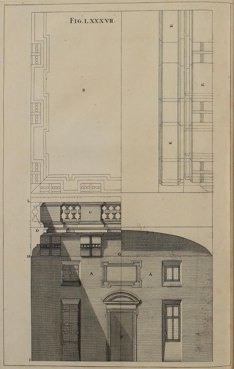
Fig. lxxxvii.
Præparatio necessaria ad sequentem figuram, & ad projectiones horizontales in laquearibus vel testudinibus.
Exhibet hæc figura in AA unum ex quatuor parietibus aulæ, cujus altitudinem veram IH velis attollere apparenter usque in L, pingendo in laqueari, vel in testudine, seriem balaustiorum. In B est vestigium geometricum quartæ partis laquearis. In C habetur elevatio medietatis latitudinis. In D est sectio coronicis & mutulorum. In E posita est elevatio medietatis longitudinis. In F est punctum oculi, in G punctum distantiæ: adeóque tota distantia est GF.
The Preparation necessary to the following Figure, and to all other horizontal Perspectives, whether on flat or vaulted Ceilings.
The Figure AA represents one of the four Walls of a Hall, whose true Height IH you would have appear rais’d to L, by painting a Ballustrade in the Ceiling thereof. B is the Geometrical Plan of the fourth part of the said Ceiling; C is the Elevation of half the Breadth; D is the Section of the Cornice and Corbels; E is the Elevation of half the Length. In F is the Point of Sight, in G the Point of Distance; so that the Distance itself is FG.
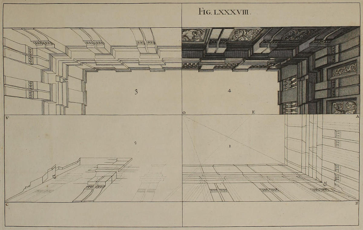
Fig. lxxxviii.
Horizontalis projectio balaustiorum figuræ octogesimæseptimæ, cum brevi distantia.
Claritatis gratiâ totum laquear divisum est in quatuor partes. Prima continet contractionem vestigii & elevationis, quæ perficiuntur methodo consueta. Nam linea AOV est horizontalis, BC est linea plani. Punctum oculi est O, distantiæ E. Secunda pars continet sectionem L, quæ dat projecturas mutulorum aliarumque partium, desumendas ex sectione D figuræ octogesimæseptimæ, deformando eam in angulis B & C. Tertia pars complectitur delineationem integram sine umbris: ultima pars eandem complectitur cum umbris.
Ob punctum distantiæ parum remotum à puncto oculi, nimiam amplitudinem ac deformem apparentiam habere videtur hæc delineatio. Nihilominus, si ex distantia EO figuram suspexeris, omnis deformitas evanescet.
Ut fucus imperitis fiat, industrii Pictoris interest parare sibi geminum exemplar suorum Operum, in quibus distantia sit nimis brevis; unum videlicet palam ostendendum, in quo punctum distantiæ sit remotum à puncto oculi, quantum necesse est ad vitandam omnem deformitatem. Alterum verò, in ipsomet Opere clam usurpandum.
Si pingendæ sint testudines, oportet prius facere in eis reticulationem peculiarem; quæ quia difficilis est, & paucis explicari nequit, in aliud Opus reservatur.
The horizontal Projection of the Ballustrade of the Eighty-seventh Figure, view’d at a small Distance.
For the better Illustration of this Figure, I have divided the whole Ceiling into Four Parts. The first contains the Plan and Elevation in Perspective, after the usual manner; AOV being the horizontal Line, BC that of the Plan; the Point of Sight O, and that of Distance E. The second Part contains the Section L, which gives the Projectures of the Corbels and other Parts taken from the Section D of the Eighty-seventh Figure, by drawing it in the Angles B and C. The third Part comprehends the Delineation of the Perspective without Shadows. The fourth Part contains the same wholly shadow’d and finish’d.
Through the near Approach of the Point of Distance to the Point of Sight, you may perhaps imagine this Draught will appear too wide, and so have an ill Effect: But when once you view it from its due Distance EO, you will find all such Doubts vanish and come to nothing.
When you have to deal with Persons unskill’d in these things, and are to paint for so small a Distance; your best way is to make two Draughts; one for publick Shew, in which you may place the Point of Distance so far from the Point of Sight, as is necessary for preventing Deformity; and the other you may privately make use of in performing your Work.
If you are to paint arch’d or vaulted Ceilings, a particular kind of Net or Lattice-work must first be made therein; the Performance whereof being difficult, and not capable of being explain’d in few words, I have reserv’d it for another Volume.
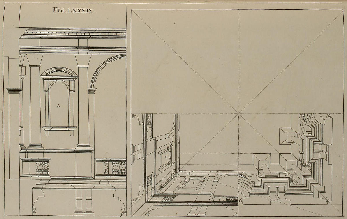
Fig. lxxxix.
Horizontalis projectio architecturæ in laqueari quadrato.
Si laquear sit quadratum, & valde distans ab oculo, architecturam huic similem in eo depingere licebit. A est elevatio geometrica; eadem verò deformata in B & C, gerit munus vestigii & elevationis. Medietas unius ex quatuor partibus, usui esse potest in toto opere, aut premendo chartam, aut eâ perforatâ, immittendo per foramina carbonem minutissimè contusum.
An horizontal Projection of Architecture in a square Ceiling.
If the Ceiling be square, and very remote from the Eye, you may paint in it some such Piece of Architecture as this. A is the geometrical Elevation; the same reduc’d into Perspective in B and C does the Office of a Plan and Elevation. The Half of one of the four Parts may suffice for the Draught of the whole Work, either by tracing over the Lines of the Paper, or by pricking small Holes therein, and pouncing them through with Charcole finely powder’d.
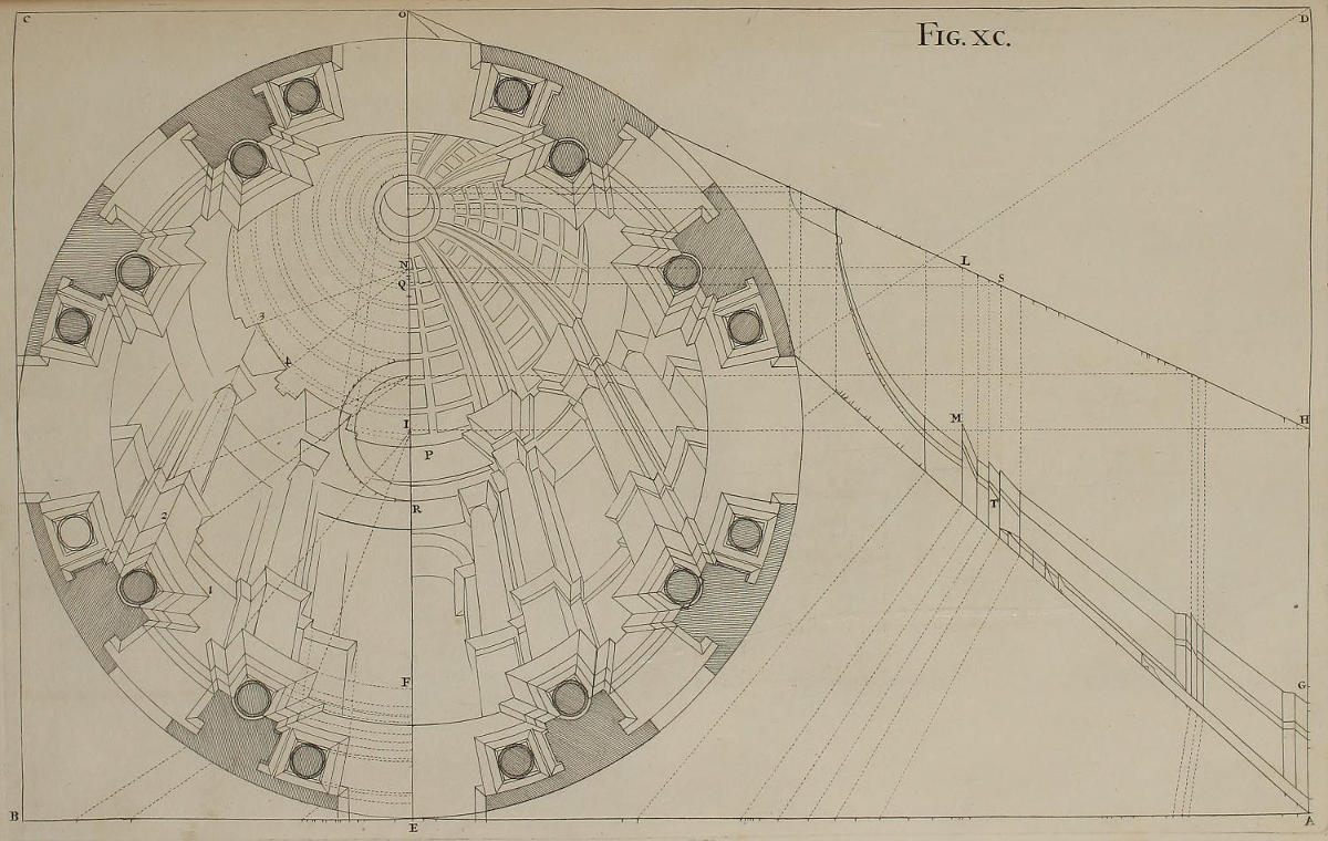
Fig. xc.
Horizontalis projectio tholi.
Initium hujus rei fiet à vestigio geometrico, in quo duæ series circulorum designant columnas; aliæ lineæ designant stylobatas, ac projecturas & ungues basium & coronicum. Linea plani est AB, horizontalis CD, perpendicularis AD. Punctum oculi est O, distantiæ D; adeóque figura hæc debet habere supra oculum altitudinem DO. Punctum oculi positum fuit extra ipsum tholum, ut qui eum aspiciunt, minus defatigentur, ac plus appareat de architectura & de artificio; secus verò contingeret si punctum oculi esset in medio. Itaque puncta lineæ EF transferentur in partem AG lineæ AD. Centrum I vestigii transferetur in H & ex omnibus his punctis fient visuales ad O. Deinde altitudine tholi, ac divisionibus partium singularum tum ipsius, tum laternæ, translatis in lineam AB, ex punctis divisionum fient rectæ ad punctum distantiæ D. Ubi autem hæ secant visualem AO, erigentur perpendicula, quorum sectiones cum visuali HO dabunt centra pro singulis circulis. Inter visuales AG ducere oportet lineas terminativas columnarum & coronicum; quemadmodum fieret, si ex vestigio eruta fuisset elevatio geometrica. His positis, aggredieris delineationem opticam ipsius tholi, translatis in perpendicularem EO centris ope parallelarum HI, LN; ac semidiametro LM fiet circulus NP pro simâ coronicis: semidiametro ST fiet circulus QR, & sic de reliquis. Quomodo autem per rectas ex angulis vestigii ad punctum oculi, habeantur ungues coronicis, ostendunt numeri 1, 2, 3, 4; lineæ verò laterales unguium tendunt ad centra suorum circulorum, ut videre est in N 3, 4. In vestigio, ne nimium occupetur, mutulos omisimus.
Ex his patet necessitas faciendi vestigium geometricum totius tholi, ac non sufficere vestigium unius columnæ; quum singulæ peculiares exigant deformationes. Quum autem Opus ipsum delineandum ac pingendum fuerit, ipsum desumere non poteris ex parvo exemplari, ope reticulationis; Quinimo suis locis ducere oportebit lineas visuales, & invenire centra omnium circulorum. Figendo autem funiculum in singulis centris, ipsius adjumento facillimè absolves omnes circumferentias.
A Cupola in horizontal Perspective.
In the Execution of this Work, you are to begin with the Geometrical Plan; in which the two Ranges of Circles denote the Columns, the other Lines shew the Pedestals, with the Projectures and Breaks of the Bases and Cornices. The Line of the Plan is AB, that of the Horizon CD, the perpendicular Line is AD. The Point of Sight is O, that of Distance D; wherefore this Figure ought to be plac’d as much above the Eye, as the Height DO. I have set the Point of Sight something without the Cupola, that the Eye might be less weary’d in viewing the Work, and embrace more of the Architecture, than it could have done, had the Point of Sight been in the midst. The Points of the Line EF are transferr’d into AG, part of the Line AD. The Center of the Plan I is continu’d to H, and from all these Points visual Lines are drawn to O. Then placing the Heights of every part both of the Cupola and Lantern on the Line AB, from the Points of those Divisions draw Lines to the Point of Distance D; and where they cut the Visual AO, erect Perpendiculars intersecting the Line HO; which Points are the Centers of the several Circles. On the Visuals, between AG, must be describ’d the Out-lines of the Columns and Cornices, in like manner as when a Geometrical Upright is rais’d from a Plan. This done, you proceed to the Delineation of the Cupola itself in Perspective, by transferring into the Perpendicular EO the several Centers of HO, by Parallels to HI, as LN, &c. On the Center, with the Interval LM, describe the Circle NP, for the Nose of the Cornice; and with the Semidiameter ST describe the Circle QR, and so of the rest. The Numbers 1, 2, 3, 4, shew how the Breaks of the Cornice are determin’d by Lines from the Angles of the Geometrical Plan tending to the Point of Sight, till they intersect the Circle: The Returns of which Breaks are made by Lines tending to the Centers of their respective Circles; as is plain from N 3, and N 4. In this Plan I have omitted the Corbels, lest I should too much encumber the Work.
Hence appears the Necessity of making the Geometrical Plan of the whole Cupola, the Plan of a single Column not being sufficient; by reason each requires its particular Delineation. And when the Work itself is to be drawn for painting, you can’t well take it from a small Draught by way of Net-work or Squares, but the visual Lines should be drawn in their proper places, and the several Centers found; in which, by fixing Strings, you may readily describe the Circumferences of all the Circles.
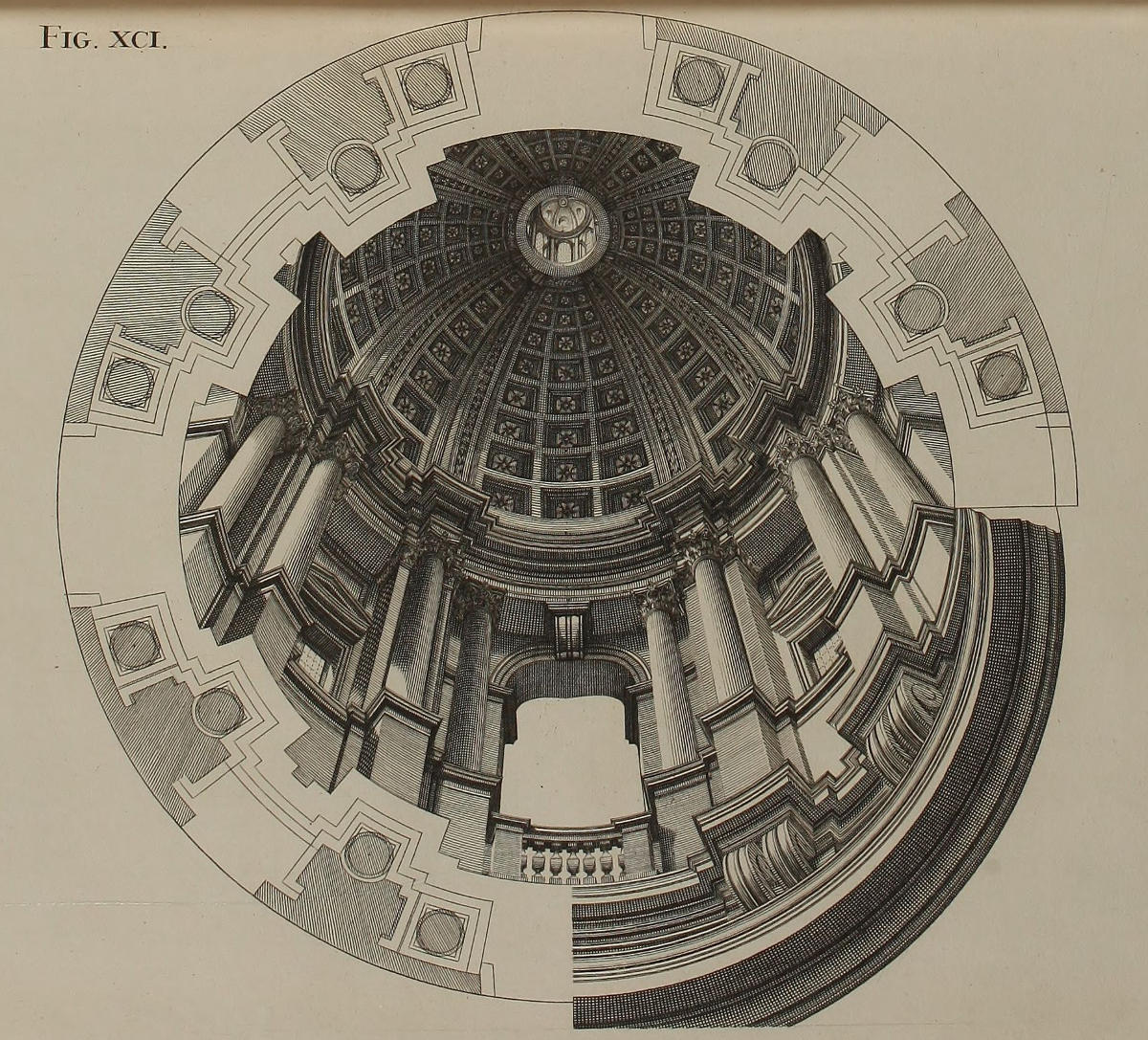
Fig. xci.
Tholus figuræ nonagesimæ, cum luminibus & umbris.
Tholus quem vides in hac paginâ, pollicetur sibi vitam diuturniorem illo, quem super telario plano insignis amplitudinis, depinxi anno 1685. in Templo S. Ignatii Collegii Romani. Proinde si casus aliquis illum absumat, non deerunt qui ex isto eundem in melius reficiant. Mirati fuerunt Architecti nonnulli, quòd columnas anteriores mutulis imposuerim, id enim in solidis ædificiis ipsi non facerent. Verùm eos metu omni liberavit amicissimus mihi Pictor, ac pro me spopondit, damnum omne se statim reparaturum, si fatiscentibus mutulis, columnas in præceps ruere contingat.
The Cupola of the Ninetieth Figure, with its Lights and Shades.
The Cupola in this Plate will in all Likelihood be of longer Duration, than that which I painted on a very large Table, for the flat Ceiling of the Church of S. Ignatius of the Roman College, anno 1685. For if that suffer by any Accident, with the help of this its place may be supply’d by a better. Some Architects dislik’d my setting the advanc’d Columns upon Corbels, as being a thing not practis’d in solid Structures; but a certain Painter, a Friend of mine, remov’d all their Scruples, by answering for me, That if at any time the Corbels should be so much surcharg’d with the Weight of the Columns, as to endanger their Fall, he was ready to repair the Damage at his own Cost.
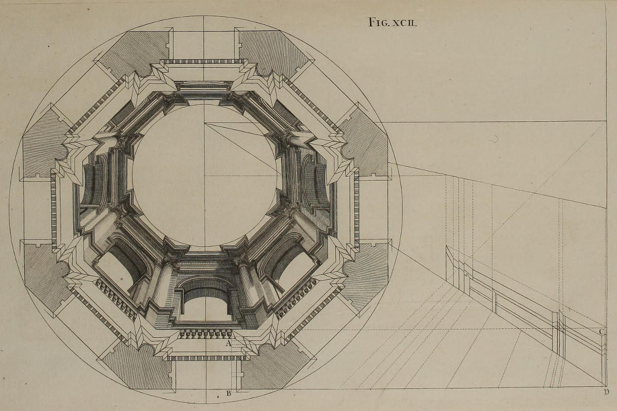
Fig. xcii.
Tholus octangularis.
Ex circulo fiet octagonum, accipiendo medietatem quadrantis circuli, ut habeantur singula latera octagoni. In eisdem lateribus distribuetur vestigium geometricum totius architecturæ, cum projecturis omnium membrorum, juxta modum quem servavimus in limbo circulari figuræ nonagesimæ. Utiliter etiam fieret elevatio geometrica totius Operis; quamvis ob spatii angustias ego eam omiserim. Deinde positâ una cuspide circini in centro circuli, extendetur alia cuspis ad altitudinem singularum projecturarum inter spatium A & B, ut hic vides: atque ope parallelarum, omnia transferentur in lineam CD, ut fiat optica deformatio, quam poscit sectio elevationis, cum aliis præparationibus, ut in figura præcedenti. Nam hic quoque ope circulorum invenire oportet puncta extrema in prominentiis membrorum singulorum architecturæ: ut conjungendo puncta per lineas rectas, quæ forment facies octagoni, compleatur totum Opus.
An Octangular Cupola.
From the Circle describe the Octagon, by taking half the Quadrant of the former for each Side of the latter. On these Sides the Geometrical Plan of the whole Architecture is to be dispos’d, with the Projectures of all the Members thereof, in the same manner as was done in the circular Border of the Ninetieth Figure. It will also be expedient, to make the Geometrical Elevation of the whole Work, tho’ thro’ Want of Room I have here omitted it. Then placing one Point of the Compasses in the Center of the Circle, extend the other to the Height of the several Projectures between A and B, as you see in the Figure; and by help of the Parallels transfer them all into the Line CD, for putting the Profile of the Upright into Perspective, and drawing the other Requisites, as in the foregoing Figure. For here also, by means of the Circles, are found the extreme Points of the Projectures of the several Members of the Architecture; and by conjoining these Points with strait Lines agreeable to the Shape of the Octagon, the whole Work is completed.
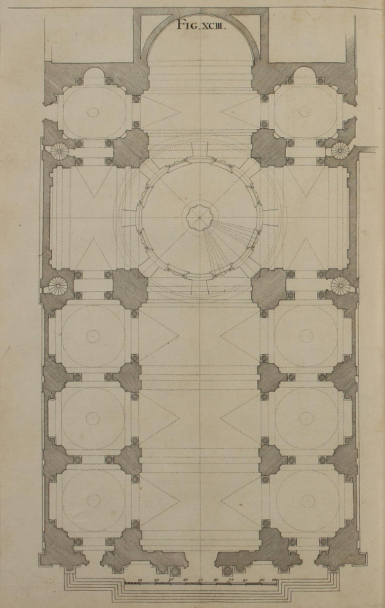
Fig. xciii.
Vestigium templi Ludovisiani S. Ignatii almæ urbis.
Constitueram huic Libro finem imponere figurâ nonagesimasecunda; nihilominus ut satisfaciam precibus amicorum, cupientium addiscere modum reticulationis opticæ, quæ adhibetur in superficiebus irregularibus, ejusque memini figurâ octogesima octava, publici juris facere decrevi ejus construendæ methodum. Ipsiusmet retis ope delineavi non solùm ædificium mox repræsentandum, sed etiam figuras omnes testudinis templi Ludovisiani, in qua pingenda nunc occupor. Eademque reticulatione, quæ erit ultima figura hujus Libri, dabimus Operi nostro suum complementum; quum nulla sit superficies, in qua suas delineationes juxta Perspectivæ regulas, earum rerum Studiosi absolvere nequeant.
Exhibet hæc figura vestigium totius templi. Quamvis enim non indigeam nisi testudine inter januam maximam & tholum; proderit nihilominus Architecturæ Studiosis, universi Operis elegantiam ac symmetriam per otium contemplari.
The Geometrical Plan of the Church of S. Ignatius at Rome.
I had once determin’d to end this Book with the Ninety-second Figure; but at the Request of some Friends, who were desirous to learn the Making of Perspective Net-work for irregular Surfaces, as was hinted in the Eighty-eighth Figure; I resolv’d to publish the Manner of performing the same. By the Help of this Net-work, I delineated not only the Architecture now to be treated of; but also each Figure in the Vault of the Church of S. Ignatius, which I am at present employ’d in painting. The Method is laid down in the last Figure of this Book, and entirely completes the same; there being no Superficies, how irregular soever, but the Studious may thereon describe, by these Rules, whatever Perspective he has occasion for.
This Figure contains the Plan of the whole Church; for though my present Design requir’d no more than the Vault of the Nave, between the great Door and the Cupola; I thought it might be nevertheless acceptable to the Curious in Architecture, to have a View of the whole Design, so celebrated for the Elegancy and Proportion of its Parts.
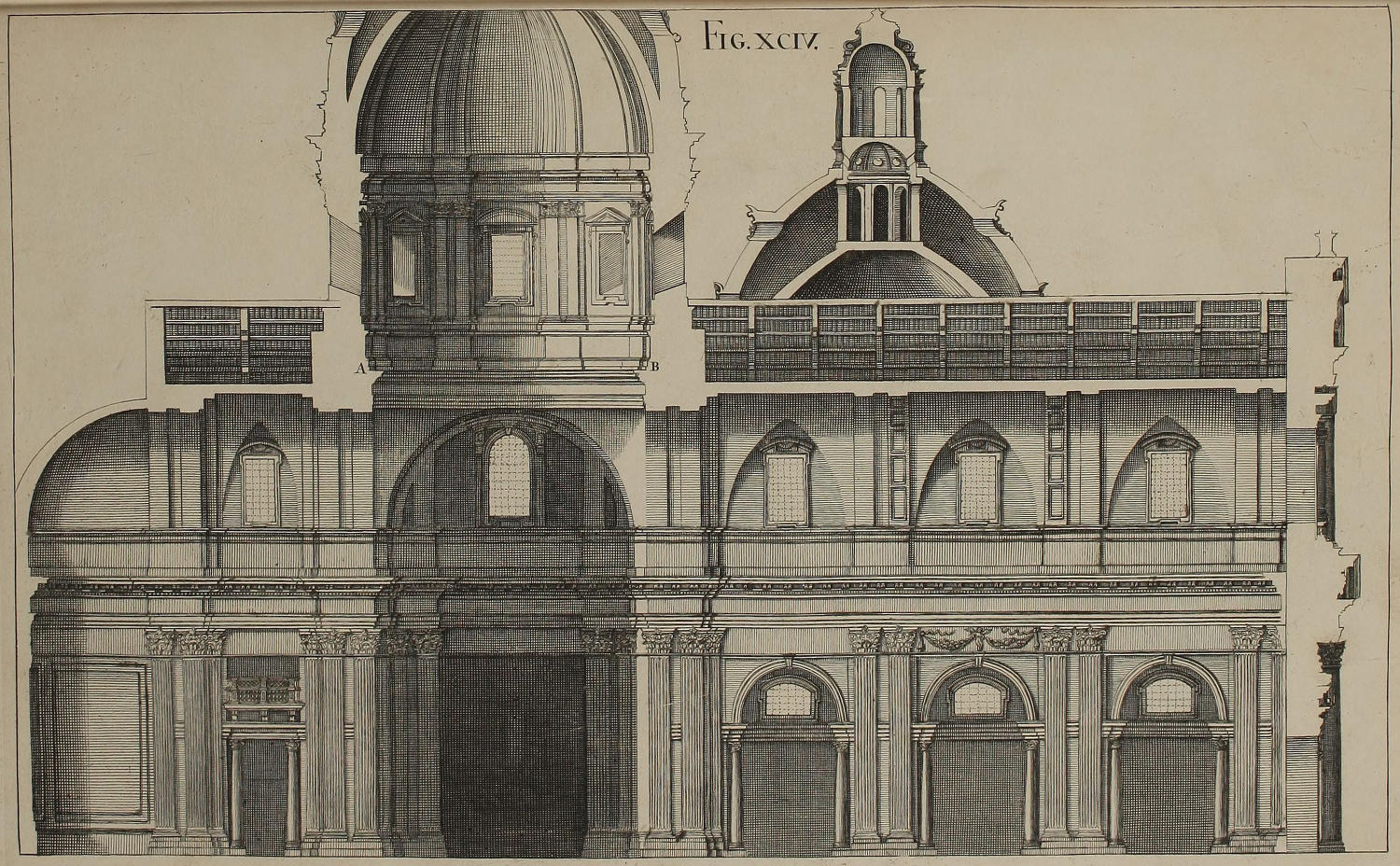
Fig. xciv.
Orthographia templi Ludovisiani.
Vt magis tibi gratificer, orthographiam seu elevationem templi Ludovisiani in longum dissecti delineavi, cum omnibus mensuris quæ vestigio sunt communes; addito tholo juxta ideam Autoris. Ejus autem nondum constructi loco, positum est in A & B telarium cum tholo depicto, de quo supra in figuris nonagesimâ & nonagesimaprimâ.
The Orthography, or Geometrical Elevation of the Inside of S. Ignatius’s Church.
For your greater Satisfaction, I have here given the Geometrical Upright of the Church dissected lengthwise, with all its Measures agreeable to those of the Plan; as also the Cupola design’d by the Author: Which not being yet built, instead thereof is plac’d between A and B, the painted Cupola before describ’d in the Ninetieth and Ninety-first Figures.
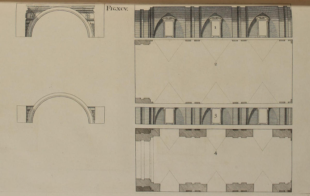
Fig. xcv.
Aliæ præparationes ad figuras nonagesimamoctavam & nonagesimamnonam.
Ex hac figura in quatuor partes divisa, disces ex uno intuitu methodum qua sum auspicatus opticam delineationem templi Ludovisiani. Prima pars exhibet latus dextrum testudinis inter januam templi ac tholum. Secunda pars continet vestigium ejusdem testudinis, arcubus ac lunulis distinctæ. Tertia pars continet latus dextrum testudinis usque ad summitatem fenestrarum, unde incipit Architectura quam pingimus in fornice. Quarta pars est vestigium geometricum fornicis, cum prominentia quam habent arcus in summitate jam dicta fenestrarum. Fingimus autem eandem esse soliditatem, tum ædificii depicti, tum navis templi; solæ enim columnæ, quæ respondent pilis templi, prominent extra ædificium.
Other Preparations to the Ninety-eighth and Ninety-ninth Figures.
By this Figure divided into four Parts, you will at first Sight perceive the Method I observ’d in beginning the Perspective Design of this Church of S. Ignatius. The first Part shews the right-hand Side of the Vault between the Door and the Cupola. The second contains the Plan of the same Vault, with its Arches and Lunettes. The third Part represents the same right-hand Side, to the top of the Windows; where begins the Architecture painted in the Vault. The fourth Part contains the Geometrical Plan of that part of the Vault which is painted; with the Lunettes made by the Arches above the Heads of the aforesaid Windows. The Disposition of the painted Architecture above, is the same with that of the Nave of the Church; save that, answerable to the Pilasters below, I have suppos’d Columns projecting over the Work.
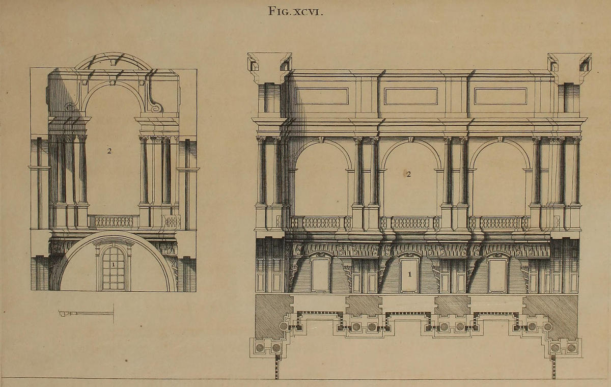
Fig. xcvi.
Aliæ præparationes ad figuras nonagesimamoctavam & nonagesimamnonam.
Prima pars figuræ hujus trifariam divisæ, repræsentat elevationem geometricam lateris templi supra coronicem, & ædificii in testudine pingendi. Secunda pars complectitur arcum testudinis maximum, & elevationem geometricam faciei ejusdem ædificii. Tertia pars exhibet vestigium totius ædificii pingendi in testudine, cujus amplitudo eadem est cum amplitudine navis, ut antea dicebamus. Porrò vestigium geometricum non minus necessarium est ad pingendum ædificium, quàm ad ipsum ex materiâ solidâ extruendum, ut alibi monuimus.
Other Preparations to the Ninety-eighth and Ninety-ninth Figures.
In this Figure, which consists of three parts, the first represents the Geometrical Elevation of the Right-side of the Nave above the Cornice, and of the Design painted in the Vault. The second contains the great Arch of the Vault, and the Geometrical Elevation of the Front of the said Design. The third part shews the Plan of the whole Work painted on the Vault, the Extent and Disposition of which is the same with that of the Nave, as beforemention’d. The Geometrical Plan, as I have formerly hinted, is no less necessary for the painting a Design in Perspective, than it is for raising a Structure with solid Materials.
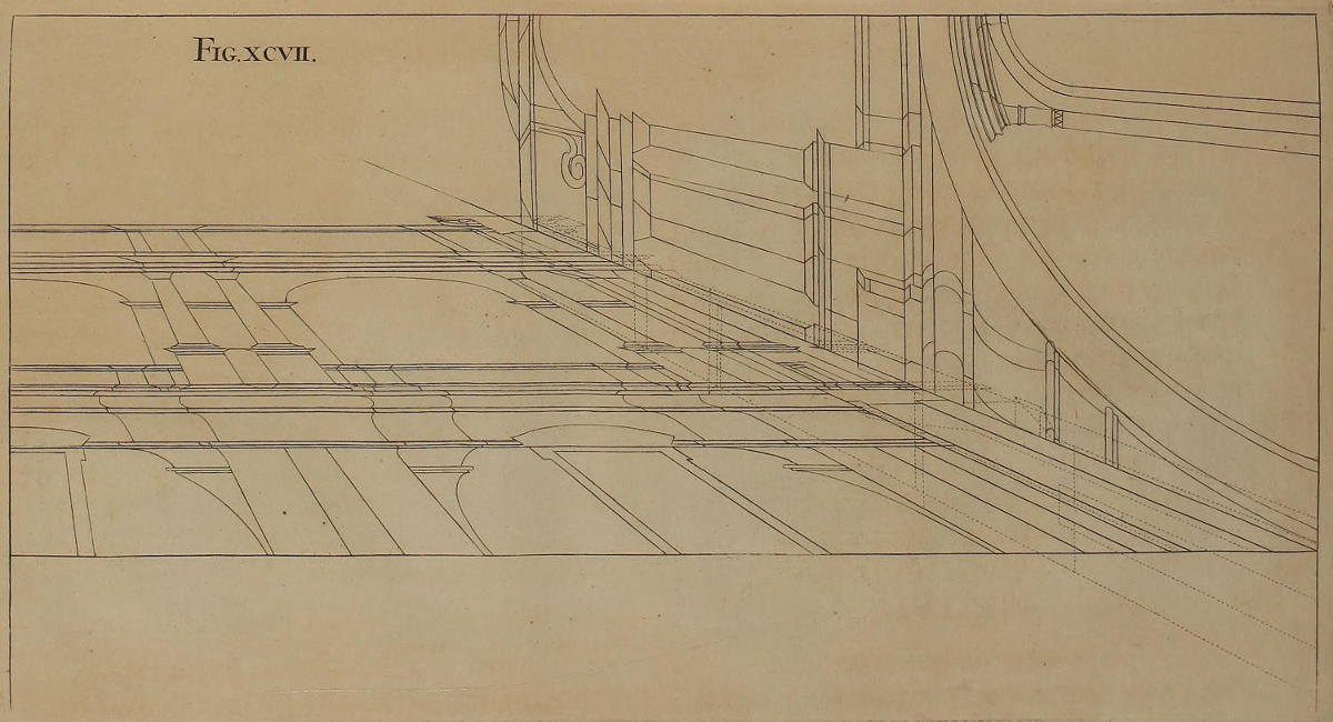
Fig. xcvii.
Alia præparatio ad figuras nonagesimamoctavam & nonagesimamnonam.
Ut optica projectio vestigii & elevationis quartæ partis totius Operis distinctior evaderet, mensuras partium singularum quadruplicavi, eandemque methodum in hac delineatione tenui, quæ figuris octogesimasextâ, octogesimaseptimâ, octogesimaoctavâ, & octogesimanonâ, explicata fuit. Punctum oculi positum est in medio navis Ecclesiæ; punctum distantiæ est in lineâ ex quâ incipit arcus testudinis.
Another Preparation to the Ninety-eighth and Ninety-ninth Figures.
That the Perspective of the fourth part of the Plan and Elevation of this Work might be more distinct, I have in this Figure made the Measures of each part four times as big as in the former; and have kept the same Method in this Delineation, as was deliver’d in the Eighty-sixth, Eighty-seventh, Eighty-eighth, and Eighty-ninth Figures foregoing. I have set the Point of Sight in the midst of the Nave of the Church; and the Point of Distance is in the Line from which the Arch of the Vault springs.
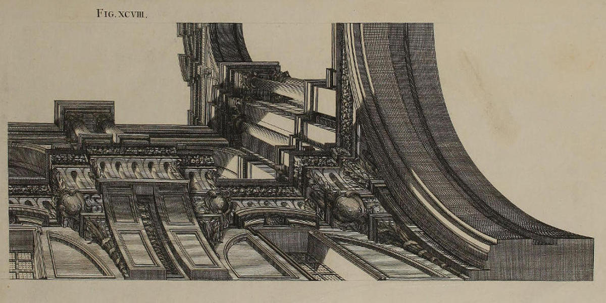
Fig. xcviii.
Quadrans Architecturæ horizontalis in fornice, cum luminibus & umbris.
Habes in hac paginâ quadrantem totius Operis, modo consueto erutum ex præcedenti: nimirùm, cuspide circini ex angulis vestigii accipiuntur lineæ perpendiculares; ex angulis verò elevationis desumuntur lineæ parallelæ, ac lineæ visuales ad punctum oculi.
A fourth Part of the Architectonical Design, painted on the Vault of S. Ignatius’s Church; with its Lights and Shadows.
In this Figure you have a Quarter of the whole Work, drawn from the foregoing Figure, after the usual Manner; namely, by taking with the Compasses the perpendicular Lines from the Angles of the Plan; and the parallel Lines from those of the Elevation, as also the visual Lines to the Point of Sight.
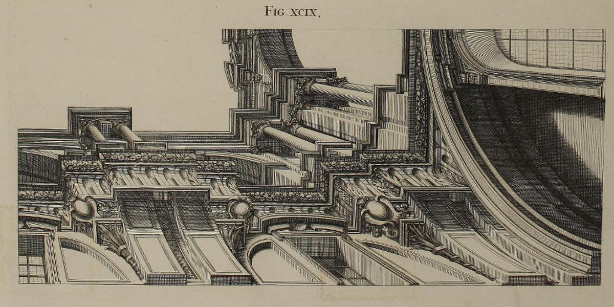
Fig. xcix.
Alter quadrans totius Operis.
Ob diversitatem duorum quadrantum, tum in longitudine, tum in luminibus & umbris, seorsim apponendum utrumque censui; ut in eis delineandis omnem difficultatem tibi adimerem.
Another Quarter of the whole Design.
By reason of the Difference of the two Quarters, as well in Length, as in their Lights and Shadows, I resolv’d to describe them separately, that you might find no Difficulty in designing the whole Work.
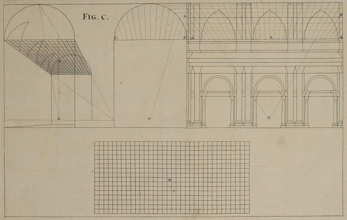
Fig. c.
Modus reticulationis faciendæ in testudinibus.
Opera quæ fiunt in planis, contenta sunt duplici reticulatione, ut notum est. Nam una earum fit in exemplari, altera fit in superficie in quâ ipsum Opus pingendum est. At verò testudines exigunt tres reticulationes. Prima fit in exemplari, quod supponimus delineatum esse juxta regulas Perspectivæ horizontalis. Secunda reticulatio constat ex funiculis, & est pensilis; cujus formam geometricam habes in M. Locum ubi figendi sunt clavi qui sustineant funiculos, exhibent rectæ AB, EF: optica verò deformatio retis est in N. Punctum oculi est O, distantiæ est LO. Itaque si imagineris, tempore nocturno, lumen candelæ aut lucernæ existere in O, atque à reti ex funiculis projici lineas umbrosas in testudinem, eædemque lineæ pennicillo colorentur, habebitur tertia reticulatio ad pingendam testudinem necessaria.
Dixi si imagineris, quia in testudinem obductam tabulato, ac remotam à reti, & multò magis à lumine, vel projici nequeunt umbræ, vel nequeunt esse vividæ ac distinctæ, ut oportet. Itaque ubi nimia fuerit distantia, figes in O extremitatem fili; eóque usque ad testudinem extenso, utéris veluti radio ac lumine candelæ, ad notandum umbræ locum. Proderit etiam, ut super tabulato motum fili obsecundes lumine alicujus candelæ, quod ipsi filo proximè admoveas. Atque his aliisque adminiculis, tuâque industriâ, colores induces super lineis umbrosis, ac tertiam reticulationem absolves. Posset etiam rete ex filis figi in parvâ distantiâ à coronice, puta in GH, unde incipit basis ædificii: tunc autem umbræ in fornice sunt magis distinctæ ac visibiles.
Diligentissimè curabis, ne mensuræ exemplaris discrepent ullatenus à mensuris testudinis: ut rete incidens in angulos, arcus, aut lunulas testudinis, exactè respondeat reti exemplaris. Demum si in vitia quæ emendari nequeant, incidere nolis; scito, regulas omnes Perspectivæ horizontalis, æquè in hominibus aut animalibus, ac in columnis aut coronicibus pingendis, omnino servari oportere.
The Method of drawing the Net or Lattice-Work on Vaults.
For Works on a flat Superficies, two Net-works are sufficient; as has been already intimated: One drawn on the Copy; the other on the Table to be painted. But for arch’d Surfaces, or Vaults, three are requir’d: One made on the Copy, which I suppose drawn according to Rules of horizontal Perspective. The second consists of a Frame of small Cords or Threads, to be hung up; the Geometrical Form of which is M. The Lines AB, EF, shew the Place where this Frame is to be fix’d, in the same manner as the Perspective N. The Point of Sight is O; of Distance, LO. Therefore, if you imagine a Lamp or Candle fix’d in the Night-time at the Point O; the Shadows of the Thread, thrown thereby on the Vault, being trac’d by a Pencil, make the third Net-work requir’d for painting the same.
I say, if you imagine a Lamp thus fix’d; because either the Scaffold to the Vault, or the great Distance of the Vault from the Net-work, or the greater of both from the Light, may prevent the Shadows from being thrown at all, or at least, may render them so faint, as not to be distinct enough for the purpose. Therefore, where this happens, instead of the Light fix one End of a Thread in the Point O; and extending the other to the Vault, make use of it as a Ray from the Lamp or Candle, for describing the Place of the Shadows. It will be also of great use, to second the Motion of the Thread with the Light of a Candle you may have by you on the Scaffold, holding the same near the Thread itself. By this, and other such Helps, which your own Industry will suggest, you may lay these Shadows in Colours, and complete the third Net-work requir’d. The Frame of Threads may also be fix’d nearer the Vault at some Distance above the Cornice, as at GH, where the painted Architecture begins; for the Shadows thrown on the Arch will by that means become more visible and distinct.
You must be very careful, that the Measures of your Copy are exactly the same with those of the Vault, that the Net-work thrown into the Angles, Arches and Lunettes of the Vault, may perfectly correspond with that of your Copy. Lastly, if you would not run into inextricable Errors; assure yourself, that all these Rules of horizontal Perspective are as strictly to be observ’d in the Figures of Men or Animals, as in painting Columns, Cornices, or the like.
Explicatio linearum plani, & horizontis, punctorum oculi, & distantiæ; de hoc ultimo pressiús.
Tres lineæ diversi inter se nominis, & muneris, item, & duo puncta præcipuè necessaria sunt, ut delineatio quælibet opticè reddi queat: prima vocatur linea plani, secunda horizontalis ubi est punctum oculi; de tertia loquar in elevationibus: alterum de duobus punctis assignatur oculo, & vulgò dicitur punctum oculi; alterum verò assignatur distantiæ, à qua nomen habet. Punctum oculi notissimum est, punctum verò distantiæ non ità; in hujus igitur explicatione morabor, & ut clariùs ostendam quid sit, & quomodo formandum sit, selegi descriptionem Ecclesiæ geometricè habitam, quam in tres partes divisi, in vestigium, sectionem, & interiorem faciem, in qua facie velit quis pingere, seu delineare aliquid opticè, ut elongetur ad mensuram aperturæ quadrati P, ut habes in vestigio, & ad mensuram profunditatis Q, quam habes in sectione.
Super faciem CCCC quam puta esse delineamentum, habes rationem, qua debes disponere supradicta puncta, & lineas. HI erit linea plani: NON erit linea horizontalis, quæ fieri solet distans à linea plani altitudine hominis, ut vides in B. Punctum oculi erit in O; punctum distantiæ erit in N, ex qua parte malueris. Hoc punctum N debet tantum abesse à puncto O, quantum tuo arbitratu tu vis procul esse ut videas profunditatem illius quadrati PQ, sicut vides in exemplo vestigii, & sectionis; ubi rem velut in suo statu naturali exhibeo; in iis enim tam abest N ab O, quam abest homo ab A ad DE, & homo B in sectione, ab FG, ubi est murus in quo pingendum, vel delineandum est.
Si ulteriùs curiosè descriptionem hanc consideres, videbis quam bene respondeat quadratum P in plano, & elevatio Q, ut naturalis status rei in sectione Perspectivæ positæ in facie CCCC, quæ est delineatio. Videbis enim visuales, quæ secant in plano spatium RS, ita pariter secare spatium TV in elevatione: & segmentum visualium XZ in sectione respondere YK in elevatione, quod demonstratione non caret.
An Explanation of the Lines of the Plan and Horizon, and of the Points of Sight and Distance; but more especially of this last.
For beginning any Design in Perspective, there are principally requir’d three Lines, and two Points: One Line where the Feet stand, which is call’d the Line of the Plan, or Ground-line: The second where the Eye is plac’d, call’d the horizontal Line: I shall speak of the third in the Elevations. Of the Points, one is assign’d to the Eye, the other to the Distance. The first of these is generally known, the latter not so well understood, though of great Use for giving the Removal or Depth of every Object. I shall therefore insist a while on the Explanation of the Point of Distance; and that I may more clearly shew what it is, I have chosen the Geometrical Description of a Church, which is divided into three Parts; viz. the Plan, Profile, and inner Face; in the midst of which Face one would paint a Piece of Perspective, that should seem to recede as much as the Square P in the Plan, and the Depth Q in the Profile.
On the Face CCCC, which suppose that of the Design, you see the Manner of disposing the two Lines and the two Points. HI is the Ground-line. NON is the horizontal Line, which is usually made a Man’s Height above the Ground line, as in B. The Point of Sight is O, the Point of Distance N, on which side you will. This Point N must be as far from O, as the Distance you determine to place yourself at for viewing the Depth of the Square PQ; as is exemplify’d in the Plan and Profile, where you see the thing as in its natural Position: And in them N is distant from O, as far as the Man in A is remov’d from DE; or the Man B in the Profile from FG, which is the Wall to be drawn or painted on.
If you farther and more strictly examine this Description, you’ll discern how well the Square of the Plan P, and the Elevation Q, correspond as if naturally put into Perspective on the Face CCCC, which is the Draught. For you see the Visuals which cut the Space RN in the Plan, cut the same Space TV in the Upright; and the Segment of the Visuals XZ in the Profile, answer that of YK in the Elevation; which needs no Demonstration.
Quadratum opticè delineatum.
Postquam descripseris in papyro separata quadratum geometricum A, facies duas lineas parallelas inter se distantes altitudine, quam dederis puncto oculi; linea inferior erit linea plani, linea superior erit linea horizontalis, super quam ponuntur puncta oculi O, & distantiæ E, quod sit ex parte quam mavis: linea distantiæ non debet esse brevior magnitudine rerum describendarum. Transfer posteà circino latitudinem quadrati A in CB, unà cum visualibus ad punctum O; & similiter transfer longitudinem ipsius quadrati in DC, ducens lineam à puncto D ad punctum distantiæ E, transeuntem per visualem CO, & ubi illa secat, habebis terminum quadrati optici GFCB, ducens parallelam ad lineam plani in F.
Ut autem hoc idem citiùs absolverem, sæpius chartam complicavi, ut habes in A.
A Square in Perspective.
After you have drawn, on a separate Paper, the Geometrical Square A, make two parallel Lines as much distant one from the other, as you would have the Height of the Eye. The under Line is the Plan or Ground-line; the upper Line is that of the Horizon, on which are plac’d the Points of Sight O, and of Distance E, on which side you please. The Line of Distance should not be shorter than the Extent of the thing to be describ’d in Perspective. Then with your Compasses set the Breadth of the Square A on CB, and draw Visuals to the Point O; and from the Length of the Square transferr’d into DC, draw a Line from the Point D to the Distance E; and where that cuts the Visual CO, by drawing a Line parallel to GF, you describe the Square in Perspective GFCB.
For the more quick Dispatch of this, I commonly fold the Paper, as you see in A.
Rectangulus altera parte oblongior opticé.
Quidquid in proximo quadrato vidisti, facies in præsenti. Transferres latitudinem BC in BC, & longitudinem in CD, ducens latitudinem BC ad punctum oculi O, & longitudinem CD ad punctum distantiæ E. Ubi vero hæc linea secat visualem CO, erit terminus rectanguli supradicti FG, BC, ducens parallelam, ut supra.
An Oblong Square in Perspective.
What was done in the preceding, repeat in this Third Figure. Transfer the Breadth BC into BC, and the Length into CD, drawing the Breadth BC to the Point of Sight O, and the Length CD to the Point of Distance E. Where this cuts the Visual CO, you terminate the Square FG, BC, by drawing the Parallel, as before.
Quadratum duplex opticé.
Eodem modo construes quadratum duplex A, transferens circino, aut duplicando chartulam, latitudinem cujuscumque lineæ, ut vides in punctis 1, 2, 3, 4, 5, 6, super lineam plani in iisdem numeris, & ab istis transferes visuales ad punctum O. Postea transfer longitudinem 7, 8, 9, 10, super lineam plani in iisdem pariter numeris, & ab istis duc lineas ad punctum distantiæ E. Ubi hæ lineæ secant lineam 6, 7, O, fiunt lineæ parallelæ ad lineam plani, & quadratum conficitur; parem constructionem facies de quadrato secundo, & tertio, facilè ex dictis.
A double Square in Perspective.
The double Square A is made after the same manner as the former, by transporting, either with the Compasses, or folded Paper, the Breadth of every Line, as you see the Points 1, 2, 3, 4, 5, 6, on the Ground-line mark’d with the same Numbers; and from these draw Visuals to the Point of Sight. Then transfer the Points of Length 7, 8, 9, 10, into the Ground-line, as you see also in the same Numbers; and direct their Lines to the Point of Distance E. Where these intersect the Visual 6, 7, O, make Parallels to the Ground-line, and the Square is complete. The same is done in describing the middle Square, and that on the other Side.
Quadratorum vestigia cum elevationibus.
Figuram hanc in duas partes divisi; in superiori parte vides tria quadrata optica aliquantulum adumbrata, eaque tam inter se distantia, quanta est distributio super lineam plani. BC erit quadratum primum. Secundum erit in EF. Si ergo posueris longitudinem quadrati in BC, eamque duxeris ad distantiam, secabit in DD visualem AO. Si pariter posueris alterum spatium longitudinis ejusdem quadrati in EF, & duxeris ad lineam distantiæ, habebis secundum quadratum opticé. Idem facies de tertio, & de aliis, quæ distribuenda sunt.
In secunda parte. Si desideres supra totidem vestigia formare elevationes cuborum, & stylobatarum, ut in inferiori figuræ parte vides, satis erit ex omni vestigiorum angulo elevare lineas occultas, & apparentes, determinando altitudinem faciei L primo cubo, & anguli ejusdem faciei dabunt altitudinem omnium aliorum.
Immò etiam totidem cubos formare potes sine lineis occultis, ducendo solùm apparentes, ut vides in tribus expositis adumbratis, & nitidis, quorum perpendiculares sumuntur ab angulis vestigiorum, ut in superiori figura habes in H, & lineæ plani translatæ sunt ab angulis elevationis, ut videtur in F.
Several Plans of Squares, with their Elevations.
I have divided this Figure into two Parts; In the uppermost you have three Squares in Perspective a little shadow’d, distant one from another, according to their Distribution on the Ground-line. BC is the first Square; EF the second. If you then set the Length of a Square on BC, and draw Lines to the Point of Distance, they will intersect the Visual AO in DD. In like manner, if you set another Length of the said Square on EF, and draw to the Point of Distance, you’ll have the second Square in Perspective. The same you may do in the third, and as many as you have occasion for.
In the second Part you see, that if upon the fore-mention’d Plans the Elevations of Cubes or Pedestals were requir’d, it would suffice to elevate the occult and visible Lines from every Angle of the Plan; and determining the Height of the Face L of the first Cube, the Angles of that Face drawn to the Point of Sight, give the Height of all the others.
You may form the same Cubes without occult Lines, drawing only those that are apparent, as you see in the three Cubes that are finish’d and shadow’d; the Perpendiculars of which are taken with the Compasses from the Angles of the Plan, as is shewn in HI of the upper Figure; and the level Lines are transferr’d from the Angles of the Elevation, as in FG of the same Figure.
Modus delineandi opticè sine lineis occultis.
Desiderans facili methodo figuram hanc exponere, dabo rationem elevandi corpora sine lineis occultis, ut in superiori tetigi; ostendam igitur hic, quomodo quinque cubi adumbrati desumantur ab eorum vestigiis, & elevationibus.
Duas debes facere præparationes, si libeat, in chartis etiam separatis. Prima erit formare geometricè vestigium, & elevationem, ut vides in B & A. Secunda erit distribuere super lineam plani latitudinem vestigii B, puta in NM, & in duabus proximis: Illius longitudo MX ducta ad distantiam D, secat visualem MO in R. Spatium autem obliquatum E utile etiam est aliis duobus quadratis positis super eamdem lineam plani; anguli quorum translati ad distantiam B, totidem angulos dabunt inter visuales NO, MO. Hoc posito, duces perpendicularem ad angulum N, quæ in elevationibus geometricis semper necessaria est, eaque tertia linea est, quam supra dixi. Transfer postea altitudinem A in NF, cum visualibus FO, NO, & invenies altitudinem ST. Hoc pariter de cæteris eveniet.
Sciendum superest quonam modo supradicta præparatione uti possis ad construendos stylobatas adumbratos, & inornatos.
Super aliam igitur chartam dispone situm cum duabus lineis, plani scilicet, & horizontis, una cum puncto oculi O, & perpendiculari V, ejusdem mensuræ cum supradicta præparatione, & faciens uti me fecisse vides. Experire postea circino NF æqualia esse 1, 5, & 2, 6. Metire pariter ST, & invenies æqualia 7 & 3; facies postea lineas planas, & visuales ad punctum oculi, & habebis planum superius cubi in 1, 2, 3, 4. Hoc idem faciendum est de aliis. Uno verbo: anguli vestigiorum dabunt tibi lineas perpendiculares, & anguli elevationis dabunt lineas planas; atque hoc semper erit.
The Manner of designing in Perspective without occult Lines.
Being desirous to make this Rule as easy as possible, I shall give a farther Account of raising Solids without the Help of occult Lines, which I only touch’d upon in the foregoing Figure. I therefore here shew you, how the five shadow’d Cubes of this Figure are taken from their Plans and Elevations.
Two things preparatory are to be done, and, if you please, on separate Papers. The first is, to describe the Geometrical Plan and Elevation, as you see in B and A. The second is, to dispose on the Ground-line the Breadth of the Plan B; as, for Example, in NM, and the two next to it. The Length thereof MX, drawn to the Point of Distance D, cuts the Visual MO in R; and the Foreshortning E serves also for the other two Squares plac’d upon the same Ground-line, whole Angles being directed to the Distance D, give as many Angles on the Visuals NO, MO. This done, erect a Perpendicular on the Angle N, which in Geometrical Elevations is always necessary, and is the third Line mention’d in the first Figure. Then carry the Height A on NF, drawing the Visuals FO, NO, which determine the Height ST, and that of the other Squares.
It remains to be known, how to make use of the foresaid Preparation for the Construction of the shadow’d Pedestals.
On another Paper therefore dispose the Horizontal and Ground-lines, together with the Point of Sight O, and the Perpendicular V, keeping the same Measures as in the aforesaid Preparation, and doing as I have done. You may prove by the Compasses, that NF is equal to 1, 5, and 2, 6, and measuring ST, you’ll find it equal to 7, 3, then drawing the level Lines, and the Visuals to the Point of Sight, you have the upper Face of the Cube C in 1, 2, 3, 4. The same must be done in the others. In a word, the Angles of the Plan give you the perpendicular Lines, and the Angles of the Elevation give the level Lines, or those parallel to the Ground-line; and this you are always to understand for the future.
Aliud exemplum construendi vestigium geometricum, cum elevatione longitudinis.
Vides hic stylobatam P in quatuor partes divisum, & adumbratum. Si illum opticè delineare velis, construere debes supradictas præparationes, geometricam nempe, & opticam. Nomine geometricæ intelligo vestigium A, & elevationem B; nomine vero opticæ, totum id quod includitur in GCDEO.
Transfer igitur latitudinem geometricam CD vestigii A super lineam plani pariter CD, & transfer longitudinem DE super lineam plani pariter DE, operans more solito; & habebis vestigium opticé. Transfer posteà elevationem HX in CG perpendicularis; ducens visualem GO, eleva ad lineam GO omnem angulum, quem planum facit in linea CO, & habebis altitudinem necessariam etiam sectionis.
Transferes denique circino in aliam chartam angulos vestigii, qui dabunt tibi lineas perpendiculares, & anguli sectionis dabunt lineas planas: Visuales vero duces ad punctum oculi.
Another Example of a Geometrical Plan, with the Elevation of its Length.
If you would delineate in Perspective the Pedestal P, which you here see divided into four Parts, and shadow’d; you must make the two foregoing Preparations; namely, the Geometrical and the Perspective. By the Geometrical, I mean the Plan A, and the Elevation B; By the Perspective, all that’s contain’d within G, C, D, E, O.
Then transfer the Geometrical Breadth CD of the Plan A, into CD of the Ground-line; and the Length DE of the said Plan into DE of the Ground-line working after the usual manner; and you will have the Plan in Perspective. Again, set the Elevation HX on CG of the Perpendicular, and drawing the Visual GO, elevate thereto every Angle made by the Plan on the Line CO, and you have all the Heights necessary for the Profile.
Lastly, by the Compasses you transport on a clean Paper the Angles of the Plan, which give the perpendicular Lines; and those of the Profile, which give the level Lines. The Visuals you draw to the Point of Sight.
Stylobata opticé.
Hic etiam postquam feceris supradictas præparationes, geometricam scilicet, & opticam; facies præsentem stylobatam adumbratum, transferens circino angulos vestigii, ut construas perpendiculares; & angulos sectionis, ut formes lineas planas, ut supra. Nam sic duo anguli vestigii MO dabunt lineas perpendiculares EF; angulus vestigii R dabit perpendicularem P, & sic reliqui anguli dabunt reliquas lineas perpendiculares. Similiter à sectione angulus I dabit lineam planam HN. Breviter, primus terminus sectionis ID dabit altitudinem linearum planarum in facie stylobatæ adumbrati EFHN. Secundus terminus Q dabit altitudinem faciei oppositæ, & occultæ P.
Duo tamen moneo; primum, ut faciens vestigia geometrica, ducas ab elevatione A totidem lineas ad latera vestigii B, quot angulos invenies in prominentiis supradictæ elevationis A, ut manifestè vides in lineis quas ex punctis composui, illæ enim à stylobata A cadunt super vestigium B; quare prominentia major in elevatione L facit lineam majorem L in vestigio.
Secundum quod moneo sit, ut volens elongare vestigium opticè delineatum MOR à linea plani K, quantum erit spatium C in eadem linea plani, tantumdem elongabitur spatium G à linea ejusdem plani.
A Pedestal in Perspective.
Here also, after you have made the two foregoing Preparations, the Geometrical and the Perspective; this shadow’d Pedestal is made by taking with the Compasses the Angles of the Plan, for drawing the Perpendiculars, and the Angles of the Profile for the level Lines, as before. Thus the two Angles of the Plan MO, give the perpendicular Lines EF. The Angle of the Plan R, gives the Perpendicular P; and the other Angles give their respective Perpendiculars. So likewise in the Profile, the Angle I gives the level Line HN. In short, the first Out-line of the Profile ID gives the Height of the level Lines on the Front of the shadow’d Pedestal. The other Out-line Q gives the Height of the occult and back part thereof.
Nevertheless, two things are to be observ’d; first, that in making the Geometrical Plan, you draw from the Elevation A, as many Lines to the Side of the Plan B, as you have Angles in the Projectures of the said Elevation; as is manifest in the pointed Lines, which fall, from the Upright A, on the Plan B, where that of the greatest Projecture L in the Elevation makes the outer Line L of the Plan.
The second thing to be observ’d, is, That if you would have the Perspective-Plan MOR as far within the Ground-line K, as the Breadth of the Space C on the same Line, the Space G will then be the Distance thereof from the said Ground-line.
Optica delineatio Architecturæ Jacobi Barozzii: & primum, de stylobata Ordinis Etrusci.
Quandoquidem omnibus nota est Architectura Barozzii, eam hic penitus immutatam cum suis regulis particularibus, & generalibus expono; Metieris autem illam modulis ut fieri solet; qui igitur illam desiderat, in sequentibus figuris inveniet totam, simulque discet opticè reddere. Cum autem non minus Opticæ studioso quam Architecturæ necesse sit, efficere delineamenta rei construendæ, ab hoc verè, ab illo fictè, id est, cum uterque facere debeat vestigium, elevationem, sectionem, & faciem, ob id delineavi hic stylobatam Ordinis Etrusci cum suo vestigio, quem vides in AB, ut faciliùs percipias quod in proxima figura dixi, à totidem scilicet angulis prominentiarum elevationis, totidem ducendas esse lineas super lineam vestigii; cum hoc necesse sit ad inveniendum illorum angulorum cum istis lineis concursum in suis degradationibus. Nota, longitudinem, quam voco F ductam in G esse illam, à qua non solùm nascitur vestigii obliquitas, verùm etiam ab illa nascitur obliquitas illius quam voco sectionem E. Ob id in altero hujus ejusdem figuræ stylobata totum id è contrario videbis.
Non ampliùs repetam quonam modo eruatur nitida delineatio, de qua superiùs pluries; dicam tamen angulos primi termini sectionis E daturos lineas planas faciei D, & angulos vestigii daturos omnes perpendiculares.
The Architecture of Vignola put in Perspective; and first, the Pedestal of the Tuscan Order.
Since every one is acquainted with Vignola’s Architecture, I determine not to alter it, but to explain it, with its general and particular Rules; measuring the same with Modules, after the usual manner. He therefore that has it not, may find it in the following Figures, and at the same time learn the Method of putting it in Perspective. And whereas the Drawing the Plan, Elevation and Profile of what’s to be built, is no less necessary for him that studies Perspective, than for the Architect, the first performing in Appearance, what the latter does in Reality; I have therefore here delineated the Tuscan Pedestal, with its Plan, as you see in AB, that you may the better apprehend what I said in the foregoing Figure, That from all the Angles of Projecture in the Elevation, Lines must be let fall on the Plan; this being of absolute necessity for finding the Correspondence of the Angles with the Lines in the Perspective Projection. Observe, that what I always call Length, as from F to G, is that from which proceeds not only the Foreshortning of the Plan; but also that which I call the Profile E. Wherefore, in the opposite Pedestal of the same Figure, you’ll see a contrary Disposition of the Whole.
I shall not here repeat, how the finish’d Pedestal is taken from these; having so largely spoken of that before; but briefly tell you, that the Angles of the first Out-line of the Profile E give the level Lines of the Face D, and the Angles of the Plan give all the Perpendiculars.
Stylobata Doricus, & ratio vitandi difficultatem quamdam, quæ occurrit inter illum opticè delineandum.
Hic oritur difficultas hæc. Vestigium A opticè translatum in C adeò contrahitur, ut distinctè videri nequeat ubi collocetur circini pes, ut transferri possint perpendiculares stylobatæ adumbrati; totaque hæc difficultas oritur à propinquitate quam habet linea horizontalis, seu punctum oculi cum linea plani. Ut igitur illam vincas: Duces lineam plani inferiùs quantum libuerit, & super illam feres denuò latitudinem, & longitudinem more solito, retinendo puncta oculi, & distantiæ OF, & sic videbis vestigia magis minusve distincta; Vestigium enim E distinctius est vestigio D, & D distinctius est vestigio C.
A Dorick Pedestal, with the Manner of shunning a Difficulty, which occurs in putting the same in Perspective.
In this Figure a Difficulty arises, which is this; That the Plan A put in Perspective in C, is so foreshorten’d, that one can’t see distinctly, where to place the Compasses, for transferring the Perpendiculars on the shadow’d Pedestal; which is caus’d by the too near Approach of the horizontal Line to the Ground-line. For avoiding this Difficulty, draw another Ground-line as much below the first as you please, and carry the Breadth and Length thereon, after the usual manner, still keeping the same Points of Sight and Distance O and F: And according to the Removal of the Ground-line, the Plans will be more or less distinct; as you see the Plan E is more distinct than D, and D is more so than C.
Stylobata Ionicus, & ratio vitandi aliam difficultatem in elevationibus.
In elevationibus etiam sectionis opticè potest accidere, ut si visualis LK nimis recta sit, sectio B restringatur. Elongando lineam plani ab L ad M, visualis MN erit inclinatior, & consequenter sectio C erit latior, & distinctior.
Nota, difficultatem hanc sæpe sæpiùs te habiturum in figuris præcipuè, quæ multas lineas habent, ut in figura quadragesimasecunda, ubi pariter rationem vitandi confusionem reddam.
Neque tibi molestiæ sim, quod in hac figura lineam horizontalem infra lineam plani collocaverim, id enim feci, ut illarum diversos effectus videas, utque tu in tuis studiis mutes, & discas.
The Ionick Pedestal, and the Way to shun another Difficulty in the Elevations.
In Elevations of the Profile in Perspective, it may sometimes happen, that the Visual LK may be so direct, as to render the Profile B too close and narrow; wherefore prolonging the Ground-line from L to M, make the Visual MN, which being much more oblique, does consequently render the Profile C more broad and distinct.
And observe, that this Difficulty will very often occur; especially in Figures that have many Lines, as the Forty-second Figure has, where I speak also of the manner of avoiding the same.
Nor let it trouble you, that in this Figure I have plac’d the horizontal Line below the Ground-line; which I have done, that you might see their different Effects, and by changing the Disposition of your Designs, improve and learn.
Stylobata Corinthius cum suis pilis.
Fecisse septimam figuram magno tibi documento erit ad construendum, & dividendum stylobatam A, & vestigium B; cum nihil addere debeas præter pilas C cum coronice, quæ duo latera ambit. Opticè hoc vestigium delineabis in D, quæ delineatio distinctior est, quia inferiùs duxi lineam plani; & distinctior etiam est sectio E, cum elongaverim visualem FG. Sic semper agam, ut detur locus figuræ adumbratæ, & ut etiam videas perpendiculares stylobatæ adumbrati cadere super angulos vestigii, & lineas planas incidere è diametro super angulos sectionis E. Iterùm libenter moneo, ut facias supradictas præparationes in chartulis separatis, ut initio assuescas transferendis figuris nitidis circino; facile enim tibi postea erit integras machinas Perspectivæ jucundioris delineare, ut videbis: in hoc enim tota regulæ hujusce, & totius operis facilitas sita est.
A Corinthian Pedestal, with its Pilasters.
The Performance of the Seventh Figure will be a great Assistance to you, in the Construction and Division of this Pedestal A, and the Plan B; since you have nothing more to add here, but the Pilasters C, and the Mouldings which surround the two Sides. This Plan is put in Perspective in D, and becomes more distinct by my sinking the Ground-line lower; and the Profile E is also more distinct by the Removal of the Visual FG, as mention’d in the foregoing Chapter. This I shall always do, that there may remain Room for the shadow’d Figure, and that you may also see that the Perpendiculars of the shaded Pedestal fall directly upon the Angles of the Plan, and that the level Lines directly answer the Angles of the Profile E. I repeat my Advice, that you would make the foresaid Preparations on several Papers, and accustom yourself at the beginning to take off the finish’d Figures with the Compasses; for it will become very easy to you afterward, to design entire Machines of delightful Perspectives, as you’ll see hereafter. And indeed in this Practice, the Facility of this Rule, and of all that follows in this Work, does chiefly consist.
Non omnium sensus est, uni optico operi unicum tantùm punctum assignare, e. g. toti spatio fornicis, tholi, & tribunæ, quam vocant, expressæ in figura nonagesimatertia, nolunt concedi unicum punctum, volunt concedi plura.
Respondeo, objectionem hanc dupliciter intelligi posse: vel enim intelligi posset, non esse assignandum unicum punctum toti illi spatio; atque in hoc sensu vera est; cum enim spatium illud valde oblongum sit, dividi debuit in partes, atque assignanda tribunæ, quam dicunt, tholo, & fornici, propria puncta; cum hoc communiter doceant, ubi situs nimium est longus, & parùm altus. Vel potest intelligi de qualibet ex dictis partibus, & sic intellecta penitùs falsa est. Primò, quia præstantiores fornices aularum, & templorum, qui optico artificio ornati sint, si unicum opus reddunt, à suismet authoribus determinatum idemque unicum punctum accepisse compertum est. Secundò, quia cum ars optica sit mera veri fictio, non id pictor facere potest, ut à qualibet parte simulet veritatem, verùm ab uno determinato puncto id ostendit. Tertiò, quia si, e. g. fornici, qui uno integroque optico opere ornetur, plura puncta assignaveris, nullum reperies locum, unde integrum opus spectare possis, & ad summum ex quolibet puncto tantùm partem illius spectabis, nusquam verò totum opus. Ex dictis igitur rationibus concludo ab inducentibus plura puncta in eodem opere induci malum majus eo, quod unicum punctum inducit; quare hoc omnino necessarium est situi in quo unicum opus formandum sit, ad quod collimare debeant ex omni operis parte figuræ simul & architectura. Quo posito, negari rationabiliter nequit, à me etiam concedi unicum punctum spectando fornici amplo, aptoque ad repræsentandum unicum opus, qualis est fornix in D. Ignatii templo. Si verò propter situm irregularem, ut dicimus, architectura extra punctum aliquantulum deformetur, & figuræ pariter operi optico intermixtæ extra commune punctum aliquam patientur deformitatem, præterquam quod à supradictis rationibus excusatur, nequaquam id vitio arti est, sed laudi; quandoquidem ars à suo puncto exhibet, proportione positâ, ut rectum, ut planum, ut concavum, id quod tale non est.
Every one does not approve, that in a Perspective of great Extent one Point of Sight only should be assign’d the whole Work; as for Example, In the whole Length of the Nave, Cupola, and Tribune, express’d in the Ninety-third Figure, they will by no means allow of one single Point, but insist upon several.
I answer, This Objection may be understood two ways; either that one Point alone is not sufficient for that whole Length, and in this sense ’tis true; for that Space being very long, it ought to be divided into Parts, and proper Points assign’d to the Tribune, Cupola, and Vault of the Nave; as is commonly taught, where the Situation is of a great Length, and not very high. Or it may be understood of any One of the said Parts, and so is altogether false. First, Because in the Vaults of Halls or Churches painted by the greatest Masters, if they consist of one Piece only, we find but one Point of Sight assign’d. Secondly, Since Perspective is but a Counterfeiting of the Truth, the Painter is not oblig’d to make it appear real when seen from Any part, but from One determinate Point only. Thirdly, Because, if in a Vault, for Example, where you would paint one entire Design of Architecture and Figures, you assign several Points of Sight, you will find no place whence you may take a perfect View of the Whole, and at best you can only view each Part from its proper Point. From all which Reasons I conclude, that the Introduction of many Points into the same Piece, is more injurious to the Work, than making use of one only: Wherefore ’tis absolutely necessary in a regular Situation, and where the Work is all of a piece, so to place the same, as that the Figures and Architecture may from every part of the Design have respect thereto. This suppos’d, I confess that I myself make use of one Point of Sight only, in very large Vaults that consist of one Design, such as that of the Nave of the Church of S. Ignatius. If therefore through the Irregularity of the Place, the Architecture appear with some Deformity, and the Figures intermix’d therewith seem any thing lame and imperfect when view’d out of the proper Point, besides the Reasons just now given, it’s so far from being a Fault, that I look upon it as an Excellency in the Work, that when view’d from the Point determin’d, it appear, with due Proportion, streight, flat, or concave; when in reality it is not so.
| INSTRUMENTA paranda, | Fig. | UTENSILS for Drawing. |
| Explicatio linearum plani & horizontis, ac punctorum oculi & distantiæ, | I. | Explication of the Lines of the Plan and Horizon, and of the Points of the Eye and of the Distance. |
| Modus delineandi opticè quadratum, | II. | The Manner of delineating a Square in Perspective. |
| Optica delineatio rectanguli, alterâ parte longioris, | III. | The Delineation of an oblong Square in Perspective. |
| Optica descriptio quadrati duplicis, | IV. | The Optical Delineation of a double Square. |
| Vestigia quadratorum cum elevationibus, | V. | Plans of Squares with their Elevations. |
| Modus opticæ delineationis absque lineis occultis, | VI. | The Manner of designing in Perspective without occult Lines. |
| Aliud exemplum vestigii geometrici, cum elevatione longitudinis, | VII. | Another Example of a Geometrical Plan and Upright put into Perspective. |
| Optica projectio stylobatæ, | VIII. | The Projection of a Pedestal in Perspective. |
| Optica delineatio Architecturæ Jacobi Barozzii, & primum de stylobata Ordinis Etrusci, | IX. | The Architecture of Vignola in Perspective, and first of his Pedestal of the Tuscan Order. |
| Optica deformatio stylobatæ Dorici; ubi de modo vitandi confusionem in vestigiis delineandis, | X. | A Dorick Pedestal in Perspective, with the Manner of avoiding Confusion in designing the Plans. |
| Stylobatæ Ionici deformatio; ubi de vitanda confusione in elevationibus, | XI. | The Ionick Pedestal in Perspective, with the Manner of avoiding Confusion in Elevations. |
| Deformatio stylobatæ Corinthii, cum duabus pilis, | XII. | The Corinthian Pedestal, with its Pilasters, in Perspective. |
| Projectio stylobatæ Ordinis Compositi, | XIII. | The Projection of a Pedestal of the Composite Order. |
| Deformatio circulorum, | XIV. | Circles in Perspective. |
| Optica delineatio columnæ, | XV. | A Column in Perspective. |
| Optica projectio basis Etruscæ, | XVI. | The Tuscan Base in Perspective. |
| Deformatio basis Doricæ, | XVII. | The Dorick Base in Perspective. |
| Optica delineatio basis Ionicæ, | XVIII. | The Ionick Base in Perspective. |
| Optica imminutio basis Corinthiæ, | XIX. | The Corinthian Base in Perspective. |
| Basis Atticurga opticè imminuta, | XX. | The Attick Base in Perspective. |
| Optica imminutio capitelli Etrusci, | XXI. | The Tuscan Capital in Perspective. |
| Optica projectio capitelli Dorici, | XXII. | The Projection of a Dorick Capital in Perspective. |
| Deformatio capitelli Ionici, | XXIII. | The Ionick Capital in Perspective. |
| Optica projectio capitelli Corinthii, | XXIV. | The Corinthian Capital in Perspective. |
| Optica descriptio capitelli Compositi, | XXV. | The Composite Capital in Perspective. |
| Deformatio coronicis Etruscæ, | XXVI. | The Tuscan Entablature in Perspective. |
| Optica delineatio coronicis Doricæ, | XXVII. | The Dorick Entablature in Perspective. |
| Præparatio figuræ sequentis, | XXVIII. | Preparatory to the following Figure. |
| Optica projectio ædificii Dorici, | XXIX. | A Projection of the Dorick Order in Perspective. |
| Optica projectio ædificii Ionici; ubi de modo jungendi fictum cum vero, | XXX. | An Ionick Work in Perspective, with the Manner of reconciling the fictitious to the solid Architecture. |
| Optica projectio coronicis Corinthiæ, cum capitello & summitate columnæ, | XXXI. | The Optick Projection of a Corinthian Cornice, with the Capital and part of the Column. |
| Delineatio geometrica coronicis Ordinis Compositi, | XXXII. | The Geometrical Design of a Cornice of the Composite Order. |
| Deformatio coronicis Compositæ, | XXXIII. | A Composite Cornice in Perspective. |
| Præparatio ad figuram trigesimamquintam, | XXXIV. | Preparatory to the Thirty-fifth. |
| Deformatio coronicis Compositæ ad latus inspectæ, | XXXV. | A Side-View of the Composite Cornice in Perspective. |
| Præparatio ad figuram trigesimamseptimam, | XXXVI. | Preparatory to the Thirty-seventh. |
| Deformatio columnæ Etruscæ, | XXXVII. | A Tuscan Column in Perspective. |
| Præparatio ad figuram trigesimamnonam, | XXXVIII. | Preparatory to the Thirty-ninth. |
| Deformatio ædificii Dorici, | XXXIX. | A Piece of Dorick Architecture in Perspective. |
| Vestigium geometricum ædificii Ordinis Dorici, | XL. | The Geometrical Plan of a Design of the Dorick Order. |
| Elevatio geometrica ædificii Dorici, | XLI. | The Geometrical Elevation of the foregoing Design. |
| Modus vitandi confusionem in contractione vestigiorum & elevationum, | XLII. | The Manner of avoiding Confusion in reducing Plans and Elevations into Perspective. |
| Contractio vestigii figuræ quadragesimæ, | XLIII. | The Plan of the Fortieth Figure in Perspective. |
| Contractio elevationis figuræ quadragesimæprimæ, | XLIV. | The Elevation of the Forty-first Figure in Perspective. |
| Dimidium ædificii Dorici opticè deformati, | XLV. | One half of the Dorick Design in Perspective. |
| Alterum dimidium ejusdem ædificii, | XLVI. | The other half of the same Design. |
| Vestigia ædificii Ionici, | XLVII. | The Plan of an Ionick Building. |
| Elevatio geometrica ædificii Ionici, | XLVIII. | Geometrical Upright of the foregoing Ionick Design. |
| Deformatio elevationis ædificii Ionici, | XLIX. | The Elevation of the Ionick Design in Perspective. |
| Architectura Ionica, | L. | A Design of Ionick Architecture. |
| Ordo Corinthius, | LI. | A Corinthian Design in Perspective. |
| Delineatio columnæ spiralis Ordinis Compositi, | LII. | The Description of a wreath’d Column of the Composite Order. |
| Ordines Architecturæ desumpti ex Palladio & Scamozzio, | LIII. A. | The Orders of Architecture taken from Palladio and Scamozzi. |
| Modus triplex delineandi columnas spirales, | LIII. B. | Three different ways of delineating wreath’d Columns. |
| Vestigia ædificii Ordinis Corinthii, | LIV. | The Plan of a Design of the Corinthian Order. |
| Elevatio ædificii Ordinis Corinthii, | LV. | The Geometrical Elevation of a Corinthian Work. |
| Deformatio vestigiorum & elevationis ædificii Corinthii, | LVI. | The Perspective-Plans and Upright of the Corinthian Design foregoing. |
| Adumbratio figuræ sequentis, | LVII. | The rough Draught of the following Figure. |
| Ædificium Ordinis Corinthii octangulare, | LVIII. | Part of an Octangular Work of the Corinthian Order. |
| Vestigia Tabernaculi octangularis, | LIX. | The Plans of an Octangular Tabernacle. |
| Tabernaculum octangulare, | LX. | An Octangular Tabernacle in Perspective. |
| Modus erigendi machinas quæ constant pluribus ordinibus telariorum, | LXI. | The Manner of erecting Machines that consist of several Ranges of Frames. |
| De reticulandis telariis, quæ repræsentent ædificia solida, | LXII. | Of making the Net-work on Frames, for representing the Architecture as solid. |
| Vestigia ædificii quadrati, | LXIII. | The Plan of a square Design. |
| Ædificium quadratum, | LXIV. | A square Design in Perspective. |
| Vestigium ædificii rotundi opticè imminutum, | LXV. | The Plan of a Circular Work in Perspective. |
| Projectio ædificii rotundi, | LXVI. | A Circular Design in Perspective. |
| Vestigium geometricum, ac prima præparatio ad figuram septuagesimamprimam, | LXVII. | The Geometrical Plan, and first Preparation to the Seventy-first Figure. |
| Elevatio geometrica vestigii præcedentis, & secunda præparatio ad figuram septuagesimamprimam, | LXVIII. | The Geometrical Elevation of the foregoing Plan, and second Preparation to the Seventy-first Figure. |
| Deformatio vestigii figuræ sexagesimæseptimæ, & præparatio tertia ad figuram septuagesimamprimam, | LXIX. | The Plan of the Sixty-seventh Figure in Perspective, and third Preparation to the Seventy-first Figure. |
| Deformatio elevationis figuræ sexagesimæoctavæ, & præparatio quarta ad figuram septuagesimamprimam, | LXX. | The Perspective of the Elevation of the Sixty-eighth Figure, and fourth Preparation to the Seventy-first. |
| Theatrum repræsentans nuptias Canæ Galilææ, constructum Romæ anno 1685, in expositione Ven. Sacramenti, in templo Farnesiano Societatis Jesu, | LXXI. | A Theater representing the Marriage of Cana in Galilee, erected in the Jesuits Church at Rome, 1685, for the Solemnity of exposing the Holy Sacrament. |
| De theatris scenicis, | LXXII. | Of Scenes for the Stage. |
| Aliud vestigium theatri; ubi de modo inveniendi ejus punctum, | LXXIII. | Another Plan of a Theater, with the Method of finding the Point of Sight therein. |
| Sectio scenarum theatri, | LXXIV. | The Section or Profile of Scenes for Theaters. |
| Elevatio scenarum coram inspectarum; ubi docetur artificium, ut scenæ obliquæ appareant rectæ, | LXXV. | The Elevation of Scenes in Front, and how the oblique Scenes are made to appear direct. |
| Modus delineandi exemplar scenarum, | LXXVI. | The Manner of delineating the Designs of Scenes. |
| Modus reticulandi & pingendi scenas theatri, | LXXVII. | The Manner of making the Net-work or Squares, and painting the Scenes of Theaters. |
| De projectionibus horizontalibus, | LXXVIII. | Of horizontal Projections. |
| Projectiones vestigii & elevationis mutuli, | LXXIX. | The Plan and Elevation of a Corbel in Perspective. |
| Horizontalis projectio mutuli inumbrati, | LXXX. | The horizontal Projection of a shaded Corbel. |
| Stylobatæ Corinthii horizontaliter contracti, | LXXXI. | Corinthian Pedestals in an horizontal Perspective. |
| Columna Corinthia horizontaliter deformata, | LXXXII. | A Corinthian Column in horizontal Perspective. |
| Capitella Corinthia horizontaliter contracta, | LXXXIII. | A Corinthian Capital in horizontal Perspective. |
| Coronix Corinthia, | LXXXIV. | A Corinthian Cornice. |
| Coronix Corinthia horizontaliter contracta, | LXXXV. | A Corinthian Cornice in horizontal Perspective. |
| Horizontalis projectio columnæ, | LXXXVI. | A Column in horizontal Perspective. |
| Præparatio necessaria ad sequentem figuram, & ad projectiones horizontales in laquearibus vel testudinibus, | LXXXVII. | The Preparation necessary to the following Figure, and to all other horizontal Perspectives, whether on flat or vaulted Ceilings. |
| Horizontalis projectio balustiorum figuræ octogesimæseptimæ, cum brevi distantia, | LXXXVIII. | The horizontal Projection of the Balustrade of the Eighty-seventh Figure, view’d at a small Distance. |
| Horizontalis projectio Architecturæ in laqueari quadrato, | LXXXIX. | A horizontal Piece of Architecture in a square Ceiling. |
| Horizontalis projectio tholi, | XC. | A Cupola in horizontal Perspective. |
| Tholus figuræ nonagesimæ, cum luminibus & umbris, | XCI. | The Cupola of Fig. 90, with its Lights and Shades. |
| Tholus octangularis, | XCII. | An Octangular Cupola. |
| Vestigium templi Ludovisiani S. Ignatii almæ urbis, | XCIII. | The Geometrical Plan of S. Ignatius’s Church at Rome. |
| Orthographia templi Ludovisiani, | XCIV. | The Orthography of S. Ignatius’s Church. |
| Aliæ præparationes ad figuras 98 & 99, | XCV. | Other Preparations to the 98th and 99th Figures. |
| Aliæ præparationes ad figuras 98 & 99, | XCVI. | Other Preparations to the 98th and 99th Figures. |
| Alia præparatio ad figuras 98 & 99, | XCVII. | Another Preparation to the 98th and 99th Figures. |
| Quadrans Architecturæ horizontalis in fornice, cum luminibus & umbris, | XCVIII. | Fourth-part of the Architectonical Design on the Vault of S. Ignatius’s Church, with its Lights and Shades. |
| Alter quadrans totius operis, | XCIX. | Another Quarter of the whole Design. |
| Modus reticulationis faciendæ in testudinibus, | C. | The Method of drawing the Net-work on Vaults. |
FINIS.
Transcriber’s Note
The following is a list of changes made to the original text to correct suspected printing errors:
Under the heading:
| FIGURA QUARTA. | 6, 7, => 6, 7, O |
| FIGURA OCTAVA. | ex lilinea => ex linea |
| The Ninth Figure. | yon must => you must |
| Figura Trigesimaprima. | qudratâ => quadratâ |
| Figura Trigesimaquinta. | denineationem => delineationem |
| The Seventy-second FIGURE. | hundred an twenty => hundred and twenty |
| FIGURA OCTOGESIMA. | qnam => quam |
| FIGURA Nonagesima. | centrum => Centrum |
| Figura Nonagesimaprima. | spospondit => spopondit |
| FIGURA SECUNDA. | longitudidinem => longitudinem |
| FIGURA QUINTA. | superoiri => superiori |
| INDEX. | Doric => Dorick (twice, lines XL and XLV) |
| Subscribers. | Gr. D. of Tosoany => Gr. D. of Toscany |
| Respondetur objectioni... | punctum aliqualem => punctum aliquam |