THE PETROL ENGINE
BOOKS FOR MOTOR ENGINEERS.
Electrical Ignition for Internal Combustion Engines. By M. A. Codd. 109 illus., 163 pp., cr. 8vo. 3s. net.
Introduction—Principle of Electric Flow—Batteries—Switches—Coils—Auto-Tremblers—Lodge Ignition—Distributors—Magneto Ignition—High Tension Magnetos—Faults and Remedies—Magneto Repairs—Induction Coil Design—Index.
Dynamo Lighting for Motor Cars. By M. A. Codd, Author of “Electrical Ignition for Internal Combustion Engines.” 128 illus., vi + 96 pp. 8vo. 2s. 6d. net.
Introduction and General Principles—Fitting the System—Wiring the Car—Permanent Magnet System—Permanent and Electro-Magnet System—Electro-Magnetically Governed System—Electro-Magnetically Controlled System—Mechanically Controlled System—Hot Wire Controlled System—Some useful Accessories—Upkeep, Maintenance, and Location of Faults—Index.
English-French and French-English Dictionary of the Motor Car, Cycle and Boat. By Frederick Lucas. 171 pp., cr. 8vo. 2s. net.
Motor Cycles, Side Cars and Cycle Cars, Construction, Management and Repair. By V. W. Page, M.E. A comprehensive non-technical treatise, defining all forms of the lighter self-propelled vehicles, principles of operation, construction, and practical application of component parts. 8vo, 344 illus., 550 pp. (New York.) 6s. 6d. net.
The Modern Gasolene Automobile, its Design, Construction, Maintenance and Repair. By Victor W. Page, M.E., late Technical Editor of the “Automobile Journal.” 500 illus., 693 pp., 8vo. (New York.) 12s. net.
Drawings for Medium Sized Repetition Work, with Examples of Drawings for Motor-Car Parts. By R. D. Spinney, A.M.I.Mech.E. 47 illus., 130 pp., 8vo. 3s. 6d. net.
Motor Body Building in all its branches. By C. W. Terry, Organizer and Inspector of the City and Guilds of London Institute. With additional matter by Arthur Hall, Graduate member of “The Institute of British Carriage Manufacturers,” 1st class certificate in honours of the City and Guilds of London Institute, and other awards; Instructor in Motor Body Building, Municipal Technical College, Brighton, etc., etc. Medium 8vo, 256 pp., 15 illus., 5 plates. 10s. 6d. net.
E. & F. N. SPON, LTD., 57 HAYMARKET, LONDON, S.W.
A Text-book dealing with the Principles
of Design and Construction, with
a Special Chapter on the
Two-stroke Engine
By
FRANCIS JOHN KEAN
B.Sc. (Lond.); M.I.M.E.
First-Class Honourman in Engineering; Head of the Motor Car Engineering
Department of the Polytechnic School of Engineering, Regent Street,
London, W.; Formerly Lecturer on Experimental Engineering
at McGill University, Montreal, Canada
71 ILLUSTRATIONS
London
E. & F. N. SPON, Limited, 57 HAYMARKET
New York
SPON & CHAMBERLAIN, 123 LIBERTY STREET
1915
v
| PAGE | ||
| List of Illustrations | ix | |
| Preface | xiii | |
| CHAPTER I | ||
| General Principles— | ||
| Explosive Mixtures | 1 | |
| The Meaning of Suction | 2 | |
| The Meaning of Compression | 3 | |
| The Meaning of a Stroke | 3 | |
| The Otto Cycle | 5 | |
| CHAPTER II | ||
| Description of a Typical Petrol Engine— | ||
| The Cylinder | 8 | |
| CHAPTER III | ||
| Engine Details— | ||
| The Piston | 17 | |
| The Connecting Rod | 21 | |
| The Crankshaft | 23 | |
| The Flywheel | 25 | |
| CHAPTER IV | ||
| The Valves— | ||
| Poppet Valves | 29 | |
| Sleeve Valves | 31 | |
| The Camshafts and Eccentric Shafts | 33 | |
| The Timing Wheels | 37 | |
| viThe Crankchamber | 38 | |
| CHAPTER V | ||
| The Carburettor and Carburation— | ||
| The Float Chamber | 44 | |
| The Petrol Jet and Choke Tube | 46 | |
| The Mixing Chamber and Throttle Valve | 47 | |
| Recent Improvements in Carburettors | 47 | |
| Pressure Feed and Gravity Feed | 50 | |
| CHAPTER VI | ||
| Ignition and Ignition Devices— | ||
| The Sparking Plug | 51 | |
| The High Tension Magneto | 52 | |
| The Ignition Coil | 57 | |
| Wiring Diagram for Magneto Ignition System | 60 | |
| Wiring Diagram for a Coil Ignition System | 60 | |
| Timing the Ignition | 62 | |
| CHAPTER VII | ||
| Lubrication— | ||
| Properties of Oils | 63 | |
| Splash System of Lubrication | 63 | |
| Improved System of Splash Lubrication | 64 | |
| Forced Lubrication | 65 | |
| CHAPTER VIII | ||
| Cooling— | ||
| Natural or Thermo-Syphon Circulation | 69 | |
| Forced or Pump Circulation | 71 | |
| CHAPTER IX | ||
| The Points of a Good Engine— | ||
| Choosing the Number of Cylinders | 75 | |
| The Question of the Valves | 77 | |
| viiEconomy and Durability | 79 | |
| CHAPTER X | ||
| Two-stroke Engines— | ||
| The Two-port Two-stroke Engine | 80 | |
| The “Kean” Duplex Air Scavenging Engine | 85 | |
| The Twin-cylinder Two-stroke Engine | 96 | |
| CHAPTER XI | ||
| Horse-power and the Indicator Diagram— | ||
| Work | 98 | |
| Power | 98 | |
| Brake Horse-power | 99 | |
| Rated Horse-power | 100 | |
| Indicated Horse-power | 101 | |
| The Indicator Diagram | 102 | |
| CHAPTER XII | ||
| Liquid Fuels— | ||
| Petrol | 108 | |
| Benzol | 108 | |
| Alcohol | 109 | |
| Paraffin | 109 | |
| Thermal Efficiency | 110 | |
| APPENDIX | ||
| Engine Troubles | 113 | |
| Timing the Ignition | 115 | |
| INDEX | 117 | |
ix
| fig. | Description. | page |
| 1. | Diagram to explain the meaning of Suction | 1 |
| 2. | Diagram to explain the meaning of Compression | 2 |
| 3. | Otto Cycle. The Suction Stroke | 3 |
| 4. | Otto Cycle. The Compression Stroke | 4 |
| 5. | Otto Cycle. The Power Stroke | 5 |
| 6. | Otto Cycle. The Exhaust Stroke | 6 |
| 7. | General arrangement of a Modern Petrol Engine | 9 |
| 8. | Sectional Drawing of a T-headed Cylinder | 12 |
| 9. | Outside View of a Water-jacketed Cylinder | 12 |
| 10. | Stud | 14 |
| 11. | Bolt | 14 |
| 12. | Setscrew | 14 |
| 13. | Motor-cycle Engine with air-cooled Cylinder | 14 |
| 14. | Aeroplane Engine Cylinder | 15 |
| 15. | Cast-iron Piston | 18 |
| 16. | Method of fixing Gudgeon Pin | 19 |
| 17. | Three forms of Piston-head | 19 |
| 18. | Connecting Rod in the form of a Stamping | 20 |
| 19. | Connecting Rod turned from a solid Bar of Steel | 21 |
| 20. | Crankpin and Crankwebs | 22 |
| 21. | Four-throw Crankshaft | 23 |
| 22. | Motor-cycle Crankpin | 24 |
| 23. | Balanced Crank | 25 |
| 24. | Sketch showing the unbalanced portion of a Crank | 25 |
| 25. | Balanced Two-throw Crankshaft | 26 |
| 26. | Force acting on a Flywheel Rim | 26 |
| 27. | Built-up Steel Flywheel | 27 |
| 28. | Flywheel turned from a Steel Stamping | 28 |
| x29. | General arrangement of a Poppet Valve | 30 |
| 30. | Sectional Drawing of the Cylinder of a Sleeve-valve Engine | 31 |
| 31. | Sectional Drawing of the Cylinder of a Sleeve-valve Engine | 32 |
| 32. | Poppet Valve-head, showing Slot for Grinding-in purposes | 34 |
| 33. | Inlet and Exhaust Valve Cams | 34 |
| 34. | Eccentric Sheave and Rod for a Sleeve Valve | 36 |
| 35. | A Pair of Timing Wheels | 37 |
| 36. | A Crank Chamber, outside end view | 39 |
| 37. | A Crank Chamber, sectional view | 39 |
| 38. | General arrangement of the Carburetting Plant | 43 |
| 39. | Sectional Drawing of a Carburettor of the Jet Type | 44 |
| 40. | Plain Form of the Choke Tube | 47 |
| 41. | Petrol Jet for atomising the Petrol | 48 |
| 42. | Compensated Petrol Jet | 48 |
| 43. | Automatic Spring-controlled Extra-air Valve | 49 |
| 44. | Plan View of Automatic Extra-air Valve | 49 |
| 45. | Sectional Drawing of a Sparking Plug | 51 |
| 46. | A Sparking Plug | 52 |
| 47. | Outside View of a High-tension Magneto | 52 |
| 48. | View of High Tension Magneto showing Distributor and Contact Breaker | 53 |
| 49. | End View of High Tension Magneto | 54 |
| 50. | An Ignition Coil | 56 |
| 51. | An Ignition Coil Case | 57 |
| 52. | Low Tension Contact Breaker for Coil Ignition (Wipe Form) | 58 |
| 53. | Wiring Diagram for Four Cylinder Engine with Magneto Ignition (High Tension) | 60 |
| 54. | Wiring Diagram for Four Cylinder Engine with Trembler Coil Ignition | 61 |
| 55. | Improved System of Splash Lubrication | 64 |
| 56. | Sectional View of Connecting Rod end, showing Scoop and Oil Trough | 65 |
| 57. | Forced Lubrication System | 66 |
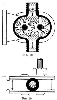
| 58. | Sectional View of Rotary Oil Pump | 67 |
| 59. | A Rotary Oil Pump | 67 |
| xi60. | Thermo-syphon Water Cooling System | 69 |
| 61. | Forced Water Circulation by means of a Pump | 70 |
| 62. | Forms of Water Piping | 74 |
| 63. | Two-port Two-stroke Engine with Crankchamber Compression | 81 |
| 64. | Diagrammatic Sketch of a Duplex Two-stroke Air Scavenging Engine | 87 |
| 65. | General Arrangement of the “Kean” Two-stroke Engine | 91 |
| 66. | Twin-cylinder Two-stroke Engine with Crankchamber Compression | 97 |
| 67. | Petrol Engine Brake | 100 |
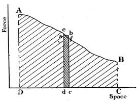
| 68. | Force-space or “Work” Diagram | 103 |
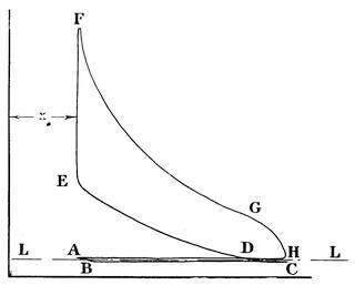
| 69. | Petrol Engine Indicator Diagram Four-stroke Cycle | 105 |
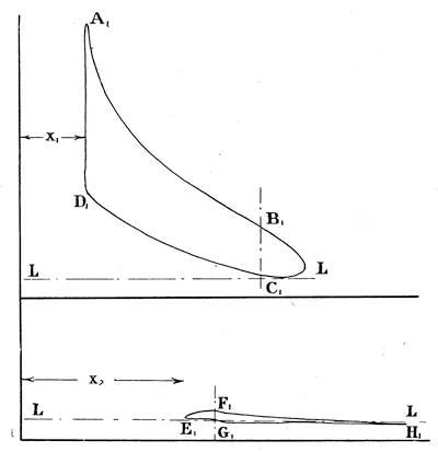
| 70. | Petrol Indicator Diagram for a Two-stroke Engine | 106 |
| 71. | Diagram of Valve-setting | 116 |
xiii
This book deals with principles. There are many books which give a descriptive account of existing types of engines, but my object in writing this volume has been to assist the reader to obtain thoroughly sound notions of the principles of design and construction which underlie all current practice. If a man understands, for example, the construction of the elements of a carburettor and how they ought to perform their several functions, he should have no difficulty in understanding any special type of carburettor placed upon the market. In dealing with the subject of ignition I have purposely avoided any detailed explanation of the manner in which the spark discharge is produced, because I felt that it introduces new ideas and probably causes the reader to lose sight of the fact that the magneto is only, after all, an accessory, although of course a most important one. I hope that the accounts of my experiments with the two-stroke will be of some service to inventors and others; the many extraordinary breakdowns, defects and adventures encountered during this period of my career have not been inserted because they would undoubtedly cause the reader to forget, for the time being, his fundamental principles.
My colleague, Mr. Oliver Mitchell, who lectures at the Polytechnic on “Motor Car Management and Inspection,” has read through the proofs for me and very kindly sugxivgested several small additions to the text, which I have incorporated; he also suggested the insertion of the valve-setting diagram in the Appendix. My thanks are due to Mr. Mitchell for his services and also to my wife for her assistance in the preparation of the Index.
FRANCIS JOHN KEAN.
The Polytechnic School of Engineering,
Regent Street, London, W.
July, 1915.
1
THE PETROL ENGINE
Explosive Mixtures.—If a small quantity of liquid petrol or benzol be placed in an open vessel and exposed to a current of air it will quickly disappear or evaporate. We say that the liquid petrol has been vaporized or turned into petrol vapour. A mixture of air and petrol vapour can be ignited and burnt, the rate of burning being affected by the strength of the mixture. The strength of the mixture is determined by measuring the respective volumes of air and petrol vapour present in a known volume of the mixture. It is possible to form a mixture of air and petrol vapour in such proportions that when ignited by an electric spark it will be completely burnt2 at such a rate that the combustion is almost instantaneous, i.e., it will explode. This mixture of air and petrol vapour would then be referred to as an explosive mixture and would be suitable for supplying to the cylinder of a petrol engine.
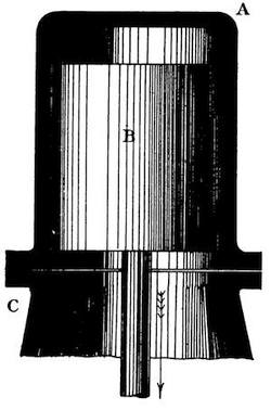
The Meaning of Suction.—Imagine an iron cylinder A (Fig. 1) held down on a rigid base C and fitted with a gas-tight piston B. If we pull the piston down sharply to the position shown in Fig. 2 we will realize that there is apparently some force inside the cylinder which is trying to suck the piston up again. The fact that the piston is being withdrawn and no more air or gas admitted above it to fill up the volume it has displaced on its descent causes a partial vacuum in the cylinder. Now if by means of a tap or valve of some kind we could put the cylinder in communication with the atmosphere, air would rush in and fill up the cylinder until the pressure of the gases3 in it became equal to atmospheric pressure, when no more air could enter, because there would be no excess of pressure to force it in. In technical language we would say, “the piston has sucked in a charge of air” through the tap or valve.
The Meaning of Compression.—Close the tap or valve and push the piston up again sharply to its original position of Fig. 1. You will now encounter considerable resistance and experience a force pushing down against you because you are reducing the volume of the gas and thereby increasing its pressure; that is to say, you are compressing the gas, because you are now making an amount of gas that recently occupied the whole cylinder fit itself into the small space between the top of the cylinder and the crown of the piston. In technical language you would say, “the piston has now compressed the charge” of gas within the cylinder.
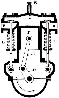
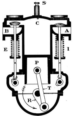
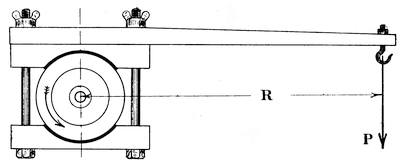
The Meaning, of a Stroke.—In an engine such as is4 shown diagrammatically in Figs. 3 and 4, when the piston P moves from its topmost position in the cylinder down to its very lowest position we say it has completed a downstroke, and when it moves upwards from its lowest to its highest position we say the piston has completed an upstroke. The length of the piston’s stroke is equal to twice the length of the crank radius R, and is measured by observing the distance moved by the piston in travelling from its highest position in the cylinder to its lowest or vice versa. The space existing above the piston between it and the cylinder head when the piston has reached its highest position in the cylinder is called the clearance space. It is also referred to as the combustion chamber, or chamber in which the petrol gas is exploded. When the piston is either at the top or bottom of its stroke the crank radius R and connecting rod T are in one and the same straight line; under these conditions we say the crank is on its inner or outer dead-centre.
5
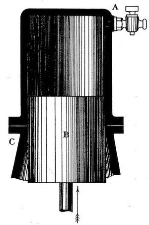
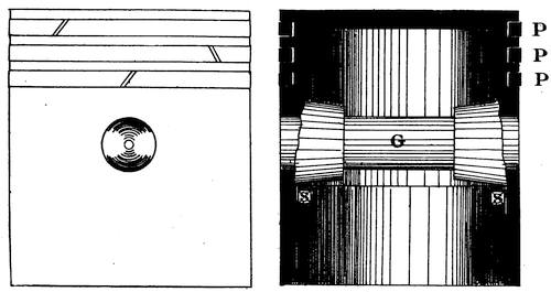
The Otto Cycle.—Most petrol engines operate on what is known as the “Otto” cycle, in which the cycle of events is completed once in every four strokes (or two revolutions) made by the engine. The “Otto” cycle is therefore usually referred to as the four-stroke cycle. In the accompanying diagrams (Figs. 3, 4, 5, and 6) we show in diagrammatic form the interior of a petrol engine cylinder fitted with mushroom type valves.
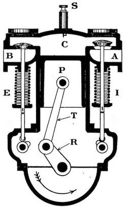
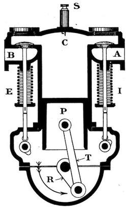
In studying the figures we assume the engine is being cranked round by hand in the direction of the arrow while we view it from the “flywheel” end (i.e. the end adjacent to the driver’s seat), then A is the pipe which leads the mixture of air and petrol vapour from the carburettor to the cylinder and is called the induction pipe. C is the cylinder, P the piston, I the inlet valve, E the exhaust valve, T the connecting rod, R the crank, and S the sparking plug. The pipe B which leads the burnt gases from the6 exhaust valve to the silencer is called the exhaust pipe. The cycle of operations is as follows:—
(1) On the first downstroke made by the piston a suction effect or partial vacuum is produced in the cylinder; the air and petrol vapour in the induction pipe being at atmospheric pressure, which is in excess of that now existing in the cylinder, flow into the cylinder as soon as the inlet valve I is opened by the engine mechanism. At the end of this, the suction stroke, the inlet valve closes and traps the charge of explosive mixture in the engine cylinder. This is shown in Fig. 3.
(2) On the first upstroke made by the piston the charge of explosive mixture is compressed ready for firing. Both valves are shut. This is shown in Fig. 4.
(3) On the second downstroke made by the piston the sparking plug S passes a spark which explodes the charge at the very commencement of the downward move7ment of the piston. The force of the explosion drives the piston downwards, doing useful work. Both valves are shut. This is the power stroke, and sufficient power must be developed on this stroke not only to do the work required from the engine but also to tide it over the other three idle strokes. On this stroke the piston drives the crank by means of the connecting rod, but on the other three strokes of the cycle the crank has to drive the piston by means of the power or energy stored in the engine flywheel on the power stroke. Towards the end of the power stroke (or explosion stroke) the engine mechanism opens the exhaust valve E and allows part of the burnt gases to escape to the silencer along the exhaust pipe. This is shown in Fig. 5.
(4) On the second upstroke of the cycle the piston pushes the remaining burnt gases out of the cylinder through the exhaust valve. When the piston reaches the top of its stroke the exhaust valve closes. This is shown in Fig. 6. The cycle of operations then begins again, giving one power stroke and three idle strokes each time as already described.
8
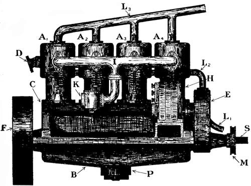
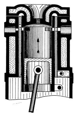
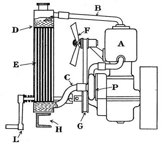
For the purpose of explaining the cycle of operations we have considered only a diagrammatic sketch of an imaginary motor-car engine, but in Fig. 7 we illustrate an up-to-date motor-car engine. In the first place we note the position and arrangement of the four water-cooled cylinders, A1, A2, A3, A4, containing their pistons and mushroom type valves. These are conveniently placed in a vertical position and mounted on top of the crankchamber C, to the bottom of which is attached the oil-base B. At the front of the engine are shown the timing wheels in their casing E, and at the rear end the flywheel F. The starting-handle connexion is at S, the fan pulley being shown at M. The high tension magneto which supplies the current to the sparking plugs is shown at H, and I is the induction pipe connected to the carburettor K. The water circulating pump is on the off side of the engine and does not appear in the illustration, but L1 is the inlet water pipe leading from the radiator (not shown) to the water pump, and L2 is the delivery pipe from the pump to the respective cylinder jackets, L3 being the outlet water pipe. The exhaust pipe is shown at D, and the oil pump at P. The valve springs, valve tappets and guides can also be clearly seen. In examining the several parts of the engine in detail we must not lose sight of their respective positions in the general arrangement view of Fig. 7.
The Cylinder.—Probably one of the most important parts of an engine is the cylinder. As we have already seen, it is inside the cylinder that the charge of petrol9 vapour and air is exploded and completely burnt. The heat energy of the petrol mixture which is liberated by the explosion is immediately transformed into mechanical work and propels the piston forward like a projectile from a gun. But we must also notice that our present-day arrangements (clever as they are) are by no means perfect, and we cannot, even under the most favourable circumstances, convert more than about one-third of the heat energy of the petrol mixture into the mechanical energy of the moving piston. Of the remaining two-thirds of the heat, part is used up in heating the cylinder walls, the piston and the valves, and the remainder goes out with the exhaust gases to the silencer, finally escaping to the outside air. Thus two important facts are brought to our notice:—
10
(1) The reason why we use petrol to drive our motor-cars is because petrol (and certain other liquid fuels such as benzol, etc.) contains within itself a store of energy which can be liberated as heat when the fuel is burnt or exploded in the presence of air in the engine cylinder.
(2) At the present day, even with our most up-to-date contrivances, we cannot make use of two-thirds of the available heat in our petrol. Instead of being able to turn this heat into useful mechanical work, we are compelled to throw it away—to waste it. Further than that, we have to make special provision to ensure that it shall be wasted as quickly as possible and as easily as possible. We take out the greatest amount that we can possibly turn into work and then hasten to dissipate the remaining two-thirds. We cast hollow chambers on the outside of our cylinders through which we circulate cold water to keep down the heat in the cylinder walls; if our cylinder walls and piston get too hot our engine may seize up, therefore we must cool them to ensure satisfactory running. Again we make large exhaust valves and provide a free escape through the silencer for the exhaust gases, so that when we have snatched our useful one-third of the heat supply we may throw the remainder away into the atmosphere as rapidly as possible.—this part is of no use to us, we cannot turn it into work, then why let it stay here and heat our cylinder walls and piston still further?
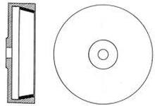
It is a good plan to extend this hollow chamber, containing the water in circulation, at least round the whole of the combustion chamber and all round the inlet and exhaust valve passages and down the barrel of the cylinder as far as the walls are likely to come into contact with the hot gases from the explosions. We refer to this hollow chamber, with its circulating water, as the water-jacket of the cylinder. It is not absolutely essential to have our cylinder water-jacketed, especially with small engines for motor-cycles and engines for aeroplanes which have revolving cylinders,11 but it is practically essential in nearly all other cases. Even in the special cases mentioned it is found necessary to form special heat radiating fins on the outside of the heated walls to assist in dissipating or getting rid of the surplus heat and preventing seizure of the piston within the cylinder. These fins are clearly seen on the cylinder of the motor-cycle engine shown in Fig. 13.
Thus we may say that motor-car engine cylinders are bound to be water-jacketed, i.e., to have a hollow space round them containing water in circulation. The cylinders themselves are nearly always made in the form of iron castings and the jacket spaces form part of the cylinder casting as a general rule, but occasionally the water-jacket space is formed by attaching plates or tubes to the cylinder casting by means of bolts or screws—not an easy thing to arrange successfully, as it requires water-tight joints.
The procedure for manufacturing a motor-car cylinder is first of all to design and calculate the proportions of the various parts and get out a set of working drawings. From these drawings we get patterns and core-boxes made in wood. The patterns are the exact shape of the finished cylinder on the outside, and the core-boxes are the exact shape of the inside of the finished cylinder (except in so far as allowance has to be made for parts which must afterwards be machined).
The patterns are pushed down into the moulding sand in the foundry, and when withdrawn leave their impression, thus forming moulds. The core-boxes are filled with sand, which when withdrawn furnishes us with masses of sand that are the counterpart of the interior of the cylinder in shape. These cores are supported centrally in the mould (which is usually in halves, or more than two parts), while the molten iron is poured into the intervening space to form the iron casting. When the casting has cooled down the sand can be cleaned off quite easily. One set of patterns and core-boxes will thus produce quite a number of cylinder castings, each being similar in every respect to the other, the process12 being a quick and fairly cheap method of reproduction. Later on the cylinder barrel has to be machined and bored out true to very fine limits by the use of boring tools and some kind of boring machine or lathe. The flanges or flat faces have to be planed true in a planing machine and the valve stem guides and valve seatings must be carefully and truly machined to correct size and shape.
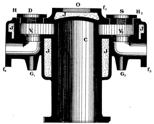
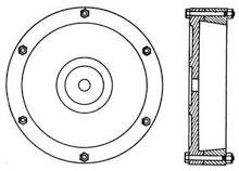
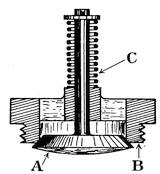
Fig. 8.—Sectional Drawing of a T-headed Water-Jacketed Cylinder. Valves on opposite sides of Cylinder.
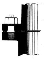
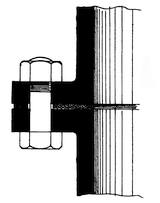
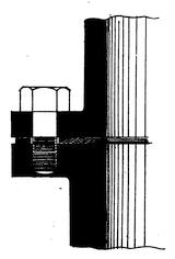
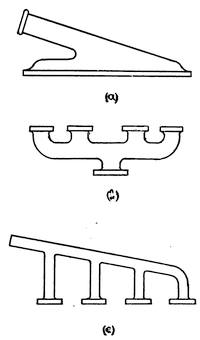
Figs. 88 and 9 show two views of a single motor-car engine cylinder, the water-jacket forming part of the cylinder casting. In the figures C is the cylinder barrel or bore; J the water-jacket; I the inlet for the jacket water; O the outlet for the jacket water; D is for the13 compression tap; S for the sparking plug; V1, V2 are the valve seats; G1, G2 are the valve stem guides; H1, H2 are caps which may be removed when the valves are being put in or taken out; f1, f2, f3, f4, f5 are called flanges. The flange f1 is used for attaching the cylinder to the crankchamber; while it is quite true that the force of the explosion within the cylinder drives the piston downwards, it is equally true that it also tends to force the cylinder head off or to blow the cylinder casting upwards off the crankchamber, unless it is14 securely fastened to it by means of screws or bolts15 passing through the flange f1. The flanges, f2, f3 are for the inlet and outlet water pipe attachments, and f4, f5 are for the induction pipe and exhaust pipe connexions. Generally the pipes will have flanges and be held tight against the flanges on the cylinder casting by means of screws or studs. Figs. 10, 11, and 12 show how two metal flanges are held in contact by means of screws or studs or bolts, and they also show the packing materials between the metal surfaces which keep the joint tight and prevent water or gas leaking across the flanges and escaping to the outside air, or air leaking in if the internal pressure is below that of the atmosphere.
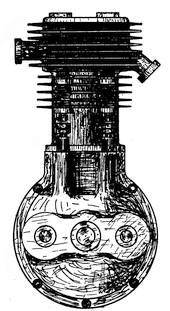
Fig. 13.—Motor-Cycle Engine
with
an L-headed Air-Cooled Cylinder.
Valves both on same side of Cylinder.
In Figs. 8 and 9 the valves are placed one on each side of the cylinder, this form of cylinder being known as a T-headed cylinder, but it is rather more usual here in England to place both valves on the same side of the cylinder and next to each other as indicated in Fig. 13, this form16 of cylinder being known as an L-headed cylinder. The chief object is of course to avoid the use of two valve shafts and also to produce a neater looking engine, but the T-headed design is better cleaned or scavenged by the passage of the inlet and exhaust gases. When a motor-car engine has two cylinders we frequently find them both in a single casting, having a common water-jacket, and then we say they are cast in pairs. A four-cylinder engine may thus have: (1) Cylinders cast separately; (2) Cylinders cast in pairs; (3) Cylinders cast en bloc; or all four in a single large casting. The third method is cheapest in first cost, but in the event of breakage will become the most expensive. The second method is a sound compromise.
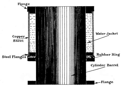
An example of a built-up cylinder and water-jacket is shown in Fig. 14, the cylinder barrel being of steel tube with steel flanges, and the water-jacket being formed by copper tube slipped over the outside of the steel cylinder. Its great advantage lies in the reduction of weight, and it is thus largely used for aeroplane work. The valves would then be fitted in the top cover of the cylinder and driven by overhead gearing.
17
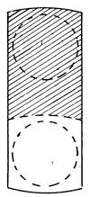
The Piston is perhaps the most important detail to consider, for it is on the piston that the force of the explosion acts when the heat energy is converted into mechanical energy. It must be made sufficiently strong to withstand the bursting effect of successive explosions, and yet if we make the metal too thick it will retain too much of the waste heat and the piston may seize in the cylinder due to expansion. To understand why the piston is likely to seize in the cylinder we have only to remember that when a metal body is heated it gets larger in every direction, but if cooled it returns to its original size. Now if we make the metal of the piston too thick so that the waste heat cannot pass quickly through it and dissipate itself at cooler parts of the engine, then the bulk of this heat will be concentrated in the piston head, causing it to expand and become a tight fit in the cylinder, as the cylinder walls are fairly thin and in contact with the jacket water which keeps them fairly cool and prevents them expanding much above their normal size. The actual amount of expansion is very small of course, but there is very little clearance between the piston and the cylinder walls, even when the engine is all cold—perhaps five-thousandths of an inch. The piston therefore must be strong, yet as light as we can make it, having regard to the necessity for its being amply stiff and rigid and able to stand up to its work.
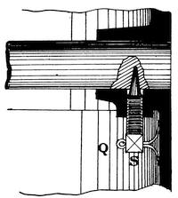
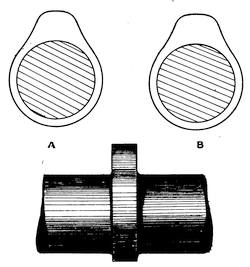
Generally it will be an iron casting in the form of a small cylinder (see Fig. 15), having provision in it for the packing rings P, and the gudgeon pin G, with its fastening screws18 S1, S2. The piston itself, as we have observed, must be a nice sliding fit in the bore of the cylinder without any shake or side play when there are no packing rings in the grooves. The packing rings are turned to size so as to fit the cylinder exactly and prevent any gas leaking past the piston into the crankchamber. These rings are very light, are made from cast iron, and arranged to break joint, as indicated, by cutting the middle ring in the opposite direction to the two outer ones. Bosses are cast on the inside of the piston and afterwards bored out to receive the steel gudgeon pin or wrist pin G. This pin is best made of plain parallel cylindrical form ground true, and the bosses in the piston should be reamered out to the exact size of the pin. When the pin has been inserted the tapered screws are screwed hard up by means of a special spanner and bear against the pin, preventing it from coming loose or from shaking or knocking. There are many other methods of fixing the gudgeon pin which are not shown here; each has some special point in its favour, but the one illustrated is undoubtedly the best and affords a positive adjustment for wear.
19
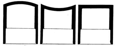
An enlarged view of one of the bosses, showing the taper pin in detail and how the split pin Q prevents it from slacking back by contact with the wall of the piston, is shown in Fig. 16. Sometimes the lower part of the piston is made lighter by drilling holes through the walls. It is very important to reduce the weight of the piston as much as possible, otherwise the engine cannot attain a high speed, so that it becomes essential to bear this in mind when constructing engines for racing purposes. Frequently we find steel pistons used, as they may be made lighter for the same strength, and then steel piston rings may be used; they are not much in favour for ordinary motor-car engines because the steel pistons expand at a greater rate than the cast iron of the cylinder, so that there is more liability to seizure. The crown of the piston is sometimes curved upwards and at other times curved downwards, but more often it is flat as shown in Fig. 17. The gudgeon pin is20 sometimes made of mild steel, and the surface is then case-hardened in the centre where the connecting rod end bears. At the present time it is quite as common to find gudgeon pins made of special nickel steel or other steel alloys that do not require case-hardening. On the whole these special21 steels make the best gudgeon pins and stand the hardest wear.
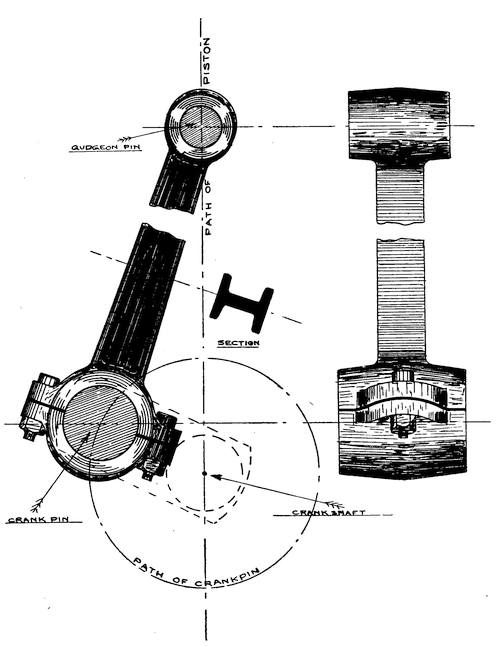
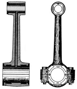
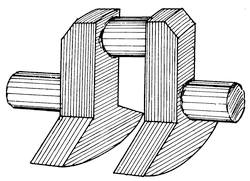
The Connecting Rod is another very important detail of the engine mechanism, its function being to transmit the force of the explosion from the piston to the crankshaft.
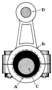
One end of the connecting rod moves up and down with the piston and oscillates (or swings to and fro) on the gudgeon pin, while the other end of the connecting rod travels in a circle, being pivoted at the crankpin and rotating in a circle which has for its centre the centre line of the engine crankshaft. This is clearly indicated in Fig. 18. On the suction stroke of the engine the piston has to be pulled down, as we have already seen; on the explosion stroke the greatest pressure acts on the piston and pushes the connecting rod down. Thus sometimes the connecting rod is being pulled and at other times it is being pushed; in each case it has to overcome the resistance of the engine and drive the car. It is evident, therefore, that the character of the load carried by a connecting rod is just about as complex and dangerous as it is possible for a system of loading to be, and great care has to be taken in the design22 of such rods to ensure adequate strength without undue weight, as this would tend to keep down the maximum speed of the engine. Another important consideration is the cost of production, and for this reason one often finds it in the form of a phosphor bronze stamping of I section, although the ideal form is a round section of steel with a straight taper from gudgeon pin to crankpin end, and having a hole bored right up the centre to reduce the weight without sacrificing much strength. When the rod is made in the form of a stamping between dies it is possible to turn out great quantities at very low cost and at a very rapid rate, whereas the round steel rods would require to be machined from the solid bar to compete in price with the others. When phosphor bronze is used it is only necessary to bore out carefully and face the bearings at the two ends for the gudgeon pin and crankpin; the bearing at the crankpin end is always formed with a removable cap to facilitate fitting it nicely to the crankpin, journal and also to allow for adjustment as the bearing wears. With steel rods it is23 necessary to cast a white-metal lining in the crankpin end and then bore it out to form the bearing, but the crosshead bearing is usually formed by a phosphor bronze bush. It is evident, therefore, that the steel rods are more expensive, but they make a splendid mechanical job. A steel connecting rod is shown complete in Fig. 19. Stamped steel rods of I section are also commonly used and are much better and stronger than those made entirely of phosphor bronze.
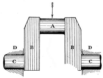
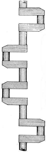
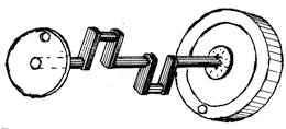
The Crankshaft, as its name implies, is a shaft with one or more cranks or right-angled bends in it. Its function is to convert the sliding motion of the piston into the rotary motion of the flywheel and revolving shaft. A crankshaft with a single throw (or single crank) is shown in Fig. 20; a four-throw crankshaft is shown in Fig. 21; and Fig. 22 shows how an equivalent motion can be obtained by a single pin fixed into the face of a flywheel. This device (Fig. 22) is frequently used for motor-cycle engines. Crankshafts are always made of steel; sometimes mild steel is used, but more usually24 special alloys of steel containing chrome, nickel, vanadium, etc., are used. The general practice at the present time is to machine the crankshaft direct out of a solid bar of steel; this requires special jigs for holding the work and special tools for cutting the metal, but is the quickest, cheapest, and most satisfactory method to adopt. A few firms specialize in this class of work with high-grade steel and can supply crankshafts from stock.
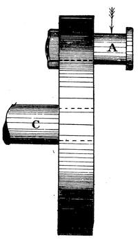
It is easily seen by examining Fig. 18 that the crankshaft is being twisted in overcoming the engine resistance, while Fig. 20 shows that the crankshaft is being bent under the push from the connecting rod, so that we say the material of a crankshaft is subjected to combined bending and twisting, and as such a combination is not easy to resist we see now why special steel alloys are required for safety, combined with economy in material and reduction of weight. In Fig. 20 the crankpin is shown at A, the crank cheeks or webs at B1, B2 and the crankshaft proper at C. The portions of the crankshaft C which work in the bearings D1, D2 are termed journals. A crankshaft must be very stiff and not bend or twist sensibly, otherwise the shaft will vibrate when the engine runs up to speed—which would be very undesirable. It must be perfectly true with all the bearings absolutely in line and the journals well bedded down in their respective brasses (or bearings), otherwise mechanical25 troubles will arise. Each crank with its crankpin and webs forms a lop-sided or unbalanced mass, so that either (1) each crank must have its own balance weight as in Fig. 23, or (2) special balancing masses must be fitted at each end of the crankshaft. A convenient method of balancing the crankshaft is to have a fan pulley at one end and the flywheel at the opposite end, so that by drilling holes in the faces of these discs an amount of metal may be removed from them sufficient to balance the excess weight of the respective crankpins and webs. In Fig. 24 the shaded area indicates that portion of the crank which constitutes an unbalanced mass. Crankshafts for high-speed engines have always to be very carefully balanced, otherwise the engines will never run satisfactorily, the want of balance being greatly aggravated as the speed of rotation increases. Fig. 25 shows how the crankshaft of a two-cylinder engine may be balanced by drilling holes in the flywheel and fan pulley respectively, but the same effect may be produced by attaching balancing masses—this latter method would, however, be more inconvenient and expensive. The crankpins and journals are ground truly circular after being turned in the lathe as true as possible.
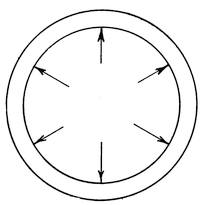
The Flywheel.—We have already de26scribed how the force driving the piston of a motor-car engine varies during the four strokes of the cycle, but we must note that it also varies considerably during each individual stroke. Thus, on what is known as the explosion stroke (or power stroke) of the cycle, the pressure at the commencement of this stroke may be exceedingly great and yet towards the end of the stroke the gases have expanded and the exhaust valve has been opened, so that the pressure acting on the piston is then very small. Again, on the compression, suction, and exhaust strokes, the piston has to be pushed or pulled by some means, as no power is being generated. Therefore, if the engine is to be self-acting and run continuously, some means must be provided for storing up the great force of the explosions and giving it out again on the idle strokes. The function of the flywheel is to store any energy given to it over and above that required to drive the car and to give it out again when required for performing the functions of compressing, exhausting, and sucking in gas, as well as to keep the car running steadily. It is simply a heavy wheel mounted on the end of the crankshaft which, when once started revolving at a high speed, is not27 easily stopped, and which will give up part of its energy each time its speed is reduced owing to the demands of the engine; but when the engine is generating power the wheel will speed up and store the excess—the mere fact that the wheel is heavy causes these changes in speed to occur slowly, and therefore on the whole the fluctuation of speed is not great when a suitable flywheel is fitted. The flywheel does not limit the maximum speed of the engine, as it could go on slowly increasing in speed if no resistance was encountered until the wheel finally burst or flew to pieces. Thus the flywheel does not regulate the speed of the engine; it merely smooths out the inequalities in the several strokes of the “cycle.” Flywheels of motor-car engines are now always made of steel, so that they can be safely run at speeds up to 3,000 revolutions per minute without fear of the rim bursting. All parts of the rim tend to fly off radially in the direction of the arrows as shown in Fig. 26 under the action of centrifugal force. A built-up flywheel is shown in Fig. 27, and one made from a single stamping of steel is shown in Fig. 28. Generally speaking, when a coned clutch is fitted one portion of it is formed on the inside of the flywheel rim as indicated in these two figures. When the28 construction shown in Fig. 28 is adopted the lining would be inserted after the clutch cone had been put into place; very often the lining is made up of sections which can be readily inserted or withdrawn after the cone is in position.
29
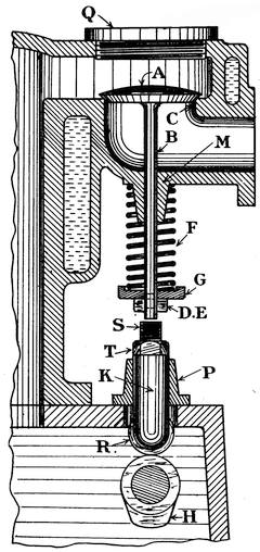
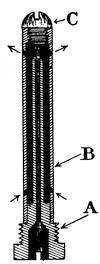
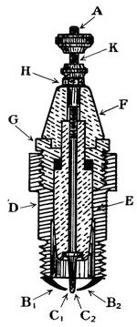
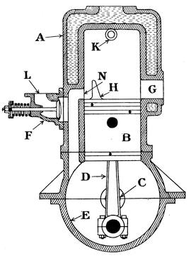
Poppet Valves.—Valves are provided for the purpose of controlling the admission of the mixture to the cylinder and also for controlling the exhaust or ejection of the burnt gases at the end of the firing stroke. The most common form of valve is the mushroom or poppet type of valve shown in Fig. 29, in which A is the valve head, B is the valve stem, C is the valve seating, and D is the cotter hole for the cotter E. It will be seen that the general appearance of the valve is a disc of steel with a fine stem to it similar to a mushroom in general outline—hence its name. The valve has a coned face which is kept pressed down on a coned seating by means of the pressure of a powerful spring F acting on the washer G, which bears against the cotter E and thus presses down the valve stem. To ensure that the valve shall always come down correctly on its seating and make a gas-tight joint, the valve stem guide M is provided.
The cam H raises the valve off its seat at the required instant when the motion of the camshaft brings the cam under the roller R. The cam lifts the roller vertically and with it the tappet or push rod K, which slides vertically upwards in the guide P and lifts the valve. The tappet is provided with an adjustable head S kept in position by the locknut T. To adjust the clearance between the head of the tappet and the underside of the valve stem the locknut T must first be slackened back and then the head S can be screwed up or down as desired, the best clearance30 being about 1/64 of an inch; the locknut is then tightened down again. During this operation the valve must be down on its seat. Sometimes to reduce the noise arising from the tappet striking the valve stem, the head of the tappet is padded with some material such as hard vulcanite fibre, but this wears down more quickly than steel and requires frequent adjustment. The latest device for reducing the noise arising from the valve mechanism consists in totally enclosing the valve gear and springs either by metal plates bolted to the cylinder casting or by extending the crankchamber to cover it all in, and then it is certain to be well lubricated. The exhaust valve is always liable to give trouble either from leakage or seizure or other causes due to the great heat of the exhaust gases, so that the valves are often made now of tungsten steel alloy which is not31 much affected by heat. If a mushroom type valve leaks it can be ground in and made a tight fit on its seating, provision usually being made for this in the form of a slot cut in the valve head, as shown in Fig. 32, for the insertion of a screwdriver or special tool. To grind in a valve, remove the cap Q by unscrewing it, raise the spring F by pushing up the washer G and then withdraw the cotter E. Lift out the valve and smear the coned face with fine emery powder and oil (or water). Put the valve back and turn it to and fro on its seating by means of the screwdriver, keeping a firm pressure down on it; continue the operation until by examining the valve you ascertain that it touches on the seating all the way round, then couple up the spring again, after carefully removing all traces of the emery powder.
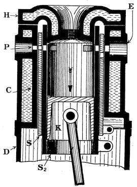
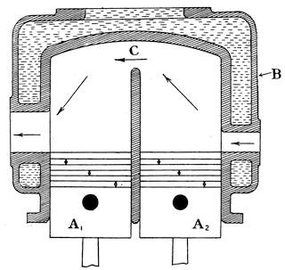
Sleeve Valves.—Another form of valve which has come very much into favour is the sleeve valve, two views of which are shown in Figs. 30 and 31. In this case the32 gases enter the cylinder through ports or slots P cut in the cylindrical cast iron sleeves S1, S2, which are placed between the piston K and the walls of the water-jacketed cylinder C. These sleeves are moved up and down inside the cylinder, while the piston travels up and down inside the inner sleeve S2 just as though it constituted the cylinder C. Some engines have two sleeves, as shown in the figure, but others have only one sleeve, and there is very little to choose between the two types on the score of efficiency. The great claim made for the sleeve valve is that it is almost noiseless in action and gives very much fuller openings for inlet and outlet of the gases. The piston has the usual number of packing rings to keep it gas-tight, and there is also a deep packing ring provided in the head of the cylinder H to keep the sleeve S2 gas-tight and prevent loss of compression pressure. The head of the cylinder is usually detachable, and has often separate water connexions in the form of pipes leading from the cylinder jackets. The sleeves33 receive their reciprocating motion from eccentrics and rods attached to pins shown at the bottom right-hand corner of each sleeve. It might be expected that the sleeves would get very hot or very dry and seize up, or the piston might seize, but in actual practice this has not occurred to any great extent, and on the whole they have been very successful. It is, however, necessary to keep the engine well lubricated, especially when the sleeves get worn, as the oil prevents loss of gas by leakage past the sleeves and piston. In Fig. 31 the two sleeves have come together in such a position that the ports coincide with the exhaust ports cut in the cylinder walls and therefore the exhaust is full open, and as the sleeves travel at times in opposite directions quick opening and closing of the ports is secured. The cylinder head is held down to the cylinder casting by screws or bolts and can be readily detached for cleaning or inspecting the interior of the cylinder. The great objection raised against the sleeve valves is their excessive weight and the unmechanical manner in which they are operated.
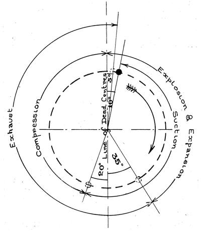
The Camshafts and Eccentric Shafts.—These are usually made from the same material as the crankshaft and machined from the solid bar, the projecting cams or eccentrics being afterwards cut to the correct shape. In the case of a camshaft it is very important that the shape of the cams should be such that they lift the valves quickly off their seats to the full extent of their opening (or lift), keep them open for as long a period as desirable, and then allow them to close quickly but without shock. Cams which have straight sides are more in favour than those with curved sides, but if the action of the cams is to be theoretically correct the side of the cam should be curved in such a manner that the valve is lifted at first with a uniformly increasing speed and afterwards with a uniformly decreasing speed, so that it will be at rest in its top position. If this is not done the valve tappet may jump a little above34 the cam each time the valve is lifted. In Fig. 33 the cam A is intended for the inlet valve and the cam B for the exhaust valve, the essential difference being that the exhaust valve must be kept open longer than the inlet valve, and therefore the exhaust valve cam is the wider of the two. The timing of the inlet and exhaust valves of an up-to-date engine may be explained by considering the crankpin circle as divided into 360 parts or degrees. If there were no lag or lead in the opening of the valves, then they would open when the crank was on its dead-centre and close when the crank was on its dead-centre. The inlet valve would open when the crank was on its top dead-centre and close when it had reached its bottom dead-centre, this representing35 the suction stroke of the engine. Then would follow compression and explosion, giving two strokes or one revolution before the exhaust valve commenced to open. The exhaust valve would then open when the crank was on its bottom dead-centre and close when the crank reached its top dead-centre corresponding to the completion of the exhaust stroke. It is very important that the pressure of the gases above the piston when it commences to move upwards on the exhaust stroke should be as low as possible, and this can only be secured by opening the exhaust valve towards the end of the explosion or power stroke, thus allowing the bulk of the gases to escape and leaving the piston with little resistance to encounter on its upward exhaust stroke. Therefore we give the exhaust valve a lead of about 30 degrees, which means that it begins to open when the engine crank is 30 degrees from the bottom dead-centre on the downward explosion stroke, and we give it a lag of about 5 degrees in closing. This means that we keep the exhaust valve open until the crank has moved 5 degrees over the top centre, so that we may fully utilize the momentum of the gases to clear out the cylinder or scavenge it. As the piston moves rapidly up the cylinder on the exhaust stroke it pushes the gases in front of it out through the exhaust opening, but when it gets to the top of its stroke the piston stops and then comes down again for the suction stroke, whereas the gases will tend to keep on moving if they are not unduly restricted in their passage through the exhaust system, so that we can generally obtain some slight advantage by giving the exhaust valve a small amount of lag in closing.
The pressure of the gases in the cylinder after the exhaust valve closes will nearly always be a little above atmospheric pressure, and therefore nothing is gained by opening the inlet valve immediately the exhaust closes—we generally allow an interval of 5 degrees, which means that the total lag of the inlet valve is 10 degrees in opening, or the inlet36 valve does not begin to open until the crank has moved 10 degrees off its top dead-centre on the downward suction stroke. At the end of the suction stroke the piston will again come to rest before moving up on the compression stroke, but the gases will continue to rush into the cylinder from the carburettor owing to their momentum if we leave the inlet valve open a little longer, hence we generally give it a lag of 20 degrees in closing, which means that the inlet valve does not close until the crank has moved 20 degrees up from the bottom dead-centre on the compression stroke.
The camshaft requires to be well supported in bearings to prevent it from sagging or bending under its load. If the shaft and the cams are not made from nickel steel or high-grade steel alloy, they require to be case-hardened (hardened on the surface) to prevent wear on the surfaces due to the pressure of the valve springs, which is considerable and may reach 100 lb. per valve easily; the same applies to the rollers of the tappets. When sleeve valves are fitted to the engine, eccentric sheaves must be used instead of cams, as no springs are employed. An eccentric sheave with its strap and rod are shown in Fig. 34. The valve shaft or lay shaft is shown at C, and the sheave with the hole bored37 eccentrically is shown at A, and B is the combined eccentric strap and rod. The pin D operates the sleeve valve, giving it a reciprocating motion in a vertical direction, the angular movement being taken up by the oscillation of the rod about the pin D, which would be fixed into the sleeve. Sometimes a groove is formed round the periphery of the eccentric disc or sheave to keep the strap in position and prevent end movement. As the weight of the sleeves is very considerable, the pin D and the eccentric rod must be well proportioned to prevent breakage or undue wear.
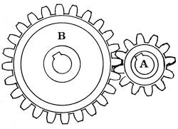
The Timing Wheels.—As there is only one suction stroke and one exhaust stroke in every two revolutions of the engine crankshaft, it will be clear that the camshaft or eccentric shaft must be driven at half the speed of the engine crankshaft. This may be done by the use of two gear wheels or wheels having teeth cut on their periphery, such wheels when used for this purpose being called timing wheels, because the positions of the cams on the camshaft (or the eccentrics on the eccentric shaft) relative to the engine crankshaft when the teeth of the timing wheels are put into mesh determines the timing of the inlet and exhaust valves, i.e., the instant at which they will open or close. A pair of timing wheels is shown in Fig. 35. The pinion A has twelve teeth and is keyed to the engine crankshaft, but the wheel B, which is keyed to the valve shaft,38 has twenty-four teeth, and hence the valve shaft runs at half the speed of the crankshaft. The wheels shown are spur gears, and the teeth run straight across the rim of the wheel; it is, however, quite common to find wheels with curved or helical teeth, as these run quieter. Sometimes when spur gearing is used, one of the wheels is made of fibre and the other of steel, but when helical gears are used the wheels are generally made from nickel steel of high tensile strength. The finer the pitch of the teeth (i.e. the distance between the centres of consecutive teeth) the quieter the gears will run, but the question of strength and the cost of production must also be considered. The latest practice is to use a silent chain drive; this originated with the introduction of the sleeve valve and eccentric shaft. When chains are used for the timing wheels provision must be made for taking up slack in the chain owing to stretching of the links, and as this cannot be done in the usual manner (by sliding the sprocket wheels further apart) owing to the centres of the crankshaft and the valve shaft being rigidly fixed by the bearings, a small jockey pulley (with teeth on it similar to those on the chain sprocket wheels) is provided attached to a short shaft or spindle, which can be raised or lowered at will, and thus keep the correct tension on the chain. The chain drive must be more expensive and require more attention; moreover, it cannot be so very much quieter in action than good well-cut helical gearing.
The Crankchamber.—The crankchamber, as its name implies, is the receptacle which contains and supports the crankshaft and also the camshaft. It is generally an aluminium casting, but frequently for commercial vehicle engines the top portion is made of cast iron and the bottom portion of sheet steel. In either case brass or gunmetal bearings, often lined with white metal, are fitted for the shafts to revolve in, and the engine cylinders are mounted on the top of the chamber. Provision should be made39 on the sides and ends of the crankchamber for fitting the magneto and oil pump and also the water pump, if required. There must also be some form of housing or extension of the chamber to enclose the timing wheels, and sometimes the whole of the valve gear is contained within the crankchamber to ensure proper lubrication for it and stop any noise from it reaching the outside world. It is also important that there should be large inspection openings fitted with proper oil-tight covers and some provision for easily pouring large quantities of oil down into the lower portion of the chamber. The design of a crankchamber necessitates careful forethought to ensure ample provision for all the necessary attachments and fittings and to secure the maximum accessibility of all parts. One or two vent pipes, consisting of upwardly projecting pipes having their outer end covered with wire gauze and screened from dust should be provided to allow hot air and gas to escape from the chamber.
40
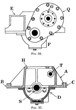
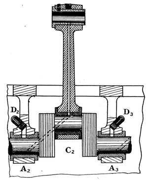
Two views of a crankchamber of modern design are shown in Figs. 36 and 37. In these figures A is the top half of the crankchamber which rests upon the chassis or framework of the car, being bolted to an underframe at B and C. The cylinders are attached to the chamber at the flange H by means of studs and nuts. This portion, the top half of the crankchamber, requires to be very strong and stiff, because the upward pressure of the explosions acts on the crown of the cylinder and tends to tear the cylinder off the flange H, while at the same time it exerts a great force on the piston, pushing it downwards and tending to force the crankshaft down out of its bearings. In the best practice the whole weight of the crankshaft is supported from the top half of the crankchamber and is carried on the bearing bolts as shown at S, so that they also receive the downward thrust of the piston and in their turn transmit it to the main casting.
The bottom half of the crankchamber then becomes merely an oil container, or reservoir, and dust cover; it should be so arranged and situated that it may be readily removed for inspection of shaft and bearings from underneath. Sometimes the crankchamber has long arms, which can be attached directly to the side members of the chassis, or it may be supported in the chassis by a tubular cross member.
In Fig. 37 the camshaft is shown at T; the magneto would be carried on the bracket E and driven by gearing from the crankshaft. The facing at G is for the water pump, which, in this case, is intended to be mounted on an extension of the camshaft T. The oil pump would be fixed at F, preferably towards the rear of the engine, so as to secure an adequate supply of oil for the pump when the car is climbing a steep hill. The oil could be drawn off and the reservoir emptied by unscrewing the large plug shown in the centre of D in Fig. 37. The timing wheel housing or casing is shown at Q; the oil ducts and con41nexions for supplying the main bearings with oil are not shown in these drawings, nor are the inspection openings and covers. The upper half of the crankchamber frequently becomes very hot, due to conduction of heat from the metal of the cylinders, and for this reason it has from time to time been proposed to draw the air supply of the carburettor through the crankchamber to serve the dual purpose of cooling the bearings and heating the air supply to the carburettor; but the idea has not found favour, as there is considerable risk of dust and grit finding its way into the bearings and causing trouble due to abrasion.
42
A carburettor is a contrivance for supplying an explosive mixture of air and petrol vapour to a petrol engine. Petrol, although a liquid fuel, is a combination of carbon and hydrogen which, when supplied with the necessary air, can be burnt and thus evolve heat, which heat is turned into work inside the engine cylinder. What we have to supply to the engine is really a mixture of air and petrol vapour in certain proportions, such a mixture being often spoken of as carburetted air on account of the carbon contained in it. About two parts of petrol vapour (by volume) are required to every one hundred parts of mixture, or fifteen pounds of air to every pound of petrol vapour (by weight). This carburetted air must be of the required strength and form a homogeneous mixture in the form of a vapour. The problem of carburation consists in forming a mixture of the correct strength and character. Air may be carburetted by passing it over the surface of liquid petrol in a surface carburettor, or by drawing it over or among wicks saturated with liquid petrol as in the wick type of carburettor, but both these methods have been largely superseded by the use of what is now known as a jet or spray type of carburettor, in which the petrol is sprayed from a fine jet and mixes with air which is passing up rapidly round the outside of the jet. In all cases, however, the liquid petrol must be vaporized before entering the engine, and to do this heat must be supplied to the mixture, just as water has to be heated before it can be vaporized and turned into steam. Under ordinary circumstances sufficient heat43 can be obtained from the incoming air to effect vaporization of the liquid petrol if it issues in the form of a very finely divided spray, but when the demand for mixture, from the engine, is great the air cannot supply the requisite heat without its temperature falling below the vaporization point; hence most carburettors of up-to-date pattern are fitted with a mixing chamber surrounded by a hot-water jacket. The essential features of the carburetting plant are shown diagrammatically in Fig. 38, in which A is the petrol tank fitted with the petrol tap G, to which is coupled the petrol pipe F. Some form of petrol filter as indicated at B should be placed between the tank and the carburettor C. The throttle valve of the carburettor is shown at H, the extra-air valve at E, and the engine induction pipe at D.
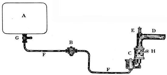
Fig. 38.—General arrangement of the Carburetting Plant, showing Petrol Tank (A), Petrol Filter (B), Carburettor (C), and Extra-air Valve (E).
The carburettor proper may be constructed in a variety of forms, but the elements of which it is composed are: (1) the float chamber A, (2) the petrol44 jet B, (3) the choke tube C, (4) the mixing chamber D, and (5) the throttle valve E, as shown in Fig. 39.
The Float Chamber is generally cylindrical in form and the liquid enters at the bottom, the flow being regulated by a pointed rod called a needle valve. A hollow metal float which can slide freely up and down the needle valve stem operates two levers which are pivoted on the45 float chamber cover. It is well known that when a body is immersed in a liquid the liquid exerts an upward pressure on the body equal to the weight of liquid displaced by the body. The float being hollow and made of very thin sheet metal, displaces a very large quantity of liquid in proportion to its own weight, and is therefore very buoyant. The buoyancy of the float will, of course, depend on the density of the liquid in the float chamber, and it will naturally sink deeper down into petrol than it would into a heavier spirit such as paraffin or benzol. The action of the float is as follows:—Supposing the petrol to be turned off and the needle valve lifted up off its seating, then on turning on the petrol supply the petrol will run into the float chamber, and as the level of the liquid rises the float will rise too, lifting up the outer ends of the levers and depressing the needle valve down on to its seating by means of the collar which is rigidly attached to the spindle of the needle valve. If at any time the level of the liquid in the chamber falls, the float will fall also, thus allowing the outer ends of the levers to drop and raise up the needle valve from its seating; this allows more petrol to enter the chamber and raises the float again, thus keeping a constant level in the chamber.
The height of the orifice in the top of the petrol jet above the bottom of the float chamber determines the height at which we require the liquid to stand in the chamber. As a general rule the level of the liquid in the float chamber should be slightly below the top of the jet orifice to prevent the liquid oozing over and causing flooding or continuous dripping of petrol from the jet, even when the engine is not running. The height of the collar on the needle valve spindle must be adjusted until the float closes the valve down on its seating when the liquid has risen to the desired height in the float chamber. Hence, if a carburettor has been adjusted to work with petrol, it will require to have some slight extra weight added to the float when working46 with heavier spirits to cause it to sink to the required depth in these denser spirits.
The Petrol Jet and Choke Tube.—The petrol jet generally consists of a short tube of fine bore, one end of which contains a very small orifice for the purpose of spraying the petrol into the choke tube. When the engine is at rest it is easily seen that the pressure of the air in the choke tube is atmospheric, and that the pressure above the liquid in the float chamber is also atmospheric, but when the engine is running it draws air up the choke tube at a very high speed and thus causes a partial vacuum round the petrol jet, and therefore the petrol spurts out of the jet under the pressure difference which then exists and issues in the form of a fine spray which is readily vaporized. The choke tube is purposely made of rather small diameter, in order to get a high air speed, which results in a low pressure round the jet and ensures a good driving force to spray the petrol out of the jet. The speed of the engine is controlled by the position of the throttle valve or disc E, which regulates the amount of air flowing up the choke tube, and therefore incidentally checks the quantity of petrol issuing from the jet by regulating the vacuum in the neighbourhood of the jet orifice. At low engine speeds there is very little suction or vacuum effect on the jet, but at high engine speeds with full throttle opening the maximum suction of the engine is exerted upon the jet. Thus at low speeds with this type of carburettor we do not get enough petrol out of the jet, and at high speeds we get too much, which results in too weak a mixture at low speeds and too rich a mixture at high speeds. One reason for this is that the air flows out of the choke tube faster than it flows into it, owing to the fact that its volume increases as the pressure decreases, and hence the pressure round the jet falls very rapidly indeed as the air velocity increases and causes too much petrol to issue from the jet in proportion to the quantity of air flowing through the tube.47 The choke tube is often a plain piece of pipe, as shown in Fig. 40, instead of being tapered as in Fig. 39.
The Mixing Chamber and Throttle Valve.—The throttle valve is usually a plain flat disc of metal mounted on a spindle which can be rotated and thus regulate the size of the air passage to the engine. It is placed above the petrol jet and situated in the mixing chamber, which is simply a short length of pipe (of the same bore as the engine induction pipe) surrounded by a hot-water jacket, the supply of hot water being drawn from the engine cooling system. The heat from this jacket should be sufficient to make up for the fall in temperature that would otherwise result due to the vaporization of the petrol as explained above.
Recent Improvements in Carburettors.—Another defect of this simple type of carburettor becomes apparent in the larger sizes required for multi-cylinder engines. To pass the requisite quantity of petrol to keep the engine running at high speeds without creating too great a suction effort and thereby hampering the engine, necessitates the use of a jet of larger calibre, so that the liquid is no longer sprayed but issues in the form of a fine stream which is not readily vaporized. This has been overcome by the use of multiple-jet carburettors which have several jets each surrounded by its own choke tube, but all controlled by one throttle valve and supplied from one common float chamber. In this case the total cross-sectional area of all the jet orifices together could be made sufficient to pass the necessary quantity of fuel, but the bore of each individual jet orifice would be comparatively small and spraying would result as before. Another very successful device is shown in Fig. 41, in which A is the petrol jet which, in this case, has no special orifice and is surrounded by a larger tube B containing small holes for the inlet of air and out48flow of petrol. As the petrol issues from the jet it strikes against the pointed cone on the end of the screw C, and is thus very successfully atomized and broken into small particles which can be readily vaporized.
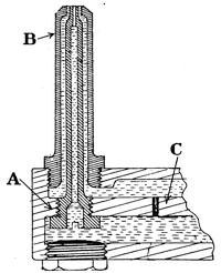
Fig. 42.—Compensated Petrol Jet.
A is the Main Jet and B the
Compensating Jet supplied
hrough the Orifice C.
There are several devices for keeping the strength of the mixture constant at all engine speeds irrespective of the amount of vacuum in the choke tube. One of the best of these is illustrated in Fig. 42, and consists in the use of a compensating jet. The main petrol jet A is of sufficient size to supply the requirements of the engine under full speed and with the resulting high vacuum; it is fed directly from the float chamber in the usual manner. The compensating jet B surrounds the main jet and is supplied with petrol through an orifice C, so arranged that it offers a greater resistance to flow than the passage up the centre of the main jet. At all engine speeds up to a certain predetermined maximum the compensating jet will supply most of the petrol, but as the demand increases the main jet will also begin to supply, and simultaneously the compensating jet will commence to go out of action owing to its supply of petrol becoming partly or wholly exhausted due to the restriction of the orifice C.
49
The simple jet-in-tube carburettor has been greatly improved by the addition of an automatic extra-air valve, of which a simple form is shown in Figs. 43 and 44. It consists of a small mushroom type valve A, with its seating B so arranged that it can be screwed into the induction pipe of the engine. The valve is held up against its seating by a light spring C, so that at high engine speeds when there is a good vacuum in the induction pipe the pressure of the atmosphere will open the valve against the tension of the spring and allow air to pass into the induction pipe, thus reducing the amount of vacuum and simultaneously weakening the mixture.
The points of a good carburettor:—
These may be set out in the following order—
(1) Complete atomization and vaporization of the liquid fuel at all engine speeds.
(2) The supply of an adequate quantity of gas of the correct proportions with all throttle openings and at all temperatures.
(3) Sufficient mechanical strength and durability to withstand road shocks and to ensure freedom from breakdowns without undue weight or complications.
(4) Ability to continue working correctly when the car is on an incline or affected by the camber of the highway.
(5) Moderate first cost.
50
Pressure Feed and Gravity Feed.—In Fig. 38 we showed a gravity-fed system or one in which the petrol is fed from the tank to the float chamber of the carburettor by the action of gravity only. For this system to be successful at all times the carburettor must be placed low down to obtain a good head for the flow of petrol in the connecting pipes, as there is a practical limit to the height at which the petrol tank can be fixed. Also the pipes must have a continuous run down towards the float chamber to prevent air-locks in them, and they must be kept away from the hot exhaust system. When all these points can be secured this system is perfect. An alternative system is to force the petrol into the float chamber by maintaining an air pressure (of 2 or 3 lb. per square inch) on the surface of the liquid in the petrol tank. With this arrangement the carburettor may, if desired, be situated above the level of the petrol tank in a more accessible position, but it necessitates the fitting of a small air pump on the engine and the use of a hand air pump for starting.
51
We have already stated that the charge of explosive mixture is ignited in the cylinder at the end of the compression stroke by means of an electric spark. The electric spark takes place as the result of an electric discharge across the gap between the electrodes of the sparking plug.
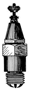
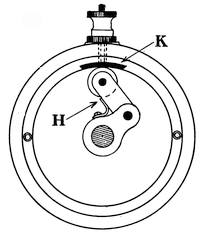
The Sparking Plug.—Two views of a typical sparking plug are shown in Figs. 45 and 46, in which A is the high tension electrode which is periodically charged with electricity at high voltage (or electrical pressure) from a high tension magneto or a high tension coil, and B1, B2 are electrodes which, being in metallic contact with the cylinders and framework of the engine, are thus at zero potential. The electric discharge occurs across the gap C1, C2 in the form of a spark or flash. The electrode A is heavily insulated from the metal casing D of the sparking plug by porcelain insulators E and F. The locknuts G and H serve to keep the plug gas-tight and hold the several portions together mechanically. The terminal K is used for clamping the wire (or52 lead) which brings the supply of high tension electricity. The high tension electric current may be supplied either by (1) a magneto machine or (2), a coil and accumulator ignition system.
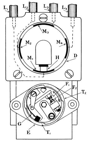
Fig. 48.—End View of a High Tension Magneto, showing High Tension Distributor and Low Tension Contact Breaker.
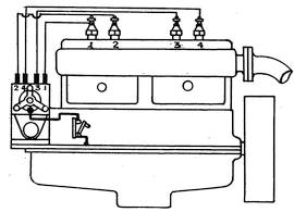
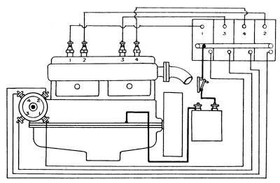
The High Tension Magneto.—In Figs. 47, 48 and 49 we show a modern high tension magneto suitable for a four-cylinder engine. It consists of the stationary magnets A, the driving spindle B, the high tension electrode D, the high tension distributor C, and the low tension contact breaker E. The armature, condenser, and distributor gear wheels are not shown in the drawings, but are situated inside the machine in the space between the high tension electrode D and the low tension contact breaker E. As the spindle B is rotated by gearing driven from the engine crankshaft the arma53ture attached to it generates a high tension current and a low tension current. The high tension current passes to the high tension electrode D and thence across the machine to the carbon brush H of the high tension distributor C. The low tension current passes through the platinum-tipped contact screws F1, F2 of the low tension contact breaker. Twice during each revolution of the armature these contacts are separated owing to the fibre block attached to the bell crank lever G passing over the stationary cams T1, T2; this constitutes the make-and-break device for interrupting the primary current. The momentary interruption of the primary current in this way causes a very great increase in the electrical pressure (or voltage) of the secondary or high tension current which is sufficient54 to bring about the spark discharge across the gap between the electrodes of the sparking plug. Since there are two of these cams on the low tension contact breaker it will be understood that the armature can supply current for two sparks in every revolution it makes. If we bear this fact in mind we will have no difficulty in determining the relative speeds of the magneto armature and the engine crankshaft for any type of engine. A four-stroke engine requires one spark in every two revolutions made by the crankshaft, so that a four-cylinder engine of this type requires two sparks per revolution, and the magneto armature must run at crankshaft speed. A six-cylinder engine working on the four-stroke cycle would require three sparks per revolution, but the armature of the magneto only supplies two, therefore it must be driven at one-and-a-half times the crankshaft speed.
The high tension distributor consists of the carbon brush55 H driven by gearing from the magneto armature and the metal segments M1, M2, M3, M4, which are mounted in a block of insulating fibre. There must be as many segments on the distributor as there are cylinders on the engine, one segment for each sparking plug; but the armature cannot supply more than two sparks per revolution, and therefore if the distributor has four segments it must be driven at half the armature speed, and if it has six segments it must be driven at one-third of the armature speed. Each metal segment is electrically connected to a sparking plug lead such as L1, L2, L3, L4. The high tension electrode D is attached to a light carbon brush which presses on a gunmetal collector ring at the high tension end of the armature winding. A special terminal is provided at P, so that when a wire is attached to it and connected to the frame of the engine (usually through a switch) the low tension windings are short-circuited or closed on themselves, and the make-and-break has no effect, because there is always the path through the switch until it is opened again. Under these circumstances the voltage of the high tension circuit is not sufficient to cause the spark discharge, and the ignition is then said to be switched off. The instant at which the spark occurs may be advanced or made earlier by moving the rocker arm K, which carries the stationary cams T1, T2 backwards, whereas if it is moved forward the ignition is retarded and occurs later in the stroke. Normal ignition occurs when the lever is midway in its range of movement and corresponds to the position of the piston when the crank is on the top dead-centre, whereas advanced ignition occurs just before the piston has completed the compression stroke, and retarded ignition will take place after the crank has passed the dead-centre and when the piston has moved down a little on the power (or explosion) stroke. Advancing the ignition increases the speed, and retarding the ignition reduces the speed, except when the engine is overloaded, and then it may pick up speed a little or run56 better if the ignition is slightly retarded—but the exact behaviour will depend on the temperature of the metal walls and piston within the cylinder.
We have mentioned that normal ignition occurs when the crank is exactly on the dead-centre and the piston at the top of its stroke. If we set the magneto when the engine is at rest so that ignition ought to occur on dead-centre when the arm K is in its mid position the actual sparking will be late on account of the time lag of the electric current. The current takes time to flow and in that brief element of time the crank has moved a few degrees off the dead-centre, at high speeds. Hence the ignition must be advanced if the charge is to be correctly fired when the engine is running fast. If the ignition is too far advanced it will cause the engine57 to “knock,” especially under heavy loads. If the ignition is retarded the charge is not fired at the commencement of the stroke so that a portion of the power theoretically available in the fuel is lost to exhaust at the end of the stroke. Retarded ignition always causes overheating of the exhaust system.
If the arm K is fixed mechanically in its mid position so that the ignition can neither be advanced nor retarded, we have what is known as fixed ignition.
An Ignition Coil suitable for a single cylinder engine is shown in Figs. 50 and 51, in which A and B are the low tension terminals and C is the high tension terminal. The trembler blade is shown at D, with the adjusting screw F 58and the platinum-tipped contacts G1, G2. The iron core of the coil projects a little above the case, as shown at E in Fig. 50. The strength and character of the spark may be varied considerably by slightly screwing F up or down. When current is supplied to the low tension terminals of the coil it flows through the primary winding and magnetizes the iron core, completing its circuit by passing across the platinum contacts. When the trembler blade is attracted to the iron core the primary circuit is broken by the temporary separation of the platinum contacts, and therefore the magnetism ceases, the trembler is released, and the circuit is completed again. Thus the trembler blade is set rapidly vibrating and making and breaking the primary circuit as long as the roller attached to the rotating arm H of the low tension contact breaker shown in Fig. 52 is in contact with the metal segment K, and this results in the production of a succession of sparks at the sparking plug which is connected to the terminal C of the high tension winding. This is very useful especially when starting an engine, but with modern high-speed engines the trembler has only time to give one spark at high engine speeds, and therefore the magneto has the advantage except for easy starting. This has led to the introduction of dual ignition systems, and in particular to that system in which the main ignition is by magneto, but there is a supplementary coil fitted to supply high tension current to the ordinary high tension magneto distributor when the engine is at rest,59 the coil being cut out after the engine has got up speed. But this has been largely superseded by the use of electric motors for starting the engine, although the magneto is still relied upon for the ignition of the charge in the cylinders. The contact breaker and coil just described would be very suitable for a single cylinder petrol engine, or a non-trembler coil might be used in conjunction with a contact breaker of the quick break type used on magnetos and illustrated in Fig. 48. In the case of a multi-cylinder engine having coil ignition we may use separate coils without a high tension distributor, or a single coil and a high tension distributor having as many segments as there are engine cylinders and arranged similarly to the magneto distributor of Fig. 48. When no high tension distributor is fitted there must be a separate coil for each cylinder, and the high tension wire runs direct from the coil to the sparking plug, so that the character of the spark as well as the exact instant at which it occurs may not be the same in each of the cylinders. If there is a high tension distributor it should be mounted on the same driving spindle as the low tension contact breaker, in order that the ignition may be synchronized, i.e., the spark will occur at the same point in the piston’s stroke for all the cylinders. The ignition may be advanced or retarded by moving the casing of the low tension contact breaker relative to the roller arm, thus causing it to make contact either earlier or later in the revolution.
At one time it was thought that two-point ignition gave increased power and efficiency. Two-point ignition means simultaneous firing of the charge from more than one plug. Sometimes two high tension leads were led from each distributor segment and connected to the two plugs in the corresponding cylinder—this constituted the parallel system. Another system employed a special plug with both electrodes insulated from the engine frame; this was coupled in series with an ordinary plug so that the spark jumped the gaps in succession. It is quite evident, however, that if60 the gas is thoroughly mixed up and in a state of violent agitation as the result of rapid compression, a single well-placed spark will fire it successfully and so no gain results from simultaneous ignition at another and less favoured point.
Wiring Diagram for Magneto Ignition System.—The electrical connexions are extremely simple in the case of a high tension magneto ignition system. In Fig. 53 we show a four-cylinder engine fitted with high tension magneto. The only wires required are the four high tension cables from the high tension distributor to the sparking plugs and the earthing wire leading from the short circuiting terminal to the frame of the engine through a switch as indicated. The firing order of the cylinders may be either 1, 3, 4, 2 or 1, 2, 4, 3, as desired (provided the cranks are arranged in the usual manner, that is, in the order shown in Fig. 21). In determining the order of firing of the respective cylinders the engine should be turned round very slowly by hand and careful note made of the order in which the firing strokes occur. To determine the firing stroke the piston should be moving downwards and the position of the valves noted; if both valves are shut then this is the firing stroke, but if the inlet valve is opening it is the suction stroke.
Wiring Diagram for a Coil Ignition System.—The61 electrical connexions for a coil ignition system are slightly more difficult to follow out; they are shown in Fig. 54 for the same engine illustrated in Fig. 53. In the diagram we show four separate trembler pattern coils, each of which can give a succession of sparks as long as contact is being made on any one segment of the low tension contact breaker connected to it. All the low tension terminals of the coils are connected together to a common busbar, which is supplied with current from the accumulator direct. The current flows from the busbar through the low tension windings of each of the coils in turn, as it comes into operation through the engine-driven contact breaker, and returns to the battery through the frame of the engine. High tension cables lead from the high tension terminal of each coil direct to the sparking plugs, and therefore the ignition is not necessarily synchronized.
When the switch in the low tension circuit is opened the ignition is off, because the current is then permanently interrupted; when the switch is closed the ignition is on.62 To economize current a quick make-and-break device should be used instead of the wipe form of contact breaker illustrated, and a non-trembler coil used. It is very important to fully retard the ignition lever when starting an engine having coil ignition, because it is very liable to backfire and injure the operator’s wrist; with magneto ignition this is less liable to happen.
Timing the Ignition.—Various instructions are given from time to time for correctly timing magneto ignition, but the following will be found to give satisfactory results. First ascertain the firing order of the cylinders as explained above, and then bring No. 1 piston on to the top dead-centre. Rotate the driving spindle of the magneto until the carbon brush H of the high tension distributor makes contact on the segment connected to the lead marked (1). If the leads are not marked it will be necessary to determine which is No. 1 by observing the direction of rotation of the brush. Next adjust the position of the driving spindle very carefully by turning it to and fro, so that when the ignition lever K (see Fig. 48) is in its mid position the platinum contacts Fl, F2 are fully separated, the brush H still being on segment No. 1. Then push the magneto gear wheel into mesh with the engine gear wheel which is to drive it, and firmly bolt down the magneto to its bracket. Similar instructions may be followed out for the coil ignition system.
63
Properties of Oils.—Owing to the very high speed at which the modern petrol engine runs great attention must be paid to lubricating the moving parts, otherwise undue wear or even seizure will result. We must be very careful to choose a suitable oil, one which is chemically pure and retains its lubricating properties at high temperatures. A considerable amount of oil finds its way into the cylinder, where it comes into direct contact with the hot gases. If an oil is heated a temperature will sooner or later be attained, when the oil will give off an inflammable vapour, i.e., one which will burn. This temperature is called the flash point of the oil. If the oil is likely to get into the cylinder of a petrol engine it should have a very high flash point; in fact, most of these oils do not flash until well over 400° Fahrenheit. Also when the oil is burnt it must not leave any appreciable residue. Some oils are very defective in this respect, and leave large quantities of carbon deposit on the metal walls of the cylinder and the valves; others again are gummy or too viscous even at high temperatures. Such oils must be avoided equally with those which lose their viscosity too much under heat.
Splash System of Lubrication.—One method of lubricating the working parts is known as the splash system. In this system oil is poured into the crankchamber and the moving parts dip into it, splashing it all over the interior of the crankcase and the lower portions of the cylinder walls. Oil holes are drilled in such positions that as the oil drops down again after being splashed upwards some of64 it will fall into these holes and lubricate the bearings. This is a very cheap method of lubrication in first cost, but very wasteful and unsatisfactory in regular use, hence it has practically died out. As the oil is used up a fresh supply must be admitted by some form of continuous drip-feed arrangement, the oil being forced over very often from a small tank on the footboard by means of air pressure or the pressure of the exhaust gases from the engine. It is very difficult under these circumstances to estimate how much oil is present in the crankchamber at any given instant, so that there was usually alternately too much or too little. Too little oil meant undue wear on bearings (perhaps seizure), and too much oil meant a smoky exhaust which became very obnoxious when the engine was suddenly accelerated.
Improved System of Splash Lubrication.—This is a combination of the splash system and the forced system, and is shown in Figs. 55 and 56. In these figures A2 and A3 represent two of the main engine bearings which support 65the crankshaft; C1, C2, C3 are three of the crankpins; F1, F2, F3 are oil troughs placed under the crankpins; D2, D3 are oil feed pipes to the main bearings. Generally speaking, the oil is drawn from the bottom of the crankcase by means of a pump, and this pump delivers the oil to some form of indicator mounted on the dashboard of the car. After passing through the indicator the oil flows by two main pipes, one of which feeds the main bearings by means of branches D2, D3, etc., and the other feeds oil troughs by means of branches such as G2. When the troughs are full the oil overflows into the bottom of the crankchamber, and so there is always a constant depth of oil for the scoops attached to the connecting rod ends to dip into, and one great drawback to the splash system is overcome; also the main bearings are always sure of being amply supplied. The oil pump may be an ordinary plunger type pump or a rotary pump.
Forced Lubrication.—One system of forced lubrication is shown in Fig. 57. The general arrangement of the system is very similar to the preceding one, except that there are no troughs in the crankchamber and all the bearings receive an ample supply of oil under pressure so that the journals are supported in their bearings on a film of oil and the metals never come in direct contact with each other. After entering the main bearings the oil passes through holes drilled in the crankshaft and thus positively lubricates the crankpin bearing, passing up the connecting rod either internally as shown or by an external pipe it lubricates the gudgeon pin and then falls down into the crankchamber. On its way down it gets splashed about and thus lubricates the cylinder66 walls and piston; sometimes these are positively lubricated by leading the oil through the centre of the gudgeon pin direct to the surface of the cylinder walls—but this often gives an excess of oil and causes a smoky exhaust. In Figs. 58 and 59 we show two views of a very popular form of oil pump for forced lubrication systems. It consists of two gear wheels, one of which is driven by a spindle from the engine crankshaft, and it drives the second wheel by means of the projecting teeth. The oil is picked up by the teeth and passed round from the suction to the delivery side of the pump on the outer edge of the wheels; no liquid can pass direct across between the teeth which are in mesh, and hence the direction of rotation is as shown by the arrows.
67
The difficulty of securing a really good lubricant for petrol engines must be apparent from a study of the prices of the various oils. It will be observed that they are all considerably more expensive than petrol, and therefore we must economize in their use. The old splash system was very wasteful and consumed oil at the rate of one gallon every hundred miles at least, but a modern system of forced lubrication will not require more than one gallon of oil every thousand miles. Perhaps an average everyday figure for ordinary motor-car engines would be one gallon every 250 miles. The pressure of the oil in a forced feed system varies in different makes of engines from 5 up to 40 pounds per square inch—a very common figure, however, is 10 pounds per square inch. The speed of the oil pump also varies considerably, and ranges from 500 up to 2,000 revolutions per minute at normal engine speed. Generally a small relief valve is fitted in the pump casing, which returns oil to the crankchamber if the pressure tends to rise above the desired limit due to the engine speed increasing. We have mentioned already that the flash point is generally over 400° Fahrenheit when the oil is new, but after it has been in the crankcase some time and got used over and over again it is found that the petrol68 vapour leaking past the piston rings of the engine condenses when the engine cools down after a run and drops into the oil in the sump, thus lowering its viscosity and its flash point. According to Mr. Morcom it may come down as low as 200° Fahrenheit (about), but if the oil is heated and the petrol driven off the flash point goes up again. Therefore it is a good plan with forced lubrication systems to empty the old oil out periodically and fill up entirely with fresh oil.
69
We have already explained the necessity for cooling the cylinders of a petrol engine by means of a water-jacket, and we now proceed to show how the circulation system may be arranged. There are two forms of circulation in use: (1) Natural; (2) Forced.
Natural or Thermo-Syphon Circulation.—This system is shown in Fig. 60, and may be explained as follows:—The heat generated by the successive explosions within the cylinder causes the water at the top of the cylinder jacket A to get hot. As a column of hot water is lighter than one of cold water of equal height, the heated water rises up the pipe B and flows into the top of the radiator D, while colder water from the bottom of the radiator flows70 up the pipe C and into the cylinder jacket A. It is important that the height of the water in the radiator D should be at such a level that the outlet from the pipe B is submerged.
In the radiator the water falls through a series of tubes E, having gills or fins on the outside for the purpose of dissipating the heat. The cooling of the water is also assisted by the fan F, which is driven from the fan pulley G and draws air past the radiator tubes at high speed. Sometimes the water in the radiator is made to fall through a series of cells which are formed of cast aluminium; such a radiator is called a honeycomb radiator. It is important that the pipe C should not have any sharp bends and it should not rise very much in height, but the outlet pipe B may have a considerable rise with advantage. Both the inlet and outlet pipes should be of large diameter with this system of circulation, and the radiator should be so71 arranged that there is a good head of water above the cylinders. In the drawings H is the front cross-member of the chassis, K is the starting-handle clutch, and L is the starting handle.
Forced or Pump Circulation.—With this system the water is positively circulated through the jackets; it is drawn from the bottom of the radiator by the pump P (Fig. 61), which is mechanically driven from the valve shaft of the engine, and delivered under pressure to the jacket A. The outlet of the pipe B need not be drowned, and the pipe C may be arranged in any way most convenient to the chassis. Sometimes when a pump is fitted the pipes are arranged so that the system may be operated as a thermo-syphon in the event of a breakdown of the pump. It is not uncommon to experience trouble due to leakage at the pump gland, which results in gradual loss of water from the system, and therefore the thermo-syphon or natural circulation has much to recommend it. Also it may be said that the pump represents an additional complication to the engine and means increased first cost. Every moving part we add to the engine is of course an additional potential source of trouble, but the addition of a really first-class water circulating pump of the type shown in Fig. 58 cannot be said to be anything but a reasonable precaution. The weight and size of every part of a motor-car engine and chassis have been so much reduced recently, owing to competition with American firms, that many manufacturers who adopted the thermo-syphon principle experienced great trouble with it owing to the small size of radiator fitted, as well as faulty arrangement of the connexions. Considering any one engine, it follows that if a certain size of radiator and a given quantity of water in the circulating system will keep the engine cool when a pump is used to give a positive circulation, then a larger radiator and greater quantity of water will be required for natural circulation. Thermo-syphon circulation also means a high radiator and72 bonnet, which many people object to on the score of appearance, without considering its utility. With natural circulation greater care must be exercised to keep the radiator well filled, but this often leads to other difficulties on bad roads owing to the water splashing from the overflow pipe and finding its way on to ignition appliances. Before starting an engine it is always advisable to remove the radiator filling cap and examine the water level; if it should happen that at any time while the engine is running the circulating system runs quite dry, owing to a breakdown or leakage, do not attempt to pour water into the radiator, but simply raise both sides of the bonnet and leave the engine to cool down first. Again, when filling the radiator for a forced circulating system, it is desirable to give the engine a turn or two with the starting handle occasionally to operate the pump and prevent air locks; very often the radiator appears to be full, but as soon as the engine commences to run the water disappears owing to the system not being full, due to the above-mentioned cause. In cold or frosty weather all the water should be drained off from the circulating system when the car is in the garage, unless the garage is heated or some anti-freezing solution is used. Glycerine or alcohol added to the water will prevent it freezing, but as an additional precaution in cold countries one often sees travelling rugs strapped over the radiator and bonnet.
Occasionally one gets trouble due to the water boiling in the jackets, and on this account reasonable care should always be exercised in unscrewing the radiator filling cap if the presence of steam is suspected. An engine may have been running well for a long time without trouble and then develop symptoms of overheating in the circulation system. This overheating may be either local or general. Local overheating may result from some partial seizure of the piston in the cylinder due to dirt on the walls, or from the presence of grease on the outside of the cylinder73 walls, in the jacket space. If grease is suspected or there is furring up in the passages of the jacket due to bad water supply, the trouble may be cured by adding some common washing soda to the water in the radiator and running the engine with the car at standstill for half-an-hour or so. After this drain off all the water and sludge, allow the engine to cool down, and then fill up again with clean water.
General overheating may result from leaky pistons and pistons rings, or from the use of too weak a mixture in the carburettor, or from overloading the engine. If the mixture supplied to the engine is very weak, the overheating will be very marked on the exhaust side of the engine. Local overheating causes the engine to “knock” badly.
In arranging the jackets and the pipes care must be taken to arrange that a cock is placed at the lowest point in the system, so that the whole may be completely emptied, and the inlet pipe to the jacket should enter at the very bottom of the jacket chamber for the same reason. It may be thought that all that is necessary is to provide plenty of space in the jackets round the cylinders and plenty of water in the whole system, but experience shows that it is very important not to make the jacket space too large, so as to ensure positive circulation and avoid local circulation in any one portion of the jacket. When cylinders are cast in pairs the back pair have a tendency to discharge their hot water into the front pair and so back to the inlet pipe again, hence this should be guarded against in arranging the outlet pipes.
Pipes suitable for use with multi-cylinder engines are shown in Fig. 62, in which (a) is an outlet pipe for a monobloc casting, and (b) and (c) are inlet and outlet pipes respectively for engines having separate cylinders. It is advisable to modify the diameter of the branches by the insertion of metal orifice plates at the flanges to ensure an equitable distribution of the water among the several cylinders.
74
The weight of water carried in the circulation system for a fifteen horse-power engine would be about 30 lb. with pump circulation, whereas 60 lb. would be required for thermo-syphon cooling. It is not desirable to cool the engine too much. The jacket water temperature may be allowed to reach 180° Fahrenheit at full load, but if this is exceeded there is liability to boiling. Given two similar engines of equal power and equally loaded, one of which was operated with a jacket temperature of 100° Fahrenheit and the other at 180° Fahrenheit, the hotter engine would show a gain in economy of from five to ten per cent. in fuel consumption. In considering the type of radiator to adopt, one would not recommend the honeycomb variety (except for appearance) owing to the difficulty of cleaning the passages after it has been in use some time; and the gilled tube would be more efficient than the plain tube. The amount of tube required depends of course on its diameter, but a rough approximation would be twelve feet of gilled tube or eighteen feet of plain tube (of half-inch diameter) per brake horse-power.
75
Choosing the Number of Cylinders.—It is a very difficult problem to select the best engine for a particular purpose, as there are so many factors which influence one’s choice. A single cylinder engine would only be used for a motor-cycle or a small car of low power; the vibration and noise resulting from the use of a single cylinder petrol engine of even six horse-power are most objectionable, and difficulties of starting and risk of engine unexpectedly pulling up and stopping are greatly enhanced. The two-cylinder engine offers better prospects, and was for some time considered quite good enough for most purposes, but owing to its comparatively bad balance and its low torque it has fallen into disfavour. We have seen how the rotating parts of the engine can be balanced, but we have not considered the reciprocating parts. To understand this question of balancing we must talk about “inertia forces.” All bodies possess inertia, that is, they resent changes in their state of rest or motion. If a body is moving uniformly it tends to keep on doing so, whereas if it is at rest it tends to remain so. To start the body off from rest, or to stop the body and bring it to rest, requires a force to be exerted, and this force may be called the inertia force. When a petrol engine is running at high speed the piston has to be started and stopped at the top and bottom of its stroke every time the crankshaft revolves once, and to do this very large forces are needed, because it has to be done so quickly. These inertia forces take the form76 of pushes or pulls on the shaft and framework of the engine, and thus cause vibrations to be set up. If the periodicity or frequency of these forced vibrations happens to coincide with the natural period of vibration of the shaft material the shaft will commence to whip, and may possibly break under the excessive strain. In a two-cylinder engine with cranks 180 degrees apart (or half a revolution) one piston is moving upwards and the other piston is moving downwards, both at very high speed; and both have to be brought to rest when the cranks come on their respective dead-centres. The piston which is moving up tends to lift the shaft up with it, and the one which is moving down tends to pull the shaft down with it, because the connecting rods check the progress of the pistons and bring them to rest at the top and bottom of their strokes. If these two pulls acted in line with each other they would balance, but the cylinders are usually mounted side by side, and then the two pulls virtually act at the ends of a bar whose length is the longitudinal distance between the vertical centre lines of the two cylinders. Thus these two inertia forces tend to rotate the whole engine first in a clockwise direction and then in a counter-clockwise direction, according to which piston is moving up or down. The only way to balance these forces under these conditions is to extend the crankshaft longitudinally and place another pair of cylinders and cranks in line with the first, but so arranged that the inertia forces tend to turn the engine in the opposite direction to the first pair. This gives us the well known four-cylinder arrangement so much in evidence at the present time, the arrangement of cranks being shown in Fig. 21. A six-cylinder engine gives perfect balance if all the parts are of equal weight, and the cranks at 120 degrees to each other in opposed pairs.
Again, a single-cylinder engine gives one power stroke in every two revolutions of the shaft, a two-cylinder gives a power stroke in every revolution, a four-cylinder gives77 two power strokes, and a six-cylinder gives three power strokes in every revolution of the shaft. Hence a six-cylinder engine is very flexible (i.e., can accommodate itself easily to varying loads), is perfectly balanced, and can be made both powerful and economical. One objection to the use of engines with multiple cylinders (exceeding, say, four in number) is that the crankshaft is more liable to vibrate and cause very harsh running at high speeds on account of the fact that the periodicity of the power impulses imparted to the shaft approaches the natural period of vibration of the shaft. This effect arises from torsional oscillations and is distinct from the periodicity due to inertia forces which acts in the vertical plane. A four-cylinder engine is nearly as good as a six-cylinder of equal power, and is of course much cheaper in first cost, takes up less room, and weighs less. A good four-cylinder engine will often prove more economical in running costs than a six-cylinder, as it will probably be running a greater length of time at or near its full output, and the work done on the idle strokes of the cycle will be less owing to the smaller number of cylinders.
Another feature to consider is the arrangement of the cylinder castings. A monobloc casting (cylinders all in one casting) gives a very short engine and reduces the length of the crankshaft, but in the event of one cylinder bore being damaged the advantage lies with the separate cylinder construction.
The Question of the Valves.—The question as to which is the better engine, the sleeve valve or the poppet valve, cannot be said to have been definitely decided yet. The great feature of the poppet valve used to be its very quick opening and closing, but nowadays engines turn over so fast that very strong springs are needed to close the valves in a reasonable time. One complete revolution of the engine means that the crank has turned through 360 degrees, and the inlet valve is open while the crank turns through 190 degrees (on the average), but during part of78 this time it is being lifted or opened, and during an equal period it is being closed. The question then is, “How long does it remain fully open?” The answer is—not more than ten degrees at the most! To keep the inlet valve open longer than this would require excessively stiff springs and throw a great strain on the valve gear. Now this is where the sleeve valve managed to get a look in—as one might say. With two sleeves moving in opposite directions, or one sleeve receiving a special form of motion, we can open and close the ports and keep them fully open for just as long period or even longer than the poppet valve. If it were not for the fact that sleeve valves are heavy and not so easy to keep gas-tight as poppet valves, it is perfectly obvious that the poppet valve would have disappeared or taken second place long before this.
Another great advantage of the sleeve valve is that by making large ports we can easily secure larger valve openings than are possible, for practical reasons, with a poppet valve. It is now claimed also that the interior of the cylinders keeps free from carbon deposit much longer with sleeve valves than with poppet valves, this carbon deposit being due chiefly to the use of too rich a mixture which causes the combustion to be imperfect and results in the deposit of solid carbon on the walls and sides of the combustion chamber. Carbon deposit is also caused by using unsuitable lubricating oil, but it principally arises from the use of too rich a mixture for the purposes of securing quick acceleration. Perfect combustion is only secured by the use of a relatively weak mixture, which would prevent the maximum power being developed and give rather a feeble acceleration. Modern engines have to be very carefully designed to reduce this nuisance of the carbon deposit to a minimum, and also with a view to its speedy and efficient removal when it does take place. Detachable cylinder heads have been introduced principally to allow of rapid removal of carbon deposit from pistons and valves and79 the combustion chamber. If the carbon deposit is allowed to accumulate, pinking or sharp knocking commences, due to pre-ignition of the charge by red-hot particles of carbon. This results in loss of power, and is first noticed by inability to climb steep hills that were formerly negotiated with ease. Mention must also be made of the great claim for silence of running of sleeve valve engines, and this is thoroughly justified with high-class engines of the sleeve valve type, provided they are in the hands of skilled drivers. In unskilled hands one finds that the poppet valve is safer, and will stand more knocking about without much increase in noise resulting. Rotary valves have fallen into disuse on account of the difficulty of keeping them gas-tight. There is nothing to choose between poppet and sleeve valves on the score of economy in running.
Economy and Durability.—A good modern petrol engine of reasonable size—say over 3 in. bore—will give one brake horse-power for an hour from the consumption of two-thirds of a pint of petrol. This means that an engine giving 12½ horse-power on the brake would use a gallon of petrol every hour. But economy in petrol consumption is not the only desirable feature of a petrol engine. There must be economy in lubricating oil and in cost of replacements or repairs. Nowadays the tendency with high grade steel alloys and other modern metals of high strength and durability is to cut everything down to its minimum size with a view to reducing the cost of production. This often leads to many serious troubles in running on the road. In choosing an engine one should carefully examine such points as provision for wear and adjustment, strength and rigidity, and whether the engine impresses one with a sense of its durability and also its general accessibility.
80
In the two-stroke type of petrol engine the cycle of operations is completed in two working strokes of the piston instead of the four required by the “Otto” cycle; there is thus one explosion or power stroke in every revolution of the crankshaft. Theoretically this represents a great advance over the “Otto” cycle, but difficulties and complications arise in the practical carrying out of the cycle. The cycle on which it is desired to operate the engine is: 1st stroke—Compression; 2nd stroke—Explosion. The charge would be introduced on the compression stroke and exhausted towards the end of the explosion stroke.
Now the charge of gas required by the engine consists of a mixture of petrol vapour and air, and it must either be sucked in or pushed in under pressure. In the “Otto” cycle the charge is sucked in, and in the two-stroke cycle it is delivered to the cylinder under pressure; hence in the two-stroke cycle some form of pump is required which will suck in the charge of air and gas, compress it a small amount, and deliver it to the working cylinder at a pressure of 5 or 6 lb. per square inch above atmospheric pressure. This is where the complications commence; if we fit a separate pump for each cylinder, which is what would generally be done, or if we made one pump serve for two cylinders, we have to provide pump cylinders, pistons, rods and valves, and therefore there is practically no gain over the four-stroke engine. Hence it is that inventors all try to avoid the use of a separate charging pump and turn their atten81tion to the production of an engine in which one or more of the existing portions is made to serve as a pump for charging the working cylinder or cylinders with gas. A favourite and fairly successful device is to make the crankchamber gas-tight and use it as the cylinder of the pump, the underside of the engine piston then forming the pump piston which draws the charge from the carburettor into the crankchamber on its upstroke and compresses it on its downstroke, delivering it to the working cylinder through the inlet port as soon as the piston has uncovered it by its downward movement.
There is no exhaust valve, as the piston uncovers the exhaust ports a little before the inlet ports are opened. To prevent the new charge escaping directly across the top of the piston from the inlet ports to the exhaust ports, a deflector is fitted on the top of the piston equal in height to the height of the exhaust opening and situated immediately in front of and facing the inlet ports.
A two-stroke engine of the type referred to is shown82 diagrammatically in Fig. 63. E is the gas-tight crankchamber, upon which the water-cooled cylinder A is mounted in the usual manner and fixed by studs or bolts. The piston P carries the deflector H, which is equal in height to the height of the exhaust opening G. The piston rings are prevented from turning by pins so arranged that the joint of the rings does not pass across the ports. The connecting rod D is of usual form, and also the crankshaft C. The carburettor, or induction pipe leading from the carburettor, would be attached to the flange L, and the automatic valve F controls the admission of gaseous mixture from the carburettor to the crankchamber. The inlet ports N are often only half the height of the exhaust ports. On the upstroke of the piston a partial vacuum will be formed in the air-tight crankchamber, which will allow the atmospheric pressure to force open the valve F against the pressure of the spring and enable the air to flow into the crankchamber through the carburettor and induction pipe, carrying the charge of petrol vapour with it. We must note, however, that no vacuum can be formed until the port N has been covered up by the piston, so that a portion of the stroke is idle. On the downward stroke of the piston the charge in the crankchamber is compressed, and as soon as the piston uncovers the ports N the charge from the crankchamber flows up into the working cylinder, displacing the burnt gases as it comes into the cylinder. Exactly what happens next it is difficult to say; the probability is that this new charge rises in the cylinder a short distance (but not a sufficient amount to displace all the dead gases from the top end of the cylinder) and that some of it gets squeezed out of the exhaust opening as the piston rises and before it has had time to cover the exhaust ports. Thus, owing to the idle portion of the stroke during admission to the crankchamber and to the low compression pressure adopted in the crankchamber, the pumping portion of83 the engine has what is termed a very low volumetric efficiency.
It can be proved that this type of engine which endeavours to draw sufficient gas to fill its working cylinder into the crankchamber by means of a piston having only the same diameter as the diameter of the working cylinder itself, and which cannot avoid some idle movement during the operation together with further loss from the exhaust opening, is incapable of retaining more than a little over one-half a cylinder full of fresh combustible gas at the instant when compression commences; the remainder of the contents must be dead exhaust gas. Thus, even allowing for the double number of power impulses resulting from the use of the two-stroke cycle, it is difficult to see how this form of engine could ever give more than about one and a quarter times the power of a four-stroke engine having the same bore and stroke even when the many difficulties experienced in the practical working of two-stroke engines have been overcome. To use a high compression pressure in the crankchamber would increase the volumetric efficiency, but would result in lost work during the pumping process, besides being undesirable at the delivery stage of the process; it is much better for the transfer of the gases to take place as gently as possible. If too high a delivery pressure is used the fresh gas will enter in a sharp gust and get badly contaminated by mixture with the foul exhaust products instead of gently displacing them in bulk. The use of an automatic valve is very desirable for the gas inlet to the crankchamber, but unfortunately it limits the speed of the engine and also its flexibility or ability to pull well at all speeds. An engine with an automatic valve runs best at that speed for which the tension of the spring is most suitable. If the spring is weak the speed will be low. Tightening the tension on the spring will allow the engine to speed up, but will prevent it running well at low speeds. At high speeds and84 with correspondingly high tension the valve does not give enough opening, and therefore limits the power of the engine. It will, therefore, readily be seen that when a two-stroke engine with automatic inlet valves is pitted against a four-stroke engine with mechanically-operated inlet valves, the comparison is unfair to the two-stroke cycle. With the position and arrangement of ports shown in the drawings, one must have a deflector on the piston head to prevent excessive loss of fresh gas through the exhaust opening. After the engine has been running for some time at a high speed this deflector becomes very hot, and as a general rule the cooling effect of the incoming gases is not sufficient to prevent it attaining a red heat on the compression stroke, thus igniting the charge before the piston reaches the top of the stroke. This defect, which is called pre-ignition, causes the engine to knock, and results in a loss of power; it may be partly overcome by admitting lubricating oil with the charge, the oil then serving to cool the deflector as the charge enters the cylinder. At high engine speeds there is great risk of the hot exhaust gases in the working cylinder setting fire to the incoming charge in the inlet ports, thus causing backfiring into the crankchamber. To avoid all possibility of backfire, some form of air scavenging must be adopted, but the general arrangement of this form of two-stroke engine does not lend itself to such an addition—it would merely reduce still further the quantity of gas reaching the cylinder.
A difficulty that is peculiar to multi-cylinder engines of the two-stroke type arises from the use of open exhaust ports. The several cylinders generally discharge their exhaust gases into a common exhaust pipe or box, so that if one cylinder happens to be missing fire the exhaust from another cylinder may set fire to the wasted charge—this is usually referred to as flashing-back from the exhaust and results in irregular and spasmodic knocking. It will be clear from the foregoing that this cycle of operations,85 which is so attractive from the theoretical point of view, is not by any means so encouraging from the practical standpoint, as many inventors have discovered. The difficulties and failures of the early inventors which were so discouraging for them have only encouraged their successors and spurred them on to further efforts. After a time the attempt to produce a simple two-stroke engine was abandoned generally, and inventors turned their attention to improved forms of two-stroke engines, some of which were very costly and complicated, and none of which have survived for motor-car purposes.
The writer of this volume became interested in the problem of the two-stroke in connexion with one of these inventions for an improved engine, and at a later stage patented and designed an improved engine of the two-stroke air scavenging variety, which by that time had become a recognized type of two-stroke engine. This engine was constructed and exhibited at one of the motor shows held in London some years ago. A vast amount of experimental and research work was carried out on it by the writer, but the work had to be abandoned when incomplete owing to the Syndicate which financed the venture having exhausted its resources. The promoters of the Syndicate were anxious to produce an engine that would give double the power of a four-stroke engine, but their early attempts were not at all successful. One of their four-cylinder engines, which would have been rated at 35 horse-power on the four-stroke cycle, only gave 12 brake horse-power when tested by the writer. The engine designed by the writer, which we may call the Kean two-stroke engine, would have been rated at 25 horse-power on the four-stroke cycle, and gave approximately 35 brake horse-power. Although this result was excellent, so much advance had been made in the four-stroke engine that it did not quite come up to the best results obtained on that system, and hence we were unable to show any marked advantage to be gained86 from its adoption. My experiments clearly pointed out the road to further success, but owing to the partial failure of my attempt to beat the four-stroke engine we could not influence sufficient capital to reorganize and reconstruct the Syndicate. My engine had not been designed to secure a high speed of rotation but rather for strength and durability, but it exceeded my expectations by turning up to 1,500 revolutions per minute. The four-stroke had, however, got well ahead of me by that time, and 2,000 was becoming common for it, hence I was heavily handicapped in the race for horse-power.
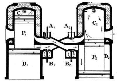
Fig. 64.—Diagrammatic Sketch showing how the Duplex Type of Two-stroke Engine operates with Air Scavenging.
A description of my engine will probably prove of interest. To understand the principle of the engine we must turn to the diagrammatic sectional view of Fig. 64. Instead of using the crankchamber of the engine as a gas pump, this type of engine has a duplex piston, and the pump chamber is formed by an annular extension of the main engine cylinder. At first sight one would say this resulted in a very high engine, but as a matter of fact the increase in height is not more than about 25 per cent. in the cylinders, and there is no difference in the crankchamber height to that of a four-stroke engine. The outstanding feature of the invention is the provision of a pump piston of larger effective diameter than the main piston and the arrangement of transfer pipes by which one pump feeds its neighbour’s power cylinder, and vice versa. These are the basis of the invention, and were being used a long time before the writer had even heard of this type of engine, but it was left for him to seize upon their capabilities and correctly proportion the area of the annulus with respect to the main engine piston. A careful study of the two-stroke problem revealed the inherent defect of the low volumetric efficiency and the tremendous possibilities of having an unlimited volume for the pump chamber by simply increasing the area of the lower or annular piston. Then followed the writer’s attempt to tackle the outstanding practical diffi87culties enumerated above. The engines already employed air scavenging, but could not really use it effectively until proper proportions had been fixed upon for the respective pipes, valves, and ports. The cycle of operations is as follows:—On the downstroke of No. 1 piston the annular portion draws a charge of gas from the carburettor into the annular chamber D1 (Fig. 64) through the inlet valve B1 and at the same time pure air is drawn into the transfer pipe by the valve A2. On the upstroke the charges of air and gas are compressed into the transfer pipe, and as soon as the piston P2 uncovers the inlet ports the air and gas enter the working cylinder. In my engine I used a relatively high compression pressure for the transfer of the charge and curved the inlet ports up towards the head of the cylinder as shown. The head of cylinder I made curved, and the exhaust ports were carefully rounded and curved also. The deflector on the head of the piston I inclined, to curl the gases back against the wall of the cylin88der, and I reduced the height of the deflector to that of the inlet port (instead of the exhaust port). My ultimate aim was to abolish the deflector entirely by suitably shaping the inlet ports, and I estimated that the path of the gases would be in the direction of the arrows. The object of raising the compression pressure in the lower cylinder was twofold. First of all I aimed at an increase of volumetric efficiency there, and secondly I hoped to propel the scavenging air and the new charge right up to the head of the cylinder and so clear out all the dead gases. Then by suitably curving the head of the cylinder I expected to compel the scavenging air to keep going ahead of the gaseous mixture and curl round and down, then following the exhaust gases out of the exhaust port.
My efforts in this direction were very unfortunately frustrated to a large extent by the fact that the cylinders of my engine had already been cast before I fully realized the tremendous importance of curving the cylinder head and giving a very steep inclination to the inlet ports. We did our best to rectify matters in the machining and finishing stages, but any engineer will understand the limitations now imposed upon us. It was impossible to get new cylinders cast owing to lack of time and funds, as we were intending to exhibit the completed engine. Thus I cannot say that my ideas were ever given a really satisfactory test; the inlet ports were curved and inclined and the cylinder head was rounded off, but not to such an extent that I can feel certain no further improvement could ever be made in those directions. Other improvements which I introduced were an improved automatic inlet valve for the gases, which was fitted inside the induction pipe and whose spring tension could be adjusted while the engine was running without letting any air leak into the induction pipe; also an improved air scavenging valve, which could be set to give the full amount of air to the engine and yet be controlled from the dashboard of the car to give any desired89 quantity of scavenging air from no air up to full air. Very large inlet valves were fitted, but when indicator diagrams were eventually obtained from the engine they showed that they were not nearly large enough and that the carburettor opening was too restricted, thus cutting down the power (and very likely the speed) of the engine by probably over 25 per cent. High tension magneto ignition was fitted and thermo-syphon cooling. Arrangements were made to carry 80 lb. of water in the system, so that the engine never showed any tendency to boil even when the car had been running for long periods on the low gear. A pump was afterwards fitted, but it did not effect the cooling of the water any better than the natural circulation, which was quite satisfactory. The range of speed was from 150 revolutions per minute up to 1,500 revolutions per minute; the lower figure is very good indeed, and can be attributed to the large number of impulses obtained due to the two-stroke cycle. At the highest speed the crankshaft received 6,000 impulses per minute, or equivalent to a four-stroke engine running at 3,000 revolutions per minute. The effective pressure in the cylinder was, however, only just over 40 pounds per square inch, due to the throttling at inlet already explained. In a four-stroke engine we would expect just double that figure. The extraordinary thing about this was that, under heavy load, when the speed was brought down to about 300 revolutions per minute, the effective pressure had risen to nearly 200 lb. per square inch, but this appears to be due to imperfect scavenging (or cleansing) of the cylinder under these conditions.
The question of silencing the exhaust from the engine had caused me some difficulty in the earlier experiments, so that I now tackled this problem and designed a special form of silencer in which the gases were first expanded to remove their pressure and then afterwards their velocity was taken up without shock. This answered so well that90 a cut-out made no difference whatever, and on taking diagrams with the optical indicator I discovered that the exhausting process was divided into equal periods of slight pressure and slight vacuum with an average of zero pressure (just atmospheric). We have seen in the earlier part of this chapter how the fitting of automatic inlet valves is liable to hamper the engine and reduce its flexibility, and this impressed me very much with the earlier engines so that at one time I adopted dual springs for the inlet valves. These springs were mounted one above the other, the lower one being much stiffer than the upper one. The idea of the invention was that the weak springs would serve for slow running and all loads up to say half the lift of the valve, and then the stiffer springs would secure correct action at high speeds. Further than this, I had them all coupled on a bar which was controlled from the driver’s seat, and by means of which I could cut out the weaker springs or reduce their effect at will. It certainly answered well in the older engines, but my new engine, shown in Fig. 65, was so satisfactory that I abandoned the idea. About five different systems of lubrication were experimented with and many lubricating oils. Finally, forced lubrication was employed for all the bearings and a drip sight-feed for the pistons.
Fig. 65.—General arrangement of the “Kean” Four-cylinder High Speed High Compression Duplex Two-stroke Engine employing Air Scavenging. In this Engine there is no Crankchamber Compression.
Much trouble was caused at one time in the new engine by knocking of various kinds, and many hours were spent in locating these troubles and curing them. The first kind of knocking was most violent and almost made one hold one’s breath in anticipation of seeing parts of the engine go skywards. This turned out to be partial seizure of a piston owing to a hard spot in the cylinder. After curing this, general knocking from all cylinders began, and was found to result from worn gudgeon pins. These had been mild steel and case-hardened; they were discarded for Ubas steel of slightly larger diameter, and this trouble disappeared. Then pre-ignition was discovered. When91 the magneto was switched off the engine slowed down and nearly stopped, then began to run on again, knocking and hammering in a most diabolical manner. All cylinders were taken off again, all parts ground up, and corners well rounded off, but still it continued. At first it seemed to be due to the deflectors, but on several very careful examinations (which of course meant dismantling the whole engine every time and removing the cylinders) no trace of overheating or burning could be found on these or anywhere else in the interior of the cylinder. Then the trouble was traced to the electrodes of the sparking plugs. This was followed by two or three weeks’ con92tinuous experiments on fitting different types of plugs, and the same type of plug was tried in four different positions inside the cylinder. Then the device of fitting the plugs to an adapter and so keeping them at the top of a small hole instead of projecting into the cylinders was tried. They still showed signs of overheating, and strange to say no loss of power or flexibility was noticeable. Finally, I fitted a water tank on the dashboard and allowed the engine to suck water into the induction pipe while it drew its mixture from the carburettor in the usual manner. I had previously fitted separate drip-feed of water to the air scavenging valves with a view to effecting cooling of the engine, but abandoned it owing to lack of results. Very soon I discovered that for every gallon of petrol the engine consumed I could let it take nearly half a gallon of water into the induction pipe. The engine ran much quieter and very smoothly, and for a time I thought I had succeeded, although the water gave me trouble in restarting if I happened to stop the engine while it was in use. It meant that the water had to be shut off some minutes before the engine was going to be stopped. The day after I thought I had effected a cure for the pre-ignition intermittent knocking began, and there was also general knocking always for a second or two when accelerating quickly under load. After much loss of time and the expenditure of a large sum of money on experiments, I persuaded the Syndicate to let me take some diagrams from the engine with an optical indicator, and eventually after nine months they consented, but they would not agree to my taking the engine out of the chassis and putting it on the bench for a proper power test. Therefore my diagrams were taken while the engine was in the garage in its chassis, and the load was applied by the propellor shaft brake, the shaft itself being withdrawn. Anyone who has attempted even in a well-equipped laboratory and with the aid of a proper brake to take diagrams from a petrol engine when the93 indicator is driven by a flexible shaft, will understand and appreciate my work in securing thirty photographic records under as many conditions of load and speed. After carefully analyzing my diagrams, I came to the conclusion that the intermittent knocking was undoubtedly flashing back from the exhaust, and the acceleration knocking was due to a cushion of hot gas which accumulated in the head end of the cylinder at times when the engine speed was low and the load on the engine was heavy.
Having explained these things to the Syndicate and pointed out the need for still larger valves, they set about attempting to raise fresh capital for the final attempt at success. They were not successful, and up to the present nothing more has been done. The Syndicate was wound up, the members drifted apart, and the patents were allowed to lapse.
The engine and chassis were eventually sold, and are still doing good service somewhere in the North of England. Meantime the writer has not rested, but has steadily formulated his ideas for the improvement of the engine, which have resulted in the securing of a fresh patent early this year. In the new engine the charge enters at the head end of the cylinder, there is a special transverse combustion chamber, and many improvements are introduced in the scavenging and flow of gases; also there is no deflector at all on the piston head. Funds have not yet been secured to enable an experimental engine to be constructed, but it is to be hoped they will be forthcoming, for the benefit of the motor-car industry generally, as the future undoubtedly lies with the two-stroke.
During the whole of this time the writer was engaged as Chief Assistant in the Engineering Department of Leeds University, being in charge of the experimental work of the students in the laboratories there. Many of the drawings were made by students in their vacation, and the writer is greatly indebted to his friend, Professor John94 Goodman, for so kindly allowing him the necessary freedom during vacation times when there is often much miscellaneous work that requires attention.
Before closing this chapter one may add a few words on carburation and ignition for two-stroke engines. A four-cylinder two-stroke engine should have cranks at right angles to secure the maximum torque on the shaft. Looked at in end view the cranks form the four arms of a cross and thus four impulses are given every revolution, but as the ordinary magneto only gives two sparks in every revolution it must be driven at twice the crankshaft speed. This puts a great strain on the machine at top speed, and also on the insulation of the windings and the plugs, so that the plugs require constant attention. Magneto troubles were found to be eliminated by the use of the special racing pattern magneto supplied by some manufacturers and the choice of high grade sparking plugs.
Carburation troubles were not so easily dealt with. A multi-cylinder two-stroke engine should undoubtedly have a multiple jet carburettor and some form of hand-controlled extra-air inlet valve on the induction pipe; also the mixing chamber of the carburettor should be water-jacketed by hot water. It was also found necessary to fit a hot water-jacket round a portion of the induction pipe, as the demand for petrol vapour was so great and the rate of evaporation so high that frost readily formed on the induction pipe unless the weather was very warm. The two-stroke engine requires its petrol much faster than the four-stroke, so that the float of the carburettor should be delicately balanced and the height of the petrol in the jet should be quite level with the top of the orifice, although this often leads to flooding.
Reviewing the description of what we have designated the Kean two-stroke engine, we may sum up the results of these experiments by saying that the engine could have developed considerably more power than it did95 had diagrams been taken from it in the first instance and the severe throttling in the carburettor and automatic inlet valves been discovered; moreover, the flashing back from the exhaust would have been located much sooner and probably cured by a re-arrangement of the exhaust manifold. If the exhaust manifold had been arranged so that there was a separate branch for at least each pair of cylinders, it would very likely have been stopped, or at any rate greatly reduced. But what could not have been altered was the acceleration knocking. It must not be imagined because I have been very frank in the criticism of my own work that the engine was a failure; it was a great success, but not sufficiently successful to represent an improvement on the best four-stroke practice. The car ran well, was very reliable and efficient in petrol consumption; the engine was quiet and extremely flexible; but it had one very objectionable feature in that every time you pressed the accelerator pedal down sharply, either to put on a spurt for the purpose of passing slower traffic or in rushing a short gradient, a peculiar knocking or hammering arose from the engine cylinders—this is what I describe as acceleration knocking and must not be confused with the knocking or hammering of a four-stroke engine when labouring on a gradient. My engine would be full of life all the time it was knocking like this, and gradually as the speed increased the noise would ease-off, even though no change of gear had been made.
The diagrams proved to me that this knocking was due to pre-ignition caused by a cushion of hot gases remaining in the top of the working cylinder, and in my opinion no alteration of the ports or cylinder head would have influenced this defect to any marked extent; therefore I should never attempt again to feed the new charge in at the bottom end of the cylinder of a two-stroke engine if I wished to obtain the maximum amount of power from it. It seems to me that other people must also have been impressed96 with similar misgivings, for in one or two types of engine using crankchamber compression we see a special attempt made to overcome it, although the method adopted leads to a rather undesirable arrangement of the engine mechanism. In the type of engine I refer to the charge may be drawn into the crankchamber in the usual manner, if desired, but the working cylinder is a casting with two bores having two separate pistons and a common combustion chamber. The charge enters above one piston while the crank is on its bottom dead-centre and is exhausted from the space above the other piston simultaneously, and the path of the gases is from the inlet port up to the top of No. (1) bore, then down to No. (2) bore, and out of the exhaust. This ensures that there shall be no cushion of hot exhaust gases left in the combustion chamber (or top end of the cylinder).
These engines have given quite good results, and would be much more extensively used but for the fact that there is double compression to overcome in starting, and their running torque, due to the number of impulses given to the crankshaft, is no better than a four-stroke engine. Fig. 66 shows the arrangement of the cylinders and the path of the gases. A1 and A2 are the twin pistons working in the water-jacketed cylinder casting B, and having the common combustion chamber C. The connecting rods may drive separate cranks in opposite directions or both be coupled together and work a single crank. It will be seen that in this type of engine the piston does not require any deflector.
The simple two-stroke engine described at the beginning of this chapter is often constructed in such a form that no automatic inlet valve is required on the crankchamber.
In this case the induction pipe is connected to a third set of ports just below and a little to one side of the inlet ports to the working cylinder, and these are uncovered by the piston towards the completion of its upstroke, thus97 allowing the carburetted air to enter the crankchamber. Such an arrangement constitutes a three-port two-stroke engine, which is of course less efficient than a two-port engine with automatic valve, but has the great merit that it is entirely valveless, and therefore extremely simple and cheap to manufacture. It is much used for motor boat work, both in this country and in America, on account of its relatively low speed of rotation.
98
A book on “The Petrol Engine” would hardly be complete without some reference to horse-power and the indicator diagram. The following definitions must be carefully studied.
Work.—A force is said to do mechanical work when it overcomes a resistance in its own line of action. The line of action of a force is a line indicating the direction in which the force acts. Engineers measure work in foot-pound units. The product obtained when we multiply the magnitude of the force or resistance (in pounds) by the distance through which it has acted or been overcome (expressed in feet) gives the quantity of work done in foot-pounds.
Example:—A force of 50 lbs. is exerted in overcoming a resistance through a distance of 12 feet. Find the work done.
Work done = Force (in lbs.) × Distance (in ft.)
= 50 × 12 = 600 ft. lbs.
Power.—The rate at which work is done is a measure of the power exerted. One horse-power is exerted when 33,000 foot-pounds of work are done in one minute. The work done per minute (in ft. lbs.) divided by 33,000 gives the horse-power expended.
Example:—To propel a motor-car along a level road at a speed of 30 miles an hour requires a tractive effort or pull of 70 lbs. if the vehicle weighs one ton. Find the horse-power required, at the road surface.
99
Horse-power = Work done per minute in ft. lbs./33,000
= Force (in lbs.) × Distance through which it acts per minute (in ft)./33,000 = (70 × 30 × 5280/60)/33,000 = (7 × 264)/330 = 5·6
Example:—If the car in the preceding example had to climb a gradient which rose one foot for every four feet traversed by the car, find the additional horse-power needed to keep up a speed of 30 miles an hour while climbing the gradient.
Here we have to raise a weight of 1 ton vertically upwards through a height equal to one-fourth of the road surface covered, every minute.
Additional Horse-power required
= (2240 (lbs.) × (30 × 5280/60) × ¼ ft. per min.)/33,000
= (2240 × 660)/33,000 = 44·8Total Horse-power to climb the gradient of 1 in 4 at 30 miles an hour = 5·6 + 44·8 = 50·4
Brake Horse-Power.—The length of the circumference or boundary line of a circle is 6·28 times the length of the radius of the circle or 3·14 times the length of its diameter. Hence, if an engine exerts a pull of P lbs. at the end of a brake arm of length R feet when it is maintaining a speed of N revolutions per minute (we may imagine the brake to be fitted round the rim of the flywheel), we can calculate the brake horse-power thus:—
100
Brake Horse-Power or B.H.P.
= (Work done on the brake per minute in ft. lbs.)/33,000hence B.H.P = (Pull at the end of the brake arm (in lbs.)) × (6·28 times the radius of the arm (in feet)) × (the number of revolutions made by the engine (in one minute))/33,000
= (P × 6·28 × R × N)/33,000
Example:—An engine being tested by a brake applied to the flywheel as shown in the sketch (Fig. 67) exerts a pull of 50 lbs. at a speed of 2,000 revolutions per minute. If the length of brake arm is 30 inches, calculate the brake horse-power developed.
Work done per minute = 50 × 6·28 × 30/12 × 2000 ft. lbs.
B.H.P. = (50 × 6·28 × 30/12 × 2000)/33,000 = 47·5
Rated Horse-Power.—For taxation purposes the Treasury makes use of a formula for the rating of petrol engines according to their probable horse-power. This formula is based on a certain speed of the piston which101 was regarded as a limiting value some years ago (when the formula was first proposed) and on the attainment of a certain effective pressure in the cylinder.
Horse-power from the Treasury formula = 0·4 d2n.
Where d = diameter of cylinder in inches,
n = number of cylinders.
With modern engines much greater horse-power is obtained, and a near approximation to the true output is obtained by using what is now known as the Joint Committee’s formula.
Brake Horse-Power = 0·46 n (d + s) (d - 1·18)
Where d = diameter of cylinder in inches.
s = length of piston’s stroke in inches.
This formula is only to be used in an attempt to predict the probable maximum horse-power which any engine will give. It must not be confused with the ordinary brake horse-power formula.
Example:—Find the probable maximum horse-power of an engine having four cylinders each 3 in. bore and a piston stroke of 4 in. What would be its horse-power for taxation purposes?
By Joint Committee’s formula—
B.H.P. = 0·46 × 4 (3 + 4)(3 - 1·18) = 1·84 × 7 × 1·82
= 23·35By Treasury formula—
B.H.P = 0·4 × 32 × 4 = 0·4 × 9 × 4 = 14·4
Indicated Horse-Power.—The horse-power which an indicator would show as being developed inside the cylinder of a petrol engine, above the piston, would be called the indicated horse-power, and should always work out a greater number than the brake horse-power or power available at the engine flywheel, because some of the power liberated from the combustion of the petrol within the cylinder is lost in friction of the piston and bearings.
102
The Indicated Horse-Power or I.H.P. = (Pe × A × L x Ne)/33,000.
Where Pe = mean effective pressure from the diagram, in lbs. per sq. inch.
A = area of piston in square inches = 0·7854(diameter of cylinder)2
L = length of stroke of piston, in feet.
Ne = number of power impulses per minute delivered to the crankshaft.
Since a four-stroke engine gives one power impulse to the crankshaft in every two revolutions, it follows that Ne is equal to half the number of revolutions per minute for a single-cylinder engine of that type, and twice the number of revolutions for a four-cylinder engine. A four-cylinder two-stroke engine might be arranged to give either two or four impulses per revolution of the crankshaft—depending upon the arrangement of the cranks.
Example:—A four-cylinder four-stroke engine runs at a speed of 2,000 revolutions per minute and the mean-effective pressure in the cylinders is 75 lbs. per square inch. Calculate the indicated horse-power if the cylinders are 4 in. × 4 in.
I.H.P = (Pe × A × L × Ne)/33,000
= (75 × 0·7854 × 42 × 4/12 × 4000}/33,000
= {75 × 12·56 × 4000}/99,000 = 38
The Indicator Diagram.—At the commencement of this chapter we explained that the work done by a force was measured by multiplying the number representing the magnitude of the force (in pounds) by the distance through which it had acted (measured in feet). This product gave us the quantity of work done in foot-pound units. Thus “quantity of work done” is really the product of two numbers, just as the area of a rectangular floor space is meas103ured by length times breadth. In symbols we write W = F × S where F is the magnitude of the force or resistance in pounds and S the distance through which it has acted, in feet. It is interesting to contemplate this symbolical expression W = F × S together with the expression Area = Length × Breadth, because it gives us a new idea for measuring work. Imagine a diagram of the kind shown in Fig. 68, in which the curved line AB has been obtained by plotting values of F and S for any imaginary case. The diagram is supposed to represent pictorially how the particular force under consideration has varied in magnitude as it has traversed a space represented, to some scale, by the length DC. It is clearly seen that the force has been decreasing in an irregular manner from some large value represented by the height DA to a small value represented by the height CB. We now proceed to show that the shaded area ABCD measures the total amount of work done by this force.
Considering for a moment just the small strip efdc of the diagram we see that it is easy to find a rectangle abcd equal in area to it. Now the height of this rectangle will be the average value of the force while it traversed the104 space cd, and hence the area of the rectangle abcd gives the work done by the force in passing from c to d. Similarly by dividing up the whole diagram we would obtain a number of little rectangles each equal in area to the magnitude of the work done from point to point. Thus the whole area ABCD gives the whole work done. To measure the work done in an engine cylinder we must use some form of indicator. An indicator is an instrument which traces out a diagram on which abscissæ (or horizontal distances) represent displacements of the piston and ordinates (or vertical distances) represent the pressures acting on the piston.
Ordinary steam engine indicators with pencil motion and paper drum are not suitable for use with fast running petrol engines. The moving parts of these indicators are too heavy and their springs too sluggish in action to keep correct time with these high speed engines. Again, there is too much friction between the pencil and the paper drum, as well as in the lever joints. Therefore special indicators have to be used, in which the diagram is traced out by a beam of light reflected from a mirror on to a ground glass screen or photographic plate. One corner of the mirror is tilted in time with the movement of the engine piston by means of a special reducing mechanism, and another corner of the mirror is tilted in a direction at right angles to the first by means of a very short thin rod kept in contact with a metal diaphragm subjected to the pressure of the gases in the engine cylinder. A beam of light is thrown on to the mirror from a lamp, and after reflection traces out the diagram on the screen or plate. Such an instrument would generally be described as a manograph. An indicator diagram from a four-stroke engine is shown in Fig. 69. The line ABC represents the suction stroke of the piston during which the pressure of the gases in the cylinder falls a little below that of the atmosphere. Atmospheric pressure is shown by the height of the line LL105 above the base, or line of zero pressure (perfect vacuum). The inlet valve can be opened at B and closed at D after the crank has turned the bottom dead-centre and begun the compression stroke. The line CDE represents the compression stroke of the engine, during which the gases are compressed and their pressure rises. The height of the point E above the line LL gives the compression pressure to the scale of the diagram. Ignition occurs at E, and results in an instantaneous rise of pressure to F due to the explosion, which is, however, quickly followed by expansion to G. The exhaust valve opens at G, the gases are released, and the pressure falls still further to point H. The line HA represents the exhaust stroke of the piston, and the exhaust valve would be closed after the crank had passed its upper dead-centre and commenced the suction stroke. The distance marked (x) on the diagram measures the clearance volume (or volume of the space above the piston containing the valves and referred to as the combustion chamber) to the same scale that the length106 of the diagram measures the volumetric displacement of the piston. The volume traced out by the piston during any working stroke is measured by multiplying the area of the piston in square (centimetres/inches) by the length of the stroke in (centimetres/inches) the product giving us the capacity of the cylinder in cubic (centimetres/inches). The area of the diagram HEFG gives the work done during one cycle of operations, and the area of the small diagram ABCD gives the work lost in taking in and expelling the107 charge. The small area should be subtracted from the large one to get the useful work done per cycle of operations. The area of the diagram HEFG may readily be obtained by finding its vertical height at a number of equidistant points, and from these measurements ascertaining the average or mean height of the diagram. The average height of the diagram (in inches) multiplied by its length (also in inches) gives the area in square inches.
The average or mean height of the diagram also gives what we term the mean effective pressure acting on the piston, and constitutes the Pe of the indicated horse-power formula above. The area ABCD is always small and generally neglected with four-stroke engines. There are two separate diagrams for a two-stroke engine. The diagram for the working cylinder is A1B1C1D1 in Fig. 70, and that for the crankchamber is E1F1G1H1. The effective work done per cycle is measured by the difference in the area of these two diagrams. The piston uncovers the exhaust port at B1 and closes it again at C1; it uncovers the inlet port at F1 and covers it again at G1. From F1 to G1 the charge is being delivered from the crankchamber to the working cylinder. The area of the loop E1F1G1H1 is larger than the corresponding portion of the four-stroke diagram and should not be neglected.
108
Important factors in the choice of a liquid fuel for use in portable internal combustion engines are: (1) low cost; (2) ease and safety of transportation or storage; (3) high volatility, i.e., readily convertible into vapour; (4) non-corrosive action on metals; (5) high heat efficiency; (6) ability to give satisfactory results in existing types of internal combustion engine.
Petrol is a liquid fuel composed of carbon (C) and hydrogen (H) in chemical combination. The principal method of producing petrol is by distillation of crude petroleum. The best mixture to use in a petrol engine is one composed of 2 cubic feet of petrol vapour to every 98 cubic feet of air. Petrol does not require any heat to vaporize it under ordinary atmospheric conditions. Pre-ignition of the charge is liable to occur if the compression pressure exceeds 100 lbs. per square inch. It does not corrode or deteriorate metal parts, but leaves a black carbon deposit if not properly burned. Its volatility is high and its specific gravity is low, being about 0·71. An average figure for the calorific value of petrol would be 20,000 B. Th. U. per lb. Petrol is very expensive and also needs care in handling. Private motorists are not allowed to store petrol or benzol.
Benzol is a liquid fuel containing more carbon (C) and less hydrogen (H) than petrol. The principal method of obtaining benzol is by distillation of coal tar. The strength of the mixture should be such that a little more air is supplied in proportion to the quantity of fuel used than is109 required for petrol. Generally, it may be said that when an engine has been running on petrol and is changed over to benzol the size of the carburettor jet orifice should be slightly reduced and the weight of the float increased—no other changes need be made anywhere. Benzol is very volatile and also highly dangerous to handle, on account of its low flash-point. It often contains impurities which attack the metal parts of the engine and gum up the valves. It is more liable to deposit carbon than petrol. Benzol attacks rubber, and paint on coachwork. It is as expensive as petrol at the present time. The specific gravity of benzol may be taken as 0·88 and its calorific value as 19,000 B. Th. U. per lb. It may be compressed above 100 lbs. per square inch without pre-igniting.
Alcohol is a liquid fuel composed of carbon (C), hydrogen (H), and oxygen (O). The principal method of obtaining alcohol is from the fermentation of vegetable matter, such as potatoes, beetroot, etc. About 6 cubic feet of vaporized alcohol to every 94 cubic feet of air should be used. The volatility of alcohol is very poor compared with petrol or benzol, and it generally contains some water in suspension. It will stand double the compression pressure of petrol without pre-igniting. Alcohol is not so liable to deposit carbon as petrol or benzol, but is very liable to cause rust. It is not obtainable as a fuel in Great Britain at present, owing to the high duty on it. Engines for use with alcohol ought really to be specially constructed for the purpose. Its calorific value is only 12,000 B. Th. U. per lb., and its specific gravity is 0·82. Alcohol requires to be heated before it will vaporize, this heat generally being obtained from the exhaust gases after the engine has been first started up. Alcohol is fairly safe to handle or store.
Paraffin is obtained during the distillation of petrol from crude petroleum, and consists of carbon (C) and hydrogen (H) in almost the same proportions as petrol. Its110 volatility is low, and it requires heat to vaporize it. The heat required for vaporization is usually obtained from the exhaust gases after the engine has been got running. In starting up a lamp must be used for heating the vaporizer of the carburettor. Paraffin will stand a little higher compression than petrol before pre-igniting. The specific gravity of paraffin may be taken as 0·80 and its calorific value as 18,000 B. Th. U. per lb. It is much cheaper than either petrol or benzol, being only about one-third of the cost. The chief objections to its use are its smell and the greasy character of the stain left by it on coachwork or clothes; also the difficulty of having to heat the vaporizing chamber of the carburettor. It is much safer to handle and store than either petrol or benzol, and requires about the same proportion of air to form an explosive mixture as that given for petrol. The range of variation of strength in the mixture which is permissible with paraffin is much less than with either petrol, benzol, or alcohol. Alcohol has the greatest range of variation in mixture strength. Paraffin is also very liable to deposit carbon, owing to the small range of variation permissible in the strength of the mixture.
Thermal Efficiency.—In the foregoing notes we have used certain terms which have not previously been explained, and therefore it is necessary to give one or two definitions.
The Specific Gravity of a fuel is the ratio of the weight of one gallon of the fuel to the weight of one gallon of water. As a gallon of water weighs 10 lbs., it will be evident from the above notes that a gallon of petrol only weighs 7·1 lbs., whereas a gallon of benzol will weigh 8·8 lbs. (approx.), hence it is not surprising to learn that more mileage per gallon is obtained with benzol than with petrol, even though the calorific value of benzol, per lb., is less than that of petrol. Sometimes the specific gravity is referred to as the density of the fuel, but this is only correct when grammes111 and centimetres are being used. The density of any fuel is the weight of 1 cubic foot expressed in pounds or, in general terms, the mass of unit volume of the fuel. The density of petrol in English units would be about 44 lbs. per cubic foot.
One British Thermal Unit is the quantity of heat required to raise the temperature of 1 lb. of water by 1 degree (Fahrenheit scale) when the temperature of the water is about 60°F.
The Calorific Value of any fuel (reckoned on the British system of units) is the amount of heat (expressed in British Thermal Units) which will be given out by 1 lb. of the fuel when it is completely burned. The liquid fuels we have to deal with are hydrocarbon compounds, and when completely burned the whole of the carbon is burned to carbon dioxide (CO2) and the hydrogen to steam (H2O), leaving no residue. By means of a calorimeter we can experimentally determine the calorific value of any fuel.
It has long been known that work can be turned into heat, and the petrol engine is a good example of the reverse process which consists in turning heat into work. In a steam engine and boiler plant the heat of the fuel is liberated under the boiler, and then a portion of it gets transferred to the water in the boiler and forms steam, which is then taken to the engine and does work in the cylinder, the whole being a wasteful process. The petrol engine is an internal combustion engine, or one in which the fuel is burnt inside the engine cylinder itself and converted directly into work. From every British Thermal Unit of heat liberated by the combustion of the fuel in the cylinder we should be able to get 778 foot-pounds of work if the thermal (or heat) efficiency of the engine was 100 per cent. The thermal efficiency (η) of any engine may be defined as the ratio which the heat equivalent of the work done per minute by the engine bears to the heat which would112 be liberated by the complete combustion of the quantity of fuel admitted to the cylinder per minute. Thus—
η = ((Horse-power of the Engine × 33,000)/778)/((Number of pounds of fuel consumed per minute) × (Calorific Value of the fuel))
Example:—An engine developing 30 horse-power uses 0·50 lb. of benzol per minute. What is its thermal efficiency? The calorific value of benzol may be taken as 19,000 B. Th. U. per lb.
η = (30 × 33,000/778)/(0·50 × 19,000) = 0·134, or 13·4 per cent.
113
Many of the troubles that are likely to arise have already been referred to in previous chapters, but the following additional notes may be found useful.
1. Engine refuses to start.
Care must be taken to observe exactly what happens, and one cannot do better than ask oneself mentally some of the following questions.
(a) Is the ignition “on”?
If a magneto is fitted the earth connexion should be open, but if a coil and accumulator are fitted the earth connexion should be closed.
(b) Is the petrol reaching the carburettor jet?
Before removing the jet for the purpose of examining and cleaning it, it would be advisable to ascertain whether the petrol was reaching the float chamber. Provided there is a reasonable amount of petrol in the tank and the tap is turned on, there must be a stoppage either in the petrol filter, the petrol pipe, or the bottom portion of the float chamber. Examine the filter and float chamber before disconnecting any pipes.
(c) Is there a good compression in all the cylinders?
If there does not appear to be any compression in any of the cylinders, it is probable that the carburettor throttle is closed and no air or gas can enter the cylinders. If there is a good compression in some cylinders and a poor one or none at all in others then—
(1) One or more of the valves may be held off its seat by dirt, by distortion, or by some derangement of the valve gear. Examine the valve gear externally, turning the engine slowly to watch its action. Afterwards remove valve caps and inspect valves if necessary.
(2) One or more of the sparking plugs or valve caps may be short of its washer. In this case the blow will be heard as the engine is turned round by hand.
114
(3) A piston may be cracked or broken or a cylinder cracked.
(4) A cylinder may have got badly worn and the rings on the piston jammed so that they no longer keep it gas-tight.
(d) Is the engine very stiff to turn over?
Stiffness is due as a rule to lack of oil on the cylinder walls, caused by absence of oil in crankchamber or the film of oil on the cylinder walls having been washed off when priming the engine with petrol in attempting to start it. If a connecting rod is bent, or the crankshaft distorted or a piston ring broken, stiffness will also be noted. Very often by removing the valve caps and pouring a teaspoonful of oil or paraffin into each cylinder the engine may be freed by vigorously turning the starting handle by hand until the cylinders and pistons are well lubricated.
(e) Is there any sign of an attempt to fire the charge such as an occasional puff of smoke from the exhaust or inlet, or an occasional jerk round of the engine as you turn the starting handle, or an occasional “bang” in the exhaust box?
If the ignition is “on” and the carburettor jet clear, the compression good and the engine quite free, yet there is no sign of a “fire” from any of the cylinders, it is possible that air is leaking into the induction pipe through a faulty joint or any one of the following ignition troubles may have occurred:—
(f) Defective sparking plug or plugs. This may arise from water or oil or dirt between the plug points; or from faulty insulation in the body of the plug. To test whether the plugs are at fault an easy method is to take a screwdriver with a wooden handle and place the metal blade on the terminal of the plug, letting the point come about one thirty-second of an inch from the metal of the cylinder or any of the pipes; when the engine is turned by hand the spark will be seen to pass across this improvised gap if the magneto and leads are in order.
(g) Defective electrical connexions.
The high tension cables may be broken, or disconnected, or short-circuited. The earth wire may be short-circuited (i.e., in electrical contact with some other wire or metal fitting). There may be a short-circuit in the ignition switch.
(h) Defective magneto or coil.
The low tension contact breaker lever may be jammed so that the make and break is inoperative, or one of the carbon brushes may have got broken. Occasionally one finds the magnets of the machine have lost their power; or there is some electrical defect in the armature or condenser. The battery may have become exhausted. The trembler blade may be stuck up.115 Water may have found its way on to the high tension electrode or into the safety spark gap.
2. Engine starts up fairly well, runs a little, and then stops.
Take care to notice the manner in which the engine runs and stops. Note whether it runs regularly or irregularly and for how long a time.
If the engine runs regularly with all cylinders firing, then probably the exhaust is choked or the petrol supply fails. Failure of the petrol supply may be due to the use of too small a jet in the carburettor, too low a level in the float chamber, or to partial stoppage in the pipe line. Another cause of this trouble of intermittent running would sometimes be loss of battery power when using coil ignition, i.e., batteries want recharging.
If the engine runs irregularly the trouble is probably due to too much oil in the cylinders causing the plugs to misfire, the presence of water or dirt in the petrol, a defective valve, a broken carbon brush, or poor electrical contact somewhere in the magneto, the low tension contact breaker (coil), or high tension distributor (coil).
To ascertain whether the engine is firing regularly on all cylinders, or to detect which cylinder is misfiring, the best procedure is to open the compression taps in turn while the engine is running and in each case speed up the engine while you have the tap open. Cylinders which are firing well give a sharp cracking noise, those which are not firing merely give a hissing noise. If no compression taps are provided, each plug must be short-circuited to the frame in turn by the screwdriver method given above. The short-circuiting process causes a reduction in engine speed except on that plug which is already not firing. The method is not so good as the compression tap process, because the plugs often get oiled up during the short-circuiting process and the difficulty is accentuated.
3. Timing the Ignition.
My colleague, Mr. Oliver Mitchell, has pointed out to me that it is often impossible to tell directly when the piston is exactly at the top of its stroke, and he recommends a study of the accompanying Valve Setting Diagram (Figure 71). From this it will be seen that it is sufficiently near to bring the engine first of all to such a position that the exhaust valve has just closed; then make a chalk mark on the flywheel and give the engine one complete turn round; the piston will then be in the firing position if the flywheel is turned a shade backwards. Another method would be to retard the ignition fully and time it so that the spark116 occurred one complete revolution after the inlet valve had just commenced to open. When either valve is closed its tappet can be felt to be free, the amount of freedom depending upon the clearance between the tappet head and valve stem.
117
(PR. 1315.)
Butler & Tanner Frome and London
Obvious typographical errors have been silently corrected. Variations in hyphenation have been standardised but all other spelling and punctuation remains unchanged.
The format of several of the equations has been changed to avoid confusion in narrow displays.