BY
E. A. POSSELT,
Head Master, Textile Department, Pennsylvania Museum and School of Industrial Art,
No. 1336 Spring Garden Street.
With 230 Illustrations.
PHILADELPHIA, PA.:
PUBLISHED UNDER THE AUSPICES OF THE SCHOOL.
1888.
Copyrighted, 1887,
BY
E. A. POSSELT.
Press of
Dando Printing and Publishing Co.,
34 S. Third St., Philadelphia.
Photo-Engravings by
The Levytype Company,
Philadelphia.
| PAGE. | ||
| History of the Jacquard Machine, | 7 | |
| The Jacquard Machine—General Arrangement and Application, | 9 | |
| Illustration of the different parts of the Jacquard Machine—Method of Operation, etc., | 11 | |
| The Jacquard Harness—The Comber-boards, | 20 | |
| Tying-up of Jacquard Harness, | 23 | |
| I.— | Straight-through Tie-up, | 23 |
| II.— | Straight-through Tie-up for Repeated Effects, in one Repeat of the Design, | 29 |
| III.— | Straight-through Tie-up of Jacquard Loom, having Front Harness attached, | 31 |
| IV.— | Centre Tie-up, | 33 |
| V.— | Straight-through and Point Tie-ups Combined, | 35 |
| VI.— | Straight-through Tie-up in Two Sections, | 48 |
| VII.— | Tying-up a Jacquard Harness for Figuring Part of the Design with an Extra Warp, | 51 |
| VIII.— | Straight-through Tie-up in Three Sections, | 53 |
| IX.— | Point Tie-up in Three Sections, | 55 |
| X.— | Combination Tie-up in Two Sections, | 56 |
| XI.— | Straight-through Tie-up in Four Sections, | 57 |
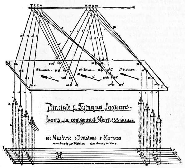
| XII.— | Tying-up of Jacquard Looms with Compound Harness attached, | 58 |
| XIII.— | Tying-up Jacquard Looms for Gauze Fabrics, | 64 |
| Modifications of the Single Lift Jacquard Machine, | 67 | |
| I.— | Double Lift Single Cylinder Jacquard Machine, | 67 |
| II.— | Double Lift Double Cylinder Jacquard Machine, | 69 |
| III.— | Substitution of Tail-cords for Hooks, | 71 |
| Tying-up of Jacquard Harness for Two-ply Ingrain Carpet, | 72 | |
| General Description of the Construction of the Fabric, | 72 | |
| Straight-through Tie-up for Ingrain Carpet, | 74 | |
| Point Tie-up for Ingrain Carpet, | 78 | |
| APPENDIX. | ||
| Preparing and Stamping of Jacquard Cards, | 85 | |
| Dobby Card Punching Machines, | 86 | |
| Piano Card Stamping Machines, | 86 | |
| Stamping of Cards, | 91 | |
| Repeating Jacquard Cards by the Positive Action Repeater, | 92 | |
| Lacing of Jacquard Cards, | 97 | |
| Lacing of Jacquard Cards by Hand, | 97 | |
| Lacing of Jacquard Cards by Machine, | 98 | |
| PRACTICAL HINTS TO LEARNERS OF JACQUARD DESIGNING. [4] | ||
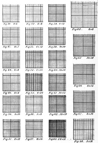
| Squared Designing Paper for the different Textile Fabrics executed on the Jacquard Machine, | 103 | |
| Practical Use of the Heavy Square in Designing Paper, | 105 | |
| Selection of Designing Paper for Single Cloth, | 105 | |
| Selection of Designing Paper for Double Cloth, | 106 | |
| Selection of Designing Paper for Two-ply Ingrain Carpet, | 106 | |
| Selection of the Proper Brush for the different □ Designing Papers, | 107 | |
| Colors used for Painting Textile Designs, | 107 | |
| Preservation of Textile Designs, | 107 | |
| Sketching of Designs for Textile Fabrics to be executed on the Jacquard Machine, | 108 | |
| Methods of Setting the Figures, | 108 | |
| Size of Sketch Required, | 109 | |
| Enlarging and Reducing Figures for Sketches, | 110 | |
| Transferring of the Sketch to the Squared Designing Paper, | 112 | |
| Outlining in Squares, | 113 | |
| Rules for Outlining in Squares Inside or Outside the Drawing Outline, | 114 | |
| Illustration of a Sketch—Outlining on □ Paper—Finished Design—Fabric Sample (Single Cloth), | 115 | |
| Designs for Damask Fabrics to be executed on a Jacquard Loom, with Compound Harness attached, | 116 | |
| Designs for Two-ply Ingrain Carpet, | 116 | |
| Designs for Dressgoods Figured with Extra Warp, | 117 | |
| Designs for Figured Pile Fabrics, | 118 | |
| The Shading of Textile Fabrics by the Weave, | 118 | |
| Glossary, | 121 | |
Very little has been written upon the Jacquard machine, and the fabrics produced by it; and nothing at all has been heretofore published in this country with regard to the machines and systems, as employed here.
Greatly assisted by the guidance, help and advice of Mr. T. C. Search, President of the Philadelphia Textile Association, and Vice-President and Chairman of the Committee of Instruction of the Pennsylvania Museum and School of Industrial Art, the author gives here the results of his practical experience on this subject, with a very detailed description of the methods of procedure with the Jacquard and accompanying machines, in the different branches of Textile Manufacture.
E. A. POSSELT.
Philadelphia, Pa., 1888.
The Jacquard machine was named after Joseph Marie Jacquard. Jacquard was born in Lyons, France, on the 7th of July, 1752. His parents were employed in the manufacture of silk fabrics. The first trade Jacquard learned was book-binding; type-founding and cutlery following successively. He was 20 years of age when his father died, leaving him a small house and hand-loom in the village of Cauzon, near Lyons. He commenced to invent different improvements in the line of weaving, but without other success than accumulating debt, compelling him to earn the living for himself and family, first in a plaster quarry at Bugey, near Lyons, afterwards by working at cutlery, type-founding and weaving in Lyons.
In 1792 he joined the Revolutionists, and after his return in the following year he and his son assisted in the defence of Lyons against the Army of the Convention, but left when his son was killed near him in battle.
Lyons Council offered him a room, for working on improvements for weaving at the “Palace of the Fine Arts,” with the condition that he should instruct scholars free of charge. During his stay there the Society of Arts, in London, offered a reward for a machine for making fishing nets. Jacquard succeeded in perfecting it, but had to travel under protection to Paris, where he had to show and explain his machine before the “Conservatorium of Arts and Trades.”
On the 2d of February, 1804, Jacquard received 3000 francs, and the gold medal from the London Society, and also an engagement in the Conservatorium of Arts, in Paris. Here he found opportunity for making improvements on his weaving machine, by the study of the older inventions of Bouchon, Falcon and Vancanson.
M. Bouchon, in 1725, employed a band of pierced paper pressed by a hand-bar against a row of horizontal wires, so as to push forward those which happened to lie opposite the blank spaces, and thus bring loops at the lower extremity of vertical wires in connection with a comb-like rack below. M. Falcon submitted in 1728 a chain of cards, and a square prism, known as the cylinder, in lieu of the band of paper of Bouchon. In 1745, Jacques de Vancanson suppressed altogether the cumbrous tail-cards of the draw-loom, and made the loom completely self-acting by placing the pierced paper or card upon the surface of a large pierced cylinder, which traveled backwards and forwards at each stroke, and revolved through a small angle by ratchet work. He also invented the rising and falling griffe, and thus made a machine very nearly resembling the actual Jacquard.
Jacquard returned to Lyons in the year 1804 to take charge of the work-house. During his stay at this place he finished his machine. He was an experienced workman, combining together the best parts of the machines of his predecessors in the same line, and succeeded as the first person in obtaining an arrangement sufficiently practical to be generally employed. In 1806 Napoleon Buonaparte changed his position, giving him an annuity of 3000 francs, but compelling him to transfer his invention to the city of Lyons, as well as any further inventions. Until 1810 Jacquard had great troubles, as his machine was not understood by the weavers. So violent was the opposition made to its introduction that he was compelled to leave Lyons in order to save his life. The Conseil des Prudhommes broke up his machines in the public places, and Jacquard was delivered over to universal ignominy. But after some years had passed the machine proved to be of the greatest value, and on the spot where the model was destroyed a statue to Jacquard now stands. He died August 7th, 1834, in Quillins, near Lyons, at 82 years of age. At the time of his death over 30,000 Jacquard machines were in operation in his native city.
If a fabric contains a great number of ends of warp bound differently in the filling, the method of guiding the warp by harness frames is too cumbrous and inefficient; in such cases it becomes necessary to use the Jacquard machine for raising the warp-threads separately by means of hook and leash.
The hooks as used for raising leash, mail, lingo, and warp-thread, consist of wires 16 to 17 inches long, with a crook on each end. On the lower crook is fastened the leash by means of the neck-cord.
The cords of each leash are threaded through the holes of the comber-board; the latter are separated from each other according to the texture of the warp in reed.
On the harness-cords are adjusted the heddles, (either twine or wire), on which are fastened the lingoes as weights. In the mails of the heddles are drawn the warp-threads.
Now, from the foregoing explanations, it will be apparent that by raising the hook in the Jacquard machine we raise the leash, and the latter raises every warp-thread throughout the fabric for interlacing with the filling.
The next point required to be known is, which hooks are to be raised, and which are to be lowered? To regulate this, a design (pattern) is prepared in which the floating of the warp over the filling is indicated.
For the warp-threads required to be raised holes are punched in the cards. In these holes the points of the needles extending through the needle-board are pushed by a spring fastened on the rear of each needle. The needles are adjusted in rows of different heights. The arrangements most used are 4, 8, and 12 rows high. Each row as to height in the machine contains a bar (knife) in the griffe. When the griffe is down, or the machine at rest, the upper crooks of the hooks are raised about half an inch above the griffe-bars.
The needles which control the position of the hooks, permitting them to rise or compelling them to remain stationary, are pressed by the springs fastened in the rear towards the cards, which are moved on a quadrilateral and perforated cylinder. This cylinder performs a movement similar to a pendulum towards the points of the needles. Any needle for which a hole was punched in the card will penetrate the cylinder; consequently, the corresponding hook will remain in its natural position, on the crook over the corresponding griffe-bar, and upon lifting the griffe the hook will be raised.
Again, needles for which no holes are punched in the cards will be thrust back by moving the cylinder containing the cards towards the needle-board; this motion[10] forces back the corresponding hooks, pushing them away from the griffe-bars above, and upon raising the griffe they will remain stationary; hence, if a blank card were pressed against all the needles of any machine, the entire number of needles the machine contains would be pushed back, and none of the hooks would come in contact with the griffe-bars, and, consequently, raising the griffe would produce an empty lift. On the other hand, using a card having every hole of the cylinder punched, (or the empty cylinder used), would lift every needle in the machine. Pressing the needles towards the rear compresses the springs; these will again expand as soon as the cylinder leaves the needle-board. The hooks, which were left standing in their position over the griffe-bars are caught by the latter at the raising of the griffe. The elevation of these hooks raises the leashes fastened to them, thus causing the lifted warp-threads to form a shed with those not lifted.
Jacquard machines are made of different sizes and descriptions, some having only a few hooks and others a large number. The sizes most often used are 100, 200, 400, 600, 900, 1200 hooks. The number or size is always indicated by the number of needles and hooks which it contains, without counting the reserve rows, of which there are generally two. These reserve rows are used for various purposes, such as raising the selvedge; raising the front harness; raising the shuttle-boxes on hand-looms; guiding the take-up motion on hand-looms; indicating a certain card through ringing a bell on hand-looms, etc.
Sometimes a few of the needles and hooks from the reserve are added to the main part of the needles and hooks. For example: Take a design in which the ground weave repeats on 12 ends; working a 400 machine, we find:
400 ÷ 12 = 33 repeats of the weave, less 4 hooks;
Consequently, if this ground-weave is repeated all over the width of the fabric, we must use either:
396 hooks, leaving 4 hooks more to be added to the two rows already used; or 408 hooks, requiring us to call upon the reserve rows for eight extra hooks.
Hooks which have no leashes adjusted must be taken out of the machine.
Sometimes two, three, or more, machines are employed on one loom, and may be worked in different manners. In this country Jacquard machines, for power as well as hand-looms, are made of iron, whereas in Europe the machines for hand-looms (comprising the greater part of the Jacquard machines in use) are made of wood; using the iron ones only for power-looms; and even yet, in most cases, the wooden machines are used for the latter.
Every Jacquard machine may be divided into the following parts:
1. The Frame and the Perforated Board through which
the neck-cords are passed.
2. The Griffe and necessary attachments for lifting the
same.
3. The Hooks.
4. The Needles.
5. The Springs and Spring Frame.
6. The Needle-board.
7. The Cylinder, Hammer,
and Batten.
8. The Catches.
9. The Cards.
10. The Jacquard Harness.
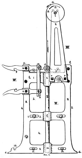
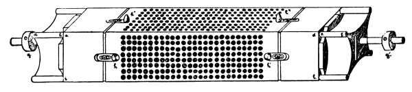
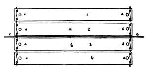
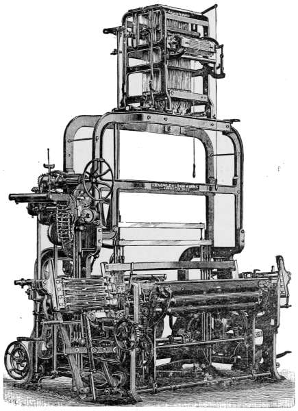
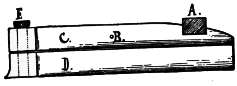
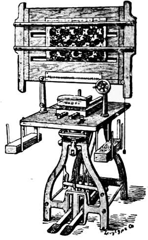
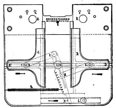
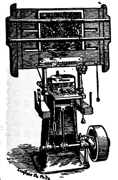
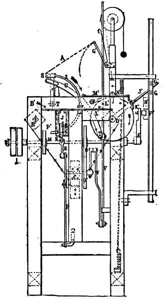
Fig. I.,[A] represents the side view of the “frame” of a common 200 Jacquard machine by a, b, c, d. The width of the frame in its main part [see 6 to 7] is 9-1/2 inches.
1-1/8 inches is the width of the iron casting at the places marked 8 and 9.
2 inches is the height of casting at the place indicated by 1.
1-1/2 inches is the height of casting at the place indicated by 3.
1-3/4 inches is the height of casting at the place indicated by 5.
The open part of the frame, marked 2 in drawing, is 6 inches high.
The open part of the frame, marked 4 in drawing, is 5 inches high. Hence, the main height of the frame is as follows:
| 1 = 2 | inches. |
| 2 = 6 | inches. |
| 3 = 1-1/2 | inches. |
| 4 = 5 | inches. |
| 5 = 1-3/4 | inches. |
| ------- | |
| 16-1/4 inches main height. |
[A] For illustration of the present article a 200 Jacquard machine is used, illustrated on pages 11-17 by Figs. I. to XI., which contains the same principles of construction as any other size machine. These illustrations are drawn one-fourth of the actual size; hence, any measures, etc., we have omitted may readily be found by any student.
The perforated bottom board, through which the neck-cords are passed, contains one hole for every hook in the machine, and is illustrated in Fig. II. separately. It shows the following measurements:
| Entire width of board | = | 8 inches. | |
| Entire length of board | = | 12 inches. | |
| Thickness of board | = | 3/4 inches. |
| Distance of holes from each centre, | {a, in length of board, 0.27 inch. (See l to b.) | ||
| {b, in width of board, 7/8 inch. (See m to w.) | |||
Distance of first row from the part of the frame illustrated in Fig. I., 2-3/4 inches.
Distance of first row from the rear part of the frame, 2-1/2 inches.
This board is fastened by screws to the frame at places indicated in Fig. I. by 11 and 12.
Besides the frame, Fig. I. illustrates: Under I. the Jacquard plunger, 3/4 inch diameter, for guiding the griffe (attached to its head) when raising. To strengthen the steadiness of this latter movement shoulders are attached to the frame at the three places where the plunger slides.
| Height of frame at k, | = 2-3/4 inches. |
| Height of frame at l, | = 2 inches. |
| Height of frame at m, | = 2 inches. |
Screws, f, dotted in drawing, on head of plunger, fasten the griffe to it.
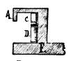
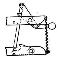
Part III. in Fig. I. illustrates the attachment for providing the lifting of the plunger in a hand-loom, likewise the griffe, etc. This consists of a triangular shaped frame 14-1/4 inches high, or less, according to height of room. This part is fastened to the front part of the frame by bolts at o and p. In the slot at the top, between r and s, a wooden cylinder of 3-1/2 inches diameter is fastened to an iron shaft resting in the frame at t.
At 13 a leather strap is fastened to this cylinder and to the plunger 14. It will easily be seen that by turning the wooden cylinder in the direction of the arrows, 15, the plunger will be raised with the griffe fastened to its top. By[13] reversing the action of the cylinder, the plunger and griffe will return to their previous positions. The action thus described constitutes a “single lift,” raising and lowering of plunger and griffe for each pick.
At IV., Fig. I., the “catches” for turning the cylinder at the lantern are illustrated. The distance of the centre of the screws which hold the catches to the frame is 4-3/4 inches. Between these two catches the cylinder is adjusted to the batten, and the direction of its turning is regulated by the catch which is brought in contact with the lantern. If the catch, y, turns, the cylinder will turn the card situated on its top towards the needle-board, and if catch, z, is brought into contact with the lantern, the card hanging below the needle-board will be the next in turn to be pushed towards the needles.
The entire length of the catches in the present illustration is 8 ins., allowing 5-1/4 ins. for the catch itself and 2-3/4 ins. for the part to which it is fastened. Making this catch in two pieces is preferable to the old style of one piece, because the moment of turning the cylinder can be more easily regulated.
Fig. III. illustrates the top view of the griffe. As mentioned before, the griffe is fastened to the plunger by means of screws. In the drawing the dark shaded places marked f are the hollow places in the griffe, through which the screws fasten the latter to the plunger. The griffe, like the other parts explained, is made of cast iron, and the machine is of the following dimensions:
| Length of griffe, a to b, | = 9-3/4 inches. |
| Depth of griffe, a to c, | = 6-5/8 inches. |
| Extension on each side, e to f, | = 1-1/2 inches. |
| Distance of griffe-bars, s to s, | = 7/8 inch. |
| Length of griffe-bars, m to n, | = 9-1/4 inches. |
| Height of griffe-bars, [see Fig. IV., sectional cut of griffe-bars,] | = 7/8 inch. inches. |
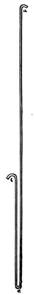
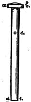
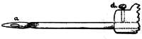
Fig. V. represents a hook as used in the present machine, made of No. 13-1/4 bright spring wire. Height, a to c, = 16-5/8 inches. Height of rester, b to c, = 6-5/8 inches.
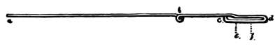
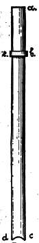
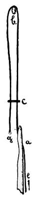
Fig. VI. illustrates a needle, as used in connection with the hook. Distance from head to loop, 9-1/8 inches, = a to c. Length of loop, 1-5/8 inches, = c to d. 10-3/4 inches entire length.
The distance from head to eye (for passing through the hook) is regulated according to the row in which the needle belongs. In the present illustration this is, Head to eye, = 7 inches, = a to b. The eye, = 3/8 inch, = b.
Eight different positions of the distance of the eye from head will be required by an 8-row machine. The needles are made of No. 15-1/2 bright spring wire. The loop on the end, c to d, permits a pin to be inserted, [see Fig. VII., o], and also holds the needle in position.
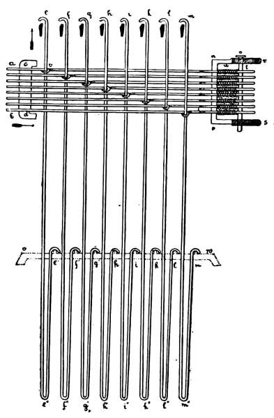
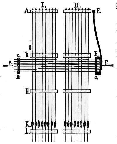
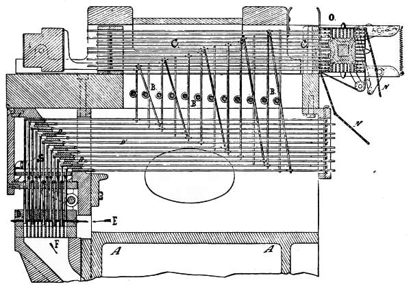
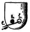
Fig. VII. gives a clear understanding of the arrangement of hooks, needles, griffe-bars, springs, frame for holding the latter, and the needle-board. This drawing is in accordance with the preceding ones, executed one-fourth of the actual size, and represents the sectional cut of one cross-row in the Jacquard machine containing 8 hooks, (as it is an 8-row deep machine which we explain): e to e´, 1st hook; f to f´, 2d hook; g to g´, 3d hook; h to h´, 4th hook; i to i´, 5th hook; k to k´, 6th hook; l to l´, 7th hook; m to m´, 8th hook. These hooks are held in their required places by the eyes of the needles [see place v at hook 1], through which the former are passed.
The needles rest with their heads in the needle-board, a to b, extending outside, towards the cylinder, for about 1/2 inch. The rear part of the needle—the loop—is passed between two bars of the spring frame, n, p, and held by the latter firmly, but with sufficient play for a longitudinal motion for pressing towards their springs. The pin, o, is inserted for holding the springs in their places. One pin is required for each vertical row of needles. The part of the spring frame, r, n, p, s, unshaded, is made of cast iron; the shaded part (extension) is constructed of wood. Below the upper crook of the hooks, the black sections represent a sectional cut of the griffe-bars; v to w indicates the rester for the lower hooks, which keeps the latter in their required position.
A study of this illustration will show that when the heads of the needles, a-b,[15] are pushed backwards, in the direction of arrows, the hooks are also moved. If the needles are not pushed, the upper crooks of the hooks will remain in position, as in drawing, over the griffe-bar; and raising the latter will consequently raise every one of these hooks. Therefore, if a blank card is pressed against the 208 needles of the machine, all the needles and hooks will be pushed back, out of the way of contact with the griffe-bars, thus causing an empty lift when they are raised; whereas, by pressing with an empty cylinder, or with a card, containing as many holes as the machine has needles, and so placed that the holes are exactly opposite the needles, none of them would be moved, and each hook would remain vertical over its griffe-bar; and raising the griffe will lift every hook.
As mentioned before, the springs, u, are attached to the needles between the needle-frame, n-p, and the pin, o. Fig. VI., the distance e to f indicates the part of the loop around which the spring is adjusted, and where it rests against the expansion of the loop. f, in Fig. VI., represents the place where pin, o, (as shown in Fig. VII.) passes through the loop and is fastened to the needle-frame on top and bottom. Pressing the needle at the head compresses the spring, as the latter is securely fastened on one end by the wider part of the loop, and on the other end by a pin inserted in the loop and fastened to the frame. Remove the pressure at the head of the needle, and the spring will return to its natural position, pushing the needle into its old place. These springs are made of thin brass wire.
It is necessary to keep the needle-eyes in the proper place, otherwise it would result in bending the hook out of its perpendicular position, and by lowering the griffe its bars would possibly come in contact with the head of the hook, crushing the latter, or doing more damage if not detected at once. Each needle or hook, if worn out, can be replaced by pulling out the pin, o, thus loosening the needle and giving a chance to work the required hook out of the needle-eye.
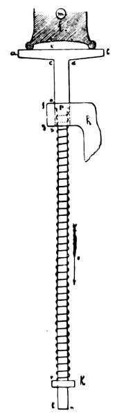
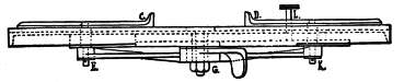
Fig. VIII. represents the batten motion to be attached to the guiding-rod, [see No. 14, in Fig. I.], and the frame, [see No. 16, in Fig. I.] The batten, 2, is connected to a triangular lever by means of lever, d. Another vertical lever connects the lower part of this triangular lever to a projecting bolt, k, fixed to the guiding-rod of the griffe. By raising the guiding-rod, thus raising lever, k, in the direction of the arrow, the batten is thrown outwards, [see direction of arrow below c], returning again to its former position at the lowering of the griffe. f indicates the place where the triangular lever is fastened (movable) to the projecting bolt, extending out of the frame. a indicates the place for the cylinder. Part 1 of the batten is movable at l in the direction of arrow, s, allowing the cylinder to be inserted. Part 1 is fastened (after putting the cylinder in at a), to 2 by means of the screw, n.
Fig. IX. represents the cylinder, with the lantern for turning the same by means of the catches. The dimensions for the cylinder in the present machine are as follows:
| Height of cylinder, | = | 2-7/16 | inches. |
| Width of cylinder, | = | 13 | inches. |
| Width of lantern, | = | 1-1/2 | inches. |
| Average length of spindle, | = | 2 | inches. |
This cylinder is carried in the batten, the latter moving in the groove provided for it under 10, Fig. I. This batten has sufficient vibratory motion to enable it to move the required distance away from the needle-board. After coming in contact with the catch it still moves until the cylinder has performed a complete turn. The cylinder is steadied in the required position by the hammer pressing by the means of a spring towards the lantern from below.
Fig. X. illustrates the hammer as attached to the batten; a to b, (equals 3 inches in width in our present illustration), represents the head of the hammer, forming the foundation for steadying the cylinder in its turning. The hammer is pressed for this purpose towards the cylinder by means of the spring, s to r. Parts h and k guide the hammer in its up and down movements, and are solid parts of the batten. By turning the cylinder the hammer is pushed down in the direction of the arrow, t, thus compressing the spring, which returns to its normal position after the cylinder has completed its turn, ready for being advanced towards the needle-board.
The following are accurate measurements of this part of the machine:
| Height of head of hammer at a and b, | = | 1/4 | inch. |
| Thickness of hammer-head, e to c, | = | 3/8 | inch. |
| Height of hammer-head when at rest above the top guiding part, c to o, | = | 1-1/2 | inch. |
| Width of the guiding-rod, c to d, | = | 1/2 | inch. |
| Thickness of “top guide,” f to g, | = | 3/4 | inch. |
| Thickness of “lower guide,” f to r, | = | 1/4 | inch. |
| Distance between these guides, | = | 9 | inches. |
| Total height of guiding-rod, | = | 10-1/2 | inches. |
The shaded part of the drawing above the hammer represents the cylinder, i, which has its shaft for turning at m.
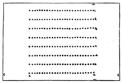
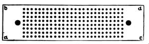
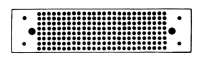
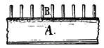
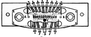
As before mentioned, the heads of the needles are passed through the needle-board. A drawing of this board, representing the front view, is shown in Fig. XI. The following are the dimensions:
a to c, = 9-1/2 inches. a to b, = 2-3/8 inches.
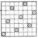
Each side of the prism, always technically called the cylinder, has a protruding peg about 1/2 inch in length. When in contact with the needle-board these pegs enter the black holes shown upon either side in drawing. The 208 needles and holes in the present machine are represented by a small spot for the former with an outside ring for the latter.
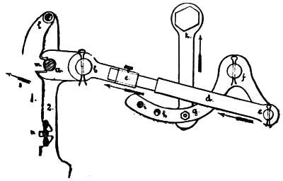
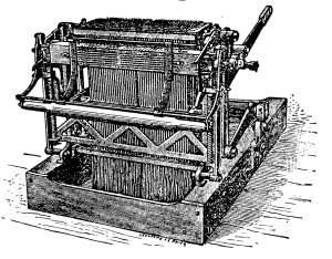
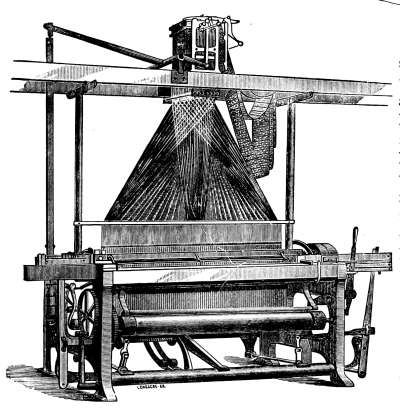
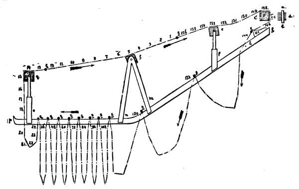
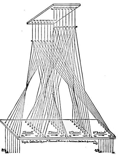
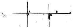
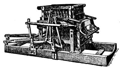
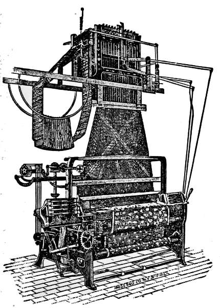
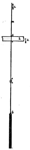
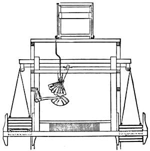
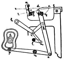
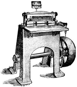
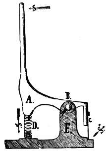
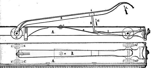
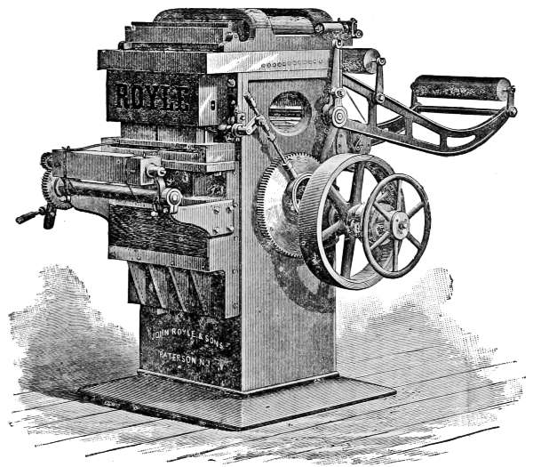
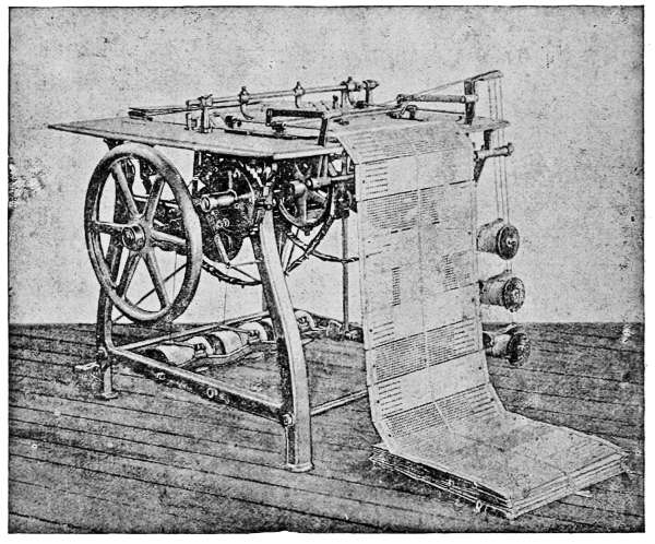
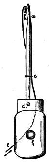
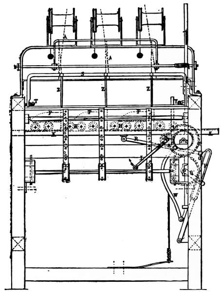
The lifting of the griffe, which in turn also operates the other parts of the Jacquard head, as explained before, is not always produced from above: very often this lifting is arranged to be done by means of a lever arrangement from below the griffe. This method of working the mechanism in the Jacquard machine is illustrated by Fig. XII., representing the perspective view of a 400 Jacquard machine, (W. P. Uhlinger, builder).
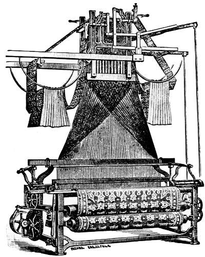
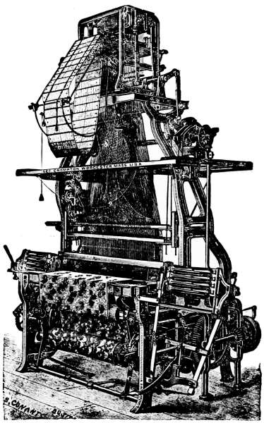
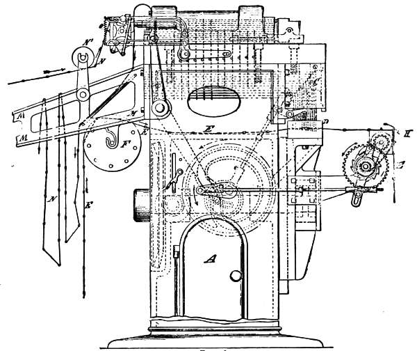
Fig. XIII. represents the same machine adjusted to the loom. On the longer arm of the lever a series of holes are found. These regulate the height of the lift by the vertical rod which provides the required movement. The nearer this rod is adjusted to the Jacquard head the higher the lift of the Jacquard harness, thus forming the shed.
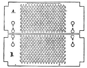
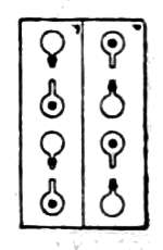
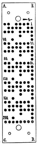
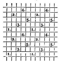
Fig. XIV. represents a single Jacquard card, as required for the 200 Jacquard[18] machine, 1/4 of its actual size. This shows 26 rows of holes in its width and 8 rows in its depth, 208 holes. These holes are shown in black, one for each hook in the machine. Besides these a large hole on each side permit the pegs of the cylinder to enter into the needle-board. The cards are interlaced in an endless arrangement.
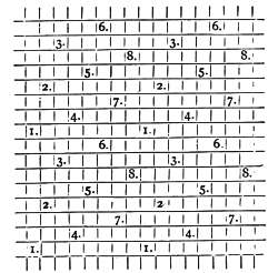
Fig. XV. illustrates four cards laced together. The large holes (marked d in drawing) are peg holes to receive the pegs, h, h´, h´´, h´´´, etc., of the cylinder, as shown in Fig. IX. These pegs are movable so that any small variations at cutting with different card-stamping machines can be rectified. The paper used for the cards must be of sufficient thickness to resist the wear caused by the needles, as well as to give steadiness to the cards when resting in the pegs of the cylinder.
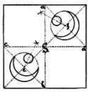
The cards are interlaced in an endless arrangement; hence, one card is brought after the other in rotation towards the needles. The cards only refuse service by not fitting properly on the cylinder, i. e., if the peg holes are too near together or too far apart; or if the cards are warped, which is liable to happen in a damp workshop.
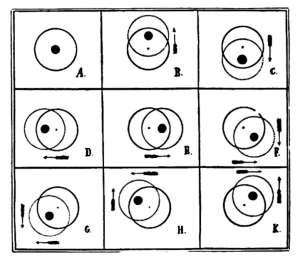
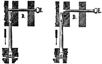
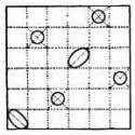
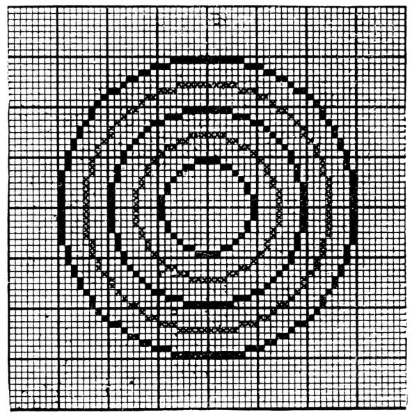
A careful examination of the cards fitting on the cylinder is absolutely necessary, otherwise a wrong lifting of the hooks destroying the cards by the pegs punching new holes would result. The cylinder with cards perfectly cut must be set so as to allow the needles to penetrate into the centre of the holes stamped for them in the card. Sometimes the cylinder is set too high or too low—too far in front or too far in rear. To ascertain the proper position, lift the machine and place some paint, or grease from the machine, on the heads of the needles. Afterwards let the machine “fall in,” which will bring the cards against the heads of the needles, producing an impression and indicating the exact position of the needle-heads. The cylinder is always set in its proper position when no marks are made by the entering needles on the margins of the stamped holes and where there are no holes the impression left by the needle head must be equally distant from the surrounding holes.
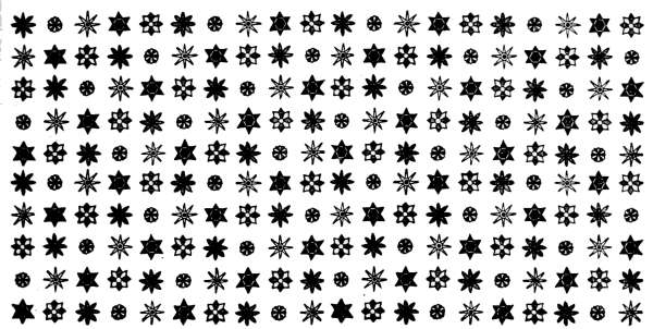
To get a clear understanding of this examine Fig. XVI. illustrating six different impressions of the needles. The circle shown with full lines in each of these six illustrations represents the correct position of the circumference of the hole, and the dotted circles the various errors that may exist.
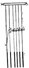
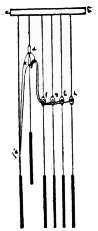
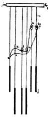
If the machine produces wrong lifts of the hooks and the trouble is not found in the setting of the cylinder, nor in the hooks or needles, then ascertain if the cylinder is adjusted by means of the lever arrangement, close enough to the needle-board; for if it is not, the hooks will not be pushed far enough from the griffe-bars, and by raising the latter a wrong shed will be produced. When using a great number of cards in a set they are made to fold into a “rack.” This is done by attaching a wire 1 to 1-1/2 inches longer than the cards at the junction of, say every 12th, 15th, or 20th cards. [See c at Fig. XV.]
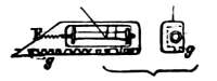
The cards fall through a wooden frame, Fig. XVII., but the wires attached to the cards, being longer, can not pass through, and the cards will remain suspended, and subsequently fold together in a very compact manner.
In Fig. XVII. we illustrate 156 cards arranged with wires attached to every twelfth card, as follows: between cards 156 and 1, 12 and 13, 24 and 25, 36 and 37, 48 and 49, 60 and 61, 72 and 73, 84 and 85, 96 and 97, 108 and 109, 120 and 121, 132 and 133, 144 and 145.
At e, f, g, are shown prisms of the size of the cylinder, by which the cards are guided and regulated in their run towards the cylinder, (direction of arrow); i and h represent round rollers, also placed in rack for guiding cards after leaving the cylinder, c; a and b, the needle-board; c and d, the needles of the machine. S represents the wires as inserted in cards for holding them in the frame.
To the lower end of the hooks (c. in Fig. V.) the neck-cords are adjusted. The latter are passed separately through one of the corresponding holes of the perforated bottom board (Fig. II.) To these neck-cords are fastened the leashes of the Jacquard harness about 1/2 to 1 inch above the frame containing the rods which guide the neck-cords vertically as the hooks are raised and lowered. The different harness-cords are threaded through the comber-board in various ways called “Tie-ups,” which will be explained later.
There are two kinds of comber-boards used upon Jacquard looms:
1st. Comber-boards made of a solid piece of material, either wood or porcelain.
2d. Comber-boards made in strips of either of the materials above named, and adjusted afterwards in a wooden frame.
Before ordering a comber-board, it is necessary to know the texture of the fabric in the loom, and also the number or size of the machine to be used; for the number of holes per inch in the comber-board is regulated by this. Afterwards, we may, if we choose, arrange the number of holes in depth of the comber-board, according to the number of griffe-bars in the machine, (guided by the fabric to be made). We may have eight griffe-bars in the machine, and arrange the comber-board 4, 6, 8, 10, 12 rows deep; or we may have 12 griffe-bars in the machine, and arrange the comber-board 12, 10, 8, 6, 4 rows deep.
Rule: The number of holes to one inch in the comber-board must equal the texture of the fabric to one inch in loom.
Example: Suppose a fabric with a texture in the loom of 100 threads, and we are to use a 600 Jacquard machine, with 12 rows. The width of the fabric in the loom is to be 36 inches.
The width and depth of the comber-board are regulated by the width of the cloth required and by the design to be used.
The greater the number of rows in depth the closer they must be; the same is true of the width.
It is necessary to take care not to have the comber-board too deep, as the consequence would be a bad shed; furthermore, we must not have the holes too close together, as in a high texture this would make trouble in the weaving through the catching of the heddles with the warp, and also cause useless chafing of the warp-threads and the heddles.
In Jacquard work we generally use the same texture, or as near as possible, as the loom is tied up for; but changes are sometimes unavoidable. If we reduce the texture of the fabric in a Jacquard loom tied-up for a solid comber-board, we must reduce proportionally the number of hooks and needles used in designing, and hence the number of heddles used per inch. These heddles will thus be left empty when drawing in the warp. To accomplish this lift the full machine and throw the hooks not to be used from the knives, lowering in this way every mail which is not to be used. Sometimes there may be only one, two, three, or four hooks to be thrown off, on account of the design. At other times it may be necessary that one-eighth, or one-fourth, or even one-half of the whole number shall be dropped for this purpose. For instance, suppose we have a dressgoods design of 596 threads and a 600 machine. These four ends left off the 600, if in 6, 7, 8, or more inches in width, would not affect the fabric nor the cost to any great extent; hence we may leave out the first or last four needles of the 600.
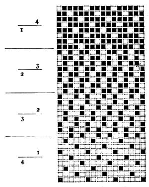
Suppose we have a texture of 100 in the comber-board, to lower to 66 ends per inch. 66 ends, or the nearest even part of 100 (66-2/3) is 2/3 of 100; hence, we only need two-thirds of our machine; and as the same is supposed to be arranged 12 rows deep, we need 2/3 of 12 rows, or 8 rows. The four rows thus found necessary to drop may be dropped from the ends, or alternately, as follows:
Every alternate 2 rows taken, 1 row missed, 4 times over, = 12 rows. Or, 2 rows missed, 8 rows taken, 2 rows missed, = 12 rows.
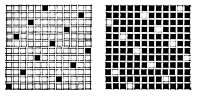
By these comber-boards which are used to a great advantage on narrow loom work up to 36 inch fabrics, we can change the texture for the fabric; for the strips composing the comber-board may be drawn apart, thus changing the higher texture to lower; whereas in a solid comber-board this could only be done by re-tying the harness or changing the number of needles used in the machine. To give a clear understanding Figs. XVIII., XIX., XX. are needed.
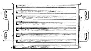
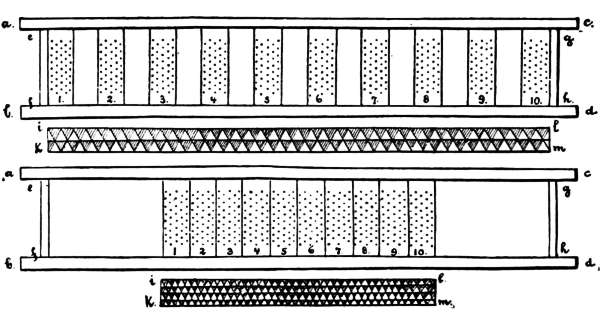
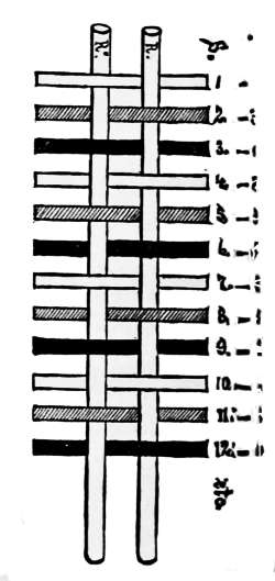
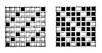
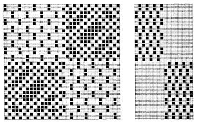
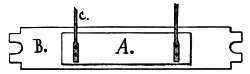
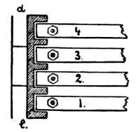
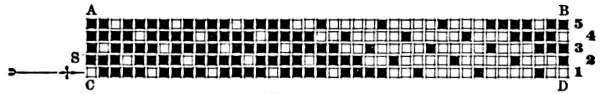
Fig. XVIII. represents an 8-row deep comber-board, a, b, c, d, composed of 10 strips which are set close together. By examining each strip 5 cross-rows of holes will be found, making the whole number of holes 400.
Suppose the comber-board as represented in Fig. XVIII. is intended for a texture of 100 ends per inch; this will give for the width of the fabric (i, k, to l, m,) 4 inches.
In Fig. XIX. the comber-board is arranged for a texture of half as many ends, or 50 holes per inch, and the 10 strips are arranged accordingly; the empty places between the strips are of same size as the strips themselves, and the fabric design below the comber-board is arranged to correspond.
Fig. XX. illustrates the sectional cut of the comber-board used in drawings, Figs. XVIII. and XIX., and the letters indicating the different parts of these figures which correspond.
Under this heading we classify one repeat of the arrangement of threading harness-cords in the comber-board, and therefore one repeat of the design of the fabric. We find fabrics in which are used one or more divisions of one system of threading harness-cords in the comber-board; again, there are others in which one or more divisions of one system are combined with one or more divisions of another, or even of two or three other systems.
After the harness-cords are threaded through the comber-board the heddles are adjusted. Of these there are two kinds:
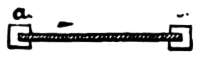
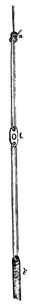
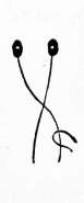
Fig. XXI. illustrates a regular twine heddle one-fourth of its actual size.
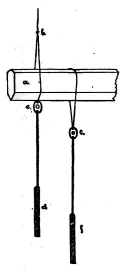
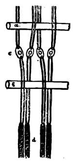
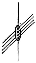
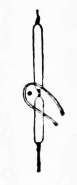
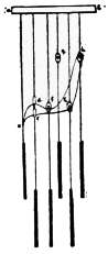
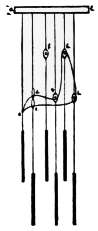
Fig. XXII. illustrates the method observed for combining heddle and harness-cords. a, the guide-board, to get the mails regular in height; b, the knot combining heddle and harness-cord. [See a in Fig. XXI.] c, the mail. d, the lingo.
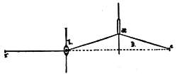
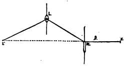
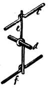
Fig. XXIII. illustrates the average position of the mail in a loom. a, breast-beam of the loom. c, the warp-beam or guide-beam over which the warp runs on its way towards the harness. b, the position of the heddle. d, the lingo.
This requires a clear conception of the rotation in which the different heddles are threaded, according to the tie-up employed. Two methods are in use: 1st. The heddle nearest the weaver is the first to be threaded, and the heddle of the same row in rear of the comber-board is the last. 2d. This principle reversed, thus arranging the leasing from rear to front.
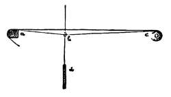
The latter method is the one most generally observed. Every row in depth of comber-board is leased separately, and in rotation secured to the lease-twines, a and b, in Fig. XXIV., thus forming an uninterrupted line of heddles through the entire Jacquard harness. Through these heddles the warp is afterwards drawn in rotation.
This tie-up contains in its principle the foundation of all the others. Three methods are in common use, which we will now explain.
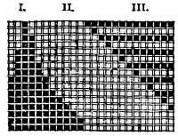
This tie-up is represented in Fig. XXV.
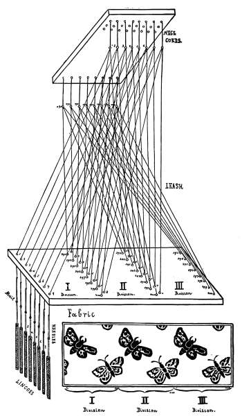
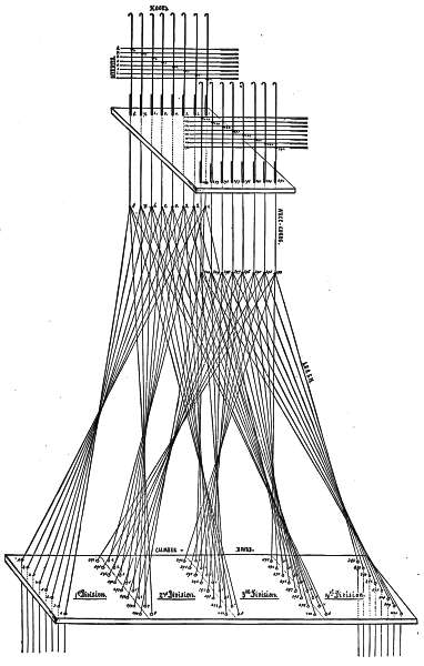
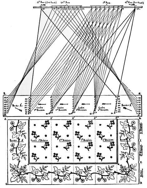
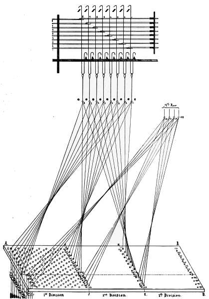
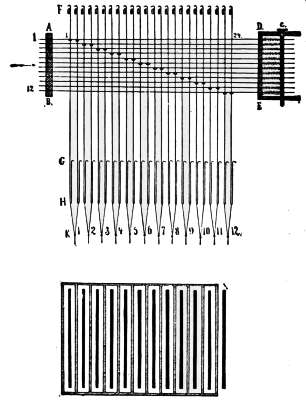
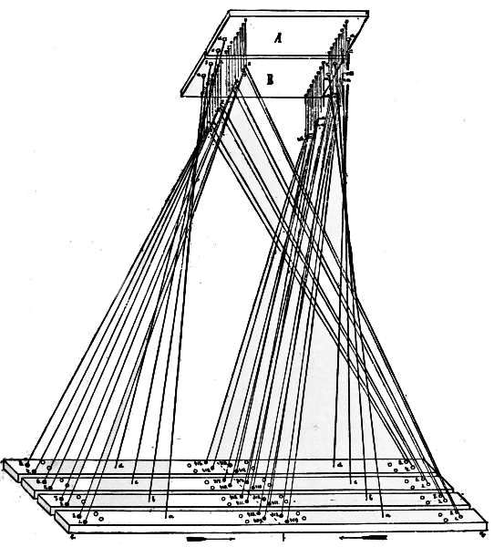
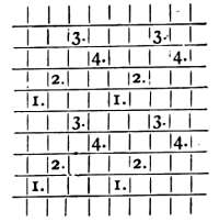
As mentioned in the heading of this article, the Jacquard harness, or the leashes, are fastened to the machine in rotation from front to rear, the threading of the comber-board being done from rear to front. The comber-board is in three divisions. The machine used for illustrating is a 400 Jacquard 8-row machine, and the comber-board used is also 8 rows deep. This method of tying-up of the leashes forms what is technically known as “open harness.” As the drawing is designed to explain a 400 machine, 8 rows drawn in the comber-board, also 8 rows deep, one row in height of the cylinder will equal one row in depth on the comber-board. In examining the illustration the eye must follow the line connecting the[25] numbers on the neck-cords to the corresponding numbers near the holes on the comber-board. If this be done, the tie-up will readily explain itself. It will also explain the method of procedure if a machine is used containing a different number of needles and hooks, and a comber-board having as many rows in depth as there are griffe-bars in the machine. For example, a 600 machine, with 12 griffe-bars, needs for this tie-up a comber-board 12 rows deep; and a 200 machine, with 8 griffe-bars, requires a comber-board 8 rows deep, etc., etc.
The drawing shows a comber-board with 3 divisions, each division furnishing one harness-cord to each neck-cord, making in all three harness-cords to every neck-cord. The same tie-up will apply should the drawing contain a different number of divisions. The illustration shows only the first and last rows of each division in the comber-board, and also the first and last rows of neck-cords.
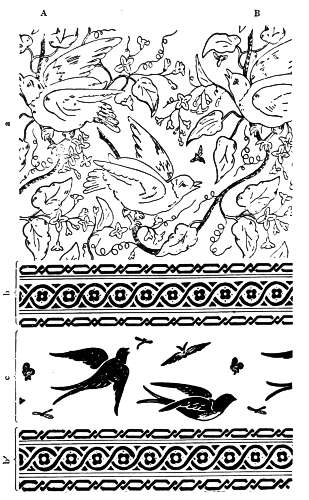
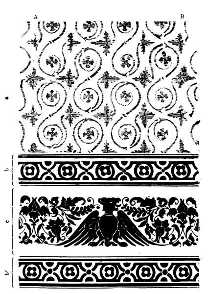
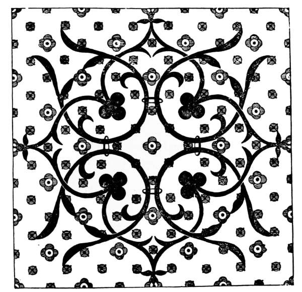
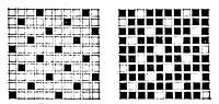
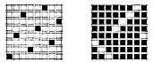
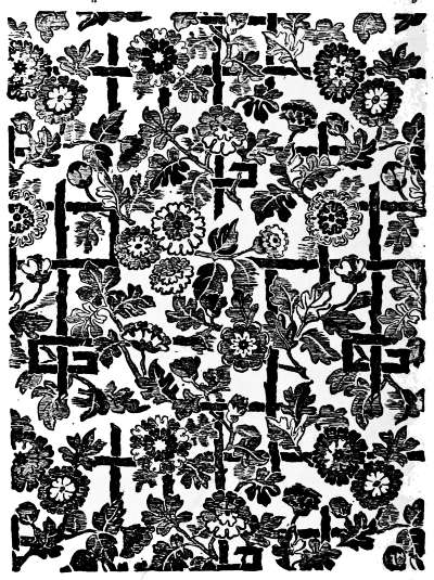
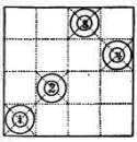
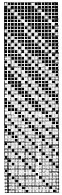
The design below the drawing represents a damask fabric to be executed on this tie-up, requiring the whole number of needles for one repeat of the pattern of 400 threads. In designing for these tie-ups it is necessary to arrange the design to repeat itself in the number of needles that will be used in producing the fabric. The first and last threads must connect with each other, without interruption, forming a continuous design over all the divisions. Thus we find, in fabric design of a damask towel, Fig. XXVI., the repeat (division) from A to B. In the centre of the design marked a, and the main part of the border marked c, we find one repeat; whereas borders b and b´ repeat 8 times.
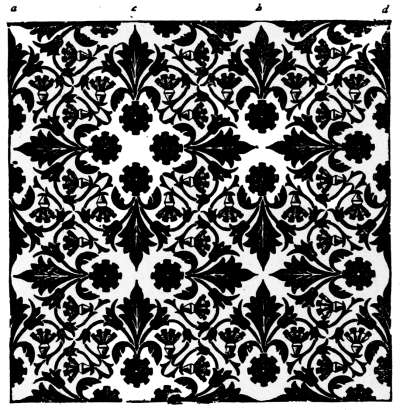
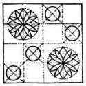
In the fabric illustrated by design, Fig. XXVII., again a damask towel, the repeat, or one division, is also indicated by A to B. The centre of the fabric, a, repeats twice in one division; borders b and b´ repeat four times in the same distance; whereas the main design of the border indicated by c requires one complete division.
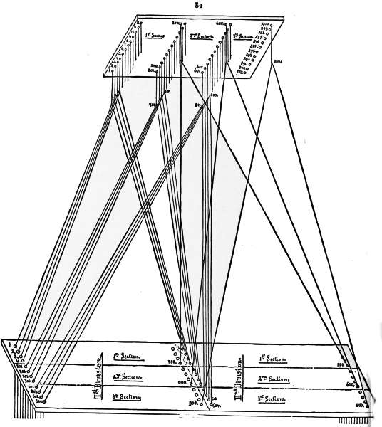
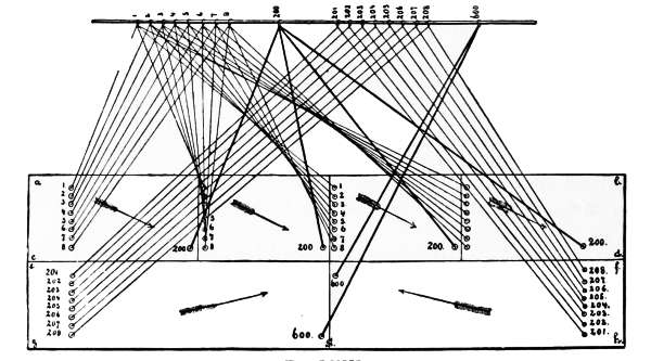
This is the second method for the straight-through tie-up, and is illustrated in Fig. XXVIII. The Jacquard harness is fastened to the machine, at the neck-cords, from rear to front. The threading of the comber-board is also from rear to front. In this method the work of attaching the leashes to the neck-cords is commenced in the rear instead of the front of the machine, thus giving a different view and arrangement of the tie-up. This disposition of the threads is called a “sectional harness arrangement.”
The illustration shows a 400 Jacquard or 8-row machine, in connection with an 8-row deep comber-board, with one row in the comber-board requiring a corresponding row on the face of the cylinder. It will also explain the method of procedure with this tie-up in Jacquard machines with comber-boards of different sizes.
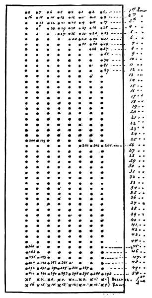
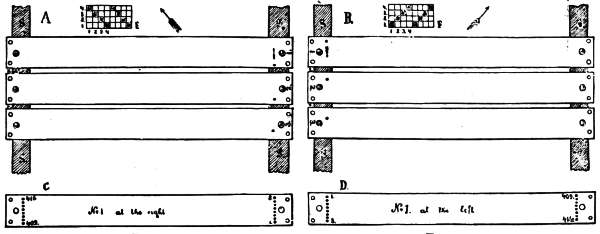
Fig. XXIX. represents the perforated board at the bottom of the machine through which the neck-cords pass, attaching the leash to the neck-cords. The first row, containing neck-cords numbered 1, 2, 3, 4, 5, 6, 7, and 8, and the 50th row, containing those numbered 393, 394, 395, 396, 397, 398, 399, and 400, are the only ones shown in Fig. XXVIII. illustrating the tie-up. The comber-board is divided[28] into four sections; hence, the drawing, as represented in Fig. XXVIII., calls for a fabric with 1600 ends in width. 400 ends, or any number dividing into 400, can be used for the repeat of the pattern. The method followed in the illustration may be applied to any size of Jacquard machine, and also to any required number of divisions in the comber-board.
In ascertaining the number of hooks or needles for one repeat of the design, determine accurately if the repeat of the weave employed for binding the ground or the figure divides evenly into this number. For example, take bottom board, Fig. XXIX., calling for 400 hooks and 400 needles. Suppose the ground weave to be an 8-leaf satin, and the design to repeat once in the 400 hooks. 400 ÷ 8 = 50 repeats, showing an equal division But suppose a 12-leaf satin is used; it is obvious that 12 is not an even factor of 400, as the division shows a remainder of 4. To dispose of this remainder two methods are open:
First. Omit last 4 ends and use only 396 hooks, a multiple of 12, giving 33 repeats; or,
Second. Add 8 hooks from the reserve rows, elsewhere previously alluded to, thus increasing the number to 408, which is also a multiple of 12, giving 34 repeats.
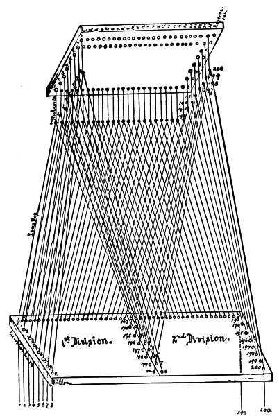
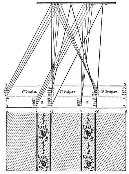
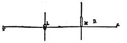
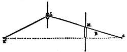
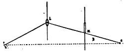
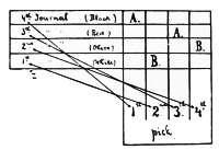
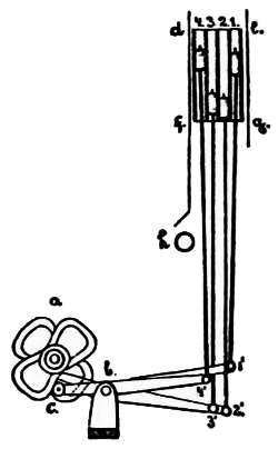
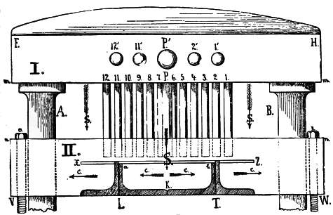
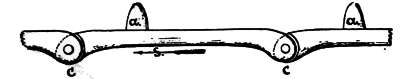
The English system, which is widely used, has the Jacquard machine so adjusted upon the loom as to have the cylinder lengthways, running in the same direction as the comber-board; or, what is the same thing, running in the direction of the width of the fabric. [See Fig. XXX.]
The 8 hooks of one cross-row (one hook from each of the 8 griffe-bars) run in the[29] direction from the cloth beam towards the warp beam. Having the same number of rows in depth, in comber-board as there are griffe-bars, one may readily see the advantages of this tie-up. The first row in depth of the comber-board contains harness-cords from neck-cords 1 to 8. The second row deep of comber-board contains harness-cords from neck-cords 9 to 16, finishing each division on the last (25th) row, with harness-cords from neck-cords 193 to 200.
Should we have a 600 machine, with 12 rows, the comber-board would also have 12 rows, as the 600 machine contains 12 griffe-bars. The first row of the comber-board receives the harness-cords from Nos. 1 to 12; the second row from Nos. 13 to 24, and so on, finishing on the last (50th) row of comber-board with 589 to 600.
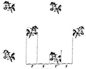
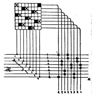
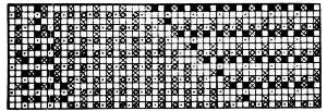
This method of arranging the tying-up of the Jacquard harness is based upon the necessity for producing patterns having a larger number of warp-threads than the Jacquard used has needles. The principle to be observed is found in producing small effects which repeat themselves in the general design.
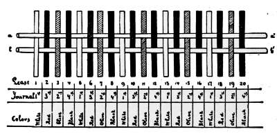
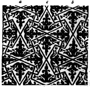
The number of cords for the leashes depends upon the frequency with which these repeats occur. Fabrics with stripe effects offer greater opportunities for reducing the number of hooks and needles than other designs. Fig. XXXI. illustrates such a design with its tie-up, using a 400 Jacquard machine with 8 rows. The pattern shows four distinct effects, as follows:
The next subject to consider is the different arrangement of repeated effects in one division. Commence at the left-hand side of the fabric sketch with effect A, which repeats only once in one pattern or one division. The illustration shows two divisions, and also that each hook of rows 1 to 16, inclusive, in the first division can be connected with each hook of rows 1 to 16, inclusive, in the second division, because these rows produce the same effect in the design, which repeats itself in these two places. This connection forms what is technically called a leash, and it will always be found that for every harness-cord a leash contains, there will be found a repeat in the design to correspond.
Effect B is repeated four times in the design, or in each division. By having two divisions for the illustration we find that to produce the necessary repeats in the design each hook of rows 17 to 21, inclusive, requires 8 harness-cords to each leash.
Effect C repeats twice in one pattern or one division. Having two divisions for the illustration, each hook of row 22, including row 34, requires 4 harness-cords to each leash.
Effect D repeats once in pattern, once in division. This will give a result similar to A, two divisions, row 35, including row 50, with two harness-cords to each leash. This tie-up illustrates the first row of every effect, and also the last leash, 400.
Adding the number of warp-threads in the full repeat of the pattern, we have:
| Effect A = | 128 threads. |
| Effect B = | 40 threads. |
| Effect C = | 104 threads. |
| Effect B = | 40 threads. |
| Effect D = | 128 threads. |
| Effect B = | 40 threads. |
| Effect C = | 104 threads. |
| Effect B = | 40 threads. |
| ---- | |
| 624 threads. |
Or, in other words, we are producing with a “straight-through tie-up for repeated effects” on a 400 Jacquard machine, a design, which would require a 600 machine on a common straight-through tie-up, including the two reserve rows, or 624 needles; in other words, a saving is made of 224 needles in one full repeat of the pattern.
In designing for looms tied up for similar styles, the repeats of effects must be kept in mind. The general style of every design may be changed, but the arrangement of the repeated effects cannot be altered without changing the entire Jacquard harness.
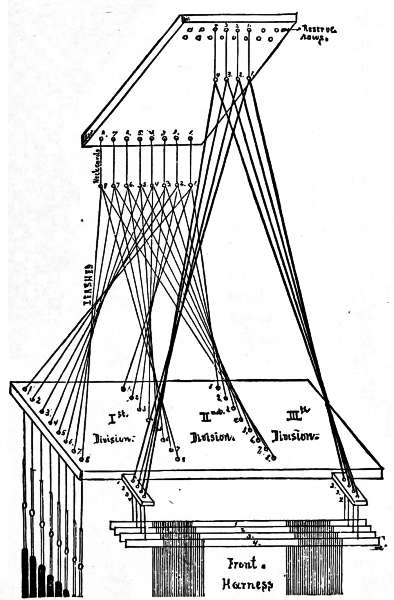
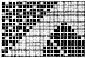
As mentioned in the beginning of this work, every Jacquard machine contains two reserve rows, which may be used for various purposes. One of the purposes to which these rows are frequently put is the enlargement of the design of the fabric by using harness on the front of the comber-board, technically known as “front harness.” For example, in damask table-cloths, we may use the Jacquard harness for producing the border of the fabric. The centre part may be produced with front harness, forming a checkerboard, or some similar effect. This process may be reversed by designing the centre of the table-cloth for the Jacquard harness, and the border for the front harness.
A third method is to design part of the centre and part of the border for the Jacquard harness, the other parts being designed for the front harness. This tie-up is also used to a great extent in the manufacture of dressgoods, etc., where stripe effects produced by the front harness, alternate with floral or geometrical designs produced by the Jacquard harness.
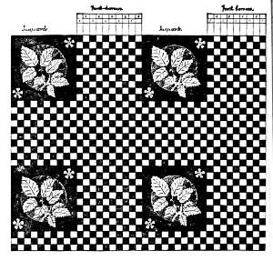
In Fig. XXXIII. the centre of a table-cloth cover is shown to further illustrate this method of tying-up. One-half of the width of the design is for the Jacquard harness; the other half is for the front harness. To produce the required checkerboard effect these front harness are used here in two distinct sets.
The 1st set = 5 harness, working on the 5-leaf satin warp for face, alternating with the
2d set = 5 harness, working on the 5-leaf satin filling for face.
If only 8 front harness should be used for the design, we should have the
Set 1 to alternate with set 2 to form the check. Care must be taken that the number of checks formed by the front harness are evenly arranged to the figured part of the fabric. For example, Fig. XXXIII., in the front harness part of the design shows 5 warp checks and 5 filling checks in one row, = 10 checks.
Suppose 10 front harness are used and 20 warp-threads allowed for each check; then 20 × 10 = 200 warp-threads, all used for effects by the front harness.
This requires 200 warp-threads for figure effects to be used by the Jacquard harness.
The repeat of the pattern is therefore 400 warp-threads, which is produced by straight-through tie-up, front harness attached, with 200 hooks and needles for FIGURE PART of the design, plus 10 hooks and needles for CHECKERBOARD PART of the fabric taken from the 16 hooks and needles of 2 reserve rows, leaves 6 hooks and needles for selvedge, etc.
As previously stated, the front harness may be used for dressgoods fabrics. In this way the design may be enlarged to any required extent.
Fig. XXXII. illustrates this method, using an 8-row Jacquard machine, with 4 front harness adjusted, in common use for the manufacture of dressgoods fabrics, damasks, etc.
Fig. XXXIV. shows a fabric designed for dressgoods forming an all-over-set pattern. In this design parts F and F´´ must be executed with the Jacquard leashes; parts G and G can be executed with front harness. For example: parts F and F´´ require each 100 hooks, the ground part to be woven in 4 harness broken twill. We find the answer as to number of warp-threads in the repeat and number of hooks required for weaving as follows:
| F | = | 100 threads. |
| G | = | 100 threads (because covering the same distance as F in part of the fabric.) |
| F´´ | = | 100 threads |
| G | = | 100 threads |
| ---- | ||
| 400 warp threads in repeat. | ||
| F | = | 100 hooks. |
| F´´ | = | 100 hooks |
| ---- | ||
| 200 hooks for figure. | ||
| 4 hooks for weaving the ground, front harness. | ||
| ---- | ||
| 204 hooks required to weave design, Fig. XXXIV., repeating with 400 warp-threads. | ||
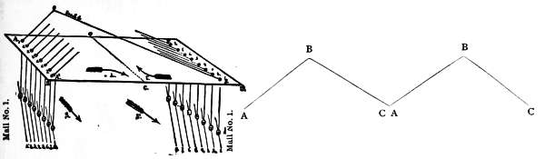
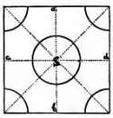
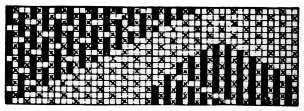
The centre tie-up, also called the point tie-up, has for its purpose the enlargement of the design in fabrics such as table-covers, dressgoods, etc. This tie-up resembles in its principle that of a common point-draw on the harness-loom. After drawing from front to rear once straight through the entire set of harness, draw from rear to front and repeat. The only difference between harness-work and Jacquard work is in the fact, that with harness we commence to draw in from the first harness straight through to the last, A to B, and back again, B to C; but with the Jacquard tie-up on this method this is arranged through the threading of the comber-board, having a straight-through leasing of the heddles and drawing in of the warp.
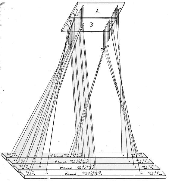
In Fig. XXXV. there is a clear illustration given of the principle of the centre tie-up on an 8-row comber-board A, A´, B, B´. In laying out the comber board, it must be divided by the line C, C´, into two equal parts, D, C, and C, D´. In the part A, A´, C, C´, of the comber-board, we commence threading with leash 1 at the left-hand rear corner, running in succession towards the centre, as indicated by the arrow on this part of the comber-board.
In part B, B´, C, C´, the threading begins in the opposite corner, to the right-hand in front, with number 1 leash, threading in rotation the number of leashes from the front towards the rear, as again indicated on the figure by an arrow. After leasing and threading the harness, No. 1 leash will contain in its two mails the first and the last of the warp-threads, as indicated in Fig. XXXV. by the numbers, and the rotation by the arrows, S and S´.
Fig. XXXVI. represents this centre or point tie-up applied to a 200 Jacquard machine; comber-board, 8 rows deep; two full divisions; A, B, the first division; B, D, the second division; C and C´ forming the centre in each division. This machine will, if tied-up in this manner, produce a design requiring 400 warp-threads. We must arrange the design for this tie-up so as to repeat forwards and backwards respectively in the centre. Such a design will run upwards at a given angle to a definite point, then it will return by the same angle in an opposite direction until it reaches the base from which it originally started.
In this manner design, Fig. XXXVII., is constructed. A, B, C, C´, D, correspond with the same letters used in Fig. XXXVI.; hence, it will readily explain itself, as well as the method to be observed in designing for this kind of tie-up. The design runs straight through from A to C, and repeats itself backwards from C to B, finishing at B the first full division.
B-C´ equal A-C,}
C´-D equal C-B,} forming the second division.
Any changes as to different sizes of machines, rows deep of comber-board, or number of divisions, must be executed upon the principle explained in this article.
A.—For fabrics requiring for their centres a straight-through tie-up and for their borders a point tie-up, one-half division of it for each border.
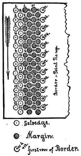
These tie-ups are used to a great extent for napkins, handkerchiefs, scarfs, and similar damask fabrics, in which the centre part of the fabric is worked on the straight-through method; the borders on each side on the point tie-up, repeating equally from[36] centre towards the selvedge. In the other two borders to be woven at the beginning and the end of the fabric, the same principle is observed, thus producing four corner squares, only two of which need be designed, as the other two repeat through the arrangement of the tie-up, which must repeat equally towards both sides of the border at the connecting places.
Fig. XXXVIII. illustrates this method of tying-up a 200 machine, using 192 hooks and needles, equal to 24 long rows of a regular 8-row deep machine. The machine is divided into two sections, as follows:
| Needles 1 to 96 for the 1st section or centre. | ||
| Needles 97 to 192 for the 2d section or the border. | ||
| 4 repeats of centre, | = 4 x 96 = 384 | ends. |
| 2 repeats of border, one for each side, | = 2 x 96 = 192 | ends. |
| ---- | ||
| 576 | ends in fabric, not including selvedge. | |
The drawing represents four divisions for the centre, hence four harness-cords for each leash. The border, having only two repeats in the fabric, will contain only two harness-cords to one leash. In the drawing the first full row of the machine is indicated, which is equal to the first row deep of every centre division; containing harness-cords 1, 2, 3, 4, 5, 6, 7, and 8. We also show (heavy line) the last centre leash, No. 96 being the last hook of row 12 of the machine. The borders A´ and A´´ are from the same design, but the figure runs in an opposite direction in each one, as indicated by the arrows in the comber-board above. Border A´ commences with harness-cord from leash 192, ending with harness-cord from leash 97, near the centre design. Border A´´ commences with harness-cord from leash 97, near the centre design, ending with harness-cord from leash 192 near the selvedge. The great difficulty to be overcome in arranging these patterns for the loom is in the union of the two tie-ups, the straight-through and the point.
As previously stated, the borders A´ and A´´ are made with the point tie-up, while the remainder of the borders are made with the straight-through tie-up. The combination of these two tie-ups occurs in the corner squares of the border, and the arrangement must be such as will permit the two sides of the corner patterns to properly unite with the design for the balance of the border.
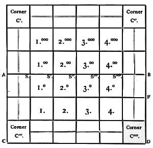
Ground plan for above fabric: Letters A, C, D, B, F, correspond to same letters as used on the outside of fabric design. S, S´, S´´, S´´´, S´´´´, also correspond for centre division.
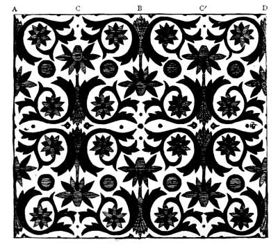
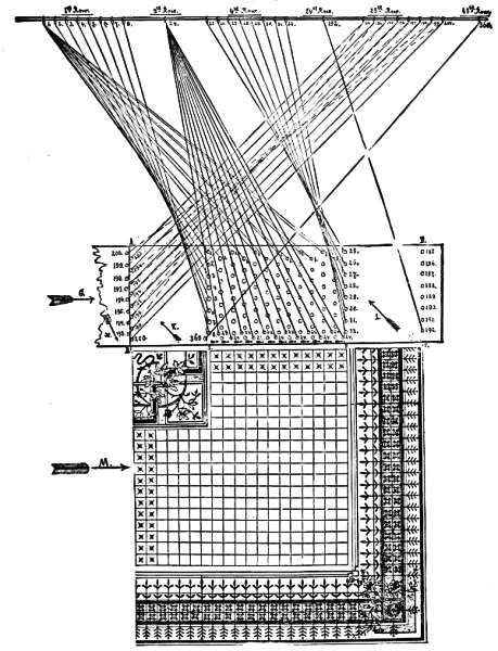
For the purpose of giving a correct comprehension of the foregoing explanation of tying-up, but under a different arrangement, Fig. XXXIX. was designed for a 600 machine, having the same arrangement of the borders, viz.: point tie-up, using one-half division for each side; the centre a straight tie-up, but employing only one repeat. The following particulars will explain the entire procedure:
200 needles and hooks are used for borders, point tie-up, once through, equals 1/2 division for each border. [See letters B and B´ on comber-board.]
400 needles and hooks are used for centre, straight tie-up, one repeat. [See letter C on comber-board.]
| 200 ends for each border, | = | 400 warp-threads. |
| 200 ends for centre, | = | 400 warp-threads. |
| ---- | ||
| 800 warp-threads. | ||
In the ground plan of the fabric A is the centre; B, B´, B´´, B´´´, borders; C, C´, C´´, C´´´, corners.
Fig. XL. is a fabric design executed on this principle: a to b, border; c to d, centre; b to a, repeat of the first border.
B.—For fabrics requiring for their centres a straight-through tie-up, and for their border on point tie-up one full division for each border.
This arrangement of both foundation tie-ups resembles the preceding. The only difference is found in employing the full division of the centre or point tie-up for each border instead of the half division.
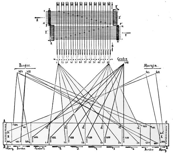
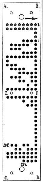
Fig. XLI. illustrates this method of tying-up adjusted to a 600 Jacquard machine. The centre of the fabric requires 400 needles and hooks in 6 repeats or divisions, or 400 × 6 = 2400 warp-threads. The border calls for 204 needles and hooks, point tie-up, one full division for each side, or 204 × 2 x 2 = 816 warp-threads. The arrangement of margin and selvedge, as applied on each side, is explained[40] separately through ground plan of comber-board by fig. XLII. The margin calls for 8 needles and 8 hooks in machine, 6 repeats of same for each side, or 96 warp-threads. The selvedge is formed by 2, 4 or 8 needles, (working plain), and has 24 heddles for each side or 48 selvedge-threads in warp. These selvedge ends may, if preferred, be drawn two ends in one heddle. By adding these different systems of threads we find:
| Centre | = | 2400 warp-threads. |
| Borders | = | 816 warp-threads. (814 if point drawn only once.) |
| Margin | = | 96 warp-threads. |
| Selvedge | = | 48 warp-threads. |
| ----- | ||
| 3360 threads in warp. | ||
For the centre part of the fabric, needle and hook 1 to 400 are used.
For the border part of the fabric, needle and hook 401 to 604 are used.
For the margin part of the fabric, needle and hook 605 to 612 are used.
Leaving one complete row of the reserve to use for selvedge, etc., if required.
In drawing, Fig. XLI., we only illustrate centre and border of the tie-up, so as not to confuse the eye by too many lines, and, as mentioned at the beginning, employed Fig. XLII. for illustrating the ground plan for selvedge and margin. In selvedge and margin the harness-cords are indicated by consecutive numbers, thus:
Margin, 1 to 48.
Selvedge, 1 to 24.
When threading margin in comber-board:
1, 9, 17, 25, 33, 41, call for the same leash.
2, 10, 18, 26, 34, 42, call for the same leash.
3, 11, 19, 27, 35, 43, call for the same leash.
4, 12, 20, 28, 36, 44, call for the same leash.
5, 13, 21, 29, 37, 45, call for the same leash.
6, 14, 22, 30, 38, 46, call for the same leash.
7, 15, 23, 31, 39, 47, call for the same leash.
8, 16, 24, 32, 40, 48, call for the same leash.
Leashes in centre part of fabric, 1 to 400 call for 6 harness-cords.
Leashes in border part of fabric, 401 to 604 call for 14 harness-cords.
Leashes in margin part of fabric, 605 to 612 call for 12 harness-cords.
Leashes for selvedge if using 4 hooks, 613 to 616 call for 12 harness-cords.
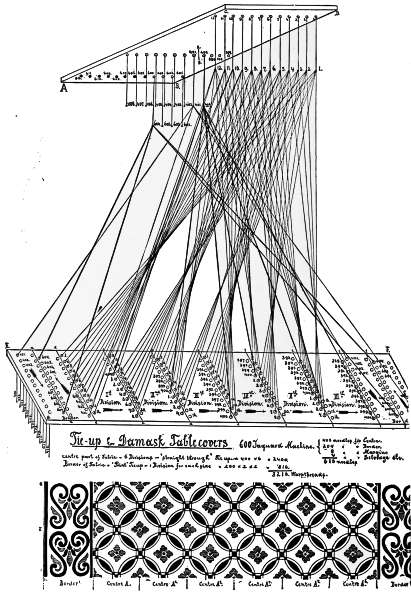
This tie-up is the one most frequently employed in the manufacture of damask table-covers. Not only will drawings and explanations lead to a thorough understanding of the procedure, but they will also readily show the great variety of textile fabrics to which the principle of this tie-up may be applied.
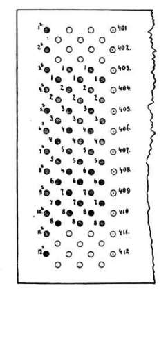
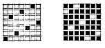
Fig. XLIII. illustrates the margin arranged 8 threads for each row, and 5 rows or 40 threads for each side. The selvedge in this drawing is illustrated by one complete row of 12 double threads for each side. The selvedge and margin holes are all represented shaded. The selvedge is marked S in addition to the number. The five margin rows are indicated each by figures 1 to 8. The[41] nearest row of border is also represented, being numbered 401 to 412, corresponding to Fig. XLI. This method of using only 8 rows of the 12-row deep comber-board is extensively used in fabrics of a common texture, employing an 8 harness satin for the margin as weave, which repeats once for each row in comber-board. Besides, a great advantage results from being able to tie-up 8 leashes threaded 8 rows deep in comber-board to the 8 hooks in 1 row of the machine, which the weave calls for.
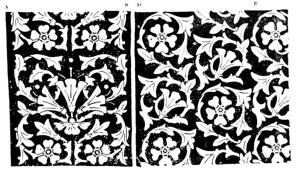
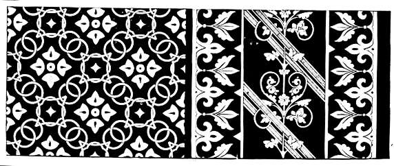
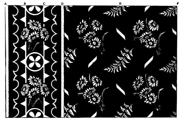
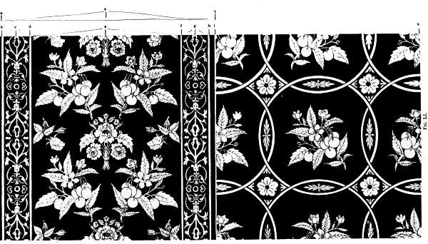
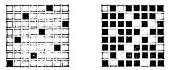
Fig. XLIV. and Fig. XLV. represent designs for fabrics executed on this method of tying-up.
Fig. XLIV.—A to B = border, C the centre.
B to D = margin, between centre and border.
D to E = 1 repeat of the centre, 6 times over in width of fabric.
Fig. XLV.—A to B = border, C its centre.
B to D = centre, 6 times over in width of fabric.
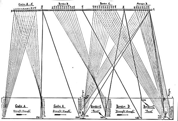
C.—For fabrics having the centre for straight-through, with the border for straight-through and point tie-ups, (half divisions), combined.
This method of tying-up is illustrated in Fig. XLVI., and the fabric produced in Fig. XLVII. With this method of tying-up is usually introduced an extra margin for the purpose of separating the ornamentation of the design, so as to permit of a clearer definition. This is tied-up on 8 needles and hooks, situated between border and centre, (24 ends) shown at margin B in the design. The centre of the fabric, (two divisions only illustrated out of ten actually used), is tied-up on the straight-through method, requiring for its working, harness-cords 1 to 240. The border has the point tie-up in half sections; these half sections have a straight-through tie-up design in its centre. Harness-cords 241 to 456 are used for the straight-through section, and 457 to 600 for the point tie-up section. The margin is produced by harness-cords 601 to 608, leaving 16 needles and hooks of the machine unemployed, which may be used for selvedge or other purposes. The drawing of this tie-up and fabric illustrates only the right-hand side. The complete design requires, in addition to the borders and margins, 10 divisions or repeats in the centre. The figure shows only two of these repeats and border and margins of one side. The number of ends in the fabric is found as follows:
| Centre, | 10 × 240 | = | 2400 ends. |
| Border, | {point, 4 × 144 = 576} {straight, 2 × 216 = 432} |
= | 1008 ends. |
| Margin, | {between border and centre, 24 × 2 = 48} {between border and selvedge, 48 × 2 = 96} |
= | 144 ends. |
| Selvedge, not indicated in drawing of tie-up, | = | 48 ends. | |
| ----- | |||
| 3620 ends in warp. | |||
Number of harness-cords required for each leash:
Leashes 1 to 240 = 10 cords to 1 leash.
Leashes 241 to 456 = 2 cords to 1 leash.
Leashes 457 to 600 = 4 cords to 1 leash.
Leashes 601 to 608 = 18 cords to 1 leash.
Selvedge leashes, if worked by 4 needles and hooks, = 12 cords to 1 leash.
Fig. XLVIII., on page 42, illustrates another fabric design to be executed on this method of tie-up.
| A to D = Border | { A to B = point tie-up with C to D. { B to C = straight-through part. |
| D to E = Centre, | first repeat, division, for straight-through. |
D.—For fabrics composed of the straight-through tie-up for centre; the point tie-up, half divisions, and the point tie-up, full divisions, for borders.
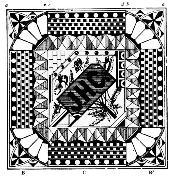
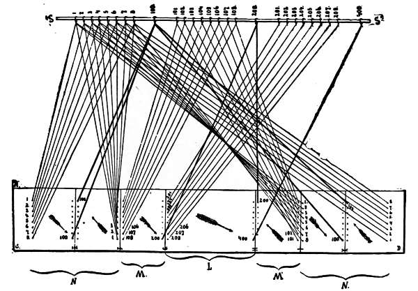
This method of tie-up is used to a great extent in the manufacture of damask napkins, containing in its centre the monogram of hotels, restaurants, or private names. This effect is produced by floating the filling.
In this manner, we find tie-up, Fig. XLIX., and fabric sample, Fig. L., executed, using for explanation a 400 Jacquard machine, certainly very low texture for these fabrics. In case of a higher texture being necessary, each effect must be proportionally increased. The machines most generally used for this class of fabrics are of the 900-1200 denomination.
Taking the present tie-up into consideration, we find the centre for forming the monogram, containing 200 harness-cords tied-up straight-through the borders on[44] each side of the monogram, is executed on the point tie-up, one-half section for each side, taking 100 needles and hooks, or harness-cords. The outside border on each side is executed on the point tie-up, using one complete division of it for each side; and in addition, 100 harness-cords for the working. Adding these various divisions of the harness-cords gives the number of warp-threads as follows, viz.:
| Border, N, | 100 needles on point | = 200 threads, (199 if omitting the point the second time). |
| Border, M, | 100 needles on straight | = 100 threads. |
| Centre, L, | 200 needles on straight | = 200 threads. |
| Border, M´, | 100 needles on return | = 100 threads. |
| Border, N´, | 100 needles on point | = 200 threads, (199 if omitting the double point.) |
| ---- 800 threads. | ||
For number of harness cords to each leash we find:
Needles and hooks, 1 to 100 = 4 cords to each leash.
Needles and hooks, 101 to 200 = 2cords to each leash.
Needles and hooks, 201 to 400 = 1 cord to each leash.
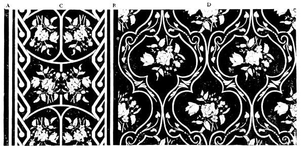
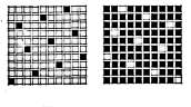
Fig. LI. illustrates a fabric, damask table-cover, to be executed on the same principle.
| Margin = a to b and h to i. | ||
| Border | { small = | {b to c and return c to d} Point. |
| {f to g and return g to h} | ||
| { main = | d to e and return e to f Point. | |
| Centre = 1st division i to k, straight-through. | ||
This fabric can also be executed on the tie-up explained through Fig. XLI., as follows:
Border = a to i on point tie-up, e for centre or point.
Centre = 1st division i to k, straight-through.
E.—Mixed Tie-up.
Containing in one repeat of the design the straight-through tie-up and the point tie-up, one full division, for the centre; the point tie-up, in half divisions, repeating once through on each side of the fabric, to make the border. These arrangements of tie-ups are used to a great extent in the manufacture of damask fabrics of every denomination.
The principle of using mixed tie-ups, Fig. LII., is found in the necessity of producing large designs, containing varied effects, with a proportionally smaller Jacquard machine. Under whatever management the straight-through and the point tie-ups are combined, their principle remains undisturbed. Every time we arrange a Jacquard loom on a mixed tie-up, we must consider that any subsequent design must be arranged with reference to the same principle as the one in use, otherwise the work must all be rearranged, which would have to be done even for the smallest change in the number of ends for each effect.
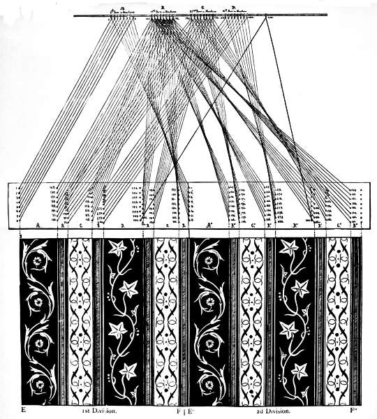
Take for illustration a damask fabric, Fig. LIII., handkerchief, bureau scarf, art square, etc. The details given will make the work quite plain:
Part of comber-board from A to B, or D to C, illustrates one-half of the board and procedure of tying-up. The design below also shows only one-half of the fabric. Arrow, G, near comber-board, and arrow, M, near fabric, are placed to indicate the direction in which a repeat is obtained. The fabric will form its centre at D, repeating towards each border and selvedge. This is illustrated in the comber-board by the 1-row deep, outside of line A, D. Harness-cords indicated by dotted lines. The threading of this last mentioned row, as well as the threading of the half division of the point tie-up, is indicated by arrows H and K, forming the centre by means of harness-cords 193 and 193. The straight-through tie-up part of the fabric is found between E and F, containing 12 repeats in the centre, and also the same number in the lower border. In the comber-board is illustrated this arrangement, repeating the first row, containing harness-cords 1, 2, 3, 4, 5, 6, 7, 8, twelve times, and the last hole of the third row containing harness-cord No. 24, twelve times. On the bottom of the comber-board these 12 repeats are indicated by 12 small arrows between parts E to F.
The first row in the first division of the straight-through tie-up is completely[47] threaded; the other eleven have only the harness-cord from leash 1, as indicated; this is done so as not to confuse the eye with too many lines. The border of the fabric is arranged for harness-cords 25 to 192 on the point tie-up, having one-half division[48] on each side. Arrow L indicates the right-hand border. The border on the left requires the same harness-cords which are threaded in comber-board from right to left; hence the borders of the fabric contain the same design repeating from the centre towards the selvedge.
At the beginning we stated that the use of mixed tie-ups made it possible to employ a smaller size Jacquard machine for large designs containing various effects. The following analysis of Fig. LII. shows very clearly how this is done.
Number of warp-ends in one complete repeat in width of the fabric:
Border, right-hand, = 168 threads.
Centre, straight-tie, = 288 threads.
Centre, point-tie, { = 168 threads.
{ = 168 threads.
Centre, straight-tie, = 288 threads.
Border, left-hand, = 168 threads.
-----
1248 ends warp in fabric.
Number of needles required to produce the design:
Border, = 168 needles.
Centre on straight-tie, = 24 needles.
Centre on point-tie, = 168 needles.
360 needles required for producing the complete design, thus saving the difference between 1248 and 360, or 888 needles; all of which is accomplished through the use of the mixed tie-up.
Number of harness-cords required for each leash:
Leashes 1 to 24 contain 24 cords for one repeat of the entire design. Leashes 25 to 360 contain 2 cords for one repeat of the entire design. It is not always practicable to reduce the effects in a design to the lowest possible number of needles. On account of the changes in styles, it is best to arrange these tie-ups with a view to giving as much opportunity as possible to the designer. In the present tie-up experience teaches that it will be more advantageous to arrange the straight-through tie-up either for 6 divisions to 48 ends each, or 4 divisions to 72 ends each. 360 needles, as figured at the beginning, require a 400 machine, or, counting reserve rows, 416 needles; hence we can, without disadvantage, increase 360 needles to 384 or 408, which will give a greater scope, if required, to make a new design.
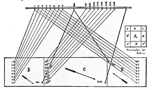
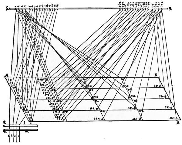
This tie-up, Fig. LIV., is used on fabrics having two different kinds of warp, which, as a rule, are of different colors. One of these warps is shown working at B in the comber-board, and also at the bottom-board. The other warp employed for the figure effect is shown working at A. Fabrics that are made on this tie-up can also be made on the common straight-through; but the work of designing and card stamping will be largely increased. In the illustration all the figure-threads,[49] and also all the threads used for the weave (binder-threads) can be designed without interruption to each other. The breaking off of the figures is thus avoided, a thing quite impossible where the regular straight-through tie-up is used. The drawing given herewith represents this straight-through tie-up in sections applied to a 200 Jacquard machine. The reserve rows are omitted. The machine and the comber-board, it will be observed, are divided into two even parts. In one part, the rear of A, of the comber-board we thread only in the leashes from needles 1 to 100, and in the other part, front of B, from needles 101 to 200. Hence, the first row of the comber-board contains leashes 1 to 4 and 101 to 104; the second row will contain leashes 5 to 8 and 105 to 108; the third row will contain leashes 9 to 12 and 109 to 112, and so on, each division finishing on the last row (25th) with leashes 97 to 100 and 197 to 200.
The leasing of the threads is always done by alternately threading the harness-cords of section A with section B. Hence, first thread of the warp draws in first mail of leash No. 1; second thread of the warp draws in first mail of leash No. 101; third thread of the warp draws in first mail of leash No. 2; fourth thread of the warp draws in first mail of leash No. 102.
Fig. LV., a fabric design for cloaking for straight-through tie-up in two sections. A, face warp, black silk; B, back warp, black cotton.
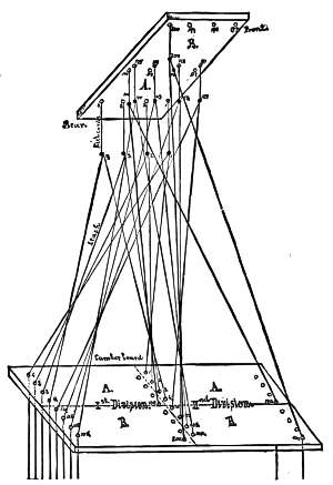
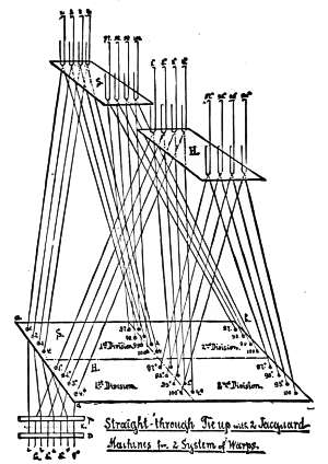
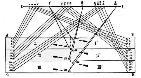
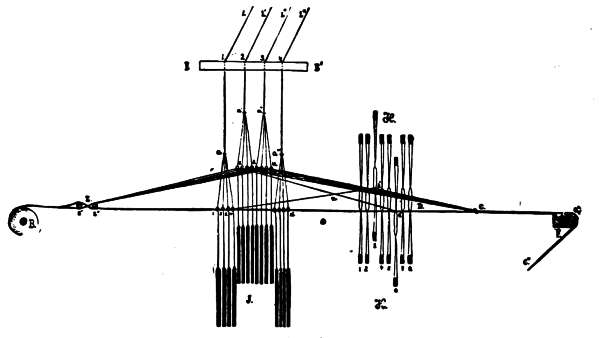
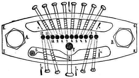
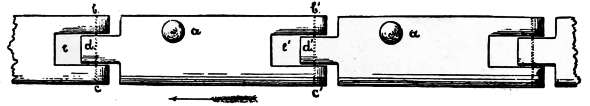
Sometimes two or more machines are employed in producing fabrics having two systems of warps; each machine working on its own system. In this manner Fig. LVI. is executed, representing a straight-through tie-up arranged for two Jacquard machines, S and H, in which the warp is drawn in the Jacquard harness as follows: one end from machine S, one end from machine H. For explanation two 100 Jacquard machines are used for the purpose of simplifying the arrangements of laying out and threading the comber-board. A larger Jacquard machine for the illustrations would require more leashes, and the explanation would be more difficult.
The comber-board, a, b, c, d, is divided into two equal parts, S and H. Each part containing the harness-cord for one machine only. The drawing of the tie-up is arranged for two divisions, and also readily explains any tie-up for more divisions.
The leasing of the Jacquard harness, K, is arranged (as illustrated in the drawing by leash-rods p and r) to commence as follows:
1st end: harness-cord fastened to No. 1 needle of machine, S; 2d end to No. 1º needle of machine, H; 3d end to No. 2 needle of machine, S; 4th end to No. 2º needle of machine, H; 5th end to No. 3 needle of machine, S; 6th end to No. 3º needle of machine, H; 7th end to No. 4 needle of machine, S; 8th end to No. 4º needle of machine, H.
These eight ends, forming the first complete row of the comber-board, will use the first row of both machines; the second row of the comber-board will use the second row of both machines; and so on, until every row of the comber-board, with corresponding row of the Jacquard machine, is taken up. In the drawing we have indicated, as usual, besides the first row, the last row of the machine and the comber-board; or, in other words, we show the threading of
Warp end 193: harness-cord fastened to No. 97 needle of harness S.
Warp end 194: harness-cord fastened to No. 97º needle of harness H.
Warp end 195: harness-cord fastened to No. 98 needle of harness S.
Warp end 196: harness-cord fastened to No. 98º needle of harness H.
Warp end 197: harness-cord fastened to No. 99 needle of harness S.
Warp end 198: harness-cord fastened to No. 99º needle of harness H.
Warp end 199: harness-cord fastened to No. 100 needle of harness S.
Warp end 200: harness-cord fastened to No. 100º needle of harness H.
This method of using two Jacquard machines, on the principle explained, is employed on Jacquard looms for dressgoods figured with an extra warp, on upholstery goods, and similar textile fabrics.
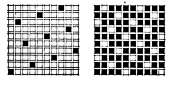
Fig. LVII. shows a fabric design for a curtain, to be executed on the straight-through tie-up in two sections.
To explain, take the regular upholstery fabric tie-up known as “petty point,” on a 600 machine 12 rows in depth. 600 ÷ 12 = 50 + 2 rows reserve = 52 rows in width. We find used—
| 1 | row for selvedge. |
| 10 | rows for binders (B). |
| 41 | rows for figure (A). |
| --- | |
| 52 | rows. |
41 (rows figure) × 12 (needles for one row) = 492 needles to be used for figure.
10 (rows binder) × 12 (needles for one row) = 120 needles to be used for binder.
Suppose we have four divisions in loom, hence, four harness-cords to one leash, for the figure section, or 492 × 4 = 1968 ends of warp used for figure. 1968 threads of figure warp require the same number of threads of ground warp, which must be divided by 120, the number of needles and hooks set apart for it in the machine, or—as each needle and hook carries one leash—120 leashes. 1968 ÷ 120 = 16 repeats; and 48 leashes, or four rows in the machine, must each have 17 harness-cords carrying 816 threads; and 72 leashes, or six rows in the machine, must each have 16 harness-cords carrying 1152 threads, = 1968.
This tie-up (the character of which is indicated in Fig. LVIII.) is used for textile fabrics having two distinct warps in part of the fabric, and a single warp in the[52] remainder, for ground only. It will readily be seen in the drawing which explains this tie-up that one part of the fabric will have to contain more ends of warp per inch than the other, as the figuring is done with an extra warp upon the regular ground cloth. The number of ends of ground warp per inch will, as a general rule, be the same throughout the fabric. In Fig. LVIII., explaining this method of tying-up, the texture is twice as high in the figure stripe as in the ground part of the fabric. If 40 ends of warp per inch are used for the ground, 80 ends per inch must be used in the figured part, B to C, B´ to C´.
A 200 machine is used in the illustration, divided as follows:
150 needles for the ground over the entire fabric, A to B´´.
50 needles for the figure effects, B to C, and B´ to C´.
The comber-board, therefore, must be arranged accordingly, (2-2/3 divisions in drawing executed). The depth of the comber-board is divided into two parts: H, M, N, K, the first; M, N, O, P, the second. The first contains leashes fastened to neck-cords attached to needles 151 to 200, or the figure part, F and F´; the second contains leashes fastened to neck-cords attached to the needles 1 to 150, or the ground part for the entire fabric. In the drawing of lines showing the harness-cords of the Jacquard harness we have only indicated:
A. The ground part, leashes Nos. 1, 2, 3 and 4 in rotation, and No. 150. This last leash of the ground warp we have indicated by a heavy line.
B. For the figure part, needles 151 to 200 are used. Leashes 151, 152, 153, 154, are indicated in rotation, also the leash operated by hook 200; this latter one being also lined more distinctly than the others.
These explanations readily show how to adapt the tying-up for any textile fabric made upon this principle to any number Jacquard machine.
The straight-through tie-up in three sections, which is illustrated by drawings, Figs. LIX. and LX., is largely used in the manufacture of fancy plushes and velvets, and also in the construction of any other kinds of fabrics in which the face is figured in three systems of warps, or in two systems of warps for the face and one system for the binder.
If it were required, these fabrics could be made on the straight tie-up, (Figs. XXV., XXVIII. and XXX.), but, as will readily be seen, they may be worked to much better advantage, both for designing and card-stamping, upon the method shown here.
Fig. LIX. illustrates the method of adjusting the leashes to the neck-cords and threading the comber-board. In the example, we use for describing the method a 900 Jacquard machine, and follow the English system for placing it on the loom. The machine is divided into three sections: Section 1, using hooks and needles 1 to 300; Section 2, using hooks and needles 301 to 600; Section 3, using hooks and needles 601 to 900, leaving the two reserve rows (generally found in every machine) out of the illustration.
The comber-board is divided into two divisions lengthways, (but the same method must be observed if more than two divisions are used), and also into three sections in its depth. The number of sections in the comber-board must correspond to the number of sections in the machine.
The threading of the machine is done from the rear towards the front, and from the left towards the right. The threading of the comber-board is done in a corresponding manner. 300 ends for each section in one division, divided by 4 rows deep each section, making 75 cross-rows. Threading of the Jacquard harness is as follows:
| No. 1 | from Section 1, white. |
| 301 | from Section 2, shaded. |
| 601 | from Section 3, black. |
| 2 | from Section 1, white. |
| 302 | from Section 2, shaded. |
| 602 | from Section 3, black. |
| 3 | from Section 1, white. |
| 303 | from Section 2, shaded. |
| 603 | from Section 3, black. |
| 4 | from Section 1, white. |
| 304 | from Section 2, shaded. |
| 604 | from Section 3. black. |
| 5 | from Section 1, white. |
| 305 | from Section 2, shaded. |
| 605 | from Section 3, black. |
And so on; all of which are shown separately in Fig. LX.
R and R´´ are for the two-lease strings; S, the successive order of threads; S´´, the number of leashes. Hooks and needles correspond with drawing A. White warp-threads indicate section 1; shaded warp-threads, section 2; black warp-threads, section 3. The fine lines in Fig. LIX. indicate the leashes for the first[55] row deep of the comber-board; the heavy lines indicate the last leash for each section.
Fig. LXI. illustrates a fabric designed for this tie-up. The various small star effects are arranged on the principle of the 5-leaf satin.
This method of tying-up Jacquard looms shows the point tie-up applied to the three-section arrangement, on the same principle as the straight-through in paragraph VIII.
Fig. LXII. shows the comber-board divided into three distinct sections, marked I., II. and III. For explanation, take a 300 machine; allow 100 needles and hooks for each section, distributed as follows: Section I., 1 to 100; Section II., 101 to 200; Section III., 201 to 300. Each section contains 200 warp-threads; and the complete[56] division of three sections, 600 threads. The threading of three sections, illustrated in Fig. LX., is applied to the present tie-up, as follows:
| 1st end, from section | I., | attached to No. 1 | harness-cord. |
| 2d end, from section | II., | attached to No. 101 | harness-cord. |
| 3d end, from section | III., | attached to No. 201 | harness-cord. |
| 4th end, from section | I., | attached to No. 2 | harness-cord. |
| 5th end, from section | II., | attached to No. 102 | harness-cord. |
| 6th end, from section | III., | attached to No. 202 | harness-cord. |
| 7th end, from section | I., | attached to No. 3 | harness-cord. |
| 8th end, from section | II., | attached to No. 103 | harness-cord. |
| 9th end, from section | III., | attached to No. 203 | harness-cord. And so on. |
This tie-up illustrates the point tie-up and the straight-through combined on the two-section system. In Fig. LXIII., a 600 machine is used for illustration; the comber-board being divided into two parts: a, b, c, d, for No. 1 section; e, f, g, h, for No. 2 section.
No. 1 section requires the use of needles and hooks 1 to 200 on the straight-through principle, four divisions, taking 800 warp-threads.
No. 2 section requires the use of needles and hooks 201 to 600 on the point principle, one division, taking 800 warp-threads. The two sections thus use 1600 warp-threads in one repeat.
The threading of the harness is as follows: 1-201, 2-202, 3-203, etc., ending with 200-201.
This tie-up, as well as any changes in the arrangement and the number of needles, (but not changed in its principle), is used for double color figures of warps of large design, with a small all-over figure effect (No. 1 section) for the ground. Fig. LXIV. is executed on this tie-up.
Fig. LXV. shows 384 needles and hooks of the Jacquard machine, threaded in four sections in comber-board, A, B, C, D. The threading of comber-board is as follows:
1st, No. 1 leash in section 1.
2d, No. 2 leash in section 2.
3d, No. 3 leash in section 3.
4th, No. 4 leash in section 4.
5th, No. 5 leash in section 1.
6th, No. 6 leash in section 2.
7th, No. 7 leash in section 3.
8th, No. 8 leash in section 4.
9th, No. 9 leash in section 1.
And so on. The threading of the harness is explained below the comber-board, l and m indicating the leash-strings; and warp-threads 1, 2, 3, 4, from leashes 1, 2, 3, 4, are indicated as threaded.
384 times 4 divisions make 1536 warp-threads.
Tying-up of Jacquard looms with extra compound harness, consists in applying two separate systems of harness in the loom. The warp-threads, after having passed through the Jacquard harness, are passed through harness in front. Each system of harness performs special duty, although they are both working the same warp. The Jacquard harness is used for forming the general design on a large scale; the second harness divides this pattern into detail, (twills, satins, or any other desired weave). The above tie-up is necessary in the manufacture of rich damasks and similar fabrics, where a large number of warp-ends is required, with a correspondingly small number of picks per inch. Suppose a damask fabric to contain 300 ends warp per inch, with only 75 picks per inch; or in the proportion of 4 to 1. Now, to employ this principle of making four ends warp equal to one filling, the size of the design would be produced in the fabric, but the richness, and also the fineness, of the face of the fabric would be entirely lost. To prevent this it should be the object of the designer to keep the fine warp-threads entirely on the surface, to interweave the proportion of ends varying between warp and filling (as in example above, four warp-threads) separately. This principle of textures requires the compound harness to be attached; or, in other words, a machine must be used which is capable of raising not only every alternate thread, but every third, fourth, or eighth thread, if required, for the formation of the body of the cloth.
Fig. LXVI. illustrates as plainly as possible the principle of tying-up to do this work, using a 100 Jacquard machine for figuring, comber-board threaded in three divisions, four heddles to each leash, eight compound harnesses.
In the tying-up of Jacquard harness four heddles to one leash are generally used, as illustrated at c, in Fig. LXVI.; each heddle containing one warp-thread. Fig. LXVII. shows the arrangement of these four warp-threads, when using only one heddle to each leash, but in which the mail contains four eyes. This method is less frequently employed. Instead of using a 100 machine, as in Fig. LXVI.,
A 200 machine (straight-through) will require 800 warp-threads for each division.
300 machine (straight-through) will require 1200 warp-threads for each division.
400 machine (straight-through) will require 1600 warp-threads for each division.
600 machine (straight-through) will require 2400 warp-threads for each division.
900 machine (straight-through) will require 3600 warp-threads for each division.
1200 machine (straight-through) will require 4800 warp-threads for each division.
To change the tie-up principle from the straight-through method to the point method, taking a 1200 machine using four heddles per harness-cord, 9600 warp-threads will be required for each division for repeat of pattern.
This little example plainly shows the great advantage of this method of tying-up looms for making the finest damasks, etc.
To explain the general method of this tie-up, commence with Fig. LXVI., which represents a 100 machine, three divisions, four heddles to one leash, eight compound harnesses.
It will not be necessary to explain the threading of the comber-board, as[60] this is always done on the same plain principles. The four heddles of the first row deep of comber-board emerge below the board at the beginning of the first division, marked a, a´, a´´, a´´´. The first row deep in comber-board in the first division, and the last row deep in comber-board in the third division only are shown; but as these two rows also indicate the first and last rows in the Jacquard machine, and as the principle of a, a´, a´´, a´´´, and b, b´, b´´, b´´´, has to be observed in every one of these 75 rows deep in width of comber-board E´ to E´´ taken, it will explain the tie-up for the entire number. At c, in leash a, four distinct heddles are adjusted; the same thing is repeated in every one of the eight leashes extended in drawing below the comber-board, giving in return, thus: four heddles and three divisions in a 100 machine = 4 × 3 × 100, or 1200 warp-threads for the entire fabric.
Now, following the first heddle downwards on leash 1, a, c, marked on drawing, d, (indicated by dotted lines), No. 1 harness of the compound harness, H, is reached. The cross X on this harness indicates that the warp-thread drawn through mail fastened on heddle, d, must also be drawn through No. 1 harness; the next heddle from the same leash will reach No. 2 harness; and so on until No. 4 harness is taken up, which will finish No. 1 harness-cord of No. 1 leash in the first division. The second harness-cord, a´, will use harness 5, 6, 7, 8; the third harness-cord, a´´, will use harness 1, 2, 3, 4, over again, as used by a; the fourth harness-cord, a´´´, will use harness 5, 6, 7, 8, over again, as used by a´.
Continue in this manner until leash 100 in the first division on harness 5, 6, 7, 8, is finished. The second and third divisions strictly repeat the first.
Fig. LXIX. represents the side elevation for Fig. LXVI. In both of these drawings some of the letters and figures correspond, as follows: harness-cords[61] a, a´, a´´, a´´´, in first row deep of comber-board, E, E´. H shows compound harness set 1, 2, 3, 4, 5, 6, 7, 8; figures 1, 2, 3, 4, on top of comber-board represent the first row deep from the front elevation in drawing.
New letters: B, the warp-beam; Z, the lease of the warp formed by rods, Z´ and Z´´; O, the distance between the Jacquard harness and compound harness set, H. D, the shed, as formed in loom when weaving. For illustration of this shed pick No. 7 in Fig. LXVIII., shows that leashes 2 and 3, or a´ and a´´, are raised at the same time. Leashes 1 and 4, or a and a´´´, are not raised.
The principle of forming the shed for picking the shuttle will be more particularly explained later on by Figs. LXX. to LXXV.
At c, in Fig. LXIX., the beginning of the shed is shown; also the last woven part of the fabric, c, c´, c´´, which is indicated as passing around the breast-beam, F. L, L´, L´´, L´´´, indicate leashes 1, 2, 3, 4, extending to the Jacquard machine towards neck-cords 1, 2, 3, 4.
Fig. LXX. represents a warp-thread forming the bottom part of a shed. Mail, L, and harness, H, occupy a position similar to that of mail and harness for warp-thread passing through No. 1 heddle of leash a, and harness 1 in Fig. LXIX.
Warp-thread No. 2, passing through leash a, and harness 2, in Fig. LXIX. is the same.
Warp-thread No. 4, passing through leash a, and harness 4, in Fig. LXIX. is the same.
Warp-thread No. 13, passing through leash a´´´, and harness 5, in Fig. LXIX. is the same.
Warp-thread No. 15, passing through leash a´´´, and harness 7, in Fig. LXIX. is the same.
Warp-thread No. 16, passing through leash a´´´, and harness 8, in Fig. LXIX. is the same.
Fig. LXXI. shows a warp-thread forming part of the top shed by raising the leash; hence mail, L, is shown raised. The compound harness is supposed to be resting, which allows the warp-thread to slide up to the height of the required size of shed. This figure illustrates plainly the following warp-threads in Fig. LXIX.
Warp-thread No. 5, passing through leash a´, and harness 5, in Fig. LXIX. is the same.
Warp-thread No. 7, passing through leash a´, and harness 7, in Fig. LXIX. is the same.
Warp-thread No. 8, passing through leash a´, and harness 8, in Fig. LXIX. is the same.
Warp-thread No. 9, passing through leash a´´, and harness 1, in Fig. LXIX. is the same.
Warp-thread No. 10, passing through leash a´´, and harness 2, in Fig. LXIX. is the same.
Warp-thread No. 12, passing through leash a´´, and harness 4, in Fig. LXIX. is the same.
Fig. LXXII. illustrates the side view of a warp-thread where the hook of the Jacquard is not raised; hence, the mail remains in its resting place. Following the warp-thread towards c, the compound harness is shown raised, thus forming part[62] of the top of a shed. This figure is designed to show the passage of the warp-thread through mail No. 3 of leash a, and harness No. 3, in Fig. LXIX.
Fig. LXXIII. illustrates a thread forming part of a lower shed. In the drawing the mail is raised, but at the same time the heddle of harness is lowered, compelling the thread to rest on the bottom of the lay. This figure is designed to show warp-thread passing through mail No. 6, of leash a´, and harness No. 6, in Fig. LXIX.
Fig. LXXIV. is a side view of a thread forming the upper part of a shed where mail and harness have been raised the same as in Fig. LXIX., the warp-thread passing through mail No. 11 of leash, a´´, and harness No. 3.
Fig. LXXV. illustrates mail not raised and harness down. This change is not necessary in Fig. IV.; the warp-thread forming the lower part of the shed.
In Figs. LXX. to LXXV. the following letters correspond with the same letters in Fig. LXIX.: Z´´, nearest lease-rod to Jacquard harness; D, shed for picking shuttle; C, starting point of shed or last woven place of fabric.
The eyes of these heddles are much longer than those of common heddles. They must be sufficiently long to allow the six movements illustrated in Fig. LXX. to LXXV., hence the height of these heddle eyes will influence the height of the shed.
For working compound harness a separate small witch-loom is generally used, thus saving, to a great extent, the Jacquard cards. In this manner the ground may be easily altered without changing any cards, it being only necessary to change the small set of cards on the witch-loom controlling one repeat of the body weave for the harness. The number of picks for the harness can also be readily adjusted to one change in the Jacquard figure without disturbing the cards of any consequence. For example: in manufacturing a damask fabric, suppose four harness picks make one change of figure in the Jacquard machine, and it is necessary to reduce these four picks to one change of figure, on account of having to use some heavier filling, or other similar reason; this alteration can be easily made when using two separate machines.
The number of harness used is regulated by the weave required for raising, and the weave required for lowering.
The number of harness may vary to a large degree, as we may use any suitable weave from the 4-leaf twill up to the 16-leaf satin. As a general rule, for fine damasks we use the 8-leaf satin, requiring 8 harness.
There are three distinct positions for the harness: 1st, centre; 2d, up; 3d, down.
Fig. LXVIII., p. 60, illustrates the 8-leaf satin combining filling and warp up in one design.
A great variety of combinations of different weaves for this class of textile fabrics exist. It is only necessary to illustrate a few more examples to guide us in finding the principles underlying these changes.
Fig. LXXIX. is an example of warp and filling, binding in a 4-leaf twill. Both systems are illustrated for a clear understanding: [X] Fig. A, indicates the raising of the harness for forming the upper part of the shed; □ Fig. B, indicates the rotation of drawing warp-threads from the upper shed into the lower shed. Drawing-in draft is for 4-harness (straight).
Gauze fabrics are produced by a separate system of weaves, which have the peculiar characteristic of warp-threads not lying parallel to each other. One kind of this warp is called the “douping warp” or “whip-threads;” these are twisted around the ground-warp. The ground-threads, as well as the whip-threads, which work together, must be drawn into one dent.
Jacquard gauze can be worked in various ways; for example: One whip-thread against one or more ground-threads. More than one whip-thread against one or more ground-threads.
There are two methods of tying-up for gauze fabrics: 1st. A tie-up in which the doups are worked by one, two, three or four shafts in front of the Jacquard harness. 2d. A tie-up in which the gauze figuring is done all over the fabric, requiring each doup to be arranged for working separately. If the ground-threads and whip-threads are worked from the same Jacquard machine, the latter must be divided into two sections: 1st section for the ground-threads with ground heddles; 2d section for the whip-threads with standard heddles.
If a fabric contains the gauze in the form of a stripe, arranged one end ground and one end whip, the same number of hooks are required for the ground and whip-threads of each section, and an extra dead harness must be employed; but if this arrangement of one end ground and one end whip must form figures, then the ground and whip-threads must form the first section, and the whip-threads alone the second section. In this case the second section requires only half as many hooks as the first; and for the same reason, if we are forming figures with two ground-threads and one whip-thread, the first section will contain three times as many hooks as the second, etc. Very often two whip-threads are used for twisting, in which case they must be drawn together in the doup. If several whip and ground-threads are drawn into one reed they usually work independently at first on a regular weave; following this is the gauze weave formed by a certain number of whip-threads raised either on the left or right of the ground-threads contained in the same dent. This movement brings into operation the second section of the machine containing the harness-cords for the standard heddles. The technical terms for these various combinations are: single-thread gauze, double-thread gauze, triple-thread gauze, etc.
The tie-up most generally used requires two-thirds of the needles for ground heddles and one-third of the needles for standard heddles; hence, if using a 200 machine we find: 128 needles and hooks for the ground heddles, and 64 needles and hooks for the standard heddles. [See Fig. LXXXVII., p. 65.]
The comber-board is divided into two sections. The rear part (2/3) is used for the ground, the front part (1/3) is used for the standard.
Thread the warp into the ground heddles in the same manner as a common straight-through tie-up. Then take the first left-hand thread of the warp and draw it through the doup. The next two warp-threads draw above the first one on the[66] left-hand side of the same doup. These three warp-threads must be drawn together in one dent. After drawing the first pair in one dent, leave one, two, or more dents empty, according to the fabric. The 4th, 5th and 6th warp-threads, also each subsequent pair, are threaded the same as the first.
Figs. LXXXVIII. and LXXXIX. are designed for illustrating this point. The lingoes for the doups are about one-half the weight of those used for the ground heddles.
Fig. XC. represents a fancy gauze to be executed in this manner.
Fig. XCI. represents the threading of the harness for a gauze fabric: f, g, first and second warp-thread, over the doup; h, i, third and fourth, through the doup.
Figs. XCII. and XCIII. illustrate the two movements of the harness in the gauze weave.
Figs. XCIV. and XCV. illustrate the movements of the harness in the regular weave: a, b, represents the comber-board; c, the place where the doup is fastened to the dead harness; d, e, the standard heddle; f, g, h, i, the mails of the common heddles.
The following are the fourteen different movements that might be required in
regular weaving. The figures show the number of threads up and the number
down, thus: ![]() equal first warp-thread up; second, third, and fourth down.
equal first warp-thread up; second, third, and fourth down.
| 1. | | = f up. |
| 2. | | = g up. |
| 3. | | = h up, doup raised. |
| 4. | | = i up, doup raised. |
| 5. | | = f and g up. |
| 6. | | = g and h up, doup raised. |
| 7. | | = h and i up, doup raised. [Illustrated by Fig. XCIII.] |
| 8. | | = f and h up, doup raised. [See Fig. XCV.] |
| 9. | | = f and i up, doup raised. |
| 10. | | = g and i up, doup raised. [See Fig. XCIV.] |
| 11. | | = f, g, and h up, doup raised. |
| 12. | | = g, h, and i up, doup raised. |
| 13. | | = f, g, and i up, doup raised. |
| 14. | | = f, h, and i up, doup raised. |
These fourteen different movements cover all the possible changes in regular weaving. The movement (7) illustrated in Fig. 8, in addition to forming the regular weave, is also necessary to the formation of the gauze weave.
These few explanations clearly show the great variety of effects possible for the designer; for he can figure with the regular method of weaving, and can also figure gauze weaving to exchange with regular weaving, forming a separate design on the fabric.
Having thoroughly described the construction and action of the regular Jacquard machine, it now remains to illustrate and explain its modifications. Among the most prominent are:
The principle of this machine consists in raising the warp-threads any number of times in succession without allowing the shed to close, thus performing the work in nearly half the time, and with less wear and tear on the warp.
Fig. XCVI. represents the sectional cut of one row across all the griffe-bars. The machine selected for the illustration is of the 12-row type. Jacquard machines of this description have two hooks to one needle; therefore in the drawing twenty-four[68] hooks are represented. Two griffes are provided, each working every alternate hook.
In Fig. XCVI. the sectional cut of both griffes is shown, and in Fig. XCVII. the top view of both griffes; the first set is represented shaded, the second black. The former requires hooks Nos. 1, 3, 5, 7, 9, 11, 13, 15, 17, 19, 21, 23, and the latter Nos. 2, 4, 6, 8, 10, 12, 14, 16, 18, 20, 22, 24.
This arrangement permits either hook to be lifted separately by the griffes, and a corresponding elevation of the leash. As these griffes work in opposition, one descends while the other ascends; this motion prevents the leash from dropping the entire length of the cords, since the ascending griffe catches it at half distance as the two griffes pass each other. In this operation the shed is never entirely closed, and a corresponding gain in speed is attained. It will thus be seen that the “double lift” single cylinder has great advantages over the ordinary machine. Of course, the warp-thread must make its complete journeys up and down when called for by the design; but when once up, it need not be brought down until absolutely required by the pattern. The warp is thus subjected to less friction in working, and it is possible to use yarns with less twist and obtain good results.
The advantages arising from not closing the shed may be seen in the following example of a warp-thread working on an 8-leaf satin, in which seven picks are up in succession.
By the single lift machine this warp-thread must travel seven times up and seven times down, thus closing the shed absolutely seven times, with a corresponding wear and tear. The double lift single cylinder arrangement does not require the warp-thread to make these seven complete journeys to the “race-board” of the lay, but instead it makes seven half trips. The saving may be shown by the following analysis: Single lift machine, warp-thread, seven picks up in succession, in 8-leaf satin (warp-face) requiring fourteen complete movements.
Double lift single cylinder machine requiring for the same effect:
| Up the first time, | = one complete movement. | |
| Six times down, Six times up, | } half movements, | = six complete movements. |
| Down the last time, Or eight complete movements. | = one complete movement. | |
Showing the utility of the two machines to be to each other as 8 to 14, or 4 to 7.
Fig. XCVIII. illustrates the complete double lift single cylinder Jacquard machine, as built by W. P. Uhlinger, Philadelphia. In this drawing both griffes are distinctly visible; also their mode of operation by means of the double-acting lever. This machine has the set of hooks for each griffe-bar protected by a plate of sheet iron, thus steadying the hooks in their motion, and enabling smaller crooks to be used for the latter.
Fig. IC. represents a double lift single cylinder Jacquard machine as built by Thomas Halton, Philadelphia, attached to a regular broad loom, (Knowles or Crompton), and tied-up for upholstery work. The griffe-bars in this Jacquard machine are constructed of such height that when lifted they never rise above the crooks of the hooks, which are thrown out of operation by the descent of the other griffe.
Fig. C., hooks at rest.
Fig. CI., hooks 1 and 3, etc., raised, = 2 and 4, etc., at rest.
Fig. CII., hooks 2 and 4, etc., raised, = 1 and 3, etc., at rest.
The principle of this machine consists in the combination of two separate Jacquard machines. Two hooks (one of each machine) are connected to one leash of the Jacquard harness, and as each machine is operated alternately, a high speed is attained, which is the purpose of the machine. For example: 140 picks per minute (speed of loom) only requires 70 picks per minute from each part of the double lift double cylinder.
In Fig. CIII. this is clearly illustrated. It shows two 12-row machines (E and F) combined, thus giving 24 griffe-bars for the complete double machine, as the griffes work within each other. As explained for double lift single cylinder, every alternate bar is connected with a separate griffe, and these two griffes are worked alternately on the same double lever arrangement.
O to P and O´ to P´, represent the two needle-boards; P to R and P´ to R´, represent the two corresponding needle-boxes.
These double lift double cylinder Jacquard machines are mostly used in the manufacture of turkey-red goods and similar table-cover fabrics, using tie-ups similar to the one illustrated below, which is a combination of the straight-through and point tie-up, which may be alluded to once more by way of explanation in this particular case.
The illustration represents a double lift double cylinder machine containing two 600 machines, which equals an ordinary 600 machine for the tie-up.
This tie-up contains six divisions for the centre straight-through, and requiring leashes 1 to 400 from each part of the double machine. Leashes 1, 12, and 400 (heavy lines) only are illustrated in drawing.
The borders are constructed on the point tie-up, and require leashes 401 to 604 from each part of the double machine. The first and last leash only are illustrated. The margins between border and selvedge are worked by leashes 605 to 612. Centre and border are 12 rows deep, arranged in the comber-board; the margin 8 rows deep, on account of working it (as is generally done) on an 8-leaf[71] satin. One complete row in machine, (both parts), as well as in the comber-board, (illustrated on each side in drawing), is left for the selvedge.
Fig. CIV. represents this machine (built by Thomas Halton, Philadelphia,) attached to a Clipper loom. In this drawing both sets of cards (one to contain the even numbers, and the other the uneven numbers) are clearly visible, and also the double lever arrangement for working every cylinder alternately. As the cylinders run at only half speed, the wear on the cards is reduced to a minimum.
Jacquard machines having this construction are generally employed in the manufacture of ingrain carpets.
Fig. CV. represents the sectional cut of one row of needles across the machine; also the necessary boards for guiding and operating the tail-cords. This machine consists of two divisions (I. and II.,) which are worked alternately for the common 2-ply ingrain carpet.
A, represents the top board, to which the tail-cords are fastened around a wire by knot shown below the boards. Each board is 6-1/4 by 3/4 inches, with a distance of 1-1/4 inches between them.
B, represents the “Lifter-boards” (trap-boards) which are shown in top view in the special article devoted to the manufacture of ingrain carpets. (Fig. CIX., p. 74.) Its dimensions are 6-1/4 inches by 1 inch. Distance from top-boards to lifter-boards, 9-1/4 inches. C to D, needle-board. Arrow, S, the direction of working the cylinder towards the needles. F to G, the needle-box[72] with its pin for holding the needles in position. Each needle is connected to two tail-cords, as indicated in the drawing, one for figure and one for ground. H and L are the two guide-boards for the tail-cords. Distance from B to H, 7-1/4 inches, from H to L, 8-1/2 inches. Dimensions of each guide-board, 6-1/4 inches by 3/4 inch. Each tail-cord is weighted by a small lead weight, as shown at K in drawing.
In this machine the springs for the needles are omitted, and a board large enough to cover the ends of all the needles, substituted. [See arrow, P.]
Fig. CVI. illustrates the rear view of the needle-box, B, and the board for pressing the needles, A. C shows the hanger, which is attached (movable) to the top of the machine. [See E, in Fig. CV.]
Two-ply Ingrain Carpet is an article composed of two fabrics, produced on the regular double-cloth system. These two fabrics are arranged in the loom to form figures by a simple exchanging of positions. A great variety of colors may be put into each of these separate fabrics, (ground and figure), and the most elaborate designs may be used. On every part of the carpet where these two fabrics do not exchange, each works on the plain weave. The exchanging of these two fabrics binds both into one, thus forming the ingrain carpet. In the manufacture of this carpet four sets of warp-threads, and also four sets of filling-threads are generally employed; but, if occasionally more or less should be used, in warp or in filling, or in both, in the same fabric, the principle of exchanging is still observed. If employing four sets in warp and filling, two sets of each are used for forming the figure, the other two sets forming the ground, each of the figure-threads having as its mate one of the ground-threads. These threads are so arranged that when a figure-thread appears upon the face of the fabric its mate appears upon the back, and when the figure-thread appears upon the back the corresponding ground-thread appears upon the face.
To give a clearer understanding of the foregoing, a sectional cut of an Ingrain carpet fabric is given in Fig. CVII.
Suppose the filling-threads for the figure to be:
Red, indicated by heavy shaded circles; picks 2, 6, 10, 14, 18, 22, 26, 30.
Black, indicated by full black circles; picks 4, 8, 12, 16, 20, 24, 28, 32.
And the filling-threads for the ground to be:
White, indicated by empty circles; picks 1, 5, 9, 13, 17, 21, 25, 29.
Olive, indicated by light shaded circles; picks 3, 7, 11, 15, 19, 23, 27, 31.
A careful examination of the drawing shows that the white threads mate with the red, and the black threads with the olive, so that when one of these colors shows upon the face the mating color will show upon the back, and vice versa.
As a general rule, these warp-threads are of the same color as the weft-threads; hence, every filling pick, appearing either on face or back, is bound by a warp-thread[74] of the same color. The sectional cut represents four distinct effects with 32 picks, thus allowing 8 picks for the illustration of each part.
1st effect, picks 1 to 8, is ground up (white and olive).
2d effect, picks 9 to 16, is figure up (red and black).
3d effect, picks 17 to 24, is 1st effect in "shot about" (red and olive up).
4th effect, picks 25 to 32, is 2d effect in "shot about" (white and black up).
Two methods of tying-up Jacquard harness are in use:
1st, the “straight-through” principle, (known to the trade as “cross-point”).
2d, the “point” method, (known to the trade as “centre-tie”).
Fig. CVIII., p. 73, represents the arrangement of the neck-cords with the heddles (through the harness-cords). There are two separate bottom boards in the machine, marked A, B, for ground and figure; also two corresponding lifter-boards, which are illustrated separately by Fig. CIX.
The four journals are clearly illustrated by Fig. CX. (each journal carrying its own set of threads).
The first thread in the loom (left side) will be found on the first journal.
The second thread in the loom (left side) will be found on the third journal.
The third thread in the loom (left side) will be found on the second journal.
The fourth thread in the loom (left side) will be found on the fourth journal.
This arrangement of threads, 1, 3, 2, 4, is repeated throughout the fabric. For an example, a carpet is shown termed “extra fine,” executed on 26 “designs,” requiring 26 × 8, or 208 small squares for warp on the designing paper. Ingrain carpets are generally woven one yard wide, having in this width two repeats or divisions; hence the number of harness-cords for the present example is as follows: 26 × 8 = 208 × 2, for ground and figure; 416 × 2, for two divisions, = 832 harness-cords (or 416 leashes) required for tying-up.
Fig. CXI. illustrates the adjustment of heddle (mail) and lingo through the journal, J, by means of the heavy knot at b. This knot must be large enough not to pass through the hole of the journal. The average measures for the present drawing are as follows:
Lingo, f to g = 9 inches.
Heddle, e to f = 8 inches.
c to d = 10 inches.
Mail, d to e = 6/8 inches.
Height of journal, b to c = 1-1/8 inches.
Connecting cord of heddle to harness-cord, a to b = 6 inches.
This drawing will explain the principle of raising the warp either by means of the harness-board, (arrow 1), or by means of the knot through raising the journal, (arrow 2). If raised by means of the harness-cord, the connecting heddle slides upwards in the hole provided for it in the journal; or the journal takes the place of a common comber-board; but if the journal be used for raising, the knot, b, will rise with it, carrying the heddle the same as before, the harness-cords becoming slack by this movement.
In Fig. CVIII., p. 73, the journals are arranged as follows:
| 1st journal, | } for ground,{ | White, 1st set of threads. | } }For repeat, }— 238 times }over. } |
| 2d journal, | Olive, 3d set of threads. | ||
| 3d journal, | } for figure, { | Red, 2d set of threads. | |
| 4th journal, | Black, 4th set of threads. | ||
In the same drawing are also represented the first eight heddles (in both divisions), as connected with harness-cords 1, 2, 3, 4, 5, 6, 7, 8; also the last four heddles of the rear journal (fourth) connected with their corresponding cords, 404, 408, 412, 416.
The first row (1 to 8) illustrates the principle of tying-up the harness and the leasing of the heddles; whereas the four heddles in the rear (404, 408, 412, and 416) show the practical commencement of the tie-up, i. e., four neck-cords in succession to four heddles of the journal.
A represents bottom-board in the machine where the neck-cords for the ground harness-cords pass through. B, the bottom-board in the machine where the neck-cords for the figure harness-cords pass through.
In Fig. CIX., showing the lifter-boards, A is also used for the ground, and B for the figure; 26 rows of the machine are shown for explaining the tie-up for a texture known as “extra fine,” or equal to 832 heddles in the width of loom (one yard).
Jacquard machines for two-ply ingrain carpets are usually constructed with 34 rows, and 33-1/2 of these are used. 33-1/2 rows have 33-1/2 × 8, or 268 needles, which carry 1072 threads, the number actually used in what is termed a full “extra super.” Should only 30 of these be used, having 30 × 8, or 240 needles, and carrying 960[76] threads for warp, the carpet is termed “super;” and if 25 rows, with 25 × 8 = 200 needles are used, carrying 800 threads, the product is called “fine” ingrain, and represents about the lowest grade of these carpets. It frequently happens that we find slight variations in the number of threads used in the various grades of carpet named. The pattern may require such a change, or economy in production may induce the maker to use a smaller number; or, as is done in a few instances, a manufacturer may always make his “extra super” on 32 rows; but all such changes are done by a corresponding depreciation of the value of the fabric, as compared with a full “extra super” of 33-1/2 rows.
Fig. CIX., p. 74, illustrates the full 34 rows, and indicates 26 rows used for illustration of tie-up (4 rows empty on each side). In power-looms the raising of the different journals is generally accomplished by an arrangement of cams, but in hand-looms it is done by the lifter-boards.
In Fig. CIX. the four large holes on each side are made for this purpose, and the wires for raising the journals are shown by heavy lines in tie-up in Fig. CVIII., p. 73. Fig. CXII. represents the process of lifting the journals, as follows:
First pick raises lifter-board A, journal 4; second pick raises lifter-board B, journal 1; third pick raises lifter-board A, journal 3; fourth pick raises lifter-board B, journal 2.
The two positions of the four “tails” in these four picks are illustrated as follows: Fig. CXIII., hole in cylinder; CXIV., no hole in[77] cylinder. The black spots represent the knots, either as caught in the slot or passing free in the hole.
Looms tied-up on the foregoing principles have but one operation of the Jacquard needles for every two picks of the loom, there being an operation of the ground and figure lifter-boards in succession between the operations of the Jacquard needles. Each Jacquard needle controls two tails, one connected with the warp for the figure, (red and black in our example), and the other to the warp for the ground, (olive and white in our example). The drawing of the lifter-boards shows the slots for catching the tails in opposite directions from each other; hence, when the figuring tail of the needle is adjusted so as to be lifted by the figure lifter-board, the ground-tail will not be acted on by the ground lifter-board when it rises.
To give a clear understanding of the foregoing explanations, a detailed statement of the operations of the loom necessary in weaving a piece of the fabric is shown in sectional cut Fig. CVII., as follows:
| Pick. | Color. | Lift-board for figure. | Lift-board for ground. | Journal lifts. | Threads down. |
| 1 | White. | Rises, no lift. | At rest. | White to bind on face. | Red, black, olive. |
| 2 | Red. | At rest. | Lifts white and olive. | Red. | Black for binding on back. |
| 3 | Olive. | Rises, no lift. | At rest. | Olive to bind on face. | Red, black, white. |
| 4 | Black. | At rest. | Lifts white and olive. | Black. | Red for binding on back. |
| 5 | White. | Rises, no lift. | At rest. | White to bind on face. | Red, black, olive. |
| 6 | Red. | At rest. | Lifts white and olive. | Red. | Black for binding on back. |
| 7 | Olive. | Rises, no lift. | At rest. | Olive to bind on face. | Red, black, white. |
| 8 | Black. | At rest. | Lifts white and olive. | Black. | Red for binding on back. |
| 9 | White. | Lifts red and black. | At rest. | White. | Olive for binding on back. |
| 10 | Red. | At rest. | Rises, no lift. | Red to bind on face. | Black, white, olive. |
| 11 | Olive. | Lifts red and black. | At rest. | Olive. | White for binding on back. |
| 12 | Black. | At rest. | Rises, no lift. | Black to bind on face. | Red, white, olive. |
| 13 | White. | Lifts red and black. | At rest. | White. | Olive for binding on back. |
| 14 | Red. | At rest. | Rises, no lift. | Red to bind on face. | Black, white, olive. |
| 15 | Olive. | Lifts red and black. | At rest. | Olive. | White for binding on back. |
| 16 | Black. | At rest. | Rises, no lift. | Black to bind on face. | Red, white, olive. |
| 17 | White. | Lifts red and black. | At rest. | White. | Olive to bind on back. |
| 18 | Red. | At rest. | Rises, no lift. | Red to bind on face. | Black, white, olive. |
| 19 | Olive. | Rises, no lift. | At rest. | Olive to bind on face. | White, red, black. |
| 20 | Black. | At rest. | Lifts white and olive. | Black. | Red to bind on back. |
| 21 | White. | Lifts red and black. | At rest. | White. | Olive to bind on back. |
| 22 | Red. | At rest. | Rises, no lift. | Red to bind on face. | Black, white, olive. |
| 23 | Olive. | Rises, no lift. | At rest | Olive to bind on face. | White, red, black. |
| 24 | Black. | At rest. | Lifts white and olive. | Black. | Red to bind on back. |
| 25 | White. | Rises, no lift. | At rest. | White to bind on face. | Olive, red, black. |
| 26 | Red. | At rest. | Lifts white and olive. | Red. | Black to bind on back. |
| 27 | Olive. | Lifts red and black. | At rest. | Olive. | White to bind on back. |
| 28 | Black. | At rest. | Rises, no lift. | Black to bind on face. | Red, white, olive. |
| 29 | White. | Rises, no lift. | At rest. | White to bind on face. | Olive, red, black. |
| 30 | Red. | At rest. | Lifts white and olive. | Red. | Black to bind on back. |
| 31 | Olive. | Lifts red and black. | At rest. | Olive. | White to bind on back. |
| 32 | Black. | At rest. | Rises, | Black to bind | Red, white, |
Fig. CXV., p. 76, illustrates a fabric design for an ingrain carpet, straight-through tie-up, a and b forming one repeat, (or one division), equal to one-half yard.
This method of tying-up is based upon the straight-through tie-up principle, arranged as follows: The design in the fabric repeats from its centre equally towards each selvedge.
Figs. CXVI. and CXVII. illustrate two fabric designs, a to b, the width of the fabric or one yard on the loom; c is the centre or point of the design; b to d is the repeat of a to c, where the widths are sewed together.
Fig. CVIII., p. 73, shows the first and last rows, also the two centre rows of the journals threaded to the neck-cords (tail-cords) of the machine. Each cord is numbered to correspond. a, b, c, d, represent the cords for lifting the journals, on the same principle as in the straight-through tie-up. In power-looms this is done by a cam arrangement.
Fig. CXIX., p. 80, is designed to give a thorough understanding of the adjustment of harness-cords to heddles, as well as the leasing of the latter. The numbers selected for indicating the different cords correspond with those used in Fig. CXVIII.
Journal 1 = white, } ground.
Journal 2 = olive, }
Journal 3 = red, } figure.
Journal 4 = black, }
[79]
| Arrangement of threading; a to b, 51 times repeated, | = | 408 cords. | |
| The last row in the half width illustrated separately by c to d, which is the same as a to b, |
= | 8 cords. | 416 |
| ---- | |||
| S forms the centre or point; e to f,
first row of each journal, near centre, (repeat of centre-cord for ground or figure omitted; see o on journals 2 and 4), |
= | 6 cords. | |
| g to h, 50 times repeated, | = | 400 cords. | |
| i to k, last row, same as g to h, | = | 8 cords. | 414 |
| ---- | |||
| Total number of cords used, | 830 | ||
The following is the method employed in drawing for indicating the different colors of warp-threads:
Blank for white, } ground.
Light shaded for olive, }
Heavy shaded for red, } figure.
Black for black, }
The beauty of an ingrain carpet consists in its color combination. In hand-looms the common batten is used in connection with a shuttle which is somewhat curved, a form most suitable to being thrown by the hand. The batten naturally falls towards the weaver by its own gravity, being usually worked a little out of a vertical line for that purpose. In this method the shed forms its own shuttle-race, or bed upon which the shuttle slides. When two or more shuttles are used, they are laid on the woven piece of carpet before the weaver, and he selects them as required. If a solid shuttle-race is connected to the batten, the warp-threads are pressed down upon it and the shuttle slides upon the ridge of the warp-threads. In this case the “fly-shuttle” is used, and also the “drop-box;” the latter being operated by some of the reserve needles of the Jacquard machine.
Fig. CXX. shows a shuttle-box[81] mechanism for carpet hand-looms. As already stated, the four journals in power-looms are lifted by cams or similar contrivances. In Fig. CXXI. (representing the Crompton carpet loom) this cam arrangement is clearly visible; the cams are situated above the journals, the latter being lifted by means of the journal rods from above. The loom carries four shuttle-boxes at each end of the lathe; any one of the series at either end can be brought into line with the shuttle-race at any pick.
In some looms the journals are also lifted from below, as shown in Fig. CXXII., representing the “Knowles” carpet loom. In this the journals are controlled by a chain motion, instead of a cam, operating either journal at will, which can not be done on a loom where the journals are actuated by cams. This permits the shading of a fabric to be changed without cutting out the warp and re-drawing it. The box mechanism (four boxes on each side of the lathe) is positive, and controlled by a chain on the same shaft as the journals, and may be used with the chain alone, or[82] with the chain in combination with the cards. The motion can be run forward or reversed at will, and any box called as desired.
Before closing this article, it is necessary to mention the method of working the loom built with a stationary “shuttle-raceway” and an independent “comb,” the latter having a reciprocating movement for beating up the filling, and a rising and falling motion for bringing the comb up into, and taking it out of the warp; it has also yielding racks and filling forks, and a cam so timed for operating the forks, that the latter will seize the filling and carry it forward in front of the range of the said comb.
Fig. CXXIII. illustrates the side view of the comb and its lay; also the parts necessary to be shown for working the same: k, the independent lay; d, the comb; c, the reed; a, its lathe; b, the shuttle-race; c, the breast beam of loom; oval ring, d, e, g, represents the motion of the comb in beating up the filling; e, r, upper shed of the warp; e, t, lower shed of the warp; x, the shed; h, stud fixed to the loom framing; h, i, to i, k, toggle connection of lay to stud, h; i, m, to m, l, crank connected at i to the toggles; l, crank shaft; p, o, lever for raising and lowering the lay, k; n, its fulcrum; s, grooved cam for working lever, p, o.
The vibratory movement of the comb-lay for beating up the filling is produced by the action of the cranks upon the toggle connections; and the upward and downward movement of the lay, to produce the entrance of the comb into the warp and its withdrawal therefrom, is produced by the action of the lever upon the grooved cam. The comb, d, is constructed of teeth, which are secured together by a bolt passing through them, and which have their bases of dovetail form to enable them to be secured between a dovetail lip, on the lay, and a dovetail clamping plate, secured to the lay by bolts.
Fig. CXXIV. illustrates the method of lifting the journals from below. The journals, of which there are four, are arranged to work in upright fixed guides on the loom framing, d, e, f, g, and are operated by treadles, which are arranged in pairs below, each journal being connected with one pair of treadles by two rods at[83] its opposite ends. These treadles are operated by cams for each pair of treadles and each journal.
Fig. CXXV. represents the top view of the “fixed guides” containing the journals. This loom is provided with ten shuttle-boxes, (seven for the revolver, three upright), for each side, and built by the Furbush Machine Company, being a combination of their older carpet loom known as the “Murkland,” and the “Duckworth Carpet Loom.”

The Jacquard card consists of a strong, durable pasteboard cut to the exact size of the cylinder. For cutting or preparing the cards to the required size, a table is used with the different sizes of cards indicated on its surface. A sharp steel blade is adjusted to the side of the table. A heavy knife of sufficient length, and containing a second steel blade, is secured to a projecting bolt on the rear end of the table, allowing enough play for the knife to be easily raised and lowered. The blade of the knife works close against the blade fastened to the table; and when pressed down both blades rest close together. On the front side of the table is a long groove in which is a guide, fastened by a bolt and nut. This guide can be set to suit any of the marks on the table, thus regulating the size of the cards to be cut.
Two measures (the length and the width) are required to be cut for each set of cards: 1st. The sheets of pasteboard are required to be trimmed one way in sufficient number for the length of the cards. 2d. Each trimmed sheet is afterwards separated in strips of the required width.
The oldest method for stamping cards, now only occasionally used, consists of two perforated steel plates, between which the blank cards are placed, and the required holes stamped by hand by means of punches. It will easily be seen that this method is not up to the present advanced times, hence various machines have been introduced for arranging the punches. Among those most generally used are:
| I.— | Dobby Card Punching Machines. |
| II.— | Piano Card Stamping Machines. |
| III.— | Repeating Machines. |
These machines, illustrated by Fig. 1., (W. P. Uhlinger, builder), are used for stamping cards for the smaller Jacquard machines, technically termed “Dobbies.” They are of very compact build, and operated by belt-power. The whole card is punched at one revolution or stroke. The rack on top of the machine holds the design. The punches for peg-holes and lace-holes are immovable, while the key punches act independently, at the will of the operator. Jacquard cards for these machines are generally composed of the strongest pasteboard, and require a very strongly constructed machine.
These are operated in two ways, by the belt or foot-power. There are two kinds of each: “French index” and “American index.”
Figs. 2 to 11 are drawn to one-half the actual size of the “Uhlinger Card Stamping Machine.”
Figs. 13, 16, 17, 18, 19 are drawn to one-quarter the actual size of the “Royle Card Stamping Machine.”
Figs. 2 and 13 (E, F, G, H,) represent the top view of the head (cover taken off), the twelve holes for holding the punches for one row, also the large hole for holding the peg, P. Each punch works vertically, and is guided by a key for stamping the hole.
Fig. 14 illustrates the punch (actual size) as used in the “Royle” machine: a to b = 3/4 inch; b to c = 2-7/8 inches; 7/32 inch diameter of punch, d to c.
Fig. 15 illustrates a corresponding key: diameter of key 3/16 inch, d to e; diameter of head, 3/8 inch, a to b; c is the hole for inserting the pin which holds the spring. The length of the keys vary from 1-3/4 to 2-1/8 inches, according to the position they occupy in the machine. The punch and key of the Uhlinger machine are shown (one-half of actual size) in Figs. 4 and 5.
A and B, in Figs. 2 and 13, represent the piston for guiding the head in its vertical motion.
Fig. 3 represents the front view of the head. The numbers and letters indicating the different parts correspond with Fig. 2.
The principle of construction and action of the heads in both kinds of machine are similar. Each key is provided with a fine spiral spring, which, after every action of the key, returns it to its original position. The key for the peg-hole is controlled by the larger spring, S, D, in Figs. 2 and 13. The arrows in these two drawings indicate the direction taken by the keys when under pressure.
When cutting cards eight rows deep, the thumb of the right hand works the key for the peg-hole; the eight keys in the rear of the machine (which are the ones to be used) are worked by the four fingers of each hand.
When cutting cards twelve rows deep, the eight keys in the rear are operated by the eight fingers in the same manner; but the thumb of the right hand operates [88] keys marked 1 and 2, and the thumb of the left hand operates keys marked 11 and 12.
During the cutting operation the fingers should not be removed from the keys; they should always be in readiness to press the required key into action, as this is the only way to become expert.
The eye of the card stamper must rest uninterruptedly on his design; and the keys are called at will by the fingers, without the eye leaving the design, to find out where a certain key or finger is situated at the time.
Fig. 4 shows relative positions of punch, S, and key, E, when ready for stamping a hole.
Fig. 5 shows the relative positions of punch and key when no hole is required.
O represents the Jacquard card as resting in the slot of the lower head. II. in Fig. 3, marked X to Z, shows a full width view of this card.
The space D, in Figs. 4 and 5 permits the spring to be inserted regulating the key. A, B, C, solid parts of the upper head, (I., in Fig. 3). F, G, K, L, solid parts of the lower head, (II., in Fig. 3).
The cards are passed into and through the stationary part of the head at X, Z, and are attached to a “carriage” in the rear of the punch head.
Two methods are employed for moving the carriage:
1st. By a “skipper” at its rear fastened to the carriage, which moves in a rack of pins secured to the cutting table. This method of construction is used by the Uhlinger machine. Figs. 6 and 7 are front and side views of this mechanism. Figs. 8 and 9, the top view and sectional cut of the rack.
2d. The rack is fastened to the carriage, and the skipper to the table, thus reversing the first method. [See Fig. 19, top view.] This method of construction is employed in the Royle machine.
The distance of the pins in the racks in both systems of construction (American and French) corresponds to the distance of the rows in the card. The racks are generally constructed for 600, 900, and 1200 Jacquard machines. Of these three sizes the 1200 is the most advantageous, as cards can be cut for any smaller size machine. The rack of a 900 machine (French index) contains 88 pins, while that of a 1200 machine (French index) contains 114 pins.
Fig. 10 illustrates the “catch” for holding the cards in the Uhlinger machine. This is fastened to the carriage when pressed by the hand on top in the direction of arrow, S; this catch will compress spring, D, in the direction of arrow, S´, thus opening the “blade,” C, (front view shown by Fig. 11), in the direction of arrow, S´´, thus allowing the card to be inserted and held, securely fastened to the carriage.
Fig. 18 illustrates the side view of the carriage and its catch for holding the Jacquard card as used in the Royle machine. Arrow, S, indicates the pressure of the operator’s hand on lever, B, when the card is inserted. This lever presses by means of presser, D, in the direction of arrow, S´, on the double-acting lever, E, [90] at c. This lever moving around its fulcrum, e, will lift catch, F, in the direction of arrow, S´´, thus allowing the card to be inserted. Spring, G, fastened to main part of carriage, A, by means of screw, a, secures the card to the catch. C, C´, are the carriage wheels, of which there are four.
Fig. 19 represents the top view of Fig. 18, and is designed to show the arrangement of levers, wheels, and catches of the complete rack as used for a 900 machine. The letters indicating the different parts correspond with the ones used in Fig. 18.
Fig. 16 shows top view and ground plan, and Fig. 17 the front elevation of the “card-guide,” as constructed on the Royle machine. It is universal and self-adjusting to any width of cards from 3/4 to 3-1/2 inches; both guide-plates, C and D, are caused to move equally toward or away from the peg-punch, thus accurately centering the peg-hole in all cards.
Letters A, B, P, and numbers 1 to 12, correspond to those used in Fig. 13. E, F, H, K, are the three levers moving around pin, G, (the latter in even line with the centre of the peg-hole, P). These levers are held by screw, L, in any required position. Spring, S, holds lever, F, H, against pin, T, which in turn is fastened to the same plate as screw, L.
Fig. 16 indicates the card-guide set for a 12-row card. Let us suppose it necessary to cut an 8-row card. Loosen screw, L, and spring, S, will instantly contract until each side of the guide has moved the required distance (two holes and two spaces between holes) towards the centre. Much valuable time is saved by the use of this guide, as it instantly adjusts itself to any width of card, and at the same time centralizes each card passed through the machine. In factories where broken cards require to be constantly renewed, the value of this guide is especially noticeable, there being no material interruption of the regular work of the operator, who can replace the damaged card at the moment wanted.
Letters indicating the different parts in Fig. 17, correspond to those used in Fig. 16. As mentioned before, the pistons, A and B, of the cutting head are connected below the table to the cutting levers, and by a simple combination of levers, [91] the cutting pedal is brought in direct relation to the cutting lever; all of which are illustrated in the perspective view of the Royle machine in Fig. 20, and the Uhlinger machine in Fig. 12. The working of the cutting pedal is very simple. Pressing the pedal, situated at the right, causes the punch head to descend, and the punch penetrates the card. Transferring the pressure from the right to the left pedal raises the punch-head to its former position, (punches above card), ready for a repetition of these movements. The “skip” arrangement allows the carriage to advance the distance from one pin to the other in the card-rack, thus placing the card in proper position under the punches.
At the proper height above the punch-head is the reading-board, on which the guide-rules are moved across the design by screws, which are connected by gearing and operated by means of the hand-wheel or crank shown on the lower side of the board. As drawing-pins or thumb-tacks are generally used as fastenings for the design, the reading-board is made of soft wood, and its trimmings are made of hard wood.
Fig. 21 illustrates the Uhlinger Card Stamping Machine operated by belt-power. Being the same in principle as the foot-power machine, it is only necessary to state that instead of working the machine by means of the cutting pedals, it is done automatically by simply touching any of the keys that operate the punches; thus the machine makes one stroke and punches the required holes.
Before commencing this work a clear conception of the tie-up and leasing of the heddles is required. The holes in the cards for the needles to penetrate, or the spots in cards where no hole is to be stamped, must be arranged in an uninterrupted chain from one row to the other, until all the rows are taken up. As previously mentioned, the method observed in tying-up the loom is the guide for stamping the cards. The number of ends required in a certain design may repeat only once in the number of hooks and needles employed in the Jacquard machine; or they may repeat two, three, or more times.
Fig. 23 illustrates a design upon 40 warp-threads. Fig. 22 shows the corresponding[92] card, (French index), one-fourth of its actual size, for the first pick. In a 200 machine this design will repeat itself five times. The lace-holes and the peg-holes are blank. The reserve row (26th) is shaded, and the design as cut in card is indicated by black dots. This cut also shows the direction of reading each row to correspond with the numbering for the punch-heads, in Figs. 2, 3, 13, and card-guide in Fig. 16. The numbers 1 to 40, 41 to 80, 81 to 120, 121 to 160, 161 to 200, indicate the direction of stamping the design, as well as the five repeats to form the complete card. In this connection it will be of great advantage to examine Fig. XXIX., p. 28, under the head of the Jacquard Machine and its Tie-ups.
Fig. 24 illustrates a Jacquard card (American index) stamped for ingrain carpets, one-half of actual size. This card illustrates the stamping for two textures, 1´ to 208´ being for “extra fine.” The 26 rows needed are shown full black, and marked to correspond. The peg-holes and lace-holes are left blank. In the other texture, or what is termed “extra super” ingrain carpet, the additional rows are represented by the shaded holes at the ends of the cards. Arrow, S, indicates the direction for commencing to read off each row.
If several sets of cards of one design are required for starting a corresponding number of looms, and the first set has been produced by the “piano machine” exact duplicates can easily be obtained at small cost to the manufacturer by the “Repeating Machine.” This machine is built by Messrs. John Royle & Sons, Paterson, N. J., and is illustrated by Fig. 25 in a perspective view.
Fig. 26, p. 94, represents the front elevation of the throat-piece through which the cards that are to be cut pass, the carriage on which it is supported, and the mechanism employed for imparting a rising and falling motion to the carriage.
Fig. 27, p. 95, is a vertical longitudinal section of the upper portion of the machine.
Fig. 28, p. 95, gives a perspective view in detail of portions of a selecting-needle and key-wire and a lever connecting them.
Fig. 29, p. 95, gives a view in detail of the mechanism employed to turn the pattern cylinder.
The cards to be duplicated (N, N, Fig. 26, p. 94,) are arranged upon the card race-arms (M, M, Fig. 26,) in the same manner as upon a[93] loom. The uncut or blank cards, having been previously laced together, (E, E, Fig. 26), are piled in the rear at the base of the column, and thence passed forward through the machine, and delivered finished in front.
The perforating of the cards is performed by a vertically reciprocating die, (D, Fig. 26), and a set of punches (C, Fig. 26,) carried in a fixed punch-head, and capable of being pushed upward when such movement is not prevented. The cards commonly used are of a size to receive 600 holes, and hence that number of punches are required.
The cards (E) to be cut are drawn over a “reel” or “idler” (F, Fig. 26,) at the back of the machine, and thence pass through openings in the base frame to the front of the machine, and over a square cylinder having a step-by-step rotary motion. By each quarter turn of this cylinder, the chain of cards is drawn forward sufficiently to bring a new card in the die. By the rising movement of the die (carriage), which takes place as soon as the intermittent feed of the cards has ceased, the card in the throat of the machine is carried up against the lower ends of the punches, and is cut or perforated by all such punches as have their upward movement prevented by the keys; while such punches as are not arrested by the keys are carried upward, and do not puncture the card. The pieces of card cut off fall through a throat or opening in the carriage (F, Fig. 27,) into the hollow base frame, (A, Fig. 27), and can be taken out at the door, (A, Fig. 26).
It will therefore be apparent that the variations in the cards are produced simply by holding down different punches in successive punching operations. This is regulated by the original set of cards, (N, Fig. 26), which are passed over the pattern cylinder (O, Fig. 26). The latter has also a step-by-step rotary motion similar to the cylinder first described. Its four faces are covered with holes the same distances apart as the perforations in the pattern cards. This pattern cylinder is mounted in bearings in a carriage on the top of the machine, and is reciprocated back and forth between the successive rotary movements of the feed and pattern cylinders.
In the upper part of the machine are arranged what are termed selecting needles, (C, Fig. 27), which consist of wires arranged in horizontal rows, with their ends opposite to the pattern cylinder, and which are the same distance apart as the holes in the cylinder, so that if the cylinder were moved up by the carriage against the ends of the needles, the latter would enter the holes in the cylinder, and would not be moved longitudinally. There are the same number of selecting needles as punches in the machine—six hundred. When, however, a perforated pattern card is on the cylinder, and it is moved against the ends of the selecting needles, such needles as are opposite the perforations of the cards will enter them, and will not be moved, while such needles as are opposite the blank spaces of the cards will be moved longitudinally. [See Fig. 27 for illustration.] At the reverse movement of the[95] carriage, an “evener,” which is secured to it at the end opposite the pattern cylinder, strikes against the ends of all the needles so moved and pushes them back to their original position. Above each of the punches before described is a horizontal sliding key (D, Fig. 27,) attached to a horizontal key-wire (D´, Fig. 27), and the 600 key-wires are arranged in horizontal rows below the selecting needles, and are each connected by a lever (B, Fig. 27,) with the corresponding selecting needle. Consequently, a longitudinal motion of any selecting needle will move the key-wire with which it is connected in a reverse direction.
Fig. 28 gives a clear demonstration of the connection of a selecting needle, c, to the key-wire, f by means of the lever, e, movable around the fixed pin, d. Each key (D, Fig. 27,) consists of a cylindrical plug of metal, which, projecting over a punch, forms an abutment to keep that punch from rising, but if withdrawn, allows the punch to rise without resistance.
A step arrangement of the punches and keys is adopted; that is, the upper ends of the outer rows of punches are highest and the punches in the several rows decrease in height till the inner row is reached, where the punches are the lowest. Hence, the keys of the upper rows, which correspond to the outer rows of punches, are carried over the inner rows of punches and terminate over the punches in the outer rows.
Normally, all the keys are above the punches, and all would punch when the die ascends, but when a pattern card is carried by the pattern cylinder against the ends of the selecting needles, certain needles are moved and produce a reverse movement of the corresponding key-wires, and draws certain keys out of reach of their punches; no resistance being offered to the upward movement of such punches, they do not perforate the cards.
The carriage on which the pattern cylinder is carried being mounted directly on the top of the machine, can be readily lifted off to afford access to the parts below, and it is provided with a movable hood, which may be lifted to inspect the selecting needles.
The keys and key-wires are arranged farther apart vertically than the selecting needles, thus enabling larger keys and heavier and stronger key bearings to be used, and avoiding any liability of the punches striking the keys in the tier next above when those of their own tier are withdrawn.
Instead of applying a separate spring to each punch to move it downward or return it as the die recedes, a positively operated returning plate is used, which moves down as the die recedes and acts on collars on the punches, [see d, Fig. 27], and forces all the punches down. This is very important, for if any of the punches should fail to descend, the movement of their keys would be prevented, and thereby the machine would fail to properly repeat.
The bearings of the pattern cylinder are so constructed that the cylinder can be instantly changed to allow either a 400 or a 600-hole cylinder to be used, so that the bearings can be adjusted to adapt them for either size cylinder.
The bearings of the feed cylinder, whereby the chain of cards to be cut is moved, are constructed and supported so as to enable them to be readily adjusted to suit slight variations in the tightness with which the cards are laced, or in a greater degree to suit large or small cards, and the mechanism whereby the cylinder is operated is capable of ready adjustment for the same purpose.
It is well known that the punching of a great number of holes simultaneously, even in cardboard, requires great power, and entails enormous shock and great wear on the machine; to obviate this difficulty, the punches are slightly varied in length relative to their keys, so that they will not all act on the cards at exactly the same instant, and the strain on the machine and power required are thereby greatly reduced.
Is indispensable to the machine. This is a separate little machine, designed to set upon a bench or table, and is used especially for cutting the peg and lace-holes. It may be operated very readily by hand, but if desired, is easily adapted to run by power. The feeding is done by one motion of the hand, and once handling of the card; the cards leave the press by gravitation, and arrange themselves in piles. The press is arranged to cut cards for 400 or 600 machines.
Two methods are observed for lacing Jacquard cards: A, hand-lacing on a common frame; B, lacing by power.
For this purpose the cards are put on a common frame containing on its surface pegs of a corresponding size to those used on the cylinder. The pegs on the frame are made of hard wood, and the pegs of the cylinder of brass. These pegs on the frame are located at exact distances apart, and the frames are built to hold from 30 to 50 cards, superficially arranged.
Figs. 30 and 31 illustrate the frame under S, showing at a three cards arranged for a fabric, with a twill effect from left to right; and at b the same cards arranged for a twill in the opposite direction, from right to left. These frames are arranged to slide into each, so as to adapt them to the distances of the peg-holes in the cards. To give a clear understanding as to the distance of these pegs from each other a few measures most generally used for lacing frames are given.
1. For a 200 Machine (French Index.)
The centre of the pegs are 2-9/16´´ apart. Width of cards 2-5/16´´, allowing 1/4´´ for distance between the cards. Diameter of the pegs at the bottom, 3/8´´. Distance of the centre of one peg to the centre of the corresponding one across the frame, 7-1/2´´. Length of card, 9-5/8´´.
2. For a 600 Machine (French Index).
The centre of the pegs are 3-5/8´´ apart. Width of cards, 3-3/8´´, allowing 1/4´´ for distance between cards. Diameter of the pegs at the bottom, 3/8´´. Distance of the centre of one peg to the centre of the corresponding one across the frame, 14-5/8´´. Length of card, 16-7/8´´.
3. For an Ingrain Carpet Machine (American Index).
The centre of the pegs are 3´´ from each other. Width of cards 2-3/4´´, allowing 1/4´´ for the distance between the cards. Diameter of the pegs at the bottom, 3/8´´. Distance of the centre of one peg to the centre of the corresponding one across the frame, 11-3/8´´. Length of card, 13-1/4´´.
Different styles of machines are constructed for doing this work, among which we find machines requiring two needles for each series of holes in the Jacquard cards, and machines using one shuttle in connection with each needle. The Jacquard cards mostly needed are for machines containing 400, 600, etc., hooks and needles.
The Jacquard cards for these sizes have three series of lace-holes, and the number of needles, or needles and shuttles, used in the machine, is proportionally increased.
Is the one most extensively employed, hence we will take this machine (W. P. Uhlinger, Phila., builder,) for the subject.
Fig. 32 represents the perspective view of a lacing machine for 600 Jacquard cards. The table is located at a convenient height, and is 33-1/2 by 36-1/2 inches. Two grooves, each 1-1/16 inches by 26-1/2 inches, are located five inches from front and rear respectively, and 9-1/8 inches from each side. A third groove of the same size is situated in the centre, 6-1/32 inches from the others. An endless chain runs in each groove, consisting of 24 links, corresponding in length to the width of the card to be laced. Each link of the two outside chains has a peg of a size corresponding to the one used on the cylinder in the Jacquard machine.
Fig. 33 illustrates the side view of a link, and the method of jointing: a, the peg; c, the joint of link; the length of each link being 3-1/2 inches, and the height 1/3 inch at the joint; the diameter of the pegs at the bottom, 3/8 inch; the height of each peg, 1/2 inch.
Fig. 34 shows the top view of Fig. 33, illustrating two complete links. The body of each link is 2-3/8 inches long; the head, 5/8 inch long; the slot, 1 inch long. a represents the peg; e the empty spaces between each pair of links, to receive the teeth (1/2 inch high) of wheel (8 inches diameter, Fig. 36). This wheel holds and guides the endless chain; also imparts the required movement to the cards. It is regulated by a cam arrangement. [See Fig. 35.]
Two needles are required for each of the three series of lace-holes, or six needles in all. The process of lacing each series is the same; as the three horizontal working needles are connected to one rod; thus, by working this rod, they are operated correspondingly. The three vertical working needles are arranged in the same manner, and also the three loop-guides.
Fig. 37 shows a top view of one of the loop-guides, d, a, c. The dotted lines near a represent the position of the corresponding “presser” for the cards during the lacing process. Length of strip c, = 5 inches; length of strip d, = 13 inches; width of each strip, = 3/4 inch; width of empty space, between c and d, = 3/4 inch. b indicates the top view of the vertical working needle. Arrow, S, direction the cards run while being laced. As previously mentioned, two needles are required for each series of lace-holes.
Fig. 38 shows the top view of the needle, which works in a horizontal direction. Fig. 39 side view of the same. Fig. 38 is shown threaded, whereas Fig. 39 is not threaded, so as to give a clear view of the eye. This needle is fastened to its holder by means of screw, d; the blade of the needle extends 3-1/2 inches; width of needle at bottom, 3/16 inch.
Two different sets of lacing twines are used, viz.:
1st. Set of fine thread running from three spools shown in a vertical position on the side of the machine, used for threading the needles running in a horizontal direction. In our explanation we denote this twine with “a.” (7-ply, No. 14 soft laid mule yarn.)
2d. The set of heavy twine running from spools arranged horizontally near the bottom in rear of machine is threaded to the vertical needles. This twine is indicated by “b” in our explanations. (No. 24 braid banding.)
In Fig. 38, arrow, e, illustrates the twine, “a,” as coming off the spools. On the bottom of the “holder” is an extension which is separately illustrated in its front view by Fig. 40. This extension contains a pin marked k, which guides the twine into the hole, l; (e and arrow in Fig. 38 correspond with e and arrow in Fig. 40).
The position of this twine in working is shown in Fig. 38. C, the crossing of the two twines preparatory to forming the loop, is illustrated. The mechanical construction is such that needle, a, is withdrawn from loop at the same time needle, b, commences to rise, placing the twines in position shown in Fig. 41. Needle, b, will in turn pull down as soon as needle, a, is ready for moving forward. By moving needle, b, down, its twine will form a loop, [see Fig. 42], held in its position by the “loop-guide,” Fig. 37. Through this loop, needle, a, is again inserted. Needle, b, will leave the card below as soon as needle, a, is in its loop. At this juncture the cards will be moved by means of the catch and chain of links one hole or one space between cards, whichever may be required. After this is done, needle, b, will rise in its new place, and at the same time needle, a, commences its backward journey through the loop shown and explained in Figs. 38 and 41 at the beginning; thus ready for a repetition of the two movements.
The foregoing explanations will give the principle of this card-lacing machine as follows: “One needle holds the other’s twine until the other needle has moved one point ahead.”
Fig. 43 illustrates the side elevation. Fig. 44 illustrates the front elevation. The construction of this machine and its working are as follows:
Over the prisms, B, C, D, of the same size and shape as a cylinder of the Jacquard machine, run three endless chains. Surrounded by this endless chain is the shuttle-box, E, with three shuttles, one of which is illustrated in Fig. 45. On each of these shuttles a toothed rod, K, is fastened, the teeth of which work in the circles, H, H, as soon as a shuttle is put in its lay, J. This toothed rod, which runs underneath the circles, H, is used to move the shuttles to and fro. L indicates the pulleys for driving the machine. M´ and O, O´, the gear-wheels; Q, the lever, and P, its guide, connected as shown. The bent needles, Z, work in connection with the shuttles, E. These needles are tubes through which the twine for lacing from spools, A, are passed. These tubes are adjusted to rod, S, which swings around pin, T, and gets its motion from rod, U, V, W.
The Jacquard cards are placed on the machine at B´, and move in rotation under needle, Z. The movement of the cards must be so regulated that, notwithstanding the want of uniformity in the arrangement of the holes, each hole in turn must come directly under the lacing needles.
The lacing of the cards is produced as follows: After the cards have moved one hole, the needles, Z, lower to P´, Fig. 43, making the shed. The shuttles move[102] with their points under the thread thus lowered by the needle, and pass clear through the loop. After the needles rise, they will in turn tighten the loop, the shuttles return to their original position, and the work repeats.
This method of lacing Jacquard cards has the disadvantage of compelling the machine to be stopped oftener than if using the two-needle system (Fig. 32), as the shuttles will only hold a small quantity of lacing twine.
Designers for Jacquard work, in addition to being good draughtsmen, must be thoroughly acquainted with the three systems of weaves: plain, twills and satins, and their sub-divisions; also with the structure of double cloth, three-ply cloth, four-ply cloth, etc. He must know the influence of the texture upon the weaves and the fabric; the arrangement of the threads in the dents of the reed; the different systems of tying-up the Jacquard harness; and the stamping of the Jacquard cards for the various kinds of textile fabrics.
The classifying of the □ designing paper is done by enclosing a number of small rectangles, horizontal and vertical, within a certain distance by a heavy line. Such enclosures are known in practice as “squares.” The spaces between the vertical lines indicate the warp-threads, and those between the horizontal lines the filling threads. As a rule the warp dimension is indicated first; and a design paper having five rectangles vertical with ten horizontal, is variously read and indicated as 5 by 10, 5 × 10, or 5/10.
Figs. 46 to 68 represent some of the styles of □ designing paper most frequently used. The size of the square may vary in each kind of paper, and must be selected according to the fabric to be sketched. For example: There are three styles of 8 × 8 □ designing paper in general use: One forming 1/2 inch heavy squares, (Fig. 48), one forming 3/4 inch heavy squares, (Fig. 64), and the other forming 1 inch heavy squares. These sizes may still be varied.
The principle of these three kinds of □ designing paper is identical, the size preferred being left to the pleasure of the designer. If a design is to be made for a great number of needles, say 600, 900, 1200, etc., it will be best to use the smallest size; whereas in a design for only 100 to 200 needles the larger sizes may be employed.
The heavy square serves as a unit of measurement, as well as a means of calculation, and shows readily and exactly the size of the design. The eye becomes accustomed to grasping the meaning of this large square, and comprehends at a glance the situation. For instance:
On 8 × 8 paper, 25 squares means 8 × 25, or 200 rectangles each way. 10 × 10 paper, 10 × 25, or 250 rectangles each way. 10 by 12 paper, 10 × 25, or 250 rectangles one way, and 12 × 25, 300 rectangles the other way.
These rectangles in actual work represent threads or ends, thus:
200 ends on 8 × 8 paper require 25 squares.
300 ends on 10 × 10 paper require 30 squares.
450 ends on 10 × 12 paper require 45 squares one way, and 450 ÷ 12, or 37 squares + 6 lines the other way.
The squares will also assist in putting the weave in a design. For example: Suppose a design for a damask table-cover is required, having for weaves the 8-leaf satin. By using the 8 by 8 paper the “risers” or “sinkers” of the 8-leaf satin are found in the same place in each square, thus any error in forming the weave is at once detected. Sometimes more than one square is required for ascertaining this fact; suppose in the preceding example the □ paper to be 10 by 10, then the number of threads represented by four successive squares = 4 times 10, or 40, being five repeats of the 8-leaf satin, as 5 times 8 = 40.
For single cloth the character of the designing paper is ascertained by the number of warp and filling threads required per inch in the finished fabric. For example: A damask fabric with a texture, when finished, of 80/120 (80 ends warp and 120 picks filling per inch) will require a designing paper of corresponding proportion, or as 80 is to 120, = 8 × 12.
In stripes, checks, etc., the texture in part of the fabric is changed; such changes require separate designs. If the difference is only slight, one kind of paper is used. Select the paper derived through the proportion of the two as required. For example: A dressgoods fabric forming two distinct effects in one repeat of 400 warp-threads (200 successive ends required for each effect).
The first effect made on a texture 60/80.
The second effect made on a texture 80/80.
Two distinct designs (one for each effect) are required:
For the first effect use a paper proportioned as 60 to 80, or 6 × 8.
For the second effect use a paper proportioned as 80 to 80, or 8 × 8.
If only one kind of □ designing paper be used for both effects, find the average of the warp, thus: 6 + 8 = 14, and 14 ÷ 2 = 7, showing that paper 7 × 8 is the substitute. If using a designing paper under similar circumstances the sketch must be squared to correspond.
In fabrics where one line (visible across the face) is produced by two or more different colored threads, (each pick forming part face, part body or back of the fabric), the designing paper to be used is shown by the proportion of the line effects to the warp-threads (figure) per inch. Example: Take a dress-goods fabric, extra figured in the filling, having the following texture: Warp, 60 ends per inch; filling, 100 picks per inch, double system, 1 pick for ground, 1 pick for figure. The paper required is as 60:(100 ÷ 2) or as 60:50 = 12 × 10, or 6 × 5.
The figure is painted upon the paper in various colors and by the card-stamping when cutting the ground cards. The extra colors are treated as if they were ground. When cutting for the extra figure, deal with it alone.
If a fabric has the double-cloth system applied to the warp, only using one filling for both kinds of warp, and the Jacquard-harness is tied-up for “single sections,” the squared designing paper required is found from the proportion of the number of face and back warp-threads per inch, to the number of picks per inch. Example: Take a dressgoods fabric constructed on the following texture: 80 ends warp, 1 end ground, 1 end figure, and 60 picks to 1 inch. The proportion for the paper is as 80:60, or 8 × 6 designing paper.
If the tie-up in the loom is for double sections, (Fig. LIV. or LVI.), the fabric in the previous example requires the comparison of the face-warp with the filling, and the answer is: 80 ÷ 2 or 40 ends of face-warp per inch, 60 picks filling per inch, giving the proportion of 40 to 60, requiring 8 × 12, or 4 × 6 designing paper for the figure. The ground part of the design is executed separately on the same kind of paper; or if the weave is of a short repeat, stamped without design.
In selecting the □ designing paper for double cloth, such as cloakings, coatings, etc., made with a back-warp, and executed on any of the single section tie-ups, use the lines between the squares to indicate the back-warp and back-filling. The proportion of ends of face-warp to face-filling in one inch of the finished fabric indicates the kind of paper needed.
Example: If a fabric has the following texture:
Warp, 2 ends face, 1 end back, 90 ends per inch.
Filling, 3 ends face, 1 end back, 132 picks "
The kind of designing paper needed is found by dividing 90 by 3, and multiplying by 2, thus: 90 ÷ 3 × 2 = 60, number of ends of face-warp per inch, and 132 ÷ 4 × 3 = 99, number of picks filling per inch, giving a 60 × 99 paper, or its equivalent, 6 × 10.
Face cards for these fabrics must be stamped twice, first for the face weave, and afterward for the binder. If using a 12-row machine, use punches 1, 2, 4, 5, 7, 8, 10, and 11, for face; 3, 6, 9, and 12, for the back of the fabric.
Always observe the proportion existing between the number of warp and filling-threads. For instance, take a carpet having 1072 ends warp (536 ground and 536[107] filling) per yard, with 30 picks per inch (1 pick ground and 1 pick filling, or 15 pair). Then, 1072 ÷ 36 = 29-28/36 ends of warp per inch. The proposition is as 29-28/36: 30; or, what is practically the same, 30: 30, showing that the paper must be equally divided, and 8 × 8 may be used, as is usually done.
Again, take a carpet having 832 ends warp (416 ground, 416 figure) per yard with 20 picks per inch (1 pick ground, 1 pick figure, or 10 pair). Then 832 ÷ 36 = 23-4/36, and the proportion is as 23-1/9: 20, or as 7-19/27: 6-2/3, practically 8: 7; and 8 × 7 paper may be used.
Note.—It will always be advantageous for the card stamping if the designing paper be selected so that the number of warp-ends in one square equals the number of griffe-bars used in the Jacquard machine.
The brush used by the designer must be clipped according to the size of the rectangles of the paper. It should cover the rectangle in warp direction at one sweep of the hand; hence each size of the squared paper requires a specially prepared brush for quick, good, and perfect work.
For this purpose take common colors (in powder), and mix with water and mucilage to avoid rubbing off after application. Use no more mucilage than necessary, as too much will be followed by slow and imperfect work. Colors mixed in this manner must be kept moist by adding a few drops of water daily. The colors most generally used for painting textile designs are:
Vermilion.
Lamp Black.
White Lead.
Emerald Green.
Chrome Yellow.
Burnt Umber.
Cobalt Blue.
Carmine, etc.
A few drops of alcohol will greatly assist the mixing of vermilion, umber, and similar colors which have no affinity for water. Chloride of lime is used on colors having a vegetable basis (as carmine, etc.,) for correcting imperfections, applying weaves or changes in the colored part of a design.
If the designing paper becomes greasy, the colors will not adhere. To cure this take a moist sponge and wipe off the paper.
To prevent textile designs (painted on the □ designing paper) from being soiled, apply a thin solution of white shellac varnish, which dries almost instantaneously. A design preserved in this manner can be cleaned off at any time with a wet sponge, and after years have passed will appear bright and distinct.
The first work to be done in making an original design, or in reproducing a design by making an analysis of a woven fabric, is to prepare the “sketch.” This sketch may be arranged the exact size of pattern needed, or it may be proportionally larger or smaller. If the design is a reproduction from a woven fabric, a correct duplicate on the regular drawing paper is required; for this sketch is of the same value to the designer for Jacquard work as the correct picking out of a weave is to the designer for harness loom-work.
In preparing an original sketch, the points to be considered are: The setting of the figure, and the most practical size.
To give a clear illustration of this, Figs. 69, 70, 71, 72, 73, 74, 75, and 76 are designed, representing a few of the methods most frequently used. A separate explanation of each will familiarize the student with this part of the work.
Fig. 69 illustrates the setting of a figure in “plain.” The space allowed for one repeat (outline of the square) is shown divided horizontally and vertically into two equal parts each way. [See dotted lines a, b, and c, d, thus giving the centre for the square at S.] The design contains two circles in its repeat; one of these circles is shown with its centre at S, and the other circle is illustrated divided into four quarters, as shown in the four corners of the square.
Fig. 70 represents another “plain” setting, but the figure employed, a half-moon with a small circle near it, is set in two directions.
Fig. 71 illustrates a design having in its repeat two different figures, each set by itself in “plain.” A third figure, ring e, f, g, h, is used four times to break the general prominence of the effect.
Fig. 72 shows the setting of a figure in a design similar to a “four-harness broken twill.”
Fig. 73 shows a combination of one figure set in four-harness broken twill style, the other set in plain.
Fig. 74 shows the setting of a figure in the “five-leaf satin” style. [See diagram, p. 109.]
Fig. 75 shows the setting of two figures in the “six-leaf satin” style.
Fig. 76 illustrates the setting of one figure in the “eight-leaf satin” method.
In setting figures in a sketch the appearance of “streaks” must be avoided. To do this it will be found advantageous to sketch more than one repeat of the pattern; if possible, sketch two each way, that the streaking, if any, may show itself in the sketch, and be corrected there. Nearly all the patterns seen in fabrics which show streaks can be traced to designers who prepare their designs without sketches; for if a sketch had been made, the streaking of the fabric might have been foreseen had the designer exercised proper care in the examination and perfecting of his sketch. Figures taken from plants, or from life, can be set in the same manner as explained for Figs. 69 to 76. For example, Fig. 77, the figure for design. Fig. XXXIV., p. 32, the latter being set after the method illustrated by Fig. 70.
Figs. XXV., XXVI., XXXIII., XXXVIII., XLI., XLIV., XLV., XLVII., XLVIII., LI., LV., LVII., LXI., etc., all show sketches for fabrics executed on one or the other methods of construction just explained.
This is regulated by the number of harness-cords in one repeat or division, the method of tie-up employed, and the texture of the finished fabric. For example:[110] Take 400 harness-cords for one division. Texture of the fabric when finished 100/90. Tie-up employed, straight-through. Required: The size of one repeat for the sketch.
Answer: 400 ÷ 100 = 4 inches. The figures may be arranged in this sketch to repeat one, two, three, four, or more times in the 4 inches thus available.
Figures are not always enlarged or reduced by free-hand drawing. Some designers always use the “squaring off” process. The latter is clearly illustrated by Figs. 78 and 79. Fig. 79 shows the reduction of Fig. 78, and Fig. 78 the enlargement of Fig. 79.
The method observed is of different size squares for each design. Each square of Fig. 78 containing the same proportion of the whole design as is shown by the corresponding squares of Fig. 79.
Fig. 80 illustrates another method of ruling off a figure preparatory to enlargement, reduction, or duplication.
This “squaring off” is not always done in a sketch for the reasons just mentioned, it being frequently done to assist the designer in the original construction[112] of his figure. Such an application of its utility may be observed in Fig. 81, centre for Damask; Fig. 82, border for Damask; and Figs. 83 and 84, sketches for Damask table-cover, centre, with side border. The design of a border for a centre, or vice versa, must be selected to correspond (Fig. 85).
Fig. 86 shows a horizontal and vertical border, both of the same design. It is obvious that it would be a very imperfect design if either border should be allowed to form the corner, hence a union must be carefully constructed embodying the same general features as the design.
Having obtained a perfect sketch of the design as it appears in the fabric, or as it is desired to show, the outlines are transferred to the □ designing paper. This always requires an enlargement of the design, and to accomplish this the sketch itself must be ruled proportionally to the heavy squares found on the □ designing paper. If these squares should be too small for the sketch, they may be enlarged by throwing 4, 9, or 12 of the “squares” into one large one; which is indicated by extra ruling off with pencil upon the required heavy lines. In this case the sketch is ruled off corresponding to these pencil lines. The transfer of the sketch to the required □ designing paper is governed by rules already explained for the enlargement of a design on the regular drawing paper. After the design is transferred to the □ designing paper it must be[113] “outlined in squares.”
This consists in painting the small squares forming the outline of the figure as called for by the outline of the drawing. Two methods are observed: One “outlining in squares” inside the “drawing outline;” the other “outlining in squares” outside the “drawing outline.”
If painting outside the outline, no small squares are taken, in which the drawing outline, taken from inside the figure, encloses more than one-half of their surfaces. If painting the “outline in squares” inside the “drawing outline,” this rule is reversed, thus no small square can be taken which is overrun by the drawing outline more than one-half from the outside of the design. The most difficult part of the outlining in squares is to obtain the nearest possible reproduction of the drawing outline. If circles, curves, etc., are to be made, they must be reproduced as nearly correct as possible; no bunches, cuts, etc., should disturb its symmetry.
Fig. 87 shows the variations and methods to be resorted to in “outlining by squares” the five circles, each of different size.
Fig. 88 shows the formation of projected straight lines varying from a horizontal to a vertical direction. The full changes by 8s, 7s, 6s, 5s, 4s, 3s, 2s, 1s are shown in full black. The half changes between the 2s and 3s are formed of 2s and 3s taken alternately as shown by the shaded line. Another half change between 1s and 2s, also represented by the shaded effect, shows the change to be a repetition of the step 1, 1, 2. Between this last mentioned change and the regular 2s change, we find the direction of a straight line as derived from a repetition of 2, 2, 1, indicated[114] by the [.] Below the regular change by 1s the straight line is formed by using 7 times 1 and once 2 repeated. Above the regular change by 1s as shown by the black diagonal, these same changes will form straight lines running from 45° to 90°.
The outlining in squares outside the drawing outline is observed in designs having the figure produced by the filling. The outlining in squares inside the drawing outline is observed in designs having the figure produced by the warp. By reversing these two rules, the figure in the design would be changed from the sketch, for if outlining in squares inside the drawing outline, using filling for figure, the figure would be reduced proportionally to the reduction made or taken away by the outline squares. Thus, also, if the warp formed the figure, and the[115] “outlining being done in squares,” outside the drawing outline, the figure would increase proportionally the size of the squared outline. These rules refer to painting the squares for warp only. Some fabrics require also the painting of the filling squares.
The foregoing explanation may be reduced to the following Rule: If the figure is required to be in white, “outline by squares” outside the drawing outline; if the figure is required to be painted, “outline by squares” inside the drawing outline.
After the design is outlined by full small squares, either the figure or the ground (as required, but generally the figure) is painted all over. The paint required for this work has been previously described. It is only necessary to mention that it must have body enough to be clearly visible, but not sufficient to obscure the black ruled lines of the paper, which must show clearly through the paint. The weave, if necessary, is next put on the required spots, either in white or black paint.
Outlining on □ paper—finished design and fabric sample. For single-cloth fabrics, as damasks, dressgoods, etc.
To give a clear illustration of the entire process from sketch to finished design, Figs. 89, 90, and 91 are designed. Fig. 92 showing the effect of the design on the fabric after being woven.
Fig. 89 represents a sketch for a fabric supposed to be executed with 80 warp-threads in one repeat; thus, if using 8 by 8 □ designing paper, (texture in this example supposed to be equal in filling and warp), the sketch must be divided and ruled off into eight parts each way.
Fig. 90 illustrates the sketch transferred to the □ designing paper. Fig. A represents the “drawing in outline.” Fig. B, the “outlining in squares.” Fig. 91, the complete design; and Fig. 92, the fabric sample.
These designs require no special weave, as that is taken care of by the compound harness in front of the Jacquard harness, as explained in Chapter XII., page 58. After painting in the design, it is finished, ready for card-stamping. Fig. 93 shows us a leaf, taken from sketch (Fig. 80), which may be used in connection with a larger design, but will clearly illustrate this division of textile work.
In these fabrics, when the ground and figure are indicated in the design, the same is considered[117] as finished. As previously stated in the article devoted to these fabrics, a two-ply ingrain carpet is composed of two fabrics, in which the journals introduce the weave, and the double-acting Jacquard machine the exchange of ground and figure effect.
Fig. 94 represents a small portion of a design illustrating the three principal effects of this operation.
I. = figure up.
II. = ground up.
III. = effect technically known as “shot-about,” derived from one pick, figure up; one pick, ground up; and repeated.
In Fig. 95 a detailed description or analysis of the interlacing warp and filling of Fig. 94 is given.
| |
= figure up. | } Produced by the } Jacquard machine. |
| = ground up. | ||
| = weave for ground. | } Produced by } journals. | |
| = weave for figure. |
The two-ply ingrain carpet can also be made upon a Jacquard loom, tied up for double sections. [See Chapter VI., page 48.] This is also extensively used in the manufacture of upholstery fabrics; in fact, the latter mentioned method is almost exclusively used in Europe.
In Fig. 95 the weave of the “shot-about” effect calls for two picks face, and two
picks back. An examination of this part of the draft shows that the warp-thread
represented by the light pick ![]() is to be raised, or has been raised in the
adjoining heavy pick
is to be raised, or has been raised in the
adjoining heavy pick ![]() ; further, we find the two light picks separated by the
raising of a different warp-thread in each pick, which is also effected between the two
heavy picks by the lowering of another warp-thread. This places the ground-thread
below its corresponding figure or mate thread, or the figure thread below its
corresponding ground-thread.
; further, we find the two light picks separated by the
raising of a different warp-thread in each pick, which is also effected between the two
heavy picks by the lowering of another warp-thread. This places the ground-thread
below its corresponding figure or mate thread, or the figure thread below its
corresponding ground-thread.
If these mate threads introduced in succession are required to show side by side, either on the face or the back of the fabric, these changes must be indicated on the design by different colors. If such effects are to be introduced when using the common ingrain Jacquard machine, the needles of the latter must be operated at each pick; this requires twice as many cards as are used in designs where the mate thread is always placed below or above its corresponding thread.
In the article explaining the double section tie-up, [see Chapter VI., p. 48], as well as the one on the selection of the proper squared paper required for these fabrics, the general character of these fabrics has been explained.
As mentioned in Chapter VI., the machine is divided in two parts, figure and ground; the Jacquard harness is leased one end figure, one end ground, and repeated.
Fig. 96 illustrates a part of such a design, and is to be cut for the figure part of the needles.
Fig. 97 shows the plain weave, which is cut without a design in that portion of the card which operates the ground of the Jacquard harness.
Fig. 98 shows the analysis of the woven fabric for the design referred to in Fig. 96.
[N. B.—The plain weave used for explaining the present example may be
substituted by other weaves, as a
![]() twill,
twill,
![]() twill, or the four harness broken
twill, etc., without changing the figure design.]
twill, or the four harness broken
twill, etc., without changing the figure design.]
Designs for figured pile fabrics (terry or velvet), Plushes, Astrakhans, etc., are also executed without introducing a weave in the design. The design is only intended for the pile-threads, which are raised when introducing the wire; the front harness operating the ground-warp. The pile-warp, when raised over the wire, is bound by means of the previous pick, as well as by the pick following by the filling to the ground cloth.
This is generally done in the “figure” part (especially in flowers, leaves, etc.), of damasks and similar textile fabrics. The shading can be applied to the satin weaves to the best advantage.
Put the ground weave (filling for face) over the entire part of the □ designing paper, which is required to be shaded; afterwards add one, two, three or more horizontal or vertical (connecting) spots to the one spot which forms the foundation or satin filling for face. The heaviness of the shade is regulated by the sketch or the fabric. For example: In an 8-leaf satin the difference between filling for face and warp for face may be made with three or four changes only; or with the entire seven changes.
For shading twill weaves no rule can be given.
Fig. 100 shows the shading of the 5-leaf satin, four changes, each eight threads, giving 4 × 8, or 32 threads for the effect.
Fig. 101 illustrates the 8-leaf satin applied for shading a circle, using in rotation every possible change.
Fig. 102 illustrates the shading of the 10-leaf satin from
filling for face ![]() ,
to warp for face
,
to warp for face ![]() , and back again
to filling for face.
, and back again
to filling for face.
Fig. 103 represents the
![]() eight harness twill,
shaded from the filling for face to the warp for face effect;
the change occurring every eight picks.
eight harness twill,
shaded from the filling for face to the warp for face effect;
the change occurring every eight picks.
Technical words, names and terms given in the Index, with reference to the number of the page where explained, are a complete collection used in the work.
The Glossary, connected with the Index, contains those terms (mostly technical words) which to some extent have been mentioned in the book, or terms which, in the course of study, will appear alone. They are treated in a short but thorough and comprehensive manner in this Glossary.
PAGE
American Index, Piano Card-stamping machines for, 86
Analysis, the art of resolving a machine, fabric, or substance of any kind, into its constituent parts.
Arrangement of hooks, needles, griffe-bars, springs, spring-frame and needle-board in the single-lift Jacquard machine, 14
Backing, the filling of the lower fabric in a double cloth.
Batten, the frame which carries the cylinder in its motion to and from the needle-board, 15
Batten Motion, 15
Binder-warp, the warp-threads producing the foundation of a fabric; interior warp; this warp is generally not visible in the finished fabric. Used in astrakhans, velvets, plushes, Brussels carpets, upholstery fabrics, etc.
Bobbin. The filling is wound on the bobbin, and the latter placed in the shuttle.
Bonchon, M., the inventor of the principle of the Jacquard machine, 7
Border, the outer part of a fabric.
Brush, as required for perfect work, 107
Camel Hair is the hair of certain camels, and is used either combed or carded.
Card-guide, used in the Piano Card-stamping machine, 90
Card-rack, 19
Card-wire, 19
Carriage, technical name for a part of the Piano Card-stamping machine, 88
---- Technical name for a part of the Repeating machine, 93, 96
Cashmere, or Kashmere wool, is the fine hair of the Cashmere goat, which thrives upon the Himalaya mountains and surrounding country, in Asia. Cashmere is also used to indicate certain fabrics made of wool or silk warp and goat hair, or fine merino wool filling.
Catch, a part of the Carriage in the Piano machine, 88
Catches, a part of the Jacquard machine, 13
Centre Tie-up or Point Tie-up, 33
Colors used for painting textile designs, 107
Comber-board, (Cumber-board and Compart-board are also technical terms frequently used for it); a perforated board which guides and keeps the harness-cords in the required positions. Lately, wires crossing each other and adjusted in a frame are used with advantage; this latter style is patented by The G. W. Stafford Manufacturing Co., Providence, R. I., 20, 130
---- Made in strips and adjusted in a frame, 21
---- Made of a solid piece of material, 20
Combination Tie-up in two sections, 56
Compound Harness. Designs for fabrics executed on a Jacquard loom with Compound Harness attached, 116
---- General arrangement and application, 58
---- Number to use of, 63
---- Positions during weaving,63
---- Their operation by a separate machine,62
---- Weaves for working,63
Cotton is the white, downy, fibrous substance which envelopes the seeds of various species of the cotton plant, gossypium, belonging to the natural order malvaceæ.
---- The size of the yarn when spun is calculated by numbers, commencing with No. 1, which requires 840 yards to 16 ounces; every successive number requiring 840 yards additional for the original 16 ounces.
Cow Hair, mixed with a suitable fibre like wool, is spun into the filling for coarse ingrain carpets, and similar coarse fabrics, as backing-filling for cloakings, etc.
Cylinder, a part of the Jacquard machine,7, 9, 16
Damask, a fabric originally made at Damascus, and composed of rich silk. The name is at present applied to various textile fabrics composed of cotton, linen, etc., which are of common household use, as table-covers, towels, etc.
Designing Paper for the different textile fabrics,103
Divisions of a comber-board,22
Dobbies, Index machines, Witches, etc., are small Jacquard machines, or machines constructed upon its principles.
Dobby Card-punching Machine,86
Double Cloth, selection of designing paper for,106
---- Two separate fabrics fastened together in the process of weaving. The advantages of double cloth are various, amongst which we find: To produce a heavier and thicker cloth; using materials to their best advantage; producing effects impossible to be procured in single cloth, etc. There are three divisions of double cloth:—
a, using one system of warp and two systems of filling;
b, using two systems of warp and one system of filling;
c, using two systems of warp and two systems of filling.
Double-lift Double-cylinder Jacquard Machine, principle of construction, advantages over the single-lift, and method of operation,69
Double-lift Single-cylinder Jacquard Machine, principle of construction, advantages over the single-lift, and method of operation,67
Doup, an arrangement used in the manufacture of gauze fabrics which compels certain warp-threads to cross each other,64-66
Douping Warp, also known as Whip-thread, and used in connection with the ground-warp or standard thread in the construction of gauze fabrics,64
Drawing-in Draft, method to be observed in drawing-in a warp in the eyes of the heddle.
End, the technical word for a thread which is used often in its place.
Expert in Card-stamping, how to become,86, 88
Extra Fine, a two-ply ingrain carpet constructed with 832 threads warp, (36 inch wide fabric), exclusive of the selvedge,74
Extra Super, a two-ply ingrain carpet constructed with 1072 threads in warp, (36 inch wide fabric), exclusive of the selvedge,75
Extra Warp, designs figured with,117
Fabric, the structure of anything; the manner in which the parts of anything are united by art and labor; workmanship, texture, make, etc.
---- Manufactured cloth of any kind or material.
Fabrics for which the Jacquard machine must be used,9
Falcon, M., the inventor of the cylinder and the Jacquard cards,7
Feed Cylinder, a part of the Repeating machine,96
Filling, the threads running crosswise in a cloth.
Flax. This term is used to designate the flax or linen fibre, and also the plant from which it is obtained.
Frame, a part of the Jacquard machine,11
French Index, Piano Card-stamping machines for,86
Gauze Fabrics, their peculiar characteristic construction,64
---- Threading of the harness for,64-66
---- Tying-up for,64
Griffe, a part of the Jacquard machine; also called Knife Box,7, 9, 10, 13
Griffe-bars, a part of the Jacquard machine; also called Knives,9, 10
Guide-board, used for regulating the height of the mails by tying-up a Jacquard harness,23
Guiding-rod. See Jacquard Plunger.
Hammer, a part of the Jacquard machine,16
Harness cords, the cords of each leash,9
Heavy Square, its practical points of use on designing paper,105
Heddle and Harness-cord, combining,23
Heddles, as required for compound harness,62
---- For the Jacquard harness,9, 22
Hook, a part of the Jacquard machine,9, 10, 13
Index Machines. See Dobbies.
Ingrain, as applied to carpets, was originally intended for a fabric where the wool was colored before carding and spinning, but which is not true at present, as the yarn is mostly manufactured before coloring. The great variety of colors used in an ingrain carpet at the present time, the constant changing of styles, besides the saving of expense by coloring the yarn after manufacture, are the general reasons for it. Ingrain carpet in our country means the same as Scottish or Kidderminster in Europe.
Ingrain Carpet, two-ply, construction of the fabric,72
---- Two-ply, designs for,116
---- Two-ply, Jacquard Machine,71
---- Two-ply, selection of designing paper,106
---- Two-ply, tying-up of its Jacquard harness,72
Ingrain Carpet Loom, two-ply, built with a stationary shuttle-raceway and an independent comb for beating up the filling,82
---- Two-ply, in which the journals are lifted from above by means of a cam arrangement,81
---- Two-ply, in which the journals are lifted from below and controlled by either a chain or cam motion,81, 82
Jacquard Cards, general arrangement and application,7, 9, 17, 18
---- Preparing of,85
Jacquard Designing, practical hints,103
Jacquard Harness, general arrangement and application,20
Jacquard, Joseph Marie, life of,7, 8
Jacquard Loom, a loom furnished with the Jacquard arrangement.
Jacquard Plunger, a part of the Jacquard machine; also known as Guiding-rod,12
Journals, peculiarly constructed harness frames used in the manufacture of two-ply ingrain carpets,75
Jute is a native plant of China and the East Indies; its long fibre, which is of a brown to silver gray color, is used largely in the manufacture of Brussels and tapestry carpets, rugs, etc., for the body—ground structure of the fabric. It is distinguished from flax by being colored yellow under the influence of sulphuric acid and iodine solution. The size of the thread when spun is indicated by the same rule as wool—Cut system—300 yards to 16 ounces.
Keys, as used in the Piano Card-stamping machine,86
Keys, as used in the Repeating machine,93
Key Wire, used in the Repeating machine,95
Lace-hole Press,96
Lacing of Jacquard cards,97
Lacing Frame,97
Lacing Machines, using two needles for lacing each series of holes,98
---- Using one needle and one shuttle for lacing each series of holes,100
Lacing Needles,100
Lacing Twine, the kind to use for machine lacing,100
Lantern, an iron extension put on the cylinder of the Jacquard machine. The cylinder is turned by means of the catches working on the lantern,16
Leaf, a harness; thus: 3-leaf twill or 3-harness twill, etc.
Lease, or leas.
Leasing of the Jacquard harness,23
Leash, two or more harness-cords combined and adjusted to one neck-cord. For every harness-cord a leash contains there will be found a repeat in the design to correspond,9
Lifter-boards, or Trap-boards, used in the Jacquard machine for two-ply ingrain carpet,71
Lingo, a small iron weight for each harness-cord,9, 22, 23
Loom Pickers are generally made of raw hide; less frequently of sole leather or wood. The picker stick, which is operated by means of cams or arms on the loom, drives the picker, and the latter the shuttle.
Loop-guide, a part of the lacing machine,99
Mail, made of metal, forms the centre part of a twine heddle; in the eye of the mail the warp-thread is drawn,22, 23
---- Its position in the loom,23
Margin, plain part between border and selvedge, or centre and border in a damask table-cover, etc.
Mate Threads, technical name used in two-ply ingrain carpets; one ground-thread and its corresponding figure-thread,72-80
Merino, originally the wool of the Spanish Merino sheep, and known as some of the finest wool. Colonial wools, as Australia, Cape of Good Hope, New Zealand, bear the character of the Merino, derived through introducing and breeding the original stock in those countries.
Modifications of the single-lift Jacquard machine,67
Mohair, the fleece of the Angora goat. It is largely used in the manufacture of light-weight dress goods, which are characterized by their lustre. In pile fabrics, as plushes, velvets, astrakhans, etc., of a plain or figured denomination, mohair is often used for the “pile-warp,” whereas the ground or body of the fabric is made of cotton.
Neck-cord, the cord combining leash and hook,9
Needle, a part of the Jacquard machine,9, 10, 14
Needle-board, a part of the Jacquard machine,17
Open Harness, tie-up,23
Outlining in Squares, methods and rules for,113-115
Pattern-cylinder, a part of the Repeating machine,94-96
Perforated Bottom-board, a part of the Jacquard machine; through this board the neck-cords are passed, combining the hooks to the leash,12
Petty-point Tie-up,51
Piano Card-stamping Machine, operated by belt power,91
---- Operated by foot power,86
Pick, one filling thread; one passage of the shuttle through the shed.
Pile Fabrics can have the pile produced either by the warp or the filling. If the pile has to be produced by the warp, a certain number of warp-threads are raised on certain picks over wires. These elevated threads are interwoven in the pick preceding the interweaving of the wire, and also in the pick following it, with a filling-thread to the ground cloth. After a certain number of wires have been inserted, the first interwoven wire is drawn out of the fabric to be used over, which operation is repeated in rotation with every wire. We find terry and velvet piles. If the pile is produced by the filling, some or all filling-threads must float in certain places to allow the thread to be cut at this place, or its fibres to be raised during the process of finishing the fabric,53, 118
---- Designs for,118
Plain-weave, also known as cotton-weave; in this weave, warp and filling cross each other at right angles, and interweave alternately. Frequently used for ground-weave in Jacquard designs.
Point Tie-up or Centre Tie-up,33
Point Tie-up, for two-ply ingrain carpets,78
Point Tie-up in three Sections,55
Preserving of designs executed on □ paper,107
Presser, a part of the Lacing machine,99
Punch, as used in the Piano Card-stamping machine,86
---- As used in the Repeating machine,93
Punch-head, a part of the Piano machine,86
---- A part of the Repeating machine,93
Rack, a part of the Piano Card-stamping machine,88
Reed, a series of narrow strips of metal, between which the warp-threads pass in the loom. The purpose of the reed is to keep the warp evenly divided, also to strike the filling in many places at the beating the reed towards the breast-beam of the loom. The reed is known by numbers, the number in each case indicating how many splits are in one inch. Rule for ascertaining the reed number, if the number of ends in the warp and the width in the reed are known; the threads per dent either given or to be selected according to the fabric:—Divide the number of ends in the warp by the width in the reed, which gives the number of threads per inch; divide this result again by the number of threads in one dent, according to the weave or rows deep of comber-board. Whole numbers or half numbers are generally used for grading reeds only.
Reel, or Idler, a part of the Repeating machine,93
Repeat, that which is to be repeated; as the repeat of a pattern, the repeat of an effect in a design, etc.
Repeating Machine, for Jacquard cards,92
Reserve Rows. Nearly every Jacquard machine contains two extra rows of needles in addition to the number as classified,10
Satin-weaves are characterized by a smooth face. The stitch of the threads is opposite to that of the twill weaves. The foundations for designing a satin-weave are, in the first place, to arrange as much as possible distributed stitching; in the second, to have this as regular as possible. The satin-weaves commence with the five-harness, and can after this be made on any number of harness. To find the run of stitching in the easiest way, use the following rule: Divide the number of harness into two parts, which must neither be equal, nor the one a multiple of the other. Afterwards take one result and add it, commencing to count from 1 until all threads or harnesses are taken up, as example: Five harness—5 = 2 + 3. Commencing with one and adding two points, we have as follows: 1 + 2 = 3 + 2 = 5 + 2 = 7, or 2 + 2 = 4. This will give the stitch as: 1, 3, 5, 2, 4, which means: the first pick stitches in the first warp-thread, the second pick stitches in the third warp-thread, the third pick stitches in the fifth warp-thread, the fourth pick stitches in the second warp-thread, the fifth pick stitches in the fourth warp-thread.
---- Are frequently employed for ground-weaves in Jacquard designs.
Section of the comber-board, dividing the comber-board in its depth.
Sectional Harness Arrangement,26
Selecting Needle, used in the Repeating machine,94
Selvedge, the edge of cloth, woven in such a manner as to prevent ravelling, and often closed by complicating the threads; also called List, Listing.
Setting of Figures in a sketch,108
Setting of the Cylinder,18
Shading of textile fabrics by the weave,118
---- Rules for,119
Shed, the separation of the warp to allow the shuttle to pass through.
Shot-about, the alternate exchange (filling ways) of figure up and ground up in two-ply ingrain carpet,72, 117
Shuttles are the means for carrying the filling into and through the shed.
Shuttle-box Mechanism, for carpet hand-looms,80
Shuttle-raceway, the part of the lay on which the shuttle travels to and fro.
Silk consists of the pale yellow, buff colored, or white fibre, which the silk worm spins around about itself when entering the pupa or chrysalis state. Spun Silks are calculated as to size of the thread on the same basis as cotton. The adopted custom of specifying the size of raw silk is by giving the weight of 1000 yards in drams, avoirdupois.
Single Cloth, selection of designing paper,105
Single-lift Jacquard Machine. By it warp-threads, as called for, according to the Jacquard cards, are raised and lowered each pick.
Sizes of Jacquard Machines,10
Sketches, enlarging and reducing figures for,110
Sketch, principles for,108
---- Size required,109
---- Transferring to the □ designing paper,112, 115
Skipper, technical name for a part of the Piano Card-stamping machine,88
Spools. This technical term applies to a barrel, having a head on each end.
Spring Frame, a part of the Jacquard machine,14
Springs, as used in connection with the needles in the Jacquard machine,9, 10, 15
Squaring-off, a process employed for enlarging and reducing figures in sketches,110
---- A process employed in the construction of original sketches,111
---- A process employed in transferring the sketch to the □ designing paper,112, 115
Straight-through Tie-up. The Jacquard harness threaded on the machine in the direction from front to rear,23
---- The Jacquard harness threaded on the machine in the direction from rear to front,26
---- On the English system,28
---- For repeating effects in one repeat of the design,29
---- For two-ply ingrain carpets,74
---- In four sections,57
---- In three sections,53
---- In two sections (for double cloth),48, 50, 51
---- Of a Jacquard harness, having front harness attached,32
---- Single and double sections combined,51
Straight-through Tie-up and Point Tie-up, combined,35, 39, 42, 43, 46
---- Applied to a double-lift double-cylinder Jacquard machine,70
Stop Motions, for looms, are attachments for stopping the loom when the filling breaks or runs out. The Protector, an additional attachment to the loom, might also be classified as a stop motion, as it stops the loom in case the shuttle fails to reach its box.
Super, a two-ply ingrain carpet constructed with 960 threads warp (36 inch wide fabric), exclusive of the selvedge,76
Tail-cords, the substitutes of the regular hooks used in the ingrain carpet machine,71
Temples, attachments to the loom on each side of the selvedge, for holding the last woven part of the fabric in even width, with the width of the fabric in its reed, thus preventing as much useless chafing of the warp as possible.
Terry, a loop; an uncut pile fabric.
Textile, a woven fabric.
Texture, changing, for fabrics using a Jacquard harness threaded in the solid comber-board,21
---- Number of warp and filling-ends in one inch; there are two textures:
a, for the fabric in the loom (reed).
b, for the finished fabric.
Twills are frequently employed as ground-weaves for Jacquard designs.
---- A weave running diagonally across the fabric. They are divided into even-sided, uneven-sided, broken, and fancy twills.
Twist. The amount and the direction of the twist in yarns of any kind of material is very important; thus it should never be overlooked in the preparation of a design for textile fabrics.
Tying-up of Jacquard Looms, with compound harness attached,58
Vaucanson, the inventor of the griffe,7
Velvet, a cut pile fabric.
Warp, the threads running lengthwise in a cloth; the yarn which passes through the Jacquard harness and the reed.
Weave, the way the two systems of threads (warp and filling), composed of any kind of material, are interlaced.
Whip-thread. See Douping Warp.
Witches. See Dobbies.
Wool. By the term wool we comprehend the hairy covering of several species of mamalia, more especially that of the sheep. It is more flexible, elastic and curly than hair. Wool as used for warp and filling is either combed or carded, technically known as worsted or wool-spun yarn. The size of the thread for worsted is calculated by 560 yards to 16 ounces for No. 1, and the same number of yards is added for each successive number balanced by the original 16 ounces. For woolen yarn two methods of calculating the size are in use: The Cut system, having 300 yards to one cut (16 ounces); the Run system, having 1600 yards to one run (16 ounces). The same number of yards are added to each successive number of cut or run, also to be balanced by the original 16 ounces.
The Bridesburg Manuf’g Co. Textile Machinery Builders, 201-203 Chestnut Street, Philadelphia. Stockton Bates, President. Wm. D. Shubert, Secretary. Roller, Goodyear, and Witch Harness, Sheeting, Duck, Bag, Clipper, Gebhart, Ticking, and all kinds arranged for jacquard tops. Wool and Worsted Cards, Pickers, Renovators, Mules. Shoddy and Hair Pickers. Foss & Pevey,—Wellman,—and Iron Roller Cards. Drawing,—Railway Heads,—Spinning Frames, Reels,—Mill Warpers,—Spoolers. Plans for all kinds of Mills made.
Jas. H. Billington & co., established 1848. manufacturers’ supplies of every description, for cotton, woolen, silk, and worsted machinery. manufacturers of bobbins, spools, shuttles,and skewers, oak leather belting, machine cards, and specialties. general mill furnishers. no. 113 Chestnut street, Philadelphia, pa. correspondence solicited.
Barbour’s Irish Flax Thread, 1784–1887 Barbour’s Jacquard Harness Thread, Noted for Strength and Smoothness, and Warranted not to Stretch. The Barbour Brothers Company, New York, Boston, Philadelphia, Chicago, St. Louis, and San Francisco.
Bonaker & Jones. Manufacturers of Design Paper For Carpet & Upholstery. Designers; 58 N 4th St. Philadelphia. Represented by Vincent T. Rafferty. Having the experience and facilities for making Design Papers in all sizes, we are enabled to supply manufacturers with the best at the lowest rates. Special sizes made to order. Will be pleased to give you prices for any quantity or size you may need.
Jacquard Machines (Single and Double Action) Of Improved Construction. We give great attention to the workmanship, use only the best materials, and produce The Best Machine in the Market. Our prices compare favorably with those more cheaply built. We furnish machines constructed on the English plan—leaving out bottom board and glass rods—when desired. Geo. W. Stafford Mfg. Co., Nos. 3 and 5 Point Street, Providence, R. I., Machine Builders. Single and Double Action Jacquards, Single and Double Action Dobbies, The only Double Action Open Shed Positive Dobbie, Equalizing Spring Jacks, Cottrell’s Positive Let-off Motion, etc., etc. Sketches and Designs furnished and Cards Cut. Mail Eyes, Twine, Lingoes, Wires, Springs, etc., furnished. Leno Weaving—both simple and compound—a specialty. (Patented September 6, 1887.) This Comber-board can be seen at the Textile School, 1336 Spring Garden Street, Philadelphia. Stafford’s Patent Comber Board. The divisions are made with wires crossing each other, giving the least possible wearing surface on the twine, thus reducing friction on the outside of the harness, and consequent wear; preventing bagging and the jumping of lingoes; Jacquards can be run at much higher speed where this board is adopted. Five years’ use has sustained the above claims and demonstrated its practicability.
The Textile Record, 425 Walnut Street, Philadelphia. The Foremost Textile Journal of the United States. Covering every Department of Textile Manufacture. Weaving and Jacquard Work Fully Discussed. Each Number filled with Original and Practical Articles. The largest staff of Expert Contributors. The Textile Record has positive practical value to every mill owner and mill worker. Its contributions to the literature of the textile industry surpass in value and interest everything yet attempted on this side of the Atlantic. Richly Illustrated in Each Number. Sample Copies on Application to The Textile Record, No. 425 Walnut Street, Philadelphia, PA.
ROYLE’S
Highest Award at the American Institute, 1873,
The Special Medal of Silver. Highest Award at New Orleans,
The Gold Medal with First Degree of Merit. Improved Piano Machines
—AND—Automatic, Positive Action, Power Repeaters,
For Cutting Jacquard Pattern Cards. Improved Silk Machinery:
Warpers, Beamers, Quillers, Dobbies, Covering
Or “Gimp” Machines, Twisters, &c.
John Royle & Sons,
Paterson, N. J.
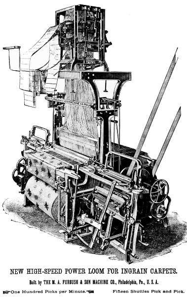
New High-speed Power Loom For Ingrain Carpets. Built by the M. a. Furbush & Son Machine Co., Philadelphia, Pa., U. S. A. One Hundred Picks per Minute. Fifteen Shuttles Pick and Pick.
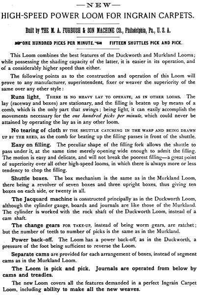
New High-speed Power Loom For Ingrain Carpets. Built by The M. a. Furbush & Son Machine Co., Philadelphia, Pa., U. S. A. One Hundred Picks Per Minute. Fifteen Shuttles Pick and Pick. This Loom combines the best features of the Duckworth and Murkland Looms; while possessing the shading capacity of the latter, it is easier in its operation, and of a considerably higher speed than either. The following points as to the construction and operation of this Loom will prove to any manufacturer, superintendent, fixer or weaver the superiority of the same over any other style: Runs light.There is no heavy lay to operate, as in other looms. The lay (raceway and boxes) are stationary, and the filling is beaten up by means of a comb, which is the only part that swings; being light, it can easily accomplish the movements necessary for the one hundred picks per minute, which could never be attained by operating the lay as in any other loom. No tearing of cloth By the Shuttle Catching in the Warp and Being Drawn Up by the Reed, as the comb for beating up the filling passes in front of the shuttle. Easy on filling. The peculiar shape of the filling fork allows the shuttle to pass under it, at the same time merely opening wide enough to admit the filling. The motion is easy and delicate, and will not break the poorest filling—a great point of superiority over all other high-speed looms, in which there is always more or less tendency to chop the filling. Shuttle boxes. The box mechanism is the same as in the Murkland Loom, there being a revolver of seven boxes and three upright boxes, thus giving ten boxes on each side, or twenty in all. The Jacquard machine is constructed principally as in the Duckworth Loom, although the cylinder gauge, boards and journals are like those of the Murkland. The cylinder is worked with the rock shaft of the Duckworth Loom, instead of a cam shaft. The change gears For Take-up, instead of being worm gears, are ratchet; but the number of teeth to number of picks is the same as in the Murkland. Power back-off. The Loom has a power back-off, as in the Duckworth, a pressure of the foot being sufficient to reverse the Loom. Separate cams are provided for each arrangement of boxes, instead of segment cams as in the Murkland Loom. The Loom is pick and pick. Journals are operated from below by cams and treadles. The new Loom covers all the features demanded in a perfect Ingrain Carpet Loom, including ability to make all the new weaves.
Loom Picker Co. Biddeford, Maine, Manufacturers of Raw Hide and Leather Loom Pickers and Strapping,Including many varieties of Raw Hide Pickers never before made in this country, such as Scoops, Centre Scoops, Pressed Centres, Feathered Feet Bows, XL Bows, All of which are a superior substitute for the ordinary Bow Picker. Sole Manufacturers of the Parker Patent Drop Box Picker, Which is so constructed that the blow is against the edge of the hide forming the body of the Picker. These Pickers have no plug in the Shuttle Strike to be driven out or worked loose, and they are guaranteed not to break at the head. Also, Manufacturers of Loom Harnesses of Superior Quality. All Harnesses are made of the very best quality of twine and stock, and are carefully finished. They are guaranteed to possess all the requirements of a superior article. An Illustrated Catalogue giving a detailed description of our goods will be mailed on application.
Chas. Ashoff,manufacturer of Reeds and Heddles, And Dealer in Manufacturers’ Supplies, Nos. 191 and 193 Berks Street, Philadelphia, PA.
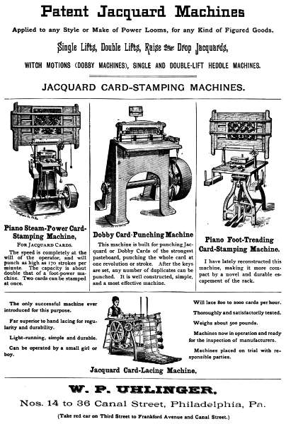
Patent Jacquard Machines Applied to any Style or Make of Power Looms, for any Kind of Figured Goods. Single Lifts, Double Lifts, Raise and Drop Jacquards, Witch Motions (Dobby Machines), Single and Double-lift Heddle Machines. Jacquard Card-stamping Machines. Piano Steam-Power Card-Stamping Machine,For Jacquard Cards. The speed is completely at the will of the operator, and will punch as high as 170 strokes per minute. The capacity is about double that of a foot-power machine. Two cards can be stamped at once. Dobby Card-Punching Machine. This machine is built for punching Jacquard or Dobby Cards of the strongest pasteboard, punching the whole card at one revolution or stroke. After the keys are set, any number of duplicates can be punched. It is well constructed, simple, and a most effective machine. Piano Foot-Treading Card-Stamping Machine. I have lately reconstructed this machine, making it more compact by a novel and durable escapement of the rack. Jacquard Card-Lacing Machine. The only successful machine ever introduced for this purpose. Far superior to hand lacing for regularity and durability. Light-running, simple and durable. Can be operated by a small girl or boy. Will lace 800 to 2000 cards per hour. Thoroughly and satisfactorily tested. Weighs about 500 pounds. Machines now in operation and ready for the inspection of manufacturers. Machines placed on trial with responsible parties. W. P. Uhlinger, Nos. 14 to 36 Canal Street, Philadelphia, Pa. (Take red car on Third Street to Frankford Avenue and Canal Street.)
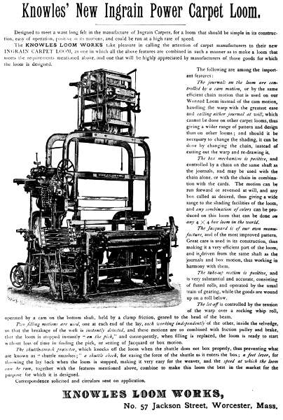
Knowles’ New Ingrain Power Carpet Loom. Designed to meet a want long felt in the manufacture of Ingrain Carpets, for a loom that should be simple in its construction, easy of operation, positive in its motions, and could be run at a high rate of speed. The Knowles Loom Works take pleasure in calling the attention of carpet manufacturers to their new Ingrain Carpet Loom, as one in which all the above features are combined in such a manner as to make a loom that meets the requirements mentioned above, and one that will be highly appreciated by manufacturers of those goods for which the loom is designed. The following are among the important features: The journals on the loom are controlled by a cam motion, or by the same efficient chain motion that is used on our Worsted Loom instead of the cam motion, handling the warp with the greatest ease and calling either journal at will, which cannot be done on other carpet looms, thus giving a wider range of pattern and design than on other looms; and should it be necessary to change the shading, it can be done by changing the chain, instead of cutting out the warp and re-drawing it. The box mechanism is positive, and controlled by a chain on the same shaft as the journals, and may be used with the chain alone, or with the chain in combination with the cards. The motion can be run forward or reversed at will, and any box called as desired, thus giving a wide range to the shading facilities of the loom, and any combination of colors can be produced on this loom that can be done on any 4 × 4 box loom in the world. The Jacquard is of our own manufacture, and of the most improved pattern. Great care is used in its construction, thus making it a very efficient part of the loom, and is driven from the same shaft as the journals and box motion, thus working in harmony with them. The take-up motion is positive, and is very substantial and accurate, consisting of fluted rolls, and operated by the usual train of gearing, while the goods are wound up on a roll below. The let-off is controlled by the tension of the warp over a rocking whip roll, operated by a cam on the bottom shaft, held by a clamp friction, geared to the head of the beam. Two filling motions are used, one at each end of the lay, each working independently of the other, inside the selvedge, so that the breakage of the weft is instantly detected, and these motions are so combined with friction pulley and brake, that the loom is stopped instantly “on the pick,” and consequently, when filling is replaced, the loom is ready to start without loss of time in finding the pick, or setting of Jacquard or box motion. The shuttle-smash protector, which knocks off the loom when the shuttle does not box properly, thus preventing what are known as “shuttle smashes;” a shuttle check, for easing the force of the shuttle as it enters the box; a foot lever, for throwing the lay back when the loom is stopped, making it very easy for the weaver, and the speed at which the loom can be run, together with the features mentioned above, combine to make this loom the best in the market for the purpose for which it is designed. Correspondence solicited and circulars sent on application. Knowles Loom Works, No. 57 Jackson Street, Worcester, Mass.
Schaum & Uhlinger, 1030-1038 New Market St., Philadelphia, Pa. Manufacturers of Ribbon, Tape and Webbing Looms, Latest Improvements. New Patterns. Lathes Or Battons, For Ribbons, Fringes, Tapes, Suspender and Goring Web, &c. We construct our Lathes on correct mechanical principles, use only the best materials, and produce The Best Lathe In the Market. Write to us for estimates: it will pay you. Jacquard Machines, With any desired number of hooks. Applied to any manufacture of loom. Harness Tied up for all Figured Weaving. A Full Line of Weavers’ Supplies: Mails, Lingoes, Heddles, Harness Twine, Compart-Boards, Glass Rings, Shuttle Eyes, &c. If you contemplate manufacturing Figured Goods, write to us for information, or send us samples of the goods you desire to make, and we will furnish you estimates for a complete equipment, including Jacquard Machines, with harness tied-up, designs made, cards cut, &c. Fifteen years’ practical experience in this line of business enables us to give our customers the Best Results with the Least Expense. Schaum & Uhlinger, 1030-1038 New Market St., Philadelphia, Pa.
TEXTILE SCHOOL OF THE Pennsylvania Museum and School of Industrial Art,
Classrooms: {No. 1336 Spring Garden Street, {S. E. Cor. Broad & Spring Garden Sts.
THE LEADING TEXTILE SCHOOL IN AMERICA.
Founded in co-operation with the Trustees of the Penna. Museum and School of Industrial Art,
WM. PLATT PEPPER, President,
by the following members of the Philadelphia Textile Association:
Thomas Dolan & Co.,
John & James Dobson,
William Wood & Co.,
William Arrott,
John Yewdall,
Fiss, Banes, Erben & Co.,
Conyers Button & Co.,
George & James Bromley,
Seville Schofield,
Alexander Crow & Son,
James Smith & Co.,
M. A. Furbush & Son,
John Bromley & Sons,
Thomas L. Leedom,
James Doak, Jr. & Co.,
Charles Spencer & Co.,
H. Becker & Co.,
Andreas Hartel,
S. B. M. Fleisher,
Grundy Bros. & Campion,
H. W. Butterworth & Sons,
Stead & Miller.
Extract from COURSE OF STUDY for Day Class, requiring three years’ attendance at School.
FIRST YEAR’S COURSE.
The hand-loom, analyzed and explained.
Elementary principles of “dressing” warps; beaming the same; fixing of harness; drawing-in; reed and reed calculations, etc., for single cloth.
A general study of the nature of materials used in weaving textile fabrics; explanation of the necessary materials and instruments used by designers.
Weaves.—Ground or Foundation Weaves.
I. Plain, or cotton weave, and fancy figuring through color arrangements in warp and filling, for light-weight fabrics.
II. Twill weaves—a, one-sided twills; b, even-sided twills; and fancy figuring with same through color arrangements in warp and filling.
III. Satin weaves—a, single satins; b, double satins; c, figuring in single satins.
Drafting Weaves.
Lectures, with practical examples and rules observed.
Derivative Weaves.
Basket, rib, and granite weaves; steep, curved, broken, skip, corkscrew, and fancy twills; pointed twills and honeycomb weaves; pique weaves, and combinations of miscellaneous weaves.
Standard sizes of cotton wool and worsted yarns, with calculations.
Picking out samples of textile fabrics constructed on single weaves, with methods and rules employed in duplication.
Original weaves for single cloth; complete orders for manufacturing.
Instrumental drawing in elementary exercises, with instruments; construction of plane figures; line shading, etc.
Freehand drawing; enlargement and reduction of designs; analysis of plants for the purpose of design for textile fabrics.
Work in color; lectures on color harmony.
SECOND YEAR’S COURSE.
The power-looms analyzed and explained, and practical weaving and fixing; a, the Thos. Wood roller loom, for ginghams, shirtings, cottonades, dress goods, etc.; b, the Crompton loom, and c, the Knowles loom, for worsted and woolen fabrics of every description; single and double beam work.
Double Cloths—Study of the best methods of combining different weaves, as: Designs backed with weft; designs backed with warp; designs backed with warp and weft; designs for double cloth, double faced.
Calculation: ascertaining the cost, production, etc., of the different fabrics.
Analyses of single cloth (fancy), and double cloth fabrics, and reproduction with various changes, as requested.
The Jacquard Machine Analyzed and Explained; principles of construction and method of operation of the single lift machine; the various modifications, such as double lift single cylinder, double lift double cylinder; “laying out” of comber-boards, and figuring for various changes in texture; tying-up of harness for single cloth.
The Bridesburg Clipper Loom analyzed and explained, and practical work on it, with special reference to its use in connection with the double lift double cylinder Jacquard machine for damask table-covers, etc.
Card-stamping machines (French index) analyzed and explained, and actual work for single cloth on the machine; explanation of, and practical work in card-lacing.
Theoretical work; designing paper with reference to the different textures of single cloth fabrics.
Sketching of designs for single cloth, and transferring sketch to the □ designing paper.
Shading of fabrics by the weave.
Analysis of Jacquard work for actual reproduction; also for reproduction with various (given) changes.
Study of special fabrics, such as dress trimmings, fringes, etc.
Study of processes for textile fabrics before and after weaving.
Instrumental drawing in lettering; drawing plans for machinery, rooms, mill buildings, etc.
Illustrating processes of weaving.
Illustrating sectional cuts of textile fabrics, etc.
Freehand drawing; sketching for the different textile fabrics on Jacquard work.
Work in color; lectures (advanced course); practice in the use of color.
Chemistry.
Theory of Chemistry applicable to the textile art.
THIRD YEAR’S COURSE.
The two-ply ingrain carpet machine analyzed and explained.
The ingrain carpet hand-loom, and the ingrain carpet power-loom, built by the M. A. Furbush & Son Machine Co., analyzed, explained, and practical work.
Card-stamping machine (American index) analyzed, explained, and practical work.
Tying-up of Jacquard harness (French index) machines for double cloth; three and four-ply fabrics.
Advanced Work for the Harness Loom.
Study and practical work of cut pile fabrics—velvets, plushes, etc.; terry pile fabrics, with wires and without wires; terry and velvet pile combined.
Astrakans, cut, uncut, also cut and uncut combined.
Chenille, rugs, curtains, etc.
Gauze fabrics, plain, figured, and combined with other weaves.
Designing for upholstery fabrics, Jacquard gauze, Brussels carpet, tapestry carpet, double face Brussels carpet, etc.
Card-stamping on the French index stamping machine for two, three, and four-ply fabrics.
Instrumental and freehand drawing similar to second year’s course, but for more difficult objects in textile fabrics and machinery.
Work in color; application of theory of harmony to dyeing.
Chemistry.
Theory and practice of chemistry, including actual work in the laboratory and dyeing of fabrics.
T. C. SEARCH,
Chairman Committee on Instruction of the School, and Pres. Phila. Textile Association.
The Circular of the Committee on Instruction will be mailed upon application.
PRESS COMMENTS.
A Model School of Industrial Art.
We cannot, at this time, speak of its provisions by which drawing, modeling, designing, etc., are taught; but we desire to call particular attention to the facilities that are offered for a practical instruction in weaving and textile design. Special courses are provided for teaching designing for all varieties of textile fabrics, and its practical application to loom work. As a complete course in its theoretical and practical utility we do not hesitate to say it is without an equal in America. A school of this kind is of the highest importance to the manufacturing community that centres about Philadelphia.—Boston Journal of Commerce.
An American Textile School.
The Textile Department of the Pennsylvania Museum and School of Industrial Art clearly fulfils the requirements of a good Textile School, and the promise is that it will speedily become one of the best in the world, as it is now decidedly the most advanced in this country. Pupils are taught designing for all varieties of textile fabrics, and to make them thoroughly familiar with loom work, so that they may be able not only to prepare their own designs, but also to reproduce their own patterns in the cloth.
This institution, by fitting young Americans for exact scientific work in the textile industries, will confer a huge benefit upon them and upon the nation.—The Textile Record of America.
The Textile Department of the School of Industrial Art, 1336 Spring Garden St.
Many scholars who have been at this school in former years are now filling responsible and profitable positions.—The Bulletin, Phila.
Thomas Wood & Co., Fairmount Machine Works, Twenty-Second and Wood Streets, Philadelphia, Pa. Power Looms. Patent Bobbin Winding Machines. Patent Cop Winding Machines. Improved Presser Beaming Machines. Plain Beaming Machines. Improved Reels for Wool, Worsted, Cotton, Linen, etc. Improved Presser Spoolers. Plain Spoolers. Warp Splitting Machines. Hank Twisting Machines. Warping Mills with Patent Driving Heads and Improved Hecks. Single and Double Warp Sizing Machines. Dyeing Machines for Warp and Piece Goods. Cradle and Cone Indigo Mills. Fulling Mills. Calendering Machines. Self-acting Wool Scouring Machines. Yarn Bundling Presses. Loom Beam Trucks. Shafting, Hangers, Pulleys, etc. Adjustable Self-oiling Bearings. Patent Friction Pulleys. Improved Cut-off Coupling. Patent Couplings. Patent Loose Pulleys. Gearing. Elevators. Plans Made and Factories Completely Equipped with Machinery.
Mill and Manufacturers’ Supplies.
Sole Philadelphia Agent For
Stoddard, Lovering & Co.,
Boston, Massachusetts, and Bradford, England.
Importers of English Worsted Machinery, and Hattersley Looms, for every class
of work. Also, Pickers, Temples, Loom Springs, and White’s Picker Leather
in the side or by the strap, Torlotin’s Sizing; also, all other English Supplies.
Also Agent For
Charles L. Ireson, Boston, Massachusetts.
Pure Oak-tanned Leather Belting and Findings, Wire-sewed Belting, and maker
of Ireson’s Patent Self-adjusting Leather Link Belting.
Stedman & Smith, Lawrence, Massachusetts.
Machinists and makers of Machine Castings, and every kind of Mill work.
John W. Barlow,
Lawrence, Massachusetts.
Bow, Drop Box, English Scoop, or other Pickers of best quality.
Banning, Bissell & Co.,New York, N. Y.
Porcelain Department:—Pot Eyes, Steps, Shuttle Eyes, and Pottery Goods of
every description.
Single and Double Belting, Belt Hooks, Springs, Temples, Picker and Lace Leather
(Coupes), Cleaning Cloths, Belt Dressing, (both American and Hepburn & Gale’s English),
Felt Cloth, Porcelain Goods, Fibre Washers, Banding, Gears, &c., &c., in stock at all
times. All Supplies not in stock can be procured at once.
Worsted Mill Machinery and Supplies a Specialty.
David B. Douglass,
201 Church St., Philadelphia, Pa.
Transcriber’s notes:
In the text version, italics are represented by _underscores_, and bold and black letter text by =equals= symbols. Superscripts are represented by ^{} and subscripts by _{}
Missing or incorrect punctuation has been repaired.
Inconsistent spelling and hyphenation have been left,
In the html version, dittos have been replaced by the repeated text so that text alignes for easier reading.
In the html version, adverts (unless all plain text) have been reproduced as illustrations to demonstrate layouts, decorations and fonts. The text from each illustration is given below each illustration, unformatted.
The following mistakes have been noted: