*** START OF THE PROJECT GUTENBERG EBOOK 53542 ***
Transcriber’s notes:
The text of this book has been preserved in its original form
apart from correction of two typographic errors: embarrasment →
embarrassment, Cassegranian → Cassegrainian. Inconsistent hyphenation
has not been altered. A lengthy preliminary section concerning the
Smithsonian Institution precedes the actual subject matter. A black
dotted underline indicates a hyperlink to a page, illustration or
footnote (hyperlinks are also highlighted when the mouse pointer
hovers over them). Page numbers are shown
in the right margin and footnotes are located at the end. Footnotes are located at the end.
The original blank cover has been modified by adding
a title and is placed in the public domain.
On the Construction of a Silvered Glass Telescope
SMITHSONIAN
CONTRIBUTIONS TO KNOWLEDGE.
VOL. XIV.
EVERY MAN IS A VALUABLE MEMBER OF SOCIETY, WHO, BY HIS OBSERVATIONS, RESEARCHES, AND EXPERIMENTS,
PROCURES KNOWLEDGE FOR MEN.—Smithson.
CITY OF WASHINGTON:
PUBLISHED BY THE SMITHSONIAN INSTITUTION.
MDCCCLXV.
ADVERTISEMENT.
This volume forms the fourteenth of a series, composed of original memoirs on different
branches of knowledge, published at the expense, and under the direction, of
the Smithsonian Institution. The publication of this series forms part of a general
plan adopted for carrying into effect the benevolent intentions of James Smithson,
Esq., of England. This gentleman left his property in trust to the United States
of America, to found, at Washington, an institution which should bear his own
name, and have for its objects the “increase and diffusion of knowledge among
men.” This trust was accepted by the Government of the United States, and an
Act of Congress was passed August 10, 1846, constituting the President and the
other principal executive officers of the general government, the Chief Justice of
the Supreme Court, the Mayor of Washington, and such other persons as they might
elect honorary members, an establishment under the name of the “Smithsonian
Institution for the increase and diffusion of knowledge among men.” The
members and honorary members of this establishment are to hold stated and special
meetings for the supervision of the affairs of the Institution, and for the advice
and instruction of a Board of Regents, to whom the financial and other affairs are
intrusted.
The Board of Regents consists of three members ex officio of the establishment,
namely, the Vice-President of the United States, the Chief Justice of the Supreme
Court, and the Mayor of Washington, together with twelve other members, three of
whom are appointed by the Senate from its own body, three by the House of
Representatives from its members, and six persons appointed by a joint resolution
of both houses. To this Board is given the power of electing a Secretary and other
officers, for conducting the active operations of the Institution.
To carry into effect the purposes of the testator, the plan of organization should
evidently embrace two objects: one, the increase of knowledge by the addition of
new truths to the existing stock; the other, the diffusion of knowledge, thus
increased, among men. No restriction is made in favor of any kind of knowledge;
and, hence, each branch is entitled to, and should receive, a share of attention.
The Act of Congress, establishing the Institution, directs, as a part of the plan of
organization, the formation of a Library, a Museum, and a Gallery of Art, together
with provisions for physical research and popular lectures, while it leaves to the
Regents the power of adopting such other parts of an organization as they may
deem best suited to promote the objects of the bequest.
After much deliberation, the Regents resolved to divide the annual income into
two parts—one part to be devoted to the increase and diffusion of knowledge by
means of original research and publications—the other part of the income to be
applied in accordance with the requirements of the Act of Congress, to the gradual
formation of a Library, a Museum, and a Gallery of Art.
The following are the details of the parts of the general plan of organization
provisionally adopted at the meeting of the Regents, Dec. 8, 1847.
DETAILS OF THE FIRST PART OF THE PLAN.
I. To increase Knowledge.—It is proposed to stimulate research, by offering
rewards for original memoirs on all subjects of investigation.
1. The memoirs thus obtained, to be published in a series of volumes, in a quarto
form, and entitled “Smithsonian Contributions to Knowledge.”
2. No memoir, on subjects of physical science, to be accepted for publication,
which does not furnish a positive addition to human knowledge, resting on original
research; and all unverified speculations to be rejected.
3. Each memoir presented to the Institution, to be submitted for examination to
a commission of persons of reputation for learning in the branch to which the
memoir pertains; and to be accepted for publication only in case the report of this
commission is favorable.
4. The commission to be chosen by the officers of the Institution, and the name
of the author, as far as practicable, concealed, unless a favorable decision be made.
5. The volumes of the memoirs to be exchanged for the Transactions of literary
and scientific societies, and copies to be given to all the colleges, and principal
libraries, in this country. One part of the remaining copies may be offered for
sale; and the other carefully preserved, to form complete sets of the work, to
supply the demand from new institutions.
6. An abstract, or popular account, of the contents of these memoirs to be given
to the public, through the annual report of the Regents to Congress.
II. To increase Knowledge.—It is also proposed to appropriate a portion of the
income, annually, to special objects of research, under the direction of suitable
persons.
1. The objects, and the amount appropriated, to be recommended by counsellors
of the Institution.
2. Appropriations in different years to different objects; so that, in course of time,
each branch of knowledge may receive a share.
3. The results obtained from these appropriations to be published, with the
memoirs before mentioned, in the volumes of the Smithsonian Contributions to
Knowledge.
4. Examples of objects for which appropriations may be made:—
(1.) System of extended meteorological observations for solving the problem of
American storms.
(2.) Explorations in descriptive natural history, and geological, mathematical,
and topographical surveys, to collect material for the formation of a Physical Atlas
of the United States.
(3.) Solution of experimental problems, such as a new determination of the
weight of the earth, of the velocity of electricity, and of light; chemical analyses
of soils and plants; collection and publication of articles of science, accumulated
in the offices of Government.
(4.) Institution of statistical inquiries with reference to physical, moral, and
political subjects.
(5.) Historical researches, and accurate surveys of places celebrated in American
history.
(6.) Ethnological researches, particularly with reference to the different races of
men in North America; also explorations, and accurate surveys, of the mounds
and other remains of the ancient people of our country.
I. To diffuse Knowledge.—It is proposed to publish a series of reports, giving an
account of the new discoveries in science, and of the changes made from year to year
in all branches of knowledge not strictly professional.
1. Some of these reports may be published annually, others at longer intervals,
as the income of the Institution or the changes in the branches of knowledge may
indicate.
2. The reports are to be prepared by collaborators, eminent in the different
branches of knowledge.
3. Each collaborator to be furnished with the journals and publications, domestic
and foreign, necessary to the compilation of his report; to be paid a certain sum for
his labors, and to be named on the title-page of the report.
4. The reports to be published in separate parts, so that persons interested in a
particular branch, can procure the parts relating to it, without purchasing the
whole.
5. These reports may be presented to Congress, for partial distribution, the
remaining copies to be given to literary and scientific institutions, and sold to individuals
for a moderate price.
The following are some of the subjects which may be embraced in the reports:—
I. PHYSICAL CLASS.
1. Physics, including astronomy, natural philosophy, chemistry, and meteorology.
2. Natural history, including botany, zoology, geology, &c.
3. Agriculture.
4. Application of science to arts.
II. MORAL AND POLITICAL CLASS.
5. Ethnology, including particular history, comparative philology, antiquities, &c.
6. Statistics and political economy.
7. Mental and moral philosophy.
8. A survey of the political events of the world; penal reform, &c.
III. LITERATURE AND THE FINE ARTS.
9. Modern literature.
10. The fine arts, and their application to the useful arts.
11. Bibliography.
12. Obituary notices of distinguished individuals.
II. To diffuse Knowledge.—It is proposed to publish occasionally separate treatises
on subjects of general interest.
1. These treatises may occasionally consist of valuable memoirs translated from
foreign languages, or of articles prepared under the direction of the Institution, or
procured by offering premiums for the best exposition of a given subject.
2. The treatises to be submitted to a commission of competent judges, previous
to their publication.
DETAILS OF THE SECOND PART OF THE PLAN OF ORGANIZATION.
This part contemplates the formation of a Library, a Museum, and a Gallery of
Art.
1. To carry out the plan before described, a library will be required, consisting,
1st, of a complete collection of the transactions and proceedings of all the learned
societies of the world; 2d, of the more important current periodical publications,
and other works necessary in preparing the periodical reports.
2. The Institution should make special collections, particularly of objects to
verify its own publications. Also a collection of instruments of research in all
branches of experimental science.
3. With reference to the collection of books, other than those mentioned above,
catalogues of all the different libraries in the United States should be procured, in
order that the valuable books first purchased may be such as are not to be found
elsewhere in the United States.
4. Also catalogues of memoirs, and of books in foreign libraries, and other
materials, should be collected, for rendering the Institution a centre of bibliographical
knowledge, whence the student may be directed to any work which he may
require.
5. It is believed that the collections in natural history will increase by donation,
as rapidly as the income of the Institution can make provision for their reception;
and, therefore, it will seldom be necessary to purchase any article of this kind.
6. Attempts should be made to procure for the gallery of art, casts of the most
celebrated articles of ancient and modern sculpture.
7. The arts may be encouraged by providing a room, free of expense, for the
exhibition of the objects of the Art-Union, and other similar societies.
8. A small appropriation should annually be made for models of antiquity, such
as those of the remains of ancient temples, &c.
9. The Secretary and his assistants, during the session of Congress, will be
required to illustrate new discoveries in science, and to exhibit new objects of art;
distinguished individuals should also be invited to give lectures on subjects of
general interest.
In accordance with the rules adopted in the programme of organization, each
memoir in this volume has been favorably reported on by a Commission appointed
for its examination. It is however impossible, in most cases, to verify the statements
of an author; and, therefore, neither the Commission nor the Institution can
be responsible for more than the general character of a memoir.
The following rules have been adopted for the distribution of the quarto volumes
of the Smithsonian Contributions:—
1. They are to be presented to all learned societies which publish Transactions,
and give copies of these, in exchange, to the Institution.
2. Also, to all foreign libraries of the first class, provided they give in exchange
their catalogues or other publications, or an equivalent from their duplicate volumes.
3. To all the colleges in actual operation in this country, provided they furnish,
in return, meteorological observations, catalogues of their libraries and of their
students, and all other publications issued by them relative to their organization
and history.
4. To all States and Territories, provided there be given, in return, copies of all
documents published under their authority.
5. To all incorporated public libraries in this county, not included in any of
the foregoing classes, now containing more than 10,000 volumes; and to smaller
libraries, where a whole State or large district would be otherwise unsupplied.
OFFICERS
OF THE
SMITHSONIAN INSTITUTION.
THE PRESIDENT OF THE UNITED STATES,
Ex-officio PRESIDING OFFICER OF THE INSTITUTION.
THE VICE-PRESIDENT OF THE UNITED STATES,
Ex officio SECOND PRESIDING OFFICER.
SALMON P. CHASE,
CHANCELLOR OF THE INSTITUTION.
JOSEPH HENRY,
SECRETARY OF THE INSTITUTION.
SPENCER F. BAIRD,
ASSISTANT SECRETARY.
W. W. SEATON, Treasurer.
| ALEXANDER D. BACHE, |  | Executive Committee. |
| RICHARD WALLACH, |
| RICHARD DELAFIELD, |
REGENTS.
| —— —— | Vice-President of the United States. |
| Salmon P. Chase, | Chief Justice of the United States. |
| Richard Wallach, | Mayor of the City of Washington. |
| Lyman Trumbull, | Member of the Senate of the United States. |
| William P. Fessenden, | " " " " " " |
| Garrett Davis, | " " " " " " |
| Samuel S. Cox, | Member of the House of Representatives U. S. |
| James W. Patterson, | " " " " " " |
| Henry W. Davis, | " " " " " " |
| William B. Astor, | Citizen of New York. |
| Theodore D. Woolsey, | " of Connecticut. |
| Louis Agassiz, | " of Massachusetts. |
| (Vacancy.) | —— —— |
| Alexander D. Bache, | " of Washington. |
| Richard Delafield, | " of Washington. |
MEMBERS EX-OFFICIO OF THE INSTITUTION.
| Andrew Johnson, | President of the United States. |
| —— —— | Vice-President of the United States. |
| William H. Seward, | Secretary of State. |
| Hugh McCulloch, | Secretary of the Treasury. |
| Edwin M. Stanton, | Secretary of War. |
| Gideon Welles, | Secretary of the Navy. |
| William Dennison, | Postmaster-General. |
| James Speed, | Attorney-General. |
| Salmon P. Chase, | Chief Justice of the United States. |
| David P. Holloway, | Commissioner of Patents. |
| Richard Wallach, | Mayor of the City of Washington. |
HONORARY MEMBER.
James Harlan. The Secretary of the Interior.
TABLE OF CONTENTS.1
| | PAGE |
| ARTICLE I. | Introduction. Pp. 16. | |
| Advertisement | iii |
| List of Officers of the Smithsonian Institution | ix |
| ARTICLE II. | Discussion of the Magnetic and Meteorological Observations made at
the Girard College Observatory, Philadelphia, in 1840, 1841, 1842,
1843, 1844, and 1845. Third Section, comprising Parts VII, VIII,
AND IX. Vertical Force. Investigation of the Eleven (or Ten)
Year Period and of the Disturbances of the Vertical Component of
the Magnetic Force, and Appendix on the Magnetic Effect of the
Aurora Borealis; with an Investigation of the Solar Diurnal
Variation, and of the Annual Inequality of the Vertical Force;
and of the Lunar Effect or the Vertical Force, the inclination, and
Total Force. By A. D. Bache, LL. D., F. R. S., Mem. Corr. Acad.
Sc. Paris; Prest. Nat. Acad. Sciences; Superintendent U. S. Coast Survey.
Pp. 72. (Published May, 1864.) |
| ARTICLE III. | Discussion of the Magnetic and Meteorological Observations made at
the Girard College Observatory, Philadelphia, in 1840, 1841, 1842,
1843, 1844, and 1845. Fourth Section, comprising Parts X, XI, AND
XII. Dip and Total Force. Analysis of the Disturbances of the
Dip and Total Force; Discussion of the Solar Diurnal Variation
and Annual Inequality of the Dip and Total Force; and Discussion
of the Absolute Dip, with the Final Values for Declination, Dip
and Force between 1841 and 1845. By A. D. Bache, LL. D., F. R. S.,
Mem. Corr. Acad. Sc. Paris; Prest. Nat. Acad. Sciences; Superintendent
U. S. Coast Survey. Pp. 44. (Published January, 1865.) |
| ARTICLE IV. | On the Construction of a Silvered Glass Telescope, fifteen and a half
inches in Aperture, and its Use in Celestial Photography. By
Henry Draper, M. D., Professor of Natural Science in the University of
New York. Pp. 60. (Published July, 1864.) |
| §1. Grinding and Polishing the Mirrors | 2 |
| §2. The Telescope Mounting | 27 |
| §3. The Clock Movement | 38 |
| §4. The Observatory | 41 |
| §5. The Photographic Laboratory | 46 |
| §6. The Photographic Enlarger | 51 |
| ARTICLE V. | Palæontology of the Upper Missouri: A Report upon Collections made
principally by the Expeditions under command of Lieut. G. K. Warren,
U. S. Top. Engrs., in 1855 and 1856. Invertebrates. By F. B.
Meek and F. V. Hayden, M. D. Part I. Pp. 158, and five Plates.
(Published April, 1865.) |
| Introductory Remarks | vii |
| I. | Silurian Age. Potsdam Period | 1 |
| II. | Carboniferous Age. Carboniferous Period | 11 |
| III. | Carboniferous Age. Permian Period | 48 |
| IV. | Reptilian Age. Jurassic Period | 66 |
| Index | 129 |
| Explanations of Plates. |
| ARTICLE VI. | Cretaceous Reptiles of the United States. By Joseph Leidy, M. D.,
Professor of Anatomy in the University of Pennsylvania, Curator of the
Academy of Natural Sciences of Philadelphia. Pp. 140 and twenty plates.
(Published May, 1865.) |
| Introduction | 1 |
| Sauria | 5 |
| Chelonia | 104 |
| A Synopsis, in which an attempt is made to define more closely the Genera
and Species of Reptiles whose remains are described in the preceding pages | 115 |
| Index | 121 |
| References to the Plates | 123 |
SMITHSONIAN CONTRIBUTIONS TO KNOWLEDGE.
ON THE CONSTRUCTION
OF A
SILVERED GLASS TELESCOPE,
FIFTEEN AND A HALF INCHES IN APERTURE,
AND
ITS USE IN CELESTIAL PHOTOGRAPHY.
BY
HENRY DRAPER, M. D.,
PROFESSOR OF NATURAL SCIENCE IN THE UNIVERSITY OF NEW YORK.
[ACCEPTED FOR PUBLICATION, JANUARY, 1864.]
COMMISSION
TO WHICH THIS PAPER HAS BEEN REFERRED.
Prof. Wolcott Gibbs.
Com. J. M. Gilliss, U. S. N.
Joseph Henry,
Secretary S. I.
COLLINS, PRINTER,
PHILADELPHIA.
CONTENTS.
HISTORICAL SKETCH OF THE TELESCOPE. MEMOIR DIVIDED INTO SIX SECTIONS:—
| §1. | Grinding and Polishing the Mirrors | 2 |
| 1. Experiments on a metal speculum. Corrosion by aqua regia; voltaic grinding | 2 |
| 2. Silvering glass. Foucault’s and Cimeg’s processes; details of silvering a mirror; thickness and durability of silver films; their use in daguerreotyping | 2 |
| 3. Grinding and polishing glass. Division of subject | 6 |
| a. Peculiarities of glass; effects of pressure; effects of heat; oblique mirrors | 6 |
| b. Emery and rouge; elutriation of emery | 10 |
| c. Tools of iron, lead, pitch; the gauges; the leaden tool; the iron tool; the pitch polisher | 10 |
| d. Methods of examination; two tests, eyepiece and opaque screen; appearance of spherical surface; oblate spheroidal surface; hyperbolic surface; irregular surface; details of tests; atmospheric movements; correction for parallel rays by measure; appearances in relief on mirrors | 13 |
| e. Machines; Lord Rosse; Mr. Lassell; spiral stroke machine; its construction and use; the foot-power; method of local corrections; its advantages and disadvantages; machine for local corrections; description and use | 19 |
| 4. Eyepieces, plane mirrors, and test objects | 26 |
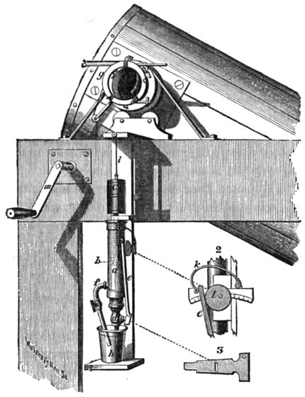
| §2. | The Telescope Mounting | 27 |
| Stationary eyepiece; method of counterpoising | 27 |
| a. The tube; the mirror support; air sac; currents in the tube | 28 |
| b. The supporting frame | 31 |
| §3. | The Clock Movement | 33 |
| a. The sliding plateholder; the frictionless slide | 33 |
| b. The clepsydra; the sand-clock | 36 |
| c. The sun camera | 40 |
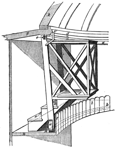
| §4. | The Observatory | 41 |
| a. The building | 41 |
| b. The dome; its peculiarities | 44 |
| c. The observer’s chair | 45 |
| §5. | The Photographic Laboratory | 46 |
| a. Description of the apartment | 46 |
| b. Photographic processes; washed plates; difficulties of celestial photography | 47 |
| §6. | The Photographic Enlarger | 51 |
| a. Low powers; use of a concave mirror, its novelty and advantages; of the making of reverses | 51 |
| b. High powers; microscopic photography | 54 |
AN ACCOUNT
OF
THE CONSTRUCTION AND USE OF A SILVERED GLASS TELESCOPE.
The construction of a reflecting telescope capable of showing every celestial
object now known, is not a very difficult task. It demands principally perseverance
and careful observation of minutiæ. The cost of materials is but trifling
compared with the result obtained, and I can see no reason why silvered glass
instruments should not come into general use among amateurs. The future hopes
of Astronomy lie in the multitude of observers, and in the concentration of the
action of many minds. If what is written here should aid in the advance of that
noble study, I shall feel amply repaid for my labor.
A short historical sketch of this telescope may not be uninteresting. In the summer
of 1857, I visited Lord Rosse’s great reflector, at Parsonstown, and, in addition
to an inspection of the machinery for grinding and polishing, had an opportunity
of seeing several celestial objects through it. On returning home, in 1858, I
determined to construct a similar, though smaller instrument; which, however,
should be larger than any in America, and be especially adapted for photography.
Accordingly, in September of that year, a 15 inch speculum was cast, and a
machine to work it made. In 1860, the observatory was built, by the village
carpenter, from my own designs, at my father’s country seat, and the telescope
with its metal speculum mounted. This latter was, however, soon after abandoned,
and silvered glass adopted. During 1861, the difficulties of grinding and polishing
that are detailed in this account were met with, and the remedies for many of them
ascertained. The experiments were conducted by the aid of three 15 1/2 inch disks
of glass, together with a variety of smaller pieces. Three mirrors of the same
focal length and aperture are almost essential, for it not infrequently happens that
two in succession will be so similar, that a third is required for attempting an
advance beyond them. One of these was made to acquire a parabolic figure, and
bore a power of 1,000. The winter was devoted to perfecting the art of silvering,
and to the study of special photographic processes. A large portion of 1862
was spent with a regiment in a campaign in Virginia, and but few photographs
were produced till autumn, when sand clocks and clepsydras of several kinds having
been made, the driving mechanism attained great excellence. During the winter,
the art of local corrections was acquired, and two 15 1/2 inch mirrors, as well as two
of 9 inches for the photographic enlarging apparatus, were completed. The greater
part of 1863 has been occupied by lunar and planetary photography, and the
enlargement of the small negatives obtained at the focus of the great reflector.
Lunar negatives have been produced which have been magnified to 3 feet in
diameter. I have also finished two mirrors 15 1/2 inches in aperture, suitable for a
Herschelian telescope, that is, which can only converge oblique pencils to a focus
free from aberration. This work has all been accomplished in the intervals of professional
labor.
The details of the preceding operations are arranged as follows: §1. Grinding
and Polishing the Mirrors; §2. The Telescope Mounting; §3. The Clock
Movement; §4. The Observatory; §5. The Photographic Laboratory; §6.
The Photographic Enlarger.
§1. GRINDING AND POLISHING THE MIRRORS.
(1.) Experiments on a Metal Speculum.
My first 15 inch speculum was an alloy of copper and tin, in the proportions
given by Lord Rosse. His general directions were closely followed, and the
casting was very fine, free from pores, and of silvery whiteness. It was 2 inches
thick, weighed 110 pounds, and was intended to be of 12 feet focal length. The
grinding and polishing were conducted with the Rosse machine. Although a great
amount of time was spent in various trials, extending over more than a year, a fine
figure was never obtained—the principal obstacle to success being a tendency to
polish in rings of different focal length. It must, however, be borne in mind that
Lord Rosse had so thoroughly mastered the peculiarities of his machine as to produce
with it the largest specula ever made and of very fine figure.
During these experiments there was occasion to grind out some imperfections,
8/100 of an inch deep, from the face of the metal. This operation was greatly assisted
by stopping up the defects with a thick alcoholic solution of Canada balsam, and
having made a rim of wax around the edge of the mirror, pouring on nitro-hydrochloric
acid, which quickly corroded away the uncovered spaces. Subsequently an
increase in focal length of 15 inches was accomplished, by attacking the edge
zones of the surface with the acid in graduated depths.
An attempt also was made to assist the tedious grinding operation by including
the grinder and mirror in a Voltaic circuit, making the speculum the positive pole.
By decomposing acidulated water between it and the grinder, and thereby oxidizing
the tin and copper of the speculum, the operation was much facilitated, but the
battery surface required was too great for common use. If a sufficient intensity
was given to the current, speculum metal was transferred without oxidation to the
grinder, and deposited in thin layers upon it. It was proposed at one time to make
use of this fact, and coat a mirror of brass with a layer of speculum metal by
electrotyping. The gain in lightness would be considerable.
During the winter of 1860 the speculum was split into two pieces, by the
expansion in freezing of a few drops of water that had found their way into the
supporting case.
(2.) Silvering Glass.
At Sir John Herschel’s suggestion (given on the occasion of a visit that my
father paid him in 1860), experiments were next commenced with silvered glass
specula. These were described as possessing great capabilities for astronomical
purposes. They reflect more than 90 per cent. of the light that fulls upon them,
and only weigh one-eighth as much as specula of metal of equal aperture.
As no details of Steinheil’s or Foucault’s processes for silvering in the cold way
were accessible at the time, trials extending at intervals over four months were
made. A variety of reducing agents were used, and eventually good results
obtained with milk sugar.
Soon after a description of the process resorted to by M. Foucault in his excellent
experiments was procured. It consists in decomposing an alcoholic solution
of ammonia and nitrate of silver by oil of cloves. The preparation of the solutions
and putting them in a proper state of instability are very difficult, and the results
by no means certain. The silver is apt to be soft and easily rubbed off, or of a
leaden appearance. It is liable to become spotted from adherent particles of the
solutions used in its preparation, and often when dissolved off a piece of glass with
nitric acid leaves a reddish powder. Occasionally, however, the process gives
excellent results.
In the winter of 1861, M. Cimeg published his method of silvering looking-glasses
by tartrate of potash and soda (Rochelle salt). Since I have made modifications
in it fitting the silver for being polished on the reverse side, I have never on
any occasion failed to secure bright, hard, and in every respect, perfect films.
The operation, which in many details resembles that of M. Foucault, is divided
into: 1st, cleaning the glass; 2d, preparing the solutions; 3d, warming the glass;
4th, immersion in the silver solution and stay there; 5th, polishing. It should be
carried on in a room warmed to 70° F. at least. The description is for a 15 1/2 inch
mirror.
1st. Clean the glass like a plate for collodion photography. Rub it thoroughly
with nitric acid, and then wash it well in plenty of water, and set it on edge on
filtering paper to dry. Then cover it with a mixture of alcohol and prepared chalk,
and allow evaporation to take place. Rub it in succession with many pieces of
cotton flannel. This leaves the surface almost chemically clean. Lately, instead
of chalk I have used plain uniodized collodion, and polished with a freshly-washed
piece of cotton flannel, as soon as the film had become semi-solid.
2d. Dissolve 560 grains of Rochelle salt in two or three ounces of water and
filter. Dissolve 800 grains of nitrate of silver in four ounces of water. Take an
ounce of strong ammonia of commerce, and add nitrate solution to it until a brown
precipitate remains undissolved. Then add more ammonia and again nitrate
of silver solution. This alternate addition is to be carefully continued until the
silver solution is exhausted, when some of the brown precipitate should remain in
suspension. The mixture then contains an undissolved
excess of oxide of silver. Filter. Just before using, mix
with the Rochelle salt solution, and add water enough
to make 22 ounces.
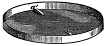
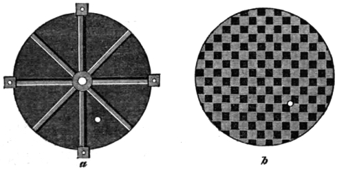
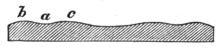
The vessel in which the silvering is to be performed may
be a circular dish (Fig. 1) of ordinary tinplate, 16 1/2 inches
in diameter, with a flat bottom and perpendicular sides one inch high, and coated
inside with a mixture of beeswax and rosin (equal parts), At opposite ends of one
diameter two narrow pieces of wood, a a′, 1/8 of an inch thick, are cemented. They
are to keep the face of the mirror from the bottom of the vessel, and permit of a
rocking motion being given to the glass. Before using such a vessel, it is necessary
to touch any cracks that may have formed in the wax with a hot poker. A spirit
lamp causes bubbles and holes through to the tin. The vessel too must always,
especially if partly silvered, be cleaned with nitric acid and water, and left filled
with cold water till needed. Instead of the above, India-rubber baths have been
occasionally used.
3d. In order to secure fine and hard deposits in the shortest time and with weak
solutions, it is desirable, though not necessary, to warm the glass slightly. This is
best done by putting it in a tub or other suitably sized vessel, and pouring in water
enough to cover the glass. Then hot water is gradually stirred in, till the mixture
reaches 100° F. It is also advantageous to place the vessels containing the ingredients
for the silvering solution in the same bath for a short time.
4th. On taking the glass out of the warm water, carry it to the silvering vessel—into
which an assistant has just previously poured the mixed silvering solution—and
immediately immerse it face downwards, dipping in first one edge and then
quickly letting down the other till the face is horizontal. The back of course is
not covered with the fluid. The same precautions are necessary to avoid streaks
in silvering as in the case of putting a collodion plate in the bath. Place the
whole apparatus before a window. Keep up a slow rocking motion of the glass,
and watch for the appearance of the bright silver film. The solution quickly turns
brown, and the silver soon after appears, usually in from three to five minutes.
Leave the mirror in the liquid about six times as long. At the expiration of the
twenty minutes or half hour lift it out, and look through it at some very bright
object. If the object is scarcely visible, the silver surface must then be washed
with plenty of water, and set on edge on bibulous paper to dry. If, on the contrary,
it is too thin, put it quickly back, and leave it until thick enough. When
polished the silver ought, if held between the eye and the sun, to show his disk
of a light blue tint. On coming out of the bath the metallic surface should have
a rosy golden color by reflected light.
5th. When the mirror is thoroughly dry, and no drops of water remain about
the edges, lay it upon its back on a thoroughly dusted table. Take a piece of the
softest thin buckskin, and stuff it loosely with cotton to make a rubber. Avoid
using the edge pieces of a skin, as they are always hard and contain nodules of
lime.
Go gently over the whole silver surface with this rubber in circular strokes,
in order to commence the removal of the rosy golden film, and to condense the
silver. Then having put some very fine rouge on a piece of buckskin laid flat on
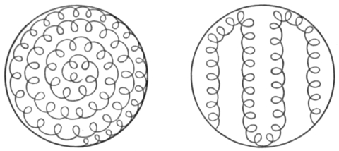
the table, impregnate the rubber with it. The best stroke for polishing is a motion
in small circles, at times going gradually round on the mirror, at times across on
the various chords (Fig. 2). At the end of an hour of continuous gentle rubbing,
with occasional touches on the flat rouged skin, the surface will be polished so as
to be perfectly black in oblique positions, and, with even moderate care, scratchless.
The process is like a burnishing. Put the rubber carefully away for another
occasion.
The thickness of the silver thus deposited is about 1/200,000 of an inch. Gold
leaf, when equally transparent, is estimated at the same fraction. The actual value
of the amount on a 15 1/2 inch mirror is not quite a cent—the weight being less than
4 grains (239 milligrammes on one occasion when the silver was unusually thick),
if the directions above given are followed.
Variations in thickness of this film of silver on various parts of the face of the
mirror are consequently only small fractions of 1/200,000 of an inch, and are therefore
of no optical moment whatever. If a glass has been properly silvered, and shows
the sun of the same color and intensity through all parts of its surface, the most
delicate optical tests will certainly fail to indicate any difference in figure between
the silver and the glass underneath. The faintest peculiarities of local surface
seen on the glass by the method of M. Foucault, will be reproduced on the silver.
The durability of these silver films varies, depending on the circumstances under
which they are placed, and the method of preparation. Sulphuretted hydrogen
tarnishes them quickly. Drops of water may split the silver off. Under certain
circumstances, too, minute fissures will spread all over the surface of the silver, and
it will apparently lose its adhesion to the glass. This phenomenon seems to be
connected with a continued exposure to dampness, and is avoided by grinding the
edge of the concave mirror flat, and keeping it covered when not in use with a sheet
of flat plate glass. Heat seems to have no prejudicial effect, though it might have
been supposed that the difference in expansibility would have overcome the mutual
adhesion.
Generally silvered mirrors are very enduring, and will bear polishing repeatedly,
if previously dried by heat. I have some which have been used as diagonal reflectors
in the Newtonian, and have been exposed during a large part of the day
to the heat of the sun concentrated by the 15 1/2 inch mirror. These small mirrors
are never covered, and yet the one now in the telescope has been there a year, and
has had the dusty film—like that which accumulates on glass—polished off it a
dozen times.
In order to guard against tarnishing, experiments were at first made in gilding
silver films, but were abandoned when found to be unnecessary. A partial conversion
of the silver film into a golden one, when it will resist sulphuretted hydrogen,
can be accomplished as follows: Take three grains of hyposulphite of soda, and
dissolve it in an ounce of water. Add to it slowly a solution in water of one grain
of chloride of gold. A lemon yellow liquid results, which eventually becomes clear.
Immerse the silvered glass in it for twenty-four hours. An exchange will take place,
and the film become yellowish. I have a piece of glass prepared in this way which
remains unhurt in a box, where other pieces of plain silvered glass have changed
some to yellow, some to blue, from exposure to coal gas.
I have also used silvered glass plates for daguerreotyping. They iodize beautifully
if freshly polished, and owing probably to the absence of the usual copper
alloy of silver plating, take impressions with very short exposures. The resulting
picture has a rosy warmth, rarely seen in ordinary daguerreotypes. The only precaution
necessary is in fixing to use an alcoholic solution of cyanide of potassium,
instead of hyposulphite of soda dissolved in water. The latter has a tendency to
split up the silver. The subsequent washing must be with diluted common alcohol.
Pictures obtained by this method will bear high magnifying powers without
showing granulation. Unfortunately the exposure required for them in the telescope
is six times as great as for a sensitive wet collodion, though the iodizing be carried
to a lemon yellow, the bromizing to a rose red, and the plate be returned to the
iodine.
(3.) Grinding and Polishing Glass.
Some of the facts stated in the following paragraphs, the result of numerous
experiments, may not be new to practical opticians. I have had, however, to polish
with my own hands more than a hundred mirrors of various sizes, from 19 inches
to 1/4 of an inch in diameter, and to experience very frequent failures for three years,
before succeeding in producing large surfaces with certainty and quickly. It is
well nigh impossible to obtain from opticians the practical minutiæ which are
essential, and which they conceal even from each other. The long continued researches
of Lord Rosse, Mr. Lassell, and M. Foucault are full of the most valuable
facts, and have been of continual use.
The subject is divided into: a. The Peculiarities of Glass; b. Emery and Rouge;
c. Tools of Iron, Lead and Pitch; d. Methods of Examining Surfaces; e. Machines.
a. Peculiarities of Glass.
Effects of Pressure.—It is generally supposed that glass is possessed of the power
of resistance to compression and rigidity in a very marked manner. In the course
of these experiments it has appeared that a sheet of it, even when very thick, can
with difficulty be set on edge without bending so much as to be optically worthless.
Fortunately in every disk of glass that I have tried, there is one diameter on either
end of which it may stand without harm.
In examining lately various works on astronomy and optics, it appears that the
same difficulty has been found not only in glass but also in speculum metal. Short
used always to mark on the edge of the large mirrors of his Gregorian telescopes
the point which should be placed uppermost, in case they were removed from their
cells. In achromatics the image is very sensibly changed in sharpness if the flint
and crown are not in the best positions; and Mr. Airy, in mounting the Northumberland
telescope, had to arrange the means for turning the lenses on their common
axis, until the finest image was attained. In no account, however, have I found a
critical statement of the exact nature of the deformation, the observers merely
remarking that in some positions of the object glass there was a sharper image than
in others.
Before I appreciated the facts now to be mentioned, many fine mirrors were
condemned to be re-polished, which, had they been properly set in their mountings,
would have operated excellently.
Effect of Pressure on a Reflecting Surface.
In attempting to ascertain the nature of deformations by pressure, many changes
were made in the position of the disk of glass, and in the kind of support. Some
square mirrors, too, were ground and polished. As an example of the final results,
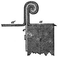
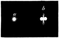
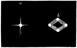
the following case is presented: A 15 1/2 inch unsilvered mirror 1 1/4 inch thick was
set with its best diameter perpendicular, the axis of the mirror being horizontal
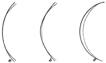
(Fig. 8). The image of a pin-hole illuminated by a lamp was then observed to be
single, sharply defined, and with interference rings surrounding it as at a, Fig. 3.
On turning the glass 90 degrees, that is one quarter way round,
its axis still pointing in the same direction, it could hardly be
realized that the same concave surface was converging the rays.
The image was separated into two of about equal intensity, as
at b, with a wing of light going out above and below from the
junction. Inside and outside of the focal plane the cone of
rays had an elliptical section, the major axis being horizontal
inside, and perpendicular outside. Turning the mirror still
more round the image gradually improved, until the original diameter was perpendicular
again—the end that had been the uppermost now being the lowest. A
similar series of changes occurred in supporting the glass on various parts of the
other semicircle. It might be supposed that irregularities on the edge of the glass
disk, or in the supporting arc would account for the phenomena. But two facts
dispose of the former of these hypotheses: in the first place if the glass be turned
exactly half way round, the character of the image is unchanged, and it is not to
be believed that in many different mirrors this could occur by chance coincidence.
In the second place, one of these mirrors has been carefully examined after being
ground and polished three times in succession, and on each occasion required the
same diameter to be perpendicular. As to the second hypothesis no material difference
is observed whether the supporting arc below be large or small, nor when it
is replaced by a thin semicircle of tinplate lined with cotton wool.
I am led to believe that this peculiarity results from the structural arrangement
of the glass. The specimens that have served for these experiments have probably
been subjected to a rolling operation when in a plastic state, in order to be reduced
to a uniform thickness. Optical glass, which may be made by softening down
irregular fragments into moulds at a temperature below that of fusion, may have
the same difficulty, but whether it has a diameter of minimum compression can
only be determined by experiment. Why speculum metal should have the same
property might be ascertained by a critical examination of the process of casting,
and the effect of the position of the openings in the mould for the entrance of the
molten metal.
Effects of Heat.—The preceding changes in glass when isolated appear very
simple, and their remedy, to keep the proper diameter perpendicular, is so obvious
that it may seem surprising that they should have given origin to any embarrassment.
In fact it is now desirable to have a disk in which they are well marked. But in
practice they are complicated in the most trying manner with variations produced
by heat pervading the various parts of the glass unequally. The following case
illustrates the effects of heat:—
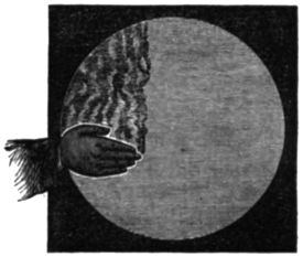
Effects of Heat on a Reflecting Surface.
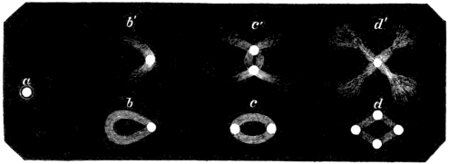
A 15 1/2 inch mirror, which was giving at its centre of curvature a very fine image
(a, Fig. 4) of an illuminated pin-hole, was heated at the edge by placing the right
hand on the back of the mirror, at one end of the horizontal diameter. In a few
seconds an arc of light came out from the image as at b′, and on putting the left
hand on the other extremity of the same diameter the appearance c′ was that of
two arcs of light crossing each other, and having an image at each intersection.
The mirror did not recover its original condition in ten minutes. Another person
on a subsequent occasion touching the ends of the perpendicular diameter at the
same time that the horizontal were warmed, caused the image d′ to become somewhat
like two of c′, put at right angles to each other. A little distance outside
the focus the complementary appearances, b, c, d, were found.
By unsymmetrical warming still more remarkable forms emerged in succession,
some of which were more like certain nebulæ with their milky light, than any
regular geometrical figure.
If the glass had, after one of these experiments, been immediately put on the
polishing machine and re-polished, the changes in surface
would to a certain extent have become permanent,
as in Chinese specula, and the mirror would have required
either re-grinding or prolonged polishing to get
rid of them. This occurred unfortunately very frequently
in the earlier stages of this series of experiments,
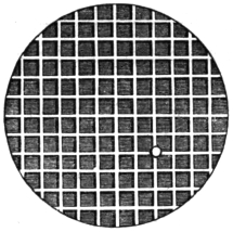
and gave origin on one occasion to a surface
which could only show the image of a pin-hole as a
lozenge (b, Fig. 5), with an image at each angle inside
the focus, and as an image a with four wings outside.
Effects of Heat rendered permanent.
But it must not be supposed that such apparent causes as these are required to
disturb a surface injuriously. Frequently mirrors in the process for correction of
spherical aberration will change the quality of their images without any perceptible
reason for the alteration. A current of cold or warm air, a gleam of sunlight, the
close approach of some person, an unguarded touch, the application of cold water
injudiciously will ruin the labor of days. The avoidance of these and similar causes
requires personal experience, and the amateur can only be advised to use too much
caution rather than too little.
Such accidents, too, teach a useful lesson in the management of a large telescope,
never, for instance, to leave one-half the mirror or lens exposed to radiate into cold
space, while the other half is covered by a comparatively warm dome. Under the
head of the Sun-Camera, some further facts of this kind may be found.
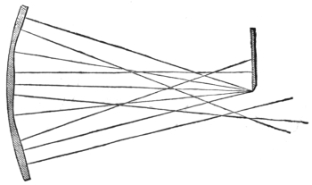
Oblique Mirrors.—Still another propensity of glass and speculum metal must be
noted. A truly spherical concave can only give an image free from distortion when
it is so set that its optical axis points to the object and returns the image directly
back towards it. But I have polished a large number of mirrors in which an image
free from distortion was produced only when oblique pencils fell on the mirror, and
the image was returned along a line forming an angle of from 2 to 3 degrees with
the direction of the object. Such mirrors, though exactly suited for the Herschelian
construction, will not officiate in a Newtonian unless the diagonal mirror be put
enough out of centre in the tube, to compensate for the figure of the mirror. Some
of the best photographs of the moon that have been produced in the observatory,
were made when the diagonal mirror was 6 inches out of centre in the 16 inch
tube. Of course the large mirror below was not perpendicular to the axis of the
tube, but was inclined 2° 32′. The figure of such a concave might be explained by
the supposition that it was as if cut out of a parabolic surface of twice the diameter,
so that the vertex should be on the edge. But if the mirror was turned 180° it
apparently did just as well as in the first position, the image of a round object being
neither oval nor elliptical, and without wings. The image, however, is never quite
as fine as in the usual kind of mirrors. The true explanation seems rather to be
that the radius of curvature is greater along one of the diameters than along that
at right angles. How it is possible for such a figure to arise during grinding and
polishing is not easy to understand, unless it be granted that glass yields more to
heat and compression in one direction than another.
After these facts had been laboriously ascertained, and the method of using such
otherwise valueless mirrors put in practice as above stated, chance brought a letter
of Maskelyne to my notice. He says, “I hit upon an extraordinary experiment
which greatly improved the performance of the six-feet reflector”.... It was
one made by Short. “As a like management may improve many other telescopes,
I shall here relate it: I removed the great speculum from the position it ought to
hold perpendicular to the axis of the tube when the telescope is said to be rightly
adjusted, to one a little inclined to the same and found a certain inclination of about
2 1/2° (as I found by the alteration of objects in the finer one of Dollond’s best night
glasses with a field of 6°), which caused the telescope to show the object (a printed
paper) incomparably better than before; insomuch that I could read many of the
words which before I could make nothing at all of. It is plain, therefore, that this
telescope shows best with a certain oblique pencil of rays. Probably it will be found
that this circumstance is by no means peculiar to this telescope.” This very valuable
observation has lain buried for eighty-two years, and ignorance of it has led to the
destruction of many a valuable surface.
As regards the method of combating this tendency, it is as a general rule best
to re-grind or rather re-fine the surface, for though pitch polishing has occasionally
corrected it in a few minutes, it will not always do so. I have polished a surface
for thirteen and a half hours, examining it frequently, without changing the obliquity
in the slightest degree.
Glass, then, is a substance prone to change by heat and compression, and requiring
to be handled with the utmost caution.
b. Emery and Rouge.
In order to excavate the concave depression in a piece of glass, emery as coarse
as the head of a pin has been commonly used. This cuts rapidly, and is succeeded
by finer grained varieties, till flour emery is reached. After that only washed
emeries should be permitted. They are made by an elutriating process invented
by Dr. Green.
Five pounds of the finest sifted flour emery are mixed with an ounce of pulverized
gum arabic. Enough water to make the mass like treacle is then added, and the
ingredients are thoroughly incorporated by the hand. They are put into a deep jar
containing a gallon of water. After being stirred the fluid is allowed to come to
rest, and the surface be skimmed. At the end of an hour the liquid containing
extremely fine emery in suspension is decanted or drawn off with a siphon, nearly
down to the level of the precipitated emery at the bottom, and set aside to subside
in a tall vessel. When this has occurred, which will be in the lapse of a few hours,
the fluid is to be carefully poured back into the first vessel, and the fine deposit in
the second put into a stoppered bottle. In the same way by stirring up the precipitate
again, emery that has been suspended 30, 10, 3, 1 minutes, and 20, 3,
seconds is to be secured and preserved in wide-mouthed vessels.
The quantity of the finer emeries consumed in smoothing a 15 1/2 inch surface is
very trifling—a mass of each as large as two peas sufficing.
Rouge, or peroxide of iron, is better bought than prepared by the amateur. It
is made by calcining sulphate of iron and washing the product in water. Three
kinds are usually found in commerce: a very coarse variety containing the largest
percentage of the cutting black oxide of iron, which will scratch glass like quartz;
a very fine variety which can hardly polish glass, but is suitable for silver films;
and one intermediate. Trial of several boxes is the best method of procuring that
which is desired.
c. Tools of Iron, Lead, and Pitch.
In making a mirror, one of the first steps is to describe upon two stout sheets of
brass or iron, arcs of a circle with a radius equal to twice the desired focal length,
and to secure, by filing and grinding them together, a concave and convex gauge.
When the radius bar is very long, it may be hung against the side of a house. By
the assistance of these templets, the convex tools of lead and iron and the concave
surface of the mirror are made parts of a sphere of proper diameter.
The excavation of a large flat disc of glass to a concave is best accomplished by
means of a thick plate of lead, cast considerably more convex than the gauge.
The central parts wear away very quickly, and when they become too flat must be
made convex again by striking the lead on the back with a hammer. The glass is
thus caused gradually to approach the right concavity. Ten or twelve hours usually
suffice to complete this stage. The progress of the excavating is tested sufficiently
well by setting the convex gauge on a diameter of the mirror, and observing how
many slips of paper of a definite thickness will pass under the centre or edge, as
the case may be. This avoids the necessity of a spherometer. The thickness of
paper is found correctly enough by measuring a half ream, and dividing by the
number of sheets. In this manner differences in the versed sine of a thousandth
of an inch may be appreciated, and a close enough approximation to the desired
focal length reached—the precision required in achromatics not being needed.
The preparation of the iron tools on which the grinding is to be finished is very
laborious where personal exertion is used. They require to be cast thin in order
that they may be easily handled, and hence cannot be turned with very great
exactness.
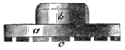
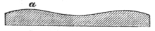
The pair for my large mirrors are 15 1/2 inches in diameter, and were cast 3/8 of an
inch thick, being strengthened however on the back by eight ribs 3/4 of an inch high,
radiating from a solid centre two inches in diameter (a, Fig. 6). They weighed 25
pounds apiece. Four ears, with a tapped hole in each, project at equal distances
round the edge, and serve either as a means of attachment for a counterpoise lever,
or as handles.
After these were turned and taken off the lathe chuck, they were found to be
somewhat sprung, and had to be scraped and ground in the machine for a week
before fitting properly. The slowness in grinding results from the emery becoming
imbedded in the iron, and forming a surface as hard as adamant.
Once acquired, such grinders are very valuable, as they keep their focal length
and figure apparently without change if carefully used, and only worked on glass
of nearly similar curvature. At first no grooves were cut upon the face, for in the
lead previously employed for fining they were found to be a fruitful source of
scratches, on account of grains of emery imbedding in them, and gradually breaking
loose as the lead wore away. Subsequently it appeared, that unless there was
some means of spreading water and the grinding powders evenly, rings were likely
to be produced on the mirror, and the iron was consequently treated as follows:—
A number of pieces of wax, such as is used in making artificial flowers, were
procured. The convex iron was laid out in squares of 3/4 of an inch on the side,
and each alternate one being touched with a thick alcoholic solution of Canada
balsam, a piece of wax of that size was put over it. This was found after many
trials to be the best method of protecting some squares, and yet leaving others in
the most suitable condition to be attacked. A rim of wax, melted with Canada
balsam, was raised around the edge of the iron, and a pint of aqua regia poured
in. In a short time this corroded out the uncovered parts to a sufficient depth,
leaving an appearance like a chess-board, except that the projecting squares did not
touch at the adjoining angles (b, Fig. 6). I should have chipped the cavities out,
instead of dissolving them away, but for fear of changing the radius of curvature
and breaking the thin plate. However as soon as the iron was cleaned, it proved
to have become flatter, the radius of curvature having increased 7 3/4 inches. This
shows what a state of tension and compression there must be in such a mass, when
the removal of a film of metal 1/50 of an inch thick, here and there, from one surface,
causes so great a change.
When the glass has been brought to the finest possible grain on such a grinder,
a polishing tool has to be prepared by covering the convex iron with either pitch
or rosin. These substances have very similar properties, but the rosin by being
clear affords an opportunity of seeing whether there are impurities, and therefore
has been frequently used, straining being unnecessary. It is, however, too hard as
it occurs in commerce, and requires to be softened with turpentine.
A mass sufficiently large to cover the iron 1/8 of an inch thick is melted in a
porcelain or metal capsule by a spirit lamp. When thoroughly liquid the lamp is
blown out, and spirits of turpentine added, a drachm or two at a time. After each
addition a chisel or some similar piece of metal is dipped into the fluid rosin, and
then immersed in water at the temperature of the room. After a minute or two it
is taken out, and tried with the thumb-nail. When the proper degree of softness is
obtained, an indentation can be made by a moderate pressure.
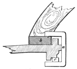
The iron having been heated in hot water is then
painted in stripes 1/8 of an inch deep with this resinous composition.
The glass concave to be polished being smeared
with rouge, is pressed upon it to secure a fit, and the iron
is then put in cold water. With a narrow chisel straight
grooves are made, dividing the surface into squares of one
inch, separated by intervals of one-quarter of an inch (Fig.
7). Under certain circumstances it is also desirable to take
off every other square, or perhaps reduce the polishing surface
irregularly here and there, to get an excess of action on
some particular portion of the mirror.
It is well, on commencing to polish with a tool made in this way, to warm the
glass as well as the tool in water (page 4) before bringing the two in contact. If
this is not done the polishing will not go on kindly, a good adaptation not being
secured for a length of time, and the glass surface being injured at the outset. The
rosin on a polisher put away for a day or two suffers an internal change, a species
of irregular swelling, and does not retain its original form. Heating, too, has a
good effect in preventing disturbance by local variations of temperature in the glass.
The description of “Local Polishers” will be given under Machines.
d. Methods of Examining Surfaces.
I have been in the habit of testing mirrors exclusively at the centre of curvature,
not putting them in the telescope tube until nearly parabolic or finished. The
means of trial are so excellent, the indications obtained so precise, and the freedom
from atmospheric disturbances so complete, that the greatest facilities are offered
for ascertaining the nature of a surface. In addition the observer is entirely independent
of day or night, and of the weather. I do not think that anything more
is learned of the telescope, even under favorable circumstances, than in the workshop.
For the improvement of these methods of observation, Science is largely
indebted to M. Foucault, whose third test—the second in the next paragraph—is
sufficient to afford by itself a large part of the information required in correcting
a concave surface.
There are two distinct modes of examination: 1st, observing with an eye-piece
the image of an illuminated pin-hole at the focus, and the cone of rays inside and
outside that plane; 2d, receiving the entire pencil of light coming from the mirror
through the pupil on the retina, and noticing the distribution of light and shade,
and the appearances in relief on the face of the mirror.
Testing a Concave at the Centre of Curvature.
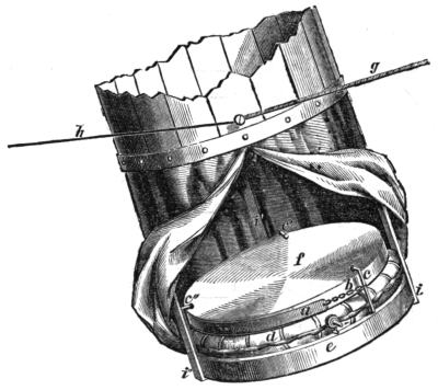
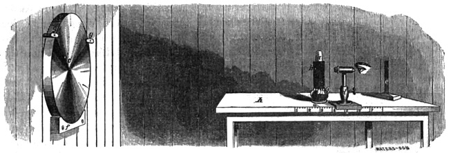
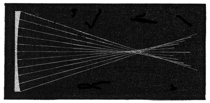
The arrangements for these tests are as follows: Around the flame of a lamp (a,
Fig. 8) a sheet of tin is bent so as to form a cylindrical screen. Through it at the
height of the brightest part of the flame, as at b, two holes are bored, a quarter of an
inch apart, one 1/32 of an inch in diameter, the other as small as the point of the finest
needle will make—perhaps 1/200 of an inch. This apparatus is to be set at the centre
of curvature of the mirror c—the optical axis of the latter being horizontal—and
so adjusted that the light which diverges from the illuminated hole in use, may,
after impinging on the concave surface of the glass, return to form an image close
by the side of the tin screen. In the case of the first test, the returning rays are
received into an eye-piece or microscope, d, magnifying 20 times, and moving upon
a divided scale to and from the mirror. In the second test the eye-piece is removed
away from before the eye, and a straight-edged opaque screen, e, is put in its place.
The mirror is supported in these trials by an arc of wood f, lined with thick woollen
stuff, and above two wooden latches, g, g, prevent it from falling forward, but
do not compress it. It is, of course, unsilvered. In the figure the table is represented
very much closer to the mirror than it should be. In trials on the 15 1/2 inch
it has to be 25 feet distant.
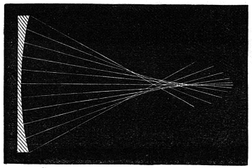
Action of the Opaque Screen.
The appearance that a truly spherical concave surface presents with the first test
is: the image of the hole is sharply defined without any areola of aberration around
it, and is surrounded by interference rings. Inside and outside the focus the cone
of rays is exactly similar, and circular in section. It presents no trace of irregular
illumination, nor any bright or dark circles. With the second test, when the eye
is brought into such a position that it receives the whole pencil of reflected rays,
and the opaque screen is gradually drawn across in front of the pupil, the brightness
of the surface slowly diminishes, until just as the screen is cutting off the last
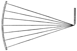
relic of the cone of rays (Fig. 9), the mirror presents
an uniform grayish tint, followed by total
darkness, and gives to the eye the sensation of a
plane.
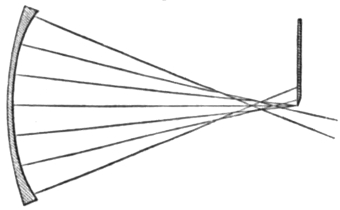
Caustic of Oblate Spheroidal Mirror.
If, however, the mirror is not spherical, but
instead gradually decreases in focal length toward
the edge, the following changes result: The
image at the best focus is surrounded by a nebulosity,
stronger as the deviation from the sphere
is greater, and neither can a sharp focus be
obtained nor interference fringes seen. In order
to include this nebulosity in the image, it will be necessary to push the eye-piece
toward the mirror. Before the cone of rays has completed its convergence, the
mass of light will be seen to have accumulated at the periphery, and after the focus
is past and divergence has commenced, the
accumulation will be around the axis. That
is, a caustic (Fig. 10) is formed with its
summit from the mirror. By the second
test, in gradually eclipsing the light coming
from the mirror, just before all the rays are
obstructed, a part of those which have constituted
the nebulosity will escape past the
screen (Fig. 11) into the eye, and cause
there an extremely exaggerated appearance
in relief of the solid superposed upon the
true surface beneath. The glass will no longer seem to be a plane, but to have a
section as in Fig. 12. Let us examine by the aid of M. Foucault’s diagrams why it
is that the surface seems thus curved. If the
dotted line, Fig. 13, represents the section
of the mirror, and the solid line a section of
a spherical mirror of the same mean focal
length, it will be seen that the curves touch
at two points, but are separated by an interval
elsewhere. If this interval be projected
by means of the differences of the ordinates,
the resulting curve will be found to be the
same as that which the mirror apparently
has.
Action of the Opaque Screen.
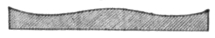
Apparent Section of Oblate Spheroidal Mirror.
If the opaque screen be drawn a short
distance from the mirror, the appearance of
the section curve will seem to change, the
bottom of the groove (Fig. 12) between the
centre and edge advancing inwards, and the
mound in the middle growing smaller. If
the screen be pushed toward the mirror the
reverse takes place, the central mound becoming larger, but the edge decreasing.
The reason for these variations becomes apparent by considering the three diagrams,
Fig. 14. The dotted curve in each instance represents the real curve of the mirror
described in the last paragraph, while the
solid lines are circles drawn with radii progressionally
shorter in a, b and c, and represent
sections of three spherical mirrors
whose focal lengths also progressively
shorten.
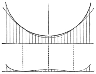
Section of Spherical and Spheroidal Mirrors.
Relation of Spheres to Oblate Spheroid.
Caustic of Hyperbolic Mirror.
Apparent Section of Hyperbolic Mirror.
When the opaque screen is at a given
distance from the mirror under examination,
the only parts of the mirror which can officiate
well are those which have a curvature
corresponding to a radius equal to the same
distance. All the other parts seem as if they were covered by projecting circular
masses. In looking at Fig. 14, it is plain, then, if the opaque screen is at a maximum
distance from the mirror, that the central parts alone will seem to operate,
because the two curves (a) only touch there. If the screen is moved toward the
mirror the curves (b) will coincide at some point between the centre and edge, while
if carried still farther in only the edges touch and the appearance will be as if a
large mound were fixed upon the centre. I have been careful in explaining how
a surface may thus seem to present entirely different characteristics if examined
from points of view which vary slightly in distance, because a knowledge of these
facts is of the utmost importance in correcting such an erroneous figure. It is now
obvious that the correction will be equally effectual if the mirror be polished with a
small rubber on the edge, or on the centre, or partly on each. The only difference
in the result will be, that the mean focal length will be increased in the first instance,
and decreased in the second, while it will remain unchanged in the third.
If the mirror, instead of having a section like that of an oblate spheroid, should
have either an ellipse, parabola, or hyperbola, as its section curve, the appearances
seen above are reversed. Whilst by the first test there is still an aberration round
the image at the best focus, the eye-piece must now be drawn from the mirror to
include it. The cone of rays is most dense round the axis inside, and at the
periphery outside the focus, and the
summit of the caustic (Fig. 15) is
turned towards the mirror. The
second test shows a section as in
Fig. 16, a depression at the centre,
and the edges turned backwards.
The nature of the movement necessary
to reduce the surface to a sphere
is very plainly indicated, action on a
zone a between the centre and edge.
If, however, a parabolic section is
required, the zone a must not be
entirely removed, and the surface
rendered apparently flat, but as much
of it must be left as experience shows to be desirable.
Action of the Opaque Screen.
Apparent Section of Mirror with Rings.
If, in still a fourth instance, the mirror is not formed by the revolution of any
regular curve upon its axis, but has upon its surface zones of longer and shorter
radius intermixed irregularly, a very common
case, the two tests still indicate with
precision the parts in fault, and the correction
demanded. Thus the mirror seen in
section in Fig. 17, when the principal mass
of light was obstructed by the opaque screen,
would still permit that coming from certain
parts to find its way into the eye.
Figure 18 represents an irregular mirror,
that was produced in the process of correction
of a hyperbolic surface, which had an
apparent section like Fig. 16 previously.
The zone a had been acted upon with a
small local polisher, and the mirror was
finished by subsequently softening down b and c with a larger tool.
After having gained from the preceding paragraphs a general idea of the value
and nature of these tests at the centre of curvature, a more particular description
of their use is desirable. M. Foucault in his methods first brings the mirror to a
spherical surface, and then by moving the luminous pin-hole toward the mirror,
and correspondingly retracting the eye-piece or opaque screen, carries it, avoiding
aberration continually by polishing, through a series of ellipsoidal curvatures,
advancing step by step toward the paraboloid of revolution. The length of the
apartment, however, soon puts a termination to this gradual system of correction,
and he is forced to perform the last steps of the conversion by an empirical process,
and eventually to resort to trial in the telescope.
With my mirrors of 150 inches focal length, demanding from the outset a room
more than 25 feet long, this successive system had to be abandoned. It was not
found feasible to place the lamp in the distant focus of the ellipse—the workshop
being less than 30 feet long—and putting the luminous source on stands outside,
introduced several injurious complications, not the least of which was currents in
the layers of variously refracting air in the apartment. In a still room the density
and hygrometric variations in its various parts only give rise to slight embarrassment.
The moment, however, that currents are produced, satisfactory examination
of a mirror becomes difficult. The air is seen only too easily to move in great
spiral convolutions between the mirror and the eye, areolæ of aberration appear
around a previously excellent image, and were it not for the second test, any determination
of surface would be impossible. By that test the real deviations from
truth of figure can be distinguished from the atmospheric,
and to a practised eye sufficient indications
of necessary changes given. Such a movement as
that caused by placing the hand in or under the line
of the converging rays, will completely destroy the
beauty of an image, and by the second test give
origin in the first case to the appearance Fig. 19.
In order to be completely exempt at all times from
aërial difficulties, it is desirable to have control of a
long underground apartment, the openings of which
can be tightly closed. As no artificial warmth is
needed, there is the minimum of movement in the
inclosed air, and conclusions respecting a surface may be arrived at in a very short
time. The mirror may also be supported from the ground, so that tremulous vibrations
which weary the eye, and interfere with the accuracy of criticism, may be
avoided.
Driven then from observing an image kept continually free from aberration,
through advancing ellipsoidal changes, it became necessary to study the gradual
increase of deformation, produced by the greater and greater departures from a
spherical surface, as the parabola was approached. It was found that a sufficient
guide is still provided in these tests, by modifying them properly.
The longitudinal aberration of a mirror of small angular opening is easily calculated—being
equal to the square of half the aperture, divided by eight times the
principal focal length. That is, if a 15 1/2 inch mirror of 150 inches focal length
were spherical, and were used to converge parallel rays, those from its edge would
reach a focus 5/100 of an inch nearer the mirror than those from its central parts.
If now the converse experiment be tried, and a mirror of the same size and focal
length which can converge parallel rays, falling on all its parts, to one focus, be
examined at the centre of curvature, it gives there an amount of longitudinal
aberration 10/100 of an inch, equal to twice the preceding. This latter, then, is the
condition at the centre of curvature, to which such mirror must be brought in order
to converge parallel rays with exactness. In addition, strict watch must be kept
upon the zones intermediate between the centre and edge, both by measurement
with diaphragms of their aberration, and better yet, by observation of the regularity
of the curve of that apparent solid, Fig. 16, seen by the second test.
This modification of the first test is literally a method of parabolizing by measure,
and is capable of great precision when the eye learns to estimate where the exact
focus of a zone is. The little irregularities found round the edges of the holes
through the tin screen, Fig. 8, are in this respect of material assistance. They
show, too, the increased optical or penetrating power that is gained by increase of
aperture. Minute peculiarities, not visible under very high powers with a 10 inch
diaphragm, become immediately perceptible even with less magnifying when the
whole aperture is used, provided the mirror is spherical.
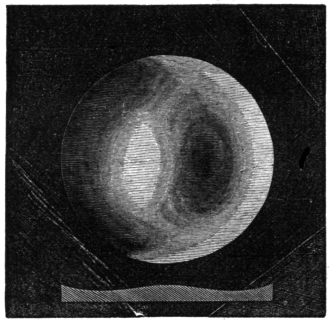
Adjusting the Opaque Screen.
In the use of the second test precautions have to be taken, as may be inferred
from page 15, to set the opaque screen exactly in the proper position. The best
method for ascertaining its location is, having received the image into the eye,
placed purposely too near the mirror, to cause the screen to move across the cone
of rays from the right towards the left side. A jet black shadow begins to advance
at the same time, and in the same direction
across the mirror. If the eye is then moved
from the mirror sufficiently, this black shadow
can be made to originate by the same motion
of the screen as before, from the left or opposite
side of the mirror. Midway between these
extremes there is a point where the advance is
from neither side. This is the true position
for the screen when it is desired to see the imperfections
of the surface in highly exaggerated
relief, as in Fig. 20, which represents the
appearance of Fig. 12.2
The interpretation of the lights and shadows
upon the face of a mirror in this test is always
easy, and the observer is not likely to mistake
an elevation for a depression, if he bears in mind the fact that the surface under
examination must always be regarded as illuminated by an oblique light coming
from a source on the side opposite to that from which the screen advances, coming
for instance from the left hand side, in the above description.
In practice, the diaphragms commonly used for a 15 1/2 inch mirror have been as
small as the light from the unsilvered surface would allow. A six inch aperture at
the centre, a ring an inch wide round the edge, and a two inch zone midway between
the two.
e. Machines.
In the beginning of this section the difficulties into which I fell with Lord Rosse’s
machine were stated. These caused it at the time to be abandoned. A machine
based on the same idea as Mr. Lassell’s beautiful apparatus was next constructed.
It varied, however, in this, that the hypocycloidal curve was described partly by the
rotation of the mirror, and partly by the motions of the polisher—the axes of the
spindles carrying the two being capable either of coincidence or lateral separation
to a moderate extent. A great deal of time and labor was expended in grinding
and polishing numerous mirrors with it, but still the difficulty that had been so
annoying in the former machine persisted. Frequently, in fact generally, from six
to eight zones of unequal focal length were visible, although on some occasions
when the mirror was hyperbolic, the number was reduced to two. At first it was
supposed that the fault lay with the polishing, the pitch accumulating irregularly
from being of improper softness, for it was found to be particularly prone to heap
up at the centre. But after I had introduced a method of fine grinding with elutriated
hone powder, which enabled the glass to reject light before the pitch
polishing, it became evident that the zones were connected with the mode of
motion of the mechanism. Many changes were made in the speed of its various
elements, and a contrivance to control the irregular motion of the polisher introduced,
but a really fine and uniform parabolic surface was never obtained, the very
best showing when finished zones of different focal lengths. Although it cannot
be said that I have tried this machine thoroughly, for Mr. Lassell has produced
specula of exquisite defining power with it, and must have avoided these imperfections
to a great extent, yet the evident necessity of complicating the movement3
considerably, to avoid the polishing in rings, led me to adopt an entirely different
construction, which was used until quite recently. Although it has now been
replaced by another machine, which is still better in principle, and gives fine results
much more quickly, yet as it produced one parabolic surface that bore a power of
more than 1000, and as it serves to introduce the process of grinding, it is worthy
of description. The action of machines for grinding and polishing has been
thoroughly examined in my workshop, no less than seven different ones having
been made at various times.
The machine, which is a simplification of Lord Rosse’s, was intended to give
spiral strokes. It differed from the original, however, in demanding a changeable
stroke, and in the absence of the lateral motion. In another most essential feature
it varied from both that and Mr. Lassell’s, the mirror was always uppermost while
polishing, and being uncounterpoised escaped to as great an extent as possible from
the effects of irregular pressure. To any one who has studied the deformations of
a reflecting surface, and knows how troublesome it is to support a mirror properly,
the advantage is apparent.
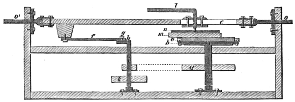
The construction is as follows: A stout vertical shaft, a, Fig. 21, carries at its
top a circular table b, upon which the polisher c is screwed. Below a band-wheel d
is fixed. Above the table, at a distance of four inches, a horizontal bar e is arranged,
so as to move back and forward in the direction of its length, and to carry with it
by means of a screw l, the mirror m, and its iron back or chuck n. The bar is
moved by a connecting rod f, attached to it at one end, and at the other to a pin g
moving a slot. This slot is in a crank h, carried by a vertical shaft i, near the
former one a. The band-wheel k is connected with the foot power, Fig. 22. The
machine, except those parts liable to wear by friction, is made of wood. The ends
o o′ of the horizontal bar e, are defended by brass tubes working in mahogany, and
have even now but little shake, though many hundred thousands of reciprocations
have been made.
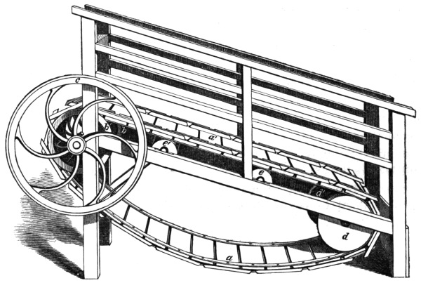
The foot power consists of an endless band with wooden treads a a′, passing at
one end of the apparatus over iron wheels b b′, which carry the band-wheel c upon
their axle. At the other end it goes over the rollers d d′. Two pairs of intermediate
wheels e e′, serve to sustain the weight of the man or animal working in it.
The treads are so arranged that they interlock, and form a platform, which will
not yield downwards. Owing to its inclination when a weight is put on the platform
a′, it immediately moves from b toward d and the band-wheel turns. By a
moderate exertion, equivalent to walking up a slight incline at a slow rate, a power
more than sufficient to polish a 15 1/2 inch mirror is obtained. This machine,
in which very little force is lost in overcoming friction, is frequently employed
for dairy use, and is moved commonly in the State of New York by a sheep. I
have generally myself walked in the one used by me, and have travelled some days,
during five hours, more than ten miles.
In order to give an idea of the method of using a grinding and polishing machine,
the following extract from the workshop note-book is introduced:—
“A disk of plate glass 15 1/2 inches in diameter, and 1 1/4 inch thick was procured.
It had been polished flat on both sides, so that its internal constitution
might be seen.4 It was fastened upon the table b of the machine, by four blocks
of wood as at c, Fig. 21. Underneath the glass were three thick folds of blanket,
15 inches in diameter, to prevent scratching of the lower face, and avoid risk of
fracture. A convex disk of lead weighing 40 pounds having been cast, was laid
upon the upper surface of the glass, and then the screw l was depressed so as to
catch in a perforated iron plate n, at the back of the lead m, and press downward
strongly.
“Emery as coarse as the head of a pin having been introduced, through a hole
in the lead, motion was commenced and continued for half an hour, an occasional
supply of emery being given. The machine made 150 eight-inch cross strokes, and
the mirror 50 revolutions per minute. The grinder m was occasionally restrained
from turning by the hand. At the end of the time the detritus was washed away,
and an examination with the gauge made. A spot 11 inches in diameter, and 1/60
of an inch deep, was found to have been ground out. The same process was continued
at intervals for ten hours, measurements with the gauge being frequently
made. The concave was then sufficiently deep. The leaden grinder was kept of
the right convexity by beating it on the back when necessary. A finer variety of
coarse emery, and after that flour emery were next put on, each for an hour. These
left the surface moderately smooth, and nearly of the right focal length. The
leaden grinder was then dismissed, and the iron one, Fig. 6, put in its stead. The
mirror was removed from its place, and ground upon a large piece of flat glass for
ten minutes, to produce a circular outline to the concavity. It was cemented with
soft pitch to the concave iron disk, the counterpart of Fig. 6, and again recentred
on the blanketed table b. Emeries of 3 and 20 seconds, and 1, 3, 10, 30, 60 minutes’
elutriation were worked on it, an hour each. The rate of cross motion was reduced
to 25 per minute to avoid heating, the mirror still revolving once for every three
cross strokes. The screw pressure of l was stopped. This produced a surface
exquisitely fine, semi-transparent, and appearing as if covered with a thin film of
dried milk. It could reflect the light from objects outside the window until an
incidence of 45 degrees was reached, and at night was found to be bright enough
for a preliminary examination at the centre of curvature.
“The polisher was constructed in the usual way (page 12), and being smeared
with rouge was fastened to the table b, where the mirror had been. The latter
warmed in water to 120° F., was then put face downwards upon the former, and
the screw l so lowered as to cause no pressure. The machine was allowed to make
20 four-inch cross strokes per minute, and the polisher to revolve once for every
three strokes. The mirror being unconstrainedly supported on the polisher, was
irregularly rotated by hand, or rather prevented from rotating with the polisher.
The tendency of this method is to produce an almost spherical surface. To change
it to a paraboloid, it was only necessary when the glass was polished all over to
increase the length of the stroke to 8 inches, and continue working fifteen minutes
at a time, examining in the intervals by the tests at the centre of curvature. The
production of a polish all over occupied about two hours, but the correction of
figure took more time, on account of the frequent examinations, and the absolute
necessity of allowing the mirror to come back to a state of equilibrium from which
it had been disturbed when worked on the machine.” I have seen a mirror which
was parabolic when just off the machine, by cooling over night become spherical.
And these heat changes are often succeeded by other slower molecular movements,
which continue to modify a surface for many days after.
This correction, where time and not length of stroke is the governing agent, has
once or twice been accomplished in fifteen minutes, but sometimes has cost several
hours. If the figure should have become a hyperboloid of revolution, that is, have
its edge zones too long in comparison with the centre, it is only necessary to shorten
the stroke to bring it back to the sphere, or even to overpass that and produce a
surface in which at the centre of curvature the edge zones have too short a focal
length (Fig. 12).
Very much less trouble from zones of unequal focal length was experienced after
this machine and system of working were adopted. This was owing probably partly
to the element of irregularity in the rotation of the mirror, and partly to the fact
that the surface is kept spherical until polished, and is then rapidly changed to
the paraboloid. Where the adjustments of an apparatus are made so as to attempt
to keep a surface parabolic for some hours, there is a strong tendency for zones to
appear, and of a width bearing a fixed relation to the stroke.
The method of producing reflecting surfaces next to be spoken of, is however
that which has finally been adopted as the best of all, being capable of forming
mirrors which are as perfect as can be, and yet only requiring a short time. It
is the correction of a surface by local retouches. In the account published by M.
Foucault, it appears that he is in France the inventor of this improvement.
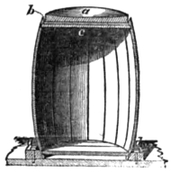
Section of Optician’s Post.
The mode of practising the retouches is as follows: Several disks of wood, as a,
Fig. 23, varying from 8 inches to 1/2 an inch in diameter, are to be provided, and
covered with pitch or rosin of the usual hardness, in squares
as at c, on one side.5 On the other a low cylindrical handle
b, is to be fixed. The mirror a, Fig. 24, having been fined
with the succession of emeries before described, is laid face
upward on several folds of blanket, arranged upon a circular
table, screwed to an isolated post in the centre of the apartment,
which permits the operator to move completely round it. An ordinary barrel
has generally supplied the place of the post, the head c, Fig. 24, serving for the
circular table, and the rim b preventing the mirror sliding
off. The other end is fastened to the floor by four cleets d d´.
The large polisher is first moved over the surface in straight
strokes upon every chord, and a moderate pressure is exerted.
As soon as the mirror is at all brightened, perhaps in
five minutes, the operation is to be suspended, and an examination
at the centre of curvature made. By carefully
turning round, the best diameter for support is to be found,
and marked with a rat-tail file on the edge, and then the
curve of the mirror ascertained. If it is nearly spherical,
as will be the case if the grinding has been conducted with
care and irregular heating avoided, it is to be replaced on the blanketed support, and
the previous action kept up until a fine polish, free from dots like stippling, is
attained. This stage should occupy three or four hours. Another examination
should reveal the same appearances as the preceding. It is next necessary to
lengthen the radius of curvature of the edge zones, or what is much better shorten
that of the centre, so as to convert the section curve into a parabola. This is
accomplished by straight strokes across every diameter of the face, at first with a
4 inch, then with a 6 inch, and finally with the 8 inch polisher. Examinations
must, however, be made every five or ten minutes, to determine how much lateral
departure from a direct diametrical stroke is necessary, to render the curve uniform
out to the edge. Care must be taken always to warm the polisher, either in front
of a fire or over a spirit lamp, before using it.
Perhaps the most striking feature in this operation is that the mirror presents
continually a curve of revolution, and is not diversified with undulations like a
ruffle. By walking steadily round the support, on the top of which the mirror is
placed, there seems to be no tendency for such irregularities to arise.
If the correction for spherical aberration should have proceeded too far, and
the mirror become hyperbolic, the sphere can be recovered by working a succession
of polishers of increasing size on the zone a, Fig. 16, intermediate between the
centre and edge, causing their centres to pass along every chord that can be described
tangent to the zone.
A most perfect and rapid control can thus be exercised over a surface, and an
uniform result very quickly attained. It becomes a pleasant and interesting occupation
to produce a mirror. But two effects have presented themselves in this
operation, which unfortunately bar the way to the very best results. In the first
place the edge parts of such mirrors, for more than half an inch all around, bend
backwards and become of too great focal length, and the rays from these parts
cannot be united with the rest forming the image. In the second place, the surface,
when critically examined by the second test, is found to have a delicate wavy
or fleecy appearance, not seen in machine polishing.6 Although the variations from
the true curve implied by these latter greatly exaggerated imperfections are exceedingly
small, and do not prevent a thermometer bulb in the sunshine appearing
like a disk surrounded by rings of interference, yet they must divert some undulations
from their proper direction, or else they would not be visible. All kinds of
strokes have been tried, straight, sweeping circular, hypocycloidal, &c. without
effecting their removal. M. Foucault, who used a paper polisher, also encountered
them. Eventually they were imputed to the unequal pressure of the hand, and in
consequence a machine to overcome the two above mentioned faults of manual
correction was constructed.
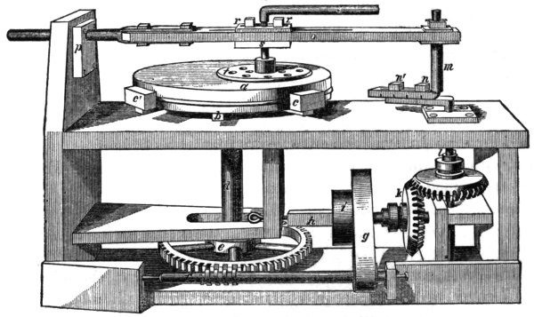
Machine for Local Corrections.
The mirror a, is carried by an iron chuck or table b, covered with a triple
fold of blanket, and is prevented from slipping off by four cleets c c′. The vertical
shaft d passes through a worm-wheel e, the endless screw of which f, is driven
by a band g, from the primary shaft h. At i is the band-wheel for connection to
the foot-power. At one end of the primary shaft is firmly fixed the cogwheel k,
which drives the crank-shaft l. Attached to the horizontal part of l, is the crank-pin
m. The two bolts n n′ move in a slot, so that the crank-pin may be set at any
distance from 0 to 2 inches, out of line with l. Above, the crank-pin carries one
end of the bar o, the other end passing through an elliptical hole in the oak-block
p. Down the middle of the bar runs a long slot, through which the screw-pin q
passes, and which permits q to be brought over any zone from the centre to the
edge of the mirror a. It is retained by the bolts r r′, which are tapped into s.
The local polisher is seen at t. The curve which the centre of the local polisher
describes upon the face of the mirror, varies with the adjustments. Fig. 26 is a
reduction from one traced by the machine, the overlapping
being seen on the left side. The mirror is not tightly confined
by the cleets c c′, for that would certainly injure the
figure, but performs a slow motion of rotation, so that in
no two successive strokes are the same parts of the edge
pressed against them.
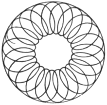
The local polishers are made of lead, alloyed with a small
proportion of antimony, and are 8, 6, and 4 inches in diameter,
respectively. The largest and smallest are most
used, the former on account of its size polishing most
quickly, but the latter giving the truest surface. The rosin
that covers them is just indentable by the thumb nail, and is arranged in a novel
manner. The leaden basis, as seen at t, Fig. 25, is perforated in many places with
holes, which permit evaporation, serve for the introduction of water where needed,
and allow the rosin to spread freely. Grooves are made from one aperture to
another, and the rosin thus divided into irregular portions. The effects of the production
of heat are in this way avoided.
The mirror may be ground and fined on this machine, in the same manner as on
that described at page 21, or it may be ground with a small tool 8 inches in
diameter, as recently suggested by M. Foucault, the results in the latter case being
just as good a surface of revolution as in the former. It is best polished with the
8 inch, and a moderate pressure may be given by the screw q, if the pitch is not
too soft. This, however, tends to leave an excavated place at the centre of the
mirror, the size depending on the stroke of the crank m, which should be about 2
inches. The pin q ought to be half way from the centre to the edge of the mirror,
but must be occasionally moved right or left an inch along the slot. When the
surface is approaching a perfect polish, the warmed 4 inch polisher must be put in
the place of the 8 inch. The pin q must be set exactly half-way between the centre
and edge of the mirror, and the crank must have a stroke of two inches radius.
The polisher then just goes up to the centre of the glass surface with one edge,
and to the periphery with the other, while the outer excursion of the inner edge
and inner excursion of the outer edge meet, and neutralize one another at a midway
point. Wherever the edge of a polisher changes direction many times in
succession, on a surface, a zone is sure to form, unless avoided in this manner. All
the foregoing description is for a 15 1/2 inch mirror.
By this system of local polishing the difficulties of heat, distribution of polishing
powders, irregular contact of the rosin, &c. that render the attainment of a fine
figure so uncertain usually, entirely disappear. A spherical surface is produced as
above described, and afterwards by moving q towards the edge, and at the same
time increasing the stroke, it is converted into a paraboloid. The fleecy appearance
spoken of on a former page is not perceived, and the surface is good almost up to
the extreme edge.
(4.) Eye-Pieces, Plane Mirrors and Test Objects.
The telescope is furnished with several eye-pieces of various construction, giving
magnifying powers from 75 to 1200, or if it were desired even higher. For the
medium powers 300 and 600 Ramsden, or rather positive eye-pieces have been
adopted. They differ, however, from the usual form in being achromatic, that is,
each plano-convex is composed of a flint and crown, arranged according to formulas
calculated by Littrow. In this way a large flat field and absence of color are
secured, and the fine images yielded by the mirror are not injured. For the higher
powers, single achromatic lenses are used, and for the highest of all a Ross
microscope.
With these means it has been found that the parabolic surfaces yielded by the
processes before described, will define test objects excellently. Of close double
stars they will separate such as γ2 Andromedæ, and show the colors of the components.
In the case of unequal stars which seem to be more severe tests, they can
show the close companion of Sirius—discovered by Mr. Alvan Clark’s magnificent
refractor—the sixth component of θ1 Orionis, and a multitude of other difficult
objects.
As an example of light collecting power, Debillisima between ε and 5 Lyræ is
found to be quintuple, as first noticed by Mr. Lassell. In the 18 1/2 inch specula of
Herschel, it was only recorded as double, and, according to Admiral Smyth, Lord
Rosse did not notice the fourth and fifth components. Jupiter’s moons show with
beautiful disks, and their difference in diameter is very marked. As for the body
of that planet, it is literally covered with belts up to the poles. The bright and
dark spots on Venus, and the fading illumination of her inner edge, and its irregularities
are perceived even when the air is far from tranquil. Stars are often seen
as disks, and without any wings or tails, unless indeed the mirror should be wrongly
placed, so that the best diameter for support is not in the perpendicular plane, passing
through the axis of the tube.
It has been found that no advantage other than the decrease of atmospheric
influence on the image, results from cutting down the aperture of these mirrors by
diaphragms, while the disadvantage of reducing the separating power, is perceived
at the same time. Faint objects can be better seen with the whole surface than
with a reduced aperture, and this though apparently a property common to all
reflectors and object glasses is not so in reality. A defective edge will often cause
the whole field to be filled with a pale milky light, which will extinguish the fainter
stars. Good definition is just as important for faint as for close objects.
The properties of these mirrors have been best shown by the excellence of the
photographs taken with them. Although these are not as sharp as the image seen
in the telescope, yet it must not be supposed that an imperfect mirror will give just
as good pictures. A photograph which is magnified to 3 feet, represents a power
of 380. As the original negative taken at the focus of the mirror is not quite 1 1/2
inch in diameter when the moon is at its mean distance, it has to be enlarged
about 25 times, and has therefore to be very sharp to bear it.
The light collecting power of an unsilvered mirror is quite surprising. With a
15 1/2 inch, the companion of α Lyræ can be perceived, though it is only of the
eleventh magnitude. The moon and other bright objects are seen with a purity
highly pleasing to the eye, some parts being even more visible than after silvering.
In order to finish this description, one part more of the optical apparatus requires
to be noticed—the plane mirrors. In the Newtonian reflector the image is rejected
out at the side of the tube by a flat surface placed at 45° with the optical axis of
the large concave.7 If this secondary mirror is either convex or concave, it modifies
the image injuriously, causing a star to look like a cross, and this though the curvature
be so slight as hardly to be perceptible by ordinary means. For a long time
I used a piece 3 × 5 inches, which was cut from the centre of a large looking-glass
accidentally broken, but eventually found that by grinding three pieces of 6 inches
in diameter against one another, and polishing them on very hard pitch, a nearer
approach to a true plane could be made. They were tested by being put in the
telescope, and observing whether the focus was lengthened or shortened, and also
by trial on a star. When sufficiently good to bear these tests, a piece of the right
size was cut out with a diamond, from the central parts.
§2. THE TELESCOPE MOUNTING.
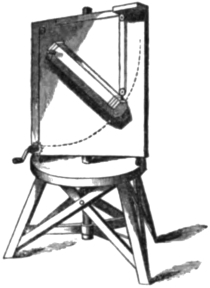
Miss Herschel’s Telescope.
The telescope is mounted as an altitude and azimuth instrument, but in a manner
that causes it to differ from the usual instrument of that kind. The essential
feature is, that the eye-piece or place of the sensitive plate is
stationary at all altitudes, the observer always looking
straight forward, and never having to stoop or assume inconvenient
and constrained positions.
The stationary eye-piece mounting was first used by
Miss Caroline Herschel, who had a 27 inch Newtonian
arranged on that plan. Fig. 27. (Smyth’s Celestial Cycle.)
Subsequently it was applied to a large telescope by Mr.
Nasmyth, the eminent engineer, but no details of his construction
have reached me. He used it for making drawings
of the moon, which are said to be excellently executed.
When it became necessary to determine how my telescope
should be mounted, I was strongly urged to make it
an equatorial. But after reflecting on the fact that it was intended for photography,
and that absolute freedom from tremor was essential, a condition not attained in
the equatorial when driven by a clock, and in addition that in the case of the moon
rotation upon a polar axis does not suffice to counteract the motion in declination,
I was led to adopt the other form.
A great many modifications of the original idea have been made. For instance,
instead of counterpoising the end of the tube containing the mirror by extending
the tube to a distance beyond the altitude or horizontal axis, I introduced a system
of counterpoise levers which allows the telescope to work in a space little more than
its own focal length across. This construction permits both ends of the tube to be
supported, the lower one on a wire rope, and gives the greatest freedom from tremor,
the parts coming quickly to rest after a movement. In the use of the telescope for
photography, as we shall see, the system of bringing the mass of the instrument to
complete rest before exposing the sensitive plate, and only driving that plate itself
by a clock, is always adopted.
The obvious disadvantage connected with the alt-azimuth mounting—the difficulty
of finding some objects—has not been a source of embarrassment. In fact
the instability of the optical axis in reflecting instruments, if the mirror is unconstrainedly
supported, as it should be, renders them unsuitable for determinations of
position. A little patience will enable an observer to find all necessary tests, or
curious objects.
The mounting is divided into: a. The Tube; and b. The supporting frame.
a. The Tube.
The telescope tube is a sixteen sided prism of walnut wood, 18 inches in diameter,
and 12 feet long. The staves are 3/8 of an inch thick, and are hooped together with
four bands of brass, capable of being tightened by screws. Inside the tube are
placed two rings of iron, half an inch thick, reducing the internal diameter to about
16 inches. At opposite sides of the upper end of the tube are screwed the perforated
trunnions a, Fig. 28 (of which only one is shown), upon which it swings.
Surrounding the other end is a wire rope b b′ b″, the ends of which go over the
pulleys c (c′ not shown) on friction rollers, and terminate in disks of lead d d′.
These counterpoises are fastened on the ends of levers e e′, which turn below on a
fixed axle f.
By this arrangement as the tube assumes a horizontal position and becomes, so
to speak, heavier, the counterpoises do the same, while when the tube becomes
perpendicular, and most of its weight falls upon the trunnions, the counterpoises are
carried mostly by their axle. A continual condition of equilibrium is thus reached,
the tube being easily raised or depressed to any altitude desired. It is necessary,
however, to constrain the wire rope b b′ b″, to move in the arc of the circle described
by the end of the tube and ends of the levers and hence the twelve rollers or guide
pulleys g g′ g″. Over some of the same pulleys a thin wire rope h h′ runs, but while
its ends are fastened to the lower part of the tube at b, the central parts go twice
around a roller connected with the winch i, near the eye-piece, thus enabling the
observer to move the telescope in altitude, without taking the eye from the eye-piece.
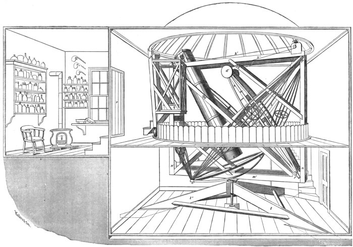
Sectional View of Observatory.
The iron wire rope required to be carefully made, so as to avoid rigidity. It
contains 2 1/3 miles of wire, 1/100 of an inch in diameter, and has 300 strands. Each
single wire will support 7 pounds. It is, however, more flexible than a hempen
rope of the same size, owing to its loose twisting.
At the lower end of the tube, at the distance of a foot, and crossing it at right
angles, held by three bars of iron i i′ i″, Fig. 29, is a circular table of oak e, which
carries an India-rubber air sac d, and upon this the mirror f is placed. The edge
support of the mirror is furnished by a semicircular band of tin-plate a, lined inside
with cotton, and fastened at the ends by links of chain b, (b′ not seen) to two screws
c c′; g and h are the wire ropes, marked b and h in Fig. 28.
Instead of the blanket support which Herschel found so advantageous, M. Foucault
has suggested this use of an air sac. In his instrument there is a tube going
up to the observer, by which he may adjust its degree of inflation. It requires
that there should be three bearings c c′ c″, in front of the mirror, against which it
may press when the sac behind is inflated, otherwise the optical axis is altogether
too instable, and objects cannot be found. The arrangement certainly gives beautiful
definition, bringing stars to a disk when the glass just floats, without touching
its front bearings. The first sac that I made was composed of two circular sheets
of India-rubber cloth, joined around the edges. But this could not be used while
photographing, because the image was kept in a state of continuous oscillation if
there was a breeze, and even under more favorable circumstances took a long time
to come to rest. It was not advisable to blow the mirror hard up against its three
front bearings, in order to avoid the instability, for then every point in of an object
became triple. To the eye the oscillations were not offensive, because the swaying
image was sharp.
Subsequently, however, an air chair cushion was procured, and as the surface was
flat instead of convex the difficulty became so much less, that the blanket support
was definitely abandoned. It is necessary that the mirror should have free play in
the direction of the length of the tube when this kind of support is used, and that
is the reason why the tin edge hoop must terminate in links of chain.
The interval, eight or ten inches, which separates the face of the mirror from the
tube, is occupied by a curtain of black velvet, confined below by a drawing cord
and tacked above to the tube. This permits access to the mirror to put a glass
cover on it, and when shut down stops the current of air rushing up. When the
instrument is not being used this curtain is left open, because the mirror and tube
are in that case kept more uniform in temperature with the surrounding air.
In spite of such contrivances there is still sometimes a strong residual current
in the tube. I have tried to overcome it by covering the mouth of the tube with
a sheet of flat glass, but have been obliged to abandon that because the images
were injured. At one time, too, when it was supposed that the current was partly
from the observer’s body, heated streams of air going out around the tube, the
aperture in the dome was closed by a conical bag of muslin, which fitted the mouth
of the telescope tightly. The only advantages resulting were mere bodily comfort
and a capability of perceiving fainter objects than before, because the sky-light
was shut off.
b. The Supporting Frame.
The frame which carries the preceding parts is of wood, and rests on a vertical
axis a, Fig. 30, turning below in a gun-metal cup b, supported by a marble block
resting on the solid rock. The upper end of the axis is sustained by two collars,
one c c′ above, and the other below an intermediate triangular box e e′ from the
sides of which three long beams f f f 12 × 3 inches diverge, gradually declining
till they meet the solid rock at the limits of the excavation in which the observatory
is placed. These beams are fastened together by cross-pieces g g g, Fig. 31, and
go through the floor in spaces h h h, so contrived that the floor does not touch them.
At the ends they are cased with a thick leaden sheathing, to deaden vibration
and prevent the access of moisture.
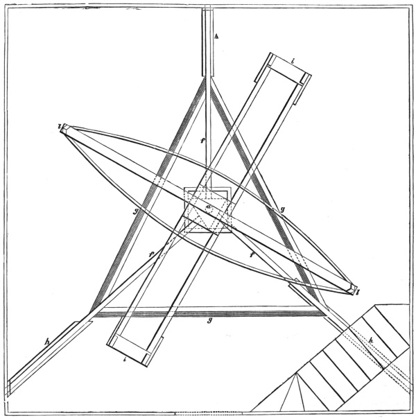
Plan of Observatory (lower floor).
This tripod support in connection with the sustaining of the telescope by the wire
rope, gives that steadiness which is so essential in photography. Only a slight
amount of force, about two pounds, is required to move the instrument in azimuth,
though it weighs almost a thousand pounds.
The plan of the frame centrally carried by the axis a is as follows: From the
corners of a parallelogram i i (2 × 13 feet) of wooden beams, eight inches thick
and three inches broad, perpendiculars n n′, Fig. 28, rise. At the top they are
connected by lighter pieces to form a parallelogram, similar to that below, and just
large enough to contain the tube of the telescope. At right angles to the parallelogram
below, and close upon it, a braced bar o o′, Fig. 28, crosses. From its extremities
four slanting braces as at p p′, Fig. 28, go to the corners of the upper
parallelogram, and combine to give it lateral support. At the top of one close
pair of the perpendiculars n′, Fig. 28, are bronze frames carrying friction rollers
upon which the trunnions move, while similarly upon the other pair n are two
pulleys, also on friction rollers, for the wire rope coming from the counterpoises.
Movement in altitude is very easily accomplished, and with the left hand upon
the winch i, under high powers, both altitude and azimuth motions are controlled,
and the right hand left free. The whole apparatus works so well, that in ordinary
observation the want of a clock movement has not been felt. Of course for photography
that is essential.
§3. THE CLOCK MOVEMENT.
The apparatus for following celestial bodies is divided into two parts; a. The
Sliding Plate-holder; and b. The Clepsydra. In addition a short description of the
Sun-Camera, c, is necessary.
a. The Sliding Plate-holder.
Mr. De La Rue, who has done so much for celestial photography, was the first
to suggest photographing the moon on a sensitive plate, carried by a frame moving
in the apparent direction of her path. He never, however, applied an automatic
driving mechanism, but was eventually led to use a clock which caused the
whole telescope to revolve upon a polar axis, and thus compensate for the rotation
of the earth, and on certain occasions for the motion of the moon herself. In this
way he has produced the best results that have been obtained in Europe. Lord
Rosse, too, employed a similar sliding plate-holder, but provided with clock-work
to move it at an appropriate rate. I have not been able as yet to procure any
precise account of either of these instruments.
The first photographic representations of the moon ever made, were taken by
my father, Professor John W. Draper, and a notice of them published in his quarto
work “On the Forces that Organize Plants,” and also in the September number,
1840, of the London, Edinburgh, and Dublin Philosophical Magazine. He presented
the specimens to the New York Lyceum of Natural History. The Secretary
of that Association has sent me the following extract from their minutes:—
“March 23d, 1840. Dr. Draper announced that he had succeeded in getting a
representation of the moon’s surface by the Daguerreotype.... The time
occupied was 20 minutes, and the size of the figure about 1 inch in diameter.
Daguerre had attempted the same thing, but did not succeed. This is the first time
that anything like a distinct representation of the moon’s surface has been obtained.
“Robt. H. Brownne, Secretary.”
As my father was at that time however much occupied with experiments on the
Chemical Action of Light, the Influence of Light on the Decomposition of Carbonic
Acid by Plants, the Fixed Lines of the Spectrum, Spectrum Analysis, &c., the
results of which are to be found scattered through the Philosophical Magazine,
Silliman’s Journal, and the Journal of the Franklin Institute, he never pursued this
very promising subject. Some of the pictures were taken with a three inch, and
some with a five inch lens, driven by a heliostat.
In 1850, Mr. Bond, taking advantage of the refractor of 15 inches aperture at
Cambridge, obtained some fine pictures of the moon, and subsequently of double
stars, more particularly Mizar in Ursa Major. The driving power, in this instance,
was also applied to move the telescope upon a polar axis.
Besides these, several English and continental observers, Messrs. Hartnup, Phillips,
Crookes, Father Secchi, and others, have worked at this branch of astronomy, and,
since 1857, Mr. Lewis M. Rutherfurd, of New York, has taken many exquisite
lunar photographs, which compare favorably with foreign ones.
But in none of these instances has the use of the sliding plate-holder been persisted
in, and its advantages brought into view. In the first place it gets rid completely
of the difficulties arising from the moon’s motion in declination, and in the
second, instead of injuring the photograph by the tremors produced in moving the
whole heavy mass of a telescope weighing a ton or more, it only necessitates the
driving of an arrangement weighing scarcely an ounce.
My first trials were with a frame to contain the sensitive plate, held only at three
points. Two of these were at the ends of screws to be turned by the hands, and
the third was on a spring so as to maintain firm contact. This apparatus worked
well in many respects, but it was found that however much care might be taken,
the hands always caused some tremor in the instrument. It was evident then
that the difficulty from friction which besets the movements of all such delicate
machinery, and causes jerking and starts, would have to be avoided in some other way.
I next constructed a metal slide to run between two parallel strips, and ground
it into position with the greatest care. This, when set in the direction of the moon’s
apparent path, and moved by one screw, worked better than the preceding. But
it was soon perceived that although the strips fitted the frame as tightly as practicable,
an adhesion of the slide took place first to one strip and then to the other, and
a sort of undulatory or vermicular progression resulted. The amount of deviation
from a rectilinear motion, though small, was enough to injure the photographs.
At this stage of the investigation the regiment of volunteers to which I belonged
was called into active service, and I spent several months in Virginia.
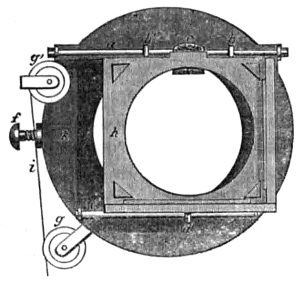
My brother, Mr. Daniel Draper, to whose mechanical ingenuity I have on several
occasions been indebted for assistance in the manifold difficulties that have arisen
while constructing this telescope, continued these experiments at intervals. He
presented me on my return with a slide and sand-clock, with which some excellent
photographs have been taken. He had found that unless the slide above mentioned
was made ungovernably long, the same trouble continued. He then ceased catching
the sliding frame h, Fig. 32, by two opposite sides, and made it run along a
single steel rod a, being attached by means of two perforated plates of brass b, b′.
The cord i going to the sand-clock, was applied so as to pull as nearly as possible in
the direction of the rod. A piece of cork c, gave the whole steadiness, and yet
softness of motion. The lower end of the frame was prevented from swinging back
and forward by a steel pin d, which played along the glass rod e. All these parts
were attached to a frame k, fitting on the eyepiece
holder, and permitting the rod a to change from
the horizontal position in which it is here drawn, to
any angular one desired. The thumb-screw f retained
it in place; g and g′ are pulleys which permit
the cord to change direction.
Subsequently, a better method of examining the
uniformity of the rate, than by noticing the sharpness
of the photograph produced, was invented. It
consists in arranging a fixed microscope, magnifying
about 40 times, at the back of the ground glass
plate, which fits in the same slide as the sensitive
plate. By watching the granulated appearance
pass before the eye, as the slide is moved by the
clock, the slightest variation from uniformity, any pulsatile or jerking movement is
rendered visible. By the aid of this microscopic exaggeration, it was seen that
occasionally, when there had been considerable changes in temperature, the steadiness
of the motion varied. This was traced to the irregular slipping of b, b′.
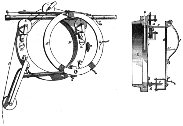
Frictionless Slide (front view).
Sectional view.
A different arrangement was then adopted, by which a lunar crater can be
kept bisected as long as is necessary, and which gives origin to no irregularities, but
pursues a steady course. The principle is, not to allow a slipping friction anywhere,
but to substitute rolling friction, upon wheels turning on points at the ends of their
axles. The following wood-cut is half the real size of this arrangement.
A glass rod a, a′, Fig. 33, is sustained by two wheels b, b′, and kept in contact,
with them by a third friction roller c, pressed downward by a spring. This rod
carries a circular frame d, d′, upon which at e, e′, e″, are three glass holders and
platinum catches. A spring f holds the sensitive plate in position, by pressing
against its back. The circular frame d is kept in one plane by a fourth friction
roller g, which runs on a glass rod h, and is kept against it by the inward pressure
of the overhanging frame d. The cord i is attached to the arm k, and pulls in the
direction of the glass rod a. From m to a fixed point near b, a strip of elastic India-rubber
is stretched, to keep the cord tight. The ring of brass n, n′ carries the
whole, serving as a basis for the stationary parts, and in its turn being fastened to
the eyepiece holder, so as to allow the glass rod a to change direction, and be
brought into coincidence with the apparent path of the moon. At o is a thumb-screw
or clamp. Through the ring n, n′, a groove p is cut, into which a piece of
yellow glass may be placed, when the actinic rays are to be shut off from the plate.
Since this contrivance has been completed, all the previous difficulties have
vanished. The moving of a plate can be accomplished with such precision, that
when the atmosphere was steady, negatives were taken which have been enlarged
to three feet in diameter.
The length of time that such a slide can be made to run is indefinite, depending
in my case on the size of the diagonal flat mirror, and aperture of the eyepiece
holder. I can follow the moon for nearly four minutes, but have never required
to do so for more than fifty seconds. At the mouth of the instrument, where no
secondary mirror is necessary, the time of running could be increased.
The setting of the frictionless slide in angular position is accomplished as follows:
A ground glass plate is put into it, with the ground face toward the mirror. Upon
this face a black line must have been traced, precisely parallel to the rod a. This
may be accomplished by firmly fixing a pencil point against the ground side, and
then drawing the frame d and glass past it, while the rest of the slide is held fast.
As the moon passes across the field, the position of the apparatus must be changed,
until one of the craters runs along the line from end to end. A cross line drawn
perpendicular to the other, serves to adjust the rate of the clepsydra as we shall
see, and when a crater is kept steadily on the intersection for twice or three times
the time demanded to secure an impression, the adjustment may be regarded as
complete.
It is necessary of course to expose the sensitive plate soon after, or the apparent
path of the moon will have changed direction, unless indeed the slide is set to suit
a future moment.
b. The Clepsydra.
My prime mover was a weight supported by a column of sand, which, when the
sand was allowed to run out through a variable orifice below, could be made to
descend with any desired velocity and yet with uniformity. In addition, by these
means an unlimited power could be brought to bear, depending on the size of the
weight. Previously it was proposed to use water, and compensate for the decrease
in flow, as the column shortened, by a conical vessel; but it was soon perceived that
as each drop of water escaped from the funnel-shaped vessel, only a corresponding
weight would be brought into play. This is not the case with sand, for in this
instance every grain that passes out causes the whole weight that is supported by
the column to come into action. In the former instance a movement consisting of
a series of periods of rest and periods of motion occurs, because power has to accumulate
by floating weight lagging behind the descending water, and then suddenly
overtaking it. In the latter case, on the contrary, there is a regular descent, all
minor resistances in the slide being overcome by the steady application of the whole
mass of the weight.
When these advantages in the flow of sand were ascertained, all the other prime
movers were abandoned. Mercury-clocks, on the principle of the hydrostatic paradox,
air-clocks, &c., in great variety, had been constructed.
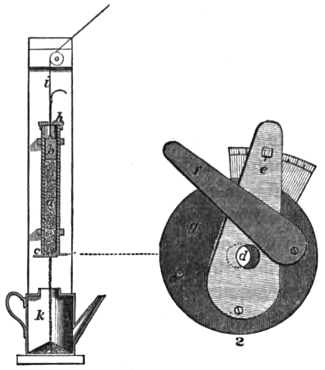
The sand-clock consisted of a tube a (Fig. 34), eighteen inches long and one and
a half in diameter, nearly filled with sand that had been raised to a bright red heat
and sifted. Upon the top of the sand a leaden
weight b was placed. At the bottom of the
tube a peculiar stopcock, seen at (2) enlarged,
regulated the flow, the amount passing depending
on the size of the aperture d. This stopcock
consisted of two thin plates, fixed at one
end and free at the other. The one marked e
is the adjusting lever, and its aperture moves
past that in the plate g. The lever f serves to
turn the sand off altogether, without disturbing
the size of the other aperture, which, once set
to the moon’s rate, varies but slightly in short
times. A movable cover h, perforated to allow
the cord i to pass through, closed the top, while
the vessel k retained the escaped sand, which at
suitable times was returned into the tube a, the
weight b being temporarily lifted out. From
the clock the cord i communicated motion to
the frictionless slide, as shown in Fig. 33. This cord should be as inelastic as
possible, consistent with pliability, and well waxed.
One who has not investigated the matter would naturally suppose that the flow
of sand in such a long tube would be much quicker when the tube was full than
when nearly empty, and that certainly that result would occur when a heavy weight
was put on the shifting mass. But in neither case have I been able to detect the
slightest variation, for, although by shaking the tube a diminution of the space
occupied by the sand may be caused, yet no increase of weight tried could accomplish
the same reduction. These peculiarities seem to result from the sand arching
as it were across the vessel, like shot in a narrow tube, and only yielding when the
under supports are removed. In blasting, a heavy charge of gunpowder can be
retained at the bottom of a hole, and made to split large masses of rock, by filling
the rest of the hole with dry sand.
I believe that no prime mover is more suitable than a sand-clock for purposes
where steady motion and a large amount of power are demanded. The simplicity,
for instance, of a heliostat on this plan, the large size it might assume, and its
small cost, would be great recommendations. In these respects its advantages over
wheelwork are very apparent. The precision with which such a sand-clock goes
may be appreciated when it is stated, that under a power of 300 a lunar crater can
be kept bisected for many times the period required to photograph it. To secure
the greatest accuracy in the rate of a sand-clock, some precautions must be taken.
The tube should be free from dents, of uniform diameter, and very smooth or
polished inside. Water must not be permitted to find access to the sand, and
hygrometric varieties of that substance should be avoided, or their salts washed out.
The sand should be burned to destroy organic matter, and so sifted as to retain
grains nearly equal in size. The weight, which may be of lead, must be turned so
as to go easily down the tube, and must be covered with writing paper or some
other hard and smooth material, to avoid the proneness to adhesion of sand. A
long bottle filled with mercury answers well as a substitute.
I have used in such clocks certain metallic preparations: Fine shot, on account
of its equality of size, might do for a very large clock with a considerable opening
below, but is unsuitable for a tube of the size stated above. There is, however,
a method by which lead can be reduced to a divided condition, like fine gunpowder,
when it may replace the sand. If that metal is melted with a little antimony, and
while cooling is shaken in a box containing some plumbago, it breaks up at the
instant of solidifying into a fine powder, which is about five times as heavy as sand.
If after being sifted to select the grains of proper size, it is allowed to run through
a small hole, the flow is seen to be entirely different from that of sand, looking as
if a wire or solid rod were descending, and not an aggregation of particles. It is
probable, therefore, that it would do better than sand for this purpose. I have not,
however, given it a fair trial, because just at the time when the experiments with the
sand-clock had reached this point, I determined to try a clepsydra as a prime mover.
The reason which led to this change was that it was observed on a certain occasion
when the atmosphere was steady, that the photographs did not correspond in
sharpness, being in fact no better than on other nights when there was a considerable
flickering motion in the air. A further investigation showed that in these
columns of sand there is apt to be a minute vibrating movement. At the plate-holder
above this is converted into a series of arrests and advances. On some
occasions, however, these slight deviations from continuous motion are entirely
absent, and generally, indeed, they cannot be seen, if the parts of the image seem
to vibrate on account of currents in the air. By the aid of the microscopic exaggeration
described on a former page—which was subsequently put in practice—they
may be observed easily, if present.
When the negative produced at the focus of the great mirror is intended to be
enlarged to two feet or more in size, these movements injure it sensibly. A variety
of expedients was resorted to in order to avoid them, but none proved on all
occasions successful.
It is obvious that in a water-clock, where the mobility of the fluid is so much
greater than that of solid grains, this difficulty would not arise. The following
contrivance in which the fault of the ordinary clepsydra, in varying rate of flow as
the column shortens, is avoided, was next made. With it the best results are
attainable, and it seems to be practically perfect.
It consists of a cylinder a, in which a piston b moves watertight. At the top of
the piston rod is a leaden five-pound weight c, from which the cord i goes to the
sliding plateholder g. The lower end of the cylinder terminates in a stopcock d,
the handle of which carries a strong index rod e, moving on a divided arc. At f
a tube with a stopcock is attached. Below, a vessel h receives the waste fluid.
In using the clepsydra the stopcock of f is opened, and the piston being pulled
upwards, the cylinder fills with water from h. The stopcock is then closed, and if
d also is shut, the weight will remain motionless. The string i is next connected
with the slide, and the telescope turned on the moon. As soon as the slide is
adjusted in angular position (page 36) the stopcock d is opened, until the weight c
moves downwards, at a rate that matches the moon’s apparent motion.
In order to facilitate the rating of the clepsydra, the index rod e is pressed by a
spring k (2), against an excentric l. As the excentric is turned round, the stopcock
d is of course opened, with great precision and delicacy. The plug of this stopcock
(3) is not perforated by a round hole, but has a slit. This causes equal movements
in the rod e, to produce equal changes in the flow. The rating requires
consequently only a few moments.
The object of the side tube f is to avoid disturbing d when it becomes necessary
to refill the cylinder, for when it is once opened to the right degree, it hardly
requires to be touched again during a night’s work. In order to arrest the downward
motion of the piston at any point, a clamp screws on the piston rod, and can
be brought into contact with the cylinder head, as in the figure.
That this instrument should operate in the best manner, it is essential to have
the interior of the brass cylinder polished from end to end, and of uniform diameter.
If any irregularity should be perceived in the rate of going, it can be cured completely
by taking out the piston, impregnating its leather stuffing with fine rotten
stone and oil, and then rubbing it up and down for five minutes in the cylinder, so
as to restore the polish. The piston and cylinder must of course be wiped, and
regreased with a mixture of beeswax and olive oil (equal parts) after such an
operation. In replacing the piston, the cylinder must be first filled with water, to
avoid the presence of air, which would act as a spring.
Although it may be objected that this contrivance seems to be very troublesome
to use, yet that is not the case in practice. Even if it were, it so far surpasses any
prime mover that I have seen, where the utmost accuracy is needed, that it would
be well worth employing.
c. The Sun Camera.
In taking photographs of the sun with the full aperture of this telescope, no
driving mechanism is necessary. On the contrary, the difficulty is rather to arrange
the apparatus so that an exposure short enough may be given to the sensitive plate,
and solarization of the picture avoided. It is not desirable to reduce the aperture,
for then the separating power is lessened. The time required to obtain a negative
is a very small fraction of a second, for the wavy appearance produced by atmospheric
disturbance is not unfrequently observed sharply defined in the photograph,
though these aerial motions are so rapid that they can scarcely be counted. Some
kind of shutter that can admit and cut off the solar image with great quickness is
therefore necessary.
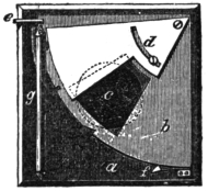
In front of an ordinary camera a, Fig. 36, attached to the eyepiece holder of the
telescope, and from which the lenses have been removed, a spring shutter is fixed.
It consists of a quadrant of thin wood b, fastened by its right
angle to one corner of the camera. Over the hole in this
quadrant a plate of tin d can be adjusted, and held in position
by a screw moving in a slot so as to reduce the hole if desired
to a mere slit. It may vary from 1 1/2 inch to less than 1/50 of
an inch. The quadrant is drawn downwards by an India-rubber
spring g, 1 inch wide, 1/8 of an inch thick, and 8 inches
long. This spring is stretched when in action to about 12
inches, and when released draws the slit past the aperture c in
the camera. Two nicks in the edge of the quadrant serve with the assistance of a
pin e, which can easily be drawn out by a lever (not shown in the cut), to confine
the slit either opposite to or above c. A catch at f prevents the shutter recoiling.
The sensitive plate is put inside the box as usual in a plate-holder. When a photograph
is taken, the spring shutter is drawn up so that the lower nick in the edge
of the quadrant is entered by the pin e, and the inside of the camera obscured.
The front slide of the plateholder is then removed in the usual manner, and the
solar image being brought into proper position by the aid of the telescope finder,
the trigger retaining e is touched, the shutter flies past c, and the sensitive plate may
then be removed to be developed.
To avoid the very short exposure needed when a silvered mirror of 188 square
inches of surface is used, I have taken many solar photographs with an unsilvered
mirror, which only reflects according to Bouguer 2 1/2 per cent. of the light falling
upon it, and should permit an exposure 37 times as long as the silvered mirror.
This is the first time that a plain glass mirror has been used for such a purpose,
although Sir John Herschel suggested it for observation many years ago. But
eventually this application of the unsilvered mirror had to be abandoned. It has,
it is true, the advantage of reducing the light and heat, but I found that the moment
the glass was exposed to the Sun, it commenced to change in figure, and alter in
focal length. This latter difficulty, which sometimes amounts to half an inch,
renders it well nigh impossible to find the focal plane, and retain it while taking
out the ground glass, and putting in the sensitive plate. If the glass were supported
by a ring around the edge, and the back left more freely exposed to the air, the
difficulty would be lessened but not avoided, for a glass mirror can be raised to 120° F.
on a hot day by putting it in the sunshine, though only resting on a few points.
Other means of reducing the light and heat, depending on the same principle, can
however be used. By replacing the silvered diagonal mirror with a black glass or
plain unsilvered surface, as suggested by Nasmyth, the trouble sensibly disappears.
I have in this way secured not only maculæ and their penumbræ, but also have
obtained faculæ almost invisible to observation. On some occasions, too, the precipitate-like
or minute flocculent appearance on the Sun’s disk was perceptible.
It seems, however, that the best means of acquiring fine results with solar photography,
would be to use the telescope as a Cassegrainian, and produce an image so
much enlarged, that the exposure would not have to be conducted with such rapidity.
Magnifying the image by an eyepiece would in a general way have the same result,
but in that case the photographic advantages of the reflector would be lost, and it
would be no better than an achromatic.
§4. THE OBSERVATORY.
This section is divided into a, The Building; b, The Dome; and c, The Observer’s
Chair.
a. The Building.
The Observatory is on the top of a hill, 225 feet above low water mark, and is
in Latitude 40° 59′ 25″ north, and Longitude 73° 52′ 25″ west from Greenwich,
according to the determinations of the Coast Survey. It is near the village of
Hastings-upon-Hudson, and is about 20 miles north of the city of New York. The
surrounding country on the banks of the North River is occupied by country seats,
on the slopes and summits of ridges of low hills, and no offensive manufactories
vitiate the atmosphere with smoke. Our grounds are sufficiently extensive to exclude
the near passages of vehicles, and to avoid tremor and other annoyances.
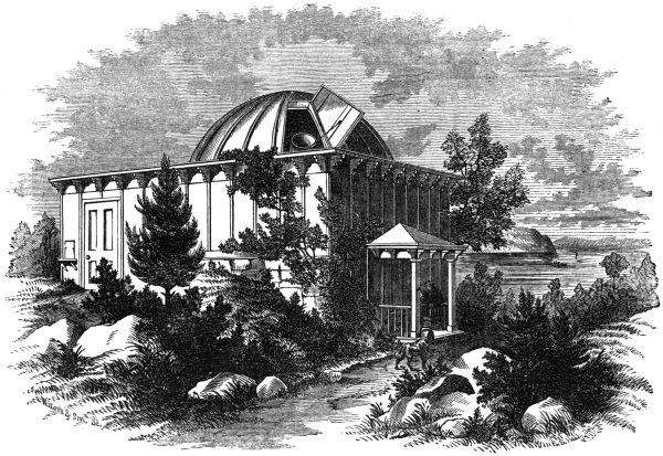
Dr. Draper’s Observatory.
An uninterrupted horizon is commanded in every direction, except where trees
near the dwelling house cut off a few degrees toward the southwest. The advantages
of the location are very great, and often when the valleys round are filled with
foggy exhalations, there is a clear sky over the Observatory, the mist flowing down
like a great stream, and losing itself in the chasm through which the Hudson here
passes.
The foundation and lower story of the building are excavated out of the solid
granite, which appears at the edge of the hill. This arrangement was intended to
keep the lower story cool, and avoid, in the case of the metal reflector, sudden
changes of temperature. The eastern side of the lower story, however, projects
over the brow of the hill, and is therefore freely exposed to the air, furnishing, when
desired, both access and thorough ventilation through the door. The second story
or superstructure is of wood, lined inside with boards like the story below. They
serve to inclose in both cases a non-conducting sheet of air.
The inside dimensions of both stories taken together are 17 1/2 feet square, and 22
feet high, to the apex of the dome. This space is unnecessarily large for the telescope,
which only requires a cylinder 13 feet in diameter and 13 feet high. A general
idea of the internal arrangement is gained from Fig. 28. In Fig. 38, a a′ is the
floor of the gallery, b b′ b″ the circular aperture in which the telescope c c′ turns.
The staircase is indicated by d. The Enlarger, §6, rests on the shelf e, the heliostat
being outside at f. The door going into the photographic room is at g, h h′ are
tables, i the water tank, k the tap and sink, l the stove, m a heliostat shelf, n the
door, o the window.
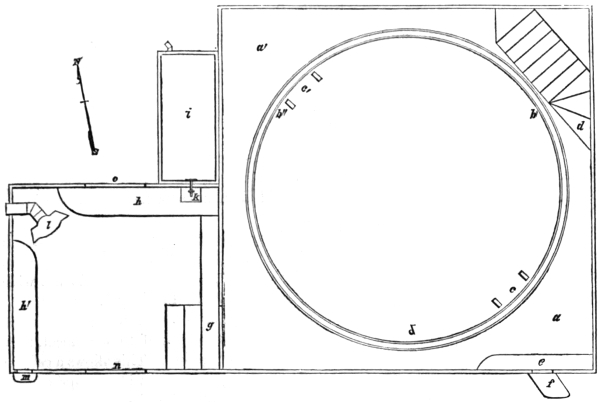
Plan of Observatory (upper floor).
The building is kept ventilated by opening the door in the lower part, and the
dome shutter, seen in Fig. 37, for some time before using the instrument. On a summer
day the upper parts, and especially those close under the dome, become without
this precaution very hot, and this occurred even before the tin roof was painted.
Bright tinplate seems not to be able to reflect by any means all the heat that falls
upon it, but will become so warm in July that rosin will melt on it, and insects which
have lighted in a few moments dry up, and soon become pulverizable. A knowledge
of these facts led to the abandonment of wooden sheathing under the tin, for without
it when night comes on the accumulated heat radiates away rapidly, and ceases to
cause aerial currents near the telescope.
The interior of the building is painted and wainscoted, and the roof is ornamented
partly in blue and oak, and partly with panels of tulip-tree wood.
There are only two windows, and they are near the southern angles of the roof.
While they admit sunshine on some occasions, they can on others be closed, and
the interior be reduced to darkness. In the southeast corner a small opening e
may allow a solar beam three inches in diameter to come in from a heliostat outside.
The greatest facilities are thus presented for optical and photographical experiments,
for in the latter case the whole room can be used as a camera obscura.
b. The Dome.
The roof of the observatory is 20 feet square. The angles are filled in solid, and
a circular space 15 feet in diameter is left to be covered by the revolving dome.
Although such a construction is architecturally weak and liable to lose its level, yet
the great advantages of having the building below square, and the usefulness of
the corners, determined its adoption, the disadvantages being overcome by a very
light dome.
The dome is 16 feet in outside diameter, and rises to a height of 5 feet above its
base. It is, therefore, much flatter than usual, in fact, might have been absolutely
flat, with this method of mounting. It would then have been liable, however, to
be crushed in by the deep winter snows.
It consists of 32 ribs, arcs of a circle, uniting at a common centre above. Each
one is formed of two pieces of thin whitewood, b, Fig. 39, fastened side by side,
with the best arrangements of the grain for strength. They are three inches wide
and one inch thick at the lower end, and taper gradually to 2 1/2 by 1.
Over these ribs tinplate is laid in triangular strips or gores, about 18 inches wide
at the base, and 10 feet long. Where the adjacent triangles of tin a a′ meet, they
are not soldered, but are bent together. This allows a certain
amount of contraction and expansion, and is water-proof. It
strengthens the roof so much, that if the ribs below were taken
away, this corrugated though thin dome would probably
sustain itself. The tin is fastened to the dome ribs b by
extra pieces c inserted in the joint and doubled with the
other parts, while below they are nailed to the ribs. In the
figure the tin is represented very much thicker than it is in
reality.
This dome, although it has 250 square feet of surface, only
weighs 250 pounds. That at the Cambridge (Massachusetts)
Observatory, 29 1/2 feet in diameter, weighs 28,000 pounds.
The slit or opening is much shorter than usual, only extending half way from
the base towards the summit. It is in reality an inclined window, 2 1/2 feet wide at
the bottom, 1 1/2 wide at the top, and 4 feet long. It is closed by a single shutter,
as seen in Fig. 37, and this when opened is sustained in position by an iron rod
furnished with a hinge at one end and a hook at the other.
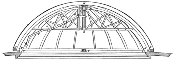
The principal peculiarity of the dome, the means by which it is rotated, remains
to be described. Usually in such structures rollers or cannon balls are placed at
intervals under the edge, and by means of rack work, a motion of revolution is
slowly accomplished. Here, on the contrary, the whole dome b b′ b″ (Fig. 40) is
supported on an arch h h′ h″, carrying an axis a at its centre, around which a slight
direct force, a pull with a single finger, will cause movement, and by a sudden push
even a quarter of an entire revolution may be accomplished. It is desirable, however,
to let it rest on the edge b b″, when not in use. At c there is an iron catch
on the arch, by which the lever e, that raises the dome, is held down. The fulcrum
is at d. The lever is hinged near c, so that when by being depressed it should have
come in the way of the telescope below, the lower half g can be pushed up, the
part from c toward d still holding the dome supported.
The arch can be set across the observatory in any direction, north and south, east
and west, or at any intermediate position, because the abutments where the ends
rest, are formed by a ring l l′ l″, fastened round the circular aperture, through the
stationary part of the roof.
When the telescope is not in use, and the dome is let down, so that there is no
longer an interval of a quarter of an inch between it and the rest of the roof, it
is confined inside by four clamps and wedges. Otherwise, owing to its lightness, it
would be liable to be blown away. These clamps a,
Fig. 41, are three sides of a square, made of iron one
inch square. They catch above by a point in the
wooden basis-circle of the dome b, and below are
tightened by the wedge c.
When the dome is raised it is prevented from moving
laterally and sliding off by three rollers, one of which
is seen at f, Fig. 40. These catch against its inner edge,
and only allow slight play. At first it was thought necessary
to have a subsidiary half arch at right angles to
the other to hold it up, but that is now removed.
All the parts work very satisfactorily, and owing to
the care taken to get the roof-circle and basis-circle flat and level, no leakage takes
place at the joint, and even snow driven by high winds is unable to enter.
c. The Observer’s Chair.
This is not a chair in the common acceptation of the word, but is rather a movable
platform three feet square, capable of carrying two or more persons round the
observatory, and maintaining them in an invariable position with regard to the telescope
eyepiece.
Its general arrangement is better comprehended from the sketch, Fig. 42, than
from a labored description. Below, it runs on a pair of wheels a (one only is
visible) 9 inches in diameter, whose axles point to the centre of the circle upon
which they run. They are prevented from shifting outwards by a wooden railroad
b, b′, and inwards by the paling l, l′. Above, the chair moves on a pair of small
rollers c, which press against a circular strip or track d, d′, nailed around the lower
edge of the dome opening. Access to the platform is gained by the steps e, e′.
Attached to the railing of this platform, and near it on the telescope, are two
tables (not shown in the figure) for eyepieces, the sliding plateholder, &c.
§5. THE PHOTOGRAPHIC LABORATORY.
This section is divided into a, Description of the Apartment; and b, Photographic
Processes.
a. Description of the Apartment.
The room in which the photographical operations are carried on, adjoins and
connects with the observatory on the southeast, as is shown in Figs. 28 and 38.
It is 9 by 10 feet inside, and is supplied with shelves and tables running nearly all the
way round, which have upon them the principal chemical reagents. It is furnished,
too, with an opening to admit, from a heliostat outside, a solar beam of any size, up
to three inches in diameter.
The supply of water is derived from rain falling on the roof of the building, and
running into a tank i, Fig. 38, which will contain a ton weight. The roof exposes
a surface of 532 square feet, and consequently a fall of rain equal to one inch in
depth, completely fills the tank. During the course of the year the fall at this place
is about 32 inches, so that there is always an abundance. In order to keep the
water free from contamination, the roof is painted with a ground mineral compound,
which hardens to a stony consistence, and resists atmospheric influences well. The
tank is lined with lead, but having been in use for many years for other purposes, is
thoroughly coated inside with various salts of lead, sulphates, &c. In addition the
precaution is taken of emptying the tank by a large stopcock when a rainstorm is
approaching, so that any accumulation of organic matter, which can reduce nitrate
of silver, may be avoided. It has not been found feasible to use the well or spring
water of the vicinity.
The tank is placed close under the eaves of the building, so as to gain as much
head of water as is desirable. From near its bottom a pipe terminating in a stopcock
k, Fig. 38, passes into the Laboratory. In the northeast corner of the room,
and under the tap is a sink for refuse water and solutions, and over which the
negatives are developed. It is on an average about twelve feet distant from the
telescope. In another corner of the room is a stove, resembling in construction an
open fireplace, but sufficient nevertheless to raise the temperature to 80° F. or higher,
if necessary. As a provision against heat in summer, the walls and roof are double,
and a free space with numerous openings above is left for circulation of air, drawn
from the foundations. The roof is of tinplate, fastened directly to the rafters, without
sheathing, in order that heat may not accumulate to such an extent during the
day as to constitute a source of disturbance when looking across it at night.
For containing negatives, which from being unvarnished require particular care,
there is at one side of the room a case with twenty shallow drawers each to hold
eighteen. They accumulate very rapidly, and were it not for frequent reselections
the case would soon be filled. On some nights as many as seventeen negatives have
been taken, most of which were worthy of preservation. Not less than 1500 were
made in 1862 and ’63.
b. Photographic Processes.
In photographic manipulations I have had the advantage of my father’s long
continued experience. He worked for many years with bromide and chloride of
silver in his photo-chemical researches (Journal of the Franklin Institute, 1837),
and when Daguerre’s beautiful process was published, was the first to apply it to
the taking of portraits (Phil. Mag., June, 1840) in 1839; the most important of all
the applications of the art. Subsequently he made photographs of the interference
spectrum, and ascertained the existence of great groups of lines M, N, O, P, above
H, and totally invisible to the naked eye (Phil. Mag., May, 1843). The importance
of these results, and of the study of the structure of flames containing various
elementary bodies, that he made at the same time, are only now exciting the
interest they deserve.
In 1850, when his work on Physiology was in preparation, and the numerous
illustrations had to be produced, I learnt microscopic photography, and soon after
prepared the materials for the collodion process, then recently invented by Scott
Archer. We produced in 1856 many photographs under a power of 700 diameters,
by the means described in the next section.
At first the usual processes for portrait photography were applied to taking the
Moon. But it was soon found necessary to abandon these and adopt others. When
a collodion negative has to be enlarged—and this is always the case in lunar photography,
where the original picture is taken at the focus of an object glass or mirror—imperfections
invisible to the naked eye assume an importance which causes the
rejection of many otherwise excellent pictures. Some of these imperfections are
pinholes, coarseness of granulation in the reduced silver, liability to stains and markings,
spots produced by dust.
These were all avoided by washing off the free nitrate of silver from the sensitive
plate, before exposing it to the light, and again submitting it to the action of water,
and dipping it back into the nitrate of silver bath before developing. The quantity
of nitrate of silver necessary to development when pyrogallic acid is used, is however
better procured by mixing a small quantity of a standard solution of that salt
with the acid.
The operation of taking a lunar negative is as follows. The glass plates 2 3/4 × 3 1/4
inches are kept in nitric acid and water until wanted. They are then washed under
a tap, being well rubbed with the fingers, which have of course been properly cleaned.
They are wiped with a towel kept for the purpose. Next a few drops of iodized
collodion are poured on each side, and spread with a piece of cotton flannel. They
are then polished with a large piece of this flannel, and deposited in a close dry
plate box. This system of cleaning with collodion was suggested by Major Russel,
to whose skilful experiments photography is indebted for the tannin process. It
certainly is most effective, the drying pyroxyline removing every injurious impurity.
There is never any trouble from dirty plates.
The stock of plates for the night’s work, a dozen or so, being thus prepared, one
of them is taken, and by movement through the air is freed from fibres of cotton.
It is then coated with filtered collodion being held near the damp sink. The coated
plate, when sufficiently dry, is immersed in a 40 grain nitrate of silver bath, acidified
with nitric acid until it reddens litmus paper. The exact amount of acid in the bath
makes in this “Washed Plate Process” but little difference. When the iodide and
bromide of silver are thoroughly formed the plate is removed, drained for a moment,
and then held under the tap till all greasiness, as it is called, disappears. Both front
and back receive the current in turn.
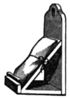
It is then exposed, being carried on a little wooden stand, Fig. 43, covered with
filtering paper to the telescope, and deposited on the sliding plateholder which has
been set to the direction and rate of the moon, while the plate was in the bath.
The time of exposure is ascertained by counting the beats of a half-second pendulum.
The method by which exposure without causing tremor is accomplished, is as
follows: A yellow glass slides through the eyepiece-holder, Fig. 33, just in front
of the sensitive plate, and is put in before the plate. The yellow-colored moon is
centred on the collodion film, and the clepsydra and slide are set in motion, the
mass of the telescope being at rest. A pasteboard screen is put in front of the
telescope, and the yellow glass taken out. After 20 seconds the instrument remaining
still untouched and motionless, the screen is withdrawn, and
as many seconds allowed to elapse as desirable. The screen is then
replaced and the plate taken back to the photographic room.
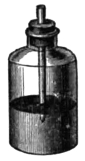
After being again put under the tap to remove any dust or impurity, it
is dipped into the nitrate bath for a few seconds. Two drachms of a solution
of protosulphate of iron 20 grains, acetic acid 1 drachm, and water
1 ounce, is poured on it. As soon as the image is fairly visible this is
washed off, and the development continued if necessary with a weak
solution of pyrogallic acid and citro-nitrate of silver—pyrogallic and
citric acids each 1/5 grain, nitrate of silver 1/10 grain, water 1 drachm. In order to
measure these small quantities standard solutions of the substances are made, so
that two drops of each contain the desired amount. They are kept in
bottles, through the corks of which pipettes descend to just below the
level of the liquid. This avoids all necessity of filtering, and yet no
blemishes are produced by particles of floating matter.
During the earlier part of the development, when the protosulphate
of iron is on the film, an accurate judgment can be formed as to the proper
length of time for the exposure in the telescope. If the image
appears in 10 seconds, it will acquire an appropriate density for enlargement
in 45 seconds, and will have the minimum of what is called
fogging and the smallest granulations. If it takes longer to make its
first appearance the exposure must be lengthened, and vice versa.
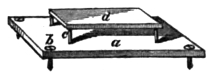
The latter part of the development, when re-development is practised, is purposely
made slow, so that the gradation of tones may be varied by changing the proportion
of the ingredients. As it would be tiresome and uncleanly
to hold the plates in the hand, a simple stand is used
to keep them level. It consists of a piece of thin wood a,
Fig. 45, with an ordinary wood screw, as at b, going through
each corner. Four wooden pegs, as at c, furnish a support
for the plate d. By the aid of this contrivance and the
washing system, I seldom get my fingers marked, and what is much more important,
rarely stain a picture.
When the degree of intensity most suitable for subsequent enlargement is reached,
that is, when the picture is like an overdone positive, the plate is again flooded with
water, treated with cyanide of potassium or hyposulphite of soda, once more
washed and set upon an angle on filtering paper to dry. It is next morning labelled,
and put away unvarnished in the case.
To the remark that this process implies a great deal of extra trouble, it can only
be replied that more negatives can be taken on each night than can be kept, and that,
even were it not so, one good picture is worth more than any number of bad ones.
Although the above is the method at present adopted, and by which excellent
results have been obtained, it may at any moment give place to some other, and is
indeed being continually modified. The defects it presents are two—first, the time
of exposure is too long, and second, there is a certain amount of lateral diffusion
in the thickness of the film, and in consequence a degree of sharpness inferior to
that of the image produced by the parabolic mirror. The shortest time in which
the moon has been taken in this observatory has been one-third of a second, on the
twenty-first day, but on that occasion the sky was singularly clear, and the intrinsic
splendor of the light great. The full moon under the same circumstances would
have required a much shorter exposure. A person, however, who has put his eye
at the focus of such a silvered mirror will not be surprised at the shortness of the
time needed for impressing the bromo-iodide film; the brilliancy is so great that it
impairs vision, and for a long time the exposed eye fails to distinguish any moderately
illuminated object. The light from 188 square inches of an almost total
reflecting surface is condensed upon 2 square inches of sensitive plate.
Occasionally a condition of the sky, the reverse of that mentioned above, occurs.
The moon assumes a pale yellow color, and will continue to be of that non-actinic
tint for a month or six weeks. This phenomenon is not confined to special localities,
but may extend over great tracts of country. In August, 1862, when our regiment
was encamped in Virginia, at Harper’s Ferry, the atmosphere was in this condition
there, and was also similarly affected at the observatory, more than 200 miles distant.
As to the cause, it was not forest or prairie fires, for none of them of sufficient
magnitude and duration occurred, but was probably dust in a state of minute
division. No continued rain fell for several weeks, and the clay of the Virginia roads
was turned into a fine powder for a depth of many inches. The Upper Potomac
river was so low that it could be crossed dry-shod. On a subsequent occasion when
the same state of things occurred again, I exposed a series of plates (whose sensitiveness
was not less than usual, as was proved by a standard artificial flame) to the
image of the full moon in the 15 1/2 inch reflector for 20 seconds, and yet obtained
only a moderately intense picture. This was 40 times as long as common.
Upon all photographic pictures of celestial objects the influence of the atmosphere
is seen, being sometimes greater and sometimes less. To obtain the best impressions,
just as steady a night is necessary as for critical observations. If the image
of Jupiter is allowed to pass across a sensitive plate, a streak almost as wide as the
planet is left. It is easily seen not to be continuous, as it would have been were
there no atmospheric disturbances, but composed of a set of partially isolated images.
Besides this planet, I have also taken impressions of Venus, Mars, double stars, &c.
An attempt has been made to overcome lateral diffusion in the thickness of the
film by the use of dry collodion plates, more particularly those of Major Russel and
Dr. Hill Norris. These present, it is true, a fine and very thin film during exposure,
but while developing are so changed by wetting in their mechanical condition that
no advantage has resulted. It was while trying them, that I ascertained the great
control that hot water exercises over the rapidity of development, and time of exposure,
owing partly no doubt to increase of permeability in the collodion film, but
also partly to the fact that chemical decompositions go on more rapidly at higher
temperatures. I have attempted in vain to develop a tannin plate when it and the
solutions used were at 32° F., and this though it had had a hundred times the exposure
to light that was demanded when the plate was kept at 140° F. by warm water.
Protochloride of palladium, which I introduced in 1859, is frequently employed
when it is desired to increase the intensity of a negative without altering its thickness.
This substance will augment the opacity 16 times, without any tendency to
injure the image or produce markings. It is only at present kept out of general
use by the scarcity of the metal.
§6. THE PHOTOGRAPHIC ENLARGER.
Two distinct arrangements are used for enlarging, a, for Low Powers varying
from 1 to 25; and b, for High Powers from 50 to 700 diameters.
a. Low Powers.
The essential feature in this contrivance is an entire novelty in photographic
enlargement, and it is so superior to solar cameras, as they are called, that they are
never used in the observatory now. It consists in employing instead of an achromatic
combination of lenses, a mirror of appropriate curvature to magnify the
original negatives or objects. The advantages are easily enumerated, perfect coincidence
of visual and chemical foci, flat field, absolute sharpness of definition. If the
negative is a fine one, the enlarged proofs will be as good as possible.
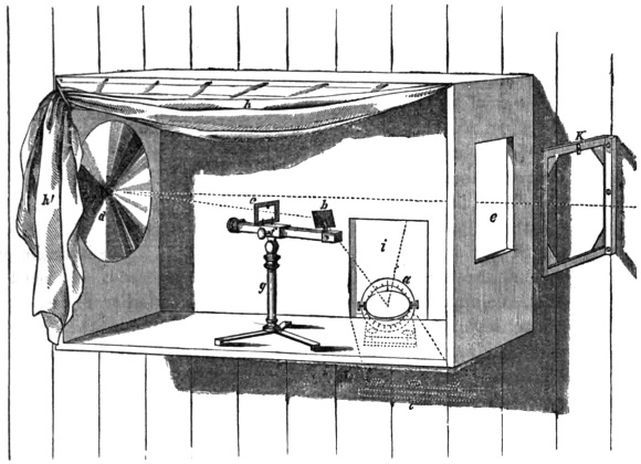
The Photographic Enlarger.
The mirror is of 9 inches aperture, and 11 1/2 inches focal length. It was polished
on my machine to an elliptical figure of 8 feet distance between the conjugate foci,
and was intended to magnify 7 times. At first the whole mirror was allowed to
officiate, the object being illuminated by diffused daylight. But it was soon apparent,
that although a minute object placed in one focus was perfectly reproduced
at the other, seven times as large, yet a large one was not equally well defined in
all its parts.
I determined then to produce the enlarged image by passing a solar-beam 1 1/2 inch
in diameter through the original lunar negative—placed in the focus nearest to the
mirror—and allowing it to fall on a portion of the concave mirror, 1 1/2 inch in
diameter, at one side of the vertex. Being reflected, it returns past the negative,
and goes to form the magnified image at the other focus of the ellipse.
In Fig. 46, a is the heliostat on a stone shelf outside; b a silvered glass mirror,
to direct the parallel rays through c, the negative; d is the elliptical mirror; e an
aperture to be partly closed by diaphragms; f a rackwork movement carried by the
tripod g; the curtain h h′ shuts out stray light from the interior of the observatory.
The aperture i is also diaphragmed, but is shown open to indicate the position of
the heliostat, the shelf of which joins the outside of the building at l. The dotted
line points out the course of the light, which coming from the sun falls on the
heliostat mirror a, then on b, through c to d, and thence returning through e to the
sensitive plate in the plate holder k.
The distance of this last can be made to vary, being either two feet or twenty-eight
feet from d. In the latter case a magnifying power of about 25 results, the
moon being made three feet in diameter. The sensitive plate is carried by a frame,
which screws to the side wall of the building, and can be easily changed in position.
The focussing is accomplished by the rack f. Where so small a part (1 1/2 inch) of
the surface of the mirror is used, a rigid adherence then to the true foci of this
ellipse is not demanded, the mirror seeming to perform equally well whether magnifying
7 or 25 times. Theoretically it would seem to be limited to the former
power.
If instead of placing a lunar photograph, which in the nature of the case is never
absolutely sharp, at c, some natural object, as for instance a section of bone, is attached
to the frame moved by f, then under a power of 25 times it is as well defined as in
any microscope, while at the same time the amount of its surface seen at once is
much larger than in such instruments, and the field is flat. If the intention were,
however, to make microscopic photographs, a mirror of much shorter focal length
would be desirable, one approaching more to those of Amici’s microscopes.
By the aid of a concave mirror used thus obliquely, or excentrically, all the difficulties
in the way of enlarging disappear, and pictures of the greatest size can be
produced in perfection. I should long ago have made lunar photographs of more
than 3 feet in diameter, except for the difficulties of manipulating such large surfaces.
In order to secure a constant beam of sunlight a heliostat is placed outside the
observatory, at its southeast corner f, Fig. 38. This beam, which can be sent for
an entire day in the direction of the earth’s axis, is intercepted as shown at b, Fig.
46, and thus if needed an exposure of many hours could be given. The interior of
the observatory and photographic room being only illuminated by faint yellow rays,
no camera box is required to cut off stray light. The eye is by these means kept
in a most sensitive condition, and the focussing can be effected with the critical
accuracy that the optical arrangement allows, no correction for chromatic aberration
being demanded.
I have made all the parts of this apparatus so that they can be easily separated
or changed. The flat mirrors are of silvered glass, and are used with the silvered
side toward the light, to avoid the double image produced when reflection from both
sides of a parallel plate of glass is permitted. The large concave mirror happens
to be of speculum metal, but it can be repolished if necessary by means of a four
inch polisher, passed in succession over every chord of the face. A yellow film of
tarnish easily accumulates on metal specula if they are not carefully kept, and decreases
their photographic power seriously.
Of the making of Reverses.—In addition to the use of the Enlarger for magnifying,
it is found to have important advantages in copying by contact. The picture
of the image of the moon produced in the telescope is negative, that is, the lights
and shades are reversed. In enlarging such a negative reversal again takes place,
and a positive results. This positive cannot, however, be used to make prints on
paper, because in that operation reversing of light and shade once more occurs. It
is necessary then at some stage to introduce still another reversal. This may be
accomplished either by printing from the original negative a positive, which may be
enlarged, or else printing from the enlarged positive a negative to make the paper
proofs from. In either case a collodion film, properly sensitized, is placed behind
the positive or negative, and the two exposed to light.
If diffused light or lamplight is used, the two plates must be as closely in contact
as possible, or the sharpness of the resulting proof is greatly less than the original.
This is because the light finds its way through in many various directions. If the
two plates, however, are placed in the cone of sunlight coming from the Enlarger,
and at a distance of fifteen or twenty feet from it, the light passes in straight lines
and only in one direction through the front picture to the sensitive plate behind.
I have not been able to see under these circumstances any perceptible diminution
in sharpness, though the plates had been 1/16 of an inch apart. It is perfectly feasible
to use wet collodion instead of dry plates, no risk of scratching by contact is incurred,
and the whole operation is easily and quickly performed. The time of exposure, 5
seconds, is of convenient length, but may be increased by putting a less reflecting
surface or an unsilvered glass mirror in the heliostat. A diaphragm with an aperture
of half an inch if placed at e, Fig. 46, to shut out needless light, and avoid
injuring the sharpness of the reverse by diffusion through the room. In enlarging
other diaphragms are also for the same reason put in the place of this one. For a
half moon for instance, a yellow paper with a half circular aperture, whose size may
be found by trial in a few minutes, is pinned against e.
The enlarged pictures obtained by this apparatus are much better than can be
obtained by any other method known at present. The effect, for instance, of a
portrait, made life-size, is very striking. Some astronomers have supposed that
advantages would arise from taking original lunar negatives of larger size in the
telescope, that is, from enlarging the image two or three times by a suitable eyepiece
or concave achromatic, before it reached the sensitive plate. But apart from
the fact that a reflector would then have all the disadvantages of an achromatic,
the atmospheric difficulties, which in reality constitute the great obstacle to success,
would not be diminished by such means. The apparent advantage, that of not
magnifying defects in the collodion, is not of much moment, for when development
of the photographs is properly conducted, and thorough cleanliness practised,
imperfections are not produced, and the size of the silver granules is not objectionable.
b. High Powers.
Although negatives of astronomical objects have not as yet been made which
could stand the high powers of the arrangement about to be described, yet they
bear the lower powers well, and give promise of improvement in the future.
Photography of microscopic objects as usually described, consists in passing a
beam of light through the transparent object into the compound body of the microscope,
and receiving it on its exit from the eyepiece upon a ground glass or sensitive
plate. The difficulty which besets the instrument generally, and interferes
with the production of fine results, arises from the uncertainty of ascertaining the
focus or place for the sensitive plate. For if the collodion film be put where the
image on ground glass seems best defined, the resulting photograph will not be
sharp, because the actinic rays do not form their image there, but either farther
from or nearer to the lenses, depending on the amount of the chromatic correction
given by the optician. Practically by repeated trials and variation of the place of
the sensitive compound, an approximation to the focus of the rays of maximum
photographic intensity is reached.
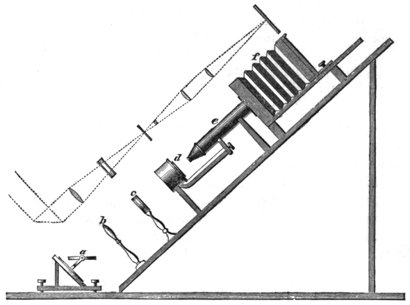
Microscope for Photography.
During my father’s experiments on light, and more particularly when engaged
in the invention of portrait photography, he found that the ammonio-sulphate of
copper, a deep blue liquid, will separate the more refrangible rays of light, the rays
concerned in photography, from the rest. If a beam of sunlight be passed through
such a solution, inclosed between parallel plates of glass, and then condensed upon
an object on the stage of a microscope, a blue colored image will be formed on the
ground glass, above the eyepiece. If the place of best definition be carefully ascertained,
and a sensitive plate put in the stead of the ground glass, a sharp photograph
will always result.
Besides, there is no danger of burning up the object, as there would be if the
unabsorbed sunlight were condensed on it, and hence a much larger beam of light
and much higher powers can be used. The best results are attained when an image
of the sun produced by a short focussed lens is made to fall upon and coincide with
the transparent object. In 1856 we obtained photographs of frog’s blood disks,
navicula angulata, and several other similar objects under a power of 700 diameters,
excellently defined. Since then several hundreds of microscopic pictures have been
taken.
In the figure, a is the heliostat, b a lens of three inches aperture, c the glass cell
for the ammonio-sulphate of copper, d the object on the stage of the microscope e,
f the camera for the ground glass or sensitive plate. Above the figure the course
of the rays is shown by dotted lines.
In concluding this account of a Silvered Glass Telescope I may answer an inquiry
which doubtless will be made by many of my readers, whether this kind of reflector
can ever rival in size and efficiency such great metallic specula as those of Sir
William Herschel, the Earl of Rosse, and Mr. Lassell? My experience in the
matter, strengthened by the recent successful attempt of M. Foucault to figure such
a surface more than thirty inches in diameter, assures me that not only can the four
and six feet telescopes of those astronomers be equalled, but even excelled. It is
merely an affair of expense and patience. I hope that the minute details I have
given in this paper may lead some one to make the effort.
Hastings, Westchester County,
New York, 1863.
Postscript.—Since writing the above I have completed a photograph of the moon
50 inches in diameter. The original negative from which it has been made, bears
this magnifying well, and the picture has a very imposing effect.
PUBLISHED BY THE SMITHSONIAN INSTITUTION,
WASHINGTON CITY,
JULY, 1864.
*** END OF THE PROJECT GUTENBERG EBOOK 53542 ***