*** START OF THE PROJECT GUTENBERG EBOOK 50846 ***
The Project Gutenberg eBook, Mechanics of the Household, by E. S. (Edward
Spencer) Keene
MECHANICS OF THE HOUSEHOLD
McGraw-Hill Book Co., Inc.
PUBLISHERS OF BOOKS FOR
Coal Age ▼ Electric Railway Journal
Electrical World ▼ Engineering News-Record
American Machinist ▼ The Contractor
Engineering & Mining Journal ▼ Power
Metallurgical & Chemical Engineering
Electrical Merchandising
MECHANICS
OF THE
HOUSEHOLD
A COURSE OF STUDY DEVOTED TO
DOMESTIC MACHINERY AND
HOUSEHOLD MECHANICAL
APPLIANCES
E. S. KEENE
DEAN OF MECHANIC ARTS
NORTH DAKOTA AGRICULTURAL COLLEGE
First Edition
McGRAW-HILL BOOK COMPANY, Inc.
239 WEST 39TH STREET. NEW YORK
LONDON: HILL PUBLISHING CO., Ltd.
6 & 8 BOUVERIE ST., E. C.
1918
Copyright, 1918, by the
McGraw-Hill Book Company, Inc.
[v]
INTRODUCTION
This book is intended to be a presentation of the physical
principles and mechanism employed in the equipment that has
been developed for domestic convenience. Its aim is to provide
information relative to the general practice of domestic engineering.
The scope of the work is such as to present: first, the
use of household mechanical appliances; second, the principles
involved and the mechanism employed. It is not exhaustive,
neither does it touch many of the secondary topics that might be
discussed in connection with the various subjects. It does,
however, describe at least one representative piece of each type
of household apparatus that is used in good practice.
The mechanism used in the equipment of a modern dwelling
is worthy of greater attention, as a course of study, than it
has been heretofore accorded. The fact that any house, rural
or urban, may be provided with all domestic conveniences included
in: furnace heating, mechanical temperature regulation,
lighting facilities, water supply, sewage disposal and other
appliances, indicates the general use of domestic machinery in
great variety. To comprehend the application and adaptability
of this mechanism requires a knowledge of its general plan
of construction and principles of operation.
Heating systems in great variety utilize steam, hot water,
or hot air as the vehicle of transfer of heat from the furnace,
throughout the house. Each of these is made in the form of
special heating plants that may be adapted, in some special
advantage to the various conditions of use. A knowledge of
their working principles and general mechanical arrangement
furnishes a fund of information that is of every day application.
The systems available for household water distribution take
advantage of natural laws, which aided by suitable mechanical
devices and conveniently arranged systems of pipes, provide
water-supply plants to satisfy any condition of service. They
may be of simple form, to suit a cottage, or elaborated to the
requirements of large residences and made entirely automatic in[vi]
action. In each, the apparatus consists of parts that perform
definite functions. The parts may be obtained from different
makers and assembled as a working unit or the plant may be purchased
complete as some special system of water supply. An acquaintance
with domestic water supply apparatus may be of service
in every condition of life.
The type of illumination for a house or a group of buildings,
may be selected from a variety of lighting systems. In rural
homes, choice may be made between oil gas, gasolene, acetylene
and electricity, each of which is used in a number of successful
plants that differ only in the mechanism employed.
Any building arranged with toilet, kitchen and laundry conveniences
must be provided with some form of sewage disposal.
Private disposal plants are made to meet many conditions of service.
The mechanical construction and principles of operation
are not difficult to comprehend and their adaptation to a given
service is only an intelligent conception of the possible conditions
of disposal, dependent on the natural surroundings.
There are few communities where household equipment cannot
be found to illustrate each of the subjects discussed. Most
modern school houses are equipped for automatic control of
temperature, ventilation and humidity. They are further
provided with systems of gas, water and electric distribution
and arrangements for sewage disposal. These facilities furnish
demonstration apparatus that are also examples of their application.
Additional examples of the various forms of plumbing
and pipe fittings, valves, traps and water fixtures may be found
in the shop of dealers in plumbers and steam-fitters supplies.
Attention is called to the value of observing houses in process
of construction and the means employed for the placement of
the pipes for the sewer, gas, water, electric conduits, etc. These
are generally located by direction of the specifications provided
by the architect but observation of their installation is necessary
for a comprehension of actual working conditions. It
is suggested that the work be made that of, first, acquiring
an idea of established practice, and second, that of investigating
the examples of its application.
[vii]
CONTENTS
| Preface | v |
| CHAPTER I |
| Page |
The Steam Heating Plant
Heat of Vaporization—Steam Temperature—Gage Pressure—Absolute
Pressure—Two-pipe System—Separate-return System—Overhead
or Drop System—Water-filled Radiators—Air Vents—Automatic
Air Vents—Steam Radiator Valves—The House-heating Steam
Boiler—Boiler Trimmings—The Water Column—The Steam Gage—The
Safety Valve—The Draft Regulator—Rule for Proportioning
Radiators—Proportioning the Size of Mains—Forms of
Radiators—Radiator Finishings—Pipe Coverings—Vapor-system
Heating. |
1 |
| CHAPTER II |
The Hot-water Heating Plant
The Low-pressure Hot-water System—The High-pressure Hot-water
System—Heating-plant Design—Overhead System of Hot-water
Heating—Expansion Tanks—Radiator Connection—Hot-water
Radiators—Hot-water Radiator Valves—Air Vents—Automatic
Hot-water Air Vents. |
37 |
| CHAPTER III |
The Hot-air Furnace
Construction—Furnace-gas Leaks—Location of the
Furnace—Flues—Combination Hot-air and Hot-water Heater. |
51 |
| CHAPTER IV |
Temperature Regulation
Hand Regulation—Damper Regulator for Steam Boiler—Damper
Regulators for Hot-water Furnaces—The Thermostat Motor—Combined
Thermostat and Damper Regulator—Thermostat-motor Connections. |
59
[viii] |
| CHAPTER V |
Management of Heating Plants
General Advice—The Economy of Good Draft—General Firing
Rules—Weather and Time of Day—Night Firing—First-day
Firing—Other Day Firing—Economy and Fuels—For Burning Soft
Coal—For Burning Coke—Other Rules for Water Boilers—Air-vent
Valves on Radiators—The Air Valves—End of the Season—The Right
Chimney Flue—“Smokey” Chimneys. |
70 |
| CHAPTER VI |
Plumbing
Water Supply—Water Cocks—Bibb-cocks—Self-closing
Bibbs—Lever-handle Bibbs—Fuller Cocks—Wash-tray Bibbs—Basin
Cocks—Pantry Cocks—Sill Cocks—Valves—Kitchen and
Laundry Fixtures—The Bathroom—Bath Tubs—Wash Stands and
Lavatories—Traps—Back-venting—Soil Pipe—Water Closets—Washout
Closets—Washdown Closets—Siphon-jet Closet—Flush Tanks—Low-down
Flush Tank—Opening Stopped Pipes—Sewer Gas—Range Boilers—The
Water-back—Excessive Pressure—Blow-off Cock—Location of Range
Boiler—Double Heater Connections—Horizontal Range Boilers—Tank
Heaters—Overheater Water—Furnace Hot-water Heaters—Instantaneous
Heaters. |
82 |
| CHAPTER VII |
Water Supply
Water Analysis—Pokegama Water—River Water—Artesian
Water—Medical Water—Organic Matter—Ammonia—Hardness
in Water—Iron in Water—Water Softening With Hydrated
Silicates—Chlorine—Polluted Water—Pollution of Wells—Safe
Distance in the Location of Wells—Surface Pollution of
Wells—Water Table—The Divining Rod—Selection of a Type of
Well—Flowing Wells—Construction of Wells—Dug Wells—Open
Wells—The Ideal Well—Coverings of Concrete—Artesian
Wells—Driven Wells—Bored Wells—Cleaning Wells—Gases in
Wells—Peculiarities of Wells—Breathing Well—Freezing
Wells—Pumps—The Lift Pump—The Force Pump—Tank Pump—Well
Pumps—Wooden Pump—Pumps for Driven Wells—Deep-well
Pumps—Tubular Well Cylinders—Chain Pumps—Rain Water
Cisterns—Filters—The Hydraulic Ram—Single-acting Hydraulic
Ram—The Double-acting Hydraulic Ram—Domestic Water-supply
Plants—Gravity Water Supply—Pressure-tank System of Water
Supply—The Pressure Tank—Power Water-supply Plants—Electric
Power Water Supply—The Water Lift. |
125
[ix] |
| CHAPTER VIII |
Sewage Disposal
The Septic Tank—The Septic Tank With a Sand-bed Filter—The Septic
Tank and Anaerobic Filter—Limit of Efficiency. |
168 |
| CHAPTER IX |
| Coal
Oxidation of Hydrocarbons—Graphitic Anthracite—Cannel
Coal—Lignite—Peat—Wood—Charcoal—Coke—Gas-coke—Briquettes
—Comparative Value of Coal to Other Fuels—Price of Coal. |
182 |
| CHAPTER X |
Atmospheric Humidity
Humidity of the Air—Relative Humidity—The Hygrometer—The
Hygrodeik—Dial Hygrometers—The Swiss Cottage
“Barometer”—Dew-point—To Determine the Dew-point—Frost
Prediction—Prevention of Frost—Humidifying Apparatus. |
196 |
| CHAPTER XI |
Ventilation
196
Quantity of Air Discharged by a Flue—Cost of Ventilation—The
Wolpert Air Tester—Pneumatic Temperature Regulation—Mechanical
Ventilation—The Plenum Method—Ventilation Apparatus—Air
Conditioning—Humidifying Plants—Vaporization as a Cooling
Agent—Air-cooling Plants—Humidity Control. |
219 |
| CHAPTER XII |
Gaseous and Liquid Fuels
Gaseous and Liquid Fuels—Coal Gas—All-oil Water Gas—Pintsch
Gas—Blau Gas—Water Gas—Measurement of Gas—Gas Meters How
to Read the Index—Prepayment Meters—Gas-service Rules—Gas
Ranges—Lighting and Heating with Gasoline—Gasoline—Kerosene—The
Cold-process Gas Machine—The Hollow-wire System of Gasoline
Lighting and Heating—Mantle Gas Lamps—Open-flame Gas Burners—The
Inverted-mantle Gasoline Lamp—Portable Gasoline Lamp—Central
Generator Plants—Central-generator Gas Lamps—Boulevard
Lamps—Gasoline Sad Irons—Alcohol Sad Irons—Alcohol Table
Stoves—Danger from Gaseous and Liquid Fuels—Acetylene-gas
Machine—Types of Acetylene Generators—Gas Lighters—Acetylene
Stoves. |
250
[x] |
| CHAPTER XIII |
Electricity
Incandescent Electric Lamps—The Mazda Lamp—Candlepower—Lamp
Labels—Illumination—The Foot-candle—The
Lumen—Reflectors—Choice of Reflector—Lamp Transformers—Units
of Electrical Measurements—Miniature Lamps—Effects of Voltage
Variations—Turn-down Electric Lamps—The Dim-a-lite—Gas-filled
Lamps—Daylight Lamps—Miniature Tungsten Lamps—Flash Lights—The
Electric Flat-iron—The Electric Toaster—Motors, Fuse
Plugs—Electric Heaters—Intercommunicating Telephones—Electric
Signals—Buzzers—Burglar Alarms—Annunciators—Table
Pushes—Bell-ringing Transformers—The Recording Wattmeter—To
Read the Meter—State Regulation of Meter Service—Electric
Batteries—Battery Formation—Battery Testers—Electric
Conductors—Lamp Cord—Portable Cord—Annunciator Wire—Private
Electric Generating Plants—Storage Batteries—The Pilot
Cell—National Electrical Code—Electric Light Wiring—Outlet
Boxes—Automatic Door Switch—Plug Receptacles—Heater Switch,
Pilot and Receptacle—Service Switch—Local Switches—Pilot
Lights—Wall and Ceiling Sockets—Drop Lights. |
305 |
| Index |
385 |
MECHANICS OF THE HOUSEHOLD
[1]
CHAPTER I
THE STEAM HEATING PLANT
The use of steam as a means of heating dwellings is common
in every part of the civilized world. Plants of all sizes are constructed,
that not only give satisfactory service but are efficient
in the use of fuel, and require the minimum amount of attention.
The manufacture of steam heating apparatus has come to be
a distinct industry, and represents a special branch of engineering.
Many manufacturing companies, pursue this line of business
exclusively. The result has been the development of many
distinctive features and systems of steam heating, that are very
excellent for the purposes intended.
Practice has shown that large plants can be operated more
economically than small ones. Steam may be carried through
underground, insulated pipes to great distances with but small
loss of heat. This has lead to the sale of exhaust steam, from
the engines of manufacturing plants, for heating purposes and
the establishment of community heating plants, where the dwellings
of a neighborhood are heated from a central heating plant;
each subscriber paying for his heat according to the number of
square feet of radiating surface his house contains.
In the practice most commonly followed, with small steam
heating plants, the steam is generated in a boiler located at any
convenient place, but commonly in the basement. The steam
is distributed through insulated pipes to the rooms, where it gives
up its heat to cast-iron radiators, and from them it is imparted
to the air; partly by radiation but most of the heat is transmitted
to the air in direct contact with the radiator surface.
The heating capacity of a radiator is determined by its outside
surface area, and is commonly termed, radiating surface or
heating surface. Radiators of different styles and sizes are listed
by manufacturers, according to the amount of heating surface[2]
each possesses. Radiators are sold at a definite amount per
square foot, and may be made to contain any amount of heating
surface, for different heights from 12 to 45 inches.
The widespread use of steam as a means of heating buildings
is due to its remarkable heat content. When water is converted
into vapor the change is attended by the absorption of a large
amount of heat. No matter at what temperature water is
evaporated, a definite quantity of heat is required to merely
change the water into vapor without changing its temperature.
The heat used to vaporize water in a steam boiler is given up in
the radiators when the steam is condensed. It is because of this
property that steam is such a convenient vehicle for transferring
heat from the furnace—where it is generated—to the place to
be warmed. This heat of vaporization is really the property
which gives to steam its usefulness as a means of heating.
Heat of Vaporization.
—The temperature of the steam is comparatively
an unimportant factor in the amount of heat given
up by the radiator. It is the heat liberated at the time the steam
changes from vapor to water that produces the greatest effect in
changing the temperature of the house. This evolution of heat
by condensation is sometimes called the latent heat of vaporization.
It is the heat that was used up in changing the water to
vapor. The following table of the properties of steam shows the
temperatures and exact amounts of latent heat that correspond
to various pressures.
When water at the boiling point is turned into steam at the
same temperature, there are required 965.7 B.t.u. for each pound
of water changed into steam. In the table, this is the latent
heat of the vapor of water at 0, gage pressure. As the pressure
and corresponding temperature rise, the latent heat becomes
less. At 10 pounds gage pressure, the temperature of the steam
is practically 240°F., but the heat of vaporization is 946 thermal
units. When the steam is changed back into water, as it is when
condensed in the radiators, this latent heat becomes sensible and
is that which heats the rooms. The steam enters the radiators
and, coming into contact with the relatively colder walls, is condensed.
As condensation takes place, the latent heat of the
steam becomes sensible heat and is absorbed by the radiators
and then transferred to the air of the rooms.
[3]
Properties of Steam
| Absolute pressure | Gage pressure |
Temperature | Latent heat |
| 0 | 14.7 | 212.00 | 965.70 |
| 1 | 15.0 | 213.04 | 964.96 |
| 2 | 16.0 | 216.33 | 962.63 |
| 3 | 17.0 | 219.45 | 960.49 |
| 4 | 18.0 | 220.40 | 958.32 |
| 5 | 19.0 | 225.25 | 958.30 |
| 6 | 20.0 | 227.95 | 954.38 |
| 7 | 21.0 | 230.60 | 952.50 |
| 8 | 22.0 | 233.10 | 950.62 |
| 9 | 23.0 | 235.49 | 949.03 |
| 10 | 24.0 | 237.81 | 947.37 |
| 11 | 25.0 | 240.07 | 945.76 |
| 12 | 26.0 | 242.24 | 944.25 |
| 13 | 27.0 | 244.32 | 942.74 |
| 14 | 28.0 | 246.35 | 941.29 |
| 15 | 29.0 | 248.33 | 939.88 |
| 16 | 30.0 | 250.26 | 938.50 |
| 17 | 31.0 | 252.13 | 937.17 |
| 18 | 32.0 | 253.98 | 935.45 |
| 19 | 33.0 | 255.77 | 934.57 |
| 20 | 34.0 | 257.52 | 933.32 |
| 21 | 35.0 | 259.22 | 932.10 |
| 22 | 36.0 | 260.88 | 930.92 |
| 23 | 37.0 | 262.50 | 929.76 |
| 24 | 38.0 | 264.09 | 928.62 |
| 25 | 39.0 | 265.65 | 927.51 |
Whenever water is evaporated, heat is used up at a rate that
in amount depends on its temperature and the quantity of water
vaporized. This heat of vaporization is important, not only in
problems which relate to steam heating but in all others where
vapor of water exerts an influence—ventilation of buildings,
atmospheric humidity, the formation of frost, refrigeration, and
many other applications in practice; this factor is one of the
important items in quantitative determinations of heat. It will
appear repeatedly in considering ventilation and humidity.
At temperatures below the boiling point of water, the heat of
vaporization gradually increases until, at the freezing point,
it is 1092 B.t.u. Water vaporizes at all temperatures—even
ice evaporates—and the cooling effect produced by evaporation[4]
from sprinkled streets in summer, or the chilling sensation
brought about by the winds of winter are caused largely because
of its effect. The evaporation of perspiration from the body is
one of the means of keeping it cool. At the temperature of the
body 98.6 the heat of vaporization is 1046 B.t.u.
Steam Temperatures.
—While the temperature of steam is an
unimportant factor in the heating of buildings there are many
uses in which it is of the greatest consequence. When steam is
employed for cooking or baking it is not the quantity of heat but
its intensity that is necessary for the accomplishment of its
purpose.
Steam cookers must work at a temperature suitable to the
articles under preparation, and the length of time required in the
process. Examination of the table on page 3, will show that
steam at the pressure of the air or 0, gage pressure, has a
temperature of 212°F., which for boiling is sufficiently intense for
ordinary cooking; but for all conditions required of steam cooking,
a pressure of 25 pounds gage pressure is required. The temperature
corresponding to 25 pounds is shown in the table as
267°F. Baking temperatures for oven baking as for bread
requires temperatures of 400°F. or higher. To bake by steam
at that temperature would require a gage pressure of 185 pounds
to the square inch.
The British thermal unit is the English unit of measure of heat.
It is the amount of heat required to raise the temperature of a
pound of water 1°F. From the table it will be seen that
steam at 10 pounds gage pressure, is only 27.4° hotter than
it was at 0 pounds. In raising the pressure of a pound of
steam from 0 to 10 pounds, the steam gained only 27.4 B.t.u.
of heat. The amount of heat gained by raising the pressure to
10 pounds is small as compared with the heat it received on vaporizing.
The extra fuel used up in raising the pressure is not well
expended. It is customary, therefore, in heating plants, to use
only enough pressure in the boiler to carry the steam through
the system. This amount is rarely more than 10 pounds and
oftener but 3 or 4 pounds pressure.
Gage Pressure—Absolute Pressure.
—In the practice of engineering
among English speaking people, pressures are stated in
pounds per square inch, above the atmosphere. This is termed[5]
gage pressure. It is that indicated by the gages of boilers, tanks,
etc., subjected to internal pressure. Under ordinary conditions
the term pressure is understood to mean gage pressure, the 0
point being that of the pressure of the atmosphere. This system
requires pressures below that of the atmosphere to be expressed
as a partial vacuum, a complete vacuum being 14.7 pounds below
the normal atmospheric pressure.
In order to measure positively all pressures above a vacuum,
the normal atmosphere is 14.7 pounds; all pressures above that
point are continued on the same scale, thus:
Gage pressure 0 = 14.7 absolute
Gage pressure 10 = 10 + 14.7 = 24.7 absolute
Gage pressure 20 = 20 + 14.7 = 34.7 absolute
Absolute pressures are, therefore, those of the gage plus the
additional amount due to the atmosphere. All references to
pressure in this work are intended to indicate gage pressure unless
specifically mentioned as absolute pressure.
Steam heating as applied to buildings may be considered under
two general methods: the pressure system in which steam under
pressure above the atmosphere is utilized to procure circulation;
and the vacuum system in which the steam is used at a pressure
below that of the atmosphere. Each of these systems is used
under a great variety of conditions, and to some is applied specific
names but the principle of operation is very much the same
in all of a single class.
Steam heating plants are now seldom installed in the average
home but they are very much employed in apartment houses and
the larger residences. In large buildings and in groups of buildings
heated from a central point, steam is used for heating almost
exclusively. The type of plant employed for any given condition
will depend on the architecture of the buildings and their
surroundings. In very large buildings and in groups of buildings,
the vacuum system is very generally employed. This system
has, as a special field of heating, the elaborate plants required in
large units.
The low-pressure gravity system of heating is used in buildings
of moderate size, large residences, schools, churches, apartment
houses, and the like. Under this form of steam heating is[6]
to be included vapor heating systems. This is the same as the
low-pressure plant except that it operates under pressure only
slightly above the atmosphere and possesses features that frequently
recommend its use over any other form of steam heating.
The term vapor heating is used to distinguish it from the low-pressure
system.
The low-pressure gravity system, with which we are most
concerned, takes its name from the conditions under which it
works. The low pressure refers
to the pressure of the
steam in the boiler, which is
generally 3 or 4 pounds; and
since the water of condensation
flows back to the boiler by
reason of gravity, it is a gravity
system.
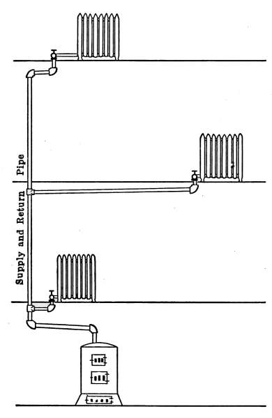
Fig. 1.—Diagram of a gravity system
steam heating plant.
The placing of the pipes
which are to carry the steam
to the radiators and return the
water of condensation to the
boiler may consist of one or
both of two standard arrangements.
They are known as
the single-pipe system and the
two-pipe system.
Fig. 1 shows a diagram of a
single-pipe system in its simplest
form. In the figure the
pipe marked supply and return,
connects the boiler with the
radiators. From the vertical pipe called a riser, the steam is
taken to the radiators through branch pipes that all slope toward
the riser, so that the water of condensation may readily flow back
into the boiler. The water of condensation, returning to the
boiler, must under this condition, flow in a direction contrary to
the course of the steam supplying the radiators. In Fig. 2 is
given a simple application of this system. A single pipe from
the top of the boiler, in the basement, marked supply and return
pipe, connects with one radiator on the floor above. The[7]
radiator and all of the connecting pipes are set to drain the
water of condensation into the boiler.
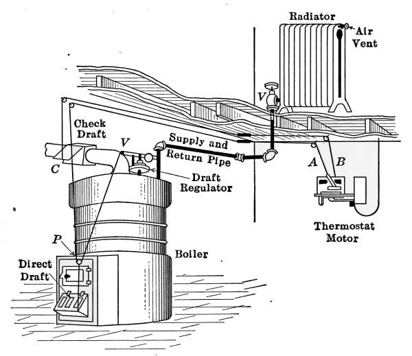
Fig. 2.—A simple form of steam heating plant. The furnace fire is controlled
by a thermostat and a damper regulator.
When the valve is opened to admit steam to the radiator, the
air vent must also be opened to allow the escape of the contained
air. The steam will not diffuse with the air in the radiator and
unless the air is allowed to escape, the steam will not enter. As
the steam enters the cold radiator, it is rapidly condensed, and
collects on the walls in the form of dew, at the same time giving
up its latent heat. The heat is liberated as condensation takes
place, and as the dew forms on the radiator walls the heat is
conducted directly to the iron. The water runs to the bottom
of the radiator and then through the pipes; back to the boiler.
The water occupies but relatively a little space and may return
through the same pipe, while more steam is entering the radiator.
As the steam condenses in the radiator, its reduction in volume
tends to reduce the pressure and thus aids additional steam from
the boiler to enter. In this manner a constant supply of heat
enters the radiator in the form of steam which when condensed
goes back to the boiler at a temperature very near the boiling
point to be revaporized. It should be kept in mind that it is the[8]
heat of vaporization, not the temperature of the steam that is
utilized in the radiator, and that the heat of vaporization is the
vehicle of transfer. The water returning to the boiler may be at
the boiling point and the steam supplying the heat to the radiators
may be at the same temperature.
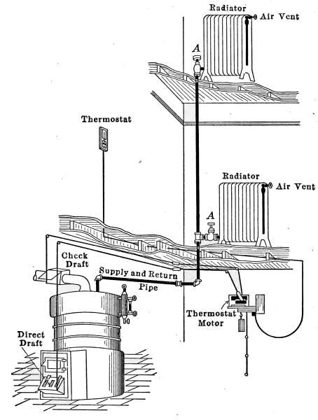
Fig. 3.—A gravity system steam heating plant of two radiators. The furnace
is governed by a thermostat.
Fig. 3 is a slightly different arrangement of the same boiler as
that shown in Fig. 2, connected with two radiators on different
floors. The same riser supplies both radiators with steam and
takes the water of condensation back to the boiler.
Fig. 4 is an example of the single-pipe system applied to a small
house. In the drawing, the boiler in the basement is shown
connected with four radiators on the first floor and three on the
second floor. The pipes connecting with the more distant radiators
are only extensions of the pipes connecting the radiators near[9]
the boiler. As in Figs. 1, 2 and 3, all of the pipes and radiators
are set to drain back into the boiler. If at any place the pipe is
so graded that a part of the water is retained, poor circulation
will result, because of the restricted area of the pipe, and the
radiators will not be properly heated. This lack of drainage is
also a common cause of hammering and pounding in steam systems,
known as water-hammer. The formation of water-hammer
is caused by steam flowing through a water-restricted area, into
a cold part of the system, where condensation takes place very
rapidly. The condensation of the steam is so rapid and complete
that the resulting vacuum draws the trapped water into the
space with the force of a hammer stroke. The hammering will
continue so long as the conditions exist. The pipes in the basement
are suspended from the floor joists by hangers as shown in
the drawing. In practice the pipes in the basement are covered
with some form of insulating material to prevent loss of heat.
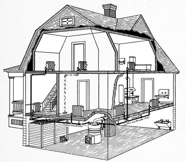
Fig. 4.—The gravity system steam heating plant installed in a dwelling.
As stated above, the single-pipe system may be successfully
used in all house-heating plants except those of large size. It[10]
requires the least amount of pipe and labor for installation of the
circulating system and when well constructed performs very
satisfactorily all of the functions required in a small heating plant.
One of the commonest causes of trouble in a single-pipe system
is due to the radiator connections. The single radiator connection
requires the entering steam and escaping water of condensation
to pass through the same opening. Under ordinary conditions
this double office of the radiator valve is accomplished with
satisfaction but occasionally it is the cause of considerable noise.
At any time the valve is left only partly open the steam will enter
and condense because of the lower pressure inside the radiator
but the condensed water will not be able to escape. The water
has only the force of gravity to carry it out of the radiators and
if it meets no opposition will flow back through the pipe to the
boiler; but if it is required to pass a small opening through which
steam is flowing in a contrary direction, the water will be retained
in the radiators. Single-pipe radiators, therefore, work satisfactorily
only under conditions which will permit the steam to
enter and the water to leave as fast as it is formed. In ordinary
use the valve at any time is apt to be left slightly open and this
produces undesirable working conditions.
In larger buildings, where greater distances require longer
runs of pipe and more complicated connections, and where the
volume of condensed steam is too great to be taken care of in a
single pipe, this system does not work satisfactorily.
Two-pipe System.
—Fig. 5 is a diagram of a two-pipe system.
Here, each radiator has a supply pipe, through which the steam
enters, and a return pipe which conducts the water away. The
branch pipes from a common supply pipe or riser, carry steam to
the various radiators and all of the return pipes empty into a single
return pipe that takes the water back to its source. It will be
noticed that in this case the riser also connects at the bottom with
the return pipe. This connection is made for the purpose of
conducting away the condensation that takes place in the connecting
pipes. The water will always stand in these pipes, at
the same height as the water in the boiler. The supply pipe from
the boiler, and the branch pipes connecting the radiators all slope
toward the riser. The condensation in the connecting pipes
does not pass through the radiators as it returns to the boiler.
[11]
An exception to this general rule is shown in the radiator on
the second floor. In this case the supply pipe slopes downward
as it approaches the radiator. To prevent carrying water
through the radiator, a small pipe under the left-hand valve connects
with the return pipe and the water is thus conducted to the
main return pipe.
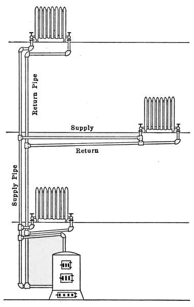
Fig. 5.—Diagram showing the arrangement
of a two-pipe steam plant.
Fig. 6 is a simple application of the arrangement shown in
Fig. 5. The steam may be easily traced from the boiler to the
radiators, and back through
the return pipes to its source.
The pipe marked R is the
connection between the main
supply pipe and the return
pipe that takes away the condensation
of the riser. It is
connected to the main return
pipe below the water line of
the boiler and, therefore, does
not interfere in any way with
the passage of the steam.
Each radiator empties its
water of condensation into a
common return pipe, that
finally connects with the boiler
below the water line.
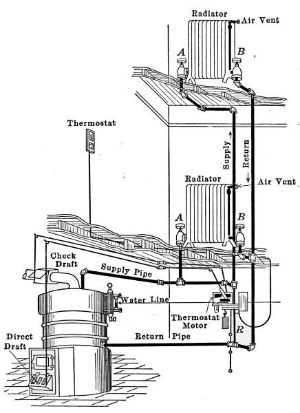
Fig. 6.—A two-pipe steam heating plant.
This arrangement may be
elaborated to almost any extent
and is an improvement
over the single-pipe system.
It is quite commonly used as
a method of steam distribution,
but it lacks the required
elements necessary to a positive circulation. As an example:
Suppose that the plant shown in Fig. 6 is working and that
the radiator on the first floor is hot, but the valves of the
radiator on the second floor are closed and it is cold. The steam
entering at the valve A of the lower radiator is being condensed
as fast as the heat is radiated. The steam will pass on through
the valve B into the return pipe and as soon as the return pipe[12]
becomes hot it will contain steam at practically the same pressure
as that in the supply pipe. This is what takes place in every
working steam plant. Now suppose that it is desired to heat
the radiator on the floor above. The steam valve A of the upper
radiator is opened to admit steam and the return valve is also
opened to allow the water to escape. There is steam in both the
supply and return pipes of the radiator below at the same pressure,
each tending to send steam into the radiator above at opposite
ends. This would make a condition exactly the same as a
single-pipe system, with a supply pipe at both ends of the radiator
and the result would, of course, be the same as in the single-pipe
system. There being no place for the water to escape except
against the incoming steam, the water will sometimes surge back
and forth with the customary noises peculiar to such conditions.
It must not be understood that this will always occur, because[13]
systems of this kind are in use with fairly good results, but noisy
radiators are not at all rare when working under this condition
and the cause is from that described. To overcome this difficulty
and change the system into one in which there would be a positive
circulation from A to B, in each radiator, allowing the steam
always to enter at the valve A and escape at B, the system must
be changed to that of separate returns.
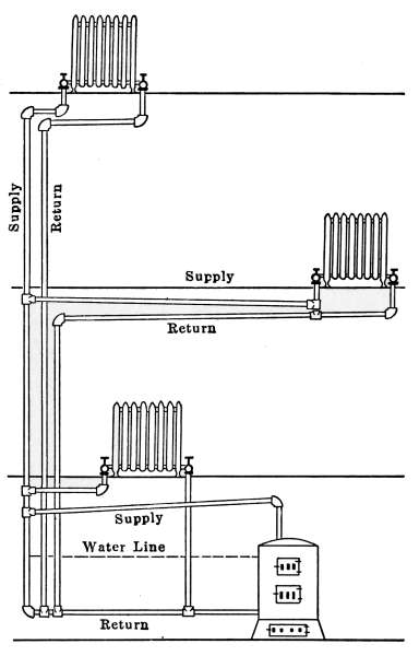
Fig. 7.—Diagram of a separate return
steam system.
Separate-return System.
—A diagram of a separate-return system
is shown in Fig. 7. In this figure, the radiator, boiler and
supply pipes are the same as
those of Fig. 5, but there is a
separate return pipe from
each of the radiators, connecting
with the main return pipe
at a point below the water
line of the boiler. Examination
of this diagram will show
that there is an independent
circuit for the steam through
each radiator. The steam is
taken from a common riser as
before but after passing
through the radiator the
water is returned by a separate
pipe to the main return
pipe at the bottom of the
boiler. Fig. 8 is an application
of separate-return system.
It is exactly the same as Fig.
6, except that each radiator
has an independent return
pipe. Steam must always
enter the radiators at the
valves A and leave at the valves B. This makes a positive circulation
that renders each radiator independent of the others.
There is no opportunity for steam to pass through one radiator
and interfere with the return water of another; it, therefore, prevents
the possibility of hammering or surging so common in
poorly designed steam systems.
[14]
Of all the methods of steam heating where the water of condensation
is returned to the boiler by reason of gravity this is
the most satisfactory. This plant requires a larger amount of
pipe than the other systems described and as a consequence the
cost of installation is greater but it repays in excellence of
service the extra expense incurred.
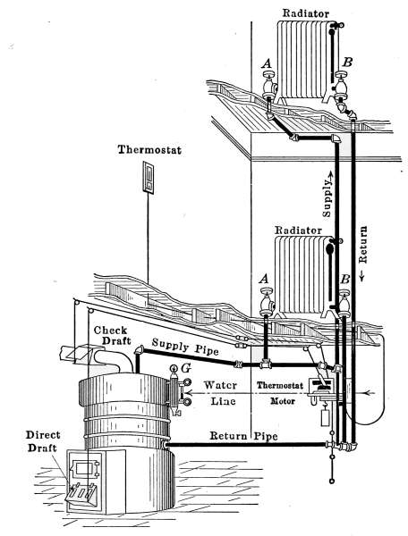
Fig. 8.—A separate return heating plant.
Overhead or Drop System.
—There is yet another gravity
system of steam heating that is sometimes used in large buildings
where economy in the use of pipe is desired; this is the overhead
or drop system shown in Fig. 9. It is not a common method of
piping and is given here only because of its occasional use. In
the arrangement of the drop system, the supply pipe for the
radiators rises from the boiler to the highest point of the system
and the branch pipes for the radiators are taken off from the
descending pipe. Its action is the same as that of a single-pipe[15]
system but the advantage gained by the arrangement is that the
steam in the main supply pipes travels in the same direction as
the returning water of condensation; the cause of surging in long
risers is thus eliminated.
The two-pipe systems of steam heating are more certain in
action than the single-pipe methods because there is nothing to
interfere with the progress of
the steam on its way to the
radiators. In long branch
pipes of the single-pipe system,
the returning water is
frequently caught by the advancing
steam and carried to
the end of the pipe, when
slugging and surging is the
result.
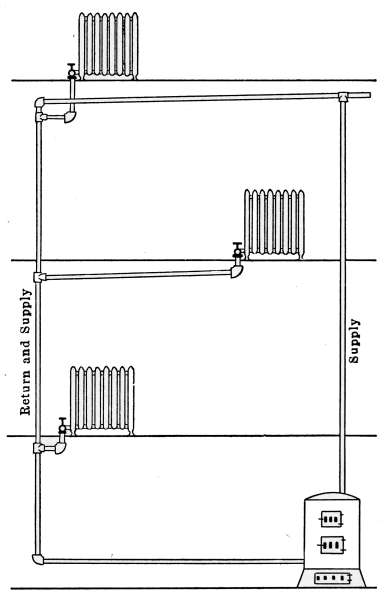
Fig. 9.—Diagram of the overhead or
drop system steam plant.
Water-filled Radiators.
—Radiators
frequently fill with
water and are noisy because
of the position of the valve.
This may be true in any gravity
system but particularly so
in radiators having a single
pipe. When the valve of a
single-pipe radiator is opened
a very small amount, the
entering steam is immediately
condensed but the water
cannot escape because the incoming
steam entirely fills the opening. Under this condition, the
radiator may entirely fill with water. If the valve is then opened
wide, the imprisoned water has an opportunity to escape while
the steam is entering, but the entering steam and escaping water
sets up a water-hammer that sometimes is terrific and lasts
until the water is discharged from the radiator. The same
condition may exist in a two-pipe system, if the steam valve is
slightly opened while the escape valve is closed, but in a well-designed
system the radiator will be immediately emptied when
both valves are open.
[16]
Air Vents.
—All radiators must be provided with air vents.
The vent is placed near the top of the last loop of the radiator,
at the end opposite from the entering steam, as indicated in Figs.
2, 3, 6, etc. The object of the vent is to allow the air to
escape from the radiator as the steam enters. Steam will not
diffuse with the air and, therefore, cannot enter the radiator
until the air is discharged. The air vent may be a simple cock
such as is shown in Fig. 10, that must be opened by hand when
the steam is turned on, to allow the air to escape, and closed
when the steam appears at the vent; or it may be an automatic
vent, that opens when the radiator cools and closes automatically
when the radiator is filled with steam. There are many makes
of air vents of both hand-regulating and automatic types; of
the former, Fig. 10 furnishes a common example. The part
A, in the figure, is threaded and screws tightly into a hole made
to receive it in the end loop of the radiator. The part B is a
screw-plug that closes the passage C, leading to the inside of the
radiator. When the steam is turned on, the vent must be
opened until the air is discharged, after which it is closed by the
hand-wheel D.
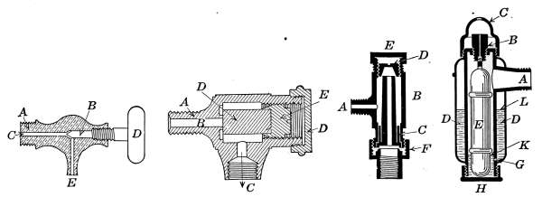
Fig. 10.Fig. 11.
Fig. 12.Fig. 13.
Fig. 10.—A common form of air vent for radiators.
Fig. 11.—An inexpensive automatic radiator air vent.
Fig. 12.—Monash No. 16 automatic air vent.
Fig. 13.—The Allen float, radiator air vent.
Automatic Air Vents.
—These vents depend for their action on
the expansion of a part of the valve due to the temperature of the
steam. The valve remains closed when hot and opens when
cold. The difference in temperature between the steam and the
expelled air from the radiator is the controlling factor. In the[17]
automatic vent shown in Fig. 11, the part A is screwed into the
radiator loop. The discharge C is open to the air or connected
with a drip pipe, which returns the water to the basement. The
cylinder D, which closes the passage B, is made of a material of a
high coefficient of expansion. The piece D, when cool, is contracted
sufficiently to leave the passage B open to the air. When
the steam is turned on, the expelled air from the radiator escapes
through B and C, but when the steam reaches D the heat quickly
expands the piece and closes the vent.
Most automatic vents require adjusting when put in place and
occasionally need readjustment. The cap O, of Fig. 11, may be
removed with a wrench and a screw-driver used to adjust the
piece D, so as to shut off the steam when the radiator is filled
with steam. The expanding piece is simply screwed down until
the steam ceases to escape.
Fig. 12 is another style of automatic vent, constructed on the
same principle as that of Fig. 11, but probably more positive in
action. In this vent the part A attaches to the radiator. The
expanding portion B is made in the form of a hollow cylinder,
through which the air and steam escape to the atmosphere. It
is longer than the corresponding piece in the other vent and is
more sensitive because of its greater length and exposed surface.
As the piece B elongates from expansion, the upper end makes a
joint with the conical piece D. The shape of this latter piece
gives better opportunity for a tight joint than in the other form
of vent and in practice gives better service.
Fig. 13 is a cross-section of the Allen vent. This is an example
of a vent which depends for its action on a float. Whenever
sufficient water accumulates in the body of the vent to raise
the float, it closes the vent by means of its buoyancy. The body
of the vent shown in Fig. 13 is composed of two concentric cylinders.
The float E occupies the inner cylinder, while surrounding
it is the outer cylinder D. The outer cylinder is entirely closed
except a little hole at G. The float is made of light metal and
fits loosely in the inner cylinder. The steam from the radiator
condenses in the vent until the inner cylinder is filled with water,
up to the opening A. The float by its buoyancy keeps the opening
in B stopped, and no steam can escape. The air of the outer
cylinder D is expanded by the heat of the steam and most of the[18]
air escapes through the hole G. When the radiator cools, the
rarefied air in D contracts and draws the water from the inner
cylinder into the space D; this allows the float to fall and unstop
the opening in B. When the steam again reaches the vent, the
heat expands the air in D and forces the water into the inner
cylinder; the float is again raised and stops the opening in B.
Many other air vents are in common use but most of them
operate on one or the other of the principles described. Fig. 11
is a relatively inexpensive vent, while Fig. 12 is higher-priced.
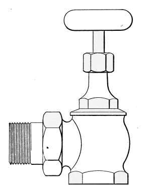
Fig. 14.—Steam radiator
valve.
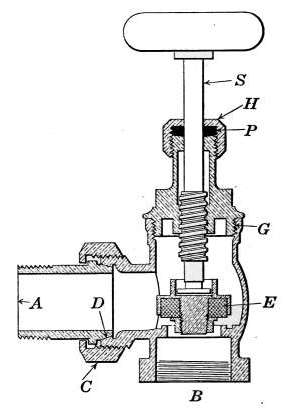
Fig. 15.—Sectional view of a
steam radiator valve.
Steam Radiator Valves.
—Like most other mechanical appliances
that are extensively used, radiator valves are made by a
great number of manufacturers and in many different forms.
Some possess special features that are intended to increase their
working efficiency but the type of radiator valve most commonly
used for ordinary construction is that illustrated in Figs. 14 and
15. It is a style of angle valve that takes the place of an elbow
and being made with a union joint, also furnishes a means of
disconnecting the radiator without disturbing the pipes. Fig.
14 is an outside view of the valve and Fig. 15 shows its mechanical
construction. The part B screws onto the end of the steam
pipe and A connects with the radiator. The part C-D is the
union. The nut C screws onto the valve and makes a steam-tight[19]
joint at D, between the parts. In case it is desired to
remove the radiator, it furnishes an easy means of detaching the
valve. The composition valve-disc E makes a seat on the brass
ring directly under it, to shut off the steam. In case the valve
leaks, the disc may be removed by taking the valve casing apart
at G. The worn disc can then be replaced with a new one which
may be obtained from the dealer who furnished the valve. The
only moving part of the valve exposed to the air is at the point
where the valve-stem S enters the casing. The joint is made
steam-tight by the packing P. The packing is greased candle
wicking that is wound around the stem and held tightly in place
by the screw-cap H. If the valve leaks at this joint, a turn or
two with a wrench will stop the escape of the steam.
THE HOUSE-HEATING STEAM BOILER
House-heating boilers were formerly made of sheet metal and
are still so constructed to some extent, but by far the greater
number are now made of cast iron. Sheet-metal boilers are
constructed at the factory, ready to be installed, but the cast-iron
type is made in sections and assembled to make a complete
boiler, at the time the plant is erected. Sectional boilers are
convenient to install, on account of the possibility of handling
the parts in a limited space, that would not admit an assembled
boiler without tearing down a part of the basement for admission.
Cast-iron boilers as commonly used for heating dwellings are
made in two definite styles. The small sizes are cylindrical in
form and are used for either steam or hot-water heating. The
larger sizes are made as illustrated in Figs. 16 and 17, the
former being an outside view, and the latter showing the internal
arrangement of the same boiler. The fire-box, water space and
smoke passages are easily recognized. Each division represents
a separate section which assembled as that in the figures makes a
complete boiler with a common opening as shown at the top of
Fig. 17. These boilers are used for residences of large size and
for buildings of less than 10,000 feet of radiating surface. For
large buildings, the steam is most commonly generated in boilers
built for high pressure.
In small plants, intended for either steam or hot-water heating,[20]
the cylindrical style of boiler shown in Fig. 18 is commonly used.
As constructed by different manufacturers, the parts differ quite
materially but Fig. 18 shows all of the essential features and
serves to illustrate the different working parts. The sections
into which the boiler is divided are indicated on the left-hand
side of the figure by the numbers 1 to 6. The parts from 1 to 5
are screwed together with threaded nipples, joining the central
column. The part 6 contains the grate and the ash-pit, with
the draft and clean-out doors.
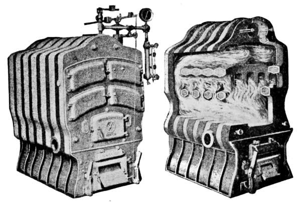
Fig. 16.
Fig. 17.
Fig. 16.—Sectional cast-iron boiler for steam or hot-water heating.
Fig. 17.—Interior view of the boiler shown in Fig. 16.
The drawing shows the boiler cut through the middle lengthwise
and exposes to view all of the essential features. The fire-box
and the spaces occupied by the steam and water are easily
recognized. It will be seen that the water space surrounds the
fire-box except at the bottom and that the space above the fire-box
presents a large amount of heating surface to the flame and
heated gases as they pass to the chimney. The arrows show
their course; first through the openings near the center, then
through those further away. The object being to keep the[21]
heat as long as possible in contact with the heating surfaces
without interfering with the draft.
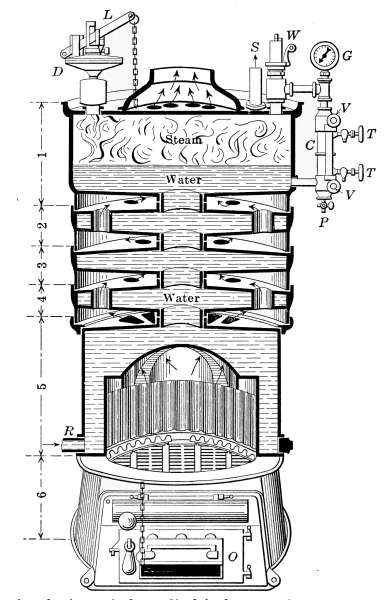
Fig. 18.—Sectional view of the cylindrical type of cast-iron, sectional boiler.
There is no standard method of rating the heating capacity of
boilers of this kind and as a consequence, boilers of different
makes—for the same rating—are not the same in actual heating
capacity. The boilers are sold by their makers in sizes that
are intended to furnish heat sufficient to supply a definite number
of square feet of radiating surface. The ratings are quite
generally too high for the weather conditions of the Northwest.
A common practice with contractors is to select boilers for a
given plant 50 per cent. and even 100 per cent. larger than those
rated by the manufacturers for the same amount of radiation.[22]
Some manufacturers sell their boilers at honest ratings but they
are exceptions.
In specifying the capacity of a house-heating plant it is common
practice to require the boiler to be of such size as will easily
heat a definite number of square feet of radiating surface. The
radiators are required to possess sufficient radiating surface to
keep the house at 70°F. in any weather. In the absence of any
rules or specifications for determining the heating capacity of the
boiler, the only means of securing a satisfactory plant is to require
a guarantee of the contractor to install a
boiler such as will fulfil the conditions stated
above.
Boiler Trimmings.
—Attached to the
boiler and required for its safe operation are
a number of appliances that demand special
attention. The office of each part should be
thoroughly appreciated and the mechanical
construction should be fully understood.
An intimate acquaintance with the details of
the plant, helps to make its operation satisfactory
and adds to the efficiency with which
it can be made to perform its duty.
The Water Column.
—In Fig. 18 the
water column is shown at C. It is attached
to the boiler by pipes at points above and
below the water line, so as to allow a free
passage of the water of the boiler to the interior.
The water line should be 3 or 4 inches above the top
heating surface. Attached to the water column is the gage-glass,
the try-cocks T and T and the steam gage G.
The object of the gage-glass is to show the height of the water
in the boiler. It is shown in place on the boiler in Figs. 16 and
18 and in detail in Fig. 19. The lower part of the gage-glass
occupies a position on the boiler about 2 inches above the top
heating surface. When the boiler is working, the level of the
water should always be visible in the glass and should stand
normally one-third to one-half full.
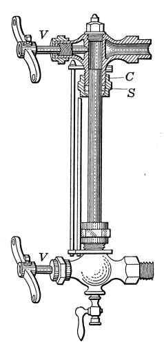
Fig. 19.—The water
gage.
The water gage is attached to the water column by two brass
valves V. The valves are provided so that in case the water[23]
glass should be broken the openings may be closed. The ends
of the glass are made tight by “stuffing-boxes” marked C, in the
figure. The packing S is generally in the form of rubber rings
but greased wicking may be used if necessary as in the case of
valve-stems.
The try-cocks T and T (Fig. 18) are also intended to indicate the
approximate height of the water in the boiler and should the water
glass be broken may be used in its place. The openings of the try-cocks
point toward the floor. When a cock is opened, should
steam alone escape, it will be absorbed by the air, but if water is
escaping, although much of it will be vaporized and look like
steam, some of the water will be carried to the floor and produce
a wet spot. When the cock is opened wide the escaping water
from the lower cock should always wet the floor.
The drip-cock P (Fig. 18) at the bottom of the gage-glass is
for draining the water column and for blowing out any deposit
that may collect in the opening of the column. This cock should
be opened occasionally to assure the correctness of the gage-glass.
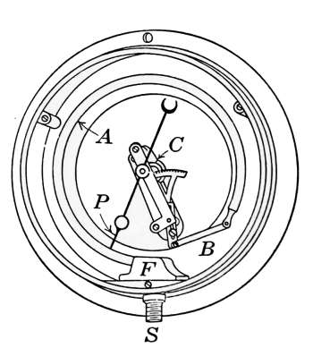
Fig. 20.—Typical Bourdon
pressure gage with the
face removed.
The Steam Gage.
—Steam pressure is measured in pounds to
the square inch above the pressure of the atmosphere. The
gages used for indicating the pressure of
the steam are made in several forms but
the type most commonly used is that
shown in Fig. 20. It is known as the
Bourdon type of gage and takes its name
from the bent tube A, which furnishes its
active principle. The Bourdon barometer
invented in 1849 employed this form of
sensitive tube. In the drawing the face
of the gage has been removed to show
the working parts. The sensitive part is
the flat elastic tube A, which is bent in
the form of a circle. When the pressure of the steam enters at
S the air in the tube is compressed and the tube tends to straighten.
The movement of the tube caused by the steam pressure is communicated
to the pointer by a link connection and gear as shown
in the drawing. The amount of straightening of the tube will
be in proportion to the steam pressure and is indicated by the
numbers marked on the face of the gage. When the pressure is[24]
released, the tube returns to its original position and the spiral
spring C turns the hand back to its first position.
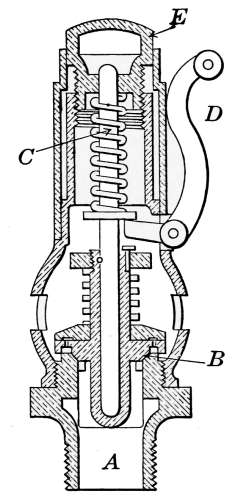
Fig. 21.—Cross-section
of a pop
valve.
The Safety Valve.
—All steam boilers should be provided
with safety valves as a safeguard against excessive steam pressures.
Of the various types of safety valves, that known as the
pop-valve is most commonly used on house-heating boilers. It
is indicated at W in Fig. 18 and is shown in section in Fig. 21.
The part A is screwed into the top of the boiler at any convenient
place. The pressure of the spring C holds the valve B on its seat
until the internal pressure reaches a certain intensity
at which the valve is set, when it opens
and allows the excess steam to escape. When
the pressure is reduced, the spring forces the
valve back on its seat. The handle D permits
the valve to be lifted at any time as an assurance
that it is in working order. This should
be done occasionally, as the valve may stick to
the seat after long standing and allow the pressure
to rise above the point at which it should
“pop.”
The valve may be set to “blow off” at any desired
pressure by the adjusting piece E. House-heating
boilers generally have their safety valves
set to blow off at 8 or 10 pounds.
The Draft Regulator.
—As a means of automatic
control of the steam pressure, the draft regulator is frequently
used to so govern the fire that when a certain steam
pressure is reached, the direct draft will be automatically closed
and the check-draft damper opened. The draft regulator is
shown in place at D in Fig. 18, and will also be found in Fig. 16.
A detailed description of the regulator will be found on pages
60 and 61.
RULE FOR PROPORTIONING RADIATORS
Rules for determining the amount of radiating surface that
will be required to satisfactorily heat a building to 70°F. regardless
of weather conditions are entirely empirical, that is, they are
derived from experience. It is evident that no definite rule can[25]
be established that will take into account the method of building
construction, the kind and amount of materials that make up
the walls and the quality of workmanship employed. These
variable quantities coupled with the changing climatic conditions
of temperature and wind velocity produce a complication that
cannot be overcome in a formula that will give exact results.
Many rules are in use for this purpose, no two of which give
exactly the same results when applied to a problem. A common
practice is to apply one of the rules in use and then under
conditions of exceptional exposure, to add to the amount thus
calculated as experience may dictate.
The following rule by Professor R. G. Carpenter of Cornell
University was taken from a handbook published by the J. L.
Mott Iron Works of New York. This company manufactures
and deals in all kinds of apparatus entering into steam and hot-water
heating and the rule is given as one that has produced
satisfactory results.
Rule.—Add the area of the glass surface in the room to one-quarter
of the exposed wall surface, and to this add from one-fifty-fifth to
three-fifty-fifths of the cubical contents (one-fifty-fifth for rooms on
upper floor, two-fifty-fifths for rooms on first floor and three-fifty-fifths
for large halls); then for steam multiply by 0.25, and for hot water
by 0.40.
Example.—A room 20 by 12 by 10 feet with glass exposure of 48
feet, ¼ of wall exposure (two sides exposed) 320 feet = 80, 1⁄55
of 2400 = 44.
48 + 80 + 44 = 172 × 0.25 = 43 feet.
If you add 2⁄55 the surface would be 54 feet.
If you add 3⁄55 the surface would be 65 feet.
PROPORTIONING THE SIZE OF MAINS
For any size system of steam or water heating the following
rule will be found entirely satisfactory for mains 100 feet long;
for each 100 feet additional use a size larger ratio.
Rule.—
r = (3.1416/d)R = a/r × 100.
r represents ratio of main in inches for each 100 feet of surface; d,
diameter of pipe; R, quantity of radiation carried by size of pipe; a,
area of pipe in inches.
[26]
From this the following table has been constructed:
| Diameter of pipe |
Area of pipe |
Ratio to each 100
feet of surface |
Quantity of radiation,
steam or water, on a
given size pipe |
| 1½ | 1.767 | 2.10 | 84 |
| 2 | 3.141 | 1.57 | 200 |
| 2½ | 4.908 | 1.25 | 400 |
| 3 | 7.069 | 1.04 | 700 |
| 3½ | 9.621 | 0.90 | 1,062 |
| 4 | 12.566 | 0.78 | 1,590 |
| 4½ | 15.904 | 0.70 | 2,272 |
| 5 | 19.625 | 0.63 | 3,120 |
| 6 | 28.274 | 0.52 | 5,440 |
| 7 | 38.484 | 0.45 | 8,550 |
| 8 | 50.265 | 0.40 | 12,556 |
| 9 | 63.617 | 0.35 | 18,100 |
| 10 | 78.540 | 0.30 | 25,300 |
FORMS OF RADIATORS
Radiators are much the same in appearance for both steam and
hot-water heating. They are hollow cast-iron columns so designed
that they may be fastened together in units of any number
of sections. The sections are made in size to present a definite
number of square feet of outside surface that is spoken of as
radiating surface. The amount of radiating surface in any
radiator depends on its height and the contour of the cross-section.
The radiator sections may be made in the form of a single
column as Fig. 22 or they may be divided into two, three, four or
more columns to increase their radiating surface.
The following table, taken from a manufacturer’s catalogue,
shows the method of rating the heating capacity of a particular
design. In the table, the first column gives the number of sections
in the radiator, the second column states the length of the
radiator in inches. The columns headed heating surface give
the heights of the sections in inches and the amount of radiating
surface in various radiators of different heights and numbers of
sections. As an example: This table refers to the three-column
radiators of Fig. 23. Such a radiator 32 inches high with 10[27]
sections would contain 45 square feet of radiating surface and
would be 25 inches in length.
No. of
sections |
Length
2½ in.
per section |
Heating surface—square feet |
45 in. high,
6 sq. ft.
per sec. |
38 in. high,
5 sq. ft.
per sec. |
32 in. high,
4½ sq. ft.
per sec. |
26 in. high,
3¾ sq. ft.
per sec. |
23 in. high,
3¼ sq. ft.
per sec. |
20 in. high,
2¾ sq. ft.
per sec. |
| 2 | 5 | 12 | 10 | 9 | 7½ | 6½ | 5½ |
| 3 | 7½ | 18 | 15 | 13½ | 11¼ | 9¾ | 8¼ |
| 4 | 10 | 24 | 20 | 18 | 15 | 13 | 11 |
| 5 | 12½ | 30 | 25 | 22½ | 18¾ | 16¼ | 13¾ |
| 6 | 15 | 36 | 30 | 27 | 22½ | 19½ | 16½ |
| 7 | 17½ | 42 | 35 | 31½ | 26¼ | 22¾ | 19¼ |
| 8 | 20 | 48 | 40 | 36 | 30 | 26 | 22 |
| 9 | 22½ | 54 | 45 | 40½ | 33¾ | 29¼ | 24¾ |
| 10 | 25 | 60 | 50 | 45 | 37½ | 32½ | 27½ |
| 11 | 27½ | 66 | 55 | 49½ | 41¼ | 35¾ | 30¼ |
| 12 | 30 | 72 | 60 | 54 | 45 | 39 | 33 |
| 13 | 32½ | 78 | 65 | 58½ | 48¾ | 42¼ | 35¾ |
| 14 | 35 | 84 | 70 | 63 | 52½ | 45½ | 38½ |
| 15 | 37½ | 90 | 75 | 67½ | 56¼ | 48¾ | 41¼ |
| 16 | 40 | 96 | 80 | 72 | 60 | 52 | 44 |
| 17 | 42½ | 102 | 85 | 76½ | 63¾ | 55¼ | 46¾ |
| 18 | 45 | 108 | 90 | 81 | 67½ | 58½ | 49½ |
| 19 | 47½ | 114 | 95 | 85½ | 71¼ | 61¾ | 52¼ |
| 20 | 50 | 120 | 100 | 90 | 75 | 65 | 55 |
| 21 | 52½ | 126 | 105 | 94½ | 78¾ | 68¼ | 57¾ |
| 22 | 55 | 132 | 110 | 99 | 82½ | 71½ | 60½ |
| 23 | 57½ | 138 | 115 | 103½ | 86¼ | 74¾ | 63¼ |
| 24 | 60 | 144 | 120 | 108 | 90 | 78 | 66 |
| 25 | 62½ | 150 | 125 | 112½ | 93¾ | 81¼ | 68¾ |
| 26 | 65 | 156 | 130 | 117 | 97½ | 84½ | 71½ |
| 27 | 67½ | 162 | 135 | 121½ | 101¼ | 87¾ | 74¼ |
| 28 | 70 | 168 | 140 | 126 | 105 | 91 | 77 |
| 29 | 72½ | 174 | 145 | 130½ | 108¾ | 94¼ | 79¾ |
| 30 | 75 | 180 | 150 | 135 | 112½ | 97½ | 82½ |
| 31 | 77½ | 186 | 155 | 139½ | 116¼ | 100¾ | 85¼ |
| 32 | 80 | 192 | 160 | 140 | 120 | 104 | 88 |
Fig. 22 is a radiator made up of eight single-column sections.[28]
In Fig. 23 is shown five three-column radiators, varying in
height from 20 to 45 inches.
The sections of steam radiators are joined together at the bottom
with close-nipples, so as to leave an opening from end to
end. The sections of hot-water radiators are joined in the same
manner, except that there is an opening at both top and bottom.
Fig. 30 shows the openings of a hot-water radiator installed as
direct-indirect heater. Fig. 24 illustrates a special form of
radiator that is intended to be placed under windows and in
other places that will not admit the high
form. Such a radiator as that shown
in the picture is often covered with a
window seat and in cold weather becomes
the favorite place of the sitting room.
Another special form is that of Fig. 25.
As a corner radiator this style is much to be preferred to the
ordinary method of connection; here the angle is completely
filled—there is no open space in the corner.
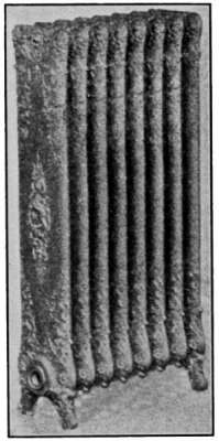
Fig. 22.
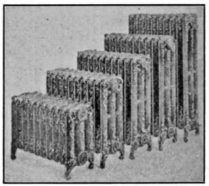
Fig. 23.
Fig. 22.—Single column steam radiator.
Fig. 23.—Three-column radiators of different heights; for steam or hot-water
heating.
Wall radiators such as shown in Fig. 26 are made to set
close to the wall, where floor space is limited. They are particularly
adapted for use in narrow halls, bathrooms and other
places where the ordinary type could not be conveniently used.
A radiator that will appeal to all neat housekeepers is that of
Fig. 27. It does not stand on the floor as in the case of the[29]
ordinary type, but is hung from the wall by concealed brackets.
The difficulty of sweeping under this radiator is entirely avoided.
Fig. 28 is a radiator designed to furnish a warming oven for
plates and for heating the room at the same time. It is sometimes
installed in dining rooms.
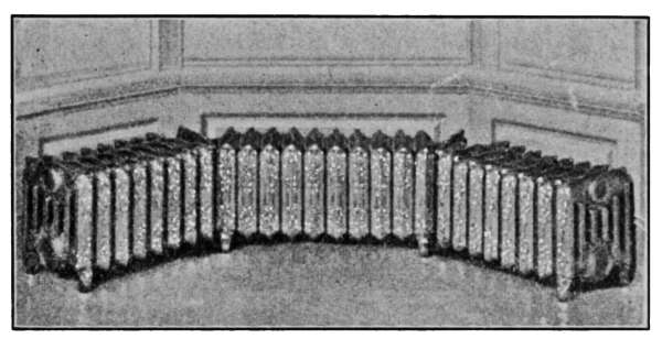
Fig. 24.—Six-column, low form of hot-water radiators to be placed under
windows.
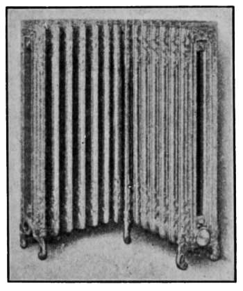
Fig. 25.—Two-column corner
radiator for steam heating.
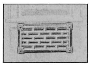
Fig. 26.—Wall form, radiator for steam
or hot water.
The ordinary method of heating by the use of radiators is
known as the direct method. The air is heated by coming
directly into contact with the radiators and distributed through
the room by convection. If the arrangement is such that the
air is brought from outdoors and heated by the radiator before
entering the room, it is called the indirect method of heating.
Such an arrangement is illustrated in Fig. 29. The radiator[30]
is located beneath the floor, in a passage that takes the air from
outdoors and after being heated, enters the room through a
register located in the wall.
Fig. 30 is still another arrangement known as the direct-indirect
method of heating. The radiator is placed in position, as for
direct heating, but the air supply is taken from outdoors. The
radiator base is enclosed and a double damper T regulates the
amount of air that comes from the outside. When the inside
damper is closed and the outside damper is open, as is shown in
the drawing, the air comes from outdoors and is heated as it
passes through the radiator on its way to the room. If the
dampers are reversed, the air circulates through the radiator as
in the case of direct radiation.
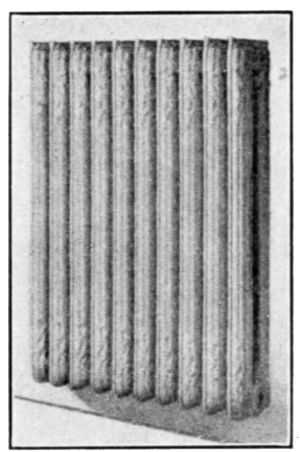
Fig. 27.—Two-column radiator
suspended from the wall by
brackets.
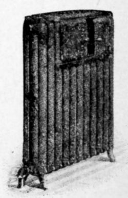
Fig. 28.—Dining-room
radiator containing a warming
oven.
In the use of the direct or the direct-indirect method of heating
the principal object to be attained is that of ventilation, but
quite generally the passages are so arranged that the air may be
taken from outdoors or, if desired, the air of the house may be
sent through the radiators to be reheated. In extremely cold
and windy weather it is sometimes difficult to keep the house at
the desired temperature when all of the air supply comes from
the outside. Under such conditions the outside air is used only
occasionally. In mild weather it is common to use the outdoor
air most of the time. The cost of heating, when these methods
are used, is higher than by direct radiation, because the air is[31]
being constantly changed in temperature from that of the outside
to 70°.
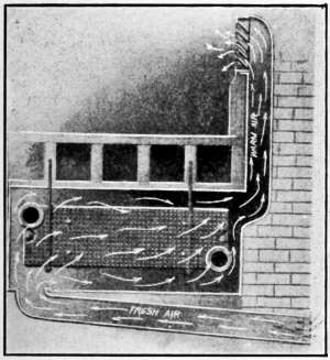
Fig. 29.—Ventilation by the indirect
method of heating.
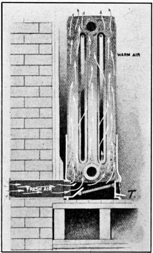
Fig. 30.—Ventilation by the direct-indirect
method of heating.
Radiator Finishings.
—In steam and hot-water heating the
decoration of the radiators is a much more important item than
that of a good-looking surface or one which will harmonize with
the setting. Until recently radiator finishing has been considered
a minor detail and the familiar bronze has been looked
upon as a standard covering, while painted radiators were considered
only a matter of taste. The character of the surface is,
however, the determining factor in the quantity of heat given
out by radiators. This has been determined in the experimental
laboratory of the University of Michigan by Professor John A.
Allen. Comparison was made of bare cast-iron radiators with
the same forms painted as indicated in the following table. The
bare radiator was taken at 100 per cent.; the other finishes[32]
are expressed in per cent. above or below that of the bare
radiator.
Condensing
capacity,
per cent. |
| No. 1, a cast-iron radiator, bare as received from the foundry | 100 |
| No. 2, a cast-iron radiator, coated with aluminum bronze | 78 |
| No. 3, a cast-iron radiator, three coats of white enamel paint | 102 |
| No. 4, a cast-iron radiator, coated with copper bronze | 80 |
| No. 5, a cast-iron radiator, three coats of green enamel paint | 101 |
| No. 6, a cast-iron radiator, three coats of black enamel paint | 101 |
The author has stated further that, “It might be said in general
that all bronzes reduce the heating effect of the radiator
about 25 per cent. while lead paints and enamels give off the same
amount of heat as bare iron. The number of coats of paint on
the radiator makes no difference. The last coat is always the
determining factor in heat transmission.”
PIPE COVERINGS
All hot-water or steam pipes in the basement and in other
places not intended to be used for heating should be covered
with some form of insulating material. At ordinary working
temperature a square foot of hot pipe surface will radiate about
15 B.t.u. of heat per minute. To prevent this loss of heat and
the consequent waste of fuel the pipes should be covered with
some form of insulating material.
Pipe coverings are made of many kinds of material and some
possess insulating properties that may reduce the loss to as low
a point as 15 per cent. of the amount radiated by a bare pipe.
Many good insulating materials do not give satisfactory results
as pipe coverings because they do not keep their shape, some
cannot be considered in the average plant because of high cost.
Wood-pulp paper is extensively used as a cheap covering;
it is a good insulator and under ordinary conditions makes a
satisfactory covering. A more efficient and also a more expensive
covering that is extensively used is that made of magnesia
carbonate and known as magnesia covering. Aside from these,
other forms made of cork, hair-felt, asbestos and composition
coverings are sometimes used in house-heating plants.
In selecting a pipe covering, there should be taken into account[33]
not only its insulating properties but its ability to resist fire,
dampness or breeding places for vermin. It rests entirely with
the owner whether he covers the pipes with a combustible or an
incombustible material when the insulating properties are about
the same. Coverings made of animal or vegetable materials
under some conditions furnish a breeding place for vermin.
Pipe coverings are made in sections about 3 feet in length and
from 1 to 13⁄8 inches in thickness. The sections are usually
cut in halves lengthwise to permit being put in place. The
sections are covered with common muslin to keep the material
in place and sometimes are painted after being installed. Painting
has nothing to do with their insulating capabilities, but it
preserves the cloth and makes a neat appearance. The sections
when put in place are secured by pasting one of the loose edges
of the cloth to the surface. The ends of the sections are bound
together with strips of metal. Fig. 31 shows the appearance of
the pipe when the covering is in place.
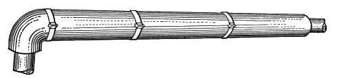
Fig. 31.—Pipe covering.
Irregular surfaces like the body of the furnace, pipe connections,
etc., are insulated by coverings made from a plaster that
is made expressly for such work. It is known as asbestus plaster.
The plaster may be purchased in bulk and put in place with a
trowel. As it is found in the market the plaster requires only
the addition of water to put into working form.
The value of a pipe covering is not in proportion to its thickness.
Experiments with pipe coverings have shown that a thickness
of 13⁄8 inches will reduce the radiation 90 per cent., but
doubling the thickness reduces the loss only 5 per cent. It,
therefore, does not pay to make a covering more than 13⁄8 inches
thick.
Vapor-system Heating.
—This system of heating is not greatly
different from the steam plants already described but it is
operated under conditions which do not permit the steam in the[34]
boiler to rise beyond a few ounces of pressure. Since the plant
is intended to work at a pressure that is scarcely indicated by
an ordinary steam gage, it has been termed a vapor system to
distinguish it from the pressure systems which employ steam, up
to 5 pounds or more to the square inch. The heat is transmitted
to the radiators in the same manner as in the pressure
systems. The heat of vaporization of steam is somewhat greater
at the boiling point of water than at higher pressures, and the
lack of pressure, therefore, increases its heating capacity. This
is shown in the table, properties of steam, on page 3. The
successful operation of such a plant rests in the delivery of the
vapor to the radiators at only the slightest pressure and the
return of the condensate to the boiler without noise or obstruction
to the circulation at the same time ejecting the contained air.
The excellence of the system depends in the greatest measure
on good design and the employment of special facilities that
allow all water to be discharged from the radiators and returned
to the boiler without accumulation at any part of the circulating
system. It requires, further, the discharge of the air from the
system at atmospheric pressure. The system is, therefore, practically
pressureless.
Various systems of vapor heating are sold under the names
of their manufacturers. Each possesses special appliances for
producing positive circulation that are advocated as features of
particular excellence. The vapor system of heating has met with
a great deal of favor as a more nearly universal form of heating
than either the pressure-steam plant or the hot-water method of
heating.
Fig. 31a is a diagram illustrating the C. A. Dunham system
of vapor heating. It will be noticed that there are no air vents
on the radiators. The air from the radiators is ejected through
a special form of trap that is indicated in the drawing. These
traps permit the water and air to pass from the radiators but
close against the slightly higher temperature of the vapor. This
assures the condensation of the vapor in the radiators and excludes
it from the return pipes. The water returns to the boiler
in much the same manner as in the pressure systems already described
but the air escapes through the air eliminator as indicated
in the drawing. The system is, therefore, under atmospheric[35]
pressure at this point and only a slight amount greater
in the boiler.
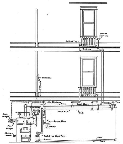
Fig. 31
a.—Diagram showing the C. A. Dunham Co.’s system of vapor heating.
The water of condensation is returned to the boiler against
the vapor pressure, by a force exerted by the column of water
in the pipe connecting the air eliminator with the boiler. The
main return is placed 24 inches or more above the water line of
the boiler. It is the pressure of this column that forces the
water into the boiler through the check valve, against the vapor
pressure in the boiler.
[36]
It might be imagined that the water in the boiler and that
in the air-eliminator pipe formed a “U-tube,” the vapor pressure
on the water surface in the boiler, and the atmospheric pressure
on the water in the eliminator standpipe. The slight vapor pressure
in the boiler is counterbalanced by a column of water in the
eliminator pipe. It is this condition that fixes a distance of 24
inches from the water line to the return pipe; that is, the force
exerted by a column of water 24 inches high is required to send
the water into the boiler.
The vapor pressure is controlled by means of the pressurestat,
which is an electrified Bourdon spring pressure gage, connected
up by simple wiring to the damper motor, which may be any form
of damper regulator. In residential work, the pressurestat is so
connected with a thermostat, that both pressure and temperature
conditions operate and control this damper regulator, which in
turn controls the draft and the fire.
The two instruments are so connected that if the pressure
mounts to 8 ounces and the pressurestat caused the draft damper
to close and the check to open, the thermostat cannot reverse
the damper, regardless of the temperature in the room, until
the pressure drops below the limiting 8-ounce pressure. Just
so long as the pressure is below 8 ounces, the thermostat is the
master in the control of the dampers. The minute that the
pressure goes up to 8 ounces then the pressurestat takes control.
[37]
CHAPTER II
THE HOT-WATER HEATING PLANT
Of the various systems of heating dwellings that by hot-water
is considered by many to be the most satisfactory. On account
of its high specific heat, water at a temperature much below the
boiling point furnishes the heat necessary to keep the temperature
of the house at the desired degree. The temperature of
the radiators is generally much lower than those heated by
steam but the amount of radiating surface is greater than for
steam heating plants of the same capacity. It is because of
the relatively low temperature at which the water is used, that
the greater amount of heating surface is required.
One objection to the use of hot water as a means of heating
is, that once the heat of the house is much reduced, the furnace
is a long time in raising the temperature to normal. This is
due to the fact that the temperature of the water of the entire
system must be uniformly raised, because of its continuous passage
through the heater. On the other hand, this uniformity
of the temperature of the water prevents sudden changes in
the temperature of the house. Water-heating plants work with
perfect quiet and may be so regulated to suit the outside temperature
that the heat of the water will just supply the amount
to suit the prevailing conditions.
The care required in the management of the boiler is less
than that required in the steam plant because of the fewer
appliances necessary for its safe operation. Another advantage
in the use of the hot-water plant is its adaptability to the
temperature conditions during the chilly weather of early fall and
late spring, when a very small amount of heat is required. At
such times the temperature of the radiators is but a few degrees
warmer than the outside air. The amount of attention necessary
for maintaining the proper furnace fire under such conditions is
less then for any other form of heating. The increasing use of[38]
the hot-water plant for heating the average-sized dwelling attests
to its excellence in service.
The Low-pressure Hot-water System.
—A hot-water system
consists of a heater, in which the water receives its supply of
heat, the circulating pipes for conducting the heated water to
and from the radiators that supply heat to the rooms, and the
expansion tank that receives the excess of water caused when the
temperature is raised from normal
to the working degree. In
addition to the parts named there
are a number of appliances to
be described later, that are required
to make the system complete.
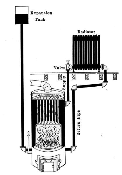
Fig. 32.—Diagram of a simple form
of hot-water heating plant.
A hot-water plant of the simplest
form is shown in Fig. 32.
The illustration presents each of
the features mentioned above,
as in a working plant. The
different parts are shown cut
across through the middle, the
black portion representing water.
Not only does the water fill the
entire system but appears in the
expansion tank when the plant
is cold.
Hot-water heaters are quite
generally in the form of internally
fired boilers. The fire-box
occupies a place inside the boiler and is surrounded, except at
the bottom, by the water space. Commonly, these boilers are
made of cast iron and are constructed in sections, the same as
the steam boiler shown in Fig. 16. Manufacturers sell a single
style for either steam or hot-water heating. The boiler in Fig.
32 is cylindrical in form. It is made of wrought iron and contains
a large number of vertical tubes through which the heat
from the furnace must pass on its way to the chimney.
As the water is heated it expands and rises to the top of the
boiler because of its decreased weight. Since the water in the[39]
radiator is really a part of the same body of water, the heated
portion rises through the supply pipe to the top of the radiator.
As the hot water rises in the radiator, it displaces an equal amount
of cold water, which enters the boiler at the bottom. This
displacement is constant and produces a circulation that begins
as soon as the fire is started and varies with the difference in
temperature between the hot water leaving the boiler at the top
and the cold water entering at the bottom.
As the water in the system is heated and expands, there must
be some provision made to receive the enlarging volume. In
this arrangement a pipe connects the bottom of the boiler with
the expansion tank located at a point above the radiator. Under
the conditions represented in the drawing the water does not
circulate through the tank and as a consequence the water it
contains is always cold.
In raising its temperature, water absorbs more heat than any
other fluid and on cooling it gives up an equal amount. As
a consequence it furnishes an excellent vehicle for transmitting
the heat of the furnace to the rooms to be heated. Water,
however, is a poor conductor and receives its heat by coming
directly into contact with the hot surfaces of the furnace, and
gives it up by direct contact with the radiator walls. To transmit
heat rapidly and maintain a high radiator temperature,
the circulation of the water in the system must be the best
possible. The connecting pipes between the boiler and the radiators
must be as direct as circumstances will permit and the
amount of radiating surface in each room must be sufficient to
easily give up an ample supply of heat. Even though the furnace
is able to furnish a plentiful supply of heat to warm the house,
it cannot be transmitted to the rooms unless there is sufficient
radiating surface. A plant might prove unsatisfactory either
because of a furnace too small to furnish the necessary heat or
from an insufficient amount of radiating surface. Yet another
factor in the design of a plant is that of the conducting pipes.
Both the boiler and the radiators might be in the right proportion
to produce a good plant, but if the distributing pipes are too small
to carry the water required, or the circulation is retarded by many
turns and long runs, the plant may fail to give satisfaction.
Fig. 33 shows a complete hot-water plant adapted to a dwelling.[40]
It is just such a plant as is commonly installed in the average-sized
house but without any of the appliances used for automatic
control of temperature. The regulation of the temperature
is made entirely by hand, in so governing the fire as to provide
the required amount of heat. In the drawing the supply and
return pipes may be traced to the radiators as in the case of the
simple plant. The supply pipe from the top of the boiler branches
into two circuits to provide the water for the two groups of radiators
at the right and left side of the house. To provide any
radiator with hot water, a pipe is taken from the main supply pipe
and passing through the radiator it is brought back and connected
with the return pipe which conducts the water back to the boiler.
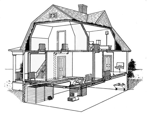
Fig. 33.—The low-pressure hot-water heating system applied to a small dwelling.
The expansion tank is located in the bathroom near the ceiling.
It is connected with the circulating system by a single pipe which
joins the supply pipe as it enters the radiator located in the
kitchen. Like the expansion tank in Fig. 31 the water it contains
is always cold. It is provided with a gage-glass which
shows the level of the water in the tank and an overflow pipe
which discharges into the bathtub, in case of an overflow. An
overflow pipe must always be provided to take care of the surplus[41]
when the water in the system becomes overheated. This
does not often occur but the provision must be made for the
emergency. The overflow pipe is frequently connected directly
with the sewer or discharged at some convenient place in the
basement.
The High-pressure Hot-water System.
—In the hot-water
plant described the expansion tank is open to the air and the
water in the system is subjected to the pressure of the atmosphere
alone. The heat of the furnace may be sufficiently great to
bring the entire volume of water of the system to the boiling
point and cause it to overflow but the temperature of the water
cannot rise much above the boiling point due to the pressure of
the atmosphere.
If the expansion tank is closed, the pressure generated by the
expanding water and the formation of steam will permit the
water to reach a much higher temperature. In the table of
temperatures and pressures of water on page 3, it will be
seen that should the pressure rise to 10 pounds, that is, 10 pounds
above the pressure of the atmosphere, the temperature of the
water would be very nearly 240°F. (239.4°F.). The difference
in heating effect in hot-water heating plants under the two conditions
is very marked. In the low-pressure system the temperature
of the radiators cannot be above 212° but the high-pressure
system set for 10 pounds pressure will heat the radiators to 240°,
and a still higher pressure would give a correspondingly higher
temperature. The amount of heat radiated by a hot body is in
proportion to the difference in temperature between the body
and the surrounding air. If we consider the surrounding air
at 60° the difference in amount of heat-radiation capacity of
the two radiators would be as 180 is to 132. The advantage
of the high-pressure system lies in its ability to heat a given
space with less radiating surface than the low-pressure system.
In Fig. 34 is illustrated an application of a simple and efficient
valve arrangement that converts a low-pressure hot-water system
into a high-pressure system without changing in any way the
piping or radiators. The drawing shows the boiler and two
radiators connected as for a low-pressure system, but attached
to the end of the pipe as it enters the expansion tank is a safety
valve B and a check valve A, as indicated in the enlarged[42]
figure of the valve. The safety valve is intended to allow the
water to escape into the expansion tank when the pressure in
the system reaches a certain point for which the valve is set.
The check valve A permits the water to reënter the system
from the tank whenever the pressure is restored to its normal
amount.
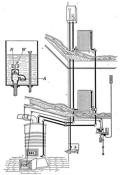
Fig. 34.—The high-pressure system of hot-water heating.
Suppose that such a system is working as a low-pressure plant.
The hot water from the top of the boiler is flowing to the radiators
through the supply pipe and the displaced cooler water is
returning to the bottom of the boiler through the return pipe as
in the other plants described. It is now found that the radiators
are not sufficiently large to heat the rooms to the desired degree
except when the furnace is fired very heavily. It is always[43]
poor economy to keep a very hot fire in any kind of a heater, because
a hot fire sends most of its heat up the chimney. If the
radiators could be safely raised in temperature, they would, of
course, give out more heat and as a result the rooms would be more
quickly heated and kept at the required temperature with less effort
by the furnace. The difficulty in this case lies solely in
there being insufficient radiator surface to supply heat as fast
as required.
The increase in radiator temperature is accomplished by the
pressure regulating valve B, attached to the end of the pipe as
it enters the expansion tank. The expansion tank with the regulating
valve is shown enlarged at the left of the figure. The valve
B is kept closed by a weight marked W, that is intended to hold
back a pressure of say 10 pounds to the square inch. A pressure
of 10 pounds will require a temperature of practically 240°F.
(see table on page 3). The check valve A is kept closed by
the pressure from the inside of the system. When the pressure
of the water goes above 10 pounds—or the amount of the weight
is intended to hold back—the valve is lifted and an amount of
water escapes through the valve B into the tank, sufficient to
relieve the pressure. Should enough water be forced out of the
system to fill the tank to the top of the overflow pipe, the overflow
water is discharged through this pipe into the sink in the
basement.
When the house has become thoroughly warmed, the demand
for a high radiator temperature is reduced, the furnace drafts
are closed, the water in the system cools and as it shrinks the
system will not be completely filled. It is then necessary to
take back from the tank the water that has been forced out
by excess pressure. It is here that the check valve comes into
use. So long as there is pressure on the pipes, this valve is held
shut and no water can escape, but as the inside pressure is
released by the cooling there will come a point where the water
in the tank will flow back through the valve A and fill the system.
This is the type of valve used by the Andrews Heating Co.
and designated a regurgitating valve. In practice it gives excellent
service. The only danger of excessive pressure in the
use of this device is the possibility of the valve becoming stuck
to the seat through disuse. Any possible danger from such an[44]
occurrence may be eliminated by the occasional lifting of the
valve by hand.
Heating-plant Design.
—A heating plant should be designed by
a person of experience. No set of rules has yet been devised that
will meet every condition. Carpenter’s rules given on page 25
serve for hot water as well as for steam as a means of determining
the radiating surface required for an ordinary building, but the
rules do not take into account the method of construction of
the house and the consequent extra radiation demanded for
poorly constructed buildings. In many cases the designer must
rely on experience as a guide where the rules will not apply.
In the case usually encountered, however, the rules given will
meet the conditions.
What was said regarding the size of steam boilers required
for definite amounts of heating surfaces, applies with equal force
to hot-water boilers, because house-heating boilers are commonly
used for either steam or hot-water heating. There are no established
rules for determining the heating capacities of house-heating
boilers. Manufacturers’ ratings are usually low. There
are some manufacturers who make honest ratings for their boilers
but they are in the minority. When the heating capacity of a
boiler is not known from experience, the only safeguard against
installing a boiler too small for the radiators to be heated, is
to require a guarantee that the plant will give satisfaction when
in operation and when considered necessary a certain percentage
of the contract price should be withheld until the plant proves
itself by actual trial.
Overhead System of Hot-water Heating.
—In Fig. 35 is illustrated
another system of high-pressure hot-water heating that
corresponds to the overhead system of steam heating. It differs
from the high-pressure system already described in the method
of distribution and in the radiator connections.
The flow pipe is taken to the attic and there joined to the
expansion tank as a point of distribution. On the expansion
tank is a safety valve set at 10 or more pounds pressure. The
flow of the water is all downward toward the radiators. The
circulation through the radiators is also different from the other
plants described. The supply pipe joins directly to the return
pipe and the connections to the radiators are made at the top and[45]
bottom of the same end. The circulation through the radiators
in this case is due to the difference in gravitational effect between
the hot and colder water at the top and bottom of the radiator.
The system requires no air vents on the radiators as all air that
might collect in the system goes up to the expansion tank. The
safety valve on the expansion tank in this case is the common
lever type. The overflow should empty into the sewer and be
pitched to prevent any water being retained in the discharge
pipe. If water should be retained in this pipe and should freeze,
the system would become dangerous, because of the possibility of
high pressures from a hot fire.
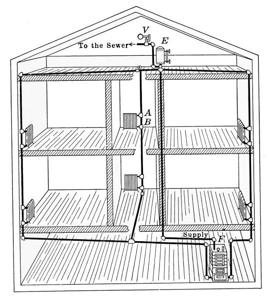
Fig. 35.—The overhead system of hot-water heating.
Expansion Tanks.
—Fig. 36 is a form of expansion tank in
common use. It may be used for either the high-or low-pressure
system. The body of the tank is made of galvanized iron and
is made to stand a considerable amount of pressure. The gage-glass
is attached at B, and the overflow at O. The pipe E connects
the tank with the circulating system and D connects with
the cold-water supply as a convenience for filling the system[46]
with water. The object in placing the stop-cock D near the
expansion tank is to avoid overflowing the system in filling.
The overflow pipe, as stated above, is most conveniently connected
with the sewer, into which the water will run in case of
an overflow, but the other methods shown are commonly used.
There should be no valve in this pipe nor in the pipe E.
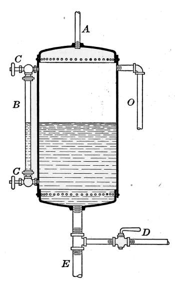
Fig. 36.—The expansion
tank.
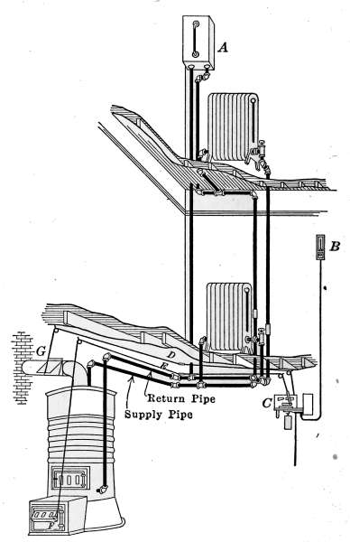
Fig. 37.—When the expansion tank of a hot-water
heating system must be so located that
it is apt to freeze, it must be piped as a radiator.
The expansion tank must be so located that there will be no
danger of freezing. Should it be necessary to place the tank in the
attic or where freezing is possible, the tank must be so connected
as to become a part of the circulating system. Such an arrangement
is shown in Fig. 37. The expansion tank is connected with
a supply and return pipe as a radiator. This arrangement is
sometimes used but it is not desirable. It is wasteful of heat
and there is always a possibility of freezing in case the fire in[47]
the furnace is extinguished a sufficient time to allow the water
to grow cold.
Any possibility of danger from excessive pressures in either
the low-pressure or the high-pressure system must originate in
the expansion tank. It is, therefore, desired to again mention
the possible causes of danger. Any closed-tank system is liable
to become overheated. The expansive force of water is irresistible
and unless some means is taken to prevent excessive pressure
some part of the apparatus is apt to burst. No closed-tank
system should be used without a safety valve.
The low-pressure or open-tank system requires no safety appliances.
So long as there is open communication between the
tank and the boiler the pressure cannot rise but slightly above
that of the atmosphere. There is only one cause that will lead
to high pressure in such a system. If the pipe connecting the
expansion tank is stopped an excessive pressure might generate.
There is little or no danger of this happening.
In the closed-tank system the expansion tank should be of
greater capacity than for the open-tank system. Its size is commonly
about one-ninth of the volume of water used. The larger
tank is necessary to prevent too rapid rise of pressure as the temperature
of the water rises. The air in the tank acts as a
cushion against which the pressure of the expanding water is
exerted.
The extended use of hot-water heating has led to the invention
of many appliances for the improvement of the circulation and
heating effects. Pulsation valves are used for retaining the water
in the boiler until a definite pressure has been attained that will
lift the valve long enough to dissipate the pressure. Many of
these systems possess merit and some of them are great improvements
over the simple plant.
Radiator Connection.
—The method of connecting the radiators
to the distributing pipes depends entirely on local conditions.
In a well-balanced system any of the methods shown in Figs. 38,
39 or 40 might be used with good heating effects. The method
of attaching the supply pipe to the radiator is, however, an important
factor in case of accumulation of air. In Fig. 41 is
shown the form of connection most commonly used. The drawing
is intended to represent a cast-iron radiator with the valve[48]
at D, and the air vent at B. Should air collect in the radiator
it will rise to the top and displace the water. The water will
continue to circulate and heat as much of the radiator as is in
contact with the water, but that part not in contact will receive
no heat from the water and will, therefore, fail to fulfill its
function. As soon as the air vent is opened the air will escape
and allow the water to entirely fill the space.
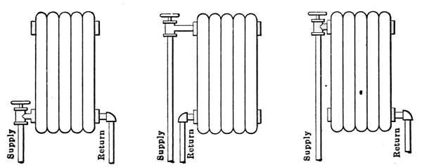
Fig. 38.
Fig. 39.
Fig. 40.
Figs. 38 to 40.—Various methods of attaching the supply and return pipes to
hot-water radiators.
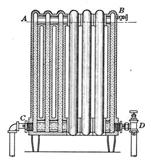
Fig. 41.—The effect of accumulation
of air in a hot-water radiator
with bottom connections.
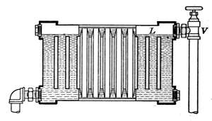
Fig. 42.—With this method of connections,
if the air collects sufficiently to force
the water down to the level L, circulation
will stop.
In Fig. 42 a much different condition exists, when air accumulates.
In this mode of connection the water enters through the
valve V, and escapes at the bottom of the opposite end. When
air fills the radiator to the line L, the circulation is stopped and
the radiator will grow cold.
[49]
The position of the valve on these radiators is of little consequence.
The valve is intended merely to interrupt the flow of
the water and may occupy a place on either end of the radiator
with the same result.
Hot-water Radiators.
—Radiators for hot-water heating are
most commonly of cast iron and in appearance are the same as
those used for steam heating. The only difference in the two
forms is in the openings between the sections. Those intended
for steam have an opening at the bottom joining the sections;
while those for hot water have openings at both top and bottom
to permit circulation of the water.
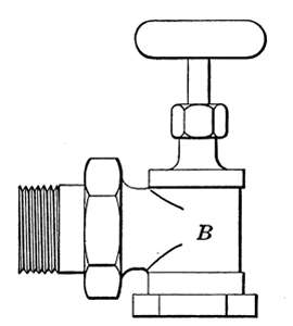
Fig. 43.—The hot-water radiator
valve.
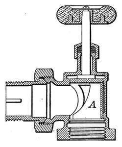
Fig. 43a.—Details of construction
of the hot-water
radiator valve.
Hot-water Radiator Valves.
—Valves for hot-water radiators
differ materially from those used on steam radiators. Figs. 43
and 43a show the outside appearance and the mechanical arrangement
of the parts of the Ohio hot-water valve. The part A in
Fig. 43a is a hollow brass cylinder attached to the valve-stem,
one side of which has been removed. When it is desired to shut
off the supply of heat the handle of the valve is given one-quarter
turn and the part A covers the opening to the inlet pipe. The
supply of water being shut off, the radiator gradually cools.
When the valve is closed a small amount of water is admitted to
the radiator through a 1⁄8-inch hole in the piece A to prevent the
possibility of freezing.
Air Vents.
—In the use of the systems of hot-water heating
described, every radiator must be supplied with an air vent of
some kind to take away the trapped air which accumulates
through use. Any kind of a valve will serve as a vent for hand[50]
regulation and generally such a cock as is shown in Fig. 10 is
employed.
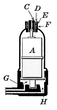
Fig. 44.—Automatic
air vent
for hot-water radiators.
Automatic Hot-water Air Vents.
—It is sometimes desired to
use automatic air vents on hot-water radiators. For such work
a vent is used that remains closed as long as water is present and
will open when the water is displaced by the accumulating air,
but will again close when the air is discharged. In such vents
the valve is controlled by a float, the buoyancy of the float when
surrounded by water serving to keep the valve closed. These
vents are not so positive in their action as automatic air vents
for steam. The change in temperature which controls the steam
vent does not take place with hot water. The automatic hot-water
vents are not perfectly reliable. They
may work with entire satisfaction for a long time
and then fail from very slight cause. The failure
of a hot-water vent is generally discovered by finding
a pool of water on the floor or a wet spot on
the ceiling or wall of the floor below.
One type of the automatic hot-water vent that
has proven quite successful is shown in Fig. 44.
The threaded lug is screwed into the radiator at
the proper point. As the water enters the radiator
the air is discharged through the vent, escaping
at the opening C. When the water has risen
to a sufficient height it enters the openings G and H until enough
is present to raise the float A. The pointed stem attached closed
the hole C with sufficient force to make an air-tight joint. The
float A is a very light copper cylinder. Its buoyancy supplies
the force to close the vent and its weight opens the vent when
the water is displaced by air. It will be readily seen that very
slight cause might prevent the performance of its duty.
[51]
CHAPTER III
THE HOT-AIR FURNACE
Of the methods of heating dwellings other than by stoves, that
of the hot-air furnace is the most common. Of the various modes
of furnace heating it is the least expensive in first cost and most
rapid in effect. In the use of steam heat, the water in the boiler
must be vaporized before its heat is available. With hot-water
heating, the whole mass of water in the entire system must be
raised considerably in temperature before its heat can affect the
temperature of the rooms, and consequently in first effect it is
very slow. In the use of the hot-air furnace the heat from the
register begins to warm the rooms when the fire is started.
Hot-air furnaces are made by manufacturing companies in a
great variety of styles and forms to suit purposes of every kind.
In practice the furnace is built in sizes, to heat a definite amount
of cubical space. The maker designs a furnace to heat a certain
number of cubic feet of space contained in a building. It must
be sufficiently large to keep the temperature at 70°F. on the
coldest nights of winter when the wind is blowing a gale. It is
evident that with the variable factors entering the problem, the
designer must be a person of experience in order that the furnace
meet the requirements.
The following table taken from a manufacturer’s catalogue
shows the method of adapting the product of the maker to any
size of dwelling. The volume of the house is calculated in cubic
feet and from this result the size of furnace most nearly suited
is selected from the table.
| Furnace number | 1 | 2 |
3 | 4 | 5 |
| Weight without casing, lb. | 984 |
1,111 | 1,340 | 1,531 |
1,934 |
Estimated capacities
in cubic feet |
8,000
to
12,000 |
12,000
to
20,000 | 20,000
to
35,000 |
35,000
to
60,000 | 60,000
to
100,000 |
Capacity in number of rooms
of ordinary size
in residence heating |
3 to 5 | 5 to 7 | 7 to 9 |
9 to 12 | 12 to 15 |
[52]
CONSTRUCTION
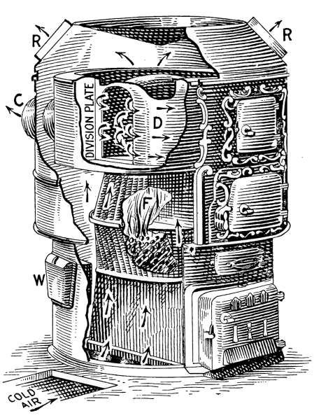
Fig. 45.—Interior view of a hot-air
furnace.
The furnace, in general construction, consists of a cast-iron
fire-box with its heating surfaces, through which the flames and
heated gases from the fire pass, on the way to the chimney; these
with the passages and heating surfaces for heating the air compose
the essential features. Fig. 45
shows such a furnace with the
sides broken away to show the
internal construction. The
flames and gases from the fire-box
F circulate through the cast-iron
drum D and are discharged
at C to the chimney. The drum
D is made in such form that it
presents to the heat from the
fire a large amount of heating
surface and at the same time
offers as little opposition as
possible to the furnace draft.
The air to be heated enters the
furnace through the cold air duct
at the bottom, and after circulating
through the drum, passes
out at the openings R to the conducting pipes. The cast-iron
box W is a water tank that should be attached to every hot-air
furnace. The water contained in the tank is for humidifying
the air as it passes through the furnace. In this furnace the
outside casing is of sheet iron, reinforced with wrought-iron
flanges. The front, which contains the doors of the fire-box,
ash-pit, etc., are of cast iron of ornamented design.
As the air to be heated passes through the furnace it receives
part of its warmth by radiation but most of it is absorbed by
coming directly into contact with the heating surfaces. Since air
is a poor conductor of heat its temperature is raised very slowly;[53]
it should, therefore, be kept in contact with the heating surfaces
as long as possible to insure an economical furnace. In common
practice the ratio of heating surface to grate surface average 35
to 1; that is, for each square foot of grate surface there is 35
square feet of heating surface to warm the passing air. Should
this ratio be increased to 50 to 1 the efficiency of the furnace
would be much improved.
If the ratio of heating surface to the grate surface is too small
for its requirements, the temperature of the air-heating surfaces
must be very high to provide the desired amount of heat. Under
such a condition the efficiency of the furnace would be low, since
in all cases where rapid combustion is required the available
amount of heat per pound of coal consumed is low. With a
large amount of heating surface, the air remains in contact with
the hot surface a relatively longer period and the desired temperature
is reached with the expenditure of a smaller amount of fuel.
A momentary exposure of the air to a red-hot surface is far less
effective than a prolonged contact with a surface having only a
moderate temperature. Time is an element of great importance
in heating air. In considering the relative merits of two furnaces
with the same amount of grate surface, that with the larger
amount of heating surface will evidently be the most efficient.
The supply of heat comes primarily from the burning coal on
the furnace grate. The grate surface should be large enough in
area to permit the required quantity of heat to be generated by
the burning fuel with a moderate fire. If the grate surface is too
small for the required purpose, a hot fire will be necessary, when
the normal amount of heat is demanded by the house. During
extremely cold weather, particularly when accompanied by high
wind, the extra heat demanded to keep the house at the desired
temperature makes necessary the use of an amount of fuel that
cannot be burned on the grate unless the fire is forced. Hot fires
can be kept up only at the expense of a large amount of heat, and
the resultant efficiency of the furnace is reduced.
High furnace temperatures are always attended by a large
loss of heat. The vastly greater quantity of air necessary to
create the combustion, the high temperature of the chimney gases
and the increased velocity of the heated gases through the
furnace, all tend to increase the amount of heat that is sent up[54]
the chimney, and to decrease the percentage of heat that
is delivered by the furnace. In order to heat the house economically
the furnace must be large enough to easily generate
the required amount of heat demanded in the most severe
weather.
Furnace-gas Leaks.
—The presence of furnace gas in the atmosphere
of a house is not only annoying but may be a source of
danger. Gas leaks are commonly due to the imperfect union of
the various parts of which the furnace is composed.
Cast-iron furnaces are constructed in sections that are assembled
to form a complete plant. In assembling, the various
parts of contact must be carefully joined to prevent the gases in
the fire-box from escaping into the air-heating space. In the
manufacture of cast-iron furnaces it is practically impossible to
form gas-tight joints by the contact of the metal alone. In the
erection of the furnace all doubtful joints are filled with stove
putty. Furnaces of good design require the use of the least
amount of this material.
Stove putty is composed of finely divided graphitic carbon
that is made into a paste suitable for filling all imperfect joints.
When the putty hardens it withstands the heat to which it is
subjected, without shrinking. In the course of time, however,
the putty may be displaced and leave openings through which
the furnace gases may leak into heating space and thus enter the
house. Leaks of the kind may be stopped by renewing the putty
which may be obtained from any dealer in stoves.
Location of the Furnace.
—The location of the furnace will
generally be governed by the exposure of the house and the
location of the chimney. In all exposed rooms on the windward
side of the house the temperature will be lower and the air pressure
higher than in other parts of the house. The increase in
atmospheric pressure makes it necessary to supply to such rooms
the hottest air practicable. The conducting pipes, therefore,
should be most directly connected with the furnace and with the
least run of horizontal pipe. The proper place for the furnace
is as near as possible the coldest place of the house.
It is a common practice to place registers near the inner corner
of the room, in order to economize in conducting pipe, in horizontal[55]
runs. A small amount of economy in first cost is thus
secured but the efficiency of the apparatus is sacrificed.
The greatest objection to placing the registers and conducting
pipes in the outer walls of buildings is that of loss of heat, due
to exposure to the outside cold and the resulting loss in circulation.
Losses of this kind may be prevented by covering the
ducts with the necessary non-conducting material. The registers
should occupy a place in the room
nearest the entering cold air.
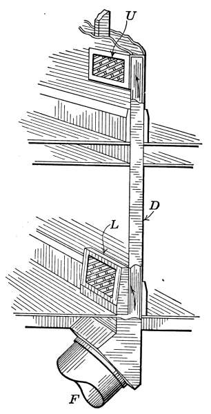
Fig. 46.—Method of conducting
warm air from the furnace
to the registers.
Flues.
—It is customary to place the
conducting pipes for the first floor in
such a way as to use only the shortest
connections. The flues used for the
second floor produce, as in a chimney,
a greater velocity of flow to the air
and as a consequence larger horizontal
pipes are used at the furnace. All
horizontal pipes should have upward
slant, as much as the basement will
permit.
The velocity of the air in the conducting
flues will depend on two factors:
the height of the flue, and the
temperature of the air. To prevent
the loss of the temperature of the air,
the flue should be covered with at least
two layers of asbestus paper bound with
wire. Wall flues are commonly flattened
and occupy a place in the wall between the studding.
Each flue should have a damper at the furnace, that will permit
the heat to be shut off from any part of the house.
Rules for proportioning of registers and conducting flues to
suit rooms of various sizes are entirely empirical. The sizes
of registers and flues found satisfactory in practice is generally
a guide for the designer. The following table is taken from a
manufacturer’s catalogue and gives a list of sizes that have proven
satisfactory under a great variety of conditions and may be
taken as good practice:
[56]
| First Floor |
|---|
Sizes of
registers
in inches |
Diameter of pipes
in inches
|
Size of rooms
in feet |
Height of ceilings
in feet |
| 12 by 15 |
12 |
18 by 20 |
11 |
| 10 by 14 |
10 |
15 by 15 |
10 |
| 9 by 12 |
9 |
14 by 15 |
9 |
| 8 by 12 |
9 |
13 by 13 |
9 |
| Second Floor |
|---|
| 10 by 14 |
10 |
18 by 20 |
10 |
| 9 by 12 |
9 |
16 by 16 |
9 |
| 8 by 12 |
8 |
13 by 13 |
8 |
| 8 by 10 |
7 |
12 by 12 |
8 |
The furnace is not only a means of heating the house but may
be a means of ventilation as
well; to this end it is desirable
to arrange the air supply
of the furnace to connect with
the outside air. This arrangement
assures a supply of
oxygen even though no special
means is arranged for discharging
the vitiated air from
the rooms.
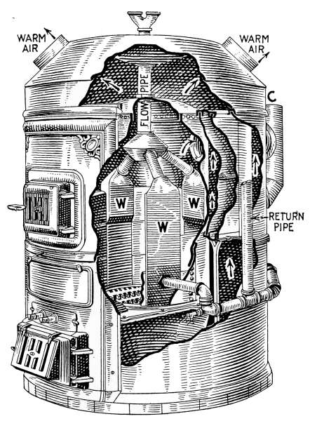
Fig. 47.—Interior construction of a combination
hot-water and hot-air furnace.
Combination Hot-air and
Hot-water Heater.
—In the
case of large houses heated
by hot air it is sometimes
better to use two or more
furnaces than to attempt to
carry the heat long distances
in the customary
pipes. Where heat is required
in rooms located at a
distance more than 30 feet, it is advisable to use a combination
hot-air and hot-water heater, the distant rooms being heated
by hot-water radiators.
A furnace arranged for such a combination is shown in Fig. 47.[57]
This furnace contains, first, the essential features of a hot-air
furnace; next, it includes a hot-water plant. The fire-box and
air-heating surfaces are easily recognized. The arrows show the
course of the air entering at the bottom of the furnace, which
after being heated by passing over the heating surfaces, escapes
at the openings marked warm air, to the distributing pipes.
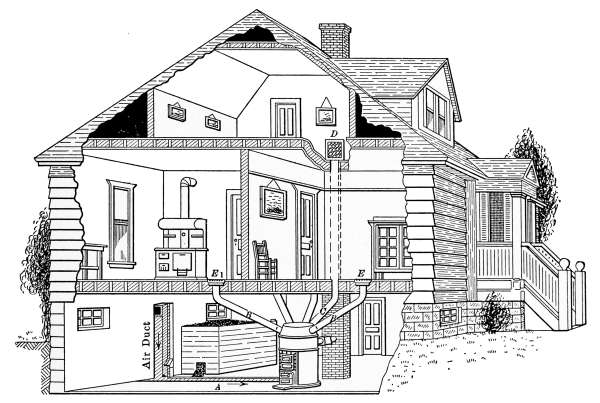
Fig. 48.—The hot-air furnace as it appears in the house.
Inside the air-heating surfaces are three hollow cast-iron pieces
W, that form a part of the walls of the fire-box. These pieces,
with their connecting pipes, form the water-heating part of the
furnace, which supplies the hot water for the radiators. The
pieces W, with the connecting pipes and radiators, form an independent
heating plant, with a fire-box in common with the
hot-air furnace.
The returning water from the radiators enters the heating
surfaces W, through the pipe marked return pipe. The heated
water is discharged from the heaters into that marked flow pipe
which conducts it to the radiators. Such a furnace is, therefore,
two independent systems, one for hot air and the other for hot
water, but with a single fire-box. This furnace, like the simple
hot-air furnace, is rated, first in the amount of space it will heat[58]
with hot air and in addition, by the number of square feet of
hot-water radiating surface that will be kept hot by the hot-water
heater.
In Fig. 48 is shown the location of the furnace in a cottage
with the conducting pipes to the various rooms. The registers in
the first floor are generally set in the floor but if desired they
may be placed in the walls. Those on the second floor are placed
in the walls because of convenience. The conducting pipes pass
through the partitions between the studding.
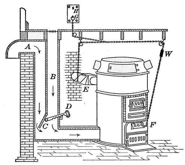
Fig. 49.—Details of air ducts and damper regulator used with the hot-air furnace.
In all well-arranged hot-air heating plants provision is made so
that the air for heating may be taken from the outside. It does
not follow that the supply of fresh air should always come from
outdoors; there are times during extremely cold weather, accompanied
by high winds, when ventilation is ample without the
outside source of supply. Since it is never desirable to take the
air supply from the basement, such an arrangement as is shown
in Fig. 49, or a modification of the same plan is commonly employed.
The duct A from the outside and B from the rooms
above connect with the air supply for the furnaces. A damper C
arranged to move on a hinge, is so placed as to admit the air from
either source as desired. The damper may be placed so as to take
part or all of the air from the outside by adjusting the handle at
the proper place.
[59]
CHAPTER IV
TEMPERATURE REGULATION
The method used for regulating the temperature of a house
will depend on its size, the conditions under which it is to be used
and the method of heating. In small houses the temperature
may be satisfactorily governed entirely by hand, that is, the
furnace drafts may be changed by hand to suit the varying
conditions of temperature. A more satisfactory method is that
of thermostatic regulation, in which a thermostatic governor and
a motor automatically control the furnace dampers so as to keep
a constant temperature at one point, generally the living room.
Where hot-water or steam heating plants are used, another device
is frequently employed to keep the temperature of the heat supply
at a constant degree. This is known as the automatic damper
regulator. The damper regulator is one of the boiler accessories
which so governs the drafts of the furnace as to keep a constant
water temperature in the hot-water heater or a constant steam
pressure in the steam boiler.
In some cases both the damper regulator and the thermostat
are used as a more complete means of temperature control.
Hand Regulation.
—As a means of changing the dampers of the
furnace from the floor above, to suit the prevailing conditions,
the arrangement shown in Fig. 49 does away with the necessity
of a journey to the basement, to remedy each change of
temperature.
A plate is fastened to the wall at any convenient place, to
which the end of a chain is attached as shown in the figure.
This connects with a second chain, the ends of which are fastened,
one to the direct draft or ash-pit damper F, and the other to the
check draft E, in the chimney. As the furnace appears in the
drawing, the direct draft is closed and the check draft is open.
By changing the ring from G to H, the movement of the chain
opens F, and closes E, admitting air to the furnace. When the[60]
temperature of the room is raised sufficiently, the drafts are restored
to their original position by replacing the ring at G.
Sometimes one or more intermediate points are made on the plate
between G and H, which permits both drafts to be kept partly
open and fewer changes are required to keep the temperature
approximately normal.
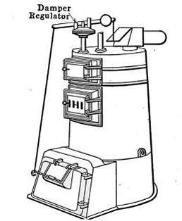
Fig. 50.—Cross-section of damper
regulator for steam boiler.
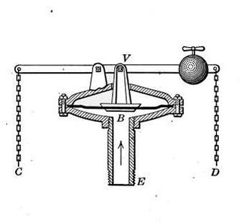
Fig. 51.—Steam boiler for house
heating, with the damper regulator, in place, attached to the dampers.
Damper Regulator for Steam Boiler.
—The damper regulator
used on a steam boiler is a simple device that automatically
controls the draft dampers by reason of the changing pressures
of the steam. The object of the damper regulator is to prevent
the generation of steam in the boiler beyond a certain pressure
at which the valve is set. This point is usually 3 or 4 pounds
below the pressure at which the safety valve would act. If in
proper working order the damper regulator will so control the
dampers that the boiler will always contain a supply of steam,
but the pressure will not reach a point requiring the action of the
safety valve. Fig. 51 illustrates its connections with the furnace
dampers. In Fig. 18 the regulator appears at D. In external
appearance and in operation of the dampers, it is the same as the
regulator for a hot-water boiler but its internal construction is
simpler. Fig. 50 shows its construction. It is attached to the
steam space of the boiler at E. The steam pressure acts directly
on the flexible metallic diaphragm B. As the pressure of the[61]
steam approaches the desired amount the diaphragm is raised
and with it the lever V. A chain D, attached to the end of the
lever, opens the check draft, and another at C closes the draft
damper. When the steam pressure falls, the diaphragm lowers
the lever and the dampers are restored to their original position.
The same movements are repeated with each rise and fall of the
steam pressure.
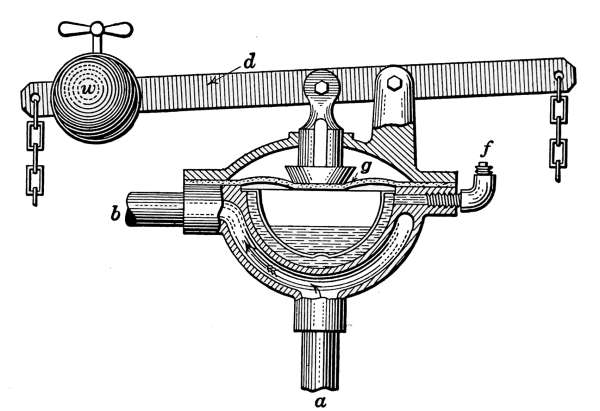
Fig. 52.—Damper
regulator for hot-water boiler.
Damper Regulators for Hot-water Furnaces.
—The damper
regulator for a hot-water boiler automatically controls the
dampers of the furnace so as to keep the water of the boiler
approximately at a constant temperature. The regulator is
shown in Fig. 52. The ends of the lever are connected to the
direct-draft and check-draft dampers, as in the case of the
damper regulator for the steam plant. A cross-section of the
working parts shows the details of construction. The lever d is
operated by a diaphragm g, which tightly covers a brass bowl,
containing a mixture of alcohol and water, of such proportions
as will produce a vapor pressure at the desired temperature,
say 200°. The hot water from the boiler passes through the
valve, entering at a and leaving at b. When the water reaches
the desired temperature, the contained liquid vaporizes and a
pressure is produced that is sufficient to lift the diaphragm and
the lever. The chain attached to the right-hand end closes the
direct-draft damper; at the same time the other end of the lever
opens the check draft, and the supply of air to the furnace fire
is entirely cut off. As soon as the water has cooled sufficiently,[62]
the vapor pressure in the bowl is reduced, allowing the weight
W to depress the diaphragm and the lever is restored to its first
position. The weight W is for adjusting the valve to the desired
temperature. The plug f tightly closes the orifice through which
the liquid is introduced into the bowl.
The object of the damper regulator on a hot-water boiler is
to govern the fire of the furnace so as to keep the water in the
boiler at the desired temperature. In case there is a demand
for heat at any part of the house, a supply of hot water will
always be on hand. It has nothing to do with the regulation
of the temperature of the house. The control of the house
temperature is the office of the thermostat.
The thermostat is a mechanical device for automatically regulating
temperature. It may be arranged to operate the valve
of a single radiator or register and so control the temperature of
a room, or as commonly used in the average dwelling, the controller
may be placed to govern the temperature of the living
room and in so doing keep the furnace in condition to satisfactorily
heat the remainder of the house.
Thermostats are made in a variety of forms by different
manufacturers but they may be divided into two general classes:
the electric, and the pneumatic types. The electric thermostat
depends on an electric current as a means of controlling the
action of the motor which in turn operates the furnace dampers
so as to maintain a constant heat supply. The pneumatic
thermostat regulates the supply of heat by means of pneumatic
valves. It will be considered later in discussing mechanical
ventilation. This type of temperature regulation is particularly
adapted to large buildings.
Fig. 53 illustrates one style of electric thermostat that is very
generally used for temperature regulation in the average dwelling.
It consists of three distinct parts—the controller, the electric battery
and the motor. In the drawing the motor is shown connected
with a steam valve, such as may be used for furnishing steam
for a series of radiators. It may with equal facility be attached
to the dampers of a furnace or other heating apparatus.
The controller occupies a place on the wall of the room to be
heated and makes electric connections between the battery and
the motor. Whenever the temperature varies from the required[63]
degree, a change of electric contact in the controller starts the
motor, and the radiator valve or the furnace drafts are opened
or closed as occasion requires.
The controller appears in Fig. 54 as commonly seen in use.
The upper part carries a thermometer and the pointer A indicates
the temperature to be maintained in the room. The middle
division indicates 70°F. Each division to the right of the middle
point raises the temperature 5°. Each division to the left lowers
the temperature a like amount.
In addition to the ordinary type this controller is furnished
with a time attachment by means of which the controller may
permit the temperature of the room to fall to any desired degree
at night and raise it again in the morning at the time for which
it is set.
This is accomplished by a little alarm clock shown at the
bottom of the controller in Fig. 54. The indicator B is arranged
to correspond with the indicator A; the middle point representing
70°F. To set the time attachment, the alarm is wound and set
as in any alarm clock, ½ hour earlier than the desired time for
rising. The indicator B is set for the day temperature and A is
set for the temperature desired during the night. At the
appointed time the alarm moves the indicator A to the desired
point for the day and the controller raises the temperature
accordingly.
Fig. 55 shows the mechanism that is exposed to view when the
cover of the controller is removed. The bent strip C is the part
that is influenced by the change of temperature. It is made of
two thin strips of metal, one of brass and the other of steel. The
two strips are soldered firmly together. Any change in temperature
will affect the strip and cause it to bend and touch the
contact point—K or J. The bending of the strip is due to
the unequal expansion of the brass and steel due to the
change of temperature. Brass expands 2.4 times as much as
steel with the same change of temperature. The amount of
bending is sufficient to make an appreciable movement in a small
fraction of a degree change. The brass part of C is on the left
and since it expands the greater amount, a rising temperature
causes C to come into contact with the point J. When this
happens the motor is started and makes one-half cycle. In so[64]
doing it shuts off the air supply of the furnace, opens the check
draft and at the same time the motor changes the electric contact
from J to K. When the temperature begins to fall, the brass contracts
in the same ratio to the steel as it expands during the
rising temperature and as a consequence the bar bends to the
left. When the strip touches the point K the motor again makes
one-half circle, admitting air once more to the furnace, closes
the check draft and shifts the electric contact back to K. When
properly started the thermostat will regulate the temperature
within a degree of temperature.
The Thermostat Motor.
—The thermostat motor automatically
opens and closes the furnace dampers or the valve that admits
steam to the radiators as heat is demanded by the controller.
The motor, as shown in Fig. 53, consists of a system of gears
and a brake S, which regulates the speed, a cam M, and armature
I, for starting and stopping the motor, and the electromagnet H-H
which operates the bar I. Two lever arms L, one in front and
the other at the back of the motor furnish means for attachment
to the valve or furnace dampers. An emergency switch at D
is shown in detail in Fig. 56. The battery B furnishes the current
which energizes the magnets and an iron weight supplies the
motive power for the motor.
The description of the operation of the motor applies to the
steam valve shown in Fig. 53. The same motor might be used
for opening and closing of the dampers of the furnace in any kind
of heat supply. The method of communicating the motion of
the motor arms to the dampers of the furnace will be described
later. The connections with the furnace drafts are shown in
Figs. 3, 6, 8, 34, etc.
Suppose that the valve for admitting steam to the radiators,
as that in Fig. 53, is closed and that the temperature of the house
is falling. The strip C of the thermostat controller is moving
toward J. When contact is made, the current from the battery
B energizes the magnets H-H and the bar I is lifted. As the
bar I is raised the catch J is released and permits the motor to
start. The bar I is held suspended by the cam M until the arm
L has made one-half revolution, when the lug K drops into the
depression in the cam made to receive it and the catch J engages
with the brake and stops the motor.
[65]
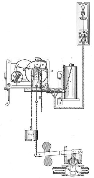
Fig. 53.—Thermostat complete with the regulator, battery and motor, attached
to a steam supply valve.
[66]
During this movement the arm L has lifted the valve arm N and
the valve admits steam to the radiators, at the same time the contact
M has been shifted from the right-hand contact to the left,
and the electric circuit is ready to be made in the controller at the
point K. When the temperature has fallen a sufficient amount
the controller bar C will make contact at K
and the motor will again make a half cycle,
changing the valve back to its original position.
This process will be kept up so long
as the motor is wound and there is sufficient
fuel in the furnace to raise the temperature.

Fig. 54.—Thermostatic
regulator with
clock attachment for
control of day and
night temperature.
Fig. 55 shows the method of connecting the
electric wires from the battery to the controller.
A three-wire cable connects the
battery, and makes contacts as indicated at
H, K and J. The wires are shown attached
to the motor as in Fig. 55. A wire is taken
from either pole of the battery and attached
to one of the ends of the magnet coil. Passing
through the magnet the wire is attached
to the frame of the motor. This makes the
cam M a part of the electric circuit. The
other two wires are attached to the brass
strips on each side of the arm L. The strips
are insulated from the frame. The electric
circuit through the magnet is made alternately
by contact with the strips at right
and left of the arm L.
In case the motor, through neglect, runs
down, a safety switch at D (Fig. 53) disconnects
the battery and keeps it from being discharged.
This switch is shown in detail in
Fig. 56. When the weight has reached its
limit, the piece C on the chain comes into
contact with D and lifting it out of contact, breaks the circuit.
When the motor is again wound, C engages with E and restores
the contact. The switch is so arranged that when open, the valve
will always be closed.
[67]
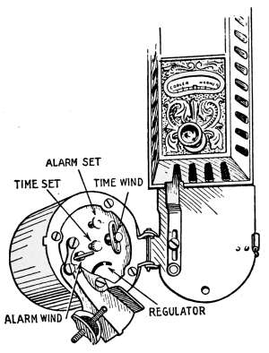
Fig. 54A.—Showing the clock
attachments to the thermostatic
regulator.
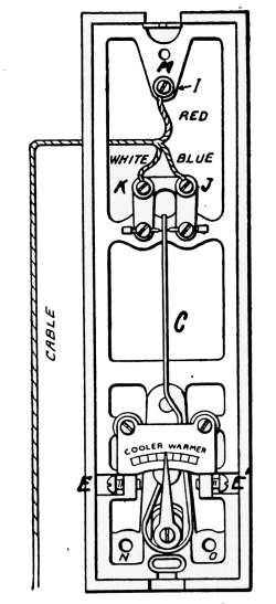
Fig. 55.—Mechanism
of the thermostatic
regulator.
Combined Thermostat and Damper Regulator.
—It is evident
that, in heating a house by steam, the damper regulator governs
only the steam pressure of the boiler. In the use of a thermostat
alone, the regulation is that of the temperature of the rooms only,
and has nothing to do with the steam pressure. As an example:
Suppose that in cold weather the house is cold and that the gage
of the steam boiler shows no pressure. The desire is to get up
steam as soon as possible. In so doing a hot fire is made with a
large amount of fuel. As soon as the steam begins to form, the
pressure rises rapidly. When the radiators have become hot and
the steam is no longer taken away as fast as it is formed, the pressure
of the steam in the boiler keeps on rising. The thermostat
will not close the furnace dampers until the temperature of the
rooms is normal. This may require so great a length of time
as to produce a great excess of steam that cannot be used at the
time and the pressure will be relieved by the safety valve. This
may not be dangerous but it is disagreeable. To prevent the
safety valve from blowing except in case of emergency, a combined
thermostat and draft regulator is used. In such a combination,[68]
the draft regulator closes the draft as soon as the pressure
reaches the desired point, after which the thermostat does the
regulating according to suit the temperature of the house.
In Fig. 2 is shown such a combination attached to a boiler.
The cord from the regulator, instead of extending directly to the
direct-draft damper, passes over the pulley P and connects to the
thermostat cord. The regulator may now close the damper to
suit the steam pressure, but after the
temperature in the rooms is normal, the
amount of heat necessary to maintain
the desired degree is regulated entirely
by the thermostat which opens and closes
the dampers regardless of the position
of the damper regulator.
If occasion should require but a very
slight amount of steam to keep the
house at the desired temperature, the
thermostat will govern the drafts aright.
If the steam pressure is in danger of becoming
excessive, the damper regulator
will govern the drafts.
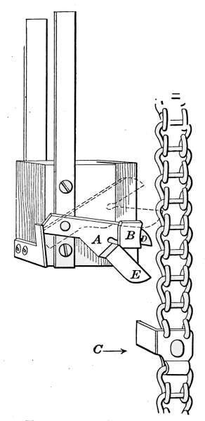
Fig. 56.—Automatic
switch which opens the battery
circuit when the thermostat
motor weight,
reaches its limit.
Thermostat-motor Connections.
—The
arrangement of cords and pulleys used
for attaching the thermostat motor to
the furnace dampers will depend very
much on local conditions. The motor
can be placed in any convenient position
so that the connecting cords will act
most directly. The motor opens and
closes the direct draft and check draft
in accordance with the demand for heat. The connections for
all kinds of furnaces are made in much the same manner. The
pulleys supplied with the motor are placed to work as freely, and
the cords to pull as directly as possible.
In Fig. 57 the motor is connected with a hot-air furnace. The
cord D is attached to the front arm of the motor and connects
with the direct-draft damper F. The cord C connects the rear
arm of the motor with the check-draft damper at E. In the
position of the dampers shown, the direct-draft damper is closed[69]
and the air is entering the chimney through the check draft E.
While this damper is open there is very little induced draft to
supply the fire with air that might leak through the crevices
around the ash-pit door, but the gases from the furnace are
completely carried away to the chimney by the air entering at E.
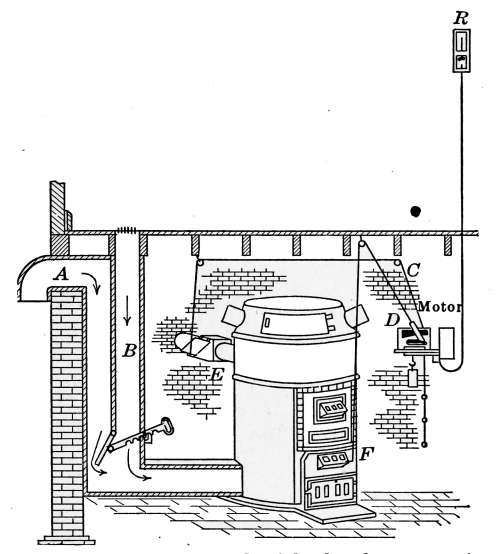
Fig. 57.—Thermostat motor connected with the dampers of a hot-air furnace.
In Figs. 3, 6, 8, 34, etc., the same motor is connected with the
furnaces of various other systems of heating. The object is the
same in all; when less heat is required, the air supply is cut off
and the furnace fire subsides; when more heat is demanded the air
is again admitted to produce greater combustion. The check
draft is an important feature as it checks the flow of air through
the furnace regardless of the position of the direct-draft damper.
Even should the direct draft be left open, the check draft when
open would destroy in a great measure the supply of air entering
the furnace.
[70]
CHAPTER V
MANAGEMENT OF HEATING PLANTS
The following instructions on the care and management of
steam and hot-water heating plants is printed with permission
of the American Radiator Co. They were prepared as a guide
to the successful operation of the Ideal heating plants but
apply with equal force to other plants of a similar character.
General Advice.
—No set rules can be given for caring for
every boiler alike—chimney flues are not alike—some have strong
draft, some are average and some are weak. There is much more
difference in the heat-making qualities of coal than is commonly
known, and it is important that the right size coal for the draft
be used. These rules apply to most all fuels. A little trying of
this way or that way of leaving the dampers (when regulators are
not used) often discovers the better way. It is well to vary from
the rules a little if any of them do not seem to bring about the
best results.
With good, average chimney flue draft and the right kind of
fuel, these rules will govern the large majority of cases.
The Economy of Good Draft.
—In many cases a boiler with
sluggish draft will burn more coal than a boiler with good draft.
In the first case the fuel may be said to “rot”—in lacking air
supply the gases pass off unburned. The “nagging” which a
boiler has to take under these conditions increases the waste of
fuel. A boiler under sharp, strong draft maintains a clear intense
fire and burns the gases—getting the larger amount of
heat from the coal.
1. Put but little coal on a low fire.
2. When adding coal to the boiler, open the smoke-pipe damper (inside
the smoke pipe) and close the cold-air check damper. This will
make a draft through the feed doorway inward and prevent the escape
of dust or gas into the cellar when the feed door is open to take fuel.
Put these parts back to their regular places after feeding.
[71]
3. When it can be done, in feeding a large amount of coal (as for
night) leave a part of the fire or flame exposed, so that the gases may
be burned as they arise.
4. When a regulator is not used, learn to use the dampers correctly
and according to the force of the chimney draft. Learn to use cold-air
check damper. Often, when closing, the ash-pit draft damper does
not check the fire enough; opening the cold-air check damper will
check it about right. Increasing or lessening the pressure of a steam
boiler must be done by changing the weight on the regulator bar.
5. Carry a deep fire or a high fire; let the live coals come up to the
feed door—even in mild weather when from 4 to 6 inches of ashes
stand on the grate.
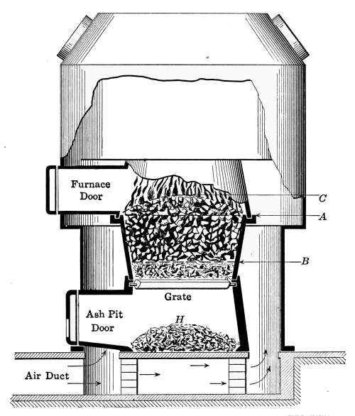
Fig. 57a.—Indicates the general condition of the furnace fire during very cold
weather. The fuel should fill the fire-pot to C. The ashes should not be allowed
to accumulate beyond B, on the grate. There should be no more ashes than
appear at H, in the ashpit.
6. In severe weather give the heater the most careful attention the
last thing at night.
[72]
7. Do not overshake or poke the fire in mild weather; once in a while
shake enough to give place for a little more fuel.
8. Do not let ashes bank up under the grate in ash-pit. Grate bars
are very hardy, but it is possible to warp them with carelessness. Taking
up the ashes once a day is the best rule, even if but little has fallen
into the pit.
9. Keep the boiler surfaces and flues clean; a crust of soot ¼ inch
in thickness causes the boiler to require half as much more fuel than
when the surfaces are clean.
10. If convenient, have a water hose to spray the ashes when cleaning
out the pit.
11. Attend the boiler from two to four times per day. In mild weather,
running with a checked fire, morning and night is usually often enough.
In severe weather, once in early morning, again at mid-day, again at
five or six o’clock and finally thorough attention at from nine to eleven
o’clock in the evening.
12. If, through burning poor coal, the fire pot gets full of ashes, or
slate and clinkers massed together, the quickest way to get a good
active fire is to dump the grate and then build a new fire—from the
kindling up.
13. If a hard clinker lodges between the grate bars, do not force the
shaking, but first dislodge the mass with a poker or slicing bar. Then
the grate will operate without damage.
Weather and Time of Day.
—In severe weather keep the fire
pot full of coal, and run the heater by the dampers or regulator
(if one is used). Thoroughly clean the grate twice a day. Let
the top of the fire in front be level with the feed door sill. Bank
up the coal higher to the rear.
In moderate weather there should be from 2 to 6 inches of ashes
between the live coal and the grate. As the weather grows
colder keep the grate and the fire pot a little cleaner—sometimes
it helps to run the poker or slicing bar over it through the clinker
door. With some fuels this is never necessary.
Night Firing.
—In very cold weather, when the house should be
kept warm all night, clean the grate well at a late hour—the
last thing. Clear the bottom of the fire pot of all ashes and clinkers
so that the grate is covered with clear-burning, red-hot coals,
then fill the pot full of fuel. If possible, leave some of the flame
exposed to burn the gases. Leave the drafts on long enough to
burn off some of the gas, then check the heater for the night.[73]
Thus there is plenty of coal to burn during the night and some on
which to commence early in the morning. Some drafts do not
make it necessary to leave the dampers on to burn off the gas
after feeding.
With the ash-pit draft damper closed and the cold-air check
damper open at night, but part of the coal is burned and there is
much of it not burned in the morning. So, by reversing the
dampers in the early morning the fire starts up quickly and often
the house may be well warmed before any coal is put into the
fire pot.
Some boilers are run the other way—a very poor way. If the
grate is cleared off in very cold weather and coal added at five
or six o’clock in the afternoon, by eleven o’clock at night nearly
one-half of the coal is burned and the grate is covered over with
a mass of ashes and clinkers. With little coal remaining, to
shake the grate will quite likely put out the remaining fire; to
put fresh coal on a low fire reduces further its declining temperature.
The result is a cold house that will grow colder until
a new fire is started.
Often in cold weather with this poor way of night firing, it
takes one or more hours of forced firing to warm the house in the
morning, and all the coal saved the night before is more than
used to get the house or building “heated up”—while the people
who should be comfortable have to get up, bathe and take breakfast
in chilly rooms. At no time in the day is heat more wanted
than about the time of getting up and starting the day. A
fire well cared for late in the evening makes a warm house
all night. And so it follows that it is much easier to add a
little more heat in the morning. And surely less coal is burned,
for the forcing of a fire part of the time often overheats, and
wastes coal.
First-day Firing.
—In the morning of moderate winter weather,
with the ash-pit draft damper open, before adding any coal allow
the fire to brighten up if it seems to be low; then (for such conditions)
spread over a thin layer of fresh coal and set the drafts
for a brisk fire. After the new fire is well started add as much
coal as may be necessary to last until next firing. Do not shake
much if any—just enough to give space for more coal. Then by
setting the regulator (if one is used), or, by closing the ash-pit[74]
draft damper and opening the cold-air check damper a little,
the boiler should keep up its work until the next firing time.
In severe weather, if the boiler has been attended to at night as
directed in the section on “night firing,” the drafts can be turned
on and the boiler run for half an hour before adding coal. Or, if
more convenient to give it immediate attention, the grate can be
thoroughly shaken and enough coal added to last until mid-day.
Often the cold-air check damper will need to be entirely closed
and the ash-pit draft damper partly open if the heater is a water
boiler. If a steam boiler, the regulator should then be set to
maintain the number of pounds of pressure wanted and so left.
Other-day Firing.
—In severe weather more coal should be
added about noon, sometimes the draft may be left on for a few
minutes and then checked. And in such weather it is often well
to give the boiler further attention at five or six o’clock. In
severest weather the boiler should not be attended more than
four times a day; and generally not less than three times.
Often much coal is wasted by “nagging” the fire—poking,
shaking and feeding it until it becomes “dyspeptic.” A sure
cure is a little common sense in regular feeding, etc.
Economy and Fuels.
—In running many boilers for moderate
weather better results follow if the grate is not shaken too much or
too often. Sometimes in moderate weather a body of ashes on
the grate checks the fire and there is enough heat without a
useless burning of fuel. Many houses are overheated in moderate
weather and too much coal burned by running the boiler as for
zero weather.
So we repeat—it is not wise to overshake or overfeed a boiler in
moderate weather. The fire should be in such shape that if a
change comes at night there is a basis for a good fire to start on.
When the grate is shaken but once during the 24 hours (during
moderate weather) late at night is the best time.
When one stops to think that heating is needed during about
7 months out of the year, and that a greater portion of this time is
usually moderate weather when a very little heat is needed, it
must be seen that the science of running the heater to save coal
is to apply common sense rules of limiting the feeding and the
attention in such periods. In severe weather we believe in giving
the boiler a liberal quantity of fuel regularly and at the right[75]
time. The time to save coal is when there is no need for burning
it. This is where a great many people make errors in running
the boiler—in forgetting to “let up” on the shaking and feeding
in moderate weather.
With some drafts and for boilers using hard coal or coke, good
economical results often are secured by opening the feed door a
little when it is desired to check the fire in moderate weather.
This depends on the draft.
For Burning Soft Coal.
—Some types of boilers are made to
burn soft coal with economy, with least work. Some types are
made specially to burn the meaner grades of soft coal. Firing
to prevent smoke is a source of economy and these ways of running
should be followed—specially with large sectional boilers.
There are two types of soft coal, viz.: The free-burning coal,
which breaks apart when burning, allowing the gases to freely
escape; and the fusing-coking coal, which, when burning, first
fuses into a solid burning mass with a hard crust over the top,
slowly coking as it burns. The latter kind is most valuable for
house-heating boilers because the gases are more thoroughly
consumed. The fusing-coking coal is worth about 20 per cent.
more for this purpose than the free-burning coal.
The gases should be allowed to pass off from the coal slowly.
Leave air inlet on the feed door open if draft permits. If possible,
use uniform sizes of coal. Avoid using coal having too much
dust—the “run-of-the-mine” may be lower in price but its heat-making
value is also low.
For the purpose of slow burning of soft coal, it is well in feeding
at night to let the fire burn up freely so that the coals are
very live with heat. Then fill in enough coal to last all night—leaving
some of the live coals uncovered if possible. With large
sectional boilers this exposure should be at the rear of the fire so
that the flame will pass over the live coals. Thus the gases
coming off from the fresh coal are burned and a larger amount
of the full heat-producing value of soft coal is made use of and
with less smoke.
After a boiler is so fed, the dampers (unless an automatic
regulator is used) should be left about as follows:
Ash-pit draft damper open a little or closed, as draft may
require.
[76]
Cold-air check damper open about one-eighth to one-third
distance of the opening.
Smoke-pipe damper about one-half closed.
A little experiment with the draft will usually tell the operator
the best way of leaving these dampers.
It will be found in the morning that the entire charge of coal
is well burned or partly coked.
The coked fuel, or that which sticks together in a mass, should
be broken up by the poker and more added generally as by rules
given in other sections.
It must always be remembered that the soft coals mined in
different parts of the country have widely varying heat-making
capacities. To obtain satisfactory results brands must be
selected which have an established reputation for excelling results
in small boilers.
For Burning Coke.
—It is best to keep the pot full of fuel—keeping
a large body of coke under a low fire rather than a little
fuel under a strong fire.
It must be remembered that coke makes a very “hot fire”
because the coke is free-burning. Care should be taken not to
leave drafts on too long in boilers not having regulators.
Coke burns best for house-heating purposes with less draft
than is required for coal, therefore to keep a low fire the ash-pit
draft damper should be kept closed, and the smoke-pipe damper
almost entirely closed. The regulator (when used) can be set to
keep the dampers about as here advised. Coke is practically
smokeless and its quick-burning character makes a cut-off damper
in the smoke pipe (which will stay fixed as it may be set) quite
necessary.
It is well to keep a layer of ashes on the grates and when shaking
stop before red-hot coals come through the grate. The coke
then burns more slowly, which increases its effectiveness.
With some drafts it may be well to “bank the fire” at night
with coke—pea coal size. This is a matter of experiment, and
depends on the character of the chimney draft.
Fire should be tended regularly—two times a day, or four at
the outside.
With an extra strong draft, at night the fuel should be packed
down by tamping with the back of a shovel.
[77]
With ordinary condition of draft, crushed coke, small egg size,
should be used.
Other Rules for Water Boilers
—To Fill System.—Open the
feed-cock when the heater is connected with a city or town water
supply; if not, fill by funnel at the expansion tank. Fill until the
gage-glass on the expansion tank shows about half full of water.
In filling the system see that all air cocks on the radiators are
closed. Then beginning with the lower floor, open the air cocks
on each radiator, one at a time, until each radiator is filled; then
close the air cock and take the next radiators on upper floors until
all are filled, after which let the water run until it shows in the
gage-glass of the water tank. After the water is heated and in
circulation, vent the radiators by opening the air valves as before.
Then again allow the water to run into the system until it rises
to the proper level in the expansion tank gage-glass.
Always keep the apparatus full of water unless the building be
vacated during the winter months, when the water should be
drawn off to prevent freezing. Never draw water off with fire
in the heater.
To draw off water, open the draw-off cock at the lowest point
in the system, and then open air cocks on all radiators as fast
as the water lowers beginning with the highest radiator.
Air-vent Valves on Radiators.
—In order to secure the full
benefit of the heating surface of a hot-water radiator, the inside
of the section must be free of air. When a radiator is “air-bound”
it means that parts of the sections are filled with air
in pockets which remain until the air is allowed to pass off
through the vent valve.
Air will gather from time to time at the highest points inside
the radiators, especially in those placed in the upper stories of the
building. These air accumulations inside cut down the working
power of a radiator exactly in proportion as they rob the inside
of the casting of proper contact with heated water. Air pockets
not only reduce effective heating surface, but they also prevent
the circulation of hot water.
Therefore, it is well once in a while to take the little key provided
by the heating contractor and open the air valves on radiators
to allow the air (if any) to escape. When a radiator does
not work as well as usual, open the air valves until the water[78]
flows, which indicates that the air has been fully released. Then
close the valve.
Valves on Cellar Mains.
—If cut-off valves have been placed
on the main and return pipes in the cellar, see that the valves
on one line of main and return pipes (at least) are open when the
boiler is under operation. Be sure that the system is open to
circulate water through the supply and return pipes before building
a fire in the boiler.
End of the Season.
—At the close of the heating season clean
all the fire and flue surfaces of the boiler. Let the water remain
in the system during the summer months. No bad results will
follow if the system is not refilled more often than once in 2 or 3
years. But, generally, it is thought that best results are secured
by emptying the system once a year (after fire is out) and refilling
with fresh water.
It is a very good idea to take down the smoke pipe in the spring,
thoroughly clean and put it back in place. Leave all doors open
on the boiler in the summer time.
Other Rules for Steam Boilers
—To Fill Boiler.—Open the
feed-cock when the heater is connected with city or town water
supply; if not, fill through the funnel. Let the water run until
the gage-glass shows about half full of water.
In the first filling, after the water has boiled, get up a pressure
of at least 10 pounds, draw the fire and blow off the boiler under
pressure through draw-off cock to remove oil and sediment,
after which refill with fresh water to the water line. This is best
done usually by the steam-fitter.
The damper regulator will control the pressure of steam, closing
the damper when the pressure is raised beyond the desired
point and opening the damper when the pressure falls below that
point. By removing the weight on the lever, different degrees
of pressure can be kept up. The regulator should be allowed to
control the drafts without interference.
Examine the water glass often to see that the water line is at
the proper height. If lower than normal open the supply pipe
until the water runs in and stands at the proper level. It is best
when no water stands in the glass, nor shows at the bottom of
the try-cock, to quickly dump the grate and do not put water into
the boiler again until it is cooled off.
[79]
If there is one or more shut-off valves on the main or return
pipes, before starting a fire see that one line of piping at least
(main and return) is open to circulate the steam.
To Control Radiators.
—When it is desired to shut off steam
from any radiator (if the regular radiator valves are used), close
the valve tight, and when it is turned on see that the valve is wide
open. A valve partly turned off will cause the radiator to fill
with water. This rule applies only to one-pipe heating systems.
The Air Valves.
—If little keyed air valves (sometimes called
“pet-cocks”) are used, follow generally the same directions as
outlined for hot-water radiators on page 49—only, of course, in
releasing the air from the radiator open the valve with the key
provided and close it just as soon as the steam unmixed with air
comes through the nose of the valve.
If “automatic” air valves are used they must be carefully
adjusted by the steam-fitter and then left to operate without
undue interference.
End of the Season.
—At the close of the heating season fill the
steam boiler with water to the safety valve and let it thus stand
through the summer.
Also thoroughly clean all the fire and flue surfaces of the boiler
and at the opening of the next season withdraw the water and
refill with fresh water to the water line, starting the boiler as
before.
It is advisable to have a competent steam-fitter blow off the
boiler under pressure and thus give the inside a thorough cleaning
when the boiler is first set up and ready for fire.
A low-pressure boiler, using good water, rarely needs blowing
off after it is once cleaned at time of setting up.
THE RIGHT CHIMNEY FLUE
The area of the flue should never be less than 8 inches in diameter
if round, or 8 by 8 inches if square—unless for a very small
heating boiler or tank heater. Nine or 10 inches round, or 8 by
12 rectangular is a good average size. The flue should generally
have a little more area than that of the connecting smoke pipes.
Draft force depends very much on the height of the flue.
The chimney top should run above the highest part of the roof[80]
and should be so located with reference to any higher buildings
nearby that the prevailing wind currents will not form eddies
which will force the air downward in the shaft. Often a shifting
cowl which will always turn the outlet away from the source of
adverse currents will promote better draft.
The flue should run as nearly straight up from the base to the
top outlet as possible. It should have no other openings into it
but the boiler smoke pipe. Sharp bends and offsets in the flue
will often reduce the area and choke the draft. The flue must be
free of any feature which prevents a free area for the passage of
smoke. The outlet must not be capped with any device which
makes the area of the outlet less than the area of the flue.
The best form of flue is a round tile—in such there is less friction
than in the square form and the spiral ascent of the draft
moves in the easiest and most natural manner.
If the flue is made of brick only, the stack should be at least
two 4-inch courses in thickness.
If there is a soot pocket in the flue below the smoke-pipe opening,
the clean-out door should always be closed. If this soot
pocket has other openings in it—from fireplaces or other connections—such
arrangements are very liable to check the draft and
prevent best action in the boiler.
The smoke pipe should not extend into the flue beyond the
inside surface of the flue, otherwise the end of the pipe cuts down
the area of the flue and injures its drawing capacity.
The inside of a flue should be smooth (pointed or plastered).
When the courses are laid with the mortar bulging out from the
joints the friction within the flue is very much increased. Often
a troublesome flue is corrected by lowering some sharp-edged
weight by a rope which should be worked against the sides of the
flue until the clogging is scraped off.
A new chimney when “green” will not have a good drawing
capacity. Short use dries out the mortar and better results
follow.
“Smokey” Chimneys.
—The failure of draft in flues may be
due to a variety of causes, one of which is illustrated in Fig. 57b.
The short chimney on the left side of the roof shows the course
of the wind as it passes over the ridge of the roof and why the
draft in such a chimney is retarded whenever this condition exists.[81]
The force of the wind, as it comes into contact with the roof,
causes a compression of the air on the windward side and a rarification
on the lee side. This inequality of pressure causes a
downward sweep of the wind as indicated by the arrows. The
effect on the low chimney is to retard the draft and sometimes
the pressure is great enough to reverse the action of the flue and
force the smoke into the house. The only remedy for such a
condition is an extension of the chimney that will raise its top
above the ridge.
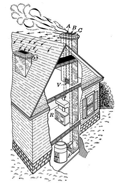
Fig. 57b.—Effect of the wind in causing down draft in low chimneys.
The same effect is often produced by a neighboring building
or a border of trees that are higher than the chimney and
dense enough to effect the wind pressure.
[82]
CHAPTER VI
PLUMBING
The term plumbing is usually understood to cover all piping
and fixtures that carry water into the house and remove the waste
material in the form of sewage. It does not include the pipes of
the heating system. Although the work of installing heating
plants is frequently done by plumbers, pipe fitting and plumbing
are two distinct trades.
In the process of building a house the rough plumbing is put
into place as soon as the structure is enclosed and the rough
floors are laid. The rough plumbing includes the soil pipe, into
which the waste pipes from the various fixtures empty, and those
pipes which must occupy a position inside the partition walls and
beneath the floors.
The connections here described are for a city dwelling and
apply to the custom of local conditions. The same system
might be used for a country residence except in regard to the
water supply and method of sewage disposal. Plants of this
type are discussed in the chapter on septic tanks.
Fig. 58 shows a cross-section of the street, exposing the sewer
S, the water main W, and the connections with the house. The
side of the house has been removed to permit a view of the water
and sewer pipes, connecting with the bathroom, kitchen, laundry
and other basement fixtures.
The lateral sewer or house drain, which connects the house
with the street sewer S, is provided with a trap G, located, in this
case, just outside the basement wall. The house drain is made
of vitrified tile, laid so as to grade into the street sewer with the
greatest possible pitch. The sections are laid as true as conditions
will permit and the joints are all carefully filled with cement
mortar to prevent leakage. The object of the trap G is to prevent
sewer gas from entering the house from the main sewer. The
trap prevents the gas from passing because the water in the bend[83]
of the trap forms a water seal, beyond which the polluted air
from the sewer cannot travel.
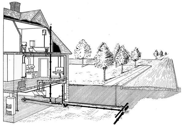
Fig. 58.—Cross-section of a city street showing the watermain and sewer pipe with their connections to a
dwelling.
Next inside the trap is the vent pipe E, that extends to the
surface of the ground. In this case it is just outside the basement[84]
wall. The top is covered with a metal cap. Another
arrangement often made to accomplish the same purpose is
shown in Figs. 61 and 62, where a piece of soil pipe in the form of
a bend is made to take the place of the cap. Inside the basement
and extending up through the partition walls to the roof is the
waste stack or soil pipe A. This pipe as is explained in detail
later, is made of cast iron and is put together with calked lead
joints. The top of the stack at the point where it passes through
the roof is shown in Fig. 59. In extending through the roof the
pipe A must make a water-tight joint to prevent water from
leaking through. This is accomplished by means of the metal
plate D, which is set under the
shingles and the piece C, that is
soldered to D. The joint between
C and A is best made with lead
the same as the other joints of the
stack. In the case of very high
stacks, the bottom should be supported by a pier or iron pipe
rest. Besides being supported at the base the stack should be
secured to the side walls or floor beams at each floor. This is
to keep the pipe from moving out of place and the consequent
opening of joints.
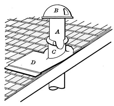
Fig. 59.—Detail of soil pipe
connection.
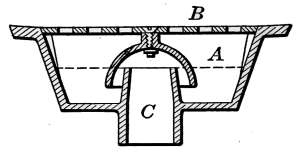
Fig. 60.—Cross-section of cellar-drain.
All of the waste pipes from the bathroom, kitchen and basement
drain into the waste stack. The cellar drain for draining
the basement is shown at T in Fig. 58. It also appears in detail
in Fig. 60. The plate B, in the latter figure, is set flush to the
surface of a depression in the floor that serves as a collecting
point for water. The floor is constructed to drain toward this
point. The plate is perforated to let the water through and is
generally hinged so that in case of stoppage the cover may be
raised. The bell-shaped piece under the cover surrounds the
piece C, to form a water seal when the level of the water is at A.[85]
In addition to this water seal there is generally a trap between
the drain and the sewer as shown in the drawing.
The method of connecting the bathroom waste pipes with the
stack is shown in Fig. 99 and will be described later. All of the
sewage of the house is emptied into the stack by the most direct
route, and from the stack it is conducted as directly as possible
into the sewer. From the drawing it will be seen that all openings
to the sewer are sealed in two separate places, once at the
outlet to prevent the air from the street sewer entering the house
drain G, and again at each opening to prevent escape of the sewer
gas from the drain into the house.

Fig. 61. Fig. 62.
Fig. 61.—House drain with outside vent, and running trap placed inside the
basement wall.
Fig. 62.—House drain with outside vent, and running trap placed outside
the basement wall.
The openings at E and A at each end of the stack permit a
constant circulation of air for ventilation. The length of the
stack and its location causes it to act as a chimney and the
draught produced takes the air in at E, and discharges it at the
top. In large houses there is sometimes added a vent stack to
produce further ventilation, but in the average dwelling the
arrangement here shown covers the common practice.
In Figs. 61 and 62 are shown in detail two methods of arranging
the sewer connections in the basement to permit of the removal
of obstructions in case the pipes at any time become stopped.
The trap, vent, etc., are easily recognized. With the arrangement
as shown in Fig. 62, the clean-out is so placed as to give access
to the inside of the pipe. Should an accumulation or obstruction
of any kind become lodged in the pipe, the stop in the clean-out[86]
is removed and a flexible metal rod is used to remove the stoppage.
The trap outside the wall has an opening through which
the obstruction may be reached in case it cannot be removed
from the first clean-out. The disadvantage in using the outside
trap, as here shown, is that it can be reached only by
excavation.
Fig. 61 shows another common method of installation. Here
the trap is placed inside the basement wall. This gives an
easier means of opening the trap than Fig. 62 affords and
accomplishes the same purpose. The connections with the
stack are the same as in Fig. 62. Obstructions in the sewer pipe
are most likely to become lodged in the trap and for this reason
the trap should occupy a position that is reasonably easy of
access.
The outside trap as described above is quite generally installed
in buildings of all kinds, but its use is by no means universal. In
some communities it is not used at all, and many plumbers
consider it only an added means of causing stoppage and an
extra expense to install.
The object of the outside trap is to keep the air of the street
sewer from entering the house drain. It is at once inferred that
the air of the street sewer is more dangerous than that of the
house drain. The street sewers, however, are ventilated at each
street corner and at each manhole. There cannot then be much
difference in the air of the two places. The traps on the fixtures
that prevent sewer gas from entering the house would be just
as efficient if the outside trap did not exist.
While the methods shown in Figs. 61 and 62 are considered good
practice, there is considerable objection to the vent being placed
near the dwelling, because of the sewer gas that is forced out,
whenever a sudden discharge of water goes into the drain. Each
time a closet is flushed, a large volume of water enters the stack
and completely fills the pipe. When this occurs, the descending
water forces out the air of the pipe ahead of it, and a gush of
offensive air filled with sewer gases is forced out of the vent.
It is evident that such a vent, located near an open window or
where it will reach the nostrils of the inhabitants is a thing
not greatly to be desired.
Outside traps when placed near the surface sometimes freeze.[87]
The circulation of air through the vent is occasionally sufficient in
cold weather to freeze the water and stop the trap.
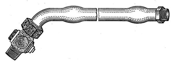
Fig. 63.—Corporation cock with lead connecting pipe.

Fig. 64.—Curb cock
as it appears
attached to the service
pipe.
Water Supply.
—The water supply taken from the street main
is conducted to the house by the pipe shown in Fig. 58, at C.
This pipe is generally of lead as piping of that metal is the most
durable for underground work. Iron used under the same conditions
will last only a few years. The connection is made with
the water main by use of a corporation cock.
This is a special style of cock that is shown
in Fig. 63. In the figure the cock is connected
with a short piece of lead pipe that is used for
making connection with the service pipe in the
house.
Located at the left of C, in Fig. 58, is the
curb-cock, used for shutting off the water from
the city lot. The curb-cock, being underground,
is reached through an iron tube by
means of a wrench attached to a long iron
rod. The curb-cock has a protective covering
in the form of an iron pipe. The lower end of
the pipe screws into the body of the cock.
The top end comes just above the grade line
of the curb and is covered with an iron screw-cap.
The curb-cock is shown in detail in Fig.
64. The pipe B is fastened to the valve at D
and A is the screw-cap. In opening and closing
the wrench fits over the part C of the valve.
On entering the building the supply pipe should be provided
with a stop and waste-cock for shutting off the water from the
house and draining the pipes that compose the system of circulation.
At V, in Fig. 58, is indicated a stop and waste-cock with[88]
the waste pipe B connected with the sewer. This cock is shown
in detail in Figs. 65 and 66. The cock is so made that when
closed there is a small opening at A, that allows the water from
the system to escape through the waste pipe.
From the water supply, the cold-water pipes may be traced in
the drawing directly to each of the fixtures of the house. The
hot-water pipe leaves the range boiler at the top and connects
with each fixture using hot water, thus making the circuit complete.
Details of the piping which provides hot water is described
under range boiler, page 116.
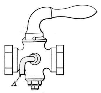
Fig 65.—Stop and drain
cock with lever handle.
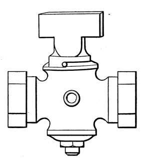
Fig. 66.—Stop and drain
cock with T handle.
WATER COCKS
The development of modern plumbing has brought about the
use of a great number of household mechanical appliances, that
have received trade names little understood by the average
person. The lack of distinguishing terms, or language in which
to describe plumbing fixtures, often leads to embarrassment,
when such articles are to be described to workmen. Common
household valves and cocks are so classified by the trade, that
mistakes are often made in their designation, because of a limited
knowledge of the use of the various articles. A little consideration
of the different classes of fixtures will make it possible to
state to a tradesman the exact article in question.
The term valve is intended to define an appliance that is used
to permit, or prevent, the passage of a liquid through the opening
or port which it guards. The term is so general in its application
that there are hundreds of different kinds of valves.
Even for a single purpose there are many styles of a given kind.
[89]
A cock was originally a rotary valve or spigot used for drawing
water. Today there are many kinds of cocks that are not
rotary in their movement.
It would be impossible in this work to describe in detail all
of the kinds of cocks and valves used in household plumbing.
It will, therefore, be the aim
to confine attention to one
article of a type and to choose
such examples as are in general
use and that are good representatives
of their classes.
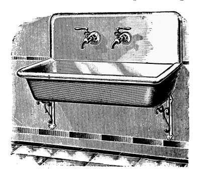
Fig. 66a.—Kitchen sink with Fuller
bibb-cocks.
Bibb-cocks.
—On the
kitchen sink, the water faucets,
such as those shown in
Fig. 66a, are termed bibb-cocks
by the plumber. If the
nozzle is plain, it is a plain
bibb. If the nozzle is threaded
so that a hose connection
may be attached as in Fig. 67, it is a hose bibb. Bibb-cocks are
found in three general styles: compression bibbs, ground-key
bibbs, and Fuller bibbs. The compression bibb takes its name
from the method of closing the valve. Fig. 68 gives an example
of its mechanical construction. This is a plain solder bibb
because the shank A is to be attached by a solder joint. If the
part A contained a thread to make a screw joint, such as Fig.
67, it would be a plain, compression, screw bibb. Fig. 68 is
another style of compression bibb-cock, largely used on sinks;
this cock, being finished with a flange, is a compression flange bibb.
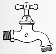
Fig. 67.—Compression
hose bibb.
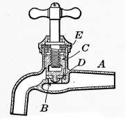
Fig. 68.—Compression
flange bibb.
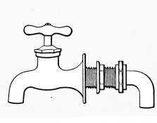
Fig. 69.—Cross-section
of plain compression bibb-cock
for a solder joint.
[90]
Fig. 69 shows quite clearly the mechanical arrangement of
the compression cock. When the handle is turned the nut C lifts
the valve from its seat B, allowing the water to escape. The
piece D is generally made of composition rubber that may be
bought at the dealers for a trifling amount but it may be replaced
temporarily with a piece of leather. The part E is
packing, to keep the water from leaking out around the stem.
The packing may be obtained from the dealer especially for the
purpose or it may be made of a disc of sheet rubber. In fact,
anything that can be put into the space will answer the purpose
temporarily. The valve is closed by compression, hence the
name compression cock. All cocks made to open and close in the
same manner are compression cocks.
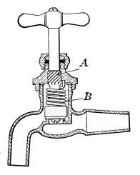
Fig. 70.—Cross-section
of plain self-closing
bibb-cock for lead pipe.
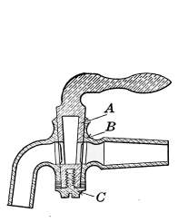
Fig. 71.—Cross-section
of lever handle,
plain bibb.
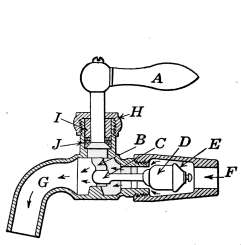
Fig. 72.—Cross-section of
plain Fuller bibb for lead
pipe.
Self-closing Bibbs.
—In Fig. 70 is one example of the many
styles of self-closing bibb-cocks. When the handle of this cock
is turned, the steep-pitched screw A opens the valve and at the
same time compresses the spiral spring B, when the handle is
released, the valve is pressed back on its seat by the spring.
Self-closing cocks are used to prevent the waste of water at
drinking fountains, wash basins and other places where the
water is apt to be left running through carelessness.
Lever-handle Bibbs.
—Fig. 71 is an example of the lever-handle,
ground-key bibb-cock. The key is the piece A, which is
tapered and forms a ground joint with the part B. The cock
takes its name from the form of the handle. The term ground-key
means that the key has been ground into place with emery
dust. This cock is kept from leaking by adjustment of the screw C.
[91]
Fuller Cocks.
—These cocks take their name from their
inventor. They are made to suit every condition for which
water cocks are used. Their universal use attests to their
utility and excellence in service. Fig. 72 shows the principle
on which all Fuller cocks work. The varying conditions under
which the cocks are used require a great many forms, but the
working principle is the same in all. In these cocks, the valve
is a rubber plug or ball that is drawn into the opening by an
eccentric piece attached to the handle. The piece D in the drawing
is the rubber plug that is drawn against the opening by the
crank B, which is worked by the lever handle A. This cock may
be repaired, in case it leaks, by unscrewing it at the joint nearest
the plug. A wrench and a pair of pliers are all the tools required.
The pieces D must be obtained from the dealer. The part J is
the packing that keeps the water from leaking out around the
stem. The screw-cap H forces a collar I down on the packing
to keep it water-tight.
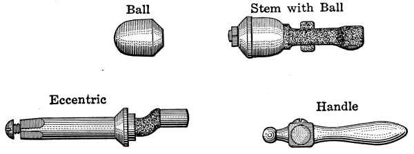
Fig. 73.—Repairs for Fuller cocks.
The parts for the Fuller cock that may be obtained for repair
are shown in detail on Fig. 73. The ball, which appears in Fig.
73 at D, is the part that receives the greatest amount of wear.
If the cock at any time fails to stop the flow of water, a new ball
may be put in place by the aid of a wrench and a pair of pliers.
The water being first shut off from the system, the cock is unscrewed
and the cap E removed with a pair of pliers. The worn
ball is then removed and a new one substituted.
Wash-tray Bibbs.
—A special style of cock is made for laundry
wash trays in both the Fuller and compression types. Of these
the Fuller type is the most convenient as the handle is placed on
the side and but one movement is required to open the cock.
This style of cock is used on the wash trays shown in Fig. 83.
[92]
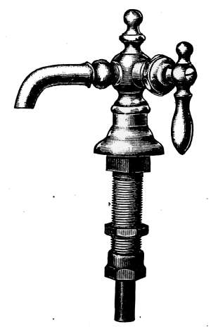
Fig. 74.—Fuller basin
cock.
Basin Cocks.
—Water cocks for wash basins are made in two
general types—the compression and the Fuller types of cocks.
Their mechanism is much the same as
for other similar styles adapted to the
use for basins. The self-closing cocks
used so largely on wash basins are compression
cocks. Fig. 74 is an example
of Fuller basin cock in general use.
Compression cocks for the same purpose
are shown on the wash basin in Fig. 90.
Pantry Cocks.
—In general form,
pantry cocks are the same as those used
for basins except that the outlet is
elongated.
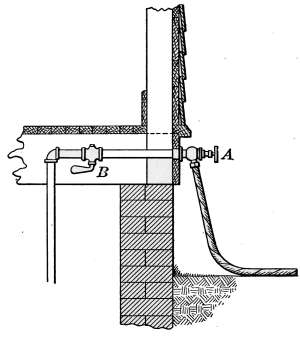
Fig. 75.—Sill cock in place attached
to the water pipe.
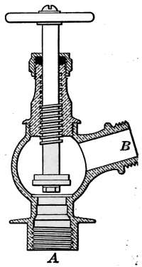
Fig. 76.—Cross section
of sill cock.
Sill Cocks.
—As a means of attaching
garden hose or lawn sprinklers, sill cocks
are placed on the side of the building
at any place convenient for their use.
Fig. 75 illustrates the method of attaching
the cock to the water supply. Fig. 76 shows in cross-section
its mechanical arrangement. The part A is screwed into the
water supply, and B furnishes the hose attachment. The valve
is operated the same as any other compression valve. In Fig.
75 the cock is shown at A with a garden hose attached. The[93]
pipe to which A is attached passes into the basement and connects
to the water supply. The stop-cock B is used to shut off
the water. When the stop-cock B is closed, A should be opened,
so that the pipe will drain. If this is neglected during freezing
weather, the pipe is apt to freeze and burst.
Valves.
—The distinction between a cock and a valve is not at
all definite. Custom has determined that in certain places a
cock shall stop the flow of a liquid but in another place, perhaps
of a similar nature, a valve shall accomplish the same purpose.
The chief distinction between a cock and a valve is that of its
external form.
In Figs. 77, 78 and 79 are three examples of valves that are
very generally used on pipes carrying any kind of fluid. The
valves are shown in cross-section to display the arrangement
of the mechanism.
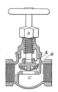
Fig. 77.—Cross-section
of globe valve with
detachable valve disc.
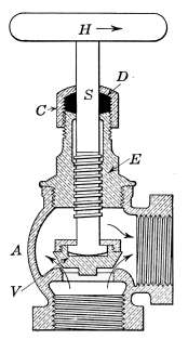
Fig. 78.—Cross-section
of angle globe valve.
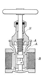
Fig. 79.—Cross-section
of gate valve.
Fig. 77 is an example of the common globe-valve. The name was
originally intended to define a valve the body of which was in
the form of a globe. The hand-wheel H, attached to the screw-stem
S, raises the valve A when desired. The valve makes close
contact with the seat C, by means of a composition rubber disc
B. The disc B may be renewed when worn out as in the case of
the radiator valve already described.
[94]
Fig. 78 represents an angle globe-valve. In general construction
it is quite similar to Figs. 14 and 15, but the valve V in this case
is a cone-shaped piece of brass, which makes a seat in a depression
provided for it. The valve V and the seat are formed as desired
and then ground into contact with emery dust or other abrasive
material, to assure a perfectly tight joint. When this valve
becomes worn and begins to leak, it may be repaired by regrinding,
but such work requires the services of a pipe-fitter. The tendency
of modern practice is to use valves with the detachable discs, such
as that of Fig. 77, because they are easily repaired.
The valve shown in Fig. 79 is known as a gate-valve. The
upper part, including the screw and stem, is the same as the
globe style but the valve proper is made in the form of two
flat gates A-A. When the valve is closed, as it appears in the
drawing, the gates are forced against the seats by the cone-shaped
piece B, which acts as a wedge, to tightly close the opening.
When the hand-wheel is turned to open the valve, the gates are
raised and are taken entirely out of the path of the flowing
liquid. Gate-valves are used in places where it is desired to
obstruct the flow as little as possible. They are somewhat more
expensive than globe-valves but are considered worth the
extra expense in service.
Kitchen and Laundry Fixtures.
—The development in modern
plumbing has wrought many changes in the styles of household
fixtures but none has been so great as that in the kitchen sink.
The old style, insanitary, wooden sink has been almost entirely
replaced by those made of pressed steel or enameled iron. They
are made in every desired size and to suit all purposes. They
may be plain or galvanized as occasion may require, or the enameled
sink is obtainable at a very slight addition in price. The
enameled sink has reached a degree of perfection where its durability
is unquestioned, and as a consequence kitchen furniture
is vastly improved at but little advance in cost.
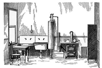
Fig. 80.—Model kitchen.
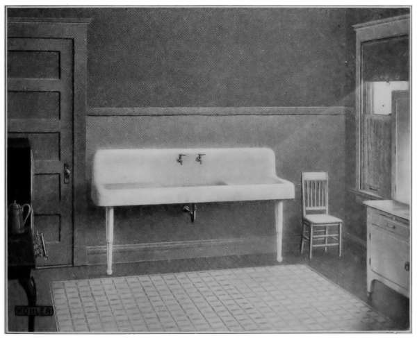
Fig. 81.—White enamel kitchen sink.
A modern kitchen in which gas is used as fuel is shown in Fig.
80. Simplicity and neatness of arrangement are the noticeable
features. This kitchen is intended to suit the average-sized
dwelling and contains all necessary plumbing, cooking and heating
apparatus. The hot-water boiler is here shown attached to
an instantaneous heater. The common kitchen sink is supplemented[95]
with a slop sink and covered with a drain board. This
simple kitchen may be elaborated to any extent. Fig. 81 shows
a kitchen sink of white enamel with two enameled drain boards.
The drain boards are sometimes covered with perforated rubber
mats.
[96]
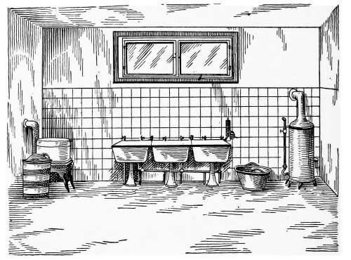
Fig. 82.—Model laundry.
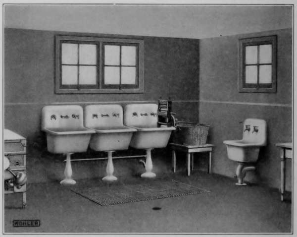
Fig. 83.—Enamel wash trays in a basement laundry.
In Fig. 82 is shown an example of the modern basement laundry.
The wash-boiler heater is shown on the left. An automatic
instantaneous water heater is on the right. The stationary
tubs or wash trays occupy the center of the picture. In detail[97]
these wash trays appear in Fig. 83. These are enamel-covered
ware and are provided with the wash-tray bibb-cocks described
above. This type of plumbing represents the most modern of
sanitary arrangements.
THE BATHROOM
With the present-day improvements in plumbing, and the
perfection in the manufacture of porcelain and enameled iron,
the bathrooms of houses of moderate cost have become places of
cleanliness, attractive, relatively free from offending odors and
supplied with all necessary sanitary fixtures.
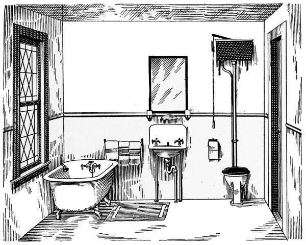
Fig. 84.—Model bath room for the average dwelling.
Enameled iron has reached a state of perfection where it rivals
porcelain in beauty. The forms of the various bathroom pieces
have been modeled for convenience in use and grace of form, at
the same time the strife of the designer has been to produce
articles that not only look well but are convenient and easily
kept clean.
Bathrooms need not be expensive in order to be convenient,
attractive and useful. The bathroom shown in Fig. 84 is such
as is installed in dwellings of moderate price. It possesses every
feature necessary to usefulness and comfort. In this room the[98]
furnishings are all of enameled iron. The floor is covered with
linoleum and the wainscoting with enamel paint.
Bath Tubs.
—Bath tubs are made in sizes that vary in length
from 4½ to 6 feet. They are constructed in a variety of forms
and of materials to suit all conditions of service. For domestic
use they are very generally made of enameled iron. This form
of construction produces serviceable and handsome furnishings
for the bathrooms of the modest house as well as for the
sumptuous bath of the most pretentious residence. An elaboration
of Fig. 84 might include the Sitz bath shown in Fig. 85 and
the fittings may be chosen
from a great variety of forms.
The recent styles of enameled
tubs are, in design, much
handsomer than those with
the roll rim and in form such
as permits a clean room with
the minimum of labor. They
are also provided with more
convenient water and drainage
fixtures.
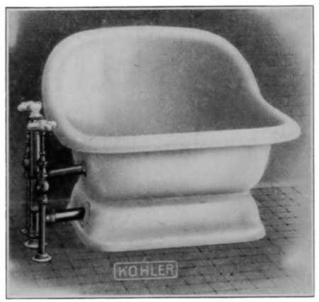
Fig. 85.—Sitz bath.
The tub of Fig. 86 sets flat
on the floor and makes a close
joint with the wall. It thus
prevents the accumulation of
dust that is difficult to remove. In addition the fixtures are arranged
in a more commodious manner and the general appearance
is most pleasing. The arrangement of the fixtures in Fig. 87 gives
still greater convenience and being arranged with a shower and
protecting curtain, provides all of the conveniences of a luxurious
bath without greatly increased cost over the simple tub.
The fixtures in this design are all in position of greatest convenience
and attached to pipes that are concealed in the wall.
[99]
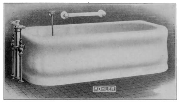
Fig. 86.—Enameled iron bath tub.
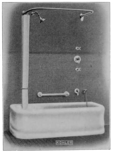
Fig. 87.—Bath tub with shower.
The fixtures usually provided with the tub are double Fuller
or compression cocks for hot and cold water, the overflow and
strainer, for the discharge of the water into the sewer in case the
tub overflows, and a drain and bath plug.
The double Fuller cock is shown in Fig. 88. It is made to open[100]
and close by the same sort of mechanism as is shown in Fig. 71,
a description of which appears on page 90.
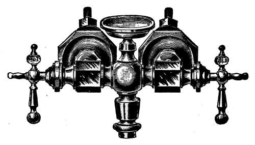
Fig. 88.—Double Fuller cock for bath tubs.
The overflow is shown in detail in Fig. 89. The part A appears
inside the tub. It is made water-tight around the edge C by a
rubber washer that is clamped tight to the surfaces by the nut
B. In case of leakage, the overflow may be removed for repair
by unscrewing the union attached to the piece D and removing
the nut B.
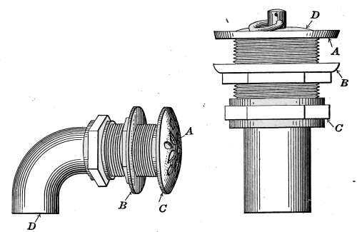
Fig. 89.
Fig. 89a.
Fig. 89.—Overflow attachment for bath tubs, lavatories, etc.
Fig. 89a.—Drain attachment for bath tubs, lavatories, etc., showing locknut
and union connection.
The drain-pipe connection is shown in Fig. 89a. The plug D
and the flange A show inside the tub. The flange is made
water-tight by a rubber washer that the nut B clamps tight to
the tub. The part C is a union which permits the tub to be[101]
detached from the drain pipe. Repairs to this joint may be
made as in the overflow.
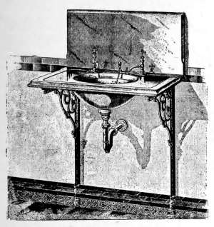
Fig. 90.—Old style marble finished
lavatory.
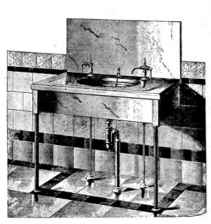
Fig. 91.—Types of lavatory plumbing
not now used in good practice.
Wash Stands and Lavatories.
—Wash stands for bathrooms are
obtainable in many forms, either plain or ornate, to suit every
condition and style of architectural finish.
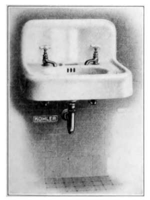
Fig. 92.—Enameled iron wall
wash basin.
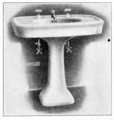
Fig. 93.—Enameled iron pedestal
wash basin.
They are made in marble, porcelain and enameled iron, the
last being the most commonly used. They are made to suit the
part of the room to be occupied, whether that is against a wall,[102]
a corner, or to stand on a pedestal on the floor. Those intended
to fasten to the wall may be supported by brackets or suspended
at the back from pieces secured in the wall.
In Figs. 90 and 91 are shown samples of marble-finished wash
basins. In former years basins of this type were very much in
use, and until the introduction of the modern porcelain and enameled
ware, it was the highest type of sanitary plumbing. The
water cocks and traps are of the same style and grade as appear
on the most modern examples of enameled ware of Figs. 92, 93 and
94. The water cocks used in Fig. 90 are of the compression type.
All of the others are of the Fuller
type. The basin in Fig. 93 is provided
with extra shut-off cocks on
the water pipe under the basin. They
are added to the plumbing merely as
a convenient means of shutting off
the water for repair. The wash stand
is usually provided with hot and cold
water cocks, a waste pipe with its
traps and overflow connections.
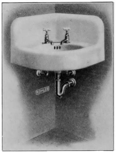
Fig. 94.—Corner wash basin.
Traps.
—The waste pipes from the
wash basin and bath tub are always
provided with some form of trap, to
prevent air from entering the room
from the sewer, charged with offending
odors. Traps are made in many
forms, but the purpose of all is to prevent the escape of sewer gas.
The plain trap S, shown in Fig. 95, is that used under the basin
in Fig. 91. It makes a tight joint by means of the nut B and a
rubber washer as in the case of other joints of the kind. The
parts C and E are unions that permit the pipe or bowl to be
removed without disturbing the remainder of the plumbing.
From the form of the trap it will be seen that the U-shaped part
below the dotted line F will always remain full of water and so
prevents the escape of air from the sewer. In case the trap
becomes stopped the obstruction will likely become lodged in
this part of the pipe. To clean the trap the screw-plug D is
taken out with a pair of pliers and the obstruction removed with a
wire.
[103]
The traps used in Figs. 90 and 92 are the same in principle as
Fig. 95 but are made to discharge into a pipe placed in the wall instead
of under the floor. The trap in Fig. 94 is a form known
as the bottle-trap that is sometimes used in the more expensive
plumbing.
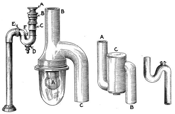
Fig. 95.
Fig. 96.
Fig. 97.
Fig. 98.
Fig. 95.—The S trap of nickel-plated brass tubing.
Fig. 96.—The Bower non-siphoning trap.
Fig. 97.—The drum type of non-siphoning trap.
Fig. 98.—An S trap made of lead pipe.
Another style much used with lavatories is the Bower trap
shown in Fig. 96. In this trap the water comes down the pipe
B and pushing aside the hollow rubber ball A, enters the space
surrounding it and is discharged at C. The ball, being light, is
held against the end of the pipe by the water and acts as a stopper
to prevent evaporation from taking place. Open traps, such as
Fig. 95, if left standing for a long time, may lose sufficient water
by evaporation to destroy the water seal and allow the sewer gas
to escape. In the use of the Bower trap such occurrence is much
less likely to take place.
Fig. 97 is another trap much used on sinks; it is known under
the trade name of the Clean Sweep trap. The part C is much
larger than the common trap and the water seal is less likely to[104]
be broken. The clean-out is larger and the interior is easy of
access in case of stoppage.
The simplest and most commonly used trap in cheap plumbing
is that of Fig. 98. It is a lead pipe bent in the form of an S. It
is the same in shape as Fig. 95 and performs its work as well but
does not have the means of detachment shown in the latter.
Traps of many other forms are in use but all have the same
function to perform and the mechanical make-up is much the
same as those described.
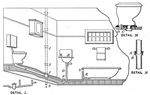
Fig. 99.—A method of bath-room plumbing using the drum trap.
The plan of attachment of the various bathroom fixtures of the
soil pipe must always depend on local conditions. The object
is to conduct the waste water to the sewer in such a way as to
give the least opportunity for stoppage and to prevent sewer gas
from escaping into the house. To accomplish this purpose the
pipes and traps are arranged according to a plan proposed by the
architect, plumber or other person familiar with the principles of
plumbing. Since these pipes are placed in the walls and under
the floors, where they are not readily accessible, it is necessary
that their arrangement be made with care and that the workmanship
be such as to assure correct installation.
In Fig. 99 is shown a common method of connecting bathroom[105]
fixtures with the sewer. The drawing shows a bathroom with
the floor broken away to show the pipe connections with the bath
tub, wash basin and closet. The overflow pipes O and V and the
drain pipes D and R from the wash basin and bath tub empty into
a large lead drum-trap T, set under the floor. This trap takes its
name from its shape. It is set in position as dictated by the conditions
under which it is used. The nickeled plate P, screwed into
the top of the trap, comes just above the bathroom floor. This
plate is easily removed in case of stoppage. It is made air-tight
by a rubber ring placed under the cover and which makes a joint
with the top edge of the drum.
It will be noticed that the waste pipes from the bath tub and
wash basin enter the trap near the bottom and discharge at the
opposite side near the top. The water will stand in the trap and
pipes level with the bottom of the discharge pipe and thus form
a seal that prevents the escape of sewer gas. This is a common
form of non-siphoning trap. It is non-siphoning because it
cannot lose its seal by reason of the siphoning effect of the water
as it passes through the waste pipes on its way to the sewer.
Another form of non-siphoning trap is the clean sweep trap shown
in Fig. 97. Such traps as Figs. 95 and 98 are siphoning traps,
since it is possible, in this form of trap, for the water to be so
completely siphoned that not enough remains to form a seal.
The small drawing, marked Detail L, is another method of connecting
the same arrangement of fixtures. The waste pipe enters
the trap as before but discharges immediately opposite. The
level of the water stands in the pipes as indicated by the dotted
line.
Back-venting.
—To prevent the possibility of loss of seal by
siphoning and the escape of sewer gas, traps are back-vented to
the main stack or to a separate vent stack. The venting is
accomplished by joining a pipe to the top of the trap or to some
point in its immediate neighborhood, and connecting this with
the main stack or the vent stack. The water in a trap so vented
will be open to the air from both sides and consequently can never
be subject to siphonic action.
In the average-sized dwelling where non-siphoning traps
are used, back-venting is not necessary, but in large houses and[106]
in plumbing where siphon traps are used, vent pipes must be attached
to the traps to assure a satisfactory system.
Fig. 100 furnishes an example of back-venting, applied to the
bathroom shown in Fig. 99. In the former figure the bath tub
and wash basin are connected with the waste pipe by siphon
traps. A siphon trap may lose its seal in two ways: by self-siphonage,
or by aspiration caused by the discharge of the water
from other fixtures. In the discharge of the siphon trap, such
as B, in Fig. 100, the long leg of the siphon, formed by the discharge
pipe, may carry away the water so completely that not
enough remains in the trap to form a seal. Again, the discharge
of the water from the bath tub through the waste pipe tends to
form a vacuum above it and in some cases the seal in B is destroyed
by the water being drawn into the vertical pipe. The
possibility of either of these occurrences is prevented by
back-venting.
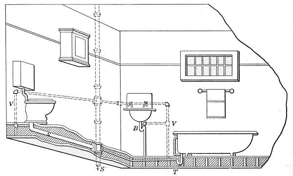
Fig. 100.—An example of back-vented plumbing as applied to the bathroom.
In Fig. 100, a pipe from the main stack is connected with the
bend of the trap at B and also to the waste pipe outside the trap
at T. A vent is also taken from the drain C, at a point just
below the trap in the closet seat. The object of all of the vents
is to prevent the tendency of the formation of a vacuum from any[107]
cause that will carry away the water seal of the trap and allow
sewer gas to enter the house.
The closet seat also contains a trap which will be described
later. It connects with soil pipe S, leading to the sewer by a
large lead pipe C.
All of the pipes under the floor, leading to the soil pipe, should
be of lead. The pipes above the floor are generally of iron or
nickel-plated brass. All of the connections in the lead pipes are
made with wiped joints; that is, the connections are made by
wiping hot solder about the joint, in a manner peculiar to this
kind of work, in such a way as to solder the pipes together. The
joints made in this manner are perfectly and permanently tight.
Lead pipes are used under such conditions, because lead is the
least affected by corrosion of any of the metals that could be
used for such work.
Soil Pipe.
—The soil pipe, of which the waste stack or house
drain is composed, is made of cast iron and comes from the factory
covered with asphaltum paint. It may be obtained in two
grades, the standard and extra heavy. The only difference is in
the thickness of the pipe. The former is commonly used in the
average dwelling. One end passes through the roof and the other
end joins to the vitrified sewer tile under the basement floor.
The joints must be perfectly tight, because a leak in this pipe
would allow sewer gas to escape into the house. One end of
each section is enlarged sufficiently to receive the small end of
the next section. The joints are made with soft lead. The
pipes are set in place and a roll of oakum is packed into the bottom
of the joint, after which molten lead is poured into the
joint, filling it completely. The oakum is used only to keep the
lead in the joint until it cools. After the lead has cooled it is
packed solidly into the joint with a hammer and calking tool.
The calking is necessary because the lead shrinks on cooling
and makes a joint that is not tight. Well-calked joints of this
kind are air-tight and permanent. Detail N (Fig. 99) shows the
arrangement of the parts of the joint as indicated at A. The
blackened portion represents the lead as it appears in the joint.
Detail M (Fig. 99) shows the methods of attaching the closet
seat to the lead waste pipe C. The end of the lead pipe is flanged
at the level of the floor, as shown at C in the detail drawing.[108]
The depression D, around the connection, is then filled with
glazier’s putty and the seat is forced down tightly in place and
fastened with lag screws.
The pipe C, from the closet, and that from the trap T, being of
lead, a special joint is necessary in connecting them with the soil
pipe, because a wiped joint cannot be made with cast iron. To
make such a connection the end of the lead pipe is “wiped” onto
a brass thimble, heavy enough to allow it to be joined to the soil
pipe by a calked lead joint. The brass thimble is then joined to
the cast-iron pipe by a calked lead joint.
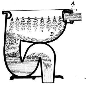
Fig. 101.—The wash-out
closet.
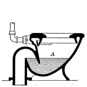
Fig. 102.—The wash-down
closet.
Water Closets.
—Water closets are made in a great number of
styles to suit the architectural surroundings and the various
conditions under which they are to be used. Many forms of
water closets are manufactured to conform to special conditions,
but those commonly used in the bathrooms of dwellings are of
three general types. The mechanical construction of each is
shown in the following drawings, Figs. 101, 102 and 103 showing
respectively in cross-section the principle of operation of the
washout closet, the washdown closet and the siphon-jet closet.
Washout Closets.—This type of closet has in the past been
used to a very great extent. It does not perform the work it has
to do, so perfectly as the others, because the shallowness of the
water in the bowl allows it to give off odors, and because it is
difficult to keep clean. The action of the closet is as follows:
When the closet is flushed the water enters the rim at A, and the
greater portion of it is washed downward at B to dislodge the
contents of the bowl. A lighter flush is sent through the openings[109]
in the side, which serves to wash the entire surface. The direction
of discharge is forward, where it dashes against the front
of the bowl and then falls into the trap. The only force received
to carry the water to the trap is from falling through the distance
from the point where it strikes the front. The flushing action
is obtained from the use of a large volume of water. As the
discharged matter is dashed against the front of the bowl, the
flushing action of the water is not sufficient to remove all the
stains; the result is an accumulation of filth. This part of the
bowl is out of sight; hence, it is seldom kept clean. The name
washout comes from the action of the water to wash out the contents
of the bowl.
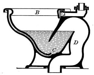
Fig. 103.—The siphon-jet
closet.
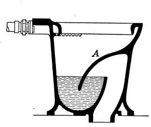
Fig. 104.—A poor design of
wash-down closet.
Washdown Closets.
—As shown in Fig. 102, the action of this
closet is to wash the contents of the bowl directly down the soil
pipe. The depth of the water at A is much greater than at the
corresponding point in the washout closets; as a consequence
fecal matter is almost submerged. The main objection to this
closet is that it is noisy. Fig. 104 shows another form of washdown
closets. This closet is open to objection because of faulty
design; the part A is difficult to keep clean because of its shape.
Siphon-jet Closet.
—What is considered by many to be the
most satisfactory closet yet designed, is that of the siphon-jet
type shown in Fig. 103. The flushing action of this closet is
entirely different from that of the others described. The flushing
water enters at A and fills the rim B. Part of the water
washes the sides of the bowl, while the remainder flows through
the jet C, and is discharged directly into the outlet. The ejected
water enters the outlet D, which, as soon as it fills, acts as a
siphon to draw the water into the soil pipe. This closet is most[110]
positive in its action, since the discharge is made by the siphon
and also receives the additional momentum due to the water
flowing through the jet. Its action is attended with but little
noise.
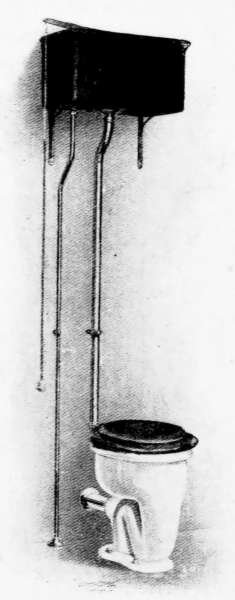
Fig. 105.—Siphon-jet closet
with the high flush tank.
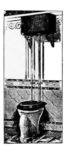
Fig. 106.—Form of closet not
now used in good practice.
Flush Tanks.
—The water closet depends for its action on one
of two general types of flush tanks, the high and the low forms.
The tank is automatically filled with water and when wanted, a
large volume of water is suddenly discharged into the sewer,
carrying with it the contents of the seat. The tank again fills
and is ready for use when required.
As illustrations of high flush tanks, those shown in Figs. 105
and 106 furnish examples of a simple and efficient form. The
details of the mechanism of this type of tank are shown in Fig.
107. The pipe from the water supply is attached at G to the
automatic valve F, which keeps the tank filled with water. The
piece F of the valve is held against the opening by the pressure
exerted through the float E. The float is a hollow copper ball.[111]
As the ball is lifted it exerts a pressure in proportion to the
amount it is submerged. When the water reaches the level
A-A, the valve is tightly closed. As the water is discharged
from the tank the ball follows the level of the water and opens
the valve, allowing the water to enter and again fill the tank.

Fig. 107.—Details of construction of a simple type of siphon flush tank.
The siphon is made of cast iron, and in the figure is shown cut
through the center. The lower end fits loosely in the piece K,
and makes a water-tight joint around its outer edge, by resting
on a rubber ring C-C. The right-hand side of the siphon is
open at H, and when the tank is full, the level of the water is at
A-A, which is almost at the top of the division plate. To discharge
the tank, the chain L, attached to the lever B, is pulled
down; this action raises the siphon from its seat. As soon as the
siphon is lifted, the water rushes through the opening around
C-C, into the pipe K; this causes a partial vacuum to form in D,
and the water is lifted over the division plate K, and flows out
at D, forming the siphon. As soon as the siphonic action begins
the siphon may be dropped back on the seat and the water will
continue to discharge until the tank is empty.
Low-down Flush Tank.
—The low-down flush tank for water
closets has met with so much favor that it has to a great extent
displaced the high tank. The reason for this is because of its
advantages over the other style. The low tank is more accessible,
more easily kept clean, and better adapted to low ceilings.
It is used successfully as a siphon tank, but other forms are in
use with satisfactory results.
Fig. 108 gives a perspective view of one style of this type of
tank attached to a siphon-jet closet. Figs. 109 and 110 give the[112]
details of the construction of two forms of this type of tank,
both of which have given efficient service. The drawing shows
the tanks with the front broken away to give a view of the working
parts. The water enters the tank and is discharged at the
points indicated. The float and supply valve works exactly as
described in the high tank. The drawing in Fig. 109 shows
the tank in the act of discharging. The discharge valve is raised
as shown at E. When the water is completely discharged, the
float occupies the position shown dotted. When the float reaches
this dotted position, its weight pulls down the piece A. This
releases the lever B, and the attached stopper E, which falls and
closes the discharge orifice. While the tank is filling with water,
a stream flows through the small pipe D, to replenish the water
in the closet that has been discharged in siphoning. When the
tank is full of water, the pieces A and B occupy the positions
shown dotted. To discharge the tank the trip is pushed down.
This action raises the lever to the position B, and with it the
attached stopper E. The piece C falls and the opposite end A
holds B suspended until the tank is completely discharged.
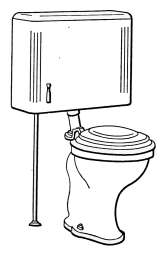
Fig. 108.—Siphon-jet
closet with low-down
tank.
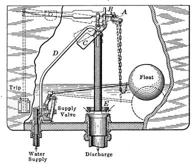
Fig. 109.—Details of construction of low-down
flush tank.
The action of the tank shown in Fig. 110 is the same as the
others except that of the discharge mechanism. In the drawing,
the tank is full of water ready to be discharged when required.[113]
A hollow rubber ball E serves as a stopper for the discharge
pipe. The ball is kept in place, when the tank is filling, by the
pressure of the water above it. The discharge is started by pressing
down the trip on the front of the tank. This raises the ball
from its seat, and being lighter than water, it floats, thus leaving
the discharge pipe open until the tank is empty, when the ball
is again back on its seat. As the tank fills the pressure of the
water above prevents the ball from again floating, until lifted
from its seat. The supply valve and refilling pipe D is the same
in action as in the other tank.
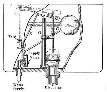
Fig. 110.—Details of construction of the
float-valve, low-down flush tank.
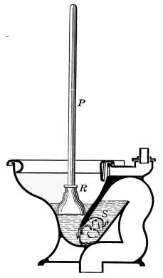
Fig. 111.—Method of
using the plumber’s friend,
in removing obstructions.
Opening Stopped Pipes.
—It occasionally happens that pipes
leading from the various toilet fixtures become stopped because of
accumulations or by articles that accidentally pass the entrance.
In case the pipe has a trap connection the stoppage is most likely
to occur at that point. Usually the obstruction may be removed
by detaching the screw-plug of the trap and removing the accumulation
with a wire.
Closet seats furnish an inviting receptacle for waste material
of almost every kind. Stoppages are not uncommon and are
generally found in the trap. One method of removing obstruction
is by use of the plumbers’ friend. This device is shown at[114]
P-R, in Fig. 111. It consists of a wooden handle P attached to
a cup-shaped rubber piece R.
The plumbers’ friend is shown in the figure, placed to remove
an obstruction S that is lodged in the trap. A sudden downward
thrust causes the rubber cap R to entirely fill the closet outlet
and the resulting pressure to the water is generally sufficient
to force the obstruction through the trap to the soil pipe.
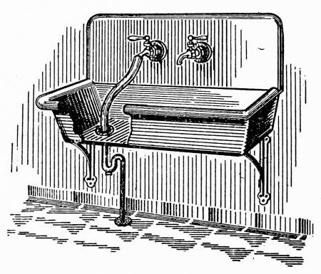
Fig. 112.—Method of removing obstructions
from a stopped drain-pipe.
The kitchen sink is another place that affords opportunity
for accumulation that stops the waste pipe. Accumulation of
grease in the trap is a common
cause of trouble. This may be
remedied to some extent by the
use of potash or caustic soda.
When the pipe is stopped and
the trouble cannot be reached
from the trap, a common method
of removing the stoppage is that
suggested in Fig. 112. A piece
of heavy rubber tubing is forced
over the water tap and the other
end tightly wedged into the drain
pipe; the water is then turned
on and generally the pressure is sufficient to force the accumulation
down the pipe.
Sewer Gas.
—The prevalent fear of the deleterious effect of
escaping sewer gas is one that has been magnified to an unwarrantable
degree. Among bacteriologists it is very generally
recognized that none of the dreaded diseases to which the human
kind is susceptible are transmitted by gases. The one possible
harmful effect recognized in sewer gas by scientists is that produced
by carbon monoxide. Sewer gas often contains, from escaping
illuminating gas, sufficient carbon monoxide to produce
the poisoning effect characteristic of that gas but the possibility
of danger is quite remote. The leakage of sewer gas is detected
by the sense of smell sooner than in almost any other way.
While leaks in sewer pipes are unhygienic in that they are conducive
to undesirable atmospheric conditions, they should not be
looked upon as the agents through which transmissible diseases
are carried.
[115]
To the average person the term sewer gas conveys the impression
of a particularly loathsome form of vaporous contagion,
capable of distributing every form of communicable disease. To
the scientific mind it means no more than a bad odor. Sewer gas
is really nothing but ill-smelling air.
RANGE BOILERS
The hot-water supply to the household is of so much importance,
that the installation of the range boiler should be made
with great care, and an understanding of the principle on which
it works should be fully appreciated by all who have to do
with its management. The ability of the boiler to supply the
demands put upon it depends in a great measure on its size and
the arrangement of its parts, but proper management is necessary
to assure a supply of hot water when required.
Range boilers are used for storing hot water heated by the
water-back of the kitchen range or other water heater, during a
period when water is not drawn. It serves as a reserve supply
where the heater is not of sufficient size to heat water as fast as
is demanded.
As commonly used, range boilers are galvanized-steel tanks
made expressly for household use. They are standard in form
and may be bought of any dealer in plumbing or household
supplies. In capacity they range from 20 to 200 gallons and are
made for either high-or low-pressure service. They are said to
be tested at the factory to a pressure of 200 pounds to the square
inch and are rated to stand a working pressure of 150 pounds.
Range boilers are galvanized after they are made and coated
both inside and out. The coating of zinc received in the galvanizing
process helps to make their seams tight and at the same
time renders the surface free from rust.
There is no definite means of determining the size of tank
to be used in any given case, because of the varying demands
of a household but a common practice is to allow 5 gallons in
capacity to each person the house is able to accommodate.
The Water-back.
—The most common method of heating water
for the range boiler is by use of the water-back or water-front of
the kitchen range. The water-back is a hollow cast-iron piece[116]
that is made to take the place of the back fire-box lining of the
range. In some ranges the heater occupies the front of the
fire-box instead of the back, in which case the heater becomes
the water-front.
The arrangement of pipes connecting the source of water
supply with the boiler is such that cold water is constantly
supplied to the tank as the hot water is drawn. If no water is
drawn from the tank, it will continue
to circulate through the tank and
heater, the water becoming constantly
hotter.
The connecting pipes are usually of
iron but sometimes pipes of copper
or brass are used. The joints should
be reamed to remove the burr that
is formed in cutting. The angles
should be 45-degree bends or better
still 90-degree bends in connecting the
heater with the tank so as to cut down
the amount of friction as much as
possible.

Fig. 113.—A common
method of connecting the range
boiler to the water-back.
In Fig. 113 is shown a standard
range boiler connected to the range.
The water is brought into the top of
the tank through the pipe a-a, and
passing through it enters the water-back
by means of the pipe b. After
passing through the water-back the water again enters the tank
through the pipes c and d, as indicated by the arrow. The
flow pipe (carrying the out-going water) from the water-back
may be connected with the tank at e, as shown dotted or in
some cases the connections are made at both places. The velocity
of circulation depends on the vertical height of the column
of hot water and the greater height will, therefore, improve the
circulation and thus increase the efficiency of the heater. The
circulation of the water through the tank and heater is produced
by its change in weight as the water is heated. As the
hot water comes from the water-back it rises in the pipe because
it is lighter in weight than the cooler water of the tank. In[117]
the case of the pipe shown dotted in Fig. 113 the longer vertical
rise will give a greater upward velocity of the hot water
and consequently a better circulation through the entire circuit.
The construction of the water-back is shown in the small
drawing. The connections are made at b and c as before. A
division plate in the water-back causes the water flowing in at
b to follow the length of the heater at the bottom and return at
the top as indicated by the arrow, when it is discharged at C.
The hottest water is always at the top of the tank and the
temperature grades uniformly from the hottest at the top to
the coolest at the bottom. The reason for extending the pipe
a so far down into the tank is that the cold water may not
mingle with the hot water and reduce its temperature on entering
the tank. Near the top of the pipe a is a small hole f that is intended
to prevent the water from being siphoned from the tank
in case a vacuum is formed in the cold-water pipe. In this arrangement
the water enters and leaves at the top of the tank.
In case the supply is shut off at any time the tank is left almost
full of water, because the siphoning effect cannot extend below
the small hole f.
Excessive Pressure.
—Accidents due to the explosion of hot-water
backs are not at all rare and it should be borne in mind
that there is danger of excessive pressure being formed should
the pipes b and c become stopped. Under normal conditions
the pressure generated by the heated water is relieved by the
water in the tank being forced back into the supply pipe. The
pressure in the tank, therefore, cannot become greater than that
of the source of supply, but if b and c should become stopped
with the water-back full of water a dangerous pressure might
result. The greatest danger from this cause is that of freezing.
It frequently happens that houses are closed during cold weather
and the water-back is left undrained. The water freezes and
when a fire is started in the range, the ice in the water-back
is the first to melt. In a short time steam will be generated that
will soon produce a sufficient pressure to burst the water-back.
This has happened many times with disastrous results. Such
dangers may be avoided by the exercise of a reasonable amount
of care in the management of the range. To drain the water-back,
the water is first shut off at the point where the supply[118]
pipe enters the house. The water in the range boiler is then
drawn off by means of the cock h.
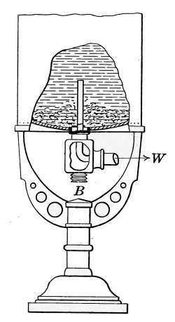
Fig. 114.—Blow-off
for removing sediment.
Blow-off Cock.
—When a considerable amount of sediment
is carried in the water the range boiler acts
as a settling tank and the deposit accumulated
at the bottom will in time amount to
a source of trouble. The
accumulation is shown in
Fig. 114. The part W,
which connects with B,
is sometimes provided
with a blow-off cock
that will admit of a discharge
of the sediment.
More commonly the
piping is arranged as
shown in Fig. 113, when
sediment is removed by
occasionally drawing
water from the cock h.
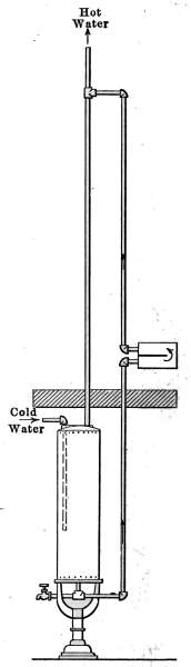
Fig. 115.—Method
of connecting the range
boiler when placed on
the floor below the
heater.
Location of Range Boiler.
—It is sometimes
desired to place the range boiler on a
different floor, either above or below the
range. While such arrangements are entirely
possible the circulation of the water is not so
good as that described above. The weight
of the two columns of water in the connecting
pipes are so nearly balanced that good circulation
is not always possible. In Fig. 115
the connections are shown, where the tank
is located in the basement. In connecting
the water-back to the tank under such conditions
the piping is relatively the same
as is shown in the dotted connections of Fig.
113, but the connections are longer. The
circulating pipe comes from the bottom of
the tank and leads to the bottom of the water-back. The flow
pipe from the top of the water-back is extended up to a distance
equal or greater than the distance from the water-back to the[119]
bottom of the tank. The hot water is taken from the top of
the flow pipe at any place above the tank.
Double Heater Connections.
—Two heaters are sometimes connected
to one range boiler, each circuit being independent of
the other. Under such conditions one or both heaters may be
used. When the tank is connected as shown in Fig. 116 the pipe
a, from the bottom of the tank, branches and leads to b and b´,
at the bottom of each of the heaters. The flow pipes from the
top of the heaters enter the tank at separate places, the lower
heater sending its water into the side of the
tank at c, and the upper heater flowing into
the pipe d, at the top of the tank. It would
be perfectly possible to reverse the connections
for the flow pipes in the arrangement
of Fig. 116 and attain the same results.
In such combinations the heaters are sometimes
piped tandem, the water flowing
through each of the heaters in turn. This,
however, is not the best method to employ,
for if only one of the heaters is used the
second acts to cool the water.
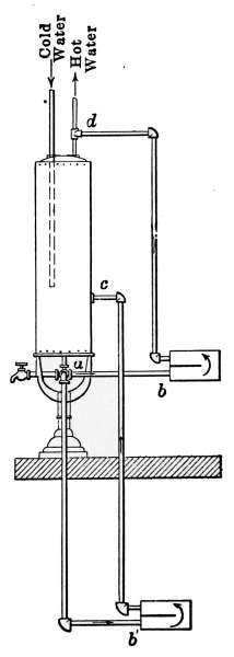
Fig. 116.—Double
connections for the
range boiler where a
heater is placed in
the basement for occasional
use.
Horizontal Range Boilers.
—It occasionally
happens that in a small kitchen there
is no convenient floor space for the range
boiler and it becomes necessary to suspend
it from the ceiling. It is perfectly possible
to station the ordinary range boiler in such
a position and have it work fairly well but
from the location of the cold-water inlet,
only that part of the range boiler above the
cold water pipe is actually used for storage.
The water in the lower half constantly mixes
with the entering cold water before it is
heated by passing through the water-back. When hot water
is drawn from the top of the range boiler, cold water enters by
the cold-water pipe and reduces the temperature of most of the
lower half. Fig. 117 illustrates such an arrangement. In this
case the pipes connected with the water-back are those that correspond
to the circulating pipes a and e in Fig. 113.
[120]
Suppose the range boiler is full of water, and that it is being
heated. The lower pipe at the left-hand end is conducting the
water to the water-back and it is being returned to the range boiler
by the upper pipe at the same end. When the hot water is
drawn from the top of the range boiler by the hot-water pipe,
the entering cold water mixes with hot water in most of the
lower half of the range boiler
before it has been heated by
passing through the water-back
and so reduces the temperature
of most of the lower
half of the tank.
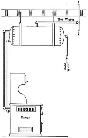
Fig. 117.—Method of connecting
the vertical range-boiler
in a horizontal position.
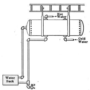
Fig. 118.—Horizontal range-boiler suspended
from the ceiling.
A much better tank for the
purpose is that indicated in Fig. 118. This is a tank made
particularly for such a location. The cold water enters at the
bottom of the tank and also leaves the bottom on its way
to the water-back. Circulation takes place through the water-back
as before but when hot water is drawn from the top of
the tank, the entering cold water at the bottom mixes with only
that at the lower part of the tank and so cools but a small
amount of the hot water in storage. Hot-water tanks of this
kind are tapped for pipe connections in two places on both the top
and bottom sides and also at the ends as shown in the drawing.
[121]
Tank Heaters.
—When the demand for hot water is sufficient
to warrant a separate hot-water heater the apparatus similar
to Fig. 119 is used. With such a heater, the conditions of overheated
water—to be described later—may be almost entirely
avoided. In this case the connections are arranged similarly to
those of the range boiler but a separate furnace takes the place
of the water-back. The heater is simply a small furnace made
expressly for heating water. Connected with the discharge pipe
p is a draft-regulating valve which controls the drafts of the
heater. The draft-regulator is set to so control
the furnace that water at the desired
temperature will always be in the tank.
The mechanism of this regulator is the same
as the draft-regulator described under hot-water
heating plants.
Overheated Water.
—Under ordinary conditions
the water contained in the range
boiler is below the atmospheric boiling point
(212°F.) but at times when a hot fire is kept
up in the range for a considerable period, the
temperature will rise to a degree much above
that amount. The temperature to which
the water will rise will depend on the pressure
of the water supply. As an example—suppose
the gage pressure of the water
supply is 25 pounds. The temperature corresponding
to that pressure is 258°F. The
temperature of the water in the tank will rise to that amount
but not further because any additional temperature will produce
a higher pressure, but a higher pressure would be greater than the
pressure of the water supply and hence will back the water into
the supply pipe. This condition of things, then, acts as a safety
valve to the tank to prevent excessive pressures.
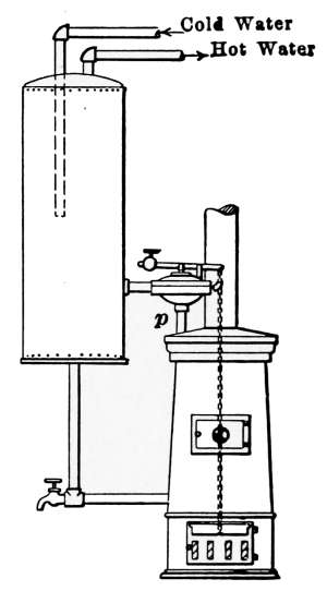
Fig. 119.—Independent
hot-water heater
with temperature regulator.
When the water at a high temperature is drawn from the tap a
considerable part of it will instantly vaporize, because of the
reduced pressure. If water at a pressure of 25 pounds is drawn
from the faucet, the temperature, 258°F., is sufficient to send all
of the water instantly into steam. This high temperature will
scald at the slightest touch. The water drawn from the faucet[122]
will continue to vaporize as it comes into the air until the water
in the tank is cooled by the incoming cold water. The only
means of relieving the overheated condition is to open the faucet
a slight amount and allow a portion of the heated water to be
drawn off.
It is evident from what has been said of the range boiler that
it operates under a variety of conditions.
It is first a storage tank in
which is accumulated the water, heated
from a greater or less period of use of
the range. Should the range fire be
maintained through the day or night
the supply of hot water will be excessive
and superheating is the result. If the
heater is to be used during short periods
of time, the piping should be arranged
to produce the best circulation; on the
contrary, should the heater be used continuously—as
in the case of a furnace
coil—a slow circulation through the
tank is most to be desired and the
piping should be arranged for that
purpose.
In the use of furnace heaters, superheating
is likely to occur during cold
weather when a hot fire must be used
over a long period of time. In order
to conserve the heat accumulated under
such conditions a hot-water radiator
is frequently connected with the range
boiler through which to dispose of the
excess heat. This radiator may be
placed in any desired position and so
connected by a valve as to discontinue
its use at any time.
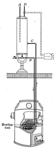
Fig. 120.—The range boiler
connections when a furnace
coil is used for hot-water heating.
Furnace Hot-water Heaters.
—It is sometimes more convenient
to use the furnace as a means of heating water than the
kitchen range. Such an arrangement is shown in Fig. 120,
where a loop of pipe in the fire-box of the furnace takes the place[123]
of the water-back. The arrangement of the pipes in the range
boiler are as before, the water entering the tank through the
pipe A, circulates through the pipes B and C, receiving its heat
while passing through the loop in the furnace, in exactly the
same way as in the water-back. It would be quite possible to
also connect the kitchen range with the tank as shown by the
dotted lines indicating the water-back. Such an arrangement
would virtually be that shown in Fig. 116, where the two heaters
on different floors are connected with the boiler.
Instantaneous Heaters.
—In isolated bathrooms where no constant
supply of hot water is available, instantaneous hot-water
heaters are much used. In many houses where a range fire is
used intermittently, particularly during the summer months,
a like method is used for the hot-water supply. These heaters
are made in many forms to suit any condition. Some are very
simple, being made of a gas heater, the heat from which is held
against a long coil of pipe or a large amount of heating surface
in other form, through which the water circulates on its way
to the tap. Others are quite elaborate, being made entirely
automatic in their action. The Ruud heater, for example, is
so constructed that when the hot-water faucet is opened the
reduced water pressure starts a gas heater in contact with a
series of pipe coils through which the water circulates. As soon
as the water faucet is closed the water pressure automatically
closes the gas valve, cutting off the supply of gas. A little gas
jet used for igniting the burner is left constantly burning, ready
to light the gas whenever hot water is required.
Fig. 121 illustrates a simple form of instantaneous heater that
is relatively inexpensive and has met with a great deal of favor.
A sheet-iron casing encloses a sinuous, multiple coil of pipes
through which the water passes. The heat furnished by a Bunsen
burner of a large number of small jets is evenly distributed
over the bottom of the heater. The heating coils are arranged to
interrupt the heat passing through the casing and absorb as
much as possible. To do good work such a heater must be
connected by a pipe to a chimney flue which furnishes a good
draught.
Instantaneous water heaters should not be used in bathrooms
unless the products of combustion from the heater are carried[124]
away by a chimney. The combustion of the required amount
of gas produces a large volume of carbonic acid gas which if
allowed to remain in the room is not only deleterious but may be
a positive danger to life. Cases of asphyxiation from this cause
are not at all rare.
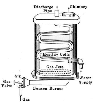
Fig. 121.—Gas heater for hot-water
supply.
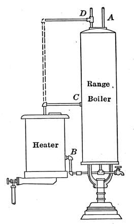
Fig. 122.—Hot-water supply with
gas heater, connected to the range
boiler.
Fig. 122 shows the heater connected with a range boiler.
In this case the heater may be considered as taking the place
of the water-back. It may, however, be used as an auxiliary
heater. In the picture of the kitchen shown in Fig. 80, an
instantaneous heater is shown attached to the range boiler.
It is located in this case between the kitchen range and the
boiler.
[125]
CHAPTER VII
WATER SUPPLY
The use of water enters into each detail of the affairs of
everyday life and forms a part of every article of food; its
quality has much to do with the health of the family, and its
convenience of distribution lends greatly to the contentment of
its members. The family water supply should be as carefully
guarded as means will permit, and judicious care should be
exercised to prevent the possibility of its pollution. Where
the source of the water is known, it should be the subject of
unremitting attention.
Water comes originally from rain or snow and as it falls, it
is pure. Water, however, in falling through the air absorbs the
contained vapors and washes the air free from suspended organic
matter in the form of dust, so that when it reaches the earth
rain water contains some impurities.
As the water is absorbed by the earth, it comes into contact
with the mineral matter and organic materials of animal and
vegetable origin contained in the soil; and as water is a most
wonderful solvent, it soon contains mineral salts and possibly
the leachings from the organic substances through which it
passes. The impurities usually found in well water are in the
form of mineral salts that have been taken up from the earth,
but other contaminating materials may come from the surface
and be carried into the well by accidental drainage.
Water that is colorless and odorless is usually considered good
for drinking and in the absence of more accurate means of
determination may be used as a test of excellence; but it often
happens that water possessing these qualities is so heavily
freighted with mineral salts as to be the direct cause of impaired
health. Again, water that appears pure may be polluted with
disease-producing bacteria to such an extent as to endanger
the lives of all who use it. The fact that a source of drinking[126]
water bears a local reputation for purity, because of long usage,
cannot be taken as a test of its actual purity until it has been
subjected to chemical and bacterial examination.
It must not be inferred that all water is likely to be unsuitable
for drinking; there is, however, a possibility of the water being
polluted from natural sources and from accidental causes, that
are sometimes preventable; and the only means of determining
the purity of water is by chemical and bacterial examining.
Water Analysis.
—In order to be assured as to the quality of
drinking water, it should be subjected to analysis and the result
of the analysis inspected by a physician of good standing. Such
analysis may usually be obtained free of charge from the State
Board of Health and if asked, the Chief Chemist will usually give
his opinion regarding the quality as drinking water.
In chemical water analysis, the total amount of solids, regardless
of their nature is taken as indicative of its excellence for
drinking purposes. These solids may be either in suspension
and give the water a color or produce a turbidity, or they may
be entirely in solution and the water appear colorless. English
authorities on the subject place the allowable proportion of
solids at 500 parts to the million. Any water that contains
more than 500 parts to the million is condemned for drinking
purposes. Water containing 500 parts or less to the million
is considered good. The Standard of the American Board of
Health permits the use of water for city supply that contains
1000 parts of solid matter to the million.
The amount of solids contained in water is not at all a definite
indication of its quality for drinking purposes, as may be inferred
from the widely varying amounts permitted by the different
authorities, but it gives an indication of its character because of
the known physiological action of the contained solids.
Chemical analysis alone cannot be taken as a complete indication
of the character of water, because such analysis shows
nothing of the bacteria that may be present. The organic matter
may indicate the possible presence of bacteria, but microscopic
examination will be required to determine its harmful properties.
As examples of the chemical constituents of potable waters,
the following furnish illustrations of different types of water in
general use.
[127]
Pokegama Water.
—The water from Pokegama Spring at
Detroit, Minn. is used widely through the Northwest as a table
water. It is considered to be a very excellent drinking water
because of the low amount of solids and the absence of any
deleterious constituents. The complete chemical analysis as reported
by the North Dakota Pure Food Laboratory is as follows:
| | Grains per gallon |
| Sodium chloride | 0.0200 |
| Sodium sulphate | 0.0357 |
| Sodium carbonate | 3.9288 |
| Calcium carbonate | 11.3997 |
| Lime carbonate | 0.0016 |
| Magnesium carbonate | 3.8896 |
| Sodium phosphate | trace |
| Potassium sulphate | 0.4435 |
| Silica | 0.4416 |
| Organic matter | 0.1006 |
| | ———— |
| Total | 20.2611 |
The total solids, 20.2611 grains per gallon, equivalent to 346.85
parts per million, is very low and composed of carbonates of
sodium, calcium and magnesium, none of which are in any way
harmful even in much larger quantities. The amount of organic
matter is practically nothing.
River Water.
—The water supply of the city of Fargo, N. D.,
is taken from the Red River of the North, which after being
filtered through a mechanical filtration plant is supplied to the
water system of the city. The river water in its raw state is
considered unfit for drinking because of the amount of organic
matter present at different times of the year.
Analysis of raw water from intake pipe, April 14, 1913:
| | Parts per million |
| Chlorine | | 10 |
| Equivalent as sodium chloride, salt | | 16 |
| Volatile and organic matter | 80 | |
| Mineral solids | 180 | |
| | —— | |
| Total solids | 260 | |
In this water neither the solids nor the organic matter are at
all high but during a part of each year there are many pathogenic[128]
germs present, the contained typhoid bacillus being the most
feared. The following is an analysis after the water has been
filtered, April 14, 1913:
| | Parts per million |
| Chlorine | | 12 |
| Equivalent as sodium chloride, salt | | 18 |
| Volatile and organic matter | 45 | |
| Mineral solids | 140 | |
| | —— | |
| Total solids | 185 | |
It will be noticed that in the process of filtration there has been
removed from the water 35 parts to the million of organic matter
and with probably 99 per cent. of the pathogenic bacteria. In
addition there has been removed 40 parts to the million of mineral
solids, the removal of which has changed a very hard water
to that which is reasonably soft. The process of filtration has
changed water that is generally condemned for drinking to one
that is considered remarkably good.
Artesian Water.
—The analysis of the sample of artesian water
given below is an example of the water analysis made by the
North Dakota Pure Food Laboratory. It furnishes an illustration
of the type of reports that are returned from samples of
water submitted for examination. This report was in the form
of a letter which was taken at random from the files of the
laboratory.
Sample of artesian water No. 1936 from Moorhead, Minn.:
| | Parts per million |
| Chlorine | | 70 |
| Equivalent as sodium chloride, salt | | 116 |
| Volatile and organic matter | 90 |
| Mineral solids | 455 | |
| | —— | |
| Total solids | 545 | |
“The solids in this water are made up of sodium chloride, salt, 116
parts; volatile and organic matter, 90 parts; lime sulphate, a trace;
lime carbonate, a slight amount; magnesium carbonate, a slight amount;
and the balance of the solids are all wholly made up of sodium bicarbonate.
This water is low in solids and of good quality.”
Medical Water.
—The solids that occur most commonly in
spring and well water appear in the form of mineral salts. It[129]
frequently happens that salts giving a cathartic action are present
in sufficient quantity to render the water objectionable when
used for drinking. Sodium chloride or common salt frequently
occurs in quantity sufficient to be distinctly noticeable. Magnesium
sulphate (Epsom salts) and sodium sulphate (Glauber
salts), both of which are well-known laxative salts, very commonly
occur in well water. The carbonates of calcium and sulphur
also frequently found in well water are inert in physical action
when taken in drinking water. The presence of laxative salts
in spring water has given great celebrity to many springs both
in Europe and America that are famous as cures for all manner
of human ills. Such curative value as these springs possess is
derived from the cathartic salts contained by the water.
The table of contents of the Saratoga Congress Water as given
by Dr. Woods Hutchinson shows the solids of one of the most
celebrated of America’s medicinal waters.
| | Grains per gallon |
| Sodium chloride | 385 |
| Magnesium carbonate | 56 |
| Calcium carbonate and sulphate | 116 |
| Sodium bicarbonate | 9 |
| Sodium iodide | 4 |
| Bromide, iron, silica | trace |
| | —— |
| Total solids | 570 |
When reduced to ordinary measure and given their common
names the mineral solids in a gallon of this water will be
approximately:
| Common salt | 8 teaspoonfuls |
| Magnesium | 1 teaspoonful |
| Lime and plaster of Paris | 2 teaspoonfuls |
| Baking soda | 1⁄6 teaspoonful |
| Bromides and iodides | 1⁄12 teaspoonful |
The total solids, 570 grains per gallon, contained in Saratoga
water, gives the remarkably high content in total solids, of 9758
parts per million; this is almost ten times the limit of the American
standard. While such water would not do for constant consumption,
it is taken for considerable periods of time with beneficial
results and is recommended by many authorities as a water
of great medicinal potency.
[130]
While most medical authorities condemn the use of water high
in solids, the ideal drinking water is neither soft water nor
distilled water—that is, water that is perfectly free from any
saltiness—but one that contains a moderate amount of the ordinary
constituents of the earth. It is reasonably safe to assume
that any unpolluted water containing as high percentage of solids
as 1000 parts of total solids to the million, and that is agreeable
to the taste, would be safe for drinking.
“Chemical analysis in general indicates the possible pollution of
water. A relatively high content of organic substances, nitrate,
chlorides and sulphates, might indicate contamination, particularly
when ammonia is also present. On the other hand, a high content
of just one of the above-mentioned substances, be it organic, chloride,
nitrate or sulphate, may originate from the natural soil strata.”
Organic Matter.
—Organic matter may come from peat
swamps, decaying leaves and grasses; or it may come from
decayed animal matter which finds its way into the soil; or
worst of all it may come from cesspools or other sewage. While
the presence of organic matter does not necessarily indicate the
presence of disease-producing bacteria, it is a medium in which
such germs live and multiply; for that reason it is an indicator
of possible harm.
“Waters containing a high percentage of organic substances and
among them products of putrefaction are frequently used without
damage but they are capable of producing gastro-intestinal catarrh,
phenomena of excitement and paralysis as well as death. Of the many
pathogenic bacteria that sooner or later may get into the water, those of
cholera and typhoid are of special importance.
“Pathogenic bacteria occur but rarely and when once they find their
way into a water, they generally do not multiply but remain for a greater
or lesser period viable.
“Bacteria enter wells by three different modes: first, from surface
water that is washed from the soil by rain; second, from faulty construction
of the curbing; and third, from bacteria entering the soil from vaults,
etc.” (Van Es).
Ammonia.
—In the analysis of water the presence of ammonia
is an indicator of organic matter. Ammonia is not of itself
injurious but it indicates the presence of matter in which bacteria[131]
find conditions suited to their growth. Free ammonia is usually
considered an indicator of recent pollution, while albuminoid
ammonia indicates the presence of nitrogenous matter that
has not undergone sufficient decomposition to form ammonia
compounds.
Hardness in Water.
—Water that holds no mineral matter in
solution is “soft water” and when soap is added will readily form a
lather. The presence of lime or magnesia is commonly the cause
of “hardness” in water. Either of these minerals, when present
form an insoluble curd when the soap is added to the water
and the soap will not form a lather until enough soap has been
added to unite with the mineral matter present. The hardening
agents are usually in the form of bicarbonates and sulphates.
All soap used in neutralizing the hardening agents is wasted,
because a lather will not form until all of the hardening materials
are neutralized. It is evident that the softening of water for
domestic purposes is beneficial, both because of the less amount
of soap required and because of the absence of the curd.
Hardness in water may occur in two forms—as temporary
hardness or as permanent hardness. When bicarbonate predominates
as the hardening agent, the water is said to be temporarily
hard because, when heated to boiling, the bicarbonate is precipitated
and the water is thus softened. When softening of such
water is to be done on a large scale, chemical treatment is
more satisfactory. Water containing bicarbonate of lime may
be softened by adding a pound of lime to 1000 gallons or 1 pound
of lime to 165 cubic feet of the water. This quantity of lime
is sufficient to remove 10 grains of the bicarbonate to the gallon.
When the mineral matter is in the form of sulphates, mainly
sulphate of lime or magnesia, the water is said to be permanently
hard, because boiling will not soften it. Such water may be
softened by adding soda ash or impure carbonate of soda. One
pound to 1¼ pounds of “washing soda” to each 1000 gallons
of water will render such water soft; by its action the sulphate
of lime is precipitated and settles to the bottom of the container;
the water may then be siphoned off leaving the precipitate in
the bottom.
Iron in Water.
—Water containing iron is found in many wells
and springs. While iron is not harmful, it is objectionable to[132]
taste and stains most things with which it is long in contact.
It may be precipitated with lime and removed as the sulphate
of magnesia described in the preceding paragraph.
Water Softening with Hydrated Silicates.
—By W. L. Stockham,
assistant chemist, North Dakota Experiment Station.
“The use of chemicals in softening water requires the mechanical
removal of the separated materials by skimming, settling or filtering
and it is difficult to determine just how much chemical to add. A new
process for softening water, and one that has awakened great interest
because of its efficiency, employs hydrated silicates of aluminum or
iron combined with soluble bases. This process softens water from
practically any condition or hardness.
“The form of apparatus in use varies from a portable jar, with an
inlet at the top and an outlet at the bottom, to the more complex
tanks for industrial and domestic purposes. A plant for domestic
use might consist of a 20-gallon tank for containing the softening material
and a second tank in which is prepared the salt solution for reactivating
the softener. The two tanks with their valves and connections
constitute the apparatus. The softener, supported by a porous plate,
sieve, or layer of gravel, completely fills the first tank and the water
to be treated passes through the interspaces between the granules.
In some plants the water passes through a layer of marble chips before
coming into contact with the softener. The apparatus may be attached
temporarily to the faucet or connected permanently with the water
system. A gravity system may be employed where the water pressure
is lacking.
“The softener is put on the market in granular form and may be
purchased and used with apparatus other than that furnished by manufacturers.
The granules are about ¼ inch in diameter and permit
a ready passage of the water through the interspaces. The material
lasts indefinitely.
“As the water passes through the apparatus, the large exposed
surface of the granules entirely absorbs the calcium and magnesium,
which produce hardness, making it soft and ready for immediate
use. The water does not require being in contact with the softener
any longer than the time taken to pass through and it emerges almost
as fast as from the faucet. The softener must be reactivated after
it has softened a certain amount of water. This is accomplished by
filling the tank with a common salt solution which is contained in the
second tank. The water supply is temporarily shut off and the salt
solution allowed to fill the softening tank. After remaining in contact[133]
with the granules for a time the chemical action of the salt releases the
calcium and magnesium, which are flushed out with the excess of salt
solution, into the sewer. The softener thus renewed is ready for softening
another supply of water. Since this renewal is a simple application
of the law of mass action, an excess of the salt must be used. The
renewal may be repeated indefinitely.
“The amount of any particular sample of water which can be softened
before renewal depends on the amount of material in the apparatus
and the hardness of the water. Five gallons of the water per pound
of softener would not be far from the average capacity. Where a
large amount of soft water is required at one time, it may be prepared
in advance and accumulated in a tank or cistern.
“The cost of softening, aside from the original cost of the plant, is
nominal, as the value of the salt solution is the only expense.
“The water produced by this process is absolutely soft and suitable
for drinking, domestic and industrial purposes. In the case of very
hard water the saving in soap for washing is more than equal to the
cost of operation. There are at least three firms manufacturing softening
plants of the kind at the present time: The Permutite Co. of New
York; the Cartright Co. of Chicago, whose product is called Borromite;
and the Des Moines Refining Co., manufacturers of Refinite.
“A comparative test of various forms of water-softening materials
may be obtained from the Regulatory Department, North Dakota
Agricultural College.”
Chlorine.
—The presence of chlorine in water may indicate
the presence of polluting matter in the form of sewage but only
when the amount is considerably above the normal amount of
chlorine that is contained in the soil in the community from
which the water is taken. An increase of the chlorine in the
water would indicate a probable pollution from sewage.
Polluted Water.
—Well water that is roily or that possesses objectionable
taste or odor may be suspected of containing polluting
matter and should be boiled before being used for drinking
purposes until such time as may be required to have it examined.
Sickness due to the use of polluted water does not necessarily
develop as specific diseases, unless the water contains disease-producing
bacteria. Typhoid fever, one of the commonest and most
dreaded of diseases, is usually transmitted by water. Typhoid
is a disease of human origin, the germ of which develops in
the alimentary tract of the human kind alone. The germs may[134]
be spread by the waste from the typhoid patient by being thrown
on the ground where it is taken up by the water and passes into
streams or it may enter wells from privies or cesspools. A
single case of typhoid has been known to so pollute the water of a
stream, as to produce an epidemic of the disease throughout the
entire length of the stream, among the people who drank its
water; while water from a polluted well often transmits disease
to a neighborhood.
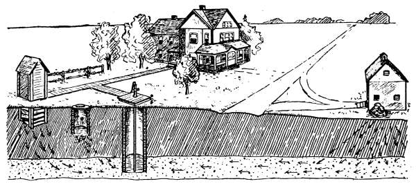
Fig. 123.—Some of the common causes of pollution of wells, and the means of
transmitting disease, such as typhoid, etc.
Pollution of Wells.
—The water from wells is often polluted
by seepage through the earth from sources that might be prevented.
Fig. 123 illustrates some of the commonest sources of
contamination that through carelessness or ignorance are located
in the neighborhood of the family water supply. The drainage
from such sources of pollution is often directed toward the well
and many cases of ill-health, disease or death are the direct
consequences of drinking its water. It may be readily observed,
in the case of the well illustrated, that the more water that is
pumped from the well, the greater will be the tendency of the
water from each of the sources of pollution to reach the well.
Another common cause of contamination of well water is that
of imperfect well curbs that allow the waste water or surface
water to flow into the well. The area about the well should be
graded to allow no standing water, and the waste should be conducted
away without permitting it to collect in standing pools.
Drainage from manured fields or other places where disintegrating
animal or vegetable matter may be absorbed by water is[135]
often the cause of temporary pollution, where the water is carried
to low-lying wells. Wells located in low areas that receive the
drainage from such places may be suspected of pollution during
the spring or early summer, when during the remainder of the
year the water is pure.
In connection with any water suspected of pollution, it is well
to remember that by boiling the water used for drinking, its
harmful properties are entirely destroyed.
Safe Distance in the Location of Wells.
—In the location of a
well, the distance of safety from sources of pollution will depend,
in a considerable measure, on the character of the soil and the
quantity and concentration of the pollution material entering
the ground water. When coming from the surface, the danger
is usually neither great nor difficult to avoid; but when cesspools
and privies in the neighborhood are sunk to a considerable depth
in porous earth, from which the supply of water is drawn, the
polluting material may reach the well undiluted. No absolute
radius of safety can be given, but certain generalizations as to
conditions may be made as to character of soil and the different
topographical conditions which surround a safe location.
In ordinary clay, or in clay mixed with pebbles and in soils of
the same general nature, through which the water circulates by
seepage, the pollution is not likely to be carried to a distance of
100 feet. Clay offers marked resistance to the passage of water,
which in beds of 3 to 5 feet thick will act as protection from pollution
from above. In sandy soils the movement of water is faster
than in clayey soils, but 150 feet may be taken as a safe distance,
unless the downward slope of the land carries the polluting material
directly to the well.
Surface Pollution of Wells.
—In dug wells, pollution from the
surface is due most commonly to careless construction and lack
of care. In Fig. 124 is indicated the most common cause of
surface pollution. The figure represents a well that has been
curbed with planks. Through lack of care the earth has sunken
at the top, permitting the surface water to flow into the well.
The top of the well is on a level with the surface and covered
with loosely laid boards which allow the waste water to drip
through the joints. Such a well, even though the source of
supply is good, will likely yield water of inferior quality.
[136]
In bored wells, polluting water may enter through the uncemented
joints of the tiling or through the joints in the staves of
wooden tubing; in drilled or driven wells, through leaky joints
or holes eaten in the iron casing by corrosive waters. By cementing
the interior surface of stone-or brick-curbed wells, by
replacing wood with cement or other impervious curbs and
by substituting new pipes for leaky iron casings, the entrance
of polluting water may be prevented.
In the average home the water supply is most commonly
taken from a well, the water from which comes through the
earth from unknown sources, and
the character of chemical salts
or organic matter the water contains
will depend on the kind of
soil through which it passes before
reaching the well.
The water from wells, whether
deep or shallow, is generally of
relatively local origin, it being absorbed
by the soil and carried to
the water stratum by percolation.
If the soil contains soluble mineral
salts the water will contain
these materials in quantities depending
on the amount of the
salts present in the earth. If
the earth contains organic matter
as pathogenic bacteria the water
is likely to contain these bacteria in like numbers as they are
present in the soil through which the water filters.
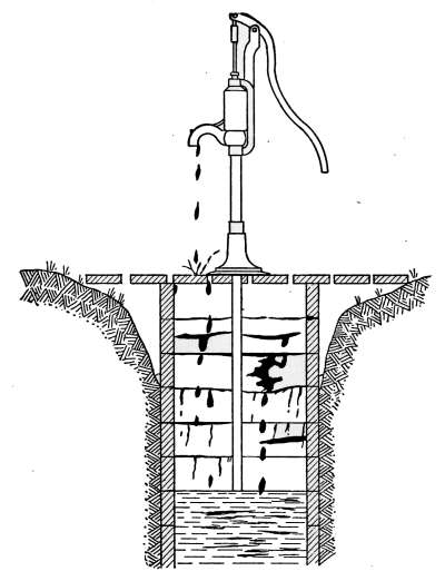
Fig. 124.—Undesirable form of
well curbing.
As usually encountered, the water-bearing earth occurs in
sheets rather than in veins or streams. The movement of the
water in such areas follows the contour of the earth and is
influenced by the varying amount of rain or snowfall and the
atmospheric pressure. The lateral movement is often only a
few inches a day and in some places no lateral movement occurs
at all. Underground streams of any kind are not usually found
except in limestone regions.
As a rule, a well is formed by digging or boring into the earth[137]
until a stratum of water-bearing soil is encountered, the type of
the well being determined by the character of the earth and the
location of the water-bearing soil. The water from the surrounding
area fills the opening to the height of the saturated soil.
As the water is pumped from the well it is replenished by the flow
from the surrounding earth. If the soil is porous, as in the case
of gravel, the water will refill the well almost as fast as it is taken
away by the pump. If the soil is dense and the inward flow is
slow, the well when once exhausted may be a long time in refilling.
Water Table.
—The upper level of the saturated portion of
the soil is known as the water table. It has a definite surface
that conforms to the broader surface irregularities. While a
definite, determinable water table appears only in porous soil,
it exists even in dense rocks. It rises and falls in wet seasons
and in drought. In exceptionally wet seasons the water table
may be at or above the surface. Under such conditions the opportunities
for the pollution of wells is much increased. In
particularly dry seasons the water table may sink below the
bottom of the well, when it is said to “go dry.” The water
table follows the surface contour in a manner depending on the
character of the soil. It is flattest in sand or gravel areas but in
clay it follows the contour of deep slopes with but slight variation.
The Devining Rod.
—The use of the devining rod, for the
purpose of locating suitable sites for wells, has been supposed by
many to be a gift possessed by a chosen few. The devining rod
is a forked branch of witch hazel, peach or other wood, which
when held in the hands and carried over the ground, is supposed
to indicate the presence of water by bending toward it.
In most cases the operators are entirely honest in their belief
and in a large proportion of trial their efforts have been successful
in locating desirable wells; but it has many times been proven
that the movement of the rod is due to an unconscious muscular
movement of the arms and hands, in places where the operator
has previously suspected the presence of water. The operator
of the devining rods is most successful in regions where water
occurs in sheets, such as often occur in gravel or pebbly clay.
The successful use of the devining rod cannot be explained by
any scientific reasons. There have been invented a number
of devining rods, claimed by their inventors to be based on[138]
scientific laws; but the government has not yet granted patents
to appliances of the kind.
Selection of a Type of Well.
—The chief factor which controls
the selection of a type of well is the nature of the water-bearing
earth, the amount of water required, the cost of construction
and the care of the resulting supply.
If a large amount of water is to be demanded of a well, to be
dug in soil through which the water percolates slowly, the well
must be large in diameter, in order that the necessary supply may
be accumulated. If the earth is porous and yields its water
readily, a small iron pipe driven into the ground may supply
the desired amount.
The character of the water-bearing material is of the greatest
importance in determining the yield of the well. In quicksand,
water is usually present in ample quantities, yet owing to the
extremely fine particles of which the quicksand is composed,
its presence as a water-bearing soil is highly undesirable.
Flowing Wells.
—Flowing wells are obtained in places where
water is confined in the earth, under sufficient pressure to lift
it to the surface, through an opening made to the water-bearing
stratum. These are known as artesian wells, from the fact that
they were first used in Artois (anciently called Artesium) in
France. In order that water may have sufficient head to lift
it to the surface, it must be confined under impervious clay or
other bed of earth, and with its source at a level considerably
higher than its point of exit. The source of supply for flowing
wells is often at a great distance. Because of the fact that
flowing wells are shut off from the surface by an impervious
layer of earth, the possibility of pollution from the surface is
effectively prevented. Any contamination of the water must
come from a distance and enter the water at its source. As
pollution rarely extends through the ground to any great lateral
distance, artesian waters are seldom polluted. The water from
artesian wells often is heavy with mineral matter and in many
cases is unfit for drinking on that account.
CONSTRUCTION OF WELLS
Wells are constructed by different methods, depending on the
character of the soil in which they are sunk. Their excavation[139]
is usually accomplished by one of three general methods: by
digging; by driving a pipe into the earth until it penetrates the
water-bearing stratum; or by boring a hole with an enlarged
earth auger, into the water-bearing soil. Artesian wells are
made by drilling with a device suitable for making a small and
very deep hole.
Dug Wells.
—In shallow wells the water seeps through the soil
from local precipitation. Deep wells are those from which the
water is brought to the surface through an impervious geologic
formation, as a bed of clay or rock, and from a depth greater
than that from which water may be lifted by atmospheric pressure.
The fact that a deep well originates from a source that
entirely differs from that of the shallow well accounts for the
difference in chemical composition which frequently exists in the
water from the two types of wells in the same neighborhood.
The form of the dug well is generally that of a cylindrical
shaft 4 feet or more in diameter and of depth depending on the
location of the water-bearing stratum. Where the character of
the soil is such that the seepage is slow and the water does not
flow into the well as fast as the pump will remove it, the well must
contain a considerable volume to supply the period of greatest
demand. Wells of this kind are commonly walled with brick or
stone to keep the sides in place and to prevent the entrance of
surface waters. The top of this curb should be brought above the
surface of the ground and should be made water-tight to prevent
the entrance of surface waters. The space around the curb,
at the surface, should be graded to drain the water away from the
well. There should be no chance for the water to collect in
pools about the well; it should be conducted away in a gutter
to the place of final disposal. The well should be covered with a
platform of concrete or planking which will allow no water to
enter from the surface.
Wells of this order are sometimes dug to great depth before
the water-bearing stratum is encountered; this may sometimes
be reached only after a great amount of expense and labor. The
historic Joseph Well, near Cairo, Egypt, is an open shaft, 18 by
24 feet in area, sunk through solid rock 160 feet.
Open Wells.
—Open wells have long been condemned as insanitary.
The familiar open well of the “Old Oaken Bucket” type[140]
is an inviting receptacle for the deposit of all manner of refuse,
which once inside remains until it is disintegrated. These wells
become the final resting place of many small animals and all
manner of creeping things, in search of water. The open top
receives wind-blown matter in the form of leaves and dust, much
of which is in the nature of polluting material.
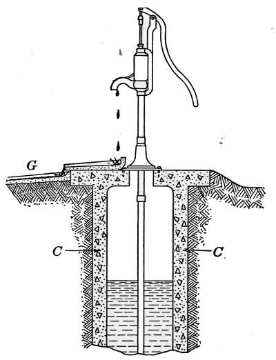
Fig. 125.—Ideal form of well curbing
with cover and drain made of
concrete.
The Ideal Well.
—In the case of a well which yields pure water,
every precaution should be taken to prevent its pollution. The
ideal form of construction is that shown in Fig. 125. In this
well, the curbing C is of heavy
concrete that extends above the
natural surface of the ground, to
prevent the entrance of surface
water, and that from seepage
through the upper stratum of the
soil. The reinforced-concrete top
forms a close joint with the curb
to prevent the entrance of waste
water and all animal life. The
pump is of iron, secured to the well
cover by bolts, set in the concrete.
The trough of concrete G conducts
the waste water from the
well to a safe distance. The earth
about the well is so graded as to
permit no water to stand in
pools.
Coverings of Concrete.
—The use of concrete for the coverings
of wells, cisterns and springs has become a recognized form of
the best construction. It is not more expensive than other good
materials and when properly executed it forms an imperishable
protection and gives a neat appearance. The spring cover in
Fig. 126, and the cistern top in Fig. 127 are illustrations of
its application.
Artesian Wells.
—Artesian wells are made by boring into
the earth until the drill reaches the artesian stratum, the internal
pressure forces the water through the opening to the
surface. They are usually small in diameter and often of
great depth. In some areas the artesian flow is found a few[141]
feet below the surface, but generally it is much deeper and 3000
feet is not an unusual depth.
The pressure and amount of flow from these wells is sometimes
sufficient to permit the water being used for the generation of
power. Small waterwheels are not uncommonly driven in this
way and the power used for the generation of electricity for
lighting and running small household appliances.
Driven Wells.
—In localities where the nature of the soil
gives opportunity, wells are made by driving a pipe to the required
depth. Wells of this character are usually made in places
where the water-bearing soil is of sand or gravel. The pipe
terminates in a sand-point such as that of Fig. 128. This sand-point
is a perforated pipe with a pointed end, that facilitates
driving. The perforations, as shown in the point P, form a
strainer which allows the water to enter the pipe but prevents
the sand from filling the opening.
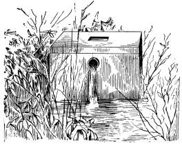
Fig. 126.—Concrete cover for
a spring.
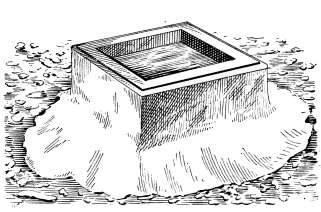
Fig. 127.—Concrete cistern top.
In the use of driven wells, the water-bearing soil must be
sufficiently open to allow the water to flow into the pipe as fast
as the pump takes it away.
Bored Wells.
—In many localities the water-bearing stratum
is of such nature as to give a ready flow of water but yet not
sufficient to permit of the use of a sand-strainer; if, however, the
opening is somewhat enlarged, the water will enter with sufficient
rapidity to supply a pump. In such cases bored wells are quite
generally used. They are made by boring a hole of the required
size with an earth auger. These wells are made of any size up
to 2 feet in diameter. They are often called tubular wells because[142]
they are lined with iron tubing or tile, to prevent the earth from
refilling the hole.
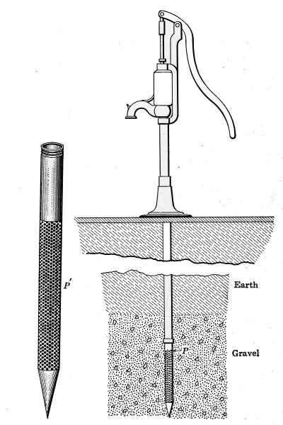
Fig. 128.—Driven well with a sand-point strainer.
Cleaning of Wells.
—Very few dug wells are so constructed as
to exclude dust and washings from the ground. It is, therefore,
necessary that they be occasionally cleaned. Accumulations
from these causes may be sufficient to hinder the entrance of the
water to the well and thus lessen its capacity.
Gases in Wells.
—One of the commonest gases found in wells is
carbon dioxide (carbonic acid gas). It may be detected by
lowering a lighted candle or lantern to the bottom. If the gas[143]
is present in dangerous quantity, the flame will be extinguished.
Death from asphyxiation due to this gas is not an uncommon
occurrence, to persons descending into wells. Before entering a
well, the test described above should be applied, as a precaution
against accident. Carbon dioxide is a colorless, odorless gas
in which a person will drown as readily as in water.
Peculiarities of Wells.
—Owing to the formation of the water-bearing
earths, from which they receive their water, many wells
possess marked peculiarities of behavior that often give rise to
local reputation because of their vagaries. These characteristics
have been classified into breathing wells, blowing wells, sucking
wells, etc. These effects are in almost every case due to variation
of barometric pressure. The ordinary level of the water in a
well is governed by the variation of rainfall, melting of snow or
the release of water by the thawing of frozen ground. It often
occurs, however, that the head of water is markedly influenced
by storms, when a rise of the level of the water occurs at the
time of low barometric pressure during the storm period. This
effect is often noticed in flowing wells. Many wells, at the approach
of storms, yield roily water to such an extent that where
the water is normally clear it may become for a period entirely
unfit to drink, because of the matter held in suspension. All
of these effects are accounted for by the varying atmospheric
pressure. At the time of high barometer, a well that ordinarily
flows freely will have to be pumped, the additional pressure of
the air holding back the water to an extent representing several
feet of head. The change of an inch in the barometric pressure
will produce slightly more than a foot in head of water. At the
time of storms, the barometer is sometimes abnormally low which
will produce a corresponding rise of water in the well. At such
time the free flow of water into a dug well, from the usual source
of supply, will cause such a rapid flow of water through the
passages in the earth as to carry with the water the sediment
that produces roily water in the well. This sediment will settle
after a while and the water will again be clear.
Breathing Well.
—Wells of this kind are most common in areas
where the water-bearing earth is of rock formation; particularly
in limestone areas, where caves and cavities are common. It
sometimes happens that in the neighborhood of a well there is a[144]
cavity in the earth of considerable volume, the only entrance to
which is through the well and that being under usual conditions
covered by water, a foot or more in depth. With such a formation
the conditions are right for a breathing well. At times of
high barometer the water is depressed and the air will flow into
the cavity through the well, when the well is said to inhale.
This inward flow of air will continue until the air pressure in the
cavity is equal to that of the outer air; and if the cavity is large
and the opening small, the inward flow of air may continue for
hours, even for days. With a fall of barometric pressure, the
air in the cavity, being at a higher pressure than the external
air, the air will flow outward and the well is said to exhale.
Freezing Wells.
—In cold climates, particularly in territory
possessing cavernous limestone deposits, breathing wells often
freeze in winter. When large volumes of frigid air are drawn into
a well, the amount of heat taken from the water is sufficient to
freeze it, and stop the supply of water. This effect is sometimes
remedied by plugging the well at the top, so that the influx
of cold air is prevented and the water does not freeze.
PUMPS
Pumps for lifting and elevating water are made of both wood
and iron in almost endless variety; but for domestic purposes
they are of two general types—the lift pump and the force pump—which
include features that are common to all. The lift pump
is intended for use in lifting water from low-head cisterns and
wells, the depth of which is not beyond the head furnished by
atmospheric pressure. The force pump performs the work of a
lift pump and in addition forces the water from the outlet at a
pressure to suit any domestic application. These pumps are
made by manufacturers in a great variety of forms, but the essential
parts are the same in all pumps intended for a single purpose.
The principle of operation is the same in all pumps of any type.
The difference in mechanism of pumps intended for the same
purpose is only in the form and arrangement of the parts.
The Lift Pump.
—The kitchen pump is an example of the lift
pump. It is universally used for household purposes where water
is to be raised from cisterns, etc., and is most commonly made[145]
throughout of cast iron. Fig. 129 illustrates one form, sometimes
called the pitcher pump, because of the slight resemblance to the
article. It frequently carries the name cistern pump from the
fact that it very generally is used to lift water from cisterns.
Although water may be raised 34 feet with a theoretically
perfect pump and with a barometric pressure of 30 inches the
actual limit is much lower. In use, 20 feet is probably about the
limit and 10 feet or less is that of common practice. A pump
that requires “priming” would raise water 15 feet with considerable
difficulty for reasons that will appear
later. In Fig. 129 is shown a sectional
view of the working parts of the
kitchen pump, the action and general
form of which apply to any lift pump.
The body of the pump contains a cylinder,
in which closely fits a piston P, containing
a valve A. At the bottom of
the cylinder is an additional valve B.
The piston and two valves constitute
the working parts of the pump. The
water is lifted through the pipe S, and is
discharged at D.
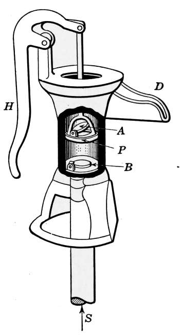
Fig. 129.—Sectional
drawing of the kitchen pump
showing its working parts.
The action of the pump is as follows:
With the piston at the bottom of the
cylinders and with no water in the pump,
the handle is forced down, which action
raised the piston. In so doing the air
below it is rarefied. The reduction of
pressure due to the rarefication of the
air allows the water to rise in the pipe S correspondingly. After
repeated strokes of the piston, the water reaches the valve B,
which raises to let it pass, but immediately closes at the end
of the upward stroke. When the space between the piston
and the valve B is filled with water, each descent of the piston
forces the water through the valve A; and when the piston is
raised, the water is lifted out through the spout.
The valve A is a loose piece of cast iron, surfaced on the lower
side to make good contact with the piston. The valve B is of
cast iron fastened to a piece of leather by a screw. The leather[146]
makes a joint with the valve-seat and furnishes an excellent
valve for its use. In order to keep the plunger P tight in the
cylinder, it is surrounded with a leather gasket. Should this
gasket become worn, as it will in time, the plunger fits loosely in
the cylinder and the pump will lift the water with difficulty,
because of the leakage around the gasket. Should the valve B
leak, the water will gradually run back into the pipe S, and the
pump when left idle will lose its “priming.” The plunger and
the valve B are the parts most likely to get out of order. If the
gasket around the piston P is very much worn, and there is no
water in cylinder, the pump will require priming before the water
can be raised. If the pump contains no water and is left standing
for a considerable time, the leather parts of the valve dry out and
shrink; when the pump is again put into use, the valves will fail
to work properly, until the leathers are again water-soaked.
Water is poured into the top of the pump until the cylinder is
filled, and as soon as the leather becomes water-soaked and fills
the cylinder, the piston will again perform its function.
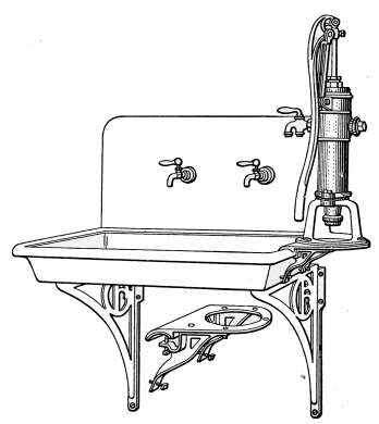
Fig. 130.—Method of attaching the house
pump to kitchen sink.
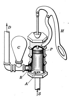
Fig. 131.—Sectional drawing
of the force pump showing its
working parts.
The Force Pump.
—The house force pump is often used in place
of the ordinary lift pump, when no other means is at hand for
providing water under pressure. It furnishes a limited means[147]
for lawn sprinkling and gives some degree of fire protection in
isolated places. It may be made a part of the kitchen sink as
shown in Fig. 130, by use of the attachment that appears in
detail under the sink. This type of pump may be used in small
water-supply plants, such as that of Fig. 143; or in connection
with small pressure tanks for the same purpose. It differs
somewhat in construction from the lift pump, in that it has no
valve in the piston and is provided with a check valve and an
air chamber for generating pressure to the discharged water.
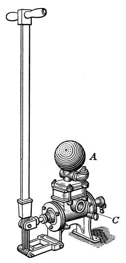
Fig. 132.—Tank
pump, commonly used
in small domestic water
supply plants.
Fig. 131 shows the essential parts of the force pump and
furnishes a means of describing its operation. All force pumps
possess the same parts and the operation
described applies with equal force to all. A
valve A is located in the bottom of the
cylinder and the check valve B prevents the
return of the water to the cylinder after it
has been forced out of the pump. The action
of the pump in raising the water is the
same as in the lift pump but when the water
fills the cylinder and the piston descends,
the water is forced through the valve B and
out at D. If the outlet pipe is slightly
smaller than the opening in the valve B, some
of the water will enter the air chamber C
and compress the air. The pressure thus
generated will immediately tend to force
the water out and in course of ordinary
pumping will send out a steady stream instead
of the intermittent flow of the lift
pump. Without the air chamber, the flow
from this pump will be a series of pulsations
that attain maximum force with each descent of the piston.
Tank Pump.
—The type of pump used with a water-supply
plant will depend entirely on the amount of water that is used.
If the supply of water to be provided is for only one or two
people the house force pump such as that of Fig. 130 will suffice;
but when a greater number of people are to be supplied, a force
pump of the type shown in Fig. 132 is quite generally used.
These pumps are made in a variety of patterns and are commonly[148]
termed tank pumps. The one shown in the Fig. 132 is a double-acting
force pump in that the cylinder receives and discharges
water at each stroke of the piston. The air chamber is located
at A. Directly beneath the air chamber is the valve chest in
which are located the valves which regulate the entrance and
discharge of the water. As used in the average domestic plant
the cylinders are 3 or 4 inches in diameter.
WELL PUMPS
The pumps intended for raising water from wells are practically
the same in construction as the house pump, except that they are
intended to deliver a greater volume of water and sometimes to
work under a different condition, as that of the deep well pump.
Well pumps have, therefore, assumed certain standard forms that
differ only in the styles of mechanism employed by different
manufacturers.
The one shown in Fig. 133 furnishes a good example of a
general-purpose iron pump which may be used either as a force
pump or a lift pump. It represents also the general construction
of a deep-well pump, where the water must be lifted from a level,
below that at which a lift pump will work.
The piston and valves are enclosed in the cylinder C, placed
below the surface of the water in the well. This cylinder also
appears in section in the small drawing, showing the details of the
valve. The operation of this pump is identical to that of the
lift pump already described, but the addition of an air chamber
gives it the necessary facility to produce a continuous flow of
water. In order to prevent the air in the air chamber from
escaping, the pump rod is surrounded with the necessary stuffing-box
which is usually packed with candle wicking to assure a good
joint. In deep wells the tube is elongated sufficiently to place
the cylinder C below the surface of the water in the well. Such
pumps are operated either by hand or by power.
Wooden Pump.
—The wooden pump of Fig. 134 furnishes a
good illustration of a type that was formerly used in great
numbers. It is an inexpensive and efficient pump made almost
entirely of wood except the cylinder which is quite generally
made of iron, lined with enamel. The valve and the piston[149]
with its valves are made of wood, but faced with leather to insure
tight joints. The piston is also provided with leather packing
to make it tight in the cylinder. The action of the pump is the
same as that already described. The wooden tube is made in
sections joined together by taper joints that are driven into place.
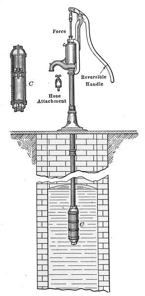
Fig. 133.—Sectional view of a well
with an iron cylinder pump, placed for
deep-well pumping.
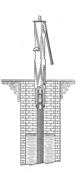
Fig. 134.—Sectional view of a
well and wooden pump for shallow
pumping.
The piece at the side of the pump is provided to drain the water
from above the piston, as a precaution against freezing during
extremely cold weather. The rod, when raised, opens an orifice[150]
that leads to the inside of the pump and permits the water to
drain into the well.
Pumps for Driven Wells.
—The method of constructing driven
wells—that of driving a pipe into the earth to the water-bearing
stratum of sand or gravel—requires a special end to prevent the
pump tube from becoming stopped. In order that the fine
material may not enter and fill the lower end of the tube, a
sand-point is used, such as that shown in Fig. 128. It is made of
perforated brass tubing and provided with a sharpened end to
facilitate driving. The perforations act as a strainer that keeps
out all but the fine particles which will pass the pump valves.
Sand-points are made with strainers of various degrees of fineness
to suit the different conditions of soils. These strainers may
in the course of time become filled with particles of the soil that
lodge in the perforations and the outside become so encrusted as
to prevent the entrance of the water. In such case, the pipe
must be pulled out of the ground and the point replaced by a new
one. In Fig. 128 is shown a driven well with the sand-point in
the water-bearing stratum. If the small particles of earth clog
the strainer the pump will “work hard” and yield only a portion
of the water the soil is capable of giving when the strainer is
clear.
Deep-well Pumps.
—The principle of operation as described
in the lift pump takes advantage of the atmospheric pressure to
lift the water above the first valve. The limiting distance to
which water can be lifted by the atmospheric pressure will depend
on the altitude and the atmospheric pressure. With the normal
atmospheric pressure at sea level, water can be lifted, theoretically,
34 feet, but in practice the limiting value is never even
approximated. The pump is usually placed within 10 of 12 feet
of the water and 20 feet is about the limit of distance. The
reason for this is because of the impossibility of keeping the joints
tight in the valve and tubing.
Where water is to be raised from a deep well, the cylinder with
its piston is placed near the water and the tube and rod, as that
of Fig. 133, connects the cylinder with the pump stock. After
the water has passed the valve in the piston, it may be readily
lifted to the pump stock. In this way water is raised from wells
of great depth.
[151]
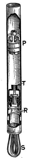
Fig. 135.
Tubular-well Cylinders.
—Tubular wells that are cased with
iron pipe are provided with a special type of pump
cylinder that admits of deep-well operation. The
casing of the well being in place, the cylinder shown
in Fig. 135 is forced down the casing to its proper
place, the spring S holding it in place until it is firmly
secured. A special seating tool is now lowered into
the casing and attaches at T to the coupling; as the
tool is turned, rubber packing R is expanded, locking
the cylinder firmly to the casing. This makes a complete
pump cylinder, which with the piston P in place
is operated as any other pump.
Chain Pumps.
—In shallow wells and other sources
of supply, where water is to be lifted only a short
distance, chain pumps have been used to a great extent,
because of their quick action. This pump, as
shown in Fig. 136, elevates the water by an endless
chain being drawn through the tube, the lower end
of which is below the surface of the water. The chain
is provided at intervals with discs or rubber or iron,
that fit the bore of the tube and form pistons which
elevate the water as they ascend. The chain passes
around a wheel in the upper part of the box and is
worked by the crank. Chain pumps are not
usually employed to elevate water a greater
height than 20 feet. They are not efficient
pumps and are not sanitary because of the
opportunity they give for admitting polluting
material to the well. Their one advantage
is that of quick action in elevating water
short distances.
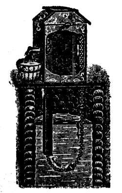
Fig. 136.—Chain
pump often used in
shallow wells.
RAIN-WATER CISTERNS
Cisterns for the storage of rain water have
been used from the time immemorial and are
constructed in a great variety of forms. For
household use they are often made in the form
of wooden or metal tanks, either elevated or
placed in the basement; the greater number, however, are of
the underground variety made of brick or concrete.
[152]
Wooden cisterns are made by manufacturers in different sizes
and shipped to the user “knocked down;” that is, they are taken
apart and the staves, bottom and hoops are shipped, packed in
small space to save space in transportation. Under some conditions
they give good service but are apt to leak at times and
require attention on that account. In damp basements they
give out the disagreeable odor of damp wood.
Tanks made of galvanized iron are much used as cisterns for
temporary use. They are inexpensive and give good service
but are short-lived. Possibility of leakage is their greatest disadvantage.
Underground cisterns are built either in the basement
or outside the house. They are quite generally made jug-shaped,
but are often constructed of concrete in square and
rectangular form. When built of brick the walls are often made
of a single course, but walls made of two courses of brick are
considered better practice. The walls and floor are made water-tight
by plastering with an inch or more of cement mortar.
When cisterns are made of concrete, the floor should be put
in 6 inches in depth and as soon after as possible the walls are put
up. In good construction the walls are 8 inches in thickness of
concrete, made of 1 part good Portland cement, 2 parts clean
sand and 4 parts crushed stone. If the cistern is square or
rectangular in form the walls should be reinforced with woven
wire or steel rods, to prevent cracking.
The curb of the cistern should extend above the surface of the
ground sufficiently to prevent surface water from entering, and
the top should be covered with a wood-lined sheet-metal cover
to prevent freezing.
Filters.
—Unfiltered cistern water is not, as a rule, fit for drinking
purposes because of pollution from dust and impurities
washed from the roof, but for bathing and laundry work filtered
rain water is greatly to be desired.
As rain water comes from the roofs of buildings, there is
washed into the cistern a considerable quantity of dust, leaves,
bird droppings and other polluting materials which contaminate
and discolor the water. This foreign matter is not injurious
for the purposes intended, but to render the water clear it should
be filtered before using.
Filters for cisterns are quite generally made of soft brick laid in[153]
cement mortar, the face of the brick being left uncovered. Fig.
137 illustrates a simple and efficient form of filter made of a
single course of brick. A space one-fourth to one-third of the
volume of the cistern is left for the filtered water. The opening
at the top of the wall must be large enough to admit a man, for
some sediment will collect even in the filtered water and the filter
must be occasionally cleaned.
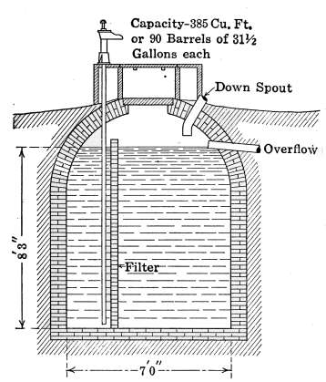
Fig. 137.—Cross-section of a brick curbed
cistern with a brick filter wall.
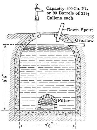
Fig. 138.—Cross-section of a concrete
cistern with a brick dome filter.
The filter shown in Fig. 138 is dome-shaped and built of brick.
The water is pumped from inside the filter and the suction of
pumping filters the water as it is used. In this case the filtering
action is accelerated by reason of the reduced pressure inside the
filter as the water is pumped. The chief disadvantage in this
form of filter is the small area exposed for the filtering action and
the relatively greater amount of work required for pumping the
water, due to the partial vacuum formed as the water is pumped.
The cistern in Fig. 139 is provided with a catch basin which
acts as a strainer for removing leaves, etc., that would stain the
water. It is made in the form of a concrete basin and partly
filled with gravel. The filter in this case is formed by a depression
in the cistern floor. A section of tile is placed on the floor,[154]
and around it is filled the filtering material of gravel and sand.
Filters of this kind are often filled with charcoal or other materials
that are expected to purify the water. They are usually inefficient
because their value as absorbers of polluting agents is
short-lived and unless the materials are frequently renewed they
are valueless and sometimes a detriment to rapid filtration.
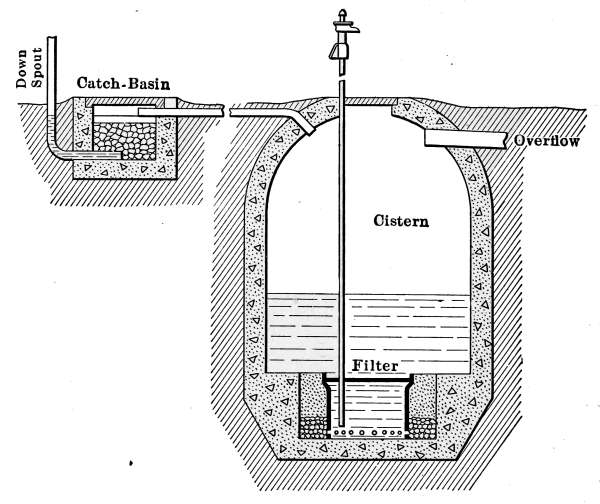
Fig. 139.—Cross-section of a concrete cistern, containing a sand filter.
THE HYDRAULIC RAM
In places where its use is possible, the hydraulic ram is a most
convenient and inexpensive means of mechanical water supply.
It is simple in construction, requires very little attention and
its cost of operation is only the labor necessary to keep it in
repair. Whenever a sufficient supply of water will admit of a
fall of a few feet, the hydraulic ram may be used as a pump for
forcing the water to a distant elevated point, where it may be
utilized for all domestic purposes. The water may be used
directly from the ram or stored in an elevated tank as a reserve
supply; or accumulated in a pressure tank, where additional
pressure is required.
The hydraulic ram has been used since 1796, when it was
invented by Joseph de Montgolfier. The principle of its operation[155]
is that of the utilization of the energy of flowing water. The
running water is made to give up a portion of its momentum to
elevate a part of the water, and transport it to a considerable
distance. If the source of supply and the fall is sufficient, almost
any amount may be elevated and carried to a great distance.
Large rams are sometimes used as a means of water supply for
small towns. In the use of the double-acting ram, one source
of water may be used to operate the ram and water from an
entirely different source may be delivered. It sometimes
happens that a muddy stream and a clear spring are so located,
that the water of the stream can be utilized to furnish the energy
for conveying the spring water to a point where it is desired for
use. This is accomplished by the double-acting ram in a most
efficient manner.
Single-acting Hydraulic Ram.
—Fig. 140 represents the installation
of a single-acting hydraulic ram, placed to take water from
a spring E, and deliver it to an elevated tank at the house on the
hill.
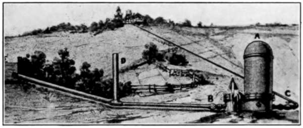
Fig. 140.—Hydraulic ram driven by the water from a spring.
In case the ram must be located at a considerable distance
from the spring in order to attain the required fall, a standpipe
D—slightly larger than the supply pipe—is used to take advantage
of the full force of the water. In long pipes, the friction
of the flowing water absorbs a considerable amount of the energy
of flow and a standpipe, located as indicated at D, in the picture,
will assure the full force of the flowing water in the ram.
The ram is commonly placed in an underground pit as protection
from freezing during cold weather, and a drain from the
bottom of the pit conducts the waste water away. The supply[156]
pipe or drive pipe B and delivery pipe C are buried underground
below the frost line as a protection from freezing.
In Fig. 141 a sectional view of the ram shows all of the working
parts. The air chamber G is shown partly filled with water; the
impetus valve D is that part of the ram which checks the flow of
the running water and forces a part of it through the valve E, at
the bottom of the air chamber.
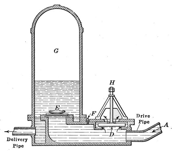
Fig. 141.—Cross-section of a single-acting hydraulic ram.
When inactive the valve D stands open and as the water enters
from the pipe A, it flows through the valve to the waste pipe but
as soon as the full force of the water bears on the valve it will
suddenly close. This sudden stop of the flowing water will lift
the valve E, and the energy of flow, due to its sudden stopping,
will force some of the water into the chamber G. As this action
occurs the upward pressure against the valve D is released and
it reopens but immediately closes again as the water begins to
flow. This process is kept up, each closure of the valve sending
a little water into the air chamber. As the water gradually fills
the air chamber, it is subjected to the same action as was described
in the pressure tank, the air above the surface being compressed
and the pressure developed in the space G forces the water
out through the delivery pipe where it attains a force that is a
factor of the height of the original fall.
The air in the chamber G, is subject to the same conditions[157]
of loss as that of the pressure tank, and to be assured of a supply
to give pressure to the water, some air must be carried into the
chamber with the water. For this purpose the valve F provided.
After the chamber is partially filled, there occurs a reaction
in the flow of water at each closure of the valve, which
causes a little air to be drawn in through the valve F with each
impulse. This air bubbles up through the water and enters
the chamber where it assures an elastic cushion for closing the
valve E.
The flow of water from the supply pipe is regulated at H by a
nut on the stem of the impetus valve which permits its regulation.
Closing the valve slightly causes a less supply of water to be
delivered; opening the valve wider gives a greater supply.
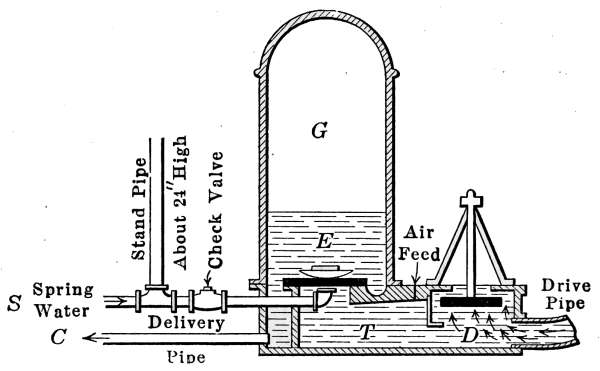
Fig. 142.—Sectional view of a double-acting hydraulic ram.
The Double-acting Hydraulic Ram.
—The diagram of Fig. 142
illustrates the working principle of the double-acting hydraulic
ram mentioned above; where the water from a muddy stream is
used to drive the ram and that from a separate source, as a spring
is delivered.
The construction of the double-acting ram is similar to the
single-acting ram, but a separate pipe S discharges spring water
directly below the valve which acts just as though it had entered
at the drive pipe. The ram in this case is receiving water from
the drive pipe D, which operates the valve and furnishes power
for elevating the spring water. The spring water enters the
ram through the pipe S, to keep the space T filled, directly under
the valve. The water which enters the air chamber is, therefore,
only that from the spring.
A standpipe is arranged as shown in the figure, with a check[158]
valve to prevent the water in the ram from being forced back
into the spring water pipe after entering the ram.
DOMESTIC WATER-SUPPLY PLANTS
Until recent years, no thought was given to private water-supply
plants, in any except the more pretentious residences.
It was formerly supposed that the cost of machinery and installation
of such plants prohibited the use of a water system in the
average home. As an item of expense in building, a satisfactory
water-supply system may be installed at a lower cost than is
paid for plumbing and bathroom fixtures.
In recent years much attention has been given to the design
of small water-supply plants for isolated homes, such as are
required for suburban and rural dwellings, with the result that
the necessary apparatus to suit any conditions may be obtained
of any enterprising dealer.
The degree of completeness with which the plant is to be
arranged will depend on the funds to be expended, but in the most
modest dwelling some form of water-supply plant is possible.
Where opportunity is given to make the plant complete, its
appointments of construction may be elaborated to almost any
extent. A suburban or country residence may be made as
perfect in point of toilet, kitchen and laundry conveniences, as
where city water and sewer service are available. The water-supply
plant may be operated by hand or by power, and if so
desired may be made completely automatic in action.
Gravity Water-supply Plant.
—In point of simplicity, the plant
shown in Fig. 143 represents a water system that answers every
purpose of a cottage and yet is only an elevated tank for storage
of water, combined with a house force pump. The tank in this
case may be made of wood or metal and is open at the top. The
water is sent into the tank by the pump, and gravity furnishes
the force for carrying it to the fixtures in the kitchen and
bathroom.
In using a tank of the kind shown in the drawing, provision
should be made for the possibility of leakage. This is arranged
for by having the tank set in a shallow pan, so constructed that
in case of accident the water may be carried away without doing[159]
damage. This type of plant is not usually employed in cold
climates, unless some provision is made to prevent the water in
the tank from freezing. Tanks of this kind are sometimes used
in cold climates but a much more desirable plant for the purpose
is described below. In Fig. 143 the water from the cistern W is
raised by the pump P, which also forces it into the tank above
the kitchen. The gravitational force given the water, because
of its elevated position is all that is necessary to carry the water
to the fixtures in the bathroom and kitchen sink. As shown in
the drawing, it furnishes a complete water system that will
perform all of the requirements of water distribution for a small
family.
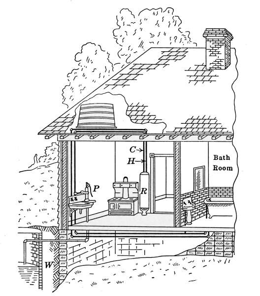
Fig. 143.—Sectional view of a cottage containing a simple gravity water-supply
plant.
The pipes from the range boiler are attached to the water
heater, which forms a part of the kitchen range as explained on
pages 116 to 120. It receives the supply of cold water directly
from the tank through the pipe marked C, and the hot water
from the range boiler is supplied through the pipe H. Cold water
is also taken from the tank directly to each of the cold-water taps.
[160]
The pump P is a house pump, such as is shown in Fig. 130.
It is a small force pump, designed to suit the conditions of
domestic use and is made to send water into the sink or into the
supply tank as desired.
Pressure-tank System of Water Supply.
—The water-supply
plant shown in Fig. 144 is another simple construction, somewhat
more elaborate than the last, so arranged that the danger of
freezing is practically eliminated. This is a simple pressure-tank
system in which a tightly built metal water tank takes the
place of the elevated tank of the previous figure, and a tank
pump is used for lifting and giving pressure to the water. It is
a more complete plant than the first and intended to accommodate
a larger dwelling. The drawing shows all of the fixtures
and connecting pipes that are required in the average home.
It shows all of the appliances for connecting the pressure tank
and range boiler with the wash trays in the basement, with all
of the fixtures in the bathroom and with the fixtures in the
kitchen sink. The range boiler is the same as those previously
described and connected to the heater in an identical manner.
The original source of supply in this case is a cistern, sunk
below the basement floor. The water is lifted from the cistern
by the pump and forced into the pressure tank through a pipe
near the bottom where it furnishes the supply for the house.
The pressure tank may be of any size to suit the requirements
of the house and may be placed in either a vertical or horizontal
position. It is sometimes galvanized, as a precaution against
rust, but this is not a necessary requirement. The pipe which
conveys the water from the pump connects with the tank near
the bottom. As the water enters, the contained air above its
surface is compressed into smaller and smaller space. The
pressure that is developed by the compressed air furnishes
the force by which the water is driven out of the tank and
through the distributing pipes to the various parts of the
system.
If the air in the tank when empty is compressed to one-half
its original volume, then the gage pressure will be about 15
pounds to the square inch; if the air is compressed to one-third
its original volume, that is, when the tank is two-thirds full of
water, the gage pressure will be about 30 pounds to the square[161]
inch, which is enough to supply water at any point of a two-story
building with ample force. By pumping more water into the
tank, a pressure of 50 or 60 pounds may be obtained without
difficulty; but 40 pounds is generally sufficient for all the demands
of a house plant. This is an application of the Boyle’s law which
as stated in text books of physics is: “The temperature remaining
the same, the pressure on confined gas varies inversely as its
volume.” As the volume of such a confined body of gas is made
smaller, the pressure increases in like ratio. The desired pressures
are easily attained with a hand force pump such as is shown
in the drawing.
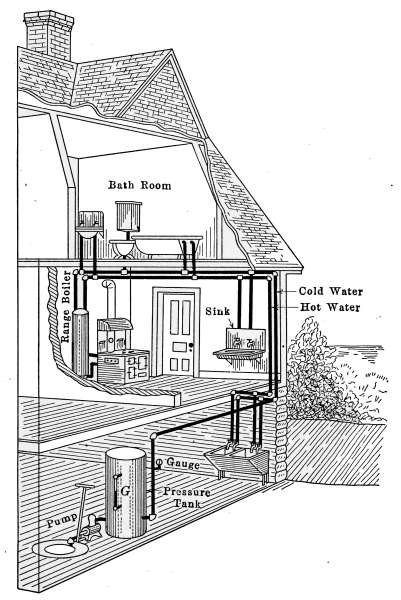
Fig. 144.—The pressure-tank system of water supply as it appears in a dwelling.
The gage-glass G on the side of the tank is intended to show[162]
the height of the water in the tank at any time, and the pressure
gage attached to the supply pipe shows the amount of pressure
sustained by the water.
The Pressure Tank.
—The water leaves the tank by a pipe
attached near the bottom and branches to supply each fixture,
to which the water is to be conducted. In the drawing, the pipe
may be traced from the point where it leaves the tank to the various
fixtures. The cold-water pipe terminates at the range boiler,
for at that point the hot-water system begins. The range boiler
is connected by two pipes to the water heater in the kitchen
range. The water heater is a part of the fire-box of the kitchen
range and so long as the fire is kept
burning, water is heated and stored
in the range boiler. Where the
house is furnace-heated, the furnace
fire is sometimes utilized for heating
the water by use of a coil of pipe
above the fire and which may take
the place of the range heater. Various
other means are also employed
for heating the water as described
under range boilers. In Fig. 145 is
shown a nearer view of a pressure
tank with the pump attached. The
pump is in this case identical in its
action to the one shown in Fig. 132,
but differs slightly in mechanical design.
The drawing shows the gage-glass
G, for indicating the height of
water; the pressure gage P, which indicates the pressure to
which the water is subjected; the attachment of the supply
pipe S, and the delivery pipe D. The water tap T is provided
to draw off the water when the tank is to be emptied.
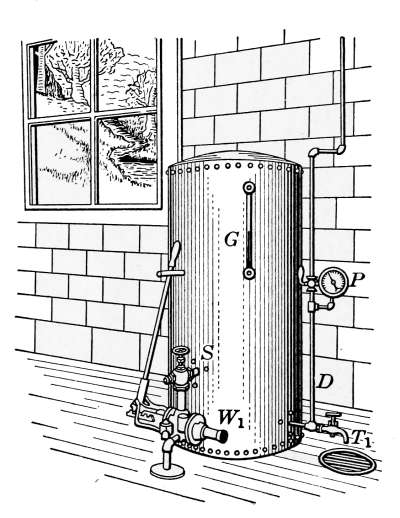
Fig. 145.—The pressure tank
complete, with the pump and
gages as used for domestic water
supply.
In operation, the air in the pressure tank furnishes the force
which sends the water through the pipes to the various points,
and forces it through the taps at the desired rate. If for any
reason the air in the tank escapes, the propelling force is destroyed.
This may occur by reason of absorption of the air by
the water, due to the pressure to which it is subjected; or to[163]
small air leaks that may develop in the joints, which allow the
air to escape. To overcome the possibility of these occurrences,
arrangement is made whereby air may be pumped into the tank
by the same pump as that which supplies the water. In this
way, the air is introduced with the water, which bubbles up
through it to the surface. If at any time the pressure in the tank
is lost, it may be replaced by pumping air alone into the tank.
Power Water-supply Plants.
—Where the pump is expected
to furnish water to any considerable amount beyond that for
household use, it is desirable that the plant be power-driven.
If the work of watering stock, lawn sprinkling, etc., is intended,
the tank and pump must be enlarged to suit the desired amount
of water, and a gasoline engine, windmill or electric motor will
be used for power. Where local conditions will permit, a
hydraulic ram may be substituted for the pump and the pressure
tank used for additional pressure and storage.
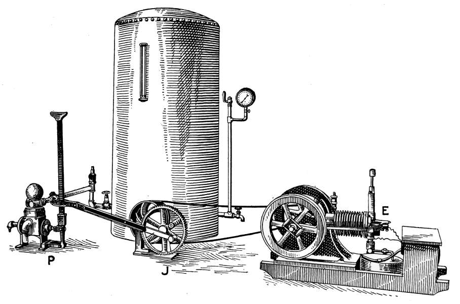
Fig. 146.—Tank pump operated by a small gasoline engine.
Fig. 146 shows a plant in which the pump is driven by a
gasoline engine. In the figure, the engine E is shown connected
by a belt to a speed-reducing device or “jack,” marked J. The
object of this machine is to reduce the speed of rotation and
charge it to the required motion for operating the pump. The[164]
jack is connected to the pump by a rod attached to a large gear,
so as to produce the desired crank motion; and the opposite end
of the rod is attached to the pump handle. The rod may be
detached at any time and the pump worked by hand.
Electric Power Water Supply.
—Fig. 147 shows another type
of power plant in which an electric motor operates the pump.
In this style of plant, the pulley on the electric motor M is
connected by a belt to the large wheel W, from which the crank
motion is secured for driving the pump P. This machine is
provided with an automatic starting and stopping device, which
automatically controls the supply
of water in the system. Whenever
the pressure in the tank falls to a
certain point, the change of pressure
produced on the diaphram valve A
starts the motor, and the pump sends
water into the tank until the pressure
in the tank again reaches the amount
for which the valve is set, at which
time the valve disconnects the electric
contact to the motor and the
pump stops working.
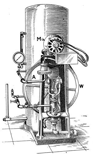
Fig. 147.—Pressure tank supplied
by an electrically driven pump.
Wind-power Water Supply.
—In
Fig. 148 is shown a larger and more
complete plant than the former, in
which a windmill furnishes the power
for pumping and a large underground
tank is utilized for the main
supply of water. The tank marked,
Well Water Pressure Tank, in this
case is so placed that the end is exposed in the well curb, where
the height of the water may be observed at any time. The
pump is operated as any other of its kind, but is provided with
an automatic pressure cylinder, which controls the operation of
the mill through the rise and fall of the water in the tank. At
any time the water in the tank falls to a certain point, the
pump is thrown into gear by the pressure cylinder, and the
water is pumped into the tank until a definite height is reached;
at this point the pump is automatically thrown out of gear and[165]
remains inactive until an additional supply of water is required.
The plant is therefore automatic in its action and requires only
that the mill be kept oiled and in running order.
As shown in the drawing, the large tank receives its supply of
water from the well and aside from providing a reserve supply
furnishes power for pumping cistern water. The water from
the large tank is piped into the house for use as required, and from
the same pipe is taken a hydrant for lawn sprinkling; in addition,
this water is piped to the barn where it is used for watering stock.
A branch of the same pipe is intended to operate a water lift,
which in turn furnishes the house with soft water from the rain-water
cistern for bathing, laundry, and kitchen purposes.
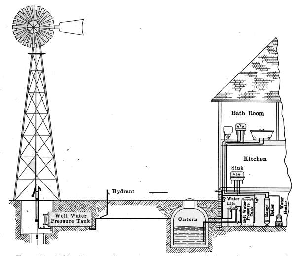
Fig. 148.—This diagram shows the arrangement of domestic water-supply
apparatus, in which a windmill furnishes the pressure necessary for operating
the entire plant.
The Water Lift.
—The water lift is a combined water engine
and pump, the motive power for which is the pressure from the[166]
well-water tank. The soft water, pumped by the water lift,
is stored in the smaller pressure tank marked Soft Water Pressure
Tank in the drawing, and furnishes a supply for the purposes
mentioned. The water lift is so constructed that when the
pressure in the soft-water tank equals the pressure in the well-water
tank, the lift will stop working and will not start again
until water has been drawn from the taps. Whenever water is
drawn from any part of the system, the pressure will be reduced
and the lift will immediately begin pumping more water and will
continue until the pressure of the two tanks are the same. The
system is entirely automatic, each part depending on the power
originally supplied by the windmill. The plant could be just as
successfully operated by substituting a gasoline engine or other
source of power for the windmill. The machinery for such a
plant is not at all complicated neither is it difficult to manage,
yet it is complete in every particular and furnishes an almost
ideal arrangement for a country or suburban home.
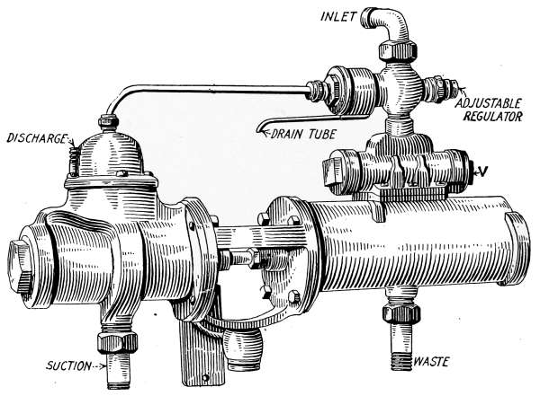
Fig. 149.—The water lift.
In order to be assured of a supply of water over periods of
atmospheric quiet, the well-water tank must be sufficiently
large to supply water for 3 or 4 days; but in case of emergency
water may be pumped by hand.
A nearer view of the water lift is shown in Fig. 149. In the[167]
figure, the right-hand cylinder with its valve V is the water
engine which furnishes the power for operating the pump, enclosed
in the left-hand cylinder. The water pressure of the
main supply furnishes the energy which drives the engine, the
piston rod of which is attached to the pump piston. The engine
receives its supply of water through the pipe marked Inlet and
the waste water is discharged to the sewer by the waste pipe on
the opposite side of the cylinder. The operation of the lift is governed
by an automatic regulator which so controls the engine
that it starts pumping whenever the pressure in the system falls
to a certain point. The regulator marked Adjustable Regulator
in the drawing may be adjusted to suit the water pressure desired
in the distributing system.
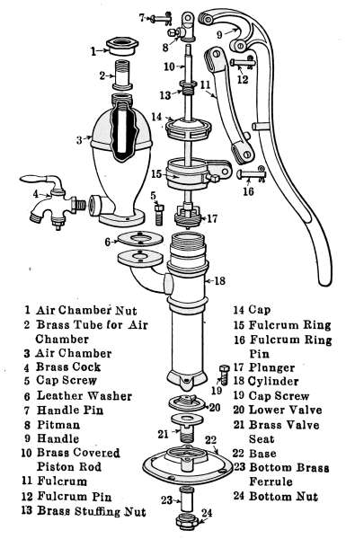
Fig. 150.—The terms by which the parts of a force pump are designated.
[168]
CHAPTER VIII
SEWAGE DISPOSAL
The disposal of sewage, in a convenient and sanitary manner
is a problem of serious importance in the equipment of isolated
dwellings with modern household conveniences. The manner of
heating, lighting and of water supply are questions of selection
among a number of established systems, but the problem of sewage
disposal must in a great measure be determined by local
conditions. Unless the natural surroundings are such as will
permit sewage to be emptied directly into a stream of considerable
volume, the problem of its safe disposal becomes one of serious
importance.
Sewage is understood to mean the fluid waste from the kitchen,
toilet and laundry and has nothing whatever to do with garbage.
Sewage disposal has to do with conducting away the house
waste and disposing of it in a sanitary manner. Sewage disposal
does not necessarily have anything to do with sewage purification;
although a sewage disposal plant may be so constructed as
to discharge a purified effluent, it usually is understood to have
to do alone with its disposal in a manner that does not offend
the aesthetic sense. A simple sewage plant is anything that
will take the sewage away from the house in such a way as to
produce no unsightly accumulations that will decay and produce
offensive odors.
A sewage purification plant is one in which the raw sewage from
the house drain is first liquefied, after which the liquid is passed
into a filter where it undergoes a process of bacterial disintegration
and the organic matter reduced to the inorganic state, where
no further change is possible. The water which flows from such
a filter is clear and sparkling, and is often taken for spring water.
The degree of purification given to the sewage will depend on
the style of filter and the length of time necessary for the water
to pass through it.
[169]
Sewage is composed of organic matter in a fluid or part fluid
condition, contained in a large volume of water. It is not usually
the dark, heavy, foul-smelling fluid that is imagined by many,
but a turbid liquid possessing only a few of the qualities usually
ascribed to sewage. Under favorable conditions practically
all of the organic matter will be readily dissolved and the sewage
will become entirely liquid.
As a liquid, the raw sewage is in the most favorable condition
for rapid decay and if left standing in the air it soon develops
properties that render it highly objectionable.
The decay of all organic matter is a process of disintegration
that ultimately ends in the elements from which it came. In the
disposal of sewage, the aim is to permit this disintegration to
take place under conditions that will be least offensive to the
aesthetic sensibilities, and in some cases to render it free from
harmful properties should there be present the bacteria of communicable
disease.
The successful disposal of sewage from cities is accomplished
under a great variety of conditions. It is much easier to arrange
for sewage purification on a large scale than in a small way.
The reason for this is that in the care of a city the sewage-disposal
plant is under the supervision of a competent person, whose
business it is to see that the conditions are kept at the highest
efficiency. Private plants are left almost entirely without care,
until they fail from causes that are usually preventable. Sewage
may be successfully purified under a great many conditions,
but no type of plant has as yet proven itself successful that does
not receive intelligent attention.
The most successful of small sewage disposal plant is the
septic tank system alone or in connection with an adequate
form of bacterial filter. Cesspools are not to be countenanced
by people of intelligence. The cesspool has been so universally
condemned by authorities on sanitation, that all intelligent
people look upon it as a thing filthy beyond description. Although
the septic tank is little more than an improved cesspool,
the condition under which it acts is entirely different
from that which takes place in the latter and with care
and watchfulness, it may be made to work to a degree of
perfection that is surprising. The one great cause of the[170]
failure of small sewage-disposal plants is the lack of proper
care.
The process of sewage purification as now practised in the
most successful plants is largely mechanical, but bacterial action
plays a part of great importance in the completion of
the process. It consists of two stages: the tank treatment,
in which the sewage is liquefied; and the process of filtration
where the liquefied sewage—commonly called the effluent—from
the septic tank undergoes a process of filtration and
bacterial purification.
The Septic Tank.
—The septic tank alone, as used for sewage
disposal, is often termed a sewage purifying plant, when in reality
it is only intended to change the sewage into a form in which it can
be readily carried away. The word septic means putrifying,
and when applied to sewage disposal it furnishes a convenient
term but has nothing to do with purification. The septic tank
furnishes only the first stage of the purifying process, and although
its effluent may be clear and possess little odor, it is
nevertheless unpurified. The septic tank discharges an effluent
of more or less completely digested sewage, instead, as in the
cesspool, of permitting it to remain a constantly festering mass,
to be slowly absorbed by the earth.
The sewage is first collected in a tank of sufficient size to contain
the discharge from the house for 24 hours. In the process
of digestion which the sewage undergoes while in the tank, it is
rendered almost entirely liquid; at the same time it is acted upon
by the bacteria that are developed, and that tend to reduce the
sewage to its elemental form. The effluent liquid which passes out
of the tank is almost colorless and possesses relatively little odor.
The tendency of the change which takes place in the tank is
to nitrify the organic matter but under ordinary conditions the
action is not fully complete. The effluent sometimes undergoes
but little change except to be reduced to a liquid. If the effluent
is now allowed to flow into a ditch where it will stand in pools,
further putrification will take place with its resulting annoyance.
In case the septic tank is to be used alone, the effluent should be
conducted to a stream for final disposal. A septic tank must be
built to accommodate a certain number of people and of sufficient
size to take care of the entering sewage. The action which goes[171]
on in the tank will render the contents almost entirely fluid, and
under good conditions the sewage will be completely digested.
When working properly, a thick scum will form on the surface,
through which filters the gases that are liberated in the process
of disintegration. The formation of the scum is an indication
that the filter is doing its best work. Should the tank be required
to take care of more sewage than it can conveniently
handle, the scum will not form and the effluent will be turbid
because of the undigested matter.
The change that takes place in the sewage while it remains in
the tank is first that of being liquefied and then disintegrated by
bacterial action. That such a change does take place is evidenced
by the residue that is found in the tank in the process of
cleaning. This is a black granular substance, composed mostly
of humus and commonly known as sludge. The amount of
accumulated sludge is relatively small, and the operation of cleaning
is not necessary more than twice a year and is not the disagreeable
task one might suppose.
The Septic Tank With a Sand-bed Filter.
—In places where
the use of the septic tank alone is not possible, it sometimes
happens that the natural conditions are such as will permit the
effluent to be drained directly into the soil. With such a condition,
the effluent goes into a filter bed composed of gravel or
other loose material, where it undergoes still further bacterial
action and if the process is complete, the water which comes
from the filter bed is clear and odorless. Under good conditions
it is clear sparkling water and contains but a small amount of
impurities.
Septic tanks are made in many forms but that illustrated in
Figs. 151 and 152 is commonly used. In Fig. 151 the tank is
shown in position to receive the sewage from the house drain,
where it is to undergo the first treatment and then to be conducted
to a filter bed made of porous tile, set in loose soil. The
tank is shown in detail in Fig. 152. It is a cemented brick
cistern with an opening to the surface that contains a double
cover as a protection during cold weather. A brick partition
divides the tank into spaces G and H, that contain volumes that
are to each other as 1 to 2. The tank is of such size as will hold
a volume of sewage equal to 24 hours’ use; that is, it is expected[172]
that any portion of sewage will remain in the tank for that length
of time. The sewage enters at A, in such a way as will give the
least disturbance of the liquid of the tank. An opening C allows
the liquid to pass from H into G, where any additional sewage
entering H will displace an equal amount in G, which will pass
out at B to the filter bed. The partition D is high enough so
that the scum that forms on the surface will not pass directly
into the space G. The entrance and exit pipes are made of
vitrified sewer tile with the openings below the surface.
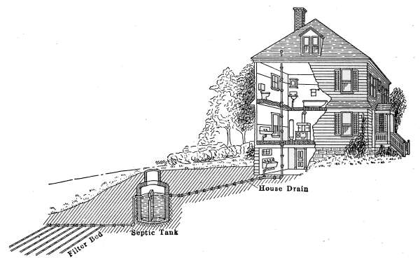
Fig. 151.—Sectional view of a septic tank, connected with a sand-bed filter; for
the disposal of sewage from a residence.
As the sewage enters the tank A, a considerable portion will
sink to the bottom, while some will float to the top where a thick
scum will gather. By far the greatest portion of solids will be
readily dissolved in the water and the remainder will be still
further reduced to liquid form by bacterial solution. The process
of disintegration that goes on evolves a considerable amount of
carbon dioxide and ammonia which filters through the scum.
The process that now goes on in the tank is that of liquefying the
organic matter and changing it from organic to the inorganic
state.
The bacteriologist recognizes in the process of sewage disintegration
the work of two classes of bacteria, the aerobic or those[173]
bacteria that work by reason of air and do their work only in its
presence and the anaerobic or those that work in the absence of
air. In the action of the sewage-disposal plant both kinds of
bacteria are at work. If, in the final stage where the sewage
passes into the filter, air can be carried into the earth the action
will be hastened.
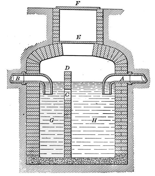
Fig. 152.—Section of the septic tank in Fig. 151 showing details of construction.
It is evident that, since the sewage entering the tank is
almost entirely dissolved, under ideal action this system would
give very little trouble, but actually as the sewage enters the
tank the disturbance caused by the incoming water forces some
of the undigested matter into the outlet and being carried into
the filter bed it will be deposited at the first opportunity. This
will cause the filter bed to fill up with undigested sewage at the
point nearest the entrance, and in course of time it will stop the
pipe because of this accumulation.
To avoid such an occurrence, tanks have been built in which an
automatic siphon discharges the effluent whenever a certain
quantity has collected. Such a tank is shown in Fig. 153. With
this arrangement, the sewage enters the first tank at A, and passes[174]
into the second tank at B. At S is shown an automatic siphon,
so made that when the effluent has collected to the height of the
water line, the siphon automatically discharges the contents of
the tank. This is known as a dosage tank because periodically
a dose of the effluent is discharged into the filter bed. The
volume discharged is sufficient to fill the greater portion of the
bed, and force out the air in the loose soil. As the water filters
from the bed the air is drawn in to take its place and gives the
bacteria which work in the presence of air an opportunity to
do their work. The work done by this filter bed is first to filter
out any suspended matter carried in the effluent which will lodge
on the surface of the filter material and then to undergo the slow
process of integration, and to permit the oxidation of the dissolved
sewage. If this matter is deposited faster than it disintegrates
then the filter will fill up and finally refuse to work.
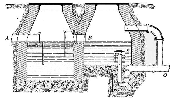
Fig. 153.—Sectional view of a two-chamber septic tank with a dosage siphon.
The Septic Tank and Anaerobic Filter.
—In places where the
use of the simple septic tank is not possible and where the character
of the soil will not permit of a natural sand-bed filter, an
anaerobic filter may be constructed through which to pass the
effluent from the septic tank.
The anaerobic filter is one in which anaerobic bacterial action
is given opportunity to reduce the organic matter in the sewage
to its elemental condition. The filter may be constructed in any
form that will permit the process of filtration to be carried out
in a way that will afford good anaerobic action. The extent to[175]
which the purification is to be carried will determine the form and
size of the filter.
In Fig. 154 is shown such a plant, where a combined septic tank
and anaerobic filter discharges its effluent into a filter ditch in
which the purifying process is continued through a bed of gravel
of any desired length. The figure illustrates a plant that was
designed for a country residence. The septic tank and anaerobic
filter are located relatively as shown in the drawing, the filter
ditch following the course of a roadway. The water is finally
discharged into a little stream, where it mingles with the water
from a spring, and flows through a meadow.

Fig. 154.—Sectional view of a septic tank combined with an anærobic filter; together
with the details of construction and plan of arrangement.
The septic tank in Fig. 154 is quite similar in construction to the
others described except that a section of sewer tile takes the place
of the brick wall between the two parts of the tank. The opening
O, through which the effluent is discharged, is located a little
above the center of the tank.
The anaerobic filter is a tank, rectangular in cross-section,
made with brick walls and cemented on the inside. The effluent
from the septic tank enters the anaerobic filter in a chamber, that
is separated from the main tank by a wooden grating against
which rests the filter material. As indicated in the drawing, the
bottom is filled with coarse material; stones or broken tiles[176]
about 4 inches in diameter. Above this is a layer of material
about 2 inches in diameter and above that another layer of 1-inch
material; the top is made of gravel. This forms the anaerobic
filter, in which takes place the bacterial action away from the
presence of air. The interspaces in the filter material allows the
effluent from the septic tank to seep through and deposit the
particles of matter held in suspension. The arrangement is
such as is best suited to the anaerobic action. Here, shut away
from the light and air, the organic matter in the effluent undergoes
disintegration just as would happen in the earth.
It is evident that some of the matter that should remain in the
septic tank and be removed as sludge will be carried into the
anaerobic filter. This will, of course, form an insoluble deposit
that will accumulate and in the course of time the filter will become
clogged. It should be expected that such a filter will ultimately
need renewing, for this reason the top is made of a slab of
reinforced concrete that may be raised to allow the removal and
refilling of the filter material.
The automatic siphon discharges the water from the chamber
S, whenever it fills. The discharged water from the siphon is
conducted into a drain tile, placed in a ditch filled with gravel or
other loose material, which serves as an additional filter and in
which the water undergoes a still further purification. This filter
ditch is constructed as indicated in longitudinal section. The
water from the siphon enters the tile C and seeping through the
filling is drained away in the tile shown at D.
The tiles are not set close together, but the joints are left open
and covered by pieces of broken tile as shown in H. This is to
prevent the filter material from entering the tile and thus stopping
the ready flow of the water.
The filter ditch of the plant will be constructed according to
the contour of the ground and will follow the natural drainage.
The course of the ditch—if it is desired to use one—will accommodate
itself to the character of the ground. The final discharge
of the water will be determined by the natural drainage.
That a plant of this kind will work perfectly when new is
is beyond a doubt but that it will continue indefinitely to give
perfect satisfaction is not reasonable to expect. The septic tank
will require cleaning, probably once a year. The anaerobic filter[177]
will require renewing at intervals, depending on the amount of
sewage the filter is required to take care of and the rate at which
the plant is worked, probably once in 4 or 5 years. If the septic
tank is of insufficient size to readily digest the sewage, the accumulation
of sludge in the anaerobic filter will be greater than
should occur.
It would be only reasonable to suppose that the siphon will
sometimes refuse to discharge.
Even though it is an automatic
siphon, circumstances may cause it
at times to fail to act. For this
reason the manhole is placed so
that the siphon may be inspected
and repaired, should it be necessary.
It must not be supposed that once
such a plant is in place that all of
the work is over. The success of
a good sewage-disposal plant of this
kind demands eternal vigilance.
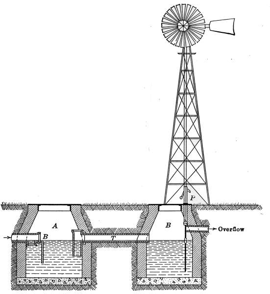
Fig. 155.—Septic tank with a settling basin and windmill pump.
In the level areas where the
possibilities of natural drainage is
not good, it sometimes occurs that
plants such as those described are
not permissible. To overcome such conditions the plant in
Fig. 155 represents an installation where the effluent is carried
several hundred feet through a drain tile before it is finally discharged
into an outlet. This plant is made up of two separate
tanks, the first acting as a septic tank, while the second tank is
a settling chamber. The water from the second chamber is[178]
pumped by windmill power and discharged into a drain tile at
the required height through which it is carried to the place of
final deposit.
Limit of Efficiency.
—Much that has been written on the
subject conveys the impression that the septic tank alone, used
under various conditions, will eliminate disease germs and all
offending features of sewage and render it a pure water with a
small amount of residue remaining in the tank. That such is
not the case is all too evident to many who have constructed
plants expecting perfect results and have attained only partial
success.
It is not reasonable that a plant giving satisfaction under the
usual conditions could accomplish its purpose under stress of
work. It is quite evident that the amount of sewage from any
source cannot be constant. It is equally evident that the effluent
from the plant cannot always be the same; but with reasonable
limits of variation, a suitably designed tank ought to take care of
the sewage from a house at all times and discharge an effluent
that is reasonably clear and without offending odor.
It should be kept in mind that, as commonly used, the chief
office of the septic tank is to do away with the things that offend
the senses, and not to make an effluent that might serve as drinking
water. It must also be kept in mind that if the disease germs
enter the plant because of sickness in the house that there is
every possibility that the germs will be in the discharged water.
The plant must be located as is directed by the natural surroundings
but the drainage must be away from buildings and
particularly from wells.
Small sewage plants are reasonably efficient and add immensely
to the comfort and healthful conditions of the home. They are
not perfect in their action but there is excellent reason to believe
that the plant of ideal construction will yet be attained.
In a flat country where drainage is difficult, the form of plant
must be modified to suit the prevailing conditions but some form
of working plant can always be devised. Small plants do not
give so efficient results as those of large size but they do very
acceptable work. To do good service they must receive attention
but the actual amount of labor they demand is small. Small
sewage-disposal plants are not expensive nor difficult to construct,[179]
and for the amount of labor and money expended they give
returns that cannot be estimated.
In determining the character of plant to be constructed, in
any particular place, local conditions will in a great measure
decide the type to be used. The degree of purity to which it
will be necessary to reduce the effluent will depend on the location
of the plant and the means of final disposal. If the effluent
can be run into a stream of sufficient volume, the septic tank alone
will probably answer the purpose.
The septic tank reduces sewage to a liquid form which has some
odor. It may be carried away in an open ditch which has good
flow, but if allowed to collect in pools it will undergo further
putrescence and be objectionable.
It may be possible to use a small creek for final disposal but
one in which the effluent from a septic tank alone would be objectionable.
In such a case the use of the septic tank combined with
an anaerobic filter would probably give a permissible degree of
purity.
With a plant composed of a septic tank and anaerobic filter,
sewage is rendered almost free from odor and the effluent will
not undergo further putrescence when collected in pools.
In many cases it is desired to purify the effluent still further,
either because of lack of means for final disposal or because the
effluent would contaminate the water into which it is discharged.
In such cases the plant will consist of the septic tank, an anaerobic
filter and a filter ditch or sand-bed filter. The effluent from such
a plant will be clear sparkling water that might be mistaken for
spring water.
The design and construction of sewage-disposal plants has been
made a subject of investigation in a number of State engineering
experiment stations. In addition, manufacturers of cement
have prepared descriptive literature that is sent gratis on application.
These bulletins contain detailed information as to the
working properties and construction of private plants to suit the
various conditions of disposal. The following is taken by permission
of the Universal Portland Cement Co. from their bulletin
on “Concrete Septic Tanks.”
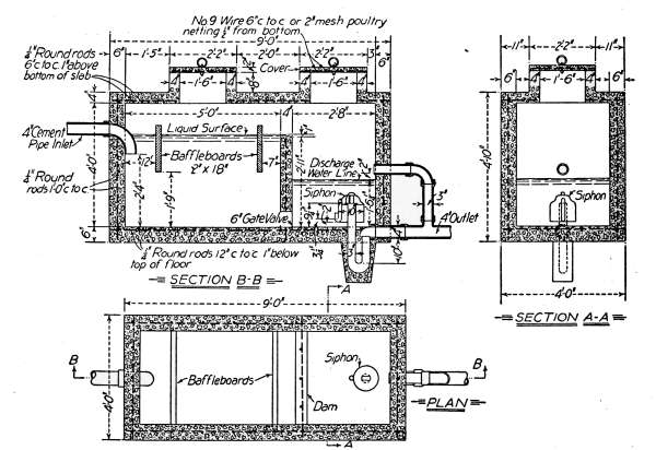
Fig. 156.—Septic tank. This shows the construction as if cut away along a
center line following its length, also a section of the siphon chamber and a plan
of the whole construction.
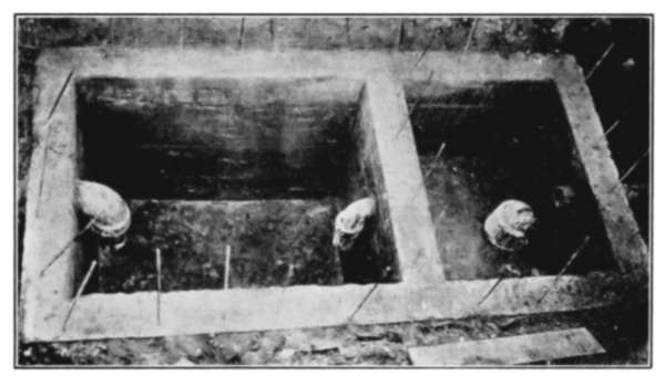
Fig. 156a.—Photographic reproduction of a concrete septic tank, similar to
that of Fig. 153. The tank requires only the cover to make it complete.
“The design in Fig. 156 shows a septic tank as it would appear if
partly cut away to expose the interior to view, and as if cut in half[180]
along a center line following its length. This type will be found to
operate effectively where final disposal is accomplished by sub-surface
irrigation. This system once started is self-operating due to the siphon
shown in the second, or right-hand compartment, which at regular[181]
intervals empties the contents and discharges them into the line of
tile from which the liquids leach out through joints into the soil. In a
tank constructed as shown in the design mentioned, it is very important
to use a siphon to empty the second compartment at intervals instead
of allowing a continuous outward flow of contents, because of the tendency
for drains to become clogged when liquids are constantly trickling
through.
“The size of tank required for residence use depends upon the quantity
of sewage to be handled in the first chamber during a day of 24
hours; therefore, this compartment should be large enough to contain
an entire day’s flow. This frequently amounts to from 30 to 50 gallons
per person per day, so the required capacity can readily be computed
from these figures, although it must be remembered that the required
depth for the tank should be figured from the top of the concrete baffle
wall or partition which separates the first and second compartments.
Another point to bear in mind is that the width of the first compartment
should be about one-half its length.”
[182]
CHAPTER IX
COAL
Coal is of prehistoric origin, formed from accumulation of
vegetable matter, supposed to be the remains of immense forests.
In past ages the deposits underwent destructive distillation from
great heat and was subjected to pressure, sufficient to compress it
into varying degrees of hardness. Coal is composed of carbon,
hydrogen and oxygen, with small quantities of nitrogen and varying
amounts of sulphur and ash.
The coals from different geological formations vary in quality
from the hard dry anthracites to the soft wet lignites, with the
intermediate bituminous coals; all of which furnish fuels that when
burned will produce amounts of heat, depending on their composition,
the quantity of moisture contained and the conditions
of their combustion.
Carbon, of which coal is principally composed, exists in different
combinations, depending on the condition of its formation.
Part of the carbon is combined with hydrogen to form hydrocarbon
that may be driven off when heated, and which forms the
volatile portion of the coal. The remainder of the carbon appears
in the form of coke—when the volatile matter is driven off—and
is said to be fixed. The fixed carbon and volatile constituents
together make up the combustible.
Other ingredients of coal that require attention are the moisture,
and the incombustible matter that forms ash. Moisture
varies in quantity from as low as 0.75 per cent. in hard coal to 50
per cent. in lignite. The amounts of ash in different coals vary
from 3 to 30 per cent. of the weights of the fuel.
The heating value of coals differs in amount by reason of the
variable quantities of fixed and combined carbons, moisture and
ash. Different coals are compared in value by the number of
B.t.u. per pound of dry coal that can possibly be developed when
burned, and with these factors are given the percentages of
moisture and ash.
There are no distinct demarkations between different grades of[183]
coal. The classifications are made because of their chief characteristics
and they commonly are graded as anthracites, semi-anthracites,
semi-bituminous and bituminous coals. These
classes comprehend the most common commercial coals of the
United States. Aside from those named are forms of coal that
are occasionally found, such as graphitic anthracite, cannel coal,
etc., and the various lignites.
The value of coal as a heat-producing agent is represented by
the B.t.u. it is capable of turning to useful account. The price
of coal should be based on the amount of heat it is capable of
generating when burned. In considering the value of coal for
any particular purpose, thought must be taken as to its characteristic
properties, for coals that produce excellent results for one
purpose may be very unsatisfactory in others. Soft coal containing
a large percentage of volatile matter usually produces a
great amount of smoke and unless carefully fired this will condense
and form accumulations of soot that are objectionable.
For reasons of this kind bituminous coals are often sold at a lower
price than their rated heating value might indicate.
Anthracite or hard coal
possesses bright lustrous surfaces when
newly fractured, that when handled do not soil the hands. It contains
a high percentage of carbon, a small amount of volatile
matter and little moisture. It is greatly in demand as a domestic
fuel because it burns slowly with an intense heat, practically
without flame and produces no smoke. It invariably commands
a higher price than soft coal, but in heating value is not superior
to the better grades of soft coal. In furnaces for house heating
the use of soft coal often gives better satisfaction than hard coal.
The grades of hard coal found in the market will vary with the
demand in any locality but those recognized by the trade are:
| Egg | Coal will pass through | 2¾-inch mesh screen. |
| Stove | Coal will pass through | 2-inch mesh screen. |
| Chestnut | Coal will pass through | 13⁄8-inch mesh screen. |
| Pea | Coal will pass through | ¾-inch mesh screen. |
| No. 1 Buckwheat | Coal will pass through | ½-inch mesh screen. |
| No. 2 Buckwheat | Coal will pass through | ¼-inch mesh screen. |
| No. 3 Buckwheat | Coal will pass through | 1⁄8-inch mesh screen. |
Hard coal of stove and chestnut sizes are those most commonly
used for domestic heating, because they are well suited for[184]
furnaces and heating stoves. Of the two sizes chestnut coal is
most largely used and on account of the greater demand, the
price for this size is usually somewhat in advance of the others; at
the same time the smaller sizes—pea and buckwheat coals—are
less in price for the same grade of coal. Under conditions that will
permit their use the latter coals are an economical form of fuel.
Bituminous or soft coal
represents the chief fuel of commerce.
The market prices of these coals are determined largely by reason
of their reputation as desirable fuel. The variations in price
depend on the physical qualities, rather than on the amount of heat
evolved in combustion. The compositions of coals vary markedly
in different localities and often in the same locality several grades
are produced. It sometimes happens that from different parts
of a mine the coal will differ very much in heat value.
Bituminous coals are roughly classified as coking and free-burning.
The former is valuable for gas manufacture and for
production of coke. The coking coals fuse on being heated,
allowing the volatile portion to escape; and when the gas has
been all distilled, the residue is coke. When used for gas making,
the volatile portion forms the illuminating gas. When burned
in a furnace, the gases from soft coal burn with a yellow flame and
usually with considerable smoke. The classification of bituminous
coals differ somewhat in the East from that of the West.
Eastern bituminous coals are commonly graded:
A. Run-of-mine coal = unscreened coal as taken from the mine.
B. Lump coal = that which passes over a bar screen with 1¼-inch
openings.
C. Nut coal = that which passes through a bar screen with 1¼-inch
openings and over one with ¾-inch openings.
D. Slack = all that which passes through a ¾-inch bar screen.
Western bituminous coal:
E. Run-of-mine coal = the unscreened coal as taken from the mine.
F. Lump coal—divides as 6-inch, 3-inch and 1¼-inch according to the
diameter of the mesh through which the pieces pass the screens.
G. Nut coal—varying from 1¼-inch size to ¾-inch in diameter.
H. Screening = all coal which passes a 1¼-inch screen including the
dust.
Heat derived from coal—or any other fuel—in the process
of combustion is due to oxidation. Combustion or burning
is caused by rapid oxidation. When oxygen combines with[185]
carbon in sufficient quantities, carbon dioxide is formed and at
the same time heat is liberated. In burning fuel, if the carbon
is completely oxidized and changed into carbon dioxide, the greatest
amount of heat is produced. The required oxygen is furnished
by the air, which through the dampers of the furnace
regulates the rate of combustion.
Oxidation of Hydrocarbons.
—In the oxidation of hydrocarbons,
as that of burning coal gas, the combination of the elements forms
carbon dioxide and water. The presence of the water, formed
in combustion, is often shown in the formation of moisture on
the bottom of a cold vessel when placed over a gas flame. The
same effect is observed in a newly lighted kerosene lamp, when
the film of moisture forms inside the cold lamp chimney. As soon
as the surfaces become heated the moisture is evaporated. Occasionally,
the accumulation of moisture in chimneys, from this
cause, is sufficient during extremely cold weather to form ice
in the part of the chimney exposed to the outside air. Chimneys
have been known to become so stopped by accumulation of ice
from this cause as to materially interfere with the draft.
The fixed carbon of the coal, when oxidized, has a constant
heating value of 14,000 B.t.u. per pound. The volatile hydrocarbons
develop amounts of heat when burned, depending on
their composition, and differ in coals from different localities.
The heat obtained from the volatile part of coal depends on its
chemical composition and differs very materially; it may be as
high as 21,000 B.t.u. per pound, or as low as 12,000 B.t.u. per
pound.
A high percentage of volatile matter usually indicates a fuel
that will produce a large volume of smoke, which—unless the
combustion is complete in the furnace—will deposit soot as
soon as it is condensed, either in the chimney or in the outside
air. The ash has no heating value, and the contained moisture
has a negative heating effect, because considerable heat is required
to evaporate and raise it to the temperature of the gases
of the furnace. In burning fuel the moisture uses up the heat
of combustion in proportion as it appears in the coal. The
moisture is bought as coal but requires heat to get rid of it; so the
percentage of water in coal should be considered very carefully.
It is customary in comparing the heating values of coals, to[186]
state the proportionate parts of fixed carbon, volatile matter,
moisture and ash as well as the B.t.u. per pound of dry coal. The
heat value in B.t.u. per pound of fuel is usually obtained by burning
samples in a calorimeter from which the heat per pound is
calculated. The heat value of fuels used in power plants are
often determined by careful tests of the amount of power derived
for each pound of fuel burned in the furnace. This is done by
weighing the fuel burned and measuring the water evaporated.
The ashes are weighed and this weight together with the weight
of moisture present is subtracted from that of the coal to determine
the amount of combustible of the fuel. The final results
are expressed by the number of pounds of water evaporated per
pound of combustible and also the weight to water evaporated
per pound of coal burned.
Semi-bituminous coal
represents a class between the hard and
soft grades. It contains less carbon and more volatile matter
than hard coal. It burns with a short flame with very little
smoke and is valuable as a furnace fuel. The Pocahontas coal
of West Virginia is an example of this class. Semi-bituminous
coal is often called smokeless coal, because in burning it produces
relatively little smoke. It will be noted in the table of heat
values on page 192 that coal of this variety has high heat-producing
properties. It is a very friable coal and for that reason is
apt to contain considerable dust. As a furnace fuel it produces—when
carefully fired—very satisfactory results.
Graphitic Anthracite.
—This is a type of coal found in Rhode
Island and Massachusetts which resembles both graphite and
anthracite coal. It is gray in color, very hard and burns with
extreme difficulty.
Cannel Coal.
—This is a variety of bituminous coal, rich in
hydrocarbons. It burns with a bright flame without fusing and
is often used for open fires.
Lignite.
—This is a type of fuel that in point of geological formation
represents the condition between true coal and peat.
Lignite occurs in immense deposits throughout the middle
portion of the western half of the United States, where beds 20
feet in depth are not uncommon. It varies in color from black
to brown and in many localities is known as brown coal.
When newly mined, lignite contains a large percentage of
water, sometimes as high as 50 per cent. On account of this[187]
large moisture content it has a relatively low calorific value,
but when dry the amount of heat evolved per pound compares
very favorably with soft coal.
Peat.
—As a fuel, peat has been used very little in the United
States on account of the abundance of the better grades of fuel,
but in many parts of the country it is used locally to a considerable
extent. In peat bogs from which the fuel is taken, the peat
is formed from grasses and sedges which in time produce a carbonaceous
mass that becomes sufficiently dense to be taken out in
sections, with a long narrow spade. The peat is then built into
piles where after drying it is ready to be burned.
Wood.
—On account of its relative scarcity and correspondingly
high price, wood is no longer a commercial fuel of any consequence.
The low heating value of wood as compared with coal
makes it a prohibitive fuel except in forest localities. Wood is
commonly sold by the cord and no attention is given by dealers
to its value in heat-producing capacity.
The desirability of wood as a fuel is chiefly that of reputation.
It is usually considered that hickory is the ideal fire wood, dry
maple a close second and that oak is next in desirability as fuel;
following which are ash, elm, beech, etc., depending on the density
of the wood. The price of wood per cord depends on the
nearness and abundance of supply.
The actual heating values of different woods as determined by
Gottlieb show that per pound of dry wood there is little difference
in heat value between different kinds of hard woods, and that
pine gives per pound the highest value of all. The table given
below was taken from “Steam” published by the Babcock-Wilcox
Co.
Kinds
of wood | Per cent.
of ash |
B.t.u. per
pound |
| Oak | 0.37 | 8,316 |
| Ash | 0.57 | 8,480 |
| Elm | 0.50 | 8,510 |
| Beech | 0.57 | 8,591 |
| Birch | 0.29 | 8,586 |
| Fir | 0.28 | 9,063 |
| Pine | 0.37 | 9,153 |
| Poplar | 1.86 | 7,834 |
| Willow | 3.37 | 7,926 |
[188]
In considering this table it must be kept in mind that the
values are for dry wood per pound.
As given in Kent’s “Engineer’s Pocket Book” the weights of
different fuel woods per cord (thoroughly air-dried) are about
as follows:
| 1 cord hickory or hard maple |
4,500 pounds equal to | 1,800 pounds coal |
| 1 cord white oak |
3,850 pounds equal to | 1,540 pounds coal |
| 1 cord beech, red and black oak |
3,250 pounds equal to | 1,300 pounds coal |
| 1 cord poplar, chestnut and elm |
2,350 pounds equal to | 940 pounds coal |
| 1 cord average pine |
2,000 pounds equal to | 800 pounds coal |
The above values in pounds of coal may be taken to represent
average bituminous coals. As given by Suplee’s “Mechanical
Engineers’ Reference Book,” eight samples of coals representing
bituminous coals from mines east of the Mississippi River give
an average heating value of 13,755 B.t.u. per pound.
Charcoal.
—This is made from wood by driving off the volatile
constituents; the residual carbon, which forms the charcoal is a
fuel that burns without smoke or flame. Charcoal is made by
piling wood in a heap, which is covered with earth. In the bottom
of the heap a fire generates the necessary heat for distilling
off the volatile matter. Charcoal holds to wood the same relation
that coke bears to coal.
Coke.
—This is the residue from the distillation of coal. It
comprises from 60 to 70 per cent. of the original coal and contains
most of the carbon and all of the ash of the coal. Coke is gray in
color and has a slightly metallic luster; it is porous, brittle and in
handling gives out something of a metallic ring. It is often sold
for fuel as a byproduct by gas factories. In heating value gas-coke
gives about 14,000 B.t.u. per pound when dry and as a consequence
is rated as an excellent fuel. Clean coke burns without
flame and is capable of producing an intense heat. On account
of its porous nature it occupies a relatively large volume per ton.
It is most successfully burned in stoves and furnaces with large
fire-boxes.
Gas-coke,
which is the residue from the gas retorts, is somewhat
inferior in heating value to coke made in ovens but it is
an excellent fuel where furnaces are adapted to its use. Gas-coke
is often stored, by piling it in heaps, in the open and on account[189]
of its porous nature it absorbs considerable moisture. Where
exposed to the weather the amount of contained moisture depends
on the amount of rain or snow the coke has absorbed. This
amount is easily determined by weighing a fair sample and driving
off the moisture in an oven. The sample should be weighed
several times until the weight remains constant.
Briquettes.
—Briquetted coal and other fuels are produced
by compressing coal dust or other powdered fuel, mixed with coal
tars or other bituminous binder in sufficient quantity to cause
the adhesion of the particles when pressed into form under great
pressure. Owing to the relative cheapness of fuel, briquettes
have been used but very little in the United States. With the
advance in the price of coal of the past few years, they have
found a place on the market and have become a common form
of fuel.
The heat value of briquettes will depend on the kind and
quality of material that enters into their composition. Quite
generally, they produce heat equal to the average grade of soft
coal. In the Northwest briquettes made of West Virginia
semi-bituminous coal sell at the same price as run-of-mine
coal of the same quality. Their use has proven satisfactory
as a furnace fuel and they will very likely be sold in increasing
quantities.
Comparative Value of Coal to Other Fuels.
—Until a comparatively
recent time, coal has been sold by weight and reputation
alone; but conditions are rapidly approaching, which will require
it to be sold according to its composition and heating value.
Among manufacturers and others using large quantities of fuel,
the practice of contracting for coal by specification is becoming
increasingly common. The determining factors are the amounts
of moisture, ash, sulphur, carbon, and volatile matter the coal
contains, as well as the size of the pieces and freedom from dust.
In a few of the most progressive cities, coal dealers are required
to supply coal for schools and other municipal uses, which has
been subject to the approval of the City Engineer. The time is
not far distant when dealers will be required to submit samples
of all fuel, for sale to the public, to the examination of the municipal
authorities.
[190]
The following table of the heating values of various fuels is
taken from Benson’s “Industrial Chemistry.”
British Thermal Units for One Cent from Different Fuels
| Acetylene, from carbide at 10 cents per pound | 600 |
| Denatured alcohol, at 40 cents per gallon | 2,000 |
| Air gas (from gasoline, 80°Bé at 25 cents per gallon) | 3,000 |
| Water gas, at $1 per 1000 cubic feet | 3,000 |
| Coal gas, at $1 per 1000 cubic feet | 6,500 |
| Gasoline, at 20 cents per gallon | 7,500 |
| Kerosene, at 15 cents per gallon | 11,000 |
| Natural gas, at 50 cents per 1000 cubic feet | 18,000 |
| Charcoal, at 10 cents per bushel (15 pounds) | 20,000 |
| Petroleum at 5 cents per gallon | 30,000 |
| Producer gas, from anthracite, $7 per ton | 30,000 |
| Producer gas, from coke, $5 per ton | 36,000 |
| Anthracite, at $7 per ton | 46,000 |
| Producer gas, from soft coal, at $3 per ton | 50,000 |
| Coke, at $5 per ton | 54,000 |
| Mond producer gas from soft coal, at $3 per ton | 65,000 |
| Soft coal, at $3 per ton | 80,000 |
Price of Coal.
—The value of coal as a fuel will depend on the
amount of heat it is capable of producing when burned; its price
should therefore be determined by the heating value per pound
of fuel as purchased. Secondary determining factors in price are
those of convenience of handling and the difficulty in burning the
fuel such as the size and uniformity of the pieces, the formation
of clinkers, smoke and accumulation of soot. Soft coals, containing
a large amount of volatile matter, usually produce much soot
and smoke and as a consequence sell for a lower price than coals
that produce little smoke.
The selection of fuels will depend on the type of heating plant
in use, whether by stoves or by furnaces. If by stoves, whether it
is possible to use soft coal as a fuel. The automatically fed
stove, of the base-burner type, are usually designed for the use of
hard coal and in such stoves the use of soft coal would not be
possible. Other stoves and furnaces are usually capable of burning
soft coal with varying degrees of satisfaction, depending on
the design and surrounding conditions.
[191]
The following prices, from the local market, show the usual
ratings of various fuels in common use. These prices vary with
the locality and somewhat with the season. It is usually possible
to purchase coal at some reduction in price during the summer
months when the demand for coal is light.
| Hard coal—stove size | $10.25 per ton |
| Hard coal—nut size | 10.50 per ton |
| Semi-bituminous—run-of-the-mine | 9.00 per ton |
| Pennsylvania bituminous—run-of-the-mine | 7.50 per ton |
| Soft coal—Ohio—run-of-the-mine | 7.50 per ton |
| Soft coal—Illinois—bituminous—run-of-the-mine | 7.50 per ton |
| Soft coal—Iowa—bituminous—run-of-the-mine | 7.50 per ton |
| Briquettes-mixture semi-bituminous coal dust | 9.00 per ton |
| Wood (oak), sawed, stove length and split | 8.50 per cord |
The price of coal is determined in many localities by the distance
from the sources of supply and the means of transportation.
The fact that coals from all of the principal mining areas from
Pennsylvania, west to Iowa, are sold at points in the Northwest
for the same price, is due in greatest measure to transportation
rates on the Great Lakes. The prices of Eastern coals at Duluth
are such that in competition with Western coals they are sold at
the same price as is shown by the table.
It is usually impossible for the average householder, or even
the dealer, to determine definitely the exact locality from which
his fuel is mined. Even when such information is obtainable,
the quality is still in doubt, unless analysis is obtainable by sample.
The data given in the following tables is such as will furnish a fair
knowledge of the relative heating values of coals from the principal
mining areas of the United States. The data was obtained
from a considerable number of authorities but chiefly from the
reports of the United States Geological Survey. The different
items are not intended to be exact, they merely represent reliable
average conditions.
The varying conditions of available heat and percentage of
moisture given in the following table are such as to be of little
use to those unaccustomed to problems of this kind, unless a
systematic method of comparison is made of the different fuels.
[192]
Approximate Composition and Calorific Value of Typical American Coals
1
Locality |
2
Kind of coal |
3
Number,
of samples
examined |
Moisture |
5
Volatile
matter |
6
Fixed
carbon |
7
B.t.u.
pound per
dry coal |
8
Ash |
| Pa. | Anthracite | 12 |
5.05 | 5.52 |
82.54 | 12,682 | 11.53 |
| Md. | Semi-
bituminous |
5 | 2.39 |
17.73 | 75.44 |
14,530 | 7.40 |
| Pa. | Semi-
bituminous |
15 | 3.60 |
19.26 | 74.46 | 14,211 | 8.32 |
| W. Va. | Semi-
bituminous |
12 | 2.50 |
19.00 | 75.70 | 14,758 |
5.24 |
| Ala. | Bituminous |
6 | 3.55 |
29.99 | 59.24 | 13,522 |
10.73 |
| Ark. | Bituminous |
2 | 1.42 |
16.58 | 73.37 | 14,205 |
10.05 |
| Colo. | Bituminous |
6 | 9.89 | 37.34 |
52.53 | 12,325 | 10.32 |
| Ill. | Bituminous |
22 | 10.31 | 36.73 |
50.52 | 11,504 | 12.73 |
| Ia. | Bituminous |
8 | 7.72 | 39.15 |
50.54 | 12,656 | 10.33 |
| Kan. | Bituminous |
3 | 4.25 | 32.20 |
51.17 | 12,031 | 13.75 |
| Ky. | Bituminous |
9 | 5.99 | 34.58 |
56.56 | 13,341 | 8.86 |
| Mo. | Bituminous |
9 | 11.52 | 37.85 |
48.11 | 12,398 | 14.04 |
| Ohio. | Bituminous |
14 | 5.65 | 38.51 |
50.59 | 12,839 | 10.65 |
| Okla. | Bituminous |
3 | 5.72 | 34.83 |
52.76 | 12,648 | 12.41 |
| N.M. | Bituminous |
1 | 12.17 | 36.31 |
51.17 | 12,126 | 12.52 |
| Pa. | Bituminous |
15 | 2.44 | 33.41 |
58.31 | 13,732 | 8.40 |
| Tenn. | Bituminous |
4 | 2.53 | 36.58 |
58.21 | 14,098 | 5.47 |
| Tex. | Bituminous |
3 | 3.84 | 35.05 |
48.99 | 12,302 | 15.96 |
| Va. | Bituminous |
5 | 2.71 | 31.32 |
62.47 | 14,025 | 6.92 |
| W. Va. | Bituminous |
10 | 2.61 | 33.92 |
58.80 | 14,094 | 7.27 |
| Colo. | Lignite |
6 | 19.75 | 45.21 |
45.85 | 10,799 | 8.93 |
| N. D. | Lignite |
5 | 35.93 | 44.33 |
43.21 | 10,420 | 12.45 |
| Tex. | Lignite |
6 | 30.86 | 44.06 |
39.21 | 10,297 | 16.76 |
| Wyo. | Lignite |
4 | 14.71 | 48.47 |
44.49 | 11,608 | 7.035 |
The following table was prepared from the date of that preceding
combined with the prices of various coals to be obtained in the
local market. The table is intended to present a method of
comparing the values of fuels from different coal areas. The
consumer is interested to know the amount of heat purchased in
the form of fuel. The table shows in the column headed “Heat
per $1,” the number of B.t.u. purchased for $1 in coal; the number
of available B.t.u. in the different kinds of coal may be taken as a
relative comparison of their values as fuel.
The gas-coke in the table is that sold by the local gas company.
The amount of moisture in this case is relatively high because of[193]
the fact that the coke is stored in a yard exposed to the weather,
where it absorbs all precipitated moisture. A less amount of
moisture would give a higher value for the same fuel.
| Kind of coal |
Price
per
ton |
Per cent.,
water |
B.t.u.
per 100
pounds |
B.t.u. to
evaporate
water |
B.t.u.
per 100
÷ cost per
100 pounds |
Heat per $1 |
Bituminous
Pennsylvania |
$7.50 | 2.44 |
1,340,000 - 3,439 = |
1,336,565
————
$0.375 |
= 3,564,000 B.t.u. |
Semi-
bituminous
West Virginia |
$9.00 | 3.06 |
1,420,000 - 4,315 = |
1,415,685
————
$0.45 |
= 3,145,000 B.t.u. |
| Gas-coke |
$7.00 | 10.00 |
1,117,900 - 16,888 = |
1,101,012
————
$0.35 |
= 3,145,000 B.t.u. |
North
Dakota
lignite |
$4.50 | 35.90 |
668,000 - 50,728 = |
607,282
———
$0.225 |
= 2,703,000 B.t.u. |
Bituminous
Illinois |
$7.50 | 10.31 |
1,032,000 - 14,398 = |
1,017,602
————
$0.375 |
= 2,980,000 B.t.u. |
Bituminous
Iowa |
$7.50 | 13.10 |
1,012,000 - 18,471 = |
994,529
———
$0.375 |
= 2,652,000 B.t.u. |
Hard coal
Pennsylvania |
$10.50 | 3.05 |
1,230,000 - 4,195 = |
1,225,905
————
$0.525 |
= 2,335,000 B.t.u. |
Semi-bituminous coal commands considerable favor as a
house-heating fuel, because of the fact that it burns with much
less smoke than bituminous coal. In available heat it is considerably
above the Western bituminous coal and it sells at a
price $1.50 higher per ton. The reason for the difference in
price is not so much on account of its heating value, as because
of relatively small amount of smoke produced in combustion.
Other coals capable of producing more heat are sold at less price
because of smoke and soot produced in burning.
Hard coal at $10.50 is the most expensive coal of all. The
ratio of available heat units per $1 for hard coal, as compared
with the best soft coal, is as 23 is to 35. This means that at the
stated prices those who burn hard coal pay the additional price,
because of the physical properties it possesses.
In constructing the above table, 100 pounds of coal was taken
as a unit of comparison. The price per ton is that given in the
table of local prices. The per cent. of moisture and the B.t.u.
per pound of fuel was taken from table on page 192.
[194]
In explaining the method by which the different items were
obtained, it will be necessary to discuss briefly the condition of
combustion and the heat losses that take place when fuel is
burned.
The moisture in the fuel is the undesirable part, because it
requires a large amount of heat to dispose of it. It is looked upon
as so much water, that must be raised in temperature from that
in which it is taken from the coal bin to the temperature and condition
of vapor in which it passes into the chimney. When the
fuel enters the furnace the water is heated to the boiling point.
In changing temperature it absorbs 1 B.t.u. for each pound of
water, through each degree of change. Suppose that, as in
the case of Pennsylvania bituminous coal which contains 2.44
pounds of water to each 100 pounds of coal, the coal entering
the furnace was at 50°F. To raise its temperature to the boiling
point (212°F.) required a change of 162°. The 2.44 pounds of
water raised this amount
162 × 2.44 = 395.28 B.t.u.
To change the 2.44 pounds of water, into steam at the atmospheric
pressure requires 969.7 B.t.u. (heat of vaporization),
practically 970 B.t.u. per pound of water. The heat required
to vaporize 2.44 pounds of water is
2.44 × 970 = 2366.80 B.t.u.
The vapor is now raised in temperature, to that of the furnace,
which we may assume is 1200°F. The furnace being at atmospheric
pressure the vapor merely expands in volume as a gas.
The specific heat of steam at atmospheric pressure is 0.464;
that is, 1 pound of steam requires only 0.464 B.t.u. to raise it a
degree, and 2.44 pounds of water will absorb
0.464 × 2.44 × 1200 = 1356.00 B.t.u.
Of this last amount of heat, approximately 50 per cent. is
recovered as the gases pass through the furnace. The total
loss of heat due to the evaporation of the water is
| Raising temperature from normal to 212° | 395 B.t.u. |
| Evaporation | 2,366 B.t.u. |
| Changing temperature of vapor, less 50 per cent. | 678 B.t.u. |
| | ————— |
| Total heat loss | 3,439 B.t.u. |
[195]
In the 100 pounds of coal under consideration, there is 100
pounds, less 2.44 pounds of water, or 97.56 of dry coal, each
pound of which contains 13,732 B.t.u. as given by the table on
page 193. This gives
97.56 × 12,682 = 1,339,753 = practically 1,340,000 B.t.u.
From this quantity is subtracted the loss of heat, 3439.
1,340,000 - 3439 = 1,336,561 B.t.u.
This represents the total available heat in 100 pounds of
coal. If this quantity is now divided by the cost of 100 pounds
of coal at $7.25 per ton, the result, 3,564,000 B.t.u., will be the
available heat bought for $1 as given in column 7 of the table.
[196]
CHAPTER X
ATMOSPHERIC HUMIDITY
The physical effect of atmospheric humidity has come to be
recognized by all who deal in problems of house heating, sanitation
and hygiene. The difference in effect of dry atmosphere,
from that of air containing a desirable degree of moisture, is
very noticeable in all buildings that are artificially heated. The
effect of dry air is made apparent in the average home during the
winter months by the shrinking of the woodwork and furniture.
The absorption of the moisture from the building which is usually
termed “drying out,” causes the joints in the floors and casements
to open, doors to shrink until they fail to latch and drawers that
have opened with difficulty during the summer then work freely.
Winter time is the season of prevalent colds, chaps and roughness
of the skin, not so much on account of cold weather as because
of dry air. The skin which is normally moist is kept dry
by constant evaporation with the attending discomfort of an
irritated surface and the results which follow.
The humidity of the air in which we live and on which we
depend for life has much to do with the bodily comfort we derive
in existence, and is suspected of being the cause of many physical
ailments. Ventilation engineers not only recognize this condition
but have found means of controlling it. It is possible
to so control atmosphere temperature and humidity of buildings
as to produce any desired condition.
Humidity of the Air.
—The amount of water vapor in the air is
called the humidity of the air. It may vary from a fraction of a
grain per cubic foot in extremely cold weather, to 20 grains per
cubic foot during the occasional hot weather of summer.
Since the amounts of moisture that air will hold depends on
its temperature, and as the air is ordinarily only partly saturated,
the varying amount of moisture are expressed either as relative
humidity and stated in per cent. saturation or in the actual weight
of water in grains per cubic foot and known as absolute humidity.
[197]
The relative humidity of the atmosphere is the amount of
moisture contained in a given space as compared with the amount
the same air could possibly hold at that temperature. Warm
air will hold more moisture than the same air when cold. Air
absorbs water like a sponge to a point of saturation. When the
air is filled with moisture, any change which takes place to reduce
the temperature also reduces its capacity to hold the water
vapor and the excess is deposited as dew. This supersaturation
ordinarily takes place near things which lose their heat faster
than the surrounding air and the nearest colder surface acts as a
condenser to receive the drops of dew. Grass being in convenient
position is the commonest receptacle for dew formation. If the
dew forms in the air it falls as rain, but if the temperature of the
dew-point is below freezing, the dew immediately freezes and
snow is the result.
In the consideration of problems that involve atmospheric
moisture, both relative and absolute humidity are factors of
common use, that are capable of exact determination. The relative
humidity of the air is most readily determined and as it expresses
the state of the atmosphere in which plants and animals
live and thrive, as opposed to other conditions of humidity in
which they sometimes sicken and die, it is one of the indicators
of the quality of atmospheric air.
In the subject of ventilation, which is undertaken later, it will
be found that a definite knowledge of atmospheric humidity has
much to do with the successful operation of ventilation apparatus.
Most people recognize the “balmy air of June” without realizing
just why at the same temperature other seasons are not so delightful.
In reality it is the condition of atmospheric humidity
combined with an agreeable temperature that gives the kind of
air in which we find the greatest degree of comfort.
The effect of moderately warm humid air is that of higher
temperature than the thermometer indicates. When the atmosphere
is near the point of saturation, the evaporation which
usually goes on, from the surface of the body, practically ceases.
In summer time a temperature of 85°F. with relative humidity
of 90 per cent. saturation seems warmer than a temperature of
100° at 40 per cent. saturation, because of the cooling effect
produced by the increased evaporation due to the drier air.
[198]
In winter, when most of the time is spent indoors, in an atmosphere
that is very dry, the sensation of discomfort produced by
the lack of humidity oftentimes leads to physical derangements
that would never appear under more desirable conditions. The
cause of many ailments of the nose, throat and lungs during the
winter months is attributed by physiologists to breathing almost
constantly the dry vitiated indoor air. The cause of dry air in
buildings is not difficult to explain; it is a great deal more difficult
to realize that the lack of water breeds so much discomfort.
In order to express the condition of humidity that may exist
in the average dwelling, office or school-room during the winter,
it is most convenient to refer to the results of varying atmospheric
conditions that are given in Table 1—Properties of Air—which
appears below. In the second column of the table, under the
heading “Weight of vapor per cubic foot of saturated air,”
will be found the amount of moisture in grains per cubic foot
that will be required to humidify air at different temperatures.
It will be seen that at 10° the air will contain, when fully saturated,
only 1.11 grains of water, while at 70° temperature the same air
would hold 8 grains of water. These amounts will be found in the
column opposite the temperature readings. It is at once evident
that when saturated air at 10° is raised to normal temperature
70°, the original amount of moisture is contained in an atmosphere
capable of holding 8 grains of water. Its relative
humidity will therefore be 1.11⁄8, practically 14 per cent. saturated.
Unless moisture is received by the air from some other
source this condition will produce a very dry atmosphere.
The normal atmospheric temperature of 70°F. with a relative
humidity of 50 to 60 per cent. saturation produces a condition
that is one of agreeable warmth to the average person in health
and is recognized as the atmosphere most desirable. To some,
this state of temperature and humidity is that of too much
warmth and a temperature of 68°, with the same humidity, is
most agreeable. At the same temperature, a reduction of the
humidity to 20 per cent. saturation will produce a feeling of discomfort
and the sensation will be that of a lack of heat. The
cause for this latter feeling is due to excessive evaporation of
moisture from the body.
[199]
Table I.—Properties of Air
Temperature
of the air |
Weight of vapor
per cubic foot
of saturated air |
Weight of
cubic foot of
saturated air |
| Fahrenheit | Grains | Grains |
| 10° | 1.11 | 589.4 |
| 11 | 1.15 | 588.1 |
| 12 | 1.19 | 586.8 |
| 13 | 1.24 | 585.5 |
| 14 | 1.28 | 584.2 |
| 15 | 1.32 | 582.9 |
| 16 | 1.37 | 581.6 |
| 17 | 1.41 | 580.3 |
| 18 | 1.47 | 579.1 |
| 19 | 1.52 | 577.8 |
| 20 | 1.58 | 576.5 |
| 21 | 1.63 | 575.3 |
| 22 | 1.69 | 574.0 |
| 23 | 1.75 | 572.7 |
| 24 | 1.81 | 571.5 |
| 25 | 1.87 | 570.2 |
| 26 | 1.93 | 569.0 |
| 27 | 2.00 | 567.7 |
| 28 | 2.07 | 566.5 |
| 29 | 2.14 | 565.3 |
| 30 | 2.21 | 564.1 |
| 31 | 2.29 | 562.8 |
| 32 | 2.37 | 561.6 |
| 33 | 2.45 | 566.4 |
| 34 | 2.53 | 559.2 |
| 35 | 2.62 | 558.0 |
| 36 | 2.71 | 556.8 |
| 37 | 2.80 | 555.6 |
| 38 | 2.89 | 554.4 |
| 39 | 2.99 | 553.2 |
| 40 | 3.09 | 552.0 |
| 41 | 3.19 | 550.8 |
| 42 | 3.30 | 549.6 |
| 43 | 3.41 | 548.4 |
| 44 | 3.52 | 547.2 |
| 45 | 3.64 | 546.1 |
| 46 | 3.76 | 544.9 |
| 47 | 3.88 | 543.7 |
| 48 | 4.01 | 541.3 |
| 49 | 4.14 | 542.5 |
| 50 | 4.28 | 540.2 |
| 51 | 4.42 | 539.0 |
| 52 | 4.56 | 537.9 |
| 53 | 4.71 | 536.7 |
| 54 | 4.86 | 535.5 |
| 55 | 5.02 | 534.4 |
| 56 | 5.18 | 533.2 |
| 57 | 5.34 | 532.1 |
| 58 | 5.51 | 534.9 |
| 59 | 5.69 | 529.8 |
| 60 | 5.87 | 528.6 |
| 61 | 6.06 | 527.0 |
| 62 | 6.25 | 526.3 |
| 63 | 5.45 | 525.2 |
| 64 | 6.65 | 524.0 |
| 65 | 6.87 | 522.0 |
| 66 | 7.08 | 521.7 |
| 67 | 7.30 | 520.0 |
| 68 | 7.53 | 519.4 |
| 69 | 7.76 | 518.3 |
| 70 | 8.00 | 517.2 |
The evaporation of moisture is always accompanied with the
loss of heat required to produce such change of condition. This
is known as the heat of vaporization and represents a definite
amount of heat that is used up whenever water is changed into
vapor. No matter what its temperature may be—whether hot[200]
or cold—when water is vaporized, a definite amount of heat is
required to change the water into vapor.
Water may be evaporated at any temperature; even ice evaporates.
A common instance of the latter is that of wet clothes
which “freeze dry” in winter weather when hung on the clothes
line. The rate at which evaporation takes place depends on the
dryness of the surrounding air and the rapidity of its motion.
In dry windy weather evaporation is most rapid.
As before stated, whenever water evaporates—at no matter
what temperature—a definite quantity of heat is necessary to
change the water into vapor. The exact amount of heat required
to produce this change varies somewhat with the temperature
and atmospheric pressure but it always represents a large loss
of heat. At the boiling point of water (212°F.) the heat of
vaporization is 970 B.t.u. for each pound of water evaporated,
but at a lower temperature it is greater than that amount. At
the temperature of the body (98.6°) the heat necessary to evaporate
a pound of moisture from its surface is 1045 B.t.u.
It is the absorption of heat due to evaporation that cools the air
of a sprinkled street. The more rapid the evaporation the more
pronounced is the decline of temperature in the immediate vicinity.
The same effect is produced when moisture is evaporated
from the surface of the body. The acceleration of evaporation
caused by a breeze or the blast of air from an electric fan is that
which produces the chilling sensation to the body. During
winter weather the effect of the cold wind is rendered more severe
by evaporation of moisture from the body. In health, the body
being in a slightly moist condition, the evaporation which goes
on from its surface is what keeps it cool in warm weather, but
if on account of excessive dryness of the surrounding air the
evaporation is very rapid, a sensation of cold is the result.
Not only does excessively dry air produce the sensation of
chilliness but the loss of heat from the body due to sudden or
long exposure effects the general health and is conducive to chills
that are followed by fever. In health the temperature of the
body is constant and normally 98.6°F.; any condition that reduces
that temperature tends toward a lowering of vitality and the
consequent inability to withstand the attack of disease. In a
very dry atmosphere the skin, instead of being slightly moist, is[201]
kept dry, the result of which is the irritation that produces chaps
and roughness of the surface.
Reports of the U. S. Weather Department show that the relative
humidity of Death Valley, which is the driest and hottest known
country, during the driest period of the year—between May and
September—averages 15.5 per cent. saturation. In winter,
many buildings, particularly offices and school buildings are not
far from that atmospheric condition, constantly. Under the
usual conditions of house heating, there is an almost absolute
lack of means to give moisture to the air. Almost without
exception steam-heating plants and hot-water heating plants
in office buildings and dwellings are without any provision for
changing the atmospheric humidity.
In school buildings that are not kept under a more desirable
condition of temperature and humidity, the general health is
impaired and the behavior of the pupils very markedly influenced.
The tension of a school-room full of fidgety nervous children can
be very promptly and greatly reduced by the introduction of
water vapor into the air to 50 per cent. saturation.
All modern school buildings, auditoriums, etc., are provided—aside
from the heating plants—with means of ventilating in
which the entering air is washed and humidified to the desired
degree, before being sent into the rooms.
The popular conception of the hot-air furnace method of heating
is that it produces particularly dry air, when in reality it is
the only type of house-heating plant in which any provision is
made for adding water to the air. These furnaces are usually
furnished with a water reservoir by use of which the humidity
may be raised to a desirable point.
Much of the water which enters the air of the average home,
during winter weather, comes from the evaporation that goes on
in the kitchen. Usually on wash days the humidity is raised to
a marked degree and that day is commonly followed by a short
period of agreeable atmospheric condition. The arrangement
of many houses is such that a much-improved condition of humidity
might be obtained from the kitchen by continuous evaporation
of water from a tea-kettle.
[202]
Relative Humidity
Depression of wet-bulb thermometer (t-t')
Air
temp.
t | 1.0 |
2.0 | 3.0 | 4.0 |
5.0 | 6.0 | 7.0 |
8.0 | 9.0 | 10.0 |
| 35 | 91 | 82 | 73 | 64 | 55 | 46 | 37 | 29 | 20 | 12 |
| 36 | 91 | 82 | 73 | 65 | 56 | 48 | 39 | 31 | 23 | 14 |
| 37 | 91 | 83 | 74 | 66 | 58 | 49 | 41 | 33 | 25 | 17 |
| 38 | 91 | 83 | 75 | 67 | 59 | 51 | 43 | 35 | 27 | 19 |
| 39 | 92 | 84 | 76 | 68 | 60 | 52 | 44 | 37 | 29 | 21 |
| | | |
| | |
| | |
| |
| 40 | 92 | 84 | 76 | 68 | 61 | 53 | 46 | 38 | 31 | 23 |
| 41 | 92 | 84 | 77 | 69 | 62 | 54 | 47 | 40 | 33 | 26 |
| 42 | 92 | 85 | 77 | 70 | 62 | 55 | 48 | 41 | 34 | 28 |
| 43 | 92 | 85 | 78 | 70 | 63 | 56 | 49 | 43 | 36 | 29 |
| 44 | 93 | 85 | 78 | 71 | 64 | 57 | 51 | 44 | 37 | 31 |
| | | |
| | |
| | |
| |
| 45 | 93 | 86 | 79 | 71 | 65 | 58 | 52 | 45 | 39 | 33 |
| 46 | 93 | 86 | 79 | 72 | 65 | 59 | 53 | 46 | 40 | 34 |
| 47 | 93 | 86 | 79 | 73 | 66 | 60 | 54 | 47 | 41 | 35 |
| 48 | 93 | 87 | 80 | 73 | 67 | 60 | 54 | 48 | 42 | 36 |
| 49 | 93 | 87 | 80 | 74 | 67 | 61 | 55 | 49 | 43 | 37 |
| | | |
| | |
| | |
| |
| 50 | 93 | 87 | 81 | 74 | 68 | 62 | 56 | 50 | 44 | 39 |
| 51 | 94 | 87 | 81 | 75 | 69 | 63 | 57 | 51 | 45 | 40 |
| 52 | 94 | 88 | 81 | 75 | 69 | 63 | 58 | 52 | 46 | 41 |
| 53 | 94 | 88 | 82 | 75 | 70 | 64 | 58 | 53 | 47 | 42 |
| 54 | 94 | 88 | 82 | 76 | 70 | 65 | 59 | 54 | 48 | 43 |
| | | |
| | |
| | |
| |
| 55 | 94 | 88 | 82 | 76 | 71 | 65 | 60 | 55 | 49 | 44 |
| 56 | 94 | 88 | 82 | 77 | 71 | 66 | 61 | 55 | 50 | 45 |
| 57 | 94 | 88 | 83 | 77 | 72 | 66 | 61 | 56 | 51 | 46 |
| 58 | 94 | 89 | 83 | 77 | 72 | 67 | 62 | 57 | 52 | 47 |
| 59 | 94 | 89 | 83 | 78 | 73 | 68 | 63 | 58 | 53 | 48 |
| | | |
| | |
| | |
| |
| 60 | 94 | 89 | 84 | 78 | 73 | 68 | 63 | 58 | 53 | 49 |
| 61 | 94 | 89 | 84 | 79 | 74 | 68 | 64 | 59 | 54 | 50 |
| 62 | 94 | 89 | 84 | 79 | 74 | 69 | 64 | 60 | 55 | 50 |
| 63 | 95 | 90 | 84 | 79 | 74 | 70 | 65 | 60 | 56 | 51 |
| 64 | 95 | 90 | 85 | 79 | 75 | 70 | 66 | 61 | 56 | 52 |
Air
temp.
t | 11.0 |
12.0 | 13.0 | 14.0 |
15.0 | 16.0 | 17.0 |
18.0 | 19.0 | 20.0 |
| 35 | 4 | | | | | | | | | |
| 36 | 6 | | | | | | | | | |
| 37 | 9 | 1 |
| | | | | | | |
| 38 | 12 | 4 |
| | | | | | | |
| 39 | 14 | 7 |
| | | | | | | |
| | | |
| | |
| | |
|
| 40 | 16 | 9 | 2 |
| | | | | | |
| 41 | 18 | 11 | 5 |
| | | | | | |
| 42 | 21 | 14 | 7 | 0 |
| | | | | |
| 43 | 23 | 16 | 9 | 3 |
| | | | | |
| 44 | 24 | 18 | 12 | 5 |
| | | | | |
| | | |
| | |
| | |
|
| 45 | 26 | 20 | 14 | 8 | 2 |
| | | | |
| 46 | 28 | 22 | 16 | 10 | 4 |
| | | | |
| 47 | 29 | 23 | 17 | 12 | 6 | 1 |
| | | |
| 48 | 31 | 25 | 19 | 14 | 8 | 3 |
| | | |
| 49 | 32 | 26 | 21 | 15 | 10 | 5 |
| | | |
| | | |
| | |
| | |
|
| 50 | 33 | 28 | 22 | 17 | 12 | 7 | 2 |
| | |
| 51 | 35 | 29 | 24 | 19 | 14 | 9 | 4 |
| | |
| 52 | 36 | 30 | 25 | 20 | 15 | 10 | 6 | 0 |
| |
| 53 | 37 | 32 | 27 | 22 | 17 | 12 | 7 | 3 |
| |
| 54 | 38 | 33 | 28 | 23 | 18 | 14 | 9 | 5 | 0 |
|
| | | |
| | |
| | |
|
| 55 | 39 | 34 | 29 | 25 | 20 | 15 | 11 | 6 | 2 |
|
| 56 | 40 | 35 | 31 | 26 | 21 | 17 | 12 | 8 | 4 |
| 57 | 41 | 36 | 32 | 27 | 23 | 18 | 14 | 10 | 5 | 1 |
| 58 | 42 | 38 | 33 | 28 | 24 | 20 | 15 | 11 | 7 | 3 |
| 59 | 43 | 39 | 34 | 30 | 25 | 21 | 17 | 13 | 9 | 5 |
| | | |
| | |
| | |
|
| 60 | 44 | 40 | 35 | 31 | 27 | 22 | 18 | 14 | 10 | 6 |
| 61 | 45 | 40 | 36 | 32 | 28 | 24 | 20 | 16 | 12 | 8 |
| 62 | 46 | 41 | 37 | 33 | 29 | 25 | 21 | 17 | 13 | 9 |
| 63 | 47 | 42 | 38 | 34 | 30 | 26 | 22 | 18 | 14 | 11 |
| 64 | 48 | 43 | 39 | 35 | 31 | 27 | 23 | 20 | 16 | 12 |
[203]
Relative Humidity (Continued)
Depression of wet-bulb thermometer (t-t´)
Air
temp.
t |
1.0 | 2.0 | 3.0 |
4.0 | 5.0 | 6.0 |
7.0 | 8.0 | 9.0 |
10.0 | 11.0 |
| 65 | 95 |
90 | 85 | 80 |
75 | 70 | 66 |
62 | 57 | 53 |
48 |
| 66 | 95 |
90 | 85 | 80 |
76 | 71 | 66 |
62 | 58 | 53 |
49 |
| 67 | 95 |
90 | 85 | 80 |
76 | 71 | 67 |
62 | 58 | 54 |
50 |
| 68 | 95 |
90 | 85 | 81 |
76 | 72 | 67 |
63 | 59 | 55 |
51 |
| 69 | 95 |
90 | 86 | 81 |
77 | 72 | 68 |
64 | 59 | 55 |
51 |
| | | |
| | |
| | |
| | |
| 70 | 95 | 90 |
86 | 81 | 77 |
72 | 68 | 64 |
60 | 56 | 52 |
| 71 | 95 | 90 |
86 | 82 | 77 |
73 | 69 | 64 |
60 | 56 | 53 |
| 72 | 95 | 91 |
86 | 82 | 78 |
73 | 69 | 65 |
61 | 57 | 53 |
| 73 | 95 | 91 |
86 | 82 | 78 |
73 | 69 | 65 |
61 | 58 | 54 |
| 74 | 95 | 91 |
86 | 82 | 78 |
74 | 70 | 66 |
62 | 58 | 54 |
| | | |
| | |
| | |
| | |
| 75 | 96 | 91 |
87 | 82 | 78 |
74 | 70 | 66 |
63 | 59 | 55 |
| 76 | 96 | 91 |
87 | 83 | 78 |
74 | 70 | 67 |
63 | 59 | 55 |
| 77 | 96 | 91 |
87 | 83 | 79 |
75 | 71 | 67 |
63 | 59 | 56 |
| 78 | 96 | 91 |
87 | 83 | 79 |
75 | 71 | 67 |
64 | 60 | 57 |
| 79 | 96 | 91 |
87 | 83 | 79 |
75 | 71 | 68 |
64 | 60 | 57 |
| | | |
| | |
| | |
| | |
| 80 | 96 | 91 |
87 | 83 | 79 |
76 | 72 | 68 |
64 | 61 | 57 |
| 82 | 96 | 92 |
88 | 84 | 80 |
76 | 72 | 69 |
65 | 62 | 58 |
| 84 | 96 | 92 |
88 | 84 | 80 |
77 | 73 | 70 |
66 | 63 | 59 |
| 86 | 96 | 92 |
88 | 85 | 81 |
77 | 74 | 70 |
67 | 63 | 60 |
| 88 | 96 | 92 |
88 | 85 | 81 |
78 | 74 | 71 |
67 | 64 | 61 |
| | | |
| | |
| | |
| | |
| 90 | 96 | 92 |
89 | 85 | 81 |
78 | 75 | 71 |
68 | 65 | 62 |
| 92 | 96 | 92 |
89 | 85 | 82 |
78 | 75 | 72 |
69 | 65 | 62 |
| 94 | 96 | 93 |
89 | 86 | 82 |
79 | 75 | 72 |
69 | 66 | 63 |
| 96 | 96 | 93 |
89 | 86 | 82 |
79 | 76 | 73 |
70 | 67 | 64 |
| 98 | 96 | 93 |
89 | 86 | 83 |
79 | 76 | 73 |
70 | 67 | 64 |
| | | |
| | |
| | |
| | |
| 100 | 96 | 93 |
90 | 86 | 83 |
80 | 77 | 74 |
71 | 68 | 65 |
| 102 | 96 | 93 |
90 | 86 | 83 |
80 | 77 | 74 |
71 | 68 | 65 |
| 104 | 97 | 93 |
90 | 87 | 84 |
80 | 77 | 74 |
72 | 69 | 66 |
| 106 | 97 | 95 |
90 | 87 | 84 |
81 | 78 | 75 |
72 | 69 | 66 |
| 108 | 97 | 93 |
90 | 87 | 84 |
81 | 78 | 75 |
72 | 70 | 67 |
Air
temp.
t |
12.0 | 13.0 |
14.0 | 15.0 | 16.0 |
17.0 | 18.0 | 19.0 |
20.0 |
| 65 | 44 | 40 |
36 | 32 | 28 |
25 | 21 | 17 |
13 |
| 66 | 45 | 41 |
37 | 33 | 29 |
26 | 22 | 18 |
15 |
| 67 | 46 | 42 |
38 | 34 | 30 |
27 | 23 | 20 |
16 |
| 68 | 47 | 43 |
39 | 35 | 31 |
28 | 24 | 21 |
17 |
| 69 | 47 | 44 |
40 | 36 | 32 |
29 | 25 | 22 |
19 |
| | | |
| | |
| | |
| 70 | 48 | 44 |
40 | 37 | 33 |
30 | 26 | 23 |
20 |
| 71 | 49 | 45 |
41 | 38 | 34 |
31 | 27 | 24 |
21 |
| 72 | 49 | 46 |
42 | 39 | 35 |
32 | 28 | 25 |
22 |
| 73 | 50 | 46 |
43 | 40 | 36 |
33 | 29 | 26 |
23 |
| 74 | 51 | 47 |
44 | 40 | 37 |
34 | 30 | 27 |
24 |
| | | |
| | |
| | |
| 75 | 51 | 48 | 44 | 41 | 38 | 34 | 31 | 28 | 25 |
| 76 | 52 | 48 | 45 | 42 | 38 | 35 | 32 | 29 | 26 |
| 77 | 52 | 49 | 46 | 42 | 39 | 36 | 33 | 30 | 27 |
| 78 | 53 | 50 | 46 | 43 | 40 | 37 | 34 | 31 | 28 |
| 79 | 54 | 50 | 47 | 44 | 41 | 37 | 34 | 31 | 29 |
| | | |
| | |
| | |
| 80 | 54 | 51 | 47 | 44 | 41 | 38 | 35 | 32 | 29 |
| 82 | 55 | 52 | 49 | 46 | 43 | 40 | 37 | 34 | 31 |
| 84 | 56 | 53 | 50 | 47 | 44 | 41 | 38 | 35 | 32 |
| 86 | 57 | 54 | 51 | 48 | 45 | 42 | 39 | 37 | 34 |
| 88 | 58 | 55 | 52 | 49 | 46 | 43 | 41 | 38 | 35 |
| | | |
| | |
| | |
| 90 | 59 | 56 | 53 | 50 | 47 | 44 | 42 | 39 | 37 |
| 92 | 59 | 57 | 54 | 51 | 48 | 45 | 43 | 40 | 38 |
| 94 | 60 | 57 | 54 | 52 | 49 | 46 | 44 | 41 | 39 |
| 96 | 61 | 58 | 55 | 53 | 50 | 47 | 45 | 42 | 40 |
| 98 | 61 | 59 | 56 | 53 | 51 | 48 | 46 | 43 | 41 |
| | | |
| | |
| | |
| 100 | 62 | 59 | 57 | 54 | 52 | 49 | 47 | 44 | 42 |
| 102 | 63 | 60 | 57 | 55 | 52 | 50 | 47 | 45 | 43 |
| 104 | 63 | 61 | 58 | 56 | 53 | 51 | 48 | 46 | 14 |
| 106 | 64 | 61 | 59 | 56 | 54 | 51 | 49 | 47 | 45 |
| 108 | 64 | 62 | 59 | 57 | 54 | 52 | 50 | 47 | 45 |
[204]
The prevailing impression seems to exist that when air is
heated, it loses its moisture. In reality, air that is heated only
attains a condition in which its capacity for containing moisture
is increased. If after being heated to a high degree—and is
relatively very dry—the air is reduced to its original temperature,
the amount of moisture will be the same as was originally contained.
In heating houses with hot air, the seemingly dry condition
is usually due to temperature alone. When a hot-air
furnace is provided with the customary reservoir for moistening
the discharged air, it may be made to produce excellent conditions
of atmospheric humidity. The heated air readily absorbs the
water evaporated in the furnace from the water reservoir and
enters the rooms as relatively dry air but containing more moisture
than the outside air; when it has been reduced in temperature
by mixing with the cooler air of the house, its moisture content
remains unaltered and at the lower temperature its relative
humidity is increased.
Relative Humidity.
—Suppose that on a damp day the outside
temperature is 50° and that the atmosphere is 90 per cent.
saturated. The air that comes into the house at this temperature
and humidity is heated to 70°. The rise of temperature gives
the air the property of absorbing additional moisture so that the
relative humidity which was 90 per cent. is now much less.
From the table relative humidity, will be seen that at 50°
temperature and 90 per cent. saturation the air contains 3.67
grains of moisture. When the air is heated to 70°, it still contains
the original amount of moisture but its relative humidity
has decreased with the change of temperature. It is really the
amount of moisture present—3.67 grains—divided by the amount
necessary to saturate the air at 70°, which is 8 grains; this gives
approximately a relative humidity 40 per cent. saturation.
As the temperature goes lower, less and less moisture is required
to saturate the air. If saturated air at 0°F., which contains
0.48 grain of water, is raised to 70°F.—where 8 grains of water is
required for saturation—the percentage of saturation would be
0.48⁄8 or 6 per cent.
The Hygrometer.
—The instrument most commonly employed
for determining atmospheric humidity is the hygrometer.
This appliance is composed of two thermometers mounted in a
frame with a vessel for holding water. One of the thermometers[205]
is intended to register the temperature of the air and is called the
dry-bulb thermometer. The bulb of the other—the wet-bulb
thermometer—is covered with a piece of cloth or other porous
material which is kept saturated with water, absorbed from
the water holder. The dryness of the air is indicated in the
wet-bulb thermometer by the decline of temperature due to
evaporation.
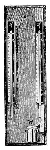
Fig. 157.—Hygrometer
of U. S.
Weather Bureau
type; for determining
atmospheric
humidity.
The rate of evaporation from the wet-bulb covering will vary
with the humidity and if the air is very dry the wet-bulb thermometer
will register a temperature several degrees
below that of the other thermometer. If
the air is saturated with moisture, no evaporation
will take place and the thermometers
will read alike. The relative humidity of the
air as indicated by the readings of the thermometers
is taken directly from a humidity
table. The table is made to suit any condition
of atmospheric humidity and the determinations
require no calculation.
Fig. 157 shows the U. S. Weather Bureau
pattern hygrometer such as is used at the
weather stations. The wet-bulb thermometer
has a muslin or knitted silk covering
which dips into a metal water cup as shown
in the figure. It is important that the
covering of the wet bulb be kept in good
condition. The evaporation of the water
from the covering leaves in the meshes particles
of solid matter that were held in solution
in the water. The accumulation of the
solids ultimately prevent the water from
thoroughly wetting the wick.
An observation consists in reading the two thermometers and
from the difference between the wet-bulb reading and that of the
dry-bulb, the relative humidity is taken directly from the table.
To illustrate, suppose that the dry-bulb thermometer reads 60°
and that the wet-bulb reads 56°. The difference between the
two readings is 4°. In the table of relative humidity on page
202, 60° is found in the column headed, Air temp. t, and opposite[206]
that number in the column headed 4 is 78, which indicates that
under the observed conditions the air is 78 per cent. saturated
with moisture. This table is suited for air temperatures from
35°F. to 80°F. and depressions of the wet-bulb thermometer
from 1°F. to 20°F. The table, therefore, has a range of variations
which will admit humidity determinations for all ordinary
conditions.
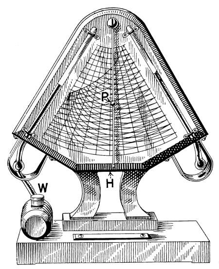
Fig. 158.—The hygrodeik. A form
of hygrometer in which relative humidity
is found directly from a diagram.
The Hygrodeik.
—In Fig. 158 is shown a form of hygrometer
known as a hygrodeik, by means of which atmospheric humidity
may be determined without the use of the tables. In the figure
the wet-bulb and dry-bulb thermometers
are easily recognized.
A glass water bottle W is held
to the base of the instrument
by spring clips which permit its
removal to be filled with water.
Between the thermometers is a
diagram chart from which the
atmospheric humidity is taken.
An index arm, carrying a movable
pointer P, permits the instrument
to be set for any observed
thermometer readings.
The index is really a graphical
method of expressing the figures
given in the table on pages 202-203.
In the picture the wet-bulb
thermometer reads 65°, the
dry-bulb thermometer 77°. To
determine the relative humidity under these conditions the movable
arm is swung to the left and the pointer P placed on the
left-hand scale at the line 65°. The arm is then swung to the
right until the pointer touches the downward curving line beginning
at 77°, the dry-bulb reading. The lower end of the arm H
now points to the relative humidity, where 52 per cent. is indicated
by the scale at the bottom of the index.
The same result is obtained from the table of Relative Humidity.
The readings of the thermometers in the figure give a
difference in temperature of 12°, the dry-bulb thermometer[207]
reads 77°. Referring this data to the humidity table, the
column marked 12, for the depression of the wet-bulb thermometer
and opposite 77° in the air temperature column, is
found 53 which indicates the per cent. of saturation. The
hygrodeik gives further the temperature of the dew-point, on
the scale to the right; and the absolute humidity may be found
by following the upward curving line nearest the pointer, at the
end of which line is given the value in grains
of moisture per cubic foot. The hygrodeik
or other instrument of the kind is very largely
used in places where relative humidity is
regularly observed by those of limited experience,
as in school-rooms, auditoriums,
etc. Such records are not intended to be
perfectly accurate and the readings of the
hygrodeik are very well-suited for the
purpose.
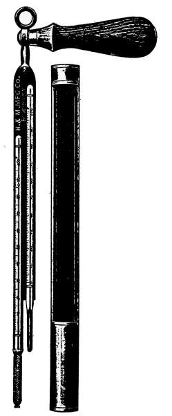
Fig. 159.—Psychrometer
of U. S. Weather
Bureau type; for accurate
determination of
atmospheric humidity.
In using the hygrometer and the hygrodeik
the instruments are stationary; they are
usually hung on the wall in a convenient
location for observation and are placed to
avoid accidental drafts in order that the
conditions surrounding the observation may
be the same at all times. The evaporation
which takes place from the wet bulb is due
to natural convection and does not always
reach the maximum amount. The evaporation
is furthermore influenced by accidental
variations and consequently the results cannot
be considered exact.
Under conditions that demand more exact humidity records
than are obtainable with hygrometer, the psychrometer furnishes
means of making more accurate observation. The psychrometer
shown in Fig. 159 is of the form used by the U. S. Weather
Department. Like the hygrometer, it is composed of a wet-bulb
and a dry-bulb thermometer but no water cup is attached
to the instrument for moistening the wick of the wet bulb. When
ready for use the wick is wet with water before each observation.
The greater accuracy to be attained by the use of this instrument[208]
is on account of the maximum evaporation which is obtained
from the wet bulb for any atmospheric condition. The
evaporation which takes place from the wet-bulb thermometer
in quiet air is not so great as that which occurs if the same air is in
motion. In moving air, however, there is a certain maximum
rate beyond which no further evaporation will take place.
The motion of the air may be produced either by blowing on
the bulb with a fan or air blast, or by whirling the thermometer.
With the psychrometer the latter method is used. This instrument
is provided with a handle which is pivoted to the frame
and about which it is swung to produce a maximum evaporation
from the wick. When a motion of the air is attained sufficient
to produce a saturated atmosphere
about the bulb, the temperature will
remain constant.
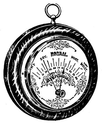
Fig. 160.—Dial hygrometer.
A velocity of air or the motion of
the wet-bulb thermometer 10 feet per
second is that usually taken as the
rate for observation and the swinging
is kept up 3 or 4 minutes or until the
temperature of the wet-bulb thermometer
remains stationary.
Then the temperature of each thermometer
is read and the humidity
found in the table. Relative humidity
determinations may be made at temperatures below the freezing
point if sufficient precaution is taken in the observations.
When the instrument is not in use, it is kept in the metallic
case shown in the picture, to protect it from injury.
Dial Hygrometers.
—Various forms of hygrometers are in use,
in which a pointer is intended to indicate on a dial the percentage
of atmospheric humidity. That shown in Fig. 160 is one of
the common forms. Instruments of this kind depend for their
action on the absorptive property of catgut or other materials
that are sensitive to the moisture changes of the air.
These instruments give fairly accurate readings in a small
range for a limited time, but they are apt to go out of adjustment
from causes that cannot be controlled. Unless they are occasionally
compared with a standard humidity determination, their[209]
readings cannot be relied upon for definite amounts of atmospheric
moisture.
The Swiss Cottage “Barometer.”
—Fig. 161 is one of the
instruments of absorptive class that are sometimes used as
weather indicators. The images which occupy the openings in
the cottage are so arranged that with the approach of damp
weather the man comes outside and at the same time the woman
moves back into the house. In fair weather the reverse movement
takes place. The figures are mounted on the opposite
ends of a light stick which is fastened to an upright pillar. The
movement of the images is caused by the
change in length of a piece of catgut which
is secured to the pillar and also to the frame
of the house. Any change in atmospheric
humidity causes a contraction or elongation
of the catgut which moves the pillar
and with it the images.
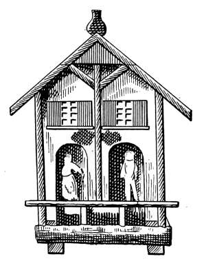
Fig. 161.—Swiss cottage
“Barometer.” This
device is arranged to
show the condition of
atmospheric humidity
by the movement of the
images. It is not really
a barometer.
Since stormy weather is accompanied
by a high degree of humidity and fair
weather is attended with dry atmosphere,
the movement of the images indicates in
some degree the weather changes; but the
device is not in any way influenced by
atmospheric pressure and hence is not a
barometer.
Dew-point.
—Dew is formed whenever
falling temperature of the air passes the
point where saturation occurs. The reduction of the temperature
of air raises the relative humidity because of the diminished
capacity to contain moisture. As the temperature declines
there will come a point at which the air is saturated and any
further decrease of temperature will cause supersaturation. At
this point the moisture will be deposited on the cooler surfaces
in the form of drops. The temperature at which dew begins
to form is known as the dew-point. The sweating of cold
water pipes, the dew that forms on a water glass and other
relatively cold surfaces is caused by a temperature below the
dew-point of the air.
[210]
Dew-point Table
Dew-point in degrees Fahrenheit, barometer pressure 29 inches
Air temp.
t | Vapor
press. e |
Depression of wet-bulb thermometer (t-t´) |
| 1.0 | 2.0 | 3.0 |
4.0 | 5.0 | 6.0 |
7.0 | 8.0 |
| 30 | 0.164 | 27 | 25 | 22 | 18 | 14 | 9 | +3 | -5 |
| 31 | 0.172 | 29 | 26 | 23 | 20 | 16 | 11 | 5 | -2 |
| 32 | 0.180 | 30 | 27 | 24 | 21 | 17 | 13 | 8 | +1 |
| 33 | 0.187 | 31 | 28 | 25 | 22 | 19 | 15 | 10 | 3 |
| 34 | 0.195 | 32 | 29 | 27 | 24 | 20 | 16 | 12 | 6 |
| 35 | 0.203 | 33 | 30 | 28 | 25 | 22 | 18 | 14 | 8 |
| 36 | 0.211 | 34 | 31 | 29 | 26 | 23 | 20 | 15 | 11 |
| 37 | 0.219 | 35 | 32 | 30 | 27 | 24 | 21 | 17 | 13 |
| 38 | 0.228 | 36 | 33 | 31 | 28 | 26 | 23 | 19 | 14 |
| 39 | 0.237 | 37 | 34 | 32 | 29 | 27 | 24 | 21 | 16 |
| 40 | 0.247 | 38 | 35 | 33 | 31 | 28 | 25 | 22 | 18 |
| 41 | 0.256 | 39 | 37 | 34 | 32 | 29 | 26 | 23 | 20 |
| 42 | 0.266 | 40 | 38 | 35 | 33 | 30 | 28 | 25 | 21 |
| 43 | 0.277 | 41 | 39 | 36 | 34 | 31 | 29 | 26 | 23 |
| 44 | 0.287 | 42 | 40 | 38 | 35 | 32 | 30 | 27 | 24 |
| 45 | 0.298 | 43 | 41 | 39 | 36 | 34 | 31 | 29 | 26 |
| 46 | 0.310 | 44 | 42 | 40 | 37 | 35 | 32 | 30 | 27 |
| 47 | 0.322 | 45 | 43 | 41 | 39 | 36 | 34 | 31 | 28 |
| 48 | 0.334 | 46 | 44 | 42 | 40 | 37 | 35 | 32 | 30 |
| 49 | 0.347 | 47 | 45 | 43 | 41 | 39 | 36 | 34 | 31 |
| 50 | 0.360 | 48 | 46 | 44 | 42 | 40 | 37 | 35 | 32 |
| 51 | 0.373 | 49 | 47 | 45 | 43 | 41 | 39 | 36 | 34 |
| 52 | 0.387 | 50 | 48 | 46 | 44 | 42 | 40 | 37 | 35 |
| 53 | 0.402 | 51 | 49 | 47 | 45 | 43 | 41 | 39 | 36 |
| 54 | 0.417 | 52 | 50 | 49 | 47 | 44 | 42 | 40 | 38 |
| 55 | 0.432 | 53 | 52 | 50 | 48 | 46 | 43 | 41 | 39 |
| 56 | 0.448 | 54 | 53 | 51 | 49 | 47 | 45 | 43 | 40 |
| 57 | 0.465 | 55 | 54 | 52 | 50 | 48 | 46 | 44 | 42 |
| 58 | 0.482 | 56 | 55 | 53 | 51 | 49 | 47 | 45 | 43 |
| 59 | 0.499 | 57 | 56 | 54 | 52 | 50 | 48 | 46 | 44 |
| 60 | 0.517 | 58 | 57 | 55 | 53 | 51 | 49 | 47 | 45 |
| 61 | 0.536 | 59 | 58 | 56 | 54 | 52 | 51 | 49 | 46 |
| 62 | 0.555 | 60 | 59 | 57 | 55 | 54 | 52 | 50 | 48 |
| 63 | 0.575 | 61 | 60 | 58 | 56 | 55 | 53 | 51 | 49 |
| 64 | 0.595 | 62 | 61 | 59 | 58 | 56 | 54 | 52 | 50 |
| 65 | 0.616 | 63 | 62 | 60 | 59 | 57 | 55 | 53 | 51 |
| 66 | 0.638 | 64 | 63 | 61 | 60 | 58 | 56 | 54 | 53 |
| 67 | 0.661 | 65 | 64 | 62 | 61 | 59 | 57 | 56 | 54 |
| 68 | 0.684 | 67 | 65 | 63 | 62 | 60 | 58 | 57 | 55 |
| 69 | 0.707 | 68 | 66 | 64 | 63 | 61 | 60 | 58 | 56 |
| 70 | 0.732 | 69 | 67 | 66 | 64 | 62 | 61 | 59 | 57 |
| 71 | 0.757 | 70 | 68 | 67 | 65 | 63 | 62 | 60 | 58 |
| 72 | 0.783 | 71 | 69 | 68 | 66 | 65 | 63 | 61 | 60 |
| 73 | 0.810 | 72 | 70 | 69 | 67 | 66 | 64 | 62 | 61 |
| 74 | 0.838 | 73 | 71 | 70 | 68 | 67 | 65 | 64 | 62 |
| 75 | 0.866 | 74 | 72 | 71 | 69 | 68 | 66 | 65 | 63 |
| 76 | 0.896 | 75 | 73 | 72 | 70 | 69 | 67 | 66 | 64 |
| 77 | 0.926 | 76 | 74 | 73 | 71 | 70 | 68 | 67 | 65 |
| 78 | 0.957 | 77 | 75 | 74 | 72 | 71 | 69 | 68 | 66 |
| 79 | 0.989 | 78 | 76 | 75 | 73 | 72 | 70 | 69 | 67 |
| 80 | 1.022 | 79 | 77 | 76 | 75 | 73 | 72 | 70 | 69 |
Air temp.
t |
Vapor
press. e |
Depression of wet-bulb thermometer (t-t´) |
| 9.0 | 10.0 | 11.0 |
12.0 | 13.0 | 14.0 |
15.0 | 16.0 |
| 30 | 0.164 | -20 | | | | | | | |
| 31 | 0.172 | -14 | -50 | | | | | | |
| 32 | 0.180 | -9 | -29 | | | | | | |
| 33 | 0.187 | -5 | -20 | | | | | | |
| 34 | 0.195 | -2 | -14 | -50 | | | | | |
| 35 | 0.203 | +1 | -8 | -28 | | | | | |
| 36 | 0.211 | 4 | -4 | -19 | | | | | |
| 37 | 0.219 | 7 | -1 | -12 | -44 | | | | |
| 38 | 0.228 | 9 | +3 | -7 | -25 | | | | |
| 39 | 0.237 | 12 | 6 | -3 | -16 | | | | |
| 40 | 0.247 | 14 | 8 | +1 | -10 | -35 | | | |
| 41 | 0.256 | 16 | 11 | 4 | -5 | -21 | | | |
| 42 | 0.266 | 17 | 13 | 7 | -1 | -13 | -59 | | |
| 43 | 0.277 | 19 | 15 | 10 | +3 | -7 | -28 | | |
| 44 | 0.287 | 21 | 17 | 12 | 6 | -2 | -17 | | |
| 45 | 0.298 | 22 | 19 | 14 | 8 | +2 | -9 | -37 | |
| 46 | 0.310 | 24 | 20 | 16 | 11 | 5 | -4 | -20 | |
| 47 | 0.322 | 25 | 22 | 18 | 13 | 8 | +0 | -12 | -53 |
| 48 | 0.334 | 27 | 23 | 20 | 15 | 10 | +4 | -6 | -25 |
| 49 | 0.347 | 28 | 25 | 21 | 17 | 13 | 7 | -2 | -15 |
| 50 | 0.360 | 29 | 27 | 23 | 19 | 15 | 9 | +2 | -8 |
| 51 | 0.373 | 31 | 28 | 25 | 21 | 17 | 12 | 6 | -3 |
| 52 | 0.387 | 32 | 29 | 26 | 23 | 19 | 14 | 9 | +1 |
| 53 | 0.402 | 34 | 31 | 28 | 24 | 21 | 16 | 11 | 5 |
| 54 | 0.417 | 35 | 32 | 29 | 26 | 23 | 19 | 14 | 8 |
| 55 | 0.432 | 36 | 34 | 31 | 28 | 24 | 21 | 16 | 11 |
| 56 | 0.448 | 38 | 35 | 32 | 29 | 26 | 23 | 19 | 14 |
| 57 | 0.465 | 39 | 36 | 34 | 31 | 28 | 24 | 21 | 16 |
| 58 | 0.482 | 40 | 38 | 35 | 32 | 29 | 26 | 22 | 18 |
| 59 | 0.499 | 42 | 39 | 37 | 34 | 31 | 28 | 24 | 20 |
| 60 | 0.517 | 43 | 41 | 38 | 35 | 32 | 29 | 26 | 22 |
| 61 | 0.536 | 44 | 42 | 39 | 37 | 34 | 31 | 28 | 24 |
| 62 | 0.555 | 46 | 43 | 41 | 38 | 35 | 32 | 30 | 26 |
| 63 | 0.575 | 47 | 45 | 42 | 40 | 37 | 34 | 31 | 28 |
| 64 | 0.595 | 48 | 46 | 44 | 41 | 38 | 36 | 33 | 30 |
| 65 | 0.616 | 49 | 47 | 45 | 43 | 40 | 37 | 34 | 31 |
| 66 | 0.638 | 51 | 48 | 46 | 44 | 42 | 39 | 36 | 33 |
| 67 | 0.661 | 52 | 50 | 48 | 45 | 43 | 40 | 38 | 35 |
| 68 | 0.684 | 53 | 51 | 49 | 47 | 44 | 42 | 39 | 36 |
| 69 | 0.707 | 54 | 52 | 50 | 84 | 46 | 43 | 41 | 38 |
| 70 | 0.732 | 55 | 53 | 51 | 49 | 47 | 45 | 42 | 40 |
| 71 | 0.757 | 57 | 55 | 53 | 51 | 49 | 46 | 44 | 41 |
| 72 | 0.783 | 58 | 56 | 54 | 52 | 50 | 48 | 45 | 43 |
| 73 | 0.810 | 59 | 57 | 55 | 53 | 51 | 49 | 47 | 44 |
| 74 | 0.838 | 60 | 58 | 56 | 54 | 53 | 50 | 48 | 46 |
| 75 | 0.866 | 61 | 60 | 58 | 56 | 54 | 52 | 50 | 47 |
| 76 | 0.896 | 62 | 61 | 59 | 57 | 55 | 53 | 51 | 49 |
| 77 | 0.926 | 64 | 62 | 60 | 58 | 56 | 54 | 52 | 50 |
| 78 | 0.957 | 65 | 63 | 61 | 59 | 58 | 56 | 54 | 52 |
| 79 | 0.989 | 66 | 64 | 62 | 61 | 59 | 57 | 55 | 53 |
| 80 | 1.022 | 67 | 65 | 64 | 62 | 60 | 58 | 56 | 54 |
[212]
The temperature at which dew forms will depend on the
amount of moisture present in the air, but with a definite humidity
and air pressure it will always occur at the same temperature.
If the dew-point is above freezing, the dew will form as drops of
water, but if it is at or slightly below the freezing point, the dew
will appear as frost. White frost is formed when the dew-point
is only a few degrees below the freezing point. A Black frost
occurs when the atmospheric humidity is so low that dew does
not form until the temperature is much below the freezing point.
To Determine the Dew-point.
—The dew-point may be found
by a number of methods, usually described in works on physics
but practical determinations are made with a hygrometer or
psychrometer and a dew-point table. Accurate determinations
must be made by the use of the psychrometer; those made by
the hygrometer are approximate. Suppose the reading of the
dry-bulb thermometer is 68 and that this is designated as t;
at the time the wet-bulb temperature is 57 and is called t´.
The depression of the wet bulb for these temperatures (t-t´) is
11°. In the dew-point table above is found in the dry-bulb
column, opposite this number in the column headed 11—under
depression of the wet-bulb thermometer—is 49, which is the
dew-point for the observed conditions.
As another illustration, suppose the dry bulb of the psychrometer
marks 65° and the wet bulb indicates 56°F.; then 65-56
equals 9° of the cold produced by evaporation. The dew-point
is determined in exactly the same way as with the hygrometer.
Opposite 65, in the dry-bulb column of the dew-point table,
under the column of differences marked 9, is found the dew-point
for the observed conditions. This is 49° at which temperature
dew will begin to form.
Frost Prediction.
—The formation of dew is always attended
with a liberation of heat—the heat of vaporization—which tends
to check the further decline of temperature. The heat thus
developed is usually sufficient to prevent the fall of temperature
beyond a very few degrees, but at times when there is little
moisture in the air the fall of several degrees of temperature is
necessary before the heat liberated by the forming dew balances
the heat lost by radiation and the temperature remains
stationary.
[213]
This condition of things was pointed out many years ago by
Tyndall, who in his book on “Heat” states: “The removal for a
single summer’s night of the aqueous vapor which covers England
would be attended by the destruction of every plant which a
freezing temperature would kill.”
The frosts of late spring and early fall which occur at times
of dry air and cloudless sky are often caused by local conditions
that are not forecasted by the weather department and often
may be successfully combated.
At the time of suspected frost, the temperature of the dew-point
in relation to the freezing point determines the probability
of a freezing temperature. If the dew-point occurs at 10° or
more above the freezing point there will be little danger of a
killing frost. As the difference in temperature between the dew-point
and the frost point decreases, the danger of frost increases.
If the dew-point falls at the freezing point, frost is a certainty.
In using the table on page 214, the open diagonal line may be
considered the danger line and any dew-point falling below the
temperature thus indicated will be considered dangerously near
the frost point. This table differs from the other dew-point
table only in the range of temperature. The dew-point is found
in exactly the same way as before. In the use of the psychrometer
and table as a means of frost prediction it is first necessary
to make a reading of the wet-bulb and dry-bulb temperature
described above. The dry-bulb reading is found in the left-hand
column of the table; then follow the horizontal line opposite
the figure, till the perpendicular column is reached indicating
the difference in reading between the dry and wet bulb. The
number at the meeting will be the temperature of the dew-point.
For example, suppose the dry bulb stands at 65° and the wet
bulb at 55°, the difference being 10° and dew-point under these
conditions will be 47°.
If the dew-point is 10° or more above the freezing point there
is no danger of a frost, but if the conditions are such as to give a
temperature difference less than 10° above the freezing point
there would be danger. If the dew-point falls below the open
diagonal line of the table there is danger and that danger increases
as the difference in degrees between the freezing point
and the dew-point becomes less.
[214]
As another illustration, suppose that at sunset at the time of
suspected frost the dry-bulb thermometer read 54 and the
depression of the wet bulb showed 10°. Referring to the table
it will be seen that for these conditions the dew-point falls at 33
which is only 1° above the freezing point. It is highly probable
that frost would form.
Dew-point Table for Frost Prediction
Depression of the wet-bulb thermometer
Dry-bulb
temp. | 1 |
2 | 3 | 4 |
5 | 6 | 7 |
8 | 9 | 10 |
11 | 12 | 13 |
| 70 | 69 | 67 | 66 | 64 | 62 | 61 | 59 | 57 | 55 | 53 | 51 | 49 | 47 |
| 69 | 68 | 66 | 64 | 63 | 61 | 59 | 58 | 56 | 54 | 52 | 50 | 48 | 46 |
| 68 | 67 | 65 | 63 | 62 | 60 | 58 | 57 | 55 | 53 | 51 | 49 | 46 | 44 |
| 67 | 66 | 64 | 62 | 61 | 59 | 57 | 55 | 54 | 52 | 50 | 47 | 45 | 43 |
| 66 | 64 | 63 | 61 | 60 | 58 | 56 | 54 | 52 | 50 | 48 | 46 | 44 | |
| 65 | 63 | 62 | 60 | 59 | 57 | 55 | 53 | 51 | 49 | 47 | 45 | 42 | 41 |
| 64 | 62 | 61 | 59 | 57 | 56 | 54 | 52 | 50 | 48 | 46 | 43 | | 40 |
| 63 | 61 | 60 | 58 | 56 | 55 | 53 | 51 | 49 | 47 | 44 | 42 | 41 | 38 |
| 62 | 60 | 59 | 57 | 55 | 53 | 52 | 50 | 48 | 45 | 43 | | 39 | 37 |
| 61 | 59 | 58 | 56 | 54 | 52 | 50 | 48 | 46 | 44 | 42 | 41 | 38 | 35 |
| 60 | 58 | 57 | 55 | 53 | 51 | 49 | 47 | 45 | 43 | | 39 | 36 | 33 |
| 59 | 57 | 56 | 54 | 52 | 50 | 48 | 46 | 44 | | 40 | 38 | 43 | 32 |
| 58 | 56 | 55 | 53 | 51 | 49 | 47 | 45 | 42 | 41 | 39 | 36 | 33 | 30 |
| 57 | 55 | 54 | 52 | 50 | 48 | 46 | 44 | | 40 | 37 | 35 | 31 | 28 |
| 56 | 54 | 53 | 51 | 49 | 47 | 44 | 42 | 41 | 39 | 36 | 33 | 30 | 26 |
| 55 | 53 | 52 | 50 | 48 | 46 | 43 | | 40 | 37 | 34 | 31 | 28 | 25 |
| 54 | 52 | 50 | 49 | 46 | 44 | 42 | 41 | 39 | 36 | 33 | 30 | 27 | 23 |
| 53 | 51 | 49 | 47 | 45 | 43 | | 40 | 37 | 34 | 31 | 28 | 25 | 20 |
| 52 | 50 | 48 | 46 | 44 | 42 | 41 | 38 | 36 | 33 | 30 | 27 | 23 | 18 |
| 51 | 49 | 47 | 45 | 43 | | 40 | 37 | 34 | 31 | 28 | 25 | 21 | 16 |
| 50 | 48 | 46 | 44 | 42 | 41 | 38 | 36 | 33 | 30 | 27 | 23 | 19 | 14 |
| 49 | 47 | 45 | 43 | | 40 | 37 | 34 | 31 | 28 | 25 | 21 | 17 | 11 |
| 48 | 46 | 44 | 42 | 41 | 38 | 36 | 33 | 30 | 27 | 23 | 19 | 14 | 9 |
| 47 | 45 | 43 | | 40 | 37 | 35 | 32 | 29 | 25 | 22 | 17 | 12 | 6 |
| 46 | 44 | 42 | 41 | 39 | 36 | 33 | 30 | 27 | 24 | 20 | 15 | 10 | 3 |
| 45 | 43 | | 40 | 37 | 35 | 32 | 29 | 26 | 22 | 18 | 13 | 7 | -1 |
| 44 | 42 | 41 | 39 | 36 | 33 | 30 | 27 | 24 | 20 | 16 | 11 | 4 | -5 |
| | | 40 | 37 | 35 | 32 | 29 | 26 | 23 | 19 | 14 | 8 | 1 | -9 |
| 43 | 41 | 39 | 36 | 34 | 31 | 28 | 25 | 21 | 17 | 12 | 6 | -2 | -15 |
| 42 | 40 | 38 | 35 | 33 | 29 | 26 | 23 | 19 | 15 | 9 | 3 | -6 | -22 |
| 41 | 39 | 36 | 34 | 31 | 28 | 25 | 22 | 17 | 13 | 7 | 0 | -11 | -32 |
| 40 | 38 | 35 | 33 | 30 | 27 | 24 | 20 | 16 | 11 | 4 | -4 | -16 | -74 |
| 39 | 37 | 34 | 32 | 29 | 26 | 22 | 18 | 14 | 8 | 2 | -8 | 23 | |
| 38 | 36 | 33 | 31 | 28 | 24 | 21 | 17 | 12 | -6 | -1 | -12 | -35 | |
[215]
Prevention of Frost.
—From the discussion of frost formation
it is evident that, the temperature of the dew-point being the
determining factor in its probable occurrence, any expedient that
may be used either to increase the humidity or to conserve the
radiation of heat would prevent a dangerous decline of temperature.
Frost prevention is practised in all fruit-growing regions
and the method pursued depends on the kind of vegetation to
be protected.
In the protection of orchards the use of smudge pots are probably
the commonest means for preventing the loss of heat.
The object is to create a cloud of smoke over and about the
orchard so that it forms a protective covering which prevents
the escape of the heat.
In the case of a light frost—that is, where the temperature
falls only a few degrees below the frost point—the plants in small
gardens and flower beds may be prevented from freezing by
liberal sprinkling with water. This is done to raise the humidity
of the atmosphere surrounding the vegetation. Most vegetation
withstands the temperature at the freezing point without particular
injury, and the freezing of part of the water liberates heat in
sufficient quantity to prevent a further decline of temperature.
This heat liberated on the freezing of water is described in physics
as the heat of fusion and in changing part of the water into ice
sufficient heat is liberated to check the further fall of temperature.
Humidifying Apparatus.
—Opportunity for adding moisture,
in the desired quantity, to the air of the average dwelling is
limited to the evaporation of water in the heating plant, from
vessels attached to the radiators or that which goes on in the
kitchen. Household humidifying plants are within the range
of possibility but there is not yet sufficient demand for their
use to make attractive their manufacture.
In the hot-air furnace a water reservoir is usually a part of the
chamber in which the air supply is heated. The water in the
reservoir is heated to a greater or lesser degree, depending on the
temperature of the furnace and vaporized both by heat and by
the constantly changing air.
In the use of a steam plant or hot-water heating plant the
opportunity of humidifying the air is very limited. One method
is that of suspending water tanks to the back of the radiators[216]
from which water is vaporized. While this method is fairly
efficient as a humidifier it is inconvenient and therefore apt to be
neglected. In houses heated by stoves there are sometimes
water urns attached to the top of the frame which are intended
for the evaporation of water but as a rule they are not of sufficient
size to be of appreciable value.
The quantity of water required to humidify the air of a house
will depend first, on the temperature and humidity of the outside
air; second, on the cubic contents of the building; third,
on the rate of change of air in the building. If the ventilation
is good the rate of atmospheric change is rapid and the amount
of water in consequence must be correspondingly increased.
The data included in the following table showing the relative
humidity and amount of water required were taken from a seven-room
frame dwelling in Fargo, N. D., during particularly severe
winter weather. The relative humidity determinations were
made with a hygrodeik each day at noon. The house was heated
by a hot-air furnace arranged to take its air supply from the
outside.
The air supply is recorded under Cold-air intake. The furnace
was provided with a water pan for humidifying the air supply.
The amount of water evaporated each day is recorded in the column
headed Evap. in 24 hours. The outside temperature
ranged from -12°F. to -21°F. The weather was clear and calm
except the last day, Jan. 12, which was windy. The higher
humidity on that day was no doubt due to the greater amount
of heat required from the furnace and the consequent evaporation
of the water from the water pan.
The humidity determinations made by a hygrodeik, as before
explained, are only approximately correct but sufficiently exact
for practical purposes. The temperature is given in degrees
Fahrenheit.
In the table it will be noticed that the outside air was used
only a part of the time because of the severity of the weather.
Attention is called to the quantity of water required to keep the
humidity at the amount shown. This averages 27½ quarts
per day. At the time these observations were made the physics
lecture-room at the North Dakota Agricultural College averaged
18 to 20 per cent. saturation during class hours, with observations[217]
made from a similar instrument. This is a steam-heated room
with only accidental means of adding water to the air. The
result was an atmosphere 3½ per cent. above that of Death
Valley.
Hot-air Furnace
Readings taken at 12 o’clock noon each day
| Date |
Temp.
outside |
Wet
bulb |
Dry
bulb |
Per cent.
saturated |
Evap. In
24 hours |
Cold-air intake |
| quarts | pints |
| Dec. 13 | -13 | 54° | 63° | 53 | | | Closed 8 a.m. |
| Dec. 14 | -18 | 55 | 66 | 47 | | | Open |
| Dec. 15 | -20 | 57 | 68 | 49 | 21 | | Closed 7 a.m. |
| Dec. 16 | -18 | 57 | 67 | 51 | 20 | 1 | Closed 7 a.m. |
| Dec. 17 | -22 | 58 | 69 | 48 | 18 | 1 | Closed 7 a.m. |
| Dec. 18 | -16 | 55 | 65 | 51 | 17 | 1½ | Closed 6:30 a.m. |
| Dec. 19 | -10 | 57 | 68 | 47 | 20 | 1 | Closed 8 a.m. |
| Dec. 20 | 0 | 59 | 70 | 49 | 13 | ¾ | Not open at night |
| Jan. 8 | -12 | 58 | 71 | 43 | 18 | | Closed |
| Jan. 9 | -17 | 57 | 71 | 39 | 25 | | Open 24 hours |
| Jan. 10 | -16 | 58 | 69 | 45 | 27 | 1 | Open 10 hours |
| Jan. 11 | -21 | 60 | 75 | 40 | 30 | | Closed |
| Jan. 12 | -15 | 60 | 73 | 46 | 30 | | Closed |
The amounts of water evaporated may seem large to those
who are unaccustomed to quantitatively consider problems in
ventilation but the small amount of water in the air at -21°
must produce a very dry atmosphere when it is raised to 70° in
temperature.
The amount of moisture in air at 20°F. and at 80 per cent.
humidity is only 1.58 grains to the cubic foot. If this air is
now raised to 70° the moisture will still be 1.58 grains where
there should be 4 grains of water to make 50 per cent. humidity.
It therefore will require the addition of practically 2.42
grains of water for each cubic foot of entering air in order to
bring it up to 50 per cent. humidity.
In a case with the above conditions of atmosphere, suppose
it is desired to know the amount of water that would be taken
up in humidifying the air for a school-room of size to accommodate
40 pupils. The prescribed quantity of air for this purpose is[218]
30 cubic feet per minute for each pupil. The air is to be maintained
at a humidity 50 per cent. saturated. The problem will
be one of simple arithmetic. If each pupil is to receive 30 cubic
feet of air per minute or 1800 cubic feet per hour, the 40 pupils
receiving 1800 cubic feet per hour will require 40 × 1800 = 72,000
cubic feet of air per hour. To each cubic foot of the air is to be
added 2.74 grains of water, 72,000 × 2.42 = 164,240 grains of
water. Reducing this to pounds, 164,240 ÷ 7000 = 23.46
pounds or 2.77 gallons of water per hour.
In practice the room will show a higher amount than 50 per
cent. humidity with this addition of the amount of water, because
of the water vapor that is exhaled from the lungs of the pupils.
That a considerable amount of water vapor is added to the atmosphere
by breath exhalation is made evident from the moisture
condensed by breathing on a cold pane of glass. In any unventilated
room occupied by a considerable number of people the
humidity is thus increased a very noticeable amount.
The change in humidity of the air in a closed room filled with
people is very pronounced. The constant exhalation of moisture
from the lungs is sufficient to saturate the air in a short time.
The heavy atmosphere of overcrowded, unventilated rooms is
due to moisture exhalation, body odors and increased carbonic
acid gas. As the humidity of the atmosphere is increased a
sensation of uncomfortable warmth is the result of the lesser
evaporation.
[219]
CHAPTER XI
VENTILATION
The purity of air in any habitable enclosure is determined by
the amount of CO2 (Carbonic acid gas) included in its composition.
The process of ventilation is that of adding fresh air to
the impure atmosphere of houses, until a desirable quality is
attained. In the opinion of hygienists, when air does not exceed
6 to 8 parts of CO2, by volume in 10,000, the ventilation is desirable.
Ordinary outdoor air contains about 4 parts of CO2 to
10,000, while very bad air may contain as high as 80 parts to the
same quantity. The quantity of air required for the ventilation
of a building is determined by the number of people to be provided.
The amount of air required per individual per hour
necessary to produce a desired condition of ventilation is determined
by adopting a standard of purity to suit the prevailing
circumstances.
In hospitals where pure air is considered of greatest importance
4000 and 5000 cubic feet per inmate per hour is not uncommon.
The practice of supplying 30 cubic feet of air per person
per minute (1800 cubic feet per hour) seems to fulfill the average
requirements. It is the amount commonly specified for
school-rooms.
The quantity of fresh air required per person to insure good
ventilation will depend on the type of building to be supplied
and varies somewhat with different authorities. The De Chaumont
standard is that of 1 cubic foot of air per second or 3600
cubic feet per hour, for each person to be accommodated. De
Chaumont assumed a condition of purity which will permit less
than 2 parts in 10,000 of CO2 over that carried by country air.
In considering the same problem from the basis of permissible
CO2, if 6 parts of CO2 in 10,000 represents purity of the required
air, then 3000 cubic feet per person per hour is necessary. Likewise,
the varying amounts for different degrees of purity are[220]
given by Kent in the following table. The upper line gives the
permissible number of parts of CO2 per 10,000, while below each
factor appears the number of cubic feet of air required per hour
for each person supplied.
| 6 | 7 | 8 |
9 | 10 | 15 |
20 | = Parts of CO2 per 10,000 |
| 3,000 | 2,000 | 1,500 |
1,200 | 1,000 | 545 |
375 | = Cubic feet of pure air per hour |
It is generally recognized, that it is possible to live under
conditions where no attempt is made to change the air in a building.
It is also an established fact that the only preventive and
cure for tuberculosis is that of living constantly in an atmosphere
of the purest air. The greatest attainable degree of health is
enjoyed by those who live in the open air, because oxidation
is one of the most efficient forms of prevention and elimination
of disease, and an abundance of pure air is the only assured
means of sufficient oxidation.
The De Chaumont standard is intended to represent the limit
beyond which the sense of smell fails to detect body odors or
“closeness” in an occupied room. The amount of CO2 that air
contains is not an absolute index of its purity, but it gives a
standard under ordinary conditions, makes possible the requirement
of a definite quantity of air. If it were possible to express
the amount of oxygen contained in the atmosphere, the same
relative condition might be attained.
The ordinary man exhales 0.6 cubic foot of CO2 per hour.
Some forms of lighting apparatus produces this gas in greater
amounts. The ordinary kerosene lamp gives out 1 cubic foot of
CO2 per hour. A gas light using 5 cubic feet of gas per hour
produces 3.75 cubic feet of CO2 in the same time. Any form
of combustion permitting the products to escape into the air
of the room tends to lower the quality of the atmosphere by adding
to its content of CO2.
The prevailing impression that impure air is heavy and settles
to the floor is erroneous. Impurities in the form of gases and
vapors (principally carbonic acid gas and odors) diffuse throughout[221]
the entire space, and the entering fresh air tends to dilute
the entire volume.
As a quantative problem, ventilation consists in admitting
pure air into an impure atmosphere in amount to give a definite
degree of purity. This is accomplished by admitting sufficient
air to completely change the atmosphere at stated intervals, or
to provide a definite quantity for each inhabitant.
The methods by which ventilation may be accomplished will
depend on the type of building to be ventilated and the apparatus
it is possible to use. When the use of mechanical ventilation
appliances are permissible, any desired degree of atmospheric
purity may be maintained at all times, under any condition of
climate or change of weather.
In buildings where mechanical ventilation cannot be considered
as that of the average dwelling, the problem is one of producing
an average condition of reasonably pure air by natural convection.
In the average dwelling, ventilation is accomplished by
the natural draft produced in chimneys or air flues, by partially
opened windows and by the force produced by the movement of
the outside air. In some buildings a better condition of ventilation
is attained by ordinary means than at first sight seems
possible.
The fact that it is difficult to keep a house at the desired temperature
during cold weather indicates that a considerable
quantity of outside air is constantly entering and heated air is
leaving the building. It may be, however, that the ventilation
under such condition is unsatisfactory, even though the
amount of air which enters the building is sufficient in quantity
to produce a desirable atmosphere. If the places of entrance
and exit are so located that the entering air has no opportunity
to mix with the air of the building, the advantage of its presence
is lost.
In the burning of fuel in stoves and furnaces, the amount of
oxygen necessary for combustion is supplied by the air which is
first taken into the house and thus forms its atmosphere before
it can enter the heater. Theoretically, about 12 pounds of air are
required for the combustion of a pound of coal, but in practice
a much larger amount actually passes through the heater. As
given by Suplee, from 18 to 24 pounds of air are actually used[222]
in burning 1 pound of coal. If 20 pounds of air per pound of fuel
is taken as an average, there will be required 198 cubic feet of
air per pound of coal consumed. In a building that requires 10
tons of coal to be used during the winter months, this would
necessitate the average use of 1977 cubic feet of air per hour,
which must be drawn into the house before it can enter the stoves.
This air acts as a means of ventilation and if it is used to advantage
would furnish a supply sufficient in amount to produce
excellent ventilation, considerably more than enough for two
people. The amount of air drawn into the house in this way is
further increased by that which passes into the chimney flue
through the check-draft dampers, when the
fires are burning low.
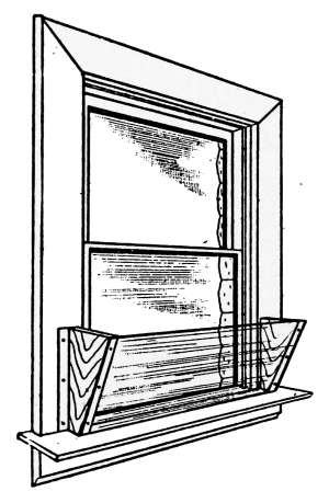
Fig. 162.—A simple
expedient for the prevention
of drafts and
improving ventilation.
The aim of architects is to construct
buildings as completely windproof as possible,
but that such construction is attained
in only a slight degree is sometimes very
evident during cold weather. No matter
how tightly constructed buildings may be,
most of the contained air filters through the
cracks and crevices of the walls or through
the joints of the windows and door frames,
because there is seldom any special provision
made for its entrance. During extremely
cold and windy weather the amount of air
that enters the house in this way—because
of the air pressure on the windward side—is sometimes sufficient
to keep the temperature at an uncomfortably low degree. Under
such conditions, the air drifts through the building faster than
it can be raised to the desired temperature and the rooms on the
windward side of the building cannot be kept comfortably warm.
The common method of ventilation in dwellings is that of
partially open windows. The air thus admitted, being colder
and consequently heavier than that at the temperature of the
room, sinks to the lowest level. In so doing it creates drafts
that produce discomfort and act only in the smallest degree to
produce the desired effect of ventilation. The effect of window
ventilation may be greatly improved by a simple expedient
illustrated in Fig. 162. In this, the entering air meets a deflector[223]
in the form of a board or pane of glass that directs the cold air
upward where it mingles with the heated air with the least production
of a noticeable draft. This is the most efficient method
of house ventilating where no special provision is made for the
admission of fresh air.
The object sought in ventilating a room is to keep up the
quality of the air by constant addition of fresh air, and in order
to bring about a uniform purification of the entire atmosphere
the entering air must be mixed with that already in the enclosure.
If the discomforts of drafts are to be avoided, this mixing process
must be brought about by admitting the cold air at the
upper part of the room.
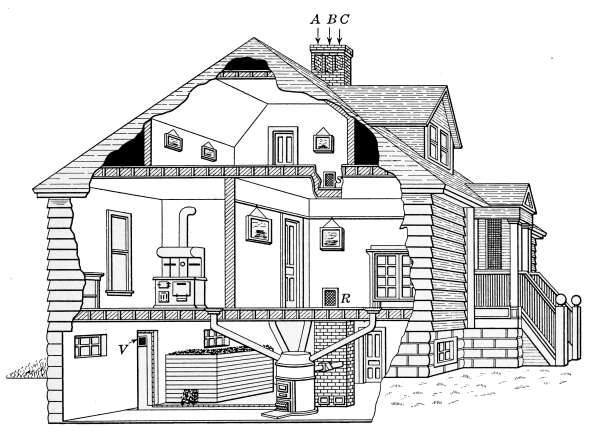
Fig. 163.—A chimney flue used as a ventilator.
Warm air rises to the top of the room because it is lighter than
the colder air beneath it. The coldest air is always lowest in
point of elevation and unless there is some means to stir up the
entire volume this condition will always remain the same.
When the easiest means of air for entering and leaving are near
the floor, the cold entering air and that which goes out will
always be in the lower part of the room, even when the supply[224]
is amply large. If no opportunity is given for the fresh air to
mix with that already in the room, a poor average quality will
result.
In the process of ventilation, the entering air should be admitted
at, or directed toward, the highest part of the room, so that
the pure cold air may have a chance to mix with that which is
warmest. Air is not a good conductor of heat, and in mixing
warm and cold air the cold particles will tend to float downward
and take up heat from the warmer air with which it comes into
contact, and thus produces a more uniform temperature.
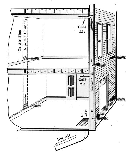
Fig. 164.—Method of admitting cold air into rooms so as to produce the best
condition of ventilation.
The condition most to be desired is that of admitting cold
air at a point where it will most readily mingle with the warm
air from the source of heat. The reduction in temperature that
must take place from this mixture will produce a gravitational
circulation. Unfortunately this is not always possible to attain
in an old building, but in the construction of a new building air[225]
ducts placed to admit air at points near the ceiling and located
with reference to the supply of heat will bring about the best
effect of ventilation.
The air which enters a room should, therefore, be near the
top or so directed that the entering shaft will carry it upward.
The air which is taken out of the room should leave from a point
near the floor. In so doing it will tend to produce a more uniform
quality and a more even distributor of the heat.
In order that the most desirable quality of atmosphere may
be attained, there should be a constant supply of pure air entering
and an equal amount discharging from the house. In the
better-constructed dwelling such a condition is often provided
through a ventilating flue that is a part of the chimney. This
flue is arranged with registers placed to take air from the parts
of the house requiring the greatest amount of air. Such an
arrangement is shown in the picture in Fig. 163.
Fig. 164 shows the method of Fig. 163 combined with a
direct means of admitting fresh air from the inside. The fresh
air ducts should be provided with dampers to control the effect
of extreme cold and wind.
Quantity of Air Discharged by a Flue.
—Any change of temperature
of air produces a change equal to 1⁄491 part of its
volume, for each degree variation. If a cubic foot of air is raised
in temperature 1°F., its volume is 1⁄491 part larger than the
original volume, and its buoyancy in the surrounding air is
increased correspondingly. Air that has a temperature higher
than that surrounding it will tend to rise because it is lighter.
The air rising from a hot-air register or from a heated surface
are illustrations of this condition.
Since the change of volume—or what is the same thing, its
tendency to rise—increases 1⁄491 for each degree difference in
temperature, the upward velocity of highly heated air will be
very great. In warm air that fills a chimney flue or a room, the
same tendency exists, the warmest air rises to the highest point
and if the air can escape, as in the case of a chimney, a draft will
result.
The draft of a chimney, in quiet air, is due to the difference in
temperature between the air inside the flue above that outside the
house. A chimney that does not “draw” and causes a stove to[226]
“smoke,” will often produce sufficient draft after the flue
has been warmed. The upward movement of the warmer air
in the flue produces a constantly increasing velocity, until it
reaches the top of the chimney. This is an accelerated velocity
that may be calculated by use of the formula given in physics,
to express the velocity of accelerated motion. The well-known
formula V = √(2gh) may be modified to express the conditions
existing in a flue and permit of the calculation of the quantity
of air discharged.
The upward flow of air in a chimney flue being due to the
difference in temperature of the air in the flue over the outside
air, the flow of air from the rooms will continue as long as the
difference in temperature exists. Moreover, the air that is
discharged from the rooms will be replenished from the outside,
and for the air sent out of the flue a corresponding amount will
be brought into the rooms through any openings that exist—door
or windows or through cracks or crevices, depending on the
completeness with which the house is closed. In no case is a
house air-tight. The air pressure registered by the barometer is
always the same inside as that outside the building. During
cold weather, when the windows and doors are closed, the air is
escaping through the chimney and also through every little
crack and chink in the top of the rooms where the air is warmest.
The colder air is entering at the same time through the joints
about windows, door casings, through the crevices in the walls
and particularly through the open joints made by the baseboards
and the floor. This latter entrance of cold air is one of the commonest
causes of cold floors. The shrinkage of the baseboards
and floors from the quarter-round moulding which forms the
joint leaves openings through which cold air is freely admitted
from partitions and outside walls. The cold, heavier air remains
near the floor because it can rise only when heated or forced
upward by a draft. If the same air were permitted to enter at
points near the ceiling and mingle with the warmest air in the
room, a more uniform temperature would result, as well as
better ventilation. The entering cold air, mixing with the
warm air at the top of the room, would be reduced in its temperature
and weight. The heavier air in falling would diffuse[227]
with the air beneath it and thus improve the general quality of
the atmosphere.
It is important to remember that the discharge of air through
a chimney flue will depend, in considerable amount, on the rate
the new air is able to enter the house. In a new, tightly constructed
house, the flue is often capable of discharging air much
faster than it can enter, when it must find its way in through
accidental openings. In such cases an open door or window immediately
improves the draft of the stove.
The ventilation in the average dwelling is and must be accomplished
by natural draft that is generated through difference
in temperature of the air. The possibility of providing an
acceptable system of continuous ventilation is confined to the
draft of the chimney or to a flue provided especially for that
purpose. Such being the case, the dimensions of flues constructed
for ventilation should be the subject of investigation.
The work that a chimney or ventilating flue has to do is continuous
and will last throughout its lifetime; its proportions
should therefore be considered with more than passing care.
It has been stated that the method of calculating volumes of
air that will pass through a flue is based on the formula used to
express the velocity of accelerated motion. The fundamental
formula must be changed to suit the conditions produced when
air is heated and made buoyant by expansion.
As has been stated, the change in temperature of air 1°F.
causes an increase or decrease 1⁄491 part of its volume for each
degree change. Any portion of air, warmer than that which
surrounds it, tends to rise because of its lighter weight; the tendency
to rise increases with the difference in temperature. The
draft of a flue is caused by this condition of difference in temperature
between the air inside the flue and the outside atmosphere.
In order that this general condition may be expressed in the
simplest form let: T = the temperature inside the flue in degrees
F.
t = the temperature outside the flue in degrees F.
H = the height of the flue in feet.
The quantity (T-t)/491 expresses the difference in temperature in
degrees, divided by the change of volume for each degree. This[228]
gives the constant upward tendency of the air in passing through
the flue. If this quantity is placed in the formula V = √(2gh),
so as to exert its influence through the height of flue H, the condition
may be expressed:
V = √(2g((T-t)/491)H)
The factor g, representing the acceleration of gravity, is
constant and equal to 32 feet per second. The quantity 2g
may be removed from under the radical and the formula becomes:
V = 8√(((T-t)/491)H)
The formula may now be used to express the volume of discharge
of air from a flue. Suppose such a flue contains an area
of 1 square foot in cross-section and that it is desired to estimate
the air discharged from the flue per hour. The value of g is given
in feet per second, and in order to make the formula express the
volume of air discharged in cubic feet per hour, it must be
multiplied by the number of seconds in an hour. Volume
discharged in cubic feet per hour
= 60 × 60 × 8√(((T-t)/491)H) = 28,800√(((T-t)/491)H)
This formula applies to conditions such as will permit uniform
movement of the air in a straight flue, uninfluenced by irregular,
odd-shaped passages and rough surfaces. Moreover, it is
supposed that the air may enter the house as rapidly as it escapes.
The theoretical discharge will, in most instances, be less than the
calculated amount, because the air cannot enter the house as
fast as it may be discharged by the flue. It is a common custom
to consider the theoretical flue only 50 per cent. efficient. As
applied to the formula, the constant 28,800 when reduced 50 per
cent. will become 14,400, and will be so used in the calculations
as follows.
As an illustration of the application of the formula, suppose
that the temperature in the house and in the flue is 70°F. and that
the outside temperature is 20°F. The height of the chimney is
30 feet. The area of the flue is 1 square foot.
[229]Volume = 14,400 √(((T - t)/491)H)
= 14,400√(((70 - 20)/491) × 30)
= 25,140 cubic feet per hour.
Such a ventilating flue would be sufficient in size, under the
conditions given, to furnish air at the rate of 25,140 cubic feet
per hour or 30 cubic feet per minute to 13 persons, provided of
course that the air could enter the building at the rate demanded.
Where no provision is made for the air to enter the building
it must find its way by the accidental openings. A common
illustration of this effect may be noticed in the rate at which the
fire of a stove will burn in a tightly closed room. The opening
of a door or window causes an immediate increase of combustion,
because of the extra air supply. It is evident that in well-constructed
houses other means should be provided for admitting
air than that of accidental opening.
The following table calculated by the above formula gives the
quantity of air in cubic feet per hour discharged through a flue
of 1 square foot cross-section. The table shows the calculated
discharge from flues of heights varying from 15 to 40 feet, and
with temperature differences from 10° to 100° between the outside
air and that of the house.
Height of flue
in feet | Temperature of air in the flue above that of external air |
| 10 | 15 | 20 | 25 | 30 | 50 | 100 |
| 15 | 7,980 | 9,720 | 11,280 | 12,550 | 13,800 | 17,820 | 25,140 |
| 20 | 9,180 | 11,180 | 13,080 | 14,520 | 15,900 | 20,520 | 29,040 |
| 25 | 10,260 | 12,600 | 14,520 | 16,260 | 17,820 | 22,980 | 32,460 |
| 30 | 11,280 | 13,800 | 15,900 | 17,825 | 19,500 | 25,140 | 35,580 |
| 35 | 12,180 | 14,880 | 17,160 | 19,200 | 21,060 | 27,180 | 38,400 |
| 40 | 13,020 | 15,900 | 18,360 | 20,520 | 22,500 | 29,040 | 40,980 |
In Fig. 163 is illustrated the form of chimney that is often used
for the ventilation of dwellings. This is built with three flues.
The flue to the left—marked A at the top—is intended to carry
away the smoke and gases from the kitchen range. The flue[230]
to the right is that to which is connected the smoke pipe from the
furnace. The flue in the middle marked B is for ventilation.
Occupying as it does the space between the other two, it is kept
warm by the heat of the other flues and the draft is thus increased.
Openings to the flue are shown in the different floors at the points
R and S. The openings are furnished with registers which may
be regulated to suit the weather conditions.
The dimensions of such a flue may be calculated by the formula
given or the area may be taken from the table to correspond
with required conditions. In all cases flues should be made
ample in size, as they must often do their maximum work under
the poorest conditions for the production of good draft.
The amount of air discharged from the flue as given in the
table is due to the gravitational effect alone. The suction
produced by the wind adds in a very large degree to the amount
of air discharged. The quantity of air that will flow from a
30-foot flue, by reason of the suction of the wind, blowing 7 miles
per hour is equal to the same flue working by gravity with a
temperature difference of 20°. With a wind velocity of 7 miles
per hour and a temperature as given, the capacity of the flue is
doubled. It is easy, therefore, to understand why the rate at
which fires burn is so greatly increased by high winds. At the
time of very high winds, a chimney flue will carry away three
and even four times the volume discharged at the time of atmospheric
calm.
Cost of Ventilation.
—The cost of good ventilation is often
looked upon as prohibitive, because of the expense in heat necessary
to keep the inside atmosphere at standard purity. Cost of
ventilation is determined by analysis of the known conditions and
calculations made of the amount of extra heat necessary to
warm the greater volume of air.
The common practice of estimating the quantity of heat used
in any form of heating or ventilation is by reference to the B.t.u.
used in producing the desired condition. This unit, as has already
been stated, is the amount of heat necessary to change a
pound of water, 1°F.
In considering the cost of heating the air for ventilation, it
must be borne in mind that the heat used in raising the temperature
of the air contained in an enclosure is only a part of that[231]
necessary for warming the building. Most of the heat used goes
to keep up the loss due to radiation and conduction which goes
on from the windows, the walls and other parts of the building
that are exposed to the outside cold. The material of which
the building is composed must be heated and in turn radiates
its heat to the colder outside air.
The quantity of heat necessary to change the temperature of
a definite amount of air is easy of calculation. The problem
is that of determining the number of heat units required to
warm the necessary air to suit the average condition of weather.
We will assume that the house is heated to the normal temperature
70°, and that the additional cost of heating the air for ventilation
over the amount thus expended is the cost of ventilation.
Assuming that the house is so constructed that it is possible
to supply air at the rate of 1000 cubic feet per hour to each
person of a family of five, this condition will necessitate 5000
cubic feet of air per hour or 120,000 cubic feet of air per day.
The house is such that 10 tons of coal are required per year,
at a cost of $10 per ton. The period of winter weather will be
considered 5 months of 30 days each. This will be 150 days,
during which the fuel for heating the house will cost 662⁄3 cents
per day.
The average temperature of the outdoor air during the entire
period will be assumed to be 20°F., thus requiring the air for
ventilation to be changed 50° in order to raise it to the normal
temperature, 70°.
The weight of a cubic foot of air at 70° is practically 0.075
pound. The 120,000 cubic feet of air used per day will, therefore,
weigh 0.075 × 120,000 = 9000 pounds which must be raised
50° in temperature.
In order to express in B.t.u. the necessary heat required to
produce the change of air temperature, the quantity of air is
best stated in an equivalent amount of water. The specific
heat of air is 0.237; that is, the amount of heat necessary to
change a pound of air 1° is 0.237 of the amount used in changing
1 pound of water 1°. The 9000 pounds of air expressed as an
equivalent amount of water will then be:
9000 × 0.237 = 2133 pounds of water.
[232]
This amount of water raised 1° is equivalent to raising 120,000
cubic feet of air 1°. Now the average change in the temperature
of the air is 50°, so that 50 × 2133 will be the number of heat
units used.
50 × 2133 = 106,650 B.t.u.
That is, 106,650 B.t.u. will be required to heat the air for
ventilation one day.
In order to express this amount of heat in terms of fuel consumed,
it will be assumed that the coal contained 14,000 B.t.u.
per pound, this being a fair valuation of good coal. The average
house-heating furnace will turn into available heat about 50
per cent. of the fuel burned. This value is taken from house-heating
fuel tests made at the Iowa State College. The available
heat in each pound of coal then will be 7000 B.t.u.
106,650 ÷ 7000 = 15.2 pounds of coal.
That is, 15.2 pounds of coal per day must be burned in order
to furnish 1000 cubic feet of air per person each hour at the
desired temperature.
At $10 a ton of 2000 pounds, the fuel costs ½ cent per pound.
The cost of ventilation is, therefore, ½ × 15.2 = 7.60 cents a
day, not an extravagant amount for good air.
It is evident that with the use of hot-air furnaces which take
their entire amount of air from outdoors, the extra amount of
heat necessary for this improved quality of atmosphere is very
well expended. The use of ventilating devices adds only a
relatively small amount to the total cost of heating and provides
for the well-being of the occupants of the house—in the form of
good air—an amount of healthfulness impossible of calculation.
The best ventilation is attained where a constant supply of
fresh air is admitted to the house at points from which the best
circulation may be secured and equal quantities of vitiated air
are removed from the different apartments.
It is understood that in the process of natural ventilation the
desired condition can only be approximated and that the permissible
ventilation appliances are so placed as to give results
such as to permit the air to follow the natural laws that must
prevail.
[233]
If the house is heated by stoves, the outside air is best admitted
near the ceiling, so that the cold air on entering may come into
contact and mingle with the warmest air in the room. The
circulation will by this method be effected by gravity.
In the use of the hot-air furnace, the air supply—as has already
been explained in the figures on pages 55 and 58—is brought
from the outside, where after being heated it enters the rooms
through the registers placed near the floor. Being
warmer than the air in the room, it tends to
quickly rise. The currents set up by its motion
help to produce a uniform temperature and to
diffuse the new air through the entire space. The
more evenly the air is distributed the more uniform
will be the condition of temperature of the
room.
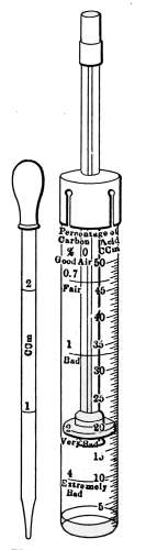
Fig. 165.—The
Wolpert air
tester; an instrument
used to determine
the quality
of air.
In hot-water and steam heating, the direct
method of heating in Fig. 29 and the indirect
method of Fig. 30 show two forms of apparatus
for admitting air to buildings that are quite generally
employed for ventilation of dwellings. In the
use of all such devices for ventilation purposes,
there should be provided means of escape of air
corresponding in amount to the fresh air admitted.
The exhaust air vent should be located near the
floor to bring about the best results. The degree
of success attending the use of such apparatus
will depend on the amount of care taken, to suit
the position of the dampers to the prevailing
weather.
The Wolpert Air Tester.
—The purity of air is
expressed by quantity of carbonic acid gas included
in its composition. In order to determine the degree of
purity of any atmosphere the amount of contained gas must be determined.
This is accomplished by use of simple apparatus that
may be successfully operated by those who are unacquainted
with chemical analytical methods. The process is due to
chemical action but the manipulation of the required apparatus
is purely mechanical.
Fig. 165 shows the Wolpert air tester which is a form of this[234]
apparatus that has given general satisfaction. The results
attained by its use are approximate but sufficiently exact for
all practical purposes. The apparatus consists of a graduated
glass tube in which fits a rubber piston mounted on a hollow
glass rod, through which the sample of air is admitted to the tube.
The chemicals used for absorbing the carbonic acid gas are furnished
with the instrument but may be replenished without
difficulty. Directions for its use are furnished with the tester
that may be readily followed after a trial. The results obtained
are read directly from the side of the tube. The tester may
be obtained from any dealer in chemical or physical apparatus.
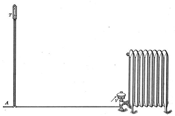
Fig. 166.—Thermostat regulator and motor-valve attached to a radiator.
Pneumatic Temperature Regulation.
—Pneumatic temperature
regulation is very generally used in large and complicated heating
systems, because of its positive action and completeness of heat
control. This method of heat regulation utilizes the energy of
compressed air, with which to open and close the valves of the
radiators. It may be adapted to any mode of heating and can
be used with any size of plant, but is particularly suited to extended
systems. The radiators, providing heat for any particular
space, are under control of separate thermostats,
which by means of motor valves admit heat only as required.
A motor, operated by compressed air, is attached directly to[235]
each radiator valve. Any change in temperature of the room
causes the thermostat to correct in the radiator the required
amount of heat.
With this method of regulation the temperature-controlling
element of the thermostat, like that of the electro-thermostatic
system, is a sensitive part, which by expanding and contracting
with the heat and cold directly controls the heat in any part of
the building. The motive power for opening and closing the
valves of steam or hot-water radiators or for operating the dampers
in a hot-air system is supplied by compressed air. The air supply
is furnished by an air compressor which automatically
stores air under pressure in a pressure
tank, from which is drawn the necessary energy,
as occasion demands. The air is conducted to
the motors through small pipes which are connected
with the regulating elements and also with
the motors. The function of the thermostat is to
so govern the air which enters the motor as to
correct any change in the temperature of the
rooms. This it does by opening and closing the
valves as occasion demands.
In Fig. 166 is shown the arrangement of the
thermostat T as it appears on the wall. Air
from the supply tank is conveyed by the pipe A
through the thermostat T to the motor valve V attached
to the radiator. The function of the
thermostat is that of so controlling the radiator
valve by means of the motor V that the radiator will give out
just sufficient heat to keep the room at the desired temperature.
A closer view of the thermostat is given in Fig. 167.
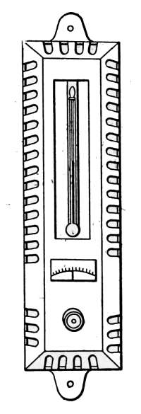
Fig. 167.—Outside
view of
thermostat as it
appears in use.
The thermostat illustrated in Fig. 167 is that employed by
the National Regulator Co. The drawing shows the exterior
and interior construction of the parts enclosed in the previous
illustration. The pipe C at the right and opening P at the
left are the same as A in Fig. 169; likewise, the pipe D connects
at the opening M of the motor valve in Fig. 169.
Referring again to Fig. 168, the sensitive part consists of a
tube A of vulcanized rubber. It is the dark-shaded part in the
left-hand drawing. Any change in the air temperature influences[236]
the length of this tube. The changing length of the tube
effects the air supply to close the radiator valve when the temperature
rises above the desired amount and to reopen it when
more heat is required. A finely threaded screw passes through
the plug H at the top and to this is secured the indicating disc
X. The bottom of this screw is cupped to receive the point of
the rod K, which connects with the piece L. Any change in
length of the sensitive tube moves the valve lever O, and thus
opens or closes the air port G.
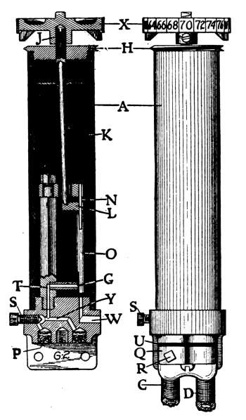
Fig. 168.—Internal construction
of the National
Regulator Co.’s thermostatic
regulator.
Air under pressure is supplied by the pipe C, connected to
the air supply, flowing into the thermostat through the filter
P, the restriction S, the passage T, and
the port G. The adjustment of the
thermostat for different temperatures
is provided for by the screw J through
the top plug H, and the indicating disc
X. The screw R in the connector Q at
the base of the thermostat is a needle
valve which opens or closes the connection
with the air supply, and is used as
an air shut-off valve when it is desired
to remove the thermostat. The screw
S is a restriction valve which controls
the supply of air to the thermostat,
and this screw is set so as to allow the
air to pass in a restricted quantity.
When the temperature of the apartment
has risen so as to expand the
thermostatic element A, the pressure on
K and L is relieved and the spring N
closes the port G. The air admitted through the restriction
screw S, since it cannot escape through the port G, accumulates
in the passage Y and pipe D, filling the diaphragm and
moving the valve into the position to decrease the supply of
heat. When the temperature of the apartment has decreased
so as to produce pressure on the connecting rod K, through
the contraction of the thermostatic element A, the port G will
be opened by the valve lever O, allowing the air in the pipe D,
together with that which flows through the restriction S, to[237]
escape through the passage W to the atmosphere, allowing no
air to accumulate in the pipe D, and thus permitting the spring
at the diaphragm to actuate the damper or valve for more heat.
The amount of air released through the port G by the valve
lever O varies the pressure accumulated in the pipe D and produces
the graduated or intermediate action desired.
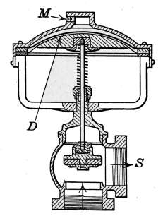
Fig. 169.—Cross-section of
pneumatic radiator valve showing
its internal construction.
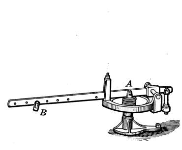
Fig. 170.—Pneumatic motor valve for
automatic control of dampers, etc.
A further application of air pressure in temperature regulation
is that of the type of motor shown in Fig. 170. This device is
intended to open and close dampers such as are used in the automatic
regulation of temperature where heated air is used to warm
the buildings. The operation of the motor is the same as that
which controls the steam valve. The pressure exerted by the
diaphragm is applied at A and the attachment to the damper is
made at B. The motors indicated at V and N in Fig. 174 and
D in Fig. 175 are examples of its application.
Mechanical Ventilation.
—Draft ventilation produced by open
windows, flues and chimneys is influenced by extremes of temperature
and by the force and changing direction of the wind;
it is, therefore, but imperfectly controlled. The superiority of
mechanical ventilation is generally recognized because the
amount of entering air may be regulated to suit any circumstance
and its temperature and humidity varied to conform to
any desired atmospheric conditions. Mechanical ventilating
plants are seldom employed in any but the more pretentious
dwellings, but their use has extended to a degree that they are
occasionally installed in apartment buildings and their further[238]
application is likely to grow. Neither the cost of installation
nor the expense of operation is prohibitive in dwellings of the
better types. Mechanical ventilation is quite generally employed
in school buildings, auditoriums, hospitals, public buildings and
others where means will permit, and there is a universal recognition
of the effects of the agreeably conditioned air.
Mechanical ventilation may be accomplished by power-driven
fans, either by exhausting the air from the building or by forcing
air into it, and under some conditions a combination of the two
methods is used.
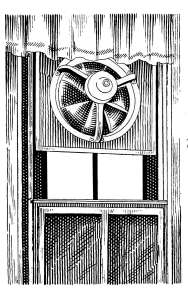
Fig. 171.—Exhaust fan for
induced ventilation.
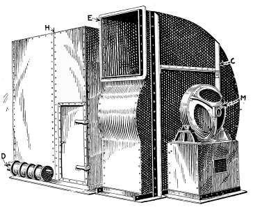
Fig. 172.—Ventilation apparatus in which is
included the heater coils, the fan and the motor.
The exhaust method of ventilation is that in which air is blown
out of the building by a fan; and the supply, to replenish that
taken away, is conducted into the building through ducts prepared
for the purpose. In some cases the induced air supply
leaks into the rooms through the joints in the doors and windows,
and through the accidental crevices. In Fig. 171 is shown a
simple exhaust fan installed to produce such a change of air.
It is suitable for kitchens and other places where it is desired to
eliminate smoke or gases rather than to produce a supply of air.
With this apparatus the air of the room is blown out by the rotating
fan and new air to take the place of that exhausted is drawn
in at any convenient opening.
[239]
The Plenum Method.
—That form of mechanical ventilation
by means of which air is forced into the rooms is known as the
plenum method. It is the most positive means of air supply
because its action is attended by a slight pressure above the
outside air; it is continuous in action and the amount of entering
air is under control. The escape of the expelled air is made
through vent flues especially constructed for the purpose.
Ventilation Apparatus.
—Fig. 172 illustrates the form of apparatus
used for ventilating buildings where no attempt is made at
washing or humidifying the air. Enclosed in a sheet-iron case
C is a fan which is driven by the electric motor M. The capacity
of the fan, for the delivery of air, is made to suit the requirements
of the building. In this case the fan is secured to an
extension of the armature shaft of the motor. Connecting with
the case which encloses the fan is another sheet-iron box H,
containg coils of heating pipe. The heating apparatus is designed
to change the temperature of the entering air to suit the requirements
of the building.
This represents the draw-through or induced-draft type of
ventilation apparatus. The air delivered by the fan induces a
flow of outside air which is drawn through the heating coils and
discharged through the opening E. At this point it enters the
main ventilation duct from which it is distributed by branch
conduits throughout the building.
The temperature of the air sent out from the fan is regulated
by the steam valves of the heater coils to suit the prevailing
conditions. Under some installations of this character the ventilating
air is made to furnish the heat necessary to warm the
building as well as to provide its air supply. As ordinarily
used, however, the temperature of the ventilating air is the
same as that of the room.
The method of conveying air to the various apartments
depends entirely on local conditions. The conduits may be
made of sheet iron, placed to suit the existing conditions; but
when a building is constructed with a ventilating plant in view
as a part of the building equipment, it is customary to make the
ducts part of the partitions. In brick buildings the ducts are
constructed, so far as it is practicable, in the walls. These
ducts are made in size and arrangement to suit the amount of[240]
air required for each room. When the plant is put into operation
each duct is tested with an anemometer which indicates the
velocity of the entering air. The calculated amount of air, determined
by the velocity and area of the entering column, when
compared with the necessary quantity demanded for good
ventilation, gives the efficiency of the system.
Air Conditioning.
—In addition to the possibility of a constant
supply of air, a combination of the exhaust and plenum methods
admits of air purification. With such a plant, the air may be
washed free from all suspended dust or gases and moistened to
any degree of humidity. The process of washing and humidifying
air is known as air conditioning. Apparatus for air conditioning
is made in a variety of forms to produce any desired
extent of air purification and any degree of humidity. The
plant may be regulated by hand or it may be made entirely
automatic in its action. Air-conditioning plants may be arranged
to produce air that is purified, humidified and warmed during
winter weather and in summer the hot humid atmosphere may be
cooled and dehumidified to a temperature and percentage of
moisture that is most agreeable.
Conditioned air is often used in manufactories, not for the
purpose of supplying good air to the employees but because of
the effect of the atmospheric air on the products. The manufacture
of textile fabrics often demands a constant atmospheric
humidity in order that the material produced may be uniform
in grade; this is particularly true in the making of silks. Various
manufactories require an atmosphere free from lint and
dust in order that the best quality of material may be produced.
The air for ventilation in such places is washed free from all
suspended matter before being sent into the building.
In Fig. 173 is indicated an application of apparatus similar
in construction to that just described. The arrangement of
the parts is such as to produce a Plenum hot-air system of ventilation
and temperature regulation.
The plant occupies a room in the basement and the drawing
shows the method of heating, together with the plan of distribution.
The air duct leading to the room above furnishes an
example of the manner of admitting the warmed air to the rooms.
[241]The dampers C1, C2, etc., are controlled by separate motors.
The motor M is under the control of the thermostat T in the
room above. Any change of temperature in the room is corrected
by the damper to admit cold or warm air as is desired.
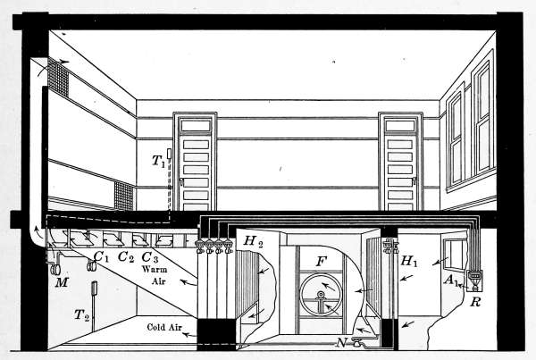
Fig. 173.—Plenum hot-blast heating system with temperature regulation.
The power-driven fan F draws in outdoor air from an opening
A, through a set of heater coils H1, in which it is raised considerably
in temperature. The heater in this case is a coil of steam
pipes. The air—after being warmed—is taken into the fan and
from it may be sent through a second set of coils H2, to receive
additional heat, or if already sufficiently warmed the air from
the fan may pass under the second set of coils and receive no
heat from them. Under the first heater coil is also a bypass
which may be opened by the motor N to admit cold air that is
drawn directly into the fan. The movement of the air through
these bypasses is under control of the thermostat, which causes
the motor N to open or close the bypass to suit the temperature
of the room. When the bypass is opened the steam is shut
off from the heater coils.
Examination of the drawing will show that the air from the
fan may pass through a second heater H2, to the place marked
warm air, or it may pass under the heater to the compartment
marked cold air. The amount of warm and cold air which enters
the duct is regulated by the position of the dampers C.
[242]
The position of the dampers C, which is controlled by the
motors M, is made to take amounts of cold or warm air to produce
the desired temperature in the rooms. The motors C1,
etc., are under control of the thermostat in each room. Any
change of temperature in the room will immediately affect the
thermostat. The effect on the thermostat will so change the
air pressure in the motor that the valve C is moved to correct
the difference in room temperature. If warm air is demanded,
the motor changes the damper C to close the cold-air supply and
take air that must pass through the heater coils H2. If only
cold air is desired the damper will turn to shut off the course
through the heaters and admit air directly from outdoors.
Humidifying Plants.
—Mechanical ventilation plants that are
intended for washing the air may be made up of parts similar to
that of Fig. 173, but in addition to the apparatus shown provision
is made for the air to pass through a chamber filled with a spray
of water. The air in passing through this spray is washed free
of dust and at the same time absorbs water necessary for its
desired humidity.
The humidity of air may be increased by the addition of moisture
or decreased (dehumidified) by raising its temperature, thereby
increasing its capacity for containing moisture. Suppose that
air at 50° is saturated with moisture; it will contain practically
4 grains of water per cubic foot. If now the temperature of the
air is raised to 70°, the same amount of air is capable of containing
8 grains of water and is, therefore, only 50 per cent. saturated.
Humidification is accomplished in air-conditioning plants
through one of two general methods: by the evaporation type of
apparatus, in which the passing air absorbs moisture from contact
with a large area of water; or the spray method, in which
the water is broken into a very fine spray by a specially devised
nozzle and thus rendered easy of absorption by the air to be
moistened. A third method is sometimes employed, in which
steam is introduced into the air supply. Steam is already vaporized
water and immediately becomes a part of the air without
further change. The steam type of humidifying plant possesses
features that limit its application, in that the steam in some cases
may possess objectionable odor or includes the vapor of grease,
either of which would materially effect its use. Further, the[243]
heat of vaporization liberated by the condensing steam is also
a factor that influences the temperature of the air and in case
of direct humidification must receive special attention.
Vaporization as a Cooling Agent.
—The evaporation of water
has a distinct value aside from humidifying the air, in that
the cooling effect is in direct proportion to the added moisture.
In the process of evaporation the heat necessary to change the
water into vapor is taken from the surrounding air and the temperature
is thus materially lowered.
In practical air-conditioning apparatus, of the evaporative or
spray types, the process consists of drawing the outside air into
a chamber filled with falling water that is broken up into drops
like rain or spray. In passing, every particle of the air comes into
contact with the water drops; the almost invisible particles of
dust adhere to the water and are carried away leaving the air
washed clean. In addition to freeing the air from dust, the
intimate mixture of the air permits of a ready absorption of the
water, which is taken up to any per cent. of saturation. After
leaving the spray chamber, the moisture-laden air passes through
an eliminator in which any unabsorbed moisture is extracted.
It is possible for air to become not only completely saturated
with water under the conditions encountered in a humidifying
plant, but in addition, the movement of the air may carry along
unabsorbed particles that are precipitated directly after leaving
the spray chamber. For this reason the air is passed through an
eliminator.
The eliminator is composed of a series of irregular sheet-metal
surfaces so arranged that the air is required to abruptly change
its direction several times in its passage of a short distance. The
impact of the air against the surfaces and the centrifugal force
exerted by the sudden changes of direction throw out the excess
moisture and any remaining suspended matter the air may contain.
The saturated air from the eliminator passes through a heater
where the temperature is raised to that of the rooms. In the
rise of temperature the air which is saturated is rendered capable
of absorbing more moisture, and hence has been dehumidified.
The rise of temperature and the corresponding decrease in relative
humidity is intended to be such as to leave in the finished air
the desired percentage of moisture.
[244]
Air-cooling Plants.
—The use of air-washing and humidifying
plants so far mentioned has been confined to elimination of
dust and the addition of moisture to air, under winter conditions.
The same type of apparatus, used in summer, becomes a cooling
plant, and by observance of the necessary requirements may be
used to produce agreeable atmospheric conditions during hot
weather.
When used for such purpose the air is washed, by passing it
through falling water which frees it from dust and reduces its
temperature. It is then further cooled by passing over cold
surfaces that take the place of the heaters used in cold weather.
The cooling surfaces are pipe coils kept cold by the contained
water which comes from the water supply or from a refrigerating
plant. The temperature and humidity are thus changed to suit
the requirements of the conditioned air.
During the hot weather of summer the most disagreeable
atmospheric condition is that caused by humidity near saturation,
at a time of relatively high temperature. Under such conditions
the cooling plant not only cools the air, but causes a precipitation
of the moisture on the cold surfaces which are kept below the
dew-point. The air is cooled and dehumidified to a point such
that the conditioned air produces an agreeable atmosphere.
The regulation of the degree to which the air is cooled is accomplished
by the same general methods as are used in heating.
Humidity Control.
—The method of regulating atmospheric
humidity in a humidifying plant will be determined by the conditions
under which it is intended to work. There are a variety
of means employed that may be used to bring about the same
effects, each of which is particularly suited to certain requirements.
The present object is to describe the essential features of
airconditioning plants, by use of illustrations representing each
of the three methods mentioned above. That of the ventilation
of a school building under winter conditions will be taken as
an example.
In Fig. 174 is shown a heating and ventilating system in which
the air conditioning is accomplished by automatic regulators
for both temperature and humidity. The plant occupies a room
in the basement, and a room directly above illustrates the conditions
that prevail in all of the other rooms of the building. The[245]
principal features of the plant are the fan G, which supplies the
air; the hot-air furnace H, which furnishes the heat; and the
water spray S, which provides the moisture with which the air
is humidified.

Fig. 174.—Furnace blast system of heating, with temperature regulation and
humidity control.
The air is drawn in at A to a room in which a motor-driven
fan G forces the supply through the heating apparatus into the
building. The air after leaving the fan passes through a cold-air
duct C to the heating surfaces H to be warmed. The air
in passing over the heating surfaces is raised to a degree considerably
above the temperature of the rooms. The hot air leaving
the heater H enters the tempered air chamber T through the passage
K. A damper M provides means for also admitting cold
air to the chamber T directly from the fan. The thermostat,
located at O, is connected with a pneumatic motor V (similar to
Fig. 170) which regulates the supply of cold and hot air from K
and M to suit the desired temperature of the air supply for the
rooms above. The arm of the motor V is so arranged that an
upward movement opens the cold-air and closes the hot-air
passages; the downward movement produces the opposite effect.
The motor V thus controls the temperature of the air.
In this system the air is humidified by a direct water spray[246]
marked S in the drawing. A part of the hot air from the heater
H may escape through the damper W and absorb water on its
way to the duct D, which takes the air to the room above, where
it enters through the register E. This air as it comes from the
heater, being hot, will absorb a larger amount of water than the
air could hold when cooled to room temperature; for this reason
only a part of the air supply is humidified. The supply of the
hot humid air is admitted to the duct D in such quantity as will
produce the desired degree of humidity in the rooms.
The degree of room temperature is governed by the thermostat,
in the room, which, by means of the motor N, controls the
damper F. This damper admits hot humid air and the tempered
air from the chamber T in proper proportion. At any time the
humidity of the air in the room reaches the maximum amount for
which it is set, the humidostat, through its motor, closes the valve
R, which controls the water supply to the spray nozzle, and the
moisture in the air is reduced until a further amount is demanded.
With apparatus of this kind the temperature and humidity may
be kept practically constant.
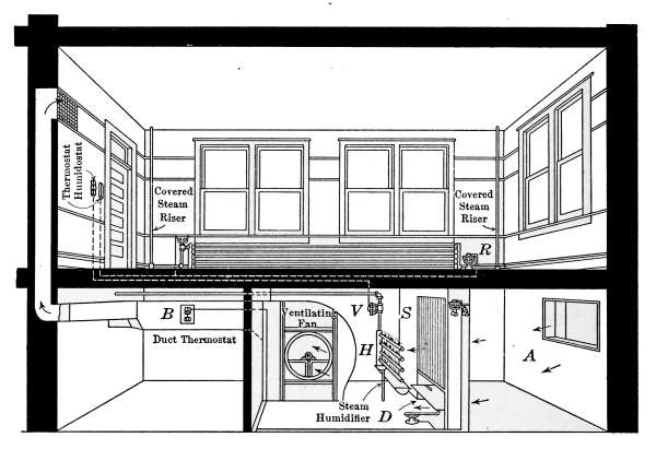
Fig. 175.—Direct steam heating system with mechanical fan-blast ventilation,
temperature regulation and humidity control.
Fig. 175 shows another arrangement of a similarly controlled
plant in which steam is used for humidifying the air. The air is[247]
admitted at A, from whence it passes through a steam-heating
coil S, which raises it to a predetermined temperature. The
steam jets are arranged at H, for providing the necessary moisture.
The humidostat through a motor valve V governs the
amount of steam that is permitted to enter the humidifying
chamber. A thermostat located in the air duct at B controls the
temperature of the air sent to the rooms by regulating the amount
of heat given out by the steam coils S. This control is made
still more sensitive by use of a cold-air bypass. The damper D
is opened by a motor valve to admit cold air at the same time
the steam is shut off from the heater coils.
In this plant the ventilating air is not intended to supply all
of the heat to the rooms. A thermostat on the wall controls the
room temperature by regulating the amount of steam admitted
to the radiators. In the ventilating plant previously described,
all of the heat for the building is supplied through the ventilating
system; in the plant shown in Fig. 175, the heating apparatus
which warms the building is entirely separate and may be used
when the ventilating system is inoperative.
The humidity is controlled by admitting saturated air to the
warmer air of the rooms in such quantity as will produce the
desired mixture. The humidostat, on the left-hand wall, regulates
the quantity of moisture by opening or closing the steam
valve V as occasion requires.
Another example of air-conditioning plant similar in principle
to that just described is often called the dew-point system. It
depends for its action on a definite dew-point temperature at
which the air is saturated with moisture, before being heated to
room temperature. The air to be conditioned is first warmed, by
passing through a set of tempering coils, to a degree at which it
will contain the necessary moisture when saturated. After
saturation the temperature is raised by a second set of heating
coils to the room temperature, the moisture contained being right
to give the desired humidity.
To illustrate, suppose that it is desired to maintain a constant
humidity of 50 per cent. saturation at 70°F. in the building. The
temperature at which the air must be saturated, to contain 4
grains of moisture per cubic foot, is found in the table on page 199
to be 48°F.
[248]
The entering air must first be raised to that temperature by
the tempering coils. The air then enters the spray chamber
where it absorbs moisture to saturation, by contact with a
multitude of water particles. This saturated air now passes
through a second set of heated coils and takes up heat sufficient
to raise it to the finished temperature.
The dew-point temperature at which the air enters the spray
chamber and the final temperature are kept constant by motor-operated
valves which supply the heating coils with the necessary
heat in the form of steam. The motors are controlled by
thermostats, placed to measure the temperature of the air as it
enters the saturator and the finished air as it enters the rooms.
If these conditions are now kept constant, the finished air will
be constantly 50 per cent. saturated.
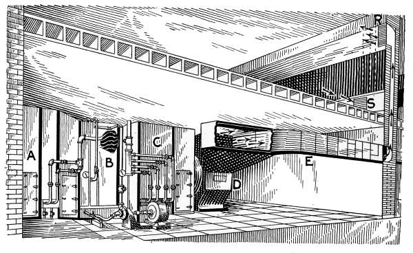
Fig. 176.—School building section showing a complete air-conditioning plant.
A plant of this character is illustrated in Fig. 176. The figure
shows the exterior of the casings which enclose the tempering
coils and saturator at A, the eliminator at B, and the heating
coils at C. This is another draw-through type of plant where a
fan, enclosed in D, draws the air through the conditioning
apparatus and forces it through the sheet-iron ducts E. The
passages in the walls—as indicated by the arrows—conduct
the air through the register R, into the room. The register S[249]
represents the discharge duct through which the vitiated air
is forced from the room.
In this system of air conditioning, all of the ventilating air is
to be saturated with moisture at a temperature such that when
raised to room temperature will contain the desired percentage
of humidity. The saturator occupies the space between A and B.
A number of spray jets are arranged to fill the entire space with
water drops that are moving in every direction. The air, as it
passes, must come into contact with the drops again and again,
until by repeated impact each particle is completely saturated
and at the same time washed free from dust. It has already been
explained that the movement of the saturated air through a mass
of spray will carry with it a considerable amount of unabsorbed
water that must be taken out by an eliminator. A section of the
casing is broken out at B, showing the eliminator plates. The
irregular surfaces of these plates repeatedly change the direction
of the passing air, and the suspended water or remaining solid
matter is thrown against the surfaces where they adhere. The
moisture accumulates in drops of water that run down the plates
to the bottom of the enclosure and finally into the sewer.
From the eliminator the air passes through the heating coils
enclosed in C, where it is heated to the necessary temperature for
admission to the rooms.
The regulation of the temperature of the tempering coils and
heating coils is accomplished as in the other plants described.
The thermostats with their motors operate the valves of the
heaters to admit steam sufficient to keep constant temperatures
at the different parts. The humidity is maintained at a constant
amount by saturating the air at a constant temperature and
therefore no humidostat is required.
[250]
CHAPTER XII
GASEOUS AND LIQUID FUELS
Gaseous and Liquid Fuels.
—Gaseous and liquid fuels used for
domestic illumination and heating may be divided into three
general classes—coal gas, including carburetted water gas and
producer gas and their various mixtures; oil gas, acetylene and
gasoline gas. Of these the first is the most important as an
illuminating gas, while for industrial and domestic purposes
producer gas is of no importance as a fuel gas. Gasoline, acetylene
and oil gases are generated and used to a remarkable extent
in isolated dwellings as fuel and for illumination.
The value of any gas for domestic purposes will depend on the
amount of heat that is produced when it is burned. In the earlier
days of its use coal gas was employed entirely as an illuminant
and its value was expressed in illuminating power; at the present
time the standard often prescribed by regulation is that of its
illuminating capability and is stated in candlepower. There
is, however, a tendency to establish the more consistent standard
of expressing the value of gas by its heat value. The reasons for
this is the general use of mantle gas burners which depend on the
heating value alone for their efficiency and the fact that coal gas is
very extensively used for domestic fuel.
Coal Gas.
—Coal gas is derived from the solid hydrocarbons of
coal transformed into the more convenient, gaseous form of fuel
by means of distillation. Coal gas was first made by distilling
coal from an iron pot over a fire and to some extent this is still
the principle of the present practice. The gas as it comes
from the retort is subjected to a refining process of washing and
scrubbing to remove the undesirable properties when it is stored
in a large gasometer for distribution through pipes to its places
of use. Coal gas is now used largely for fuel as well as for lighting.
Unless the heating value of gas is regulated by law in any
community and determinations of its quality are made regularly[251]
by some competent official, the amount of heat contained in coal
gas is entirely at the option of the manufacturer and manager’s
conscience. The value as given in the table on page 252 is the
number of B.t.u. coal gas should contain. The heating value of
any gas is determined by burning the gas in a calorimeter made
expressly for the measurement of the heat of combustion for
each foot of the gas consumed.
All-oil Water Gas.
—In places where an abundant supply of
cheap oil is available, all-oil water gas has met with a great deal
of favor. It is made by atomizing crude oil by a blast of steam
in a heated chamber where a combination of the vaporized oil
and steam form a gas. In general the gas resembles coal gas
and as given in the table on page 252 is slightly higher in heating
value.
Pintsch Gas.
—One of the commercial adaptations of oil gas is
that of the Pintsch process of compressing the gas in tanks for
transportation. In the Pintsch process, the gas is subjected to
a pressure of 10 atmospheres—about 150 pounds. This condensation
permits a sufficiently large volume of gas to be stored
in tanks as to make possible the lighting of railroad trains, etc.,
by gaslight. The pressure of the gas is reduced by an automatic
regulating valve to that required by the burner. The flame is
very much the same as that produced by coal gas.
Blau Gas.
—Another commercial adaptation of oil gas is that
known as Blau gas. In this process of storage the gas is subjected
to 100 atmospheres of pressure—about 1500 pounds. This
pressure is sufficient to liquefy the gas and as a result a large
amount can be transported in a relatively small space. According
to Fulweiler 1 gallon of the liquefied gas will yield about 28
cubic feet of the expanded gas and there will remain a residue
that may run up to 9 per cent.
Water Gas.
—When the vapor of water is brought into contact
with incandescent carbon, the water is decomposed and
sufficient carbon is absorbed to produce a fuel gas. Its manufacture
depends on the decomposition that takes place when
steam is blown into a bed of incandescent coal. The gas made
by this reaction is a water gas, but due to the fact that when
burned it gives a blue flame, it is known as “blue gas.” It has
a heating value of about 300 B.t.u. per cubic foot, and as compared[252]
with coal gas which gives 622 B.t.u. per cubic foot, would be
reckoned at about one-half its value as a heating agent. Blue
gas may be rendered luminous by the addition of some hydrocarbon
that will liberate free carbon in the flame when burned.
This is accomplished in the process of manufacture by the addition
of vaporized oil.
The following table as stated by Fulweiler gives the heating
values of the gases commonly used for domestic purposes in
British thermal units per cubic foot.
| Coal gas. | 622 B.t.u. |
| Carburetted water gas | 643 B.t.u. |
| Pintsch gas. | 1,276 B.t.u. |
| Blau gas. | 1,704 B.t.u. |
| All-oil water gas | 680 B.t.u. |
| Acetylene gas | 1,350 B.t.u. |
| Gasoline gas. | 514 B.t.u. |
| Oil gas | 1,320 B.t.u. |
| Blue water gas | 300 B.t.u. |
The cost and calorific values as computed by Dr. Willard of
the State Agricultural College of Kansas, given below, shows the
relative values of various kinds of domestic fuels.
| | | Cost per
pound cents |
Cal. per
Gram |
Cal. for
1 cent |
| Wood, 20 per cent. H.O. | $ 5.00 per cord |
0.167 | 2.3 | 7,620 |
| Bitu. coal | $ 4.25 per ton. |
0.213 | 7.5 | 16,009 |
| Ant. coal | $12.50 per ton |
0.625 | 6.0 | 4,354 |
| Gasoline, sp. gr. 68 | $ 0.14 per gallon, 5⅔ pounds. |
2.470 | 10.0 | 1,846 |
| Kerosene, sp. gr. 80 | $ 0.11 per gallon, 6⅔ pounds. |
1.650 | 10.0 | 2,753 |
| Coal gas, 1.50 per 1000 cubic feet. |
3.100 | 20.0 | 2,927 |
| Alcohol, 90 per cent., 50 per gallon, 7 pounds |
7.140 | 6.4 | 404 |
| Electricity, 0.15 per kilowatt-hour |
57.4 |
The relatively high heat value of Blau gas (1704 B.t.u.) and the
fact that it may be reduced to a liquid form for transportation
has resulted in the manufacture of small lighting plants that may
be used in places where other forms of liquid or gaseous fuel are
not desirable.
For transportation the gas is compressed in seamless, steel
bottles that contain about 20 pounds of liquid. The charged[253]
bottles are shipped to the consumer and when empty are returned
to the manufacturers to be refilled.
The entire plant—ready to be attached to the distributing
pipes in the house—is contained in a steel cabinet. The charged
tanks are attached to a larger tank into which the liquid gas is
first expanded. This expansion is accomplished by an automatic
valve that maintains a constant pressure in the large tank.
With this plant the lamps and burners of the stoves are operated
as with city gas—no generating or preliminary preparation
being necessary. As soon as the bottles are exhausted they are
replaced by others and the empty bottles are shipped to the factory
to be refilled.
Measurement of Gas.
—When gas of any kind is purchased
from a manufacturing company, the amount used is measured by
a gas meter, located at the point where the gas main enters the
building. The readings of the meter are taken by the company
at stated intervals and the amount registered is charged to the
account of the consumer. Gas is sold in cubic feet and is so
registered by the meter. The price is quoted by the manufacturers
at a definite rate per thousand cubic feet. The difference
between the last two readings of the meter furnishes the amount
from which the gas bill is reckoned.
The occupants of a building are responsible for all gas registered
by the meter and, therefore, should be acquainted with the
conditions under which the gas is sold. Gas bills are often the
subject of dispute because of failure to understand the period of
time covered by the amount claimed; again, the varying length
of days due to the season of the year has a pronounced effect
on the amount of gas consumed. Lack of care in the economical
use of gas is probably the most prolific cause of disputed bills.
The amount due for gas may at any time be checked by the
consumer who keeps a record of the meter readings. At any
time the correctness of a meter is doubted, arrangement may be
made with the gas company to have it tested for accuracy.
This is done in the office of the company, by attaching the meter
to a measuring device—called a meter prover—in which a definite
measured amount of gas is passed through the meter and comparison
made with meter registration. If it is found that the
meter does not register correctly, the gas company is in duty bound[254]
to make good the difference. If, however, the meter is found to be
correct, it is customary to charge for the services of proving the
meter.
Gas Meters.
—The gas meter as ordinarily used is shown in
Fig. 177. In Fig. 178 the same meter is shown with the top and
front exposed.
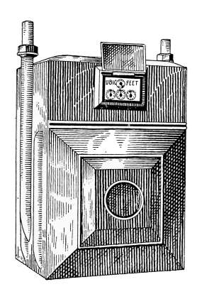
Fig. 177.—Gas meter.
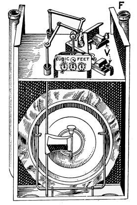
Fig. 178.—Gas meter showing
internal mechanism.
The meter is operated by the pressure of the gas which enters
at the inlet pipe on the left-hand side of the meter as you face
the index. The gas from this pipe comes into the valve chamber
and passes alternately into the diaphragms and their chambers,
as the valve ports V are opened and closed by the action of the
meter. The movement of the valve in opening the port which
admits gas to the diaphragm closes the port to the chamber
which has filled. The gas entering the diaphragm expands it
like a bellows and forces the gas out of the chamber, through
the middle part of the valve into the outlet pipe F. While this
action is going on, the gas is entering the case compartment on
the opposite side of the meter and also forcing the gas from its
diaphragm through the opening F.
While the meter is in operation, one of the diaphragms and
one of the case compartments are filling while the others are
emptying. The movement of the diaphragm discs is transformed
to the recording dial by the connecting levers shown at the top[255]
of the figure. The movement of these levers is such as to produce
a rotary motion to a tangent which is attached to a shaft
that operates the recording dial. The tangent is carried around
in a circle by the action of the arms and its movement is registered
on the index of each cycle of the diaphragms.
The measurement is accomplished by the displacement of a
definite amount of gas with each movement of the discs; first,
from the chamber and then from the diaphragms.
HOW TO READ THE INDEX
The index of a gas meter looks quite complicated, but it is
really a very simple contrivance. The small circle on the top
in Fig. 177 is for testing purposes only and need not be considered.
The dial of Fig. 177 is shown in Fig. 177A. The first circle,
marked 1 thousand, registers 100 feet for each figure, 1000 feet
for the entire circle. If the pointer stood on 9 it would mean
900 cubic feet. The second circle registers 1000 for each figure,
or 10,000 for the entire circle. When the pointer of the first
circle has been around once, it reaches 0 on that circle, but
the hand on the second has moved to figure 1, showing 1000
feet used. The process goes on until the pointer of the second
circle has traveled around and stands at zero. The pointer on
the third circle, however, has moved to 1, indicating 10,000.
This explanation shows the general plan of the index. A few
minutes study of it will render the index as easy to read as the
face of a clock. Of course, the pointers do not always stand
exactly on the figures as they move from figure to figure as the
gas is used.
Suppose your index stood like this:

Fig. 177A.—Gas-meter dial. It reads 38600 cubic feet.
Take the figure 3 on the 100 thousand circle, the figure 8 on
the 10 thousand, and the figure 6 on the 1 thousand, and you have[256]
30,000, 8000, and 600, or 38,600 feet. To ascertain the quantity
of gas used in the time elapsing between the readings of the meter,
subtract the quantity registered at the previous reading. Thus,
if the previous reading was 38,600 feet, and the next reading
40,100 feet, the pointers standing thus:

Fig. 177B.—Gas-meter dial. It reads 40100 cubic feet.
| You have | 40,100 |
| Subtract your last reading | 38,600 and you find |
| | ——— |
| that your bill should be for | 1,500 feet |
When 100,000 feet have been passed, the index is at zero; that
is, all the pointers stand at 0, and the registration begins all over
again.
Prepayment Meters.
—In many places it is desirable to sell
gas in small quantities and to prepay the amount for a given
supply of gas. This is accomplished by
a meter such as that of Fig. 179. The
meter is constructed much the same as the
former but provided with a mechanism
such that when a coin—usually 25 cents—is
deposited, according to the printed
directions in the instrument, an amount
of gas representing the proportional current
rate is allowed to pass the meter.
The supply is cut off as soon as the
amount paid for is used; when in order
to receive more gas, another coin must be
deposited as before.
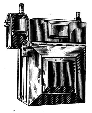
Fig. 179.—The prepayment
gas meter.
Gas-service Rules.
—The rules for the regulation of gas service
are in many States under the control of a board or commission
whose duty it is to form codes prescribing the measurement
and sale of all public utilities. The following form, General
Order No. 20, State Public Utilities Commission of Illinois,[257]
gives an idea of the requirements in that State for the sale of
coal gas.
Rule 3. Request Tests.—Each utility furnishing metered service shall
make a test of the accuracy of any meter, upon written request by a consumer:
Provided, first, that the meter in question has not been tested by the
utility or by the commission within 6 months previous to such request;
and second, that the consumer will agree to accept the result of the test
made by the utility as determining the basis for settling the difference
claimed. No charge shall be made to the consumer for any such test. A
report, giving the result of every such test, shall be made to the consumer.
Rule 4. Adjustment of Bills for Meter Error.—If on any test of
a service meter, either by the utility or by the commission, such meter shall
be found to have a percentage of error greater than that allowed in Rule 11
(see below) for gas meters, the following provisions for the adjustment of
bills shall be observed.
(a) Fast Meters.—If the meter is faster than allowable, the utility shall
refund to the consumer a percentage of the amount of his bills for the 6
months previous to the test or for the time the meter was installed, not exceeding
6 months, corresponding to the percentage of error of the meter.
No part of a minimum, service or demand charge need be refunded.
(b) Slow Meters.—If the meter is found not to register or to run slow, the
utility may render a bill to the consumer for the estimated consumption
during the preceding 6 months, not covered by bills previously rendered, but
such action shall be taken only in cases of substantial importance where the
utility is not at fault for allowing the incorrect meter to be in service.
Rule 11. Gas-meter Accuracy.—(a) Method of Testing.—All tests to
determine the accuracy of registration of a gas service meter shall be made
with a suitable meter prover. At least two test runs shall be made on each
meter, the results of which shall agree with each other within one-half
per cent. (½%).
(c) Allowable Error.—Whenever a meter is tested to determine the accuracy
with which it has been registering in service, it may be considered as
correct if found not more than two per cent. (2%) in error, and no adjustment
of charges shall be entailed unless the error is greater than this amount.
Rule 15. Heating Value.—Each utility furnishing manufactured gas
shall supply gas which at any point at least 1 mile from the plant, and tested
in the place where it is consumed, shall have a monthly average total heating
value of not less than 565 B.t.u. per cubic foot, and at no time shall the total
heating value of the gas at such point be less than 530 B.t.u. per cubic foot.
To arrive at the monthly average total heating value, the results of all
tests made on any one day shall be averaged and the average of all such daily
averages shall be taken as the monthly average.
Rule 8. Railroad Commission of Wisconsin.—Each utility furnishing
gas service must supply gas giving a monthly average of not less than 600
B.t.u. total heating value per cubic foot, as referred to standard conditions
of temperature and pressure. The minimum heating value shall never[258]
fall below 550. The tests to determine the heating value of the gas shall be
made anywhere within a 1-mile radius of the center of distribution.
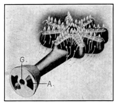
Fig. 180.—Detroit Jewel one-piece,
star-shaped burner.
Gas Ranges.
—Gas ranges and all other heaters using gas as a
fuel are constructed to utilize the principle of the Bunsen burner.
Fig. 180 illustrates the type of
burner used in the Jewel gas
range. This represents the
form adapted to the top burners
for all direct-contact cooking
or heating. The burners
are of different sizes and arranged
as they appear in Fig.
181. This picture shows the
top of the range as seen from
above, looking directly downward.
The gas supply pipe
and individual valves for each
burner are in position as they
appear in front of the range.
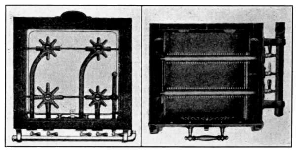
Fig. 181.
Fig. 182.
Fig. 181.—Showing top burners and valve attachment of a gas stove.
Fig. 182.—Section showing arrangement of oven burners and lighter of a gas
oven.
In operation, the nozzles of the gas valves stand directly in
front of the opening G, in Fig. 180. The stream of gas in passing
into the burner induces a flow of air through the opening A. The
mixture of gas and air is such as will burn with the characteristic
Bunsen flame without smoke.
[259]
The oven burners are different in form but the individual
flames are the same as those of the top burners. They extend
across the oven as shown in Fig. 182. In this the top of the
oven is removed and burners as seen are viewed from above.
The top burners are lighted by direct application of a burning
match but the oven burners must be lighted by first igniting a
special torch or “pilot lighter.” The middle gas valve of Fig.
182 is turned and the torch lighted, then the other valves are
opened and the jets are instantly ignited. As soon as they are
burning the pilot lighter is extinguished by turning its valve.
The reason for this special lighter is because of the possibility
of explosion at the time of lighting. The gas from the jets is
mixed with air at the proper proportion to be violently explosive
and if by chance the gas should be turned on a sufficient time
to fill the oven with this explosive mixture and then lighted,
an explosion would be certain, with every possibility of disastrous
consequences. All gas ovens should be lighted in a
manner similar to that described.
Lighting and Heating with Gasoline.
—The remarkable growth
of modern cities, the building of small towns in the west, and the
improvement in suburban and rural homes has created a demand
for efficient means of illumination in the form of small household
lighting plants. The development and improvement in electric
lighting has induced an equal, if not greater, improvement in
gas lighting. Up to the year 1875, the open-flame gas jet
represented the most improved form of city lighting. Then came
electricity, which for a time bade fair to supplant all other
forms of illumination; but the relative high cost of electric lighting,
even with the advantages it afforded, was a stimulus to
improvement in less expensive forms of illuminants.
The invention of the incandescent-mantle gas burner enormously
increased the opportunities for gas lighting and opened
an inviting field of endeavor. In a relatively short time, three
distinct types of gasoline lighting plants for household illumination
came into common use, with a great number of different
systems in each type. As a means of economical illumination
the only rival of any consequence to the small gasoline-gas plant
of today is acetylene. The dangers attending the use of these
agents of illumination have been rapidly eliminated, until today—when[260]
intelligently managed—they are fully as safe as any other
means of artificial lighting. Gasoline plants are now in common
use in cities where competition with all other forms of illumination
require excellence in service to hold an established place.
In order that any mechanical appliance may be used with the
best results, its principle of operation and mechanism must be
thoroughly understood. In the case of gasoline plants, not only
familiarity with the mechanism should be acquired but an
intimate knowledge of gasoline and its characteristic properties
should be gained, that the peculiarities of the plant may be more
fully comprehended.
Gasoline
is the first distillate of crude petroleum; that is, in
the process of separation, the crude petroleum is distilled from
a retort and the condensed vapors at different degrees of temperature
form the various grades of gasoline, kerosene, lubricating
oil, paraffin, etc. The crude oil is placed in the still and heated;
the distillate that first comes from the condenser, at the lowest
temperature of the still, is gasoline of a light spiritous nature.
As the process of distillation continues, this part of the petroleum
is entirely driven off and it is necessary to raise the temperature
of the still in order to vaporize an additional portion of the oil.
There is no distinct line of separation between the gasoline that
first comes from the condenser and that which comes over after
the temperature is raised, except that it is less of a spiritous
nature and contains more oily matter. As the temperature of the
retort is gradually raised, the distillate contains less and less of
the spiritous and constantly more of the oily matter.
In order to grade gasoline for the market, the standard adopted
was that of relative density. The distillations produced at
various temperatures are mixed to produce various densities
which form definite grades of gasoline. The Beaumé hydrometer
is a scale of relative specific gravities in which the different
densities are expressed in degrees. The highest grade of gasoline
produced by the first distillation is 90°Bé.; that is, the hydrometer
will sink in the gasoline to 90° on the scale. As the temperature
of the retort is gradually raised, the distillate becomes
heavier and the next commercial grade is 86° gasoline. The
86° gasoline contains a greater proportion of oily matter and a
less amount of that of a spiritous nature. The next commercial[261]
grade that is produced, as the temperature is raised, is 76° gasoline,
a still highly volatile spirit but containing more oil than
the last. This process is kept up until there is an amount of
oil in the distillate that can no longer be termed gasoline, when
kerosene is distilled from the retort.
The following descriptions of gasoline and kerosene by B. L.
Smith, State Oil Inspection Chemist of North Dakota, gives a
definite idea of their properties and the requirements of the law
in their regulation and sale.
“Gasoline is formed by the condensation of vapor that passes off at
comparatively low temperatures during the distillation of crude petroleum.
It has been common practice among refiners to collect as ‘straight’
gasoline all that distillate having a specific gravity above 60°Bé. At
present, the name applies broadly to all the lighter products of petroleum
above 50°Bé. in gravity, including products obtained from the ‘casing-head’
gases of oil wells, by methods of compression and cooling, and
also the ‘cracked’ gasoline formed by the decomposition of heavier
oils when subjected to high temperature and pressure.
“It has been the custom to grade and sell gasoline according to
‘high’ or ‘low’ gravity test. Recent study and investigation has
shown that specific gravity in itself is of very little value in determining
the quality of a gasoline. It may be taken as an index of other
properties, particularly its volatility, if information as to its source
and method of production are at hand; but under present market
conditions a specific-gravity determination is entirely inadequate.
The specific-gravity test alone may give a high rating to a poor gasoline
and a low rating to a good one. It has been discarded as a standard
of comparison by the U. S. Bureau of Mines. It indicates nothing
definite about the quality of a gasoline and in many cases it does not
even approximate relative values. Volatility, that is, the ease with
which it vaporizes, is the fundamental property that determines the
grade, quality, and usefulness of gasoline. The Beaumé test, however,
must remain the standard for grading gasolene until a more definite
measure is adopted.
“The Oil Inspection Law (1917) for the State of North Dakota,
states, that: ‘all gasolines, sold or offered for sale in this State for household
use, shall, when one hundred cubic centimeters are subjected to
a distillation in a flask—as described for distilling of oil—show not
less than three (3) per cent. distilling at one hundred and fifty-eight
(158) degrees Fahrenheit, and there shall not be more than six (6)
per cent. residue at two hundred and eighty-four (284) degrees Fahrenheit,[262]
which shall be known as the chemical test for gasoline sold or
offered for sale in this State for domestic purposes.’
“Gasoline for household purposes, as for use in cold-process lighting
systems should contain not more than a very slight amount of constituents
that do not vaporize readily. It is obvious that a gasoline for
cleaning or drying purpose should contain no oily or kerosene distillate.
On the other hand, the gasoline for use in a gasoline stove or other
generator, where heat is employed in its vaporization, may contain a
considerable amount of the less volatile oils. The amount of gasoline
sold for household use is in very minor proportion to the immense
quantity used for motor purposes.
“No hard and fast line differentiates good motor gasoline from
bad. In fact standards of quality seem to be varying with advances
in engine design, so that what once was poor gasoline can now be
successfully used. Improvement in carburetors seem to be keeping
pace with the ever increasing amount of kerosene in the ordinary motor
gasoline.
“Gravity test cannot be relied upon as indicating the kerosene
content. In the laboratories of the Oil Inspection Department for
the State of North Dakota, there have been examined two gasolines
of the same gravity, 56.2°Bé. at 60°F., but which contains 31 per cent.
and 62 per cent. of kerosene respectively, and their distillation range
is quite different. On the other hand, there are other gasolines whose
boiling range is nearly parallel and similar, yet whose gravities are 50.2°Bé.
and 59.2°Bé. respectively. Also a gasoline and a kerosene having
a difference in gravity of but 1°Bé. and a difference of nearly 100°F.
in the temperature at which they begin to boil and a difference at 200°F.
in the temperature at which all had distilled over. The so-called ‘low’-test
gasolines average between 35 per cent. and 40 per cent. kerosene.
The chief element of advantage in the so-called ‘high’-test gasolines
seems to be that they yield a maximum efficiency over a larger range of
engine conditions.
“We have a sample of gasoline sold as ‘high’-test gasoline which
contains 29 per cent. of kerosene. Indeed it has a high Beaumé gravity
(63.70) compared to the average low-gravity gasolines on the market,
and it also contains a large amount (14 per cent.) of very easily volatile
constituents. Such a product seems to be a blend of very light ‘casing-head’
stock with kerosene of low boiling range to give the ‘high’ gravity.
“It is desirable that a gasoline should contain a certain percentage
of very low-boiling constituents, so that engines may start more readily,
especially in unfavorable conditions of weather or climate; but a large
proportion would be undesirable because of loss through evaporation[263]
and the liability of accidental ignition and explosion. A reasonable
amount of light volatile material would probably be about 3½ per cent.
Again a reasonably low percentage of the very less volatile constituents
is desirable to insure complete vaporization at a not too high temperature,
say not more than 10 per cent.; but such a gasoline would be expensive.
The producers and refiners claim that the present immense
demand necessitates the mixture of low-boiling kerosene constituents
with the true gasoline fraction.
“Kerosene.
—The character of this fuel is best understood by comparing
it with gasoline, which it in general resembles, except that it is much
less volatile. It is obtained from crude petroleum at a temperature
just above that (300°F.) at which gasoline passes off. Its chief use is
as an illuminant in lamps. It is also increasingly used as a fuel in
cooking stoves, small portable heaters, and as a motor fuel for engines
and tractors.
“The laws of most States stipulate certain tests which kerosene must
meet in order to be approved for general sale. These tests include
color, flash point, fire test, sulphur determination, and candlepower
tests. The North Dakota Oil Inspection Law (1917) specifies that
the color shall be water-white when viewed by transmitted light through
a layer of oil 4 inches deep. It shall not give a flash test below 100°F.
and shall not have a fire test below 125°F. Such illuminating oils shall
not contain water or tar-like matter, nor shall they contain more
than a trace of any sulphur compound. The photometric test, when
burning under normal conditions, shall not show a fall of more than
25 per cent. in candlepower in a burning test of not less than 6 hours
nor more than 8 hours’ duration, consuming 95 per cent. of the oil.
“The flash point of an oil is the lowest temperature at which vapors
arising therefrom ignite, without setting fire to the oil itself, when a
small test flame is quickly approached near the surface in a test cup
and quickly removed.
“The fire test of an oil is the lowest temperature at which the oil
itself ignites from its vapors and continues to burn when a test flame
is quickly approached near its surface and quickly removed.
“When oils containing sulphur are burned, the sulphur is thrown
off in the form of gaseous sulphur compounds. Because of their
poisonous nature and their bleaching and disintegrating action on
clothing, hangings, wall coverings, etc., it is obvious that to safeguard
the health and preserve the furnishings of the home, illuminating
oils should contain not more than a trace of sulphur compounds, and
that their flash and fire limits should be high enough to insure safety
in ordinary use in lamps and stoves.
[264]
“The law further specifies as to the boiling limits of kerosene: ‘It
shall be the duty of the State Oil Inspector ... to have chemical
tests made ... demonstrating whether or no such oils contain
more than 4 per cent. residue after being distilled at a temperature of
570°F., and shall not contain more than 6 per cent. of oil distilling at
310°F., when one hundred cubic centimeters of the oil is distilled from
a side-neck distilling flask’ of certain specified dimensions.
“This is to insure the kerosene against an excess of easily inflammable
material of the gasoline range and thus render it dangerous to
the user. In addition it is to insure against an undue proportion of
heavy constituent of lubricating oil distillate, which would clog the wick
and reduce the efficiency, heating and illuminating value of the oil.”
LIGHTING AND HEATING WITH GASOLINE
The extended use of gasoline as a lighting and heating agent,
has brought about the development of a great number of mechanical
devices that are intended to furnish the house with an
efficient source of illumination and at the same time provide
the kitchen with a convenient and relatively inexpensive fuel.
These machines are generally simple in mechanical construction
and so designed as to eliminate most of the dangers involved
in the use of gasoline. In operation, they require a minimum
amount of attention when suited to the purpose for which they
are intended. That the object of the plants is attained is attested
by the great number in use and the degree of satisfaction afforded
the users.
The three systems of gasoline lighting referred to above are
known commercially by terms which are characteristic of the
process involved:
1. The cold-process system, in which the gasoline is vaporized,
at the temperature of an underground supply tank, and after
being mixed with the required amount of air is sent through the
building in ordinary gas pipes exactly as in the case of city gas.
2. The hollow-wire system, in which the gasoline is sent from
the supply tank to the burners in a liquid form, where it is vaporized
by heat and the vapor mixed with the necessary air to
afford complete combustion.
3. The central-generator or tube system, in which the gasoline is
sent to a central generator from a supply tank and there vaporized[265]
by heat, at the same time being mixed with air in sufficient
amounts to render it a completely combustible gas without
further dilution.
THE COLD-PROCESS GAS MACHINE
The gas machine of the cold-process type is so constructed that
air is forced through a tank or carburetor, containing gasoline
and remains in its presence until saturated with gasoline vapor.
This saturated air is afterward diluted with additional air, to
produce a quality of gas that contains proportions of air and gasoline
vapor which will produce complete combustion when burned
with an open flame.
Combustion is a rapid chemical change in which heat is evolved
due to the union of carbon and oxygen. If the carbon is
completely oxidized, the combination produces carbon dioxide
(CO2) and the greatest amount of heat is evolved.
Gasoline being a highly volatile liquid will vaporize at temperatures
as low as -10°F., but as the temperature is higher
vaporization will be more rapid. In a confined space, at relatively
low temperature, such as the carburetor of a gas machine,
the vaporization will at first be very rapid; but after the more
highly spiritous portion has been evaporated, a considerable
part, even of the lighter grades, will be vaporized very slowly. In
the cold-process machines, only the lighter grades can be used
with success and even then, in inefficient machines, a portion of
the lesser volatile gasoline will have to be thrown away. For
this reason and for others that will appear later, it is advisable to
consider very closely the working properties of the entire plant.
In order to obtain gas that will always be of the same quality
and at the same time use gasoline in an efficient manner, the gas
machine must be composed of three essential parts: the blower,
the carburetor and the mixer.
The blower is that part of the machine which supplies air for
absorbing the gasoline vapor and maintaining a constant pressure
on the system. It is usually made in the form of a rotary pump,
the motive power for which is a heavy weight. The pump may,
however, be driven by water pressure furnished by city water
pipes or other water supply.
[266]
The carburetor is a tank which contains the supply of gasoline
and is so constructed as to permit the air from the blower to
most readily take up the gasoline vapor. It should be so arranged
that when the contained gasoline becomes old and less
volatile, the air may remain in its presence a sufficient time to
become saturated by slow absorption.
The mixer is that part of the machine which regulates the
amount of gasoline vapor contained in the gas entering the distributing
pipes. In order to satisfactorily perform its function,
it should be so arranged as to permit a constant amount of gasoline
vapor to enter the mixture which composes the finished
gas. This amount should be such as to produce a bright clear
flame in an open gas jet. If the gas contains too great an amount
of gasoline vapor, the flame will smoke. If too little gasoline
vapor is present, the flames will be pale and lacking in heat.
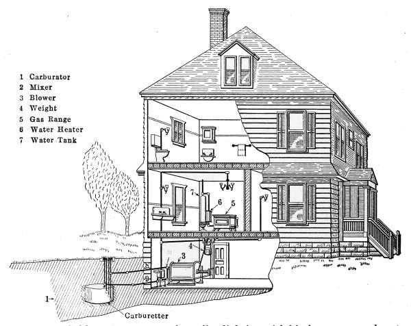
Fig. 183.—Cold-process system of gasoline lighting with kitchen range and water
heater.
In Fig. 183, the entire plant is shown in place. It occupies
a place inside the building, usually in the basement. In the[267]
figure the carburetor is marked 1; the mixer 2 stands at the end
of the blower, which is numbered 3. The motive power of the
blower is furnished by a heavy weight, which is raised by a
block and tackle, the cord of which is attached to the drum and
fastened to the shaft of the blower. The force furnished by
the weight 4 drives the blower and maintains a constant pressure
on the gas in the system. The pipe 8 conducts the air from the
blower to the carburetor, which is located underground, below
the frost line and 25 or 30 feet away from the building.
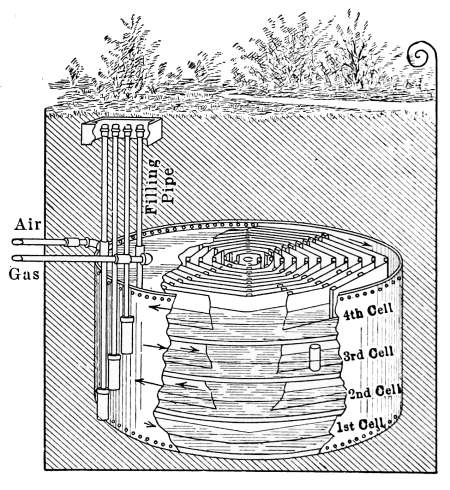
Fig. 184.—Carburetor for cold-process
gasoline lighting plant.
The carburetor in this case is also the storage tank, as shown
in detail in Fig. 184. The carburetor is divided laterally into
two or more compartments, depending
on the size of the plant
to be accommodated. That
shown in Fig. 184 contains four
compartments and is intended
for a large plant. The construction
is such that the compartments
are only partly filled with
gasoline, and arranged to permit
the air from the blower,
which enters at the pipe marked
air, to pass through each compartment
in succession, beginning
at the bottom, in order
that it may become completely
saturated with gasoline vapor.
As an additional means of aiding the saturation of the passing
air, the compartments in this carburetor are provided with spiral
passages through which the air must pass, so that when it
reaches the outlet pipe, marked gas, the air is completely filled
with gasoline vapor.
The vapor-saturated air now leaves the carburetor by pipe 9,
in Fig. 183, and enters the mixing chamber 2, where it is mixed
with the required amount of atmospheric air, to make it completely
combustible when burned at the burner.
The mixing chamber is shown in detail in Fig. 185. The
mixing is done automatically and the quality of the gas is[268]
uniform, regardless of the varying conditions of the attending
temperature and the quality of the gasoline in the carburetor.
The vitally important feature of any gas machine is, that a
constant amount of gasoline vapor be carried to the burners. If
the gas contains too great an amount of gasoline vapor, a smoky
flame will be the result; if an insufficient amount of gasoline
is present, the flame will be pale and give out little light. When
freshly charged, the gasoline in the carburetor will vaporize very
readily, and a large amount of air must be added to the gas to
reduce it to the proper consistency; but from old gasoline, which
has lost most of the highly volatile matter, a smaller proportion
of atmospheric air will be demanded.
For this reason, a
mixing regulator that will
always deliver gas containing
the same amount of gasoline
vapor is necessary to give satisfactory
service. The mixer
shown in Fig. 185 accomplishes
this office by reason of the
specific gravity of the gas.
As the air in the carburetor
takes up gasoline vapor, its
specific gravity is increased
until the air is saturated; and
by adding the amount of atmospheric
air necessary for
complete combustion the weight
is reduced to a definite amount which will be constant. The
required mixture will, therefore, always weigh the same amount.
The principle on which this mixer works is that described in
physics as the principle of Archimedes: “that a body immersed
in a fluid will lose in weight an amount equal to the liquid displaced.”
In the application of the law, the gas in the mixer is
the fluid, and the float—to be described—is the displacing body.
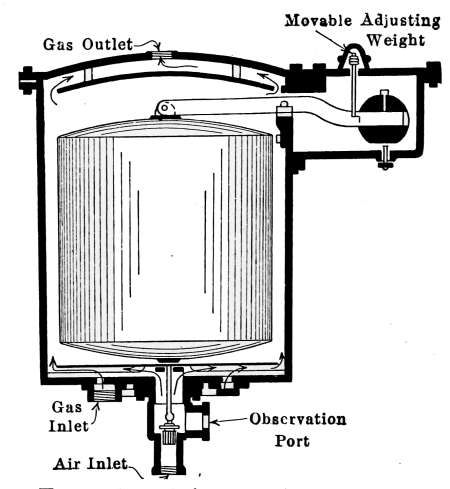
Fig. 185.—Diagram illustrating the
mixer of the Detroit cold-process system
of gasoline lighting.
The mixer in Fig. 185, is shown cut across lengthwise. The
outside casing is indicated by the heavy black lines. The gas
which leaves the opening at the top—marked gas outlet—is a
mixture of gasoline and air that may be used for exactly the same[269]
purpose and in the same manner as coal gas. It may be used
in open-flame gas jets or in the mantle gas lamps for lighting
purposes and also as fuel gas for domestic heating. The gas is
distributed through the building in ordinary gas pipes which are
installed as for any other kind of gas. In Fig. 183 the distributing
pipes are indicated by the heavy lines.
The valve in the air inlet, in the bottom of the mixer, controls
the amount of air to be admitted. The entering gas from the
carburetor being heavier than the desired mixture, will raise the
float and in so doing will open the air valve and allow the air
from the blower to enter. The float and valve are so adjusted
that the desired mixture is attained when the balance beam is
level. Any variation in the mixture will change its weight and
the valve corrects the change whether it be too much or too little
air.
The openings at the bottom, marked gas inlet and air inlet,
are intended for the admission of the saturated vapor from the
carburetor, and the atmospheric air, as required. The float
which fills the greater part of the inner space is a light sheet-metal
drum, that is tightly sealed and nicely balanced by a
counterweight on the opposite end of the suspending bar. The
counterweight is made adjustable by the device marked movable
adjusting weight—in the drawing—which permits the quantity of
entering gas to be slightly changed as the gasoline in the
carburetor grows old.
The adjustment of the counterweight to suit the gas given
off from old gasoline in the carburetor, and the occasional rewinding,
to elevate the blower weight, is practically all the attention
this plant requires. It is a real gas plant which gives every
service that may be obtained from coal gas.
THE HOLLOW-WIRE SYSTEM OF GASOLINE LIGHTING
AND HEATING
The hollow-wire system of gasoline lighting possesses the
advantage of simplicity in construction and ease of installation
that makes it attractive, particularly for use in small dwellings.
The ease with which plants of this character are installed in
buildings already constructed and its relatively low cost has[270]
made it a popular means of lighting. The same principle as that
used in the hollow-wire system is applied to portable gasoline
lamps in which a remarkably convenient and brilliant lamp is
made to take the place of the customary kerosene lamp. Small
portable gasoline lamps are now extensively used for the same
purpose as ordinary oil lanterns. These lamps are convenient
as a source of light, make a handsome appearance and are relatively
inexpensive to operate.
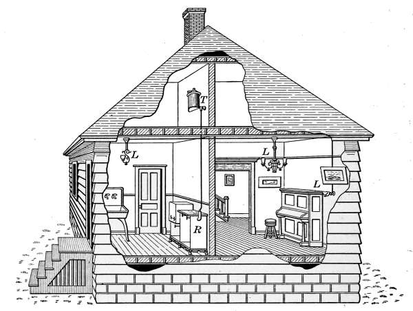
Fig. 186.—Hollow-wire system of gasoline lighting with gravity feed.
The hollow-wire system as commonly employed is illustrated
in Figs. 186 and 187. In the gravity type of the system as
illustrated in Fig. 186, the supply of gasoline is stored in the
upper part of the house in a tank T and conducted to the burners
below, through a system of small copper tubes as indicated by
the heavy lines in the drawing. The same tank is used to supply
the gasoline for the stove R in the kitchen and the lamps L in
the different apartments. The gasoline supply in this case, is
obtained entirely by gravity. This type of plant is not approved
by the National Board of Underwriters but its use is quite
generally permitted. The storage of gasoline in this form should
be done with caution as carelessness or accident might lead to[271]
serious results. With an arrangement of this kind the force of
gravity gives the pressure which supplies the burners below but
it would not be possible to use the lamps on the same floor
with the tank.
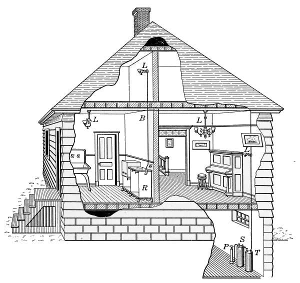
Fig. 187.—Hollow-wire system of gasoline lighting with pressure-tank feed.
Where it is desired to use lamps on both floors, a pressure
tank is employed for supplying the gasoline to the lamps, as indicated
in Fig. 187. In this plant the pressure tanks S, T in the basement,
furnish the pressure which forces the supply of gasoline
through the small tubes to the lamps L in the different rooms
and also to the stove R in the kitchen.
The means of furnishing the pressure for supplying the gasoline
to the burners may be a simple tank as that in Fig. 188, or the
more elaborate apparatus shown in the double tank of Fig. 189.
Either style will give good results but the double tank requires
the least attention in operation and is therefore more satisfactory
in use.
The tank in Fig. 188 is made of sheet metal of such weight as[272]
will safely withstand the pressure necessary in its use. It is
arranged with an opening E, for filling with gasoline, a pressure
gage for indicating the air pressure to which the gasoline is
subjected, and two needle valves; C, for attaching an air pump and
D, to which the hollow wire is attached for distributing the gasoline
to the places of use. The tank is filled with gasoline to
about the line A, and then air pressure is applied with an ordinary
air pump to say 20 pounds to the square inch. This pressure
will be much more than will be necessary to force the gasoline
through the tubes but it is intended to last for a considerable
length of time.
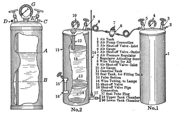
Fig. 188.
Fig. 189.
Fig. 188.—Simple gasoline pressure-tank.
Fig. 189.—Double-pressure tank for constant pressure service in gasoline lighting
systems.
The principle of operation is that known in physics as Boyle’s
law, that “the temperature being constant, the pressure of a
confined gas will be inversely as its volume.” That is, if the
tank is perfectly tight, the pressure above the line A, in the tank,
will gradually become less as the gasoline is used and when its
level is at the line B, where the volume is twice the original
amount, the pressure will be one-half what it was originally,
and will still be sufficient to force the gasoline through the tubes
to the lamps. It is evident that once the tank is charged and
the air pressure applied it will require no further attention
until a considerable part of the gasoline is consumed. If at[273]
any time the pressure in the tank becomes too low to feed the
lamps, a few strokes of the pump will raise it to the required
amount.
While the single tank does the required work, its use is not
perfect because the pressure is constantly varying. If a lamp
is set to burn at a definite pressure, any decrease in the gasoline
supply due to falling pressure will change the amount of light
given by the lamp; while the variation in the pressure of the
single supply tank is not great, a more perfect effect is attained
in the double type of tank as that of Fig. 189.
The object attained in the use of two tanks differs with different
manufacturers. The tank shown in Fig. 183, being intended to
maintain a constant pressure on the gasoline, is quite different
from those described in Fig. 197 in use with the central-generator
system of lighting, to be described later. In Fig. 189 tank
No. 1 is for air supply alone and tank No. 2 is the storage tank
for gasoline. Between the two tanks is a pressure-regulating valve
6-7, which keeps a constant pressure on tank No. 2 so long as the
air pressure of the tank No. 1 is equal or greater than the other.
The gasoline in tank No. 2 will therefore be always under the
same pressure and when the lamps are once burning the gasoline
supply to each lamp will be a constant amount.
Tank No. 2 is separated by the head 13 into two compartments,
marked 18 and 19. The connection between the two compartments
is made by the valve 15 and the connection 16. The
gasoline supply for the lighting system is taken from the lower
chamber at the valve marked 17.
It is possible to refill this tank with gasoline while the system
is working. To accomplish this, the air supply is cut off from
tank No. 1, by closing valve 9 and the valve 15 is closed to retain
the pressure on the lower chamber of tank No. 2. The screw-plug
is then taken from the tube 12 and the tank refilled. The
screw-plug is then returned to its place, the valves 9 and 15 are
again opened and the regulating valve immediately restores the
desired pressure.
The amount of pressure required on the system will depend on
the height to which the gasoline is carried within the building.
The pressure is generally 1 pound to each foot in height and to
do the best work the pressure must be constant.
[274]
These plants may serve as a fuel supply for gasoline stove as
indicated at R or any other source of domestic heating. The
usual gravity supply tank is replaced by the hollow wire through
which is the gasoline from the tank in the basement.
Mantle Gas Lamps.
—Mantle lamps that are intended for
using city gas are much the same in construction as those using
the cold-process gasoline gas; the styles of mechanism differ
somewhat with manufacturers but all lamps of this kind possess
the essential features that are common to all. Either of these
gases may be used with open-flame burners, such as Fig. 193, but
since the introduction of mantle lamps, the open-flame burners
are rarely used for household illumination.
In the incandescent-mantle lamp, the light is produced by
heating to incandescence a filmy mantle of highly refractory
material. The higher the temperature to which the mantle of
a lamp is raised, the greater is the quantity of light produced.
The office of the burner is to produce a uniform heat throughout
the mantle with the use of the least amount of gas. As ordinarily
furnished from the mains, coal gas or gasoline gas is too rich in
carbon to be used in mantle lamps without dilution. When gas
is burned in a mantle lamp, it must contain sufficient oxygen—which
is supplied by the air—to combine completely with the
contained carbon and reduce it to carbon dioxide. If insufficient
air is supplied, the lamp will smoke and the mantle will soon be
filled with soot.
In the use of the various gases—made from coal, gasoline,
kerosene, alcohol, etc.—as a fuel for the production of either
heat or light, the form of the burner in which the gas is consumed
is the most important factor of the system. Without burners
in which to generate a satisfactory supply of heat for the desired
purposes, mantle gas lamps would never have come into common
use. An understanding of the mechanism of the burners of a
system is of first importance because of the possibility of the
failure of the entire plant through an improper adjustment of
the lamps.
If complete combustion of the gas is attained in the burner,
the greatest amount of heat will be evolved and the residue
[275]will be an odorless gas, carbon dioxide (CO2). If the gas is not
completely burned the odor of the gas is noticeable in the air.
Incomplete combustion may be caused by an insufficient air
supply, which causes a smoky flame; or if a larger flame is used
than the burner is designed to carry, some of the gas will escape
unburned. In either case the greatest amount of heat is not
developed by the burner.
In most burners, whether for heating or lighting—in which
gas, gasoline or alcohol is used as a fuel—the principle of operation
is that of the Bunsen tube. One noticeable exception to this
rule is the burners used with the central-generating
systems where the Bunsen tube is
a part of the generator.
The gas generated from any hydrocarbon
will burn completely, only after being mixed
with air or other incombustible gas, in proportions
such as will completely oxidize the
carbon contained in the fuel.
In Fig. 190 the familiar laboratory Bunsen
burner affords an excellent illustration of
the Bunsen principle which forms a part of
all burners using gas as a fuel. The gas from
the supply pipe issues from a small opening
A into a tube B and by the force of its velocity
the entering gas carries into the tube
above it a quantity of air that may be regulated
by the size of the opening. If the
gas is burned without being first mixed with
air, the flame will be dull and smoky but if air is admitted to
mix with the gas, an entirely different flame is produced, the
characteristic shape of which is shown in the figure.
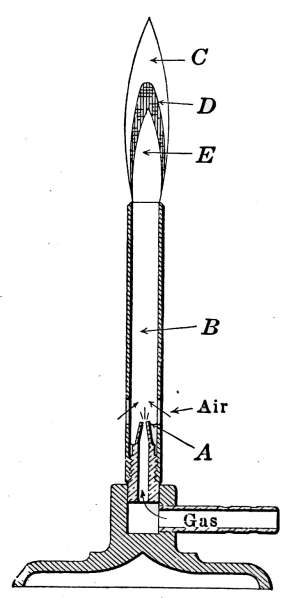
Fig. 190.—Cross-section
of Bunsen burner
showing characteristic
Bunsen flame.
The upper part of the flame C is known as the reducing flame;
it is blue in color and intensely hot. The portion D is the oxidizing
flame; it is pale blue, sometimes light green in color. The
lower part E is the gas before it begins to burn. When burning
in air, the Bunsen flame gives scarcely any light, all of the energy
being expended in heat. In the gas stove where the burners
are made up of a great number of small jets, it will be seen that
each jet shows the characteristic features of the Bunsen flame.
The incandescent-mantle gaslight takes advantage of the heat[276]
generated by the Bunsen flame and produces an incandescent
light that has revolutionized gas lighting. The flame of the
Bunsen tube is burned inside a mantle which is rendered incandescent
by the heat.
The incandescent mantle was invented by Dr. Auer von
Welsbach and was known for a long time as the Welsbach light;
but improvements in the process of making the mantles, brought
other lamps of the same type on the market, when it became
known as the mantle lamp. The first serviceable mantles were
made in 1891 and from that time there has been a
steady development in the gas-lighting industry.
The original mantles were made of knitted cotton
yarn, impregnated with rare earths and are still so
made; but the most durable mantles are now constructed
from ramie or china grass. After being
knitted, the mantles are impregnated with thorium
nitrate, with the addition of a small quantity of
cerium nitrate, and occasionally other nitrates.
The mantles are then shaped and mounted; the fiber
is burned out and the mantles are dipped in collodion
to give them stability for transportation. When
placed in the lamp for use, the collodion is first
burned off and the remaining oxide of thorium forms
the incandescent mantle. One style of mantle is
now being made in which the fiber is not burned out
until it is placed in the lamp. They are commonly
used with gasoline lamps and give very good results.
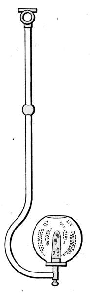
Fig. 191.—Gas
lamp
with upright
mantle.
The first incandescent-mantle gas lamps to be used were of
the upright type, such as is shown in Fig. 191, and for a long
time they were the only mantle lamps in use. While the upright
mantle was a great improvement over the open-flame gas jet,
the lamp was not satisfactory because of the shadows cast by
the fixture and from the fact that a large amount of the light was
lost by being directed upward from the incandescent mantle.
With the development of the inverted type, the mantle lamp
was greatly improved. In the use of lamps of any kind, the
desired position of the illumination is that in which the light is
directed downward. In the inverted type of mantle lamp this
feature is accomplished and adds materially to the efficiency of[277]
the light, because the rays are sent in the direction of greatest
service. The upright mantle lamps are still sold but by far the
greater number offered for sale are of the inverted type.
The essential features of all gas lamps used under these conditions
are shown in Fig. 192, which represents the common
bracket type of lamp. The gas-cock C, connects the lamp with
the gas supply G. The gas escapes into the Bunsen tube, through
an opening in the tip P, which is so constructed that the amount
of gas may be varied to suit the required conditions. The
brass screw nut N may be raised or lowered and thus increase or
diminish the amount of escaping gas by reason of the position
of the pin P. If the nut is screwed completely down the pin
closes the opening and the gas is entirely shut off. When the
lamp is put in place, the burner
is adjusted to admit the proper
amount of gas and so long as the
quality of the gas remains the
same, no further adjustment will
be necessary. Any change to a
richer or poorer gas will, however,
require an adjustment of the
burner to suit the mantle. The
amount of gas admitted is only
that which will produce complete
combustion in the mantle when combined with the required
amount of air. Each burner must, therefore, be designed for
the mantle in use.
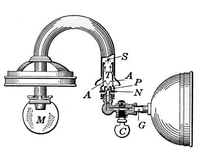
Fig. 192.—Mantle gas lamp showing
details of Bunsen tube.
As the gas leaves the opening above the pin P, it enters the
mixing chamber of the Bunsen tube and air is drawn at the
openings A-A. The mixture of the gas and air is accomplished
in the tube leading to the mantle M, where it is burned. In
all lamps of this kind, there is a wire screen placed relatively as
S, the object of which is to prevent the mixture in the tube from
exploding—in case of low pressure—and thus cause the gas to
ignite and burn at the point of entrance to the tube.
At any time the pressure is insufficient to send a steady flow
of gas into the tube, the flame may “flash back” and ignite the
gas at the point of entrance where it will continue to burn. If,[278]
however, the screen is interposed between the gas supply and the
burner, the flame of explosion will not pass the screen.
In lighting the lamp, the gas is turned on and a lighted match
is held under the mantle, the explosive mixture of gas and air
fills the mantle and escapes into the globe, in which it is usually
inclosed. As soon as ignition takes place the gas outside the
mantle explodes with the effect that is startling but not necessarily
dangerous. The escaping gas continues to burn and heats the
mantle to incandescence.
The amount of escaping gas is regulated by turning the gas-cock
to produce the greatest brilliance with the least flame outside
the mantle. When used for household illumination, the
intensity of the light is such as to be objectionable, when used
directly; but when surrounded by an opal glass globe to diffuse
the light, this is a highly satisfactory and economical means of
lighting.
Open-flame Gas Burners.
—Gas jets of the open-flame type
continue to be used to some extent but the more efficient mantle
lamp has very largely supplanted
lights of this kind. In the past,
these gas lights were made in a
great many styles and were
known under a variety of trade
names—the fish-tail burner, the
bats-wing burner and the Argand
burner—and were at times
very generally used for gas
lighting.
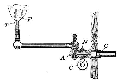
Fig. 193.—Swing-bracket gas lamp
with open-flame burner.
The common gas jet is illustrated
in Fig. 193. The figure shows a bracket fixture which
is generally fastened to a pipe in the wall. A swing-joint at A
permits the flame F to be moved into different positions. The
annular opening A permits the gas to pass to the jet in any
position to which the light is moved. The gas-cock C is a cone-shaped
plug, which has been ground to perfectly fit its socket.
It should move with perfect freedom, and yet prevent the escape
of the gas. A slotted screw N permits the joint to be readjusted,
should the plug become loose in the socket.
The gas-tips T are made of a number of different kinds of[279]
materials and are commonly termed lava-tips but tips for gas
and gasoline are frequently made of metal. The bottom of the
tip is cone-shaped, which permits it to be forced into place in the
end of the tube with a pair of pliers. In size the tips are graded
by the amount of gas which they will allow to escape in cubic
feet per hour. For example—a 4-foot tip will use approximately
4 cubic feet of gas per hour. They are made in a number of sizes
to suit the varying requirements.
The Inverted-mantle Gasoline Lamp.
—The inverted-mantle
gasoline-gas lamp shown in Fig. 194, furnishes a good example of
mechanism and principle of operation, when used with the hollow-wire
system. This is the bracket style of lamp but the same
mechanism is used in other forms of fixtures. Lamps of similar
construction are suspended from the ceiling, either singly or in
clusters; they are also used in portable form.
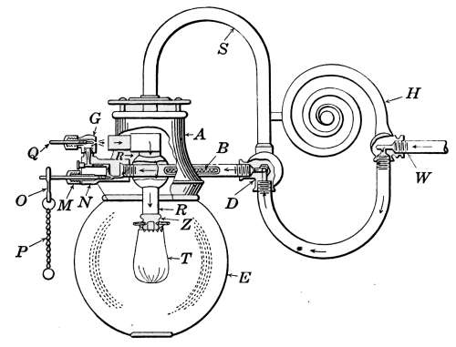
Fig. 194.—Sectional view of hollow-wire mantle gasoline lamp.
In Fig. 194 the lamp consists of a bracket H, which is secured
to the wall and through the stem of which the gasoline is conducted
to the generator by the pipe W. The arrows show the
course of the gasoline and its vapor as it passes through the lamp.
On entering the generator the gasoline first passes, the percolation,
through an asbestos wick B, the object of which is to prevent
the vapor pressure from acting directly on the gasoline in
the supply tube. The gasoline passes through the wick B,
largely by capillary action, as it must enter the generator against
a pressure greater than that afforded by the pressure tank. The[280]
vaporization of the gasoline takes place in the tube above the
mantle T, from the flame of which it receives the necessary heat.
In lighting the lamp an asbestos torch saturated with alcohol is
ignited and hung on the frame, so that the flame may heat the
generating casting N. This process usually requires less than a
minute, generally about 40 or 50 seconds. The torch supplies
heat sufficient to generate the vapor for lighting the lamp, but
as soon as lighted the heat from the glowing mantle keeps the
generator at the required temperature for continuous supply of
vapor.
When the generator is sufficiently heated by the generating
torch, the needle valve N is opened by pulling the chain P. This
allows the gasoline vapor from the generating tube to escape at
G into the induction tube R. As the vapor enters the induction
tube at a high velocity, it carries with it the atmospheric air in
quantity sufficient to render it completely combustible. The
opening G and the tube together form a Bunsen burner. The
lamp is so proportioned as to give a mixture of gasoline vapor and
air that will produce complete combustion in the mantle T. The
portion of the burner Z, through which the gas enters the mantle,
is a brass tip, filled with a fluted strip of German silver, so arranged
that the gas on entering the mantle will be uniformly
distributed and that the heat generated will render the entire
mantle uniformly brilliant.
One feature of the lamp that requires special attention is the
opening G, through which the vapor from the generator is discharged
into the induction tube. This is a very small opening
and occasionally becomes stopped or partly closed. When this
occurs the lamp fails to receive the necessary amount of gas,
and the light is unsatisfactory. In this lamp, the cleaning
needle Q is provided for removing the stoppage. The needle
is simply screwed into the opening and forces out the obstruction;
when it is withdrawn, the opening is left free. A more
convenient device for accomplishing the same purpose is described
in the portable lamp, Figs. 195 and 196.
Portable Gasoline Lamps.
—The portable form of desk and
reading lamps for the use of gasoline is made in a great variety
of styles. They are sometimes constructed to feed by gravity,
but by far the greater number are operated by the pressure[281]
method. The portable lamp must be a complete gas plant,
with storage tank for the gasoline, pipe system for conducting the
gasoline to the lamp, generator and burner. To give satisfactory
results, the lamp must be capable of being lighted with
the least degree of trouble and operated with the least amount
of care. The immense number of lamps of this kind that are
sold shows that they meet all of these requirements and have
proven satisfactory in operation. Their greatest attractiveness
is their capability of giving a very large amount of light at
relatively low cost.
Fig. 195 illustrates a portable gasoline lamp in which a convenient
and efficient form of generating mechanism is combined
with an attractively proportioned exterior. The
lamp works on the principle of the hollow-wire
system, the base serving as a storage and pressure
tank, the frame of the lamp acting as the tube for
supplying the lamp with gasoline, and the canopy
containing the generating mechanism.
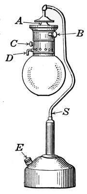
Fig. 195.—Portable
gasoline
mantle
lamp.
The tank in the base is filled with gasoline at
the opening E, which is made air-tight by a screw-plug.
The plug also contains an attachment piece
for the air pump, which furnishes the pressure to
the gasoline. The hollow standard reaches to the
bottom of the tank and through it the gasoline
is forced to the point marked A, where the gasoline
enters the generating mechanism. This part
of the lamp, which is entirely concealed by the
lamp canopy, is shown in detail in Fig. 196. The reference
letters in Fig. 195 apply to the same parts in the detail drawing.
The gasoline enters an asbestos-packed tube F at the point A,
and after percolating through the tube, reaches the regulating
valve at the point G. The hand-wheel B opens and closes the
valve, and thus controls the entrance of the gasoline to the generating
tube H, where it is converted into the vapor. The vapor
now needs only the addition of air to make it the desired gas for
illuminating the mantle.
The vapor from the generating tube escapes at the small hole
K, located directly under the mixing chamber M. The supply of
air is received through the tube C, provided with a regulator,[282]
which is readily accessible from the outside of the lamp. The
mixture of gasoline vapor and air is accomplished as in the other
lamps described, through the Bunsen tube N. In this case, the
Bunsen tube is extended and increased in size to produce a
mixing chamber of considerable volume. The mantle is attached
to the tip O. The tip, like the one already described, is made
of German silver and constructed to produce a flame that will
entirely fill the mantle.
This lamp is provided with a special means of keeping the
opening K free from accumulations. The opening K, through
which the gasoline vapor escapes
from the generator, is very
small and a slight stoppage will
materially interfere with the flow
of the vapor and thus impair
the illuminating effect of the
light. A lever D operates an
eccentric which engages the
piece P, to which is attached a
pin that readily enters an opening
K, when the lever is turned.
Any accumulation which may
lodge in the opening is instantly
removed and the needle returned
to its place by a turn of
the lever D.
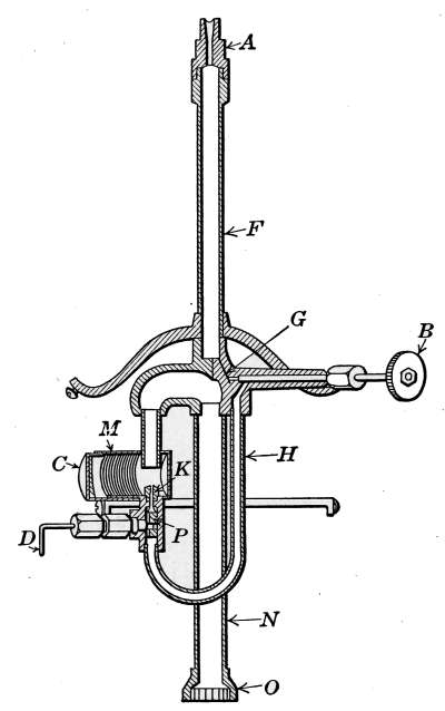
Fig. 196.—Sectional view of the
generator for the American hollow-wire
gasoline lamp.
Central-generator Plants.
—The
central-generator or tube
system of lighting with gasoline,
differs from the other methods
described, in the manner of
generating and distributing the
supply of gas to the lamps. In the hollow-wire system each
lamp generates its own gas supply. With the central-generator
system the gas for all of the lamps is generated and properly
mixed with air in a central generator, and the finished gas distributed
through tubes to the different burners and there burned
in incandescent mantles. The gas as it leaves the generator[283]
requires no further mixing with air and therefore the burners are
not of the Bunsen type.
Central-generator gas machines are made in a number of
different forms by different manufacturers, all of which are
intended to perform the same work but differ in the mechanism
employed. The machines are simple in construction and as in
the hollow-wire system are capable of using lower grades of
gasoline than can be used with the cold-process plants. The
gas from a central generator may be used for all purposes for
which gasoline gas is employed, either for lighting or heating.
One difficulty in the use of the machine is the lack of flexibility
when required for only a few lamps or varying number of lights.
Although these plants are sometimes used for lighting and heating
dwellings, their use is limited, for the reason that variation
of the number of lights requires the generator to be regulated
to suit the change in the gas supply. The plants cannot be
conveniently cut down to one light. Their most general use is
that of lighting churches, stores, halls, auditoriums, etc., where
a variable amount of light is not demanded. Plants of this
character are quite generally used for street lighting and for
other outside illumination.
An efficient and simple plant of the central-generator type is
shown in Fig. 197. The supply of gasoline is stored in a tank
similar to that used with the hollow-wire system and placed in
any convenient location. The gasoline is conducted to the generator
G, through a hollow wire marked W. The generator is
inclosed in a sheet-iron box, which is located at any convenient
place in the building. From the generator the gas is conducted
through the tube to the lamps L.
In Fig. 198 is shown a diagram of the generator, cut through
the middle lengthwise, in which all of the working parts are
shown in their relative positions. The reference figures designate
the same parts of the generator in Figs. 197 and 198.
In the process of generation the tank is filled with gasoline
and pressure applied with the air pump. The tanks described
in Fig. 189 might be used to advantage with this plant but the
one shown in Fig. 197 is so constructed that the larger tank is
used for storage of gasoline. The gasoline is pumped directly
into the smaller tank which alone is kept under pressure. The[284]
pump P is enclosed in the large tank; at any time it is desired to
replenish the supply of gasoline, it is only necessary to open the
valve V and pump the necessary supply into the small tank.
This transfer may be done at any time without danger from
escaping gasoline vapor.
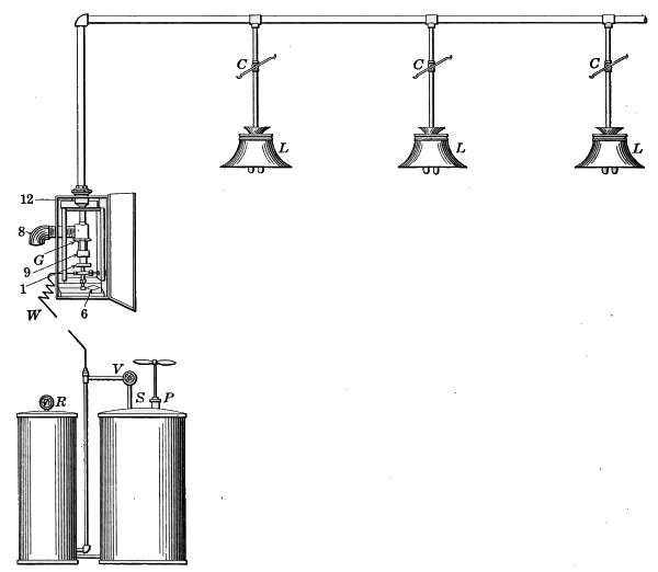
Fig. 197.—Diagram of central-generator tube system of gasoline lighting.
The process of generating the gas is best understood by reference
to Fig. 198, which shows the internal construction of the
generator. The liquid gasoline is admitted at the bottom
through the small pipe W, and then enters the space 4, where it
is vaporized. The initial flow of gas is generated by heating
the generator with an alcohol flame from the iron cup 1, which
surrounds the generator. When the generator is heated the
gasoline admitted to the generator is immediately vaporized;
when, by turning the handle 6, the needle valve 5 opens a small[285]
orifice through which the heated gasoline vapor escapes into the
tube 7, above.
The blast of vapor issuing from the orifice carries with it air
of sufficient volume to render the gasoline vapor an explosive
mixture that when burned in the mantle will be reduced to
CO2 gas.
When the initial heating by the alcohol flame is exhausted,
sufficient gas has been generated so that part of it may be used
as a sub-flame in the gas burner 9,
to keep the generator heated. The
gas is conducted to the burner
from the main tube 11, through
the pipe 12-14, as indicated by the
arrows. The burner 9 surrounds
the generator and the size of the
flame is regulated by the valve 15,
which is opened an amount sufficient
to admit the necessary gas
to the burner.
To start the generator, the cup
1 is filled with alcohol and ignited.
The needle valve 2 is now opened
by turning the hand-wheel 3, admitting
gasoline into the generator
chamber 4, where the vaporization
of the gasoline takes place. The
flame from the burning alcohol will
heat the generator in about a minute. When the generator is
hot, the needle valve 5 is opened slightly, by turning the lever
6, and the gasoline vapor under high pressure blows into the
tube 7. As the gasoline vapor is blown into the tube 7, air is
drawn in through the opening 8, as indicated by the arrows.
The generator is practically a large Bunsen tube from which
the mixture of gasoline vapor and air is conducted to the burners
by a connecting pipe.
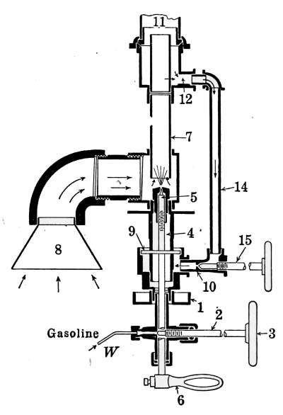
Fig. 198.—Cross-section of the
generator for the tube system of
gasoline lighting.
Gas machines operated on this principle are made to accommodate
a definite number of lamps. After the lamps are lighted,
the amount of gas is regulated to suit the number in use. If at
any time it is desired to reduce the number of lamps in operation,[286]
the gas supply must be regulated to suit the lights left
burning.
As an illustration, suppose that a plant of ten lamps had been
burning and that it was desired to reduce the number to six;
four of the lamps are extinguished by turning the levers C, which
control the gas-cocks. The generator which had been supplying
sufficient gas for ten lights will continue to produce the same
amount until the lever 6 is turned to reduce the supply of gasoline
to the required amount for six lamps. This is done by gradually
closing the valve 5 until the lamps again burn brightly.
In small plants the least number of lamps that will work
satisfactorily at one time is three. Automatic regulators are
made for plants of considerable
size but do not satisfactorily
control the gas when the
lamps are reduced below three
in number. The gas from these
plants may readily be used in
kitchen ranges, water heaters
and other domestic purposes.
Individual plants for operating
ranges in restaurants and hotels
are in common use. The plants
are subject to minor derangements
that require correcting as
they occur, but as soon as the
mechanism and characteristic properties of the plant are known,
the correction of any difficulty that may present itself is easily
accomplished.
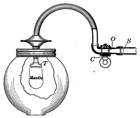
Fig. 199.—Gas lamp for use with the
central-generator or tube system of gasoline
lighting.
Central-generator Gas Lamps.
—Fig. 199 shows the general
construction and arrangement of the parts of the inverted-mantle lamp
used with the central-generator system. In outward
appearance the lamp is much like any other inverted-mantle
gas lamp, but in arrangement of parts it is markedly different.
The gas-cock C is larger than that used with the ordinary fixture,
because the opening O must carry a larger volume of gas than
that for supplying gas to lamps using the Bunsen tube. In
the use of lamps with the Bunsen tube, the gas from the mains
is mixed with approximately twenty times its volume of air;[287]
with a lamp like that of Fig. 199, where the mixture has already
been made in the generator, the conducting tubes and the gas-cock
must be relatively very large.
The screen S, which corresponds to the screen
S in Fig. 192, is quite as necessary as in the other
lamp. It not only assures a uniform distribution
of the gas in the tube but it prevents the mantle
from being broken when the burner is lighted.
If this screen is punctured, the explosion which
takes place when the burner is lighted will be
sufficient to blow out the bottom of the mantle.
The burner tip T is practically the same as that
used with other mantle lamps.
Boulevard Lamps.
—Gasoline
lamps for outside illumination may
be constructed to operate with any
of the systems described, but the
hollow-wire and the generator
systems are most conveniently used,
because each post may be arranged
as an independent plant. For illuminating
private grounds or public
thoroughfares, lamps such as are
illustrated in Figs. 200 and 201 are very generally
used.
The lamp shown in Fig. 200 is of the central
generator type in which the storage tank and
generator mechanism are located in the base of
the post. These lamps are also sometimes constructed
with a time attachment in the base of the
post, arranged with a clock mechanism so that
the light may be automatically extinguished at
any desired time.
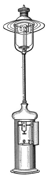
Fig. 200.—Boulevard
lamp
with generator
in the base of the
lamp post.
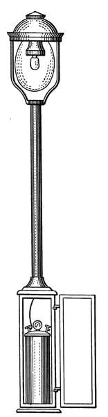
Fig. 201.—Boulevard
lamp
operated by the
hollow-wire
method of lighting.
In Fig. 201 the lamp is of the hollow-wire type
and as in the case of the other, the supply tank
is in the base of the post. With this system
it would be possible to supply several lamps from
a common supply tank, provided the hollow wire was protected
against damage. The lamps arranged to work on either system,[288]
require the same amount of attention and are subject to the
same derangements as those for inside service.
Burners for gasoline stoves
are made in a great variety of
forms, each having some special points of excellence that are
used to recommend the sale of the stove. The most essential
feature of a gasoline stove is the burner, since on its successful
performance will depend the satisfaction given by the stove.
Many self-generating burners have been devised which have met
with a great deal of favor, but the type of burner most widely
used and the first to be devised
for the purpose is the
generating burner similar in
principle to the generating
gasoline lamp.
The burner is first heated
from an outside source, in
order to generate sufficient
gas to start the flame, after
which the heat from the
burner will develop the gas
supply. With gasoline stoves
of this kind, the supply tank
is elevated, in order that the
force of gravity may give
sufficient pressure to send
the gasoline into the generator
while the flame is burning.
In the hollow-wire
system the same type of burner is used, but the gasoline is forced
into the burner by the pressure in the tank.
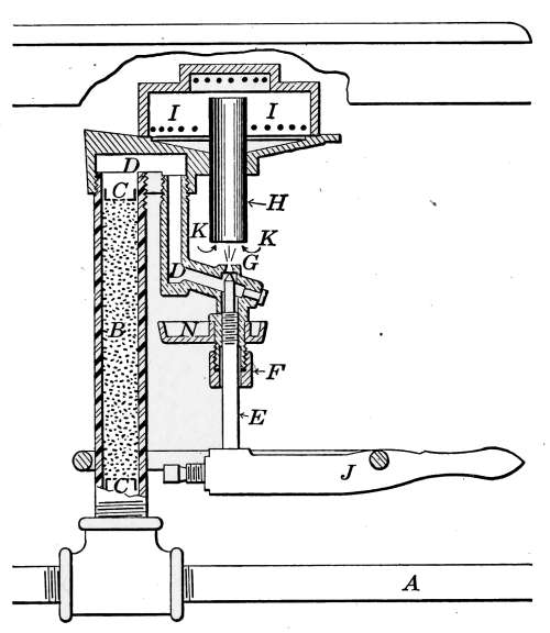
Fig. 202.—Sectional view of the generator
and burner of a gasoline stove.
In Fig. 202 is shown a sectional view of the burner as it appears
in the stove. The supply tank, or hollow wire from the pressure
tank, sends the gasoline into the tube A at the bottom of the
stove, to which several burners may be attached. The tube B,
through which the gasoline percolates on its way to the generator,
is filled with moderately coarse sand, or other material that is
intended to prevent the gasoline from being forced out of the
pipe by the pressure that is developed in the generator. The[289]
pieces C-C are perforated metal plugs that prevent the escape
of the particles of which B is composed.
The generator is a brass casting D-D which is firmly screwed
to the top of the tube B. A needle-valve E governs the discharge
of the gasoline vapor at G, where the vapor enters the tube H, as
indicated at K-K. The gasoline vapor enters the open Bunsen
tube H, and with it is carried the air necessary to produce the
required gas for complete combustion. The piece N is the
generating cup in which is burned the generating fluid—either
gasoline or alcohol. The gasoline from the pipe A percolates
through the material in B and flows into the generator. The
needle-valve being closed, the space D-D fills with gasoline.
To light the burner, the hand-wheel J is turned, opening the
needle-valve a sufficient length of time to allow the gasoline to
fill the cup N with fuel for generating the initial volume of vapor.
A still better way is to fill the cup with alcohol, because the burning
alcohol does not fill the air with smoke and odors, as in the
case of gasoline, when used for generating purposes. The
generating material having been ignited and burned out, the
generator is hot and filled with vapor. The heated generator
vaporizes a portion of the contained gasoline and forms sufficient
pressure to force the remaining gasoline back through B into the
supply tank. The material of the tube B permits only a slow
movement of the gasoline and prevents the possibility of surging
in the generator.
The initial supply of vapor being generated, the needle-valve
may be opened and the gas lighted above the burner I-I, where
it should burn in little jets at each opening with the characteristic
Bunsen flame. It sometimes happens that the generator is not
heated sufficiently, by the generating flame, to vaporize the
necessary gasoline for starting the burner; in this case liquid
gasoline will be forced from the opening G, and the burner will
flare up intermittently in a red smoky flame. When this occurs
the burners must be regenerated.
Gasoline Sad Irons.
—The use of gaseous or liquid fuel is always
attended by an element of danger, because of the possibility of
accidental explosion. The use of gasoline, the most highly
volatile of all liquid fuels, has, however, come to be very
generally used as a source of heat for domestic purposes. The[290]
danger of accident in the use of gasoline as a fuel for heating
sad irons is largely due to ignorance of the involved mechanism
or carelessness in manipulation. A knowledge of the principle
included in their operation, together with an observance of the
possible cause of accident, will reduce the element of danger to
a negligible quantity.
The use of gasoline sad irons has come into favor because of
their convenience and economy in operation. These irons, in
common with the use of gasoline in its other applications of
heating and lighting, are made in a great many forms but the
principle of operation is confined to two types.

Fig. 203.—Gasoline flat-iron operated
by a heated fuel tank.
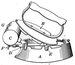
Fig. 204.—Gasoline flat-iron showing
the position of the cover while
initial charge of gas is being generated.
First, those in which the gasoline is forced into the generator
by the vapor pressure, from the heated supply tank; and second
those in which the pressure is caused by pumping air into the
supply tank after the manner of the hollow-wire system of
lighting.
The first type of iron is illustrated in Fig. 203. The same iron
is shown in Fig. 204, with the top in position for generating vapor
pressure necessary to start the burner. The body of the iron A
is a hollow casting, designed to receive the generator and burner
in such position that the bottom portion of the iron may be
uniformly heated. The generator and burner are shown in
detail in Fig. 205, in which a sectional view is given of the parts,
cut across lengthwise of the iron.
In starting the burner for use, the tank is first filled—not quite
full—of strained gasoline. The precaution of straining the gasoline[291]
should be taken, to prevent putting into the tank anything
that will possibly choke the needle-valve. Alcohol is used for
generating the vapor supply, because the flame does not black
the iron and fill the room with smoke as in the case when gasoline
is used for the purpose. When the alcohol is ignited, the cover
is placed in position as shown in Fig. 204, so that the flame may
heat not only the generator but also the tank. The object of
heating the tank is that the heated gasoline may furnish pressure
with which to force the gasoline into the generator. When the
alcohol used for generating is almost burned out, the valve F is
slightly opened and the burner lighted.
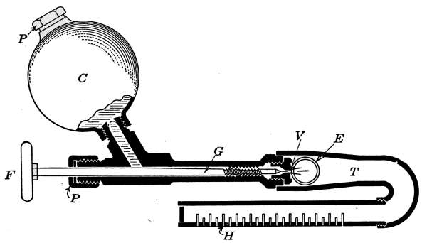
Fig. 205.—Sectional view of gasoline flat-iron generator and burner.
As shown in Fig. 205, the generator G is a brass tube, inclosing
the valve-stem G, which terminates in the needle-valve V. This
valve regulates the supply of gas admitted to the burner and is
operated by the hand-wheel F. When the gasoline in the tank
has been heated the necessary amount, the vapor in G is allowed
to escape through the valve V. The vapor is discharged into
the Bunsen tube, and with it the air is carried in through the
openings E, from both sides of the iron. The burner is a brass
tube, slotted as shown at H, through which the gas escapes,
forming a short flame of large area close to the part of the iron
to be heated. The size of the flame is regulated by the hand-wheel
F.
The tank is entirely closed, the plug P being provided with a
lead washer to insure a tight joint. The plug is further provided
with a soft metal center which acts as a “safety-plug” in case of[292]
overheating. Should the iron at any time become too hot, the
soft metal center will melt and the released pressure in the tank
will put out the burner flame. The soft metal center may be
renewed with a drop of solder. In case the safety-plug at any
time is melted, the hot gasoline will spurt from the opening and
immediately vaporize. This of course would, in a short time,
produce an explosive atmosphere which if ignited would be
dangerous. In case of accident the iron should be carried to the
open air and the flame smothered with a cloth.
Alcohol Sad Irons.
—Irons of the same style are also made in
which alcohol is used as a fuel. The alcohol irons differ in construction
from those using gasoline only in the amount of air
that is mixed with the vapor. In
general appearance the two styles
look very much alike, but in the
alcohol iron one of the intakes E
is entirely closed and the other
opening is partially closed.
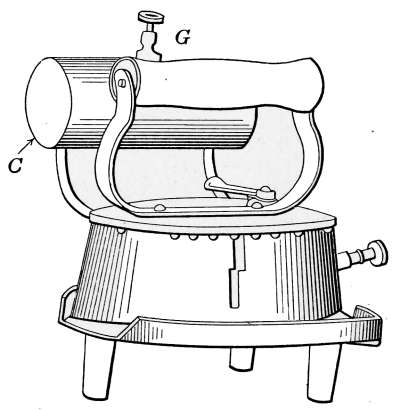
Fig. 206.—Gasoline flat-iron operated
by an air-pressure fuel tank.
The operation of these irons is
identical to those using gasoline,
but they are preferred by those who
fear the use of that fuel. In reality
there is little difference in the
danger attending the use of the
two liquids. It is only fair to say,
however, that the use of any highly
volatile fuel is attended with some danger when used carelessly,
but with a reasonable amount of care and a knowledge of the
mechanism of the machine in use the danger is of minor
consequence.
In Fig. 206 is illustrated another style of gasoline sad iron, the
working principle of which is the same as those already described
but the supply tank is not heated to give pressure to the gasoline
in the tank. In this iron the tank is located at one side of the
iron and pressure is applied with an air pump as in the hollow-wire
system of lighting. The burner is generated after the
manner of the others and operated in exactly the same manner.
The chief difference is that the possibility of excessive pressure
through overheating is eliminated.
[293]
Alcohol Table Stoves.
—In the United States the use of alcohol
as a fuel has never been extensively employed because of the
duty imposed on its manufacture by the Federal Government.
In 1896 this duty was removed from denatured alcohol and the
cost was sufficiently reduced
to permit a great extension
in its use as a fuel.
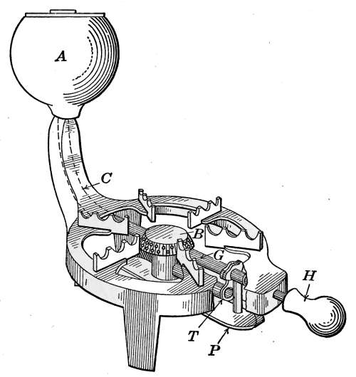
Fig. 207.—Alcohol vapor stove.
Denatured alcohol is any
alcohol to which has been
added any of the list of prescribed
volatile fluids that will
render the alcohol unfit for
use in beverages and not materially
change its heating
value. Denatured alcohol is
sold at a price that will permit
its use in small flat-irons,
table stoves and other forms of
burners where small amounts
of heat are generated for convenience.
At the price of denatured alcohol as generally sold,
it cannot compete with gasoline and kerosene as a fuel.
In Fig. 207 is shown a convenient and inexpensive form of
table stove, in which the vapor of alcohol is burned in practically
the same manner as the vapor of gasoline in the burners already
described. The supply of alcohol is stored in a tank A, and fed
by gravity to the burner B, the flame from which resembles that
of the ordinary gasoline burner.
The generator G with the other essential parts are shown in
detail in Fig. 208. The reference letters indicate the same parts
in the detail drawing as in Fig. 207.
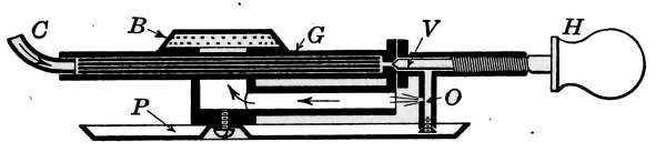
Fig. 208.—Sectional view of the generator and burner of the alcohol vapor stove.
The alcohol flows from the supply tank through the pipe C to
the generator G, which is a brass tube filled with copper wires.[294]
The vapor for starting the burner is generated by opening the
valve V and allowing a small amount of alcohol to flow through
the orifice C into the pan P directly below the generator. The
valve is then closed and the alcohol ignited. When the generating
flame has burned out, the valve V is again opened and the
vapor which has generated in the tube escapes at the orifice C
and enters the Bunsen tube T, (Fig. 207) carrying with it the
proper amount of air to produce the Bunsen flame at each of the
holes of the burner.
As in the case of the gasoline burners the orifice C sometimes
becomes clogged and it is necessary to insert a small wire to clear
the opening. With the stove is provided a tool for this purpose.
With stoves of this kind, the supply tank must not be tightly
closed, because any pressure in the tank would cause it to become
dangerous. The alcohol is fed to the generator entirely by
gravity. The stopper of the tank contains a small hole at the
top which should be kept open to avoid the generation of pressure
should the tank become accidentally heated.
Stoves of this kind may be conveniently used for a great variety
of household purposes, and when intelligently handled are relatively
free from danger.
Danger from Gaseous and Liquid Fuels.
—All combustible
gases or vapors, when mixed within definite amounts, are explosive.
The violence of the explosion will be in proportion to the
volumes of the gas and the condition of confinement.
When gasoline or other volatile fuel is vaporized in a closed
room, there is danger of an explosion, should the mixture of the
vapor and air reach explosive proportions. It is dangerous to
enter a room with a lighted match or open-flame lamp, where
gaseous odor is markedly noticeable. In case of danger of this
kind the windows and doors should be immediately opened to
produce the most rapid ventilation.
In the act of igniting the flame in a gas or vapor stove, the
lighter should be made ready before the gas is turned on. Explosions
in gas and vapor stoves are usually due to carelessness
in igniting the fuel. It should be kept constantly in mind that,
if a combustible gas is allowed to escape and mix with air in
any space and then ignited, an explosion of more or less violence
is sure to occur.
[295]
Gasoline and kerosene are lighter than water and will float on
its surface. The flames from these oils are aggravated when
water is used in attempting to extinguish them. The burning
oil floating on the surface of the water increases the burning
surface.
Burning oil must be either removed to a place where danger
will not result or the flames must be smothered. In case of a
small blaze, the fire may be extinguished with a cloth, preferably
of wool, or if circumstances will permit, with ashes sand or earth.
Alcohol dissolves in water and may, therefore, be diluted to a
point where it will no longer burn.
ACETYLENE-GAS MACHINES
Acetylene is a gas that is generated when water is absorbed
by calcium carbide, after the manner in which carbonic acid gas
is evolved when lime slakes with water, but with the liberation
of a larger amount of the combustible gas.
Calcium carbide is a product resulting from the union of lime
and coke, fused in an electric furnace to form a grayish-brown
mass. It is brittle and more or less crystalline in structure and
looks much like stone. It will not burn except when heated with
oxygen. A cubic foot of the crushed calcium carbide weighs
160 pounds.
Calcium carbide—or carbide as it is ordinarily termed—may
be preserved for any length of time if kept sealed from the air,
but the ordinary moisture of the atmosphere gradually slakes it
and after exposure for a considerable time it changes into slaked
lime. The carbide itself has no odor, but in the air it is always
attended by the penetrating odor of acetylene, because of the gas
liberated by the moisture absorbed from the air.
If protected from moisture, calcium carbide cannot take fire,
being like lime in this respect; it is therefore a safe substance to
store. It is transported under the same classification as hardware,
and will keep indefinitely if properly sealed.
A pound of pure carbide yields 5½ cubic feet of acetylene, but
in commercial form, as rated by the National Board of Fire
Underwriters, lump carbide is estimated at 4½ cubic feet per
pound. In the generation of acetylene, exact weights of carbide[296]
and water always enter into combination, i.e., 64 parts of carbide
to 34 parts of water, and a definite amount of heat is evolved for
each part of carbide consumed.
Uncontrolled, the gas burns with a bright but not brilliant
flame and with a great deal of smoke, but when used in a burner
suited for its combustion it burns with a clear brilliant flame of a
quality approaching sunlight. While carbide is not explosive
nor inflammable, it may, if it finds access to water, create a
pressure such as to burst its container, and it is not impossible
that heat might be generated sufficient to ignite the gas under
such conditions. That such condition would often occur is not
at all probable. When water is sprinkled upon carbide, in
quantity such that it will all be taken up, the resultant slaked
lime is left dry and dusty, and occupies more space than the
original carbide. When more than enough water is employed,
the remaining mixture of lime and water is whitewash.
Chemically considered, acetylene is C2H2; it is composed of
carbon and hydrogen and belongs to a class of compounds known
as hydrocarbons, represented in nature by petroleum, natural
gas, etc. It is composed of 92.3 per cent. carbon and 7.7 per
cent. of hydrogen, both combustible gases. It is a non-poisonous,
colorless gas, with a persistent and penetrating odor. Its
presence in the air, to the extent of 1 part in 1000 is distinctly
perceptible. When burning brightly in a jet, there is no perceptible
odor. When completely burned it requires for its combustion
2½ times its volume of oxygen.
All combustible gases, when mixed with air and ignited, produce
more or less violent explosions. Acetylene is no exception
to the rule, and when allowed to escape into any enclosed space
it will quickly produce a violently explosive mixture, so that it is
always dangerous to enter a room or basement with a lamp or
flame of any kind where the odor of gas is perceptible. This is
quite true with a combustible gas of any kind, but with acetylene
all mixtures from 3 to 30 per cent. are capable of being exploded
with greater or less violence.
The kindling point of acetylene is lower than coal gas or
gasoline gas. To ignite either of the latter gases, a flame is
necessary to start the combustion, but a spark or a glowing cigar
is sufficient to ignite acetylene. It should therefore be borne in[297]
mind that acetylene is not only explosive when mixed with air
but that it is very easy to ignite. Under ordinary pressures
pure acetylene is not explosive, but at pressure above 15 pounds
to the square inch explosions sometimes occur where proper precautions
are not observed. At all pressures such as are required
for household purposes acetylene is as safe for use as any other
gas.
Although acetylene is in danger of exploding when under
pressure, it is perfectly safe, when the proper conditions are
observed, in tanks for a great many kinds of portable lights.
Where acetylene is used in portable tanks under pressure,
advantage is taken of its solubility in acetone. This is a product
of the distillation of wood which possesses the property of absorbing
acetylene to a remarkable degree. In addition to this
property is the more important one of rendering the acetylene
non-explosive when under pressure. The tanks for its storage
are filled with asbestos or other absorbent material that is
saturated with acetone. The acetylene is then forced into the
tanks under pressure and is absorbed by the acetone. The
safety of this means of storage lies in the degree of perfection to
which the tanks are filled with the absorbent material. There
must be no space anywhere in the tank where undissolved
acetylene can exist. Its freedom from danger under such
conditions has been thoroughly demonstrated in its use for
railroad and automobile lamps.
The use of acetylene as a fuel for cooking and for the various
other purposes of domestic use is successfully accomplished in
burners that give the blue flame desired for such purposes.
Complete cooking ranges and various other heating and cooking
devices are regularly sold by dealers in heating appliances, while
water-heaters, hot-plates, chafing-dish heaters, etc., are as much
a possibility as with any other of gaseous fuel and in as
reasonably an inexpensive way.
Coal gas, containing as it does sufficient carbon monoxide to
render it poisonous, will cause death when inhaled for any length
of time, but acetylene under the same conditions will have no
deleterious effect.
Types of Acetylene Generators.
—There are two general
methods of generating acetylene for domestic illuminating and[298]
heating purposes: that of adding carbide to water, and that in
which the water is mixed with carbide. The two types are
illustrated in the diagrams shown in Figs. 209 and 210. The
first method, that in which the carbide is dropped into water, is
shown in Fig. 209. The tank A is the generator and B is the
receiver or gas-holder. The tank A holds a considerable quantity
of water and is provided with a container C for holding the supply
of carbide. The tank A is connected with the gas-holders by a
pipe which extends above the water line in the tank B, where
the gas is allowed to collect in the gas-holder G. A charge of
carbide, sufficient to fill the holder with gas, is pushed into the
tank A by raising the lever H. Immediately the water begins
to combine with the carbide and the bubbles of gas pass up
through the water and are conducted into the tank B. The
holder G is lifted by the gas and its weight furnishes the pressure
necessary to force the gas into the pipes, which conduct it to the
burners. If this machine were provided with the proper mechanism
to feed into the generator a supply of carbide whenever the
gas in the holder is exhausted, the machine would represent the
modern “carbide to water” generator.
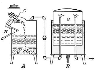
Fig. 209.—Diagram of a carbide-to-water
acetylene-gas generator.
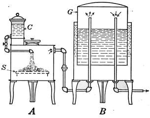
Fig. 210.—Diagram of a water-to-carbide
acetylene-gas machine.
The “water to carbide” generator is shown diagrammatically in
Fig. 210. As in the other figure, A is the generator and B is the
gas-holder. A supply of carbide S is placed in the generator
and water from a tank C is allowed to drip or spray onto the
carbide. The gas collects in the gas-holder as before. This
apparatus represents in principle the parts of a machine for
generating acetylene by this process. The actual machines are[299]
arranged to perform the functions necessary to make the machines
automatic in their action.
Whatever the type of the machine, the object is to keep in the
holders a sufficient amount of gas with which to supply the
demand made on the plant. Machines representing each of the
types described are to be obtained, but the greater number of those
manufactured are of the “carbide to water” form.
In the formative period of acetylene generators many accidents
of serious consequence resulted from imperfect mechanism.
Imperfections have been gradually eliminated until the machines
which have survived are efficient in action and mechanically
free from dangerous eccentricities.
The qualities demanded of a good generator are: There must
be no possibility of an explosive mixture in any of the parts; it
must insure a cool generation of gas; it must be well-constructed
and simple to operate; it should create no pressure above a few
ounces; it should be provided with an indicator to show how low
the charge of carbide has become in order that it may be recharged
in due season, and it must use up the carbide completely.
Because of the fact that the greater number of acetylene-gas
machines of today are of the “carbide to water” type, in the
description to follow that type of machine is used. They are
generally made in two parts, one part containing the generating
apparatus and the other acting as gasometer (gas-holder),
but some machines are made in which one cell contains both the
generator and gasometer.
In Fig. 211 is shown a two-part, gravity-fed machine, in which
all of the internal working parts are exposed to view. The
tank (a), as in the diagram, is the generator and the tank (b)
contains the gasometer marked G. Each tank possesses a
number of appliances which are necessary to make the machine
automatic in its action. The part C of the generator contains
the supply of carbide, broken into small pieces, a portion of
which is dropped into the water whenever additional gas is
required. The feed mechanism F is controlled by the gasometer
bell G, which is buoyed up by the gas it contains. When the
supply of gas becomes low, the descending bell carries with it
the end of the lever F, which is attached to the feed valve;
this motion raises the feed valve and allows some of the carbide[300]
to fall into the water. The gas that is immediately generated
passes into the gasometer through the pipe P, and as the bell is
raised by the accumulating gas the valve V is closed.
The gas as it enters the gasometer passes through a hollow
device W, that looks like an inverted T, the lower edge of which is
tooth-shaped and extends below the surface of the water. The
gas, in passing this irregular surface, is broken up and comes
through the water in little bubbles, in order that it may be washed
clean of dust. This device also prevents the return of the gas
to the generator tank during the process of charging.
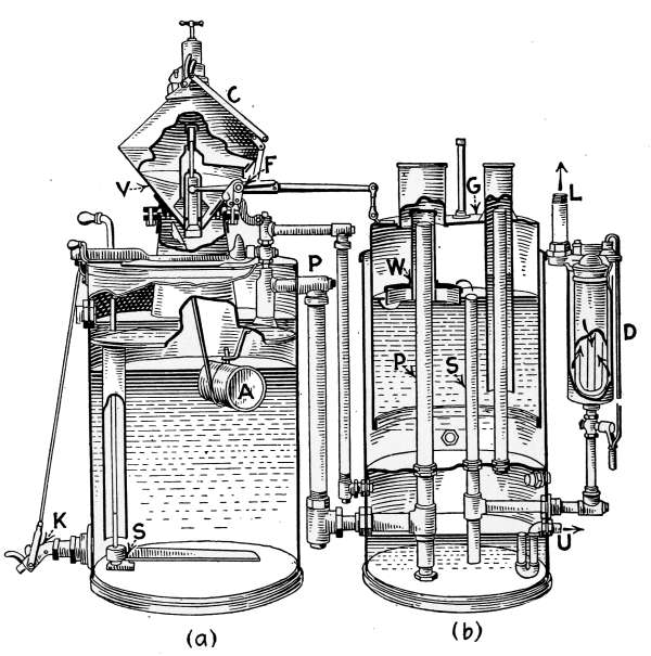
Fig. 211.—Sectional view of the Colt acetylene-gas machine.
The gas escapes from the bell through the pipe S to the filter D,
where any dust that may have escaped the washing process is
removed by a felt filter. It finally leaves the machine by the
pipe L, at which point it enters the system through which it is
conveyed to the different lighting fixtures.
It will be noticed that the tank (b) is divided into two compartments,
the upper portion containing the water in which the gasometer
floats. The lower compartment is also partly filled
with water which acts as a safety valve to prevent any escape of[301]
gas into the room in which the generator is located. The lower
end of the pipes P and S are immersed in the water at the bottom
chamber of the tank, from which the gas could escape in case too
much is generated and finally exit through the vent pipe U to
the outside air.
The float A in the tank (a) is a safety device that prevents the
introduction of carbide unless the tank contains a full supply of
water. The float is a hollow metal cylinder connected by a rod
to a hinged cup under the bottom opening of the carbide holder.
When the water is withdrawn from the generator, the float falls
and the cup shuts off the carbide outlet.
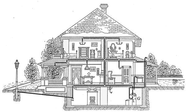
Fig. 212.—Sectional view of a house equipped with acetylene lights and domestic
heating apparatus.
The accumulation of lime, from the disintegrated carbide,
requires occasional removal from the tank (a); the valve K is
provided for this purpose. The lever S is used to stir up the lime
which is deposited on the bottom of the tank, that it may be
carried out with the discharged water.
Machines of this kind that are safeguarded against leakage of
gas or the possibility of accumulated pressure are practically free
from danger in the use of acetylene. The accidental leakage of
gas from defective pipes and fixtures produce only the element of
risk that is assumed with the use of any other form of gas for
illuminating purposes.
[302]
Acetylene is distributed through the house in pipes in the
same manner as for ordinary illuminating gas. The sizes of the
pipes to suit the varying conditions of use are regulated by rules
provided by the National Board of Fire Underwriters. These
rules state definitely the sizes of pipes required for machines of
different capacities. Rules of this kind and others that specify
all matters relating to the use of acetylene may be obtained
from any fire insurance agent.
The general plan of piping is shown in Fig. 212. The generator
G is in this case a “water to carbide” machine and is
shown connected to the kitchen range, as well as the pipe system
which may be traced to the lamps in the different rooms, to the
porch lights and to the boulevard lamp in front of the building.
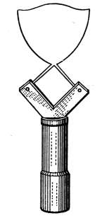
Fig. 213.—Acetylene
gas burner.
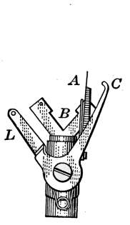
Fig. 214.—Electric
igniter for acetylene
gas burners.
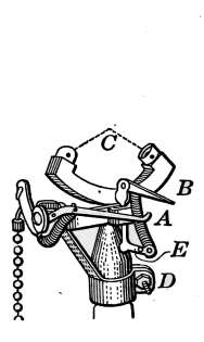
Fig. 215.—Electric igniter
for acetylene gas
burners.
The type of burner used in acetylene lamps is shown in Fig.
213. The gas issues from two openings to form the jet as it
appears in the engraving. These burners are made in sizes to
consume ¼, ½, ¾, and 1 foot per hour depending on the amount of
light demanded.
Gas Lighters.
—The acetylene gas jets are lighted ordinarily with
a match or taper but electric igniters are often used for that purpose.
Electric lighters for acetylene lamps are practically the
same as those used with ordinary gas lamps but they must be
adapted to the type of burner on which they are used. Electric
igniters that are intended to be used with lamps placed in inaccessible
places are different in construction from those within reach.
In Figs. 214 and 215 are illustrated two forms of igniters that
are intended to be used on bracket or pendent lamps. They[303]
differ in mechanical construction to suit two different conditions.
Fig. 214 is an igniter in which is also included the gas-cock. The
gas is lighted by pulling a cord or chain attached to the lever L.
The movement of this lever turns on the gas and at the same
time brings the piece C in contact with the wire A to complete
an electric circuit. As the contact between these two pieces is
broken, a spark is formed that ignites the gas escaping from the
burner at B. On releasing the lever a spring returns the piece C
to its original position. The light is extinguished by a second
pull of the lever.
Fig. 215 illustrates a style of igniter which may be attached
to an ordinary gas-cock. It is attached to the stem of the burner
by a clamp D. The gas is turned
on by the usual gas-cock and by pulling
the chain at the left the jet is
lighted. In pulling the chain the arm
A is raised and carries with it the
arm B. When the arms A and B
touch, an electric circuit is formed
with a battery and spark coil. When
the desired position of the arms is
reached, the points separate to form
an electric flash which lights the gas.
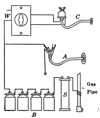
Fig. 216.—Diagram of electric
igniters attached to gas
burners.
Fig. 216 illustrates in A the method
of installing electric igniters like those
described. A battery B and a spark
coil S are joined in circuit as shown. The gas pipe acts as one
of the wires of the circuit. A battery of four dry cells is commonly
used for the purpose. The spark coil is a simple coil of
wire wound on a heavy iron core, which serves to intensify the
spark when the circuit is broken. In using the igniter, it is
only necessary to see that the cells are joined in series with the
coil and attached to the insulated part of the igniter. As already
explained the action of the igniter is to close the circuit and immediately
break the contact at a point where the spark will ignite
the gas. On being released the igniter returns to its original
position.
In the fixture shown at C is an igniter such as is used in places
that cannot be conveniently reached. To light the jet, the circuit[304]
is completed by turning the switch at W. As soon as the gas is
lighted the switch is again turned to break the igniter-circuit.
In this device the current passes through a magnet coil in the
igniter which acts to open and close the circuit with the same effect
as in the others.
Acetylene Stoves.
—Stoves in which acetylene is used as a fuel
are quite similar in construction to those which burn coal gas.
The principle of operation is that of mixing the acetylene with air
in proper proportion so as to produce complete combustion
when burned.
[305]
CHAPTER XIII
ELECTRICITY
The adaptability of electricity to household use for lighting,
heating and the generation of power has brought into use a host
of mechanical devices that have found a permanent place in
every community where electricity may be obtained at a reasonable
rate, or where it can be generated to advantage in small
plants.
Because of its cleanliness and convenience, electricity is used
in preference to other forms of lighting, even though its cost is
relatively high. Electric power for household purposes is constantly
finding new applications and will continue to increase in
favor because its use as compared with hand power is remarkably
inexpensive. Small motors adapted to most of the ordinary
household uses are made in convenient sizes and sold at
prices that are conducive to their greater use. Human energy
is far too precious to be expended in household drudgery
where mechanical power can be used in its place and often to
greater advantage.
Electric heating devices compete favorably with many of the
established forms of household heating appliances, the electric
flat-iron being a notable example. In all applications where
small amounts of heat are required for short periods of time,
electricity is used at a cost that permits its use, in competition
with other forms of heating.
The remarkable advance that has taken place in electric
transmission in the past few years tends to an enormous increase
in its use. The constant increase in its use for lighting, heating
and power purposes is due in a great measure to the development
of efficient electric generating plants from which this energy may
be obtained at the least cost. In those communities where[306]
hydro-electric generation is possible its field of application is
almost without end.
Incandescent Electric Lamps.
—Anything made in the form of
an illuminating device, in which the lighting element is rendered
incandescent by electricity, may properly be called an incandescent
lamp, whether the medium is incandescent gas as in
the Moore lamp, an incandescent vapor as the Cooper Hewitt
mercury-vapor lamp, or the incandescent filament of carbon or
metal such as is universally used for lighting.
From the year 1879, when Mr. Edison announced the perfection
of the incandescent electric lamp, until 1903, when for a short
period tantalum lamps were used, very little improvement had
been made in the carbon-filament lamp. Immediately following
the introduction of the tantalum lamp came the tungsten lamp,
which because of its wonderfully increased capability for producing
light has extended artificial illumination to a degree
almost beyond comprehension. The influence of the tungsten
lamp has induced a new era of illumination that has affected the
entire civilized world. The development of the high-efficiency
incandescent lamp has brought about a revolution in electric
lighting. Its use is universal and its application is made in every
form of electric illumination.
Regardless of the immense number of tungsten lamps in use,
the carbon-filament lamp is still employed in great numbers and
will probably continue in use for a long time to come. In
places where lamps are required for occasional use and for short
intervals of time, the carbon filament still finds efficient use.
In one form of manufacture the carbon filament is subjected to a
metalizing process that materially increases its efficiency.
This form, known commercially as the GEM lamp, fills an
important place in electric lighting.
Of the rare-metal filament lamps, those using tungsten and
tantalum are in general use, but the tungsten lamps give results
so much superior in point of economy in current consumed
that the future filament lamps will beyond doubt be of that
type unless some other material is found that will give better
results.
The filaments of the first tungsten lamps were very fragile
and were so easily broken that their use was limited, but in a[307]
very short time methods were found for producing filaments
capable of withstanding general usage and having an average
life of 1000 hours of service. These lamps give an efficiency of
1.1 to 1.25 watts per candlepower of light, as will be later more
fully explained. This, as compared with the carbon-filament
lamps which average 3.1 to 4.5 watts per candlepower, gives a
remarkable advantage to the former. The tungsten lamp has a
useful life that for cost of light is practically one-third that of the
carbon-filament lamp.
The metal tungsten, from which the lamp filament is made,
was discovered in 1871. It is not found in the metallic state
but occurs as tungstate of iron and manganese and as calcium
tungstate. Up to 1906 it was known only in laboratories and
on account of its rarity the price was very high. As greater
bodies of ore were found and the process of extraction became
better known, the price soon dropped to a point permitting its
use for lamp filaments in a commercial scale.
Pure tungsten is hard enough to scratch glass. Its fusing
point is higher than any other known metal; under ordinary conditions
it is almost impossible to melt it and this property gives
its value as an incandescent filament. One of the laws that affect
the lighting properties of incandescent lamps is: “the higher the
temperature of the glowing filament, the greater will be the
amount of light furnished for a given amount of current consumed.”
The high melting point permits the tungsten filament
to be used at a higher temperature than any other known material.
Tungsten is not ductile, and in ordinary form cannot be
drawn into wire. Because of this fact, the filaments of the
first lamps were made by the “paste” process, which consisted
of mixing the powdered metal with a binding material, in the
form of gums, until the mass acquired a consistency in which it
might be squirted through a minute orifice in a diamond dye. The
resulting thread was dried, after which it was heated, and finally
placed in an atmosphere of gases which attacked the binding material
without affecting the metal. When heated by electricity
in this condition, the particles of metal fused together to form
a filament of tungsten. While the “paste” filaments were never
satisfactory in general use, their efficiency as a light-producing[308]
agent inspired a greater diligence in the search for a more durable
form.
Although tungsten in ordinary condition is not at all ductile,
methods were soon found for making tungsten wire and the
wire-filament lamps are now those of general use. One process
of producing the drawn wire is that of filling a molten mass of a
ductile metal with powdered tungsten after which wire is drawn
from the mixture in the usual way. The enclosing metal is then
removed by chemical means or volatilized by heat.
Of the difficulties encountered in the use of metal-filament
lamps that of the low resistance offered by the wire was overcome
by using filaments very
small in cross-section and of as
great length as could be conveniently
handled. The long
tungsten filament requires a
method of support very different
from the carbon lamp.
The characteristic form of
tungsten lamps is shown in
Fig. 217, in which the various
parts of the lamp are named.
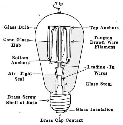
Fig. 217.—An Edison Mazda lamp
and its parts.
The filament of an incandescent
lamp is heated because of
the current which passes
through it. The electric pressure
furnished by the voltage, forces current through the filament
in as great an amount as the resistance will permit. A 16-candlepower
carbon lamp attached to a 110-volt circuit requires practically
½ ampere of current to render the filament incandescent; the
filament resistance must, therefore, allow the passage of ½ ampere.
With a given size of filament, its length must be such as will
produce the desired resistance. A greater length of this filament
would give more resistance and a correspondingly less amount
of current would give a dim light because of its lower temperature.
Likewise, a shorter filament would allow more current to pass
and a brighter light would result. When the size and length of
filament is once found that will permit the right amount of current
to pass, if the voltage is kept constant, the filaments will always[309]
burn with the same brightness. This is in accordance with Ohm’s
law which as stated in a formula is
E = RC
that is E, the electromotive force in volts, is always equal to the
product of the resistance R, in ohms, and the current C, in
amperes.
In the incandescent lamp, if the electromotive force is 110
volts and the current is ½ ampere, the resistance will be 220 ohms
and as expressed by the law
110 = 220 × 0.5
From this it is seen that any change in the voltage will produce
a corresponding change in the current to keep an equality in the
equation. If the voltage increases, the current also increases
and the lamp burns brighter. Should the voltage decrease the
current will decrease and the lamp will burn dim. This dimming
effect is noticeable in any lighting system whenever there
occurs a change in voltage.
The quantity of electricity used up in such a lamp is expressed
in watts, which is the product of the volts and amperes of the
circuit. In the lamp described, the product of the voltage (110)
by the amount of passing current (½ ampere) is 55 watts. With
the above conditions the 16 candlepower of light will require 3.43
watts in the production of each candlepower. The best performance
of carbon-filament lamps give a candlepower for each
3.1 watts of energy.
The filament of the tungsten lamp must offer a resistance
sufficient to prevent only enough current to pass as will raise
its temperature to a point giving the greatest permissible amount
of light, and yet not destroy the wire. The high fusing point
and the low specific heat of tungsten permits the filament to be
heated to a higher temperature than the carbon filament and with
a less amount of electric energy. These are the properties that
give to the tungsten lamp its value over the carbon lamp.
The exact advantage of the tungsten lamp has been investigated
with great care and its behavior under general working conditions
is definitely known. In light-giving properties where the
carbon-filament lamp requires 3.1 watts to produce a candlepower[310]
of light, in the tungsten filament only 1.1 watts are necessary
to cause the same effect. The tungsten lamp therefore gives
almost three times as much light as the carbon lamp for the same
energy expended. The manufacturers aim to make lamps that
give the greatest efficiency for a definite number of hours of service.
It has been agreed that 1000 working hours shall be the
life of the lamps and in that period the filament should give its
greatest amount of light for the energy consumed.
The Mazda Lamp.
—The trade name for the lamp giving the
greatest efficiency is Mazda. The term is taken as a symbol
of efficiency in electric incandescent lighting. At present the
Mazda is the tungsten-filament lamp, but should there be found
some other more efficient means of lighting, which can take its
place to greater advantage, that will become the Mazda lamp.
Candlepower.
—The incandescent lamps are usually rated in
light-giving properties by their value in horizontal candlepower.
This represents the mean value of the light of the lamp which
comes from a horizontal plane passing through the center of
illumination and perpendicular to the long axis of the lamp.
Candlepower in this connection originally referred to the English
standard candle which is made of spermaceti. The standard
candle is 0.9 inch in diameter at the base, 0.8 inch in diameter at
the top and 10 inches long. It burns 120 grains of spermaceti and
wick per hour. This candle is not satisfactory as a standard
because of the variable conditions that must surround its use.
The American or International standard is equal to 1.11 Hefner
candles. The Hefner candle (which is the standard in continental
Europe and South American countries) is produced by a
lamp burning amylacetate. This lamp consists of a reservoir
and wick of standard dimensions which gives a constant quantity
of light. The light from this lamp has proven much more
satisfactory as a means of measurement of light than the English
standard and therefore its use has been very generally adopted.
The light given out by an incandescent lamp is not the same
in all directions. In making comparisons it is necessary to define
the position from which the light of the lamps is taken. The
horizontal candlepower affords a fairly exact means of comparing
lamps which have the same shape of filament, but for
different kinds of lamps it does not give a true comparison. The[311]
spherical candlepower is used to compare lamps of different construction
as this gives the mean value at all points of a sphere
surrounding the lamp. The candlepower is measured at various
positions about the lamp with the use of a photometer, and the
mean of these values is taken as the mean spherical candlepower.
At their best, carbon-filament lamps require in electricity
3.1 w.p.c. (watts per candlepower). As the lamp grows old the
number of watts per candle power increases, until in very old
lamps the amount of electricity used to produce a given amount
of light may become excessively large. According to a bulletin
issued by the Illinois Engineering Experiment Station on the
efficiency of carbon-filament incandescent lamps, the amount of
electrical energy per candlepower varied from 3.1 w.p.c., when
new, to 4.2 w.p.c., after burning 800 hours.
A common practice in the use of carbon-filament lamps is to
consider that the period of useful life ends at a point where the
amount of electricity, per candlepower, reaches 20 per cent. in
excess of the original amount. This point (sometimes termed
the smashing point) would be reached after 800 working hours,
according to the Illinois Station, and at about 1000 hours as
stated by the bulletins of the General Electric Co. If a carbon-filament
lamp burns for an average period of 3 hours a day for a
year, it ought to be replaced.
The Edison screw base as shown in Fig. 217 is now generally
used in all makes of incandescent lamps for attaching the lamp
to the socket. When screwed into place this base forms in the
socket the connections with the supply wires, to produce a circuit
through the lamp. One end of the filament is attached to the
brass cap contact; the opposite end connects with the brass screw
shell of the base. When the current is turned on, the contact
made in the switch is such as to form a complete circuit between
the supply wires; the voltage sending a constant current through
the lamp produces a steady incandescence of the filament.
In Fig. 218 is shown a carbon-filament lamp attached to an
ordinary socket. The lamp base and socket are shown in section
to expose all of the parts that comprise the mechanism. The insulated
wires of the lamp cord enter the top of the socket and the
ends attach to the binding screws A and B, which are insulated
from each other and form the brass shell which encases the socket.[312]
The lamp base is shown screwed into the socket, the brass cap
contact F making connection at G; the screw shell joins the socket
at D. To the key S is attached a brass rod R, on which is fastened
E, the contact-maker. The rod R passes through a supportary
frame which is secured to the lamp socket at G. As
shown in the figures the piece E makes contact with a brass
spring attached to A, and this completes a circuit through the
filament. The brass cap contact of the lamp base makes connection
at one end of the filament H, the
other end of the filament K is attached to
the brass screw shell of the base, which in
turn connects with the screw shell of the
socket and this shell is connected with the
piece containing the binding screw B by the
rod C to complete the circuit. When the
key S turns, the contact above E is broken
and the lamp ceases to burn.
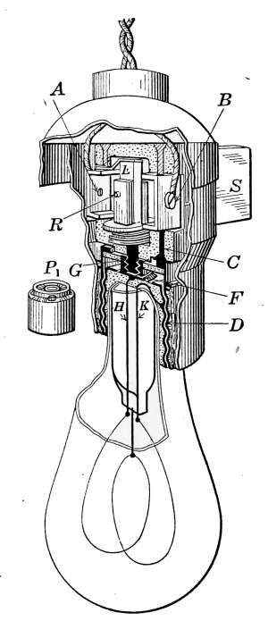
Fig. 218.—Section of a
lamp base and socket.
Fig. 118 shows the use of an adapter
that is sometimes encountered in old electric
fixtures, the use of which requires explanation.
Mention has already been made
of the various forms of lamp sockets in use
before the Edison base became a standard.
In order to use an Edison lamp in a socket
intended for another form of base an adapter
must be employed to suit the new base
to the old socket. In the figure the piece
P1, is the adapter. This is intended to
adapt the standard lamp base to a socket
that was formerly in use on the Thompson-Houston system of
electric lighting. The adapter is joined to the old socket by the
screw at G and the circuit formed as already described.
Lamp Labels.
—For many years all incandescent lamps were
rated in candlepower and were made in sizes 8, 16, 32, etc., candlepower.
On the label was printed the voltage at which the lamp
was intended to operate, and also the candlepower it was supposed
to develop. Thus 110 v., 16 cp. indicated that when used
on 110-volt circuit, the lamp would give 16 candlepower of light.
This label in no way indicated the amount of energy expended.[313]
With the development of the more efficient filaments came a
tendency to label lamps in the amount of energy consumed. This
has resulted in all lamps being labeled to show the voltage of the
circuit suited to the lamp, and the watts of electricity consumed
when working at that voltage. At present a lamp label may be
marked 110 v., 40 w., which indicates that it is intended to
develop its best performance at 110 volts and will consume 40
watts at that voltage.
Commercial lamps are now manufactured in sizes of 10, 15,
25, 40, 60, 75, and 100 watts capacity for ordinary use. Of these
the 40-watt lamp probably fulfills the greatest number of conditions
and is most commonly used. Besides these there are
the high-efficiency lamps of the gas-filled variety that are made
in larger sizes and the miniature lamps in great variety. All
are labeled to show the volts and the watts consumed.
Illumination.
—The development of high-efficiency lamps has
caused a radical change in the methods of illumination. With
cheaper light came the desire to more nearly approximate the
effect of daylight in illumination. This has brought into use
indirect illumination, in which the light from the lamp is diffused
by reflection from the ceiling and walls of the room. Illuminating
engineering is now a business that has to do with placing of lamps
to the greatest advantage in lighting any desired space. In
large and complicated schemes of lighting professional services
are necessary, but in household lighting the required number of
lamps for the various apartments are almost self-evident. The
lighting of large rooms, however, requires thoughtful consideration
and in many cases the only definite solution of the problem
is that of calculation.
The Foot-candle.
—The amount of illumination produced over
a given area depends not only on the number of lamps and their
candlepower, but upon their distribution and the color of the
walls and furnishings. In the calculation of problems in illumination,
units of measure are necessary to express the amount of
light that will be furnished at any point from its source. The
units adopted for such purposes are the foot-candle and the
lumen.
The Lumen.
—A light giving 1 candlepower, placed in the
center of a sphere of 1 foot radius illuminates a sphere, the area[314]
of which is 4 × 3.1416 or 12.57 square feet. The intensity of
light on each square foot is denoted as a candle-foot. The
candle-foot is the standard of illumination on any surface. The
quantity of light used in illuminating each square foot of the
sphere is called a lumen. A light of 1 candlepower will therefore
produce an intensity of 1 candle-foot over 12.57 square
feet and give 12.57 lumens. Therefore, if all of the light is
effective on a plane to be illuminated, a lamp rated at 400 lumens
would light an area of 400 square feet to an average intensity of
1 candle-foot.
To find the number of lamps required for lighting any space,
the area in square feet is multiplied by the required intensity
in foot-candles, to obtain the total necessary lumens, and the
amount thus obtained is divided by the effective lumens per
lamp.
The bulletins of the Columbia Incandescent Lamp Works
gives the following method of calculating the number of lamps
required to light a given space:
Number of lamps = (S × I)/(Effective lumens per lamp)
S (square feet) × I (required illumination in foot-candles)
= total lumens.
The total lumens divided by the number of effective lumens
per lamp gives the number of lamps required. In using the
formula the effective lumens per lamp is taken from the following
table:
| Watts per lamp | 25 | 40 | 60 | 160 | 150 | 250 |
| Effective lumens per lamp | 95 | 160 | 250 | 420 | 630 | 1090 |
| Lumens per watt | 3.8 | 4.0 | 4.2 | 4.2 | 4.2 | 4.3 |
The size of the units is a matter of choice since six 400-lumen
units are equal to four 600-lumen units in illuminating power,
etc. In deciding upon the proper size of lamps to use, consideration
must be taken of the outlets if the building is already wired.
In general the fewest units consistent with good distribution will
be the most economical. The table shows the lumens effective
for ordinary lighting with Mazda lamps and clear high-efficiency
reflectors with dark walls and ceiling. Where both ceiling and
walls are very light these figures may be increased by 25 per cent.
[315]
To illustrate the use of the table, take an average room 16 by
24 to be lighted with Mazda lamps to an intensity of 3.5 foot-candles.
If clear Holoplane reflectors are used, the values for
lumens effective on the plane may be increased 10 per cent.
due to reflection from fairly light walls. The lamps in this case
are to be of the 40-watt type which in the table are rated at 160
lumens. To this amount 10 per cent. is added on account of the
reflectors and walls. This data applied to the formula gives:
s = 16 by 24 feet
I = 3.5
Lumens per lamp = 160
((16 × 24) × 3.5)/176 = eight 40-watt lamps.
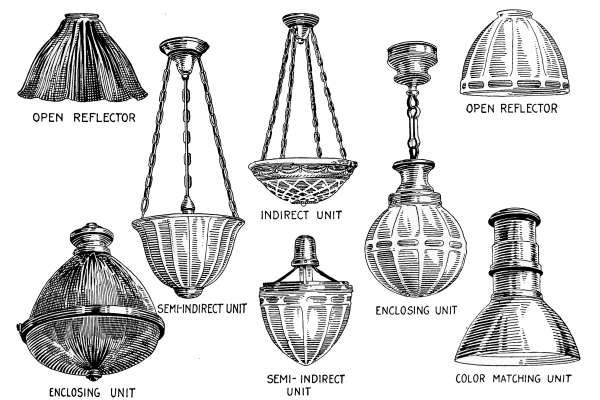
Fig. 219.
Reflectors.
—The character and form of reflectors have much
to do with the effective distribution of the light produced by
the lamp. The most efficient form of reflectors are made of
glass and designed to project the light in the desired direction.
The illustration in Fig. 219, marked open reflector, shows the
characteristic features of reflectors designed for special purposes.
They are made of prismatic glass fashioned into such form as
will produce the desired effect and at the same time transmit[316]
and diffuse a part of the light to all parts of the space to be
lighted. The greater portion of the light is sent in the direction
in which the highest illumination is desired. The reflectors
are made to concentrate the light on a small space or to spread
it over a large area as is desired. They are, therefore, designated
as intensive or extensive reflectors and made in a variety of forms.
Choice of Reflector.
—Where the light from a single lamp must
spread over a relatively great area, it is advisable to use an
extensive form of reflector. This reflector is applicable to general
residence lighting, also uniform lighting of large areas where
low ceilings or widely spaced outlets demand a wide distribution
of light. Where the area to be lighted by one lamp is smaller,
the intensive reflector is used. Such cases include brilliant
local illumination, as for reading tables, single-unit lighting or
rooms with high ceilings as pantries or halls.
Where an intense light on a small area directly below the
lamp is desired, a focusing reflector is used. The diameter of the
circle thus intensely lighted is about one-half the height of the
lamp above the plane considered. Focusing reflectors are used
in vestibules or rooms of unusually high ceilings.
| Type | Height above plane to be lighted |
| Extensive | 1⁄2 D |
| Intensive | 4⁄5 D |
| Focusing | 4⁄3 D |
| D = distance between sides of room to be illuminated. |
The various other fixtures of Fig. 219 that are designated
as reflectors are in some cases only a means of diffusion of light.
In the use of the high-efficiency gas-filled lamps the light is too
bright to be used directly for ordinary illumination. When these
lamps are placed in opal screens of the indirect or the semi-indirect
form the light produced for general illumination is
very satisfactory. Considerable light is lost in passing through
the translucent glass but this is compensated by the use of the
high-efficiency lamps and the general satisfaction of light distribution.
Lamp Transformers.
—Lamps of the Mazda type, constructed
to work at the usual commercial voltages, are made in low-power
forms to consume as little as 10 watts; but owing to the difficulty
of arranging a suitable filament for the smaller sizes of lamps,[317]
less voltage is required to insure successful operation. The
lamps for this purpose are of the type used in connection with
batteries and require 1 or more volts to produce the desired
illumination. When these little lamps are used on a commercial
circuit, the reduction of the voltage is accomplished by small
transformers, located in the lamp socket. The operating principle
and further use of the transformers will be explained later
under doorbell transformers. The lamp transformer, although
miniature in design, is constructed as any other of its kind but
designed to reduce the usual voltage of the circuit to 6 volts of
pressure. The socket is that intended for the use of the Mazda
automobile lamp giving 2 candlepower. This lamp used with
electricity at the average rate per kilowatt can be burned for
10 hours at less than half a cent. In bedrooms, sickrooms and
other places where a small amount of light is necessary but where
a considerable quantity is objectionable, the miniature lamp
transformer serves an admirable purpose in adapting the
voltage of the commercial alternating circuit to that required
for lamps of small illuminating power. Such a transformer is
shown in Fig. 220.
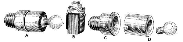
Fig. 220.—Miniature lamp transformer complete and the parts of which it is
composed.
The figure shows in A the assembled attachment with the lamp
bulb in place. The part B, the transformer, changes the line
voltage to that of a battery lamp. A line voltage of 110 may be
transformed to suit a 6-volt miniature lamp. The parts C and
D compose the screw base and the cover, in which is fitted the
transformer B.
Units of Electrical Measurement.
—The general application
of electricity has brought into common use the terms necessary in
its measurement and units of quantity by which it is sold. The
volt, ampere and ohm are terms that are used to express the conditions[318]
of the electric circuit; the watt and the kilowatt are units
that are employed in measuring its quantity in commercial usage.
The use of these units in actual problems is the most satisfactory
method of appreciating their application.
As already explained the volt is the unit of electric pressure
which causes current to be sent through any circuit. The electric
circuits of houses are intended to be under constant voltage—commonly
110 or 220—but the voltage may be any amount for
which the generating system is designed. Independent lighting
systems such as are used in house-lighting plants—to be described
later—commonly employ 32 volts of electric pressure.
Opposed to the effect of the volts of electromotive force is
the resistance of the circuit, which is measured in ohms. Resistance
has been called electric friction; it expresses itself as
heat and tends to diminish the flow of current. Every circuit
offers resistance depending on the length, the kind and the size
of wire used. Since the wires of commercial lighting systems
are made of copper, it can be said that the resistance of the
circuit increases as the size of the conducting wire decreases.
In large wires the resistance is small but as the size of the wire
is reduced the resistance is increased. A long attachment
cord of a flat-iron, may offer sufficient resistance to prevent
the iron from heating properly.
The ampere is the unit which measures the amount of current.
The amperes of current determine the rate at which the electricity
is being used in any circuit. The wires of a house must be
of a size sufficient to carry the necessary current without heating.
Any house wire which becomes noticeably warm is too small
for the current it carries and should be replaced by one that is
larger.
The watt is the unit of electric quantity. The quantity of
electricity being used in any circuit is the product of the volts
of pressure and amperes of current flowing through the wires.
The amount of current—in amperes—sent through the circuit is
the direct result of the volts of pressure; the quantity of electricity
is therefore the product of these two factors. A 25-watt lamp on
a circuit of 110 volts uses 0.227 ampere of current.
25 watts = 110 volts × 0.227 amperes.
[319]
Ten such lamps use
10 × 0.227 amperes = 2.27 amperes.
The product of 110 volts and 2.27 amperes is 250 watts.
In order to express quantity of energy, it is necessary to state
the length of time the energy is to act and originally the watt
represented the energy of a volt-ampere for one second. For
commercial purposes this quantity is too small for convenient use
and the hour of time was taken instead. The watt of commercial
measurement is the watt-hour and in the purchase of electricity
the watt is always understood as that quantity.
Even as a watt-hour the measure is so small as to require a
large number to express ordinary amounts and a still larger unit
of 1000 watt-hours or the kilowatt-hour was adopted and has become
the accepted unit of commercial electric measurement. Just
as a dollar in money conveniently represents 1000 mills so does a
kilowatt of electricity represent a convenient quantity.
In the purchase of electricity, the consumer pays a definite
amount, say 10 cents per kilowatt. This represents an exact
quantity of energy, that may be expended in light, in heat, or in
the generation of power, all of which may be expressed as definite
quantities.
As light, it indicates in the electric lamp the number of candle-power-hours
that may be obtained for 10 cents. At this rate
a single watt costs 0.01 cent an hour. A 25-watt electric lamp will
therefore cost 0.25 (¼) cent for each hour of use; a 60-watt
lamp costs 0.6 cent per hour; the ten 25-watt lamp mentioned
above using 250 watts costs 2.5 cents per hour.
As heat, it is expressed in English-speaking countries as British
thermal units, 1 kilowatt-hour representing 3412 B.t.u. per
hour. One cent’s worth of electricity at the rate given yields
341.2 B.t.u. of heat.
As power, it represents an exact amount of work. So expressed,
a watt represents 1⁄746 horsepower; therefore a kilowatt is represented
in power as 1000⁄746 = 1.3 horsepower. Since the kilowatt
purchased for 10 cents is a kilowatt-hour, the equivalent horsepower
is for the same length of time. At the assumed rate, 10
cents buys 1.3 horsepower for one hour. When used as work[320]
it represents 2,544,000 foot-pounds or 255,400 foot-pounds of
work for 1 cent. This work when expended in a motor, to
do the family washing or perform any other household drudgery,
represents the greatest value to be derived from its use. A ½-horsepower
motor is amply large to operate a family washing
machine. Even though the motor is only 50 per cent. efficient
its cost of operation is less than 7 cents per hour.
Miniature Lamps.
—Miniature electric lamps include all that
are not used for general illuminating purposes. The term applies
more particularly to the form of the base than to the voltage
or candlepower of the filament. There are three general classes
of these lamps: candelabra and decorative, that operate on lighting
circuits of 100 to 130 volts and are usually intended for decorative
purposes; general battery lamps used for flash lights; and
lamps for automobiles and electric-vehicle service.
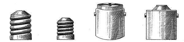
Candelabra screw base
Miniature screw base
Double-contact bayonet candelabra base
Single-contact bayonet candelabra base
Fig. 221.—Miniature lamp bases.
The term miniature lamp applies more particularly to the
base than to the voltage or candlepower. The style of base is
characteristic of the service for which the lamp is designed rather
than the size or number of watts consumed. There are two
general styles of bases: the screw type of the Edison construction
of which there are two sizes; and the bayonet type of which
there are two styles of construction.
Bases for miniature lamps are made in form to suit the conditions
of their use. The styles at present are shown in Fig. 221.
Of these the screw bases at the left are those attached to small
flash-lamp bulbs and others of the smaller sizes of lamps. The
two at the right of the figure are the bayonet style used under
conditions not suited to the screw contact. In the case of automobile
lamps and in places where vibration will cause loss of
contact the bayonet base is generally in use. The lamp is held
in place by the projecting lugs that engage with openings in the[321]
socket and kept in place by the pressure of a spring. The
contact with the lamp filament is made by two terminals that
make connection directly with the terminals of the lamp filament.
The single contact base is kept in place similarly to that of the
other but makes a single contact at the end of the socket while
the other but makes a single contact at the end of the socket
while the circuit is completed through the pressure exerted between
the projecting lugs and the socket.
Effect of Voltage Variations.
—Voltage variation may be temporary,
due to changing load in the circuit, or in constantly
overloaded circuits the voltage may be
constantly below normal. The change
in electric pressure affects in a considerable
degree the amount of light given
by the lamp. As an example, a 5 per
cent. drop from the normal voltage will
cause a decrease of 31 per cent. in the
amount of light given. This means
that if a lamp is working on a circuit
of 110 volts and the voltage from any
cause were to drop to 104½ volts, the
light would decrease 6.8, almost 7
candlepower. Drop in voltage may also
be due to the resistance of wires that
are too small for the service. Lamps
attached to such a circuit will constantly
burn dim.
Turn-down Electric Lamps.
—The
ordinary incandescent lamp lacks the
flexibility of gas and oil lamp, in that
the amount of light cannot be varied
at will. This feature is attained in the
electric turn-down lamp either by resistance added to the lamp
circuit or by the use of two separate filaments in a single globe;
one of ordinary lamp size and the other of such size that it consumes
only a fraction as much energy as the normal lamp.
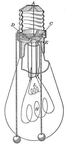
Fig. 222.—Sectional view
of a “turn-down” lamp
socket.
Turn-down lamps of the latter form are made in several styles,
the chief points of difference being in the method of changing
the contact from the high-to the low-power filament. In Fig. 222[322]
a sectional view shows the “pull-string” form of lamp in which
the parts are exposed. The long filament H and the smaller one
L represent two individual lamps of different lighting power.
The change in light is made from one to the other by pulling the
string which is attached to a switch in the socket and which
changes the contact to send the current through the filament
giving the desired amount of light. The figure shows a carbon-filament
lamp, but tungsten lamps are made to accomplish the
same purpose. The difficulty of manufacturing a 1-candlepower
tungsten lamp for direct operation on a 110-volt circuit requires
the filaments to work in series. The figure is arranged on the
same plan as for a tungsten lamp.
The lamp base when screwed into the socket makes contact
with the two service wires of the circuit at A and at E, which
are part of the screw base. To light the lamp the current is
switched on as in any lamp. The current enters at A and passes
down the connecting piece to the contact B. The piece B is
moved by the cord to light either the large or the small filament.
In the position shown the current enters the small filament at C
and in order to complete the circuit to E must traverse both the
large and the small filament. The resistance of the small filament
is such that the passing current raises it to a temperature
of incandescence but the large filament does not heat sufficiently
to give an appreciable amount of light. When the cord is pulled
to light the large filament, the contact is made at D and the
current passes directly through the large filament to complete
the circuit at E.
Turn-down lamps are especially adapted to the home. Their
use in a child’s bedroom or sick chamber is a great convenience.
The lamps are often constructed with a long-distance cord extending
from a fixture to the bedside. By this means a dim or bright
light is given as desired, with the least inconvenience. Turn-down
lamps are made in a variety of sizes. The large filaments
are arranged to give 8, 16, and 32 candlepower. With the 8-candlepower
lamp the small filament gives ½ candlepower and
with the 16-and 32-candlepower the small filament gives 1
candlepower.
With the lamps described, the variation in amount of light
is attained by changing the contacts, to bring into action filaments[323]
of different resistances. They admit of only two changes,
either the lamp burns at full capacity or at the least light the
lamp will give. The heat liberated by the large filament, when
the small light is in use, takes place inside the lamp globe.
The Dim-a-lite.
—In another form of turn-down lamp the
change in amount of light is produced by external resistance in
the circuit. The resistance is furnished by a coil of wire which is
enclosed in a special lamp socket. It possesses the advantage
as a turn-down lamp in a number of changes of light. The added
resistance in a socket decreases the flow of current and, therefore,
the filament gives less light. The resistance wire is divided into
a number of sections and contact with the terminals
of these sections decreases the light with
each addition of resistance. The heat generated
in the resistance coils is dissipated by the brass
covering of the socket.
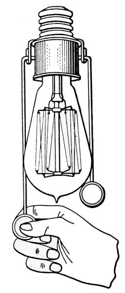
Fig. 223.—The
resistance
type of “turn-down”
lamp.
An illustration of a turn-down lamp using a
separate resistance is that of Fig. 223, known
commercially as the Dim-a-lite, which is an excellent
example. The Dim-a-lite attachment is
a lamp socket in which is enclosed a miniature
rheostat or resistance unit. The lamp, when
placed on the Dim-a-lite, makes electrical contact
as in an ordinary socket but with the
difference that in series with the lamp filament
is the rheostat, by means of which additional resistance
may be added to change the current flowing
in the lamp. The rheostat is so arranged that contact may be
made at four different points in the resistance coil, through which
the electricity may be varied from 100 to 20 per cent. of the
normal quantity. The resistance in any case permits current to
pass through the filament in amounts of 70, 30 and 20 per cent. of
the normal amount. In use, the variation is made by pulling one
string to add resistance and thus dim the light; or by pulling the
other string, the resistance is decreased and more electricity
passes through the filament to produce a brighter light. The
quantity of light given out by the filament does not vary in the
ratio of the added resistance but a variable light is obtained at
the expense of a small amount of electricity which is changed[324]
into heat. When the light is burning at its dimmest only 20 per
cent. of the normal current is used. Under this condition the
light given out by filament does not express the high efficiency
attained when the lamp is burning at its full power but it does
give a convenient form of light regulation with the
minimum waste of energy.
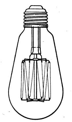
Fig. 224.—40-watt
Mazda B
lamp (½
scale).
Gas-filled Lamps.
—Until 1913 the filaments of
all Mazda lamps operated in a vacuum. The vacuum
serving the purpose of preventing oxidation and at
the same time it reduced the energy loss to the
least amount. It was found, however, under some
conditions of construction that lamps filled with
inert gas gave a higher efficiency and more satisfactory
service than those of the vacuum type. In this
construction, the filament is operated at a temperature
much higher than that of the vacuum lamp
and as a consequence gives light at a less cost per
candlepower. Mazda vacuum lamps are now designated by the
General Electric Co. as Mazda B lamps, Fig. 224, and those of
the gas-filled variety, Fig. 225, are designated as Mazda C lamps.
The filaments of the gas-filled lamps are intensely brilliant and
where they come within the line of vision should be screened from
the eyes. The high efficiency of these lamps
permit the use of opal shades to produce a desired
illumination at a rate of cost that compares
favorably with the unscreened light of the
vacuum lamps.
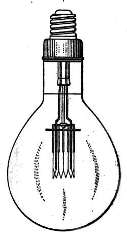
Fig. 225.—750-watt
Mazda C
lamp (¼ scale).
Daylight Lamps.
—The color of the light from
an incandescent electric lamp depends on the
temperature of the filament. In the case of the
gas-filled Mazda lamp the high filament temperature
produces a light that differs markedly
from the vacuum lamps in that it contains a
greater amount of blue and green rays. It is
therefore possible to produce light that is the
same as average daylight. Gas-filled lamps with
globes colored to produce light of noonday quality are produced
at an expenditure of 1.2 watts per candlepower.
In the matching of colors, it should be kept in mind that the[325]
tint of any color is influenced by the kind of light by which it is
viewed. Colors matched by ordinary incandescent light containing
a large percentage of red rays cannot produce the same
effect when the same articles are seen in light of different
quality. The daylight lamps are therefore intended to be used
under conditions that require daylight quality.
Miniature Tungsten Lamps.
—The wonderful light-giving properties
of tungsten has made possible the use of miniature incandescent
lamps for an almost infinite variety of usages. The
miniature lamps are similar in action to other incandescent electric
lamps except that they are operated on voltages lower than
is used on commercial circuits. When used on commercial
circuits, incandescent tungsten lamps of less than 10 watts
capacity require filaments that are too delicate to withstand the
conditions of ordinary use. The properties of tungsten are such
that the passage of only a small amount of current is required
to render the filament incandescent. In the case of a 110-volt
circuit, a 10-watt lamp requires only 0.09+ ampere to produce
the desired incandescence. It will be remembered that the watt
is a volt-ampere and the 10-watt lamp will then require
110 volts × 0.09 + ampere = 10 watts.
Since 10-watt lamps are the smallest units that may be used
on 110-volt circuits, their employment in smaller sizes must be
such as will give more stable filaments. This is possible when the
lamps are used at lower voltage. A 10-watt lamp on a 10-volt
circuit will require an ampere of current.
10 volts × 1 ampere = 10 watts.
A filament suitable for an ampere of current is shorter and
heavier than that of the 110-volt lamp and therefore furnishes a
good form of construction. Still lower voltages may be used
with filaments suited to the quantity of light desired.
In the case of battery lamps that are intended to operate on 1
or more volts, the filaments are made in size and length to suit
the condition of action. In all cases the product of the volts and
amperes give the capacity of the lamp in watts.
Miniature lamps are ordinarily marked to show the voltage on
which they are intended to operate. A 6-volt battery lamp is[326]
intended to be used with a primary battery of four to six cells depending
on the condition of usage, or three cells of storage battery,
each cell of which gives 2 volts of pressure.
Flash Lights.
—These are portable electric lamps composed of
a miniature incandescent bulb, which with one or more dry cells
are enclosed in a frame to suit the purpose of their use. They are
made in pocket sizes or in form to be conveniently carried in the
hand and are convenient and efficient lamps wherever a small
amount of light is required for a short time. The electricity for
operating the lamp is supplied by a battery of dry cells (to be
described later), or by a single dry cell. In each case the incandescent
bulb is suited to the voltage of the battery.
In replacing the bulbs care must be taken to see that the voltage
is that suited to the battery. The voltage is usually stamped
on the lamp base or marked on the bulb. In case a lamp intended
for a single cell is used with a battery of three or four
cells, the lamp filament will soon be destroyed. The reverse
will be true should a lamp intended for a battery be used with a
single cell. The single cell giving not much more than a volt
of electromotive force will not send sufficient current through
the lamp filament to render it incandescent.
The Electric Flat-iron.
—The changes that have been made in
domestic appliances by the extended use of electricity have
brought many innovations but none are more pronounced than
the improvements made in the domestic flat-iron. It was the
first of the household heating devices to receive universal recognition
and its place as a domestic utility is firmly established.
The relatively high cost of heat as generated through electric
energy is in a great measure counterbalanced in the flat-iron by
high efficiency in its use. In the electric iron, the heat is developed
in the place where it can be used to the greatest advantage,
and transmitted to the face of the iron with but very little
loss. Because of this direct application the cost of operation is
but slightly in excess of the other methods of heating.
The electric flat-iron has now become a part of the equipment
of every commercial laundry, where electricity can be obtained
at a reasonable rate. The popularity of the electric iron is due
to its cleanliness and to the increased amount of work that may
be accomplished through its use. Because of the time saved in[327]
changing irons and the comfort of the room by reason of its lower
temperature, a sufficiently greater amount of work is accomplished
to more than compensate for the greater cost of heat.
The electric current is conducted to the flat-iron from the
house circuit by wires made into the form of a flexible cord.
The cord attaches to the electric-lamp fixture by a screw-plug
and connects with the iron by a special attachment piece as indicated
at P and R in Fig. 226. Connection is made to an incandescent
lamp socket at any convenient place. The only precaution
necessary in attaching the
iron is to see that the fuse and the
wires, which form the circuit, are of
size sufficient to transmit the amount
of current the iron is rated to use.
As explained later, the fuse which is
a part of every electric house circuit,
and the conducting wires which form
the heater circuit, must be sufficient
in size to transmit the necessary current
without material heating.
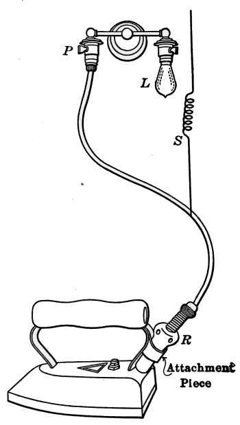
Fig. 226.—Electric flat-iron and
its attachments.
The cord connects with the socket
at P, and the current turned on.
It is attached with the iron by a
piece R, made of non-conducting and
heat-resisting material and arranged
to make contact with the heater
terminals by two brass plugs that
are insulated from the body of the
iron and afford easy means of making
electric contact. The contact plugs
are shown in Fig. 227. To make electric connection, the contact
piece is simply pushed over the plugs, where it is held in
place by friction. Instructions which accompany a flat-iron
when purchased advise that the attachment piece be used in
turning off the current. The reason for this is because of the
flash that accompanies the break in the circuit when disconnection
is made in the socket. This flash is really a small electric
arc, that forms as the circuit is broken and which burns away
the switch at the point of disconnection. The arc so formed[328]
burns away the contact pieces in the switch and it is soon destroyed.
The attachment piece will stand this wear more readily
than the socket switch and hence is preferable for disconnecting.
The irons are frequently provided with a special switch
for the service required in the flat-iron.
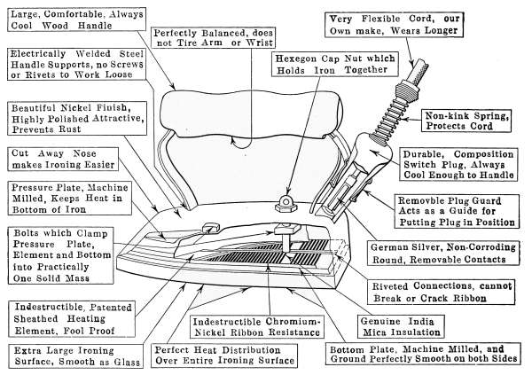
Fig. 227.—Electric flat-iron showing position of the heating element and contact
plugs.
A spiral spring connected to the attachment cord prevents
it from kinking when in use and thus breaking the conducting
wires. The attachment cord is made of stranded wires to make it
flexible. The strands of fine copper wire are made to correspond
to the gage numbers by which the various sizes of wire are designated.
In use the constant movement of the iron tends to
kink the cord and thus breaks the strands. This action is most
pronounced at the point where the cord attaches to the iron.
For this reason a spiral spring wire encloses the cord for a short
distance above the attachment piece. After long usage the cord
is apt to break in this vicinity. It may usually be repaired by
cutting off the ends of the cords and new connections made in
the attachment piece. When the iron is in use the slack portion
of the cord is kept from interfering with the work by the[329]
coiled wire S, which connects with the cord at any convenient
place.
Electric flat-irons are made in a variety of styles and forms,
the mechanism of each possessing some particular advantage, but
all are provided with the same essential parts, chief of which
is the heater with its electric attachment piece. In Fig. 228
is shown very clearly the construction of an example in which
attention is called to the points of excellence that are required
in a particularly serviceable iron. The form of the heating element
which is recognized in the iron is also shown in Fig. 228.
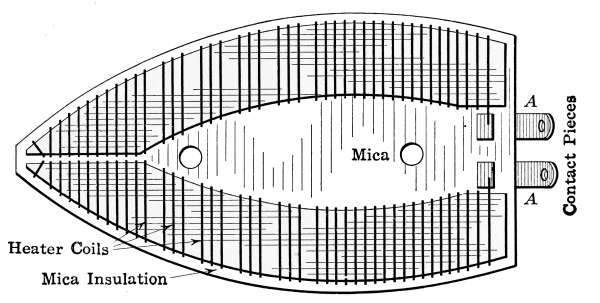
Fig. 228.—Electric flat-iron heating element.
In the figure the heater is made of coils of resistance wire,
wound on a suitable frame of mica. The heating element is insulated
from the body of the iron with sheets of mica, this being
a material that makes an excellent insulator and is not materially
affected by the heat to which it is subjected. The resistance
wire of which the element is composed is especially prepared
to resist the corroding action common to metal when heated in air.
The form of the element is such as to permit the least movement
of the turns of wire—in their constant heating and cooling—that
will allow the different spires to make contact and thus change
the resistance. Should the spires of wire come together, the
current would be shunted across the contact and the resistance
of the element decreased. The effect of such a reduction of resistance
would be an increased flow of current and a corresponding
increase of heat. In this, as in the electric lamp and all other
electric circuits, the current, voltage and resistance follow the
conditions of Ohm’s law.
[330]
Different sizes of irons will, of course, require different amounts
of current. A 6-pound iron, such as is commonly used for household
work, will take about 5 amperes of current at 110 volts
pressure. The amount of electricity the iron is intended to
consume is generally stamped on the nameplate of the manufacturer.
This is specified by the number of volts and
amperes of current the iron is rated to use. As an example,
the iron may be marked, Volts 105-115, Amperes 2-3. This
indicates that the iron is intended to be used on circuits that
carry electric pressure varying from 105 to 115 volts and that
the heater will use from 2 to 3 amperes of current, depending
on the voltage.
To estimate the cost of operating such an iron, it is necessary
to determine the number of watts of electric energy consumed.
The number of watts of energy developed under any condition
will be the product of the volts times the amperes. Suppose that
in the above example the iron was used on a circuit of 110 volts.
Under this condition the current required to keep the iron hot
would be 2.5 amperes. The product of these two qualities, 110
× 2.5 is 275 watts. If the cost of electricity is 10 cents per
kilowatt-hour (1000 watts) the cost of operating the iron would
be
275⁄1000 × 10 cents = 2¾ cents an hour.
Since the electric iron requires a much larger amount of current
than is usually required for ordinary lighting, the circuit
on which it is used should receive more than passing attention.
The wires should be of size amply large to carry without heating
the current necessary for its operation. This topic will be discussed
later but it is well here to call attention to the necessity
for a circuit suited to the required current. If an iron requiring
5 amperes of current is attached to a circuit that is intended to
carry only 3 amperes the conducting wires will be overheated
and may be the cause of serious results.
The Electric Toaster.
—As shown in Fig. 229 the toaster is
made of a series of heating elements mounted on mica frames and
supported on a porcelain base. It is an example of heating by
exposed wires and direct radiation. The heaters H are coils of[331]
flat resistance wire that are wound on wedge-shaped pieces of
mica. They are supported on a wire frame that is formed to receive
slices of bread on each side of the heaters. The attachment
piece A and the material of the heater is similar in construction
to that of the flat-iron. The electric circuit may be
traced from the contacts at A and B in the attachment plug by
the dotted lines which indicate the wires in the porcelain base.
The current traverses each coil in turn and connects with the
next, alternately at the top and bottom. The resistance is such
as will permit the voltage of the circuit to send through the coils
current sufficient to raise the heaters to a red heat. The added
resistance of the hot wires decreases the flow of current to keep
the temperature at the desired degree.
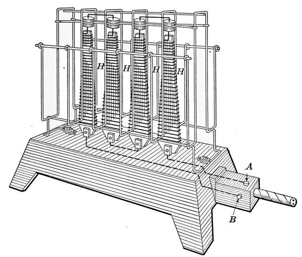
Fig. 229.—The electric toaster.
In a heater of this kind the resistance of the wire may increase
with age and the coils fail to glow with a sufficient brightness.
The reason for the lack of heat is that of decrease in current,
due to the increased resistance of the wires. This condition may
be corrected by the removal of a little of the heater coils. If a
turn or two of the heater wire is removed, the resistance of the
circuit is reduced and the effect of the increased current will
produce a higher temperature in the heater.
[332]
Motors.
—As a means of developing mechanical power in small
units, the electric motor has made possible its application in
many household uses that were formerly performed entirely by
manual labor. As a domestic utility electrical power is generated
at a cost that is the least expensive of all its applications.
As a means of lighting and heating electricity has had to compete
with established methods and has won place because of the advantages
it possesses over that of cost. In the development of
domestic power it has practically no opponent. There is no other
form of power that can be so successfully utilized in delivering
mechanical work for the purposes required. A kilowatt of
electric energy, for which 10 cents is a common price, will furnish
a surprising amount of manual labor. Theoretically, 746 watts
is equal to 1 horsepower. The commercial kilowatt is rated at
an hour of time, and is, therefore, equal theoretically to 11⁄3
horsepower for one hour. While motors cannot be expected to
transform all of this energy into actual work without loss, even
at the low rate of efficiency attained by the small electric motor,
they furnish power at a relatively small cost.
The first applications of electric power were those for sewing
machines, fans, washing machines, etc. Its use has made possible
the vacuum cleaner, automatic pumping, refrigeration,
ventilation, and many other minor uses as the turning of ice-cream
freezers, churning and rocking the cradle.
Electric motors are made in many sizes for power generation
and in forms to suit any application. They are made to develop
1⁄30 horsepower and in other fractional sizes for both direct
and alternating current.
In applying mechanical power to any particular purpose
special appliances must be made to adopt electric motors to the
required work. This is accomplished in all household requirements.
The motors are made to run at a high rate of speed and
must be reduced in motion by pulleys or gears to suit their condition
of operation. As in the case of electric lamps they must
be suited to the voltage and type of current of the circuit on
which they are to be used.
Commercial electric circuits furnish electricity in two types,
direct current, ordinarily termed D.C., and A.C. or alternating
current. The terms direct and alternating current apply to the[333]
direction of the electric impulses which constitute the transmitted
energy. In the electric dynamo, the generation of the current
is due to impulses that are induced in the wires of the dynamo
armature as they pass through a magnetic field of great intensity.
These electric impulses are directed by the manner in which the
wires cut across the lines of force which make up the magnetic field.
In the case of the direct current the impulses are always in the
same direction through the circuit, while in the other they are induced
alternately to and fro and so produce alternating current.
The term electric current is used only for convenience of expressing
a directed form of energy. Since nothing really passes
through the wires but a wave of energy, the effect is the same
whether the electric impulses are in the same or in opposite directions.
An incandescent lamp will work equally well on an
A.C. or a D.C. circuit of the proper voltage; but in the case of motors
the form of construction must be suited to the kind of current.
Both A.C. and D.C. commercial circuits are in common use,
the units of measurement are the same for each but in ordering a
motor it is necessary to state the type of current and the voltage,
in order that the dealer may supply the required machine. In
the case of an alternating motor it is further necessary to state
the number of cycles of changes of direction made per second
in the A.C. circuit. All of this information may be obtained by
inquiring of a local electrician or of the power station from which
the current is obtained.
There is still another item of information necessary to be
supplied with an order for a motor, other than those of fractional
horsepower. With motors of a horsepower or more it is necessary
to state the number of phases included in the circuit. This
information to be complete must state whether the motor is
to operate on a single-phase, two-phase, or three-phase circuit.
These terms apply to a condition made possible in A.C. generation
that permits one, two, or three complete impulses to be developed
in a circuit at the same time. These phases are transmitted
by three wires, any two of which will form a circuit and give a
supply of energy at the same voltage. Either one phase or all
may be used at the same time and for this reason the phase of an
A.C. motor should be given in an order. To make the information
complete there should be included the number of cycles or complete[334]
electric impulses per second produced in the circuit. Suppose
that a 1-horsepower motor is required to work on an A.C.
circuit of 110 volts. Inquiry of the electric company reveals
that the circuit is three-phase at 60 cycles per second. The
dealer on receiving this information will be able to send a motor
to suit your conditions. Most A.C. motors of 1 horsepower or
less are of the single-phase variety. In the case of D.C. motors
it is necessary only to state the voltage of the circuit to make
the required information complete.
Fuse Plugs.
—Every electric circuit is liable to occurrences
known as short-circuiting or “shorting.” This is a technical
term describing a condition where, by accident or design, the
wires of a circuit are in any way connected by a low-resistance
conductor or by coming directly into contact with each other.
In case of shorting, the resistance is practically all removed and
the amount of current which flows through the circuit is so great
as to produce a dangerous amount of heat in the wires. If the
covering of a lamp cord becomes worn so as to permit the bare
wire of the two strands to come together, a “short” is produced.
Immediately, the reduced resistance permits the electric pressure
to send an amount of current through the wires, greater than they
are intended to carry. When this occurs an electric arc will
form at the point of contact with the accompanying flash of
vaporizing metal and the wire will finally burn off. Fires
started from this cause are not uncommon.
To guard against accidents from short-circuiting, every electric
circuit should be provided with fuses which, in cases of emergency,
are intended to melt and thus break the circuit. Fuses
are made of lead-composition or aluminum and are used in the
form of wire or ribbon-like strips, of sizes that will carry a definite
amount of current. They are designated by their carrying
capacity in amperes. As an example: a 2-ampere fuse will
carry 2 amperes of current without noticeable heating, but at a
dangerous overload the fuse will melt and the circuit be broken.
Should a short-circuit be formed at any time, the rush of current
through the fuse will cause it almost immediately to melt, and
stop the flow of current. They are, therefore, the safeguard of
the circuit against undue heating of the conducting wires.
When an open fuse blows (melts), the heat generated by the[335]
arc, formed at the breaking circuit, is so sudden that there is
frequently an explosive effect that throws the melted metal in
all directions, and in case it comes into contact with combustible
material a fire may result. To do away with this danger, fire
insurance companies in their specifications of electric fixtures
state what forms of fuses will be acceptable in the buildings to be
insured. These specifications are known as the Underwriters
Rules and may be obtained from any fire insurance company.
The fuses, or fuse plug, as they are commonly called, generally
occupy a place in a cabinet or distributing panel, near the point
where the lead wires enter the building. The cabinet contains
the porcelain cutouts for sending the current through the different
circuits; the fuse plugs form a part of the cutouts, one fuse to each
wire. The cabinet contains besides
the cutouts a double-poled
switch to be used for shutting
off the current from the building
when desired.
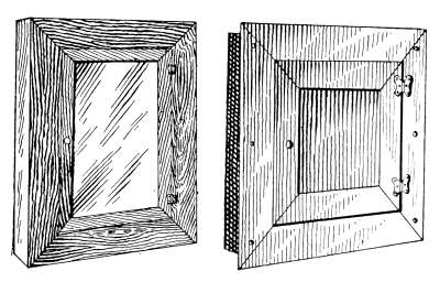
Fig. 230.—Electric cabinets.
Cabinets for this purpose are
made in standard form of wood
or steel to suit the condition of
service. These cabinets may be
obtained from any dealers in
electrical supplies or the cabinet may be made a part of the
house since they are only small shallow closets. Fig. 230 represents
such a cabinet as is used in the average dwelling. It
is made of a light wooden frame set between the studding of a
partition at any convenient place. The bottom of the cabinet
is made sloping to prevent its being used as a place of storage
for articles that might lead to trouble. The cabinet is sometimes
lined with asbestos paper as a prevention from fire but this is
not necessary as the fuse plugs and their receptacles, when of
approved design, are sufficient to prevent accident.
The main wires which supply the house with electricity—marked
lead wires—are brought into the cabinet as shown in
Fig. 231 and attached to the poles of the switch S. In passing
through the switch the lead wires each contain a mica-covered
fuse plug F, that will be described later. The current at any time
may be entirely cut off from the house by pulling the handle H,[336]
which is connected by an insulating bar and the contacts N of
the switch. When the handle H is pulled to separate the contact
pieces, all electric connection is severed at that point.
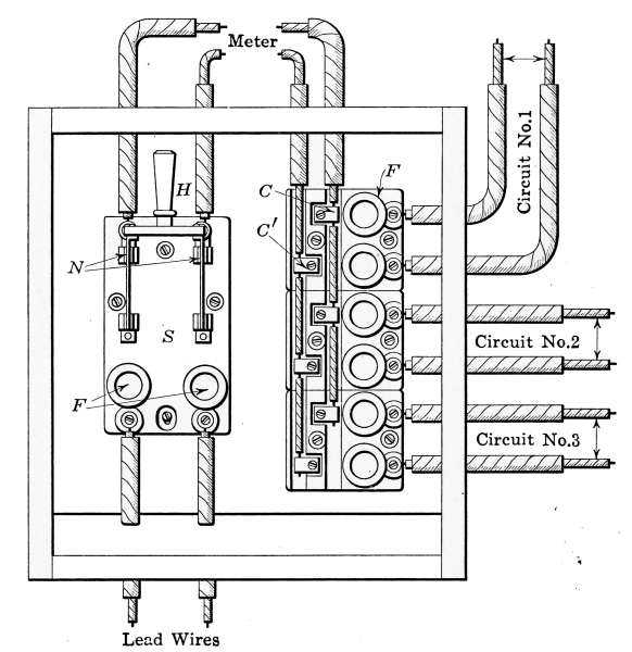
Fig. 231.—Electric panel containing cutout blocks, fuses and switch.
The wattmeter for measuring the current is placed at the
points marked meter, as a part of the main circuit. The main
wires in the cabinet terminate in the porcelain cutouts, from
which are taken off the various circuits of the house. In the
figure, three such cutouts are shown making three circuits marked
1, 2, and 3. In circuit No. 1, the fuses are marked F. These
wires are joined to the main wires at the points marked C and C´.
The number of circuits the house will contain depends on the
number of lights and the manner in which they are placed. The
circuits are intended to be arranged so that in case of a short,
no part of the house will be left entirely in darkness.
Fuses for general use are made in two different types—the
plug type and the cartridge type—each of which conforms to the
rules of the Underwriters Association. Those most commonly[337]
used for house wiring are the plug type shown in Fig. 232 and
indicated in the figure just described. These plugs are made of
porcelain and provided with a screw base which permits their being
screwed into place like an incandescent lamp. The front of
the plug is arranged with a mica window which allows inspection
to be made in case of a short, the blown fuse indicating the circuit
in which the trouble is located. Another style of the same
type of plug, known as the re-fusable fuse plug, permits the fuse
to be replaced after the wire has been destroyed by a short.
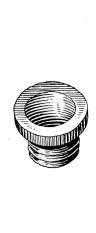
Fig. 232.—Mica covered
fuse plug.
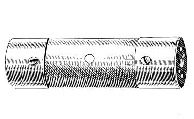
Fig. 233.—Cartridge fuse.
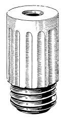
Fig. 234.—Plug receptacle
for cartridge
fuse.
The second type is commonly known as the cartridge fuse plug
from its general appearance. This fuse is shown in Fig. 233.
The fusable wire is enclosed in a composition fiber tube, the
ends of which are covered by brass caps which afford contact
pieces in the fuse receptacle and to which are fastened the ends
of the fuse wire. These fuses are very generally employed in
power circuits and others of large current capacity. The small
circle in the center of the label is the indicator. When the fuse
burns out, a black spot will appear in the circle. It is sometimes
desirable to use the cartridge fuse plug in receptacles intended
for the mica-covered type. The use of the cartridge fuses under
this condition is effected by use of a porcelain receptacle such as
is shown in Fig. 234; the cartridge fuse is simply inserted into the
receptacle which is then screwed into the socket in place of the
mica fuse.
In order to avoid any possible chance of overloading the wires
of a circuit, fuses are installed which are suited to the work to be
performed. Suppose that there are ten 40-watt lamps that may[338]
be used on a circuit, each lamp of which requires 4⁄11 ampere
of current.
110 × C = 40 watts
C = 40⁄110 = 4⁄11 ampere per lamp.
Ten such lamps require ten times 4⁄11 ampere or 40⁄11 = 3.7
amperes to supply the lamps.
A fuse that will carry 3.7 amperes of current will supply the
circuit but a 5-ampere fuse will permit an increase in the size
of the lamp and will fulfill all the necessary conditions. If,
however, an electric heater requiring 7 amperes were attached to
the circuit, the fuse being intended for only 5 amperes would soon
burn out. When a fuse burns out it must be replaced either with
an entirely new receptacle or the fuse wire must be replaced.
It sometimes happens that in case of a blown fuse there is no
extra part at hand and a wire of much greater carrying capacity
is used in its place. It should be remembered that in this practice
of “coppering” a blown fuse, has taken away the protection
against short-circuiting with its possibility of mischief.
When a short occurs, the cause should be sought for. It
cannot be located and on being replaced a second fuse blows, the
services of an electrician should be secured.
Electric Heaters.
—All electric heating devices—whether in
the form of hot plates, ovens, stoves or other domestic heating
apparatus-possess heating elements somewhat similar to the flat-iron
or the toaster. The construction of the heating element will
depend on the use for which the heater is intended and the temperature
to be maintained. Hot plates similar to that of Fig.
235 are made singly or two or more in combination. When the
heat is to be transmitted directly by radiation the heating coils
are open, as with the toaster. Under other conditions the coils
are embedded in enamel that is fused to a metal plate. In
elements of this kind the heat is transmitted to the plate entirely
by conduction from which it is utilized in any manner requiring
a heated surface. The form of the heating element will, therefore,
depend on the application of the heat, whether it is by direct
radiation or by a combination of radiation and conduction.
Electric ovens are constructed to utilize electric heat in an
insulated enclosure. Heat derived from electricity is more[339]
expensive than from other sources but when used in insulated
ovens it may be made to conveniently perform the service of that
derived from other fuels. In electric ovens the heaters are
attached to inside walls. As in other heating elements they are
arranged to suit the conditions for which the oven is to be used.
The heaters are usually so divided as to permit either all of the
heaters to be used at the same time to quickly produce a high
temperature, or only a portion of the heat to be used in keeping
up the temperature lost by radiation. Ovens of this kind may be
provided with regulators by means of which the heat may be
automatically kept at any desired temperature. Such heating
and temperature regulation may be used to produce any desired
condition, but in practice the cost of the heat is the factor which
determines its use. Unless electric heat is conserved by insulation
it cannot become a competitor with other forms of heating.
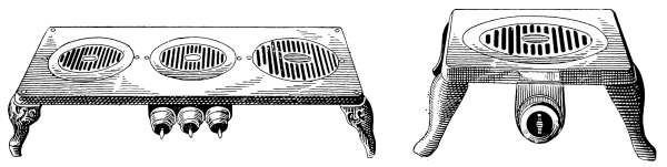
Fig. 235.—Electric three-burner hot plate.
Electric hot plate.
Electric cooking stoves and ranges are made for every form of
domestic and culinary service. They fulfill many purposes that
may be obtained in no other way. As conveniences, the cost of
heat becomes of secondary consideration and their use is constantly
increasing. In Fig. 236 is an example of a time-controlled
and automatically regulated electric range. In the picture is
shown separately all of the heaters for the ovens and stove top.
The part S shows the switches attached to the heaters of
the stove top, which is raised to show the connecting wires. In
the larger oven there are two heaters of 1000 watts each, and in
the smaller oven one heater of 850 watts. Each heater may be
controlled separately with a switch giving three regulations of
heat—high, medium and low. The advantage of this arrangement
lies in the fact that one can set the two heaters in the oven
at different temperatures which will permit either a slow or quick[340]
heat, but when the predetermined temperature is reached the
current will be automatically cut off by the circuit-breakers.
Such flexibility of heat control in the ovens permits the operator
to apply heat at both top and bottom for baking and roasting
at just the desired temperature. This arrangement also avoids
the danger of scorching food from concentration of heat, and
warping utensils or the linings of the oven. All oven heaters on
the automatic ranges are further controlled and mastered by the
circuit-breakers.
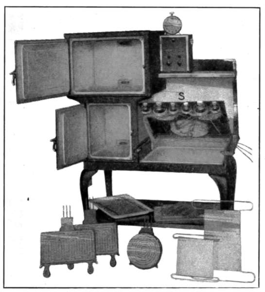
Fig. 236.—Electric range. Showing how all parts can be removed for cleaning
and replacement.
Intercommunicating Telephones.
—This form of telephone is
used over short distances such as from room to room in buildings
or for connecting the house with the stable, garage, etc. It is
complete, in that it possesses the same features as any other
telephone but the signal is an electric call-bell instead of the
polarized electric bell used in commercial telephone service.
[341]
Any telephone is made to perform two functions: (1) that of
a signal with which to call attention; and (2) the apparatus
required to transmit spoken words. In the intercommunicating
telephone or interphone, the signal is made like any call-bell and
parts are similar to those described under electric signals. The
bell-ringing mechanism is included in the box with the transmitting
apparatus and the signal is made by pressing a push
button. It is not suitable for connecting with public telephones.
Telephone companies, as a rule, do not permit connection with
their lines any apparatus which they do not control.
The interphone of Fig. 237 shows the instrument complete
except the battery. This form of instrument is inexpensive,
easy to put in, simple to operate and supplies
a most excellent means of intercommunication.
Complete directions for installation
are supplied with the phones by
the manufacturers.
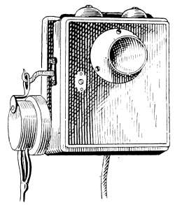
Fig. 237.—The intercommunicating
telephone.
Electric Signals.
—Electrical signaling devices
for household use, in the form of bells
and buzzers, are made in a great variety of
forms and sizes to suit every condition of
requirement. The vibrating mechanism of
the doorbell is used in all other household
signals except that of the magneto telephone.
It is an application of the electromagnet, in which
the magnetism is applied to vibrate a tapper against the rim
of a bell.
A bell system consists of the gong with its mechanism for
vibrating the armature, an electric battery or A.C. transformer
connected to the magnet coils to form an electric circuit and a
push button which serves to close the circuit whenever the
bell is to be sounded. The bell system is an open-circuit form
of apparatus; that is, the circuit is not complete except during
the time the bell is ringing. By pressing the push button the
circuit is closed and the electric current from the battery flows
through the magnet and causes the tapper to vibrate. When the
push button is released the circuit is broken and the circuit
stands open until the bell is to be again used. The parts of the
bell mechanism are shown in Fig. 238 where with the battery,[342]
the push button and the connecting wires is shown a complete
doorbell outfit. These parts may be placed in different parts of
the building and connected by wires as shown in the Fig. 239.
The bell is located at R, in the kitchen. The battery is placed
in the closet at B, the connecting wires are indicated by the heavy
lines; they are secured to any convenient part of the wall and
extend into the basement and are fastened to the joists. The
wires terminate in the push button P, where they pass through
the frame of the front door. The wires are secured by staples
to keep them in place. Each wire is fastened separately to avoid
the danger of short-circuiting. If both wires are secured with a
single staple there is a possibility of the insulation being cut and a
short produced across the staple.
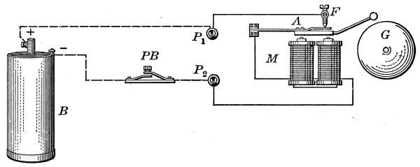
Fig. 238.—Diagram showing the parts of an electric doorbell.
The battery B, in Fig. 238, is a single dry cell but more commonly
it is composed of two dry cells joined in series. It is connected,
as shown in the figure, to the binding posts P1 and P2 of
the vibrating mechanism, the push button PB serving to make
contact when the circuit is to be closed. When the button is
pressed the circuit is complete from the + pole of the battery
cell through the binding post P1, across the contact F, through
the spring A, through the magnet coils M, across the binding
post P2 and push button to the-pole of the cell. The vibration
of the tapper is caused by the magnetized cores of the coils M.
When the electric current flows through the coils of wire, the iron
cores become temporary magnets. This magnetism attracts
the iron armature attached to the spring A, and it is suddenly
pulled forward with energy sufficient to cause the tapper to strike
the gong. As the armature moves forward, the spring contact
at F is broken and the current stops flowing through the magnet[343]
coils. When the current ceases to flow in the magnet coils, the
cores are demagnetized and the armature is drawn back by the
spring A to the original position. As soon as the contact is
restored at F a new impulse is received only to be broken as
before. In this manner the bell continues ringing so long as the
push button makes contact. The screw at F is adjusted to suit
the contact with the spring attached to the armature. The
motion of the armature may be regulated to a considerable
degree by this adjustment. When properly set the screw is
locked in place by a nut and should require no further
attention.
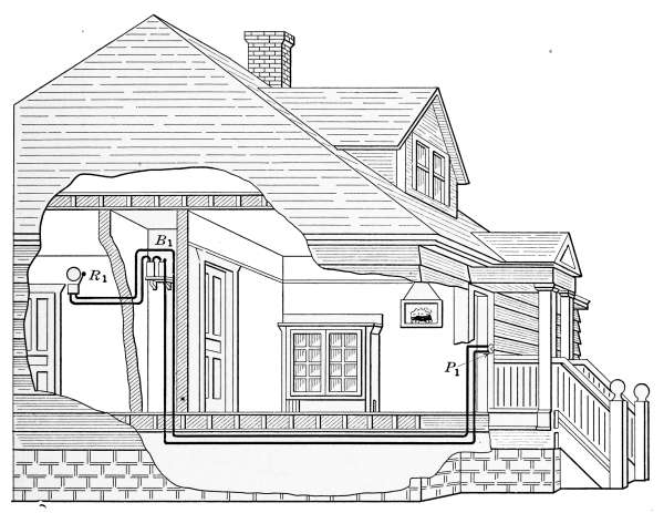
Fig. 239.—Example of an electric doorbell installation.
Electric bells vary in price according to design and workmanship.
A bell outfit may be purchased complete for $1 but
it is advisable to install a bell of better construction, as few pieces
of household mechanism repay their cost in service so often as a
well-made bell. The bell should be rigid, well-constructed, and
the contact piece F should be adjustable. This part F, being[344]
the most important of the moving parts of the bell, is shown separately
in Fig. 240. Only the ends of the magnet coils with their
cores are shown in the figure. The contact is made at A, by the
pressure of the spring against the end of the adjustable screw D.
When the screw is properly adjusted it is locked securely in place
by the nut G. The screw D is held with a screw-driver and the
nut G forced into position to prevent any movement. If the
screw is moved, so that contact is lost at A, the bell will not ring.
In the better class of bells the point of the screw and its contact
at A are made of platinum
to insure long life. With
each movement of the
armature a spark forms at
the contact which wears
away the point, so that to
insure good service these
points must be made of
refractory material.
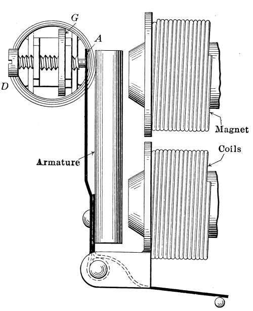
Fig. 240.—Diagram of the vibrating mechanism
used in buzzers and doorbells.
Buzzers.
—Electric bells
are often objectionable as
signal calls because of their
clamor, but with the removal
of the bell the vibrating
armature serves
equally well as a signal but
without the undesirable
noise. With the bell and
tapper removed the operating
mechanism of such a device works with a sound that has
given to them the name of buzzers. Fig. 241 illustrates the
form of an iron-cased buzzer for ordinary duty. The working
parts are enclosed by a stamped steel cover that may be easily
removed. The mechanism is quite similar to that already described
in the doorbell and Fig. 240 shows in detail the working
parts. The noise, from which the device takes its name, is
produced by the armature and spring in making and breaking
contact.
Burglar Alarms.
—A burglar alarm is any device that will
give notice of the attempted entrance of an intruder. It is[345]
usually in the form of a bell or buzzer placed in circuit with a
battery, as a doorbell system, in which the contact piece is
placed to detect the opening of a door or window. The contact
is arranged to start the alarm whenever the window or door is
opened beyond a certain point. The attachment shown in Fig.
242 is intended to form the contact for a window. It is set in the
window frame so that the lug C will be depressed and close the
alarm circuit in case the sash is raised sufficiently to admit a man.
Each window may be furnished with a similar device and the
doors provided with suitable contacts which together form a
system to operate in a single alarm. During the time when the
alarm is not needed it is disconnected by a switch. The windows
and doors are sometimes connected with an annunciator which
will indicate the place from which an alarm is given. An annunciator
used for this purpose designates the exact point at which
the contact is made and removes the necessity of searching for
the place of attempted entrance.
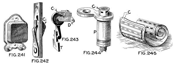
Fig. 241.—The electric buzzer.
Fig. 242.—Contact for a window burglar alarm.
Fig. 243.—Trip contact which announces the opening of a door.
Fig. 244.—Contact for a door alarm.
Fig. 245.—Doorway or hall matting with contacts for electric alarm.
In Fig. 243 is illustrated one form of door trip which may be
used on a door to announce its opening. This trip makes electric
connection in the alarm circuit when the opening door comes
into contact with the swinging piece T, but no contact is made as
the door closes. The trip is fastened with screws at D to the
frame above the door. The opening door comes into contact with
T and moves it forward until the electric circuit is formed at C;
after the door has passed, a spring returns it to place. As the[346]
door is closed, the part T is moved aside without making electric
contact.
Fig. 244 is another form of door alarm that makes contact when
the door is opened and remains in contact until the door is closed.
The part P is set into the door frame of the door in such position
that the contact at C is held open when the door is closed.
When the door is opened a spring in C closes the contact and
causes the alarm to sound. It continues to sound until the door
is closed and the contact is broken. When the use of the alarm
is not required, the contact-maker is turned to one side and the
contact is held open by a catch. It is put out of use by pressing
the plunger to one side.
The matting shown in Fig. 245 is provided with spring contacts
so placed that no part may be stepped upon without sounding
the alarm. When placed in a doorway and properly connected
with a signal, no person can enter without starting an alarm. The
matting is attached to the alarm by the wires C and contacts
are set at close intervals so that a footstep on the mat must
close at least one contact.
Annunciators.
—It is often convenient for a bell or buzzer to
serve two or more push buttons placed in different parts of the
house. In order that there may be means of designating the
push button used—when the bell is rung—an annunciator is provided.
This is a box arranged with an electric bell and the
required number of pointers and fingers corresponding to the
push buttons. In Fig. 246 is shown an annunciator with
which two push buttons are served by the single bell. The
annunciator is placed at the most convenient place of observation,
usually in the kitchen. When the bell rings the pointer
indicates the push button that has last been used. In hotels or
apartment houses an annunciator with a single bell may thus
serve any number of push buttons. In a burglar-alarm system
the annunciator numbers are arranged to indicate the windows and
other openings at which entrance might be made. When the
alarm sounds the annunciator indicates the place from which the
alarm is made.
Table Pushes.
—Call bells to be rung from the dining-room
table are connected with an annunciator or to a separate bell.
The table pushes may be temporarily clamped on the edge of the[347]
table and connected by a cord to an attachment set in the floor
or the connection may be made by a foot plate set on the floor.
In Fig. 247 is shown a form of push P which is intended to be
clamped to the edge of the table under the cloth. The plate F
forms the floor connection. It is set permanently with the upper
edge flush with the surface of the floor. The part S, in which
the connecting cord terminates, when inserted in the floor plate,
makes contact at the points C to form an electric circuit with
the battery. The foot plate shown in Fig. 248 is only an enlarged
push button which is set under the table in convenient positions
to be pressed with the foot. Its connection might be made as
indicated or with the same floor connection as that of the preceding
figure. Fig. 249 is a simpler form of floor push in which a
metallic plug is inserted in the floor plate. When the plug R
is pressed, contact is made at the points C to form the circuit
with the battery and bell.
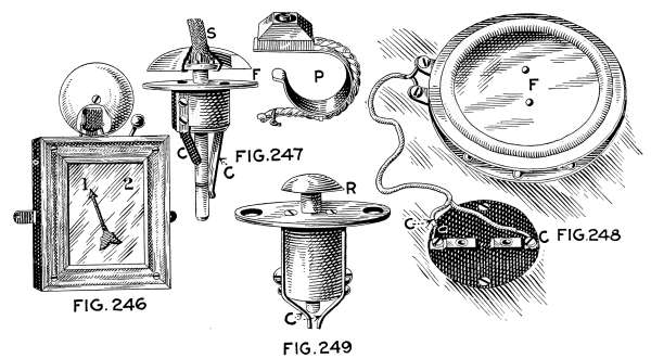
Fig. 246.—A kitchen annunciator.
Fig. 247.—Plug attachment and table
push for a dining table.
Fig. 248.—Foot plate and contact for table bell.
Fig. 249.—Call bell attachment with detachable
contact piece.
Bell-ringing Transformers.
—The general employment of alternating
electricity for all commercial service requiring distant
transmission is because of the possibility of changing the
voltage to suit any condition. The energy transmitted is determined
by the amperes of current carried by the wires and the[348]
volts of pressure by which it is impelled. The product of these
two factors determines the watts of energy transmitted.
110 volts × 1 ampere = 110 watts.
If the voltage is raised to say ten times the original intensity
with the same current, the quantity of energy is ten times the
original amount.
1100 volts × 1 ampere = 1100 watts.
The carrying capacity of wires is determined by the amperes
of current that can be transmitted without heating.
The cost of copper wire is such that the expense of large wires
for carrying a large current is unnecessary where by raising the
voltage a small wire will perform the same service; therefore, it is
desirable to transmit electric energy at a high voltage and then
transform it to suit the condition of usage.
Alternating current may be transformed to a higher or a lower
voltage to suit any condition by using step-up or step-down
transformers.
A transformer is a simple device composed of two coils of wire
wound on a closed core of iron. The coil into which is sent the
inducing current is the primary. That in which the current is
induced is the secondary coil. The change in voltage between
primary and secondary coils vary as the number of turns of wire
which compose the coils. The house circuit may be stepped
down from the customary 110 volts to a voltage such as is furnished
by a single dry cell, or a battery of cells.
In principle, the action of the transformer is the same as that
of the induction coil, a detailed explanation of which will be found
in any text-book of physics. Each impulse of current in the
primary coil of the transformer magnetizes its core and the magnetism
thus excited induces a corresponding current in the
secondary coil. Since alternating current in the primary coil
constantly changes the polarity of the core, each change of magnetism
induces current in the secondary coil.
Small transformers are frequently used for operating doorbells,
annunciators, etc., in place of primary batteries. These transformers
are also used to supply current for lighting low-power
tungsten lamps that cannot be used with the ordinary voltages[349]
employed in house lighting. The primary wires of the transformer
are attached to the service wires in the house and from
the secondary wires voltages are taken to suit the desired purposes.
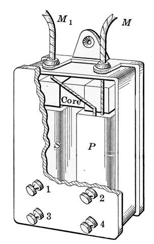
Fig. 250.—Doorbell transformer.
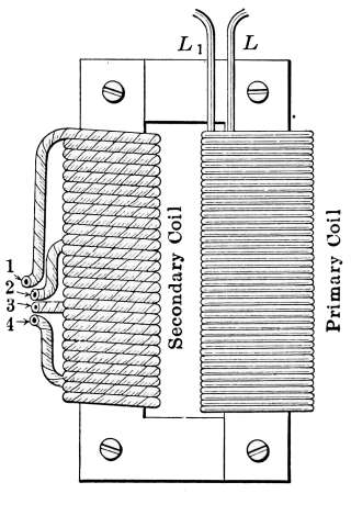
Fig. 251.—Details of doorbell
transformer.
Fig. 250 shows such a transformer with the cover partly
broken away to expose the interior construction. The wires
from house mains MM lead the current to the primary coil P
which is a large number of turns of fine wire wound about a soft-iron
core. The induced current in the secondary coil S is taken
from the contact points 1, 2, 3 and 4. The construction of the
transformer coils shown in Fig. 250 indicates the primary wires
at LL of Fig. 251. The wires of the primary coil are permanently
attached to house wires. The reactive effect of the magnetism
in the coil permits only enough current to flow as will keep the
core excited. This is a step-down transformer and the secondary
coil contains fewer turns of wire than the primary coil. Since
the voltage induced in the secondary coil is determined by the
number of turns of wire in action, this coil is so arranged that
circuits formed by attachment with different contacts give a
variety of voltages. The numbers on the front of Fig. 250
correspond to those of Fig. 251. The coils between contact 1
and the others 2, 3 and 4, represent different number of turns of
wire and in them is induced voltages corresponding with the
number of turns of wire in each.
[350]
The Recording Wattmeter.
—To determine the amount of electricity
used by consumers, each circuit is provided with some form
of wattmeter. These meters might be more correctly called
watt-hour meters since they register the watt-hours of electrical
energy that pass through the circuit.
Fig. 252.—Recording
watt meter.
In the common type of meter, the recording apparatus in composed
of a motor and a registering dial. The motor is intended
to rotate at a rate that is proportional to the amount of passing
current. An example of this device is the Thompson induction
meter of Fig. 252. The motion of the aluminum disc seen
through the window in front indicates at any time the rate at
which electricity is being used. This constitutes the rotating
part of the motor. It is propelled by the magnetism, created by
the passing current, and is sensitive to every
change that takes place in the electric circuit.
Each lamp, heater or motor that is brought
into use or turned off produces a change of
current in the conducting wires and this change
is indicated by the rate of rotation of the disc.
Each rotation of the disc represents the passage
of a definite amount of electricity that is
recorded on the registering dials.
The shaft on which the disc is mounted is connected with the
recording mechanism by a screw which engages with the first of a
train of gears. These gears have, to each other, a ratio of 10
to 1; that is, ten rotations of any right-hand gear, causes one
rotation of the gear next to the left. The pointers on the dial
are attached to the gear spindles. One rotation of the right-hand
dial will move the pointer next to the left one division
on its dial. Each dial in succession will move in like ratio.
The meters are carefully calibrated and usually record with
truthfulness the amount of electricity used. They are, however,
subject to derangement that produces incorrect registration.
To Read the Meter.
—First, note carefully the unit in which
the dial of the meter reads. The figures above the dial circle
indicate the value of one complete revolution of the pointer in
that circle. Therefore, each division indicates one-tenth of the
amount marked above or below the circle.
Second, in reading, note the direction of rotation of the pointers.[351]
Commencing at the right, the first pointer rotates in the direction
of the hands of a clock (clockwise); the second rotates counter-clockwise;
the third, clockwise; etc., alternately. The direction
of rotation of any one pointer may easily be determined by
noting the direction of the sequence of figures placed around
each division. The arrows (shown above) indicate the direction
of rotation of the pointers when the meter is in operation.
Third, read the figures indicated by the pointers from right
to left, setting down the figures as they are read, i.e., in a position
relative to the position of the pointers. Note: One revolution of
the first or right-hand pointer makes one-tenth of a revolution of
the pointer next to it on the left. One revolution of this second
pointer makes one-tenth of a revolution of the pointer next to it
on the left, etc. Therefore, if, when reading the dial, it is found
that the second pointer rests very nearly over one of the tenth
divisions and it is doubtful as to
whether it has passed that mark,
it is only necessary to refer to the
pointer next to it on the right.
If this pointer on the right has
not completed its revolution, it
shows that the second pointer has
not yet reached the division in
question. If it has completed its revolution, that is, passed the
zero, it indicates that the second pointer has reached the division
and the figure corresponding is to be set down for the reading.
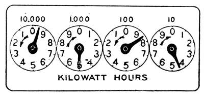
Fig. 253a.—This dial reads 9484
kilowatt hours.
The foregoing also applies to the remaining pointers. When
it is desired to know whether a pointer has passed a tenth division
mark, it is necessary to refer only to the next pointer
to the right of it.
Fourth, see if the register is direct-reading, i.e., has no multiplying
constant. Some registers are not direct-reading in that
they require multiplying the dial reading by a constant such
as 10 or 100 in order to obtain the true reading. If the register
bears some notation such as “Multiply by 100,” the reading
as indicated by the pointers should be multiplied by 10 or 100
as the case may be to determine the true amount of energy
consumed.
Some of the earlier forms of meters were equipped with what[352]
is known as a “non-direct-reading register.” In this case, the
reading must be multiplied by the figure appearing on the dial
as just explained, but the dial differs from those just described
in that the multiplying constant is generally a fraction such as
½, etc., and the dial has five pointers. This older style of
register reads in “watt-hours” of “kilowatt-hours.”
Fifth, the reading of the dial does not necessarily show the
watt-hours used during the past month. In other words, the
pointers do not always start from zero. To determine the number
of watt-hours used during a certain period it is necessary to
read the dial at the beginning of a period and again at the end
of that period. By subtracting the first reading from the second,
the number of watt-hours or kilowatt-hours used during the
period is obtained.
The meter man, having in his possession a record of the
readings of each customer’s meter for the preceding months, is
thus able to determine the amount of energy consumed monthly.
EXAMPLES OF METER READINGS
Fig. 253a shows an example of an ordinary dial reading.
Commencing at the first right-hand pointer, Fig. 253c, it is
noted that the last figure passed over by the pointer is 1.
The next circle to the left shows the figure last passed to be
2, bearing in mind that the direction of the rotation of this
pointer is counter-clockwise. The last figure passed by the next
pointer to the left is 1, while that passed by the last pointer to
the left is obviously 9. The reading to be set down, therefore,
is 9121.
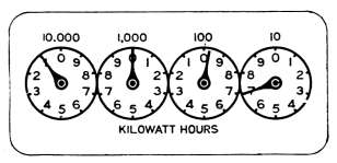
Fig. 253b.—This dial reads 997
kilowatt hours.
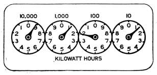
Fig. 253c.—This dial reads 9121
kilowatt hours.
In a similar manner the dial shown in Fig. 253b may be
read. In this case, however, three of the pointers rest nearly[353]
over the divisions and care must be used to follow the direction
to avoid error. Commencing at the right, the first pointer indicates
7. The second pointer has passed 9 and is approaching 0.
The third pointer appears to rest directly over 0, but since the
second pointer reads but 9, the third cannot have completed its
revolution and hence the figure last passed is set down which
in this case is 9. Similarly, the fourth or left-hand pointer
appears to rest directly over 1 but by referring to the pointer
next to it on the right, we find that its indication is 9 as just
explained. Therefore, the fourth pointer cannot have reached
1, and so the figure last passed which is 0 is set down, which in
this case is 9. Similarly, the fourth or left-hand pointer appears
to rest directly over 1, but by referring to the pointer next to
it on the right we find that its indication is 9 as just explained.
Therefore, the fourth pointer cannot have reached 1, and so
we set down the figure last passed which is 0. The figures as
they have been set down, therefore, are 0997, which indicates
that 997 kilowatt-hours of electricity have been used.
If, for example, the reading of this meter for the preceding
month was 976 kilowatt-hours, the number of kilowatt-hours
used during that month would be 997-976 = 21 kilowatt-hours.
State Regulation of Meter Service.
—Electric wattmeters are
subject to errors that may cause them to run either fast or slow.
Complaints made of inaccurate records or readings are usually
rectified by the electric company. In many States all public
utilities are governed by laws that are formulated by public
utilities commissions or other bodies from which may be obtained
bulletins fully describing the conditions required of public service
corporations or owners of public utilities. The following quotation
from Bulletin No. V., 233 of the Railroad Commission of
Wisconsin, will give an illustration of the requirement in that
State.
Rule 14.—Creeping Meters.—No electric meter which registers upon
“no load” shall be placed in service or allowed to remain in service.
This means that when no electricity is being used in the system
the motor disc should remain stationary and if it shows any
motion under such condition it is not recording accurately.
[354]
PERIODIC TESTS
Rule 17.—Each watt-hour meter shall be tested according to the following
schedule and adjusted whenever it is found to be in error more than
1 per cent., the tests both before and after adjustment being made at
approximately three-quarters and one-tenth of the rated capacity of the
meter. Meters operated at low power-factor shall also be tested at approximately
the minimum power-factor under which they will be required
to operate. The tests shall be made by comparing the meter, while connected
in its permanent position, on the consumer’s premises with approved,
suitable standards, making at least two test runs at each load, of at least
30 seconds each, which agree within 1 per cent.
Single-phase, induction-type meters having current capacities not exceeding
50 amperes shall be tested at least once every 4 months and as much
oftener as the results obtained shall warrant.
All single-phase induction-type meters having current capacities exceeding
50 amperes and all polyphase and commutator-type meters having voltage
ratings not exceeding 250 volts and current capacities not exceeding
50 amperes shall be tested at least once every 12 months.
All other watt-hour meters shall be tested at least once every 6 months.
Rule 20.—Request Tests.—Each utility furnishing metered electric
service shall make a test of the accuracy of any electricity meter upon
request of the consumer, provided the consumer does not request such
test more frequently than once in 6 months. A report giving the results
of each request test shall be made to the consumer and the complete,
original record kept on file in the office of the utility.
Electric Batteries.
—Electric batteries are composed of electric
cells that are made in two general types: the primary cell,
in which electricity is generated by the decomposition of zinc;
and the secondary cell or storage cell in which electricity from a
dynamo may be accumulated and thus stored. Electric cells are
the elements of which electric batteries are made; a single electric
cell is often called a battery but the battery is really two
or more cells combined to produce effects that cannot be attained
by a single element.
Both primary and secondary batteries form a part of the household
equipment but the work of the secondary battery is used
more particularly for electric lighting, the operation of small
motors and for other purposes where continuous current is required.
It will, therefore, be considered in another place.
Primary batteries are used to operate call-bells, table pushes,
buzzers, night latches and various other forms of electric alarms
besides which they are used in gas lighters, thermostat motors[355]
and for many special forms, all of which form an important part
in the affairs of everyday life. Primary battery cells for household
use are made to be used in the wet and dry form, but the
dry cell is now more extensively used than any other kind and
for most purposes has supplanted the wet form.
Formerly all primary cells were made of zinc and copper plates
placed in a solution called an electrolite, that dissolved the zinc
and thus generated electricity, the electrolite acting as a conductor
of the electricity to the opposite plate. In later electric
cells the copper was replaced by plates of carbon and from
the zinc and carbon cell was finally evolved the present-day
dry cell. When the use of electric cells reached a point where
portable batteries were required, a form was demanded from
which the solution could not be lost accidentally. The first
electric cells in which the electrolite was not fluid was, therefore,
called a dry cell. These cells are not completely dry. The
electrolite is made in the form of a paste that acts in the same
manner as the fluid electrolite and is only dry in that it is not fluid.
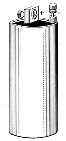
Fig. 254.—Electric
dry cell.

Fig. 255.—Details of electric
dry cell.
In construction the dry cell is shown in Figs. 254 and 255,
the former showing its exterior and the latter exposing its internal
construction. The container is a zinc can which is lined
with porous paper to prevent the filler from coming into contact
with the zinc. The zinc further is the active electrode, the[356]
chemical destruction of which generates the electricity. The
parts enclosed in the container are: a carbon rod, which acts
as the positive pole; and the filler, composed of finely divided
carbon mixed with manganese dioxide and wet with a solution
of salammoniac. The composition plug, made of coal-tar products
and rosin, is intended to keep the contents of the can in
place and prevent the evaporation of the moisture. Binding
posts attached to the carbon rod and soldered to the can furnish
the + and-poles.
In the action of cell, the salammoniac attacks the zinc in
which chemical action electricity is evolved. The electricity is
conducted to the carbon pole through the carbon and the salammoniac
solution which in this case is the electrolite. In the
dissolution of the zinc, hydrogen gas is liberated which adds to
the resistance of the cell and thus reduces the current. The
presence of the hydrogen is increased when the action of the cell
is rapid and the decrease in current is said to be due to polarization.
The manganese dioxide is mixed with the filler in order
that the free hydrogen may combine with the oxide and thus
reduce the resistance. This process is known as depolarization.
The combination between the hydrogen and the oxide is slow
and for this reason the depolarization of batteries sometimes
require several hours. Dry cells are usually contained in paper
cartons to prevent the surfaces from coming into contact and
thus destroying their electrical action.
The best cell is that which gives the greatest amount of current
for the longest time. Under any condition the working
value of a cell is determined by the number of amperes of current
it can furnish. The current is measured by a battery tester
such as Fig. 257. The + connection of the tester is placed in
contact with the + pole of the cell or battery and the other connection
placed on the-pole. The pointer will immediately
indicate the current given out by the battery. A new dry cell
will give 20 or more amperes of current for a short time but if
used continuously the quantity of current will be reduced by
polarizing until but a very small amount is generated. A cell
that indicates less than 5 amperes should be replaced. If short-circuited,
that is if the poles are connected without any intervening
resistance, a large amount of current will be given but the[357]
cell will soon wear out and possibly be ruined. A cell should,
therefore, never be allowed to become short-circuited. The voltage
of a cell is practically continuous and should be from 1.5
to 1 volt. It is quite possible that a cell may possess its normal
voltage and yet deliver little current; the voltage of a cell does
not indicate its working property. In order to be assured of
active cells they should be tested at the time of purchase with
an ammeter.
The moisture in the paste of a cell is that which forms the
circuit between the zinc and the carbon elements. If the paste
has dried out its resistance is increased and the cell generates
little current. The voltage of such a cell may be normal while
the amperage is very low. Cells in this condition may be revived
by adding moisture to the paste as a temporary remedy. This
may be accomplished by puncturing the can with a nail and adding
water. A solution of salammoniac may be used instead of
water and the cell soaked to accomplish the same purpose; this,
however, is only a temporary expedient.
Temperature influences the working properties of an electric
cell in pronounced manner. The moisture contained in the cell
is composed of ammonium chloride and zinc chloride and consequently
the resistance of the cell increases with the fall of temperature;
the effect of the resistance thus added is a decrease in
the flow of current. Batteries should be kept in a temperature
as nearly as possible that of 70°F. The battery regains its
normal rate of discharge when the temperature is restored.
The normal voltage and amperage for a given make of cell is
practically the same for all. The size of the cell does not in
any way influence the voltage. Small cells and large cells are
the same. The large cells are advantageous only in that they
give out a greater number of ampere-hours of energy. All batteries
are rated in the number of ampere-hours of current they
are capable of furnishing. The ampere-hour represents an
ampere of current for one hour. On this basis all batteries are
rated for the total amount of energy they are capable of producing.
If the battery is worked at a high current, its life is
short; if however, it is discharged at a low rate, its life should be
long. In all cases the product of the number of amperes and
the number of hours constitute the ampere-hours of energy
produced.
[358]
Battery Formation.
—For
ordinary household work as
that of operating doorbells,
etc., the cells which form a
battery are joined in series,
that is the positive or carbon
pole of one cell is joined
to the zinc or negative pole
of the next. The cells so
connected are placed in circuit
with the bell and push
button. If by accident the
two cells of a battery are
joined with both carbon
poles or both zinc poles together
the battery will give
out no current because the
voltage is opposed.
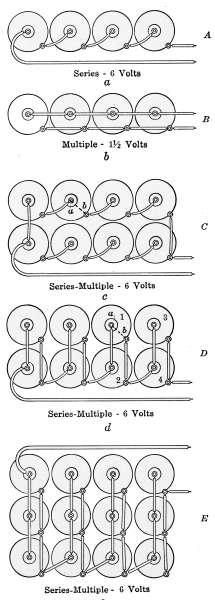
Fig. 256.—Battery combinations.
In the use of batteries for
ignition as for gasoline engines,
automobiles, etc., the
arrangement of the cells has
frequently a decided influence
on the effect produced.
In Fig. 256 A is
represented four cells joined
in series, that is the carbon
or + poles are joined with
the zinc or-poles, alternately.
Connected in this
manner if each cell gives 1.5
volts the battery will give
4 × 1.5 = 6 volts; the current,
however, will remain
as that of a single cell. If
the cells singly give 20 amperes,
the battery will give 20 amperes.
When cells are connected in
this form the current passes[359]
through each cell in turn and is as much a part of the circuit
as the wires. Should one of the cells be “dead”—that is delivering
no current—it will act as additional resistance and the
current is reduced.
When joined in multiple or parallel connection as in Fig. 256 B,
in which all similar binding posts are connected, the effect is
decidedly different. In the multiple connection all of the zincs
are joined to act as a single zinc and all of the carbons are likewise
joined and act as a single carbon. In such a combination
the voltage will be that of a single cell 1.5 volts, but the amperage
will be four times that of a single cell or 80 amperes.
The diagrams and following descriptions of possible combinations
were taken from a bulletin on battery connections issued
by the French Battery and Carbon Co.
By combining the series and multiple connections, as shown in
Fig. C, both the voltage and current can be increased over that
delivered by one cell. Referring to the figure, it is seen that
in each of the two rows of four cells the cells are connected
in series. This would produce 6 volts and 20 amperes for the
series of four which may now be assumed as a unit, so that
the two rows can be imagined as two large cells, each of
which has a normal output of 20 amperes at 6 volts. Now
by connecting the similar poles of two such large cells they
are in multiple and we get an increased current or 40 amperes
and 6 volts, which is the capacity of the eight cells connected
as shown in the figure. This is commonly designated as a
multiple-series battery.
Fig. 256 D illustrates a multiple-series connection made in a
different manner, but which produces the same voltage and
current as the above mentioned. In Fig. D, two cells at a time
are connected in multiple, and these sets are then connected in
series. The capacity of each set of two is 40 amperes at 1½ volts,
and as these four sets are connected in series the total output of
the eight cells combined is 6 volts and 40 amperes, the same as
that produced by the connections shown in Fig. C.
Fig. E shows the multiple-series connection illustrated in Fig.
D, applied to twelve cells in which four sets of three cells each
are wired in series, the three cells of a set being in multiple so that
the capacity of a set is 1½ volts and 60 amperes. By connecting[360]
the four sets in series as shown, the total capacity will be 60
amperes at 6 volts.
The use of the series-multiple connection is a distinct step
forward in dry-cell use. The arrangement of cells shown in Figs.
C or D is better than the arrangement in Fig. A, in just the same
way that a team of horses is better than a single horse. One
horse pulling a load of 2 tons may become exhausted in one hour,
but two horses pulling that same load may work continuously
for six hours. It is true that in Fig. C there are twice as many
cells used as in Fig. A, but the eight cells in Fig. C will do from
three to four times as much work as the four cells in Fig. A. In
other words, while more cells are used in the multiple-series
arrangement, the amount of service per cell is greater and the
service is, therefore, cheaper in the multiple-series arrangement.
Some battery manufacturers sell their batteries put up in boxes,
the cells being connected up in multiple-series and surrounded
by pitch or tar to keep out the moisture. This has certain
advantages as well as certain disadvantages. One of the objections
to this method of putting up dry cells is that if by any
chance one cell out of the eight or twelve which are buried in the
pitch is defective it will run all of the cells down, and being
buried offers no means of detection or removal. It is not possible
to guarantee absolutely that a weak cell will not be occasionally
included in a large number, so dry cells may be expected
to vary to some degree among themselves.
It is interesting to know the effect of one weak cell on a series-multiple
arrangement. If, for example, in Fig. C or Fig. D,
the dotted line connecting (a) and (b) be used to indicate a cell
which is partly short-circuited by internal weakness or external
defect the result is as follows:
In the arrangement shown in Fig. C, where one cell of the
upper four is short-circuited, the lower four will discharge through
the upper four even though the external circuit is not closed;
that is, one short-circuited cell will cause a run-down in all of the
cells. In Fig. D, however, one short-circuited cell will influence
not the entire set but the other one to which it is directly connected.
There is thus seen to be an advantage in the arrangement
of Fig. D and Fig. E, over the arrangement in Fig. C.
In making connections between cells insulated wire should be[361]
used, or special battery connectors are preferably employed.
The ends of the wires or connectors and the binding posts must
be scraped clean so that good electrical connection can be made
between the two, and the knurled nuts should be screwed tight
into place. Care must also be taken that the pasteboard covering
around the battery is not torn. This would allow contact between
the zinc containers, and thus short-circuit the cells. The
batteries should be placed so that the zinc cans and the binding
posts of any cell do not come into contact with any other cell.
Vibration might cause enough motion for the brass terminal to
wear through the pasteboard of the neighboring cell and make
contact with the zinc can.
Different classes of work require different amounts of current
at different voltages and by choosing the proper combination of
series, multiple, or series-multiple connections
practically every requirement can be
fulfilled. For electric bells, telegraph instruments,
miniature lights, toy motors with fine
wire windings, etc., series connection is recommended
for the reason that the resistance of
the external circuit is high and a large voltage
is necessary. For spark coils, magnets
and toy motors with large wire windings, multiple
or series-multiple connection of batteries
should be used as a high voltage is not required.
For some work, gas-engine ignition especially, it is economical
to have two complete sets of batteries, either of which can be
thrown into the circuit at will, so that while one set is delivering
current the other is recuperating. It has been estimated that
by using two sets of batteries, properly connected to give the
desired current, the life of each set is increased about four times.
Thus it is seen that a saving of 50 per cent. is effected in the cost
of the batteries.
Battery Testers.
—The “strength” of a cell is determined by
the amperes of current it is capable of producing; therefore, a
meter that will indicate the amount of current being produced
is used to test the current strength of the cell. Battery testers
are made to indicate voltage or amperage and sometimes the
instrument is made to indicate both volts and amperes. As explained[362]
above, the voltage of a cell is not a true indicator of its
strength. The ampere meter or ammeter, as it is termed, is the
proper indicator of the strength of the cell.
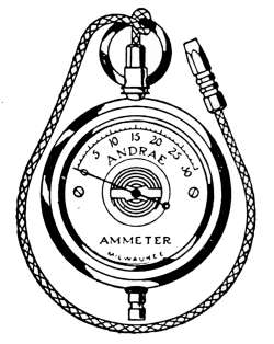
Fig. 257.—Battery
tester.
The common battery tester does not always give the exact
number of amperes of current, but it indicates the relative
strength which is really the thing desired. When the current
from an active cell is once shown on the dial of the tester, any
other cell of the same intensity will be indicated in like amount.
Electric Conductors.
—Covered wire for carrying electricity
is made in a great variety of forms and designated by names that
have been suggested by their use. These wires are made of a
single strand or in cables, where several wires are collected,
insulated and formed into a single piece. Cables may contain
any number of insulated wires.
The sizes of wires are determined by a wire gage. In the
United States the B. & S. gage is used as the standard for all
wires and sheet metal. The gage originated with the Brown &
Sharp Mfg. Co. of Providence, R. I., and has become a national
standard by common consent. The numbers range from No.
0000 to No. 60. The size of wire for household electrical service
ranges from No. 18 which is 0.04 inch in diameter to No. 8
which is 0.128 inch across. The carrying capacities in amperes
of wires, as given by the Underwriters’ table of sizes from No. 8
to No. 18, are as follows:
Wire
gage No. |
Rubber
insulation,
amperes |
Other
insulation,
amperes |
| 8 | 35 | 50 |
| 10 | 25 | 30 |
| 12 | 20 | 25 |
| 14 | 15 | 20 |
| 16 | 6 | 10 |
| 18 | 3 | 5 |
Lamp Cord.
—The flexible cord used for drop lights, connectors,
portable lamps, extensions, etc., is made of two cords twisted together
or two cords laid parallel and covered with braided silk or
cotton. The conductors consist of a number of No. 30 B. & S.
gage, unannealed copper wires twisted into a cable of required
capacity. The conductor is wound with fine cotton thread over
which is a layer of seamless rubber, and the whole is covered with[363]
braided cotton or silk. Lamp cord is sold in three grades, old
code, new code, and commercial, which vary only in the thickness
and quality of rubber which encloses the conductor.
The new code lamp cord is identical with the old code form
except that it is required by the National Board of Fire Underwriters
to be covered with a higher quality of rubber insulation
than was used in the old form. The commercial cord is not
recognized by the National Board of Underwriters. It is practically
the same as that described but does not conform to the tests
prescribed for the new code cord.
The sizes of the conductors enclosed in the lamp cord are made
equal in carrying capacity to the standard wire gage numbers.
The sizes ordinarily used are No. 18 and 20 gage but they are
made in sizes from No. 10 to No. 22 of the Brown & Sharp gage.
Portable Cord.
—This is a term used to designate reinforced
lamp cord. The wires are laid parallel and are covered as with
a supplementary insulation of rubber. The additional insulation
and the braided covering assumes a cylindrical form. The
covering is saturated with weatherproof compound, waxed and
polished.
Annunciator Wire.
—This wire is made in the usual sizes and
covered with two layers of cotton thread saturated with a special
wax and highly polished. As the name implies it is used for annunciators,
door bells and other purposes of like importance.
Private Electric Generating Plants.
—The conveniences to be
derived from the use of electricity were for many years available
only by those who lived in distributing areas covered by commercial
electrical generating plants. Except in towns of sufficient
size to warrant the erection of expensive light and power systems
or along the lines of electric power transmission, current for
domestic purposes was not obtainable.
Within a comparatively few years there have been developed
a number of small electric generating systems that are suitable
for supplying the average household with the electric energy for
all domestic conveniences. The combination of the gasoline engine,
the electric dynamo and the storage battery have made possible
generating apparatus that is operated with the minimum of
difficulty and which supplies all of the electric appliances that
were formerly served only from commercial electric circuits.
[364]
An electric generating system is commonly termed an electric
plant. It consists of an engine for the development of power,
a dynamo for changing the power into electricity and—to be of
the greatest service—a storage battery for the accumulation of
a supply of energy to be used at such times as are not convenient
to keep the dynamo in active operation.
Such a combination, each part comprised of mechanism with
which the average householder is unfamiliar, seems at first too
great a complication to put into successful practice. Such, however,
is not the case. The operation of small electric generating
plants is no longer an experiment. Their general use testifies to
their successful service. The working principles are in most cases
those of elementary physics combined with mechanism, the
management of which is not difficult to comprehend. Such
plants are made to suit every condition of application and at a
cost that is condusive to general employment.
In a brief space it is not possible to enter into a detailed discussion
of the gasoline engine, the electric dynamo, and the storage
battery with the various appliances necessary for their operation;
it is, therefore, intended to give only a general description of the
leading features of each. The manufacturers of such plants
furnish to their customers and to others who are interested detailed
information with explicit instructions for their successful
management.
The first private lighting plants were made up of parts built
by different manufacturers and assembled to form generating
systems with little regard to their adaptability. A gasoline
engine belted to a dynamo of the proper generating capacity supplied
the electricity. Neither the engines nor the dynamos were
particularly suited to the work to be performed, yet these combinations
were sufficiently successful to command a ready sale.
The energy thus generated was accumulated in a storage battery
from which was taken the current for a lighting and heating device.
Besides the generating and storage apparatus there is
required in such a system, a switchboard, to which are attached
the necessary meters and switches that are required to measure
and direct the current to the various electric circuits.
Foresighted manufacturers, comprehending the probable future
demand, began the construction of the various parts, suited to[365]
the work and the conditions under which they were to be employed.
The manufacture of apparatus, designed for the special
service and composed of the fewest possible parts, has reduced
the operating difficulty to a point of relative simplicity. Experience
in the use of a large number of these plants has revealed
to the maker the course of many minor difficulties of operation
and the means of their correction. The mechanism has been
improved to prevent possible derangement and to simplify the
means of control, until the private electric plant is successfully
employed by those who have had no former experience with
power-generating machines.
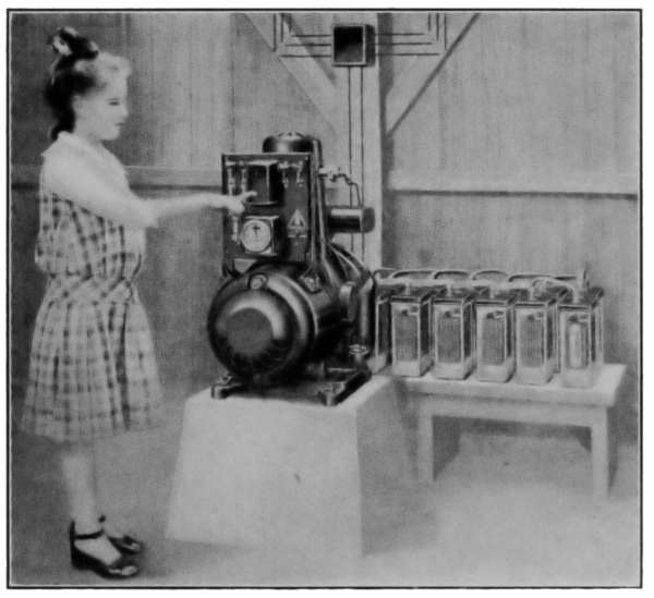
Fig. 258.—Household electric generating plant.
As an example of the private electric plant Fig. 258 shows
the apparatus included in a combined engine, dynamo and switchboard,
connected with a storage battery. The relative size of
the machine is shown by comparison with the girl in the act of
starting the motor. This plant is of capacity suitable for supplying
an average home with electricity for all ordinary domestic
uses. A nearer view of the generating apparatus is given
in Fig. 259 in which all of the exterior parts are named. An[366]
interior view of the generating apparatus is given in Fig. 260,
in which is exposed all of the working parts. The right-hand
side of the picture shows all of the parts of the gasoline engine
that furnishes the power for driving the generator. This is an
example of an air-cooled gasoline engine in which the excess heat
developed in the cylinder is carried away by a drought of air.
The air draft is induced by the flywheel of the engine, which is
constructed as a fan. The blades of the fan, when in motion, are
so set as to draw air into the top of the engine casing and exhaust
it from the rim of the wheel. The air in passing takes up
the heat in excess of that necessary for the proper cylinder temperature.
This form of cylinder cooling takes the place of the
customary water circulation and thus eliminates its attending
sources of trouble. In principle the engine is the same as is
employed in automobiles and other power generation.
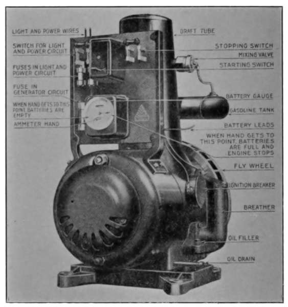
Fig. 259.—Combined motor, electric generator and switchboard.
On the left-hand side is seen the dynamo and switchboard.[367]
The dynamo armature is attached to the crankshaft of the engine
by which it is rotated in a magnetic field to produce the desired
amount of electricity. The brushes, in contact with the commutator,
conduct the electricity as it is generated in the armature,
which after passing through the switchboard is made available
from the two wires at the top of the board marked “light and
power wires.” These wires are connected with the storage battery
and also to the house circuits through which the current is
to be sent.
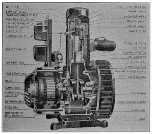
Fig. 260.—Details of motor, electric generator and switchboard.
Referring to the switchboard of Fig. 259, the three switches
and the ammeter comprise the necessary accessories. The starting
switch is so arranged that by pressing the lever a current of
electricity from the storage battery is sent through the dynamo.
The dynamo acting as a motor starts the engine. When the
engine has attained its proper speed its function as a dynamo
overcomes the current pressure from the battery and sends electricity
into the cells to restore the expended energy, or if so desired
the current may be used directly from the dynamo for any[368]
household purpose. The box enclosing the switch contains a
magnetic circuit-breaker so constructed that when the battery is
completely charged the switch automatically releases its contact
and stops the engine.
The “stopping switch” at the right of the board and the
“switch for light and circuit” on the left are used respectively
for stopping the engine and for opening and closing the house
circuits.
The meter performs a multiple function, in that it shows at
any time the condition of charge in the storage battery, the rate
at which current is entering or leaving the battery and also acts
to stop the engine when the battery is charged. At any time the
pointer reaches the mark indicated in the picture, the ignition
circuit is automatically broken and the engine stops. The fuses
on the board in this case perform the same function as those already
described.
Storage Batteries.
—These batteries have already been mentioned
as secondary batteries. They are sometimes called electric
accumulators. The electricity is stored or accumulated, not
by reason of the destruction of an electrode as in the primary
cell but by the chemical change that takes place in the plates as
the charging current is sent through the cell. When the battery
is discharged, the current from the dynamo is sent through the
battery circuit in the reverse direction to that of the discharge
and the plates are restored to their original condition. The
action that takes place in charging and discharging is due to
chemical changes that take place in the plates and also in the
solution or electrolyte in which the plates are immersed.
There are two types of storage batteries, those made of lead
plates immersed in an acid electrolyte and the Edison battery
which is composed of iron-nickel cells immersed in a caustic
potash electrolyte. The former type is most commonly used
and is the one to be described.
The lead-plate cell illustrated in Fig. 262 shows all of the
parts of a working element. The plates are made in the form
of lead grids which when filled to suit the requirements of their
action, form the positive and negative electrodes. The negative
plates are filled with finely divided metallic lead which when
charged are slate gray in color. The positive plates are filled[369]
with lead oxide. When charged they are chocolate brown in
color. In the figure there are three positive and four negative
plates which together form the element, then with their separators
are placed in a solution of sulphuric acid electrolyte. The
separators are thin pieces of wood and perforated rubber plates
that keep the positive and negative plates from touching each
other and keep in place the disintegration produced by the
electro-chemical action of the cell.
The unit of electric capacity in batteries is the ampere-hour.
The cell illustrated will accumulate 80 ampere-hours of energy.
It will discharge an ampere of current for 80
hours. If desired it may be discharged at the
rate of two amperes for 40 hours, or four amperes
for 20 hours, or at any other rate of amperes and
hours, the product of which is 80. The number
of ampere-hours a cell will accumulate will depend
on the area of the positive and negative plates;
large cells will store a greater number of ampere-hours
than those of small size.
The cells, no matter what size, give an average
electric pressure of 2 volts.
The plates are joined by heavy plate-straps
connecting all of the positives on one end and
all of the negative kind on the opposite end. To
insure rigidity the two sets are secured to the rubber
cover by locknuts. In this cell the plates are
suspended from the cover. The plate terminals
are made of heavy lead connectors that when
formed into a battery are joined together with
lead bolts and nuts.
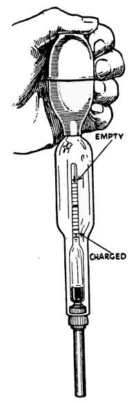
Fig. 261.—Hydrometer
for
testing storage
battery electrolyte.
The electrolyte is a solution of pure sulphuric acid in distilled
water and on its purity depends, in a great measure, its action
and length of life. The electrolyte is made of a definite density
which is expressed as its specific gravity. When fully charged
the electrolyte will test 1220 by the hydrometer. That is, it
will be 1.220 heavier than water. When discharged it will test
by the hydrometer 1185. This means that in discharging the
density has been reduced to 1.185 that of water. The chemical
change in the electrolyte is, therefore, an important part of the[370]
charge and discharge of the cell. The density of an electrolyte
may be determined by a hydrometer such as Fig. 261. This is an
ordinary glass hydrometer such as is used for determining the
density of fluids, enclosed in a glass tube, to which is attached
a rubber bulb. The point of the tube is inserted into the opening
at the top of the cell and the electrolyte drawn into the tube
by the reopening of the collapsed bulb. The density is then read
from the stem of the hydrometer.
The Pilot Cell.
—In order to make apparent this density of
the electrolyte without the necessity of its measurement with a
hydrometer, one cell of the battery is provided with a gage as
that of Fig. 262. This is an enlargement of the end of the jar
in which floats a hollow glass ball of such weight that it will at
any time indicate by its position the relative density of the
solution. When the cell is charged the ball stands at the top
of the gage and indicates a density 1220; when discharged it is
at the bottom and expressed by its position a density of 1185.
The electrolyte densities are the indicators of the conditions of
charge. The ball by its position shows at a glance the quantity
of electricity in the battery.
The voltage usually employed in household electric plants is
that of a battery composed of 16 cells. Since the normal voltage
of a storage cell is 2 volts such a battery joined in series is 32
volts. This voltage for the purpose fulfills all ordinary conditions
and is generally employed. A battery of 16 cells, of
80-ampere-hour capacity, will deliver current of 1 ampere for
80 hours at 32 volts intensity. A 20-watt lamp on a 32-volt
circuit requires 2⁄3 ampere for its operation. The battery will,
therefore, keep lighted one such lamp for 96 hours, or four 20-watt
lamps may be lighted continuously for 24 hours, or eight
lamps for 12 hours, before recharging.
Aside from its ability to supply the required light for the
average home, it furnishes energy sufficient for heating a flat-iron
or other heating apparatus, to operate motors for pumping
water, driving a washing machine or any other of the domestic
requirements.
Such plants are made in sizes to suit any condition of requirement.
In large establishments a larger motor generator and
battery will be necessary with which to generate and store the[371]
required electricity but in any case suitable apparatus is to be
obtained to meet any requirement of light, heat or power
developed.
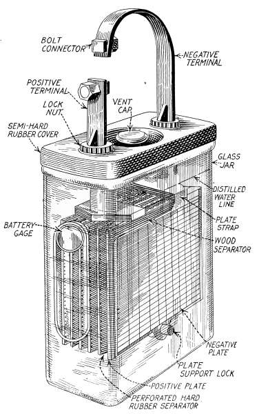
Fig. 262.—Electric storage cell.
National Electrical Code.
—The details governing the size, the
manner of placing and securing wires in buildings is included in
the regulations published by the National Board of Fire Underwriters
as the National Electric Code. Likewise the mechanical
construction of all apparatus dealing with electric distribution
is definitely specified so that manufacturers furnish reliable
materials for all requirements. In the specifications for furnishing[372]
buildings with the use of electricity, descriptions are made
of the desired types and styles of the switches and various other
fixtures to suit the requirements.
Electric Light Wiring.
—In the equipment of a house for the
use of electricity, the wiring, together with distributing panel,
the various outlets, receptacles, switches, and other appliances
that make up the system, is of more than passing consequence.
In the construction of the electric system it is important that the
wires and their installation be done in a manner to meet every
contingency.
The following descriptions for electric house wiring were taken
from a set of specifications published by the Bryant Electric Co.
as applying to buildings of wood frame construction. The specifications
serve as explanations for the appliances required in an
ordinary dwelling. The specifications are for the least expensive
form of good practice in wiring for frame buildings. They would
not be permitted in large cities where further protection from fire
is required and where more rigid rules are demanded by the
Board of Fire Underwriters.
1. System.—The circuit wiring shall be installed as a two-wire direct
current or alternating system. Not more than 16 outlets or a maximum of
660 watts shall be placed on any one circuit, allowing 110 watts for each
baseboard plug connection or extension outlet and 55 watts for each 16
candlepower lamp indicated at the various wall and ceiling outlets on plans.
All wiring shall be installed as a concealed knob-and-tube system.
The type of wiring is designated as a two-wire direct or alternating
current system in order that there shall be no doubt as
to the method of wiring to be used. There are other methods
that might be employed that need not be discussed here.
The 16 outlets mentioned are intended to cover all lamps or
plug attachments that are to be used for heaters, fans, motors,
or any other electric device. The 660 watts at 110 volts pressure
will require 6 amperes in the main wires of the circuit,
which is the maximum current the wires are intended to carry.
This does not mean that 110-watt lamps might not be used
but that no single circuit shall carry lamps that will aggregate
more than 660 watts.
The concealed knob-and-tube system mentioned is illustrated
in Figs. 263 and 264, in which the wires which pass through joists[373]
and studding are to be insulated by porcelain tubes and those
wires which lay parallel to these members are to be fastened to
porcelain knobs which are
secured by screws to the wood
pieces to prevent any possibility
of coming into contact
with electric conducting materials.
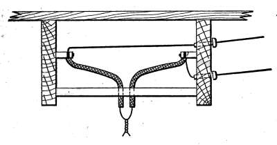
Fig. 263.—Manner of securing wires
by the knob-and-tube system for ceiling
outlets.
2. Outlets.—At each and every
switch, wall, ceiling, receptacle or
other outlet shown on plans, install
a metal outlet box of a style most
suitable for the purpose of the outlet. All outlet boxes must be rigidly
secured in place by approved method and those intended for fixtures shall
be provided with a fixture stud, or in the case of large fixtures, a hanger to
furnish support independent of
the outlet box.
Outlet Boxes.
—For the
safe and convenient accommodation
of switches, receptacles
or other connections
in the walls and ceilings
of a building, outlet boxes
are used as a means of securing
the wire terminals to the
receptacles. These boxes
are made in a number of
forms for general application.
One style is shown in Fig.
265. The boxes are made
of sheet steel and arranged
to be secured in place with
screws. The box is further
provided with screw fastenings
to which the switch or
receptacle may be firmly
attached.
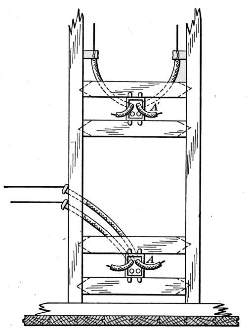
Fig. 264.—This shows the knob-and-tube
system of securing the wires in partitions
and the manner of fastening metal
“cut out” boxes; for switch, attachments,
plugs, etc.
3. Installation of Wires, Etc.—All wires shall be rigidly supported on
porcelain insulators which separate the wire at least 1 inch from the surface[374]
wired over. Wires passing through floors, studding, etc., shall be protected
with porcelain tubes, and where wires pass vertically through bottom
plates, bridging, etc., of partitions, an extra tube shall be used to protect
wires from plaster droppings. Wires must be supported at least every 4
feet and where near gas or water pipes extra supports shall be used. All
porcelain material shall be non-absorptive and broken or damaged pieces
must be replaced. Tubes shall be of sufficient length to bush entire length
of hole. At outlets the wires shall be protected by flexible tubing, the same
to be continuous from nearest wire support to inside of outlet box. Wires
installed in masonry work shall be protected by approved rigid iron conduit
which shall be continuous from outlet to outlet.
The method and reasons for supporting the wires described
above are as have already been mentioned under item 1. The
reason for extra supports near gas pipes and water
pipes is as a precaution against the possibility of
short-circuiting.
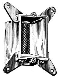
Fig. 265.—Outlet
box.
4. Conductors.—Conductors shall be continuous from
outlet to outlet and no splices shall be made except in
outlet boxes. No wire smaller than No. 14 B. & S. gage
shall be used and for all circuits of 100 feet or longer,
No. 12, B. & S. gage or larger shall be used. All conductors
of No. 8 B. & S. gage or larger shall be stranded.
Wires shall be of sufficient length at outlets to make connection
to apparatus without straining connections. Splices shall be made
both mechanically and electrically perfect, and the proper thickness of
rubber and friction tape shall be then applied.
Continuous conductors are required because of the possibility
of defects in the joints of spliced wire.
5. Position of Outlets.—Unless otherwise indicated or directed, plug
receptacles shall be located just above baseboard; wall brackets, 5 feet above
finished floor in bedrooms, and 5 feet 6 inches in all other rooms; wall
switches, 4 feet above finished floors. All outlets shall be centered with regard
to panelling, furring, trim, etc., and any outlet which is improperly
located on account of above conditions must be corrected at the contractor’s
expense. All outlets must be set plumb and extend to finish of wall, ceiling
or floor, as the case may be, without projecting beyond same.
6. Materials.—All materials used in carrying out these specifications
shall be acceptable to the National Board of Fire Underwriters and to the
local department having jurisdiction. Where the make or brand is specified
or where the expression “equal to” is used, the contractor must notify
the architect of the make or brand to be used and receive his approval before
any of said material is installed. Where a particular brand or make is
distinctly specified, no substitution will be permitted.
[375]
7. Grade of Wire.—The insulation of all conductors shall be rubber,
with protecting braids, which shall be N.E.C. Standard (National Electrical
Code Standard).
8. Outlet Boxes.—Outlet boxes shall be standard pressed steel, knock-out
type and shall be enameled.
9. Local Switches.—Local wall switches shall be two-button flush type
completely enclosed in a box of non-breakable insulating material with
brass beveled-edge cover plate finished to match surrounding hardware.
Fig. 269 shows the various forms and grades of switches that
there are on the market. The screws which attach the plate to
the switch enter bushings that are under spring tension thereby
preventing defacement of the plate by overtightening of the
screws. Single-pole is to be used where the load will not be in excess
of 660 watts; double-pole to be used where the load is more
then 660 watts or where for any other reason it is desirable to
break the current at both wires. Three-point switches are to be
used when a light or group of lights is to be controlled, as hall
lights that may be lighted or extinguished, from either the top
or at the bottom of a stairway. Four-point switches are to be
used between and two, three-point switches to control additional
lights. Where two or more switches are placed together an
approved gang plate is to be provided which designates the use
of each switch. Where indicated on the plan, clothes closets
shall be equipped with automatic door switch to connect the light
when the door is open.
10. Pilot Lights.—Switches controlling cellar, attic and porch lights
shall have pilot lamp in parallel on the load side of the switch. The switch
in Fig. 3 requires for its installation a two-gang outlet box. The ruby bull’s-eye
which covers the lamp is practically flush, extending from the wall no
further than the buttons of the switch.
Pilot lights are intended to indicate the operation of other
lights or apparatus that cannot be directly observed.
The term bull’s-eye applies to a colored-glass button covering
a miniature lamp which burns whenever a light is used which is
apt to be forgotten and allowed to burn for a longer time than
necessary.
11. Plug Receptacles.—Plug receptacles shall be of the disappearing-door
type, with beveled-edge brass cover plate finished to match surrounding
hardware (see Fig. 266). In this receptacle the doors are pushed inward
by the insertion of the plug and upon its withdrawal close automatically,[376]
effectually excluding dirt and concealing the live terminals. It is the latest
and best plug receptacle obtainable.
Plug receptacles are the attachments for the terminal pieces
of plugs, which temporarily connect portable lamps, electric fans
or other devices, they are made in many forms.
12. Wall and Ceiling Sockets.—One-light ceiling receptacles shall
be of a type to fit standard 3¼-inch or 4-inch outlet boxes. Wall sockets
shall be of the insulated base type. Sockets in cellars shall be made entirely
of porcelain and of the pull type. All lamp sockets used in fulfilling these
specifications shall have an approved rating of 660 watts, 250 volts.
13. Drop Lights.—Drop lights shall consist of the necessary length of
reinforced cord supported by an insulated rosette with brass base and cover;
the latter to cover 4-inch outlet box, and furnished with a key socket complete
with a 2¼-inch shade-holder. Each drop cord shall have an adjuster.
14. Heater Switch, Pilot and Receptacle.—Heating device outlets
shall be equipped with combination of switch, pilot light and receptacle with
plug and spare pilot lamp.
15. Service Switch.—The service-entrance switch shall be 30 amperes,
porcelain base with connections for plug fuses.
Installation of Service Switch.—Service switch shall be installed in
a moisture-proof metal box with hinged door.
Panel Cabinet.—The distributing panel cabinet shall be of steel not
less than No. 12 gage reinforced with angle iron frames, which shall be securely
riveted in place. Cabinet shall be larger than panel to give at least
4-inch wire space around panel and shall be given at least two coats of moisture-repellant
paint.
Distributing Panel.—The distributing panel shall consist of two-wire
125-volt branch cutouts, two-wire 125-volt porcelain-base panel-board
units, two-wire 125-volt porcelain-base deadfront panel-board units. The
distributing panel shall be surrounded with an ebony asbestos or slate
partition ½ inch thick which will form a wire space around panel.
Fuses.—All fuses for branch circuits shall be not more than 10 amperes
capacity. The contractor shall furnish the owner with 150 per cent. of
required number of 125-volt plug-type fuses for complete installation.
Panel Trim and Door.—The panel trim and door shall be of steel, with
brass cylinder lock and concealed hinges, all furnished under this contract.
A directory of circuits and outlets served by panel shall be enclosed in glass
with metal frame, mounted on inside of panel door.
Hardware.—All hardware furnished under this contract shall match in
quality and finish other adjacent hardware.
Three-way Control.—The nearest outlet at top and bottom of all stairs
and in entrance hall shall be controlled by three-way switches located on
separate floors where directed.
Electrolier Control.—Wherever there are ceiling outlets for fixtures
having three or more sockets controlled by wall switches three wires shall[377]
be run between the switch box and the outlet to permit the use of electrolier
switches.
Dining-room Circuit.—Furnish and install in dining-room, where indicated
on plans, an approved floor box containing an approved 25-ampere
plug receptacle. The wires connecting this receptacle to the center of
distribution shall be No. 10 B. & S. gage. Furnish and deliver to whom directed
an approved multiple-connection block consisting of three individually
fused plug receptacles. The connection between the plug receptacle and
this block shall be made by means of 10 feet of No. 10 B. & S. approved silk-covered
portable cord with an approved 20-ampere cord connector 2 feet
from the multiple block.
House Feeders.—The size of the feeder from the service switch to the
panel board shall be figured in accordance with the National Code rules for
carrying capacity, allowing for all circuits being fully loaded. The feeder
shall be of sufficient size, however, to confine the drop in voltage with all
lights in circuit to 1 per cent. of the line voltage.
Service Connection.—Make extension of house feeder overhead to
lighting company’s mains and make all connections complete to the satisfaction
of the light company and the architect. Furnish and install the
necessary frame or backboard for meter.
Call Bells.—The contractor shall furnish, install and connect all push
buttons, bells, buzzers and annunciators, as shown on plans or therein
described. All wiring shall be cleated in joists, studs, etc., with insulated
staples. Damp places, metal pipes of all descriptions, flues, etc., must be
avoided and wire fastenings must be applied in such a way that insulation
is not damaged. No splices shall be made where same will not be accessible
at any time after completion of building. Wires shall not be smaller than
No. 18 B. & S. gage and shall be damp-proof insulated. Bells, buzzers, buttons,
etc., shall be of approved make. Push button for main entrance door
shall be provided with ornamental place with approved finish. Push button
in dining-room shall consist of combination floor push, with necessary length
of flexible cord and approved portable foot push. Furnish and install
where directed three cells of carbon cylinder battery in a substantial cabinet.
Burglar Alarm.—Furnish and install complete burglar alarm system
consisting of the necessary wires, window springs, door springs, night latch
cutout for front door, bell, batteries, cabinet, interconnection strip, etc.,
and everything required for a complete open-circuit system. Each window
sash and door throughout the building shall be equipped with contact
spring of approved make and all springs on same side of building on each
floor shall be wired on one circuit and terminated on single-pole knife switch
on interconnection strip. The interconnection strip shall be located as
directed and shall have cutout switches for each circuit as well as a double-pole
battery switch. The battery shall consist of at least three dry cells in
suitable cabinet placed where directed and both positive and negative leads
shall be carried direct to interconnection strip. The burglar-alarm wires
shall be not less than No. 16 B. & S. gage, insulated and installed as specified
for call bells.
[378]
Intercommunicating Telephones.—Furnish and install an intercommunicating
telephone system complete with all telephone sets, wiring,
batteries, etc. All wires to be cables containing one pair of No. 22 B. & S.
gage conductors for each station and a pair of No. 16 B. & S. gage conductors
for talking and ringing battery respectively. Each pair of wires shall be
twisted and all pairs shall be twisted around each other to eliminate cross
talk and inductive noises. The wires shall be silk insulated, with a moisture
repellent of beeswax or varnish and the whole covered with a lead sheath
at least 1⁄64 inch in thickness. Where cables terminate in outlet boxes they
shall be fanned out and laced in an orderly manner and secured to connecting
terminals, one of which shall be provided for each wire. Install where
directed in an approved cabinet at least four cells of dry battery each, for
talking and ringing purposes.
Installation of Interphone Cable.—Intercommunicating cables
shall be supported with pipe straps and liberal clearance shall be observed
where near steam or other pipes.
Automatic Door Switch.
—Where indicated on the plan, clothes
closets shall be equipped with automatic door
switch to connect the light when the door is open.
Fig. 266 is placed in the door frame in such
position that electric contact is made by release of
the projecting pin as the door is opened. When
the door is closed, the pin is depressed and the light
is extinguished
Plug Receptacles.
—Plug receptacles shall be
selected from the styles shown in Figs. 267,a, b, c
or d.
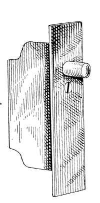
Fig. 266.—Automatic
door switch.
Fig. 267,a is the disappearing-door type with
beveled-edge brass cover plate finished to match
surrounding hardware. In this receptacle the doors
are pushed inward by the insertion of the plug and upon its
withdrawal close automatically, effectually excluding dirt and
concealing the live terminals. It is the latest and best plug receptacle
obtainable.
Fig. 267,b is of the Chapman type with beveled-edge brass
cover plate finished to match surrounding hardware. In this
receptacle the doors open outward but are flush whether the plug
is in or out.
[379]
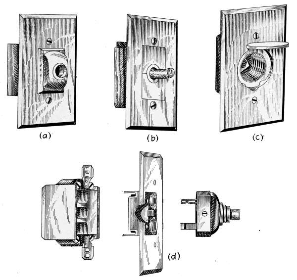
Fig. 267.—Styles of plug receptacles.
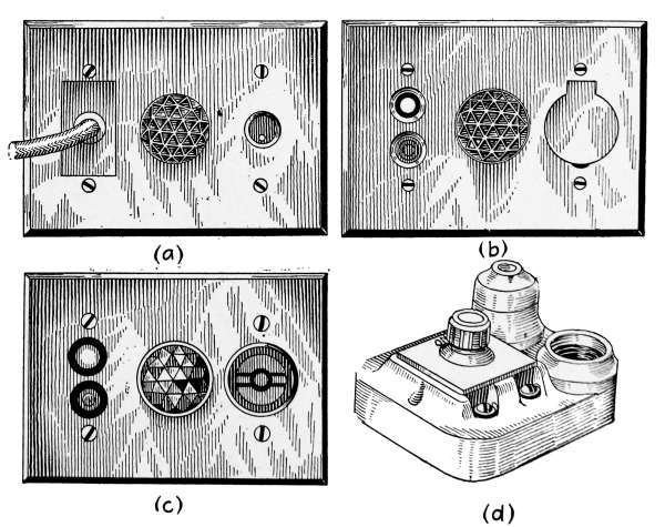
Fig. 268.—Heating-device receptacles.
Fig. 267,c is of the screw-plug type with beveled-edge brass
cover plate finished to match surrounding hardware. By many[380]
this is preferred for apartment use as it will receive any style of
Edison attachment plug.
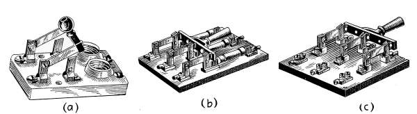
Fig. 269.—Service switches.
Fig. 267,d is of the removable-mechanism type with beveled-edge
brass cover plate finished to match surrounding hardware.
The mechanism of this receptacle is exchangeable with the mechanism
of the double-pole switch as shown in Fig. 270,c.
Heater Switch, Pilot and Receptacle.
—Heating-device outlets
shall be equipped with combination of switch, pilot light and
receptacle with plug and spare pilot lamp. Figs. 268,a, b, c and
d, represent various forms from which selection may be made.
All are adapted for the same purpose and differ only in mechanical
arrangement.
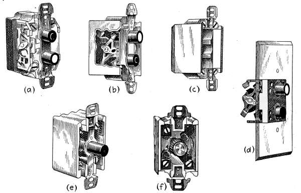
Fig. 270.—Local wall switches.
[381]
Service Switch.
—The service entrance switch may be selected
from the three styles shown in Figs. 269,a, b, and c.
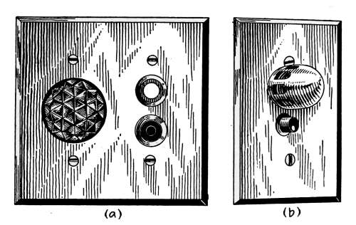
Fig. 271.—Pilot lights.

Fig. 272.—Wall and ceiling sockets.
Fig. 269,a is composed of a 30-ampere porcelain base with connections
for plug fuses.
Fig. 269,b is a slate base with connections for cartridge fuses.
[382]
Fig. 269,c is a slate base with connections for open-link fuses
Local Switches.
—Local wall switches may be selected from the
various styles shown in Figs. 270,a, b, c, d and e.
Fig. 270,a is the two-button flush type completely enclosed in a
box of non-breakable insulating material with brass beveled
cover plate finished to match surrounding hardware.
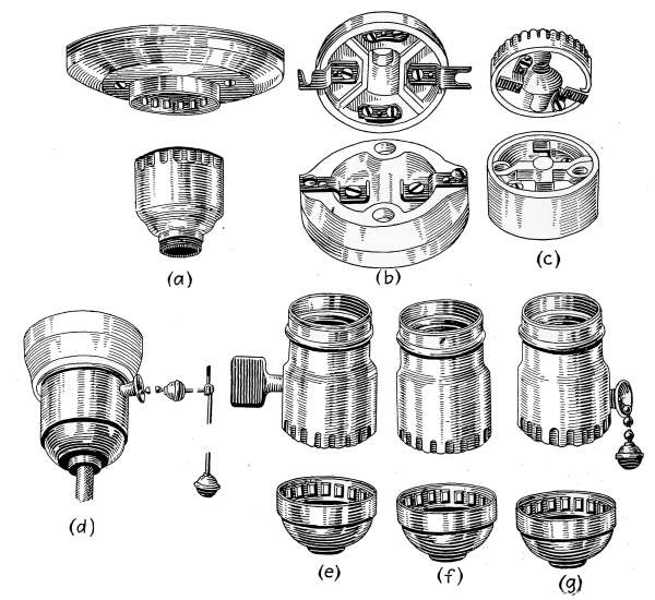
Fig. 273.—Drop-light attachments and lamp bases.
Fig. 270,b is a two-button flush type with brass beveled-edge
cover plate finished to match surrounding hardware.
Fig. 270,c is of the removable-mechanism type with brass beveled-edge
cover plate finished to match surrounding hardware.
Fig. 270,d is the single-button flush type with brass beveled-edge
cover plate finished to match surrounding hardware.
Fig. 270,e is the rotary-flush type with brass beveled-edge
cover plate finished to match surrounding hardware.
[383]
Pilot Lights.
—Switches controlling cellar, attic and porch
lights may be either Fig. 270,a or b.
Fig. 270,a requires for its installation a two-gang outlet box.
The ruby bull’s-eye which covers the lamp is practically flush,
extending from the wall no further than the buttons of the
switch.
Fig. 270,b is installed in a single-gang box. The lamp extends
through the plate and is protected by a perforated cage
which extends about an inch from the plate.
Wall and Ceiling Sockets.
—One-light ceiling receptacles may
be selected from the types shown in Figs. 272,a, b, c, d and e.
Fig. 272,a is of a type to fit standard 3¼-inch or 4-inch
outlet boxes.
Fig. 272,b is of the small concealed-base type.
Fig. 272,c is of the large concealed-base type.
Fig. 272,d is of the insulated-base type.
Fig. 272,e is of the porcelain-base type.
Sockets in cellars shall be made entirely of porcelain. Those
in bathrooms shall be entirely of porcelain and of the pull type.
Drop Lights.
—Drop lights shall consist of the necessary
length of reinforced cord supported by either brass or porcelain
bases. Each drop cord to have an adjuster. Figs. 273,a, b, c, d, e,
f, g, illustrate the various styles. Fig. 273,h is a shade holder to
be used with the drop lights.
[385]
INDEX
- A
- Acetylene, gas burner, 302
- gas machine, the Colt, 300
- machines, 295
- generators, types of, 297
- stoves, 304
- Air conditioning, 240
- cooling plants, 244
- discharged by a flue, 225
- eliminators, 35, 36
- properties of, table, 199
- tester, the Wolpert, 233
- valves, 19
- Alcohol, sad irons, 289
- table stoves, 293
- Annunciators, 346
- Anthracite, graphitic, 186
- Atmospheric humidity, 196
- B
- Backventing, of plumbing, 105
- Bathroom, 97
- Bathtubs, 98
- fixtures for, 100
- Bibb, compression flange, 89
- flange, 89
- Fuller, 89
- hose, 89
- lever handle, 90
- screw, 89
- self-closing, 90
- solder, 89
- wash-tray, 91
- Boiler, at end of season, 79
- cast-iron, 19, 20, 38
- cylindrical form of, 38
- house heating, 19, 24
- rules for management of, 77
- sheet-metal, 19
- Boiler, steam, rules for management of, 78
- the house-heating steam, 19
- Boyle’s law, definition, 161, 272
- Briquettes, 189
- British thermal units, 4
- for one cent, 190
- B.t.u., 2, 32, 182, 185
- Burglar alarms, 344
- Buzzers, 344
- C
- Candle, foot, 313
- Hefner, 310
- power, 310
- horizontal, 310
- spherical, 311
- Cellar drain, 84
- Cell, Pilot, storage battery, 370
- Cesspools, 169
- Charcoal, 188
- Check-draft damper, 24
- Chimney flue, the right, 79
- Chimneys, “smokey,” 80, 81
- Cisterns, filters for, 152, 153
- galvanized iron tanks as, 152
- rain-water, 151
- wooden, 152
- Clinkers, 72, 73
- Close-nipples, 28
- Coal, 182
- anthracite or hard, 183, 193
- bituminous or soft, 184
- burning soft, 75
- calorific value of typical American, 192, 193
- cannel, 186
- coking, 184
- comparative value of, 189
- free burning, 75[386]
- Coal, fusing-coking, 75
- grades of soft, 184
- pea size, 76
- price of, 190, 191
- semi-bituminous, 186, 193
- Cocks, basin, 92
- bibb, 88
- corporation, 87
- curb, 87
- Fuller, 91
- bibb, 89
- repairs for, 91
- pantry, 93
- sill, 93
- stop and drain, 88
- stop and waste, 87
- Code, national electric, 371
- Coke, 76, 188
- gas, 188
- Column, the water, 22
- Condensation, water of, 6, 10, 11, 15, 35
- Conductors, 374
- Cord, lamp, 363
- portable, 363
- Current, alternating, 332
- direct, 332
- D
- Damper, ash-pit, 59
- check-draft, 24, 67, 69, 70
- direct-draft, 59, 61, 67
- regulator, 59, 60
- combined thermostat and, 67
- for hot-water furnaces, 61, 62
- for steam boiler, 60, 78
- Design, heating plant, 44
- Devining rod, 137
- Dew-point, 209
- to determine the, 212
- Dim-a-lite, 323
- Door bells, 342
- Draft, economy of good furnace, 70
- hand, regulation, 59
- induced, 69
- Drip-cock, 23
- Dry cells, 354
- E
- Electric annunciators, 346
- batteries, 354
- battery formation, 358
- testers, 360
- burglar alarms, 344
- buzzers, 344
- conductors, 362
- door bell, 342
- dry cell, 355
- flat-iron, 326
- fuse plugs, 334, 337
- generating plants, 363
- heaters, 338
- heating devices, 305
- lamp cord, 362
- lamps, Gem, 306
- incandescent, 306
- motors, 332
- panel, 336
- range, 340
- signals, 341
- stoves, 339
- table pushes, 346
- toaster, 330
- Electrical measurements, units of, 317
- Electricity, 305
- Eliminator, air, 35, 36
- Evaporation as a cooling agent, 243
- F
- Filaments, carbon, 308
- incandescent lamp, 306, 307
- tungsten, 307
- Fire-box, 19, 20, 54
- Firing, first day, 73
- in moderate weather, 74
- in severe weather, 74
- night, 72
- Fixtures, bathroom, 105
- kitchen and laundry, 94
- Flat-iron, electric, 326
- Flues, furnace, 55[387]
- Flush tanks, 110
- details of construction, 112, 113
- low down, 111
- Foot-candle, 313
- Frost prediction, 212
- Fuels, comparative value of coal to other, 189
- danger from gaseous and liquid, 294
- heating values of domestic, 252
- moisture in, 194
- Furnace, cast-iron, 54
- firing, general rules for, 70
- times of day for, 72
- location of, 54
- the hot-air, 51, 52
- construction of, 52
- Furnace-gas leaks, 54
- Fuse plugs, 334
- G
- Gage, Bourdon type of, 23
- electrified Bourdon spring pressure, 36
- glass, 22, 40, 161, 162
- steam, 22
- water, 22
- Gas, acetylene, machines, 295
- all-oil water, 251
- Blau, 251
- burner, Bunsen, 275
- open-flame, 278
- coal, 250
- lamps, mantle, 274, 276, 277
- lighters, 302
- measurements of, 253
- meter dials, reading of, 255, 256
- meters, 254
- prepayment, 256
- Pintsch, 251
- service rules, 256, 257
- ranges, 258
- water, 251
- Gases, heating values of, 252
- Gasoline, 250
- Beaumé test of, 261
- Gasoline, boulevard lamp, 287
- central generator plants for use of, 282
- cold process system of lighting with, 264, 265
- gas lamps, 286
- gravity test of, 262
- hollow-wire system of lighting and heating with, 269
- lamps, inverted mantle, 279
- portable, 280, 281
- lighting and heating with, 259, 264
- regulation and sale of, 261
- sad irons, 289
- stoves, burners for, 288
- Gate valve, 94
- Globe valve, 93
- angle, 94
- Grate surface, 53
- Gravity system, low pressure, 6, 15
- H
- Heaters, combination hot-air and hot-water, 56
- direct and indirect, 28
- furnace hot-water, 122
- instantaneous, 123
- tank, 121
- wash boilers, 96
- Heating, C. A. Dunham’s system of vapor, 34, 35
- direct indirect, 30
- hot-water, 26
- indirect method of, 29, 30
- low pressure system of, 5, 6
- overhead or drop system of steam, 14
- system of hot water, 44
- plants, management of, 70
- separate return system of steam, 13
- single pipe system of steam, 6, 12, 15
- steam, 26
- surface of furnaces, 56[388]
- Heating, radiators, 26
- two pipe system of steam, 6, 10, 11, 15
- Heat, of vaporization, 2
- specific, 37
- Hot-air furnace, 61
- Hot-water heaters, 38
- House drain, 82
- Humidifying apparatus, 215
- plants, 242
- Humidity, absolute, 196
- atmospheric, 196
- control, 244
- of the air, 196
- relative, 197, 204
- Hydraulic ram, 154
- double acting, 157
- single acting, 155
- Hydrometer, storage battery, 368
- Hygrodeik, 206
- Hygrometer, 204
- dial, 208
- I
- Illumination, 313
- intensity of, 314
- quantity of, 314
- K
- Kerosene, 263
- legal tests for, 263
- L
- Lamp, base, the Edison, 311
- cord, 363
- labels, 312
- Lamps, boulevard, 287
- carbon filament, 311
- central-generator gas, 286
- daylight, electric, 324
- gas-filled electric, 324
- incandescent electric, 306
- mantle, 276
- inverted-mantle gasoline, 279
- Lamps, Mazda, 310
- miniature electric, 320, 325
- portable, gasoline, 280
- tantalum, 306
- tungsten-filament, 306
- turn-down electric, 321
- Lights, drop, 383
- flash, 326
- pilot, 383
- Lignite, 186
- Lumen, 313
- O
- Outlet boxes, 373
- Overflow pipe, 45
- Overheated water, 47
- P
- Peat, 187
- Pilot light, 375
- Pipes, covering, 33
- eliminator, 36
- flow, 57
- openings stopped, 113
- overflow, 40, 41
- return, 6, 10, 57
- supply, 6, 10
- Plant, hot-water heating, 37
- steam heating, 1, 5
- Plug receptacles, 378
- Plumbers friend, 113
- Plumbing, 81
- rough, 82
- Pneumatic motor valve, 237
- radiator valve, 237
- Polluted water, 134
- Pollution of wells, 134
- Pressure, absolute, 4
- gage, 4
- tank, 162
- vapor, 35, 36
- Properties of steam, 3
- Psychrometer, 207
- Pump, force, the, 146
- lift, the, 144
- tank, 146[389]
- Pumps, 144
- chain, 151
- deep well, 150
- for driven wells, 150
- priming of, 145
- well, 148
- wooden, 148
- R
- Radiating surface, 1, 21, 22, 27
- Radiators, air vent on, 77
- connections, 10, 47
- corner, 28
- finishings, 31
- forms of, 26
- hot-water, 28, 49
- rules for proportioning, 24, 25
- single column, 28
- pipe, 10, 15
- three column, 28
- to control, 79
- wall, 28
- water-filled, 15
- Range boilers, 115
- blow-off cock, 118
- double heater connections for, 119
- excessive pressure in, 117
- horizontal, 119
- location, 118
- Reflectors, 315
- choice of, 316
- focusing, 316
- holoplane, 315
- intensive, 316
- Registers, rules for proportioning, 55
- Regulator, combined thermostat and damper, 67
- damper, 59, 60, 67
- draft, 24
- temperature, 59, 67
- Riser, 6, 10
- S
- Sad irons, alcohol, 292
- gasoline, 289
- Safety valve, 24, 44, 47, 67
- Septic tank, 170
- and anaerobic filter, 174
- automatic siphon for, 176
- concrete, 179
- limit of efficiency of, 178
- Universal Portland Cement Co., 179
- with sand-bed filter, 171
- Sewage, 168
- disposal, 168
- purification, 168
- Sewer, 82, 85
- gas,114
- Short circuiting, 334
- Sitz bath, 98
- Slicing bar, 72
- Slugging, 15
- Soil pipe, 84, 107
- Soot pocket, 80
- Stand pipe eliminator, 36
- Steam temperatures, 4
- Stop-cock, 46
- Stove, acetylene, 292
- gasoline, 288
- putty, 54
- Surface, grate, 53
- air-heating, 53
- Surging, 15
- Switch, automatic door, 378
- heater, 380
- local, 382
- service, 381
- System, high-pressure hot-water, 41
- low-pressure gravity, 6
- hot-water, 38
- overhead or drop, 14
- separate return, 13
- single pipe, 8
- two pipe, 10
- T
- Table, air discharged from flues, 229
- required for ventilation, 220
- calorific value of American coals, 192[390]
- Table, dew-point, 210, 211
- frost prediction, 214
- heating values of coals, 93
- gases, 252
- wood, 187, 188
- hot-air furnaces, 51
- registers, 51
- lumens per watt, 314
- prices of fuels, 191
- properties of air, 199
- steam, 3
- radiators, sizes of, 27
- record of evaporation from hot-air furnace, 217
- relative heating values of domestic fuel, 252
- humidity, 202, 203
- sizes of hard coal, 183
- heating mains, 26
- hot-air furnaces, 51
- soft coal, 184
- thermal units for one cent, 190
- Table pushes, 346
- Tank heaters, 121
- expansion, 38, 40, 41, 45, 46, 47
- Telephones, intercommunicating, 340
- Temperature regulation, 59
- hand, 59
- pneumatic, 234
- Thermostats, 62, 67
- controllers, 62, 63
- electric, 62
- motor, 64
- National Regulator Co., 235, 236
- pneumatic, 62
- time attachment, 63
- Transformers, bell-ringing, 347
- lamp, 316
- Traps, Bower, 103
- clean sweep, 103
- drum, 103, 105
- for bathroom fixture, 102, 103
- inside, 83
- non-siphoning, 105
- outside, 83
- sewer for house drains, 82
- siphoning, 106
- S, 103, 104
- Try-cocks, 22, 23
- Tungsten, 307
- U
- Union joint, 18
- V
- Vacuum, 5
- Valve, air, 79
- angle, 18
- check, 42, 43
- definition of, 88, 93
- disc, 19
- globe, 93
- hot-water radiator, 49
- Ohio hot-water, 49
- on cellar mains, 78
- safety, 24, 44, 47
- steam radiator, 18
- stem, 19
- Valves, definition of, 93
- globe, 93
- Vaporization, heat of, 2
- Ventilation, 219
- apparatus, 239
- by direct method of heating, 31
- by indirect method of heating, 31
- cost of, 230
- De Chaumont standard of, 219
- mechanical, 237
- of dwellings, 222, 223, 224
- Plenum method of, 239
- quantity of air required for, 220
- Vents, air, 16, 45, 48, 49
- automatic air, 16
- hot-water air, 50
- Monash No. 16 air, 16
- pipe, 83
- radiator, 16
- sewer, 85
- the Allen float, 16[391]
- Voltage variation, effect of, 321
- W
- Wash stands and lavatories, 101
- Waste stack, 84, 85
- Water, ammonia in, 130
- analyses, 126
- artesian, 128
- back, 115
- chlorine in, 133
- closets, 108
- siphon-jet, 108
- washdown, 109
- washout, 108
- frost, 115
- hammer, 9, 15
- hardness in, 131
- iron in, 131
- lift, 165
- medical, 128
- of condensation, 11
- organic matter in, 130
- overheated, 121
- Pokegama, 127
- polluted, 133
- river, 127
- seal, 83
- softening with hydrated silicates, 132
- supply, 87, 125
- electric power, 164
- plants, domestic, 158
- gravity, 158
- power, 163[392]
- pressure tank system of, 160
- wind power, 164
- table, 137
- Wattmeter, periodic tests of, 354
- readings, 352
- recording, 350
- state regulation of, 353
- to read the, 350
- Well, the ideal, 140
- Wells, artesian, 140
- bored, 141
- breathing, 143
- cleaning of, 142
- concrete coverings for, 140
- construction of, 138
- curbing of, 136, 140
- cylinders for tubular, 151
- driven, 141
- dug, 139
- flowing, 138
- freezing, 144
- gases in, 142
- open, 139
- peculiarities of, 143
- safe distance in the location of, 135
- selection of the type of, 138
- surface pollution of, 135
- Wiped joints, 107
- Wire annunciator, 353
- Wiring, electric light, 372
- Wood, 187
- heating value of, 187
Transcriber's Note
The book cover image was created by the transcriber and is placed in the public domain.
Minor punctuation errors e.g. missing "." in "Fig." have been corrected.
Inconsistent hyphenation and use of ligatures has been left
e.g. cast-iron and cast iron. (Often the difference is between the
hyphenation in the text, that used in captions to illustrations
and that used in the index.)
Both gasolene and gasoline are used in the text
Both carburator and carburetor are used in the text
Many of the table values have errors which can be shown by graphing the results,
these have been left as printed but are noted here:
- p.5. Absolute Pressure 5, Latent heat of 958.30 should be 956.30
- p.199.
Air temperature 33 degF. Weight of cu. ft. air 566.4 should be 560.4
Air temperature 43 degF. Weight of cu. ft. air 548.4 should be 542.4
Air temperature 49 degF. Weight of cu. ft. air 542.5 should be 541.5
Air temperature 58 degF. Weight of cu. ft. air 534.9 should be 530.9
Air temperature 63 degF. Weight of vapor/cu. ft. air should be 6.45
- p.203. Air Temp. 106, 2 deg. depression of wet-bulb thermometer 95 should be 93
- p.211. Dew point. 69, 12 deg. depression of wet-bulb thermometer 84 should be 48
- p.214.
Dry-bulb temp. 39, 12 deg. depression of wet-bulb thermometer 23 should be -23
Dry-bulb temp. 38 9 deg. depression of wet-bulb thermometer -6 should be 6
- p.314. Column heading should read
Watts per lamp 25 40 60 100 150 250
Other errors found:
| Page number | Original text | Corrected text |
|---|
| 33 |
asbestus plaster |
Asbetos is used elsewhere but this could be a trade name so it
has been left as printed. |
| 55 | two layers of asbestus paper |
As above. |
| 56 | heating the house |
The "us" in house was upside-down. |
| 93 | pipe to which A is attached |
A should be in italics. |
| 100 | bath tubs, avatories |
bath tubs, lavatories |
| 133 | drinking porposes |
drinking purposes |
| 133 | elementary tract |
alimentary tract |
| 137 | It is flatest |
It is flattest |
| 161 | Boyles |
Boyle's |
| 162 | wtih the pump |
with the pump |
| 180 | its legnth |
its length |
| 181 | hould |
should |
| 188 | As given by Suplees |
As given by Suplee's |
| 216 | hydrodeik |
hygrodeik |
| 220 | Cubic feet or pure air |
Cubic feet of pure air |
| 239 | containg coils |
containing coils |
| 243 | sheet-met a surfaces |
sheet-metal surfaces |
| 259 | and explosion |
an explosion |
| 268 | The vitally improtant |
The vitally important |
| 269 | end of the supending bar |
end of the suspending bar |
| 269 | gasoline in the caburetor |
gasoline in the carburetor |
| 270 | gasoline for the stove S |
gasoline for the stove R |
| 272 | Boyles law |
Boyle's law |
| 279 | Inverted-mantel Gasoline Lamp |
Inverted-mantle Gasoline Lamp |
| 281 | percolating trough the tube |
percolating through the tube |
| 305 | elect ic transmission |
electric transmission |
| 309 | the electrotromotive force |
electromotive force |
| 319 | 1000 746 = 1.3 horsepower |
1000/746 = 1.3 horsepower |
| 320 | Minature screw base |
Miniature screw base |
| 329 | also shown in Fig. 288 |
also shown in Fig. 228 |
| 343 | the contact peice |
the contact piece |
| 345 | window burgler alarm |
window burglar alarm |
| 347 | inserted in the floor place |
inserted in the floor plate |
| 352 | at the begining |
at the beginning |
| 356 | require severals hours |
require several hours |
| 357 | The amper-hour |
The ampere-hour |
| 358 | If the cells singly give 20 volts, the battery will give 20 volts |
If the cells singly give 20 amperes, the battery will give 20 amperes |
| 385 | Boyles' law, definition |
Boyle's law, definition |
| 387 | blau, 251 |
Blau, 251 |
| 390 | DeChaumont |
De Chaumont |
*** END OF THE PROJECT GUTENBERG EBOOK 50846 ***